Embed Size (px)
Citation preview
CMUX User Guide 30268ST10299A Rev. 3 – 19/01/09

CMUX User Guide 30268ST10299A Rev. 3 – 19/01/09
Reproduction forbidden without Telit Communications S.p.A. written authorization - All Rights Reserved page 2 of 28
This document is referred to the following products: APPLICABILITY TABLE
PRODUCT PART NUMBER (1)
GT864-QUAD 4990150069
GT864-PY 4990150070
GM862-GPS GM862GPS***-***
GM862-QUAD-PY GM862PYT***-***
GM862-QUAD GM862QUD***-***
GC864-QUAD GC864QUD***-***
GC864-PY GC864PYT***-***
GC864-QUAD-C2 GC864QC2***-***
GC864-PY-C2 GC864PC2***-***
GC864-QUAD w/SIM holder GC864QUH***-***
GC864-Pyw/SIM holder GC864PUH***-***
GE863-GPS GE863GPS***-***
GE863-PY GE863PYT***-***
GE863-QUAD GE863QUD***-***
GE863-SIM MNO dependant (2)
GE863-PRO3 without OS GE863PR3***-***
GE863-PRO3 with Linux OS GE863PR3***-***
GE863-PRO3 64MB w/o OS GE863PR3***-***
GE863-PRO3 64MB w Linux OS GE863PR3***-***
GE864-PY GE864PYT***-***
GE864-QUAD GE864QUD***-***
GE864-QUAD Automotive GE864AUT***-***
(1) The suffix “***-***” depends on the module HW/SW configuration. Please contact your Telit representative for details (2) Mobile Network Operator dependant, ask to TTSC or contact your regional sales representative for details
From SW Version:
7.02.04 / 7.03xx0

CMUX User Guide 30268ST10299A Rev. 3 – 19/01/09
Reproduction forbidden without Telit Communications S.p.A. written authorization - All Rights Reserved page 3 of 28
Contents
1 INTRODUCTION............................................................................................................................. 5 1.1 Purpose of the document........................................................................................................................5
2 APPLICABLE DOCUMENTS ........................................................................................................ 6
3 TECHNICAL CHARACTERISTICS .............................................................................................. 7 3.1 Product architecture...............................................................................................................................7
3.2 Implementation feature..........................................................................................................................9
4 SERIAL MULTIPLEXER PROTOCOL ....................................................................................... 10 4.1 CMUX Frame Structure ......................................................................................................................10
4.2 UIH Control Channel Frame Coding .................................................................................................13
4.3 UIH Data Channel Frame Coding ......................................................................................................15
4.4 CMUX establishment scenario ............................................................................................................16
4.5 CMUX establishment scenario typical log .........................................................................................17
4.6 Lookup table for FCS calculation .......................................................................................................18
5 INTEGRATOR HINTS .................................................................................................................. 19 5.1 Basic requirement.................................................................................................................................19
5.2 Restriction .............................................................................................................................................19
5.3 Exception to independent profile setting ............................................................................................21
5.4 Suggestion..............................................................................................................................................21
6 TELIT SERIAL PORT PC INTERFACE FOR CMUX ............................................................... 22 6.1 Interface Specification..........................................................................................................................22
6.2 Scenario .................................................................................................................................................22
6.3 Graphical Interface ..............................................................................................................................23
6.4 Application Setup .................................................................................................................................25
7 AT Commands ................................................................................................................................ 26
8 Document Change Log................................................................................................................... 27

CMUX User Guide 30268ST10299A Rev. 3 – 19/01/09
Reproduction forbidden without Telit Communications S.p.A. written authorization - All Rights Reserved page 4 of 28
DISCLAIMER The information contained in this document is the proprietary information of Telit Communications S.p.A. and its affiliates (“TELIT”). The contents are confidential and any disclosure to persons other than the officers, employees, agents or subcontractors of the owner or licensee of this document, without the prior written consent of Telit, is strictly prohibited. Telit makes every effort to ensure the quality of the information it makes available. Notwithstanding the foregoing, Telit does not make any warranty as to the information contained herein, and does not accept any liability for any injury, loss or damage of any kind incurred by use of or reliance upon the information. Telit disclaims any and all responsibility for the application of the devices characterized in this document, and notes that the application of the device must comply with the safety standards of the applicable country, and where applicable, with the relevant wiring rules. Telit reserves the right to make modifications, additions and deletions to this document due to typographical errors, inaccurate information, or improvements to programs and/or equipment at any time and without notice. Such changes will, nevertheless be incorporated into new editions of this application note. Copyright: Transmittal, reproduction, dissemination and/or editing of this document as well as utilization of its contents and communication thereof to others without express authorization are prohibited. Offenders will be held liable for payment of damages. All rights are reserved. Copyright © Telit Communications SpA 2009.

CMUX User Guide 30268ST10299A Rev. 3 – 19/01/09
Reproduction forbidden without Telit Communications S.p.A. written authorization - All Rights Reserved page 5 of 28
1 INTRODUCTION
1.1 Purpose of the document The scope of this document is to describe a multiplexing protocol implemented on the Telit module. The multiplexing protocol can be used to send any data, SMS, fax, TCP data. NOTE: CUMX can be activated only with the interface SELINT 2; this means that for the modules GM862-QUAD/PY and GE863-QUAD/PY which start as default in SELINT 0 or SELINT 11, before activating CMUX, interface should be changed to SELINT 2.
1 please consult AT Commands Reference Guide 80000ST10025a for more information
CMUX User Guide 30268ST10299A Rev. 3 – 19/01/09
Reproduction forbidden without Telit Communications S.p.A. written authorization - All Rights Reserved page 6 of 28
2 APPLICABLE DOCUMENTS • Digital Cellular Telecommunications Systems (Phase 2+); Terminal Equipment to Mobile Station
(TE-MS) “Multiplexer Protocol”; ETSI TS 101 369 V7.1.0 (1999-11), GSM 07.10 Version 7.1.0, Release 199

CMUX User Guide 30268ST10299A Rev. 3 – 19/01/09
Reproduction forbidden without Telit Communications S.p.A. written authorization - All Rights Reserved page 7 of 28
3 TECHNICAL CHARACTERISTICS
3.1 Product architecture The Multiplexer mode enables one serial interface to transmit data to four different customer applications. This is achieved with the Multiplexer (Mux) that provides four virtual channels. This is represents a great advantage for fax, data, and GPRS ongoing calls. Thanks to the Multiplexer feature operations such as controlling the module or using the SMS service can be done via the additional channels without disturbing the data flow and no access to the second UART is necessary. Another important particularity is that it is possible to use several independent electronic devices or interfaces at the same time, since Multiplexer permits to create more than one access to the module. To access the three virtual interfaces, both the GSM engine and the customer application must contain Mux components that communicate over the multiplexer protocol. In Multiplexer mode, AT commands and data are encapsulated into packets. Each packet has channel identification and may vary in length.

CMUX User Guide 30268ST10299A Rev. 3 – 19/01/09
Reproduction forbidden without Telit Communications S.p.A. written authorization - All Rights Reserved page 8 of 28
Telit serial communications and AT interface layer
CMUX User Guide 30268ST10299A Rev. 3 – 19/01/09
Reproduction forbidden without Telit Communications S.p.A. written authorization - All Rights Reserved page 9 of 28
3.2 Implementation feature Some of the most important characteristics of CMUX are described below.
• 7.10 CMUX Basic Option used • CMUX implementation support four full DLCI (Serial Port) • Every CMUX instance has its own user profile storage in NVM • Independent setting of unsolicited message. • In case of GPS product one serial port can be dedicated to NMEA output. • Every CMUX instance has its own independent flow control.

CMUX User Guide 30268ST10299A Rev. 3 – 19/01/09
Reproduction forbidden without Telit Communications S.p.A. written authorization - All Rights Reserved page 10 of 28
4 SERIAL MULTIPLEXER PROTOCOL
4.1 CMUX Frame Structure All information transmitted between the module and the application are based on frame that has the following frame Structure:
Flag Address Control Length Indicator Information FCS Flag
1 octet 1 octet 1 octet 1or2 octets Unspecified length but
integral number of octets
1 octet 1 octet
Flag Octet Each frame begins and ends with a flag octet defined as Binary: 11111001 or Hexadecimal: 0xF9 Address Octet The form of address octet is the following:
0 1 2 3 4 5 6 7 EA C/R D L C I
EA: Extension Bit Should always have the value 1 as the basic option of the protocol. C/R: Command Response The C/R (command/response) bit identifies the frame as either a command or a response. In conformance with the standard HDLC rules, a command frame contains the address of the data link connection entity to which it is transmitted while a response frame contains the address of the data link connection entity transmitting the frame.
Command/response Direction C/R value Command Application ⎯⎯→ Module 1 Module ⎯⎯→ Application 0 Response Application ⎯⎯→ Module 0 Module ⎯⎯→ Application 1

CMUX User Guide 30268ST10299A Rev. 3 – 19/01/09
Reproduction forbidden without Telit Communications S.p.A. written authorization - All Rights Reserved page 11 of 28
Example: Let’s suppose that application is the one that takes the initiative to initialize the multiplexer (i.e. sends the SABM command at DLCI 0) and that the Module accepts the initialization of the multiplexer (i.e. sends the UA response at DLCI 0). DLCI: Data Link Connection Identifier DLCI value identifies the Virtual Port inside the Module with the following assignment
DLCI Virtual Port type 0 Reserved to Control Channel 1 Virtual Port #1 2 Virtual Port #2 3 Virtual Port #3 4 Reserved for Python debug
Control Field The content of the control field defines the type of frame as in the following table:
Frame Type 0 1 2 3 4 5 6 7 SABM (Set Asynchronous Balanced Mode) 1 1 1 1 P/F 1 0 0 UA (Unnumbered Acknowledgement) 1 1 0 0 P/F 1 1 0 DM (Disconnected Mode) 1 1 1 1 P/F 0 0 0 DISC (Disconnect) 1 1 0 0 P/F 0 1 0 UIH (Unnumbered Information with Header check)
1 1 1 1 P/F 1 1 1
P/F stands for Poll/Final bit: Commands: P=1 Response: F=1 SABM (Set Asynchronous Balanced Mode) The SABM command is used by the application to start the HDLC Connection and module will answer to this command with an UA Frame. UA (Unnumbered Acknowledgement) The UA response is sent by the module as an acknowledgement that a SABM or DISC command was accepted. DM (Disconnected Mode) In case module rejects SABM or DISC command it will send DM response, this happens if for example a SABM is sent for a DLCI not supported. Or if a DISC is sent to a DLCI Address already closed.

CMUX User Guide 30268ST10299A Rev. 3 – 19/01/09
Reproduction forbidden without Telit Communications S.p.A. written authorization - All Rights Reserved page 12 of 28
DISC (Disconnect) The DISC is used to close a previously established connection. If the application sends a disc for the DLCI 0 (the control channel), all the established channels will be closed. The module will answer to this command with an UA Frame. UIH (Unnumbered Information) Please refer to the following chapters for the detailed information about UIH Length Indicator This Octet specifies the length of the information field
0 1 2 3 4 5 6 7 E/A L1 L2 L3 L4 L5 L6 L7
E/A Bit should be 1 in case 7 bits are enough for the len (len <= 127) otherwise len should be coded with two octets as described below: Octet 1
0 1 2 3 4 5 6 7 0 L1 L2 L3 L4 L5 L6 L7
Octet 2
0 1 2 3 4 5 6 7 1 L9 L10 L11 L12 L13 L14 L15
NOTE: Since the maximum frame length used by Telit implementation is 128, Octet 2 is never used. Codification of the octet (Octet 1=0 and Octet 2=1) derives from GSM 07.10. Information Data The information field is the payload of the frame and carries the user data. The field exists only for frame type that contains UIH Control Field. The P/F bit should be set to value 0 when this field is sent. FCS (Frame Checking Sequence) The FCS is calculated over the entire frame, but excluding the flags. Only in case of UIH frame the FCS will not be calculated over the information field. The FCS is the ones complement of the sum (modulo 2) of
the remainder of xk (x7 + x6 + x5 + x4 + x3 + x2 + x1 + 1) divided (modulo 2) by the generator polynomial x8 + x2 + x + 1,
where k is the number of bits in the frame.2 See specific chapter with code examples for more implementation details.
2 refer to the ETSI Specification 07.10
CMUX User Guide 30268ST10299A Rev. 3 – 19/01/09
Reproduction forbidden without Telit Communications S.p.A. written authorization - All Rights Reserved page 13 of 28
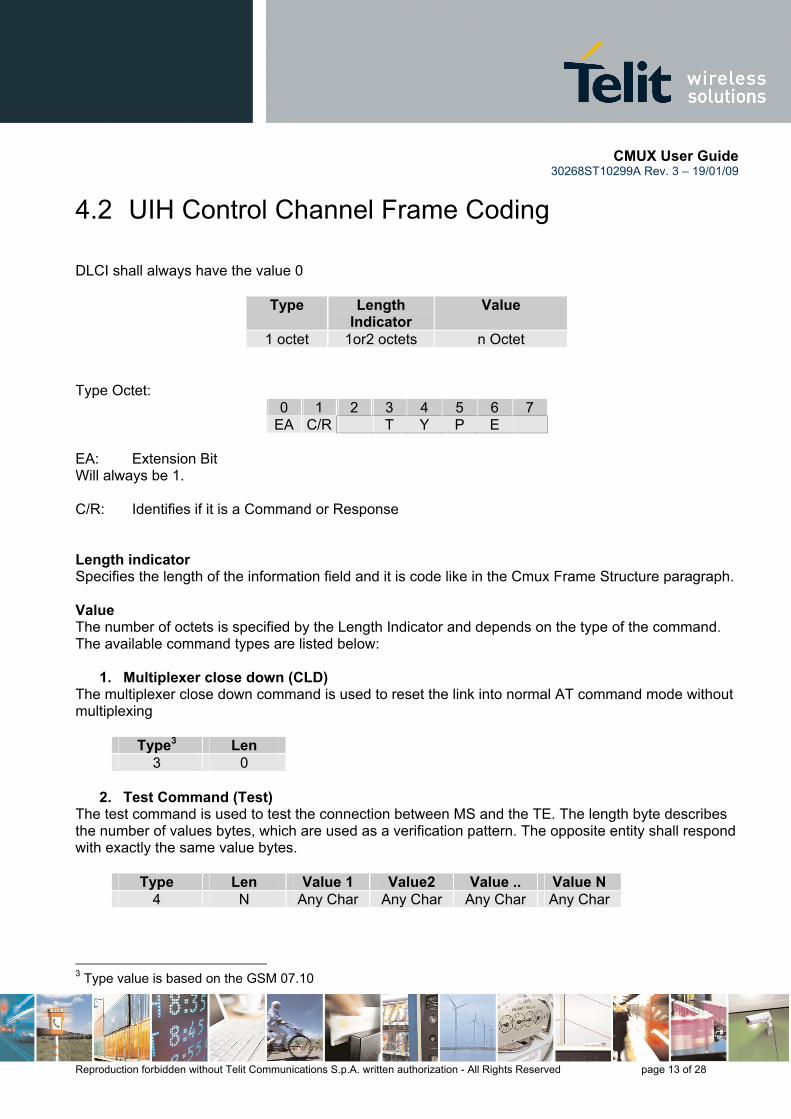
4.2 UIH Control Channel Frame Coding DLCI shall always have the value 0
Type Length Indicator
Value
1 octet 1or2 octets n Octet Type Octet:
0 1 2 3 4 5 6 7 EA C/R T Y P E
EA: Extension Bit Will always be 1. C/R: Identifies if it is a Command or Response Length indicator Specifies the length of the information field and it is code like in the Cmux Frame Structure paragraph. Value The number of octets is specified by the Length Indicator and depends on the type of the command. The available command types are listed below:
1. Multiplexer close down (CLD) The multiplexer close down command is used to reset the link into normal AT command mode without multiplexing
Type3 Len 3 0
2. Test Command (Test)
The test command is used to test the connection between MS and the TE. The length byte describes the number of values bytes, which are used as a verification pattern. The opposite entity shall respond with exactly the same value bytes.
Type Len Value 1 Value2 Value .. Value N 4 N Any Char Any Char Any Char Any Char
3 Type value is based on the GSM 07.10
CMUX User Guide 30268ST10299A Rev. 3 – 19/01/09
Reproduction forbidden without Telit Communications S.p.A. written authorization - All Rights Reserved page 14 of 28
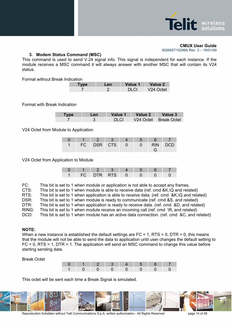
3. Modem Status Command (MSC) This command is used to send V.24 signal info. This signal is independent for each instance. If the module receives a MSC command it will always answer with another MSC that will contain its V24 status. Format without Break Indication
Type Len Value 1 Value 2 7 2 DLCI V24 Octet
Format with Break Indication
Type Len Value 1 Value 2 Value 3 7 3 DLCI V24 Octet Break Octet
V24 Octet from Module to Application
0 1 2 3 4 5 6 7 1 FC DSR CTS 0 0 RIN
G DCD
V24 Octet from Application to Module
0 1 2 3 4 5 6 7 1 FC DTR RTS 0 0 0 0
FC: This bit is set to 1 when module or application is not able to accept any frames. CTS: This bit is set to 1 when module is able to receive data (ref. cmd &K,\Q and related) RTS: This bit is set to 1 when application is able to receive data. (ref. cmd &K,\Q and related) DSR: This bit is set to 1 when module is ready to communicate (ref. cmd &S, and related) DTR: This bit is set to 1 when application is ready to receive data. (ref. cmd &D, and related) RING: This bit is set to 1 when module receive an incoming call (ref. cmd \R, and related) DCD: This bit is set to 1 when module has an active data connection. (ref. cmd &C, and related) NOTE: When a new instance is established the default settings are FC = 1, RTS = 0, DTR = 0, this means that the module will not be able to send the data to application until user changes the default setting to FC = 0, RTS = 1, DTR = 1. The application will send an MSC command to change this value before starting sending data. Break Octet
0 1 2 3 4 5 6 7 1 0 0 0 0 0 0 0
This octet will be sent each time a Break Signal is simulated.
CMUX User Guide 30268ST10299A Rev. 3 – 19/01/09
Reproduction forbidden without Telit Communications S.p.A. written authorization - All Rights Reserved page 15 of 28
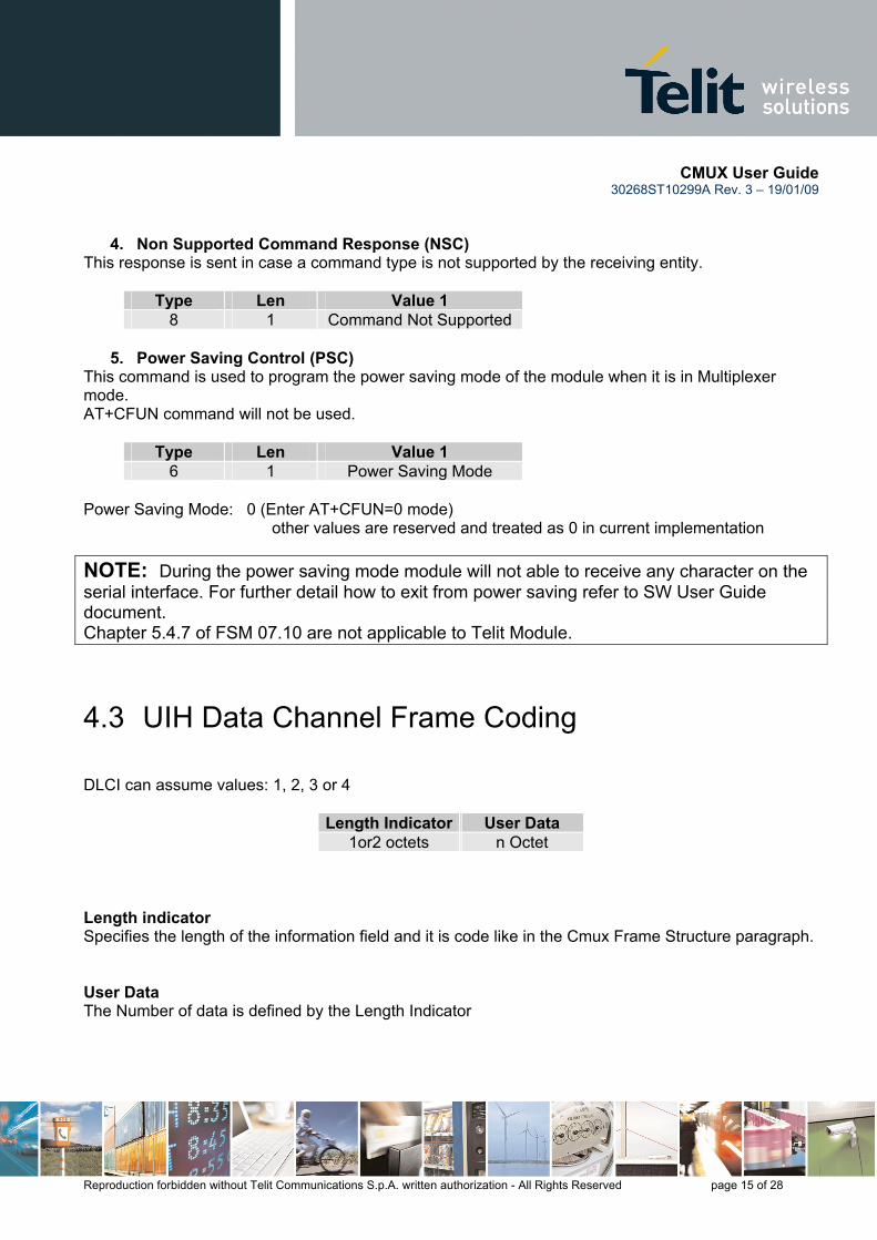
4. Non Supported Command Response (NSC) This response is sent in case a command type is not supported by the receiving entity.
Type Len Value 1 8 1 Command Not Supported
5. Power Saving Control (PSC)
This command is used to program the power saving mode of the module when it is in Multiplexer mode. AT+CFUN command will not be used.
Type Len Value 1 6 1 Power Saving Mode
Power Saving Mode: 0 (Enter AT+CFUN=0 mode) other values are reserved and treated as 0 in current implementation NOTE: During the power saving mode module will not able to receive any character on the serial interface. For further detail how to exit from power saving refer to SW User Guide document. Chapter 5.4.7 of FSM 07.10 are not applicable to Telit Module.
4.3 UIH Data Channel Frame Coding DLCI can assume values: 1, 2, 3 or 4
Length Indicator User Data 1or2 octets n Octet
Length indicator Specifies the length of the information field and it is code like in the Cmux Frame Structure paragraph. User Data The Number of data is defined by the Length Indicator
CMUX User Guide 30268ST10299A Rev. 3 – 19/01/09
Reproduction forbidden without Telit Communications S.p.A. written authorization - All Rights Reserved page 16 of 28
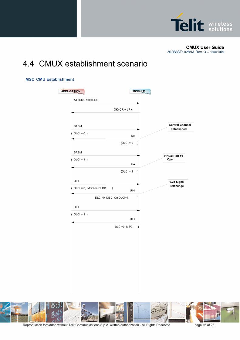
4.4 CMUX establishment scenario
MODULEAPPLICATION
MSC CMU Establishment
V.24 SignalExchange
Virtual Port #1Open
Control Channel Established
UIH
( DLCI=0, MSC, On DLCI=1 )
UIH
( DLCI = 0, MSC on DLCI1 )
SABM
( DLCI = 0 )
UIH
(DLCI=0, MSC )
UIH
( DLCI = 1 )
UA
((DLCI = 1 )
SABM
( DLCI = 1 )
UA
((DLCI = 0 )
OK<CR><LF>
AT+CMUX=0<CR>

CMUX User Guide 30268ST10299A Rev. 3 – 19/01/09
Reproduction forbidden without Telit Communications S.p.A. written authorization - All Rights Reserved page 17 of 28
4.5 CMUX establishment scenario typical log Red - commands sent from Application to Module Green - commands sent form Module to Application Black - Comments // ASCII Log AT#SELINT=2 -Make sure that Interface selection is equal 2 OK ATE0V1&K3&D2 -Disable Echo, Activate Hardware Flow Control, Program the DTR to disconnect OK AT+CMUX=0 -Start MUX protocol OK NOTE: After Multiplexer is established the AT Instance 1 is removed from the Physical Serial port and mapped to Virtual COM1. The settings ATE0V1&K3&D2 will be available on Virtual port #1. // Hexadecimal Log F9 03 3F 01 1C F9 -DLCI = 0, SABM CMD, POLL BIT SET F9 03 73 01 D7 F9 -DLCI = 0, UA RESPONSE, FINAL BIT SET CMUX Protocol Established F9 07 3F 01 DE F9 -DLCI = 1, SABM CMD, POLL BIT SET F9 07 73 01 15 F9 -DLCI = 1, UA RESPONSE, FINAL BIT SET Virtual Port #1 Opened F9 03 EF 09 E1 05 07 0C FB F9 -DLCI = 0, UIH Frame, MSC Cmd for DLCI 1 Application Set FC=0, RTS=1, DTR=1 for Virtual Com 1 F9 03 EF 09 E1 05 07 0C FB F9 -DLCI = 0, UIH Frame, MSC Cmd for DLCI 1 Module Set FC=0, RTS=1, DTR=1, RING=0, DCD=0 for Virtual Com 1 Ready to send AT Command on Instance #1 F9 05 EF 10 41 54 2B 43 47 4D 52 0D xx F9 -Send Command AT+CGMR F9 05 EF 27 0D 0A 30 37 2E 30 32 2E 35 30 34 0D 0A 0D 0A 4F 4B 0D 0A 8° F9 -Answer from module is <CR><LF>07.02.504<CR><LF><CR><LF><OK> F9 03 EF 05 41 00 F2 F9 - Send PSC = 0 Command To wake up the module or the Application Toggle refer to the AT command AT+CFUN=0.

CMUX User Guide 30268ST10299A Rev. 3 – 19/01/09
Reproduction forbidden without Telit Communications S.p.A. written authorization - All Rights Reserved page 18 of 28
4.6 Lookup table for FCS calculation The following part of the code is provided to make easier the FCS calculation: static const unsigned char crctable[256] = { //reversed, 8-bit, poly=0x07 0x00, 0x91, 0xE3, 0x72, 0x07, 0x96, 0xE4, 0x75, 0x0E, 0x9F, 0xED, 0x7C, 0x09, 0x98, 0xEA, 0x7B, 0x1C, 0x8D, 0xFF, 0x6E, 0x1B, 0x8A, 0xF8, 0x69, 0x12, 0x83, 0xF1, 0x60, 0x15, 0x84, 0xF6, 0x67, 0x38, 0xA9, 0xDB, 0x4A, 0x3F, 0xAE, 0xDC, 0x4D, 0x36, 0xA7, 0xD5, 0x44, 0x31, 0xA0, 0xD2, 0x43, 0x24, 0xB5, 0xC7, 0x56, 0x23, 0xB2, 0xC0, 0x51, 0x2A, 0xBB, 0xC9, 0x58, 0x2D, 0xBC, 0xCE, 0x5F, 0x70, 0xE1, 0x93, 0x02, 0x77, 0xE6, 0x94, 0x05, 0x7E, 0xEF, 0x9D, 0x0C, 0x79, 0xE8, 0x9A, 0x0B, 0x6C, 0xFD, 0x8F, 0x1E, 0x6B, 0xFA, 0x88, 0x19, 0x62, 0xF3, 0x81, 0x10, 0x65, 0xF4, 0x86, 0x17, 0x48, 0xD9, 0xAB, 0x3A, 0x4F, 0xDE, 0xAC, 0x3D, 0x46, 0xD7, 0xA5, 0x34, 0x41, 0xD0, 0xA2, 0x33, 0x54, 0xC5, 0xB7, 0x26, 0x53, 0xC2, 0xB0, 0x21, 0x5A, 0xCB, 0xB9, 0x28, 0x5D, 0xCC, 0xBE, 0x2F, 0xE0, 0x71, 0x03, 0x92, 0xE7, 0x76, 0x04, 0x95, 0xEE, 0x7F, 0x0D, 0x9C, 0xE9, 0x78, 0x0A, 0x9B, 0xFC, 0x6D, 0x1F, 0x8E, 0xFB, 0x6A, 0x18, 0x89, 0xF2, 0x63, 0x11, 0x80, 0xF5, 0x64, 0x16, 0x87, 0xD8, 0x49, 0x3B, 0xAA, 0xDF, 0x4E, 0x3C, 0xAD, 0xD6, 0x47, 0x35, 0xA4, 0xD1, 0x40, 0x32, 0xA3, 0xC4, 0x55, 0x27, 0xB6, 0xC3, 0x52, 0x20, 0xB1, 0xCA, 0x5B, 0x29, 0xB8, 0xCD, 0x5C, 0x2E, 0xBF, 0x90, 0x01, 0x73, 0xE2, 0x97, 0x06, 0x74, 0xE5, 0x9E, 0x0F, 0x7D, 0xEC, 0x99, 0x08, 0x7A, 0xEB, 0x8C, 0x1D, 0x6F, 0xFE, 0x8B, 0x1A, 0x68, 0xF9, 0x82, 0x13, 0x61, 0xF0, 0x85, 0x14, 0x66, 0xF7, 0xA8, 0x39, 0x4B, 0xDA, 0xAF, 0x3E, 0x4C, 0xDD, 0xA6, 0x37, 0x45, 0xD4, 0xA1, 0x30, 0x42, 0xD3, 0xB4, 0x25, 0x57, 0xC6, 0xB3, 0x22, 0x50, 0xC1, 0xBA, 0x2B, 0x59, 0xC8, 0xBD, 0x2C, 0x5E, 0xCF }; static UINT8 CalcFCS( UINT8 *buf, int len) {
UINT8 FCS=0xFF;
while (len--) FCS=crctable[FCS^*buf++];
return (0xFF-FCS); } static int CheckFCS( UINT8 *buf, int len) {
UINT8 FCS=0xFF ; UINT8 crc ;
while (len--) { FCS=crctable[FCS^*buf++]; }
/*0xCF is the reversed order of 11110011.*/ return (FCS==0xCF);
}

CMUX User Guide 30268ST10299A Rev. 3 – 19/01/09
Reproduction forbidden without Telit Communications S.p.A. written authorization - All Rights Reserved page 19 of 28
5 INTEGRATOR HINTS
5.1 Basic requirement The customer/integrator in order to design its own multiplexer application must follow these basic requirements:
• The GSM engine supports the basic option and UIH Framing according to GSM 07.10; • Character framing must be configured for 8 data bits, no parity and 1 stop bit; • It is recommended to used the hardware flow control with multiplexer mode and it should be
set before you enter in Multiplexer mode with command AT&K3; • DTR Lines should be set correctly (pull-up), since a transition of the DTR causes closing of
multiplexer.
5.2 Restriction If the GSM engine is operating in multiplexer mode, the following restrictions will be applied:
• Software flow control XON/XOFF flow control is not supported in multiplexer mode. • Call control: a voice call can be initiated, answered and closed on any channel • Call control: Data or Fax call can be initiated and answered on any channel but closed only on
the channel where the call was started/answered • Phonebook access: if you wish to write the same phonebook entry on two or more different
channels at the same time, please note that only the last entry will be stored; • When in Multiplexed mode, the escape sequence ‘+++’ will not be detected by the module. It is
responsibility of the application to use the break octet of the MSC (Modem Status Command) instead. Break octet of the MSC produce the same effect as ‘+++’ escape sequence.
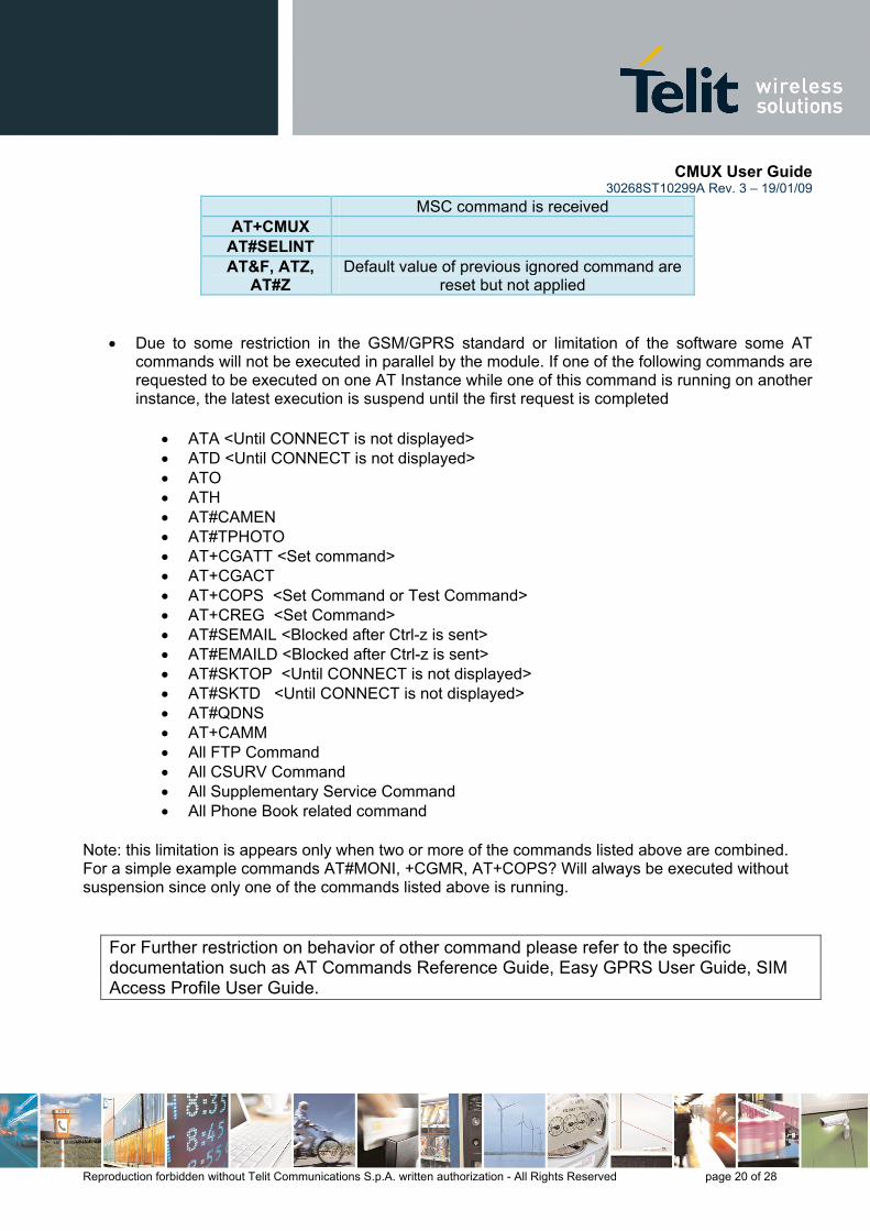
• The commands reported in the table below are ignored in case of Multiplexer mode. To be more precise it is possible to read/write values but they will have no effect on the behavior of the module
AT+IPR AT+IFC AT+ICF
ATS2; ATS12; ‘+++’
Escape sequence is not handled by the Module but shall be handled by the applicator that will send a BREAK signal to the module using the
MSC command ATS25 Module will recognize DTR off as soon as the
CMUX User Guide 30268ST10299A Rev. 3 – 19/01/09
Reproduction forbidden without Telit Communications S.p.A. written authorization - All Rights Reserved page 20 of 28
MSC command is received AT+CMUX
AT#SELINT AT&F, ATZ,
AT#Z Default value of previous ignored command are
reset but not applied
• Due to some restriction in the GSM/GPRS standard or limitation of the software some AT commands will not be executed in parallel by the module. If one of the following commands are requested to be executed on one AT Instance while one of this command is running on another instance, the latest execution is suspend until the first request is completed
• ATA <Until CONNECT is not displayed> • ATD <Until CONNECT is not displayed> • ATO • ATH • AT#CAMEN • AT#TPHOTO • AT+CGATT <Set command> • AT+CGACT • AT+COPS <Set Command or Test Command> • AT+CREG <Set Command> • AT#SEMAIL <Blocked after Ctrl-z is sent> • AT#EMAILD <Blocked after Ctrl-z is sent> • AT#SKTOP <Until CONNECT is not displayed> • AT#SKTD <Until CONNECT is not displayed> • AT#QDNS • AT+CAMM • All FTP Command • All CSURV Command • All Supplementary Service Command • All Phone Book related command
Note: this limitation is appears only when two or more of the commands listed above are combined. For a simple example commands AT#MONI, +CGMR, AT+COPS? Will always be executed without suspension since only one of the commands listed above is running.
For Further restriction on behavior of other command please refer to the specific documentation such as AT Commands Reference Guide, Easy GPRS User Guide, SIM Access Profile User Guide.

CMUX User Guide 30268ST10299A Rev. 3 – 19/01/09
Reproduction forbidden without Telit Communications S.p.A. written authorization - All Rights Reserved page 21 of 28
5.3 Exception to independent profile setting Every instance has its own user profile stored in NVM, with the exception of the following AT commands that will modify the global operation of the system, independently from the CMUX instance that is using them.
• AT#HFMICG • AT#HSMICG • AT+CMUT • AT#STM • AT#SHFEC • AT#CAP • AT+CLVL • AT#SRS • AT+CRSL • AT#SRP • AT#NITZ • AT+CALM • AT#SHFSD • AT#DAC • AT+CFUN • AT+COPS • AT#CODEC • AT#DVI • AT#E2SMSRI • AT#E2SLRI • AT+CSCB
The AT commands that require to modify a setting would be saved in a global profile. They would be reloaded at boot time with relation to the ATY1, ATY0 previously issued on the instance CMUX1 or ASC0.
5.4 Suggestion When in multiplexed mode it is suggested not to used the +CFUN=0 or AT+CFUN=5 command but the PSC (Power saving command).
In case the AT+CFUN command is used we suggest not to set AT+CFUN=5 because in this case the DTR on/off transition can cause disconnection of the CMUX protocol. CMUX protocol is not sensitive to AT&Dx setting.
In absence of communication it is suggested to send a periodic Test Command to the module to verify if the CMUX protocol has been correctly established.

CMUX User Guide 30268ST10299A Rev. 3 – 19/01/09
Reproduction forbidden without Telit Communications S.p.A. written authorization - All Rights Reserved page 22 of 28
6 TELIT SERIAL PORT PC INTERFACE FOR CMUX
6.1 Interface Specification Telit has developed a tool called Telit Serial Port MUX in order to make easier application of the CMUX mode. It is a PC interface able to manage data coming/to or being sent from/to CMUX. This target has been achieved by creating up to four serial virtual ports on the PC and using a specific communication protocol to manage the communication between the real serial COM that changes data with CMUX and each of the virtual port.
6.2 Scenario
As you can see, it is possible to run 3 different applications using the same CMUX module, for example 3 HyperTerminal can send AT commands at the same time to the same module.
CCMMUUXX CC OO MM
PPyytthhoonn ddeebbuugg
VViirrttuuaall CCOOMM 11
VViirrttuuaall CCOOMM 22
VViirrttuuaall CCOOMM 33 PPCC TTOOOOLL33
PPCC TTOOOOLL 11
PPCC TTOOOOLL 22
PPCC TTOOOOLL 44
PC MODULE

CMUX User Guide 30268ST10299A Rev. 3 – 19/01/09
Reproduction forbidden without Telit Communications S.p.A. written authorization - All Rights Reserved page 23 of 28
6.3 Graphical Interface Telit Serial Port Mux application on your PC after installation looks as in the following figure:
• Modem Port Panel: contains information about the modem connected to your PC, such as:
1. which COM on your PC will be used to transfer data (this can be set during the initial setup or in the Setup voice of the application menu)
2. COM Speed selected. 3. Connection Status: it can be “idle” or “error” when CMUX is disconnected, “connecting”
when PC is trying to connect to CMUX and “connected” when CMUX is connected successfully.
Modem Port Panel: • Real port (COM) used
for communication with PC
• Speed (Baud rate) • Status
Virtual Port Panel: • Virtual port number • Status • Baud Rate • Bytes Transmitted\Received • RTS: Request to send • DTR: Data Terminal Ready • CTS: Clear To Send • DCD: Data Carrier Detect • DSR: Data Set Ready • RI: Ring Indicator
Tray icon: when Telit Serial Port Mux is working, there is a Tray Icon that shows the state of the connection

CMUX User Guide 30268ST10299A Rev. 3 – 19/01/09
Reproduction forbidden without Telit Communications S.p.A. written authorization - All Rights Reserved page 24 of 28
4. Indication about the model of the modem connected.
• Virtual Port Panel: here you can find all the information about the connection using a Virtual Com installed on your PC:
1. Virtual Com number. 2. Virtual Port Status: it can be “idle”, “idle no DCD”, “Error”, “Opened”. 3. Baud Rate. 4. Number of bytes received and transmitted (RX Bytes, TX Bytes). 5. All the common serial port signals like RequestToSend, DataTerminalReady,
ClearToSend, DataCarrierDetected, DataSetReady and RingIndicator.
• Tray Icon: indicates the status of the Serial Port Mux:
1. CMUX connected: the Tray Icon is blinking.
2. CMUX disconnected or connecting.
3. CMUX error.

CMUX User Guide 30268ST10299A Rev. 3 – 19/01/09
Reproduction forbidden without Telit Communications S.p.A. written authorization - All Rights Reserved page 25 of 28
6.4 Application Setup In order to select the number of Virtual ports that are going to be created, real COM ports that are going to be used and their speed you should go to the Setup menu. These setups can be done during the tool installation and also when the tool is running.
Virtual Ports created can also be visualized in the Device Manager.
Module Serial Port Panel: here you can select the Real COM to use and its speed
Virtual Serial Port Panel: here you can create virtual ports

CMUX User Guide 30268ST10299A Rev. 3 – 19/01/09
Reproduction forbidden without Telit Communications S.p.A. written authorization - All Rights Reserved page 26 of 28
7 AT Commands AT commands related to the CMUX feature are the following:
command description +CMUX Enable/Disable Multiplexing Mode #CMUXSCR4 CMUX Script Enable
For more detailed information please refer to AT Commands Reference Guide 80000ST10025a.
4 only for the modules with Python feature

CMUX User Guide 30268ST10299A Rev. 3 – 19/01/09
Reproduction forbidden without Telit Communications S.p.A. written authorization - All Rights Reserved page 27 of 28
8 Document Change Log RReevviissiioonn DDaattee CChhaannggeess ISSUE #0 13/10/06 Initial release ISSUE #1 07/09/07 Added products into the applicability table ISSUE #2 01/02/08 6.1 How to begin: updated
general overview of the document 4.1 CMUX Frame Structure: updated Added PSC (Power Saving Control) paragraph 4.2 General review of document
ISSUE #3 19/01/2009 Update P/N list and applicability table

CMUX User Guide 30268ST10299A Rev. 3 – 19/01/09
Reproduction forbidden without Telit Communications S.p.A. written authorization - All Rights Reserved page 28 of 28