Embed Size (px)
Citation preview

CMS User Manual

CONTENTS
1 Product introduction
1.1 Import statement
Thank you for using this Center Professional series product. Please read this manual carefully before installing this application software.
This software version is under continual improvement and we reserve the right to make change without notice.
2
Exemption ClauseWe have tried our best to ensure the information contained in this manual is accurate, complete and up-to-date, we makes no representation as to its accuracy or completeness and expressly disclaims any liability whatsoever for any loss howsoever arising from or in reliance upon the whole or any part of such information
Read this manual carefully before using this software, we do not undertake any responsibility for the harms and losses caused by using this product incorrectly.
1.2 Software Instruction
After installing and running the program, recording and capturing frames, system will keep the relative files.
1.2.1 Software Installation Directory
Software defaulted path should be C:\ Program Files\DVR Centaurus and user can specify a particular installing path during the installation.
1.2.2 Record file storage
System record file will be kept to drive D. and when drive D is full, the record fill will auto convert to next drive.
When all the drives except drive C is full, system will automatically overwrite the earlier recorded files starting from drive D
1.2.3 Image / Log / Setting information storage
Store image, log and all setting information at C:\ Program Files\DVR Centaurus\System; Users have no permission to store or get these files.
1.3 Application environment
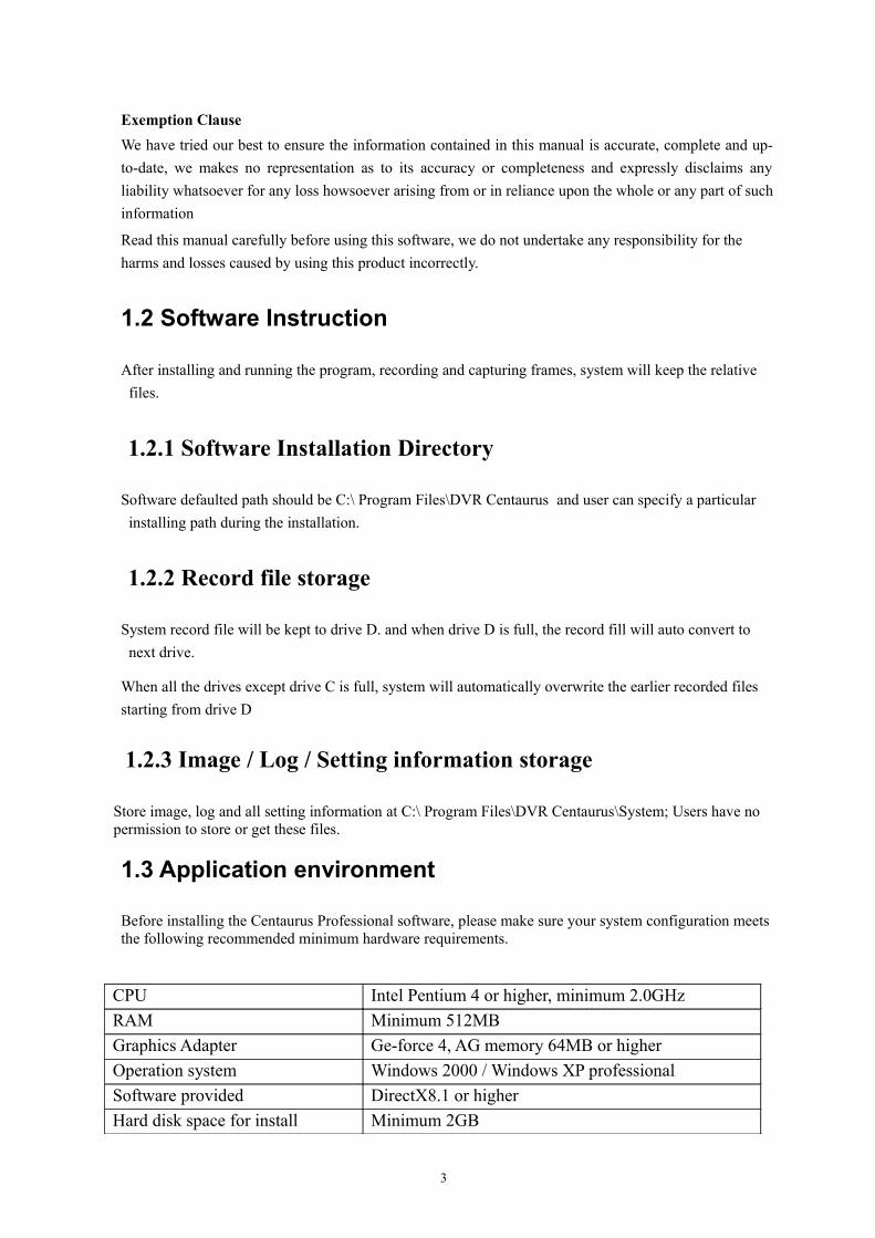
Before installing the Centaurus Professional software, please make sure your system configuration meets the following recommended minimum hardware requirements.
CPU Intel Pentium 4 or higher, minimum 2.0GHzRAM Minimum 512MBGraphics Adapter Ge-force 4, AG memory 64MB or higherOperation system Windows 2000 / Windows XP professionalSoftware provided DirectX8.1 or higherHard disk space for install Minimum 2GB
3

2 System overview
2.1 System structure
The software includes two major components. After installing and running the two major components, system will be easier to perform live media data viewing, database browsing, recorded media data retrieving and back-up etc.
Local server
Local server act as a core for database retrieve, video management and auto control of the whole security system.
Monitor and record the live real-time video;
Set external device data (such as camera, alarm etc.);
Control external devices and record system operational database;
Realize auto-control for the whole security system.
Remote server
User could monitor and record the real-time video, set relative data of external device (such as camera, alarm etc), control external devices and record system operational database and realize auto-control for the whole security system from a remote server.
2.2 Usage management
According to the functionality and characters of this software, we strongly suggest:
All operators should proceed basic operation training to avoid any wrong operation
You should establish user management and grade system.
3 Installation and Un-installation
3.1 Software installation
1. Double-click to run DVR_Centaurus_Setup_1.0.2-ENU.exe on your computer, and system will show below windows
4

2. Click [Next >] to enter into the below window:
Installation route is faulted to C:\ Program Files \ DVR Centaurus. If you want to change the installation route, pleas click [Browse…] button to specify a location again and click [Next>] button to continue.
3. Wait for the installation processing to complete, and then click [Finish] button to exit the installation program.
3.2 Software un-installation
Note : Please backup all the files stored at \Program Files\DVR Centaurus \System before un-installation so as to retrieve relative settings, images and Log information after installing the software next time.
If user need to un-install the software, please enter into [start-setting-control panel-add/delete program] to un-install the software.
5
User could also run File Un-installation Program to un-install. Details as follows:
1. Double-click to run uninst.exe, and click [Next >] to continue.
2. System will enter into the below window. Asked whether the Uninstall CMS. Click "Yes"
3. Wait for the un-installation processing to complete, and then click [Finish] button to exit the un-installation program.
After installing DVR Centaurus, system will automatically generate a DVR. Centaurus file (defaulted route is C:\Program files\DVR Centaurus). Please manually delete the file.
4 Node operations
4.1 Software reboots and Log in
4.1.1 Software reboot
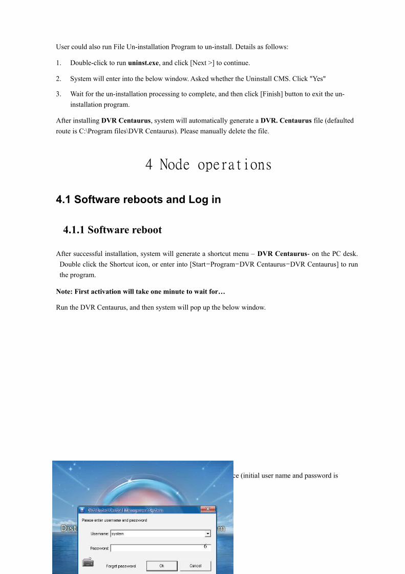
After successful installation, system will generate a shortcut menu – DVR Centaurus- on the PC desk. Double click the Shortcut icon, or enter into [Start-Program-DVR Centaurus-DVR Centaurus] to run the program.
Note: First activation will take one minute to wait for…
Run the DVR Centaurus, and then system will pop up the below window.
Input user name and password to enter into CMS main interface (initial user name and password is system).
6

After activate and log in the program successfully, two icons will appear at the lower-right corner of task bar (shown as follows).
Icon Function DescriptionCentaurus Media Server Media serverCentaurus Replay Server Playback server
4.2 Add sub-node
After logging-in system successfully, click [Nodes] menu at the left side of main interface to display nodes tree (shown as follows).
7

Operation button briefing
Item Description1 Add sub node2 Delete sub node3 Change remote user of note
4.2.1 Add DVR
1. Click the icon [ ] (shown as follows):
2. And it will button to pop up [Add device] window.
8

Server name: specify a name for remote DVR; Server address: Input the IP address of sub-DVR you need to add Server port: Input preset media port of the remote DVR User name / Password: Input user name and password of the remote DVR.
3. Click [Add] button to exit the [Add Device] menu.
4. Follow the above steps 1-3 to add more sub-DVRs. (Shown as follow Node tree):
Note: 1.You could add sub-node successfully only when remote DVR is online (Shown as above Node tree).
2. Make sure all DVRs are connected to network correctly before adding DVR.
Add DVR by add Auto ID.
1. Click button to pop up window below:
9
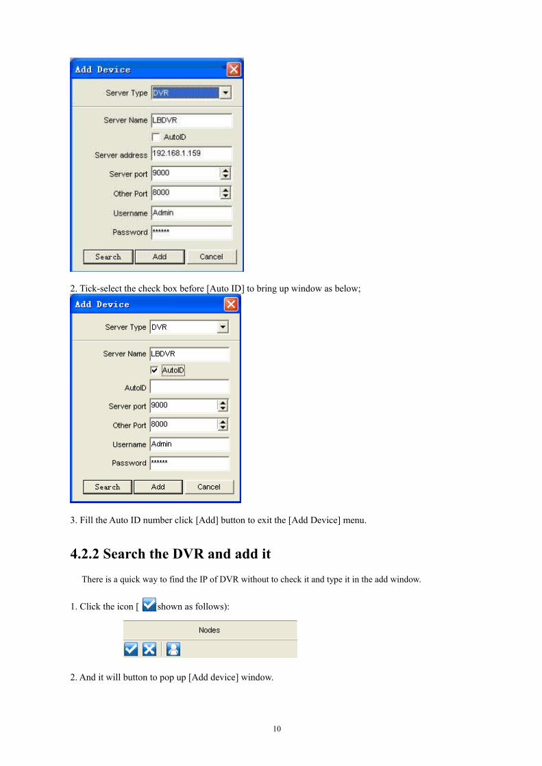
2. Tick-select the check box before [Auto ID] to bring up window as below;
3. Fill the Auto ID number click [Add] button to exit the [Add Device] menu.
4.2.2 Search the DVR and add itThere is a quick way to find the IP of DVR without to check it and type it in the add window.
1. Click the icon [ ] (shown as follows):
2. And it will button to pop up [Add device] window.
10

3. Click the search button .And then tick-select the check box before index which you need to add.
4. Click [Add] button to exit the [Add Device] menu.
4.3 Delete sub node
1. Click and highlight one sub node you want to delete at node tree list;
2. Click [ ] icon to delete the sub node.
5 Main Interfaces
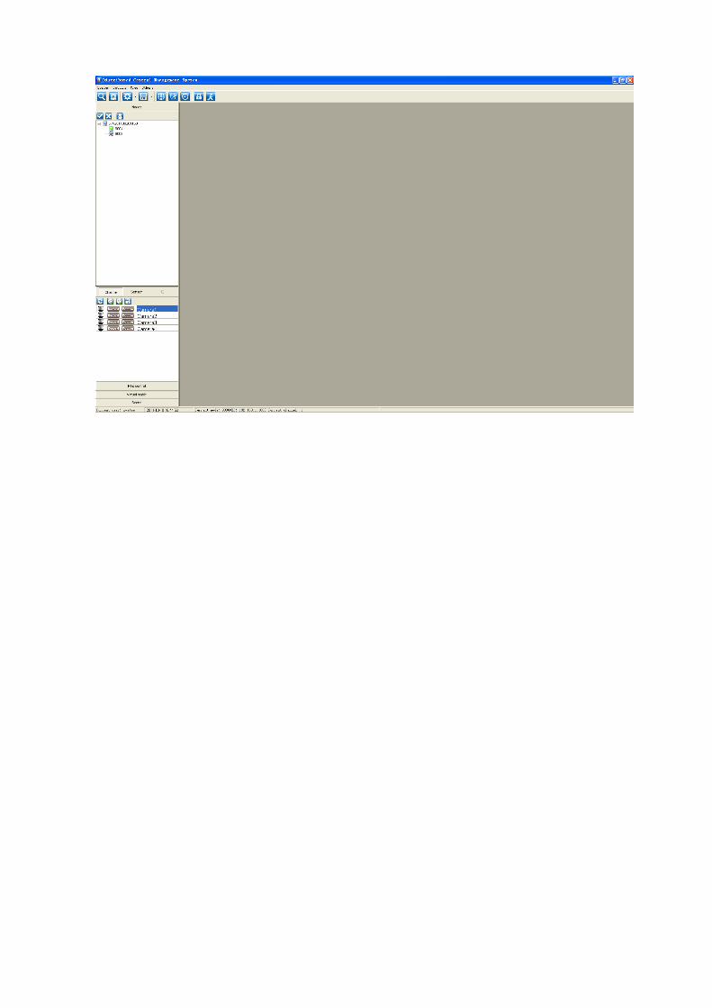
User main interface
11

There are two ways to preview the monitor interface;Way 1: Drag the node (for example, 9004) to network browsing. All the cameras’ views can be opened at one time.Way 2: Left click the node to pull down the camera list, and then drag the camera name to network browsing. You can open the views one by one.You may chose any way to view depends on your need.
5.1 Remote Monitoring
5.1.1 Add remote monitoring
User could remote monitor the system via LAN/VAN.
When local node proceeds any operation for remote node, that means the local user has remote monitoring authority and could automatically authenticate the remote user. Details please refer to section?
Click [ ] icon or double-click channel name to pop up the below [Network preview] window.
12

Note:
1. When proceed [Capture frame] operation, make sure the capture images have been saved as the DVR you are operating.
2. You could proceed remote monitoring only when you have added the remote server to local DVR.
3. You firstly add the relative remote DVR to your local DVR before network preview.
Detailed [Add node] operation, please refer to section 4.2 – Add sub node.
Please follow the step below to add a remote camera to local for network preview
1. Click the [Nodes tree] to extend the Node list

3. Highlight Node (9004) and double click channel name (Camera1) to pop up the below preview window,
Or firstly click [ ] icon to open Preview window and slide the relative channel name to any
display window.
Note: If Sliding DVR name to Preview window, system will automatically open all the channels of this DVR (such as DVR 9004).
By the same token, you also could slide any channel of other DVR to Display window to realize monitoring multiple DVRs simultaneously.
Video switch:You could freely exchange video’s location. To move a video channel to another empty video cell, drag-and drop the view to the target video cell; or/andTo switch the channels, drag-and-drop the view to the other, then the two channels will switch with each other.
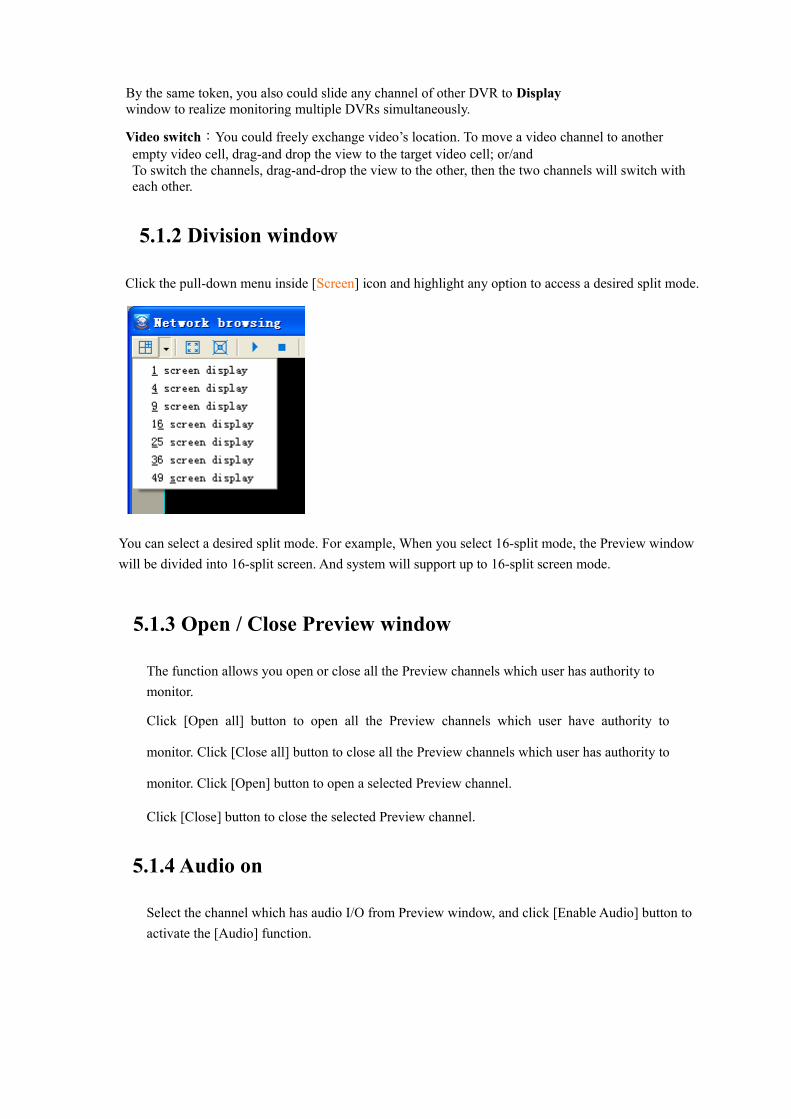
5.1.2 Division window
Click the pull-down menu inside [Screen] icon and highlight any option to access a desired split mode.
You can select a desired split mode. For example, When you select 16-split mode, the Preview window will be divided into 16-split screen. And system will support up to 16-split screen mode.
5.1.3 Open / Close Preview window
The function allows you open or close all the Preview channels which user has authority to monitor.
Click [Open all] button to open all the Preview channels which user have authority to
monitor. Click [Close all] button to close all the Preview channels which user has authority to
monitor. Click [Open] button to open a selected Preview channel.
Click [Close] button to close the selected Preview channel.
5.1.4 Audio on
Select the channel which has audio I/O from Preview window, and click [Enable Audio] button to activate the [Audio] function.

Note:
1. User could hear sound only when local server has installed one speaker device.
2. Please make sure audio input connect to DVR before enabling audio
3. User should also tick-selected corresponding [Audio] options shown as above.
4. Must choose main stream to realize this function. About how to set the main stream, please refer to 7.1.3 real time setting.
5.1.5 Capture frame
1. Select a camera and click [Capture] icon on the top of Preview window and then system will pop up the [Capture] window and display all the information about the captured image.

2. Click pull-down menu under the [location] menu to save the capture image to [Temp space] or [Permanent space];
3. Click [Ok] to save the image, or [cancel] to exit the [Capture frame] window.
5.1.6 Change window mode
Click Changes window mode button [ ] to toggle between Preview and multiple display modes.
5.1.7 Enlarge / restore display window
Double click any preview window to enlarge the window to full screen, and double click again to restore it to original one.
Click right key of mouse to enlarge Preview window to full screen, and click again to restore it to original one.
5.2 PTZ Control
Select camera with PTZ control under the Preview window and click [PTZ control] panel to enter into PTZ control menu.
Note: Make sure you have correctly configured corresponding PTZ parameter before this. For PTZ setting please refer to section 7.2.2.5, or relative DVR user’s manual


PTZ operation will include PTZ control, Preset point control and Auto Patrol.
PTZ control
Click arrow directions (total eight directions) under PTZ control interface to manually adjust PTZ location;
Move [Speed] cursor to adjust PTZ moving speed. When moving toward left, PTZ moving will slow down, and toward right, its moving speed up.
Clicking [ / ] button of Zoom/Focus/Iris could manually adjust zoom in/out, focus and iris respectively.
Click [Wiper] and/or [Light] button to open wiper and/or light, and clicking again will stop wiper and/or light.
Note:
[Wiper/Light] button will be not available for the PTZ without wiper/light;
Some PTZ camera may support up to four directions.
Pre-setting control
Input one preset value under [Preset] option, and click [Call] button, PTZ camera will auto rotate to the preset point.
Add preset point
A preset is a set of specific target point of a PTZ camera. Up to 128 presets per camera can be stored. (One PTZ camera will keep some special preset according to actual PTZ parameter).
Please follow the below steps to add preset point
1. Click the Preview window with PTZ control;
2. Click arrow direction of PTZ panel to manually adjust PTZ camera to specified location;
3. Input preset point value under [Preset] option, also move up/down arrow directions to adjust the preset value;
4. Click [Set] option to save the preset point.
Follow the above step1~4 to set more preset points.
If you modify any preset point, you follow the above steps and reset preset point value.
Call preset point
Input one preset value under [Preset] option, and click [Call] button, PTZ camera will auto rotate to the preset point.
Using the [Call] function will authenticate if you have succeed to add/delete preset point.
Delete preset point
Please follow the below steps to delete preset point:

1. Input preset point value under [Preset] option;
2. Click [Delete] button to delete the preset point.
Note: If one PTZ camera does not support the [Delete] option that means the preset point can’t be deleted.
Build preset point scan list
The function allows you build preset point scan list to perform preset point scan.
Please follow the below steps to establish preset point scan list:
1. Click [Add ] button under the middle-bottom of Preset control panel to pop up
below window.
2. Specify serial no and dwell time of preset point and click [Ok] button to add preset point to list;
3. Follow the above steps to add more preset point to list;
4. All the preset points you have added will be displayed in the list
Highlight one preset point and click Delete button [ ]to remove the preset point from list.
Highlight one preset point and click [Modify ] button to modify the preset point
5. Click [Save ] button to save the scan list info.
The following picture has shown you that have already added ID No. 1, 2, 3 to scan list.
Scan preset point
1. Tick-select the check box before preset point ID.;2. Tick-select the check box before Auto Patrol to start scan, tick-select it again to stop
scan.
Note: However you add preset point to scan list, system will always scan preset points repeatedly from small ID to large.

5.3 Playback
Remote playbackThe [Playback] option allows you playback recorded files locally or remotely, including normal recording, motion recording and sensor recording, and perform recorded file’s editing.
1. Click [ ] icon on the top of main interface to pop up the [Playback] window as shown below.
Note: Local host can playback the recorded files on the remote server only when the local host have added the remote server and have corresponding authority.
PC node playback
There are two ways to play PC node playbackWay one:
1. Click [storage center] button to pop up the dropdown list as follow.
2. Click [setting]--[disk config]. You can select where to store the file and you can find where you store the schedule record when you want to play the files too.
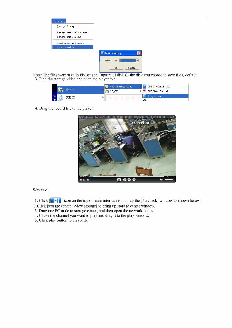
Note: The files were save in FlyDragon Capture of disk C (the disk you choose to save files) default.3. Find the storage video and open the player.exe.
4. Drag the record file to the player.
Way two:
1. Click [ ] icon on the top of main interface to pop up the [Playback] window as shown below. 2.Click [storage center→view storage] to bring up storage center window.3. Drag one PC node to storage center, and then open the network nodes.4. Chose the channel you want to play and drag it to the play window.5. Click play button to playback.

Add node method please refer to section 4.2- [Add sub node].
Playback control bar
Icon DescriptionPlay
Pause
StopFast ForwardLoop PlayEdit fileDeletecorrect spelling for(spilt window)select record typeNormal Record;Motion RecordAudio On/OffCapture

Speed adjustDate selectEnable synchronizationTime Bar
Note: When some icon display shadow, that means the function is not available under current status.
5.3.1 Playback
Select playback channel1. Select a desired playback channel and drag-and-drop the channel to
Preview panel;
2. Click [Play ] button
3. If you want to playback multiple channels, click [Screen] icon to divide screen firstly;
4. Then drag-and-drop desired playback channels to specific Preview panels;
5. Click [Play ] button respectively, or press [ ] button to play the Videos simultaneously
Note: When user select a remote camera for playback, please firstly select the remote node from the
Nodes Tree. The [ ] icon means the remote node is on line. The user can playback the recorded files from the channel when the local user have an remote permission to access the node.
How to search Record
The [ ] icon stands for Normal Record;
The [ ] icon stands for Motion Record;
1. Select one channel which you want to playback, then drag it to playback preview area.
2. Click [ ] icon and select a record type.
Record type includes Normal record and Motion Record, and is regarded as defaulted type.
3. Click pull-down menu under the [Date] option and select a desired date. And system defaulted date is current date.
4. Follow above steps 1~3 to search relative recorded file you desire to playback for each channel.
5. After finishing Search, all recorded file will be displayed in Play List beneath Time Bar.
Play
Select one channel and click [Play] button, and system will playback all the recorded files starting from the earliest record you searched.

Double-click some time point on the Time Bar, System will start to playback recorded file from this point and end to playback with all searched records finished
Pause
Click [Pause] button to pause the recorded file which is playing.
On the [Pause] mode, the recorded file will be played starting from the pause when clicking play button again.
Stop
Click [Stop] button to stop the recorded file which is playing, and Play control bar will return back to the start point.
Fast Forwarding
On the [Play] mode, clicking [Fast Forwarding] button will allow you fast play the recorded file.
5.3.2 Loop Play
After finishing Search the recorded files, user can loop play the recorded files at a particular time.
Please follow the steps below to perform the [Loop Play] operation.
1. Click the [Loop Play ] icon2. Press the [ ] button and click a particular time at Time Bar to specify start time of Loop play.
3. Press the [ ] button and click a particular time at Time Bar to specify end time of Loop
play.
4. Click button [ ], system will loop play the recorded files within the above time quantum.
5. You can set multiple channels to loop play the recorded files by following the above steps.
5.3.3 Edit file
This function allows you edit and convert the recorded files as executable recorded file. User can copy the executable recorded file to PC for play purpose.
The executable recorded file will be saved as the below path:
[Drive: \ Program Files\DVR Centaurus \ work folder\ save file\]Follow the steps below to clip the recorded files
1. Loop play recorded files you need to edit as shown section 5.3.2--Loop Play
2. Click the [ ] icon to enter into the below window.

3. User can set password here and click [Ok] button to return back the Playback interface. Once you select [Enable password] option, you need input this password while playing the clipped recording file every time
4. Click [ ] icon again to pop up below dialog.
5. Click [Ok] button to clip and save the loop play files
Note:
When multiple channels are loop playing, you start to clip the recorded files. At this moment, every channel will generate a stand-alone edited file.
Clicking [ ] icon will end editing, and finished editing files will be saved simultaneously.
Defaulted Time Bar will be displayed as shown below
You can slide middle key of mouse to zoom in/out Time Bar, and move the cursor to move the bar left and right.
Delete Channel
Select one channel from the Channels List and Click [ ] button to delete the channel.
Division Window
Click [ ] icon to divide screen to a desired split-mode. Details please refer to Section 5.1.2 .
Audio on/out
On the Play mode, select one Play channel and click [Audio on/out] icon. Now you can play audio synchronically while playing record.
Note: If you want to play audio on the playback mode, you must record audio simultaneously while recording video.
Capture
Detailed Capture operations please refer to section 5.1.5.

5.3.4 Speed Adjust
Move the cursor on the Speed Bar to adjust the play speed of recorded file. Play speed range is between x1/8 and x8. When mouse is pointed to cursor, system will display speed value.
Enlarge Play Zone
Double-clicking one Play zone can enlarge the zone to whole playback window, and double clicking again will return back the original one.
Click the right key of mouse to enlarge the playback window to full screen, and click again to return back the original one.
5.3.5 Synchronization
On multi-channel Playback mode, Select one channel and then click [ ] icon to enable [Synchronization] function. All the recorded files with the same time will be played synchronically.
5.3.6 Date Search
You can playback recorded files in different date by selecting date for one selected channel.5.4 Alarm center
Click [ →Alarm center] to enter the alarm center setting window.
Operation: including channel setting and sensor setting. Channel setting means I/O alarm setting.
You can select any camera or any input to set any kind of alarm.

5.5 Scene
The function is convenient for user to clarify to save Network Preview setting and toggle Net Previews for viewing.
Take the Parking for example and follows the steps below to demonstrate the function1. Open Net Preview and drag all the cameras installed in the Parking to the Preview window2. Click [Scene] option in the left of Main Interface.
3. Extend the [Scene] menu as shown below.
4. Click [ ] icon to pop up the below window.
5. Input one scene name specified by you (For example, here you can input Parking as scene name) and click [Ok] button to save and rack the [Scene] interface.
Type: includes Net Transport and Playback.
6. When you need to view one scene, you will firstly select the scene name and then click [ ] icon or double click the scene name directly. And system will automatically load the scene and preview all the camera’s surveillance videos for the scene, and no need to manually search its cameras for the scene each time.
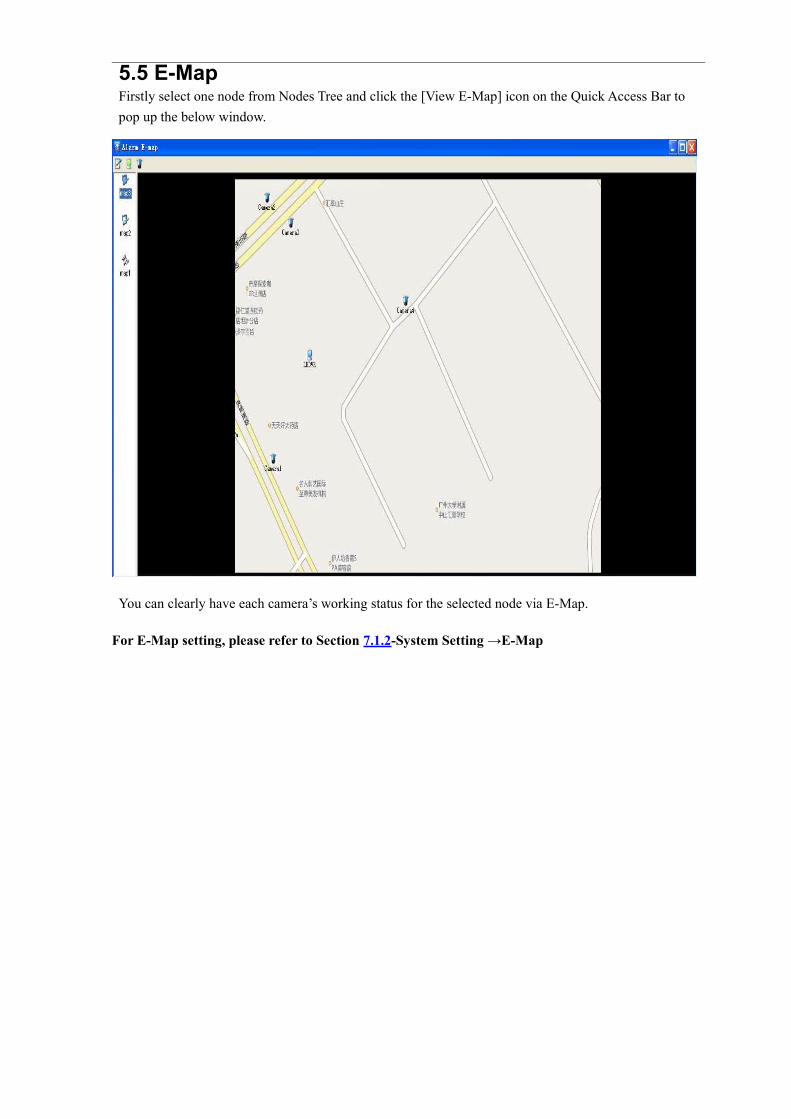
5.5 E-MapFirstly select one node from Nodes Tree and click the [View E-Map] icon on the Quick Access Bar to pop up the below window.
You can clearly have each camera’s working status for the selected node via E-Map.
For E-Map setting, please refer to Section 7.1.2-System Setting →E-Map

User can have multiple E-Maps for one node.
:indicates defaulted E-Map icon;
:indicated non-defaulted E-map icon.
User can select a E-map icon, and selected E-map will de displayed in the E-map window.
Remote E-map can be displayed locally only when the remote E-map updated to local server.
Add, edit and update for E-map please kindly refer to the section 7.1.2 – System setting→ E-
map. Note: Remote E-map will be displayed only when the remote server is online.
Function key of E-map:
1— Refresh E-map
2— Display top node map
3— Hide camera
When motion alarm, sensor alarm and alarm I/O is triggered, the corresponding icon will be flash in E-map.
Operating camera
You can perform net transmittal, record to my computer, record to nodes and playback operation for the cameras of E-map
Highlight one camera icon of E-map and click the right key of mouse to pop up the below menu.

Net transmittal
Click [Net transmittal] menu to pop up the Live surveillance window and view real-time video of the selected camera.
Record to my computer
Click [Save date to local] menu to record the selected camera’s video to my computer.
Playback
Click [Playback] to popup [Playback] window and playback the selected camera’s record starting from current time. And when motion detection is not triggered, system shall playback normal record, and when motion is triggered, system will playback motion alarm record.
Operating sensor
You can perform net transmittal, record to my computer, record to nodes and playback operation to channels relative to the sensor through operating the sensor of E-map
Highlight one sensor icon of E-map and click the right key of mouse to pop up the below menu.
Net transmittal
Click [Net transmittal] menu to pop up the live surveillance window and view real-time video of camera relative to the selected sensor.
Record to my computer
Click [Record to my computer] menu to record video of camera relative to the selected sensor to my computer.
Playback
Click [Playback] to popup [Playback] window and playback record of camera relative to the selected sensor starting from current time. And when sensor alarm is not triggered, system shall playback normal record, and when sensor alarm is triggered, system will playback sensor alarm record.
5.6 View Logs
All the operations performed by system will be recorded in the Log. User can carry out malfunction diagnosis and setting recovery by viewing Log information
Click the [View Logs] icon on the Quick Access bar of Main interface to enter into the below [Log]

window.
Log Search
1. Firstly specify a start time and End time of Log and select Log type on the bottom-left corner of [Log] window.
2. Click [Search] button, and then all the Logs with this time quantum will be listed.
Log View
Clicking [+ /- ] icon of Tree-structure directory to extend or fold the Log tree.
1. Extend Log tree and select a date you want to view. Every date can display multiple pages and every page will display 500 lines of log information.
2. Select one page and 500 selected log lines of information will be displayed in Log list
3. Clicking [Show All logs] icon on the top of [Log] window will display all the Log information you searched to [Log list]
4. Click [Show any logs of Record],[Show any logs of Motion], [Show any logs of Net], [Show any logs of Playback], [Show any logs of PTZ], [Show any logs of system], [Show any logs of schedule], [show any logs of Instant playback], [show any logs of E-map], [show any logs of remote command] icons respectively to classify to display the corresponding Log information.
Change window mode
Click [Change window mode] icon on the top of Log window, system will allow you toggle window mode between floating window and Working window.
Export Log

Click [Export Log] icon on the top of Log window to export log information to txt file or Excel file.
5.7 Schedule
After clicking [Start/Stop schedule] icon, system will normal record, as per the schedule you have set.
Once the [Schedule] function is activated, user will not manually operate with channel, sensor and I/O.
For Schedule setting please refer to section 7.1.1 – Record Schedule.
Way to stop schedule recording:
Click storage button [ ] to select [view storage].Drag the PC node to storage center, and then open the network nodes.Click the channel which you want to stop record, and click stop record to stop.
5.8 Option
5.8.1 Lock/Unlock
User will not carry out any operation when system is locked. And user can lock system through below

two methods after logging-in.
Method one:
Click [ ] icon on the top of main interface.
Method two:
Click [System→Log out] menu to log out the system as shown below.
Unlock:Click [ ] icon again on the top of Main interface to pop up the below window.
Input user name and password to unlock and log in system.
Note: We strongly suggest that user should lock system with no operation to avoid any wrong operation.
5.8.2 Switch user
User can switch user through the below two methods.
Method one:
1. Click the [ ] icon to lock system;
2. Click the [ ] icon again to unlock system and enter into Log in interface;
3. Input new username and password to log in system.
Method two:
1. Click [System→Log out] menu on the top of Main interface as shown below.

2. Click [ ] icon to pop up Log-in window;
3. Input new username and password.
Note: Herein new username indicate the user name have set to system.
5.8.3 Quit System
1 Click [ ] icon on the right-top corner of Main interface or [ ] icon on the top.
2 System will pop up the below dialog, and click [Ok] button to quit system.
3 Click [Ok] button to enter into the below window.
Tick-select the defaulted [Close service] option, system will close [Watchdog], [Media Server],[Replay Server] and [Disk Manage Server] accordingly when quitting system.
Tick-select [Power off] option, system will close operation system while quitting this system.
Uncheck [Power off] option, system will quit the program and return back to operation system desktop.
5.8.4 Change password
1. Click [System →Change password] menu as shown below;

2. System will pop up the below dialog, and please input new password and valid password, then click
[Ok] button to finish this change.
5.8.5 Change remote user
Please follow the below steps to change remote user of node.
1. Extend Node tree;
2. Select the remote node you want to change;
3. Click [Change remote user of node] icon as shown below;
4. Enter into the below dialog, and please input new user name and password to below dialog.

5. Click [Ok] button to finish the change for the remote user of node.
Note: Herein new user should be set to the remote node.
5.9 Node Status sign
Click [Node Tree] of Node Tree display area and node list and status will be displayed as shown below.
Taking the above for example: Local node name should be myPC, and its sub nodes include 9008, 9140 and 9004.
Node Status
On line: indicate the node is on line but be not selected, such as 9008 and 9004.
On line and Select:indicates the node is online and mouse have selected the node, such as remote node:9104.
Off line:indicates the remote node is off line. When remote node is not connected, a red “ ” sign will appear. That means the remote node is off line.
Select node
Press the left key of mouse to select one node, and the selected mode icon will be displayed in green.
And its status will be changed from to . You can view local status of
each channel.
Unchecked node icon should be displayed in blue.
When one node is selected, channel list and status info will be displayed.

6 Views
6.1 View Server StatusHighlight [View→View Server Status] menu and pop up the below window.
You can click the right button to perform the relative operation for the selected server.
6.2 View Disk StatusSelect a node and click [View→View Disk Status] menu to enter into the below window.
6.3 View LogsPlease refer to section 5.6 - Logs
6.4 View Capture FramesClick [View→View Capture Frame] option and then enter into the below interface.
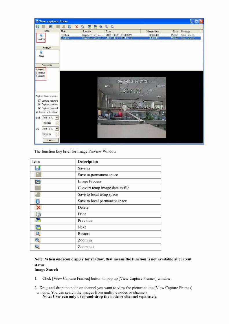
The function key brief for Image Preview Window
Icon DescriptionSave asSave to permanent spaceImage ProcessConvert temp image data to fileSave to local temp spaceSave to local permanent spaceDeletePrintPreviousNextRestoreZoom inZoom out
Note: When one icon display for shadow, that means the function is not available at current status.Image Search
1. Click [View Capture Frames] button to pop up [View Capture Frames] window;
2. Drag-and-drop the node or channel you want to view the picture to the [View Capture Frames] window. You can search the images from multiple nodes or channels
Note: User can only drag-and-drop the node or channel separately.

3. You can select Capture Frame source from Capture frame source area. System default selects all the capture frame sources.
4. Select [Capture frame time] and specify the start date/time and end date/time. If uncheckedCapture frame time, system all the date/time as Capture frame time.;
5. Click [Search] button to start searching. During the search processing, the [Search] button will be displayed in grey;
6. After finishing search, the images for the selected node/channel will be displayed in Image list, and corresponding nodes / channels will be also displayed in Node list and Channel list.
7. Click a node from Node List, all the images searched from the node will be displayed in the Video Preview Area. By the same token, the images searched from the channel will be also displayed in the Video Preview Area.
8. Video Preview Zone also display Capture frames user, source, time, dimension, size and area for each images
How to deal with the searched images
Save as…
The function allows you save the selected image as BMP file. Please follow the below steps:
1. Select one image;
2. Click [ ] icon to pop up the below window.
3. Specify a path and file name and click [Save] button to save the image.
Save to local permanent space
The function allows you save images to a specified position so as to keep more space for permanent space. The images can be searched and previewed by entering into [View capture frames] window.Please follow the step below to save to permanent space.
1. Click [ ] button to pop up the below window.

2. After the processing is finished, system will prompt you to save to permanent space successfully.
3. Click [Ok] to confirm to save the picture successful.
Save to local temp space
The function allows you save images to a specified position so as to keep more space for temp space. The images can be searched and previewed by entering into [View capture frames] window.Please follow the step below to save to permanent space.
1. Click [ ] button to pop up the below window.
2. After the processing is finished, system will prompt you to save to permanent space successfully.
3. Click [Ok] to confirm to save the picture successful.
After the processing is finished, image storage character will be changed from permanent space to transient space
Image Process
The function allows you process a selected image and save it. Please follow the below step to demonstrate the function.
1. Select an image2. Click [View→View Capture frames] to enter into [View Capture Frames] window and then
click [ ]icon.

3. Two images appear in the image display area. Left image is original one, and right image is processed ones.
4. You can adjust color, brightness, contrast, saturation, hue, gray, expose and noise process for the image to reach a desired effect
Note: Click [Restore] button to recover the image to original ones.
5. After finishing image process, click [ ] icon to pop up the below window.
6. Specify the path and file name and click [Save] button to save the processed image.
Delete
The function allows you delete a selected image. Please follow the below steps to delete a deleted image.
Delete
1. Select a image;
2. Click [ View→View capture frames] option and click [ ] icon to delete the image.
Note: Deleted image will be not recovered.

The function allows you print a selected image.
Switch Preview mode
Click [View→View capture frame] option and click [ / ] icon to preview image one by one
Zoom in / out
ResetZoom inZoom out
Click [ / / ] icon to restore / zoom in /zoom out the image
6.5 E-mapFor details please refer to section 5.5– E-map
7 System configurations
Note:Before setting system configuration, make sure you have fully understand and classify local setting and remote setting clearly.
Local setting: indicate local CMS setting, and its usage range limit to local CMS system. Remote setting: indicate remote PC or DVR setting, and mainly for remote device.
7.1 Local Setup
7.1.1 Schedule
The option allows you set relative parameters for normal recording, motion recording and sensor recording. When [Schedule] option is set to “Enable”, system will start/stop recording as schedule.
Details please refer to section 5.7 –Start / Stop Schedule.
Select one node and click pull down menu of [storage center] button to select [Setup storage] option.
System will pop up the below window.

Drag-and-drop one node to a [Storage center] display area.
+
Picture 7-1-1
[Source storage center] indicates the PC which is used to save record. Operation button brief
Operation button for Schedule window
Item Description1 Save setting2 Delete channel or sensor3 Copy channel or sensor4 Paste to channel or sensor

5 Paste to all the channels or sensors
Operation buttons for Channel
Item Description Function1 Zoom in Enlarge the Time Bar to display more precise time.2 Restore Recover Time Bare scale to normal type3 Zoom out Zoom out Time Bar scale4 Copy date Copy setting of one date to current date.5 Stick current date Stick one copied information to all the dates
Add Normal record schedule for single channelGenerally, the dates shown as [Schedule] interface should stand for one week, that is to say, from Sunday to Saturday. After finishing [Schedule] setting, one single channel will loop play by weeks as per [Schedule] setting.
Please follow up the steps below to add one Schedule.1. Enter into [Schedule setting] interface and extend all the channels of one node you want to
set record schedule;2. Select a desired channel and select a date you will set record. The selected date will display
in white;The selected date will be divided into two parts by broken line. The first half part is used to set normal record schedule, the latter half part to set motion alarm
3. Press [Ctrl] key at the keyboard and click the left right of mouse and drag-and-drop mouse within the first half part. You could find one line shown in green within the first half part.The channel will perform normal record during the time quantum of the date.
4. Press [Ctrl] key at the keyboard and click the left right of mouse and drag-and-drop mouse within the latter half part. You could find one line shown in blue within the latter half part.The channel will open motion detection function during this time quantum of the date. The function could be activated only when motion occurs.
5. You follow up the above steps to set normal record and motion detection of other date for the channel;
6. Click [Save] button to save the above setting. And or
You can also follow up the below step to add Schedule:1. Enter into [Schedule setting] interface and extend all the channels of one node you want to
set record schedule;2. Select a desired channel;3. Select a date you will set record. The selected date will display in white;4. Move curse to the selected date and click right key of mouse to enter into below pop-up menu:

5. Highlight and click [Add] option, a line of setting option will be added on the bottom of date.(Details please refer to below.)
6. Tick-select the schedule type you want to add, and set effective time of schedule;7. Click [Ok] button to save the above setting.
8. Follow up the above steps to set record schedule for different channels, dates and types
Copy datePlease follow up the below steps to copy Monday’s schedule to Tuesday
1. Select Monday’s schedule shown in white;
2. Click [ ] button at the top-left corner, or right-click the date and enter into [Pop-up
menu→ Copy date];
3. Select Monday’s schedule and click [ ] button at the top-left corner, or right-click the date
and then enter into [Pop-up menu→Paste date];
4. Click [ ] button to save the above setting.
Copy channel
Please follow up the below steps to copy one channel’ schedule to other:1. Extend all the channels for one node and select one channel;
2. Click [Copy channel/sensor] button at the top-left corner;
3. Select one channel you want to paste, and then click [Paste channel/sensor] button;
4. Click [ ] button to save the above setting.
Modify Schedule
If you want to modify one schedule, select the schedule and click right key of mouse to select
[Modify] option. After successful modification, click [ ] button to save and exit the setting.
And or,
1. Select the date you want to modify;
2. Click [ ] button at the top-left corner to delete current schedule; If you click [Delete channel/sensor] button, all the schedules for the channel will be deleted;
3. Follow up the above Add Schedule to add any schedule of the date again;

4. Click [Save] button to save the above modification.
Note: When multiple positions need to perform same modification, it is more effective if you use[Copy] and [Paste] function mentioned in the previous chapter.
Please do click [Save] button after all Schedules setting are
finished! Sensor Schedule
Sensor Schedule setting is same as Channel schedule setting. Details please refer to [Channel Schedule] setting.Note: When you use [Copy/Paste Schedule] function, you will need to copy/paste channel and
sensor settings respectively.
Delete Channel/Sensor Schedule setting
Please follow up below steps to delete one channel/sensor schedule setting:
1. Select one channel/sensor from camera lists;
2. Click [Delete Channel/Sensor] button at the operation button bar for Schedule window to delete all the Schedule setting of selected channel/sensor.
7.1.2 E-Map
The function allows you edit, add and delete local and remote E-map.
1. Select a local node from Nodes tree, and click [ ] icon;

2. Select [Setting→Setup E-map] option to pop up the below window.
Buttons' function brief introduction
Item Description1 Add E-map2 Delete E-map3 Edit E-map4 Cancel edit5 Refresh E-map6 Update E-map7 Save as default map8 Select Map image9 Save E-map
Add E-map
The function allows you add a E-map to the selected node. Please follow the below steps to add the E-map.
1. Click [Add E-map] icon to pop up the below window.
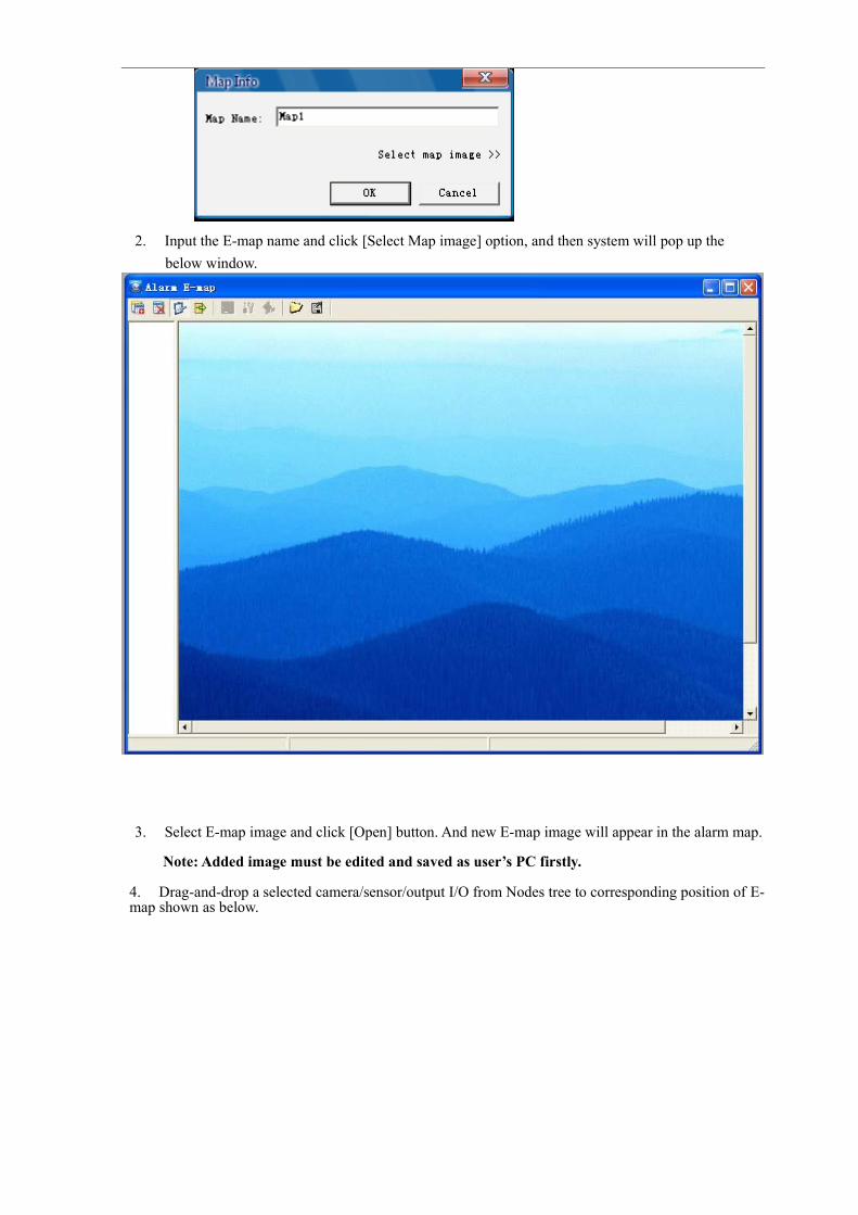
2. Input the E-map name and click [Select Map image] option, and then system will pop up the below window.
3. Select E-map image and click [Open] button. And new E-map image will appear in the alarm map.
Note: Added image must be edited and saved as user’s PC firstly.
4. Drag-and-drop a selected camera/sensor/output I/O from Nodes tree to corresponding position of E-map shown as below.

Note: When each camera, sensor and output I/O has been added to E-map, the camera/sensor/output I/O can’t be added to the same E-map again.
5. Click the [Save] button, and system will pop up the below prompt window.
6. Click [Yes] button to pop up the below window.
7. Click [Ok] button to save the E-map to the selected node.
Delete E-map
The function allows you delete a E-map from the node. Please follow below step to delete E-map.
1. Firstly select one E-map from [Alarm E-map] window and the selected map will display theDisplay area of [Alarm E-map] window.

2. Click [Delete] icon to pop up the below dialog.
3. Click [Yes] button to pop up the below dialog.
4. Click [Ok] button to end the delete processing.
Edit E-map
The function allows you edit the exiting E-map. Please follow the below step to edit E-map.
1. Firstly select one E-map from [Alarm E-map] window and the selected map will display theDisplay area of [Alarm E-map] window.
2. Click [Edit] icon to enter into the edit status.
3. Edit E-map as per actual request.
Delete an existing camera/sensor/output I/O from E-map
Highlight a camera or sensor or output I/O and click the right key of mouse to pop up the below window.
Add camera/sensor/ output I/O to E-map.
Drag-and-drop a selected camera or sensor or output I/O to corresponding position of E-map.
4. After finishing edit, click [save] button to pop up the below window.
5. Click [Yes] button to pop up the below window.
6. Click [Ok] button to save the E-map to a selected Node.
Cancel Edit
Click [Cancel] button before the above step 4, system will cancel the previous operation and E-map will recover to original ones.
Refresh E-map
Click [Refresh E-map] button to refresh the E-map list.
Update E-map
The function allows you update the sub-node to your local node. Please follow the steps below to update E-map.
1. Add a sub-node to local node
2. Set E-map to local node and confirm detailed position of sub node. (Drag-and-drop the sub-node name to local E-map
3. Select sub node and setup E-map, and also set detailed position of Node, channel and sensor in the E-map.
4. Click [Save] button to save the above setting.
5. Click [Update] button to save the E-map of sub-node to local node.
6. In the local node, click [View→View E-map] option, and then find the position of the sub node
7. Click node icon, now you can view the E-map of the sub node.
Save as default map
Select a map from [Alarm Map] window and click [Save as default map] button. Now the selected map has been set to default map.
Select map image
The function allows you convert current map image to other ones. Please follow the steps below to select map image.
1. Firstly select one E-map from [Alarm E-map] window and the selected map will display theDisplay area of [Alarm E-map] window.
2. Click [select map image] button to pop up the below window.
3. Select a desired image and click [Open] button;
4. The selected image will be updated to E-map;
5. Click left key of mouse to refresh original camera/sensor/output I/O in the map.
6. After finishing refresh, click [save] button to pop up the below window.
7. Click [Yes] button to pop up the below window.

8.Click [Ok] button to save the map to a selected node.
Alarm events pop up the E-MapWhen you finish setup E-map ,you also setting Alarm center,
First ,select camera channels, then select alarm trigger event “show network view” or “show E-map”
When camera occur motion or sensor events, it will pop up E-map.

.3 Real time setting
Click [Setting→ real time setting] menu, system will enter into the below real time setting window. You can set the stream here.
7.1.4 User authority
You may add、delete and modify user authority or add、delete and modify users in user group.
Click [select setting item→ user authority] menu to bring up the user authority setting window;

7.2 Remote SettingCarrying out a modification for a remote setting will directly affect remote built-in device (DVR). Carrying out a modification for a remote setting will directly save to remote node.
If you modify IP address of one DVR in the Basic information, and DVR will use the modified IP address when logging in next time.
7.2.1 Device settingNote: The user can perform system setting only when he/she is allowed to get access to the linked device. And if user need remote perform system setting, the user must have remote authority.
Select one DVR node in the nodes list under main interface, and click [Setting→system information to enter into [System setting] window.
7.2.1.1 System Info
Click [ →System Info] option and modify relative system information configuration as per your actual system info. As shown below.

7.2.2.2 Network setting
The option allows you option and modify relative network environment as shown below.
Click [Network setting] option to enter into the [Network setting] window.

7.2.2.3 Encode setting
The option allows you perform encode parameters setting.Click [System information→ Encode setting] menu to enter into the below [encode setting] window.
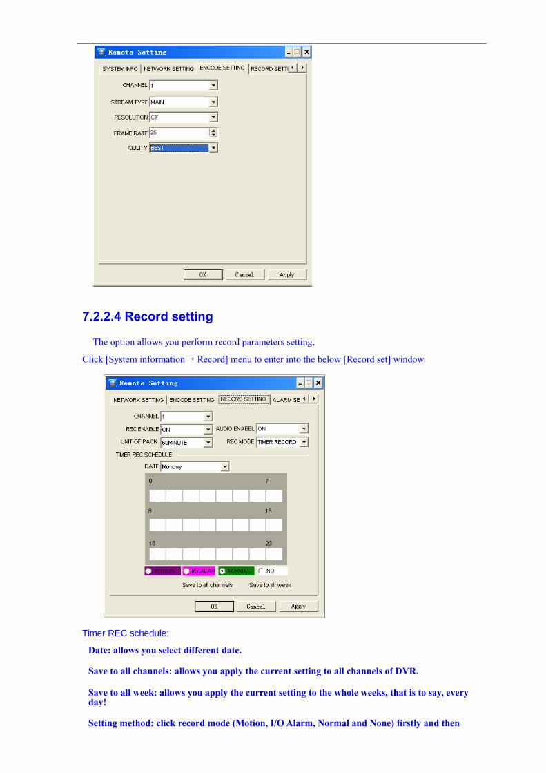
7.2.2.4 Record setting
The option allows you perform record parameters setting.
Click [System information→ Record] menu to enter into the below [Record set] window.
Timer REC schedule:
Date: allows you select different date.
Save to all channels: allows you apply the current setting to all channels of DVR.
Save to all week: allows you apply the current setting to the whole weeks, that is to say, every day!
Setting method: click record mode (Motion, I/O Alarm, Normal and None) firstly and then
click the grid of time bar
Every grid stands for one hour;
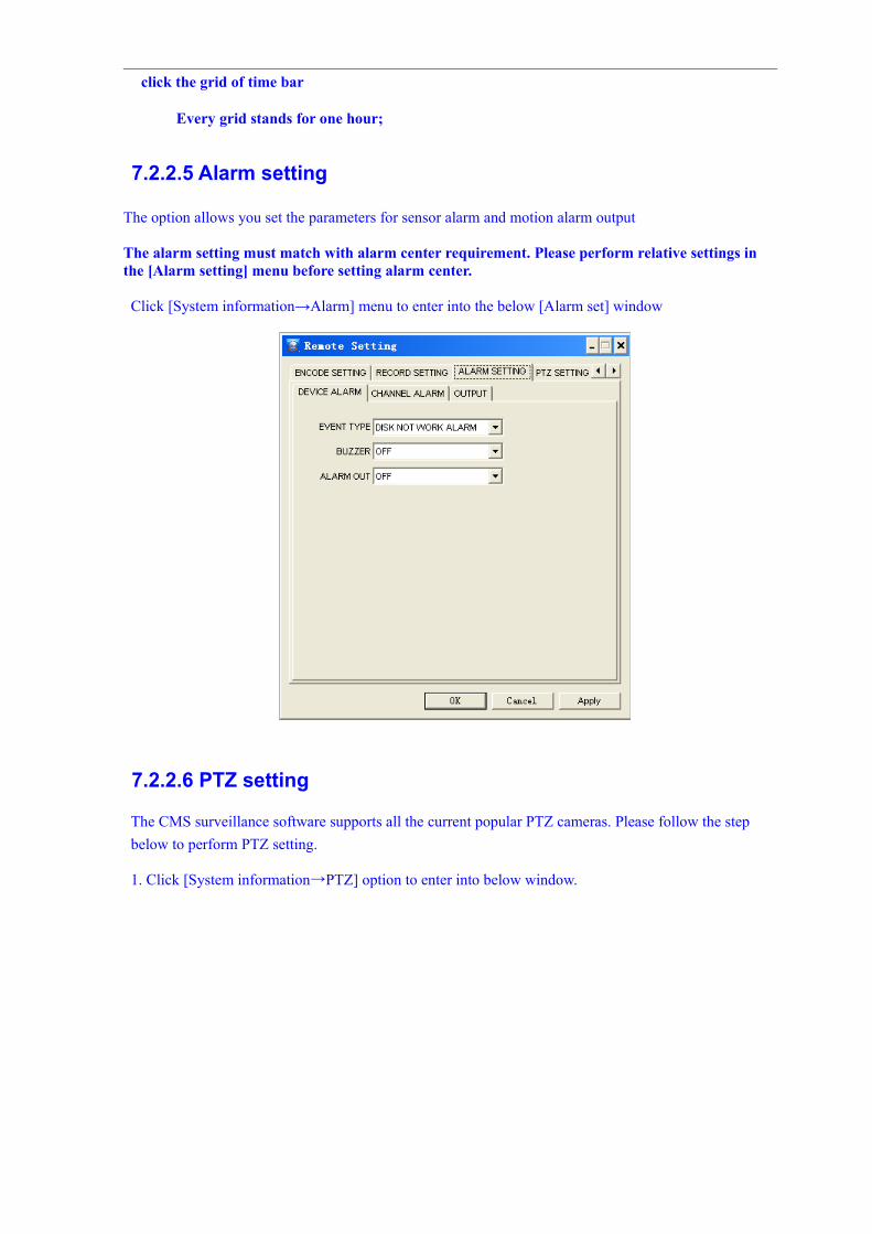
7.2.2.5 Alarm setting
The option allows you set the parameters for sensor alarm and motion alarm output
The alarm setting must match with alarm center requirement. Please perform relative settings in the [Alarm setting] menu before setting alarm center.
Click [System information→Alarm] menu to enter into the below [Alarm set] window
7.2.2.6 PTZ setting
The CMS surveillance software supports all the current popular PTZ cameras. Please follow the step below to perform PTZ setting.
1. Click [System information→PTZ] option to enter into below window.

Note:PTZ control connection method, please refer to corresponding DVR manual.
2. Select one channel with PTZ control, and then set below parameter as per your actual request. Protocol:Select corresponding protocol supported by PTZ (generally PTZ supports Pelco-D and Pelco-P).
Data bit: match with PTZ camera’s parameter.
Baud rate: match with PTZ camera’s
parameter. Stop bit: match with PTZ camera’s
parameter. Verify bit: match with PTZ
camera’s parameter.
Address: When connecting multiple PTZ cameras, the option is affected. Different address stands for different PTZ camera.
3. Click [Apply] and [Ok] button to save the setting.
4. Follow the above steps 1~3 to perform the setting for all the PTZ cameras.
5. Click [Apply] button to save all the settings you have performed on the [PTZ setting] window.
6. Click [Ok] button to save and exit the [System information] window, and
Click [Cancel] button to quit and exit the window.
7.3 Other Setup
7.3.1 Auto Login
The setup allows you auto-run CMS system with operation system auto-Login.

1. Select local node and click [ ] button on the tool bar,
2. then select System information→Option→Auto Login
You are prompted “Please input the system administrator password”. And please input admin password and verify the password and then click [Ok] button to save and exit the [Auto Login setup] window.
System will auto login operation system after rebooting; and/or
Tick-select the [Auto Run System] option and click [Ok] button to save and exit the [Auto Login Setup] window.
System will auto run the CMS surveillance program after auto logging-in operation system. At this moment, please manually input user name and password of CMS to enter into the surveillance system.
Auto Login:
Click [System] menu and select [Setup Auto Login] option, system will enter into the below window.
1. Input CMS user name and password, and tick-select [Enable] option.
2. Click [Ok] button to save and exit the [Setup Auto Login] menu
3. Now you will auto-login CMS system with windows start.
7.3.2 Auto shutdown / Auto reboot
1. Click [Set] menu and select [Setup Auto Shutdown] option as shown below:

2. System will pop up the below window:
Auto shutdown: when the option is available, system will be auto shutdown at a specific time.Auto reboot: When the option is available, system will be auto-rebooted at a specific time Days:indicates the days when you have set the PC auto-shutdown/auto-rebooted.Time:indicate the time that PC is auto-shut downed/auto-rebooted.
Click [Ok] button to save and exit the [Auto-shutdown] menu.
Click [Cancel] to quit and exit the [Auto shutdown] menu.
7.3.3 Auto Lock1. Click [Set] menu and select [Setup Auto Lock] option to pop up below window.
1. Tick-select [Enable Auto Lock] option and set [Mouse idle lock time]2. Click [Save & quit] buttonAbout how to unlock, please refer to section 5.9.1 – Lock / Unlock.