Embed Size (px)
Citation preview

Available on CMS information server CMS CR -2016/112
The Compact Muon Solenoid Experiment
Mailing address: CMS CERN, CH-1211 GENEVA 23, Switzerland
Conference Report31 May 2016 (v3, 06 June 2016)
An FPGA based track finder at L1 for CMS at theHigh Luminosity LHC
C. Amstutz, F. A. Ball, M. N. Balzer, J. Brooke, L. Calligaris, D. Cieri, E. J. Clement, G. Hall, T. R. Harbaum, K.Harder, P. R. Hobson, G. M. Iles, T. James, K. Manolopoulos, T. Matsushita, A. D. Morton, D. Newbold, S.Paramesvaran, M. Pesaresi, I. D. Reid, A. W. Rose, O. Sander, T. Schuh, C. Shepherd-Themistocleous, A.
Shtipliyski, S. P. Summers, A. Tapper, I. Tomalin, K. Uchida, P. Vichoudis, M. Weber
Abstract
A new CMS Tracker is under development for operation at the High Luminosity LHC from 2025. Itincludes an outer tracker based on PT-modules which will construct tracker stubs, built by correlatingclusters in two closely spaced sensor layers for the rejection of low transverse momentum track hits,and transmit them off-detector at 40MHz. If tracker data is to contribute to maintaining the Level-1 trigger rate under increased luminosity, a crucial component of the upgrade will be the ability toidentify tracks with transverse momentum above 3GeV/c by building tracks out of stubs. A conceptfor an FPGA-based track finder using a fully time-multiplexed spatially pipelined architecture is pre-sented, where track candidates are identified using a projective binning algorithm. Results from ahardware demonstrator system, where a slice of the track trigger will be constructed to help gauge theperformance and requirements for a full system, will be included.
Presented at IEEE-RT2016 IEEE-NPSS Real Time Conference (RT)

An FPGA-Based Track Finder for the L1 Trigger ofthe CMS Experiment at the High Luminosity LHCC. Amstutz, F. A. Ball, M. N. Balzer, J. Brooke, L. Calligaris, D. Cieri, E. J. Clement, G. Hall, T. R. Harbaum,K. Harder, P. R. Hobson, G. M. Iles, T. James, K. Manolopoulos, T. Matsushita, A. D. Morton, D. Newbold, S.
Paramesvaran, M. Pesaresi, I. D. Reid, A. W. Rose, O. Sander, T. Schuh, C. Shepherd-Themistocleous, A.Shtipliyski, S. P. Summers, A. Tapper, I. Tomalin, K. Uchida, P. Vichoudis, M. Weber for the CMS Collaboration
Abstract—A new tracking system is under development foroperation in the CMS experiment at the High Luminosity LHC.It includes an outer tracker which will construct stubs, builtby correlating clusters in two closely spaced sensor layers forthe rejection of hits from low transverse momentum tracks,and transmit them off-detector at 40 MHz. If tracker data is tocontribute to keeping the Level-1 trigger rate at around 750 kHzunder increased luminosity, a crucial component of the upgradewill be the ability to identify tracks with transverse momentumabove 3 GeV/c by building tracks out of stubs. A concept for anFPGA-based track finder using a fully time-multiplexed archi-tecture is presented, where track candidates are identified usinga projective binning algorithm based on the Hough Transform. Ahardware system based on the MP7 MicroTCA processing cardhas been assembled, demonstrating a realistic slice of the trackfinder in order to help gauge the performance and requirementsfor a full system. This paper outlines the system architectureand algorithms employed, highlighting some of the first resultsfrom the hardware demonstrator and discusses the prospects andperformance of the completed track finder.
I. THE HIGH-LUMINOSITY LARGE HADRON COLLIDER
IN order to fully exploit the scientific potential of the LargeHadron Collider (LHC) [1], it is planned to operate the
machine at a luminosity up to one order of magnitude abovenominal design performance. The High-Luminosity LHC (HL-LHC) upgrade [2] is expected to take place during a 30 monthshut-down around 2024, facilitating a peak luminosity of5−7.5×1034 cm−2 s−1, corresponding to an average numberof proton-proton interactions per 40 MHz bunch crossing, or
Manuscript received May 31, 2016.G. Hall, G. M. Iles, T. James, M. Pesaresi, A. W. Rose, A. Shtipliyski, S.
P. Summers, A. Tapper, K. Uchida are with Imperial College, London. (GB)L. Calligaris, D. Cieri, K. Harder, K. Manolopoulos, C. Shepherd-
Themistocleous, I. Tomalin are with STFC - Rutherford Appleton Lab. (GB)C. Amstutz, M. N. Balzer, T. R. Harbaum, O. Sander, T. Schuh, M. Weber
are with KIT - Karlsruhe Institute of Technology (DE)F. A. Ball, J. Brooke, E. J. Clement, D. Newbold, S. Paramesvaran are with
the University of Bristol (GB)T. Matsushita is with the Austrian Academy of Science (AT)P. Hobson, A. Morton, I. Reid are with Brunel University London (GB)P. Vichoudis is with CERN - European Organization for Nuclear ResearchThis work was supported in part by the the UK Science and Technology
Facilities Council. We gratefully acknowledge their support.The research leading to these results has received funding from the People
Programme (Marie Curie Actions) of the European Union’s Seventh Frame-work Programme FP7/2007-2013/ under REA grant agreement nr. 317446INFIERI ’INtelligent Fast Interconnected and Efficient Devices for FrontierExploitation in Research and Industry’
Fig. 1. Overview of the CMS detector, as a transverse slice through thebarrel [3].
pileup (PU), of 140 to 200. With a targeted total integratedluminosity of 3000 fb−1 the HL-LHC will enable precisionHiggs measurements, searches for rare processes that maydeviate from the Standard Model and further increase the highmass and low cross-section observation limits into the multi-TeV regime.
II. THE COMPACT MUON SOLENOID OUTER TRACKERUPGRADE
The Compact Muon Solenoid (CMS) is a large, generalpurpose particle detector at the LHC, designed to investigatea wide range of physics phenomena. It consists of a setof sub-detectors, including the tracking system, surroundingthe interaction point, as shown in Fig. 1. A more detaileddescription of the CMS detector, together with a definitionof the coordinate system used and the relevant kinematicvariables, can be found in [3].
The complete replacement of the CMS tracker will be neces-sary during the shut-down preceding the HL-LHC, primarilydue to the expected radiation damage of the silicon sensorsfollowing ∼ 15 years of operation. The HL-LHC environmentwill additionally provide a significant challenge for the newtracker [4]. It must maintain a high track reconstructionefficiency and a low misidentification rate under increasedpileup conditions. To achieve this the occupancy must be keptat or below the 1% level throughout, requiring an increase ingranularity. As a result of increased exposure, the radiationhardness of the tracker must also be improved.
978-1-5090-2014-0/16/$31.00 ©2016 IEEE

Fig. 2. Cluster matching in pT-modules. Correlating closely spaced clustersbetween two sensor layers, separated by a few mm, allows discrimination oftransverse momentum based on the particle bend in the CMS magnetic field.Only tracks with pT > 2− 3 GeV/c are transferred to the L1 trigger.
The Level-1 (L1) trigger is an event selection system basedon custom electronics that uses coarse grained informationfrom the calorimeter and muon sub-detectors to reject eventsthat are not interesting for subsequent physics analysis. UnderHL-LHC conditions, increasing the transverse momentum (pT)or transverse energy (ET) thresholds at the L1 trigger wouldnot reduce the rate sufficiently without losses of potentiallyinteresting events, unless some tracking information could beprovided to the system. Track-based information would be ableto reduce the trigger rate at L1 by validating trigger objects,for example in providing an improved pT assignment to muontriggers which are a major cause of high background ratesunder increased pileup. However, it is not practical to transferall tracking data to the L1 trigger. A novel design has thereforebeen proposed for the outer tracker upgrade, which allows alimited amount of tracking information to be sent to the L1trigger.
The proposed solution [5], [6] utilises two sensors, closelyseparated (by order millimetres) in the track direction, to dis-criminate on track pT based on its local bend within the 3.8 Tmagnetic field, see Fig. 2. Within these pT-modules, chargedparticles will produce stubs, correlated pairs of clusters, if theyare consistent with tracks of transverse momenta greater than aconfigurable threshold (typically 2-3 GeV/c). In a typical eventapproximately 98% of charged particles have a pT < 2 GeV/cand these are not considered to be useful for event selection atL1. Therefore by transferring only the stubs to the L1 trigger itis expected that a rate reduction of ∼ 10 is achievable [7], [8]enabling the use of lower bandwidth and lower power opticallinks for transmission off-detector.
Two pT-modules are in development for the tracker upgrade,2S strip-strip modules, and PS pixel-strip modules, see Fig. 3.The 2S modules are designed to be used at radii r > 60 cmfrom the beam axis, where the hit occupancies are lower. Bothupper and lower sensors consist of ∼ 10 cm×10 cm siliconstrip sensors, with a pitch of 90µm in r-φ and 5 cm in z.The PS modules will be used at radii 20 < r < 60 cm wherethe occupancies are highest. These consist of an upper siliconstrip sensor and a lower pixelated sensor, both of dimension
Fig. 3. The 2S module (left) and PS module (right), described in the text.
z [mm]
0 500 1000 1500 2000 2500
r[m
m]
0
200
400
600
800
1000
1200
0.0 0.2 0.4 0.6 0.8 1.0 1.2 1.4 1.6
1.8
2.0
2.2
2.4
2.6
2.83.03.2
4.0
η
Fig. 4. One quadrant map of 2S (red) and PS (blue) module placementin the proposed outer tracker [4]. All results presented here assume thislayout. However, in order to reduce construction costs and improve overallperformance, the tracker is now expected to have tilted modules for the threePS barrel layers.
∼ 5 cm×10 cm, with a pitch of 100 µm in r-φ. The pitch inz is 2.4 cm for the strips, and 1.5 mm for the pixels. Thefiner granularity afforded by the pixel sensors provides moreaccurate pointing resolution along the beam axis, which iscrucial for identifying interaction vertices at L1 under highpileup conditions.
The stub finding correlation logic is executed by on-detectorASICs. Each 2S module contains 16 readout ASICs, knownas CMS binary chips (CBCs) [9], [10] which each performthe stub finding logic on a 128 strip segment on upper andlower sensors, and transfer the stubs to concentrator ASICson the corresponding half-module. The concentrator is capableof transmitting up to twelve stubs per eight 40 MHz bunchcrossings. Data is expected to be optically transferred from2S modules at 5.12 Gbps, depending on advancements inoptical technology [11].
Fig. 4 depicts the proposed upgraded tracker layout, and the2S and PS module placements. This includes six barrel layers,and five endcap disks on each side. The upgraded geometryextends the pseudorapidity range of the endcaps from |η| = 2.5to |η| = 3; however, modules located at η > 2.55 are notexpected to send data to L1.
An L1 track-trigger using fully reconstructed tracks wouldimprove the performance of the L1 decision-making algo-rithms in a number of ways. Candidate tracks will be usedto validate objects seen by the muon and calorimeter systems.Discrimination between genuine electron objects and π0 → γγbackground will be made possible. Isolation of electrons,photons, muons and taus will be significantly improved, andthe pT resolution of muons at L1 will be greatly enhanced.Identification of primary vertices using tracks is expected toreduce the significant jet-based background rate [4].

In order to reconstruct tracks at L1, a number of challengesremain. The task can be broadly divided into three steps: dataformatting and delivery, pattern recognition or track building,and fine track fitting; with an overall processing latency goalof ∼ 4 µs. Any feasible method will also need to take intoaccount requirements from the first layer of off-detector trackerreadout electronics known as the Data, Trigger and Control(DTC) [4] system, and detector cabling constraints. Oneapproach to pattern recognition uses a fully time-multiplexedHough Transform (HT) technique [12].
III. THE HOUGH TRANSFORM
A well known method of detecting geometric features, suchas straight lines, in digital images, the Hough Transform [13],can be applied to the task of identifying tracks from trackerstubs. In the case of CMS, a Hough Transform can be used tofind primary charged particles with pT > 3 GeV/c in the r-φplane of the outer tracker. The trajectories of these particlesare bent in this plane due to the 3.8 T homogeneous magneticfield in the z direction (longitudinal to the beam) provided bythe solenoid. Therefore, within the tracking volume, the radiusof curvature R (in m) of a charged particle is a function of itstransverse momentum pT (in GeV) and charge q (in electroniccharge),
R =pT
1.14 q. (1)
To simplify the equation describing the path of the particle,the radius of curvature of particles with pT > 3 GeV/c can beconsidered constant, i.e. any energy loss of the particle, forexample through multiple scattering, can be neglected to firstorder. The trajectory ~r may therefore be described by a circleequation,
R2 =(~r − ~M
)2
, (2)
where ~M points to the circle centre.As a second simplification, track finding can be restricted to
particles from the interaction point (anywhere along the beamaxis) since these primary tracks are most relevant for the L1trigger. Therefore the circle centre is given by
~M = R φ̂φ0 with φ̂φ0 =
(- sinφ0
cosφ0
). (3)
Only two parameters are necessary to describe a track inthe r-φ plane, for example R and the initial azimuth angle ofthe track φ0. Inserting this information, and a single measuredposition (r, φ) of a particle in (2) leads to
R2 = r2 − 2 rR r̂φ · φ̂φ0+R2 with r̂φ =
(cosφ
sinφ
).(4)
In fact, an infinite number of different circles can be drawnbetween the origin and this measured position, however thecorresponding track parameters are correlated
r
2R= sin (φ− φ0) . (5)
x
y track
12
34
5
6
q/pt
φ58
6
5
4
3
21
track⇒
Fig. 5. Illustration of the Hough Transform. On the left-hand side is a sketchof one quarter of the tracker barrel in r-φ. The track of a single particle isdrawn and the stubs from each of the six detector layers are shown as dots. Onthe right-hand side is the track parameter plane where the six correspondingHough-transformed stubs are drawn as lines and their intersection identifiesthe track and its parameters (q/pT, φ58).
For high pT, i.e. large R, the sine term may be linearised.This leads to the formula,
φ0 = φ− 0.57 q
pT· r . (6)
This result shows how stub positions correspond to straightlines in the track parameter plane q/pT-φ0. As described bythe Hough Transform, an intersection of those straight linesin the track parameter plane would identify a circle in the r-φplane, consistent with the origin and all participating stubs.Fig. 5 visualises the use of the Hough Transform for six stubsproduced by a primary track.
Since the radius of curvature of a particle with pT >3 GeV/c is greater than the outer radius of the tracker (r =1.2 m), all such particles will reach the outermost extent of thetracker traversing a minimum number of six detector layers. Acircle that is consistent with at least one stub from each layershould be identified as a track candidate, however to allow fordetector inefficiencies, the threshold is set at a minimum offive detector layers.
In track parameter space, the gradients of the straight linesare given by the radius of the stubs, and are therefore alwayspositive. To optimise the distribution of lines in track parame-ter space, the stub radius is transformed to r58 = r−58cm. Asa consequence it is necessary to use φ58 as a track parameter,which is the φ coordinate of the track at a radius of 58 cm, toretain the form of (6):
φ58 = φ− 0.57 q
pT· r58 . (7)
Algorithmically, the Hough Transform in track parameterspace can be achieved by constructing an array with a certaingranularity, bounded by the full range of 2π in φ58 and all|q/pT| above 3 GeV/c. The granularity should be as fine aspossible to deliver the most precise track candidates, but courseenough to take into account the simplifications described above(for example, misalignments due to multiple scattering) andthe finite hit resolution of the tracker modules. Therefore thegranularity of the track parameter plane for the entire trackeris given by 1024 rows in φ58 and 32 columns in q/pT.
To find tracks, the stub positions in (r58, φ) need to betransformed into straight lines with (7), so that they can be
2 input links 2 output linksBook Keeper
Bin Bin Bin Bin· · · Bin Bin
stubs candidates
step 1)
Fig. 6. Overview of the Hough Segment. Components are shown as boxesand data paths as lines, where arrows indicate the direction of communication.
filled accordingly into the track parameter array. One featureof the stub is that it contains a bend measurement, given by thedifference in strips between the clusters on the upper and lowersensors in the module, which provides a rough estimate of thepT of the particle that produced it. Therefore a stub only needsto be binned into the subset of q/pT columns consistent withthe stub bend. Valid track candidates correspond to elementsin the track parameter array containing stubs from at least fivedifferent detector layers.
IV. IMPLEMENTATION
The Hough Transform track finder described above has beenimplemented in firmware for an FPGA. The design can bedivided into two steps, the filling of the track parameter arraywith stubs, followed by the readout of stubs from the arraycells that have been identified as track candidates. Each stephas been implemented as a pipelined firmware, which canprocess one stub per clock cycle at 240 MHz. Since CMS isexpected to produce on average about 12 k stubs per bunchcrossing (pileup of 140) at 40 MHz, many parallel workingarrays are necessary.
To achieve this parallelism the tracker can be subdividedinto 288 segments (32 in φ and 9 in η). The regional segmen-tation requires duplication of stubs across segments leadingto an expected 18 k stubs per bunch crossing for the entiretracker, i.e. an average of ∼60 stubs per segment.
Each segment will be processed by an independent unit,called a Hough Segment, which contains its own track pa-rameter array. Fig. 6 gives an overview of a Hough Segment.Due to the regional segmentation in φ, each Hough Segmentonly needs to cover a sub-range in φ58 meaning that the trackparameter array is 32 rows in φ58 and 32 columns in q/pT.One Hough Segment consists of a Book Keeper and 32 Bins,where each Bin corresponds to a q/pT column.
A. Input pipeline
As described above, the Hough Transform is implementedas two pipelines. The input pipeline describes the processingsteps from incoming stubs to the creation of track candidatesand starts with the Book Keeper.
1) Book Keeper: The Book Keeper connects the trackparameter array with the segment I/O. It receives data, onestub per clock cycle, which is promptly stored within a 36 Kb(1 Kb = 1024 bits) block memory. The block memory addresspointer of the stub is sent to the first Bin of the Hough
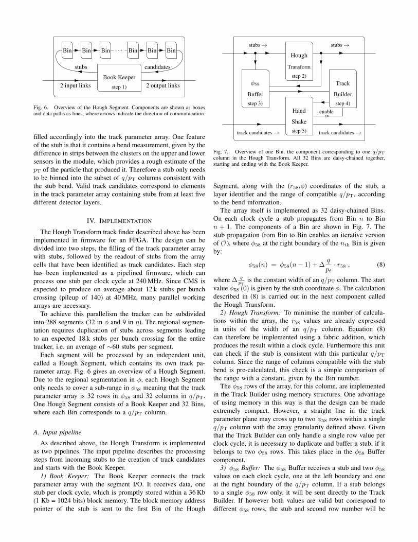
Hand
Shake
Track
BuilderBuffer
φ58
Hough
Transform
stubs →
track candidates →
stubs →
track candidates →
enable
step 2)
step 3) step 4)
step 5)
Fig. 7. Overview of one Bin, the component corresponding to one q/pTcolumn in the Hough Transform. All 32 Bins are daisy-chained together,starting and ending with the Book Keeper.
Segment, along with the (r58,φ) coordinates of the stub, alayer identifier and the range of compatible q/pT, accordingto the bend information.
The array itself is implemented as 32 daisy-chained Bins.On each clock cycle a stub propagates from Bin n to Binn + 1. The components of a Bin are shown in Fig. 7. Thestub propagation from Bin to Bin enables an iterative versionof (7), where φ58 at the right boundary of the nth Bin is givenby:
φ58(n) = φ58(n− 1) + ∆q
pt· r58 , (8)
where ∆ qpT
is the constant width of an q/pT column. The startvalue φ58 (0) is given by the stub coordinate φ. The calculationdescribed in (8) is carried out in the next component calledthe Hough Transform.
2) Hough Transform: To minimise the number of calcula-tions within the array, the r58 values are already expressedin units of the width of an q/pT column. Equation (8)can therefore be implemented using a fabric addition, whichproduces the result within a clock cycle. Furthermore this unitcan check if the stub is consistent with this particular q/pTcolumn. Since the range of columns compatible with the stubbend is pre-calculated, this check is a simple comparison ofthe range with a constant, given by the Bin number.
The φ58 rows of the array, for this column, are implementedin the Track Builder using memory structures. One advantageof using memory in this way is that the design can be madeextremely compact. However, a straight line in the trackparameter plane may cross up to two φ58 rows within a singleq/pT column with the array granularity defined above. Giventhat the Track Builder can only handle a single row value perclock cycle, it is necessary to duplicate and buffer a stub, if itbelongs to two φ58 rows. This takes place in the φ58 Buffercomponent.
3) φ58 Buffer: The φ58 Buffer receives a stub and two φ58values on each clock cycle, one at the left boundary and oneat the right boundary of the q/pT column. If a stub belongsto a single φ58 row only, it will be sent directly to the TrackBuilder. If however both values are valid but correspond todifferent φ58 rows, the stub and second row number will be

stored into a 18 Kb block memory FIFO for later processing.In the case that there is no valid input (i.e. during a gap in thedata stream), the φ58 Buffer will send a stub from the FIFOto the Track Builder to maximise processing throughput.
4) Track Builder: The Track Builder sorts the stubs into 32φ58 values using a segmented memory. The memory contains64 pages, where one half is reserved for even events and theother half for odd events. Each page corresponds to a φ58 row,and has the capacity to store up to 32 stub pointers, such thatthe 64 pages fits into one 18 Kb block memory. The necessarybook keeping, in particular the count of stored stubs per page,is achieved using distributed memory.
The Track Builder must also identify track candidates acrossany of the φ58 rows. The identification of pages as trackcandidates is again based on the use of distributed memory.For each row, a pattern of activated detector layers is storedas an 8-bit word, with one bit for each possible detector layer.On every clock cycle a valid stub arrives, a ’1’ will be writtento the corresponding layer bit. If the word contains at least five’1’s the corresponding φ58 row will be marked for readout.
The stream of incoming stubs ends inside this segmentedmemory, which therefore represents the end of the inputpipeline.
B. Output pipeline
The goal is to create a pipeline of track candidate stubs,which propagate from the first Bin to the Book Keeper. Thetrack candidate stubs are stored in a segmented memory insideeach Track Builder. The readout of pages, which have beenmarked as track candidates, is controlled by the Hand Shake.
5) Hand Shake: The Hand Shake first shifts the trackcandidate stubs from the previous Bin to the next Bin alonguntil there are no more stubs in the pipeline. Then it enablesthe readout of its Track Builder, such that a contiguous blockof track candidate stubs will be created. The φ58 row and theBin number, i.e. the q/pT column, will be attached to the stubpointer by the Track Builder.
6) Book Keeper: The Book Keeper initiates the readout atthe end of an input packet of stubs from an event, and after32 clock cycles receives a stream of track candidate stubsfor this event from the last Bin in the daisy-chain. A trackcandidate stub consists of a φ58 value, a q/pT value, anda stub pointer. The stub pointer corresponds to the positionin the 36 Kb memory where the full stub information wasstored at the beginning of the input pipeline, which is thenextracted by the Book Keeper. As a last action, the BookKeeper formats the full stub information and track parametersand transfers the data to the output of the Hough Segment.
Table I shows the resource utilisation of one Bin and Table IIshows the utilisation of one Hough Segment, including LUTs(Look Up Tables), LUTRAMs (distributed RAMs), FF (FlipFlops) and BRAM (Block RAMs), for the Xilinx Virtex-7XC7VX690T FPGA [14]. Through the smart use of commonmemory structures, it is possible to map the complex HoughTransform array into the FPGA in an extremely compact way.Division of the array into daisy-chained Bins is particularly
TABLE IRESOURCE UTILISATION OF ONE BIN BASED ON THE XILINX VIRTEX-7
XC7VX690T.
Resource Number Used in %LUT 188 0.04LUTRAM 26 0.01FF 204 0.02BRAM 1 0.07
TABLE IIRESOURCE UTILISATION OF ONE SEGMENT BASED ON THE XILINX
VIRTEX-7 XC7VX690T.
Resource Number Used in %LUT 6014 1.39LUTRAM 836 0.48FF 6718 0.78BRAM 33 2.24
advantageous, as it enables highly flexible placement androuting possibilities.
V. THE HARDWARE DEMONSTRATOR
The purpose of the demonstrator system is to run MonteCarlo simulated physics samples, with pileup, under HL-LHCconditions for an upgrade tracker geometry, through hardwareand ensure matching with emulation software, in order tovalidate expected performance within latency constraints. Ascalable slice of the track finder has been designed to allowthe demonstration of the concept using currently availabletechnology. One demonstrator slice can process at a time 1/8of the tracker in φ, all of tracker in η, and one in every 36bunch crossings. One can sequentially run data for all eightφ-octants through the demonstrator hardware, allowing resultsto be obtained for the entire tracker.
The hardware demonstrator, located at the CERN TrackerIntegration Facility (TIF) is installed in a standard LHCrack, which provides power and cooling. The demonstratorconsists of one custom Schroff dual-star MicroTCA crate,equipped with a commercial NAT MicroTCA Carrier Hub(MCH) for Gigabit Ethernet communication via the backplane,and a CMS specific auxiliary card known as the AMC13[15] for synchronisation, timing and control. The Schroffcrate is also equipped with eleven Imperial Master Processor,Virtex-7, Extended Edition (MP7-XE) double width AMCcards [16], which act as the processing boards for the trackfinder demonstrator. The MP7 was originally developed forthe CMS L1 calorimeter trigger upgrade, which was installedin CMS in 2015. Each MP7 is equipped with a Xilinx Virtex-7 XC7VX690T FPGA, and 12 Avago Technologies MiniPODoptical transmitters/receivers, each providing 12 optical linksrunning at up to 10.3 Gbps, for a total optical bandwidth of0.74 Tbps in each direction.
The MP7 development group also provides a generic in-frastructure firmware, which segregates core tasks such astransceiver buffering, I/O formatting, external communication,and configuration, from the algorithm itself. This generic coreallows a system such as the demonstrator to be built up of

Fig. 8. The demonstrator system consists of four layers of MP7s; source,Geometric Processor (GP), Hough Transform (HT) and sink. The data movesdownstream on optical links. Thirty-six optical links connect each sourceboard to the GP. Twenty-four links connect the GP to each HT board. EachHT board is also connected to the sink with 24 optical links.
firmware blocks, each residing on a single MP7-XE, daisy-chained together with high speed optics. Using multiple MP7sin this way, one can easily extrapolate to the FPGA resourcesthat may be available in a future processing card, meaningthat final system performance can be estimated with currentlyavailable technology. This also allows firmware tasks to beeasily divided between personnel, if common I/O formatsbetween the firmware blocks are defined. These firmwareblocks and the connections between them are shown in Fig. 8and described below.
Seven MP7-XE boards are currently used for the demonstra-tor chain. Two of these boards, named sources, contain largebuffers that can store up to 30 events of stub data for a singledetector octant. The sources represent data from a set of upto 72 DTCs. The stub data from the DTCs is injected intothe large buffers on the source boards via IPBus [17], and isalready pre-formatted in a 48-bit global coordinate scheme.Each source provides a stream of data to the downstreamboard on 36 links, equivalent to the DTCs that make upadjacent detector octants. Input data from two adjacent octantsis required, to be able to handle tracks that traverse the regionalboundary.
The Geometric Processor (GP) board must format the 48-bitstubs into the 64-bit stubs required by the Hough Transform(HT) board, and assign each stub to one of four sub-sectorsin φ, and nine sub-sectors in η, duplicating across sectorboundaries when necessary. In order to simplify the HTfirmware, the GP assigns stubs a layer ID (0-5 in barrel, 0-4in endcaps), and a minimum/maximum viable pT column inthe HT, based on the stub bend. The duplication rules acrossφ are tuned for a pT = 3 GeV/c particle, and utilize both theφ coordinate of the stub, and the stub bend information, tokeep the duplication rate below 25% without efficiency loss.
Although two MP7-XEs contain the FPGA logic resourcesrequired to run the HT for a φ-octant, three demonstratorboards are allocated, to allow for future optimisations andadditions to the firmware.
Downstream of the HT is the sink board. The sink runsidentical firmware to the two sources, and can buffer theHT output from about 30 simulated physics events, beforebeing read-out with IPBus. Additional boards are also installedin the demonstrator crate, which allow testing of individual
Fig. 9. The demonstrator crate is equipped with 11 MP7-XE boards, anAMC13, MCH and the required optics.
firmware blocks, and single board data taking in parallel withfull demonstrator operation. The demonstrator crate is shownin Fig. 9.
In addition to the primary demonstrator at the CERN TIF,there are smaller single or dual-MP7 set-ups at RutherfordAppleton Laboratory (RAL), Imperial College London, andCERN. These allow for development and validation of indi-vidual firmware blocks, before they are integrated in the fulldemonstrator.
VI. HARDWARE DEMONSTRATOR RESULTS
Simulated physics events up to a pileup of 200 interactionsper bunch crossing have been run through the demonstratorsystem. Studies so far have focused on µ+µ− and tt̄ eventsat pileup of 0, 140 and 200. The demonstrator softwareframework allows simulated physics samples generated in theofficial CMS Software (CMSSW) to be converted into textfiles which are then injected into the hardware demonstratorvia IPBus. The output of the hardware is then converted backinto a CMSSW format, and is compared with the results ofemulation software running on the same simulated physicsevent. This way it is possible to compare the results of thehardware and the emulation software, validating any simula-tion results of track finder performance. Two different versionsof the emulation software have been developed. One versionuses integer precision, and is clock-cycle accurate. It is writtenusing the CIrcuit DAta Flow (CIDAF) framework [18]. Theother version of the emulator is simpler, faster, and also usesinteger precision. It is, however, not designed to be clock cycleaccurate. All results in this paper use this latter version of theemulator.
In Fig. 10, 11 and 12 hardware results are plotted as blackpoints, alongside software emulation (red lines). All plots weregenerated with a dataset of 1000 bunch crossings with thespecified physics conditions.
Excellent matching between hardware and software hasbeen measured with both tt̄ and µ+µ− signals, at a pileupof 0, 140 and 200. Fig. 10 show the average track rates forµ+µ− at pileup of 140, and tt̄ at pileup of 200, respectively.An average hardware/software matching of 99.5% is observed

Fig. 10. Average track rate vs φ segment (0-31) for hardware demonstratorand emulation software, µ+µ− at pileup 140 (above). Average track ratevs η segment (0-8) for hardware demonstrator and emulation software, tt̄ atpileup 200 (below). Ratio plots are also provided below the rate plots, wherethe ratio of hardware rate over software rate (black point) is shown alongsideunity (blue line).
for tt̄ inclusive tracks at pileup of 200. At up to 200 pileup,average µ+µ− matching is greater than 99.9%.
Fig. 11 and 12 show efficiency as measured in bothhardware and emulation software for finding µ+µ− and tt̄inclusive tracks at pileup of 200. Tracking efficiency here ismeasured relative to Monte Carlo simulation truth tracks, withpT > 3 GeV/c, and stubs in a minimum of five tracker layers.An overall tracking efficiency of 99.79% is observed for µ+µ−
signals in both hardware and software. For tt̄ inclusive tracks,an overall tracking efficiency of 97.58% and 98.28% areobserved in hardware and software respectively. This smalldiscrepancy of 0.7% between hardware and software efficiencyappears primarily at low pT(< 10 GeV/c) and high |η|(> 1.5).
A stub rate reduction factor of 9.95 has been measuredin hardware at pileup of 140, see Table III. For the highlyoccupied conditions of tt̄ events at pileup of 200, the ratereduction factor is measured to be 3.76.
Latency measurements of the demonstrator chain have beenmade, see Table IV. The latency of the HT stage was mea-sured at 1092 ns, while the latency of the GP stage was
Fig. 11. Demonstrator results for µ+µ− signals at pileup of 200. Trackingefficiency vs η for hardware demonstrator and emulation software (above).Tracking efficiency vs pT for hardware demonstrator and emulation software(below). The sample size is 1000 bunch crossings. Tracking efficiency ismeasured relative to Monte Carlo simulation truth tracks, with pT > 3 GeV/c,and stubs in a minimum of five tracker layers.
TABLE IIIMEASURED RATE REDUCTION IN DEMONSTRATOR. NOTE THAT STUBSIMULATION CONDITIONS WERE SLIGHTLY DIFFERENT IN THE tt̄ AND
µ+µ− SAMPLES.
Pileup Signal Stubs in Stubs out Tracks out140 µ+µ− 15920 1599 215
140 tt̄ 16131 2483 322
200 µ+µ− 25382 5529 736
200 tt̄ 25081 6665 875
measured to be 280 ns, for a total algorithmic latency of1372 ns. Measurements of the infrastructure latency have alsobeen made, which includes optical link traversal time andserialisation/de-serialisation. The total infrastructure latency is483 ns. When measured for the entire demonstrator chain ofsource to sink at once, or measured individually for each layerand summed, these results agree. The latency of the system isfixed, regardless of pileup, or segment occupancy.
VII. SUMMARY
The LHC luminosity will be increased by up to an orderof magnitude from 2026 onwards, in order to maximise thepotential physics reach of the collider. It will also be necessaryto upgrade the CMS outer tracker at this time. The high pileupconditions expected at HL-LHC necessitate the incorporationof tracking information early in the triggering chain to main-tain the L1 selection rate and physics performance.

Fig. 12. Demonstrator results for tt̄ signals at pileup of 200. Trackingefficiency vs η for hardware demonstrator and emulation software (above).Tracking efficiency vs pT for hardware demonstrator and emulation software(below). The sample size is 1000 bunch crossings. Tracking efficiency ismeasured relative to Monte Carlo simulation truth tracks, with pT > 3 GeV/c,and stubs in a minimum of five tracker layers.
TABLE IVDEMONSTRATOR LATENCY MEASUREMENTS
Latency [ns]Source event buffers → GP rx buffers 179
GP tx buffers → HT rx buffers 142HT tx buffers → Sink event buffers 162
Infrastructure total 483
GP algorithm 280HT algorithm 1092
Algorithm total 1372
CMS plans on selecting only hits from charged particlescompatible with pT > 2− 3 GeV/c by correlating particle hitsbetween stacked silicon sensors, which can then be read out toa L1 track-finder at an acceptable rate. This information willthen be combined with muon and calorimeter objects beforethe final L1 decision is made.
A design for a L1 track-finder utilising Time Multiplexed2D Hough transforms in FPGAs has been proposed. Simula-tion results demonstrate a high track-finding efficiency, and arate reduction of order 10 at 140 pileup.
Firmware for the initial stages of this track-finder has beendeveloped. By regionalising the detector data for indepen-dent parallel Hough Transform segments, the full patternrecognition algorithm can easily be scaled, distributing overseveral FPGAs if necessary. Together with a well balanced and
compact implementation of each segment, use of the HoughTransform to find tracks under HL-LHC conditions is feasibleeven in todays technology.
This design has been demonstrated in hardware, using anumber of MP7 boards in a MicroTCA crate. The demon-strator slice can find tracks in all of η, 1/8 of the trackerin φ, and every 1/36 bunch crossings in time. However,each φ-octant can be processed in turn, to take data for theentire tracker. Fully simulated physics events including tt̄ andµ+µ− at pileup of 0, 140 and 200 have been processed bythe demonstrator hardware. Results show excellent match-ing (99.5% in high occupancy physics conditions) betweenthe hardware demonstrator and the emulation software, andtracking efficiencies in excess of 97.5%. Stub rate reductionwith the Hough transform by a factor of 10 at 140 pileuphas been demonstrated. Latency measurements made withhardware demonstrate a fixed algorithmic latency of 1372 ns,well within the allocated 4 µs for track primitive generation.Downstream stages will soon be added to the demonstratorthat will filter and fit the tracks in preparation for correlationwith muon chambers and calorimeter information.

REFERENCES
[1] L. Evans and P. Bryant, LHC Machine, 2008 JINST 3 S08001, Available:http://stacks.iop.org/1748-0221/3/i=08/a=S08001.
[2] G. Apollinari, I. Bejar Alonso, O. Bruning, M. Lamont, L. Rossi High-Luminosity Large Hadron Collider (HL-LHC) : Preliminary DesignReport, CERN, Geneva, 2015, DOI: 10.5170/CERN-2015-005.
[3] The CMS Collaboration (S. Chatrchyan et al.), The CMS experi-ment at the CERN LHC, 2008 JINST 3 S08004, DOI: 10.1088/1748-0221/3/08/S08004.
[4] The CMS Collaboration, Technical Proposal for the Phase-II Upgradeof the Compact Muon Solenoid, CERN-LHCC-2015-010. June 2015,Available: https://cds.cern.ch/record/2020886.
[5] J. Jones, G. Hall, C. Foudas, A. Rose, A Pixel Detector for Level-1 Triggering at SLHC, 11th Workshop on Electronics for LHC Ex-periments, Heidelberg, September 2005, CERN Report CERN-2005-011(2005) 130-134.
[6] M. Pesaresi, Development of a new Silicon Tracker for CMSat Super-LHC, Imperial College thesis (2010), Available:https://workspace.imperial.ac.uk/highenergyphysics/Public/theses/.
[7] M. Pesaresi and G. Hall, Simulating the performance of a pT track-ing trigger for CMS, 2010 JINST 5 C08003, DOI: 10.1088/1748-0221/5/08/C08003.
[8] G. Hall, M. Raymond and A. Rose, 2-D PT module concept forthe SLHC CMS tracker, 2010 JINST 5 C07012, DOI: 10.1088/1748-0221/5/07/C07012.
[9] M. Raymond et al., The CMS binary chip for microstrip trackerreadout at the SLHC, 2012 JINST 7 C01033, DOI:10.1088/1748-0221/7/01/C01033.
[10] G. Hall, M. Pesaresi, M. Raymond, D. Braga, L. Jones, P. Murray, M.Prydderch et al., CBC2: a CMS microstrip readout ASIC with logic fortrack-trigger modules at HL-LHC, Nucl. Instrum. Meth. A 765 (2014)214, DOI: 10.1088/1748-0221/7/10/C10003.
[11] F. Ravera for the CMS collaboration, CMS Tracker upgrade for HL-LHC: R&D plans, present status and perspectives, Nucl. Instrum. Meth.A 824 (2016) 455-458, Conference: C15-05-24.1 Proceedings, DOI:10.1016/j.nima.2015.09.029.
[12] G. Hall, A Time-Multiplexed Track-Trigger for the CMS HL-LHCupgrade, Frontier Detectors for Frontier Physics: 13th Pisa Meeting onAdvanced Detectors, La Biodola, Isola D’elba, Italy, 24 - 30 May 2015,CMS-CR-2015-109, Available: https://cds.cern.ch/record/2027712.
[13] P. V. C. Hough, Method and means for recognizing complex patterns,December 18th 1962, US Patent 3,069,654.
[14] Xilinx, 7 Series FPGAs Overview, Product Speci-fication, DS180 (v1.17) May 27, 2015, Available:http://www.xilinx.com/support/documentation/data sheets/ds180 7Series Overview.pdf.
[15] E. Hazen, A. Heister, C. Hill, J. Rohlf, S.X. Wu and D.Zou, TheAMC13XG: a new generation clock/timing/DAQ module for CMS Mi-croTCA, 2013 JINST 8 C12036, DOI: 10.1088/1748-0221/8/12/C12036.
[16] K. Compton, A. Rose et al., The MP7 and CTP-6: multi-hundred Gbpsprocessing boards for calorimeter trigger upgrades at CMS, 2012 JINST7 C12024, DOI: 10.1088/1748-0221/7/12/C12024.
[17] C. Ghabrous Larrea, K. Harder, D. Newbold, D. Sankey, A. Rose,A. Thea and T. Williams, IPbus: a flexible Ethernet-based controlsystem for xTCA hardware, 2015 JINST 10 C02019, DOI:10.1088/1748-0221/10/02/C02019.
[18] C. Amstutz et al. Emulation of a prototype FPGA track finder for theCMS Phase-2 upgrade with the CIDAF emulation framework, IEEE RealTime Conference, 5 Jun 2016, Proceedings of this conference.