Embed Size (px)
Citation preview

CMR
INSTITUTE OF
TECHNOLOGY
USN
Internal Assesment Test II – May 2019
Sub: BASIC ELECTRICAL ENGINEERING Code: 18ELE23
Date: 15.05.2019 Duration: 90 mins Max Marks: 50 Sem: 2 Section: I,J,K,L,M,N,O
Note: Answer any FIVE FULL Questions
Sketch neat figures wherever necessary. Answer to the point. Good luck!
Marks OBE
CO RBT
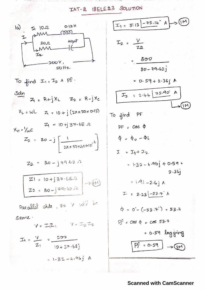
1 (a)
For the circuit shown, Solve for a) current in each branch b) power factor of the circuit
[5] CO2 L3
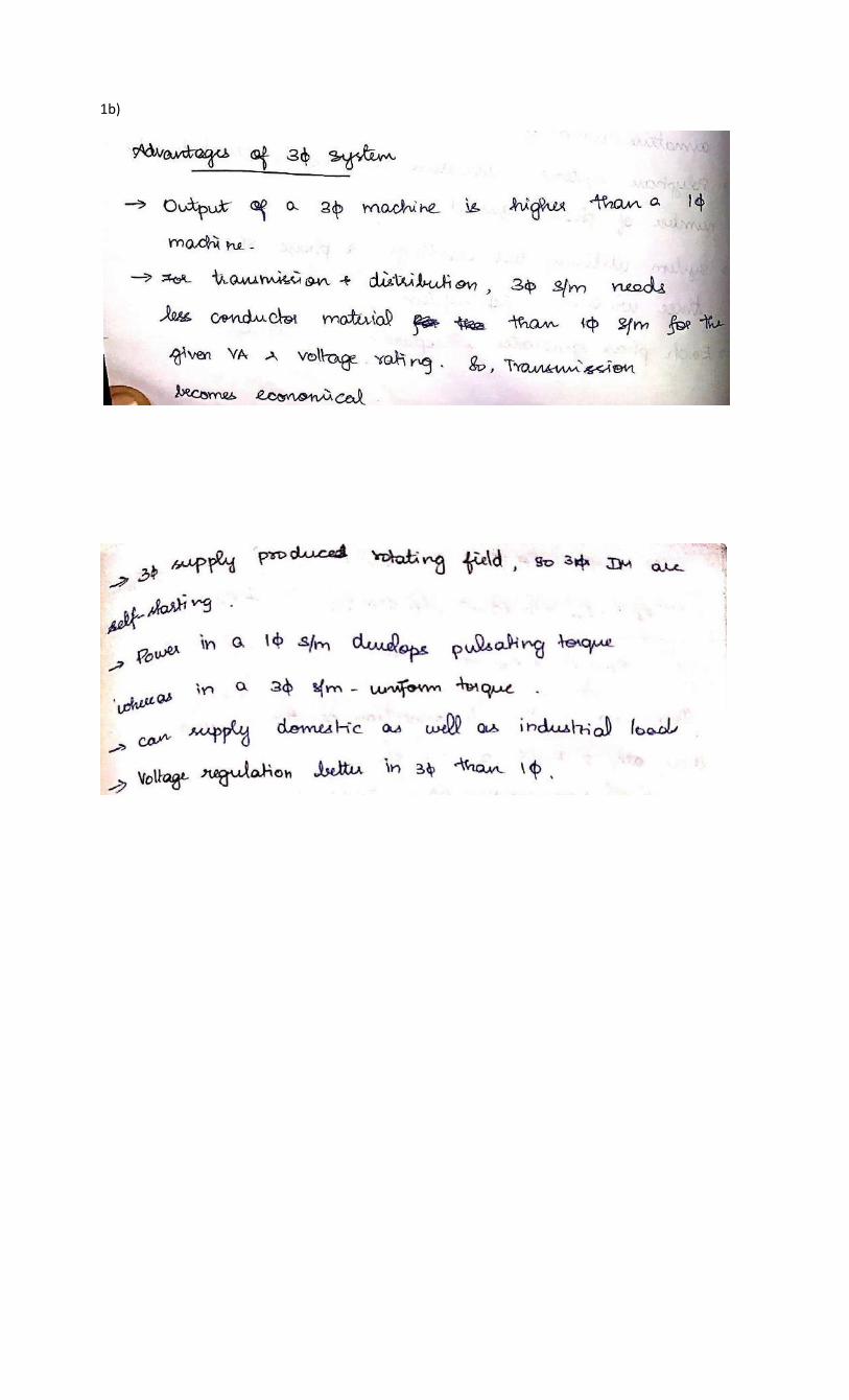
(b) What is Phase Sequence? List the advantages of three phase system over single phase
system. [5] CO3 L1
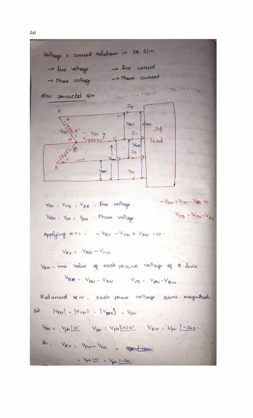
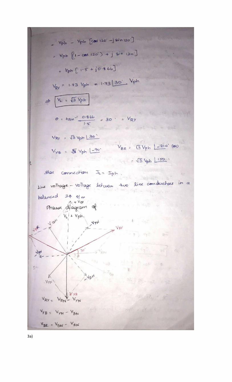
2 (a) In a three phase star connection, find the relation between line and phase values of
voltages and currents. Also derive the equation for three phase power [5] CO3 L2
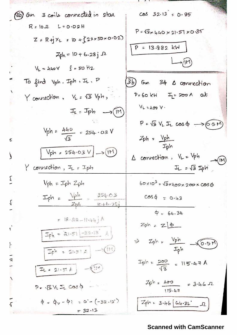
(b) Three coils each having a resistance of 10 Ω and inductance of 0.02H are connected in
star across 440V, 50 Hz three phase supply. Calculate phase voltage, phase current,
line current and Power.
[5] CO3 L3
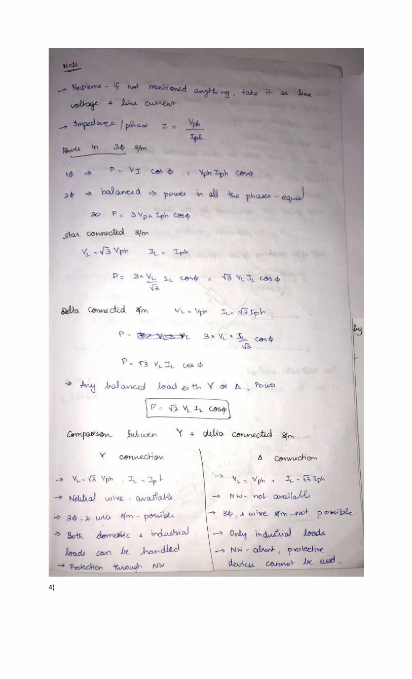
3 (a) In a three phase delta connection, find the relation between line and phase values of
voltages and currents. Also derive the equation for three phase power [5] CO3 L2
(b) A 3 phase delta connected balanced load consumes a power of 60 KW taking up a
lagging current of 200 A, at a line voltage of 400 V, 50 Hz. Find the parameters of each
phase.
[5] CO3 L3
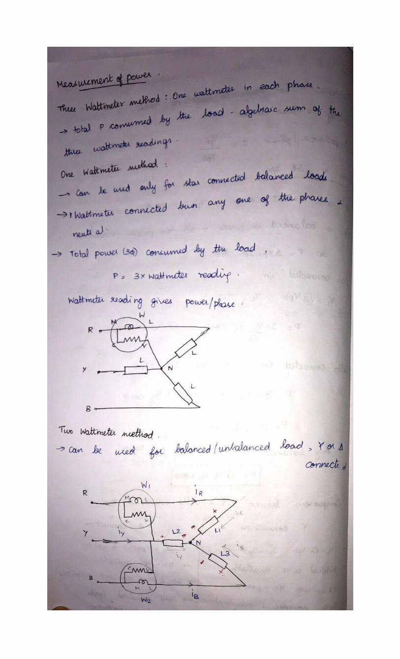
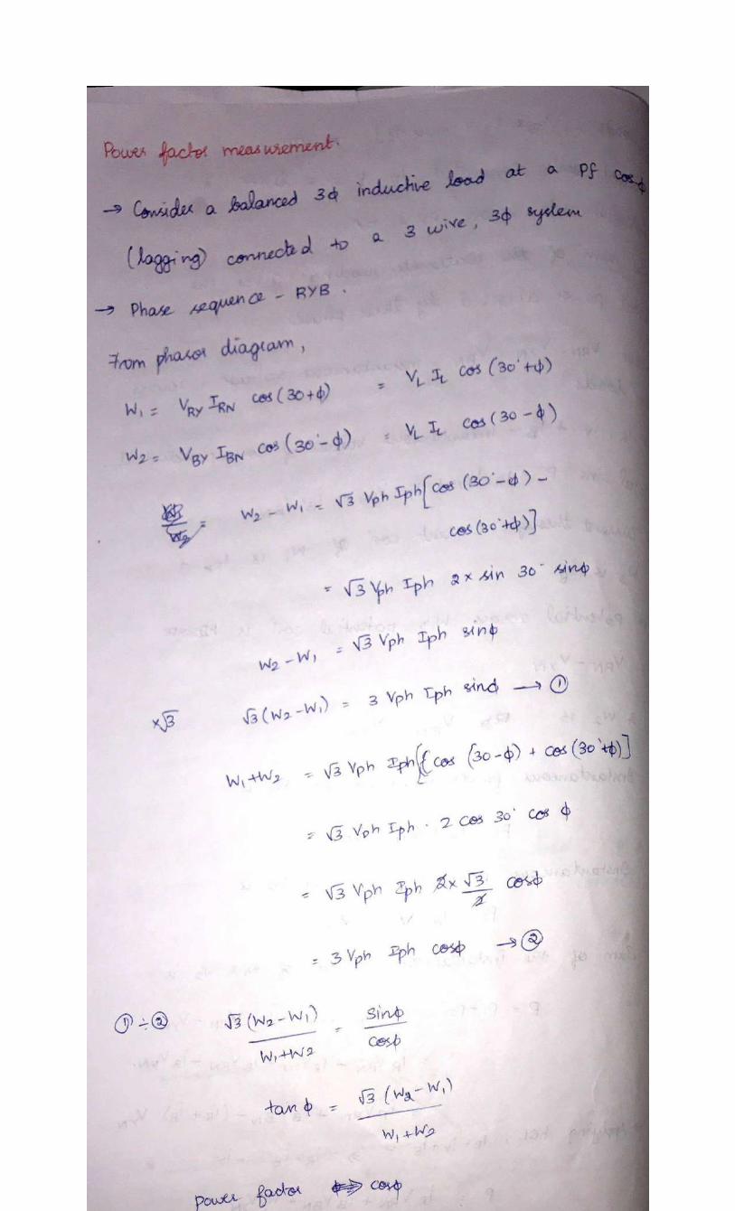
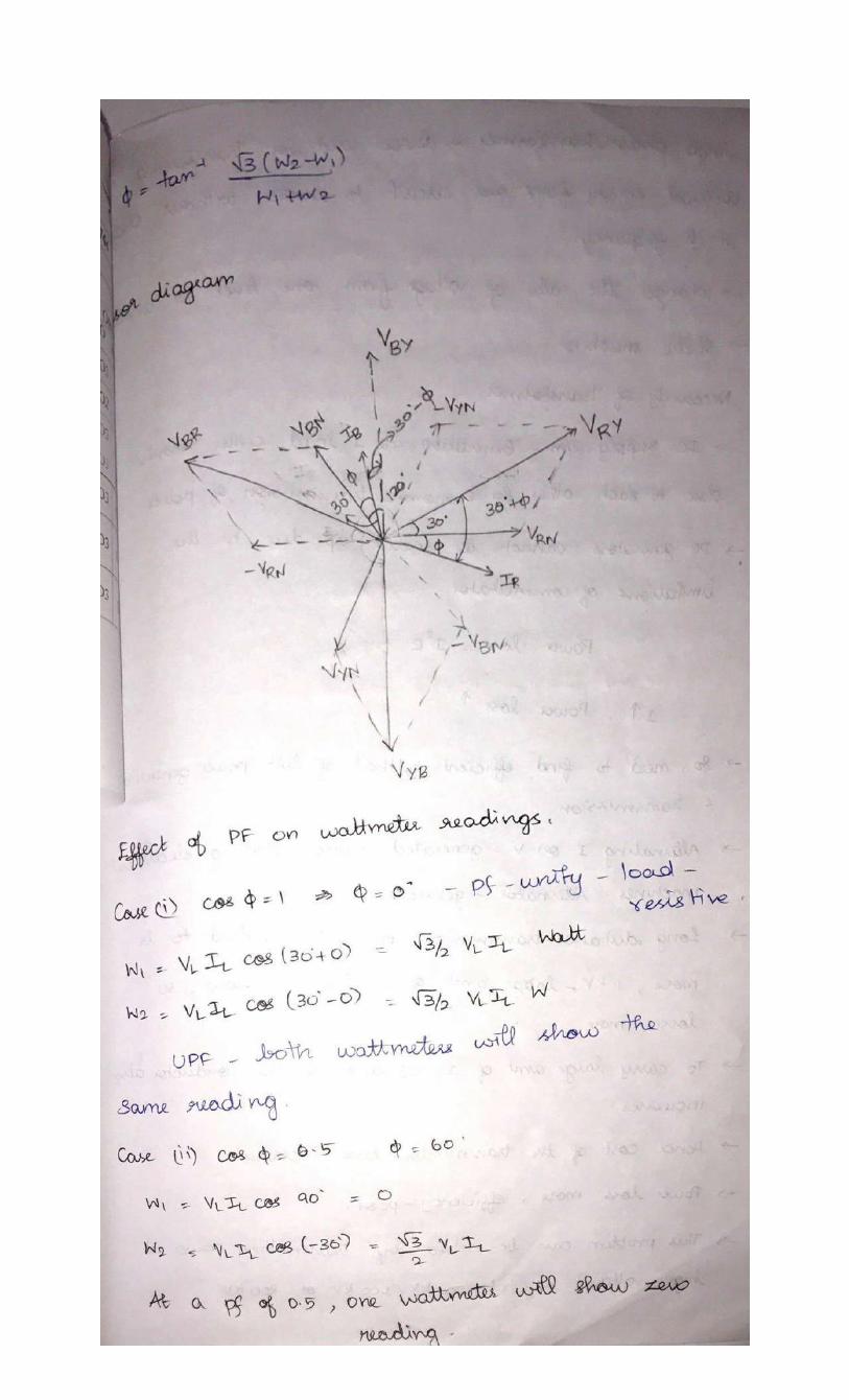
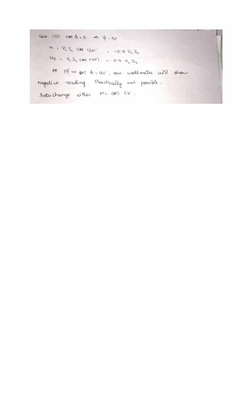
4 Show that two wattmeters are sufficient to measure three phase power. Also with
phasor diagram, derive an expression for the power factor in terms of wattmeter
readings
[10] CO3 L2
5 (a) What is the necessity of earthing? Explain any one type of earthing with a neat diagram
[5] CO5 L2
(b) Write a short note on a)MCB b) Precautions against Electric Shock [5] CO5 L1
6 With a neat sketch and truth table, explain two way and three way control of a lamp [10] CO5 L2
7 a) Find total current, power & power factor for the given circuit.
[5] CO4 L3
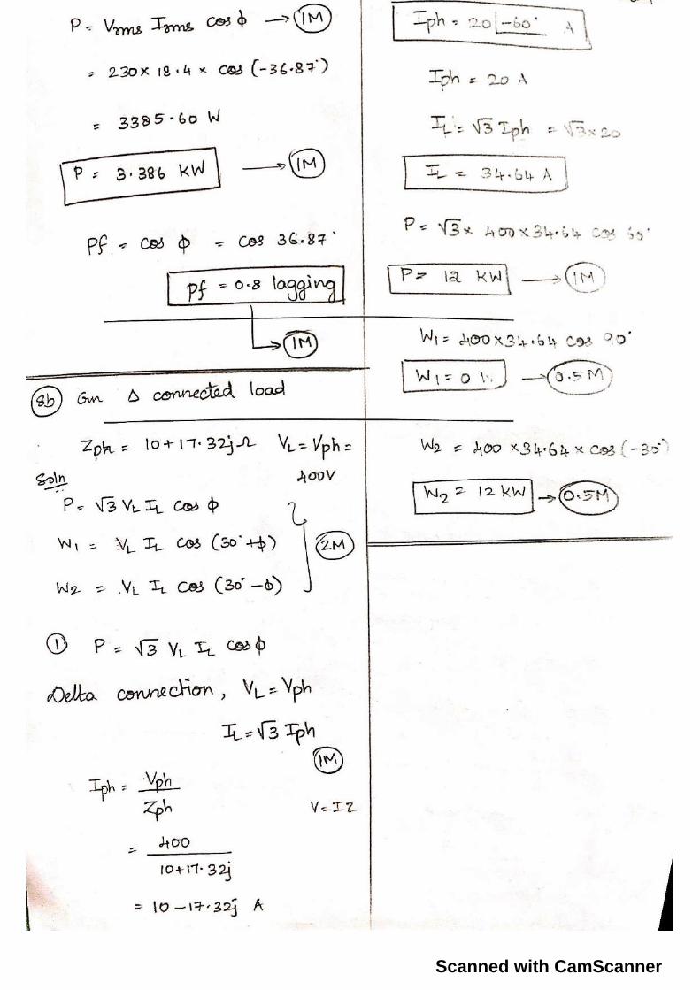
b) The input power to a three phase induction motor running on 400V, 50 Hz supply was
measured by two wattmeter method and the readings were 3000 W and 1000 W.
Calculate a) Total Power input b) Power factor c) Line current
[5] CO3 L3
8 a) Briefly explain conduit wiring with neat sketches. Also mention its advantages and
disadvantages. [5] CO4 L2
b) Two wattmeter method is used to measure power consumed by a delta connected load.
Each branch of load having an impedance of (10+17.32j) Ω. Supply voltage is 400V.
Calculate the total Power and readings on individual wattmeters.
[5] CO3 L3
--------------------------------------------------------------------------------------------------------------------------------------------------------------------------
1b)
2a)
3a)

4)

Scanned with CamScanner
Scanned with CamScanner

Scanned with CamScanner
Scanned with CamScanner
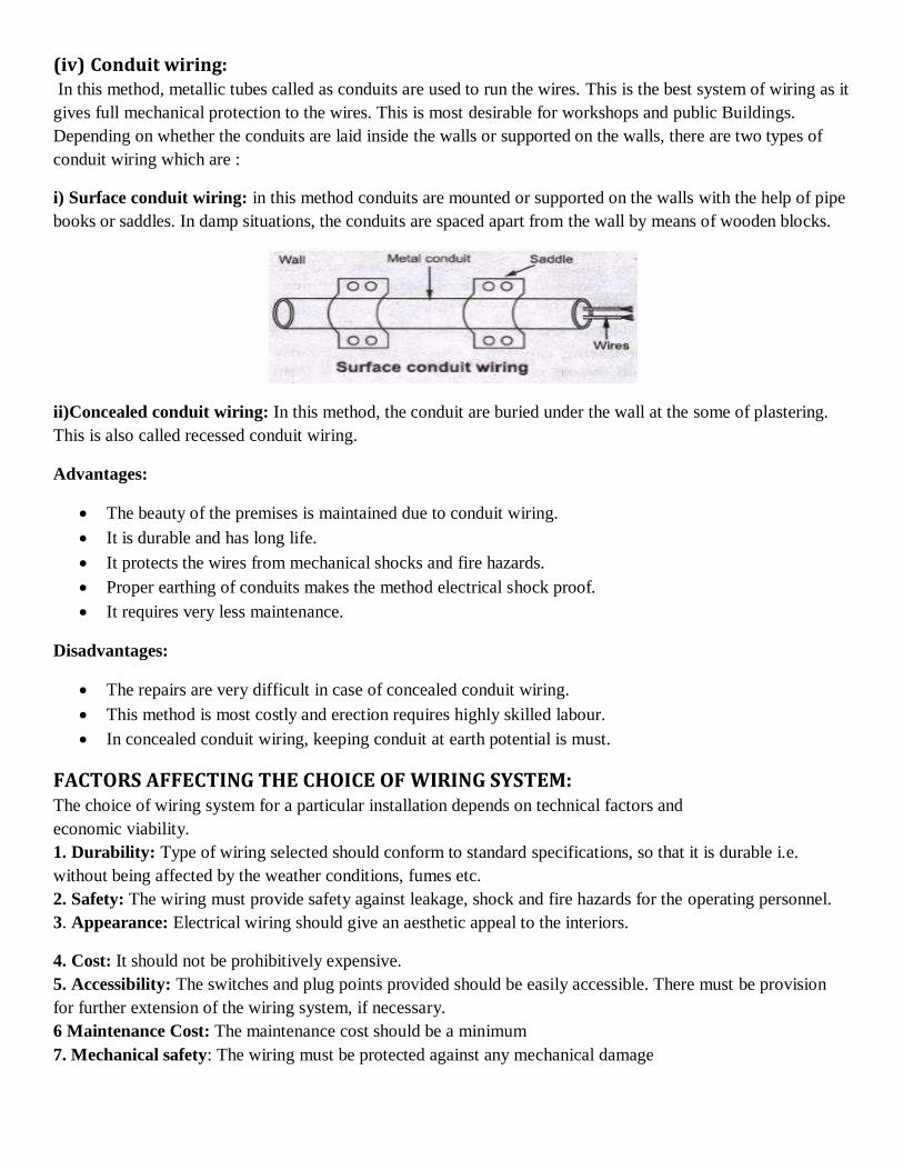
(iv) Conduit wiring: In this method, metallic tubes called as conduits are used to run the wires. This is the best system of wiring as it
gives full mechanical protection to the wires. This is most desirable for workshops and public Buildings.
Depending on whether the conduits are laid inside the walls or supported on the walls, there are two types of
conduit wiring which are :
i) Surface conduit wiring: in this method conduits are mounted or supported on the walls with the help of pipe
books or saddles. In damp situations, the conduits are spaced apart from the wall by means of wooden blocks.
ii)Concealed conduit wiring: In this method, the conduit are buried under the wall at the some of plastering.
This is also called recessed conduit wiring.
Advantages:
The beauty of the premises is maintained due to conduit wiring.
It is durable and has long life.
It protects the wires from mechanical shocks and fire hazards.
Proper earthing of conduits makes the method electrical shock proof.
It requires very less maintenance.
Disadvantages:
The repairs are very difficult in case of concealed conduit wiring.
This method is most costly and erection requires highly skilled labour.
In concealed conduit wiring, keeping conduit at earth potential is must.
FACTORS AFFECTING THE CHOICE OF WIRING SYSTEM:
The choice of wiring system for a particular installation depends on technical factors and
economic viability.
1. Durability: Type of wiring selected should conform to standard specifications, so that it is durable i.e.
without being affected by the weather conditions, fumes etc.
2. Safety: The wiring must provide safety against leakage, shock and fire hazards for the operating personnel.
3. Appearance: Electrical wiring should give an aesthetic appeal to the interiors.
4. Cost: It should not be prohibitively expensive.
5. Accessibility: The switches and plug points provided should be easily accessible. There must be provision
for further extension of the wiring system, if necessary.
6 Maintenance Cost: The maintenance cost should be a minimum
7. Mechanical safety: The wiring must be protected against any mechanical damage

Specification of Wires:
The conductor material, insulation, size and the number of cores, specifies the electrical wires. These are
important parameters as they determine the current and voltage handling capability of the wires. The conductors
are usually of either copper or aluminum. Various insulating materials like PVC, TRS, and VIR are used. The
wires may be of single strand or multi strand. Wires with combination of different diameters and the number of
cores or strands are available.
Ex: 1/20 or 3/22
The numerator indicates the number of strands while the denominator corresponds to the diameter of the wire in
SWG (Standard Wire Gauge). SWG 20 corresponds to a wire of diameter 0.914mm, while SWG 22
corresponds to a wire of diameter 0.737 mm.
A 7/0 wire means, it is a 7-cored wire of diameter 12.7mm (0.5 inch). The selection of the wire is made
depending on the requirement considering factors like current and voltage ratings, cost and application.
Example: Application: domestic wiring
1. Lighting - 3/20 copper wire
2. Heating - 7/20 copper wire
The enamel coating (on the individual strands) mutually insulates the strands and the wire on the
whole is provided with PVC insulation. The current carrying capacity depends on the total area
of the wire. If cost is the criteria then aluminum conductors are preferred. In that case, for the
same current rating much larger diameter of wire is to be used.
Two- way and Three- way Control of Lamps: The domestic lighting circuits are quite simple and they are usually controlled from one point. But in certain
cases it might be necessary to control a single lamp from more than one point (Two or Three different points).
For example: staircases, long corridors, large halls etc.
(i)Two-way Control of lamp:
Two-way control is usually used for staircase lighting. The lamp can be controlled from two different points:
one at the top and the other at the bottom - using two- way switches which strap wires interconnect. They are
also used in bedrooms, big halls and large corridors. The circuit is shown in the following figure.
Switches S1 and S2 are two-way switches with a pair of terminals 1&2, and 3&4 respectively.
When the switch S1 is in position1 and switch S2 is in position 4, the circuit does not form a closed loop
and there is no path for the current to flow and hence the lamp will be OFF.
When S1 is changed to position 2 the circuit gets completed and hence the lamp glows or is ON. N
ow if S2 is changed to position 3 with S1 at position 2 the circuit continuity is broken and the lamp is off.
Thus the lamp can be controlled from two different points.
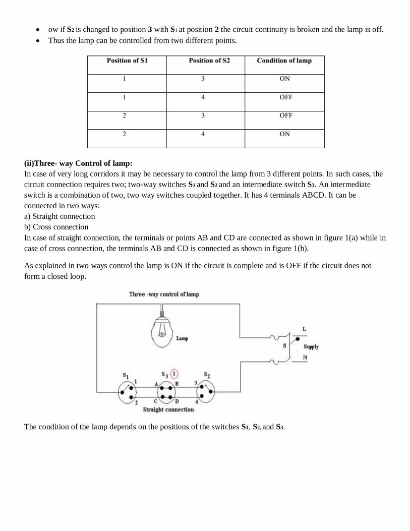
(ii)Three- way Control of lamp:
In case of very long corridors it may be necessary to control the lamp from 3 different points. In such cases, the
circuit connection requires two; two-way switches S1 and S2 and an intermediate switch S3. An intermediate
switch is a combination of two, two way switches coupled together. It has 4 terminals ABCD. It can be
connected in two ways:
a) Straight connection
b) Cross connection
In case of straight connection, the terminals or points AB and CD are connected as shown in figure 1(a) while in
case of cross connection, the terminals AB and CD is connected as shown in figure 1(b).
As explained in two ways control the lamp is ON if the circuit is complete and is OFF if the circuit does not
form a closed loop.
The condition of the lamp depends on the positions of the switches S1, S2, and S3.
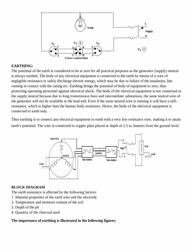
EARTHING:
The potential of the earth is considered to be at zero for all practical purposes as the generator (supply) neutral
is always earthed. The body of any electrical equipment is connected to the earth by means of a wire of
negligible resistance to safely discharge electric energy, which may be due to failure of the insulation, line
coming in contact with the casing etc. Earthing brings the potential of body of equipment to zero, thus
protecting operating personnel against electrical shock. The body of the electrical equipment is not connected to
the supply neutral because due to long transmission lines and intermediate substations, the same neutral wire of
the generator will not be available at the load end. Even if the same neutral wire is running it will have a self-
resistance, which is higher than the human body resistance. Hence, the body of the electrical equipment is
connected to earth only.
Thus earthing is to connect any electrical equipment to earth with a very low resistance wire, making it to attain
earth’s potential. The wire is connected to copper plate placed at depth of 2.5 to 3meters from the ground level.
BLOCK DIAGRAM
The earth resistance is affected by the following factors:
1. Material properties of the earth wire and the electrode
2. Temperature and moisture content of the soil
3. Depth of the pit
4. Quantity of the charcoal used
The importance of earthing is illustrated in the following figures:

Necessity of Earthing:
1. To protect the operating personnel from danger of shock in case they come in contact with the charged frame
due to defective insulation.
2. To maintain the line voltage constant under unbalanced load condition.
3. Protection of the equipments
4. Protection of large buildings and all machines fed from overhead lines against lightning
Methods of Earthing:
The important methods of earthing are the plate earthing and the pipe earthing. The earth resistance for copper
wire is 1 ohm and that of G I wire less than 3 ohms. The earth resistance should be kept as low as possible so
that the neutral of any electrical system, which is earthed, is maintained almost at the earth potential. The
typical value of the earth resistance at powerhouse is 0. 5 ohm and that at substation is 1 ohm.
1. Plate earthing 2. Pipe earthing
1. Plate Earthing:
In this method a copper plate of 60cm x 60cm x 3.18cm or a GI plate of the size 60cm x 60cm x 6.35cm is used
for earthing. The plate is placed vertically down inside the ground at a depth of 3m and is embedded in alternate
layers of coal and salt for a thickness of 15 cm. In addition, water is poured for keeping the earth electrode
resistance value well below a maximum of 5 ohms. The earth wire is securely bolted to the earth plate. A
cement masonry chamber is built with a cast iron cover for easy regular maintenance.
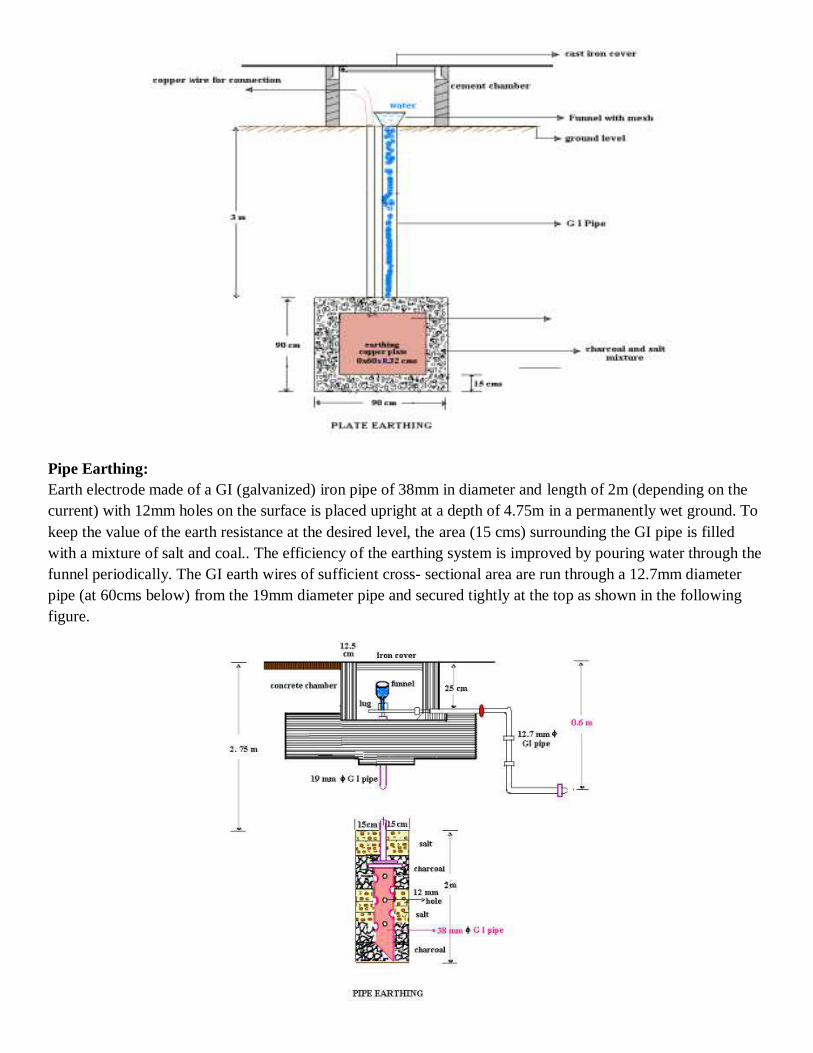
Pipe Earthing:
Earth electrode made of a GI (galvanized) iron pipe of 38mm in diameter and length of 2m (depending on the
current) with 12mm holes on the surface is placed upright at a depth of 4.75m in a permanently wet ground. To
keep the value of the earth resistance at the desired level, the area (15 cms) surrounding the GI pipe is filled
with a mixture of salt and coal.. The efficiency of the earthing system is improved by pouring water through the
funnel periodically. The GI earth wires of sufficient cross- sectional area are run through a 12.7mm diameter
pipe (at 60cms below) from the 19mm diameter pipe and secured tightly at the top as shown in the following
figure.

When compared to the plate earth system the pipe earth system can carry larger leakage currents as a much
larger surface area is in contact with the soil for a given electrode size. The system also enables easy
maintenance as the earth wire connection is housed at the ground level.
PROTECTIVE DEVICES
Protection for electrical installation must be provided in the event of faults such as short circuit, overload and
earth faults. The protective circuit or device must be fast acting and isolate the faulty part of the circuit
immediately. It also helps in isolating only required part of the circuit without affecting the remaining circuit
during maintenance. The following devices are usually used to provide the necessary protection:
1. Fuses
2. Relays
3. Miniature circuit breakers (MCB)
4. Earth leakage circuit breakers (ELCB)
FUSE
The electrical are designed to carry a particular rated value of current under normal circumstances. Under
abnormal conditions such as short circuit, overload or any fault the current raises above this value, damaging
the equipment and sometimes resulting in fire hazard. Fuses are pressed into operation under such situations.
Fuse is a safety device used in any electrical installation, which forms the weakest link between the supply and
the load. It is a short length of wire made of lead / tin /alloy of lead and tin/ zinc having a low melting point and
low ohmic losses. Under normal operating conditions it is designed to carry the full load current. If the current
increases beyond this designed value due any of the reasons mentioned above, the fuse melts (said to be blown)
isolating the power supply from the load as shown in the following figures.

CHARACTERISTICS OF FUSE MATERIAL
The material used for fuse wires must have the following characteristics
1. Low melting point
2. Low ohmic losses
3. High conductivity
4. Lower rate of deterioration
Different types of fuses:
Re-wirable or kit -kat fuses: These fuses are simple in construction, cheap and available up-to a current rating
of 200A. They are erratic in operation and their performance deteriorates with time.
Plug fuse: The fuse carrier is provided with a glass window for visual inspection of the fuse wire.
Cartridge fuse: Fuse wire usually an alloy of lead is enclosed in a strong fiber casing. The fuse element is
fastened to copper caps at the ends of the casing. They are available up -to a voltage rating of 25kV. They are
used for protection in lighting installations and power lines.
Miniature Cartridge fuses: These are the miniature version of the higher rating cartridge fuses, which are
extensively used in automobiles, TV sets, and other electronic equipments.
Transformer fuse blocks: These porcelain housed fuses are placed on secondary of the distribution
transformers for protection against short circuits and overloads.
Expulsion fuses: These consist of fuse wire placed in hollow tube of fiber lined with asbestos. These are suited
only for outdoor use for example, protection of high voltage circuits.
Semi-enclosed re-wirable fuses: These have limited use because of low breaking capacity.
Time-delay fuse: These are specially designed to withstand a current overload for a limited time and find
application in motor circuits.
HRC CARTRIDGE FUSE:
The high rupturing capacity or (HRC) fuse consists of a heat resistant ceramic body. Then silver or bimetallic
fuse element is welded to the end brass caps. The space surrounding the fuse element is filled with quartz
powder. This filler material absorbs the arc energy and extinguishes it. When the current exceeds the rated value
the element melts and vaporizes. The vaporized silver fuses with the quartz and offers a high resistance and the
arc is extinguished.
Advantages:
1. Fast acting
2. Highly reliable
3. Relatively cheaper in comparison to other high current interrupting device
Disadvantages:
1. Requires replacement
2. The associated high temperature rise will affect the performance of other devices