Embed Size (px)
Citation preview

CPI CMP 200® / CMP 200® DR SERIES
X-RAY GENERATOR
OPERATOR’S MANUAL
PREPARED BY: COMMUNICATIONS & POWER INDUSTRIES CANADA INC. 45 RIVER DRIVE GEORGETOWN, ONTARIO, CANADA L7G 2J4 TELEPHONE: (905) 877-0161
OPERATOR’S MANUAL P/N
740985-00
740985-01

CPI CMP 200® / CMP 200® DR SERIES X-RAY GENERATOR
OPERATOR’S MANUAL
Address any questions regarding X-ray generator operation to: CPI Canada Incorporated, 45 River Drive Georgetown, Ontario, Canada L7G 2J4 Telephone: (905) 877-0161
Fax: (905) 877-8320 Attention: Customer Support Department
E-mail: [email protected] Attention: Customer Support Department

X-Ray Generator Operator’s Manual 740985 Rev. U Page 1
CMP 200® / CMP 200® DR
INTRODUCTION 1
MEMBRANE CONSOLE
SAFETY AND SPECIFICATIONS 2
OPERATOR’S MANUAL
CONSOLE CONTROLS 3
Manual Part Number: 740985
PROGRAMMING THE CONSOLE 4
ERROR CODES AND MESSAGES 5
GENERATOR EXPOSURE TABLES 6
MAINTENANCE SCHEDULE 7
X-RAY TUBE DATA 8
The original version of this manual (15 January 2002) has been drafted in the English language by: Communications & Power Industries Inc. communications & medical products division.

Page 2 X-Ray Generator Operator’s Manual 740985 Rev. U
(This page intentionally left blank)

X-Ray Generator Operator’s Manual 740985 Rev. U Page 3
INTRODUCTION 1 This 100 kHz high frequency X-ray generator is a component of a radiographic X-ray system used in hospitals and clinics. It is used with film-based systems or with DR flat panel detectors along with an imaging system for diagnostic radiographic imaging. It is a non-invasive device, and is designed to image the major systems of the body: Skull, shoulder, thorax, upper arm, lower arm, abdomen, pelvis, femur, knee, tibula-fibula, foot.
The generator features state-of-the-art computer-based control to ensure minimum patient dose, excellent reproducibility, and superior image contrast. The operator control functions are designed to be simple and user-friendly.
The APR (Anatomical Programming) and the optional AEC (Automatic Exposure Control) features give you controlled exposure factors, automatically optimized for the radiological study selected.
MAIN FEATURES
• Output power levels 32 to 80 kW. • Output capability 125 kV / 150 kV, dependant on model. • Smaller, lighter, modular design. • Constant dose output due to kV and mA regulation during exposures. • User-friendly controls. • Large LCD panel for APR and technique display. • User-friendly system configuration. • Programmed for APR operation, with manual override of technique factors. • Extensive self-diagnostics with operator prompt messages. • Time and mA / mAs selections are to IEC standards.
OPTIONS • Remote exposure hand switch. • AEC (Automatic Exposure Control). • Tomography. • Dual Speed Starter (400 / 480 VAC models only). • Various digital interfaces, dependent on model. • Dose-Area Product (DAP).
PATIENT POPULATION • Age: Infant to geriatric. • Weight:
∗ APR mode: Pediatric, small, medium and large patients. The selection of pediatric patient size may disabled by the service engineer.
∗ Manual mode: Exposure factors are set manually, will allow weights from newborn to obese adult. • Health: Patients requiring an X-ray may have conditions ranging from mild trauma to chronic, life
threatening illnesses. FREQUENCY OF USE
• Typical range 20 exposures / day to 1500 exposures / day (1 day = 24 hr period).

1 Introduction
Page 4 X-Ray Generator Operator’s Manual 740985 Rev. U
SAFETY NOTICE: This manual contains important safety information. An understanding of this information is critical to the safe operation of your equipment. Please ensure that you read the warning notices before using the equipment.
GENERATOR DUTY CYCLE LIMIT
NOTE: THE FOLLOWING SECTION CONTAINS IMPORTANT INFORMATION. PLEASE READ AND UNDERSTAND THIS MATERIAL BEFORE CONTINUING.
Internal X-ray generator components will heat up during normal use of the generator. This is similar to X-ray tube heating during normal generator operation. The amount of heat produced is proportional to the product of kV, mA, and time. Modern X-ray generators are designed to operate with the majority of X-ray tubes over their rated power ranges. They are designed for operating duty cycles consistent with practical patient examination routines that allow for reasonable cooling intervals between X-ray exposures. This X-ray generator has internal duty cycle monitoring to warn of excessive heat build-up. If the generator calculates that the next exposure will exceed the rated generator duty cycle limit, a warning message “GEN DUTY WARNING” will be displayed. Further exposures are inhibited at this point, and the generator must be allowed to cool sufficiently such that this message is no longer displayed. The generator also monitors the X-ray tube’s thermal switch, and will inhibit exposures when the tube reaches its thermal limit. It is the responsibility of the installer to implement and verify this interlock.
DAILY X-RAY TUBE WARM-UP PROCEDURE
CAUTION: THE FOLLOWING PROCEDURE PRODUCES X-RAYS. OBSERVE ALL SAFETY PRECAUTIONS TO PROTECT PERSONNEL.
Use this procedure when the generator is first turned on for the day, or when it has not been used for several hours. This procedure provides for exposures at medium power before the tube is used at maximum mA or kV values. This will reduce the possibility of damaging the anode and high voltage components. No test setup is required.
For maximum stability and reliability, use the following techniques at start up: Select the following: • Large focal spot. • 80 kV. • Normal 50/60 Hz anode rotation.
For a 300 kHU to a 400 kHU tube, use approximately 200 mAs per exposure. For a 200 kHU to 300 kHU tube use approximately 150 mAs per exposure. • Depending on the X-ray tube power rating, select either 100 mA or 200 mA. • Make one (1) to three (3) exposures (depending on tube loading) at 30-second intervals.

Introduction 1
X-Ray Generator Operator’s Manual 740985 Rev. U Page 5
TERMINOLOGY
Direct radiography Radiography in which the permanent recording is effected at an image reception area (i.e. film).
Indirect radiography Radiography in which the permanent recording is effected after transfer of the information obtained at an image reception area (i.e. digital imaging system).
Reference Air Kerma rate Air Kerma rate free in air in the primary X-ray beam measured under specific conditions and expressed at the patient entrance reference point.
Patient entrance reference point Point intended to represent the intersection of the X-ray beam axis with the entrance surface of the patient.
Isocentre In radiological equipment with several modes of movement of the reference axis around a common centre, the centre of the smallest sphere through which the radiation beam axis passes.
Entrance field size Dimensions of the field in the entrance plane of an X-ray image receptor that can be used for the transmission of an X-ray pattern under specific conditions.

1 Introduction
Page 6 X-Ray Generator Operator’s Manual 740985 Rev. U
(This page intentionally left blank)

X-Ray Generator Operator’s Manual 740985 Rev. U Page 7
SAFETY AND SPECIFICATIONS 2 Keep this operator’s manual with the equipment at all times, and periodically review the operating and safety instructions.
SAFETY / WARNING SYMBOLS
Warning symbol used to indicate a potential hazard to operators, service personnel or to the equipment. It indicates a requirement to refer to the accompanying documentation for details.
Radiation exposure symbol used on operator console. Lights to indicate that an exposure is in progress. This is accompanied by an audible tone from the console.
WARNING THIS X-RAY UNIT MAY BE DANGEROUS TO PATIENT AND OPERATOR UNLESS SAFE EXPOSURE FACTORS, OPERATING INSTRUCTIONS AND MAINTENANCE SCHEDULES ARE OBSERVED.
Radiation warning label on console. Never allow unqualified personnel to operate the X-ray generator.
WARNING: PROPER USE AND SAFE OPERATING PRACTICES WITH RESPECT TO X-RAY GENERATORS ARE THE RESPONSIBILITY OF THE USERS OF SUCH GENERATORS. THE MANUFACTURER PROVIDES INFORMATION ON ITS PRODUCTS AND ASSOCIATED HAZARDS, BUT ASSUMES NO RESPONSIBILITIES FOR AFTER-SALE OPERATING AND SAFETY PRACTICES.
THE MANUFACTURER ACCEPTS NO RESPONSIBILITY FOR ANY GENERATOR NOT
MAINTAINED OR SERVICED ACCORDING TO THE SERVICE AND INSTALLATION MANUAL OR ANY GENERATOR THAT HAS BEEN MODIFIED IN ANY WAY.
THE MANUFACTURER ALSO ASSUMES NO RESPONSIBILITY FOR X-RAY RADIATION
OVEREXPOSURE OF PATIENTS OR PERSONNEL RESULTING FROM POOR OPERATING TECHNIQUES OR PROCEDURES.
WARNING: THIS X-RAY UNIT MAY BE DANGEROUS TO PATIENT AND OPERATOR UNLESS SAFE EXPOSURE FACTORS, OPERATING INSTRUCTIONS AND MAINTENANCE SCHEDULES ARE OBSERVED.
CAUTION: DO NOT EXCEED THE TUBE MAXIMUM OPERATING LIMITS SHOWN IN THE X-RAY TUBE DATA SECTION AT THE END OF THE OPERATOR’S MANUAL. INTENDED LIFE AND RELIABILITY WILL NOT BE OBTAINED UNLESS GENERATORS ARE OPERATED WITHIN PUBLISHED SPECIFICATIONS.

3 Console Controls
Page 8 X-Ray Generator Operator’s Manual 740985 Rev. U
X-ray radiation exposure may be damaging to health, with some effects being cumulative and extending over periods of many months or even years. X-ray operators should avoid any exposure to the primary beam and take protective measures to safeguard against scatter radiation. Scatter radiation is caused by any object in the path of the primary beam and may be of equal or less intensity than the primary beam that exposes the film. No practical design can incorporate complete protection for operators or service personnel who do not take adequate safety precautions. Only authorized and properly trained service and operating personnel should be allowed to work with this X-ray generator equipment. The appropriate personnel must be made aware of the inherent dangers associated with the servicing of high voltage equipment and the danger of excessive exposure to X-ray radiation during system operation. • Operators should be trained on the use of the equipment within the facility. They should have the knowledge
in radiology, and the skills, attitude, and judgment to safely and effectively operate the equipment.
• Operators are trained on the use of the X-ray generator by the installer of the X-ray generator. The operator’s manual may be used as a training aid.
• Wear protective clothing. Protective aprons with an equivalent of a minimum of 1/64” (0.35 mm) of lead are recommended.
• Repetitive or prolonged exposures may result in local skin dose levels that cause adverse tissue reactions.
• To protect the patient against radiation, always use radiation protection accessories in addition to devices which are fitted to the X-ray equipment.
• Keep as large a distance as possible away from the object being exposed and the X-ray tube assembly.
• Never operate this X-ray equipment in areas where there is a risk of explosion. Detergents and disinfectants, including those used on patients, may create explosive mixtures of gases. Please observe the relevant regulations.
• This X-ray equipment may only be operated in medical rooms which meet IEC requirements.
• The operator must not touch any part of the console or X-ray generator and the patient simultaneously.
• The operator console, or anything electrically connected to it, must never be used within 6 ft (1.8 m) of the patient environment.
• This equipment is not suitable for use in an oxygen-rich environment.
• Do not place liquids (coffee, beverages, flowers, etc) on the control console or generator main cabinet.
• Always ensure adequate ventilation around the control console and generator main cabinet. Do not operate the equipment near curtains, drapes, etc which may block the ventilation slots.
• The control console must be located inside an X-ray shielded control booth within the X-ray room, or outside the X-ray room.
• The control console is intended for fixed mounting. It is not a portable device.
• Do not operate the console or generator main cabinet in direct sunlight or near any heat sources.
• Do not operate the console near strong magnetic fields (microwave ovens, speakers, etc), and avoid routing the console cables near these devices.
• The console and generator main cabinet must be operated in locations that are clean (free of excess dust, dirt, debris, etc), stable (free of vibration), and secure such that the console cannot slip or tip.
• Only trained maintenance staff may remove the covers of the generator cabinet and the control console.
Console Controls 3
X-Ray Generator Operator’s Manual 740985 Rev. U Page 9
• The X-ray generator’s installation instructions are included in the CMP 200 service manual, which is a separate item from the Operator’s manual. The designated service organization is qualified to perform the equipment installation.
Do not connect unapproved equipment to the rear of the console. J3 is for connection of an external hand switch, J4 is a serial port for use by an external computer, and J8 is for the interconnect cable to the main cabinet. INCORRECT CONNECTIONS OR USE OF UNAPPROVED EQUIPMENT MAY RESULT IN INJURY OR EQUIPMENT DAMAGE.

3 Console Controls
Page 10 X-Ray Generator Operator’s Manual 740985 Rev. U
APPLICABLE STANDARDS
This series of X-ray generators comply with the regulatory requirements and design standards in this section as follows: • VZW2555 series: Only the standards marked with an asterisk * under SAFETY.
• VZW2556 series: All standards in this section.
A) SAFETY
• * FDA Center for Devices & Radiological Health (CDRH) - 21 CFR subchapter J (USA), Part 1010 and 1020, Class I.
• * Radiation Emitting Devices Act - C34 (Canada).
• Medical Device Regulations (Canada), Class 3.
• EC Directive 93/42/EEC (amended by 2007/47/EC) concerning Medical Devices (European Community), Class IIb.
• * EN60601-1/IEC 60601-1, EN60601-2-7/IEC 60601-2-7, CSA 60601.1, UL60601.1. • CAN/CSA-C22.2 No. 60601-1-08, IEC 60601-1:2005/EN60601-1:2006, CAN/CSA 60601-2-54-11,
IEC 60601-2-54:2009/EN60601-2-54:2009, ANSI/AAMI ES60601-1:2005. -Type of protection against electric shock: Class I equipment. Warning: To avoid the risk of electric shock, this equipment must only be connected to a supply mains with protective ground.
-Overvoltage category classification: II. -Pollution degree classification: 2. -Degree of protection against electric shock: Not classified. -Degree of protection against harmful ingress of water: Ordinary equipment. -Mode of operation: Continuous operation with intermittent loading (standby - exposure). -Equipment not suitable for use in presence of a flammable anesthetic mixture with air or with oxygen or nitrous oxide.
• EN 60601-1-4/IEC 60601-1-4, EN 62304/IEC 62304. • EN ISO 14971. • ** EN 62366:2008. ** This standard applies only to X-ray generators with a CPI-supplied operator’s console. It does not apply to “smart power supplies” in which the OEM or integrator supplies the operator’s console.
• EN 60601.1.2/IEC 60601.1.2, applying the following standards:
Electromagnetic Immunity IEC61000-4-2 Electrostatic Discharge IEC61000-4-3 Radiated RF Field IEC61000-4-4 Electrical Fast Transient IEC61000-4-5 Surge IEC61000-4-6 Conducted RF Immunity IEC61000-4-8 Magnetic Field Immunity IEC61000-4-11 Voltage Dips, Interrupts, and Variations Electromagnetic Emission: EN55011 (CISPR Publication II Emissions Standards Group 1, Class A)
• ACPEIP---------------------------------------------China RoHS • DIRECTIVE 2011/65/EU, RoHS--------------Restriction of Hazardous Substances
NOTE: All referenced standards are considered to be at the latest adopted revision.
Console Controls 3
X-Ray Generator Operator’s Manual 740985 Rev. U Page 11
PRODUCT MARKING
The CE Mark is a declaration by the manufacturer that the product complies with the requirements of the applicable European Union (EU) medical device directive and that the product has been subject to conformity assessment procedures as provided in that directive.
A CSA mark with the indicators “C” and “US” means that product is certified for both the U.S. and Canadian markets, to the applicable U.S. and Canadian standards.

3 Console Controls
Page 12 X-Ray Generator Operator’s Manual 740985 Rev. U
B) EMC (EN 60601-1-2:2001/IEC 60601-1-2:2001) Guidance and manufacturer’s declaration – electromagnetic emissions
The VZW2556 series of X-ray generators are intended for use in the electromagnetic environment specified below. The customer or the user of the VZW2556 series should assure that it is used in such an environment. Emissions test Compliance Electromagnetic environment - guidance
RF emissions CISPR 11
Group 1 The VZW2556 series of X-ray generators use RF energy only for their internal functions. Therefore, the RF emissions are very low and are not likely to cause any interference in nearby electronic equipment.
RF emissions CISPR 11
Class A (The VZW2556 series of X-ray generators in
combination with shielded location)
The VZW2556 series of X-ray generators must be used only in a shielded location with a minimum RF shielding effectiveness and, for each cable that exits the shielded location, a minimum RF filter attenuation of 40dB from 30 MHz to 230 MHz and 47dB from 230 MHz to 1 GHz. (The minimum at 30 MHz is 40dB and the minimum at 230 MHz is 47dB.) The VZW2556 series is suitable for use in all establishments other than domestic and those directly connected to the public low-voltage power supply network that supplies buildings used for domestic purposes.
Harmonic emissions
IEC 61000-3-2
Not Applicable
Voltage fluctuations/
flicker emissions IEC 61000-3-3
Not Applicable
NOTE It is essential that the actual shielding effectiveness and filter attenuation of the shielded location be verified to assure that they meet the minimum specifications.

Console Controls 3
X-Ray Generator Operator’s Manual 740985 Rev. U Page 13
Guidance and manufacturer’s declaration – electromagnetic immunity
The VZW2556 series of X-ray generators are intended for use in the electromagnetic environment specified below. The customer or the user of the VZW2556 series should assure that it is used in such an environment.
Immunity test
IEC 60601 test level
Compliance level
Electromagnetic environment – guidance
Electrostatic discharge (ESD) IEC 61000-4-2
± 6 kV contact ± 8 kV air
± 6 kV contact ± 8 kV air
Floors should be wood, concrete or ceramic tile. If floors are covered with synthetic material, the relative humidity should be at least 30%.
Electrical fast transient/burst IEC 61000-4-4
± 2 kV for power supply lines ± 1 kV for
input/output lines
± 2 kV for power supply lines ± 1 kV for
input/output lines
Mains power quality should be that of a typical commercial or hospital environment.
Surge IEC 61000-4-5
± 1 kV differential mode
± 2 kV common mode
± 1 kV differential mode
± 2 kV common mode
Mains power quality should be that of a typical commercial or hospital environment.
Voltage dips, short interruption,
and voltage variations on power supply
input lines IEC 61000-4-11
< 5 % UT
(> 95 % dip in UT)for 0.5 cycle
40 % UT
(60 % dip in UT) for 5 cycles
70 % UT
(30 % dip in UT)
< 5 % UT (> 95 % dip in UT)
for 5 s
< 5 % UT
(> 95 % dip in UT)for 0.5 cycle
40 % UT
(60 % dip in UT) for 5 cycles
70 % UT
(30 % dip in UT)
< 5 % UT (> 95 % dip in UT)
for 5 s
Mains power quality should be that of a typical commercial or hospital environment. If the user of the VZW2556 series X-ray generator requires continued operation during power mains interruptions, it is recommended that the X-ray generator be powered from an uninterruptible power supply or battery.
Power frequency (50/60 Hz)
IEC 61000-4-8
3 A/m 3 A/m Power frequency magnetic fields should be at levels characteristic of a typical location in a typical commercial or hospital environment
NOTE: UT is the A.C. mains voltage prior to application of the test level.

3 Console Controls
Page 14 X-Ray Generator Operator’s Manual 740985 Rev. U
Guidance and manufacturer’s declaration – electromagnetic immunity
The VZW2556 series of X-ray generators is intended for use in the electromagnetic environment specified below. The customer or the user of the VZW2556 series should assure that it is used in such an environment.
Immunity test
IEC 60601 test level
Compliance level
Electromagnetic environment - guidance
Conducted RF IEC 61000-4-6
3 Vrms 150 kHz to
80MHz
3 Vrms 150 kHz to
80MHz
The VZW2556 series of X-ray generators must be used only in a shielded location with a minimum RF shielding effectiveness and, for each cable that enters the shielded location, a minimum RF filter attenuation of 40dB from 30 MHz to 230 MHz and 47dB from 230 MHz to 1 GHz. (The minimum at 30 MHz is 40dB and the minimum at 230 MHz is 47dB.)
Radiated RF IEC 61000-4-3
3 V/m 80MHz to 2.5
GHz
3 V/m 80MHz to 2.5
GHz
Field strengths outside the shielded location from fixed RF transmitters, as determined by an electromagnetic site survey, should be less than 3 V/m.a
Interference may occur in the vicinity of equipment marked with the following symbol:
NOTE 1 These guidelines may not apply all situations. Electromagnetic propagation is affected by absorption and reflection from structures, objects and people. NOTE 2 It is essential that the actual shielding effectiveness and filter attenuation of the shielded location be verified to assure that they meet the minimum specification. a Field strengths from fixed transmitters, such as base stations for radio (cellular/cordless) telephones and
land mobile radios, amateur radio, AM and FM radio broadcast and TV broadcast cannot be predicted theoretically with accuracy. To assess the electromagnetic environment due to fixed RF transmitters, an electromagnetic site survey should be considered. If the measured field strength in the location in which the VZW2556 series of X-ray generators is used exceeds the applicable RF compliance level above, the X-ray generator should be observed to verify normal operation. If abnormal performance is observed, additional measures may be necessary, such as re-orienting or relocating the X-ray generator.

Console Controls 3
X-Ray Generator Operator’s Manual 740985 Rev. U Page 15
ELECTROMAGNETIC COMPATIBILITY (EMC) In accordance with the intended use, some models of this series of X-ray generators comply with the European Council Directive concerning Medical Devices. The CE marking affixed to compliant products signifies this. One of the harmonized standards of this Directive defines the permitted levels of electromagnetic emission from this equipment and its required immunity from the electromagnetic emissions of other devices. It is not possible, however, to exclude with absolute certainty the possibility that other high frequency electronic equipment, which is fully compliant to the EMC regulations, will not adversely affect the operation of this generator. If the other equipment has a comparatively high level of transmission power and is in close proximity to the generator, these EMC concerns (the risk of interference) may be more pronounced. It is therefore recommended that the operation of equipment of this type such as mobile telephones, cordless microphones and other similar mobile radio equipment be restricted from the vicinity of this X-ray generator. OUTPUT PARAMETERS
kV range: 40 to 125 kV, 40 to 150 kV some models kV accuracy: ± (5 % + 1) over the full kV range. Time range: 1.0 to 6300 milliseconds. mAs range: 0.1 to 500 mAs (32/40 kW)
0.1 to 630 mAs (50 kW) 0.1 to 800 mAs (65 kW) 0.1 to 1000 mAs (80 kW)
mAs accuracy: ± (10 % + 0.2) mAs. mA range: 10 to 400 mA (32 kW)
10 to 500 mA (40 kW) 10 to 630 mA (50 kW) 10 to 800 mA (65 kW) 10 to 1000 mA (80 kW)
Coefficient of linearity: 0.05 (station to station) mAs. Coefficient of reproducibility: kV, mAs ≤ 0.05. Lowest current – time product: 0.1 mAs. Loading factors which will allow lowest current - time product:
Refer to table 1 in section 6.

3 Console Controls
Page 16 X-Ray Generator Operator’s Manual 740985 Rev. U
OUTPUT PARAMETER GENERATOR SERIES LOADING FACTOR
Maximum X-ray tube voltage and highest X-ray tube current at
that voltage
32 kW 40 kW 50 kW 65 kW 80 kW
125 kV, 250 mA / 150 kV, 200 mA 125 kV, 320 mA / 150 kV, 250 mA
150 kV, 320 mA 150 kV, 400 mA 150 kV, 500 mA
Maximum X-ray tube current and highest X-ray tube voltage at
that current
32 kW 40 kW 50 kW 65 kW 80 kW
400 mA, 80 kV 500 mA, 80 kV 630 mA, 80 kV 800 mA, 81 kV 1000 mA, 80 kV
Combination of X-ray tube current and X-ray tube voltage
resulting in highest output power
32 kW 40 kW 50 kW 65 kW 80 kW
320 mA, 100 kV 400 mA, 100 kV 500 mA, 100 kV 630 mA, 103 kV 800 mA, 100 kV
Highest constant output power at 100 kV, 0.1 sec
32 kW
40 kW
50 kW
65 kW
80 kW
32 kW (320 mA, 100 kV, 0.1 s)
40 kW (400 mA, 100 kV, 0.1 s)
50 kW (500 mA, 100 kV, 0.1 s)
63 kW (630 mA, 100 kV, 0.1 s)
80 kW (800 mA, 100 kV, 0.1 s)
Nominal shortest irradiation time (AEC exposures)
All models (AEC control is available over
the full kV and mA range)
15 ms AEC control is achieved by varying the
ms of the exposure. The AEC ms range is 15 ms to an installer-
programmable maximum not to exceed 600 mAs.
ENVIRONMENTAL SPECIFICATIONS
OPERATING Ambient temperature range 10 to 40 °C (50 to 104 °F). Relative humidity 20 to 80%, non-condensing. Altitude -700 to 3000 meters (1100 to 700 hPa, 825 to 525 mm Hg).
This information is provided to help you establish safe operating conditions for both you and your X-ray generator. Do not operate this X-ray generator except in accordance with information included in this section, and any additional information provided by the X-ray generator manufacturer and / or competent safety authorities.

Console Controls 3
X-Ray Generator Operator’s Manual 740985 Rev. U Page 17
CONSOLE CONTROLS 3 OPERATOR CONTROL PANEL
I II III SMALL LARGEAEC mAs mA/mS
PREPAUX 1 AUX 2WALLBUCKY
NON-BUCKY
TABLEBUCKY
OFF ON
EXPOSE
MODE FOCALSPOT
AEC FIELD
MENU
ON
TEXT VERSIONCMP200_002B.CDR
I II IIImAs mA/mS
AUX 1 AUX 2
SYMBOL VERSION
1 5 2
34 2
1 5 2
243
1. Power ON and OFF buttons 2. PREP and X-RAY EXPOSE buttons, and PREP and X-RAY EXPOSURE indicators 3. Radiography controls and display 4. Image receptor buttons 5. Anatomical programming controls and display, BACK / FORWARD buttons, and
MENU (reset) button

3 Console Controls
Page 18 X-Ray Generator Operator’s Manual 740985 Rev. U
POWER, PREP, AND X-RAY EXPOSURE CONTROLS Bringing the Generator into Operation To bring the X-ray generator into operation switch the generator ON, verify the tube is warmed up as described in section 1 and then set the required exposure techniques as described in this section before taking exposures. Power On, Power Off
OFF ON
OR
Press ON or to switch the X-ray generator on. The console will light up and a brief self - check will be performed. All front panel LEDs, including the X-ray exposure LED, should light briefly. This is an LED self - test and does NOT indicate the presence of X-RAYS. The speaker should briefly beep near the end of the console self-test. Press the MENU (reset) button to continue if any error messages are presented.
Press OFF or to switch the generator off. Prep, X-Ray Exposure and Exposure Indicator
PREP EXPOSE
OR
Press and hold the PREP or button to spin the rotor. The prep indicator LED will light when ready to make an exposure.
While pressing the prep or button, press and hold the EXPOSE or button to make an X-ray exposure.
The X-ray exposure indicator will light when an X-ray exposure is being taken.
Pressing the EXPOSE or button only will cycle the generator through prep and then exposure.
When the prep button is pressed, SPINNING ROTOR will be
displayed in the LCD display window. When the prep cycle is complete, X-RAY READY will be
displayed in the LCD display window. During the X-ray exposure, X-RAY ON will be displayed in
the LCD display window.

Console Controls 3
X-Ray Generator Operator’s Manual 740985 Rev. U Page 19
HAND SWITCH (Optional): Press the hand switch halfway to the PREP position. This will spin the rotor. Fully depress and hold the hand switch in the EXPOSE position to make an X-ray exposure. RADIOGRAPHY CONTROLS AND DISPLAY
1. Technique select button and indicators. 2. Field select buttons and indicators. 3. Film / Screen select button and indicators. 4. Focus select button and indicators. 5. kV up / down buttons and display (non-CM thickness mode).
CM thickness up / down buttons and display (CM thickness mode). 6. mA up / down buttons and display (non-CM thickness mode).
kV up / down buttons and display (CM thickness mode). 7. Density / ms / mAs up / down buttons and display. 8. ms / mAs readout. 9. AEC - ON indicator / post-mAs display.
Note: The highest reference Air Kerma will be delivered if the following parameters are set to their highest values: kV, mA, ms, mAs and density. Additionally, increasing the frame rate will increase the reference Air Kerma per frame.

3 Console Controls
Page 20 X-Ray Generator Operator’s Manual 740985 Rev. U
Technique Select Button and Indicators
AEC mAs mA/mS
MODE
OR
mAs mA/mS
This function may be disabled in programming. Press the MODE button until the appropriate LED lights to indicate the desired technique.
• AEC or for Automatic Exposure Control (1 point technique, kV control only).
• mAs for mAs technique (2 point technique, kV and mAs control).
• mA/mS for mA and ms technique (3 point technique, kV, mA and ms control).
This has no direct impact on the delivered reference Air Kerma / Air Kerma per frame. The delivered reference Air Kerma / Air Kerma per frame will be influenced by the relative kV, mA, mAs and ms settings as described later in this section.
PLEASE NOTE THE FOLLOWING WHEN IN CM-THICKNESS MODE:
• If you are in CM-thickness (AEC mode), and then select CM-thickness (mAs mode) via the technique selector button, the previously set backup mAs will be displayed for that CM thickness. Press the CM - or + buttons to update the display and use the normal mAs, not the backup mAs that was carried forward.
• If you are in CM-thickness (mAs mode), and then select CM-thickness (AEC mode) via the technique selector button, the displayed backup ms will be based on the programmed mAs for that CM thickness. Press the CM - or + buttons to set the backup ms display to use the appropriate backup ms, not the value that was carried forward.
Field Select Buttons and Indicators (for AEC only)
AEC FIELD
OR
Press the appropriate field select button(s) to select the desired field or combination of fields. The adjacent LED(s) will light to indicate the selected field(s). All three fields may not be deselected. Operates only when AEC is selected. The delivered reference Air Kerma / Air Kerma per frame will be minimized if only the required AEC fields are selected and if the X-ray beam is collimated to expose the region of interest only.

Console Controls 3
X-Ray Generator Operator’s Manual 740985 Rev. U Page 21
Caution: The exposures parameters, particularly the mA and ms, must be confirmed before making an exposure. These parameters may change when switching between AEC and non-AEC modes, depending on the AEC backup mode or generator programming.
Film / Screen Select Button and Indicators. (Non-DR models only)
I II III
OR
I II III
In AEC mode, press the FILM SCREEN or button to select the desired film / screen combination. The appropriate LED will light to indicate the desired selection.
• I for film / screen I. Normally the lowest speed film. • II for film / screen II. • III for film / screen III. Normally the highest speed film. This adjusts the dose to maintain the correct optical density. In non-AEC mode, indicates which film / screen has been programmed for the selected APR. The corresponding film / screen combination should then be used for that exposure. Increasing the film speed will decrease the delivered reference Air Kerma / Air Kerma per frame.
Focus Select Button and Indicators
SMALL LARGE
FOCALSPOT
OR
Press the FOCAL SPOT button until the appropriate LED lights to indicate the desired focal spot.
• SMALL or for small focus.
• LARGE or for large focus. This function may be programmed for auto focal spot selection. The delivered reference Air Kerma / Air Kerma per frame will decrease if the selected focal spot decreases the mA.

3 Console Controls
Page 22 X-Ray Generator Operator’s Manual 740985 Rev. U
Note: The rate of scrolling for the kV, mA, and ms display increases if the buttons are pressed continuously. To return to the slowest scroll rate, release the button(s) and start again.
kV up / down buttons and display (CM up / down buttons and display in CM-thickness mode)
To increase kV / CM thickness, press +. To decrease kV / CM thickness, press -. Displays demanded kVp of the exposure. Displays selected CM thickness when CM-thickness function is active. Decreasing the kV / CM thickness will decrease the delivered reference Air Kerma / Air Kerma per frame.
mA up / down buttons and display (kV up / down buttons and display in CM-thickness mode)
To increase mA / kV, press +. To decrease mA / kV, press -. Displays demanded mA of the exposure. This is active for AEC in non CM-thickness mode or mA/ms techniques only. Displays kV when the CM-thickness function is active. Decreasing the mA / kV will decrease the delivered reference Air Kerma / Air Kerma per frame.

Console Controls 3
X-Ray Generator Operator’s Manual 740985 Rev. U Page 23
Density / ms / mAs up / down buttons and display For non CM-thickness mode:
To increase density, ms, mAs, or backup ms/mAs press +. To decrease density, ms, mAs, or backup ms/mAs press -.
IN AEC MODE: • Displays DENS (density) when “fixed” AEC backup mode
is selected. Displays DENS and backup ms when “variable ms” AEC backup mode is selected. Displays DENS and backup mAs when “variable mAs” AEC backup mode is selected. DENS will be displayed above or below the backup ms / mAs in these modes, depending on setting. The + / - buttons only adjust the parameter displayed on top. To swap the density and the backup ms or mAs displays, press both the - and + density buttons. Refer to Setting AEC Backup ms or mAs for further details. The density range is typically -5 to +5. (Installer programmable to have a range of up to -8 to +8). This varies the optical density by changing the dose. The % dose change per density step change is installer programmable.
• Displays mAs when mAs is selected.
• Displays time (ms) when mA/ms is selected. Decreasing the density, ms or mAs will decrease the delivered reference Air Kerma / Air Kerma per frame. When setting the backup ms or mAs, the lowest practical values should be used. These are values of backup ms or mAs that are low enough to quickly terminate an abnormally long AEC exposure but high enough that normal AEC exposures are not terminated by the backup timer.

3 Console Controls
Page 24 X-Ray Generator Operator’s Manual 740985 Rev. U
For CM thickness mode:
To increase density, ms, or mAs press +. To decrease density, ms, or mAs press -. • Displays DENS (density) when AEC is selected.
The density range is typically -5 to +5. (Installer programmable to have a range of up to -8 to +8). This varies the optical density by changing the dose. The % dose change per density step change is installer programmable.
• Displays mAs when mAs is selected.
• Displays time (ms) when mA/ms is selected. Decreasing the density, ms or mAs will decrease the delivered reference Air Kerma / Air Kerma per frame.
ms / mAs readout The significance of the ms/mAs readout varies, depending on mode selected: • In AEC mode, with fixed backup time selected, the AEC backup time is displayed. • In AEC mode, with either variable ms or variable mAs backup time, the backup mAs
or ms value is displayed. • In mAs mode, the calculated exposure ms will be displayed (based on the mAs
selected). • In mA/ms mode, the calculated mAs of the exposure will be displayed (based on the
mA and ms selected). AEC - ON indicator / post-mAs display • Displays AEC when AEC is selected. • Displays Post mAs after an AEC exposure.

Console Controls 3
X-Ray Generator Operator’s Manual 740985 Rev. U Page 25
Setting AEC backup ms or mAs (applies to non CM-thickness mode only) The AEC backup mode is installer programmable for each receptor. If FIXED AEC backup time has been programmed for the selected receptor, the backup ms and mAs cannot be adjusted. If the selected receptor is programmed for FIXED mode, density (DENS) only is displayed, as in the top figure, below. If ms or mAs AEC backup has been selected, the AEC backup ms or mAs respectively may be operator adjusted. Follow the steps below. 1. If variable ms AEC backup has been programmed for the selected receptor, press the + or
- buttons shown below to change the AEC backup time.
2. If variable mAs AEC backup has been programmed for the selected receptor, press the + or - buttons shown below to change the AEC backup mAs.
3. To select density, press both the - and + density buttons. This will swap the density and AEC backup adjustments. Pressing both buttons again will swap the displays to allow further adjustment of AEC backup ms or mAs.
Setting AEC backup mAs (CM-thickness mode only) The AEC backup mAs in CM-thickness mode is set as described in section 4, under PROGRAMMING CM THICKNESS.

3 Console Controls
Page 26 X-Ray Generator Operator’s Manual 740985 Rev. U
IMAGE RECEPTOR BUTTONS AND INDICATORS
TEXT VERSION SYMBOL VERSION
AUX 1 AUX 2WALLBUCKY
NON-BUCKY
TABLEBUCKY AUX 1 AUX 2
1. Table, with Bucky, image receptor select. 2. Table, non Bucky, image receptor select. 3. Wall Bucky image receptor select. 4. Auxiliary 1 image receptor select. 5. Auxiliary 2 image receptor select.
Note: Image Receptors (1-5) are depicted as the console is shipped from the factory. The receptors may have been reprogrammed during installation. As a result, the receptors may contain installer - applied icons that differ from those shown in this manual.
Note: Exposure parameters described above will typically change if the image receptor changes. These changed parameters will influence the delivered reference Air Kerma / Air Kerma per frame.
Table, with Bucky, Image Receptor
TABLEBUCKY
OR
Press this button to select the table Bucky image receptor. The adjacent indicator will light.
Console Controls 3
X-Ray Generator Operator’s Manual 740985 Rev. U Page 27
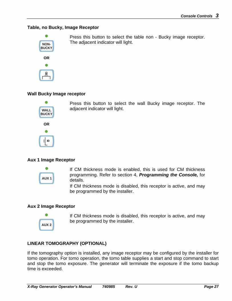
Table, no Bucky, Image Receptor
NON-BUCKY
OR
Press this button to select the table non - Bucky image receptor. The adjacent indicator will light.
Wall Bucky Image receptor
WALLBUCKY
OR
Press this button to select the wall Bucky image receptor. The adjacent indicator will light.
Aux 1 Image Receptor
AUX 1
If CM thickness mode is enabled, this is used for CM thickness programming. Refer to section 4, Programming the Console, for details. If CM thickness mode is disabled, this receptor is active, and may be programmed by the installer.
Aux 2 Image Receptor
AUX 2
If CM thickness mode is disabled, this receptor is active, and may be programmed by the installer.
LINEAR TOMOGRAPHY (OPTIONAL) If the tomography option is installed, any image receptor may be configured by the installer for tomo operation. For tomo operation, the tomo table supplies a start and stop command to start and stop the tomo exposure. The generator will terminate the exposure if the tomo backup time is exceeded.
3 Console Controls
Page 28 X-Ray Generator Operator’s Manual 740985 Rev. U
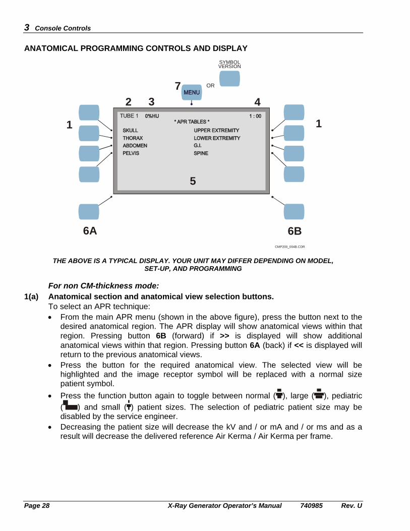
ANATOMICAL PROGRAMMING CONTROLS AND DISPLAY
CMP200_004B.CDR
OR
SYMBOLVERSION
1 1
2 3 4
5
6A 6B
7
THE ABOVE IS A TYPICAL DISPLAY. YOUR UNIT MAY DIFFER DEPENDING ON MODEL, SET-UP, AND PROGRAMMING
For non CM-thickness mode:
1(a) Anatomical section and anatomical view selection buttons. To select an APR technique: • From the main APR menu (shown in the above figure), press the button next to the
desired anatomical region. The APR display will show anatomical views within that region. Pressing button 6B (forward) if >> is displayed will show additional anatomical views within that region. Pressing button 6A (back) if << is displayed will return to the previous anatomical views.
• Press the button for the required anatomical view. The selected view will be highlighted and the image receptor symbol will be replaced with a normal size patient symbol.
• Press the function button again to toggle between normal ( ), large ( ), pediatric ( ) and small ( ) patient sizes. The selection of pediatric patient size may be disabled by the service engineer.
• Decreasing the patient size will decrease the kV and / or mA and / or ms and as a result will decrease the delivered reference Air Kerma / Air Kerma per frame.

Console Controls 3
X-Ray Generator Operator’s Manual 740985 Rev. U Page 29
• The LCD display will show the programmed X-ray technique factors. • You may override the programmed techniques by pressing the appropriate selection
button (the ability to override the AEC / mAs / mA/ms function may be disabled in programming). When any of the default techniques have been changed, the highlight will be replaced with a rectangular outline around the anatomical view. Simply overriding the programmed parameters will not change the programmed parameters. To make permanent changes to the APR, see CHAPTER 4: PROGRAMMING THE CONSOLE.
For CM thickness mode:
1(b) Anatomical section and anatomical view selection buttons. NOTE: CM thickness mode is only available if it has been enabled in programming.
This must be done by your service representative. CM thickness with AEC is only available on image receptors that are
programmed for “variable mAs” AEC backup. CM thickness (mAs) is available with all AEC backup configurations.
CM thickness is only available when an anatomical view is selected. If an anatomical view has not been selected, the technique selector button selects mA/ms-mAs-AEC in non CM-thickness mode. When an anatomical view has been selected, the technique selector button selects mA/ms-mAs-AEC in a combination of CM thickness and non CM-thickness modes as depicted below.
To select an APR technique: • From the main APR menu (shown in the figure on the previous page), press the
button next to the desired anatomical region. The APR display will show anatomical views within that region. Pressing button 6B (forward) if >> is displayed will show additional anatomical views within that region. Pressing button 6A (back) if << is displayed will return to the previous anatomical views.

3 Console Controls
Page 30 X-Ray Generator Operator’s Manual 740985 Rev. U
• Press the button for the required anatomical view. The selected view will be highlighted and the image receptor symbol will be replaced with a normal size patient symbol. The patient size cannot be changed in CM thickness mode.
• The LCD display will show the programmed X-ray technique factors. • The mid value of the programmed CM range will initially be displayed. Pressing + or
- will scroll through the available CM range for that anatomical view. • The kV and / or mAs is varied automatically as the CM is changed. • Decreasing the CM thickness will decrease the kV and / or mAs and as a result will
decrease the delivered reference Air Kerma / Air Kerma per frame. • You may override the programmed techniques by pressing the appropriate selection
button (the ability to override the AEC / mAs / mA/ms function may be disabled in programming). When any of the default techniques have been changed, the highlight will be replaced with a rectangular outline around the anatomical view. Simply overriding the programmed parameters will not change the programmed parameters. To make permanent changes to the APR, see CHAPTER 4: PROGRAMMING THE CONSOLE.
2. Tube 1 display.
This indicator will display TUBE 1 at all times. 3. Anode heat indicator (%HU) readout.
Indicates the tube anode heat for the selected X-ray tube. An anode heat-warning message will be displayed at an installer-programmable level, typically 80 % of the maximum tube H.U. rating. Exposures that will exceed a value of typically 90 % of the tube H.U. rating will be inhibited (this is also installer programmable).
4. Time readout - 24 hour mode.
The current time is displayed in 24 hour format. 5. Status and operator message display area.
This area shows status, warning, and error messages. 6. Back (<<) and forward (>>) selection buttons 6A and 6B.
Press button 6A (BACK) and button 6B (FORWARD) to scroll forward or backward through the display. The symbols << or >> will be displayed when these buttons are active.
7. MENU button.
• Press the MENU button to return to the main menu when in one of the APR submenus. RESET will be displayed below the MENU button when this is active.
• Pressing this button will clear error messages.
NOTE: THE FACTORY-DEFAULT X-RAY TECHNIQUE FACTORS MUST BE CONFIRMED AS BEING SUITABLE FOR THE APPLICATION. THESE SHOULD BE EDITED AS REQUIRED, WITH THE UPDATED TECHNIQUE FACTORS SAVED AS PER CHAPTER 4.

Console Controls 3
X-Ray Generator Operator’s Manual 740985 Rev. U Page 31
DAP - DOSE AREA PRODUCT (OPTIONAL) The DAP function is only available if the optional DAP device is installed in the X-ray system, and if the DAP function has been enabled in programming. DAP Overview
• The DAP device requires a brief “settling” period after the generator is switched on.
The console will display the start-up screen during the DAP settling period. If the DAP does not stabilize within the normal settling time, the console will display the message DAP NOT READY, and will then proceed to the normal operating mode without the DAP display. If this happens, it indicates that the DAP did not stabilize in the normal time. You may wish to switch the generator off and then on again in an attempt to let the DAP stabilize. If the DAP is still not ready after a second attempt, you may choose to proceed without DAP and then contact your service representative.
• The DAP display is reset to zero when the generator is switched off and then on
again.
Note: A reading of 0mGycm2 or 0.0μGym2 (standard resolution DAP) or 0.0mGycm2 or 0.00μGym2 (high-resolution DAP) indicates that the DAP display has been reset at power-on or manually reset as described later in this section, and that no exposures have been taken since it was reset. Further information regarding standard resolution DAP vs. high-resolution DAP is in this section.
Note: Always check local regulations to determine how frequently the DAP device must be tested. The procedure to test the DAP follows later in this section.
DAP Display • Before proceeding with initial Dose-Area Product measurements, ensure that the
DAP display is zero (0mGycm2 / 0.0μGym2 / 0.0mGycm2 / 0.00μGym2). The DAP display may be manually reset to zero as described in DAP Reset / Test / Print, following.
• The DAP measures and displays cumulative Dose-Area Product. • The maximum reading on the DAP display for each of the DAP modes is shown in
the table on the next page.

3 Console Controls
Page 32 X-Ray Generator Operator’s Manual 740985 Rev. U
Standard Resolution DAP vs. High Resolution DAP This X-ray generator supports standard resolution DAP chambers and high-resolution DAP chambers. High-resolution DAP chambers provide an increase in resolution by a factor of 10 vs. standard resolution DAP chambers. Additionally, the installer or service engineer may program the generator to display DAP in units of mGycm2 or μGym2 (0.1 μGym2 = 1 mGycm2). If the generator is programmed to display DAP in units of mGycm2.
Installed DAP chamber type DAP display * Standard resolution 0 mGycm2 / 1234567 mGycm2.
The maximum reading on the DAP display is 9999999 mGycm2.
High resolution 0.0 mGycm2 / 123456.7 mGycm2 for DAP values below 999999.9 mGycm2, 1234567 mGycm2 for vales above 999999.9 mGycm2. The maximum reading on the DAP display is 9999999 mGycm2.
If the generator is programmed to display DAP in units of μGym2.
Installed DAP chamber type DAP display * Standard resolution 0.0 μGym2 / 123456.7 μGym2.
The maximum reading on the DAP display is 999999.9 μGym2.
High resolution 0.00 μGym2 / 123456.78 μGym2. The maximum reading on the DAP display is 999999.99 μGym2.
* The table above shows the format of the DAP display for the four conditions noted. The examples show the DAP display when it is zeroed, the display format when actual data is displayed and the maximum value that can be displayed.

Console Controls 3
X-Ray Generator Operator’s Manual 740985 Rev. U Page 33
DAP Reset / Test / Print The DAP display may be reset to zero, a manual DAP functional test may be performed when desired, and a label may be printed with the DAP and patient information as described below. The PRINT option is only available if it has been enabled in programming. 1. Press the MENU button when DAP is displayed at the top center of the LCD screen
at the main APR menus. The DAP reset / test / print menu will open. • Press RESET to reset the DAP display to zero. The DAP display will reset. • Press TEST to test the DAP. The message “O.K.” will be displayed if the DAP
has passed its test. • Press PRINT to print the DAP label. Printing…..will briefly be displayed at the
bottom of the screen while data is being sent to the printer. The printer will print the date and time near the top of the label, and the accumulated Dose-Area Product (mGycm2 or μGym2) near the middle of the label. This information is retrieved from the generator at the time the label is printed. Several headings are printed on the labels; the corresponding information may be written in the adjacent spaces using indelible ink:
NAME: Enter the patient’s name. M / F: Check (Male or Female). BORN: Date of Birth. Use the format shown (d / m / y). I.D. #: Enter the patient’s and / or operator’s identification number. TECH: Enter techniques as appropriate for the record.
• Press EXIT to exit the DAP reset / test / print menu when finished.
NOTE: THE X-RAY GENERATOR MUST BE CONFIGURED FOR THE SPECIFIC PRINTER BY THE INSTALLER OR SERVICE ENGINEER (SEIKO INSTRUMENTS DPU-414 OR SLP-200 PRINTER). THE GENERATOR WILL BE COMPATIBLE ONLY WITH THE SELECTED PRINTER, THEREFORE ONLY THAT PRINTER MODEL MUST BE USED IN THIS INSTALLATION.
NOTE: THE PAPER OR LABELS USED IN THE PRINTER MUST MEET ALL APPLICABLE REGULATIONS. MEDICAL GRADE PAPER OR LABELS, APPROVED FOR MEDICAL RECORDS, MUST NORMALLY BE USED.
Refer to the printer manual for the printer operating instructions, paper feeding, printer troubleshooting, and related information. During the console start-up routine, after the generator has been switched on, the paper in the printer is automatically positioned by the RESET PRINTER function

3 Console Controls
Page 34 X-Ray Generator Operator’s Manual 740985 Rev. U
(This page intentionally left blank)

X-Ray Generator Operator’s Manual 740985 Rev. U Page 35
PROGRAMMING THE CONSOLE 4 RUNNING THE APR VALIDATOR AND MISCELLANEOUS PROGRAMMING FUNCTIONS The programming mode provides access to the following functions: • Allows the current APR settings to be edited. • Provides access to the Utility menu. • Allows the APR editor to be enabled or disabled. • Provides access to the APR validator function. ENTERING INTO PROGRAMMING MODE 1. Start with the generator switched OFF.
2. Press and hold the MENU button while pressing the power ON or button on the operator console. The MENU button must be pressed until the console beeps.
3. When the console finishes its power-on sequence and the ENTER PASSWORD prompt is displayed, press the MENU button 4 times to access the following menu:
* GENERATOR SETUP * UTILITY APR EDITOR: DISABLED VALIDATE APR EXIT SETUP
4 Programming the Console
Page 36 X-Ray Generator Operator’s Manual 740985 Rev. U
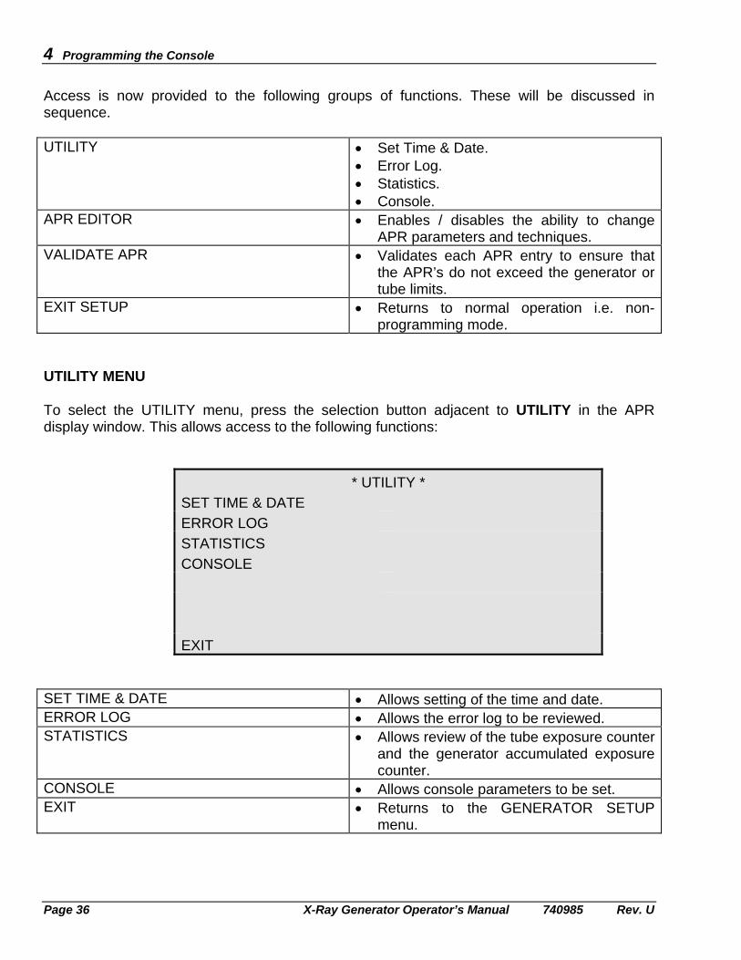
Access is now provided to the following groups of functions. These will be discussed in sequence. UTILITY • Set Time & Date.
• Error Log. • Statistics. • Console.
APR EDITOR • Enables / disables the ability to change APR parameters and techniques.
VALIDATE APR • Validates each APR entry to ensure that the APR’s do not exceed the generator or tube limits.
EXIT SETUP • Returns to normal operation i.e. non-programming mode.
UTILITY MENU To select the UTILITY menu, press the selection button adjacent to UTILITY in the APR display window. This allows access to the following functions:
* UTILITY * SET TIME & DATE
ERROR LOG
STATISTICS
CONSOLE
EXIT SET TIME & DATE • Allows setting of the time and date. ERROR LOG • Allows the error log to be reviewed. STATISTICS • Allows review of the tube exposure counter
and the generator accumulated exposure counter.
CONSOLE • Allows console parameters to be set. EXIT • Returns to the GENERATOR SETUP
menu.

Programming the Console 4
X-Ray Generator Operator’s Manual 740985 Rev. U Page 37
Set Time and Date
* SET TIME & DATE * YEAR: 2002 HOUR: 1MONTH: 1 MIN: 35DAY: 1 + - EXIT
Use these steps to set the time and date.
1. From the UTILITY menu, select SET TIME & DATE. 2. Select the parameter to change by pressing the associated button. Press the buttons next
to the + or - symbols on the LCD display to set the desired value. Time is set in 24 hour format.
3. Select EXIT to return to the UTILITY menu. Error Log
* ERROR LOG * ERROR # 10 OF 100 DATE: 09-12-2001 TIME: 13:09ERROR CODE: 30 +ERROR MESSAGE: ROTOR FAULT -
kVp: 80 mA: 12.5 ms: 500 EXIT
Use these steps to view the error log.
1. From the UTILITY menu select ERROR LOG. 2. Select ERROR # and press the + or - buttons to scroll through the error log. The error
code, error message, date and time of the error, and exposure factors will be displayed in the APR display window, while control settings will be indicated via the appropriate indicator LEDs on the console.
3. Select EXIT to return to the UTILITY menu.

4 Programming the Console
Page 38 X-Ray Generator Operator’s Manual 740985 Rev. U
Statistics
* STATISTICS * TUBE 1 EXP: 0 TOTAL EXP: 0 EXIT
The statistics menu shows the X-ray tube exposure count, and the accumulated generator exposure count.
1. From the UTILITY menu select STATISTICS. 2. The statistics (the number of exposures on the X-ray tube, and the total generator
exposures) may now be viewed.
3. Select EXIT to return to the UTILITY menu. Console
* CONSOLE CONFIG* SLOW KEY REPEAT: 200MS LCD SCREEN MED. KEY REPEAT: 150MS APR MODE: NO FAST KEY REPEAT: 75MS + SPEAKER VOLUME: 15 - EXIT
The CONSOLE CONFIG menu displays console parameters that may be changed to suit operator preferences.
1. From the UTILITY menu select CONSOLE. 2. Select SLOW KEY REPEAT. Press the buttons next to the + or - symbols on the LCD
display to set the speed at which the displays change for the first 5 counts while a button is pressed.

Programming the Console 4
X-Ray Generator Operator’s Manual 740985 Rev. U Page 39
3. Select MED. KEY REPEAT. Press the + or - button to select the speed at which displays change while the button is pressed for the next 5 counts.
4. Select FAST KEY REPEAT. Press the + or - button to select the speed at which displays change while the button is pressed after 10 counts.
5. Select SPEAKER VOLUME. Press the + or - button to set the speaker volume in the range 1 to 15.
6. Select LCD SCREEN. Press button to toggle between normal and reverse display for the LCD display screen.
7. Select APR MODE. Press the selection button to toggle between NO and YES. Selecting YES disallows changes to the AEC / mAs / mA/ms selections when in normal operating mode. If manual technique changes are disabled via this utility, AEC / mAs / mA/ms changes can only be made by selecting an APR technique that has been programmed to the desired technique. APR MODE must be set to NO to allow switching between AEC / mAs / mA/ms in normal operating mode.
8. Select EXIT to return to the UTILITY menu.
9. Select EXIT again to return to the GENERATOR SETUP menu. APR EDITOR / EDITING THE APR The APR editor must be set to ENABLED in order to change the default APR techniques.
* GENERATOR SETUP * UTILITY APR EDITOR: ENABLED VALIDATE APR EXIT SETUP
Use these steps to edit the programmed APR techniques.
NOTE: BEFORE MAKING CHANGES TO THE DEFAULT APR TECHNIQUES, PLEASE RECORD ALL CURRENT DEFAULTS. THESE DEFAULTS MAY BE RECORDED IN COPIES OF THE APR PROGRAMMING WORKSHEET AT THE END OF THIS CHAPTER. 1. From the GENERATOR SETUP menu select APR EDITOR.

4 Programming the Console
Page 40 X-Ray Generator Operator’s Manual 740985 Rev. U
2. Press the APR EDITOR button to toggle between ENABLED and DISABLED: • The APR editor must be set to ENABLED in order to change and then save the
changed APR techniques. The APR will then default to the newly saved techniques. • Setting the APR editor to DISABLED does not allow editing and then saving the
changed APR technique(s). The generator stores the last APR editor setting (ENABLED or DISABLED) prior to being switched OFF. If the APR editor was previously ENABLED, APR changes may subsequently be made and then saved in normal operating mode without the need to manually set the APR editor to ENABLED. To disable this feature, the APR editor must be set to DISABLED.
3. Return to normal operation by pressing EXIT SETUP.
4. The following menu will be displayed. This is a typical menu which may vary in some details depending on generator type, APR programming and setup.
TUBE1 0%HU 1:00
*APR TABLES* SKULL UPPER EXTREMITY THORAX LOWER EXTREMITY ABDOMEN SPINE PELVIS SPECIAL PROCEDURES 2 mAs
kVp: 70 mA: 100 ms: 20
5. Perform the APR technique change(s) as described below:
a) Select the desired anatomical region to be edited; for example SKULL.
b) Select the desired anatomical view to edit, for example SKULL AP/PA. The selection will be highlighted and the default patient size will be shown.
c) Select the patient size to edit within the selected view, for example “normal”. The patient size is changed by pressing the APR selection button to toggle through the normal ( ), large ( ), pediatric ( ) and small ( ) patient sizes. Note that the selection of pediatric patient size may disabled by the service engineer.
All techniques with the exception of kV and mA/ms or mAs will be common to all patient sizes. The common techniques for all patient sizes within the selected view should be programmed first, then the desired kV and mA/ms or mAs should be programmed for the selected patient size. After these techniques are saved per the remainder of this section, kV and mA/ms or mAs may be programmed for the remaining patient sizes in the same anatomical view.

Programming the Console 4
X-Ray Generator Operator’s Manual 740985 Rev. U Page 41
6. The default selections are shown on the console, for example: Receptor 1, 70 kV, 100 mA, 20 ms, technique = mA/ms, large focus. 10. Change the settings and technique(s) to the desired value(s). Parameters that may be
edited are kV, mA/mAs, ms, technique select (AEC / mAs / mA/ms), focus, image receptor plus density, AEC field selection and film screen in AEC mode.
The anatomical view being edited will be highlighted with a rectangular outline as soon as any parameter is changed within the current view. Also the word SAVE will appear in the display window below the MENU button.
11. Continue making all desired APR changes within the currently selected view.
12. When finished, press SAVE. This is the first step necessary to save the changes. This also allows the option of canceling the changes in the next step.
13. If you do not want to save the changes, select EXIT (BACK button) to abort the SAVE function. To save the changes, select SAVE (FORWARD button). The message SAVING DATA... will briefly appear.
14. Press the MENU button to return to the main APR screen. 15. You may now make changes to the remaining patient sizes within the same anatomical
view or reprogram other anatomical views by repeating steps 5 to 14. Remember that all settings will be common to all patient sizes within the same anatomical view except for kV, mA/ms and mAs.
16. It is suggested that the APR editor be set to DISABLED as described earlier in this section in order to avoid unintended APR changes in the future.

4 Programming the Console
Page 42 X-Ray Generator Operator’s Manual 740985 Rev. U
PROGRAMMING CM THICKNESS 1. Follow steps 1 to 3 of the previous section (APR EDITOR). 2. Select the desired APR to edit. 3. Select a CM thickness (mAs) or CM thickness (AEC) mode. Select the desired image
receptor, film screen, focal spot, and AEC fields (if applicable) for the selected anatomical view.
4. The AUX 1 button is used for CM thickness programming. In programming mode (with the APR EDITOR set to ENABLED), pressing AUX 1 scrolls through CM START → CM STEP → CM as required to program these parameters.
CM START The minimum CM for the selected technique (CM START range is 1 to 14). To program, refer to step 5.
CM STEP The step size used to establish the CM vs kVp and mAs curve. The CM STEP range is 1 to 5. To program, refer to step 5.
CM The steps on the CM vs kV and mAs curve. To program, refer to step 5.
5. (a) Determine the minimum and maximum thickness in cm for the selected anatomical
view. Thickness outside of this range cannot be selected later in normal operating mode, therefore these dimensions should be chosen carefully.
(b) Determine the cm step size by the following formula: CM Step Size = 8
Maximum thickness (cm) - Minimum thickness (cm)
The calculated step size must be rounded up to the nearest integer, i.e. 1.66 rounds up to a step size of 2.
(c) Select CM START, then enter the minimum thickness determined in step (a).
(d) Select CM STEP, then enter the cm step size calculated in step (b), maximum step size = 5.
(e) Select CM. Press the CM - and + buttons to confirm that the minimum and maximum thickness limits are acceptable. Repeat the above steps if necessary to optimize the minimum and maximum thickness limits. Set CM to minimum thickness before attempting to toggle back to CM START, or else an error message GOTO 1st CM will be presented.
1. (f) Press CM - to select the minimum thickness. Set the kV and mAs or kV and backup mAs as appropriate for the selected thickness. (In CM thickness (mAs) mode, kV and mAs may be programmed; in CM thickness (AEC) mode, kV and backup mAs may be programmed).
Refer to Programming the mAs / backup mAs, below for the recommended procedure to set this parameter.

Programming the Console 4
X-Ray Generator Operator’s Manual 740985 Rev. U Page 43
(g) Press CM + to select the next thickness step. Set the kVp and mAs / backup mAs for that thickness as per 5 (f). Nine (9) thickness steps are available, with the step size as previously set. The desired kV and mAs / backup mAs may be set for each of those 9 thickness steps. In the normal operating mode, the thickness steps will be 1 cm, regardless of the step size set in APR edit mode. The console will interpolate between the step sizes set up in APR edit mode to determine the correct kV and mAs / backup mAs for each 1 cm thickness step in normal operating mode.
(h) Repeat 5 (g) for the remaining CM steps.
6. When finished editing the APR, press the MENU button. This is the first step necessary to save the changes. This also allows the option of canceling the changes in the next step.
7. If you do not wish to save the changes, select EXIT (BACK button) to abort the SAVE function. To save the changes, select SAVE (FORWARD button). The message SAVING DATA... will briefly appear.
8. Repeat this procedure to edit other anatomical views.
9. Set the APR EDITOR to DISABLED to return to normal operating mode and prevent inadvertent programming changes.

4 Programming the Console
Page 44 X-Ray Generator Operator’s Manual 740985 Rev. U
Programming the mAs / backup mAs 1. When programming the mAs (for CM-thickness, mAs mode), or the backup mAs (for CM-
thickness, AEC mode), use the proper mAs (that will produce the correct non-AEC exposure) for each CM thickness step. This will ensure proper CM-thickness programming:
• In CM-thickness (mAs mode), the correct mAs will be assigned to each CM thickness step.
• In CM-thickness (AEC mode), the backup mAs will be nominally two times the programmed mAs, i.e. if 11 mAs is programmed for a certain CM thickness, the backup mAs will be nominally 22 mAs. This “doubling” of the programmed mAs to arrive at the backup mAs is done automatically by the generator when in CM-thickness, AEC mode.
2. The mAs values that are entered during CM-thickness programming are saved in memory after performing the SAVE function as described above.
• If you are in CM-thickness (AEC mode), and the CM - or + buttons are pressed to review the programmed mAs values, the mAs display will update to show the “two times” backup mAs.
• If you are in CM-thickness (AEC mode), and then select CM-thickness (mAs mode) via the technique selector button, the “two times” backup mAs value will be displayed for that CM thickness. Press the CM - or + buttons to update the display and use the normal mAs, not the doubled backup mAs that was carried forward.
• If you are in CM-thickness (mAs mode), and then select CM-thickness (AEC mode) via the technique selector button, the normal mAs value will be displayed for that CM thickness. Press the CM - or + buttons to update the display and use the “two times” backup mAs, not the normal mAs that was carried forward.
MAKING CHANGES TO THE APR TEXT
The anatomical sections and views as displayed in the APR window may be altered to suit your requirements, but you will need to contact your service representative to have this done. Use copies of the worksheet on the next page to record your desired changes. One sheet should be used per APR view; the master copy should be photocopied as many times as necessary to record the required changes.

Programming the Console 4
X-Ray Generator Operator’s Manual 740985 Rev. U Page 45
VALIDATE APR
The APR validator checks each APR entry to confirm that none of the requested parameters exceed the generator limits. The APR validator will also check that the requested functions(s) within each APR are enabled. Invalid APR’s may result due to GenWare® downloads - as APR’s are not validated within GenWare® - or previously valid APR’s may become invalid if generator limits or setup parameters are subsequently changed. Invalid parameters and techniques may be corrected after the APR validator has completed its validation checks.
NOTE: The APR validator is not available if CM thickness mode is enabled. If the APR validator is selected with CM thickness mode turned on, a message will be displayed indicating that CM thickness mode is currently not supported by the APR validator.
1. From the GENERATOR SETUP menu select VALIDATE APR. This accesses the main
APR VALIDATOR screen, shown below.
2. Pressing EXIT at any time that this button is available will return to the GENERATOR SETUP menu.
P: 0% T: F:
*APR VALIDATOR*
EXIT START
3. Press START to start the APR validator. The APR validation process will start.
While the APR validator is running: • The name of each anatomical view being validated and the associated patient size will
flash at the bottom of the APR validator screen along with its programmed parameters and techniques.
• The console LED’s will light to indicate which image receptors and techniques are associated with the APR that is currently being validated.
• Failed APR’s will be listed near the top of the APR validator screen. A maximum of four failed APR’s will be displayed at one time.

4 Programming the Console
Page 46 X-Ray Generator Operator’s Manual 740985 Rev. U
4. Pressing STOP while the APR validator is running will stop the APR validation.
5. While the APR validator is running or after it is finished or was stopped: • P indicates percent completion. This will continuously update while the APR validator
is running. The APR validation is finished when this indicates 100%. If the APR validator is stopped before it has finished, this will display the percent completion at the time the APR validator was stopped.
• T shows the number of APR’s that have been validated. This will continuously update while the APR validator is running. If the APR validator is stopped before it has finished, this will display the number of APR’s that were validated at the time the APR validator was stopped.
• F shows the number of APR’s that failed. This will continuously update while the APR validator is running. If the APR validator is stopped before it has finished, this will display the number of APR’s that failed at the time the APR validator was stopped.
When the APR validator has finished running
P: 100% T: 376 F: 46 [ 0 – 46 ] *APR VALIDATOR*
HIP LATERAL 202 GEN. KW LIMIT
HIP LATERAL 202 GEN. KW LIMIT
VIEW #1 49 NOT ENABLED
VIEW #2 49 NOT ENABLED 17 mAs
kVp: 77 mAs: 5.6 EXIT
6. The view above shows the APR validator screen when the APR validator has finished
running. • The percent completion is shown as 100%. • 376 APR’s have been validated. • 46 APR’s have failed.
7. The console will first validate all APR’s that use the large focus (receptor 1), then small focus (receptor 1). Next will be large focus (receptor 2), then small focus (receptor 2), etc until all APR’s associated with all image receptors are exhausted.

Programming the Console 4
X-Ray Generator Operator’s Manual 740985 Rev. U Page 47
8. The display at the top right of the LCD display (0 – 46 in the example) denotes the following: • The first number (0) indicates the number of APR items above the visible list on the
current display. In the example above there are 0 items above the visible list, meaning that the list of failed APR’s is at the top of the page.
• The second number (46) refers to the number of failed APR’s that are below the top of the page. In the example above 46 items are below the top of the list. Four failed APR’s are shown, therefore there are another 42 listings that are not shown. Scrolling up or down as described in the next step will show the failed APR’s that are not displayed in the current list.
9. To scroll up and down the list of failed APR’s, if there are more than four items listed: • To scroll up in the list, press the soft key button [7]. • To scroll down in the list, press the soft key button [8]. Refer to the figure below for the location of the referenced buttons.
CMP200_0027.CDR
78
1234
10. To edit a failed APR: • Select the APR to be edited using the adjacent soft key button [1] to [4] as per the
figure above. The selected APR will be highlighted in PREVIEW MODE as per the figure below.
• The parameters and techniques that are currently requested by the selected APR will be shown (63 kV, 320 mA, 1280 mAs, 100 ms in the example below). The anatomical region that is the parent of the selected anatomical view is displayed at the top left of the LCD display.
• Select EDIT to edit the selected APR. The EDIT button that allows failed APR’s to be edited will only be available if the APR EDITOR has been set to ENABLED. The APR editor is enabled via the GENERATOR SETUP menu.

4 Programming the Console
Page 48 X-Ray Generator Operator’s Manual 740985 Rev. U
To edit a failed APR
UPPER EXT EDIT [ 0 – 46 ] *APR VALIDATOR*
HIP LATERAL 202 GEN. KW LIMIT
VIEW #1 49 NOT ENABLED
VIEW #2 49 NOT ENABLED 100 ms kVp: 63 mA: 320 mAs: 1280
EXIT PREVIEW MODE 11. In EDIT mode (the console will be in EDIT mode after the EDIT button is pressed).
• The console will attempt to change the value(s) that caused the APR validation to fail. For example, if the generator is set to maximum mA = 200 mA and the selected APR is requesting 360 mA, the console will then reduce the maximum mA to under 200 mA.
• Another example of a failed APR is an anatomical view that is programmed for AEC. If the APR is programmed to select an image receptor does not allow AEC operation, then the APR validator will display the error message 49 NOT ENABLED. In this case, service personnel must reprogram the generator to allow AEC operation on the selected receptor.
• Select SAVE if the revised parameters and techniques are acceptable. The message SAVING APR DATA… will be briefly displayed. Do not turn the power off while the data is being saved, as doing so will corrupt the entire APR database.
• APR’s that have been fixed will be removed from the list of failed APR’s. • The console will validate the remaining patient sizes within the same anatomical view
after each save. These will also be removed from the list of failed APR’s if applicable. • To exit the EDIT mode without making any changes, press one of the soft key buttons
[1] to [4] that is associated with a failed APR. 12. Repeat steps 10 and 11 to edit the remaining APR’s.

Programming the Console 4
X-Ray Generator Operator’s Manual 740985 Rev. U Page 49
APR PROGRAMMING WORKSHEET (THIS IS A MASTER, MAKE WORKING COPIES AS NEEDED)
kV Table Bucky Receptor
Tech Select
Patient Size Small
Focus
FieldSelect
Non Bucky Receptor
mAs
Medium
Wall Bucky Receptor
Aux 1
Aux 2
mA/ms
Large
Film Screen
mA/mAs
ms
DENSITY
__________________
__________________
__________________
__________________
__________________
__________________
__________________
__________________
__________________
__________________
__________________
__________________
__________________
__________________
__________________
__________________
MENU 1APR TABLESMAX 16 CHARACTERS
MENU 2ANATOMICAL VIEWMAX 16 CHARACTERS
AEC Small
Large
CMP200_005B.CDR

4 Programming the Console
Page 50 X-Ray Generator Operator’s Manual 740985 Rev. U
(This page intentionally left blank)

X-Ray Generator Operator’s Manual 740985 Rev. U Page 51
ERROR CODES AND MESSAGES 5 The generator console will display status messages on the APR display during normal and abnormal operation of the generator. This chapter contains tables of those messages and suggests actions to be taken should any malfunctions occur. Messages may be cleared by pressing the MENU button. Operator Messages
These messages indicate the status of the generator. No action is required.
MESSAGE DESCRIPTION INITIALIZATION Displayed during power up sequence. SPINNING ROTOR Displayed when prep state is active. X-RAY READY Displayed when generator is ready to expose X-RAY ON Displayed during an X-ray exposure. DAP NOT READY The optional DAP is in its “warm up” state, and not ready to make DAP
measurements. Limit Messages
These messages indicate that an exposure has been requested that exceeds one or more limits.
MESSAGE PROBLEM ACTION AEC DENSITY LIM. Requested density not programmed. Select another
density or request those steps be programmed. Consult your service representative for this.
ANODE HEAT WARN. Anode has exceeded programmed warning level.
Wait for anode to cool.
CAL LIMIT Requested parameter not calibrated. Consult your service representative.
GEN DUTY WARNING The X-ray generator has reached its duty warning limit.
Re-evaluate technique factors. Further exposures will be inhibited. The generator must be allowed to cool sufficiently.

5 Error Codes and Messages
Page 52 X-Ray Generator Operator’s Manual 740985 Rev. U
MESSAGE PROBLEM ACTION
GEN. JOULE LIMIT The requested exposure will exceed the generators kilo joule heat limit.
Allow the generator to cool sufficiently to allow the requested exposure.
GEN. KV LIMIT Requested kV not allowed as generator kV limit has been reached.
None.
GEN. KW LIMIT Requested parameter not allowed as generator kW limit has been reached.
None.
GEN. MA LIMIT Requested mA not allowed as generator mA limit has been reached.
None.
GEN. MAS LIMIT Requested mAs not allowed as generator mAs limit has been reached.
None.
GEN. MS LIMIT 1. Requested ms not allowed as generator ms limit has been reached.
2. Maximum ms reached at requested power. Reduce mA or kV.
None.
GOTO 1st CM Displayed if attempting to exit CM if the CM setting is not at minimum.
Set CM to minimum value before continuing.
HOUSE HEAT WARN. Tube housing has exceeded housing warning level.
Wait for housing to cool.
INVALID PARAM. Generator detected invalid parameter within received message, message ignored.
Select valid parameter.
LABEL JAMMED The labels are jammed. Clear the paper jam. OUT OF LABELS The printer is out of labels. Load more labels. PLATEN OPEN The paper platen is not positioned
properly. Check the platen position.
PRINTER COMM ERROR The printer has reported a communication error.
Try printing again.
PRINTER ERROR The printer self-diagnostics have reported a printer problem.
Refer to the printer manual.
PRINTER OFF-LINE The printer is off-line. Put the printer on-line.
TUBE KV LIMIT Requested kV not allowed as tube kV limit has been reached.
None.
TUBE KW LIMIT Requested parameter not allowed as tube kW limit has been reached.
None.
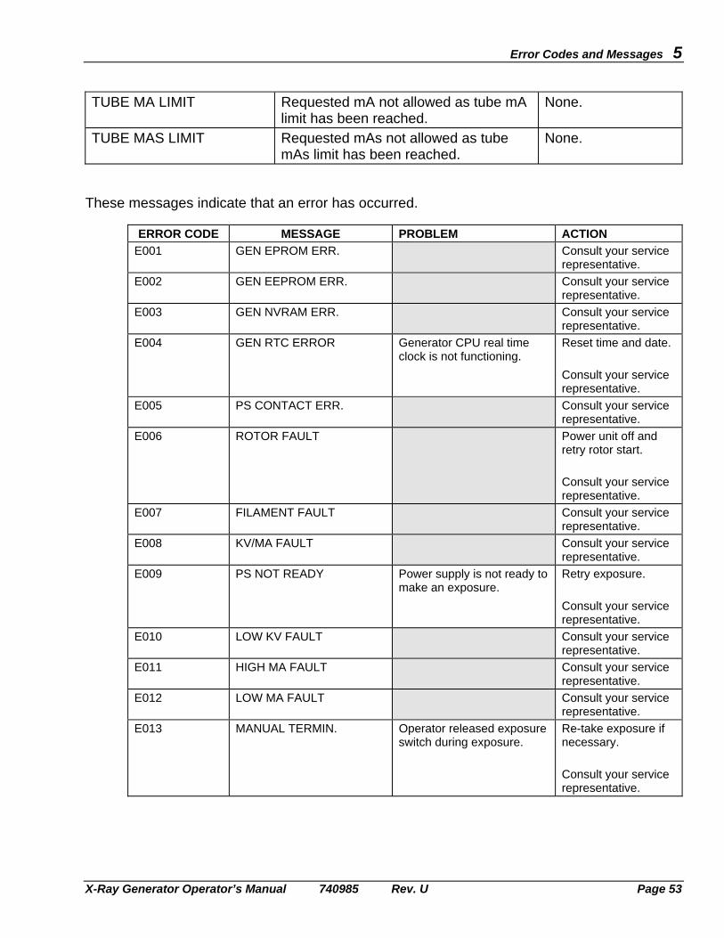
Error Codes and Messages 5
X-Ray Generator Operator’s Manual 740985 Rev. U Page 53
TUBE MA LIMIT Requested mA not allowed as tube mA
limit has been reached. None.
TUBE MAS LIMIT Requested mAs not allowed as tube mAs limit has been reached.
None.
These messages indicate that an error has occurred.
ERROR CODE MESSAGE PROBLEM ACTION E001 GEN EPROM ERR. Consult your service
representative. E002 GEN EEPROM ERR. Consult your service
representative. E003 GEN NVRAM ERR. Consult your service
representative. E004 GEN RTC ERROR Generator CPU real time
clock is not functioning. Reset time and date. Consult your service representative.
E005 PS CONTACT ERR. Consult your service representative.
E006 ROTOR FAULT Power unit off and retry rotor start. Consult your service representative.
E007 FILAMENT FAULT Consult your service representative.
E008 KV/MA FAULT Consult your service representative.
E009 PS NOT READY Power supply is not ready to make an exposure.
Retry exposure. Consult your service representative.
E010 LOW KV FAULT Consult your service representative.
E011 HIGH MA FAULT Consult your service representative.
E012 LOW MA FAULT Consult your service representative.
E013 MANUAL TERMIN. Operator released exposure switch during exposure.
Re-take exposure if necessary. Consult your service representative.

5 Error Codes and Messages
Page 54 X-Ray Generator Operator’s Manual 740985 Rev. U
ERROR CODE MESSAGE PROBLEM ACTION
E014 AEC BUT ERROR AEC exposure exceeded allowed back up time.
Check exposure technique settings. Consult your service representative.
E015 AEC BU MAS ERR. AEC exposure exceeded allowed back up mAs.
Check exposure technique settings. Consult your service representative.
E016 TOMO BUT ERROR Tomo exposure exceeded back-up time.
Check exposure technique settings.
E017 NOT CALIBRATED Consult your service representative.
E018 PREP TIMEOUT Generator has been in prep state too long.
Reduce length of time in prep state.
E019 ANODE HEAT LIMIT Selected parameters will cause X-ray tube to exceed its programmed anode heat limit.
Reduce parameters or wait for tube to cool.
E020 THERMAL INT #1 X-ray tube # 1 too hot and its thermal switch has opened.
Wait for X-ray tube # 1 to cool.
E021 THERMAL INT #2 X-ray tube # 2 too hot and its thermal switch has opened.
Wait for X-ray tube # 2 to cool.
E022 DOOR INTERLOCK Door is open. Close door. E023 COLLIMATOR ERR. Collimator is not ready. Check collimator. E024 CASSETTE ERROR Cassette is not ready. Check cassette. E026 SPARE INT. Spare input is not ready. Consult your service
representative. E028 PREP SW CLOSED Consult your service
representative. E029 XRAY SW CLOSED Consult your service
representative. E032 CONSOLE COMM ERR Generator has detected
error in communication to console.
Turn power off and then on to reset generator. Consult your service representative.
E033 GEN BATTERY LOW Consult your service representative.
E034 +12VDC ERROR Consult your service representative.
E035 -12VDC ERROR Consult your service representative.

Error Codes and Messages 5
X-Ray Generator Operator’s Manual 740985 Rev. U Page 55
ERROR CODE MESSAGE PROBLEM ACTION
E036 +15VDC ERROR Consult your service representative.
E037 -15VDC ERROR Consult your service representative.
E038 CAL DATA ERROR Consult your service representative.
E039 AEC DATA ERROR Consult your service representative.
E041 REC DATA ERROR Consult your service representative.
E042 TUBE DATA ERR. Consult your service representative..
E043 KV ERROR Switch OFF generator. Prevent further use of generator, then. consult your service representative.
E044 COMM ERROR Received communication message not valid and ignored.
Reset error.
E045 NOT SUPPORTED Received message is valid, but not supported by this system.
Reset error.
E046 MODE INHIBITED Attempting to change CM thickness in AEC mode if the receptor is not programmed for mAs backup. Received message is valid, but not allowed during present state.
Consult your service representative. Reset error.
E048 FOCUS MISMATCH Consult your service representative.
E049 NOT ENABLED Requested function has not been programmed to be enabled.
Consult your service representative.
E050 GEN DATA ERROR Consult your service representative.
E051 AEC DEVICE ERR Generator has detected no feedback signal from AEC device.
Check that X-ray tube is pointing at correct AEC device. Consult your service representative.
E052 HIGH SF CURRENT Consult your service representative.
E053 HIGH LF CURRENT Consult your service representative.

5 Error Codes and Messages
Page 56 X-Ray Generator Operator’s Manual 740985 Rev. U
ERROR CODE MESSAGE PROBLEM ACTION
E054 AEC OUT OF RANGE Consult your service representative.
E055 NO FIELDS ACTIVE AEC enabled but no fields are selected.
Select AEC field(s).
E056 NO TUBE SELECTED Consult your service representative.
E057 AEC STOP ERROR Consult your service representative.
E058 CONSOLE BUT ERR. Consult your service representative.
E059 HOUSE HEAT LIMIT X-ray tube housing has exceeded limit.
Wait for tube to cool.
E060 EXP. KV HIGH Consult your service representative.
E061 EXP. KV LOW Consult your service representative.
E062 EXP_ SW ERROR Consult your service representative.
E063 FACTORY DEFAULTS Consult your service representative.
E065 TOMO DEVICE ERR. Consult your service representative.
E067 PS DUTY LIMIT Generator duty limit reached.
Allow the generator to cool before continuing.
E069 MAS OVERTIME ERR Consult your service representative.
E070 SOFTWARE KEY ERR Consult your service representative.
E071 DAP DOSE OVERFLW The accumulated DAP value exceeds the display limit.
Reset the DAP.
E072 DAP DEVICE ERR. The DAP device is not functional.
Consult your service representative.
E073 DAP DATA ERROR Consult your service representative.
E074 INVERTER 1 ERROR Consult your service representative.
E075 INVERTER 2 ERROR Consult your service representative.
E076 INVERTER 3 ERROR Consult your service representative.
E077 RES. CIRCUIT ERR Consult your service representative.
E078 BUCKY1 INTERLOCK Consult your service representative.
E079 BUCKY2 INTERLOCK Consult your service representative.

Error Codes and Messages 5
X-Ray Generator Operator’s Manual 740985 Rev. U Page 57
ERROR CODE MESSAGE PROBLEM ACTION
E080 INTERLOCK 1 OPEN Consult your service representative.
E081 INTERLOCK 2 OPEN Consult your service representative.
E082 KV OVER VOLTAGE Consult your service representative.
E083 ANODE MA FAULT Consult your service representative.
E084 CATHODE MA FAULT Consult your service representative.
E085 ROTOR MAIN FAULT Consult your service representative.
E086 ROTOR SHFT FAULT Consult your service representative.
E150 TABLE COMM ERR A communication error has occurred with the table.
Ensure that the table is powered on. Consult your service representative.

5 Error Codes and Messages
Page 58 X-Ray Generator Operator’s Manual 740985 Rev. U
(This page intentionally left blank)

X-Ray Generator Operator’s Manual 740985 Rev. U Page 59
GENERATOR EXPOSURE 6 TABLES
Table 1 following shows the nominal mAs resulting from preselected ms and mA values. This table also shows the range and interrelation of these loading factors. For example, if 20 mAs is selected at 200 mA, it can be seen that the exposure time will be approximately 100 ms. This is determined by reading down the 200 mA column to 20 mAs; then by reading the nominal exposure time 100 ms as shown at the left side of the table, along the 20 mAs row. An extra copy of this table is provided on pages 71 to 80 that may be photocopied as required, or removed from this manual and placed in a suitable location as per local requirements.

6 Generator Exposure Tables
Page 60 X-Ray Generator Operator’s Manual 740985 Rev. U
(This page intentionally left blank)

Generator Exposure Tables 6
X-Ray Generator Operator’s Manual 740985 Rev. U Page 61
GENERATOR TECHNIQUE SELECTION (3 Point Selection: mA/ms & mAs)
Time mA Selected (ms) 10 11 12.5 14 16 18 20 22 25 28 32 36 40 45 50 56 63
1.0 1.1 1.2 1.4 1.6 0.10 1.8 0.10 0.11 2.0 0.10 0.11 0.125 2.2 0.10 0.11 0.125 0.14 2.5 0.10 0.11 0.125 0.14 0.16 2.8 0.10 0.11 0.125 0.14 0.16 0.18 3.2 0.10 0.11 0.125 0.14 0.16 0.18 0.20 3.6 0.10 0.11 0.125 0.14 0.16 0.18 0.20 0.22 4.0 0.10 0.11 0.125 0.14 0.16 0.18 0.20 0.22 0.25 4.5 0.10 0.11 0.125 0.14 0.16 0.18 0.20 0.22 0.25 0.28 5.0 0.10 0.11 0.125 0.14 0.16 0.18 0.20 0.22 0.25 0.28 0.32 5.6 0.10 0.11 0.125 0.14 0.16 0.18 0.20 0.22 0.25 0.28 0.32 0.36 6.3 0.10 0.11 0.125 0.14 0.16 0.18 0.20 0.22 0.25 0.28 0.32 0.36 0.40 7.1 0.10 0.11 0.125 0.14 0.16 0.18 0.20 0.22 0.25 0.28 0.32 0.36 0.40 0.45 8.0 0.10 0.11 0.125 0.14 0.16 0.18 0.20 0.22 0.25 0.28 0.32 0.36 0.40 0.45 0.50 9.0 0.10 0.11 0.125 0.14 0.16 0.18 0.20 0.22 0.25 0.28 0.32 0.36 0.40 0.45 0.50 0.56 10 0.10 0.11 0.125 0.14 0.16 0.18 0.20 0.22 0.25 0.28 0.32 0.36 0.40 0.45 0.50 0.56 0.63 11 0.11 0.125 0.14 0.16 0.18 0.20 0.22 0.25 0.28 0.32 0.36 0.40 0.45 0.50 0.56 0.63 0.71 12.5 0.125 0.14 0.16 0.18 0.20 0.22 0.25 0.28 0.32 0.36 0.40 0.45 0.50 0.56 0.63 0.71 0.80 14 0.14 0.16 0.18 0.20 0.22 0.25 0.28 0.32 0.36 0.40 0.45 0.50 0.56 0.63 0.71 0.80 0.90 16 0.16 0.18 0.20 0.22 0.25 0.28 0.32 0.36 0.40 0.45 0.50 0.56 0.63 0.71 0.80 0.90 1.0 18 0.18 0.20 0.22 0.25 0.28 0.32 0.36 0.40 0.45 0.50 0.56 0.63 0.71 0.80 0.90 1.0 1.1 20 0.20 0.22 0.25 0.28 0.32 0.36 0.40 0.45 0.50 0.56 0.63 0.71 0.80 0.90 1.0 1.1 1.25 22 0.22 0.25 0.28 0.32 0.36 0.40 0.45 0.50 0.56 0.63 0.71 0.80 0.90 1.0 1.1 1.25 1.4
Table 1: mAs values vs. mA & time selected Table 1 continued on next page
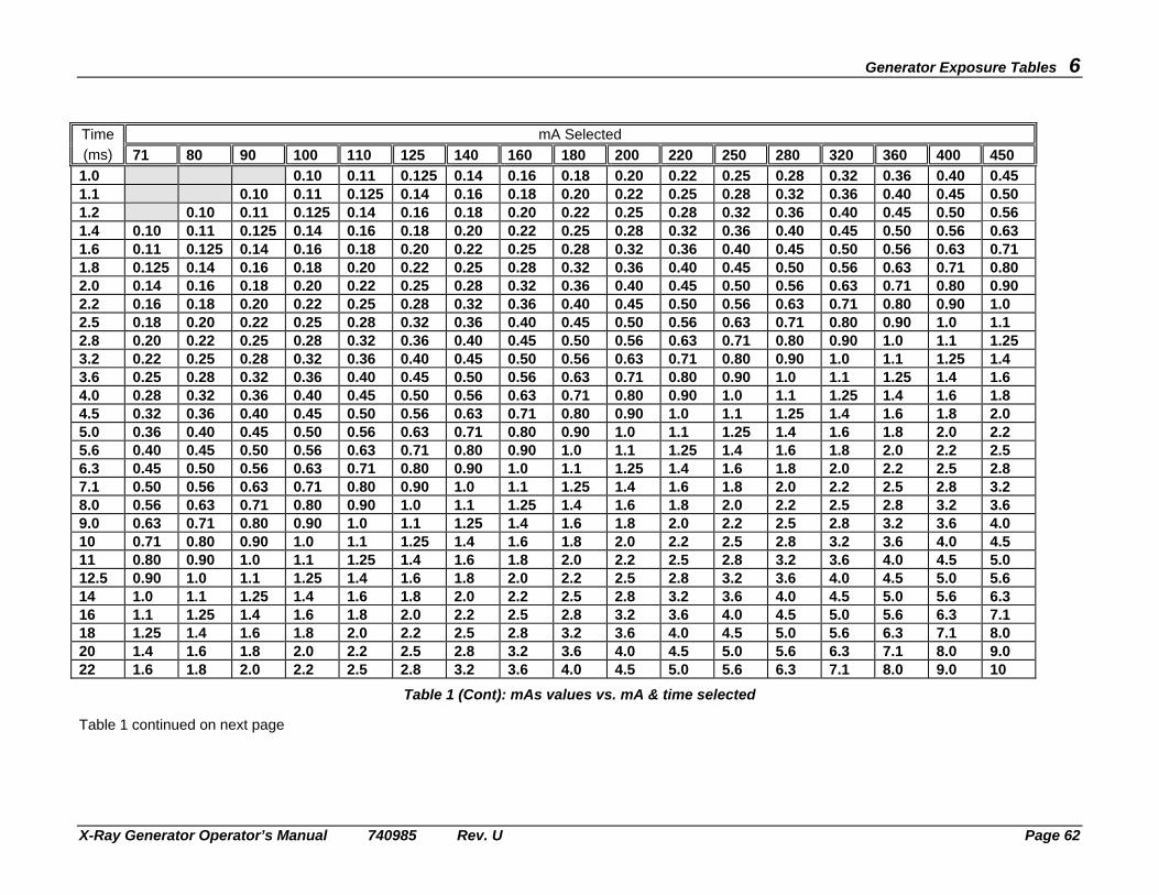
Generator Exposure Tables 6
X-Ray Generator Operator’s Manual 740985 Rev. U Page 62
Time mA Selected (ms) 71 80 90 100 110 125 140 160 180 200 220 250 280 320 360 400 450
1.0 0.10 0.11 0.125 0.14 0.16 0.18 0.20 0.22 0.25 0.28 0.32 0.36 0.40 0.45 1.1 0.10 0.11 0.125 0.14 0.16 0.18 0.20 0.22 0.25 0.28 0.32 0.36 0.40 0.45 0.50 1.2 0.10 0.11 0.125 0.14 0.16 0.18 0.20 0.22 0.25 0.28 0.32 0.36 0.40 0.45 0.50 0.56 1.4 0.10 0.11 0.125 0.14 0.16 0.18 0.20 0.22 0.25 0.28 0.32 0.36 0.40 0.45 0.50 0.56 0.63 1.6 0.11 0.125 0.14 0.16 0.18 0.20 0.22 0.25 0.28 0.32 0.36 0.40 0.45 0.50 0.56 0.63 0.71 1.8 0.125 0.14 0.16 0.18 0.20 0.22 0.25 0.28 0.32 0.36 0.40 0.45 0.50 0.56 0.63 0.71 0.80 2.0 0.14 0.16 0.18 0.20 0.22 0.25 0.28 0.32 0.36 0.40 0.45 0.50 0.56 0.63 0.71 0.80 0.90 2.2 0.16 0.18 0.20 0.22 0.25 0.28 0.32 0.36 0.40 0.45 0.50 0.56 0.63 0.71 0.80 0.90 1.0 2.5 0.18 0.20 0.22 0.25 0.28 0.32 0.36 0.40 0.45 0.50 0.56 0.63 0.71 0.80 0.90 1.0 1.1 2.8 0.20 0.22 0.25 0.28 0.32 0.36 0.40 0.45 0.50 0.56 0.63 0.71 0.80 0.90 1.0 1.1 1.25 3.2 0.22 0.25 0.28 0.32 0.36 0.40 0.45 0.50 0.56 0.63 0.71 0.80 0.90 1.0 1.1 1.25 1.4 3.6 0.25 0.28 0.32 0.36 0.40 0.45 0.50 0.56 0.63 0.71 0.80 0.90 1.0 1.1 1.25 1.4 1.6 4.0 0.28 0.32 0.36 0.40 0.45 0.50 0.56 0.63 0.71 0.80 0.90 1.0 1.1 1.25 1.4 1.6 1.8 4.5 0.32 0.36 0.40 0.45 0.50 0.56 0.63 0.71 0.80 0.90 1.0 1.1 1.25 1.4 1.6 1.8 2.0 5.0 0.36 0.40 0.45 0.50 0.56 0.63 0.71 0.80 0.90 1.0 1.1 1.25 1.4 1.6 1.8 2.0 2.2 5.6 0.40 0.45 0.50 0.56 0.63 0.71 0.80 0.90 1.0 1.1 1.25 1.4 1.6 1.8 2.0 2.2 2.5 6.3 0.45 0.50 0.56 0.63 0.71 0.80 0.90 1.0 1.1 1.25 1.4 1.6 1.8 2.0 2.2 2.5 2.8 7.1 0.50 0.56 0.63 0.71 0.80 0.90 1.0 1.1 1.25 1.4 1.6 1.8 2.0 2.2 2.5 2.8 3.2 8.0 0.56 0.63 0.71 0.80 0.90 1.0 1.1 1.25 1.4 1.6 1.8 2.0 2.2 2.5 2.8 3.2 3.6 9.0 0.63 0.71 0.80 0.90 1.0 1.1 1.25 1.4 1.6 1.8 2.0 2.2 2.5 2.8 3.2 3.6 4.0 10 0.71 0.80 0.90 1.0 1.1 1.25 1.4 1.6 1.8 2.0 2.2 2.5 2.8 3.2 3.6 4.0 4.5 11 0.80 0.90 1.0 1.1 1.25 1.4 1.6 1.8 2.0 2.2 2.5 2.8 3.2 3.6 4.0 4.5 5.0 12.5 0.90 1.0 1.1 1.25 1.4 1.6 1.8 2.0 2.2 2.5 2.8 3.2 3.6 4.0 4.5 5.0 5.6 14 1.0 1.1 1.25 1.4 1.6 1.8 2.0 2.2 2.5 2.8 3.2 3.6 4.0 4.5 5.0 5.6 6.3 16 1.1 1.25 1.4 1.6 1.8 2.0 2.2 2.5 2.8 3.2 3.6 4.0 4.5 5.0 5.6 6.3 7.1 18 1.25 1.4 1.6 1.8 2.0 2.2 2.5 2.8 3.2 3.6 4.0 4.5 5.0 5.6 6.3 7.1 8.0 20 1.4 1.6 1.8 2.0 2.2 2.5 2.8 3.2 3.6 4.0 4.5 5.0 5.6 6.3 7.1 8.0 9.0 22 1.6 1.8 2.0 2.2 2.5 2.8 3.2 3.6 4.0 4.5 5.0 5.6 6.3 7.1 8.0 9.0 10
Table 1 (Cont): mAs values vs. mA & time selected Table 1 continued on next page

Generator Exposure Tables 6
X-Ray Generator Operator’s Manual 740985 Rev. U Page 63
Time mA Selected (ms) 500 560 630 710 800 900 1000
1.0 0.50 0.56 0.63 0.71 0.80 0.90 1.0 1.1 0.56 0.63 0.71 0.80 0.90 1.0 1.1 1.2 0.63 0.71 0.80 0.90 1.0 1.1 1.25 1.4 0.71 0.80 0.90 1.0 1.1 1.25 1.4 1.6 0.80 0.90 1.0 1.1 1.25 1.4 1.6 1.8 0.90 1.0 1.1 1.25 1.4 1.6 1.8 2.0 1.0 1.1 1.25 1.4 1.6 1.8 2.0 2.2 1.1 1.25 1.4 1.6 1.8 2.0 2.2 2.5 1.25 1.4 1.6 1.8 2.0 2.2 2.5 2.8 1.4 1.6 1.8 2.0 2.2 2.5 2.8 3.2 1.6 1.8 2.0 2.2 2.5 2.8 3.2 3.6 1.8 2.0 2.2 2.5 2.8 3.2 3.6 4.0 2.0 2.2 2.5 2.8 3.2 3.6 4.0 4.5 2.2 2.5 2.8 3.2 3.6 4.0 4.5 5.0 2.5 2.8 3.2 3.6 4.0 4.5 5.0 5.6 2.8 3.2 3.6 4.0 4.5 5.0 5.6 6.3 3.2 3.6 4.0 4.5 5.0 5.6 6.3 7.1 3.6 4.0 4.5 5.0 5.6 6.3 7.1 8.0 4.0 4.5 5.0 5.6 6.3 7.1 8.0 9.0 4.5 5.0 5.6 6.3 7.1 8.0 9.0 10 5.0 5.6 6.3 7.1 8.0 9.0 10 11 5.6 6.3 7.1 8.0 9.0 10 11 12.5 6.3 7.1 8.0 9.0 10 11 12.5 14 7.1 8.0 9.0 10 11 12.5 14 16 8.0 9.0 10 11 12.5 14 16 18 9.0 10 11 12.5 14 16 18 20 10 11 12.5 14 16 18 20 22 11 12.5 14 16 18 20 22
Table 1 (Cont): mAs values vs. mA & time selected Table 1 continued on next page

Generator Exposure Tables 6
X-Ray Generator Operator’s Manual 740985 Rev. U Page 64
Time mA Selected (ms) 10 11 12.5 14 16 18 20 22 25 28 32 36 40 45 50 56 63
25 0.25 0.28 0.32 0.36 0.40 0.45 0.50 0.56 0.63 0.71 0.80 0.90 1.0 1.1 1.25 1.4 1.6 28 0.28 0.32 0.36 0.40 0.45 0.50 0.56 0.63 0.71 0.80 0.90 1.0 1.1 1.25 1.4 1.6 1.8 32 0.32 0.36 0.40 0.45 0.50 0.56 0.63 0.71 0.80 0.90 1.0 1.1 1.25 1.4 1.6 1.8 2.0 36 0.36 0.40 0.45 0.50 0.56 0.63 0.71 0.80 0.90 1.0 1.1 1.25 1.4 1.6 1.8 2.0 2.2 40 0.40 0.45 0.50 0.56 0.63 0.71 0.80 0.90 1.0 1.1 1.25 1.4 1.6 1.8 2.0 2.2 2.5 45 0.45 0.50 0.56 0.63 0.71 0.80 0.90 1.0 1.1 1.25 1.4 1.6 1.8 2.0 2.2 2.5 2.8 50 0.50 0.56 0.63 0.71 0.80 0.90 1.0 1.1 1.25 1.4 1.6 1.8 2.0 2.2 2.5 2.8 3.2 56 0.56 0.63 0.71 0.80 0.90 1.0 1.1 1.25 1.4 1.6 1.8 2.0 2.2 2.5 2.8 3.2 3.6 63 0.63 0.71 0.80 0.90 1.0 1.1 1.25 1.4 1.6 1.8 2.0 2.2 2.5 2.8 3.2 3.6 4.0 71 0.71 0.80 0.90 1.0 1.1 1.25 1.4 1.6 1.8 2.0 2.2 2.5 2.8 3.2 3.6 4.0 4.5 80 0.80 0.90 1.0 1.1 1.25 1.4 1.6 1.8 2.0 2.2 2.5 2.8 3.2 3.6 4.0 4.5 5.0 90 0.90 1.0 1.1 1.25 1.4 1.6 1.8 2.0 2.2 2.5 2.8 3.2 3.6 4.0 4.5 5.0 5.6 100 1.0 1.1 1.25 1.4 1.6 1.8 2.0 2.2 2.5 2.8 3.2 3.6 4.0 4.5 5.0 5.6 6.3 110 1.1 1.25 1.4 1.6 1.8 2.0 2.2 2.5 2.8 3.2 3.6 4.0 4.5 5.0 5.6 6.3 7.1 125 1.25 1.4 1.6 1.8 2.0 2.2 2.5 2.8 3.2 3.6 4.0 4.5 5.0 5.6 6.3 7.1 8.0 140 1.4 1.6 1.8 2.0 2.2 2.5 2.8 3.2 3.6 4.0 4.5 5.0 5.6 6.3 7.1 8.0 9.0 160 1.6 1.8 2.0 2.2 2.5 2.8 3.2 3.6 4.0 4.5 5.0 5.6 6.3 7.1 8.0 9.0 10 180 1.8 2.0 2.2 2.5 2.8 3.2 3.6 4.0 4.5 5.0 5.6 6.3 7.1 8.0 9.0 10 11 200 2.0 2.2 2.5 2.8 3.2 3.6 4.0 4.5 5.0 5.6 6.3 7.1 8.0 9.0 10 11 12.5 220 2.2 2.5 2.8 3.2 3.6 4.0 4.5 5.0 5.6 6.3 7.1 8.0 9.0 10 11 12.5 14 250 2.5 2.8 3.2 3.6 4.0 4.5 5.0 5.6 6.3 7.1 8.0 9.0 10 11 12.5 14 16 280 2.8 3.2 3.6 4.0 4.5 5.0 5.6 6.3 7.1 8.0 9.0 10 11 12.5 14 16 18 320 3.2 3.6 4.0 4.5 5.0 5.6 6.3 7.1 8.0 9.0 10 11 12.5 14 16 18 20 360 3.6 4.0 4.5 5.0 5.6 6.3 7.1 8.0 9.0 10 11 12.5 14 16 18 20 22 400 4.0 4.5 5.0 5.6 6.3 7.1 8.0 9.0 10 11 12.5 14 16 18 20 22 25 450 4.5 5.0 5.6 6.3 7.1 8.0 9.0 10 11 12.5 14 16 18 20 22 25 28 500 5.0 5.6 6.3 7.1 8.0 9.0 10 11 12.5 14 16 18 20 22 25 28 32
Table 1 (Cont): mAs values vs. mA & time selected Table 1 continued on next page

Generator Exposure Tables 6
X-Ray Generator Operator’s Manual 740985 Rev. U Page 65
Time mA Selected (ms) 71 80 90 100 110 125 140 160 180 200 220 250 280 320 360 400 450
25 1.8 2.0 2.2 2.5 2.8 3.2 3.6 4.0 4.5 5.0 5.6 6.3 7.1 8.0 9.0 10 11 28 2.0 2.2 2.5 2.8 3.2 3.6 4.0 4.5 5.0 5.6 6.3 7.1 8.0 9.0 10 11 12.5 32 2.2 2.5 2.8 3.2 3.6 4.0 4.5 5.0 5.6 6.3 7.1 8.0 9.0 10 11 12.5 14 36 2.5 2.8 3.2 3.6 4.0 4.5 5.0 5.6 6.3 7.1 8.0 9.0 10 11 12.5 14 16 40 2.8 3.2 3.6 4.0 4.5 5.0 5.6 6.3 7.1 8.0 9.0 10 11 12.5 14 16 18 45 3.2 3.6 4.0 4.5 5.0 5.6 6.3 7.1 8.0 9.0 10 11 12.5 14 16 18 20 50 3.6 4.0 4.5 5.0 5.6 6.3 7.1 8.0 9.0 10 11 12.5 14 16 18 20 22 56 4.0 4.5 5.0 5.6 6.3 7.1 8.0 9.0 10 11 12.5 14 16 18 20 22 25 63 4.5 5.0 5.6 6.3 7.1 8.0 9.0 10 11 12.5 14 16 18 20 22 25 28 71 5.0 5.6 6.3 7.1 8.0 9.0 10 11 12.5 14 16 18 20 22 25 28 32 80 5.6 6.3 7.1 8.0 9.0 10 11 12.5 14 16 18 20 22 25 28 32 36 90 6.3 7.1 8.0 9.0 10 11 12.5 14 16 18 20 22 25 28 32 36 40 100 7.1 8.0 9.0 10 11 12.5 14 16 18 20 22 25 28 32 36 40 45 110 8.0 9.0 10 11 12.5 14 16 18 20 22 25 28 32 36 40 45 50 125 9.0 10 11 12.5 14 16 18 20 22 25 28 32 36 40 45 50 56 140 10 11 12.5 14 16 18 20 22 25 28 32 36 40 45 50 56 63 160 11 12.5 14 16 18 20 22 25 28 32 36 40 45 50 56 63 71 180 12.5 14 16 18 20 22 25 28 32 36 40 45 50 56 63 71 80 200 14 16 18 20 22 25 28 32 36 40 45 50 56 63 71 80 90 220 16 18 20 22 25 28 32 36 40 45 50 56 63 71 80 90 100 250 18 20 22 25 28 32 36 40 45 50 56 63 71 80 90 100 110 280 20 22 25 28 32 36 40 45 50 56 63 71 80 90 100 110 125 320 22 25 28 32 36 40 45 50 56 63 71 80 90 100 110 125 140 360 25 28 32 36 40 45 50 56 63 71 80 90 100 110 125 140 160 400 28 32 36 40 45 50 56 63 71 80 90 100 110 125 140 160 180 450 32 36 40 45 50 56 63 71 80 90 100 110 125 140 160 180 200 500 36 40 45 50 56 63 71 80 90 100 110 125 140 160 180 200 220
Table 1 (Cont): mAs values vs. mA & time selected Table 1 continued on next page

Generator Exposure Tables 6
X-Ray Generator Operator’s Manual 740985 Rev. U Page 66
Time mA Selected (ms) 500 560 630 710 800 900 1000
25 12.5 14 16 18 20 22 25 28 14 16 18 20 22 25 28 32 16 18 20 22 25 28 32 36 18 20 22 25 28 32 36 40 20 22 25 28 32 36 40 45 22 25 28 32 36 40 45 50 25 28 32 36 40 45 50 56 28 32 36 40 45 50 56 63 32 36 40 45 50 56 63 71 36 40 45 50 56 63 71 80 40 45 50 56 63 71 80 90 45 50 56 63 71 80 90 100 50 56 63 71 80 90 100 110 56 63 71 80 90 100 110 125 63 71 80 90 100 110 125 140 71 80 90 100 110 125 140 160 80 90 100 110 125 140 160 180 90 100 110 125 140 160 180 200 100 110 125 140 160 180 200 220 110 125 140 160 180 200 220 250 125 140 160 180 200 220 250 280 140 160 180 200 220 250 280 320 160 180 200 220 250 280 320 360 180 200 220 250 280 320 360 400 200 220 250 280 320 360 400 450 225 250 280 320 360 400 450 500 250 280 320 360 400 450 500
Table 1 (Cont): mAs values vs. mA & time selected Table 1 continued on next page

Generator Exposure Tables 6
X-Ray Generator Operator’s Manual 740985 Rev. U Page 67
Time mA Selected (ms) 10 11 12.5 14 16 18 20 22 25 28 32 36 40 45 50 56 63
560 5.6 6.3 7.1 8.0 9.0 10 11 12.5 14 16 18 20 22 25 28 32 36 630 6.3 7.1 8.0 9.0 10 11 12.5 14 16 18 20 22 25 28 32 36 40 710 7.1 8.0 9.0 10 11 12.5 14 16 18 20 22 25 28 32 36 40 45 800 8.0 9.0 10 11 12.5 14 16 18 20 22 25 28 32 36 40 45 50 900 9.0 10 11 12.5 14 16 18 20 22 25 28 32 36 40 45 50 56 1000 10 11 12.5 14 16 18 20 22 25 28 32 36 40 45 50 56 63 1100 11 12.5 14 16 18 20 22 25 28 32 36 40 45 50 56 63 71 1250 12.5 14 16 18 20 22 25 28 32. 36 40 45 50 56 63 71 80 1400 14 16 18 20 22 25 28 32 36 40 45 50 56 63 71 80 90 1600 16 18 20 22 25 28 32 36 40 45 50 56 63 71 80 90 100 1800 18 20 22 25 28 32 36 40 45 50 56 63 71 80 90 100 110 2000 20 22 25 28 32 36 40 45 50 56 63 71 80 90 100 110 125 2200 22 25 28 32 36 40 45 50 56 63 71 80 90 100 110 125 140 2500 25 28 32 36 40 45 50 56 63 71 80 90 100 110 125 140 160 2800 28 32 36 40 45 50 56 63 71 80 90 100 110 125 140 160 180 3200 32 36 40 45 50 56 63 71 80 90 100 110 125 140 160 180 200 3600 36 40 45 50 56 63 71 80 90 100 110 125 140 160 180 200 220 4000 40 45 50 56 63 71 80 90 100 110 125 140 160 180 200 220 250 4500 45 50 56 63 71 80 90 100 110 125 140 160 180 200 220 250 280 5000 50 56 63 71 80 90 100 110 125 140 160 180 200 220 250 280 320 5600 56 63 71 80 90 100 110 125 140 160 180 200 220 250 280 320 360 6300 63 71 80 90 100 110 125 140 160 180 200 220 250 280 320 360 400
Table 1 (Cont): mAs values vs. mA & time selected Table 1 continued on next page

Generator Exposure Tables 6
X-Ray Generator Operator’s Manual 740985 Rev. U Page 68
Time mA Selected (ms) 71 80 90 100 110 125 140 160 180 200 220 250 280 320 360 400 450
560 40 45 50 56 63 71 80 90 100 110 125 140 160 180 200 220 250 630 45 50 56 63 71 80 90 100 110 125 140 160 180 200 220 250 280 710 50 56 63 71 80 90 100 110 125 140 160 180 200 220 250 280 320 800 56 63 71 80 90 100 110 125 140 160 180 200 220 250 280 320 360 900 63 71 80 90 100 110 125 140 160 180 200 220 250 280 320 360 400 1000 71 80 90 100 110 125 140 160 180 200 220 250 280 320 360 400 450 1100 80 90 100 110 125 140 160 180 200 220 250 280 320 360 400 450 500 1250 90 100 110 125 140 160 180 200 220 250 280 320 360 400 450 500 560 1400 100 110 125 140 160 180 200 220 250 280 320 360 400 450 500 560 630 1600 110 125 140 160 180 200 220 250 280 320 360 400 450 500 560 630 710 1800 125 140 160 180 200 220 250 280 320 360 400 450 500 560 630 710 800 2000 140 160 180 200 220 250 280 320 360 400 450 500 560 630 710 800 900 2200 160 180 200 220 250 280 320 360 400 450 500 560 630 710 800 900 1000 2500 180 200 220 250 280 320 360 400 450 500 560 630 710 800 900 1000 2800 200 220 250 280 320 360 400 450 500 560 630 710 800 900 1000 3200 220 250 280 320 360 400 450 500 560 630 710 800 900 1000 3600 250 280 320 360 400 450 500 560 630 710 800 900 1000 4000 280 320 360 400 450 500 560 630 710 800 900 1000 4500 320 360 400 450 500 560 630 710 800 900 1000 5000 360 400 450 500 560 630 710 800 900 1000 5600 400 450 500 560 630 710 800 900 1000 6300 450 500 560 630 710 800 900 1000
Table 1 (Cont): mAs values vs. mA & time selected Table 1 continued on next page

Generator Exposure Tables 6
X-Ray Generator Operator’s Manual 740985 Rev. U Page 69
Time mA Selected (ms) 500 560 630 710 800 900 1000
560 280 320 360 400 450 500 560 630 320 360 400 450 500 560 630 710 360 400 450 500 560 630 710 800 400 450 500 560 630 710 800 900 450 500 560 630 710 800 900 1000 500 560 630 710 800 900 1000 1100 550 630 710 800 900 1000 1250 630 710 800 900 1000 1400 710 800 900 1000 1600 800 900 1000 1800 900 1000 2000 1000 2200 2500 2800 3200 3600 4000 4500 5000 5600 6300
Table 1 (Cont): mAs values vs. mA & time selected Continued on next page

Generator Exposure Tables 6
X-Ray Generator Operator’s Manual 740985 Rev. U Page 70
Note: 32 kW Generators Maximum mA = 400 Maximum mAs = 500 40 kW Generators Maximum mA = 500 Maximum mAs = 500 50 kW Generators Maximum mA = 630 Maximum mAs = 630 65 kW Generators Maximum mA = 800 Maximum mAs = 800 80 kW Generators Maximum mA = 1000 Maximum mAs = 1000
Note: 1) mA/TIME values are tube rating dependent. For certain tubes, some mA/TIME selections are not available at higher kV selections.
2) The maximum power output of this family of generators is 32 kW, 40 kW, 50 kW, 65 kW or 80 kW respectively. The generator
software does not allow a kV and mA combination to be selected that exceeds these maximum values.
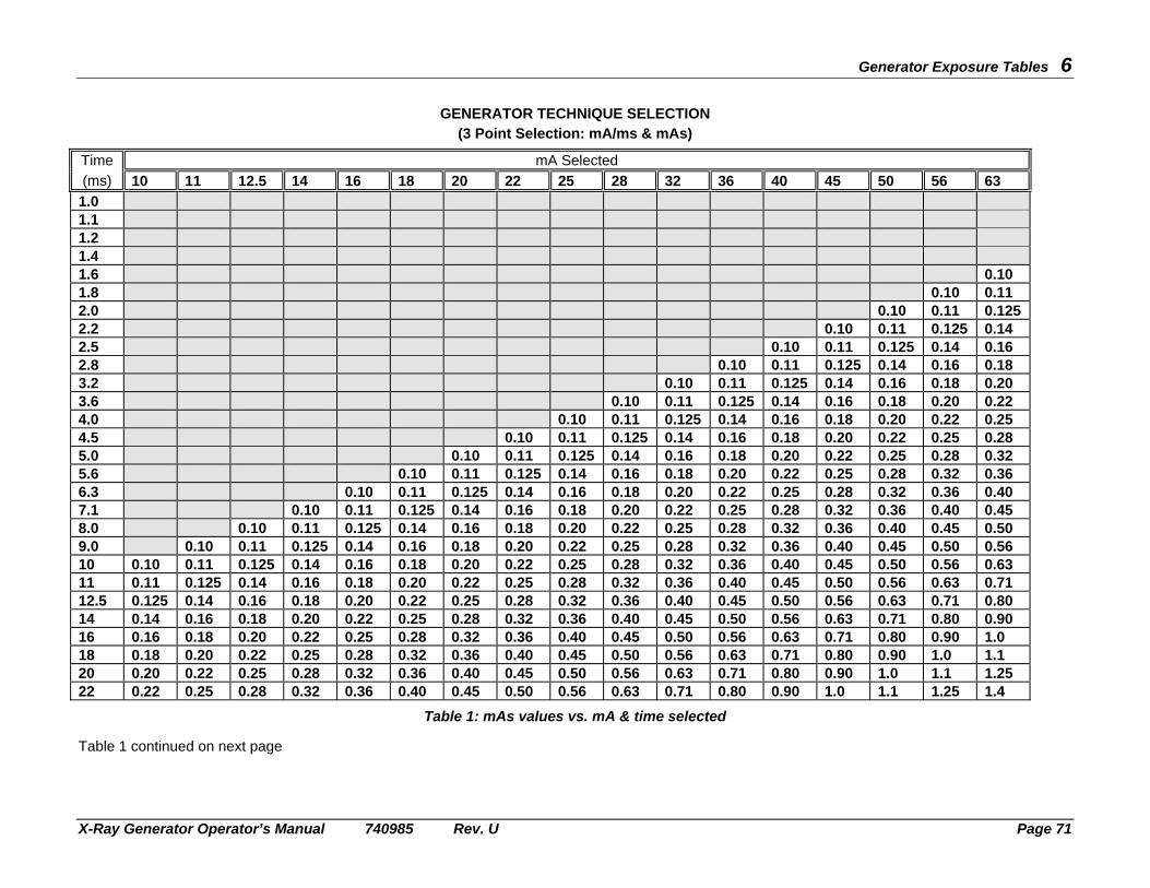
Generator Exposure Tables 6
X-Ray Generator Operator’s Manual 740985 Rev. U Page 71
GENERATOR TECHNIQUE SELECTION (3 Point Selection: mA/ms & mAs)
Time mA Selected (ms) 10 11 12.5 14 16 18 20 22 25 28 32 36 40 45 50 56 63
1.0 1.1 1.2 1.4 1.6 0.10 1.8 0.10 0.11 2.0 0.10 0.11 0.125 2.2 0.10 0.11 0.125 0.14 2.5 0.10 0.11 0.125 0.14 0.16 2.8 0.10 0.11 0.125 0.14 0.16 0.18 3.2 0.10 0.11 0.125 0.14 0.16 0.18 0.20 3.6 0.10 0.11 0.125 0.14 0.16 0.18 0.20 0.22 4.0 0.10 0.11 0.125 0.14 0.16 0.18 0.20 0.22 0.25 4.5 0.10 0.11 0.125 0.14 0.16 0.18 0.20 0.22 0.25 0.28 5.0 0.10 0.11 0.125 0.14 0.16 0.18 0.20 0.22 0.25 0.28 0.32 5.6 0.10 0.11 0.125 0.14 0.16 0.18 0.20 0.22 0.25 0.28 0.32 0.36 6.3 0.10 0.11 0.125 0.14 0.16 0.18 0.20 0.22 0.25 0.28 0.32 0.36 0.40 7.1 0.10 0.11 0.125 0.14 0.16 0.18 0.20 0.22 0.25 0.28 0.32 0.36 0.40 0.45 8.0 0.10 0.11 0.125 0.14 0.16 0.18 0.20 0.22 0.25 0.28 0.32 0.36 0.40 0.45 0.50 9.0 0.10 0.11 0.125 0.14 0.16 0.18 0.20 0.22 0.25 0.28 0.32 0.36 0.40 0.45 0.50 0.56 10 0.10 0.11 0.125 0.14 0.16 0.18 0.20 0.22 0.25 0.28 0.32 0.36 0.40 0.45 0.50 0.56 0.63 11 0.11 0.125 0.14 0.16 0.18 0.20 0.22 0.25 0.28 0.32 0.36 0.40 0.45 0.50 0.56 0.63 0.71 12.5 0.125 0.14 0.16 0.18 0.20 0.22 0.25 0.28 0.32 0.36 0.40 0.45 0.50 0.56 0.63 0.71 0.80 14 0.14 0.16 0.18 0.20 0.22 0.25 0.28 0.32 0.36 0.40 0.45 0.50 0.56 0.63 0.71 0.80 0.90 16 0.16 0.18 0.20 0.22 0.25 0.28 0.32 0.36 0.40 0.45 0.50 0.56 0.63 0.71 0.80 0.90 1.0 18 0.18 0.20 0.22 0.25 0.28 0.32 0.36 0.40 0.45 0.50 0.56 0.63 0.71 0.80 0.90 1.0 1.1 20 0.20 0.22 0.25 0.28 0.32 0.36 0.40 0.45 0.50 0.56 0.63 0.71 0.80 0.90 1.0 1.1 1.25 22 0.22 0.25 0.28 0.32 0.36 0.40 0.45 0.50 0.56 0.63 0.71 0.80 0.90 1.0 1.1 1.25 1.4
Table 1: mAs values vs. mA & time selected Table 1 continued on next page

Generator Exposure Tables 6
X-Ray Generator Operator’s Manual 740985 Rev. U Page 72
Time mA Selected (ms) 71 80 90 100 110 125 140 160 180 200 220 250 280 320 360 400 450
1.0 0.10 0.11 0.125 0.14 0.16 0.18 0.20 0.22 0.25 0.28 0.32 0.36 0.40 0.45 1.1 0.10 0.11 0.125 0.14 0.16 0.18 0.20 0.22 0.25 0.28 0.32 0.36 0.40 0.45 0.50 1.2 0.10 0.11 0.125 0.14 0.16 0.18 0.20 0.22 0.25 0.28 0.32 0.36 0.40 0.45 0.50 0.56 1.4 0.10 0.11 0.125 0.14 0.16 0.18 0.20 0.22 0.25 0.28 0.32 0.36 0.40 0.45 0.50 0.56 0.63 1.6 0.11 0.125 0.14 0.16 0.18 0.20 0.22 0.25 0.28 0.32 0.36 0.40 0.45 0.50 0.56 0.63 0.71 1.8 0.125 0.14 0.16 0.18 0.20 0.22 0.25 0.28 0.32 0.36 0.40 0.45 0.50 0.56 0.63 0.71 0.80 2.0 0.14 0.16 0.18 0.20 0.22 0.25 0.28 0.32 0.36 0.40 0.45 0.50 0.56 0.63 0.71 0.80 0.90 2.2 0.16 0.18 0.20 0.22 0.25 0.28 0.32 0.36 0.40 0.45 0.50 0.56 0.63 0.71 0.80 0.90 1.0 2.5 0.18 0.20 0.22 0.25 0.28 0.32 0.36 0.40 0.45 0.50 0.56 0.63 0.71 0.80 0.90 1.0 1.1 2.8 0.20 0.22 0.25 0.28 0.32 0.36 0.40 0.45 0.50 0.56 0.63 0.71 0.80 0.90 1.0 1.1 1.25 3.2 0.22 0.25 0.28 0.32 0.36 0.40 0.45 0.50 0.56 0.63 0.71 0.80 0.90 1.0 1.1 1.25 1.4 3.6 0.25 0.28 0.32 0.36 0.40 0.45 0.50 0.56 0.63 0.71 0.80 0.90 1.0 1.1 1.25 1.4 1.6 4.0 0.28 0.32 0.36 0.40 0.45 0.50 0.56 0.63 0.71 0.80 0.90 1.0 1.1 1.25 1.4 1.6 1.8 4.5 0.32 0.36 0.40 0.45 0.50 0.56 0.63 0.71 0.80 0.90 1.0 1.1 1.25 1.4 1.6 1.8 2.0 5.0 0.36 0.40 0.45 0.50 0.56 0.63 0.71 0.80 0.90 1.0 1.1 1.25 1.4 1.6 1.8 2.0 2.2 5.6 0.40 0.45 0.50 0.56 0.63 0.71 0.80 0.90 1.0 1.1 1.25 1.4 1.6 1.8 2.0 2.2 2.5 6.3 0.45 0.50 0.56 0.63 0.71 0.80 0.90 1.0 1.1 1.25 1.4 1.6 1.8 2.0 2.2 2.5 2.8 7.1 0.50 0.56 0.63 0.71 0.80 0.90 1.0 1.1 1.25 1.4 1.6 1.8 2.0 2.2 2.5 2.8 3.2 8.0 0.56 0.63 0.71 0.80 0.90 1.0 1.1 1.25 1.4 1.6 1.8 2.0 2.2 2.5 2.8 3.2 3.6 9.0 0.63 0.71 0.80 0.90 1.0 1.1 1.25 1.4 1.6 1.8 2.0 2.2 2.5 2.8 3.2 3.6 4.0 10 0.71 0.80 0.90 1.0 1.1 1.25 1.4 1.6 1.8 2.0 2.2 2.5 2.8 3.2 3.6 4.0 4.5 11 0.80 0.90 1.0 1.1 1.25 1.4 1.6 1.8 2.0 2.2 2.5 2.8 3.2 3.6 4.0 4.5 5.0 12.5 0.90 1.0 1.1 1.25 1.4 1.6 1.8 2.0 2.2 2.5 2.8 3.2 3.6 4.0 4.5 5.0 5.6 14 1.0 1.1 1.25 1.4 1.6 1.8 2.0 2.2 2.5 2.8 3.2 3.6 4.0 4.5 5.0 5.6 6.3 16 1.1 1.25 1.4 1.6 1.8 2.0 2.2 2.5 2.8 3.2 3.6 4.0 4.5 5.0 5.6 6.3 7.1 18 1.25 1.4 1.6 1.8 2.0 2.2 2.5 2.8 3.2 3.6 4.0 4.5 5.0 5.6 6.3 7.1 8.0 20 1.4 1.6 1.8 2.0 2.2 2.5 2.8 3.2 3.6 4.0 4.5 5.0 5.6 6.3 7.1 8.0 9.0 22 1.6 1.8 2.0 2.2 2.5 2.8 3.2 3.6 4.0 4.5 5.0 5.6 6.3 7.1 8.0 9.0 10
Table 1 (Cont): mAs values vs. mA & time selected Table 1 continued on next page

Generator Exposure Tables 6
X-Ray Generator Operator’s Manual 740985 Rev. U Page 73
Time mA Selected (ms) 500 560 630 710 800 900 1000
1.0 0.50 0.56 0.63 0.71 0.80 0.90 1.0 1.1 0.56 0.63 0.71 0.80 0.90 1.0 1.1 1.2 0.63 0.71 0.80 0.90 1.0 1.1 1.25 1.4 0.71 0.80 0.90 1.0 1.1 1.25 1.4 1.6 0.80 0.90 1.0 1.1 1.25 1.4 1.6 1.8 0.90 1.0 1.1 1.25 1.4 1.6 1.8 2.0 1.0 1.1 1.25 1.4 1.6 1.8 2.0 2.2 1.1 1.25 1.4 1.6 1.8 2.0 2.2 2.5 1.25 1.4 1.6 1.8 2.0 2.2 2.5 2.8 1.4 1.6 1.8 2.0 2.2 2.5 2.8 3.2 1.6 1.8 2.0 2.2 2.5 2.8 3.2 3.6 1.8 2.0 2.2 2.5 2.8 3.2 3.6 4.0 2.0 2.2 2.5 2.8 3.2 3.6 4.0 4.5 2.2 2.5 2.8 3.2 3.6 4.0 4.5 5.0 2.5 2.8 3.2 3.6 4.0 4.5 5.0 5.6 2.8 3.2 3.6 4.0 4.5 5.0 5.6 6.3 3.2 3.6 4.0 4.5 5.0 5.6 6.3 7.1 3.6 4.0 4.5 5.0 5.6 6.3 7.1 8.0 4.0 4.5 5.0 5.6 6.3 7.1 8.0 9.0 4.5 5.0 5.6 6.3 7.1 8.0 9.0 10 5.0 5.6 6.3 7.1 8.0 9.0 10 11 5.6 6.3 7.1 8.0 9.0 10 11 12.5 6.3 7.1 8.0 9.0 10 11 12.5 14 7.1 8.0 9.0 10 11 12.5 14 16 8.0 9.0 10 11 12.5 14 16 18 9.0 10 11 12.5 14 16 18 20 10 11 12.5 14 16 18 20 22 11 12.5 14 16 18 20 22
Table 1 (Cont): mAs values vs. mA & time selected Table 1 continued on next page
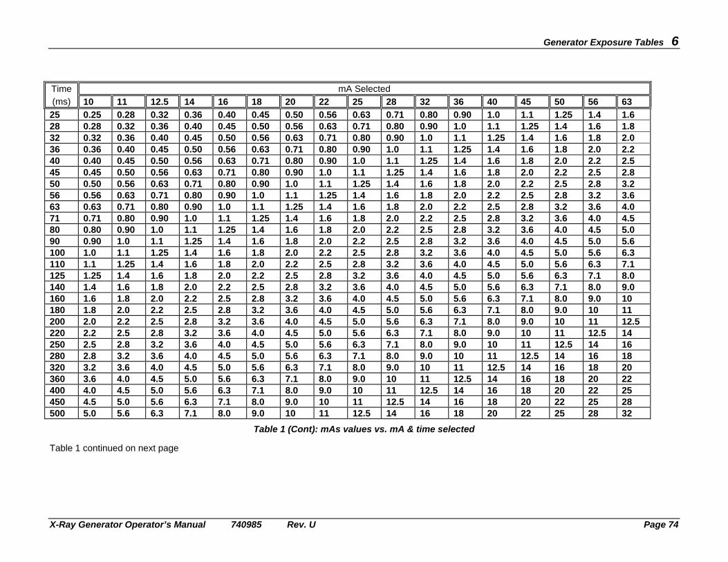
Generator Exposure Tables 6
X-Ray Generator Operator’s Manual 740985 Rev. U Page 74
Time mA Selected (ms) 10 11 12.5 14 16 18 20 22 25 28 32 36 40 45 50 56 63
25 0.25 0.28 0.32 0.36 0.40 0.45 0.50 0.56 0.63 0.71 0.80 0.90 1.0 1.1 1.25 1.4 1.6 28 0.28 0.32 0.36 0.40 0.45 0.50 0.56 0.63 0.71 0.80 0.90 1.0 1.1 1.25 1.4 1.6 1.8 32 0.32 0.36 0.40 0.45 0.50 0.56 0.63 0.71 0.80 0.90 1.0 1.1 1.25 1.4 1.6 1.8 2.0 36 0.36 0.40 0.45 0.50 0.56 0.63 0.71 0.80 0.90 1.0 1.1 1.25 1.4 1.6 1.8 2.0 2.2 40 0.40 0.45 0.50 0.56 0.63 0.71 0.80 0.90 1.0 1.1 1.25 1.4 1.6 1.8 2.0 2.2 2.5 45 0.45 0.50 0.56 0.63 0.71 0.80 0.90 1.0 1.1 1.25 1.4 1.6 1.8 2.0 2.2 2.5 2.8 50 0.50 0.56 0.63 0.71 0.80 0.90 1.0 1.1 1.25 1.4 1.6 1.8 2.0 2.2 2.5 2.8 3.2 56 0.56 0.63 0.71 0.80 0.90 1.0 1.1 1.25 1.4 1.6 1.8 2.0 2.2 2.5 2.8 3.2 3.6 63 0.63 0.71 0.80 0.90 1.0 1.1 1.25 1.4 1.6 1.8 2.0 2.2 2.5 2.8 3.2 3.6 4.0 71 0.71 0.80 0.90 1.0 1.1 1.25 1.4 1.6 1.8 2.0 2.2 2.5 2.8 3.2 3.6 4.0 4.5 80 0.80 0.90 1.0 1.1 1.25 1.4 1.6 1.8 2.0 2.2 2.5 2.8 3.2 3.6 4.0 4.5 5.0 90 0.90 1.0 1.1 1.25 1.4 1.6 1.8 2.0 2.2 2.5 2.8 3.2 3.6 4.0 4.5 5.0 5.6 100 1.0 1.1 1.25 1.4 1.6 1.8 2.0 2.2 2.5 2.8 3.2 3.6 4.0 4.5 5.0 5.6 6.3 110 1.1 1.25 1.4 1.6 1.8 2.0 2.2 2.5 2.8 3.2 3.6 4.0 4.5 5.0 5.6 6.3 7.1 125 1.25 1.4 1.6 1.8 2.0 2.2 2.5 2.8 3.2 3.6 4.0 4.5 5.0 5.6 6.3 7.1 8.0 140 1.4 1.6 1.8 2.0 2.2 2.5 2.8 3.2 3.6 4.0 4.5 5.0 5.6 6.3 7.1 8.0 9.0 160 1.6 1.8 2.0 2.2 2.5 2.8 3.2 3.6 4.0 4.5 5.0 5.6 6.3 7.1 8.0 9.0 10 180 1.8 2.0 2.2 2.5 2.8 3.2 3.6 4.0 4.5 5.0 5.6 6.3 7.1 8.0 9.0 10 11 200 2.0 2.2 2.5 2.8 3.2 3.6 4.0 4.5 5.0 5.6 6.3 7.1 8.0 9.0 10 11 12.5 220 2.2 2.5 2.8 3.2 3.6 4.0 4.5 5.0 5.6 6.3 7.1 8.0 9.0 10 11 12.5 14 250 2.5 2.8 3.2 3.6 4.0 4.5 5.0 5.6 6.3 7.1 8.0 9.0 10 11 12.5 14 16 280 2.8 3.2 3.6 4.0 4.5 5.0 5.6 6.3 7.1 8.0 9.0 10 11 12.5 14 16 18 320 3.2 3.6 4.0 4.5 5.0 5.6 6.3 7.1 8.0 9.0 10 11 12.5 14 16 18 20 360 3.6 4.0 4.5 5.0 5.6 6.3 7.1 8.0 9.0 10 11 12.5 14 16 18 20 22 400 4.0 4.5 5.0 5.6 6.3 7.1 8.0 9.0 10 11 12.5 14 16 18 20 22 25 450 4.5 5.0 5.6 6.3 7.1 8.0 9.0 10 11 12.5 14 16 18 20 22 25 28 500 5.0 5.6 6.3 7.1 8.0 9.0 10 11 12.5 14 16 18 20 22 25 28 32
Table 1 (Cont): mAs values vs. mA & time selected Table 1 continued on next page

Generator Exposure Tables 6
X-Ray Generator Operator’s Manual 740985 Rev. U Page 75
Time mA Selected (ms) 71 80 90 100 110 125 140 160 180 200 220 250 280 320 360 400 450
25 1.8 2.0 2.2 2.5 2.8 3.2 3.6 4.0 4.5 5.0 5.6 6.3 7.1 8.0 9.0 10 11 28 2.0 2.2 2.5 2.8 3.2 3.6 4.0 4.5 5.0 5.6 6.3 7.1 8.0 9.0 10 11 12.5 32 2.2 2.5 2.8 3.2 3.6 4.0 4.5 5.0 5.6 6.3 7.1 8.0 9.0 10 11 12.5 14 36 2.5 2.8 3.2 3.6 4.0 4.5 5.0 5.6 6.3 7.1 8.0 9.0 10 11 12.5 14 16 40 2.8 3.2 3.6 4.0 4.5 5.0 5.6 6.3 7.1 8.0 9.0 10 11 12.5 14 16 18 45 3.2 3.6 4.0 4.5 5.0 5.6 6.3 7.1 8.0 9.0 10 11 12.5 14 16 18 20 50 3.6 4.0 4.5 5.0 5.6 6.3 7.1 8.0 9.0 10 11 12.5 14 16 18 20 22 56 4.0 4.5 5.0 5.6 6.3 7.1 8.0 9.0 10 11 12.5 14 16 18 20 22 25 63 4.5 5.0 5.6 6.3 7.1 8.0 9.0 10 11 12.5 14 16 18 20 22 25 28 71 5.0 5.6 6.3 7.1 8.0 9.0 10 11 12.5 14 16 18 20 22 25 28 32 80 5.6 6.3 7.1 8.0 9.0 10 11 12.5 14 16 18 20 22 25 28 32 36 90 6.3 7.1 8.0 9.0 10 11 12.5 14 16 18 20 22 25 28 32 36 40 100 7.1 8.0 9.0 10 11 12.5 14 16 18 20 22 25 28 32 36 40 45 110 8.0 9.0 10 11 12.5 14 16 18 20 22 25 28 32 36 40 45 50 125 9.0 10 11 12.5 14 16 18 20 22 25 28 32 36 40 45 50 56 140 10 11 12.5 14 16 18 20 22 25 28 32 36 40 45 50 56 63 160 11 12.5 14 16 18 20 22 25 28 32 36 40 45 50 56 63 71 180 12.5 14 16 18 20 22 25 28 32 36 40 45 50 56 63 71 80 200 14 16 18 20 22 25 28 32 36 40 45 50 56 63 71 80 90 220 16 18 20 22 25 28 32 36 40 45 50 56 63 71 80 90 100 250 18 20 22 25 28 32 36 40 45 50 56 63 71 80 90 100 110 280 20 22 25 28 32 36 40 45 50 56 63 71 80 90 100 110 125 320 22 25 28 32 36 40 45 50 56 63 71 80 90 100 110 125 140 360 25 28 32 36 40 45 50 56 63 71 80 90 100 110 125 140 160 400 28 32 36 40 45 50 56 63 71 80 90 100 110 125 140 160 180 450 32 36 40 45 50 56 63 71 80 90 100 110 125 140 160 180 200 500 36 40 45 50 56 63 71 80 90 100 110 125 140 160 180 200 220
Table 1 (Cont): mAs values vs. mA & time selected Table 1 continued on next page
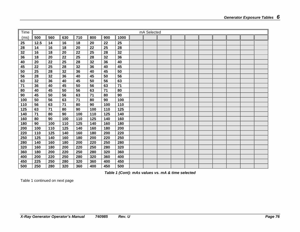
Generator Exposure Tables 6
X-Ray Generator Operator’s Manual 740985 Rev. U Page 76
Time mA Selected (ms) 500 560 630 710 800 900 1000
25 12.5 14 16 18 20 22 25 28 14 16 18 20 22 25 28 32 16 18 20 22 25 28 32 36 18 20 22 25 28 32 36 40 20 22 25 28 32 36 40 45 22 25 28 32 36 40 45 50 25 28 32 36 40 45 50 56 28 32 36 40 45 50 56 63 32 36 40 45 50 56 63 71 36 40 45 50 56 63 71 80 40 45 50 56 63 71 80 90 45 50 56 63 71 80 90 100 50 56 63 71 80 90 100 110 56 63 71 80 90 100 110 125 63 71 80 90 100 110 125 140 71 80 90 100 110 125 140 160 80 90 100 110 125 140 160 180 90 100 110 125 140 160 180 200 100 110 125 140 160 180 200 220 110 125 140 160 180 200 220 250 125 140 160 180 200 220 250 280 140 160 180 200 220 250 280 320 160 180 200 220 250 280 320 360 180 200 220 250 280 320 360 400 200 220 250 280 320 360 400 450 225 250 280 320 360 400 450 500 250 280 320 360 400 450 500
Table 1 (Cont): mAs values vs. mA & time selected Table 1 continued on next page

Generator Exposure Tables 6
X-Ray Generator Operator’s Manual 740985 Rev. U Page 77
Time mA Selected (ms) 10 11 12.5 14 16 18 20 22 25 28 32 36 40 45 50 56 63
560 5.6 6.3 7.1 8.0 9.0 10 11 12.5 14 16 18 20 22 25 28 32 36 630 6.3 7.1 8.0 9.0 10 11 12.5 14 16 18 20 22 25 28 32 36 40 710 7.1 8.0 9.0 10 11 12.5 14 16 18 20 22 25 28 32 36 40 45 800 8.0 9.0 10 11 12.5 14 16 18 20 22 25 28 32 36 40 45 50 900 9.0 10 11 12.5 14 16 18 20 22 25 28 32 36 40 45 50 56 1000 10 11 12.5 14 16 18 20 22 25 28 32 36 40 45 50 56 63 1100 11 12.5 14 16 18 20 22 25 28 32 36 40 45 50 56 63 71 1250 12.5 14 16 18 20 22 25 28 32. 36 40 45 50 56 63 71 80 1400 14 16 18 20 22 25 28 32 36 40 45 50 56 63 71 80 90 1600 16 18 20 22 25 28 32 36 40 45 50 56 63 71 80 90 100 1800 18 20 22 25 28 32 36 40 45 50 56 63 71 80 90 100 110 2000 20 22 25 28 32 36 40 45 50 56 63 71 80 90 100 110 125 2200 22 25 28 32 36 40 45 50 56 63 71 80 90 100 110 125 140 2500 25 28 32 36 40 45 50 56 63 71 80 90 100 110 125 140 160 2800 28 32 36 40 45 50 56 63 71 80 90 100 110 125 140 160 180 3200 32 36 40 45 50 56 63 71 80 90 100 110 125 140 160 180 200 3600 36 40 45 50 56 63 71 80 90 100 110 125 140 160 180 200 220 4000 40 45 50 56 63 71 80 90 100 110 125 140 160 180 200 220 250 4500 45 50 56 63 71 80 90 100 110 125 140 160 180 200 220 250 280 5000 50 56 63 71 80 90 100 110 125 140 160 180 200 220 250 280 320 5600 56 63 71 80 90 100 110 125 140 160 180 200 220 250 280 320 360 6300 63 71 80 90 100 110 125 140 160 180 200 220 250 280 320 360 400
Table 1 (Cont): mAs values vs. mA & time selected Table 1 continued on next page

Generator Exposure Tables 6
X-Ray Generator Operator’s Manual 740985 Rev. U Page 78
Time mA Selected (ms) 71 80 90 100 110 125 140 160 180 200 220 250 280 320 360 400 450
560 40 45 50 56 63 71 80 90 100 110 125 140 160 180 200 220 250 630 45 50 56 63 71 80 90 100 110 125 140 160 180 200 220 250 280 710 50 56 63 71 80 90 100 110 125 140 160 180 200 220 250 280 320 800 56 63 71 80 90 100 110 125 140 160 180 200 220 250 280 320 360 900 63 71 80 90 100 110 125 140 160 180 200 220 250 280 320 360 400 1000 71 80 90 100 110 125 140 160 180 200 220 250 280 320 360 400 450 1100 80 90 100 110 125 140 160 180 200 220 250 280 320 360 400 450 500 1250 90 100 110 125 140 160 180 200 220 250 280 320 360 400 450 500 560 1400 100 110 125 140 160 180 200 220 250 280 320 360 400 450 500 560 630 1600 110 125 140 160 180 200 220 250 280 320 360 400 450 500 560 630 710 1800 125 140 160 180 200 220 250 280 320 360 400 450 500 560 630 710 800 2000 140 160 180 200 220 250 280 320 360 400 450 500 560 630 710 800 900 2200 160 180 200 220 250 280 320 360 400 450 500 560 630 710 800 900 1000 2500 180 200 220 250 280 320 360 400 450 500 560 630 710 800 900 1000 2800 200 220 250 280 320 360 400 450 500 560 630 710 800 900 1000 3200 220 250 280 320 360 400 450 500 560 630 710 800 900 1000 3600 250 280 320 360 400 450 500 560 630 710 800 900 1000 4000 280 320 360 400 450 500 560 630 710 800 900 1000 4500 320 360 400 450 500 560 630 710 800 900 1000 5000 360 400 450 500 560 630 710 800 900 1000 5600 400 450 500 560 630 710 800 900 1000 6300 450 500 560 630 710 800 900 1000
Table 1 (Cont): mAs values vs. mA & time selected Table 1 continued on next page

Generator Exposure Tables 6
X-Ray Generator Operator’s Manual 740985 Rev. U Page 79
Time mA Selected (ms) 500 560 630 710 800 900 1000
560 280 320 360 400 450 500 560 630 320 360 400 450 500 560 630 710 360 400 450 500 560 630 710 800 400 450 500 560 630 710 800 900 450 500 560 630 710 800 900 1000 500 560 630 710 800 900 1000 1100 550 630 710 800 900 1000 1250 630 710 800 900 1000 1400 710 800 900 1000 1600 800 900 1000 1800 900 1000 2000 1000 2200 2500 2800 3200 3600 4000 4500 5000 5600 6300
Table 1 (Cont): mAs values vs. mA & time selected Continued on next page

Generator Exposure Tables 6
X-Ray Generator Operator’s Manual 740985 Rev. U Page 80
Note: 32 kW Generators Maximum mA = 400 Maximum mAs = 500 40 kW Generators Maximum mA = 500 Maximum mAs = 500 50 kW Generators Maximum mA = 630 Maximum mAs = 630 65 kW Generators Maximum mA = 800 Maximum mAs = 800 80 kW Generators Maximum mA = 1000 Maximum mAs = 1000
Note: 1) mA/TIME values are tube rating dependent. For certain tubes, some mA/TIME selections are not available at higher kV selections.
2) The maximum power output of this family of generators is 32 kW, 40 kW, 50 kW, 65 kW or 80 kW respectively. The generator
software does not allow a kV and mA combination to be selected that exceeds these maximum values.

X-Ray Generator Operator’s Manual 740985 Rev. U Page 81
MAINTENANCE SCHEDULE 7 This section is organized into two parts. The first part of this section details tests by which the operator can verify that the AEC circuits are functioning, and that there are no apparent defects in the console or associated equipment. These tests should be done monthly as a minimum, or more frequently if required by local regulations.
CAUTION: THE AEC VERIFICATION PROCEDURE REQUIRES THE PRODUCTION OF X-RAYS. OBSERVE CORRECT OPERATING PROCEDURES, AND TAKE APPROPRIATE PRECAUTIONS AGAINST X-RADIATION.
The second part of this section is the recommended maintenance schedule for your generator.
WARNING: REFER ALL SERVICING TO APPROPRIATE SERVICE PERSONNEL WHO ARE TRAINED TO SERVICE THIS EQUIPMENT AND WHO ARE FAMILIAR WITH THE POTENTIAL HAZARDS ASSOCIATED WITH THIS EQUIPMENT.
NOTE: MAINTENANCE SCHEDULE FREQUENCY MAY BE DETERMINED BY CERTAIN REGULATORY REQUIREMENTS OF THE COUNTRY OR STATE IN WHICH THE INSTALLATION IS LOCATED. ALWAYS CHECK THE LOCAL CODES AND REGULATIONS WHEN DETERMINING A MAINTENANCE SCHEDULE.

7 Maintenance Schedule
Page 82 X-Ray Generator Operator’s Manual 740985 Rev. U
AEC FUNCTIONAL CHECK The following procedure may be used to verify that the AEC circuits are functioning on generators equipped with AEC (automatic exposure control). 1. Switch the generator ON, and select an appropriate radiographic image receptor. 2. Align the X-ray tube and the selected image receptor such that the central ray is directly
over the center field of the AEC pickup device. Set the focal spot to film plane distance to 40 in. (1 m).
3. Select AEC mode of operation. Select center field, large focus.
MINIMUM EXPOSURE TIME: 4. With no object in the radiation field, adjust the collimator or beam limiting device to project
a 10 in. X 10 in. (24 cm X 24 cm) field at the image receptor. 5. Select 80 kVp, 100 mA, and a backup mAs of 50 if it is operator selectable. If this is not
operator selectable, the default AEC backup settings must be used. Refer to the note at the end of this page to determine the AEC backup mode that has been programmed.
6. Make an exposure and verify that the POST mAs reading is ≤ 2 mAs.
MAXIMUM EXPOSURE TIME: 7. Close the collimator or beam limiting device completely. Place a folded lead apron over
the image receptor. 8. Select 60 kVp, 100 mA, and a backup mAs of 50 if it is operator selectable. If this is not
operator selectable, the default backup settings must be used. Refer to the note at the end of this page to determine the AEC backup mode that has been programmed.
9. Make an exposure and verify that the error message AEC DEVICE ERR, AEC BUT ERROR or AEC BU MAS ERR is indicated in the APR display window after the exposure has terminated. This confirms that the exposure has continued until it was terminated by the AEC backup circuits in the generator.
NOTE: The AEC backup mode is installer programmable. Three modes are available, FIXED, MAS, and MS. Only the MAS mode allows the operator to set the backup mAs for an AEC exposure. FIXED: The generator will determine the maximum AEC backup time, not to exceed preset AEC backup mAs/ms values or system limits. The characters AEC will be displayed in the time window of the LED display during AEC operation. MAS: Allows the operator to adjust the AEC backup mAs, not to exceed preset AEC backup mAs/ms values or system limits. The mAs value will be displayed in the time window of the LED display during AEC operation. MS: Allows the operator to adjust the AEC backup ms, not to exceed preset AEC backup mAs/ms values or system limits. The ms value will be displayed in the time window of the LED display during AEC operation.

Maintenance Schedule 7
X-Ray Generator Operator’s Manual 740985 Rev. U Page 83
CONSOLE AND MISCELLANEOUS GENERATOR CHECKS The user must routinely check the X-ray equipment for apparent defects or damage. Report any apparent defects or irregular operation of any equipment to service personnel immediately, and discontinue use of the suspected faulty equipment until repairs are made. Continuing operation with faulty equipment may present various safety hazards, including risk of increased radiation. 1. Check all visual displays (warning and status lights, technique displays and indicators,
etc) for normal operation. 2. Check all audible indicators (speakers, beepers, etc) for normal operation, and check that
the loudness settings are adequate for the environment. 3. Check all interconnect cables and connectors for damage.

7 Maintenance Schedule
Page 84 X-Ray Generator Operator’s Manual 740985 Rev. U
MAINTENANCE ACTIVITIES IN THE TABLE BELOW ARE TO BE PERFORMED BY AUTHORIZED SERVICE PERSONNEL ONLY. HOWEVER THE OWNER OR OPERATOR OF THE EQUIPMENT MUST SCHEDULE THE SUGGESTED MAINTENANCE ACTIVITY WHEN REQUIRED BY CONTACTING THEIR LOCAL SERVICE AGENCY.
Maintenance Frequency
Description of Preventative Maintenance
Every 6 Months AND whenever a related certifiable X-ray component is replaced:
1. Clean and re-grease all HV connections using vapor proof compound.
2. Check that all HV connections are tight. 3. Clean the control console and main cabinet as needed.
REFER TO NEXT PAGE, CLEANING, BEFORE PROCEEDING.
4. Ensure that there are no obstructions blocking the ventilation holes or louvers on the generator cabinet.
5. Perform the X-ray tube auto calibration routine. 6. Verify the calibration of the generator. 7. Perform any additional tests required by laws governing
this installation. Every 12 months: 1. Examine the following for any visible damage and replace
any damaged components:
• The exterior of the control console, including the membrane switch assembly.
• The cable between the control console and the generator main cabinet.
• The hand switch (if used) and the cable connecting this to the console.
2. Open the generator cabinet and examine the unit for any
visible damage: missing or loose ground connections, oil leaks, damaged cables etc.
Every 3 years Replace the cooling fan in the generator main cabinet. Every 5 years: Replace the batteries on the console board in the control
console and the on the generator control board in the main cabinet.
Maintenance Schedule 7
X-Ray Generator Operator’s Manual 740985 Rev. U Page 85
CLEANING • To clean the console surfaces (without disinfecting) use soap and water. This should be
applied using a lint-free cloth as described below. • If console surfaces need to be disinfected, use Actichlor or equivalent with a Hypochlorite
concentration of 3 to 5%. ∗ Dilute the disinfectant 50/50 with water. ∗ Spray or dampen a lint-free cloth with the diluted disinfectant. The cloth must be damp
only, not wet. ∗ Gently wipe the console surfaces with the damp cloth.
• Never use any corrosive, solvent or abrasive detergents or polishes. • Ensure that no water or other liquid can enter any equipment. This precaution prevents
short circuits and corrosion forming on components. • Disinfection by spraying is not recommended because the disinfectant may enter the X-ray
equipment. • Methods of disinfection used must conform to legal regulations and guidelines regarding
disinfection and explosion protection. • If disinfectants which form explosive mixtures of gases are used in the room, these gases
must have dissipated before switching on the equipment again. • If room disinfection is done with an atomizer, it is recommended that the equipment be
switched OFF, allowed to cool down and covered with a plastic sheet. When the disinfectant mist has subsided, the plastic sheet may be removed and the equipment be disinfected by wiping.

7 Maintenance Schedule
Page 86 X-Ray Generator Operator’s Manual 740985 Rev. U
(This page intentionally left blank)

X-Ray Generator Operator’s Manual 740985 Rev. U Page 87
X-RAY TUBE DATA 8
The following pages contain data for the X-ray tube(s) used with your X-ray generator at the time of installation.

8 X-Ray Tube Data
Page 88 X-Ray Generator Operator’s Manual 740985 Rev. U
(This page intentionally left blank)

X-Ray Tube Data 8
X-Ray Generator Operator’s Manual 740985 Rev. U Page 89
NOTE TO INSTALLER:
INSERT TUBE DATA HERE.

8 X-Ray Tube Data
Page 90 X-Ray Generator Operator’s Manual 740985 Rev. U
(This page intentionally left blank)