Embed Size (px)
Citation preview
CMM366B-4G/CMM366CAN-4G
CLOUD MONITORING COMMUNICATION MODULE
USER MANUAL
SMARTGEN (ZHENGZHOU) TECHNOLOGY CO., LTD.
Chinese trademark
English trademark
SmartGen — make your generator smart
SmartGen Technology Co., Ltd.
No.28 Jinsuo Road
Zhengzhou
Henan Province
P. R. China
Tel: 0086-(0)371-67988888/67981888
0086-(0)371-67991553/67992951
0086-(0)371-67981000(overseas)
Fax: 0086-(0)371-67992952
Web: www.smartgen.com.cn
www.smartgen.cn
Email: [email protected]
All rights reserved. No part of this publication may be reproduced in any material form (including
photocopying or storing in any medium by electronic means or other) without the written permission of
the copyright holder.
Applications for the copyright holder’s written permission to reproduce any part of this publication should
be addressed to SmartGen Technology at the address above.
Any reference to trademarked product names used within this publication is owned by their respective
companies.
SmartGen Technology reserves the right to change the contents of this document without prior notice.
Table 1 - Software Version
Date Version Note
2020-03-10 1.0 Original release.
2020-05-15 1.1 Fix Fig. 14 Unit from cm to mm.
CMM366B-4G/CAN-4G Cloud Monitoring Communication Module User Manual
CMM366B-4G/CAN-4G Cloud Monitoring Communication Module 2020-05-15 Version 1.1 Page 3 of 19
CONTENT
1 OVERVIEW ......................................................................................................................................... 4
2 PERFORMANCE AND CHARACTERISTICS .................................................................................... 4
3 SPECIFICATION ................................................................................................................................. 5
4 PANEL AND TERMINAL DESCRIPTION........................................................................................... 5
4.1 PANEL INDICATOR AND BUTTONS .......................................................................................... 5
4.2 GPRS/4G ANTENNA PORT ........................................................................................................ 7
4.3 GPS ANTENNA PORT ................................................................................................................ 7
4.4 SIM INSTALLATION .................................................................................................................... 7
4.5 RS485 PORT ............................................................................................................................... 8
4.6 RS232 PORT ............................................................................................................................... 8
4.7 LINK PORT .................................................................................................................................. 8
4.8 USB HOST ................................................................................................................................... 9
4.9 USB DEVICE ............................................................................................................................... 9
4.10 CAN PORT ................................................................................................................................ 10
4.11 TERMINALS .............................................................................................................................. 10
5 PROGRAMMABLE PARAMETERS ................................................................................................. 11
5.1 CONTENTS AND SCOPES OF PARAMETERS ........................................................................ 11
5.2 PC CONFIGURATION INTERFACE ......................................................................................... 12
6 SYSTEM DIAGRAM.......................................................................................................................... 13
7 CASE DIMENSION AND INSTALLATION ....................................................................................... 13
8 APP INSTALLATION STEPS ........................................................................................................... 15
9 FAULT FINDING ............................................................................................................................... 18
10 PACKING LIST .............................................................................................................................. 18
11 APPENDIX (ORDER MODEL) ...................................................................................................... 19
CMM366B-4G/CAN-4G Cloud Monitoring Communication Module User Manual
CMM366B-4G/CAN-4G Cloud Monitoring Communication Module 2020-05-15 Version 1.1 Page 4 of 19
1 OVERVIEW
CMM366B-4G/CMM366CAN-4G Cloud Monitoring Communication Module is 4G wireless network
communication protocol switching module of global network communication, which can achieve genset
(with SCI) connection with Internet. After logging into cloud server, module will receive corresponding
genset controller communication protocol from cloud server. Cloud server module can obtain genset
data information via RS485, USB, LINK, CAN, or RS232, and send the information to related could
server via 4G wireless network. Users can at real time monitor genset running status and check genset
running records by mobile APP (IOS or Android), or PC etc. terminal device.
It not only can realize genset monitoring, but also can be connected with some digital alarm inputs, to
realize monitoring of genset entrance guard, prevention of burglary, fire control etc. ancillary facilities.
It has GPS positioning function, which can upload the obtained longitude and latitude, altitude
information at real time to the corresponding cloud server.
CMM366CAN-4G cloud monitoring communication module has CAN port, but CMM366B-4G hasn't.
Except for this, these two cloud monitoring communication modules has same functions.
2 PERFORMANCE AND CHARACTERISTICS
Connected to cloud server via 4G wireless network, one cloud monitoring module for one genset;
Multiple communicating ports with genset control module: RS485, RS232, LINK, CAN, USB (Host);
which can monitor most genset control modules of leading brands internationally;
Wide power supply: DC (8~35)V, which can directly use genset build-in start battery;
With ARM-based 32-bit SCM, high integration of system and strong programming ability;
GPS positioning function to obtain genset location information, to realize genset location;
Applying network data communication protocol of Json format, upload the genset data changes at
real time, meanwhile compression algorithm is applied, which extremely reduces network flow;
Immediately upload the data to cloud server when genset alarms occur;
Event log memory function, which can ensure data won't get lost when network is not steady;
Cloud Modem can be upgraded by 4G signal, convenient for module' s maintenance;
2 configurable digital input ports, which can be connected with external alarm signals;
Module panel has power and multiple communication status indicators; clear for watching module
working status;
Lamp test function;
Parameter setting function: users can do parameter setting by module USB port;
Applying standard π-type 35mm guide-rail installation or screw-fixed installation, and the module
can be installed in the genset control box;
Modular structure design, flame retardant ABS enclosure, light weight, compact structure with easy
installation.
CMM366B-4G/CAN-4G Cloud Monitoring Communication Module User Manual
CMM366B-4G/CAN-4G Cloud Monitoring Communication Module 2020-05-15 Version 1.1 Page 5 of 19
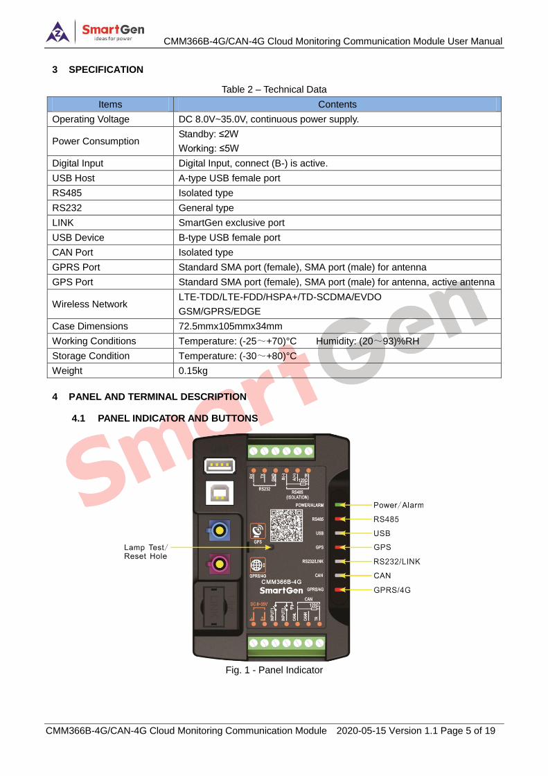
3 SPECIFICATION
Table 2 – Technical Data
Items Contents
Operating Voltage DC 8.0V~35.0V, continuous power supply.
Power Consumption Standby: ≤2W
Working: ≤5W
Digital Input Digital Input, connect (B-) is active.
USB Host A-type USB female port
RS485 Isolated type
RS232 General type
LINK SmartGen exclusive port
USB Device B-type USB female port
CAN Port Isolated type
GPRS Port Standard SMA port (female), SMA port (male) for antenna
GPS Port Standard SMA port (female), SMA port (male) for antenna, active antenna
Wireless Network LTE-TDD/LTE-FDD/HSPA+/TD-SCDMA/EVDO
GSM/GPRS/EDGE
Case Dimensions 72.5mmx105mmx34mm
Working Conditions Temperature: (-25~+70)°C Humidity: (20~93)%RH
Storage Condition Temperature: (-30~+80)°C
Weight 0.15kg
4 PANEL AND TERMINAL DESCRIPTION
4.1 PANEL INDICATOR AND BUTTONS
Fig. 1 - Panel Indicator
CMM366B-4G/CAN-4G Cloud Monitoring Communication Module User Manual
CMM366B-4G/CAN-4G Cloud Monitoring Communication Module 2020-05-15 Version 1.1 Page 6 of 19
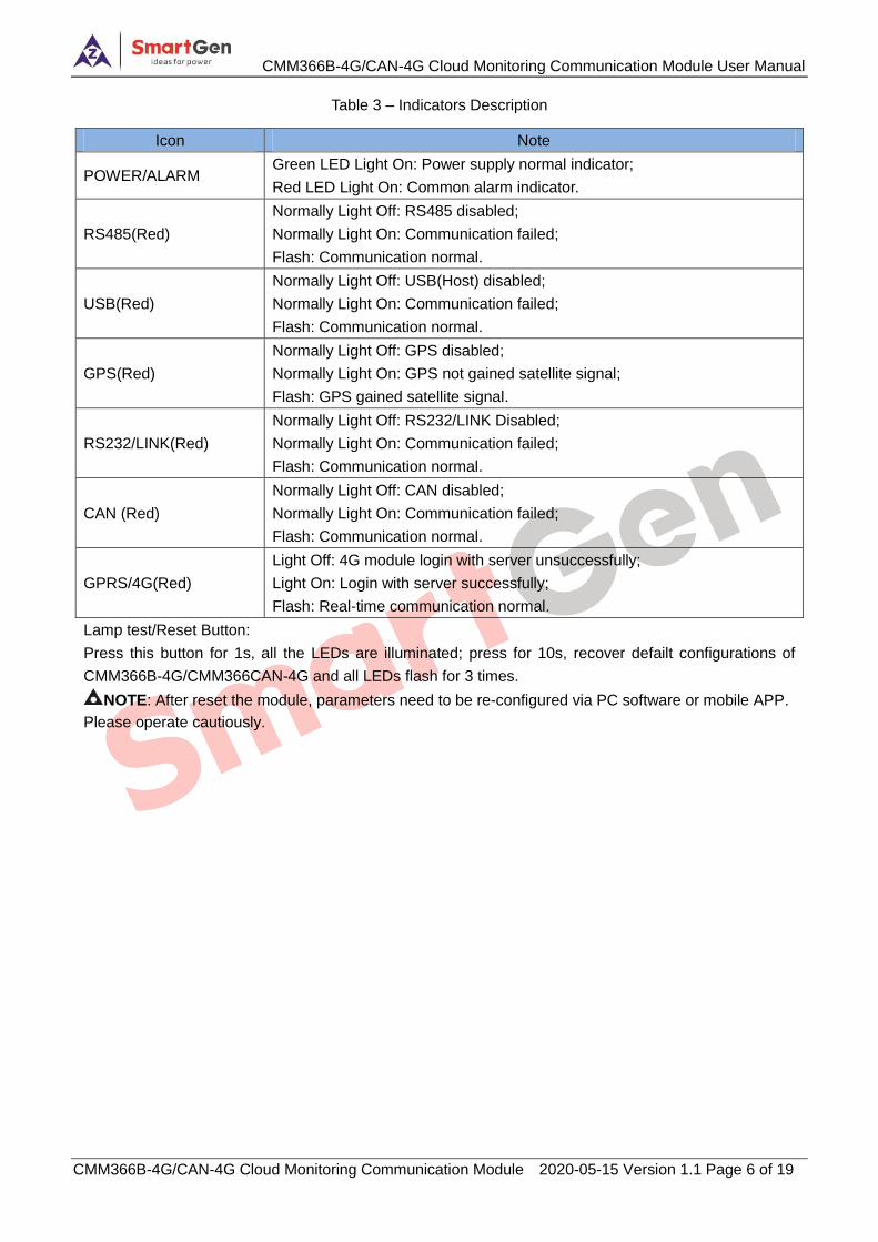
Table 3 – Indicators Description
Icon Note
POWER/ALARM Green LED Light On: Power supply normal indicator;
Red LED Light On: Common alarm indicator.
RS485(Red)
Normally Light Off: RS485 disabled;
Normally Light On: Communication failed;
Flash: Communication normal.
USB(Red)
Normally Light Off: USB(Host) disabled;
Normally Light On: Communication failed;
Flash: Communication normal.
GPS(Red)
Normally Light Off: GPS disabled;
Normally Light On: GPS not gained satellite signal;
Flash: GPS gained satellite signal.
RS232/LINK(Red)
Normally Light Off: RS232/LINK Disabled;
Normally Light On: Communication failed;
Flash: Communication normal.
CAN (Red)
Normally Light Off: CAN disabled;
Normally Light On: Communication failed;
Flash: Communication normal.
GPRS/4G(Red)
Light Off: 4G module login with server unsuccessfully;
Light On: Login with server successfully;
Flash: Real-time communication normal.
Lamp test/Reset Button:
Press this button for 1s, all the LEDs are illuminated; press for 10s, recover defailt configurations of
CMM366B-4G/CMM366CAN-4G and all LEDs flash for 3 times.
NOTE: After reset the module, parameters need to be re-configured via PC software or mobile APP.
Please operate cautiously.
CMM366B-4G/CAN-4G Cloud Monitoring Communication Module User Manual
CMM366B-4G/CAN-4G Cloud Monitoring Communication Module 2020-05-15 Version 1.1 Page 7 of 19
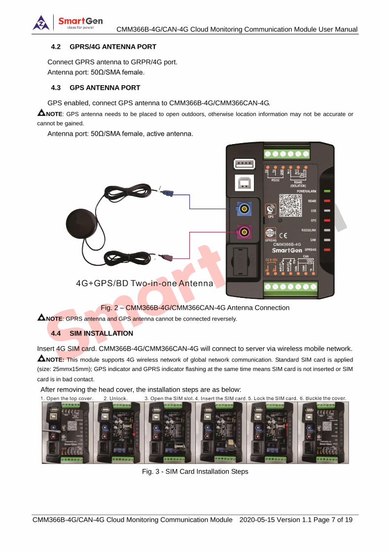
4.2 GPRS/4G ANTENNA PORT
Connect GPRS antenna to GRPR/4G port.
Antenna port: 50Ω/SMA female.
4.3 GPS ANTENNA PORT
GPS enabled, connect GPS antenna to CMM366B-4G/CMM366CAN-4G.
NOTE: GPS antenna needs to be placed to open outdoors, otherwise location information may not be accurate or
cannot be gained.
Antenna port: 50Ω/SMA female, active antenna.
Fig. 2 – CMM366B-4G/CMM366CAN-4G Antenna Connection
NOTE: GPRS antenna and GPS antenna cannot be connected reversely.
4.4 SIM INSTALLATION
Insert 4G SIM card. CMM366B-4G/CMM366CAN-4G will connect to server via wireless mobile network.
NOTE: This module supports 4G wireless network of global network communication. Standard SIM card is applied
(size: 25mmx15mm); GPS indicator and GPRS indicator flashing at the same time means SIM card is not inserted or SIM
card is in bad contact.
After removing the head cover, the installation steps are as below:
Fig. 3 - SIM Card Installation Steps
CMM366B-4G/CAN-4G Cloud Monitoring Communication Module User Manual
CMM366B-4G/CAN-4G Cloud Monitoring Communication Module 2020-05-15 Version 1.1 Page 8 of 19
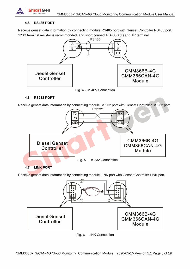
4.5 RS485 PORT
Receive genset data information by connecting module RS485 port with Genset Controller RS485 port.
120Ω terminal resistor is recommonded, and short connect RS485 A(+) and TR terminal.
Fig. 4 - RS485 Connection
4.6 RS232 PORT
Receive genset data information by connecting module RS232 port with Genset Controller RS232 port.
Fig. 5 – RS232 Connection
4.7 LINK PORT
Receive genset data information by connecting module LINK port with Genset Controller LINK port.
Fig. 6 – LINK Connection
CMM366B-4G/CAN-4G Cloud Monitoring Communication Module User Manual
CMM366B-4G/CAN-4G Cloud Monitoring Communication Module 2020-05-15 Version 1.1 Page 9 of 19
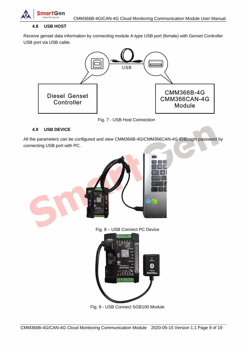
4.8 USB HOST
Receive genset data information by connecting module A-type USB port (female) with Genset Controller
USB port via USB cable.
Fig. 7 - USB Host Connection
4.9 USB DEVICE
All the parameters can be configured and view CMM366B-4G/CMM366CAN-4G ID&Login password by
connecting USB port with PC.
Fig. 8 – USB Connect PC Device
Fig. 9 - USB Connect SGB100 Module
CMM366B-4G/CAN-4G Cloud Monitoring Communication Module User Manual
CMM366B-4G/CAN-4G Cloud Monitoring Communication Module 2020-05-15 Version 1.1 Page 10 of 19
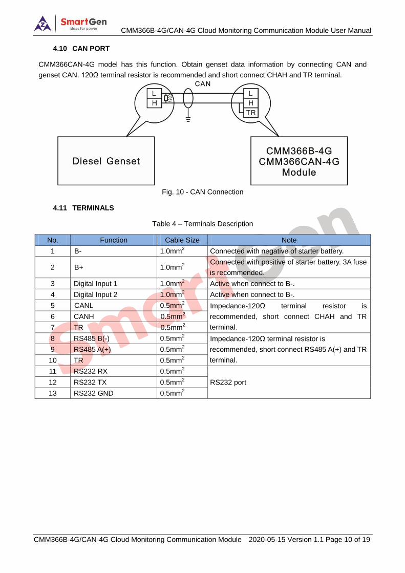
4.10 CAN PORT
CMM366CAN-4G model has this function. Obtain genset data information by connecting CAN and
genset CAN. 120Ω terminal resistor is recommended and short connect CHAH and TR terminal.
Fig. 10 - CAN Connection
4.11 TERMINALS
Table 4 – Terminals Description
No. Function Cable Size Note
1 B- 1.0mm2 Connected with negative of starter battery.
2 B+ 1.0mm2
Connected with positive of starter battery. 3A fuse
is recommended.
3 Digital Input 1 1.0mm2 Active when connect to B-.
4 Digital Input 2 1.0mm2 Active when connect to B-.
5 CANL 0.5mm2 Impedance-120Ω terminal resistor is
recommended, short connect CHAH and TR
terminal.
6 CANH 0.5mm2
7 TR 0.5mm2
8 RS485 B(-) 0.5mm2 Impedance-120Ω terminal resistor is
recommended, short connect RS485 A(+) and TR
terminal.
9 RS485 A(+) 0.5mm2
10 TR 0.5mm2
11 RS232 RX 0.5mm2
RS232 port 12 RS232 TX 0.5mm2
13 RS232 GND 0.5mm2
CMM366B-4G/CAN-4G Cloud Monitoring Communication Module User Manual
CMM366B-4G/CAN-4G Cloud Monitoring Communication Module 2020-05-15 Version 1.1 Page 11 of 19
5 PROGRAMMABLE PARAMETERS
5.1 CONTENTS AND SCOPES OF PARAMETERS
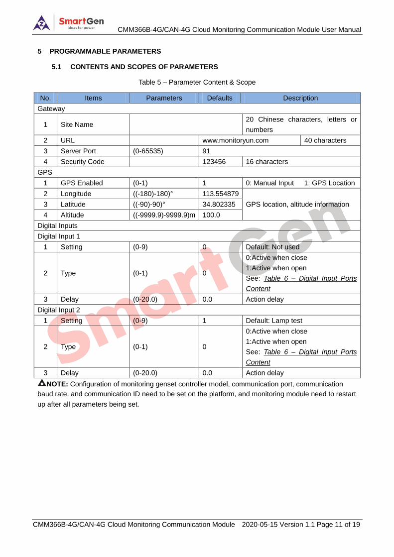
Table 5 – Parameter Content & Scope
No. Items Parameters Defaults Description
Gateway
1 Site Name 20 Chinese characters, letters or
numbers
2 URL www.monitoryun.com 40 characters
3 Server Port (0-65535) 91
4 Security Code 123456 16 characters
GPS
1 GPS Enabled (0-1) 1 0: Manual Input 1: GPS Location
2 Longitude ((-180)-180)° 113.554879
GPS location, altitude information 3 Latitude ((-90)-90)° 34.802335
4 Altitude ((-9999.9)-9999.9)m 100.0
Digital Inputs
Digital Input 1
1 Setting (0-9) 0 Default: Not used
2 Type (0-1) 0
0:Active when close
1:Active when open
See: Table 6 – Digital Input Ports
Content
3 Delay (0-20.0) 0.0 Action delay
Digital Input 2
1 Setting (0-9) 1 Default: Lamp test
2 Type (0-1) 0
0:Active when close
1:Active when open
See: Table 6 – Digital Input Ports
Content
3 Delay (0-20.0) 0.0 Action delay
NOTE: Configuration of monitoring genset controller model, communication port, communication
baud rate, and communication ID need to be set on the platform, and monitoring module need to restart
up after all parameters being set.
CMM366B-4G/CAN-4G Cloud Monitoring Communication Module User Manual
CMM366B-4G/CAN-4G Cloud Monitoring Communication Module 2020-05-15 Version 1.1 Page 12 of 19
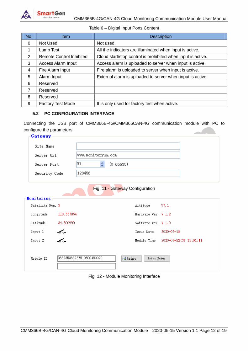
Table 6 – Digital Input Ports Content
No. Item Description
0 Not Used Not used.
1 Lamp Test All the indicators are illuminated when input is active.
2 Remote Control Inhibited Cloud start/stop control is prohibited when input is active.
3 Access Alarm Input Access alarm is uploaded to server when input is active.
4 Fire Alarm Input Fire alarm is uploaded to server when input is active.
5 Alarm Input External alarm is uploaded to server when input is active.
6 Reserved
7 Reserved
8 Reserved
9 Factory Test Mode It is only used for factory test when active.
5.2 PC CONFIGURATION INTERFACE
Connecting the USB port of CMM366B-4G/CMM366CAN-4G communication module with PC to
configure the parameters.
Fig. 11 - Gateway Configuration
Fig. 12 - Module Monitoring Interface
CMM366B-4G/CAN-4G Cloud Monitoring Communication Module User Manual
CMM366B-4G/CAN-4G Cloud Monitoring Communication Module 2020-05-15 Version 1.1 Page 13 of 19
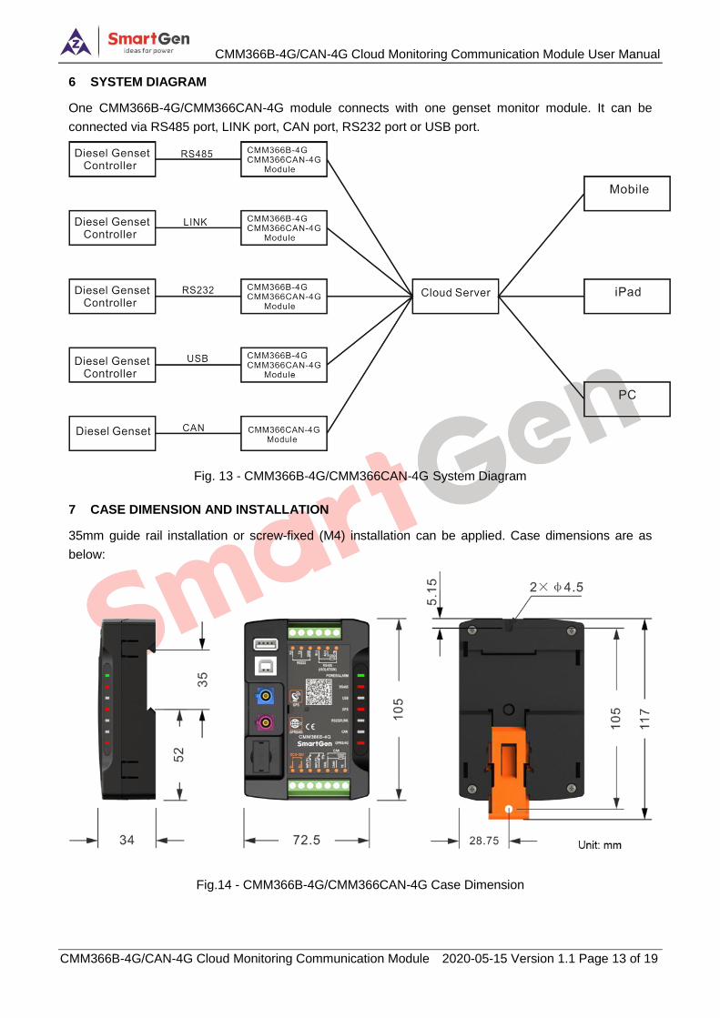
6 SYSTEM DIAGRAM
One CMM366B-4G/CMM366CAN-4G module connects with one genset monitor module. It can be
connected via RS485 port, LINK port, CAN port, RS232 port or USB port.
Fig. 13 - CMM366B-4G/CMM366CAN-4G System Diagram
7 CASE DIMENSION AND INSTALLATION
35mm guide rail installation or screw-fixed (M4) installation can be applied. Case dimensions are as
below:
Fig.14 - CMM366B-4G/CMM366CAN-4G Case Dimension
CMM366B-4G/CAN-4G Cloud Monitoring Communication Module User Manual
CMM366B-4G/CAN-4G Cloud Monitoring Communication Module 2020-05-15 Version 1.1 Page 14 of 19
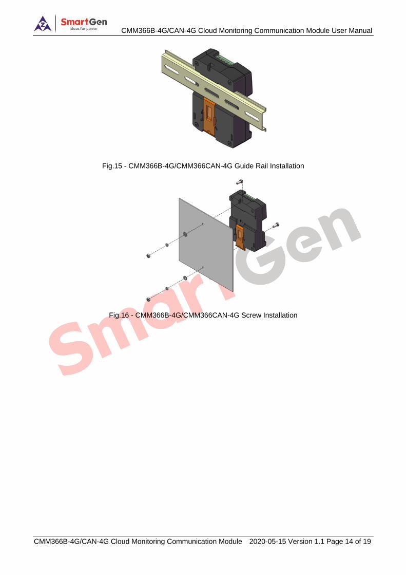
Fig.15 - CMM366B-4G/CMM366CAN-4G Guide Rail Installation
Fig.16 - CMM366B-4G/CMM366CAN-4G Screw Installation
CMM366B-4G/CAN-4G Cloud Monitoring Communication Module User Manual
CMM366B-4G/CAN-4G Cloud Monitoring Communication Module 2020-05-15 Version 1.1 Page 15 of 19
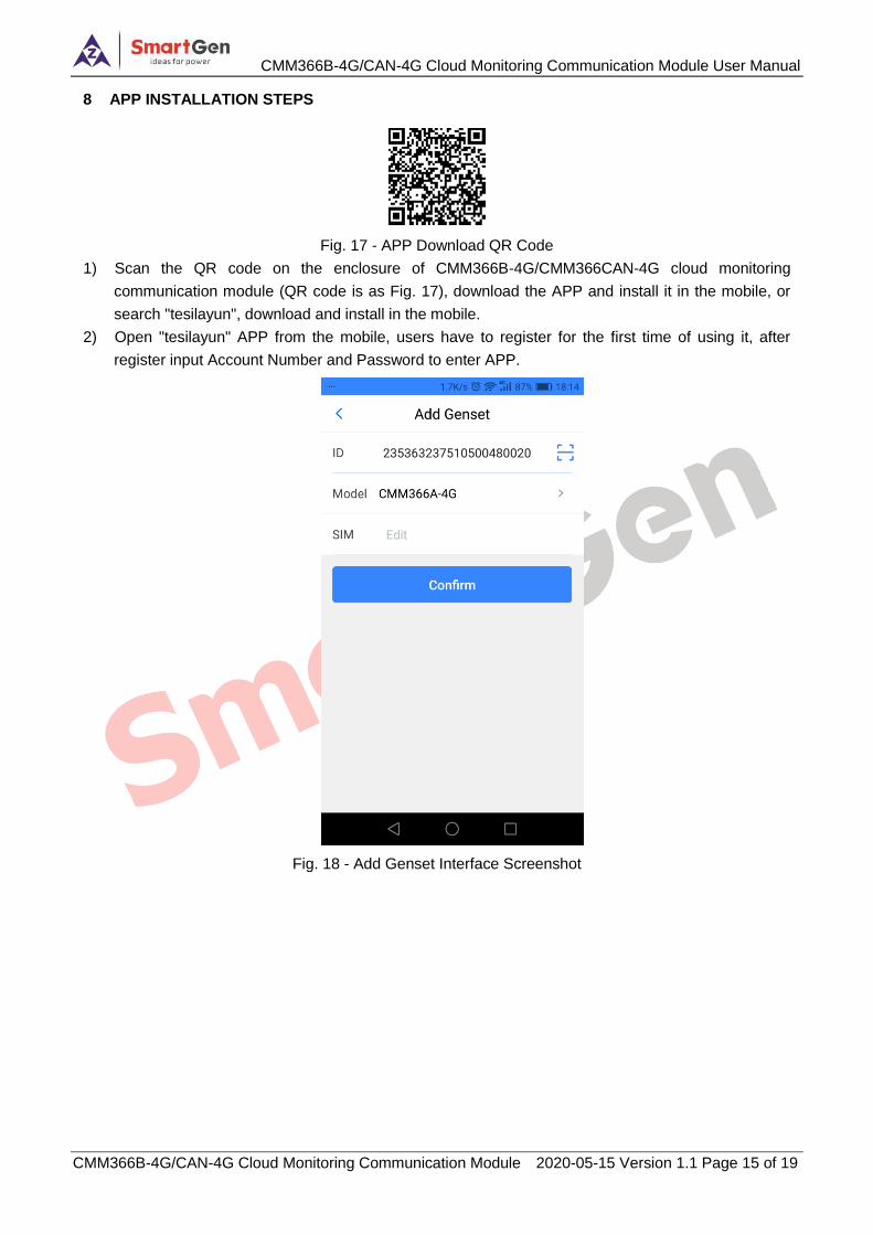
8 APP INSTALLATION STEPS
Fig. 17 - APP Download QR Code
1) Scan the QR code on the enclosure of CMM366B-4G/CMM366CAN-4G cloud monitoring
communication module (QR code is as Fig. 17), download the APP and install it in the mobile, or
search "tesilayun", download and install in the mobile.
2) Open "tesilayun" APP from the mobile, users have to register for the first time of using it, after
register input Account Number and Password to enter APP.
Fig. 18 - Add Genset Interface Screenshot
CMM366B-4G/CAN-4G Cloud Monitoring Communication Module User Manual
CMM366B-4G/CAN-4G Cloud Monitoring Communication Module 2020-05-15 Version 1.1 Page 16 of 19
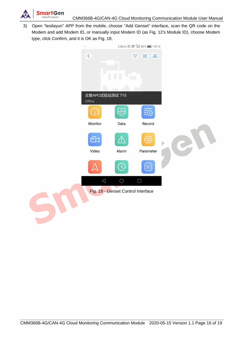
3) Open "tesilayun" APP from the mobile, choose "Add Genset" interface, scan the QR code on the
Modem and add Modem ID, or manually input Modem ID (as Fig. 12's Module ID), choose Modem
type, click Confirm, and it is OK as Fig. 18.
Fig. 19 - Genset Control Interface
CMM366B-4G/CAN-4G Cloud Monitoring Communication Module User Manual
CMM366B-4G/CAN-4G Cloud Monitoring Communication Module 2020-05-15 Version 1.1 Page 17 of 19
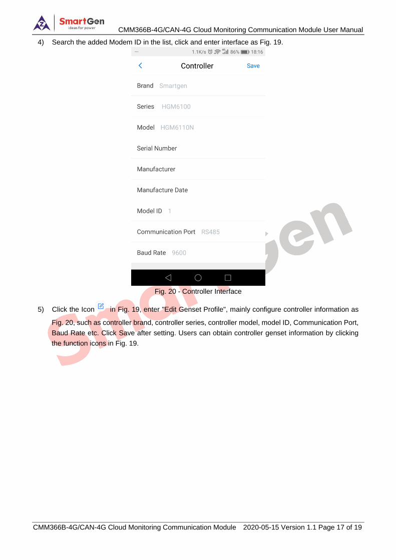
4) Search the added Modem ID in the list, click and enter interface as Fig. 19.
Fig. 20 - Controller Interface
5) Click the Icon in Fig. 19, enter "Edit Genset Profile", mainly configure controller information as
Fig. 20, such as controller brand, controller series, controller model, model ID, Communication Port,
Baud Rate etc. Click Save after setting. Users can obtain controller genset information by clicking
the function icons in Fig. 19.
CMM366B-4G/CAN-4G Cloud Monitoring Communication Module User Manual
CMM366B-4G/CAN-4G Cloud Monitoring Communication Module 2020-05-15 Version 1.1 Page 18 of 19
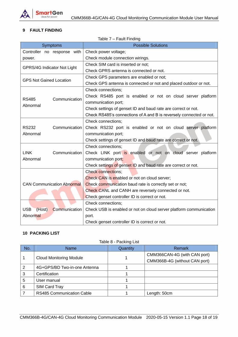
9 FAULT FINDING
Table 7 – Fault Finding
Symptoms Possible Solutions
Controller no response with
power.
Check power voltage;
Check module connection wirings.
GPRS/4G Indicator Not Light Check SIM card is inserted or not;
Check GPRS antenna is connected or not.
GPS Not Gained Location Check GPS parameters are enabled or not;
Check GPS antenna is connected or not and placed outdoor or not.
RS485 Communication
Abnormal
Check connections;
Check RS485 port is enabled or not on cloud server platform
communication port;
Check settings of genset ID and baud rate are correct or not.
Check RS485’s connections of A and B is reversely connected or not.
RS232 Communication
Abnormal
Check connections;
Check RS232 port is enabled or not on cloud server platform
communication port;
Check settings of genset ID and baud rate are correct or not.
LINK Communication
Abnormal
Check connections;
Check LINK port is enabled or not on cloud server platform
communication port;
Check settings of genset ID and baud rate are correct or not.
CAN Communication Abnormal
Check connections;
Check CAN is enabled or not on cloud server;
Check communication baud rate is correctly set or not;
Check CANL and CANH are reversely connected or not.
Check genset controller ID is correct or not.
USB (Host) Communication
Abnormal
Check connections;
Check USB is enabled or not on cloud server platform communication
port.
Check genset controller ID is correct or not.
10 PACKING LIST
Table 8 - Packing List
No. Name Quantity Remark
1 Cloud Monitoring Module 1 CMM366CAN-4G (with CAN port)
CMM366B-4G (without CAN port)
2 4G+GPS/BD Two-in-one Antenna 1
3 Certification 1
5 User manual 1
6 SIM Card Tray 1
7 RS485 Communication Cable 1 Length: 50cm
CMM366B-4G/CAN-4G Cloud Monitoring Communication Module User Manual
CMM366B-4G/CAN-4G Cloud Monitoring Communication Module 2020-05-15 Version 1.1 Page 19 of 19
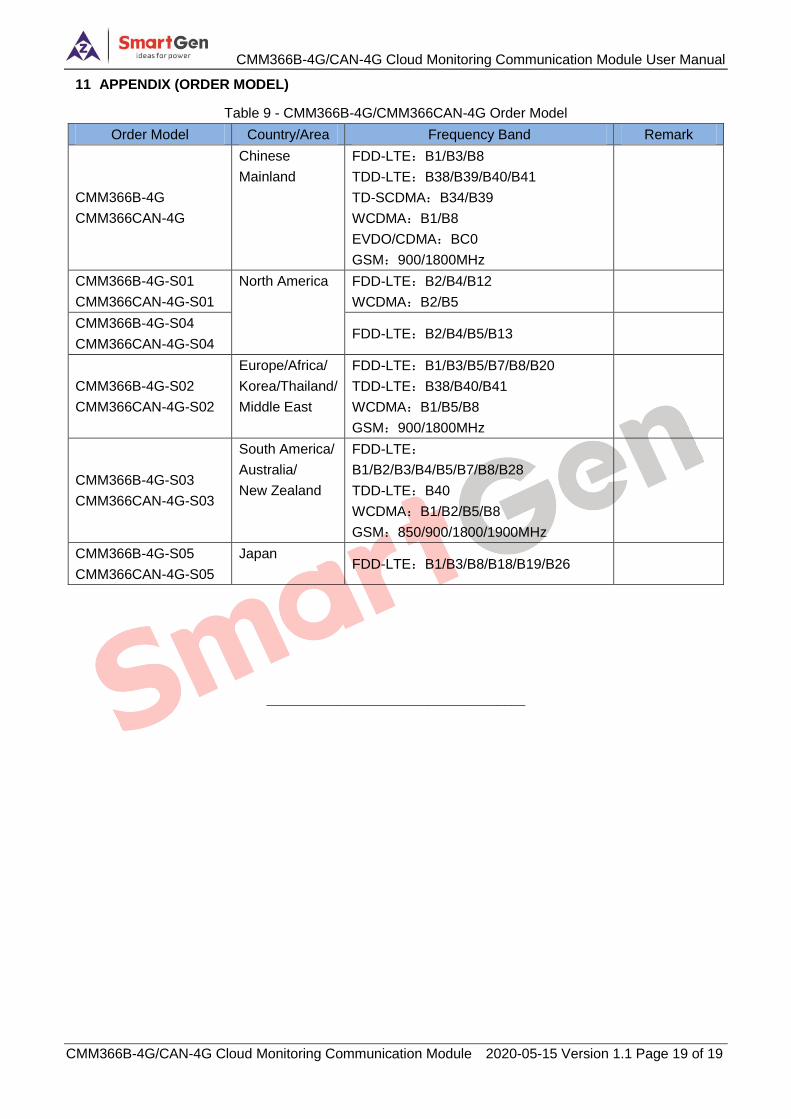
11 APPENDIX (ORDER MODEL)
Table 9 - CMM366B-4G/CMM366CAN-4G Order Model
Order Model Country/Area Frequency Band Remark
CMM366B-4G
CMM366CAN-4G
Chinese
Mainland
FDD-LTE:B1/B3/B8
TDD-LTE:B38/B39/B40/B41
TD-SCDMA:B34/B39
WCDMA:B1/B8
EVDO/CDMA:BC0
GSM:900/1800MHz
CMM366B-4G-S01
CMM366CAN-4G-S01
North America FDD-LTE:B2/B4/B12
WCDMA:B2/B5
CMM366B-4G-S04
CMM366CAN-4G-S04 FDD-LTE:B2/B4/B5/B13
CMM366B-4G-S02
CMM366CAN-4G-S02
Europe/Africa/
Korea/Thailand/
Middle East
FDD-LTE:B1/B3/B5/B7/B8/B20
TDD-LTE:B38/B40/B41
WCDMA:B1/B5/B8
GSM:900/1800MHz
CMM366B-4G-S03
CMM366CAN-4G-S03
South America/
Australia/
New Zealand
FDD-LTE:
B1/B2/B3/B4/B5/B7/B8/B28
TDD-LTE:B40
WCDMA:B1/B2/B5/B8
GSM:850/900/1800/1900MHz
CMM366B-4G-S05
CMM366CAN-4G-S05
Japan FDD-LTE:B1/B3/B8/B18/B19/B26
_____________________________________