Embed Size (px)
Citation preview

CMG-6TDCMG-6TDCMG-6TDCMG-6TDDigital Broadband Seismometer
Operator's guideOperator's guideOperator's guideOperator's guide
Part No. MAN-T60-0002
Designed and manufactured byGüralp Systems Limited3 Midas House, Calleva ParkAldermaston RG7 8EAEngland
Proprietary Notice: The information in this manual isproprietary to Güralp Systems Limited and may not be copiedor distributed outside the approved recipient's organisationwithout the approval of Güralp Systems Limited. GüralpSystems Limited shall not be liable for technical or editorialerrors or omissions made herein, nor for incidental orconsequential damages resulting from the furnishing,performance, or usage of this material.
Issue B 2008-11-12

CMG-6TD
Table of ContentsTable of ContentsTable of ContentsTable of Contents
1 Introduction............................................................................................................................41.1 Options.............................................................................................................................5
2 First encounters......................................................................................................................82.1 Unpacking and packing....................................................................................................82.2 Test installation................................................................................................................92.3 Testing several instruments together..............................................................................11
3 Installing the 6TD.................................................................................................................153.1 Handling notes................................................................................................................153.2 Connections....................................................................................................................153.3 Installation notes.............................................................................................................163.4 Installing in vaults..........................................................................................................173.5 Installing in pits..............................................................................................................193.6 Rapid installation............................................................................................................233.7 Setting up the Ethernet interface....................................................................................283.8 Setting up wireless networking......................................................................................333.9 Configuring the built-in digitizer...................................................................................433.10 Downloading data over FireWire.................................................................................433.11 Receiving data in Scream!............................................................................................48
4 Configuration with Scream!................................................................................................504.1 Configuring the digitizer................................................................................................504.2 Controlling the instrument..............................................................................................624.3 Digitizer status streams..................................................................................................70
5 Calibrating the 6TD.............................................................................................................735.1 The calibration pack.......................................................................................................735.2 Calibration methods.......................................................................................................765.3 Noise calibration with Scream! .....................................................................................765.4 The coil constant............................................................................................................79
6 Command line interface......................................................................................................816.1 FORTH...........................................................................................................................816.2 General configuration.....................................................................................................826.3 GPS and timing systems.................................................................................................846.4 Output configuration......................................................................................................88
2 Issue B

Operator's Guide
6.5 Triggering.......................................................................................................................906.6 Calibration......................................................................................................................936.7 Actions............................................................................................................................956.8 Flash storage and filing..................................................................................................966.9 Filing modes.................................................................................................................1006.10 FireWire disks............................................................................................................103
7 Updating the 6TD...............................................................................................................106
8 Connector pinouts..............................................................................................................1098.1 Instrument output port..................................................................................................1098.2 Instrument FIREWIRE port..........................................................................................1098.3 Instrument ETHERNET port........................................................................................1108.4 Breakout box data port.................................................................................................1108.5 Breakout box GPS port.................................................................................................1108.6 Breakout box power port..............................................................................................111
9 Specifications......................................................................................................................112
10 Revision history................................................................................................................113
November 2008 3

CMG-6TD
1 1 1 1 IntroductionIntroductionIntroductionIntroductionThe CMG-6TD is an ultra-lightweight digital three-axis seismometer consistingof three sensors in a sealed case, which can measure the north/south, east/westand vertical components of ground motion simultaneously. Each sensor issensitive to ground vibrations over a wide frequency range (0.033 – 50 Hz asstandard). This frequency response is made possible by advanced force-balancefeedback electronics. A built-in 24-bit digitizer converts ground movements todigital data at source with maximum fidelity.
The 6TD has a rugged, waterproof design for ease of installation, and requiresno levelling or centring as long as its base is within 3 ° from the horizontal. Forthe best results, however, you should install where possible on a hard, near-horizontal surface well coupled to the bedrock.
Once it is provided with 10 – 28 V power the 6TD will begin operatingautomatically, measuring and digitizing ground movements and eitheroutputting them to your own recording system, or saving them into internalFlash memory. Accurate timing information can be taken from a GPS unitconnected to the 6TD through a breakout box. Both breakout box and GPS arenormally supplied with the instrument.
4 Issue B

Operator's Guide
Each seismometer is delivered with a detailed calibration sheet showing itsserial number, measured frequency response in both the long period and theshort period sections of the seismic spectrum, sensor DC calibration levels, andthe transfer function in poles/zeros notation.
6TD sensors can be delivered in sets of 5 with GPS and cabling included. Eachset is supplied in a “smart” case allowing you to huddle-test the sensors withoutneeding to unpack them.
State of health information
The 6TD constantly monitors the status of the GPS and timing systems,outputting information in a plain text status stream.
An electronic thermometer also provides regular measurements of the sensor'sinternal temperature, which are reported in the same stream. The thermometer iscalibrated to an accuracy up to ± 0.33 °C, with a linearity of ± 0.5 °C.
1.1 Options
Storage and interfaces
The 6TD can be supplied with up to 16 Gb of internal Flash memory for datastorage. The amount you need will depend on the length of your experiment andthe sampling rates used.
You can download data from the internal storage
• over the sensor's standard RS232 data port (compatible with Scream!and other Güralp data modules),
• over a fast IEEE.1394 (FireWire) link with optional power,
• using an optional “smart” case, over USB from up to five units at once
November 2008 5

CMG-6TD
(see Section 2.3, page 11), or
• if fitted, using the Ethernet interface to transfer data over a local areanetwork.
Sensor response
The 6TD can be supplied with a response which is flat to velocity from 100 Hzto any of 1 Hz, 0.1 Hz (10 s), 0.033 Hz (30 s) or 0.016 Hz (60 s).
If you do not require high-frequency data, a low-pass digital filter may beinstalled at a frequency (below 100 Hz) that you specify.
Wireless networking
The sensor can be fitted with an optional 802.11b (“Wi-Fi”) wireless interfacein addition to the Ethernet port. This option allows data flow to be establishedfrom autonomous installations with a minimum of setting up.
For temporary deployments, instruments can be buried in shallow pits with onlythe antenna above ground. You can then contact each station from a wireless-enabled PC running Scream! without disturbing the instrument, includingmonitoring real-time data and configuring the digitizer.
6 Issue B

Operator's Guide
More permanent arrays also benefit from wireless technology, particularly inremote areas or where the terrain makes long cable runs impractical.
For example, stations might be installed with high-gain antennae directedtowards a visible natural feature which is easier to access.
At this location, which can be up to 500 m away, a low-power CMG-DCM datamodule might act as an access point for the array elements and forward dataonto a higher-bandwidth radio link.
In semi-permanent arrays, a wireless-enabled DCM or laptop PC can be set upas a temporary access point for the duration of a site visit.
November 2008 7

CMG-6TD
2 2 2 2 First encountersFirst encountersFirst encountersFirst encounters
2.1 Unpacking and packing
The 6TD seismometer is delivered in a single transportation case. Thepackaging is specifically designed for the 6TD and should be reused wheneveryou need to transport the sensor. Please note any damage to the packaging whenyou receive the equipment, and unpack on a safe, clean surface. For eachinstrument in the packaging, you should have received:
• the seismometer;
• the breakout box (which provides separate connections for the signal,control and power lines);
• a Güralp GPS receiver unit with mounting rod;
• a waterproof IEEE.1394 (FireWire) cable;
• a 15 m GPS cable, with 6-pin mil-spec connectors at both ends;
• a power supply cable, with bare wires at one end and a 10-pin mil-specsocket at the other;
• a serial data cable, with a standard 9-pin D connector at one end and a10-pin mil-spec plug at the other; and
• a calibration and installation sheet.
If you have ordered several instruments with a “smart” case, you can test themtogether using power and data distribution units inside the case: see section 2.3,page 11.
Assuming all the parts are present, stand the seismometer in the centre of abench and identify its external features:
• a handle with North indication,
• a 19-way mil-spec plug for data, power and GPS signals;
• a 6-way mil-spec plug for the FireWire interface;
• if fitted, a 6-way mil-spec plug for the Ethernet interface;
• if fitted, a connector for the Wi-Fi interface;
8 Issue B
Operator's Guide
• a spirit level,
• three feet (two adjustable, and one fixed), and
• two accurate orientation pins (one brass and one steel).
If the Wi-Fi interface is fitted, you will also be supplied with a small aerial fortesting purposes.
Serial number
The sensor's serial number can be found on the label stuck to the top lid of thesensor. You should quote this serial number if you need assistance from GüralpSystems.
2.2 Test installation
This section gives an overview of how to set up a 6TD and begin recordingdata. We recommend that you set up a test instrument in your office orlaboratory as a “dry run” to gain a basic understanding of the system and tocheck that it is functioning as expected.
This test installation will use the instrument's default settings. Data will bereceived using Güralp Systems' Scream! software, available from the website
http://www.guralp.com/
You will need access to a PC with a 9-pin RS232 port, and a 12 V powersource.
1. Install Scream! on your PC and run it.
2. Connect the wire from the breakout box to the 6TD's 19-pin connector.
3. Connect the 6-pin connector on the breakout box to the GPS unit usingthe GPS cable. Position the GPS so that it has a good view of the sky.
If you do not have a view of the sky, you can operate the sensor withouta GPS unit, but timing information may be inaccurate.
4. Connect the 6-pin data plug on the breakout box to the 9-pin RS232 porton your PC using the serial cable.
5. Use the power cable to connect the 10-pin power plug on the breakoutbox to a fused 10 – 28 V power source.
The instrument is now fully operational, and will already be producing
November 2008 9

CMG-6TD
data.
6. After a few seconds you should see the 6TD's digitizer appear underNetwork – Local – Com1 in the left-hand panel of Scream!'s mainwindow. (If your PC has multiple serial ports, it may appear under someother Com port name.) Soon after, data streams will begin appearing inthe right-hand panel. Streams with higher sample rates will appearsooner than those with lower sample rates.
If this does not happen, check all connections, and ensure the powersupply is providing the correct voltage and current.
7. Each data stream has a Stream ID, a six-character string unique to it.Stream IDs normally identify the instrument, component and sample rateof each stream. Thus the stream 1026Z2 refers to a Z-componentstream from instrument 1026, at tap 2. For more details on taps andsample rates, see section 4.1, page 51.
Data streams ending in 00 are status streams containing any extrainformation sent from the digitizer.
8. To view data, select a stream and then double-click to open a Waveviewwindow.
You can view several streams at once by holding down SHIFT as youselect, and then double-clicking the selection.
10 Issue B

Operator's Guide
9. To start recording new data to a file, right-click on a stream or aselection of streams and choose Start recording from the pop-up menu.Recording settings, directories, etc., can be altered by selecting File →Setup... from the main menu and switching to the Recording tab.
10.To view status information, select the stream and right-click to open apop-up menu. Select View.
The first few status blocks will consist of the 6TD's start-up messages,including its software revision number and the data streams selected fordownloading and triggering.
Later blocks give information on the GPS system (number of satellitesvisible, the location of the GPS antenna, time synchronization status,etc.) and the baud rates in use for each channel.
2.3 Testing several instruments together
6TD instruments can be ordered in sets of five, with each set delivered in asingle rigid polyurethane transport case.
November 2008 11

CMG-6TD
Within this case, the sensors are packed so that you can huddle-test the sensorsand view data in Scream! without needing to unpack them. This is done using apower distribution box and USB and FireWire data hubs built into the case.
The power and data distribution boxes are located at the front of the case.
The package is shipped with each instrument already connected to these units,so you can begin testing immediately.
The power supply and combined USB data output cables can be accessedthrough a waterproof port on the outside of the case.
To test the instruments:
12 Issue B
Operator's Guide
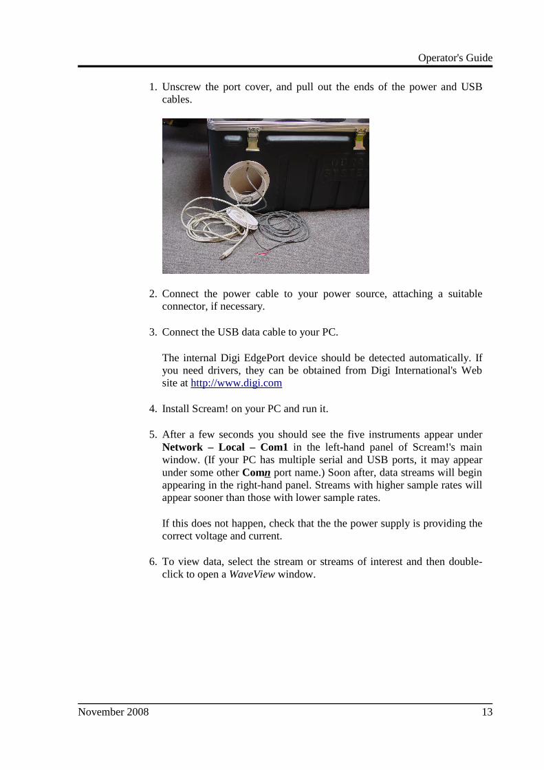
1. Unscrew the port cover, and pull out the ends of the power and USBcables.
2. Connect the power cable to your power source, attaching a suitableconnector, if necessary.
3. Connect the USB data cable to your PC.
The internal Digi EdgePort device should be detected automatically. Ifyou need drivers, they can be obtained from Digi International's Website at http://www.digi.com
4. Install Scream! on your PC and run it.
5. After a few seconds you should see the five instruments appear underNetwork – Local – Com1 in the left-hand panel of Scream!'s mainwindow. (If your PC has multiple serial and USB ports, it may appearunder some other Comn port name.) Soon after, data streams will beginappearing in the right-hand panel. Streams with higher sample rates willappear sooner than those with lower sample rates.
If this does not happen, check that the the power supply is providing thecorrect voltage and current.
6. To view data, select the stream or streams of interest and then double-click to open a WaveView window.
November 2008 13

CMG-6TD
You can also add data streams to an open Waveview window bydragging a selection onto it from Scream!'s main window.
7. In addition to the power and USB data distribution units, the caseincludes a IEEE.1394 (“FireWire”) hub for you to test high speed datatransfer. To do this, connect a FireWire cable from each instrument tothe hub.
Once the instruments are connected, you can access them all through theFireWire data cable, which is accessible through the waterproof port inthe side of the case.
8. To download all stored data from the array when it is stored in itstransport case, attach a FireWire hard disk to this cable and power up thearray using the power cable from the same port.
Be sure to allow enough time for all the data to transfer. The 6TD shouldbe able to transfer data at a sustained rate of around 10 Mb/s, so a full 8Gb CMG-6TD instrument should take around 12 minutes to transfer allits data.
14 Issue B

Operator's Guide
3 3 3 3 Installing the 6TDInstalling the 6TDInstalling the 6TDInstalling the 6TD
3.1 Handling notes
Although it has a rugged design, the 6TD is still a sensitive instrument, and iseasily damaged if mishandled. If you are at all unsure about the handling orinstallation of the device, you should contact Güralp Systems for assistance.
• Do not bump or jolt the sensor when handling or unpacking.
• Do not kink or walk on the data cable (especially on rough surfaces suchas gravel), nor allow it to bear the weight of the sensor.
• Move the instrument with care, and report any sign of loose componentsor parts moving inside the instrument to Güralp Systems.
• Do not connect the instrument to power sources except where instructed.
• Do not ground any of the signal lines from the sensor.
All parts of the 6TD are waterproof.
3.2 Connections
The instrument
The 6TD's output connectors are all located on the sensor lid. The sensor can besupplied with a number of options, so not all the connectors may be present onyour instrument.
All 6TD instruments have a 19-pin mil-spec connector which carries power,data and GPS signals. The supplied breakout box (see below) providesindividual connectors for these, or you can make up your own cable if youprefer.
The 6TD may also have connectors for the FireWire, Ethernet or Wi-Fiinterfaces.
November 2008 15

CMG-6TD
The breakout box
In addition to the cable to the instrument, which is moulded into the case, thebreakout box provides
• a 6-pin socket for connecting the supplied GPS unit;
• a 10-pin plug for connecting to a PC's serial interface or a Güralp datamodule; and
• a 6-pin mil-spec plug for connecting a 12 V power supply.
You may need to attach a suitable connector to the power cable provided. The6TD draws a nominal current of 75 mA from a 12 V supply when in use; thus,using a 12 V, 25 Ah sealed heavy-duty lead-acid battery, you should expect theinstrument to operate for around a week without recharging.
3.3 Installation notes
For the best possible results, a seismometer should be installed on a seismic pierin a specially-built vault, where conditions are near perfect. Here, wave-trainsarriving at the instrument reflect very well the internal motion of subsurfacerock formations. However, this is not always feasible. For example,
• instruments may need to be deployed rapidly, perhaps to monitor theactivity of a volcano showing signs of rejuvenation, or to study theaftershocks of a major earthquake;
• installations may be required in remote locations, or otherwise incircumstances where it is infeasible to build a vault.
In these situations, the seismometer and its emplacement need to be consideredas a mechanical system, which will have its own vibrational modes andresonances. These frequencies should be raised as high as possible so that they
16 Issue B

Operator's Guide
do not interfere with true ground motion: ideally, beyond the range of theinstrument. This is done by
• standing the sensor on bedrock where possible, or at least deep in well-compacted subsoil;
• clearing the floor of the hole of all loose material; and
• using as little extra mass as possible in preparing the chamber.
In temporary installations, environmental factors are also important. The sensorneeds to be well protected against
• fluctuations in temperature,
• turbulent air flow around walls or trees, or around sharp corners or edgesin the immediate vicinity of the sensor;
• vibration caused by heavy machinery (even at a distance), or byoverhead power lines.
This can be done by selecting a suitable site, and placing the instrument in aprotective enclosure. An open-sided box of 5 cm expanded polystyrene slabs,placed over the instrument and taped down to exclude draughts, makes anexcellent thermal shield.
After installation, the instrument case and mounting surface will slowly returnto the local temperature, and settle in their positions. This will take around fourhours from the time installation is completed.
3.4 Installing in vaults
You can install a 6TD in an existing seismic vault with the following procedure:
1. Unpack the sensors from their container, saving the shipping boxes forlater transportation.
2. Prepare the mounting surface, which should be smooth and free ofcracks. Remove any loose particles or dust, and any pieces of loosesurfacing. This ensures good contact between the instrument's feet andthe surface.
3. If it is not already present, inscribe an accurate North-South line on themounting surface.
4. Place the sensor over the scribed line, so that the brass and steel pointersare aligned with the marked directions, with the brass pointer facing
November 2008 17

CMG-6TD
North. This can be done by rotating the base of the sensor whilstobserving it from above. The brass pointer can be found next to one ofthe feet.
If you cannot easily see the pointers, you should align the sensor usingthe north arrow on the handle. However, the alignment of the handlewith the sensors inside is less accurate than the metal pointers, so theyshould be used wherever possible.
5. The top panel of the 6TD includes a spirit level.
Level the sensor using each of the adjustable feet of the instrument inturn, until the bubble in the spirit level lies entirely within the innercircle. (The instrument can operate with up to 2 ° of tilt, but withreduced performance.)
The feet are mounted on screw threads. To adjust the height of a foot,turn the brass locking nut anticlockwise to loosen it, and rotate the footso that it screws either in or out. When you are happy with the height,tighten the brass locking nut clockwise to secure the foot.
18 Issue B

Operator's Guide
When locked, the nut should be at the bottom of its travel for optimalnoise performance.
6. Connect a 12 V fused power supply to the breakout box.
7. Connect the data cable to a PC. Run Scream!, and check that data isbeing produced. Optionally, also check the mass position outputs(streams ending M8, M9 and MA.) These streams are digitized at a slowerrate, and may take up to 15 minutes to appear.
8. Cover the instrument with thermal insulation, for example, a 5 cmexpanded polystyrene box. This will shield it from thermal fluctuationsand convection currents in the vault. It also helps to stratify the air in theseismometer package. Position the thermal insulation carefully so that itdoes not touch the sensor package.
9. Ensure that the sensor cable is loose and that it exits the seismometerenclosure at the base of the instrument. This will prevent vibrations frombeing inadvertently transmitted along the cable.
3.5 Installing in pits
For outdoor installations, high-quality results can be obtained by constructing aseismic pit.
November 2008 19

CMG-6TD
Depending on the time and resources available, this type of installation can suitall kinds of deployment, from rapid temporary installations to medium-termtelemetered stations.
Ideally, the sensor should rest directly on the bedrock for maximum coupling tosurface movements. However, if bedrock cannot be reached, good results can beobtained by placing the sensor on a granite pier on a bed of dry sand.
1. Prepare a hole of 60 – 90 cm depth to compacted subsoil, or down to thebedrock if possible.
2. On granite or other hard bedrock, use an angle grinder to plane off thebedrock at the pit bottom so that it is flat and level. Stand the instrumentdirectly on the bedrock, and go to step 7.
3. On soft bedrock or subsoil, you should install a pier as depicted below.
4. Pour a layer of loose, fine sand into the pit to cover the base. The type ofsand used for children's sand-pits is ideal, since the grains are clean, dryand within a small size range. On top of the sand, place a smooth, flatgranite plinth around 20 cm across, and shift it to compact the sand and
20 Issue B

Operator's Guide
provide a near-level surface.
Placing a granite plinth on a sand layer increases the contact between theground and the plinth, and improves the performance of the instrument.There is also no need to mix concrete or to wait for it to set.
5. Alternatively, if time allows and granite is not available, prepare aconcrete mix with sand and fine grit, and pour it into the hole. Agitate(“puddle”) it whilst still liquid, to allow it to flow out and form a levelsurface, then leave to set. Follow on from step 7.
Puddled concrete produces a fine-textured, level floor for emplacing theseismometer. However, once set hard, the concrete does not have thebest possible coupling to the subsoil or bedrock, which has some leewayto shift or settle beneath it.
6. Alternatively, for the most rapid installation, place loose soil over thebottom of the pit, and compact it with a flat stone. Place the seismometeron top of this stone. This method emulates that in step 3, but can beperformed on-site with no additional equipment.
7. Set up the instrument as described in Section 3.4, page 17 (steps 4 to 9).
8. The instrument must now be shielded from air currents and temperaturefluctuations. This is best done by covering it with a thermal shield.
An open-sided box of 5 cm expanded polystyrene slabs is recommended.If using a seismic plinth on sand (from steps 3–4 or 5), ensure that thebox is firmly placed in the sand, without touching the plinth at any point.In other installations, tape the box down to the surface to excludedraughts.
9. Alternatively, if a box is not available, cover the instrument with finesand up to the top.
November 2008 21

CMG-6TD
The sand insulates the instrument and protects it from thermalfluctuations, as well as minimizing unwanted vibration.
10.Ensure that the sensor cable is loose and that it exits the seismometerenclosure at the base of the instrument. This will prevent vibrations frombeing inadvertently transmitted along the cable.
11.Cover the pit with a wooden lid, and back-fill with fresh turf.
Other installation methods
The recommended installation methods have been extensively tested in a widerange of situations. However, past practice in seismometer installation hasvaried widely.
Some installations introduce a layer of ceramic tiles between a rock or concreteplinth and the seismometer (left):
However, noise tests show that this method of installation is significantlyinferior to the same concrete plinth with the tiles removed (right). Horizontalsensors show shifting due to moisture trapped between the concrete and tiling,whilst the vertical sensors show pings as the tile settles.
Other installations have been attempted with the instrument encased in plasterof Paris, or some other hard-setting compound (left):
Again, this method produces inferior bonding to the instrument, and moisturebecomes trapped between the hard surfaces. We recommend the use of fine drysand (right) contained in a box if necessary, which can also insulate the
22 Issue B

Operator's Guide
instrument against convection currents and temperature changes. Sand has thefurther advantage of being very easy to install, requiring no preparation.
Finally, many pit installations have a large space around the seismometer,covered with a wooden roof. Large air-filled cavities are susceptible to currentswhich produce lower-frequency vibrations, and sharp edges and corners cangive rise to turbulence. We recommend that a wooden box is placed around thesensor to protect it from these currents. Once in the box, the emplacement maybe backfilled with fresh turf to insulate it from vibrations at the surface, orsimply roofed as before.
By following these guidelines, you will ensure that your seismic installation isready to produce the highest quality data.
3.6 Rapid installation
The 6TD is specially designed for rapid installation, and may be fully installedin a few hours. This section details a method of deploying 6TD instrumentswith the minimum of additional equipment. This is recommended for situationswhere seismic instrumentation needs to be installed very quickly, e.g. to study aresumption of volcanic activity, or where difficulty of access to the site preventsyou from constructing a full seismic pit. You should always construct a pit ifpossible (see section 3.5, page 19), since the data produced will be ofsignificantly higher quality.
1. Prepare a hole of 60 – 90 cm depth to compacted subsoil, or down to thebedrock if possible.
2. Clean the hole down to the bottom, and remove any loose material fromthe mouth. Ensure that the bottom of the hole is relatively flat.
November 2008 23

CMG-6TD
3. If the bottom of the hole is made of hard rock, you may need to put insome loose sand or soil so that the sensor can be levelled.
4. Connect the sensor to cables for the GPS unit and power source. If your6TD has the Wi-Fi option, connect your antenna to the sensor.
5. Carefully insert the instrument into the hole, protected by a tough plasticbag to keep water out. Use a bag strong enough to bear the weight of thesensor and breakout box, so that it can be recovered easily.
6. Press the sensor down firmly into the soil, without tapping or hitting it.
7. Check the bubble level on top of the instrument package.
Adjust the instrument's position if necessary so that the bubble liesentirely within the black circle.
8. Pack soil or sand around the instrument to hold it steady. Make sure thesoil or sand is firmly compacted and not at all loose.
9. Recheck the bubble level. If you cannot adjust the soil packing at this
24 Issue B

Operator's Guide
stage and the sensor is not level, you will need to clear the hole andrestart from step 3.
10.Place the breakout box and any excess cable on top of the sensor, insidethe plastic bag.
11.Group the cables coming from the bag for a distance of about 1 m, andkeep them together with insulating tape.
12.Tie the top of the package and fold it over so that water cannot get in.Leave any excess cable within the bag.
13.Cover the installation with soil or sand until it is no longer visible.
14.Attach a GPS unit to the cable coming from the sensor. Position it sothat it has a good view of the sky.
If possible, place the GPS near the instrument so that it can be foundmore easily.
15.If you are installing a 6TD with Wi-Fi, connect and install the antenna.
November 2008 25

CMG-6TD
16.Bury the cables so that they cannot be seen.
17.If you are using a battery as a power source, dig a second hole for it.This hole does not need to be as deep as the pit for the instrument—perhaps 10 cm plus the height of the battery.
18.Attach the sensor power cable to the battery, and wrap it in anotherplastic bag. Place the bag in the hole.
19.Tie the bag and fold over, to make the battery as waterproof as possible.
20.Bury the power cable between the battery and the instrument, andcompact soil or sand around the bag.
21.Fill in and cover the hole so that it is not visible.
Recovery
Care should be taken when recovering the 6TD, since tapping or banging it cancause damage to the sensors inside. The following instructions assume that youhave installed the instrument following the steps above.
26 Issue B
Operator's Guide
1. Find the GPS receiver, which will be the only feature visible from thesurface, and follow the buried data cable from it to the instrument.
2. Carefully remove earth from the hole until you find the power cablecoming from the instrument.
3. Follow the power cable to the battery pit, and carefully dig away the soilto reveal the battery about 10 cm from the surface.
4. Disconnect the power cable from the battery. (With the power off, thesensor is less likely to suffer electrical damage during recovery.)
5. Return to the location of the sensor, and dig down to it. You should beable to remove a spade's head depth of soil without hitting theinstrument. Beyond that, using a small hand shovel, follow the wires andcarefully remove the remaining soil until you can see the plastic bag.Take special care not to damage the wires, which should be tied togetherin the vicinity of the bag.
6. Carry on removing soil, either with your hands or (very carefully!) withthe shovel, until the whole bag is uncovered to about half the height ofthe instrument.
7. If the hole is relatively dry, open the bag and remove the breakout boxand cabling. Lift the instrument out by its handle.
Do not lift the instrument by any of the attached cables. Straining thecables may result in invisible damage, making future installationsunreliable.
8. Alternatively, if the hole is waterlogged, carefully lift out the entire bagin one piece, and remove the contents at the surface.
3.7 Setting up the Ethernet interface
CMG-6TD instruments with Ethernet features installed use an embeddedLantronix X-Port module to provide the network interface. This module can beconfigured using a built-in Web server.
Before you can access the Web server, however, you will need to assign thedevice an IP address. This can be done using Lantronix' DeviceInstaller utilityfor Microsoft Windows, or using a DHCP server. You will need a PC with anetwork interface installed.
November 2008 27

CMG-6TD
Using DeviceInstaller
1. Download and install the DeviceInstaller utility from the LantronixWeb site at http://www.lantronix.com/
2. DeviceInstaller also requires the Microsoft .NET framework to beinstalled. If you do not have this already, it can be downloaded athttp://www.microsoft.com/
3. Find out the MAC address of the 6TD's network interface. This shouldbe printed on a label on the case.
4. If the Data Out port on the breakout box is connected to anything,disconnect it.
5. Connect the 6TD's ETHERNET port to the the PC's network interface,either using a crossover Ethernet cable or through a network hub.
Using a hub, you can connect several 6TDs to the same PC andconfigure them all at the same time.
DeviceInstaller will not work through routers or across the Internet. Allthe devices need to be on the same network segment as the PC.
6. Run DeviceInstaller.
DeviceInstaller's main window has two panels, a tree on the left (withLantronix Devices at the top) and a table on the right.
The program will automatically look for Lantronix devices on all ofyour computer's network interfaces. If necessary, you can narrow theselection by clicking on an entry in the tree on the left.
An X-Port entry should appear in the table on the right, denoting that adevice has been detected.
28 Issue B

Operator's Guide
If more than one X-Port entry appears, DeviceInstaller has detectedseveral devices.
For every detected device, the program shows the Hardware Address(i.e. the MAC address), and the IP address it is currently using. If yourlocal network uses a DHCP server, the device will ask the DHCP serverto assign it an address. Otherwise, a random address will be chosenautomatically.
Automatic random addresses all begin with 169.254. The 6TD willchoose a different one every time it is power cycled or rebooted.
7. The address of the 6TD may be shown in red with the statusUnreachable.
If this happens, the sensor and PC cannot communicate because they arenot on the same subnet. Click Assign IP to start the IP configurationwizard.
Follow the instructions in the wizard to set the IP address, or configureDHCP if you are using a DHCP server. When you have finished, clickSearch to find the sensor with its new IP address.
8. If you want to configure the 6TD to use a static IP address, use theAssign IP wizard as above, and click Search again.
9. Double-click on the entry which corresponds to the 6TD you want toconfigure.
November 2008 29

CMG-6TD
The right-hand panel will change to show the current properties of thedevice.
10. Switch to the Web Configuration tab, and click Go to open the Webconfiguration interface.
Alternatively, click Use External Browser to use your own Webbrowser to configure the instrument.
11. Follow the steps below to configure the module from its Web interface.
Using DHCP
If you cannot install DeviceInstaller on your PC, or do not wish to, you can alsoget access to the 6TD using a standard DHCP server. In most cases you willneed to have administrative privileges to do this.
1. Install and start the DHCP service on your PC.
2. Connect the 6TD's ETHERNET port to the the PC's network interface,either using a crossover Ethernet cable or through a network hub.
Using a hub, you can connect several 6TDs to the same PC andconfigure them all at the same time.
30 Issue B

Operator's Guide
DHCP will not work through routers or across the Internet. All thedevices need to be on the same network segment as the PC.
3. Monitor the DHCP server to find out what IP address it gives to eachinstrument.
4. To configure a device, enter its IP address into a web browser.
Configuration with the Web interface
Once you have access to the X-Port's Web interface, you can configure it withits proper settings.
1. The Web page is divided into three. A menu on the left switchesbetween pages of configuration options on the right. There is also abanner at the top, which tells you the current firmware revision and theMAC address.
To navigate around the Web site, click on the entries in the left-handmenu. When you have made changes to the settings on any page, savethem by clicking OK before you leave the page.
2. The X-Port has two serial channels which you can connect to. By defaultthese are exposed on ports 10001 and 10002.
Channel 1 (normally port 10001) is connected to a serial console whichis exposed on the power port of the breakout box. If you have problemsconnecting to the 6TD, you can attach a standard Güralp Systems power/data cable to this port and use Scream! to access the console.
Channel 2 (port 10002) is connected to the 6TD's digital output, unlessyou have connected a serial data cable from the breakout box to acomputer. If the breakout box is connected, the 6TD will send datastreams through that interface rather than to the X-Port.
Click on Channel 2 – Serial Settings.
November 2008 31

CMG-6TD
Set the Baud Rate to 19200. This is the default baud rate for the 6TD'sdigital output. If you change the baud rate in Scream! or using theterminal, you must come back to this page and change the Baud Ratesetting.
The remaining settings can be left at their default values. Click OK tosave your changes.
For full information on the X-Port's configuration options, please referto the X-Port documentation, which is available on the Lantronix Website, http://www.lantronix.com/
3. When you have finished setting up the X-Port, apply the new settings byclicking Apply Settings. The X-Port will re-boot with the new settingsin effect.
If the Wi-Port is using an automatically chosen random IP (beginningwith 169.254), the IP address will change when you do this. You willneed to go back to DeviceInstaller to find out the new IP address.
3.8 Setting up wireless networking
CMG-6TD instruments with wireless features installed use an embeddedLantronix Wi-Port module to provide the network interface. This module can beconfigured using the DeviceInstaller utility for Microsoft Windows, or using aDHCP server. You will need a PC with a wireless card installed.
You may find it easiest to gather together all the Wi-Fi hardware before takingit into the field, and configuring it from a local wireless-enabled PC.
CMG-6TD instruments with the wireless networking option also have anETHERNET port for attaching to a wired network. You can switch between thewired and wireless interfaces using DeviceInstaller.
There are two types of wireless network topology supported by the Wi-Port.
● Infrastructure networks need additional hardware, such as wirelessaccess points and routers, to work. Any host on the wireless networkwill communicate with the access point or router, which manages all theconnections and ensures data is transmitted correctly. This device mayalso provide connectivity to the Internet or your local network.
● Ad hoc networks can be set up with no additional hardware. Each hoston the wireless network attempts to communicate directly with the otherhosts.
Ad hoc networks are easy to set up, but they are only suitable with a small
32 Issue B

Operator's Guide
number of hosts. In seismic networks, infrastructure mode is normallypreferred, since sensors do not need to communicate with each other.
Using DeviceInstaller in an infrastructure network
1. Download and install the DeviceInstaller utility from the LantronixWeb site at http://www.lantronix.com/
2. DeviceInstaller also requires the Microsoft .NET framework to beinstalled. If you do not have this already, it can be downloaded athttp://www.microsoft.com/
3. Find out the MAC address of the 6TD's network interface. This shouldbe printed on a label on the case.
4. Configure your wireless router or access point to use a network name(SSID) of LTRX_IBSS
5. Disable any security features of the wireless router or access point.
6. Run DeviceInstaller.
The main window has two panels, a tree on the left (with LantronixDevices at the top) and a table on the right.
7. The program will automatically look for Lantronix devices on all ofyour computer's network interfaces. If necessary, you can narrow theselection by clicking on an entry in the tree on the left.
A Wi-Port entry should appear in the table on the right, denoting that adevice has been detected.
If more than one Wi-Port entry appears, DeviceInstaller has detectedseveral devices.
November 2008 33

CMG-6TD
For every detected device, the program shows the Hardware Address(i.e. the MAC address), and the IP address it is currently using. If youare using a wireless router with a DHCP server, or an access pointconnected to a network with a DHCP server, the device will use DHCPto assign it an address. Otherwise, a random address will be chosenautomatically.
Automatic random addresses all begin with 169.254. The 6TD willchoose a different one every time it is power cycled or rebooted.
8. The address of the 6TD may be shown in red with the statusUnreachable.
If this happens, the sensor and PC cannot communicate because they arenot on the same subnet. Click Assign IP to start the IP configurationwizard.
Follow the instructions in the wizard to set the IP address, or configureDHCP if you are using a DHCP server. When you have finished, clickSearch to find the sensor with its new IP address.
9. If you want to configure the 6TD to use a static IP address, use theAssign IP wizard as above, and click Search again.
10. Double-click on the entry which corresponds to the 6TD you want toconfigure.
34 Issue B

Operator's Guide
The right-hand panel will change to show the current properties of thedevice.
11. Switch to the Web Configuration tab, and click Go to open the Webconfiguration interface.
Alternatively, click Use External Browser to use your own Webbrowser to configure the instrument.
12. Follow the steps below to configure the module from its Web interface.
Using DHCP in infrastructure mode
If you cannot install DeviceInstaller on your PC, or do not wish to, you can alsoget access to the 6TD using a standard DHCP server. In most cases you willneed to have administrative privileges to do this.
1. Install and start the DHCP service on your PC.
2. Configure your wireless router or access point to use a network name(SSID) of LTRX_IBSS
3. Disable any security features of the wireless router or access point.
4. Monitor the DHCP server to find out what IP address it gives to eachWi-Port in range. If necessary, power cycle the sensor(s).
5. To configure a device, enter its IP address into a web browser.
Using “ad hoc” mode
If you do not have a wireless router or access point, you can configure yourcomputer to set up an ad hoc wireless network when the 6TD comes withinrange.
November 2008 35

CMG-6TD
To configure Windows XP to set up an ad hoc wireless network:
1. Open the Control Panel and select Network Connections.
2. Right-click on the Wireless Connection icon and select Properties.Switch to the Wireless Networks tab.
3. Under Preferred networks, click Advanced. Select Computer-to-computer (ad hoc) networks only.
Ensure the Automatically connect to non-preferred networks box is notticked. Click Close to return to the Wireless Network ConnectionProperties window.
4. Under Preferred networks, click Add.... Switch to the Association tab.
36 Issue B

Operator's Guide
5. Fill in the Network name (SSID) of LTRX_IBSS
6. Set Network Authentication to Open and Data encryption to Disabled.Click OK .
The network connection should now be visible under Preferrednetworks, and in the main Wireless Network Connection window.
Initially, the network will be shown as Not connected.
7. Power cycle the 6TD. After a short while, your computer should reportthat it has connected to the LTRX_IBSS network.
8. Use DeviceInstaller to find the 6TD on the new network.
If your computer is configured to obtain its network addressautomatically, both it and the 6TD will be using automatic random IP
November 2008 37
CMG-6TD
addresses.
Automatic random addresses all begin with 169.254. Both hosts willchoose a different one every time they are power cycled or rebooted, orwhen the wireless network connection is lost.
To prevent this happening, configure your computer to use a static IPaddress, and use the Assign IP wizard in DeviceInstaller to assign astatic IP address to the 6TD.
Configuration with the Web interface
Once you have access to the Wi-Port's Web interface, you can configure it withits proper settings.
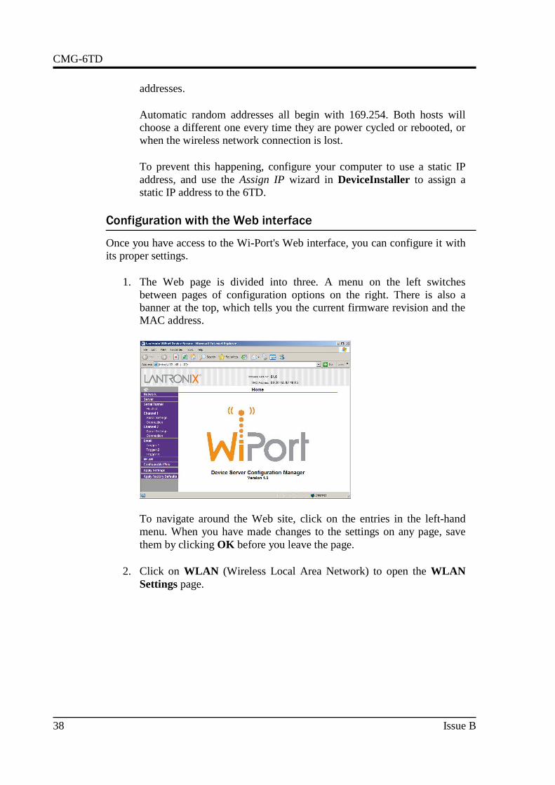
1. The Web page is divided into three. A menu on the left switchesbetween pages of configuration options on the right. There is also abanner at the top, which tells you the current firmware revision and theMAC address.
To navigate around the Web site, click on the entries in the left-handmenu. When you have made changes to the settings on any page, savethem by clicking OK before you leave the page.
2. Click on WLAN (Wireless Local Area Network) to open the WLANSettings page.
38 Issue B
Operator's Guide
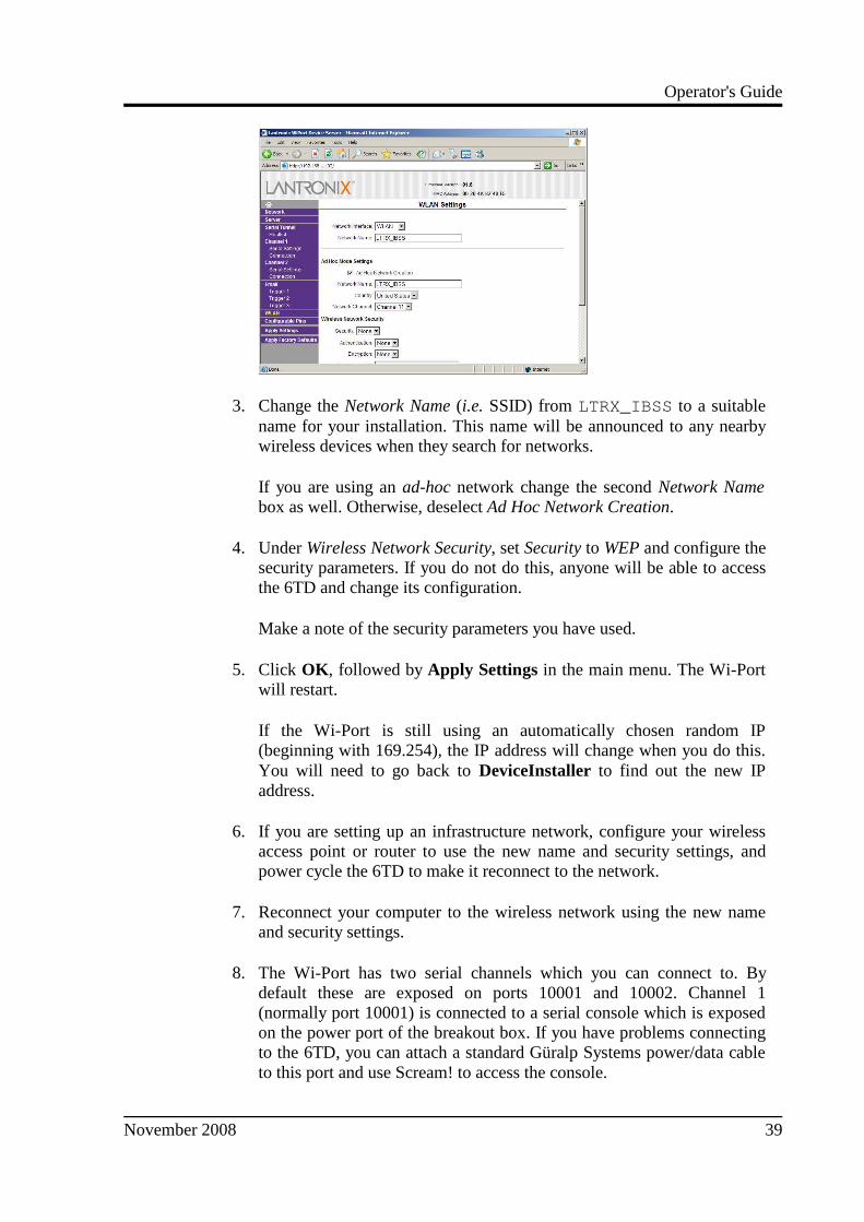
3. Change the Network Name (i.e. SSID) from LTRX_IBSS to a suitablename for your installation. This name will be announced to any nearbywireless devices when they search for networks.
If you are using an ad-hoc network change the second Network Namebox as well. Otherwise, deselect Ad Hoc Network Creation.
4. Under Wireless Network Security, set Security to WEP and configure thesecurity parameters. If you do not do this, anyone will be able to accessthe 6TD and change its configuration.
Make a note of the security parameters you have used.
5. Click OK , followed by Apply Settings in the main menu. The Wi-Portwill restart.
If the Wi-Port is still using an automatically chosen random IP(beginning with 169.254), the IP address will change when you do this.You will need to go back to DeviceInstaller to find out the new IPaddress.
6. If you are setting up an infrastructure network, configure your wirelessaccess point or router to use the new name and security settings, andpower cycle the 6TD to make it reconnect to the network.
7. Reconnect your computer to the wireless network using the new nameand security settings.
8. The Wi-Port has two serial channels which you can connect to. Bydefault these are exposed on ports 10001 and 10002. Channel 1(normally port 10001) is connected to a serial console which is exposedon the power port of the breakout box. If you have problems connectingto the 6TD, you can attach a standard Güralp Systems power/data cableto this port and use Scream! to access the console.
November 2008 39

CMG-6TD
Channel 2 (port 10002) is connected to the 6TD's digital output, unlessyou have connected a serial data cable from the breakout box to acomputer. If the breakout box is connected, the 6TD will send datastreams through that interface rather than to the Wi-Port.
Click on Channel 2 – Serial Settings.
9. Set the Baud Rate to 19200. This is the default baud rate for the 6TD'sdigital output. If you change the baud rate in Scream! or using theterminal, you must come back to this page and change the Baud Ratesetting.
10. The remaining settings can be left at their default values. Click OK tosave your changes.
For full information on the Wi-Port's configuration options, please referto the Wi-Port documentation, which is available on the Lantronix Website, http://www.lantronix.com/
11. When you have finished setting up the Wi-Port, apply the new settingsby clicking Apply Settings. The Wi-Port will re-boot with the newsettings in effect.
Installing wireless hardware
The small antenna supplied with the 6TD is adequate for initial testing ortemporary installations with an access point within 50 m of the instrument.
40 Issue B

Operator's Guide
To send data over a larger distance, or if the line of sight between the antennaand the access point is blocked, you will need to use a larger and more powerfulantenna.
In infrastructure mode, you can reduce the power requirements by using adirectional antenna pointed at the location of the access point. The access pointdoes not need to be permanently present. For example, you could set up an arrayof 6TD instruments with antennas pointed towards a prominent natural featurewith line of sight to all the instruments, and access them all from this locationusing a laptop PC.
November 2008 41

CMG-6TD
3.9 Configuring the built-in digitizer
Autonomous 6TD installations will need to be configured before deployment.You can do this either
• using the graphical interface provided by Scream! (see chapter 4, page49), or
• over a terminal connection (see chapter 6, page 80).
Both methods provide full access to the configuration options of the built-indigitizer.
In particular, 6TD can operate in a number of filing modes. These modesdetermine whether the unit stores data in its on-board Flash memory, sends itover the serial link in GCF format, or does some combination of these. Seesection 4.2, page 64, for more details.
3.10 Downloading data over FireWire
The easiest way to download data over Firewire is to connect a suitable disk tothe FireWire port of the 6TD and power cycle the instrument.
If you have ordered a 6TD with the powered FireWire option, you can attach thedisk directly to the 6TD with no additional connections. Otherwise, you willneed to connect the disk to a power source through the supplied adapter.
When the sensor restarts, it will automatically the disk and flush all new data toit.
If you do not want to restart the instrument, you can also flush data to diskmanually:
1. Open the digitizer's console. To do this using Güralp Systems' Scream!
42 Issue B

Operator's Guide
software, right-click on the digitizer's icon (once it appears) and selectTerminal.... From a Güralp DCM, issue the command minicom -nport-number.
2. Connect a suitable disk to the FireWire port of the 6TD. Power the diskif necessary.
3. Issue the command FLUSH
This will download all data from the 6TD that it has not alreadytransferred. If you want to transfer the entire contents of Flash memory,use the command FLUSHALL. For more details, see page 102.
4. Close the terminal session. If you are using Scream! or a DCM, the 6TDshould start transmitting immediately. Otherwise, you may need to issuethe command GO to start transferring data.
Reading 6TD disks
The 6TD uses a special disk format, DFD, for recording data. This format isalso used by other Güralp digitizers such as the DM24.
You can read this data into a PC using Scream! or the Windows ReadSCSI orgcfxtract utilities, which are freely available from the Güralp Systems Website. Linux and Solaris command line utilities are also available for reading datafrom a DFD disk.
The DFD format is not the same as that used by the Güralp Systems DCM datamodule, which uses a FAT32-compatible journalling file system.
Güralp Systems can provide fully-tested disks with FireWire and USBconnectors. Alternatively, a third-party FireWire disk may be used (althoughcompatibility is not guaranteed.)
To read a disk using ReadSCSI:
1. Attach the disk to your computer. You can use FireWire, USB, or anyother interface supported by your computer and the disk.
2. Run ReadSCSI. The program will first search for non-DOS disks on allthe interfaces it understands.
November 2008 43

CMG-6TD
If it does not find your disk, check that it is properly connected and thatthe relevant drivers have been installed, and click Re-Scan.
3. ReadSCSI tries to find Scream!'s configuration file to discover whereto put the recorded streams. These values are automatically entered intothe Data Format, Data File Duration, Status File Duration, FilenameFormat, and Base Directory boxes. If you do not use Scream!, or youwant to use different settings, fill them in here:
Data Format : ReadSCSI can automatically convert the GCF data onthe disk to a variety of seismic data formats. Choose the format yourequire from the drop-down list.
Data File Duration : How many minutes long to make each saved file,before starting a new one. For file formats that do not supportdiscontinuous data, ReadSCSI will also start a new file whenever thereis a data gap.
Status File Duration : How many hours long to make files from statusstreams.
Filename Format : This allows you to describe how you want files to benamed by entering a format specifier. The string you enter is used toconstruct the file names for all files. Among the specifiers you can useare:
YYYY the year number (e.g. 2003),
M the month number (1 – 12),
D the day of the month (1 – 31),
44 Issue B

Operator's Guide
H the hour (0 – 23),
N the minute (0 – 59),
S the second (0 – 59),
R or J the day in the year (0 – 366),
X the date represented as an 8-digit hexadecimal number (this allows acomplete date to fit in the DOS 8.3 format, for compatibility),
I the System ID,
T the Stream ID (e.g. DM24Z2),
C the component identifier (Z,N,E,M, etc.),
P the sample rate, in samples per second;
A a combination of T, C and P to give a standard, unique name for thestream (useful for directories).
The specifiers MM, DD, HH, NN, SS, RRR, JJJ, IIIIII and TTTTTTare the same as their single-letter counterparts, but they are padded withzeros or underscores to a constant length. YY can also be used for a 2-digit abbreviation of the year (e.g. 03 for 2003), and MMM for a 3-letter month name (jan , feb , etc.)
Any other letters (including small letters) in the filename will be left asthey are, so you can add constant descriptions or field separators as youwish. Owing to operating system limitations, you cannot use any of thepunctuation marks * ? " : < > | in filenames. You can createdirectory structures by using the \ character.
For example:
T\YYYY_MM_DD;HHhNNmSSs will give filenames likedmz2\1997_10_05;07h35m20s .
You should always ensure that files are given unique names. Scream!writes each stream separately. If it finds that it cannot write to a filebecause it is already open for another stream, the write will fail and datawill not be recorded.
Base Directory : The directory in which to place all the data files, andany subdirectories you have specified.
November 2008 45

CMG-6TD
4. If you want to transfer the whole disk (including data that you mayalready have), click Start now.
5. To transfer specific streams or time periods, check Specify TransferParameters:
6. If you want to set the time period covered by the downloaded data,check Start Date / Time, End Date / Time, or both, and fill the dateand time in the boxes.
7. If you want to record only specific streams, check Streams and selectthe streams of interest from the list.
8. Click Start. You can pause and resume a transfer that is in progress withthe Pause button.
9. After you have downloaded all the data from the disk, and if you want tore-use it, click Reset Disk. This sets the flags on the disk so that the6TD can overwrite the old data with new.
You can also read disks with Scream!. This allows you to view data in theprocess of being transferred, but is slightly slower, because Scream! does notread data in strict order. To read a disk with Scream!:
1. Attach the disk to your computer. You can use FireWire, USB, or anyother interface supported by your computer and the disk.
2. Run Scream!, and select File → Setup... from the main menu. Select theFiles tab.
3. Set the Base Directory, Filename Format and Data Format as describedabove. Also, if required, set the Post-processor and Granularity options
46 Issue B

Operator's Guide
to your preference. Consult the Scream! documentation for details.
4. Select the Recording tab, and check Auto Record—Enable for DataStreams and Auto Record—Enable for Status Streams. Click OK .
Scream! will remember the recording options you set in steps 3 and 4 forlater occasions.
5. Select File → Read SCSI disk... from the main menu. Scream! willsearch for attached disks, and open a window with a list of all thestreams it has found.
6. Select the streams you want to replay, and click Open. The disk willappear in the left-hand pane of Scream!'s main window, and the streamsyou have selected will start playing into the stream buffer, as well asbeing recorded.
7. When you have finished transferring the data, if you want to reset thedisk, select File → Reset SCSI disk... from Scream!'s main menu.Select the disk you want to reset, and click OK .
3.11 Receiving data in Scream!
There are several ways a 6TD instrument can connect to Scream!:
• A direct serial connection can be made from the breakout box to yourcomputer. This is the method we recommend for testing the instrument(see Section 2.2, page 9).
• The serial port can also be used to connect an external modem. Detailsof how to connect modems are available on the Güralp Systems Website.
• Data can be received from the instrument over the optional Ethernet orwireless links. Before you can do this, you will need to set up its IPaddress and network configuration, as described in Sections 3.7 (page27)and 3.8 (page 32.)
To connect to a 6TD over the network:
1. Run Scream!, and select Windows – Network Control from the mainmenu. Click on the My Client tab.
November 2008 47

CMG-6TD
2. Right-click in the white panel beneath Server, and select Add TCPServer....
3. Input the IP address of the 6TD, with the output port 10001, for example
192.168.33.2:10001
Click OK .
4. After a short wait, an entry for the instrument should appear in the pane.Right-click on the entry and select Connect.
5. If the connection is successful, you should see blocks appearing in theBlock Rx pane, and streams will appear in Scream!'s main window.Close the Network Control window.
48 Issue B

Operator's Guide
4 4 4 4 Configuration with Scream!Configuration with Scream!Configuration with Scream!Configuration with Scream!The 6TD unit contains a built-in 3-channel digitizer, which can be configuredusing Güralp System's Scream! software package.
4.1 Configuring the digitizer
Scream! 4 distinguishes between configuration and control of digitizers. Themost important difference is that a digitizer may be controlled through Scream!at any time whilst it is acquiring data, whereas configuration options only takeeffect after a reboot (with consequent loss of data.)
To change the configuration of any connected digitizer:
1. Locate the digitizer you want to configure. All connected digitizers havean entry in the tree on the left of Scream!'s main window. If the digitizeris transmitting data through a remote server or DCM, you may need to“unroll” the entry for that server (by clicking on the icon) to see thedigitizers connected to it.
2. Right-click on the digitizer's entry (not the icon for the server or anyComxx icon). Digitizers are shown with icons depicting a colouredcylinder.
3. Click Configure.... Scream! will then contact the digitizer and retrieveits current configuration, a process which will take a few seconds. Thisdone, the Configuration setup window will be displayed.
4. Once you are happy with any changes you have made in theConfiguration Setup window, click UPLOAD to send them to thedigitizer and reboot. This will take a short while.
To control a digitizer whilst it is running, either right-click on the digitizer'sentry in the list and click Control..., or double-click the entry. In either caseScream! will contact the digitizer to retrieve control information and display theControl window. The options you can control immediately are:
• the type of sensor you are using,
• GPS power cycling options,
• the short-term and long-term average values for triggering (but notwhich streams perform the trigger, or which are output by it) (see section4.1, page 52),
• the length of pre-trigger and post-trigger periods,
November 2008 49

CMG-6TD
• calibration signal options, and
• mass control functions.
Some of these options can also be altered in the Configuration setup window.For more information on the Control window, see section 4.2, pgae 61.
If you need a more powerful interface to the 6TD, you can also issue commandsto it directly using Scream!'s terminal mode. A terminal window is opened byright-clicking on the digitizer's entry in the list and selecting Terminal.... Thedigitizer will stop transmitting data while you have a terminal window open, butmay still store it in Flash memory (depending on the current filing mode.)
The remaining sections of this chapter describe in detail the configurationoptions available for the 6TD. Many of these options will also be available forother Güralp digitizers
System ID
The System ID pane gives information about the digitizer and its internalsoftware, and allows you to change GPS timing parameters.
System Identifier and Serial Number : The digitizer type is identified by itssystem identifier and serial number. Every data and status block generated bythe digitizer includes these two fields at the beginning, so that the block’s origincan be identified. On delivery from the factory, the system identifier and theserial number are set to the GSL works order number and the digitizer’s serialnumber, but any combination of letters A-Z and numbers can be used, such asan abbreviation of your institution’s name, etc. The system identifier can be upto 5 characters long, whilst the serial number cannot be longer than 4.
Sensor Type : This option tells Scream! which control commands to make
50 Issue B

Operator's Guide
available to the user. The 6TD does not require separate control commands, soyou should not change this option.
GPS Type : The digitizer needs to be able to time-stamp accurately all data thatpasses through it. It sets its clock by receiving time signals from the GPSsatellite network using an attached Trimble GPS unit. This is hard-wired intothe 6TD, so the GPS Type setting has no effect.
Enable GPS power cycling : If you are using a GPS unit to receive timesignals, but do not experience significant drift in the system's clock (forexample, in a stable-temperature environment), you can save power by selectingEnable GPS power cycling. With this option in use, the GPS time is onlychecked at intervals of a specified number of hours. Disabling this option keepsthe GPS unit running constantly; if you have ample power, this will give themost accurate results. You can choose any whole number of hours for theinterval.
Output control
The Output control tab allows you to configure which data streams are sent toScream! from the digitizer.
The 6TD initially samples incoming data at 2000 Hz. This data is then filteredand reduced to a lower rate (decimated) using an on-board digital signalprocessing unit, or DSP. The DSP has several filtering-decimation stages,which run one after the other. Stages which can produce output are called taps.The 6TD can output 4 taps simultaneously.
Each configurable tap can be set to a different decimation factor by choosingvalues from the drop-down menus on the left. Decimation factors of 2, 4, 5, 8,and 10 are available. The numbers visible in the drop-down menu of each tapare the data rates that each of the possible decimation factors will provide, given
November 2008 51

CMG-6TD
the settings of the taps above it. Only integer (Hz) data rates are allowed: thus,for example, if one tap emits data at 25 Hz, the only possible further decimationfactor is 5.
To the right of each decimation factor menu is a grid of check-boxes. Theseboxes mark which streams of data to generate at each sample rate. Thescreenshot above shows a possible configuration for a triaxial instrument. Everychannel of the digitizer may be output at any tap; currently, all three axes arebeing output at Tap 2 (20Hz).
If you want to change the names used for the channels, click in the white boxcontaining a Z in the above picture, and type a letter or number. It will name thechannels with a sequence of letters or numbers beginning with the one youchoose (e.g. A, B, C; 2, 3, 4; 9, A, B), unless you type Z in which case they willrevert to Z, N, and E.
Each combination of channel and tap has two check-boxes. The upper check-box of each pair activates continuous output, whilst the lower activatestriggered output. In the example above, the digitizer will output datacontinuously for all three channels at Tap 2, but never for any other taps. If youdo not need all the streams to output at all rates, you should leave boxesunchecked to save communications capacity. You cannot check both continuousand triggered output for the same channel and tap.
When you enable a triggered stream, the digitizer will output data in that streamonly when a particular set of trigger criteria are met. This is showndiagrammatically as data passing through a switch. In the example above, wemight want the high-rate data from Tap 0 to be generated only when an eventregisters at some other tap. To do this, tick one or more of the lower set ofcheck-boxes for Tap 0.
With this configuration uploaded, Tap 2 will continue to produce output at alltimes, but Tap 0 will also emit data whenever the trigger criteria are met. TheTriggering button is now shown in red to remind you that the trigger is active.
Every checked box in this window will give rise to a data stream coming fromthe digitizer, which will be displayed in Scream!'s main window when Scream!first receives some data from it. Every stream is identified by a 6-charactercode, where the first four characters identify the digitizer, and the last twocharacters identify the individual stream. The first four characters are set bydefault to the serial number of the digitizer; you can change this on the SystemID pane (see page 50) or from the digitizer's console.
Triggering
In its standard configuration, the 6TD outputs continuous data at a sample rateyou specify. In addition to this, Güralp digitizers can run a triggering algorithmon the data they acquire. This allows you to record data continuously at a
52 Issue B

Operator's Guide
relatively low sample rate, but record at a much higher sample rate during shortperiods when the trigger is active. The parameters controlling the triggeringalgorithm, and controlling the data output once the system is triggered, are allselectable by the user, permitting maximum flexibility of operation and themost efficient use of available storage space.
The 6TD can be set up for triggered output, that is, to output certain datastreams only when a particular trigger criterion is met. The trigger criterion canbe tested with data from the same or some other stream. For example, you coulduse a later tap (with a lower sample rate) as a trigger for output from an earlier,more detailed tap. Scream! 4 also allows you to configure each digitizer toreceive triggers from other digitizers.
To create a new stream with a trigger, open Scream!'s Digitizer configurationwindow for the relevant digitizer, and click on the Output control tab. In theOutput control pane, a tap which gives rise to a triggered stream has a tick inthe lower row of its grid of check-boxes. You cannot configure the triggercriteria until you have selected at least one stream to be affected by the trigger.
Once you have decided which streams should be output when the trigger isactivated, you will be able to click on the Triggering button to describe thetrigger condition. Alternatively, click on the Triggering tab at the top of thewindow. Either action will open the Triggering pane:
There are two triggering algorithms which Güralp digitizers can use. However,not all models can use both methods. Scream! will find out from the digitizerwhether its on-board software supports each method.
STA/LTA
The STA/LTA algorithm applies a simple short-term average – long-term
November 2008 53

CMG-6TD
average calculation to the triggering stream. It works by identifying sections ofan incoming data stream when the signal amplitude increases. The purpose oftaking a short term average, rather than triggering on signal amplitude directly,is to make it less likely that spurious spikes will trigger the device. Averagingalso introduces an element of frequency selectivity into the triggering process.
You can select which tap is tested for the trigger from the Data source drop-down menu. The tap does not have to output data to Scream! for you to be ableto use it here.
Any or all of the channels available at that tap may be used to determine atrigger. You can select which channels are considered by checking the boxes inthe Channel column of the table. If any of the checked channels passes thetrigger condition, the trigger will activate, and will not detrigger until all of thechecked channels have fallen below their respective ratio values.
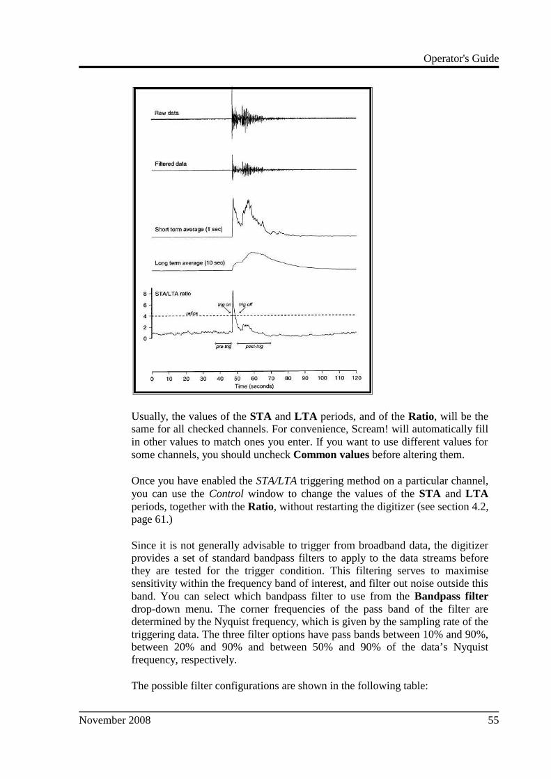
The STA and LTA columns allow you to set the intervals over which the twoaverages are calculated, in seconds. Typically, the time interval for the shortterm average should be about as long as the signals you want to trigger on,while the long term average should be taken over a much longer interval. Boththe STA and LTA values are recalculated continually, even during a trigger.
The Ratio column determines by what factor the STA and LTA must differ forthe trigger to be passed. Finding the ratio most suited to your needs is best doneby experiment. Too high a value will result in events being missed, while toolow a value will result in spurious non-seismic noise triggering the system. Likethe averages, their ratio is continuously recalculated for all components. Notethat none of the boxes are allowed to be empty, and so you will need to enter thenew value before removing the old one. Alternatively, you can use the up anddown cursor keys to change the values.
For example, setting the STA to 1 second, the LTA to 10 seconds and the Ratioto 4 would give rise to the following trigger behaviour:
54 Issue B
Operator's Guide
Usually, the values of the STA and LTA periods, and of the Ratio, will be thesame for all checked channels. For convenience, Scream! will automatically fillin other values to match ones you enter. If you want to use different values forsome channels, you should uncheck Common values before altering them.
Once you have enabled the STA/LTA triggering method on a particular channel,you can use the Control window to change the values of the STA and LTAperiods, together with the Ratio, without restarting the digitizer (see section 4.2,page 61.)
Since it is not generally advisable to trigger from broadband data, the digitizerprovides a set of standard bandpass filters to apply to the data streams beforethey are tested for the trigger condition. This filtering serves to maximisesensitivity within the frequency band of interest, and filter out noise outside thisband. You can select which bandpass filter to use from the Bandpass filterdrop-down menu. The corner frequencies of the pass band of the filter aredetermined by the Nyquist frequency, which is given by the sampling rate of thetriggering data. The three filter options have pass bands between 10% and 90%,between 20% and 90% and between 50% and 90% of the data’s Nyquistfrequency, respectively.
The possible filter configurations are shown in the following table:
November 2008 55

CMG-6TD
Tap # Rate (samples/s)
Bandwidth 1(Hz)
Bandwidth 2(Hz)
Bandwidth 5(Hz)
0 200 10 – 90 20 – 90 50 – 90
1 100 5 – 45 10 – 45 25 – 45
50 2.5 – 22.5 5 – 22.5 12.5 – 22.5
40 2 – 18 4 – 18 10 – 18
25 1.25 – 11.25 2.5 – 11.25 6.25 – 11.25
20 1 – 9 2 – 9 5 – 9
2 50 2.5 – 22.5 5 – 22.5 12.5 – 22.5
25 1.25 – 11.25 2.5 – 11.25 6.25 – 11.25
20 1 – 9 2 – 9 5 – 9
10 0.5 – 4.5 1 – 4.5 2.5 – 4.5
8 0.4 – 3.6 0.8 – 3.6 2 – 3.6
5 0.25 – 2.25 0.5 – 2.25 1.25 – 2.25
4 0.2 – 1.8 0.4 – 1.8 1 – 1.8
2 0.1 – 0.9 0.2 – 0.9 0.5 – 0.9
3 25 1.25 – 11.25 12.5 – 11.25 6.25 – 11.25
10 0.5 – 4.5 1 – 4.5 2.5 – 4.5
5 0.25 – 2.25 0.5 – 2.25 1.25 – 2.25
4 0.2 – 1.8 0.4 – 1.8 1 – 1.8
2 0.1 – 0.9 0.2 – 0.9 0.5 – 0.9
1 0.05 – 0.45 0.1 – 0.45 0.25 – 0.45
As can be seen, the filter you choose defines the set of permissible sample rates.
The spectral amplitudes for the various frequency responses available are shownin the figures below.
56 Issue B

Operator's Guide
Level
Using the Level triggering method, a trigger is generated whenever one of thechecked components reaches a certain level above the baseline. You can selectwhich tap is monitored from the Data source drop-down menu, and thechannel(s) to be considered from the Channel column of the table. The valuesin the Level column are the number of counts above the baseline that channelmust reach before a trigger is generated.
As with the STA/LTA method, the values of the Level will often be the same forall checked channels. If you want to use different values for some channels, youshould uncheck Common values before altering them.
Once you have enabled the Level triggering method on a particular channel, youcan use the Control window to change the level at which the system triggerswithout restarting the digitizer.
External triggering
When a digitizer or digital sensor triggers, it sends the trigger itself to connecteddevices, as well as any extra data that it has been configured to record. You canconfigure other digitizers to respond to this signal by triggering in turn. This isan option which you can specify at the time of manufacture.
As an example, to instruct a stand-alone digitizer with digital inputs to respondto triggers generated by an attached digital sensor:
November 2008 57
CMG-6TD
1. Open the Configuration setup window for the digital sensor, and checkEnable External Trigger Output to make it send triggers to connecteddevices.
2. UPLOAD the new configuration to the digital sensor.
3. Open the Configuration setup window for the digitizer, and checkEnable External Trigger Input to make it listen for triggers comingfrom the digital instrument, and record data from attached analogueinstruments when it receives one (depending on its Output controlconfiguration.)
4. UPLOAD the new configuration to the digitizer,
If a digitizer has both Enable External Trigger Output and Enable ExternalTrigger Input selected, it will record data when it receives an external triggeras if it had triggered itself, but it will not send that trigger on to other digitizers.It will only send a trigger message if its own triggering criteria are satisfied.
Pre-trigger and post-trigger recording
In order to capture all of a seismic event, it is often useful to be able to recorddata immediately preceding the trigger. Güralp digitizers have an internal bufferof some seconds which allows this data to be added to the triggered stream. Pre-trigger data is particularly useful for emergent-type signals, where the systemdoes not trigger until one phase after the first arrival. In addition, to ensure thatthe coda of each event is included, some seconds of data are recorded after thesystem detriggers.
The two boxes at bottom right of the Triggering pane allow the user to set thepre-trigger and post-trigger data intervals, in seconds. These values determinethe minimum length of time during which data will be saved before the triggercondition occurs, and after it has lapsed. Regardless of the intervals chosen, thedata in the triggered streams will begin on a whole second.
Mux Channels
The 6TD provides a range of slow-rate auxiliary channels for reporting thesystem's state of health and other diagnostic information, known as multiplexed(“Mux”) channels. The number of Mux channels depends on the model andconfiguration of your digitizer. Generally, three channels are used to report thesensor mass position, and another measures the internal temperature of thedigitizer. In addition to these, up to 12 Mux channels may be supplied for theuser's own purposes. Some digitizers have a separate AUXILIARY port whichcan be used to access these channels.
The collection and transmission of Mux channels is controlled using the MuxChannels pane:
58 Issue B

Operator's Guide
If a tick is placed in the box next to a channel, its data will be collected andtransmitted as a data stream in GCF format, just as with the normal datachannels. To indicate that the data comes from a Mux channel, the Stream IDwill take the form ****Mx , where M stands for Mux and x is a hexadecimalinteger (i.e. 0 – 9, and A – F for 10 through 15). The Z, N/S and E/W MassPosition Mux channels appear as M8, M9 and MA respectively.
Ports
The Baud Rates pane of the Configuration setup window allows you to programthe baud rate and stop bits for the 6TD's output port.
If you have a 6TD with Ethernet or Wi-Fi options, the settings you configurehere are used both on the standard data output port, and on the internal portwhich sends data to the Ethernet/Wi-Fi module. If you change them, you willalso need to configure the Ethernet/Wi-Fi module to receive data with the newsettings. This can be done using the Lantronix DeviceInstaller utility (seeSections 3.7 and 3.8.)
November 2008 59

CMG-6TD
The baud rate you choose must satisfy two conditions:
• It must be high enough to allow all the transmission of all data generatedby the digitizer at the sampling rates you have chosen. For three streamsof data at 100 Hz, for example, 9600 baud will usually be sufficient. Ifyou wish to transmit 200 Hz data, however, the baud rate must be atleast 19200.
• It must be low enough to fit within the operating range of the telemetryequipment you are using. While modern modems often offer transferrates up to 56 kbaud, the telephone or transmission lines may notsupport these rates. The same holds true for radio telemetry.
Usually, the transmit and receive rates of the data port will be the same. If not,you may select different data rates by removing the check in the box markedIdentical TX/RX rates.
The Stop Bits option allows you to choose whether the serial link uses 1 or 2stop bits. In most cases this can be left at 1, although 2 may be required if youare sending data over ‘difficult’ transmission lines (for example, some types ofradio link.) Using 2 stop bits will add a 10% overhead to the data.
You will also need to set the data rate for Scream's local serial port, as well asfor the SAM/DCM or other communications device (if you are using one). InScream!, you can configure a serial port by right-clicking on its icon (not that ofthe digitizer) and selecting Configure... from the pop-up menu: for moredetails, consult the online help or user guide for Scream!. If you are using anadditional communications device, you should consult its documentation tolearn how to set its baud rate.
60 Issue B

Operator's Guide
4.2 Controlling the instrument
To control a digitizer whilst it is running, either right-click on the digitizer'sentry in the list to the left of Scream!'s main window (not the Local or Comxxicons) and click Control..., or simply double-click the entry. Scream! will thencontact the digitizer and retrieve its current status, a process which will take afew seconds, after which the Control window will be displayed. Once you arehappy with any changes you have made in the Control window, click Apply tosend them to the digitizer, where they will take effect immediately.
System
When the Control window is first opened, it will be showing the System pane.
Sensor Type : This option tells Scream! which control commands to makeavailable to the user. The digitizer module is already programmed with theproper sensor type, so you should not change this option.
If you change the Sensor Type, you may have to Apply the change, close theControl window, and open a new one to access the Mass Control options.
Enable GPS power cycling : If you are using a GPS unit to receive timesignals, but do not experience significant drift in the system's clock (forexample, in a stable-temperature environment), you can save power by selectingEnable GPS power cycling.
When this option is selected, the 6TD will only check the GPS time at intervalsof a specified number of hours.
November 2008 61

CMG-6TD
Triggering
The Triggering pane is very similar to the corresponding pane of theConfiguration setup window, although not all options are available since somerequire rebooting the digitizer. See section 4.1, page 49, for more details.
Calibration
You can check that your instrumentation is correctly calibrated by injectingknown signals into the sensor's feedback loop. The Calibration pane allows youto do this.
Each channel calibrates the corresponding axis of the instrument. Select one ofthe Z, N/S and E/W check boxes to calibrate that axis.
The calibration signal is digitized at a slower rate and returned as a Muxchannel (see above)O) ending MB.
62 Issue B
Operator's Guide
The Duration box tells the digitizer how long to provide the calibration signalbefore disconnecting. This avoids the system being inadvertently left incalibration mode. The default is 2 minutes. If you change this setting, it willrevert to the default value after one calibration stage.
All Güralp digitizers can produce either sine-wave or square-wave (step)calibration signals; newer models can also carry out broadband noisecalibration. The Sine wave calibration signal always starts and stops on the zerocrossing. The frequency or period given by the boxes at bottom left. Onlyintegers between 1 and 10 may be specified for either frequency or period, so togenerate a 0.5 Hz signal you should select Period and set the time to 2(seconds). Likewise, if you require a 0.25 second period you should selectFrequency and set the rate to 4 (Hz). In this manner, you can select frequenciesranging from 0.1 to 10 Hz (10 to 0.1 s periods).
You can specify step calibration by selecting the Square wave button. Thesquare wave consists of a positive step at the start of the next minute of thedigitizer’s internal clock, followed by a negative step after a specified numberof minutes. After a further delay of the same number of minutes, the calibrationsignal is disconnected. The default is 2 minutes. The Period and Frequency areignored.
The Broadband Noise calibration signal consists of a constant stream of whitenoise, which lasts for the specified number of minutes. The Period andFrequency are ignored.
Mass Control
The CMG-6TD does not need mass locking, unlocking, or centring. However,instructing the 6TD to “centre” switches it into a 1 second response mode,where you can monitor the mass positions more easily.
You can issue this instruction from the Mass Control tab:
November 2008 63

CMG-6TD
To switch into 1 second response mode, click Centre.
Data flow
The 6TD operates in one of several filing modes. These modes relate to how theunit uses its Flash memory:
• as a simple data store, from which you can request data (FILING, DUALand DUPLICATE modes);
• as a buffer holding unacknowledged blocks, which are transmitted inpreference to real-time data (FIFO mode); or
• as a buffer holding unacknowledged blocks, which are transmittedwhenever the channel is free but no real-time data blocks are ready(ADAPTIVE mode).
Separate from these modes are buffering modes, which tell the unit what to dowhen its Flash memory becomes full: either
• carry on, overwriting the oldest data held, or
• stop writing and switch the 6TD into DIRECT mode.
You can switch between filing modes in Scream! by right-clicking on thedigitizer and clicking on Control..., then navigating to the Data Flow pane:
Clicking Apply in this window immediately activates the filing mode you haveselected—there is no need to reboot.
64 Issue B

Operator's Guide
If you prefer, you can use the 6TD terminal to switch between filing modes. Thecommands to use, which take effect immediately, are given below.
FILING
Syntax: FILING
Instructs the 6TD not to transmit blocks to clients automatically, but to store alldigitized data in the Flash memory. If you have chosen the RECYCLE bufferingmode (see below), the memory is used in circular fashion, i.e. if it becomes full,incoming blocks begin overwriting the oldest in memory. If the WRITE-ONCEmode is active, the instrument will switch to DIRECT mode (see above) whenthe memory becomes full.
You can retrieve blocks from an instrument in FILING mode by connecting toits terminal interface and issuing commands such as FLUSH, or throughScream! (see below).
Heartbeat messages
When in FILING mode, an instrument transmits “heartbeat” messages over itsdata port. These short messages take the place of data blocks, and ensure thatprograms such as Scream! know that an instrument is present.
You can change the frequency of heartbeat messages from Scream!'s Controlwindow, or with the command HEARTBEAT.
You can tell Scream! to download new data automatically whenever it receives
November 2008 65

CMG-6TD
a heartbeat message from an instrument in FILING mode. This is useful, forexample, in autonomous installations connected by intermittent modem links.To enable this feature:
1. Choose File → Setup... from Scream!'s main menu, and navigate to theRecording pane.
2. Check Auto-upload on heartbeat.
3. Click OK .
Using FILING mode with Auto-upload on heartbeat ensures that Scream!receives all new data whenever it can, regardless of the configuration of anydevices between you and the instrument.
DUPLICATE
Syntax: DUPLICATE
Instructs the DM24 to transmit streams directly to clients as well as storing alldata into Flash storage as for FILING mode.
An instrument in DIRECT mode still honours the GCF Block RecoveryProtocol: a temporary RAM buffer always holds the last 256 blocks generated,
66 Issue B

Operator's Guide
and if a client fails to receive a block it can request its retransmission.
If you expect breaks in communication between the instrument and its client tolast more than 256 blocks, or if you want the instrument to handle breaks intransmission (rather than relying on the client to request missed blocks), youshould use
• ADAPTIVE mode, if you want data to stay as near to real time aspossible (but do not mind if blocks are received out of order) or
• FIFO mode, if you need blocks to be received in strict order (but do notmind if the instrument takes a while to catch up to real time.)
FIFO (First In First Out)
Syntax: FIFO
Instructs the 6TD to begin writing blocks to Flash memory as for FILING mode,but also to transmit data to clients. Data is transmitted in strict order, oldestfirst; the 6TD will only transmit the next block when it receives an explicitacknowledgement of the previous block.
If the communications link is only marginally faster than the data rate, it willtake some time to catch up with the real-time data after an outage. If you wantdata to be transmitted in real-time where possible, but are worried aboutpossible breaks in communication, you should use ADAPTIVE mode instead.
FIFO mode will consider a data block successfully transmitted once it hasreceived an acknowledgement from the next device in the chain. If there areseveral devices between you and the instrument, you will need to set up thefiling mode for each device (if applicable) to ensure that data flow works theway you expect.
Like all the filing modes, FIFO mode does not delete data once it has beentransmitted. You can still request anything in the Flash memory using Scream!or over the command line. The only way data can be deleted is if it isoverwritten (in the RECYCLE buffering mode, see below) or if you delete itmanually.
ADAPTIVE
Syntax: ADAPTIVE
November 2008 67

CMG-6TD
Instructs the 6TD to transmit current blocks to clients if possible, but to store allunacknowledged blocks in the Flash memory and re-send them, oldest first,when time allows. ADAPTIVE mode is best suited for “real-time” installationswhere the link between digitizer and client is intermittent or difficult of access.
If the communications link is only marginally faster than the data rate, it willusually be busy transmitting real-time data. Thus, it may take a while for theinstrument to work through the missed blocks. In this case, and if your clientsupports it, you may prefer to use the Block Recovery Protocol to requestmissed blocks where possible.
Some software packages (most commonly Earthworm) cannot handle blocksbeing received out of time order. If you are using such a package, ADAPTIVEmode will not work, and may crash the software.
DUAL
Syntax: DUAL
Instructs the 6TD to transmit continuous streams directly to clients as forDUPLICATE mode, but to store triggered data only into Flash storage.
If you choose DUAL mode but do not select any continuous streams for output,the instrument will send heartbeat messages as for FILING mode. Scream! canpick these up and download new data as necessary.
RE-USE / RECYCLE
Syntax: RE-USE
Instructs the 6TD to carry on using the current filing technique when the Flash
68 Issue B

Operator's Guide
memory becomes full, overwriting the oldest data held. This buffering mode iscalled RECYCLE in Scream! and on the DCM.
For example, in DUAL mode with RECYCLE buffering, the latest continuousdata will be transmitted to you as normal, and the latest triggered data may beretrieved from the Flash memory using Scream! or the command line. However,if you do not download data regularly from the Flash memory, you may loseolder blocks. This mode thus lets you define the end point of the data held bythe instrument.
WRITE-ONCE
Syntax: WRITE-ONCE
Instructs the 6TD to stop writing data to the Flash memory when it is full, andto switch to DIRECT mode automatically.
For example, in FIFO mode with WRITE-ONCE buffering, the station willtransmit data to you continuously, but also save it in the Flash memory until it isfull. Once full, the instrument will switch to DIRECT mode and continuetransmitting, though no further data will be saved. This mode thus lets youdefine the start point of the data held by the instrument.
4.3 Digitizer status streams
All Güralp digitizers have a separate stream for reporting information about thesystem, such as their GPS and time synchronization status. This statusinformation is in plain ASCII text format.
To see a Status window for any digitizer, double-click on the Stream IDxxxx 00 . This stream always has a reported sample rate of 0 samples/s.
During boot-up each unit reports its model type, firmware revision number, itsSystem ID and serial number. This information is followed by the number ofresets that have occurred and the time of the latest reboot from its internalclock. The following lines report the current configuration of the unit's samplerates, output taps, and baud rates. A typical digitizer re-boot status messagelooks like this:
November 2008 69

CMG-6TD
The system will produce a similar status message whenever it is powered up,and whenever you reboot it (normally, after changing its configuration.)
GPS
If a GPS unit is fitted, its operational status is reported on reboot and thebehaviour of the time synchronisation software will also be shown.
From a cold start, GPS will initially report No GPS time together with itslast position (taken from the internal backup.) All messages from the GPS thatinvolve a change of its status are automatically reported. Repeated statusmessages are not shown to avoid unnecessary clutter.
This report shows the satellites the system has found, and their correspondingsignal strengths.
If the system has not been moved from its previous location, it should be able tofind enough satellites to obtain an accurate GPS time fairly quickly; if the GPSreceiver has difficulty finding satellites, there may be a delay of several minutesbefore a new message is displayed.
Before beginning, the digitizer's internal time synchronisation software willwait for the GPS unit to report a good position fix from at least 3 satellites, forat least 6 consecutive messages. Messages are normally received every 10 to 20seconds.
The system will then set the internal clock and re-synchronise the Analogue toDigital Converters so that the data is accurately time-stamped to the newreference. Any data transmitted up to this point will be stamped with the timefrom the internal backup clock, which is set to the new accurate time at the endof this process. The re-synchronisation will result in a discontinuity in the datareceived.
From this point, the control process will attempt to keep the internal time-basesynchronised to the GPS 1 pulse per second output, by adjusting a voltage-controlled crystal oscillator. First it alters the voltage control to minimise the
70 Issue B

Operator's Guide
error. Next it attempts to minimise both the “phase error” (i.e. the offsetbetween the internal 1 Hz signal and the GPS) and the drift (the frequency errorrelative to GPS.) During the control process the system reports the measurederrors and the control signal applied, as a PWM (Pulse Width Modulation)value.
During the initial, coarse adjustment stage only the coarse voltage control isused and no drift calculation is made. If the system is operating in a similarenvironment to that when the system was last powered (most importantly, thesame temperature) the saved control parameters will be appropriate and thesystem should rapidly switch to the ‘fine’ control mode. The system reports itscontrol status and parameters each minute, with error measurements given innominal timebase units. In a stable temperature environment the system shouldsoon settle down showing an offset error of only a few thousand (average error< 100 microseconds) and a drift rate under 100 counts (< 1 in 10-6).
November 2008 71

CMG-6TD
5 5 5 5 Calibrating the 6TDCalibrating the 6TDCalibrating the 6TDCalibrating the 6TD
5.1 The calibration pack
All Güralp sensors are fully calibrated before they leave the factory. Bothabsolute and relative calibration calculations are carried out. The results aregiven in the calibration pack supplied with each instrument:
Works Order : The Güralp factory order number including the instrument,used internally to file details of the sensor's manufacture.
Serial Number : The serial number of the instrument
Date : The date the instrument was tested at the factory.
Tested By : The name of the testing engineer.
There follows a table showing important calibration information for eachcomponent of the instrument, VERTICAL, NORTH/SOUTH, and EAST/WEST.Each row details:
Velocity Output (Differential) : The sensitivity of each component to velocityat 1 Hz, in volts per m/s. Because the 6TD uses balanced differential outputs,the signal strength as measured between the +ve and –ve lines will be twice thetrue sensitivity of the instrument. To remind you of this, the sensitivities aregiven as 2 × (single-ended sensitivity) in each case.
Mass Position Output : The sensitivity of the mass position outputs toacceleration, in volts per m/s². These outputs are single-ended and referenced tosignal ground.
Feedback Coil Constant : A constant describing the characteristics of thefeedback system. You will need this constant, given in amperes per m/s², if youwant to perform your own calibration calculations (see below.)
Power Consumption : The average power consumption of the sensor duringtesting, given in terms of the current (in amperes) drawn from a 12 V supply.
Calibration Resistor : The value of the resistor in the calibration circuit. Youwill need this value if you want to perform your own calibration calculations(see below.)
Poles and zeroes
Most users of seismometers find it convenient to consider the sensor as a “black
72 Issue B

Operator's Guide
box”, which produces an output signal V from a measured input x. So long asthe relationship between V and x is known, the details of the internal mechanicsand electronics can be disregarded. This relationship, given in terms of theLaplace variable s, takes the form
[V / x](s) = G A H(s)
In this equation
• G is the acceleration output sensitivity (gain constant) of the instrument.This relates the actual output to the desired input over the flat portion ofthe frequency response.
• A is a constant which is evaluated so that A H(s) is dimensionless andhas a value of 1 over the flat portion of the frequency response. Inpractice, it is possible to design a system transfer function with a verywide-range flat frequency response.
The normalising constant A is calculated at a normalising frequencyvalue fm = 1 Hz, with s = j fm, where j = √–1.
• H(s) is the transfer function of the sensor, which can be expressed infactored form:
In this equation zn are the roots of the numerator polynomial, giving the
zeros of the transfer function, and pm are the roots of the denominator
polynomial giving the poles of the transfer function.
In the calibration pack, G is the sensitivity given for each component on the firstpage, whilst the roots zn and pm, together with the normalising factor A, are
given in the Poles and Zeros table. The poles and zeros given are measureddirectly at Güralp Systems' factory using a spectrum analyser. Transferfunctions for the vertical and horizontal sensors may be provided separately.
Frequency response curves
The frequency response of each component of the 6TD is described in thenormalised amplitude and phase plots provided. The response is measured atlow and high frequencies in two separate experiments. Each plot marks the low-frequency and high-frequency cutoff values (also known as –3 dB or half-powerpoints).
November 2008 73

CMG-6TD
If you want to repeat the calibration to obtain more precise values at a frequencyof interest, or to check that a sensor is still functioning correctly, you can injectcalibration signals into the system using a Güralp digitizer or your own signalgenerator, and record the instrument's response.
Obtaining copies of the calibration pack
Our servers keep copies of all calibration data that we send out. In the event thatthe calibration information becomes separated from the instrument, you canobtain all the information using our free e-mail service. Simply [email protected] with the serial number of the instrument in the subjectline, e.g.
From: [email protected]: [email protected]: T6315
The server will reply with the calibration documentation in Word format. Thebody of your e-mail will be ignored.
5.2 Calibration methods
Velocity sensors such as the 6TD are not sensitive to constant DC levels, eitheras a result of their design or because of an interposed high-pass filter. Instead,three common calibration techniques are used.
• Injecting a step current allows the system response to be determined inthe time domain. The amplitude and phase response can then becalculated using a Fourier transform. Because the input signal haspredominantly low-frequency components, this method generally givespoor results. However, it is simple enough to be performed daily.
74 Issue B

Operator's Guide
• Injecting a sinusoidal current of known amplitude and frequency allowsthe system response to be determined at a spot frequency. However,before the calibration measurement can be made the system must beallowed to reach a steady state; for low frequencies, this may take a longtime. In addition, several measurements must be made to determine theresponse over the full frequency spectrum.
• Injecting white noise into the calibration coil gives the response of thewhole system, which can be measured using a spectrum analyser.
You can calibrate a 6TD sensor using any of these methods, using its built-insignal generator.
5.3 Noise calibration with Scream!
The most convenient way to calibrate a 6TD instrument is to use its pseudo-random broadband noise generator with Scream!'s noise calibration extension.The extension is part of the standard distribution of Scream!, and contains allthe algorithms needed to determine the complete sensor response in a singleexperiment.
Information on other calibration methods is available on the Güralp SystemsWeb site.
1. In Scream!'s main window, right-click on the digitizer's icon and selectControl.... Open the Calibration pane.
2. Select the calibration channel corresponding to the instrument, andchoose Broadband Noise. Select the component you wish to calibrate,together with a suitable duration and amplitude, and click Inject now. Anew data stream ending Cn (n = 0 – 7) should appear in Scream!'s mainwindow containing the returned calibration signal.
3. Open a Waveview window on the calibration signal and the returned
November 2008 75

CMG-6TD
streams by selecting them and double-clicking. The streams shoulddisplay the calibration signal combined with the sensors' ownmeasurements. If you cannot see the calibration signal, zoom into theWaveview using the scaling icons at the top left of the window or thecursor keys.
Drag the calibration stream Cn across the Waveview window, so that itis at the top.
4. If the returning signal is saturated, retry using a calibration signal withlower amplitude, until the entire curve is visible in the Waveviewwindow.
5. If you need to scale one, but not another, of the traces, right-click on thetrace and select Scale.... You can then type in a suitable scale factor forthat trace.
6. Pause the Waveview window by clicking on the icon.
7. Hold down SHIFT and drag across the window to select the calibrationsignal and the returning component(s). Release the mouse button,keeping SHIFT held down. A menu will pop up. Choose BroadbandNoise Calibration.
8.
9. The script will ask you to fill in sensor calibration parameters for eachcomponent you have selected.
76 Issue B

Operator's Guide
Most data can be found on the calibration sheet for your sensor. UnderInstrument response, you should fill in the sensor response code for yoursensor, according to the table below. Instrument Type should be set tothe model number of the sensor.
If the file calvals.txt exists in the same directory as Scream!'sexecutable (scream.exe ), Scream! will look there for suitablecalibration values.
See the Scream! manual for full details of this file. Alternatively, youcan edit the sample calvals.txt file supplied with Scream!.
10.Click OK. The script will return with a graph showing the responsivity ofthe sensor in terms of amplitude and phase plots for each component (ifappropriate.)
The accuracy of the results depends on the amount of data you haveselected, and its sample rate. To obtain good-quality results at lowfrequency, it will save computation time to use data collected at a lowersample rate; although the same information is present in higher-ratestreams, they also include a large amount of high-frequency data whichmay not be relevant to your purposes.
November 2008 77
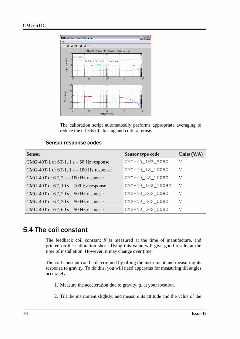
CMG-6TD
The calibration script automatically performs appropriate averaging toreduce the effects of aliasing and cultural noise.
Sensor response codes
Sensor Sensor type code Units (V/A)
CMG-40T-1 or 6T-1, 1 s – 50 Hz response CMG-40_1HZ_50HZ V
CMG-40T-1 or 6T-1, 1 s – 100 Hz response CMG-40_1S_100HZ V
CMG-40T or 6T, 2 s – 100 Hz response CMG-40_2S_100HZ V
CMG-40T or 6T, 10 s – 100 Hz response CMG-40_10S_100HZ V
CMG-40T or 6T, 20 s – 50 Hz response CMG-40_20S_50HZ V
CMG-40T or 6T, 30 s – 50 Hz response CMG-40_30S_50HZ V
CMG-40T or 6T, 60 s – 50 Hz response CMG-40_60S_50HZ V
5.4 The coil constant
The feedback coil constant K is measured at the time of manufacture, andprinted on the calibration sheet. Using this value will give good results at thetime of installation. However, it may change over time.
The coil constant can be determined by tilting the instrument and measuring itsresponse to gravity. To do this, you will need apparatus for measuring tilt anglesaccurately.
1. Measure the acceleration due to gravity, g, at your location.
2. Tilt the instrument slightly, and measure its attitude and the value of the
78 Issue B

Operator's Guide
mass position output for the component you wish to calibrate.
To make it easier to measure mass positions, you should use the RESPcommand to place the instrument in 1 second response modebeforehand. To do this, open a Terminal window in Scream! (seeChapter 6, page 80) and issue the commands
OK-11 RESPMASSES?0 RESP
3. Repeat this measurement for several tilt angles.
4. For the vertical sensor, the input acceleration is given by a = g sin φ,whilst for the horizontal sensor, it is a = g ( 1 – cos φ ).
Calculate the input acceleration for each of the tilt angles used, and plota graph of mass position output against input acceleration.
5. The gradient of the line obtained gives the sensitivity of the coil (inV/m/s2, if g was measured in m/s2 and the mass position in V.)
6. The coil constant K is equal to this sensitivity divided by the value of thedisplacement feedback resistor, given on the calibration sheet.
November 2008 79

CMG-6TD
6 6 6 6 Command line interfaceCommand line interfaceCommand line interfaceCommand line interfaceYou can connect to the internal software of the 6TD over its output serial portand communicate with it.
To enter command mode from Scream!, right-click on the digitizer's icon andselect Terminal... from the menu that pops up. A window will open, and oncethe 6TD and computer are communicating properly you will see the prompt
ok
If you prefer, you can use a terminal program on your computer (such asminicom on Linux, or hypertrm on Microsoft Windows) to connect to the6TD.
Whilst you are in terminal mode, data transfer will be interrupted; the 6TD mayuse its Flash memory as a temporary store, depending on how you haveconfigured it. Some commands, such as SET-TAPS, require a reboot to takeeffect.
Güralp DCM and AM modules also allow you to send commands direct to the6TD using the command-line tool gcli . For more information, please see themanual for your data module.
If you have problems connecting to the digitizer's console, you should checkthat the serial port's options and baud rate are set correctly in Scream! or yourterminal program. As supplied, the 6TD expects connections at 19200 baud,with 8 data bits, no parity bit and 1 stop bit. No flow control is used.
6.1 FORTH
The 6TD uses a FORTH-like interpreter to implement its features. To issue acommand in FORTH, you must supply the arguments before the command, forexample:
0 19200 BAUD
In FORTH, anything you enter is termed a word. New words (case insensitive)are placed on a stack. Some words are known to the system, and may representcommands; if a command finds itself at the top of the stack (e.g. because it isthe last thing you typed), they will execute, remove themselves from the stack,and then remove further items from the stack to use as arguments.
Thus, in the command above, the numbers have no immediate effect, so stay onthe stack. BAUD removes itself and the previous two items (here 0 and 19200 )off the stack, then performs its action using these as arguments.
80 Issue B

Operator's Guide
If a command completes with nothing remaining on the stack, the digitizer willshow the prompt ok . Otherwise, no prompt will be given. Some commands,such as SAMPLES/SEC, clear the stack automatically after they execute.Pressing ENTER twice will always clear the stack.
Some commands are interactive, and will ask you to provide extra informationafter you execute them. In the following sections, interactive commands areshown as example sessions, where information you enter is given in mediumand messages returning from the 6TD are given in bold.
Some of the less-used commands are not normally available over the terminalinterface. In order to access these, you need to import them into the currentdictionary with the command ok-1 . You now have access to the full FORTHword list. To return to the normal state of the interpreter, issue the command[seal] .
6.2 General configuration
SET-ID
Syntax: SET-ID (interactive)
Sets the system identifier and serial number of the 6TD to values you supply.
SET-IDSystem Identifier ( WO3008 ) MY6TD
Serial # ? ( 123400 ) 4507
The system identifier you supply may contain up to 5 alphanumeric (0 – 9, A –Z) characters. The 6TD will pad any remaining space on the right with zeroes. Ifyou want to use a system identifier less than 5 characters long, insert zeroes onthe left to make it up to 5 characters. The digitizer will interpret leading zeroesas blank. (Because of this, you cannot have a system identifier that begins witha zero.)
The serial number you supply must contain 4 alphanumeric (0 – 9, A – Z)characters as shown. As for the system identifier, leading zeroes are interpretedas blank.
BAUD
Syntax: port baud-rate BAUD
Sets the baud rate for one of the serial ports on the 6TD, in bytes per second.The 6TD has a single port, numbered 0. For example,
0 19200 BAUD
November 2008 81

CMG-6TD
This will reset a standard 6TD to its default configuration.
The allowable values for baud-rate are 4800, 7200, 9600, 14400, 19200,57600 and 115200. Note especially that 38400 baud is not available on the 6TD.
If you have a 6TD with Ethernet or Wi-Fi options, the settings you configurehere are used both on the standard data output port, and on the internal portwhich sends data to the Ethernet/Wi-Fi module. If you change them, you willalso need to configure the Ethernet/Wi-Fi module to receive data with the newsettings. This can be done using the Lantronix DeviceInstaller utility (seeSections 3.7 and 3.8.)
LOAD
Syntax: LOAD (interactive)
Starts an Xmodem file transfer for new 6TD firmware. For full instructions, seeChapter 7, page 103.
This command is in the extended dictionary; to use it, first issue the commandok-1 and finish with [seal] .
LOAD-I
Syntax: LOAD-I (interactive)
Starts an Xmodem file transfer for a new Info Block. This block can be up to 1K long, and will automatically be transmitted from the 6TD when it first powersup. You can use the Info Block to store any information you like: for example,about the digitizer, your project, or calibration data for attached sensors.
Before uploading an Info Block, you must convert it to Intel Hex format. Freely-downloadable tools exist that can help you with this conversion. Similarsoftware is also available from Güralp Systems.
This command is in the extended dictionary; to use it, first issue the commandok-1 and finish with [seal] .
TEMP?
Syntax: TEMP?
Display the current temperature measurement from the internal thermometer.
ETHER
Syntax: ETHER ENABLE | ETHER DISABLE
82 Issue B

Operator's Guide
Enables or disables the optional Ethernet and Wi-Fi devices on the 6TD.
When the Ethernet device is enabled, data produced by the 6TD will be sent tothe device for transmission across the network, unless you have plugged a serialcable into the Data Out port of the breakout box. In this case, data will be sentover the standard RS232 interface only. This is the default behaviour.
When the Ethernet device is disabled, data will always be sent out over thestandard RS232 interface, and the internal Ethernet/Wi-Fi module will not beused.
6.3 GPS and timing systems
GPS-TYPE
Syntax: type GPS-TYPE
Tells the DM24 which kind of GPS is attached to it.
type can be one of
• 0, if no GPS is available, or
• 2, for attached GPS equipment using the NMEA protocol.
HR-CYCLE
Syntax: interval HR-CYCLE
Sets the interval between GPS fixes. Under normal operation, the system willpower on the GPS system every interval hours and synchronize its internalclock with GPS timing signals. Once the internal clock is sufficiently close toGPS time, the GPS system will be automatically powered down for anotherinterval hours.
Setting interval to 0 will make the 6TD leave the GPS on continuously.This is recommended if your installation has access to mains power.
To find out the current HR-CYCLE setting, issue HR-CYCLE?
XGPS
Syntax: 0 XGPS | 1 XGPS
Manually switches on or off the GPS system, overriding the HR-CYCLEcommand (see above). If you issue 0 XGPS, the digitizer will switch off therelay; 1 XGPS will switch it on. Once the GPS system is switched on, the
November 2008 83

CMG-6TD
digitizer will automatically check the timing signal and synchronise its internalclock before switching off the GPS and returning to normal operation.
SET-RTC
Syntax: year month day hour minute second centisecondSET-RTC
Sets the system's real time clock. This time will be used from power-up until itis corrected by an attached GPS. If you are not using GPS but are synchronizingfrom some other time source, you will need to re-issue this command regularlyto ensure the 6TD does not drift.
SET-CLOCK
Syntax: SET-CLOCK (interactive)
Sets the internal clock.
SET-CLOCKEnter Date & Time -YYYY MM DD HH MM SS2006 02 01 12 53 25 Clock set to 2006 2 1 12:53:27 ok_SBHY
The time should be entered in the form year month day hour minutesecond, padding each field with zeroes so that they line up with the guideabove.
If the DM24 does not recognize the time format you have used, it will outputthe message Invalid Time Entry .
This setting will be overridden when the GPS system next synchronizes theclock.
TIME?
Syntax: TIME?
Displays the current time as held in the system's real time clock. If a GPS isattached, this will be synchronized to it. The output is given in the form
year month day hour: minute: second ok
.FIX
Syntax: .FIX
Displays the current GPS timing fix. The GPS must be attached and poweredup for this command to be valid; if it is not, you will see an error message. You
84 Issue B

Operator's Guide
can power up the GPS manually with the command XGPS.
The 6TD will reply in the form
.fix year month day hour: minute: second =>> fix-mode SV#'ssatellites ( number-of-satellites ) ok
where
● year month day hour: minute: second is the current time (ifsynchronised to GPS);
● fix-mode is the fix type (either Auto 2-D or Auto 3-D ), and
● satellites is a list of the satellites currently visible. The 6TD willcarry out clock trimming only if an Auto 3-D fix is available, whichrequires at least 3 satellites to be visible.
If the 6TD is not attached to a GPS, you will see the message
NO GPSNo FIX SV#'s none ok
.POSITION
Syntax: .POSITION
Displays the current reported GPS position, in the form
.position Lat latitude Long longitude ok
where latitude and longitude are displayed in degrees, minutes andseconds.
This command is in the extended dictionary; to use it, first issue the commandok-1 and finish with [seal] .
If the 6TD is not attached to a GPS, you will see the message
No position info ok
LEAPSECOND
Syntax: yyyy mm dd LEAPSECOND
Manually notify the digitizer of an upcoming leap second. This command is notnormally necessary, since GPS already has support for leap seconds. However,some units do not properly interpret the GPS signals. See SQPATCH, below.
November 2008 85

CMG-6TD
The leap second is taken to be at the end of the day yyyy- mm- dd.
SQPATCH
Syntax: SQPATCH ENABLE | SQPATCH DISABLE
Enables or disables the internal patch for older GPS receivers based on TrimbleLassen SQ units. These units misinterpret the GPS system's advancenotification of a leap second, and consequently run one second slow until theleap second occurs.
With SQPATCH enabled, the time reported by the digitizer is offset by 1second to counteract this problem. If you have set LEAPSECOND, above,SQPATCH will automatically be disabled when the leap second occurs, and thedigitizer will then run normally.
GPS receivers with the latest firmware do not suffer from this problem.
To find out whether SQPATCH is currently enabled, issue the command.SQPATCH
6.4 Output configuration
SAMPLES/SEC
Syntax: tap-0 tap-1 tap-2 tap-3 samples/sec
The DSP software on the 6TD supports up to 7 cascaded filter/decimationstages. Each stage can be set to one of three decimation factors, which dividethe sample rate by 2, 4 or 5. Decimation factors of 8 and 10 are also available,which the 6TD produces by combining two decimation stages. As a result, datacan be output at up to 4 concurrent data rates. These configured output stagesare called taps.
The ADC within the unit outputs data at 2000 samples/s, so taps can havesample rates between 1 and 1,000 samples/s.
The arguments tap-0 to tap-3 are the sample rates at each tap in turn,starting with the highest. You must ensure that each rate is lower than theprevious one by a factor of 2, 4, 5, 8 or 10. Non-integer values are not allowed.
For example:
1000 250 125 25 samples/sec500 100 5 1 samples/sec200 100 20 4 samples/sec
86 Issue B

Operator's Guide
400 40 20 10 samples/sec
As long as you specify the initial taps, you can omit later ones. The commandfills in the value of the missing taps, using a decimation factor of 2 wherepossible. Thus, the following commands are equivalent:
400 40 20 10 samples/sec400 40 samples/sec
SET-TAPS
Syntax: tap-0 tap-1 tap-2 tap-3 SET-TAPS
Sets which components are output under normal conditions, and at which tap(s).
tap-0 to tap-3 are integers below 8, whose binary bits represent the Z (1), N(2) and E (4) components respectively. Each one sets which components areoutput at that tap under normal conditions. You cannot set tap 0 to outputstreams.
For example, if you issue
1 5 7 0 SET-TAPS
• tap 1 will output only the Z component (1);
• tap 2 will output the Z and E components ( 1 + 4 = 5 );
• tap 3 will output all three components ( 1 + 2 + 4 = 7 ); and
• tap 4 will not output anything; and
To set triggered output streams, you should use the TRIGGERED commanddescribed below.
COMPRESSION
Syntax: bits size COMPRESSION or NORMAL COMPRESSION
Sets the maximum amount of compression to use. Greater compression meansthe digitizer outputs data more efficiently, so more can be transmitted over alink with a given bandwidth. However, compressing streams uses processorpower and can increase data latency.
The digitizer compresses data without loss, so compression is most effectivewhen the data contains relatively little information. In most cases, when a
November 2008 87

CMG-6TD
seismic event occurs, the digitizer will need to decrease the compression level.
bits can be one of 8BIT , 16BIT and 32BIT . 8BIT (the default) is themaximum amount of compression; 32BIT denotes no compression.
size determines the maximum number of data samples in a GCF block. Thismust be between 20 and 250; the default is 250.
GCF blocks must be a whole number of seconds long. If you set size to a verysmall value, so that size samples is less than 1 second for some streams, thedigitizer will output 1 block every second for those streams, ignoring the valueof size.
Thus, if you issue 32BIT 20 COMPRESSION , streams with a sample rate of20 samples/s and higher will output one block per second, whilst lower ratestreams will output 20-sample blocks: every 5 seconds for 4 samples/s data, etc.
The special value, NORMAL COMPRESSION, returns the setting to its defaultvalue, and is equivalent to 8BIT 250 COMPRESSION .
6.5 Triggering
TRIGGERS
Syntax: components TRIGGERS
Selects which component or components can generate a trigger. Only thesecomponents will be examined by the triggering algorithm.
components is an integer below 16, whose binary bits represent the Z (1), N(2), E (4) and auxiliary (8) components respectively. Thus, for example,
• 1 TRIGGERS will trigger from the Z component only (1);
• 6 TRIGGERS will trigger from either the N or E components (2 + 4 =6);
• 7 TRIGGERS will trigger from any of the three components (1 + 2 + 4= 7);
• 0 TRIGGERS will disable the triggering system.
TRIGGERED
Syntax: tap components TRIGGERED
Selects which component or components will be output when a trigger is
88 Issue B

Operator's Guide
generated, and at which tap (sample rate).
tap is the tap number at which to output the triggered stream. You can setwhich taps output which sample rate using the SAMPLES/SEC command,described above.
components is an integer below 16, which represents which components tooutput in the same fashion as in the TRIGGERS command, above.
(These two commands have similar names; remember that a componentTRIGGERS the system, whilst taps and components can be TRIGGERED.)
STA
Syntax: Z-secs N-secs E-secs STA
Sets the length of the “short-term” averaging period in the STA/LTA triggeringalgorithm.
Z-secs, N-secs, and E-secs are the time period over which to calculate the average for the Z, N, and E components respectively. If acomponent is not considered by the triggering algorithm (see TRIGGERS,above), the value you specify here will be ignored.
For example, 1 2 2 STA will calculate short-term averages for 1 s of the Zcomponent, and 2 s of the horizontal components.
LTA
Syntax: Z-secs N-secs E-secs LTA
Sets the length of the “long-term” averaging period in the STA/LTA triggeringalgorithm.
Z-secs, N-secs, and E-secs are the time period over which to calculatethe average for the Z, N, and E components respectively. If a component is notconsidered by the triggering algorithm (see TRIGGERS, above), the value youspecify here will be ignored.
For example, 15 20 20 STA will calculate long-term averages for 15 s of theZ component, and 20 s of the horizontal components.
RATIOS
Syntax: Z-ratio N-ratio E-ratio RATIOS
Sets the ratio of STA to LTA above which a trigger will be declared in the STA/
November 2008 89

CMG-6TD
LTA triggering algorithm.
Z-ratio, N-ratio, and E-ratio are the time period over which tocalculate the average for the Z, N, and E components respectively. If acomponent is not considered by the triggering algorithm (see TRIGGERS,above), the value you specify here will be ignored.
For example, 4 10 10 RATIOS will cause the 6TD to trigger if theSTA/LTA ratio is above 4 for the Z component, or above 10 for the horizontalcomponents.
BANDPASS
Syntax: tap filter BANDPASS
The 6TD passes the stream(s) which generate STA/LTA triggers through aband-pass filter before examining them. The corner frequency of the band-passfilter can be changed with the BANDPASS command.
• filter = 1 creates a filter with a corner at 10 % of the Nyquistfrequency for tap tap (i.e. 5 % of its sample rate)
• filter = 2 creates a filter with a corner at 20 % of the Nyquistfrequency for tap tap (i.e. 15 % of its sample rate)
• filter = 5 creates a filter with a corner at 50 % of the Nyquistfrequency for tap tap (i.e. 25 % of its sample rate)
PRE-TRIG
Syntax: time PRE-TRIG
Sets the pre-trigger recording time. time is the number of seconds of data tooutput from before a trigger is declared.
POST-TRIG
Syntax: time POST-TRIG
Sets the post-trigger recording time. time is the number of seconds of data tooutput after a trigger condition lapses. If an event persists for some time, alltriggering components must fall below the threshold before the trigger conditionwill lapse; only then will the post-trigger period begin.
TRIGGERIN
Syntax: TRIGGERIN ENABLE | TRIGGERIN DISABLE
90 Issue B
Operator's Guide
Enables or disables external trigger input, in instruments equipped with thisoption.
Enabling external trigger input allows you to trigger the 6TD from an externallogic level supplied through its digital output port. This voltage can be between5 and 10 V supplied between the Trigger In pin and signal ground. If the 6TD istriggered externally, it will behave exactly as if it had generated the triggeritself.
TRIGGEROUT
Syntax: TRIGGEROUT ENABLE | TRIGGEROUT DISABLE
Enables or disables external trigger output, in instruments equipped with thisoption.
Enabling external trigger output allows you to trigger other equipment through arelay contained within the 6TD whenever it triggers. The 6TD's digital outputport contains two pins (Trigger out, common and Trigger out, normally-open)which are connected when it triggers. In particular, you can connect a seconddigitizer with TRIGGERIN ENABLE in effect, in which case triggered datafrom both instruments will be transmitted whenever the DM24 triggers.
If a DM24 has both TRIGGERIN ENABLE and TRIGGEROUT ENABLE ineffect, only triggers which the DM24 itself has generated will be output.Triggers received through the Trigger in port will cause the DM24 to outputtriggered streams, but will not be passed on to other digitizers.
6.6 Calibration
SINEWAVE
Syntax: component freq-or-period unit SINEWAVE
Instructs the 6TD to inject a sine-wave calibration signal, starting on the zerocrossing.
component specifies which component is to be calibrated, one of Z, N/S , orE/W.
freq-or-period and unit together determine the frequency of thecalibration signal. If unit is HZ, then freq-or-period is taken as afrequency, in Hz; if SECOND, then it is interpreted as a period, in s. Forexample:
N/S 4 HZ SINEWAVE
November 2008 91

CMG-6TD
freq-or-period must be an integer; if you want to specify a period of, forexample, 0.5 s, you should specify it as 2 HZ instead.
The calibration signal will be automatically disconnected after 2 minutes if youhave not altered the setting using the MINUTE command, described below.
SQUAREWAVE
Syntax: component SQUAREWAVE
Instructs the 6TD to inject a square-wave (step function) calibration signal,consisting of a positive step on the start of the next clock minute, followed by anegative step some minutes later (by default, 2). The calibration is disconnectedthe same number of minutes after the negative edge.
component specifies which component is to be calibrated, one of Z, N/S , orE/W.
You can alter the duration of each step using the MINUTE command, describedbelow.
RANDOMCAL
Syntax: component RANDOMCAL
Instructs the 6TD to inject a white-noise calibration signal generated by anonboard pseudo-random number generator.
component specifies which component is to be calibrated, one of Z, N/S , orE/W. Some sensors use only the Z calibration loop for all three components.
The calibration signal will be automatically disconnected after 2 minutes if youhave not altered the setting using the MINUTE command, described below.
MINUTE
Syntax: duration MINUTE
Sets for how long the next SINEWAVE calibration signal will be injected, or theperiod of the next SQUAREWAVE calibration signal.
duration is the desired interval, in minutes. If you now issue a SINEWAVEcommand, the calibration will last duration minutes; if the next calibrationcommand is SQUAREWAVE, a positive step of duration minutes will begenerated, followed by a negative step of a further duration minutes.
If you do not issue MINUTE, calibration signals will default to 2 minutes. This
92 Issue B

Operator's Guide
is to avoid the sensor and digitizer inadvertently being left in calibration mode.Issuing, e.g., 5 MINUTE will cause the next calibration signal to last 5 minutes,but later calibration signals will revert to a duration of 2 minutes. You will needto issue a MINUTE command before each injection.
Because of the way FORTH works, you can insert MINUTE commands intoSQUAREWAVE or SINEWAVE commands, for example:
N/S 4 HZ 5 MINUTE SINEWAVEE/W 10 MINUTE SQUAREWAVE
%AMPLITUDE
Syntax: percentage %AMPLITUDE
Sets the calibration amplitude to the given percentage of the full-scale signal.
6.7 Actions
RESP
Syntax: value RESP
The 6TD provides a 1 second response mode for use when monitoring masspositions or adjusting offsets. To enter this mode, issue the command 1 RESP.
Once you have finished monitoring the mass positions, you can return tobroadband response mode by issuing 0 RESP.
MASSES?
Syntax: MASSES?
Displays the current, instantaneous position of the three sensor masses, incounts (range ±8 000 000):
masses? z-position n/s-position e/w-position ok
RE-BOOT
Syntax: RE-BOOT
Causes the 6TD to reset. Some configuration changes will only take effect afteryou have rebooted the instrument.
November 2008 93

CMG-6TD
6.8 Flash storage and filing
SHOW-FLASH
Syntax: SHOW-FLASH
Reports status information about Flash memory in the 6TD. For example:
SHOW-FLASH for a new system with 8 × 64Mb chips fitted:
show-flash FILESTORE C 0000FFFF00000000FILESTORE K 1048160Last Flush: CHIP - -1 0000FFFFLast write: CHIP – 35 00000FF8 ok
The first two lines display internal diagnostic information, whilst the last twolines describe the position in Flash
• where data was last flushed, and
• where data was last written.
DOWNLOAD
Syntax: DOWNLOAD (but see below)
Sets up a data transfer from the Flash memory over the serial connection.Which data is downloaded depends on various parameters you can set, whichallow you to select a particular stream, streams of a specified sample rate, orstreams within a certain time window. You can set parameters separately, orplace the definitions before the DOWNLOAD command, e.g.
ALL-FLASH HPA0N1 STREAM DOWNLOAD
2004 12 01 00 00 FROM-TIME ALL-DATA DOWNLOAD
100 S/S ALL-TIMES DOWNLOAD
ALL-DATA ALL-TIMES DOWNLOAD
Before DOWNLOAD will work, it needs to know
● the desired time period, which is specified with ALL-FLASH, ALL-TIMES, or FROM-TIME and/or TO-TIME , and
● the streams you want to download, which are specified with ALL-DATA, S/S , or STATUS-ONLY.
94 Issue B

Operator's Guide
The parameters are fully described in the following sections. If you miss out aparameter, DOWNLOAD will use the value you last used.
The DOWNLOAD command returns immediately, so that you can issue morecommands if required. To close the connection and begin downloading, issuethe GO command.
You can pause a download by entering terminal mode, and restart with anotherGO or abort with END-DOWNLOAD.
When you complete a DOWNLOAD without specifying a time period, the 6TDmarks the latest position with an internal read pointer, which can be used as astart point for the next DOWNLOAD with the command ALL-TIMES (seebelow.)
FROM-TIME
Syntax: yyyy mm dd hh mm FROM-TIME
Instructs the 6TD to transmit only data more recent than yyyy- mm-ddhh: mm, where
• yyyy is a four-digit year (1989 – 2069);
• mm is the month number (1 – 12);
• dd is the day of the month (1 – 31);
• hh is the hour of the day (0 – 23); and
• mm is the minute of the hour (0 – 59).
TO-TIME
Syntax: yyyy mm dd hh mm TO-TIME
Instructs the 6TD to transmit only data earlier than yyyy- mm- dd hh:mm,where yyyy, mm, dd, hh and mm have the same meanings as in FROM-TIME,above.
You can combine FROM-TIME with TO-TIME to download data from aspecific time window.
When a TO-TIME download completes, the read pointer will be moved to theend of the downloaded data. The old position of the read pointer is forgotten, soissuing ALL-TIMES may transmit data you have previously downloaded.
November 2008 95

CMG-6TD
ALL-TIMES
Syntax: ALL-TIMES
Clears any time selection in force. The next DOWNLOAD will begin at the readpointer, and end with the newest data. When it has finished, the read pointerwill be moved to the end of the downloaded data.
ALL-FLASH
Syntax: ALL-FLASH
Moves the read pointer to the oldest data held by the 6TD, and sets up theDOWNLOAD to transfer all data since that time.
This command does not alter which streams are to be transmitted; you shouldspecify streams or use the ALL-DATA command in addition to this one.
When you issue ALL-FLASH, the old position of the read pointer is forgotten.Issuing ALL-TIMES will not restore it.
ALL-DATA
Syntax: ALL-DATA
Instructs the 6TD to transmit all the data streams it holds next time aDOWNLOAD is issued. This command does not alter the read pointer or specify atime period.
STREAM
Syntax: STREAM stream-id (n.b.)
Instructs the 6TD to transmit only the stream with ID stream-id. Stream IDsare normally a 4-character device code (e.g. HPA0) followed by a componentletter (N) and a tap number (1).
Unlike most FORTH commands, the stream-id parameter goes after thecommand.
The read pointer will be moved to the end time of the download, so asubsequent ALL-TIMES DOWNLOAD will not transfer any other streams thatwere recorded during this period. To retrieve these streams, you will have tospecify the time period explicitly with FROM-TIME (and TO-TIME ifnecessary), or download all stored data with ALL-FLASH.
96 Issue B

Operator's Guide
STATUS-ONLY
Syntax: STATUS-ONLY
Instructs the 6TD to transmit only status streams (text streams, normally withstream IDs ending in 00 .)
The read pointer will be moved to the end time of the download, so asubsequent ALL-TIMES DOWNLOAD will not transfer any data streams thatwere recorded during this period. To retrieve these streams, you will have tospecify the time period explicitly with FROM-TIME (and TO-TIME ifnecessary), or download all stored data with ALL-FLASH.
S/S
Syntax: rate S/S
Instructs the 6TD to transmit only streams with sample rates equal to rate. Ifrate is zero, only status streams are transmitted.
The read pointer will be moved to the end time of the download, so asubsequent ALL-TIMES DOWNLOAD will not transfer any other streams thatwere recorded during this period. To retrieve these streams, you will have tospecify the time period explicitly with FROM-TIME (and TO-TIME ifnecessary), or download all stored data with ALL-FLASH.
This command should not be confused with the SAMPLES/SEC command.
RESET-FLASH
Syntax: RESET-FLASH
Resets the Flash memory pointers. The DM24 will start overwriting old datafrom the beginning of memory. You can still access this data, if it has not beenoverwritten.
ERASEFILE
Syntax: ERASEFILE (interactive)
Clears the entire Flash memory. When you issue this command, the 6TD willask you for confirmation. Enter y to confirm.
November 2008 97
CMG-6TD
You will not be able to access any data previously held in Flash memory afterissuing this command.
6.9 Filing modes
The 6TD operates in one of several filing modes. These modes relate to how theunit uses its Flash memory. For more details, see section 4.2, page 64.
DIRECT
Syntax: DIRECT
Instructs the 6TD not to use Flash memory for storage. Instead, all data istransmitted directly to clients.
FILING
Syntax: FILING
Instructs the 6TD not to transmit blocks to clients automatically, but to store alldigitized data in the Flash memory. The memory is used in circular fashion, i.e.if it becomes full, incoming blocks begin overwriting the oldest in memory.
You can retrieve blocks from an instrument in FILING mode by connecting toits terminal interface and issuing DOWNLOAD commands, or by transferring thedata to a FireWire disk.
When in FILING mode, an instrument transmits “heartbeat” messages over itsdata port. These short messages take the place of blocks, and ensure thatprograms such as Scream! know that an instrument is present. You can changethe frequency of heartbeat messages using the command HEARTBEAT.
DUPLICATE
Syntax: DUPLICATE
Instructs the DM24 to transmit all new data directly to clients (as in DIRECTmode) as well as storing it in Flash memory (as in FILING mode). If a clientfails to acknowledge a block, the digitizer does not attempt to retransmit it.
DUAL
Syntax: DUAL
Instructs the DM24 to transmit any continuous streams directly to clients (as forDIRECT mode) but to store triggered data into Flash storage (as for FILINGmode.)
98 Issue B

Operator's Guide
If you choose this mode, the instrument will send heartbeat messages inaddition to any continuous streams you have configured. Scream! can pick theseup and download new data as necessary.
ADAPTIVE
Syntax: ADAPTIVE
Instructs the 6TD to transmit current blocks to clients if possible, but to store allunacknowledged blocks in the Flash memory and re-send them, oldest first,when time allows.
FIFO
Syntax: FIFO
Instructs the 6TD to begin writing blocks to Flash memory as for FILING , butalso to transmit data to clients. Data is transmitted in strict order, oldest first;the 6TD will only transmit the next block when it receives an explicitacknowledgement of the previous block.
HEARTBEAT
Syntax: interval HEARTBEAT
When the DM24 is in FILING mode, it outputs status messages periodicallyover the RS232 port. This command changes how often these messages areproduced.
interval is measured in units of 30 ms. For example, issuing
600 HEARTBEAT
will cause the DM24 to output heartbeat messages every (600 × 30) = 18000 ms= 18 s.
If you connect to a digitizer in FILING mode using Scream!, Scream! will notdetect the digitizer until it has sent a heartbeat message. Therefore, you shoulduse a relatively short heartbeat interval if you have a continuously-connectedinstrument.
MS-GAP
Syntax: interval MS-GAP
Sets the interval the digitizer should wait for a GCF ACK (acknowledged)message, before assuming that the block could not be transmitted.
November 2008 99

CMG-6TD
If a period of interval passes without an acknowledgement, the digitizer'sbehaviour depends on the current filing mode (see above.)
interval is measured in milliseconds. The default is 150. If the value isgreater than the average time between blocks being generated, and an outageoccurs in the return communications link, the digitizer will be producing datafaster than it can transmit it, and gaps will start to be observed. However,systems using slower communications links (e.g. radio links) may be unable toacknowledge blocks in under 150 ms. You should choose a value forinterval which is suitable for your particular installation.
RE-USE
Syntax: RE-USE
Instructs the 6TD to use its Flash memory as a circular buffer, overwriting theoldest data when it becomes full.
In this mode, the Flash memory will always contain the latest data.
WRITE-ONCE
Syntax: WRITE-ONCE
Instructs the 6TD not to overwrite data in the Flash memory when it becomesfull Instead, when the digitizer runs out of space, it switches to DIRECT filingmode and will leave the Flash memory untouched.
MODE?
Syntax: MODE?
Displays the current disk usage mode (RE-USE = Circular; WRITE-ONCE =Write Once.)
6.10 FireWire disks
DIR
Syntax: DIR
Displays the contents of the FireWire disk as a directory listing.
dir N00000002V31333934Logon0000C000 00000000@L00000000,00100000,0000FFC1FW INIT
100 Issue B

Operator's Guide
DISKSIZE K 60051600STREAM | start | finish |length620600 18 2002 12 13 15:08:50 2096304 2001 01 C5 0 4:43:24 2096288Diskfree (sectors) 118006880Diskfree (MB) 57620ok
The first lines give general status information about the storage available,followed by the directory itself—notably
N00000002 : the number of devices connected to the hub (here, 2);
FW INIT : denotes that the disk was successfully mounted;
DISKSIZE K 60051600 : the size of the device, in kilobytes;
620600 : the stream ID of the sensor;
18 : the starting cluster number;
2002 12 13 15:08:50 : the date and time of the earliest block in memory;
2096304 : the end cluster number;
2001 01 C5 04:43:24 : the date and time of the latest block in memory;
2096288 : the total number of clusters of data held.
If there is no disc connected, or the cable is faulty, you will see the message FWIerr (i.e. input/output error).
FLUSH
Syntax: FLUSH
Starts transferring data from Flash memory to an attached IEEE.1394(FireWire) device, starting at the point where the previous FLUSH ended (ifany.) The 6TD remembers the new flush point, so that next time you issueFLUSH no data will be repeated.
If you want to transfer the entire Flash storage, use FLUSHALL instead.
During the transfer the 6TD will report the sector numbers that are beingtransferred:
flush Last Flush : 00200056 2002 12 17 09:22:2200200056 Starting Transfer 00200056CHIP – 0020005600200812
November 2008 101
CMG-6TD
002010120020181200202012...Transfer Finished
If no data has been written to Flash since the last FLUSH, you will see themessage No data to save .
If there is no disc connected, or the cable is faulty, you will see the message Nodisk found .
FLUSHALL
Syntax: FLUSHALL
Transfers all the data currently in Flash storage, and updates the FLUSH pointerso that subsequent FLUSH operations do not duplicate the data.
RESET-DISC
Syntax: RESET-DISC | RESET-DISK
Resets the FAT (file allocation table) of a Firewire disc, so that it contains nofiles. You should only use this command if you want to overwrite any dataalready on the disc. You will be asked for confirmation before the operationproceeds.
In emergencies, you may be able to recover data from a disc which has beenerroneously reset by dumping the disc contents directly onto your computer(with dd or a similar direct read tool), as long as you have not allowed new datato overwrite the old.
If there is no disc connected, or the cable is faulty, you will see the message FWIerr .
102 Issue B

Operator's Guide
7 7 7 7 Updating the 6TDUpdating the 6TDUpdating the 6TDUpdating the 6TDThe firmware of the 6TD can be updated remotely over its output port.
In Scream!’s main window, right-click on the instrument's icon and selectTerminal... from the pop-up menu. (If this fails, connect the instrument directlyto a serial port and right-click on the serial port instead.)
Check that there is two-way communication with the digitizer by pressingEnter. The instrument should reply with ok on a new line.
Type ok-1 to enable advanced commands. The instrument will reply with amessage describing the current firmware version.
If the firmware needs updating:
1. Type load and press ENTER. The instrument will display
load C
The instrument will now wait up to 10 seconds for you to provide afirmware file.
2. Right-click on the terminal window and select Send file...:
November 2008 103

CMG-6TD
Firmware updates for the 6TD normally have filenames likeupper_122.hex .
3. Choose the latest file and click Open.
4. If the file opens successfully, Scream! will show the progress of theupload:
Depending on the speed of the link, it may take up to 20 minutes totransfer the firmware.
5. When the transfer completes, type re-boot to restart the 6TD.
6. At this point you may want to switch the 6TD off and then back on, toensure that it restarts properly.
Allow 30 seconds for the instrument to restart.
7. Right-click on the instrument's icon in Scream! and select Configure...
104 Issue B

Operator's Guide
Check that the Software Version corresponds to the version you havejust uploaded.
November 2008 105
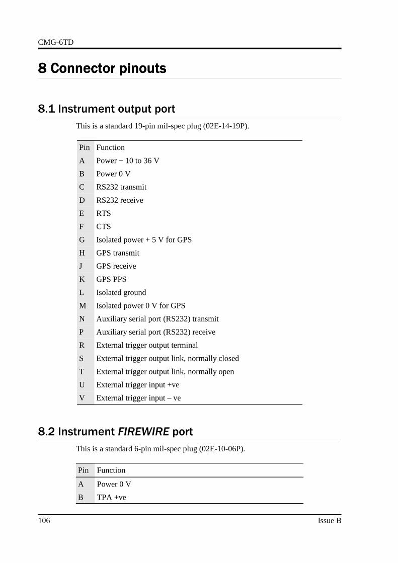
CMG-6TD
8 8 8 8 Connector pinoutsConnector pinoutsConnector pinoutsConnector pinouts
8.1 Instrument output port
This is a standard 19-pin mil-spec plug (02E-14-19P).
Pin Function
A Power + 10 to 36 V
B Power 0 V
C RS232 transmit
D RS232 receive
E RTS
F CTS
G Isolated power + 5 V for GPS
H GPS transmit
J GPS receive
K GPS PPS
L Isolated ground
M Isolated power 0 V for GPS
N Auxiliary serial port (RS232) transmit
P Auxiliary serial port (RS232) receive
R External trigger output terminal
S External trigger output link, normally closed
T External trigger output link, normally open
U External trigger input +ve
V External trigger input – ve
8.2 Instrument FIREWIRE port
This is a standard 6-pin mil-spec plug (02E-10-06P).
Pin Function
A Power 0 V
B TPA +ve
106 Issue B

Operator's Guide
C TPA −ve
D TPB −ve
E TPB +ve
F Power + V (powered FireWire option)
8.3 Instrument ETHERNET port
Instruments with the Wi-Fi and Ethernet networking options have an additional6-pin mil-spec plug (02E-10-06P) for this interface.
Pin Function
B Data transmit +ve (RJ45 pin 1)
C Data receive +ve (RJ45 pin 3)
E Data receive –ve (RJ45 pin 6)
F Data transmit –ve (RJ45 pin 2)
8.4 Breakout box data port
This is a standard 6-pin mil-spec plug (02E-10-06P).
Pin Function
A RS232 transmit
B RS232 receive
C RTS
D CTS
F Isolated ground
8.5 Breakout box GPS port
This is a standard 6-pin mil-spec socket (02E-10-06S).
Pin Function
A Isolated ground
B RS232 receive from GPS
November 2008 107

CMG-6TD
C RS232 transmit to GPS
D PPS
F Power +5 V
8.6 Breakout box power port
This is a standard 10-pin mil-spec plug (02E-12-10P).
Pin Function
A 0 V
B +12 V DC supply
J Auxiliary serial port (RS232) receive (optional)
K Auxiliary serial port (RS232) transmit (optional)
108 Issue B

Operator's Guide
9 9 9 9 SpecificationsSpecificationsSpecificationsSpecifications
Outputs andresponse
Sensitivity 2000 V/m/s
Nominal output sensitivity2.0 × 10-9 m/s/count
Standard output format 24-bit
Noise-free resolution(NPR) at 20 samples/s
> 132 dB r.m.s.(> 22 bits)
Standard frequency band0.033 Hz (30 s) – 100Hz
Digital signal processor TMS3200 at 144 MHz
Output rate User selectable
RS232 baud rate User selectable
Physical Lowest spurious resonance 450 Hz
Operating temperaturerange
–10 to +75 °C
Pressure jacket materialhard anodisedaluminium
Internal thermometeraccuracy
±0.33 °C (30 °C)±0.5 °C (10..50 °C)±1.0 °C (–10..75 °C)
Internal thermometerlinearity
±0.5 °C
Internal thermometerresolution
0.0625 °C
Sensor base platehard anodisedaluminium
Base diameter 154 mm
Sensor height242 mm (includinghandle)
Sensor weight 3.0 kg
Power Voltage requirements10..24 V using 12 VDC/DC converter
Current at 12 V DC withGPS
165 mA
November 2008 109

CMG-6TD
10 10 10 10 Revision historyRevision historyRevision historyRevision history2006-10-02 B Added revision history; changes for CD24 digitizer;
Wi-Fi and Ethernet options
2005-06-02 A New document
110 Issue B