Embed Size (px)
Citation preview

Installation and Operation Manual
CMA12SB-0 SeriesHorizontal/Side Discharge
Condensing Units
517.787.2100 • www.marsdelivers.com • www.heatcontroller.com

Installation and Operation Manual - CMA12SB-0 Series
Split Universal Type
INSTALLATION MANUAL
Thank you very much for purchasing our air conditioner, Before using your air conditioner , please read this manual carefully and keep it for future reference.
1installation manual
Be sure to be in conformity with the local, national and international laws and regulations.
Read "PRECAUTIONS" carefully before installation.
The following precautions include important safty items. Observe them and never forget.
Keep this manual with the owner's manual in a handy place for future reference.
1. PRECAUTIONS
The safty precautions listed here are divided into two categories.
After completing the installation, make sure that the unit operates properly during the start-up operation. Please instruct the customer on how to operate the unit and keep it maintained.Also, inform customers that they should store this installation manual along with the owner's manual for future reference.
Be sure only trained and qualified service personnel to install, repair or service the equipment.
Improper installation, repair, and maintenance may result in electric shocks, short-circuit, leaks, fire or other damage to the equipment.
Failure to observe a warning may result in death.
Failure to observe a caution may result in injury or damage to the equipment.
CONTENTS PAGE
1. PRECAUTIONS..................................................................... 2. INSTALLATION INFORMATION
3. OUTDOOR UNIT INSTALLATION....................................
4. INSTALL THE CONNECTING PIPE
6. WIRING
5. CONNECTIVE DIAGRAM.................................................
Install according to this installation instructions strictly. If installation is defective, it will cause water leakage, electrical shock and fire.
Use the attached accessories parts and specified parts for installation. otherwise, it will cause the set to fall, water leakage, electrical shock and fire.
Install at a strong and firm location which is able towithstand the set' s weight. If the strength is not enough or installation is not properly done, the set will drop to cause injury.
The appliance shall not be installed in the laundry.
Before obtaining access to terminals, all supply circuits must be disconnected.
The appliance must be positioned so that the plug is accessible.
The enclosure of the appliance shall be marked by word, or by symbols, with the direction of the fluid flow.
For electrical work, follow the local national wiring standard, regulation and this installation instructions. An independent circuit and single outlet must be used. If electrical circuit capacity is not enough or defect in electrical work, it will cause electrical shock or fire.
Use the specified cable and connect tightly and clamp the cable so that no external force will be acted on the terminal.If connection or fixing is not perfect, it will cause heat-up or fire at the connection.
Wiring routing must be properly arranged so that control board cover is fixed properly. If control board cover is not fixed perfectly, it will cause heat-up at connection point of terminal, fire or electricalshock.
If the supply cord is damaged, it must be replaced by the manufacture or its service agent or a similarly qualified person in order to avoid a hazard.
An all-pole disconnection switch having a contact separation of at least 3mm in all poles should be connected in fixed wiring.
When carrying out piping connection, take care not to let air substances go into refrigeration cycle. Otherwise, it will cause lower capacity, abnormal highpressure in the refrigeration cycle, explosion and injury.
Do not modify the length of the power supply cord or use of extension cord, and do not share the single outlet with other electrical appliances. Otherwise, it will cause fire or electrical shock.
Carry out the specified installation work after taking into account strong winds, typhoons or earthquakes.Improper installation work may result in the equipment falling and causing accidents.
CAUTION
WARNING
WARNING
...............................................
............................................................................
.................................
12
3
577
2installation manual
To install properly, please read this "installation manual" at first.
The air conditioner must be installed by qualified persons.
When installing the indoor unit or its tubing, please follow this manual as strictly as possible.
If the air conditioner is installed on a metal part of the building, it must be electrically insulated according to the relevant standards to electrical appliances.
When all the installation work is finished, please turn on the power only after a thorough check.
Regret for no further announcement if there is any change of this manual caused by product improvement.
2. INSTALLATION INFORMATION
Ground the air conditioner.Do not connect the ground wire to gas or water pipes, lightning rod or a telephone ground wire.Incompletegrounding may result in electric shocks.
Be sure to install an earth leakage breaker.Failure to install an earth leakage breaker may result in electric shocks.
The appliance is not intended for use by young children or infirm persons without supervision.
Don't install the air conditioner in the following locations:
There is petrolatum existing.
There is salty air surrounding (near the coast).
There is caustic gas (the sulfide, for example) existing in the air (near a hot spring).
The Volt vibrates violently (in the factories).
In buses or cabinets.
In kitchen where it is full of oil gas.
There is strong electromagnetic wave existing.
There are inflammable materials or gas.
There is acid or alkaline liquid evaporating.
Other special conditions.
If the refrigerant leaks during installation, ventilate the area immediately.Toxic gas may be produced if the refrigerant comes into the place contacting with fire.
The temperature of refrigerant circuit will be high, please keep the interconnection cable away from the coppertube.
After completing the installation work, check that the refrigerant does not leak.Toxic gas may be produced if the refrigerant leaks into the room and comes into contact with a source of fire, such as a fan heater, stove or cooker.
INSTALLATION ORDERSelect the location;
Install the outdoor unit;
Install the connecting pipe ;
Wiring;
CAUTION
3installation manual
4installation manual
5installation manual installation manual
6installation manual
7 8installation manual
9installation manual
10installation manual
3.1 Installation Place3. OUTDOOR UNIT INSTALLATION
There is enough room for installation and maintenance.
The air outlet and the air inlet are not impeded, and can not be reached by strong wind.
It must be a dry and well ventilating place.
The support is flat and horizontal and can stand theweight of the outdoor unit. And will no additional noise or vibration.
Your neighborhood will not feel uncomfortable with the noise or expelled air.
It is easy to install the connecting pipes or cables.
Determine the air outlet direction where the discharged air is not blocked.
There is no danger of fire due to leakage of inflammable gas.
The piping length between the outdoor unit and the indoor unit may not exceed the allowable piping length.
In the case that the installation place is exposed to strong wind such as a seaside, make sure the fan operating properly by putting the unit lengthwise along the wall or using a dust or shield.(Refer to Fig.6-1)
If possible, do not install the unit where it is exposed to direct sunlight.
If necessary, install a blind that does not interfere with the air flow.
During the heating mode, the water drained off theoutdoor unit ,The condensate should be well drained away by the drain hole to an appropriate place, so as not to interfere other people.
Select the position where it will not be subject to snow drifts, accumulation of leaves or other seasonal debris. If unavoidable, please cover it with a shelter.
Locate the outdoor unit as close to the indoor unit as possible.
If possible, please remove the obstacles nearby to prevent the performance from being impeded by too little of air circulation.
The minimum distance between the outdoor unit andobstacles described in the installation chart does notmean that the same is applicable to the situation of an airtight room. Leave open two of the three directions(M,N,P) (Refer to Fig.3-5)
XO
Strong
wind
The outdoor unit should be installed in the location that meets the following requiements:
Fig.3-1
11installation manual
CAUTION
Fig.3-6
4. INSTALL THE CONNECTING PIPE
Check whether the height drop between the indoor unit and outdoor unit, the length of refrigerant pipe, and the number of the bends meet the following requirements:
All field piping must be provided by a licensedrefrigeration technician and must comply with therelevant local and national codes.
Do not let air, dust, or other impurities fall in the pipe system during the time of installation.
The connecting pipe should not be installed until the indoor and outdoor units have been fixed already.
Keep the connecting pipe dry, and do not let moisture in during installation.
The Procedure of Connecting Pipes4.1
Never hold the inlet of the outdoor unit to prevent it from deforming.
Do not touch the fan with hands or other objects.
Do not lean it more than 45, and do not lay it sidelong.
Make concrete foundation accoding to the sepecif-ications of the outdoor units.(Refer to Fig.3-6)
Fasten the feet of this unit with bolts firmly to prevent it from collapsing in case of earthquake or strong wind.(Refer to Fig.3-6)
3.3 Moving and installation
Since the gravity center of the unit is not at its physicalcenter, so please be careful when lifting it with a sling.
Table 4-1
Capacity (Btu/h)
<18K
≥18K~<36K≥36K~<60K
≥60K
The type of models
R410A air conditioner and Centrifugal fan outdoor unit
30m/98ft
25m/82ft
30m/98ft
20m/66ft
20m/66ft
10m/33ft
15m/49ft
8m/26ft
refrigerant pipeThe length of
height dropThe max
>60cm / 23.6”
Fix with bolts
CAUTION
CAUTION
How to connect the pipes
Drill a hole in the wall (suitable just for the size of the wall conduit), then set on the fittings such as the wall conduit and its cover.
Bind the connecting pipe and the cables together tightly with binding tapes.Pass the bound connecting pipe through the wall conduct from outside. Be careful of the pipe allocation to do ondamage to the tubing.
Connect the pipes. Refer to "How to Connect the pipes" for details.
Expel the air with a vacuum pump. Refer to "How to expel the air with a vacuum pump" for details.
open the stop values of the outdoor unit to make therefrigerant pipe connecting the indoor unit with the outdoor unit in fluent flow.
Check the leakage. Check all the joints with the leak detector or soap water.
Cover the joints of the connecting pipe with the soundproof / insulating sheath (fittings), and bind it well with the tapes to prevent leakage.
Execute heat insulation work completely on both sides of the gas piping and the liquid piping. Otherwise, this can sometimes result in water leakage.
1
2
3
5
6
7
4
Be sure to with insulating materials cover all the exposed parts of the flare pipe joints and refrigerant pipe on the liquid-side and the gas-side. Ensure that there is no gap between them.Incomplete insulation may cause water condensation.
Flaring1
Cut a pipe with a pipe cutter. (refer to Fig.4-1)
2
Bend the tubing in proper way. Do not harm to them.
Connect the indoor unit at first, then the outdoor unit.
Too large torque will harm the bellmouthing and too small will cause leakage. Please determine the torqueaccording to Table 4-2.
After the connecting work is finished, be sure to check that there is no gas leak.
The bending angle should not exceed 90.
Bending position is preferably in the middle of thebendable pipe. The larger the bending radius the better it is.
Do not bend the pipe more than three times.
When connecting the flare nut, coat the flare both inside and outside with either oil or ester oil and initially tighten by hand 3 or 4 turns before tighting firmly.
Be sure to use both a spanner and torque wrench together when connecting or disconnecting pipes to /from the unit. (Fig.4-4)
Table 4-2
Insert a flare nut into a pipe and flare the pipe.
Refer to Table 4-2 for the dimension of flare nut spaces.
Fig.4-1
Bend the pipe with thumb
min-radius 100mm
Fig.4-2
Fig.4-3
Fig.4-4
How to expel the air with a vacuum pump
Stop valve operation intruduction1. Opening stop valve
2. Closing stop valve
1)
2)
1)
2)
3)
Remove the cap and turn the valve counterclock-wise with the hexagon wrench.
Turn it until the shaft stops.Do not apply excessive force to the stop valve. Doing so may breakthe valve body, as the valve is not a backseat type. Always use the special tool.
Make sure to tighten the cap securely.
Remove the cap and turn the valve clockwise with the hexagon wrench.
Securely tighten the valve until the shaft contacts the main bodyseal.
90 Lean crude burr
12installation manual
CAUTION
CAUTION
Tightening torque N.M (Turn clockwise to close)
StopValve size Shaft (valve body)
Cap(Valve lid)
Ø6.45.4~6.6 Hexagonal
wrench 4 mm13.5~16.5
11.5~13.9
Ø9.5
Ø12.7 8.1~9.9 18~22
Ø15.9 13.5~16.5 Hexagonalwrench 6 mm 23~27
Ø22.227~33
Hexagonalwrench10 mm
36~44Ø25.4
Loosen and remove the maintenance nuts of stop valves Aand B, and connect the charge hose of the manifold valve to the service port of stop valve A. (Be sure that stop valves Aand B are both closed)
Connect the joint of the charge hose with the vacuum pump.
Open the Lo-lever of the manifold value completely.
Turn on the vacuum pump. At the beginning of pumping, loosen the maintenance nut of stop valve B a little to check whether the air comes in (the sound of the pump changes, and the indicator of compound meter turns below zero). Then fasten the maintenace nut.
1
2
4
3
5
7
6
-76 cmHg
Lo-lever Hi-lever
Charge hose Charge hose
Vacuum pump
Lo-lever
Manifold valveMulti-meter Pressure meter
Fig.4-7
Note On Adding Refrigerant4.3
Using the vacuum pump
When the pumping has finished, close the Lo-lever of the manifold valve completely and turn off the vacuumpump.Make pumping for 15 minutes or more and check that the compound meter indicates -76cmHg(-1X10 Pa)
Loosen and remove the cap of stop valves A and B to open stop valve A and B completely, then fasten the cap.
Disassemble the charge hose from the service port of stop valve A, and fasten the nut.
5
Fig.4-6
Fig.4-5
Always use a charge hose for service port connection.
After tightening the cap, check that no refrigerant leaksarepresent.
service port
cap
maintenance nut
hexagon holeshaftseal
Make sure to tighten the cap securely.For the tightening torque, refer to the table below.
Outdoorunit
Indoorunit
Stop valve
Gas side
Liquid side
A C
D
B
Table 4-3
Maintenance nut
Ventilate the air if there was any refrigerant leakage during the installation.Leaked refrigerant will generate poisonous gas ifmeeting fire.
Make sure there is no refrigerant leakage after the installation.Leaked refrigerant will generate poisonous gas ifmeeting fire.
Allowed Lenght and Drop of PipesRequirements are different when installing the outdoor unit, please refer to outdoor unit installation manual for detailed information.
Material and Size of the Pipes
Three length(3m,5m,10m)of pipes are available to purchase.
4.2. Refrigerant pipe installation
13installation manual
14installation manual
15installation manual
The temperature of refrigerant circuit will be high, pleasekeep the interconnection cable away from the copper tube.
Dissemble the bolts from the cover.(If there isn't a cover on the outdoor unit, disassemble the bolts from the maintenance board, and pull it in the direction of the arrow to remove the protection board.)(Refer to Fig.6-1)
Connect the connective cables to the terminals as identified with their respective mached numbers on the terminal block of indoor and outdoor units.
Re-install the cover or the protection board.
Connect the cable6.1
The power connection for the air conditioner has to be done at the main power distribution. The distribution has to be of a low impedance, normally the required impedance reaches at a 32 A fusing point.
No other equipment has to be connected with this power line.
For detailed installation acceptance please refer to your power supplier, if restrictions do apply for products like washing machines, air conditioners or electrical ovens.
For power details of the air conditioner refer to the rating plate of the product.
For any question contact your local dealer.
1
2
4
3
5
6. WIRING
The appliance shall be installed in accordance with national wiring regulations.
The air conditioner should use separate power supply with rated voltage.
The external power supply to the air conditioner should have ground wiring, which is linked to the ground wiring of the indoor and outdoor unit.
The wiring work should be done by qualified persons according to circuit drawing.
An all-pole disconnection device which has at least 3mm sepaaration distance in all pole and a residual current device (RCD) with the rating of above 10mA shall be incorporated in the fixed wiring according to the national rule.
Be sure to locate the power wiring and the signal wring well to avoid cross-disturbance.
Do not turn on the power until you have checked carefully after wiring.
The power cord type designation is H07RN-F.
Remark per EMC Directive 2004/108/ECFor to prevent flicker impressions during the start of the compressor (technical process) following installation conditions do apply.
NOTE
Fig.6-1
NOTEAll the pictures in this manual are for explanationpurpose only. They may be slightly different from the air conditioner you purchased(depend on model).The actual shape shall prevail.
6. Outdoor unit
Wrong wiring connections may cause some electrical parts to malfunction.
CAUTION
Remove the electric parts cover from the outdoor unit.
Connect the connective cables to the terminals as identified with their respective matched numbers on the terminal block of indoor and outdoor units. (Connective cable sheathlength to be removed and insert into the terminal block.)
To prevent the ingress off water, from a loop of theconnective cable as illustrated in the installation diagram of indoor and outdoor units.
Insulate unused cords (conductors) with PVC-tape. Process them so they do not touch any electrical or metal parts.
1.
2.
3.
4.
Fig.6-2
Cord wire
40mm10mm
16installation manual
The Specification of Power6.2(Refer to Table6-1)
17installation manual
18installation manual
20installation manual
22installation manual
19installation manual
21installation manual
23installation manual
QSWI-002AEN
16122000000008
The design and specifications are subject to change without prior notice for productimprovement.Consult with the sales agency or manufacturer for details.
20151209
>300mm
mm003>
mm0002>
>600mm
(Wall or obstacle)
Maintain channel
Air outlet
Air inlet
M
P
Air inlet
N
Fig.3-5
1. Split type outdoor unit
3.2 Space of installation and maintenance
5. CONNECTIVE DIAGRAM
Fig. 5-1
Liquid side
orifice
Gas side
25 35
MODEL
POWER(outdoor)
CIRCUIT BREAKER/FUSE(A)
PHASE
VOLT
18 24 30 36
208/230 V 208/2 30V
1 P h a s e 1 P h a s e
208/2 30V
1 P h a s e
208/2 30V
1 P h a s e
15 20
Table 6-1
(mm)
Ø6.35/0.25in 8.3/0.327in 8.7/0.343in
Ø9.52/0.375in 12.0/0.472in 12.4/0.488in
Ø12.7/0.5in 15.4/0.606in 15.80.622in
Ø15.9/0.626in
Ø19.1/0.725in
18.6/0.732in 19.0/0.748in
22.9/0.902in 23.3/0.917in
R0.4~0.8
45 °±2
90 ° ± 4
A
min maxPipe gauge Tightening torque Flare dimensin AFlare shape
97.2~118.6 N.m(990~1210 kgf.cm)
(630~770 kgf.cm)61.8~75.4 N.m
49.5~60.3 N.m(504~616 kgf.cm)
32.7~39.9 N.m(333~407 kgf.cm)
14.2~17.2 N.m(144~176 kgf.cm)
Fig.3-4
Fig.3-3
A
BD
W
H
W
H
Fig.3-2
Cover
Screw
φ φ φ
Split Universal Type
INSTALLATION MANUAL
Thank you very much for purchasing our air conditioner, Before using your air conditioner , please read this manual carefully and keep it for future reference.
1installation manual
Be sure to be in conformity with the local, national and international laws and regulations.
Read "PRECAUTIONS" carefully before installation.
The following precautions include important safety items.
Keep this manual with the owner's manual in a handy place for future reference.
1. PRECAUTIONS
The safety precautions listed here are divided into two categories.
After completing the installation, make sure that the unit operates properly during the start-up operation. Please instruct the customer on how to operate the unit and keep it maintained. Also, inform customers that they should store this installation manual along with the owner's manual for future reference.
Be sure only trained and qualified service personnel to install, repair or service the equipment.
Improper installation, repair, and maintenance may result in electric shocks, short-circuit, leaks, fire or other damage to the equipment.
Failure to observe a warning may result in death.
Failure to observe a caution may result in injury or damage to the equipment.
CONTENTS PAGE
1. PRECAUTIONS..................................................................... 2. INSTALLATION INFORMATION
3. OUTDOOR UNIT INSTALLATION....................................
4. INSTALL THE CONNECTING PIPE
6. WIRING
5. CONNECTIVE DIAGRAM.................................................
Follow these installation instructions strictly. If installation is defective, it will cause water leakage, electrical shock and fire.
Use the attached accessories and specified parts for installation. otherwise, it will cause the unit to fall, water leakage, electrical shock and fire.
Install at a strong and firm location which is able to withstand the unit's weight. If the strength is not enough or installation is not properly done, the set will fall to cause injury.
This appliance should not be installed in a laundry room.
The enclosure of the appliance shall be marked by word, or by symbols, with the direction of the fluid flow.
For electrical work, follow the local and national wiring standards, regulations and this installation instructions. An independent circuit must be used. If electrical circuit capacity is not enough or electrical work is defective, it will cause electrical shock or fire.
Use specified cable and connect tightly. Clamp the cable so that no external force acts on the terminal.If connection is not perfect, it will cause heat or fire at the connection.
Wire routing must be properly arranged so that control board cover is fixed properly. If control board cover is not fixed perfectly, it will cause heat-up at connection point of terminal, fire or electrical shock.
If the supply cord is damaged, it must be replaced by the manufacturer or its service agent or a similarly qualified person in order to avoid a hazard.
An all-pole disconnect switch having a contact separation of at least 3mm in all poles should be used on fixed wiring.
When carrying out piping connection, take care not to let air or substances go into refrigeration lines. Otherwise, it will cause lower capacity, abnormal high pressure in the refrigeration cycle, explosion and injury.
Carry out the installation taking into account strong winds, typhoons or earthquakes. Improper installation work may result in the equipment falling and causing accidents.
CAUTION
WARNING
WARNING
...............................................
............................................................................
.................................
12
3
577
2installation manual
To install properly, please read this "installation manual" at first.
The air conditioner must be installed by qualified persons.
When installing the indoor unit or its tubing, please follow this manual as strictly as possible.
If the air conditioner is installed on a metal part of the building, it must be electrically insulated according to the relevant standards to electrical appliances.
When all the installation work is finished, please turn on the power only after a thorough check.
Regret for no further announcement if there is any change of this manual caused by product improvement.
2. INSTALLATION INFORMATION
Ground the air conditioner.Do not connect the ground wire to gas or water pipes, lightning rod or a telephone ground wire.Incompletegrounding may result in electric shocks.
Be sure to install an earth leakage breaker.Failure to install an earth leakage breaker may result in electric shocks.
The appliance is not intended for use by young children or infirm persons without supervision.
Don't install the air conditioner in the following locations:
There is petrolatum existing.
There is salty air surrounding (near the coast).
There is caustic gas (the sulfide, for example) existing in the air (near a hot spring).
The Volt vibrates violently (in the factories).
In buses or cabinets.
In kitchen where it is full of oil gas.
There is strong electromagnetic wave existing.
There are inflammable materials or gas.
There is acid or alkaline liquid evaporating.
Other special conditions.
If the refrigerant leaks during installation, ventilate the area immediately.Toxic gas may be produced if the refrigerant comes into the place contacting with fire.
The temperature of refrigerant circuit will be high, please keep the interconnection cable away from the coppertube.
After completing the installation work, check that the refrigerant does not leak.Toxic gas may be produced if the refrigerant leaks into the room and comes into contact with a source of fire, such as a fan heater, stove or cooker.
INSTALLATION ORDERSelect the location;
Install the outdoor unit;
Install the connecting pipe ;
Wiring;
CAUTION
3installation manual
4installation manual
5installation manual installation manual
6installation manual
7 8installation manual
9installation manual
10installation manual
3.1 Installation Place3. OUTDOOR UNIT INSTALLATION
There is enough room for installation and maintenance.
The air outlet and the air inlet are not impeded, and can not be reached by strong wind.
It must be a dry and well ventilating place.
The support is flat and horizontal and can stand theweight of the outdoor unit. And will no additional noise or vibration.
Your neighborhood will not feel uncomfortable with the noise or expelled air.
It is easy to install the connecting pipes or cables.
Determine the air outlet direction where the discharged air is not blocked.
There is no danger of fire due to leakage of inflammable gas.
The piping length between the outdoor unit and the indoor unit may not exceed the allowable piping length.
In the case that the installation place is exposed to strong wind such as a seaside, make sure the fan operating properly by putting the unit lengthwise along the wall or using a dust or shield.(Refer to Fig.6-1)
If possible, do not install the unit where it is exposed to direct sunlight.
If necessary, install a blind that does not interfere with the air flow.
During the heating mode, the water drained off theoutdoor unit ,The condensate should be well drained away by the drain hole to an appropriate place, so as not to interfere other people.
Select the position where it will not be subject to snow drifts, accumulation of leaves or other seasonal debris. If unavoidable, please cover it with a shelter.
Locate the outdoor unit as close to the indoor unit as possible.
If possible, please remove the obstacles nearby to prevent the performance from being impeded by too little of air circulation.
The minimum distance between the outdoor unit andobstacles described in the installation chart does notmean that the same is applicable to the situation of an airtight room. Leave open two of the three directions(M,N,P) (Refer to Fig.3-5)
XO
Strong w
ind
The outdoor unit should be installed in the location that meets the following requiements:
Fig.3-1
11installation manual
CAUTION
Fig.3-6
4. INSTALL THE CONNECTING PIPE
Check whether the height drop between the indoor unit and outdoor unit, the length of refrigerant pipe, and the number of the bends meet the following requirements:
All field piping must be provided by a licensedrefrigeration technician and must comply with therelevant local and national codes.
Do not let air, dust, or other impurities fall in the pipe system during the time of installation.
The connecting pipe should not be installed until the indoor and outdoor units have been fixed already.
Keep the connecting pipe dry, and do not let moisture in during installation.
The Procedure of Connecting Pipes4.1
Never hold the inlet of the outdoor unit to prevent it from deforming.
Do not touch the fan with hands or other objects.
Do not lean it more than 45, and do not lay it sidelong.
Make concrete foundation accoding to the sepecif-ications of the outdoor units.(Refer to Fig.3-6)
Fasten the feet of this unit with bolts firmly to prevent it from collapsing in case of earthquake or strong wind.(Refer to Fig.3-6)
3.3 Moving and installation
Since the gravity center of the unit is not at its physicalcenter, so please be careful when lifting it with a sling.
Table 4-1
Capacity (Btu/h)
<18K
≥18K~<36K≥36K~<60K
≥60K
The type of models
R410A air conditioner and Centrifugal fan outdoor unit
30m/98ft
25m/82ft
30m/98ft
20m/66ft
20m/66ft
10m/33ft
15m/49ft
8m/26ft
refrigerant pipeThe length of
height dropThe max
>60cm / 23.6”
Fix with bolts
CAUTION
CAUTION
How to connect the pipes
Drill a hole in the wall (suitable just for the size of the wall conduit), then set on the fittings such as the wall conduit and its cover.
Bind the connecting pipe and the cables together tightly with binding tapes.Pass the bound connecting pipe through the wall conduct from outside. Be careful of the pipe allocation to do ondamage to the tubing.
Connect the pipes. Refer to "How to Connect the pipes" for details.
Expel the air with a vacuum pump. Refer to "How to expel the air with a vacuum pump" for details.
open the stop values of the outdoor unit to make therefrigerant pipe connecting the indoor unit with the outdoor unit in fluent flow.
Check the leakage. Check all the joints with the leak detector or soap water.
Cover the joints of the connecting pipe with the soundproof / insulating sheath (fittings), and bind it well with the tapes to prevent leakage.
Execute heat insulation work completely on both sides of the gas piping and the liquid piping. Otherwise, this can sometimes result in water leakage.
1
2
3
5
6
7
4
Be sure to with insulating materials cover all the exposed parts of the flare pipe joints and refrigerant pipe on the liquid-side and the gas-side. Ensure that there is no gap between them.Incomplete insulation may cause water condensation.
Flaring1
Cut a pipe with a pipe cutter. (refer to Fig.4-1)
2
Bend the tubing in proper way. Do not harm to them.
Connect the indoor unit at first, then the outdoor unit.
Too large torque will harm the bellmouthing and too small will cause leakage. Please determine the torqueaccording to Table 4-2.
After the connecting work is finished, be sure to check that there is no gas leak.
The bending angle should not exceed 90.
Bending position is preferably in the middle of thebendable pipe. The larger the bending radius the better it is.
Do not bend the pipe more than three times.
When connecting the flare nut, coat the flare both inside and outside with either oil or ester oil and initially tighten by hand 3 or 4 turns before tighting firmly.
Be sure to use both a spanner and torque wrench together when connecting or disconnecting pipes to /from the unit. (Fig.4-4)
Table 4-2
Insert a flare nut into a pipe and flare the pipe.
Refer to Table 4-2 for the dimension of flare nut spaces.
Fig.4-1
Bend the pipe with thumb
min-radius 100mm
Fig.4-2
Fig.4-3
Fig.4-4
How to expel the air with a vacuum pump
Stop valve operation intruduction1. Opening stop valve
2. Closing stop valve
1)
2)
1)
2)
3)
Remove the cap and turn the valve counterclock-wise with the hexagon wrench.
Turn it until the shaft stops.Do not apply excessive force to the stop valve. Doing so may breakthe valve body, as the valve is not a backseat type. Always use the special tool.
Make sure to tighten the cap securely.
Remove the cap and turn the valve clockwise with the hexagon wrench.
Securely tighten the valve until the shaft contacts the main bodyseal.
90 Lean crude burr
12installation manual
CAUTION
CAUTION
Tightening torque N.M (Turn clockwise to close)
StopValve size Shaft (valve body)
Cap(Valve lid)
Ø6.45.4~6.6 Hexagonal
wrench 4 mm13.5~16.5
11.5~13.9
Ø9.5
Ø12.7 8.1~9.9 18~22
Ø15.9 13.5~16.5 Hexagonalwrench 6 mm 23~27
Ø22.227~33
Hexagonalwrench10 mm
36~44Ø25.4
Loosen and remove the maintenance nuts of stop valves Aand B, and connect the charge hose of the manifold valve to the service port of stop valve A. (Be sure that stop valves Aand B are both closed)
Connect the joint of the charge hose with the vacuum pump.
Open the Lo-lever of the manifold value completely.
Turn on the vacuum pump. At the beginning of pumping, loosen the maintenance nut of stop valve B a little to check whether the air comes in (the sound of the pump changes, and the indicator of compound meter turns below zero). Then fasten the maintenace nut.
1
2
4
3
5
7
6
-76 cmHg
Lo-lever Hi-lever
Charge hose Charge hose
Vacuum pump
Lo-lever
Manifold valveMulti-meter Pressure meter
Fig.4-7
Note On Adding Refrigerant4.3
Using the vacuum pump
When the pumping has finished, close the Lo-lever of the manifold valve completely and turn off the vacuumpump.Make pumping for 15 minutes or more and check that the compound meter indicates -76cmHg(-1X10 Pa)
Loosen and remove the cap of stop valves A and B to open stop valve A and B completely, then fasten the cap.
Disassemble the charge hose from the service port of stop valve A, and fasten the nut.
5
Fig.4-6
Fig.4-5
Always use a charge hose for service port connection.
After tightening the cap, check that no refrigerant leaksarepresent.
service port
cap
maintenance nut
hexagon holeshaftseal
Make sure to tighten the cap securely.For the tightening torque, refer to the table below.
Outdoorunit
Indoorunit
Stop valve
Gas side
Liquid side
A C
D
B
Table 4-3
Maintenance nut
Ventilate the air if there was any refrigerant leakage during the installation.Leaked refrigerant will generate poisonous gas ifmeeting fire.
Make sure there is no refrigerant leakage after the installation.Leaked refrigerant will generate poisonous gas ifmeeting fire.
Allowed Lenght and Drop of PipesRequirements are different when installing the outdoor unit, please refer to outdoor unit installation manual for detailed information.
Material and Size of the Pipes
Three length(3m,5m,10m)of pipes are available to purchase.
4.2. Refrigerant pipe installation
13installation manual
14installation manual
15installation manual
The temperature of refrigerant circuit will be high, pleasekeep the interconnection cable away from the copper tube.
Dissemble the bolts from the cover.(If there isn't a cover on the outdoor unit, disassemble the bolts from the maintenance board, and pull it in the direction of the arrow to remove the protection board.)(Refer to Fig.6-1)
Connect the connective cables to the terminals as identified with their respective mached numbers on the terminal block of indoor and outdoor units.
Re-install the cover or the protection board.
Connect the cable6.1
The power connection for the air conditioner has to be done at the main power distribution. The distribution has to be of a low impedance, normally the required impedance reaches at a 32 A fusing point.
No other equipment has to be connected with this power line.
For detailed installation acceptance please refer to your power supplier, if restrictions do apply for products like washing machines, air conditioners or electrical ovens.
For power details of the air conditioner refer to the rating plate of the product.
For any question contact your local dealer.
1
2
4
3
5
6. WIRING
The appliance shall be installed in accordance with national wiring regulations.
The air conditioner should use separate power supply with rated voltage.
The external power supply to the air conditioner should have ground wiring, which is linked to the ground wiring of the indoor and outdoor unit.
The wiring work should be done by qualified persons according to circuit drawing.
An all-pole disconnection device which has at least 3mm sepaaration distance in all pole and a residual current device (RCD) with the rating of above 10mA shall be incorporated in the fixed wiring according to the national rule.
Be sure to locate the power wiring and the signal wring well to avoid cross-disturbance.
Do not turn on the power until you have checked carefully after wiring.
The power cord type designation is H07RN-F.
Remark per EMC Directive 2004/108/ECFor to prevent flicker impressions during the start of the compressor (technical process) following installation conditions do apply.
NOTE
Fig.6-1
NOTEAll the pictures in this manual are for explanationpurpose only. They may be slightly different from the air conditioner you purchased(depend on model).The actual shape shall prevail.
6. Outdoor unit
Wrong wiring connections may cause some electrical parts to malfunction.
CAUTION
Remove the electric parts cover from the outdoor unit.
Connect the connective cables to the terminals as identified with their respective matched numbers on the terminal block of indoor and outdoor units. (Connective cable sheathlength to be removed and insert into the terminal block.)
To prevent the ingress off water, from a loop of theconnective cable as illustrated in the installation diagram of indoor and outdoor units.
Insulate unused cords (conductors) with PVC-tape. Process them so they do not touch any electrical or metal parts.
1.
2.
3.
4.
Fig.6-2
Cord wire
40mm10mm
16installation manual
The Specification of Power6.2(Refer to Table6-1)
17installation manual
18installation manual
20installation manual
22installation manual
19installation manual
21installation manual
23installation manual
QSWI-002AEN
16122000000008
The design and specifications are subject to change without prior notice for productimprovement.Consult with the sales agency or manufacturer for details.
20151209
>300mm
mm003>
mm0002>
>600mm
(Wall or obstacle)
Maintain channel
Air outlet
Air inlet
M
P
Air inlet
N
Fig.3-5
1. Split type outdoor unit
3.2 Space of installation and maintenance
5. CONNECTIVE DIAGRAM
Fig. 5-1
Liquid side
orifice
Gas side
25 35
MODEL
POWER(outdoor)
CIRCUIT BREAKER/FUSE(A)
PHASE
VOLT
18 24 30 36
208/230 V 208/2 30V
1 P h a s e 1 P h a s e
208/2 30V
1 P h a s e
208/2 30V
1 P h a s e
15 20
Table 6-1
(mm)
Ø6.35/0.25in 8.3/0.327in 8.7/0.343in
Ø9.52/0.375in 12.0/0.472in 12.4/0.488in
Ø12.7/0.5in 15.4/0.606in 15.80.622in
Ø15.9/0.626in
Ø19.1/0.725in
18.6/0.732in 19.0/0.748in
22.9/0.902in 23.3/0.917in
R0.4~0.8
45 °±2
90 ° ± 4
A
min maxPipe gauge Tightening torque Flare dimensin AFlare shape
97.2~118.6 N.m(990~1210 kgf.cm)
(630~770 kgf.cm)61.8~75.4 N.m
49.5~60.3 N.m(504~616 kgf.cm)
32.7~39.9 N.m(333~407 kgf.cm)
14.2~17.2 N.m(144~176 kgf.cm)
Fig.3-4
Fig.3-3
A
BD
W
H
W
H
Fig.3-2
Cover
Screw
φ φ φ
Horizontal/Side Discharge Condensing Units Heat Controller
1

Installation and Operation Manual - CMA12SB-0 Series
2
Split Universal Type
INSTALLATION MANUAL
Thank you very much for purchasing our air conditioner, Before using your air conditioner , please read this manual carefully and keep it for future reference.
1installation manual
Be sure to be in conformity with the local, national and international laws and regulations.
Read "PRECAUTIONS" carefully before installation.
The following precautions include important safty items. Observe them and never forget.
Keep this manual with the owner's manual in a handy place for future reference.
1. PRECAUTIONS
The safty precautions listed here are divided into two categories.
After completing the installation, make sure that the unit operates properly during the start-up operation. Please instruct the customer on how to operate the unit and keep it maintained.Also, inform customers that they should store this installation manual along with the owner's manual for future reference.
Be sure only trained and qualified service personnel to install, repair or service the equipment.
Improper installation, repair, and maintenance may result in electric shocks, short-circuit, leaks, fire or other damage to the equipment.
Failure to observe a warning may result in death.
Failure to observe a caution may result in injury or damage to the equipment.
CONTENTS PAGE
1. PRECAUTIONS..................................................................... 2. INSTALLATION INFORMATION
3. OUTDOOR UNIT INSTALLATION....................................
4. INSTALL THE CONNECTING PIPE
6. WIRING
5. CONNECTIVE DIAGRAM.................................................
Install according to this installation instructions strictly. If installation is defective, it will cause water leakage, electrical shock and fire.
Use the attached accessories parts and specified parts for installation. otherwise, it will cause the set to fall, water leakage, electrical shock and fire.
Install at a strong and firm location which is able towithstand the set' s weight. If the strength is not enough or installation is not properly done, the set will drop to cause injury.
The appliance shall not be installed in the laundry.
Before obtaining access to terminals, all supply circuits must be disconnected.
The appliance must be positioned so that the plug is accessible.
The enclosure of the appliance shall be marked by word, or by symbols, with the direction of the fluid flow.
For electrical work, follow the local national wiring standard, regulation and this installation instructions. An independent circuit and single outlet must be used. If electrical circuit capacity is not enough or defect in electrical work, it will cause electrical shock or fire.
Use the specified cable and connect tightly and clamp the cable so that no external force will be acted on the terminal.If connection or fixing is not perfect, it will cause heat-up or fire at the connection.
Wiring routing must be properly arranged so that control board cover is fixed properly. If control board cover is not fixed perfectly, it will cause heat-up at connection point of terminal, fire or electricalshock.
If the supply cord is damaged, it must be replaced by the manufacture or its service agent or a similarly qualified person in order to avoid a hazard.
An all-pole disconnection switch having a contact separation of at least 3mm in all poles should be connected in fixed wiring.
When carrying out piping connection, take care not to let air substances go into refrigeration cycle. Otherwise, it will cause lower capacity, abnormal highpressure in the refrigeration cycle, explosion and injury.
Do not modify the length of the power supply cord or use of extension cord, and do not share the single outlet with other electrical appliances. Otherwise, it will cause fire or electrical shock.
Carry out the specified installation work after taking into account strong winds, typhoons or earthquakes.Improper installation work may result in the equipment falling and causing accidents.
CAUTION
WARNING
WARNING
...............................................
............................................................................
.................................
12
3
577
2installation manual
To install properly, please read this "installation manual" at first.
The air conditioner must be installed by qualified persons.
When installing the indoor unit or its tubing, please follow this manual as strictly as possible.
If the air conditioner is installed on a metal part of the building, it must be electrically insulated according to the relevant standards to electrical appliances.
When all the installation work is finished, please turn on the power only after a thorough check.
Regret for no further announcement if there is any change of this manual caused by product improvement.
2. INSTALLATION INFORMATION
Ground the air conditioner.Do not connect the ground wire to gas or water pipes, lightning rod or a telephone ground wire.Incompletegrounding may result in electric shocks.
Be sure to install an earth leakage breaker.Failure to install an earth leakage breaker may result in electric shocks.
The appliance is not intended for use by young children or infirm persons without supervision.
Don't install the air conditioner in the following locations:
There is petrolatum existing.
There is salty air surrounding (near the coast).
There is caustic gas (the sulfide, for example) existing in the air (near a hot spring).
The Volt vibrates violently (in the factories).
In buses or cabinets.
In kitchen where it is full of oil gas.
There is strong electromagnetic wave existing.
There are inflammable materials or gas.
There is acid or alkaline liquid evaporating.
Other special conditions.
If the refrigerant leaks during installation, ventilate the area immediately.Toxic gas may be produced if the refrigerant comes into the place contacting with fire.
The temperature of refrigerant circuit will be high, please keep the interconnection cable away from the coppertube.
After completing the installation work, check that the refrigerant does not leak.Toxic gas may be produced if the refrigerant leaks into the room and comes into contact with a source of fire, such as a fan heater, stove or cooker.
INSTALLATION ORDERSelect the location;
Install the outdoor unit;
Install the connecting pipe ;
Wiring;
CAUTION
3installation manual
4installation manual
5installation manual installation manual
6installation manual
7 8installation manual
9installation manual
10installation manual
3.1 Installation Place3. OUTDOOR UNIT INSTALLATION
There is enough room for installation and maintenance.
The air outlet and the air inlet are not impeded, and can not be reached by strong wind.
It must be a dry and well ventilating place.
The support is flat and horizontal and can stand theweight of the outdoor unit. And will no additional noise or vibration.
Your neighborhood will not feel uncomfortable with the noise or expelled air.
It is easy to install the connecting pipes or cables.
Determine the air outlet direction where the discharged air is not blocked.
There is no danger of fire due to leakage of inflammable gas.
The piping length between the outdoor unit and the indoor unit may not exceed the allowable piping length.
In the case that the installation place is exposed to strong wind such as a seaside, make sure the fan operating properly by putting the unit lengthwise along the wall or using a dust or shield.(Refer to Fig.6-1)
If possible, do not install the unit where it is exposed to direct sunlight.
If necessary, install a blind that does not interfere with the air flow.
During the heating mode, the water drained off theoutdoor unit ,The condensate should be well drained away by the drain hole to an appropriate place, so as not to interfere other people.
Select the position where it will not be subject to snow drifts, accumulation of leaves or other seasonal debris. If unavoidable, please cover it with a shelter.
Locate the outdoor unit as close to the indoor unit as possible.
If possible, please remove the obstacles nearby to prevent the performance from being impeded by too little of air circulation.
The minimum distance between the outdoor unit andobstacles described in the installation chart does notmean that the same is applicable to the situation of an airtight room. Leave open two of the three directions(M,N,P) (Refer to Fig.3-5)
XO
Strong
wind
The outdoor unit should be installed in the location that meets the following requiements:
Fig.3-1
11installation manual
CAUTION
Fig.3-6
4. INSTALL THE CONNECTING PIPE
Check whether the height drop between the indoor unit and outdoor unit, the length of refrigerant pipe, and the number of the bends meet the following requirements:
All field piping must be provided by a licensedrefrigeration technician and must comply with therelevant local and national codes.
Do not let air, dust, or other impurities fall in the pipe system during the time of installation.
The connecting pipe should not be installed until the indoor and outdoor units have been fixed already.
Keep the connecting pipe dry, and do not let moisture in during installation.
The Procedure of Connecting Pipes4.1
Never hold the inlet of the outdoor unit to prevent it from deforming.
Do not touch the fan with hands or other objects.
Do not lean it more than 45, and do not lay it sidelong.
Make concrete foundation accoding to the sepecif-ications of the outdoor units.(Refer to Fig.3-6)
Fasten the feet of this unit with bolts firmly to prevent it from collapsing in case of earthquake or strong wind.(Refer to Fig.3-6)
3.3 Moving and installation
Since the gravity center of the unit is not at its physicalcenter, so please be careful when lifting it with a sling.
Table 4-1
Capacity (Btu/h)
<18K
≥18K~<36K≥36K~<60K
≥60K
The type of models
R410A air conditioner and Centrifugal fan outdoor unit
30m/98ft
25m/82ft
30m/98ft
20m/66ft
20m/66ft
10m/33ft
15m/49ft
8m/26ft
refrigerant pipeThe length of
height dropThe max
>60cm / 23.6”
Fix with bolts
CAUTION
CAUTION
How to connect the pipes
Drill a hole in the wall (suitable just for the size of the wall conduit), then set on the fittings such as the wall conduit and its cover.
Bind the connecting pipe and the cables together tightly with binding tapes.Pass the bound connecting pipe through the wall conduct from outside. Be careful of the pipe allocation to do ondamage to the tubing.
Connect the pipes. Refer to "How to Connect the pipes" for details.
Expel the air with a vacuum pump. Refer to "How to expel the air with a vacuum pump" for details.
open the stop values of the outdoor unit to make therefrigerant pipe connecting the indoor unit with the outdoor unit in fluent flow.
Check the leakage. Check all the joints with the leak detector or soap water.
Cover the joints of the connecting pipe with the soundproof / insulating sheath (fittings), and bind it well with the tapes to prevent leakage.
Execute heat insulation work completely on both sides of the gas piping and the liquid piping. Otherwise, this can sometimes result in water leakage.
1
2
3
5
6
7
4
Be sure to with insulating materials cover all the exposed parts of the flare pipe joints and refrigerant pipe on the liquid-side and the gas-side. Ensure that there is no gap between them.Incomplete insulation may cause water condensation.
Flaring1
Cut a pipe with a pipe cutter. (refer to Fig.4-1)
2
Bend the tubing in proper way. Do not harm to them.
Connect the indoor unit at first, then the outdoor unit.
Too large torque will harm the bellmouthing and too small will cause leakage. Please determine the torqueaccording to Table 4-2.
After the connecting work is finished, be sure to check that there is no gas leak.
The bending angle should not exceed 90.
Bending position is preferably in the middle of thebendable pipe. The larger the bending radius the better it is.
Do not bend the pipe more than three times.
When connecting the flare nut, coat the flare both inside and outside with either oil or ester oil and initially tighten by hand 3 or 4 turns before tighting firmly.
Be sure to use both a spanner and torque wrench together when connecting or disconnecting pipes to /from the unit. (Fig.4-4)
Table 4-2
Insert a flare nut into a pipe and flare the pipe.
Refer to Table 4-2 for the dimension of flare nut spaces.
Fig.4-1
Bend the pipe with thumb
min-radius 100mm
Fig.4-2
Fig.4-3
Fig.4-4
How to expel the air with a vacuum pump
Stop valve operation intruduction1. Opening stop valve
2. Closing stop valve
1)
2)
1)
2)
3)
Remove the cap and turn the valve counterclock-wise with the hexagon wrench.
Turn it until the shaft stops.Do not apply excessive force to the stop valve. Doing so may breakthe valve body, as the valve is not a backseat type. Always use the special tool.
Make sure to tighten the cap securely.
Remove the cap and turn the valve clockwise with the hexagon wrench.
Securely tighten the valve until the shaft contacts the main bodyseal.
90 Lean crude burr
12installation manual
CAUTION
CAUTION
Tightening torque N.M (Turn clockwise to close)
StopValve size Shaft (valve body)
Cap(Valve lid)
Ø6.45.4~6.6 Hexagonal
wrench 4 mm13.5~16.5
11.5~13.9
Ø9.5
Ø12.7 8.1~9.9 18~22
Ø15.9 13.5~16.5 Hexagonalwrench 6 mm 23~27
Ø22.227~33
Hexagonalwrench10 mm
36~44Ø25.4
Loosen and remove the maintenance nuts of stop valves Aand B, and connect the charge hose of the manifold valve to the service port of stop valve A. (Be sure that stop valves Aand B are both closed)
Connect the joint of the charge hose with the vacuum pump.
Open the Lo-lever of the manifold value completely.
Turn on the vacuum pump. At the beginning of pumping, loosen the maintenance nut of stop valve B a little to check whether the air comes in (the sound of the pump changes, and the indicator of compound meter turns below zero). Then fasten the maintenace nut.
1
2
4
3
5
7
6
-76 cmHg
Lo-lever Hi-lever
Charge hose Charge hose
Vacuum pump
Lo-lever
Manifold valveMulti-meter Pressure meter
Fig.4-7
Note On Adding Refrigerant4.3
Using the vacuum pump
When the pumping has finished, close the Lo-lever of the manifold valve completely and turn off the vacuumpump.Make pumping for 15 minutes or more and check that the compound meter indicates -76cmHg(-1X10 Pa)
Loosen and remove the cap of stop valves A and B to open stop valve A and B completely, then fasten the cap.
Disassemble the charge hose from the service port of stop valve A, and fasten the nut.
5
Fig.4-6
Fig.4-5
Always use a charge hose for service port connection.
After tightening the cap, check that no refrigerant leaksarepresent.
service port
cap
maintenance nut
hexagon holeshaftseal
Make sure to tighten the cap securely.For the tightening torque, refer to the table below.
Outdoorunit
Indoorunit
Stop valve
Gas side
Liquid side
A C
D
B
Table 4-3
Maintenance nut
Ventilate the air if there was any refrigerant leakage during the installation.Leaked refrigerant will generate poisonous gas ifmeeting fire.
Make sure there is no refrigerant leakage after the installation.Leaked refrigerant will generate poisonous gas ifmeeting fire.
Allowed Lenght and Drop of PipesRequirements are different when installing the outdoor unit, please refer to outdoor unit installation manual for detailed information.
Material and Size of the Pipes
Three length(3m,5m,10m)of pipes are available to purchase.
4.2. Refrigerant pipe installation
13installation manual
14installation manual
15installation manual
The temperature of refrigerant circuit will be high, pleasekeep the interconnection cable away from the copper tube.
Dissemble the bolts from the cover.(If there isn't a cover on the outdoor unit, disassemble the bolts from the maintenance board, and pull it in the direction of the arrow to remove the protection board.)(Refer to Fig.6-1)
Connect the connective cables to the terminals as identified with their respective mached numbers on the terminal block of indoor and outdoor units.
Re-install the cover or the protection board.
Connect the cable6.1
The power connection for the air conditioner has to be done at the main power distribution. The distribution has to be of a low impedance, normally the required impedance reaches at a 32 A fusing point.
No other equipment has to be connected with this power line.
For detailed installation acceptance please refer to your power supplier, if restrictions do apply for products like washing machines, air conditioners or electrical ovens.
For power details of the air conditioner refer to the rating plate of the product.
For any question contact your local dealer.
1
2
4
3
5
6. WIRING
The appliance shall be installed in accordance with national wiring regulations.
The air conditioner should use separate power supply with rated voltage.
The external power supply to the air conditioner should have ground wiring, which is linked to the ground wiring of the indoor and outdoor unit.
The wiring work should be done by qualified persons according to circuit drawing.
An all-pole disconnection device which has at least 3mm sepaaration distance in all pole and a residual current device (RCD) with the rating of above 10mA shall be incorporated in the fixed wiring according to the national rule.
Be sure to locate the power wiring and the signal wring well to avoid cross-disturbance.
Do not turn on the power until you have checked carefully after wiring.
The power cord type designation is H07RN-F.
Remark per EMC Directive 2004/108/ECFor to prevent flicker impressions during the start of the compressor (technical process) following installation conditions do apply.
NOTE
Fig.6-1
NOTEAll the pictures in this manual are for explanationpurpose only. They may be slightly different from the air conditioner you purchased(depend on model).The actual shape shall prevail.
6. Outdoor unit
Wrong wiring connections may cause some electrical parts to malfunction.
CAUTION
Remove the electric parts cover from the outdoor unit.
Connect the connective cables to the terminals as identified with their respective matched numbers on the terminal block of indoor and outdoor units. (Connective cable sheathlength to be removed and insert into the terminal block.)
To prevent the ingress off water, from a loop of theconnective cable as illustrated in the installation diagram of indoor and outdoor units.
Insulate unused cords (conductors) with PVC-tape. Process them so they do not touch any electrical or metal parts.
1.
2.
3.
4.
Fig.6-2
Cord wire
40mm10mm
16installation manual
The Specification of Power6.2(Refer to Table6-1)
17installation manual
18installation manual
20installation manual
22installation manual
19installation manual
21installation manual
23installation manual
QSWI-002AEN
16122000000008
The design and specifications are subject to change without prior notice for productimprovement.Consult with the sales agency or manufacturer for details.
20151209
>300mm
mm003>
mm0002>
>600mm
(Wall or obstacle)
Maintain channel
Air outlet
Air inlet
M
P
Air inlet
N
Fig.3-5
1. Split type outdoor unit
3.2 Space of installation and maintenance
5. CONNECTIVE DIAGRAM
Fig. 5-1
Liquid side
orifice
Gas side
25 35
MODEL
POWER(outdoor)
CIRCUIT BREAKER/FUSE(A)
PHASE
VOLT
18 24 30 36
208/230 V 208/2 30V
1 P h a s e 1 P h a s e
208/2 30V
1 P h a s e
208/2 30V
1 P h a s e
15 20
Table 6-1
(mm)
Ø6.35/0.25in 8.3/0.327in 8.7/0.343in
Ø9.52/0.375in 12.0/0.472in 12.4/0.488in
Ø12.7/0.5in 15.4/0.606in 15.80.622in
Ø15.9/0.626in
Ø19.1/0.725in
18.6/0.732in 19.0/0.748in
22.9/0.902in 23.3/0.917in
R0.4~0.8
45 °±2
90 ° ± 4
A
min maxPipe gauge Tightening torque Flare dimensin AFlare shape
97.2~118.6 N.m(990~1210 kgf.cm)
(630~770 kgf.cm)61.8~75.4 N.m
49.5~60.3 N.m(504~616 kgf.cm)
32.7~39.9 N.m(333~407 kgf.cm)
14.2~17.2 N.m(144~176 kgf.cm)
Fig.3-4
Fig.3-3
A
BD
W
H
W
H
Fig.3-2
Cover
Screw
φ φ φ
Split Universal Type
INSTALLATION MANUAL
Thank you very much for purchasing our air conditioner, Before using your air conditioner , please read this manual carefully and keep it for future reference.
1installation manual
Be sure to be in conformity with the local, national and international laws and regulations.
Read "PRECAUTIONS" carefully before installation.
The following precautions include important safty items. Observe them and never forget.
Keep this manual with the owner's manual in a handy place for future reference.
1. PRECAUTIONS
The safty precautions listed here are divided into two categories.
After completing the installation, make sure that the unit operates properly during the start-up operation. Please instruct the customer on how to operate the unit and keep it maintained.Also, inform customers that they should store this installation manual along with the owner's manual for future reference.
Be sure only trained and qualified service personnel to install, repair or service the equipment.
Improper installation, repair, and maintenance may result in electric shocks, short-circuit, leaks, fire or other damage to the equipment.
Failure to observe a warning may result in death.
Failure to observe a caution may result in injury or damage to the equipment.
CONTENTS PAGE
1. PRECAUTIONS..................................................................... 2. INSTALLATION INFORMATION
3. OUTDOOR UNIT INSTALLATION....................................
4. INSTALL THE CONNECTING PIPE
6. WIRING
5. CONNECTIVE DIAGRAM.................................................
Install according to this installation instructions strictly. If installation is defective, it will cause water leakage, electrical shock and fire.
Use the attached accessories parts and specified parts for installation. otherwise, it will cause the set to fall, water leakage, electrical shock and fire.
Install at a strong and firm location which is able towithstand the set' s weight. If the strength is not enough or installation is not properly done, the set will drop to cause injury.
The appliance shall not be installed in the laundry.
Before obtaining access to terminals, all supply circuits must be disconnected.
The appliance must be positioned so that the plug is accessible.
The enclosure of the appliance shall be marked by word, or by symbols, with the direction of the fluid flow.
For electrical work, follow the local national wiring standard, regulation and this installation instructions. An independent circuit and single outlet must be used. If electrical circuit capacity is not enough or defect in electrical work, it will cause electrical shock or fire.
Use the specified cable and connect tightly and clamp the cable so that no external force will be acted on the terminal.If connection or fixing is not perfect, it will cause heat-up or fire at the connection.
Wiring routing must be properly arranged so that control board cover is fixed properly. If control board cover is not fixed perfectly, it will cause heat-up at connection point of terminal, fire or electricalshock.
If the supply cord is damaged, it must be replaced by the manufacture or its service agent or a similarly qualified person in order to avoid a hazard.
An all-pole disconnection switch having a contact separation of at least 3mm in all poles should be connected in fixed wiring.
When carrying out piping connection, take care not to let air substances go into refrigeration cycle. Otherwise, it will cause lower capacity, abnormal highpressure in the refrigeration cycle, explosion and injury.
Do not modify the length of the power supply cord or use of extension cord, and do not share the single outlet with other electrical appliances. Otherwise, it will cause fire or electrical shock.
Carry out the specified installation work after taking into account strong winds, typhoons or earthquakes.Improper installation work may result in the equipment falling and causing accidents.
CAUTION
WARNING
WARNING
...............................................
............................................................................
.................................
12
3
577
2installation manual
To install properly, please read this "installation manual" first.
The air conditioner must be installed by qualified persons.
When installing the indoor unit or its tubing, please follow this manual as strictly as possible.
If the air conditioner is installed on a metal part of the building, it must be electrically insulated according to the relevant standards to electrical appliances.
When all the installation work is finished, please turn on the power only after a thorough check.
Product improvements may occur without notice in this manual.
2. INSTALLATION INFORMATION
Ground the air conditioner.Do not connect the ground wire to gas or water pipes, lightning rod or a telephone ground wire. Incomplete grounding may result in electric shocks.
Be sure to install an earth leakage breaker.Failure to install an earth leakage breaker may result in electric shocks.
This appliance is not intended for use by young children or infirm persons without supervision.
Don't install the air conditioner in the following locations:
Near petrolatum
Where there is salty air surrounding (near the coast).
Where there is caustic gas (the sulfide, for example)
existing in the air (near a hot spring).
The voltage varies (in factories).
In buses or cabinets.
In kitchen.
Where there are strong electromagnetic waves existing.
Where there are flammable materials or gas.
Where there is acid or alkaline liquid evaporating.
Other special conditions.
If the refrigerant leaks during installation, ventilate the area immediately.Toxic gas may be produced if the refrigerant comes into contact with fire.
The temperature of refrigerant circuit will be high, please keep communication cable away from the copper tube.
After completing the installation work, check for refrigerant leakage.Toxic gas may be produced if the refrigerant leaks into the room and comes into contact with a source of fire, such as a heater, stove or cooker.
ORDER OF INSTALLATION Select the location;
Install the outdoor unit;
Install the connecting pipe ;
Wiring;
CAUTION
3installation manual
4installation manual
5installation manual installation manual
6installation manual
7 8installation manual
9installation manual
10installation manual
3.1 Installation Place3. OUTDOOR UNIT INSTALLATION
There is enough room for installation and maintenance.
The air outlet and the air inlet are not impeded, and can not be reached by strong wind.
It must be a dry and well ventilating place.
The support is flat and horizontal and can stand theweight of the outdoor unit. And will no additional noise or vibration.
Your neighborhood will not feel uncomfortable with the noise or expelled air.
It is easy to install the connecting pipes or cables.
Determine the air outlet direction where the discharged air is not blocked.
There is no danger of fire due to leakage of inflammable gas.
The piping length between the outdoor unit and the indoor unit may not exceed the allowable piping length.
In the case that the installation place is exposed to strong wind such as a seaside, make sure the fan operating properly by putting the unit lengthwise along the wall or using a dust or shield.(Refer to Fig.6-1)
If possible, do not install the unit where it is exposed to direct sunlight.
If necessary, install a blind that does not interfere with the air flow.
During the heating mode, the water drained off theoutdoor unit ,The condensate should be well drained away by the drain hole to an appropriate place, so as not to interfere other people.
Select the position where it will not be subject to snow drifts, accumulation of leaves or other seasonal debris. If unavoidable, please cover it with a shelter.
Locate the outdoor unit as close to the indoor unit as possible.
If possible, please remove the obstacles nearby to prevent the performance from being impeded by too little of air circulation.
The minimum distance between the outdoor unit andobstacles described in the installation chart does notmean that the same is applicable to the situation of an airtight room. Leave open two of the three directions(M,N,P) (Refer to Fig.3-5)
XO
Strong w
ind
The outdoor unit should be installed in the location that meets the following requiements:
Fig.3-1
11installation manual
CAUTION
Fig.3-6
4. INSTALL THE CONNECTING PIPE
Check whether the height drop between the indoor unit and outdoor unit, the length of refrigerant pipe, and the number of the bends meet the following requirements:
All field piping must be provided by a licensedrefrigeration technician and must comply with therelevant local and national codes.
Do not let air, dust, or other impurities fall in the pipe system during the time of installation.
The connecting pipe should not be installed until the indoor and outdoor units have been fixed already.
Keep the connecting pipe dry, and do not let moisture in during installation.
The Procedure of Connecting Pipes4.1
Never hold the inlet of the outdoor unit to prevent it from deforming.
Do not touch the fan with hands or other objects.
Do not lean it more than 45, and do not lay it sidelong.
Make concrete foundation accoding to the sepecif-ications of the outdoor units.(Refer to Fig.3-6)
Fasten the feet of this unit with bolts firmly to prevent it from collapsing in case of earthquake or strong wind.(Refer to Fig.3-6)
3.3 Moving and installation
Since the gravity center of the unit is not at its physicalcenter, so please be careful when lifting it with a sling.
Table 4-1
Capacity (Btu/h)
<18K
≥18K~<36K≥36K~<60K
≥60K
The type of models
R410A air conditioner and Centrifugal fan outdoor unit
30m/98ft
25m/82ft
30m/98ft
20m/66ft
20m/66ft
10m/33ft
15m/49ft
8m/26ft
refrigerant pipeThe length of
height dropThe max
>60cm / 23.6”
Fix with bolts
CAUTION
CAUTION
How to connect the pipes
Drill a hole in the wall (suitable just for the size of the wall conduit), then set on the fittings such as the wall conduit and its cover.
Bind the connecting pipe and the cables together tightly with binding tapes.Pass the bound connecting pipe through the wall conduct from outside. Be careful of the pipe allocation to do ondamage to the tubing.
Connect the pipes. Refer to "How to Connect the pipes" for details.
Expel the air with a vacuum pump. Refer to "How to expel the air with a vacuum pump" for details.
open the stop values of the outdoor unit to make therefrigerant pipe connecting the indoor unit with the outdoor unit in fluent flow.
Check the leakage. Check all the joints with the leak detector or soap water.
Cover the joints of the connecting pipe with the soundproof / insulating sheath (fittings), and bind it well with the tapes to prevent leakage.
Execute heat insulation work completely on both sides of the gas piping and the liquid piping. Otherwise, this can sometimes result in water leakage.
1
2
3
5
6
7
4
Be sure to with insulating materials cover all the exposed parts of the flare pipe joints and refrigerant pipe on the liquid-side and the gas-side. Ensure that there is no gap between them.Incomplete insulation may cause water condensation.
Flaring1
Cut a pipe with a pipe cutter. (refer to Fig.4-1)
2
Bend the tubing in proper way. Do not harm to them.
Connect the indoor unit at first, then the outdoor unit.
Too large torque will harm the bellmouthing and too small will cause leakage. Please determine the torqueaccording to Table 4-2.
After the connecting work is finished, be sure to check that there is no gas leak.
The bending angle should not exceed 90.
Bending position is preferably in the middle of thebendable pipe. The larger the bending radius the better it is.
Do not bend the pipe more than three times.
When connecting the flare nut, coat the flare both inside and outside with either oil or ester oil and initially tighten by hand 3 or 4 turns before tighting firmly.
Be sure to use both a spanner and torque wrench together when connecting or disconnecting pipes to /from the unit. (Fig.4-4)
Table 4-2
Insert a flare nut into a pipe and flare the pipe.
Refer to Table 4-2 for the dimension of flare nut spaces.
Fig.4-1
Bend the pipe with thumb
min-radius 100mm
Fig.4-2
Fig.4-3
Fig.4-4
How to expel the air with a vacuum pump
Stop valve operation intruduction1. Opening stop valve
2. Closing stop valve
1)
2)
1)
2)
3)
Remove the cap and turn the valve counterclock-wise with the hexagon wrench.
Turn it until the shaft stops.Do not apply excessive force to the stop valve. Doing so may breakthe valve body, as the valve is not a backseat type. Always use the special tool.
Make sure to tighten the cap securely.
Remove the cap and turn the valve clockwise with the hexagon wrench.
Securely tighten the valve until the shaft contacts the main bodyseal.
90 Lean crude burr
12installation manual
CAUTION
CAUTION
Tightening torque N.M (Turn clockwise to close)
StopValve size Shaft (valve body)
Cap(Valve lid)
Ø6.45.4~6.6 Hexagonal
wrench 4 mm13.5~16.5
11.5~13.9
Ø9.5
Ø12.7 8.1~9.9 18~22
Ø15.9 13.5~16.5 Hexagonalwrench 6 mm 23~27
Ø22.227~33
Hexagonalwrench10 mm
36~44Ø25.4
Loosen and remove the maintenance nuts of stop valves Aand B, and connect the charge hose of the manifold valve to the service port of stop valve A. (Be sure that stop valves Aand B are both closed)
Connect the joint of the charge hose with the vacuum pump.
Open the Lo-lever of the manifold value completely.
Turn on the vacuum pump. At the beginning of pumping, loosen the maintenance nut of stop valve B a little to check whether the air comes in (the sound of the pump changes, and the indicator of compound meter turns below zero). Then fasten the maintenace nut.
1
2
4
3
5
7
6
-76 cmHg
Lo-lever Hi-lever
Charge hose Charge hose
Vacuum pump
Lo-lever
Manifold valveMulti-meter Pressure meter
Fig.4-7
Note On Adding Refrigerant4.3
Using the vacuum pump
When the pumping has finished, close the Lo-lever of the manifold valve completely and turn off the vacuumpump.Make pumping for 15 minutes or more and check that the compound meter indicates -76cmHg(-1X10 Pa)
Loosen and remove the cap of stop valves A and B to open stop valve A and B completely, then fasten the cap.
Disassemble the charge hose from the service port of stop valve A, and fasten the nut.
5
Fig.4-6
Fig.4-5
Always use a charge hose for service port connection.
After tightening the cap, check that no refrigerant leaksarepresent.
service port
cap
maintenance nut
hexagon holeshaftseal
Make sure to tighten the cap securely.For the tightening torque, refer to the table below.
Outdoorunit
Indoorunit
Stop valve
Gas side
Liquid side
A C
D
B
Table 4-3
Maintenance nut
Ventilate the air if there was any refrigerant leakage during the installation.Leaked refrigerant will generate poisonous gas ifmeeting fire.
Make sure there is no refrigerant leakage after the installation.Leaked refrigerant will generate poisonous gas ifmeeting fire.
Allowed Lenght and Drop of PipesRequirements are different when installing the outdoor unit, please refer to outdoor unit installation manual for detailed information.
Material and Size of the Pipes
Three length(3m,5m,10m)of pipes are available to purchase.
4.2. Refrigerant pipe installation
13installation manual
14installation manual
15installation manual
The temperature of refrigerant circuit will be high, pleasekeep the interconnection cable away from the copper tube.
Dissemble the bolts from the cover.(If there isn't a cover on the outdoor unit, disassemble the bolts from the maintenance board, and pull it in the direction of the arrow to remove the protection board.)(Refer to Fig.6-1)
Connect the connective cables to the terminals as identified with their respective mached numbers on the terminal block of indoor and outdoor units.
Re-install the cover or the protection board.
Connect the cable6.1
The power connection for the air conditioner has to be done at the main power distribution. The distribution has to be of a low impedance, normally the required impedance reaches at a 32 A fusing point.
No other equipment has to be connected with this power line.
For detailed installation acceptance please refer to your power supplier, if restrictions do apply for products like washing machines, air conditioners or electrical ovens.
For power details of the air conditioner refer to the rating plate of the product.
For any question contact your local dealer.
1
2
4
3
5
6. WIRING
The appliance shall be installed in accordance with national wiring regulations.
The air conditioner should use separate power supply with rated voltage.
The external power supply to the air conditioner should have ground wiring, which is linked to the ground wiring of the indoor and outdoor unit.
The wiring work should be done by qualified persons according to circuit drawing.
An all-pole disconnection device which has at least 3mm sepaaration distance in all pole and a residual current device (RCD) with the rating of above 10mA shall be incorporated in the fixed wiring according to the national rule.
Be sure to locate the power wiring and the signal wring well to avoid cross-disturbance.
Do not turn on the power until you have checked carefully after wiring.
The power cord type designation is H07RN-F.
Remark per EMC Directive 2004/108/ECFor to prevent flicker impressions during the start of the compressor (technical process) following installation conditions do apply.
NOTE
Fig.6-1
NOTEAll the pictures in this manual are for explanationpurpose only. They may be slightly different from the air conditioner you purchased(depend on model).The actual shape shall prevail.
6. Outdoor unit
Wrong wiring connections may cause some electrical parts to malfunction.
CAUTION
Remove the electric parts cover from the outdoor unit.
Connect the connective cables to the terminals as identified with their respective matched numbers on the terminal block of indoor and outdoor units. (Connective cable sheathlength to be removed and insert into the terminal block.)
To prevent the ingress off water, from a loop of theconnective cable as illustrated in the installation diagram of indoor and outdoor units.
Insulate unused cords (conductors) with PVC-tape. Process them so they do not touch any electrical or metal parts.
1.
2.
3.
4.
Fig.6-2
Cord wire
40mm10mm
16installation manual
The Specification of Power6.2(Refer to Table6-1)
17installation manual
18installation manual
20installation manual
22installation manual
19installation manual
21installation manual
23installation manual
QSWI-002AEN
16122000000008
The design and specifications are subject to change without prior notice for productimprovement.Consult with the sales agency or manufacturer for details.
20151209
>300mm
mm003>
mm0002>
>600mm
(Wall or obstacle)
Maintain channel
Air outlet
Air inlet
M
P
Air inlet
N
Fig.3-5
1. Split type outdoor unit
3.2 Space of installation and maintenance
5. CONNECTIVE DIAGRAM
Fig. 5-1
Liquid side
orifice
Gas side
25 35
MODEL
POWER(outdoor)
CIRCUIT BREAKER/FUSE(A)
PHASE
VOLT
18 24 30 36
208/230 V 208/2 30V
1 P h a s e 1 P h a s e
208/2 30V
1 P h a s e
208/2 30V
1 P h a s e
15 20
Table 6-1
(mm)
Ø6.35/0.25in 8.3/0.327in 8.7/0.343in
Ø9.52/0.375in 12.0/0.472in 12.4/0.488in
Ø12.7/0.5in 15.4/0.606in 15.80.622in
Ø15.9/0.626in
Ø19.1/0.725in
18.6/0.732in 19.0/0.748in
22.9/0.902in 23.3/0.917in
R0.4~0.8
45 °±2
90 ° ± 4
A
min maxPipe gauge Tightening torque Flare dimensin AFlare shape
97.2~118.6 N.m(990~1210 kgf.cm)
(630~770 kgf.cm)61.8~75.4 N.m
49.5~60.3 N.m(504~616 kgf.cm)
32.7~39.9 N.m(333~407 kgf.cm)
14.2~17.2 N.m(144~176 kgf.cm)
Fig.3-4
Fig.3-3
A
BD
W
H
W
H
Fig.3-2
Cover
Screw
φ φ φ
Heat Controller Horizontal/Side Discharge Condensing Units

Installation and Operation Manual - CMA12SB-0 Series
3
Split Universal Type
INSTALLATION MANUAL
Thank you very much for purchasing our air conditioner, Before using your air conditioner , please read this manual carefully and keep it for future reference.
1installation manual
Be sure to be in conformity with the local, national and international laws and regulations.
Read "PRECAUTIONS" carefully before installation.
The following precautions include important safty items. Observe them and never forget.
Keep this manual with the owner's manual in a handy place for future reference.
1. PRECAUTIONS
The safty precautions listed here are divided into two categories.
After completing the installation, make sure that the unit operates properly during the start-up operation. Please instruct the customer on how to operate the unit and keep it maintained.Also, inform customers that they should store this installation manual along with the owner's manual for future reference.
Be sure only trained and qualified service personnel to install, repair or service the equipment.
Improper installation, repair, and maintenance may result in electric shocks, short-circuit, leaks, fire or other damage to the equipment.
Failure to observe a warning may result in death.
Failure to observe a caution may result in injury or damage to the equipment.
CONTENTS PAGE
1. PRECAUTIONS..................................................................... 2. INSTALLATION INFORMATION
3. OUTDOOR UNIT INSTALLATION....................................
4. INSTALL THE CONNECTING PIPE
6. WIRING
5. CONNECTIVE DIAGRAM.................................................
Install according to this installation instructions strictly. If installation is defective, it will cause water leakage, electrical shock and fire.
Use the attached accessories parts and specified parts for installation. otherwise, it will cause the set to fall, water leakage, electrical shock and fire.
Install at a strong and firm location which is able towithstand the set' s weight. If the strength is not enough or installation is not properly done, the set will drop to cause injury.
The appliance shall not be installed in the laundry.
Before obtaining access to terminals, all supply circuits must be disconnected.
The appliance must be positioned so that the plug is accessible.
The enclosure of the appliance shall be marked by word, or by symbols, with the direction of the fluid flow.
For electrical work, follow the local national wiring standard, regulation and this installation instructions. An independent circuit and single outlet must be used. If electrical circuit capacity is not enough or defect in electrical work, it will cause electrical shock or fire.
Use the specified cable and connect tightly and clamp the cable so that no external force will be acted on the terminal.If connection or fixing is not perfect, it will cause heat-up or fire at the connection.
Wiring routing must be properly arranged so that control board cover is fixed properly. If control board cover is not fixed perfectly, it will cause heat-up at connection point of terminal, fire or electricalshock.
If the supply cord is damaged, it must be replaced by the manufacture or its service agent or a similarly qualified person in order to avoid a hazard.
An all-pole disconnection switch having a contact separation of at least 3mm in all poles should be connected in fixed wiring.
When carrying out piping connection, take care not to let air substances go into refrigeration cycle. Otherwise, it will cause lower capacity, abnormal highpressure in the refrigeration cycle, explosion and injury.
Do not modify the length of the power supply cord or use of extension cord, and do not share the single outlet with other electrical appliances. Otherwise, it will cause fire or electrical shock.
Carry out the specified installation work after taking into account strong winds, typhoons or earthquakes.Improper installation work may result in the equipment falling and causing accidents.
CAUTION
WARNING
WARNING
...............................................
............................................................................
.................................
12
3
577
2installation manual
To install properly, please read this "installation manual" at first.
The air conditioner must be installed by qualified persons.
When installing the indoor unit or its tubing, please follow this manual as strictly as possible.
If the air conditioner is installed on a metal part of the building, it must be electrically insulated according to the relevant standards to electrical appliances.
When all the installation work is finished, please turn on the power only after a thorough check.
Regret for no further announcement if there is any change of this manual caused by product improvement.
2. INSTALLATION INFORMATION
Ground the air conditioner.Do not connect the ground wire to gas or water pipes, lightning rod or a telephone ground wire.Incompletegrounding may result in electric shocks.
Be sure to install an earth leakage breaker.Failure to install an earth leakage breaker may result in electric shocks.
The appliance is not intended for use by young children or infirm persons without supervision.
Don't install the air conditioner in the following locations:
There is petrolatum existing.
There is salty air surrounding (near the coast).
There is caustic gas (the sulfide, for example) existing in the air (near a hot spring).
The Volt vibrates violently (in the factories).
In buses or cabinets.
In kitchen where it is full of oil gas.
There is strong electromagnetic wave existing.
There are inflammable materials or gas.
There is acid or alkaline liquid evaporating.
Other special conditions.
If the refrigerant leaks during installation, ventilate the area immediately.Toxic gas may be produced if the refrigerant comes into the place contacting with fire.
The temperature of refrigerant circuit will be high, please keep the interconnection cable away from the coppertube.
After completing the installation work, check that the refrigerant does not leak.Toxic gas may be produced if the refrigerant leaks into the room and comes into contact with a source of fire, such as a fan heater, stove or cooker.
INSTALLATION ORDERSelect the location;
Install the outdoor unit;
Install the connecting pipe ;
Wiring;
CAUTION
3installation manual
4installation manual
5installation manual installation manual
6installation manual
7 8installation manual
9installation manual
10installation manual
3. OUTDOOR UNIT INSTALLATION3.1 Location
There is enough room for installation and maintenance.
The air outlet and the air inlet are not impeded, and can not be reached by strong wind.
It must be a dry and well ventilating place.
The support is flat and horizontal and can stand the weight of the outdoor unit. And will no create additional noise or vibration.
Your neighborhood will not mind the noise or expelled air.
It is easy to install the connecting pipes or cables.
Determine the air outlet direction where the discharged air is not blocked.
There is no danger of fire due to leakage of flammable gas.
The piping length between the outdoor unit and the indoor unit may not exceed the allowable piping length.
In the case that the installation location is exposed to strong wind such as a seaside, make sure the fan operates properly by putting the unit lengthwise along the wall or using a shield.(Refer to Fig.6-1)
If possible, do not install the unit where it is exposed to direct sunlight.
If necessary, install a blind that does not interfere with the air flow.
During the heating mode, water drains off the outdoor unit ,The condensate should be drained well away by the drain hole to an appropriate place.
Select the position where it will not be subject to snow drifts, accumulation of leaves or other seasonal debris. If unavoidable, please cover with a shelter.
Locate the outdoor unit as close to the indoor unit as possible.
If possible, please remove the obstacles nearby to prevent the performance from being impeded by too little air circulation.
The minimum distance between the outdoor unit and obstacles described in the installation chart does not mean that the same is applicable to the situation of an airtight room. Leave open two of the three directions (M,N,P) (Refer to Fig.3-5)
XO
Strong w
ind
The outdoor unit should be installed in a location that meets the following requirements:
Fig.3-1
11installation manual
CAUTION
Fig.3-6
4. INSTALL THE CONNECTING PIPE
Check whether the height drop between the indoor unit and outdoor unit, the length of refrigerant pipe, and the number of the bends meet the following requirements:
All field piping must be provided by a licensedrefrigeration technician and must comply with therelevant local and national codes.
Do not let air, dust, or other impurities fall in the pipe system during the time of installation.
The connecting pipe should not be installed until the indoor and outdoor units have been fixed already.
Keep the connecting pipe dry, and do not let moisture in during installation.
The Procedure of Connecting Pipes4.1
Never hold the inlet of the outdoor unit to prevent it from deforming.
Do not touch the fan with hands or other objects.
Do not lean it more than 45, and do not lay it sidelong.
Make concrete foundation accoding to the sepecif-ications of the outdoor units.(Refer to Fig.3-6)
Fasten the feet of this unit with bolts firmly to prevent it from collapsing in case of earthquake or strong wind.(Refer to Fig.3-6)
3.3 Moving and installation
Since the gravity center of the unit is not at its physicalcenter, so please be careful when lifting it with a sling.
Table 4-1
Capacity (Btu/h)
<18K
≥18K~<36K≥36K~<60K
≥60K
The type of models
R410A air conditioner and Centrifugal fan outdoor unit
30m/98ft
25m/82ft
30m/98ft
20m/66ft
20m/66ft
10m/33ft
15m/49ft
8m/26ft
refrigerant pipeThe length of
height dropThe max
>60cm / 23.6”
Fix with bolts
CAUTION
CAUTION
How to connect the pipes
Drill a hole in the wall (suitable just for the size of the wall conduit), then set on the fittings such as the wall conduit and its cover.
Bind the connecting pipe and the cables together tightly with binding tapes.Pass the bound connecting pipe through the wall conduct from outside. Be careful of the pipe allocation to do ondamage to the tubing.
Connect the pipes. Refer to "How to Connect the pipes" for details.
Expel the air with a vacuum pump. Refer to "How to expel the air with a vacuum pump" for details.
open the stop values of the outdoor unit to make therefrigerant pipe connecting the indoor unit with the outdoor unit in fluent flow.
Check the leakage. Check all the joints with the leak detector or soap water.
Cover the joints of the connecting pipe with the soundproof / insulating sheath (fittings), and bind it well with the tapes to prevent leakage.
Execute heat insulation work completely on both sides of the gas piping and the liquid piping. Otherwise, this can sometimes result in water leakage.
1
2
3
5
6
7
4
Be sure to with insulating materials cover all the exposed parts of the flare pipe joints and refrigerant pipe on the liquid-side and the gas-side. Ensure that there is no gap between them.Incomplete insulation may cause water condensation.
Flaring1
Cut a pipe with a pipe cutter. (refer to Fig.4-1)
2
Bend the tubing in proper way. Do not harm to them.
Connect the indoor unit at first, then the outdoor unit.
Too large torque will harm the bellmouthing and too small will cause leakage. Please determine the torqueaccording to Table 4-2.
After the connecting work is finished, be sure to check that there is no gas leak.
The bending angle should not exceed 90.
Bending position is preferably in the middle of thebendable pipe. The larger the bending radius the better it is.
Do not bend the pipe more than three times.
When connecting the flare nut, coat the flare both inside and outside with either oil or ester oil and initially tighten by hand 3 or 4 turns before tighting firmly.
Be sure to use both a spanner and torque wrench together when connecting or disconnecting pipes to /from the unit. (Fig.4-4)
Table 4-2
Insert a flare nut into a pipe and flare the pipe.
Refer to Table 4-2 for the dimension of flare nut spaces.
Fig.4-1
Bend the pipe with thumb
min-radius 100mm
Fig.4-2
Fig.4-3
Fig.4-4
How to expel the air with a vacuum pump
Stop valve operation intruduction1. Opening stop valve
2. Closing stop valve
1)
2)
1)
2)
3)
Remove the cap and turn the valve counterclock-wise with the hexagon wrench.
Turn it until the shaft stops.Do not apply excessive force to the stop valve. Doing so may breakthe valve body, as the valve is not a backseat type. Always use the special tool.
Make sure to tighten the cap securely.
Remove the cap and turn the valve clockwise with the hexagon wrench.
Securely tighten the valve until the shaft contacts the main bodyseal.
90 Lean crude burr
12installation manual
CAUTION
CAUTION
Tightening torque N.M (Turn clockwise to close)
StopValve size Shaft (valve body)
Cap(Valve lid)
Ø6.45.4~6.6 Hexagonal
wrench 4 mm13.5~16.5
11.5~13.9
Ø9.5
Ø12.7 8.1~9.9 18~22
Ø15.9 13.5~16.5 Hexagonalwrench 6 mm 23~27
Ø22.227~33
Hexagonalwrench10 mm
36~44Ø25.4
Loosen and remove the maintenance nuts of stop valves Aand B, and connect the charge hose of the manifold valve to the service port of stop valve A. (Be sure that stop valves Aand B are both closed)
Connect the joint of the charge hose with the vacuum pump.
Open the Lo-lever of the manifold value completely.
Turn on the vacuum pump. At the beginning of pumping, loosen the maintenance nut of stop valve B a little to check whether the air comes in (the sound of the pump changes, and the indicator of compound meter turns below zero). Then fasten the maintenace nut.
1
2
4
3
5
7
6
-76 cmHg
Lo-lever Hi-lever
Charge hose Charge hose
Vacuum pump
Lo-lever
Manifold valveMulti-meter Pressure meter
Fig.4-7
Note On Adding Refrigerant4.3
Using the vacuum pump
When the pumping has finished, close the Lo-lever of the manifold valve completely and turn off the vacuumpump.Make pumping for 15 minutes or more and check that the compound meter indicates -76cmHg(-1X10 Pa)
Loosen and remove the cap of stop valves A and B to open stop valve A and B completely, then fasten the cap.
Disassemble the charge hose from the service port of stop valve A, and fasten the nut.
5
Fig.4-6
Fig.4-5
Always use a charge hose for service port connection.
After tightening the cap, check that no refrigerant leaksarepresent.
service port
cap
maintenance nut
hexagon holeshaftseal
Make sure to tighten the cap securely.For the tightening torque, refer to the table below.
Outdoorunit
Indoorunit
Stop valve
Gas side
Liquid side
A C
D
B
Table 4-3
Maintenance nut
Ventilate the air if there was any refrigerant leakage during the installation.Leaked refrigerant will generate poisonous gas ifmeeting fire.
Make sure there is no refrigerant leakage after the installation.Leaked refrigerant will generate poisonous gas ifmeeting fire.
Allowed Lenght and Drop of PipesRequirements are different when installing the outdoor unit, please refer to outdoor unit installation manual for detailed information.
Material and Size of the Pipes
Three length(3m,5m,10m)of pipes are available to purchase.
4.2. Refrigerant pipe installation
13installation manual
14installation manual
15installation manual
The temperature of refrigerant circuit will be high, pleasekeep the interconnection cable away from the copper tube.
Dissemble the bolts from the cover.(If there isn't a cover on the outdoor unit, disassemble the bolts from the maintenance board, and pull it in the direction of the arrow to remove the protection board.)(Refer to Fig.6-1)
Connect the connective cables to the terminals as identified with their respective mached numbers on the terminal block of indoor and outdoor units.
Re-install the cover or the protection board.
Connect the cable6.1
The power connection for the air conditioner has to be done at the main power distribution. The distribution has to be of a low impedance, normally the required impedance reaches at a 32 A fusing point.
No other equipment has to be connected with this power line.
For detailed installation acceptance please refer to your power supplier, if restrictions do apply for products like washing machines, air conditioners or electrical ovens.
For power details of the air conditioner refer to the rating plate of the product.
For any question contact your local dealer.
1
2
4
3
5
6. WIRING
The appliance shall be installed in accordance with national wiring regulations.
The air conditioner should use separate power supply with rated voltage.
The external power supply to the air conditioner should have ground wiring, which is linked to the ground wiring of the indoor and outdoor unit.
The wiring work should be done by qualified persons according to circuit drawing.
An all-pole disconnection device which has at least 3mm sepaaration distance in all pole and a residual current device (RCD) with the rating of above 10mA shall be incorporated in the fixed wiring according to the national rule.
Be sure to locate the power wiring and the signal wring well to avoid cross-disturbance.
Do not turn on the power until you have checked carefully after wiring.
The power cord type designation is H07RN-F.
Remark per EMC Directive 2004/108/ECFor to prevent flicker impressions during the start of the compressor (technical process) following installation conditions do apply.
NOTE
Fig.6-1
NOTEAll the pictures in this manual are for explanationpurpose only. They may be slightly different from the air conditioner you purchased(depend on model).The actual shape shall prevail.
6. Outdoor unit
Wrong wiring connections may cause some electrical parts to malfunction.
CAUTION
Remove the electric parts cover from the outdoor unit.
Connect the connective cables to the terminals as identified with their respective matched numbers on the terminal block of indoor and outdoor units. (Connective cable sheathlength to be removed and insert into the terminal block.)
To prevent the ingress off water, from a loop of theconnective cable as illustrated in the installation diagram of indoor and outdoor units.
Insulate unused cords (conductors) with PVC-tape. Process them so they do not touch any electrical or metal parts.
1.
2.
3.
4.
Fig.6-2
Cord wire
40mm10mm
16installation manual
The Specification of Power6.2(Refer to Table6-1)
17installation manual
18installation manual
20installation manual
22installation manual
19installation manual
21installation manual
23installation manual
QSWI-002AEN
16122000000008
The design and specifications are subject to change without prior notice for productimprovement.Consult with the sales agency or manufacturer for details.
20151209
>300mm
mm003>
mm0002>
>600mm
(Wall or obstacle)
Maintain channel
Air outlet
Air inlet
M
P
Air inlet
N
Fig.3-5
1. Split type outdoor unit
3.2 Space of installation and maintenance
5. CONNECTIVE DIAGRAM
Fig. 5-1
Liquid side
orifice
Gas side
25 35
MODEL
POWER(outdoor)
CIRCUIT BREAKER/FUSE(A)
PHASE
VOLT
18 24 30 36
208/230 V 208/2 30V
1 P h a s e 1 P h a s e
208/2 30V
1 P h a s e
208/2 30V
1 P h a s e
15 20
Table 6-1
(mm)
Ø6.35/0.25in 8.3/0.327in 8.7/0.343in
Ø9.52/0.375in 12.0/0.472in 12.4/0.488in
Ø12.7/0.5in 15.4/0.606in 15.80.622in
Ø15.9/0.626in
Ø19.1/0.725in
18.6/0.732in 19.0/0.748in
22.9/0.902in 23.3/0.917in
R0.4~0.8
45 °±2
90 ° ± 4
A
min maxPipe gauge Tightening torque Flare dimensin AFlare shape
97.2~118.6 N.m(990~1210 kgf.cm)
(630~770 kgf.cm)61.8~75.4 N.m
49.5~60.3 N.m(504~616 kgf.cm)
32.7~39.9 N.m(333~407 kgf.cm)
14.2~17.2 N.m(144~176 kgf.cm)
Fig.3-4
A
BD
W
H
Fig.3-2
Cover
Screw
φ φ φ
Model
12
Horizontal/Side Discharge Condensing Units Heat Controller

Installation and Operation Manual - CMA12SB-0 Series
4
Split Universal Type
INSTALLATION MANUAL
Thank you very much for purchasing our air conditioner, Before using your air conditioner , please read this manual carefully and keep it for future reference.
1installation manual
Be sure to be in conformity with the local, national and international laws and regulations.
Read "PRECAUTIONS" carefully before installation.
The following precautions include important safty items. Observe them and never forget.
Keep this manual with the owner's manual in a handy place for future reference.
1. PRECAUTIONS
The safty precautions listed here are divided into two categories.
After completing the installation, make sure that the unit operates properly during the start-up operation. Please instruct the customer on how to operate the unit and keep it maintained.Also, inform customers that they should store this installation manual along with the owner's manual for future reference.
Be sure only trained and qualified service personnel to install, repair or service the equipment.
Improper installation, repair, and maintenance may result in electric shocks, short-circuit, leaks, fire or other damage to the equipment.
Failure to observe a warning may result in death.
Failure to observe a caution may result in injury or damage to the equipment.
CONTENTS PAGE
1. PRECAUTIONS..................................................................... 2. INSTALLATION INFORMATION
3. OUTDOOR UNIT INSTALLATION....................................
4. INSTALL THE CONNECTING PIPE
6. WIRING
5. CONNECTIVE DIAGRAM.................................................
Install according to this installation instructions strictly. If installation is defective, it will cause water leakage, electrical shock and fire.
Use the attached accessories parts and specified parts for installation. otherwise, it will cause the set to fall, water leakage, electrical shock and fire.
Install at a strong and firm location which is able towithstand the set' s weight. If the strength is not enough or installation is not properly done, the set will drop to cause injury.
The appliance shall not be installed in the laundry.
Before obtaining access to terminals, all supply circuits must be disconnected.
The appliance must be positioned so that the plug is accessible.
The enclosure of the appliance shall be marked by word, or by symbols, with the direction of the fluid flow.
For electrical work, follow the local national wiring standard, regulation and this installation instructions. An independent circuit and single outlet must be used. If electrical circuit capacity is not enough or defect in electrical work, it will cause electrical shock or fire.
Use the specified cable and connect tightly and clamp the cable so that no external force will be acted on the terminal.If connection or fixing is not perfect, it will cause heat-up or fire at the connection.
Wiring routing must be properly arranged so that control board cover is fixed properly. If control board cover is not fixed perfectly, it will cause heat-up at connection point of terminal, fire or electricalshock.
If the supply cord is damaged, it must be replaced by the manufacture or its service agent or a similarly qualified person in order to avoid a hazard.
An all-pole disconnection switch having a contact separation of at least 3mm in all poles should be connected in fixed wiring.
When carrying out piping connection, take care not to let air substances go into refrigeration cycle. Otherwise, it will cause lower capacity, abnormal highpressure in the refrigeration cycle, explosion and injury.
Do not modify the length of the power supply cord or use of extension cord, and do not share the single outlet with other electrical appliances. Otherwise, it will cause fire or electrical shock.
Carry out the specified installation work after taking into account strong winds, typhoons or earthquakes.Improper installation work may result in the equipment falling and causing accidents.
CAUTION
WARNING
WARNING
...............................................
............................................................................
.................................
12
3
577
2installation manual
To install properly, please read this "installation manual" at first.
The air conditioner must be installed by qualified persons.
When installing the indoor unit or its tubing, please follow this manual as strictly as possible.
If the air conditioner is installed on a metal part of the building, it must be electrically insulated according to the relevant standards to electrical appliances.
When all the installation work is finished, please turn on the power only after a thorough check.
Regret for no further announcement if there is any change of this manual caused by product improvement.
2. INSTALLATION INFORMATION
Ground the air conditioner.Do not connect the ground wire to gas or water pipes, lightning rod or a telephone ground wire.Incompletegrounding may result in electric shocks.
Be sure to install an earth leakage breaker.Failure to install an earth leakage breaker may result in electric shocks.
The appliance is not intended for use by young children or infirm persons without supervision.
Don't install the air conditioner in the following locations:
There is petrolatum existing.
There is salty air surrounding (near the coast).
There is caustic gas (the sulfide, for example) existing in the air (near a hot spring).
The Volt vibrates violently (in the factories).
In buses or cabinets.
In kitchen where it is full of oil gas.
There is strong electromagnetic wave existing.
There are inflammable materials or gas.
There is acid or alkaline liquid evaporating.
Other special conditions.
If the refrigerant leaks during installation, ventilate the area immediately.Toxic gas may be produced if the refrigerant comes into the place contacting with fire.
The temperature of refrigerant circuit will be high, please keep the interconnection cable away from the coppertube.
After completing the installation work, check that the refrigerant does not leak.Toxic gas may be produced if the refrigerant leaks into the room and comes into contact with a source of fire, such as a fan heater, stove or cooker.
INSTALLATION ORDERSelect the location;
Install the outdoor unit;
Install the connecting pipe ;
Wiring;
CAUTION
3installation manual
4installation manual
5installation manual installation manual
6installation manual
7 8installation manual
9installation manual
10installation manual
3.1 Installation Place3. OUTDOOR UNIT INSTALLATION
There is enough room for installation and maintenance.
The air outlet and the air inlet are not impeded, and can not be reached by strong wind.
It must be a dry and well ventilating place.
The support is flat and horizontal and can stand theweight of the outdoor unit. And will no additional noise or vibration.
Your neighborhood will not feel uncomfortable with the noise or expelled air.
It is easy to install the connecting pipes or cables.
Determine the air outlet direction where the discharged air is not blocked.
There is no danger of fire due to leakage of inflammable gas.
The piping length between the outdoor unit and the indoor unit may not exceed the allowable piping length.
In the case that the installation place is exposed to strong wind such as a seaside, make sure the fan operating properly by putting the unit lengthwise along the wall or using a dust or shield.(Refer to Fig.6-1)
If possible, do not install the unit where it is exposed to direct sunlight.
If necessary, install a blind that does not interfere with the air flow.
During the heating mode, the water drained off theoutdoor unit ,The condensate should be well drained away by the drain hole to an appropriate place, so as not to interfere other people.
Select the position where it will not be subject to snow drifts, accumulation of leaves or other seasonal debris. If unavoidable, please cover it with a shelter.
Locate the outdoor unit as close to the indoor unit as possible.
If possible, please remove the obstacles nearby to prevent the performance from being impeded by too little of air circulation.
The minimum distance between the outdoor unit andobstacles described in the installation chart does notmean that the same is applicable to the situation of an airtight room. Leave open two of the three directions(M,N,P) (Refer to Fig.3-5)
XO
Strong w
ind
The outdoor unit should be installed in the location that meets the following requiements:
Fig.3-1
11installation manual
CAUTION
Fig.3-6
4. INSTALL THE CONNECTING PIPE
Check whether the height drop between the indoor unit and outdoor unit, the length of refrigerant pipe, and the number of the bends meet the following requirements:
All field piping must be provided by a licensedrefrigeration technician and must comply with therelevant local and national codes.
Do not let air, dust, or other impurities fall in the pipe system during the time of installation.
The connecting pipe should not be installed until the indoor and outdoor units have been fixed already.
Keep the connecting pipe dry, and do not let moisture in during installation.
The Procedure of Connecting Pipes4.1
3.3 Moving and installation
Since the center of gravity of the unit is not at its physical center, please be careful when lifting with a sling.
Never hold the inlet of the outdoor unit to prevent it from deforming.
Do not touch the fan with hands or other objects.
Do not lean it more than 45, and do not lay it horizontally.
Install concrete foundation according to the specifications of the outdoor units.(Refer to Fig.3-6)
Fasten the feet of this unit with bolts firmly to prevent it from collapsing in case of earthquake or strong wind.(Refer to Fig.3-6)
Table 4-1
Capacity (Btu/h)
<18K
≥18K~<36K≥36K~<60K
≥60K
The type of models
R410A air conditioner and Centrifugal fan outdoor unit
30m/98ft
25m/82ft
30m/98ft
20m/66ft
20m/66ft
10m/33ft
15m/49ft
8m/26ft
refrigerant pipeThe length of
height dropThe max
>60cm / 23.6”
Fix with bolts
CAUTION
CAUTION
How to connect the pipes
Drill a hole in the wall (suitable just for the size of the wall conduit), then set on the fittings such as the wall conduit and its cover.
Bind the connecting pipe and the cables together tightly with binding tapes.Pass the bound connecting pipe through the wall conduct from outside. Be careful of the pipe allocation to do ondamage to the tubing.
Connect the pipes. Refer to "How to Connect the pipes" for details.
Expel the air with a vacuum pump. Refer to "How to expel the air with a vacuum pump" for details.
open the stop values of the outdoor unit to make therefrigerant pipe connecting the indoor unit with the outdoor unit in fluent flow.
Check the leakage. Check all the joints with the leak detector or soap water.
Cover the joints of the connecting pipe with the soundproof / insulating sheath (fittings), and bind it well with the tapes to prevent leakage.
Execute heat insulation work completely on both sides of the gas piping and the liquid piping. Otherwise, this can sometimes result in water leakage.
1
2
3
5
6
7
4
Be sure to with insulating materials cover all the exposed parts of the flare pipe joints and refrigerant pipe on the liquid-side and the gas-side. Ensure that there is no gap between them.Incomplete insulation may cause water condensation.
Flaring1
Cut a pipe with a pipe cutter. (refer to Fig.4-1)
2
Bend the tubing in proper way. Do not harm to them.
Connect the indoor unit at first, then the outdoor unit.
Too large torque will harm the bellmouthing and too small will cause leakage. Please determine the torqueaccording to Table 4-2.
After the connecting work is finished, be sure to check that there is no gas leak.
The bending angle should not exceed 90.
Bending position is preferably in the middle of thebendable pipe. The larger the bending radius the better it is.
Do not bend the pipe more than three times.
When connecting the flare nut, coat the flare both inside and outside with either oil or ester oil and initially tighten by hand 3 or 4 turns before tighting firmly.
Be sure to use both a spanner and torque wrench together when connecting or disconnecting pipes to /from the unit. (Fig.4-4)
Table 4-2
Insert a flare nut into a pipe and flare the pipe.
Refer to Table 4-2 for the dimension of flare nut spaces.
Fig.4-1
Bend the pipe with thumb
min-radius 100mm
Fig.4-2
Fig.4-3
Fig.4-4
How to expel the air with a vacuum pump
Stop valve operation intruduction1. Opening stop valve
2. Closing stop valve
1)
2)
1)
2)
3)
Remove the cap and turn the valve counterclock-wise with the hexagon wrench.
Turn it until the shaft stops.Do not apply excessive force to the stop valve. Doing so may breakthe valve body, as the valve is not a backseat type. Always use the special tool.
Make sure to tighten the cap securely.
Remove the cap and turn the valve clockwise with the hexagon wrench.
Securely tighten the valve until the shaft contacts the main bodyseal.
90 Lean crude burr
12installation manual
CAUTION
CAUTION
Tightening torque N.M (Turn clockwise to close)
StopValve size Shaft (valve body)
Cap(Valve lid)
Ø6.45.4~6.6 Hexagonal
wrench 4 mm13.5~16.5
11.5~13.9
Ø9.5
Ø12.7 8.1~9.9 18~22
Ø15.9 13.5~16.5 Hexagonalwrench 6 mm 23~27
Ø22.227~33
Hexagonalwrench10 mm
36~44Ø25.4
Loosen and remove the maintenance nuts of stop valves Aand B, and connect the charge hose of the manifold valve to the service port of stop valve A. (Be sure that stop valves Aand B are both closed)
Connect the joint of the charge hose with the vacuum pump.
Open the Lo-lever of the manifold value completely.
Turn on the vacuum pump. At the beginning of pumping, loosen the maintenance nut of stop valve B a little to check whether the air comes in (the sound of the pump changes, and the indicator of compound meter turns below zero). Then fasten the maintenace nut.
1
2
4
3
5
7
6
-76 cmHg
Lo-lever Hi-lever
Charge hose Charge hose
Vacuum pump
Lo-lever
Manifold valveMulti-meter Pressure meter
Fig.4-7
Note On Adding Refrigerant4.3
Using the vacuum pump
When the pumping has finished, close the Lo-lever of the manifold valve completely and turn off the vacuumpump.Make pumping for 15 minutes or more and check that the compound meter indicates -76cmHg(-1X10 Pa)
Loosen and remove the cap of stop valves A and B to open stop valve A and B completely, then fasten the cap.
Disassemble the charge hose from the service port of stop valve A, and fasten the nut.
5
Fig.4-6
Fig.4-5
Always use a charge hose for service port connection.
After tightening the cap, check that no refrigerant leaksarepresent.
service port
cap
maintenance nut
hexagon holeshaftseal
Make sure to tighten the cap securely.For the tightening torque, refer to the table below.
Outdoorunit
Indoorunit
Stop valve
Gas side
Liquid side
A C
D
B
Table 4-3
Maintenance nut
Ventilate the air if there was any refrigerant leakage during the installation.Leaked refrigerant will generate poisonous gas ifmeeting fire.
Make sure there is no refrigerant leakage after the installation.Leaked refrigerant will generate poisonous gas ifmeeting fire.
Allowed Lenght and Drop of PipesRequirements are different when installing the outdoor unit, please refer to outdoor unit installation manual for detailed information.
Material and Size of the Pipes
Three length(3m,5m,10m)of pipes are available to purchase.
4.2. Refrigerant pipe installation
13installation manual
14installation manual
15installation manual
The temperature of refrigerant circuit will be high, pleasekeep the interconnection cable away from the copper tube.
Dissemble the bolts from the cover.(If there isn't a cover on the outdoor unit, disassemble the bolts from the maintenance board, and pull it in the direction of the arrow to remove the protection board.)(Refer to Fig.6-1)
Connect the connective cables to the terminals as identified with their respective mached numbers on the terminal block of indoor and outdoor units.
Re-install the cover or the protection board.
Connect the cable6.1
The power connection for the air conditioner has to be done at the main power distribution. The distribution has to be of a low impedance, normally the required impedance reaches at a 32 A fusing point.
No other equipment has to be connected with this power line.
For detailed installation acceptance please refer to your power supplier, if restrictions do apply for products like washing machines, air conditioners or electrical ovens.
For power details of the air conditioner refer to the rating plate of the product.
For any question contact your local dealer.
1
2
4
3
5
6. WIRING
The appliance shall be installed in accordance with national wiring regulations.
The air conditioner should use separate power supply with rated voltage.
The external power supply to the air conditioner should have ground wiring, which is linked to the ground wiring of the indoor and outdoor unit.
The wiring work should be done by qualified persons according to circuit drawing.
An all-pole disconnection device which has at least 3mm sepaaration distance in all pole and a residual current device (RCD) with the rating of above 10mA shall be incorporated in the fixed wiring according to the national rule.
Be sure to locate the power wiring and the signal wring well to avoid cross-disturbance.
Do not turn on the power until you have checked carefully after wiring.
The power cord type designation is H07RN-F.
Remark per EMC Directive 2004/108/ECFor to prevent flicker impressions during the start of the compressor (technical process) following installation conditions do apply.
NOTE
Fig.6-1
NOTEAll the pictures in this manual are for explanationpurpose only. They may be slightly different from the air conditioner you purchased(depend on model).The actual shape shall prevail.
6. Outdoor unit
Wrong wiring connections may cause some electrical parts to malfunction.
CAUTION
Remove the electric parts cover from the outdoor unit.
Connect the connective cables to the terminals as identified with their respective matched numbers on the terminal block of indoor and outdoor units. (Connective cable sheathlength to be removed and insert into the terminal block.)
To prevent the ingress off water, from a loop of theconnective cable as illustrated in the installation diagram of indoor and outdoor units.
Insulate unused cords (conductors) with PVC-tape. Process them so they do not touch any electrical or metal parts.
1.
2.
3.
4.
Fig.6-2
Cord wire
40mm10mm
16installation manual
The Specification of Power6.2(Refer to Table6-1)
17installation manual
18installation manual
20installation manual
22installation manual
19installation manual
21installation manual
23installation manual
QSWI-002AEN
16122000000008
The design and specifications are subject to change without prior notice for productimprovement.Consult with the sales agency or manufacturer for details.
20151209
>300mm
mm003>
mm0002>
>600mm
(Wall or obstacle)
Maintain channel
Air outlet
Air inlet
M
P
Air inlet
N
Fig.3-5
3.2 Clearance for installation and maintenance
1. Split type outdoor unit
5. CONNECTIVE DIAGRAM
Fig. 5-1
Liquid side
orifice
Gas side
25 35
MODEL
POWER(outdoor)
CIRCUIT BREAKER/FUSE(A)
PHASE
VOLT
18 24 30 36
208/230 V 208/2 30V
1 P h a s e 1 P h a s e
208/2 30V
1 P h a s e
208/2 30V
1 P h a s e
15 20
Table 6-1
(mm)
Ø6.35/0.25in 8.3/0.327in 8.7/0.343in
Ø9.52/0.375in 12.0/0.472in 12.4/0.488in
Ø12.7/0.5in 15.4/0.606in 15.80.622in
Ø15.9/0.626in
Ø19.1/0.725in
18.6/0.732in 19.0/0.748in
22.9/0.902in 23.3/0.917in
R0.4~0.8
45 °±2
90 ° ± 4
A
min maxPipe gauge Tightening torque Flare dimensin AFlare shape
97.2~118.6 N.m(990~1210 kgf.cm)
(630~770 kgf.cm)61.8~75.4 N.m
49.5~60.3 N.m(504~616 kgf.cm)
32.7~39.9 N.m(333~407 kgf.cm)
14.2~17.2 N.m(144~176 kgf.cm)
Fig.3-4
Fig.3-3
A
BD
W
H
W
H
Fig.3-2
Cover
Screw
φ φ φ
Heat Controller Horizontal/Side Discharge Condensing Units
12 inch
12 in
ch
24 inch
80 in
ches

Installation and Operation Manual - CMA12SB-0 Series
5
Split Universal Type
INSTALLATION MANUAL
Thank you very much for purchasing our air conditioner, Before using your air conditioner , please read this manual carefully and keep it for future reference.
1installation manual
Be sure to be in conformity with the local, national and international laws and regulations.
Read "PRECAUTIONS" carefully before installation.
The following precautions include important safty items. Observe them and never forget.
Keep this manual with the owner's manual in a handy place for future reference.
1. PRECAUTIONS
The safty precautions listed here are divided into two categories.
After completing the installation, make sure that the unit operates properly during the start-up operation. Please instruct the customer on how to operate the unit and keep it maintained.Also, inform customers that they should store this installation manual along with the owner's manual for future reference.
Be sure only trained and qualified service personnel to install, repair or service the equipment.
Improper installation, repair, and maintenance may result in electric shocks, short-circuit, leaks, fire or other damage to the equipment.
Failure to observe a warning may result in death.
Failure to observe a caution may result in injury or damage to the equipment.
CONTENTS PAGE
1. PRECAUTIONS..................................................................... 2. INSTALLATION INFORMATION
3. OUTDOOR UNIT INSTALLATION....................................
4. INSTALL THE CONNECTING PIPE
6. WIRING
5. CONNECTIVE DIAGRAM.................................................
Install according to this installation instructions strictly. If installation is defective, it will cause water leakage, electrical shock and fire.
Use the attached accessories parts and specified parts for installation. otherwise, it will cause the set to fall, water leakage, electrical shock and fire.
Install at a strong and firm location which is able towithstand the set' s weight. If the strength is not enough or installation is not properly done, the set will drop to cause injury.
The appliance shall not be installed in the laundry.
Before obtaining access to terminals, all supply circuits must be disconnected.
The appliance must be positioned so that the plug is accessible.
The enclosure of the appliance shall be marked by word, or by symbols, with the direction of the fluid flow.
For electrical work, follow the local national wiring standard, regulation and this installation instructions. An independent circuit and single outlet must be used. If electrical circuit capacity is not enough or defect in electrical work, it will cause electrical shock or fire.
Use the specified cable and connect tightly and clamp the cable so that no external force will be acted on the terminal.If connection or fixing is not perfect, it will cause heat-up or fire at the connection.
Wiring routing must be properly arranged so that control board cover is fixed properly. If control board cover is not fixed perfectly, it will cause heat-up at connection point of terminal, fire or electricalshock.
If the supply cord is damaged, it must be replaced by the manufacture or its service agent or a similarly qualified person in order to avoid a hazard.
An all-pole disconnection switch having a contact separation of at least 3mm in all poles should be connected in fixed wiring.
When carrying out piping connection, take care not to let air substances go into refrigeration cycle. Otherwise, it will cause lower capacity, abnormal highpressure in the refrigeration cycle, explosion and injury.
Do not modify the length of the power supply cord or use of extension cord, and do not share the single outlet with other electrical appliances. Otherwise, it will cause fire or electrical shock.
Carry out the specified installation work after taking into account strong winds, typhoons or earthquakes.Improper installation work may result in the equipment falling and causing accidents.
CAUTION
WARNING
WARNING
...............................................
............................................................................
.................................
12
3
577
2installation manual
To install properly, please read this "installation manual" at first.
The air conditioner must be installed by qualified persons.
When installing the indoor unit or its tubing, please follow this manual as strictly as possible.
If the air conditioner is installed on a metal part of the building, it must be electrically insulated according to the relevant standards to electrical appliances.
When all the installation work is finished, please turn on the power only after a thorough check.
Regret for no further announcement if there is any change of this manual caused by product improvement.
2. INSTALLATION INFORMATION
Ground the air conditioner.Do not connect the ground wire to gas or water pipes, lightning rod or a telephone ground wire.Incompletegrounding may result in electric shocks.
Be sure to install an earth leakage breaker.Failure to install an earth leakage breaker may result in electric shocks.
The appliance is not intended for use by young children or infirm persons without supervision.
Don't install the air conditioner in the following locations:
There is petrolatum existing.
There is salty air surrounding (near the coast).
There is caustic gas (the sulfide, for example) existing in the air (near a hot spring).
The Volt vibrates violently (in the factories).
In buses or cabinets.
In kitchen where it is full of oil gas.
There is strong electromagnetic wave existing.
There are inflammable materials or gas.
There is acid or alkaline liquid evaporating.
Other special conditions.
If the refrigerant leaks during installation, ventilate the area immediately.Toxic gas may be produced if the refrigerant comes into the place contacting with fire.
The temperature of refrigerant circuit will be high, please keep the interconnection cable away from the coppertube.
After completing the installation work, check that the refrigerant does not leak.Toxic gas may be produced if the refrigerant leaks into the room and comes into contact with a source of fire, such as a fan heater, stove or cooker.
INSTALLATION ORDERSelect the location;
Install the outdoor unit;
Install the connecting pipe ;
Wiring;
CAUTION
3installation manual
4installation manual
5installation manual installation manual
6installation manual
7 8installation manual
9installation manual
10installation manual
3.1 Installation Place3. OUTDOOR UNIT INSTALLATION
There is enough room for installation and maintenance.
The air outlet and the air inlet are not impeded, and can not be reached by strong wind.
It must be a dry and well ventilating place.
The support is flat and horizontal and can stand theweight of the outdoor unit. And will no additional noise or vibration.
Your neighborhood will not feel uncomfortable with the noise or expelled air.
It is easy to install the connecting pipes or cables.
Determine the air outlet direction where the discharged air is not blocked.
There is no danger of fire due to leakage of inflammable gas.
The piping length between the outdoor unit and the indoor unit may not exceed the allowable piping length.
In the case that the installation place is exposed to strong wind such as a seaside, make sure the fan operating properly by putting the unit lengthwise along the wall or using a dust or shield.(Refer to Fig.6-1)
If possible, do not install the unit where it is exposed to direct sunlight.
If necessary, install a blind that does not interfere with the air flow.
During the heating mode, the water drained off theoutdoor unit ,The condensate should be well drained away by the drain hole to an appropriate place, so as not to interfere other people.
Select the position where it will not be subject to snow drifts, accumulation of leaves or other seasonal debris. If unavoidable, please cover it with a shelter.
Locate the outdoor unit as close to the indoor unit as possible.
If possible, please remove the obstacles nearby to prevent the performance from being impeded by too little of air circulation.
The minimum distance between the outdoor unit andobstacles described in the installation chart does notmean that the same is applicable to the situation of an airtight room. Leave open two of the three directions(M,N,P) (Refer to Fig.3-5)
XO
Strong w
ind
The outdoor unit should be installed in the location that meets the following requiements:
Fig.3-1
11installation manual
CAUTION
Fig.3-6
4. INSTALL CONNECTING PIPECheck whether the height difference between theindoor unit and outdoor unit, the length of refrigerantpipe, and the number of bends meet the followingrequirements:
The Procedure of Connecting Pipes4.1
Never hold the inlet of the outdoor unit to prevent it from deforming.
Do not touch the fan with hands or other objects.
Do not lean it more than 45, and do not lay it sidelong.
Make concrete foundation accoding to the sepecif-ications of the outdoor units.(Refer to Fig.3-6)
Fasten the feet of this unit with bolts firmly to prevent it from collapsing in case of earthquake or strong wind.(Refer to Fig.3-6)
3.3 Moving and installation
Since the gravity center of the unit is not at its physicalcenter, so please be careful when lifting it with a sling.
Table 4-1
Capacity (Btu/h)
<18K
The type of models
R410A air conditioner and Centrifugal fan outdoor unit
20m/66ft 8m/26ft
refrigerant pipeThe length of
height dropThe max
>60cm / 23.6”
Fix with bolts
CAUTION
CAUTION
How to connect the pipes
Drill a hole in the wall (suitable just for the size of the wall conduit), then set fittings, such as wall conduit and cover.
Bind the connecting pipe and the cables together tightly with binding tapes.Pass the bound connecting pipe through the wall conduct from outside. Be careful of the pipe allocation to do no damage to the tubing.
Connect the pipes. Refer to "How to Connect the pipes" for details.
Expel the air with a vacuum pump. Refer to "How to expel the air with a vacuum pump" for details.
open the stop valves of the outdoor unit to make the refrigerant pipe connecting the indoor unit with the outdoor unit to allow flow.
Check leakage. Check all the joints with leak detector or soapy water.
Cover the joints of the connecting pipe with soundproof / insulating sheath (fittings), and bind it well with tape to prevent leakage.
All field piping must be provided by a licensed refrigeration technician and must comply with the relevant local and national codes.
Do not let air, dust, or other impurities fall in the pipe system during the time of installation.
The connecting pipe should not be installed until the indoor and outdoor units have been fixed already.
Keep the connecting pipe dry, and do not let moisture in during installation.
Insulate completely on both sides of the gas piping and the liquid piping. Otherwise, this can sometimes result in water leakage.
1
2
3
5
6
7
4
Be sure to with insulating materials cover all the exposed parts of the flare pipe joints and refrigerant pipe on the liquid-side and the gas-side. Ensure that there is no gap between them.Incomplete insulation may cause water condensation.
Flaring1
Cut pipe with a pipe cutter. (refer to Fig.4-1)
2
Bend the tubing in proper way. Do not harm to them.
Connect the indoor unit at first, then the outdoor unit.
Too large torque will harm the bellmouthing and too small will cause leakage. Please determine the torqueaccording to Table 4-2.
After the connecting work is finished, be sure to check that there is no gas leak.
The bending angle should not exceed 90.
Bending position is preferably in the middle of thebendable pipe. The larger the bending radius the better it is.
Do not bend the pipe more than three times.
When connecting the flare nut, coat the flare both inside and outside with either oil or ester oil and initially tighten by hand 3 or 4 turns before tighting firmly.
Be sure to use both a spanner and torque wrench together when connecting or disconnecting pipes to /from the unit. (Fig.4-4)
Table 4-2
Fig.4-1
Insert a flare nut onto a pipe and flare the pipe.
Refer to Table 4-2 for the dimension of flare nut spaces.
Bend the pipe with thumb
min-radius 100mm
Fig.4-2
Fig.4-3
Fig.4-4
How to expel the air with a vacuum pump
Stop valve operation intruduction1. Opening stop valve
2. Closing stop valve
1)
2)
1)
2)
3)
Remove the cap and turn the valve counterclock-wise with the hexagon wrench.
Turn it until the shaft stops.Do not apply excessive force to the stop valve. Doing so may breakthe valve body, as the valve is not a backseat type. Always use the special tool.
Make sure to tighten the cap securely.
Remove the cap and turn the valve clockwise with the hexagon wrench.
Securely tighten the valve until the shaft contacts the main bodyseal.
90 Lean crude burr
12installation manual
CAUTION
CAUTION
Tightening torque N.M (Turn clockwise to close)
StopValve size Shaft (valve body)
Cap(Valve lid)
Ø6.45.4~6.6 Hexagonal
wrench 4 mm13.5~16.5
11.5~13.9
Ø9.5
Ø12.7 8.1~9.9 18~22
Ø15.9 13.5~16.5 Hexagonalwrench 6 mm 23~27
Ø22.227~33
Hexagonalwrench10 mm
36~44Ø25.4
Loosen and remove the maintenance nuts of stop valves Aand B, and connect the charge hose of the manifold valve to the service port of stop valve A. (Be sure that stop valves Aand B are both closed)
Connect the joint of the charge hose with the vacuum pump.
Open the Lo-lever of the manifold value completely.
Turn on the vacuum pump. At the beginning of pumping, loosen the maintenance nut of stop valve B a little to check whether the air comes in (the sound of the pump changes, and the indicator of compound meter turns below zero). Then fasten the maintenace nut.
1
2
4
3
5
7
6
-76 cmHg
Lo-lever Hi-lever
Charge hose Charge hose
Vacuum pump
Lo-lever
Manifold valveMulti-meter Pressure meter
Fig.4-7
Note On Adding Refrigerant4.3
Using the vacuum pump
When the pumping has finished, close the Lo-lever of the manifold valve completely and turn off the vacuumpump.Make pumping for 15 minutes or more and check that the compound meter indicates -76cmHg(-1X10 Pa)
Loosen and remove the cap of stop valves A and B to open stop valve A and B completely, then fasten the cap.
Disassemble the charge hose from the service port of stop valve A, and fasten the nut.
5
Fig.4-6
Fig.4-5
Always use a charge hose for service port connection.
After tightening the cap, check that no refrigerant leaksarepresent.
service port
cap
maintenance nut
hexagon holeshaftseal
Make sure to tighten the cap securely.For the tightening torque, refer to the table below.
Outdoorunit
Indoorunit
Stop valve
Gas side
Liquid side
A C
D
B
Table 4-3
Maintenance nut
Ventilate the air if there was any refrigerant leakage during the installation.Leaked refrigerant will generate poisonous gas ifmeeting fire.
Make sure there is no refrigerant leakage after the installation.Leaked refrigerant will generate poisonous gas ifmeeting fire.
Allowed Lenght and Drop of PipesRequirements are different when installing the outdoor unit, please refer to outdoor unit installation manual for detailed information.
Material and Size of the Pipes
Three length(3m,5m,10m)of pipes are available to purchase.
4.2. Refrigerant pipe installation
13installation manual
14installation manual
15installation manual
The temperature of refrigerant circuit will be high, pleasekeep the interconnection cable away from the copper tube.
Dissemble the bolts from the cover.(If there isn't a cover on the outdoor unit, disassemble the bolts from the maintenance board, and pull it in the direction of the arrow to remove the protection board.)(Refer to Fig.6-1)
Connect the connective cables to the terminals as identified with their respective mached numbers on the terminal block of indoor and outdoor units.
Re-install the cover or the protection board.
Connect the cable6.1
The power connection for the air conditioner has to be done at the main power distribution. The distribution has to be of a low impedance, normally the required impedance reaches at a 32 A fusing point.
No other equipment has to be connected with this power line.
For detailed installation acceptance please refer to your power supplier, if restrictions do apply for products like washing machines, air conditioners or electrical ovens.
For power details of the air conditioner refer to the rating plate of the product.
For any question contact your local dealer.
1
2
4
3
5
6. WIRING
The appliance shall be installed in accordance with national wiring regulations.
The air conditioner should use separate power supply with rated voltage.
The external power supply to the air conditioner should have ground wiring, which is linked to the ground wiring of the indoor and outdoor unit.
The wiring work should be done by qualified persons according to circuit drawing.
An all-pole disconnection device which has at least 3mm sepaaration distance in all pole and a residual current device (RCD) with the rating of above 10mA shall be incorporated in the fixed wiring according to the national rule.
Be sure to locate the power wiring and the signal wring well to avoid cross-disturbance.
Do not turn on the power until you have checked carefully after wiring.
The power cord type designation is H07RN-F.
Remark per EMC Directive 2004/108/ECFor to prevent flicker impressions during the start of the compressor (technical process) following installation conditions do apply.
NOTE
Fig.6-1
NOTEAll the pictures in this manual are for explanationpurpose only. They may be slightly different from the air conditioner you purchased(depend on model).The actual shape shall prevail.
6. Outdoor unit
Wrong wiring connections may cause some electrical parts to malfunction.
CAUTION
Remove the electric parts cover from the outdoor unit.
Connect the connective cables to the terminals as identified with their respective matched numbers on the terminal block of indoor and outdoor units. (Connective cable sheathlength to be removed and insert into the terminal block.)
To prevent the ingress off water, from a loop of theconnective cable as illustrated in the installation diagram of indoor and outdoor units.
Insulate unused cords (conductors) with PVC-tape. Process them so they do not touch any electrical or metal parts.
1.
2.
3.
4.
Fig.6-2
Cord wire
40mm10mm
16installation manual
The Specification of Power6.2(Refer to Table6-1)
17installation manual
18installation manual
20installation manual
22installation manual
19installation manual
21installation manual
23installation manual
QSWI-002AEN
16122000000008
The design and specifications are subject to change without prior notice for productimprovement.Consult with the sales agency or manufacturer for details.
20151209
>300mm
mm003>
mm0002>
>600mm
(Wall or obstacle)
Maintain channel
Air outlet
Air inlet
M
P
Air inlet
N
Fig.3-5
1. Split type outdoor unit
3.2 Space of installation and maintenance
5. CONNECTIVE DIAGRAM
Fig. 5-1
Liquid side
orifice
Gas side
25 35
MODEL
POWER(outdoor)
CIRCUIT BREAKER/FUSE(A)
PHASE
VOLT
18 24 30 36
208/230 V 208/2 30V
1 P h a s e 1 P h a s e
208/2 30V
1 P h a s e
208/2 30V
1 P h a s e
15 20
Table 6-1
(mm)
Ø6.35/0.25in 8.3/0.327in 8.7/0.343in
Ø9.52/0.375in 12.0/0.472in 12.4/0.488in
Ø12.7/0.5in 15.4/0.606in 15.80.622in
Ø15.9/0.626in
Ø19.1/0.725in
18.6/0.732in 19.0/0.748in
22.9/0.902in 23.3/0.917in
R0.4~0.8
45 °±2
90 ° ± 4
A
min maxPipe gauge Tightening torque Flare dimensin AFlare shape
97.2~118.6 N.m(990~1210 kgf.cm)
(630~770 kgf.cm)61.8~75.4 N.m
49.5~60.3 N.m(504~616 kgf.cm)
32.7~39.9 N.m(333~407 kgf.cm)
14.2~17.2 N.m(144~176 kgf.cm)
Fig.3-4
Fig.3-3
A
BD
W
H
W
H
Fig.3-2
Cover
Screw
φ φ φ
Horizontal/Side Discharge Condensing Units Heat Controller

Installation and Operation Manual - CMA12SB-0 Series
6
Split Universal Type
INSTALLATION MANUAL
Thank you very much for purchasing our air conditioner, Before using your air conditioner , please read this manual carefully and keep it for future reference.
1installation manual
Be sure to be in conformity with the local, national and international laws and regulations.
Read "PRECAUTIONS" carefully before installation.
The following precautions include important safty items. Observe them and never forget.
Keep this manual with the owner's manual in a handy place for future reference.
1. PRECAUTIONS
The safty precautions listed here are divided into two categories.
After completing the installation, make sure that the unit operates properly during the start-up operation. Please instruct the customer on how to operate the unit and keep it maintained.Also, inform customers that they should store this installation manual along with the owner's manual for future reference.
Be sure only trained and qualified service personnel to install, repair or service the equipment.
Improper installation, repair, and maintenance may result in electric shocks, short-circuit, leaks, fire or other damage to the equipment.
Failure to observe a warning may result in death.
Failure to observe a caution may result in injury or damage to the equipment.
CONTENTS PAGE
1. PRECAUTIONS..................................................................... 2. INSTALLATION INFORMATION
3. OUTDOOR UNIT INSTALLATION....................................
4. INSTALL THE CONNECTING PIPE
6. WIRING
5. CONNECTIVE DIAGRAM.................................................
Install according to this installation instructions strictly. If installation is defective, it will cause water leakage, electrical shock and fire.
Use the attached accessories parts and specified parts for installation. otherwise, it will cause the set to fall, water leakage, electrical shock and fire.
Install at a strong and firm location which is able towithstand the set' s weight. If the strength is not enough or installation is not properly done, the set will drop to cause injury.
The appliance shall not be installed in the laundry.
Before obtaining access to terminals, all supply circuits must be disconnected.
The appliance must be positioned so that the plug is accessible.
The enclosure of the appliance shall be marked by word, or by symbols, with the direction of the fluid flow.
For electrical work, follow the local national wiring standard, regulation and this installation instructions. An independent circuit and single outlet must be used. If electrical circuit capacity is not enough or defect in electrical work, it will cause electrical shock or fire.
Use the specified cable and connect tightly and clamp the cable so that no external force will be acted on the terminal.If connection or fixing is not perfect, it will cause heat-up or fire at the connection.
Wiring routing must be properly arranged so that control board cover is fixed properly. If control board cover is not fixed perfectly, it will cause heat-up at connection point of terminal, fire or electricalshock.
If the supply cord is damaged, it must be replaced by the manufacture or its service agent or a similarly qualified person in order to avoid a hazard.
An all-pole disconnection switch having a contact separation of at least 3mm in all poles should be connected in fixed wiring.
When carrying out piping connection, take care not to let air substances go into refrigeration cycle. Otherwise, it will cause lower capacity, abnormal highpressure in the refrigeration cycle, explosion and injury.
Do not modify the length of the power supply cord or use of extension cord, and do not share the single outlet with other electrical appliances. Otherwise, it will cause fire or electrical shock.
Carry out the specified installation work after taking into account strong winds, typhoons or earthquakes.Improper installation work may result in the equipment falling and causing accidents.
CAUTION
WARNING
WARNING
...............................................
............................................................................
.................................
12
3
577
2installation manual
To install properly, please read this "installation manual" at first.
The air conditioner must be installed by qualified persons.
When installing the indoor unit or its tubing, please follow this manual as strictly as possible.
If the air conditioner is installed on a metal part of the building, it must be electrically insulated according to the relevant standards to electrical appliances.
When all the installation work is finished, please turn on the power only after a thorough check.
Regret for no further announcement if there is any change of this manual caused by product improvement.
2. INSTALLATION INFORMATION
Ground the air conditioner.Do not connect the ground wire to gas or water pipes, lightning rod or a telephone ground wire.Incompletegrounding may result in electric shocks.
Be sure to install an earth leakage breaker.Failure to install an earth leakage breaker may result in electric shocks.
The appliance is not intended for use by young children or infirm persons without supervision.
Don't install the air conditioner in the following locations:
There is petrolatum existing.
There is salty air surrounding (near the coast).
There is caustic gas (the sulfide, for example) existing in the air (near a hot spring).
The Volt vibrates violently (in the factories).
In buses or cabinets.
In kitchen where it is full of oil gas.
There is strong electromagnetic wave existing.
There are inflammable materials or gas.
There is acid or alkaline liquid evaporating.
Other special conditions.
If the refrigerant leaks during installation, ventilate the area immediately.Toxic gas may be produced if the refrigerant comes into the place contacting with fire.
The temperature of refrigerant circuit will be high, please keep the interconnection cable away from the coppertube.
After completing the installation work, check that the refrigerant does not leak.Toxic gas may be produced if the refrigerant leaks into the room and comes into contact with a source of fire, such as a fan heater, stove or cooker.
INSTALLATION ORDERSelect the location;
Install the outdoor unit;
Install the connecting pipe ;
Wiring;
CAUTION
3installation manual
4installation manual
5installation manual installation manual
6installation manual
7 8installation manual
9installation manual
10installation manual
3.1 Installation Place3. OUTDOOR UNIT INSTALLATION
There is enough room for installation and maintenance.
The air outlet and the air inlet are not impeded, and can not be reached by strong wind.
It must be a dry and well ventilating place.
The support is flat and horizontal and can stand theweight of the outdoor unit. And will no additional noise or vibration.
Your neighborhood will not feel uncomfortable with the noise or expelled air.
It is easy to install the connecting pipes or cables.
Determine the air outlet direction where the discharged air is not blocked.
There is no danger of fire due to leakage of inflammable gas.
The piping length between the outdoor unit and the indoor unit may not exceed the allowable piping length.
In the case that the installation place is exposed to strong wind such as a seaside, make sure the fan operating properly by putting the unit lengthwise along the wall or using a dust or shield.(Refer to Fig.6-1)
If possible, do not install the unit where it is exposed to direct sunlight.
If necessary, install a blind that does not interfere with the air flow.
During the heating mode, the water drained off theoutdoor unit ,The condensate should be well drained away by the drain hole to an appropriate place, so as not to interfere other people.
Select the position where it will not be subject to snow drifts, accumulation of leaves or other seasonal debris. If unavoidable, please cover it with a shelter.
Locate the outdoor unit as close to the indoor unit as possible.
If possible, please remove the obstacles nearby to prevent the performance from being impeded by too little of air circulation.
The minimum distance between the outdoor unit andobstacles described in the installation chart does notmean that the same is applicable to the situation of an airtight room. Leave open two of the three directions(M,N,P) (Refer to Fig.3-5)
XO
Strong w
ind
The outdoor unit should be installed in the location that meets the following requiements:
Fig.3-1
11installation manual
CAUTION
Fig.3-6
4. INSTALL THE CONNECTING PIPE
Check whether the height drop between the indoor unit and outdoor unit, the length of refrigerant pipe, and the number of the bends meet the following requirements:
All field piping must be provided by a licensedrefrigeration technician and must comply with therelevant local and national codes.
Do not let air, dust, or other impurities fall in the pipe system during the time of installation.
The connecting pipe should not be installed until the indoor and outdoor units have been fixed already.
Keep the connecting pipe dry, and do not let moisture in during installation.
The Procedure of Connecting Pipes4.1
Never hold the inlet of the outdoor unit to prevent it from deforming.
Do not touch the fan with hands or other objects.
Do not lean it more than 45, and do not lay it sidelong.
Make concrete foundation accoding to the sepecif-ications of the outdoor units.(Refer to Fig.3-6)
Fasten the feet of this unit with bolts firmly to prevent it from collapsing in case of earthquake or strong wind.(Refer to Fig.3-6)
3.3 Moving and installation
Since the gravity center of the unit is not at its physicalcenter, so please be careful when lifting it with a sling.
Table 4-1
Capacity (Btu/h)
<18K
≥18K~<36K≥36K~<60K
≥60K
The type of models
R410A air conditioner and Centrifugal fan outdoor unit
30m/98ft
25m/82ft
30m/98ft
20m/66ft
20m/66ft
10m/33ft
15m/49ft
8m/26ft
refrigerant pipeThe length of
height dropThe max
>60cm / 23.6”
Fix with bolts
CAUTION
CAUTION
How to connect the pipes
Drill a hole in the wall (suitable just for the size of the wall conduit), then set on the fittings such as the wall conduit and its cover.
Bind the connecting pipe and the cables together tightly with binding tapes.Pass the bound connecting pipe through the wall conduct from outside. Be careful of the pipe allocation to do ondamage to the tubing.
Connect the pipes. Refer to "How to Connect the pipes" for details.
Expel the air with a vacuum pump. Refer to "How to expel the air with a vacuum pump" for details.
open the stop values of the outdoor unit to make therefrigerant pipe connecting the indoor unit with the outdoor unit in fluent flow.
Check the leakage. Check all the joints with the leak detector or soap water.
Cover the joints of the connecting pipe with the soundproof / insulating sheath (fittings), and bind it well with the tapes to prevent leakage.
Execute heat insulation work completely on both sides of the gas piping and the liquid piping. Otherwise, this can sometimes result in water leakage.
1
2
3
5
6
7
4
Be sure to with insulating materials cover all the exposed parts of the flare pipe joints and refrigerant pipe on the liquid-side and the gas-side. Ensure that there is no gap between them.Incomplete insulation may cause water condensation.
Flaring1
Cut a pipe with a pipe cutter. (refer to Fig.4-1)
2
Too much torque will harm the flare and too little will cause leakage. Please determine the torque according to Table 4-2.
After the connecting work is finished, be sure to check that there is no gas leak.
Be sure to use both a spanner and torque wrench together when connecting or disconnecting pipes to /from the unit. (Fig.4-4)
Table 4-2
Insert a flare nut into a pipe and flare the pipe.
Refer to Table 4-2 for the dimension of flare nut spaces.
Fig.4-1
Connect the indoor unit first, then the outdoor unit.
Bend the tubing in proper way. Do not harm them.
Bend the pipe with thumb
min-radius 100mm
Fig.4-2
The bending angle should not exceed 90°.
Bending position is preferably in the middle of the bendable pipe. The larger the bending radius the better it flows.
Do not bend the pipe more than three times.
When connecting the flare nut, coat the flare both inside and outside with either oil or ester oil and initially tighten by hand 3 or 4 turns before tightening firmly.
Fig.4-3
Fig.4-4
How to expel the air with a vacuum pump
Access valve operation 1. Opening access valve
2. Closing stop valve
1)
2)
1)
2)
3)
Remove the cap and turn the valve counterclock-wise with the hexagon wrench.
Turn it until the shaft stops. Do not apply excessive force to the access valve. Doing so may break the valve body, as the valve is not a backseat type. Always use a service tool.
Make sure to tighten the cap securely.
Remove the cap and turn the valve clockwise with the hexagon wrench.
Securely tighten the valve until the shaft contacts the main body seal.
90 Lean crude burr
12installation manual
CAUTION
CAUTION
Tightening torque N.M (Turn clockwise to close)
StopValve size Shaft (valve body)
Cap(Valve lid)
Ø6.45.4~6.6 Hexagonal
wrench 4 mm13.5~16.5
11.5~13.9
Ø9.5
Ø12.7 8.1~9.9 18~22
Ø15.9 13.5~16.5 Hexagonalwrench 6 mm 23~27
Ø22.227~33
Hexagonalwrench10 mm
36~44Ø25.4
1
2
4
3
5
7
6
-76 cmHg
Lo-lever Hi-lever
Charge hose Charge hose
Vacuum pump
Lo-lever
Manifold valveMulti-meter Pressure meter
Fig.4-7
Note On Adding Refrigerant4.3
Using the vacuum pump
Loosen and remove the maintenance nuts of stop valves A and B, and connect the charge hose of the manifold valve to the service port of stop valve A. (Be sure that stop valves A and B are both closed)
Connect the joint of the charge hose with the vacuum pump.
Open the Lo-lever of the manifold value completely.
Turn on the vacuum pump. At the beginning of pumping, loosen the maintenance nut of stop valve B a little to check whether the air comes in (the sound of the pump changes, and the indicator of compound meter turns below zero). Then fasten the maintenance nut.
When the pumping has finished, close the Lo-lever of the manifold valve completely and turn off the vacuum pump. Run pump for 15 minutes or more and check that the compound meter indicates -76cmHg(-1X10 Pa)5
Loosen and remove the cap of service valves A and B to open stop valve A and B completely, then fasten the cap.
Disassemble the charge hose from the service port of service valve A, and fasten the nut.
Fig.4-6
Fig.4-5
Always use a charge hose for service port connection.
After tightening the cap, check that no refrigerant leaks are present.
service port
cap
maintenance nut
hexagon holeshaftseal
Make sure to tighten the cap securely.For tightening torque, refer to the table below.
Outdoorunit
Indoorunit
Stop valve
Gas side
Liquid side
A C
D
B
Table 4-3
Maintenance nut
Ventilate the air if there was any refrigerant leakage during the installation.Leaked refrigerant will generate poisonous gas ifmeeting fire.
Make sure there is no refrigerant leakage after the installation.Leaked refrigerant will generate poisonous gas ifmeeting fire.
Allowed Lenght and Drop of PipesRequirements are different when installing the outdoor unit, please refer to outdoor unit installation manual for detailed information.
Material and Size of the Pipes
Three length(3m,5m,10m)of pipes are available to purchase.
4.2. Refrigerant pipe installation
13installation manual
14installation manual
15installation manual
The temperature of refrigerant circuit will be high, pleasekeep the interconnection cable away from the copper tube.
Dissemble the bolts from the cover.(If there isn't a cover on the outdoor unit, disassemble the bolts from the maintenance board, and pull it in the direction of the arrow to remove the protection board.)(Refer to Fig.6-1)
Connect the connective cables to the terminals as identified with their respective mached numbers on the terminal block of indoor and outdoor units.
Re-install the cover or the protection board.
Connect the cable6.1
The power connection for the air conditioner has to be done at the main power distribution. The distribution has to be of a low impedance, normally the required impedance reaches at a 32 A fusing point.
No other equipment has to be connected with this power line.
For detailed installation acceptance please refer to your power supplier, if restrictions do apply for products like washing machines, air conditioners or electrical ovens.
For power details of the air conditioner refer to the rating plate of the product.
For any question contact your local dealer.
1
2
4
3
5
6. WIRING
The appliance shall be installed in accordance with national wiring regulations.
The air conditioner should use separate power supply with rated voltage.
The external power supply to the air conditioner should have ground wiring, which is linked to the ground wiring of the indoor and outdoor unit.
The wiring work should be done by qualified persons according to circuit drawing.
An all-pole disconnection device which has at least 3mm sepaaration distance in all pole and a residual current device (RCD) with the rating of above 10mA shall be incorporated in the fixed wiring according to the national rule.
Be sure to locate the power wiring and the signal wring well to avoid cross-disturbance.
Do not turn on the power until you have checked carefully after wiring.
The power cord type designation is H07RN-F.
Remark per EMC Directive 2004/108/ECFor to prevent flicker impressions during the start of the compressor (technical process) following installation conditions do apply.
NOTE
Fig.6-1
NOTEAll the pictures in this manual are for explanationpurpose only. They may be slightly different from the air conditioner you purchased(depend on model).The actual shape shall prevail.
6. Outdoor unit
Wrong wiring connections may cause some electrical parts to malfunction.
CAUTION
Remove the electric parts cover from the outdoor unit.
Connect the connective cables to the terminals as identified with their respective matched numbers on the terminal block of indoor and outdoor units. (Connective cable sheathlength to be removed and insert into the terminal block.)
To prevent the ingress off water, from a loop of theconnective cable as illustrated in the installation diagram of indoor and outdoor units.
Insulate unused cords (conductors) with PVC-tape. Process them so they do not touch any electrical or metal parts.
1.
2.
3.
4.
Fig.6-2
Cord wire
40mm10mm
16installation manual
The Specification of Power6.2(Refer to Table6-1)
17installation manual
18installation manual
20installation manual
22installation manual
19installation manual
21installation manual
23installation manual
QSWI-002AEN
16122000000008
The design and specifications are subject to change without prior notice for productimprovement.Consult with the sales agency or manufacturer for details.
20151209
>300mm
mm003>
mm0002>
>600mm
(Wall or obstacle)
Maintain channel
Air outlet
Air inlet
M
P
Air inlet
N
Fig.3-5
1. Split type outdoor unit
3.2 Space of installation and maintenance
5. CONNECTIVE DIAGRAM
Fig. 5-1
Liquid side
orifice
Gas side
25 35
MODEL
POWER(outdoor)
CIRCUIT BREAKER/FUSE(A)
PHASE
VOLT
18 24 30 36
208/230 V 208/2 30V
1 P h a s e 1 P h a s e
208/2 30V
1 P h a s e
208/2 30V
1 P h a s e
15 20
Table 6-1
(mm)
Ø6.35/0.25in 8.3/0.327in 8.7/0.343in
Ø9.52/0.375in 12.0/0.472in 12.4/0.488in
Ø12.7/0.5in 15.4/0.606in 15.80.622in
Ø15.9/0.626in
Ø19.1/0.725in
18.6/0.732in 19.0/0.748in
22.9/0.902in 23.3/0.917in
R0.4~0.8
45 °±2
90 ° ± 4
A
min maxPipe gauge Tightening torque Flare dimensin AFlare shape
97.2~118.6 N.m(990~1210 kgf.cm)
(630~770 kgf.cm)61.8~75.4 N.m
49.5~60.3 N.m(504~616 kgf.cm)
32.7~39.9 N.m(333~407 kgf.cm)
14.2~17.2 N.m(144~176 kgf.cm)
Fig.3-4
Fig.3-3
A
BD
W
H
W
H
Fig.3-2
Cover
Screw
φ φ φ
Heat Controller Horizontal/Side Discharge Condensing Units
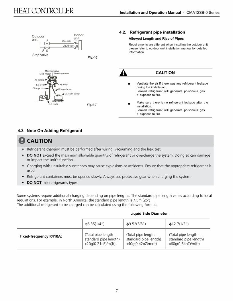
Installation and Operation Manual - CMA12SB-0 Series
7
Split Universal Type
INSTALLATION MANUAL
Thank you very much for purchasing our air conditioner, Before using your air conditioner , please read this manual carefully and keep it for future reference.
1installation manual
Be sure to be in conformity with the local, national and international laws and regulations.
Read "PRECAUTIONS" carefully before installation.
The following precautions include important safty items. Observe them and never forget.
Keep this manual with the owner's manual in a handy place for future reference.
1. PRECAUTIONS
The safty precautions listed here are divided into two categories.
After completing the installation, make sure that the unit operates properly during the start-up operation. Please instruct the customer on how to operate the unit and keep it maintained.Also, inform customers that they should store this installation manual along with the owner's manual for future reference.
Be sure only trained and qualified service personnel to install, repair or service the equipment.
Improper installation, repair, and maintenance may result in electric shocks, short-circuit, leaks, fire or other damage to the equipment.
Failure to observe a warning may result in death.
Failure to observe a caution may result in injury or damage to the equipment.
CONTENTS PAGE
1. PRECAUTIONS..................................................................... 2. INSTALLATION INFORMATION
3. OUTDOOR UNIT INSTALLATION....................................
4. INSTALL THE CONNECTING PIPE
6. WIRING
5. CONNECTIVE DIAGRAM.................................................
Install according to this installation instructions strictly. If installation is defective, it will cause water leakage, electrical shock and fire.
Use the attached accessories parts and specified parts for installation. otherwise, it will cause the set to fall, water leakage, electrical shock and fire.
Install at a strong and firm location which is able towithstand the set' s weight. If the strength is not enough or installation is not properly done, the set will drop to cause injury.
The appliance shall not be installed in the laundry.
Before obtaining access to terminals, all supply circuits must be disconnected.
The appliance must be positioned so that the plug is accessible.
The enclosure of the appliance shall be marked by word, or by symbols, with the direction of the fluid flow.
For electrical work, follow the local national wiring standard, regulation and this installation instructions. An independent circuit and single outlet must be used. If electrical circuit capacity is not enough or defect in electrical work, it will cause electrical shock or fire.
Use the specified cable and connect tightly and clamp the cable so that no external force will be acted on the terminal.If connection or fixing is not perfect, it will cause heat-up or fire at the connection.
Wiring routing must be properly arranged so that control board cover is fixed properly. If control board cover is not fixed perfectly, it will cause heat-up at connection point of terminal, fire or electricalshock.
If the supply cord is damaged, it must be replaced by the manufacture or its service agent or a similarly qualified person in order to avoid a hazard.
An all-pole disconnection switch having a contact separation of at least 3mm in all poles should be connected in fixed wiring.
When carrying out piping connection, take care not to let air substances go into refrigeration cycle. Otherwise, it will cause lower capacity, abnormal highpressure in the refrigeration cycle, explosion and injury.
Do not modify the length of the power supply cord or use of extension cord, and do not share the single outlet with other electrical appliances. Otherwise, it will cause fire or electrical shock.
Carry out the specified installation work after taking into account strong winds, typhoons or earthquakes.Improper installation work may result in the equipment falling and causing accidents.
CAUTION
WARNING
WARNING
...............................................
............................................................................
.................................
12
3
577
2installation manual
To install properly, please read this "installation manual" at first.
The air conditioner must be installed by qualified persons.
When installing the indoor unit or its tubing, please follow this manual as strictly as possible.
If the air conditioner is installed on a metal part of the building, it must be electrically insulated according to the relevant standards to electrical appliances.
When all the installation work is finished, please turn on the power only after a thorough check.
Regret for no further announcement if there is any change of this manual caused by product improvement.
2. INSTALLATION INFORMATION
Ground the air conditioner.Do not connect the ground wire to gas or water pipes, lightning rod or a telephone ground wire.Incompletegrounding may result in electric shocks.
Be sure to install an earth leakage breaker.Failure to install an earth leakage breaker may result in electric shocks.
The appliance is not intended for use by young children or infirm persons without supervision.
Don't install the air conditioner in the following locations:
There is petrolatum existing.
There is salty air surrounding (near the coast).
There is caustic gas (the sulfide, for example) existing in the air (near a hot spring).
The Volt vibrates violently (in the factories).
In buses or cabinets.
In kitchen where it is full of oil gas.
There is strong electromagnetic wave existing.
There are inflammable materials or gas.
There is acid or alkaline liquid evaporating.
Other special conditions.
If the refrigerant leaks during installation, ventilate the area immediately.Toxic gas may be produced if the refrigerant comes into the place contacting with fire.
The temperature of refrigerant circuit will be high, please keep the interconnection cable away from the coppertube.
After completing the installation work, check that the refrigerant does not leak.Toxic gas may be produced if the refrigerant leaks into the room and comes into contact with a source of fire, such as a fan heater, stove or cooker.
INSTALLATION ORDERSelect the location;
Install the outdoor unit;
Install the connecting pipe ;
Wiring;
CAUTION
3installation manual
4installation manual
5installation manual installation manual
6installation manual
7 8installation manual
9installation manual
10installation manual
3.1 Installation Place3. OUTDOOR UNIT INSTALLATION
There is enough room for installation and maintenance.
The air outlet and the air inlet are not impeded, and can not be reached by strong wind.
It must be a dry and well ventilating place.
The support is flat and horizontal and can stand theweight of the outdoor unit. And will no additional noise or vibration.
Your neighborhood will not feel uncomfortable with the noise or expelled air.
It is easy to install the connecting pipes or cables.
Determine the air outlet direction where the discharged air is not blocked.
There is no danger of fire due to leakage of inflammable gas.
The piping length between the outdoor unit and the indoor unit may not exceed the allowable piping length.
In the case that the installation place is exposed to strong wind such as a seaside, make sure the fan operating properly by putting the unit lengthwise along the wall or using a dust or shield.(Refer to Fig.6-1)
If possible, do not install the unit where it is exposed to direct sunlight.
If necessary, install a blind that does not interfere with the air flow.
During the heating mode, the water drained off theoutdoor unit ,The condensate should be well drained away by the drain hole to an appropriate place, so as not to interfere other people.
Select the position where it will not be subject to snow drifts, accumulation of leaves or other seasonal debris. If unavoidable, please cover it with a shelter.
Locate the outdoor unit as close to the indoor unit as possible.
If possible, please remove the obstacles nearby to prevent the performance from being impeded by too little of air circulation.
The minimum distance between the outdoor unit andobstacles described in the installation chart does notmean that the same is applicable to the situation of an airtight room. Leave open two of the three directions(M,N,P) (Refer to Fig.3-5)
XO
Strong w
ind
The outdoor unit should be installed in the location that meets the following requiements:
Fig.3-1
11installation manual
CAUTION
Fig.3-6
4. INSTALL THE CONNECTING PIPE
Check whether the height drop between the indoor unit and outdoor unit, the length of refrigerant pipe, and the number of the bends meet the following requirements:
All field piping must be provided by a licensedrefrigeration technician and must comply with therelevant local and national codes.
Do not let air, dust, or other impurities fall in the pipe system during the time of installation.
The connecting pipe should not be installed until the indoor and outdoor units have been fixed already.
Keep the connecting pipe dry, and do not let moisture in during installation.
The Procedure of Connecting Pipes4.1
Never hold the inlet of the outdoor unit to prevent it from deforming.
Do not touch the fan with hands or other objects.
Do not lean it more than 45, and do not lay it sidelong.
Make concrete foundation accoding to the sepecif-ications of the outdoor units.(Refer to Fig.3-6)
Fasten the feet of this unit with bolts firmly to prevent it from collapsing in case of earthquake or strong wind.(Refer to Fig.3-6)
3.3 Moving and installation
Since the gravity center of the unit is not at its physicalcenter, so please be careful when lifting it with a sling.
Table 4-1
Capacity (Btu/h)
<18K
≥18K~<36K≥36K~<60K
≥60K
The type of models
R410A air conditioner and Centrifugal fan outdoor unit
30m/98ft
25m/82ft
30m/98ft
20m/66ft
20m/66ft
10m/33ft
15m/49ft
8m/26ft
refrigerant pipeThe length of
height dropThe max
>60cm / 23.6”
Fix with bolts
CAUTION
CAUTION
How to connect the pipes
Drill a hole in the wall (suitable just for the size of the wall conduit), then set on the fittings such as the wall conduit and its cover.
Bind the connecting pipe and the cables together tightly with binding tapes.Pass the bound connecting pipe through the wall conduct from outside. Be careful of the pipe allocation to do ondamage to the tubing.
Connect the pipes. Refer to "How to Connect the pipes" for details.
Expel the air with a vacuum pump. Refer to "How to expel the air with a vacuum pump" for details.
open the stop values of the outdoor unit to make therefrigerant pipe connecting the indoor unit with the outdoor unit in fluent flow.
Check the leakage. Check all the joints with the leak detector or soap water.
Cover the joints of the connecting pipe with the soundproof / insulating sheath (fittings), and bind it well with the tapes to prevent leakage.
Execute heat insulation work completely on both sides of the gas piping and the liquid piping. Otherwise, this can sometimes result in water leakage.
1
2
3
5
6
7
4
Be sure to with insulating materials cover all the exposed parts of the flare pipe joints and refrigerant pipe on the liquid-side and the gas-side. Ensure that there is no gap between them.Incomplete insulation may cause water condensation.
Flaring1
Cut a pipe with a pipe cutter. (refer to Fig.4-1)
2
Bend the tubing in proper way. Do not harm to them.
Connect the indoor unit at first, then the outdoor unit.
Too large torque will harm the bellmouthing and too small will cause leakage. Please determine the torqueaccording to Table 4-2.
After the connecting work is finished, be sure to check that there is no gas leak.
The bending angle should not exceed 90.
Bending position is preferably in the middle of thebendable pipe. The larger the bending radius the better it is.
Do not bend the pipe more than three times.
When connecting the flare nut, coat the flare both inside and outside with either oil or ester oil and initially tighten by hand 3 or 4 turns before tighting firmly.
Be sure to use both a spanner and torque wrench together when connecting or disconnecting pipes to /from the unit. (Fig.4-4)
Table 4-2
Insert a flare nut into a pipe and flare the pipe.
Refer to Table 4-2 for the dimension of flare nut spaces.
Fig.4-1
Bend the pipe with thumb
min-radius 100mm
Fig.4-2
Fig.4-3
Fig.4-4
How to expel the air with a vacuum pump
Stop valve operation intruduction1. Opening stop valve
2. Closing stop valve
1)
2)
1)
2)
3)
Remove the cap and turn the valve counterclock-wise with the hexagon wrench.
Turn it until the shaft stops.Do not apply excessive force to the stop valve. Doing so may breakthe valve body, as the valve is not a backseat type. Always use the special tool.
Make sure to tighten the cap securely.
Remove the cap and turn the valve clockwise with the hexagon wrench.
Securely tighten the valve until the shaft contacts the main bodyseal.
90 Lean crude burr
12installation manual
CAUTION
CAUTION
Tightening torque N.M (Turn clockwise to close)
StopValve size Shaft (valve body)
Cap(Valve lid)
Ø6.45.4~6.6 Hexagonal
wrench 4 mm13.5~16.5
11.5~13.9
Ø9.5
Ø12.7 8.1~9.9 18~22
Ø15.9 13.5~16.5 Hexagonalwrench 6 mm 23~27
Ø22.227~33
Hexagonalwrench10 mm
36~44Ø25.4
Loosen and remove the maintenance nuts of stop valves Aand B, and connect the charge hose of the manifold valve to the service port of stop valve A. (Be sure that stop valves Aand B are both closed)
Connect the joint of the charge hose with the vacuum pump.
Open the Lo-lever of the manifold value completely.
Turn on the vacuum pump. At the beginning of pumping, loosen the maintenance nut of stop valve B a little to check whether the air comes in (the sound of the pump changes, and the indicator of compound meter turns below zero). Then fasten the maintenace nut.
1
2
4
3
5
7
6
-76 cmHg
Lo-lever Hi-lever
Charge hose Charge hose
Vacuum pump
Lo-lever
Manifold valveMulti-meter Pressure meter
Fig.4-7
Note On Adding Refrigerant4.3
Using the vacuum pump
When the pumping has finished, close the Lo-lever of the manifold valve completely and turn off the vacuumpump.Make pumping for 15 minutes or more and check that the compound meter indicates -76cmHg(-1X10 Pa)
Loosen and remove the cap of stop valves A and B to open stop valve A and B completely, then fasten the cap.
Disassemble the charge hose from the service port of stop valve A, and fasten the nut.
5
Fig.4-6
Fig.4-5
Always use a charge hose for service port connection.
After tightening the cap, check that no refrigerant leaksarepresent.
service port
cap
maintenance nut
hexagon holeshaftseal
Make sure to tighten the cap securely.For the tightening torque, refer to the table below.
Outdoorunit
Indoorunit
Stop valve
Gas side
Liquid side
A C
D
BTable 4-3
Maintenance nut
Ventilate the air if there was any refrigerant leakage during the installation.Leaked refrigerant will generate poisonous gas if exposed to fire.
Make sure there is no refrigerant leakage after the installation.Leaked refrigerant will generate poisonous gas if exposed to fire.
Allowed Length and Rise of PipesRequirements are different when installing the outdoor unit, please refer to outdoor unit installation manual for detailed information.
4.2. Refrigerant pipe installation
13installation manual
14installation manual
15installation manual
The temperature of refrigerant circuit will be high, pleasekeep the interconnection cable away from the copper tube.
Dissemble the bolts from the cover.(If there isn't a cover on the outdoor unit, disassemble the bolts from the maintenance board, and pull it in the direction of the arrow to remove the protection board.)(Refer to Fig.6-1)
Connect the connective cables to the terminals as identified with their respective mached numbers on the terminal block of indoor and outdoor units.
Re-install the cover or the protection board.
Connect the cable6.1
The power connection for the air conditioner has to be done at the main power distribution. The distribution has to be of a low impedance, normally the required impedance reaches at a 32 A fusing point.
No other equipment has to be connected with this power line.
For detailed installation acceptance please refer to your power supplier, if restrictions do apply for products like washing machines, air conditioners or electrical ovens.
For power details of the air conditioner refer to the rating plate of the product.
For any question contact your local dealer.
1
2
4
3
5
6. WIRING
The appliance shall be installed in accordance with national wiring regulations.
The air conditioner should use separate power supply with rated voltage.
The external power supply to the air conditioner should have ground wiring, which is linked to the ground wiring of the indoor and outdoor unit.
The wiring work should be done by qualified persons according to circuit drawing.
An all-pole disconnection device which has at least 3mm sepaaration distance in all pole and a residual current device (RCD) with the rating of above 10mA shall be incorporated in the fixed wiring according to the national rule.
Be sure to locate the power wiring and the signal wring well to avoid cross-disturbance.
Do not turn on the power until you have checked carefully after wiring.
The power cord type designation is H07RN-F.
Remark per EMC Directive 2004/108/ECFor to prevent flicker impressions during the start of the compressor (technical process) following installation conditions do apply.
NOTE
Fig.6-1
NOTEAll the pictures in this manual are for explanationpurpose only. They may be slightly different from the air conditioner you purchased(depend on model).The actual shape shall prevail.
6. Outdoor unit
Wrong wiring connections may cause some electrical parts to malfunction.
CAUTION
Remove the electric parts cover from the outdoor unit.
Connect the connective cables to the terminals as identified with their respective matched numbers on the terminal block of indoor and outdoor units. (Connective cable sheathlength to be removed and insert into the terminal block.)
To prevent the ingress off water, from a loop of theconnective cable as illustrated in the installation diagram of indoor and outdoor units.
Insulate unused cords (conductors) with PVC-tape. Process them so they do not touch any electrical or metal parts.
1.
2.
3.
4.
Fig.6-2
Cord wire
40mm10mm
16installation manual
The Specification of Power6.2(Refer to Table6-1)
17installation manual
18installation manual
20installation manual
22installation manual
19installation manual
21installation manual
23installation manual
QSWI-002AEN
16122000000008
The design and specifications are subject to change without prior notice for productimprovement.Consult with the sales agency or manufacturer for details.
20151209
>300mm
mm003>
mm0002>
>600mm
(Wall or obstacle)
Maintain channel
Air outlet
Air inlet
M
P
Air inlet
N
Fig.3-5
1. Split type outdoor unit
3.2 Space of installation and maintenance
5. CONNECTIVE DIAGRAM
Fig. 5-1
Liquid side
orifice
Gas side
25 35
MODEL
POWER(outdoor)
CIRCUIT BREAKER/FUSE(A)
PHASE
VOLT
18 24 30 36
208/230 V 208/2 30V
1 P h a s e 1 P h a s e
208/2 30V
1 P h a s e
208/2 30V
1 P h a s e
15 20
Table 6-1
(mm)
Ø6.35/0.25in 8.3/0.327in 8.7/0.343in
Ø9.52/0.375in 12.0/0.472in 12.4/0.488in
Ø12.7/0.5in 15.4/0.606in 15.80.622in
Ø15.9/0.626in
Ø19.1/0.725in
18.6/0.732in 19.0/0.748in
22.9/0.902in 23.3/0.917in
R0.4~0.8
45 °±2
90 ° ± 4
A
min maxPipe gauge Tightening torque Flare dimensin AFlare shape
97.2~118.6 N.m(990~1210 kgf.cm)
(630~770 kgf.cm)61.8~75.4 N.m
49.5~60.3 N.m(504~616 kgf.cm)
32.7~39.9 N.m(333~407 kgf.cm)
14.2~17.2 N.m(144~176 kgf.cm)
Fig.3-4
Fig.3-3
A
BD
W
H
W
H
Fig.3-2
Cover
Screw
φ φ φ
Horizontal/Side Discharge Condensing Units Heat Controller
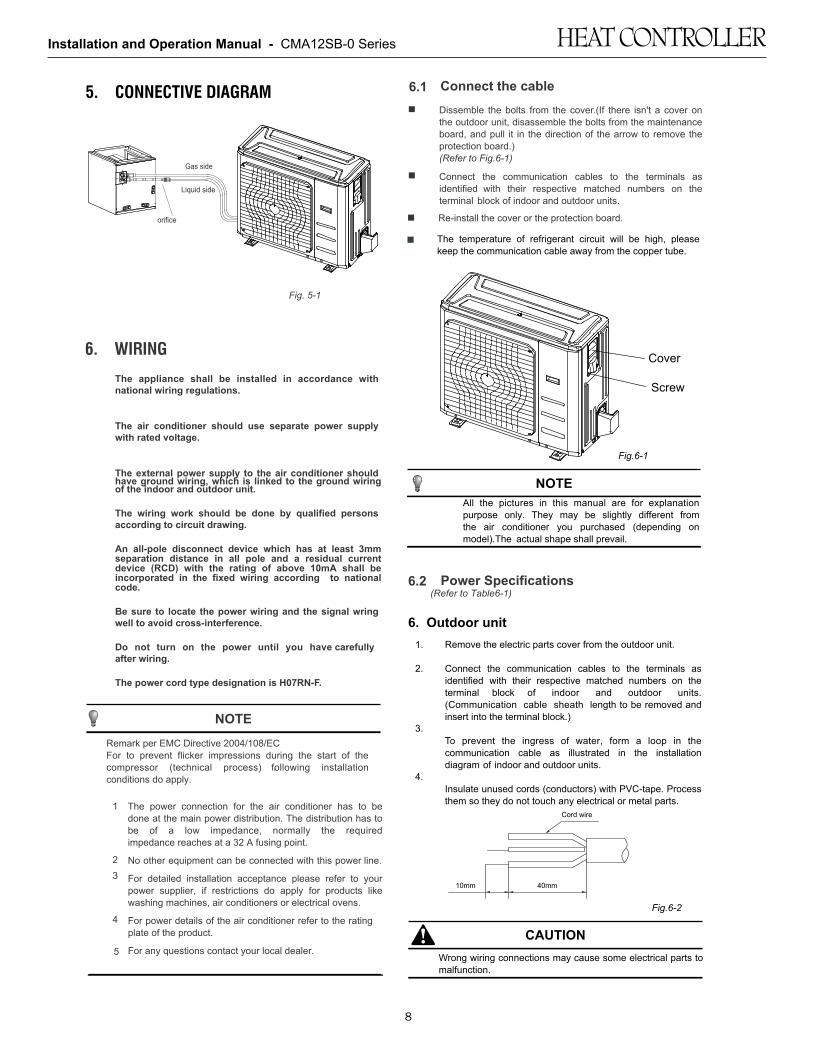
Installation and Operation Manual - CMA12SB-0 Series
8
Split Universal Type
INSTALLATION MANUAL
Thank you very much for purchasing our air conditioner, Before using your air conditioner , please read this manual carefully and keep it for future reference.
1installation manual
Be sure to be in conformity with the local, national and international laws and regulations.
Read "PRECAUTIONS" carefully before installation.
The following precautions include important safty items. Observe them and never forget.
Keep this manual with the owner's manual in a handy place for future reference.
1. PRECAUTIONS
The safty precautions listed here are divided into two categories.
After completing the installation, make sure that the unit operates properly during the start-up operation. Please instruct the customer on how to operate the unit and keep it maintained.Also, inform customers that they should store this installation manual along with the owner's manual for future reference.
Be sure only trained and qualified service personnel to install, repair or service the equipment.
Improper installation, repair, and maintenance may result in electric shocks, short-circuit, leaks, fire or other damage to the equipment.
Failure to observe a warning may result in death.
Failure to observe a caution may result in injury or damage to the equipment.
CONTENTS PAGE
1. PRECAUTIONS..................................................................... 2. INSTALLATION INFORMATION
3. OUTDOOR UNIT INSTALLATION....................................
4. INSTALL THE CONNECTING PIPE
6. WIRING
5. CONNECTIVE DIAGRAM.................................................
Install according to this installation instructions strictly. If installation is defective, it will cause water leakage, electrical shock and fire.
Use the attached accessories parts and specified parts for installation. otherwise, it will cause the set to fall, water leakage, electrical shock and fire.
Install at a strong and firm location which is able towithstand the set' s weight. If the strength is not enough or installation is not properly done, the set will drop to cause injury.
The appliance shall not be installed in the laundry.
Before obtaining access to terminals, all supply circuits must be disconnected.
The appliance must be positioned so that the plug is accessible.
The enclosure of the appliance shall be marked by word, or by symbols, with the direction of the fluid flow.
For electrical work, follow the local national wiring standard, regulation and this installation instructions. An independent circuit and single outlet must be used. If electrical circuit capacity is not enough or defect in electrical work, it will cause electrical shock or fire.
Use the specified cable and connect tightly and clamp the cable so that no external force will be acted on the terminal.If connection or fixing is not perfect, it will cause heat-up or fire at the connection.
Wiring routing must be properly arranged so that control board cover is fixed properly. If control board cover is not fixed perfectly, it will cause heat-up at connection point of terminal, fire or electricalshock.
If the supply cord is damaged, it must be replaced by the manufacture or its service agent or a similarly qualified person in order to avoid a hazard.
An all-pole disconnection switch having a contact separation of at least 3mm in all poles should be connected in fixed wiring.
When carrying out piping connection, take care not to let air substances go into refrigeration cycle. Otherwise, it will cause lower capacity, abnormal highpressure in the refrigeration cycle, explosion and injury.
Do not modify the length of the power supply cord or use of extension cord, and do not share the single outlet with other electrical appliances. Otherwise, it will cause fire or electrical shock.
Carry out the specified installation work after taking into account strong winds, typhoons or earthquakes.Improper installation work may result in the equipment falling and causing accidents.
CAUTION
WARNING
WARNING
...............................................
............................................................................
.................................
12
3
577
2installation manual
To install properly, please read this "installation manual" at first.
The air conditioner must be installed by qualified persons.
When installing the indoor unit or its tubing, please follow this manual as strictly as possible.
If the air conditioner is installed on a metal part of the building, it must be electrically insulated according to the relevant standards to electrical appliances.
When all the installation work is finished, please turn on the power only after a thorough check.
Regret for no further announcement if there is any change of this manual caused by product improvement.
2. INSTALLATION INFORMATION
Ground the air conditioner.Do not connect the ground wire to gas or water pipes, lightning rod or a telephone ground wire.Incompletegrounding may result in electric shocks.
Be sure to install an earth leakage breaker.Failure to install an earth leakage breaker may result in electric shocks.
The appliance is not intended for use by young children or infirm persons without supervision.
Don't install the air conditioner in the following locations:
There is petrolatum existing.
There is salty air surrounding (near the coast).
There is caustic gas (the sulfide, for example) existing in the air (near a hot spring).
The Volt vibrates violently (in the factories).
In buses or cabinets.
In kitchen where it is full of oil gas.
There is strong electromagnetic wave existing.
There are inflammable materials or gas.
There is acid or alkaline liquid evaporating.
Other special conditions.
If the refrigerant leaks during installation, ventilate the area immediately.Toxic gas may be produced if the refrigerant comes into the place contacting with fire.
The temperature of refrigerant circuit will be high, please keep the interconnection cable away from the coppertube.
After completing the installation work, check that the refrigerant does not leak.Toxic gas may be produced if the refrigerant leaks into the room and comes into contact with a source of fire, such as a fan heater, stove or cooker.
INSTALLATION ORDERSelect the location;
Install the outdoor unit;
Install the connecting pipe ;
Wiring;
CAUTION
3installation manual
4installation manual
5installation manual installation manual
6installation manual
7 8installation manual
9installation manual
10installation manual
3.1 Installation Place3. OUTDOOR UNIT INSTALLATION
There is enough room for installation and maintenance.
The air outlet and the air inlet are not impeded, and can not be reached by strong wind.
It must be a dry and well ventilating place.
The support is flat and horizontal and can stand theweight of the outdoor unit. And will no additional noise or vibration.
Your neighborhood will not feel uncomfortable with the noise or expelled air.
It is easy to install the connecting pipes or cables.
Determine the air outlet direction where the discharged air is not blocked.
There is no danger of fire due to leakage of inflammable gas.
The piping length between the outdoor unit and the indoor unit may not exceed the allowable piping length.
In the case that the installation place is exposed to strong wind such as a seaside, make sure the fan operating properly by putting the unit lengthwise along the wall or using a dust or shield.(Refer to Fig.6-1)
If possible, do not install the unit where it is exposed to direct sunlight.
If necessary, install a blind that does not interfere with the air flow.
During the heating mode, the water drained off theoutdoor unit ,The condensate should be well drained away by the drain hole to an appropriate place, so as not to interfere other people.
Select the position where it will not be subject to snow drifts, accumulation of leaves or other seasonal debris. If unavoidable, please cover it with a shelter.
Locate the outdoor unit as close to the indoor unit as possible.
If possible, please remove the obstacles nearby to prevent the performance from being impeded by too little of air circulation.
The minimum distance between the outdoor unit andobstacles described in the installation chart does notmean that the same is applicable to the situation of an airtight room. Leave open two of the three directions(M,N,P) (Refer to Fig.3-5)
XOS
trong wind
The outdoor unit should be installed in the location that meets the following requiements:
Fig.3-1
11installation manual
CAUTION
Fig.3-6
4. INSTALL THE CONNECTING PIPE
Check whether the height drop between the indoor unit and outdoor unit, the length of refrigerant pipe, and the number of the bends meet the following requirements:
All field piping must be provided by a licensedrefrigeration technician and must comply with therelevant local and national codes.
Do not let air, dust, or other impurities fall in the pipe system during the time of installation.
The connecting pipe should not be installed until the indoor and outdoor units have been fixed already.
Keep the connecting pipe dry, and do not let moisture in during installation.
The Procedure of Connecting Pipes4.1
Never hold the inlet of the outdoor unit to prevent it from deforming.
Do not touch the fan with hands or other objects.
Do not lean it more than 45, and do not lay it sidelong.
Make concrete foundation accoding to the sepecif-ications of the outdoor units.(Refer to Fig.3-6)
Fasten the feet of this unit with bolts firmly to prevent it from collapsing in case of earthquake or strong wind.(Refer to Fig.3-6)
3.3 Moving and installation
Since the gravity center of the unit is not at its physicalcenter, so please be careful when lifting it with a sling.
Table 4-1
Capacity (Btu/h)
<18K
≥18K~<36K≥36K~<60K
≥60K
The type of models
R410A air conditioner and Centrifugal fan outdoor unit
30m/98ft
25m/82ft
30m/98ft
20m/66ft
20m/66ft
10m/33ft
15m/49ft
8m/26ft
refrigerant pipeThe length of
height dropThe max
>60cm / 23.6”
Fix with bolts
CAUTION
CAUTION
How to connect the pipes
Drill a hole in the wall (suitable just for the size of the wall conduit), then set on the fittings such as the wall conduit and its cover.
Bind the connecting pipe and the cables together tightly with binding tapes.Pass the bound connecting pipe through the wall conduct from outside. Be careful of the pipe allocation to do ondamage to the tubing.
Connect the pipes. Refer to "How to Connect the pipes" for details.
Expel the air with a vacuum pump. Refer to "How to expel the air with a vacuum pump" for details.
open the stop values of the outdoor unit to make therefrigerant pipe connecting the indoor unit with the outdoor unit in fluent flow.
Check the leakage. Check all the joints with the leak detector or soap water.
Cover the joints of the connecting pipe with the soundproof / insulating sheath (fittings), and bind it well with the tapes to prevent leakage.
Execute heat insulation work completely on both sides of the gas piping and the liquid piping. Otherwise, this can sometimes result in water leakage.
1
2
3
5
6
7
4
Be sure to with insulating materials cover all the exposed parts of the flare pipe joints and refrigerant pipe on the liquid-side and the gas-side. Ensure that there is no gap between them.Incomplete insulation may cause water condensation.
Flaring1
Cut a pipe with a pipe cutter. (refer to Fig.4-1)
2
Bend the tubing in proper way. Do not harm to them.
Connect the indoor unit at first, then the outdoor unit.
Too large torque will harm the bellmouthing and too small will cause leakage. Please determine the torqueaccording to Table 4-2.
After the connecting work is finished, be sure to check that there is no gas leak.
The bending angle should not exceed 90.
Bending position is preferably in the middle of thebendable pipe. The larger the bending radius the better it is.
Do not bend the pipe more than three times.
When connecting the flare nut, coat the flare both inside and outside with either oil or ester oil and initially tighten by hand 3 or 4 turns before tighting firmly.
Be sure to use both a spanner and torque wrench together when connecting or disconnecting pipes to /from the unit. (Fig.4-4)
Table 4-2
Insert a flare nut into a pipe and flare the pipe.
Refer to Table 4-2 for the dimension of flare nut spaces.
Fig.4-1
Bend the pipe with thumb
min-radius 100mm
Fig.4-2
Fig.4-3
Fig.4-4
How to expel the air with a vacuum pump
Stop valve operation intruduction1. Opening stop valve
2. Closing stop valve
1)
2)
1)
2)
3)
Remove the cap and turn the valve counterclock-wise with the hexagon wrench.
Turn it until the shaft stops.Do not apply excessive force to the stop valve. Doing so may breakthe valve body, as the valve is not a backseat type. Always use the special tool.
Make sure to tighten the cap securely.
Remove the cap and turn the valve clockwise with the hexagon wrench.
Securely tighten the valve until the shaft contacts the main bodyseal.
90 Lean crude burr
12installation manual
CAUTION
CAUTION
Tightening torque N.M (Turn clockwise to close)
StopValve size Shaft (valve body)
Cap(Valve lid)
Ø6.45.4~6.6 Hexagonal
wrench 4 mm13.5~16.5
11.5~13.9
Ø9.5
Ø12.7 8.1~9.9 18~22
Ø15.9 13.5~16.5 Hexagonalwrench 6 mm 23~27
Ø22.227~33
Hexagonalwrench10 mm
36~44Ø25.4
Loosen and remove the maintenance nuts of stop valves Aand B, and connect the charge hose of the manifold valve to the service port of stop valve A. (Be sure that stop valves Aand B are both closed)
Connect the joint of the charge hose with the vacuum pump.
Open the Lo-lever of the manifold value completely.
Turn on the vacuum pump. At the beginning of pumping, loosen the maintenance nut of stop valve B a little to check whether the air comes in (the sound of the pump changes, and the indicator of compound meter turns below zero). Then fasten the maintenace nut.
1
2
4
3
5
7
6
-76 cmHg
Lo-lever Hi-lever
Charge hose Charge hose
Vacuum pump
Lo-lever
Manifold valveMulti-meter Pressure meter
Fig.4-7
Note On Adding Refrigerant4.3
Using the vacuum pump
When the pumping has finished, close the Lo-lever of the manifold valve completely and turn off the vacuumpump.Make pumping for 15 minutes or more and check that the compound meter indicates -76cmHg(-1X10 Pa)
Loosen and remove the cap of stop valves A and B to open stop valve A and B completely, then fasten the cap.
Disassemble the charge hose from the service port of stop valve A, and fasten the nut.
5
Fig.4-6
Fig.4-5
Always use a charge hose for service port connection.
After tightening the cap, check that no refrigerant leaksarepresent.
service port
cap
maintenance nut
hexagon holeshaftseal
Make sure to tighten the cap securely.For the tightening torque, refer to the table below.
Outdoorunit
Indoorunit
Stop valve
Gas side
Liquid side
A C
D
B
Table 4-3
Maintenance nut
Ventilate the air if there was any refrigerant leakage during the installation.Leaked refrigerant will generate poisonous gas ifmeeting fire.
Make sure there is no refrigerant leakage after the installation.Leaked refrigerant will generate poisonous gas ifmeeting fire.
Allowed Lenght and Drop of PipesRequirements are different when installing the outdoor unit, please refer to outdoor unit installation manual for detailed information.
Material and Size of the Pipes
Three length(3m,5m,10m)of pipes are available to purchase.
4.2. Refrigerant pipe installation
13installation manual
14installation manual
15installation manual
Dissemble the bolts from the cover.(If there isn't a cover on the outdoor unit, disassemble the bolts from the maintenance board, and pull it in the direction of the arrow to remove the protection board.)(Refer to Fig.6-1)
Connect the communication cables to the terminals as identified with their respective matched numbers on the terminal block of indoor and outdoor units.
Re-install the cover or the protection board.
The temperature of refrigerant circuit will be high, please keep the communication cable away from the copper tube.
Connect the cable6.1
The power connection for the air conditioner has to be done at the main power distribution. The distribution has to be of a low impedance, normally the required impedance reaches at a 32 A fusing point.
No other equipment can be connected with this power line.
For detailed installation acceptance please refer to your power supplier, if restrictions do apply for products like washing machines, air conditioners or electrical ovens.
For power details of the air conditioner refer to the rating plate of the product.
For any questions contact your local dealer.
1
2
4
3
5
6. WIRING
The appliance shall be installed in accordance with national wiring regulations.
The air conditioner should use separate power supply with rated voltage.
The external power supply to the air conditioner should have ground wiring, which is linked to the ground wiring of the indoor and outdoor unit.
The wiring work should be done by qualified persons according to circuit drawing.
An all-pole disconnect device which has at least 3mm separation distance in all pole and a residual current device (RCD) with the rating of above 10mA shall be incorporated in the fixed wiring according to national code.
Be sure to locate the power wiring and the signal wring well to avoid cross-interference.
Do not turn on the power until you have carefully after wiring.
The power cord type designation is H07RN-F.
Remark per EMC Directive 2004/108/ECFor to prevent flicker impressions during the start of the compressor (technical process) following installation conditions do apply.
NOTE
Fig.6-1
NOTEAll the pictures in this manual are for explanation purpose only. They may be slightly different from the air conditioner you purchased (depending on model).The actual shape shall prevail.
6. Outdoor unit
Wrong wiring connections may cause some electrical parts to malfunction.
CAUTION
Remove the electric parts cover from the outdoor unit.
Connect the communication cables to the terminals as identified with their respective matched numbers on the terminal block of indoor and outdoor units. (Communication cable sheath length to be removed and insert into the terminal block.)
To prevent the ingress of water, form a loop in the communication cable as illustrated in the installation diagram of indoor and outdoor units.
Insulate unused cords (conductors) with PVC-tape. Process them so they do not touch any electrical or metal parts.
1.
2.
3.
4.
Fig.6-2
Cord wire
40mm10mm
16installation manual
6.2 Power Specifications(Refer to Table6-1)
17installation manual
18installation manual
20installation manual
22installation manual
19installation manual
21installation manual
23installation manual
QSWI-002AEN
16122000000008
The design and specifications are subject to change without prior notice for productimprovement.Consult with the sales agency or manufacturer for details.
20151209
>300mm
mm003>
mm0002>
>600mm
(Wall or obstacle)
Maintain channel
Air outlet
Air inlet
M
P
Air inlet
N
Fig.3-5
1. Split type outdoor unit
3.2 Space of installation and maintenance
5. CONNECTIVE DIAGRAM
Fig. 5-1
Liquid side
orifice
Gas side
25 35
MODEL
POWER(outdoor)
CIRCUIT BREAKER/FUSE(A)
PHASE
VOLT
18 24 30 36
208/230 V 208/2 30V
1 P h a s e 1 P h a s e
208/2 30V
1 P h a s e
208/2 30V
1 P h a s e
15 20
Table 6-1
(mm)
Ø6.35/0.25in 8.3/0.327in 8.7/0.343in
Ø9.52/0.375in 12.0/0.472in 12.4/0.488in
Ø12.7/0.5in 15.4/0.606in 15.80.622in
Ø15.9/0.626in
Ø19.1/0.725in
18.6/0.732in 19.0/0.748in
22.9/0.902in 23.3/0.917in
R0.4~0.8
45 °±2
90 ° ± 4
A
min maxPipe gauge Tightening torque Flare dimensin AFlare shape
97.2~118.6 N.m(990~1210 kgf.cm)
(630~770 kgf.cm)61.8~75.4 N.m
49.5~60.3 N.m(504~616 kgf.cm)
32.7~39.9 N.m(333~407 kgf.cm)
14.2~17.2 N.m(144~176 kgf.cm)
Fig.3-4
Fig.3-3
A
BD
W
H
W
H
Fig.3-2
Cover
Screw
φ φ φ
Heat Controller Horizontal/Side Discharge Condensing Units

Installation and Operation Manual - CMA12SB-0 Series
9
2015 1515
9installation manual
30
MODEL
POWER(outdoor)
CIRCUIT
MCA
BREAKER/FUSE(A)
PHASE
VOLT
112 8 24 36
208/230 V 208/2 30V
1 P h a s e 1 P h a s e
208/2 30V
1 P h a s e
15 20
Table 6-1
115V
1 P h a s e
20
Horizontal/Side Discharge Condensing Units Heat Controller

Installation and Operation Manual - CMA12SB-0 Series
10

6/2016
www.marsdelivers.com • www.heatcontroller.com
1900 Wellworth Ave., Jackson, MI 49203 • Ph. 517-787-2100 • www.comfort-aire.com • www.century-hvac.com