Embed Size (px)
Citation preview
PRODUCT FAMILY DATA SHEET
Cree LED / 4400 Silicon Drive / Durham, NC 27703 USA / +1.919.313.5330 / www.cree-led.com
© 2021 Cree LED. The information in this document is subject to change without notice. Cree® and the Cree logo are registered trademarks, and the Cree LED logo is a trademark, of Cree, Inc.
CLD-CT1359REV 6 1
CLX6E-FKC: PLCC6 3 in 1 SMD LED
PRODUCT DESCRIPTION
This SMD LED features an IPx8 water
resistant rating in a PLCC6 package. These
high performance tricolor SMT
LEDs are designed to work in a wide
range of applications. A wide viewing angle
and high brightness make
these LEDs suitable for outdoor and
full color video signage applications.
The encapsulation resin contains UV
inhibitors to minimize the effects of
long-term exposure to direct
sunlight, resulting in stable light
output over the life of the LED. This PLCC6
package has an increased
package height to ease in the
manufacturing process.
FEATURES
• Size (mm): 3.5 x 3.4 x 2.8
• Dominant WavelengthRed (619 - 624nm)Green (520 - 535nm)Blue (460 - 480nm)
• Luminous Intensity (mcd) Red (355 - 805) Green (710 - 1400) Blue (140 - 355)
• Water-Resistant (IPx8)*
• Moisture Sensitivity Level: 5a
• Lead-Free
• RoHS Compliant
*:This part is tested under the condition of assembling it on a PCB with isolating the electrical path by silicone.
The leads area of the LED is not IPx8 rated and it’s required to insulate for moisture by customer in outdoor
application.
APPLICATIONS
• Architecture Lighting
• Outdoor Full-Color Video Screen
• Decorative Lighting
• Amusement
CLX6E-FKC: PLCC6 3 IN 1 SMD LED
© 2021 Cree LED. The information in this document is subject to change without notice. Cree® and the Cree logo are registered trademarks, and the Cree LED logo is a trademark, of Cree, Inc.
CLD-CT1359REV 6 2
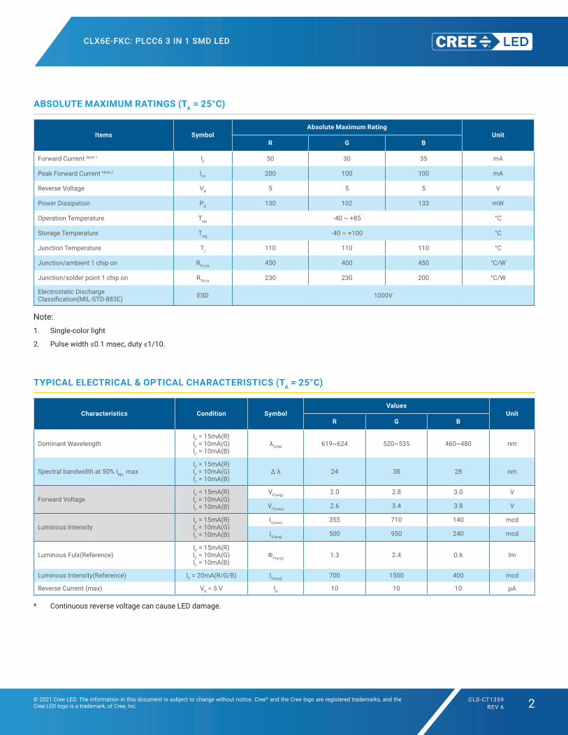
ABSOLUTE MAXIMUM RATINGS (TA = 25°C)
Items SymbolAbsolute Maximum Rating
UnitR G B
Forward Current Note 1 IF 50 30 35 mA
Peak Forward Current Note 2 IFP 200 100 100 mA
Reverse Voltage VR 5 5 5 V
Power Dissipation PD 130 102 133 mW
Operation Temperature Topr -40 ~ +85 °C
Storage Temperature Tstg -40 ~ +100 °C
Junction Temperature TJ 110 110 110 °C
Junction/ambient 1 chip on RTHJA 450 400 450 °C/W
Junction/solder point 1 chip on RTHJs 230 230 200 °C/W
Electrostatic DischargeClassification(MIL-STD-883E) ESD 1000V
Note:1. Single-color light
2. Pulsewidth≤0.1msec,duty≤1/10.
TYPICAL ELECTRICAL & OPTICAL CHARACTERISTICS (TA = 25°C)
Characteristics Condition SymbolValues
UnitR G B
Dominant WavelengthIF = 15mA(R)IF = 10mA(G)IF = 10mA(B)
λDOM 619~624 520~535 460~480 nm
Spectral bandwidth at 50% IREL maxIF = 15mA(R)IF = 10mA(G)IF = 10mA(B)
Δλ 24 38 28 nm
Forward VoltageIF = 15mA(R)IF = 10mA(G)IF = 10mA(B)
VF(avg) 2.0 2.8 3.0 V
VF(max) 2.6 3.4 3.8 V
Luminous IntensityIF = 15mA(R)IF = 10mA(G)IF = 10mA(B)
IV(min) 355 710 140 mcd
IV(avg) 500 950 240 mcd
Luminous Fulx(Reference)IF = 15mA(R)IF = 10mA(G)IF = 10mA(B)
ΦV(avg) 1.3 2.4 0.6 lm
Luminous Intensity(Reference) IF = 20mA(R/G/B) IV(avg) 700 1500 400 mcd
Reverse Current (max) VR = 5 V IR 10 10 10 μA
* Continuous reverse voltage can cause LED damage.
CLX6E-FKC: PLCC6 3 IN 1 SMD LED
© 2021 Cree LED. The information in this document is subject to change without notice. Cree® and the Cree logo are registered trademarks, and the Cree LED logo is a trademark, of Cree, Inc.
CLD-CT1359REV 6 3
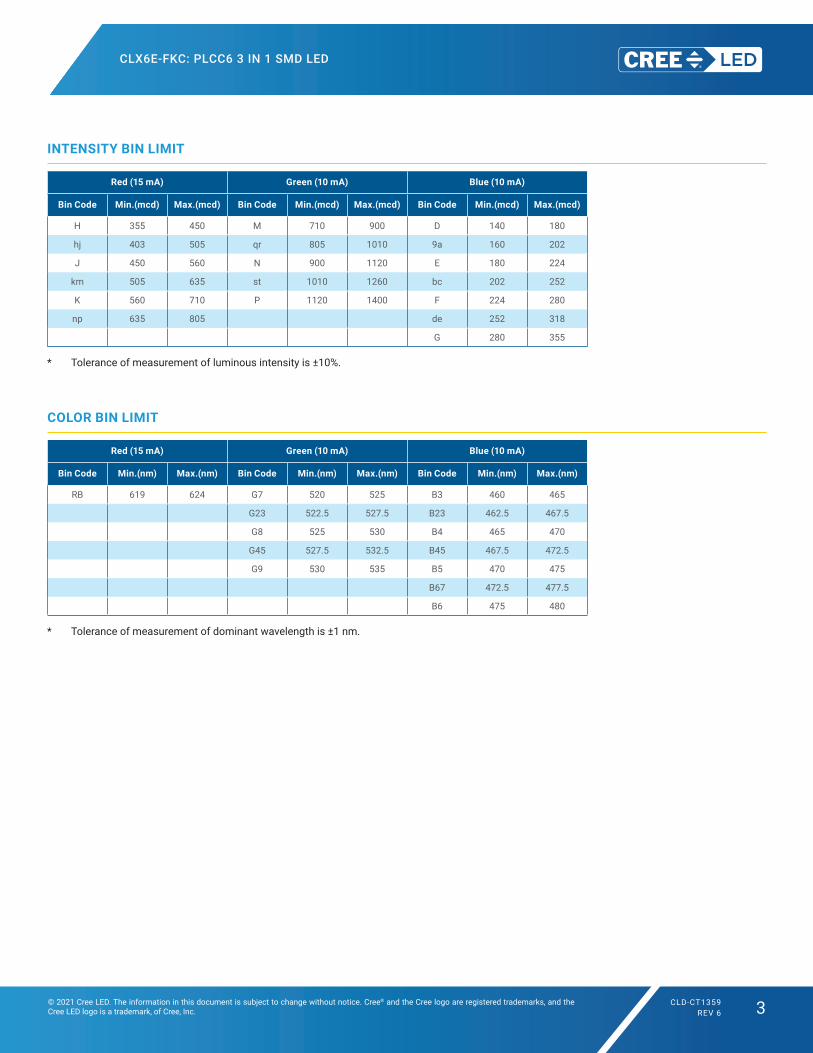
INTENSITY BIN LIMIT
Red (15 mA) Green (10 mA) Blue (10 mA)
Bin Code Min.(mcd) Max.(mcd) Bin Code Min.(mcd) Max.(mcd) Bin Code Min.(mcd) Max.(mcd)
H 355 450 M 710 900 D 140 180
hj 403 505 qr 805 1010 9a 160 202
J 450 560 N 900 1120 E 180 224
km 505 635 st 1010 1260 bc 202 252
K 560 710 P 1120 1400 F 224 280
np 635 805 de 252 318
G 280 355
* Tolerance of measurement of luminous intensity is ±10%.
COLOR BIN LIMIT
Red (15 mA) Green (10 mA) Blue (10 mA)
Bin Code Min.(nm) Max.(nm) Bin Code Min.(nm) Max.(nm) Bin Code Min.(nm) Max.(nm)
RB 619 624 G7 520 525 B3 460 465
G23 522.5 527.5 B23 462.5 467.5
G8 525 530 B4 465 470
G45 527.5 532.5 B45 467.5 472.5
G9 530 535 B5 470 475
B67 472.5 477.5
B6 475 480
* Tolerance of measurement of dominant wavelength is ±1 nm.
CLX6E-FKC: PLCC6 3 IN 1 SMD LED
© 2021 Cree LED. The information in this document is subject to change without notice. Cree® and the Cree logo are registered trademarks, and the Cree LED logo is a trademark, of Cree, Inc.
CLD-CT1359REV 6 4
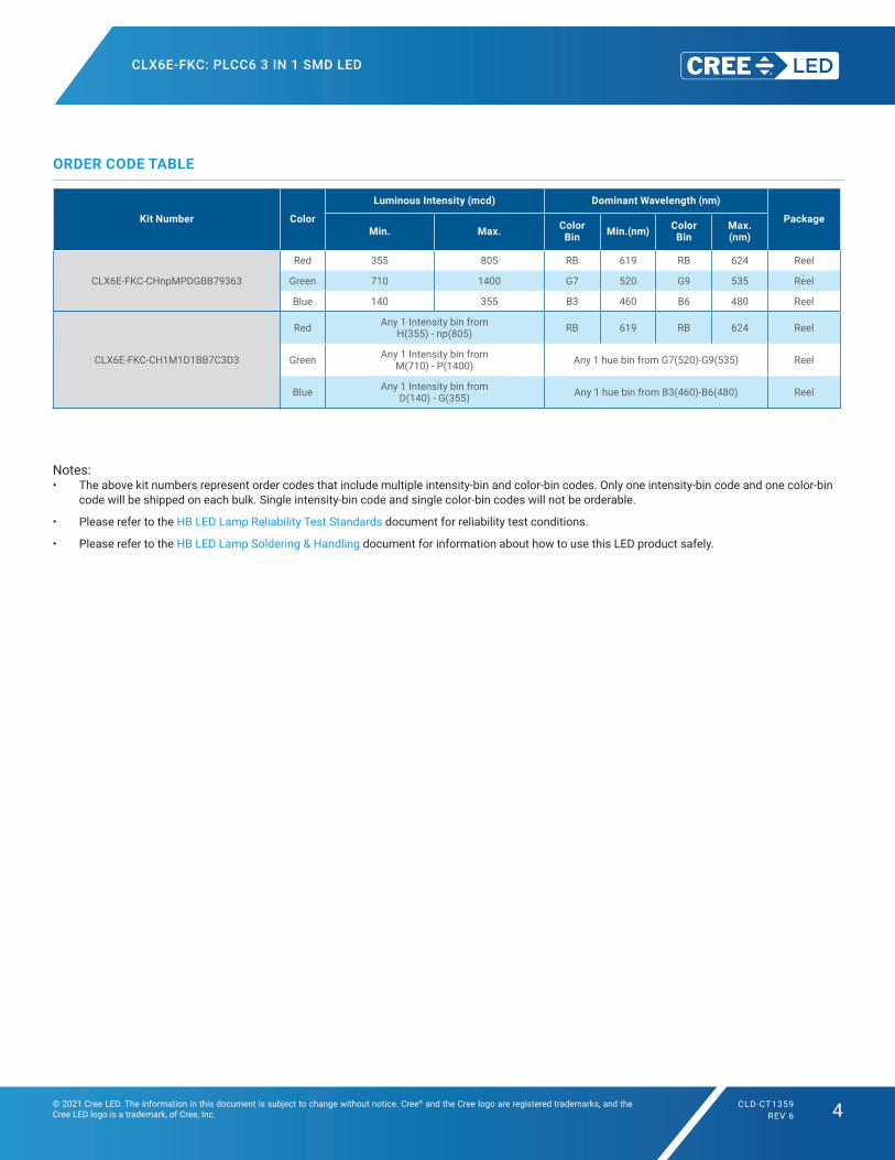
ORDER CODE TABLE
Kit Number Color
Luminous Intensity (mcd) Dominant Wavelength (nm)
PackageMin. Max. Color
Bin Min.(nm) Color Bin
Max.(nm)
CLX6E-FKC-CHnpMPDGBB79363
Red 355 805 RB 619 RB 624 Reel
Green 710 1400 G7 520 G9 535 Reel
Blue 140 355 B3 460 B6 480 Reel
CLX6E-FKC-CH1M1D1BB7C3D3
Red Any 1 Intensity bin from H(355) - np(805) RB 619 RB 624 Reel
Green Any 1 Intensity bin from M(710) - P(1400) Any 1 hue bin from G7(520)-G9(535) Reel
Blue Any 1 Intensity bin from D(140) - G(355) Any 1 hue bin from B3(460)-B6(480) Reel
Notes:• The above kit numbers represent order codes that include multiple intensity-bin and color-bin codes. Only one intensity-bin code and one color-bin
code will be shipped on each bulk. Single intensity-bin code and single color-bin codes will not be orderable.
• Please refer to the HB LED Lamp Reliability Test Standards document for reliability test conditions.
• Please refer to the HB LED Lamp Soldering & Handling document for information about how to use this LED product safely.
CLX6E-FKC: PLCC6 3 IN 1 SMD LED
© 2021 Cree LED. The information in this document is subject to change without notice. Cree® and the Cree logo are registered trademarks, and the Cree LED logo is a trademark, of Cree, Inc.
CLD-CT1359REV 6 5
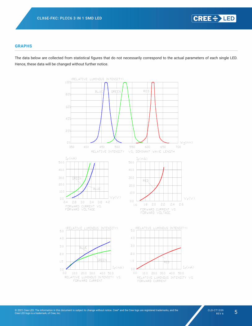
GRAPHS
ThedatabelowarecollectedfromstatisticalfiguresthatdonotnecessarilycorrespondtotheactualparametersofeachsingleLED.
Hence, these data will be changed without further notice.
CLX6E-FKC: PLCC6 3 IN 1 SMD LED
© 2021 Cree LED. The information in this document is subject to change without notice. Cree® and the Cree logo are registered trademarks, and the Cree LED logo is a trademark, of Cree, Inc.
CLD-CT1359REV 6 6
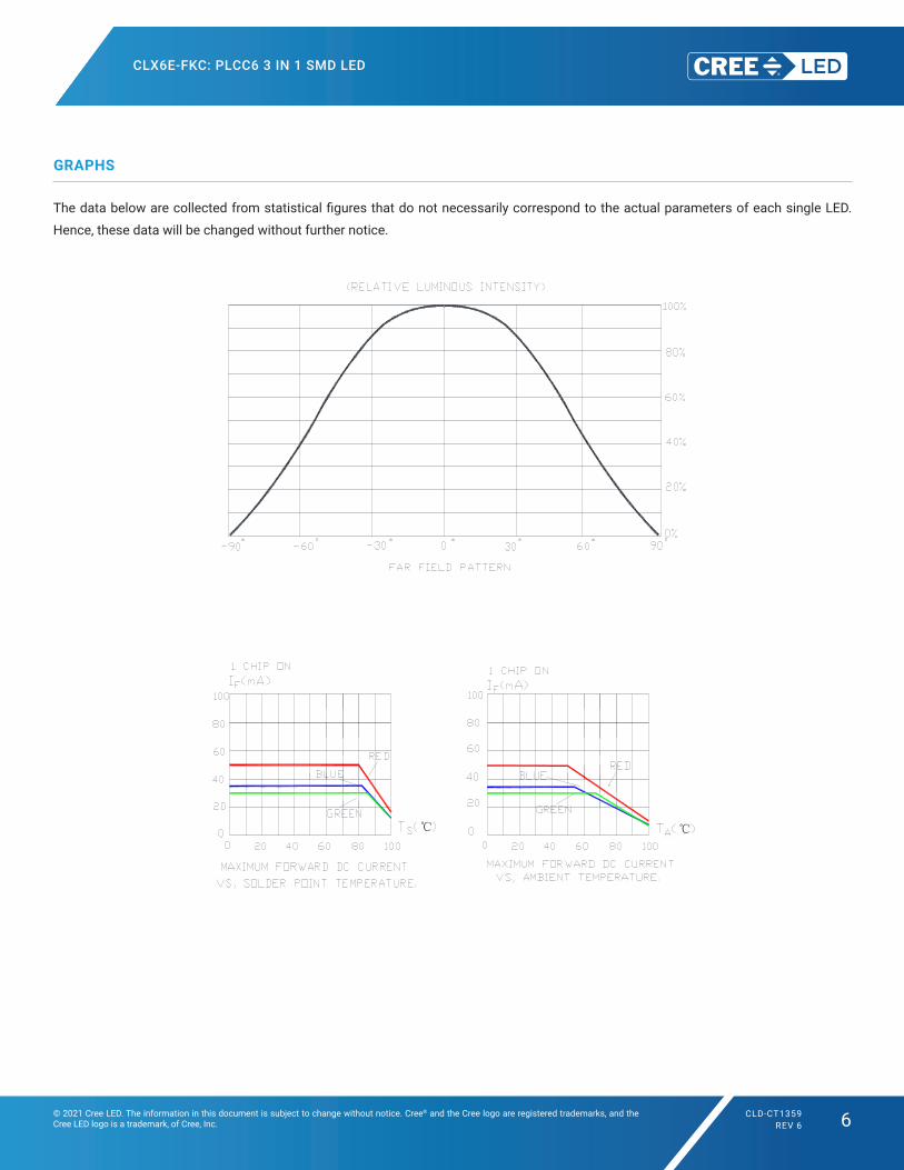
GRAPHS
ThedatabelowarecollectedfromstatisticalfiguresthatdonotnecessarilycorrespondtotheactualparametersofeachsingleLED.
Hence, these data will be changed without further notice.
℃ ℃
CLX6E-FKC: PLCC6 3 IN 1 SMD LED
© 2021 Cree LED. The information in this document is subject to change without notice. Cree® and the Cree logo are registered trademarks, and the Cree LED logo is a trademark, of Cree, Inc.
CLD-CT1359REV 6 7
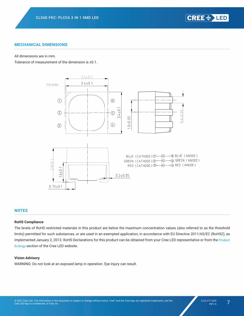
MECHANICAL DIMENSIONS
All dimensions are in mm.
Tolerance of measurement of the dimension is ±0.1.
NOTES
RoHS Compliance
The levels of RoHS restricted materials in this product are below the maximum concentration values (also referred to as the threshold
limits) permitted for such substances, or are used in an exempted application, in accordance with EU Directive 2011/65/EC (RoHS2), as
implemented January 2, 2013. RoHS Declarations for this product can be obtained from your Cree LED representative or from the Product
Ecology section of the Cree LED website.
Vision Advisory
WARNING: Do not look at an exposed lamp in operation. Eye injury can result.
( )
( )
( )
( )
( )
( )
CLX6E-FKC: PLCC6 3 IN 1 SMD LED
© 2021 Cree LED. The information in this document is subject to change without notice. Cree® and the Cree logo are registered trademarks, and the Cree LED logo is a trademark, of Cree, Inc.
CLD-CT1359REV 6 8
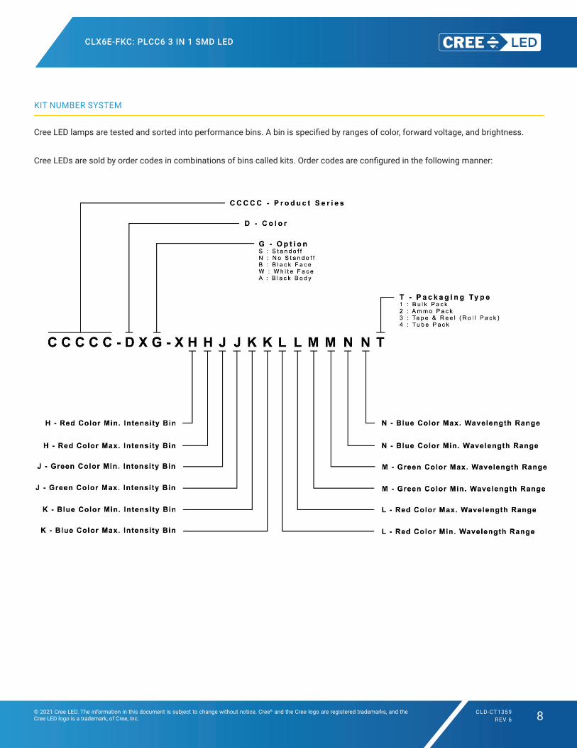
KIT NUMBER SYSTEM
CreeLEDlampsaretestedandsortedintoperformancebins.Abinisspecifiedbyrangesofcolor,forwardvoltage,andbrightness.
CreeLEDsaresoldbyordercodesincombinationsofbinscalledkits.Ordercodesareconfiguredinthefollowingmanner:
CLX6E-FKC: PLCC6 3 IN 1 SMD LED
© 2021 Cree LED. The information in this document is subject to change without notice. Cree® and the Cree logo are registered trademarks, and the Cree LED logo is a trademark, of Cree, Inc.
CLD-CT1359REV 6 9
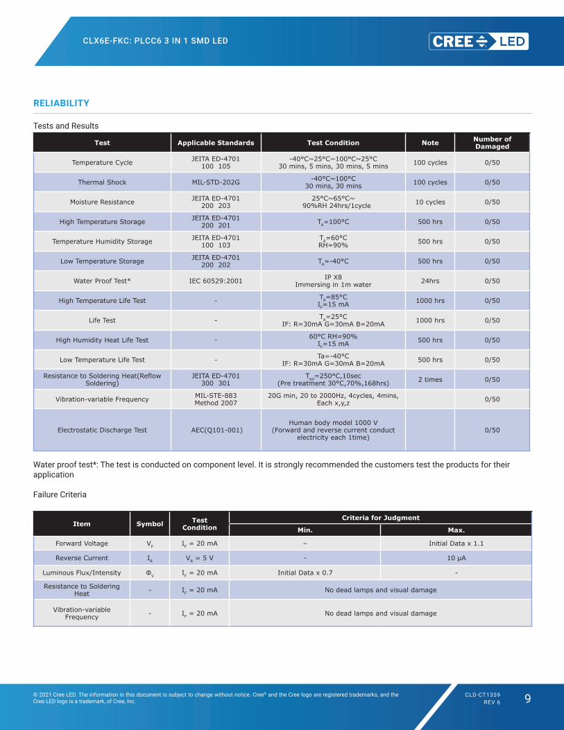
RELIABILITY
Tests and Results
Test Applicable Standards Test Condition Note Number ofDamaged
Temperature Cycle JEITA ED-4701 100 105
-40°C~25°C~100°C~25°C30 mins, 5 mins, 30 mins, 5 mins 100 cycles 0/50
Thermal Shock MIL-STD-202G -40°C~100°C30 mins, 30 mins 100 cycles 0/50
Moisture Resistance JEITA ED-4701 200 203
25°C~65°C~ 90%RH 24hrs/1cycle 10 cycles 0/50
High Temperature Storage JEITA ED-4701 200 201 TA=100°C 500 hrs 0/50
Temperature Humidity Storage JEITA ED-4701 100 103
TA=60°CRH=90% 500 hrs 0/50
Low Temperature Storage JEITA ED-4701 200 202 TA=-40°C 500 hrs 0/50
Water Proof Test* IEC 60529:2001 IP X8Immersing in 1m water 24hrs 0/50
High Temperature Life Test - TA=85°CIF=15 mA 1000 hrs 0/50
Life Test - TA=25°CIF: R=30mA G=30mA B=20mA 1000 hrs 0/50
High Humidity Heat Life Test - 60°C RH=90%IF=15 mA 500 hrs 0/50
Low Temperature Life Test - Ta=-40°CIF: R=30mA G=30mA B=20mA 500 hrs 0/50
Resistance to Soldering Heat(Reflow Soldering)
JEITA ED-4701 300 301
Tsol=250°C,10sec (Pre treatment 30°C,70%,168hrs) 2 times 0/50
Vibration-variable Frequency MIL-STE-883 Method 2007
20G min, 20 to 2000Hz, 4cycles, 4mins, Each x,y,z 0/50
Electrostatic Discharge Test AEC(Q101-001) Human body model 1000 V
(Forward and reverse current conduct electricity each 1time)
0/50
Water proof test*: The test is conducted on component level. It is strongly recommended the customers test the products for their application
Failure Criteria
Item Symbol TestCondition
Criteria for Judgment
Min. Max.
Forward Voltage VF IF = 20 mA – Initial Data x 1.1
Reverse Current IR VR = 5 V - 10 μA
Luminous Flux/Intensity ФV IF = 20 mA Initial Data x 0.7 -
Resistance to Soldering Heat - IF = 20 mA No dead lamps and visual damage
Vibration-variable Frequency - IF = 20 mA No dead lamps and visual damage
CLX6E-FKC: PLCC6 3 IN 1 SMD LED
© 2021 Cree LED. The information in this document is subject to change without notice. Cree® and the Cree logo are registered trademarks, and the Cree LED logo is a trademark, of Cree, Inc.
CLD-CT1359REV 6 10
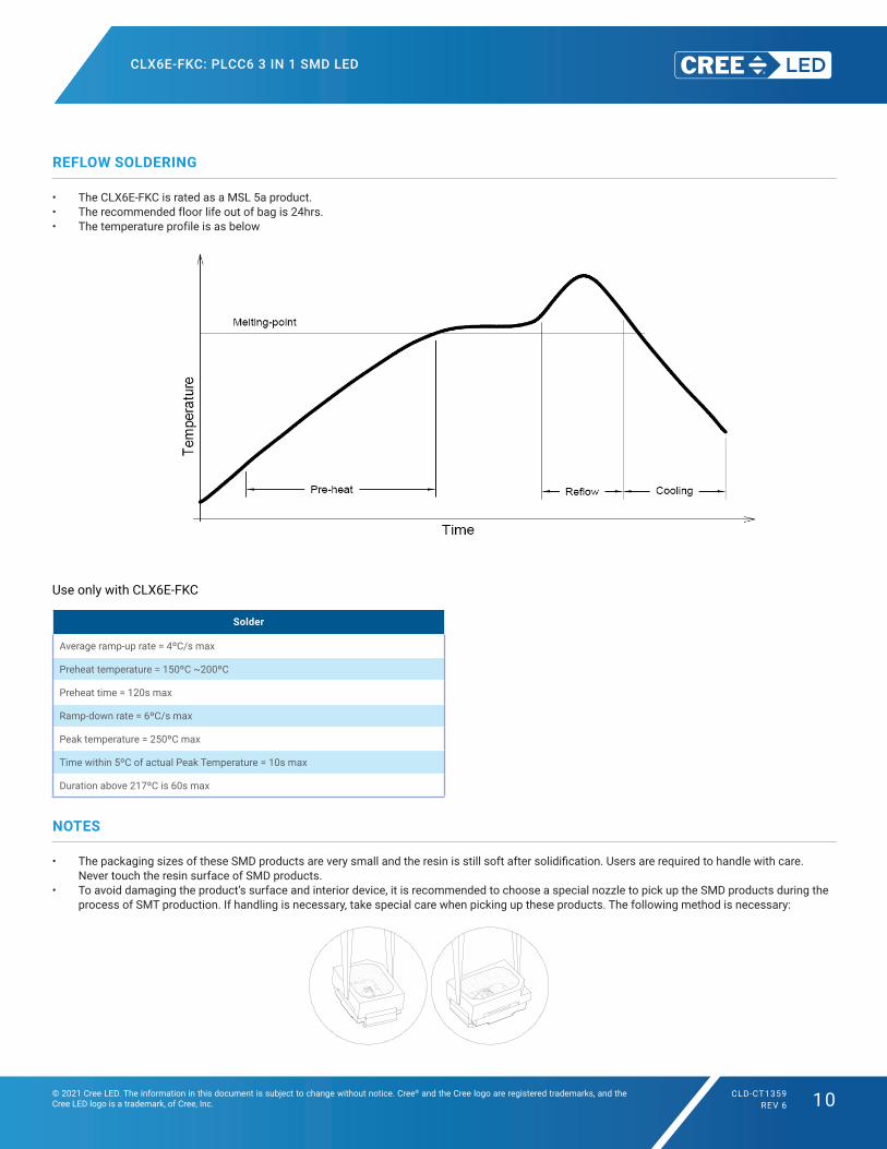
REFLOW SOLDERING
• The CLX6E-FKC is rated as a MSL 5a product. • The recommended floor life out of bag is 24hrs. • The temperature profile is as below
Use only with CLX6E-FKC
Solder
Average ramp-up rate = 4ºC/s max
Preheat temperature = 150ºC ~200ºC
Preheat time = 120s max
Ramp-down rate = 6ºC/s max
Peak temperature = 250ºC max
Time within 5ºC of actual Peak Temperature = 10s max
Duration above 217ºC is 60s max
NOTES
• ThepackagingsizesoftheseSMDproductsareverysmallandtheresinisstillsoftaftersolidification.Usersarerequiredtohandlewithcare.Never touch the resin surface of SMD products.
• To avoid damaging the product’s surface and interior device, it is recommended to choose a special nozzle to pick up the SMD products during the process of SMT production. If handling is necessary, take special care when picking up these products. The following method is necessary:
Document No.: CREE-05-0057 Rev. NO. : 16
9/9
pick up SMD products during the process of SMT production . If handling is necessary, it should take more
careful to pick up these products. The following two methods are necessary :
Fig. 1a: For Small Top SMD Fig. 1b: For Mini side 0.8mm SMD
For Small Top SMD series , it is recommended to use rubber material Nozzle to pick up SMD products .Two
figure size for reference : a.) Circular Nozzle: inner diameter: Ø1.8mm+/-0.05mm, outer diameter: Ø2.3mm+/-0.05mm.
b.) Rectangle Nozzle: inner size: 1.3mm x 2.3mm, outer size > SMD size.
6. Electrostatic Discharge and Surge current Electrostatic discharge (ESD) or surge current (EOS) may damage SMD LED. Precautions such as ESD wrist strap, ESD shoe strap or antistatic gloves must be worn whenever handling of SMD LED. All devices, equipment and machinery must be properly grounded. It is recommended to perform electrical test to screen out ESD failures at final inspection. It is important to eliminate the possibility of surge current during circuitry design 7. Heat Management
Heat management of SMD LED must be taken into consideration during the design stage of SMD LED application. The current should be de-rated appropriately by referring to the de-rating curve attached on each product specification.
Data is subject to change without prior notice.
Document No.: CREE-05-0057 Rev. NO. : 17
6/11
Use all SMD besides LP6-NPP1-01-N1 Solder = Sn63-Pb37 Solder = Lead-free
Average ramp-up rate = 4ºC/s max. Average ramp-up rate = 4ºC/s max
Preheat temperature = 100ºC ~150ºC Preheat temperature = 150ºC ~200ºC
Preheat time = 120s max. Preheat time = 120s max.
Ramp-down rate = 6ºC/s max. Ramp-down rate = 6ºC/s max.
Peak temperature = 230ºC max. Peak temperature = 250ºC max.
Time within 5ºC of actual Peak Temperature = 10s max. Time within 5ºC of actual Peak Temperature = 10s max.
Duration above 183ºC is 60s max. Duration above 217ºC is 60s max. Only use LP6-NPP1-01-N1 Solder = Low Lead-free
Average ramp-up rate = 3ºC/s max.
Preheat temperature = 130ºC ~170ºC
Preheat time = 120s max.
Ramp-down rate = 6ºC/s max.
Peak temperature = 213ºC max.
Time within 3ºC of actual Peak Temperature = 25s max.
Duration above 200ºC is 40s max. Recommended solder pad design for heat dissipation (LM1 series):
0.5
7.5
7.0
4.5
2.6
1.5
CLX6E-FKC: PLCC6 3 IN 1 SMD LED
© 2021 Cree LED. The information in this document is subject to change without notice. Cree® and the Cree logo are registered trademarks, and the Cree LED logo is a trademark, of Cree, Inc.
CLD-CT1359REV 6 11
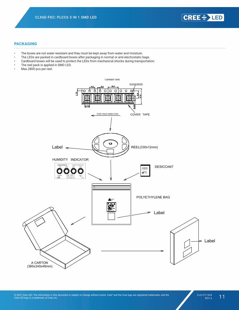
PACKAGING
• The boxes are not water resistant and they must be kept away from water and moisture.• The LEDs are packed in cardboard boxes after packaging in normal or anti-electrostatic bags.• Cardboard boxes will be used to protect the LEDs from mechanical shocks during transportation.• The reel pack is applied in SMD LED.• Max 2800 pcs per reel.