Embed Size (px)
Citation preview

Begin
Club Car IQ Technical Information
Updated 6-2-17
NextGENERAL WIRING DIAGRAM
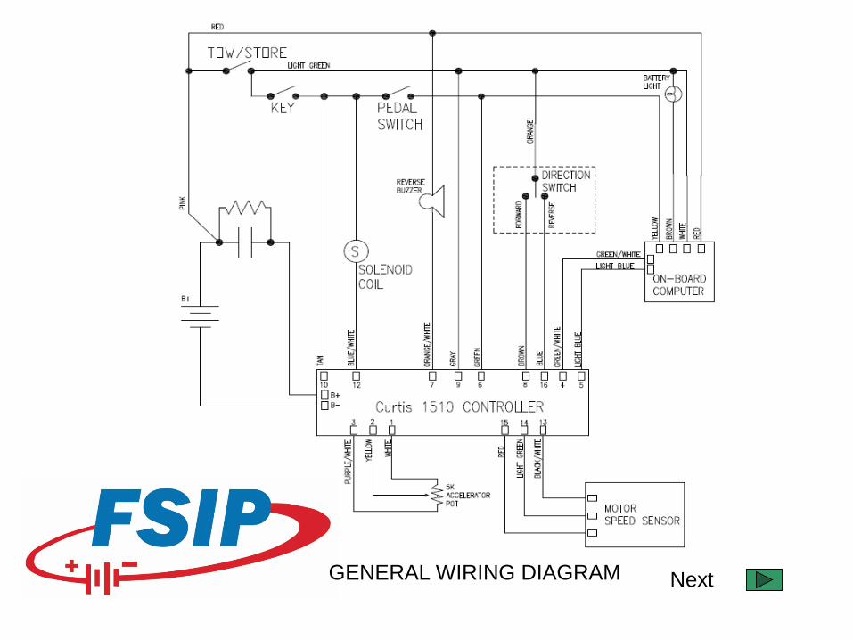
TECHNICAL ASSISTANCE
Solenoid Does Not Close
Solenoid Closes But No Travel
Vehicle Travels in reverse when in forward direction, and in forward when in reverse direction.
Solenoid closes and vehicle runs a few feet then quits
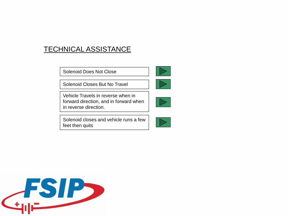
PRIOR TO CONTINUED TROUBLESHOOTING THE FOLLOWING STEPS MUST BE TAKEN
1. POSITION THE CART ON LEVEL GROUND AND BLOCK FRONT TIRES TO PREVENT VEHICLE FROM ROLLING.
2. ELEVATE THE DRIVE TIRES FROM THE GROUND.
My vehicle is safely lifted from the ground.
Back
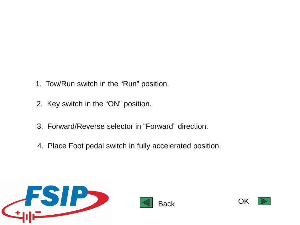
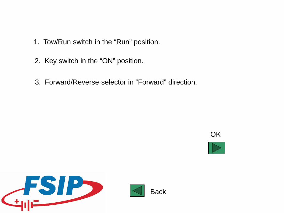
1. Tow/Run switch in the “Run” position.
2. Key switch in the “ON” position.
3. Forward/Reverse selector in “Forward” direction.
4. Place Foot pedal switch in fully accelerated position.
OKBack
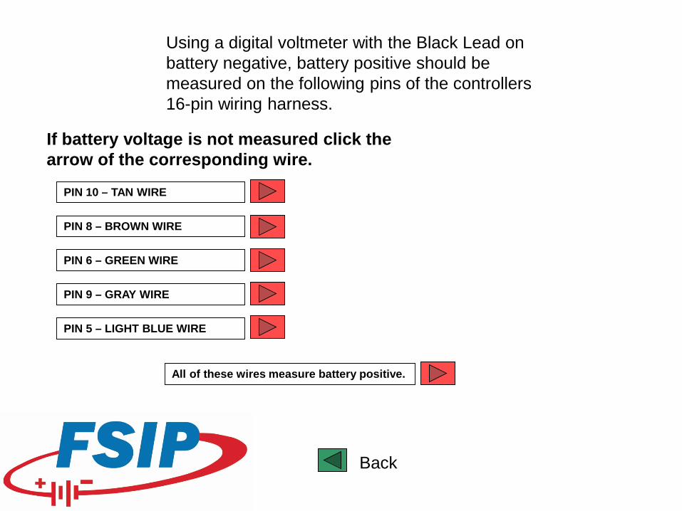
Using a digital voltmeter with the Black Lead on battery negative, battery positive should be measured on the following pins of the controllers 16-pin wiring harness.
PIN 10 – TAN WIRE
PIN 8 – BROWN WIRE
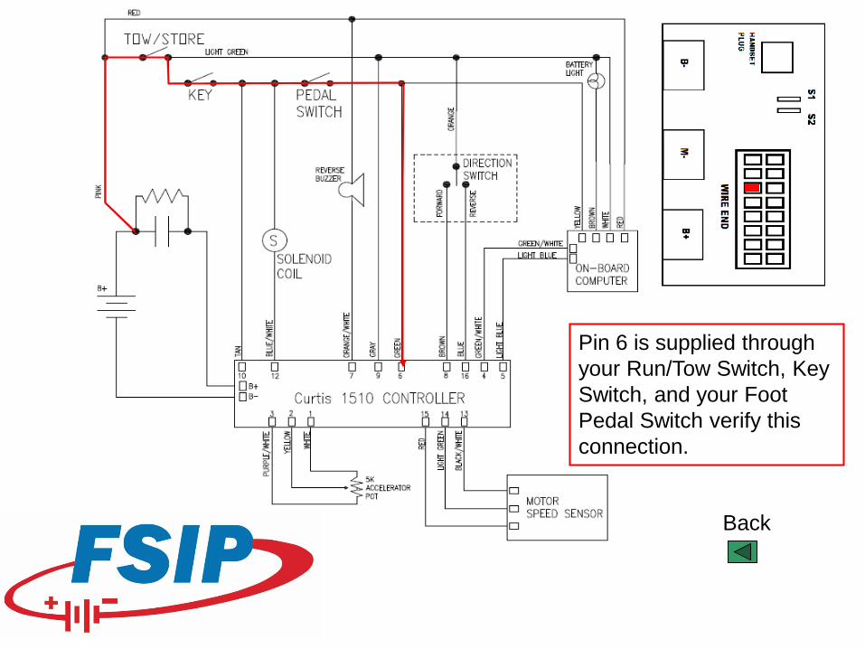
PIN 6 – GREEN WIRE
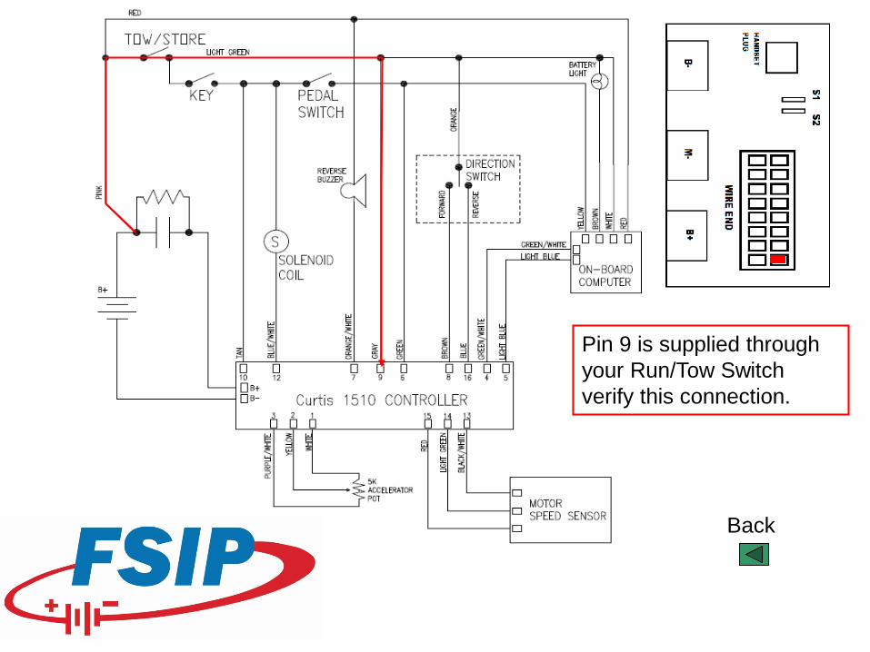
PIN 9 – GRAY WIRE
If battery voltage is not measured click the arrow of the corresponding wire.
All of these wires measure battery positive.
Back
PIN 5 – LIGHT BLUE WIRE
Back
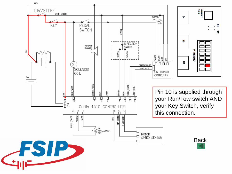
Pin 10 is supplied through your Run/Tow switch AND your Key Switch, verify this connection.
Back
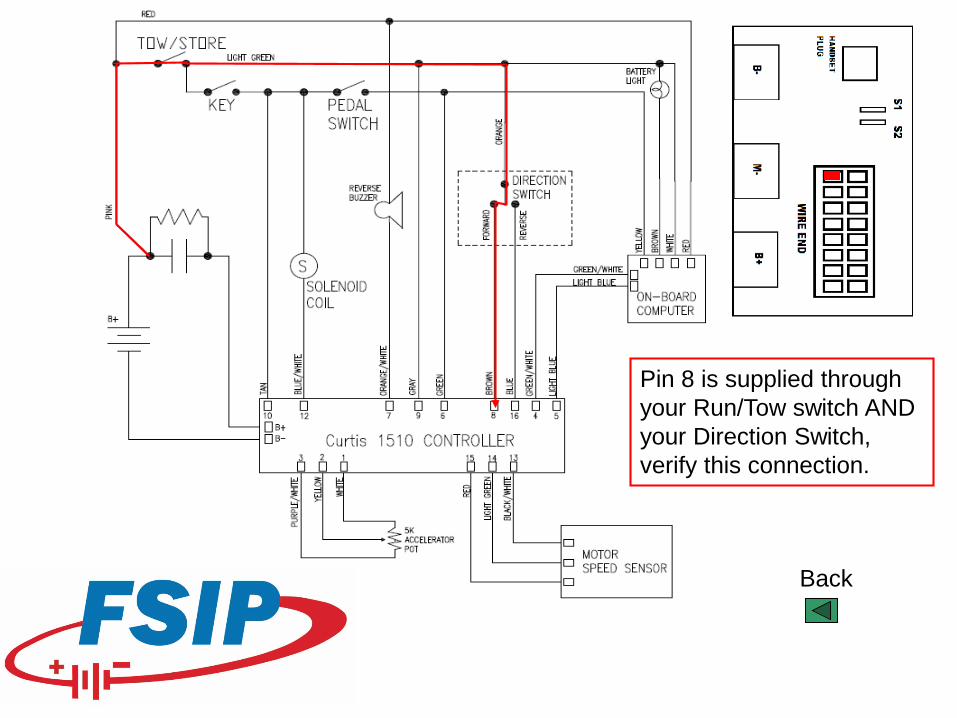
Pin 8 is supplied through your Run/Tow switch AND your Direction Switch, verify this connection.
Back
Pin 6 is supplied through your Run/Tow Switch, Key Switch, and your Foot Pedal Switch verify this connection.
Back
Pin 9 is supplied through your Run/Tow Switch verify this connection.
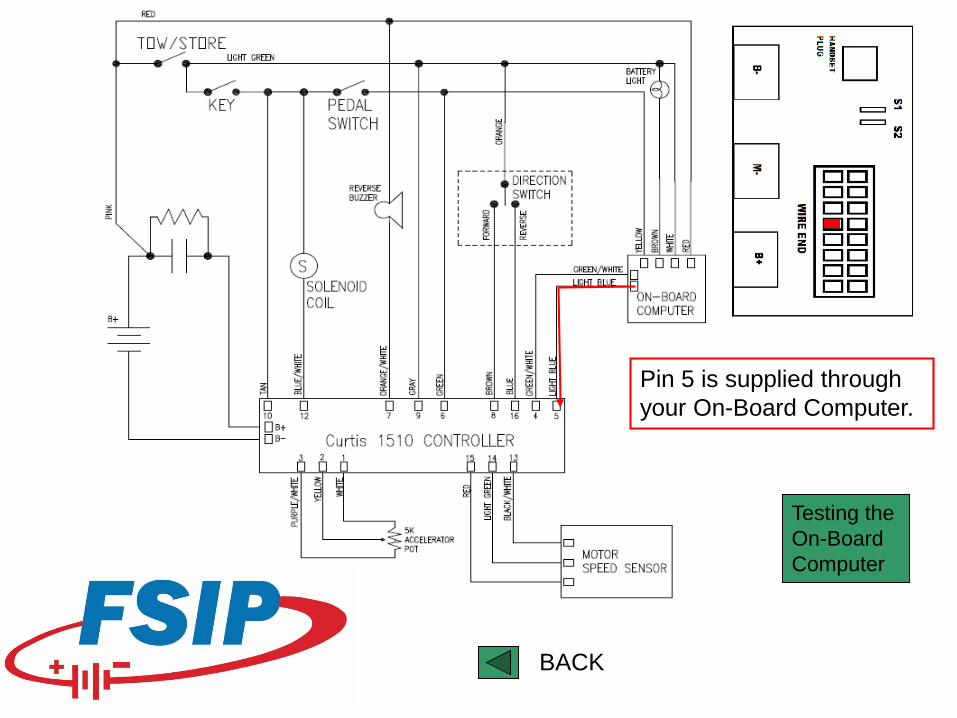
Pin 5 is supplied through your On-Board Computer.
Testing the On-Board Computer
BACK
Is your dash-mounted battery warning light illuminated?
YES NO
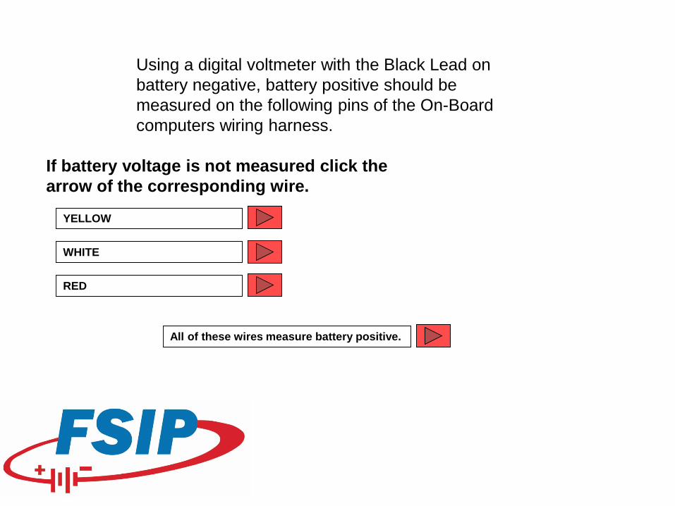
Using a digital voltmeter with the Black Lead on battery negative, battery positive should be measured on the following pins of the On-Board computers wiring harness.
YELLOW
WHITE
RED
If battery voltage is not measured click the arrow of the corresponding wire.
All of these wires measure battery positive.
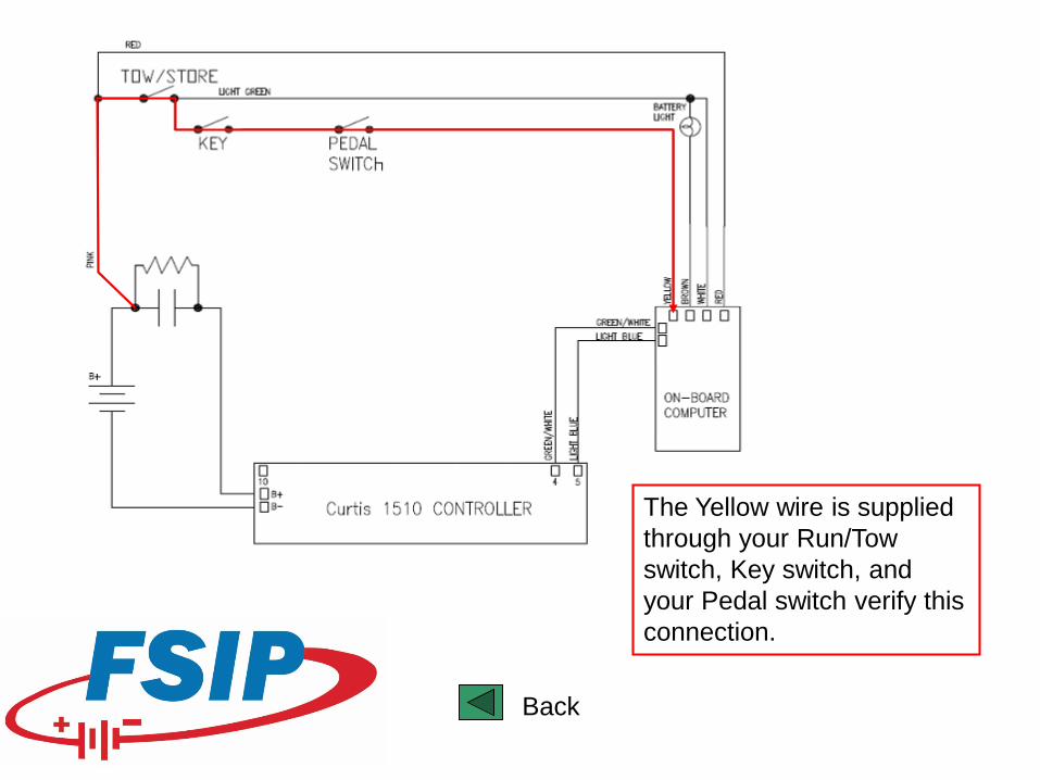
The Yellow wire is supplied through your Run/Tow switch, Key switch, and your Pedal switch verify this connection.
Back
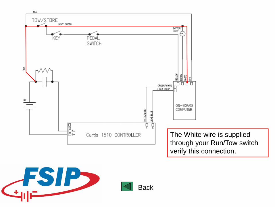
The White wire is supplied through your Run/Tow switch verify this connection.
Back
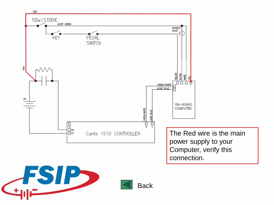
The Red wire is the main power supply to your Computer, verify this connection.
Back
Next
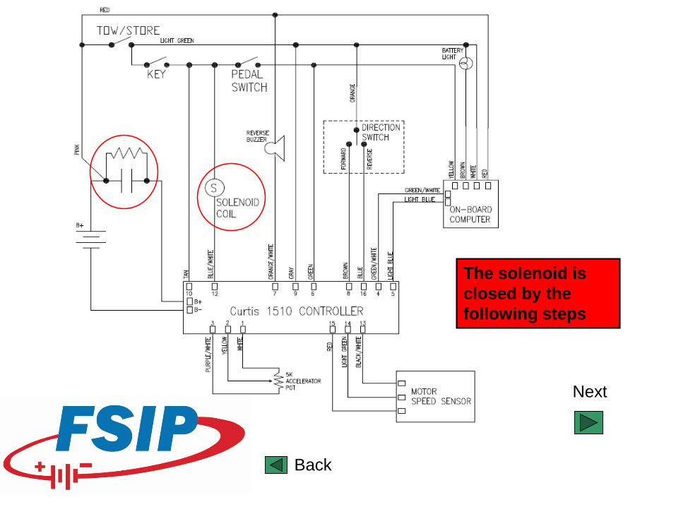
The solenoid is closed by the following steps
Back
Next
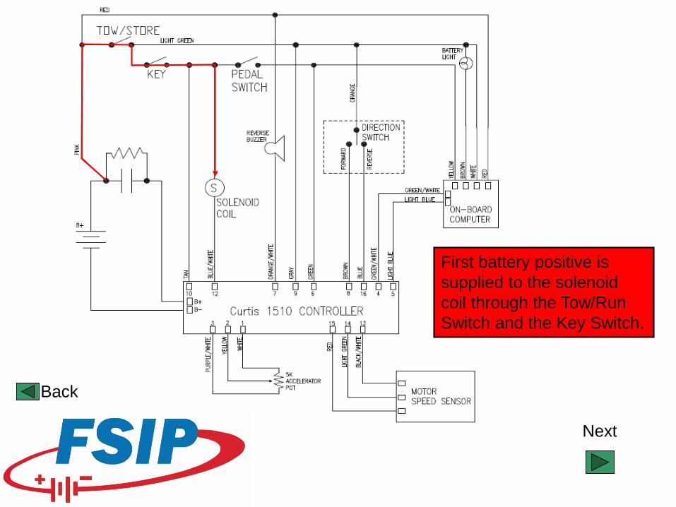
First battery positive is supplied to the solenoid coil through the Tow/Run Switch and the Key Switch.
Back
Next
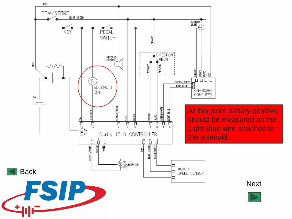
At this point battery positive should be measured on the Light Blue wire attached to the solenoid.
Back
Next
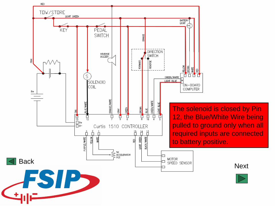
The solenoid is closed by Pin 12, the Blue/White Wire being pulled to ground only when all required inputs are connected to battery positive.
Back
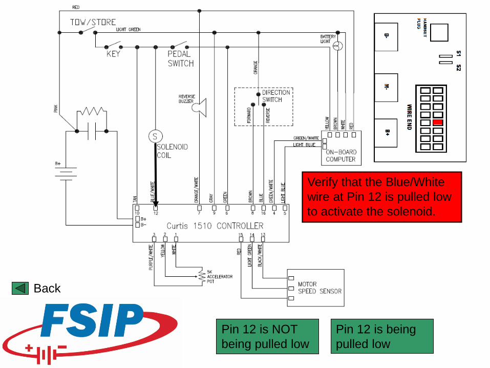
Pin 12 is being pulled low
Pin 12 is NOT being pulled low
Verify that the Blue/White wire at Pin 12 is pulled low to activate the solenoid.
Back
End
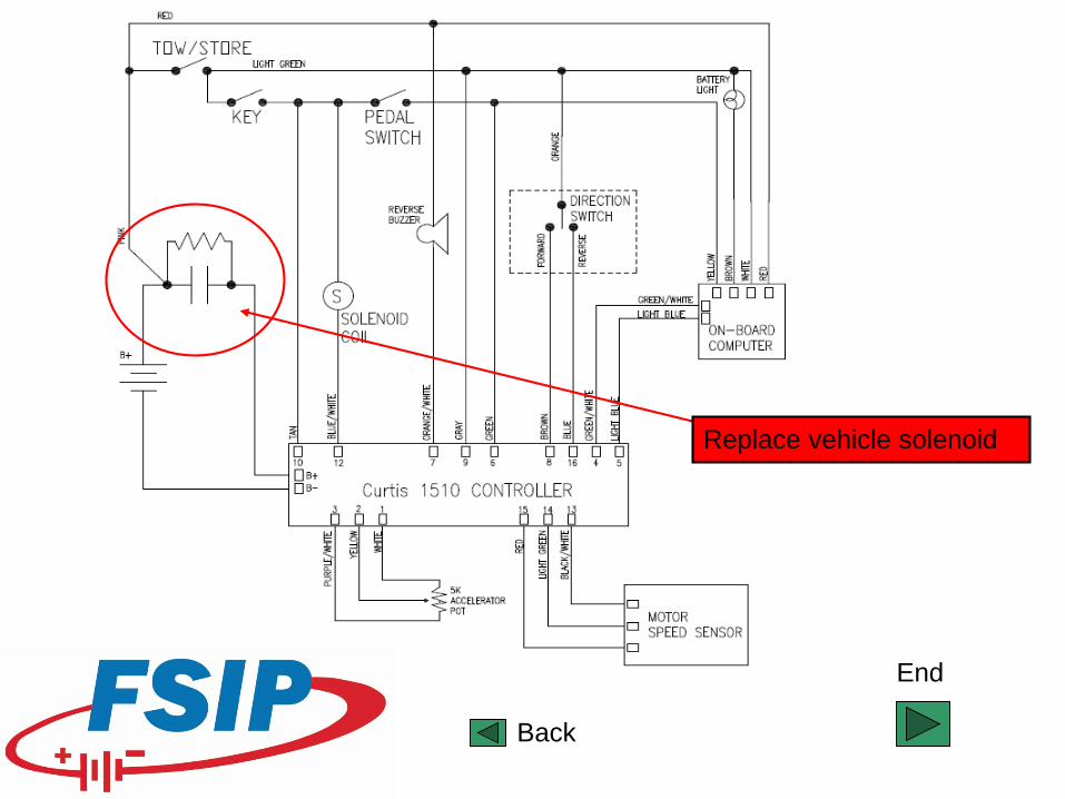
Replace vehicle solenoid
Back

Your controller is not working to OEM specifications. Contact Flight Systems Industrial Products at 1-800-333-1194 to have your controller remanufactured.
End
1. Tow/Run switch in the “Run” position.
2. Key switch in the “ON” position.
3. Forward/Reverse selector in “Forward” direction.
OK
Back
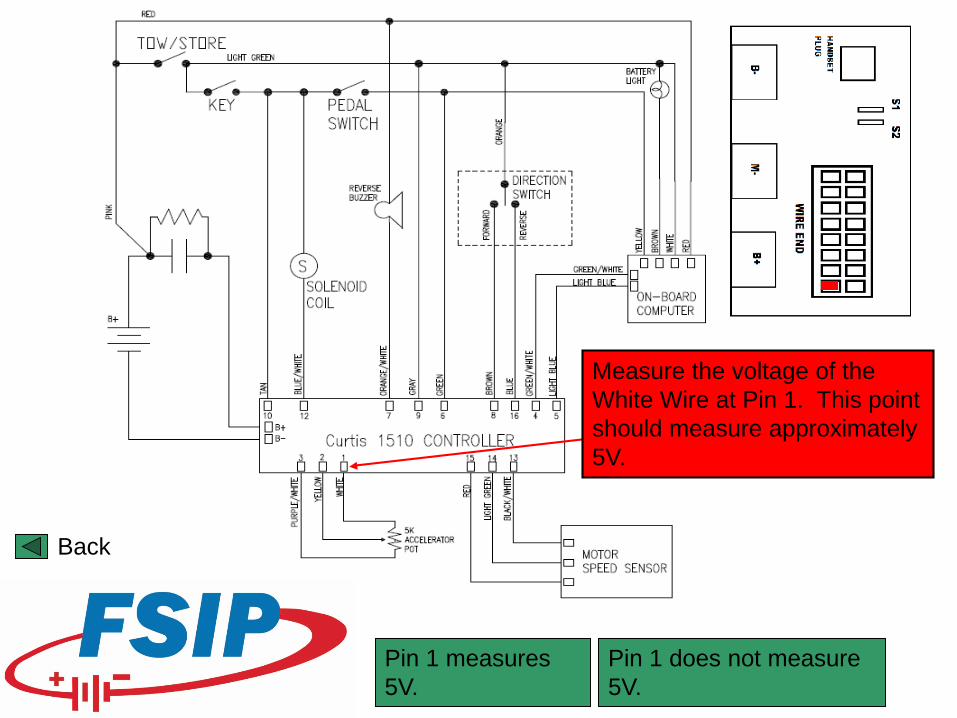
Pin 1 measures 5V.
Pin 1 does not measure 5V.
Measure the voltage of the White Wire at Pin 1. This point should measure approximately 5V.
Back
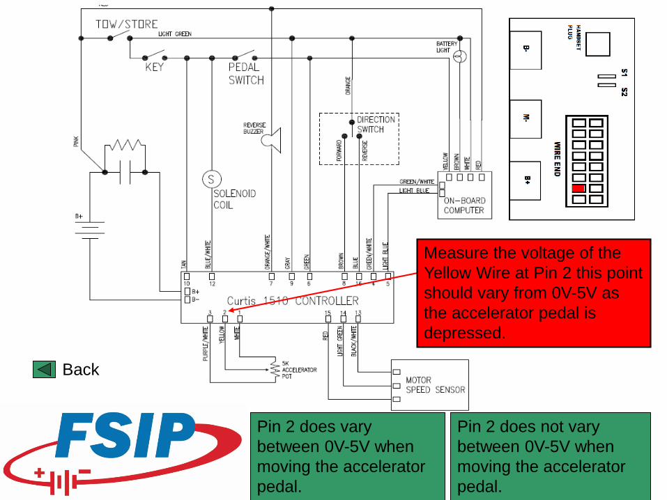
Pin 2 does not vary between 0V-5V when moving the accelerator pedal.
Pin 2 does vary between 0V-5V when moving the accelerator pedal.
Measure the voltage of the Yellow Wire at Pin 2 this point should vary from 0V-5V as the accelerator pedal is depressed.
Back
End
Back
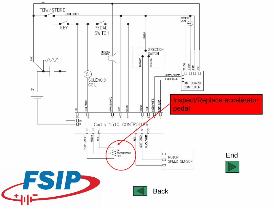
Inspect/Replace accelerator pedal
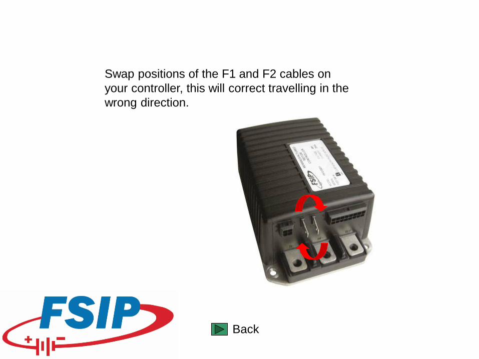
Swap positions of the F1 and F2 cables on your controller, this will correct travelling in the wrong direction.
End
Back
This indicates your battery state of charge is low, please re-connect your vehicle charger until battery warning light is extinguished.
Back
After verifying all input voltages to your on-board computer are correct, and verifying battery state of charge is ok, the vehicle on-board computer may need to be reset. Remove the battery positive cable for 10-15 minutes then re-connect to restart computer. If this does not return vehicle functionality the vehicle computer may be faulty.
Back
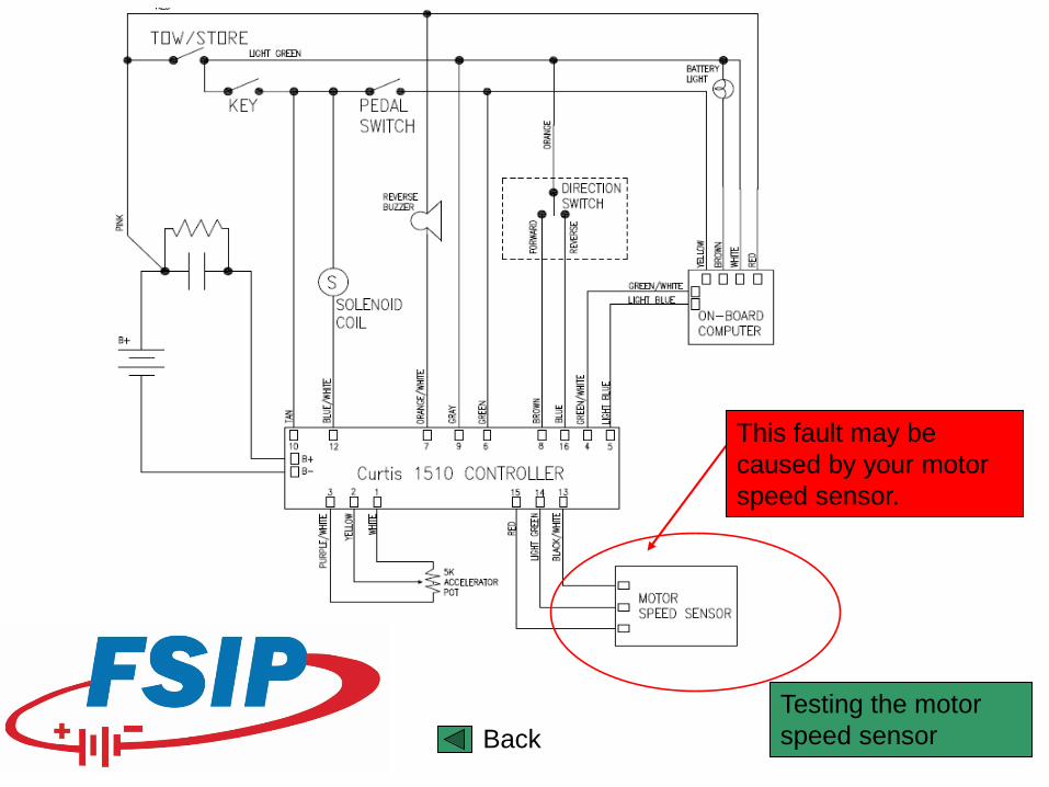
This fault may be caused by your motor speed sensor.
Testing the motor speed sensorBack
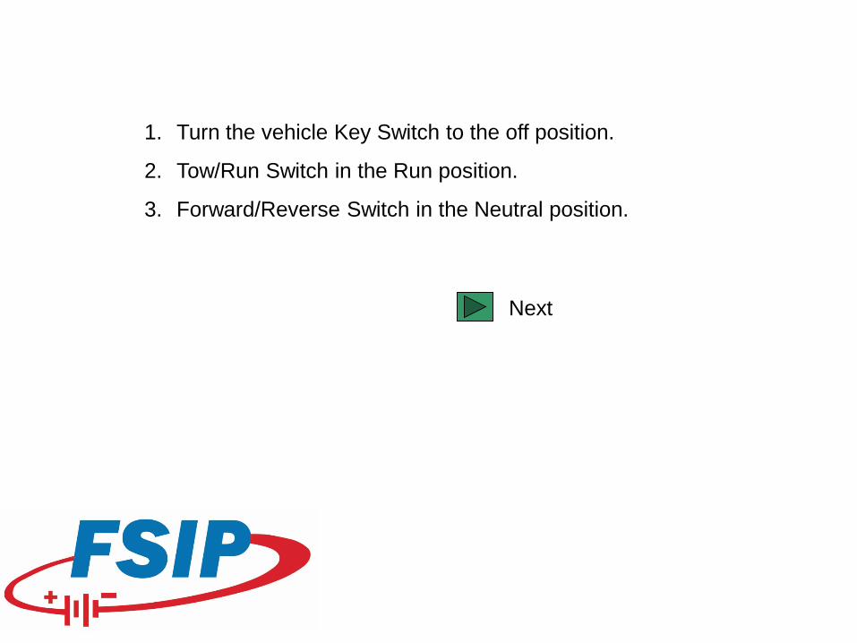
1. Turn the vehicle Key Switch to the off position.
2. Tow/Run Switch in the Run position.
3. Forward/Reverse Switch in the Neutral position.
Next
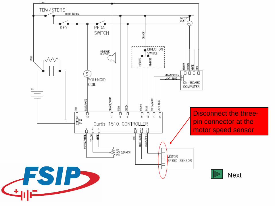
Disconnect the three-pin connector at the motor speed sensor
Next
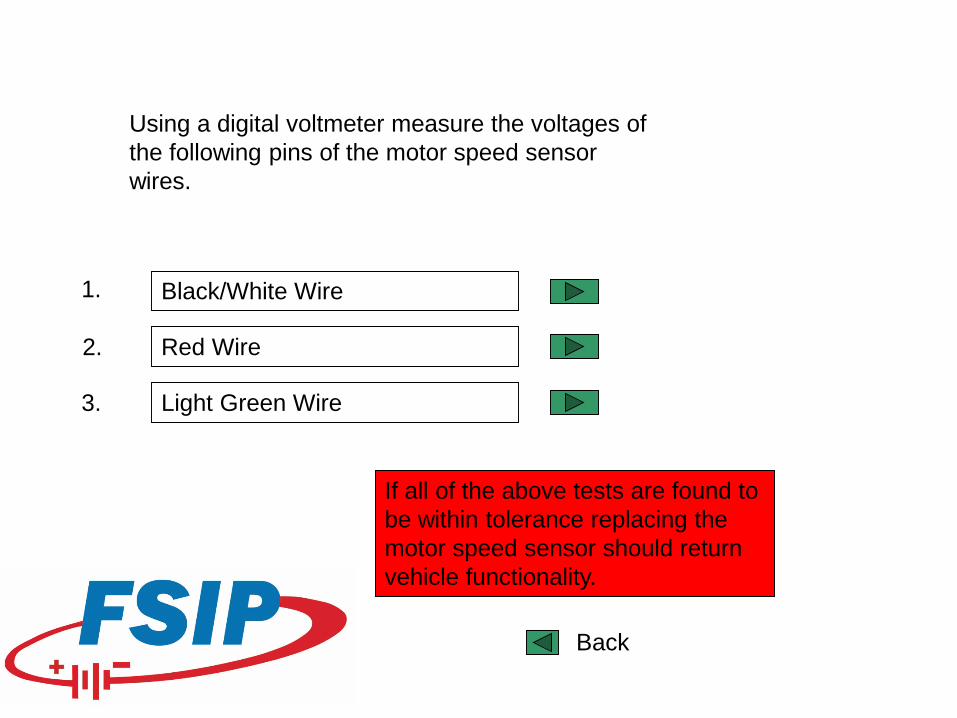
Using a digital voltmeter measure the voltages of the following pins of the motor speed sensor wires.
Black/White Wire
Red Wire
Light Green Wire
If all of the above tests are found to be within tolerance replacing the motor speed sensor should return vehicle functionality.
1.
2.
3.
Back
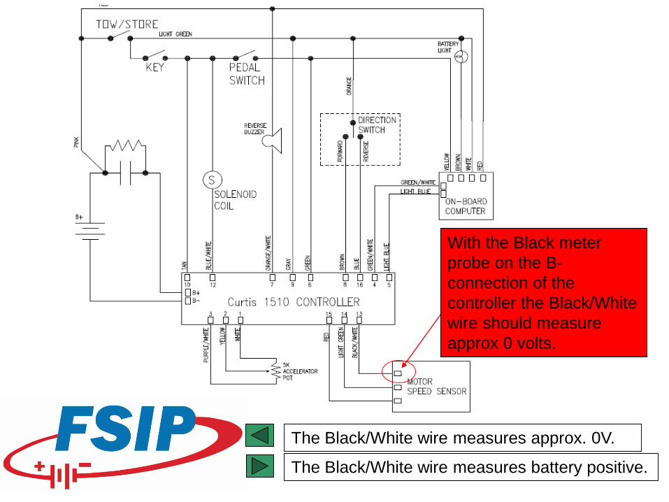
The Black/White wire measures approx. 0V.
With the Black meter probe on the B-connection of the controller the Black/White wire should measure approx 0 volts.
The Black/White wire measures battery positive.
Verify the continuity of the Black/White wire from pin 13 of the controllers 16 pin connector to the three pin connector at the motor speed sensor and replace wire if necessary.
Continuity is ok
Back
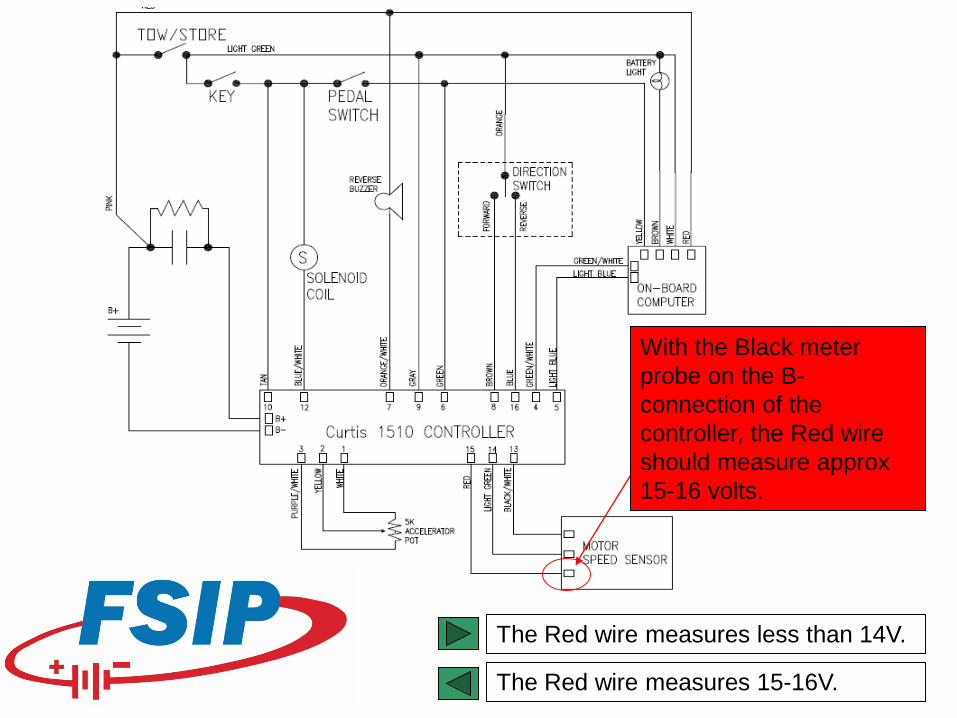
With the Black meter probe on the B-connection of the controller, the Red wire should measure approx 15-16 volts.
The Red wire measures less than 14V.
The Red wire measures 15-16V.
Verify the continuity of the Red wire from pin 15 of the controllers 16 pin connector to the three pin connector at the motor speed sensor and replace wire if necessary.
Continuity is ok
Back
Back
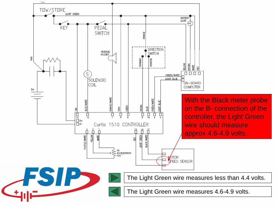
With the Black meter probe on the B- connection of the controller, the Light Green wire should measure approx 4.6-4.9 volts.
The Light Green wire measures less than 4.4 volts.
The Light Green wire measures 4.6-4.9 volts.

Verify the continuity of the Light Green wire from pin 14 of the controllers 16 pin connector to the three pin connector at the motor speed sensor and replace wire if necessary.
Continuity is ok
Back