Embed Size (px)
Citation preview

1
INSTALLATION INSTRUCTIONSSingle Car Clopay WindCode® Instructions
(For use with Insulated and Uninsulated Steel Residential Garage Door Instruction Manual)
Things to Know BeforeYou BeginThis is a supplement to the Clopay SteelResidential Garage Door Instructions (Steel)and Insulated Steel Garage Door Instructions(Insulated) (Referred to as MANUAL). It coversimportant information unique to ClopayWindCode® Doors. For all other informationand safety warnings concerning your ClopayWindCode® garage door, see the MANUAL.Read all of the information below beforebeginning installation.
WindCode® doors require additional struts andhinge attachments beyond what is required onstandard doors. The installation and attachmentof these struts and hinges are outlined in thismanual. Specifically, these instructions cover thefollowing hardware attachment:
1) Attachment of Hinges2) Top Bracket Installation3) Addition and Attachment of Struts4) Jamb / Track Configuration5) Track Bracket Placement
Each Clopay WindCode® door is included inone of nine categories: W1 - W9. Each categorycovers a different range of windload and subse-quently, a specific strut configuration. (Tables 1 & 2)
NOTE: It is the buyer’s responsibility to purchasethe garage door required to meet local buildingcodes.
Clopay WindCode® garage doors not installedwith the proper reinforcement (struts, hinges,jamb brackets, track, fasteners) will not performas designed to meet the building code require-ments.
Windload reinforcement on single car doors (9'0"wide and under) is configured differently thanstrutting on double car doors (9'2" wide and over).
An electric impact gun is strongly recommendedfor installation of WindCode® doors.
To determine what door you have, locate theidentification sticker found on the end of the doorpackage. This sticker will identify the door size,door model, and windload category. (FIG. 1)
Consumer Hotline1-800-225-6729
Fig. 1
WindCode®
Door ModelDoorWidth
DoorHeight
IDENTIFICATION STICKER (Located On Package)(Example: Model 82 Windload Category W5)
82W5 SW 8'00 x 7'00 WXZ 25PWINDOWS: S3
WINDOWTRIM: F24
INSUL: F
LOCK: 3
SPRINGS: EUS
PACK: U 1
RADIUS: 12
LIFT: S
PART # A747628
I.D. # 48397276520753
COMMENT: WINDOW PLACEMENTSPECIAL PRODUCTION INSTR.KEYING INSTRUCTIONS
SGL STRGTH
FOAM
LOCK BAR
EXTENSION
UNIPAC
MISC:
MOUNT: AKR
Table 1
Test ApproximateWindload Windload Test MPHCategory (P.S.F.) Gust Speed
W1 16 to 23 90W2 24 to 28 100W3 29 to 33 110W4 34 to 42 120W5 43 to 54 140W6 55 to 60 150W7 60 to 68 155W8 69 to 81 170W9 81 + 180

2
Strut Attachment
Struts are placed lengthwise across the door toadd strength. Strut configurations vary dependingon WindCode® category and door size. Table 2shows six of the most common WindCode®
doors and refers to a specific drawing in thismanual. These drawings (Figures 11 to 16 in theback of this supplement) include specific strutconfiguration and detailed technical informationfor each door. After reviewing the strut configura-tion, turn to page 3 to begin the actual installation.For specifications and drawings for other doormodels please call the Clopay Consumer Hotlineat 1-800-225-6729.
Table 2
Model Windload Door Strutting* Corresponding PushnutsNumber Category Width Configuration Figure / Drawing Required
73/75/80/82/ W4 Up to 9'0" 1 per section Figure 11 / 300159 No84A/90/94 (Single Car)
2400/2401/4400/ W4 Up to 9'0" 1-1-0-1** Figure 12 / 100773 No4401/4300/4301/ (Single Car)4310/ HDG/HDGL
1000/183/ W5 Up to 9'0" 1 per section Figure 13 / 101242 No187/1001 (Single Car)
2400/2401/4400/ W6 Up to 9'0" 2 on first Figure 14 / 101526 No4401/4300/4301/ (Single Car) section, 1 on all4310/HDG/HDGL other sections
84A/94 W7 Up to 9'0" 2 per section (only Figure 15 / Yes, Fig. 8(Single Car) 1 on 3rd section) 101702-24
2400/2401/4400/ W8 Up to 9'0" 2 per section Figure 16 / 101703 No4401/4300/4301/ (Single Car)4310/HDG
* The bottom section is considered the first section, the second section from the bottom is considered the second section, etc.**Strut pattern is found only on doors that are four sections high (6'6" to 7'0"). A strut pattern of 1-1-0-1-0 for doors that are five sections high (7'6" to 8'0")
3
Fig. 2A
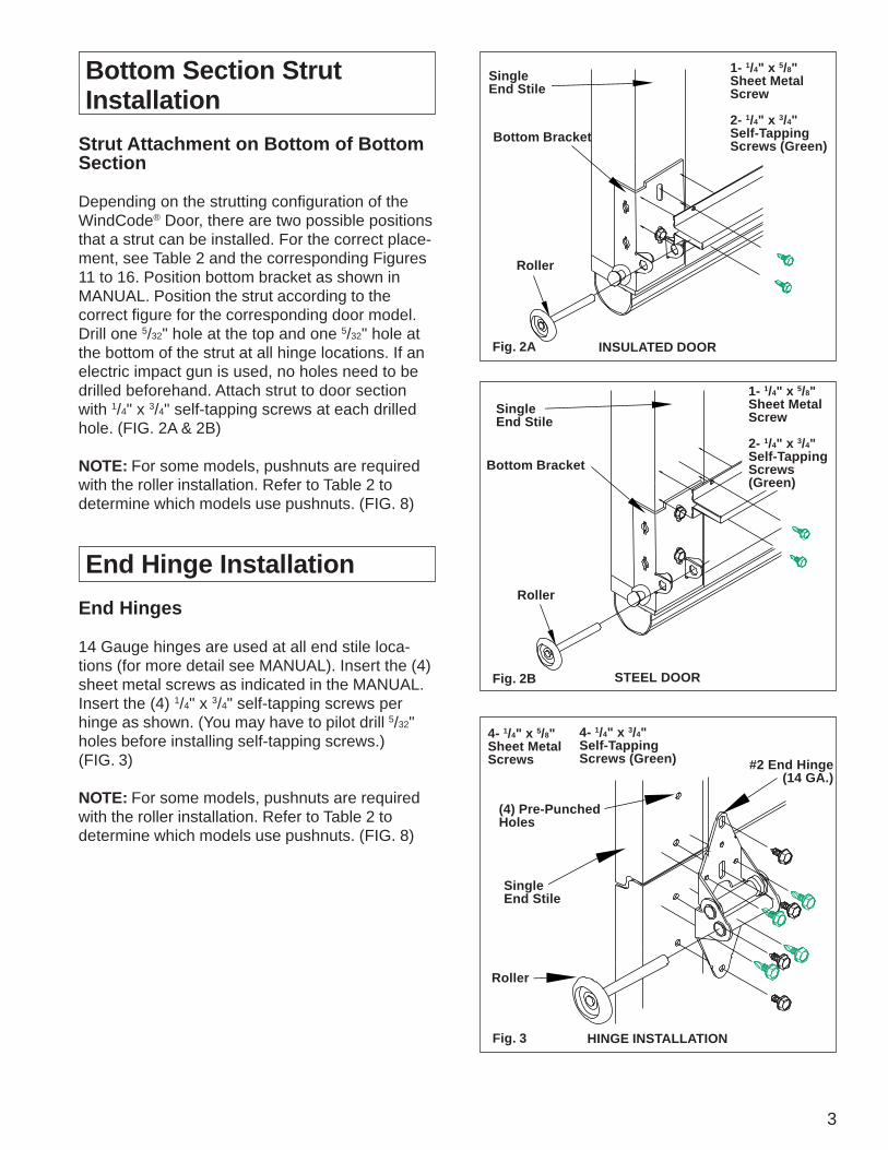
Bottom Section Strut Installation
Strut Attachment on Bottom of BottomSection
Depending on the strutting configuration of theWindCode® Door, there are two possible positionsthat a strut can be installed. For the correct place-ment, see Table 2 and the corresponding Figures11 to 16. Position bottom bracket as shown inMANUAL. Position the strut according to thecorrect figure for the corresponding door model.Drill one 5/32" hole at the top and one 5/32" hole atthe bottom of the strut at all hinge locations. If anelectric impact gun is used, no holes need to bedrilled beforehand. Attach strut to door sectionwith 1/4" x 3/4" self-tapping screws at each drilledhole. (FIG. 2A & 2B)
NOTE: For some models, pushnuts are requiredwith the roller installation. Refer to Table 2 todetermine which models use pushnuts. (FIG. 8)
End Hinge Installation
End Hinges
14 Gauge hinges are used at all end stile loca-tions (for more detail see MANUAL). Insert the (4)sheet metal screws as indicated in the MANUAL.Insert the (4) 1/4" x 3/4" self-tapping screws perhinge as shown. (You may have to pilot drill 5/32"holes before installing self-tapping screws.)(FIG. 3)
NOTE: For some models, pushnuts are requiredwith the roller installation. Refer to Table 2 todetermine which models use pushnuts. (FIG. 8)
Fig. 2B
SingleEnd Stile
Bottom Bracket
Roller
1- 1/4" x 5/8"Sheet MetalScrew
2- 1/4" x 3/4"Self-TappingScrews (Green)
Bottom Bracket
Roller
SingleEnd Stile
Fig. 3
(4) Pre-PunchedHoles
#2 End Hinge(14 GA.)
SingleEnd Stile
Roller
4- 1/4" x 5/8"Sheet MetalScrews
4- 1/4" x 3/4"Self-TappingScrews (Green)
INSULATED DOOR
STEEL DOOR
HINGE INSTALLATION
1- 1/4" x 5/8"Sheet MetalScrew
2- 1/4" x 3/4"Self-TappingScrews(Green)

4
Intermediate Section Strut Installation
The strut installation for the intermediatesection is different for steel and insulateddoors. Refer to the appropriate section below.
Single Hinge Strut Attachment (Steel)
Depending on the strutting configuration of theWindCode® Steel Door, there are two possiblepositions that a strut can be installed. For thecorrect placement, see Table 2 and the corre-sponding Figures 11 to 16. To attach strut, posi-tion the strut on the door. Drill one 5/32" hole at thetop and one 5/32" hole at the bottom of the strut atall hinge locations. If an electric impact gun isbeing used, no holes need to be drilled before-hand. Attach strut to door section with 1/4" x 3/4"self-tapping screws at each drilled hole. (FIG. 4)
Note that the strut on the top of the section over-laps the bottom leaf of the hinge. If required, astrut mounted at the bottom of the section can bemounted above the hinge leaf. (FIG. 4A)
NOTE: For some models, pushnuts are requiredwith the roller installation. Refer to Table 2 todetermine which models use pushnuts. (FIG. 8)
Single Hinge Strut Attachment(Insulated)
Depending on the strutting configuration of theWindCode® insulated door, there are two possiblepositions that a strut can be installed. For thecorrect placement, see Table 2 and the corre-sponding Figures 11 to 16. For insulated doorsthe struts must overlap the hinge leafs on both thetop and bottom. To attach strut, position the struton the door. Drill one 5/32" hole at the top and one5/32" hole at the bottom of the strut at all hingelocations. If an electric impact gun is used, noholes need to be drilled beforehand. Attach strutto door section with 1/4" x 3/4" self-tapping screwsat each drilled hole. (FIG. 5 & 5A)
NOTE: For some models, pushnuts are requiredwith the roller installation. Refer to Table 2 todetermine which models use pushnuts. (FIG. 8)
Fig. 5
21/4" x 3/4"Self-TappingScrews (Green)To ReplaceCorrespondingSheet MetalScrews
DrillHoles
Hinge
Roller
Strut
End Stile
Strut
Hinge
Roller
21/4" x 3/4"Self-TappingScrews (Green)To ReplaceCorrespondingSheet MetalScrews
Strut
End Stile
Strut
DrillHoles
Fig. 4AFig. 4
Fig. 5A

5
Fig. 6
Top Bracket Installation
Top Bracket
In most instances, WindCode® doors use aheavier gauge top bracket. Due to this, the holesin the bracket will not line up with the holes in thestiles. Install the top of the top brackets approxi-mately 3" to 31/2" below the top of the section with(4) 1/4" x 3/4" self-tapping screws. Once installed,the slide adjustments must be aligned so that theroller lines up with the track so the door will closeflush to the door jamb. (FIG. 6)
NOTE: For some models, pushnuts are requiredwith the roller installation. Refer to Table 2 todetermine which models use pushnuts. (FIG. 8)
Top Section Strut Attachment
Depending on the strutting configuration of theWindCode® door, a strut may be required on thetop section (See Table 2 and correspondingdrawing). To attach a strut at the top of the topsection it must be placed above the top rollerbracket. Drill one 5/32" hole at the top and one5/32" hole at the bottom of the strut at all hinge(or back-up plate (insulated) locations.) If anelectric impact gun is used, no holes need to bedrilled beforehand. Attach strut to door sectionwith 1/4" x 3/4" self-tapping screws at each drilledhole. (FIG. 7)
NOTE: For some models, pushnuts are requiredwith the roller installation. Refer to Table 2 todetermine which models use pushnuts. (FIG. 8)
Roller and Pushnut
To install the pushnut roller, slide the roller intothe hinge then slide the pushnut onto the shaftof the roller until it is within an 1/8" to 1/4" from thehinge. (FIG. 8)
NOTE: Do NOT install pushnut before installingroller into hinge. Use 1/2" Deep Draw socket andhammer to tap on pushnuts.
Top SectionOf Door
Single End Stile
Holes On StileDo Not MatchWith BracketHoles
RollerAdjustableTop Bracket
41/4" x 3/4"Self-TappingScrews (Green)
Fig. 8
21/4" x 3/4"Self-Tapping Screws (Green)
End Stile
Strut
INSTALLED
#2 End Hinge(14 GA.)
Pushnut
SingleEndStile
Roller
Fig. 7
Roller Shaft

6
Fig. 9
Fig. 10
Optional StopMoulding
Track Bracket*
5/16" x 15/8"Wood LagScrew.(1) Per Bracket
Track*
Wood Jamb
*Track FastenedTo Track Brackets.Each BracketAttached WithOne 1/4" x 5/8"Bolt and Nut ORTwo 1/4" Rivets.
Rear Track Hanger (ProvidedBy Door Installer)
13 GA. Galv. Steel Flag Bracket.Each Fastened To Wood Jamb With(3) 5/16" x 15/8" Wood Lag Screw.
2" Galv. Steel Track
Steel Track Bracket (4) Per Side.
Op
enin
g H
eig
ht
= D
oo
r H
eig
ht
LX
4X
3X2
X1
Door Bracket PlacementsHeight L X1 X2 X3 X4
6' 6" 70" 31/2" 10" 35" 60"7' 0" 76" 31/2" 10" 38" 66"7' 6" 82" 31/2" 10" 34" 58"8' 0" 88" 31/2" 10" 34" 58"
Jamb Configuration
The design of the supporting structuralelements (i.e. door jamb) shall be theresponsibility of the professional of recordfor the building or structure and in accordancewith current building codes for the loads listedon the technical drawing (attached) for thespecific model.
It is also important that the vertical 2 x 6 woodjambs are attached to the supporting structurein a method that is sufficient to transfer theloads exerted by the wind pressures. Somesuggested vertical jamb attachment methodsare included in the drawings. (FIG. 11 to 16)
Track Bracket Placement
Track bracket placement are configureddifferently according to height. Typically,WindCode® doors require more trackbrackets than non-WindCode® doors.However, each track bracket is attachedto the track and jamb using the samefasteners and method of attachmentas shown in the MANUAL. (FIG. 9 & 10)
Opener Reinforcement Installation
Attachment of Opener Reinforcement
Refer to the MANUAL for installation instructions.If the Clopay WindCode® door requires a strutacross the top of the top section, this takes theplace of any horizontal angle iron required by theMANUAL. The vertical angle as shown in theMANUAL is still required on WindCode® Doors.

7
Fig
. 11
CA
TE
GO
RY
: W4
M
OD
EL
S: 7
3, 7
5, 8
2, 8
4A, 9
0, 9
4S
TR
UT
PL
AC
EM
EN
T S
HO
WN
IN G
RE
EN

8
CA
TE
GO
RY
: W4
M
OD
EL
S: 2
400,
240
1, 2
310,
440
0, 4
401,
431
0, 2
300,
HD
G, 4
300,
430
1, H
DG
LS
TR
UT
PL
AC
EM
EN
T S
HO
WN
IN G
RE
EN
Fig
. 12

9
CA
TE
GO
RY
: W5
M
OD
EL
S: 1
000,
183
, 187
, 100
1S
TR
UT
PL
AC
EM
EN
T S
HO
WN
IN G
RE
EN
Fig
. 13

10
CA
TE
GO
RY
: W6
M
OD
EL
S: 2
400,
240
1, 4
400,
440
1, 4
310,
230
0, 2
310,
HD
G, 4
300,
430
1, H
DG
LS
TR
UT
PL
AC
EM
EN
T S
HO
WN
IN G
RE
EN
Fig
. 14

11
CA
TE
GO
RY
: W7
M
OD
EL
S: 8
4A, 9
4S
TR
UT
PL
AC
EM
EN
T S
HO
WN
IN G
RE
EN
Fig
. 15

12
CA
TE
GO
RY
: W8
M
OD
EL
S: 2
400,
240
1, 4
300,
430
1, 4
310,
440
0, 4
401,
HD
GS
TR
UT
PL
AC
EM
EN
T S
HO
WN
IN G
RE
EN
Fig
. 16
©2000 Clopay Building Products Company, Inc. P/N 0130350 4/2002