Embed Size (px)
Citation preview
Apache CloudStack 4.0.2
CloudStackInstallation Guide
open source cloud com put ing
™
Apache CloudStack
CloudStack Installation Guide
Apache CloudStack 4.0.2 CloudStack Installation GuideAuthor Apache CloudStack
Licensed to the Apache Software Foundation (ASF) under one or more contributor licenseagreements. See the NOTICE file distributed with this work for additional information regardingcopyright ownership. The ASF licenses this file to you under the Apache License, Version 2.0 (the"License"); you may not use this file except in compliance with the License. You may obtain a copy ofthe License at
http://www.apache.org/licenses/LICENSE-2.0
Unless required by applicable law or agreed to in writing, software distributed under the License isdistributed on an "AS IS" BASIS, WITHOUT WARRANTIES OR CONDITIONS OF ANY KIND, eitherexpress or implied. See the License for the specific language governing permissions and limitationsunder the License.
Apache CloudStack is an effort undergoing incubation at The Apache Software Foundation (ASF).
Incubation is required of all newly accepted projects until a further review indicates that theinfrastructure, communications, and decision making process have stabilized in a manner consistentwith other successful ASF projects. While incubation status is not necessarily a reflection of thecompleteness or stability of the code, it does indicate that the project has yet to be fully endorsed bythe ASF.
Installation Guide for CloudStack.
iii
1. Concepts 11.1. What Is CloudStack? .................................................................................................... 11.2. What Can CloudStack Do? ........................................................................................... 11.3. Deployment Architecture Overview ................................................................................ 2
1.3.1. Management Server Overview ........................................................................... 31.3.2. Cloud Infrastructure Overview ............................................................................ 31.3.3. Networking Overview ......................................................................................... 4
2. Cloud Infrastructure Concepts 52.1. About Zones ................................................................................................................ 52.2. About Pods .................................................................................................................. 62.3. About Clusters ............................................................................................................. 72.4. About Hosts ................................................................................................................. 72.5. About Primary Storage ................................................................................................. 82.6. About Secondary Storage ............................................................................................. 82.7. About Physical Networks .............................................................................................. 9
2.7.1. Configurable Characteristics of Physical Networks ............................................... 92.7.2. Basic Zone Network Traffic Types ...................................................................... 92.7.3. Basic Zone Guest IP Addresses ....................................................................... 102.7.4. Advanced Zone Network Traffic Types .............................................................. 102.7.5. Advanced Zone Guest IP Addresses ................................................................ 112.7.6. Advanced Zone Public IP Addresses ................................................................ 112.7.7. System Reserved IP Addresses ....................................................................... 11
3. Building from Source 133.1. Getting the release ..................................................................................................... 133.2. Verifying the downloaded release ................................................................................ 13
3.2.1. Getting the KEYS ............................................................................................ 133.2.2. GPG ............................................................................................................... 133.2.3. MD5 ................................................................................................................ 143.2.4. SHA512 .......................................................................................................... 14
3.3. Prerequisites for building Apache CloudStack .............................................................. 143.4. Extracting source ........................................................................................................ 153.5. Building DEB packages .............................................................................................. 15
3.5.1. Setting up an APT repo ................................................................................... 163.5.2. Configuring your machines to use the APT repository ........................................ 16
3.6. Building RPMs ........................................................................................................... 163.6.1. Creating a yum repo ........................................................................................ 173.6.2. Configuring your systems to use your new yum repository .................................. 18
4. Installation 194.1. Who Should Read This .............................................................................................. 194.2. Overview of Installation Steps ..................................................................................... 194.3. Minimum System Requirements .................................................................................. 20
4.3.1. Management Server, Database, and Storage System Requirements .................... 204.3.2. Host/Hypervisor System Requirements ............................................................. 20
4.4. Configure package repository ...................................................................................... 214.4.1. DEB package repository .................................................................................. 214.4.2. RPM package repository .................................................................................. 22
4.5. Management Server Installation .................................................................................. 224.5.1. Management Server Installation Overview ......................................................... 224.5.2. Prepare the Operating System ......................................................................... 234.5.3. Install the Management Server on the First Host ................................................ 244.5.4. Install the database server ............................................................................... 244.5.5. Prepare NFS Shares ....................................................................................... 28
CloudStack Installation Guide
iv
4.5.6. Prepare and Start Additional Management Servers ............................................ 334.5.7. Prepare the System VM Template .................................................................... 334.5.8. Installation Complete! Next Steps ..................................................................... 35
5. User Interface 375.1. Log In to the UI ......................................................................................................... 37
5.1.1. End User's UI Overview ................................................................................... 375.1.2. Root Administrator's UI Overview ..................................................................... 375.1.3. Logging In as the Root Administrator ................................................................ 385.1.4. Changing the Root Password ........................................................................... 38
5.2. Using SSH Keys for Authentication ............................................................................. 395.2.1. Creating an Instance Template that Supports SSH Keys ..................................... 395.2.2. Creating the SSH Keypair ................................................................................ 405.2.3. Creating an Instance ........................................................................................ 415.2.4. Logging In Using the SSH Keypair ................................................................... 41
6. Steps to Provisioning Your Cloud Infrastructure 436.1. Overview of Provisioning Steps ................................................................................... 436.2. Adding a Zone ........................................................................................................... 44
6.2.1. Basic Zone Configuration ................................................................................. 456.2.2. Advanced Zone Configuration .......................................................................... 48
6.3. Adding a Pod ............................................................................................................. 536.4. Adding a Cluster ........................................................................................................ 53
6.4.1. Add Cluster: KVM or XenServer ....................................................................... 536.4.2. Add Cluster: vSphere ....................................................................................... 54
6.5. Adding a Host ............................................................................................................ 566.5.1. Adding a Host (XenServer or KVM) .................................................................. 576.5.2. Adding a Host (vSphere) .................................................................................. 58
6.6. Add Primary Storage .................................................................................................. 586.6.1. System Requirements for Primary Storage ........................................................ 586.6.2. Adding Primary Stroage ................................................................................... 59
6.7. Add Secondary Storage .............................................................................................. 606.7.1. System Requirements for Secondary Storage .................................................... 606.7.2. Adding Secondary Storage ............................................................................... 60
6.8. Initialize and Test ....................................................................................................... 61
7. Global Configuration Parameters 637.1. Setting Global Configuration Parameters ..................................................................... 637.2. About Global Configuration Parameters ....................................................................... 63
8. Hypervisor Installation 678.1. KVM Hypervisor Host Installation ................................................................................ 67
8.1.1. System Requirements for KVM Hypervisor Hosts ............................................... 678.1.2. KVM Installation Overview ................................................................................ 678.1.3. Prepare the Operating System ......................................................................... 688.1.4. Install and configure the Agent ......................................................................... 698.1.5. Install and Configure libvirt ............................................................................... 698.1.6. Configure the Security Policies ......................................................................... 708.1.7. Configure the network bridges .......................................................................... 718.1.8. Configuring the firewall .................................................................................... 748.1.9. Add the host to CloudStack .............................................................................. 75
8.2. Citrix XenServer Installation for CloudStack ................................................................. 768.2.1. System Requirements for XenServer Hosts ....................................................... 768.2.2. XenServer Installation Steps ............................................................................ 778.2.3. Configure XenServer dom0 Memory ................................................................. 778.2.4. Username and Password ................................................................................. 77
v
8.2.5. Time Synchronization ....................................................................................... 778.2.6. Licensing ......................................................................................................... 788.2.7. Install CloudStack XenServer Support Package (CSP) ....................................... 788.2.8. Primary Storage Setup for XenServer ............................................................... 798.2.9. iSCSI Multipath Setup for XenServer (Optional) ................................................. 808.2.10. Physical Networking Setup for XenServer ........................................................ 808.2.11. Upgrading XenServer Versions ....................................................................... 84
8.3. VMware vSphere Installation and Configuration ............................................................ 878.3.1. System Requirements for vSphere Hosts .......................................................... 878.3.2. Preparation Checklist for VMware ..................................................................... 888.3.3. vSphere Installation Steps ................................................................................ 898.3.4. ESXi Host setup .............................................................................................. 908.3.5. Physical Host Networking ................................................................................. 908.3.6. Storage Preparation for vSphere (iSCSI only) .................................................... 948.3.7. Add Hosts or Configure Clusters (vSphere) ....................................................... 97
9. Choosing a Deployment Architecture 999.1. Small-Scale Deployment ............................................................................................. 999.2. Large-Scale Redundant Setup ................................................................................... 1009.3. Separate Storage Network ........................................................................................ 1019.4. Multi-Node Management Server ................................................................................ 1019.5. Multi-Site Deployment ............................................................................................... 101
10. Amazon Web Service Interface Compatibility 10510.1. Amazon Web Services EC2 Compatible Interface ..................................................... 10510.2. System Requirements ............................................................................................. 10510.3. Enabling the AWS API Compatible Interface ............................................................ 10510.4. AWS API User Setup Steps .................................................................................... 106
10.4.1. AWS API User Registration .......................................................................... 10610.4.2. AWS API Command-Line Tools Setup ........................................................... 107
10.5. Using Timeouts to Ensure AWS API Command Completion ....................................... 10710.6. Supported AWS API Calls ....................................................................................... 108
11. Managing Networks and Traffic 11111.1. Guest Traffic ........................................................................................................... 11111.2. Networking in a Pod ............................................................................................... 11111.3. Networking in a Zone .............................................................................................. 11311.4. Basic Zone Physical Network Configuration .............................................................. 11311.5. Advanced Zone Physical Network Configuration ....................................................... 114
11.5.1. Configure Guest Traffic in an Advanced Zone ................................................ 11411.5.2. Configure Public Traffic in an Advanced Zone ................................................ 115
11.6. Using Multiple Guest Networks ................................................................................ 11511.6.1. Adding an Additional Guest Network ............................................................. 11511.6.2. Changing the Network Offering on a Guest Network ....................................... 115
11.7. Security Groups ...................................................................................................... 11611.7.1. About Security Groups ................................................................................. 11611.7.2. Adding a Security Group .............................................................................. 11711.7.3. Enabling Security Groups ............................................................................. 11711.7.4. Adding Ingress and Egress Rules to a Security Group .................................... 117
11.8. External Firewalls and Load Balancers .................................................................... 11811.9. Load Balancer Rules .............................................................................................. 11911.10. Guest IP Ranges .................................................................................................. 11911.11. Acquiring a New IP Address .................................................................................. 11911.12. Releasing an IP Address ....................................................................................... 11911.13. Static NAT ............................................................................................................ 120
CloudStack Installation Guide
vi
11.14. IP Forwarding and Firewalling ............................................................................... 12011.15. IP Load Balancing ................................................................................................ 12011.16. DNS and DHCP .................................................................................................... 12011.17. VPN ..................................................................................................................... 120
11.17.1. Configuring VPN ........................................................................................ 12111.17.2. Using VPN with Windows ........................................................................... 12111.17.3. Using VPN with Mac OS X ......................................................................... 12211.17.4. Setting Up a Site-to-Site VPN Connection .................................................... 123
11.18. About Inter-VLAN Routing ..................................................................................... 12911.19. Configuring a Virtual Private Cloud ........................................................................ 131
11.19.1. About Virtual Private Clouds ....................................................................... 13111.19.2. Adding a Virtual Private Cloud .................................................................... 13311.19.3. Adding Tiers .............................................................................................. 13311.19.4. Configuring Access Control List .................................................................. 13511.19.5. Adding a Private Gateway to a VPC ............................................................ 13711.19.6. Deploying VMs to the Tier .......................................................................... 13811.19.7. Acquiring a New IP Address for a VPC ........................................................ 13811.19.8. Releasing an IP Address Alloted to a VPC ................................................... 13911.19.9. Enabling or Disabling Static NAT on a VPC ................................................. 14011.19.10. Adding Load Balancing Rules on a VPC .................................................... 14111.19.11. Adding a Port Forwarding Rule on a VPC .................................................. 14211.19.12. Removing Tiers ........................................................................................ 14311.19.13. Editing, Restarting, and Removing a Virtual Private Cloud ........................... 143
11.20. Management Server Load Balancing ...................................................................... 14411.20.1. Topology Requirements .............................................................................. 144
A. Revision History 147
Chapter 1.
1
Concepts
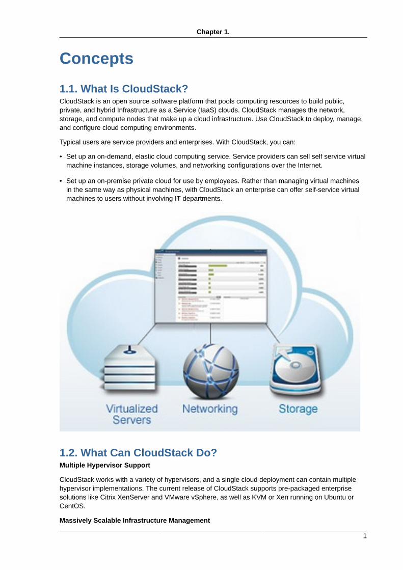
1.1. What Is CloudStack?CloudStack is an open source software platform that pools computing resources to build public,private, and hybrid Infrastructure as a Service (IaaS) clouds. CloudStack manages the network,storage, and compute nodes that make up a cloud infrastructure. Use CloudStack to deploy, manage,and configure cloud computing environments.
Typical users are service providers and enterprises. With CloudStack, you can:
• Set up an on-demand, elastic cloud computing service. Service providers can sell self service virtualmachine instances, storage volumes, and networking configurations over the Internet.
• Set up an on-premise private cloud for use by employees. Rather than managing virtual machinesin the same way as physical machines, with CloudStack an enterprise can offer self-service virtualmachines to users without involving IT departments.
1.2. What Can CloudStack Do?Multiple Hypervisor Support
CloudStack works with a variety of hypervisors, and a single cloud deployment can contain multiplehypervisor implementations. The current release of CloudStack supports pre-packaged enterprisesolutions like Citrix XenServer and VMware vSphere, as well as KVM or Xen running on Ubuntu orCentOS.
Massively Scalable Infrastructure Management
Chapter 1. Concepts
2
CloudStack can manage tens of thousands of servers installed in multiple geographically distributeddatacenters. The centralized management server scales linearly, eliminating the need for intermediatecluster-level management servers. No single component failure can cause cloud-wide outage. Periodicmaintenance of the management server can be performed without affecting the functioning of virtualmachines running in the cloud.
Automatic Configuration Management
CloudStack automatically configures each guest virtual machine’s networking and storage settings.
CloudStack internally manages a pool of virtual appliances to support the cloud itself. Theseappliances offer services such as firewalling, routing, DHCP, VPN access, console proxy, storageaccess, and storage replication. The extensive use of virtual appliances simplifies the installation,configuration, and ongoing management of a cloud deployment.
Graphical User Interface
CloudStack offers an administrator's Web interface, used for provisioning and managing the cloud, aswell as an end-user's Web interface, used for running VMs and managing VM templates. The UI canbe customized to reflect the desired service provider or enterprise look and feel.
API and Extensibility
CloudStack provides an API that gives programmatic access to all the management features availablein the UI. The API is maintained and documented. This API enables the creation of command linetools and new user interfaces to suit particular needs. See the Developer’s Guide and API Reference,both available at Apache CloudStack Guides1 and Apache CloudStack API Reference2 respectively.
The CloudStack pluggable allocation architecture allows the creation of new types of allocators for theselection of storage and Hosts. See the Allocator Implementation Guide (http://docs.cloudstack.org/CloudStack_Documentation/Allocator_Implementation_Guide).
High Availability
CloudStack has a number of features to increase the availability of the system. The ManagementServer itself may be deployed in a multi-node installation where the servers are load balanced. MySQLmay be configured to use replication to provide for a manual failover in the event of database loss. Forthe hosts, CloudStack supports NIC bonding and the use of separate networks for storage as well asiSCSI Multipath.
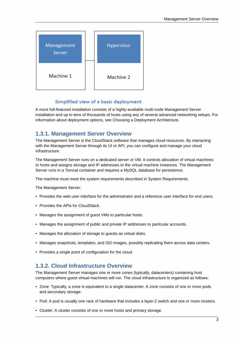
1.3. Deployment Architecture OverviewA CloudStack installation consists of two parts: the Management Server and the cloud infrastructurethat it manages. When you set up and manage a CloudStack cloud, you provision resources such ashosts, storage devices, and IP addresses into the Management Server, and the Management Servermanages those resources.
The minimum production installation consists of one machine running the CloudStack ManagementServer and another machine to act as the cloud infrastructure (in this case, a very simple infrastructureconsisting of one host running hypervisor software). In its smallest deployment, a single machine canact as both the Management Server and the hypervisor host (using the KVM hypervisor).
1 http://incubator.apache.org/cloudstack/docs2 http://incubator.apache.org/cloudstack/docs/api
Management Server Overview
3
A more full-featured installation consists of a highly-available multi-node Management Serverinstallation and up to tens of thousands of hosts using any of several advanced networking setups. Forinformation about deployment options, see Choosing a Deployment Architecture.
1.3.1. Management Server OverviewThe Management Server is the CloudStack software that manages cloud resources. By interactingwith the Management Server through its UI or API, you can configure and manage your cloudinfrastructure.
The Management Server runs on a dedicated server or VM. It controls allocation of virtual machinesto hosts and assigns storage and IP addresses to the virtual machine instances. The ManagementServer runs in a Tomcat container and requires a MySQL database for persistence.
The machine must meet the system requirements described in System Requirements.
The Management Server:
• Provides the web user interface for the administrator and a reference user interface for end users.
• Provides the APIs for CloudStack.
• Manages the assignment of guest VMs to particular hosts.
• Manages the assignment of public and private IP addresses to particular accounts.
• Manages the allocation of storage to guests as virtual disks.
• Manages snapshots, templates, and ISO images, possibly replicating them across data centers.
• Provides a single point of configuration for the cloud.
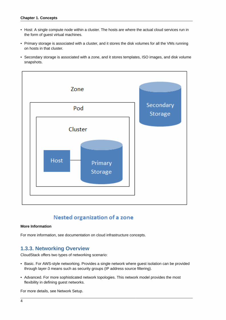
1.3.2. Cloud Infrastructure OverviewThe Management Server manages one or more zones (typically, datacenters) containing hostcomputers where guest virtual machines will run. The cloud infrastructure is organized as follows:
• Zone: Typically, a zone is equivalent to a single datacenter. A zone consists of one or more podsand secondary storage.
• Pod: A pod is usually one rack of hardware that includes a layer-2 switch and one or more clusters.
• Cluster: A cluster consists of one or more hosts and primary storage.
Chapter 1. Concepts
4
• Host: A single compute node within a cluster. The hosts are where the actual cloud services run inthe form of guest virtual machines.
• Primary storage is associated with a cluster, and it stores the disk volumes for all the VMs runningon hosts in that cluster.
• Secondary storage is associated with a zone, and it stores templates, ISO images, and disk volumesnapshots.
More Information
For more information, see documentation on cloud infrastructure concepts.
1.3.3. Networking OverviewCloudStack offers two types of networking scenario:
• Basic. For AWS-style networking. Provides a single network where guest isolation can be providedthrough layer-3 means such as security groups (IP address source filtering).
• Advanced. For more sophisticated network topologies. This network model provides the mostflexibility in defining guest networks.
For more details, see Network Setup.
Chapter 2.
5
Cloud Infrastructure Concepts
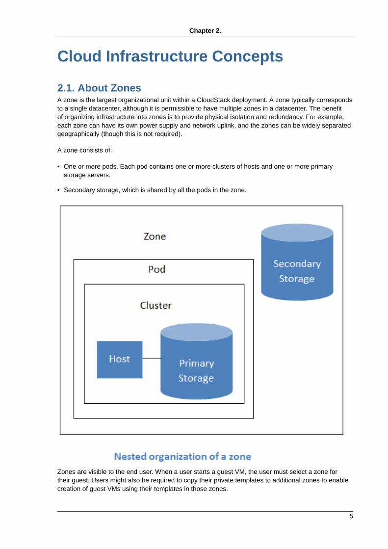
2.1. About ZonesA zone is the largest organizational unit within a CloudStack deployment. A zone typically correspondsto a single datacenter, although it is permissible to have multiple zones in a datacenter. The benefitof organizing infrastructure into zones is to provide physical isolation and redundancy. For example,each zone can have its own power supply and network uplink, and the zones can be widely separatedgeographically (though this is not required).
A zone consists of:
• One or more pods. Each pod contains one or more clusters of hosts and one or more primarystorage servers.
• Secondary storage, which is shared by all the pods in the zone.
Zones are visible to the end user. When a user starts a guest VM, the user must select a zone fortheir guest. Users might also be required to copy their private templates to additional zones to enablecreation of guest VMs using their templates in those zones.
Chapter 2. Cloud Infrastructure Concepts
6
Zones can be public or private. Public zones are visible to all users. This means that any user maycreate a guest in that zone. Private zones are reserved for a specific domain. Only users in thatdomain or its subdomains may create guests in that zone.
Hosts in the same zone are directly accessible to each other without having to go through a firewall.Hosts in different zones can access each other through statically configured VPN tunnels.
For each zone, the administrator must decide the following.
• How many pods to place in a zone.
• How many clusters to place in each pod.
• How many hosts to place in each cluster.
• How many primary storage servers to place in each cluster and total capacity for the storageservers.
• How much secondary storage to deploy in a zone.
When you add a new zone, you will be prompted to configure the zone’s physical network and add thefirst pod, cluster, host, primary storage, and secondary storage.
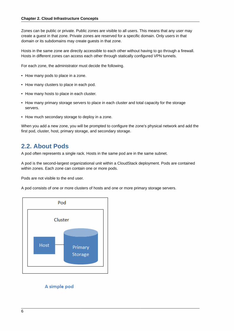
2.2. About PodsA pod often represents a single rack. Hosts in the same pod are in the same subnet.
A pod is the second-largest organizational unit within a CloudStack deployment. Pods are containedwithin zones. Each zone can contain one or more pods.
Pods are not visible to the end user.
A pod consists of one or more clusters of hosts and one or more primary storage servers.
About Clusters
7
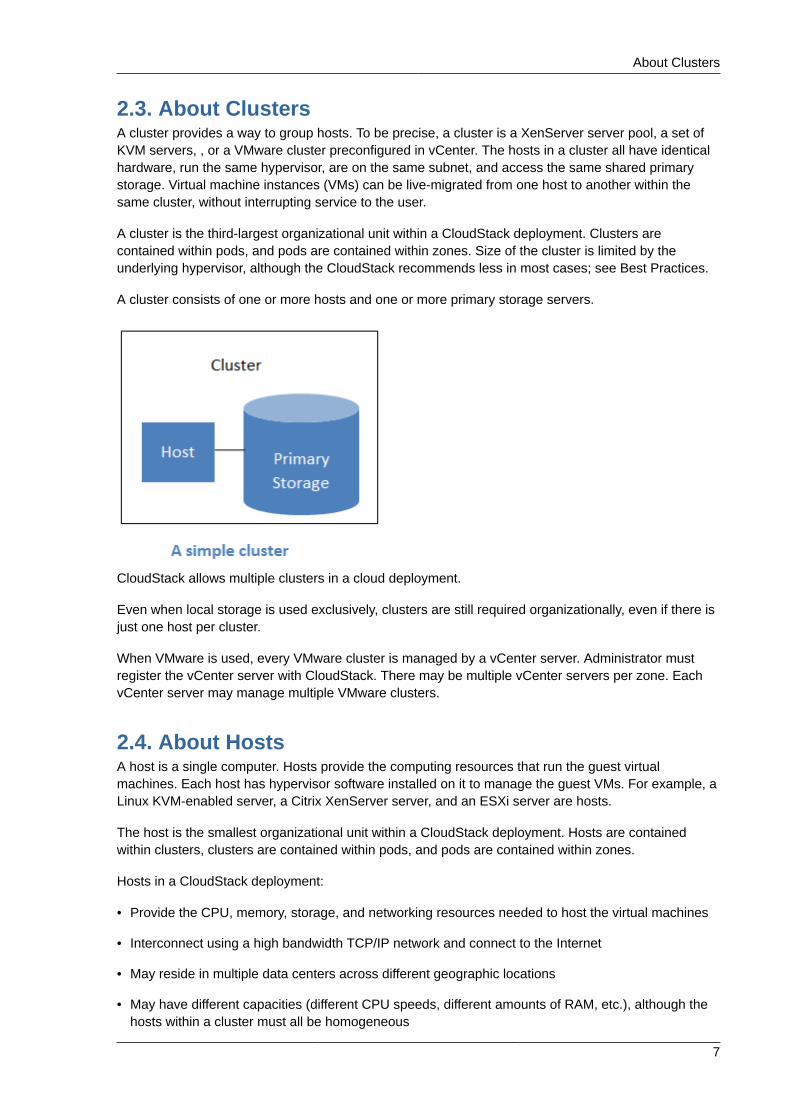
2.3. About ClustersA cluster provides a way to group hosts. To be precise, a cluster is a XenServer server pool, a set ofKVM servers, , or a VMware cluster preconfigured in vCenter. The hosts in a cluster all have identicalhardware, run the same hypervisor, are on the same subnet, and access the same shared primarystorage. Virtual machine instances (VMs) can be live-migrated from one host to another within thesame cluster, without interrupting service to the user.
A cluster is the third-largest organizational unit within a CloudStack deployment. Clusters arecontained within pods, and pods are contained within zones. Size of the cluster is limited by theunderlying hypervisor, although the CloudStack recommends less in most cases; see Best Practices.
A cluster consists of one or more hosts and one or more primary storage servers.
CloudStack allows multiple clusters in a cloud deployment.
Even when local storage is used exclusively, clusters are still required organizationally, even if there isjust one host per cluster.
When VMware is used, every VMware cluster is managed by a vCenter server. Administrator mustregister the vCenter server with CloudStack. There may be multiple vCenter servers per zone. EachvCenter server may manage multiple VMware clusters.
2.4. About HostsA host is a single computer. Hosts provide the computing resources that run the guest virtualmachines. Each host has hypervisor software installed on it to manage the guest VMs. For example, aLinux KVM-enabled server, a Citrix XenServer server, and an ESXi server are hosts.
The host is the smallest organizational unit within a CloudStack deployment. Hosts are containedwithin clusters, clusters are contained within pods, and pods are contained within zones.
Hosts in a CloudStack deployment:
• Provide the CPU, memory, storage, and networking resources needed to host the virtual machines
• Interconnect using a high bandwidth TCP/IP network and connect to the Internet
• May reside in multiple data centers across different geographic locations
• May have different capacities (different CPU speeds, different amounts of RAM, etc.), although thehosts within a cluster must all be homogeneous
Chapter 2. Cloud Infrastructure Concepts
8
Additional hosts can be added at any time to provide more capacity for guest VMs.
CloudStack automatically detects the amount of CPU and memory resources provided by the Hosts.
Hosts are not visible to the end user. An end user cannot determine which host their guest has beenassigned to.
For a host to function in CloudStack, you must do the following:
• Install hypervisor software on the host
• Assign an IP address to the host
• Ensure the host is connected to the CloudStack Management Server
2.5. About Primary StoragePrimary storage is associated with a cluster, and it stores the disk volumes for all the VMs running onhosts in that cluster. You can add multiple primary storage servers to a cluster. At least one is required.It is typically located close to the hosts for increased performance.
CloudStack is designed to work with all standards-compliant iSCSI and NFS servers that aresupported by the underlying hypervisor, including, for example:
• Dell EqualLogic™ for iSCSI
• Network Appliances filers for NFS and iSCSI
• Scale Computing for NFS
If you intend to use only local disk for your installation, you can skip to Add Secondary Storage.
2.6. About Secondary StorageSecondary storage is associated with a zone, and it stores the following:
• Templates — OS images that can be used to boot VMs and can include additional configurationinformation, such as installed applications
• ISO images — disc images containing data or bootable media for operating systems
• Disk volume snapshots — saved copies of VM data which can be used for data recovery or tocreate new templates
The items in zone-based NFS secondary storage are available to all hosts in the zone. CloudStackmanages the allocation of guest virtual disks to particular primary storage devices.
To make items in secondary storage available to all hosts throughout the cloud, you can addOpenStack Object Storage (Swift, swift.openstack.org1) in addition to the zone-based NFS secondarystorage. When using Swift, you configure Swift storage for the entire CloudStack, then set up NFSsecondary storage for each zone as usual. The NFS storage in each zone acts as a staging areathrough which all templates and other secondary storage data pass before being forwarded to Swift.The Swift storage acts as a cloud-wide resource, making templates and other data available to anyzone in the cloud. There is no hierarchy in the Swift storage, just one Swift container per storage
1 http://swift.openstack.org
About Physical Networks
9
object. Any secondary storage in the whole cloud can pull a container from Swift at need. It is notnecessary to copy templates and snapshots from one zone to another, as would be required whenusing zone NFS alone. Everything is available everywhere.
2.7. About Physical NetworksPart of adding a zone is setting up the physical network. One or (in an advanced zone) more physicalnetworks can be associated with each zone. The network corresponds to a NIC on the hypervisorhost. Each physical network can carry one or more types of network traffic. The choices of traffictype for each network vary depending on whether you are creating a zone with basic networking oradvanced networking.
A physical network is the actual network hardware and wiring in a zone. A zone can have multiplephysical networks. An administrator can:
• Add/Remove/Update physical networks in a zone
• Configure VLANs on the physical network
• Configure a name so the network can be recognized by hypervisors
• Configure the service providers (firewalls, load balancers, etc.) available on a physical network
• Configure the IP addresses trunked to a physical network
• Specify what type of traffic is carried on the physical network, as well as other properties likenetwork speed
2.7.1. Configurable Characteristics of Physical NetworksCloudStack provides configuration settings you can use to set up a physical network in a zone,including:
• What type of network traffic it carries (guest, public, management, storage)
• VLANs
• Unique name that the hypervisor can use to find that particular network
• Enabled or disabled. When a network is first set up, it is disabled – not in use yet. The administratorsets the physical network to enabled, and it begins to be used. The administrator can later disablethe network again, which prevents any new virtual networks from being created on that physicalnetwork; the existing network traffic continues even though the state is disabled.
• Speed
• Tags, so network offerings can be matched to physical networks
• Isolation method
2.7.2. Basic Zone Network Traffic TypesWhen basic networking is used, there can be only one physical network in the zone. That physicalnetwork carries the following traffic types:
• Guest. When end users run VMs, they generate guest traffic. The guest VMs communicate witheach other over a network that can be referred to as the guest network. Each pod in a basic zone
Chapter 2. Cloud Infrastructure Concepts
10
is a broadcast domain, and therefore each pod has a different IP range for the guest network. Theadministrator must configure the IP range for each pod.
• Management. When CloudStack’s internal resources communicate with each other, they generatemanagement traffic. This includes communication between hosts, system VMs (VMs used byCloudStack to perform various tasks in the cloud), and any other component that communicatesdirectly with the CloudStack Management Server. You must configure the IP range for the systemVMs to use.
Note
We strongly recommend the use of separate NICs for management traffic and guest traffic.
• Public. Public traffic is generated when VMs in the cloud access the Internet. Publicly accessibleIPs must be allocated for this purpose. End users can use the CloudStack UI to acquire these IPsto implement NAT between their guest network and the public network, as described in Acquiring aNew IP Address.
• Storage. Traffic such as VM templates and snapshots, which is sent between the secondary storageVM and secondary storage servers. CloudStack uses a separate Network Interface Controller (NIC)named storage NIC for storage network traffic. Use of a storage NIC that always operates on a highbandwidth network allows fast template and snapshot copying. You must configure the IP range touse for the storage network.
In a basic network, configuring the physical network is fairly straightforward. In most cases, you onlyneed to configure one guest network to carry traffic that is generated by guest VMs. If you use aNetScaler load balancer and enable its elastic IP and elastic load balancing (EIP and ELB) features,you must also configure a network to carry public traffic. CloudStack takes care of presenting thenecessary network configuration steps to you in the UI when you add a new zone.
2.7.3. Basic Zone Guest IP AddressesWhen basic networking is used, CloudStack will assign IP addresses in the CIDR of the pod to theguests in that pod. The administrator must add a Direct IP range on the pod for this purpose. TheseIPs are in the same VLAN as the hosts.
2.7.4. Advanced Zone Network Traffic TypesWhen advanced networking is used, there can be multiple physical networks in the zone. Eachphysical network can carry one or more traffic types, and you need to let CloudStack know which typeof network traffic you want each network to carry. The traffic types in an advanced zone are:
• Guest. When end users run VMs, they generate guest traffic. The guest VMs communicate witheach other over a network that can be referred to as the guest network. This network can beisolated or shared. In an isolated guest network, the administrator needs to reserve VLAN ranges toprovide isolation for each CloudStack account’s network (potentially a large number of VLANs). In ashared guest network, all guest VMs share a single network.
• Management. When CloudStack’s internal resources communicate with each other, they generatemanagement traffic. This includes communication between hosts, system VMs (VMs used byCloudStack to perform various tasks in the cloud), and any other component that communicates
Advanced Zone Guest IP Addresses
11
directly with the CloudStack Management Server. You must configure the IP range for the systemVMs to use.
• Public. Public traffic is generated when VMs in the cloud access the Internet. Publicly accessibleIPs must be allocated for this purpose. End users can use the CloudStack UI to acquire these IPsto implement NAT between their guest network and the public network, as described in “Acquiring aNew IP Address” in the Administration Guide.
• Storage. Traffic such as VM templates and snapshots, which is sent between the secondary storageVM and secondary storage servers. CloudStack uses a separate Network Interface Controller (NIC)named storage NIC for storage network traffic. Use of a storage NIC that always operates on a highbandwidth network allows fast template and snapshot copying. You must configure the IP range touse for the storage network.
These traffic types can each be on a separate physical network, or they can be combined with certainrestrictions. When you use the Add Zone wizard in the UI to create a new zone, you are guided intomaking only valid choices.
2.7.5. Advanced Zone Guest IP AddressesWhen advanced networking is used, the administrator can create additional networks for use by theguests. These networks can span the zone and be available to all accounts, or they can be scopedto a single account, in which case only the named account may create guests that attach to thesenetworks. The networks are defined by a VLAN ID, IP range, and gateway. The administrator mayprovision thousands of these networks if desired.
2.7.6. Advanced Zone Public IP AddressesWhen advanced networking is used, the administrator can create additional networks for use by theguests. These networks can span the zone and be available to all accounts, or they can be scopedto a single account, in which case only the named account may create guests that attach to thesenetworks. The networks are defined by a VLAN ID, IP range, and gateway. The administrator mayprovision thousands of these networks if desired.
2.7.7. System Reserved IP AddressesIn each zone, you need to configure a range of reserved IP addresses for the management network.This network carries communication between the CloudStack Management Server and various systemVMs, such as Secondary Storage VMs, Console Proxy VMs, and DHCP.
The reserved IP addresses must be unique across the cloud. You cannot, for example, have a host inone zone which has the same private IP address as a host in another zone.
The hosts in a pod are assigned private IP addresses. These are typically RFC1918 addresses. TheConsole Proxy and Secondary Storage system VMs are also allocated private IP addresses in theCIDR of the pod that they are created in.
Make sure computing servers and Management Servers use IP addresses outside of the SystemReserved IP range. For example, suppose the System Reserved IP range starts at 192.168.154.2 andends at 192.168.154.7. CloudStack can use .2 to .7 for System VMs. This leaves the rest of the podCIDR, from .8 to .254, for the Management Server and hypervisor hosts.
In all zones:
Provide private IPs for the system in each pod and provision them in CloudStack.
Chapter 2. Cloud Infrastructure Concepts
12
For KVM and XenServer, the recommended number of private IPs per pod is one per host. If youexpect a pod to grow, add enough private IPs now to accommodate the growth.
In a zone that uses advanced networking:
For zones with advanced networking, we recommend provisioning enough private IPs for your totalnumber of customers, plus enough for the required CloudStack System VMs. Typically, about 10additional IPs are required for the System VMs. For more information about System VMs, see Workingwith System Virtual Machines in the Administrator's Guide.
When advanced networking is being used, the number of private IP addresses available in each podvaries depending on which hypervisor is running on the nodes in that pod. Citrix XenServer and KVMuse link-local addresses, which in theory provide more than 65,000 private IP addresses within theaddress block. As the pod grows over time, this should be more than enough for any reasonablenumber of hosts as well as IP addresses for guest virtual routers. VMWare ESXi, by contrast usesany administrator-specified subnetting scheme, and the typical administrator provides only 255 IPsper pod. Since these are shared by physical machines, the guest virtual router, and other entities, it ispossible to run out of private IPs when scaling up a pod whose nodes are running ESXi.
To ensure adequate headroom to scale private IP space in an ESXi pod that uses advancednetworking, use one or both of the following techniques:
• Specify a larger CIDR block for the subnet. A subnet mask with a /20 suffix will provide more than4,000 IP addresses.
• Create multiple pods, each with its own subnet. For example, if you create 10 pods and each podhas 255 IPs, this will provide 2,550 IP addresses.
Chapter 3.
13
Building from SourceThe official CloudStack release is always in source code form. While there may exist conveniencebinaries in various forms from a number of places, the source is the canonical release will be source.In this document we'll cover acquiring the source release, building that into binary, deployablepackages.
While building and deploying directly from source is certainly possible, the reality of Infrastructure-as-a-Service cloud computing implies a need to deploy packages on a potentially large number ofsystems, which RPMs and DEBs fill nicely.
Building and deploying directly from source is thus outside the scope of this document, but isdocumented in the INSTALL.md file in the release.
3.1. Getting the releaseYou can download the latest CloudStack release from the Apache CloudStack project downloadpage1.
You'll notice several links under the 'Latest release' section.
1. apache-cloudstack-4.0.2-src.tar.bz22 - This is the link to the release itself.
2. PGP3 - This is a detached cryptographic signature that can be used to help verify the authenticityof the release.
3. MD54 - An MD5 hash of the release to aid in verify the validity of the release download.
4. SHA5125 - A SHA512 hash of the release to aid in verify the validity of the release download.
3.2. Verifying the downloaded releaseThere are a number of mechanisms to check the authenticity and validity of a downloaded release.
3.2.1. Getting the KEYSTo enable you to verify the GPG signature, you will need to download the KEYS6 file.
You next need to import those keys, which you can do by running the following command:
# gpg --import KEYS
3.2.2. GPGThe CloudStack project provides a detached GPG signature of the release. To check the signature,run the following command:
1 http://incubator.apache.org/cloudstack/downloads.html2 http://www.apache.org/dyn/closer.cgi/dist/cloudstack/releases/4.0.2/apache-cloudstack-4.0.2-src.tar.bz23 http://www.apache.org/dist/cloudstack/releases/4.0.2/apache-cloudstack-4.0.2-src.tar.bz2.asc4 http://www.apache.org/dist/cloudstack/releases/4.0.2/apache-cloudstack-4.0.2-src.tar.bz2.md55 http://www.apache.org/dist/cloudstack/releases/4.0.2/apache-cloudstack-4.0.2-src.tar.bz2.sha6 http://www.apache.org/dist/cloudstack/KEYS
Chapter 3. Building from Source
14
$ gpg --verify apache-cloudstack-4.0.2-src.tar.bz2.asc
If the signature is valid you will see a line of output that contains 'Good signature'.
3.2.3. MD5In addition to the cryptographic signature, the CloudStack provides a number of cryptographic hashesto aid in assurance of validity of the downloaded release. You can verify this hash by executing thefollowing command:
$ gpg --print-md MD5 apache-cloudstack-4.0.2-src.tar.bz2 | diff - apache-cloudstack-4.0.2-src.tar.bz2.md5
If this successfully completes you should see no output. If there is any output from them, then thereis a difference between the hash you generated locally and the hash that has been pulled from theserver.
3.2.4. SHA512In addition to the MD5 hash, the CloudStack project provides a SHA512 cryptographic hash to aidin assurance of the validity of the downloaded release. You can verify this hash by executing thefollowing command:
$ gpg --print-md SHA512 apache-cloudstack-4.0.2-src.tar.bz2 | diff - apache-cloudstack-4.0.2-src.tar.bz2.sha
If this command successfully completes you should see no output. If there is any output from them,then there is a difference between the hash you generated locally and the hash that has been pulledfrom the server.
3.3. Prerequisites for building Apache CloudStackThere are a number of prerequisites needed to build and package CloudStack. This documentassumes compilation on a Linux system that uses RPMs or DEBs for package management.
The minimum bootstrapped prerequisites for building CloudStack includes the following:1. Apache Ant
2. JDepend
3. Apache Maven (version 3)
4. Java (Java 6/OpenJDK 1.6)
5. Apache Web Services Common Utilities (ws-commons-util)
6. MySQL
7. MySQLdb (provides Python database API)
8. Tomcat 6 (not 6.0.35)
9. genisoimage
10. rpmbuild or dpkg-dev and their dependencies
Extracting source
15
3.4. Extracting sourceExtracting the CloudStack release is relatively simple and can be done with a single command asfollows:
$ tar -jxvf apache-cloudstack-4.0.2-src.tar.bz2
You can now move into the directory:
$ cd ./apache-cloudstack-4.0.2-src
3.5. Building DEB packagesIn addition to the bootstrap dependencies, you'll also need to install several other dependencies.Note that we recommend using Maven 3, which is not currently available in 12.04.1 LTS. So, you'llalso need to add a PPA repository that includes Maven 3. After running the command add-apt-repository, you will be prompted to continue and a GPG key will be added.
$ sudo apt-get update$ sudo apt-get install python-software-properties$ sudo add-apt-repository ppa:natecarlson/maven3$ sudo apt-get update$ sudo apt-get install ant debhelper openjdk-6-jdk tomcat6 libws-commons-util-java genisoimage python-mysqldb libcommons-codec-java libcommons-httpclient-java liblog4j1.2-java maven3
While we have defined, and you have presumably already installed the bootstrap prerequisites,there are a number of build time prerequisites that need to be resolved. CloudStack uses maven fordependency resolution. You can resolve the buildtime depdencies for CloudStack by running:
$ mvn3 -P deps
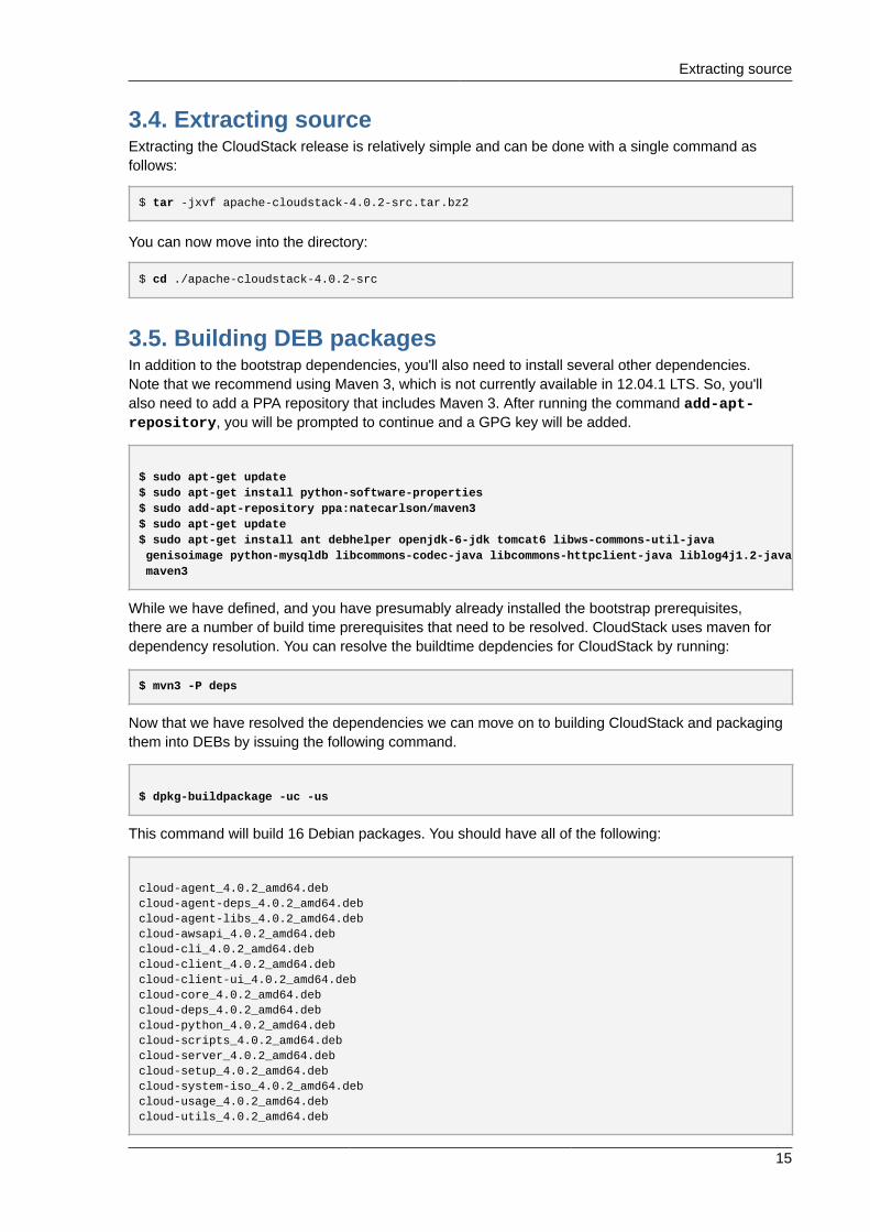
Now that we have resolved the dependencies we can move on to building CloudStack and packagingthem into DEBs by issuing the following command.
$ dpkg-buildpackage -uc -us
This command will build 16 Debian packages. You should have all of the following:
cloud-agent_4.0.2_amd64.debcloud-agent-deps_4.0.2_amd64.debcloud-agent-libs_4.0.2_amd64.debcloud-awsapi_4.0.2_amd64.debcloud-cli_4.0.2_amd64.debcloud-client_4.0.2_amd64.debcloud-client-ui_4.0.2_amd64.debcloud-core_4.0.2_amd64.debcloud-deps_4.0.2_amd64.debcloud-python_4.0.2_amd64.debcloud-scripts_4.0.2_amd64.debcloud-server_4.0.2_amd64.debcloud-setup_4.0.2_amd64.debcloud-system-iso_4.0.2_amd64.debcloud-usage_4.0.2_amd64.debcloud-utils_4.0.2_amd64.deb
Chapter 3. Building from Source
16
3.5.1. Setting up an APT repoAfter you've created the packages, you'll want to copy them to a system where you can serve thepackages over HTTP. You'll create a directory for the packages and then use dpkg-scanpackagesto create Packages.gz, which holds information about the archive structure. Finally, you'll add therepository to your system(s) so you can install the packages using APT.
The first step is to make sure that you have the dpkg-dev package installed. This should havebeen installed when you pulled in the debhelper application previously, but if you're generatingPackages.gz on a different system, be sure that it's installed there as well.
$ sudo apt-get install dpkg-dev
The next step is to copy the DEBs to the directory where they can be served over HTTP. We'll use /var/www/cloudstack/repo in the examples, but change the directory to whatever works for you.
sudo mkdir -p /var/www/cloudstack/repo/binarysudo cp *.deb /var/www/cloudstack/repo/binarysudo cd /var/www/cloudstack/repo/binarysudo dpkg-scanpackages . /dev/null | tee Packages | gzip -9 > Packages.gz
Note: Override Files
You can safely ignore the warning about a missing override file.
Now you should have all of the DEB packages and Packages.gz in the binary directory andavailable over HTTP. (You may want to use wget or curl to test this before moving on to the nextstep.)
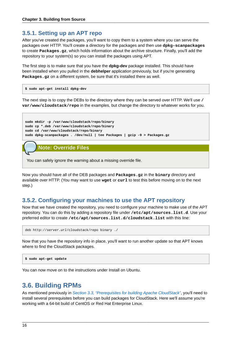
3.5.2. Configuring your machines to use the APT repositoryNow that we have created the repository, you need to configure your machine to make use of the APTrepository. You can do this by adding a repository file under /etc/apt/sources.list.d. Use yourpreferred editor to create /etc/apt/sources.list.d/cloudstack.list with this line:
deb http://server.url/cloudstack/repo binary ./
Now that you have the repository info in place, you'll want to run another update so that APT knowswhere to find the CloudStack packages.
$ sudo apt-get update
You can now move on to the instructions under Install on Ubuntu.
3.6. Building RPMsAs mentioned previously in Section 3.3, “Prerequisites for building Apache CloudStack”, you'll need toinstall several prerequisites before you can build packages for CloudStack. Here we'll assume you'reworking with a 64-bit build of CentOS or Red Hat Enterprise Linux.
Creating a yum repo
17
# yum groupinstall "Development Tools"
# yum install java-1.6.0-openjdk-devel.x86_64 ant ant-jdepend genisoimage mysql mysql-server ws-common-utils MySQL-python tomcat6
Next, you'll need to install build-time dependencies for CloudStack with Maven. We're using Maven3, so you'll want to grab a Maven 3 tarball7 and uncompress it in your home directory (or whateverlocation you prefer):
$ tar zxvf apache-maven-3.0.4-bin.tar.gz
$ export PATH=/usr/local/apache-maven-3.0.4//bin:$PATH
Maven also needs to know where Java is, and expects the JAVA_HOME environment variable to beset:
$ export JAVA_HOME=/usr/lib/jvm/jre-1.6.0-openjdk.x86_64/
Verify that Maven is installed correctly:
$ mvn --version
You probably want to ensure that your environment variables will survive a logout/reboot. Be sure toupdate ~/.bashrc with the PATH and JAVA_HOME variables.
Now it's time to grab the dependencies to build CloudStack:
$ mvn -P deps
Now that we have resolved the dependencies we can move on to building CloudStack and packagingthem into RPMs by issuing the following command.
$ ./waf rpm
Once this completes, you should find assembled RPMs in artifacts/rpmbuild/RPMS/x86_64
3.6.1. Creating a yum repoWhile RPMs is an ideal packaging format - it's most easily consumed from yum repositories over anetwork. We'll move into the directory with the newly created RPMs by issuing the following command:
$ cd artifacts/rpmbuild/RPMS/x86_64
Next we'll issue a command to create the repository metadata by issuing the following command:
$ createrepo ./
7 http://maven.apache.org/download.cgi
Chapter 3. Building from Source
18
The files and directories within our current working directory can now be uploaded to a web server andserve as a yum repository
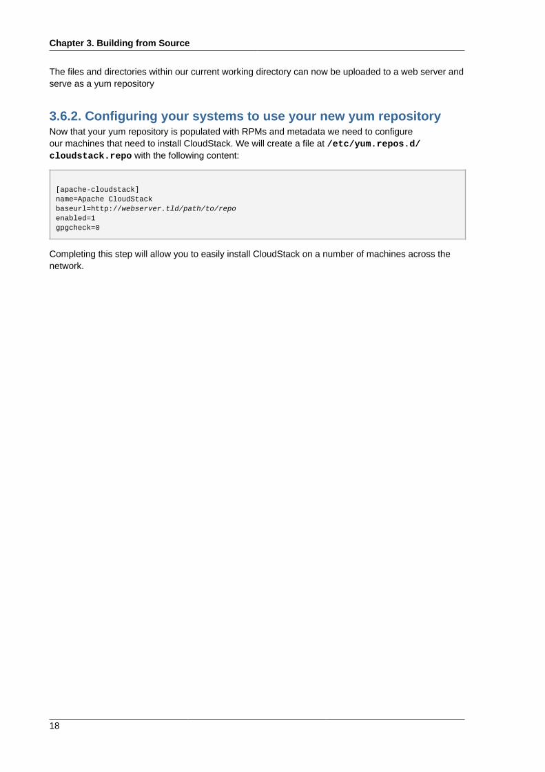
3.6.2. Configuring your systems to use your new yum repositoryNow that your yum repository is populated with RPMs and metadata we need to configureour machines that need to install CloudStack. We will create a file at /etc/yum.repos.d/cloudstack.repo with the following content:
[apache-cloudstack]name=Apache CloudStackbaseurl=http://webserver.tld/path/to/repoenabled=1gpgcheck=0
Completing this step will allow you to easily install CloudStack on a number of machines across thenetwork.
Chapter 4.
19
Installation
4.1. Who Should Read ThisFor those who have already gone through a design phase and planned a more sophisticateddeployment, or those who are ready to start scaling up a trial installation. With the followingprocedures, you can start using the more powerful features of CloudStack, such as advanced VLANnetworking, high availability, additional network elements such as load balancers and firewalls, andsupport for multiple hypervisors including Citrix XenServer, KVM, and VMware vSphere.
4.2. Overview of Installation StepsFor anything more than a simple trial installation, you will need guidance for a variety of configurationchoices. It is strongly recommended that you read the following:
• Choosing a Deployment Architecture
• Choosing a Hypervisor: Supported Features
• Network Setup
• Storage Setup
• Best Practices
1. Make sure you have the required hardware ready. See Section 4.3, “Minimum SystemRequirements”
2. Install the Management Server (choose single-node or multi-node). See Section 4.5,“Management Server Installation”
3. Log in to the UI. See Chapter 5, User Interface
4. Add a zone. Includes the first pod, cluster, and host. See Section 6.2, “Adding a Zone”
5. Add more pods (optional). See Section 6.3, “Adding a Pod”
6. Add more clusters (optional). See Section 6.4, “Adding a Cluster”
7. Add more hosts (optional). See Section 6.5, “Adding a Host”
8. Add more primary storage (optional). See Section 6.6, “Add Primary Storage”
9. Add more secondary storage (optional). See Section 6.7, “Add Secondary Storage”
10. Try using the cloud. See Section 6.8, “Initialize and Test”
Chapter 4. Installation
20
4.3. Minimum System Requirements
4.3.1. Management Server, Database, and Storage SystemRequirementsThe machines that will run the Management Server and MySQL database must meet the followingrequirements. The same machines can also be used to provide primary and secondary storage, suchas via localdisk or NFS. The Management Server may be placed on a virtual machine.
• Operating system:
• Preferred: CentOS/RHEL 6.3+ or Ubuntu 12.04(.1)
• 64-bit x86 CPU (more cores results in better performance)
• 4 GB of memory
• 50 GB of local disk (When running secondary storage on the management server 500GB isrecommended)
• At least 1 NIC
• Statically allocated IP address
• Fully qualified domain name as returned by the hostname command
4.3.2. Host/Hypervisor System RequirementsThe host is where the cloud services run in the form of guest virtual machines. Each host is onemachine that meets the following requirements:
• Must support HVM (Intel-VT or AMD-V enabled).
• 64-bit x86 CPU (more cores results in better performance)
• Hardware virtualization support required
• 4 GB of memory
• 36 GB of local disk
• At least 1 NIC
•Note
If DHCP is used for hosts, ensure that no conflict occurs between DHCP server used for thesehosts and the DHCP router created by CloudStack.
• Latest hotfixes applied to hypervisor software
• When you deploy CloudStack, the hypervisor host must not have any VMs already running
Configure package repository
21
• All hosts within a cluster must be homogenous. The CPUs must be of the same type, count, andfeature flags.
Hosts have additional requirements depending on the hypervisor. See the requirements listed at thetop of the Installation section for your chosen hypervisor:
Warning
Be sure you fulfill the additional hypervisor requirements and installation steps provided in thisGuide. Hypervisor hosts must be properly prepared to work with CloudStack. For example, therequirements for XenServer are listed under Citrix XenServer Installation.
• Section 8.1.1, “System Requirements for KVM Hypervisor Hosts”
• Section 8.2.1, “System Requirements for XenServer Hosts”
• Section 8.3.1, “System Requirements for vSphere Hosts”
4.4. Configure package repositoryCloudStack is only distributed from source from the official mirrors. However, members of theCloudStack community may build convenience binaries so that users can install Apache CloudStackwithout needing to build from source.
If you didn't follow the steps to build your own packages from source in the sections for Section 3.6,“Building RPMs” or Section 3.5, “Building DEB packages” you may find pre-built DEB and RPMpackages for your convience linked from the downloads1 page.
Note
These repositories contain both the Management Server and KVM Hypervisor packages.
4.4.1. DEB package repositoryYou can add a DEB package repository to your apt sources with the following commands. Please notethat currently only packages for Ubuntu 12.04 LTS (precise) are being build.
Use your preferred editor and open (or create) /etc/apt/sources.list.d/cloudstack.list.Add the community provided repository to the file:
deb http://cloudstack.apt-get.eu/ubuntu precise 4.0
We now have to add the public key to the trusted keys.
$ wget -O - http://cloudstack.apt-get.eu/release.asc|apt-key add -
1 http://incubator.apache.org/cloudstack/downloads.html
Chapter 4. Installation
22
Now update your local apt cache.
$ apt-get update
Your DEB package repository should now be configured and ready for use.
4.4.2. RPM package repositoryIf you're using an RPM-based system, you'll want to add the Yum repository so that you can installCloudStack with Yum.
Yum repository information is found under /etc/yum.repos.d. You'll see several .repo files in thisdirectory, each one denoting a specific repository.
To add the CloudStack repository, visit the downloads page2 for the repository information. It will looksomething like this:
[cloudstack]name=cloudstackbaseurl=http://server.url/downloads/rpm/stable/enabled=1gpgcheck=1
Next you'll want to add the GPG key:
$ rpm --import http://server.url/downloads/RPM-GPG-KEY.txt
Now you should be able to install CloudStack using Yum.
4.5. Management Server Installation
4.5.1. Management Server Installation OverviewThis section describes installing the Management Server. There are two slightly different installationflows, depending on how many Management Server nodes will be in your cloud:
• A single Management Server node, with MySQL on the same node.
• Multiple Management Server nodes, with MySQL on a node separate from the ManagementServers.
In either case, each machine must meet the system requirements described in System Requirements.
2 http://incubator.apache.org/cloudstack/downloads.html
Prepare the Operating System
23
Warning
For the sake of security, be sure the public Internet can not access port 8096 or port 8250 on theManagement Server.
The procedure for installing the Management Server is:
1. Prepare the Operating System
2. Download and install vhd-util.
3. Install the First Management Server
4. Install and Configure the MySQL database
5. Prepare NFS Shares
6. Prepare and Start Additional Management Servers (optional)
7. Prepare the System VM Template
4.5.2. Prepare the Operating SystemThe OS must be prepared to host the Management Server using the following steps. These stepsmust be performed on each Management Server node.
1. Log in to your OS as root.
2. Check for a fully qualified hostname.
hostname --fqdn
This should return a fully qualified hostname such as "managament1.lab.example.org". If it doesnot, edit /etc/hosts so that it does.
3. Make sure that the machine can reach the Internet.
ping www.cloudstack.org
4. Turn on NTP for time synchronization.
Note
NTP is required to synchronize the clocks of the servers in your cloud.
a. Install NTP.
yum install ntp
Chapter 4. Installation
24
apt-get install openntpd
5. Repeat all of these steps on every host where the Management Server will be installed.
4.5.3. Install the Management Server on the First HostThe first step in installation, whether you are installing the Management Server on one host or many, isto install the software on a single node.
Note
If you are planning to install the Management Server on multiple nodes for high availability, do notproceed to the additional nodes yet. That step will come later.
The CloudStack Management server can be installed using either RPM or DEB packages. Thesepackages will depend on everything you need to run the Management server.
4.5.3.1. Install on CentOS/RHELWe start by installing the required packages:
yum install cloud-client
4.5.3.2. Install on Ubuntu
apt-get install cloud-client
4.5.3.3. Downloading vhd-utilBefore setting up the Management Server, download vhd-util from vhd-util3
If the Management Server is RHEL or CentOS, copy vhd-util to /usr/lib64/cloud/common/scripts/vm/hypervisor/xenserver
If the Management Server is Ubuntu, copy vhd-util to /usr/lib/cloud/common/scripts/vm/hypervisor/xenserver/vhd-util
4.5.4. Install the database serverThe CloudStack management server uses a MySQL database server to store it's data. When you areinstalling the management server on a single node you can install the MySQL server locally. Whenusing a multi-node installation the MySQL database has to run on an external node.
CloudStack has been tested with MySQL 5.1 and 5.5, both should work fine. These versions areincluded in RHEL/CentOS and Ubuntu.
3 http://download.cloud.com.s3.amazonaws.com/tools/vhd-util
Install the database server
25
4.5.4.1. Install the Database on the Management Server NodeThis section describes how to install MySQL on the same machine with the Management Server. Thistechnique is intended for a simple deployment that has a single Management Server node. If you havea multi-node Management Server deployment, you will typically use a separate node for MySQL. SeeSection 4.5.4.2, “Install the Database on a Separate Node”.
1. Install MySQL from the package repository from your distribution:
yum install mysql-server
apt-get install mysql-server
2. Edit the MySQL configuration (/etc/my.cnf or /etc/mysql/my.cnf, depending on your OS) andinsert the following lines in the [mysqld] section. You can put these lines below the datadir line.The max_connections parameter should be set to 350 multiplied by the number of ManagementServers you are deploying. This example assumes one Management Server.
Note
On Ubuntu you can also create a file /etc/mysql/conf.d/cloudstack.cnf and add thesedirectives there. Don't forget to add [mysqld] on the first line of the file.
innodb_rollback_on_timeout=1innodb_lock_wait_timeout=600max_connections=350log-bin=mysql-binbinlog-format = 'ROW'
3. On RHEL/CentOS MySQL doesn't start after installation, start it manually.
service mysqld start
4.Warning
On RHEL and CentOS, MySQL does not set a root password by default. It is very stronglyrecommended that you set a root password as a security precaution. Run the followingcommands, and substitute your own desired root password. This step is not required onUbuntu as it asks for a root password during installation.
Run this command to secure your installation. Since we are running MySQL locally you cananswer "Y" to all questions.
mysql_secure_installation
Chapter 4. Installation
26
5. Set up the database. The following command creates the "cloud" user on the database.
• In dbpassword, specify the password to be assigned to the "cloud" user. You can choose toprovide no password although that is not recommended.
• In deploy-as, specify the username and password of the user deploying the database. In thefollowing command, it is assumed the root user is deploying the database and creating the"cloud" user.
• (Optional) For encryption_type, use file or web to indicate the technique used to pass in thedatabase encryption password. Default: file. See About Password and Key Encryption.
• (Optional) For management_server_key, substitute the default key that is used to encryptconfidential parameters in the CloudStack properties file. Default: password. It is highlyrecommended that you replace this with a more secure value. See About Password and KeyEncryption.
• (Optional) For database_key, substitute the default key that is used to encrypt confidentialparameters in the CloudStack database. Default: password. It is highly recommended that youreplace this with a more secure value. See About Password and Key Encryption.
cloud-setup-databases cloud:<dbpassword>@localhost \ --deploy-as=root:<password> \ -e <encryption_type> \ -m <management_server_key> \ -k <database_key>
When this script is finished, you should see a message like “Successfully initialized the database.”
4.5.4.2. Install the Database on a Separate NodeThis section describes how to install MySQL on a standalone machine, separate from theManagement Server. This technique is intended for a deployment that includes several ManagementServer nodes. If you have a single-node Management Server deployment, you will typically use thesame node for MySQL. See Section 4.5.4.1, “Install the Database on the Management Server Node”.
Note
The management server doesn't require a specific distribution for the MySQL node. You canuse a distribution or Operating System of your choice. Using the same distribution as themanagement server is recommended, but not required. See Section 4.3.1, “Management Server,Database, and Storage System Requirements”.
1. Install MySQL from the package repository from your distribution:
yum install mysql-server
apt-get install mysql-server
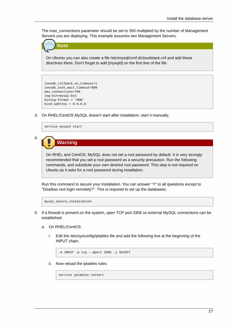
2. Edit the MySQL configuration (/etc/my.cnf or /etc/mysql/my.cnf, depending on your OS) andinsert the following lines in the [mysqld] section. You can put these lines below the datadir line.
Install the database server
27
The max_connections parameter should be set to 350 multiplied by the number of ManagementServers you are deploying. This example assumes two Management Servers.
Note
On Ubuntu you can also create a file /etc/mysql/conf.d/cloudstack.cnf and add thesedirectives there. Don't forget to add [mysqld] on the first line of the file.
innodb_rollback_on_timeout=1innodb_lock_wait_timeout=600max_connections=700log-bin=mysql-binbinlog-format = 'ROW'bind-address = 0.0.0.0
3. On RHEL/CentOS MySQL doesn't start after installation, start it manually.
service mysqld start
4.Warning
On RHEL and CentOS, MySQL does not set a root password by default. It is very stronglyrecommended that you set a root password as a security precaution. Run the followingcommands, and substitute your own desired root password. This step is not required onUbuntu as it asks for a root password during installation.
Run this command to secure your installation. You can answer "Y" to all questions except to"Disallow root login remotely?". This is required to set up the databases.
mysql_secure_installation
5. If a firewall is present on the system, open TCP port 3306 so external MySQL connections can beestablished.
a. On RHEL/CentOS:
i. Edit the /etc/sysconfig/iptables file and add the following line at the beginning of theINPUT chain.
-A INPUT -p tcp --dport 3306 -j ACCEPT
ii. Now reload the iptables rules.
service iptables restart
Chapter 4. Installation
28
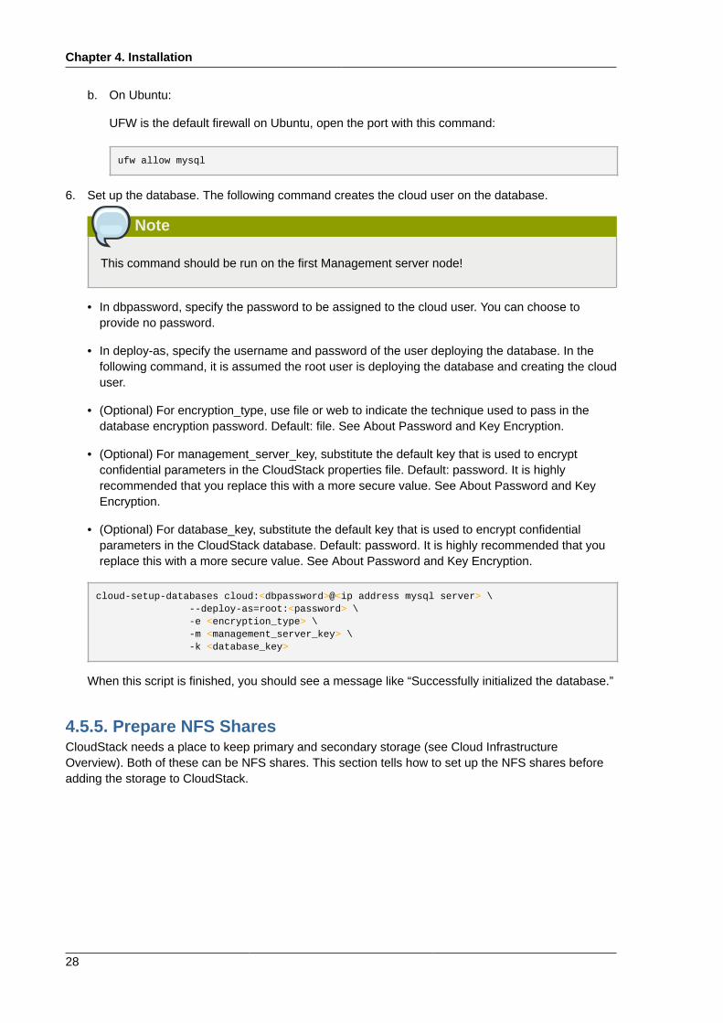
b. On Ubuntu:
UFW is the default firewall on Ubuntu, open the port with this command:
ufw allow mysql
6. Set up the database. The following command creates the cloud user on the database.
Note
This command should be run on the first Management server node!
• In dbpassword, specify the password to be assigned to the cloud user. You can choose toprovide no password.
• In deploy-as, specify the username and password of the user deploying the database. In thefollowing command, it is assumed the root user is deploying the database and creating the clouduser.
• (Optional) For encryption_type, use file or web to indicate the technique used to pass in thedatabase encryption password. Default: file. See About Password and Key Encryption.
• (Optional) For management_server_key, substitute the default key that is used to encryptconfidential parameters in the CloudStack properties file. Default: password. It is highlyrecommended that you replace this with a more secure value. See About Password and KeyEncryption.
• (Optional) For database_key, substitute the default key that is used to encrypt confidentialparameters in the CloudStack database. Default: password. It is highly recommended that youreplace this with a more secure value. See About Password and Key Encryption.
cloud-setup-databases cloud:<dbpassword>@<ip address mysql server> \ --deploy-as=root:<password> \ -e <encryption_type> \ -m <management_server_key> \ -k <database_key>
When this script is finished, you should see a message like “Successfully initialized the database.”
4.5.5. Prepare NFS SharesCloudStack needs a place to keep primary and secondary storage (see Cloud InfrastructureOverview). Both of these can be NFS shares. This section tells how to set up the NFS shares beforeadding the storage to CloudStack.
Prepare NFS Shares
29
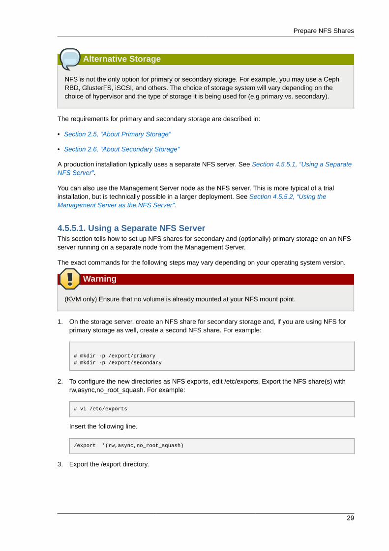
Alternative Storage
NFS is not the only option for primary or secondary storage. For example, you may use a CephRBD, GlusterFS, iSCSI, and others. The choice of storage system will vary depending on thechoice of hypervisor and the type of storage it is being used for (e.g primary vs. secondary).
The requirements for primary and secondary storage are described in:
• Section 2.5, “About Primary Storage”
• Section 2.6, “About Secondary Storage”
A production installation typically uses a separate NFS server. See Section 4.5.5.1, “Using a SeparateNFS Server”.
You can also use the Management Server node as the NFS server. This is more typical of a trialinstallation, but is technically possible in a larger deployment. See Section 4.5.5.2, “Using theManagement Server as the NFS Server”.
4.5.5.1. Using a Separate NFS ServerThis section tells how to set up NFS shares for secondary and (optionally) primary storage on an NFSserver running on a separate node from the Management Server.
The exact commands for the following steps may vary depending on your operating system version.
Warning
(KVM only) Ensure that no volume is already mounted at your NFS mount point.
1. On the storage server, create an NFS share for secondary storage and, if you are using NFS forprimary storage as well, create a second NFS share. For example:
# mkdir -p /export/primary# mkdir -p /export/secondary
2. To configure the new directories as NFS exports, edit /etc/exports. Export the NFS share(s) withrw,async,no_root_squash. For example:
# vi /etc/exports
Insert the following line.
/export *(rw,async,no_root_squash)
3. Export the /export directory.
Chapter 4. Installation
30
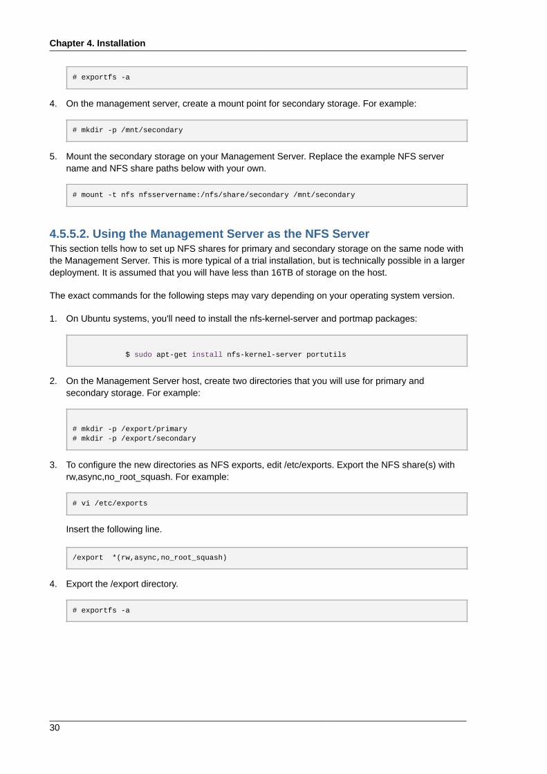
# exportfs -a
4. On the management server, create a mount point for secondary storage. For example:
# mkdir -p /mnt/secondary
5. Mount the secondary storage on your Management Server. Replace the example NFS servername and NFS share paths below with your own.
# mount -t nfs nfsservername:/nfs/share/secondary /mnt/secondary
4.5.5.2. Using the Management Server as the NFS ServerThis section tells how to set up NFS shares for primary and secondary storage on the same node withthe Management Server. This is more typical of a trial installation, but is technically possible in a largerdeployment. It is assumed that you will have less than 16TB of storage on the host.
The exact commands for the following steps may vary depending on your operating system version.
1. On Ubuntu systems, you'll need to install the nfs-kernel-server and portmap packages:
$ sudo apt-get install nfs-kernel-server portutils
2. On the Management Server host, create two directories that you will use for primary andsecondary storage. For example:
# mkdir -p /export/primary# mkdir -p /export/secondary
3. To configure the new directories as NFS exports, edit /etc/exports. Export the NFS share(s) withrw,async,no_root_squash. For example:
# vi /etc/exports
Insert the following line.
/export *(rw,async,no_root_squash)
4. Export the /export directory.
# exportfs -a
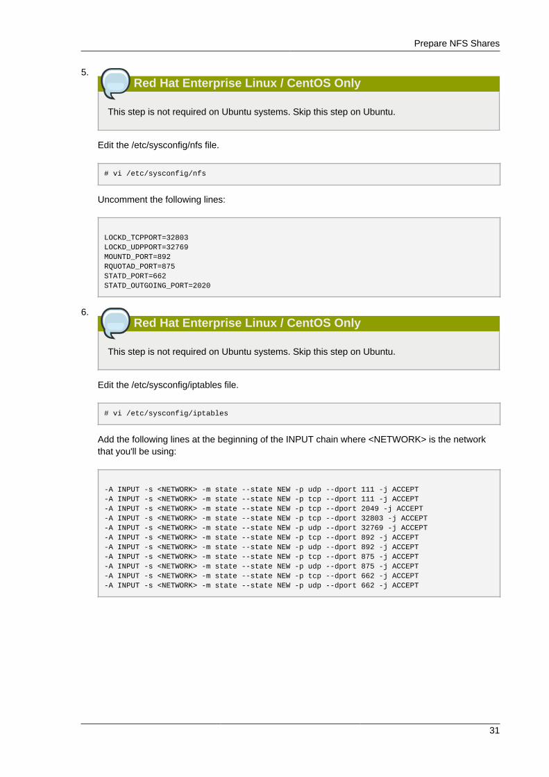
Prepare NFS Shares
31
5.Red Hat Enterprise Linux / CentOS Only
This step is not required on Ubuntu systems. Skip this step on Ubuntu.
Edit the /etc/sysconfig/nfs file.
# vi /etc/sysconfig/nfs
Uncomment the following lines:
LOCKD_TCPPORT=32803LOCKD_UDPPORT=32769MOUNTD_PORT=892RQUOTAD_PORT=875STATD_PORT=662STATD_OUTGOING_PORT=2020
6.Red Hat Enterprise Linux / CentOS Only
This step is not required on Ubuntu systems. Skip this step on Ubuntu.
Edit the /etc/sysconfig/iptables file.
# vi /etc/sysconfig/iptables
Add the following lines at the beginning of the INPUT chain where <NETWORK> is the networkthat you'll be using:
-A INPUT -s <NETWORK> -m state --state NEW -p udp --dport 111 -j ACCEPT-A INPUT -s <NETWORK> -m state --state NEW -p tcp --dport 111 -j ACCEPT-A INPUT -s <NETWORK> -m state --state NEW -p tcp --dport 2049 -j ACCEPT-A INPUT -s <NETWORK> -m state --state NEW -p tcp --dport 32803 -j ACCEPT-A INPUT -s <NETWORK> -m state --state NEW -p udp --dport 32769 -j ACCEPT-A INPUT -s <NETWORK> -m state --state NEW -p tcp --dport 892 -j ACCEPT-A INPUT -s <NETWORK> -m state --state NEW -p udp --dport 892 -j ACCEPT-A INPUT -s <NETWORK> -m state --state NEW -p tcp --dport 875 -j ACCEPT-A INPUT -s <NETWORK> -m state --state NEW -p udp --dport 875 -j ACCEPT-A INPUT -s <NETWORK> -m state --state NEW -p tcp --dport 662 -j ACCEPT-A INPUT -s <NETWORK> -m state --state NEW -p udp --dport 662 -j ACCEPT
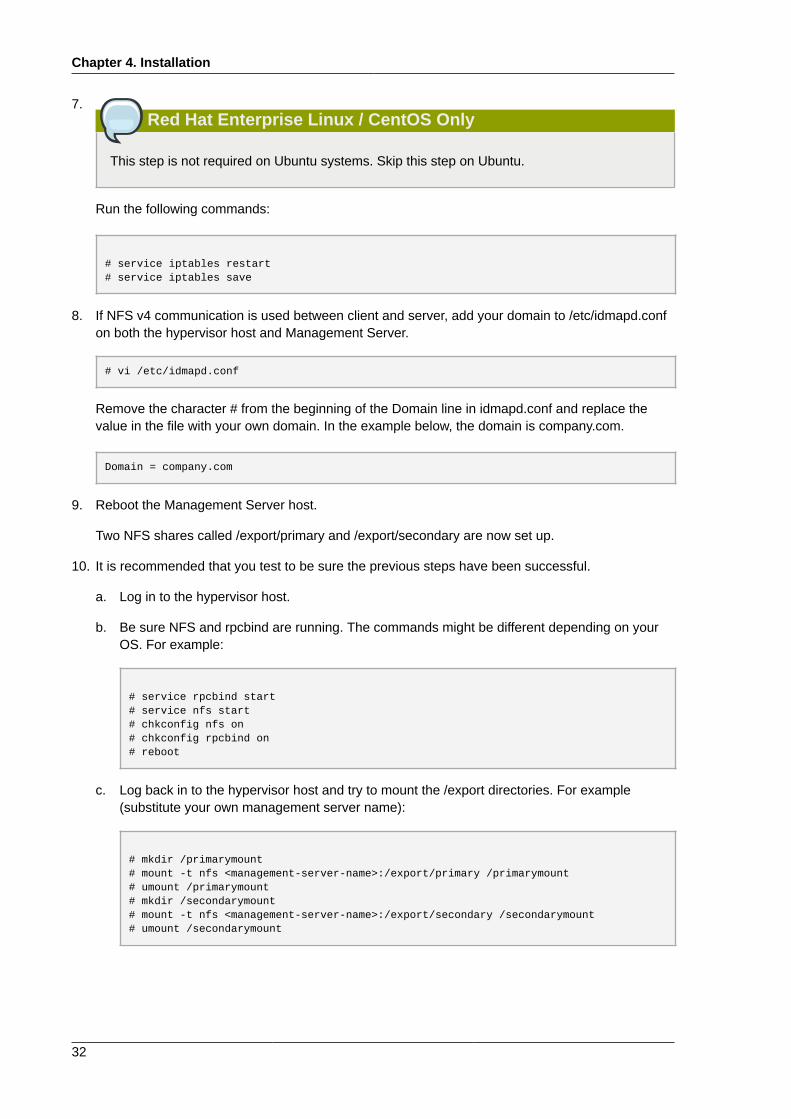
Chapter 4. Installation
32
7.Red Hat Enterprise Linux / CentOS Only
This step is not required on Ubuntu systems. Skip this step on Ubuntu.
Run the following commands:
# service iptables restart# service iptables save
8. If NFS v4 communication is used between client and server, add your domain to /etc/idmapd.confon both the hypervisor host and Management Server.
# vi /etc/idmapd.conf
Remove the character # from the beginning of the Domain line in idmapd.conf and replace thevalue in the file with your own domain. In the example below, the domain is company.com.
Domain = company.com
9. Reboot the Management Server host.
Two NFS shares called /export/primary and /export/secondary are now set up.
10. It is recommended that you test to be sure the previous steps have been successful.
a. Log in to the hypervisor host.
b. Be sure NFS and rpcbind are running. The commands might be different depending on yourOS. For example:
# service rpcbind start# service nfs start# chkconfig nfs on# chkconfig rpcbind on# reboot
c. Log back in to the hypervisor host and try to mount the /export directories. For example(substitute your own management server name):
# mkdir /primarymount# mount -t nfs <management-server-name>:/export/primary /primarymount# umount /primarymount# mkdir /secondarymount# mount -t nfs <management-server-name>:/export/secondary /secondarymount# umount /secondarymount
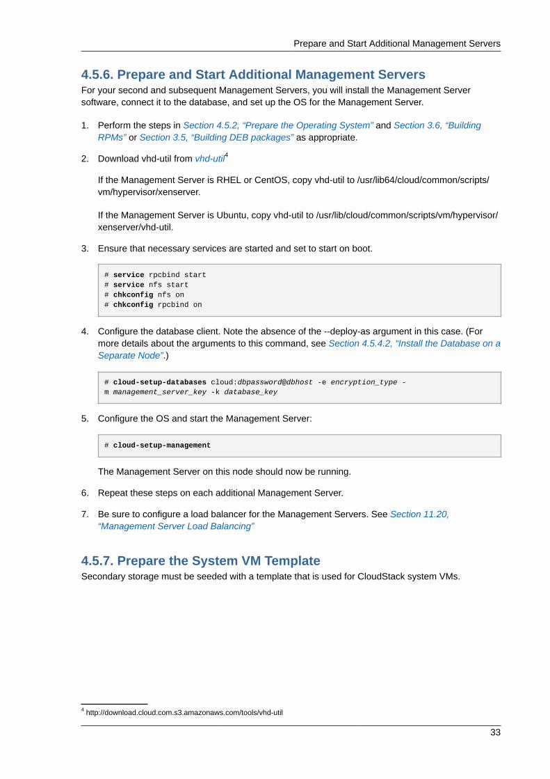
Prepare and Start Additional Management Servers
33
4.5.6. Prepare and Start Additional Management ServersFor your second and subsequent Management Servers, you will install the Management Serversoftware, connect it to the database, and set up the OS for the Management Server.
1. Perform the steps in Section 4.5.2, “Prepare the Operating System” and Section 3.6, “BuildingRPMs” or Section 3.5, “Building DEB packages” as appropriate.
2. Download vhd-util from vhd-util4
If the Management Server is RHEL or CentOS, copy vhd-util to /usr/lib64/cloud/common/scripts/vm/hypervisor/xenserver.
If the Management Server is Ubuntu, copy vhd-util to /usr/lib/cloud/common/scripts/vm/hypervisor/xenserver/vhd-util.
3. Ensure that necessary services are started and set to start on boot.
# service rpcbind start# service nfs start# chkconfig nfs on# chkconfig rpcbind on
4. Configure the database client. Note the absence of the --deploy-as argument in this case. (Formore details about the arguments to this command, see Section 4.5.4.2, “Install the Database on aSeparate Node”.)
# cloud-setup-databases cloud:dbpassword@dbhost -e encryption_type -m management_server_key -k database_key
5. Configure the OS and start the Management Server:
# cloud-setup-management
The Management Server on this node should now be running.
6. Repeat these steps on each additional Management Server.
7. Be sure to configure a load balancer for the Management Servers. See Section 11.20,“Management Server Load Balancing”
4.5.7. Prepare the System VM TemplateSecondary storage must be seeded with a template that is used for CloudStack system VMs.
4 http://download.cloud.com.s3.amazonaws.com/tools/vhd-util
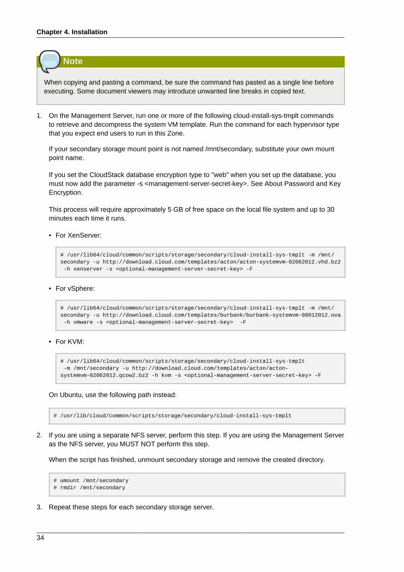
Chapter 4. Installation
34
Note
When copying and pasting a command, be sure the command has pasted as a single line beforeexecuting. Some document viewers may introduce unwanted line breaks in copied text.
1. On the Management Server, run one or more of the following cloud-install-sys-tmplt commandsto retrieve and decompress the system VM template. Run the command for each hypervisor typethat you expect end users to run in this Zone.
If your secondary storage mount point is not named /mnt/secondary, substitute your own mountpoint name.
If you set the CloudStack database encryption type to "web" when you set up the database, youmust now add the parameter -s <management-server-secret-key>. See About Password and KeyEncryption.
This process will require approximately 5 GB of free space on the local file system and up to 30minutes each time it runs.
• For XenServer:
# /usr/lib64/cloud/common/scripts/storage/secondary/cloud-install-sys-tmplt -m /mnt/secondary -u http://download.cloud.com/templates/acton/acton-systemvm-02062012.vhd.bz2 -h xenserver -s <optional-management-server-secret-key> -F
• For vSphere:
# /usr/lib64/cloud/common/scripts/storage/secondary/cloud-install-sys-tmplt -m /mnt/secondary -u http://download.cloud.com/templates/burbank/burbank-systemvm-08012012.ova -h vmware -s <optional-management-server-secret-key> -F
• For KVM:
# /usr/lib64/cloud/common/scripts/storage/secondary/cloud-install-sys-tmplt -m /mnt/secondary -u http://download.cloud.com/templates/acton/acton-systemvm-02062012.qcow2.bz2 -h kvm -s <optional-management-server-secret-key> -F
On Ubuntu, use the following path instead:
# /usr/lib/cloud/common/scripts/storage/secondary/cloud-install-sys-tmplt
2. If you are using a separate NFS server, perform this step. If you are using the Management Serveras the NFS server, you MUST NOT perform this step.
When the script has finished, unmount secondary storage and remove the created directory.
# umount /mnt/secondary# rmdir /mnt/secondary
3. Repeat these steps for each secondary storage server.
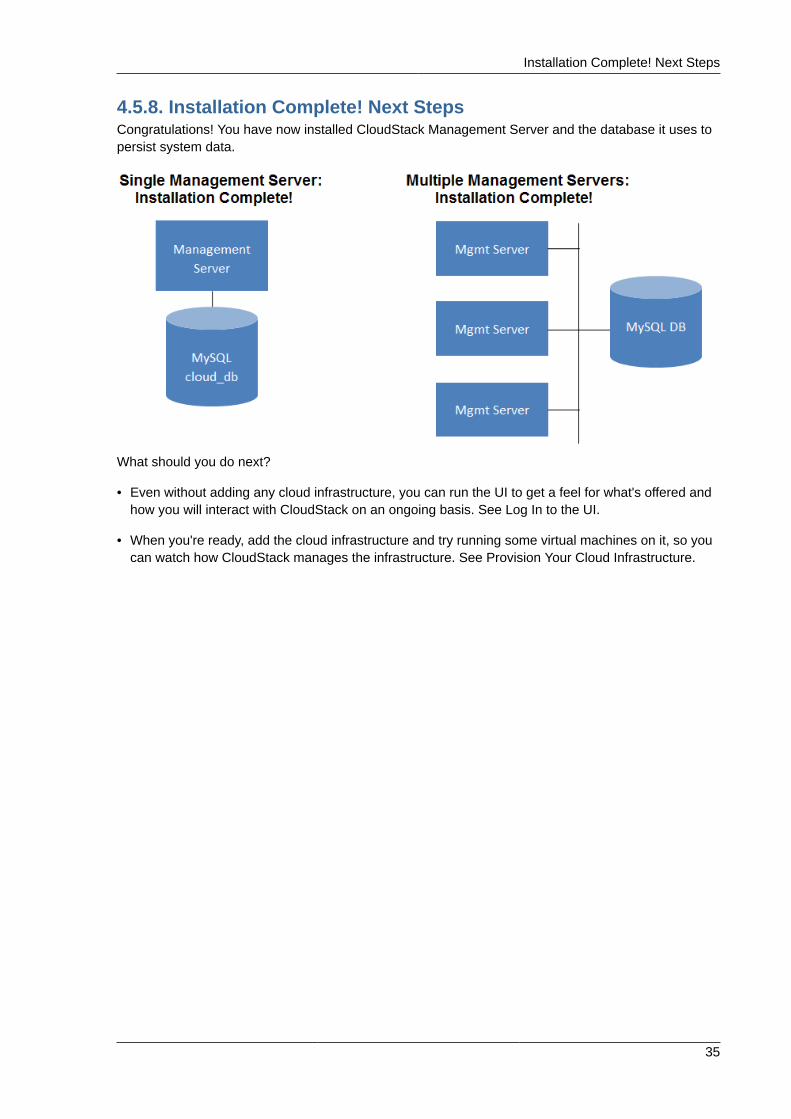
Installation Complete! Next Steps
35
4.5.8. Installation Complete! Next StepsCongratulations! You have now installed CloudStack Management Server and the database it uses topersist system data.
What should you do next?
• Even without adding any cloud infrastructure, you can run the UI to get a feel for what's offered andhow you will interact with CloudStack on an ongoing basis. See Log In to the UI.
• When you're ready, add the cloud infrastructure and try running some virtual machines on it, so youcan watch how CloudStack manages the infrastructure. See Provision Your Cloud Infrastructure.

36
Chapter 5.
37
User Interface
5.1. Log In to the UICloudStack provides a web-based UI that can be used by both administrators and end users. Theappropriate version of the UI is displayed depending on the credentials used to log in. The UI isavailable in popular browsers including IE7, IE8, IE9, Firefox 3.5+, Firefox 4, Safari 4, and Safari 5.The URL is: (substitute your own management server IP address)
http://<management-server-ip-address>:8080/client
On a fresh Management Server installation, a guided tour splash screen appears. On later visits, you’llsee a login screen where you specify the following to proceed to your Dashboard:
UsernameThe user ID of your account. The default username is admin.
PasswordThe password associated with the user ID. The password for the default username is password.
DomainIf you are a root user, leave this field blank.
If you are a user in the sub-domains, enter the full path to the domain, excluding the root domain.
For example, suppose multiple levels are created under the root domain, such as Comp1/hr. Theusers in the Comp1 domain should enter Comp1 in the Domain field, whereas the users in the Comp1/sales domain should enter Comp1/sales.
For more guidance about the choices that appear when you log in to this UI, see Logging In as theRoot Administrator.
5.1.1. End User's UI OverviewThe CloudStack UI helps users of cloud infrastructure to view and use their cloud resources,including virtual machines, templates and ISOs, data volumes and snapshots, guest networks, and IPaddresses. If the user is a member or administrator of one or more CloudStack projects, the UI canprovide a project-oriented view.
5.1.2. Root Administrator's UI OverviewThe CloudStack UI helps the CloudStack administrator provision, view, and manage the cloudinfrastructure, domains, user accounts, projects, and configuration settings. The first time you start theUI after a fresh Management Server installation, you can choose to follow a guided tour to provisionyour cloud infrastructure. On subsequent logins, the dashboard of the logged-in user appears.The various links in this screen and the navigation bar on the left provide access to a variety ofadministrative functions. The root administrator can also use the UI to perform all the same tasks thatare present in the end-user’s UI.
Chapter 5. User Interface
38
5.1.3. Logging In as the Root AdministratorAfter the Management Server software is installed and running, you can run the CloudStack userinterface. This UI is there to help you provision, view, and manage your cloud infrastructure.
1. Open your favorite Web browser and go to this URL. Substitute the IP address of your ownManagement Server:
http://<management-server-ip-address>:8080/client
On a fresh Management Server installation, a guided tour splash screen appears. On later visits,you’ll see a login screen where you can enter a user ID and password and proceed to yourDashboard.
2. If you see the first-time splash screen, choose one of the following.
• Continue with basic setup. Choose this if you're just trying CloudStack, and you want a guidedwalkthrough of the simplest possible configuration so that you can get started right away. We'llhelp you set up a cloud with the following features: a single machine that runs CloudStacksoftware and uses NFS to provide storage; a single machine running VMs under the XenServeror KVM hypervisor; and a shared public network.
The prompts in this guided tour should give you all the information you need, but if you want justa bit more detail, you can follow along in the Trial Installation Guide.
• I have used CloudStack before. Choose this if you have already gone through a design phaseand planned a more sophisticated deployment, or you are ready to start scaling up a trial cloudthat you set up earlier with the basic setup screens. In the Administrator UI, you can start usingthe more powerful features of CloudStack, such as advanced VLAN networking, high availability,additional network elements such as load balancers and firewalls, and support for multiplehypervisors including Citrix XenServer, KVM, and VMware vSphere.
The root administrator Dashboard appears.
3. You should set a new root administrator password. If you chose basic setup, you’ll be prompted tocreate a new password right away. If you chose experienced user, use the steps in Section 5.1.4,“Changing the Root Password”.
Warning
You are logging in as the root administrator. This account manages the CloudStack deployment,including physical infrastructure. The root administrator can modify configuration settings tochange basic functionality, create or delete user accounts, and take many actions that should beperformed only by an authorized person. Please change the default password to a new, uniquepassword.
5.1.4. Changing the Root PasswordDuring installation and ongoing cloud administration, you will need to log in to the UI as the rootadministrator. The root administrator account manages the CloudStack deployment, including physicalinfrastructure. The root administrator can modify configuration settings to change basic functionality,create or delete user accounts, and take many actions that should be performed only by an authorized
Using SSH Keys for Authentication
39
person. When first installing CloudStack, be sure to change the default password to a new, uniquevalue.
1. Open your favorite Web browser and go to this URL. Substitute the IP address of your ownManagement Server:
http://<management-server-ip-address>:8080/client
2. Log in to the UI using the current root user ID and password. The default is admin, password.
3. Click Accounts.
4. Click the admin account name.
5. Click View Users.
6. Click the admin user name.
7.Click the Change Password button.
8. Type the new password, and click OK.
5.2. Using SSH Keys for AuthenticationIn addition to the username and password authentication, CloudStack supports using SSH keys tolog in to the cloud infrastructure for additional security. You can use the createSSHKeyPair API togenerate the SSH keys.
Because each cloud user has their own SSH key, one cloud user cannot log in to another cloud user'sinstances unless they share their SSH key files. Using a single SSH key pair, you can manage multipleinstances.
5.2.1. Creating an Instance Template that Supports SSH KeysCreate a instance template that supports SSH Keys.
1. Create a new instance by using the template provided by cloudstack.
For more information on creating a new instance, see
2. Download the cloudstack script from The SSH Key Gen Script1to the instance you have created.
wget http://downloads.sourceforge.net/project/cloudstack/SSH%20Key%20Gen%20Script/cloud-set-guest-sshkey.in?r=http%3A%2F%2Fsourceforge.net%2Fprojects%2Fcloudstack%2Ffiles%2FSSH%2520Key%2520Gen%2520Script%2F&ts=1331225219&use_mirror=iweb
3. Copy the file to /etc/init.d.
cp cloud-set-guest-sshkey.in /etc/init.d/
4. Give the necessary permissions on the script:
1 http://sourceforge.net/projects/cloudstack/files/SSH%20Key%20Gen%20Script/
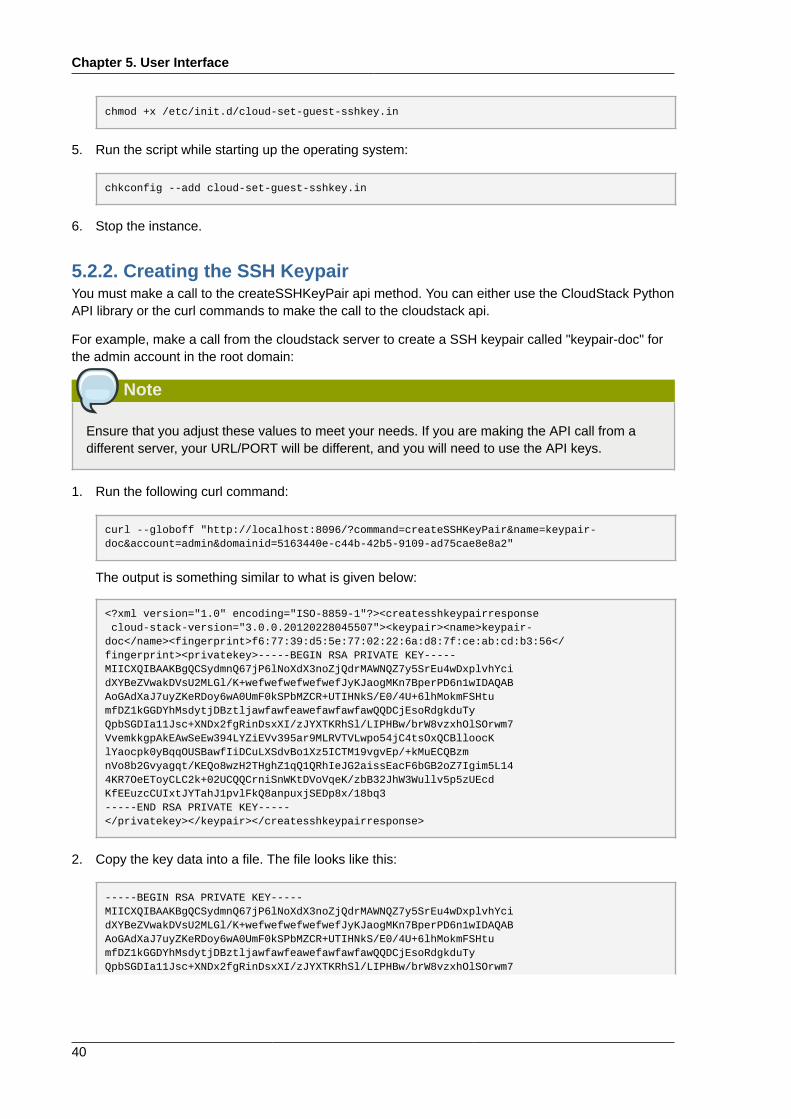
Chapter 5. User Interface
40
chmod +x /etc/init.d/cloud-set-guest-sshkey.in
5. Run the script while starting up the operating system:
chkconfig --add cloud-set-guest-sshkey.in
6. Stop the instance.
5.2.2. Creating the SSH KeypairYou must make a call to the createSSHKeyPair api method. You can either use the CloudStack PythonAPI library or the curl commands to make the call to the cloudstack api.
For example, make a call from the cloudstack server to create a SSH keypair called "keypair-doc" forthe admin account in the root domain:
Note
Ensure that you adjust these values to meet your needs. If you are making the API call from adifferent server, your URL/PORT will be different, and you will need to use the API keys.
1. Run the following curl command:
curl --globoff "http://localhost:8096/?command=createSSHKeyPair&name=keypair-doc&account=admin&domainid=5163440e-c44b-42b5-9109-ad75cae8e8a2"
The output is something similar to what is given below:
<?xml version="1.0" encoding="ISO-8859-1"?><createsshkeypairresponse cloud-stack-version="3.0.0.20120228045507"><keypair><name>keypair-doc</name><fingerprint>f6:77:39:d5:5e:77:02:22:6a:d8:7f:ce:ab:cd:b3:56</fingerprint><privatekey>-----BEGIN RSA PRIVATE KEY-----MIICXQIBAAKBgQCSydmnQ67jP6lNoXdX3noZjQdrMAWNQZ7y5SrEu4wDxplvhYcidXYBeZVwakDVsU2MLGl/K+wefwefwefwefwefJyKJaogMKn7BperPD6n1wIDAQABAoGAdXaJ7uyZKeRDoy6wA0UmF0kSPbMZCR+UTIHNkS/E0/4U+6lhMokmFSHtumfDZ1kGGDYhMsdytjDBztljawfawfeawefawfawfawQQDCjEsoRdgkduTyQpbSGDIa11Jsc+XNDx2fgRinDsxXI/zJYXTKRhSl/LIPHBw/brW8vzxhOlSOrwm7VvemkkgpAkEAwSeEw394LYZiEVv395ar9MLRVTVLwpo54jC4tsOxQCBlloocKlYaocpk0yBqqOUSBawfIiDCuLXSdvBo1Xz5ICTM19vgvEp/+kMuECQBzmnVo8b2Gvyagqt/KEQo8wzH2THghZ1qQ1QRhIeJG2aissEacF6bGB2oZ7Igim5L144KR7OeEToyCLC2k+02UCQQCrniSnWKtDVoVqeK/zbB32JhW3Wullv5p5zUEcdKfEEuzcCUIxtJYTahJ1pvlFkQ8anpuxjSEDp8x/18bq3-----END RSA PRIVATE KEY-----</privatekey></keypair></createsshkeypairresponse>
2. Copy the key data into a file. The file looks like this:
-----BEGIN RSA PRIVATE KEY-----MIICXQIBAAKBgQCSydmnQ67jP6lNoXdX3noZjQdrMAWNQZ7y5SrEu4wDxplvhYcidXYBeZVwakDVsU2MLGl/K+wefwefwefwefwefJyKJaogMKn7BperPD6n1wIDAQABAoGAdXaJ7uyZKeRDoy6wA0UmF0kSPbMZCR+UTIHNkS/E0/4U+6lhMokmFSHtumfDZ1kGGDYhMsdytjDBztljawfawfeawefawfawfawQQDCjEsoRdgkduTyQpbSGDIa11Jsc+XNDx2fgRinDsxXI/zJYXTKRhSl/LIPHBw/brW8vzxhOlSOrwm7
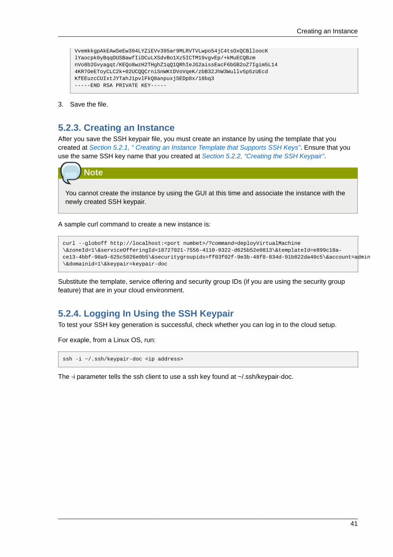
Creating an Instance
41
VvemkkgpAkEAwSeEw394LYZiEVv395ar9MLRVTVLwpo54jC4tsOxQCBlloocKlYaocpk0yBqqOUSBawfIiDCuLXSdvBo1Xz5ICTM19vgvEp/+kMuECQBzmnVo8b2Gvyagqt/KEQo8wzH2THghZ1qQ1QRhIeJG2aissEacF6bGB2oZ7Igim5L144KR7OeEToyCLC2k+02UCQQCrniSnWKtDVoVqeK/zbB32JhW3Wullv5p5zUEcdKfEEuzcCUIxtJYTahJ1pvlFkQ8anpuxjSEDp8x/18bq3-----END RSA PRIVATE KEY-----
3. Save the file.
5.2.3. Creating an InstanceAfter you save the SSH keypair file, you must create an instance by using the template that youcreated at Section 5.2.1, “ Creating an Instance Template that Supports SSH Keys”. Ensure that youuse the same SSH key name that you created at Section 5.2.2, “Creating the SSH Keypair”.
Note
You cannot create the instance by using the GUI at this time and associate the instance with thenewly created SSH keypair.
A sample curl command to create a new instance is:
curl --globoff http://localhost:<port numbet>/?command=deployVirtualMachine\&zoneId=1\&serviceOfferingId=18727021-7556-4110-9322-d625b52e0813\&templateId=e899c18a-ce13-4bbf-98a9-625c5026e0b5\&securitygroupids=ff03f02f-9e3b-48f8-834d-91b822da40c5\&account=admin\&domainid=1\&keypair=keypair-doc
Substitute the template, service offering and security group IDs (if you are using the security groupfeature) that are in your cloud environment.
5.2.4. Logging In Using the SSH KeypairTo test your SSH key generation is successful, check whether you can log in to the cloud setup.
For exaple, from a Linux OS, run:
ssh -i ~/.ssh/keypair-doc <ip address>
The -i parameter tells the ssh client to use a ssh key found at ~/.ssh/keypair-doc.

42
Chapter 6.
43
Steps to Provisioning Your CloudInfrastructureThis section tells how to add zones, pods, clusters, hosts, storage, and networks to your cloud. If youare unfamiliar with these entities, please begin by looking through Chapter 2, Cloud InfrastructureConcepts.
6.1. Overview of Provisioning StepsAfter the Management Server is installed and running, you can add the compute resources for it tomanage. For an overview of how a CloudStack cloud infrastructure is organized, see Section 1.3.2,“Cloud Infrastructure Overview”.
To provision the cloud infrastructure, or to scale it up at any time, follow these procedures:
1. Change the root password. See Section 5.1.4, “Changing the Root Password”.
2. Add a zone. See Section 6.2, “Adding a Zone”.
3. Add more pods (optional). See Section 6.3, “Adding a Pod”.
4. Add more clusters (optional). See Section 6.4, “Adding a Cluster”.
5. Add more hosts (optional). See Section 6.5, “Adding a Host”.
6. Add primary storage. See Section 6.6, “Add Primary Storage”.
7. Add secondary storage. See Section 6.7, “Add Secondary Storage”.
8. Initialize and test the new cloud. See Section 6.8, “Initialize and Test”.
When you have finished these steps, you will have a deployment with the following basic structure:
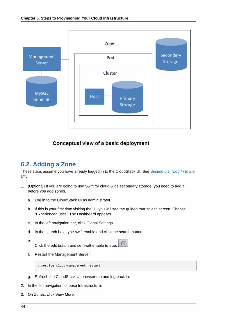
Chapter 6. Steps to Provisioning Your Cloud Infrastructure
44
6.2. Adding a ZoneThese steps assume you have already logged in to the CloudStack UI. See Section 5.1, “Log In to theUI”.
1. (Optional) If you are going to use Swift for cloud-wide secondary storage, you need to add itbefore you add zones.
a. Log in to the CloudStack UI as administrator.
b. If this is your first time visiting the UI, you will see the guided tour splash screen. Choose“Experienced user.” The Dashboard appears.
c. In the left navigation bar, click Global Settings.
d. In the search box, type swift.enable and click the search button.
e.Click the edit button and set swift.enable to true.
f. Restart the Management Server.
# service cloud-management restart
g. Refresh the CloudStack UI browser tab and log back in.
2. In the left navigation, choose Infrastructure.
3. On Zones, click View More.
Basic Zone Configuration
45
4. (Optional) If you are using Swift storage, click Enable Swift. Provide the following:
• URL. The Swift URL.
• Account. The Swift account.
• Username. The Swift account’s username.
• Key. The Swift key.
5. Click Add Zone. The zone creation wizard will appear.
6. Choose one of the following network types:
• Basic. For AWS-style networking. Provides a single network where each VM instance isassigned an IP directly from the network. Guest isolation can be provided through layer-3means such as security groups (IP address source filtering).
• Advanced. For more sophisticated network topologies. This network model provides the mostflexibility in defining guest networks and providing custom network offerings such as firewall,VPN, or load balancer support.
For more information about the network types, see Section 2.7, “About Physical Networks”.
7. The rest of the steps differ depending on whether you chose Basic or Advanced. Continue with thesteps that apply to you:
• Section 6.2.1, “Basic Zone Configuration”
• Section 6.2.2, “Advanced Zone Configuration”
6.2.1. Basic Zone Configuration1. After you select Basic in the Add Zone wizard and click Next, you will be asked to enter the
following details. Then click Next.
• Name. A name for the zone.
• DNS 1 and 2. These are DNS servers for use by guest VMs in the zone. These DNS serverswill be accessed via the public network you will add later. The public IP addresses for the zonemust have a route to the DNS server named here.
• Internal DNS 1 and Internal DNS 2. These are DNS servers for use by system VMs in thezone (these are VMs used by CloudStack itself, such as virtual routers, console proxies, andSecondary Storage VMs.) These DNS servers will be accessed via the management trafficnetwork interface of the System VMs. The private IP address you provide for the pods musthave a route to the internal DNS server named here.
• Hypervisor. (Introduced in version 3.0.1) Choose the hypervisor for the first cluster in the zone.You can add clusters with different hypervisors later, after you finish adding the zone.
• Network Offering. Your choice here determines what network services will be available on thenetwork for guest VMs.
Chapter 6. Steps to Provisioning Your Cloud Infrastructure
46
Network Offering Description
DefaultSharedNetworkOfferingWithSGService If you want to enable security groups forguest traffic isolation, choose this. (See UsingSecurity Groups to Control Traffic to VMs.)
DefaultSharedNetworkOffering If you do not need security groups, choosethis.
DefaultSharedNetscalerEIPandELBNetworkOfferingIf you have installed a Citrix NetScalerappliance as part of your zone network, andyou will be using its Elastic IP and ElasticLoad Balancing features, choose this. Withthe EIP and ELB features, a basic zone withsecurity groups enabled can offer 1:1 staticNAT and load balancing.
• Network Domain. (Optional) If you want to assign a special domain name to the guest VMnetwork, specify the DNS suffix.
• Public. A public zone is available to all users. A zone that is not public will be assigned to aparticular domain. Only users in that domain will be allowed to create guest VMs in this zone.
2. Choose which traffic types will be carried by the physical network.
The traffic types are management, public, guest, and storage traffic. For more information aboutthe types, roll over the icons to display their tool tips, or see Basic Zone Network Traffic Types.This screen starts out with some traffic types already assigned. To add more, drag and drop traffictypes onto the network. You can also change the network name if desired.
3. (Introduced in version 3.0.1) Assign a network traffic label to each traffic type on the physicalnetwork. These labels must match the labels you have already defined on the hypervisor host. Toassign each label, click the Edit button under the traffic type icon. A popup dialog appears whereyou can type the label, then click OK.
These traffic labels will be defined only for the hypervisor selected for the first cluster. For all otherhypervisors, the labels can be configured after the zone is created.
4. Click Next.
5. (NetScaler only) If you chose the network offering for NetScaler, you have an additional screen tofill out. Provide the requested details to set up the NetScaler, then click Next.
• IP address. The NSIP (NetScaler IP) address of the NetScaler device.
• Username/Password. The authentication credentials to access the device. CloudStack usesthese credentials to access the device.
• Type. NetScaler device type that is being added. It could be NetScaler VPX, NetScaler MPX, orNetScaler SDX. For a comparison of the types, see About Using a NetScaler Load Balancer.
• Public interface. Interface of NetScaler that is configured to be part of the public network.
• Private interface. Interface of NetScaler that is configured to be part of the private network.
• Number of retries. Number of times to attempt a command on the device before consideringthe operation failed. Default is 2.
Basic Zone Configuration
47
• Capacity. Number of guest networks/accounts that will share this NetScaler device.
• Dedicated. When marked as dedicated, this device will be dedicated to a single account. WhenDedicated is checked, the value in the Capacity field has no significance – implicitly, its value is1.
6. (NetScaler only) Configure the IP range for public traffic. The IPs in this range will be used for thestatic NAT capability which you enabled by selecting the network offering for NetScaler with EIPand ELB. Enter the following details, then click Add. If desired, you can repeat this step to addmore IP ranges. When done, click Next.
• Gateway. The gateway in use for these IP addresses.
• Netmask. The netmask associated with this IP range.
• VLAN. The VLAN that will be used for public traffic.
• Start IP/End IP. A range of IP addresses that are assumed to be accessible from the Internetand will be allocated for access to guest VMs.
7. In a new zone, CloudStack adds the first pod for you. You can always add more pods later. For anoverview of what a pod is, see Section 2.2, “About Pods”.
To configure the first pod, enter the following, then click Next:
• Pod Name. A name for the pod.
• Reserved system gateway. The gateway for the hosts in that pod.
• Reserved system netmask. The network prefix that defines the pod's subnet. Use CIDRnotation.
• Start/End Reserved System IP. The IP range in the management network that CloudStackuses to manage various system VMs, such as Secondary Storage VMs, Console Proxy VMs,and DHCP. For more information, see System Reserved IP Addresses.
8. Configure the network for guest traffic. Provide the following, then click Next:
• Guest gateway. The gateway that the guests should use.
• Guest netmask. The netmask in use on the subnet the guests will use.
• Guest start IP/End IP. Enter the first and last IP addresses that define a range that CloudStackcan assign to guests.
• We strongly recommend the use of multiple NICs. If multiple NICs are used, they may be in adifferent subnet.
• If one NIC is used, these IPs should be in the same CIDR as the pod CIDR.
9. In a new pod, CloudStack adds the first cluster for you. You can always add more clusters later.For an overview of what a cluster is, see About Clusters.
To configure the first cluster, enter the following, then click Next:
• Hypervisor. (Version 3.0.0 only; in 3.0.1, this field is read only) Choose the type of hypervisorsoftware that all hosts in this cluster will run. If you choose VMware, additional fields appearso you can give information about a vSphere cluster. For vSphere servers, we recommend
Chapter 6. Steps to Provisioning Your Cloud Infrastructure
48
creating the cluster of hosts in vCenter and then adding the entire cluster to CloudStack. SeeAdd Cluster: vSphere.
• Cluster name. Enter a name for the cluster. This can be text of your choosing and is not usedby CloudStack.
10. In a new cluster, CloudStack adds the first host for you. You can always add more hosts later. Foran overview of what a host is, see About Hosts.
Note
When you add a hypervisor host to CloudStack, the host must not have any VMs alreadyrunning.
Before you can configure the host, you need to install the hypervisor software on the host. Youwill need to know which version of the hypervisor software version is supported by CloudStackand what additional configuration is required to ensure the host will work with CloudStack. To findthese installation details, see:
• Citrix XenServer Installation and Configuration
• VMware vSphere Installation and Configuration
• KVM vSphere Installation and Configuration
To configure the first host, enter the following, then click Next:
• Host Name. The DNS name or IP address of the host.
• Username. The username is root.
• Password. This is the password for the user named above (from your XenServer or KVMinstall).
• Host Tags. (Optional) Any labels that you use to categorize hosts for ease of maintenance.For example, you can set this to the cloud's HA tag (set in the ha.tag global configurationparameter) if you want this host to be used only for VMs with the "high availability" featureenabled. For more information, see HA-Enabled Virtual Machines as well as HA for Hosts.
11. In a new cluster, CloudStack adds the first primary storage server for you. You can always addmore servers later. For an overview of what primary storage is, see About Primary Storage.
To configure the first primary storage server, enter the following, then click Next:
• Name. The name of the storage device.
• Protocol. For XenServer, choose either NFS, iSCSI, or PreSetup. For KVM, choose NFS,SharedMountPoint,CLVM, or RBD. For vSphere choose either VMFS (iSCSI or FiberChannel)or NFS. The remaining fields in the screen vary depending on what you choose here.
6.2.2. Advanced Zone Configuration1. After you select Advanced in the Add Zone wizard and click Next, you will be asked to enter the
following details. Then click Next.
Advanced Zone Configuration
49
• Name. A name for the zone.
• DNS 1 and 2. These are DNS servers for use by guest VMs in the zone. These DNS serverswill be accessed via the public network you will add later. The public IP addresses for the zonemust have a route to the DNS server named here.
• Internal DNS 1 and Internal DNS 2. These are DNS servers for use by system VMs in thezone(these are VMs used by CloudStack itself, such as virtual routers, console proxies,andSecondary Storage VMs.) These DNS servers will be accessed via the management trafficnetwork interface of the System VMs. The private IP address you provide for the pods musthave a route to the internal DNS server named here.
• Network Domain. (Optional) If you want to assign a special domain name to the guest VMnetwork, specify the DNS suffix.
• Guest CIDR. This is the CIDR that describes the IP addresses in use in the guest virtualnetworks in this zone. For example, 10.1.1.0/24. As a matter of good practice you should setdifferent CIDRs for different zones. This will make it easier to set up VPNs between networks indifferent zones.
• Hypervisor. (Introduced in version 3.0.1) Choose the hypervisor for the first cluster in the zone.You can add clusters with different hypervisors later, after you finish adding the zone.
• Public. A public zone is available to all users. A zone that is not public will be assigned to aparticular domain. Only users in that domain will be allowed to create guest VMs in this zone.
2. Choose which traffic types will be carried by the physical network.
The traffic types are management, public, guest, and storage traffic. For more information aboutthe types, roll over the icons to display their tool tips, or see Section 2.7.4, “Advanced ZoneNetwork Traffic Types”. This screen starts out with one network already configured. If you havemultiple physical networks, you need to add more. Drag and drop traffic types onto a greyed-outnetwork and it will become active. You can move the traffic icons from one network to another; forexample, if the default traffic types shown for Network 1 do not match your actual setup, you canmove them down. You can also change the network names if desired.
3. (Introduced in version 3.0.1) Assign a network traffic label to each traffic type on each physicalnetwork. These labels must match the labels you have already defined on the hypervisor host. Toassign each label, click the Edit button under the traffic type icon within each physical network. Apopup dialog appears where you can type the label, then click OK.
These traffic labels will be defined only for the hypervisor selected for the first cluster. For all otherhypervisors, the labels can be configured after the zone is created.
4. Click Next.
5. Configure the IP range for public Internet traffic. Enter the following details, then click Add. Ifdesired, you can repeat this step to add more public Internet IP ranges. When done, click Next.
• Gateway. The gateway in use for these IP addresses.
• Netmask. The netmask associated with this IP range.
• VLAN. The VLAN that will be used for public traffic.
Chapter 6. Steps to Provisioning Your Cloud Infrastructure
50
• Start IP/End IP. A range of IP addresses that are assumed to be accessible from the Internetand will be allocated for access to guest networks.
6. In a new zone, CloudStack adds the first pod for you. You can always add more pods later. For anoverview of what a pod is, see Section 2.2, “About Pods”.
To configure the first pod, enter the following, then click Next:
• Pod Name. A name for the pod.
• Reserved system gateway. The gateway for the hosts in that pod.
• Reserved system netmask. The network prefix that defines the pod's subnet. Use CIDRnotation.
• Start/End Reserved System IP. The IP range in the management network that CloudStackuses to manage various system VMs, such as Secondary Storage VMs, Console Proxy VMs,and DHCP. For more information, see Section 2.7.7, “System Reserved IP Addresses”.
7. Specify a range of VLAN IDs to carry guest traffic for each physical network (see VLAN AllocationExample ), then click Next.
8. In a new pod, CloudStack adds the first cluster for you. You can always add more clusters later.For an overview of what a cluster is, see Section 2.3, “About Clusters”.
To configure the first cluster, enter the following, then click Next:
• Hypervisor. (Version 3.0.0 only; in 3.0.1, this field is read only) Choose the type of hypervisorsoftware that all hosts in this cluster will run. If you choose VMware, additional fields appearso you can give information about a vSphere cluster. For vSphere servers, we recommendcreating the cluster of hosts in vCenter and then adding the entire cluster to CloudStack. SeeAdd Cluster: vSphere .
• Cluster name. Enter a name for the cluster. This can be text of your choosing and is not usedby CloudStack.
9. In a new cluster, CloudStack adds the first host for you. You can always add more hosts later. Foran overview of what a host is, see Section 2.4, “About Hosts”.
Note
When you deploy CloudStack, the hypervisor host must not have any VMs already running.
Before you can configure the host, you need to install the hypervisor software on the host. Youwill need to know which version of the hypervisor software version is supported by CloudStackand what additional configuration is required to ensure the host will work with CloudStack. To findthese installation details, see:
• Citrix XenServer Installation for CloudStack
• VMware vSphere Installation and Configuration
• KVM Installation and Configuration
Advanced Zone Configuration
51
To configure the first host, enter the following, then click Next:
• Host Name. The DNS name or IP address of the host.
• Username. Usually root.
• Password. This is the password for the user named above (from your XenServer or KVMinstall).
• Host Tags. (Optional) Any labels that you use to categorize hosts for ease of maintenance. Forexample, you can set to the cloud's HA tag (set in the ha.tag global configuration parameter)if you want this host to be used only for VMs with the "high availability" feature enabled. Formore information, see HA-Enabled Virtual Machines as well as HA for Hosts, both in theAdministration Guide.
10. In a new cluster, CloudStack adds the first primary storage server for you. You can always addmore servers later. For an overview of what primary storage is, see Section 2.5, “About PrimaryStorage”.
To configure the first primary storage server, enter the following, then click Next:
• Name. The name of the storage device.
• Protocol. For XenServer, choose either NFS, iSCSI, or PreSetup. For KVM, choose NFS,SharedMountPoint, CLVM, and RBD. For vSphere choose either VMFS (iSCSI or FiberChannel)or NFS. The remaining fields in the screen vary depending on what you choose here.
NFS • Server. The IP address or DNS name ofthe storage device.
• Path. The exported path from the server.
• Tags (optional). The comma-separated listof tags for this storage device. It should bean equivalent set or superset of the tags onyour disk offerings.
The tag sets on primary storage acrossclusters in a Zone must be identical. Forexample, if cluster A provides primary storagethat has tags T1 and T2, all other clusters inthe Zone must also provide primary storagethat has tags T1 and T2.
iSCSI • Server. The IP address or DNS name ofthe storage device.
• Target IQN. The IQN ofthe target. For example,iqn.1986-03.com.sun:02:01ec9bb549-1271378984.
• Lun. The LUN number. For example, 3.
• Tags (optional). The comma-separated listof tags for this storage device. It should bean equivalent set or superset of the tags onyour disk offerings.
Chapter 6. Steps to Provisioning Your Cloud Infrastructure
52
The tag sets on primary storage acrossclusters in a Zone must be identical. Forexample, if cluster A provides primary storagethat has tags T1 and T2, all other clusters inthe Zone must also provide primary storagethat has tags T1 and T2.
preSetup • Server. The IP address or DNS name ofthe storage device.
• SR Name-Label. Enter the name-labelof the SR that has been set up outsideCloudStack.
• Tags (optional). The comma-separated listof tags for this storage device. It should bean equivalent set or superset of the tags onyour disk offerings.
The tag sets on primary storage acrossclusters in a Zone must be identical. Forexample, if cluster A provides primary storagethat has tags T1 and T2, all other clusters inthe Zone must also provide primary storagethat has tags T1 and T2.
SharedMountPoint • Path. The path on each host that is wherethis primary storage is mounted. Forexample, "/mnt/primary".
• Tags (optional). The comma-separated listof tags for this storage device. It should bean equivalent set or superset of the tags onyour disk offerings.
The tag sets on primary storage acrossclusters in a Zone must be identical. Forexample, if cluster A provides primary storagethat has tags T1 and T2, all other clusters inthe Zone must also provide primary storagethat has tags T1 and T2.
VMFS • Server. The IP address or DNS name ofthe vCenter server.
• Path. A combination of the datacentername and the datastore name. Theformat is "/" datacenter name "/" datastorename. For example, "/cloud.dc.VM/cluster1datastore".
• Tags (optional). The comma-separated listof tags for this storage device. It should bean equivalent set or superset of the tags onyour disk offerings.
Adding a Pod
53
The tag sets on primary storage acrossclusters in a Zone must be identical. Forexample, if cluster A provides primary storagethat has tags T1 and T2, all other clusters inthe Zone must also provide primary storagethat has tags T1 and T2.
11. In a new zone, CloudStack adds the first secondary storage server for you. For an overview ofwhat secondary storage is, see Section 2.6, “About Secondary Storage”.
Before you can fill out this screen, you need to prepare the secondary storage by setting up NFSshares and installing the latest CloudStack System VM template. See Adding Secondary Storage :
• NFS Server. The IP address of the server.
• Path. The exported path from the server.
12. Click Launch.
6.3. Adding a PodWhen you created a new zone, CloudStack adds the first pod for you. You can add more pods at anytime using the procedure in this section.
1. Log in to the CloudStack UI. See Section 5.1, “Log In to the UI”.
2. In the left navigation, choose Infrastructure. In Zones, click View More, then click the zone towhich you want to add a pod.
3. Click the Compute and Storage tab. In the Pods node of the diagram, click View All.
4. Click Add Pod.
5. Enter the following details in the dialog.
• Name. The name of the pod.
• Gateway. The gateway for the hosts in that pod.
• Netmask. The network prefix that defines the pod's subnet. Use CIDR notation.
• Start/End Reserved System IP. The IP range in the management network that CloudStackuses to manage various system VMs, such as Secondary Storage VMs, Console Proxy VMs,and DHCP. For more information, see System Reserved IP Addresses.
6. Click OK.
6.4. Adding a ClusterYou need to tell CloudStack about the hosts that it will manage. Hosts exist inside clusters, so beforeyou begin adding hosts to the cloud, you must add at least one cluster.
6.4.1. Add Cluster: KVM or XenServerThese steps assume you have already installed the hypervisor on the hosts and logged in to theCloudStack UI.
Chapter 6. Steps to Provisioning Your Cloud Infrastructure
54
1. In the left navigation, choose Infrastructure. In Zones, click View More, then click the zone in whichyou want to add the cluster.
2. Click the Compute tab.
3. In the Clusters node of the diagram, click View All.
4. Click Add Cluster.
5. Choose the hypervisor type for this cluster.
6. Choose the pod in which you want to create the cluster.
7. Enter a name for the cluster. This can be text of your choosing and is not used by CloudStack.
8. Click OK.
6.4.2. Add Cluster: vSphereHost management for vSphere is done through a combination of vCenter and the CloudStack adminUI. CloudStack requires that all hosts be in a CloudStack cluster, but the cluster may consist of asingle host. As an administrator you must decide if you would like to use clusters of one host or ofmultiple hosts. Clusters of multiple hosts allow for features like live migration. Clusters also requireshared storage such as NFS or iSCSI.
For vSphere servers, we recommend creating the cluster of hosts in vCenter and then adding theentire cluster to CloudStack. Follow these requirements:
• Do not put more than 8 hosts in a vSphere cluster
• Make sure the hypervisor hosts do not have any VMs already running before you add them toCloudStack.
To add a vSphere cluster to CloudStack:
1. Create the cluster of hosts in vCenter. Follow the vCenter instructions to do this. You will create acluster that looks something like this in vCenter.
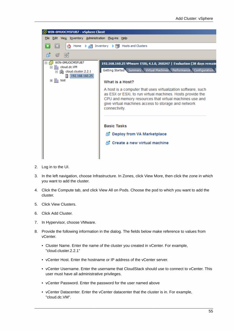
Add Cluster: vSphere
55
2. Log in to the UI.
3. In the left navigation, choose Infrastructure. In Zones, click View More, then click the zone in whichyou want to add the cluster.
4. Click the Compute tab, and click View All on Pods. Choose the pod to which you want to add thecluster.
5. Click View Clusters.
6. Click Add Cluster.
7. In Hypervisor, choose VMware.
8. Provide the following information in the dialog. The fields below make reference to values fromvCenter.
• Cluster Name. Enter the name of the cluster you created in vCenter. For example,"cloud.cluster.2.2.1"
• vCenter Host. Enter the hostname or IP address of the vCenter server.
• vCenter Username. Enter the username that CloudStack should use to connect to vCenter. Thisuser must have all administrative privileges.
• vCenter Password. Enter the password for the user named above
• vCenter Datacenter. Enter the vCenter datacenter that the cluster is in. For example,"cloud.dc.VM".
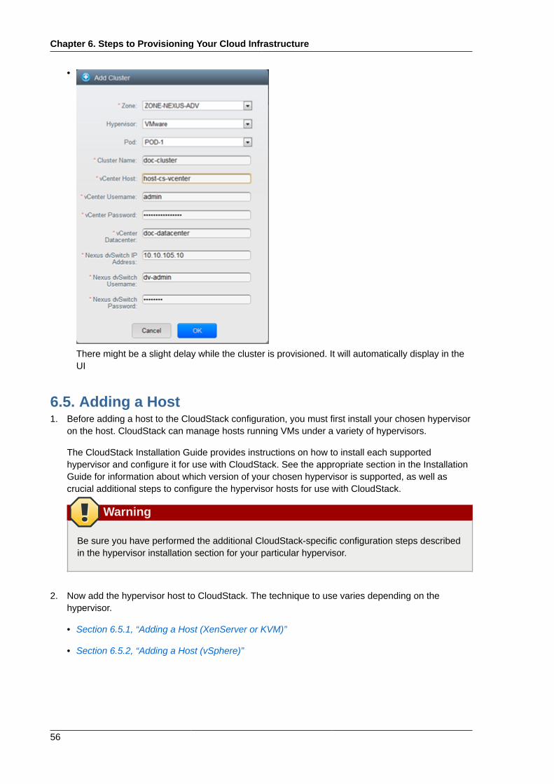
Chapter 6. Steps to Provisioning Your Cloud Infrastructure
56
•
There might be a slight delay while the cluster is provisioned. It will automatically display in theUI
6.5. Adding a Host1. Before adding a host to the CloudStack configuration, you must first install your chosen hypervisor
on the host. CloudStack can manage hosts running VMs under a variety of hypervisors.
The CloudStack Installation Guide provides instructions on how to install each supportedhypervisor and configure it for use with CloudStack. See the appropriate section in the InstallationGuide for information about which version of your chosen hypervisor is supported, as well ascrucial additional steps to configure the hypervisor hosts for use with CloudStack.
Warning
Be sure you have performed the additional CloudStack-specific configuration steps describedin the hypervisor installation section for your particular hypervisor.
2. Now add the hypervisor host to CloudStack. The technique to use varies depending on thehypervisor.
• Section 6.5.1, “Adding a Host (XenServer or KVM)”
• Section 6.5.2, “Adding a Host (vSphere)”
Adding a Host (XenServer or KVM)
57
6.5.1. Adding a Host (XenServer or KVM)XenServer and KVM hosts can be added to a cluster at any time.
6.5.1.1. Requirements for XenServer and KVM Hosts
Warning
Make sure the hypervisor host does not have any VMs already running before you add it toCloudStack.
Configuration requirements:
• Each cluster must contain only hosts with the identical hypervisor.
• For XenServer, do not put more than 8 hosts in a cluster.
• For KVM, do not put more than 16 hosts in a cluster.
For hardware requirements, see the installation section for your hypervisor in the CloudStackInstallation Guide.
6.5.1.1.1. XenServer Host Additional RequirementsIf network bonding is in use, the administrator must cable the new host identically to other hosts in thecluster.
For all additional hosts to be added to the cluster, run the following command. This will cause the hostto join the master in a XenServer pool.
# xe pool-join master-address=[master IP] master-username=root master-password=[your password]
Note
When copying and pasting a command, be sure the command has pasted as a single line beforeexecuting. Some document viewers may introduce unwanted line breaks in copied text.
With all hosts added to the XenServer pool, run the cloud-setup-bond script. This script will completethe configuration and setup of the bonds on the new hosts in the cluster.
1. Copy the script from the Management Server in /usr/lib64/cloud/common/scripts/vm/hypervisor/xenserver/cloud-setup-bonding.sh to the master host and ensure it is executable.
2. Run the script:
# ./cloud-setup-bonding.sh
Chapter 6. Steps to Provisioning Your Cloud Infrastructure
58
6.5.1.1.2. KVM Host Additional Requirements• If shared mountpoint storage is in use, the administrator should ensure that the new host has all the
same mountpoints (with storage mounted) as the other hosts in the cluster.
• Make sure the new host has the same network configuration (guest, private, and public network) asother hosts in the cluster.
6.5.1.2. Adding a XenServer or KVM Host• If you have not already done so, install the hypervisor software on the host. You will need to know
which version of the hypervisor software version is supported by CloudStack and what additionalconfiguration is required to ensure the host will work with CloudStack. To find these installationdetails, see the appropriate section for your hypervisor in the CloudStack Installation Guide.
• Log in to the CloudStack UI as administrator.
• In the left navigation, choose Infrastructure. In Zones, click View More, then click the zone in whichyou want to add the host.
• Click the Compute tab. In the Clusters node, click View All.
• Click the cluster where you want to add the host.
• Click View Hosts.
• Click Add Host.
• Provide the following information.
• Host Name. The DNS name or IP address of the host.
• Username. Usually root.
• Password. This is the password for the user from your XenServer or KVM install).
• Host Tags (Optional). Any labels that you use to categorize hosts for ease of maintenance. Forexample, you can set to the cloud's HA tag (set in the ha.tag global configuration parameter) ifyou want this host to be used only for VMs with the "high availability" feature enabled. For moreinformation, see HA-Enabled Virtual Machines as well as HA for Hosts.
There may be a slight delay while the host is provisioned. It should automatically display in the UI.
• Repeat for additional hosts.
6.5.2. Adding a Host (vSphere)For vSphere servers, we recommend creating the cluster of hosts in vCenter and then adding theentire cluster to CloudStack. See Add Cluster: vSphere.
6.6. Add Primary Storage
6.6.1. System Requirements for Primary StorageHardware requirements:
• Any standards-compliant iSCSI or NFS server that is supported by the underlying hypervisor.
Adding Primary Stroage
59
• The storage server should be a machine with a large number of disks. The disks should ideally bemanaged by a hardware RAID controller.
• Minimum required capacity depends on your needs.
When setting up primary storage, follow these restrictions:
• Primary storage cannot be added until a host has been added to the cluster.
• If you do not provision shared primary storage, you must set the global configuration parametersystem.vm.local.storage.required to true, or else you will not be able to start VMs.
6.6.2. Adding Primary StroageWhen you create a new zone, the first primary storage is added as part of that procedure. You can addprimary storage servers at any time, such as when adding a new cluster or adding more servers to anexisting cluster.
Warning
Be sure there is nothing stored on the server. Adding the server to CloudStack will destroy anyexisting data.
1. Log in to the CloudStack UI (see Section 5.1, “Log In to the UI”).
2. In the left navigation, choose Infrastructure. In Zones, click View More, then click the zone in whichyou want to add the primary storage.
3. Click the Compute tab.
4. In the Primary Storage node of the diagram, click View All.
5. Click Add Primary Storage.
6. Provide the following information in the dialog. The information required varies depending on yourchoice in Protocol.
• Pod. The pod for the storage device.
• Cluster. The cluster for the storage device.
• Name. The name of the storage device.
• Protocol. For XenServer, choose either NFS, iSCSI, or PreSetup. For KVM, choose NFS orSharedMountPoint. For vSphere choose either VMFS (iSCSI or FiberChannel) or NFS.
• Server (for NFS, iSCSI, or PreSetup). The IP address or DNS name of the storage device.
• Server (for VMFS). The IP address or DNS name of the vCenter server.
• Path (for NFS). In NFS this is the exported path from the server.
• Path (for VMFS). In vSphere this is a combination of the datacenter name and the datastorename. The format is "/" datacenter name "/" datastore name. For example, "/cloud.dc.VM/cluster1datastore".
Chapter 6. Steps to Provisioning Your Cloud Infrastructure
60
• Path (for SharedMountPoint). With KVM this is the path on each host that is where thisprimary storage is mounted. For example, "/mnt/primary".
• SR Name-Label (for PreSetup). Enter the name-label of the SR that has been set up outsideCloudStack.
• Target IQN (for iSCSI). In iSCSI this is the IQN of the target. For example,iqn.1986-03.com.sun:02:01ec9bb549-1271378984.
• Lun # (for iSCSI). In iSCSI this is the LUN number. For example, 3.
• Tags (optional). The comma-separated list of tags for this storage device. It should be anequivalent set or superset of the tags on your disk offerings..
The tag sets on primary storage across clusters in a Zone must be identical. For example, ifcluster A provides primary storage that has tags T1 and T2, all other clusters in the Zone mustalso provide primary storage that has tags T1 and T2.
7. Click OK.
6.7. Add Secondary Storage
6.7.1. System Requirements for Secondary Storage• NFS storage appliance or Linux NFS server
• (Optional) OpenStack Object Storage (Swift) (see http://swift.openstack.org)
• 100GB minimum capacity
• A secondary storage device must be located in the same zone as the guest VMs it serves.
• Each Secondary Storage server must be available to all hosts in the zone.
6.7.2. Adding Secondary StorageWhen you create a new zone, the first secondary storage is added as part of that procedure. You canadd secondary storage servers at any time to add more servers to an existing zone.
Warning
Be sure there is nothing stored on the server. Adding the server to CloudStack will destroy anyexisting data.
1. If you are going to use Swift for cloud-wide secondary storage, you must add the Swift storage toCloudStack before you add the local zone secondary storage servers. See Section 6.2, “Adding aZone”.
2. To prepare for local zone secondary storage, you should have created and mounted an NFS shareduring Management Server installation. See Section 4.5.5, “Prepare NFS Shares”.
Initialize and Test
61
3. Make sure you prepared the system VM template during Management Server installation. SeeSection 4.5.7, “Prepare the System VM Template”.
4. Now that the secondary storage server for per-zone storage is prepared, add it to CloudStack.Secondary storage is added as part of the procedure for adding a new zone. See Section 6.2,“Adding a Zone”.
6.8. Initialize and TestAfter everything is configured, CloudStack will perform its initialization. This can take 30 minutes ormore, depending on the speed of your network. When the initialization has completed successfully, theadministrator's Dashboard should be displayed in the CloudStack UI.
1. Verify that the system is ready. In the left navigation bar, select Templates. Click on the CentOS5.5 (64bit) no Gui (KVM) template. Check to be sure that the status is "Download Complete." Donot proceed to the next step until this status is displayed.
2. Go to the Instances tab, and filter by My Instances.
3. Click Add Instance and follow the steps in the wizard.
a. Choose the zone you just added.
b. In the template selection, choose the template to use in the VM. If this is a fresh installation,likely only the provided CentOS template is available.
c. Select a service offering. Be sure that the hardware you have allows starting the selectedservice offering.
d. In data disk offering, if desired, add another data disk. This is a second volume that will beavailable to but not mounted in the guest. For example, in Linux on XenServer you will see /dev/xvdb in the guest after rebooting the VM. A reboot is not required if you have a PV-enabled OS kernel in use.
e. In default network, choose the primary network for the guest. In a trial installation, you wouldhave only one option here.
f. Optionally give your VM a name and a group. Use any descriptive text you would like.
g. Click Launch VM. Your VM will be created and started. It might take some time to downloadthe template and complete the VM startup. You can watch the VM’s progress in the Instancesscreen.
4.To use the VM, click the View Console button.
Congratulations! You have successfully completed a CloudStack Installation.
If you decide to grow your deployment, you can add more hosts, primary storage, zones, pods, andclusters.

62
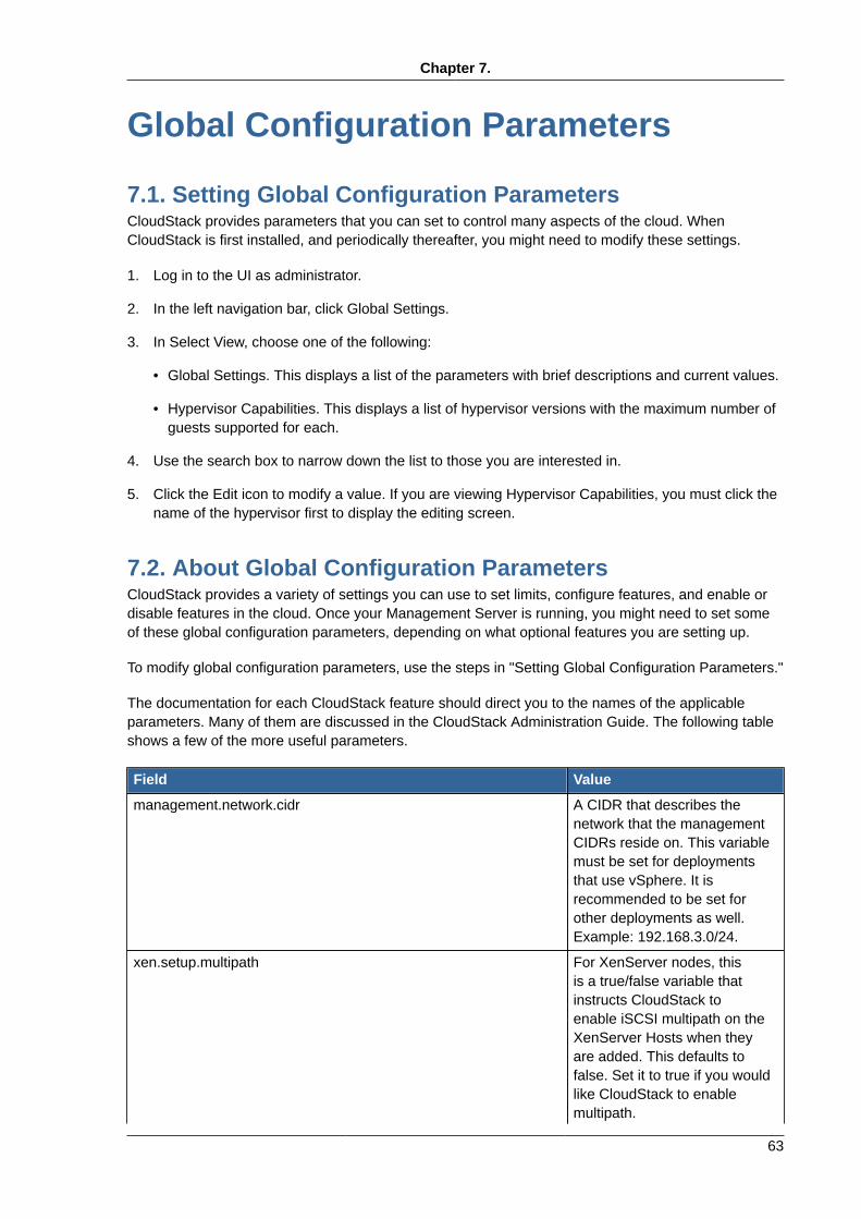
Chapter 7.
63
Global Configuration Parameters
7.1. Setting Global Configuration ParametersCloudStack provides parameters that you can set to control many aspects of the cloud. WhenCloudStack is first installed, and periodically thereafter, you might need to modify these settings.
1. Log in to the UI as administrator.
2. In the left navigation bar, click Global Settings.
3. In Select View, choose one of the following:
• Global Settings. This displays a list of the parameters with brief descriptions and current values.
• Hypervisor Capabilities. This displays a list of hypervisor versions with the maximum number ofguests supported for each.
4. Use the search box to narrow down the list to those you are interested in.
5. Click the Edit icon to modify a value. If you are viewing Hypervisor Capabilities, you must click thename of the hypervisor first to display the editing screen.
7.2. About Global Configuration ParametersCloudStack provides a variety of settings you can use to set limits, configure features, and enable ordisable features in the cloud. Once your Management Server is running, you might need to set someof these global configuration parameters, depending on what optional features you are setting up.
To modify global configuration parameters, use the steps in "Setting Global Configuration Parameters."
The documentation for each CloudStack feature should direct you to the names of the applicableparameters. Many of them are discussed in the CloudStack Administration Guide. The following tableshows a few of the more useful parameters.
Field Value
management.network.cidr A CIDR that describes thenetwork that the managementCIDRs reside on. This variablemust be set for deploymentsthat use vSphere. It isrecommended to be set forother deployments as well.Example: 192.168.3.0/24.
xen.setup.multipath For XenServer nodes, thisis a true/false variable thatinstructs CloudStack toenable iSCSI multipath on theXenServer Hosts when theyare added. This defaults tofalse. Set it to true if you wouldlike CloudStack to enablemultipath.
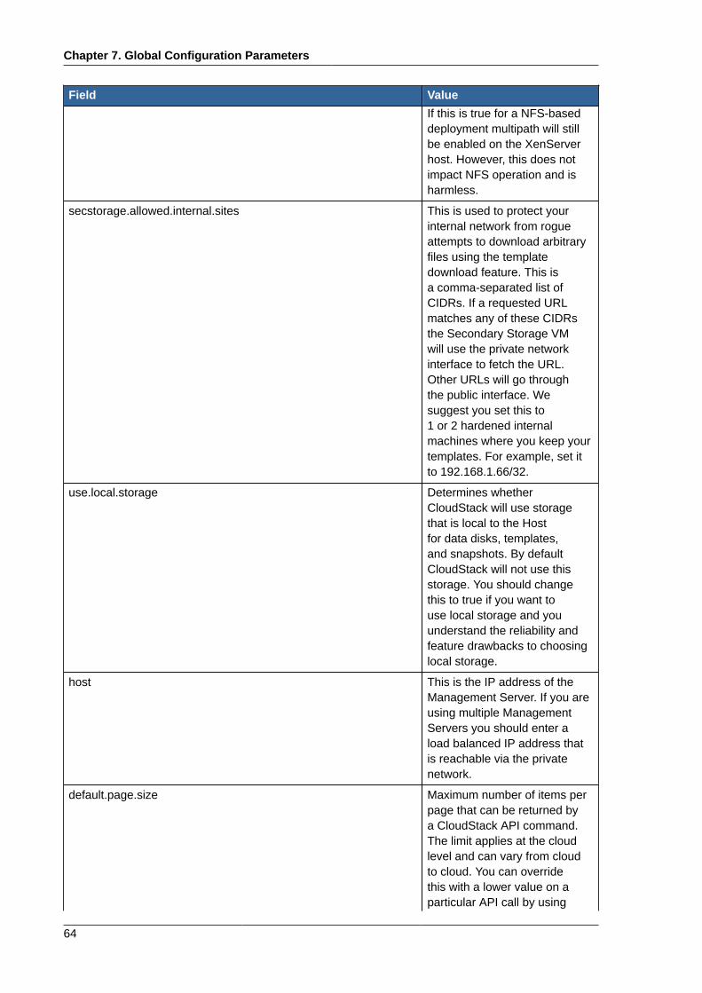
Chapter 7. Global Configuration Parameters
64
Field ValueIf this is true for a NFS-baseddeployment multipath will stillbe enabled on the XenServerhost. However, this does notimpact NFS operation and isharmless.
secstorage.allowed.internal.sites This is used to protect yourinternal network from rogueattempts to download arbitraryfiles using the templatedownload feature. This isa comma-separated list ofCIDRs. If a requested URLmatches any of these CIDRsthe Secondary Storage VMwill use the private networkinterface to fetch the URL.Other URLs will go throughthe public interface. Wesuggest you set this to1 or 2 hardened internalmachines where you keep yourtemplates. For example, set itto 192.168.1.66/32.
use.local.storage Determines whetherCloudStack will use storagethat is local to the Hostfor data disks, templates,and snapshots. By defaultCloudStack will not use thisstorage. You should changethis to true if you want touse local storage and youunderstand the reliability andfeature drawbacks to choosinglocal storage.
host This is the IP address of theManagement Server. If you areusing multiple ManagementServers you should enter aload balanced IP address thatis reachable via the privatenetwork.
default.page.size Maximum number of items perpage that can be returned bya CloudStack API command.The limit applies at the cloudlevel and can vary from cloudto cloud. You can overridethis with a lower value on aparticular API call by using
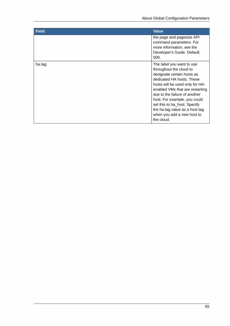
About Global Configuration Parameters
65
Field Valuethe page and pagesize APIcommand parameters. Formore information, see theDeveloper's Guide. Default:500.
ha.tag The label you want to usethroughout the cloud todesignate certain hosts asdedicated HA hosts. Thesehosts will be used only for HA-enabled VMs that are restartingdue to the failure of anotherhost. For example, you couldset this to ha_host. Specifythe ha.tag value as a host tagwhen you add a new host tothe cloud.

66
Chapter 8.
67
Hypervisor Installation
8.1. KVM Hypervisor Host Installation
8.1.1. System Requirements for KVM Hypervisor HostsKVM is included with a variety of Linux-based operating systems. Although you are not required to runthese distributions, the following are recommended:
• CentOS / RHEL: 6.3
• Ubuntu: 12.04(.1)
The main requirement for KVM hypervisors is the libvirt and Qemu version. No matter what Linuxdistribution you are using, make sure the following requirements are met:
• libvirt: 0.9.4 or higher
• Qemu/KVM: 1.0 or higher
In addition, the following hardware requirements apply:
• Within a single cluster, the hosts must be of the same distribution version.
• All hosts within a cluster must be homogenous. The CPUs must be of the same type, count, andfeature flags.
• Must support HVM (Intel-VT or AMD-V enabled)
• 64-bit x86 CPU (more cores results in better performance)
• 4 GB of memory
• At least 1 NIC
• When you deploy CloudStack, the hypervisor host must not have any VMs already running
8.1.2. KVM Installation OverviewIf you want to use the Linux Kernel Virtual Machine (KVM) hypervisor to run guest virtual machines,install KVM on the host(s) in your cloud. The material in this section doesn't duplicate KVM installationdocs. It provides the CloudStack-specific steps that are needed to prepare a KVM host to work withCloudStack.
Warning
Before continuing, make sure that you have applied the latest updates to your host.
Chapter 8. Hypervisor Installation
68
Warning
It is NOT recommended to run services on this host not controlled by CloudStack.
The procedure for installing a KVM Hypervisor Host is:
1. Prepare the Operating System
2. Install and configure libvirt
3. Configure Security Policies (AppArmor and SELinux)
4. Install and configure the Agent
8.1.3. Prepare the Operating SystemThe OS of the Host must be prepared to host the CloudStack Agent and run KVM instances.
1. Log in to your OS as root.
2. Check for a fully qualified hostname.
$ hostname --fqdn
This should return a fully qualified hostname such as "kvm1.lab.example.org". If it does not, edit /etc/hosts so that it does.
3. Make sure that the machine can reach the Internet.
$ ping www.cloudstack.org
4. Turn on NTP for time synchronization.
Note
NTP is required to synchronize the clocks of the servers in your cloud. Unsynchronizedclocks can cause unexpected problems.
a. Install NTP
$ yum install ntp
$ apt-get install openntpd
5. Repeat all of these steps on every hypervisor host.
Install and configure the Agent
69
8.1.4. Install and configure the AgentTo manage KVM instances on the host CloudStack uses a Agent. This Agent communicates with theManagement server and controls all the instances on the host.
First we start by installing the agent:
In RHEL or CentOS:
$ yum install cloud-agent
In Ubuntu:
$ apt-get install cloud-agent
The host is now ready to be added to a cluster. This is covered in a later section, see Section 6.5,“Adding a Host”. It is recommended that you continue to read the documentation before adding thehost!
8.1.5. Install and Configure libvirtCloudStack uses libvirt for managing virtual machines. Therefore it is vital that libvirt is configuredcorrectly. Libvirt is a dependency of cloud-agent and should already be installed.
1. In order to have live migration working libvirt has to listen for unsecured TCP connections. We alsoneed to turn off libvirts attempt to use Multicast DNS advertising. Both of these settings are in /etc/libvirt/libvirtd.conf
Set the following paramaters:
listen_tls = 0
listen_tcp = 1
tcp_port = "16059"
auth_tcp = "none"
mdns_adv = 0
2. Turning on "listen_tcp" in libvirtd.conf is not enough, we have to change the parameters as well:
On RHEL or CentOS modify /etc/sysconfig/libvirtd:
Uncomment the following line:
#LIBVIRTD_ARGS="--listen"
On Ubuntu: modify /etc/default/libvirt-bin
Add "-l" to the following line::
libvirtd_opts="-d"
Chapter 8. Hypervisor Installation
70
so it looks like:
libvirtd_opts="-d -l"
You will also want to edit /etc/libvirt/qemu.conf and make sure that "vnc_listen = 0.0.0.0"is uncommented.
3. Restart libvirt
In RHEL or CentOS:
$ service libvirtd restart
In Ubuntu:
$ service libvirt-bin restart
8.1.6. Configure the Security PoliciesCloudStack does various things which can be blocked by security mechanisms like AppArmor andSELinux. These have to be disabled to ensure the Agent has all the required permissions.
1. Configure SELinux (RHEL and CentOS)
a. Check to see whether SELinux is installed on your machine. If not, you can skip this section.
In RHEL or CentOS, SELinux is installed and enabled by default. You can verify this with:
$ rpm -qa | grep selinux
b. Set the SELINUX variable in /etc/selinux/config to "permissive". This ensures that thepermissive setting will be maintained after a system reboot.
In RHEL or CentOS:
vi /etc/selinux/config
Change the following line
SELINUX=enforcing
to this
SELINUX=permissive
c. Then set SELinux to permissive starting immediately, without requiring a system reboot.
$ setenforce permissive
2. Configure Apparmor (Ubuntu)
a. Check to see whether AppArmor is installed on your machine. If not, you can skip this section.
Configure the network bridges
71
In Ubuntu AppArmor is installed and enabled by default. You can verify this with:
$ dpkg --list 'apparmor'
b. Disable the AppArmor profiles for libvirt
$ ln -s /etc/apparmor.d/usr.sbin.libvirtd /etc/apparmor.d/disable/
$ ln -s /etc/apparmor.d/usr.lib.libvirt.virt-aa-helper /etc/apparmor.d/disable/
$ apparmor_parser -R /etc/apparmor.d/usr.sbin.libvirtd
$ apparmor_parser -R /etc/apparmor.d/usr.lib.libvirt.virt-aa-helper
8.1.7. Configure the network bridges
Warning
This is a very important section, please make sure you read this thoroughly.
In order to forward traffic to your instances you will need at least two bridges: public and private.
By default these bridges are called cloudbr0 and cloudbr1, but you do have to make sure they areavailable on each hypervisor.
The most important factor is that you keep the configuration consistent on all your hypervisors.
8.1.7.1. Network exampleThere are many ways to configure your network. In the Basic networking mode you should have two(V)LAN's, one for your private network and one for the public network.
We assume that the hypervisor has one NIC (eth0) with three tagged VLAN's:
1. VLAN 100 for management of the hypervisor
2. VLAN 200 for public network of the instances (cloudbr0)
3. VLAN 300 for private network of the instances (cloudbr1)
On VLAN 100 we give the Hypervisor the IP-Address 192.168.42.11/24 with the gateway 192.168.42.1
Note
The Hypervisor and Management server don't have to be in the same subnet!
Chapter 8. Hypervisor Installation
72
8.1.7.2. Configuring the network bridgesIt depends on the distribution you are using how to configure these, below you'll find examples forRHEL/CentOS and Ubuntu.
Note
The goal is to have two bridges called 'cloudbr0' and 'cloudbr1' after this section. This should beused as a guideline only. The exact configuration will depend on your network layout.
8.1.7.2.1. Configure in RHEL or CentOSThe required packages were installed when libvirt was installed, we can proceed to configuring thenetwork.
First we configure eth0
vi /etc/sysconfig/network-scripts/ifcfg-eth0
Make sure it looks similair to:
DEVICE=eth0HWADDR=00:04:xx:xx:xx:xxONBOOT=yesHOTPLUG=noBOOTPROTO=noneTYPE=Ethernet
We now have to configure the three VLAN interfaces:
vi /etc/sysconfig/network-scripts/ifcfg-eth0.100
DEVICE=eth0.100HWADDR=00:04:xx:xx:xx:xxONBOOT=yesHOTPLUG=noBOOTPROTO=noneTYPE=EthernetVLAN=yesIPADDR=192.168.42.11GATEWAY=192.168.42.1NETMASK=255.255.255.0
vi /etc/sysconfig/network-scripts/ifcfg-eth0.200
DEVICE=eth0.200HWADDR=00:04:xx:xx:xx:xxONBOOT=yesHOTPLUG=noBOOTPROTO=noneTYPE=EthernetVLAN=yesBRIDGE=cloudbr0
Configure the network bridges
73
vi /etc/sysconfig/network-scripts/ifcfg-eth0.300
DEVICE=eth0.300HWADDR=00:04:xx:xx:xx:xxONBOOT=yesHOTPLUG=noBOOTPROTO=noneTYPE=EthernetVLAN=yesBRIDGE=cloudbr1
Now we have the VLAN interfaces configured we can add the bridges on top of them.
vi /etc/sysconfig/network-scripts/ifcfg-cloudbr0
Now we just configure it is a plain bridge without an IP-Adress
DEVICE=cloudbr0TYPE=BridgeONBOOT=yesBOOTPROTO=noneIPV6INIT=noIPV6_AUTOCONF=noDELAY=5STP=yes
We do the same for cloudbr1
vi /etc/sysconfig/network-scripts/ifcfg-cloudbr1
DEVICE=cloudbr1TYPE=BridgeONBOOT=yesBOOTPROTO=noneIPV6INIT=noIPV6_AUTOCONF=noDELAY=5STP=yes
With this configuration you should be able to restart the network, although a reboot is recommended tosee if everything works properly.
Warning
Make sure you have an alternative way like IPMI or ILO to reach the machine in case you made aconfiguration error and the network stops functioning!
8.1.7.2.2. Configure in UbuntuAll the required packages were installed when you installed libvirt, so we only have to configure thenetwork.
vi /etc/network/interfaces
Chapter 8. Hypervisor Installation
74
Modify the interfaces file to look like this:
auto loiface lo inet loopback
# The primary network interfaceauto eth0.100iface eth0.100 inet static address 192.168.42.11 netmask 255.255.255.240 gateway 192.168.42.1 dns-nameservers 8.8.8.8 8.8.4.4 dns-domain lab.example.org
# Public networkauto cloudbr0iface cloudbr0 inet manual bridge_ports eth0.200 bridge_fd 5 bridge_stp off bridge_maxwait 1
# Private networkauto cloudbr1iface cloudbr1 inet manual bridge_ports eth0.300 bridge_fd 5 bridge_stp off bridge_maxwait 1
With this configuration you should be able to restart the network, although a reboot is recommended tosee if everything works properly.
Warning
Make sure you have an alternative way like IPMI or ILO to reach the machine in case you made aconfiguration error and the network stops functioning!
8.1.8. Configuring the firewallThe hypervisor needs to be able to communicate with other hypervisors and the management serverneeds to be able to reach the hypervisor.
In order to do so we have to open the following TCP ports (if you are using a firewall):
1. 22 (SSH)
2. 1798
3. 16509 (libvirt)
4. 5900 - 6100 (VNC consoles)
5. 49152 - 49216 (libvirt live migration)
It depends on the firewall you are using how to open these ports. Below you'll find examples how toopen these ports in RHEL/CentOS and Ubuntu.
Add the host to CloudStack
75
8.1.8.1. Open ports in RHEL/CentOSRHEL and CentOS use iptables for firewalling the system, you can open extra ports by executing thefollowing iptable commands:
$ iptables -I INPUT -p tcp -m tcp --dport 22 -j ACCEPT
$ iptables -I INPUT -p tcp -m tcp --dport 1798 -j ACCEPT
$ iptables -I INPUT -p tcp -m tcp --dport 16509 -j ACCEPT
$ iptables -I INPUT -p tcp -m tcp --dport 5900:6100 -j ACCEPT
$ iptables -I INPUT -p tcp -m tcp --dport 49152:49216 -j ACCEPT
These iptable settings are not persistent accross reboots, we have to save them first.
$ iptables-save > /etc/sysconfig/iptables
8.1.8.2. Open ports in UbuntuThe default firewall under Ubuntu is UFW (Uncomplicated FireWall), which is a Python wrapper aroundiptables.
To open the required ports, execute the following commands:
$ ufw allow proto tcp from any to any port 22
$ ufw allow proto tcp from any to any port 1798
$ ufw allow proto tcp from any to any port 16509
$ ufw allow proto tcp from any to any port 5900:6100
$ ufw allow proto tcp from any to any port 49152:49216
Note
By default UFW is not enabled on Ubuntu. Executing these commands with the firewall disableddoes not enable the firewall.
8.1.9. Add the host to CloudStackThe host is now ready to be added to a cluster. This is covered in a later section, see Section 6.5,“Adding a Host”. It is recommended that you continue to read the documentation before adding thehost!
Chapter 8. Hypervisor Installation
76
8.2. Citrix XenServer Installation for CloudStackIf you want to use the Citrix XenServer hypervisor to run guest virtual machines, install XenServer6.0 or XenServer 6.0.2 on the host(s) in your cloud. For an initial installation, follow the steps below. Ifyou have previously installed XenServer and want to upgrade to another version, see Section 8.2.11,“Upgrading XenServer Versions”.
8.2.1. System Requirements for XenServer Hosts• The host must be certified as compatible with one of the following. See the Citrix Hardware
Compatibility Guide: http://hcl.xensource.com
• XenServer 5.6 SP2
• XenServer 6.0
• XenServer 6.0.2
• You must re-install Citrix XenServer if you are going to re-use a host from a previous install.
• Must support HVM (Intel-VT or AMD-V enabled)
• Be sure all the hotfixes provided by the hypervisor vendor are applied. Track the release ofhypervisor patches through your hypervisor vendor’s support channel, and apply patches as soonas possible after they are released. CloudStack will not track or notify you of required hypervisorpatches. It is essential that your hosts are completely up to date with the provided hypervisorpatches. The hypervisor vendor is likely to refuse to support any system that is not up to date withpatches.
• All hosts within a cluster must be homogenous. The CPUs must be of the same type, count, andfeature flags.
• Must support HVM (Intel-VT or AMD-V enabled in BIOS)
• 64-bit x86 CPU (more cores results in better performance)
• Hardware virtualization support required
• 4 GB of memory
• 36 GB of local disk
• At least 1 NIC
• Statically allocated IP Address
• When you deploy CloudStack, the hypervisor host must not have any VMs already running
Warning
The lack of up-do-date hotfixes can lead to data corruption and lost VMs.
XenServer Installation Steps
77
8.2.2. XenServer Installation Steps1. From https://www.citrix.com/English/ss/downloads/, download the appropriate version of
XenServer for your CloudStack version (see Section 8.2.1, “System Requirements for XenServerHosts”). Install it using the Citrix XenServer Installation Guide.
2. After installation, perform the following configuration steps, which are described in the next fewsections:
Required Optional
Section 8.2.3, “Configure XenServer dom0Memory”
Section 8.2.7, “Install CloudStack XenServerSupport Package (CSP)”
Section 8.2.4, “Username and Password” Set up SR if not using NFS, iSCSI, or localdisk; see Section 8.2.8, “Primary StorageSetup for XenServer”
Section 8.2.5, “Time Synchronization” Section 8.2.9, “iSCSI Multipath Setup forXenServer (Optional)”
Section 8.2.6.1, “Getting and Deploying aLicense”
Section 8.2.10, “Physical Networking Setup forXenServer”
8.2.3. Configure XenServer dom0 MemoryConfigure the XenServer dom0 settings to allocate more memory to dom0. This can enable XenServerto handle larger numbers of virtual machines. We recommend 2940 MB of RAM for XenServer dom0.For instructions on how to do this, see http://support.citrix.com/article/CTX126531. The article refers toXenServer 5.6, but the same information applies to XenServer 6.0.
8.2.4. Username and PasswordAll XenServers in a cluster must have the same username and password as configured in CloudStack.
8.2.5. Time SynchronizationThe host must be set to use NTP. All hosts in a pod must have the same time.
1. Install NTP.
# yum install ntp
2. Edit the NTP configuration file to point to your NTP server.
# vi /etc/ntp.conf
Add one or more server lines in this file with the names of the NTP servers you want to use. Forexample:
server 0.xenserver.pool.ntp.orgserver 1.xenserver.pool.ntp.orgserver 2.xenserver.pool.ntp.orgserver 3.xenserver.pool.ntp.org
3. Restart the NTP client.
Chapter 8. Hypervisor Installation
78
# service ntpd restart
4. Make sure NTP will start again upon reboot.
# chkconfig ntpd on
8.2.6. LicensingCitrix XenServer Free version provides 30 days usage without a license. Following the 30 day trial,XenServer requires a free activation and license. You can choose to install a license now or skipthis step. If you skip this step, you will need to install a license when you activate and license theXenServer.
8.2.6.1. Getting and Deploying a LicenseIf you choose to install a license now you will need to use the XenCenter to activate and get a license.
1. In XenCenter, click Tools > License manager.
2. Select your XenServer and select Activate Free XenServer.
3. Request a license.
You can install the license with XenCenter or using the xe command line tool.
8.2.7. Install CloudStack XenServer Support Package (CSP)(Optional)
To enable security groups, elastic load balancing, and elastic IP on XenServer, download and installthe CloudStack XenServer Support Package (CSP). After installing XenServer, perform the followingadditional steps on each XenServer host.
1. Download the CSP software onto the XenServer host from one of the following links:
For XenServer 6.0.2:
http://download.cloud.com/releases/3.0.1/XS-6.0.2/xenserver-cloud-supp.tgz
For XenServer 5.6 SP2:
http://download.cloud.com/releases/2.2.0/xenserver-cloud-supp.tgz
For XenServer 6.0:
http://download.cloud.com/releases/3.0/xenserver-cloud-supp.tgz
2. Extract the file:
# tar xf xenserver-cloud-supp.tgz
3. Run the following script:
# xe-install-supplemental-pack xenserver-cloud-supp.iso
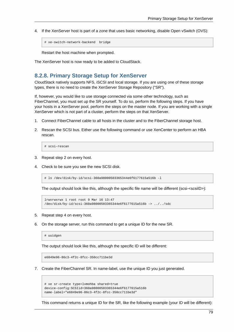
Primary Storage Setup for XenServer
79
4. If the XenServer host is part of a zone that uses basic networking, disable Open vSwitch (OVS):
# xe-switch-network-backend bridge
Restart the host machine when prompted.
The XenServer host is now ready to be added to CloudStack.
8.2.8. Primary Storage Setup for XenServerCloudStack natively supports NFS, iSCSI and local storage. If you are using one of these storagetypes, there is no need to create the XenServer Storage Repository ("SR").
If, however, you would like to use storage connected via some other technology, such asFiberChannel, you must set up the SR yourself. To do so, perform the following steps. If you haveyour hosts in a XenServer pool, perform the steps on the master node. If you are working with a singleXenServer which is not part of a cluster, perform the steps on that XenServer.
1. Connect FiberChannel cable to all hosts in the cluster and to the FiberChannel storage host.
2. Rescan the SCSI bus. Either use the following command or use XenCenter to perform an HBArescan.
# scsi-rescan
3. Repeat step 2 on every host.
4. Check to be sure you see the new SCSI disk.
# ls /dev/disk/by-id/scsi-360a98000503365344e6f6177615a516b -l
The output should look like this, although the specific file name will be different (scsi-<scsiID>):
lrwxrwxrwx 1 root root 9 Mar 16 13:47/dev/disk/by-id/scsi-360a98000503365344e6f6177615a516b -> ../../sdc
5. Repeat step 4 on every host.
6. On the storage server, run this command to get a unique ID for the new SR.
# uuidgen
The output should look like this, although the specific ID will be different:
e6849e96-86c3-4f2c-8fcc-350cc711be3d
7. Create the FiberChannel SR. In name-label, use the unique ID you just generated.
# xe sr-create type=lvmohba shared=truedevice-config:SCSIid=360a98000503365344e6f6177615a516bname-label="e6849e96-86c3-4f2c-8fcc-350cc711be3d"
This command returns a unique ID for the SR, like the following example (your ID will be different):
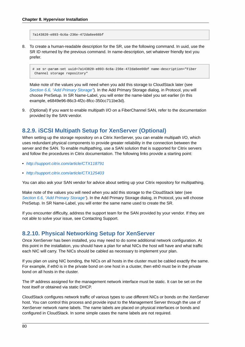
Chapter 8. Hypervisor Installation
80
7a143820-e893-6c6a-236e-472da6ee66bf
8. To create a human-readable description for the SR, use the following command. In uuid, use theSR ID returned by the previous command. In name-description, set whatever friendly text youprefer.
# xe sr-param-set uuid=7a143820-e893-6c6a-236e-472da6ee66bf name-description="Fiber Channel storage repository"
Make note of the values you will need when you add this storage to CloudStack later (seeSection 6.6, “Add Primary Storage”). In the Add Primary Storage dialog, in Protocol, you willchoose PreSetup. In SR Name-Label, you will enter the name-label you set earlier (in thisexample, e6849e96-86c3-4f2c-8fcc-350cc711be3d).
9. (Optional) If you want to enable multipath I/O on a FiberChannel SAN, refer to the documentationprovided by the SAN vendor.
8.2.9. iSCSI Multipath Setup for XenServer (Optional)When setting up the storage repository on a Citrix XenServer, you can enable multipath I/O, whichuses redundant physical components to provide greater reliability in the connection between theserver and the SAN. To enable multipathing, use a SAN solution that is supported for Citrix serversand follow the procedures in Citrix documentation. The following links provide a starting point:
• http://support.citrix.com/article/CTX118791
• http://support.citrix.com/article/CTX125403
You can also ask your SAN vendor for advice about setting up your Citrix repository for multipathing.
Make note of the values you will need when you add this storage to the CloudStack later (seeSection 6.6, “Add Primary Storage”). In the Add Primary Storage dialog, in Protocol, you will choosePreSetup. In SR Name-Label, you will enter the same name used to create the SR.
If you encounter difficulty, address the support team for the SAN provided by your vendor. If they arenot able to solve your issue, see Contacting Support.
8.2.10. Physical Networking Setup for XenServerOnce XenServer has been installed, you may need to do some additional network configuration. Atthis point in the installation, you should have a plan for what NICs the host will have and what trafficeach NIC will carry. The NICs should be cabled as necessary to implement your plan.
If you plan on using NIC bonding, the NICs on all hosts in the cluster must be cabled exactly the same.For example, if eth0 is in the private bond on one host in a cluster, then eth0 must be in the privatebond on all hosts in the cluster.
The IP address assigned for the management network interface must be static. It can be set on thehost itself or obtained via static DHCP.
CloudStack configures network traffic of various types to use different NICs or bonds on the XenServerhost. You can control this process and provide input to the Management Server through the use ofXenServer network name labels. The name labels are placed on physical interfaces or bonds andconfigured in CloudStack. In some simple cases the name labels are not required.
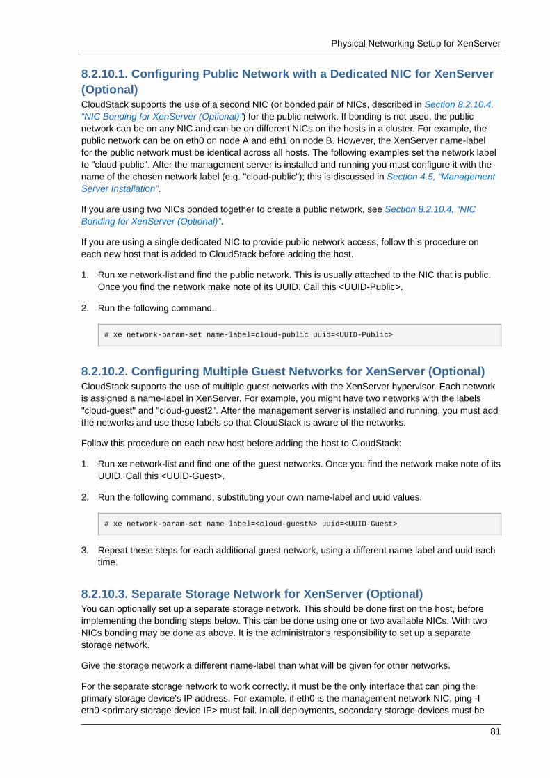
Physical Networking Setup for XenServer
81
8.2.10.1. Configuring Public Network with a Dedicated NIC for XenServer(Optional)CloudStack supports the use of a second NIC (or bonded pair of NICs, described in Section 8.2.10.4,“NIC Bonding for XenServer (Optional)”) for the public network. If bonding is not used, the publicnetwork can be on any NIC and can be on different NICs on the hosts in a cluster. For example, thepublic network can be on eth0 on node A and eth1 on node B. However, the XenServer name-labelfor the public network must be identical across all hosts. The following examples set the network labelto "cloud-public". After the management server is installed and running you must configure it with thename of the chosen network label (e.g. "cloud-public"); this is discussed in Section 4.5, “ManagementServer Installation”.
If you are using two NICs bonded together to create a public network, see Section 8.2.10.4, “NICBonding for XenServer (Optional)”.
If you are using a single dedicated NIC to provide public network access, follow this procedure oneach new host that is added to CloudStack before adding the host.
1. Run xe network-list and find the public network. This is usually attached to the NIC that is public.Once you find the network make note of its UUID. Call this <UUID-Public>.
2. Run the following command.
# xe network-param-set name-label=cloud-public uuid=<UUID-Public>
8.2.10.2. Configuring Multiple Guest Networks for XenServer (Optional)CloudStack supports the use of multiple guest networks with the XenServer hypervisor. Each networkis assigned a name-label in XenServer. For example, you might have two networks with the labels"cloud-guest" and "cloud-guest2". After the management server is installed and running, you must addthe networks and use these labels so that CloudStack is aware of the networks.
Follow this procedure on each new host before adding the host to CloudStack:
1. Run xe network-list and find one of the guest networks. Once you find the network make note of itsUUID. Call this <UUID-Guest>.
2. Run the following command, substituting your own name-label and uuid values.
# xe network-param-set name-label=<cloud-guestN> uuid=<UUID-Guest>
3. Repeat these steps for each additional guest network, using a different name-label and uuid eachtime.
8.2.10.3. Separate Storage Network for XenServer (Optional)You can optionally set up a separate storage network. This should be done first on the host, beforeimplementing the bonding steps below. This can be done using one or two available NICs. With twoNICs bonding may be done as above. It is the administrator's responsibility to set up a separatestorage network.
Give the storage network a different name-label than what will be given for other networks.
For the separate storage network to work correctly, it must be the only interface that can ping theprimary storage device's IP address. For example, if eth0 is the management network NIC, ping -Ieth0 <primary storage device IP> must fail. In all deployments, secondary storage devices must be
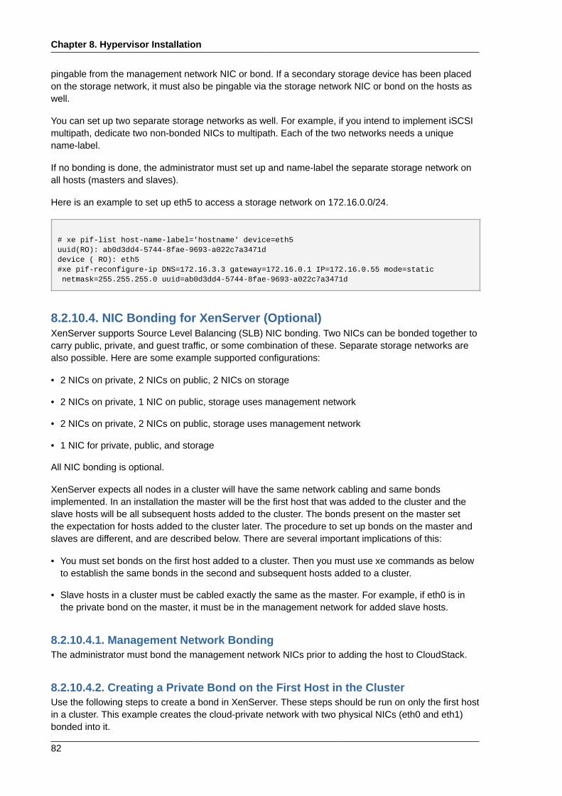
Chapter 8. Hypervisor Installation
82
pingable from the management network NIC or bond. If a secondary storage device has been placedon the storage network, it must also be pingable via the storage network NIC or bond on the hosts aswell.
You can set up two separate storage networks as well. For example, if you intend to implement iSCSImultipath, dedicate two non-bonded NICs to multipath. Each of the two networks needs a uniquename-label.
If no bonding is done, the administrator must set up and name-label the separate storage network onall hosts (masters and slaves).
Here is an example to set up eth5 to access a storage network on 172.16.0.0/24.
# xe pif-list host-name-label='hostname' device=eth5uuid(RO): ab0d3dd4-5744-8fae-9693-a022c7a3471ddevice ( RO): eth5#xe pif-reconfigure-ip DNS=172.16.3.3 gateway=172.16.0.1 IP=172.16.0.55 mode=static netmask=255.255.255.0 uuid=ab0d3dd4-5744-8fae-9693-a022c7a3471d
8.2.10.4. NIC Bonding for XenServer (Optional)XenServer supports Source Level Balancing (SLB) NIC bonding. Two NICs can be bonded together tocarry public, private, and guest traffic, or some combination of these. Separate storage networks arealso possible. Here are some example supported configurations:
• 2 NICs on private, 2 NICs on public, 2 NICs on storage
• 2 NICs on private, 1 NIC on public, storage uses management network
• 2 NICs on private, 2 NICs on public, storage uses management network
• 1 NIC for private, public, and storage
All NIC bonding is optional.
XenServer expects all nodes in a cluster will have the same network cabling and same bondsimplemented. In an installation the master will be the first host that was added to the cluster and theslave hosts will be all subsequent hosts added to the cluster. The bonds present on the master setthe expectation for hosts added to the cluster later. The procedure to set up bonds on the master andslaves are different, and are described below. There are several important implications of this:
• You must set bonds on the first host added to a cluster. Then you must use xe commands as belowto establish the same bonds in the second and subsequent hosts added to a cluster.
• Slave hosts in a cluster must be cabled exactly the same as the master. For example, if eth0 is inthe private bond on the master, it must be in the management network for added slave hosts.
8.2.10.4.1. Management Network BondingThe administrator must bond the management network NICs prior to adding the host to CloudStack.
8.2.10.4.2. Creating a Private Bond on the First Host in the ClusterUse the following steps to create a bond in XenServer. These steps should be run on only the first hostin a cluster. This example creates the cloud-private network with two physical NICs (eth0 and eth1)bonded into it.
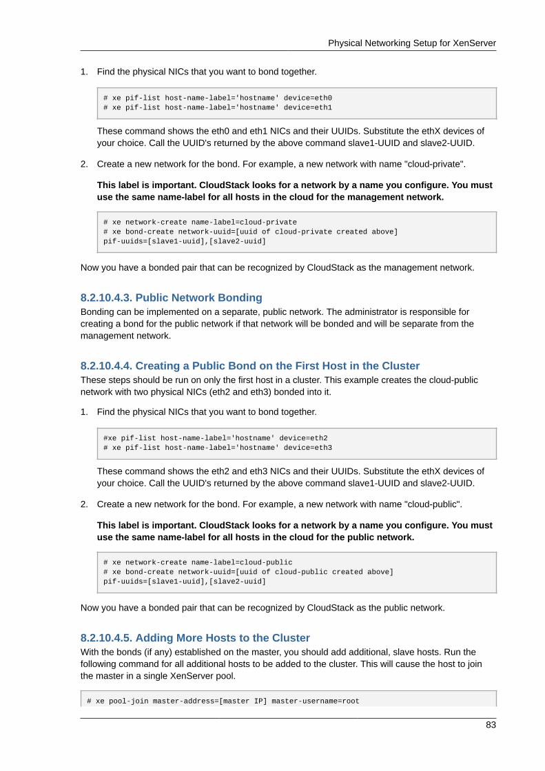
Physical Networking Setup for XenServer
83
1. Find the physical NICs that you want to bond together.
# xe pif-list host-name-label='hostname' device=eth0# xe pif-list host-name-label='hostname' device=eth1
These command shows the eth0 and eth1 NICs and their UUIDs. Substitute the ethX devices ofyour choice. Call the UUID's returned by the above command slave1-UUID and slave2-UUID.
2. Create a new network for the bond. For example, a new network with name "cloud-private".
This label is important. CloudStack looks for a network by a name you configure. You mustuse the same name-label for all hosts in the cloud for the management network.
# xe network-create name-label=cloud-private# xe bond-create network-uuid=[uuid of cloud-private created above]pif-uuids=[slave1-uuid],[slave2-uuid]
Now you have a bonded pair that can be recognized by CloudStack as the management network.
8.2.10.4.3. Public Network BondingBonding can be implemented on a separate, public network. The administrator is responsible forcreating a bond for the public network if that network will be bonded and will be separate from themanagement network.
8.2.10.4.4. Creating a Public Bond on the First Host in the ClusterThese steps should be run on only the first host in a cluster. This example creates the cloud-publicnetwork with two physical NICs (eth2 and eth3) bonded into it.
1. Find the physical NICs that you want to bond together.
#xe pif-list host-name-label='hostname' device=eth2# xe pif-list host-name-label='hostname' device=eth3
These command shows the eth2 and eth3 NICs and their UUIDs. Substitute the ethX devices ofyour choice. Call the UUID's returned by the above command slave1-UUID and slave2-UUID.
2. Create a new network for the bond. For example, a new network with name "cloud-public".
This label is important. CloudStack looks for a network by a name you configure. You mustuse the same name-label for all hosts in the cloud for the public network.
# xe network-create name-label=cloud-public# xe bond-create network-uuid=[uuid of cloud-public created above]pif-uuids=[slave1-uuid],[slave2-uuid]
Now you have a bonded pair that can be recognized by CloudStack as the public network.
8.2.10.4.5. Adding More Hosts to the ClusterWith the bonds (if any) established on the master, you should add additional, slave hosts. Run thefollowing command for all additional hosts to be added to the cluster. This will cause the host to jointhe master in a single XenServer pool.
# xe pool-join master-address=[master IP] master-username=root
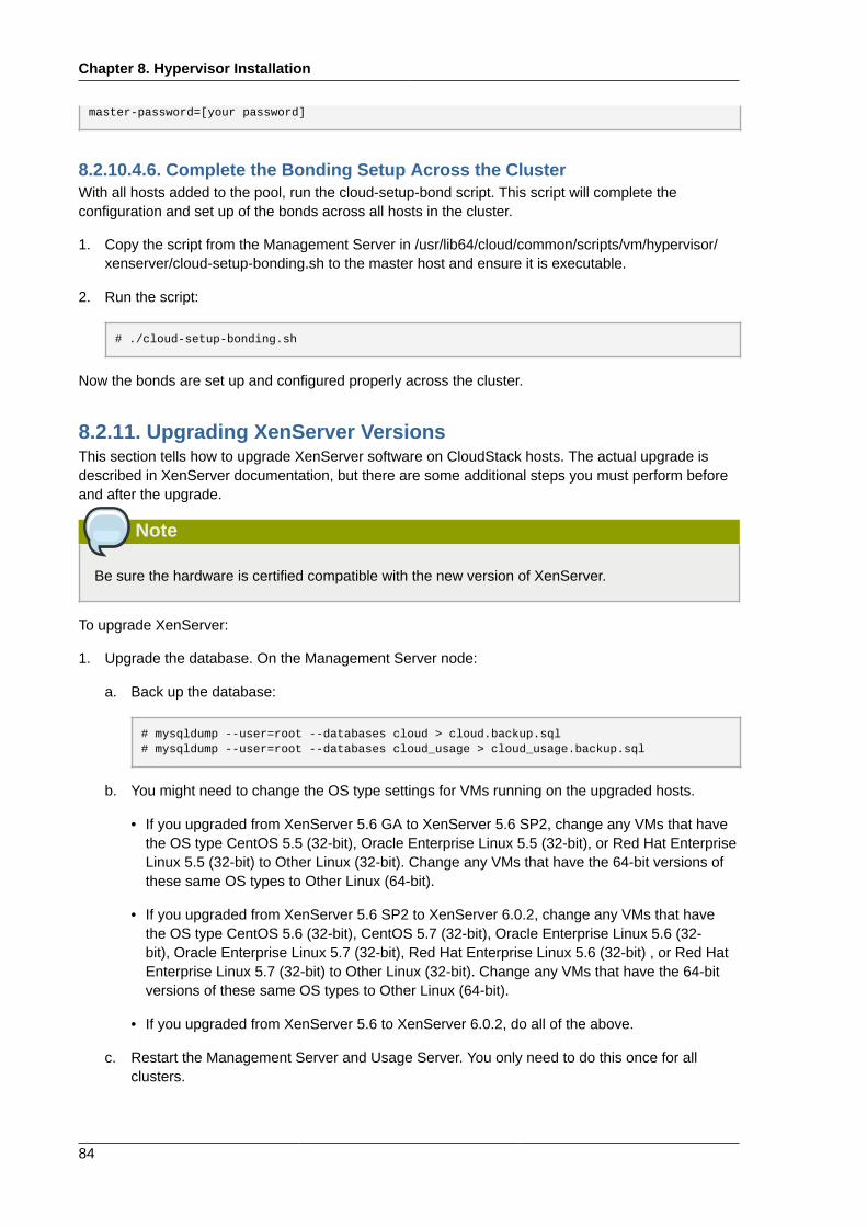
Chapter 8. Hypervisor Installation
84
master-password=[your password]
8.2.10.4.6. Complete the Bonding Setup Across the ClusterWith all hosts added to the pool, run the cloud-setup-bond script. This script will complete theconfiguration and set up of the bonds across all hosts in the cluster.
1. Copy the script from the Management Server in /usr/lib64/cloud/common/scripts/vm/hypervisor/xenserver/cloud-setup-bonding.sh to the master host and ensure it is executable.
2. Run the script:
# ./cloud-setup-bonding.sh
Now the bonds are set up and configured properly across the cluster.
8.2.11. Upgrading XenServer VersionsThis section tells how to upgrade XenServer software on CloudStack hosts. The actual upgrade isdescribed in XenServer documentation, but there are some additional steps you must perform beforeand after the upgrade.
Note
Be sure the hardware is certified compatible with the new version of XenServer.
To upgrade XenServer:
1. Upgrade the database. On the Management Server node:
a. Back up the database:
# mysqldump --user=root --databases cloud > cloud.backup.sql# mysqldump --user=root --databases cloud_usage > cloud_usage.backup.sql
b. You might need to change the OS type settings for VMs running on the upgraded hosts.
• If you upgraded from XenServer 5.6 GA to XenServer 5.6 SP2, change any VMs that havethe OS type CentOS 5.5 (32-bit), Oracle Enterprise Linux 5.5 (32-bit), or Red Hat EnterpriseLinux 5.5 (32-bit) to Other Linux (32-bit). Change any VMs that have the 64-bit versions ofthese same OS types to Other Linux (64-bit).
• If you upgraded from XenServer 5.6 SP2 to XenServer 6.0.2, change any VMs that havethe OS type CentOS 5.6 (32-bit), CentOS 5.7 (32-bit), Oracle Enterprise Linux 5.6 (32-bit), Oracle Enterprise Linux 5.7 (32-bit), Red Hat Enterprise Linux 5.6 (32-bit) , or Red HatEnterprise Linux 5.7 (32-bit) to Other Linux (32-bit). Change any VMs that have the 64-bitversions of these same OS types to Other Linux (64-bit).
• If you upgraded from XenServer 5.6 to XenServer 6.0.2, do all of the above.
c. Restart the Management Server and Usage Server. You only need to do this once for allclusters.
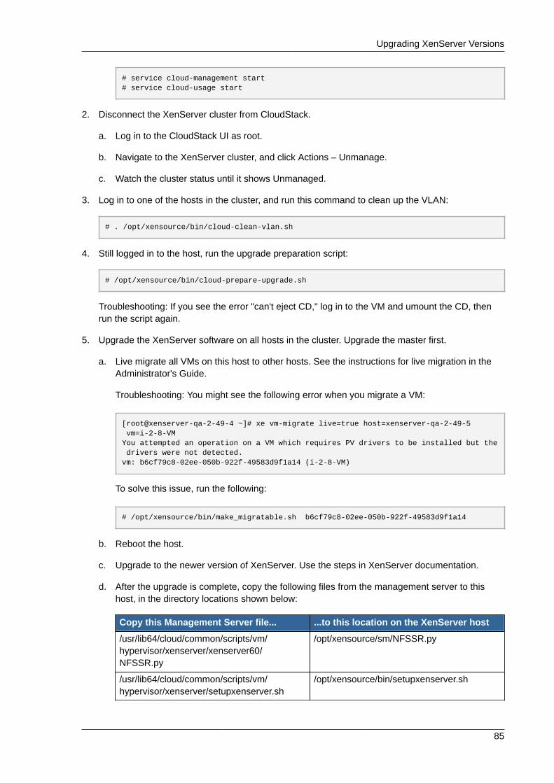
Upgrading XenServer Versions
85
# service cloud-management start# service cloud-usage start
2. Disconnect the XenServer cluster from CloudStack.
a. Log in to the CloudStack UI as root.
b. Navigate to the XenServer cluster, and click Actions – Unmanage.
c. Watch the cluster status until it shows Unmanaged.
3. Log in to one of the hosts in the cluster, and run this command to clean up the VLAN:
# . /opt/xensource/bin/cloud-clean-vlan.sh
4. Still logged in to the host, run the upgrade preparation script:
# /opt/xensource/bin/cloud-prepare-upgrade.sh
Troubleshooting: If you see the error "can't eject CD," log in to the VM and umount the CD, thenrun the script again.
5. Upgrade the XenServer software on all hosts in the cluster. Upgrade the master first.
a. Live migrate all VMs on this host to other hosts. See the instructions for live migration in theAdministrator's Guide.
Troubleshooting: You might see the following error when you migrate a VM:
[root@xenserver-qa-2-49-4 ~]# xe vm-migrate live=true host=xenserver-qa-2-49-5 vm=i-2-8-VMYou attempted an operation on a VM which requires PV drivers to be installed but the drivers were not detected.vm: b6cf79c8-02ee-050b-922f-49583d9f1a14 (i-2-8-VM)
To solve this issue, run the following:
# /opt/xensource/bin/make_migratable.sh b6cf79c8-02ee-050b-922f-49583d9f1a14
b. Reboot the host.
c. Upgrade to the newer version of XenServer. Use the steps in XenServer documentation.
d. After the upgrade is complete, copy the following files from the management server to thishost, in the directory locations shown below:
Copy this Management Server file... ...to this location on the XenServer host
/usr/lib64/cloud/common/scripts/vm/hypervisor/xenserver/xenserver60/NFSSR.py
/opt/xensource/sm/NFSSR.py
/usr/lib64/cloud/common/scripts/vm/hypervisor/xenserver/setupxenserver.sh
/opt/xensource/bin/setupxenserver.sh
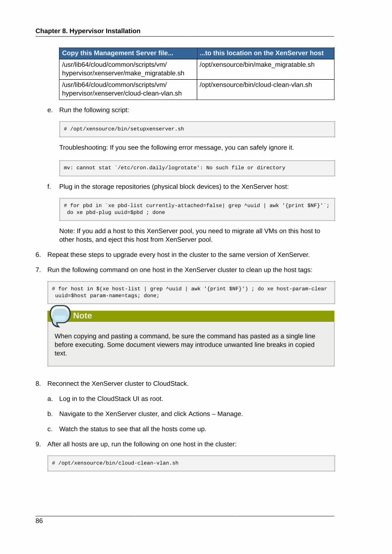
Chapter 8. Hypervisor Installation
86
Copy this Management Server file... ...to this location on the XenServer host
/usr/lib64/cloud/common/scripts/vm/hypervisor/xenserver/make_migratable.sh
/opt/xensource/bin/make_migratable.sh
/usr/lib64/cloud/common/scripts/vm/hypervisor/xenserver/cloud-clean-vlan.sh
/opt/xensource/bin/cloud-clean-vlan.sh
e. Run the following script:
# /opt/xensource/bin/setupxenserver.sh
Troubleshooting: If you see the following error message, you can safely ignore it.
mv: cannot stat `/etc/cron.daily/logrotate': No such file or directory
f. Plug in the storage repositories (physical block devices) to the XenServer host:
# for pbd in `xe pbd-list currently-attached=false| grep ^uuid | awk '{print $NF}'`; do xe pbd-plug uuid=$pbd ; done
Note: If you add a host to this XenServer pool, you need to migrate all VMs on this host toother hosts, and eject this host from XenServer pool.
6. Repeat these steps to upgrade every host in the cluster to the same version of XenServer.
7. Run the following command on one host in the XenServer cluster to clean up the host tags:
# for host in $(xe host-list | grep ^uuid | awk '{print $NF}') ; do xe host-param-clear uuid=$host param-name=tags; done;
Note
When copying and pasting a command, be sure the command has pasted as a single linebefore executing. Some document viewers may introduce unwanted line breaks in copiedtext.
8. Reconnect the XenServer cluster to CloudStack.
a. Log in to the CloudStack UI as root.
b. Navigate to the XenServer cluster, and click Actions – Manage.
c. Watch the status to see that all the hosts come up.
9. After all hosts are up, run the following on one host in the cluster:
# /opt/xensource/bin/cloud-clean-vlan.sh
VMware vSphere Installation and Configuration
87
8.3. VMware vSphere Installation and ConfigurationIf you want to use the VMware vSphere hypervisor to run guest virtual machines, install vSphere onthe host(s) in your cloud.
8.3.1. System Requirements for vSphere Hosts
8.3.1.1. Software requirements:• vSphere and vCenter, both version 4.1 or 5.0.
vSphere Standard is recommended. Note however that customers need to consider theCPU constraints in place with vSphere licensing. See http://www.vmware.com/files/pdf/vsphere_pricing.pdf and discuss with your VMware sales representative.
vCenter Server Standard is recommended.
• Be sure all the hotfixes provided by the hypervisor vendor are applied. Track the release ofhypervisor patches through your hypervisor vendor's support channel, and apply patches as soonas possible after they are released. CloudStack will not track or notify you of required hypervisorpatches. It is essential that your hosts are completely up to date with the provided hypervisorpatches. The hypervisor vendor is likely to refuse to support any system that is not up to date withpatches.
Apply All Necessary Hotfixes
The lack of up-do-date hotfixes can lead to data corruption and lost VMs.
8.3.1.2. Hardware requirements:• The host must be certified as compatible with vSphere. See the VMware Hardware Compatibility
Guide at http://www.vmware.com/resources/compatibility/search.php.
• All hosts must be 64-bit and must support HVM (Intel-VT or AMD-V enabled).
• All hosts within a cluster must be homogenous. That means the CPUs must be of the same type,count, and feature flags.
• 64-bit x86 CPU (more cores results in better performance)
• Hardware virtualization support required
• 4 GB of memory
• 36 GB of local disk
• At least 1 NIC
• Statically allocated IP Address
8.3.1.3. vCenter Server requirements:• Processor - 2 CPUs 2.0GHz or higher Intel or AMD x86 processors. Processor requirements may be
higher if the database runs on the same machine.
Chapter 8. Hypervisor Installation
88
• Memory - 3GB RAM. RAM requirements may be higher if your database runs on the same machine.
• Disk storage - 2GB. Disk requirements may be higher if your database runs on the same machine.
• Microsoft SQL Server 2005 Express disk requirements. The bundled database requires up to 2GBfree disk space to decompress the installation archive.
• Networking - 1Gbit or 10Gbit.
For more information, see "vCenter Server and the vSphere Client Hardware Requirements" at http://pubs.vmware.com/vsp40/wwhelp/wwhimpl/js/html/wwhelp.htm#href=install/c_vc_hw.html.
8.3.1.4. Other requirements:• VMware vCenter Standard Edition 4.1 or 5.0 must be installed and available to manage the vSphere
hosts.
• vCenter must be configured to use the standard port 443 so that it can communicate with theCloudStack Management Server.
• You must re-install VMware ESXi if you are going to re-use a host from a previous install.
• CloudStack requires VMware vSphere 4.1 or 5.0. VMware vSphere 4.0 is not supported.
• All hosts must be 64-bit and must support HVM (Intel-VT or AMD-V enabled). All hosts within acluster must be homogenous. That means the CPUs must be of the same type, count, and featureflags.
• The CloudStack management network must not be configured as a separate virtual network. TheCloudStack management network is the same as the vCenter management network, and will inheritits configuration. See Section 8.3.5.2, “Configure vCenter Management Network”.
• CloudStack requires ESXi. ESX is not supported.
• All resources used for CloudStack must be used for CloudStack only. CloudStack cannot shareinstance of ESXi or storage with other management consoles. Do not share the same storagevolumes that will be used by CloudStack with a different set of ESXi servers that are not managedby CloudStack.
• Put all target ESXi hypervisors in a cluster in a separate Datacenter in vCenter.
• The cluster that will be managed by CloudStack should not contain any VMs. Do not run themanagement server, vCenter or any other VMs on the cluster that is designated for CloudStack use.Create a separate cluster for use of CloudStack and make sure that they are no VMs in this cluster.
• All the required VLANS must be trunked into all network switches that are connected to the ESXihypervisor hosts. These would include the VLANS for Management, Storage, vMotion, and guestVLANs. The guest VLAN (used in Advanced Networking; see Network Setup) is a contiguous rangeof VLANs that will be managed by CloudStack.
8.3.2. Preparation Checklist for VMwareFor a smoother installation, gather the following information before you start:
• Information listed in Section 8.3.2.1, “vCenter Checklist”
• Information listed in Section 8.3.2.2, “Networking Checklist for VMware”
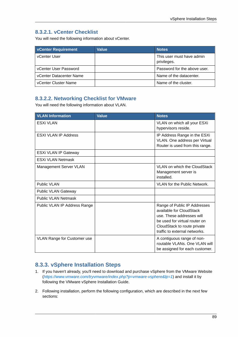
vSphere Installation Steps
89
8.3.2.1. vCenter ChecklistYou will need the following information about vCenter.
vCenter Requirement Value Notes
vCenter User This user must have adminprivileges.
vCenter User Password Password for the above user.
vCenter Datacenter Name Name of the datacenter.
vCenter Cluster Name Name of the cluster.
8.3.2.2. Networking Checklist for VMwareYou will need the following information about VLAN.
VLAN Information Value Notes
ESXi VLAN VLAN on which all your ESXihypervisors reside.
ESXI VLAN IP Address IP Address Range in the ESXiVLAN. One address per VirtualRouter is used from this range.
ESXi VLAN IP Gateway
ESXi VLAN Netmask
Management Server VLAN VLAN on which the CloudStackManagement server isinstalled.
Public VLAN VLAN for the Public Network.
Public VLAN Gateway
Public VLAN Netmask
Public VLAN IP Address Range Range of Public IP Addressesavailable for CloudStackuse. These addresses willbe used for virtual router onCloudStack to route privatetraffic to external networks.
VLAN Range for Customer use A contiguous range of non-routable VLANs. One VLAN willbe assigned for each customer.
8.3.3. vSphere Installation Steps1. If you haven't already, you'll need to download and purchase vSphere from the VMware Website
(https://www.vmware.com/tryvmware/index.php?p=vmware-vsphere&lp=1) and install it byfollowing the VMware vSphere Installation Guide.
2. Following installation, perform the following configuration, which are described in the next fewsections:
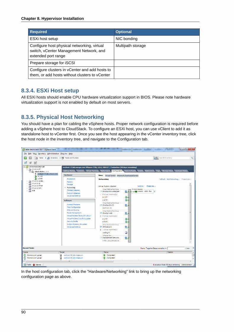
Chapter 8. Hypervisor Installation
90
Required Optional
ESXi host setup NIC bonding
Configure host physical networking, virtualswitch, vCenter Management Network, andextended port range
Multipath storage
Prepare storage for iSCSI
Configure clusters in vCenter and add hosts tothem, or add hosts without clusters to vCenter
8.3.4. ESXi Host setupAll ESXi hosts should enable CPU hardware virtualization support in BIOS. Please note hardwarevirtualization support is not enabled by default on most servers.
8.3.5. Physical Host NetworkingYou should have a plan for cabling the vSphere hosts. Proper network configuration is required beforeadding a vSphere host to CloudStack. To configure an ESXi host, you can use vClient to add it asstandalone host to vCenter first. Once you see the host appearing in the vCenter inventory tree, clickthe host node in the inventory tree, and navigate to the Configuration tab.
In the host configuration tab, click the "Hardware/Networking" link to bring up the networkingconfiguration page as above.
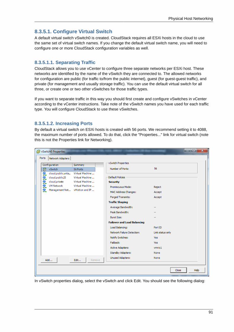
Physical Host Networking
91
8.3.5.1. Configure Virtual SwitchA default virtual switch vSwitch0 is created. CloudStack requires all ESXi hosts in the cloud to usethe same set of virtual switch names. If you change the default virtual switch name, you will need toconfigure one or more CloudStack configuration variables as well.
8.3.5.1.1. Separating TrafficCloudStack allows you to use vCenter to configure three separate networks per ESXi host. Thesenetworks are identified by the name of the vSwitch they are connected to. The allowed networksfor configuration are public (for traffic to/from the public internet), guest (for guest-guest traffic), andprivate (for management and usually storage traffic). You can use the default virtual switch for allthree, or create one or two other vSwitches for those traffic types.
If you want to separate traffic in this way you should first create and configure vSwitches in vCenteraccording to the vCenter instructions. Take note of the vSwitch names you have used for each traffictype. You will configure CloudStack to use these vSwitches.
8.3.5.1.2. Increasing PortsBy default a virtual switch on ESXi hosts is created with 56 ports. We recommend setting it to 4088,the maximum number of ports allowed. To do that, click the "Properties..." link for virtual switch (notethis is not the Properties link for Networking).
In vSwitch properties dialog, select the vSwitch and click Edit. You should see the following dialog:
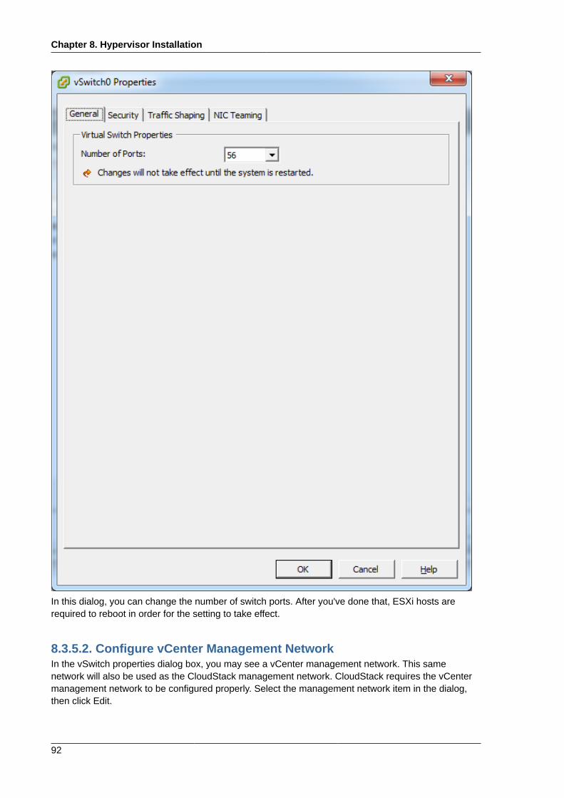
Chapter 8. Hypervisor Installation
92
In this dialog, you can change the number of switch ports. After you've done that, ESXi hosts arerequired to reboot in order for the setting to take effect.
8.3.5.2. Configure vCenter Management NetworkIn the vSwitch properties dialog box, you may see a vCenter management network. This samenetwork will also be used as the CloudStack management network. CloudStack requires the vCentermanagement network to be configured properly. Select the management network item in the dialog,then click Edit.
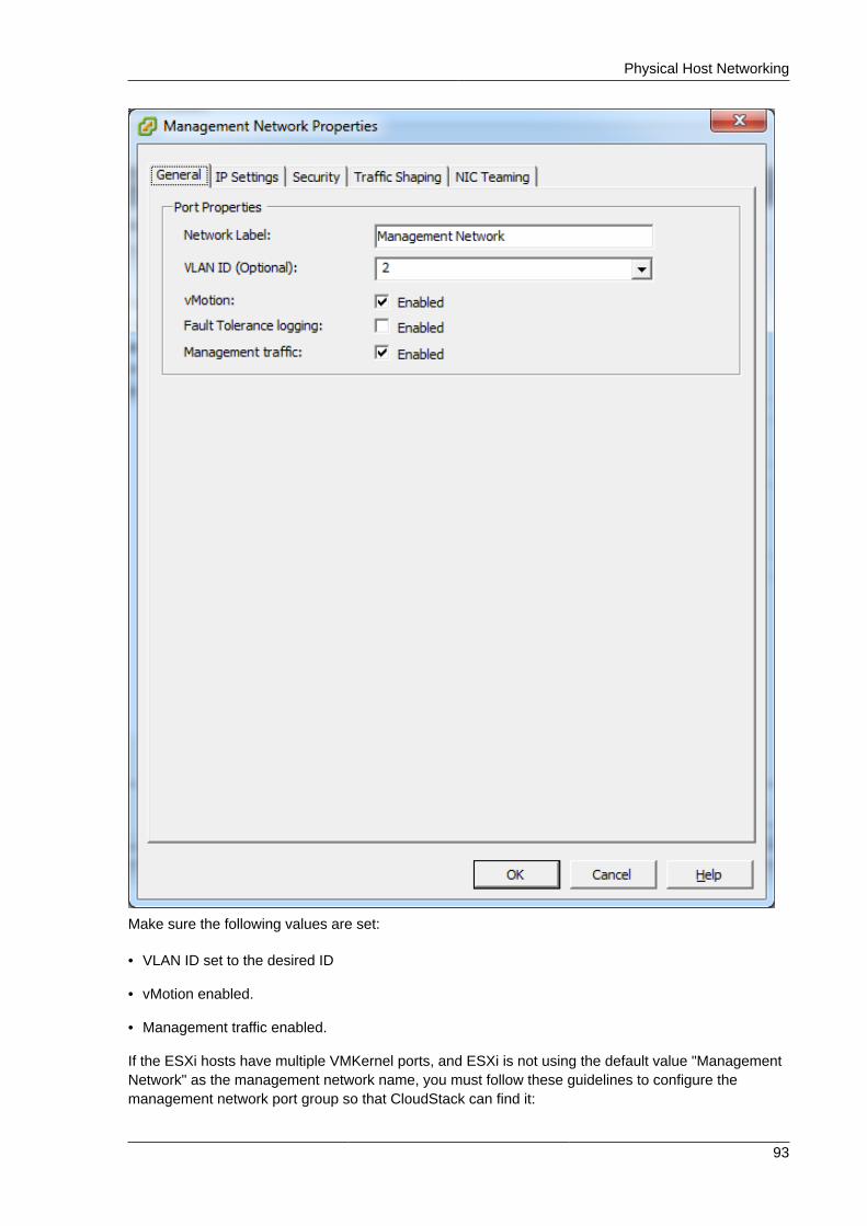
Physical Host Networking
93
Make sure the following values are set:
• VLAN ID set to the desired ID
• vMotion enabled.
• Management traffic enabled.
If the ESXi hosts have multiple VMKernel ports, and ESXi is not using the default value "ManagementNetwork" as the management network name, you must follow these guidelines to configure themanagement network port group so that CloudStack can find it:
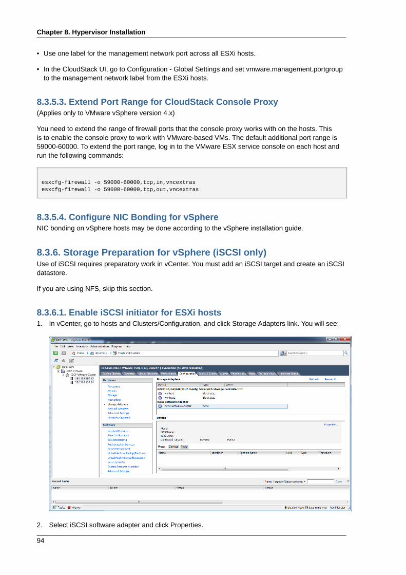
Chapter 8. Hypervisor Installation
94
• Use one label for the management network port across all ESXi hosts.
• In the CloudStack UI, go to Configuration - Global Settings and set vmware.management.portgroupto the management network label from the ESXi hosts.
8.3.5.3. Extend Port Range for CloudStack Console Proxy(Applies only to VMware vSphere version 4.x)
You need to extend the range of firewall ports that the console proxy works with on the hosts. Thisis to enable the console proxy to work with VMware-based VMs. The default additional port range is59000-60000. To extend the port range, log in to the VMware ESX service console on each host andrun the following commands:
esxcfg-firewall -o 59000-60000,tcp,in,vncextrasesxcfg-firewall -o 59000-60000,tcp,out,vncextras
8.3.5.4. Configure NIC Bonding for vSphereNIC bonding on vSphere hosts may be done according to the vSphere installation guide.
8.3.6. Storage Preparation for vSphere (iSCSI only)Use of iSCSI requires preparatory work in vCenter. You must add an iSCSI target and create an iSCSIdatastore.
If you are using NFS, skip this section.
8.3.6.1. Enable iSCSI initiator for ESXi hosts1. In vCenter, go to hosts and Clusters/Configuration, and click Storage Adapters link. You will see:
2. Select iSCSI software adapter and click Properties.
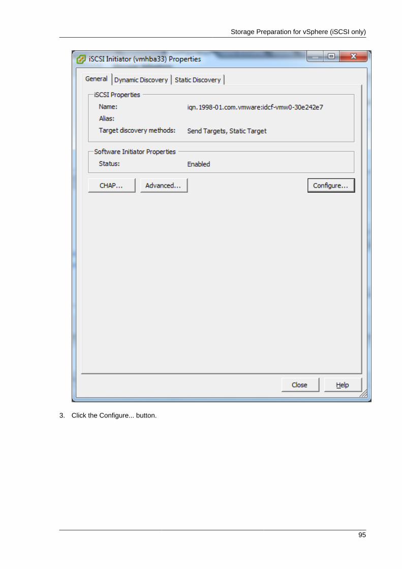
Storage Preparation for vSphere (iSCSI only)
95
3. Click the Configure... button.
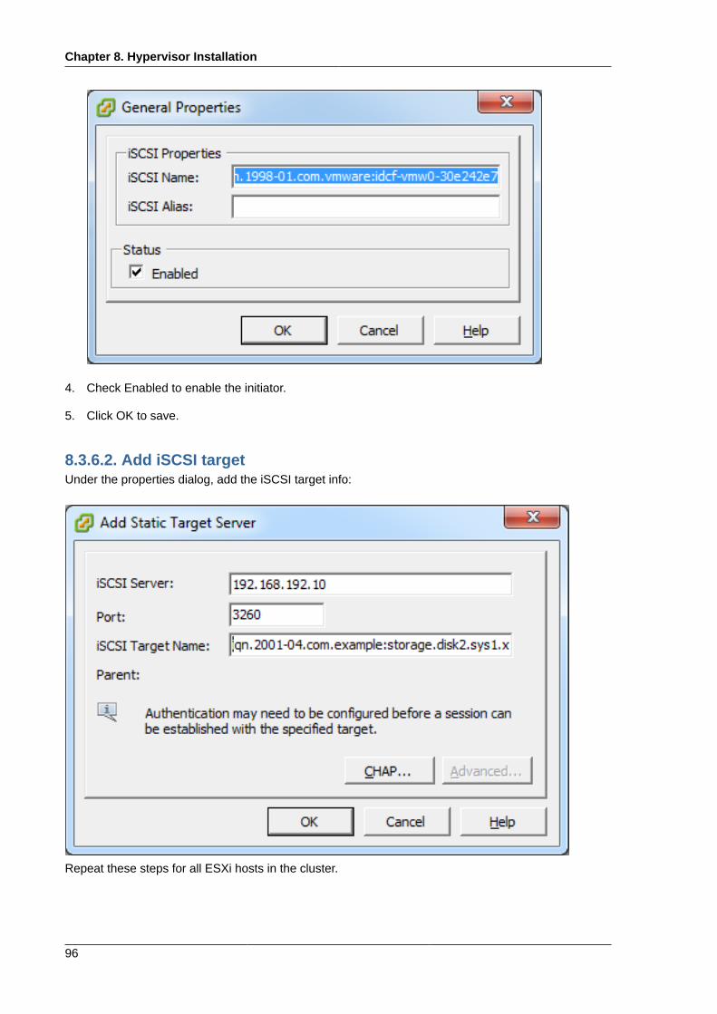
Chapter 8. Hypervisor Installation
96
4. Check Enabled to enable the initiator.
5. Click OK to save.
8.3.6.2. Add iSCSI targetUnder the properties dialog, add the iSCSI target info:
Repeat these steps for all ESXi hosts in the cluster.
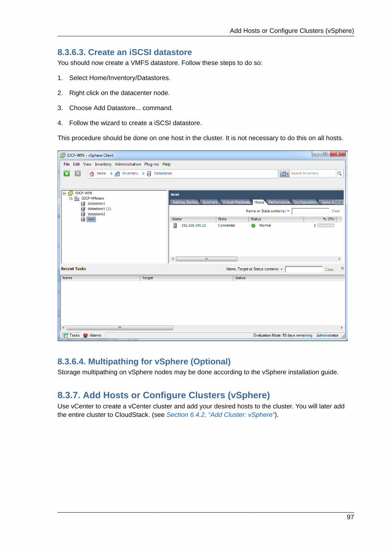
Add Hosts or Configure Clusters (vSphere)
97
8.3.6.3. Create an iSCSI datastoreYou should now create a VMFS datastore. Follow these steps to do so:
1. Select Home/Inventory/Datastores.
2. Right click on the datacenter node.
3. Choose Add Datastore... command.
4. Follow the wizard to create a iSCSI datastore.
This procedure should be done on one host in the cluster. It is not necessary to do this on all hosts.
8.3.6.4. Multipathing for vSphere (Optional)Storage multipathing on vSphere nodes may be done according to the vSphere installation guide.
8.3.7. Add Hosts or Configure Clusters (vSphere)Use vCenter to create a vCenter cluster and add your desired hosts to the cluster. You will later addthe entire cluster to CloudStack. (see Section 6.4.2, “Add Cluster: vSphere”).

98
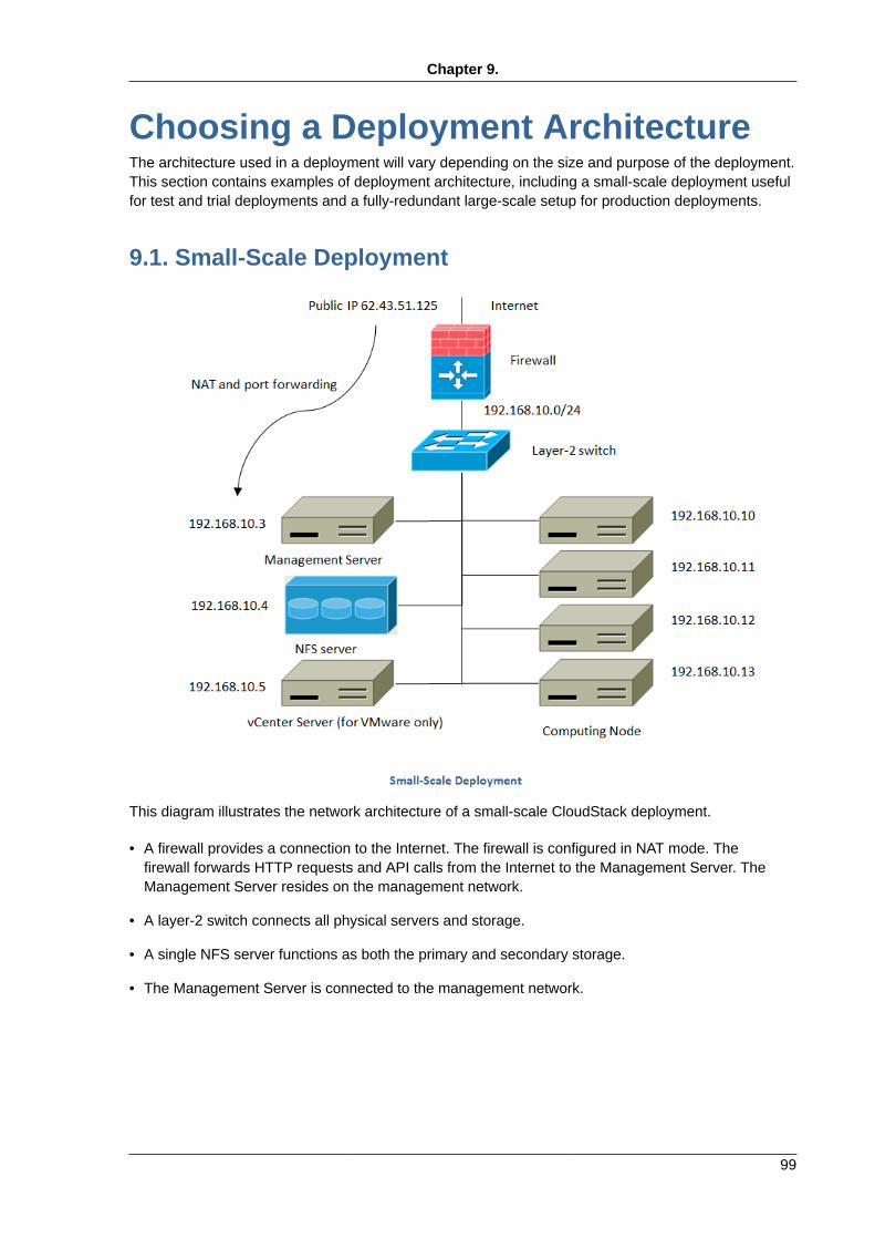
Chapter 9.
99
Choosing a Deployment ArchitectureThe architecture used in a deployment will vary depending on the size and purpose of the deployment.This section contains examples of deployment architecture, including a small-scale deployment usefulfor test and trial deployments and a fully-redundant large-scale setup for production deployments.
9.1. Small-Scale Deployment
This diagram illustrates the network architecture of a small-scale CloudStack deployment.
• A firewall provides a connection to the Internet. The firewall is configured in NAT mode. Thefirewall forwards HTTP requests and API calls from the Internet to the Management Server. TheManagement Server resides on the management network.
• A layer-2 switch connects all physical servers and storage.
• A single NFS server functions as both the primary and secondary storage.
• The Management Server is connected to the management network.
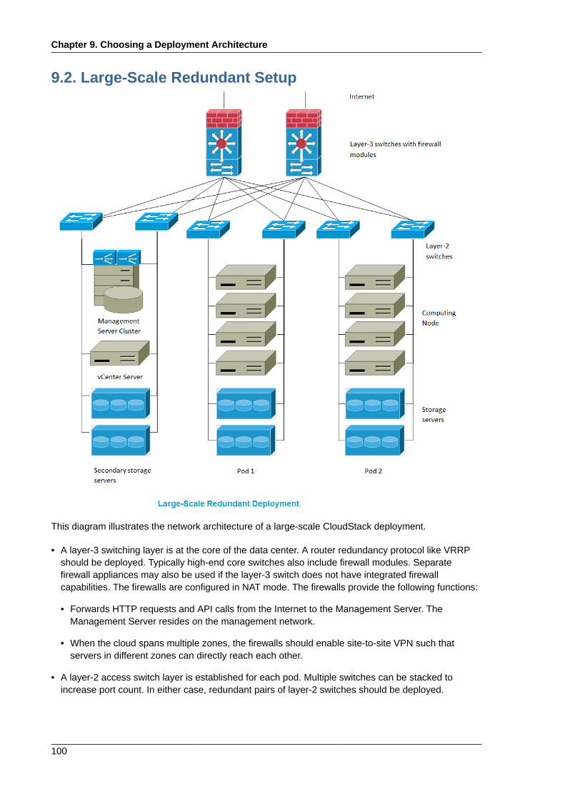
Chapter 9. Choosing a Deployment Architecture
100
9.2. Large-Scale Redundant Setup
This diagram illustrates the network architecture of a large-scale CloudStack deployment.
• A layer-3 switching layer is at the core of the data center. A router redundancy protocol like VRRPshould be deployed. Typically high-end core switches also include firewall modules. Separatefirewall appliances may also be used if the layer-3 switch does not have integrated firewallcapabilities. The firewalls are configured in NAT mode. The firewalls provide the following functions:
• Forwards HTTP requests and API calls from the Internet to the Management Server. TheManagement Server resides on the management network.
• When the cloud spans multiple zones, the firewalls should enable site-to-site VPN such thatservers in different zones can directly reach each other.
• A layer-2 access switch layer is established for each pod. Multiple switches can be stacked toincrease port count. In either case, redundant pairs of layer-2 switches should be deployed.
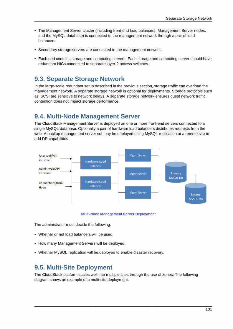
Separate Storage Network
101
• The Management Server cluster (including front-end load balancers, Management Server nodes,and the MySQL database) is connected to the management network through a pair of loadbalancers.
• Secondary storage servers are connected to the management network.
• Each pod contains storage and computing servers. Each storage and computing server should haveredundant NICs connected to separate layer-2 access switches.
9.3. Separate Storage NetworkIn the large-scale redundant setup described in the previous section, storage traffic can overload themanagement network. A separate storage network is optional for deployments. Storage protocols suchas iSCSI are sensitive to network delays. A separate storage network ensures guest network trafficcontention does not impact storage performance.
9.4. Multi-Node Management ServerThe CloudStack Management Server is deployed on one or more front-end servers connected to asingle MySQL database. Optionally a pair of hardware load balancers distributes requests from theweb. A backup management server set may be deployed using MySQL replication at a remote site toadd DR capabilities.
The administrator must decide the following.
• Whether or not load balancers will be used.
• How many Management Servers will be deployed.
• Whether MySQL replication will be deployed to enable disaster recovery.
9.5. Multi-Site DeploymentThe CloudStack platform scales well into multiple sites through the use of zones. The followingdiagram shows an example of a multi-site deployment.
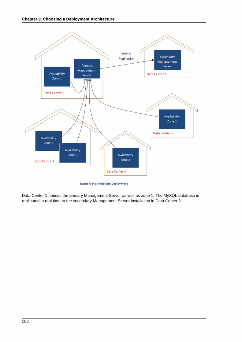
Chapter 9. Choosing a Deployment Architecture
102
Data Center 1 houses the primary Management Server as well as zone 1. The MySQL database isreplicated in real time to the secondary Management Server installation in Data Center 2.
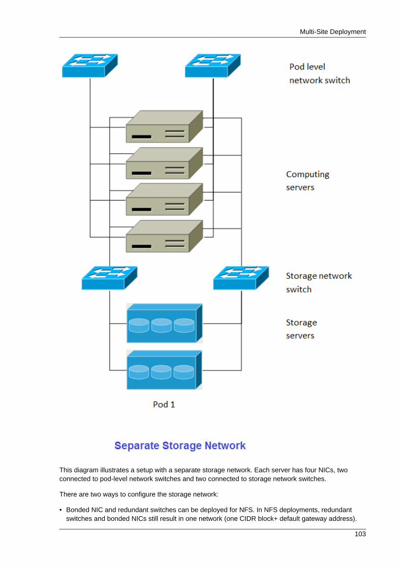
Multi-Site Deployment
103
This diagram illustrates a setup with a separate storage network. Each server has four NICs, twoconnected to pod-level network switches and two connected to storage network switches.
There are two ways to configure the storage network:
• Bonded NIC and redundant switches can be deployed for NFS. In NFS deployments, redundantswitches and bonded NICs still result in one network (one CIDR block+ default gateway address).
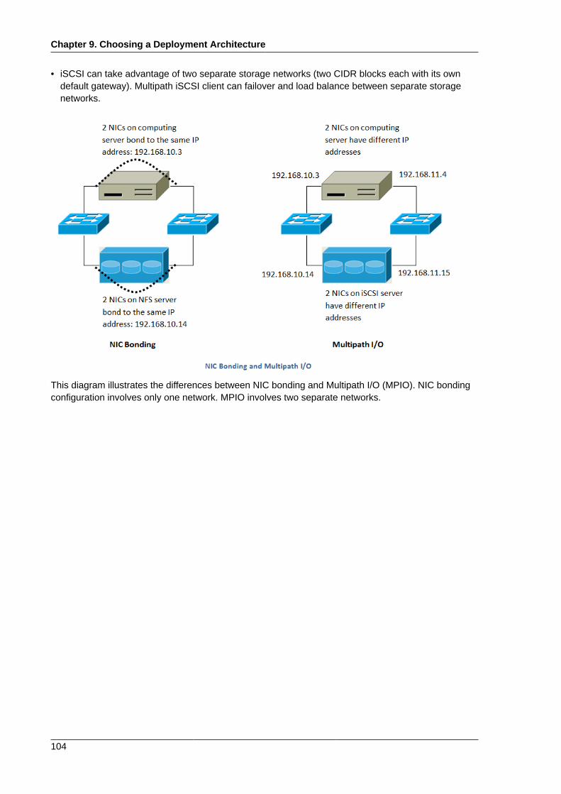
Chapter 9. Choosing a Deployment Architecture
104
• iSCSI can take advantage of two separate storage networks (two CIDR blocks each with its owndefault gateway). Multipath iSCSI client can failover and load balance between separate storagenetworks.
This diagram illustrates the differences between NIC bonding and Multipath I/O (MPIO). NIC bondingconfiguration involves only one network. MPIO involves two separate networks.
Chapter 10.
105
Amazon Web Service InterfaceCompatibility
10.1. Amazon Web Services EC2 Compatible InterfaceCloudStack can translate Amazon Web Services (AWS) API calls to native CloudStack API callsso that users can continue using existing AWS-compatible tools. This translation service runs asa separate web application in the same tomcat server as the management server of CloudStack,listening on the same port. This Amazon EC2-compatible API is accessible through a SOAP webservice.
Note
This service was previously enabled by separate software called CloudBridge. It is now fullyintegrated with the CloudStack management server.
Limitations
• Supported only in zones that use basic networking.
• Available in fresh installations of CloudStack. Not available through upgrade of previous versions.
• If you need to support features such as elastic IP, set up a Citrix NetScaler to provide this service.The commands such as ec2-associate-address will not work without EIP setup. Users running VMsin this zone will be using the NetScaler-enabled network offering (DefaultSharedNetscalerEIP andELBNetworkOffering).
10.2. System Requirements• This interface complies with Amazon's WDSL version dated November 15, 2010, available at http://
ec2.amazonaws.com/doc/2010-11-15/.
• Compatible with the EC2 command-line tools EC2 tools v. 1.3.6230, which can be downloaded athttp://s3.amazonaws.com/ec2-downloads/ec2-api-tools-1.3-62308.zip.
10.3. Enabling the AWS API Compatible InterfaceThe software that provides AWS API compatibility is installed along with CloudStack. However, youmust enable the feature and perform some setup steps.
1. Set the global configuration parameter enable.ec2.api to true. See Chapter 7, Global ConfigurationParameters.
2. Create a set of CloudStack service offerings with names that match the Amazon service offerings.You can do this through the CloudStack UI as described in the Administration Guide.
Chapter 10. Amazon Web Service Interface Compatibility
106
Warning
Be sure you have included the Amazon default service offering, m1.small.
3. If you did not already do so when you set the configuration parameter in step 1, restart theManagement Server.
# service cloud-management restart
4. (Optional) The AWS API listens for requests on port 7080. If you prefer AWS API to listen onanother port, you can change it as follows:
a. Edit the files /etc/cloud/management/server.xml, /etc/cloud/management/server-nonssl.xml,and /etc/cloud/management/server-ssl.xml.
b. In each file, find the tag <Service name="Catalina7080">. Under this tag, locate <Connectorexecutor="tomcatThreadPool-internal" port= ....<.
c. Change the port to whatever port you want to use, then save the files.
d. Restart the Management Server.
Note
If you re-install CloudStack, you will have to make these changes again.
10.4. AWS API User Setup StepsIn general, users need not be aware that they are using a translation service provided by CloudStack.They need only send AWS API calls to CloudStack's endpoint, and it will translate the calls to thenative API. Users of the Amazon EC2 compatible interface will be able to keep their existing EC2tools and scripts and use them with their CloudStack deployment, by specifying the endpoint of themanagement server and using the proper user credentials. In order to do this, each user must performthe following configuration steps:
• Generate user credentials and register with the service.
• Set up the environment variables for the EC2 command-line tools.
• For SOAP access, use the endpoint http://CloudStack-management-server:8080/awsapi.The CloudStack-management-server can be specified by a fully-qualified domain name or IPaddress.
10.4.1. AWS API User RegistrationEach user must perform a one-time registration. The user follows these steps:
AWS API Command-Line Tools Setup
107
1. Obtain the following by looking in the CloudStack UI, using the API, or asking the cloudadministrator:
• The CloudStack server's publicly available DNS name or IP address
• The user account's API key and Secret key
2. Generate a private key and a self-signed X.509 certificate. The user substitutes their own desiredstorage location for /path/to/… below.
$ openssl req -x509 -nodes -days 365 -newkey rsa:2048 -keyout /path/to/private_key.pem -out /path/to/cert.pem
3. Register the mapping from the X.509 certificate to the API/Secret keys. Download the followingscript from http://download.cloud.com/releases/3.0.3/cloudstack-aws-api-register and run it.Substitute the values that were obtained in step 1 in the URL below.
$ cloudstack-aws-api-register --apikey=User’s CloudStack API key --secretkey=User’s CloudStack Secret key --cert=/path/to/cert.pem --url=http://CloudStack.server:8080/awsapi
Note
A user with an existing AWS certificate could choose to use the same certificate with CloudStack,but the public key would be uploaded to the CloudStack management server database.
10.4.2. AWS API Command-Line Tools SetupTo use the EC2 command-line tools, the user must perform these steps:
1. Be sure you have the right version of EC2 Tools. The supported version is available at http://s3.amazonaws.com/ec2-downloads/ec2-api-tools-1.3-62308.zip.
2. Set up the environment variables that will direct the tools to the server. As a best practice, youmay wish to place these commands in a script that may be sourced before using the AWS APItranslation feature.
$ export EC2_CERT=/path/to/cert.pem$ export EC2_PRIVATE_KEY=/path/to/private_key.pem$ export EC2_URL=http://CloudStack.server:8080/awsapi$ export EC2_HOME=/path/to/EC2_tools_directory
10.5. Using Timeouts to Ensure AWS API CommandCompletionThe Amazon EC2 command-line tools have a default connection timeout. When used withCloudStack, a longer timeout might be needed for some commands. If you find that commands are notcompleting due to timeouts, you can gain more time for commands to finish by overriding the defaulttimeouts on individual commands. You can add the following optional command-line parameters to anyCloudStack-supported EC2 command:
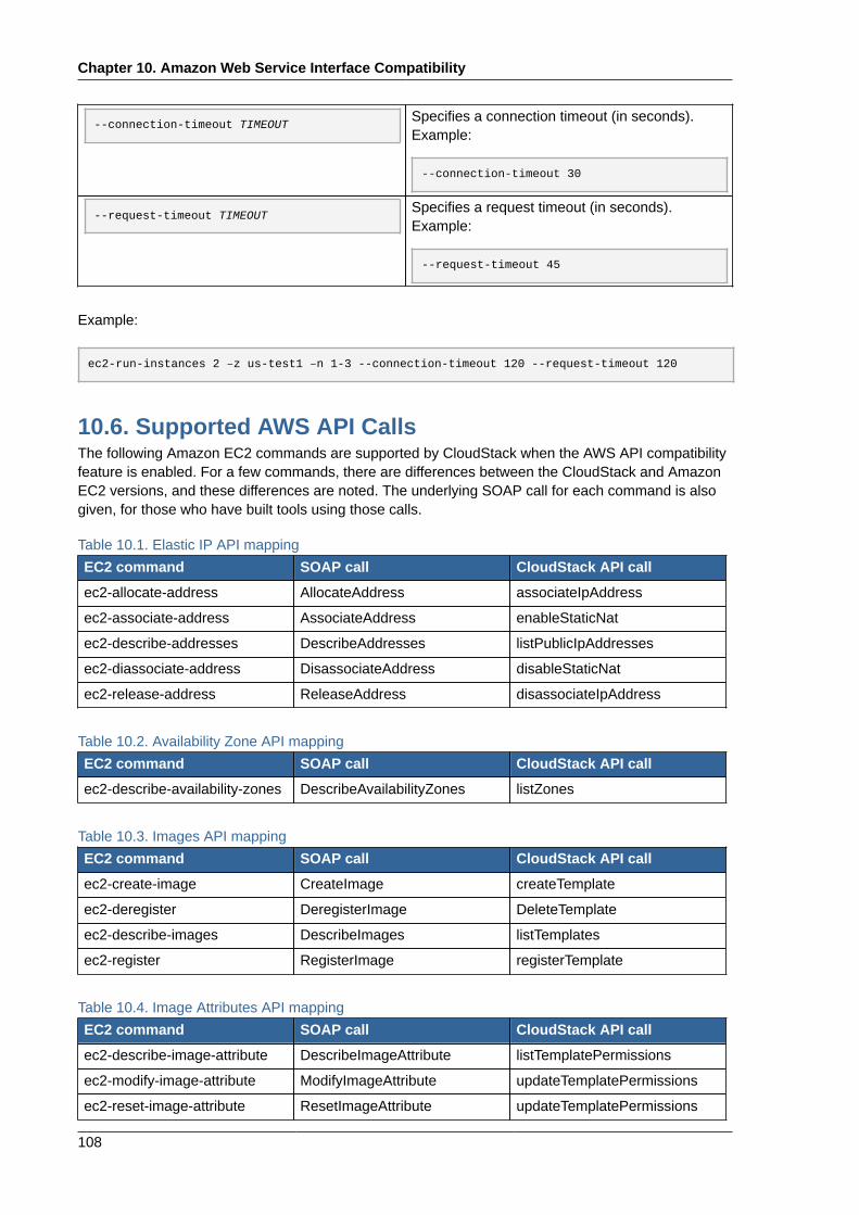
Chapter 10. Amazon Web Service Interface Compatibility
108
--connection-timeout TIMEOUTSpecifies a connection timeout (in seconds).Example:
--connection-timeout 30
--request-timeout TIMEOUTSpecifies a request timeout (in seconds).Example:
--request-timeout 45
Example:
ec2-run-instances 2 –z us-test1 –n 1-3 --connection-timeout 120 --request-timeout 120
10.6. Supported AWS API CallsThe following Amazon EC2 commands are supported by CloudStack when the AWS API compatibilityfeature is enabled. For a few commands, there are differences between the CloudStack and AmazonEC2 versions, and these differences are noted. The underlying SOAP call for each command is alsogiven, for those who have built tools using those calls.
Table 10.1. Elastic IP API mapping
EC2 command SOAP call CloudStack API call
ec2-allocate-address AllocateAddress associateIpAddress
ec2-associate-address AssociateAddress enableStaticNat
ec2-describe-addresses DescribeAddresses listPublicIpAddresses
ec2-diassociate-address DisassociateAddress disableStaticNat
ec2-release-address ReleaseAddress disassociateIpAddress
Table 10.2. Availability Zone API mapping
EC2 command SOAP call CloudStack API call
ec2-describe-availability-zones DescribeAvailabilityZones listZones
Table 10.3. Images API mapping
EC2 command SOAP call CloudStack API call
ec2-create-image CreateImage createTemplate
ec2-deregister DeregisterImage DeleteTemplate
ec2-describe-images DescribeImages listTemplates
ec2-register RegisterImage registerTemplate
Table 10.4. Image Attributes API mapping
EC2 command SOAP call CloudStack API call
ec2-describe-image-attribute DescribeImageAttribute listTemplatePermissions
ec2-modify-image-attribute ModifyImageAttribute updateTemplatePermissions
ec2-reset-image-attribute ResetImageAttribute updateTemplatePermissions
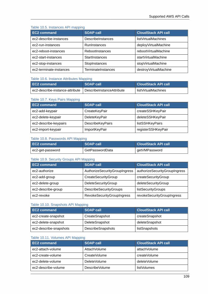
Supported AWS API Calls
109
Table 10.5. Instances API mapping
EC2 command SOAP call CloudStack API call
ec2-describe-instances DescribeInstances listVirtualMachines
ec2-run-instances RunInstances deployVirtualMachine
ec2-reboot-instances RebootInstances rebootVirtualMachine
ec2-start-instances StartInstances startVirtualMachine
ec2-stop-instances StopInstances stopVirtualMachine
ec2-terminate-instances TerminateInstances destroyVirtualMachine
Table 10.6. Instance Attributes Mapping
EC2 command SOAP call CloudStack API call
ec2-describe-instance-attribute DescribeInstanceAttribute listVirtualMachines
Table 10.7. Keys Pairs Mapping
EC2 command SOAP call CloudStack API call
ec2-add-keypair CreateKeyPair createSSHKeyPair
ec2-delete-keypair DeleteKeyPair deleteSSHKeyPair
ec2-describe-keypairs DescribeKeyPairs listSSHKeyPairs
ec2-import-keypair ImportKeyPair registerSSHKeyPair
Table 10.8. Passwords API Mapping
EC2 command SOAP call CloudStack API call
ec2-get-password GetPasswordData getVMPassword
Table 10.9. Security Groups API Mapping
EC2 command SOAP call CloudStack API call
ec2-authorize AuthorizeSecurityGroupIngress authorizeSecurityGroupIngress
ec2-add-group CreateSecurityGroup createSecurityGroup
ec2-delete-group DeleteSecurityGroup deleteSecurityGroup
ec2-describe-group DescribeSecurityGroups listSecurityGroups
ec2-revoke RevokeSecurityGroupIngress revokeSecurityGroupIngress
Table 10.10. Snapshots API Mapping
EC2 command SOAP call CloudStack API call
ec2-create-snapshot CreateSnapshot createSnapshot
ec2-delete-snapshot DeleteSnapshot deleteSnapshot
ec2-describe-snapshots DescribeSnapshots listSnapshots
Table 10.11. Volumes API Mapping
EC2 command SOAP call CloudStack API call
ec2-attach-volume AttachVolume attachVolume
ec2-create-volume CreateVolume createVolume
ec2-delete-volume DeleteVolume deleteVolume
ec2-describe-volume DescribeVolume listVolumes
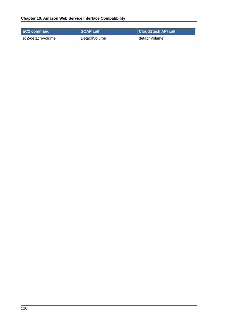
Chapter 10. Amazon Web Service Interface Compatibility
110
EC2 command SOAP call CloudStack API call
ec2-detach-volume DetachVolume detachVolume
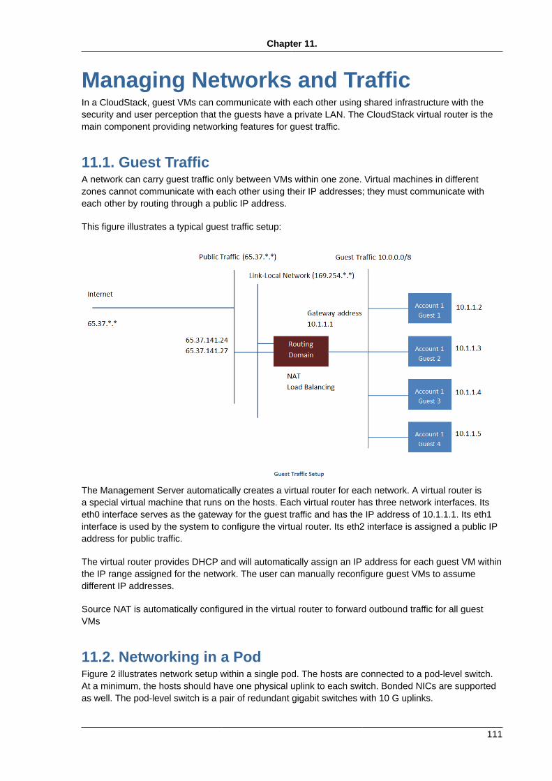
Chapter 11.
111
Managing Networks and TrafficIn a CloudStack, guest VMs can communicate with each other using shared infrastructure with thesecurity and user perception that the guests have a private LAN. The CloudStack virtual router is themain component providing networking features for guest traffic.
11.1. Guest TrafficA network can carry guest traffic only between VMs within one zone. Virtual machines in differentzones cannot communicate with each other using their IP addresses; they must communicate witheach other by routing through a public IP address.
This figure illustrates a typical guest traffic setup:
The Management Server automatically creates a virtual router for each network. A virtual router isa special virtual machine that runs on the hosts. Each virtual router has three network interfaces. Itseth0 interface serves as the gateway for the guest traffic and has the IP address of 10.1.1.1. Its eth1interface is used by the system to configure the virtual router. Its eth2 interface is assigned a public IPaddress for public traffic.
The virtual router provides DHCP and will automatically assign an IP address for each guest VM withinthe IP range assigned for the network. The user can manually reconfigure guest VMs to assumedifferent IP addresses.
Source NAT is automatically configured in the virtual router to forward outbound traffic for all guestVMs
11.2. Networking in a PodFigure 2 illustrates network setup within a single pod. The hosts are connected to a pod-level switch.At a minimum, the hosts should have one physical uplink to each switch. Bonded NICs are supportedas well. The pod-level switch is a pair of redundant gigabit switches with 10 G uplinks.
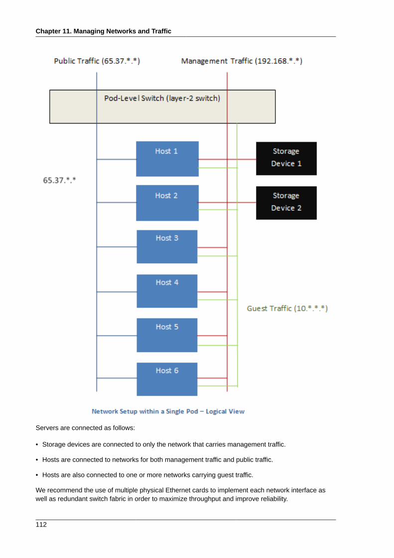
Chapter 11. Managing Networks and Traffic
112
Servers are connected as follows:
• Storage devices are connected to only the network that carries management traffic.
• Hosts are connected to networks for both management traffic and public traffic.
• Hosts are also connected to one or more networks carrying guest traffic.
We recommend the use of multiple physical Ethernet cards to implement each network interface aswell as redundant switch fabric in order to maximize throughput and improve reliability.
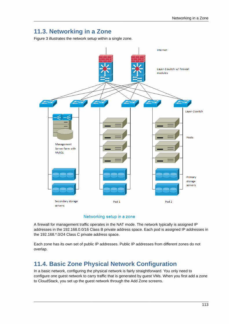
Networking in a Zone
113
11.3. Networking in a ZoneFigure 3 illustrates the network setup within a single zone.
A firewall for management traffic operates in the NAT mode. The network typically is assigned IPaddresses in the 192.168.0.0/16 Class B private address space. Each pod is assigned IP addresses inthe 192.168.*.0/24 Class C private address space.
Each zone has its own set of public IP addresses. Public IP addresses from different zones do notoverlap.
11.4. Basic Zone Physical Network ConfigurationIn a basic network, configuring the physical network is fairly straightforward. You only need toconfigure one guest network to carry traffic that is generated by guest VMs. When you first add a zoneto CloudStack, you set up the guest network through the Add Zone screens.
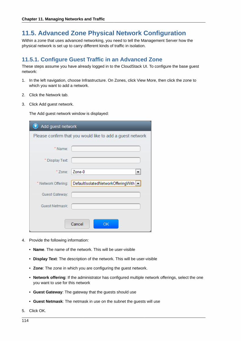
Chapter 11. Managing Networks and Traffic
114
11.5. Advanced Zone Physical Network ConfigurationWithin a zone that uses advanced networking, you need to tell the Management Server how thephysical network is set up to carry different kinds of traffic in isolation.
11.5.1. Configure Guest Traffic in an Advanced ZoneThese steps assume you have already logged in to the CloudStack UI. To configure the base guestnetwork:
1. In the left navigation, choose Infrastructure. On Zones, click View More, then click the zone towhich you want to add a network.
2. Click the Network tab.
3. Click Add guest network.
The Add guest network window is displayed:
4. Provide the following information:
• Name. The name of the network. This will be user-visible
• Display Text: The description of the network. This will be user-visible
• Zone: The zone in which you are configuring the guest network.
• Network offering: If the administrator has configured multiple network offerings, select the oneyou want to use for this network
• Guest Gateway: The gateway that the guests should use
• Guest Netmask: The netmask in use on the subnet the guests will use
5. Click OK.
Configure Public Traffic in an Advanced Zone
115
11.5.2. Configure Public Traffic in an Advanced ZoneIn a zone that uses advanced networking, you need to configure at least one range of IP addresses forInternet traffic.
11.6. Using Multiple Guest NetworksIn zones that use advanced networking, additional networks for guest traffic may be added at any timeafter the initial installation. You can also customize the domain name associated with the network byspecifying a DNS suffix for each network.
A VM's networks are defined at VM creation time. A VM cannot add or remove networks after it hasbeen created, although the user can go into the guest and remove the IP address from the NIC on aparticular network.
Each VM has just one default network. The virtual router's DHCP reply will set the guest's defaultgateway as that for the default network. Multiple non-default networks may be added to a guest inaddition to the single, required default network. The administrator can control which networks areavailable as the default network.
Additional networks can either be available to all accounts or be assigned to a specific account.Networks that are available to all accounts are zone-wide. Any user with access to the zone cancreate a VM with access to that network. These zone-wide networks provide little or no isolationbetween guests.Networks that are assigned to a specific account provide strong isolation.
11.6.1. Adding an Additional Guest Network1. Log in to the CloudStack UI as an administrator or end user.
2. In the left navigation, choose Network.
3. Click Add guest network. Provide the following information:
• Name: The name of the network. This will be user-visible.
• Display Text: The description of the network. This will be user-visible.
• Zone. The name of the zone this network applies to. Each zone is a broadcast domain, andtherefore each zone has a different IP range for the guest network. The administrator mustconfigure the IP range for each zone.
• Network offering: If the administrator has configured multiple network offerings, select the oneyou want to use for this network.
• Guest Gateway: The gateway that the guests should use.
• Guest Netmask: The netmask in use on the subnet the guests will use.
4. Click Create.
11.6.2. Changing the Network Offering on a Guest NetworkA user or administrator can change the network offering that is associated with an existing guestnetwork.
• Log in to the CloudStack UI as an administrator or end user.
Chapter 11. Managing Networks and Traffic
116
• If you are changing from a network offering that uses the CloudStack virtual router to one that usesexternal devices as network service providers, you must first stop all the VMs on the network. SeeStopping and Starting VMs. Then return here and continue to the next step
• In the left navigation, choose Network
•Click the name of the network you want to modify .
• In Network Offering, choose the new network offering, then click Apply.
• A prompt appears asking whether you want to keep the existing CIDR. This is to let you know that ifyou change the network offering, the CIDR will be affected. Choose No to proceed with the change.
• Wait for the update to complete. Don’t try to restart VMs until after the network change is complete.
• If you stopped any VMs in step 2, restart them.
11.7. Security Groups
11.7.1. About Security GroupsSecurity groups provide a way to isolate traffic to VMs. A security group is a group of VMs that filtertheir incoming and outgoing traffic according to a set of rules, called ingress and egress rules. Theserules filter network traffic according to the IP address that is attempting to communicate with the VM.Security groups are particularly useful in zones that use basic networking, because there is a singleguest network for all guest VMs. In CloudStack 3.0.3 - 3.0.5, security groups are supported only inzones that use basic networking.
Note
In a zone that uses advanced networking, you can instead define multiple guest networks toisolate traffic to VMs.
Each CloudStack account comes with a default security group that denies all inbound traffic andallows all outbound traffic. The default security group can be modified so that all new VMs inherit someother desired set of rules.
Any CloudStack user can set up any number of additional security groups. When a new VM islaunched, it is assigned to the default security group unless another user-defined security group isspecified. A VM can be a member of any number of security groups. Once a VM is assigned to asecurity group, it remains in that group for its entire lifetime; you can not move a running VM from onesecurity group to another.
You can modify a security group by deleting or adding any number of ingress and egress rules. Whenyou do, the new rules apply to all VMs in the group, whether running or stopped.
If no ingress rules are specified, then no traffic will be allowed in, except for responses to any trafficthat has been allowed out through an egress rule.
Adding a Security Group
117
11.7.2. Adding a Security GroupA user or administrator can define a new security group.
1. Log in to the CloudStack UI as an administrator or end user.
2. In the left navigation, choose Network
3. In Select view, choose Security Groups.
4. Click Add Security Group.
5. Provide a name and description.
6. Click OK.
The new security group appears in the Security Groups Details tab.
7. To make the security group useful, continue to Adding Ingress and Egress Rules to a SecurityGroup.
11.7.3. Enabling Security GroupsIn order for security groups to function in a zone, the security groups feature must first be enabled forthe zone. The administrator can do this when creating a new zone, by selecting a network offering thatincludes security groups. The procedure is described in Basic Zone Configuration in the AdvancedInstallation Guide.
11.7.4. Adding Ingress and Egress Rules to a Security Group1. Log in to the CloudStack UI as an administrator or end user.
2. In the left navigation, choose Network
3. In Select view, choose Security Groups, then click the security group you want .
4. To add an ingress rule, click the Ingress Rules tab and fill out the following fields to specify whatnetwork traffic is allowed into VM instances in this security group. If no ingress rules are specified,then no traffic will be allowed in, except for responses to any traffic that has been allowed outthrough an egress rule.
• Add by CIDR/Account. Indicate whether the source of the traffic will be defined by IP address(CIDR) or an existing security group in a CloudStack account (Account). Choose Account if youwant to allow incoming traffic from all VMs in another security group
• Protocol. The networking protocol that sources will use to send traffic to the security group.TCP and UDP are typically used for data exchange and end-user communications. ICMP istypically used to send error messages or network monitoring data.
• Start Port, End Port. (TCP, UDP only) A range of listening ports that are the destination for theincoming traffic. If you are opening a single port, use the same number in both fields.
• ICMP Type, ICMP Code. (ICMP only) The type of message and error code that will beaccepted.
• CIDR. (Add by CIDR only) To accept only traffic from IP addresses within a particular addressblock, enter a CIDR or a comma-separated list of CIDRs. The CIDR is the base IP address ofthe incoming traffic. For example, 192.168.0.0/22. To allow all CIDRs, set to 0.0.0.0/0.
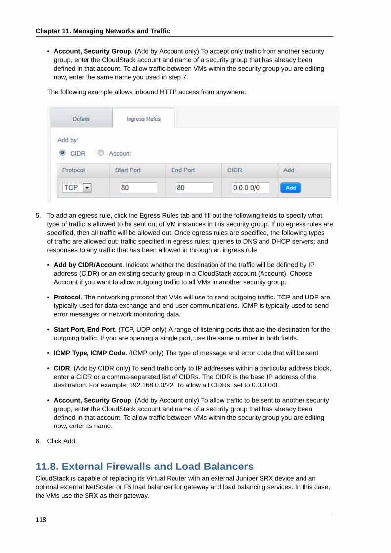
Chapter 11. Managing Networks and Traffic
118
• Account, Security Group. (Add by Account only) To accept only traffic from another securitygroup, enter the CloudStack account and name of a security group that has already beendefined in that account. To allow traffic between VMs within the security group you are editingnow, enter the same name you used in step 7.
The following example allows inbound HTTP access from anywhere:
5. To add an egress rule, click the Egress Rules tab and fill out the following fields to specify whattype of traffic is allowed to be sent out of VM instances in this security group. If no egress rules arespecified, then all traffic will be allowed out. Once egress rules are specified, the following typesof traffic are allowed out: traffic specified in egress rules; queries to DNS and DHCP servers; andresponses to any traffic that has been allowed in through an ingress rule
• Add by CIDR/Account. Indicate whether the destination of the traffic will be defined by IPaddress (CIDR) or an existing security group in a CloudStack account (Account). ChooseAccount if you want to allow outgoing traffic to all VMs in another security group.
• Protocol. The networking protocol that VMs will use to send outgoing traffic. TCP and UDP aretypically used for data exchange and end-user communications. ICMP is typically used to senderror messages or network monitoring data.
• Start Port, End Port. (TCP, UDP only) A range of listening ports that are the destination for theoutgoing traffic. If you are opening a single port, use the same number in both fields.
• ICMP Type, ICMP Code. (ICMP only) The type of message and error code that will be sent
• CIDR. (Add by CIDR only) To send traffic only to IP addresses within a particular address block,enter a CIDR or a comma-separated list of CIDRs. The CIDR is the base IP address of thedestination. For example, 192.168.0.0/22. To allow all CIDRs, set to 0.0.0.0/0.
• Account, Security Group. (Add by Account only) To allow traffic to be sent to another securitygroup, enter the CloudStack account and name of a security group that has already beendefined in that account. To allow traffic between VMs within the security group you are editingnow, enter its name.
6. Click Add.
11.8. External Firewalls and Load BalancersCloudStack is capable of replacing its Virtual Router with an external Juniper SRX device and anoptional external NetScaler or F5 load balancer for gateway and load balancing services. In this case,the VMs use the SRX as their gateway.
Load Balancer Rules
119
11.9. Load Balancer RulesA CloudStack user or administrator may create load balancing rules that balance traffic received at apublic IP to one or more VMs. A user creates a rule, specifies an algorithm, and assigns the rule to aset of VMs.
Note
If you create load balancing rules while using a network service offering that includes an externalload balancer device such as NetScaler, and later change the network service offering to one thatuses the CloudStack virtual router, you must create a firewall rule on the virtual router for each ofyour existing load balancing rules so that they continue to function.
11.10. Guest IP RangesThe IP ranges for guest network traffic are set on a per-account basis by the user. This allows theusers to configure their network in a fashion that will enable VPN linking between their guest networkand their clients.
11.11. Acquiring a New IP Address1. Log in to the CloudStack UI as an administrator or end user.
2. In the left navigation, choose Network.
3. Click the name of the network where you want to work with.
4. Click View IP Addresses.
5. Click Acquire New IP, and click Yes in the confirmation dialog.
You are prompted for confirmation because, typically, IP addresses are a limited resource. Withina few moments, the new IP address should appear with the state Allocated. You can now use theIP address in port forwarding or static NAT rules.
11.12. Releasing an IP Address1. Log in to the CloudStack UI as an administrator or end user.
2. In the left navigation, choose Network.
3. Click the name of the network where you want to work with.
4. Click View IP Addresses.
5. Click the IP address you want to release.
6.Click the Release IP button .
Chapter 11. Managing Networks and Traffic
120
11.13. Static NATA static NAT rule maps a public IP address to the private IP address of a VM in order to allow Internettraffic into the VM. The public IP address always remains the same, which is why it is called "static"NAT. This section tells how to enable or disable static NAT for a particular IP address.
11.14. IP Forwarding and FirewallingBy default, all incoming traffic to the public IP address is rejected. All outgoing traffic from the guests istranslated via NAT to the public IP address and is allowed.
To allow incoming traffic, users may set up firewall rules and/or port forwarding rules. For example,you can use a firewall rule to open a range of ports on the public IP address, such as 33 through 44.Then use port forwarding rules to direct traffic from individual ports within that range to specific portson user VMs. For example, one port forwarding rule could route incoming traffic on the public IP's port33 to port 100 on one user VM's private IP.
For the steps to implement these rules, see Firewall Rules and Port Forwarding.
11.15. IP Load BalancingThe user may choose to associate the same public IP for multiple guests. CloudStack implements aTCP-level load balancer with the following policies.
• Round-robin
• Least connection
• Source IP
This is similar to port forwarding but the destination may be multiple IP addresses.
11.16. DNS and DHCPThe Virtual Router provides DNS and DHCP services to the guests. It proxies DNS requests to theDNS server configured on the Availability Zone.
11.17. VPNCloudStack account owners can create virtual private networks (VPN) to access their virtual machines.If the guest network is instantiated from a network offering that offers the Remote Access VPN service,the virtual router (based on the System VM) is used to provide the service. CloudStack provides aL2TP-over-IPsec-based remote access VPN service to guest virtual networks. Since each networkgets its own virtual router, VPNs are not shared across the networks. VPN clients native to Windows,Mac OS X and iOS can be used to connect to the guest networks. The account owner can create andmanage users for their VPN. CloudStack does not use its account database for this purpose but usesa separate table. The VPN user database is shared across all the VPNs created by the account owner.All VPN users get access to all VPNs created by the account owner.
Configuring VPN
121
Note
Make sure that not all traffic goes through the VPN. That is, the route installed by the VPN shouldbe only for the guest network and not for all traffic.
• Road Warrior / Remote Access. Users want to be able to connect securely from a home or officeto a private network in the cloud. Typically, the IP address of the connecting client is dynamic andcannot be preconfigured on the VPN server.
• Site to Site. In this scenario, two private subnets are connected over the public Internet with asecure VPN tunnel. The cloud user’s subnet (for example, an office network) is connected througha gateway to the network in the cloud. The address of the user’s gateway must be preconfigured onthe VPN server in the cloud. Note that although L2TP-over-IPsec can be used to set up Site-to-SiteVPNs, this is not the primary intent of this feature.
11.17.1. Configuring VPNTo set up VPN for the cloud:
1. Log in to the CloudStack UI as an administrator or end user.
2. In the left navigation, click Global Settings.
3. Set the following global configuration parameters.
• remote.access.vpn.client.ip.range – The range of IP addressess to be allocated to remoteaccess VPN clients. The first IP in the range is used by the VPN server.
• remote.access.vpn.psk.length – Length of the IPSec key.
• remote.access.vpn.user.limit – Maximum number of VPN users per account.
To enable VPN for a particular network:
1. Log in as a user or administrator to the CloudStack UI.
2. In the left navigation, click Network.
3. Click the name of the network you want to work with.
4. Click View IP Addresses.
5. Click one of the displayed IP address names.
6.Click the Enable VPN button .
The IPsec key is displayed in a popup window.
11.17.2. Using VPN with WindowsThe procedure to use VPN varies by Windows version. Generally, the user must edit the VPNproperties and make sure that the default route is not the VPN. The following steps are for WindowsL2TP clients on Windows Vista. The commands should be similar for other Windows versions.
Chapter 11. Managing Networks and Traffic
122
1. Log in to the CloudStack UI and click on the source NAT IP for the account. The VPN tab shoulddisplay the IPsec preshared key. Make a note of this and the source NAT IP. The UI also lists oneor more users and their passwords. Choose one of these users, or, if none exists, add a user andpassword.
2. On the Windows box, go to Control Panel, then select Network and Sharing center. Click Setup aconnection or network.
3. In the next dialog, select No, create a new connection.
4. In the next dialog, select Use my Internet Connection (VPN).
5. In the next dialog, enter the source NAT IP from step 1 and give the connection a name. CheckDon't connect now.
6. In the next dialog, enter the user name and password selected in step 1.
7. Click Create.
8. Go back to the Control Panel and click Network Connections to see the new connection. Theconnection is not active yet.
9. Right-click the new connection and select Properties. In the Properties dialog, select theNetworking tab.
10. In Type of VPN, choose L2TP IPsec VPN, then click IPsec settings. Select Use preshared key.Enter the preshared key from Step 1.
11. The connection is ready for activation. Go back to Control Panel -> Network Connections anddouble-click the created connection.
12. Enter the user name and password from Step 1.
11.17.3. Using VPN with Mac OS XFirst, be sure you've configured the VPN settings in your CloudStack install. This section is onlyconcerned with connecting via Mac OS X to your VPN.
Note, these instructions were written on Mac OS X 10.7.5. They may differ slightly in older or newerreleases of Mac OS X.
1. On your Mac, open System Preferences and click Network.
2. Make sure Send all traffic over VPN connection is not checked.
3. If your preferences are locked, you'll need to click the lock in the bottom left-hand corner to makeany changes and provide your administrator credentials.
4. You will need to create a new network entry. Click the plus icon on the bottom left-hand sideand you'll see a dialog that says "Select the interface and enter a name for the new service."Select VPN from the Interface drop-down menu, and "L2TP over IPSec" for the VPN Type. Enterwhatever you like within the "Service Name" field.
5. You'll now have a new network interface with the name of whatever you put in the "Service Name"field. For the purposes of this example, we'll assume you've named it "CloudStack." Click on thatinterface and provide the IP address of the interface for your VPN under the Server Address field,and the user name for your VPN under Account Name.
Setting Up a Site-to-Site VPN Connection
123
6. Click Authentication Settings, and add the user's password under User Authentication and enterthe pre-shared IPSec key in the Shared Secret field under Machine Authentication. Click OK.
7. You may also want to click the "Show VPN status in menu bar" but that's entirely optional.
8. Now click "Connect" and you will be connected to the CloudStack VPN.
11.17.4. Setting Up a Site-to-Site VPN ConnectionA Site-to-Site VPN connection helps you establish a secure connection from an enterprise datacenterto the cloud infrastructure. This allows users to access the guest VMs by establishing a VPNconnection to the virtual router of the account from a device in the datacenter of the enterprise. Havingthis facility eliminates the need to establish VPN connections to individual VMs.
The supported endpoints on the remote datacenters are:
• Cisco ISR with IOS 12.4 or later
• Juniper J-Series routers with JunOS 9.5 or later
Note
In addition to the specific Cisco and Juniper devices listed above, the expectation is that anyCisco or Juniper device running on the supported operating systems are able to establish VPNconnections.
To set up a Site-to-Site VPN connection, perform the following:
1. Create a Virtual Private Cloud (VPC).
See Section 11.19, “Configuring a Virtual Private Cloud”.
2. Create a VPN Customer Gateway.
3. Create a VPN gateway for the VPC that you created.
4. Create VPN connection from the VPC VPN gateway to the customer VPN gateway.
11.17.4.1. Creating and Updating a VPN Customer Gateway
Note
A VPN customer gateway can be connected to only one VPN gateway at a time.
To add a VPN Customer Gateway:
1. Log in to the CloudStack UI as an administrator or end user.
2. In the left navigation, choose Network.
3. In the Select view, select VPN Customer Gateway.
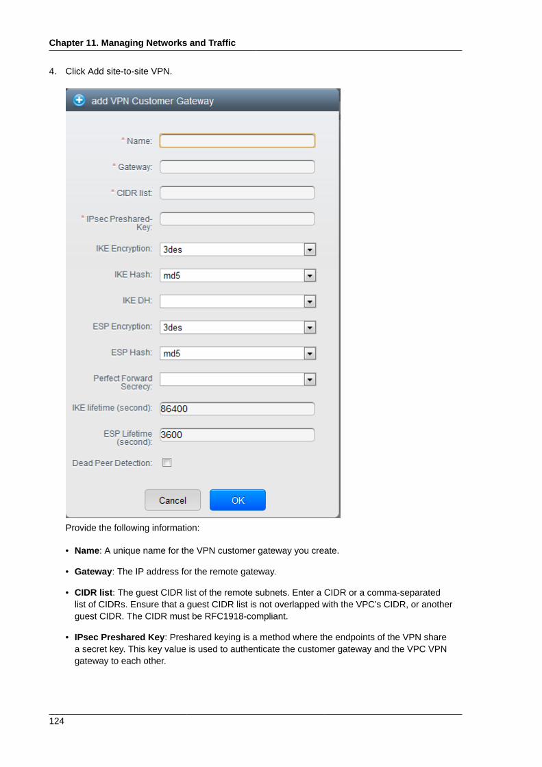
Chapter 11. Managing Networks and Traffic
124
4. Click Add site-to-site VPN.
Provide the following information:
• Name: A unique name for the VPN customer gateway you create.
• Gateway: The IP address for the remote gateway.
• CIDR list: The guest CIDR list of the remote subnets. Enter a CIDR or a comma-separatedlist of CIDRs. Ensure that a guest CIDR list is not overlapped with the VPC’s CIDR, or anotherguest CIDR. The CIDR must be RFC1918-compliant.
• IPsec Preshared Key: Preshared keying is a method where the endpoints of the VPN sharea secret key. This key value is used to authenticate the customer gateway and the VPC VPNgateway to each other.
Setting Up a Site-to-Site VPN Connection
125
Note
The IKE peers (VPN end points) authenticate each other by computing and sending akeyed hash of data that includes the Preshared key. If the receiving peer is able to createthe same hash independently by using its Preshared key, it knows that both peers mustshare the same secret, thus authenticating the customer gateway.
• IKE Encryption: The Internet Key Exchange (IKE) policy for phase-1. The supported encryptionalgorithms are AES128, AES192, AES256, and 3DES. Authentication is accomplished throughthe Preshared Keys.
Note
The phase-1 is the first phase in the IKE process. In this initial negotiation phase, the twoVPN endpoints agree on the methods to be used to provide security for the underlying IPtraffic. The phase-1 authenticates the two VPN gateways to each other, by confirming thatthe remote gateway has a matching Preshared Key.
• IKE Hash: The IKE hash for phase-1. The supported hash algorithms are SHA1 and MD5.
• IKE DH: A public-key cryptography protocol which allows two parties to establish a sharedsecret over an insecure communications channel. The 1536-bit Diffie-Hellman group is usedwithin IKE to establish session keys. The supported options are None, Group-5 (1536-bit) andGroup-2 (1024-bit).
• ESP Encryption: Encapsulating Security Payload (ESP) algorithm within phase-2. Thesupported encryption algorithms are AES128, AES192, AES256, and 3DES.
Note
The phase-2 is the second phase in the IKE process. The purpose of IKE phase-2 is tonegotiate IPSec security associations (SA) to set up the IPSec tunnel. In phase-2, newkeying material is extracted from the Diffie-Hellman key exchange in phase-1, to providesession keys to use in protecting the VPN data flow.
• ESP Hash: Encapsulating Security Payload (ESP) hash for phase-2. Supported hash algorithmsare SHA1 and MD5.
• Perfect Forward Secrecy: Perfect Forward Secrecy (or PFS) is the property that ensures thata session key derived from a set of long-term public and private keys will not be compromised.This property enforces a new Diffie-Hellman key exchange. It provides the keying material
Chapter 11. Managing Networks and Traffic
126
that has greater key material life and thereby greater resistance to cryptographic attacks. Theavailable options are None, Group-5 (1536-bit) and Group-2 (1024-bit). The security of the keyexchanges increase as the DH groups grow larger, as does the time of the exchanges.
Note
When PFS is turned on, for every negotiation of a new phase-2 SA the two gateways mustgenerate a new set of phase-1 keys. This adds an extra layer of protection that PFS adds,which ensures if the phase-2 SA’s have expired, the keys used for new phase-2 SA’s havenot been generated from the current phase-1 keying material.
• IKE Lifetime (seconds): The phase-1 lifetime of the security association in seconds. Default is86400 seconds (1 day). Whenever the time expires, a new phase-1 exchange is performed.
• ESP Lifetime (seconds): The phase-2 lifetime of the security association in seconds. Default is3600 seconds (1 hour). Whenever the value is exceeded, a re-key is initiated to provide a newIPsec encryption and authentication session keys.
• Dead Peer Detection: A method to detect an unavailable Internet Key Exchange (IKE) peer.Select this option if you want the virtual router to query the liveliness of its IKE peer at regularintervals. It’s recommended to have the same configuration of DPD on both side of VPNconnection.
5. Click OK.
Updating and Removing a VPN Customer GatewayYou can update a customer gateway either with no VPN connection, or related VPN connection is inerror state.
1. Log in to the CloudStack UI as an administrator or end user.
2. In the left navigation, choose Network.
3. In the Select view, select VPN Customer Gateway.
4. Select the VPN customer gateway you want to work with.
5.To modify the required parameters, click the Edit VPN Customer Gateway button
6.To remove the VPN customer gateway, click the Delete VPN Customer Gateway button
7. Click OK.
11.17.4.2. Creating a VPN gateway for the VPC1. Log in to the CloudStack UI as an administrator or end user.
2. In the left navigation, choose Network.
3. In the Select view, select VPC.
Setting Up a Site-to-Site VPN Connection
127
All the VPCs that you have created for the account is listed in the page.
4. Click the Configure button of the VPC to which you want to deploy the VMs.
The VPC page is displayed where all the tiers you created are listed in a diagram.
5. Click the Settings icon.
The following options are displayed.
• IP Addresses
• Gateways
• Site-to-Site VPN
• Network ACLs
6. Select Site-to-Site VPN.
If you are creating the VPN gateway for the first time, selecting Site-to-Site VPN prompts you tocreate a VPN gateway.
7. In the confirmation dialog, click Yes to confirm.
Within a few moments, the VPN gateway is created. You will be prompted to view the details of theVPN gateway you have created. Click Yes to confirm.
The following details are displayed in the VPN Gateway page:
• IP Address
• Account
• Domain
11.17.4.3. Creating a VPN Connection1. Log in to the CloudStack UI as an administrator or end user.
2. In the left navigation, choose Network.
3. In the Select view, select VPC.
All the VPCs that you create for the account are listed in the page.
4. Click the Configure button of the VPC to which you want to deploy the VMs.
The VPC page is displayed where all the tiers you created are listed in a diagram.
5. Click the Settings icon.
The following options are displayed.
• IP Addresses
• Gateways
• Site-to-Site VPN
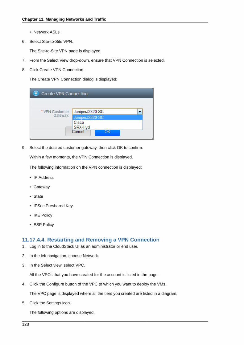
Chapter 11. Managing Networks and Traffic
128
• Network ASLs
6. Select Site-to-Site VPN.
The Site-to-Site VPN page is displayed.
7. From the Select View drop-down, ensure that VPN Connection is selected.
8. Click Create VPN Connection.
The Create VPN Connection dialog is displayed:
9. Select the desired customer gateway, then click OK to confirm.
Within a few moments, the VPN Connection is displayed.
The following information on the VPN connection is displayed:
• IP Address
• Gateway
• State
• IPSec Preshared Key
• IKE Policy
• ESP Policy
11.17.4.4. Restarting and Removing a VPN Connection1. Log in to the CloudStack UI as an administrator or end user.
2. In the left navigation, choose Network.
3. In the Select view, select VPC.
All the VPCs that you have created for the account is listed in the page.
4. Click the Configure button of the VPC to which you want to deploy the VMs.
The VPC page is displayed where all the tiers you created are listed in a diagram.
5. Click the Settings icon.
The following options are displayed.
About Inter-VLAN Routing
129
• IP Addresses
• Gateways
• Site-to-Site VPN
• Network ASLs
6. Select Site-to-Site VPN.
The Site-to-Site VPN page is displayed.
7. From the Select View drop-down, ensure that VPN Connection is selected.
All the VPN connections you created are displayed.
8. Select the VPN connection you want to work with.
The Details tab is displayed.
9.To remove a VPN connection, click the Delete VPN connection button
To restart a VPN connection, click the Reset VPN connection button present in the Details tab.
11.18. About Inter-VLAN RoutingInter-VLAN Routing is the capability to route network traffic between VLANs. This feature enablesyou to build Virtual Private Clouds (VPC), an isolated segment of your cloud, that can hold multi-tierapplications. These tiers are deployed on different VLANs that can communicate with each other.You provision VLANs to the tiers your create, and VMs can be deployed on different tiers. The VLANsare connected to a virtual router, which facilitates communication between the VMs. In effect, youcan segment VMs by means of VLANs into different networks that can host multi-tier applications,such as Web, Application, or Database. Such segmentation by means of VLANs logically separateapplication VMs for higher security and lower broadcasts, while remaining physically connected to thesame device.
This feature is supported on XenServer and VMware hypervisors.
The major advantages are:
• The administrator can deploy a set of VLANs and allow users to deploy VMs on these VLANs. Aguest VLAN is randomly alloted to an account from a pre-specified set of guest VLANs. All the VMsof a certain tier of an account reside on the guest VLAN allotted to that account.
Note
A VLAN allocated for an account cannot be shared between multiple accounts.
• The administrator can allow users create their own VPC and deploy the application. In this scenario,the VMs that belong to the account are deployed on the VLANs allotted to that account.
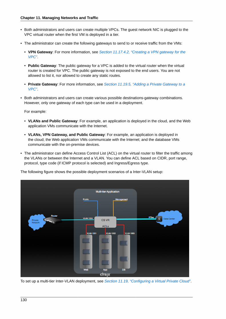
Chapter 11. Managing Networks and Traffic
130
• Both administrators and users can create multiple VPCs. The guest network NIC is plugged to theVPC virtual router when the first VM is deployed in a tier.
• The administrator can create the following gateways to send to or receive traffic from the VMs:
• VPN Gateway: For more information, see Section 11.17.4.2, “Creating a VPN gateway for theVPC”.
• Public Gateway: The public gateway for a VPC is added to the virtual router when the virtualrouter is created for VPC. The public gateway is not exposed to the end users. You are notallowed to list it, nor allowed to create any static routes.
• Private Gateway: For more information, see Section 11.19.5, “Adding a Private Gateway to aVPC”.
• Both administrators and users can create various possible destinations-gateway combinations.However, only one gateway of each type can be used in a deployment.
For example:
• VLANs and Public Gateway: For example, an application is deployed in the cloud, and the Webapplication VMs communicate with the Internet.
• VLANs, VPN Gateway, and Public Gateway: For example, an application is deployed inthe cloud; the Web application VMs communicate with the Internet; and the database VMscommunicate with the on-premise devices.
• The administrator can define Access Control List (ACL) on the virtual router to filter the traffic amongthe VLANs or between the Internet and a VLAN. You can define ACL based on CIDR, port range,protocol, type code (if ICMP protocol is selected) and Ingress/Egress type.
The following figure shows the possible deployment scenarios of a Inter-VLAN setup:
To set up a multi-tier Inter-VLAN deployment, see Section 11.19, “Configuring a Virtual Private Cloud”.
Configuring a Virtual Private Cloud
131
11.19. Configuring a Virtual Private Cloud
11.19.1. About Virtual Private CloudsCloudStack Virtual Private Cloud is a private, isolated part of CloudStack. A VPC can have its ownvirtual network topology that resembles a traditional physical network. You can launch VMs in thevirtual network that can have private addresses in the range of your choice, for example: 10.0.0.0/16.You can define network tiers within your VPC network range, which in turn enables you to groupsimilar kinds of instances based on IP address range.
For example, if a VPC has the private range 10.0.0.0/16, its guest networks can have the networkranges 10.0.1.0/24, 10.0.2.0/24, 10.0.3.0/24, and so on.
Major Components of a VPC:A VPC is comprised of the following network components:
• VPC: A VPC acts as a container for multiple isolated networks that can communicate with eachother via its virtual router.
• Network Tiers: Each tier acts as an isolated network with its own VLANs and CIDR list, where youcan place groups of resources, such as VMs. The tiers are segmented by means of VLANs. TheNIC of each tier acts as its gateway.
• Virtual Router: A virtual router is automatically created and started when you create a VPC. Thevirtual router connect the tiers and direct traffic among the public gateway, the VPN gateways, andthe NAT instances. For each tier, a corresponding NIC and IP exist in the virtual router. The virtualrouter provides DNS and DHCP services through its IP.
• Public Gateway: The traffic to and from the Internet routed to the VPC through the public gateway.In a VPC, the public gateway is not exposed to the end user; therefore, static routes are not supportfor the public gateway.
• Private Gateway: All the traffic to and from a private network routed to the VPC through the privategateway. For more information, see Section 11.19.5, “Adding a Private Gateway to a VPC”.
• VPN Gateway: The VPC side of a VPN connection.
• Site-to-Site VPN Connection: A hardware-based VPN connection between your VPC and yourdatacenter, home network, or co-location facility. For more information, see Section 11.17.4, “SettingUp a Site-to-Site VPN Connection”.
• Customer Gateway: The customer side of a VPN Connection. For more information, seeSection 11.17.4.1, “Creating and Updating a VPN Customer Gateway”.
• NAT Instance: An instance that provides Port Address Translation for instances to access theInternet via the public gateway. For more information, see Section 11.19.9, “Enabling or DisablingStatic NAT on a VPC”.
Network Architecture in a VPCIn a VPC, the following four basic options of network architectures are present:
• VPC with a public gateway only
• VPC with public and private gateways
Chapter 11. Managing Networks and Traffic
132
• VPC with public and private gateways and site-to-site VPN access
• VPC with a private gateway only and site-to-site VPN access
Connectivity Options for a VPCYou can connect your VPC to:
• The Internet through the public gateway.
• The corporate datacenter by using a site-to-site VPN connection through the VPN gateway.
• Both the Internet and your corporate datacenter by using both the public gateway and a VPNgateway.
VPC Network ConsiderationsConsider the following before you create a VPC:
• A VPC, by default, is created in the enabled state.
• A VPC can be created in Advance zone only, and can't belong to more than one zone at a time.
• The default number of VPCs an account can create is 20. However, you can change it by using themax.account.vpcs global parameter, which controls the maximum number of VPCs an account isallowed to create.
• The default number of tiers an account can create within a VPC is 3. You can configure this numberby using the vpc.max.networks parameter.
• Each tier should have an unique CIDR in the VPC. Ensure that the tier's CIDR should be within theVPC CIDR range.
• A tier belongs to only one VPC.
• All network tiers inside the VPC should belong to the same account.
• When a VPC is created, by default, a SourceNAT IP is allocated to it. The Source NAT IP isreleased only when the VPC is removed.
• A public IP can be used for only one purpose at a time. If the IP is a sourceNAT, it cannot be usedfor StaticNAT or port forwarding.
• The instances only have a private IP address that you provision. To communicate with the Internet,enable NAT to an instance that you launch in your VPC.
• Only new networks can be added to a VPC. The maximum number of networks per VPC is limitedby the value you specify in the vpc.max.networks parameter. The default value is three.
• The load balancing service can be supported by only one tier inside the VPC.
• If an IP address is assigned to a tier:
• That IP can't be used by more than one tier at a time in the VPC. For example, if you have tiers Aand B, and a public IP1, you can create a port forwarding rule by using the IP either for A or B, butnot for both.
• That IP can't be used for StaticNAT, load balancing, or port forwarding rules for another guestnetwork inside the VPC.
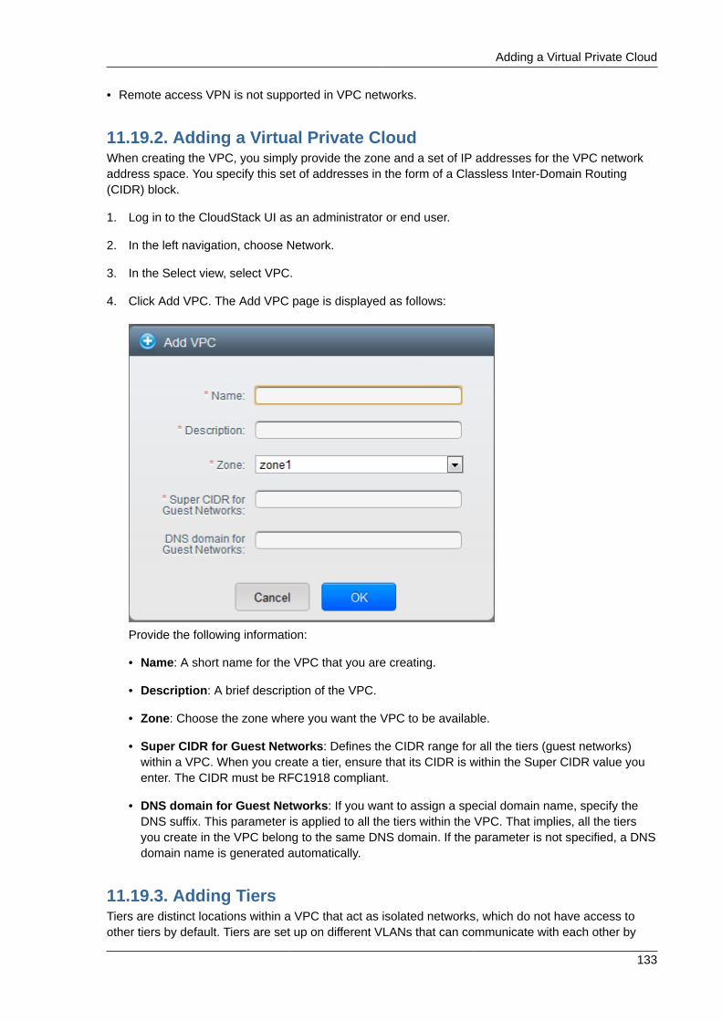
Adding a Virtual Private Cloud
133
• Remote access VPN is not supported in VPC networks.
11.19.2. Adding a Virtual Private CloudWhen creating the VPC, you simply provide the zone and a set of IP addresses for the VPC networkaddress space. You specify this set of addresses in the form of a Classless Inter-Domain Routing(CIDR) block.
1. Log in to the CloudStack UI as an administrator or end user.
2. In the left navigation, choose Network.
3. In the Select view, select VPC.
4. Click Add VPC. The Add VPC page is displayed as follows:
Provide the following information:
• Name: A short name for the VPC that you are creating.
• Description: A brief description of the VPC.
• Zone: Choose the zone where you want the VPC to be available.
• Super CIDR for Guest Networks: Defines the CIDR range for all the tiers (guest networks)within a VPC. When you create a tier, ensure that its CIDR is within the Super CIDR value youenter. The CIDR must be RFC1918 compliant.
• DNS domain for Guest Networks: If you want to assign a special domain name, specify theDNS suffix. This parameter is applied to all the tiers within the VPC. That implies, all the tiersyou create in the VPC belong to the same DNS domain. If the parameter is not specified, a DNSdomain name is generated automatically.
11.19.3. Adding TiersTiers are distinct locations within a VPC that act as isolated networks, which do not have access toother tiers by default. Tiers are set up on different VLANs that can communicate with each other by
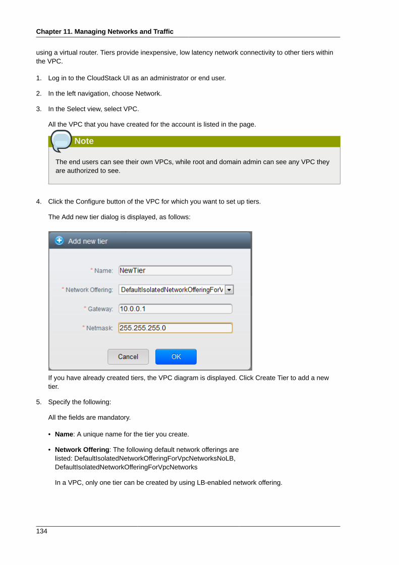
Chapter 11. Managing Networks and Traffic
134
using a virtual router. Tiers provide inexpensive, low latency network connectivity to other tiers withinthe VPC.
1. Log in to the CloudStack UI as an administrator or end user.
2. In the left navigation, choose Network.
3. In the Select view, select VPC.
All the VPC that you have created for the account is listed in the page.
Note
The end users can see their own VPCs, while root and domain admin can see any VPC theyare authorized to see.
4. Click the Configure button of the VPC for which you want to set up tiers.
The Add new tier dialog is displayed, as follows:
If you have already created tiers, the VPC diagram is displayed. Click Create Tier to add a newtier.
5. Specify the following:
All the fields are mandatory.
• Name: A unique name for the tier you create.
• Network Offering: The following default network offerings arelisted: DefaultIsolatedNetworkOfferingForVpcNetworksNoLB,DefaultIsolatedNetworkOfferingForVpcNetworks
In a VPC, only one tier can be created by using LB-enabled network offering.
Configuring Access Control List
135
• Gateway: The gateway for the tier you create. Ensure that the gateway is within the SuperCIDR range that you specified while creating the VPC, and is not overlapped with the CIDR ofany existing tier within the VPC.
• Netmask: The netmask for the tier you create.
For example, if the VPC CIDR is 10.0.0.0/16 and the network tier CIDR is 10.0.1.0/24, thegateway of the tier is 10.0.1.1, and the netmask of the tier is 255.255.255.0.
6. Click OK.
7. Continue with configuring access control list for the tier.
11.19.4. Configuring Access Control ListDefine Network Access Control List (ACL) on the VPC virtual router to control incoming (ingress) andoutgoing (egress) traffic between the VPC tiers, and the tiers and Internet. By default, all incoming andoutgoing traffic to the guest networks is blocked. To open the ports, you must create a new networkACL. The network ACLs can be created for the tiers only if the NetworkACL service is supported.
1. Log in to the CloudStack UI as an administrator or end user.
2. In the left navigation, choose Network.
3. In the Select view, select VPC.
All the VPCs that you have created for the account is listed in the page.
4. Click the Settings icon.
The following options are displayed.
• IP Addresses
• Gateways
• Site-to-Site VPN
• Network ACLs
5. Select Network ACLs.
The Network ACLs page is displayed.
6. Click Add Network ACLs.
To add an ACL rule, fill in the following fields to specify what kind of network traffic is allowed inthis tier.
• CIDR: The CIDR acts as the Source CIDR for the Ingress rules, and Destination CIDR for theEgress rules. To accept traffic only from or to the IP addresses within a particular address block,enter a CIDR or a comma-separated list of CIDRs. The CIDR is the base IP address of theincoming traffic. For example, 192.168.0.0/22. To allow all CIDRs, set to 0.0.0.0/0.
• Protocol: The networking protocol that sources use to send traffic to the tier. The TCP andUDP protocols are typically used for data exchange and end-user communications. The ICMPprotocol is typically used to send error messages or network monitoring data.
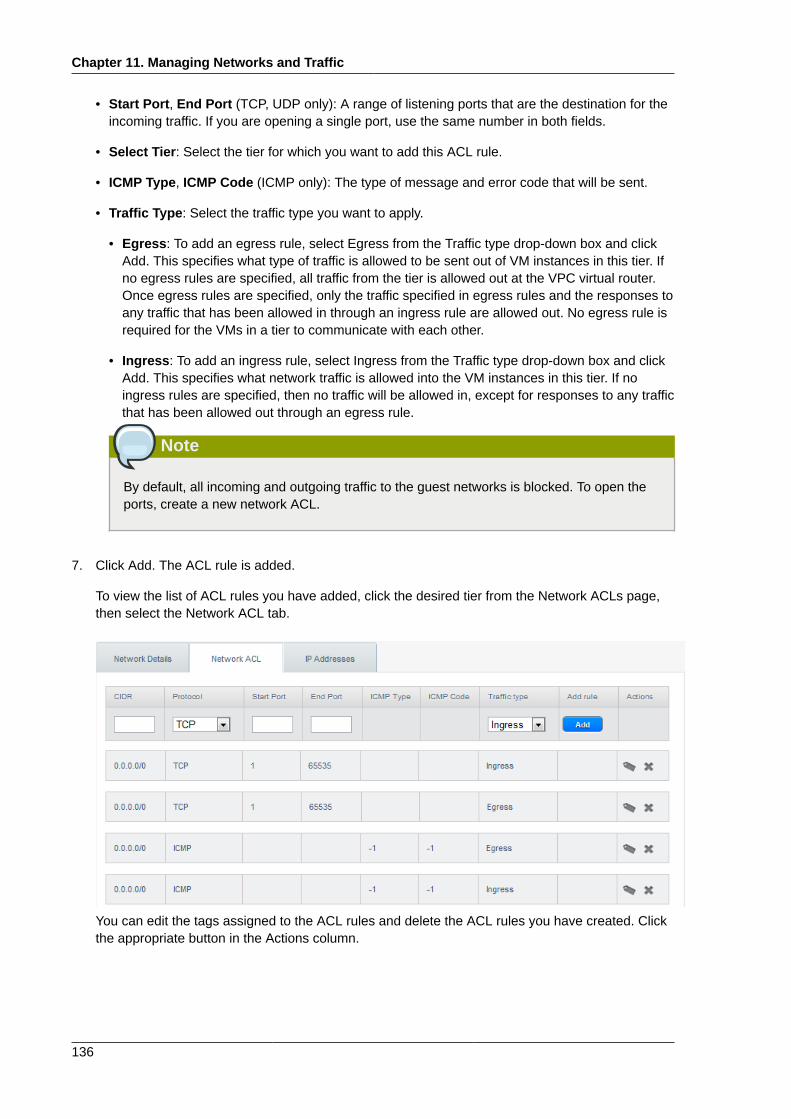
Chapter 11. Managing Networks and Traffic
136
• Start Port, End Port (TCP, UDP only): A range of listening ports that are the destination for theincoming traffic. If you are opening a single port, use the same number in both fields.
• Select Tier: Select the tier for which you want to add this ACL rule.
• ICMP Type, ICMP Code (ICMP only): The type of message and error code that will be sent.
• Traffic Type: Select the traffic type you want to apply.
• Egress: To add an egress rule, select Egress from the Traffic type drop-down box and clickAdd. This specifies what type of traffic is allowed to be sent out of VM instances in this tier. Ifno egress rules are specified, all traffic from the tier is allowed out at the VPC virtual router.Once egress rules are specified, only the traffic specified in egress rules and the responses toany traffic that has been allowed in through an ingress rule are allowed out. No egress rule isrequired for the VMs in a tier to communicate with each other.
• Ingress: To add an ingress rule, select Ingress from the Traffic type drop-down box and clickAdd. This specifies what network traffic is allowed into the VM instances in this tier. If noingress rules are specified, then no traffic will be allowed in, except for responses to any trafficthat has been allowed out through an egress rule.
Note
By default, all incoming and outgoing traffic to the guest networks is blocked. To open theports, create a new network ACL.
7. Click Add. The ACL rule is added.
To view the list of ACL rules you have added, click the desired tier from the Network ACLs page,then select the Network ACL tab.
You can edit the tags assigned to the ACL rules and delete the ACL rules you have created. Clickthe appropriate button in the Actions column.
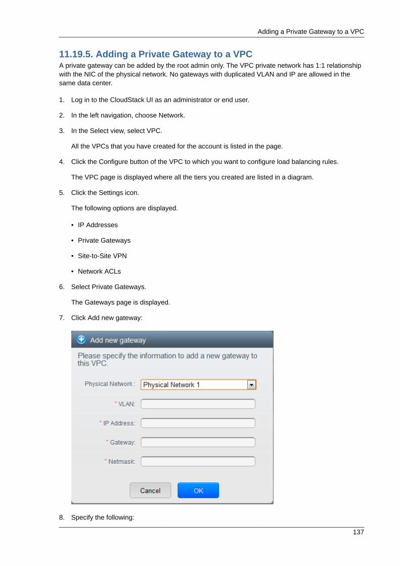
Adding a Private Gateway to a VPC
137
11.19.5. Adding a Private Gateway to a VPCA private gateway can be added by the root admin only. The VPC private network has 1:1 relationshipwith the NIC of the physical network. No gateways with duplicated VLAN and IP are allowed in thesame data center.
1. Log in to the CloudStack UI as an administrator or end user.
2. In the left navigation, choose Network.
3. In the Select view, select VPC.
All the VPCs that you have created for the account is listed in the page.
4. Click the Configure button of the VPC to which you want to configure load balancing rules.
The VPC page is displayed where all the tiers you created are listed in a diagram.
5. Click the Settings icon.
The following options are displayed.
• IP Addresses
• Private Gateways
• Site-to-Site VPN
• Network ACLs
6. Select Private Gateways.
The Gateways page is displayed.
7. Click Add new gateway:
8. Specify the following:
Chapter 11. Managing Networks and Traffic
138
• Physical Network: The physical network you have created in the zone.
• IP Address: The IP address associated with the VPC gateway.
• Gateway: The gateway through which the traffic is routed to and from the VPC.
• Netmask: The netmask associated with the VPC gateway.
• VLAN: The VLAN associated with the VPC gateway.
The new gateway appears in the list. You can repeat these steps to add more gateway for thisVPC.
11.19.6. Deploying VMs to the Tier1. Log in to the CloudStack UI as an administrator or end user.
2. In the left navigation, choose Network.
3. In the Select view, select VPC.
All the VPCs that you have created for the account is listed in the page.
4. Click the Configure button of the VPC to which you want to deploy the VMs.
The VPC page is displayed where all the tiers you created are listed.
5. Click the Add VM button of the tier for which you want to add a VM.
The Add Instance page is displayed.
Follow the on-screen instruction to add an instance. For information on adding an instance, seeAdding Instances section in the Installation Guide.
11.19.7. Acquiring a New IP Address for a VPCWhen you acquire an IP address, all IP addresses are allocated to VPC, not to the guest networkswithin the VPC. The IPs are associated to the guest network only when the first port-forwarding, loadbalancing, or Static NAT rule is created for the IP or the network. IP can't be associated to more thanone network at a time.
1. Log in to the CloudStack UI as an administrator or end user.
2. In the left navigation, choose Network.
3. In the Select view, select VPC.
All the VPCs that you have created for the account is listed in the page.
4. Click the Configure button of the VPC to which you want to deploy the VMs.
The VPC page is displayed where all the tiers you created are listed in a diagram.
5. Click the Settings icon.
The following options are displayed.
• IP Addresses
Releasing an IP Address Alloted to a VPC
139
• Gateways
• Site-to-Site VPN
• Network ACLs
6. Select IP Addresses.
The IP Addresses page is displayed.
7. Click Acquire New IP, and click Yes in the confirmation dialog.
You are prompted for confirmation because, typically, IP addresses are a limited resource. Withina few moments, the new IP address should appear with the state Allocated. You can now use theIP address in port forwarding, load balancing, and static NAT rules.
11.19.8. Releasing an IP Address Alloted to a VPCThe IP address is a limited resource. If you no longer need a particular IP, you can disassociate it fromits VPC and return it to the pool of available addresses. An IP address can be released from its tier,only when all the networking ( port forwarding, load balancing, or StaticNAT ) rules are removed forthis IP address. The released IP address will still belongs to the same VPC.
1. Log in to the CloudStack UI as an administrator or end user.
2. In the left navigation, choose Network.
3. In the Select view, select VPC.
All the VPCs that you have created for the account is listed in the page.
4. Click the Configure button of the VPC whose IP you want to release.
The VPC page is displayed where all the tiers you created are listed in a diagram.
5. Click the Settings icon.
The following options are displayed.
• IP Addresses
• Gateways
• Site-to-Site VPN
• Network ACLs
6. Select IP Addresses.
The IP Addresses page is displayed.
7. Click the IP you want to release.
8.In the Details tab, click the Release IP button
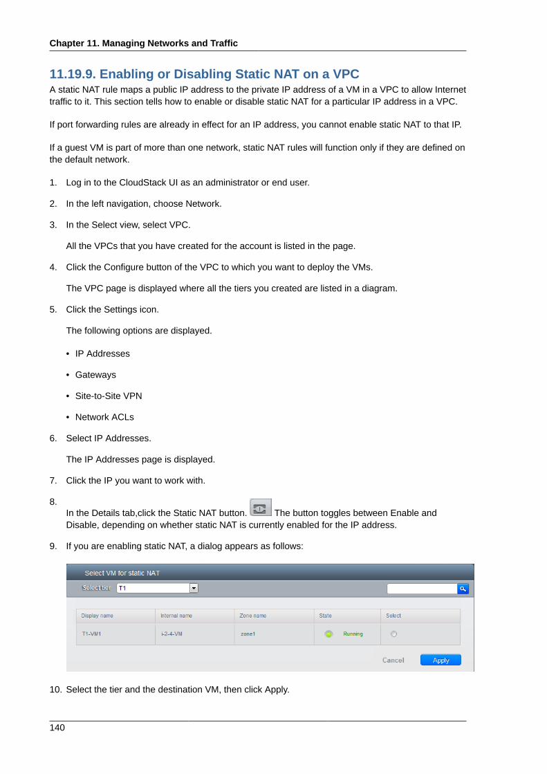
Chapter 11. Managing Networks and Traffic
140
11.19.9. Enabling or Disabling Static NAT on a VPCA static NAT rule maps a public IP address to the private IP address of a VM in a VPC to allow Internettraffic to it. This section tells how to enable or disable static NAT for a particular IP address in a VPC.
If port forwarding rules are already in effect for an IP address, you cannot enable static NAT to that IP.
If a guest VM is part of more than one network, static NAT rules will function only if they are defined onthe default network.
1. Log in to the CloudStack UI as an administrator or end user.
2. In the left navigation, choose Network.
3. In the Select view, select VPC.
All the VPCs that you have created for the account is listed in the page.
4. Click the Configure button of the VPC to which you want to deploy the VMs.
The VPC page is displayed where all the tiers you created are listed in a diagram.
5. Click the Settings icon.
The following options are displayed.
• IP Addresses
• Gateways
• Site-to-Site VPN
• Network ACLs
6. Select IP Addresses.
The IP Addresses page is displayed.
7. Click the IP you want to work with.
8.In the Details tab,click the Static NAT button. The button toggles between Enable andDisable, depending on whether static NAT is currently enabled for the IP address.
9. If you are enabling static NAT, a dialog appears as follows:
10. Select the tier and the destination VM, then click Apply.
Adding Load Balancing Rules on a VPC
141
11.19.10. Adding Load Balancing Rules on a VPCA CloudStack user or administrator may create load balancing rules that balance traffic received at apublic IP to one or more VMs that belong to a network tier that provides load balancing service in aVPC. A user creates a rule, specifies an algorithm, and assigns the rule to a set of VMs within a VPC.
1. Log in to the CloudStack UI as an administrator or end user.
2. In the left navigation, choose Network.
3. In the Select view, select VPC.
All the VPCs that you have created for the account is listed in the page.
4. Click the Configure button of the VPC to which you want to configure load balancing rules.
The VPC page is displayed where all the tiers you created are listed in a diagram.
5. Click the Settings icon.
The following options are displayed.
• IP Addresses
• Gateways
• Site-to-Site VPN
• Network ACLs
6. Select IP Addresses.
The IP Addresses page is displayed.
7. Click the IP address for which you want to create the rule, then click the Configuration tab.
8. In the Load Balancing node of the diagram, click View All.
9. Select the tier to which you want to apply the rule.
Note
In a VPC, the load balancing service is supported only on a single tier.
10. Specify the following:
• Name: A name for the load balancer rule.
• Public Port: The port that receives the incoming traffic to be balanced.
• Private Port: The port that the VMs will use to receive the traffic.
• Algorithm. Choose the load balancing algorithm you want CloudStack to use. CloudStacksupports the following well-known algorithms:
Chapter 11. Managing Networks and Traffic
142
• Round-robin
• Least connections
• Source
• Stickiness. (Optional) Click Configure and choose the algorithm for the stickiness policy. SeeSticky Session Policies for Load Balancer Rules.
• Add VMs: Click Add VMs, then select two or more VMs that will divide the load of incomingtraffic, and click Apply.
The new load balancing rule appears in the list. You can repeat these steps to add more loadbalancing rules for this IP address.
11.19.11. Adding a Port Forwarding Rule on a VPC1. Log in to the CloudStack UI as an administrator or end user.
2. In the left navigation, choose Network.
3. In the Select view, select VPC.
All the VPCs that you have created for the account is listed in the page.
4. Click the Configure button of the VPC to which you want to deploy the VMs.
The VPC page is displayed where all the tiers you created are listed in a diagram.
5. Click the Settings icon.
The following options are displayed.
• IP Addresses
• Gateways
• Site-to-Site VPN
• Network ACLs
6. Choose an existing IP address or acquire a new IP address. Click the name of the IP address inthe list.
The IP Addresses page is displayed.
7. Click the IP address for which you want to create the rule, then click the Configuration tab.
8. In the Port Forwarding node of the diagram, click View All.
9. Select the tier to which you want to apply the rule.
10. Specify the following:
• Public Port: The port to which public traffic will be addressed on the IP address you acquired inthe previous step.
• Private Port: The port on which the instance is listening for forwarded public traffic.
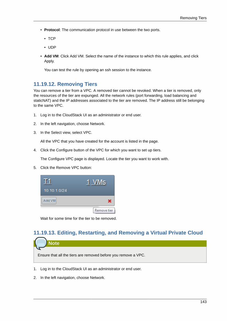
Removing Tiers
143
• Protocol: The communication protocol in use between the two ports.
• TCP
• UDP
• Add VM: Click Add VM. Select the name of the instance to which this rule applies, and clickApply.
You can test the rule by opening an ssh session to the instance.
11.19.12. Removing TiersYou can remove a tier from a VPC. A removed tier cannot be revoked. When a tier is removed, onlythe resources of the tier are expunged. All the network rules (port forwarding, load balancing andstaticNAT) and the IP addresses associated to the tier are removed. The IP address still be belongingto the same VPC.
1. Log in to the CloudStack UI as an administrator or end user.
2. In the left navigation, choose Network.
3. In the Select view, select VPC.
All the VPC that you have created for the account is listed in the page.
4. Click the Configure button of the VPC for which you want to set up tiers.
The Configure VPC page is displayed. Locate the tier you want to work with.
5. Click the Remove VPC button:
Wait for some time for the tier to be removed.
11.19.13. Editing, Restarting, and Removing a Virtual Private Cloud
Note
Ensure that all the tiers are removed before you remove a VPC.
1. Log in to the CloudStack UI as an administrator or end user.
2. In the left navigation, choose Network.
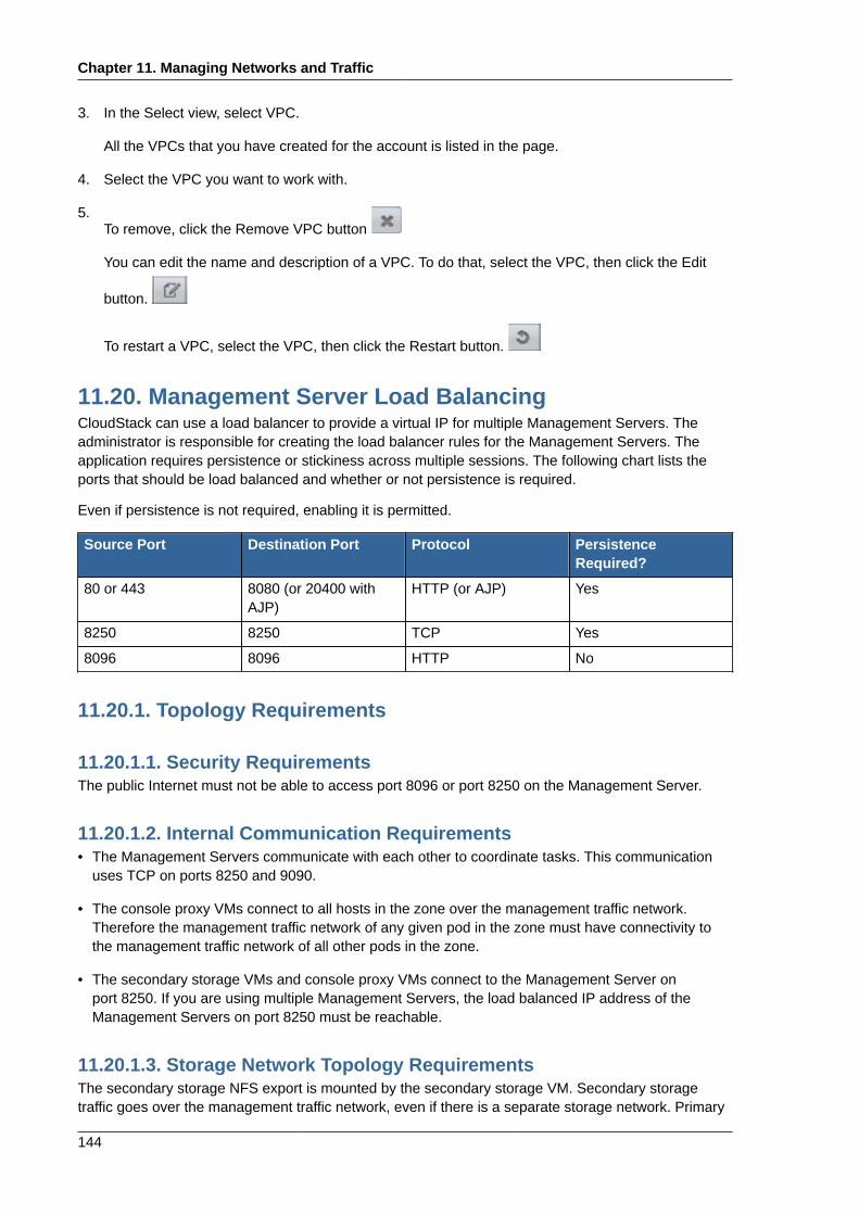
Chapter 11. Managing Networks and Traffic
144
3. In the Select view, select VPC.
All the VPCs that you have created for the account is listed in the page.
4. Select the VPC you want to work with.
5.To remove, click the Remove VPC button
You can edit the name and description of a VPC. To do that, select the VPC, then click the Edit
button.
To restart a VPC, select the VPC, then click the Restart button.
11.20. Management Server Load BalancingCloudStack can use a load balancer to provide a virtual IP for multiple Management Servers. Theadministrator is responsible for creating the load balancer rules for the Management Servers. Theapplication requires persistence or stickiness across multiple sessions. The following chart lists theports that should be load balanced and whether or not persistence is required.
Even if persistence is not required, enabling it is permitted.
Source Port Destination Port Protocol PersistenceRequired?
80 or 443 8080 (or 20400 withAJP)
HTTP (or AJP) Yes
8250 8250 TCP Yes
8096 8096 HTTP No
11.20.1. Topology Requirements
11.20.1.1. Security RequirementsThe public Internet must not be able to access port 8096 or port 8250 on the Management Server.
11.20.1.2. Internal Communication Requirements• The Management Servers communicate with each other to coordinate tasks. This communication
uses TCP on ports 8250 and 9090.
• The console proxy VMs connect to all hosts in the zone over the management traffic network.Therefore the management traffic network of any given pod in the zone must have connectivity tothe management traffic network of all other pods in the zone.
• The secondary storage VMs and console proxy VMs connect to the Management Server onport 8250. If you are using multiple Management Servers, the load balanced IP address of theManagement Servers on port 8250 must be reachable.
11.20.1.3. Storage Network Topology RequirementsThe secondary storage NFS export is mounted by the secondary storage VM. Secondary storagetraffic goes over the management traffic network, even if there is a separate storage network. Primary
Topology Requirements
145
storage traffic goes over the storage network, if available. If you choose to place secondary storageNFS servers on the storage network, you must make sure there is a route from the management trafficnetwork to the storage network.
11.20.1.4. External Firewall Topology RequirementsWhen external firewall integration is in place, the public IP VLAN must still be trunked to the Hosts.This is required to support the Secondary Storage VM and Console Proxy VM.
11.20.1.5. Advanced Zone Topology RequirementsWith Advanced Networking, separate subnets must be used for private and public networks.
11.20.1.6. XenServer Topology RequirementsThe Management Servers communicate with XenServer hosts on ports 22 (ssh), 80 (HTTP), and 443(HTTPs).
11.20.1.7. VMware Topology Requirements• The Management Server and secondary storage VMs must be able to access vCenter and all ESXi
hosts in the zone. To allow the necessary access through the firewall, keep port 443 open.
• The Management Servers communicate with VMware vCenter servers on port 443 (HTTPs).
• The Management Servers communicate with the System VMs on port 3922 (ssh) on themanagement traffic network.
11.20.1.8. KVM Topology RequirementsThe Management Servers communicate with KVM hosts on port 22 (ssh).

146

147
Appendix A. Revision HistoryRevision 1-0 October 5 2012 Jessica Tomechak , Radhika PC , Wido den
HollanderInitial publication

148