Embed Size (px)
Citation preview
CloudStack Installation DocumentationRelease 4.12.0.0
Apache Software Foundation
Apr 19, 2018

Contents
1 Choosing a Deployment Architecture 31.1 Choosing a Deployment Architecture . . . . . . . . . . . . . . . . . . . . . . . . . . . . . . . . . . 3
2 Quick Installation Guide 132.1 Quick Installation Guide for CentOS 6 . . . . . . . . . . . . . . . . . . . . . . . . . . . . . . . . . 13
3 Source Installation 233.1 Building from Source . . . . . . . . . . . . . . . . . . . . . . . . . . . . . . . . . . . . . . . . . . 23
4 General Installation 314.1 Installation overview . . . . . . . . . . . . . . . . . . . . . . . . . . . . . . . . . . . . . . . . . . . 314.2 Management Server Installation . . . . . . . . . . . . . . . . . . . . . . . . . . . . . . . . . . . . . 33
5 Configuration 475.1 Configuring your CloudStack Installation . . . . . . . . . . . . . . . . . . . . . . . . . . . . . . . . 47
6 Hypervisor Setup 736.1 Host Hyper-V Installation . . . . . . . . . . . . . . . . . . . . . . . . . . . . . . . . . . . . . . . . 736.2 Host KVM Installation . . . . . . . . . . . . . . . . . . . . . . . . . . . . . . . . . . . . . . . . . . 776.3 Host LXC Installation . . . . . . . . . . . . . . . . . . . . . . . . . . . . . . . . . . . . . . . . . . 926.4 Host VMware vSphere Installation . . . . . . . . . . . . . . . . . . . . . . . . . . . . . . . . . . . 1006.5 Host Citrix XenServer Installation . . . . . . . . . . . . . . . . . . . . . . . . . . . . . . . . . . . . 124
7 Network Setup 1357.1 Network Setup . . . . . . . . . . . . . . . . . . . . . . . . . . . . . . . . . . . . . . . . . . . . . . 135
8 Storage Setup 1518.1 Storage Setup . . . . . . . . . . . . . . . . . . . . . . . . . . . . . . . . . . . . . . . . . . . . . . . 1518.2 Small-Scale Setup . . . . . . . . . . . . . . . . . . . . . . . . . . . . . . . . . . . . . . . . . . . . 1518.3 Large-Scale Setup . . . . . . . . . . . . . . . . . . . . . . . . . . . . . . . . . . . . . . . . . . . . 1528.4 Storage Architecture . . . . . . . . . . . . . . . . . . . . . . . . . . . . . . . . . . . . . . . . . . . 1528.5 Network Configuration For Storage . . . . . . . . . . . . . . . . . . . . . . . . . . . . . . . . . . . 153
9 Optional Installation 1599.1 Additional Installation Options . . . . . . . . . . . . . . . . . . . . . . . . . . . . . . . . . . . . . 1599.2 About Password and Key Encryption . . . . . . . . . . . . . . . . . . . . . . . . . . . . . . . . . . 170
i

ii
CloudStack Installation Documentation, Release 4.12.0.0
This is the Apache CloudStack installation guide, for the Documentation home, the administrator guide or the Release-Notes please see:
• Documentation home
• Administration Guide
• Release Notes
Note: In this guide we first go through some design and architectural choices to build your cloud. Then we dive intoa single node quick start guide to give you a feel for the installation process. The source installation steps are given inthe follow-on section for people who want to build their own packages. Otherwise you can use the general installationwhich makes use of community maintained package repositories. The rest of the guide goes through the configurationof the data-center and the setup of the network, storage and hypervisors.
Contents 1
CloudStack Installation Documentation, Release 4.12.0.0
2 Contents
CHAPTER 1
Choosing a Deployment Architecture
1.1 Choosing a Deployment Architecture
The architecture used in a deployment will vary depending on the size and purpose of the deployment. This sectioncontains examples of deployment architecture, including a small-scale deployment useful for test and trial deploymentsand a fully-redundant large-scale setup for production deployments.
3
CloudStack Installation Documentation, Release 4.12.0.0
1.1.1 Small-Scale Deployment
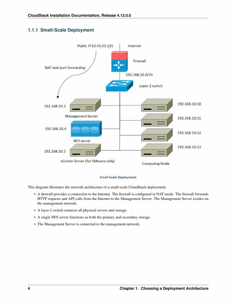
This diagram illustrates the network architecture of a small-scale CloudStack deployment.
• A firewall provides a connection to the Internet. The firewall is configured in NAT mode. The firewall forwardsHTTP requests and API calls from the Internet to the Management Server. The Management Server resides onthe management network.
• A layer-2 switch connects all physical servers and storage.
• A single NFS server functions as both the primary and secondary storage.
• The Management Server is connected to the management network.
4 Chapter 1. Choosing a Deployment Architecture
CloudStack Installation Documentation, Release 4.12.0.0
1.1.2 Large-Scale Redundant Setup
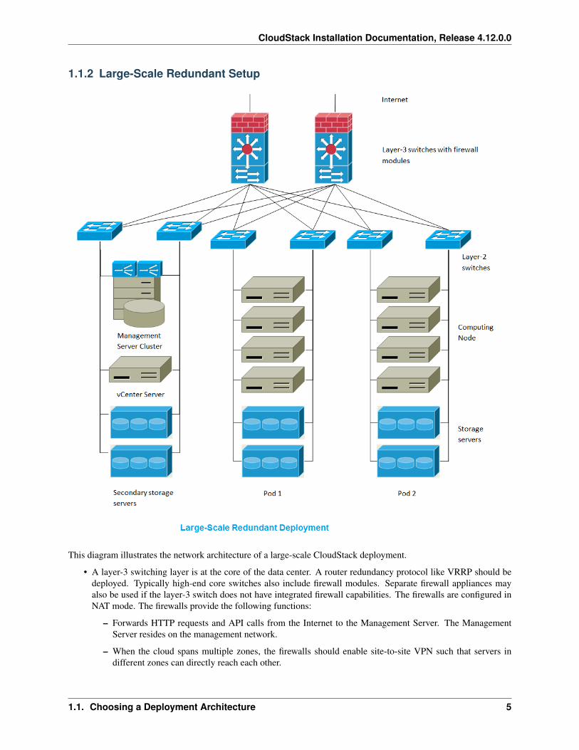
This diagram illustrates the network architecture of a large-scale CloudStack deployment.
• A layer-3 switching layer is at the core of the data center. A router redundancy protocol like VRRP should bedeployed. Typically high-end core switches also include firewall modules. Separate firewall appliances mayalso be used if the layer-3 switch does not have integrated firewall capabilities. The firewalls are configured inNAT mode. The firewalls provide the following functions:
– Forwards HTTP requests and API calls from the Internet to the Management Server. The ManagementServer resides on the management network.
– When the cloud spans multiple zones, the firewalls should enable site-to-site VPN such that servers indifferent zones can directly reach each other.
1.1. Choosing a Deployment Architecture 5
CloudStack Installation Documentation, Release 4.12.0.0
• A layer-2 access switch layer is established for each pod. Multiple switches can be stacked to increase portcount. In either case, redundant pairs of layer-2 switches should be deployed.
• The Management Server cluster (including front-end load balancers, Management Server nodes, and the MySQLdatabase) is connected to the management network through a pair of load balancers.
• Secondary storage servers are connected to the management network.
• Each pod contains storage and computing servers. Each storage and computing server should have redundantNICs connected to separate layer-2 access switches.
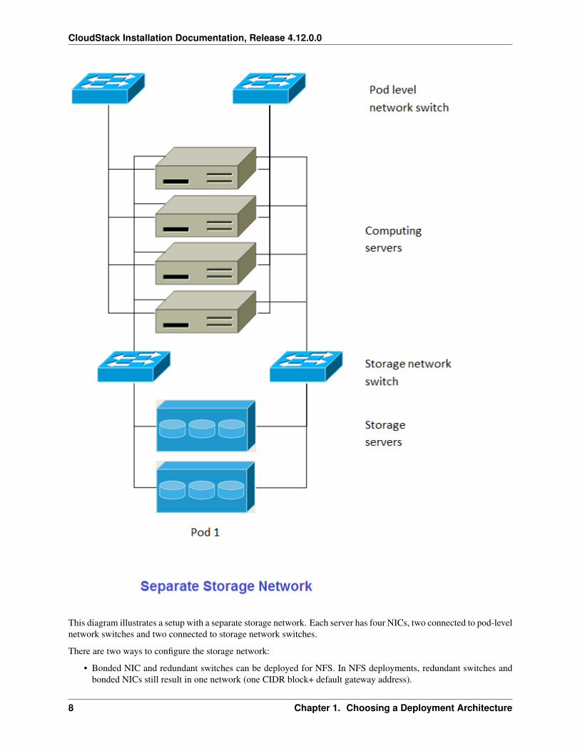
1.1.3 Separate Storage Network
In the large-scale redundant setup described in the previous section, storage traffic can overload the managementnetwork. A separate storage network is optional for deployments. Storage protocols such as iSCSI are sensitiveto network delays. A separate storage network ensures guest network traffic contention does not impact storageperformance.
1.1.4 Multi-Node Management Server
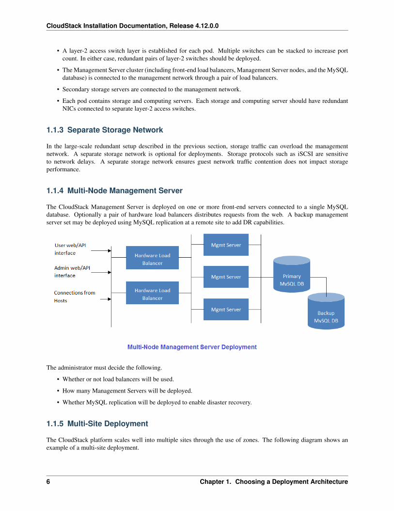
The CloudStack Management Server is deployed on one or more front-end servers connected to a single MySQLdatabase. Optionally a pair of hardware load balancers distributes requests from the web. A backup managementserver set may be deployed using MySQL replication at a remote site to add DR capabilities.
The administrator must decide the following.
• Whether or not load balancers will be used.
• How many Management Servers will be deployed.
• Whether MySQL replication will be deployed to enable disaster recovery.
1.1.5 Multi-Site Deployment
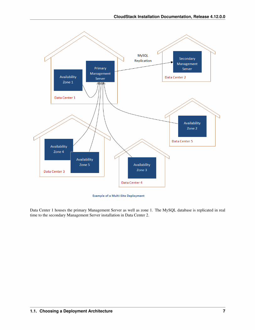
The CloudStack platform scales well into multiple sites through the use of zones. The following diagram shows anexample of a multi-site deployment.
6 Chapter 1. Choosing a Deployment Architecture
CloudStack Installation Documentation, Release 4.12.0.0
Data Center 1 houses the primary Management Server as well as zone 1. The MySQL database is replicated in realtime to the secondary Management Server installation in Data Center 2.
1.1. Choosing a Deployment Architecture 7
CloudStack Installation Documentation, Release 4.12.0.0
This diagram illustrates a setup with a separate storage network. Each server has four NICs, two connected to pod-levelnetwork switches and two connected to storage network switches.
There are two ways to configure the storage network:
• Bonded NIC and redundant switches can be deployed for NFS. In NFS deployments, redundant switches andbonded NICs still result in one network (one CIDR block+ default gateway address).
8 Chapter 1. Choosing a Deployment Architecture
CloudStack Installation Documentation, Release 4.12.0.0
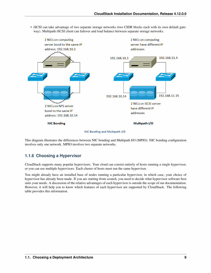
• iSCSI can take advantage of two separate storage networks (two CIDR blocks each with its own default gate-way). Multipath iSCSI client can failover and load balance between separate storage networks.
This diagram illustrates the differences between NIC bonding and Multipath I/O (MPIO). NIC bonding configurationinvolves only one network. MPIO involves two separate networks.
1.1.6 Choosing a Hypervisor
CloudStack supports many popular hypervisors. Your cloud can consist entirely of hosts running a single hypervisor,or you can use multiple hypervisors. Each cluster of hosts must run the same hypervisor.
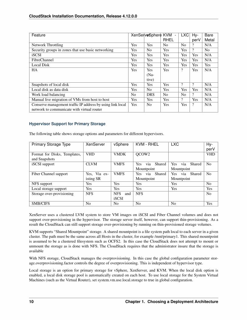
You might already have an installed base of nodes running a particular hypervisor, in which case, your choice ofhypervisor has already been made. If you are starting from scratch, you need to decide what hypervisor software bestsuits your needs. A discussion of the relative advantages of each hypervisor is outside the scope of our documentation.However, it will help you to know which features of each hypervisor are supported by CloudStack. The followingtable provides this information.
1.1. Choosing a Deployment Architecture 9
CloudStack Installation Documentation, Release 4.12.0.0
Feature XenServervSphere KVM -RHEL
LXC Hy-perV
BareMetal
Network Throttling Yes Yes No No ? N/ASecurity groups in zones that use basic networking Yes No Yes Yes ? NoiSCSI Yes Yes Yes Yes Yes N/AFibreChannel Yes Yes Yes Yes Yes N/ALocal Disk Yes Yes Yes Yes Yes YesHA Yes Yes
(Na-tive)
Yes ? Yes N/A
Snapshots of local disk Yes Yes Yes ? ? N/ALocal disk as data disk Yes No Yes Yes Yes N/AWork load balancing No DRS No No ? N/AManual live migration of VMs from host to host Yes Yes Yes ? Yes N/AConserve management traffic IP address by using link localnetwork to communicate with virtual router
Yes No Yes Yes ? N/A
Hypervisor Support for Primary Storage
The following table shows storage options and parameters for different hypervisors.
Primary Storage Type XenServer vSphere KVM - RHEL LXC Hy-perV
Format for Disks, Templates,and Snapshots
VHD VMDK QCOW2 VHD
iSCSI support CLVM VMFS Yes via SharedMountpoint
Yes via SharedMountpoint
No
Fiber Channel support Yes, Via ex-isting SR
VMFS Yes via SharedMountpoint
Yes via SharedMountpoint
No
NFS support Yes Yes Yes Yes NoLocal storage support Yes Yes Yes Yes YesStorage over-provisioning NFS NFS and
iSCSINFS No
SMB/CIFS No No No No Yes
XenServer uses a clustered LVM system to store VM images on iSCSI and Fiber Channel volumes and does notsupport over-provisioning in the hypervisor. The storage server itself, however, can support thin-provisioning. As aresult the CloudStack can still support storage over-provisioning by running on thin-provisioned storage volumes.
KVM supports “Shared Mountpoint” storage. A shared mountpoint is a file system path local to each server in a givencluster. The path must be the same across all Hosts in the cluster, for example /mnt/primary1. This shared mountpointis assumed to be a clustered filesystem such as OCFS2. In this case the CloudStack does not attempt to mount orunmount the storage as is done with NFS. The CloudStack requires that the administrator insure that the storage isavailable
With NFS storage, CloudStack manages the overprovisioning. In this case the global configuration parameter stor-age.overprovisioning.factor controls the degree of overprovisioning. This is independent of hypervisor type.
Local storage is an option for primary storage for vSphere, XenServer, and KVM. When the local disk option isenabled, a local disk storage pool is automatically created on each host. To use local storage for the System VirtualMachines (such as the Virtual Router), set system.vm.use.local.storage to true in global configuration.
10 Chapter 1. Choosing a Deployment Architecture
CloudStack Installation Documentation, Release 4.12.0.0
CloudStack supports multiple primary storage pools in a Cluster. For example, you could provision 2 NFS serversin primary storage. Or you could provision 1 iSCSI LUN initially and then add a second iSCSI LUN when the firstapproaches capacity.
1.1.7 Best Practices
Deploying a cloud is challenging. There are many different technology choices to make, and CloudStack is flexibleenough in its configuration that there are many possible ways to combine and configure the chosen technology. Thissection contains suggestions and requirements about cloud deployments.
These should be treated as suggestions and not absolutes. However, we do encourage anyone planning to build a cloudoutside of these guidelines to seek guidance and advice on the project mailing lists.
Process Best Practices
• A staging system that models the production environment is strongly advised. It is critical if customizationshave been applied to CloudStack.
• Allow adequate time for installation, a beta, and learning the system. Installs with basic networking can be donein hours. Installs with advanced networking usually take several days for the first attempt, with complicatedinstallations taking longer. For a full production system, allow at least 4-8 weeks for a beta to work through allof the integration issues. You can get help from fellow users on the cloudstack-users mailing list.
Setup Best Practices
• Each host should be configured to accept connections only from well-known entities such as the CloudStackManagement Server or your network monitoring software.
• Use multiple clusters per pod if you need to achieve a certain switch density.
• Primary storage mountpoints or LUNs should not exceed 6 TB in size. It is better to have multiple smallerprimary storage elements per cluster than one large one.
• When exporting shares on primary storage, avoid data loss by restricting the range of IP addresses that canaccess the storage. See “Linux NFS on Local Disks and DAS” or “Linux NFS on iSCSI”.
• NIC bonding is straightforward to implement and provides increased reliability.
• 10G networks are generally recommended for storage access when larger servers that can support relativelymore VMs are used.
• Host capacity should generally be modeled in terms of RAM for the guests. Storage and CPU may be overpro-visioned. RAM may not. RAM is usually the limiting factor in capacity designs.
• (XenServer) Configure the XenServer dom0 settings to allocate more memory to dom0. This can enableXenServer to handle larger numbers of virtual machines. We recommend 2940 MB of RAM for XenServerdom0. For instructions on how to do this, see http://support.citrix.com/article/CTX126531. The article refers toXenServer 5.6, but the same information applies to XenServer 6.0.
Maintenance Best Practices
• Monitor host disk space. Many host failures occur because the host’s root disk fills up from logs that were notrotated adequately.
1.1. Choosing a Deployment Architecture 11
CloudStack Installation Documentation, Release 4.12.0.0
• Monitor the total number of VM instances in each cluster, and disable allocation to the cluster if the total isapproaching the maximum that the hypervisor can handle. Be sure to leave a safety margin to allow for thepossibility of one or more hosts failing, which would increase the VM load on the other hosts as the VMs areredeployed. Consult the documentation for your chosen hypervisor to find the maximum permitted number ofVMs per host, then use CloudStack global configuration settings to set this as the default limit. Monitor theVM activity in each cluster and keep the total number of VMs below a safe level that allows for the occasionalhost failure. For example, if there are N hosts in the cluster, and you want to allow for one host in the cluster tobe down at any given time, the total number of VM instances you can permit in the cluster is at most (N-1) *(per-host-limit). Once a cluster reaches this number of VMs, use the CloudStack UI to disable allocation to thecluster.
Warning: The lack of up-do-date hotfixes can lead to data corruption and lost VMs.
Be sure all the hotfixes provided by the hypervisor vendor are applied. Track the release of hypervisor patches throughyour hypervisor vendor’s support channel, and apply patches as soon as possible after they are released. CloudStackwill not track or notify you of required hypervisor patches. It is essential that your hosts are completely up to datewith the provided hypervisor patches. The hypervisor vendor is likely to refuse to support any system that is not up todate with patches.
12 Chapter 1. Choosing a Deployment Architecture
CHAPTER 2
Quick Installation Guide
2.1 Quick Installation Guide for CentOS 6
2.1.1 Overview
What exactly are we building?
Infrastructure-as-a-Service (IaaS) clouds can be a complex thing to build, and by definition they have a plethora ofoptions, which often lead to confusion for even experienced admins who are newcomers to building cloud platforms.The goal for this runbook is to provide a straightforward set of instructions to get you up and running with CloudStackwith a minimum amount of trouble.
High level overview of the process
This runbook will focus on building a CloudStack cloud using KVM on CentOS 6.8 with NFS storage on a flat layer-2network utilizing layer-3 network isolation (aka Security Groups), and doing it all on a single piece of hardware.
KVM, or Kernel-based Virtual Machine is a virtualization technology for the Linux kernel. KVM supports nativevirtualization atop processors with hardware virtualization extensions.
Security Groups act as distributed firewalls that control access to a group of virtual machines.
Prerequisites
To complete this runbook you’ll need the following items:
1. At least one computer which supports and has enabled hardware virtualization.
2. The CentOS 6.8 x86_64 minimal install CD
3. A /24 network with the gateway being at xxx.xxx.xxx.1, no DHCP should be on this network and none of thecomputers running CloudStack will have a dynamic address. Again this is done for the sake of simplicity.
13
CloudStack Installation Documentation, Release 4.12.0.0
2.1.2 Environment
Before you begin , you need to prepare the environment before you install CloudStack. We will go over the steps toprepare now.
Operating System
Using the CentOS 6.8 x86_64 minimal install ISO, you’ll need to install CentOS 6 on your hardware. The defaultswill generally be acceptable for this installation.
Once this installation is complete, you’ll want to connect to your freshly installed machine via SSH as the root user.Note that you should not allow root logins in a production environment, so be sure to turn off remote logins once youhave finished the installation and configuration.
Configuring the network
By default the network will not come up on your hardware and you will need to configure it to work in your environ-ment. Since we specified that there will be no DHCP server in this environment we will be manually configuring yournetwork interface. We will assume, for the purposes of this exercise, that eth0 is the only network interface that willbe connected and used.
Connecting via the console you should login as root. Check the file /etc/sysconfig/network-scripts/ifcfg-eth0, it willlook like this by default:
DEVICE="eth0"HWADDR="52:54:00:B9:A6:C0"NM_CONTROLLED="yes"ONBOOT="no"
Unfortunately, this configuration will not permit you to connect to the network, and is also unsuitable for our purposeswith CloudStack. We want to configure that file so that it specifies the IP address, netmask, etc., as shown in thefollowing example:
Note: You should not use the Hardware Address (aka the MAC address) from our example for your configuration. Itis network interface specific, so you should keep the address already provided in the HWADDR directive.
DEVICE=eth0HWADDR=52:54:00:B9:A6:C0NM_CONTROLLED=noONBOOT=yesBOOTPROTO=noneIPADDR=172.16.10.2NETMASK=255.255.255.0GATEWAY=172.16.10.1DNS1=8.8.8.8DNS2=8.8.4.4
Note: IP Addressing - Throughout this document we are assuming that you will have a /24 network for your Cloud-Stack implementation. This can be any RFC 1918 network. However, we are assuming that you will match the machineaddress that we are using. Thus we may use 172.16.10.2 and because you might be using the 192.168.55.0/24 networkyou would use 192.168.55.2
14 Chapter 2. Quick Installation Guide
CloudStack Installation Documentation, Release 4.12.0.0
Now that we have the configuration files properly set up, we need to run a few commands to start up the network:
# chkconfig network on
# service network start
Hostname
CloudStack requires that the hostname be properly set. If you used the default options in the installation, then yourhostname is currently set to localhost.localdomain. To test this we will run:
# hostname --fqdn
At this point it will likely return:
localhost
To rectify this situation - we’ll set the hostname by editing the /etc/hosts file so that it follows a similar format to thisexample:
127.0.0.1 localhost localhost.localdomain localhost4 localhost4.localdomain4::1 localhost localhost.localdomain localhost6 localhost6.localdomain6172.16.10.2 srvr1.cloud.priv
After you’ve modified that file, go ahead and restart the network using:
# service network restart
Now recheck with the hostname –fqdn command and ensure that it returns a FQDN response
SELinux
At the moment, for CloudStack to work properly SELinux must be set to permissive. We want to both configure thisfor future boots and modify it in the current running system.
To configure SELinux to be permissive in the running system we need to run the following command:
# setenforce 0
To ensure that it remains in that state we need to configure the file /etc/selinux/config to reflect the permissive state, asshown in this example:
# This file controls the state of SELinux on the system.# SELINUX= can take one of these three values:# enforcing - SELinux security policy is enforced.# permissive - SELinux prints warnings instead of enforcing.# disabled - No SELinux policy is loaded.SELINUX=permissive# SELINUXTYPE= can take one of these two values:# targeted - Targeted processes are protected,# mls - Multi Level Security protection.SELINUXTYPE=targeted
2.1. Quick Installation Guide for CentOS 6 15
CloudStack Installation Documentation, Release 4.12.0.0
NTP
NTP configuration is a necessity for keeping all of the clocks in your cloud servers in sync. However, NTP is notinstalled by default. So we’ll install and and configure NTP at this stage. Installation is accomplished as follows:
# yum -y install ntp
The actual default configuration is fine for our purposes, so we merely need to enable it and set it to start on boot asfollows:
# chkconfig ntpd on# service ntpd start
Configuring the CloudStack Package Repository
We need to configure the machine to use a CloudStack package repository.
Note: The Apache CloudStack official releases are source code. As such there are no ‘official’ binaries available. Thefull installation guide describes how to take the source release and generate RPMs and and yum repository. This guideattempts to keep things as simple as possible, and thus we are using one of the community-provided yum repositories.
To add the CloudStack repository, create /etc/yum.repos.d/cloudstack.repo and insert the following information.
[cloudstack]name=cloudstackbaseurl=http://cloudstack.apt-get.eu/centos/6/4.11/enabled=1gpgcheck=0
NFS
Our configuration is going to use NFS for both primary and secondary storage. We are going to go ahead and setuptwo NFS shares for those purposes. We’ll start out by installing nfs-utils.
# yum -y install nfs-utils
We now need to configure NFS to serve up two different shares. This is handled comparatively easily in the /etc/exportsfile. You should ensure that it has the following content:
/export/secondary *(rw,async,no_root_squash,no_subtree_check)/export/primary *(rw,async,no_root_squash,no_subtree_check)
You will note that we specified two directories that don’t exist (yet) on the system. We’ll go ahead and create thosedirectories and set permissions appropriately on them with the following commands:
# mkdir -p /export/primary# mkdir /export/secondary
CentOS 6.x releases use NFSv4 by default. NFSv4 requires that domain setting matches on all clients. In our case,the domain is cloud.priv, so ensure that the domain setting in /etc/idmapd.conf is uncommented and set as follows:Domain = cloud.priv
Now you’ll need uncomment the configuration values in the file /etc/sysconfig/nfs
16 Chapter 2. Quick Installation Guide
CloudStack Installation Documentation, Release 4.12.0.0
LOCKD_TCPPORT=32803LOCKD_UDPPORT=32769MOUNTD_PORT=892RQUOTAD_PORT=875STATD_PORT=662STATD_OUTGOING_PORT=2020
Now we need to configure the firewall to permit incoming NFS connections. Edit the file /etc/sysconfig/iptables
-A INPUT -s 172.16.10.0/24 -m state --state NEW -p udp --dport 111 -j ACCEPT-A INPUT -s 172.16.10.0/24 -m state --state NEW -p tcp --dport 111 -j ACCEPT-A INPUT -s 172.16.10.0/24 -m state --state NEW -p tcp --dport 2049 -j ACCEPT-A INPUT -s 172.16.10.0/24 -m state --state NEW -p tcp --dport 32803 -j ACCEPT-A INPUT -s 172.16.10.0/24 -m state --state NEW -p udp --dport 32769 -j ACCEPT-A INPUT -s 172.16.10.0/24 -m state --state NEW -p tcp --dport 892 -j ACCEPT-A INPUT -s 172.16.10.0/24 -m state --state NEW -p udp --dport 892 -j ACCEPT-A INPUT -s 172.16.10.0/24 -m state --state NEW -p tcp --dport 875 -j ACCEPT-A INPUT -s 172.16.10.0/24 -m state --state NEW -p udp --dport 875 -j ACCEPT-A INPUT -s 172.16.10.0/24 -m state --state NEW -p tcp --dport 662 -j ACCEPT-A INPUT -s 172.16.10.0/24 -m state --state NEW -p udp --dport 662 -j ACCEPT
Now you can restart the iptables service with the following command:
# service iptables restart
We now need to configure the nfs service to start on boot and actually start it on the host by executing the followingcommands:
# service rpcbind start# service nfs start# chkconfig rpcbind on# chkconfig nfs on
2.1.3 Management Server Installation
We’re going to install the CloudStack management server and surrounding tools.
Database Installation and Configuration
We’ll start with installing MySQL and configuring some options to ensure it runs well with CloudStack.
Install by running the following command:
# yum -y install mysql-server
With MySQL now installed we need to make a few configuration changes to /etc/my.cnf. Specifically we need to addthe following options to the [mysqld] section:
innodb_rollback_on_timeout=1innodb_lock_wait_timeout=600max_connections=350log-bin=mysql-binbinlog-format = 'ROW'
Now that MySQL is properly configured we can start it and configure it to start on boot as follows:
2.1. Quick Installation Guide for CentOS 6 17
CloudStack Installation Documentation, Release 4.12.0.0
# service mysqld start# chkconfig mysqld on
MySQL connector Installation
Install Python MySQL connector using the official MySQL packages repository. Create the file /etc/yum.repos.d/mysql.repo with the following content:
[mysql-connectors-community]name=MySQL Community connectorsbaseurl=http://repo.mysql.com/yum/mysql-connectors-community/el/$releasever/$basearch/enabled=1gpgcheck=1
Import GPG public key from MySQL:
rpm --import http://repo.mysql.com/RPM-GPG-KEY-mysql
Install mysql-connector
yum install mysql-connector-python
Installation
We are now going to install the management server. We do that by executing the following command:
# yum -y install cloudstack-management
With the application itself installed we can now setup the database, we’ll do that with the following command andoptions:
# cloudstack-setup-databases cloud:password@localhost --deploy-as=root
When this process is finished, you should see a message like “CloudStack has successfully initialized the database.”
Now that the database has been created, we can take the final step in setting up the management server by issuing thefollowing command:
# cloudstack-setup-management
If the servlet container is Tomcat7 the argument –tomcat7 must be used.
System Template Setup
CloudStack uses a number of system VMs to provide functionality for accessing the console of virtual machines,providing various networking services, and managing various aspects of storage. This step will acquire those systemimages ready for deployment when we bootstrap your cloud.
Now we need to download the system VM template and deploy that to the share we just mounted. The managementserver includes a script to properly manipulate the system VMs images.
18 Chapter 2. Quick Installation Guide
CloudStack Installation Documentation, Release 4.12.0.0
/usr/share/cloudstack-common/scripts/storage/secondary/cloud-install-sys-tmplt \-m /export/secondary \-u http://cloudstack.apt-get.eu/systemvm/4.6/systemvm64template-4.6.0-kvm.qcow2.bz2 \-h kvm -F
That concludes our setup of the management server. We still need to configure CloudStack, but we will do that afterwe get our hypervisor set up.
2.1.4 KVM Setup and Installation
KVM is the hypervisor we’ll be using - we will recover the initial setup which has already been done on the hypervisorhost and cover installation of the agent software, you can use the same steps to add additional KVM nodes to yourCloudStack environment.
Prerequisites
We explicitly are using the management server as a compute node as well, which means that we have already performedmany of the prerequisite steps when setting up the management server, but we will list them here for clarity. Thosesteps are:
1. Configuring the network
2. Hostname
3. SELinux
4. NTP
5. Configuring the CloudStack Package Repository
You shouldn’t need to do that for the management server, of course, but any additional hosts will need for you tocomplete the above steps.
Installation
Installation of the KVM agent is trivial with just a single command, but afterwards we’ll need to configure a fewthings.
# yum -y install cloudstack-agent
KVM Configuration
We have two different parts of KVM to configure, libvirt, and QEMU.
QEMU Configuration
KVM configuration is relatively simple at only a single item. We need to edit the QEMU VNC configuration. This isdone by editing /etc/libvirt/qemu.conf and ensuring the following line is present and uncommented.
vnc_listen=0.0.0.0
2.1. Quick Installation Guide for CentOS 6 19
CloudStack Installation Documentation, Release 4.12.0.0
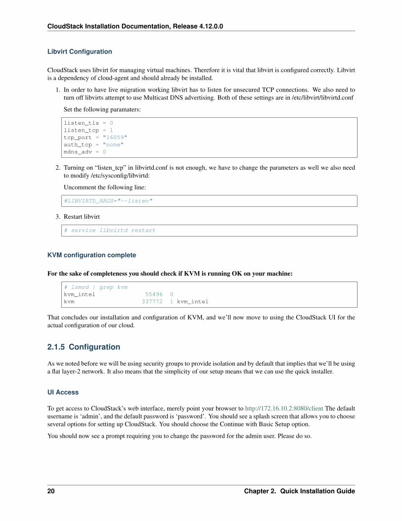
Libvirt Configuration
CloudStack uses libvirt for managing virtual machines. Therefore it is vital that libvirt is configured correctly. Libvirtis a dependency of cloud-agent and should already be installed.
1. In order to have live migration working libvirt has to listen for unsecured TCP connections. We also need toturn off libvirts attempt to use Multicast DNS advertising. Both of these settings are in /etc/libvirt/libvirtd.conf
Set the following paramaters:
listen_tls = 0listen_tcp = 1tcp_port = "16059"auth_tcp = "none"mdns_adv = 0
2. Turning on “listen_tcp” in libvirtd.conf is not enough, we have to change the parameters as well we also needto modify /etc/sysconfig/libvirtd:
Uncomment the following line:
#LIBVIRTD_ARGS="--listen"
3. Restart libvirt
# service libvirtd restart
KVM configuration complete
For the sake of completeness you should check if KVM is running OK on your machine:
# lsmod | grep kvmkvm_intel 55496 0kvm 337772 1 kvm_intel
That concludes our installation and configuration of KVM, and we’ll now move to using the CloudStack UI for theactual configuration of our cloud.
2.1.5 Configuration
As we noted before we will be using security groups to provide isolation and by default that implies that we’ll be usinga flat layer-2 network. It also means that the simplicity of our setup means that we can use the quick installer.
UI Access
To get access to CloudStack’s web interface, merely point your browser to http://172.16.10.2:8080/client The defaultusername is ‘admin’, and the default password is ‘password’. You should see a splash screen that allows you to chooseseveral options for setting up CloudStack. You should choose the Continue with Basic Setup option.
You should now see a prompt requiring you to change the password for the admin user. Please do so.
20 Chapter 2. Quick Installation Guide
CloudStack Installation Documentation, Release 4.12.0.0
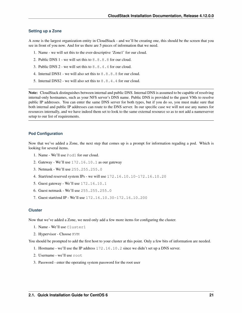
Setting up a Zone
A zone is the largest organization entity in CloudStack - and we’ll be creating one, this should be the screen that yousee in front of you now. And for us there are 5 pieces of information that we need.
1. Name - we will set this to the ever-descriptive ‘Zone1’ for our cloud.
2. Public DNS 1 - we will set this to 8.8.8.8 for our cloud.
3. Public DNS 2 - we will set this to 8.8.4.4 for our cloud.
4. Internal DNS1 - we will also set this to 8.8.8.8 for our cloud.
5. Internal DNS2 - we will also set this to 8.8.4.4 for our cloud.
Note: CloudStack distinguishes between internal and public DNS. Internal DNS is assumed to be capable of resolvinginternal-only hostnames, such as your NFS server’s DNS name. Public DNS is provided to the guest VMs to resolvepublic IP addresses. You can enter the same DNS server for both types, but if you do so, you must make sure thatboth internal and public IP addresses can route to the DNS server. In our specific case we will not use any names forresources internally, and we have indeed them set to look to the same external resource so as to not add a namerserversetup to our list of requirements.
Pod Configuration
Now that we’ve added a Zone, the next step that comes up is a prompt for information regading a pod. Which islooking for several items.
1. Name - We’ll use Pod1 for our cloud.
2. Gateway - We’ll use 172.16.10.1 as our gateway
3. Netmask - We’ll use 255.255.255.0
4. Start/end reserved system IPs - we will use 172.16.10.10-172.16.10.20
5. Guest gateway - We’ll use 172.16.10.1
6. Guest netmask - We’ll use 255.255.255.0
7. Guest start/end IP - We’ll use 172.16.10.30-172.16.10.200
Cluster
Now that we’ve added a Zone, we need only add a few more items for configuring the cluster.
1. Name - We’ll use Cluster1
2. Hypervisor - Choose KVM
You should be prompted to add the first host to your cluster at this point. Only a few bits of information are needed.
1. Hostname - we’ll use the IP address 172.16.10.2 since we didn’t set up a DNS server.
2. Username - we’ll use root
3. Password - enter the operating system password for the root user
2.1. Quick Installation Guide for CentOS 6 21
CloudStack Installation Documentation, Release 4.12.0.0
Primary Storage
With your cluster now setup - you should be prompted for primary storage information. Choose NFS as the storagetype and then enter the following values in the fields:
1. Name - We’ll use Primary1
2. Server - We’ll be using the IP address 172.16.10.2
3. Path - Well define /export/primary as the path we are using
Secondary Storage
If this is a new zone, you’ll be prompted for secondary storage information - populate it as follows:
1. NFS server - We’ll use the IP address 172.16.10.2
2. Path - We’ll use /export/secondary
Now, click Launch and your cloud should begin setup - it may take several minutes depending on your internetconnection speed for setup to finalize.
That’s it, you are done with installation of your Apache CloudStack cloud.
22 Chapter 2. Quick Installation Guide
CHAPTER 3
Source Installation
3.1 Building from Source
The official CloudStack release is always in source code form. You will likely be able to find “convenience binaries,”the source is the canonical release. In this section, we’ll cover acquiring the source release and building that so thatyou can deploy it using Maven or create Debian packages or RPMs.
Note that building and deploying directly from source is typically not the most efficient way to deploy an IaaS.However, we will cover that method as well as building RPMs or Debian packages for deploying CloudStack.
The instructions here are likely version-specific. That is, the method for building from source for the 4.7.x series isdifferent from the 4.2.x series.
If you are working with a unreleased version of CloudStack, see the INSTALL.md file in the top-level directory of therelease.
3.1.1 Getting the release
You can download the latest CloudStack release from the Apache CloudStack project download page.
Prior releases are available via archive.apache.org as well. See the downloads page for more information on archivedreleases.
You’ll notice several links under the ‘Latest release’ section. A link to a file ending in tar.bz2, as well as a PGP/GPGsignature, MD5, and SHA512 file.
• The tar.bz2 file contains the Bzip2-compressed tarball with the source code.
• The .asc file is a detached cryptographic signature that can be used to help verify the authenticity of the release.
• The .md5 file is an MD5 hash of the release to aid in verify the validity of the release download.
• The .sha file is a SHA512 hash of the release to aid in verify the validity of the release download.
23
CloudStack Installation Documentation, Release 4.12.0.0
3.1.2 Verifying the downloaded release
There are a number of mechanisms to check the authenticity and validity of a downloaded release.
Getting the KEYS
To enable you to verify the GPG signature, you will need to download the KEYS file.
You next need to import those keys, which you can do by running:
$ wget http://www.apache.org/dist/cloudstack/KEYS$ gpg --import KEYS
GPG
The CloudStack project provides a detached GPG signature of the release. To check the signature, run the followingcommand:
$ gpg --verify apache-cloudstack-4.11.0.0-src.tar.bz2.asc
If the signature is valid you will see a line of output that contains ‘Good signature’.
MD5
In addition to the cryptographic signature, CloudStack has an MD5 checksum that you can use to verify the downloadmatches the release. You can verify this hash by executing the following command:
$ gpg --print-md MD5 apache-cloudstack-4.11.0.0-src.tar.bz2 | diff - apache-→˓cloudstack-4.11.0.0-src.tar.bz2.md5
If this successfully completes you should see no output. If there is any output from them, then there is a differencebetween the hash you generated locally and the hash that has been pulled from the server.
SHA512
In addition to the MD5 hash, the CloudStack project provides a SHA512 cryptographic hash to aid in assurance of thevalidity of the downloaded release. You can verify this hash by executing the following command:
$ gpg --print-md SHA512 apache-cloudstack-4.11.0.0-src.tar.bz2 | diff - apache-→˓cloudstack-4.11.0.0-src.tar.bz2.sha
If this command successfully completes you should see no output. If there is any output from them, then there is adifference between the hash you generated locally and the hash that has been pulled from the server.
3.1.3 Prerequisites for building Apache CloudStack
There are a number of prerequisites needed to build CloudStack. This document assumes compilation on a Linuxsystem that uses RPMs or DEBs for package management.
You will need, at a minimum, the following to compile CloudStack:
1. Maven (version 3)
24 Chapter 3. Source Installation
CloudStack Installation Documentation, Release 4.12.0.0
2. Java (Java 8/OpenJDK 1.8)
3. Apache Web Services Common Utilities (ws-commons-util)
4. MySQL
5. MySQLdb (provides Python database API)
6. genisoimage
7. rpmbuild or dpkg-dev
3.1.4 Extracting source
Extracting the CloudStack release is relatively simple and can be done with a single command as follows:
$ tar -jxvf apache-cloudstack-4.11.0.0-src.tar.bz2
You can now move into the directory:
$ cd ./apache-cloudstack-4.11.0.0-src
3.1.5 Install new MySQL connector
Install Python MySQL connector using the official MySQL packages repository.
MySQL connector APT repository
Install the following package provided by MySQL to enable official repositories:
wget http://dev.mysql.com/get/mysql-apt-config_0.7.3-1_all.debsudo dpkg -i mysql-apt-config_0.7.3-1_all.deb
Make sure to activate the repository for MySQL connectors.
sudo apt-get updatesudo apt-get install mysql-connector-python
MySQL connector RPM repository
Add a new yum repo /etc/yum.repos.d/mysql.repo:
[mysql-community]name=MySQL Community connectorsbaseurl=http://repo.mysql.com/yum/mysql-connectors-community/el/$releasever/$basearch/enabled=1gpgcheck=1
Import GPG public key from MySQL:
rpm --import http://repo.mysql.com/RPM-GPG-KEY-mysql
Install mysql-connector
3.1. Building from Source 25
CloudStack Installation Documentation, Release 4.12.0.0
yum install mysql-connector-python
3.1.6 Building DEB packages
In addition to the bootstrap dependencies, you’ll also need to install several other dependencies. Note that we recom-mend using Maven 3.
$ sudo apt-get update$ sudo apt-get install python-software-properties$ sudo apt-get update$ sudo apt-get install debhelper openjdk-8-jdk libws-commons-util-java genisoimage→˓libcommons-codec-java libcommons-httpclient-java liblog4j1.2-java maven
While we have defined, and you have presumably already installed the bootstrap prerequisites, there are a number ofbuild time prerequisites that need to be resolved. CloudStack uses maven for dependency resolution. You can resolvethe buildtime depdencies for CloudStack by running:
$ mvn -P deps
Now that we have resolved the dependencies we can move on to building CloudStack and packaging them into DEBsby issuing the following command.
$ dpkg-buildpackage -uc -us
This command will build the following debian packages. You should have all of the following:
cloudstack-common-4.11.0.0.amd64.debcloudstack-management-4.11.0.0.amd64.debcloudstack-agent-4.11.0.0.amd64.debcloudstack-usage-4.11.0.0.amd64.debcloudstack-cli-4.11.0.0.amd64.deb
Setting up an APT repo
After you’ve created the packages, you’ll want to copy them to a system where you can serve the packages over HTTP.You’ll create a directory for the packages and then use dpkg-scanpackages to create Packages.gz, whichholds information about the archive structure. Finally, you’ll add the repository to your system(s) so you can installthe packages using APT.
The first step is to make sure that you have the dpkg-dev package installed. This should have been installed when youpulled in the debhelper application previously, but if you’re generating Packages.gz on a different system, be surethat it’s installed there as well.
$ sudo apt-get install dpkg-dev
The next step is to copy the DEBs to the directory where they can be served over HTTP. We’ll use /var/www/cloudstack/repo in the examples, but change the directory to whatever works for you.
$ sudo mkdir -p /var/www/cloudstack/repo/binary$ sudo cp *.deb /var/www/cloudstack/repo/binary$ cd /var/www/cloudstack/repo/binary$ sudo sh -c 'dpkg-scanpackages . /dev/null | tee Packages | gzip -9 > Packages.gz'
26 Chapter 3. Source Installation
CloudStack Installation Documentation, Release 4.12.0.0
Note: You can safely ignore the warning about a missing override file.
Now you should have all of the DEB packages and Packages.gz in the binary directory and available over HTTP.(You may want to use wget or curl to test this before moving on to the next step.)
Configuring your machines to use the APT repository
Now that we have created the repository, you need to configure your machine to make use of the APT repository. Youcan do this by adding a repository file under /etc/apt/sources.list.d. Use your preferred editor to create/etc/apt/sources.list.d/cloudstack.list with this line:
deb http://server.url/cloudstack/repo/binary ./
Now that you have the repository info in place, you’ll want to run another update so that APT knows where to find theCloudStack packages.
$ sudo apt-get update
You can now move on to the instructions under Install on Ubuntu.
3.1.7 Building RPMs from Source
As mentioned previously in “Prerequisites for building Apache CloudStack”, you will need to install several prerequi-sites before you can build packages for CloudStack. Here we’ll assume you’re working with a 64-bit build of CentOSor Red Hat Enterprise Linux.
# yum groupinstall "Development Tools"
# yum install java-1.8.0-openjdk-devel.x86_64 genisoimage mysql mysql-server ws-→˓commons-util MySQL-python createrepo
Next, you’ll need to install build-time dependencies for CloudStack with Maven. We’re using Maven 3, so you’ll wantto grab Maven 3.0.5 (Binary tar.gz) and uncompress it in your home directory (or whatever location you prefer):
$ cd ~$ tar zxvf apache-maven-3.0.5-bin.tar.gz
$ export PATH=~/apache-maven-3.0.5/bin:$PATH
Maven also needs to know where Java is, and expects the JAVA_HOME environment variable to be set:
$ export JAVA_HOME=/usr/lib/jvm/java-1.8.0-openjdk.x86_64
Verify that Maven is installed correctly:
$ mvn --version
You probably want to ensure that your environment variables will survive a logout/reboot. Be sure to update ~/.bashrc with the PATH and JAVA_HOME variables.
Building RPMs for CloudStack is fairly simple. Assuming you already have the source downloaded and have uncom-pressed the tarball into a local directory, you’re going to be able to generate packages in just a few minutes.
3.1. Building from Source 27
CloudStack Installation Documentation, Release 4.12.0.0
Note: Packaging has Changed. If you’ve created packages for CloudStack previously, you should be aware that theprocess has changed considerably since the project has moved to using Apache Maven. Please be sure to follow thesteps in this section closely.
Generating RPMS
Now that we have the prerequisites and source, you will cd to the packaging/ directory.
$ cd packaging/
Generating RPMs is done using the package.sh script:
$ ./package.sh -d centos63
For other supported options(like centos7), run ./package.sh --help
That will run for a bit and then place the finished packages in dist/rpmbuild/RPMS/x86_64/.
You should see the following RPMs in that directory:
cloudstack-agent-4.11.0.0.el6.x86_64.rpmcloudstack-cli-4.11.0.0.el6.x86_64.rpmcloudstack-common-4.11.0.0.el6.x86_64.rpmcloudstack-management-4.11.0.0.el6.x86_64.rpmcloudstack-usage-4.11.0.0.el6.x86_64.rpm
Creating a yum repo
While RPMs is a useful packaging format - it’s most easily consumed from Yum repositories over a network. The nextstep is to create a Yum Repo with the finished packages:
$ mkdir -p ~/tmp/repo
$ cd ../..$ cp dist/rpmbuild/RPMS/x86_64/*rpm ~/tmp/repo/
$ createrepo ~/tmp/repo
The files and directories within ~/tmp/repo can now be uploaded to a web server and serve as a yum repository.
Configuring your systems to use your new yum repository
Now that your yum repository is populated with RPMs and metadata we need to configure the machines that need toinstall CloudStack. Create a file named /etc/yum.repos.d/cloudstack.repo with this information:
[apache-cloudstack]name=Apache CloudStackbaseurl=http://webserver.tld/path/to/repoenabled=1gpgcheck=0
Completing this step will allow you to easily install CloudStack on a number of machines across the network.
28 Chapter 3. Source Installation
CloudStack Installation Documentation, Release 4.12.0.0
3.1.8 Building Non-OSS
If you need support for the VMware, NetApp, F5, NetScaler, SRX, or any other non-Open Source Software (nonoss)plugins, you’ll need to download a few components on your own and follow a slightly different procedure to buildfrom source.
Warning: Some of the plugins supported by CloudStack cannot be distributed with CloudStack for licensingreasons. In some cases, some of the required libraries/JARs are under a proprietary license. In other cases, therequired libraries may be under a license that’s not compatible with Apache’s licensing guidelines for third-partyproducts.
1. To build the Non-OSS plugins, you’ll need to have the requisite JARs installed under the deps directory.
Because these modules require dependencies that can’t be distributed with CloudStack you’ll need to downloadthem yourself. Links to the most recent dependencies are listed on the *How to build CloudStack* page on thewiki.
2. You may also need to download vhd-util, which was removed due to licensing issues. You’ll copy vhd-util tothe scripts/vm/hypervisor/xenserver/ directory.
3. Once you have all the dependencies copied over, you’ll be able to build CloudStack with the noredist option:
$ mvn clean$ mvn install -Dnoredist
1. Once you’ve built CloudStack with the noredist profile, you can package it using the “Building RPMs fromSource” or “Building DEB packages” instructions.
3.1. Building from Source 29
CloudStack Installation Documentation, Release 4.12.0.0
30 Chapter 3. Source Installation
CHAPTER 4
General Installation
4.1 Installation overview
• Introduction
– Who Should Read This
– Installation Steps
• Minimum System Requirements
– Management Server, Database, and Storage System Requirements
– Host/Hypervisor System Requirements
• Package Repository
4.1.1 Introduction
Who Should Read This
For those who have already gone through a design phase and planned a more sophisticated deployment, or those whoare ready to start scaling up a trial installation. With the following procedures, you can start using the more powerfulfeatures of CloudStack, such as advanced VLAN networking, high availability, additional network elements such asload balancers and firewalls, and support for multiple hypervisors including Citrix XenServer, KVM, and VMwarevSphere.
Installation Steps
For anything more than a simple trial installation, you will need guidance for a variety of configuration choices. It isstrongly recommended that you read the following:
31
CloudStack Installation Documentation, Release 4.12.0.0
• Choosing a Deployment Architecture
• Choosing a Hypervisor: Supported Features
• Network Setup
• Storage Setup
• Best Practices
1. Make sure you have the required hardware ready. See Minimum System Requirements
2. Install the Management Server (choose single-node or multi-node). See Management Server Installation
3. Configure your cloud. See Configuring your CloudStack Installation
(a) Using CloudStack UI. See *User Interface*
(b) Add a zone. Includes the first pod, cluster, and host. See Adding a Zone
(c) Add more pods (optional). See Adding a Pod
(d) Add more clusters (optional). See Adding a Cluster
(e) Add more hosts (optional). See Adding a Host
(f) Add more primary storage (optional). See Add Primary Storage
(g) Add more secondary storage (optional). See Add Secondary Storage
4. Try using the cloud. See Initialize and Test
4.1.2 Minimum System Requirements
Management Server, Database, and Storage System Requirements
The machines that will run the Management Server and MySQL database must meet the following requirements.The same machines can also be used to provide primary and secondary storage, such as via localdisk or NFS. TheManagement Server may be placed on a virtual machine.
• Operating system:
– Preferred: CentOS/RHEL 7.2+, CentOS/RHEL 6.8+ or Ubuntu 14.04(.2) or higher
• 64-bit x86 CPU (more cores results in better performance)
• 4 GB of memory
• 250 GB of local disk (more results in better capability; 500 GB recommended)
• At least 1 NIC
• Statically allocated IP address
• Fully qualified domain name as returned by the hostname command
Host/Hypervisor System Requirements
The host is where the cloud services run in the form of guest virtual machines. Each host is one machine that meetsthe following requirements:
• Must support HVM (Intel-VT or AMD-V enabled).
• 64-bit x86 CPU (more cores results in better performance)
32 Chapter 4. General Installation
CloudStack Installation Documentation, Release 4.12.0.0
• Hardware virtualization support required
• 4 GB of memory
• 36 GB of local disk
• At least 1 NIC
• Latest hotfixes applied to hypervisor software
• When you deploy CloudStack, the hypervisor host must not have any VMs already running
• All hosts within a cluster must be homogeneous. The CPUs must be of the same type, count, and feature flags.
Hosts have additional requirements depending on the hypervisor. See the requirements listed at the top of the Installa-tion section for your chosen hypervisor:
Warning: Be sure you fulfill the additional hypervisor requirements and installation steps provided in thisGuide. Hypervisor hosts must be properly prepared to work with CloudStack. For example, the requirementsfor XenServer are listed under Citrix XenServer Installation.
4.1.3 Package Repository
CloudStack is only distributed from source from the official Apache mirrors. However, members of the CloudStackcommunity may build convenience binaries so that users can install Apache CloudStack without needing to build fromsource.
If you didn’t follow the steps to build your own packages from source in the sections for “Building RPMs from Source”or “Building DEB packages” you may find pre-built DEB and RPM packages for your convenience linked from thedownloads page.
Note: These repositories contain both the Management Server and KVM Hypervisor packages.
4.2 Management Server Installation
4.2.1 Overview
This section describes installing the Management Server. There are two slightly different installation flows, dependingon how many Management Server nodes will be in your cloud:
• A single Management Server node, with MySQL on the same node.
• Multiple Management Server nodes, with MySQL on a node separate from the Management Servers.
In either case, each machine must meet the system requirements described in Minimum System Requirements.
Warning: For the sake of security, be sure the public Internet can not access port 8096 or port 8250 on theManagement Server.
The procedure for installing the Management Server is:
1. Prepare the Operating System
4.2. Management Server Installation 33
CloudStack Installation Documentation, Release 4.12.0.0
2. (XenServer only) Download and install vhd-util.
3. Install the First Management Server
4. Install and Configure the MySQL database
5. Prepare NFS Shares
6. Prepare and Start Additional Management Servers (optional)
7. Prepare the System VM Template
4.2.2 Prepare the Operating System
The OS must be prepared to host the Management Server using the following steps. These steps must be performedon each Management Server node.
1. Log in to your OS as root.
2. Check for a fully qualified hostname.
hostname --fqdn
This should return a fully qualified hostname such as “management1.lab.example.org”. If it does not, edit/etc/hosts so that it does.
3. Make sure that the machine can reach the Internet.
ping cloudstack.apache.org
4. Turn on NTP for time synchronization.
Note: NTP is required to synchronize the clocks of the servers in your cloud.
Install NTP.
yum install ntp
sudo apt-get install openntpd
5. Repeat all of these steps on every host where the Management Server will be installed.
4.2.3 Install the Management Server on the First Host
The first step in installation, whether you are installing the Management Server on one host or many, is to install thesoftware on a single node.
Note: If you are planning to install the Management Server on multiple nodes for high availability, do not proceed tothe additional nodes yet. That step will come later.
The CloudStack Management server can be installed using either RPM or DEB packages. These packages will dependon everything you need to run the Management server.
34 Chapter 4. General Installation
CloudStack Installation Documentation, Release 4.12.0.0
Configure package repository
CloudStack is only distributed from source from the official mirrors. However, members of the CloudStack communitymay build convenience binaries so that users can install Apache CloudStack without needing to build from source.
If you didn’t follow the steps to build your own packages from source in the sections for “Building RPMs from Source”or “Building DEB packages” you may find pre-built DEB and RPM packages for your convenience linked from thedownloads page.
Note: These repositories contain both the Management Server and KVM Hypervisor packages.
RPM package repository
There is a RPM package repository for CloudStack so you can easily install on RHEL based platforms.
If you’re using an RPM-based system, you’ll want to add the Yum repository so that you can install CloudStack withYum.
Yum repository information is found under /etc/yum.repos.d. You’ll see several .repo files in this directory,each one denoting a specific repository.
To add the CloudStack repository, create /etc/yum.repos.d/cloudstack.repo and insert the followinginformation.
[cloudstack]name=cloudstackbaseurl=http://cloudstack.apt-get.eu/centos/$releasever/4.11/enabled=1gpgcheck=0
Now you should be able to install CloudStack using Yum.
DEB package repository
You can add a DEB package repository to your apt sources with the following commands. Please note that onlypackages for Ubuntu 14.04 LTS (Trusty) and Ubuntu 16.04 (Xenial) are being built at this time. DISCLAIMER:Ubuntu 12.04 (Precise) is no longer supported.
Use your preferred editor and open (or create) /etc/apt/sources.list.d/cloudstack.list. Add thecommunity provided repository to the file:
deb http://cloudstack.apt-get.eu/ubuntu trusty 4.11
We now have to add the public key to the trusted keys.
sudo wget -O - http://cloudstack.apt-get.eu/release.asc|apt-key add -
Now update your local apt cache.
sudo apt-get update
Your DEB package repository should now be configured and ready for use.
4.2. Management Server Installation 35
CloudStack Installation Documentation, Release 4.12.0.0
Install on CentOS/RHEL
yum install cloudstack-management
Install on Ubuntu
sudo apt-get install cloudstack-management
4.2.4 Downloading vhd-util
This procedure is required only for installations where XenServer is installed on the hypervisor hosts.
Before setting up the Management Server, download vhd-util from http://download.cloud.com.s3.amazonaws.com/tools/vhd-util. and copy it into /usr/share/cloudstack-common/scripts/vm/hypervisor/xenserver of the Management Server.
4.2.5 Install the database server
The CloudStack management server uses a MySQL database server to store its data. When you are installing themanagement server on a single node, you can install the MySQL server locally. For an installation that has multiplemanagement server nodes, we assume the MySQL database also runs on a separate node.
CloudStack has been tested with MySQL 5.1 and 5.5. These versions are included in RHEL/CentOS and Ubuntu.
Install the Database on the Management Server Node
This section describes how to install MySQL on the same machine with the Management Server. This technique isintended for a simple deployment that has a single Management Server node. If you have a multi-node ManagementServer deployment, you will typically use a separate node for MySQL. See Install the Database on a Separate Node.
1. Install MySQL from the package repository of your distribution:
yum install mysql-server
sudo apt-get install mysql-server
2. Open the MySQL configuration file. The configuration file is /etc/my.cnf or /etc/mysql/my.cnf,depending on your OS.
Insert the following lines in the [mysqld] section.
You can put these lines below the datadir line. The max_connections parameter should be set to 350 multipliedby the number of Management Servers you are deploying. This example assumes one Management Server.
innodb_rollback_on_timeout=1innodb_lock_wait_timeout=600max_connections=350log-bin=mysql-binbinlog-format = 'ROW'
36 Chapter 4. General Installation
CloudStack Installation Documentation, Release 4.12.0.0
Note: You can also create a file /etc/mysql/conf.d/cloudstack.cnf and add these directives there.Don’t forget to add [mysqld] on the first line of the file.
3. Start or restart MySQL to put the new configuration into effect.
On RHEL/CentOS, MySQL doesn’t automatically start after installation. Start it manually.
service mysqld start
On Ubuntu, restart MySQL.
sudo service mysql restart
4. (CentOS and RHEL only; not required on Ubuntu)
Warning: On RHEL and CentOS, MySQL does not set a root password by default. It is very stronglyrecommended that you set a root password as a security precaution.
Run the following command to secure your installation. You can answer “Y” to all questions.
mysql_secure_installation
5. CloudStack can be blocked by security mechanisms, such as SELinux. Disable SELinux to ensure + that theAgent has all the required permissions.
Configure SELinux (RHEL and CentOS):
(a) Check whether SELinux is installed on your machine. If not, you can skip this section.
In RHEL or CentOS, SELinux is installed and enabled by default. You can verify this with:
rpm -qa | grep selinux
(b) Set the SELINUX variable in /etc/selinux/config to “permissive”. This ensures that the permis-sive setting will be maintained after a system reboot.
In RHEL or CentOS:
vi /etc/selinux/config
Change the following line
SELINUX=enforcing
to this:
SELINUX=permissive
(c) Set SELinux to permissive starting immediately, without requiring a system reboot.
setenforce permissive
6. Set up the database. The following command creates the “cloud” user on the database.
4.2. Management Server Installation 37
CloudStack Installation Documentation, Release 4.12.0.0
cloudstack-setup-databases cloud:<dbpassword>@localhost \--deploy-as=root:<password> \-e <encryption_type> \-m <management_server_key> \-k <database_key> \-i <management_server_ip>
• In dbpassword, specify the password to be assigned to the “cloud” user. You can choose to provide nopassword although that is not recommended.
• In deploy-as, specify the username and password of the user deploying the database. In the followingcommand, it is assumed the root user is deploying the database and creating the “cloud” user.
• (Optional) For encryption_type, use file or web to indicate the technique used to pass in the databaseencryption password. Default: file. See About Password and Key Encryption.
• (Optional) For management_server_key, substitute the default key that is used to encrypt confidential pa-rameters in the CloudStack properties file. Default: password. It is highly recommended that you replacethis with a more secure value. See About Password and Key Encryption.
• (Optional) For database_key, substitute the default key that is used to encrypt confidential parameters inthe CloudStack database. Default: password. It is highly recommended that you replace this with a moresecure value. See About Password and Key Encryption.
• (Optional) For management_server_ip, you may explicitly specify cluster management server node IP. Ifnot specified, the local IP address will be used.
When this script is finished, you should see a message like “Successfully initialized the database.”
Note: If the script is unable to connect to the MySQL database, check the “localhost” loopback address in /etc/hosts. It should be pointing to the IPv4 loopback address “127.0.0.1” and not the IPv6 loopback address::1. Alternatively, reconfigure MySQL to bind to the IPv6 loopback interface.
7. If you are running the KVM hypervisor on the same machine with the Management Server, edit /etc/sudoersand add the following line:
Defaults:cloud !requiretty
8. Now that the database is set up, you can finish configuring the OS for the Management Server. This commandwill set up iptables, sudoers, and start the Management Server.
cloudstack-setup-management
You should get the output message “CloudStack Management Server setup is done.” If the servlet container isTomcat7 the argument –tomcat7 must be used.
Install the Database on a Separate Node
This section describes how to install MySQL on a standalone machine, separate from the Management Server. Thistechnique is intended for a deployment that includes several Management Server nodes. If you have a single-nodeManagement Server deployment, you will typically use the same node for MySQL. See “Install the Database on theManagement Server Node”.
Note: The management server doesn’t require a specific distribution for the MySQL node. You can use a distributionor Operating System of your choice. Using the same distribution as the management server is recommended, but not
38 Chapter 4. General Installation
CloudStack Installation Documentation, Release 4.12.0.0
required. See “Management Server, Database, and Storage System Requirements”.
1. Install MySQL from the package repository from your distribution:
yum install mysql-server
sudo apt-get install mysql-server
2. Edit the MySQL configuration (/etc/my.cnf or /etc/mysql/my.cnf, depending on your OS) and insert the follow-ing lines in the [mysqld] section. You can put these lines below the datadir line. The max_connections parametershould be set to 350 multiplied by the number of Management Servers you are deploying. This example assumestwo Management Servers.
Note: On Ubuntu, you can also create /etc/mysql/conf.d/cloudstack.cnf file and add these directives there.Don’t forget to add [mysqld] on the first line of the file.
innodb_rollback_on_timeout=1innodb_lock_wait_timeout=600max_connections=700log-bin=mysql-binbinlog-format = 'ROW'bind-address = 0.0.0.0
3. Start or restart MySQL to put the new configuration into effect.
On RHEL/CentOS, MySQL doesn’t automatically start after installation. Start it manually.
service mysqld start
On Ubuntu, restart MySQL.
sudo service mysql restart
4. (CentOS and RHEL only; not required on Ubuntu)
Warning: On RHEL and CentOS, MySQL does not set a root password by default. It is very stronglyrecommended that you set a root password as a security precaution. Run the following command to secureyour installation. You can answer “Y” to all questions except “Disallow root login remotely?”. Remote rootlogin is required to set up the databases.
mysql_secure_installation
5. If a firewall is present on the system, open TCP port 3306 so external MySQL connections can be established.
On Ubuntu, UFW is the default firewall. Open the port with this command:
ufw allow mysql
On RHEL/CentOS:
(a) Edit the /etc/sysconfig/iptables file and add the following line at the beginning of the INPUT chain.
-A INPUT -p tcp --dport 3306 -j ACCEPT
4.2. Management Server Installation 39
CloudStack Installation Documentation, Release 4.12.0.0
(b) Now reload the iptables rules.
service iptables restart
6. Return to the root shell on your first Management Server.
7. Set up the database. The following command creates the cloud user on the database.
• In dbpassword, specify the password to be assigned to the cloud user. You can choose to provide nopassword.
• In deploy-as, specify the username and password of the user deploying the database. In the followingcommand, it is assumed the root user is deploying the database and creating the cloud user.
• (Optional) For encryption_type, use file or web to indicate the technique used to pass in the databaseencryption password. Default: file. See About Password and Key Encryption.
• (Optional) For management_server_key, substitute the default key that is used to encrypt confidential pa-rameters in the CloudStack properties file. Default: password. It is highly recommended that you replacethis with a more secure value. See About Password and Key Encryption.
• (Optional) For database_key, substitute the default key that is used to encrypt confidential parameters inthe CloudStack database. Default: password. It is highly recommended that you replace this with a moresecure value. See About Password and Key Encryption.
• (Optional) For management_server_ip, you may explicitly specify cluster management server node IP. Ifnot specified, the local IP address will be used.
cloudstack-setup-databases cloud:<dbpassword>@<ip address mysql server> \--deploy-as=root:<password> \-e <encryption_type> \-m <management_server_key> \-k <database_key> \-i <management_server_ip>
When this script is finished, you should see a message like “Successfully initialized the database.”
8. Now that the database is set up, you can finish configuring the OS for the Management Server. This commandwill set up iptables, sudoers, and start the Management Server.
cloudstack-setup-management
You should get the output message “CloudStack Management Server setup is done.”
4.2.6 Prepare NFS Shares
CloudStack needs a place to keep primary and secondary storage (see Cloud Infrastructure Overview). Both of thesecan be NFS shares. This section tells how to set up the NFS shares before adding the storage to CloudStack.
Note: NFS is not the only option for primary or secondary storage. For example, you may use Ceph RBD, GlusterFS,iSCSI, and others. The choice of storage system will depend on the choice of hypervisor and whether you are dealingwith primary or secondary storage.
The requirements for primary and secondary storage are described in:
• “About Primary Storage”
• “About Secondary Storage”
40 Chapter 4. General Installation
CloudStack Installation Documentation, Release 4.12.0.0
A production installation typically uses a separate NFS server. See Using a Separate NFS Server.
You can also use the Management Server node as the NFS server. This is more typical of a trial installation, but istechnically possible in a larger deployment. See Using the Management Server as the NFS Server.
Using a Separate NFS Server
This section tells how to set up NFS shares for secondary and (optionally) primary storage on an NFS server runningon a separate node from the Management Server.
The exact commands for the following steps may vary depending on your operating system version.
Warning: (KVM only) Ensure that no volume is already mounted at your NFS mount point.
1. On the storage server, create an NFS share for secondary storage and, if you are using NFS for primary storageas well, create a second NFS share. For example:
mkdir -p /export/primarymkdir -p /export/secondary
2. To configure the new directories as NFS exports, edit /etc/exports. Export the NFS share(s) withrw,async,no_root_squash,no_subtree_check. For example:
vi /etc/exports
Insert the following line.
/export *(rw,async,no_root_squash,no_subtree_check)
3. Export the /export directory.
exportfs -a
4. On the management server, create a mount point for secondary storage. For example:
mkdir -p /mnt/secondary
5. Mount the secondary storage on your Management Server. Replace the example NFS server name and NFSshare paths below with your own.
mount -t nfs nfsservername:/export/secondary /mnt/secondary
Using the Management Server as the NFS Server
This section tells how to set up NFS shares for primary and secondary storage on the same node with the ManagementServer. This is more typical of a trial installation, but is technically possible in a larger deployment. It is assumed thatyou will have less than 16TB of storage on the host.
The exact commands for the following steps may vary depending on your operating system version.
1. On RHEL/CentOS systems, you’ll need to install the nfs-utils package:
yum install nfs-utils
On Debian/Ubuntu systems, use:
4.2. Management Server Installation 41
CloudStack Installation Documentation, Release 4.12.0.0
# apt-get install nfs-kernel-server
2. On the Management Server host, create two directories that you will use for primary and secondary storage. Forexample:
mkdir -p /export/primarymkdir -p /export/secondary
3. To configure the new directories as NFS exports, edit /etc/exports. Export the NFS share(s) withrw,async,no_root_squash,no_subtree_check. For example:
vi /etc/exports
Insert the following line.
/export *(rw,async,no_root_squash,no_subtree_check)
4. Export the /export directory.
exportfs -a
5. Edit the /etc/sysconfig/nfs file.
vi /etc/sysconfig/nfs
Uncomment the following lines:
LOCKD_TCPPORT=32803LOCKD_UDPPORT=32769MOUNTD_PORT=892RQUOTAD_PORT=875STATD_PORT=662STATD_OUTGOING_PORT=2020
6. Edit the /etc/sysconfig/iptables file.
vi /etc/sysconfig/iptables
Add the following lines at the beginning of the INPUT chain, where <NETWORK> is the network that you’llbe using:
-A INPUT -s <NETWORK> -m state --state NEW -p udp --dport 111 -j ACCEPT-A INPUT -s <NETWORK> -m state --state NEW -p tcp --dport 111 -j ACCEPT-A INPUT -s <NETWORK> -m state --state NEW -p tcp --dport 2049 -j ACCEPT-A INPUT -s <NETWORK> -m state --state NEW -p tcp --dport 32803 -j ACCEPT-A INPUT -s <NETWORK> -m state --state NEW -p udp --dport 32769 -j ACCEPT-A INPUT -s <NETWORK> -m state --state NEW -p tcp --dport 892 -j ACCEPT-A INPUT -s <NETWORK> -m state --state NEW -p udp --dport 892 -j ACCEPT-A INPUT -s <NETWORK> -m state --state NEW -p tcp --dport 875 -j ACCEPT-A INPUT -s <NETWORK> -m state --state NEW -p udp --dport 875 -j ACCEPT-A INPUT -s <NETWORK> -m state --state NEW -p tcp --dport 662 -j ACCEPT-A INPUT -s <NETWORK> -m state --state NEW -p udp --dport 662 -j ACCEPT
7. Run the following commands:
service iptables restartservice iptables save
42 Chapter 4. General Installation
CloudStack Installation Documentation, Release 4.12.0.0
8. If NFS v4 communication is used between client and server, add your domain to /etc/idmapd.conf on both thehypervisor host and Management Server.
vi /etc/idmapd.conf
Remove the character # from the beginning of the Domain line in idmapd.conf and replace the value in the filewith your own domain. In the example below, the domain is company.com.
Domain = company.com
9. Reboot the Management Server host.
Two NFS shares called /export/primary and /export/secondary are now set up.
10. It is recommended that you test to be sure the previous steps have been successful.
(a) Log in to the hypervisor host.
(b) Be sure NFS and rpcbind are running. The commands might be different depending on your OS. Forexample:
service rpcbind startservice nfs startchkconfig nfs onchkconfig rpcbind onreboot
(c) Log back in to the hypervisor host and try to mount the /export directories. For example, substitute yourown management server name:
mkdir /mnt/primarymount -t nfs <management-server-name>:/export/primary /mnt/primaryumount /primarymkdir /secondarymount -t nfs <management-server-name>:/export/secondary /mnt/secondaryumount /mnt/secondary
4.2.7 Additional Management Servers
For your second and subsequent Management Servers, you will install the Management Server software, connect it tothe database, and set up the OS for the Management Server.
1. Perform the steps in “Prepare the Operating System” and “Building RPMs from Source” or “Building DEBpackages” as appropriate.
2. This step is required only for installations where XenServer is installed on the hypervisor hosts.
Download vhd-util from vhd-util
Copy vhd-util to /usr/share/cloudstack-common/scripts/vm/hypervisor/xenserver.
3. Ensure that necessary services are started and set to start on boot.
service rpcbind startservice nfs startchkconfig nfs onchkconfig rpcbind on
4.2. Management Server Installation 43
CloudStack Installation Documentation, Release 4.12.0.0
4. Configure the database client. Note the absence of the –deploy-as argument in this case. (For more details aboutthe arguments to this command, see Install the Database on a Separate Node.)
cloudstack-setup-databases cloud:dbpassword@dbhost \-e encryption_type \-m management_server_key \-k database_key \-i management_server_ip
5. Configure the OS and start the Management Server:
cloudstack-setup-management
The Management Server on this node should now be running. If the servlet container is Tomcat7 the argument–tomcat7 must be used.
6. Repeat these steps on each additional Management Server.
7. Be sure to configure a load balancer for the Management Servers. See “Management Server Load Balancing”.
4.2.8 Prepare the System VM Template
Secondary storage must be seeded with a template that is used for CloudStack system VMs.
Note: When copying and pasting a command, be sure the command has pasted as a single line before executing.Some document viewers may introduce unwanted line breaks in copied text.
1. On the Management Server, run one or more of the following cloud-install-sys-tmplt commands toretrieve and decompress the system VM template. Run the command for each hypervisor type that you expectend users to run in this Zone.
If your secondary storage mount point is not named /mnt/secondary, substitute your own mount pointname.
If you set the CloudStack database encryption type to “web” when you set up the database, you must now addthe parameter -s <management-server-secret-key>. See About Password and Key Encryption.
This process will require approximately 5 GB of free space on the local file system and up to 30 minutes eachtime it runs.
• For Hyper-V
/usr/share/cloudstack-common/scripts/storage/secondary/cloud-install-sys-→˓tmplt \-m /mnt/secondary \-u http://cloudstack.apt-get.eu/systemvm/4.6/systemvm64template-4.6.0-hyperv.→˓vhd.zip \-h hyperv \-s <optional-management-server-secret-key> \-F
• For XenServer:
/usr/share/cloudstack-common/scripts/storage/secondary/cloud-install-sys-→˓tmplt \-m /mnt/secondary \-u http://cloudstack.apt-get.eu/systemvm/4.6/systemvm64template-4.6.0-xen.vhd.→˓bz2 \
44 Chapter 4. General Installation
CloudStack Installation Documentation, Release 4.12.0.0
-h xenserver \-s <optional-management-server-secret-key> \-F
• For vSphere:
/usr/share/cloudstack-common/scripts/storage/secondary/cloud-install-sys-→˓tmplt \-m /mnt/secondary \-u http://cloudstack.apt-get.eu/systemvm/4.6/systemvm64template-4.6.0-vmware.→˓ova \-h vmware \-s <optional-management-server-secret-key> \-F
• For KVM:
/usr/share/cloudstack-common/scripts/storage/secondary/cloud-install-sys-→˓tmplt \-m /mnt/secondary \-u http://cloudstack.apt-get.eu/systemvm/4.6/systemvm64template-4.6.0-kvm.→˓qcow2.bz2 \-h kvm \-s <optional-management-server-secret-key> \-F
• For LXC:
/usr/share/cloudstack-common/scripts/storage/secondary/cloud-install-sys-→˓tmplt \-m /mnt/secondary \-u http://cloudstack.apt-get.eu/systemvm/4.6/systemvm64template-4.6.0-kvm.→˓qcow2.bz2 \-h lxc \-s <optional-management-server-secret-key> \-F
• For OVM3:
/usr/share/cloudstack-common/scripts/storage/secondary/cloud-install-sys-→˓tmplt \-m /mnt/secondary \-u http://cloudstack.apt-get.eu/systemvm/4.6/systemvm64template-4.6.0-ovm.raw.→˓bz2 \-h ovm3 \-s <optional-management-server-secret-key> \-F
2. If you are using a separate NFS server, perform this step. If you are using the Management Server as the NFSserver, you MUST NOT perform this step.
When the script has finished, unmount secondary storage and remove the created directory.
umount /mnt/secondaryrmdir /mnt/secondary
3. Repeat these steps for each secondary storage server.
4.2. Management Server Installation 45
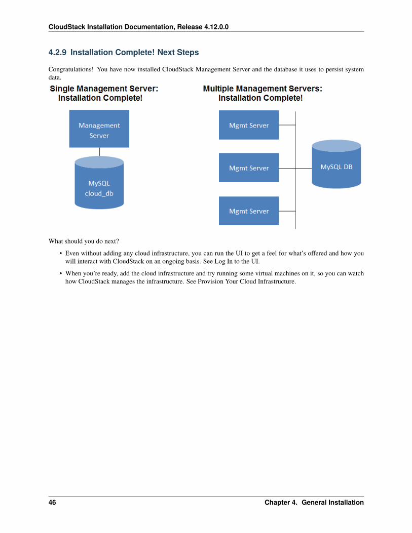
CloudStack Installation Documentation, Release 4.12.0.0
4.2.9 Installation Complete! Next Steps
Congratulations! You have now installed CloudStack Management Server and the database it uses to persist systemdata.
What should you do next?
• Even without adding any cloud infrastructure, you can run the UI to get a feel for what’s offered and how youwill interact with CloudStack on an ongoing basis. See Log In to the UI.
• When you’re ready, add the cloud infrastructure and try running some virtual machines on it, so you can watchhow CloudStack manages the infrastructure. See Provision Your Cloud Infrastructure.
46 Chapter 4. General Installation
CHAPTER 5
Configuration
5.1 Configuring your CloudStack Installation
This section tells how to add regions, zones, pods, clusters, hosts, storage, and networks to your cloud. If you areunfamiliar with these entities, please begin by looking through *Cloud Infrastructure Concepts*.
5.1.1 Overview of Provisioning Steps
After the Management Server is installed and running, you can add the compute resources for it to manage. For anoverview of how a CloudStack cloud infrastructure is organized, see “Cloud Infrastructure Overview”.
To provision the cloud infrastructure, or to scale it up at any time, follow these procedures:
1. Define regions (optional). See Adding Regions (optional).
2. Add a zone to the region. See Adding a Zone.
3. Add more pods to the zone (optional). See Adding a Pod.
4. Add more clusters to the pod (optional). See Adding a Cluster.
5. Add more hosts to the cluster (optional). See Adding a Host.
6. Add primary storage to the cluster. See Add Primary Storage.
7. Add secondary storage to the zone. See Add Secondary Storage.
8. Initialize and test the new cloud. See Initialize and Test.
When you have finished these steps, you will have a deployment with the following basic structure:
47
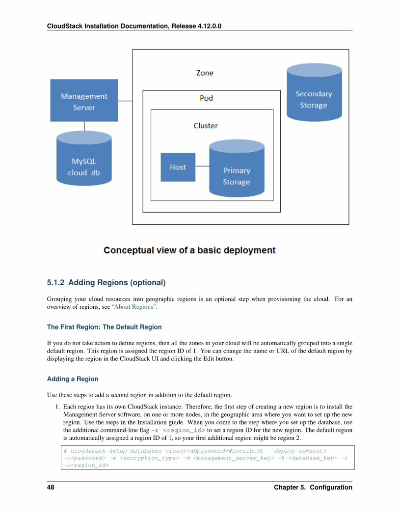
CloudStack Installation Documentation, Release 4.12.0.0
5.1.2 Adding Regions (optional)
Grouping your cloud resources into geographic regions is an optional step when provisioning the cloud. For anoverview of regions, see “About Regions”.
The First Region: The Default Region
If you do not take action to define regions, then all the zones in your cloud will be automatically grouped into a singledefault region. This region is assigned the region ID of 1. You can change the name or URL of the default region bydisplaying the region in the CloudStack UI and clicking the Edit button.
Adding a Region
Use these steps to add a second region in addition to the default region.
1. Each region has its own CloudStack instance. Therefore, the first step of creating a new region is to install theManagement Server software, on one or more nodes, in the geographic area where you want to set up the newregion. Use the steps in the Installation guide. When you come to the step where you set up the database, usethe additional command-line flag -r <region_id> to set a region ID for the new region. The default regionis automatically assigned a region ID of 1, so your first additional region might be region 2.
# cloudstack-setup-databases cloud:<dbpassword>@localhost --deploy-as=root:→˓<password> -e <encryption_type> -m <management_server_key> -k <database_key> -r→˓<region_id>
48 Chapter 5. Configuration
CloudStack Installation Documentation, Release 4.12.0.0
2. By the end of the installation procedure, the Management Server should have been started. Be sure that theManagement Server installation was successful and complete.
3. Now add the new region to region 1 in CloudStack.
(a) Log in to CloudStack in the first region as root administrator (that is, log in to <re-gion.1.IP.address>:8080/client).
(b) In the left navigation bar, click Regions.
(c) Click Add Region. In the dialog, fill in the following fields:
• ID. A unique identifying number. Use the same number you set in the database during ManagementServer installation in the new region; for example, 2.
• Name. Give the new region a descriptive name.
• Endpoint. The URL where you can log in to the Management Server in the new region. This has theformat <region.2.IP.address>:8080/client.
4. Now perform the same procedure in reverse. Log in to region 2, and add region 1.
5. Copy the account, user, and domain tables from the region 1 database to the region 2 database.
In the following commands, it is assumed that you have set the root password on the database, which is aCloudStack recommended best practice. Substitute your own MySQL root password.
(a) First, run this command to copy the contents of the database:
# mysqldump -u root -p<mysql_password> -h <region1_db_host> cloud account→˓user domain > region1.sql
(b) Then run this command to put the data onto the region 2 database:
# mysql -u root -p<mysql_password> -h <region2_db_host> cloud < region1.sql
6. Remove project accounts. Run these commands on the region 2 database:
# mysql> delete from account where type = 5;
7. Set the default zone as null:
# mysql> update account set default_zone_id = null;
8. Restart the Management Servers in region 2.
Adding Third and Subsequent Regions
To add the third region, and subsequent additional regions, the steps are similar to those for adding the second region.However, you must repeat certain steps additional times for each additional region:
1. Install CloudStack in each additional region. Set the region ID for each region during the database setup step.
cloudstack-setup-databases cloud:<dbpassword>@localhost --deploy-as=root:→˓<password> -e <encryption_type> -m <management_server_key> -k <database_key> -r→˓<region_id>
2. Once the Management Server is running, add your new region to all existing regions by repeatedly using theAdd Region button in the UI. For example, if you were adding region 3:
5.1. Configuring your CloudStack Installation 49
CloudStack Installation Documentation, Release 4.12.0.0
(a) Log in to CloudStack in the first region as root administrator (that is, log in to <re-gion.1.IP.address>:8080/client), and add a region with ID 3, the name of region 3, and the endpoint <re-gion.3.IP.address>:8080/client.
(b) Log in to CloudStack in the second region as root administrator (that is, log in to <re-gion.2.IP.address>:8080/client), and add a region with ID 3, the name of region 3, and the endpoint <re-gion.3.IP.address>:8080/client.
3. Repeat the procedure in reverse to add all existing regions to the new region. For example, for the third region,add the other two existing regions:
(a) Log in to CloudStack in the third region as root administrator (that is, log in to <re-gion.3.IP.address>:8080/client).
(b) Add a region with ID 1, the name of region 1, and the endpoint <region.1.IP.address>:8080/client.
(c) Add a region with ID 2, the name of region 2, and the endpoint <region.2.IP.address>:8080/client.
4. Copy the account, user, and domain tables from any existing region’s database to the new region’s database.
In the following commands, it is assumed that you have set the root password on the database, which is aCloudStack recommended best practice. Substitute your own MySQL root password.
(a) First, run this command to copy the contents of the database:
# mysqldump -u root -p<mysql_password> -h <region1_db_host> cloud account→˓user domain > region1.sql
(b) Then run this command to put the data onto the new region’s database. For example, for region 3:
# mysql -u root -p<mysql_password> -h <region3_db_host> cloud < region1.sql
5. Remove project accounts. Run these commands on the region 3 database:
mysql> delete from account where type = 5;
6. Set the default zone as null:
mysql> update account set default_zone_id = null;
7. Restart the Management Servers in the new region.
Deleting a Region
Log in to each of the other regions, navigate to the one you want to delete, and click Remove Region. For example, toremove the third region in a 3-region cloud:
1. Log in to <region.1.IP.address>:8080/client.
2. In the left navigation bar, click Regions.
3. Click the name of the region you want to delete.
4. Click the Remove Region button.
5. Repeat these steps for <region.2.IP.address>:8080/client.
50 Chapter 5. Configuration
CloudStack Installation Documentation, Release 4.12.0.0
5.1.3 Adding a Zone
When you add a new zone, you will be prompted to configure the zone’s physical network and add the first pod, cluster,host, primary storage, and secondary storage.
1. Log in to the CloudStack UI as the root administrator. See “Log In to the UI”.
2. In the left navigation, choose Infrastructure.
3. On Zones, click View More.
4. Click Add Zone. The zone creation wizard will appear.
5. Choose one of the following network types:
• Basic. For AWS-style networking. Provides a single network where each VM instance is assigned an IPdirectly from the network. Guest isolation can be provided through layer-3 means such as security groups(IP address source filtering).
• Advanced. For more sophisticated network topologies. This network model provides the most flexibilityin defining guest networks and providing custom network offerings such as firewall, VPN, or load balancersupport.
6. The rest of the steps differ depending on whether you chose Basic or Advanced. Continue with the steps thatapply to you:
• “Basic Zone Configuration”
• “Advanced Zone Configuration”
Basic Zone Configuration
1. After you select Basic in the Add Zone wizard and click Next, you will be asked to enter the following details.Then click Next.
• Name. A name for the zone.
• DNS 1 and 2. These are DNS servers for use by guest VMs in the zone. These DNS servers will beaccessed via the public network you will add later. The public IP addresses for the zone must have a routeto the DNS server named here.
• Internal DNS 1 and Internal DNS 2. These are DNS servers for use by system VMs in the zone (theseare VMs used by CloudStack itself, such as virtual routers, console proxies, and Secondary Storage VMs.)These DNS servers will be accessed via the management traffic network interface of the System VMs. Theprivate IP address you provide for the pods must have a route to the internal DNS server named here.
• Hypervisor. (Introduced in version 3.0.1) Choose the hypervisor for the first cluster in the zone. You canadd clusters with different hypervisors later, after you finish adding the zone.
• Network Offering. Your choice here determines what network services will be available on the networkfor guest VMs.
5.1. Configuring your CloudStack Installation 51
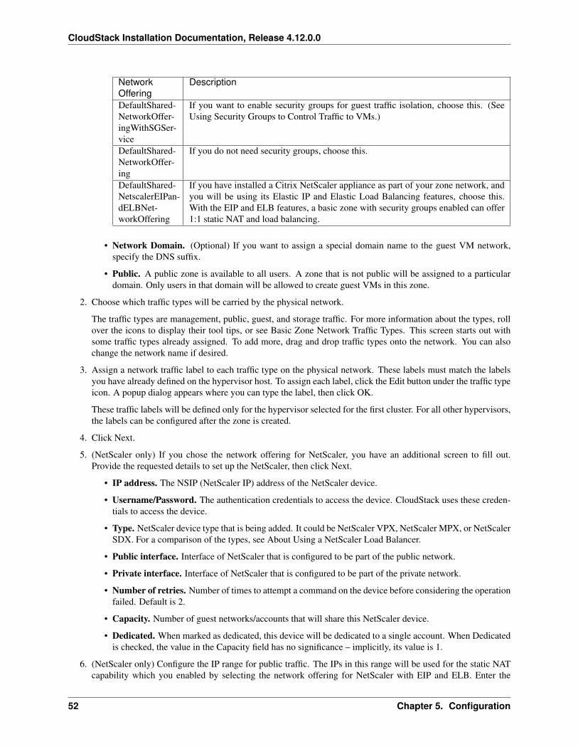
CloudStack Installation Documentation, Release 4.12.0.0
NetworkOffering
Description
DefaultShared-NetworkOffer-ingWithSGSer-vice
If you want to enable security groups for guest traffic isolation, choose this. (SeeUsing Security Groups to Control Traffic to VMs.)
DefaultShared-NetworkOffer-ing
If you do not need security groups, choose this.
DefaultShared-NetscalerEIPan-dELBNet-workOffering
If you have installed a Citrix NetScaler appliance as part of your zone network, andyou will be using its Elastic IP and Elastic Load Balancing features, choose this.With the EIP and ELB features, a basic zone with security groups enabled can offer1:1 static NAT and load balancing.
• Network Domain. (Optional) If you want to assign a special domain name to the guest VM network,specify the DNS suffix.
• Public. A public zone is available to all users. A zone that is not public will be assigned to a particulardomain. Only users in that domain will be allowed to create guest VMs in this zone.
2. Choose which traffic types will be carried by the physical network.
The traffic types are management, public, guest, and storage traffic. For more information about the types, rollover the icons to display their tool tips, or see Basic Zone Network Traffic Types. This screen starts out withsome traffic types already assigned. To add more, drag and drop traffic types onto the network. You can alsochange the network name if desired.
3. Assign a network traffic label to each traffic type on the physical network. These labels must match the labelsyou have already defined on the hypervisor host. To assign each label, click the Edit button under the traffic typeicon. A popup dialog appears where you can type the label, then click OK.
These traffic labels will be defined only for the hypervisor selected for the first cluster. For all other hypervisors,the labels can be configured after the zone is created.
4. Click Next.
5. (NetScaler only) If you chose the network offering for NetScaler, you have an additional screen to fill out.Provide the requested details to set up the NetScaler, then click Next.
• IP address. The NSIP (NetScaler IP) address of the NetScaler device.
• Username/Password. The authentication credentials to access the device. CloudStack uses these creden-tials to access the device.
• Type. NetScaler device type that is being added. It could be NetScaler VPX, NetScaler MPX, or NetScalerSDX. For a comparison of the types, see About Using a NetScaler Load Balancer.
• Public interface. Interface of NetScaler that is configured to be part of the public network.
• Private interface. Interface of NetScaler that is configured to be part of the private network.
• Number of retries. Number of times to attempt a command on the device before considering the operationfailed. Default is 2.
• Capacity. Number of guest networks/accounts that will share this NetScaler device.
• Dedicated. When marked as dedicated, this device will be dedicated to a single account. When Dedicatedis checked, the value in the Capacity field has no significance – implicitly, its value is 1.
6. (NetScaler only) Configure the IP range for public traffic. The IPs in this range will be used for the static NATcapability which you enabled by selecting the network offering for NetScaler with EIP and ELB. Enter the
52 Chapter 5. Configuration
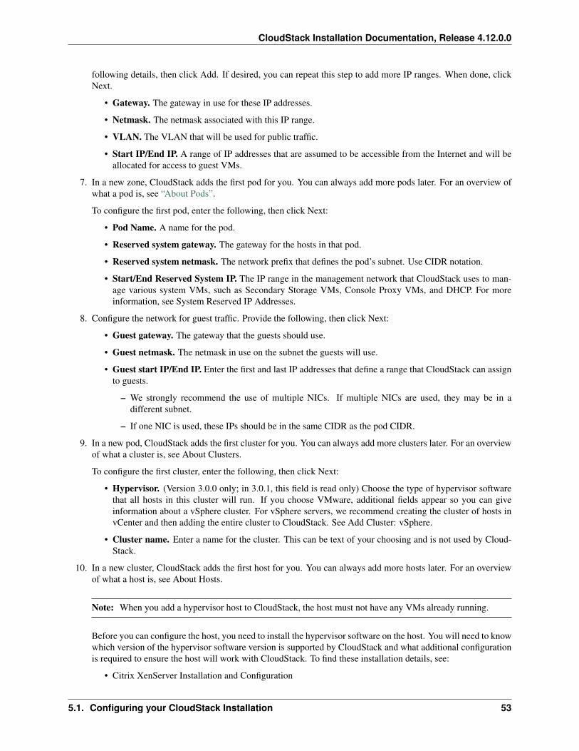
CloudStack Installation Documentation, Release 4.12.0.0
following details, then click Add. If desired, you can repeat this step to add more IP ranges. When done, clickNext.
• Gateway. The gateway in use for these IP addresses.
• Netmask. The netmask associated with this IP range.
• VLAN. The VLAN that will be used for public traffic.
• Start IP/End IP. A range of IP addresses that are assumed to be accessible from the Internet and will beallocated for access to guest VMs.
7. In a new zone, CloudStack adds the first pod for you. You can always add more pods later. For an overview ofwhat a pod is, see “About Pods”.
To configure the first pod, enter the following, then click Next:
• Pod Name. A name for the pod.
• Reserved system gateway. The gateway for the hosts in that pod.
• Reserved system netmask. The network prefix that defines the pod’s subnet. Use CIDR notation.
• Start/End Reserved System IP. The IP range in the management network that CloudStack uses to man-age various system VMs, such as Secondary Storage VMs, Console Proxy VMs, and DHCP. For moreinformation, see System Reserved IP Addresses.
8. Configure the network for guest traffic. Provide the following, then click Next:
• Guest gateway. The gateway that the guests should use.
• Guest netmask. The netmask in use on the subnet the guests will use.
• Guest start IP/End IP. Enter the first and last IP addresses that define a range that CloudStack can assignto guests.
– We strongly recommend the use of multiple NICs. If multiple NICs are used, they may be in adifferent subnet.
– If one NIC is used, these IPs should be in the same CIDR as the pod CIDR.
9. In a new pod, CloudStack adds the first cluster for you. You can always add more clusters later. For an overviewof what a cluster is, see About Clusters.
To configure the first cluster, enter the following, then click Next:
• Hypervisor. (Version 3.0.0 only; in 3.0.1, this field is read only) Choose the type of hypervisor softwarethat all hosts in this cluster will run. If you choose VMware, additional fields appear so you can giveinformation about a vSphere cluster. For vSphere servers, we recommend creating the cluster of hosts invCenter and then adding the entire cluster to CloudStack. See Add Cluster: vSphere.
• Cluster name. Enter a name for the cluster. This can be text of your choosing and is not used by Cloud-Stack.
10. In a new cluster, CloudStack adds the first host for you. You can always add more hosts later. For an overviewof what a host is, see About Hosts.
Note: When you add a hypervisor host to CloudStack, the host must not have any VMs already running.
Before you can configure the host, you need to install the hypervisor software on the host. You will need to knowwhich version of the hypervisor software version is supported by CloudStack and what additional configurationis required to ensure the host will work with CloudStack. To find these installation details, see:
• Citrix XenServer Installation and Configuration
5.1. Configuring your CloudStack Installation 53
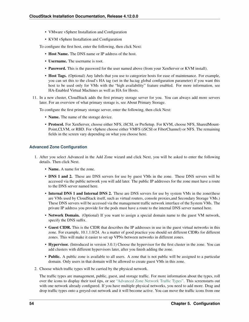
CloudStack Installation Documentation, Release 4.12.0.0
• VMware vSphere Installation and Configuration
• KVM vSphere Installation and Configuration
To configure the first host, enter the following, then click Next:
• Host Name. The DNS name or IP address of the host.
• Username. The username is root.
• Password. This is the password for the user named above (from your XenServer or KVM install).
• Host Tags. (Optional) Any labels that you use to categorize hosts for ease of maintenance. For example,you can set this to the cloud’s HA tag (set in the ha.tag global configuration parameter) if you want thishost to be used only for VMs with the “high availability” feature enabled. For more information, seeHA-Enabled Virtual Machines as well as HA for Hosts.
11. In a new cluster, CloudStack adds the first primary storage server for you. You can always add more serverslater. For an overview of what primary storage is, see About Primary Storage.
To configure the first primary storage server, enter the following, then click Next:
• Name. The name of the storage device.
• Protocol. For XenServer, choose either NFS, iSCSI, or PreSetup. For KVM, choose NFS, SharedMount-Point,CLVM, or RBD. For vSphere choose either VMFS (iSCSI or FiberChannel) or NFS. The remainingfields in the screen vary depending on what you choose here.
Advanced Zone Configuration
1. After you select Advanced in the Add Zone wizard and click Next, you will be asked to enter the followingdetails. Then click Next.
• Name. A name for the zone.
• DNS 1 and 2. These are DNS servers for use by guest VMs in the zone. These DNS servers will beaccessed via the public network you will add later. The public IP addresses for the zone must have a routeto the DNS server named here.
• Internal DNS 1 and Internal DNS 2. These are DNS servers for use by system VMs in the zone(theseare VMs used by CloudStack itself, such as virtual routers, console proxies,and Secondary Storage VMs.)These DNS servers will be accessed via the management traffic network interface of the System VMs. Theprivate IP address you provide for the pods must have a route to the internal DNS server named here.
• Network Domain. (Optional) If you want to assign a special domain name to the guest VM network,specify the DNS suffix.
• Guest CIDR. This is the CIDR that describes the IP addresses in use in the guest virtual networks in thiszone. For example, 10.1.1.0/24. As a matter of good practice you should set different CIDRs for differentzones. This will make it easier to set up VPNs between networks in different zones.
• Hypervisor. (Introduced in version 3.0.1) Choose the hypervisor for the first cluster in the zone. You canadd clusters with different hypervisors later, after you finish adding the zone.
• Public. A public zone is available to all users. A zone that is not public will be assigned to a particulardomain. Only users in that domain will be allowed to create guest VMs in this zone.
2. Choose which traffic types will be carried by the physical network.
The traffic types are management, public, guest, and storage traffic. For more information about the types, rollover the icons to display their tool tips, or see “Advanced Zone Network Traffic Types”. This screenstarts outwith one network already configured. If you have multiple physical networks, you need to add more. Drag anddrop traffic types onto a greyed-out network and it will become active. You can move the traffic icons from one
54 Chapter 5. Configuration
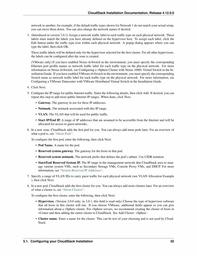
CloudStack Installation Documentation, Release 4.12.0.0
network to another; for example, if the default traffic types shown for Network 1 do not match your actual setup,you can move them down. You can also change the network names if desired.
3. (Introduced in version 3.0.1) Assign a network traffic label to each traffic type on each physical network. Theselabels must match the labels you have already defined on the hypervisor host. To assign each label, click theEdit button under the traffic type icon within each physical network. A popup dialog appears where you cantype the label, then click OK.
These traffic labels will be defined only for the hypervisor selected for the first cluster. For all other hypervisors,the labels can be configured after the zone is created.
(VMware only) If you have enabled Nexus dvSwitch in the environment, you must specify the correspondingEthernet port profile names as network traffic label for each traffic type on the physical network. For moreinformation on Nexus dvSwitch, see Configuring a vSphere Cluster with Nexus 1000v Virtual Switch in the In-stallation Guide. If you have enabled VMware dvSwitch in the environment, you must specify the correspondingSwitch name as network traffic label for each traffic type on the physical network. For more information, seeConfiguring a VMware Datacenter with VMware Distributed Virtual Switch in the Installation Guide.
4. Click Next.
5. Configure the IP range for public Internet traffic. Enter the following details, then click Add. If desired, you canrepeat this step to add more public Internet IP ranges. When done, click Next.
• Gateway. The gateway in use for these IP addresses.
• Netmask. The netmask associated with this IP range.
• VLAN. The VLAN that will be used for public traffic.
• Start IP/End IP. A range of IP addresses that are assumed to be accessible from the Internet and will beallocated for access to guest networks.
6. In a new zone, CloudStack adds the first pod for you. You can always add more pods later. For an overview ofwhat a pod is, see “About Pods”.
To configure the first pod, enter the following, then click Next:
• Pod Name. A name for the pod.
• Reserved system gateway. The gateway for the hosts in that pod.
• Reserved system netmask. The network prefix that defines the pod’s subnet. Use CIDR notation.
• Start/End Reserved System IP. The IP range in the management network that CloudStack uses to man-age various system VMs, such as Secondary Storage VMs, Console Proxy VMs, and DHCP. For moreinformation, see “System Reserved IP Addresses”.
7. Specify a range of VLAN IDs to carry guest traffic for each physical network (see VLAN Allocation Example), then click Next.
8. In a new pod, CloudStack adds the first cluster for you. You can always add more clusters later. For an overviewof what a cluster is, see “About Clusters”.
To configure the first cluster, enter the following, then click Next:
• Hypervisor. (Version 3.0.0 only; in 3.0.1, this field is read only) Choose the type of hypervisor softwarethat all hosts in this cluster will run. If you choose VMware, additional fields appear so you can giveinformation about a vSphere cluster. For vSphere servers, we recommend creating the cluster of hosts invCenter and then adding the entire cluster to CloudStack. See Add Cluster: vSphere .
• Cluster name. Enter a name for the cluster. This can be text of your choosing and is not used by Cloud-Stack.
5.1. Configuring your CloudStack Installation 55
CloudStack Installation Documentation, Release 4.12.0.0
9. In a new cluster, CloudStack adds the first host for you. You can always add more hosts later. For an overviewof what a host is, see “About Hosts”.
Note: When you deploy CloudStack, the hypervisor host must not have any VMs already running.
Before you can configure the host, you need to install the hypervisor software on the host. You will need to knowwhich version of the hypervisor software version is supported by CloudStack and what additional configurationis required to ensure the host will work with CloudStack. To find these installation details, see:
• Citrix XenServer Installation for CloudStack
• VMware vSphere Installation and Configuration
• KVM Installation and Configuration
To configure the first host, enter the following, then click Next:
• Host Name. The DNS name or IP address of the host.
• Username. Usually root.
• Password. This is the password for the user named above (from your XenServer or KVM install).
• Host Tags. (Optional) Any labels that you use to categorize hosts for ease of maintenance. For example,you can set to the cloud’s HA tag (set in the ha.tag global configuration parameter) if you want this host tobe used only for VMs with the “high availability” feature enabled. For more information, see HA-EnabledVirtual Machines as well as HA for Hosts, both in the Administration Guide.
10. In a new cluster, CloudStack adds the first primary storage server for you. You can always add more serverslater. For an overview of what primary storage is, see “About Primary Storage”.
To configure the first primary storage server, enter the following, then click Next:
• Name. The name of the storage device.
• Protocol. For XenServer, choose either NFS, iSCSI, or PreSetup. For KVM, choose NFS, SharedMount-Point, CLVM, and RBD. For vSphere choose either VMFS (iSCSI or FiberChannel) or NFS. The remain-ing fields in the screen vary depending on what you choose here.
56 Chapter 5. Configuration
CloudStack Installation Documentation, Release 4.12.0.0
NFS– Server. The IP address or DNS name of the
storage device.– Path. The exported path from the server.– Tags (optional). The comma-separated list
of tags for this storage device. It should be anequivalent set or superset of the tags on yourdisk offerings.
iSCSI– Server. The IP address or DNS name of the
storage device.– Target IQN. The IQN of the
target. For example, iqn.1986-03.com.sun:02:01ec9bb549-1271378984.
– Lun. The LUN number. For example, 3.– Tags (optional). The comma-separated list
of tags for this storage device. It should be anequivalent set or superset of the tags on yourdisk offerings.
preSetup– Server. The IP address or DNS name of the
storage device.– SR Name-Label. Enter the name-label of the
SR that has been set up outside CloudStack.– Tags (optional). The comma-separated list
of tags for this storage device. It should be anequivalent set or superset of the tags on yourdisk offerings.
SharedMountPoint– Path. The path on each host that is where
this primary storage is mounted. For exam-ple, “/mnt/primary”.
– Tags (optional). The comma-separated listof tags for this storage device. It should be anequivalent set or superset of the tags on yourdisk offerings.
VMFS– Server. The IP address or DNS name of the
vCenter server.– Path. A combination of the datacenter name
and the datastore name. The format is “/” dat-acenter name “/” datastore name. For exam-ple, “/cloud.dc.VM/cluster1datastore”.
– Tags (optional). The comma-separated listof tags for this storage device. It should be anequivalent set or superset of the tags on yourdisk offerings.
The tag sets on primary storage across clusters in a Zone must be identical. For example, if cluster Aprovides primary storage that has tags T1 and T2, all other clusters in the Zone must also provide primary
5.1. Configuring your CloudStack Installation 57
CloudStack Installation Documentation, Release 4.12.0.0
storage that has tags T1 and T2.
11. In a new zone, CloudStack adds the first secondary storage server for you. For an overview of what secondarystorage is, see “About Secondary Storage”.
Before you can fill out this screen, you need to prepare the secondary storage by setting up NFS shares andinstalling the latest CloudStack System VM template. See Adding Secondary Storage :
• NFS Server. The IP address of the server or fully qualified domain name of the server.
• Path. The exported path from the server.
12. Click Launch.
5.1.4 Adding a Pod
When you created a new zone, CloudStack adds the first pod for you. You can add more pods at any time using theprocedure in this section.
1. Log in to the CloudStack UI. See “Log In to the UI”.
2. In the left navigation, choose Infrastructure. In Zones, click View More, then click the zone to which you wantto add a pod.
3. Click the Compute and Storage tab. In the Pods node of the diagram, click View All.
4. Click Add Pod.
5. Enter the following details in the dialog.
• Name. The name of the pod.
• Gateway. The gateway for the hosts in that pod.
• Netmask. The network prefix that defines the pod’s subnet. Use CIDR notation.
• Start/End Reserved System IP. The IP range in the management network that CloudStack uses to man-age various system VMs, such as Secondary Storage VMs, Console Proxy VMs, and DHCP. For moreinformation, see System Reserved IP Addresses.
6. Click OK.
5.1.5 Adding a Cluster
You need to tell CloudStack about the hosts that it will manage. Hosts exist inside clusters, so before you begin addinghosts to the cloud, you must add at least one cluster.
Add Cluster: KVM or XenServer
These steps assume you have already installed the hypervisor on the hosts and logged in to the CloudStack UI.
1. In the left navigation, choose Infrastructure. In Zones, click View More, then click the zone in which you wantto add the cluster.
2. Click the Compute tab.
3. In the Clusters node of the diagram, click View All.
4. Click Add Cluster.
5. Choose the hypervisor type for this cluster.
58 Chapter 5. Configuration
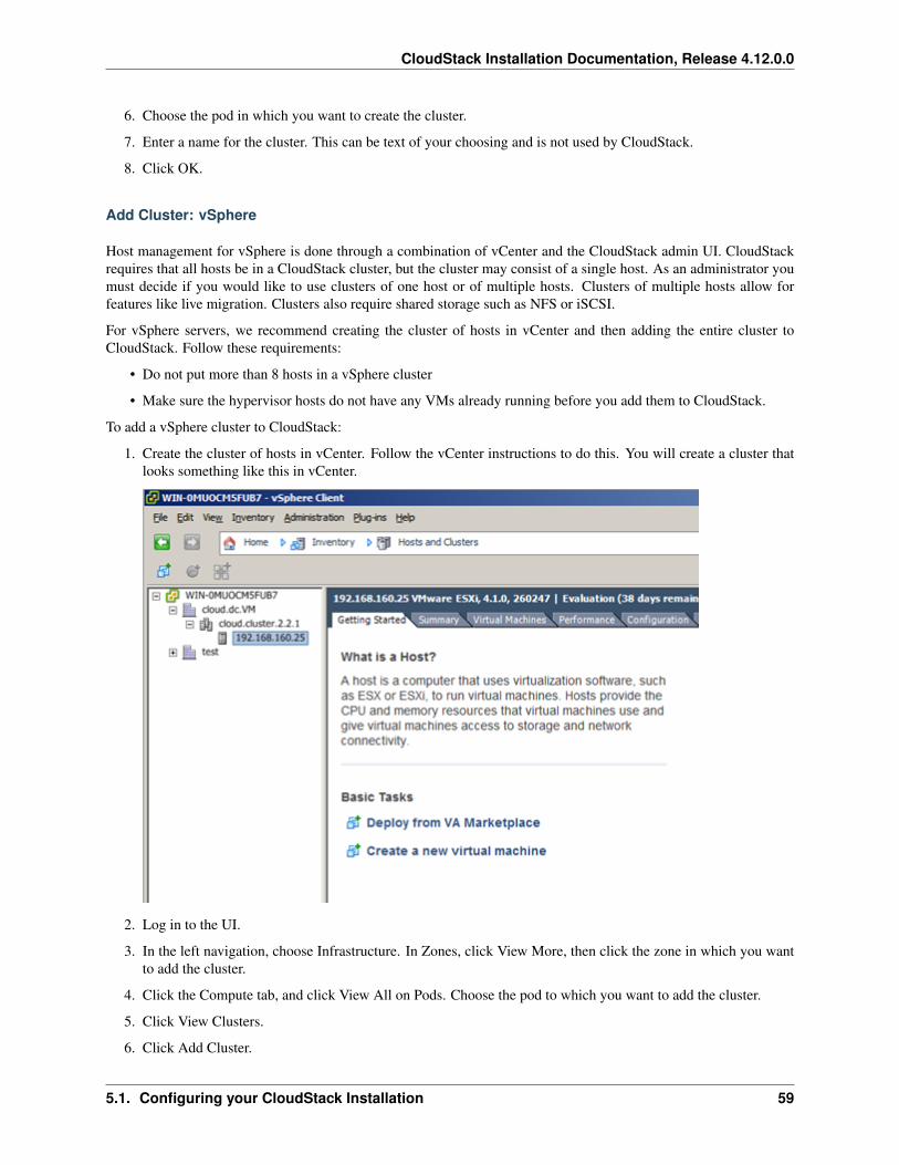
CloudStack Installation Documentation, Release 4.12.0.0
6. Choose the pod in which you want to create the cluster.
7. Enter a name for the cluster. This can be text of your choosing and is not used by CloudStack.
8. Click OK.
Add Cluster: vSphere
Host management for vSphere is done through a combination of vCenter and the CloudStack admin UI. CloudStackrequires that all hosts be in a CloudStack cluster, but the cluster may consist of a single host. As an administrator youmust decide if you would like to use clusters of one host or of multiple hosts. Clusters of multiple hosts allow forfeatures like live migration. Clusters also require shared storage such as NFS or iSCSI.
For vSphere servers, we recommend creating the cluster of hosts in vCenter and then adding the entire cluster toCloudStack. Follow these requirements:
• Do not put more than 8 hosts in a vSphere cluster
• Make sure the hypervisor hosts do not have any VMs already running before you add them to CloudStack.
To add a vSphere cluster to CloudStack:
1. Create the cluster of hosts in vCenter. Follow the vCenter instructions to do this. You will create a cluster thatlooks something like this in vCenter.
2. Log in to the UI.
3. In the left navigation, choose Infrastructure. In Zones, click View More, then click the zone in which you wantto add the cluster.
4. Click the Compute tab, and click View All on Pods. Choose the pod to which you want to add the cluster.
5. Click View Clusters.
6. Click Add Cluster.
5.1. Configuring your CloudStack Installation 59
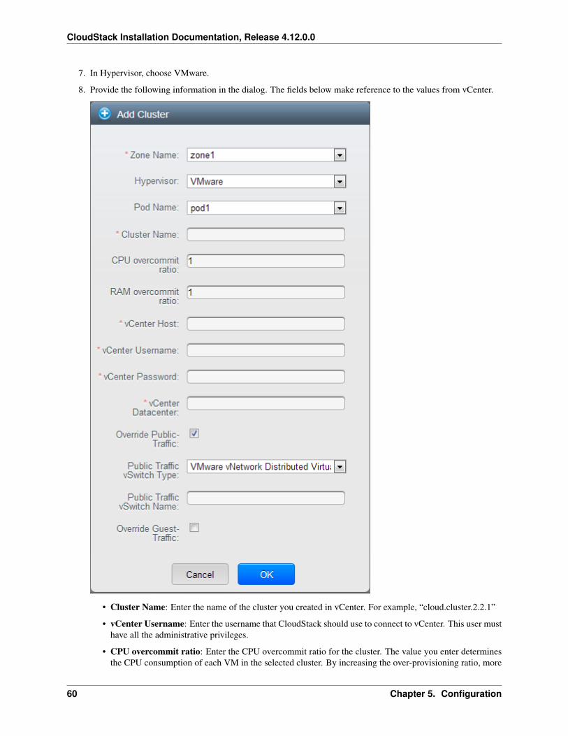
CloudStack Installation Documentation, Release 4.12.0.0
7. In Hypervisor, choose VMware.
8. Provide the following information in the dialog. The fields below make reference to the values from vCenter.
• Cluster Name: Enter the name of the cluster you created in vCenter. For example, “cloud.cluster.2.2.1”
• vCenter Username: Enter the username that CloudStack should use to connect to vCenter. This user musthave all the administrative privileges.
• CPU overcommit ratio: Enter the CPU overcommit ratio for the cluster. The value you enter determinesthe CPU consumption of each VM in the selected cluster. By increasing the over-provisioning ratio, more
60 Chapter 5. Configuration
CloudStack Installation Documentation, Release 4.12.0.0
resource capacity will be used. If no value is specified, the value is defaulted to 1, which implies noover-provisioning is done.
• RAM overcommit ratio: Enter the RAM overcommit ratio for the cluster. The value you enter determinesthe memory consumption of each VM in the selected cluster. By increasing the over-provisioning ratio,more resource capacity will be used. If no value is specified, the value is defaulted to 1, which implies noover-provisioning is done.
• vCenter Host: Enter the hostname or IP address of the vCenter server.
• vCenter Password: Enter the password for the user named above.
• vCenter Datacenter: Enter the vCenter datacenter that the cluster is in. For example, “cloud.dc.VM”.
• Override Public Traffic: Enable this option to override the zone-wide public traffic for the cluster youare creating.
• Public Traffic vSwitch Type: This option is displayed only if you enable the Override Public Trafficoption. Select a desirable switch. If the vmware.use.dvswitch global parameter is true, the default optionwill be VMware vNetwork Distributed Virtual Switch.
If you have enabled Nexus dvSwitch in the environment, the following parameters for dvSwitch configu-ration are displayed:
– Nexus dvSwitch IP Address: The IP address of the Nexus VSM appliance.
– Nexus dvSwitch Username: The username required to access the Nexus VSM appliance.
– Nexus dvSwitch Password: The password associated with the username specified above.
• Override Guest Traffic: Enable this option to override the zone-wide guest traffic for the cluster you arecreating.
• Guest Traffic vSwitch Type: This option is displayed only if you enable the Override Guest Traffic option.Select a desirable switch.
If the vmware.use.dvswitch global parameter is true, the default option will be VMware vNetwork Dis-tributed Virtual Switch.
If you have enabled Nexus dvSwitch in the environment, the following parameters for dvSwitch configu-ration are displayed:
– Nexus dvSwitch IP Address: The IP address of the Nexus VSM appliance.
– Nexus dvSwitch Username: The username required to access the Nexus VSM appliance.
– Nexus dvSwitch Password: The password associated with the username specified above.
• There might be a slight delay while the cluster is provisioned. It will automatically display in the UI.
5.1.6 Adding a Host
1. Before adding a host to the CloudStack configuration, you must first install your chosen hypervisor on the host.CloudStack can manage hosts running VMs under a variety of hypervisors.
The CloudStack Installation Guide provides instructions on how to install each supported hypervisor and config-ure it for use with CloudStack. See the appropriate section in the Installation Guide for information about whichversion of your chosen hypervisor is supported, as well as crucial additional steps to configure the hypervisorhosts for use with CloudStack.
5.1. Configuring your CloudStack Installation 61
CloudStack Installation Documentation, Release 4.12.0.0
Warning: Be sure you have performed the additional CloudStack-specific configuration steps described inthe hypervisor installation section for your particular hypervisor.
2. Now add the hypervisor host to CloudStack. The technique to use varies depending on the hypervisor.
• Adding a Host (XenServer or KVM)
• Adding a Host (vSphere)
Adding a Host (XenServer or KVM)
XenServer and KVM hosts can be added to a cluster at any time.
Requirements for XenServer and KVM Hosts
Warning: Make sure the hypervisor host does not have any VMs already running before you add it to CloudStack.
Configuration requirements:
• Each cluster must contain only hosts with the identical hypervisor.
• For XenServer, do not put more than 8 hosts in a cluster.
• For KVM, do not put more than 16 hosts in a cluster.
For hardware requirements, see the installation section for your hypervisor in the CloudStack Installation Guide.
XenServer Host Additional Requirements
If network bonding is in use, the administrator must cable the new host identically to other hosts in the cluster.
For all additional hosts to be added to the cluster, run the following command. This will cause the host to join themaster in a XenServer pool.
# xe pool-join master-address=[master IP] master-username=root master-password=[your→˓password]
Note: When copying and pasting a command, be sure the command has pasted as a single line before executing.Some document viewers may introduce unwanted line breaks in copied text.
With all hosts added to the XenServer pool, run the cloud-setup-bond script. This script will complete the configurationand setup of the bonds on the new hosts in the cluster.
1. Copy the script from the Management Server in /usr/share/cloudstack-common/scripts/vm/hypervisor/xenserver/cloud-setup-bonding.sh to the master host and ensure it is executable.
2. Run the script:
# ./cloud-setup-bonding.sh
62 Chapter 5. Configuration
CloudStack Installation Documentation, Release 4.12.0.0
KVM Host Additional Requirements
• If shared mountpoint storage is in use, the administrator should ensure that the new host has all the samemountpoints (with storage mounted) as the other hosts in the cluster.
• Make sure the new host has the same network configuration (guest, private, and public network) as other hostsin the cluster.
• If you are using OpenVswitch bridges edit the file agent.properties on the KVM host and set the parameternetwork.bridge.type to openvswitch before adding the host to CloudStack
• If you’re using a non-root user to add a KVM host, please add the user to sudoers file:
cloudstack ALL=NOPASSWD: /usr/bin/cloudstack-setup-agent defaults:cloudstack !requiretty
Adding a XenServer or KVM Host
1. If you have not already done so, install the hypervisor software on the host. You will need to know which versionof the hypervisor software version is supported by CloudStack and what additional configuration is required toensure the host will work with CloudStack. To find these installation details, see the appropriate section for yourhypervisor in the CloudStack Installation Guide.
2. Log in to the CloudStack UI as administrator.
3. In the left navigation, choose Infrastructure. In Zones, click View More, then click the zone in which you wantto add the host.
4. Click the Compute tab. In the Clusters node, click View All.
5. Click the cluster where you want to add the host.
6. Click View Hosts.
7. Click Add Host.
8. Provide the following information.
• Host Name. The DNS name or IP address of the host.
• Username. Usually root.
• Password. This is the password for the user from your XenServer or KVM install).
• Host Tags (Optional). Any labels that you use to categorize hosts for ease of maintenance. For example,you can set to the cloud’s HA tag (set in the ha.tag global configuration parameter) if you want this host tobe used only for VMs with the “high availability” feature enabled. For more information, see HA-EnabledVirtual Machines as well as HA for Hosts.
There may be a slight delay while the host is provisioned. It should automatically display in the UI.
9. Repeat for additional hosts.
Adding a Host (vSphere)
For vSphere servers, we recommend creating the cluster of hosts in vCenter and then adding the entire cluster toCloudStack. See Add Cluster: vSphere.
5.1. Configuring your CloudStack Installation 63
CloudStack Installation Documentation, Release 4.12.0.0
5.1.7 Add Primary Storage
System Requirements for Primary Storage
Hardware requirements:
• Any standards-compliant iSCSI, SMB, or NFS server that is supported by the underlying hypervisor.
• The storage server should be a machine with a large number of disks. The disks should ideally be managed bya hardware RAID controller.
• Minimum required capacity depends on your needs.
When setting up primary storage, follow these restrictions:
• Primary storage cannot be added until a host has been added to the cluster.
• If you do not provision shared primary storage, you must set the global configuration parameter sys-tem.vm.local.storage.required to true, or else you will not be able to start VMs.
Adding Primary Storage
When you create a new zone, the first primary storage is added as part of that procedure. You can add primary storageservers at any time, such as when adding a new cluster or adding more servers to an existing cluster.
Warning: When using preallocated storage for primary storage, be sure there is nothing on the storage (ex. youhave an empty SAN volume or an empty NFS share). Adding the storage to CloudStack will destroy any existingdata.
1. Log in to the CloudStack UI (see “Log In to the UI”).
2. In the left navigation, choose Infrastructure. In Zones, click View More, then click the zone in which you wantto add the primary storage.
3. Click the Compute tab.
4. In the Primary Storage node of the diagram, click View All.
5. Click Add Primary Storage.
6. Provide the following information in the dialog. The information required varies depending on your choice inProtocol.
• Scope. Indicate whether the storage is available to all hosts in the zone or only to hosts in a single cluster.
• Pod. (Visible only if you choose Cluster in the Scope field.) The pod for the storage device.
• Cluster. (Visible only if you choose Cluster in the Scope field.) The cluster for the storage device.
• Name. The name of the storage device.
• Protocol. For XenServer, choose either NFS, iSCSI, or PreSetup. For KVM, choose NFS or Shared-MountPoint. For vSphere choose either VMFS (iSCSI or FiberChannel) or NFS. For Hyper-V, chooseSMB.
• Server (for NFS, iSCSI, or PreSetup). The IP address or DNS name of the storage device.
• Server (for VMFS). The IP address or DNS name of the vCenter server.
• Path (for NFS). In NFS this is the exported path from the server.
64 Chapter 5. Configuration
CloudStack Installation Documentation, Release 4.12.0.0
• Path (for VMFS). In vSphere this is a combination of the datacenter name and the datastore name. Theformat is “/” datacenter name “/” datastore name. For example, “/cloud.dc.VM/cluster1datastore”.
• Path (for SharedMountPoint). With KVM this is the path on each host that is where this primary storageis mounted. For example, “/mnt/primary”.
• SMB Username (for SMB/CIFS): Applicable only if you select SMB/CIFS provider. The username ofthe account which has the necessary permissions to the SMB shares. The user must be part of the Hyper-Vadministrator group.
• SMB Password (for SMB/CIFS): Applicable only if you select SMB/CIFS provider. The password asso-ciated with the account.
• SMB Domain(for SMB/CIFS): Applicable only if you select SMB/CIFS provider. The Active Directorydomain that the SMB share is a part of.
• SR Name-Label (for PreSetup). Enter the name-label of the SR that has been set up outside CloudStack.
• Target IQN (for iSCSI). In iSCSI this is the IQN of the target. For example, iqn.1986-03.com.sun:02:01ec9bb549-1271378984.
• Lun # (for iSCSI). In iSCSI this is the LUN number. For example, 3.
• Tags (optional). The comma-separated list of tags for this storage device. It should be an equivalent setor superset of the tags on your disk offerings..
The tag sets on primary storage across clusters in a Zone must be identical. For example, if cluster A providesprimary storage that has tags T1 and T2, all other clusters in the Zone must also provide primary storage thathas tags T1 and T2.
7. Click OK.
Configuring a Storage Plug-in
Note: Primary storage that is based on a custom plug-in (ex. SolidFire) must be added through the CloudStack API(described later in this section). There is no support at this time through the CloudStack UI to add this type of primarystorage (although most of its features are available through the CloudStack UI).
Note: The SolidFire storage plug-in for CloudStack is part of the standard CloudStack install. There is no additionalwork required to add this component.
Adding primary storage that is based on the SolidFire plug-in enables CloudStack to provide hard quality-of-service(QoS) guarantees.
When used with Compute or Disk Offerings, an administrator is able to build an environment in which a root or datadisk that a user creates leads to the dynamic creation of a SolidFire volume, which has guaranteed performance. Sucha SolidFire volume is associated with one (and only ever one) CloudStack volume, so performance of the CloudStackvolume does not vary depending on how heavily other tenants are using the system.
The createStoragePool API has been augmented to support plugable storage providers. The following is a list ofparameters to use when adding storage to CloudStack that is based on the SolidFire plug-in:
• command=createStoragePool
• scope=zone
• zoneId=[your zone id]
5.1. Configuring your CloudStack Installation 65
CloudStack Installation Documentation, Release 4.12.0.0
• name=[name for primary storage]
• hypervisor=Any
• provider=SolidFire
• capacityIops=[whole number of IOPS from the SAN to give to CloudStack]
• capacityBytes=[whole number of bytes from the SAN to give to CloudStack]
The url parameter is somewhat unique in that its value can contain additional key/value pairs.
url=[key/value pairs detailed below (values are URL encoded; for example, ‘=’ is represented as ‘%3D’)]
• MVIP%3D[Management Virtual IP Address] (can be suffixed with :[port number])
• SVIP%3D[Storage Virtual IP Address] (can be suffixed with :[port number])
• clusterAdminUsername%3D[cluster admin’s username]
• clusterAdminPassword%3D[cluster admin’s password]
• clusterDefaultMinIops%3D[Min IOPS (whole number) to set for a volume; used if Min IOPS is not specifiedby administrator or user]
• clusterDefaultMaxIops%3D[Max IOPS (whole number) to set for a volume; used if Max IOPS is not specifiedby administrator or user]
• clusterDefaultBurstIopsPercentOfMaxIops%3D[Burst IOPS is determined by (Min IOPS * clusterDefault-BurstIopsPercentOfMaxIops parameter) (can be a decimal value)]
5.1.8 Add Secondary Storage
System Requirements for Secondary Storage
• NFS storage appliance or Linux NFS server
• SMB/CIFS (Hyper-V)
• (Optional) OpenStack Object Storage (Swift) (see http://swift.openstack.org)
• 100GB minimum capacity
• A secondary storage device must be located in the same zone as the guest VMs it serves.
• Each Secondary Storage server must be available to all hosts in the zone.
Adding Secondary Storage
When you create a new zone, the first secondary storage is added as part of that procedure. You can add secondarystorage servers at any time to add more servers to an existing zone.
Warning: Ensure that nothing is stored on the server. Adding the server to CloudStack will destroy any existingdata.
1. To prepare for the zone-based Secondary Staging Store, you should have created and mounted an NFS shareduring Management Server installation. See Prepare NFS Shares.
If you are using an Hyper-V host, ensure that you have created a SMB share.
66 Chapter 5. Configuration
CloudStack Installation Documentation, Release 4.12.0.0
2. Make sure you prepared the system VM template during Management Server installation. See “Prepare theSystem VM Template”.
3. Log in to the CloudStack UI as root administrator.
4. In the left navigation bar, click Infrastructure.
5. In Secondary Storage, click View All.
6. Click Add Secondary Storage.
7. Fill in the following fields:
• Name. Give the storage a descriptive name.
• Provider. Choose S3, Swift, NFS, or CIFS then fill in the related fields which appear. The fields will varydepending on the storage provider; for more information, consult the provider’s documentation (such asthe S3 or Swift website). NFS can be used for zone-based storage, and the others for region-wide storage.For Hyper-V, select SMB/CIFS.
Warning: Heterogeneous Secondary Storage is not supported in Regions. You can use only a singleNFS, S3, or Swift account per region.
• Create NFS Secondary Staging Store. This box must always be checked.
Warning: Even if the UI allows you to uncheck this box, do not do so. This checkbox and the threefields below it must be filled in. Even when Swift or S3 is used as the secondary storage provider, anNFS staging storage in each zone is still required.
• Zone. The zone where the NFS Secondary Staging Store is to be located.
• SMB Username: Applicable only if you select SMB/CIFS provider. The username of the account whichhas the necessary permissions to the SMB shares. The user must be part of the Hyper-V administratorgroup.
• SMB Password: Applicable only if you select SMB/CIFS provider. The password associated with theaccount.
• SMB Domain: Applicable only if you select SMB/CIFS provider. The Active Directory domain that theSMB share is a part of.
• NFS server. The name of the zone’s Secondary Staging Store.
• Path. The path to the zone’s Secondary Staging Store.
Adding an NFS Secondary Staging Store for Each Zone
Every zone must have at least one NFS store provisioned; multiple NFS servers are allowed per zone. To provision anNFS Staging Store for a zone:
1. Log in to the CloudStack UI as root administrator.
2. In the left navigation bar, click Infrastructure.
3. In Secondary Storage, click View All.
4. In Select View, choose Secondary Staging Store.
5. Click the Add NFS Secondary Staging Store button.
5.1. Configuring your CloudStack Installation 67
CloudStack Installation Documentation, Release 4.12.0.0
6. Fill out the dialog box fields, then click OK:
• Zone. The zone where the NFS Secondary Staging Store is to be located.
• NFS server. The name of the zone’s Secondary Staging Store.
• Path. The path to the zone’s Secondary Staging Store.
5.1.9 Initialize and Test
After everything is configured, CloudStack will perform its initialization. This can take 30 minutes or more, dependingon the speed of your network. When the initialization has completed successfully, the administrator’s Dashboardshould be displayed in the CloudStack UI.
1. Verify that the system is ready. In the left navigation bar, select Templates. Click on the CentOS 5.5 (64bit) noGui (KVM) template. Check to be sure that the status is “Download Complete.” Do not proceed to the next stepuntil this status is displayed.
2. Go to the Instances tab, and filter by My Instances.
3. Click Add Instance and follow the steps in the wizard.
(a) Choose the zone you just added.
(b) In the template selection, choose the template to use in the VM. If this is a fresh installation, likely onlythe provided CentOS template is available.
(c) Select a service offering. Be sure that the hardware you have allows starting the selected service offering.
(d) In data disk offering, if desired, add another data disk. This is a second volume that will be available to butnot mounted in the guest. For example, in Linux on XenServer you will see /dev/xvdb in the guest afterrebooting the VM. A reboot is not required if you have a PV-enabled OS kernel in use.
(e) In default network, choose the primary network for the guest. In a trial installation, you would have onlyone option here.
(f) Optionally give your VM a name and a group. Use any descriptive text you would like.
(g) Click Launch VM. Your VM will be created and started. It might take some time to download the templateand complete the VM startup. You can watch the VMâC™s progress in the Instances screen.
4. To use the VM, click the View Console button.
For more information about using VMs, including instructions for how to allow incoming network traffic to theVM, start, stop, and delete VMs, and move a VM from one host to another, see Working With Virtual Machinesin the AdministratorâC™s Guide.
Congratulations! You have successfully completed a CloudStack Installation.
If you decide to grow your deployment, you can add more hosts, primary storage, zones, pods, and clusters.
5.1.10 Configuration Parameters
About Configuration Parameters
CloudStack provides a variety of settings you can use to set limits, configure features, and enable or disable features inthe cloud. Once your Management Server is running, you might need to set some of these configuration parameters,depending on what optional features you are setting up. You can set default values at the global level, which will be ineffect throughout the cloud unless you override them at a lower level. You can make local settings, which will overridethe global configuration parameter values, at the level of an account, zone, cluster, or primary storage.
68 Chapter 5. Configuration
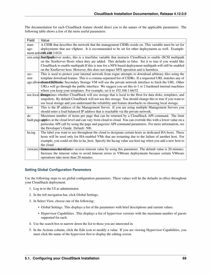
CloudStack Installation Documentation, Release 4.12.0.0
The documentation for each CloudStack feature should direct you to the names of the applicable parameters. Thefollowing table shows a few of the more useful parameters.
Field Valueman-age-ment.network.cidr
A CIDR that describes the network that the management CIDRs reside on. This variable must be set fordeployments that use vSphere. It is recommended to be set for other deployments as well. Example:192.168.3.0/24.
xen.setup.multipathFor XenServer nodes, this is a true/false variable that instructs CloudStack to enable iSCSI multipathon the XenServer Hosts when they are added. This defaults to false. Set it to true if you would likeCloudStack to enable multipath.If this is true for a NFS-based deployment multipath will still be enabledon the XenServer host. However, this does not impact NFS operation and is harmless.
sec-stor-age.allowed.internal.sites
This is used to protect your internal network from rogue attempts to download arbitrary files using thetemplate download feature. This is a comma-separated list of CIDRs. If a requested URL matches any ofthese CIDRs the Secondary Storage VM will use the private network interface to fetch the URL. OtherURLs will go through the public interface. We suggest you set this to 1 or 2 hardened internal machineswhere you keep your templates. For example, set it to 192.168.1.66/32.
use.local.storageDetermines whether CloudStack will use storage that is local to the Host for data disks, templates, andsnapshots. By default CloudStack will not use this storage. You should change this to true if you want touse local storage and you understand the reliability and feature drawbacks to choosing local storage.
host This is the IP address of the Management Server. If you are using multiple Management Servers youshould enter a load balanced IP address that is reachable via the private network.
de-fault.page.size
Maximum number of items per page that can be returned by a CloudStack API command. The limitapplies at the cloud level and can vary from cloud to cloud. You can override this with a lower value on aparticular API call by using the page and pagesize API command parameters. For more information, seethe Developer’s Guide. Default: 500.
ha.tag The label you want to use throughout the cloud to designate certain hosts as dedicated HA hosts. Thesehosts will be used only for HA-enabled VMs that are restarting due to the failure of another host. Forexample, you could set this to ha_host. Specify the ha.tag value asa host tag when you add a new host tothe cloud.
vmware.vcenter.session.timeoutDetermines the vCenter session timeout value by using this parameter. The default value is 20 minutes.Increase the timeout value to avoid timeout errors in VMware deployments because certain VMwareoperations take more than 20 minutes.
Setting Global Configuration Parameters
Use the following steps to set global configuration parameters. These values will be the defaults in effect throughoutyour CloudStack deployment.
1. Log in to the UI as administrator.
2. In the left navigation bar, click Global Settings.
3. In Select View, choose one of the following:
• Global Settings. This displays a list of the parameters with brief descriptions and current values.
• Hypervisor Capabilities. This displays a list of hypervisor versions with the maximum number of guestssupported for each.
4. Use the search box to narrow down the list to those you are interested in.
5. In the Actions column, click the Edit icon to modify a value. If you are viewing Hypervisor Capabilities, youmust click the name of the hypervisor first to display the editing screen.
5.1. Configuring your CloudStack Installation 69
CloudStack Installation Documentation, Release 4.12.0.0
Setting Local Configuration Parameters
Use the following steps to set local configuration parameters for an account, zone, cluster, or primary storage. Thesevalues will override the global configuration settings.
1. Log in to the UI as administrator.
2. In the left navigation bar, click Infrastructure or Accounts, depending on where you want to set a value.
3. Find the name of the particular resource that you want to work with. For example, if you are in Infrastructure,click View All on the Zones, Clusters, or Primary Storage area.
4. Click the name of the resource where you want to set a limit.
5. Click the Settings tab.
6. Use the search box to narrow down the list to those you are interested in.
7. In the Actions column, click the Edit icon to modify a value.
5.1.11 Granular Global Configuration Parameters
The following global configuration parameters have been made more granular. The parameters are listed under threedifferent scopes: account, cluster, and zone.
70 Chapter 5. Configuration
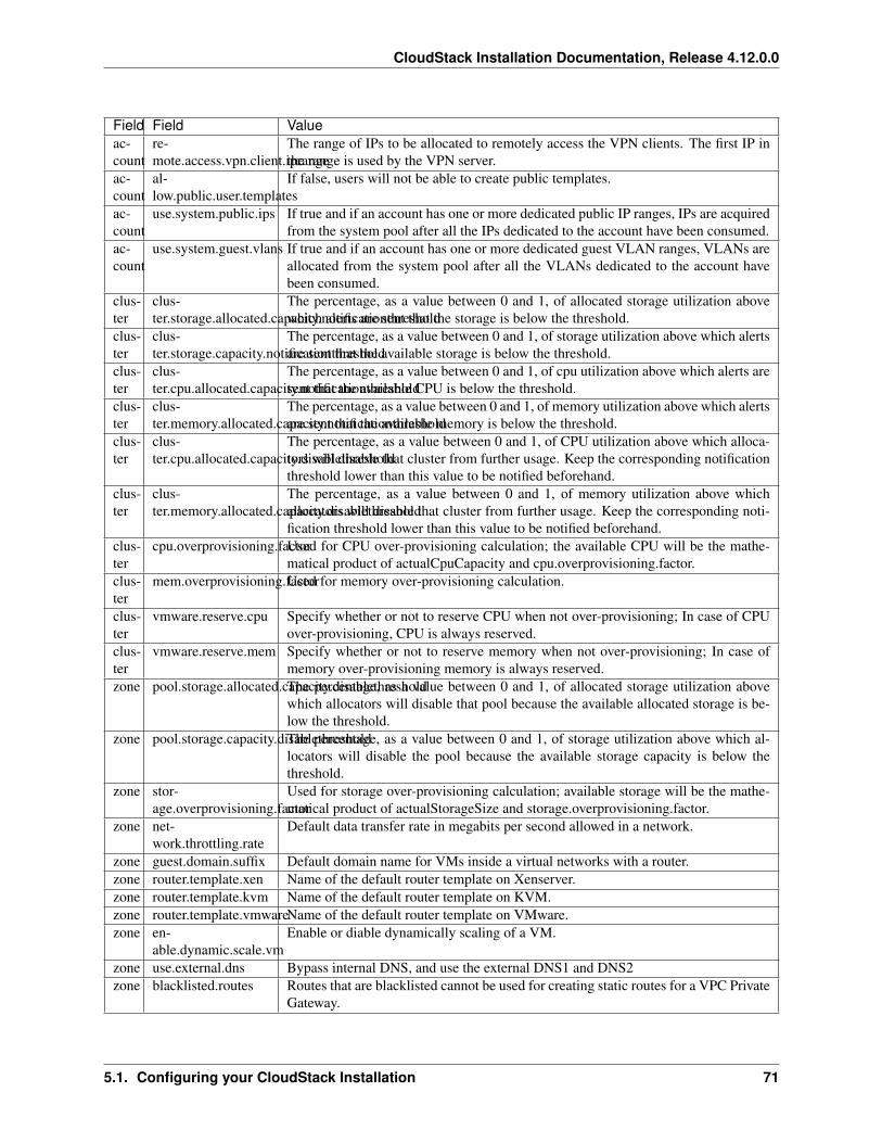
CloudStack Installation Documentation, Release 4.12.0.0
Field Field Valueac-count
re-mote.access.vpn.client.iprange
The range of IPs to be allocated to remotely access the VPN clients. The first IP inthe range is used by the VPN server.
ac-count
al-low.public.user.templates
If false, users will not be able to create public templates.
ac-count
use.system.public.ips If true and if an account has one or more dedicated public IP ranges, IPs are acquiredfrom the system pool after all the IPs dedicated to the account have been consumed.
ac-count
use.system.guest.vlans If true and if an account has one or more dedicated guest VLAN ranges, VLANs areallocated from the system pool after all the VLANs dedicated to the account havebeen consumed.
clus-ter
clus-ter.storage.allocated.capacity.notificationthreshold
The percentage, as a value between 0 and 1, of allocated storage utilization abovewhich alerts are sent that the storage is below the threshold.
clus-ter
clus-ter.storage.capacity.notificationthreshold
The percentage, as a value between 0 and 1, of storage utilization above which alertsare sent that the available storage is below the threshold.
clus-ter
clus-ter.cpu.allocated.capacity.notificationthreshold
The percentage, as a value between 0 and 1, of cpu utilization above which alerts aresent that the available CPU is below the threshold.
clus-ter
clus-ter.memory.allocated.capacity.notificationthreshold
The percentage, as a value between 0 and 1, of memory utilization above which alertsare sent that the available memory is below the threshold.
clus-ter
clus-ter.cpu.allocated.capacity.disablethreshold
The percentage, as a value between 0 and 1, of CPU utilization above which alloca-tors will disable that cluster from further usage. Keep the corresponding notificationthreshold lower than this value to be notified beforehand.
clus-ter
clus-ter.memory.allocated.capacity.disablethreshold
The percentage, as a value between 0 and 1, of memory utilization above whichallocators will disable that cluster from further usage. Keep the corresponding noti-fication threshold lower than this value to be notified beforehand.
clus-ter
cpu.overprovisioning.factorUsed for CPU over-provisioning calculation; the available CPU will be the mathe-matical product of actualCpuCapacity and cpu.overprovisioning.factor.
clus-ter
mem.overprovisioning.factorUsed for memory over-provisioning calculation.
clus-ter
vmware.reserve.cpu Specify whether or not to reserve CPU when not over-provisioning; In case of CPUover-provisioning, CPU is always reserved.
clus-ter
vmware.reserve.mem Specify whether or not to reserve memory when not over-provisioning; In case ofmemory over-provisioning memory is always reserved.
zone pool.storage.allocated.capacity.disablethresholdThe percentage, as a value between 0 and 1, of allocated storage utilization abovewhich allocators will disable that pool because the available allocated storage is be-low the threshold.
zone pool.storage.capacity.disablethresholdThe percentage, as a value between 0 and 1, of storage utilization above which al-locators will disable the pool because the available storage capacity is below thethreshold.
zone stor-age.overprovisioning.factor
Used for storage over-provisioning calculation; available storage will be the mathe-matical product of actualStorageSize and storage.overprovisioning.factor.
zone net-work.throttling.rate
Default data transfer rate in megabits per second allowed in a network.
zone guest.domain.suffix Default domain name for VMs inside a virtual networks with a router.zone router.template.xen Name of the default router template on Xenserver.zone router.template.kvm Name of the default router template on KVM.zone router.template.vmwareName of the default router template on VMware.zone en-
able.dynamic.scale.vmEnable or diable dynamically scaling of a VM.
zone use.external.dns Bypass internal DNS, and use the external DNS1 and DNS2zone blacklisted.routes Routes that are blacklisted cannot be used for creating static routes for a VPC Private
Gateway.
5.1. Configuring your CloudStack Installation 71
CloudStack Installation Documentation, Release 4.12.0.0
72 Chapter 5. Configuration
CHAPTER 6
Hypervisor Setup
6.1 Host Hyper-V Installation
If you want to use Hyper-V hypervisor to run guest virtual machines, install Hyper-V on the hosts in your cloud. Theinstructions in this section doesn’t duplicate Hyper-V Installation documentation. It provides the CloudStack-specificsteps that are needed to prepare a Hyper-V host to work with CloudStack.
6.1.1 System Requirements for Hyper-V Hypervisor Hosts
Supported Operating Systems for Hyper-V Hosts
• Windows Server 2012 R2 Standard
• Windows Server 2012 R2 Datacenter
• Hyper-V 2012 R2
Minimum System Requirements for Hyper-V Hosts
• 1.4 GHz 64-bit processor with hardware-assisted virtualization.
• 800 MB of RAM
• 32 GB of disk space
• Gigabit (10/100/1000baseT) Ethernet adapter
Supported Storage
• Primary Storage: Server Message Block (SMB) Version 3, Local
• Secondary Storage: SMB
73
CloudStack Installation Documentation, Release 4.12.0.0
6.1.2 Preparation Checklist for Hyper-V
For a smoother installation, gather the following information before you start:
74 Chapter 6. Hypervisor Setup
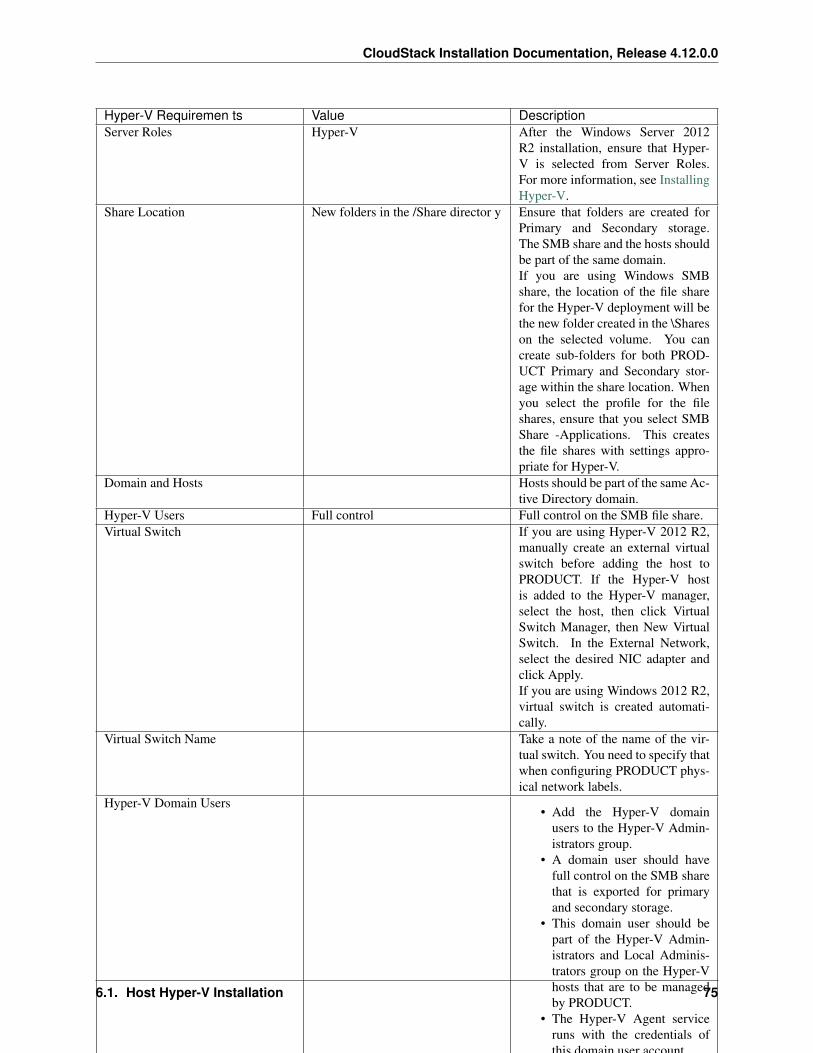
CloudStack Installation Documentation, Release 4.12.0.0
Hyper-V Requiremen ts Value DescriptionServer Roles Hyper-V After the Windows Server 2012
R2 installation, ensure that Hyper-V is selected from Server Roles.For more information, see InstallingHyper-V.
Share Location New folders in the /Share director y Ensure that folders are created forPrimary and Secondary storage.The SMB share and the hosts shouldbe part of the same domain.If you are using Windows SMBshare, the location of the file sharefor the Hyper-V deployment will bethe new folder created in the \Shareson the selected volume. You cancreate sub-folders for both PROD-UCT Primary and Secondary stor-age within the share location. Whenyou select the profile for the fileshares, ensure that you select SMBShare -Applications. This createsthe file shares with settings appro-priate for Hyper-V.
Domain and Hosts Hosts should be part of the same Ac-tive Directory domain.
Hyper-V Users Full control Full control on the SMB file share.Virtual Switch If you are using Hyper-V 2012 R2,
manually create an external virtualswitch before adding the host toPRODUCT. If the Hyper-V hostis added to the Hyper-V manager,select the host, then click VirtualSwitch Manager, then New VirtualSwitch. In the External Network,select the desired NIC adapter andclick Apply.If you are using Windows 2012 R2,virtual switch is created automati-cally.
Virtual Switch Name Take a note of the name of the vir-tual switch. You need to specify thatwhen configuring PRODUCT phys-ical network labels.
Hyper-V Domain Users• Add the Hyper-V domain
users to the Hyper-V Admin-istrators group.
• A domain user should havefull control on the SMB sharethat is exported for primaryand secondary storage.
• This domain user should bepart of the Hyper-V Admin-istrators and Local Adminis-trators group on the Hyper-Vhosts that are to be managedby PRODUCT.
• The Hyper-V Agent serviceruns with the credentials ofthis domain user account.
• Specify the credential of thedomain user while adding ahost to PRODUCT so that itcan manage it.
• Specify the credential of thedomain user while adding ashared SMB primary or sec-ondary storage.
Migration Migratio n Enable Migration.Migration Delegati on If you want to use Live Migration,
enable Delegation. Enable the fol-lowing services of other hosts par-ticipating in Live Migration: CIFSand Microsoft Virtual System Mi-gration Service.
Migration Kerberos Enable Kerberos for Live Migration.Network Access Permission forDial-in
Allow access Allow access for Dial-in connec-tions.
6.1. Host Hyper-V Installation 75
CloudStack Installation Documentation, Release 4.12.0.0
6.1.3 Hyper-V Installation Steps
1. Download the operating system from Windows Server 2012 R2.
2. Install it on the host as given in Install and Deploy Windows Server 2012 R2.
3. Post installation, ensure that you enable Hyper-V role in the server.
4. If no Active Directory domain exists in your deployment, create one and add users to the domain.
5. In the Active Directory domain, ensure that all the Hyper-v hosts are added so that all the hosts are part of thedomain.
6. Add the domain user to the following groups on the Hyper-V host: Hyper-V Administrators and Local Admin-istrators.
6.1.4 Installing the CloudStack Agent on a Hyper-V Host
The Hyper-V Agent helps CloudStack perform operations on the Hyper-V hosts. This Agent communicates with theManagement Server and controls all the instances on the host. Each Hyper-V host must have the Hyper-V Agentinstalled on it for successful interaction between the host and CloudStack. The Hyper-V Agent runs as a Windowsservice. Install the Agent on each host using the following steps.
CloudStack Management Server communicates with Hyper-V Agent by using HTTPS. For secure communicationbetween the Management Server and the host, install a self-signed certificate on port 8250.
Note: The Agent installer automatically perform this operation. You have not selected this option during the Agentinstallation, it can also be done manually as given in step 1.
1. Create and add a self-signed SSL certificate on port 8250:
(a) Create A self-signed SSL certificate:
# New-SelfSignedCertificate -DnsName apachecloudstack -CertStoreLocation→˓Cert:\LocalMachine\My
This command creates the self-signed certificate and add that to the certificate store LocalMachine\My.
(b) Add the created certificate to port 8250 for https communication:
netsh http add sslcert ipport=0.0.0.0:8250 certhash=<thumbprint> appid="→˓{727beb1c-6e7c-49b2-8fbd-f03dbe481b08}"
Thumbprint is the thumbprint of the certificate you created.
2. Build the CloudStack Agent for Hyper-V as given in Building CloudStack Hyper-V Agent.
3. As an administrator, run the installer.
4. Provide the Hyper-V admin credentials when prompted.
When the agent installation is finished, the agent runs as a service on the host machine.
6.1.5 Physical Network Configuration for Hyper-V
You should have a plan for how the hosts will be cabled and which physical NICs will carry what types of traffic. Bydefault, CloudStack will use the device that is used for the default route.
76 Chapter 6. Hypervisor Setup
CloudStack Installation Documentation, Release 4.12.0.0
If you are using Hyper-V 2012 R2, manually create an external virtual switch before adding the host to CloudStack.If the Hyper-V host is added to the Hyper-V manager, select the host, then click Virtual Switch Manager, then NewVirtual Switch. In the External Network, select the desired NIC adapter and click Apply.
If you are using Windows 2012 R2, virtual switch is created automatically.
6.1.6 Storage Preparation for Hyper-V (Optional)
CloudStack allows administrators to set up shared Primary Storage and Secondary Storage that uses SMB.
1. Create a SMB storage and expose it over SMB Version 3.
For more information, see Deploying Hyper-V over SMB.
You can also create and export SMB share using Windows. After the Windows Server 2012 R2 installation,select File and Storage Services from Server Roles to create an SMB file share. For more information, seeCreating an SMB File Share Using Server Manager.
2. Add the SMB share to the Active Directory domain.
The SMB share and the hosts managed by CloudStack need to be in the same domain. However, the storageshould be accessible from the Management Server with the domain user privileges.
3. While adding storage to CloudStack, ensure that the correct domain, and credentials are supplied. This usershould be able to access the storage from the Management Server.
6.2 Host KVM Installation
6.2.1 System Requirements for KVM Hypervisor Hosts
KVM is included with a variety of Linux-based operating systems. Although you are not required to run these distri-butions, the following are recommended:
• CentOS / RHEL: 7.X
• Ubuntu: 14.04
The main requirement for KVM hypervisors is the libvirt and Qemu version. No matter what Linux distribution youare using, make sure the following requirements are met:
• libvirt: 1.2.0 or higher
• Qemu/KVM: 2.0 or higher
The default bridge in CloudStack is the Linux native bridge implementation (bridge module). CloudStack includes anoption to work with OpenVswitch, the requirements are listed below
• libvirt: 1.2.0 or higher
• openvswitch: 1.7.1 or higher
In addition, the following hardware requirements apply:
• Within a single cluster, the hosts must be of the same distribution version.
• All hosts within a cluster must be homogenous. The CPUs must be of the same type, count, and feature flags.
• Must support HVM (Intel-VT or AMD-V enabled)
• 64-bit x86 CPU (more cores results in better performance)
• 4 GB of memory
6.2. Host KVM Installation 77
CloudStack Installation Documentation, Release 4.12.0.0
• At least 1 NIC
• When you deploy CloudStack, the hypervisor host must not have any VMs already running. These will bedestroy by CloudStack.
6.2.2 KVM Installation Overview
If you want to use the Linux Kernel Virtual Machine (KVM) hypervisor to run guest virtual machines, install KVMon the host(s) in your cloud. The material in this section doesn’t duplicate KVM installation docs. It provides theCloudStack-specific steps that are needed to prepare a KVM host to work with CloudStack.
Warning: Before continuing, make sure that you have applied the latest updates to your host.
Warning: It is NOT recommended to run services on this host not controlled by CloudStack.
The procedure for installing a KVM Hypervisor Host is:
1. Prepare the Operating System
2. Install and configure libvirt
3. Configure Security Policies (AppArmor and SELinux)
4. Install and configure the Agent
6.2.3 Prepare the Operating System
The OS of the Host must be prepared to host the CloudStack Agent and run KVM instances.
1. Log in to your OS as root.
2. Check for a fully qualified hostname.
$ hostname --fqdn
This should return a fully qualified hostname such as “kvm1.lab.example.org”. If it does not, edit /etc/hosts sothat it does.
3. Make sure that the machine can reach the Internet.
$ ping www.cloudstack.org
4. Turn on NTP for time synchronization.
Note: NTP is required to synchronize the clocks of the servers in your cloud. Unsynchronized clocks can causeunexpected problems.
(a) Install NTP
$ yum install ntp
78 Chapter 6. Hypervisor Setup
CloudStack Installation Documentation, Release 4.12.0.0
$ apt-get install openntpd
5. Repeat all of these steps on every hypervisor host.
6.2.4 Install and configure the Agent
To manage KVM instances on the host CloudStack uses a Agent. This Agent communicates with the Managementserver and controls all the instances on the host.
First we start by installing the agent:
In RHEL or CentOS:
$ yum install cloudstack-agent
In Ubuntu:
$ apt-get install cloudstack-agent
The host is now ready to be added to a cluster. This is covered in a later section, see Adding a Host. It is recommendedthat you continue to read the documentation before adding the host!
If you’re using a non-root user to add the KVM host, please add the user to sudoers file:
cloudstack ALL=NOPASSWD: /usr/bin/cloudstack-setup-agentdefaults:cloudstack !requiretty
Configure CPU model for KVM guest (Optional)
In additional,the CloudStack Agent allows host administrator to control the guest CPU model which is exposed toKVM instances. By default, the CPU model of KVM instance is likely QEMU Virtual CPU version x.x.x with leastCPU features exposed. There are a couple of reasons to specify the CPU model:
• To maximise performance of instances by exposing new host CPU features to the KVM instances;
• To ensure a consistent default CPU across all machines,removing reliance of variable QEMU defaults;
For the most part it will be sufficient for the host administrator to specify the guest CPU config in the per-host con-figuration file (/etc/cloudstack/agent/agent.properties). This will be achieved by introducing following configurationparameters:
guest.cpu.mode=custom|host-model|host-passthroughguest.cpu.model=from /usr/share/libvirt/cpu_map.xml(only valid when guest.cpu.→˓mode=custom)guest.cpu.features=vmx ept aes smx mmx ht (space separated list of cpu flags to apply)
There are three choices to fulfill the cpu model changes:
1. custom: you can explicitly specify one of the supported named model in /usr/share/libvirt/cpu_map.xml
2. host-model: libvirt will identify the CPU model in /usr/share/libvirt/cpu_map.xml which most closely matchesthe host, and then request additional CPU flags to complete the match. This should give close to maximumfunctionality/performance, which maintaining good reliability/compatibility if the guest is migrated to anotherhost with slightly different host CPUs.
3. host-passthrough: libvirt will tell KVM to passthrough the host CPU with no modifications. The differenceto host-model, instead of just matching feature flags, every last detail of the host CPU is matched. This gives
6.2. Host KVM Installation 79
CloudStack Installation Documentation, Release 4.12.0.0
absolutely best performance, and can be important to some apps which check low level CPU details, but it comesat a cost with respect to migration: the guest can only be migrated to an exactly matching host CPU.
Here are some examples:
• custom
guest.cpu.mode=customguest.cpu.model=SandyBridge
• host-model
guest.cpu.mode=host-model
• host-passthrough
guest.cpu.mode=host-passthroughguest.cpu.features=vmx
Note: host-passthrough may lead to migration failure,if you have this problem, you should use host-model or custom.guest.cpu.features will force cpu features as a required policy so make sure to put only those features that are providedby the host CPU.
6.2.5 Install and Configure libvirt
CloudStack uses libvirt for managing virtual machines. Therefore it is vital that libvirt is configured correctly. Libvirtis a dependency of cloudstack-agent and should already be installed.
1. In order to have live migration working libvirt has to listen for unsecured TCP connections. We also need toturn off libvirts attempt to use Multicast DNS advertising. Both of these settings are in /etc/libvirt/libvirtd.conf
Set the following parameters:
listen_tls = 0
listen_tcp = 1
tcp_port = "16509"
auth_tcp = "none"
mdns_adv = 0
2. Turning on “listen_tcp” in libvirtd.conf is not enough, we have to change the parameters as well:
On RHEL or CentOS modify /etc/sysconfig/libvirtd:
Uncomment the following line:
#LIBVIRTD_ARGS="--listen"
On Ubuntu 14.04: modify /etc/default/libvirt-bin
Add “-l” to the following line
80 Chapter 6. Hypervisor Setup
CloudStack Installation Documentation, Release 4.12.0.0
libvirtd_opts="-d"
so it looks like:
libvirtd_opts="-d -l"
And modify /etc/init/libvirt-bin.conf
Add “-l” to the following line
env libvirtd_opts="-d"
so it looks like:
env libvirtd_opts="-d -l"
On Ubuntu 16.04: just modify /etc/init/libvirt-bin.conf
Add “-l” to the following line
env libvirtd_opts="-d"
so it looks like:
env libvirtd_opts="-d -l"
3. Restart libvirt
In RHEL or CentOS:
$ service libvirtd restart
In Ubuntu:
$ service libvirt-bin restart
6.2.6 Configure the Security Policies
CloudStack does various things which can be blocked by security mechanisms like AppArmor and SELinux. Thesehave to be disabled to ensure the Agent has all the required permissions.
1. Configure SELinux (RHEL and CentOS)
(a) Check to see whether SELinux is installed on your machine. If not, you can skip this section.
In RHEL or CentOS, SELinux is installed and enabled by default. You can verify this with:
$ rpm -qa | grep selinux
(b) Set the SELINUX variable in /etc/selinux/config to “permissive”. This ensures that the permis-sive setting will be maintained after a system reboot.
In RHEL or CentOS:
$ vi /etc/selinux/config
Change the following line
6.2. Host KVM Installation 81
CloudStack Installation Documentation, Release 4.12.0.0
SELINUX=enforcing
to this
SELINUX=permissive
(c) Then set SELinux to permissive starting immediately, without requiring a system reboot.
$ setenforce permissive
2. Configure Apparmor (Ubuntu)
(a) Check to see whether AppArmor is installed on your machine. If not, you can skip this section.
In Ubuntu AppArmor is installed and enabled by default. You can verify this with:
$ dpkg --list 'apparmor'
(b) Disable the AppArmor profiles for libvirt
$ ln -s /etc/apparmor.d/usr.sbin.libvirtd /etc/apparmor.d/disable/
$ ln -s /etc/apparmor.d/usr.lib.libvirt.virt-aa-helper /etc/apparmor.d/→˓disable/
$ apparmor_parser -R /etc/apparmor.d/usr.sbin.libvirtd
$ apparmor_parser -R /etc/apparmor.d/usr.lib.libvirt.virt-aa-helper
6.2.7 Configuring the Networking
Warning: This is a very important section, please make sure you read this thoroughly.
Note: This section details how to configure bridges using the native implementation in Linux. Please refer to the nextsection if you intend to use OpenVswitch
CloudStack uses the network bridges in conjunction with KVM to connect the guest instances to each other and theoutside world. They also are used to connect the System VMs to your infrastructure.
By default these bridges are called cloudbr0 and cloudbr1 etc, but this can be changed to be more description.
Warning: It is essential that you keep the configuration consistent across all of your hypervisors.
There are many ways to configure your networking. Even within the scope of a given network mode. Below are a fewsimple examples.
82 Chapter 6. Hypervisor Setup
CloudStack Installation Documentation, Release 4.12.0.0
Network example for Basic Networks
In the Basic networking, all of the guests in a given pod will be on the same VLAN/subnet. It is common to usethe native (untagged) VLAN for the private/management network, so in this example we will have two VLANs, one(native) for your private/management network and one for the guest network.
We assume that the hypervisor has one NIC (eth0) with one tagged VLAN trunked from the switch:
1. Native VLAN for management network (cloudbr0)
2. VLAN 200 for guest network of the instances (cloudbr1)
In this the following example we give the Hypervisor the IP-Address 192.168.42.11/24 with the gateway 192.168.42.1
Note: The Hypervisor and Management server don’t have to be in the same subnet
Configuring the Network Bridges for Basic Networks
It depends on the distribution you are using how to configure these, below you’ll find examples for RHEL/CentOS andUbuntu.
Note: The goal is to have two bridges called ‘cloudbr0’ and ‘cloudbr1’ after this section. This should be used as aguideline only. The exact configuration will depend on your network layout.
Configure RHEL or CentOS for Basic Networks
The required packages were installed when libvirt was installed, we can proceed to configuring the network.
First we configure eth0
$ vi /etc/sysconfig/network-scripts/ifcfg-eth0
Make sure it looks similar to:
DEVICE=eth0HWADDR=00:04:xx:xx:xx:xxONBOOT=yesHOTPLUG=noBOOTPROTO=noneTYPE=EthernetBRIDGE=cloudbr0
We now have to configure the VLAN interfaces:
$ vi /etc/sysconfig/network-scripts/ifcfg-eth0.200
DEVICE=eth0.200HWADDR=00:04:xx:xx:xx:xxONBOOT=yesHOTPLUG=noBOOTPROTO=noneTYPE=Ethernet
6.2. Host KVM Installation 83
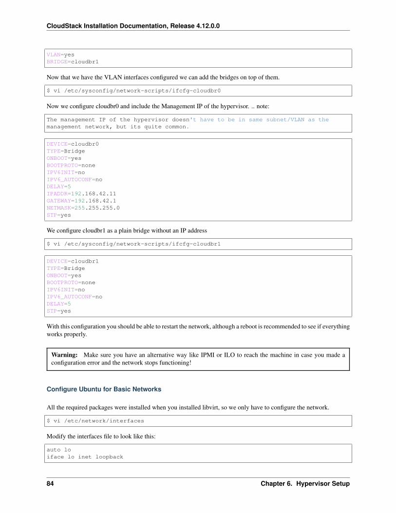
CloudStack Installation Documentation, Release 4.12.0.0
VLAN=yesBRIDGE=cloudbr1
Now that we have the VLAN interfaces configured we can add the bridges on top of them.
$ vi /etc/sysconfig/network-scripts/ifcfg-cloudbr0
Now we configure cloudbr0 and include the Management IP of the hypervisor. .. note:
The management IP of the hypervisor doesn't have to be in same subnet/VLAN as themanagement network, but its quite common.
DEVICE=cloudbr0TYPE=BridgeONBOOT=yesBOOTPROTO=noneIPV6INIT=noIPV6_AUTOCONF=noDELAY=5IPADDR=192.168.42.11GATEWAY=192.168.42.1NETMASK=255.255.255.0STP=yes
We configure cloudbr1 as a plain bridge without an IP address
$ vi /etc/sysconfig/network-scripts/ifcfg-cloudbr1
DEVICE=cloudbr1TYPE=BridgeONBOOT=yesBOOTPROTO=noneIPV6INIT=noIPV6_AUTOCONF=noDELAY=5STP=yes
With this configuration you should be able to restart the network, although a reboot is recommended to see if everythingworks properly.
Warning: Make sure you have an alternative way like IPMI or ILO to reach the machine in case you made aconfiguration error and the network stops functioning!
Configure Ubuntu for Basic Networks
All the required packages were installed when you installed libvirt, so we only have to configure the network.
$ vi /etc/network/interfaces
Modify the interfaces file to look like this:
auto loiface lo inet loopback
84 Chapter 6. Hypervisor Setup
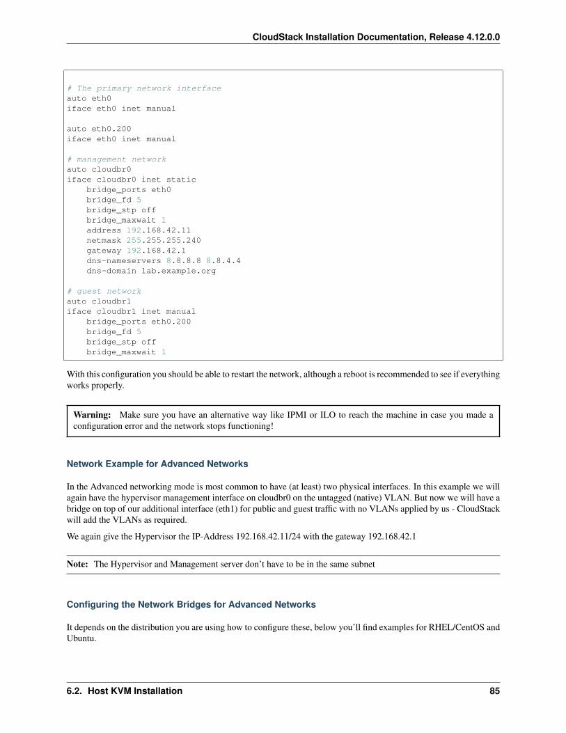
CloudStack Installation Documentation, Release 4.12.0.0
# The primary network interfaceauto eth0iface eth0 inet manual
auto eth0.200iface eth0 inet manual
# management networkauto cloudbr0iface cloudbr0 inet static
bridge_ports eth0bridge_fd 5bridge_stp offbridge_maxwait 1address 192.168.42.11netmask 255.255.255.240gateway 192.168.42.1dns-nameservers 8.8.8.8 8.8.4.4dns-domain lab.example.org
# guest networkauto cloudbr1iface cloudbr1 inet manual
bridge_ports eth0.200bridge_fd 5bridge_stp offbridge_maxwait 1
With this configuration you should be able to restart the network, although a reboot is recommended to see if everythingworks properly.
Warning: Make sure you have an alternative way like IPMI or ILO to reach the machine in case you made aconfiguration error and the network stops functioning!
Network Example for Advanced Networks
In the Advanced networking mode is most common to have (at least) two physical interfaces. In this example we willagain have the hypervisor management interface on cloudbr0 on the untagged (native) VLAN. But now we will have abridge on top of our additional interface (eth1) for public and guest traffic with no VLANs applied by us - CloudStackwill add the VLANs as required.
We again give the Hypervisor the IP-Address 192.168.42.11/24 with the gateway 192.168.42.1
Note: The Hypervisor and Management server don’t have to be in the same subnet
Configuring the Network Bridges for Advanced Networks
It depends on the distribution you are using how to configure these, below you’ll find examples for RHEL/CentOS andUbuntu.
6.2. Host KVM Installation 85
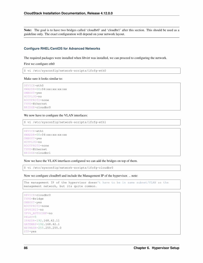
CloudStack Installation Documentation, Release 4.12.0.0
Note: The goal is to have two bridges called ‘cloudbr0’ and ‘cloudbr1’ after this section. This should be used as aguideline only. The exact configuration will depend on your network layout.
Configure RHEL/CentOS for Advanced Networks
The required packages were installed when libvirt was installed, we can proceed to configuring the network.
First we configure eth0
$ vi /etc/sysconfig/network-scripts/ifcfg-eth0
Make sure it looks similar to:
DEVICE=eth0HWADDR=00:04:xx:xx:xx:xxONBOOT=yesHOTPLUG=noBOOTPROTO=noneTYPE=EthernetBRIDGE=cloudbr0
We now have to configure the VLAN interfaces:
$ vi /etc/sysconfig/network-scripts/ifcfg-eth1
DEVICE=eth1HWADDR=00:04:xx:xx:xx:xxONBOOT=yesHOTPLUG=noBOOTPROTO=noneTYPE=EthernetBRIDGE=cloudbr1
Now we have the VLAN interfaces configured we can add the bridges on top of them.
$ vi /etc/sysconfig/network-scripts/ifcfg-cloudbr0
Now we configure cloudbr0 and include the Management IP of the hypervisor. .. note:
The management IP of the hypervisor doesn't have to be in same subnet/VLAN as themanagement network, but its quite common.
DEVICE=cloudbr0TYPE=BridgeONBOOT=yesBOOTPROTO=noneIPV6INIT=noIPV6_AUTOCONF=noDELAY=5IPADDR=192.168.42.11GATEWAY=192.168.42.1NETMASK=255.255.255.0STP=yes
86 Chapter 6. Hypervisor Setup
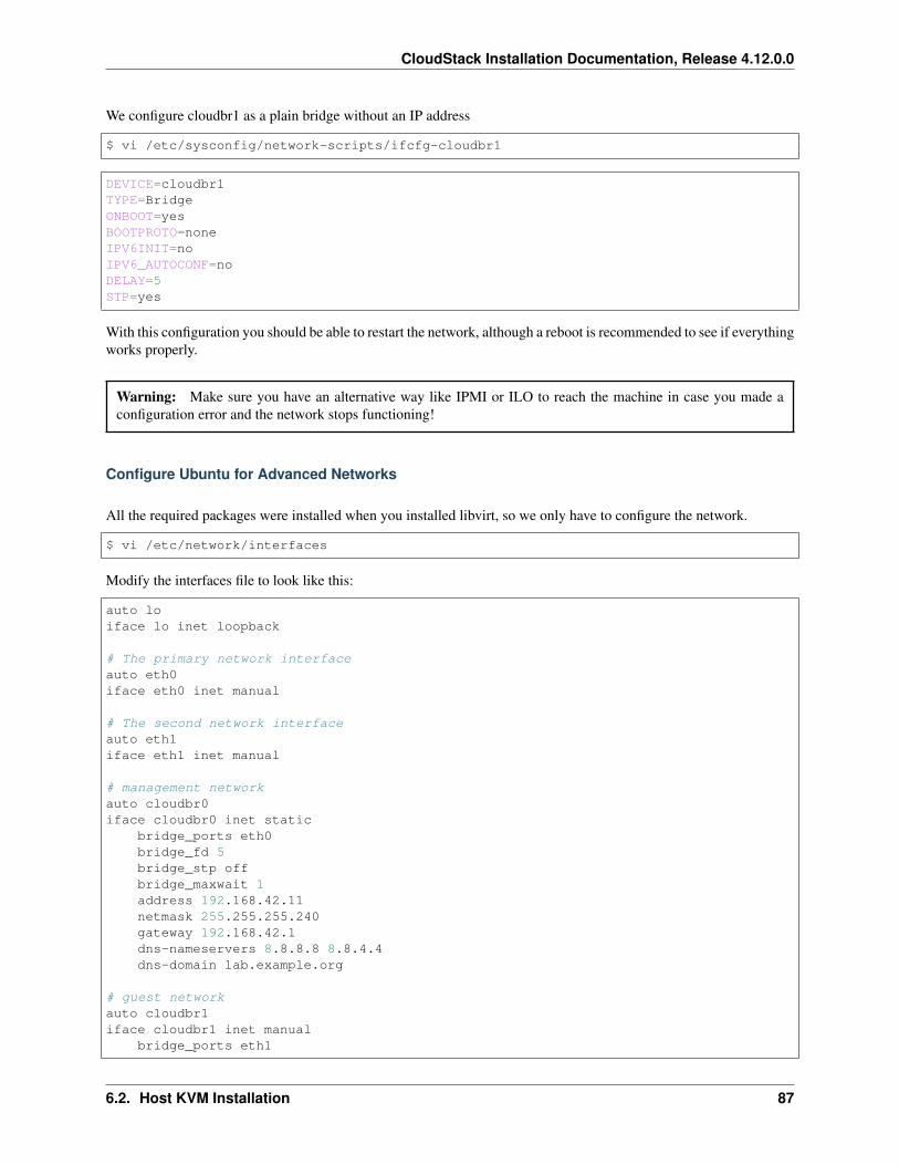
CloudStack Installation Documentation, Release 4.12.0.0
We configure cloudbr1 as a plain bridge without an IP address
$ vi /etc/sysconfig/network-scripts/ifcfg-cloudbr1
DEVICE=cloudbr1TYPE=BridgeONBOOT=yesBOOTPROTO=noneIPV6INIT=noIPV6_AUTOCONF=noDELAY=5STP=yes
With this configuration you should be able to restart the network, although a reboot is recommended to see if everythingworks properly.
Warning: Make sure you have an alternative way like IPMI or ILO to reach the machine in case you made aconfiguration error and the network stops functioning!
Configure Ubuntu for Advanced Networks
All the required packages were installed when you installed libvirt, so we only have to configure the network.
$ vi /etc/network/interfaces
Modify the interfaces file to look like this:
auto loiface lo inet loopback
# The primary network interfaceauto eth0iface eth0 inet manual
# The second network interfaceauto eth1iface eth1 inet manual
# management networkauto cloudbr0iface cloudbr0 inet static
bridge_ports eth0bridge_fd 5bridge_stp offbridge_maxwait 1address 192.168.42.11netmask 255.255.255.240gateway 192.168.42.1dns-nameservers 8.8.8.8 8.8.4.4dns-domain lab.example.org
# guest networkauto cloudbr1iface cloudbr1 inet manual
bridge_ports eth1
6.2. Host KVM Installation 87
CloudStack Installation Documentation, Release 4.12.0.0
bridge_fd 5bridge_stp offbridge_maxwait 1
With this configuration you should be able to restart the network, although a reboot is recommended to see if everythingworks properly.
Warning: Make sure you have an alternative way like IPMI or ILO to reach the machine in case you made aconfiguration error and the network stops functioning!
6.2.8 Configure the network using OpenVswitch
Warning: This is a very important section, please make sure you read this thoroughly.
In order to forward traffic to your instances you will need at least two bridges: public and private.
By default these bridges are called cloudbr0 and cloudbr1, but you do have to make sure they are available on eachhypervisor.
The most important factor is that you keep the configuration consistent on all your hypervisors.
Preparing
To make sure that the native bridge module will not interfere with openvswitch the bridge module should be addedto the blacklist. See the modprobe documentation for your distribution on where to find the blacklist. Make sure themodule is not loaded either by rebooting or executing rmmod bridge before executing next steps.
The network configurations below depend on the ifup-ovs and ifdown-ovs scripts which are part of the openvswitchinstallation. They should be installed in /etc/sysconfig/network-scripts/
OpenVswitch Network example
There are many ways to configure your network. In the Basic networking mode you should have two VLANs, one foryour private network and one for the public network.
We assume that the hypervisor has one NIC (eth0) with three tagged VLANs:
1. VLAN 100 for management of the hypervisor
2. VLAN 200 for public network of the instances (cloudbr0)
3. VLAN 300 for private network of the instances (cloudbr1)
On VLAN 100 we give the Hypervisor the IP-Address 192.168.42.11/24 with the gateway 192.168.42.1
Note: The Hypervisor and Management server don’t have to be in the same subnet
88 Chapter 6. Hypervisor Setup
CloudStack Installation Documentation, Release 4.12.0.0
Configuring the network bridges for OpenVswitch
It depends on the distribution you are using how to configure these, below you’ll find examples for RHEL/CentOS.
Note: The goal is to have three bridges called ‘mgmt0’, ‘cloudbr0’ and ‘cloudbr1’ after this section. This should beused as a guideline only. The exact configuration will depend on your network layout.
Configure OpenVswitch
The network interfaces using OpenVswitch are created using the ovs-vsctl command. This command will configurethe interfaces and persist them to the OpenVswitch database.
First we create a main bridge connected to the eth0 interface. Next we create three fake bridges, each connected to aspecific vlan tag.
# ovs-vsctl add-br cloudbr# ovs-vsctl add-port cloudbr eth0# ovs-vsctl set port cloudbr trunks=100,200,300# ovs-vsctl add-br mgmt0 cloudbr 100# ovs-vsctl add-br cloudbr0 cloudbr 200# ovs-vsctl add-br cloudbr1 cloudbr 300
Configure OpenVswitch in RHEL or CentOS
The required packages were installed when openvswitch and libvirt were installed, we can proceed to configuring thenetwork.
First we configure eth0
$ vi /etc/sysconfig/network-scripts/ifcfg-eth0
Make sure it looks similar to:
DEVICE=eth0HWADDR=00:04:xx:xx:xx:xxONBOOT=yesHOTPLUG=noBOOTPROTO=noneTYPE=Ethernet
We have to configure the base bridge with the trunk.
$ vi /etc/sysconfig/network-scripts/ifcfg-cloudbr
DEVICE=cloudbrONBOOT=yesHOTPLUG=noBOOTPROTO=noneDEVICETYPE=ovsTYPE=OVSBridge
We now have to configure the three VLAN bridges:
6.2. Host KVM Installation 89
CloudStack Installation Documentation, Release 4.12.0.0
$ vi /etc/sysconfig/network-scripts/ifcfg-mgmt0
DEVICE=mgmt0ONBOOT=yesHOTPLUG=noBOOTPROTO=staticDEVICETYPE=ovsTYPE=OVSBridgeIPADDR=192.168.42.11GATEWAY=192.168.42.1NETMASK=255.255.255.0
$ vi /etc/sysconfig/network-scripts/ifcfg-cloudbr0
DEVICE=cloudbr0ONBOOT=yesHOTPLUG=noBOOTPROTO=noneDEVICETYPE=ovsTYPE=OVSBridge
$ vi /etc/sysconfig/network-scripts/ifcfg-cloudbr1
DEVICE=cloudbr1ONBOOT=yesHOTPLUG=noBOOTPROTO=noneTYPE=OVSBridgeDEVICETYPE=ovs
With this configuration you should be able to restart the network, although a reboot is recommended to see if everythingworks properly.
Warning: Make sure you have an alternative way like IPMI or ILO to reach the machine in case you made aconfiguration error and the network stops functioning!
6.2.9 Configuring the firewall
The hypervisor needs to be able to communicate with other hypervisors and the management server needs to be ableto reach the hypervisor.
In order to do so we have to open the following TCP ports (if you are using a firewall):
1. 22 (SSH)
2. 1798
3. 16509 (libvirt)
4. 5900 - 6100 (VNC consoles)
5. 49152 - 49216 (libvirt live migration)
It depends on the firewall you are using how to open these ports. Below you’ll find examples how to open these portsin RHEL/CentOS and Ubuntu.
90 Chapter 6. Hypervisor Setup
CloudStack Installation Documentation, Release 4.12.0.0
Open ports in RHEL/CentOS
RHEL and CentOS use iptables for firewalling the system, you can open extra ports by executing the following iptablecommands:
$ iptables -I INPUT -p tcp -m tcp --dport 22 -j ACCEPT
$ iptables -I INPUT -p tcp -m tcp --dport 1798 -j ACCEPT
$ iptables -I INPUT -p tcp -m tcp --dport 16509 -j ACCEPT
$ iptables -I INPUT -p tcp -m tcp --dport 5900:6100 -j ACCEPT
$ iptables -I INPUT -p tcp -m tcp --dport 49152:49216 -j ACCEPT
These iptable settings are not persistent accross reboots, we have to save them first.
$ iptables-save > /etc/sysconfig/iptables
Open ports in Ubuntu
The default firewall under Ubuntu is UFW (Uncomplicated FireWall), which is a Python wrapper around iptables.
To open the required ports, execute the following commands:
$ ufw allow proto tcp from any to any port 22
$ ufw allow proto tcp from any to any port 1798
$ ufw allow proto tcp from any to any port 16509
$ ufw allow proto tcp from any to any port 5900:6100
$ ufw allow proto tcp from any to any port 49152:49216
Note: By default UFW is not enabled on Ubuntu. Executing these commands with the firewall disabled does notenable the firewall.
6.2.10 Additional Packages Required for Features
Secondary Storage Bypass
New in 4.11 is the ability to bypass storing a template on secondary storage, and instead directly downloading a‘template’ from an alternate remote location. In order to facilitate this the Aria2 (https://aria2.github.io/) packagemust be installed on all of your KVM hosts.
As this package often is not available in standard distribution repos, you will need to install the package from yourpreferred source.
6.2. Host KVM Installation 91
CloudStack Installation Documentation, Release 4.12.0.0
Live Migration
CloudStack uses the qemu-img to perform live migrations. In CentOS > 6.3, the qemu-img supplied by Red-Hat/CentOS ceased to include a ‘-s’ switch which performs snapshots. The ‘-s’ switch has been restored in latestCentOS/RHEL 7.x versions.
In order to be able to perform live migrations on CentOS 6.x (greater than 6.3) you must replace your version ofqemu-img with one which has been patched to include the ‘-s’ switch.
6.2.11 Add the host to CloudStack
The host is now ready to be added to a cluster. This is covered in a later section, see Adding a Host. It is recommendedthat you continue to read the documentation before adding the host!
6.3 Host LXC Installation
6.3.1 System Requirements for LXC Hosts
LXC requires the Linux kernel cgroups functionality which is available starting 2.6.24. Although you are not requiredto run these distributions, the following are recommended:
• CentOS / RHEL: 6.3
• Ubuntu: 12.04(.1)
The main requirement for LXC hypervisors is the libvirt and Qemu version. No matter what Linux distribution youare using, make sure the following requirements are met:
• libvirt: 1.0.0 or higher
• Qemu/KVM: 1.0 or higher
The default bridge in CloudStack is the Linux native bridge implementation (bridge module). CloudStack includes anoption to work with OpenVswitch, the requirements are listed below
• libvirt: 1.0.0 or higher
• openvswitch: 1.7.1 or higher
In addition, the following hardware requirements apply:
• Within a single cluster, the hosts must be of the same distribution version.
• All hosts within a cluster must be homogenous. The CPUs must be of the same type, count, and feature flags.
• Must support HVM (Intel-VT or AMD-V enabled)
• 64-bit x86 CPU (more cores results in better performance)
• 4 GB of memory
• At least 1 NIC
• When you deploy CloudStack, the hypervisor host must not have any VMs already running
92 Chapter 6. Hypervisor Setup
CloudStack Installation Documentation, Release 4.12.0.0
6.3.2 LXC Installation Overview
LXC does not have any native system VMs, instead KVM will be used to run system VMs. This means that your hostwill need to support both LXC and KVM, thus most of the installation and configuration will be identical to the KVMinstallation. The material in this section doesn’t duplicate KVM installation docs. It provides the CloudStack-specificsteps that are needed to prepare a KVM host to work with CloudStack.
Warning: Before continuing, make sure that you have applied the latest updates to your host.
Warning: It is NOT recommended to run services on this host not controlled by CloudStack.
The procedure for installing an LXC Host is:
1. Prepare the Operating System
2. Install and configure libvirt
3. Configure Security Policies (AppArmor and SELinux)
4. Install and configure the Agent
6.3.3 Prepare the Operating System
The OS of the Host must be prepared to host the CloudStack Agent and run KVM instances.
1. Log in to your OS as root.
2. Check for a fully qualified hostname.
$ hostname --fqdn
This should return a fully qualified hostname such as “kvm1.lab.example.org”. If it does not, edit /etc/hosts sothat it does.
3. Make sure that the machine can reach the Internet.
$ ping www.cloudstack.org
4. Turn on NTP for time synchronization.
Note: NTP is required to synchronize the clocks of the servers in your cloud. Unsynchronized clocks can causeunexpected problems.
(a) Install NTP
$ yum install ntp
$ apt-get install openntpd
5. Repeat all of these steps on every hypervisor host.
6.3. Host LXC Installation 93
CloudStack Installation Documentation, Release 4.12.0.0
6.3.4 Install and configure the Agent
To manage LXC instances on the host CloudStack uses a Agent. This Agent communicates with the Managementserver and controls all the instances on the host.
First we start by installing the agent:
In RHEL or CentOS:
$ yum install cloudstack-agent
In Ubuntu:
$ apt-get install cloudstack-agent
Next step is to update the Agent configuration setttings. The settings are in /etc/cloudstack/agent/agent.properties
1. Set the Agent to run in LXC mode:
hypervisor.type=lxc
2. Optional: If you would like to use direct networking (instead of the default bridge networking), configure theselines:
libvirt.vif.driver=com.cloud.hypervisor.kvm.resource.DirectVifDriver
network.direct.source.mode=private
network.direct.device=eth0
The host is now ready to be added to a cluster. This is covered in a later section, see Adding a Host. It is recommendedthat you continue to read the documentation before adding the host!
6.3.5 Install and Configure libvirt
CloudStack uses libvirt for managing virtual machines. Therefore it is vital that libvirt is configured correctly. Libvirtis a dependency of cloudstack-agent and should already be installed.
1. In order to have live migration working libvirt has to listen for unsecured TCP connections. We also need toturn off libvirts attempt to use Multicast DNS advertising. Both of these settings are in /etc/libvirt/libvirtd.conf
Set the following parameters:
listen_tls = 0
listen_tcp = 1
tcp_port = "16509"
auth_tcp = "none"
mdns_adv = 0
94 Chapter 6. Hypervisor Setup
CloudStack Installation Documentation, Release 4.12.0.0
2. Turning on “listen_tcp” in libvirtd.conf is not enough, we have to change the parameters as well:
On RHEL or CentOS modify /etc/sysconfig/libvirtd:
Uncomment the following line:
#LIBVIRTD_ARGS="--listen"
On Ubuntu: modify /etc/default/libvirt-bin
Add “-l” to the following line
libvirtd_opts="-d"
so it looks like:
libvirtd_opts="-d -l"
3. In order to have the VNC Console work we have to make sure it will bind on 0.0.0.0. We do this by editing/etc/libvirt/qemu.conf
Make sure this parameter is set:
vnc_listen = "0.0.0.0"
4. Restart libvirt
In RHEL or CentOS:
$ service libvirtd restart
In Ubuntu:
$ service libvirt-bin restart
6.3.6 Configure the Security Policies
CloudStack does various things which can be blocked by security mechanisms like AppArmor and SELinux. Thesehave to be disabled to ensure the Agent has all the required permissions.
1. Configure SELinux (RHEL and CentOS)
(a) Check to see whether SELinux is installed on your machine. If not, you can skip this section.
In RHEL or CentOS, SELinux is installed and enabled by default. You can verify this with:
$ rpm -qa | grep selinux
(b) Set the SELINUX variable in /etc/selinux/config to “permissive”. This ensures that the permis-sive setting will be maintained after a system reboot.
In RHEL or CentOS:
$ vi /etc/selinux/config
Change the following line
SELINUX=enforcing
6.3. Host LXC Installation 95
CloudStack Installation Documentation, Release 4.12.0.0
to this
SELINUX=permissive
(c) Then set SELinux to permissive starting immediately, without requiring a system reboot.
$ setenforce permissive
2. Configure Apparmor (Ubuntu)
(a) Check to see whether AppArmor is installed on your machine. If not, you can skip this section.
In Ubuntu AppArmor is installed and enabled by default. You can verify this with:
$ dpkg --list 'apparmor'
(b) Disable the AppArmor profiles for libvirt
$ ln -s /etc/apparmor.d/usr.sbin.libvirtd /etc/apparmor.d/disable/
$ ln -s /etc/apparmor.d/usr.lib.libvirt.virt-aa-helper /etc/apparmor.d/→˓disable/
$ apparmor_parser -R /etc/apparmor.d/usr.sbin.libvirtd
$ apparmor_parser -R /etc/apparmor.d/usr.lib.libvirt.virt-aa-helper
6.3.7 Configure the network bridges
Warning: This is a very important section, please make sure you read this thoroughly.
Note: This section details how to configure bridges using the native implementation in Linux. Please refer to the nextsection if you intend to use OpenVswitch
In order to forward traffic to your instances you will need at least two bridges: public and private.
By default these bridges are called cloudbr0 and cloudbr1, but you do have to make sure they are available on eachhypervisor.
The most important factor is that you keep the configuration consistent on all your hypervisors.
Network example
There are many ways to configure your network. In the Basic networking mode you should have two (V)LAN’s, onefor your private network and one for the public network.
We assume that the hypervisor has one NIC (eth0) with three tagged VLAN’s:
1. VLAN 100 for management of the hypervisor
2. VLAN 200 for public network of the instances (cloudbr0)
3. VLAN 300 for private network of the instances (cloudbr1)
96 Chapter 6. Hypervisor Setup
CloudStack Installation Documentation, Release 4.12.0.0
On VLAN 100 we give the Hypervisor the IP-Address 192.168.42.11/24 with the gateway 192.168.42.1
Note: The Hypervisor and Management server don’t have to be in the same subnet!
Configuring the network bridges
It depends on the distribution you are using how to configure these, below you’ll find examples for RHEL/CentOS andUbuntu.
Note: The goal is to have two bridges called ‘cloudbr0’ and ‘cloudbr1’ after this section. This should be used as aguideline only. The exact configuration will depend on your network layout.
Configure in RHEL or CentOS
The required packages were installed when libvirt was installed, we can proceed to configuring the network.
First we configure eth0
$ vi /etc/sysconfig/network-scripts/ifcfg-eth0
Make sure it looks similar to:
DEVICE=eth0HWADDR=00:04:xx:xx:xx:xxONBOOT=yesHOTPLUG=noBOOTPROTO=noneTYPE=Ethernet
We now have to configure the three VLAN interfaces:
$ vi /etc/sysconfig/network-scripts/ifcfg-eth0.100
DEVICE=eth0.100HWADDR=00:04:xx:xx:xx:xxONBOOT=yesHOTPLUG=noBOOTPROTO=noneTYPE=EthernetVLAN=yesIPADDR=192.168.42.11GATEWAY=192.168.42.1NETMASK=255.255.255.0
$ vi /etc/sysconfig/network-scripts/ifcfg-eth0.200
DEVICE=eth0.200HWADDR=00:04:xx:xx:xx:xxONBOOT=yesHOTPLUG=noBOOTPROTO=none
6.3. Host LXC Installation 97
CloudStack Installation Documentation, Release 4.12.0.0
TYPE=EthernetVLAN=yesBRIDGE=cloudbr0
$ vi /etc/sysconfig/network-scripts/ifcfg-eth0.300
DEVICE=eth0.300HWADDR=00:04:xx:xx:xx:xxONBOOT=yesHOTPLUG=noBOOTPROTO=noneTYPE=EthernetVLAN=yesBRIDGE=cloudbr1
Now we have the VLAN interfaces configured we can add the bridges on top of them.
$ vi /etc/sysconfig/network-scripts/ifcfg-cloudbr0
Now we just configure it is a plain bridge without an IP-Address
DEVICE=cloudbr0TYPE=BridgeONBOOT=yesBOOTPROTO=noneIPV6INIT=noIPV6_AUTOCONF=noDELAY=5STP=yes
We do the same for cloudbr1
$ vi /etc/sysconfig/network-scripts/ifcfg-cloudbr1
DEVICE=cloudbr1TYPE=BridgeONBOOT=yesBOOTPROTO=noneIPV6INIT=noIPV6_AUTOCONF=noDELAY=5STP=yes
With this configuration you should be able to restart the network, although a reboot is recommended to see if everythingworks properly.
Warning: Make sure you have an alternative way like IPMI or ILO to reach the machine in case you made aconfiguration error and the network stops functioning!
Configure in Ubuntu
All the required packages were installed when you installed libvirt, so we only have to configure the network.
98 Chapter 6. Hypervisor Setup
CloudStack Installation Documentation, Release 4.12.0.0
$ vi /etc/network/interfaces
Modify the interfaces file to look like this:
auto loiface lo inet loopback
# The primary network interfaceauto eth0.100iface eth0.100 inet static
address 192.168.42.11netmask 255.255.255.240gateway 192.168.42.1dns-nameservers 8.8.8.8 8.8.4.4dns-domain lab.example.org
# Public networkauto cloudbr0iface cloudbr0 inet manual
bridge_ports eth0.200bridge_fd 5bridge_stp offbridge_maxwait 1
# Private networkauto cloudbr1iface cloudbr1 inet manual
bridge_ports eth0.300bridge_fd 5bridge_stp offbridge_maxwait 1
With this configuration you should be able to restart the network, although a reboot is recommended to see if everythingworks properly.
Warning: Make sure you have an alternative way like IPMI or ILO to reach the machine in case you made aconfiguration error and the network stops functioning!
6.3.8 Configuring the firewall
The hypervisor needs to be able to communicate with other hypervisors and the management server needs to be ableto reach the hypervisor.
In order to do so we have to open the following TCP ports (if you are using a firewall):
1. 22 (SSH)
2. 1798
3. 16509 (libvirt)
4. 5900 - 6100 (VNC consoles)
5. 49152 - 49216 (libvirt live migration)
It depends on the firewall you are using how to open these ports. Below you’ll find examples how to open these portsin RHEL/CentOS and Ubuntu.
6.3. Host LXC Installation 99
CloudStack Installation Documentation, Release 4.12.0.0
Open ports in RHEL/CentOS
RHEL and CentOS use iptables for firewalling the system, you can open extra ports by executing the following iptablecommands:
$ iptables -I INPUT -p tcp -m tcp --dport 22 -j ACCEPT
$ iptables -I INPUT -p tcp -m tcp --dport 1798 -j ACCEPT
$ iptables -I INPUT -p tcp -m tcp --dport 16509 -j ACCEPT
$ iptables -I INPUT -p tcp -m tcp --dport 5900:6100 -j ACCEPT
$ iptables -I INPUT -p tcp -m tcp --dport 49152:49216 -j ACCEPT
These iptable settings are not persistent accross reboots, we have to save them first.
$ iptables-save > /etc/sysconfig/iptables
Open ports in Ubuntu
The default firewall under Ubuntu is UFW (Uncomplicated FireWall), which is a Python wrapper around iptables.
To open the required ports, execute the following commands:
$ ufw allow proto tcp from any to any port 22
$ ufw allow proto tcp from any to any port 1798
$ ufw allow proto tcp from any to any port 16509
$ ufw allow proto tcp from any to any port 5900:6100
$ ufw allow proto tcp from any to any port 49152:49216
Note: By default UFW is not enabled on Ubuntu. Executing these commands with the firewall disabled does notenable the firewall.
6.3.9 Add the host to CloudStack
The host is now ready to be added to a cluster. This is covered in a later section, see Adding a Host. It is recommendedthat you continue to read the documentation before adding the host!
6.4 Host VMware vSphere Installation
If you want to use the VMware vSphere hypervisor to run guest virtual machines, install vSphere on the host(s) inyour cloud.
100 Chapter 6. Hypervisor Setup
CloudStack Installation Documentation, Release 4.12.0.0
6.4.1 System Requirements for vSphere Hosts
Software requirements:
• vSphere and vCenter, versions 4.1, 5.0, 5.1 or 5.5.
vSphere Standard is recommended. Note however that customers need to consider the CPU constraints inplace with vSphere licensing. See http://www.vmware.com/files/pdf/vsphere_pricing.pdf and discuss with yourVMware sales representative.
vCenter Server Standard is recommended.
• Be sure all the hotfixes provided by the hypervisor vendor are applied. Track the release of hypervisor patchesthrough your hypervisor vendor’s support channel, and apply patches as soon as possible after they are released.CloudStack will not track or notify you of required hypervisor patches. It is essential that your hosts are com-pletely up to date with the provided hypervisor patches. The hypervisor vendor is likely to refuse to support anysystem that is not up to date with patches.
Warning: Apply All Necessary Hotfixes. The lack of up-do-date hotfixes can lead to data corruption and lostVMs.
Hardware requirements:
• The host must be certified as compatible with vSphere. See the VMware Hardware Compatibility Guide athttp://www.vmware.com/resources/compatibility/search.php.
• All hosts must be 64-bit and must support HVM (Intel-VT or AMD-V enabled).
• All hosts within a cluster must be homogenous. That means the CPUs must be of the same type, count, andfeature flags.
• 64-bit x86 CPU (more cores results in better performance)
• Hardware virtualization support required
• 4 GB of memory
• 36 GB of local disk
• At least 1 NIC
• Statically allocated IP Address
vCenter Server requirements:
• Processor - 2 CPUs 2.0GHz or higher Intel or AMD x86 processors. Processor requirements may be higher ifthe database runs on the same machine.
• Memory - 3GB RAM. RAM requirements may be higher if your database runs on the same machine.
• Disk storage - 2GB. Disk requirements may be higher if your database runs on the same machine.
• Microsoft SQL Server 2005 Express disk requirements. The bundled database requires up to 2GB free diskspace to decompress the installation archive.
• Networking - 1Gbit or 10Gbit.
For more information, see “vCenter Server and the vSphere Client Hardware Requirements”.
6.4. Host VMware vSphere Installation 101
CloudStack Installation Documentation, Release 4.12.0.0
Other requirements:
• VMware vCenter Standard Edition 4.1, 5.0, 5.1 or 5.5 must be installed and available to manage the vSpherehosts.
• vCenter must be configured to use the standard port 443 so that it can communicate with the CloudStack Man-agement Server.
• You must re-install VMware ESXi if you are going to re-use a host from a previous install.
• CloudStack requires VMware vSphere 4.1, 5.0, 5.1 or 5.5. VMware vSphere 4.0 is not supported.
• All hosts must be 64-bit and must support HVM (Intel-VT or AMD-V enabled). All hosts within a cluster mustbe homogeneous. That means the CPUs must be of the same type, count, and feature flags.
• The CloudStack management network must not be configured as a separate virtual network. The CloudStackmanagement network is the same as the vCenter management network, and will inherit its configuration. SeeConfigure vCenter Management Network.
• CloudStack requires ESXi and vCenter. ESX is not supported.
• Ideally all resources used for CloudStack must be used for CloudStack only. CloudStack should not shareinstance of ESXi or storage with other management consoles. Do not share the same storage volumes that willbe used by CloudStack with a different set of ESXi servers that are not managed by CloudStack.
• Put all target ESXi hypervisors in dedicated clusters in a separate Datacenter in vCenter.
• Ideally clusters that will be managed by CloudStack should not contain any other VMs. Do not run the manage-ment server or vCenter on the cluster that is designated for CloudStack use. Create a separate cluster for use ofCloudStack and make sure that they are no VMs in this cluster.
• All of the required VLANs must be trunked into all network switches that are connected to the ESXi hyper-visor hosts. These would include the VLANs for Management, Storage, vMotion, and guest VLANs. Theguest VLAN (used in Advanced Networking; see Network Setup) is a contiguous range of VLANs that will bemanaged by CloudStack.
6.4.2 Preparation Checklist for VMware
For a smoother installation, gather the following information before you start:
• Information listed in vCenter Checklist
• Information listed in Networking Checklist for VMware
vCenter Checklist
You will need the following information about vCenter.
vCenter Requirement NotesvCenter User This user must have admin privileges.vCenter User Password Password for the above user.vCenter Datacenter Name Name of the datacenter.vCenter Cluster Name Name of the cluster.
102 Chapter 6. Hypervisor Setup
CloudStack Installation Documentation, Release 4.12.0.0
Networking Checklist for VMware
You will need the following information about your VLANs.
VLAN Informa-tion
Notes
ESXi VLAN VLAN on which all your ESXi hypervisors reside.ESXI VLAN IPAddress
IP Address Range in the ESXi VLAN. One address per Virtual Router is used from this range.
ESXi VLAN IPGatewayESXi VLAN Net-maskManagementServer VLAN
VLAN on which the CloudStack Management server is installed.
Public VLAN VLAN for the Public Network.Public VLANGatewayPublic VLANNetmaskPublic VLAN IPAddress Range
Range of Public IP Addresses available for CloudStack use. These addresses will be used forvirtual router on CloudStack to route private traffic to external networks.
VLAN Range forCustomer use
A contiguous range of non-routable VLANs. One VLAN will be assigned for each customer.
6.4.3 vSphere Installation Steps
1. If you haven’t already, you’ll need to download and purchase vSphere from the VMware Website (https://www.vmware.com/tryvmware/index.php?p=vmware-vsphere&lp=1) and install it by following the VMware vSphereInstallation Guide.
2. Following installation, perform the following configuration, which are described in the next few sections:
Required OptionalESXi host setup NIC bondingConfigure host physical networking,virtual switch, vCenter Management Network, andextended port range
Multipathstorage
Prepare storage for iSCSIConfigure clusters in vCenter and add hosts to them, or add hosts without clusters to vCen-ter
6.4.4 ESXi Host setup
All ESXi hosts should have CPU hardware virtualization support enabled in the BIOS. Please note hardware virtual-ization support is not enabled by default on most servers.
6.4.5 Physical Host Networking
You should have a plan for cabling the vSphere hosts. Proper network configuration is required before adding avSphere host to CloudStack. To configure an ESXi host, you can use vClient to add it as standalone host to vCenter
6.4. Host VMware vSphere Installation 103
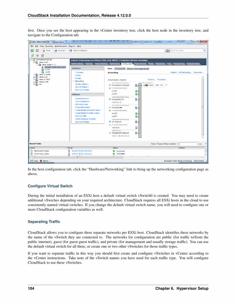
CloudStack Installation Documentation, Release 4.12.0.0
first. Once you see the host appearing in the vCenter inventory tree, click the host node in the inventory tree, andnavigate to the Configuration tab.
In the host configuration tab, click the “Hardware/Networking” link to bring up the networking configuration page asabove.
Configure Virtual Switch
During the initial installation of an ESXi host a default virtual switch vSwitch0 is created. You may need to createadditional vSwiches depending on your required architecture. CloudStack requires all ESXi hosts in the cloud to useconsistently named virtual switches. If you change the default virtual switch name, you will need to configure one ormore CloudStack configuration variables as well.
Separating Traffic
CloudStack allows you to configure three separate networks per ESXi host. CloudStack identifies these networks bythe name of the vSwitch they are connected to. The networks for configuration are public (for traffic to/from thepublic internet), guest (for guest-guest traffic), and private (for management and usually storage traffic). You can usethe default virtual switch for all three, or create one or two other vSwitches for those traffic types.
If you want to separate traffic in this way you should first create and configure vSwitches in vCenter according tothe vCenter instructions. Take note of the vSwitch names you have used for each traffic type. You will configureCloudStack to use these vSwitches.
104 Chapter 6. Hypervisor Setup
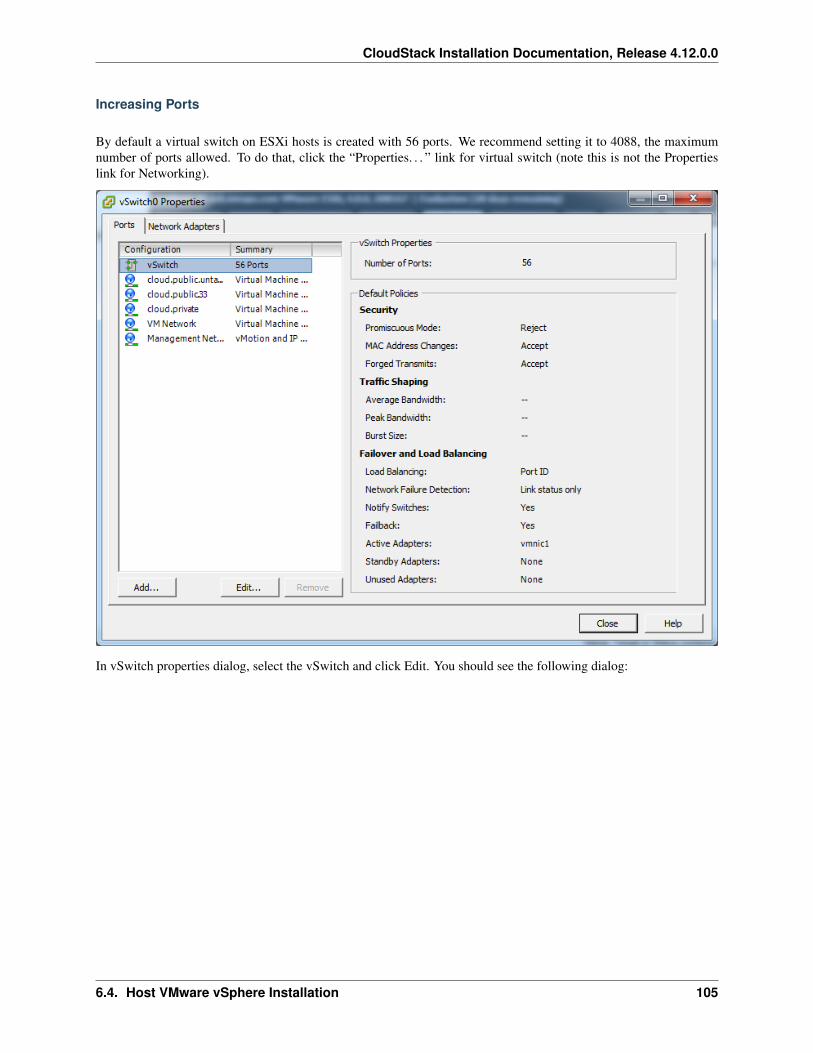
CloudStack Installation Documentation, Release 4.12.0.0
Increasing Ports
By default a virtual switch on ESXi hosts is created with 56 ports. We recommend setting it to 4088, the maximumnumber of ports allowed. To do that, click the “Properties. . . ” link for virtual switch (note this is not the Propertieslink for Networking).
In vSwitch properties dialog, select the vSwitch and click Edit. You should see the following dialog:
6.4. Host VMware vSphere Installation 105
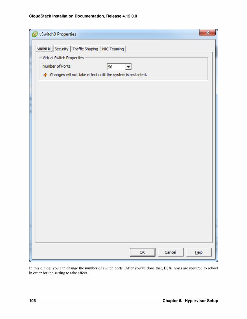
CloudStack Installation Documentation, Release 4.12.0.0
In this dialog, you can change the number of switch ports. After you’ve done that, ESXi hosts are required to rebootin order for the setting to take effect.
106 Chapter 6. Hypervisor Setup
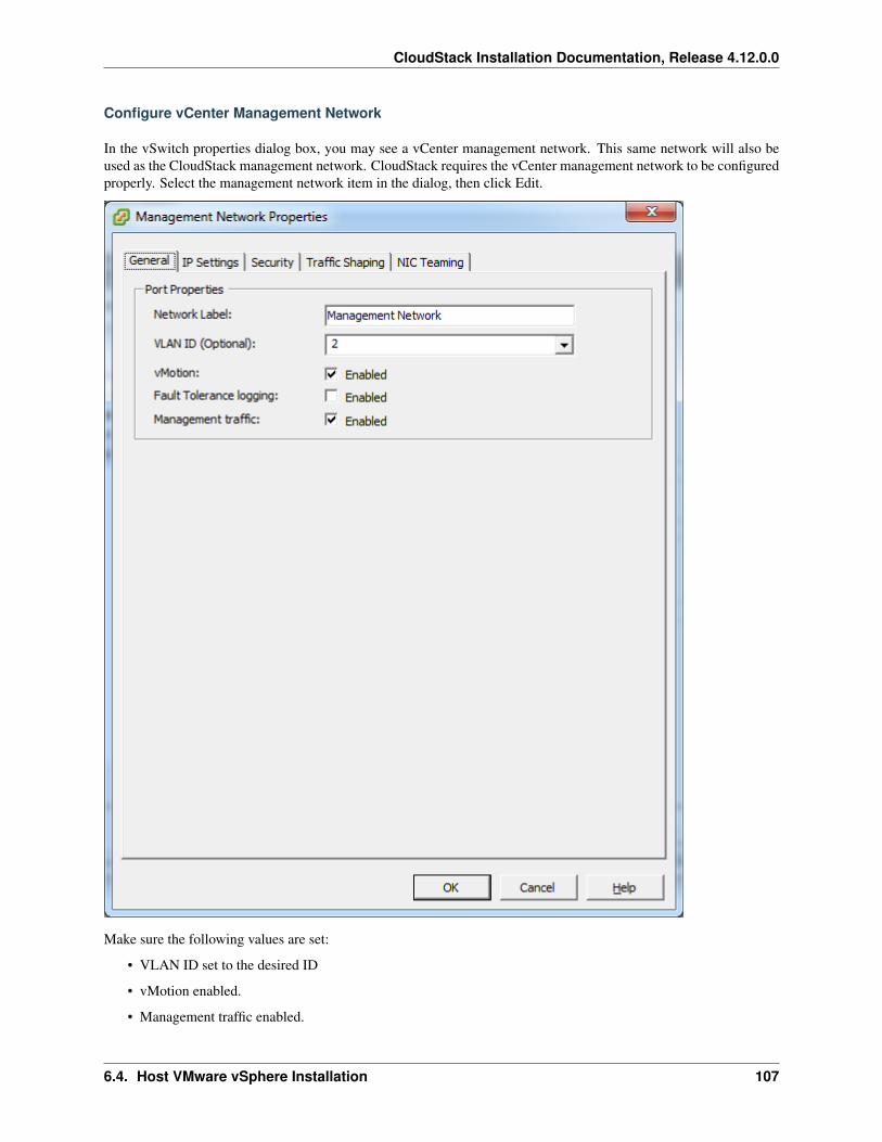
CloudStack Installation Documentation, Release 4.12.0.0
Configure vCenter Management Network
In the vSwitch properties dialog box, you may see a vCenter management network. This same network will also beused as the CloudStack management network. CloudStack requires the vCenter management network to be configuredproperly. Select the management network item in the dialog, then click Edit.
Make sure the following values are set:
• VLAN ID set to the desired ID
• vMotion enabled.
• Management traffic enabled.
6.4. Host VMware vSphere Installation 107
CloudStack Installation Documentation, Release 4.12.0.0
If the ESXi hosts have multiple VMKernel ports, and ESXi is not using the default value “Management Network” asthe management network name, you must follow these guidelines to configure the management network port group sothat CloudStack can find it:
• Use one label for the management network port across all ESXi hosts.
• In the CloudStack UI, go to Configuration - Global Settings and set vmware.management.portgroup to themanagement network label from the ESXi hosts.
Extend Port Range for CloudStack Console Proxy
(Applies only to VMware vSphere version 4.x)
You need to extend the range of firewall ports that the console proxy works with on the hosts. This is to enable theconsole proxy to work with VMware-based VMs. The default additional port range is 59000-60000. To extend theport range, log in to the VMware ESX service console on each host and run the following commands:
esxcfg-firewall -o 59000-60000,tcp,in,vncextrasesxcfg-firewall -o 59000-60000,tcp,out,vncextras
Configure NIC Bonding for vSphere
NIC bonding on vSphere hosts may be done according to the vSphere installation guide.
6.4.6 Configuring a vSphere Cluster with Nexus 1000v Virtual Switch
CloudStack supports Cisco Nexus 1000v dvSwitch (Distributed Virtual Switch) for virtual network configuration in aVMware vSphere environment. This section helps you configure a vSphere cluster with Nexus 1000v virtual switchin a VMware vCenter environment. For information on creating a vSphere cluster, see “VMware vSphere Installationand Configuration”
About Cisco Nexus 1000v Distributed Virtual Switch
The Cisco Nexus 1000V virtual switch is a software-based virtual machine access switch for VMware vSphere en-vironments. It can span multiple hosts running VMware ESXi 4.0 and later. A Nexus virtual switch consists of twocomponents: the Virtual Supervisor Module (VSM) and the Virtual Ethernet Module (VEM). The VSM is a virtualappliance that acts as the switch’s supervisor. It controls multiple VEMs as a single network device. The VSM isinstalled independent of the VEM and is deployed in redundancy mode as pairs or as a standalone appliance. TheVEM is installed on each VMware ESXi server to provide packet-forwarding capability. It provides each virtual ma-chine with dedicated switch ports. This VSM-VEM architecture is analogous to a physical Cisco switch’s supervisor(standalone or configured in high-availability mode) and multiple linecards architecture.
Nexus 1000v switch uses vEthernet port profiles to simplify network provisioning for virtual machines. There aretwo types of port profiles: Ethernet port profile and vEthernet port profile. The Ethernet port profile is applied tothe physical uplink ports-the NIC ports of the physical NIC adapter on an ESXi server. The vEthernet port profileis associated with the virtual NIC (vNIC) that is plumbed on a guest VM on the ESXi server. The port profiles helpthe network administrators define network policies which can be reused for new virtual machines. The Ethernet portprofiles are created on the VSM and are represented as port groups on the vCenter server.
108 Chapter 6. Hypervisor Setup
CloudStack Installation Documentation, Release 4.12.0.0
Prerequisites and Guidelines
This section discusses prerequisites and guidelines for using Nexus virtual switch in CloudStack. Before configuringNexus virtual switch, ensure that your system meets the following requirements:
• A cluster of servers (ESXi 4.1 or later) is configured in the vCenter.
• Each cluster managed by CloudStack is the only cluster in its vCenter datacenter.
• A Cisco Nexus 1000v virtual switch is installed to serve the datacenter that contains the vCenter cluster. Thisensures that CloudStack doesn’t have to deal with dynamic migration of virtual adapters or networks acrossother existing virtual switches. See Cisco Nexus 1000V Installation and Upgrade Guide for guidelines on howto install the Nexus 1000v VSM and VEM modules.
• The Nexus 1000v VSM is not deployed on a vSphere host that is managed by CloudStack.
• When the maximum number of VEM modules per VSM instance is reached, an additional VSM instance iscreated before introducing any more ESXi hosts. The limit is 64 VEM modules for each VSM instance.
• CloudStack expects that the Management Network of the ESXi host is configured on the standard vSwitch andsearches for it in the standard vSwitch. Therefore, ensure that you do not migrate the management network toNexus 1000v virtual switch during configuration.
• All information given in Nexus 1000v Virtual Switch Preconfiguration
Nexus 1000v Virtual Switch Preconfiguration
Preparation Checklist
For a smoother configuration of Nexus 1000v switch, gather the following information before you start:
• vCenter credentials
• Nexus 1000v VSM IP address
• Nexus 1000v VSM Credentials
• Ethernet port profile names
vCenter Credentials Checklist
You will need the following information about vCenter:
Nexus vSwitchRequirements
Value Notes
vCenter IP The IP address of the vCenter.Secure HTTP PortNumber
443 Port 443 is configured by default; however, you can change the port if needed.
vCenter User ID The vCenter user with administrator-level privileges. The vCenter User ID is requiredwhen you configure the virtual switch in CloudStack.
vCenter Password The password for the vCenter user specified above. The password for this vCenteruser is required when you configure the switch in CloudStack.
6.4. Host VMware vSphere Installation 109
CloudStack Installation Documentation, Release 4.12.0.0
Network Configuration Checklist
The following information specified in the Nexus Configure Networking screen is displayed in the Details tab of theNexus dvSwitch in the CloudStack UI:
Control Port Group VLAN ID The VLAN ID of the Control Port Group. The control VLAN is used for communi-cation between the VSM and the VEMs.
Management Port Group VLAN ID The VLAN ID of the Management Port Group. The management VLAN cor-responds to the mgmt0 interface that is used to establish and maintain the connection between the VSM and VMwarevCenter Server.
Packet Port Group VLAN ID The VLAN ID of the Packet Port Group. The packet VLAN forwards relevant datapackets from the VEMs to the VSM.
Note: The VLANs used for control, packet, and management port groups can be the same.
For more information, see Cisco Nexus 1000V Getting Started Guide.
VSM Configuration Checklist
You will need the following VSM configuration parameters:
Admin Name and Password The admin name and password to connect to the VSM appliance. You must specifythese credentials while configuring Nexus virtual switch.
Management IP Address This is the IP address of the VSM appliance. This is the IP address you specify in thevirtual switch IP Address field while configuting Nexus virtual switch.
SSL Should be set to Enable.Always enable SSL. SSH is usually enabled by default during the VSM installation.However, check whether the SSH connection to the VSM is working, without which CloudStack failes to connect tothe VSM.
Creating a Port Profile
• Whether you create a Basic or Advanced zone configuration, ensure that you always create an Ethernet portprofile on the VSM after you install it and before you create the zone.
– The Ethernet port profile created to represent the physical network or networks used by an Advanced zoneconfiguration trunk all the VLANs including guest VLANs, the VLANs that serve the native VLAN, andthe packet/control/data/management VLANs of the VSM.
– The Ethernet port profile created for a Basic zone configuration does not trunk the guest VLANs becausethe guest VMs do not get their own VLANs provisioned on their network interfaces in a Basic zone.
• An Ethernet port profile configured on the Nexus 1000v virtual switch should not use in its set of systemVLANs, or any of the VLANs configured or intended to be configured for use towards VMs or VM resourcesin the CloudStack environment.
• You do not have to create any vEthernet port profiles – CloudStack does that during VM deployment.
• Ensure that you create required port profiles to be used by CloudStack for different traffic types of CloudStack,such as Management traffic, Guest traffic, Storage traffic, and Public traffic. The physical networks configuredduring zone creation should have a one-to-one relation with the Ethernet port profiles.
110 Chapter 6. Hypervisor Setup
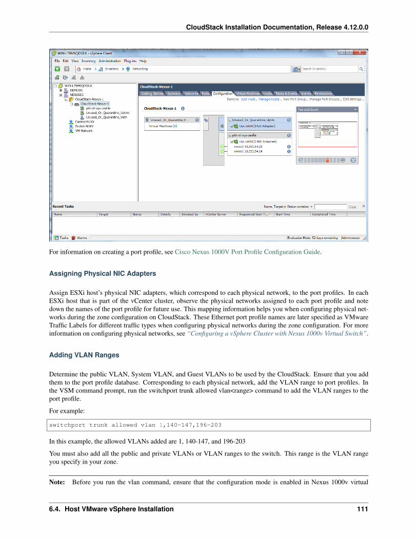
CloudStack Installation Documentation, Release 4.12.0.0
For information on creating a port profile, see Cisco Nexus 1000V Port Profile Configuration Guide.
Assigning Physical NIC Adapters
Assign ESXi host’s physical NIC adapters, which correspond to each physical network, to the port profiles. In eachESXi host that is part of the vCenter cluster, observe the physical networks assigned to each port profile and notedown the names of the port profile for future use. This mapping information helps you when configuring physical net-works during the zone configuration on CloudStack. These Ethernet port profile names are later specified as VMwareTraffic Labels for different traffic types when configuring physical networks during the zone configuration. For moreinformation on configuring physical networks, see “Configuring a vSphere Cluster with Nexus 1000v Virtual Switch”.
Adding VLAN Ranges
Determine the public VLAN, System VLAN, and Guest VLANs to be used by the CloudStack. Ensure that you addthem to the port profile database. Corresponding to each physical network, add the VLAN range to port profiles. Inthe VSM command prompt, run the switchport trunk allowed vlan<range> command to add the VLAN ranges to theport profile.
For example:
switchport trunk allowed vlan 1,140-147,196-203
In this example, the allowed VLANs added are 1, 140-147, and 196-203
You must also add all the public and private VLANs or VLAN ranges to the switch. This range is the VLAN rangeyou specify in your zone.
Note: Before you run the vlan command, ensure that the configuration mode is enabled in Nexus 1000v virtual
6.4. Host VMware vSphere Installation 111
CloudStack Installation Documentation, Release 4.12.0.0
switch.
For example:
If you want the VLAN 200 to be used on the switch, run the following command:
vlan 200
If you want the VLAN range 1350-1750 to be used on the switch, run the following command:
vlan 1350-1750
Refer to Cisco Nexus 1000V Command Reference of specific product version.
Enabling Nexus Virtual Switch in CloudStack
To make a CloudStack deployment Nexus enabled, you must set the vmware.use.nexus.vswitch parameter true byusing the Global Settings page in the CloudStack UI. Unless this parameter is set to “true” and restart the managementserver, you cannot see any UI options specific to Nexus virtual switch, and CloudStack ignores the Nexus virtualswitch specific parameters specified in the AddTrafficTypeCmd, UpdateTrafficTypeCmd, and AddClusterCmd APIcalls.
Unless the CloudStack global parameter “vmware.use.nexus.vswitch” is set to “true”, CloudStack by default usesVMware standard vSwitch for virtual network infrastructure. In this release, CloudStack doesn’t support configuringvirtual networks in a deployment with a mix of standard vSwitch and Nexus 1000v virtual switch. The deploymentcan have either standard vSwitch or Nexus 1000v virtual switch.
Configuring Nexus 1000v Virtual Switch in CloudStack
You can configure Nexus dvSwitch by adding the necessary resources while the zone is being created.
112 Chapter 6. Hypervisor Setup
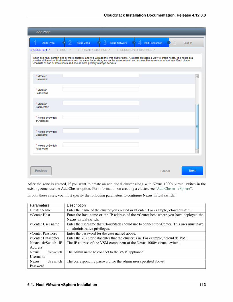
CloudStack Installation Documentation, Release 4.12.0.0
After the zone is created, if you want to create an additional cluster along with Nexus 1000v virtual switch in theexisting zone, use the Add Cluster option. For information on creating a cluster, see “Add Cluster: vSphere”.
In both these cases, you must specify the following parameters to configure Nexus virtual switch:
Parameters DescriptionCluster Name Enter the name of the cluster you created in vCenter. For example,”cloud.cluster”.vCenter Host Enter the host name or the IP address of the vCenter host where you have deployed the
Nexus virtual switch.vCenter User name Enter the username that CloudStack should use to connect to vCenter. This user must have
all administrative privileges.vCenter Password Enter the password for the user named above.vCenter Datacenter Enter the vCenter datacenter that the cluster is in. For example, “cloud.dc.VM”.Nexus dvSwitch IPAddress
The IP address of the VSM component of the Nexus 1000v virtual switch.
Nexus dvSwitchUsername
The admin name to connect to the VSM appliance.
Nexus dvSwitchPassword
The corresponding password for the admin user specified above.
6.4. Host VMware vSphere Installation 113
CloudStack Installation Documentation, Release 4.12.0.0
Removing Nexus Virtual Switch
1. In the vCenter datacenter that is served by the Nexus virtual switch, ensure that you delete all the hosts in thecorresponding cluster.
2. Log in with Admin permissions to the CloudStack administrator UI.
3. In the left navigation bar, select Infrastructure.
4. In the Infrastructure page, click View all under Clusters.
5. Select the cluster where you want to remove the virtual switch.
6. In the dvSwitch tab, click the name of the virtual switch.
7. In the Details page, click Delete Nexus dvSwitch icon.
Click Yes in the confirmation dialog box.
6.4.7 Configuring a VMware Datacenter with VMware Distributed Virtual Switch
CloudStack supports VMware vNetwork Distributed Switch (VDS) for virtual network configuration in a VMwarevSphere environment. This section helps you configure VMware VDS in a CloudStack deployment. Each vCenterserver instance can support up to 128 VDS instances and each VDS instance can manage up to 500 VMware hosts.
About VMware Distributed Virtual Switch
VMware VDS is an aggregation of host-level virtual switches on a VMware vCenter server. VDS abstracts the config-uration of individual virtual switches that span across a large number of hosts, and enables centralized provisioning,administration, and monitoring for your entire datacenter from a centralized interface. In effect, a VDS acts as a singlevirtual switch at the datacenter level and manages networking for a number of hosts in a datacenter from a centralizedVMware vCenter server. Each VDS maintains network runtime state for VMs as they move across multiple hosts,enabling inline monitoring and centralized firewall services. A VDS can be deployed with or without Virtual StandardSwitch and a Nexus 1000V virtual switch.
Prerequisites and Guidelines
• VMware VDS is supported only on Public and Guest traffic in CloudStack.
• VMware VDS does not support multiple VDS per traffic type. If a user has many VDS switches, only one canbe used for Guest traffic and another one for Public traffic.
• Additional switches of any type can be added for each cluster in the same zone. While adding the clusters withdifferent switch type, traffic labels is overridden at the cluster level.
• Management and Storage network does not support VDS. Therefore, use Standard Switch for these networks.
• When you remove a guest network, the corresponding dvportgroup will not be removed on the vCenter. Youmust manually delete them on the vCenter.
Preparation Checklist
For a smoother configuration of VMware VDS, note down the VDS name you have added in the datacenter before youstart:
114 Chapter 6. Hypervisor Setup
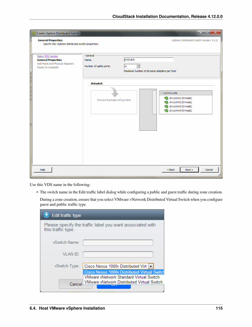
CloudStack Installation Documentation, Release 4.12.0.0
Use this VDS name in the following:
• The switch name in the Edit traffic label dialog while configuring a public and guest traffic during zone creation.
During a zone creation, ensure that you select VMware vNetwork Distributed Virtual Switch when you configureguest and public traffic type.
6.4. Host VMware vSphere Installation 115
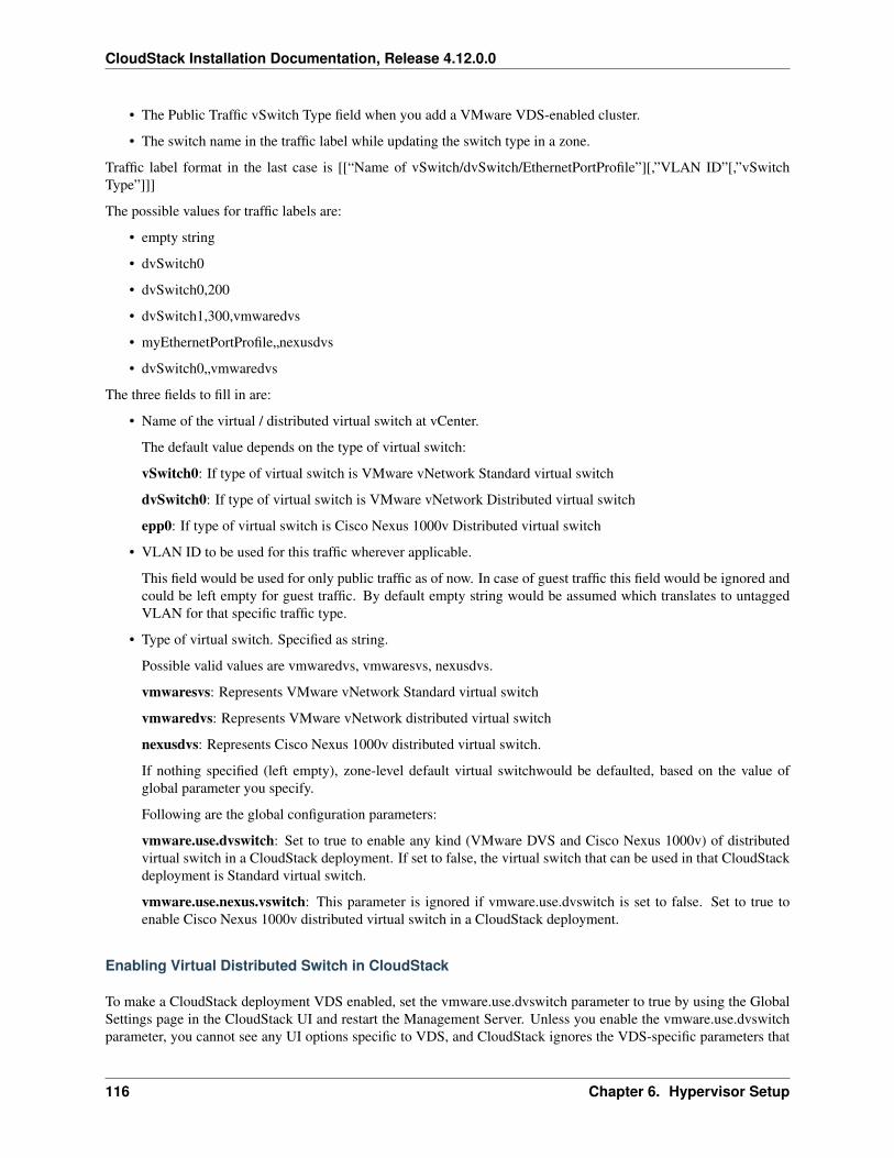
CloudStack Installation Documentation, Release 4.12.0.0
• The Public Traffic vSwitch Type field when you add a VMware VDS-enabled cluster.
• The switch name in the traffic label while updating the switch type in a zone.
Traffic label format in the last case is [[“Name of vSwitch/dvSwitch/EthernetPortProfile”][,”VLAN ID”[,”vSwitchType”]]]
The possible values for traffic labels are:
• empty string
• dvSwitch0
• dvSwitch0,200
• dvSwitch1,300,vmwaredvs
• myEthernetPortProfile„nexusdvs
• dvSwitch0„vmwaredvs
The three fields to fill in are:
• Name of the virtual / distributed virtual switch at vCenter.
The default value depends on the type of virtual switch:
vSwitch0: If type of virtual switch is VMware vNetwork Standard virtual switch
dvSwitch0: If type of virtual switch is VMware vNetwork Distributed virtual switch
epp0: If type of virtual switch is Cisco Nexus 1000v Distributed virtual switch
• VLAN ID to be used for this traffic wherever applicable.
This field would be used for only public traffic as of now. In case of guest traffic this field would be ignored andcould be left empty for guest traffic. By default empty string would be assumed which translates to untaggedVLAN for that specific traffic type.
• Type of virtual switch. Specified as string.
Possible valid values are vmwaredvs, vmwaresvs, nexusdvs.
vmwaresvs: Represents VMware vNetwork Standard virtual switch
vmwaredvs: Represents VMware vNetwork distributed virtual switch
nexusdvs: Represents Cisco Nexus 1000v distributed virtual switch.
If nothing specified (left empty), zone-level default virtual switchwould be defaulted, based on the value ofglobal parameter you specify.
Following are the global configuration parameters:
vmware.use.dvswitch: Set to true to enable any kind (VMware DVS and Cisco Nexus 1000v) of distributedvirtual switch in a CloudStack deployment. If set to false, the virtual switch that can be used in that CloudStackdeployment is Standard virtual switch.
vmware.use.nexus.vswitch: This parameter is ignored if vmware.use.dvswitch is set to false. Set to true toenable Cisco Nexus 1000v distributed virtual switch in a CloudStack deployment.
Enabling Virtual Distributed Switch in CloudStack
To make a CloudStack deployment VDS enabled, set the vmware.use.dvswitch parameter to true by using the GlobalSettings page in the CloudStack UI and restart the Management Server. Unless you enable the vmware.use.dvswitchparameter, you cannot see any UI options specific to VDS, and CloudStack ignores the VDS-specific parameters that
116 Chapter 6. Hypervisor Setup
CloudStack Installation Documentation, Release 4.12.0.0
you specify. Additionally, CloudStack uses VDS for virtual network infrastructure if the value of vmware.use.dvswitchparameter is true and the value of vmware.use.nexus.dvswitch parameter is false. Another global parameter that definesVDS configuration is vmware.ports.per.dvportgroup. This is the default number of ports per VMware dvPortGroup ina VMware environment. Default value is 256. This number directly associated with the number of guest network youcan create.
CloudStack supports orchestration of virtual networks in a deployment with a mix of Virtual Distributed Switch,Standard Virtual Switch and Nexus 1000v Virtual Switch.
Configuring Distributed Virtual Switch in CloudStack
You can configure VDS by adding the necessary resources while a zone is created.
Alternatively, at the cluster level, you can create an additional cluster with VDS enabled in the existing zone. Use theAdd Cluster option. For information as given in “Add Cluster: vSphere”.
In both these cases, you must specify the following parameters to configure VDS:
6.4. Host VMware vSphere Installation 117
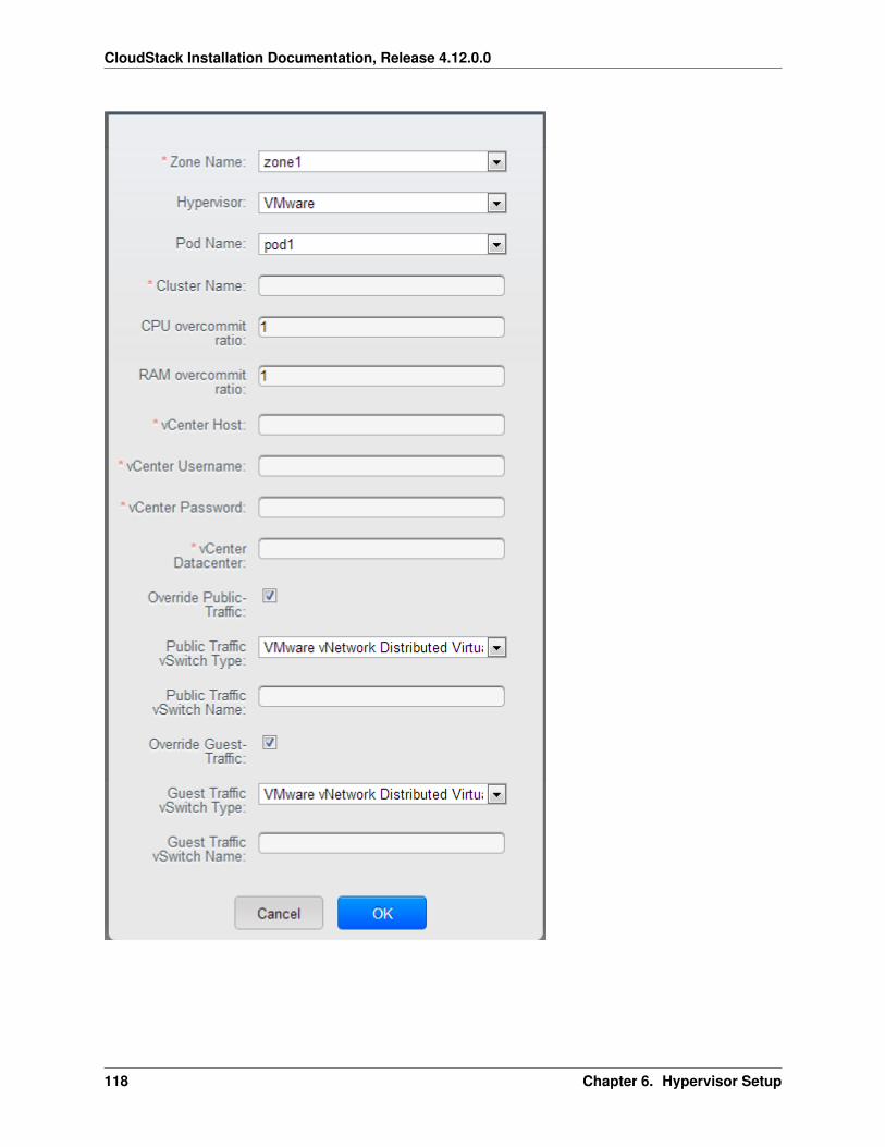
CloudStack Installation Documentation, Release 4.12.0.0
118 Chapter 6. Hypervisor Setup
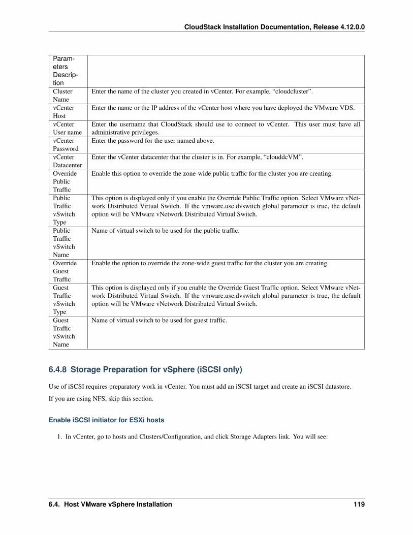
CloudStack Installation Documentation, Release 4.12.0.0
Param-etersDescrip-tionClusterName
Enter the name of the cluster you created in vCenter. For example, “cloudcluster”.
vCenterHost
Enter the name or the IP address of the vCenter host where you have deployed the VMware VDS.
vCenterUser name
Enter the username that CloudStack should use to connect to vCenter. This user must have alladministrative privileges.
vCenterPassword
Enter the password for the user named above.
vCenterDatacenter
Enter the vCenter datacenter that the cluster is in. For example, “clouddcVM”.
OverridePublicTraffic
Enable this option to override the zone-wide public traffic for the cluster you are creating.
PublicTrafficvSwitchType
This option is displayed only if you enable the Override Public Traffic option. Select VMware vNet-work Distributed Virtual Switch. If the vmware.use.dvswitch global parameter is true, the defaultoption will be VMware vNetwork Distributed Virtual Switch.
PublicTrafficvSwitchName
Name of virtual switch to be used for the public traffic.
OverrideGuestTraffic
Enable the option to override the zone-wide guest traffic for the cluster you are creating.
GuestTrafficvSwitchType
This option is displayed only if you enable the Override Guest Traffic option. Select VMware vNet-work Distributed Virtual Switch. If the vmware.use.dvswitch global parameter is true, the defaultoption will be VMware vNetwork Distributed Virtual Switch.
GuestTrafficvSwitchName
Name of virtual switch to be used for guest traffic.
6.4.8 Storage Preparation for vSphere (iSCSI only)
Use of iSCSI requires preparatory work in vCenter. You must add an iSCSI target and create an iSCSI datastore.
If you are using NFS, skip this section.
Enable iSCSI initiator for ESXi hosts
1. In vCenter, go to hosts and Clusters/Configuration, and click Storage Adapters link. You will see:
6.4. Host VMware vSphere Installation 119
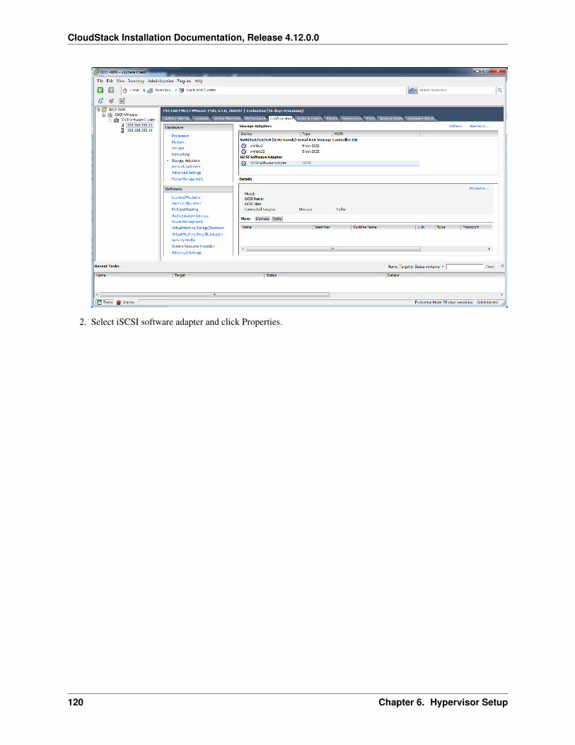
CloudStack Installation Documentation, Release 4.12.0.0
2. Select iSCSI software adapter and click Properties.
120 Chapter 6. Hypervisor Setup
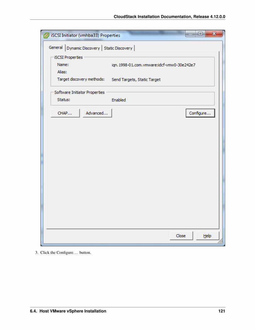
CloudStack Installation Documentation, Release 4.12.0.0
3. Click the Configure. . . button.
6.4. Host VMware vSphere Installation 121
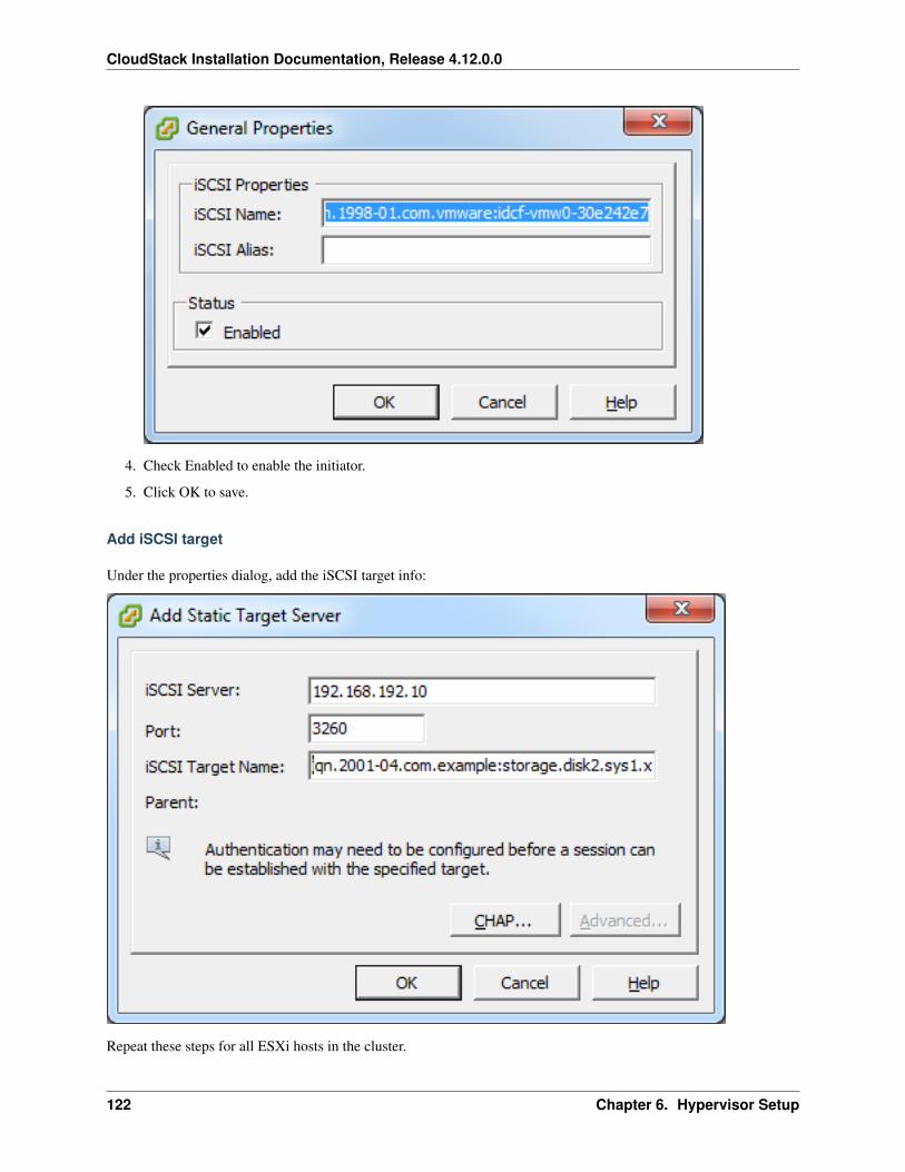
CloudStack Installation Documentation, Release 4.12.0.0
4. Check Enabled to enable the initiator.
5. Click OK to save.
Add iSCSI target
Under the properties dialog, add the iSCSI target info:
Repeat these steps for all ESXi hosts in the cluster.
122 Chapter 6. Hypervisor Setup
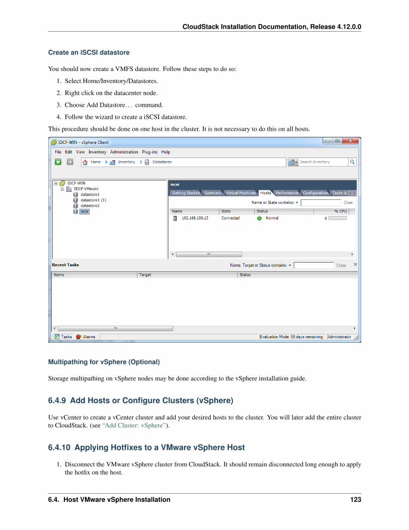
CloudStack Installation Documentation, Release 4.12.0.0
Create an iSCSI datastore
You should now create a VMFS datastore. Follow these steps to do so:
1. Select Home/Inventory/Datastores.
2. Right click on the datacenter node.
3. Choose Add Datastore. . . command.
4. Follow the wizard to create a iSCSI datastore.
This procedure should be done on one host in the cluster. It is not necessary to do this on all hosts.
Multipathing for vSphere (Optional)
Storage multipathing on vSphere nodes may be done according to the vSphere installation guide.
6.4.9 Add Hosts or Configure Clusters (vSphere)
Use vCenter to create a vCenter cluster and add your desired hosts to the cluster. You will later add the entire clusterto CloudStack. (see “Add Cluster: vSphere”).
6.4.10 Applying Hotfixes to a VMware vSphere Host
1. Disconnect the VMware vSphere cluster from CloudStack. It should remain disconnected long enough to applythe hotfix on the host.
6.4. Host VMware vSphere Installation 123
CloudStack Installation Documentation, Release 4.12.0.0
(a) Log in to the CloudStack UI as root.
See “Log In to the UI”.
(b) Navigate to the VMware cluster, click Actions, and select Unmanage.
(c) Watch the cluster status until it shows Unmanaged.
2. Perform the following on each of the ESXi hosts in the cluster:
(a) Move each of the ESXi hosts in the cluster to maintenance mode.
(b) Ensure that all the VMs are migrated to other hosts in that cluster.
(c) If there is only one host in that cluster, shutdown all the VMs and move the host into maintenance mode.
(d) Apply the patch on the ESXi host.
(e) Restart the host if prompted.
(f) Cancel the maintenance mode on the host.
3. Reconnect the cluster to CloudStack:
(a) Log in to the CloudStack UI as root.
(b) Navigate to the VMware cluster, click Actions, and select Manage.
(c) Watch the status to see that all the hosts come up. It might take several minutes for the hosts to come up.
Alternatively, verify the host state is properly synchronized and updated in the CloudStack database.
6.5 Host Citrix XenServer Installation
If you want to use the Citrix XenServer hypervisor to run guest virtual machines, install XenServer 6.0 or XenServer6.0.2 on the host(s) in your cloud. For an initial installation, follow the steps below. If you have previously installedXenServer and want to upgrade to another version, see Upgrading XenServer Versions.
6.5.1 System Requirements for XenServer Hosts
• The host must be certified as compatible with one of the following. See the Citrix Hardware CompatibilityGuide: http://hcl.xensource.com
– XenServer 5.6 SP2
– XenServer 6.0
– XenServer 6.0.2
– XenServer 6.1.0
– XenServer 6.2.0
– XenServer 6.5.0
• You must re-install Citrix XenServer if you are going to re-use a host from a previous install.
• Must support HVM (Intel-VT or AMD-V enabled)
• Be sure all the hotfixes provided by the hypervisor vendor are applied. Track the release of hypervisor patchesthrough your hypervisor vendor’s support channel, and apply patches as soon as possible after they are released.
124 Chapter 6. Hypervisor Setup
CloudStack Installation Documentation, Release 4.12.0.0
CloudStack will not track or notify you of required hypervisor patches. It is essential that your hosts are com-pletely up to date with the provided hypervisor patches. The hypervisor vendor is likely to refuse to support anysystem that is not up to date with patches.
• All hosts within a cluster must be homogeneous. The CPUs must be of the same type, count, and feature flags.
• Must support HVM (Intel-VT or AMD-V enabled in BIOS)
• 64-bit x86 CPU (more cores results in better performance)
• Hardware virtualization support required
• 4 GB of memory
• 36 GB of local disk
• At least 1 NIC
• Statically allocated IP Address
• When you deploy CloudStack, the hypervisor host must not have any VMs already running
Warning: The lack of up-to-date hotfixes can lead to data corruption and lost VMs.
6.5.2 XenServer Installation Steps
1. From https://www.citrix.com/English/ss/downloads/, download the appropriate version of XenServer for yourCloudStack version (see “System Requirements for XenServer Hosts”). Install it using the Citrix XenServerInstallation Guide.
Older Versions of XenServer:
Note that you can download the most recent release of XenServer without having a Citrix account. If you wishto download older versions, you will need to create an account and look through the download archives.
6.5.3 Configure XenServer dom0 Memory
Configure the XenServer dom0 settings to allocate more memory to dom0. This can enable XenServer to handle largernumbers of virtual machines. We recommend 2940 MB of RAM for XenServer dom0. For instructions on how to dothis, see http://support.citrix.com/article/CTX126531. The article refers to XenServer 5.6, but the same informationapplies to XenServer 6.0.
6.5.4 Username and Password
All XenServers in a cluster must have the same username and password as configured in CloudStack.
6.5.5 Time Synchronization
The host must be set to use NTP. All hosts in a pod must have the same time.
1. Install NTP.
# yum install ntp
2. Edit the NTP configuration file to point to your NTP server.
6.5. Host Citrix XenServer Installation 125
CloudStack Installation Documentation, Release 4.12.0.0
# vi /etc/ntp.conf
Add one or more server lines in this file with the names of the NTP servers you want to use. For example:
server 0.xenserver.pool.ntp.orgserver 1.xenserver.pool.ntp.orgserver 2.xenserver.pool.ntp.orgserver 3.xenserver.pool.ntp.org
3. Restart the NTP client.
# service ntpd restart
4. Make sure NTP will start again upon reboot.
# chkconfig ntpd on
6.5.6 Install CloudStack XenServer Support Package (CSP)
(Optional)
To enable security groups, elastic load balancing, and elastic IP on XenServer, download and install the Cloud-Stack XenServer Support Package (CSP). After installing XenServer, perform the following additional steps on eachXenServer host.
For XenServer 6.1:
CSP functionality is already present in XenServer 6.1
1. Run the below command
xe-switch-network-backend bridge
2. update sysctl.conf with the following
net.bridge.bridge-nf-call-iptables = 1net.bridge.bridge-nf-call-ip6tables = 0net.bridge.bridge-nf-call-arptables = 1
$ sysctl -p /etc/sysctl.conf
For XenServer 6.0.2, 6.0, 5.6 SP2:
1. Download the CSP software onto the XenServer host from one of the following links:
For XenServer 6.0.2:
http://download.cloud.com/releases/3.0.1/XS-6.0.2/xenserver-cloud-supp.tgz
For XenServer 5.6 SP2:
http://download.cloud.com/releases/2.2.0/xenserver-cloud-supp.tgz
For XenServer 6.0:
http://download.cloud.com/releases/3.0/xenserver-cloud-supp.tgz
2. Extract the file:
126 Chapter 6. Hypervisor Setup
CloudStack Installation Documentation, Release 4.12.0.0
# tar xf xenserver-cloud-supp.tgz
3. Run the following script:
# xe-install-supplemental-pack xenserver-cloud-supp.iso
4. If the XenServer host is part of a zone that uses basic networking, disable Open vSwitch (OVS):
# xe-switch-network-backend bridge
Restart the host machine when prompted.
The XenServer host is now ready to be added to CloudStack.
6.5.7 Primary Storage Setup for XenServer
CloudStack natively supports NFS, iSCSI and local storage. If you are using one of these storage types, there is noneed to create the XenServer Storage Repository (“SR”).
If, however, you would like to use storage connected via some other technology, such as FiberChannel, you must setup the SR yourself. To do so, perform the following steps. If you have your hosts in a XenServer pool, perform thesteps on the master node. If you are working with a single XenServer which is not part of a cluster, perform the stepson that XenServer.
1. Connect FiberChannel cable to all hosts in the cluster and to the FiberChannel storage host.
2. Rescan the SCSI bus. Either use the following command or use XenCenter to perform an HBA rescan.
# scsi-rescan
3. Repeat step 2 on every host.
4. Check to be sure you see the new SCSI disk.
# ls /dev/disk/by-id/scsi-360a98000503365344e6f6177615a516b -l
The output should look like this, although the specific file name will be different (scsi-<scsiID>):
lrwxrwxrwx 1 root root 9 Mar 16 13:47/dev/disk/by-id/scsi-360a98000503365344e6f6177615a516b -> ../../sdc
5. Repeat step 4 on every host.
6. On the storage server, run this command to get a unique ID for the new SR.
# uuidgen
The output should look like this, although the specific ID will be different:
e6849e96-86c3-4f2c-8fcc-350cc711be3d
7. Create the FiberChannel SR. In name-label, use the unique ID you just generated.
# xe sr-create type=lvmohba shared=truedevice-config:SCSIid=360a98000503365344e6f6177615a516bname-label="e6849e96-86c3-4f2c-8fcc-350cc711be3d"
This command returns a unique ID for the SR, like the following example (your ID will be different):
6.5. Host Citrix XenServer Installation 127
CloudStack Installation Documentation, Release 4.12.0.0
7a143820-e893-6c6a-236e-472da6ee66bf
8. To create a human-readable description for the SR, use the following command. In uuid, use the SR ID returnedby the previous command. In name-description, set whatever friendly text you prefer.
# xe sr-param-set uuid=7a143820-e893-6c6a-236e-472da6ee66bf name-description=→˓"Fiber Channel storage repository"
Make note of the values you will need when you add this storage to CloudStack later (see “Add Primary Stor-age”). In the Add Primary Storage dialog, in Protocol, you will choose PreSetup. In SR Name-Label, you willenter the name-label you set earlier (in this example, e6849e96-86c3-4f2c-8fcc-350cc711be3d).
9. (Optional) If you want to enable multipath I/O on a FiberChannel SAN, refer to the documentation provided bythe SAN vendor.
6.5.8 iSCSI Multipath Setup for XenServer (Optional)
When setting up the storage repository on a Citrix XenServer, you can enable multipath I/O, which uses redundantphysical components to provide greater reliability in the connection between the server and the SAN. To enable mul-tipathing, use a SAN solution that is supported for Citrix servers and follow the procedures in Citrix documentation.The following links provide a starting point:
• http://support.citrix.com/article/CTX118791
• http://support.citrix.com/article/CTX125403
You can also ask your SAN vendor for advice about setting up your Citrix repository for multipathing.
Make note of the values you will need when you add this storage to the CloudStack later (see “Add Primary Storage”).In the Add Primary Storage dialog, in Protocol, you will choose PreSetup. In SR Name-Label, you will enter the samename used to create the SR.
If you encounter difficulty, address the support team for the SAN provided by your vendor. If they are not able to solveyour issue, see Contacting Support.
6.5.9 Physical Networking Setup for XenServer
Once XenServer has been installed, you may need to do some additional network configuration. At this point in theinstallation, you should have a plan for what NICs the host will have and what traffic each NIC will carry. The NICsshould be cabled as necessary to implement your plan.
If you plan on using NIC bonding, the NICs on all hosts in the cluster must be cabled exactly the same. For example,if eth0 is in the private bond on one host in a cluster, then eth0 must be in the private bond on all hosts in the cluster.
The IP address assigned for the management network interface must be static. It can be set on the host itself or obtainedvia static DHCP.
CloudStack configures network traffic of various types to use different NICs or bonds on the XenServer host. You cancontrol this process and provide input to the Management Server through the use of XenServer network name labels.The name labels are placed on physical interfaces or bonds and configured in CloudStack. In some simple cases thename labels are not required.
When configuring networks in a XenServer environment, network traffic labels must be properly configured to ensurethat the virtual interfaces are created by CloudStack are bound to the correct physical device. The name-label of theXenServer network must match the XenServer traffic label specified while creating the CloudStack network. This isset by running the following command:
128 Chapter 6. Hypervisor Setup
CloudStack Installation Documentation, Release 4.12.0.0
xe network-param-set uuid=<network id> name-label=<CloudStack traffic label>
Configuring Public Network with a Dedicated NIC for XenServer (Optional)
CloudStack supports the use of a second NIC (or bonded pair of NICs, described in NIC Bonding for XenServer(Optional)) for the public network. If bonding is not used, the public network can be on any NIC and can be ondifferent NICs on the hosts in a cluster. For example, the public network can be on eth0 on node A and eth1 onnode B. However, the XenServer name-label for the public network must be identical across all hosts. The followingexamples set the network label to “cloud-public”. After the management server is installed and running you mustconfigure it with the name of the chosen network label (e.g. “cloud-public”); this is discussed in “Management ServerInstallation”.
If you are using two NICs bonded together to create a public network, see NIC Bonding for XenServer (Optional).
If you are using a single dedicated NIC to provide public network access, follow this procedure on each new host thatis added to CloudStack before adding the host.
1. Run xe network-list and find the public network. This is usually attached to the NIC that is public. Once youfind the network make note of its UUID. Call this <UUID-Public>.
2. Run the following command.
# xe network-param-set name-label=cloud-public uuid=<UUID-Public>
Configuring Multiple Guest Networks for XenServer (Optional)
CloudStack supports the use of multiple guest networks with the XenServer hypervisor. Each network is assigneda name-label in XenServer. For example, you might have two networks with the labels “cloud-guest” and “cloud-guest2”. After the management server is installed and running, you must add the networks and use these labels so thatCloudStack is aware of the networks.
Follow this procedure on each new host before adding the host to CloudStack:
1. Run xe network-list and find one of the guest networks. Once you find the network make note of its UUID. Callthis <UUID-Guest>.
2. Run the following command, substituting your own name-label and uuid values.
# xe network-param-set name-label=<cloud-guestN> uuid=<UUID-Guest>
3. Repeat these steps for each additional guest network, using a different name-label and uuid each time.
Separate Storage Network for XenServer (Optional)
You can optionally set up a separate storage network. This should be done first on the host, before implementing thebonding steps below. This can be done using one or two available NICs. With two NICs bonding may be done asabove. It is the administrator’s responsibility to set up a separate storage network.
Give the storage network a different name-label than what will be given for other networks.
For the separate storage network to work correctly, it must be the only interface that can ping the primary storagedevice’s IP address. For example, if eth0 is the management network NIC, ping -I eth0 <primary storage device IP>must fail. In all deployments, secondary storage devices must be pingable from the management network NIC or bond.If a secondary storage device has been placed on the storage network, it must also be pingable via the storage networkNIC or bond on the hosts as well.
6.5. Host Citrix XenServer Installation 129
CloudStack Installation Documentation, Release 4.12.0.0
You can set up two separate storage networks as well. For example, if you intend to implement iSCSI multipath,dedicate two non-bonded NICs to multipath. Each of the two networks needs a unique name-label.
If no bonding is done, the administrator must set up and name-label the separate storage network on all hosts (mastersand slaves).
Here is an example to set up eth5 to access a storage network on 172.16.0.0/24.
# xe pif-list host-name-label='hostname' device=eth5uuid(RO): ab0d3dd4-5744-8fae-9693-a022c7a3471ddevice ( RO): eth5#xe pif-reconfigure-ip DNS=172.16.3.3 gateway=172.16.0.1 IP=172.16.0.55 mode=static→˓netmask=255.255.255.0 uuid=ab0d3dd4-5744-8fae-9693-a022c7a3471d
NIC Bonding for XenServer (Optional)
XenServer supports Source Level Balancing (SLB) NIC bonding. Two NICs can be bonded together to carry public,private, and guest traffic, or some combination of these. Separate storage networks are also possible. Here are someexample supported configurations:
• 2 NICs on private, 2 NICs on public, 2 NICs on storage
• 2 NICs on private, 1 NIC on public, storage uses management network
• 2 NICs on private, 2 NICs on public, storage uses management network
• 1 NIC for private, public, and storage
All NIC bonding is optional.
XenServer expects all nodes in a cluster will have the same network cabling and same bonds implemented. In aninstallation the master will be the first host that was added to the cluster and the slave hosts will be all subsequenthosts added to the cluster. The bonds present on the master set the expectation for hosts added to the cluster later. Theprocedure to set up bonds on the master and slaves are different, and are described below. There are several importantimplications of this:
• You must set bonds on the first host added to a cluster. Then you must use xe commands as below to establishthe same bonds in the second and subsequent hosts added to a cluster.
• Slave hosts in a cluster must be cabled exactly the same as the master. For example, if eth0 is in the private bondon the master, it must be in the management network for added slave hosts.
Management Network Bonding
The administrator must bond the management network NICs prior to adding the host to CloudStack.
Creating a Private Bond on the First Host in the Cluster
Use the following steps to create a bond in XenServer. These steps should be run on only the first host in a cluster.This example creates the cloud-private network with two physical NICs (eth0 and eth1) bonded into it.
1. Find the physical NICs that you want to bond together.
# xe pif-list host-name-label='hostname' device=eth0# xe pif-list host-name-label='hostname' device=eth1
130 Chapter 6. Hypervisor Setup
CloudStack Installation Documentation, Release 4.12.0.0
These command shows the eth0 and eth1 NICs and their UUIDs. Substitute the ethX devices of your choice.Call the UUID’s returned by the above command slave1-UUID and slave2-UUID.
2. Create a new network for the bond. For example, a new network with name “cloud-private”.
This label is important. CloudStack looks for a network by a name you configure. You must use the samename-label for all hosts in the cloud for the management network.
# xe network-create name-label=cloud-private# xe bond-create network-uuid=[uuid of cloud-private created above]pif-uuids=[slave1-uuid],[slave2-uuid]
Now you have a bonded pair that can be recognized by CloudStack as the management network.
Public Network Bonding
Bonding can be implemented on a separate, public network. The administrator is responsible for creating a bond forthe public network if that network will be bonded and will be separate from the management network.
Creating a Public Bond on the First Host in the Cluster
These steps should be run on only the first host in a cluster. This example creates the cloud-public network with twophysical NICs (eth2 and eth3) bonded into it.
1. Find the physical NICs that you want to bond together.
# xe pif-list host-name-label='hostname' device=eth2# xe pif-list host-name-label='hostname' device=eth3
These command shows the eth2 and eth3 NICs and their UUIDs. Substitute the ethX devices of your choice.Call the UUID’s returned by the above command slave1-UUID and slave2-UUID.
2. Create a new network for the bond. For example, a new network with name “cloud-public”.
This label is important. CloudStack looks for a network by a name you configure. You must use the samename-label for all hosts in the cloud for the public network.
# xe network-create name-label=cloud-public# xe bond-create network-uuid=[uuid of cloud-public created above]pif-uuids=[slave1-uuid],[slave2-uuid]
Now you have a bonded pair that can be recognized by CloudStack as the public network.
Adding More Hosts to the Cluster
With the bonds (if any) established on the master, you should add additional, slave hosts. Run the following commandfor all additional hosts to be added to the cluster. This will cause the host to join the master in a single XenServer pool.
# xe pool-join master-address=[master IP] master-username=rootmaster-password=[your password]
6.5. Host Citrix XenServer Installation 131
CloudStack Installation Documentation, Release 4.12.0.0
Complete the Bonding Setup Across the Cluster
With all hosts added to the pool, run the cloud-setup-bond script. This script will complete the configuration and setup of the bonds across all hosts in the cluster.
1. Copy the script from the Management Server in /usr/share/cloudstack-common/scripts/vm/hypervisor/xenserver/cloud-setup-bonding.sh to the master host and ensure it is executable.
2. Run the script:
# ./cloud-setup-bonding.sh
Now the bonds are set up and configured properly across the cluster.
6.5.10 Upgrading XenServer Versions
This section tells how to upgrade XenServer software on CloudStack hosts. The actual upgrade is described inXenServer documentation, but there are some additional steps you must perform before and after the upgrade.
Note: Be sure the hardware is certified compatible with the new version of XenServer.
To upgrade XenServer:
1. Upgrade the database. On the Management Server node:
(a) Back up the database:
# mysqldump --user=root --databases cloud > cloud.backup.sql# mysqldump --user=root --databases cloud_usage > cloud_usage.backup.sql
(b) You might need to change the OS type settings for VMs running on the upgraded hosts.
• If you upgraded from XenServer 5.6 GA to XenServer 5.6 SP2, change any VMs that have the OStype CentOS 5.5 (32-bit), Oracle Enterprise Linux 5.5 (32-bit), or Red Hat Enterprise Linux 5.5 (32-bit) to Other Linux (32-bit). Change any VMs that have the 64-bit versions of these same OS types toOther Linux (64-bit).
• If you upgraded from XenServer 5.6 SP2 to XenServer 6.0.2, change any VMs that have the OS typeCentOS 5.6 (32-bit), CentOS 5.7 (32-bit), Oracle Enterprise Linux 5.6 (32-bit), Oracle EnterpriseLinux 5.7 (32-bit), Red Hat Enterprise Linux 5.6 (32-bit) , or Red Hat Enterprise Linux 5.7 (32-bit) toOther Linux (32-bit). Change any VMs that have the 64-bit versions of these same OS types to OtherLinux (64-bit).
• If you upgraded from XenServer 5.6 to XenServer 6.0.2, do all of the above.
(c) Restart the Management Server and Usage Server. You only need to do this once for all clusters.
# service cloudstack-management start# service cloudstack-usage start
2. Disconnect the XenServer cluster from CloudStack.
(a) Log in to the CloudStack UI as root.
(b) Navigate to the XenServer cluster, and click Actions – Unmanage.
(c) Watch the cluster status until it shows Unmanaged.
132 Chapter 6. Hypervisor Setup
CloudStack Installation Documentation, Release 4.12.0.0
3. Log in to one of the hosts in the cluster, and run this command to clean up the VLAN:
# . /opt/xensource/bin/cloud-clean-vlan.sh
4. Still logged in to the host, run the upgrade preparation script:
# /opt/xensource/bin/cloud-prepare-upgrade.sh
Troubleshooting: If you see the error “can’t eject CD,” log in to the VM and umount the CD, then run the scriptagain.
5. Upgrade the XenServer software on all hosts in the cluster. Upgrade the master first.
(a) Live migrate all VMs on this host to other hosts. See the instructions for live migration in the Administra-tor’s Guide.
Troubleshooting: You might see the following error when you migrate a VM:
[root@xenserver-qa-2-49-4 ~]# xe vm-migrate live=true host=xenserver-qa-2-49-→˓5 vm=i-2-8-VMYou attempted an operation on a VM which requires PV drivers to be installed→˓but the drivers were not detected.vm: b6cf79c8-02ee-050b-922f-49583d9f1a14 (i-2-8-VM)
To solve this issue, run the following:
# /opt/xensource/bin/make_migratable.sh b6cf79c8-02ee-050b-922f-49583d9f1a14
(b) Reboot the host.
(c) Upgrade to the newer version of XenServer. Use the steps in XenServer documentation.
(d) After the upgrade is complete, copy the following files from the management server to this host, in thedirectory locations shown below:
Copy this Management Server file To this location on theXenServer host
/usr/share/cloudstack-common/scripts/vm/hypervisor/xenserver/xenserver60/NFSSR.py/opt/xensource/sm/NFSSR.py/usr/share/cloudstack-common/scripts/vm/hypervisor/xenserver/setupxenserver.sh/opt/xensource/bin/setupxenserver.sh/usr/share/cloudstack-common/scripts/vm/hypervisor/xenserver/make_migratable.sh/opt/xensource/bin/make_migratable.sh/usr/share/cloudstack-common/scripts/vm/hypervisor/xenserver/cloud-clean-vlan.sh
/opt/xensource/bin/cloud-clean-vlan.sh
(e) Run the following script:
# /opt/xensource/bin/setupxenserver.sh
Troubleshooting: If you see the following error message, you can safely ignore it.
mv: cannot stat `/etc/cron.daily/logrotate`: No such file or directory
(f) Plug in the storage repositories (physical block devices) to the XenServer host:
# for pbd in `xe pbd-list currently-attached=false| grep ^uuid | awk '{print→˓$NF}'`; do xe pbd-plug uuid=$pbd ; done
6.5. Host Citrix XenServer Installation 133
CloudStack Installation Documentation, Release 4.12.0.0
Note: If you add a host to this XenServer pool, you need to migrate all VMs on this host to other hosts,and eject this host from XenServer pool.
6. Repeat these steps to upgrade every host in the cluster to the same version of XenServer.
7. Run the following command on one host in the XenServer cluster to clean up the host tags:
# for host in $(xe host-list | grep ^uuid | awk '{print $NF}') ; do xe host-param-→˓clear uuid=$host param-name=tags; done;
Note: When copying and pasting a command, be sure the command has pasted as a single line before executing.Some document viewers may introduce unwanted line breaks in copied text.
8. Reconnect the XenServer cluster to CloudStack.
(a) Log in to the CloudStack UI as root.
(b) Navigate to the XenServer cluster, and click Actions – Manage.
(c) Watch the status to see that all the hosts come up.
9. After all hosts are up, run the following on one host in the cluster:
# /opt/xensource/bin/cloud-clean-vlan.sh
134 Chapter 6. Hypervisor Setup
CHAPTER 7
Network Setup
7.1 Network Setup
Achieving the correct networking setup is crucial to a successful CloudStack installation. This section contains infor-mation to help you make decisions and follow the right procedures to get your network set up correctly.
7.1.1 Basic and Advanced Networking
CloudStack provides two styles of networking:.
Basic For AWS-style networking. Provides a single network where guest isolation can be provided through layer-3means such as security groups (IP address source filtering).
Advanced For more sophisticated network topologies. This network model provides the most flexibility in definingguest networks, but requires more configuration steps than basic networking.
Each zone has either basic or advanced networking. Once the choice of networking model for a zone has been madeand configured in CloudStack, it can not be changed. A zone is either basic or advanced for its entire lifetime.
The following table compares the networking features in the two networking models.
Networking Feature Basic Network Advanced NetworkNumber of networks Single network Multiple networksFirewall type Physical Physical and VirtualLoad balancer Physical Physical and VirtualIsolation type Layer 3 Layer 2 and Layer 3VPN support No YesPort forwarding Physical Physical and Virtual1:1 NAT Physical Physical and VirtualSource NAT No Physical and VirtualUserdata Yes YesNetwork usage monitoring sFlow / netFlow at physical router Hypervisor and Virtual RouterDNS and DHCP Yes Yes
135
CloudStack Installation Documentation, Release 4.12.0.0
The two types of networking may be in use in the same cloud. However, a given zone must use either Basic Networkingor Advanced Networking.
Different types of network traffic can be segmented on the same physical network. Guest traffic can also be segmentedby account. To isolate traffic, you can use separate VLANs. If you are using separate VLANs on a single physicalnetwork, make sure the VLAN tags are in separate numerical ranges.
7.1.2 VLAN Allocation Example
VLANs are required for public and guest traffic. The following is an example of a VLAN allocation scheme:
VLANIDs
Traffic type Scope
less than500
Management traffic. Reserved foradministrative purposes.
CloudStack software can access this, hypervisors, systemVMs.
500-599 VLAN carrying public traffic. CloudStack accounts.600-799 VLANs carrying guest traffic. CloudStack accounts. Account-specific VLAN is chosen from
this pool.800-899 VLANs carrying guest traffic. CloudStack accounts. Account-specific VLAN chosen by
CloudStack admin to assign to that account.900-999 VLAN carrying guest traffic CloudStack accounts. Can be scoped by project, domain, or
all accounts.greaterthan 1000
Reserved for future use
7.1.3 Example Hardware Configuration
This section contains an example configuration of specific switch models for zone-level layer-3 switching. It assumesVLAN management protocols, such as VTP or GVRP, have been disabled. The example scripts must be changedappropriately if you choose to use VTP or GVRP.
Dell 62xx
The following steps show how a Dell 62xx is configured for zone-level layer-3 switching. These steps assume VLAN201 is used to route untagged private IPs for pod 1, and pod 1’s layer-2 switch is connected to Ethernet port 1/g1.
The Dell 62xx Series switch supports up to 1024 VLANs.
1. Configure all the VLANs in the database.
vlan databasevlan 200-999exit
2. Configure Ethernet port 1/g1.
interface ethernet 1/g1switchport mode generalswitchport general pvid 201switchport general allowed vlan add 201 untaggedswitchport general allowed vlan add 300-999 taggedexit
136 Chapter 7. Network Setup
CloudStack Installation Documentation, Release 4.12.0.0
The statements configure Ethernet port 1/g1 as follows:
• VLAN 201 is the native untagged VLAN for port 1/g1.
• All VLANs (300-999) are passed to all the pod-level layer-2 switches.
Cisco 3750
The following steps show how a Cisco 3750 is configured for zone-level layer-3 switching. These steps assume VLAN201 is used to route untagged private IPs for pod 1, and pod 1’s layer-2 switch is connected to GigabitEthernet1/0/1.
1. Setting VTP mode to transparent allows us to utilize VLAN IDs above 1000. Since we only use VLANs up to999, vtp transparent mode is not strictly required.
vtp mode transparentvlan 200-999exit
2. Configure GigabitEthernet1/0/1.
interface GigabitEthernet1/0/1switchport trunk encapsulation dot1qswitchport mode trunkswitchport trunk native vlan 201exit
The statements configure GigabitEthernet1/0/1 as follows:
• VLAN 201 is the native untagged VLAN for port GigabitEthernet1/0/1.
• Cisco passes all VLANs by default. As a result, all VLANs (300-999) are passed to all the pod-level layer-2switches.
7.1.4 Layer-2 Switch
The layer-2 switch is the access switching layer inside the pod.
• It should trunk all VLANs into every computing host.
• It should switch traffic for the management network containing computing and storage hosts. The layer-3 switchwill serve as the gateway for the management network.
The following sections contain example configurations for specific switch models for pod-level layer-2 switching.It assumes VLAN management protocols such as VTP or GVRP have been disabled. The scripts must be changedappropriately if you choose to use VTP or GVRP.
Dell 62xx
The following steps show how a Dell 62xx is configured for pod-level layer-2 switching.
1. Configure all the VLANs in the database.
vlan databasevlan 300-999exit
2. VLAN 201 is used to route untagged private IP addresses for pod 1, and pod 1 is connected to this layer-2switch.
7.1. Network Setup 137
CloudStack Installation Documentation, Release 4.12.0.0
interface range ethernet allswitchport mode generalswitchport general allowed vlan add 300-999 taggedexit
The statements configure all Ethernet ports to function as follows:
• All ports are configured the same way.
• All VLANs (300-999) are passed through all the ports of the layer-2 switch.
Cisco 3750
The following steps show how a Cisco 3750 is configured for pod-level layer-2 switching.
1. Setting VTP mode to transparent allows us to utilize VLAN IDs above 1000. Since we only use VLANs up to999, vtp transparent mode is not strictly required.
vtp mode transparentvlan 300-999exit
2. Configure all ports to dot1q and set 201 as the native VLAN.
interface range GigabitEthernet 1/0/1-24switchport trunk encapsulation dot1qswitchport mode trunkswitchport trunk native vlan 201exit
By default, Cisco passes all VLANs. Cisco switches complain of the native VLAN IDs are different when 2 ports areconnected together. That’s why you must specify VLAN 201 as the native VLAN on the layer-2 switch.
7.1.5 Hardware Firewall
All deployments should have a firewall protecting the management server; see Generic Firewall Provisions. Optionally,some deployments may also have a Juniper SRX firewall that will be the default gateway for the guest networks; see“External Guest Firewall Integration for Juniper SRX (Optional)”.
Generic Firewall Provisions
The hardware firewall is required to serve two purposes:
• Protect the Management Servers. NAT and port forwarding should be configured to direct traffic from the publicInternet to the Management Servers.
• Route management network traffic between multiple zones. Site-to-site VPN should be configured betweenmultiple zones.
To achieve the above purposes you must set up fixed configurations for the firewall. Firewall rules and policies neednot change as users are provisioned into the cloud. Any brand of hardware firewall that supports NAT and site-to-siteVPN can be used.
138 Chapter 7. Network Setup
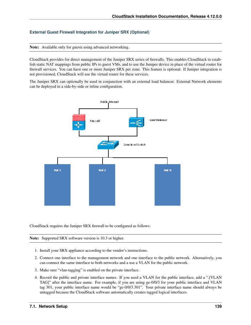
CloudStack Installation Documentation, Release 4.12.0.0
External Guest Firewall Integration for Juniper SRX (Optional)
Note: Available only for guests using advanced networking.
CloudStack provides for direct management of the Juniper SRX series of firewalls. This enables CloudStack to estab-lish static NAT mappings from public IPs to guest VMs, and to use the Juniper device in place of the virtual router forfirewall services. You can have one or more Juniper SRX per zone. This feature is optional. If Juniper integration isnot provisioned, CloudStack will use the virtual router for these services.
The Juniper SRX can optionally be used in conjunction with an external load balancer. External Network elementscan be deployed in a side-by-side or inline configuration.
CloudStack requires the Juniper SRX firewall to be configured as follows:
Note: Supported SRX software version is 10.3 or higher.
1. Install your SRX appliance according to the vendor’s instructions.
2. Connect one interface to the management network and one interface to the public network. Alternatively, youcan connect the same interface to both networks and a use a VLAN for the public network.
3. Make sure “vlan-tagging” is enabled on the private interface.
4. Record the public and private interface names. If you used a VLAN for the public interface, add a “.[VLANTAG]” after the interface name. For example, if you are using ge-0/0/3 for your public interface and VLANtag 301, your public interface name would be “ge-0/0/3.301”. Your private interface name should always beuntagged because the CloudStack software automatically creates tagged logical interfaces.
7.1. Network Setup 139
CloudStack Installation Documentation, Release 4.12.0.0
5. Create a public security zone and a private security zone. By default, these will already exist and will be called“untrust” and “trust”. Add the public interface to the public zone and the private interface to the private zone.Note down the security zone names.
6. Make sure there is a security policy from the private zone to the public zone that allows all traffic.
7. Note the username and password of the account you want the CloudStack software to log in to when it isprogramming rules.
8. Make sure the “ssh” and “xnm-clear-text” system services are enabled.
9. If traffic metering is desired:
(a) Create an incoming firewall filter and an outgoing firewall filter. These filters should be the same namesas your public security zone name and private security zone name respectively. The filters should be set tobe “interface-specific”. For example, here is the configuration where the public zone is “untrust” and theprivate zone is “trust”:
root@cloud-srx# show firewallfilter trust {
interface-specific;}filter untrust {
interface-specific;}
(b) Add the firewall filters to your public interface. For example, a sample configuration output (for publicinterface ge-0/0/3.0, public security zone untrust, and private security zone trust) is:
ge-0/0/3 {unit 0 {
family inet {filter {
input untrust;output trust;
}address 172.25.0.252/16;
}}
}
10. Make sure all VLANs are brought to the private interface of the SRX.
11. After the CloudStack Management Server is installed, log in to the CloudStack UI as administrator.
12. In the left navigation bar, click Infrastructure.
13. In Zones, click View More.
14. Choose the zone you want to work with.
15. Click the Network tab.
16. In the Network Service Providers node of the diagram, click Configure. (You might have to scroll down to seethis.)
17. Click SRX.
18. Click the Add New SRX button (+) and provide the following:
• IP Address: The IP address of the SRX.
• Username: The user name of the account on the SRX that CloudStack should use.
140 Chapter 7. Network Setup
CloudStack Installation Documentation, Release 4.12.0.0
• Password: The password of the account.
• Public Interface. The name of the public interface on the SRX. For example, ge-0/0/2. A “.x” at the endof the interface indicates the VLAN that is in use.
• Private Interface: The name of the private interface on the SRX. For example, ge-0/0/1.
• Usage Interface: (Optional) Typically, the public interface is used to meter traffic. If you want to use adifferent interface, specify its name here
• Number of Retries: The number of times to attempt a command on the SRX before failing. The defaultvalue is 2.
• Timeout (seconds): The time to wait for a command on the SRX before considering it failed. Default is300 seconds.
• Public Network: The name of the public network on the SRX. For example, trust.
• Private Network: The name of the private network on the SRX. For example, untrust.
• Capacity: The number of networks the device can handle
• Dedicated: When marked as dedicated, this device will be dedicated to a single account. When Dedicatedis checked, the value in the Capacity field has no significance implicitly, its value is 1
19. Click OK.
20. Click Global Settings. Set the parameter external.network.stats.interval to indicate how often you want Cloud-Stack to fetch network usage statistics from the Juniper SRX. If you are not using the SRX to gather networkusage statistics, set to 0.
External Guest Firewall Integration for Cisco VNMC (Optional)
Cisco Virtual Network Management Center (VNMC) provides centralized multi-device and policy management forCisco Network Virtual Services. You can integrate Cisco VNMC with CloudStack to leverage the firewall and NATservice offered by ASA 1000v Cloud Firewall. Use it in a Cisco Nexus 1000v dvSwitch-enabled cluster in CloudStack.In such a deployment, you will be able to:
• Configure Cisco ASA 1000v firewalls. You can configure one per guest network.
• Use Cisco ASA 1000v firewalls to create and apply security profiles that contain ACL policy sets for bothingress and egress traffic.
• Use Cisco ASA 1000v firewalls to create and apply Source NAT, Port Forwarding, and Static NAT policy sets.
CloudStack supports Cisco VNMC on Cisco Nexus 1000v dvSwich-enabled VMware hypervisors.
Using Cisco ASA 1000v Firewall, Cisco Nexus 1000v dvSwitch, and Cisco VNMC in a Deployment
Guidelines
• Cisco ASA 1000v firewall is supported only in Isolated Guest Networks.
• Cisco ASA 1000v firewall is not supported on VPC.
• Cisco ASA 1000v firewall is not supported for load balancing.
• When a guest network is created with Cisco VNMC firewall provider, an additional public IP is acquired alongwith the Source NAT IP. The Source NAT IP is used for the rules, whereas the additional IP is used to for theASA outside interface. Ensure that this additional public IP is not released. You can identify this IP as soon asthe network is in implemented state and before acquiring any further public IPs. The additional IP is the one that
7.1. Network Setup 141
CloudStack Installation Documentation, Release 4.12.0.0
is not marked as Source NAT. You can find the IP used for the ASA outside interface by looking at the CiscoVNMC used in your guest network.
• Use the public IP address range from a single subnet. You cannot add IP addresses from different subnets.
• Only one ASA instance per VLAN is allowed because multiple VLANS cannot be trunked to ASA ports.Therefore, you can use only one ASA instance in a guest network.
• Only one Cisco VNMC per zone is allowed.
• Supported only in Inline mode deployment with load balancer.
• The ASA firewall rule is applicable to all the public IPs in the guest network. Unlike the firewall rules createdon virtual router, a rule created on the ASA device is not tied to a specific public IP.
• Use a version of Cisco Nexus 1000v dvSwitch that support the vservice command. For example: nexus-1000v.4.2.1.SV1.5.2b.bin
Cisco VNMC requires the vservice command to be available on the Nexus switch to create a guest network inCloudStack.
Prerequisites
1. Configure Cisco Nexus 1000v dvSwitch in a vCenter environment.
Create Port profiles for both internal and external network interfaces on Cisco Nexus 1000v dvSwitch. Notedown the inside port profile, which needs to be provided while adding the ASA appliance to CloudStack.
For information on configuration, see “Configuring a vSphere Cluster with Nexus 1000v Virtual Switch”.
2. Deploy and configure Cisco VNMC.
For more information, see Installing Cisco Virtual Network Management Center and Configuring Cisco VirtualNetwork Management Center.
3. Register Cisco Nexus 1000v dvSwitch with Cisco VNMC.
For more information, see Registering a Cisco Nexus 1000V with Cisco VNMC.
4. Create Inside and Outside port profiles in Cisco Nexus 1000v dvSwitch.
For more information, see “Configuring a vSphere Cluster with Nexus 1000v Virtual Switch”.
5. Deploy and Cisco ASA 1000v appliance.
For more information, see Setting Up the ASA 1000V Using VNMC.
Typically, you create a pool of ASA 1000v appliances and register them with CloudStack.
Specify the following while setting up a Cisco ASA 1000v instance:
• VNMC host IP.
• Ensure that you add ASA appliance in VNMC mode.
• Port profiles for the Management and HA network interfaces. This need to be pre-created on Cisco Nexus1000v dvSwitch.
• Internal and external port profiles.
• The Management IP for Cisco ASA 1000v appliance. Specify the gateway such that the VNMC IP isreachable.
• Administrator credentials
• VNMC credentials
142 Chapter 7. Network Setup
CloudStack Installation Documentation, Release 4.12.0.0
6. Register Cisco ASA 1000v with VNMC.
After Cisco ASA 1000v instance is powered on, register VNMC from the ASA console.
Using Cisco ASA 1000v Services
1. Ensure that all the prerequisites are met.
See “Prerequisites”.
2. Add a VNMC instance.
See “Adding a VNMC Instance”.
3. Add a ASA 1000v instance.
See “Adding an ASA 1000v Instance”.
4. Create a Network Offering and use Cisco VNMC as the service provider for desired services.
See “Creating a Network Offering Using Cisco ASA 1000v”.
5. Create an Isolated Guest Network by using the network offering you just created.
Adding a VNMC Instance
1. Log in to the CloudStack UI as administrator.
2. In the left navigation bar, click Infrastructure.
3. In Zones, click View More.
4. Choose the zone you want to work with.
5. Click the Physical Network tab.
6. In the Network Service Providers node of the diagram, click Configure.
You might have to scroll down to see this.
7. Click Cisco VNMC.
8. Click View VNMC Devices.
9. Click the Add VNMC Device and provide the following:
• Host: The IP address of the VNMC instance.
• Username: The user name of the account on the VNMC instance that CloudStack should use.
• Password: The password of the account.
10. Click OK.
Adding an ASA 1000v Instance
1. Log in to the CloudStack UI as administrator.
2. In the left navigation bar, click Infrastructure.
3. In Zones, click View More.
4. Choose the zone you want to work with.
7.1. Network Setup 143
CloudStack Installation Documentation, Release 4.12.0.0
5. Click the Physical Network tab.
6. In the Network Service Providers node of the diagram, click Configure.
You might have to scroll down to see this.
7. Click Cisco VNMC.
8. Click View ASA 1000v.
9. Click the Add CiscoASA1000v Resource and provide the following:
• Host: The management IP address of the ASA 1000v instance. The IP address is used to connect to ASA1000V.
• Inside Port Profile: The Inside Port Profile configured on Cisco Nexus1000v dvSwitch.
• Cluster: The VMware cluster to which you are adding the ASA 1000v instance.
Ensure that the cluster is Cisco Nexus 1000v dvSwitch enabled.
10. Click OK.
Creating a Network Offering Using Cisco ASA 1000v
To have Cisco ASA 1000v support for a guest network, create a network offering as follows:
1. Log in to the CloudStack UI as a user or admin.
2. From the Select Offering drop-down, choose Network Offering.
3. Click Add Network Offering.
4. In the dialog, make the following choices:
• Name: Any desired name for the network offering.
• Description: A short description of the offering that can be displayed to users.
• Network Rate: Allowed data transfer rate in MB per second.
• Traffic Type: The type of network traffic that will be carried on the network.
• Guest Type: Choose whether the guest network is isolated or shared.
• Persistent: Indicate whether the guest network is persistent or not. The network that you can provisionwithout having to deploy a VM on it is termed persistent network.
• VPC: This option indicate whether the guest network is Virtual Private Cloud-enabled. A Virtual PrivateCloud (VPC) is a private, isolated part of CloudStack. A VPC can have its own virtual network topologythat resembles a traditional physical network. For more information on VPCs, see “About Virtual PrivateClouds”.
• Specify VLAN: (Isolated guest networks only) Indicate whether a VLAN should be specified when thisoffering is used.
• Supported Services: Use Cisco VNMC as the service provider for Firewall, Source NAT, Port Forwarding,and Static NAT to create an Isolated guest network offering.
• System Offering: Choose the system service offering that you want virtual routers to use in this network.
• Conserve mode: Indicate whether to use conserve mode. In this mode, network resources are allocatedonly when the first virtual machine starts in the network.
144 Chapter 7. Network Setup
CloudStack Installation Documentation, Release 4.12.0.0
5. Click OK
The network offering is created.
Reusing ASA 1000v Appliance in new Guest Networks
You can reuse an ASA 1000v appliance in a new guest network after the necessary cleanup. Typically, ASA 1000v iscleaned up when the logical edge firewall is cleaned up in VNMC. If this cleanup does not happen, you need to resetthe appliance to its factory settings for use in new guest networks. As part of this, enable SSH on the appliance andstore the SSH credentials by registering on VNMC.
1. Open a command line on the ASA appliance:
(a) Run the following:
ASA1000V(config)# reload
You are prompted with the following message:
System config has been modified. Save? [Y]es/[N]o:"
(b) Enter N.
You will get the following confirmation message:
"Proceed with reload? [confirm]"
(c) Restart the appliance.
2. Register the ASA 1000v appliance with the VNMC:
ASA1000V(config)# vnmc policy-agentASA1000V(config-vnmc-policy-agent)# registration host vnmc_ip_addressASA1000V(config-vnmc-policy-agent)# shared-secret key where key is the shared→˓secret for authentication of the ASA 1000V connection to the Cisco VNMC
External Guest Load Balancer Integration (Optional)
CloudStack can optionally use a Citrix NetScaler or BigIP F5 load balancer to provide load balancing services toguests. If this is not enabled, CloudStack will use the software load balancer in the virtual router.
To install and enable an external load balancer for CloudStack management:
1. Set up the appliance according to the vendor’s directions.
2. Connect it to the networks carrying public traffic and management traffic (these could be the same network).
3. Record the IP address, username, password, public interface name, and private interface name. The interfacenames will be something like “1.1” or “1.2”.
4. Make sure that the VLANs are trunked to the management network interface.
5. After the CloudStack Management Server is installed, log in as administrator to the CloudStack UI.
6. In the left navigation bar, click Infrastructure.
7. In Zones, click View More.
8. Choose the zone you want to work with.
9. Click the Network tab.
7.1. Network Setup 145
CloudStack Installation Documentation, Release 4.12.0.0
10. In the Network Service Providers node of the diagram, click Configure. (You might have to scroll down to seethis.)
11. Click NetScaler or F5.
12. Click the Add button (+) and provide the following:
For NetScaler:
• IP Address: The IP address of the SRX.
• Username/Password: The authentication credentials to access the device. CloudStack uses these creden-tials to access the device.
• Type: The type of device that is being added. It could be F5 Big Ip Load Balancer, NetScaler VPX,NetScaler MPX, or NetScaler SDX. For a comparison of the NetScaler types, see the CloudStack Admin-istration Guide.
• Public interface: Interface of device that is configured to be part of the public network.
• Private interface: Interface of device that is configured to be part of the private network.
• Number of retries. Number of times to attempt a command on the device before considering the operationfailed. Default is 2.
• Capacity: The number of networks the device can handle.
• Dedicated: When marked as dedicated, this device will be dedicated to a single account. When Dedicatedis checked, the value in the Capacity field has no significance implicitly, its value is 1.
13. Click OK.
The installation and provisioning of the external load balancer is finished. You can proceed to add VMs and NAT orload balancing rules.
7.1.6 Management Server Load Balancing
CloudStack can use a load balancer to provide a virtual IP for multiple Management Servers. The administrator isresponsible for creating the load balancer rules for the Management Servers. The application requires persistence orstickiness across multiple sessions. The following chart lists the ports that should be load balanced and whether or notpersistence is required.
Even if persistence is not required, enabling it is permitted.
Source Port Destination Port Protocol Persistence Required?80 or 443 8080 (or 20400 with AJP) HTTP (or AJP) Yes8250 8250 TCP Yes8096 8096 HTTP No
In addition to above settings, the administrator is responsible for setting the ‘host’ global config value from the man-agement server IP to load balancer virtual IP address. If the ‘host’ value is not set to the VIP for Port 8250 andone of your management servers crashes, the UI is still available but the system VMs will not be able to contact themanagement server.
7.1.7 Topology Requirements
Security Requirements
The public Internet must not be able to access port 8096 or port 8250 on the Management Server.
146 Chapter 7. Network Setup
CloudStack Installation Documentation, Release 4.12.0.0
Runtime Internal Communications Requirements
• The Management Servers communicate with each other to coordinate tasks. This communication uses TCP onports 8250 and 9090.
• The console proxy VMs connect to all hosts in the zone over the management traffic network. Therefore themanagement traffic network of any given pod in the zone must have connectivity to the management trafficnetwork of all other pods in the zone.
• The secondary storage VMs and console proxy VMs connect to the Management Server on port 8250. If youare using multiple Management Servers, the load balanced IP address of the Management Servers on port 8250must be reachable.
Storage Network Topology Requirements
The secondary storage NFS export is mounted by the secondary storage VM. Secondary storage traffic goes over themanagement traffic network, even if there is a separate storage network. Primary storage traffic goes over the storagenetwork, if available. If you choose to place secondary storage NFS servers on the storage network, you must makesure there is a route from the management traffic network to the storage network.
External Firewall Topology Requirements
When external firewall integration is in place, the public IP VLAN must still be trunked to the Hosts. This is requiredto support the Secondary Storage VM and Console Proxy VM.
Advanced Zone Topology Requirements
With Advanced Networking, separate subnets must be used for private and public networks.
XenServer Topology Requirements
The Management Servers communicate with XenServer hosts on ports 22 (ssh), 80 (HTTP), and 443 (HTTPs).
VMware Topology Requirements
• The Management Server and secondary storage VMs must be able to access vCenter and all ESXi hosts in thezone. To allow the necessary access through the firewall, keep port 443 open.
• The Management Servers communicate with VMware vCenter servers on port 443 (HTTPs).
• The Management Servers communicate with the System VMs on port 3922 (ssh) on the management trafficnetwork.
Hyper-V Topology Requirements
CloudStack Management Server communicates with Hyper-V Agent by using HTTPS. For secure communicationbetween the Management Server and the Hyper-V host, open port 8250.
KVM Topology Requirements
The Management Servers communicate with KVM hosts on port 22 (ssh).
7.1. Network Setup 147
CloudStack Installation Documentation, Release 4.12.0.0
LXC Topology Requirements
The Management Servers communicate with LXC hosts on port 22 (ssh).
7.1.8 Guest Network Usage Integration for Traffic Sentinel
To collect usage data for a guest network, CloudStack needs to pull the data from an external network statistics collectorinstalled on the network. Metering statistics for guest networks are available through CloudStack’s integration withinMon Traffic Sentinel.
Traffic Sentinel is a network traffic usage data collection package. CloudStack can feed statistics from Traffic Sentinelinto its own usage records, providing a basis for billing users of cloud infrastructure. Traffic Sentinel uses the trafficmonitoring protocol sFlow. Routers and switches generate sFlow records and provide them for collection by TrafficSentinel, then CloudStack queries the Traffic Sentinel database to obtain this information
To construct the query, CloudStack determines what guest IPs were in use during the current query interval. Thisincludes both newly assigned IPs and IPs that were assigned in a previous time period and continued to be in use.CloudStack queries Traffic Sentinel for network statistics that apply to these IPs during the time period they remainedallocated in CloudStack. The returned data is correlated with the customer account that owned each IP and thetimestamps when IPs were assigned and released in order to create billable metering records in CloudStack. When theUsage Server runs, it collects this data.
To set up the integration between CloudStack and Traffic Sentinel:
1. On your network infrastructure, install Traffic Sentinel and configure it to gather traffic data. For installationand configuration steps, see inMon documentation at Traffic Sentinel Documentation.
2. In the Traffic Sentinel UI, configure Traffic Sentinel to accept script querying from guest users. CloudStack willbe the guest user performing the remote queries to gather network usage for one or more IP addresses.
Click File > Users > Access Control > Reports Query, then select Guest from the drop-down list.
3. On CloudStack, add the Traffic Sentinel host by calling the CloudStack API command addTrafficMonitor. Passin the URL of the Traffic Sentinel as protocol + host + port (optional); for example, http://10.147.28.100:8080.For the addTrafficMonitor command syntax, see the API Reference at API Documentation.
For information about how to call the CloudStack API, see the Developer’s Guide at CloudStack API Devel-oper’s Guide.
4. Log in to the CloudStack UI as administrator.
5. Select Configuration from the Global Settings page, and set the following:
direct.network.stats.interval: How often you want CloudStack to query Traffic Sentinel.
7.1.9 Setting Zone VLAN and Running VM Maximums
In the external networking case, every VM in a zone must have a unique guest IP address. There are two variables thatyou need to consider in determining how to configure CloudStack to support this: how many Zone VLANs do youexpect to have and how many VMs do you expect to have running in the Zone at any one time.
Use the following table to determine how to configure CloudStack for your deployment.
guest.vlan.bits Maximum Running VMs per Zone Maximum Zone VLANs12 4096 409411 8192 204810 16384 102410 32768 512
148 Chapter 7. Network Setup
CloudStack Installation Documentation, Release 4.12.0.0
Based on your deployment’s needs, choose the appropriate value of guest.vlan.bits. Set it as described in Edit theGlobal Configuration Settings (Optional) section and restart the Management Server.
7.1. Network Setup 149

CloudStack Installation Documentation, Release 4.12.0.0
150 Chapter 7. Network Setup
CHAPTER 8
Storage Setup
8.1 Storage Setup
8.1.1 Primary Storage
CloudStack is designed to work with a wide variety of commodity and enterprise-rated storage systems. CloudStackcan also leverage the local disks within the hypervisor hosts if supported by the selected hypervisor. Storage typesupport for guest virtual disks differs based on hypervisor selection.
Storage Type XenServer vSphere KVMNFS Supported Supported SupportediSCSI Supported Supported via VMFS Supported via Clustered FilesystemsFiber Channel Supported via Pre-existing SR Supported Supported via Clustered FilesystemsLocal Disk Supported Supported Supported
The use of the Cluster Logical Volume Manager (CLVM) for KVM is not officially supported with CloudStack.
8.1.2 Secondary Storage
CloudStack is designed to work with any scalable secondary storage system. The only requirement is that the sec-ondary storage system supports the NFS protocol. For large, multi-zone deployments, S3 compatible storage is alsosupported for secondary storage. This allows for secondary storage which can span an entire region, however an NFSstaging area must be maintained in each zone as most hypervisors are not capable of directly mounting S3 type storage.
8.2 Small-Scale Setup
In a small-scale setup, a single NFS server can function as both primary and secondary storage. The NFS servermust export two separate shares, one for primary storage and the other for secondary storage. This could be a VM or
151
CloudStack Installation Documentation, Release 4.12.0.0
physical host running an NFS service on a Linux OS or a virtual software appliance. Disk and network performanceare still important in a small scale setup to get a good experience when deploying, running or snapshotting VMs.
8.3 Large-Scale Setup
In large-scale environments primary and secondary storage typically consist of independent physical storage arrays.
Primary storage is likely to have to support mostly random read/write I/O once a template has been deployed. Sec-ondary storage is only going to experience sustained sequential reads or writes.
In clouds which will experience a large number of users taking snapshots or deploying VMs at the same time, sec-ondary storage performance will be important to maintain a good user experience.
It is important to start the design of your storage with the a rough profile of the workloads which it will be required tosupport. Care should be taken to consider the IOPS demands of your guest VMs as much as the volume of data to bestored and the bandwidth (MB/s) available at the storage interfaces.
8.4 Storage Architecture
There are many different storage types available which are generally suitable for CloudStack environments. Specificuse cases should be considered when deciding the best one for your environment and financial constraints often makethe ‘perfect’ storage architecture economically unrealistic.
Broadly, the architectures of the available primary storage types can be split into 3 types:
8.4.1 Local Storage
Local storage works best for pure ‘cloud-era’ workloads which rarely need to be migrated between storage pools andwhere HA of individual VMs is not required. As SSDs become more mainstream/affordable, local storage based VMscan now be served with the size of IOPS which previously could only be generated by large arrays with 10s of spindles.Local storage is highly scalable because as you add hosts you would add the same proportion of storage. Local Storageis relatively inefficent as it can not take advantage of linked clones or any deduplication.
8.4.2 ‘Traditional’ node-based Shared Storage
Traditional node-based storage are arrays which consist of a controller/controller pair attached to a number of disks inshelves. Ideally a cloud architecture would have one of these physical arrays per CloudStack pod to limit the ‘blast-radius’ of a failure to a single pod. This is often not economically viable, however one should look to try to reducethe scale of any incident relative to any zone with any single array where possible. The use of shared storage enablesworkloads to be immediately restarted on an alternate host should a host fail. These shared storage arrays often havethe ability to create ‘tiers’ of storage utilising say large SATA disks, 15k SAS disks and SSDs. These differentlyperforming tiers can then be presented as different offerings to users. The sizing of an array should take into accountthe IOPS required by the workload as well as the volume of data to be stored. One should also consider the numberof VMs which a storage array will be expected to support, and the maximum network bandwidth possible through thecontrollers.
8.4.3 Clustered Shared Storage
Clustered shared storage arrays are the new generation of storage which do not have a single set of interfaces where dataenters and exits the array. Instead it is distributed between all of the active nodes giving greatly improved scalability
152 Chapter 8. Storage Setup
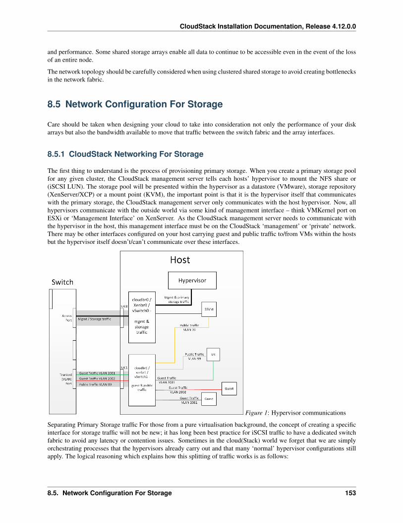
CloudStack Installation Documentation, Release 4.12.0.0
and performance. Some shared storage arrays enable all data to continue to be accessible even in the event of the lossof an entire node.
The network topology should be carefully considered when using clustered shared storage to avoid creating bottlenecksin the network fabric.
8.5 Network Configuration For Storage
Care should be taken when designing your cloud to take into consideration not only the performance of your diskarrays but also the bandwidth available to move that traffic between the switch fabric and the array interfaces.
8.5.1 CloudStack Networking For Storage
The first thing to understand is the process of provisioning primary storage. When you create a primary storage poolfor any given cluster, the CloudStack management server tells each hosts’ hypervisor to mount the NFS share or(iSCSI LUN). The storage pool will be presented within the hypervisor as a datastore (VMware), storage repository(XenServer/XCP) or a mount point (KVM), the important point is that it is the hypervisor itself that communicateswith the primary storage, the CloudStack management server only communicates with the host hypervisor. Now, allhypervisors communicate with the outside world via some kind of management interface – think VMKernel port onESXi or ‘Management Interface’ on XenServer. As the CloudStack management server needs to communicate withthe hypervisor in the host, this management interface must be on the CloudStack ‘management’ or ‘private’ network.There may be other interfaces configured on your host carrying guest and public traffic to/from VMs within the hostsbut the hypervisor itself doesn’t/can’t communicate over these interfaces.
Figure 1: Hypervisor communications
Separating Primary Storage traffic For those from a pure virtualisation background, the concept of creating a specificinterface for storage traffic will not be new; it has long been best practice for iSCSI traffic to have a dedicated switchfabric to avoid any latency or contention issues. Sometimes in the cloud(Stack) world we forget that we are simplyorchestrating processes that the hypervisors already carry out and that many ‘normal’ hypervisor configurations stillapply. The logical reasoning which explains how this splitting of traffic works is as follows:
8.5. Network Configuration For Storage 153
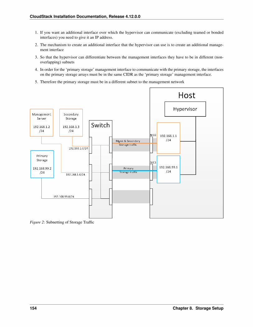
CloudStack Installation Documentation, Release 4.12.0.0
1. If you want an additional interface over which the hypervisor can communicate (excluding teamed or bondedinterfaces) you need to give it an IP address.
2. The mechanism to create an additional interface that the hypervisor can use is to create an additional manage-ment interface
3. So that the hypervisor can differentiate between the management interfaces they have to be in different (non-overlapping) subnets
4. In order for the ‘primary storage’ management interface to communicate with the primary storage, the interfaceson the primary storage arrays must be in the same CIDR as the ‘primary storage’ management interface.
5. Therefore the primary storage must be in a different subnet to the management network
Figure 2: Subnetting of Storage Traffic
154 Chapter 8. Storage Setup
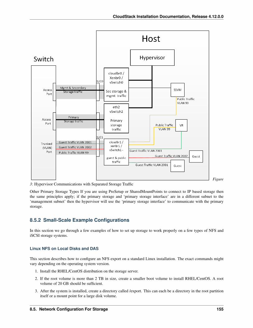
CloudStack Installation Documentation, Release 4.12.0.0
Figure3: Hypervisor Communications with Separated Storage Traffic
Other Primary Storage Types If you are using PreSetup or SharedMountPoints to connect to IP based storage thenthe same principles apply; if the primary storage and ‘primary storage interface’ are in a different subnet to the‘management subnet’ then the hypervisor will use the ‘primary storage interface’ to communicate with the primarystorage.
8.5.2 Small-Scale Example Configurations
In this section we go through a few examples of how to set up storage to work properly on a few types of NFS andiSCSI storage systems.
Linux NFS on Local Disks and DAS
This section describes how to configure an NFS export on a standard Linux installation. The exact commands mightvary depending on the operating system version.
1. Install the RHEL/CentOS distribution on the storage server.
2. If the root volume is more than 2 TB in size, create a smaller boot volume to install RHEL/CentOS. A rootvolume of 20 GB should be sufficient.
3. After the system is installed, create a directory called /export. This can each be a directory in the root partitionitself or a mount point for a large disk volume.
8.5. Network Configuration For Storage 155
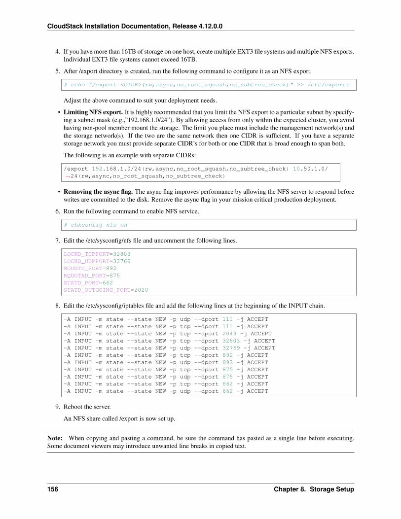
CloudStack Installation Documentation, Release 4.12.0.0
4. If you have more than 16TB of storage on one host, create multiple EXT3 file systems and multiple NFS exports.Individual EXT3 file systems cannot exceed 16TB.
5. After /export directory is created, run the following command to configure it as an NFS export.
# echo "/export <CIDR>(rw,async,no_root_squash,no_subtree_check)" >> /etc/exports
Adjust the above command to suit your deployment needs.
• Limiting NFS export. It is highly recommended that you limit the NFS export to a particular subnet by specify-ing a subnet mask (e.g.,”192.168.1.0/24”). By allowing access from only within the expected cluster, you avoidhaving non-pool member mount the storage. The limit you place must include the management network(s) andthe storage network(s). If the two are the same network then one CIDR is sufficient. If you have a separatestorage network you must provide separate CIDR’s for both or one CIDR that is broad enough to span both.
The following is an example with separate CIDRs:
/export 192.168.1.0/24(rw,async,no_root_squash,no_subtree_check) 10.50.1.0/→˓24(rw,async,no_root_squash,no_subtree_check)
• Removing the async flag. The async flag improves performance by allowing the NFS server to respond beforewrites are committed to the disk. Remove the async flag in your mission critical production deployment.
6. Run the following command to enable NFS service.
# chkconfig nfs on
7. Edit the /etc/sysconfig/nfs file and uncomment the following lines.
LOCKD_TCPPORT=32803LOCKD_UDPPORT=32769MOUNTD_PORT=892RQUOTAD_PORT=875STATD_PORT=662STATD_OUTGOING_PORT=2020
8. Edit the /etc/sysconfig/iptables file and add the following lines at the beginning of the INPUT chain.
-A INPUT -m state --state NEW -p udp --dport 111 -j ACCEPT-A INPUT -m state --state NEW -p tcp --dport 111 -j ACCEPT-A INPUT -m state --state NEW -p tcp --dport 2049 -j ACCEPT-A INPUT -m state --state NEW -p tcp --dport 32803 -j ACCEPT-A INPUT -m state --state NEW -p udp --dport 32769 -j ACCEPT-A INPUT -m state --state NEW -p tcp --dport 892 -j ACCEPT-A INPUT -m state --state NEW -p udp --dport 892 -j ACCEPT-A INPUT -m state --state NEW -p tcp --dport 875 -j ACCEPT-A INPUT -m state --state NEW -p udp --dport 875 -j ACCEPT-A INPUT -m state --state NEW -p tcp --dport 662 -j ACCEPT-A INPUT -m state --state NEW -p udp --dport 662 -j ACCEPT
9. Reboot the server.
An NFS share called /export is now set up.
Note: When copying and pasting a command, be sure the command has pasted as a single line before executing.Some document viewers may introduce unwanted line breaks in copied text.
156 Chapter 8. Storage Setup
CloudStack Installation Documentation, Release 4.12.0.0
Linux NFS on iSCSI
Use the following steps to set up a Linux NFS server export on an iSCSI volume. These steps apply to RHEL/CentOS5 distributions.
1. Install iscsiadm.
# yum install iscsi-initiator-utils# service iscsi start# chkconfig --add iscsi# chkconfig iscsi on
2. Discover the iSCSI target.
# iscsiadm -m discovery -t st -p <iSCSI Server IP address>:3260
For example:
# iscsiadm -m discovery -t st -p 172.23.10.240:3260 172.23.10.240:3260,1 iqn.2001-→˓05.com.equallogic:0-8a0906-83bcb3401-16e0002fd0a46f3d-rhel5-test
3. Log in.
# iscsiadm -m node -T <Complete Target Name> -l -p <Group IP>:3260
For example:
# iscsiadm -m node -l -T iqn.2001-05.com.equallogic:83bcb3401-16e0002fd0a46f3d-→˓rhel5-test -p 172.23.10.240:3260
4. Discover the SCSI disk. For example:
# iscsiadm -m session -P3 | grep AttachedAttached scsi disk sdb State: running
5. Format the disk as ext3 and mount the volume.
# mkfs.ext3 /dev/sdb# mkdir -p /export# mount /dev/sdb /export
6. Add the disk to /etc/fstab to make sure it gets mounted on boot.
/dev/sdb /export ext3 _netdev 0 0
Now you can set up /export as an NFS share.
• Limiting NFS export. In order to avoid data loss, it is highly recommended that you limit the NFS export to aparticular subnet by specifying a subnet mask (e.g.,”192.168.1.0/24”). By allowing access from only within theexpected cluster, you avoid having non-pool member mount the storage and inadvertently delete all its data. Thelimit you place must include the management network(s) and the storage network(s). If the two are the samenetwork then one CIDR is sufficient. If you have a separate storage network you must provide separate CIDRsfor both or one CIDR that is broad enough to span both.
The following is an example with separate CIDRs:
/export 192.168.1.0/24(rw,async,no_root_squash,no_subtree_check) 10.50.1.0/24(rw,→˓async,no_root_squash,no_subtree_check)
8.5. Network Configuration For Storage 157

CloudStack Installation Documentation, Release 4.12.0.0
• Removing the async flag. The async flag improves performance by allowing the NFS server to respond beforewrites are committed to the disk. Remove the async flag in your mission critical production deployment.
158 Chapter 8. Storage Setup
CHAPTER 9
Optional Installation
9.1 Additional Installation Options
The next few sections describe CloudStack features above and beyond the basic deployment options.
9.1.1 Installing the Usage Server (Optional)
You can optionally install the Usage Server once the Management Server is configured properly. The Usage Servertakes data from the events in the system and enables usage-based billing for accounts.
When multiple Management Servers are present, the Usage Server may be installed on any number of them. The UsageServers will coordinate usage processing. A site that is concerned about availability should install Usage Servers on atleast two Management Servers.
Requirements for Installing the Usage Server
• The Management Server must be running when the Usage Server is installed.
• The Usage Server must be installed on the same server as a Management Server.
Steps to Install the Usage Server
1. Package repository should already being configured. Refer to Configure Package Repository
2. Install package cloudstack-usage
On RHEL/CentOS systems, use:
# yum install cloudstack-usage
On Debian/Ubuntu systems, use:
159
CloudStack Installation Documentation, Release 4.12.0.0
# apt-get install cloudstack-usage
3. Once installed, start the Usage Server with the following command.
# service cloudstack-usage start
4. Enable the service at boot
On RHEL/CentOS systems, use:
# chkconfig cloudstack-usage on
On Debian/Ubuntu systems, use:
# update-rc.d cloudstack-usage defaults
The Administration Guide discusses further configuration of the Usage Server.
9.1.2 SSL (Optional)
CloudStack provides HTTP access in its default installation. There are a number of technologies and sites whichchoose to implement SSL. As a result, we have left CloudStack to expose HTTP under the assumption that a site willimplement its typical practice.
CloudStack uses Tomcat as its servlet container. For sites that would like CloudStack to terminate the SSL session,Tomcat’s SSL access may be enabled. Tomcat SSL configuration is described at http://tomcat.apache.org/tomcat-6.0-doc/ssl-howto.html.
9.1.3 Database Replication (Optional)
CloudStack supports database replication from one MySQL node to another. This is achieved using standard MySQLreplication. You may want to do this as insurance against MySQL server or storage loss. MySQL replication isimplemented using a master/slave model. The master is the node that the Management Servers are configured to use.The slave is a standby node that receives all write operations from the master and applies them to a local, redundantcopy of the database. The following steps are a guide to implementing MySQL replication.
Note: Creating a replica is not a backup solution. You should develop a backup procedure for the MySQL data thatis distinct from replication.
1. Ensure that this is a fresh install with no data in the master.
2. Edit my.cnf on the master and add the following in the [mysqld] section below datadir.
log_bin=mysql-binserver_id=1
The server_id must be unique with respect to other servers. The recommended way to achieve this is to give themaster an ID of 1 and each slave a sequential number greater than 1, so that the servers are numbered 1, 2, 3,etc.
3. Restart the MySQL service. On RHEL/CentOS systems, use:
# service mysqld restart
160 Chapter 9. Optional Installation
CloudStack Installation Documentation, Release 4.12.0.0
On Debian/Ubuntu systems, use:
# service mysql restart
4. Create a replication account on the master and give it privileges. We will use the “cloud-repl” user with thepassword “password”. This assumes that master and slave run on the 172.16.1.0/24 network.
# mysql -u rootmysql> create user 'cloud-repl'@'172.16.1.%' identified by 'password';mysql> grant replication slave on *.* TO 'cloud-repl'@'172.16.1.%';mysql> flush privileges;mysql> flush tables with read lock;
5. Leave the current MySQL session running.
6. In a new shell start a second MySQL session.
7. Retrieve the current position of the database.
# mysql -u rootmysql> show master status;+------------------+----------+--------------+------------------+| File | Position | Binlog_Do_DB | Binlog_Ignore_DB |+------------------+----------+--------------+------------------+| mysql-bin.000001 | 412 | | |+------------------+----------+--------------+------------------+
8. Note the file and the position that are returned by your instance.
9. Exit from this session.
10. Complete the master setup. Returning to your first session on the master, release the locks and exit MySQL.
mysql> unlock tables;
11. Install and configure the slave. On the slave server, run the following commands.
# yum install mysql-server# chkconfig mysqld on
12. Edit my.cnf and add the following lines in the [mysqld] section below datadir.
server_id=2innodb_rollback_on_timeout=1innodb_lock_wait_timeout=600
13. Restart MySQL. Use “mysqld” on RHEL/CentOS systems:
# service mysqld restart
On Ubuntu/Debian systems use “mysql.”
# service mysql restart
14. Instruct the slave to connect to and replicate from the master. Replace the IP address, password, log file, andposition with the values you have used in the previous steps.
mysql> change master to-> master_host='172.16.1.217',
9.1. Additional Installation Options 161
CloudStack Installation Documentation, Release 4.12.0.0
-> master_user='cloud-repl',-> master_password='password',-> master_log_file='mysql-bin.000001',-> master_log_pos=412;
15. Then start replication on the slave.
mysql> start slave;
16. Optionally, open port 3306 on the slave as was done on the master earlier.
This is not required for replication to work. But if you choose not to do this, you will need to do it when failoverto the replica occurs.
Failover
This will provide for a replicated database that can be used to implement manual failover for the Management Servers.CloudStack failover from one MySQL instance to another is performed by the administrator. In the event of a databasefailure you should:
1. Stop the Management Servers (via service cloudstack-management stop).
2. Change the replica’s configuration to be a master and restart it.
3. Ensure that the replica’s port 3306 is open to the Management Servers.
4. Make a change so that the Management Server uses the new database. The simplest process here is to put the IPaddress of the new database server into each Management Server’s /etc/cloudstack/management/db.properties.
5. Restart the Management Servers:
# service cloudstack-management start
9.1.4 Amazon Web Services Interface
Amazon Web Services Compatible Interface
CloudStack can translate Amazon Web Services (AWS) API calls to native CloudStack API calls so that users cancontinue using existing AWS-compatible tools. This translation service runs as a separate web application in the sametomcat server as the management server of CloudStack, listening on a different port. The Amazon Web Services(AWS) compatible interface provides the EC2 SOAP and Query APIs as well as the S3 REST API.
Note: This service was previously enabled by separate software called CloudBridge. It is now fully integrated withthe CloudStack management server.
Warning: The compatible interface for the EC2 Query API and the S3 API are Work In Progress. The S3compatible API offers a way to store data on the management server file system, it is not an implementation of theS3 backend.
Limitations
• Supported only in zones that use basic networking.
162 Chapter 9. Optional Installation
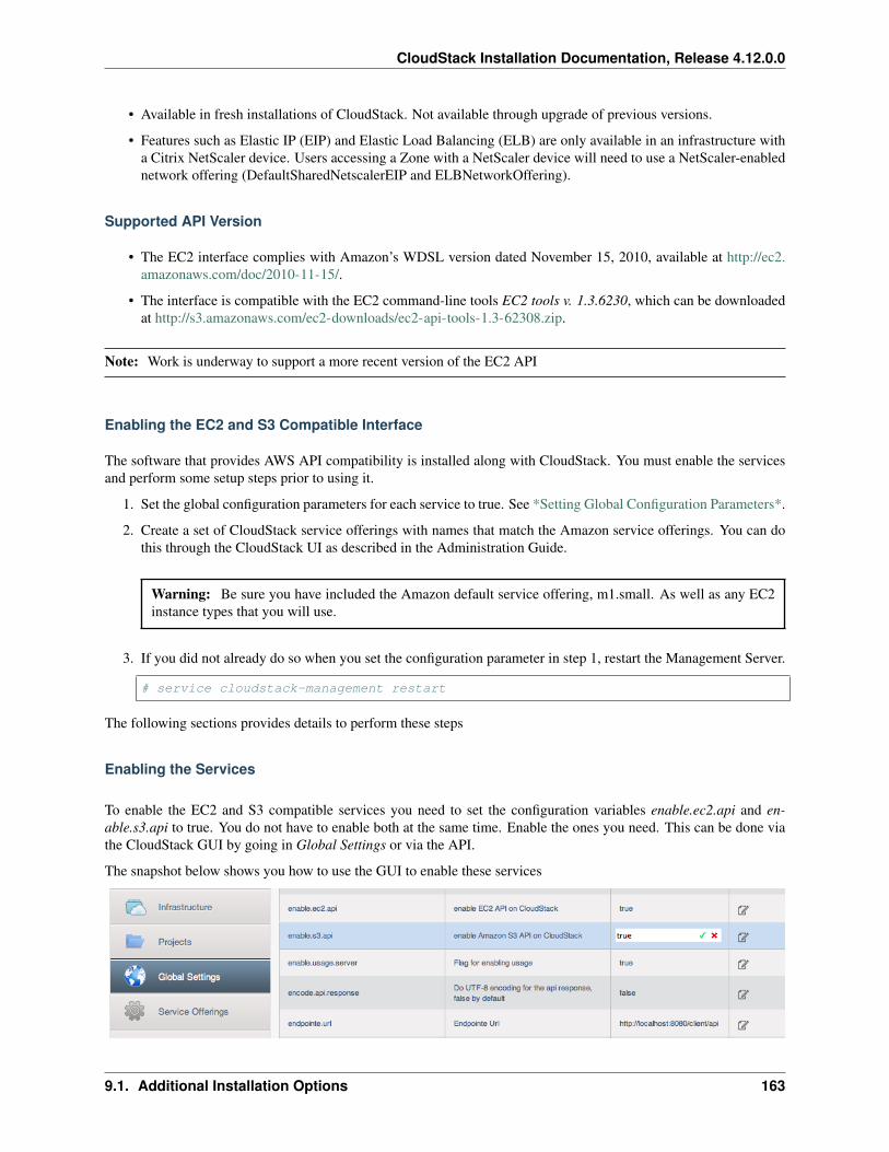
CloudStack Installation Documentation, Release 4.12.0.0
• Available in fresh installations of CloudStack. Not available through upgrade of previous versions.
• Features such as Elastic IP (EIP) and Elastic Load Balancing (ELB) are only available in an infrastructure witha Citrix NetScaler device. Users accessing a Zone with a NetScaler device will need to use a NetScaler-enablednetwork offering (DefaultSharedNetscalerEIP and ELBNetworkOffering).
Supported API Version
• The EC2 interface complies with Amazon’s WDSL version dated November 15, 2010, available at http://ec2.amazonaws.com/doc/2010-11-15/.
• The interface is compatible with the EC2 command-line tools EC2 tools v. 1.3.6230, which can be downloadedat http://s3.amazonaws.com/ec2-downloads/ec2-api-tools-1.3-62308.zip.
Note: Work is underway to support a more recent version of the EC2 API
Enabling the EC2 and S3 Compatible Interface
The software that provides AWS API compatibility is installed along with CloudStack. You must enable the servicesand perform some setup steps prior to using it.
1. Set the global configuration parameters for each service to true. See *Setting Global Configuration Parameters*.
2. Create a set of CloudStack service offerings with names that match the Amazon service offerings. You can dothis through the CloudStack UI as described in the Administration Guide.
Warning: Be sure you have included the Amazon default service offering, m1.small. As well as any EC2instance types that you will use.
3. If you did not already do so when you set the configuration parameter in step 1, restart the Management Server.
# service cloudstack-management restart
The following sections provides details to perform these steps
Enabling the Services
To enable the EC2 and S3 compatible services you need to set the configuration variables enable.ec2.api and en-able.s3.api to true. You do not have to enable both at the same time. Enable the ones you need. This can be done viathe CloudStack GUI by going in Global Settings or via the API.
The snapshot below shows you how to use the GUI to enable these services
9.1. Additional Installation Options 163
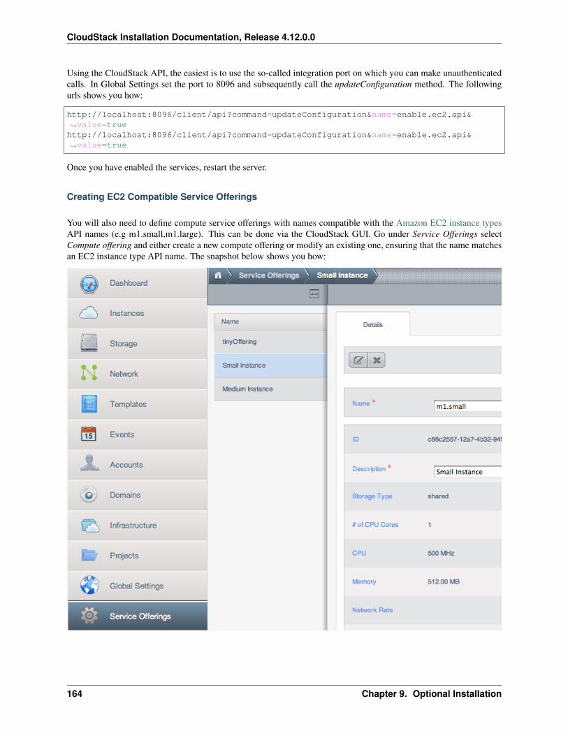
CloudStack Installation Documentation, Release 4.12.0.0
Using the CloudStack API, the easiest is to use the so-called integration port on which you can make unauthenticatedcalls. In Global Settings set the port to 8096 and subsequently call the updateConfiguration method. The followingurls shows you how:
http://localhost:8096/client/api?command=updateConfiguration&name=enable.ec2.api&→˓value=truehttp://localhost:8096/client/api?command=updateConfiguration&name=enable.ec2.api&→˓value=true
Once you have enabled the services, restart the server.
Creating EC2 Compatible Service Offerings
You will also need to define compute service offerings with names compatible with the Amazon EC2 instance typesAPI names (e.g m1.small,m1.large). This can be done via the CloudStack GUI. Go under Service Offerings selectCompute offering and either create a new compute offering or modify an existing one, ensuring that the name matchesan EC2 instance type API name. The snapshot below shows you how:
164 Chapter 9. Optional Installation
CloudStack Installation Documentation, Release 4.12.0.0
Modifying the AWS API Port
Note: (Optional) The AWS API listens for requests on port 7080. If you prefer AWS API to listen on another port,you can change it as follows:
1. Edit the files /etc/cloudstack/management/server.xml, /etc/cloudstack/management/server-nonssl.xml, and /etc/cloudstack/management/server-ssl.xml.
2. In each file, find the tag <Service name=”Catalina7080”>. Under this tag, locate <Connectorexecutor=”tomcatThreadPool-internal” port= . . . .<.
3. Change the port to whatever port you want to use, then save the files.
4. Restart the Management Server.
If you re-install CloudStack, you will have to re-enable the services and if need be update the port.
AWS API User Setup
In general, users need not be aware that they are using a translation service provided by CloudStack. They only needto send AWS API calls to CloudStack’s endpoint, and it will translate the calls to the native CloudStack API. Users ofthe Amazon EC2 compatible interface will be able to keep their existing EC2 tools and scripts and use them with theirCloudStack deployment, by specifying the endpoint of the management server and using the proper user credentials.In order to do this, each user must perform the following configuration steps:
• Generate user credentials.
• Register with the service.
• For convenience, set up environment variables for the EC2 SOAP command-line tools.
AWS API Command-Line Tools Setup
To use the EC2 command-line tools, the user must perform these steps:
1. Be sure you have the right version of EC2 Tools. The supported version is available at http://s3.amazonaws.com/ec2-downloads/ec2-api-tools-1.3-62308.zip.
2. Set up the EC2 environment variables. This can be done every time you use the service or you can set them upin the proper shell profile. Replace the endpoint (i.e EC2_URL) with the proper address of your CloudStackmanagement server and port. In a bash shell do the following.
$ export EC2_CERT=/path/to/cert.pem$ export EC2_PRIVATE_KEY=/path/to/private_key.pem$ export EC2_URL=http://localhost:7080/awsapi$ export EC2_HOME=/path/to/EC2_tools_directory
Using Timeouts to Ensure AWS API Command Completion
The Amazon EC2 command-line tools have a default connection timeout. When used with CloudStack, a longertimeout might be needed for some commands. If you find that commands are not completing due to timeouts, you canspecify a custom timeouts. You can add the following optional command-line parameters to any CloudStack-supportedEC2 command:
Specifies a connection timeout (in seconds)
9.1. Additional Installation Options 165
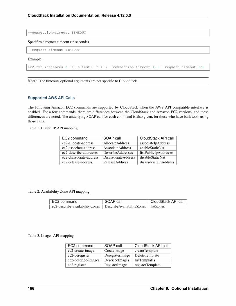
CloudStack Installation Documentation, Release 4.12.0.0
--connection-timeout TIMEOUT
Specifies a request timeout (in seconds)
--request-timeout TIMEOUT
Example:
ec2-run-instances 2 -z us-test1 -n 1-3 --connection-timeout 120 --request-timeout 120
Note: The timeouts optional arguments are not specific to CloudStack.
Supported AWS API Calls
The following Amazon EC2 commands are supported by CloudStack when the AWS API compatible interface isenabled. For a few commands, there are differences between the CloudStack and Amazon EC2 versions, and thesedifferences are noted. The underlying SOAP call for each command is also given, for those who have built tools usingthose calls.
Table 1. Elastic IP API mapping
EC2 command SOAP call CloudStack API callec2-allocate-address AllocateAddress associateIpAddressec2-associate-address AssociateAddress enableStaticNatec2-describe-addresses DescribeAddresses listPublicIpAddressesec2-diassociate-address DisassociateAddress disableStaticNatec2-release-address ReleaseAddress disassociateIpAddress
Table 2. Availability Zone API mapping
EC2 command SOAP call CloudStack API callec2-describe-availability-zones DescribeAvailabilityZones listZones
Table 3. Images API mapping
EC2 command SOAP call CloudStack API callec2-create-image CreateImage createTemplateec2-deregister DeregisterImage DeleteTemplateec2-describe-images DescribeImages listTemplatesec2-register RegisterImage registerTemplate
166 Chapter 9. Optional Installation
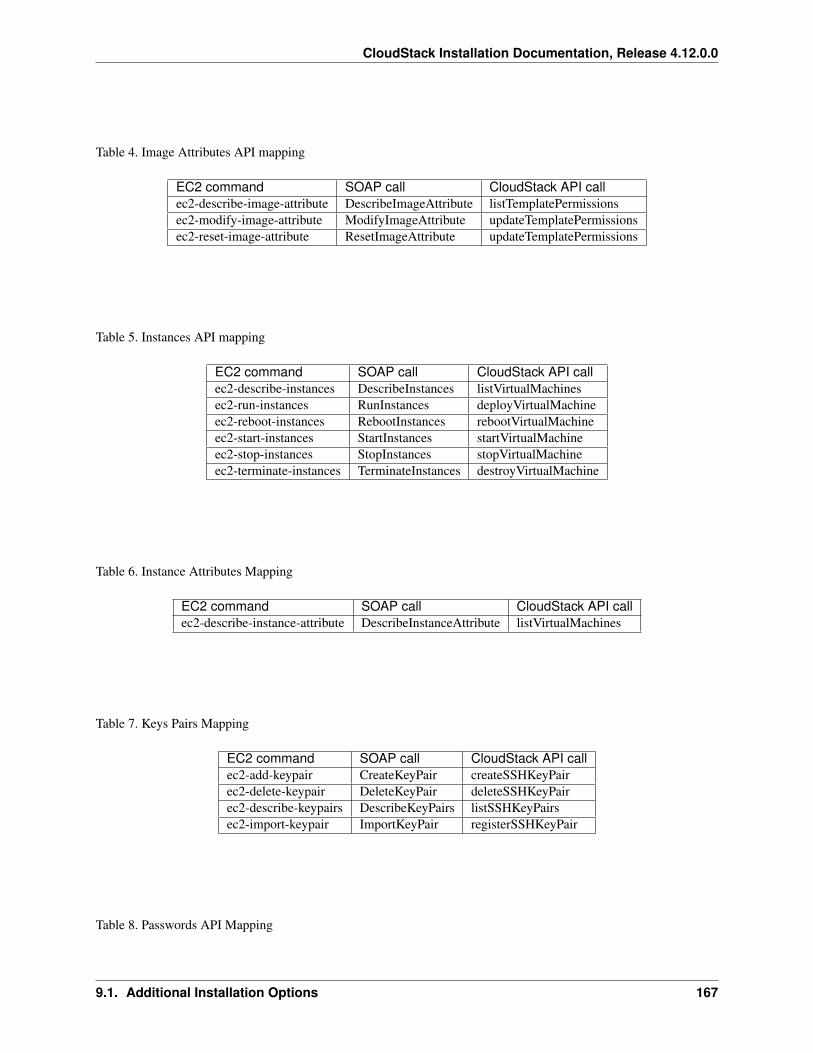
CloudStack Installation Documentation, Release 4.12.0.0
Table 4. Image Attributes API mapping
EC2 command SOAP call CloudStack API callec2-describe-image-attribute DescribeImageAttribute listTemplatePermissionsec2-modify-image-attribute ModifyImageAttribute updateTemplatePermissionsec2-reset-image-attribute ResetImageAttribute updateTemplatePermissions
Table 5. Instances API mapping
EC2 command SOAP call CloudStack API callec2-describe-instances DescribeInstances listVirtualMachinesec2-run-instances RunInstances deployVirtualMachineec2-reboot-instances RebootInstances rebootVirtualMachineec2-start-instances StartInstances startVirtualMachineec2-stop-instances StopInstances stopVirtualMachineec2-terminate-instances TerminateInstances destroyVirtualMachine
Table 6. Instance Attributes Mapping
EC2 command SOAP call CloudStack API callec2-describe-instance-attribute DescribeInstanceAttribute listVirtualMachines
Table 7. Keys Pairs Mapping
EC2 command SOAP call CloudStack API callec2-add-keypair CreateKeyPair createSSHKeyPairec2-delete-keypair DeleteKeyPair deleteSSHKeyPairec2-describe-keypairs DescribeKeyPairs listSSHKeyPairsec2-import-keypair ImportKeyPair registerSSHKeyPair
Table 8. Passwords API Mapping
9.1. Additional Installation Options 167
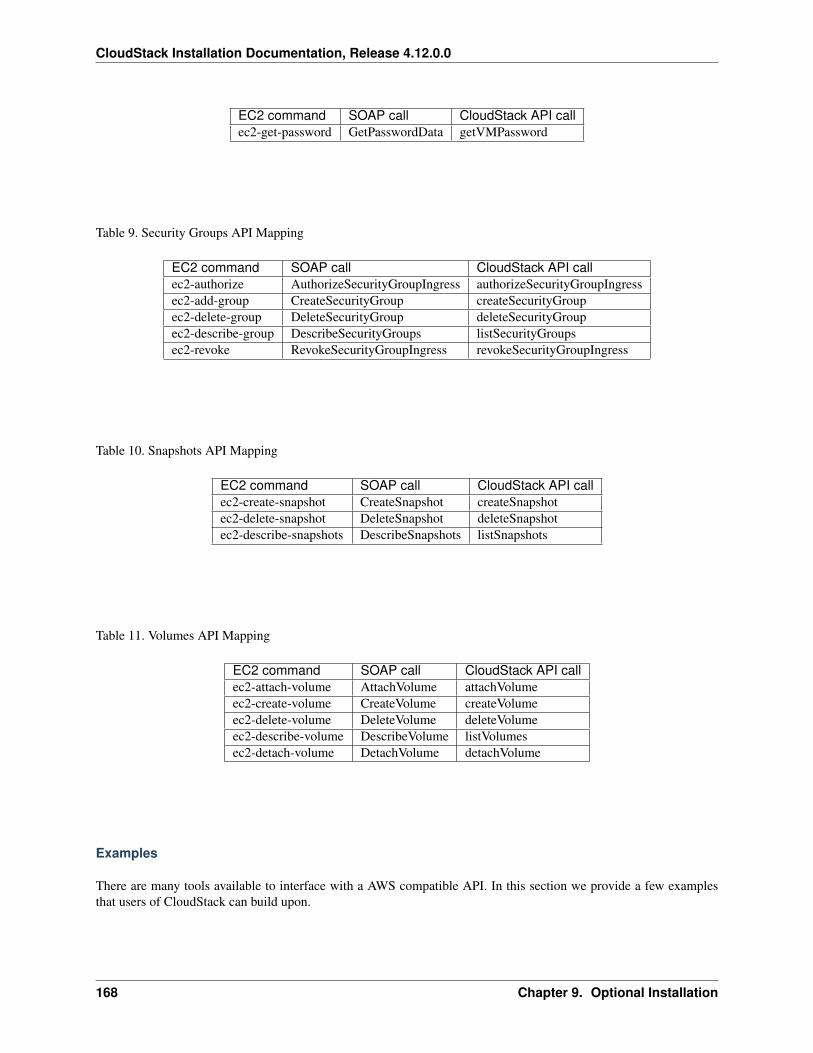
CloudStack Installation Documentation, Release 4.12.0.0
EC2 command SOAP call CloudStack API callec2-get-password GetPasswordData getVMPassword
Table 9. Security Groups API Mapping
EC2 command SOAP call CloudStack API callec2-authorize AuthorizeSecurityGroupIngress authorizeSecurityGroupIngressec2-add-group CreateSecurityGroup createSecurityGroupec2-delete-group DeleteSecurityGroup deleteSecurityGroupec2-describe-group DescribeSecurityGroups listSecurityGroupsec2-revoke RevokeSecurityGroupIngress revokeSecurityGroupIngress
Table 10. Snapshots API Mapping
EC2 command SOAP call CloudStack API callec2-create-snapshot CreateSnapshot createSnapshotec2-delete-snapshot DeleteSnapshot deleteSnapshotec2-describe-snapshots DescribeSnapshots listSnapshots
Table 11. Volumes API Mapping
EC2 command SOAP call CloudStack API callec2-attach-volume AttachVolume attachVolumeec2-create-volume CreateVolume createVolumeec2-delete-volume DeleteVolume deleteVolumeec2-describe-volume DescribeVolume listVolumesec2-detach-volume DetachVolume detachVolume
Examples
There are many tools available to interface with a AWS compatible API. In this section we provide a few examplesthat users of CloudStack can build upon.
168 Chapter 9. Optional Installation
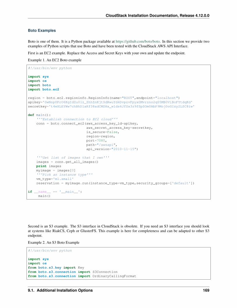
CloudStack Installation Documentation, Release 4.12.0.0
Boto Examples
Boto is one of them. It is a Python package available at https://github.com/boto/boto. In this section we provide twoexamples of Python scripts that use Boto and have been tested with the CloudStack AWS API Interface.
First is an EC2 example. Replace the Access and Secret Keys with your own and update the endpoint.
Example 1. An EC2 Boto example
#!/usr/bin/env python
import sysimport osimport botoimport boto.ec2
region = boto.ec2.regioninfo.RegionInfo(name="ROOT",endpoint="localhost")apikey='GwNnpUPrO6KgIdZu01z_ZhhZnKjtSdRwuYd4DvpzvFpyxGMvrzno2q05MB0ViBoFYtdqKd'secretkey='t4eXLEYWw7chBhDlaKf38adCMSHx_wlds6JfSx3z9fSpSOm0AbP9Moj0oGIzy2LSC8iw'
def main():'''Establish connection to EC2 cloud'''conn = boto.connect_ec2(aws_access_key_id=apikey,
aws_secret_access_key=secretkey,is_secure=False,region=region,port=7080,path="/awsapi",api_version="2010-11-15")
'''Get list of images that I own'''images = conn.get_all_images()print imagesmyimage = images[0]'''Pick an instance type'''vm_type='m1.small'reservation = myimage.run(instance_type=vm_type,security_groups=['default'])
if __name__ == '__main__':main()
Second is an S3 example. The S3 interface in CloudStack is obsolete. If you need an S3 interface you should lookat systems like RiakCS, Ceph or GlusterFS. This example is here for completeness and can be adapted to other S3endpoint.
Example 2. An S3 Boto Example
#!/usr/bin/env python
import sysimport osfrom boto.s3.key import Keyfrom boto.s3.connection import S3Connectionfrom boto.s3.connection import OrdinaryCallingFormat
9.1. Additional Installation Options 169

CloudStack Installation Documentation, Release 4.12.0.0
apikey='ChOw-pwdcCFy6fpeyv6kUaR0NnhzmG3tE7HLN2z3OB_s-ogF5HjZtN4rnzKnq2UjtnHeg_yLA5gOw'secretkey='IMY8R7CJQiSGFk4cHwfXXN3DUFXz07cCiU80eM3MCmfLs7kusgyOfm0g9qzXRXhoAPCH-→˓IRxXc3w'
cf=OrdinaryCallingFormat()
def main():'''Establish connection to S3 service'''conn = S3Connection(aws_access_key_id=apikey,aws_secret_access_key=secretkey, \
is_secure=False, \host='localhost', \port=7080, \calling_format=cf, \path="/awsapi/rest/AmazonS3")
try:bucket=conn.create_bucket('cloudstack')k = Key(bucket)k.key = 'test'try:
k.set_contents_from_filename('/Users/runseb/Desktop/s3cs.py')except:
print 'could not write file'pass
except:bucket = conn.get_bucket('cloudstack')k = Key(bucket)k.key = 'test'try:
k.get_contents_to_filename('/Users/runseb/Desktop/foobar')except:
print 'Could not get file'pass
try:bucket1=conn.create_bucket('teststring')k=Key(bucket1)k.key('foobar')k.set_contents_from_string('This is my silly test')
except:bucket1=conn.get_bucket('teststring')k = Key(bucket1)k.key='foobar'k.get_contents_as_string()
if __name__ == '__main__':main()
9.2 About Password and Key Encryption
CloudStack stores several sensitive passwords and secret keys that are used to provide security. These values arealways automatically encrypted:
• Database secret key
170 Chapter 9. Optional Installation
CloudStack Installation Documentation, Release 4.12.0.0
• Database password
• SSH keys
• Compute node root password
• VPN password
• User API secret key
• VNC password
CloudStack uses the Java Simplified Encryption (JASYPT) library. The data values are encrypted and decrypted usinga database secret key, which is stored in one of CloudStack’s internal properties files along with the database password.The other encrypted values listed above, such as SSH keys, are in the CloudStack internal database.
Of course, the database secret key itself can not be stored in the open – it must be encrypted. How then does CloudStackread it? A second secret key must be provided from an external source during Management Server startup. This keycan be provided in one of two ways: loaded from a file or provided by the CloudStack administrator. The CloudStackdatabase has a configuration setting that lets it know which of these methods will be used. If the encryption type is setto “file,” the key must be in a file in a known location. If the encryption type is set to “web,” the administrator runsthe utility com.cloud.utils.crypt.EncryptionSecretKeySender, which relays the key to the Management Server over aknown port.
The encryption type, database secret key, and Management Server secret key are set during CloudStack installation.They are all parameters to the CloudStack database setup script (cloudstack-setup-databases). The default values arefile, password, and password. It is, of course, highly recommended that you change these to more secure keys.
9.2.1 Changing the Default Password Encryption
Passwords are encoded when creating or updating users. CloudStack allows you to determine the default en-coding and authentication mechanism for admin and user logins. Two new configurable lists have been intro-duced—userPasswordEncoders and userAuthenticators. userPasswordEncoders allows you to configure the order ofpreference for encoding passwords, whereas userAuthenticators allows you to configure the order in which authenti-cation schemes are invoked to validate user passwords.
Additionally, the plain text user authenticator has been modified not to convert supplied passwords to their md5 sumsbefore checking them with the database entries. It performs a simple string comparison between retrieved and suppliedlogin passwords instead of comparing the retrieved md5 hash of the stored password against the supplied md5 hash ofthe password because clients no longer hash the password. The following method determines what encoding schemeis used to encode the password supplied during user creation or modification.
When a new user is created, the user password is encoded by using the first valid encoder loaded asper the sequence specified in the UserPasswordEncoders property in the ComponentContext.xmlor nonossComponentContext.xml files. The order of authentication schemes is determined by theUserAuthenticators property in the same files. If Non-OSS components, such as VMware environ-ments, are to be deployed, modify the UserPasswordEncoders and UserAuthenticators lists in thenonossComponentContext.xml file, for OSS environments, such as XenServer or KVM, modify theComponentContext.xml file. It is recommended to make uniform changes across both the files. When a newauthenticator or encoder is added, you can add them to this list. While doing so, ensure that the new authenticator orencoder is specified as a bean in both these files. The administrator can change the ordering of both these properties aspreferred to change the order of schemes. Modify the following list properties available in client/tomcatconf/nonossComponentContext.xml.in or client/tomcatconf/componentContext.xml.in as appli-cable, to the desired order:
<property name="UserAuthenticators"><list>
<ref bean="SHA256SaltedUserAuthenticator"/>
9.2. About Password and Key Encryption 171

CloudStack Installation Documentation, Release 4.12.0.0
<ref bean="MD5UserAuthenticator"/><ref bean="LDAPUserAuthenticator"/><ref bean="PlainTextUserAuthenticator"/>
</list></property><property name="UserPasswordEncoders">
<list><ref bean="SHA256SaltedUserAuthenticator"/><ref bean="MD5UserAuthenticator"/><ref bean="LDAPUserAuthenticator"/><ref bean="PlainTextUserAuthenticator"/>
</list></property>
In the above default ordering, SHA256Salt is used first for UserPasswordEncoders. If the module is found andencoding returns a valid value, the encoded password is stored in the user table’s password column. If it fails forany reason, the MD5UserAuthenticator will be tried next, and the order continues. For UserAuthenticators,SHA256Salt authentication is tried first. If it succeeds, the user is logged into the Management server. If it fails, md5is tried next, and attempts continues until any of them succeeds and the user logs in . If none of them works, the useris returned an invalid credential message.
172 Chapter 9. Optional Installation