Embed Size (px)
Citation preview
Fermilab
Closeout Presentation
Director's CD-1 Review of the Mu2e Project
April 3-5, 2012
Closeout Presentation
This page intentionally left blank
Director's CD-1 Review of the Mu2e ProjectApril 3-5, 2012
Page 2 of 52
Closeout Presentation
Table of ContentsExecutive Summary.............................................................................................................5
1.0 Introduction..............................................................................................................6
2.0 Accelerator...............................................................................................................7
2.1 Rings & Extraction................................................................................................82.2 Extinction & External Beamline.........................................................................102.3 Target, Heat Shield & Dump..............................................................................112.4 Radiation Shielding.............................................................................................122.5 Interactions with other projects...........................................................................13
3.0 Conventional Construction....................................................................................14
3.1 Design/ Engineering.........................................................................................143.2 LEED/ Sustainability.........................................................................................163.3 ES&H...................................................................................................................173.4 Risk.....................................................................................................................173.5 Project Staffing...................................................................................................183.6 Schedule/ Cost...................................................................................................183.7 General...............................................................................................................19
4.0 Solenoids................................................................................................................21
4.1 Production Solenoid............................................................................................214.2 Transport Solenoid..............................................................................................234.3 Detector Solenoid................................................................................................254.4 Other Components and Solenoid System Integration.........................................27
5.0 Muon Beamline.....................................................................................................28
6.0 Calorimeter, Cosmic Ray Veto..............................................................................30
6.1 Calorimeter..........................................................................................................306.2 Cosmic Ray Veto................................................................................................32
7.0 Tracker / DAQ.......................................................................................................35
7.1 Tracker................................................................................................................357.2 DAQ....................................................................................................................37
8.0 Project Management..............................................................................................39
8.1 Cost.....................................................................................................................398.2 Schedule..............................................................................................................428.3 Management........................................................................................................44
Director's CD-1 Review of the Mu2e ProjectApril 3-5, 2012
Page 3 of 52
Closeout Presentation
8.4 ES&H..................................................................................................................479.0 Charge Questions...................................................................................................50
9.1 Design Review Charge Questions for the Accelerator and Solenoid.................509.2 Cost Schedule, Management, and ES&H Charge Questions..............................51
Director's CD-1 Review of the Mu2e ProjectApril 3-5, 2012
Page 4 of 52
Closeout Presentation
Executive Summary
This Director’s CD-1 Review of the Mu2e Project was charged to make two assessments: 1) the adequacy of changes to the Project’s design since the Director’s Independent Conceptual Design Review conducted on May 03-05, 2011, and 2) whether the Project meets the CD-1 requirements specified in DOEO413.3B, focusing on cost, schedule, management, and ES&H.
The Project performed major value engineering since Fall 2011 to reduce costs. This resulted mainly in changes to the accelerator and solenoid systems. Some previous Mu2e equipment and facilities were moved to the g-2 Project and a series of GPP and AIP projects that will serve both g-2 and Mu2e. These changes were reviewed and found to be technically satisfactory for CD-1. In addition, the revised Mu2e designs were found to meet the technical and scientific requirements. The committee also believes the current designs are simpler and more straightforward, reducing risk.
In preparing for a DOE CD-1, the Project has completed the conceptual design, drafted the necessary management documents, and created a resource-loaded schedule (RLS) to produce a cost and schedule range. With some updating, the required documentation will be complete. The RLS is only recently rolled up and although the obligations fit within a preliminary funding profile recently provided by DOE, iteration of the schedule is necessary to verify logic links and durations, as well as resource-level within and across L2 subprojects. The committee believes that with sufficient project controls resources and dedicated effort from Mu2e managers, the RLS can be made self-consistent and reflect a realistic resource profile, and that this can be done in time for posting documentation for the DOE CD-1 Review that is currently scheduled for June 5-7, 2012. A status check should be performed by the Directorate by the end of April on progress towards updating the RLS.
Director's CD-1 Review of the Mu2e ProjectApril 3-5, 2012
Page 5 of 52
Closeout Presentation
1.0 Introduction
A Director’s CD-1 Review of the Muon to Electron Conversion Experiment (Mu2e) Project was held on April 3-5, 2012 at the Fermi National Accelerator Laboratory. The object of this review was to assess if the project meets the Critical Decision 1 (CD-1) “Approve Alternative Selection & Cost Range” CD-1 requirements as specified in DOE O 413.3B. Additionally, the committee reviewed the changes to the project’s design since the Director’s Impendent Conceptual Design Review conducted on May 03-05, 2011. The charge included a list of topics and specific questions to be addressed as part of the review. The assessment of the Review Committee is documented in the body of this closeout presentation.
Each section in this closeout presentation is generally organized by Findings, Comments and Recommendations. Findings are statements of fact that summarize noteworthy information presented during the review. The Comments are judgment statements about the facts presented during the review and are based on reviewers’ experience and expertise. The comments are to be evaluated by the project team and actions taken as deemed appropriate. Recommendations are statements of actions that should be addressed by the project team. The remainder of this presentation has the answers to the review charge questions.
The Mu2e Project is to develop a response to the review recommendations and present it to the Laboratory Management and regularly report on the progress during the Mu2e Working Group Meetings (WGM). A response to the recommendation(s) is expected and the actions taken will be tracked. The statuses of these recommendations are to me made available during future reviews.
Director's CD-1 Review of the Mu2e ProjectApril 3-5, 2012
Page 6 of 52
Closeout Presentation
2.0 Accelerator
Lead: Paul Derwent
Contributors: Kevin Brown, Rich Andrews
Findings The project has significantly reduced the scope of the accelerator work associated
with the project in an attempt to reduce cost with associated reduced beam intensity. The resulting plan appears to have also reduced technical risk.
The resource profile presented in the plenary session by the L2 accelerator manager strained the imagination of the reviewers. The profile showed a total of ~68 FTEs over 7 years, with ~17 FTEs in past years and a total of ~15 FTEs between now and CD-2 (and 0 FTEs in FY15).
Comments The project is assuming that spares are provided off project. We did not find this
spelled out in the project assumptions document.
The project is assuming the availability of hardware from the decommissioning of the Accumulator. While there has been discussion among the project managers, the Muon department, and the Accelerator Division about the re-use of many components, the agreement has not been formalized between the project and the lab.
The L2 and L3 managers displayed a good understanding of the technical requirements. The overall scheme is sound and capable of delivering on the beam requirements with low technical risk.
The L2 manager is in agreement that the labor profile as presented looks incorrect. It came from the scheduling software on a tight time scale and was not vetted by him before the review.
The L2 manager has felt significant pressure to cut costs. As a result, there are some places where the project is not pursuing additional design work though benefits do exist. There are opportunities for additional value engineering that could be done to improve design for performance/operation with small impact on fabrication costs. Some places are noted in sections below.
Recommendations1. Update and cross check the resource and obligation profiles before the CD-1
review.
Director's CD-1 Review of the Mu2e ProjectApril 3-5, 2012
Page 7 of 52

Closeout Presentation
2.1 Rings & Extraction
Findings The new design with the simplified systems and direct injection into the Delivery
ring is technically feasible and will adequately allow the accelerators to achieve the required beam parameters.
The design team has met a difficult challenge in reducing costs and scope without seriously affecting the beam quality. The reduction in intensity allows bypassing the use of the Accumulator ring and eliminates complicated beam manipulations.
Reduction in the number of RF systems is feasible and rational given the new requirements from the reduction in scope.
The new M3 and extraction lines pose significant challenges, given so many systems are packed into the one location.
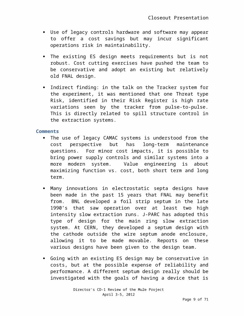
Use of legacy controls hardware and software may appear to offer a cost savings but may incur significant operations risk in maintainability.
The existing ES design meets requirements but is not robust. Cost cutting exercises have pushed the team to be conservative and adopt an existing but relatively old FNAL design.
Indirect finding: in the talk on the Tracker system for the experiment, it was mentioned that one Threat type Risk, identified in their Risk Register is high rate variations seen by the tracker from pulse-to-pulse. This is directly related to spill structure control in the extraction systems.
Comments The use of legacy CAMAC systems is understood from the cost perspective but
has long-term maintenance questions. For minor cost impacts, it is possible to bring power supply controls and similar systems into a more modern system. Value engineering is about maximizing function vs. cost, both short term and long term.
Many innovations in electrostatic septa designs have been made in the past 15 years that FNAL may benefit from. BNL developed a foil strip septum in the late 1990’s that saw operation over at least two high intensity slow extraction runs. J-PARC has adopted this type of design for the main ring slow extraction system. At CERN, they developed a septum design with the cathode outside the wire septum anode enclosure, allowing it to be made movable. Reports on these various designs have been given to the design team.
Going with an existing ES design may be conservative in costs, but at the possible expense of reliability and performance. A different septum design really should be investigated with the goals of having a device that is more likely to survive high
Director's CD-1 Review of the Mu2e ProjectApril 3-5, 2012
Page 8 of 52
Closeout Presentation
beam currents (i.e., non-resonant beam steered into the septum), will be more flexible for concurrent operation with g-2 operation, and may even be able to provide reduction in total beam losses by achieving smaller effective thickness. This area is another opportunity for value engineering.
Given the challenges of staging the M3 line, a preliminary layout should be developed and shown for the CD1 review. Having some idea how things can fit, and what services need to be added will allow the reviewers to better understand the issues.
The team should review the concern over pulse-to-pulse intensity variations identified by the Tracker group. The requirement identified in the documentation is a spill structure variation on the order of 50%. This can be reduced by various methods, some of which the team have identified. The Tracker group should quantify more precisely what their requirements are and the Extraction team should consider looking to achieve better quality spill structure. With effort, clean spill structure of less than 20% modulation have been demonstrated at other facilities using conventional feedback systems.
Recommendations2. Controls must be modernized to have maintainable systems given operation is in
10 or more years into the future.
Director's CD-1 Review of the Mu2e ProjectApril 3-5, 2012
Page 9 of 52
Closeout Presentation
2.2 Extinction & External Beamline
Findings Current design assumes Gaussian shaped beam distributions, which are a poor
approximation for a resonant extracted beam phase space.
Beam line tunnel designs are such that staging of the magnets from the Accumulator to the external beamline enclosure is more cost effective prior to g-2 equipment installation. However, this plan does complicate the rest of the installation in the beam line.
Due to the fine positioning control required for the collimators, current in-project instrumentation is minimal, if not inadequate.
Extinction requirements remain the same as presented a year ago. RF manipulations in the Delivery Ring give a factor of 10-7, with an AC dipole in the external beamline to bring the extinction down to the required factor of 10-10.
Comments Prior to CD-2, the team needs to look at the impact on the optics design, including
the effectiveness of the extinction system, when they use a phase space constructed from the slow extraction system design. Design assumptions that are based on the use of a Gaussian distribution will be affected. This will be particularly important in the collimator region.
As long as the integrity of magnets installed prior to g-2 installation is verified AND the optics design does not significantly change after g-2 installation, then it is probably reasonable to stage the magnet installations early, as planned. We note that the L3 manager plan as presented in the breakout session for staging magnets from the Accumulator to the External Beamline enclosure is different than what is in the schedule.
The team should review again the beam-line instrumentation requirements taking into consideration what is needed at the time of commissioning and considering input from operations. The setup of the extinction systems will be challenging given the number of parameters involved (collimators and uncertainties in beam trajectory and optics). It may also take significant time to find the right set of parameters and will likely require help from operations staff to find the right settings. Giving operations enough education and observation points to help do this will be required.
Extinction is still a challenging technical problem, though the proposed solutions are promising. Additional instrumentation upstream and downstream of the AC dipole would be useful in understanding performance.
RecommendationsNone.
Director's CD-1 Review of the Mu2e ProjectApril 3-5, 2012
Page 10 of 52
Closeout Presentation
2.3 Target, Heat Shield & Dump
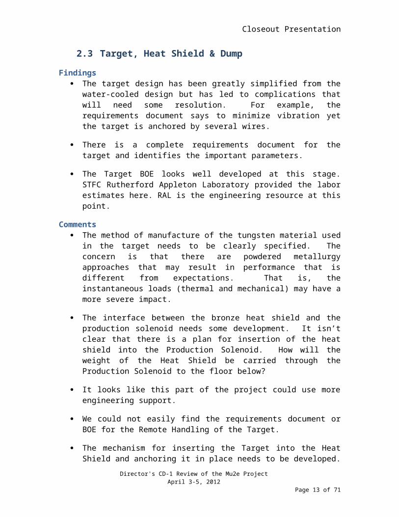
Findings The target design has been greatly simplified from the water-cooled design but
has led to complications that will need some resolution. For example, the requirements document says to minimize vibration yet the target is anchored by several wires.
There is a complete requirements document for the target and identifies the important parameters.
The Target BOE looks well developed at this stage. STFC Rutherford Appleton Laboratory provided the labor estimates here. RAL is the engineering resource at this point.
Comments The method of manufacture of the tungsten material used in the target needs to be
clearly specified. The concern is that there are powdered metallurgy approaches that may result in performance that is different from expectations. That is, the instantaneous loads (thermal and mechanical) may have a more severe impact.
The interface between the bronze heat shield and the production solenoid needs some development. It isn’t clear that there is a plan for insertion of the heat shield into the Production Solenoid. How will the weight of the Heat Shield be carried through the Production Solenoid to the floor below?
It looks like this part of the project could use more engineering support.
We could not easily find the requirements document or BOE for the Remote Handling of the Target.
The mechanism for inserting the Target into the Heat Shield and anchoring it in place needs to be developed. Will this need to be done using the remote handling equipment?
Recommendations3. Assign a dedicated mechanical engineer to serve as systems or integration engineer
for the Target Station. This engineer should help develop and review component and system requirements, oversee work in the different areas, and assure proper integration of all components and systems. We recommend identifying an individual by the CD1 review.
Director's CD-1 Review of the Mu2e ProjectApril 3-5, 2012
Page 11 of 52
Closeout Presentation
2.4 Radiation Shielding
Findings The changes in accelerator scope over the last year have greatly simplified the
shielding aspects of the project, fewer transfer points, fewer loss points.
The project is designing with a limit of ‘sky shine’, covering general exposure to the public, of < 1mRem/year.
There have been changes in the general definition covering general exposure. The definition is now < 1 mRem/year at 500 m radius (previously 175 m radius). This change has made their job easier.
Local shielding at internal loss points is expected to be necessary to meet the limits.
Comments We encourage the continuing development of the Total Loss Monitor System for
use in all the Intensity Frontier programs at the lab. We are somewhat worried about the use of the TLM as a radiation safety system as well as a loss monitor, especially with regard to operational impacts.
The number of local shielding points is anticipated to be 6. There was at least 1 point (the extraction septa) where the amount of shielding is significant. As this area is already ‘logistically challenged’ with lots of equipment, adding 1-2 feet of steel around equipment makes it even more challenged.
Recommendations4. Develop the 3D models of the tunnel equipment (especially the D30 straight) to
understand interferences and constraints in the tunnel during preliminary design.
Director's CD-1 Review of the Mu2e ProjectApril 3-5, 2012
Page 12 of 52
Closeout Presentation
2.5 Interactions with other projects
Findings The Mu2e project is assuming contributions from other projects that are necessary
to the success of Mu2e as currently scoped. These include contributions from NOvA, g-2, AIP, and GPP. The project is using common milestones to keep track.
Management setup for communication and integrated plan looks pretty good at this time – a common manager for all 3 projects, which affords ample opportunity for communication within the project.
Comments The project provided a table with the breakdown of responsibilities between g-2,
AIPs, and Mu2e. It is very helpful in understanding which project is responsible for what in the proton delivery.
The current setup using a common manager and common milestones has strengths. As the common manager did express worry about being able to effectively work on all three, there are risks to losing some of the communication and understanding.
Recommendations5. Continue regular interaction with management of the other projects to ensure that
Mu2e’s interests are understood and addressed.
Director's CD-1 Review of the Mu2e ProjectApril 3-5, 2012
Page 13 of 52
Closeout Presentation
3.0 Conventional Construction
Lead: Jesse Adams
Contributor: Damian Dockery
3.1 Design/ Engineering
Finding The objective of the conventional facilities scope is to design, construct and
deliver for occupancy, facilities that will house the Mu2e beam line components, solenoids, detectors and related technical equipment.
The facilities must meet these requirements while ensuring that it is safe to construct and operate, environmentally sensitive, and incorporates the appropriate FNAL standards and processes.
The project design or engineering is subdivided into (3) WBS elements: Conceptual, Preliminary and Final Designs.
FESS/Engineering has produced a conceptual design for the Mu2e facility through iterative processes of meetings and discussions. Documentation for this design includes a draft requirements document, an interface specification, and drawings.
The design has been developed by FESS/Engineering staff under the leadership of the L2 manager for conventional construction. Post CD-1, the L2 manager will continue to have responsibility for the design and construction of the conventional facilities, and intends to have a subcontract in place for a consultant architect/engineer for preliminary (and then final) design.
Architectural An architectural conceptual design has been developed and was presented
for the proposed facilities.
Conceptual design included initial rendering, elevations, floor plans and sections. A total of (4) Architectural drawings were included for review.
The proposed facilities are consistent and in-line with FNAL Architectural or campus standards.
Civil/ Structural Plans, elevations and sections were provided as part of the conceptual design
documents. A total of (5) Civil drawings and (11) Structural drawings were provided.
Director's CD-1 Review of the Mu2e ProjectApril 3-5, 2012
Page 14 of 52

Closeout Presentation
The site civil work presented included: site utilities, site parking and related service roads and large earthwork to support the proposed new structures.
Structural work includes the design of the following systems:
o Mu2e Beamline Enclosure – Underground concrete beamline enclosure with approximately 16 feet of shielding. Basic structure proposed was a concrete box-like structure with egress stairways at multiple locations. For construction, a large excavation and fill will be required.
o Detector Enclosure Building – Complete new facility with a sub-terrain level to be used to house the majority of the experiment equipment. Structure described was a basic conventional facility with a concrete foundation and sub terrain level with steel frame for the above ground structure.
MEP & Life Safety Drawings, basis of design, load tables, and requirements summary were
provided and thoroughly explained.
Preliminary loads (mechanical and electric) were completed. The values, while not finalized, are well developed with the information available and are appropriate for the scope of the project at this time.
A preliminary fire/life safety study was conducted for the design to provide guidance on egress, fire suppression, alarm, and detection, which have been incorporated into the design. This design follows all applicable codes and does not utilize an equivalency approach. Enough Team driven guidance is documented to move forward with proper direction for further design as the final building configuration is realized.
A modification in the floor elevation from a previous iteration has moved it to less than 30 feet below level of exit discharge, omitting the requirements for smoke control and stairway pressurization.
Comments The conceptual design is well advanced, is more than adequate for a CD-1
review and appears to meet the requirements from the scientific users.
The design is adequate and appropriate for the proposed operation and function of the facility.
There were no technical or constructability issues found.
LS: Egress paths have been properly identified in the building and general scope for detection/ suppression has been laid out well for follow on design.
Director's CD-1 Review of the Mu2e ProjectApril 3-5, 2012
Page 15 of 52
Closeout Presentation
MEP: The team will need to continue to review electrical and mechanical load requirements as the design progresses. Some of the anticipated loads are placeholders and will be further vetted as requirements are further defined.
RecommendationsNone
3.2 LEED/ Sustainability
Findings The team has made the decision to forgo pursuing LEED-NC, and concentrate
on achieving 100% Guiding Principles where reasonable and cost effective.
The reasoning for pursuing High Performance Sustainable Buildings GPs instead of LEED-NC is based on the fact that it is a process building entirely and will be unoccupied.
Comments The benefits and complexities for pursuing either HPSB Guiding Principles or
LEED-NC have been well thought out.
The team may wish to consider LEED Core and Shell as an alternative to LEED New Construction. If desirable, this could be done in lieu of or in addition to pursuing the Guiding Principles. These items are not mutually exclusive.
If LEED Core and Shell is being considered, it is suggested that the team register the project ASAP with USGBC to lock in the LEED version now. This not only prevents the project from having to meet later, more stringent requirements but also provides a clear path to the team for direction.
RecommendationsNone
Director's CD-1 Review of the Mu2e ProjectApril 3-5, 2012
Page 16 of 52
Closeout Presentation
3.3 ES&H
Findings Integrated Safety Management (ISM) concepts and process were
implemented in developing the key components and design of the proposed facilities.
A Wetland Delineation was performed by Patrick Engineering and Planning Resources Inc.
The project received an “Exemption for Construction Activities” from Chicago District, Corps of Engineers
The project is pursuing a Categorical Exclusion (CX) under the premise that at least one exception is applicable to the project. If the CX is not approved, an Environmental Assessment (EA) will be required. The CX requested is specifically driven by either the Particle Accelerators B3.10, or Support Buildings B1.15 referenced in the DOE website addressing NEPA.
Comments The approach and strategy for the targeted CX is appropriate and reasonable
for the nature of the project. The project team should consider the schedule and cost risks associated with the possible need for an EA.
The project team has done a good job identifying and implementing ES&H requirements from early in the project.
RecommendationsNone
3.4 Risk
Findings The team has established and developed a preliminary risk register including
both quantitative and qualitative risk information.
There are (21) risks including (2) opportunities.
The major risks and opportunities are associated with Market Conditions.
Comments The team is making the appropriate amount of progress required for a CD-1
review. Further development of the risk register should be implemented as the project progresses and risks/opportunities are identified.
It was noted; quantitative risk values or risk exposure for known risks was identified and applied at a Project level. The team must be cautious as not to double count contingency applied to the activity level for known risks.
Director's CD-1 Review of the Mu2e ProjectApril 3-5, 2012
Page 17 of 52
Closeout Presentation
Recommendations None.
3.5 Project Staffing
Findings FESS will manage the design and construction of the facility. FESS
engineering support will be used to develop the design through conceptual design, support an A/E consultant through Preliminary and Final Design and also provide support services through construction.
FESS has in place several design consultant service contracts and can retain design related services relatively easily and quickly.
Comments The organization and management lines are clear and centered in Tom
Lackowski as L2 manager. This strategy has been successfully used on similar FESS projects in the past.
The team is well staffed and has the appropriate level of experience to manage and support the project.
Through the use existing Architectural/Engineering service order agreements, the project team can “buy” the vast majority of services needed to complete the design or engineering related work.
Recommendations None.
3.6 Schedule/ Cost
Findings Project costs include internal FNAL labor, indirects, design related services and
construction costs which includes: labor, material, equipment, etc.
An initial Basis of Estimate (BOE) was developed. Costs were based on expert judgment, catalog/ vendor quotes or budgetary estimates.
A bottoms-up cost estimate has been developed supported by an independent estimate performed by a Contractor with FNAL experience.
Director's CD-1 Review of the Mu2e ProjectApril 3-5, 2012
Page 18 of 52
Closeout Presentation
The proposed conventional facilities will be using common materials, equipment and construction techniques. Historical costs and pricing for standard equipment proposed for this project are well known and documented in various publications.
The majority of cost for the conventional facilities will be obligated in FY2016
An initial schedule for the Conventional Facilities was developed based on expert judgment, experience with conventional civil construction and in consultation with General Contractors with FermiLab experience.
The conventional facilities construction phase is not on the critical path for the project.
Comments Costs are well known and appropriately delineated for a CD-1 level of review.
The schedule is well developed and understood for this stage of the project.
Recommendations 6. The project team needs to examine the schedule as it relates to the inter-
dependencies and relationships at the project level. The conventional facilities task relationships as they related to other critical phases of the project need to be further developed and understood to assess sequencing, funding obligations and resource planning. (Before CD-2)
3.7 General
Findings
Comments The overall design concept for the Detector Hall Enclosure facility and sub-
structure is based on specific key requirements. While this design meets the technical requirements and is cost effective for the purpose of the project, future use or flexibility may be limited. The team should consider designing the facility not only to meet the projects requirements but also to maintain sufficient flexibility to allow for future use or operational modifications. The incremental cost increase to design in flexibility will likely be far outweighed by modifications or renovations needed to re-purpose this facility. Specifically, there are several locations that have limited accessibility to the below grade spaces from above. A more uniform building shape may allow for longer overhead crane spans to ease installation of items such as solenoid equipment which as it stand now will need to be lowered through the hatch and slid into place.
Director's CD-1 Review of the Mu2e ProjectApril 3-5, 2012
Page 19 of 52
Closeout Presentation
The conceptual design requirements and interfaces have been developed through conversation and documentation. The conventional requirements specification document has been reviewed by appropriate parties in order to provide assurances that the design meets the requirements of the experiment. This an ongoing process, with higher level requirements documented for CD-1, and more detailed requirements updated as the design progresses. The conceptual design is documented in the CDR very completely, and could provide a foundation for the request for proposal for the preliminary design with a consulting architect/engineer.
Accommodation of the g-2 experiment has been thought out but needs to be continually incorporated into the conventional facility planning as it affects civil/structural as well as utility planning that would need to be revised in the future.
The conventional facilities team has developed a good list of value management alternates for further consideration as they continue to try to reduce capital and life-cycle costs.
Recommendations None.
Director's CD-1 Review of the Mu2e ProjectApril 3-5, 2012
Page 20 of 52
Closeout Presentation
4.0 Solenoids
Lead: Joe Minervini
Contributors: Pasquale Fabbricatore, Akira Yamamoto
4.1 Production Solenoid
Findings Present design comprises 3 subcoils, one having 3 layers and two having 2
conductor layers.
The conductor is Rutherford NbTi cable in coextruded aluminum stabilizer. The design is based on achieving an RRR of 1000 in the Al stabilizer with sufficient mechanical strength.
Coils are wound on a collapsible mandrel, and then vacuum pressure impregnated and then machined fitted into an external aluminum structural cylinder.
The 3 subcoils are then bolted together axially and include thermal heat conduction sheets.
The primary heat load is from nuclear heating generated by radiation at the target.
Peak field at the windings is 5.0 T for the nominal 4.56 T central field (Iop = 9.2 kA), but the coil is designed to generate as much as 5.0 T central field with a peak field at the winding of 5.4 T (Iop = 10 kA)
The coil will be conduction cooled by either forced flow helium or by natural convection. Both options are still under consideration. The current leads will be 10 kA HTS leads reused from the Tevatron.
Cost analysis has been made by two methods: A bottoms up (BUP) analysis based on detailed estimates made by FNAL staff, and budgetary estimate based primarily on vendor responses to Request for Information (RFI). A Top down method was used to check that the BUP and the RFI methods are in the expected range.
The preferred strategy is to perform a reference design for the conductor and solenoid, but procure the conductor from a commercial vendor and supply it to a commercial magnet vendor. The selected magnet vendor will perform the final design and fabrication.
Comments The method of coil fabrication by winding on the outside of the collapsible
mandrel and then shrink fitting into an outer cylinder has been used before, but more recent detector solenoids have relied more on winding directly inside the
Director's CD-1 Review of the Mu2e ProjectApril 3-5, 2012
Page 21 of 52
Closeout Presentation
outer cylinder. That method may not be applicable here because of the required 3 layer winding with a small thickness conductor (on edge winding) and the smaller winding radius. Nevertheless, there is some risk and it should be confirmed that the magnet vendor is capable to use this approach. Confirmation can be given by either proof of prior experience with this method, or by manufacturing R&D. The planned prototype coil fabrication can serve this purpose.
The committee is satisfied that conductor stability and coil safety margins are adequate because the beam power (and thus nuclear heating in the coil) has been reduced and the 1.5 K temperature margin is confirmed for the peak operating conditions.
The committee is satisfied that the team has used proper methods to analyze the cost and the results appear reasonable for this stage of the project. Further detailed analysis, supporting R&D, and further industry input will give more accuracy to the costs during the CD-2 phase of the project.
The PS will operate in a high radiation environment. Consideration should be given to if and how the PS can be maintained or repaired should the system suffer some damage during operation. For example, can human access be allowed after a reasonable shut-down period, to allow in situ repair? If not, would it require a complete replacement of the solenoid? Can some type of remote handling system be considered? This issue should be considered in the risk register.
We note that the prototype coil test will use a heater on the inner diameter of the coil to prove stable operation with simulated nuclear heating and cooling under an indirect cooling method. The committee supports this effort as an important part of the R&D plan.
Recommendations7. Confirm that the PS can be acceptance tested to 10 kA, 5.0 T central field to allow
sufficient margin to the nominal operating condition of 9.2 kA, 4.6 T.
Director's CD-1 Review of the Mu2e ProjectApril 3-5, 2012
Page 22 of 52
Closeout Presentation
4.2 Transport Solenoid
Findings The TS magnet is unique with regard to the other detector solenoids because of
the toroidal geometry. The team has taken a different approach to the coil design to reflect the more difficult EM loads distribution.
The TS magnet is comprised of upstream and downstream coil segments contained in two individual cryostats. The TSU and TSD are comprised of a total of 52 separate windings, made from 4 straight segments and 2 curved segments. The assembly is made from 13 modules per section, each containing 2 windings in a common aluminum external mandrel. The coils are wound and impregnated on separate mandrels then by heat shrink inserted into the aluminum mandrels. The coils are cooled by conduction from cooling tubes connected to the mandrels.
At this time the primary cooling for the TS will be done by forced flow of helium. The conductor current is under 2 kA so the usual vapor cooled current leads will be used.
Cost analysis has been made by two methods: A bottoms up (BUP) analysis based on detailed estimates made by FNAL staff, and budgetary estimate based primarily on vendor responses to Request for Information (RFI) for the coil winding and module fabrication, and module assembly only.
The preferred strategy is to perform a reference design for the conductor and coils and modules. The conductor will be purchased by competitive bid and supplied to a commercial magnet vendor. The reference design will serve as the basis for competitive procurement from a magnet vendor. The vendor will perform final coil and module design and fabrication.
The project team will perform the design of the cryostat and procure the cryostat components by competitive bid process.
The project team will develop a cold test facility at FNAL and cold test all coils and modules after delivery by the magnet vendor. The coils will be tested 2 modules/4 coils connected in series, at a time.
The project team will integrate all the TS coils/modules into the cryostat on site, install the TS system, and perform acceptance testing in the experimental hall.
Comments Conductor will be purchased and used to fabricate a prototype module, consisting
of two coils and the aluminum mandrel. This will be used to develop the coil fabrication methods and specifications to measure achievable tolerances. The coil will be cold tested to measure performance. Since the self-field from a single module will be less than the peak field in the toroid assembly, the coil should be operated to over the nominal current to demonstrate adequate performance. The
Director's CD-1 Review of the Mu2e ProjectApril 3-5, 2012
Page 23 of 52

Closeout Presentation
safe overcurrent level to be achieved should be determined by electrical and mechanical analysis.
The cost estimate is presently comprised of budgetary costs for the coils in modules supplied by a company, plus the FNAL internal engineering estimate for integrating the coils into the cryostats at the Mu2e Site. It would be useful to issue an RFI to industry to deliver the complete TSU and TSD assemblies with all fabrication (coils, modules, cryostat, assembly) being performed at the vendor site and delivered to FNAL for cost comparison.
In case the complete system is fabricated at a vendor, the coils/modules tests could be carried out either at FNAL with shipping to and from the vendor, or, the cold test system could be transferred to the vendor site for module testing.
The TS has many joints which could be vulnerable to excessive heating if a joint resistance is too high. The R&D program should include development of high quality joints and good local cooling. Orientation is also important to minimize field errors and to avoid inductive loop currents during coil charging and discharging which could lead to instabilities.
Recommendations8. During the CD2 stage, develop an RFI for industry to deliver the TSU and TSD
systems complete to FNAL, based on conductor and complete reference design to be supplied by FNAL.
Director's CD-1 Review of the Mu2e ProjectApril 3-5, 2012
Page 24 of 52
Closeout Presentation
4.3 Detector Solenoid
Findings Present design comprises 11 subcoils, eight coils having double layers and three
having single conductor layers. The coil is divided into three sets having different field functions, the gradient coils (C1-C7) creating a -.25 T/m gradient from 2.0 T to 1.2 T, the transition coils (C8-C10) with field ranging from 1.2 T to 1.0 T, and the spectrometer coil (C11) creating a uniform 1.0 T field.
The conductor is Rutherford NbTi cable in coextruded aluminum stabilizer. The Al stabilizer is pure aluminum since, unlike the PS, a structural alloy is not required. There are 2 conductor grades, each carrying the same current in series (6.1 kA), but with two different widths of the aluminum stabilizer.
Coils are wound on a collapsible mandrel, and then vacuum pressure impregnated and then machined fitted into an external aluminum structural cylinder. This construction is similar to the PS construction.
The subcoils are then bolted together axially, with five intermittent aluminum spool pieces separating several of the coils to create the required axial field distribution.
The primary heat load is from the usual conduction through support straps and thermal radiation, with no significant nuclear radiation heating in the winding.
The coil will be conduction cooled by either forced flow helium or by natural convection. Both options are still under consideration, although natural convection is preferred. The current leads will be HTS leads reused from the Tevatron.
Cost analysis has been made by two methods: A bottoms up (BUP) analysis based on detailed estimates made by FNAL staff, and budgetary estimate based primarily on vendor responses to Request for Information (RFI). A Top down method was used to check that the BUP and the RFI methods are in the expected range.
The preferred strategy is to perform a reference design for the conductor and solenoid, but procure the conductor from a vendor and supply it to the commercial magnet vendor. The selected magnet vendor will perform the final design and fabricate the cryostated DS magnet.
Comments The coil is very long with a high ratio of length to diameter. Although natural
convection is the preferred cooling method, it should be analyzed in detail to ensure reliable operation.
Director's CD-1 Review of the Mu2e ProjectApril 3-5, 2012
Page 25 of 52
Closeout Presentation
The long length could also be a problem to guarantee fast propagation of a quench. The quench back effect would be beneficial to rapid quench propagation but should be analyzed in detail to make sure this is not a problem. We note that the analysis with quenchback is already planned for the next phase of the project.
In general, the design and fabrication of the DS has many similarities to the PS and thus R&D performed for the PS could, in many instances also be applicable to the DS.
The conductor is appropriately identified as a long-lead procurement to be funded by CD-3a funds.
Recommendations9. Check the present availability to produce the conductor in industry. If new
development is required, take into account the need to develop four different conductor types which could impact the production schedule. This should be done before CD-2.
Director's CD-1 Review of the Mu2e ProjectApril 3-5, 2012
Page 26 of 52
Closeout Presentation
4.4 Other Components and Solenoid System Integration
Findings The scope of the solenoids WBS includes other systems besides the PS, TS, and
DS magnets including the cryogenic distribution system, the power supply system, the quench protection system, and magnetic field mapping.
Comments These other systems are fairly well known and the project team has long
experience in developing and implementing similar technology. The committee does not see any special issues here other than to apply the full technical resources required to complete the preliminary design of these systems during the CD2 phase.
The committee does recognize that the overall solenoid system WBS is a large and complicated project requiring a high level of system integration and project planning. This requires identification and documentation of all the component interfaces, e.g., PS radiation/thermal shield, target, TS collimation system, detector components, etc. as well as a highly coordinated system integration and system installation plan.
The schedule shows the tasks and times related to issuing RFQs for major system components and subsystems, including the time allocated to reviewing proposals and for vendor selection. It does not show specific milestones for final review before placing the purchase orders.
Recommendations10. Appoint a person from the solenoids project team to be the person responsible for
all interfaces and to develop a comprehensive integration and installation schedule. This person should interface with the responsible person from the overall project team.
Director's CD-1 Review of the Mu2e ProjectApril 3-5, 2012
Page 27 of 52
Closeout Presentation
5.0 Muon Beamline
Lead: Andy Stefanik
Contributors: Jim Kilmer
Findings The Muon Beamline WBS has a ~$11M baseline and a cost plus contingency of
$13.4M, giving a contingency of 24%. The upper range was presented as ~$19M.
The schedule is very detailed and based on a flowchart devised by the L2 manager to make sure all tasks were included. It provided uniformity through each of the ten subtasks.
The BOEs are very detailed and are based on the L2 manager flowchart.
Simulations to support the design effort are current to the needs. The L2 manager noted that they will need much more simulation after CD-1 to get the design to a CD-2 level. The L2 for Muon Beamline is now a member of the Simulations committee and makes his needs known directly to the simulations team.
Interface documents are reviewed by the project, signed off and under change control.
Requirements and specification documents are reviewed by the project, signed off and under change control. Interface requirements are included in these documents.
Requirements fall into two categories: Physics and Engineering. Physics requirements are written at a higher WBS level and documented in the Mu2e docdb. Engineering requirements are generated by the WBS 5.0 L2 and L3 managers based on their engineering and project experience. Engineering requirements are also generated with other WBS teams at interface meetings. It seems there are no project/L1 requirements.
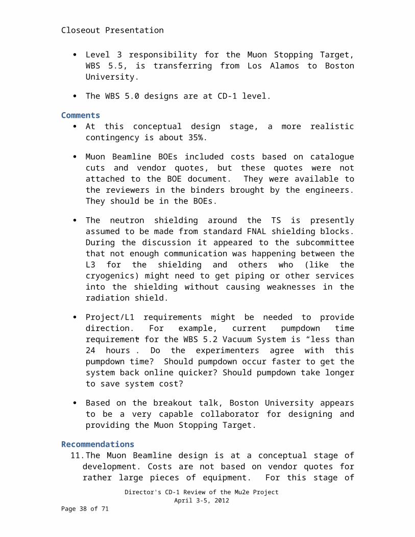
Level 3 responsibility for the Muon Stopping Target, WBS 5.5, is transferring from Los Alamos to Boston University.
The WBS 5.0 designs are at CD-1 level.
Comments At this conceptual design stage, a more realistic contingency is about 35%.
Muon Beamline BOEs included costs based on catalogue cuts and vendor quotes, but these quotes were not attached to the BOE document. They were available to the reviewers in the binders brought by the engineers. They should be in the BOEs.
Director's CD-1 Review of the Mu2e ProjectApril 3-5, 2012
Page 28 of 52
Closeout Presentation
The neutron shielding around the TS is presently assumed to be made from standard FNAL shielding blocks. During the discussion it appeared to the subcommittee that not enough communication was happening between the L3 for the shielding and others who (like the cryogenics) might need to get piping or other services into the shielding without causing weaknesses in the radiation shield.
Project/L1 requirements might be needed to provide direction. For example, current pumpdown time requirement for the WBS 5.2 Vacuum System is “less than 24 hours”. Do the experimenters agree with this pumpdown time? Should pumpdown occur faster to get the system back online quicker? Should pumpdown take longer to save system cost?
Based on the breakout talk, Boston University appears to be a very capable collaborator for designing and providing the Muon Stopping Target.
Recommendations11. The Muon Beamline design is at a conceptual stage of development. Costs are not
based on vendor quotes for rather large pieces of equipment. For this stage of the project a 24% contingency is too low. The project should review all contingencies for CD-1.
12. The Project should resolve with Technical Division management the issue of the availability of the engineer working on the vacuum system. Presently he is assigned to Mu2e on a 50% time basis and later in the project they will have need of him full time to get to a finished design.
13. Define Project/L1 requirements if there are any.
14. The project should make collaborating institutions aware of Fermilab ESH and Engineering requirements. In general to document components and systems, Fermilab requires engineering calculations that demonstrate components are safe to use, fabrication drawings, and the use of specific national codes and standards.
15. The WBS 5.0 L2 Manager should follow-up with Boston University after they receive the Muon Stopping Target from Los Alamos to go over their plans and to make sure sufficient physicist and engineering resources are available.
Director's CD-1 Review of the Mu2e ProjectApril 3-5, 2012
Page 29 of 52
Closeout Presentation
6.0 Calorimeter, Cosmic Ray Veto
Lead: Jeff Nelson
Contributors: Rich Talaga
6.1 Calorimeter
Findings Significant progress in simulations was demonstrated since the IDR. The group
has evaluated electron acceptance as a function of geometry, clarified the radiation dose and background occupancy, evaluated the test beam exposure in detailed simulations, developed a first-pass reconstruction and appropriate event filter algorithms. This allowed determination of PID and DIO rejection for a few selected calorimeter resolutions.
A small LYSO crystal array was exposed to an electron test beam. The observed energy resolution was compared to one derived from a MC simulation. The data and MC agreed well after the MC resolution was degraded by 4%. It is believed that imprecisely controlled longitudinal uniformity is the cause of the degradation. Longitudinal uniformity is an important specification for meeting the overall energy resolution goals. The calorimeter group has devised a method (involving roughening one surface) to improve longitudinal uniformity by means of diffuse reflection. The crystals will be treated in this manner and re-exposed to a test beam prior to CD-2 to validate the anticipated energy resolution.
An active R&D program including test beams, crystal characterization and qualification to meet the performance specifications is ongoing.
The preliminary physics-driven specifications were presented but currently are not sufficiently mature to specify the detector requirements to the necessary level. For example the backgrounds as a function of electron energy resolution were shown at 1.5MeV (clearly sufficient) and 5MeV (clearly insufficient) but not at the specified resolution (2MeV) or explored with granularity to quantitatively demonstrate the physics specification.
A mature conceptual design that could meet the currently presumed specifications was presented.
Selection of LYSO crystal technology has a number of positive features, including excellent light yield, small temperature dependence, robust radiation hardness and exceptionally strong mechanical properties (Young’s modulus, and ultimate tensile strength). This last feature requires less external structural support and allows a simpler method of support.
Director's CD-1 Review of the Mu2e ProjectApril 3-5, 2012
Page 30 of 52
Closeout Presentation
Two calibration systems are proposed: a source calibration method based on that used in Babar and a two-color laser calibration system.
An alternative geometry that improves acceptance and may reduce background occupancy by using a disk-based geometry seems promising.
Alternative crystals (PbWO) have a significantly lower light output, large temperature dependence and operational disadvantages. The lower light output means that the energy resolution will be well below the optimal goals of the experiment.
Comments A conceptual design that could meet the currently presumed specifications was
presented. While state of the art and not yet fully demonstrated, the specifications appear to be achievable. The design specifications were better motivated than those presented at the IDR.
As noted in the IDR, the alternative design (PbWO) is well known. In addition many advantages of the LYSO crystals are so promising that focusing the task’s effort solely on LYSO is justified.
Length of the crystals has been set to 11cm in the reference design based on simulations of shower containment. This is near the limit of lengths that would meet the resolution specification. At modest expense to the project additional conservatism could be added to the design by using somewhat longer crystals.
Uncosted physicist labor was not present for some tasks. This should be rectified before the CD-1 review.
There is a significant gap in the labor profile between the R&D period to specify the technical design and the components acquisition period post CD-3b. After that period there is a relatively short high-activity construction phase, which should make the assembly efficient. The gap in the labor profile between R&D and CD-3b will likely result in laying off the R&D technical crew. In addition the schedule indicates a ramp from the first example production modules in the R&D period to full productivity after CD-3b. A more significant preproduction phase after the indicated R&D program would allow for validation of production quality control, and production efficiency. It would also assure a more level labor profile after the initial R&D phase.
The schedule did not explicitly call out reviews to validate the design readiness prior to production fabrication and acquisition.
Having a number of viable commercial LYSO vendors makes the M&S contingency estimate (24%) reasonable given the evaluation rules at this stage of the project. Risk factors including exchange rates and commodity prices are not reflected in this estimate but are currently reflected in the project risk evaluation and cost-range estimates.
Director's CD-1 Review of the Mu2e ProjectApril 3-5, 2012
Page 31 of 52
Closeout Presentation
The contingency on the effort (32%) for R&D, acquisition, characterization, and assembly seems low given the possible large changes to the mechanical design.
Recommendations16. The specifications presented were plausible but without firm connection to the
results of physics-driven simulations of the experimental requirements. The essential functions of the calorimeter must be used to define the specifications quantitatively by CD-2.
17. Funding should be made available in a timely way to complete the necessary R&D work toward CD-2.
18. Develop a resource-leveled schedule that ensures better continuity of the task’s technical staff throughout the R&D, production, and testing.
19. Adopt a more significant preproduction phase (e.g. 10%) after the indicated R&D program that would allow for validation of the bulk production of the quality crystals and large-scale structural design prototyping.
6.2 Cosmic Ray Veto
Findings The design for the cosmic ray muon veto is based on the well-established
technology of extruded plastic scintillator read out by WLS optical fibers. The photodetector design has evolved from multi-anode PMTs to Silicon Photomultipliers (SiPMs). The new photodetector design is significantly more compact and allows readout from both ends of the WLS fibers. The system’s electronics are based on newly available commercial ASICs designed for ultrasound applications.
Simulations of the electron backgrounds induced by cosmic rays have continued since the IDR. The statistics on background simulations, based on huge samples, have increased from two background events to 14 events, yielding a prediction of somewhat less than 400 expected over the lifetime of the experiment. These lead to a specification of better than 0.01% inefficiency on the veto.
Since the last review the scintillator modules have become more robust by adopting a design that allows for a new two-ended readout for each for the four fibers in each counter. This updated module design integrates the mounting of the photo detectors and front-end electronics with ease of installation and good alignment control. It also improves the hermeticity of the veto layout.
Achieving the required high veto efficiency requires sufficiently high light yield and good control of the gaps between adjacent counters. Simulations show reasonable tolerance.
Director's CD-1 Review of the Mu2e ProjectApril 3-5, 2012
Page 32 of 52

Closeout Presentation
The new design has adopted two-ended readout in response to the IDR Comment: “An alternative method would be to use two-ended readout or splitting the readout across multiple readout front-ends”.
Comments There is a significant gap in the labor profile between the R&D period to specify
the technical design and the components acquisition period post CD-3b. After that period there is a relatively short high-activity construction phase, which should make the assembly efficient. The gap in the labor profile between R&D and CD-3b will likely result in laying off the R&D technical crew. In addition the schedule indicates a ramp from the first example production modules in the R&D period to full productivity after CD-3b. This will leave the production throughput and labor models unvalidated until well into production. A more significant preproduction phase after the indicated R&D program would allow for validation of the construction labor model, production-tooling, quality control, and production efficiency. It would also assure a more level labor profile after the initial R&D phase.
A vertical-slice test, comprising scintillator readout via the newly adopted photodetector and custom front-end electronics, and a prototype mu2e DAQ, was described and funded in the R&D program but not called out explicitly in the presentation. This should be highlighted.
As a result of a value engineering campaign the neutron shielding was reduced. If neutron rates were found to be high enough to cause problems for the veto they would also be a problem for other detector subsystems. These simulations were not completed as of this review. They must be completed prior to final design specification and CD-2.
The active detector is based on coextruded plastic scintillator: a 10cm x 1cm profile with axial 4 holes is planned. This is an extrapolation of current work, and should be achievable with more sophisticated downstream sizing and optimization of the die. An identified back-up plan is to use existing 5-cm extrusions, with a modest increase in dead space and a doubling of the number of the scintillator counters.
Validation of the light yield and threshold for the SiPM readout should be performed as part of the R&D program. The response of the scintillator to MeV neutrons should be measured to ascertain vulnerability to these backgrounds.
The scintillator QA station described in the CDR is based on a tracking cosmic ray test stand requiring up to three days of testing for each module. Recent experiments (MINOS, MINERvA, CLAS-PCAL, T2K-ND280) have used automated scanners based on cumulated gammas sources. This allows for significantly faster testing and can be based either on current readout or the production electronics.
Director's CD-1 Review of the Mu2e ProjectApril 3-5, 2012
Page 33 of 52
Closeout Presentation
Recommendations20. Funding should be made available in a timely way to complete the necessary R&D
work toward CD-2.
21. Adopt a more significant preproduction phase (e.g. 5-10%) after the indicated R&D program that would allow for validation of the construction staffing model, production-tooling, quality control, and production throughput.
22. Develop a resource-leveled schedule that ensures better continuity of the task’s technical staff throughout the R&D, production, and testing.
23. Complete the neutron background simulations, which will inform the final optical design prior to CD-2.
Director's CD-1 Review of the Mu2e ProjectApril 3-5, 2012
Page 34 of 52

Closeout Presentation
7.0 Tracker / DAQ
Lead: Peter Wilson
Contributor: Paul Padley
7.1 Tracker
Findings The Tracker is based on a straw tube design to provide low mass and allow for
operation in vacuum. Scope of the subsystem includes the mechanical assembly, readout electronics, and support infrastructure.
The straw tubes use gold.
Labor and M&S estimates draw heavily on experience from construction of the CDF drift chamber and ATLAS TRT (straws). The labor resources include un-costed scientist effort, which can be easily identified at the task level in the provided Gantt Chart.
The Tracker schedule is not resource leveled and has significant periods with little or no activity. The detector construction completion is well in advance of critical path for installation.
No milestones that cross L2 systems were shown.
No Production or Installation Readiness Reviews were provided for in the schedules shown.
A design of the readout exists with a preamp made with discrete components for each end of the straw and an ASIC mounted in the middle that digitizes the signals from both ends. Prototype preamps have been tested and a prototype ASIC that handles four straws has been submitted for fabrication. The readout of the data will use an FPGA located on detector.
Readout is planned for both ends of each straw. The difference in the timing signals will be used to locate the track along the length of the straw. Initial measurements of time difference resolution have been made with a prototype straw chamber. Simulation of the time division performance of the electronics has been performed indicating that a resolution better than 100ps is achievable. Studies of track reconstruction on simulated data shows that including position information will significantly improve reconstruction efficiency.
As recommended by the 2011 IDR, leak tests are being conducted on prototype gold-mylar straws. Preliminary results on a single straw indicate that it passes the leak requirement but only marginally.
Director's CD-1 Review of the Mu2e ProjectApril 3-5, 2012
Page 35 of 52

Closeout Presentation
Comments The Tracker group has done an excellent job rewriting the CDR since the IDR.
The Tracker schedule is quite relaxed. There are ample opportunities to speed up the schedule to match a faster schedule for the rest of the project.
It can be extremely useful to define integration tests that require simultaneous operations of several systems. For example, a test that requires operation of a subset or prototype of the tracker using prototype of the DAQ and DAQ-provided slow control.
Normally project management will require a production readiness review before the major productions are commenced. The L2 managers were unaware of any such requirement and had not provided for such in the schedule. This should be required by L1 management before major procurements and production.
Inclusion of time division measurement to the straw readout clearly will improve the track reconstruction efficiency. Pushing the time difference resolution under 100ps provides additional gain in efficiency and should be pursued.
Although initial results of the straw leak tests indicate an acceptable leak rate it was not yet clear whether the rate measured is actually from leaks or from outgassing of the straw construction materials. Careful attention needs to be paid to these tests including testing multiple straws and differentiating between outgassing and leaks.
Recommendations24. Define integration milestones that require simultaneous operation of multiple
systems before CD-1.
25. Reevaluate the risk on the purchase of straw material taking into account the potential increase in the cost of gold in the future before CD-1.
26. Tracker electronics team should make contact with the LHC electronics community to stay abreast with the latest developments in qualification of FPGAs for radiation tolerance.
Director's CD-1 Review of the Mu2e ProjectApril 3-5, 2012
Page 36 of 52
Closeout Presentation
7.2 DAQ
Findings The DAQ hardware consists almost entirely of commercial off the shelf
equipment. Only a portion of the timing distribution will be custom electronics.
Costing of the DAQ hardware is based on the cost of currently (FY12) available hardware with a reasonable assumption of the extrapolation of computing capabilities to 2017.
Labor estimates for the DAQ system are based on experience developing similar systems for the NOvA experiments. The labor resources include un-costed scientist effort, which can be easily identified at the task level in the provided Gantt Chart.
The DAQ schedule has significant periods with little or no activity particularly between CD-2 and CD-3b and after FY17. The L2 manager plans to level the schedule prior to the Lehman review including moving development of a Pilot System from after CD-3b to before CD-3b.
In several presentations the possibility of a hardware triggering option for the DAQ system was mentioned.
No milestones that cross L2 systems were shown.
No Production or Installation Readiness Reviews were provided for in the schedules shown.
Detectors deliver their data on fiber optic cables to a PCIe card mounted in a DAQ system computer. Each detector subsystem is responsible for the on-detector Readout Controllers (ROC) that connect to this fiber. Fast control signals are provided to the detector electronics over the same fiber optic plant.
Comments Hardware with capabilities necessary for the DAQ system is either currently
available commercially or should be available within 1-2 years. The pricing assumptions and assigned contingency are reasonable.
Labor estimates are reasonable and un-costed scientist effort appears to be correctly included in the project.
The DAQ schedule is quite relaxed. There are ample opportunities to speed up the schedule to match a faster schedule for the rest of the project.
Early integration tests with the detector subsystems could be achieved by using copies of the prototype or pilot DAQ as part of the detector teststands.
Director's CD-1 Review of the Mu2e ProjectApril 3-5, 2012
Page 37 of 52
Closeout Presentation
There is no “hardware triggering option”. By that we mean there is not a proposal to provide a L1 Accept signal to the front end electronics. There is a possibility to provide event filtering in the DAQ hardware, in particular by using the FPGA on the readout PCIe card. The decision on whether to exercise this option can be left until after the start of operations. There is little cost impact of maintaining this option as it would use hardware already planned for the DAQ.
It can be extremely useful to define integration tests that require simultaneous operations of several systems. For example, a test that requires operation of a subset or prototype of the tracker using prototype of the DAQ and DAQ-provided slow control.
Normally project management will require a production readiness review before the major productions are commenced. The L2 managers were unaware of any such requirement and had not provided for such in the schedule. This should be required by L1 management before major procurements and production.
Although each detector system is responsible for its own readout controllers there are substantial opportunities for shared designs between the systems.
The success of integrating the detector systems with the DAQ is highly dependent on defining the communication protocols for control messages and data synchronization. Defining these interface protocols early is critical to ensuring that the hardware and software designs are compliant. The project electrical engineer would be a good choice as the overseer of this definition process.
Recommendations27. Adjust the DAQ schedule to level the activities to better match rest of project
schedule by CD-1.
28. Purchase of production DAQ hardware should be scheduled as late as possible to take advantage of Moore’s law performance improvements and this should be done prior to CD-1.
29. Define criteria to be used to determine if they need hardware filtering. Before CD-1include a corresponding milestone for the decision.
30. Define integration milestones that require simultaneous operation of multiple systems before CD-1.
31. Before CD-1, include a milestone for completion of a draft DAQ interface protocol document that occurs within one year.
Director's CD-1 Review of the Mu2e ProjectApril 3-5, 2012
Page 38 of 52
Closeout Presentation
8.0 Project Management
Lead: Marc Kaducak
Contributors: Bill Freeman, Fran Clark, Sherese Humphrey, Elaine McCluskey, Mike Andrews
8.1 Cost
Lead: Bill Freeman
Contributor: Fran Clark
Findings The current point estimate for the TPC is $225.3M (AY$) with a base cost
estimate of $173.3M (AY$) and a bottoms-up contingency of $52.0M (AY$) associated with estimate uncertainty. The contingency was estimated by assigning separate labor and M&S contingency percentages to lowest-level scheduled activities, based on the type of estimate (e.g. catalog price, vendor quote, in-house engineering estimate, etc.) and then rolling up the results.
The proposed CD-1 TPC budget range is $204M to $281.1M (AY$). The lower bound of $204M is derived from the current point estimate for the base budget + assigned contingency less a risk-based “opportunity” budget reduction of $21.3M. The upper bound is the base budget + contingency plus an additional risk-based “threat” contingency of $55.8M.
A detailed WBS exists that is oriented by product or project phase. It has nine L2 elements. Ninety-two control accounts have currently been identified at L3 or lower, depending on the specific subsystems. A WBS dictionary down to Level 3 also exists.
Director's CD-1 Review of the Mu2e ProjectApril 3-5, 2012
Page 39 of 52

Closeout Presentation
The budget and contingency summary at WBS L2 provided by the project is shown below:
Mu2e Total Project CostEscalated Base
Cost (k$) Cont. Cont. (k$) Total Cost (k$)1. Project Management $ 20,139 0% $ 0 $ 20,1392. Accelerator $ 28,920 30% $ 8,773 $ 37,6933. Conventional
Construction $ 18,942 36% $ 6,819 $ 25,7614. Solenoid $ 73,968 38% $ 27,915 $ 101,8835. Muon Beamline $ 10,955 24% $ 2,670 $ 13,6256. Tracker $ 6,952 34% $ 2,381 $ 9,3337. Calorimeter $ 3,573 25% $ 882 $ 4,4558. Cosmic Ray Veto $ 4,027 34% $ 1,360 $ 5,3879. Trigger/DAQ $ 5,785 21% $ 1,238 $ 7,023
Total Project Cost ($K) $173,261 30% $ 52,038 $ 225,299“Opportunity” Reduction ($ 21,299)
“Threat” Contingency $ 55,801
41% of the base budget estimates (in dollars) are based on budgetary quotes, vendor quotes, or catalog prices.
A detailed resource-loaded schedule has been developed using Primavera P6. The schedule currently has approximately 3779 tasks (with 3449 work packages identified and ~420 milestones). Tasks are matched to specific WBS elements and coded with/assigned to control accounts and chargeable task codes.
P6 tasks and resource assignments are loaded into the Cobra cost processing tool as work packages and budget elements beneath chargeable task codes. Fully burdened and escalated costs for each work package are then calculated in Cobra. Cost books detailing the planned budgets in AY$ are produced using output from Cobra.
Budgeted costs in prior fiscal years (FY10 and FY11) are not matching actual costs in the schedule/Cobra.
Some longer-duration activities are currently identified and budgeted as planning packages in the P6 schedule and Cobra cost processing tool. The intent is to
Director's CD-1 Review of the Mu2e ProjectApril 3-5, 2012
Page 40 of 52
Closeout Presentation
expand those items, at the appropriate time, into more detailed work packages with associated budgets.
A draft funding profile for Mu2e was recently provided by DOE.
Some resource-leveling remains to be done before a fully meaningful comparison with the year-by-year funding profile can be made.
Comments The project team is competent and dedicated, which bodes well for the success of
the project.
The project’s methodology for estimating and compiling costs is sound. The associated documentation (BOEs, cost books, etc.) is reasonably thorough and complete for this stage of a project. Overall, the base budget estimate appears credible and realistic for this stage.
The 30% overall contingency (24% on labor and 36% on M&S) is perhaps a bit low for a project at this stage of development. In particular, the overall labor contingency of 24% seems too low.
The P6 resource-loaded schedule is reasonably detailed, with appropriate relationships linking most of the activities. However, some relationships are still missing, in particular links to certain CD and/or start-of-FY milestones. Having budget scheduled in the wrong FY can lead to few-percent errors in the calculated AY$ budgets for such tasks, due to erroneous escalation calculations.
Recommendations32. Revisit the assignment of labor contingency percentages throughout the project
before the CD-1 review and determine if any should be changed.
33. Review and reconcile the cost numbers in all project documentation and presentations to insure consistency before the CD-1 review.
Director's CD-1 Review of the Mu2e ProjectApril 3-5, 2012
Page 41 of 52
Closeout Presentation
8.2 Schedule
Lead: Sherese Humphrey
Contributor: Fran Clark
Findings Mu2e has seven level two (L2) WBS managers, with many level three (L3) WBS
managers. Each L2 manager has developed a schedule, with the assistance of L3 managers. They have also prepared the Basis of Estimate document that correlates to the cost in the resource loaded schedule.
Mu2e identified its critical path, but the schedule has some open relationships and negative float. The project agreed that this needs to be reviewed and corrected. Some of the LOE activities are not classified as LOE and are showing up on the project’s critical path.
Links and/or milestones to external projects that are off project, which could impact the success of the project, need to be incorporated into the schedule. Additionally, Mu2e has established some interface links between some L2 WBSs.
Mu2e plans to collect cost at L4 and will have 92 control accounts.
Drill downs were performed on the Accelerator, Conventional Construction and Solenoids WBSs. L2 managers, in coordination with their L3 managers, successfully performed the traces and were able to retrieve supporting information. Some material estimates require additional information, i.e., vendor quotes, to further support the estimate.
P6 schedule currently has a forecast early date for CD-4 of April 17, 2020. This allows ~17 months of programmatic float to the end of Q4FY21, the formal CD-4 date listed in the PPEP.
Comments Mu2e needs to finish correcting the logic assignments to ensure no open
relationships exist and so that the project’s critical path is reflected accurately.
Mu2e L2 and L3 managers need to ensure they have supporting engineering documentation for material estimates readily available if vendor quotes are not available. Estimate evidence needs to be objective.
External off-project links that could impact the project’s performance need to be incorporated into the schedule. Additionally, this off-project work needs to be reflected in the risk register as a potential threat.
The P6 resource-loaded schedule is reasonably detailed, with appropriate relationships linking most of the activities. However, some relationships are still
Director's CD-1 Review of the Mu2e ProjectApril 3-5, 2012
Page 42 of 52

Closeout Presentation
missing, in particular links to certain CD and/or start-of-FY milestones. For example, a three-month lag for the start of the production solenoid fabrication was intended to exist with respect to 01Oct15 but it was apparently missing, causing the start of the task to move earlier than intended. Moving the start date to Jan 2016 might impact the remaining float to CD-4, if this task is close to or on the critical path.
Recommendations34. Upon confirmation of schedule, cost and documentation update, train the L2 and
L3 managers on how to drill down their areas in a timely fashion in preparation for the CD-1 Review.
35. Thoroughly scrub the P6 schedule to eliminate remaining deficiencies in task relationships and resource assignments within and between each WBS L2 schedule.
36. Add explicit tasks for production and installation readiness reviews to the P6 schedule where needed and assign resources to them. Link them as predecessors to the associated procurement, fabrication, or installation tasks.
Director's CD-1 Review of the Mu2e ProjectApril 3-5, 2012
Page 43 of 52
Closeout Presentation
8.3 Management
Lead: Marc Kaducak
Contributor: Elaine McCluskey
Findings The point estimate TPC of $225M does not include any contingency for Project
Management.
The project management group is fully staffed with the exception of a QA manager. A plan for increased project controls and project engineering LOE exists.
Drafts of the PPEP and the Acquisition Strategy have been developed by both the Project and the DOE Federal Project Director. Some numbers such as change control thresholds and milestones are missing.
The PMP is in draft form and is largely complete, but does not include the management approach to early 2012 Fermilab decisions regarding distributed projects on which Mu2e depends.
The Conceptual Design Report is complete documenting the design at CD-1. This includes a description of the Project approach to Sustainable Design and Environmental Stewardship considerations.
A Risk Management Plan describing the current and future approach to risk management is complete. A risk register with 120 risks has been prepared. Cost and schedule impacts have been estimated for the identified risks.
A Quality Assurance Program describes the overall Project approach to QA. In the CDR, each chapter for a L2 system documents the major QA aspects for that system.
The needs of the Mu2e Project to meet the One-for-One Building Space Requirement was met with a waiver in 2009.
A NEPA Project Information Form has been prepared and submitted to the Fermilab ES&H Section for input to the Environmental Evaluation Notification Form.
Comments The project management team has done a commendable job in establishing the
team, value engineering, risk identification, generating the prerequisite documentation and collecting cost and schedule information. The management team and systems are in place for CD-1.
Director's CD-1 Review of the Mu2e ProjectApril 3-5, 2012
Page 44 of 52
Closeout Presentation
The project controls group has demonstrated the capability to produce the reports required at this phase (RLS, Critical Path, Obligation Profile, FTEs, etc.). Iterations with L2 managers for corrections and improvements are planned imminently.
The change control threshold tables are not complete and the current threshold levels seem low relative to NOvA, which has a similar total cost.
The required documentation for CD-1 exists, though the Acquisition Strategy and Preliminary Project Execution Plan are in draft form. Since the AS and PPEP include a cost range and funding profile, priority should be given to resource leveling such that these documents can be approved on schedule.
Since there are large procurements and contracts, the needs for procurement personnel and perhaps an expediter should be revisited.
The Fermilab Directorate is interested in accelerating the project schedule. Since the funding profile is still in development, opportunities for use of additional funding in FY14 and beyond should be explored to shorten the schedule.
The risk register includes approximately 120 entries, of which 25 are considered high risks. Cost and schedule impacts have been estimated. The state of risk management appears sufficient for CD-1.
The Recycler RF, connection to P1, and extraction kicker are assumed to be provided by g-2. The g-2 project has not yet received CD-0 so assumptions regarding its schedule and scope are not completely substantiated.
Presentations followed a uniform template, which was appreciated by the committee. There was some variability in familiarity with cost and schedule amongst the L2 managers. All L2s will need to review, modify, and approve their respective cost and schedule estimates so they address it confidently.
MOUs with collaboration institutions will be needed, even if all labor is uncosted.
As part of risk management, the risk board will need to convene on a regular basis to update the status of the risk register.
Recommendations37. CD-1 is scheduled in FY12. Work with lab management to plan additional
resources required for CD-2 preparation before CD-1.
38. Level project resources and develop a corresponding funding profile with DOE as soon as possible. Allow time for iterating with L2 (or appropriate level) managers. Revising the RLS is the top priority for completion by the CD-1 review.
39. Review the uncosted scientific resources to verify that they are correctly accounted for in the RLS by CD-1.
Director's CD-1 Review of the Mu2e ProjectApril 3-5, 2012
Page 45 of 52

Closeout Presentation
40. Complete change control threshold, milestone, and funding profile tables in project documents such as PPEP and Configuration Management by CD-1.
41. Ensure that equipment required from the Tevatron has been officially claimed in the register kept by Accelerator Division shortly following CD-1.
42. For the CD-1 review, prepare a table of time phased resource requirements for Project Management by function (project controls, QA, safety, etc.).
43. Ensure that the DOE CD-1 review committee is apprised of the assumptions regarding g-2, AIP, and GPP project plans and status prior to the review.
Director's CD-1 Review of the Mu2e ProjectApril 3-5, 2012
Page 46 of 52
Closeout Presentation
8.4 ES&H
Lead: Mike Andrews
Findings An Integrated Safety Management (ISM) Plan has been developed for the Mu2e
Project which addresses integration of the ISM principles and core functions.
A Project Preliminary Hazard Analysis Report has been developed which indentifies and mitigates hazards associated with the project through eight physical zones.
A Preliminary Security Vulnerability Assessment Report has been developed which identifies no additional security requirements for the Mu2e Project.
The Project Management Plan effectively addresses the ESH responsibilities for the management team.
The Mu2e Risk Management Plan has addressed the management and mitigation of ESH risks within the project through the ESH assessment documentation and ISM Program.
A Fire and Life Safety Assessment has been completed by Aon Fire Protection Engineering for the Mu2e conventional facilities.
The Laboratory ESH Section and Accelerator Division are in the process of evaluating the use of Total Loss Monitors (TLM) as a means of supplementing passive shielding requirements by limiting beam loss to meet sky shine shielding requirements.
The detector hall has included a work cell with remote handling for servicing highly radioactive components.
A wetlands delineation was performed and the study was reviewed by the Corps of Engineers with a finding that the wetlands are non-jurisdictional.
Comments The Project has assigned a dedicated individual within the project office to act as
Project ESH Coordinator. However, the Project ESH support personnel need to be more clearly defined including those ESH disciplines that are matrixed to the project including radiation safety, fire and life safety, industrial hygiene, environmental, construction safety, etc.
The Project ESH Coordinator is not listed in project management box of the Mu2e organizational chart.
Director's CD-1 Review of the Mu2e ProjectApril 3-5, 2012
Page 47 of 52

Closeout Presentation
The Project ESH presentation needs to include status of key ESH topics like the ISM Plan, ESH support, PHAR, NEPA, PSVAR, standards/codes, fire & life safety, CDR ESH design criteria, and ESH participation in the design review process.
The PHAR addresses cryogenic safety and oxygen deficiency hazards; however, preliminary ODH analysis documentation has not been completed. The results from the analysis will assist in developing design criteria.
The PHAR needs to consistently reference relevant ESH requirements, standards and codes including specific FESHM chapters, DOE Orders, NFPA, ANSI, ASME, etc. The PHAR could benefit from a summary chart rolling up the results of the PHAR worksheets both pre and post mitigation risk status. For clarity, each worksheet should include both the name and number of the zone. Section 4.1 of the PHAR makes reference to three different total number of principle zones when reviewing verbiage, tables, and figures.
A prototype Total Loss Monitor (TLM) beam loss monitoring system has been developed and is installed in Pbar. Studies are taking place to characterize TLM behavior in AP3 line and Accumulator at 8 GeV. If results are positive the TLM would become an integral part of the Radiation Safety System based on review and approval by the FNAL ESH Section. Presently as per the FRCM, a Director’s exception would also be needed for TLM’s to be used in place of passive shielding by the Mu2e Project.
The project is committed to complying with the LEED guiding principles within the design of the Mu2e facilities. This commitment should be incorporated into the project ISM Plan.
The required NEPA documentation is in process. A Project Information Form (PIF) has been submitted to the FNAL NEPA Coordinator. A draft Environmental Evaluation Notification Form (EENF) will be submitted to the DOE Fermilab Site Office (DOE-FSO) by May 4 with a formal submittal to by May 18, 2012.
Recommendations44. Provide approval/signature pages for all ESH/QA documents required for CD-1.
45. The Project ESH Coordinator should provide the presentation on over-all ESH status to the DOE CD-1 review committee.
46. Develop an organizational chart which clearly defines Mu2e Project ESH support organization including ESH disciplines and responsibilities.
47. Complete preliminary ODH analysis documentation for relevant Mu2e facilities, as defined in the PHAR.
48. Determine if the prototype TLM beam loss monitoring system is a viable sky shine shielding solution in place of passive shielding.
Director's CD-1 Review of the Mu2e ProjectApril 3-5, 2012
Page 48 of 52
Closeout Presentation
49. The Project needs to receive a letter of determination from DOE-FSO relating to NEPA strategy prior to the CD-1 review.
Director's CD-1 Review of the Mu2e ProjectApril 3-5, 2012
Page 49 of 52
Closeout Presentation
9.0 Charge Questions
9.1 Design Review Charge Questions for the Accelerator and Solenoid
9.1.1 Is the design technically adequate? Is the design likely to meet the technical requirements? Are the physics requirements clearly stated and documented? Have these requirements been translated into technical performance requirements and specifications, if not yet are there plans to do so?Yes.
9.1.2 Can the design be constructed, inspected, tested, installed, operated and maintained in a satisfactory way?Yes.
9.1.3 Is there adequate supporting documentation to support the conceptual design and the transition to developing the preliminary design?Yes.
9.1.4 Are the risks (on technical, cost, and schedule basis) of the selected base design approach and alternatives understood and are appropriate steps being taken to manage and mitigate these risks? Have areas been identified where value engineering should be done? If value engineering has been performed is it documented?Yes.
9.1.5 Has the project acceptably addressed the relative recommendations from the independent Director’s Conceptual Design Review of Mu2e that was conducted on May 03-05, 2011?Yes.
Director's CD-1 Review of the Mu2e ProjectApril 3-5, 2012
Page 50 of 52
Closeout Presentation
9.2 Cost Schedule, Management, and ES&H Charge Questions
9.2.1 Has the Project developed a quality resource loaded schedule? Has all the work been appropriately identified, estimated and scheduled, including the work associated with performing the preliminary design, final design and value engineering activities?
No, the resource-loaded schedule is not yet a quality product. The project team understands what work remains. Most work is identified in the schedule; however, attention should be paid to adding design reviews and additional milestones.
9.2.2 Are the estimated cost and proposed schedule ranges realistic, consistent with the technical and budgetary objectives, and justified by the supporting documentation?
Yes.
9.2.3 Has the Project implemented a Risk Management Process by identifying risks, performing a risk assessment and started developing mitigation plans at an appropriate level for the CD-1 stage?
Yes. A risk management process has been established and a risk register exists.
9.2.4 Is the Project Team adequately staffed and does it possess adequate experience to successfully carry out the Project
Yes. More resources will be needed following CD-1, but the project is aware of these needed. There is a general concern about availability of Accelerator Division resources.
9.2.5 Is the current staffing level adequate to complete the work to achieve CD-2? If not, has the appropriate staffing level been identified in the schedule and has a staffing plan been developed to acquire the future staffing needs?
Yes and No. Presently, the project is confident that they can achieve the requirements of CD-2. However, additional commitment and support is required from management to provide additional engineering support for the Accelerator and some additional support for project controls. If the resources are not made available, the project will not meet expectations.
Staffing levels have been identified in the schedule; however, the Accelerator staffing needs to be assessed to ensure the levels are adequate for the work required.
9.2.6 Are ES&H aspects being properly addressed given the project’s current stage of development?
Yes.
9.2.7 Is the documentation required by DOE O 413.3B in order and is the Mu2e Project ready for a DOE CD-1 review in June?
Yes, the documentation is in order and can be ready with some updating. The Project needs to revise the resource-loaded schedule, and the Directorate should assess progress
Director's CD-1 Review of the Mu2e ProjectApril 3-5, 2012
Page 51 of 52

Closeout Presentation
on the revisions by the end of April. See more detail in the cost and schedule section of the report.
Director's CD-1 Review of the Mu2e ProjectApril 3-5, 2012
Page 52 of 52