Embed Size (px)
Citation preview
1
Closed Bipolar Electrodes for Spatial Separation of H2 and O2
Evolution during Water Electrolysis and the Development of
High-Voltage Fuel Cells
Sean Goodwin, and Darren A. Walsh*
School of Chemistry and GSK Carbon Neutral Laboratory for Sustainable Chemistry
University of Nottingham
Jubilee Campus, Nottingham NG7 2TU, UK
E-mail: [email protected];
Tel: 0044 115 8467495; Fax: 0044 115 9513562
Keywords: bipolar electrochemistry, electrocatalysis, hydrogen economy, electrolyser, regenerative fuel cell
2
Abstract
Electrolytic water splitting could potentially provide clean H2 for a future ‘Hydrogen
Economy.’ However, as H2 and O2 are produced in close proximity to each other in water
electrolysers, mixing of the gases can occur during electrolysis, with potentially dangerous
consequences. Herein, we describe an electrochemical water-splitting cell, in which mixing
of the electrogenerated gases is impossible. In our cell, separate H2- and O2-evolving cells are
connected electrically by a bipolar electrode in contact with an inexpensive dissolved redox
couple (K3Fe(CN)6/K4Fe(CN)6). Electrolytic water splitting occurs in tandem with
oxidation/reduction of the K3Fe(CN)6/K4Fe(CN) redox couples in the separate compartments,
affording completely spatially-separated H2 and O2 evolution. We demonstrate operation of
our prototype cell using conventional Pt electrodes for each gas-evolving reaction, as well as
using earth-abundant Ni2P electrocatalysts for H2 evolution. Furthermore, we show that our
cell can be run in reverse, and operate as a H2 fuel cell, releasing the energy stored in the
electrogenerated H2 and O2. We also describe how the absence of an ionically-conducting
electrolyte bridging the H2- and O2-electrode compartments makes it possible to develop H2
fuel cells in which the anode and cathode are at different pH values, thereby increasing the
voltage above that of conventional fuel cells. The use of our cell design in electrolysers could
result in dramatically improved safety during operation, and the generation of higher-purity
H2 than available from conventional electrolysis systems. Our cell could also be readily
modified for the electrosynthesis of other chemicals, where mixing of the electrochemical
products is undesirable.
3
Introduction
While renewable energy from wind turbines and solar panels offers obvious
advantages over energy derived from fossil fuels, the diurnal and seasonal variability of
renewable systems means that energy-storage systems are required to maintain a smooth
energy supply. In principle, batteries could be used to store renewable electricity but,
assuming costs remain stable for the foreseeable future, most grid-scale battery systems are
too expensive (in $ W−1) for widespread adoption.1 Mechanical storage of solar energy (for
example, by pumping water uphill) is another attractive option but the requirements imposed
by local geography are significant drawbacks.2,3 An alternative approach is to use renewable
energy to drive a thermodynamically-unfavorable reaction and store the energy in the
chemical bonds of a liquid or gaseous fuel. If powered using renewable electricity, the
generation of renewable H2 from water is an extremely attractive option; the H2 could be
stored on site, and recombined with O2 in a fuel cell to generate CO2-free electricity on
demand.4 The generation of H2 using renewable electricity would also have significant
industrial implications; H2 is a key reagent in the synthesis of commodity chemicals such as
ammonia and methanol, but most of the world’s H2 is currently produced from fossil fuels,
releasing CO2 in the process.5 The reactions involved in water electrolysis are given by either
Equations 1 and 2, or 3 and 4 (depending on the pH of the electrolyser environment), giving
the overall water-splitting reaction in Equation 5:
2H+ + 2e− → H2 E0 = 0 V (1)
H2O → ½O2 + 2H+ + 2e− E0 = −1.229 V (2)
2H2O + 2e− → H2 + 2OH− E0 = −0.828 V (3)

4
2OH− → ½O2 + H2O + 2e− E0 = −0.401 V (4)
H2O → H2 + ½O2 E0cell = −1.229 V (5)
Alkaline-electrolyser technology, in which OH− ions are transported between the
electrodes through a liquid electrolyte, is relatively mature, and several commercial systems
exist.6,7 However, these systems generally have limited partial-load ranges, current densities,
and operating pressures.8 Proton-exchange membrane (PEM) electrolysers, in which H+ ions
are transported through polymeric electrolytes, offer a number of advantages over alkaline
systems, including higher reaction efficiencies, operation at higher current densities, and
lower operating costs.8 In addition, PEM electrolysers can produce compressed H2, and
suffer from lower ohmic losses than alkaline systems, due to the use of thin (~30-150 µm)
PEMs. A number of regenerative PEM electrolyser/fuel cell systems that can operate either
in the electrolyser mode or the fuel-cell mode have also been developed, with the advantage
that such systems can save space and/or cost (by requiring just a single device).9
A significant problem in all water electrolysers is that H2 and O2 are invariably
evolved in proximity to each other, so transport of gases across the electrolyte, and in the
headspace of high-pressure electrolysers, can occur, potentially resulting in the formation of
explosive H2/O2 mixtures. Mixing of H2 and O2 in the presence of catalyst particles can also
lead to the production of reactive oxygen species (ROS) that degrade PEMs.10 While PEMs
are more resistant than liquid alkaline electrolytes to gas crossover, crossover of gases
through PEMs can occur, especially during high-pressure operation. The rate of gas
crossover can be decreased by increasing the thickness of the PEMs or by using specialized
composite PEMs, but each approach decreases membrane conductivity.8,11,12 Recent efforts
to prevent gas mixing in PEM electrolysers include the development of gas-impermeable, Li+-
5
conducting ceramic electrolytes,13 which transport Li+ ions between two halves of the
electrochemical cell during electrolysis. The Segré-Silberberg effect has also been used to
control gas-bubble movement during electrolysis, minimising gas mixing at high currents,
even in the absence of a membrane, but significant gas mixing occurred at low currents.14 An
alternative strategy is to decouple H2 evolution and O2 evolution completely, and a novel
approach was reported by Cronin and co-workers who evolved H2 and O2 sequentially, using
the polyoxometalate (POM) H3PMo12O40 as a proton buffer. The POM took up protons
released during O2 evolution and then released them during H2 evolution.15-17 Another two-
step electrolysis system was designed by Xia et al., who coupled H2 and O2 evolution to
oxidation/reduction of a Ni(OH2) electrode.18,19 Reduction of H2O to H2 was accompanied by
oxidation of the Ni(OH)2 electrode to NiOOH, and the subsequent O2-evolution step was
accompanied by reduction of NiOOH to Ni(OH)2. Each of these systems offers a unique
approach to temporal separation of H2 and O2 evolution, but the time for a complete
electrolysis cycle and regeneration of the electrolysis system is obviously longer than for a
system in which simultaneous H2 and O2 evolution can occur.
In this contribution, we describe an electrolytic system in which H2 and O2 evolution
occur simultaneously, but mixing of the product gases is impossible. The key to our approach
is the use of a closed bipolar electrode (CBE), which is a single electronic conductor in
contact with two separate solutions, and at which anodic and cathodic reactions occur
simultaneously.20,21 While bipolar plates have been used for a long time to connect individual
fuel cells and electrolysers in stacks, bipolar electrochemistry in a broader sense has received
renewed interest in recent years, and is being used in electrochemical propulsion,22
sensors20,23 and for monitoring the long-term electrocatalytic activity of anodic and cathodic
half-cell reactions during water electrolysis.24 We demonstrate here a novel cell design, in
6
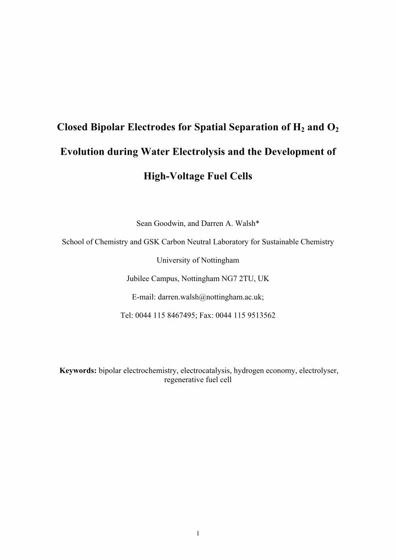
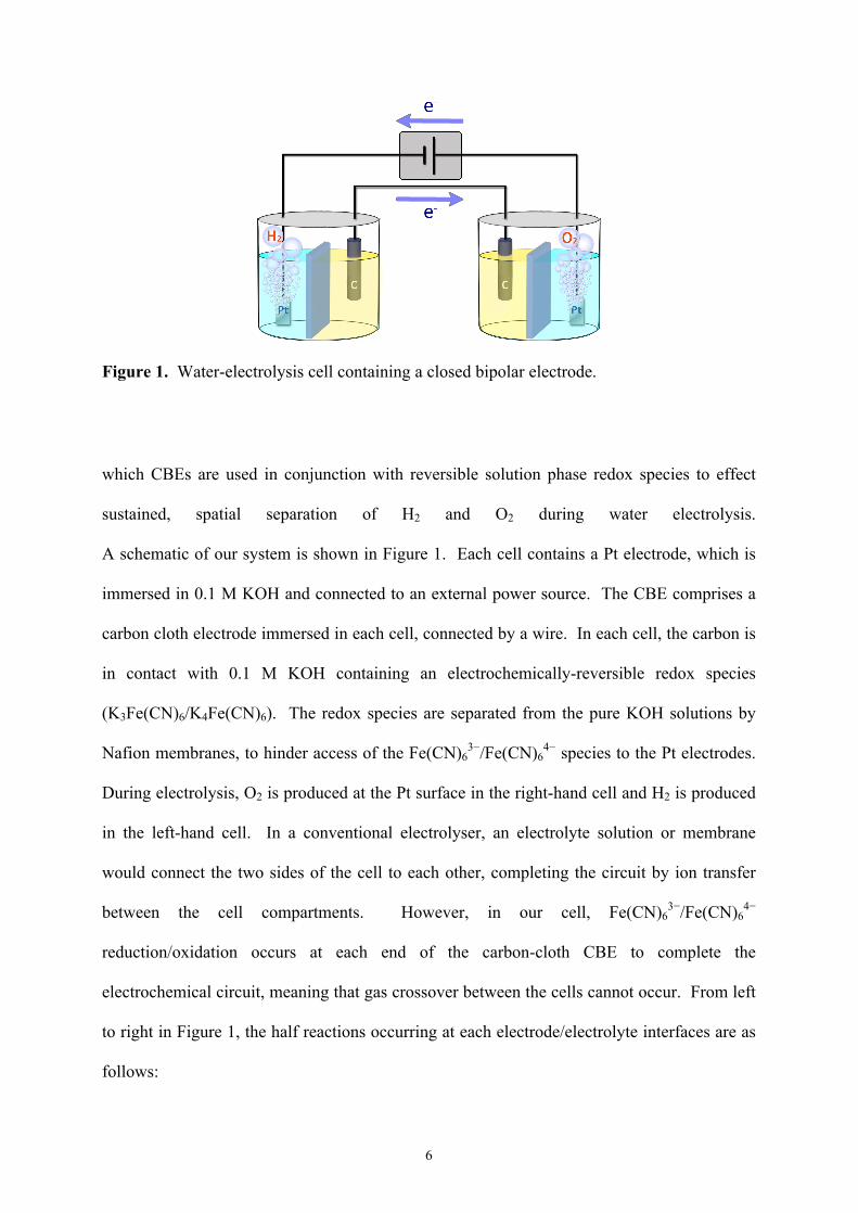
Figure 1. Water-electrolysis cell containing a closed bipolar electrode.
which CBEs are used in conjunction with reversible solution phase redox species to effect
sustained, spatial separation of H2 and O2 during water electrolysis.
A schematic of our system is shown in Figure 1. Each cell contains a Pt electrode, which is
immersed in 0.1 M KOH and connected to an external power source. The CBE comprises a
carbon cloth electrode immersed in each cell, connected by a wire. In each cell, the carbon is
in contact with 0.1 M KOH containing an electrochemically-reversible redox species
(K3Fe(CN)6/K4Fe(CN)6). The redox species are separated from the pure KOH solutions by
Nafion membranes, to hinder access of the Fe(CN)63−/Fe(CN)6
4− species to the Pt electrodes.
During electrolysis, O2 is produced at the Pt surface in the right-hand cell and H2 is produced
in the left-hand cell. In a conventional electrolyser, an electrolyte solution or membrane
would connect the two sides of the cell to each other, completing the circuit by ion transfer
between the cell compartments. However, in our cell, Fe(CN)63−/Fe(CN)6
4−
reduction/oxidation occurs at each end of the carbon-cloth CBE to complete the
electrochemical circuit, meaning that gas crossover between the cells cannot occur. From left
to right in Figure 1, the half reactions occurring at each electrode/electrolyte interfaces are as
follows:

7
Pt 2H2O + 2e− → H2 + 2OH− (6)
C cloth 2[Fe(CN)6]4− → 2[Fe(CN)6]3− + 2e− (7)
C cloth 2[Fe(CN)6]3− + 2e− → 2[Fe(CN)6]4− (8)
Pt 2OH− → ½O2 + H2O + 2e− (9)
In order to continually run the device as a water electrolyser, the anode and the cathode can be
periodically switched (i.e. hydrogen can be evolved alternately at the left and right hand Pt
electrode), maintaining the pH of the electrolytes, and regenerating the
[Fe(CN)6]3−/[Fe(CN)6]4− redox species. As we show below, the device can also be run as a
fuel cell, which releases the energy stored in the electrogenerated gases and regenerates the
[Fe(CN)6]3−/[Fe(CN)6]4− redox species. In addition, as the catholyte and anolyte in our
system cannot mix, we demonstrate that cell voltages >1.229 V can be achieved by using
different-pH electrolytes in each compartment, an approach that cannot be achieved using
conventional devices.
Results and Discussion
Electrolysis of Water in CBE System. Figure 2 shows photographs of a CBE system
before and after 3.7 V was applied between the Pt electrodes for 3 × 10³ s (much lower
potentials are required for water splitting; a high voltage was used here for demonstration
purposes). Inverted glass tubes containing the respective electrolytes were placed over each
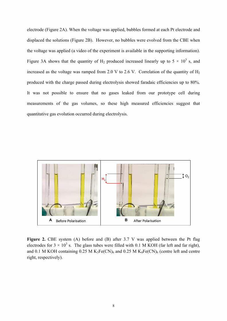
8
electrode (Figure 2A). When the voltage was applied, bubbles formed at each Pt electrode and
displaced the solutions (Figure 2B). However, no bubbles were evolved from the CBE when
the voltage was applied (a video of the experiment is available in the supporting information).
Figure 3A shows that the quantity of H2 produced increased linearly up to 5 × 10³ s, and
increased as the voltage was ramped from 2.0 V to 2.6 V. Correlation of the quantity of H2
produced with the charge passed during electrolysis showed faradaic efficiencies up to 80%.
It was not possible to ensure that no gases leaked from our prototype cell during
measurements of the gas volumes, so these high measured efficiencies suggest that
quantitative gas evolution occurred during electrolysis.
Figure 2. CBE system (A) before and (B) after 3.7 V was applied between the Pt flag electrodes for 3 × 10³ s. The glass tubes were filled with 0.1 M KOH (far left and far right), and 0.1 M KOH containing 0.25 M K3Fe(CN)6 and 0.25 M K4Fe(CN)6 (centre left and centre right, respectively).
A B

9
Figure 3. (A) Amount of H2 produced from the Pt cathode of a CBE system as a function of time, and at a range of voltages, using a Pt-wire working electrode (3.8 cm length) and a Pt flag counter electrode. Amounts are normalized to the surface area of the working electrode. (B) Cyclic voltammogram recorded at a Pt disk working electrode in a single electrochemical cell containing 0.1 M KOH, a Pt flag counter electrode, and Ag/AgCl reference electrode (dashed line). The potential was cycled between −1.7 V (initial potential) and 1.4 V at 50 mV s−1. The solid line shows a voltammogram recorded using the same working, counter and reference electrodes, but using the CBE system shown in Figure 1. The Ag/AgCl reference electrode was in the right-hand cell of the CBE system, along with the counter electrode, and the working electrode was in the left-hand cell. (C) Electrolysis current densities flowing in CBE and single-cell systems as a function of the applied potential. Pt-disk electrodes were used as the working electrode and the counter electrode. (D) m/z = 2 and m/z = 32 mass spectrometer signals recorded as a function of time after attaching the inlet of a mass spectrometer to a CBE system. −4.0 V was applied to the cell in the time range 56 s < t < 467 s and +4.0 V was applied in the range 740 < t < 1238 s.
To study the effect of using the CBE on the electrolysis reactions further, a
conventional electrochemical cell containing a Pt working electrode, a Pt counter electrode,
and an Ag/AgCl reference electrode was charged with aqueous KOH, and water electrolysis

10
in this cell was compared with that in the CBE system. The black dashed line in Figure 3B
shows the cyclic voltammogram recorded when the potential of the Pt working electrode was
cycled between −1.7 and +1.4 V vs. Ag/AgCl. At potentials positive of approximately 0.6 V,
an anodic current flowed due to O2 evolution at the Pt surface, and at potentials negative of
about −1.0 V, a cathodic current flowed due to H2 evolution. The potential difference
between the onsets of H2 evolution and O2 evolution was therefore about 1.6 V, which is
typical of that expected for water splitting using Pt electrodes.25 This voltammogram can be
compared with that recorded using the CBE system (red line of Figure 3B). The cell was set
up as shown in Figure 1, but with an Ag/AgCl reference electrode immersed in the right-hand
cell. The same Pt electrodes were used in the single electrochemical cell and CBE system,
and H2 and O2 evolution occurred in each system at the same potentials. However, the current
flowing in the CBE-containing cell was slightly lower than in the conventional cell. For
example, the current flowing at −1.4 V in the CBE cell was 67% of that flowing at the same
potential in the single cell. Figure 3C shows the electrolysis currents flowing after 90 s of
electrolysis using the CBE system and a single electrochemical cell containing Pt working
and counter electrodes. At high overpotentials, there was a considerable difference in the
electrolysis currents; the current in the CBE system was 52% of that in the single
electrochemical cell at −2.1 V due to additional resistance introduced by using the CBE.
However, at low overpotentials the currents recorded in the single-compartment and CBE
systems were the same within experimental error.
Purity of the Electrogenerated H2. A mass spectrometric experiment was undertaken
to determine whether the gases evolved in the CBE system were completely spatially
separated. Ar gas was flowed through one cell of the CBE system, to carry electrolysis
products from the cell through an outlet tube and to a mass spectrometer. The electrode in the
cell attached to the outlet tube was first polarized at −4.0 V and then at +4.0 V, and the
11
resulting mass spectrometric traces are shown in Figure 3D. When the electrode was
polarized negative, an increase in the H2 (m/z = 2, black trace) signal was observed. Initially
some O2 (m/z = 32, red trace) was also observed as ambient O2 in the cell solution was
displaced by H2, but this signal quickly decayed to the background while sustained H2
evolution was observed. When the polarity of the cell was reversed, O2 was detected from the
cell, but no H2 was observed above the background signal, confirming that spatially-separated
H2 and O2 evolution was achieved using the CBE system.
Hydrogen Evolution Using Earth Abundant Catalysts. As well as mitigating effects
such as gas crossover in water electrolysers, another challenge in the development of water
electrolysers is the discovery and development of sustainable materials for these devices. Pt-
group metals are the electrocatalysts of choice for evolution of H2 and O2 in these devices,
and many researchers are focused on the development of lower cost, earth-abundant
transition-metal electrocatalysts for these reactions.26-29 Ni2P has shown particularly high
electrocatalytic activity for H2 evolution, and we tested whether this electrocatalyst could be
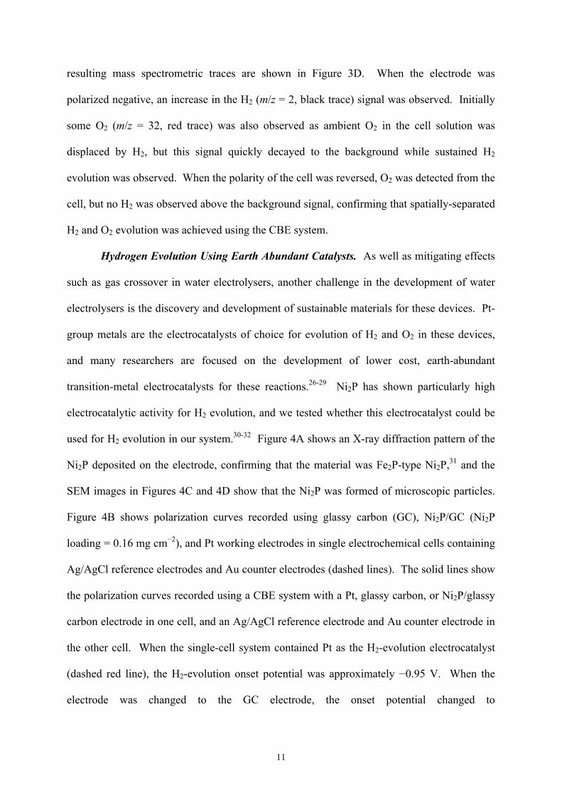
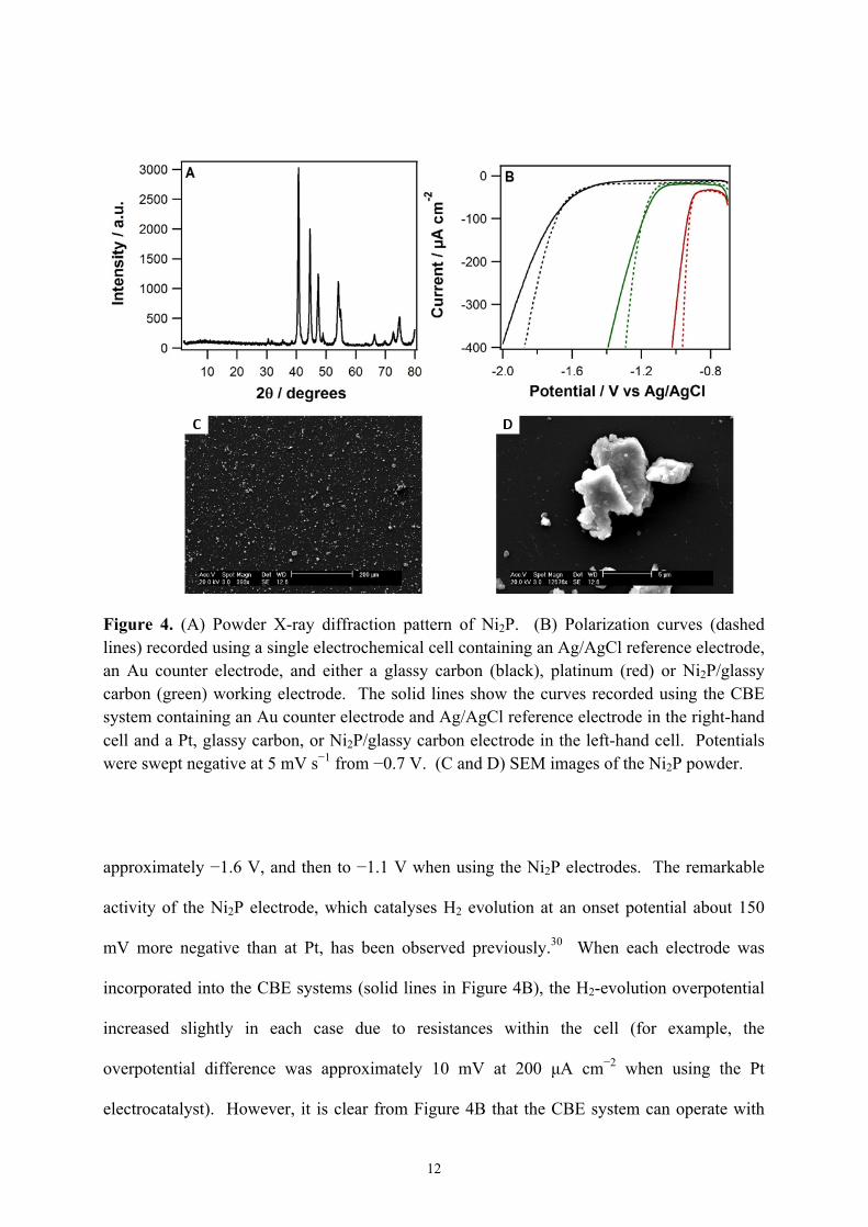
used for H2 evolution in our system.30-32 Figure 4A shows an X-ray diffraction pattern of the
Ni2P deposited on the electrode, confirming that the material was Fe2P-type Ni2P,31 and the
SEM images in Figures 4C and 4D show that the Ni2P was formed of microscopic particles.
Figure 4B shows polarization curves recorded using glassy carbon (GC), Ni2P/GC (Ni2P
loading = 0.16 mg cm−2), and Pt working electrodes in single electrochemical cells containing
Ag/AgCl reference electrodes and Au counter electrodes (dashed lines). The solid lines show
the polarization curves recorded using a CBE system with a Pt, glassy carbon, or Ni2P/glassy
carbon electrode in one cell, and an Ag/AgCl reference electrode and Au counter electrode in
the other cell. When the single-cell system contained Pt as the H2-evolution electrocatalyst
(dashed red line), the H2-evolution onset potential was approximately −0.95 V. When the
electrode was changed to the GC electrode, the onset potential changed to
12
Figure 4. (A) Powder X-ray diffraction pattern of Ni2P. (B) Polarization curves (dashed lines) recorded using a single electrochemical cell containing an Ag/AgCl reference electrode, an Au counter electrode, and either a glassy carbon (black), platinum (red) or Ni2P/glassy carbon (green) working electrode. The solid lines show the curves recorded using the CBE system containing an Au counter electrode and Ag/AgCl reference electrode in the right-hand cell and a Pt, glassy carbon, or Ni2P/glassy carbon electrode in the left-hand cell. Potentials were swept negative at 5 mV s−1 from −0.7 V. (C and D) SEM images of the Ni2P powder.
approximately −1.6 V, and then to −1.1 V when using the Ni2P electrodes. The remarkable
activity of the Ni2P electrode, which catalyses H2 evolution at an onset potential about 150
mV more negative than at Pt, has been observed previously.30 When each electrode was
incorporated into the CBE systems (solid lines in Figure 4B), the H2-evolution overpotential
increased slightly in each case due to resistances within the cell (for example, the
overpotential difference was approximately 10 mV at 200 µA cm−2 when using the Pt
electrocatalyst). However, it is clear from Figure 4B that the CBE system can operate with
13
the earth-abundant H2-evolution electrocatalyst, and the difference in overpotential observed
when using the CBE and the single electrochemical cell systems is small. Of course, our
system requires the use of a membrane in each of compartment of the cell, rather than just a
single membrane separating the H2 and O2-evolving cells in a conventional PEM electrolyser.
However, the advantage of our approach is that the two cells are separated by an electrical
conductor and not simply a membrane, so gas mixing becomes impossible. It is important to
note that, despite that fact that the conductivity of the neutralized Nafion membranes in the
alkaline medium is more than two orders of magnitude smaller than that of acidified Nafion
(3 × 10⁻⁵ S cm−1 in 0.1 M KOH vs. 9 × 10⁻³ S cm-1 for the acidified form, as measured using
impedance spectroscopy), the Nafion membranes did not cause very large overpotentials
during operation of the cell. Furthermore, the Nafion membranes retained their robustness
during operation, and prevented access of Fe(CN)63−/Fe(CN)6
4− ions to the Pt electrodes over
the course of the electrolysis (~1-2 hr). For future iterations of the CBE cell, it would be
advantageous to identify redox mediators that are electrochemically inactive at the H2 and O2-
evolving electrodes, so membranes to isolate these electrodes from the mediators actually
become unnecessary.
Decoupled H2 and O2 Oxidation in Fuel Cells containing a CBE. An energy-storage
device is only useful if the stored energy can be recovered (for example, after sunset or when
the wind stops blowing, and alternative-energy resources become ineffective). To
demonstrate that our cell could be run in reverse and used as a fuel cell, which releases the
energy stored in the electrogenerated H2, voltammetry was carried out using the system after
saturation of the electrolytes with H2 and O2. The red lines in Figure 5A and 5B show
voltammograms recorded using the system when the electrolyte in the left-hand cell was
saturated with H2 (Figure 5A) and subsequently with O2 (Figure 5B). The black dashed line

14
Figure 5. Linear sweep voltammograms recorded in stirred (A) H2-saturated and (B) O2-saturated 0.1 M KOH using a 2-mm diameter Pt working electrode in (dashed black lines) a single electrochemical cell and (solid red lines) a CBE system. A Pt flag was used as the counter electrode, and potentials were swept positive from −1.1 V vs Ag/AgCl at 50 mV s−1. When using CBE systems, the reference electrode was in the cell opposite to that of the working electrode. (C) Polarization curve (black markers) recorded using the CBE system, while O2 and H2 bubbled over the working and counter electrodes respectively. The calculated power-potential graph is shown by the blue markers. (D) Polarization curve (black markers) recorded using a CBE system in which the catholyte and anolyte contain 1.0 M H2SO4 and 1.0 M KOH, respectively (the complete cell configuration is as described in the text.) The calculated power-potential graph is shown by the blue markers.
in each voltammogram shows the response obtained using a single electrochemical cell
system when the electrolyte was saturated with H2 and O2, respectively. Figure 5A shows
that an anodic current for the H2-oxidation reaction (HOR, Equation 10) began to flow in each
system at approximately −0.9 V as the potential was swept positive in the H2-saturated
solutions. Steady HOR currents then flowed as the potential increased before the current
decreased to zero as the Pt surface became oxidized (at about 0 V vs. Ag/AgCl). Therefore,

15
the HOR proceeded at similar rates at all potentials in the single cell and the CBE system.
Figure 5B shows that the O2-reduction reaction (ORR, Equation 11) also proceeded at similar
rates in each system; the cathodic ORR current increased from about −0.1 V as the potential
was swept negative and reached approximately steady-state values at potentials negative of
−0.4 V. Therefore, the difference in HOR and ORR onset potentials was approximately 0.8 V,
as expected from previous studies of the HOR and ORR.33
H2 + 2OH− → 2H2O + 2e− E0 = 0.828 V (10)
½O2 + H2O + 2e− → 2OH− E0 = 0.401 V (11)
Polarization curves were recorded by increasing the current flowing through the CBE
system while O2 and H2 were bubbled over the cathode and anode, respectively, while each
electrolyte was stirred at 300 rpm (the system was otherwise similar to that shown in Figure
1). Figure 5C shows an initial sharp decrease in potential from about 0.9 V to about 0.6 V as
the current increased, due to activation losses. An approximately linear drop in potential from
0.6 V to 0.2 V was observed as the current increased from 80 to 480 µA cm-2, due to ohmic
losses in the cell, and finally a sharp drop in potential was observed at the highest current, due
to mass transport losses. The general shape of this polarization curve is similar to that
recorded using conventional H2 fuel cells.34 The potential-power density curve is shown in
blue, and shows that a maximum power of about 100 µW cm−2 was delivered by the CBE
system. These results show that not only can the CBE system run as an electrolyser, it can
also run in reverse as a fuel cell. Of course, relatively low peak power was produced by our
proof-of-principle prototype device due to, for example, the use of polished, smooth disk

16
electrodes and cells that were not gas-tight, but such factors can readily be optimized in future
iterations of our cell design.
Mixed pH Closed-Bipolar Electrode Fuel Cell System. The half-cell reactions
occurring in conventional fuel cells are the reverse of Equations 1 and 2 (when the electrolyte
is acidic) or Equations 10 and 11 (when the electrolyte is alkaline), giving a theoretical
maximum (thermodynamic) cell potential of 1.229 V. Note that the actual voltage of H2 fuel
cells is significantly lower than this value at all currents due to activation, ohmic, and mass-
transport losses within the cells (as is also shown in Figure 5C).35 However, by separating
two electrolytes using a CBE, it is possible to use electrolytes with different pH values to
increase the cell potential to a value higher than achievable using a single electrolyte. If the
left-hand cell (the cathode) contains O2 bubbled through a solution at pH = 0 and the right-
hand cell contains H2 bubbled through a solution at pH = 14, the overall reaction is described
by Equation 12 (which is a combination of the reverses of Equations 2 and 3), giving a higher
cell voltage than possible in a single-pH device.36
H2 + ½O2 + H+ + OH− → 2H2O E0cell = 2.057 V (12)
To avoid contact of Fe(CN)63−/Fe(CN)6
4− with an acidic electrolyte, a different CBE to that
described above was used to construct our mixed-pH cell. Ag/AgCl electrodes, in which the
potential-determining equilibria are as shown in Equation 13, were used, giving the overall
cell notation Pt|O2|1.0 M KCl, 1.0 M H2SO4|AgCl,Ag,AgCl|1.0 M KCl, 1.0 M KOH|H2|Pt.
AgCl + e− → Ag + Cl− (13)
17
To construct our prototype fuel cell, a silver plate, which had been electrolytically coated on
both sides with AgCl, was used as the CBE. O2 was bubbled over the Pt cathode, and H2 was
bubbled over the Pt anode, and the resulting polarization curve is shown in Figure 5D. At all
currents, the cell potential exceeded that achievable using the single-pH system. Note, in
particular, the very high potential at low currents (1.82 V at 5.78 mA cm−2), in excess of the
thermodynamic maximum of a conventional fuel cell when the anode and cathode are in
solutions of the same pH (1.229 V). If the anode and cathode are in solutions of different pH
values, the thermodynamic maximum voltage increases by 0.059 V × pH difference at room
temperature. The higher cell potential of the dual-pH system led to a much higher peak
power density of that cell (~4.5 mW cm−2 at about 6 mA cm−2) than of the single-pH system.
We did find during our investigations that some Ag metal dissolved from the bipolar
electrode and deposited on the Pt electrodes if the cell was run for a long time. Therefore,
while this system acts as a proof-of-principle, and demonstrates the opportunities offered by
combining CBEs and different-pH electrolytes, further work is needed to develop a more
stable CBE for use in such systems. Moreover the development of such a CBE system could
negate the need for any membranes within our devices.
Conclusions
We have shown that it is possible to separate the gases evolved from electrolytic water
splitting by using a CBE in contact with dissolved, reversible redox species (instead of an
ionically-conducting electrolyte to bridge the H2- and O2-evolution compartments). By
integrating such systems into electrolysers, the devices could run safely at much lower current
densities than typical devices can, increasing the viability of energy storage devices connected
to wind turbines and solar panels. Future iterations of our device will benefit from the use of
CBEs that negate the need for membranes separating the CBE from the H2- and O2-evolving

18
electrodes. We have also demonstrated a proof-of-concept fuel cell that, due to the spatial
separation afforded by the use of the CBE, can maintain two different pH values at the
cathode and anode. If a stable bipolar electrode were found, then a fuel cell with an open-
circuit potential near 2.057 V could potentially be made, increasing the device power output.
However, significant cell-engineering design considerations must be made before such a
system can be realized. Finally, we note that the use of Ag/AgCl electrodes as the CBE
eliminates the requirement for any membranes in our fuel cell device. This raises the
possibility of developing a H2/Cl2 fuel cells using such a bipolar system. H2/Cl2 fuel cells are
more efficient than H2/O2 fuel cells but suffer from the damage of membranes by Cl2,37 so the
concepts described here may go some way towards addressing this issue.
Experimental Section
All chemicals were from Sigma-Aldrich and were used as received. Electrochemical
experiments were carried out using a CH760 potentiostat from CH Instruments (Austin TX).
Glassy carbon, Au and Pt disk electrodes (diameters 3 mm, 2 mm, and 2 mm, respectively)
were also from CH Instruments. A 0.5-mm diameter Pt wire and Pt flag electrode (surface
areas ~ 0.8 cm2) were used for water splitting. Disk electrodes were cleaned before use by
polishing with alumina (0.3 and 0.05 µm), then rinsing with de-ionized water. Pt-wire and Pt-
flag electrodes were cleaned by annealing in a butane flame. Carbon-cloth CBE electrodes
were cut from carbon cloth (~15 cm in length) tied at one end to avoid fraying, and connected
to each other by copper wire. Nafion membranes (183 µm thickness) were stored in solutions
of 0.1 M KOH or 1.0 M H2SO4 between use. Impedance measurements were performed in
the frequency range from 100 kHz to 0.1 Hz, at an amplitude of 5 mV, and 0.0 V applied
potential, by sandwiching activated Nafion membranes between two Pt contact plates.
Powder X-ray diffraction analysis was carried out using a PANanalytical X’Pert PRO
19
diffractometer with Cu-Kα radiation operating at 40 kV and 40 mA, with 0.02° step size and
30 s step time. SEM images were recorded using a Philips Model XL30 FEG environmental
microscope operated at 20 kV. Mass spectrometry was carried out using a Pfeiffer Vacuum
Thermostar Quadropole mass spectrometer. Ni2P inks were prepared by adding 2.4 mg Ni2P
to 0.95 mL of ethanol and 50 µL of 5% Nafion. The mixture was sonicated for at least 30
minutes before pipetting the required volume onto a GC electrode and drying gently under air.
Acknowledgements
We thank the Engineering and Physical Sciences Research Council for funding
through project EP/P002382/1 the Centre for Doctoral Training in Fuel Cells and their Fuels
(Project EP/L015749/1). We also thank the Nottingham Nanoscale and Microscale Research
Centre (NMRC) for access to microscopy facilities.
References
(1) Yang, Z. G.; Zhang, J. L.; Kintner-Meyer, M. C. W.; Lu, X. C.; Choi, D. W.;
Lemmon, J. P.; Liu, J. Electrochemical Energy Storage for Green Grid. Chem. Rev. 2011, 111,
3577-3613.
(2) Whittingham, M. S. History, Evolution, and Future Status of Energy Storage.
Proc. IEEE 2012, 100, 1518-1534.
(3) Lewis, N. S.; Nocera, D. G. Powering the planet: Chemical Challenges in
Solar Energy Utilization. Proc. Natl. Acad. Sci. USA 2006, 103, 15729-15735.
(4) Shaner, M. R.; Atwater, H. A.; Lewis, N. S.; McFarland, E. W. A Comparative
Technoeconomic Analysis of Renewable Hydrogen Production using Solar Energy. Energy
Environ. Sci. 2016, 9, 2354-2371.
20
(5) Rand, D. A. J.; Dell, R. M. Hydrogen Energy: Challenges and Prospects; RSC
Publishing: Cambridge, UK, 2008.
(6) Felgenhauer, M.; Hamacher, T. State-of-the-art of Commercial Electrolyzers
and On-site Hydrogen Generation for Logistic Vehicles in South Carolina. Int. J. Hydrogen
Energy 2015, 40, 2084-2090.
(7) Zeng, K.; Zhang, D. Recent Progress in Alkaline Water Electrolysis for
Hydrogen Production and Applications. Progr. Energy Combust. Sci. 2010, 36, 307-326.
(8) Carmo, M.; Fritz, D. L.; Mergel, J.; Stolten, D. A Comprehensive Review on
PEM Water Electrolysis. Int. J. Hydrogen Energy 2013, 38, 4901-4934.
(9) Wang, Y.; Leung, D. Y. C.; Xuan, J.; Wang, H. A Review on Unitized
Regenerative Fuel Cell Technologies, Part-A: Unitized Regenerative Proton Exchange
Membrane Fuel Cells. Renew. Sust. Energy Rev. 2016, 65, 961-977.
(10) Prabhakaran, V.; Arges, C. G.; Ramani, V. Investigation of Polymer
Electrolyte Membrane Chemical Degradation and Degradation Mitigation using In Situ
Fluorescence Spectroscopy. Proc. Natl. Acad. Sci. USA 2012, 109, 1029-1034.
(11) Millet, P.; Ngameni, R.; Grigoriev, S. A.; Fateev, V. N. Scientific and
Engineering Issues Related to PEM Technology: Water Electrolysers, Fuel Cells and Unitized
Regenerative Systems. Int. J. Hydrogen Energy 2011, 36, 4156-4163.
(12) Grigoriev, S. A.; Porembskiy, V. I.; Korobtsev, S. V.; Fateev, V. N.; Auprêtre,
F.; Millet, P. High-pressure PEM Water Electrolysis and Corresponding Safety Issues. Int. J.
Hydrogen Energy 2011, 36, 2721-2728.
(13) Chen, L.; Dong, X.; Wang, F.; Wang, Y.; Xia, Y. Base-Acid Hybrid Water
Electrolysis. Chem. Commun. 2016, 52, 3147-3150.

21
(14) Hashemi, S. M. H.; Modestino, M. A.; Psaltis, D. A Membrane-less
Electrolyzer for Hydrogen Production across the pH Scale. Energy Environ. Sci. 2015, 8,
2003-2009.
(15) Symes, M. D.; Cronin, L. Decoupling Hydrogen and Oxygen Evolution during
Electrolytic Water Splitting using an Electron-coupled-proton Buffer. Nat. Chem. 2013, 5,
403-409.
(16) Rausch, B.; Symes, M. D.; Cronin, L. A Bio-Inspired, Small Molecule
Electron-Coupled-Proton Buffer for Decoupling the Half-Reactions of Electrolytic Water
Splitting. J. Am. Chem. Soc. 2013, 135, 13656-13659.
(17) Rausch, B.; Symes, M. D.; Chisholm, G.; Cronin, L. Decoupled Catalytic
Hydrogen Evolution from a Molecular Metal Oxide Redox Mediator in Water Splitting.
Science 2014, 345, 1326-1330.
(18) Chen, L.; Dong, X.; Wang, Y.; Xia, Y. Separating Hydrogen and Oxygen
Evolution in Alkaline Water Electrolysis using Nickel Hydroxide. Nat. Commun. 2016, 7,
11741.
(19) Choi, B.; Panthi, D.; Nakoji, M.; Kabutomori, T.; Tsutsumi, K.; Tsutsumi, A.
A Novel Water-splitting Electrochemical Cycle for Hydrogen Production using an
Intermediate Electrode. Chem. Eng. Sci. 2017, 157, 200-208.
(20) Fosdick, S. E.; Knust, K. N.; Scida, K.; Crooks, R. M. Bipolar
Electrochemistry. Angew. Chem. Int. Ed. 2013, 52, 10438-10456.
(21) Loget, G.; Zigah, D.; Bouffier, L.; Sojic, N.; Kuhn, A. Bipolar
Electrochemistry: From Materials Science to Motion and Beyond. Acc. Chem. Res. 2013, 46,
2513-2523.
22
(22) Jiang, J.-Z.; Guo, M.-H.; Yao, F.-Z.; Li, J.; Sun, J.-J. Propulsion of Copper
Microswimmers in Folded Fluid Channels by Bipolar Electrochemistry. RSC Adv. 2017, 7,
6297-6302.
(23) Mavre, F.; Anand, R. K.; Laws, D. R.; Chow, K.-F.; Chang, B.-Y.; Crooks, J.
A.; Crooks, R. M. Bipolar Electrodes: A Useful Tool for Concentration, Separation, and
Detection of Analytes in Microelectrochemical Systems. Anal. Chem. 2010, 82, 8766-8774.
(24) Eßmann, V.; Barwe, S.; Masa, J.; Schuhmann, W. Bipolar Electrochemistry
for Concurrently Evaluating the Stability of Anode and Cathode Electrocatalysts and the
Overall Cell Performance during Long-Term Water Electrolysis. Anal. Chem. 2016, 88, 8835-
8840.
(25) Millet, P.; Mbemba, N.; Grigoriev, S. A.; Fateev, V. N.; Aukauloo, A.;
Etiévant, C. Electrochemical Performances of PEM Water Electrolysis Cells and Perspectives.
Int. J. Hydrogen Energy 2011, 36, 4134-4142.
(26) Lukowski, M. A.; Daniel, A. S.; Meng, F.; Forticaux, A.; Li, L.; Jin, S.
Enhanced Hydrogen Evolution Catalysis from Chemically Exfoliated Metallic MoS2
Nanosheets. J. Am. Chem. Soc. 2013, 135, 10274-10277.
(27) McKone, J. R.; Sadtler, B. F.; Werlang, C. A.; Lewis, N. S.; Gray, H. B. Ni–
Mo Nanopowders for Efficient Electrochemical Hydrogen Evolution. ACS Catal. 2013, 3,
166-169.
(28) Faber, M. S.; Jin, S. Earth-abundant Inorganic Electrocatalysts and their
Nanostructures for Energy Conversion Applications. Energy Environ. Sci. 2014, 7, 3519-3542.
(29) May, K. J.; Carlton, C. E.; Stoerzinger, K. A.; Risch, M.; Suntivich, J.; Lee,
Y.-L.; Grimaud, A.; Shao-Horn, Y. Influence of Oxygen Evolution during Water Oxidation
on the Surface of Perovskite Oxide Catalysts. J. Phys. Chem. Lett. 2012, 3, 3264-3270.

23
(30) Popczun, E. J.; McKone, J. R.; Read, C. G.; Biacchi, A. J.; Wiltrout, A. M.;
Lewis, N. S.; Schaak, R. E. Nanostructured Nickel Phosphide as an Electrocatalyst for the
Hydrogen Evolution Reaction. J. Am. Chem. Soc. 2013, 135, 9267-9270.
(31) Kucernak, A. R. J.; Sundaram, V. N. N. Nickel Phosphide: The Effect of
Phosphorus Content on Hydrogen Evolution Activity and Corrosion Resistance in Acidic
Medium. J. Mater. Chem. A 2014, 2, 17435-17445.
(32) Stern, L. A.; Feng, L. G.; Song, F.; Hu, X. L. Ni2P as a Janus Catalyst for
Water Splitting: The Oxygen Evolution Activity of Ni2P Nanoparticles. Energy Environ. Sci.
2015, 8, 2347-2351.
(33) Marković, N. M.; Ross, P. N. Surface Science Studies of Model Fuel Cell
Electrocatalysts. Surf. Sci. Rep. 2002, 45, 121-229.
(34) Debe, M. K. Electrocatalyst Approaches and Challenges for Automotive Fuel
Cells. Nature 2012, 486, 43-51.
(35) Larminie, J.; Dicks, A. Fuel Cell Systems Explained; Second ed.; John Wiley
& Sons Ltd: Chichester, 2003.
(36) Cohen, J. L.; Volpe, D. J.; Westly, D. A.; Pechenik, A.; Abruna, H. D. A Dual
Electrolyte H2/O2 Planar Membraneless Microchannel Fuel Cell System with Open Circuit
Potentials in excess of 1.4 V. Langmuir 2005, 21, 3544-3550.
(37) Thomassen, M.; Sandnes, E.; Borresen, B.; Tunold, R. Evaluation of Concepts
for Hydrogen - Chlorine Fuel Cells. J. Appl. Electrochem. 2006, 36, 813-819.