Embed Size (px)
Citation preview

ML890TKR-75-1A
CLINTON SERVICE GUIDEMODEL 890TKR
FORJUKI LK-980
MACHINE PREPARATION
REMOVE ALL STOP MOTIONCONTROL PARTS ON THECAM SIDE. ONLY THE PARTSSHOWN REMAIN.
REMOVE THE REMAININGSTOP MOTION PARTS OFFTHE MACHINE DRIVE SIDEAS SHOWN.
LEAVE ROLLER ON PIVOTPIN.
QUITE TODAS LAS PIEZAS DE CONTROLPARA DETENER EL MOVIMIENTO EN ELLADO DE LA VOLANTA. SÓLO DEBENPERMANECER LAS PARTES MOSTRADAS.
QUITE TODAS LAS PIEZAS RESTANTES DEDETENER EL MOVIMIENTO DE LA PARTE DEACCIONAMIENTO DE LA MÁQUINA COMOSE MUESTRA.
DEJE EL PIVOTE DEL RODILLO.

STEP 1GUIDE BUSHING & SLIDE ARM
02-3105-01GUIDE BUSHING
10-1318-01SLIDE ARM
STEP 2 END PLATE
30-2617-01SCREW
02-3100-01END PLATE
30-2616-01SCREW
01-1622-61FLAT WASHER
STEP 3 TRIM CYLINDER
30-2616-01SCREW
01-1622-61FLAT WASHER
30-1783-01ELBOW
30-2919-01AIR CYLINDER
30-1783-01ELBOW
02-3104-01BRACKET
33-2108-03SET SCREW
01-3661-01PIN
33-1620-02HEX NUT
02-3241-01BLOCK
STEP 4 CLAMP LIFT CYLINDER
33-4106-08COTTER PIN
30-2126-01CLEVIS PIN
01-4512-31CLEVIS
33-1628-02HEX NUT
30-2616-01SCREW
01-1622-61FLAT WASHER
30-1107-01ELBOW
02-3122-01BRACKET
33-0116-06SCREW
01-1622-01FLAT WASHER
33-0210-06SCREW
30-1377-01CLAMP
30-2594-01AIR CYLINDER
STEP 5
ML890TKR-75-2A
STEP 6
STEP 7PROXIMTIY SWITCH
11-0510-02
HEAVY DUTY FOOT SWITCH ASSEMBLY11-0410-01
11-0380-01CABLEASSEMBLY
30-2633-01FOOT SWITCH
30-0519-01PLASTIC TUBING
NOTE:LUBRICATE ALLMOVING PARTSBEFORE MOUNTINGTHE END PLATE.
NOTE:INSERT SLIDE ARMINTO FOOT CLAMPAND WIPER SLOTS.
NOTE:EXISTINGSCREW & NUT
INS-2344
02-3130-01BRACKET
30-0507-01GROMMET
30-2458-01COVER
30-2459-01CONNECTOR
TOSYNCHRONIZERBOARD
30-2597-01PROXIMITYSWITCH
30-2599-01MAGNET
02-3131-01MAGNETHOLDER
33-2106-03SET SCREW
{* PART OF 10-1321-01*
PULLEY & HANDWHEEL10-1320-01
02-3108-01PULLEY
01-2479-01HANDWHEEL
01-3066-31SCREW
33-2116-08SET SCREW
SYNCHRONIZER11-0512-01
33-2210-08SCREW
10-1401-01DISC - MAGNETASS'Y
33-0106-10SCREW
33-1806-01L' WASHER
11-0505-01PC BOARD
02-3184-03COLLAR
33-2210-03SCREW
10-1402-01MOUNTINGPLATE ASS'Y
33-1806-01L' WASHER
33-0106-04SCREW

AIRINPUT
GAUGE
REGULATORLUBRICATOR
TRIMMERSOLENOID
TRIMMER CYLINDER
CLAMP LIFTCYLINDER
AIR SCHEMATIC
1/4" CLEAR 13"
1/4" RED 13"
B
P
1/4" CLEAR 12"
1/4" CLEAR 14"
3/16" RED 22"
3/16" YEL. 22"
AB
P
A
CLAMP LIFTSOLENOID
FILTER, OILER, REGULATOR, GAUGE ASSEMBLY80-0181-10
AIR CONTROL ASSEMBLY81-0828-01
01-4528-01BRACKET
33-2010-12SCREW
30-0899-01LOCK NUT
30-0277-01QUICK DISCONNECT -MALE30-1048-01QUICK DISCONNECT -FEMALE
30-0283-01TUBEFITTING
30-1752-01TEE
30-0282-01GAUGE
30-2347-01FILTER, REG.,LUB.
01-6850-02BRACKET33-2008-12SCREW30-1750-02TERMINALBLOCK33-1508-01HEX NUT33-1808-01L' WASHER
33-0108-04SCREW
11-0321-02CABLE ASS'Y30-0100-01STRAIN RELIEF
01-4707-21FITTING30-1729-01FITTING
02-2002-01BRACKET33-0708-06SCREW30-0108-04SCREW
11-0322-02CABLE30-0100-01STRAIN RELIEF35-0237-01SOLENOIDVALVE
02-2003-01COVER
33-0103-12SCREW33-1803-01LOCK WASHER
ML890TKR-75-3
ML890TKR-3
MACHINE ASSEMBLY81-0827-01
80-0487-01END PLATE ASS'Y
11-0514-01SYNCHRONIZER
10-1320-01PULLEY &HANDWHEEL
10-1318-01SLIDE ARM
CLAMP LIFTCYLINDER
RED TUBING
CLEAR TUBING
PROXIMTIY SWITCH
TRIM CYLINDER
RED TUBING
YELLOW TUBING
GUIDE BUSHING
NOTE:MOUNT THE VARIOUSCOMPONENTS ON THEEND PLATE ASSEMBLYIN THE STEPS SHOWN.

Z
W
X
TIMING INSTRUCTIONS
ML890TKR-75-4A
A. SYNCHRONIZER TIMING
1. TURN MACHINE HANDWHEEL (V) IN THE DIRECTION OF NORMALROTATION UNTIL THE TAKE-UP (W) REACHES IT'S UPPER MOSTPOSITION.
2. AT THIS TIME, WITH POWER ON, LOOSEN THE TWO SET SCREWS (X)AND TURN THE SYNCHRONIZER DISC COUNTERCLOCKWISE UNTILTHE MAGNET ON THE DISC IS ALIGNED WITH THE HALL SENSOR ANDTHE SYNCHRONIZER BOARD'S GREEN LIGHT GOES ON.
B. END OF CYCLE TIMING
A PROXIMITY SENSOR AND MAGNET IS USED TO DETECT THE END OFCYCLE ROUTINE. THE ADJUSTMENT DEPENDS ON THE SETTING OF THEEND OF CYCLE (EOC) SENSOR.
1. ADJUST THE GAP BETWEEN THE PROXIMITY SENSOR (Y) ANDMAGNET (P) TO APPROXIMATELY 1/8".
2. ROTATE, BY HAND, THE SEWING MACHINE HANDWHEEL SO THAT THESTITCH CAM IS IN THE START POSITION WITH THE NEEDLE IN THE UPPOSITION.
3. TURN THE POWER ON AND NOTE THAT THE YELLOW LIGHT ON THESYNCHRONIZER BOARD IS OFF.
4. POSITION THE MAGNET HOLDER (Z) ON THE STITCH CAM PLATE AWAYFROM THE PROXIMITY SENSOR BUT ON THE SIDE THAT IS OPPOSITETO THE DIRECTION THAT THE STITCH CAM NORMALLY ROTATES.MAKE SURE THE YELLOW LIGHT IS STILL OFF.
5. SLOWLY MOVE THE MAGNET HOLDER TOWARDS THE PROXIMITYSENSOR UNTIL THE YELLOW LIGHT ON THE SYNCHRONIZER BOARDTURNS ON. LOCK THE MAGNET HOLDER IN PLACE AND SECURE WITHSCREW.
6. OPERATE THE MACHINE. CHECK THE MACHINE DECELERATION,TRIMMING AND STOPPING POSITION. IF NOT CORRECT THEN IT MAYBE NECESSARY TO MAKE PARAMETER CHANGES USING THE LCDDISPLAY.
V
P
Y
A. CRONOMETRAJE DEL SINCRONIZADOR
1. GIRE LA RUEDA MANUAL (V) EN DIRECCIÓN DE LA ROTACIÓN NORMALHASTA QUE LA TOMA (W) LLEGUE A SU POSICIÓN MÁS ALTA.
2. EN ESE MOMENTO, CON LA MÁQUINA ENCENDIDA, AFLOJE LOS DOSTORNILLOS COLOCADORES (X) Y GIRE EL DISCO SINCRONIZADOR ENSENTIDO CONTRARIO A LAS MANECILLAS DEL RELOJ HASTA QUE ELMAGNÉTICO DEL DISCO QUEDE ALINEADO CON EL SENSOR DEL HALL YSE ENCIENDA LA LUZ VERDE DEL TABLERO DEL SINCRONIZADOR.
B. CRONOMETRAJE DEL FINAL DEL CICLO
UN SENSOR DE PROXIMIDAD Y UN MAGNÉTICO SE USA PARA DETECTAR ELFINAL DEL CICLO HABITUAL. EL AJUSTE DEPENDE DE LA COLOCACIÓN DELSENSOR DEL FINAL DEL CICLO (EOC).
1. DEJE UN ESPACIO DE 1/8 DE PULGADA ENTRE EL SENSOR DE PROXIMI-DAD (Y) Y EL MAGNÉTICO (P).
2. ROTE A MANO LA RUEDA MANUAL DE LA MÁQUINA DE COSER PARA QUELA VOLANTA DE LA PUNTADA SE COLOQUE EN LA POSICIÓN DEARRANQUE CON LA AGUJA EN LA POSICIÓN ARRIBA.
3. ENCIENDA LA MÁQUINA Y ASEGÚRESE QUE LA LUZ AMARILLA DEL TABLE-RO DEL SINCRONIZADOR SE ENCUENTRE APAGADA.
4. POSICIONE EL RETENEDOR DEL MAGNÉTICO (Z) EN EL PLATO DE LAVOLANTA DE LAS PUNTADAS LEJOS DEL SENSOR Y EN EL LADO OPUESTOA LA DIRECCIÓN QUE ROTA NORMALMENTE DICHA VOLANTA. ASEGÚRESEQUE LA LUZ AMARILLA TODAVÍA ESTÉ APAGADA.
5. MUEVA LENTAMENTE EL RETENEDOR DEL MAGNÉTICO ACERCÁNDOLO ALSENSOR HASTA QUE LA LUZ AMARILLA DEL TABLERO DEL SINCRONIZA-DOR SE ENCIENDA. ASEGURE EN SU LUGAR EL RETENEDOR DELMAGNÉTICO CON EL TORNILLO.
6. OPERE LA MÁQUINA. COMPRUEBE LAS POSICIONES DE DESACELERA-CIÓN, CORTE Y DETENIMIENTO DE LA MÁQUINA. SI NO SON CORRECTAS,PUEDE SER NECESARIO CAMBIAR EL PARÁMETRO MEDIANTE EL USO DELA PANTALLA LCD.

CLINTONMODEL 890TKR
A890 SERIES
SERVO MOTORPOSITIONER/TRIMMER
FORTACKER SEWING MACHINES
SERVICE MANUAL40-0235-01
ML890TKR-43A

SECTION I - INTRODUCTION . . . . . . . . . . . . . . . . . . . . . . . . . . . . . . . . . . . . . 1-1
SECTION II - INSTALLATION . . . . . . . . . . . . . . . . . . . . . . . . . . . . . . . . . . . . . 2-1
A.B.C.D.E.
MOTOR . . . . . . . . . . . . . . . . . . . . . . . . . . . . . . . . . . . . . . . .LCD DISPLAY . . . . . . . . . . . . . . . . . . . . . . . . . . . . . . . . . .SWITCH BOX . . . . . . . . . . . . . . . . . . . . . . . . . . . . . . . . . .POWER AND CABLE CONNECTIONS . . . . . . . . . . . . . . .MOTOR ROTATION . . . . . . . . . . . . . . . . . . . . . . . . . . . . . .
2-12-12-12-12-2
SECTION III - ADJUSTMENTS . . . . . . . . . . . . . . . . . . . . . . . . . . . . . . . . . . . . . . 3-1
A.B.
SYNCHRONIZER TIMING. . . . . . . . . . . . . . . . . . . . . . . . . . .PROXIMITY SENSOR. . . . . . . . . . . . . . . . . . . . . . . . . . . . . .
3-13-1
SECTION IV - PROGRAMMABLE LCD DISPLAY . . . . . . . . . . . . . . . . . . . . . . . 4-1
A.B.C.D.
PARAMETER ADJUSTMENTS . . . . . . . . . . . . . . . . . . . . . .MASTER RESET . . . . . . . . . . . . . . . . . . . . . . . . . . . . . . . .PULLEY RATIO . . . . . . . . . . . . . . . . . . . . . . . . . . . . . . . . . .TEST PROGRAM . . . . . . . . . . . . . . . . . . . . . . . . . . . . . . . . .
4-14-34-34-3
SECTION V - CONNECTOR DIAGRAMS . . . . . . . . . . . . . . . . . . . . . . . . . . . . . 5-1
SECTION VI - DRAWINGS AND PARTS LIST . . . . . . . . . . . . . . . . . . . . . . . . . 6-1
A.B.C.D.E.F.G.
MAJOR ASSEMBLIES . . . . . . . . . . . . . . . . . . . . . . . . . . . . .MOTOR ASSEMBLY, DC SERVO . . . . . . . . . . . . . . . . . . . .CONTROL BOX ASSEMBLY . . . . . . . . . . . . . . . . . . . . . . . .SYNCHRONIZER ASSEMBLY . . . . . . . . . . . . . . . . . . . . . . .SYNCHRONIZER ASSEMBLY . . . . . . . . . . . . . . . . . . . . . . .END OF CYCLE SENSOR. . . . . . . . . . . . . . . . . . . . . . . . . . .PROGRAMMABLE DISPLAY . . . . . . . . . . . . . . . . . . . . . . . .
6-16-26-46-56-66-76-7
®
ML890TKR-44
TABLE OF CONTENTS

INTRODUCTION
A. SYSTEM DESCRIPTION
Clinton's Model 890TKR is an electronically controlled variable speed drive for industrial sewingmachine tackers. The system consists of a brushless DC Servo motor, a hall effect synchronizer,end of cycle sensor, foot or hand switch and programmable LCD display.
The drive is used to replace the mechanical stop motion mechanism used in tackers. Air cylindersare used to operate the clamp lift and on some machines, the trimmer. No clutches or brakes areused. The result is a smooth, reliable and accurate stop motion system.
The components of the system are shown below.
B. OPERATION
A foot or hand switch is used to start the sew cycle. It is also used to drop the clamp without
sewing. When the switch is fully depressed, the sew cycle begins.
Initially the machine sews at a speed of about 900 RPM for a few stitches to prevent skippedstitches. The speed and number of stitches can be adjusted. The machine then accelerates tomaximum speed until the end of cycle sensor is sensed. At this time the machine decelerates toabout 800 RPM. After sewing a few stitches, the synchronizer hall sensor detects needle up. Themachine speed then ramps down during the final stitch and stops at needle up. During this time thetrimmer is operated. The work clamp is lifted after the machine stops.
1-1
®
ML890TKR-45SECTION I
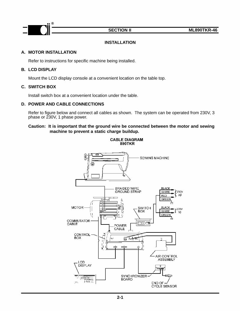
INSTALLATION
A. MOTOR INSTALLATION
Refer to instructions for specific machine being installed.
B. LCD DISPLAY
Mount the LCD display console at a convenient location on the table top.
C. SWITCH BOX
Install switch box at a convenient location under the table.
D. POWER AND CABLE CONNECTIONS
Refer to figure below and connect all cables as shown. The system can be operated from 230V, 3phase or 230V, 1 phase power.
Caution: It is important that the ground wire be connected between the motor and sewing machine to prevent a static charge buildup.
2-1
®
ML890TKR-46SECTION II
E. MOTOR ROTATION
Temporarily remove the "V" belt. Turn power on then move the pedal forward and note the directionof motor pulley rotation. If incorrect, do the following:
1. Turn power off.
2. Refer to section V-B, Hidden Parameters, and follow the instructions to change motor rotation.The parameter is in the "**** Toggle Switches" group.
3. Install the "V" belt.
2-2
®
ML890TKR-47

ADJUSTMENTS
A. SYNCHRONIZER TIMING
A hall effect sensor/magnet is used to sense when the machine is in the Needle Up position. Referto figure 3-1 below and adjust the disc as follows:
FIG. 3-1
1. Turn power on.2. Loosen the disc locking screws.3. Rotate the machine handwheel until the takeup is in the proper position for trimming.4. Rotate the disc in the direction that the machine normally turns until the green Led on the
synchronizer PC board turns on. While turning, push the disc against the spacer.5. Lock disc in place.
B. PROXIMITY SENSOR
A proximity sensor/magnet is used to sense the end of cycle. The sensor is activated a fixednumber of stitches before the machine stops. The number of stitches is set by the "END COUNT"parameter. See section IV. The default count is three (3).
Adjust the proximity sensor and magnet as follows:
1. Adjust the gap between the proximity sensor and magnet to between 1/16" and 1/8". Seefigure 3-2.
2. Start with the machine in the home position and the takeup "UP".3. Rotate the handwheel in the reverse direction, by hand, 3-1/2 stitches. If the "END COUNT"
parameter has been changed, use this number plus 1/2 stitch.4. Turn power on.5. Move the magnet in the direction the cam normally rotates, until the amber light on the synchro
nizer board turns on. Lock the magnet holder in place.
3-1
®
ML890TKR-48SECTION III

FIG. 3-2
Operate the machine and check for positioning accuracy and speed. If the machine does not stop
in the proper position, readjust the synchronizer disc. The speed of the machine, during the laststitch,can be changed with the "POSITION" parameter in the ****SPEEDS group. See section IV.
3-2
®
ML890TKR-49

PROGRAMMABLE LCD DISPLAY
The LCD display, shown in figure below is used to program and set the various parameters of the890TKR; SPEEDS, TIMERS, COUNTERS and TOGGLE SWITCHES.
Two (2) different modes of operation are available. They are:
1. Operating Mode2. Programming Mode
When power is turn on, the display is in the operating mode.
The parameters are separated into 2 main groups, as shown in the following tables. They can bechanged or reset to their default values, as described below. In addition, the LCD module can be usedto display the pulley ratio and test the synchronizer, speed control and motor encoder.
A. PARAMETER ADJUSTMENTS
Table 1 is divided into four (4) subgroups, SPEEDS, TIMERS, COUNTERS and TOGGLESWITCHES. Table 2 is divided into three (3) subgroups, SPEED, MISCELLANEOUS andTOGGLE SWITCHES. To change a parameter, follow the sequence described below.
1. Press the key to enter the programming mode. Continue pressing this key until theparameter group that is to be changed is displayed. As an alternative; press the key toenter the programming mode and display the last changed parameter.
2. Press the key to step to the next parameter in the selected group.
3. Press the key to increase or the key to decrease the contents of the displayparameter. Both keys are used to toggle parameters between states in the Toggle Switchesgroup. Hold the key closed to make the display step automatically.
4. Press the key to return to the operating mode.
4-1
®
ML890TKR-50SECTION IV

4-2
PARAMETER DESCRIPTION RANGE
JUKI 980 SINGER 269 BROTHER
****SPEEDS RPM RPM
POSITION
MAXIMUM
Machine speed during the position cycle.If *** Tgl switch "position" is set to "w/ramp", position speedaffects the slope of the ramp. If "no ramp" is selected,position speed is constant and can be changed by thisparameter.Maximum sewing machine speed.
260
2200
260
1700
260
2300
100-400
1000-2400
****MISC MISCELLANEOUS
PF DUTY
TRIM ON
TURNBAK
Average voltage applied to Pr. Ft. solenoid. The voltageshould be high enough to keep the solenoid energized withoutoverheating.Percentage of last (position) stitch that trimmer is on.
At end of cycle motor reverses to raise needle. Encoderincrements are counted. 180 increments equals 1 revolution.
3
10
65
3
10
65
3
10
65
2-10
4-10
1-250
****TOGGLE SWITCHES
DIRECTIONPOSITION
TURNBAK
SAFETY SW
SAFETY SW SEW
MOTOR
Direction of motor rotation viewed from pulley.Select position with ramp or position at constant speed.
Turns turnbak on or off. See turnbak parameter in****MISC GROUP.Enables or disables safety switch.
Determined by configuration of safety switch. If normallyopen type set to OPN; if normally closed set to CLS.Determines type of motor. Type 2 is new design.
CCWW/RAMP
OFF
DISABLED
OPN
TYPE 2
CW
OFF
DISABLED
OPN
TYPE 2
CCWW/RAMP
OFF
DISABLED
OPN
TYPE 2
CW/CCWW/RAMPNO RAMPON/OFF
ENABLED/DISABLED
OPN/CLS
TYPE 1/ TYPE 2
PARAMETER DESCRIPTION FACTORY SETTINGS RANGE
JUKI 980 SINGER 269 BROTHER
SPEED GROUP RPM RPM
SLOW STRT
END SPEED
Initial start speed. Sews at this speed for number of stitchesset by soft strt count parameter.Speed for last stitch.
700
1600
700
1600
700
1600
150-1000
800-2200
TIMER GROUP MISCELLANEOUS
STRT DELWAIT TIME
Delays machine start to allow clamp to drop.When parameter "Pdl Start" is set to "Continuous", this is thetime from the end of one cycle to the start of the next.
100350
100350
100350
10-50010-1000
COUNTER GROUP STITCHES
SLOW STRT
END COUNT
Number of stitches sewn at slow strt speed at start of cycle.Number of stitches sewn after end of cycle sensor isdetected.
2
3
2
3
2
3
0-25
1-200
TOGGLE SWITCHES
NOT N/U CLP
PDL START
SLOW ST
If set to "UP", clamp remains up if machine is not in upposition.If set to "CONTINUE", machine will restart after "wait time"seconds when foot switch is held closed.If set to "ON", soft start feature is enabled.See soft start in speed group.
UP
CONTINUE
OFF
UP
CONTINUE
OFF
UP
CONTINUE
OFF
UP/DOWN
CONTINUE/NEUTRALON/OFF
TABLE 2
TABLE 1
®
ML890TKR-51A
B. MASTER RESET
In some cases it may be necessary to reset all parameters to their default values. This is done as follows:
1. Turn power off, if it is on, then wait until the display goes blank.
2. Press the key, key and key simultaneously. Keep pressed then,
3. Turn power on. The LCD displays "PUSH SET TO RESET".
4. Push the key within 10 cycles.
5. The word "Programming" is displayed. The parameters will be reset to their default values after a fewseconds.
C. PULLEY RATIO (RATIO BETWEEN MOTOR AND MACHINE PULLEYS)
During the initial setup and after power is first turned on, the pulley ratio must be calculated. The pedal mustbe moved to the maximum forward position to do this. While the ratio is being taken, the machine speed islimited for several stitches. After the ratio is taken, the machine will then accelerate to maximum speed.
Each time power is turned off then back on, the ratio is checked when the pedal is moved forward the firsttime. If the ratio has changed, because of a pulley change, then the ratio will be recalculated. The ratio canbe displayed by pressing the and keys simultaneously. If the ratio is correct, a star (*) will bedisplayed after the ratio number.
D. TEST PROGRAM
A test program is available to test the speed control, synchronizer and encoder for proper operation. Toselect the program, press the and keys simultaneously. The word "Test Program" is displayed.Press the key to toggle between each test, i.e. Treadle, Synchronizer or Encoder. Press the keyto activate whichever test is selected.
1. Treadle Test
a. Move the pedal from neutral to heel 1 to heel 2. The display indicated each position.b. Move the pedal forward, slowly. As the pedal is moved a number (0 to 255) proportional to the
position of the pedal is displayed. The lowest number should not be more than 8 and the highestnumber not less than 250 with the "Maximum Speed" pot set to its maximum clockwise position.
c. With the pedal full forward, rotate the maximum speed pot ccw. The displayed count should decrease as the pot is turned. Return the pot to its maximum cw position.
2. Synchronizer
Rotate the handwheel. As the synchronizer passes through the UP, DOWN and TRIM position, thedisplay will indicate each of these positions.
3. Encoder
Push the pedal forward as indicated. The speed will vary with pedal position but will not go to maximumspeed. The pulley ratio will be displayed at all positions of the pedal and should agree, + 1 or 2 counts,with the actual pulley ratio (see section D).
4-3
®
ML890TKR-52

ML890TKR-53SECTION V
CONNECTOR DIAGRAMS
Listed below are the pinouts for the Model AS 890 control box connectors.
5-1
NO. TOTAL PINS CONNECTOR PIN NO. FUNCTION
1 6 SYNCHRONIZER 123456
+5DOWN SENSORUP SENSORTRIM SENSORGNDLED
2 6 AUX INPUTS 123456
+5GNDCHASSIS GNDI 1I 2I 3
3 4 AUX OUTPUTS 1234
+48 VR1+48 VR2
4 2 FOOTLIFT 12
FOOTLIFT SOL.+48V
5 9 TRIM SOLENOIDS 142536789
NOT USEDNOT USEDTRIMMER SOL. -TRIMMER SOL. +(48V)NOT USEDNOT USEDNOT USEDNOT USEDNOT USED

®
ML890TKR-54
5-2
NO. TOTAL PINS CONNECTOR PIN NO. FUNCTION
8 8 COMMUTATOR 12345678
+5ENCODER (S1)ENCODER (S2)SIG. GNDPHASE CPHASE BPHASE A-5V
9 16 LCD DISPLAY 123456789
10111213141516
EXIT1CHASSIS GND+5VGNDD0D1D2D3D4D5D6D7CA1EERDCA0
10 4 AC POWER220V, 3 PHASE
1234
PHASE APHASE BPHASE CCHASSIS GND
11 4 MOTOR VOLTAGE 1234
PHASE APHASE BPHASE CCHASSIS GND

DRAWINGS AND PARTS LIST
MODEL 890TKR
81-0748-02 (WITH LCD)81-0787-02 (NO LCD)
A. MAJOR ASSEMBLIES
6-1
®
ML890TKR-55SECTION VI

ML890TKR-25-1A

MOTOR ASSEMBLY PARTS LIST, DC SERVO
81-0731-01
6-3
ITEM DESCRIPTION PART NO. QUANTITY
123456789
101112131415
16171819202122232425262728293031
COVERSCREWSCREW, S.S.S.FANPC BOARD, ENCODERSCREWSPACERENCODER DISCSCREWENCODER SENSORMOTOR, DCSCREW, S.S.S.MOTOR/ENCODER ASSEMBLYBELT GUARD, FIXEDPULLEY - 50MMPULLEY - 60MMPULLEY - 65MMPULLEY - 70MMPULLEY - 75MMPULLEY - 80MMPULLEY - 85MMPULLEY - 90MMPULLEY - 95MMPULLEY - 100MMPULLEY - 105MMPULLEY - 110MMPULLEY - 115MMPULLEY - 120MMPULLEY - 125MMPULLEY - 130MMPULLEY - 140MMPULLEY - 150MMBELT GUARD, ADJUSTABLEKEY, PULLEYSCREW M5 X 10 HEX HD.BOLT, CARRAIGESPACERWASHER, FLATWASHER, SPLIT LOCKNUT, HEXHARDWARE KIT, MOTOR MOUNTPINBRACKET, MOTOR MOUNTSNAP RINGBOLT, ADJUSTINGNUT, HEXWASHER, SPLIT LOCKGROMMET
30-4433-0130-4434-0130-4435-0130-4436-0130-4437-0130-4438-0130-4439-0130-4440-0230-4441-0130-4442-0130-4443-0130-4444-0181-0732-0130-4445-0130-4204-5030-4204-6030-4204-6530-4204-7030-4204-7530-4204-8030-4204-8530-4204-9030-4204-95
30-4204-100 30-4204-105 30-4204-110 30-4204-115 30-4204-120 30-4204-125 30-4204-130 30-4204-140 30-4204-15030-4203-0130-4227-0130-4206-0130-4298-0130-4332-0130-4300-0130-4301-0130-4229-0130-4337-0130-4219-0130-4446-0130-4220-0130-4205-0130-4210-0130-4218-0130-4472-01
132113311112111111111111111111111123333311111111
®
ML890TKR-25-2A


6-7
11-0510-03 16 " BROTHER LK3-8430, SINGER 269
11-0510-02 8 " JUKI 980
11-0510-01 12 " SANLI LK-1999, JUKI LK-1850
PART NO. " A " LENGTH MACHINE
F. END OF CYCLE SENSORMODEL 890TKR
G. PROGRAMMABLE DISPLAY
®
ML890TKR-59
"A" LENGTH
ITEM DESCRIPTION PART NO. QUANTITY
1234
PROGRAMMABLE DISPLAYBRACKET, MOUNTINGSCREW M4 X 12SCREW
30-4321-0130-4286-0130-4287-0130-4288-01
1112