Embed Size (px)
Citation preview

VPAP™ III ST-A with QuickNavClinical GuideEnglish
Front Cover - print.qxp 31/03/2008 1:36 PM Page 1

Global leaders in sleep and respiratory medicine www.resmed.com
248216/1 08 03
VPAP III ST-A
with QuickNav
Clinical
AMER ENG
Front Cover - print.qxp 31/03/2008 1:36 PM Page 2

i
VPAP™ III ST-A with QuickNavClinical ManualEnglish

ii
ResMed Ltd (Manufacturer) 1 Elizabeth Macarthur Drive Bella Vista NSW 2153 Australia ResMed Corp (US Designated Agent) 14040 Danielson Street Poway CA 92064-6857 USA ResMed (UK) Ltd (EU Authorized Representative) 96 Milton Park Abingdon Oxfordshire OX14 4RY UK ResMed Offices Australia, Austria, Brazil, China, Finland, France, Germany, Hong Kong, India, Japan, Malaysia, Netherlands, Norway, New Zealand, Singapore, Spain, Sweden, Switzerland, UK, USA (see www.resmed.com for contact details).
VPAP III / III ST / III ST-A / III ST-A with QuickNavProtected by patents: AU 697652, AU 699726, AU 713679, AU 2002233025, CN ZL02804936.5, EP 0661071, EP 0858352, HK 1065483, US 5199424, US 5522382, US 6213119, US 6240921, US 6705315. Other patents pending.Protected by design registrations: AU 147283, AU 147335, AU 147336, CH 128.709, CH 128.710, CH 128.711, CH 128.712, DE 40201723, DE 40202007, DE 40202008, DE 40202020, ES 153514, ES 153515, ES 153516, ES 153518, ES 156135, ES 156136, FR 02 1407, GB 3001791, GB 3001819, GB 3001820, GB 3001821, JP 1164087, JP 1164265, JP 1164266, JP 1164267, JP 3638613, NZ 527088, SE 75598, SE 75599, SE 75600, SE 75715, US D467335, US D468011, US D476077, US D477868, US D487311, US D503796. Other designs pendingQuickNav, SmartStart, TiCONTROL, VPAP and Vsync are trademarks of ResMed Ltd and SmartStart, and VPAP are registered in U.S. Patent and Trademark Office.
© 2008 ResMed Ltd.
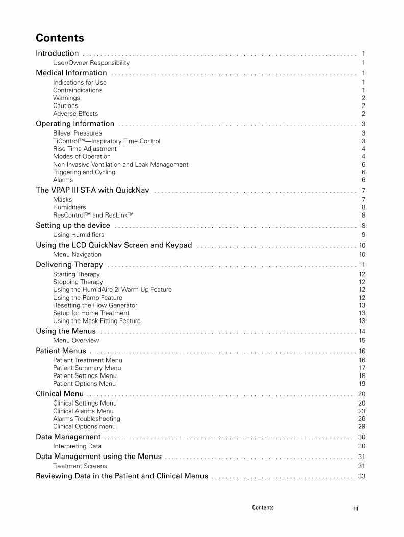
ContentsIntroduction . . . . . . . . . . . . . . . . . . . . . . . . . . . . . . . . . . . . . . . . . . . . . . . . . . . . . . . . . . . . . . . . . . . . . . . . . . . . . 1
User/Owner Responsibility 1
Medical Information . . . . . . . . . . . . . . . . . . . . . . . . . . . . . . . . . . . . . . . . . . . . . . . . . . . . . . . . . . . . . . . . . . . . . 1Indications for Use 1Contraindications 1Warnings 2Cautions 2Adverse Effects 2
Operating Information . . . . . . . . . . . . . . . . . . . . . . . . . . . . . . . . . . . . . . . . . . . . . . . . . . . . . . . . . . . . . . . . . . . 3Bilevel Pressures 3TiControl™—Inspiratory Time Control 3Rise Time Adjustment 4Modes of Operation 4Non-Invasive Ventilation and Leak Management 6Triggering and Cycling 6Alarms 6
The VPAP III ST-A with QuickNav . . . . . . . . . . . . . . . . . . . . . . . . . . . . . . . . . . . . . . . . . . . . . . . . . . . . . . . . . 7Masks 7Humidifiers 8ResControl™ and ResLink™ 8
Setting up the device . . . . . . . . . . . . . . . . . . . . . . . . . . . . . . . . . . . . . . . . . . . . . . . . . . . . . . . . . . . . . . . . . . . . 8Using Humidifiers 9
Using the LCD QuickNav Screen and Keypad . . . . . . . . . . . . . . . . . . . . . . . . . . . . . . . . . . . . . . . . . . . . . 10Menu Navigation 10
Delivering Therapy . . . . . . . . . . . . . . . . . . . . . . . . . . . . . . . . . . . . . . . . . . . . . . . . . . . . . . . . . . . . . . . . . . . . . . 11Starting Therapy 12Stopping Therapy 12Using the HumidAire 2i Warm-Up Feature 12Using the Ramp Feature 12Resetting the Flow Generator 13Setup for Home Treatment 13Using the Mask-Fitting Feature 13
Using the Menus . . . . . . . . . . . . . . . . . . . . . . . . . . . . . . . . . . . . . . . . . . . . . . . . . . . . . . . . . . . . . . . . . . . . . . . . 14Menu Overview 15
Patient Menus . . . . . . . . . . . . . . . . . . . . . . . . . . . . . . . . . . . . . . . . . . . . . . . . . . . . . . . . . . . . . . . . . . . . . . . . . . . 16Patient Treatment Menu 16Patient Summary Menu 17Patient Settings Menu 18Patient Options Menu 19
Clinical Menu . . . . . . . . . . . . . . . . . . . . . . . . . . . . . . . . . . . . . . . . . . . . . . . . . . . . . . . . . . . . . . . . . . . . . . . . . . . 20Clinical Settings Menu 20Clinical Alarms Menu 23Alarms Troubleshooting 26Clinical Options menu 29
Data Management . . . . . . . . . . . . . . . . . . . . . . . . . . . . . . . . . . . . . . . . . . . . . . . . . . . . . . . . . . . . . . . . . . . . . . 30Interpreting Data 30
Data Management using the Menus . . . . . . . . . . . . . . . . . . . . . . . . . . . . . . . . . . . . . . . . . . . . . . . . . . . . . 31Treatment Screens 31
Reviewing Data in the Patient and Clinical Menus . . . . . . . . . . . . . . . . . . . . . . . . . . . . . . . . . . . . . . . . 33
iiiContents

iv
Clinical Summary Menu 33Data Management using a PC application 34
Additional Functions . . . . . . . . . . . . . . . . . . . . . . . . . . . . . . . . . . . . . . . . . . . . . . . . . . . . . . . . . . . . . . . . . . . . 34Adding Supplemental Oxygen 34Using an Antibacterial Filter 35Using a Battery to Power the Device 36
Cleaning and Maintenance . . . . . . . . . . . . . . . . . . . . . . . . . . . . . . . . . . . . . . . . . . . . . . . . . . . . . . . . . . . . . . 36Servicing 37
Clinical Problem Solving . . . . . . . . . . . . . . . . . . . . . . . . . . . . . . . . . . . . . . . . . . . . . . . . . . . . . . . . . . . . . . . . 37Setting TiControl 38
Troubleshooting . . . . . . . . . . . . . . . . . . . . . . . . . . . . . . . . . . . . . . . . . . . . . . . . . . . . . . . . . . . . . . . . . . . . . . . . 40
Technical Specifications . . . . . . . . . . . . . . . . . . . . . . . . . . . . . . . . . . . . . . . . . . . . . . . . . . . . . . . . . . . . . . . . . 41
IntroductionThe VPAP™ III ST-A with QuickNav™ is a bilevel pressure support ventilator specifically designed for non-invasive mask ventilation. The VPAP III ST-A with QuickNav delivers a positive pressure via a single air circuit with the exhaled air exiting through a mask exhaust vent.
This manual includes information on how the device operates, as well as information on how to set up the device to optimize ventilation.
A VPAP III ST-A with QuickNav User Guide is supplied with the device. Please ensure the patient has the user manual.
User/Owner ResponsibilityThe user or owner of this system shall have sole responsibility and liability for any injury to persons or damage to property resulting from:
• operation which is not in accordance with the operating instructions supplied
• maintenance or modifications carried out unless in accordance with authorized instructions and by authorized persons.
Please read this manual carefully before use.
This manual contains special terms and icons that appear in the margins to draw your attention to specific and important information.
• Warning alerts you to possible injury.
• Caution explains special measures for the safe and effective use of the device.
• Note is an informative or helpful note.
Medical InformationIndications for UseThe VPAP III ST-A system is intended to provide non-invasive ventilation for adult patients (>66 lb) with respiratory insufficiency or obstructive sleep apnea (OSA), in the hospital or home. When used with ResMed’s Mirage Kidsta Nasal Mask, the VPAP III ST-A is intended to provide non-invasive ventilation for pediatric patients aged 7 years or older (>40 lb) with respiratory insufficiency or OSA.
CAUTION (USA ONLY)Federal law restricts this device to sale by or on the order of a physician.
ContraindicationsThe use of the VPAP III ST-A with QuickNav is contraindicated in patients with insufficient respiratory drive to endure brief interruptions in non-invasive ventilation therapy. The device is not a life support ventilator and may stop operating in the event of power failure or in the unlikely event of certain fault conditions.
The use of the device may be contraindicated in patients with:
• acute sinusitis or otitis media
• epistaxis causing a risk of pulmonary aspiration
• conditions predisposing to a risk of aspiration of gastric contents
1
1

• impaired ability to clear secretions
• hypotension or significant intravascular volume depletion
• pneumothorax or pneumomediastinum
• recent cranial trauma or surgery.
Warnings • The entire manual should be read before using the device.
• Advice contained in this manual should not supersede instructions given by the prescribing physician.
• The device should be used with masks and accessories recommended by ResMed or the prescribing physician. Use of non-recommended masks and accessories may adversely affect the function of the device.
• The device is designed for use with masks that allow exhaled gases to be flushed out through vent holes. Exhaled gases will be rebreathed if the mask is worn with the machine turned off, or the vent holes are occluded. If this occurs over prolonged periods, suffocation may occur.
• In the event of power failure or machine malfunction, remove the mask from the patient.
• The device can be set to deliver pressures up to 30 cm H2O. In the unlikely event of certain fault conditions, pressures up to 40 cm H2O are possible.
• The device is not suitable for use in the vicinity of flammable anaesthetics.
• The device should not be used with anaesthetised patients, whose breathing depends entirely on mechanical ventilation.
• If oxygen is used with the device, the oxygen flow should be stopped when the device is not operating. If oxygen flow continues when the device is not operating, oxygen may accumulate within the device and create a risk of fire.
• Do not use the device if there are obvious external defects, unexplained changes in performance or unusual noises.
• Do not open the device case. There are no user serviceable parts inside. Repairs and internal servicing should only be performed by an authorized service agent.
• The use of an antibacterial filter is recommended in situations in which cross-contamination is possible.
Cautions• At low EPAP pressures, the flow through the mask vent holes may be inadequate to clear all exhaled
gases, and some rebreathing may occur.
• The air flow for breathing produced by this device can be as much as 6°C higher than the temperature of the room. Caution should be exercised if the room temperature is warmer than 32°C.
Note: The above are general warnings and cautions. Further specific warnings, cautions and notes appear next to the relevant instructions in the manual.
Adverse EffectsPatients should report unusual chest pain, severe headache or increased breathlessness. An acute upper respiratory tract infection may require temporary discontinuation of treatment.
2
2

The following side effects may arise during the course of ventilation with the device:
• drying of the nose, mouth or throat
• bloating
• ear or sinus discomfort
• eye irritation
• mask-related skin irritations
• chest discomfort.
Operating InformationBilevel PressuresThe device assists spontaneous breathing by moving between two pressures in response to the patient flow or a preset fixed time.
The inspiratory positive airway pressure (IPAP, or the sum of PEEP and the pressure support level) assists inspiration.
The lower expiratory positive airway pressure (EPAP, or PEEP) eliminates exhaled air through the mask exhaust vent. This facilitates exhalation comfort while providing a stent to maintain an open upper airway.
The difference of the two pressures—pressure support level—contributes to improved patient ventilation.
Figure 1: VPAP III ST-A with QuickNav pressure movement
TiControl™—Inspiratory Time ControlTiControl™ is a unique feature of the VPAP series. It allows the clinician to set minimum and maximum Ti limits. Ti Min and Ti Max can be set to either side of the patient's ideal spontaneous inspiratory time, offering a ’window of opportunity’ to cycle into EPAP.
For some patients whose inspiratory effort/flow are weak and insufficient, Ti Min prevents the premature cycling to EPAP. Premature cycling to EPAP can result in insufficiently supported breaths and a reduction in tidal volume.
When breath detection becomes difficult due to excessive leak or inhibited exhalation effort/flow, Ti Max effectively prevents prolonged inspiration.
IPAP
Ti Max
Breath cycle
EPAP
0
RiseTime
Ti Min
3
3
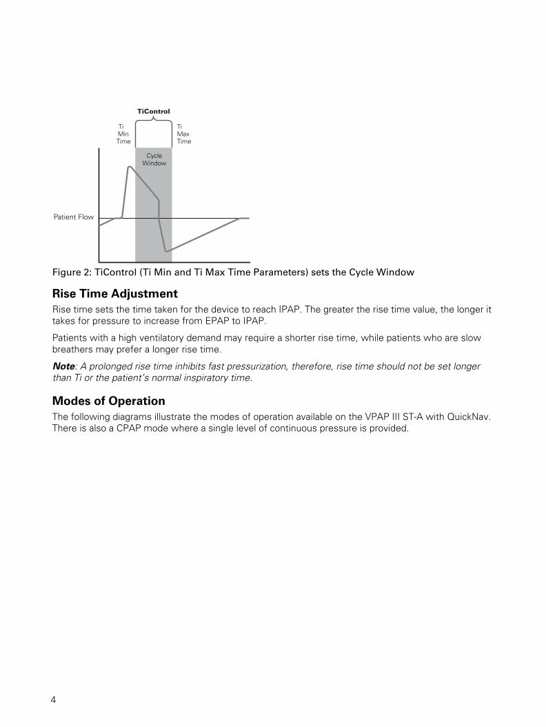
Figure 2: TiControl (Ti Min and Ti Max Time Parameters) sets the Cycle Window
Rise Time AdjustmentRise time sets the time taken for the device to reach IPAP. The greater the rise time value, the longer it takes for pressure to increase from EPAP to IPAP.
Patients with a high ventilatory demand may require a shorter rise time, while patients who are slow breathers may prefer a longer rise time.
Note: A prolonged rise time inhibits fast pressurization, therefore, rise time should not be set longer than Ti or the patient’s normal inspiratory time.
Modes of OperationThe following diagrams illustrate the modes of operation available on the VPAP III ST-A with QuickNav. There is also a CPAP mode where a single level of continuous pressure is provided.
TiControl
Patient Flow
Ti Min Time
TiMaxTime
CycleWindow
4
4

Figure 3: VPAP III ST-A with QuickNav modes
Table 1: VPAP III ST-A with QuickNav operating modes
Table 2: Key adjustable settings for VPAP III ST-A with QuickNav modes
Mode
S (Spontaneous) mode
The device senses the patient breath and triggers IPAP in response to an increase in flow, and cycles into EPAP at the end of inspiration. The breath rate and the respiratory pattern will be determined by the patient.
T (Timed) mode
The fixed breath rate and the fixed inspiration time set by the clinician are supplied regardless of patient effort.
S/T (Spontaneous/Timed) mode
The device augments any breath initiated by the patient, but will also supply additional breaths should the patient breath rate fall below the clinician's set ’backup’ breath rate.
CPAP mode
A fixed pressure is delivered.
Settings S S/T T CPAP
CPAP
IPAP
EPAP
Respiratory Rate
Ti Max
Ti
IPAP
No breath effort
Long breath(Leak or obstructive lungs)
One breath cycle
Very short breath(Restrictive lungs)
Inspiration
Patient Breath Pattern
S
S/T
T
Expiration
EPAP
IPAP
EPAP
IPAP
Ti timeEPAP
Ti time Ti time
Ti MaxTi Min
Ti MaxTi Min
Ti time
One breath cycleOne breath cycle One breath cycle
* * * **
* * * *
*
*
Patient trigger/cycle
IPAP terminated (cycle window)
5
5

Non-Invasive Ventilation and Leak ManagementTwo critical factors for the success of non-invasive ventilation therapy are:
• ventilator triggering—sensing inspiratory effort and determining the end of inspiration
• time taken to reach and maintain the set pressure, especially in the presence of leak.
The device has a unique leak management algorithm, Vsync™, that monitors the leak and adjusts the baseline flow automatically. This enables reliable triggering and cycling while maintaining the set pressures.
Triggering and Cycling Under normal conditions, the device triggers (initiates IPAP) and cycles (terminates IPAP and changes to EPAP) as it senses the change in patient flow. Patient breath detection is enhanced by the device’s automatic leak management feature—Vsync.
In addition, the device has adjustable trigger/cycle sensitivity to optimize the sensing level according to patient conditions.
High (HI) trigger sensitivity decreases the flow necessary for the device to move from EPAP to IPAP, making it easier for a patient to trigger. So, for example, for patients who have insufficient inspiratory effort (flow), set the trigger setting to ’HI’ to increase sensitivity to patient effort.
High cycle sensitivity will result in a quicker transition from IPAP to EPAP and low (LO) cycle sensitivity will delay this transition. For example, for patients who cannot maintain inspiratory flow, or who complain of having their breath ’cut off’, set the cycle setting to ’LO’ which will delay the transition from IPAP to EPAP. This will tend to prolong inspiratory time.
Figure 4: Adjustable trigger and cycle sensitivity
AlarmsThe device is fitted with alarms to alert you to changes that will affect the patient’s treatment. See “Clinical Alarms Menu” on page 23.
Ti Min
Rise Time
Trigger sensitivity
Cycle sensitivity
Settings S S/T T CPAP
Ti Min Ti Max
EPAPEPAP
Ti Min Ti Max
PatientFlow
PatientFlow High
MediumLow
Medium
High
Low
TiControl
Adjustable Trigger Sensitivity Adjustable Cycle Sensitivity
TiControl
6
6

The VPAP III ST-A with QuickNav
WARNING
• Do not connect any device to the auxiliary port other than specially designed devices
recommended by ResMed. Connection of other devices could result in injury, or
damage to the unit.
• In the clinical environment, any PC that is used with the device must be at least 1.5 m
away from, or at least 2.5 m above the patient. It must also comply with IEC 60950 or
equivalent.
MasksA ResMed mask system is recommended for use with the device. For the latest available masks, see www.resmed.com on the Products page under Service & Support.
To select the appropriate setting for your mask, see “Settings for Mask Types” on page 22.
Notes:
• ResMed VPAP devices have been designed and manufactured to provide optimum performance using ResMed vented mask systems. While other vented mask systems may be used, performance and clinical measures or monitored results may be affected.
• Not all masks are available in all regions.• ResMed’s Mirage Kidsta™ Nasal Mask is recommended for pediatric use with this device.
The VPAP III ST-A with QuickNav comprises:
• VPAP III ST-A with QuickNav device (shown above)
• Power cord
• Carry bag
• 2 m air tubing.
The following accessories may be purchased separately:
• 3 m air tubing
• Medium (52 cm) air tubing for the HumidAire and ResMed Passover humidifiers
• Hypoallergenic air filter
• Antibacterial filter.
DC Power Socket
AC Power Socket
Air filter cover
Power switch
Aux / Com Ports
Removable front cover
Handle
LCD screen
Control panel
Air outlet
7
7

HumidifiersA humidifier may be required if your patient experiences dryness of the nose, throat or mouth. The following humidifiers (supplied separately) are compatible for use with the device:
Note: Not all humidifiers are available in all regions.
ResControl™ and ResLink™The ResControl™ or ResLink™ may be connected to the device. Please refer to the relevant user manual for details.
Note: ResMed regularly releases new products. Please check our website at www.resmed.com.
Setting up the devicePlace the device on a flat surface.
CAUTION
• Be careful not to place the device where it can be bumped or where someone is likely
to trip over the power cord.
• Make sure the area around the flow generator is dry and clean. It should also be clear
of bedding, clothes and other potential blockages.
1 Connect the power cord.
Note: ResMed recommends using the AC power cord supplied with the unit. If a replacement power cord is required, contact your ResMed service centre.
2 Plug the free end of the power cord into a power outlet.
• HumidAire 2i™ heated humidifier
• HumidAire 2iC™ passover humidifier
• HumidAire™ heated humidifier
• ResMed Passover humidifier.
Power switch
AC locking clip
AC power cord
8
8

CAUTIONDo not connect both AC and DC power cords to the device at the same time, unless
otherwise specified.
WARNING
• Make sure the power cord and plug are in good condition and the equipment is not
damaged.
• The air filter cover protects the device in the event of accidental liquid spillage onto the
device. Ensure that the air filter and air filter cover are fitted at all times.
3 Connect one end of the air tubing firmly onto the air outlet of the device.
WARNING
Only a ResMed patient circuit should be used with the flow generator. A different type of
patient circuit may alter the pressure actually received and reduce the effectiveness of
ventilation. Do not use conductive or anti-static hoses or tubes.
4 Connect a mask system to the free end of the air tubing.
The VPAP III ST-A with QuickNav system is now assembled.
Before use, you will need to select the appropriate mode and set the operating parameters. See “Navigating the Clinical Menu” on page 20.
Using HumidifiersWARNING
When using a humidifier, position it lower than the patient (so that any excess
condensation drains back into the water chamber) and at the same level or lower than the
device.
Note: You don’t need to activate the humidifier option in the menus if the patient is using a HumidAire 2i, but do for other humidifers.
HumidAire 2i
The HumidAire 2i attaches to the front of the device to provide heated humidification. No other accessories are required for its use. This device automatically detects the presence of the HumidAire 2i. No menu changes are required. Please refer to the HumidAire 2i User’s Manual for details.
HumidAire 2iC
The HumidAire 2iC attaches to the front of the device to provide passover humidification (the device setting is H2i). No other accessories are required for its use. Please refer to the HumidAire 2iC User’s Manual for details.
HumidAire or Passover Humidifer
Medium size (52 cm) air tubing is a necessary accessory for connecting the device to the HumidAire or Passover humidifier. Refer to the relavant humidifer user manual for details.
9
9
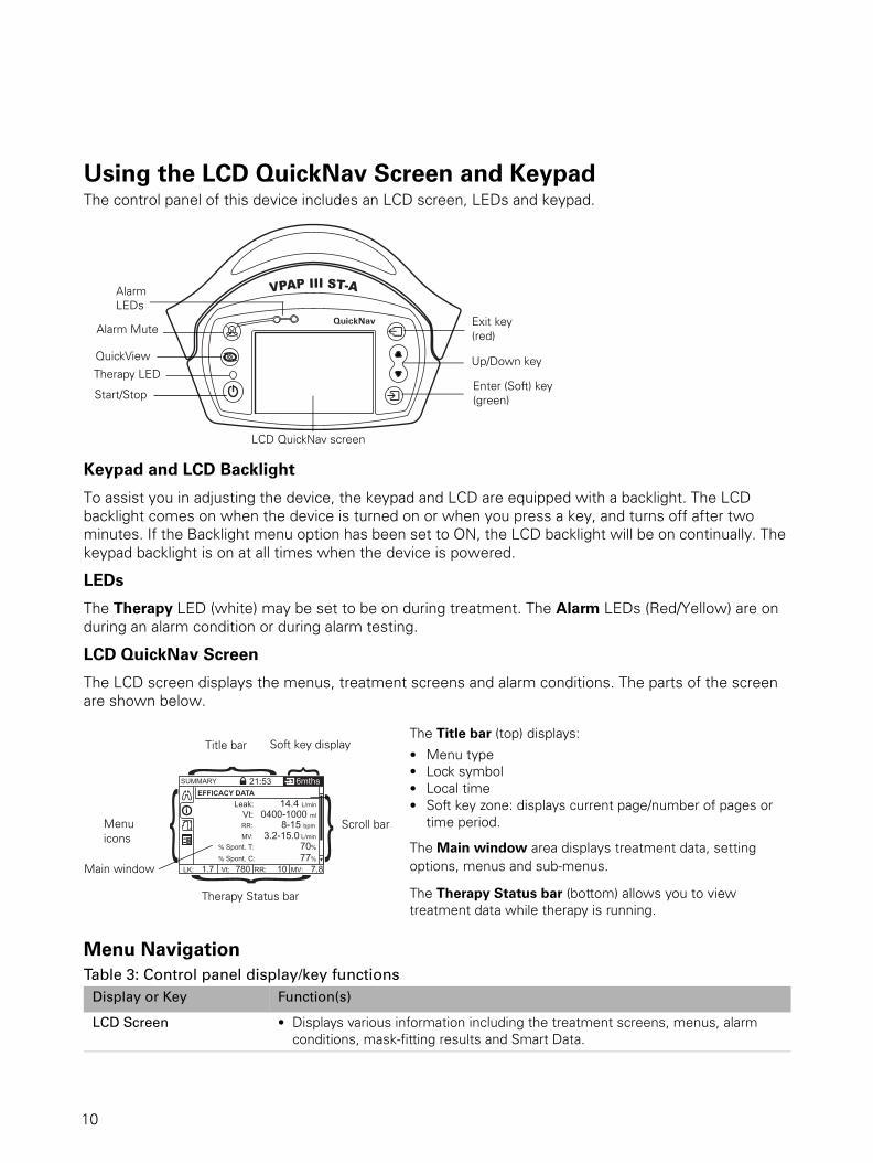
Using the LCD QuickNav Screen and KeypadThe control panel of this device includes an LCD screen, LEDs and keypad.
Keypad and LCD Backlight
To assist you in adjusting the device, the keypad and LCD are equipped with a backlight. The LCD backlight comes on when the device is turned on or when you press a key, and turns off after two minutes. If the Backlight menu option has been set to ON, the LCD backlight will be on continually. The keypad backlight is on at all times when the device is powered.
LEDs
The Therapy LED (white) may be set to be on during treatment. The Alarm LEDs (Red/Yellow) are on during an alarm condition or during alarm testing.
LCD QuickNav Screen
The LCD screen displays the menus, treatment screens and alarm conditions. The parts of the screen are shown below.
Menu Navigation Table 3: Control panel display/key functions
The Title bar (top) displays:
• Menu type• Lock symbol• Local time • Soft key zone: displays current page/number of pages or
time period.
The Main window area displays treatment data, setting options, menus and sub-menus.
The Therapy Status bar (bottom) allows you to view treatment data while therapy is running.
Display or Key Function(s)
LCD Screen • Displays various information including the treatment screens, menus, alarm conditions, mask-fitting results and Smart Data.
Alarm
Alarm Mute
Start/Stop
Exit key
Enter (Soft) key
Up/Down key
LCD QuickNav screen
(green)
QuickView
(red)
LEDs
Therapy LED
SUMMARY
LK: 1.7 Vt: 780 RR: 10 MV: 7.8
21:53EFFICACY DATA
6mths
Leak: 14.4 L/min
Vt: 0400-1000 ml
RR: 8-15 bpm
MV: 3.2-15.0 L/min
% Spont. T: 70%
% Spont. C: 77%
}}} } }Title bar Soft key display
Menu icons
Main window
Therapy Status bar
Scroll bar
10
10

Delivering Therapy1 Assemble the device and mask system as instructed. See “Setting up the device” on page 8.
2 Change the settings required for the treatment mode. For instructions on changing settings, see “Menu Navigation” on page 10.
LEDs:
• Alarm LEDs• Therapy LED
White: Therapy is running and LED option is enabled (see Table 9, “Clinical Options menu descriptions,” on page 29).
Yellow or Red: Indicates an alarm condition.
Start/Stop • Starts and stops treatment.• Extended hold (for at least two seconds) activates the mask-fitting feature.
Up/Down • Within a menu or submenu, navigates between items in that level.• Extended hold scrolls through selectable options.
Enter (green) • Allows you to enter or change the menu or function highlighted on the LCD screen. Functions of this key includes enter, change and apply, and it also operates as a soft key.
Exit (red) • Allows you to exit the current menu or go back through the menus. The function of this key is to exit from the current menu or setting.
• Extended hold (for at least three seconds) takes you to the patient home screen.
Alarm Mute • Press once to mute alarms. Press a second time to un-mute. If the problem is still present, the alarm will sound again after two minutes. See “Clinical Alarms Menu” on page 23.
QuickView • When ventilation is operating, QuickView takes you immediately from the clinical menu to the treatment screens. See “Treatment Screens” on page 31.
• Pushing QuickView again will return the display to where you were previously in the Clinical Menu.
Exit + Up/Down • Extended hold (for at least two seconds) gives access to the clinical menu from the Standby screen.
Left + Right • Extended hold (for at least two seconds) gives quick access to the Efficacy Data only in the Clinical Summary menu (see “Clinical Summary Menu” on page 33).
Display or Key Function(s)
11
11
3 Instruct the patient to lie down in bed, arrange the air tubing, and put on the mask according to steps 1 and 2 in the section “Using the Mask-Fitting Feature” on page 13.
WARNING
Do not leave long lengths of air tubing around the top of the bed; they may twist around
the patient’s head or neck while sleeping.
Note: If oxygen is used, see “Adding Supplemental Oxygen” on page 34.
Starting TherapyNote: Before starting therapy, check the integrity of the patient circuit.
Press the Start/Stop key to start the airflow. Air will begin flowing slowly and will build up to full operating pressure in about 10 to 15 seconds.
• If SmartStart™ is enabled, instruct the patient to breathe (inhale) into the mask. The device will start automatically. (see “SmartStart/Stop” on page 22)
• If oxygen is used, ensure the device is generating airflow before adding oxygen.
Stopping TherapyRemove the mask and press the Start/Stop key to stop airflow.
• If SmartStart/Stop is enabled, simply remove the mask, and treatment will stop automatically (SmartStop is not applicable with the ‘Mir Full’ mask setting, or when the Leak or Low MV [minute ventilation] Alarm is enabled).
• If oxygen is used, turn off the oxygen supply before stopping the device.
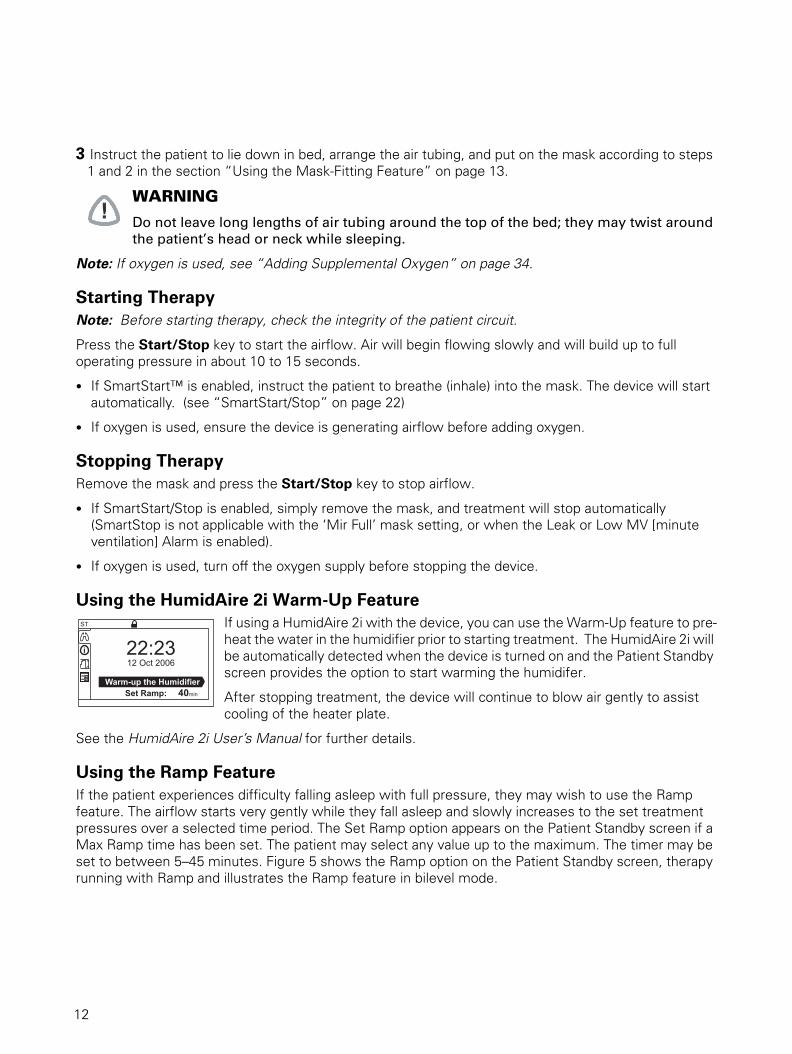
Using the HumidAire 2i Warm-Up FeatureIf using a HumidAire 2i with the device, you can use the Warm-Up feature to pre-heat the water in the humidifier prior to starting treatment. The HumidAire 2i will be automatically detected when the device is turned on and the Patient Standby screen provides the option to start warming the humidifer.
After stopping treatment, the device will continue to blow air gently to assist cooling of the heater plate.
See the HumidAire 2i User’s Manual for further details.
Using the Ramp FeatureIf the patient experiences difficulty falling asleep with full pressure, they may wish to use the Ramp feature. The airflow starts very gently while they fall asleep and slowly increases to the set treatment pressures over a selected time period. The Set Ramp option appears on the Patient Standby screen if a Max Ramp time has been set. The patient may select any value up to the maximum. The timer may be set to between 5–45 minutes. Figure 5 shows the Ramp option on the Patient Standby screen, therapy running with Ramp and illustrates the Ramp feature in bilevel mode.
ST
Set Ramp: 40min
Warm-up the Humidifier
22:2312 Oct 2006
12
12

Figure 5: (a) Patient Standby screen with Max Ramp set; (b) Therapy running with Ramp; (c) Ramp in bilevel mode.
Resetting the Flow GeneratorErasing Data (Patient Usage Hours)
To reset (zero) the patient hour counter and erase the saved usage and efficacy data, navigate to the ERASE DATA setting in the Clinical Options menu (see page 29) and press the Enter key (erase). It will ask ARE YOU SURE? If you select YES (Enter), then the usage and efficacy data will be erased and the counter reset.
The MACHINE RUN HOURS counter cannot be reset.
Restoring Factory Defaults
To restore all factory defaults, navigate to the APPLY FACTORY DEFAULTS setting in the Clinical Settings menu (see page 29) and press the Enter key (reset). It will ask ARE YOU SURE? If you select YES (Enter), you will hear a confirmation beep that all the settings are erased and the flow generator is returned to factory defaults.
Note: Restoring factory defaults will not disturb the calibration settings, MACHINE RUN HOURS counter, clock or the language setting.
Setup for Home TreatmentYou may be required to set up a device for a patient to take home. There are a number of things to be aware of:
1 Always set parameters and oxygen levels with the equipment set up in exactly the same way it will be used at the patient’s home (eg, same mask system, with the humidifier connected, the oxygen line entrained at the same place, filters in the same position, and same length air tubing).
2 Ensure that the patient has the relevant user guide and understands how to operate the equipment.
3 Make sure that the patient has a contact phone number in case of emergency. A good place to write this is in the front of the user guide.
Using the Mask-Fitting FeatureThe mask-fitting feature delivers air pressure for a three-minute period before therapy begins for adjusting mask fit to minimize leak. If a Ramp time is selected, the mask can be adjusted at a pressure closer to the prescribed pressure.
IPAP
Time
EPAP
Start pressure
0
Ramp Time
ST
Humidifier WarningSet Ramp: 40min
ST
Ramp: 19:45
21:5312 Oct 2006
40
a
b
c
13
13
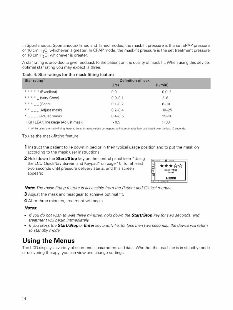
In Spontaneous, Spontaneous/Timed and Timed modes, the mask-fit pressure is the set EPAP pressure or 10 cm H2O, whichever is greater. In CPAP mode, the mask-fit pressure is the set treatment pressure or 10 cm H2O, whichever is greater.
A star rating is provided to give feedback to the patient on the quality of mask fit. When using this device, optimal star rating you may expect is three.
Table 4: Star ratings for the mask-fitting feature
To use the mask-fitting feature:
Using the MenusThe LCD displays a variety of submenus, parameters and data. Whether the machine is in standby mode or delivering therapy, you can view and change settings.
Star rating1
1 While using the mask-fitting feature, the star rating values correspond to instantaneous leak calculated over the last 10 seconds.
Definition of leak
(L/s) (L/min)
* * * * * (Excellent) 0.0 0.0–2
* * * * _ (Very Good) 0.0–0.1 2–6
* * * _ _ (Good) 0.1–0.2 6–10
* * _ _ _ (Adjust mask) 0.2–0.4 10–25
* _ _ _ _ (Adjust mask) 0.4–0.5 25–30
HIGH LEAK message (Adjust mask) > 0.5 > 30
1 Instruct the patient to lie down in bed or in their typical usage position and to put the mask on according to the mask user instructions.
2 Hold down the Start/Stop key on the control panel (see “Using the LCD QuickNav Screen and Keypad” on page 10) for at least two seconds until pressure delivery starts, and this screen appears:
Note: The mask-fitting feature is accessible from the Patient and Clinical menus.
3 Adjust the mask and headgear to achieve optimal fit.
4 After three minutes, treatment will begin.
Notes:
• If you do not wish to wait three minutes, hold down the Start/Stop key for two seconds, and treatment will begin immediately.
• If you press the Start/Stop or Enter key briefly (ie, for less than two seconds), the device will return to standby mode.
LK: 1.7 Press: 10
SETTINGS 21:53
Done
Mask FittingGood
14
14

Menu OverviewThe below flowchart provides an overview of the menu structure.
SETTINGS
AdjustableParameters
forTherapy, Circuit &
Max Ramp
OPTIONSSUMMARYTREATMENT
CLINICAL MENUUnLocked
Efficacy Data
Usage Data
Alarm History
Settings Summary
Servicing
Setup
Clock
Language
Hold Down "Exit"+ "Up" or "Down"Key for >2 secs
to Lock or Unlockthe Menu
When entering theClinical Menu, this is
the 1st Screen displayed
Clinical Home Screen
ALARMS
AdjustableParameters
forAlarm Limits& Conditions
Treatment StandbyScreen
Oximetry Data
Real Time Data
Ti Graphs
Settings Check
OR - Hold Down"Exit" Key for >2secs to Lock the
Menu
SETTINGS
AdjustableParametersfor Circuit
OPTIONSSUMMARYTREATMENT
PATIENT MENULocked
Oximetry Data
Real Time Data
Ti Graphs
Efficacy Data
Usage Data
Alarm History
Settings Summary
Servicing
Setup
Clock
Language
Patient Home Screen
When Therapy isOFF
ie when the deviceis 1st switched on,or when enteringthe Patient Menu,
this is the 1stscreen displayed
Settings Check
Patient Standby Screen
When Therapy isON
ie when "Start" ispressed or after a1 min timeout in
the Patient Menu,this is the Screen
displayed
Pushing QuickViewwill toggle fromanywhere in the
Clinical menu, to theTreatment Menu,and back again
+
+
Hold Down "Enter”+ "Exit” for quick access to the Efficacy Data.
+
Hold Down "Enter”+ "Exit” for quick access to the Efficacy Data.
15
15

Patient MenusNote: For all the clinical and patient menu illustrations and descriptions that follow, default values may vary according to region.
Patient Treatment MenuWhen the device is first turned on, the Patient Standby screen appears. After starting treatment, you can display one of the treatment screens below. Press the Enter key to scroll through the pages.The Main
window area displays treatment data in successive screens, including:
Treatment Screen 1: Oximetry Data
The Oximetry Data screen will only display if an oximeter is attached through ResLink. This provides information on:
• Oxygen saturation level (SpO2): Percentage of oxygen in the blood stream (only appears if ResLink™ and oximeter are attached).
• Pulse rate (HR): Measured in beats per minute (only appears if ResLink and oximeter are attached).
Treatment Screen 2: Therapy Data
• Leak: Current unintentional leak (units: liters per minute or liters per second).• Tidal volume (Vt): Volume of air inhaled per breath (units: milliliters per breath).• Respiratory rate (RR): Number of breaths per minute.• Minute ventilation (MV): Volume of air inhaled per minute (units: liters per minute). It is
the product of respiratory rate and tidal volume.• Estimated pressure: The estimated pressure at mask (units: cm H2O or hPa).• Ramp: Appears if ramp is operating (disappears once the ramp time has elapsed).
Treatment Screen 3: Ti Graph
The Ti Graph displays the live Ti bar history. The far left Ti bar (to the right of the Pressure bar) is constantly active, showing the current breath (this Ti bar also appears on other screens during treatment). The Ti graph displays the animated Ti bar history for 10 breaths before the screen refreshes. The far right bar always shows the most recent breath. See “Pressure Bar and Ti Bar” on page 17.
Treatment Screen 4: Settings Check
The Settings Check screen allows you to review the following device settings:
• Treatment mode: Options include: CPAP, Spontaneous, Spontaneous/Timed and Timed.
• Respiratory Rate: The set rate, or ‘backup rate’ breaths per minute.• Rise Time: The set time taken for the pressure to rise from EPAP to IPAP.• Trigger: Sensitivity for the triggering threshold.• Cycle: Sensitivity for the cycling threshold.
TREATMENT 21:53 1/4
4.0
12.0 OXIMETRY DATA
LK: 1.7 Vt: 780 RR: 10 7.8 M V :
SpO2: HR:
92 %
65
Treatment Screen 1: Oximetry Data
TREATMENT 21:53 2/4
4.0
12.0
Ramp: 19:45
Vt: RR:
780 10
Leak: 1.7
MV: 7.8 Est. Press: 11.8 cm
H20
L/min
L/min
bpm
ml
1.0 1.1 0.5 2.0 TiMx: TiMn: I:E Ti Avg:
Treatment Screen 2: Therapy Data
TREATMENT 21:53 3/4
4.0
12.0
1.0 1.1 0.5 2.0 TiMx: TiMn: I:E Ti Avg:
Treatment Screen 3: Ti Graph
TREATMENT 21:53 4/4
4.0
12.0
1.0 1.1 0.5 2.0 TiMx: TiMn: I:E Ti Avg:
SETTINGS CHECK
Mode: ST
Rise Time: Trigger:
Cycle:
ms
bpm Resp. Rate:
High High
150 10
Treatment Screen 4: Settings Check
16
16
The Pressure bar and Ti bar show the following:
Pressure bar: Graphical display of the changing pressure. In CPAP mode, this displays the set treatment pressure (units: cm H2O or hPa). In other modes, it is expiration and inspiration pressures (units: cm H2O).
Ti bar: Graphical display showing how the device changes pressure when you are inhaling and exhaling. When the Ti Bar begins or ends with a triangle, this indicates that the device has been triggered or cycled by a timed setting (Ti Min, Ti Max, RR); no triangle at the end of the bar indicates a patient triggered or cycled change.
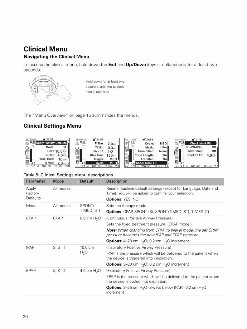
Patient Summary MenuThe patient summary menu allows you to view Efficacy Data, Usage Data, Alarm History, Event History, Settings Summary and Servicing information.
The example below shows how to navigate to the Usage Data from the Patient Summary Menu.
The Therapy Status bar (at the bottom of the screen) allows you to view treatment data while therapy is running. May include:
• Measured inspiration time (Ti Avg): The average inspiration time measured by the device (averaged over five breaths).
• Measured I:E ratio (I:E): The inspiration to expiration ratio measured by the device (averaged over five breaths).
• TiMn: The minimum inspiration time (Ti Min) set by your clinician.• TiMx: The maximum inspiration time (Ti Max) set by your clinician.• Leak (LK)• Tidal volume (Vt)• Respiratory rate (RR)• Minute ventilation (MV)• Oxygen saturation level (SpO2): only displays if an oximeter is attached through ResLink.
Spontaneous Time Triggered Ti Max Cycled Ti Min Cycled
Pressure Bar
Set IPAP
Ti Mx
Ti MnTi Bar
Ti Zero
Pressure Bar and Ti Bar
SUMMARY
LK: 1.7 Vt: 780 RR: 10 MV: 7.8
21:53EFFICACY DATAUSAGE DATAALARM HISTORY
SERVICINGSETTINGS SUMMARY
Press Enter then Down
SUMMARY
LK: 1.7 Vt: 780 RR: 10 MV: 7.8
21:53EFFICACY DATAUSAGE DATAALARM HISTORYSETTINGS SUMMARYSERVICING Press
Enter
SUMMARY
LK: 1.7 Vt: 780 RR: 10 MV: 7.8
21:53USAGE DATA
6mths
Used Since: 12 Oct 2006 Used: 740 hrs 102/106 days Usage: 7: 15 hrs/day
17
17

Patient Settings MenuThe Patient Settings menu allows you to view and change settings such as mask type, tube length and the humidifier used. You can also access the mask-fit feature.
WARNINGIf these settings do not match your system set-up, this may alter the pressure the patient
actually receives and reduce the effectiveness of your treatment.
Function Function Description Viewing Options
Efficacy Data • Leak• Vt (tidal volume)• RR (respiratory rate)• MV (minute ventilation)• % Spont. T (percentage patient triggered pressure
change)• % Spont. C (percentage patient cycled pressure
change)
Press Enter to view the data over:– day– week– month– 6 months– yearrespectively.
Usage Data • Used Since: displays date device first used since last reset.
• Used: displays the total number of hours for which the device has been used and the number of days the device was used out of the total number of days since last reset.
• Usage: Displays the average hours the device was used each day (total hours/days used).
Press Enter to view Usage (hrs/day) data over:– day– week– month– 6 months– yearrespectively.
Alarm History Displays the alarm events log in 24 hr sessions from 12 noon to 12 noon.
Note: The alarm events log is maintained when the device is powered off and in the event of a power failure.
Press Enter to view the data over consecutive days, for a five-day period.
Settings Summary The settings summary screens enable the clinician to quickly review the device settings.
View only
Servicing • Machine hours• SN: serial number of the device• SW: current software version
View only
LK: 1.7 Vt: 780 RR: 10 MV: 7.8
SETTINGS 21:53
40 Mask: UltraHumidifier: None
Tube Length: 2mCheck Mask Fit
SmrtStrtStp: Off
Function Default Function Description Settings
Mask ULTRA Selects your mask type. See “Settings for Mask Types” on page 22 for the correct setting for your mask type.
18
18

Patient Options MenuThe Patient Options menu allows you to set the local time, date and language and to test and change the alarm volume.
Humidifier NONE Selects the type of humidifier to be used with the device.
H2i (HumidAire 2iC), PASSOVER, HUMIDAIRE, NONE
If the HumidAire 2i is used, it is automatically detected and H2i is displayed.
Tube Length 2 m Selects the length of air tubing connecting your mask to the device.
2 m, 3 m
Check Mask-Fit Checks your mask-fit star rating. View only
SmartStart™
(SmrtStrtStp)
OFF If SmartStart is enabled, the device will start automatically when the patient breathes into the mask and will stop automatically when they take the mask off (SmartStop). This means the patient does not have to press the Start/Stop key to begin or end treatment.1, 2
ON, OFF
1 If you select “Mir Full” as the mask option, SmartStop is automatically disabled. SmartStart may not work with a full face mask due to safety features of the mask.
2 When the Leak or Low MV Alarms are set to ON, SmartStop is automatically disabled. SmartStop cannot be used with the Leak or Low MV Alarms because, if either of these conditions occur, SmartStop may stop treatment before the alarm signal is activated.
Function Function Description Default Settings
Setup • Alarm Vol/Test: Changes and tests the alarm volume.
Note: When you select the volume level and when you press enter, the alarm will beep at the selected volume as a test.
Medium Low, Medium and High.
• LCD Backlight. Sets the backlight to either be on all the time or to AUTO, where the backlight will turn off after two mintues and turn on again when any key is pressed.
AUTO ON, AUTO
Clock Sets the time and date.
Language Selects the menu language.1
1 A tick appears next to the currently selected language.
English2
2 The default language depends upon the region.
English, French, Spanish, Portuguese.
Function Default Function Description Settings
OPTIONS
LK: 1.7 Vt: 780 RR: 10 MV: 7.8
21:53SETUPCLOCKLANGUAGE
19
19
Clinical MenuNavigating the Clinical Menu
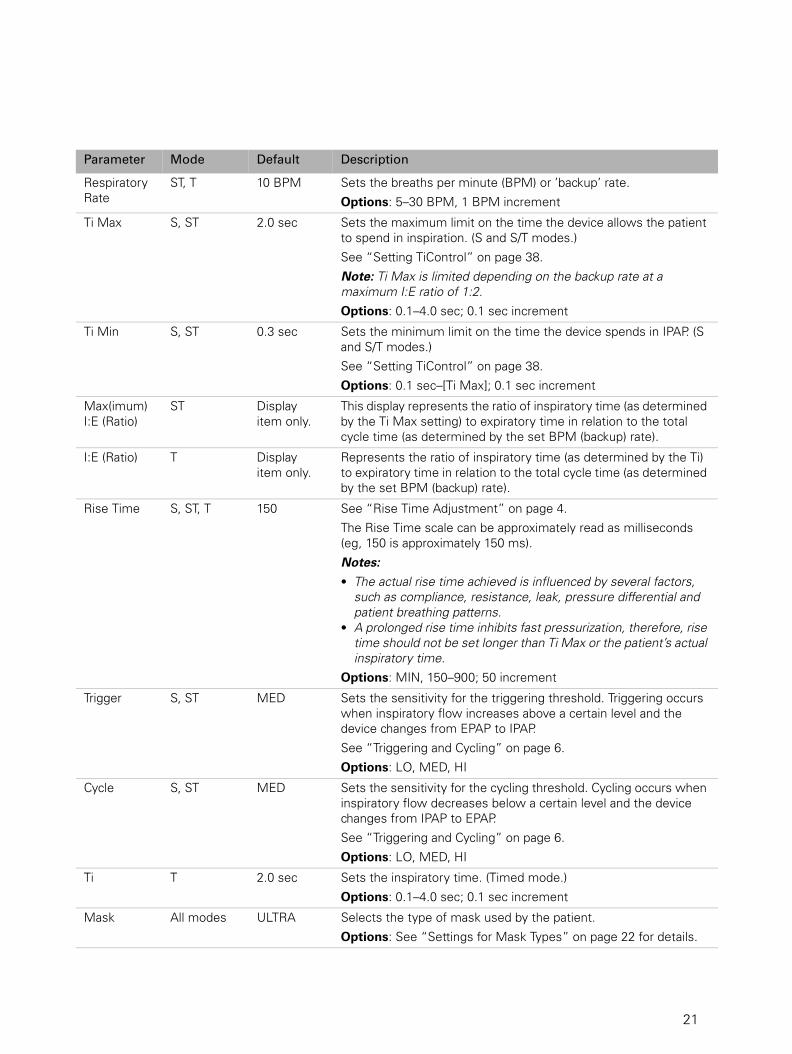
To access the clinical menu, hold down the Exit and Up/Down keys simultaneously for at least two seconds.
The “Menu Overview” on page 15 summarizes the menus.
Clinical Settings Menu
Table 5: Clinical Settings menu descriptions
Parameter Mode Default Description
Apply Factory Defaults
All modes Resets machine default settings (except for Language, Date and Time). You will be asked to confirm your selection.
Options: YES, NO
Mode All modes SPONT/TIMED (ST)
Sets the therapy mode.
Options: CPAP, SPONT (S), SPONT/TIMED (ST), TIMED (T)
CPAP CPAP 8.0 cm H2O (Continuous Positive Airway Pressure)
Sets the fixed treatment pressure. (CPAP mode.)
Note: When changing from CPAP to bilevel mode, the set CPAP pressure becomes the new IPAP and EPAP pressure.Options: 4–20 cm H2O; 0.2 cm H2O increment
IPAP S, ST, T 10.0 cm H2O
(Inspiratory Positive Airway Pressure)
IPAP is the pressure which will be delivered to the patient when the device is triggered into inspiration.
Options: 3–30 cm H2O; 0.2 cm H2O increment
EPAP S, ST, T 4.0 cm H2O (Expiratory Positive Airway Pressure)
EPAP is the pressure which will be delivered to the patient when the device is cycled into expiration.
Options: 3–25 cm H2O (always below IPAP); 0.2 cm H2O increment
Hold down for at least two
seconds, until the padlock
icon is unlocked.
SETTINGS
LK: 1.7 Vt: 780 RR: 10 7.8
21:53
M V : 4.0
12.0
Mode: ST
EPAP: 4.0 Resp. Rate: 10
Ti Max: 2.0
cm H20
cm H20
bpm
IPAP:
Apply Factory Defaults
10.0
sec
SETTINGS
LK: 1.7 Vt: 780 RR: 10 7.8
21:53
M V : 4.0
12.0
Max I:E:Rise Time: 150
Trigger: MED Cycle: MED
ms
sec
Ti Min:Ti Max:
0.32.0
1:2sec
SETTINGS
LK: 1.7 Vt: 780 RR: 10 7.8
21:53
M V : 4.0
12.0
Mask:
Tube Length: 2m AB Filter: No Check Mask Fit
Humidifier:
Cycle:
None
MED Ultra
Check Mask Fit
SETTINGS
LK: 1.7 Vt: 780 RR: 10 7.8
21:53
M V : 4.0
12.0
SmrtStrt/Stp: Off
Start EPAP: 4.0 cm H20
Max Ramp:
Check Mask Fit
Off
20
20
Respiratory Rate
ST, T 10 BPM Sets the breaths per minute (BPM) or ’backup’ rate.
Options: 5–30 BPM, 1 BPM increment
Ti Max S, ST 2.0 sec Sets the maximum limit on the time the device allows the patient to spend in inspiration. (S and S/T modes.)
See “Setting TiControl” on page 38.
Note: Ti Max is limited depending on the backup rate at a maximum I:E ratio of 1:2.Options: 0.1–4.0 sec; 0.1 sec increment
Ti Min S, ST 0.3 sec Sets the minimum limit on the time the device spends in IPAP. (S and S/T modes.)
See “Setting TiControl” on page 38.
Options: 0.1 sec–[Ti Max]; 0.1 sec increment
Max(imum) I:E (Ratio)
ST Display item only.
This display represents the ratio of inspiratory time (as determined by the Ti Max setting) to expiratory time in relation to the total cycle time (as determined by the set BPM (backup) rate).
I:E (Ratio) T Display item only.
Represents the ratio of inspiratory time (as determined by the Ti) to expiratory time in relation to the total cycle time (as determined by the set BPM (backup) rate).
Rise Time S, ST, T 150 See “Rise Time Adjustment” on page 4.
The Rise Time scale can be approximately read as milliseconds (eg, 150 is approximately 150 ms).
Notes: • The actual rise time achieved is influenced by several factors,
such as compliance, resistance, leak, pressure differential and patient breathing patterns.
• A prolonged rise time inhibits fast pressurization, therefore, rise time should not be set longer than Ti Max or the patient’s actual inspiratory time.
Options: MIN, 150–900; 50 increment
Trigger S, ST MED Sets the sensitivity for the triggering threshold. Triggering occurs when inspiratory flow increases above a certain level and the device changes from EPAP to IPAP.
See “Triggering and Cycling” on page 6.
Options: LO, MED, HI
Cycle S, ST MED Sets the sensitivity for the cycling threshold. Cycling occurs when inspiratory flow decreases below a certain level and the device changes from IPAP to EPAP.
See “Triggering and Cycling” on page 6.
Options: LO, MED, HI
Ti T 2.0 sec Sets the inspiratory time. (Timed mode.)
Options: 0.1–4.0 sec; 0.1 sec increment
Mask All modes ULTRA Selects the type of mask used by the patient.
Options: See “Settings for Mask Types” on page 22 for details.
Parameter Mode Default Description
21
21

SmartStart/Stop
If you enable the SmartStart function, the patient’s device will start automatically when they breathe into their mask, and will stop automatically when they take the mask off. This means that the patient does not have to press the Start/Stop key to begin or end treatment. See Table 5 for details about enabling SmartStart.
Note: If you select “Mir Full” as the mask option, SmartStop is automatically disabled. SmartStart may not work with a full face mask because of the anti-asphyxia valve.
When the Leak or Low MV (minute ventilation) Alarm is set to ON, SmartStart/Stop is automatically set to OFF. SmartStart/Stop cannot be used with these alarms because, if a high leak occurs, SmartStop may stop treatment before the alarm signal is activated.
Settings for Mask Types
The following table shows the setting that should be selected for each mask type.
Humidifier All modes NONE Adjusts the system for treatment with or without a humidifier.
Note: The device automatically detects the presence or absence of the HumidAire 2i.Options: HUMIDAIRE (heated HumidAire), PASSOVER (ResMed Passover), NONE, H2i (HumidAire 2iC)
Tube Length All modes 2 m Sets the length of tubing used between the unit and the mask.
Options: 2 m, 3 m
AB Filter All modes NO Adjusts the system for treatment with or without an antibacterial filter. For details, see “Using an Antibacterial Filter” on page 35.
Options: YES, NO
Check Mask Fit
All modes Displays the mask fit star rating. For details, see “Using the Mask-Fitting Feature” on page 13.
SmartStart/Stop
All modes OFF Enables or disables the SmartStart/Stop feature; when enabled, the unit will start automatically when the patient breathes into the mask and stop automatically when the patient takes the mask off.
For details, see “SmartStart/Stop” on page 22.
Options: ON, OFF
Max Ramp All modes OFF Limits the ramp times the patient may select.
Options: OFF–45 min; 5-min increment
Start CPAP CPAP 4.0 cm H2O Sets the pressure at the start of the ramp up to fixed treatment pressure.
Options: 4 cm H2O–[CPAP]; 0.2 cm H2O increment
Start EPAP S, ST, T 4.0 cm H2O Sets the pressure at the start of the ramp up to fixed treatment pressure.
Options: 2 cm H2O–[EPAP]; 0.2 cm H2O increment
Parameter Mode Default Description
22
22

Table 6: Settings for Mask Types.
Clinical Alarms MenuThe device is fitted with alarms to alert you to changes that will affect the patient’s treatment.
Table 7: Clinical Alarms Menu
Alarm Mute Key
You can mute an alarm for two minutes by pressing the Alarm Mute key once. If the problem is still present, the alarm will sound again after two minutes or you can un-mute the alarm by pressing the Alarm Mute key a second time. An Alarm LED will remain lit for as long as the problem is present.
Settings Mask
MIRAGE Mirage Swift™ Nasal Pillows SystemMirage Swift™ II Nasal Pillows System
ULTRA Ultra Mirage™ Nasal MaskUltra Mirage™ II Nasal Mask
STANDARD Mirage Activa™ Nasal MaskMirage Vista™ Nasal MaskMirage Micro™ Nasal MaskMirage Kidsta™ Nasal MaskMeridian™ Disposable Nasal Mask
MIR FULL Ultra Mirage™ Full Face MaskMirage Quattro™ Full Face MaskMirage Liberty™ Full Face MaskHospital Full Face Mask
Fixed Alarms User Adjustable Alarms
The alarms pre-set for the device are: Alarms that can be set are:
• power fail • leak alarm
• over pressure (pressure error) • non-vented mask
• over use (IPAP lower alarm) • low minute ventilation
• system fault (system error) • high pressure
• check tube. • low pressure.
TREATMENT
LK: 1.7 Vt: 780 RR: 10 7.8
21:53
MV:
1/4
CHECKCHECKTUBETUBE
Alarm LEDs (yellow and red)
Alarm Mute key
LCD screen
23
23

Testing the Alarm Signal
When the device is turned on, the alarm LEDs will flash and the alarm will beep twice to test the alarm. To test the alarm manually using the menus, or to adjust the alarm volume, go to the Options menu (Clinical or Patient), then Setup > Alarm Vol/Test.
User Adjustable Alarms
Alarms that can be set are: leak alarm, non-vented mask, low minute ventilation, high pressure and low pressure.
Figure 6: Alarms menu.
Table 8: Alarm settings and descriptions
Alarm Setting Default Description
Leak Alarm ON Enables or disables the Mask Alarm feature; when enabled, leaks > 40 L/min (0.7 L/sec) for > 20 seconds result in an audible alert and a HIGH LEAK message.1
For details, see “Leak Alarm” on page 25.
Options: ON, OFF
1 When the Leak or Low MV Alarms are set to ON, SmartStop is automatically disabled. SmartStop cannot be used with the Leak or Low MV Alarms because, if either of these conditions occur, SmartStop will stop treatment before the alarm signal is activated.
Non-Vented Alarm
(Non-vented mask alarm)
OFF Sets the non-vented mask alarm that activates within 30 seconds (15 seconds on average) when a non-vented mask is attached during therapy.
Note: Use of supplemental oxygen with a vented mask may activate the non-vent alarm (see page 34).Options: ON, OFF
Low MV
(Low minute ventilation)
2 L/min Sets the minimum minute ventilation. Activates within 30 seconds (average 15 seconds) after the measured level remains below the set limit for 30 seconds.1
Range: OFF; 2–10 L/min; 1 L/min increments.
High Press
(High pressure)
30 cm H2O Sets the high pressure limit. Activates when pressure increases above the set limit for 700 msec.
Range: OFF; 4–35 cm H2O; 1 cm H2O increments.
Low Press
(Low pressure)
-3 cm H2O Sets the maximum drop in pressure with reference to a set IPAP or CPAP pressure. Activates when the pressure drops by more than the set level for 12 seconds.
Note: When SmartStart/Stop is enabled, SmartStop activates before the LOW PRES alarm.Range: OFF; -2 to -10 cm H2O; 1 cm H2O increments.
ALARMS
LK: 1.7 Vt: 780 RR: 10 7.8
21:53 Leak Alarm:
M V : 4.0
On 12.0
Non-Vented: OffLow MV: 2
High Press: 30 Low Press: -3 cm
H20
cm H20
L/min
24
24

WARNINGIn an environment where multiple devices are in use, the devices may have different
alarm settings.
CAUTIONCarefully review the alarm settings prior to using the device with a patient to ensure that
the alarm settings are appropriate for that patient.
Leak Alarm
The flow generator is equipped with an optional Leak Alarm. The alarm will sound if the patient’s mask falls off during the night, or if there are excessive air leaks from the mask or mouth. Use the Leak Alarm menu to enable the alarm, see “Clinical Alarms Menu” on page 23. To temporarily silence the alarm, press the Alarm Mute key or fix the cause of the leak.
WARNINGLeak Alarm activation is a function of the flow generator set pressure, the air delivery
system in use and whether the humidifier mode is set. Certain set pressures and
combinations of air delivery components may mean the Leak Alarm fails to activate.
ResMed recommends that you test the Leak Alarm before commencing treatment. See
“Testing the Alarms” below.
Testing the Alarms
The alarms should be tested weekly. To test each alarm condition, follow the procedures described below.
Initial Setup
Ensure the device is setup as follows before carrying out each of the alarm tests.
1. Turn off all configurable alarms.2. Set up the flow generator with the tube attached, but no mask.3. Set Ramp to ‘OFF’.4. Set SmartStart/Stop to ‘OFF’.
Power Fail Alarm
1. Press the Start/Stop key to start therapy.2. Turn the ON/OFF switch on the device to OFF. The alarm activates immediately.3. Switch the device back ON. The alarm stops.4. Stop therapy.
Leak Alarm
1. Set the Leak Alarm to ON.2. Leave the open end of the tube unblocked.3. Press the Start/Stop key to start therapy. The alarm activates within 20 seconds.4. Stop therapy.
Non-vented Mask Alarm
1. Set the Non-vented Mask Alarm to ON.1. Press the Start/Stop key to start therapy.2. Block the open end of the tube with your hand. The alarm activates within 30 seconds.3. Stop therapy.
25
25

Alarms TroubleshootingThe most common reason for an alarm to sound is because the system has not been properly assembled. Check that the air tubing has been properly attached to the flow generator and mask (and humidifier if used).
If a fixed alarm has been activated, the LCD screen will display instructions for the user. When a user adjustable alarm has been activated, the LCD screen will display the alarm setting.
Notes:
• The alarm actions listed below are based on having the appropriate alarm settings for the patient's therapy. When a user adjustable alarm is activated, re-confirm the alarm settings.
• The alarm log and alarm settings are maintained when the device is powered down and in the event of a power loss.
• All the alarms on the device are of equal priority. If multiple alarms are active simultaneously, the active alarms will be displayed on the LCD in a rolling sequence for two seconds each, in reverse chronological order (the most recent first). When a new alarm activates, the display sequence restarts with the new alarm.
WARNINGIn the event of power failure or machine malfunction, remove the mask from the patient.
Low Minute Ventilation Alarm
1. Set the Low MV Alarm to 10 l/min.2. Press the Start/Stop key to start therapy.3. Block the open end of the tube with your hand. The alarm activates within 60 seconds.4. Stop therapy.
High Pressure Alarm
1. Set the High Pressure Alarm to 4 cm H2O.2. Set CPAP or IPAP and EPAP to 10 cm H2O.3. Press the Start/Stop key to start therapy.4. Block the open end of the tube with your hand. The alarm activates when the pressure rises.5. Stop therapy.
Low Pressure Alarm
1. Set the Low Pressure Alarm to -5 cm H2O.2. Set CPAP or IPAP and EPAP to 10 cm H2O.3. Press the Start/Stop key to start therapy.4. Leave the open end of the tube unblocked. The alarm activates within 30 seconds.5. Stop therapy.
Note: If any of these alarms fail to activate when tested, refer to the Troubleshooting section on page 40.
Warning Signal/Cause Action
For all the medium priority alarms listed below, the alarm will beep three times every 25 seconds and the yellow
LED will flash.
LCD: LCD turns off
The device stops delivering air pressure.
• Power failure. Remove your mask until power is restored.
26
26
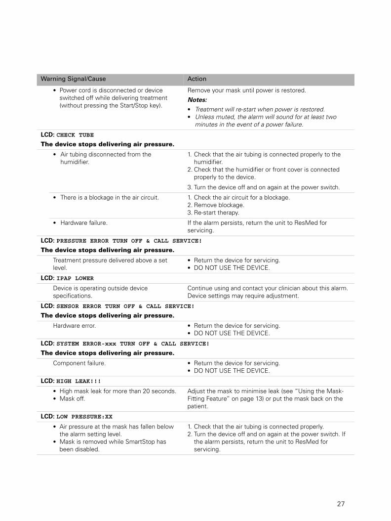
• Power cord is disconnected or device switched off while delivering treatment (without pressing the Start/Stop key).
Remove your mask until power is restored.
Notes: • Treatment will re-start when power is restored.• Unless muted, the alarm will sound for at least two
minutes in the event of a power failure.
LCD: CHECK TUBE
The device stops delivering air pressure.
• Air tubing disconnected from the humidifier.
1. Check that the air tubing is connected properly to the humidifier.
2. Check that the humidifier or front cover is connected properly to the device.
3. Turn the device off and on again at the power switch.
• There is a blockage in the air circuit. 1. Check the air circuit for a blockage.2. Remove blockage.3. Re-start therapy.
• Hardware failure. If the alarm persists, return the unit to ResMed for servicing.
LCD: PRESSURE ERROR TURN OFF & CALL SERVICE!
The device stops delivering air pressure.
Treatment pressure delivered above a set level.
• Return the device for servicing.• DO NOT USE THE DEVICE.
LCD: IPAP LOWER
Device is operating outside device specifications.
Continue using and contact your clinician about this alarm. Device settings may require adjustment.
LCD: SENSOR ERROR TURN OFF & CALL SERVICE!
The device stops delivering air pressure.
Hardware error. • Return the device for servicing.• DO NOT USE THE DEVICE.
LCD: SYSTEM ERROR-xxx TURN OFF & CALL SERVICE!
The device stops delivering air pressure.
Component failure. • Return the device for servicing.• DO NOT USE THE DEVICE.
LCD: HIGH LEAK!!!
• High mask leak for more than 20 seconds.• Mask off.
Adjust the mask to minimise leak (see “Using the Mask-Fitting Feature” on page 13) or put the mask back on the patient.
LCD: LOW PRESSURE:XX
• Air pressure at the mask has fallen below the alarm setting level.
• Mask is removed while SmartStop has been disabled.
1. Check that the air tubing is connected properly.2. Turn the device off and on again at the power switch. If
the alarm persists, return the unit to ResMed for servicing.
Warning Signal/Cause Action
27
27

• Power cord is disconnected or device switched off while delivering treatment (without pressing the Start/Stop key).
Remove your mask until power is restored.
Notes: • Treatment will re-start when power is restored.• Unless muted, the alarm will sound for at least two
minutes in the event of a power failure.
LCD: CHECK TUBE
The device stops delivering air pressure.
• Air tubing disconnected from the humidifier.
1. Check that the air tubing is connected properly to the humidifier.
2. Check that the humidifier or front cover is connected properly to the device.
3. Turn the device off and on again at the power switch.
• There is a blockage in the air circuit. 1. Check the air circuit for a blockage.2. Remove blockage.3. Re-start therapy.
• Hardware failure. If the alarm persists, return the unit to ResMed for servicing.
LCD: PRESSURE ERROR TURN OFF & CALL SERVICE!
The device stops delivering air pressure.
Treatment pressure delivered above a set level.
• Return the device for servicing.• DO NOT USE THE DEVICE.
LCD: IPAP LOWER
Device is operating outside device specifications.
Continue using and contact your clinician about this alarm. Device settings may require adjustment.
LCD: SENSOR ERROR TURN OFF & CALL SERVICE!
The device stops delivering air pressure.
Hardware error. • Return the device for servicing.• DO NOT USE THE DEVICE.
LCD: SYSTEM ERROR-xxx TURN OFF & CALL SERVICE!
The device stops delivering air pressure.
Component failure. • Return the device for servicing.• DO NOT USE THE DEVICE.
LCD: HIGH LEAK!!!
• High mask leak for more than 20 seconds.• Mask off.
Adjust the mask to minimise leak (see “Using the Mask-Fitting Feature” on page 13) or put the mask back on the patient.
LCD: LOW PRESSURE:XX
• Air pressure at the mask has fallen below the alarm setting level.
• Mask is removed while SmartStop has been disabled.
1. Check that the air tubing is connected properly.2. Turn the device off and on again at the power switch. If
the alarm persists, return the unit to ResMed for servicing.
Warning Signal/Cause Action
28
28

Clinical Options menu
Table 9: Clinical Options menu descriptions
Mask pressure exceeds alarm setting level. 1. The treatment will stop.2. Turn power off.3. Turn power back on.4. Try using the flow generator one more time.5. If the high pressure alarm activates repeatedly,
discontinue use and return to ResMed for servicing. If the alarm does not recur, then continue to use as normal.
LCD: LOW MV:XX
Minute ventilation level has dropped below the alarm setting level.
Contact your clinician.
LCD: NO MASK VENT
• Connection of a non-vented mask.• Mask expiratory flow port (vent) may be
blocked.• Use of supplemental oxygen with a vented
mask.
• Ensure your mask has an expiratory flow port (vent).• Ensure your mask expiratory flow ports (vents) are not
blocked.• Contact your clinician.
Note: The non-vented mask alarm activates within 30 seconds (15 sec on average) of using therapy with a non-vented mask.
Parameter Default Description
Alarm Vol/Test* Medium Set the alarm volume and test the alarm.
Options: Low, Medium, High
Confirm Stop OFF Enables or disables the Confirm Stop feature. When enabled, if you press the Stop key during therapy, the Confirm Stop screen will appear. If YES is selected, therapy stops. If NO is selected or any other key is pressed, therapy continues.
Options: ON, OFF
Backlight* AUTO Enables or disables the continuous LCD backlight feature. If disabled (AUTO), the LCD backlight turns off two minutes after the last menu selection and turns on when you press any key.
Options: ON, AUTO
Therapy LED OFF Enables or disables the therapy LED. If enabled, the white therapy LED is lit whilst the device is delivering therapy.
Options: ON, OFF
Warning Signal/Cause Action
OPTIONS
LK: 1.7 Vt: 780 RR: 10 7.8
21:53
M V :
SETUP CLOCK LANGUAGE
OPTIONS
LK: 1.7 Vt: 780 RR: 10 7.8
21:53
M V :
Alarm Vol/Test:
SETUP
Confirm Stop: Medium
Off Backlight: Auto
Therapy LED: OffPres. Units: cm H2O
OPTIONS
LK: 1.7 Vt: 780 RR: 10 7.8
21:53
M V :
Time: 21:53
CLOCK
Date: 12 Oct 06
OPTIONS
LK: 1.7 Vt: 780 RR: 10 7.8
21:53
M V :
English
LANGUAGE
Francais
DeutschEspanol
Italiano
29
29
* These parameters appear in both the patient and clinical menus.
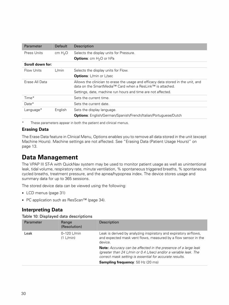
Erasing Data
The Erase Data feature in Clinical Menu, Options enables you to remove all data stored in the unit (except Machine Hours). Machine settings are not affected. See “Erasing Data (Patient Usage Hours)” on page 13.
Data ManagementThe VPAP III ST-A with QuickNav system may be used to monitor patient usage as well as unintentional leak, tidal volume, respiratory rate, minute ventilation, % spontaneous triggered breaths, % spontaneous cycled breaths, treatment pressure, and the apnea/hypopnea index. The device stores usage and summary data for up to 365 sessions.
The stored device data can be viewed using the following:
• LCD menus (page 31)
• PC application such as ResScan™ (page 34).
Interpreting DataTable 10: Displayed data descriptions
Press Units cm H2O Selects the display units for Pressure.
Options: cm H2O or hPa
Scroll down for:
Flow Units L/min Selects the display units for Flow.
Options: L/min or L/sec
Erase All Data Allows the clinician to erase the usage and efficacy data stored in the unit, and data on the SmartMedia™ Card when a ResLink™ is attached.
Settings, date, machine run hours and time are not affected.
Time* Sets the current time.
Date* Sets the current date.
Language* English Sets the display language.
Options: English/German/Spanish/French/Italian/Portuguese/Dutch
Parameter Range
(Resolution)
Description
Leak 0–120 L/min (1 L/min)
Leak is derived by analyzing inspiratory and expiratory airflows, and expected mask vent flows, measured by a flow sensor in the device.
Note: Accuracy can be affected in the presence of a large leak (greater than 24 L/min or 0.4 L/sec) and/or a variable leak. The correct mask setting is essential for accurate results.Sampling frequency: 50 Hz (20 ms)
Parameter Default Description
30
30

Data Management using the MenusTreatment ScreensAfter starting therapy, you can display one of the treatment screens below. Press the Enter key to scroll through the screens. The soft key display at the top right of the screen shows which page you are on. If no oximeter is attached, screen 1/4 won’t appear, and screens 2–4, below, will appear as screens 1–3. The Treatment screens can also be viewed from the Patient Menu.
Tidal Volume 50–3000 mL (1 mL)
Tidal volume is calculated as the integral of respiratory flow: based on the leak flow, the mask vent flow and the total flow rate.
The display is based on the five-breath moving average, updated every breath.
Note: Accuracy can be affected in the presence of a large leak (greater than 24 L/min or 0.4 L/sec) and/or a variable leak. The correct mask setting is essential for accurate results.Sampling frequency: 50 Hz (20 ms)
Respiratory Rate 6–60 BPM (0.1 BPM)
Respiratory rate is calculated by averaging the last five breaths (greater than 50 mL) detected by the device.
Note: The reported respiratory rate may be less than the backup rate in the Settings menu. As the reported respiratory rate is based on a breath greater than 50 mL, some patient breaths may not be recorded. The display of the respiratory rate is a separate function to the delivery of the backup rate. So the device will always deliver the set backup rate as intended.Sampling frequency: 50 Hz (20 ms)
Minute Ventilation 0.6–60 L/min (0.25 L/min)
Minute Ventilation is the product of respiratory rate and tidal volume.
The display is based on the five-breath moving average, updated every breath.
Note: Accuracy can be affected in the presence of a large leak (greater than 24 L/min or 0.4 L/sec) and/or a variable leak. The correct mask setting is essential for accurate results.
% Spontaneous
triggered breaths
Percentage of patient breaths in the session (or the median percentage of breaths for the range of sessions selected) that were spontaneously (flow) triggered.
% Spontaneous
cycled breaths
Percentage of patient breaths in the session (or the median percentage of breaths for the range of sessions selected) that were spontaneously (flow) cycled.
Parameter Range
(Resolution)
Description
31
31
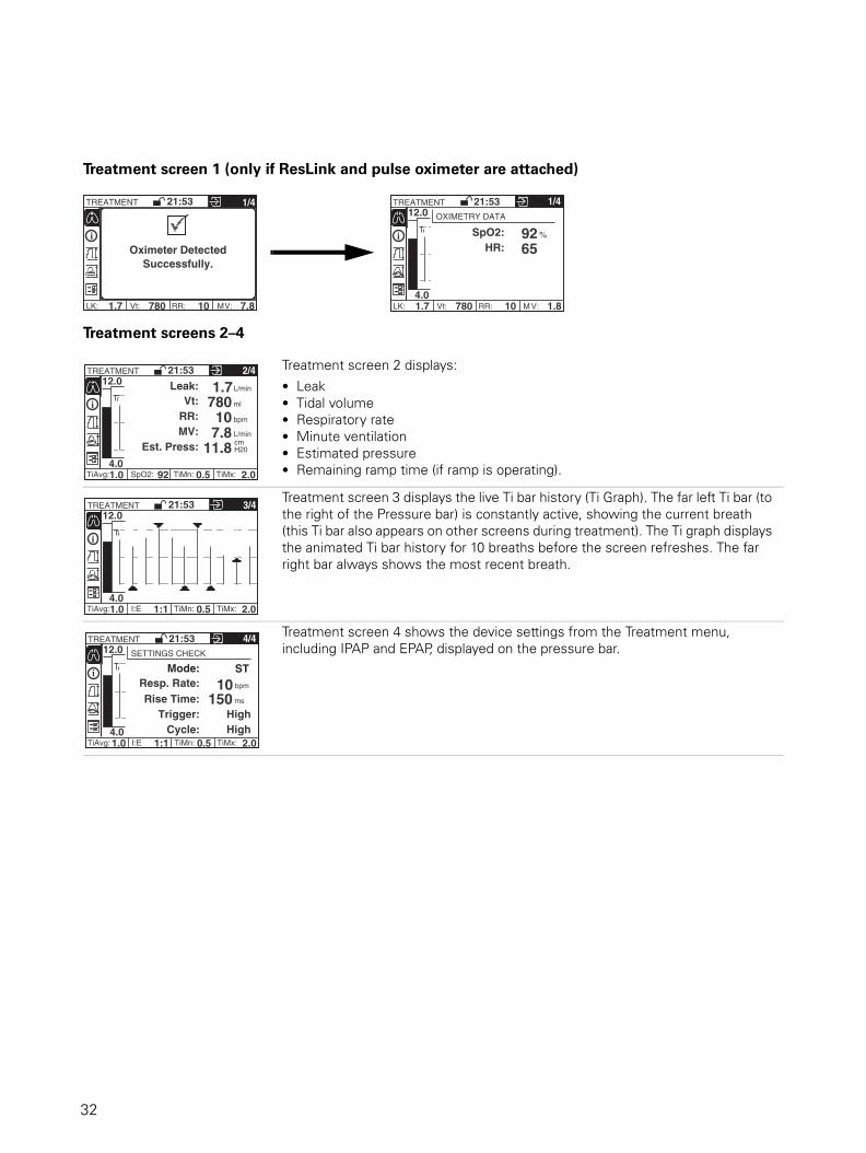
Treatment screen 1 (only if ResLink and pulse oximeter are attached)
Treatment screens 2–4
Treatment screen 2 displays:
• Leak• Tidal volume• Respiratory rate• Minute ventilation• Estimated pressure• Remaining ramp time (if ramp is operating).
Treatment screen 3 displays the live Ti bar history (Ti Graph). The far left Ti bar (to the right of the Pressure bar) is constantly active, showing the current breath (this Ti bar also appears on other screens during treatment). The Ti graph displays the animated Ti bar history for 10 breaths before the screen refreshes. The far right bar always shows the most recent breath.
Treatment screen 4 shows the device settings from the Treatment menu, including IPAP and EPAP, displayed on the pressure bar.
TREATMENT
LK: 1.7 Vt: 780 RR: 10 7.8
21:53
M V :
1/4
Oximeter Detected Successfully.
TREATMENT
LK: 1.7 Vt: 780 RR: 10 1.8
21:53
M V :
1/4
SpO2:
4.0
12.0 OXIMETRY DATA
HR: 92 %
65
TREATMENT
1.0 92 0.5 2.0
21:53
TiMx:
2/4
Vt:
4.0
12.0
RR: 780
10
Leak: 1.7
MV: 7.8 Est. Press: 11.8
TiMn:SpO2: TiAvg:
cm H20
L/min
L/min
bpm
ml
TREATMENT
1.0 1:1 0.5 2.0
21:53
TiMx:
3/4
4.0
12.0
TiMn: I:E TiAvg:
TREATMENT
1.0 1:1 0.5 2.0
21:53
TiMx:
4/4
4.0
12.0
TiMn: I:E TiAvg:
SETTINGS CHECK
Mode: ST
Rise Time: 150 Trigger:
Cycle:
ms
bpm Resp. Rate: 10
High High
32
32

Reviewing Data in the Patient and Clinical MenusTo assess the patient, data for the previous session may be compared to median values for the last week, the last month, the last six months and the last year, as displayed in the Summary menu.
Clinical Summary Menu A comprehensive set of data is available in the Clinical Summary menu, including Efficacy Data, Usage Data, Alarm History, Settings Summary and Servicing information.
Note: The Summary screens are also available in the patient menu.
Efficacy Data
Statistics quoted on the Efficacy Data screen include:
• Leak (95th centile value for mask-on time only) • Vt—tidal volume (5th and 95th centile values for mask-on time only) • Resp Rate—respiratory rate (5th and 95th centile values for mask-on time only) • MV—minute ventilation (5th and 95th centile values for mask-on time only)• % Spont. T—percentage spontaneous (flow) triggered breath• % Spont. C—percentage spontaneous (flow) cycled breath.
Usage Data
The Usage Data screen reports total hours the device has been used since the data was last erased, the Usage in hours per day and the number of days the device was used compared to the total days since the hourmeter was last reset.
For Efficacy and Usage Data, statistics are provided for five time intervals (last day, last week, last month, last six months, last year) so you can assess the significance of recent events.
All statistics calculated for a range of dates are median values. The median is a more robust measure than an average for a data set that has some extreme values.
Alarm History
Displays the alarm history over a 24-hour period (12 noon to 12 noon), for five consecutive days. Press Enter to scroll through the five consecutive 24-hour periods.
Settings Summary
Displays a summary of the current device settings.
Servicing menu
Machine Hours: Displays the total number of machine hours. SN: Displays the device serial number. SW: Displays the current software version.
SUMMARY 21:53 6mths
1.7 780 10 7.8 MV: RR: Vt: LK:
EFFICACY DATA
14.4
L/min
ml
Leak:
0400-10008-15
3.2-15.0bpm
Vt:
MV:
L/min
RR:
% Spont T:
% Spont C:70%77%
SUMMARY 21:53 6mths
1.7 780 10 7.8 MV: RR: Vt: LK:
USAGE DATA
12 Oct 2006
hrs/day
hrs
Used Since:
740 102/106
7.15 days
Used:
Usage:
SUMMARY
LK: 1.7 Vt: 780 RR: 10 7.8
21:53
M V :
ALARMS 10Sep 12.00 11Sep 12.00
Day 4
Sensor Error 07:00 - 11 Sep 06
Check Tube 01:52 - 11 Sep 06
IPAP Lower 01:45 - 11 Sep 06
High Leak 00:36 - 11 Sep 06
Low IPAP 21:42 - 10 Sep 06 High Pressure 21:31 - 10 Sep 06
SUMMARY
LK: 1.7 Vt: 780 RR: 10 7.8
21:53
M V :
SETTINGS SUMMARY
SETTINGS
Mode:
IPAP:
EPAP: Resp. Rate:
Ti Max:
ST
2.0 sec
cmH20
bpm 10 4.0
cmH20 12.0
SUMMARY
LK: 1.7 Vt: 780 RR: 10 7.8
21:53
M V :
SERVICING
Machine Hours: 00000 hrs
SN: 12345678912 SW: SX1231234-12
33
33

Data Management using a PC applicationNote: The device is compatible for use with the optional ResLink and ResScan (versions 3.5 and above).
Data can be viewed using a PC application (eg, ResScan) with the device connected directly to the PC. For further details on use, see the PC application’s manual.
If a ResLink is attached to the device, data can be downloaded from the ResLink to your PC application. For further details on use, see the ResLink manual.
Figure 7: ResLink
Additional FunctionsAdding Supplemental OxygenUp to 15 L/min of oxygen can be added at the mask or at an oxygen connector between the flow generator and the air tubing while still providing safe and effective therapy.
At the fixed rate of oxygen flow, the inhaled oxygen concentration will vary, depending on the mask selected, where the oxygen is introduced, pressure settings, patient breathing pattern and leak rate.
Note: Adding oxygen may affect the trigger and cycle reliability, delivered pressure, and the accuracy of the displayed leak, tidal volume and minute ventilation.
WARNING
• When oxygen is added, always ensure that you verify the correct operation of
triggering and cycling, and activation of mask alarm when enabled.
• If oxygen is used, the oxygen flow must be turned off when the device is not operating.
Explanation of the warning: When the device is not in operation and the oxygen is
left on, oxygen delivered into the air tube may accumulate within the device enclosure
and increase a risk of fire.
Oximeter ResLinkSmartMedia card
Nasal maskFull face mask Oxygen connector
Oxygen tubing Oxygen tubing
Oxygen connector
Oxygentubing
34
34

• Ensure the airflow is being generated by the device before the oxygen is supplied.
• Turn the oxygen supply off before stopping the airflow from the device.
• Oxygen supports combustion. Oxygen must not be used while smoking or in the
presence of an open flame.
Procedure1. Fit an oxygen connector to the air outlet of the device and fit the air tubing to the oxygen connector.
Fit the oxygen supply tubing to the port on the oxygen connector.
OR
Fit the oxygen supply tubing directly to the mask port.
2. Attach the other end of the oxygen supply tubing to an oxygen flowmeter.
3. Optimize the ventilator settings first, and then add oxygen if baseline saturation remains low.
4. Titrate oxygen according to institutional guidelines or physician prescription.
5. Determine an initial oxygen flow rate during wakefulness. Only increase oxygen during sleep when titration of pressure is complete.
6. If the patient is using oxygen at home, complete titration with the oxygen entrained into the circuit at the same place that the patient will be using it at home.
Using an Antibacterial FilterAntibacterial filters can be used with the device. The antibacterial filters increase resistance in the air circuit and may affect triggering and cycling, and accuracy of display and delivered pressures.
ResMed recommends using a filter with a low impedance (less than 2 cm H2O at 60 L/min).
The device has an antibacterial filter setting which optimizes the treatment pressures with a filter impedance (2 cm H2O impedance at 60 L/min).
When S or ST mode is used, ensure the patient’s breath is detected correctly and the device triggers and cycles accordingly.
Procedure
1. Fit an antibacterial filter to the air outlet of the device.
2. Navigate to the AB Filter setting in the Clinical Settings menu (page 20) and select "YES".
This setting enables the device to compensate for the filter.
3. Ensure the patient is triggering the device spontaneously (when S or ST mode is used).
4. If appropriate, test the mask alarm. (See “Testing the Alarms” on page 25.)
Note:
• If triggering or cycling is not performing correctly, adjust the trigger and cycle sensitivities (see “Clinical Settings Menu” on page 20).
• The antibacterial filter setting on the device has been optimized for a specific range of filters. Therefore, if you are using a filter with an impedance significantly lower or higher than 2 cm H2O at 60 L/min, reliable triggering and cycling can be achieved by setting the AB Filter setting to NO.
35
35

Using a Battery to Power the Device
Information regarding suitable DC and battery power supplies for this device can be found on www.resmed.com on the Products page under Service and Support > Ventilation Accessories.
Inverter or UPS
The power specifications for an inverter or a UPS (uninterruptible power supply) are listed in the following table.
The case temperature should be less than 50°C at an ambient temperature of 35°C. (For device temperature specifications, see “Technical Specifications” on page 41.)
Cleaning and MaintenanceThe cleaning and maintenance described in this section should be carried out regularly.
Configuration Continuous Output Power
Rating
Peak Output
Power Rating
VPAP III ST-A with QuickNav (without HumidAire 2i humidifier)
60W 225W
VPAP III ST-A with QuickNav with HumidAire 2i humidifier
Note: Use only a pure sine wave inverter when a HumidAire 2i is attached.
150W 300W (110V inverter)
600W (240V inverter)
Daily Cleaning
Mask Clean the mask according to the instructions supplied with the mask.
Air tubing Disconnect the air tubing from the device (and humidifier, if used) and store the tubing and mask in a clean, dry place until next use.
Humidifier If a humidifier is being used, clean it according to the instructions supplied with the humidifier.
Weekly Cleaning
1 Remove the air tubing from the device and the mask.
2 Wash the air tubing in warm water using mild detergent. Rinse thoroughly, hang and allow to dry.
3 Reconnect the air tubing to the air outlet and mask.
CAUTION
• Do not use bleach, chlorine-, alcohol- or aromatic-based solutions (including all
scented oils), moisturising or antibacterial soaps to clean the air tubing or the device.
These solutions may cause hardening and reduce the life of the product.
• Do not hang or store the air tubing in direct sunlight as the tubing may harden over time
and eventually crack.
Periodic Cleaning
1 Clean the exterior of the device with a damp cloth and mild liquid soap.
2 Inspect the air filter to check if it is blocked by dirt or contains holes. See “Replacing the Air Filter” on page 37.
36
36

ServicingThis product (VPAP III ST-A with QuickNav) should be inspected by an authorised ResMed service centre five years from the date of manufacture. Prior to this, the device is intended to provide safe and reliable operation provided that it is operated and maintained in accordance with the instructions provided by ResMed. Applicable ResMed warranty details are provided with the device at the time of original supply. Of course, as with all electrical devices, if any irregularity becomes apparent, you should exercise caution and have the device inspected by an authorised ResMed service centre.
If you feel that your device is not performing properly, see “Troubleshooting” on page 40.
CAUTION
Inspection and repair should only be performed by an authorised agent. Under no
circumstances should you attempt to service or repair the flow generator yourself.
Clinical Problem SolvingMouth Leaks
If mouth leaks are a persistent problem, the patient may benefit from a chin strap or a full face mask. The chin strap fits over the patient’s head and helps to hold their mouth closed during the night. Full Face Masks that cover both the nose and mouth, preventing mouth leaks, are available from ResMed.
Contact your supplier for more details or see www.resmed.com.
Indications for Humidification• Nasal stuffiness/congestion
• Rhinnorhea following the use of mask ventilation
WARNINGBeware of electric shock. Do not immerse the flow generator or power cord in water.
Always unplug the flow generator before cleaning and be sure that it is dry before
reconnecting.
CAUTIONDo not attempt to open the device. There are no user serviceable parts inside. Repairs and
internal servicing should only be performed by an authorised service agent.
Replacing the Air Filter
Inspect the air filter every month to check if it is blocked by dirt or contains holes. With normal use of the device, the air filter needs to be replaced every six months (or more often if your device is in a dusty environment). To replace the air filter:
1 Remove the air filter cover at the back of the device.
2 Remove and discard the old air filter.
3 Insert a new filter with the blue tinted side facing out.
4 Replace the air filter cover.
WARNINGDo not wash the air filter. The air filter is not washable or reusable.
37
37

• Mouth dryness
• Patients with thick secretions (eg, cystic fibrosis, bronchiectasis, etc).
Humidification may be required for patients who experience nasal and upper airway dryness as a consequence of the high flow of air being directed through the nasal and oral passages. It may also be required in those individuals who have tenacious secretions.
Mouth leaks occurring during the use of positive pressure therapy can significantly increase nasal resistance. This increase in nasal resistance associated with mouth leaks may be prevented by fully humidifying the inspired air. In most cases, using heated humidification is the most effective way to decrease nasal resistance.
Note: When using humidification, select the appropriate humidifier from the Humidifier menu (this is not necessary when using the H2i, as it is automatically detected). This will adjust the alarms and SmartStart to ensure correct activation with the increased resistance of the humidifier. For details on humidifier use, see “Using Humidifiers” on page 9.
Setting TiControlThe Ti Max and Ti Min settings allow the clinician to vary the minimum and maximum amount of inspiratory time.
Figure 8: TiControl (Ti Min and Ti Max Time Parameters) sets the Cycle Window
Setting Ti Max
Under conditions of high or variable leaks (eg, mouth leak), or where respiratory flow is restricted (eg, COPD), Ti Max provides an inspiratory time limit to better match that patient’s ideal inspiratory time.
Note: Care should be taken not to set Ti Max shorter than the patient's actual inspiratory time, as this may lead to a decrease in the effectiveness of pressure support and result in discomfort for the patient. If the patient complains that inspiratory time is too short, consider increasing the value.
Procedure
1. Observe the patient's inspiration time and respiratory pattern. (The measured Ti and I:E ratio on the treatment screens may help.)
TiControl
Patient Flow
Ti Min
Time
TiMaxTime
CycleWindow
38
38
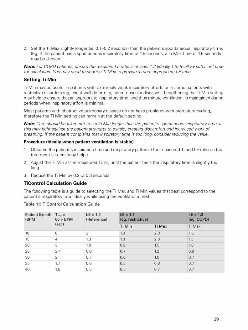
2. Set the Ti Max slightly longer (ie, 0.1–0.2 seconds) than the patient's spontaneous inspiratory time. (Eg, if the patient has a spontaneous inspiratory time of 1.5 seconds, a Ti Max time of 1.6 seconds may be chosen.)
Note: For COPD patients, ensure the resultant I:E ratio is at least 1:2 (ideally 1:3) to allow sufficient time for exhalation. You may need to shorten Ti Max to provide a more appropriate I:E ratio.
Setting Ti Min
Ti Min may be useful in patients with extremely weak inspiratory efforts or in some patients with restrictive disorders (eg, chest-wall deformity, neuromuscular diseases). Lengthening the Ti Min setting may help to ensure that an appropriate inspiratory time, and thus minute ventilation, is maintained during periods when inspiratory effort is minimal.
Most patients with obstructive pulmonary disease do not have problems with premature cycling, therefore the Ti Min setting can remain at the default setting.
Note: Care should be taken not to set Ti Min longer than the patient's spontaneous inspiratory time, as this may fight against the patient attempts to exhale, creating discomfort and increased work of breathing. If the patient complains that inspiratory time is too long, consider reducing the value.
Procedure (ideally when patient ventilation is stable)
1. Observe the patient's inspiration time and respiratory pattern. (The measured Ti and I:E ratio on the treatment screens may help.)
2. Adjust the Ti Min at the measured Ti, or, until the patient feels the inspiratory time is slightly too long.
3. Reduce the Ti Min by 0.2 or 0.3 seconds.
TiControl Calculation Guide
The following table is a guide to selecting the Ti Max and Ti Min values that best correspond to the patient's respiratory rate (ideally while using the ventilator at rest).
Table 11: TiControl Calculation Guide
Patient Breath
(BPM)
Ttot =
60 ÷ BPM
(sec)
I:E = 1:2
(Reference)
I:E = 1:1
(eg, restrictive)
I:E = 1:3
(eg, COPD)
Ti Min Ti Max Ti Max
10 6 2 1.0 2.0 1.5
15 4 1.3 1.0 2.0 1.3
20 3 1.0 0.8 1.5 1.0
25 2.4 0.8 0.7 1.2 0.8
30 2 0.7 0.6 1.0 0.7
35 1.7 0.6 0.5 0.8 0.7
40 1.5 0.5 0.5 0.7 0.7
39
39

TroubleshootingIf there is a problem, try the following suggestions.
CAUTION
If the problem cannot be solved, contact your equipment supplier or ResMed. Do not
attempt to open the device case. There are no user-serviceable parts inside. Repairs and
internal servicing should only be performed by an authorized service agent.
Problem / Possible Cause Solution
No display.
Power not connected or switch at back is not on. Ensure the power cable is connected and that the switch at the back of the device is in the ON position.
Treatment pressure seems low.
Ramp Time is in use. Wait for air pressure to build up.
Air filter is dirty. Replace air filter.
Air tubing is kinked or punctured. Straighten or replace tubing.
Air tubing is not connected properly. Check air tubing.
Mask and headgear not positioned correctly. Adjust position of mask and headgear.
Plug(s) missing from access port(s) on mask. Replace plug(s).
Pressure required for treatment may have changed. Conduct a clinical assessment and adjust pressure if necessary.
The device does not start when the patient breathes into the mask (when SmartStart is enabled).
Power cord not connected properly. Connect power cord firmly at both ends.
Power outlet may be faulty. Try another power outlet.
The device is not switched on. Turn power switch at rear of the device to on (I).
SmartStart not on. Enable SmartStart.
Breath is not deep enough to trigger SmartStart. Take a deep breath in and out through the mask.
There is excessive leak. Adjust position of mask and headgear.
Plugs may be missing from ports on mask. Replace plug(s).
Air tubing is not connected properly. Connect firmly at both ends.
Air tubing is kinked or punctured. Straighten or replace.
There is a large impedance (eg, antibacterial filter, oxygen connector) in the air circuit.
Press the Start/Stop key.
Use of a full face mask. SmartStart may operate less effectively with a full face mask.
The device does not stop when the patient removes their mask.
SmartStart/Stop is disabled. Enable SmartStart/Stop.
Use of a full face mask. SmartStop does not work with a full face mask.
Incompatible humidifier or mask system being used. Use only equipment as recommended and supplied by ResMed.
Leak Alarm or Low MV Alarm is set to ON. Set these alarms to OFF.
Leak Alarm is enabled, but alarm does not activate when the mask is removed during treatment.
40
40

Technical Specifications
Incompatible air delivery system being used. Use only equipment as recommended and supplied by ResMed.
Humidifier used but Humidifier option has not been selected.
Enable the Humidifier option.
IPAP and/or EPAP settings are too low for the air delivery components being used.
Increase IPAP and/or EPAP pressure if appropriate.
Date or time in data files is wrong.
Date or time on the device is wrong. Correct the current time and date in the Options menu.
Displays error message: SYSTEM ERROR Call service!
Component failure. Return your device for servicing.
Excessive motor noise.
Component failure. Return your device for servicing.
White LED is flashing.
Mask-fit is in use. Stop mask-fit or wait until it finishes (three minutes).
Performance • Operating pressure range: 2 to 30 cm H2O
• Maximum single fault pressure: 40 cm H2O
• Pressure Measurement Tolerance:
±0.5 cm H2O + 4% of the measured reading
• Flow Measurement Tolerance: ±0.3 L/s
Dynamic pressure
characteristics
• IPAP: 2 cm H2O to 30 cm H2O (measured at the end of standard 2 m air tubing)
• EPAP: 2 cm H2O to 25 cm H2O (measured at the end of standard 2 m air tubing)
• CPAP: 4 cm H2O to 20 cm H2O (measured at the end of standard 2 m air tubing)
Maximum flow (Pressure,
measured at the end of
standard
2 m air tubing)
Pressure (cm H2O) Flow (L/min)
10 >220
20 >220
30 >120
Inspiratory trigger (nominal)
characteristics:
The minimum flow required to initiate IPAP by ASL5000 simulator with chronically weak efforts (R20, C20, BPM20):
• For HI (high) setting: 2.5 L/min
• For MED (medium) setting: 4.0 L/min
• For LO (low) setting: 7.5 L/min (accuracy ± 0.5 L/min)
when tested with IPAP = 10 cm H2O, EPAP = 5 cm H2O, Rise Time = Min, 2 m air tubing, Ultra Mirage mask, zero leak.
Problem / Possible Cause Solution
41
41
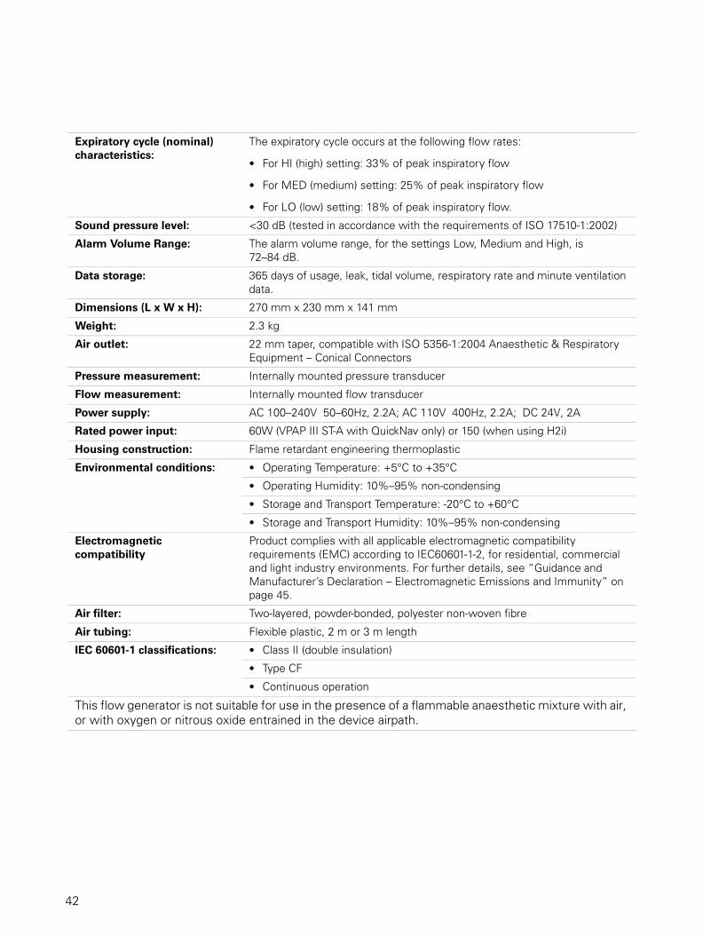
Expiratory cycle (nominal)
characteristics:
The expiratory cycle occurs at the following flow rates:
• For HI (high) setting: 33% of peak inspiratory flow
• For MED (medium) setting: 25% of peak inspiratory flow
• For LO (low) setting: 18% of peak inspiratory flow.
Sound pressure level: <30 dB (tested in accordance with the requirements of ISO 17510-1:2002)
Alarm Volume Range: The alarm volume range, for the settings Low, Medium and High, is 72–84 dB.
Data storage: 365 days of usage, leak, tidal volume, respiratory rate and minute ventilation data.
Dimensions (L x W x H): 270 mm x 230 mm x 141 mm
Weight: 2.3 kg
Air outlet: 22 mm taper, compatible with ISO 5356-1:2004 Anaesthetic & Respiratory Equipment – Conical Connectors
Pressure measurement: Internally mounted pressure transducer
Flow measurement: Internally mounted flow transducer
Power supply: AC 100–240V 50–60Hz, 2.2A; AC 110V 400Hz, 2.2A; DC 24V, 2A
Rated power input: 60W (VPAP III ST-A with QuickNav only) or 150 (when using H2i)
Housing construction: Flame retardant engineering thermoplastic
Environmental conditions: • Operating Temperature: +5°C to +35°C
• Operating Humidity: 10%–95% non-condensing
• Storage and Transport Temperature: -20°C to +60°C
• Storage and Transport Humidity: 10%–95% non-condensing
Electromagnetic
compatibility
Product complies with all applicable electromagnetic compatibility requirements (EMC) according to IEC60601-1-2, for residential, commercial and light industry environments. For further details, see “Guidance and Manufacturer’s Declaration – Electromagnetic Emissions and Immunity” on page 45.
Air filter: Two-layered, powder-bonded, polyester non-woven fibre
Air tubing: Flexible plastic, 2 m or 3 m length
IEC 60601-1 classifications: • Class II (double insulation)
• Type CF
• Continuous operation
This flow generator is not suitable for use in the presence of a flammable anaesthetic mixture with air, or with oxygen or nitrous oxide entrained in the device airpath.
42
42

Table 12: Displayed values
* Results are expressed at ATPD (Ambient Temperature and Pressure, Dry).**Results may be inaccurate in the presence of leaks or supplemental oxygen.† The displayed values are estimates. They are provided for trending purposes only.†† Results may be inaccurate if the tidal volume is below 50mL.
Pressure Variation
Value Range Accuracy Display Resolution
Pressure sensor at air outlet
Pressure* -5 to 30 cm H2O ±0.5 cm H2O (+ 4% of measured
value)
0.1 cm H2O
Flow sensor in flow generator**
Leak* 0–120 L/min † 1 L/min
Tidal volume* 50–3,000 mL † 1 mL
Respiratory rate 6–60 BPM ±0.5 BPM†† 1 BPM
Minute ventilation* 0.6–60 L/min † 0.1 L/min
Ti Avg 0.0–4.0 sec ±10% 0.1 sec
0.00
5.00
10.00
15.00
20.00
25.00
0 1 2 3
Breaths
Pre
ssu
re (
cm
H2O
)
10 BPM
15 BPM
20 BPM
Max Pressure
2/3 Max Pressure
1/3 Max Pressure
43
43

44
Pressure Volume curve
Note: The manufacturer reserves the right to change these specifications without notice.
Symbols which may Appear on the Product
Follow instructions for use; Class II equipment; Type CF equipment; Drip proof; Start/Stop;
Mask-Fit; Alarm LEDs; Alarm Mute; QuickView; Enter; Exit; AC switch only;
Environmental information WEEE 2002/96/EC is a European Directive that requires the proper disposal of electrical and electronic equipment. This device should be disposed of separately, not as unsorted municipal waste. To dispose of your device, you should use appropriate collection, reuse and recycling systems available in your region. The use of these collection, reuse and recycling systems is designed to reduce pressure on natural resources and prevent hazardous substances from damaging the environment. If you need information on these disposal systems, please contact your local waste administration. The crossed-bin symbol invites you to use these disposal systems. If you require information on collection and disposal of your ResMed device please contact your ResMed office, local distributor or go to www.resmed.com/environment.
Max Pressure
0
100
200
300
400
500
600
Pressure (cm H2O)
Volu
me (
mL
)
2/3 Max Pressure
0
100
200
300
400
500
600
Pressure (cm H2O)V
olu
me (
mL
)
10 BPM
15 BPM
20 BPM
1/3 Max Pressure
0
100
200
300
400
500
600
Pressure (cm H2O)
Volu
me (
mL
)
6.4 6.45 6.5 6.55 6.6 6.65 6.7 6.75 13.25 13.3 13.413.35 13.45 13.5 13.55 13.6
19.95 20 20.05 20.1 20.15 20.2 20.25
44

Guidance and Manufacturer’s Declaration – Electromagnetic Emissions and Immunity
Guidance and manufacturer’s declaration – electromagnetic immunity
The VPAP III ST-A with QuickNav is intended for use in the electromagnetic environment specified below. The customer or the user of the VPAP III ST-A with QuickNav should assure that it is used in such an environment.
Immunity test IEC60601-1-2 test level Compliance level Electromagnetic environment –guidance
Electrostatic discharge (ESD)IEC 61000-4-2
±6 kV contact ±8 kV air
±6 kV contact ±8 kV air
Floors should be wood, concrete or ceramic tile. If floors are covered with synthetic material, the relative humidity should be at least 30%.
Electrical fast transient/burstIEC 61000-4-4
±2 kV for power supply lines±1 kV for input/output lines
±2 kV
Not Applicable
Mains power quality should be that of a typical commercial or hospital environment.
SurgeIEC 61000-4-5
±1 kV differential mode±2 kV common mode
±1 kV differential mode ±2 kV common mode
Mains power quality should be that of a typical commercial or hospital environment.
Voltage dips, short interruptions and voltage variations on power supply input lines. IEC 61000-4-11
<5% Ut (>95% dip in Ut)for 0.5 cycle 40% Ut (60% dip in Ut) for 5 cycles 70% Ut (30% dip in Ut) for 25 cycles <5% Ut (>95% dip in Ut) for 5 sec
< 12 V(>95% dip in 240V)for 0.5 cycle 96 V (60% dip in 240 V) for 5 cycles 168 V(30% dip in 240 V) for 25 cycles <12 V (>95% dip in 240 V) for 5 sec
Mains power quality should be that of a typical commercial or hospital environment.If the user of the VPAP III ST-A with QuickNav requires continued operation during power mains interruptions, it is recommended that the VPAP III ST-A with QuickNav be powered from an uninterruptible power source.
Power frequency (50/60 Hz) magnetic fieldIEC 61000-4-8
3 A/m 3 A/m Power frequency magnetic fields should be at levels characteristic of a typical location in a typical commercial or hospital environment.Portable and mobile RF communications equipment should be used no closer to any part of the VPAP III ST-A with QuickNav, including cables, than the recommended separation distance calculated from the equation applicable to the frequency of the transmitter.Recommended separation distance
Conducted RF IEC 61000-4-6
3 Vrms 150 kHz to 80 MHz
3 Vrms d = 1.17 √P
Radiated RFIEC 61000-4-3
10 V/m80 MHz to 2.5 GHz
10 V/m d = 0.35 √P 80 MHz to 800 MHzd = 0.70 √P 800 MHz to 2.5 GHzwhere P is the maximum output power rating of the transmitter in watts (W) according to the transmitter manufacturer and d is the recommended separation distance in metres (m).Field strengths from fixed RF transmitters, as determined by an electromagnetic site survey,a should be less than the compliance level in each frequency range.b Interference may occur in the vicinity of equipment marked with the following symbol:
NOTE 1: Ut is the AC mains voltage prior to application of the test level.NOTE 2: At 80 MHz and 800 MHz, the higher frequency range applies.NOTE 3: These guidelines may not apply in all situations. Electromagnetic propagation is affected by absorption and reflection from structures, objects and people.
a Field strengths from fixed transmitters, such as base stations for radio (cellular/cordless) telephones and land mobile radios, amateur radio, AM and FM radio broadcast and TV broadcast cannot be predicted theoretically with accuracy. To assess the electromagnetic environment due to fixed RF transmitters, an electromagnetic site survey should be considered. If the measured field strength in the location in which the VPAP III ST-A with QuickNav is used exceeds the applicable RF compliance level above, the VPAP III ST-A with QuickNav should be observed to verify normal operation. If abnormal performance is observed, additional measures may be necessary, such as reorienting or relocating the VPAP III ST-A with QuickNav.b Over the frequency range 150 kHz to 80 MHz, field strengths should be less than 10 V/m.
45
45

Guidance and manufacturer’s declaration – electromagnetic emissions
The VPAP III ST-A with QuickNav is intended for use in the electromagnetic environment specified below. The customer or the user of the VPAP III ST-A with QuickNav should assure that it is used in such an environment.
Emissions test Compliance Electromagnetic environment - guidance
RF emissions CISPR11 Group 1 The VPAP III ST-A with QuickNav uses RF energy only for its internal function. Therefore, its RF emissions are very low and are not likely to cause any interference in nearby electronic equipment.
RF emissions CISPR 11 Class B The VPAP III ST-A with QuickNav is suitable for use in all establishments, including domestic establishments and those directly connected to the public low-voltage network that supplies buildings used for domestic purposes.
Harmonic Emissions IEC 61000-3-2
Class A
Voltage Fluctuations/Flicker Emissions IEC 61000-3-3 Complies
Medical Electrical Equipment needs special precautions regarding EMC and needs to be installed and put into service according to EMC information provided in this document.
Warnings: The VPAP III ST-A with QuickNav should not be used adjacent to or stacked with other equipment.If adjacent or stacked use is necessary, the VPAP III ST-A with QuickNav should be observed to verify normal operation in the configuration in which it will be used.The use of accessories (eg, humidifiers) other than those specified in this manual is not recommended. They may result in increased emissions or decreased immunity of the VPAP III ST-A with QuickNav.
Recommended separation distances between portable and mobile RF communications equipment and the VPAP III ST-A with QuickNav
The VPAP III ST-A with QuickNav is intended for use in an environment in which radiated RF disturbances are controlled. The customer or the user of the VPAP III ST-A with QuickNav can help prevent electromagnetic interference by maintaining a minimum distance between portable and mobile RF communications equipment (transmitters) and the VPAP III ST-A with QuickNav as recommended below, according to the maximum output power of the communications equipment.
Separation distance according to frequency of transmitter m
Rated maximum output power of transmitter W
150 kHz to 80 MHz
d = 1.17 √P
80 MHz to 800 MHz
d = 0.35 √P
800 MHz to 2.5 GHz
d = 0.7 √P
0.01 0.17 0.04 0.07
0.1 0.37 0.11 0.22
1 1.17 0.35 0.7
10 3.69 1.11 2.21
100 11.70 3.50 7.0
For transmitters rated at a maximum output power not listed above, the recommended separation distance d in metres (m) can be determined using the equation applicable to the frequency of the transmitter, where P is the maximum output power rating of the transmitter in watts (W) according to the transmitter manufacturer.NOTE 1: At 80 MHz and 800 MHz, the separation distance for the higher frequency range applies.NOTE 2: These guidelines may not apply in all situations. Electromagnetic propagation is affected by absorption and reflection from structures, objects and people.
46
46