Embed Size (px)
Citation preview

USE AND CAREMANUALMANUEL
D'UTILISATION
Models • Modèles
CAUTION:Read and Follow All Safety Rulesand Operating Instructions BeforeFirst Use of This Product.
PRÉCAUTION:Veuillez lire attentivement les consignes de sécurité et lesinstructions d'utilisation avantl'utilisation initiale de ce produit.
Room Air ConditionerTable of contents . . . . . . . . . . . . . . . . . . . . . . . 1
Climatiseur de pièceTable of contents . . . . . . . . . . . . . . . . . . . . . . . 12
Danby Products Limited, Guelph, Ontario Canada N1H 6Z9
Version 1C.2.06
DAC7077EEDAC8007EEDAC10007EEDAC12077EEDAC12507EE
Danby Products Inc., Findlay, Ohio USA


2
Introduction
Thank you for choosing a Danby Room Air Conditioner to cool your home. This Use and Care Manualprovides information necessary for the proper care and maintenance of your new Room Air Conditioner. Ifproperly maintained, your air conditioner will give you many years of trouble free operation. To avoidinstallation difficulties, read these instructions completely before installing/operating your unit.
NOTE: This unit is NOT designed for through-the-wall installation.
For easy reference, you may want to attach a copy of your sales receipt to this page. Note the followinginformation provided (on the manufacturer’s nameplate located on the unit). This information will be neededwhen you contact a Customer Service Representative.
Model Number:
Serial Number: ___________________________________________________
Date of Purchase: _________________________________________________
Dealer’s Name and Address: _________________________________________
________________________________________
Refer to the trouble shooting section of this Use and Care Manual if the unit is not operating correctly.If these suggestions do not solve the problem, contact an authorized service representative or call Danby TOLL FREE: 1-800-26-Danby
This symbol denotes a caution or warning
CAUTION
Do not leave a room air conditioner unattended ina space where people or animals who cannotreact to a failed unit are located. A failed unit cancause extreme overheating and fire in anenclosed, unattended space.
SAVE THESE INSTRUCTIONS!
Electrical Specifications
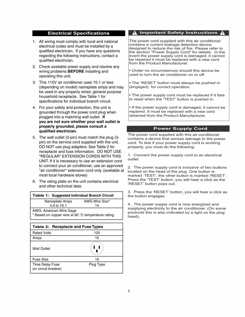
1. All wiring must comply with local and nationalelectrical codes and must be installed by aqualified electrician. If you have any questionsregarding the following instructions, contact aqualified electrician.
2. Check available power supply and resolve anywiring problems BEFORE installing andoperating this unit.
3. This 115V air conditioner uses 10.1 or less(depending on model) nameplate amps and maybe used in any properly wired, general purposehousehold receptacle. See Table 1 forspecifications for individual branch circuit.
4. For your safety and protection, this unit isgrounded through the power cord plug whenplugged into a matching wall outlet. Ifyou are not sure whether your wall outlet isproperly grounded, please consult a qualified electrician.
5. The wall outlet (3-pin) must match the plug (3-pin) on the service cord supplied with the unit.DO NOT use plug adapters. See Table 2 forreceptacle and fuse information. DO NOT USE"REGULAR" EXTENSION CORDS WITH THISUNIT. If it is necessary to use an extension cordto connect your air conditioner, use an approved"air conditioner" extension cord only. (available atmost local hardware stores)
6. The rating plate on the unit contains electricaland other technical data.
Table 1: Suggested Individual Branch Circuit
Nameplate Amps AWG Wire Size*4.9 to 10.1 14
AWG- American Wire Gage* Based on copper wire at 60 °C temperature rating.
Table 2: Receptacle and Fuse Types
Rated Volts 125Amps 15
Wall Outlet
Fuse Size 15Time Delay Fuse Plug Type(or circuit breaker)
3

Installation Notes
Tools Needed for InstallationScrew Drivers: Both Phillips and flat headPower Drill: 1/8 inch (3.2 mm) diameter drill bitPencilMeasuring TapeScissorsCarpenters Level
Your Room Air Conditioner is designed for easyinstallation in a single or double-hung window. Thisunit is NOT designed for vertical (slider type)windows and/or through-the-wall applications.
NOTE: Save the shipping carton and packingmaterials for future storage or transport of the unit.Remove from carton, the plastic bag containing theinstallation hardware kit necessary for the installationof your air conditioner. Please check the contents ofhardware kit against the corresponding model checklist, prior to installation of the unit. See Fig. 1
4
CAUTION
To avoid installation/operation difficulties,read these instructions thoroughly.
Electric Shock Hazard
To avoid the possibility of personalinjury, disconnect power to the unitbefore installing or servicing.
Energy-Saving Tips
Your Room Air Conditioner is designed to behighly efficient in energy savings.
Follow these recommendations for greater efficiency.
1. Select thermostat setting that suits your comfort needs and leave thermostat at thatchosen setting.
2. The filter is very efficient in removing airborneparticles. Keep air filter clean. Normally, filtershould be cleaned every 2 weeks. Morefrequent cleaning may be necessary dependingon indoor air quality.
3. Use drapes, curtains, or shades to keep direct sunlight from heating room, but DO NOTobstruct the air conditioner. Allow air to circulatearound the unit without obstruction.
4. Start your air conditioner before outdoor airbecomes hot and uncomfortable. This avoids aninitial period of discomfort while unit is cooling off the room.
5. When outdoor temperatures are cool enough,use HIGH or LOW FAN only. This circulatesindoor air, providing some cooling comfort, andutilizes less electricity than when operating on a cooling setting.
Installation Hardware
3/4" (19.1 mm)
*3/8" (9.5 mm) Screws(4)*Factory installed onsome models.
Safety Lock (1)
Side Curtain LH (1)
AdhesiveFoam Seal (1)
*“L” Shapedmounting bracket(1)
*Factory installedon some models.
Fig. 1
Side Curtain RH (1)
Sash bracket (2)
Screws (9)

Your unit is designed to evaporate condensationunder normal conditions. However, under extreme humidity conditions, excess condensationmay cause basepan to overflow to the outside.The Unit should be installed where condensation run-off cannot drip on pedestrians or neighboringproperties.
Select the Best Location
A. This room air conditioner is designed to fit easilyinto a single or double hung window. However,since window designs vary, it may be necessaryto make some modifications for safe, properinstallation.
B. Make sure window and frame are structurallysound and free from dry and rotted wood.
C. For maximum efficiency, install the air conditioneron a side of a house or building which favorsmore shade than sunlight. If the unit is in directsunlight, it is advisable to provide an awning overthe unit.
D. Provide sufficient clearance around the cabinet toallow for ample air circulation through the unit.See Fig. 2. The rear of the unit should beoutdoors and not in a garage nor inside abuilding. Keep unit as far away as possible fromobstacles/obstructions and at least 30" (76.2 cm)above the floor or ground. Curtains and otherobjects within a room should be prevented fromblocking the air flow.
E. Be certain the proper electrical outlet is withinreach of the installation. Use only a single outlet circuit rated at 15 amps. All wiring shouldbe in accordance with local and nationalelectrical codes.
F. DO NOT USE "REGULAR" EXTENSION CORDSWITH THIS UNIT. If it is necessary to use an extension cord to connect your air conditioner, use an approved "air conditioner" extension cord only. (available at most local hardware stores)
G. DO NOT install unit where leakage of combustiblegas is suspected. Your air conditioner may fail tooperate in air containing oils (including machineoils), sulfide gas, near hot springs, etc...
Sideobstruction
Fig. 2 Ground
Fence,wall, orother
obstacle.
Awning
12"(30.5 cm)
Min.
30"(76.2 cm)
Min.
20" (50.8 cm)
Min.
5
CAUTION
Because the compressor is located towards therear of the unit, this side will be heavier and more
awkward to manipulate. Therefore, it isrecommended to have someone assist you
during the installation of this unit.
Installation
20"(50.8 cm)
Min.

6
1. Assembly of the Upper Channel, to Cabinet. (Factory installed on some models)
• "L" Shaped Top Channel: Install the "L" shaped channel to the top of the cabinet as shown in Fig. 3 using four (4) 3/8"(9.5mm) screws.
2. Assembly of the Side Curtains to Cabinet.
• Extend the shutter from the shutter frame and slide it into the shutter guide on the sidechannel of the air conditioner as shown in Fig. 4.
• Slide the shutters into the top (“L” Shaped) and bottom (“U” Shaped channels. The shutters are identified (on frame) as left & right.
3. Completing the Installation
• Cut the foam (non adhesive) sealing strip tofit the area of the window sill that the air conditioner will rest on.
3a. Completing the Installation (cont’d)
• Carefully place the air conditioner into thewindow with the “L” shaped mounting bracket(on top) positioned in front of the upper window sash. The bottom of the cabinet should be positioned on the “recessed” portion of the window frame. Pull the window down until it rests just behind the front flange of the (top) “L”shaped mounting bracket. See Fig. 5.
• Expand the shutter frames (fully) on each side and secure the top of the frames to the window sash using one 3/4" (19.1 mm) screw on each side and one in the “L” shaped mounting bracket. Fig. 5
• Secure the shutter clamp on each side of the (lower) shutter and secure to window sill using one 3/4" (19.1mm) screw on each side. Fig.5
• Place the second foam sealing strip to fit theopening between the inside and outside windowsthen attach the safety lock to the outside windowframe using one 3/4” (19.1 mm) screw. See Fig. 6.
PLEASE NOTE: Window applications come in avariety of different styles. Therefore, it may benecessary to modify or improvise your particularinstallation.
“L” ShapedMounting Bracket
Fig. 3
Shutter Frame
Shutter
Fig. 4
Slidedown
intoguide
“U” Shaped Channel(Factory Installed)
Fig. 5
“L” ShapedMountingBracket
Window Sash
Fig. 6
Foam Seal
Shutter clamps
Safety Lock
3/4" (19.1mm)Screws
3/4" (19.1 mm)Screw
3/8" (9.5mm) Screw

LED DISPLAY: Displays the following informationindependently; Set Temperature, Ambient RoomTemperature and Auto Timer On/Off settings.
POWER: Turns unit On / Off.
MODE: Allows you to scroll through and selectthe desired operating mode; Cool , Dry , Fan Only and *Auto .The selected mode will be denoted by theadjacent indicator light. *‘Auto’ is a pre-setfactory program that automatically defines themode (Cool or Dry) and fan speed based on theset temperature.
FAN SPEED: Select from four different fan settings;
Low , Medium , High and Auto during Cool and Fan Only mode. Please note:During ‘Dry’ mode the fan speed is automaticallydefined .
ENERGY SAVER: Automatically cycles the fan onand off while the compressor is not in use.
TEMP. /TIMER Control: Used to increase ordecrease the Temperature setting in 1°C / °Fincrements.and Auto-Timer On/Off settings in 30min./1hr. increments.
Auto
Auto
7
ModeSelector
Temp/TimerControl
MODE
Auto Auto
FanSpeed
PowerButton
EnergySaver
SleepModeCheck
Filter
Key Pad Features
Note: This appliance allows you select thetemperature scale to be displayed in either “Celsius” orFahrenheit” according to your preference. To changethe temperature scale displayed on the electronicdisplay, press both the “Temp/Timer” adjust arrowssimultaneously to alternate between “Celsius” &“Fahrenheit”.
CHECK FILTER : The adjacent indicator light willilluminate as a reminder to clean the air conditionerfilter (see page 9) Once the filter has beencleaned and replaced, depress the Check Filterbutton in order to resume operation.
SLEEP MODE : When activated, the current settemperature is gradually increased over a one (1)hour period then maintained for seven (7) hours.Once the program is complete, the air conditionerwill resume to it’s previous set temperature (beforesleep mode was activated). This feature is meantto be used during the night time hours to preventthe room from getting too cold (while you sleep)and results in less compressor running time andreduced energy consumption. Sleep mode maybe cancelled by depressing the Sleep Modebutton while the program is running.
MODE
AutoTimer
LEDDISPLAY
AUTO-TIMER: Used to Initiate the Auto On and/orAuto Off timer.
While the Air Conditioner is off (Auto-On):1. Press the Auto-Timer button once and the adjacentAuto-On indicator light ‘ ‘ will illuminate.2. Use the Temp/Timer control cursors to select adelayed On time of up to 24 hours.3. Select the appropriate mode under which you wantthe unit to operate (Auto-Cool-Dry-Fan Only)4. Select the fan speed setting.5. The time you selected will appear in the LEDdisplay..
While the Air Conditioner is on (Auto-Off);1. Press the Auto-Timer button twice and the adjacent
Auto-Off indicator light will illuminate.2. Use the Temp/Timer control cursors to select adelayed Off time of up to 24 hours.3. The time you selected will appear in the LED display
The Auto On and Auto Off timer can operate during thesame program by defining the Auto-Off parametersimmediately after the Auto On parameters.
The Auto-Timer may be cancelled at any time by turningthe unit On/Off.
68

Remote Control Features
Electronic Display: Displays the followinginformation;
A: Remote Control power On/Off and Mode Icons
B: Clock and Auto-Timer settings
C: Current set temperature
D: Fan speed setting
Control Buttons
1. Power switch.
2. Mode
3. Fan Speed
4. Energy Saver
5. Auto-Timer
6. Used to increase or decrease temperature settings in 1° increments on the Celsius orFahrenheit scale.
7. Cancels current Timer ON/OFF settings.
8. Lock prevents the remote control settings frominadvertently being changed.
9. Clock: Depress the button for 3 seconds in orderto set the clock. Press the increase or decreasearrow to adjust the clock in 1 minute intervals,holding down the increase or decrease arrow willadjust the time in 10 minute intervals.
10. Used to activate the SLEEP program.
11. Toggle the LED backlight on/off.
12. Restore remote control default settings.
To operate the hand held remote control will requiretwo “AAA” Alkaline batteries (included ).
Batteries should be replaced when:
a) No signal (beep) is heard when attempting toprogram the main unit.
b) The main unit does not respond to a command
issued by the remote control.
Battery replacement:
1. Slide the rear cover on the remote in the directionof the arrow. Continue pulling (gently) until thecover separates completely from the unit.
2. Insert (2) batteries (AAA) following the sameorientation (polarity) depicted inside the batterychamber.(+/-)
3. Re-install rear cover.
4. If the remote control will not be used for extendedperiods of time (vacations etc.), batteries shouldbe removed.
The remote operates within a range of 8 meters (26 ft.) from the receiver located inside the main unit.Any obstruction between the receiver and remotemay cause signal interference, limiting the ability toprogram the main unit.
8
MODE
©
1
23
4 5
67
89
10
11
A
B C
D
ElectronicDisplay
12

Care and Maintenance
When cleaning the air conditioner, be sure toturn the POWER OFF and disconnect the powercord from the electrical outlet.
1. DO NOT use gasoline, benzine, thinner or otherchemicals on the air conditioner as thesesubstances may cause damage to the paint finishand deformation of plastic parts.
2. Never attempt to pour water directly on unit asthis will cause deterioration of the electricalinsulation.
Air Filter Removal:
The air filter is located behind the air intake frontgrill. To remove the air filter, grasp the sides of thefront grill and pull forward to open and access thefilter.
To reinstall the air filter, reverse the aboveprocedures. The air filter may be vacuumed orwashed by-hand in warm water. Dry thoroughlybefore installing.
Cleaning Air Filter
1. Use a vacuum cleaner with soft brushattachment.
2. Wash the filter in lukewarm water below 40°C(104°F): To get better results, wash with soapywater or a neutral cleaning agent.
3. Rinse the filter with clean water anddry thoroughly before re-installing.
End-of-Season Care
1. Operate the fan alone for half a day to dry out theinside of the unit.
2. Turn off power and remove plug from wall socket.
3. Clean filter.
4. Store (covered) air conditioner in a dry location.
CAUTION
When installing and/or removing the airconditionner from the window, ensure that
caution is taken to prevent the unit from fallingbackward. It is recommended that installtionor removal of the airconditioner is done with
assitance to prevent injury to persons ordamage to the unit or property.
9
IMPORTANT
DO NOT forget to install the air filter. If the airconditioner is left to operate without the air filter,dust is not removed from the room air and mayresult in machine failure.
When the air inlet grill and cabinet are dirty, wipewith lukewarm water (below 40°C / 104°F). Use ofa mild detergent is recommended.

Troubleshooting Guide
Frequently, a problem is minor and a service call may not be necessary, use this troubleshooting guide for apossible solution. If the unit continues to operate improperly, call Danby’s Toll Free Number 1-800-263-2629 forassistance, or call one of our service depots listed in the enclosed “Authorized Service Depot” listing providedwith this unit.
Difficulty Possible Cause Suggested Solution
Air conditioner will No power to unit. Check connection of power cord to not operate. power source.
Check fuse or circuit breaker.
Inefficient or no cooling. Dirty air filter. Clean or replace air filter.
Unit size inappropriate Check with dealer to determine proper unit for application. capacity for application.
Blocked air flow. Remove obstruction from grill or outdoor louvers.
Power interruption, settings Turn the unit off and wait 5 minutes beforechanged too quickly, or attempting to re-start.compressor overload tripped.
Noisy unit. Loose parts. Tighten loose parts.
Inadequate support. Provide additional support to unit.
Odors. Formation of mold, mildew, or Clean unit thoroughly.algae on wet surfaces. Place algaecide tablet in base pan.
Water dripping outside. Hot and humid weather. Condensation run-off is normal under these conditions.
Water dripping inside. Unit is not properly angled to Unit must be installed on an angle for properallow water to drain outside. condensation run-off. Check the unit and
make any adjustments.
Ice or frost build-up. Low outside temperature. When outdoor temperature is approximately65°F or below, frost may form when unit is incooling mode. Switch unit to FAN (only) operation until frost melts.
Unit air filter is dirty. Remove and clean filter.
NOTES: 1. If circuit breaker is tripped repeatedly, or fuse is blown more than once, contact a qualified technician.
2. When unit is installed using proper installation steps, unit is properly tipped towards the outdoorsto allow for condensation run-off.
10

Model • Modèle
For service, contact your nearestservice depot or call:
1-800-26- Danby(1-800-263-2629)
Pour obtenir le service, consultezvotre succursale régionale de
service ou téléphonez:
1-800-26- Danby(1-800-263-2629)
Room Air ConditionerThe model number of your room air conditioner is found on the serialplate located on the right side of the unit above the power cord.
All repair parts are available for purchase or special order when youvisit your nearest service depot. To request service and/or thelocation of the service depot nearest you, call the TOLL FREENUMBER: 1-800-263-2629
When requesting service or ordering parts, always provide thefollowing information:
• Product Type• Model Number• Part Number• Part Description
Climatiseur de pièceLe numéro de modèle de votre climatiseur se trouve sur la plaqued'information qui se trouve sur le coté droit de l’appareil par dessus lecordon d’alimentation.
Toutes les pièces de rechange ou commandes spéciales sontdisponibles de votre centre régional de service autorisé. Pour exigerle service et-ou le nom de votre centre de service régional, signalez leNUMÉRO SANS FRAIS: 1-800-263-2629
Ayez les renseignements suivants à la portée de la main lors de lacommande de pièce ou service:
• Genre de produit• Numéro de modèle• Numéro de pièce• Description de la pièce
Danby Products Limited, Guelph, Ontario Canada N1H 6Z9
DAC7077EEDAC8007EEDAC10007EEDAC12077EEDAC12507EE
Danby Products Inc., Findlay, Ohio USA