Embed Size (px)
Citation preview
This is a repository copy of Climatic versus halokinetic control on sedimentation in a dryland fluvial succession.
White Rose Research Online URL for this paper:http://eprints.whiterose.ac.uk/80263/
Version: Accepted Version
Article:
Banham, SG and Mountney, NP (2014) Climatic versus halokinetic control on sedimentation in a dryland fluvial succession. Sedimentology, 61 (2). 570 - 608. ISSN 0037-0746
https://doi.org/10.1111/sed.12064
[email protected]://eprints.whiterose.ac.uk/
Reuse
Unless indicated otherwise, fulltext items are protected by copyright with all rights reserved. The copyright exception in section 29 of the Copyright, Designs and Patents Act 1988 allows the making of a single copy solely for the purpose of non-commercial research or private study within the limits of fair dealing. The publisher or other rights-holder may allow further reproduction and re-use of this version - refer to the White Rose Research Online record for this item. Where records identify the publisher as the copyright holder, users can verify any specific terms of use on the publisher’s website.
Takedown
If you consider content in White Rose Research Online to be in breach of UK law, please notify us by emailing [email protected] including the URL of the record and the reason for the withdrawal request.

S.G. Banham & N.P. Mountney Climatic vs. halokinetic controls on dryland fluvial systems
1
Climatic versus halokinetic cont rol on sedimentation in a dryland
fluvial succession
Steven G. Banham1 & Nigel P. Mountney1
1 – Fluvial & Eolian Research Group, School of Earth and Environment, University of
Leeds, Leeds, LS2 9JT, UK (E-mail: [email protected])
Abstract
Fluvial systems and their preserved stratigraphic expression as the fill of evolving basins are
controlled by multiple factors, which can vary both spatially and temporally, including
prevailing climate, sediment provenance, localised changes in the rates of creation and infill
of accommodation in response to subsidence, and diversion by surface topographic features.
In basins that develop in response to halokinesis, mobilised salt tends to be displaced by
sediment loading to create a series of rapidly subsiding mini-basins, each separated by
growing salt walls. The style and pattern of fluvial sedimentation governs the rate at which
accommodation becomes filled, whereas the rate of growth of basin-bounding salt walls
governs whether an emergent surface topography will develop that has the potential to divert
and modify fluvial drainage pathways and thereby dictate the resultant fluvial stratigraphic
architecture. Discerning the relative roles played by halokinesis and other factors such as
climate-driven variations in the rate and style of sediment supply, is far from straightforward.
Diverse stratigraphic architectures present in temporally equivalent, neighbouring salt-walled
mini-basins demonstrate the effectiveness of topographically elevated salt walls as agents that
partition and guide fluvial pathways and thereby control the loci of accumulation of fluvial
successions in evolving mini-basins: drainage pathways can be focused into a single mini-
basin to preserve a sand-prone fill style, whilst leaving adjoining basins relatively sand-
starved. By contrast, over the evolutionary history of a suite of salt-walled mini-basins,
region-wide changes in fluvial style can be shown to have been driven by changes in
palaeoclimate and sediment-delivery style.
The Triassic Moenkopi Formation of the south-western USA represents the preserved
expression of a dryland fluvial system that accumulated across a broad, low-relief alluvial
plain, in a regressive continental to paralic setting. Within south-eastern Utah, the Moenkopi
Formation accumulated in a series of actively subsiding salt-walled mini-basins, ongoing
evolution of which exerted a significant control on the style of drainage and resultant pattern

S.G. Banham & N.P. Mountney Climatic vs. halokinetic controls on dryland fluvial systems
2
of stratigraphic accumulation. Drainage pathways developed axial (parallel) to salt walls,
resulting in compartmentalised accumulation of strata whereby neighbouring mini-basins
record significant variations in sedimentary style at the same stratigraphic level. Despite the
complexities created by halokinetic controls, the signature of climate-driven sediment
delivery can be deciphered from the preserved succession by comparison with the
stratigraphic expression of part of the system that accumulated beyond the influence of
halokinesis, and this approach can be used to demonstrate regional variations in climate-
controlled styles of sediment delivery.
Keywords : Moenkopi Formation, Salt Anticline Region, Paradox Basin, salt
wall; mini-basin, fluvial, dryland, climate, halokinesis, confined flow, non-confined
flow.
Introduction
Ephemeral fluvial systems that develop under the influence of arid climatic conditions
are common as both present-day active alluvial systems and as successions
preserved in the ancient rock record (Williams, 1971; Picard & High, 1973; Rust,
1981; Jones et al., 2005; McKie et al., 2010; McKie 2011). In addition to climate,
basin setting, tectonic regime and rates of sediment delivery from upstream
catchment areas are all important extrinsic factors that influence the style of drainage
and pattern of sedimentation in ephemeral fluvial systems (Hampton & Horton, 2007;
Thamo-Bozso et al., 2002). As a result of the interplay between these variables, a
range of different channelised and non-channelised (typically sheet-like) architectural
elements – each characterised by a varied range of internal facies compositions –
are recognised as the constituent geometrical bodies that comprise the
accumulations of ephemeral fluvial successions (e.g. Hubert & Hyde, 1982; Nichols
and Fisher, 2007; Cain & Mountney 2009, 2011). Understanding lateral and vertical
arrangements of architectural elements in terms of their style of juxtaposition relative
to one another is the key to building robust models with which to demonstrate the
relative significance of the varied external controls that can potentially act to dictate
the gross-scale architecture of such fluvial systems (Miall, 1985; Bridge and Tye,
2000; Gibling, 2006; Colombera et al., 2012a, b).
The Triassic Moenkopi Formation (Olenekian to Anisian) is present across
much of the south-western United States and has been interpreted to represent the

S.G. Banham & N.P. Mountney Climatic vs. halokinetic controls on dryland fluvial systems
3
preserved accumulation of a series of genetically-related deltaic, shoreline, tidal-flat
and continental alluvial and fluvial palaeoenvironments (Stuart et al., 1972; Blakey &
Ranney, 2008). In the southeast Utah region (Fig. 1), the Moenkopi Formation
records the preserved expression of a dryland fluvial system for which the style of
sedimentation was influenced to a considerable extent by long-lived and widespread
arid climatic conditions that prevailed across a broad, low-relief and largely non-
confined alluvial plain (Stuart et al., 1972; Blakey, 1973, 1974, 1977; Dubiel, 1994).
In the Salt Anticline Region (Elston, et al., 1962; Cater, 1970) around the town of
Moab, Utah, (Fig. 2a) the fluvial systems represented by the Moenkopi Formation
were significantly influenced by syn-sedimentary halokinesis, which involved the
growth of salt walls and the occasional sub-areal breaching of the surface landscape
by salt diapirs (Lawton & Buck, 2006; Trudgill, 2011). Areas directly adjacent to
growing salt walls experienced mini-basin subsidence (Kluth & DuChene, 2009;
Rasmussen & Rasmussen, 2009; Trudgill, 2011) and the sedimentary expression of
the Moenkopi Formation can be shown to have been controlled by both salt-wall
growth and mini-basin subsidence (Lawton & Buck, 2006; Banham & Mountney, in
press), resulting in a complex preserved sedimentary architectural style. By contrast,
in areas outside the Salt Anticline Region – including the White Canyon region of far-
south Utah (Fig 2b) – the preserved succession of the Moenkopi Formation was not
influenced by subsurface halokinesis and the sedimentology was principally
controlled by intrinsic fluvial processes moderated by episodic climatic trends
(Mullens, 1960; Thaden et al., 1964; Johnson & Thordarson, 1966; Stewart et al.,
1972; Blakey, 1974).
The aim of this study is to compare and contrast the processes by which the
detailed facies and architectural elements preserved as deposits of a low-relief,
dryland fluvial system accumulated for both a part of the system controlled
dominantly by active salt tectonics (halokinesis) and a part of the system controlled
by a combination of non-tectonic factors including the prevailing climatic regime, the
style of sediment delivery from upstream catchment areas and intrinsic (autogenic)
behaviour of the fluvial system itself. Specific objectives are as follows: (i) to interpret
the processes by which lithofacies and architectural elements preserved in a low-
relief, dryland fluvial system accumulated and became preserved; (ii) to describe how
halokinesis in the form of salt-wall uplift and ensuing mini-basin isolation acted to
control the generation and distribution of fluvial facies and architectural elements; (iii)

S.G. Banham & N.P. Mountney Climatic vs. halokinetic controls on dryland fluvial systems
4
to develop a predictive model with which to account for spatial variations in the
distribution and geometrical arrangement of architectural elements both within and
away from areas of halokinetic influence; (iv) to demonstrate how variations in
climate and fluvial-discharge regime influence the preserved stratigraphic
architecture of dryland fluvial systems.
This work is important for the following reasons: (i) it enables development of
an improved understanding of the controls that govern the formation and distribution
of architectural elements in dryland fluvial systems; (ii) it enables the relative roles of
external (allogenic) halokinetic and climatic controls on fluvial basin-fill architectures
to be identified and examined; (iii) it provides a series of detailed depositional models
with which to predict sand-body distribution in analogous settings, including
economically important subsurface reservoirs such as the Triassic Skagerrak
Formation (Hodgson et al., 1992; Smith et al. 1993) of the Central North Sea, and the
Pre-Caspian Basin of the Urals region (Barde et al, 2002a; Newell et al., 2012).
Background
Fluvial systems draining regions influenced by syn-sedimentary halokinesis and their
accumulated deposits preserved in the stratigraphic record have been the focus of
relatively few detailed studies at the scale whereby relationships between individual
architectural elements can be determined. Early studies of fluvial successions
developed in salt-walled mini-basins are those from subsurface studies of Hodgson
et al. (1992) and Smith et al. (1993) regarding the economically important,
hydrocarbon-bearing Triassic Joanne & Judy sandstones of the Central North Sea.
McKie & Audretsch (2005); McKie & Williams (2009) and McKie (2011) undertook
detailed studies of the Skagerrak Formation of the Central North Sea, specifically of
the Herron Cluster (UKCS Quad 22), to determine how the preserved sedimentary
architecture and drainage behaviour of a dryland fluvial succession that accumulated
in a salt-withdrawal mini-basin was influenced by halokinesis. More recently, Barde et
al. (2002a,b) and Newell et al. (2012) investigated the influence of halokinesis on
Permo-Triassic fluvial successions in the Pre-Caspian Basin of the Urals region of
Kazakhstan using a range of techniques including analysis of seismic reflection data
and interpretation of satellite, wireline-log and core data to delineate depositional

S.G. Banham & N.P. Mountney Climatic vs. halokinetic controls on dryland fluvial systems
5
environments. However, the subsurface nature of each of these studies precluded
analysis of detailed relationships between architectural elements.
The Chinle Formation of the Salt Anticline Region, South East Utah, has been
the subject of several studies of halokinetic influence on fluvial sedimentation (Blakey
& Gubitosa 1984; Hazel, 1994; Prochnow 2006; Mathews et al., 2007). Climate
during accumulation of this Triassic fluvial succession is considered to have been
humid, with a monsoonal component (Blakey & Ranney, 2008), and rates of
sediment supply were high relative to slow rates of subsidence that arose as a
consequence of the grounding of mini-basins due to complete salt withdrawal. As a
consequence, fluvial architectures in the Chine Formation are characterised by high
proportions of channel fill-complexes, containing coarse-grained sandstone.
Venus (2012) undertook a detailed study of the proximal part of the Cutler
Group, which accumulated as an alluvial mega-fan distributive fluvial system
(Barbeau, 2003; Cain & Mountney, 2009, 2011; cf. Hartley et al., 2010; cf. Weismann
et al., 2011) succession in the Salt Anticline Region of SE Utah. This succession
represents the preserved expression of a braided fluvial system for which high rates
of sediment supply were sufficient to fill accommodation developed in a series of salt-
walled mini-basins, thereby allowing drainage pathways to pass largely undiverted
across several blind salt walls throughout much of their evolution. As drainage
progressed over the crests of the salt walls, the fluvial systems apparently evolved in
a manner whereby subtle changes in facies and architectural-element distributions
are recorded: mean grain size systematically decreases with increasing distance
from the salt walls; ponded, finer-grained elements accumulated on the upstream
side of salt-walls; palaeodrainage direction in some areas was temporarily deflected
from the general trend in response to episodes of salt-wall growth; aeolian elements
accumulated in the sheltered lee of salt-wall generated topography. Indeed, Venus
(2012) demonstrate that drainage networks of fluvial systems represented by the
Cutler Group were unlikely to have been isolated in separate mini-basins due to the
high rate of sediment delivery to the system that allowed drainage to occur
transverse to salt wall orientation.
Basin isolation is an important factor that dictates preserved fluvial
architectural expression in salt-walled mini-basins: where mini-basins are physically
isolated from each other, sediment supply rates can vary significantly between
adjacent basins, giving rise to the development of adjoining sand-prone and sand-

S.G. Banham & N.P. Mountney Climatic vs. halokinetic controls on dryland fluvial systems
6
poor basins, potentially in close proximity to each other (Hodgson et al., 1992;
Banham & Mountney, in press).
Geological Setting
The Paradox Basin in which the Moenkopi Formation studied here accumulated, is a
Pennsylvanian to Permian foreland basin in which more than 4000 m of strata were
accumulated in the foredeep adjacent to the Uncompahgre Uplift of the Ancestral
Rocky Mountains (Barbeau, 2003). During the late-stage filling of the Paradox Basin,
the Uncompahgre Uplift remained an active source of clastic detritus and was a
major sediment source for the Permian Cutler Group. By the early Triassic, the
largely denuded uplift likely contributed only localised sources of sediment for
accumulation of the Moenkopi Formation (Dubiel et al., 1996; Nuccio & Condon,
1997; Banham & Mountney, in press), before the last remnants of the palaeo-high
were buried by deposits of the Upper Triassic Chinle Formation (Blakey & Ranney,
2008; Trudgill, 2011).
The Moenkopi Formation crops out in parts of the present-day states of
Arizona (Ward, 1901), New Mexico, Colorado, Utah, and Nevada (Darton, 1910;
Gregory, 1917; Stewart, 1959, Carter, 1970; Blakey 1973, 1974, 1989; Hintze & Axen,
1995). This formation accumulated in a mixed fluvial, coastal plain and paralic setting,
in which the shoreline underwent a gradual but prolonged marine regression
throughout the Early Triassic, such that marine-influenced environments, including
tidal flats, retreated to the northwest to become replaced further south by continental
fluvial environments (Blakey, 1974; Blakey & Ranney, 2008). The Moenkopi
Formation is divided into at least 20 formally recognised members (Blakey, 1974,
1989; Stuart et al., 1972), each reflecting regional changes in depositional sub-
environment.
Halokinesis initiated by differential sediment loading of the salt-bearing
Pennsylvanian Paradox Formation by the Pennsylvanian-aged Honaker Trail
Formation and Permian-aged Cutler Group continued from late Pennsylvanian in to
the Jurassic (Doelling, 1988; Trudgill, 2011). This influenced deposition in the Salt
Anticline Region of the foredeep of the Paradox Basin where accumulated salt was
most thickly developed and overburden greatest (Kluth & DuChene, 2009;
Rasmussen & Rasmussen, 2009; Paz et al., 2009; Trudgill & Paz 2009; Venus,
2012). Salt-induced deformation extended into the Lower Triassic Moenkopi
S.G. Banham & N.P. Mountney Climatic vs. halokinetic controls on dryland fluvial systems
7
Formation (Banham & Mountney, in press) and Upper Triassic Chinle Formation
(Hazel 1994; Prochnow et al., 2006; Matthews et al. 2007), as well as the Jurassic
Wingate Sandstone and Kayenta Formation (Doelling, 1988; Bromley, 1989), albeit
to a lesser extent than that experienced during the Permian (Fig. 1b).
The Moenkopi Formation in the Salt Anticline Region was originally described
by Shoemaker and Newman (1959) and has been studied more recently by Lawton &
Buck (2006) and Dodd & Clarke (2011). In the Salt Anticline Region, the formation is
divided into 4 members: the Tenderfoot (lowermost), Ali-Baba, Sewemup, and
Parriott (Shoemaker & Newman, 1959) (Fig. 1b). The lowermost three members are
each laterally traceable both within and between a series of salt-walled mini-basins in
the Richardson Amphitheater, Castle Valley, Big Bend, Moab, Potash and Shafer
Basin areas (Fig. 1; Doelling & Chidsey, 2009), whereas the uppermost Parriott
Member is restricted to the flanks of the Castle Valley salt wall (Shoemaker &
Newman, 1959; Stuart et al., 1972). The four members are delineated by distinct and
mappable variations in architectural style and associated facies: the Tenderfoot
Member; the Ali-Baba; the Sewemup; and the Parriott.
The Moenkopi Formation in the White Canyon region, southern Utah, is
divided into 2 members: the Torrey and Hoskinnini (Blakey, 1974) (Fig 1b). The
Hoskinnini Member was originally named by Baker & Reeside (1929) and was
interpreted as part of the Cutler Group, before being re-interpreted as a basal
member of the Moenkopi Formation (Stuart, 1959). This unit was later re-interpreted
again as a separate formation by Blakey (1974), who considered it to have
accumulated in a separate isolated basin, therefore representing a transitional unit
between the Permian and Triassic successions. The Hoskinnini Member shares
many similar characteristics with that of the Tenderfoot Member observed in the Salt-
Anticline Region (especially in the Fisher basin), and has previously been considered
a lateral equivalent (Stuart, 1959). The Torrey Member (referred to as the lower
slope-forming, cliff-forming and upper ledge-forming members by Stuart et al., 1972)
was considered in detail in this study, with basic observations being made for the
Hoskinnini Member. The depositional limit of the Sinbad Limestone, Black Dragon
and Moody Canyon Members each pinch out near Hite Crossing beyond the limit of
this study (Blakey, 1974; O’Sullivan & MacLachlan, 1975).
The palaeoclimate of the Moenkopi Formation has long been considered to
have been arid (Stuart et al.¸1972; Blakey, 1974; Morales, 1987; Stokes 1987;

S.G. Banham & N.P. Mountney Climatic vs. halokinetic controls on dryland fluvial systems
8
Blakey & Ranney, 2008), with the palaeoenvironment having formed an extremely
low-relief, low-gradient alluvial plain, based on analysis of mineral composition and
textural maturity of the accumulated sandstone and the sheet-like preserved
architectural expression of fluvial elements (Blakey, 1974).
Data and Methods
For this study, 49 vertical profiles were measured: 38 from the Salt Anticline Region
and 11 from the White Canyon area. To complement these data, drawn architectural
panels and photomontages depicting the distribution and style of juxtaposition of
architectural elements and lithofacies were used to generate a series of correlation
panels and architectural element models. Stratigraphic surfaces of significant lateral
extent and which bound major architectural elements were traced between measured
profiles to aid correlation; oblique aerial photography was used to assist tracing of
key stratal surfaces where outcrop was inaccessible or difficult to observe from on
the ground.
Of the 38 measured vertical profiles from the Salt Anticline Region, which
collectively record >9000 m of stratigraphic succession, 22 measured sections record
continuous profiles through the entire thickness of the Moenkopi Formation from the
basal contact with the underlying Cutler Group or White Rim Sandstone (a capping
formation of the Cutler Group), to the unconformable base of the overlying Chinle
Formation (Fig. 1b). The total preserved thickness of the Moenkopi Formation varies
from 125 m to 245 m, with significant variations both within and between salt-walled
mini-basins. The majority of the remaining measured sections from the Salt Anticline
Region record either the basal or top unconformities that bound the formation. For all
measured sections, the stratigraphic position of the bases of the various members
can be identified with confidence.
Each of the 11 measured vertical profiles from the White Canyon study area
record the full thickness of the Torrey Member of the Moenkopi Formation, from the
contact with the underlying Hoskinnini Member (as defined by Blakey, 1974), through
to the unconformity that defines the contact with the overlying Chinle Formation (Fig.
1b). The preserved thickness of Moenkopi Formation varies from 60 to 110 m.
S.G. Banham & N.P. Mountney Climatic vs. halokinetic controls on dryland fluvial systems
9
Palaeocurrent analysis was undertaken in all of the mini-basins observed
within the Salt Anticline Region and White Canyon Region to determine the drainage
direction and potential regions of sediment supply. Statistics including the vector
mean and vector magnitude were calculated using methods described by Lindholm
(1987). In total, 233 indicators of palaeoflow were measured from sedimentary
structures including ripple-crests, climbing-ripple strata, cross bedding foreset
azimuths and channel axes.
Sedimentology and Stratigraphy
Lithofacies Fifteen distinct and commonly occurring lithofacies types are identified throughout the
study areas (Salt Anticline Region, SAR; White Canyon Region, WCR) (Table 1; Fig.
3), with the majority of lithofacies being demonstrably of fluvial origin; the remainder
are a product of evaporitic or aeolian processes, though examples of such types
occur as accumulations of only local extent and limited thickness. Representative
vertical profiles for both the Salt Anticline Region (Fig. 4a) and White Canyon Region
(Fig. 4b) demonstrate the typical stratigraphic styles preserved in the study areas.
Vertical profiles for the Salt Anticline Region (Fig. 4a) portray representative parts of
the succession for each of three separate mini basins studied: the Fisher, Parriott
and Big Bend basins (Fig 2a). The profiles demonstrate variations in preserved fluvial
expression between neighbouring mini-basins. Vertical profiles for the White Canyon
area (Fig 4b) portray representative parts of the succession across the southern-
most study area.
Architectural Elements Representative examples of fluvial architectures present in both study areas depict
common architectural elements in the Salt Anticline Region and White Canyon
Region (Fig. 5). Fluvial facies are grouped into 2 facies associations corresponding to
(i) channelised deposition and (ii) non-confined, sheet-like deposition. Four distinct
architectural elements (F1 to F4) are associated with channelised deposition; five
other distinct architectural elements (F5 to F9) are associated with non-confined
deposition. Each architectural element is composed internally of lithofacies
assemblages that typically occur as predictable vertical or lateral successions, and
S.G. Banham & N.P. Mountney Climatic vs. halokinetic controls on dryland fluvial systems
10
each element type exhibits distinctive geometric properties (Fig. 6) and styles of
juxtaposition to neighbouring elements.
Multi-storey, multi-lateral channel-fill elements (F1) Description: F1 elements (Fig. 5a,e,f,g) are typically 3 to 10 m thick and comprise
laterally and vertically amalgamated packages of strata. A representative vertical
succession through an F1 element consists of a series one or more 0.2 to 2 m-thick
cosets. Each coset is defined at its base by a 5th-order erosional bounding surface
(Fig. 5a; Miall, 1996), commonly with a pebble-lag of either intra- or extra-formational
clasts (typically no more than 0.3 m thick but rarely up to 0.6 m thick) lying directly
upon it. The lowermost basal unit in each coset is succeeded upwards by multiple
stacked sets of trough- or high-angle-inclined planar cross-bedding (Fxt/ha Fxp), the
two forms being difficult to differentiate in cases where the outcrop trend is parallel to
the original bedform migration direction. Cross-bedded sandstone sets rarely pass
gradationally upward into sets of climbing-ripple-stratified sandstone (Frc/Fxl) or
homogeneous siltstone (Fhiss), but in most cases, such successions are not fully
preserved because the base of the overlying coset erodes into upper part of the
underlying one. Individual storeys represented by cosets of strata can be traced
laterally for 50 to 300 m; their erosional basal surfaces exhibit up to 0.5 m of relief
and they are typically cut-out laterally by adjacent storeys. Groups of laterally or
vertically amalgamated storeys collectively characterise a single F1 element,
examples of which can be traced in directions perpendicular and parallel to regional
palaeoflow for up to 2 km and 10 km, respectively. Although relief due to incision is
present at the base of F1 elements in the form of a 6th order bounding surfaces of
significant lateral extent (Miall, 1996), it rarely exceeds 1 m.
Interpretation: Multi-storey multi-lateral channel-fill elements represent the deposits of
laterally extensive, aggrading braid-belts (Fig. 7a; cf. Flores & Pillmore, 1987; Gibling,
2006). These elements are the preserved expression of sandy macro-forms that
migrated axially within channels, which themselves formed part of a wider active
braided channel complex (cf. Miall.1996; McKie 2011). The occurrence of gravel lags
in association with erosively based channel storeys indicates high-energy flow where
stream power was sufficiently high to result in incision into the underlying substrate,
followed by localised transport of pebble-grade material (mostly mud-chip rip-up
S.G. Banham & N.P. Mountney Climatic vs. halokinetic controls on dryland fluvial systems
11
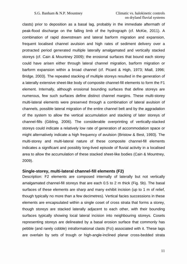
clasts) prior to deposition as a basal lag, probably in the immediate aftermath of
peak-flood discharge on the falling limb of the hydrograph (cf. McKie, 2011). A
combination of rapid downstream and lateral barform migration and expansion,
frequent localised channel avulsion and high rates of sediment delivery over a
protracted period generated multiple laterally amalgamated and vertically stacked
storeys (cf. Cain & Mountney 2009); the erosional surfaces that bound each storey
could have arisen either through lateral channel migration, barform migration or
barform expansion within a broad channel (cf. Picard & High, 1973; Miall, 1996;
Bridge, 2003). The repeated stacking of multiple storeys resulted in the generation of
a laterally extensive sheet-like body of composite channel-fill elements to form the F1
element. Internally, although erosional bounding surfaces that define storeys are
numerous, few such surfaces define distinct channel margins. These multi-storey
multi-lateral elements were preserved through a combination of lateral avulsion of
channels, possible lateral migration of the entire channel belt and by the aggradation
of the system to allow the vertical accumulation and stacking of later storeys of
channel-fills (Gibling, 2006). The considerable overprinting of vertically-stacked
storeys could indicate a relatively low rate of generation of accommodation space or
might alternatively indicate a high frequency of avulsion (Bristow & Best, 1993). The
multi-storey and multi-lateral nature of these composite channel-fill elements
indicates a significant and possibly long-lived episode of fluvial activity in a localised
area to allow the accumulation of these stacked sheet-like bodies (Cain & Mountney,
2009).
Single-storey, multi-lateral channel-fill elements (F2) Description: F2 elements are composed internally of laterally but not vertically
amalgamated channel-fill storeys that are each 0.5 to 2 m thick (Fig. 5b). The basal
surfaces of these elements are sharp and many exhibit incision (up to 1 m of relief,
though typically no more than a few decimetres). Vertical facies successions in these
elements are encapsulated within a single coset of cross strata that forms a storey,
though storeys are stacked laterally adjacent to each other, with their bounding
surfaces typically showing local lateral incision into neighbouring storeys. Cosets
representing storeys are delineated by a basal erosion surface that commonly has
pebble (and rarely cobble) intraformational clasts (Fci) associated with it. These lags
are overlain by sets of trough or high-angle-inclined planar cross-bedded strata

S.G. Banham & N.P. Mountney Climatic vs. halokinetic controls on dryland fluvial systems
12
(Fxt/ha Fxp). Rarely, sets of low-angle-inclined sandstone (la Fxp) are observed but
these never comprise more than a few percent of the element. Cross-bedded sets
present in F2 elements are typically overlain by F5 elements (sheet-like heterolithic
bodies) containing sets of climbing-ripple strata (Frc/Fxl), overlain by horizontally
interbedded sandstone and siltstone (Fhiss). These elements are typically laterally
extensive and many can be traced for over 2 km in orientations perpendicular to
regional palaeoflow.
Interpretation: Single-storey, multi-lateral channel-fill elements represent non-
aggrading laterally extensive and laterally mobile braid-belts which were succeeded
by non-confined sheet-like elements (Fig. 7b). These elements are dominated by
bedload transport processes, with cross-bedded sets representing the downstream
migration of dune-scale mesoforms (Miall 1996). The only rare presence of low-
angle-inclined Fxt lithofacies indicates that these elements did not migrate laterally to
any significant degree; rather, sedimentation occurred predominantly as a result of
down-channel migration of sandy bedforms (Miall, 1996). The laterally extensive
“sheet-like” nature of these amalgamated channel complexes arose from repeated
avulsion of active channels at a single stratigraphic horizon to form a channel belt
(Martinsen et al., 1999; Gibling 2006). Original channel width is difficult to determine
from outcrop study, but is likely to have been several hundred metres to possibly in
excess of 1 km (cf. Tunbridge 1981). The style of termination of F2 elements, which
are overlain by non-channelised elements of various types, indicates that the braid-
belt either avulsed abruptly to an alternative location elsewhere on the alluvial plain
(cf. Mackey & Bridge, 1995; Bridge 2003), else a cessation of channelised fluvial
activity occurred throughout the region in favour of non-confined sedimentation,
possibly in response to a change to a more arid climate (Blum & Tornqvist, 2000) or
to a shut-down in sediment delivery (Leeder et al., 1998).
Single-storey unilateral (i solated) channel-fill el ements with abundant infraformational clasts (F3) Description: Isolated F3 channel elements typically occur embedded within F1 and
F2 elements, although they also occur as isolated forms encased in non-confined
elements. F3 elements are discernable from F1 & F2 elements by virtue of their
distinctive fill of pebble-grade clasts of intraformational origin. F3 elements are

S.G. Banham & N.P. Mountney Climatic vs. halokinetic controls on dryland fluvial systems
13
typically defined by steep-sided channel margins inclined up to 50°; channel fills are
0.5 to 1.5 m thick and up to 15 m wide. F3 elements are overlain either by non-
confined elements or are partly eroded by channelised elements. Clasts are angular,
composed of argillaceous siltstone and (more rarely) mudstone that was apparently
derived from the local vicinity, and have diameters from 10 mm to 0.4 m. The style of
fill of these F3 elements by intraformational clasts may give rise to either a massive
(structureless) fabric (Fci) or result in the preservation of crude cross-bedding (Fxt
with Fci). The matrix present between the clasts is fine-grained sand.
Interpretation: Isolated, intraformational clast-filled elements represent the preserved
product of erosion and reworking of argillaceous material derived locally from the
surrounding alluvial plain and the subsequent deposition of this material in thread-like
channels, probably in a single cut-and-fill event related to an individual flood (Fig. 7a;
Billi, 2007; Cain & Mountney, 2009). A possible variation on this mechanism for the
generation of these elements could have arisen where locally active fluvial systems
encroached onto the flanks of a pre-existing topographic high, resulting in localised
erosion, entrainment, transport and deposition through incision (c.f. Rodríguez-López
et al., 2012) and collapse at the outer bank of the channel (Gomez-Gras & Alonso-
Zarza, 2002). In places, F3 elements can be shown to be associated with locations
proximal to topographic features on the alluvial plain, including topography generated
by salt-wall uplift (discussed later).
Massive (structureless) & horizontally laminated channel elements (F4) Description: F4 elements are typically up to 8 m thick, and are characterised at their
base by a 1 to 2 m-thick set of massive bedded sandstone (Fm), overlain by a 6 to 7
m-thick set of horizontally bedded sandstone (Fh), bedding surfaces of which reveal
primary current lineation. Basal incision typically exhibits modest relief that rarely
exceeds 1 to 2 m. These elements typically occur adjacent to multi-storey (F1), and
single storey (F2) multi-lateral channel-fill elements and in close proximity to the
flanks of salt walls, notably in the vicinity of the Castle Valley salt wall in the Parriott
basin.
Interpretation: Massive (structureless) and horizontally laminated sandstone channel-
fill elements (Fig. 6) most likely represent rapid incision and subsequent fill during a

S.G. Banham & N.P. Mountney Climatic vs. halokinetic controls on dryland fluvial systems
14
single flood event. The basal part of the channel-fill association represents rapid
deposition from suspension, before flow velocities waned and upper plane-bed
conditions prevailed (Ashley et al., 1990). The presence of a single facies succession,
most of which was horizontally laminated sandstone (Fh) with primary current
lineation demonstrates accumulation from a fast-moving flow arising from a single
flood event (McKee et al., 1966).
Sheet-like heterolithic elements (F5) Description: Elements composed of heterolithic strata are laterally extensive and can
be typically be traced laterally over many square kilometres; they comprise >75% of
the total vertical succession in some areas. A typical vertical facies succession within
this element may include a basal massive-bedded (Fm) sandstone sheet, which may
have a coarse-grained sand lag and erosive relief of up to a few tens of millimetres.
Massive sandstone (where present) is overlain by sets of climbing-ripple strata
(Frc/Fxl), within which ripple trains usually climb at a subcritical angle (Fig 6). These
pass gradationally upward into sets of homogenous or laminated siltstone (Fhiss) at
the top of the succession. Single examples of these sheet-like elements are typically
only 0.1 to 0.4 m thick, but can occur in repeating cycles that are collectively >20 m
thick (Figs. 5d,e). Sheet-like elements can occur juxtaposed laterally with
channelised elements (F1 to F4) (Fig. 5g), or vertically (Figs 5a,b,e,f), where
successive channelised elements have incised into the pre-existing sheet-like
heterolithic elements.
Interpretation: These heterolithic sheet-like elements are the preserved expression of
repeated non-confined flood events that distributed thin sheets of sediment across
the alluvial plain during episodes of elevated discharge (Fig. 7d). Each element,
defined by a fining-upward cycle, likely represents an individual flood event, where a
predictable facies succession is deposited, corresponding to deposition from a
waning flow. The lowermost massive sandstone sets, which typically possess a low-
relief and a sharp erosional base, represent the passage of an initial flood bore,
which possessed sufficient energy to entrain sediment from underlying flood deposits
before depositing them either through progressive accretion or via rapid suspension
settling as the flood-front passed (Blair, 2000). The facies succession in the upper
part of the element is characteristic of a progressive reduction of flow competence,
S.G. Banham & N.P. Mountney Climatic vs. halokinetic controls on dryland fluvial systems
15
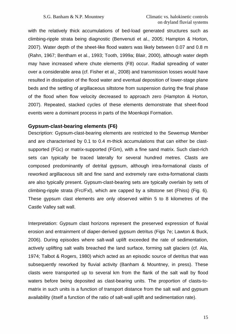
with the relatively thick accumulations of bed-load generated structures such as
climbing-ripple strata being diagnostic (Benvenuti et al., 2005; Hampton & Horton,
2007). Water depth of the sheet-like flood waters was likely between 0.07 and 0.8 m
(Rahn, 1967; Bentham et al., 1993; Tooth, 1999a; Blair, 2000), although water depth
may have increased where chute elements (F8) occur. Radial spreading of water
over a considerable area (cf. Fisher et al.¸ 2008) and transmission losses would have
resulted in dissipation of the flood water and eventual deposition of lower-stage plane
beds and the settling of argillaceous siltstone from suspension during the final phase
of the flood when flow velocity decreased to approach zero (Hampton & Horton,
2007). Repeated, stacked cycles of these elements demonstrate that sheet-flood
events were a dominant process in parts of the Moenkopi Formation.
Gypsum-clast-bearing elements (F6) Description: Gypsum-clast-bearing elements are restricted to the Sewemup Member
and are characterised by 0.1 to 0.4 m-thick accumulations that can either be clast-
supported (FGc) or matrix-supported (FGm), with a fine sand matrix. Such clast-rich
sets can typically be traced laterally for several hundred metres. Clasts are
composed predominantly of detrital gypsum, although intra-formational clasts of
reworked argillaceous silt and fine sand and extremely rare extra-formational clasts
are also typically present. Gypsum-clast-bearing sets are typically overlain by sets of
climbing-ripple strata (Frc/Fxl), which are capped by a siltstone set (Fhiss) (Fig. 6).
These gypsum clast elements are only observed within 5 to 8 kilometres of the
Castle Valley salt wall.
Interpretation: Gypsum clast horizons represent the preserved expression of fluvial
erosion and entrainment of diaper-derived gypsum detritus (Figs 7e; Lawton & Buck,
2006). During episodes where salt-wall uplift exceeded the rate of sedimentation,
actively uplifting salt walls breached the land surface, forming salt glaciers (cf. Ala,
1974; Talbot & Rogers, 1980) which acted as an episodic source of detritus that was
subsequently reworked by fluvial activity (Banham & Mountney, in press). These
clasts were transported up to several km from the flank of the salt wall by flood
waters before being deposited as clast-bearing units. The proportion of clasts-to-
matrix in such units is a function of transport distance from the salt wall and gypsum
availability (itself a function of the ratio of salt-wall uplift and sedimentation rate).
S.G. Banham & N.P. Mountney Climatic vs. halokinetic controls on dryland fluvial systems
16
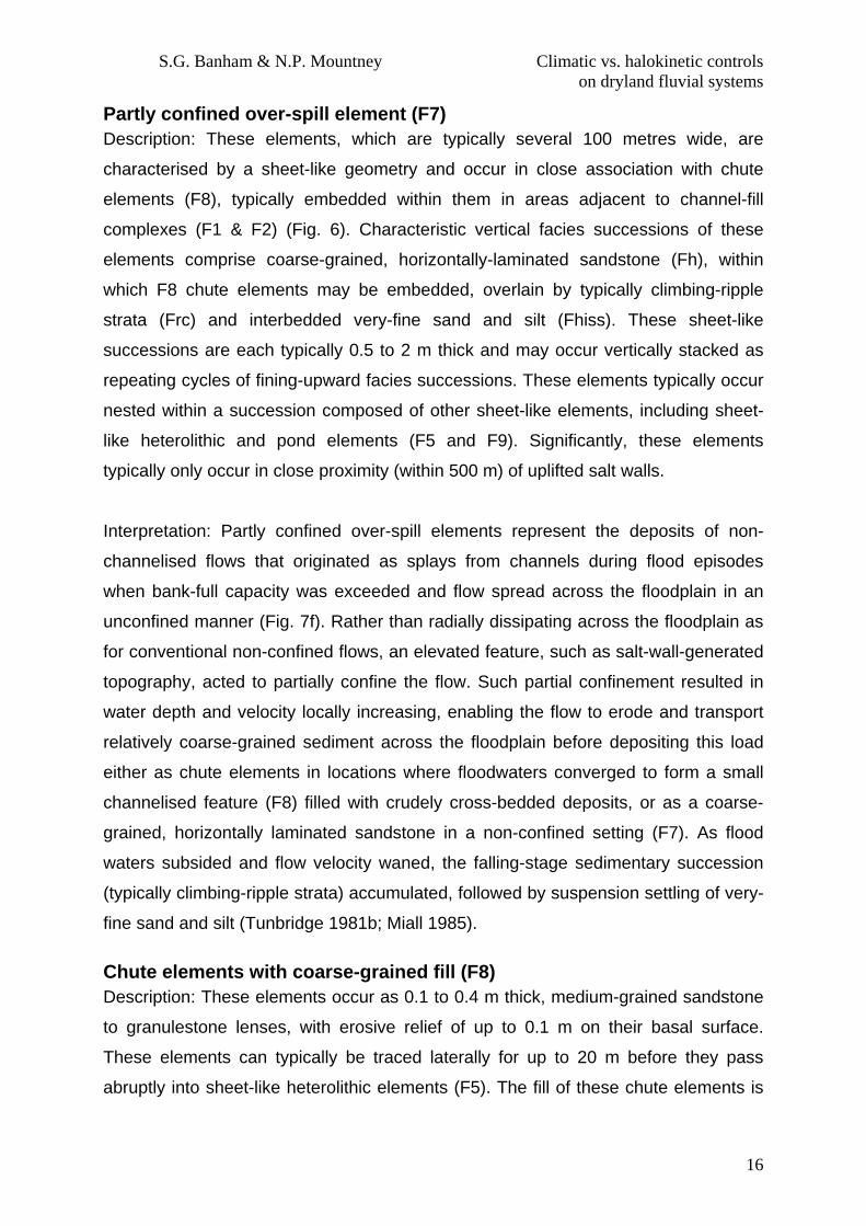
Partly confined over -spill element (F7) Description: These elements, which are typically several 100 metres wide, are
characterised by a sheet-like geometry and occur in close association with chute
elements (F8), typically embedded within them in areas adjacent to channel-fill
complexes (F1 & F2) (Fig. 6). Characteristic vertical facies successions of these
elements comprise coarse-grained, horizontally-laminated sandstone (Fh), within
which F8 chute elements may be embedded, overlain by typically climbing-ripple
strata (Frc) and interbedded very-fine sand and silt (Fhiss). These sheet-like
successions are each typically 0.5 to 2 m thick and may occur vertically stacked as
repeating cycles of fining-upward facies successions. These elements typically occur
nested within a succession composed of other sheet-like elements, including sheet-
like heterolithic and pond elements (F5 and F9). Significantly, these elements
typically only occur in close proximity (within 500 m) of uplifted salt walls.
Interpretation: Partly confined over-spill elements represent the deposits of non-
channelised flows that originated as splays from channels during flood episodes
when bank-full capacity was exceeded and flow spread across the floodplain in an
unconfined manner (Fig. 7f). Rather than radially dissipating across the floodplain as
for conventional non-confined flows, an elevated feature, such as salt-wall-generated
topography, acted to partially confine the flow. Such partial confinement resulted in
water depth and velocity locally increasing, enabling the flow to erode and transport
relatively coarse-grained sediment across the floodplain before depositing this load
either as chute elements in locations where floodwaters converged to form a small
channelised feature (F8) filled with crudely cross-bedded deposits, or as a coarse-
grained, horizontally laminated sandstone in a non-confined setting (F7). As flood
waters subsided and flow velocity waned, the falling-stage sedimentary succession
(typically climbing-ripple strata) accumulated, followed by suspension settling of very-
fine sand and silt (Tunbridge 1981b; Miall 1985).
Chute elements with coarse-grained fill (F8) Description: These elements occur as 0.1 to 0.4 m thick, medium-grained sandstone
to granulestone lenses, with erosive relief of up to 0.1 m on their basal surface.
These elements can typically be traced laterally for up to 20 m before they pass
abruptly into sheet-like heterolithic elements (F5). The fill of these chute elements is

S.G. Banham & N.P. Mountney Climatic vs. halokinetic controls on dryland fluvial systems
17
either of massive sandstone (Fm), or crude trough cross-bedding (Fxt), and is
normally overlain by a heterolithic sheet-element succession of climbing-ripple
laminated strata (Frc/Fxl) and siltstone (Fhiss).
Interpretation: Chute elements represent the preserved expression of the
convergence of non-confined floodwater on the floodplain to form minor channels
(Fig 7d; Abdullatif, 1989; Field, 2001; Benvenuti, 2005; Cain & Mountney 2009, 2011).
The localised convergence of flood waters induced local deepening and increased
flow velocity (cf. Field, 2001), which encouraged incision and the local entrainment
and transport of coarser-grained sediment via bed-load transport, possibly with the
winnowing of finer-grained material (Hjulstrom, 1935; Sundborg 1956). Rapid
deposition of coarse-grained material from suspension resulted in the accumulation
of structureless sandstone, whereas gradual waning of the late-stage flow induced
deposition from bed-load transport and the formation of crude cross-bedding (Fxt).
These chute elements likely carried flow for no more than a few hundred metres
before passing back into a non-confined flow (cf. Cain & Mountney, 2011).
Floodplain pond elements (F9) Description: Pond elements are characterised internally by associations of wave-
rippled sandstones (WR) and homogeneous or horizontally laminated siltstone, with
fine-grained deposits commonly possessing well developed and distinctive
desiccation cracks that are up to 0.6 m deep and filled with structureless siltstone or
fine sandstone. Sandstone in these elements is commonly reduced to a grey colour.
Individual pond elements are 0.2 to 0.5 m thick, and can typically be traced for 10 to
40 m laterally, though the largest example has been traced over an area of 25,000
m2.
Interpretation: Pond elements record sedimentation in the aftermath of flood events.
Floodwaters accumulated in very shallow depressions on the floodplain and formed
shallow ponds of standing water, which may have persisted for several days or
weeks (cf. Picard & High, 1973; Fisher et al., 2008). Wind blowing over the surface of
these ponds generated surface waves, which in turn allowed symmetrical ripple-
forms to develop on the fine-grained sandy substrate (Allen, 1968). Silt settled from
suspension. Loess transported by aeolian processes in the arid environment was

S.G. Banham & N.P. Mountney Climatic vs. halokinetic controls on dryland fluvial systems
18
likely trapped to form an additional sediment component. Evaporation and infiltration
of water caused the surface to dry out and resulted in the generation of desiccation
cracks, with larger cracks indicative of slower rates of desiccation.
Spatial & Temporal Variations in Sedimentary Architecture
This study considers the Moenkopi Formation in two distinct geographical areas,
each with their own tectonic and provenance history. The Moenkopi Formation in the
Salt Anticline Region was influenced by ongoing salt tectonics throughout the period
of deposition (Rasmussen & Rasmussen, 2009; Kluth & DuChene, 2009; Trudgill &
Paz, 2009; Trudgill, 2011). As a result of this halokinetic influence, the Moenkopi
Formation accumulated in a series of isolated salt-walled mini-basins, each with a
unique sediment supply and subsidence regime (Banham & Mountney, in press). The
effects of this isolation resulted in the preservation of significantly different styles of
fluvial architecture. By contrast, the Moenkopi Formation in the White Canyon area
lacks evidence for a tectonic control but instead records a strong climatic signature
that is additionally modified by the impact of spatial variations in accumulation style
that arose as a result of autogenic fluvial processes.
Salt Anticline Region
Within the Salt Anticline Region, the Moenkopi Formation accumulated in three
distinct mini-basins (Fig. 2a): the Fisher basin between the Uncompahgre Front and
the Fisher Valley salt wall, the Parriott Basin between the Fisher Valley and Castle
Valley salt walls, and the Big Bend Basin (Banham & Mountney, in press) between
the Castle Valley and Moab (Lisbon) Valley salt wall. The preserved thickness of the
Moenkopi Formation varies between the studied mini-basins, as a function of both
the subsidence history of individual basin segments and location within individual
mini-basins (e.g. depocentre versus flank); the thickest preserved succession (245 m)
occurs in the Big Bend Basin.
The Moenkopi Formation in the Salt Anticline Region is separated from the
underlying Permian Cutler Group by an angular unconformity that accounts for
approximately 25 Ma of non-deposition and erosion (Rasmussen and Rasmussen,
2009), with the angular nature of the unconformity having developed in response to
continued and progressive salt movement between the cessation of Cutler Group
sedimentation and the onset of Moenkopi Formation sedimentation (Trudgill, 2011).

S.G. Banham & N.P. Mountney Climatic vs. halokinetic controls on dryland fluvial systems
19
Although the sedimentary character of the four members of the Moenkopi Formation
tends to vary between each studied mini-basin (Fig. 9), the preserved fluvial
successions in each mini-basin share a common association of lithofacies and
architectural-element types (Figs 6 and 7a/b). Throughout accumulation of the
Moenkopi Formation, the fluvial system drained from southeast to northwest, parallel
to the trend of the linear salt walls (Fig. 9).
Tenderfoot Member The basal Tenderfoot Member attains a maximum thickness of 70 m at the Fisher
Valley Head locality in the Fisher basin (Fig. 10) but thins to only 40 m at the Mile 25
locality in Richardson Amphitheater. In the Parriott Basin, the maximum recorded
thickness is 40 m at Castle Tower and the member is generally slope forming. The
basal-most part of this member is characterised by fluvial strata with embedded
clasts apparently derived from localised reworking of the uppermost strata of the
underlying Cutler Group. A prominent feature of this member is a 1 to 2.5 m-thick
gypsum bed (GC) that is laterally continuous throughout the Parriott Basin (Fig. 10),
and which is also present in the north-eastern part of the Big Bend Basin, though has
apparently been largely eroded along the southern margin of the Fisher Basin. This
gypsum bed is characterised by a saccharoidal, crystalline texture that has been
interpreted previously to have accumulated either in a restricted tidal-flat (sabkha)
setting within a large embayment (Stuart et al., 1972; Baldwin, 1973) or as an
aeolianite (Lawton & Buck, 2006).
Although poorly exposed in the Parriott and Big-Bend basins, the beds
overlying the gypsum horizon, which are locally composed of coarse-grained
sandstone with distinctive angular grains and a gypsum cement, weather to a
distinctive orange colour making them a useful marker unit. In the Fisher Basin, the
Tenderfoot Member forms distinct cliffs, which are brown-orange in colour and beds
have a predominantly rounded profile. As a result, the beds are better exposed and
can be characterised by distinctive wavy or crinkly-laminated sandstones (facies
Scls), considered to be indicative of repeated salt precipitation and dissolution in a
sabkha-like environment (Goodall et al., 2000). Fluvial-channel elements are
generally absent. Conical-shaped de-watering structures (Fig. 5A) similar to those
observed in the Hoskinnini Member (Stuart, 1959; Chan, 1989; Dubiel et al., 1996)
occur at one locality in the transfer zone between the Cache Valley salt wall and the

S.G. Banham & N.P. Mountney Climatic vs. halokinetic controls on dryland fluvial systems
20
Fisher Valley salt wall (Fig.2: 3 km northwest of Log 16). These features are typically
1 to 2 m in height and occur as “megapolygons” (Chan 1989; Dubiel 1996) that are
traceable over an area of 100 m2 but are apparently confined both spatially and
temporally to this single area in the Salt Anticline Region, with no other examples
observed in this study area.
Ali Baba Member The cliff-forming Ali Baba Member has a sedimentary character that differs
significantly between the Fisher and Parriott basins (Fig. 10). In the Fisher Basin, the
member is ~50 m thick, and is characterised by medium- to coarse-grained
sandstone with localised pebble lags and rare beds of pebble-grade
orthoconglomerate (Fce). Metre-thick sets of tabular and trough cross-bedding
(Fxp/Fxt) are common. In the Parriott Basin the member is 25 to 40 m thick and is
characterised by interbedded siltstone and fine- to medium-grained sandstone (Fhiss)
in both the basal- and upper-most parts. By contrast, the middle part of the member
is characterised by a prominent 8 to 10 m-thick cliff-forming sandstone composite
bedset composed of dual-storey, multilateral channel-fill elements (F1) and massive
& horizontally laminated channel-fill elements (F4), which are well exposed along the
flanks of the Castle Valley and along the side of Parriott Mesa and the Priest and
Nuns mesas. This prominent, laterally extensive bedset is largely massively bedded
(Fm) in the Castle Tower area, but exhibits trough (Fxt) and planar-tabular (Fxp)
cross-bedding near Adobe Mesa and the Priest & Nuns mesas. Associated
lithofacies present in this member include, ripple forms (both current and wave
ripples) and ripple cross-lamination (Frc & WR), structureless sandstone beds (Fm),
primary current lineation (Fh), lags of mud-chip rip-up clasts of intraformational origin
(Fci), plus bedding surfaces preserving obstacle scours and desiccation cracks.
Fluvial architectural elements in the Ali-Baba Member are dominantly
characterised by 1 to 2 m-thick single-storey multi-lateral channel-elements (F2) in
the Parriott and Big Bend basins, but are additionally characterised by 6 to 10 m-thick,
vertically-stacked and amalgamated multi-storey channel elements (F1) in the Fisher
Basin, and up to 8 m thick massive & horizontally laminated channel-fill elements (F4)
in the Parriott Basin. Larger multi-storey channel-element complexes can be traced
laterally for distances in excess of 10 km in orientations parallel to palaeoflow (i.e. in
orientations parallel to the strike of the linear salt walls). Heterolithic units of

S.G. Banham & N.P. Mountney Climatic vs. halokinetic controls on dryland fluvial systems
21
interbedded siltstones and sandstones in the Parriott Basin form sheet-like fluvial
elements (F3) that are each laterally continuous for at least 200 m, with some
examples extending for in excess of 1 km.
Sewemup Member The sedimentary character of the Sewemup Member varies between each studied
mini-basin, but the member as a whole is slope forming (Fig. 10). The maximum
preserved thickness is 110 m at Castle Tower and elsewhere along the southwest
side of the Parriott Basin. The member thins to the northeast toward the Onion
Creek–Fisher Valley salt wall in the Parriott Basin.
One diagnostic feature of the Sewemup Member adjacent to the Castle Valley
salt wall is the widespread occurrence of several distinctive gypsum-clast-bearing
beds (Fig 3) (clasts 10 to 200 mm diameter; mean 100 mm), each up to 1 m thick
(FGc/m). These beds tend to be orthoconglomerates (FGc) in areas within 2000 m of
the Castle Valley salt wall but are paraconglomerates (FGm) in areas toward the
centre of the mini-basins. Gypsum clasts are absent from the Fisher Basin and from
parts of the Parriott Basin adjacent to the Onion Creek-Fisher Valley salt wall.
Common sedimentary structures in the Sewemup Member include desiccation cracks,
small gutter channels (0.1 m-deep) (F8), a range of dewatering structures including
load casts and flame structures, overturned, and convolute bedding (Fd).
Common architectural elements of the Sewemup Member include laterally
extensive bodies with sheet-like geometries that are composed internally of
heterolithic siltstone and sandstone beds (Fhiss, F6) and which are traceable for
distances in excess of 1000 metres. Single-storey channel-fill elements (F2) are rare
and, where present, they are relatively small (0.3 to 1 m thick; mean 0.4 m), with
width:thickness ratios that range from 25:1 to over 250:1, and with fills that are
characterised by trough cross-bedding (Fxt) and massive (structureless) fine-grained
sandstone (Fm). High-angle-inclined fractures (10-30 mm wide) filled with fibrous
gypsum and typically arranged in an anastomosing pattern are a distinctive non-
sedimentrary feature of this member.
Parriott Member The Parriott Member attains a maximum thickness of 40 m adjacent to the Castle
Valley salt wall and thins toward the Onion Creek – Fisher Valley salt wall, pinching
out over the crest of this salt wall. Typically, the member is 15 to 30 m thick but is

S.G. Banham & N.P. Mountney Climatic vs. halokinetic controls on dryland fluvial systems
22
mostly absent over the crests of the salt walls, either due to non-deposition on the
highs created by salt-wall uplift, or uplift and erosion prior to the onset of the
accumulation of the overlying Chinle Formation. An exception to this is a 10 m-thick
succession preserved on the nose of the Castle Valley salt wall (in the Red Hills area;
Fig. 10).
The Parriott Member is characterised by an absence of gypsum clasts
(FGc/m), with the succession containing a high proportion of multi-storey channel-fill
elements (F1) around the flanks of the Castle Valley salt wall, and single-storey
channel-fill (F2) & heterolithic sheet-like elements (F5) elsewhere in the basins. The
central and north-eastern parts of the Parriott Basin are characterised by rare and
isolated occurrences of single-storey multi-lateral channel elements (F2), each 1 to 2
m thick and several hundred metres wide. Adjacent to the nose of the Castle Valley
salt-wall in the Parriott Basin (at the so called Truck-and-Boat structure; Fig. 10) a
dual-storey fluvial channel-fill element (F1) forms a distinctive feature, which is
laterally continuous for 950 m before it is cut-out by recent erosion. In the Big Bend
Basin adjacent to the Castle Valley salt wall, the Parriott Member is characterised by
multi-lateral and multi-storey channel elements (F1) that collectively form a major
fluvial-channel complex that extends laterally for in excess of 1000 m.
The boundary between the Moenkopi Formation and the overlying Chinle
Formation is marked by a disconformity across much of the Salt Anticline Region,
although locally this boundary is represented by a distinctive angular unconformity in
areas immediately adjacent to the salt-walls, indicating uplift of the salt-walls during
or after the latter stages of deposition of the Moenkopi Formation but prior to the
onset of accumulation of the Chinle Formation.
Palaeocurrent data and sediment provenance Analyses of palaeocurrent data from the orientations of ripple crests and lee-slope
azimuths in climbing-ripple strata, trough and high-angle planar cross-bedded
sandstone in the Salt Anticline Region indicate dominant palaeo-drainage that was
consistently toward the northwest throughout accumulation of the Moenkopi
Formation (Fig. 1b) (vector mean = 302°; vector magnitude = 0.86; n = 177). Data
from individual mini-basins also reflect this overall trend (Fisher Basin: vector mean =
305°; vector magnitude = 0.91; n = 88. Parrio tt Basin: vector mean = 303°; vector
magnitude = 0.85; n = 57. Big Bend Basin: vector mean = 292°; vector magnitude =

S.G. Banham & N.P. Mountney Climatic vs. halokinetic controls on dryland fluvial systems
23
0.77; n = 32). Crests of wave ripples on exposed bedding surfaces created by bi-
oscillating currents in bodies of standing water (F9: pond elements) throughout the
Salt Anticline Region have a vector mean trend of 052° (vector magnitude = 0.73; n =
62), a trend that suggests a NW- or SE-oriented prevailing palaeowind (Fig 1b).
Provenance and petrographic analyses (Stuart et al., 1972) suggest a
dominant sediment source for the Moenkopi Formation in the Salt Anticline Region
from the San Luis Uplift. However, the abundance of extraformational conglomerates
of Uncompahgre affinity in the Ali-Baba Member in the Fisher Basin indicates a dual
source of sediment during the initial phase of accumulation in this mini-basin. The
confinement of this secondary source of extraformational clasts solely to the Fisher
Basin suggests that salt-wall-generated surface topography acted to prevent the
transverse delivery of sediment from the Uncompahgre Uplift into the Parriott or Big
Bend basins (Banham & Mountney, in press). The Tenderfoot Member contains an
abundance of reworked sediment , which has been interpreted as a reworked
remnant of the White Rim Sandstone (Dubiel et al., 1996).
White Canyon Region
The White Canyon study area in southeast Utah extends from Copper Point in the
north to Moss Back Butte in the southeast, and across to Whirlwind Draw in the Clay
Hills region to the southwest of the study area (Fig. 2). The only member of the
Moenkopi Formation studied in this area is the Torrey Member (Blakey, 1974). In the
southern part of the study area, the Moenkopi Formation lies apparently conformably
on top of the Hoskinnini Member (Fig 11 & 12, the boundary being differentiated by a
change in colour and bedding style: the Hoskinnini is generally a deeper orange
colour, is thicker-bedded, has a rounded weathering profile and exhibits undulatory
bedding; Stewart, 1959; Dubiel, 1992). The outcrop expression of the Hoskinnini
Member shares many characteristics observed in the Tenderfoot Member of the Salt
Anticline Region, including crenulated wavy laminations (Fig. 12; Stuart, 1959).
Where the Hoskinnini Member is absent, the Moenkopi Formation lies
disconformably on the Permian Organ Rock Formation (Cain & Mountney, 2009).
The Moenkopi Formation throughout this study area is disconformably overlain by the
Chinle Formation, which is differentiated from the Moenkopi Formation by a marked
increase in grain-size (from very-fine sand and silt to very-coarse sand and pebbles
where the basal Shinramup conglomerate is present). Incision of up to 8 m into the

S.G. Banham & N.P. Mountney Climatic vs. halokinetic controls on dryland fluvial systems
24
underlying Moenkopi Formation by channelised elements of the overlying Chinle
Formation is indicated by the presence of distinctive yellow, purple or grey mottling in
the basal 10 m of the Chinle Formation and, in some localities, an abundance of
petrified wood.
Hoskinnini Member The Hoskinnini Member, where observed, is typically 30 m thick and forms distinct,
orange-coloured cliffs at the base of the Moenkopi Formation (Fig. 12). The beds
forming these cliffs have a rounded profile, and some exhibit large-scale deformation
manifest as low amplitude undulating beds (Fig. 12; “Crinkly beds” – Stuart, 1959). In
addition, enigmatic conical-shaped fluid-escape structures similar to those observed
in the Tenderfoot Member of the Salt Anticline Region have been documented in the
region (Stuart, 1959; Chan 1989; Dubiel, 1992; Dubiel et al., 1996). In the Clay Hills
area, a 1 to 2 m thick crystalline gypsum bed is present, which exhibits similar
characteristics to the gypsum bed of the Tenderfoot Member of the Salt Anticline
Region.
Torrey Member Within the study area, the Torrey Member varies from 90 m thick in the southwest, to
64 m thick in the north, to only 45 m thick in the southeast, with an overall south-
westerly thinning due to progressive erosion at the top of the succession. The
member is characterised by a stepped profile that was originally divided into Lower
slope-forming, ledge-forming, and upper slope-forming members (Stewart et al.,
1972) that correspond generally to slope-forming sheet-like heterolithic elements (F5)
and cliff-forming channel fill-complex elements (F1, F2). Spatial variations in sand
content are discernable, with a higher proportion of channel elements in the upper
third of the member in the vicinity of Steer Gulch, Happy Jack Mine and Copper Point
logs (Figs 2b, 4b). A distinctive set of 4 or 5 beds containing intraformational-clasts
out crop in the lower 10 to 30 m of the member, and these are typically interbedded
with thin siltstone beds (Fig. 5b). These useful markers were observed in 8 of the 11
studied sections, spread over an area of 20 by 40 km. Within the overlying 10 to 20
m of the succession, beds disrupted by soft-sediment deformation (Fd) are common,
with the deformation style indicative of structures arising due to upward escape of
water, including load and flame structures and sand volcanoes, that occur in close
proximity to sand lobes and slump structures (cf. Owen, 1987, 1996).

S.G. Banham & N.P. Mountney Climatic vs. halokinetic controls on dryland fluvial systems
25
Channelised fluvial architectural elements (F1, F2) can, in nearly all cases, be
traced laterally for in excess of 500 m and in some instances for 10 km. Sheet-like
heterolithic elements (F5) are highly laterally extensive and can be traced for tens of
km in directions both parallel and perpendicular to palaeoflow. Silt-prone sheet-like
elements (F5) are particularly prevalent in the upper portion of the succession in the
west of the study area, where they account for over 75% of the interval. Gypsum-
clast-bearing elements (F6) are rare and are only observed in the south-western part
of the study area. A single example of gypsum clasts preserved within trough cross-
bedded strata was observed in the Clay Hills region. The origin of these gypsum
clasts is uncertain, but may relate to the gypsum bed present in the Hoskinnini
Member.
Palaeocurrent data and sediment provenance Palaeocurrent direction in the Torrey Member throughout the White Canyon study
area has a vector mean of 333° with a magni tude of 0.89 (n = 56). This favours a
likely provenance from the Defiance Upwarp (Figs. 1 & 11), to the southwest of the
study area (Stuart et al., 1972, Fillmore, 2011), a region composed of Permian strata,
including the distal fringes of the Organ Rock Formation, the undifferentiated Cutler
Group, and the De Chelley Sandstone (Stewart et al., 1972; Stanesco et al., 2000).
Discussion
Combined facies and architectural-element analysis demonstrates significant
complexity in terms of spatial and temporal variations in the deposits of the Monekopi
Formation. Although a similar set of lithofacies is present in both study areas, which
are indicative of the operation of broadly similar sedimentary processes, significant
local variations in the spatial (lateral) and temporal (vertical) arrangement of
architectural elements composed of these facies are recognised. Such variations are
here shown to have arisen in response to the impact of different sets of allogenic
controls including: (i) tectonic (halokinetic) regime, which dictated the rate of
generation of accommodation space, the width of basin floor over which the fluvial
systems could spread and the location of the salt walls; (ii) climatic regime, which
was unlikely to have been significantly different between the two study areas but
which may have varied temporally; (iii) the rate and pathway of sediment delivery
from both the principal and secondary source areas, which themselves are controlled

S.G. Banham & N.P. Mountney Climatic vs. halokinetic controls on dryland fluvial systems
26
by salt-wall location. Additionally, local variations in sedimentary character likely also
reflect the various autogenic processes that operated in the fluvial systems, including
avulsion style and frequency and the mechanisms by which bank-full channel
capacity was exceeded during floods to result in sheet-like, non-confined overland
flow.
Environment of deposition Architectural element analysis demonstrates that accumulation of sediment was
dominated by relatively thin but laterally extensive bodies: most F1 and F2 channel
elements have width-to-thickness ratios greater than 250:1; sheet-like elements (F5,
F6) have width-to-thickness ratios greater than 2000:1. These thin but laterally
extensive elements demonstrate a broad, low-relief accumulation surface.
Architectural elements with distinctive assemblages of lithofacies (Table 1) in both
channelised and non-channelised elements indicate sedimentation via repeated, low-
frequency, high-magnitude ephemeral flood events (Williams, 1970, 1971; Glennie,
1970; Picard & High, 1973; Gee, 1990). Individual sedimentary components
characteristic of an arid environment are as follows: desiccation cracks (up to 0.6m
deep) indicative of slow episodes of desiccation in non-confined elements (F6, F7,
F8); gypsum-clast-bearing elements (F6), rare tee-pee structures; the presence of a
crystalline gypsum unit, which demonstrates that the region of deposition endured
episodes of sustained aridity to allow preservation of such soluble material. Facies
associations of laterally extensive sheet-like elements (F5), including thin, massively
bedded sandstones (Fm), climbing-ripple strata (Frc/Fxl) and homogeneous and
horizontally laminated siltstone (Fhiss) demonstrate evidence for rapid deposition
from a waning flow (Williams 1971). Thin pond elements (F9) mostly of limited lateral
extent and with fills of wind-generated wave-ripple strata (Allen, 1968) demonstrate
the presence of shallow pools of standing water; the near-ubiquitous presence of
desiccation cracks indicates complete desiccation of the pools; in some examples,
the presence of desiccation cracks at multiple closely spaced stratigraphic levels
demonstrates repeated flooding and desiccation, and the transient nature of the
ponds.
Non-confined flows in extra-channel settings are widely documented as a
product of episodic, high-energy ephemeral floods in arid alluvial environments (e.g.
Rahn, 1967; Glennie, 1970; Williams, 1970, 1971; Tooth, 1999a/b, 2000). Such flows,

S.G. Banham & N.P. Mountney Climatic vs. halokinetic controls on dryland fluvial systems
27
which are typified by markedly peaked hydrographs (Reid et al., 1998), are generally
capable of transporting and distributing large volumes of sediment over relatively
short periods (Frostick et al., 1983).
Although channel elements are relatively abundant in the preserved
stratigraphy, at any given time channelised forms likely only occupied a small
proportion of the surface area, as is common in many ephemeral alluvial systems
(just 3% in the examples studied by Rust & Legun, 1983), thereby implying that most
sediment transport and deposition occurred as a result of non-confined fluvial
processes. It is the increased preservation potential of erosively-based channel
elements and their overprinting of non-confined elements (e.g. via lateral accretion
and avulsion processes) that results in them comprising a larger proportion of the
preserved stratigraphic succession.
Hampton & Horton (2007) recognised sheetflow deposits by virtue of their thin
and laterally extensive nature, with poorly defined channel banks with low clay
content (cf. North et al., 2007) characterised by high width-to-depth ratios. Such
poorly defined, high aspect ratio channel elements (>300:1) may be extremely
difficult to discern in parts of the succession dominated by non-confined elements,
especially if they are in-filled by heterolithic facies associations.
A general depositional model depicting the relationship between confined and
non-confined architectural elements observed in the Moenkopi Formation and their
likely mode of generation is shown in Fig. 8. Channel belts consisting of multiple,
shallow and potentially poorly defined braided channel networks (cf. North, 2007;
Hampton & Horton, 2007) soon exceeded bank-full capacity during rising flood stage,
resulting in over-spill of flood waters onto the adjoining alluvial plain. Non-confined
flood waters transported and distributed sediment as both bed load and suspended
load across a low-relief alluvial plain. As flood waters emanated away from the
confined channel networks, the flood-front dissipated radially across the alluvial plain.
Transmission losses due to a combination of infiltration and evaporation increased as
the flood waters became spread over a larger area, resulting in a progressive
reduction in both flow velocity and stream power (Bull, 1979), thereby leading to the
sequential accumulation of the succession of facies representative of waning flow
characteristic of non-confined elements (F5) and the preservation of pond elements
(F9). Occasionally, these non-confined flood waters converged locally, resulting in
S.G. Banham & N.P. Mountney Climatic vs. halokinetic controls on dryland fluvial systems
28
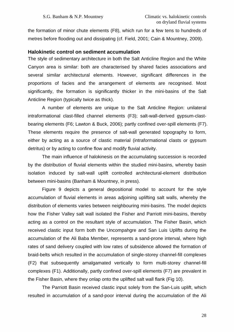
the formation of minor chute elements (F8), which run for a few tens to hundreds of
metres before flooding out and dissipating (cf. Field, 2001; Cain & Mountney, 2009).
Halokinetic control on sediment accumulation The style of sedimentary architecture in both the Salt Anticline Region and the White
Canyon area is similar: both are characterised by shared facies associations and
several similar architectural elements. However, significant differences in the
proportions of facies and the arrangement of elements are recognised. Most
significantly, the formation is significantly thicker in the mini-basins of the Salt
Anticline Region (typically twice as thick).
A number of elements are unique to the Salt Anticline Region: unilateral
intraformational clast-filled channel elements (F3); salt-wall-derived gypsum-clast-
bearing elements (F6; Lawton & Buck, 2006); partly confined over-spill elements (F7).
These elements require the presence of salt-wall generated topography to form,
either by acting as a source of clastic material (intraformational clasts or gypsum
detritus) or by acting to confine flow and modify fluvial activity.
The main influence of halokinesis on the accumulating succession is recorded
by the distribution of fluvial elements within the studied mini-basins, whereby basin
isolation induced by salt-wall uplift controlled architectural-element distribution
between mini-basins (Banham & Mountney, in press).
Figure 9 depicts a general depositional model to account for the style
accumulation of fluvial elements in areas adjoining uplifting salt walls, whereby the
distribution of elements varies between neighbouring mini-basins. The model depicts
how the Fisher Valley salt wall isolated the Fisher and Parriott mini-basins, thereby
acting as a control on the resultant style of accumulation. The Fisher Basin, which
received clastic input form both the Uncompahgre and San Luis Uplifts during the
accumulation of the Ali Baba Member, represents a sand-prone interval, where high
rates of sand delivery coupled with low rates of subsidence allowed the formation of
braid-belts which resulted in the accumulation of single-storey channel-fill complexes
(F2) that subsequently amalgamated vertically to form multi-storey channel-fill
complexes (F1). Additionally, partly confined over-spill elements (F7) are prevalent in
the Fisher Basin, where they onlap onto the uplifted salt wall flank (Fig 10).
The Parriott Basin received clastic input solely from the San-Luis uplift, which
resulted in accumulation of a sand-poor interval during the accumulation of the Ali

S.G. Banham & N.P. Mountney Climatic vs. halokinetic controls on dryland fluvial systems
29
Baba Member: fluvial activity in this basin was diminished relative to that of the
neighbouring Fisher Basin, resulting in accumulation of a higher proportion of
argillaceous elements (Fhiss). The absence of major channel networks in this basin
precluded significant reworking of this argillaceous material.
Climatic Control on sediment accumulation Evidence for climatic variation in the Moenkopi Formation is recorded as subtle
upward (vertical) changes in the overall style of sedimentation that can be discerned
and correlated across both study regions. In the Salt Anticline Region, climatic
signatures are masked by the preserved effects of other controls, including varying
rates of mini-basin subsidence and sediment supply. However, the overall style of
sedimentary architecture changes through the Moenkopi Formation (Fig. 10) and this
is likely to have occurred as a function of palaeoclimate.
Throughout accumulation of the Tenderfoot, (and the laterally equivalent
Hoskinnini Member – Stewart, 1959) conditions were interpreted to be arid and
deposition occurred in a sabkha-like setting (Dubiel, 1994), resulting in accumulation
of lithofacies Scls in the Fisher Basin, with few channel-fill complexes preserved. The
Ali Baba Member in the Salt Anticline Region is characterised by multi-storey
channel-fill complexes (F1) in the Fisher Basin, by single-storey channel-fill
complexes (F2) with sheet-like heterolithic strata (F5) in the Parriott Basin, and by a
mixture of sheet-like heterolithic elements (F5) and rare single-storey channel-fill
elements (F2) in the Big Bend Basin. Collectively, this indicates a region-wide
increase in humidity relative to the underlying member, resulting in an increased
sediment influx into the mini-basins and an increase in channelised fluvial activity
(Rumsby & Macklin, 1994). The Sewemup Member in all of the studied basins is
characterised by an abundance of sheet-like heterolithic strata (F5) and gypsum-
clast-bearing elements (F6), with few single-storey channel-fill complexes (F2).
These elements demonstrate a decrease in fluvial activity across all three mini-
basins at this stratigraphic level and record an episode when major flood events did
not occur. The fluvial reworking and subsequent preservation of highly-soluble
gypsum clasts demonstrates the ephemeral nature of the fluvial system and the
overall arid climate. During accumulation of the Parriott Member, a higher proportion
of single-storey (mainly in the Parriott Basin) and multi-storey channel-fill elements

S.G. Banham & N.P. Mountney Climatic vs. halokinetic controls on dryland fluvial systems
30
(F2, F1) were preserved, demonstrating a return to relatively less arid climatic
conditions.
Climatic signatures recorded in the Moenkopi Formation of the White Canyon
area are less obvious, in part due to the preservation of a thinner succession.
However, a channel-prone interval in the middle part of the Torrey Member (the so-
called Ledge-Forming Member of Stewart et al., 1972) tentatively correlates with the
Ali Baba Member of the Salt Anticline Region based on similar sedimentary character.
This would suggest that both study regions shared a common climatic regime,
resulting in coeval variations in sediment supply and similar stratigraphic expressions.
Conclusions
The Moenkopi Formation in the Salt Anticline Region and White Canyon area of
southern Utah is the preserved expression of a partly channelised and partly non-
channelised fluvial succession that accumulated across a low-relief alluvial plain (Fig
13). The prevailing palaeoclimate at the time of accumulation was arid, as reflected in
the style of the preserved strata. Depositional style is characterised by accumulation
of vertically amalgamated, laterally extensive sheet-like bodies throughout most parts
of the formation. These sheet-like bodies are either (i) channel-belt complexes that
lacked significant basal erosional relief, composed of single- and multi-storey, multi-
lateral channel-fill complexes, or (ii) sheet-like elements with heterolithic internal fills
that are the preserved expression of non-confined fluvial flow across an extensive
alluvial plain.
Both the Salt Anticline Region and White Canyon area share common facies
and architectural elements, indicating the action of comparable fluvial processes
under similar climatic conditions across the region. The rate of sediment
accumulation in the Salt Anticline Region was controlled primarily by rate of
accommodation generation via differential rates of mini-basin subsidence, with
sediment supply rate and pathways having governed the accumulation of sand-prone
and sand-poor styles of basin fill in neighbouring mini-basins. The absence of
halokinetic processes controlling the distribution of fluvial elements in the White
Canyon Region allowed autocyclic processes (lateral channel migration & avulsion)
to act as dominant controls on fluvial element distribution in this region. Although
halokinesis did not exert a primary control on fluvial sedimentary architecture, as
demonstrated by the presence of common facies and architectural elements in both
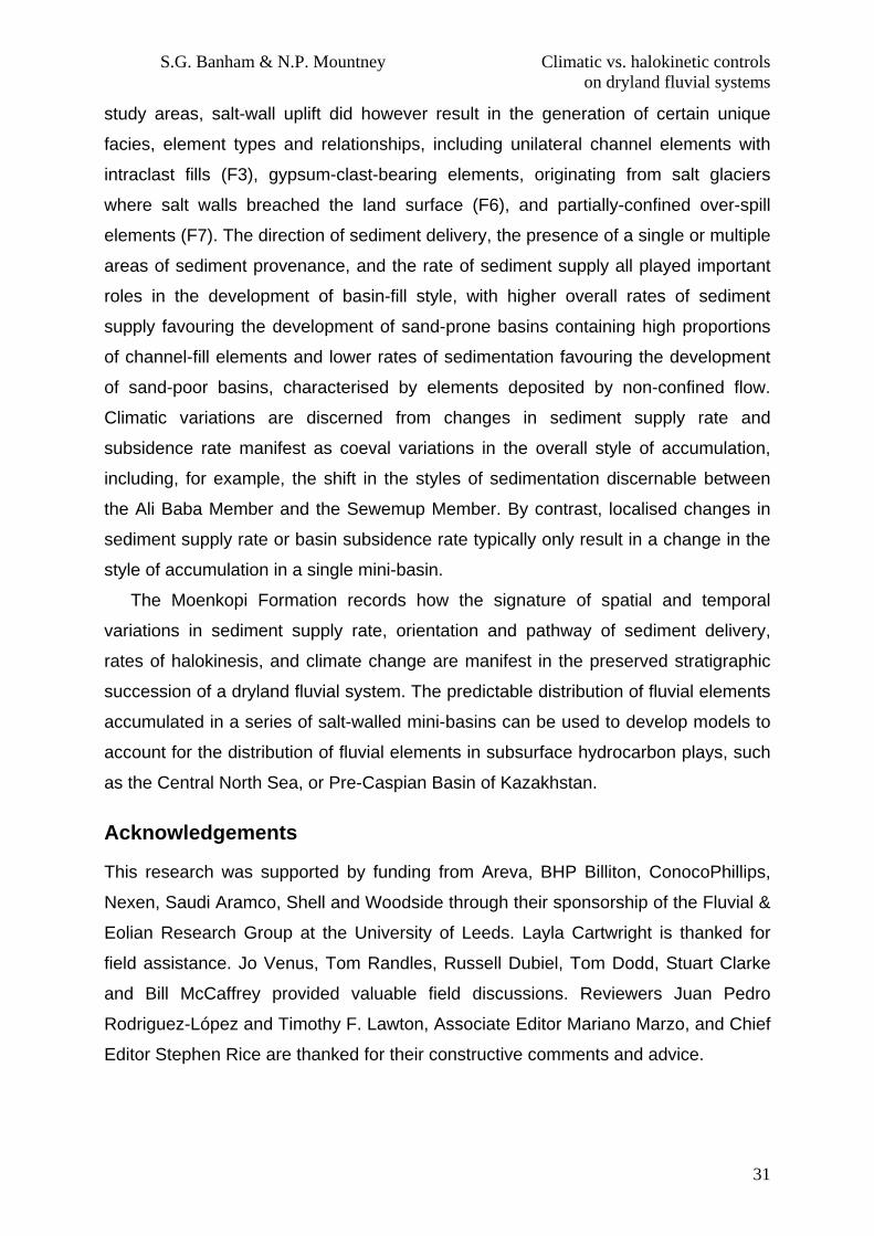
S.G. Banham & N.P. Mountney Climatic vs. halokinetic controls on dryland fluvial systems
31
study areas, salt-wall uplift did however result in the generation of certain unique
facies, element types and relationships, including unilateral channel elements with
intraclast fills (F3), gypsum-clast-bearing elements, originating from salt glaciers
where salt walls breached the land surface (F6), and partially-confined over-spill
elements (F7). The direction of sediment delivery, the presence of a single or multiple
areas of sediment provenance, and the rate of sediment supply all played important
roles in the development of basin-fill style, with higher overall rates of sediment
supply favouring the development of sand-prone basins containing high proportions
of channel-fill elements and lower rates of sedimentation favouring the development
of sand-poor basins, characterised by elements deposited by non-confined flow.
Climatic variations are discerned from changes in sediment supply rate and
subsidence rate manifest as coeval variations in the overall style of accumulation,
including, for example, the shift in the styles of sedimentation discernable between
the Ali Baba Member and the Sewemup Member. By contrast, localised changes in
sediment supply rate or basin subsidence rate typically only result in a change in the
style of accumulation in a single mini-basin.
The Moenkopi Formation records how the signature of spatial and temporal
variations in sediment supply rate, orientation and pathway of sediment delivery,
rates of halokinesis, and climate change are manifest in the preserved stratigraphic
succession of a dryland fluvial system. The predictable distribution of fluvial elements
accumulated in a series of salt-walled mini-basins can be used to develop models to
account for the distribution of fluvial elements in subsurface hydrocarbon plays, such
as the Central North Sea, or Pre-Caspian Basin of Kazakhstan.
Acknowledgements
This research was supported by funding from Areva, BHP Billiton, ConocoPhillips,
Nexen, Saudi Aramco, Shell and Woodside through their sponsorship of the Fluvial &
Eolian Research Group at the University of Leeds. Layla Cartwright is thanked for
field assistance. Jo Venus, Tom Randles, Russell Dubiel, Tom Dodd, Stuart Clarke
and Bill McCaffrey provided valuable field discussions. Reviewers Juan Pedro
Rodriguez-López and Timothy F. Lawton, Associate Editor Mariano Marzo, and Chief
Editor Stephen Rice are thanked for their constructive comments and advice.

S.G. Banham & N.P. Mountney Climatic vs. halokinetic controls on dryland fluvial systems
32
References
Abdullatif, O.M. (1989) Channel-fill and sheet-flood facies sequences in the ephemeral terminal River Gash, Kassala, Sudan. Sed. Geol. 63, 171-184.
Ala, M.A. (1974) Salt Diapirism in Southern Iran. Am. Assoc. Petrol. Geol. Bull., 58, 1758-1770.
Allen, J.R.L (1968) Current Ripples: Their relation to patterns of water and sediment motion. North-Holland Publishing Company, Amsterdam.
Ashley G.M. (Chair Person) and Others (1990) Classification of Large-Scale Subaquious bedforms: A new look at an old problem. J. Sed Petrology, 60, 160-172.
Baker, A.A. and Reeside, J.B. (1929) Correlation of the Permian of southern Utah, northern Arizona, northwest New Mexico, and southwestern Colorado. Am. Assoc. Petrol. Geol. Bull., 13, 1413-1448.
Baldwin, E.J. (1983) The Moenkopi Formation of North-Central Arizona: and Interpretation of Ancient Environments based upon Sedimentary Structures and Stratification types. J. Sed. Petrol. 43, 92-106.
Banham, S.G. and Mountney, N.P. (2013) Controls on fluvial sedimentary architecture and sediment fill state in salt-walled mini-basins: Triassic Moenkopi Formation, Salt Anticline Region, SE Utah, USA. Basin Res. DOI: 10.1111/bre.12022
Barbeau, D.L. (2003) A flexural model for the Paradox Basin: implications for the tectonics of the Ancestral Rocky Mountains. Basin Res, 15, 97-115.
Barde, J-P., Garalla, P., Harwijanto, J., and Marsky, J., (2002a). Exploration at the eastern edge of the Precaspian basin: Impact of data integration on Upper Permian and Triassic prospectivity. Am. Assoc. Petrol. Geol. Bull., 86, 399-415.
Barde, J-P., Chamberlain, P., Galavazi, M. , Gralla, P., Harwijanto, J., Marsky, J., and Van Den Belt, F . (2002b). Sedimentation during halokinesis: Permo-Triassic reservoirs of the Saigak Field, Precaspial Basin, Kazakhstan. Petrol. Geosci., 8, 177-187.
Bentham, P.A. Talling, P.J., and Burbank, D.W. (1993) Braided stream and flood-plain deposition in a rapidly aggrading basin: the Escanilla formation, Spanish Pyrenees. In: Braided Rivers (Eds. J.L. Best, C.S. Bristow), Geol. Soc. London Spec. Publ. 75, 177-194.
Benvenuti, M., Carni celli, S., Ferarri, G. and Sagri M. (2005) Depositional processes in latest Pleistocene and Holocene ephemeral streams of the Main Ethiopian Rift (Ethiopia). In: Fluvial Sedimentology VII (Eds M.D. Blum, S.B. Marriott, S.F. Leclair) IAS Spec. Publ., 35, 277-294.Billi, P. (2007) Morphology and sediment dynamics of ephemeral stream terminal distributary systems in the Kobo Basin (northern Welo, Ethiopia). Geomorphology, 85, 98-113.
S.G. Banham & N.P. Mountney Climatic vs. halokinetic controls on dryland fluvial systems
33
Blair, T.C. (2000) Sedimentology and progressive tectonic unconformities of the sheetflood-dominated Hell's Gate alluvial fan, Death Valley, California. Sed. Geol, 132, 233-262.
Blakey, R.C. (1973) Stratigraphy and Origin of the Moenkopi Formation (Triassic) of Southeastern Utah. The Mountain Geologist, 10, 1-17.
Blakey, R.C . (1974) Stratigraphy and Depositional Analysis of the Moenkopi Formation Southeastern Utah. Utah geological and Mineral Survey, Utah department of Natural Resources, 104.
Blakey, R.C . (1989) Triassic and Jurassic Geology of the southern Colorado Plateau. In: J.P. Jenny, S.J. Reynolds, Geological evolution of Arizona, Tuscon, Arizona Geological Society Digest. 17, 369-396.
Blakey, R.C. and Gubitosa, R. (1984) Controls on sandstone body geometry and architecture in the Chinle Formation (Upper Triassic) Colorado Plateau. Sed. Geol., 38, 51-86.
Blakey R.C. and Ranney W. (2008) Ancient Landscapes of the Colorado Plateau. Grand Canyon Association, Grand Canyon, Arizona.
Blum, M.D. and Tornqvist T.E. (2000) Fluvial responses to climate and sea-level change: a review and look forward. Sedimentology, 47, 2-48.
Bridge, J.S. (2003) Rivers and Floodplains: forms, processes and sedimentary record. Blackwell Science, Oxford.
Bridge, J.S. and Tye, R.S. (2000) Interpreting the Dimentions of Ancient Fluvial Channel Bars, Channels, and Channel Belts from Wireline-Logs and Cores. Am. Assoc. Petrol. Geol. Bull., 84, 1205-1228.
Bristow, C.S., and Best, J.L. (1993) Braided rivers: perspectives and problems. In: Braded Rivers (Eds J.L. Best, C.S. Bristow). Spec. Publ. Geol. Soc. London, 75, 1-11.
Bromley, M.H. (1991). Architectural features of the Kayenta Formation (Lower Jurassic), Colorado Plateau, USA: relationship to salt tectonics in the Paradox Basin. Sediment. Geol., 73. 77-99.
Bull, W.B. (1979) Threshold of critical power in streams. Geol. Soc Am. Bull, 90, 453-464.
Cain, S.A. (2009) Sedimentology and stratigraphy of a terminal fluvial fan system: the Permian Organ Rock Formation, South East Utah. PhD Thesis, Keele University.
Cain, S.A. and Mountney, N.P. (2009) Spatial and temporal evolution of a terminal fluvial fan system: the Permian Organ Rock Formation, South-east Utah, USA. Sedimentology, 56, 1774-1800.
S.G. Banham & N.P. Mountney Climatic vs. halokinetic controls on dryland fluvial systems
34
Carter, F.W. (1970) Geology of the Salt Anticline Region in Southwestern Colorado. Department of the Interior, United States Geological Survey Bulletin, 637.
Chan M.A. (1989) Erg margin of the Permian White Rim Sandstone, SE Utah. Sedimentology, 36, 235-251.
Colombera, L., Felletti, F., Mountney, N.P. and McCaffrey, W.D. (2012) A database approach for constraining stochastic simulations of the sedimentary heterogeneity of fluvial reservoirs. Am. Assoc. Petrol. Geol. Bull. 96, 2143-2166.
Colombera, L., Mountney, N.P., and McCaffrey, W.D. (2012) A relational database for the digitization of fluvial architecture: concepts and example applications. Petrol. Geosci. 18, 129-140.
Darton, N.H. (1910) A reconnaissance of parts of northwestern New Mexico and northern Arizona. Department of the Interior, United States Geological Survey Bulletin, 435.
Dodd, T.J.H and Clarke, S.M (2011) Salt Controls on Sedimentation in a Marginal-Marine to Continental Setting: Implications for Facies Development and Hydrocarbon Entrapment. Unpublished M.Sc. Thesis, Keele University.
Doelling, H.H. (1988) Geology of the Salt Valley Anticline and Arches National Park. Grand County , Utah. In: Salt Deformation in the Paradox Region (Eds H.H. Doelling, C.G. Oviatt, P.W. Huntoon), Utah Geol. Surv. Bull., 122, 7-58.
Doelling, H.H and Chidsey, T.C. (2009) Deadhorse State Park and Vicinity Geologic Road Logs, Utah. In: The Paradox Basin Revisited: New Developments in Petroleum Systems and Basin Analysis (Eds W.S. Houston, L.L. Wray and P.G. Moreland). Rocky Mountain Association of Geologists Spec. Publ., 635-672.
Dubiel, R.F., Stanesco, J.D. and Huntoon, J.E. (1992) Clastic Sabkha Facies and Paleograndwater Flow in the Hoskinnini Member of the Moenkopi Formation (Triassic Paradox Basin) – Implications for Hydrocarbon Emplacement. SEPM – Rocky Mountain Section Newsletter, 12, 2.
Dubiel, R. F. (1994). Triassic deposystems, paleogeography, and paleoclimate of the Western Interior. Mesozoic systems of the Rocky Mountain region, USA, Rocky Mountain SEPM, 133-168.
Dubiel, R.F., Huntoon, J.E ., Stanesco, J.D., Condon, S.M. and Mickelson, D. (1996) Permain-Triassic Depositional Systems, Paleogeography, Paleoclimate, and Hydrocarbon Resources in Canyonlands, Utah. Colorado Geological Survey, Open-File Report 96-4, Field Trip 5.
Elston, D.P. and Shoemaker, E.M. (1962) Uncompahgre front and salt anticline region of the Paradox Basin, Colorado and Utah. Am. Assoc. Petrol. Geol. Bull., 46, 1857-1878.

S.G. Banham & N.P. Mountney Climatic vs. halokinetic controls on dryland fluvial systems
35
Field, J. (2001) Channel avulsion on alluvial fans in southern Arizona. Geomorphology. 37, 93-104.
Fillmore, R. (2011) Geological evolution of the Colorado Plateau of Eastern Utah and Western Colorado. University of Utah Press.
Fisher, J.A., Krapf, C.B.E ., Lang, S.C., Nichols, G.J. and Payenberg, T.H.D. (2008) Sedimentology and architecture of the Douglas Creek terminal splay, Lake Eyre, central Australia. Sedimentology, 55, 1915-1930.
Flores, R.M. and Pillmore, C.L. (1987) Tectonic Control on Alluvial Paleoarchitecture and of the Cretaceous and Tertiary Ration Basin, Colorado and New Mexico. In: Recent Developments in Fluvial Sedimentology, Spec. Publ. SEPM, 39.
Frostick, L.E., Reid, I. and Layman, J.T. (1983) Changing size distribution of suspended sediment in arid-zone flash floods. Spec Publ. Int. Ass. Sediment. 6, 97-106.
Gee D.M., Anderson, M.G. and Baird, L. (1990) Large-Scale Floodplain Modelling. Earth Surf. Process. Landf., 15, 513-523.
Gibling, M.R. (2006) Width and Thickness of fluvial channel bodies and valley fills in the geological record: A literature compilation and classification. J. Sed. Res., 76, 731-770.
Glennie, K.W. (1970) Desert Sedimentary Environments. Developments in Sedimentology 14, Elsevier Publishing Company, Amsterdam.
Goodall, T.M., North, C.P. and Glennie, K.W. (2000) Surface and subsurface sedimentary structures produced by salt crusts. Sedimentology, 47, 99-118.
Gregory, H.E. (1917) Geology of the Navajo Country: A reconnaissance of parts of Arizona, New Mexico, and Utah. Department of the Interior, United States Geological Survey Professional Paper 93.
Gomez-Gras, D., and Alonso-Zarza, A.M. (2003) Reworked calcretes: their significance in the reconstruction of alluvial sequences (Permian and Triassic, Minorca Balearic Islands, Spain) Sed. Geol., 158, 299-319.
Hampton, B.A., and Horton B.K. (2007) Sheetflow fluvial processes in a rapidly subsiding basin, Altiplano plateau Bolivia. Sedimentology, 54, 1121-1147.
Hartley, A.J., Weissma nn, G.S., Nichols, G.J. and Warwick, G.L. (2010) Large Distributive Fluvial Systems: Characteristics, Distribution, and Controls on Development. J. Sed. Res. 80, 167-183.
Hazel, J.E. (1994) Sedimentary Response to Intrabasinal Salt Tectonism in the Upper Triassic Chinle Formation, Paradox Basin, Utah. U.S. Geological Survey Bulletin 2000-F.

S.G. Banham & N.P. Mountney Climatic vs. halokinetic controls on dryland fluvial systems
36
Hintze, L.F. and Axen, G.J. (1995) Geology of the Lime Mountain Quadrangle , Lincoln County, Nevada. Nevada Bureau of Mines and Geology, Map 129.
Hjulstrom, F (1935) Studies of the morphological activity of rivers as illustrated by the River Fyris. Bull. Geol. Inst. Uppsala, 25, 221-527.
Hodgson, N.A., Farnsworth, J. and Fraser, A.J. (1992) Salt-related tectonics, sedimentation, and hydrocarbon plays in the Central Graben, North Sea, UKCS. In: Exploration Britain: Geological insights for the next decade (Ed. R.F.P. Hardman), Spec. Publ. Geol. Soc. London, 67, 31-63.
Hogg, S.E. (1982) Sheetfloods, sheetwash, Sheetflow, or … ? Earth-Science Reviews, 18, 59-78.
Hubert, J.F. and Hyde, M.G. (1982) Sheet-flow deposits of graded beds and mudstones on an alluvial sandflat-playa system: Upper Triassic Blomidon redbeds, St Mary’s Bay, Nova Scotia. Sedimentology, 29, 457-474.
Johnson, H.S. and Thordarson, W. (1966) Uranium Deposits of the Moab, Monticello, White Canyon, and Monument Valley Districts Utah and Arizona. U.S. Department of the Interior, Geological Survey Bulletin 1222-H.
Jones, A.D., Auld, H.A., Carpenter, T.J., Fetkovich, E., Palmer, I.A., Rigatos, E.N. and Thompson, M.W. (2005) Jade Field: an innovative approach to high-pressure, high-temperature field development. In: Petroleum Geology: North-West Europe and Global Perspectives (Eds. A.G. Dore, B.A. Vining) Petroleum Geology Conference series, 6, 269-283.
Kluth, C.F. and DuChene, H.R. (2009) Late Pennsylvanian and early Permian structural geology and tectonic history of the Paradox Basin and Uncompahgre uplift, Colorado and Utah. In: The Paradox Basin Revisited: New Developments in Petroleum Systems and Basin Analysis (Eds W.S. Houston, L.L. Wray and P.G. Moreland). Rocky Mountain Association of Geologists Spec. Publ., 178-197.
Lawton, T.F. and Buck, B.J. (2006) Implications of diaper-derived detritus and gypsic paleosols in Lower Triassic strata near Castle Valley salt wall, Paradox Basin, Utah. Geology, 34, 885-888.
Leeder, M.R., Harris, T. and Kirkby, M.J. (1998) Sediment supply and climate change: implications for basin stratigraphy. Basin Res., 10, 7-18.
Lindholm, R. (1987) A practical approach to Sedimentology, 1st Ed., Allen & Unwin, Inc, Massachusetts.
Mackey, S.D. and Bridge, J.S. (1995) Three-Dimensional Model of Alluvial Stratigraphy: Theory and Application. J. Sed. Res. 65B, 7-31.
Mathews, W.J., Hampson, G.J., Trudgill, B.D. and Underhill, J.R. (2007) Controls on fluvio-lacustrine reservoir distribution and architecture in passive salt diapir

S.G. Banham & N.P. Mountney Climatic vs. halokinetic controls on dryland fluvial systems
37
provinces: insights from outcrop analogue. Am. Assoc. Petrol. Geol. Bull. 91, 1367-1403.
McKee E.D., Crosby, E. J. & Berryhill, H.J. (1966) Flood deposits, Bijou Creek, Colorado, June 1965. J Sed. Petrol., 37, 829-851.
McKie, T. (2011) Architecture and Behaviour of Dryland Fluvial Reservoirs, Triassic Skagerrak Formation, Central North Sea. In: From Rivers to Rock Record (eds S.K. Davidson, S. Leleu, and C.P. North) SEPM Spec. Publ. 97, 189-214.
McKie, T and Audretsch, P. (2005) Depositional and structural controls on Triassic reservoir performance in the Heron Cluster, ETAP, Central North Sea. In: North-West Europe and Global Perspectives – Proceedings of the 6th Petroleum Geology Conference, 285-297.
McKie, T., Jolley, S.J. and Kristensen, M.B. (2010) Stratigraphic and structural compartmentalization of dryland reservoirs: Triassic Heron Cluster, Central North Sea. Geol. Soc. London Spec. Publ. 347, 165-198.
McKie T. and Williams, B. (2009) Triassic palaeogeography and fluvial dispersal across the northwest European Basins. Geol. J. 44, 711-741.
Miall, A.D. (1985) Architectural-Element Analysis: A New Method of Facies Analysis Applied to Fluvial Deposits. Earth Sci. Rev. 22, 261-308.
Miall, A.D. (1996) The Geology of Fluvial Deposits. Springer, Berlin.
Morales, M. (1987) Terrestrial Fauna and Flora from the Triassic Moenkopi Formation of the Southwestern United States. J.Arizona-Nevada Acad. Sci. 22, 1-19.
Mullens, T.E. (1960) Geology of the Clay Hills Area, San Juan County, Utah. U.S. Geological Survey Bulletin 1087-H.
Newell, A.J., Benton, M.J., Kearsey, T., Taylor, G., Twitchett, R.J., & Tverdokhlebov, V.P. (2012) Calcretes, fluviolacustrine sediments and subsidence patterns in Permo-Triassic salt-walled minibasins of the south Urals, Russia. Sedimentology, 59, 1659-1676.
North, C.P., Nanson, G.C. and Fagen, S.D. (2007) Recognition of the Sedimentary Architecture of Dryland Anabranching (Anastomosing) Rivers. J. Sed. Res. 77, 925-938.
Nuccio, V.F. and Condon, S.M. (1997) Burial and Termal History of the Paradox Basin, Utah and Colorado, and Petroleum Potential of the Middle Pennsylvanian Paradox Formation. In: Geology and Resources of the Paradox Basin (eds A.C. Huffman, W.R. Lund, and L.H. Godwin), Utah Geol. Assoc. Guidebook 25.
O’Sullivan, R.B. & MacLachlan, M.E. (1975) Triassic Rocks of the Moab-White Canyon Area, Southeastern Utah. Four Corners Geol. Soc. Guidebook, 8th Field Conf., Canyonlands, 129-141.

S.G. Banham & N.P. Mountney Climatic vs. halokinetic controls on dryland fluvial systems
38
Owen, G. (1987) Deformation processes in unconsolidated sands. In: Deformation of sediments and sedimentary rocks (Eds M.E. Jones, and R.M.F. Patterson), Spec Publ Geol Soc London, 29 11-24.
Owen, G. (1996) Experimental soft-sediment deformation: structures formed by the liquefaction of unconsolidated sands and some ancient examples. Sedimentology, 43, 279-93.
Paz, M., Trudgill, B. and Kluth, C. (2009) Salt system evolution of the Northern Paradox Basin. Search and Discovery Article #30078.
Picard, M.D. and High, L.R. (1973) Sedimentary structures of ephemeral streams. Developments in sedimentology 17, Elsevier Sci. Publ. Co., Amsterdam, Netherlands.
Prochnow, S.J., Atchley, S.C. Boucher, T.E., Nordt, L.C . and Hudec, M.R. (2006) The influence of salt withdrawl subsidence on palaeosol maturity and cyclic fluvial deposition in the Upper Triassic Chinle Formation: Castle Valley, Utah. Sedimentology, 53, 1319-1345.
Rahn, P.H. (1967) Sheetfloods, Streamflood, and the formation of Pediments. Ann. Assoc Am. Geog. 57, 593-604.
Rasmussen, L. and Rasmussen D.L. (2009) Burial History Analysis of the Pennsylvanian Petroleum System in the Deep Paradox Basin Fold and Fault Belt, Colorado and Utah. In: The Paradox Basin Revisited: New Developments in Petroleum Systems and Basin Analysis (Eds W.S. Houston, L.L. Wray and P.G. Moreland). Rocky Mountain Association of Geologists Spec. Publ., 24-94.
Reid, I., Laronne, J.B. and Powell, D.M. (1998) Flash-flood and bedload dynamics of desert gravel-bed streams. Hydrol. Process., 12, 543-557.
Rumsby, B.T. , and Macklin, M. G. (1994) Channel and Floodplain Response to recent abrupt climate change: the Tyne Basin, Northern England. Earth Surf. Process. Landf., 19, 499-515.
Rodríguez-López, J.P., Lies, C.L., Van Dam, J. La Fuente, P., Arlegui, L., Ezquerro, L., and De Bore, P. (2012) Aeolian construction and alluvial dismantling of a fault-bounded intracontinental aeolian dune field (Teruel Basin, Spain); a continental perspective on Late Pliocene climate change and variability. Sedimentology, 59, 1536-1567.
Rust, B.R. (1981) Sedimentation in an arid-zone anastomosing fluvial system: Cooper’s Creek, Central Australia. J. Sedim. Petrol., 51, 745-755.
Rust, B.R. and Legun, A.S. (1983) Modern anastomosing-fluvial deposits in arid Central Australia, and a Carboniferous analogue in New Brunswick, Canada. Spec. Publ. Int. Assoc. Sediment, 6, 385-392.

S.G. Banham & N.P. Mountney Climatic vs. halokinetic controls on dryland fluvial systems
39
Shoemaker, E.M. and Newman, W.L. (1959) Moenkopi Formation (?Triassic and Triassic) in Salt Anticline Region, Colorado and Utah. Am. Assoc. Petrol. Geol. Bull., 42, 1835-1851.
Smith, R.I., Hodgson, N. and Fulton, M. (1993) Salt controls on Triassic reservoir distribution, UKCS Central North Sea. In: Petroleum Geology of Northwest Europe: Proceedings of the 4th Conference (Ed. J.R. Parker), Geol. Soc. London, 547-557.
Stewart J.H. (1959) Stratigraphic relations of Hoskinnini Member (Triassic?) of Moenkopi Formation on Colorado Plateau. Am. Assoc. Petrol. Geol. Bull., 43, 1852-1868.
Stewart J.H., Poole, F.G., Wilson, R.F. and Cadigan, R.A. (1972) Stratigraphy and Origin of the Triassic Moenkopi Formation and Related Strata in the Colorado Plateau Region. Geological Survey Professional Paper 691.
Stanesco, J.D., Dubiel, R.F. and Huntoon, J.R. (2000) Depositional Environments and Palaeotectonics of the Organ Rock Formation of the Permian Cutler Group, Southeastern Utah. In: D.A. Sprinkel, T.C. Chidsey Jr., P.B. Anderson (eds) Geology of Utah’s Parks and Monuments, Utah Geological Association Publication 28.
Stokes, W.L. (1987) Geology of Utah. Utah Geological and Mineral Survey, Occasional Paper 6.
Sundborg, A. (1956) The River Klaralven: a study of fluvial processes. Geogr. Annlr. 38, 127-316.
Thamó-Bozsó, E., Kercsmár, Z., and Annamária, N . (2002) Tectonic control on changes in sediment supply; Quaternery alluvial systems, Körös sub-basin, SE Hungary. In: Sediment flux to Basins: Causes, Controls and Consequences (Eds S.J. Jones and L.E. Frostick). Geol. Soc. London, Spec. Pub, 191, 37-53.
Thaden, R.E., Trites, A.F. and Finnell, T.L. (1964) Geology and ore deposits of the White Canyon area, San Juan and Garfield Counties, Utah. U.S. Geol. Surv. Bull. 1125.
Tooth, S. (1999a) Floodouts in central Australia. In: Varieties of Fluvial Form (Eds A.J. Miller and A. Gupta), pp. 219–247. John Wiley & Sons, New York.
Tooth, S. (1999b) Downstream changes in floodplain character on the Northern Plains of arid central Australia. Spec. Publs. Ass. Sediment. 28, 93-112.
Tooth, S. (2000) Downstream changes in dryland river channels: the Northern Plains of arid central Australia. Geomorphology, 34, 33-54.
Trudgill, B.D. (2011) Evolution of salt structure in the northern Paradox Basin: controls on evaporitic deposition, salt wall growth and supra-salt stratigraphic architecture. Basin Res., 23, 208-238.

S.G. Banham & N.P. Mountney Climatic vs. halokinetic controls on dryland fluvial systems
40
Trudgill B.D . and Paz, M. (2009) Restoration of Mountain Front and Salt Structures in the Northern Paradox Basin, SE Utah. In: The Paradox Basin Revisited: New Developments in Petroleum Systems and Basin Analysis (Eds W.S. Houston, L.L. Wray and P.G. Moreland). Rocky Mountain Association of Geologists Spec. Publ., 132-177.
Tunbridge, I.P. (1981a) Sandy high-energy flood sedimentation – some criteria for recognition, with an example from the Devonian of SW England. Sediment. Geol. 28, 79-95.
Tunbridge, I.P. (1981) Old Red Sandstone Sedimentation – An example from the Brownstones (highest Lower Old Red Sandstone) of South Central Wales, Geol.J., 16, 111-124.
Venus, J.H. (2012) Tectono-stratigraphic evolution of fluvial and aeolian systems in a salt mini-basin province during changing climatic conditions: Permian Undiferentiated Cutler Group, South East Utah, USA. Unpublished PhD Thesis, University of Leeds.
Ward, L.F. (1901) Geology of Little Colorado Valley. Am. J. Sci., 12, 401-413.
Weismann, G.S. Hartley, A.J. Nichol s G.J., Scuderi, L. A., Davidso, S.K. and Owen, A. (2011) Predictied Progradational Signatures of Distributive Fluvial Systems (DFS). Am. Geophys. Union, #EP21B-0702.
Williams G.E. (1970) The Central Australian Stream Floods of February-March 1967. J. Hydrol. 11, 185-200.
Williams G.E. (1971) Flood deposits of the Sand Bed Ephemeral Streams of central Australia. Sedimentology, 17, 1-40.
Figure Captions
Fig 1 . Paradox Basin Overview. (a) Regional map of the Paradox Basin and location
of the study areas in relation to areas of likely sediment provenance of the Moenkopi
Formation. Modified after Banham & Mountney (in press).
Fig 2. Paradox Basin Overview. (b) Regional stratigraphic column and paleaocurrent
summary data. Column depicts the average thickness of the various stratigraphic
units within the Paradox Basin, and average thickness of the Moenkopi Formation in
the three studied basins of the Salt Anticline Region and Copper Point, White
Canyon Region. Palaeocurrent summary data for each studied mini-basin and White
Canyon Region are plotted as a rose diagram vector mean (Vm) and vector
magnitude (Vg) are: Fisher Basin, Vm= 305°, Vg=0.91, n=88; Parriott Basin,

S.G. Banham & N.P. Mountney Climatic vs. halokinetic controls on dryland fluvial systems
41
Vm=303°, Vg=0.85, n=57; Big Bend, Vm= 292°, Vg=0.77, n=32; Wave Ripples, SAR,
Vm=052°, Vg=0.73, n=62; Copper Point, WCR, Vm=333°, Vg=0.89, n-56. After
Trudgill (2011) and Banham & Mountney, in press.
Fig.2 . Overview location maps. (a) Salt Anticline Region study area map depicting
the location of salt walls and mini-basins in relation to the present-day topography.
Map centre: 38.70°N, 109.324°W, geodesic syst em: WGS 84 (modified after Banham
& Mountney, in press). (b) White Canyon Region study area map. Map centre
37.566°N, 110.233°W, geodesic syst em: WGS 84. The location of measured vertical
log profiles is indicated.
Fig. 3 . Representative lithofacies of the Moenkopi Formation in the Salt Anticline
Region (SAR) and White Canyon Region (WCR). See Table 1 for explanation of
lithofacies codes. Black borders indicate photograph was taken in SAR, green border
indicate WCR. Note that all depicted facies occur commonly in both areas, unless
otherwise stated. (a) Trough cross-bedded sandstone (Fxt) with intraformational
clasts (Fci). 1: Erosive base 2: Medium- to coarse- grained trough cross-bedded
sandstone with a high proportion of intraformational clasts (which are mostly
removed by erosion) 3: Intraformational clasts are angular to sub-rounded and <30
mm in size. (b) Horizontally laminated sandstone (Fh). 1: repeating small-scale fining
upwards cycles 2: coarse-grained base of fining-up cycle. (c) Trough cross-bedded
sandstone (Fxt). 1: Large scale cross-bedding is indicative of larger bedforms that
typically develop in main channels. 2: Thin foresets within trough. 3: Grain size is
typically medium-grained, although sporadic floating pebbles do occur (both intra-
and extraformational). (d) High-angle planar cross-bedding (ha Fxp). 1: High angle
tangential terminating foresets indicate direction of palaeoflow. 2: Erosive base
foresets result from successive dunes migrating over the previous dune at sub-critical
angles of climb. (e) Climbing ripple-strata (Frc) 1: Climbing ripple stratification in sets
composed of fine- to medium-grained sandstone. 2: Positive, subcritical angle of
climb. 3: Direction of Palaeoflow. (f) Wave-ripple laminated sandstone (WR). 1:
Ripple forms preserved on upper bedding surfaces. In section these can exhibit
combinations of chevron up-building, and draping of foresets onto ripple crests. 2:
Some examples of asymmetric ripples indicate mixed uni- and bi-directional flow
regime, which are typical of wind shear influence on shallow water. (g) Gypsum-clast-

S.G. Banham & N.P. Mountney Climatic vs. halokinetic controls on dryland fluvial systems
42
bearing unit; matrix supported (FGm). 1: Gypsum clasts are sub-angular: indicative of
short transport distance. 2: Matrix-supported nature of sets indicates deposition by
debris flow or water flow. 3: Pebble-grade clast horizon overlain by coarse-grained
granulestone of gypsum micro-conglomerate, indicating disaggregation of larger
clasts in higher energy flows, or possibly indicative of longer transport distances. (h)
Gypsum-clast-bearing unit; clast supported (FGc). 1: Clast-supported gypsum
horizon indicates close proximity to the source of gypsum detritus. 2: Gypsum clast-
bearing intervals are discrete in nature, indicating episodic availability of diaper-
derived detritus. (i) Preserved ripple. 1: Preserved asymmetric ripple crest, exhibiting
a stoss and lee side of ripple. 2: Internal lamination, indicating direction of ripple
migration. 3: Erosive base where successive migrating ripple has eroded and
reworked pre-existing ripple strata. (j) Trough cross-bedded sandstone (Fxt). 1: lee
side of dunes preserved as laminations which terminate tangentially to against coset
beneath. 2: bounding surface defining top and base of coset. 3: coset, composed of
cross-strata. (k) Subcritical to critical angle climbing-ripple strata (Frc). 1: Variable
angle of climb indicates changing rate in sediment accumulation. 2: sigmoidal
laminations indicate complete preservation of migrating ripple forms. 3: Critical angle
of climb, where stoss-sides of ripples are preserved. (l) Massively bedded, graded
sandstone (Fm). 1: Coarse, poorly-sorted, angular sand grains 2: Fining up cycles,
indicating multiple phases of deposition from waning flows, or a single pulsing flow.
(m) Horizontal interbedded siltstone and sandstone (Fhiss) 1: thicker sand lens
(composed of massive bedded sandstone) preserved within a succession of
heterolithic strata. 2: typical expression of heterolithic strata composed of
interbedded sandstones and argillites, representing a deposition from a waning flow.
(n) Horizontal interbedded siltstone and sandstone (Fhiss) 1: Sand-prone Fhiss,
characterised by a higher proportion of sand preserved. 2: Sand-poor Fhiss,
characterised by lower proportion of sand preserved. Both represent variations in
sediment supply to this specific location, which can be controlled by sediment supply
rates or autocyclic processes. (o) Horizontal interbedded siltstone and sandstone
(Fhiss) 1: Climbing-ripple strata preserved in heterolithic succession, indicating bed-
load transport. 2: succeeding siltstone horizon indicates progressive decrease in flow
velocity after accumulation of climbing-ripple strata during initial stage of sediment
deposition. 3: Palaeocurrent direction. (p) Crystaline gypsum horizon (GC) Crystalline
gypsum horizon, in weathered form.

S.G. Banham & N.P. Mountney Climatic vs. halokinetic controls on dryland fluvial systems
43
Fig. 4 . (a) Representative sedimentary logs from the three studied mini-basins in the
Salt Anticline Region. Fisher basin section is from Richardson Ampitheater mile 25.5;
Parriott basin sections are Parriott Mesa south east (sand-poor part of succession)
and The Priest (sand-prone part of succession); Big Bend basin section is from Big
Bend Campsite C. (b) Representative sedimentary logs from the White Canyon
Region. See Fig. 4a for facies key.
Fig 5 . Representative architectural elements from the Salt Anticline Region (SAR). (a)
Multi-storey, multi-lateral elements with heterolithic sheet-like elements. (b) Single-
store, multi-lateral channel element. (c) Conical de-watering structure. Tape measure
is 1 m. (d) Close-up view of sheet-like heterolithic strata. Representative architectural
elements from the White Canyon Region. Representative architectural elements from
the White Canyon Region (WCR). (e) Multi-storey, multi-lateral elements with
heterolithic sheet-like elements. Note chute element nested in sand-prone portion of
sheet-like heterolithic element. (f) Multi-storey, multi-lateral channel elements nested
in sand-prone sheet-like heterolithic channel elements. (g) Margin of a channel
element, where the channel element has incised into the underlying sheet-like
heterolithic element.
Fig.6 . Representative architectural elements, depicting generalised geometries and
internal facies composition of the principal architectural elements of the Moenkopi
Formation.
Fig. 7 . Three-dimensional multi-element deposition models depicting confined- and
non-confined flow architectural elements.
Fig 8 . Generalised deposition model depicting relationships between confined & non-
confined fluvial elements.
Fig 9 . Generalised deposition model for the Salt Anticline Region. Model depicts the
relationship of fluvial elements to the uplifted Fisher Valley salt wall, which acted to
isolate the neighbouring Fisher and Parriott mini-basins.

S.G. Banham & N.P. Mountney Climatic vs. halokinetic controls on dryland fluvial systems
44
Fig 10 . Changes in stratigraphic expression between different mini-basins for
members of the Moenkopi Formation in the Salt Anticline Region. See figure 2 for
locations.
Fig. 11 . Generalised deposition model for White Canyon area. Model depicts the
relationship of fluvial elements beyond the region of halokinetic influence.
Fig 12 . Stratigraphic features of the Moenkopi Formation in the White Canyon
Region.
Fig 13 . Regional summary depositional model for the Monekopi Formation. Modified
in part from Stuart et al. (1972), Blakey (1974), Stanesco et al. (2000) and Blakey &
Ranney (2008).

Code Lithofacies Description Interpretation Fce Extraformational
conglomerate Crudely-bedded (sometimes trough cross-
bedded), matrix or clast supported, poorly sorted with rounded clasts. Matrix is medium sand to granule grade. Clasts composed of crystaline basement rocks.
Represents immature material derived from the Uncompahgre Highlands.
Fci Intraformational conglomerate
Crudely bedded, matrix or clast supported, very poorly sorted with angular clasts. Matrix can be fine- to coarse-sand. Clasts are composed of locally derived siltstone or sandstone.
Represents the entrainment and reworking of locally derived sediment. Can occur as basal lags or as channel fill.
Fxt Trough cross-bedded sandstone
Fine-sand to granule grade, moderate- to poorly-sorted and sub-angular to sub-rounded. Beds are typically 0.3 to 2 m thick. Sets can have coarse-grained lags of gravel.
Represents down-channel migration of sinuous-crested sand or gravel meso-forms (dune scale).
ha Fxp High-angle planar cross-bedded sandstone
Fine-sand to granule grade, moderate- to poorly-sorted and sub-angular to sub-rounded. Beds are typically 0.3 m to 1 m thick. This facies is defined by planar-tabular sets that are tangential to the set base. Subcritical angle of climb.
Represents sinuous- or straight-crested sand (rarely gravel) meso-forms (dune scale) migrating down channel.
la Fxp Low-angle planar cross-bedded sandstone
Fine-sand to granule grade, moderate- to poorly-sorted and sub-angular to sub-rounded. Beds are typically 0.3 m to 1 m thick. This facies is defined by planar-tabular sets that are asymptotic to the set base.
Represents cross-flow migration of sandy, laterally accreting macro-forms. Typically a component of point bars, or mid-channel bars.
Frc/Fxl Climbing-ripple strata and trough cross-laminated sandstone
Very-fine to medium sand, moderate- to well-sorted, sub-rounded to rounded. Beds typically 50 mm to 2 m thick. Ripple strata typically climb at angles <10° (subcritical), but can climb at supercritical angles (>15°). Ripple forms are sinuous-crested (Fxl) or undetermined (straight- or sinuous-crested) (Frc).
Represents down-flow migration of sandy micro-forms in either channelised or non-confined environments in waning flow regimes.
Fh Horizontally laminated sandstone
Very-fine to fine sand, moderate to well-sorted, sub-rounded to rounded. Some examples are medium- to coarse-sand and angular grains. 2 to 7 mm laminations in sets > 50 mm thick. Primary current lineation on bedding surfaces.
Deposited under upper-flow regimes either in channelised or partially/non-confined sheet-like units. Coarse-grained examples are associated with partially confined flows.
Fm Massive (structureless) sandstone
Fine- to medium-sand, moderate- to poorly-sorted, sub-angular to rounded. Bed thickness ranges from 0.1 to 2 m thick. Beds may be normally graded.
Represents rapid deposition of sand from suspension. Grading (where present) indicates gradual waining of flow velocity.
Fd Deformed bedding Very-fine to medium-sand, moderately sorted, sub-angular to sub-rounded. Set thickness ranges from 0.1 to 1.7 m. Deformed bedding includes structures such as slumps and water escape structures.
Water escape structures represent water loss via infiltration through less permeable layers in responce to increase in pore-water pressure caused by sediment loading. Slump structures may indicate sediment movement down-slope.
FGm/c Gypsum clast horizon (Matrix and clast supported)
10 to 150 mm diametre clasts with fine-grained sand matrix. Generally very-poorly sorted, with rounded gypsum clasts that can be either matrix or clast supported. Gypsum clasts are rarely mixed with intraformational clasts and very rarely with extraformational clasts.
Discrete beds of gypsum-clast-bearing strata; indicate episodic reworking of diapir-derived detritus. These strata record episodes when salt walls had breached the land surface, resulting in the availability of gypsum material for reworking.

Fhiss Horizontally interbedded siltstone and sandstone
Fine- to coarse-sand, moderately sorted, interbedded with homogeneous or laminated siltstone. Sandstone may be characteriesed by sedimentary strucures seen in facies Fh, Fm, Frc/Fxl, WR and rarely Fci . Desiccation cracks in-filled with homogeneous sandstone are common.
Represents multiple non-confined flow events where a waning flow resulted in accumulation of progresively finer-grained sediment, with associated sedimentary structures.
WR Wave-rippled sandstone Very-fine to fine-sand, poorly- to moderately-sorted, sub- angular to sub-rounded. Occurs in sets 10 mm to 0.3m thick. Typically symmetrical ripple forms but can co-exist with asymmetric ripples. Ripple crests are generally parralel and continuous over long distances relative to wavelength.
Represents micro-forms generated in response to oscillating water in puddles or shallow ponds, usually in response to wind action. Slight asymmetry of some ripple forms may indicate slight current modification.
GC Crystalline gypsum 1 to 2.5 m-thick homogenious or laminated gypsum bed (laminations may be convoluted). Gypsum may have a saccaroidal form or occur as flakey sheets. Some layers near the top of the bed can contain clinoforms.
Accumulation of gypsum by precipitation of saline water, potentially in a restricted basin. Clinoforms are interpreted to have been generated by aeolian dune-form migration (Lawton & Buck 2006) in the aftermath of episodes of desiccation.
Scls Crenulated sandstone Fine- to medium-sand, sub-angular to sub-rounded. Beds are characterised by discordant "crinkly" laminations.
Represents disruption of pre-existing sedimentary structures by water movement driven by capillary action (cf. Goodall et al., 2000).
SGb Gypsum-bound sandstone
Typically fine- to medium-sand (rarely coarse), poorly-sorted. Gypsum-bound sandstone is typically massively bedded and has a pervasive gypsum cement.
Origin is linked to throughflow of saline fluid and subsiquent precipitation of gypsum in the pore space as water evaporated at the ground surface.

HUTAAZONARI
ODAOROLCOCXIE MEWN
Gateway
Green River
Price
Grand Junction
Cortez
Monticello
Bluff
Kayenta
Durango
Telluride
Montrose
Dolores River
San Rafael River
Dirty Devil River
Gunnison River
Price River
Chinle Wash
keerC anugaL
San Juan River
SAN LUIS UPLIFT
DEFIANCEUPWARP
UNCOMPAHGRE UPLIFT
Castle Valley
Fisher Valley
Sinbad Valley
Paradox Valley
Lisbon ValleyDolores Anticline
Paradox Basin
Salt WallBasement Uplift
Depositional limitof Moenkopi Fm
Limit of salt movement
0 4020 80km
N
Salt Valley
Moab ValleySalt AnticlineRegion
WhiteCanyon Region
Moab
Gypsum Valley

500 - 600 m
PE
RM
IAN
TRIA
SS
IC
Honaker TrailFormation
ParadoxFormation
Cut
ler G
roup
LowerCutler Beds
Cedar Mesa Sst Formation
Organ Rock Formation
White RimSandstone
Moenkopi Formation
Chinle Formation
Wingate Sandstone
Kayenta Formation
Ismay
Pinkerton Trail Formation(subsurface only)
Leadville Formation + older(subsurface only)
30 - 91 m
76 - 107 m
61 - 250 m
0 - 762 m
0 - 145 m
0 - 2,450 m
0 - 1,525 m
0 - 4,300 m
318.1
309.4
305.6
299.0
251.0
199.6
Gle
n C
anyo
nG
roup
JUR
AS
SIC
Caprock(locally exposed)
UndifferentiatedCutlerGroup
SewemupMember
40 m
Chinle Formation
Chinle Formation
Chinle Formation
SewemupMember
40 m
SewemupMember110 m
Ali BabaMember
35 m
TenderfootMember
30 m
HoskininiMember
30 m
Organ RockFormation
(Cutler Gp.)
Fisher Basin Parriott Basin Big Bend Basin Copper Point(White Canyon
Region)
Parriott Member
30 m ParriottMember
70 m
TorreyMember
65 m
10
0
50
150
100
200
250
Tenderfoot Member
15 m
Ali BabaMember105 m
Tenderfoot Member
40 m
CutlerGroup
CutlerGroup
White RimTime Equivalent
Ali Baba Member
65m
PE
NN
SY
LVA
NIA
N
Her
mos
a G
roup
(m)
n: 88V.M: 305°
n: 57V.M: 303°
n: 32V.M: 292°
Palaeocurrent dataFisher Parriott Big Bend
White CanyonRegion
Wave Ripple(Wind generated: SAR Only)Channel
dominated Key Sheet
dominatedw. FGm/c
Massive-bedded sanddominated
Sheet dominated
n: 56
n: 62
V.M: 333°
V.M: 052°

0 1km
3 542
N Log location
Mesa topValleySlope
109.48333°W
38.0
000°
N38
.733
33°N
38.6
0000
°N
109.38333°W
38.6
6667
°N
109.28333°W 109.16667°W
Castle Valley Salt Wall
Richar
dson
Ampit
heate
r
Profes
sor V
alley
Cache Valley Salt Wall
Mat Martin
Point
Porcupine Rim
Adobe Mesa
Fisher Valley Salt Wall
Cotton
wood C
anyo
n
Castle Tower
Priest and Nuns
FisherTowers
Parriott Mesa
SR-128
Fisher Basin
Parriott Basin
Big Bend Basin
1
2
3
45
67 8
9
10
11
121314
15
16
17
18
19
20
2122
23 2425
26
2728
2930 31
32 33
34
35
36
3738
1. Richardson Ampitheater M25.52. Richardson Ampitheater 23. Richardson Ampitheater 14. Richardson Ampitheater 35. Hittle Bottom6. Onion Creek Bench7. Fisher Valley Head8. Fisher Valley Mega9. Fisher Valley Flank10. Taylor Ranch11. Onion Creek Take-Out12. Onion Creek South 213. Onion Creek South 114. Richardson Ampitheater Central15. Cache Valley South16. Priest & Nuns North17. The Priest18. Priest & Nuns South19. Castle Tower20. Adobe Mesa
21. Parriott Mesa North22. Parriott Mesa North West23. Parriott Mesa South Central24. Parriott Mesa South East25. Diagonal Path26. Red Cliff Lodge 127. Red Cliff Lodge 228. Zepplin Gully29. Gully of Doom30. West Flank Gully31. West Spur Logs32. 808 Gully33. Pyramid Gully34. White Rim35. Pace Road36. Round Mountain 37. Big Bend Boldering38. Big Bend Camp C

4x4 Track
Clay HillsDivide
Steep Cliff
AgateNo. 4
Moss BackButte
Mile 82Log
Camp SiteFryCanyon
Truck CabMile 67
Happy JackMine
CopperPoint
Clay H
ills
Tables of the Sun
White Canyon
Natural BridgesNational Monument
Jacob'sChair
KeyElevation
> 2000 m1750-20001500 m - 1750 m1250 m - 1500 m< 1250 m
Road
River & LakeLog Location
110.40° W37
.80
N°
37.7
0N
°37
.60
N°
37.5
0N
°37
.40
N°
37.3
0N
°110.30 W° 110.20 W° 110.10 W°
0 km5 10 15
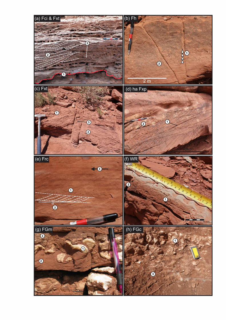
3
1
1
3
2
3
2
1
(a) Fci & Fxt (b) Fh
(c) Fxt
(e) Frc
(g) FGm (h) FGc
(f) WR
(d) ha Fxp
2
1
1
3
2
150mm
21
1
2
0 10 mm
a
3
2
1
2 m

3
2
2
1
1
(I) Preserved ripple (j) Fxt
(k) Frc, sub- to critical angle
(m) FHiss
(o) FHiss (p) GC
(n) FHiss
(l) Fm, graded bedding
1
3
2
1
1
2
0
2 m
1 m
2
1
0.4 m
3
3
2
a1
2

mud vf f
Sandm c vc
silt
gran
peb
mud vf f
Sandm c vc
silt
gran
peb
mud vf f
Sandm c vc
silt
gran
peb25
30
35
40
45
50
mud vf f
Sandm c vc
silt
gran
peb0 0
5 5
10 10
15 15
20 20
25 25Parriott Basin - Parriott Mesa SE Parriott Basin - The Priest Big Bend Basin - Big Bend Camp C KeyFisher Basin - Mile 25.5
mud vf f
Sandm c vc
silt
gran
peb
mud vf f
Sandm c vc
silt
gran
peb
Massive sandstone (Fm)
Cross-bedded sandstone(Fxt, Fxp)
Ripple-laminated sandstone(Frc, Fxl, Frw)
Gypsum-clast bearinghorizons (FGm, FGc)
Deformed bedding(Fd)
Interbedded Heterolithicstrata, sand-prone (FHiss)
Interbedded Heterolithicstrata, silt-prone (FHiss)
Horizontally laminatedsandstone (Fh)
Representative Sedimentary Logs - Salt Anticline Region
mud vf f
Sandm c vc
silt
gran
peb
mud vf f
Sandm c vc
silt
gran
peb50 50 50
55 55 55
60 60 60
65 65 65
70 70 70
75 75 75
mud vf f
Sandm c vc
silt
gran
peb
PC®340°
PC®311°
PC®280°
PC®280°
PC®300°
PC«325°
WRC«020°PC®338°
PC®309°
PC®314°
PC®304°
PC«314°
25
30
35
40
45
50
25
30
35
40
45
50
0
5
10
15
20
25
320°PC®
308°PC®
mud vf f
Sandm c vc
silt
gran
peb25
30
35
40
45
50
mud vf f
Sandm c vc
silt
gran
peb
75
mud vf f
Sandm c vc
silt
gran
peb0
5
10
15
20
25
met
res
met
res
met
res
met
res
65
70
PC®295°
PC®292°
PC®335°

mud vf f
Sandm c vc
silt
gran
peb
mud vf f
Sandm c vc
silt
gran
peb
mud vf f
Sandm c vc
silt
gran
peb25 25 25 25
30 30 30 30
35 35 35 35
40 40 40 40
45 45 45 45
50 50 50 50
mud vf f
Sandm c vc
silt
gran
peb0 0 00
5 5 55
10 10 1010
15 15 1515
20 20 2020
25 25 2525Truck Cab Log Clay Hills Divide Mile 87 Copper Point Log
mud vf f
Sandm c vc
silt
gran
peb
mud vf f
Sandm c vc
silt
gran
peb
Representitive Sedimentary Logs - White Rim Region
mud vf f
Sandm c vc
silt
gran
peb
mud vf f
Sandm c vc
silt
gran
peb50
PC→298°
PC→310°
Scree
Rd ScreeScree
PC→358°
PC→357°
PC→330°
met
res

Multi-storey channel elements, &sheet-like heterolithic elements
Single-storey channel elements, &sheet-like heterolithic elements
Close-up view of sheet-like heterolithic elements
Low-relief basal incissionSheet-like heterolithic strata
Multi-storeymulti-lateralchannel elements
S.S. channelelement
Sheet-likeheterolithic elements
Sheet-likeheterolithic elements(obscured by scree)
Single-storey elementcan be traced > 3 kmlaterally
1m
2m
Fine-grained sandstone with climbing-ripple strata
Homogeneoussiltstones interbeddedwith Fm or Frc fine-grained sandstones
0.2 m
Conical-shapeddewatering structure
a
b
c d
Tape measure = 1 m

Multi-storey channel elements, &sheet-like heterolithic elements
Multi-storey channel elements, &sheet-like heterolithic elements
Channel margin, with incisioninto heterolithic strata
Sand-prone sheet-likeheterolithic element
Silt-prone sheet-likeheterolithic element
Laterally extensivechannel elements
Chute element
Sand-proneheterolithic elements
Multi-storeychannel elements
2 m
2 m
Tape measure = 1.5 m
e
f
g

Architectural elements: typical geometry, facies successions and associations observed in outcrop
m
0 SltSst
1
2
3
4
5
f m c Pb
0 metres 50
Partially-confined over-spill elementsGenerally sheet-like form though with minor scour surfaces in some cases; common in areas between F1 channel elements and salt-walls; composed of coarse-grained, horizontally-laminated, massive, climbing ripple-laminated, trough cross-bedded sand; represent partially confined flow events.
Fluvial Channelised
Fluvial non-channelised (overbank)
0 SltSst
1
2
m
3
4
5
f m c Pb
Fxt
Fxt
Fxt
Frc
Multi-storey, multi-lateral amalgamatedchannel-fill complex
F1Vertically and laterally amalgamated, generally restricted to the Ali Baba and Parriott Members; most prevalent in the Fisher Basin where sediment supply was greatest.
0 metres 20
Fxt
Fxt
Fxt
Fxt
Fxt
FxpFci
Fce
m
0 SltSst
2
4
6
8
f m c Pb
Fhiss
Fhiss
Fxt
Fxt
Single-storey, multi-lateral channel-fillcomplex
F2Laterally but not vertically amalgamated; common in the Sewemup Member and the central parts of the Parriott Basin in the Parriott Member; infill finer-grained than that of F1 elements, possibly reflecting accumulation in more distal locations.
0 metres 50
FxtFxtFxt
Single-storey, unilateral channel element(intraformational clast-infill)
F3
0 metres 5
m
0 Slt
3
2
1
f m c PbSst
FciFci
Associated with F1 & F2 elements in locations adjacent to salt walls; fill is typically of intra-formational clasts up to 0.2 m in diameter; clasts derived locally, either by physical reworking of exposed salt-wall flanks or of overbank areas.
Massive (structureless) & horizontally laminated channel-fill element
F4
F4
F6
F7
F8
F9
F5
Occur laterally adjacent to F1 & F2 elements in locations proximal to salt walls; composed of massively-bedded sand at base (Fm); overlain by horizontally-laminated sand (Fh); implies high-energy, initially erosional flows; rapid sedimentation via suspension settling.
m0 Slt
9
6
3
f m c PbSst
0 metres 100
Fh
Fm
Frc
Fh
Frc/Fxl
Fm
Sheet-like heterolithic elementLaterally extensive sheet-like bodies composed of interbedded silts and fine-grained sands; deposited in response to the dispersion of non-confined flood waters across floodplain areas; floods sourced via overflow from main channels or via overland flow during rain storm events.
m
Sst0 Slt
1
2
3
f m c Pb
0 metres 200
FrwFruFmFxlFslt
Frc
FhFxtFxt
Fslt
Frc/Fxl
Frw
Fm
Fh
Gypsum-clast bearing elementPredominantly occur as sheet-like conglomeratic elements interbedded with sheet-like heterolithic elements (F5); common in the vicinity of the Castle Valley salt wall; reworking of gypsum detritus derived from exposed and eroding salt walls by non-confined flood waters (high-energy flows).
m
0 SltSst
0.5
1.0
1.5
2.0
f m c Pb
0 metres 200
Frc
FGm
FGc
FGmFGc
FGc
Frc/FxlFhha Fxp/Fxt
FdFm
Fslt FrcFh
FdFm
haFxp
Fxt/haFxp
Minor gravel chute elementSmall scale chute; originate from the convergence of non-confined flows in overbank settings; generally shallow (<0.3 m deep) and narrow (<20 m wide); typically filled with massive sets of medium-grained sandstone to granulestone (Fm) or crudely developed cross-bedding (ha Fxp/Fxt).
Fm
Fxp/Fxt
0 metres 5
0 SltSst
0.5
1.0
1.5
2.0
f m c Pb
Pond elementSheet-like body containing symmetric wave- ripple strata, overlain by thin siltstones; formed in response to wind blowing across bodies of standing water in floodplain areas; siltstones overlying wave-ripple strata represent the accumulation of loess.
m
Sst0 Slt
0.3
0.6
0.9
f m c Pb
0 metres 5
FrwFslt
Frw Fslt

Element F1:Multi-storey, multi-lateral channel elementsDirection of flow to NW
Viewed parallel to palaeoflow,migrating meso-forms generate sets of
high-angle-inclined planar-tabularcross-bedding (ha Fxp)
Coset groupsdefined by erosionalbasal surfaces (5th order surface) where overlying channel elements have incised into underlying elements; commonpebble lags consisting of intraformational(Fci) and extraformational(Fce) clasts Viewed perpendicular to
palaeoflow, migrating meso-formsgenerate sets of trough cross-bedding (Fxt)
Sinuous-crested dune-scale bedforms
accumulated to generate sets and compound co-sets
of trough cross-bedding (Fxt)
Progressive aggradation of the succession preserves successive horizons of multi-lateral, overlappingchannel bodies, forming F1 channel elements
50 - 400 m unspecified
3 - 10 m
Element F2: Single-storey, multi-lateral channel elementsDirection of flow to NW
Viewed parallel to palaeoflow,migrating meso-forms preserve
sets of high-angle-inclined tangentialplanar cross-bedding (ha Fxp)
F2 channel elementscommonly rework theunderlying strata, preservingbasal lags of intraformationalpebbles (Fci)
Viewed perpendicular to palaeoflow, down-flow accreting meso-forms result in preservedsets of trough cross-bedding (Fxt)
F2 channel elements are usually underlain
by non-confined sheet-likeelements (F5)
Multi-lateral channel elements are overlain byF5 elements themselves composed of climbing-ripple strata (Frc & Fxl) and representingwaning flow and eventual abandonment of thechannel complex
50 - 400 m unspecified
0.5-3 m
Element F3: Single-storey, unilateral intraformational-clast fill channel element
Direction of flow to NW
Fci pebble clast-filled channel elementscontain clasts derived from thelocalised reworking of surroundingdeposits. The source of this reworkedmaterial may have been the uplifted flank ofan adjacent salt wall, or material eroded fromsurrounding overbank areas
F3 elements tend to cut steep-sided channel bodies
F3 channel elementnested within F1 or F2
channel elements
Fci pebble clast-filled channel elements are overlain by F5elements themselves composed of climbing-ripplestrata (Frc & Fxl) and representing waningflow and eventual abandonment of the channel complex
5 - 15 munspecifi
ed
0.5-1.5 m
a
b
c

0.5 - 1 m
50 - 200 m unspecified
Element F6: Non-confined heterolithic sheet-like deposits with gypsum clast horizonsDirection of flow to NW
Element F6 is commonlyassociated with F5 elements
Gypsum clast-bearing horizons occur asboth matrix- and clast-supported deposits(FGm and FGc); typically associated withheterolithic sheet-like elements (F5)
Gypsum-clast-bearinghorizons associated with
sandier units indicating theirtransport during higher-energy
flow events
Low-abundance pioneer species colonising floodplain in aftermath of flood event. Vegetation is too sparse to encourage development of palaeosols.
Rare occurrence ofdessication cracks
400 + m unspecified
Sheet-like elements consisting of horizontallylaminated sandstone (Fh), climbing-ripplestrata (Frc/Fxl) and somemassively bedded siltstones(Fhiss)
Element F7: Partially-confined over-spill elementsDirection of flow to NW
Higher flowvelocities in the
partially confined overbankareas result in coarser-grained
sediment transported and accumulating in sheet-like
semi-confined over-spill elementsF7 elements typicallyoccur between F1 channel elements and uplifted salt walls
Thin (0.2 - 0.5 m) chutes filledwith coarse-grained high-angleFxp or Fxt are commonlyassociated with these elements
Uplifted salt-wall acts to confine over-spill water and sediment,resulting in a partially confined flow (Salt-wall geometries are exaggerated)
0.5-2 m
50 - 200 m unspecified
Element F5: Non-confined heterolithic sheets-like elementsDirection of flow to NW
Flood watersmay converge
into confined chute elements(F7) within which they may flow
for several tens of metres beforedissipating. Chute fills are typically
massive (Fm), though can contain crude cross-bedding (Fxt or Fxp)
Pond elementsaccumulate in aftermath of flooding events. Preservationof symmetrical wave-ripple strata (Frw) generated by wind action are common
Sheet-like elements consisting typically ofasymmetric climbing-ripple-laminated sands (Frc) with rare massive sandstones (Fm) and dark laminated massivesiltstones. Deposits collectively form facies Fhiss
Low-abundance pioneer species colonising floodplainin aftermath of flood event. Biogenic activity is too limited to encourage developmentof mature palaeosols. Root traces can be expressedas mottled fabric
0.5-1 m
d
e
f

Pond ElementFormed in topographic lows on thealluvial plain in the aftermath of previousflood event. Wind action in pond results in formation of wave-ripple strata, and loess
Chute ElementFormed in by the convergence of flood watersbefore dissipating after 10s - 100s m. ContainsFm, and poorly developed Fxp and Fxt Micro-scale (<1 m) topographic highs,
where flood water did not inundate.These can be depicted as small scale
onlapping relationships in preserved heterolithic successions
Non-confined water:water from shallow &poorly defined channelsoverflow onto alluvialplain after substantialrain-fall
Sheet-like heterolithic ElementsLaterally extensive sheet like elementscontaining interbedded fine sandstones(Fm, Fh, Frc/Fxl) and homogeneous siltstones
Single-storey, Multi-lateral Channel ElementsLaterally extensive, shallow channel-fill elementsamalgamated into a channel complex
Braided channelsShallow (0.5-2 m deep) containing meso-scaledown-stream accreting elements (dune-scale)depicted as trough cross bedding and somelaterally accreting elements depicted as lowangle planar cross-bedding
General Depositional Model: Channelised & Non-Channelised Elements
5 km
Direction of flow to NW
unspecified
10 m

Fisher basinParriott basin
Fisher Valley salt wall
Multi-Storey Multi-Lateral Channel Elements (F1)Laterally amalgamated channel elementsbecome vertically amalgamated as the fluvialsystem aggrades
Sand-prone mini-basin (Fisher Basin)Sand-prone basin is characterised by high ratio of sand to argillacious material. These basins tend to have high proportions of channelised, and associated elements
Sand-poor mini-basin (Parriott Basin)Sand-poor basin is characterised by lowratio of sand to argillacious material. The fill of these basins tent to be filled with non-confined elements and associated elements
Partially-confined over-spill elementsForm between channelised elementsand salt walls which act to partiallyconfine water, increasing watervelocity, allowing larger grainedmaterial to be transported
Single-storey, Multi-lateral Channel ElementsLaterally extensive, shallow channel-fill elementsamalgamated into a channel sheet . These elements are generally isolated within heterolithicsheet-like elements
Heterolithic Sheet-like ElementsLaterally extensive and vertically
amalgamated fluvial elements can represent over 80% of the stratigrahic
succession in some parts of sand-poor mini-basinsChute and Pond ElementsMinor elements are common in sand-poor mini-basins, representing convergence and disserpation of non-confined flood waters, and the pooling of flood water in the aftermath of flood events
Depositional Model: Fisher Basin & Parriott Basin deposition styleDirection of flow to NW

80 m
70 m
45 m
Ali Baba Mbr.
Ali Baba Mbr.
Ali Baba Mbr.
Tenderfoot Mbr.
Tenderfoot Mbr.
Tenderfoot Mbr.
Cutler Gp.
Sewemup Mbr.
Sewemup Mbr.
Sewemup Mbr.
Parriott Mbr.
Parriott Mbr.
White Rim Sandstone (Cutler Gp.)
Chinle Fm.
Chinle Fm.
60 m
Outcrop Expression: Fisher basin (Fisher Valley)
Outcrop Expression: Parriott basin (Castleton Tower)
Outcrop Expression: Big Bend basin (Western Flank of C.V. salt wall)

Regional Depositional Model: White Canyon Region
Cedar Mesa Sandstone
Organ Rock Formation
Direction of Flow to NW
Upstream limit ofMoenkopi Formation
deposition
Defiance Upwarp acted as the region of provenance
for the Moenkopi Formation in theWhite Canyon Region. Most of the Moenkopi Formation in this area is
likely to be composed of reworked Permianstrata
UndifferentiatedPermian
strata
Micro-topography generated bydifferential compaction (0.1m -5m in relief) can result in areas oftemporary non-deposition on the alluvial plain
Single Storey Channel ElementsIndividual channel-fill elements can coalesce to form single-storey channel belt elements that can be isolated fromother channel belts by micro-topograph,or distance or may amalgamate
Head of advancingflood waters
Pond ElementTopographic lows accumulate water in theaftermath of flood events, forming pond elements
Sheet-like Heterolithic ElementsLaterally extensive and vertically amalgamated sheet-like elements are the preserved expression of non-confined flood waters.Successive flows will result in thevertical amagamation of these elements
Hoskinini Mbr.
Torrey Mbr.
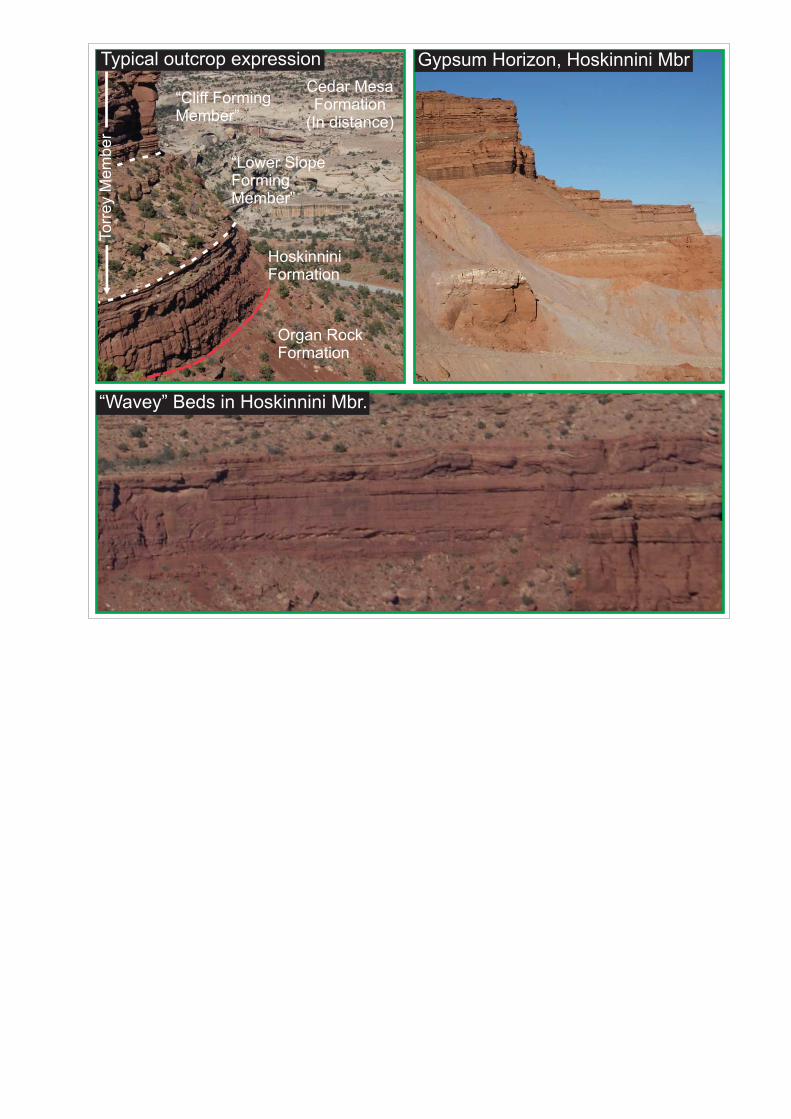
HoskinniniFormation
Lower SlopeFormingMember
Cliff FormingMember
Torr
ey M
embe
r
Organ RockFormation
Cedar MesaFormation
(In distance)
Gypsum Horizon, Hoskinnini MbrTypical outcrop expression
Wavey Beds in Hoskinnini Mbr.

Salt Anticline RegionMultiple sediment supply areas: Uncompahgre and San Luis uplifts. Salt walls control distribution of sediment in the evolving mini-basins, resulting in contrasting stratigraphic successions developing in adjacent mini-basins. Thickness of Moenkopi Fm is extremely variable due to differential rates of subsidence within the various mini-basins
Uncompahgre & San Luis UpliftThese two uplifted areas are composed ofcrystalline basement rock, and persisted as significant topographic features until late in the history of Moenkopi deposition.
Defiance UpwarpAn upland area throughout the history ofMoenkopi Fm accumulation. Permian age stratain the area are likely reworked from this area anddeposited as the Moenkopi Formation.
San Luis Uplift
Exorheic channel beltsThese channel belts drainedto a sea-way, the shorelinefor which lay to thenorthwest.
Endorheic channel beltsThese channel belts terminatewithin the continental realm dueto transmission losses before thefluvial system reaches the sea-way.
Limit of MoenkopiFm deposition
White Canyon RegionRate of Moenkopi accumulation is controlled by slowtectonic subsidence, resulting in a relatively thin successionaccumulating over broad area. Sediment accumulating inthis region are mainly derived from the Defiance Upwarp.
Permian strataPermian strata beyond
the area of Moenkopi Fmdeposition may have contributed
significant volumes of detritusinto fluvial systems draining acrossregion of Moenkopi accumulation.
Regional Depositional Model: Salt Anticline Region & White Canyon RegionDirection of Flow to NW
Uncompahgre Uplift
Defiance Uplift
Undifferentiated Cutler Group
Cedar Mesa Sandstone
Organ Rock Formation
De Chelly Sandstone


![Climate Change Adaptation Practices by Ruminant Livestock ...the spectrum of livestock versus adaptation methods to climatic change, has been identified by many researchers [29,30]](https://img.pdfslide.us/doc/110x75/5e7245a21900ce30470549f9/climate-change-adaptation-practices-by-ruminant-livestock-the-spectrum-of-livestock.jpg)