Embed Size (px)
Citation preview

Client NOPSA
Document Title INVESTIGATION INTO THE UNCONTROLLED RELEASE OF HYDROCARBONS FROM THE MONTARA WELLHEAD PLATFORM ON THE 21 AUGUST 2009 – EXPERT WITNESS REPORT
SW Doc Ref. RPT-30291-NOPSA-001 VOLUME 1
Client Reference No./Objective ID
N-11000-FM0621/A88649
Date 17 February 2012
All Rights Reserved
2012, Stuart Wright Pte Ltd
Liability Disclaimer
While every effort will be made to ensure that the information provided by Stuart Wright Pte Ltd in this report is accurate and up-to-date, Stuart
Wright Pte Ltd makes no warranty or undertaking (expressed or implied), nor does it assume any legal liability (direct or indirect) or responsibility, for
the application of any information.

INVESTIGATION INTO THE UNCONTROLLED RELEASE OF HYDROCARBONS FROM THE MONTARA WELLHEAD PLATFORM ON THE 21 AUGUST 2009
EXPERT WITNESS REPORT
17 FEBRUARY 2012 RPT-30291-NOPSA-001 VOLUME 1 REV0 PAGE 2
REVISION HISTORY
Revision Date Description Author Reviewer Approver
Rev A 17 February 2012 First Issue CS SF CS
CURRENT REVISION: Rev A
Name Position Signature Date
Prepared By:
Colin Stuart Managing & Technical Director of
Stuart Wright Pty Ltd 17 February 2012
Reviewed By:
Sean Foo Well Engineer 17 February 2012
Approved By:
Colin Stuart Managing & Technical Director of
Stuart Wright Pty Ltd 17 February 2012
DISTRIBUTION LIST
Company Name Number of Hard Copies Number of Electronic Copies
SWPL INTERNAL COPY 2 (TWO) 1 (ONE)
NOPSA EXTERNAL COPY 1 (ONE) 1 (ONE)

INVESTIGATION INTO THE UNCONTROLLED RELEASE OF HYDROCARBONS FROM THE MONTARA WELLHEAD PLATFORM ON THE 21 AUGUST 2009
EXPERT WITNESS REPORT
17 FEBRUARY 2012 RPT-30291-NOPSA-001 VOLUME 1 REV0 PAGE 3
TABLE OF CONTENTS
1. INTRODUCTION ........................................................................................................ 11
1.1 Project Description ................................................................................................... 11
1.2 Overall Report Structure ........................................................................................... 11
1.3 Scope of Work ........................................................................................................... 13
1.4 Input Data Summary ................................................................................................. 18
1.4.1 Kick-Off Meeting ................................................................................................ 18
1.4.2 Technical Queries .............................................................................................. 18
1.4.3 Data Received from NOPSA ............................................................................... 19
1.4.4 Statement on Quality of Input Data .................................................................. 19
1.4.4.1 Montara WHP Accurate Drawings .............................................................. 19
1.4.4.2 PTTEPAA Daily Drilling Reports ................................................................... 20
1.4.5 Data Requested but Not Received from NOPSA ............................................... 20
1.4.5.1 Schematics of 9 5/8” and 13 3/8” PCCC ...................................................... 20
2. BACKGROUND OF MONTARA DEVELOPMENT PROJECT ............................................ 21
2.1 Discovery to Temporary Abandonment of H1-ST1 .................................................. 21
2.1.1 Ownership ......................................................................................................... 21
2.1.2 Facilities for the Montara Field Development Project ...................................... 22
2.1.3 Planning and Construction Phases of H1/H1-ST1 ............................................. 25
2.1.3.1 Planning Phase H1/H1-ST1 .......................................................................... 25
2.1.3.2 Construction Phase of H1/H1-ST1 .............................................................. 26
2.1.4 Suspension Phase of H1-ST1 ............................................................................. 27
2.2 Tie Back and Re-entry of Montara WHP Wells ......................................................... 30
2.2.1 Tieback and Re-entry of H1-ST1 ........................................................................ 30

INVESTIGATION INTO THE UNCONTROLLED RELEASE OF HYDROCARBONS FROM THE MONTARA WELLHEAD PLATFORM ON THE 21 AUGUST 2009
EXPERT WITNESS REPORT
17 FEBRUARY 2012 RPT-30291-NOPSA-001 VOLUME 1 REV0 PAGE 4
2.2.2 Well Flow in H1-ST1 ........................................................................................... 31
2.3 Factual Time Line of Events – H1-ST1 Planning and Approval Stage ....................... 31
2.4 Factual Time Line of Events – H1-ST1 Construction Stage ....................................... 34
2.5 Factual Time Line of Events – H1-ST1 Stage 2 Suspension ....................................... 36
2.6 Factual Time Line of Events – H1-ST1 Re-Entry Stage .............................................. 38
2.7 Official and Internal Submissions by Coogee Resources/ PTTEPAA ......................... 40
3. GOOD OILFIELD PRACTICE FOR WELLS ...................................................................... 42
3.1 Reference Standards ................................................................................................. 42
3.2 Cementation - Zonal Isolation .................................................................................. 42
3.3 Well Planning and Design Considerations ................................................................ 43
3.3.1 Evaluation of Well for Flow Potential ................................................................ 43
3.3.2 Expected Wellbore Pressure and Temperature ................................................ 44
3.3.3 Expected Well Conditions.................................................................................. 45
3.3.4 Cementing Plan ................................................................................................. 45
3.3.5 Barrier Design .................................................................................................... 46
3.4 Cementing Practices and Factors Affecting Cementing Success .............................. 47
3.4.1 Slurry Design and Testing .................................................................................. 47
3.4.1.1 Lead and Tail Cement .................................................................................. 47
3.4.1.2 Thickening Time .......................................................................................... 48
3.4.1.3 Fluid Loss ..................................................................................................... 48
3.4.1.4 Static Gel Strength ...................................................................................... 48
3.4.1.5 Compressive and Sonic Strength ................................................................ 50
3.4.2 Wellbore Preparation and Conditioning ........................................................... 51
3.4.2.1 Hole Quality ................................................................................................. 51

INVESTIGATION INTO THE UNCONTROLLED RELEASE OF HYDROCARBONS FROM THE MONTARA WELLHEAD PLATFORM ON THE 21 AUGUST 2009
EXPERT WITNESS REPORT
17 FEBRUARY 2012 RPT-30291-NOPSA-001 VOLUME 1 REV0 PAGE 5
3.4.2.2 Rathole ........................................................................................................ 51
3.4.2.3 Centralizer Program .................................................................................... 51
3.4.3 Cement Job Execution ....................................................................................... 52
3.4.3.1 Pipe Movement ........................................................................................... 52
3.4.3.2 Displacement .............................................................................................. 52
3.4.4 Post Cementing Evaluation ............................................................................... 52
4. P&A AND SUSPENSION REQUIREMENTS ................................................................... 54
4.1 Facts Pertinent with respect to the PSLA ................................................................. 54
4.1.1 Objectives of the Petroleum (Submerged Lands) (Management of Well
Operations) Regulations 2004 ......................................................................................... 55
4.1.2 Requirements for Specific Well Activities as part of the Petroleum (Submerged
Lands) (Management of Well Operations) Regulations 2004 ......................................... 55
4.1.3 Impact of Well Integrity hazard or increased risk not identified in well
operations management plan as part of the Petroleum (Submerged Lands)
(Management of Well Operations) Regulations 2004 .................................................... 56
4.2 Relevance of the PSLA for P&A and Suspension Requirements ............................... 56
4.3 P&A and Suspension Requirements of NORSOK Standard D-010 ............................ 57
4.3.1 Barriers .............................................................................................................. 57
4.3.1.1 Fluid Column ............................................................................................... 60
4.3.1.2 Casing Cement............................................................................................. 61
4.3.1.3 Cement Plug ................................................................................................ 62
4.3.1.4 Drilling BOP ................................................................................................. 63
4.3.1.5 Casing Float Valves ...................................................................................... 64
4.3.1.6 Corrosion Caps ............................................................................................ 64

INVESTIGATION INTO THE UNCONTROLLED RELEASE OF HYDROCARBONS FROM THE MONTARA WELLHEAD PLATFORM ON THE 21 AUGUST 2009
EXPERT WITNESS REPORT
17 FEBRUARY 2012 RPT-30291-NOPSA-001 VOLUME 1 REV0 PAGE 6
4.3.2 Sidetracking, Abandonment and Long Term Suspension ................................. 65
4.3.2.1 Suspension .................................................................................................. 65
4.3.2.2 Temporary Abandonment ........................................................................... 65
4.3.2.3 Permanent Abandonment .......................................................................... 65
4.3.2.4 Sidetracking ................................................................................................. 66
4.4 P&A and Suspension Requirements of the Code of Federal Regulations (CFR) in the
Outer Continental Shelf ....................................................................................................... 67
4.4.1 Barriers .............................................................................................................. 67
4.4.2 Abandonment and Long Term Suspension ....................................................... 67
4.4.2.1 Long Term Suspension ................................................................................ 67
4.4.2.2 Abandonment ............................................................................................. 69
4.5 P&A and Suspension Requirements of PTTEPAA Well Construction Standards ...... 70
4.5.1 Barriers .............................................................................................................. 70
4.5.2 Abandonment and Long Term Suspension ....................................................... 70
4.5.2.1 Long Term Suspension ................................................................................ 70
4.5.2.2 Abandonment ............................................................................................. 71
5. RISK ASSESSMENT AND MANAGEMENT .................................................................... 72
5.1 Introduction .............................................................................................................. 72
5.2 Definitions ................................................................................................................. 73
5.3 What is Risk Assessment? ......................................................................................... 75
5.4 Risk Assessment Methods ........................................................................................ 78
5.5 Available Risk Assessment Techniques ..................................................................... 81
5.6 Risk Management ..................................................................................................... 83
5.7 Risk Assessment Methods Applied by PTTEPAA and Atlas Drilling .......................... 85

INVESTIGATION INTO THE UNCONTROLLED RELEASE OF HYDROCARBONS FROM THE MONTARA WELLHEAD PLATFORM ON THE 21 AUGUST 2009
EXPERT WITNESS REPORT
17 FEBRUARY 2012 RPT-30291-NOPSA-001 VOLUME 1 REV0 PAGE 7
5.7.1 PTTEPAA Risk Assessment Methods for Facilities Construction and Installation,
SIMOPS, and WHP Hookup and Pre-Commissioning ...................................................... 86
5.7.2 PTTEPAA Risk Assessment Methods for Well Construction Management System
........................................................................................................................... 89
5.7.3 Atlas Drilling Risk Assessment Methods for Routine and Emergency Operations
on Facility ........................................................................................................................ 90
5.7.4 PTTEPAA Management of Change Process ....................................................... 92
5.8 Risk Identification via WAiT© .................................................................................... 94
6. References, Codes, Standards, Regulation and Statutory Requirements .................... 95

INVESTIGATION INTO THE UNCONTROLLED RELEASE OF HYDROCARBONS FROM THE MONTARA WELLHEAD PLATFORM ON THE 21 AUGUST 2009
EXPERT WITNESS REPORT
17 FEBRUARY 2012 RPT-30291-NOPSA-001 VOLUME 1 REV0 PAGE 8
List of Figures
Figure 1: Montara WHP Mezzanine Deck Well Slots Layout .................................................... 23
Figure 2: Stage 1 Suspension Plan found on Pg 23 of “Submission – PTTEP Document
Submission – Regulatory Approvals -3.pdf” ............................................................................. 28
Figure 3 : Stage 2 Suspension Plan found on Pg 32 of “Submission – PTTEP Document
Submission – Regulatory Approvals -3.pdf” ............................................................................. 29
Figure 4 : Timeline of Events - H1-ST1 @ Planning and Construction Stage............................ 33
Figure 5 : Timeline of Events - H1-ST1 @ Construction Stage ................................................. 35
Figure 6 : Timeline of Events - H1-ST1 @ Suspension Stage .................................................... 37
Figure 7 : Timeline of Events - H1-ST1 @ Re-Entry Stage ........................................................ 39
Figure 8: Interpretation of API 65-2 Static Gel Strength Concept for Oilfield Cement Slurries ...
.................................................................................................................................................. 50
Figure 9: NORSOK D-010 Methodology for defining the requirements/guidelines for WBE .. 59
Figure 10: Fluid Column Well Barrier Element Acceptance Table (Ref: Clause 15.1 NORSOK D-
010 Standard, Rev 3, 2004) ...................................................................................................... 60
Figure 11: Casing Cement Well Barrier Element Acceptance Table (Ref: Clause 15.22 NORSOK
D-010 Standard, Rev 3, 2004) ................................................................................................... 61
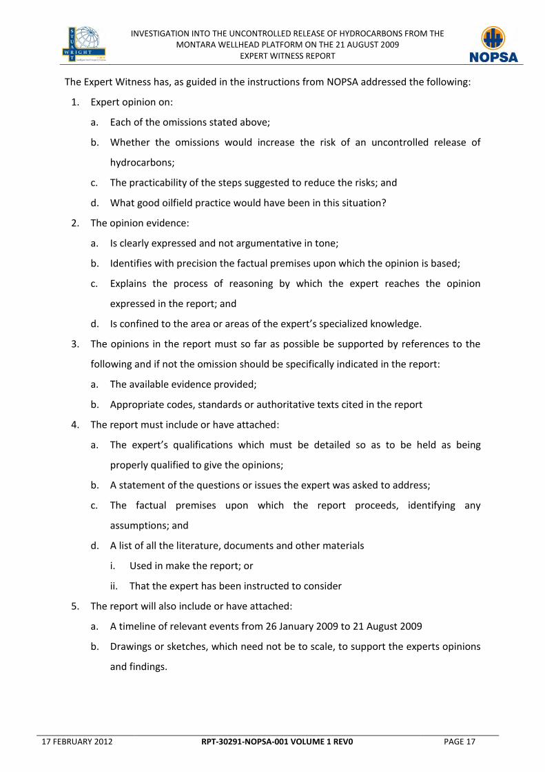
Figure 12: Cement Plug Well Barrier Element Acceptance Table (Ref: Clause 15.24 NORSOK
D-010 Standard, Rev 3, 2004) ................................................................................................... 62
Figure 13: Drilling BOP Well Barrier Element Acceptance Table (Ref: Clause 15.4 NORSOK D-
010 Standard, Rev 3, 2004) ...................................................................................................... 63
Figure 14: Casing Float Valves Well Barrier Element Acceptance Table (Ref: Clause 15.41
NORSOK D-010 Standard, Rev 3, 2004) .................................................................................... 64
Figure 15: The Risk Management Process ............................................................................... 75

INVESTIGATION INTO THE UNCONTROLLED RELEASE OF HYDROCARBONS FROM THE MONTARA WELLHEAD PLATFORM ON THE 21 AUGUST 2009
EXPERT WITNESS REPORT
17 FEBRUARY 2012 RPT-30291-NOPSA-001 VOLUME 1 REV0 PAGE 9
Figure 16: Montara Development Project Safety Case Documentation (Ref: ([EV0000008]
Coogee Resources-Montara Development-Safety Case For Construction And Installation) .. 87
Figure 17: Coogee Resources HSEMS Continuous Improvement Cycle (Ref: [EV0000008]
Coogee Resources-Montara Development-Safety Case For Construction And Installation) .. 88
Figure 18: Wells Risk Assessment and Management Process (Ref: [EV0000050] PTTEPAA
Management Standard: Well Construction Management Framework Standard ID) .............. 89
Figure 19: Seadrill Risk Management Process.......................................................................... 91
Figure 20 : PTTEP Management System Framework, Develop and Service Wells Process ..... 93

INVESTIGATION INTO THE UNCONTROLLED RELEASE OF HYDROCARBONS FROM THE MONTARA WELLHEAD PLATFORM ON THE 21 AUGUST 2009
EXPERT WITNESS REPORT
17 FEBRUARY 2012 RPT-30291-NOPSA-001 VOLUME 1 REV0 PAGE 10
List of Tables
Table 1: Summary of Technical Queries ................................................................................... 18
Table 2: Summary of Data received from NOPSA .................................................................... 19
Table 3: Description of Drilling Programme Revisions ............................................................. 25
Table 4: Drilling Programme Description of Batched Drilling Sequence of Operations for GI,
H1 and H4 ................................................................................................................................. 26
Table 5 : List of Official Submissions to NTDA by PTTEPAA from Documents Reviewed ........ 40
Table 6 : List of Internal Submissions by PTTEPAA from Documents Reviewed ...................... 41
Table 7: NORSOK D-010 Function and Type of Well Barriers................................................... 58
Table 8: Plugging Requirements as per 250.1715 .................................................................... 69
Table 9: PTTEPAA Well Construction Standard Barrier(s) Verification .................................... 70
Table 10: PTTEPAA Long Term Suspension Barrier Types ........................................................ 71
Table 11: PTTEPAA Abandonment Requirements.................................................................... 71
Table 12: List of Risk Assessment Methods and Applicability of Tools .................................... 82
Table 13: Codes and Standards Applicable for Expert Witness’s Investigation ....................... 96
Table 14: Regulations and Statutory Requirements Applicable for Expert Witness’s
Investigation ............................................................................................................................. 97

INVESTIGATION INTO THE UNCONTROLLED RELEASE OF HYDROCARBONS FROM THE MONTARA WELLHEAD PLATFORM ON THE 21 AUGUST 2009
EXPERT WITNESS REPORT
17 FEBRUARY 2012 RPT-30291-NOPSA-001 VOLUME 1 REV0 PAGE 11
1. INTRODUCTION
1.1 Project Description
On the 29 September 2011, the “National Offshore Petroleum Safety Authority” (NOPSA) of
Australia appointed Mr. Colin Stuart, Managing and Technical Director of “Stuart Wright Pty
Ltd” (SWPL) as Expert Witness in relation to NOPSA’s investigation into the uncontrolled
release of hydrocarbons from the Montara Jacket Platform on the 21 August 2009.
The role of Expert Witness as defined by NOPSA is:
1. to thoroughly review and analyze all documents provided by NOPSA;
2. to form an expert opinion on nine (9) omissions identified by NOPSA on the part of the
Operator “PTTEP Australiasia (Ashmore Cartier) Pty Ltd” (PTTEPAA) that led to the
eventual uncontrolled release of hydrocarbons; and
3. to document the findings within a written report.
This document is “Volume 1” of the full report, and is one of a total three (3) volumes
submitted to NOPSA on Friday 17 February 2012, to meet the obligations of the Expert
Witness.
The report is confined to the areas of specialized knowledge of the Expert Witness, with
clear, supported and cited references from the available evidence provided by NOPSA, and
quoting also from codes and industry standards utilized to help define the term “good
oilfield practice”.
1.2 Overall Report Structure
1. The Expert Witness’s opinion on nine (9) omissions identified by NOPSA on the part of
the Operator PTTEPAA that led to the eventual uncontrolled release of hydrocarbons is
presented in a written report comprising of three (3) volumes that must be read
together for completeness:

INVESTIGATION INTO THE UNCONTROLLED RELEASE OF HYDROCARBONS FROM THE MONTARA WELLHEAD PLATFORM ON THE 21 AUGUST 2009
EXPERT WITNESS REPORT
17 FEBRUARY 2012 RPT-30291-NOPSA-001 VOLUME 1 REV0 PAGE 12
Volume 1
Volume 1 contains an introduction and states the background regarding the appointment of
the Expert Witness.
Volume 1 also includes a “Timeline of relevant facts and events” focusing on the approvals
PTTEPAA received from the NTDRDPIFR to undertake Montara Development activities from
commencement of operations to the H1ST1 blowout event.
Finally, Volume 1 provides the reader with background information relating to good oilfield
practice and industry standards in the following areas of direct relevance to the
investigation:
1. Cementation - Zonal isolation in Oil and Gas Wells;
2. Suspension, and Plug and Abandonment (P&A); and
3. Risk Assessment.
Volume 2
Volume 2 documents the Expert Witness’s response to each question posed by NOPSA
relating to each of the nine (9) omissions identified by NOPSA on the part of the Operator
PTTEPAA, which led to the eventual uncontrolled release of hydrocarbons. This document is
structured in nine (9) individual chapters, each addressing the nine omissions in sequential
order.
Volume 3
Volume 3 addresses the Well Integrity condition of the H1-ST1 well at various critical stages
of construction, suspension, and re-entry. The Expert witness has used the proprietary Stuart
Wright Pte Ltd’s WAiT© (Well Assessment of Integrity Tool) to explain the condition of the
H1-ST1 well at these different stages. The Well Integrity condition is shown in a visual chart
format using the WAiT© process. There are two WAiT© charts in A0 size.
The SWPL WAiT© process is a comprehensive review platform used to drive a “forensic”
assessment of the candidate wells’ integrity status, and can be applied to all stages of wells’
investigation and asset-wide risk assessment and management. The SWPL WAiT© process

INVESTIGATION INTO THE UNCONTROLLED RELEASE OF HYDROCARBONS FROM THE MONTARA WELLHEAD PLATFORM ON THE 21 AUGUST 2009
EXPERT WITNESS REPORT
17 FEBRUARY 2012 RPT-30291-NOPSA-001 VOLUME 1 REV0 PAGE 13
captures the subsurface environment data, well architecture (as-built condition), and as
required, the production historical data of a well in an integrated view, and represents this
data in the form of a WAiT© chart.
For the purpose of this investigation, the WAiT© process is used to assess the Well Integrity
condition of the H1 and H1-ST1 Wells, represented in the form of two (2) charts as follows:
1. WAiT© #1 – An integrated assessment of the Well Integrity status for the Construction
and Abandonment of H1 Well, and subsequent Well Integrity status for the
Construction and Suspension of H1-ST1 Well.
2. WAiT© #2 – An integrated assessment of the Well Integrity status for the Re-entry of
H1-ST1 Well to the Blowout Event.
Volume 3 also includes the “Timeline of relevant facts and events” focusing on the
approvals PTTEPAA received from the NTDRDPIFR to undertake Montara Development
activities from commencement of operations to the H1ST1 blowout event. In addition,
where an activity is performed by PTTEPAA as Operator without prior approval from the
NTDRDPIFR, or where it deviates from the approval given by the NTDRDPIFR, this is
recorded in the Timeline. The Expert Witness has also recorded on the timeline comments
specifically relating to points in time where Risk Assessments should have been performed
using good oilfield practice.
Finally, Volume 3 contains the Expert Witness response to specific queries from NOPSA
raised during the course of the Expert Witness investigation period.
1.3 Scope of Work
The Expert Witness has performed the following in the preparation of this report:
1. Reviewed all available evidence provided by NOPSA;
2. Provided a written report with opinions based upon the nine issues listed below; and
3. Provided a signed witness statement to NOPSA to be relied upon in a criminal
proceeding.
The Expert Witness addresses the following issues below specifically under report Volume 2:

INVESTIGATION INTO THE UNCONTROLLED RELEASE OF HYDROCARBONS FROM THE MONTARA WELLHEAD PLATFORM ON THE 21 AUGUST 2009
EXPERT WITNESS REPORT
17 FEBRUARY 2012 RPT-30291-NOPSA-001 VOLUME 1 REV0 PAGE 14
1. Failure to use the correct volume of tail cement
a. An assessment of all documentation provided by NOPSA relating to the failure to
use the correct volume of tail cement when cementing the 9 5/8 inch casing shoe
in H1-ST1 Well on 7 March 2009.
b. Whether the failure to use the correct volume of tail cement when cementing the
9 5/8 inch casing shoe in the Montara H1-ST1 Well increased the risk of an
uncontrolled release of hydrocarbons.
c. What other practicable steps could have been undertaken by PTTEP to prevent the
use of an incorrect volume of tail cement?
d. What would good oilfield practice have been in this situation?
2. Pumping the wrong volume of cement
a. An assessment of all documentation provided by NOPSA relating to the risks to the
well integrity caused by pumping the wrong volume of cement into the 9 5/8 inch
casing shoe in the Montara H1-ST1 Well.
b. Whether the failure to pump the correct volume of cement into the 9 5/8 inch
casing in the Montara H1-ST1 Well increased the risk of an uncontrolled release of
hydrocarbons.
c. What other practicable steps could have been undertaken by PTTEP to prevent
pumping the wrong volume of cement.
d. What would good oilfield practice have been in this situation?
3. Over displacement of cement
a. An assessment of ALL documentation provided by NOPSA relating to the over
displacement of cement within and around the 9 5/8 inch shoe of the Montara H1-
ST1 Well.
b. Whether the over displacement of cement within and around the 9 5/8 inch casing
shoe of the Montara H1-ST1 Well, resulting in the creation of what is termed a
‘wet cement shoe’, increased the risk of an uncontrolled release of hydrocarbons.
c. What other practicable steps could have been undertaken by PTTEP to prevent the
over displacement of cement?
d. What would good oilfield practice have been in this situation?

INVESTIGATION INTO THE UNCONTROLLED RELEASE OF HYDROCARBONS FROM THE MONTARA WELLHEAD PLATFORM ON THE 21 AUGUST 2009
EXPERT WITNESS REPORT
17 FEBRUARY 2012 RPT-30291-NOPSA-001 VOLUME 1 REV0 PAGE 15
4. Failure to verify the casing shoe was a barrier
a. An assessment of ALL documentation provided by NOPSA relating to the failure to
verify the 9 5/8 inch casing shoe as a barrier in the Montara H1-ST1 Well.
b. Whether the failure to verify the 9 5/8 inch casing shoe was a barrier in the
Montara H1-ST1 Well increased the risk of an uncontrolled release of
hydrocarbons.
c. What other practicable steps could have been undertaken by PTTEP to prevent the
failure to verify the casing shoe was a barrier?
d. What would good oilfield practice have been in this situation?
5. Failure to pressure test the 9 5/8 inch cement casing shoe
a. An assessment of ALL documentation provided by NOPSA relating to the failure to
pressure test the 9 5/8 inch cement casing shoe in the Montara H1-ST1 Well after
7 March 2009.
b. Whether the failure to pressure test the 9 5/8 inch cement casing shoe after 7
March 2009 in the Montara H1-ST1 Well increased the risk of an uncontrolled
release of hydrocarbons.
c. What other practicable steps could have been undertaken by PTTEP to prevent the
failure to pressure test the 9 5/8 inch cement casing shoe?
d. What would good oilfield practice have been in this situation?
6. Failure to install the 13 3/8 inch MLS PCCC
a. An assessment of ALL documentation provided by NOPSA relating to the failure to
install the 13 3/8 inch MLS PCCC on the Montara H1-ST1 Well between 7 March
2009 and 21 April 2009.
b. Whether the failure to install the 13 3/8 inch MLS PCCC on the Montara H1-ST1
Well increased the risk of an uncontrolled release of hydrocarbons.
c. What other practicable steps could have been undertaken by PTTEP to prevent the
failure to install the 13 3/8 inch MLS PCCC?
d. What would good oilfield practice have been in this situation?

INVESTIGATION INTO THE UNCONTROLLED RELEASE OF HYDROCARBONS FROM THE MONTARA WELLHEAD PLATFORM ON THE 21 AUGUST 2009
EXPERT WITNESS REPORT
17 FEBRUARY 2012 RPT-30291-NOPSA-001 VOLUME 1 REV0 PAGE 16
7. Corrosion of the threads on the 13 3/8 inch mudline hanger
a. An assessment of ALL documentation provided by NOPSA relating to the corrosion
of the threads on the 13 3/8 inch mudline hanger of the Montara H1-ST1 Well.
b. Whether the failure to install a PCCC on the 13 3/8 inch mudline hanger of the
Montara H1-ST1 Well was one of the direct causes of the blowout, in that it led to
the corrosion of the threads on the 13 3/8 inch mudline hanger.
c. What other practicable steps could have been undertaken by PTTEP to prevent the
corrosion of the threads on the 13 3/8 inch mudline hanger?
d. What would good oilfield practice have been in this situation?
8. Removal of the 9 5/8 inch MLS PCCC
a. An assessment of ALL documentation provided by NOPSA relating to the removal
of the 9 5/8 inch MLS PCCC onto the Montara H1-ST1 Well on 20 August 2009 or
21 August 2009.
b. Whether the removal of the 9 5/8 inch MLS PCCC from the Montara H1-ST1 Well
increased the risk of an uncontrolled release of hydrocarbons.
c. What other practicable steps could have been undertaken by PTTEP to reduce the
risk, as low as reasonably practicable (ALARP), arising from the removal of the 9
5/8 inch MLS PCCC?
d. What would good oilfield practice have been in this situation?
9. Failure to reinstall the 9 5/8 inch MLS PCCC
a. An assessment of ALL documentation provided by NOPSA relating to the failure to
reinstall the 9 5/8 inch MLS PCCC onto the Montara H1-ST1 Well on 20 August
2009 or 21 August 2009.
b. Whether the failure to re-install the 9 5/8 inch MLS PCCC onto the Montara H1-
ST1 Well increased the risk of an uncontrolled release of hydrocarbons.
c. What other practicable steps could have been undertaken by PTTEP to reduce the
risk, ALARP, arising from the failure to reinstall the 9 5/8 inch MLS PCCC?
d. What would good oilfield practice have been in this situation?
INVESTIGATION INTO THE UNCONTROLLED RELEASE OF HYDROCARBONS FROM THE MONTARA WELLHEAD PLATFORM ON THE 21 AUGUST 2009
EXPERT WITNESS REPORT
17 FEBRUARY 2012 RPT-30291-NOPSA-001 VOLUME 1 REV0 PAGE 17
The Expert Witness has, as guided in the instructions from NOPSA addressed the following:
1. Expert opinion on:
a. Each of the omissions stated above;
b. Whether the omissions would increase the risk of an uncontrolled release of
hydrocarbons;
c. The practicability of the steps suggested to reduce the risks; and
d. What good oilfield practice would have been in this situation?
2. The opinion evidence:
a. Is clearly expressed and not argumentative in tone;
b. Identifies with precision the factual premises upon which the opinion is based;
c. Explains the process of reasoning by which the expert reaches the opinion
expressed in the report; and
d. Is confined to the area or areas of the expert’s specialized knowledge.
3. The opinions in the report must so far as possible be supported by references to the
following and if not the omission should be specifically indicated in the report:
a. The available evidence provided;
b. Appropriate codes, standards or authoritative texts cited in the report
4. The report must include or have attached:
a. The expert’s qualifications which must be detailed so as to be held as being
properly qualified to give the opinions;
b. A statement of the questions or issues the expert was asked to address;
c. The factual premises upon which the report proceeds, identifying any
assumptions; and
d. A list of all the literature, documents and other materials
i. Used in make the report; or
ii. That the expert has been instructed to consider
5. The report will also include or have attached:
a. A timeline of relevant events from 26 January 2009 to 21 August 2009
b. Drawings or sketches, which need not be to scale, to support the experts opinions
and findings.

INVESTIGATION INTO THE UNCONTROLLED RELEASE OF HYDROCARBONS FROM THE MONTARA WELLHEAD PLATFORM ON THE 21 AUGUST 2009
EXPERT WITNESS REPORT
17 FEBRUARY 2012 RPT-30291-NOPSA-001 VOLUME 1 REV0 PAGE 18
1.4 Input Data Summary
1.4.1 Kick-Off Meeting
A meeting was organized between NOSPA and the Expert Witness in Singapore on the 29
September 2011. During the meeting, NOPSA provide a document including an overview of
the Engagement Letter titled: “Expert Witness Report Requirements”.
NOPSA also formally handed over to the Expert Witness certified documents including:
1. 10 Folders of documents;
2. “Certified Documents Receipt Form”, signed in the presence of a representative from
the Singapore Police Force;
3. List of “Assumed Facts – Montara Wellhead Platform”; and
4. List of Acronyms.
1.4.2 Technical Queries
“Technical Queries” (TQ) raised from time to time by the Expert Witness to NOPSA are
compiled, documented, and summarized in the table below. All TQs are attached in Section 6
in Volume 3 of this report.
No. Description Date
1
TQ_30291_ NOPSA_001 Response to Montara Investigation Action Items
23-Dec-11
2 TQ_30291_ NOPSA_002 Response to Montara
Investigation Action Items 19-Jan-12
Table 1: Summary of Technical Queries

INVESTIGATION INTO THE UNCONTROLLED RELEASE OF HYDROCARBONS FROM THE MONTARA WELLHEAD PLATFORM ON THE 21 AUGUST 2009
EXPERT WITNESS REPORT
17 FEBRUARY 2012 RPT-30291-NOPSA-001 VOLUME 1 REV0 PAGE 19
1.4.3 Data Received from NOPSA
Client specific data was received in stages from NOPSA, and summarized in the table below.
Appendix B contains the complete list of data received from NOPSA.
Materials handed over by NOPSA on the 29 September 2011 and 24 October 2012 are
provided with “Evidence Numbers” (EV). However, materials handed over by NOSPA on the
25 January 2012 did not contain EV references.
For the purpose of referencing NOPSA documentation within ALL three volumes of this
report, documents received on the 29 September 2011 and 24 October 2012 will be quoted
using the EV system, and documents received on the 25 January 2012 will be quoted using
SWPL’s internal document referencing system. Appendix B contains the complete list of
documents received from NOPSA.
No. Description Date
1 Material Handover by NOPSA #1 29-Sep-11
2 Material Handover by NOPSA #2 24-Oct-12
3 Material Handover by NOPSA #3 25-Jan-12
Table 2: Summary of Data received from NOPSA
1.4.4 Statement on Quality of Input Data
The Expert Witness at each stage of the investigation reviewed in detail the input data
provided by NOPSA, and provides comments on the quality of input under Volume 2 of this
report. The following two examples demonstrate a systemic lack of completeness and
consistency across the documents prepared by the involved parties and supplied to NOPSA.
1.4.4.1 Montara WHP Accurate Drawings
The DDRs regularly mentioned a reference to “Wellhead Deck Level”, however no drawings
supplied for this study contains a reference to such a “Wellhead Deck Level”.

INVESTIGATION INTO THE UNCONTROLLED RELEASE OF HYDROCARBONS FROM THE MONTARA WELLHEAD PLATFORM ON THE 21 AUGUST 2009
EXPERT WITNESS REPORT
17 FEBRUARY 2012 RPT-30291-NOPSA-001 VOLUME 1 REV0 PAGE 20
1.4.4.2 PTTEPAA Daily Drilling Reports
No accurate drawing is available within any PTTEPAA document provided by NOPSA showing
the drilling rig elevation over the Montara WHP. This fact, together with errors on the
PTTEPAA DDR, dated 20 August 2009, [EV0000555], regarding the rotary table elevation,
compounded the uncertainty in establishing reference heights of the accuracy required in
this investigation. However, for the purpose of this investigation the rotary table elevation
level used is as per that stated in the H1-ST1 Tie-back Forward Plan, dated 19 August 2009,
[EV0000058], as being 45.75 m AHD.
In view of the above, the Expert Witness has exercised his experience and judgment
whenever an assumption is made during the course of the investigation, and is documented
accordingly within relevant sections of the report.
1.4.5 Data Requested but Not Received from NOPSA
The Expert Witness has requested certain input information from NOPSA regarding the
subject set out under §1.4.5.1 below, but has received guidance from NOPSA that this
information will not be provided, nor were they able to be located by NOPSA.
1.4.5.1 Schematics of 9 5/8” and 13 3/8” PCCC
1. No manufacturer’s specification data of PCCC used on the West Atlas has been
provided.
2. A document termed "Vetco Operating and Service Procedure Vetco OPS-03001
(Mudline Suspension System Tieback)" was located as a reference document to the
PTTEP Montara Phase 1B (Drilling & Completion Program, Rev-0 Jun 2009).
3. NOTE: With Reference to Vetco OPS-03001, the 13-3/8” Corrosion Cap was not
designed to be pressure rated, in contradiction to statements made to NT by PTTEPAA.
4. It should be highlighted that the "Vetco Operating and Service Procedure (Vecto Doc
no: OSP03001)" should not be taken as the definitive "final approved Assembly
Drawings".

INVESTIGATION INTO THE UNCONTROLLED RELEASE OF HYDROCARBONS FROM THE MONTARA WELLHEAD PLATFORM ON THE 21 AUGUST 2009
EXPERT WITNESS REPORT
17 FEBRUARY 2012 RPT-30291-NOPSA-001 VOLUME 1 REV0 PAGE 21
2. BACKGROUND OF MONTARA DEVELOPMENT PROJECT
2.1 Discovery to Temporary Abandonment of H1-ST1
2.1.1 Ownership
The Montara oil and gas resource, hereinafter known as “Montara field”, is located in the
Timor Sea, approximately 690 km West of Darwin Australia, and in water depths ranging
between 76m to 90m. It comprises an interpreted 55m gas cap on a 13.4m oil leg trapped
within a fault block, with estimated reserves of 38,000,000m3.
The Montara field AC/P7 was first discovered by BHP in 1988 and the Retention Lease
AC/RL3, hereinafter known was “the Lease”, was granted later in 1997. In 2001, “Coogee
Resources (Ashmore Cartier) Pty Ltd” (CR), acquired 50% interest in and operatorship of the
Lease and the Montara field was further appraised by Montara-3, the third well, drilled in
the field, in April 2002. As a result of this appraisal, a preliminary “Montara Field
Development Plan” was developed and submitted to the “Northern Territory Department of
Business Industry and Resource Department” (NTDBIRD) on 12 March 2003. The Montara
Preliminary Field Development Plan described the initial preferred development concept of
the Montara field which included, staged drilling of three production wells, one gas injection
well, subsea trees, flowline, umbilicals and a “floating production storage and offloading
facility” (FPSO).
In September 2003, CR acquired the remaining 50% interest and became the sole holder of
the Lease. CR then re-submitted a revised copy of the preliminary Montara Field
Development Plan based on NTDBIRD responses received and continued to conduct further
evaluation studies, aimed to increase the robustness of its plans for the proposed field
development. Changes that came through from CR’s continuous improvement efforts
included:
1. To utilize four (4) single horizontal wellbores drilled from a wellhead platform,
hereinafter known as “Montara WHP”, located North of the field;
2. To drill the horizontal sections close to the oil water contact to delay and minimize gas
encroachment;

INVESTIGATION INTO THE UNCONTROLLED RELEASE OF HYDROCARBONS FROM THE MONTARA WELLHEAD PLATFORM ON THE 21 AUGUST 2009
EXPERT WITNESS REPORT
17 FEBRUARY 2012 RPT-30291-NOPSA-001 VOLUME 1 REV0 PAGE 22
3. To re-inject produced gas at the top of the Montara structure using a single gas
injection well;
4. To use a FPSO.
Based on the above changes, CR updated the second submission to reflect the results of
subsequent studies that led to changes in the selected development concept and
contemplated the integrated nature of the Montara field development in a combined
development project including the Swift and Skua fields. In October 2006, CR submitted the
Montara Field Final Development Plan with an application for the grant of a production
license in respect of the blocks of the AC/RL3 Retention Lease.
On 13 February 2007, CR submitted to NOPSA the Operator Registration for Montara, the
FPSO and WHP, including associated wells, equipment and secondary lines. Ten (10) days
later, NOPSA accepted CR as the facility operator under the Petroleum (Submerged Lands)
(Management of Safety on Offshore Facilities) Regulations 1996, (MOSOF).
On 11 February 2009, CR changed its name to “PTTEP Australasia (Ashmore Cartier) Pty Ltd”
(PTTEPAA), and retained the same, Australian Business Number (ABN), Australian Company
Number (ACN), status, assets and obligations when it was named CR.
2.1.2 Facilities for the Montara Field Development Project
Montara Wellhead Platform
As detailed in the Montara Field Final Development Plan submitted in October 2006, the
preferred development option for the Montara field is to use a wellhead platform to locate
the dry wellheads and a tie back to a FPSO for processing of the production stream and
storage and offloading of the crude oil. On 30 June 2008, the Montara WHP, which has six (6)
well slots (refer to Figure 1), was installed on location, north western end of the field, close
to the interpreted crest of the Montara Structure.

INVESTIGATION INTO THE UNCONTROLLED RELEASE OF HYDROCARBONS FROM THE MONTARA WELLHEAD PLATFORM ON THE 21 AUGUST 2009
EXPERT WITNESS REPORT
17 FEBRUARY 2012 RPT-30291-NOPSA-001 VOLUME 1 REV0 PAGE 23
West Atlas Mobile Offshore Drilling Unit
“ATLAS Drilling (S) Pte Ltd” (ATLAS), a wholly owned subsidiary of “Seadrill Management Pte
Ltd” (SEADRILL), had been the operator of the facility known as “West Atlas Mobile Offshore
Drilling Unit” (WA MODU) for the Montara Development Project. ATLAS was appointed the
Drilling Contractor by CR to shoulder the operational and OHS contractual responsibilities
during the drilling of the Montara WHP wells. The contract commenced on 15 September
2007 and ended on 1 November 2009.
Figure 1: Montara WHP Mezzanine Deck Well Slots Layout
On 15 January 2009, the WA MODU was positioned over the Montara WHP, with no topsides
installed, for the purpose of drilling four (4) oil and gas production wells and one gas
injection well. Five (5) wells, H1-ST1, H2, H3-ST1, H4 and GI, were batched drilled to the 9
5/8” casing shoe and suspended. Upon suspending all of the 5 wells, on 21 April 2009,
PTTEPAA released the WA MODU from drilling operations on the Montara WHP.

INVESTIGATION INTO THE UNCONTROLLED RELEASE OF HYDROCARBONS FROM THE MONTARA WELLHEAD PLATFORM ON THE 21 AUGUST 2009
EXPERT WITNESS REPORT
17 FEBRUARY 2012 RPT-30291-NOPSA-001 VOLUME 1 REV0 PAGE 24
The WA MODU returned to the Montara WHP on 17 August 2009 to commence re-entry and
tie-back operations of 5 wells, for the purpose of drilling the 8 ½” open hole section, and
completing them subsequently.

INVESTIGATION INTO THE UNCONTROLLED RELEASE OF HYDROCARBONS FROM THE MONTARA WELLHEAD PLATFORM ON THE 21 AUGUST 2009
EXPERT WITNESS REPORT
17 FEBRUARY 2012 RPT-30291-NOPSA-001 VOLUME 1 REV0 PAGE 25
2.1.3 Planning and Construction Phases of H1/H1-ST1
2.1.3.1 Planning Phase H1/H1-ST1
In July 2008, CR issued the Montara Development “Basis of Well Design” (BOWD) for the
Montara H1 Well. Subsequently, the “Montara GI, H1 and H4 (Batch Drilled) Drilling
Programme” – TM-CR-MON-B-150-00001 Rev 0, hereafter known as the “Drilling Programme
Rev 0” was issued for use on 30 September 2008.
Several revisions had been made to the Drilling Programme Rev 0 and the following table
describes the changes made in each revision.
Rev # Document Revision Description Issued for Use
Date Issued
0 Assumed the Platform Topsides In Place and the wells Batch Drilled and Completed.
Yes 30 September 2008
1
Assumed the Platform Topsides Not in Place and the wells Drilled sequentially to the 9 5/8” casing shoe and Suspended. The well surface and target locations, formation tops, and directional profile were not changed. The well design had been changed to include an MLS that will allow the wells to be suspended below the top of the jacket.
Not Generally
Issued 28 November 2008
2
Assumed the Platform Topsides Not in Place and the West Atlas Conductor Deck Extension used without the conductor tensioner. This allowed the wells to be batch drilled. All three wells will be Batch Drilled to 9 5/8” casing shoe and Suspended. The well surface and target locations, formation tops, and directional profile, have not changed.
Yes 6 January 2009
Table 3: Description of Drilling Programme Revisions

INVESTIGATION INTO THE UNCONTROLLED RELEASE OF HYDROCARBONS FROM THE MONTARA WELLHEAD PLATFORM ON THE 21 AUGUST 2009
EXPERT WITNESS REPORT
17 FEBRUARY 2012 RPT-30291-NOPSA-001 VOLUME 1 REV0 PAGE 26
Batch Drilling Sequence – Well Phases
Operations Well
Move in & Rig Up GI
Drill 660mm (26”) Hole GI, H4, H1
Run & Cement 508mm (20”) Conductor GI, H4, H1
Drill 445mm (17 ½”) Hole GI, H4, H1
Run & Cement 13 3/8” Casing GI, H4, H1
Nipple Up BOP’s, Riser and Diverter GI, H4, H1
Drill 311mm (12 ¼”) Hole H1 & H4
Drill 311mm (12 ¼”) Hole GI
Run & Cement 244mm (9 5/8”) Casing H1 & H4
Run & Cement 244mm (9 5/8”) Casing GI
Suspend Well All
Rig down & Move out GI
Table 4: Drilling Programme Description of Batched Drilling Sequence of Operations for GI, H1 and H4
2.1.3.2 Construction Phase of H1/H1-ST1
The WA MODU which was positioned over the Montara WHP, spudded the H1 well on 18
January 2009.
The H1 well had a 20” (508mm) conductor set at 150.5m MDRT, a 13 3/8” (340mm) casing
set and cemented in the 17 ½” (445mm) hole section, at 1637m MDRT, and finally a 12 ¼”
(311mm) hole section directionally drilled, which intersected the top of the reservoir,
directly into the gas cap at 2935m MDRT.
Drilling of the 12 ¼” (311mm) hole section continued through the gas cap ending at an
inclination of 90° to find the oil reservoir and in the attempt, encountered poor quality
(“dirty sands”) at +/- 3602m MDRT. The well was then steered upwards to intersect oil in a
cleaner reservoir where the Gas Oil Contact (GOC) was found at 3840m MDRT. On 27
February 2009, an application to sidetrack the H1 well was submitted to the NT and was
approved on 2 March 2009. A cement plug was placed across the penetrated gas zone at the
total depth (TD) of the well, followed by a kick off plug set shallower. The side track (H1-ST1)

INVESTIGATION INTO THE UNCONTROLLED RELEASE OF HYDROCARBONS FROM THE MONTARA WELLHEAD PLATFORM ON THE 21 AUGUST 2009
EXPERT WITNESS REPORT
17 FEBRUARY 2012 RPT-30291-NOPSA-001 VOLUME 1 REV0 PAGE 27
was later kicked off at 3130m MDRT and the H1-ST1 well was eventually landed in good
quality oil sands, at a TD of 3796m MDRT.
The 9 5/8” (244mm) casing was subsequently run and cemented in place, with the shoe at
3796m MDRT and plugs bumped. However, the floats failed following a bleed off to 200psi
(9.5bbl), from a 4000psi casing pressure test. There was a rapid increase of surface pressures
to 1300psi, accompanied by a 7bbl flow back. A total of 16 bbl of inhibited seawater was re-
displaced into the well and pressure was held on the casing for some hours prior to bleeding
the well pressure to zero psi.
2.1.4 Suspension Phase of H1-ST1
An application to commence the suspension of Montara H1-ST1 development well by
PTTEPAA was made to the NT on 6 March 2009. The suspension was said to be in accordance
with the Drilling Programme Rev 2 which had been submitted and approved.
As per page 22 of the document “Submission – PTTEP Document Submission – Regulatory
Approvals -3.pdf”, it was planned for the well to be suspended in two stages. “Stage 1 will
involve the cementing and pressure testing of the 9 5/8” (244mm) casing followed by the
installation of a pressure containing suspension cap. Stage 2 will involve the recovery of the
13 3/8” (340 mm) casing above the MLS and the installation of a second pressure containing
suspension cap followed by the recovery of the 20” (508mm) casing above the MLS and the
installation of a further suspension cap.”
On 7 March 2009, Stage 1 suspension of H1-ST1 was carried out immediately as planned,
following the period of time that pressure was held on the well following the displacement
of SW into the shoe of the 9 5/8” (244mm) casing. The 9 5/8” (244mm) casing was backed
out at the MLS and a PCCC was installed. Subsequently, the WA MODU skidded over to H4 to
commence operations.
NT’s approval of the planned Stage 1 suspension (Figure 2) in response to the application
sent on 6 March 2009 was later received by PTTEPAA on 9 March 2009. An additional
application to perform Stage 2 suspensions on H1-ST1 was submitted on 12 March 2009
where the attachment had clearly shown that a 13 3/8” (340mm) “Pressure Containing”

INVESTIGATION INTO THE UNCONTROLLED RELEASE OF HYDROCARBONS FROM THE MONTARA WELLHEAD PLATFORM ON THE 21 AUGUST 2009
EXPERT WITNESS REPORT
17 FEBRUARY 2012 RPT-30291-NOPSA-001 VOLUME 1 REV0 PAGE 28
PCCC would be installed. See Figure 3. It is in the Expert’s opinion highly unusual for
approvals to be given on only a partial suspension programme.
Figure 2: Stage 1 Suspension Plan found on Pg 23 of “Submission – PTTEP Document Submission – Regulatory Approvals -3.pdf”

INVESTIGATION INTO THE UNCONTROLLED RELEASE OF HYDROCARBONS FROM THE MONTARA WELLHEAD PLATFORM ON THE 21 AUGUST 2009
EXPERT WITNESS REPORT
17 FEBRUARY 2012 RPT-30291-NOPSA-001 VOLUME 1 REV0 PAGE 29
Figure 3 : Stage 2 Suspension Plan found on Pg 32 of “Submission – PTTEP Document Submission – Regulatory Approvals -3.pdf”
Stage 2 of H1-ST1 suspension was conducted on 16 April 2009, as an offline activity. The 20”
(508mm) conductor and 13 3/8” (340mm) casing was backed out above the MLS hanger by
some means not utilising the drilling rig. The 20” (508mm) MLS trash cap was installed over
the MLS hanger but not the 13 3/8” (340mm) PCCC, contrary to what has been reported in
the DDR and the Re-Entry Programme. The fact of the 13 3/8” (340mm) PCCC not being
installed was not known until the well was re-entered on 20 August 2009.

INVESTIGATION INTO THE UNCONTROLLED RELEASE OF HYDROCARBONS FROM THE MONTARA WELLHEAD PLATFORM ON THE 21 AUGUST 2009
EXPERT WITNESS REPORT
17 FEBRUARY 2012 RPT-30291-NOPSA-001 VOLUME 1 REV0 PAGE 30
2.2 Tie Back and Re-entry of Montara WHP Wells
2.2.1 Tieback and Re-entry of H1-ST1
On 17 August 2009, the WA MODU returned to the Montara WHP. Tie back and re-entry
operations of H1-ST1 and four (4) other wells, with the purpose of drilling the horizontal
section of the wells and finally completing the wells for production, commenced on 19
August 2009 after the WA MODU was pinned at the final location. PTTEPAA issued a
“Montara Platform Forward Plan, number 1b – 20 inch tie back for 19 August 2009, Version
2.0.”
WA MODU had its drilling package above the H1-ST1 well by 4:30am on 20 August 2009 and
subsequently, the 20” (508mm) trash cap was removed. It was reported at this juncture, in
DDR#12 *“EV0000555”+, that the 13 3/8” (340mm) PCCC had not in fact been installed as
recorded at the time of well suspension and that the 13 3/8” (340mm) casing hanger threads
were found to have rust and scale on them, A decision from the onshore management team
was made to clean the tie back threads (ID) of the VETCO 13 5/8” (346mm) MLS casing
hanger on H1-ST1.
As a result of the scale build up on the 13 3/8” (340mm) PCCC on the H1-ST1 well, a
supplementary plan was issued by PTTEPAA “Montara Platform Forward Plan, number 1b –
20 inch tie back for 19 August 2009, Versions 2.0” (EV0000758) was issued. The 9 5/8”
(244mm) MLS PCCC was then removed from the H1-ST1 well after it was reported that it had
tested negative for pressure under the PCCC and as per the supplementary plan.
After the cleaning of the 13 3/8” (340mm) MLS hanger threads, the 20” (508mm) conductor
riser was installed and rough cut on the H1-ST1 well before the drilling package skidded over
to the G1-ST1 at about 5:00pm, without re-installing the 9 5/8” (244mm) PCC on the H1-ST1
well. The H1-ST1 well at this juncture was full of SW as per the operational description in
DDR#12 *“EV0000555”+. No BOP or other surface barrier was installed on the well at this
stage.

INVESTIGATION INTO THE UNCONTROLLED RELEASE OF HYDROCARBONS FROM THE MONTARA WELLHEAD PLATFORM ON THE 21 AUGUST 2009
EXPERT WITNESS REPORT
17 FEBRUARY 2012 RPT-30291-NOPSA-001 VOLUME 1 REV0 PAGE 31
2.2.2 Well Flow in H1-ST1
On 21 August 2009, at 5:30am, 12.5 hours after the rig had skidded away from H1-ST1, to
well H4, the gas alarm sounded. The H1-ST1 was observed to “burp” approximately 6.4m3 of
oil/ oily water and the flow was “deemed to be temporary”, according to the PTTEPAA DDR.
At 6:00am, a meeting was held to discuss well control options with onshore management
where a decision was made to skid the WA MODU drilling package over the H1-ST1 and run a
RTTS packer, to provide a mechanical barrier to flow.
At 7:23am, before skidding operations could commence, the H1-ST1 well started flowing
again, with such force that a column of oil and gas was blowing into the underside of the WA
MODU rig floor. An uncontrolled release of hydrocarbons which posed significant and
immediate threat to the health and safety of rig personnel should the oil and gas ignite had
taken place on well H1-ST1.
At 7:45 am, the WA OIM ordered the immediate evacuation of 52 non-essential personnel
from the WA MODU as well as the personnel on board another vessel within close vicinity. A
total of 17 personnel stayed behind on the WA MODU with the intention of regaining control
of the H1-ST1 well, however it soon became clear that their health and safety were at risk
should the oil and gas ignite. These 17 personnel evacuated the WA MODU and made their
way to a safe location.
A factual timeline of events for the H1-ST1 well, divided into four stages (Planning and
Approval, Construction, Suspension and Re-entry), as understood during the course of this
investigation, is shown in the following four sub sections.
2.3 Factual Time Line of Events – H1-ST1 Planning and Approval Stage
The following section describes the timeline of events in chart format, commencing with the
Operator Registration for Montara through to the blowout itself. The timeline is based on
the NOPSA supplied document “Assumed Facts”.

INVESTIGATION INTO THE UNCONTROLLED RELEASE OF HYDROCARBONS FROM THE MONTARA WELLHEAD PLATFORM ON THE 21 AUGUST 2009 - EXPERT WITNESS REPORT
17 FEBRUARY 2012 RPT-30291-NOPSA-001 VOLUME 1 REV0 Page 32

INVESTIGATION INTO THE UNCONTROLLED RELEASE OF HYDROCARBONS FROM THE MONTARA WELLHEAD PLATFORM ON THE 21 AUGUST 2009 - EXPERT WITNESS REPORT
17 FEBRUARY 2012 RPT-30291-NOPSA-001 VOLUME 1 REV0 Page 33
Figure 4 : Timeline of Events - H1-ST1 @ Planning and Construction Stage

INVESTIGATION INTO THE UNCONTROLLED RELEASE OF HYDROCARBONS FROM THE MONTARA WELLHEAD PLATFORM ON THE 21 AUGUST 2009 - EXPERT WITNESS REPORT
17 FEBRUARY 2012 RPT-30291-NOPSA-001 VOLUME 1 REV0 Page 34
2.4 Factual Time Line of Events – H1-ST1 Construction Stage

INVESTIGATION INTO THE UNCONTROLLED RELEASE OF HYDROCARBONS FROM THE MONTARA WELLHEAD PLATFORM ON THE 21 AUGUST 2009 - EXPERT WITNESS REPORT
17 FEBRUARY 2012 RPT-30291-NOPSA-001 VOLUME 1 REV0 Page 35
Figure 5 : Timeline of Events - H1-ST1 @ Construction Stage

INVESTIGATION INTO THE UNCONTROLLED RELEASE OF HYDROCARBONS FROM THE MONTARA WELLHEAD PLATFORM ON THE 21 AUGUST 2009 - EXPERT WITNESS REPORT
17 FEBRUARY 2012 RPT-30291-NOPSA-001 VOLUME 1 REV0 Page 36
2.5 Factual Time Line of Events – H1-ST1 Stage 2 Suspension

INVESTIGATION INTO THE UNCONTROLLED RELEASE OF HYDROCARBONS FROM THE MONTARA WELLHEAD PLATFORM ON THE 21 AUGUST 2009 - EXPERT WITNESS REPORT
17 FEBRUARY 2012 RPT-30291-NOPSA-001 VOLUME 1 REV0 Page 37
Figure 6 : Timeline of Events - H1-ST1 @ Suspension Stage

INVESTIGATION INTO THE UNCONTROLLED RELEASE OF HYDROCARBONS FROM THE MONTARA WELLHEAD PLATFORM ON THE 21 AUGUST 2009 - EXPERT WITNESS REPORT
17 FEBRUARY 2012 RPT-30291-NOPSA-001 VOLUME 1 REV0 Page 38
2.6 Factual Time Line of Events – H1-ST1 Re-Entry Stage

INVESTIGATION INTO THE UNCONTROLLED RELEASE OF HYDROCARBONS FROM THE MONTARA WELLHEAD PLATFORM ON THE 21 AUGUST 2009 - EXPERT WITNESS REPORT
17 FEBRUARY 2012 RPT-30291-NOPSA-001 VOLUME 1 REV0 Page 39
Figure 7 : Timeline of Events - H1-ST1 @ Re-Entry Stage

INVESTIGATION INTO THE UNCONTROLLED RELEASE OF HYDROCARBONS FROM THE MONTARA WELLHEAD PLATFORM ON THE 21 AUGUST 2009 - EXPERT WITNESS REPORT
17 FEBRUARY 2012 RPT-30291-NOPSA-001 VOLUME 1 REV0 Page 40
2.7 Official and Internal Submissions by Coogee Resources/ PTTEPAA
Table 5 : List of Official Submissions to NTDA by PTTEPAA from Documents Reviewed

INVESTIGATION INTO THE UNCONTROLLED RELEASE OF HYDROCARBONS FROM THE MONTARA WELLHEAD PLATFORM ON THE 21 AUGUST 2009 - EXPERT WITNESS REPORT
17 FEBRUARY 2012 RPT-30291-NOPSA-001 VOLUME 1 REV0 Page 41
Table 6 : List of Internal Submissions by PTTEPAA from Documents Reviewed

INVESTIGATION INTO THE UNCONTROLLED RELEASE OF HYDROCARBONS FROM THE MONTARA WELLHEAD PLATFORM ON THE 21 AUGUST 2009
EXPERT WITNESS REPORT
17 FEBRUARY 2012 RPT-30291-NOPSA-001 VOLUME 1 REV0 PAGE 42
3. GOOD OILFIELD PRACTICE FOR WELLS
This section of the report provides the reader with background information relating to good
oilfield practice and industry standards in the following areas of direct relevance to the
investigation:
1. Cementation - Zonal isolation in Oil and Gas Wells;
2. Suspension, and Plug and Abandonment (P&A); and
3. Risk Assessment.
3.1 Reference Standards
Where the Expert Witness refers to ‘Good Oilfield Practice’ or ‘Good Industry Practice’ in his
statements and opinions within all three (3) volumes of this report, these are drawn from
the relevant guidelines, recommended practices, standards and regulations from the
following industry bodies:
PSLA Petroleum Submerged Lands Act (Australian Regulation)
ISO International Standards Organisation
API American Petroleum Institute
NORSOK Norsk Sokkels Konkuranseposisjon (Norwegian Standard)
CFR Code of Federal Regulations in the Outer Continental Shelf -USA
SWPL Expert Witness with over 31 years experience in the Oil and Gas industry
It should be noted that most Operators would give the opinion that API standards are a
minimum standard for good oilfield practice and in some cases claim that their internal
corporate standards exceed API.
3.2 Cementation - Zonal Isolation
Good practices for zonal isolation by cementation in wells should meet two key objectives.
The first is to prevent and/or control flow from permeable formations, just prior to, during
and after cementing operations. Uncontrolled flow from permeable formations can cause
serious Well Control events that may threaten the safety of personnel, environment, and

INVESTIGATION INTO THE UNCONTROLLED RELEASE OF HYDROCARBONS FROM THE MONTARA WELLHEAD PLATFORM ON THE 21 AUGUST 2009
EXPERT WITNESS REPORT
17 FEBRUARY 2012 RPT-30291-NOPSA-001 VOLUME 1 REV0 PAGE 43
result in loss of business assets and reputation. The second objective is to minimise the
occurrence of annular flow, or more commonly termed Sustained Casing Pressure (SCP),
during the Production phase of wells. The prevalence of SCP is a serious industry challenge.
Achieving success in meeting zonal isolation objectives is through a process that considers
the full well life cycle and begins at the Well Planning and Design phase, continues to the
physical execution of cementing operations during Well Construction, and the validation of
the cement in place as a competent barrier to safeguard against well flow during the
Production and Abandonment phases respectively.
The following discussion is to provide NOPSA with an understanding of fundamental
Standards for good cementing and zonal isolation which are followed by most Operators and
accepted as ‘Good Industry Practice’. This important background information will assist
NOPSA to understand more clearly the answers given to the nine (9) questions.
3.3 Well Planning and Design Considerations
3.3.1 Evaluation of Well for Flow Potential
Before the commencement of drilling, all Operators should attempt to identify and analyze
all formations to be drilled for their flow potentials. API STANDARD 65-2, Section B.1,
recommends three (3) main techniques for achieving this as follows:
1. Site Selection
a. Encounters with potential flow zones can be minimised by diligently selecting a
site that is able to achieve the target depth while minimizing the risk of
encountering a flow. Primarily, this is accomplished through accurate review,
analysis and interpretation of available shallow and deep hazards data, and
assimilation of this information to the drilling program, especially if offset well
information is available.

INVESTIGATION INTO THE UNCONTROLLED RELEASE OF HYDROCARBONS FROM THE MONTARA WELLHEAD PLATFORM ON THE 21 AUGUST 2009
EXPERT WITNESS REPORT
17 FEBRUARY 2012 RPT-30291-NOPSA-001 VOLUME 1 REV0 PAGE 44
2. Shallow Hazards
a. Identification and evaluation of hazards through the use of shallow seismic surveys
obtained over potential wellsites can aid the operator in proper site selection. If
available, shallow seismic data from offset wells or adjacent fields where shallow
flows occurred should be used to verify the analysis.
3. Deeper Hazards
a. Similar to shallow hazards, such hazards can be identified through seismic
interpretation and/or analysis of offset wells or fields.
As stated in NORSOK D-010, the isolation of these hazards must be ensured for
abandonment, or for the duration of well suspension if applicable, by enforcing a strict two
(2) barrier philosophy.
3.3.2 Expected Wellbore Pressure and Temperature
According to API STANDARD 65-2, Section 5.6.4, accurate predictions of static and circulating
cementing temperatures have the single and greatest effect on the performance of the
cement slurry and therefore the success of the operation. These estimations are often
available in the study of offset wells or through thermal modelling performed by the
Operator.
Also available for reference from the API are temperature schedules that provide
estimations of circulating cement temperatures. These schedules are prepared using wells in
shallow water for vertical or near vertical wellbores with low deviation (see API TR 10TR3,
Temperatures for API Cement Operating Thickening Time Tests, 1993 Report from the API
Task Group on Cementing Temperature Schedules). These API schedules should not be used
for wells that vary significantly from these basic parameters of water depth and wellbore
profile, in particular these schedules do not apply to horizontal wellbores.
For wells where the API temperature schedules do not apply, an estimation of circulating
cement temperature data can be obtained using temperature recording devices that are
made up in the drillstring or dropped into the drillstring and run on clean-up trips.

INVESTIGATION INTO THE UNCONTROLLED RELEASE OF HYDROCARBONS FROM THE MONTARA WELLHEAD PLATFORM ON THE 21 AUGUST 2009
EXPERT WITNESS REPORT
17 FEBRUARY 2012 RPT-30291-NOPSA-001 VOLUME 1 REV0 PAGE 45
Once this data is available, the cement slurry should be designed to perform acceptably over
the anticipated range of temperature values that may arise based on the defined
temperature range.
3.3.3 Expected Well Conditions
As stated in B.2.1 of API STANDARD 65-2, after evaluating the well for its ability to flow,
detailed well planning can begin. An optimum well plan for these conditions incorporates the
following features, inter alia:
1. an understanding of pore pressures, fracture gradients, and required mud weights;
2. a casing plan that addresses limitations imposed by pore pressure, fracture gradient,
wellbore stability, and other operational concerns;
3. a cementing plan that provides for short- and long-term isolation of potential flow
zones;
4. evaluation of the impact of potential thermal pressure (APB) in subsea wells;
5. selection of drilling fluid(s) that will best control wellbore pressures and enhance
cementing success;
6. a hydraulics plan that provides for adequate wellbore cleaning and control of static and
dynamic wellbore pressures;
7. a barrier design that provides for control of all pressures that may be encountered
during the life of the well;
8. a contingency plan that addresses wellbore instability and unintended gains and losses
of fluids;
9. adherence to regulations;
10. a means to thoroughly and effectively communicate the plan to the personnel that will
execute it.
3.3.4 Cementing Plan
As stated in B.2.4 of API STANDARD 65-2, Short- and long-term isolation of potential flow
zones requires proper cementing planning and execution. Listed below are several aspects of
well planning that may affect the success of primary cementing operations. These items are
covered in more detail in Section 5 of API STANDARD 65-2:

INVESTIGATION INTO THE UNCONTROLLED RELEASE OF HYDROCARBONS FROM THE MONTARA WELLHEAD PLATFORM ON THE 21 AUGUST 2009
EXPERT WITNESS REPORT
17 FEBRUARY 2012 RPT-30291-NOPSA-001 VOLUME 1 REV0 PAGE 46
1. hole size and shape (washouts and annular dimension),
2. selection of mud for filter cake and rheological properties,
3. drilling fluid conditioning,
4. spacers,
5. cement slurry design,
6. pump rates,
7. centralization,
8. testing/evaluation plan.
3.3.5 Barrier Design
The barrier philosophy as stated in section B.2.7 of API STANDARD 65-2 is, in general, in good
agreement with the NORSOK D-010 standard. The API STANDARD 65-2 states that, “the
operational goal of any well design is to provide sufficient barriers between formations and
between those formations and the surface”. A well’s barrier plan should include maintaining
well control via hydrostatic pressure from fluids, selection and use of well control
equipment, and the placement of cement or other mechanical barriers in the well. The well
centre design (i.e. wellhead, BOP equipment, riser, etc.) should include a minimum of two
barriers available during any operation to prevent uncontrolled flow from the well to the
atmosphere. The barrier design should incorporate the following elements:
1. ability to withstand the maximum anticipated wellbore pressure,
2. ability to be tested for function and leaks,
3. failure of a single barrier will not result in uncontrolled flow from the well,
4. the operating environment is within the design specifications of the barrier element.

INVESTIGATION INTO THE UNCONTROLLED RELEASE OF HYDROCARBONS FROM THE MONTARA WELLHEAD PLATFORM ON THE 21 AUGUST 2009
EXPERT WITNESS REPORT
17 FEBRUARY 2012 RPT-30291-NOPSA-001 VOLUME 1 REV0 PAGE 47
3.4 Cementing Practices and Factors Affecting Cementing Success
3.4.1 Slurry Design and Testing
3.4.1.1 Lead and Tail Cement
According to section 5.7.2 of API STANDARD 65-2, lead and tail cements are routinely placed
in the annulus during primary cementing operations. Lead cement can be formulated to
meet various criteria ranging from economical filler systems to high performance design.
Lower density lead cement is used because it will have lower hydrostatic pressure thus
avoiding or minimizing losses of cement to the formation. Tail cements are typically mixed
without extending components and thus have a higher density.
Design of the cement must be carefully considered to cover the potential flowing
formations. Lead cement not normally designed to cover potential flowing formations could
be design to control flow. Doing so may require special formulations. Design for lead slurry
to cover formations with a potential to flow is the same as slurry design to cover
hydrocarbon bearing zones.
It is important to note that if the potential flow zone is covered by a tail slurry with a lead
slurry above that, the static gel strength developed on the lead slurry may reduce the
hydrostatic pressure exerted on the potential flow zone before the tail slurry reaches a static
gel strength of 500 lbf/100 ft2. The significance of 500 lbf/100 ft2 static gel strength is
explained in greater detail in section 3.4.1.4. This situation requires additional assessment
and adjustment to design and operating parameters.
Test methods for determining the performance of cement are described in API RP 10B-2 (ISO
10426-2), API RP 10B-3 (ISO 10426-3), API RP 10B-4 (ISO 10426-4), and API RP 10B-6 (ISO
10426-5). These methods should be modified, as closely as possible, to the conditions to
which the cement will be exposed during placement across the potential flowing zones
requiring isolation. Temperature/ pressure schedules should be devised for conditioning and
curing the cement for these tests.

INVESTIGATION INTO THE UNCONTROLLED RELEASE OF HYDROCARBONS FROM THE MONTARA WELLHEAD PLATFORM ON THE 21 AUGUST 2009
EXPERT WITNESS REPORT
17 FEBRUARY 2012 RPT-30291-NOPSA-001 VOLUME 1 REV0 PAGE 48
3.4.1.2 Thickening Time
According to section 5.7.4 of API STANDARD 65-2, the thickening time is the time that a
cement slurry is judged to be pumpable under conditions simulating those found downhole
during placement. Slurries are designed for the specific set of conditions found in the well
and for the designed pumping schedule (rates) to be employed during cementing operations.
The use of excessive safety factors in thickening time design should be avoided. Excessive
safety factors can cause delayed strength development, long periods of gelation and
increased likelihood of solid segregation. These factors may present a higher potential for
flow from the formation before the cement has adequate strength to prevent it.
3.4.1.3 Fluid Loss
According to section 5.7.5 of API STANDARD 65-2, Control of fluid loss plays a key role in
preventing flow. Loss of fluid from the slurry is a contributing factor in the loss of the
overbalance pressure controlling flow. The rate of fluid loss is dependent on the overbalance
pressure, the permeability of the formation, the condition of the drilling fluid cake (including
its permeability), and the fluid loss characteristics of the cement. There are numerous fluid
loss agent additives available, such as synthetic and natural polymers, copolymers, latex, and
blends thereof.
Fluid loss testing should be conducted according to API RP 10B-2/ISO 10426-2. It is not
possible to make specific recommendation on the fluid loss rate as it depends on many
factors; however a low fluid loss agent is a requirement where there is potential to flow.
3.4.1.4 Static Gel Strength
According to section 5.7.8 of API STANDARD 65-2, static gel strength development is one of
the factors that contribute to the decrease in hydrostatic pressure. As a gelled fluid interacts
with the casing and borehole wall, it starts to develop a gel strength which develops
progressively as the chemical reaction between the cement and water takes place.
Ultimately the cement slurry starts to lose its ability to transmit hydrostatic pressure. Static
gel strength development also contributes to the ability of the slurry to suspend the solids in
the slurry under static conditions. Calculating the Critical Static Gel Strength (CSGS) and then

INVESTIGATION INTO THE UNCONTROLLED RELEASE OF HYDROCARBONS FROM THE MONTARA WELLHEAD PLATFORM ON THE 21 AUGUST 2009
EXPERT WITNESS REPORT
17 FEBRUARY 2012 RPT-30291-NOPSA-001 VOLUME 1 REV0 PAGE 49
measuring the Critical Gel Strength Period (CGSP) is one of the methods to evaluate the
impact of gel strength development on the potential to resist wellbore fluid influx.
CSGS is defined as the static gel strength of the cement that results in the decay of
hydrostatic pressure to the point that pressure is balanced (hydrostatic equals pore
pressure) across the potential flowing formation(s).
CSGS = (OBP)(300)÷(L/Deff)
- OBP is the initial calculated overbalance pressure
- 300 is the conversion factor
- L is the length of the cement column above the flow zone (ft)
- Deff is the effective diameter (in.) = DOH - Dc
- Dc is the outside diameter of the casing (in.)
- DOH is the diameter of the open hole (in.)
Experimental data has shown that gas cannot freely move through cement that has static gel
strength ranging from 250 to 500 lbf/100 ft2 or more (Tinsley, J.M et al, August 1980). The
conservative upper end of this range had been adopted by the industry as the acceptable
limit. If the CSGS is lower than 500 lbf/100 ft2, it indicates a situation where there is a high
probability that formation fluids will enter the wellbore during cementing hydration, if those
permeable formations exist across the cemented interval. Vice versa, if the CSGS is
approaching 500 lbf/100 ft2, it indicates a situation where there is a low probability that
formation fluids will enter the wellbore during cementing hydration. With the exception of
density, changing the properties of the slurry will not affect the CSGS. The CSGS could only
be increased by increasing the hydrostatic overbalance on the potential flow zone, which is
achieved by decreasing the length of the cement column above the top of the flow zone,
increasing the open hole size or decreasing the casing size.
CGSP is defined as the time period starting when laboratory measurement indicate the slurry
has developed CSGS and ending when they show it has developed 500 lbf/100 ft2.
With severe flow potentials, the CGSP of the slurry should be minimized to the extent
possible. A CGSP of 45 minutes or less (measured at the temperature of the potential flow
zone) has proven effective.

INVESTIGATION INTO THE UNCONTROLLED RELEASE OF HYDROCARBONS FROM THE MONTARA WELLHEAD PLATFORM ON THE 21 AUGUST 2009
EXPERT WITNESS REPORT
17 FEBRUARY 2012 RPT-30291-NOPSA-001 VOLUME 1 REV0 PAGE 50
Static gel strength development is highly dependent on the temperature, chemical and
physical nature of the cement being used and any additives in the slurry. Additives used to
shorten the CGSP and to control other properties can shorten the gel strength development.
The Expert Witness’s interpretation of the CGSP is explained in Figure 8 below.
Figure 8: Interpretation of API 65-2 Static Gel Strength Concept for Oilfield Cement Slurries
3.4.1.5 Compressive and Sonic Strength
According to section 5.7.9 of API RP 65-2, compressive strength is the force per unit area
required to mechanically fail the cement and sonic strength is calculated by measuring the
velocity of sound through the sample. Both compressive and sonic strength are considered
synonymous. Development of a minimum of 50 psi compressive or sonic strength is required
to consider cement a barrier element. The compressive or sonic strength also impact the
WOC requirements for drill out and can also be important when considering long term well
integrity.

INVESTIGATION INTO THE UNCONTROLLED RELEASE OF HYDROCARBONS FROM THE MONTARA WELLHEAD PLATFORM ON THE 21 AUGUST 2009
EXPERT WITNESS REPORT
17 FEBRUARY 2012 RPT-30291-NOPSA-001 VOLUME 1 REV0 PAGE 51
3.4.2 Wellbore Preparation and Conditioning
3.4.2.1 Hole Quality
According to section 5.2 of API STANDARD 65-2, a hole caliper log is a recommended
prerequisite for any primary cementing job design to confirm the volume of cement slurry
required to fill the annulus to the designed top of cement in the annulus (TOC). The actual
hole size should also be known to allow proper calculations of friction pressure, both during
the cementing operation and when running casing. It is also necessary to calculate the
centralizer requirements and from centralizer calculations, to calculate flow regimes and
rates recommended for effective mud removal. The hole caliper should be of sufficient
quality to make the necessary calculations. When conditions prohibit the use of a hole
caliper log, a fluid caliper may provide a gross measurement of the hole’s circulating volume.
Sonic callipers may also be used.
3.4.2.2 Rathole
According to section 5.8.2.5 of API STANDARD 65-2, Rathole beneath the casing shoe can
lead to contamination of cement during placement, or mud can swap with the cement after
placement. These can result in poor strength development, pockets of mud, or a wet shoe.
Rathole length should be minimized or filled with cement or some other type barrier
materials (densified drilling fluid) to prevent this.
3.4.2.3 Centralizer Program
According to section 5.8.3.2 of API STANDARD 65-2, centralizing the casing across the
intervals to be isolated helps optimize drilling fluid displacement. In poorly centralized
casing, cement will follow the path of least resistance. As a result, the cement flows on the
wide side of the annulus, leaving drilling fluid in the narrow side. In a deviated and in
particular a horizontal wellbore, standoff is even more critical to prevent a solids bed from
accumulating on the low side of the annulus, and also free water from the cement slurry
forming on the high side of the casing. This results in bypassed mud channels and inability to
achieve zonal isolation. Centralization is necessary to improve flow all around the pipe and

INVESTIGATION INTO THE UNCONTROLLED RELEASE OF HYDROCARBONS FROM THE MONTARA WELLHEAD PLATFORM ON THE 21 AUGUST 2009
EXPERT WITNESS REPORT
17 FEBRUARY 2012 RPT-30291-NOPSA-001 VOLUME 1 REV0 PAGE 52
aid in mud removal. The recommended standoff should be determined from computer
modelling of mud removal and will vary with well conditions.
3.4.3 Cement Job Execution
3.4.3.1 Pipe Movement
According to section 5.9.6 of API STANDARD 65-2, Pipe reciprocation and rotation can assist
in effective mud removal. Pipe movement assists in mud removal by altering the flow path of
the mud, spacer(s), and cement slurry. Pipe movement can also help to break the gel
strengths of mud that may otherwise be bypassed by the spacer and slurry. Operators must
determine if the pipe strength is sufficient to allow for rotation.
3.4.3.2 Displacement
According to section 5.9.10 of API STANDARD 65-2, over-displacing if the plug does not bump
should be discussed prior to job execution. Volumes in excess of 50% of the capacity of the
shoe track should not be exceeded when pumping additional fluid over calculated
displacement volume. When compressible fluids are used for displacement, the volume
required for bumping the plug will be greater than the volume measured in the displacement
tanks on the cementing unit. If there is a technical or operational need to bump the plug
(e.g. pressure test casing, operate hydraulic hardware, etc) then either a measured or
calculated compressibility factor should be taken into consideration when determining the
surface volume to be pumped.
3.4.4 Post Cementing Evaluation
According to 7.3 of API STANDARD 65-2, verification of the cement in the annulus (Top of
Cement) in agreement to the design plan can be based upon volumetric returns or verified
by known wireline measurement techniques.
In order to effectively evaluate a job, one should determine if the objective of the operations
had been met. These objectives will vary depending on the cement job. Field evidence of the
cement job include record of spacer density and rheology, slurry density control, pump rates,
pump pressures and observed returns which conform to the cementing plan. Multiple

INVESTIGATION INTO THE UNCONTROLLED RELEASE OF HYDROCARBONS FROM THE MONTARA WELLHEAD PLATFORM ON THE 21 AUGUST 2009
EXPERT WITNESS REPORT
17 FEBRUARY 2012 RPT-30291-NOPSA-001 VOLUME 1 REV0 PAGE 53
recording techniques are available which include temperature, noise, acoustic and ultrasonic
cement logs. Interpretation of cement logs is highly subjective. The quality of the cement
bond and therefore isolation effectiveness can only be inferred from the downhole (log)
measurement. The industry does not have a foolproof way to measure the isolation quality
to a 100% accuracy provided by cement behind casing. Direct evidence of a failed cement
bond is regularly attained by observation of pressure (SCP) in a production well annulus, or
by detection from production data, or other measuring devices such as sonic or temperature
logs. API TR 10TR1 gives an overview of the attenuation physics, features and limitations of
the various types of cement evaluation logs.

INVESTIGATION INTO THE UNCONTROLLED RELEASE OF HYDROCARBONS FROM THE MONTARA WELLHEAD PLATFORM ON THE 21 AUGUST 2009
EXPERT WITNESS REPORT
17 FEBRUARY 2012 RPT-30291-NOPSA-001 VOLUME 1 REV0 PAGE 54
4. P&A AND SUSPENSION REQUIREMENTS
This section of the report describes the standard requirements for P&A and Suspension in
Australia, as prescribed by the Petroleum (Submerged Lands) Act 1967, and also describes
how other legislative bodies in two other major international offshore oil and gas centres
(NORSOK in Norway, and the CFR in the Outer Continental Shelf-USA) legislate requirements
for Abandonment and Suspension.
Please note that Volume 2 of this report will document, in the opinion of the Expert Witness,
a comparison of the P&A and Suspension efficiency attempted or achieved by PTTEPAA
against the requirements for Abandonment and Suspension for the H1-ST1 Well.
4.1 Facts Pertinent with respect to the PSLA
For the purpose of identifying regulations pertaining to Well Operation Management in force
at the time of the Montara development, in particular, requirements for the safe
Abandonment (for the Montara H1 Wellbore) and Suspension (for the Montara H1-ST1
Wellbore), the following facts are directly relevant and set out below.
In 1980, an Offshore Constitutional Settlement was reached and enacted by the
Commonwealth, States and Territories through the Petroleum (Submerged Lands) Act 1967.
The result of this legislation forms the framework for jurisdiction of the States/Territories,
and remains applicable at the time of the Montara Wellhead Platform event.
In regulatory fulfilment of section 5 of the Petroleum (Submerged Lands) Act 1967, the
Petroleum (Submerged Lands) (Management of Well Operations) Regulations 2004 requires
Operators to prepare a Well Operations Management Plan (WOMP) for their activities
throughout a well’s lifecycle.

INVESTIGATION INTO THE UNCONTROLLED RELEASE OF HYDROCARBONS FROM THE MONTARA WELLHEAD PLATFORM ON THE 21 AUGUST 2009
EXPERT WITNESS REPORT
17 FEBRUARY 2012 RPT-30291-NOPSA-001 VOLUME 1 REV0 PAGE 55
4.1.1 Objectives of the Petroleum (Submerged Lands) (Management of Well
Operations) Regulations 2004
With reference to the Petroleum (Submerged Lands) (Management of Well Operations)
Regulations 2004, the object of the Regulation is to ensure that, for petroleum exploration,
appraisal and production:
1. “The design of downhole activities is in accordance with good oil-field practice; and
2. Downhole activities are carried out in accordance with an accepted well operations
management plan; and
3. Risks are identified and managed in accordance with sound engineering principles and
good oil-field practice”.
4.1.2 Requirements for Specific Well Activities as part of the Petroleum
(Submerged Lands) (Management of Well Operations) Regulations 2004
With reference to Regulation 17 of the Petroleum (Submerged Lands) (Management of Well
Operations) Regulations 2004, the following are required from the Operator pertaining to
conducting well activities by regulation:
1. “A titleholder (Operator) must not commence any of the following well activities, that
lead to the physical change of a wellbore, without the approval of the Designated
Authority:
a. Well drilling;
b. Testing;
c. Well completion;
d. Abandonment or suspension of a well;
e. Well intervention.
2. Subregulation (1) applies whether or not:
a. The titleholder has a current accepted well operations management plan relating
to the activity; or
b. A new well integrity hazard exists that requires the titleholder to vary the
titleholder’s accepted well operations management plan”.

INVESTIGATION INTO THE UNCONTROLLED RELEASE OF HYDROCARBONS FROM THE MONTARA WELLHEAD PLATFORM ON THE 21 AUGUST 2009
EXPERT WITNESS REPORT
17 FEBRUARY 2012 RPT-30291-NOPSA-001 VOLUME 1 REV0 PAGE 56
4.1.3 Impact of Well Integrity hazard or increased risk not identified in well
operations management plan as part of the Petroleum (Submerged
Lands) (Management of Well Operations) Regulations 2004
With reference to Regulation 25 of the Petroleum (Submerged Lands) (Management of Well
Operations) Regulations 2004, the following are required from the Operator pertaining to
conducting well activities by regulation:
1. “A titleholder (Operator) must not commence/continue a well activity if:
a. Either:
i. A well integrity hazard has been identified in relation to the well; or
ii. There has been a significant increase in an existing risk in relation to the well;
and
b. The titleholder has not controlled the well integrity hazard or the risk”.
It should also be highlighted that the Act (section 97) also requires a titleholder to carry out
operations in accordance with “good oil field practice”.
4.2 Relevance of the PSLA for P&A and Suspension Requirements
In view of Section 4.1 above the PSLA regulatory requirements for the development of
petroleum related activities in Australia, through the Petroleum (Submerged Lands) Act,
requires Operators to conduct P&A and Suspension operations in conformance to good oil
field practices and standards, instead of providing detailed specification(s), in Well Integrity
terms, of barrier(s) philosophy to achieve required zonal isolation of permeable reservoirs
with flow potential.
For the purpose of setting the appropriate framework and providing definitions to “good oil
field practice”, the sections hereafter set out the minimum requirements, in Well Integrity
terms, for P&A and Suspension activities in accordance to relevant International Standards
and Recommended Practices.
Please note that Volume 2 of this report will document, in the opinion of the Expert Witness,
an assessment of the Well Construction Standard of PTTEPAA measured against these
International Standards and Recommended Practices.

INVESTIGATION INTO THE UNCONTROLLED RELEASE OF HYDROCARBONS FROM THE MONTARA WELLHEAD PLATFORM ON THE 21 AUGUST 2009
EXPERT WITNESS REPORT
17 FEBRUARY 2012 RPT-30291-NOPSA-001 VOLUME 1 REV0 PAGE 57
4.3 P&A and Suspension Requirements of NORSOK Standard D-010
The NORSOK standards are developed by the Norwegian petroleum industry to ensure
adequate safety, value adding and cost effectiveness for petroleum industry developments
and operations. Furthermore, NORSOK standards are as far as possible intended to influence
oil company specifications and serve as a reference in the authorities’ regulations activities.
The NORSOK standards are normally based on recognised international standards, adding
the provisions deemed necessary to fill the broad needs of the Norwegian petroleum
industry. Where relevant, NORSOK standards are used to provide the Norwegian industry
input to the international standardisation process.
The NORSOK standards are developed according to the consensus principle, generally
applicable standards, and according to established procedures defined in NORSOK A-001.
4.3.1 Barriers
With reference to the NORSOK Standard D-010, Rev 3 2004, “Well barriers are defined as
envelopes of one or several dependent Well Barrier Elements (WBEs) preventing fluids or
gases from flowing unintentionally from the formation, into another formation or to
surface”.
In addition the following individual or combined well barriers shall be a result of well
plugging activities:
Name Function Purpose
Primary well barrier
First well barrier against flow of formation fluids to surface, or to secure a last open hole.
To isolate a potential source of inflow from surface.
Secondary well barrier, reservoir
Back-up to the primary well barrier. Same purpose as the primary well barrier, and applies where the potential source of inflow is also a reservoir (w/ flow potential and/ or hydrocarbons).
Well barrier between reservoirs
To isolate reservoirs from each other. To reduce potential for flow between reservoirs.
Open hole to surface well
barrier
To isolate an open hole from surface, which is exposed whilst plugging the well.
“Fail-safe” well barrier, where a potential source of inflow is exposed after e.g. a casing cut.

INVESTIGATION INTO THE UNCONTROLLED RELEASE OF HYDROCARBONS FROM THE MONTARA WELLHEAD PLATFORM ON THE 21 AUGUST 2009
EXPERT WITNESS REPORT
17 FEBRUARY 2012 RPT-30291-NOPSA-001 VOLUME 1 REV0 PAGE 58
Name Function Purpose
Secondary well barrier,
temporary abandonment
Second, independent well barrier in connection with drilling and well activities.
To ensure safe re-connection to a temporary abandoned well, and applies consequently only where well activities has not been concluded.
Table 7: NORSOK D-010 Function and Type of Well Barriers
NORSOK D-010 describes how barrier condition can be established in section 4.2.3 of the
standard by “Well barrier acceptance criteria”, defined as “Technical and Operational
requirements that need to be fulfilled in order to qualify the well barrier or WBE for its
intended use”.
In addition, according to section 4.2.4 of the NORSOK D-010 standard, it is stated that
“General technical and operational requirements and guidelines relating to WBEs are
collated in tables in Clause 15, which shall be applicable for all type of activities and
operations. Additional requirements and guidelines or deviations to these general conditions
will be further described in the sections to follow”.
The methodology for defining the requirements/guidelines for WBEs is shown in Figure 9.
A complete description of general acceptance criteria can be found in Clause 15 of NORSOK
D-010 which contains a library of WBE acceptance criteria tables. Several schematics are
depicted below for the purpose of stating the “NORSOK D-010 endorsed acceptance criteria”
for typical well barriers. PTTEPAA, though not obliged to comply with the NORSOK D-010,
since obviously they are operating under Australian law, nevertheless, relied in their
management system on similar barriers described in NORSOK D-010. Therefore in the
experts’ opinion, it is of relevance to use NORSOK D-010 as one example of “Good Oilfield
Practice”.
What follows are the Acceptance Criteria Tables for the following WBE’s:
1. Fluid Column
2. Casing Cement
3. Cement Plug
4. Drilling BOP
5. Casing Float Valves

INVESTIGATION INTO THE UNCONTROLLED RELEASE OF HYDROCARBONS FROM THE MONTARA WELLHEAD PLATFORM ON THE 21 AUGUST 2009
EXPERT WITNESS REPORT
17 FEBRUARY 2012 RPT-30291-NOPSA-001 VOLUME 1 REV0 PAGE 59
Figure 9: NORSOK D-010 Methodology for defining the requirements/guidelines for WBE

INVESTIGATION INTO THE UNCONTROLLED RELEASE OF HYDROCARBONS FROM THE MONTARA WELLHEAD PLATFORM ON THE 21 AUGUST 2009
EXPERT WITNESS REPORT
17 FEBRUARY 2012 RPT-30291-NOPSA-001 VOLUME 1 REV0 PAGE 60
4.3.1.1 Fluid Column
Figure 10: Fluid Column Well Barrier Element Acceptance Table (Ref: Clause 15.1 NORSOK D-010 Standard, Rev 3, 2004)

INVESTIGATION INTO THE UNCONTROLLED RELEASE OF HYDROCARBONS FROM THE MONTARA WELLHEAD PLATFORM ON THE 21 AUGUST 2009
EXPERT WITNESS REPORT
17 FEBRUARY 2012 RPT-30291-NOPSA-001 VOLUME 1 REV0 PAGE 61
4.3.1.2 Casing Cement
Figure 11: Casing Cement Well Barrier Element Acceptance Table (Ref: Clause 15.22 NORSOK D-010 Standard, Rev 3, 2004)
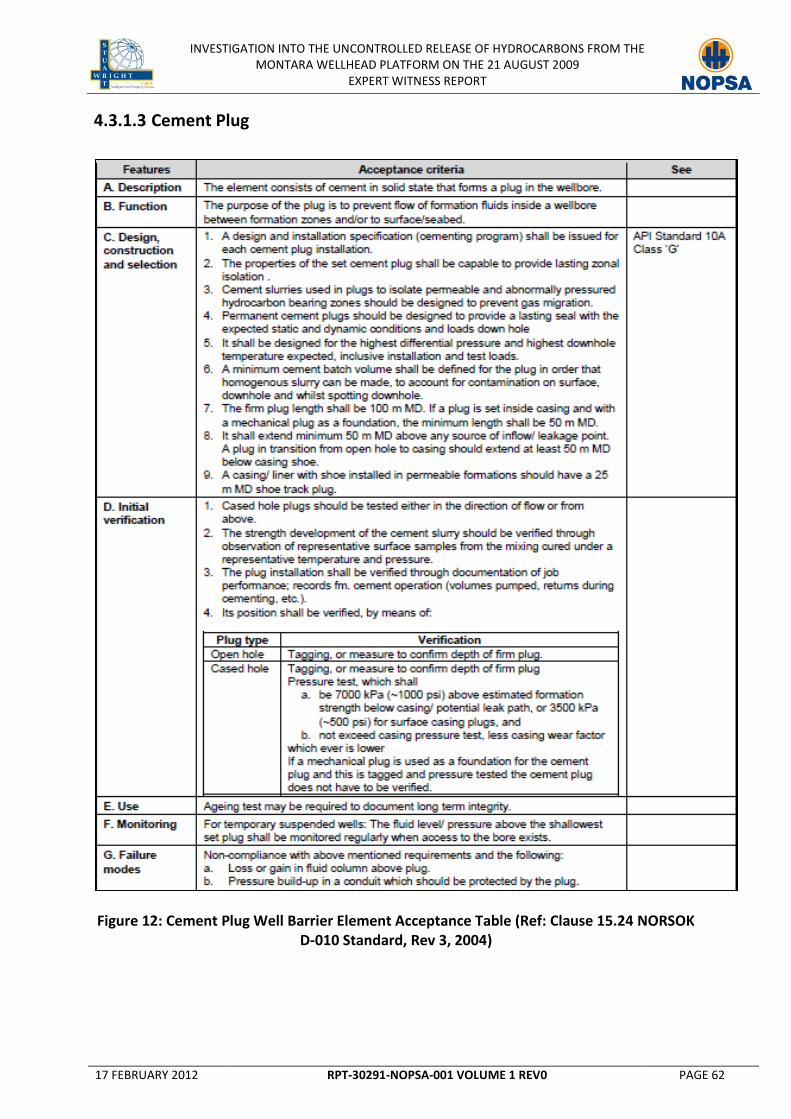
INVESTIGATION INTO THE UNCONTROLLED RELEASE OF HYDROCARBONS FROM THE MONTARA WELLHEAD PLATFORM ON THE 21 AUGUST 2009
EXPERT WITNESS REPORT
17 FEBRUARY 2012 RPT-30291-NOPSA-001 VOLUME 1 REV0 PAGE 62
4.3.1.3 Cement Plug
Figure 12: Cement Plug Well Barrier Element Acceptance Table (Ref: Clause 15.24 NORSOK D-010 Standard, Rev 3, 2004)

INVESTIGATION INTO THE UNCONTROLLED RELEASE OF HYDROCARBONS FROM THE MONTARA WELLHEAD PLATFORM ON THE 21 AUGUST 2009
EXPERT WITNESS REPORT
17 FEBRUARY 2012 RPT-30291-NOPSA-001 VOLUME 1 REV0 PAGE 63
4.3.1.4 Drilling BOP
Figure 13: Drilling BOP Well Barrier Element Acceptance Table (Ref: Clause 15.4 NORSOK D-010 Standard, Rev 3, 2004)

INVESTIGATION INTO THE UNCONTROLLED RELEASE OF HYDROCARBONS FROM THE MONTARA WELLHEAD PLATFORM ON THE 21 AUGUST 2009
EXPERT WITNESS REPORT
17 FEBRUARY 2012 RPT-30291-NOPSA-001 VOLUME 1 REV0 PAGE 64
4.3.1.5 Casing Float Valves
Figure 14: Casing Float Valves Well Barrier Element Acceptance Table (Ref: Clause 15.41 NORSOK D-010 Standard, Rev 3, 2004)
4.3.1.6 Corrosion Caps
No acceptance criteria have been provided in the NORSOK D-010 Standard, Rev 3, 2004 for
Corrosion Caps. However, as stated in section 4.2.3.3 of the NORSOK D-010, “Well barrier
acceptance criteria are technical and operational requirements that need to be fulfilled in order
to qualify the well barrier or WBE for its intended use”. It can be claimed then that “Good Oilfield
Practice” would dictate that Corrosion Caps can qualify as a well barrier provided they are
designed, selected and/or constructed such that:
1. “it can withstand the maximum anticipated differential pressure it may become exposed to;
2. it can be leak tested and function tested or verified by other methods;
3. no single failure of well barrier or WBE leads to uncontrolled outflow from the borehole/
well to the external environment;
4. re-establishment of a lost well barrier or another alternative well barrier can be done;

INVESTIGATION INTO THE UNCONTROLLED RELEASE OF HYDROCARBONS FROM THE MONTARA WELLHEAD PLATFORM ON THE 21 AUGUST 2009
EXPERT WITNESS REPORT
17 FEBRUARY 2012 RPT-30291-NOPSA-001 VOLUME 1 REV0 PAGE 65
5. it can operate competently and withstand the environment for which it may be exposed to
over time;
6. its physical location and integrity status of the well barrier is known at all times when such
monitoring is possible”.
4.3.2 Sidetracking, Abandonment and Long Term Suspension
The focus of Section 9 of the NORSOK Standard D-010, Rev 3 2004 covers requirements and
guidelines pertaining to Well Integrity for:
1. Temporary suspension of well activities and operations
2. Temporary/permanent abandonment of wells
3. Permanent abandonment of a section of a well (slot recovery, side-tracking) to construct a
new wellbore with a new geological well target.
4.3.2.1 Suspension
According to section 9.3.6 of the NORSOK Standard D-010, Rev 3 2004, suspension of operations
requires the same number of well barriers as other abandonment activities. Additionally,
NORSOK D-010 states the need for WBE testing, and verification, can be compensated by
monitoring of its performance, such as fluid level/pressure development above well barriers. In
such a case, NORSOK D-010 endorses well fluids as a qualified WBE.
4.3.2.2 Temporary Abandonment
According to section 9.3.7 of the NORSOK Standard D-010, Rev 3 2004, it shall be possible to re-
enter temporarily abandoned wells in a safe manner. Integrity of materials used for temporary
abandonment should be ensured for two (2) times the planned abandonment period. Hence, a
mechanical well barrier may be acceptable for temporary abandonment, subject to type, planned
abandonment period and subsurface environment.
4.3.2.3 Permanent Abandonment
According to section 9.3.8 of the NORSOK Standard D-010, Rev 3 2004, permanently plugged
wells shall be abandoned with an eternal perspective. There shall be at least one well barrier

INVESTIGATION INTO THE UNCONTROLLED RELEASE OF HYDROCARBONS FROM THE MONTARA WELLHEAD PLATFORM ON THE 21 AUGUST 2009
EXPERT WITNESS REPORT
17 FEBRUARY 2012 RPT-30291-NOPSA-001 VOLUME 1 REV0 PAGE 66
between surface and a potential source of inflow, unless it is a reservoir (contains hydrocarbons
and/ or has a flow potential) where two well barriers are required.
Permanent well barriers shall extend across the full cross section of the well, include all annuli.
Hence, a WBE set inside a casing, as part of a permanent well barrier, shall be located in a depth
interval where there is a WBE with verified quality in all annuli.
Open hole cement plugs can be used as a well barrier between reservoirs. It should, as far as
practicably possible, also be used as a primary well barrier.
4.3.2.4 Sidetracking
According to section 9.3.5 of the NORSOK Standard D-010, Rev 3 2004, the original wellbore shall
be “permanently abandoned” prior to a side-track.

INVESTIGATION INTO THE UNCONTROLLED RELEASE OF HYDROCARBONS FROM THE MONTARA WELLHEAD PLATFORM ON THE 21 AUGUST 2009
EXPERT WITNESS REPORT
17 FEBRUARY 2012 RPT-30291-NOPSA-001 VOLUME 1 REV0 PAGE 67
4.4 P&A and Suspension Requirements of the Code of Federal Regulations (CFR)
in the Outer Continental Shelf
The document 30 CFR 250, Subpart Q, contains the regulations of the Bureau of Safety and
Environmental Enforcement (BSEE) Offshore program that govern oil, gas, and sulphur
exploration, development, and production operations on the Outer Continental Shelf (OCS).
4.4.1 Barriers
According to 30 CFR 250.174, BSEE states that the Operator must test the first plug below the
surface plug and all plugs in lost circulation areas that are in open hole. The plug must pass one
of the following tests to verify plug integrity:
1. “A pipe weight of at least 15,000 pounds on the plug; or
2. A pump pressure of at least 1,000 pounds per square inch. Ensure that the pressure does
not drop more than 10 percent in 15 minutes”.
4.4.2 Abandonment and Long Term Suspension
4.4.2.1 Long Term Suspension
According to 30 CFR 250.174, BSEE states that for temporarily abandoning a well, the following
must be conformed to:
1. “Adhere to the plugging and testing requirements for permanently plugged wells listed in
the table in §250.1715, except for §250.1715(a)(8). The Operator does not need to sever the
casings, remove the wellhead, or clear the site;
2. Set a bridge plug or a cement plug at least 100-feet long at the base of the deepest casing
string, unless the casing string has been cemented and has not been drilled out. If a cement
plug is set, it is not necessary for the cement plug to extend below the casing shoe into the
open hole;
3. Set a retrievable or a permanent-type bridge plug or a cement plug at least 100 feet long in
the inner-most casing. The top of the bridge plug or cement plug must be no more than
1,000 feet below the mud line”.
INVESTIGATION INTO THE UNCONTROLLED RELEASE OF HYDROCARBONS FROM THE MONTARA WELLHEAD PLATFORM ON THE 21 AUGUST 2009
EXPERT WITNESS REPORT
17 FEBRUARY 2012 RPT-30291-NOPSA-001 VOLUME 1 REV0 PAGE 68
PERMANENT WELL PLUGGING REQUIREMENTS
If you have— Then you must use—
(1) Zones in open hole...........................
Cement plug(s) set from at least 100 feet below the bottom to 100 feet above the top of oil, gas, and fresh-water zones to isolate fluids in the strata.
(2) Open hole below casing...................
(i) A cement plug, set by the displacement method, at least 100 feet above and below deepest casing shoe; (ii) A cement retainer with effective back-pressure control set 50 to 100 feet above the casing shoe, and a cement plug that extends at least 100 feet below the casing shoe and at least 50 feet above the retainer; or (iii) A bridge plug set 50 feet to 100 feet above the shoe with 50 feet of cement on top of the bridge plug, for expected or known lost circulation conditions.
(3) A perforated zone that is currently open and not previously squeezed or isolated.
(i) A method to squeeze cement to all perforations; (ii) A cement plug set by the displacement method, at least 100 feet above to 100 feet below the perforated interval, or down to a casing plug, whichever is less; or (iii) If the perforated zones are isolated from the hole below, you may use any of the plugs specified in paragraphs (a)(3)(iii)(A) through (E) of this section instead of those specified in paragraphs (a)(3)(i) and (a)(3)(ii) of this section. (A) A cement retainer with effective back-pressure control set 50 to 100 feet above the top of the perforated interval, and a cement plug that extends at least 100 feet below the bottom of the perforated interval with at least 50 feet of cement above the retainer; (B) A bridge plug set 50 to 100 feet above the top of the perforated interval and at least 50 feet of cement on top of the bridge plug; (C) A cement plug at least 200 feet in length, set by the displacement method, with the bottom of the plug no more than 100 feet above the perforated interval; (D) A through-tubing basket plug set no more than 100 feet above the perforated interval with at least 50 feet of cement on top of the basket plug; or (E) A tubing plug set no more than 100 feet above the perforated interval topped with a sufficient volume of cement so as to extend at least 100 feet above the uppermost packer in the wellbore and at least 300 feet of cement in the casing annulus immediately above the packer.
(4) A casing stub where the stub end is within the casing.
(i) A cement plug set at least 100 feet above and below the stub end; (ii) A cement retainer or bridge plug set at least 50 to 100 feet above the stub end with at least 50 feet of cement on top of the retainer or bridge plug; or (iii) A cement plug at least 200 feet long with the bottom of the plug set no more than 100 feet above the stub end.
(5) A casing stub where the stub end is below the casing.
A plug as specified in paragraph (a)(1) or (a)(2) of this section, as applicable.
(6) An annular space that communicates with open hole and extends to the mud line.
A cement plug at least 200 feet long set in the annular space. For a well completed above the ocean surface, you must pressure test each casing annulus to verify isolation.
(7) A subsea well with unsealed annulus.
A cutter to sever the casing, and you must set a stub plug as specified in paragraphs (a)(4) and (a)(5) of this section.

INVESTIGATION INTO THE UNCONTROLLED RELEASE OF HYDROCARBONS FROM THE MONTARA WELLHEAD PLATFORM ON THE 21 AUGUST 2009
EXPERT WITNESS REPORT
17 FEBRUARY 2012 RPT-30291-NOPSA-001 VOLUME 1 REV0 PAGE 69
PERMANENT WELL PLUGGING REQUIREMENTS
If you have— Then you must use—
(8) A well with casing.............................
A cement surface plug at least 150 feet long set in the smallest casing that extends to the mud line with the top of the plug no more than 150 feet below the mud line.
(9) Fluid left in the hole..........................
A fluid in the intervals between the plugs that is dense enough to exert a hydrostatic pressure that is greater than the formation pressures in the intervals.
(10) Permafrost areas............................
(i) A fluid to be left in the hole that has a freezing point below the temperature of the permafrost, and a treatment to inhibit corrosion; and (ii) Cement plugs designed to set before freezing and have a low heat of hydration.
Table 8: Plugging Requirements as per 250.1715
4.4.2.2 Abandonment
According to 30 CFR 250.174, BSEE states that for permanently abandoned wellbores, in
particular with zones in the open hole, “cement plug(s) must be set from at least 100 ft below the
bottom to 100 feet above the top of oil, gas, and fresh-water zones to isolate fluids in the strata”.

INVESTIGATION INTO THE UNCONTROLLED RELEASE OF HYDROCARBONS FROM THE MONTARA WELLHEAD PLATFORM ON THE 21 AUGUST 2009
EXPERT WITNESS REPORT
17 FEBRUARY 2012 RPT-30291-NOPSA-001 VOLUME 1 REV0 PAGE 70
4.5 P&A and Suspension Requirements of PTTEPAA Well Construction Standards
4.5.1 Barriers
With reference to Section 5 of the approved PTTEPAA Well Construction Standards (referenced
by NOPSA as [“EV0000096”]), it is stated that during drilling, completion, testing, intervention
and other open hole operations, the following barriers shall be maintained in the annulus:
1. “Two proven barriers between hydrocarbon bearing permeable zones and the surface
2. One proven barrier between permeable fresh water bearing zones and surface”
Furthermore, barrier verification, as stated by PTTEPAA, must be verified in-situ as follows:
Barrier Type Verification
Cement Plug (Not surface plugs)
1. Tagging with sufficient force to confirm the top of good cement 2. Tagging pressure must equal the equivalent of 3500KPa (500 psi) 3. Or Pressure Testing to 7000 KPa (1000 psi) over leak off
Cement Plug on bridge plug
1. Tag bridge plug then pressure testing to 7000 KPa (1000 psi) over leak off after setting cement plug
Annulus Cement 1. Waiting until the surface cement (tail) samples are set, providing that the cement job proceeded normally and a clear pressure differential was observed prior to bumping the plug.
2. The differential pressure must confirm that the TOC is a minimum of 50m above any hydrocarbon or over-pressured water zone
All Other Barriers 1. By either pressure or inflow testing
Table 9: PTTEPAA Well Construction Standard Barrier(s) Verification
4.5.2 Abandonment and Long Term Suspension
4.5.2.1 Long Term Suspension
Long Term Suspension, as defined by PTTEPAA, is “when the MODU leaves the well site”. Wells
must be suspended so that they can be abandoned with rig less intervention to meet the
standards below.
Accordingly, for Long Term Suspension, “two permanent tested barriers must be installed in the
annulus and wellbore above any hydrocarbon zone or over pressured zone”. The following are
permanent barriers:
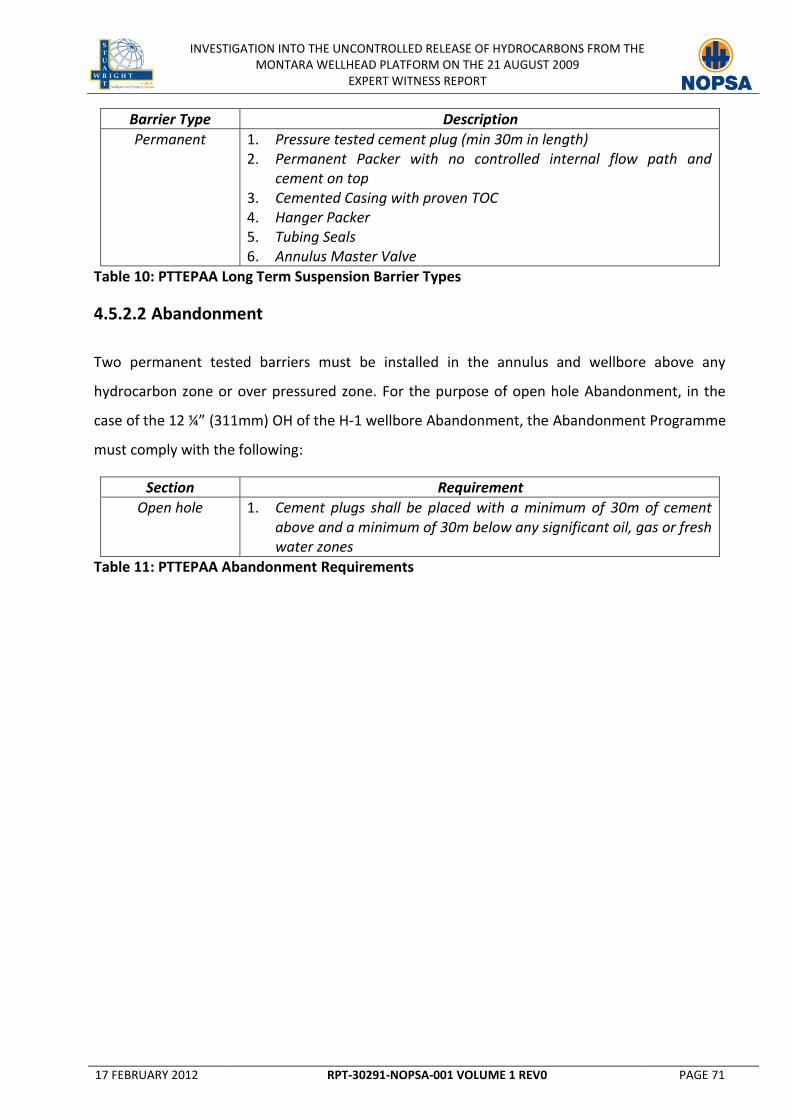
INVESTIGATION INTO THE UNCONTROLLED RELEASE OF HYDROCARBONS FROM THE MONTARA WELLHEAD PLATFORM ON THE 21 AUGUST 2009
EXPERT WITNESS REPORT
17 FEBRUARY 2012 RPT-30291-NOPSA-001 VOLUME 1 REV0 PAGE 71
Barrier Type Description
Permanent 1. Pressure tested cement plug (min 30m in length) 2. Permanent Packer with no controlled internal flow path and
cement on top 3. Cemented Casing with proven TOC 4. Hanger Packer 5. Tubing Seals 6. Annulus Master Valve
Table 10: PTTEPAA Long Term Suspension Barrier Types
4.5.2.2 Abandonment
Two permanent tested barriers must be installed in the annulus and wellbore above any
hydrocarbon zone or over pressured zone. For the purpose of open hole Abandonment, in the
case of the 12 ¼” (311mm) OH of the H-1 wellbore Abandonment, the Abandonment Programme
must comply with the following:
Section Requirement
Open hole 1. Cement plugs shall be placed with a minimum of 30m of cement above and a minimum of 30m below any significant oil, gas or fresh water zones
Table 11: PTTEPAA Abandonment Requirements

INVESTIGATION INTO THE UNCONTROLLED RELEASE OF HYDROCARBONS FROM THE MONTARA WELLHEAD PLATFORM ON THE 21 AUGUST 2009
EXPERT WITNESS REPORT
17 FEBRUARY 2012 RPT-30291-NOPSA-001 VOLUME 1 REV0 PAGE 72
5. RISK ASSESSMENT AND MANAGEMENT
This section of the report provides the reader with background information relating to good
oilfield practice and industry standards in the area of Risk Assessment, including the available
tools for conducting Operator Risk Assessments. The methodologies used by the Expert Witness
to conduct Risk Assessments are also explained in this section within the context of industry
standard practice.
5.1 Introduction
There has been a major growth in interest over the last decade to improve an organization’s
ability to deal with uncertainty, especially with its negative impact at the organization level. This
has led to the development and application of standards, systems, tools, methodologies and
processes which fall under the broad classification of "Risk Management". The methods,
definitions and goals vary widely according to whether the management of risk is within the
context of finance, insurance, engineering, project management, industrial processes, safety, or
public health and safety.
It is important to distinguish between the management of financial risks, itself a specialized area
which has evolved to manage specific business risks related to the Finance and Insurance
industries and mainly concerned with monetary gains and losses, and the management of
operational risks, which within this report relates to the coordination of activities to direct and
control an organization with regard to risks inherent in its day to day operations in order to
deliver its business objectives.
Operational Risk Management in general is evolving to overcome a lack of consistency in firstly
the definition, and secondly the implementation and practice of risk and Risk Management as it
relates across different industries. Recent trends indicate an appetite by stakeholders across
various industries at large to adopt a more consistent approach to risk and Risk Management,
evidenced by the release of the International Standards Organization document, “International
Standard ISO/FDIS 31000 Risk Management – Principles and guidelines” (ISO/FDIS 31000:2009).
For the offshore oil and gas industry operational Risk Management, hereafter referred to as Risk
Management, is regulated by a safety case regime in many countries. This activity has driven the
INVESTIGATION INTO THE UNCONTROLLED RELEASE OF HYDROCARBONS FROM THE MONTARA WELLHEAD PLATFORM ON THE 21 AUGUST 2009
EXPERT WITNESS REPORT
17 FEBRUARY 2012 RPT-30291-NOPSA-001 VOLUME 1 REV0 PAGE 73
development of numerous regulations, standards and guidelines that prescribe and advise
organizations on the best way to manage their operational risks. The recent events in major oil &
gas producing areas including offshore Australia [Montara, National Offshore Petroleum Safety
Authority (NOPSA) - Australia, 2009], the Gulf of Mexico in the USA [Macondo, Bureau of Ocean
and Environmental Management Regulation and Enforcement (BOEMRE) - USA, 2010] and
offshore Norway [Gullfaks, Petroleum Safety Authority (PSA) - Norway, 2011] have given cause
for each country’s relevant petroleum authority to revisit the subject of Risk Management with
their key stakeholders. In particular, the Norwegian PSA have explicitly stated that the “industry
does not have the right tools for incident assessment.” [Source: PSA Website:
http://www.ptil.no/news/accident-investigations-are-opportunities-for-learning-article6884-
79.html]. There has been much activity to review Risk Management as it relates to each
regulatory regime as a minimum, including the extent to which regulatory compliance is
mandated and demonstrated by operators to safeguard against the risk of similar events in the
future, in countries with and without a prescriptive regulatory regime. Central to the Risk
Management process is Risk Assessment which is associated with the overall process of risk
identification, risk analysis and risk evaluation.
5.2 Definitions
The Oxford English Dictionary defines the term Risk as “a situation involving exposure to danger”,
and in singular “the possibility that something unpleasant or unwelcome will happen.” Risk
Assessment is then defined as “a systematic process of evaluating the potential risks that may be
involved in a projected activity or undertaking.”
There exists within the Risk Management discipline a myriad of different definitions of risk and
Risk Assessment depending on the specific industry and context to which the term is applied,
reflecting the need for standardization across common lines. The most recent innovation is for
risk to be defined in terms of the effect of uncertainties on objectives whilst previous
definitions have focused on risk as being the chance of something happening that will have an
impact on objectives.
Risk is defined by the International Standards Organization document, “International Standard
ISO/FDIS 31000 Risk Management – Principles and guidelines” (ISO/FDIS 31000:2009) as the:

INVESTIGATION INTO THE UNCONTROLLED RELEASE OF HYDROCARBONS FROM THE MONTARA WELLHEAD PLATFORM ON THE 21 AUGUST 2009
EXPERT WITNESS REPORT
17 FEBRUARY 2012 RPT-30291-NOPSA-001 VOLUME 1 REV0 PAGE 74
“…effect of uncertainty on objectives.”
NOTE 1 An effect is a deviation from the expected – positive and/or negative;
NOTE 2 Objectives can have different aspects (such as financial, health and safety,
environmental goals) and can apply at different levels (such as strategic, organization-
wide, project, product and processes.
NOTE 3 Risk is often characterized by reference to potential events and consequences, or a
combination of these.
NOTE 4 Risk is often expressed in terms of a combination of the consequences of an event
(including changes in circumstances) and the associated likelihood of occurrence).
NOTE 5 Uncertainty is the state, even partial, of deficiency of information related to,
understanding or knowledge of an event, its consequence, or likelihood.
Risk Assessment is defined within ISO/FDIS 31000:2009 as the:
“…overall process of risk identification, risk analysis and risk evaluation.”
Simply put, the effective management of risk enables an organization to maximize its
opportunities and achieve its objectives.
The following oil and gas regulatory and professional bodies worldwide have adopted a similar
definition of “risk” and “Risk Assessment” as the ISO/FDIS 31000:2009 definition in general:
Regulatory Bodies
1. Petroleum Safety Authority Norway (PSA/PTIL) - Norway
2. National Offshore Petroleum Safety Authority (NOPSA) – Australia
3. UK Health and Safety Executive – United Kingdom Of Great Britain
Professional Bodies
1. A Guide to the Project Management Body of Knowledge (PMBOK) - Chapter 11 - Project
Risk Management; Project Management Institute, USA 2002 20 (New edition in 2005) -
American National Standard ANSI/PMI 99-001-2004;

INVESTIGATION INTO THE UNCONTROLLED RELEASE OF HYDROCARBONS FROM THE MONTARA WELLHEAD PLATFORM ON THE 21 AUGUST 2009
EXPERT WITNESS REPORT
17 FEBRUARY 2012 RPT-30291-NOPSA-001 VOLUME 1 REV0 PAGE 75
2. International Association of Drilling Contractors (IADC) - IADC HSE Case Guidelines
Appendix 2 Issue 3.2.1 – 1 May 2009;
3. Norsk Sokkels Konkuranseposisjon (NORSOK) – Standards developed by the Norwegian
Technology Centre;
4. Det Norske Veritas (DNV);
5.3 What is Risk Assessment?
The process for managing risk involves coordinating activities to direct and control an
organization with regard to risk, and is represented by the diagram under Figure 15 below.
Figure 15: The Risk Management Process
Effective Risk Management involves constant communication and consultation with key
stakeholders together with continuous improvement through monitoring and review throughout
the entire process. Central to managing risk effectively is through the use a rigorous Risk
Assessment process which involves the identification, analysis & evaluation of risk. Each step
within the Risk Assessment sub-process within the shaded area is set out in detail hereafter.

INVESTIGATION INTO THE UNCONTROLLED RELEASE OF HYDROCARBONS FROM THE MONTARA WELLHEAD PLATFORM ON THE 21 AUGUST 2009
EXPERT WITNESS REPORT
17 FEBRUARY 2012 RPT-30291-NOPSA-001 VOLUME 1 REV0 PAGE 76
Risk identification
Having established the context, the goal of risk identification is to identify sources of risk, areas
of impacts, events (including changes in circumstances) and their causes and their potential
consequences. The aim of this step is to generate a comprehensive list of risks based on those
events that might create, enhance, prevent, degrade, accelerate or delay the achievement of
objectives. It is also important to identify the risks associated with not pursuing an opportunity.
Comprehensive identification is critical, because a risk that is not identified at this stage will not
be included in further analysis.
Identification should include risks whether or not their source is under control of the
organization, even though the risk source or cause may not be evident. Risk identification should
include examination of the flow-on effects of particular consequences, including cascade and
cumulative effects. It should also consider a wide range of consequences even if the risk source
or cause may not be evident. As well as identifying what might happen, it is necessary to consider
possible causes and scenarios that show what consequences can occur. All significant
consequences should be considered.
Suitable risk identification tools and techniques should be applied to meet the objectives and
capabilities of the organization, and to the risks faced. Relevant and up-to-date information is
important in identifying risks. This should include appropriate background information where
possible. People with appropriate knowledge should be involved in identifying risks.
Risk analysis
Risk analysis involves developing an understanding of the risk. Risk analysis provides an input to
risk evaluation and to decisions on whether risks need to be treated, and on the most
appropriate risk treatment strategies and methods. Risk analysis can also provide an input into
making decisions where choices must be made and the options involve different types and levels
of risk.
Risk analysis involves consideration of the causes and sources of risk, their positive and negative
consequences, and the likelihood that those consequences can occur. Factors that affect
consequences and likelihood should be identified. Risk is analyzed by determining consequences
and their likelihood, and other attributes of the risk. An event can have multiple consequences

INVESTIGATION INTO THE UNCONTROLLED RELEASE OF HYDROCARBONS FROM THE MONTARA WELLHEAD PLATFORM ON THE 21 AUGUST 2009
EXPERT WITNESS REPORT
17 FEBRUARY 2012 RPT-30291-NOPSA-001 VOLUME 1 REV0 PAGE 77
and can affect multiple objectives. Existing risk controls and their effectiveness should be taken
into account. More than one technique may be required for complex applications.
The way in which consequences and likelihood are expressed and the way in which they are
combined to determine a level of risk should reflect the type of risk, the information available
and the purpose for which the Risk Assessment output is to be used. These should be consistent
with the risk criteria. It is also important to consider the interdependence of different risks and
their sources.
The confidence in determination of the level of risk and its sensitivity to preconditions and
assumptions should be considered in the analysis, and communicated effectively to decision
makers and, as appropriate, other stakeholders. Factors such as divergence of opinion among
experts, uncertainty, availability, quality, quantity and ongoing relevance of information, or
limitations on modeling should be stated and may be highlighted.
In some circumstances, a consequence can occur as a result of a range of different events or
conditions, or where the specific event is not identified. In this case, the focus of Risk
Assessment is on analyzing the importance and vulnerability of components of the system with
a view to defining treatments which relate to levels of protection or recovery strategies.
Risk analysis can be undertaken with varying degrees of detail depending on the risk, the purpose
of the analysis, and the information, data and resources available. The methods used in analyzing
risks can be qualitative, semi-quantitative or quantitative, or a combination of these, depending
on the circumstances. Some methods and the degree of detail of the analysis may be prescribed
by legislation.
Consequences and their likelihood can be determined by modeling the outcomes of an event or
set of events, or by extrapolation from experimental studies or from available data.
Consequences can be expressed in terms of tangible and intangible impacts. In some cases, more
than one numerical value or descriptor is required to specify consequences and their likelihood
for different times, places, groups or situations.

INVESTIGATION INTO THE UNCONTROLLED RELEASE OF HYDROCARBONS FROM THE MONTARA WELLHEAD PLATFORM ON THE 21 AUGUST 2009
EXPERT WITNESS REPORT
17 FEBRUARY 2012 RPT-30291-NOPSA-001 VOLUME 1 REV0 PAGE 78
Risk Evaluation
The purpose of risk evaluation is to assist in making decisions, based on the outcomes of risk
analysis, about which risks need treatment to prioritize treatment implementation.
Risk evaluation involves comparing the level of risk found during the analysis process with risk
criteria established when the context was considered. Based on this comparison, the need for
treatment can be considered.
Decisions should take account of the wider context of the risk and include consideration of the
tolerance of the risks borne by parties other than the organization that benefit from the risk.
Decisions should be made in accordance with legal, regulatory and other requirements.
In some circumstances, the risk evaluation can lead to a decision to undertake further analysis.
The risk evaluation can also lead to a decision not to treat the risk in any way other than
maintaining existing controls. This decision will be influenced by the organization’s risk attitude
and the risk criteria that have been established.
5.4 Risk Assessment Methods
The methods used in analyzing risks can be qualitative, semi-quantitative or quantitative, or a
combination of these, depending on the circumstances.
Qualitative assessment defines consequence, probability and level of risk by significance levels
such as “high”, “medium” and “low”, may combine consequence and probability, and evaluates
the resultant level of risk against qualitative criteria.
Semi-quantitative methods use numerical rating scales for consequence and probability and
combine them to produce a level of risk using a formula. Scales may be linear or logarithmic, or
have some other relationship; formulae used can also vary.
Quantitative analysis estimates practical values for consequences and their probabilities, and
produces values of the level of risk in specific units defined when developing the context. Full
quantitative analysis may not always be possible or desirable due to insufficient information
about the system or activity being analysed, lack of data, influence of human factors, etc. or
because the effort of quantitative analysis is not warranted or required. In such circumstances, a

INVESTIGATION INTO THE UNCONTROLLED RELEASE OF HYDROCARBONS FROM THE MONTARA WELLHEAD PLATFORM ON THE 21 AUGUST 2009
EXPERT WITNESS REPORT
17 FEBRUARY 2012 RPT-30291-NOPSA-001 VOLUME 1 REV0 PAGE 79
comparative semi-quantitative or qualitative ranking of risks by specialists, knowledgeable in
their respective field, may still be effective.
In cases where the analysis is qualitative, there should be a clear explanation of all the terms
employed and the basis for all criteria should be recorded. Even where full quantification has
been carried out, it needs to be recognized that the levels of risk calculated are estimates. Care
should be taken to ensure that they are not attributed a level of accuracy and precision
inconsistent with the accuracy of the data and methods employed.
There are a range of tools and techniques that can be used to perform a Risk Assessment or to
assist with the Risk Assessment process. Each of these techniques are designed to analyze risks
based on a qualitative, semi-quantitative or quantitative approach, or through a combination of
each. It may sometimes be necessary to employ more than one method of assessment.
Selection of techniques
Risk Assessment may be undertaken in varying degrees of depth and detail and using one or
many methods ranging from simple to complex. The form of assessment and its output should be
consistent with the risk criteria developed as part of establishing the context.
In general terms, suitable techniques should exhibit the following characteristics:
1. it should be justifiable and appropriate to the situation or organization under
consideration;
2. it should provide results in a form which enhances understanding of the nature of the risk
and how it can be treated;
3. it should be capable of use in a manner that is traceable, repeatable and verifiable.
The reasons for the choice of techniques should be given, with regard to relevance and
suitability. When integrating the results from different studies, the techniques used and outputs
should be comparable.
Once the decision has been made to perform a Risk Assessment and the objectives and scope
have been defined, the techniques should be selected, based on applicable factors such as:

INVESTIGATION INTO THE UNCONTROLLED RELEASE OF HYDROCARBONS FROM THE MONTARA WELLHEAD PLATFORM ON THE 21 AUGUST 2009
EXPERT WITNESS REPORT
17 FEBRUARY 2012 RPT-30291-NOPSA-001 VOLUME 1 REV0 PAGE 80
1. The objectives of the study. The objectives of the Risk Assessment will have a direct bearing
on the techniques used. For example, if a comparative study between different options is
being undertaken, it may be acceptable to use less detailed consequence models for parts
of the system not affected by the difference;
2. The needs of decision-makers. In some cases a high level of detail is needed to make a
good decision, in others a more general understanding is sufficient;
3. the type and range of risks being analysed;
4. The potential magnitude of the consequences. The decision on the depth to which Risk
Assessment is carried out should reflect the initial perception of consequences (although
this may have to be modified once a preliminary evaluation has been completed);
5. The degree of expertise, human and other resources needed. A simple method, well done,
may provide better results than a more sophisticated procedure poorly done, so long as it
meets the objectives and scope of the assessment. Ordinarily, the effort put into the
assessment should be consistent with the potential level of risk being analysed;
6. The availability of information and data. Some techniques require more information and
data than others;
7. The need for modification/updating of the Risk Assessment. The assessment may need to
be modified/updated in future and some techniques are more amendable than others in
this regard;
8. Any regulatory and contractual requirements.
In practice, Qualitative methods are best used for Risk Assessments of simple facilities or
operations, where the exposure of the workforce, public, environment or asset is low. Qualitative
Risk Assessments are often a combination of judgment and experience, and structured review
techniques. Qualitative Risk Assessments should be carried out with input from those people
directly involved with the risk.
On the other hand, Quantitative Risk Assessments (QRA) are undertaken for more complex
facilities or activities, or where required by law. QRA is typically used on all activities posing
medium or high risk that could result in one or more fatalities. Only personnel with adequate
training and experience should undertake quantitative Risk Assessments, though it is critical that
all personnel familiar with the operation or facility are involved in the study.

INVESTIGATION INTO THE UNCONTROLLED RELEASE OF HYDROCARBONS FROM THE MONTARA WELLHEAD PLATFORM ON THE 21 AUGUST 2009
EXPERT WITNESS REPORT
17 FEBRUARY 2012 RPT-30291-NOPSA-001 VOLUME 1 REV0 PAGE 81
QRA provides a structured approach to assessing risk, whether the risks are human,
hardware/software failure, environmental events or combinations of failures and events. QRA
identifies high-risk areas; assists in efficient and effective Risk Management and helps
demonstrate that risks are managed to a level deemed ALARP.
Various factors influence the selection of an approach to Risk Assessment such as the availability
of resources, the nature and degree of uncertainty in the data and information available, and the
complexity of the application.
5.5 Available Risk Assessment Techniques
The following table presents a non-exhaustive list of Risk Assessment tools and techniques
available for use in Risk Management.

INVESTIGATION INTO THE UNCONTROLLED RELEASE OF HYDROCARBONS FROM THE MONTARA WELLHEAD PLATFORM ON THE 21 AUGUST 2009
EXPERT WITNESS REPORT
17 FEBRUARY 2012 RPT-30291-NOPSA-001 VOLUME 1 REV0 PAGE 82
Table 12: List of Risk Assessment Methods and Applicability of Tools

INVESTIGATION INTO THE UNCONTROLLED RELEASE OF HYDROCARBONS FROM THE MONTARA WELLHEAD PLATFORM ON THE 21 AUGUST 2009
EXPERT WITNESS REPORT
17 FEBRUARY 2012 RPT-30291-NOPSA-001 VOLUME 1 REV0 PAGE 83
5.6 Risk Management
Risk Management, which includes Risk Assessment as defined by ISO is a set of coordinated
activities to direct and control an organization with regard to risk.
Risk management should ensure that organizations have an appropriate response to the risks
affecting them. Risk management should thus help avoid ineffective and inefficient responses to
risk that can unnecessarily prevent legitimate activities and/or distort resource allocation.
To be effective within an organization, risk management should be an integrated part of the
organization's overall governance, management, reporting processes, policies, philosophy and
culture. The same risk management approach can be adopted for all activities of an organization
including projects, defined functions, assets, and products or activities and will in turn strengthen
the linkages between these activities and the organization’s overall objectives.
Many organizations' existing management practices and processes include components of risk
management and many organizations have already adopted a formal risk management process
for particular types of risk or circumstances.
Risk management should function within a risk management framework which provides the
foundations and organizational arrangements that will embed it throughout the organization at
all levels to be successful. The framework assists an organization in managing its risks effectively
through the application of the risk management process at varying levels and within specific
contexts of the organization. The framework should ensure that risk information derived from
these processes is adequately reported and used as a basis for decision making and
accountability at all relevant organizational levels.
A key success factor of an organization’s risk management is that risk management is part of
decision making. Risk management helps decision makers make informed choices. Risk
management can help prioritize actions and distinguish among alternative courses of action.
Ultimately, risk management can help with decisions on whether a risk is unacceptable and
whether risk treatment will be adequate and effective.
It is good industry practice for Operators to consider, based on a risk-ranked approach,
performing a risk assessment for every material change to a drilling program at every stage of the

INVESTIGATION INTO THE UNCONTROLLED RELEASE OF HYDROCARBONS FROM THE MONTARA WELLHEAD PLATFORM ON THE 21 AUGUST 2009
EXPERT WITNESS REPORT
17 FEBRUARY 2012 RPT-30291-NOPSA-001 VOLUME 1 REV0 PAGE 84
well project life cycle. This facility is generally embedded within an Operator’s Management of
Change Policy, Guideline, Standards or Procedure as part of the overall operations plan, and
guides the activities of the Operator to manage risks that arise during the project.
INVESTIGATION INTO THE UNCONTROLLED RELEASE OF HYDROCARBONS FROM THE MONTARA WELLHEAD PLATFORM ON THE 21 AUGUST 2009
EXPERT WITNESS REPORT
17 FEBRUARY 2012 RPT-30291-NOPSA-001 VOLUME 1 REV0 PAGE 85
5.7 Risk Assessment Methods Applied by PTTEPAA and Atlas Drilling
A bridging document “Seadrill-West Atlas safety case revision-Document No. HSE SCR WA
070002 Montara SIMOPS Addendum” [“EV0000055”] had been created to resolve any conflict
between the PTTEPAA Well Construction Standards [“EV0000096”] and the Seadrill West Atlas
Safety Case [“EV0000006”].
Prior to the Montara drilling campaign, a facilitated SIMOPS HAZID workshop, with involvement
from PTTEPAA, Atlas Drilling personnel, and other third party well services providers was
conducted and a Safety Case Revision [“EV0000055”] was prepared, and submitted in fulfilment
of PTTEPAA’s ongoing obligation to meet the regulatory requirements set forth in the Petroleum
(Submerged Lands) (Management of Safety on Offshore Facilities) Regulations 1996, Part 3.
The bridging document contains details on hazard identification, risk management and change
control. As stated in the Safety Case Revision, the PTTEPAA Well Construction Management
System was the agreed system used to plan and execute well construction activities at the
Montara WHP as for any other drilling activities. Routine and emergency operations on the
MODU would be conducted in accordance with the West Atlas Safety Case. The introduction of
SIMOPS in the Montara Development introduced another set of Management System interfaces,
and the interactions between facilities were covered by existing process and procedures.
Accordingly, an appreciation of the Risk Assessment methods adopted by both PTTEPAA and
Atlas Drilling for all activities related to the Montara Development can be found in the following
documentation:
1. Facilities Construction and Installation: Coogee Resources-Montara Development-Safety
Case For Construction And Installation [“EV0000008”]
2. Simultaneous Operations: Coogee Resources-Montara Development-SIMOPS Plan
[“EV0000009”]
3. Wellhead Platform Hookup and Pre-Commissioning: Coogee Resources-Montara
Development-Construction & Installation Safety Case/WHP Hookup & Precommissioning
Revision [“EV0000010”]
4. Well Construction Management System: PTTEPAA Management Standard: Well
Construction Management Framework Standard ID [“EV0000050”]
INVESTIGATION INTO THE UNCONTROLLED RELEASE OF HYDROCARBONS FROM THE MONTARA WELLHEAD PLATFORM ON THE 21 AUGUST 2009
EXPERT WITNESS REPORT
17 FEBRUARY 2012 RPT-30291-NOPSA-001 VOLUME 1 REV0 PAGE 86
5. Routine and Emergency Operations on Facility: Seadrill West Atlas Safety Case
[“EV0000006”]
5.7.1 PTTEPAA Risk Assessment Methods for Facilities Construction and
Installation, SIMOPS, and WHP Hookup and Pre-Commissioning
Risk Assessment methods adopted by PTTEPAA for “Simultaneous Operations” [“EV0000009”]
and the “Wellhead Platform Hookup and Pre-Commissioning” [“EV0000010”] activities are
covered through the Risk Management System in the “Coogee Facilities Construction and
Installation Safety Case” [“EV0000010”], as depicted in Figure 16.
The Coogee Resources Management System is a system within the definition given in AS/NZS ISO
9000. The Safety Management System (SMS) that applies to the Montara Development facilities
is a component of the Coogee Resources management in which it is referred to as the health,
Safety, and Environment Management System (HSEMS). The Coogee Resources HSEMS follows a
continuous improvement cycle as shown in Figure 17, which links the specific elements of the
HSEMS to the management system model approach provided in AS/NZS 4804:2001.

INVESTIGATION INTO THE UNCONTROLLED RELEASE OF HYDROCARBONS FROM THE MONTARA WELLHEAD PLATFORM ON THE 21 AUGUST 2009
EXPERT WITNESS REPORT
17 FEBRUARY 2012 RPT-30291-NOPSA-001 VOLUME 1 REV0 PAGE 87
Figure 16: Montara Development Project Safety Case Documentation (Ref: ([EV0000008] Coogee Resources-Montara Development-Safety Case For Construction And Installation)

INVESTIGATION INTO THE UNCONTROLLED RELEASE OF HYDROCARBONS FROM THE MONTARA WELLHEAD PLATFORM ON THE 21 AUGUST 2009
EXPERT WITNESS REPORT
17 FEBRUARY 2012 RPT-30291-NOPSA-001 VOLUME 1 REV0 PAGE 88
Figure 17: Coogee Resources HSEMS Continuous Improvement Cycle (Ref: [EV0000008] Coogee Resources-Montara Development-Safety Case For Construction And Installation)

INVESTIGATION INTO THE UNCONTROLLED RELEASE OF HYDROCARBONS FROM THE MONTARA WELLHEAD PLATFORM ON THE 21 AUGUST 2009
EXPERT WITNESS REPORT
17 FEBRUARY 2012 RPT-30291-NOPSA-001 VOLUME 1 REV0 PAGE 89
5.7.2 PTTEPAA Risk Assessment Methods for Well Construction Management
System
As stated in section 3.4 of the Well Construction Management Framework [“EV0000050”], Risk
assessment and management is integral with the Well Construction Core Process. The Well
Construction Risk Management activities runs parallel and interfaces with the Core Process, but
is documented separately to provide a clear assurance of Risk Management.
Though not explicitly stated, the Well Construction Risk Management System follows a
continuous improvement cycle to ensure that the implementation and effectiveness of controls
put in place to manage Well & Well Test Design, and Operations risks will be ALARP, through the
following processes as illustrated in Figure 18.
Figure 18: Wells Risk Assessment and Management Process (Ref: [EV0000050] PTTEPAA Management Standard: Well Construction Management Framework Standard ID)

INVESTIGATION INTO THE UNCONTROLLED RELEASE OF HYDROCARBONS FROM THE MONTARA WELLHEAD PLATFORM ON THE 21 AUGUST 2009
EXPERT WITNESS REPORT
17 FEBRUARY 2012 RPT-30291-NOPSA-001 VOLUME 1 REV0 PAGE 90
5.7.3 Atlas Drilling Risk Assessment Methods for Routine and Emergency
Operations on Facility
As stated in section 2.5.1 in the Seadrill West Atlas Safety Case – Part 2 Safety Management
System [“EV0000006”], the Seadrill Risk Management process can be categorised into two (2)
areas:
1. The management of hazards associated with the overall design and operation of a process
i.e. Hazard Identification (HAZID) or Formal Safety Assessment studies;
2. The management of hazards associated with daily activities i.e. job Safety Analysis (JSA).
The basic Risk Management process remains the same in both cases and is:
1. Systematic identification of hazards;
2. Assessment of the risk arising from the hazards;
3. Implementation of suitable hazard controls;
4. Preparedness for recovery in the event of a loss control.
The Seadrill Risk Management Process is presented graphically in Figure 19.

INVESTIGATION INTO THE UNCONTROLLED RELEASE OF HYDROCARBONS FROM THE MONTARA WELLHEAD PLATFORM ON THE 21 AUGUST 2009
EXPERT WITNESS REPORT
17 FEBRUARY 2012 RPT-30291-NOPSA-001 VOLUME 1 REV0 PAGE 91
Figure 19: Seadrill Risk Management Process

INVESTIGATION INTO THE UNCONTROLLED RELEASE OF HYDROCARBONS FROM THE MONTARA WELLHEAD PLATFORM ON THE 21 AUGUST 2009
EXPERT WITNESS REPORT
17 FEBRUARY 2012 RPT-30291-NOPSA-001 VOLUME 1 REV0 PAGE 92
5.7.4 PTTEPAA Management of Change Process
PTTEPAA’s Management of Change (MOC) process can be found in Section 4.1.8 Change
Management in the Construct Service or Abandon Well Process *“DB-30291-NOPSA-401”+, one of
three documents found in the PTTEPAA *Well Construction Management System.
The activity “Change Management” is defined as a reoccurring activity carried during activity
4.1.1, 4.1.2, 4.1.3 and 4.1.4 (See Figure 20) in response to changes in the Statement of
Requirements, Basis of Design or Well Programmes that were brought about by scope changes or
unforeseen operational incidents. The tasks defined in the activities are as follows:
1. Identify Requirement for Change and Justify
a. Complete Change Request complete with justification
b. Maintain Change Register
c. Following changes are subjected to change control:
i. Changes that significantly increase risks or changes to well objectives, trajectory,
pressures, etc.
ii. Changes in material specification or requirements including surplus materials or
cancellation charges
iii. Changes the cost by USD$0.5M
d. Proposed changes should be carefully thought through and the change proposer
should be prepared to substantiate the change including the gains to be made, the
resources required and the impact of not making the change.
2. Engineer Change
a. Engineer change in accordance with the Well Construction Standards
i. Wherever possible, changes are engineered to the same level of details as the
original design
b. Carry out hazard analysis and risk mitigation in accordance with Risk Management
Activity
c. Prepare programme revision if engineer change
3. Record and Disseminate Change
a. Update the Change Register and e-mail all persons details of the change

INVESTIGATION INTO THE UNCONTROLLED RELEASE OF HYDROCARBONS FROM THE MONTARA WELLHEAD PLATFORM ON THE 21 AUGUST 2009
EXPERT WITNESS REPORT
17 FEBRUARY 2012 RPT-30291-NOPSA-001 VOLUME 1 REV0 PAGE 93
b. Record learning experience in Knowledge Database if applicable (Knowledge
Management Activity)
Figure 20 : PTTEP Management System Framework, Develop and Service Wells Process

INVESTIGATION INTO THE UNCONTROLLED RELEASE OF HYDROCARBONS FROM THE MONTARA WELLHEAD PLATFORM ON THE 21 AUGUST 2009
EXPERT WITNESS REPORT
17 FEBRUARY 2012 RPT-30291-NOPSA-001 VOLUME 1 REV0 PAGE 94
5.8 Risk Identification via WAiT©
The Expert Witness has developed the SWPL “Well Assessment of Integrity Tool” (WAiT©)
process, which is a comprehensive review platform used to drive a “forensic” assessment of the
candidate wells’ integrity status, and can be applied to all stages of wells investigation and asset-
wide risk assessment and management.
The SWPL WAiT© process captures the subsurface environment data, well architecture (as-built
condition), and production historical data of a well in an integrated view. The WAiT© process
then gives an assessment of the well integrity condition by section i.e. tubing, A-B-C annuli, using,
construction, production and/or intervention history, and concludes with primary and secondary
well barrier assessment for all components of the well architecture. Ultimately the WAiT©
process identifies the most significant MAJOR HAZARDS and TOP EVENTS for a specific well.
By the WAiT© process correctly identifying the SIGNIFICANT MAJOR HAZARDS, and subsequent
TOP EVENT (release of the hazard), the Bowtie (an endorsed method of the ISO/FDIS 31000:2009
standard’s definition and approach to Risk Assessment) process in a well with existing Well
Integrity issues, results in better clarity of the consequences, which in turn produces a realistic
assessment of the combination of the event’s Probability versus Impact. Thus the SWPL process
leads to an ultimate risk ranking which is supported factually (WAiT©).
When applied across an asset, and individually on wells over its’ life cycle, an accurate fact-based
record of the well integrity condition of a well at any time is achieved.
This tool has been used to document the well integrity condition of the H1ST1 well over its life
cycle, and is presented under Volume 3 of this report.

INVESTIGATION INTO THE UNCONTROLLED RELEASE OF HYDROCARBONS FROM THE MONTARA WELLHEAD PLATFORM ON THE 21 AUGUST 2009
EXPERT WITNESS REPORT
17 FEBRUARY 2012 RPT-30291-NOPSA-001 VOLUME 1 REV0 PAGE 95
6. References, Codes, Standards, Regulation and Statutory Requirements
A listing of required References, Codes, Standards, Regulation and Statutory Requirements
applicable to this report are stated hereafter.
No. Title of References, Codes and Standards
a ISO/FDIS 31000:2009 Risk management — Principles and guidelines on implementation,
© International Organization for Standardization
b PSA Norway, 03 March 2010, “Accident investigations are opportunities for learning”,
Petroleum Safety Authority Norway, Retrieved from the world wide web on 20th Dec
2011 from: http://www.ptil.no/news/accident-investigations-are-opportunities-for-
learning-article6884-79.html
c A Guide to the Project Management Body of Knowledge (PMBOK) - Chapter 11 - Project
Risk Management; Project Management Institute, USA 2002 20 (New edition in 2005) -
American National Standard ANSI/PMI 99-001-2004
d International Association of Drilling Contractors (IADC) - IADC HSE Case Guidelines
Appendix 2 Issue 3.2.1 – 1 May 2009
e Norsk Sokkels Konkuranseposisjon (NORSOK) – Standards developed by the Norwegian
Technology Centre
f Det Norske Veritas (DNV)
g “Well Integrity in Drilling and Well Operations”, NORSOK Standard D-010. Rev 3, August
2004, Standards Norway
h API Standard 65-2, Second Edition, Isolating Potential Flow Zones During Well
Construction December 2010
i Tinsley, J.M., Miller, E.C., Sabins, F.L. and Sutton, D.L., “Study of Factors Causing Annular
Gas Flow Following Primary Cementing,” paper SPE 8257 published in JPT, August 1980,
pp.1427-1437
j API TR 10TR3, First Edition, Temperatures for API Cement Operating Thickening Time
Tests - 1993 Report from the API Task Group on Cementing Temperature Schedules, 01-
May-1999
k API Recommended Practice 10B-2 (ISO 10426-2), First Edition, Recommended Practice
for Testing Well Cements, July 2005
l API Recommended Practice 10B-3 (ISO 10426-3), First Edition, Recommended Practice
on Testing of Deepwater Well Cement Formulations, July 2004
m API Recommended Practice 10B-4 (ISO 10426-4), First Edition, Recommended Practice
on Preparation and Testing of Foamed Cement Slurries at Atmospheric Pressure,
December 2004
n API Recommended Practice 10B-6 (ISO 10426-5), First Edition, Recommended Practice
on Determining the Static Gel Strength of Cement Formulations, AUGUST 2010
o API TR 10TR1, Second Edition, Cement Sheath Evaluation, September 2008
q Soanes, Catherine, and Angus Stevenson, Concise Oxford English dictionary. New

INVESTIGATION INTO THE UNCONTROLLED RELEASE OF HYDROCARBONS FROM THE MONTARA WELLHEAD PLATFORM ON THE 21 AUGUST 2009
EXPERT WITNESS REPORT
17 FEBRUARY 2012 RPT-30291-NOPSA-001 VOLUME 1 REV0 PAGE 96
York: Oxford University Press, 2004
s AS/NZS 4804:2001, Occupational health and safety management systems – General
guidelines on principles, systems and supporting techniques, November 2001
t AS/NZS ISO 14001:1996, Environmental management systems— Specification with
guidance for use, November 1996
u AS/NZS ISO 9001:2000, Quality management systems – Requirements, December 2000
v Vetco Operating and Service Procedure Vetco OPS-03001 (Mudline Suspension System
Tieback (no info except montara enquiry)
Table 13: Codes and Standards Applicable for Expert Witness’s Investigation

INVESTIGATION INTO THE UNCONTROLLED RELEASE OF HYDROCARBONS FROM THE MONTARA WELLHEAD PLATFORM ON THE 21 AUGUST 2009
EXPERT WITNESS REPORT
17 FEBRUARY 2012 RPT-30291-NOPSA-001 VOLUME 1 REV0 PAGE 97
No Title of Regulations and Statutory Requirements
a Electronic Code of Federal Regulations, Dec 23 2011, Title 30: Mineral Resources,
Chapter II: Bureau of Safety and Environmental Enforcement, Department of the
Interior, PART 250--OIL AND GAS AND SULPHUR OPERATIONS IN THE OUTER
CONTINENTAL SHELF
b The authority of the Minister for Resources and Energy Australia, Petroleum
(Submerged Lands) (Management of Safety on Offshore Facilities) Regulations 1996,
Part 3.
Table 14: Regulations and Statutory Requirements Applicable for Expert Witness’s
Investigation


![TF1600 Manual Rev0[1]](https://img.pdfslide.us/doc/110x75/551244174a7959df028b48a6/tf1600-manual-rev01.jpg)