Embed Size (px)
Citation preview
Mogalakwena Local Municipality Water Project: Geotechnical Investigation Report. Rev 0/May 2017
CLIENT:
LIDWALA CONSULTING ENGNEERS (SA) (PTY) LTD
GEOTECHNICAL INVESTIGATION REPORT FOR:
MOGALAKWENA LOCAL MUNICIPALITY WATER PIPELINE PROJECT.
MOGALAKWENA, LIMPOPO PROVINCE
MAY 2017
CONSULTING ENGINEERS:
MMAPHAKA TRADING SERVICES CC
Mogalakwena Local Municipality Water Project: Geotechnical Investigation Report. Rev 0/May 2017
TITLE: GEOTECHNICAL INVESTIGATION REPORT FOR THE DESIGN OF THE MOGALAKWENA LOCAL MUNICIPALITY WATER PIPELINE SYSTEM PROJECT, MOGALAKWENA. LIMPOPO PROVINCE. Prepared for: Lidwala Consulting Engineers (Pty) Ltd
Unit 18
Corner main office park
02 Payne Road, Bryanston
2021
Contact Person: Nkosinathi Dube
Office: +27 11 793 5486
Prepared by: Mmaphaka Trading Services CC
34 Block D
Mabopane
Pretoria
0190
Contact Person: T Letsoale, Pr Tech Eng.
Mobile: +27 78 650 2848
Report No. : MTS-LCE-01
Project Team: Mr N Makheda Pr Sci Nat, GSSA, SAIMM and T. Letsoale Pr Tech Eng. MSAICE
Coordinates: Lat: 23°42'11.52"S Long: 28°40'36.19"E
Location: Mogalakwena, Limpopo Province
Date: May 2017 ___________________________________________________________________ Compiled by: Reviewed by: Approved by: N. Makheda T. Letsoale T. Letsoale
……………………………. …………………………… …………………………… N Makheda, Pr Sci Nat, GSSA T. Letsoale Pr Tech Eng. MSAICE T. Letsoale Pr Tech Eng. MSAICE Engineering Geologist Geotechnical Engineer Geotechnical Engineer
Mogalakwena Local Municipality Water Project: Geotechnical Investigation Report. Rev 0/May 2017
GEOTECHNICAL INVESTIGATION REPORT FOR THE DESIGN OF THE MOGALAKWENA LOCAL MUNICIPALITY WATER PIPELINE SYSTEM PROJECT, MOGALAKWENA. LIMPOPO PROVINCE. CONTENTS
Chapter Description Page
Appendices i
List of Figures i
List of Tables i
1 Introduction 1
Background 1 1.1
Objectives & Scope of Work 1 1.2
Proposed Development 2 1.3
Terms of Reference 2 1.4
Information Supplied 2 1.5
2 Site Description 3
Location and Topography 3 2.1
Climate 4 2.2
Seismicity 6 2.3
Ground Subsidence 7 2.4
3 Geological Setting 8
Regional Geology 8 3.1
4 Investigation 9
Test Pits 9 4.1
Laboratory Testing 12 4.2
5 Geotechnical Evaluation 15
5.1. Materials properties 15
Mogalakwena Local Municipality Water Project: Geotechnical Investigation Report. Rev 0/May 2017
5.2. Excavation Conditions 17
5.3 Stability of Excavation Sidewalls 18
5.4 Corrosiveness of soils 18
5.5 Access 19
5.6 Buried services 20
5.7 Potential borrow areas 20
5.8 Stockpile Material 20
5.9 Spoiled Material 20
5.10 Earthworks (pipeline) 20
5.11 Expansive of soil profile 23
5.12 Erodability of the Soil Profile 23
5.13 Areas Subject to Flooding 23
5.14 Steep slopes and unstable natural slopes 23
6 Conclusion and Recommendation 24
6.1. General Comments and Recommendation 24
7 References 25
Mogalakwena Local Municipality Water Project: Geotechnical Investigation Report. Rev 0/May 2017
Appendices
Appendix A: Test Pit Profiles ............................................................................................................ 25 Appendix B: Laboratory results…………………………………………………………………………………………………………26
Appendix C: Test Pit Photographs…………....……………………………………………………………………………………..27
List of Figures
Figure 1: Locality map of the site.........................................................................................................3
Figure 2: Average Temperature for Mogalakwena Area ......................................................................4
Figure 3: Average Rainfall of Mogalakwena Area (www.worldweathear.com) .....................................5
Figure 4: Map showing the N Value .....................................................................................................6
Figure 5: Seismic Hazard Map of South Africa .....................................................................................7
Figure 6: Extract from the 1:250 000 Geological Map (2328) Pietersburg ............................................8
Figure 7: Test pit Positions (TP 01-14) ............................................................................................... 10
Figure 8: Test pit Positions (TP 15-25)…………………………………………………………………………………….…………10
Figure 9: Exposed rock/outcrop between TP 10 and TP 11……………………………………………………………….17
List of Tables
Table 1: Geological setting of the study area .......................................................................................8
Table 2: Test pit coordinates – Mogalakwena Site ............................................................................. 11
Table 3: Summary of laboratory test results…………………………..…………………………………………………………13
Table 4: Results of pH and conductivity tests……………………………………………………………………………………17
Table 5: Guideline conductivity values for soil corrosivity…………………….…………………………………………..18
1
Mogalakwena Local Municipality Water Project: Geotechnical Investigation Report. Rev 0/May 2017
1 Introduction
Background 1.1
Mmaphaka Trading Services CC was appointed by Lidwala Consulting Engineers (SA) (Pty) Ltd for to
undertake a geotechnical investigation for the design of a water pipeline system within the
jurisdiction of the Mogalakwena Local Municipality, Mogalakwena. Limpopo Province. The site is
located about 75km North West of Mokopane Town in Mogalakwena Local Municipality, Limpopo
Province.
The scope of work included investigation of the following:
Specific geology of the site.
Excavation of test pits to characterize the depth, areal extent, variability and engineering
properties the site soil layers.
Sampling and transportation of representative samples for testing at an independent
certified soil laboratory.
Recommendations on the suitability of the in-situ soil material for constructing foundation
layers based on defined engineering properties.
Recommendations on the backfilling of materials.
Recommendations on the proposed founding of pump stations and steel water tanks.
Groundwater conditions and drainage.
Objectives & Scope of Work 1.2
The purpose of the geotechnical investigation was to assess the underlying geological setting of the
proposed Pipeline Route, Sand Pit Pump Station, Booster Pump Station and the new elevated
Diphitshi Steel Tank and to determine typical geotechnical conditions associated with geology and
any potential geotechnical constraints that might affect the design and construction of the proposed
development. The investigation carried out included the following components:
Field work includes:
o Test pitting
o Soil sampling.
Laboratory testing.
Preparation of the geotechnical report.
2
Mogalakwena Local Municipality Water Project: Geotechnical Investigation Report. Rev 0/May 2017
This report presents the results of a geotechnical investigation undertaken for the proposed
development and provides recommendations for the detailed design, earthworks and excavation
requirements.
The ground conditions described in this report refer specifically to those encountered during the field
investigation by trial holes carried out at the proposed site. It is therefore quite possible that
conditions of localised variance with those detailed herein can be encountered during construction;
hence it is recommended that the services of a geotechnical professional be sought.
Proposed Development 1.3
The proposed development is to construct new pipeline routes, Sand Pit Pump Station, Booster Pump
Station and the new elevated Diphitshi Steel Tank. The sand pit pump station is to be constructed
adjacent to Mogalakwena River, then pump water to the new Diphitshi steel tank with booster pump
station being constructed in between. The new Diphitshi steel tank will then gravitate water to
Buffelshoek Village.
Terms of Reference 1.4
Mmaphaka Trading Services CC was appointed by Lidwala Consulting Engineers on the 11th of April
2017 to carry out a geotechnical investigation of the design of water pipeline system in Mogalakwena
Local Municipality, Mogalakwena. The appointment was based on a quotation submitted on 29th of
March 2017. The work was carried out in accordance with the quotation provided.
Information Supplied 1.5
For the purposes of assisting with the site investigation, Lidwala Consulting Engineers provided the
following information to Mmaphaka Trading Services CC:
Global Positioning System (GPS) co-ordinates and boundaries of the proposed
development.
Identified all underground services within the proposed development.
Google earth image depicting the proposed pipeline routes, pump stations and the
elevated steel tank.
3
Mogalakwena Local Municipality Water Project: Geotechnical Investigation Report. Rev 0/May 2017
2 Site Description
Location and Topography 2.1
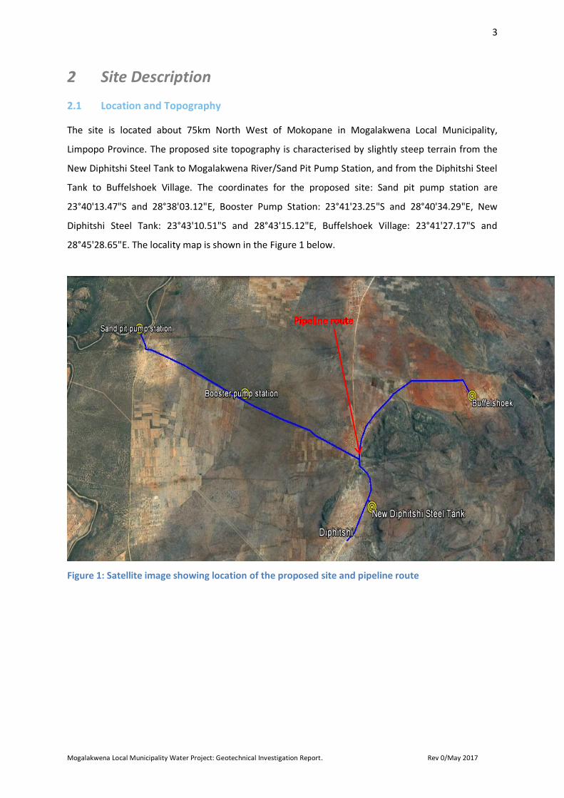
The site is located about 75km North West of Mokopane in Mogalakwena Local Municipality,
Limpopo Province. The proposed site topography is characterised by slightly steep terrain from the
New Diphitshi Steel Tank to Mogalakwena River/Sand Pit Pump Station, and from the Diphitshi Steel
Tank to Buffelshoek Village. The coordinates for the proposed site: Sand pit pump station are
23°40'13.47"S and 28°38'03.12"E, Booster Pump Station: 23°41'23.25"S and 28°40'34.29"E, New
Diphitshi Steel Tank: 23°43'10.51"S and 28°43'15.12"E, Buffelshoek Village: 23°41'27.17"S and
28°45'28.65"E. The locality map is shown in the Figure 1 below.
Figure 1: Satellite image showing location of the proposed site and pipeline route
4
Mogalakwena Local Municipality Water Project: Geotechnical Investigation Report. Rev 0/May 2017
Climate 2.2
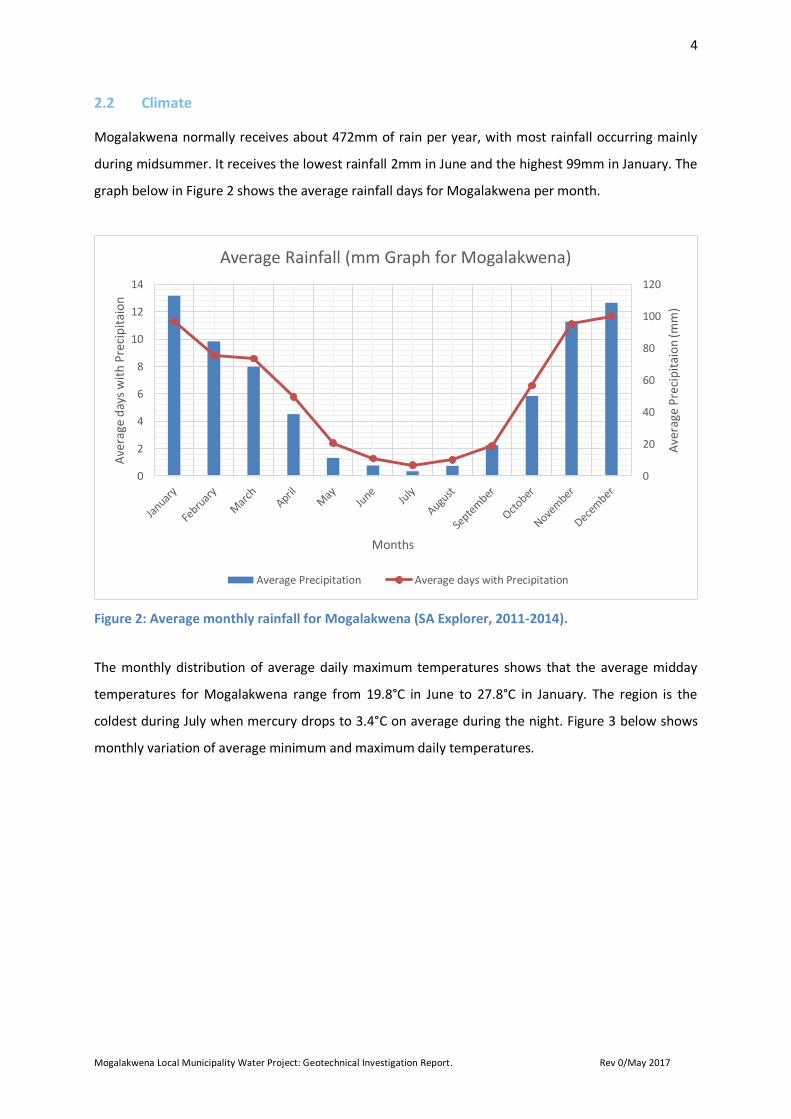
Mogalakwena normally receives about 472mm of rain per year, with most rainfall occurring mainly
during midsummer. It receives the lowest rainfall 2mm in June and the highest 99mm in January. The
graph below in Figure 2 shows the average rainfall days for Mogalakwena per month.
Figure 2: Average monthly rainfall for Mogalakwena (SA Explorer, 2011-2014).
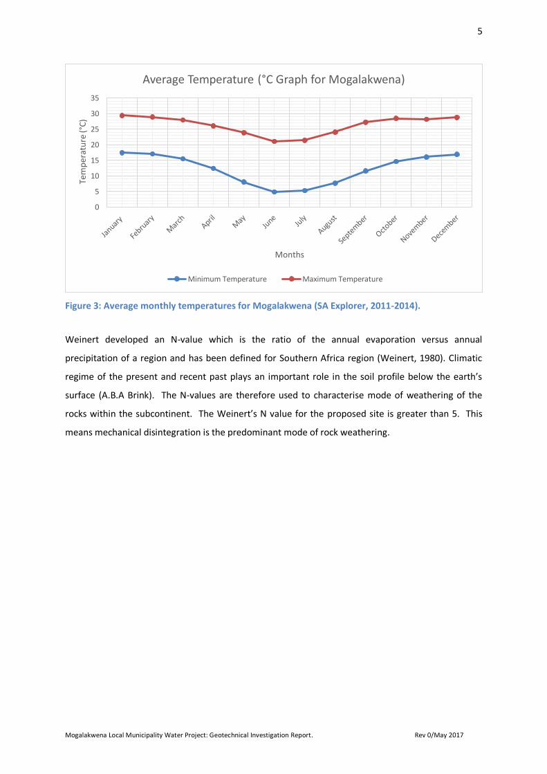
The monthly distribution of average daily maximum temperatures shows that the average midday
temperatures for Mogalakwena range from 19.8°C in June to 27.8°C in January. The region is the
coldest during July when mercury drops to 3.4°C on average during the night. Figure 3 below shows
monthly variation of average minimum and maximum daily temperatures.
0
20
40
60
80
100
120
0
2
4
6
8
10
12
14
Ave
rage
Pre
cip
itai
on
(mm
)
Ave
rage
day
s w
ith
Pre
cip
itai
on
Months
Average Rainfall (mm Graph for Mogalakwena)
Average Precipitation Average days with Precipitation
5
Mogalakwena Local Municipality Water Project: Geotechnical Investigation Report. Rev 0/May 2017
Figure 3: Average monthly temperatures for Mogalakwena (SA Explorer, 2011-2014).
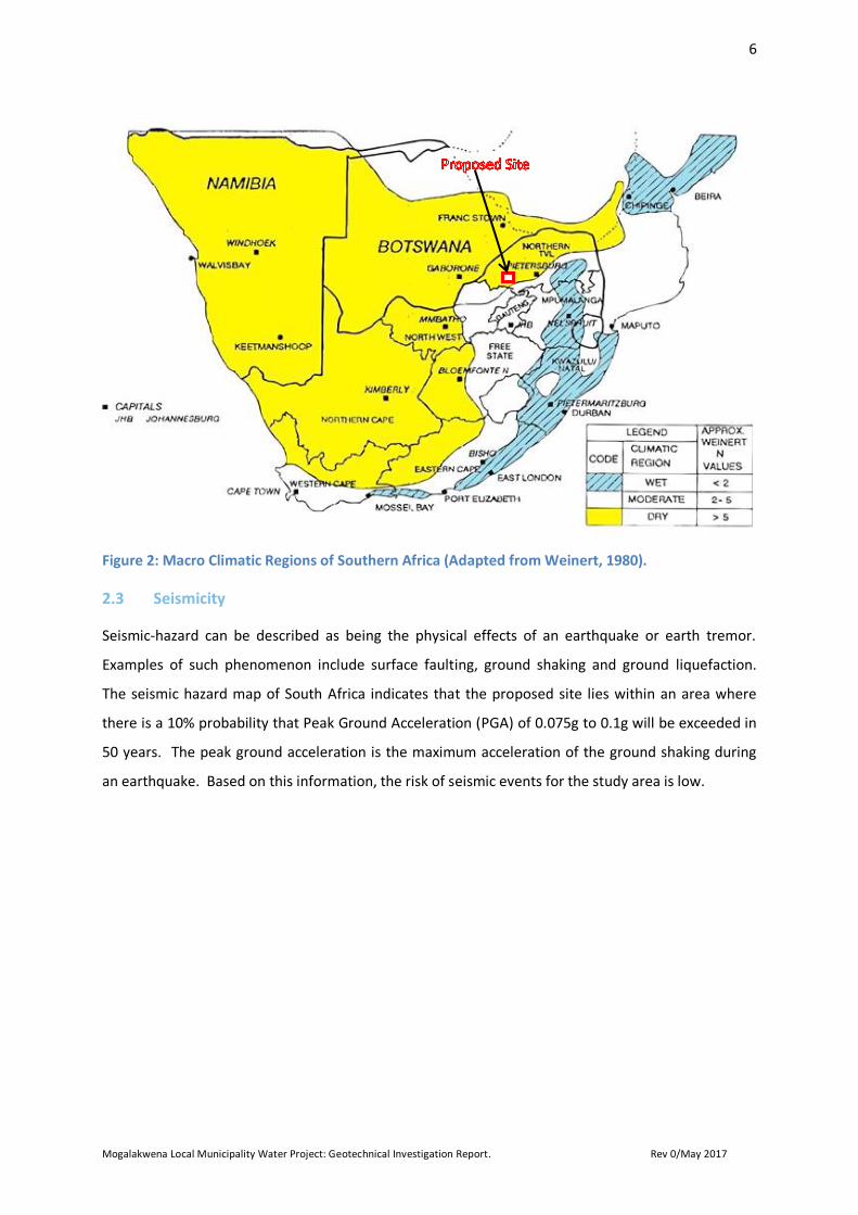
Weinert developed an N-value which is the ratio of the annual evaporation versus annual
precipitation of a region and has been defined for Southern Africa region (Weinert, 1980). Climatic
regime of the present and recent past plays an important role in the soil profile below the earth’s
surface (A.B.A Brink). The N-values are therefore used to characterise mode of weathering of the
rocks within the subcontinent. The Weinert’s N value for the proposed site is greater than 5. This
means mechanical disintegration is the predominant mode of rock weathering.
0
5
10
15
20
25
30
35
Tem
per
atu
re (°
C)
Months
Average Temperature (°C Graph for Mogalakwena)
Minimum Temperature Maximum Temperature
6
Mogalakwena Local Municipality Water Project: Geotechnical Investigation Report. Rev 0/May 2017
Figure 2: Macro Climatic Regions of Southern Africa (Adapted from Weinert, 1980).
Seismicity 2.3
Seismic-hazard can be described as being the physical effects of an earthquake or earth tremor.
Examples of such phenomenon include surface faulting, ground shaking and ground liquefaction.
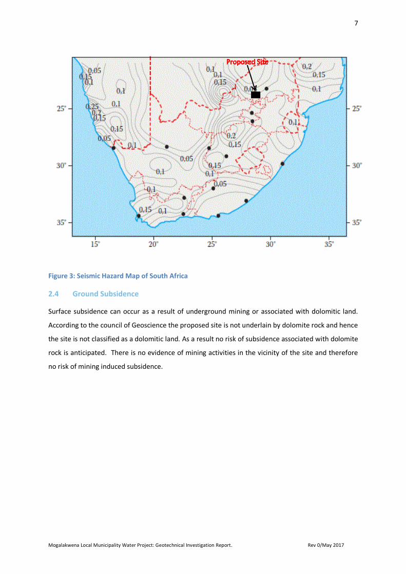
The seismic hazard map of South Africa indicates that the proposed site lies within an area where
there is a 10% probability that Peak Ground Acceleration (PGA) of 0.075g to 0.1g will be exceeded in
50 years. The peak ground acceleration is the maximum acceleration of the ground shaking during
an earthquake. Based on this information, the risk of seismic events for the study area is low.
7
Mogalakwena Local Municipality Water Project: Geotechnical Investigation Report. Rev 0/May 2017
Figure 3: Seismic Hazard Map of South Africa
Ground Subsidence 2.4
Surface subsidence can occur as a result of underground mining or associated with dolomitic land.
According to the council of Geoscience the proposed site is not underlain by dolomite rock and hence
the site is not classified as a dolomitic land. As a result no risk of subsidence associated with dolomite
rock is anticipated. There is no evidence of mining activities in the vicinity of the site and therefore
no risk of mining induced subsidence.
8
Mogalakwena Local Municipality Water Project: Geotechnical Investigation Report. Rev 0/May 2017
3 Geological Setting
Regional Geology 3.1
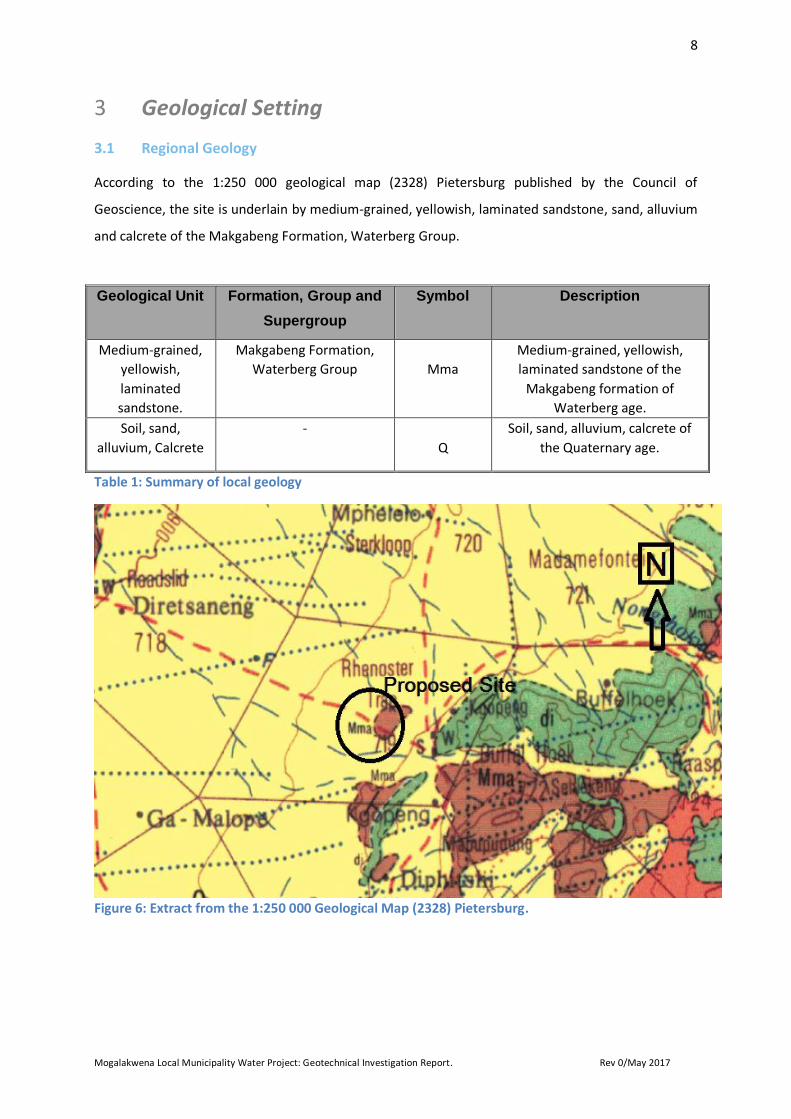
According to the 1:250 000 geological map (2328) Pietersburg published by the Council of
Geoscience, the site is underlain by medium-grained, yellowish, laminated sandstone, sand, alluvium
and calcrete of the Makgabeng Formation, Waterberg Group.
Geological Unit Formation, Group and
Supergroup
Symbol Description
Medium-grained,
yellowish,
laminated
sandstone.
Makgabeng Formation,
Waterberg Group
Mma
Medium-grained, yellowish,
laminated sandstone of the
Makgabeng formation of
Waterberg age.
Soil, sand,
alluvium, Calcrete
-
Q
Soil, sand, alluvium, calcrete of
the Quaternary age.
Table 1: Summary of local geology
Figure 6: Extract from the 1:250 000 Geological Map (2328) Pietersburg.
9
Mogalakwena Local Municipality Water Project: Geotechnical Investigation Report. Rev 0/May 2017
4 Investigation
The field exploration was conducted on the 18th and 19th of April 2017 and comprised of excavating
twenty five (25) test pits. Of the twenty five (25) test pits excavated, two test pits TP 11 and TP 12
were excavated for the Sand Pit Pump Station, test pits TP 13 and TP 14 were excavated for Booster
Pump Station, and test pits TP 15 and TP 16 were excavated for the New Diphitshi Steel Tank with
the remaining nineteen (19) test pits being excavated along the pipeline route. The test pits were
excavated using a tractor loader backhoe (TLB) hired from a local construction plant supplier.
Test Pits 4.1
A walk-over survey was carried out on the proposed site to obtain as much information as possible of
the subsurface conditions from the existing soil. Rock outcrops/exposures were identified in some
areas during the investigation. This procedure was carried simultaneously with the field work, and is
discussed below.
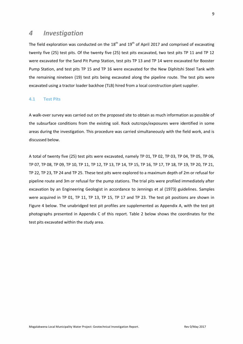
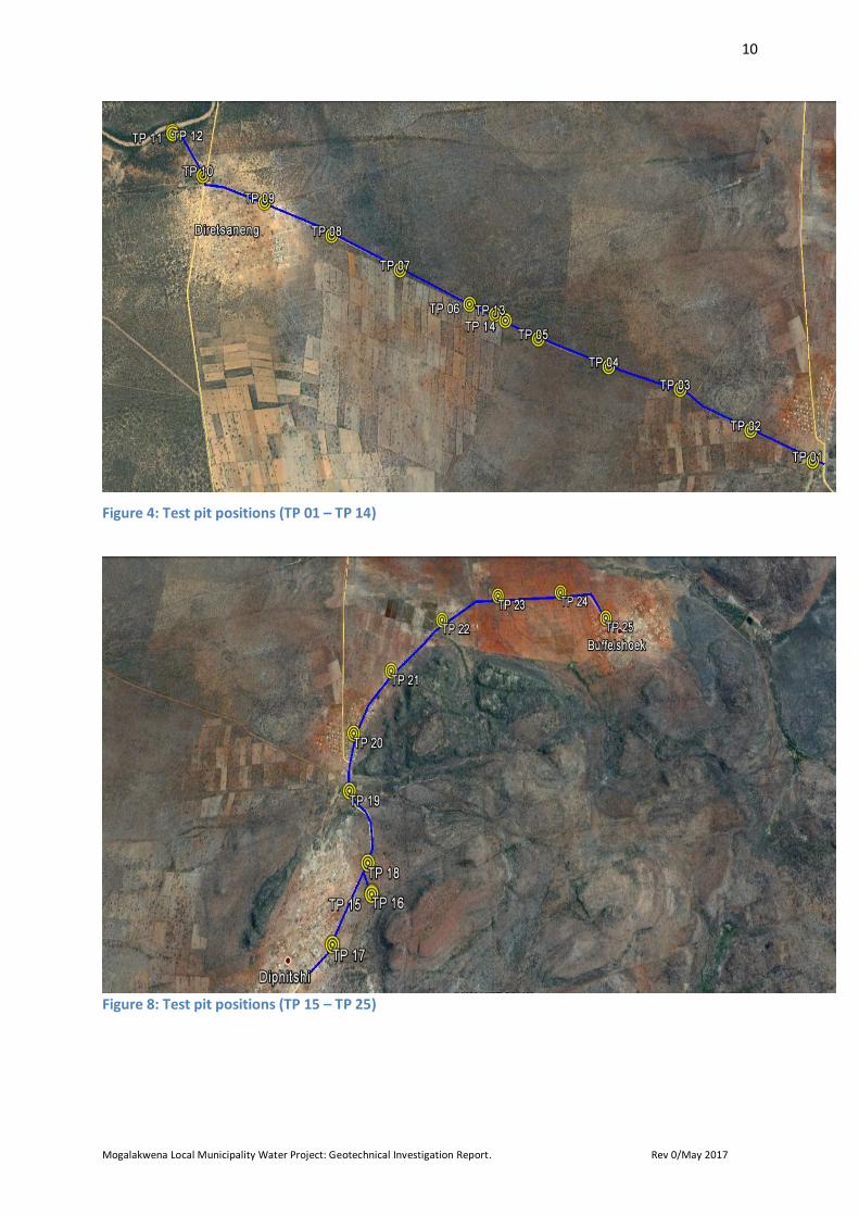
A total of twenty five (25) test pits were excavated, namely TP 01, TP 02, TP 03, TP 04, TP 05, TP 06,
TP 07, TP 08, TP 09, TP 10, TP 11, TP 12, TP 13, TP 14, TP 15, TP 16, TP 17, TP 18, TP 19, TP 20, TP 21,
TP 22, TP 23, TP 24 and TP 25. These test pits were explored to a maximum depth of 2m or refusal for
pipeline route and 3m or refusal for the pump stations. The trial pits were profiled immediately after
excavation by an Engineering Geologist in accordance to Jennings et al (1973) guidelines. Samples
were acquired in TP 01, TP 11, TP 13, TP 15, TP 17 and TP 23. The test pit positions are shown in
Figure 4 below. The unabridged test pit profiles are supplemented as Appendix A, with the test pit
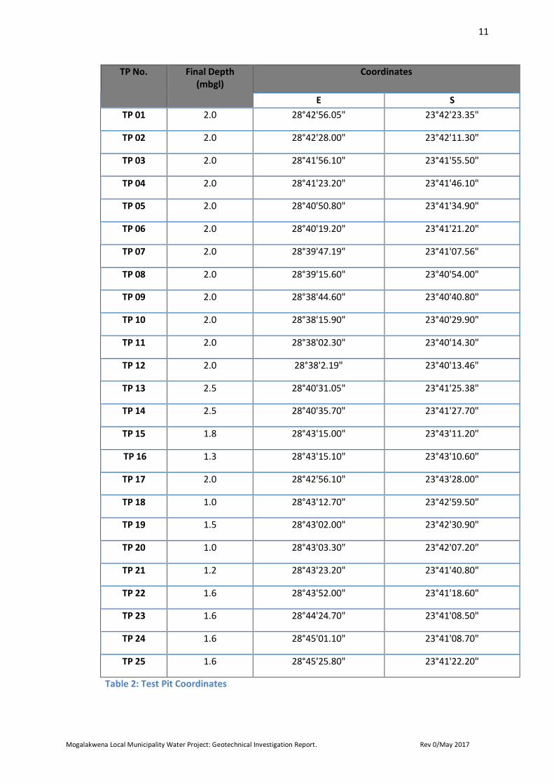
photographs presented in Appendix C of this report. Table 2 below shows the coordinates for the
test pits excavated within the study area.
10
Mogalakwena Local Municipality Water Project: Geotechnical Investigation Report. Rev 0/May 2017
Figure 4: Test pit positions (TP 01 – TP 14)
Figure 8: Test pit positions (TP 15 – TP 25)
11
Mogalakwena Local Municipality Water Project: Geotechnical Investigation Report. Rev 0/May 2017
TP No. Final Depth (mbgl)
Coordinates
E S
TP 01 2.0 28°42'56.05" 23°42'23.35"
TP 02 2.0 28°42'28.00" 23°42'11.30"
TP 03 2.0 28°41'56.10" 23°41'55.50"
TP 04 2.0 28°41'23.20" 23°41'46.10"
TP 05 2.0 28°40'50.80" 23°41'34.90"
TP 06 2.0 28°40'19.20" 23°41'21.20"
TP 07 2.0 28°39'47.19" 23°41'07.56"
TP 08 2.0 28°39'15.60" 23°40'54.00"
TP 09 2.0 28°38'44.60" 23°40'40.80"
TP 10 2.0 28°38'15.90" 23°40'29.90"
TP 11 2.0 28°38'02.30" 23°40'14.30"
TP 12 2.0 28°38'2.19" 23°40'13.46"
TP 13 2.5 28°40'31.05" 23°41'25.38"
TP 14 2.5 28°40'35.70" 23°41'27.70"
TP 15 1.8 28°43'15.00" 23°43'11.20"
TP 16 1.3 28°43'15.10" 23°43'10.60"
TP 17 2.0 28°42'56.10" 23°43'28.00"
TP 18 1.0 28°43'12.70" 23°42'59.50"
TP 19 1.5 28°43'02.00" 23°42'30.90"
TP 20 1.0 28°43'03.30" 23°42'07.20"
TP 21 1.2 28°43'23.20" 23°41'40.80"
TP 22 1.6 28°43'52.00" 23°41'18.60"
TP 23 1.6 28°44'24.70" 23°41'08.50"
TP 24 1.6 28°45'01.10" 23°41'08.70"
TP 25 1.6 28°45'25.80" 23°41'22.20"
Table 2: Test Pit Coordinates
12
Mogalakwena Local Municipality Water Project: Geotechnical Investigation Report. Rev 0/May 2017
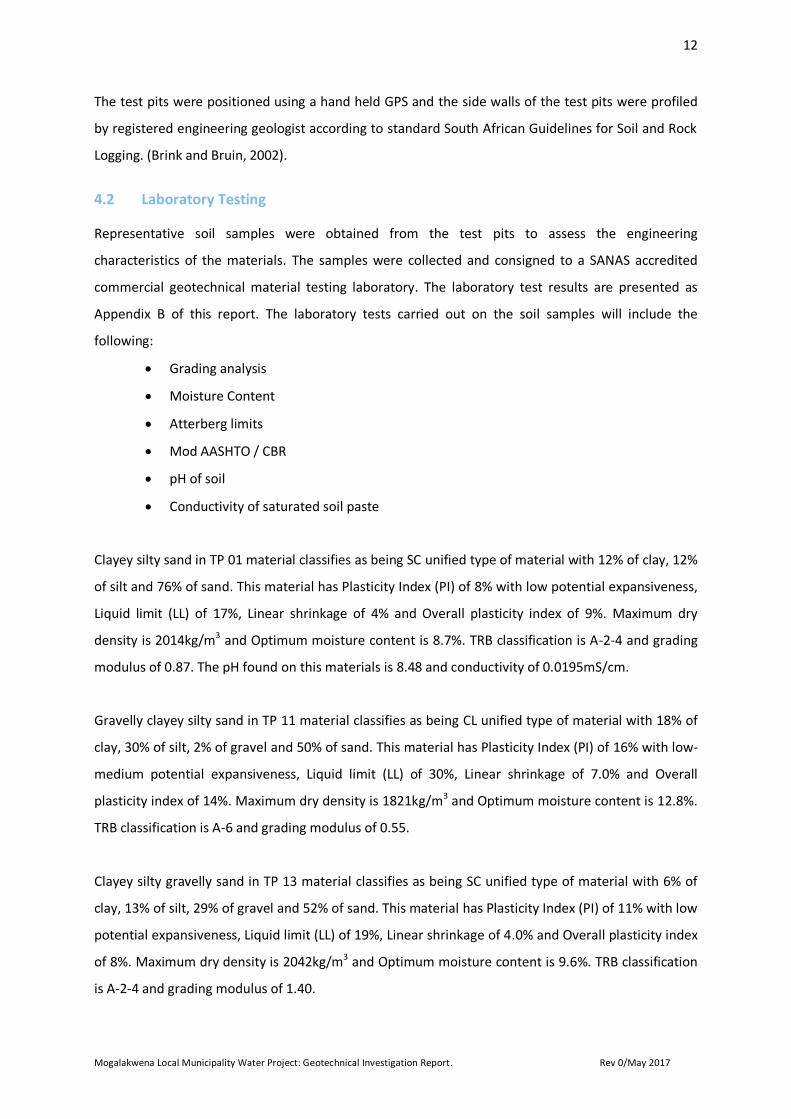
The test pits were positioned using a hand held GPS and the side walls of the test pits were profiled
by registered engineering geologist according to standard South African Guidelines for Soil and Rock
Logging. (Brink and Bruin, 2002).
Laboratory Testing 4.2
Representative soil samples were obtained from the test pits to assess the engineering
characteristics of the materials. The samples were collected and consigned to a SANAS accredited
commercial geotechnical material testing laboratory. The laboratory test results are presented as
Appendix B of this report. The laboratory tests carried out on the soil samples will include the
following:
Grading analysis
Moisture Content
Atterberg limits
Mod AASHTO / CBR
pH of soil
Conductivity of saturated soil paste
Clayey silty sand in TP 01 material classifies as being SC unified type of material with 12% of clay, 12%
of silt and 76% of sand. This material has Plasticity Index (PI) of 8% with low potential expansiveness,
Liquid limit (LL) of 17%, Linear shrinkage of 4% and Overall plasticity index of 9%. Maximum dry
density is 2014kg/m3 and Optimum moisture content is 8.7%. TRB classification is A-2-4 and grading
modulus of 0.87. The pH found on this materials is 8.48 and conductivity of 0.0195mS/cm.
Gravelly clayey silty sand in TP 11 material classifies as being CL unified type of material with 18% of
clay, 30% of silt, 2% of gravel and 50% of sand. This material has Plasticity Index (PI) of 16% with low-
medium potential expansiveness, Liquid limit (LL) of 30%, Linear shrinkage of 7.0% and Overall
plasticity index of 14%. Maximum dry density is 1821kg/m3 and Optimum moisture content is 12.8%.
TRB classification is A-6 and grading modulus of 0.55.
Clayey silty gravelly sand in TP 13 material classifies as being SC unified type of material with 6% of
clay, 13% of silt, 29% of gravel and 52% of sand. This material has Plasticity Index (PI) of 11% with low
potential expansiveness, Liquid limit (LL) of 19%, Linear shrinkage of 4.0% and Overall plasticity index
of 8%. Maximum dry density is 2042kg/m3 and Optimum moisture content is 9.6%. TRB classification
is A-2-4 and grading modulus of 1.40.
13
Mogalakwena Local Municipality Water Project: Geotechnical Investigation Report. Rev 0/May 2017
Gravelly silty clayey sand in TP 15 material classifies as being SC unified type of material with 16% of
clay, 10% of silt, 2% of gravel and 72% of sand. This material has Plasticity Index (PI) of 8% with low
potential expansiveness, Liquid limit (LL) of 16%, Linear shrinkage of 3.5% and overall plasticity index
of 8%. Maximum dry density is 2009kg/m3 and Optimum moisture content is 8.1%. TRB classification
is A-2-4 and grading modulus of 0.78.
Silty clayey sand in TP 17 material classifies as being SC unified type of material with 17% of clay, 10%
of silt and 73% of sand. This material has Plasticity Index (PI) of 10% with low potential
expansiveness, Liquid limit (LL) of 18%, Linear shrinkage of 4% and Overall plasticity index of 8%.
Maximum dry density is 2014kg/m3 and Optimum moisture content is 8.4%. TRB classification is A-2-
4 and grading modulus of 0.83. The pH found on this materials is 7.53 and conductivity of
0.0083mS/cm.
Silty clayey sand in TP 23 material classifies as being CL unified type of material with 31% of clay, 24%
of silt and 45% of sand. This material has Plasticity Index (PI) of 20% with low potential
expansiveness, Liquid limit (LL) of 36%, Linear shrinkage of 8% and Overall plasticity index of 16%.
Maximum dry density is 1746kg/m3 and Optimum moisture content is 15.2%. TRB classification is A-6
with a grading modulus of 0.55 and conductivity of 0.0456mS/cm.
14
Mogalakwena Local Municipality Water Project: Geotechnical Investigation Report. Rev 0/May 2017
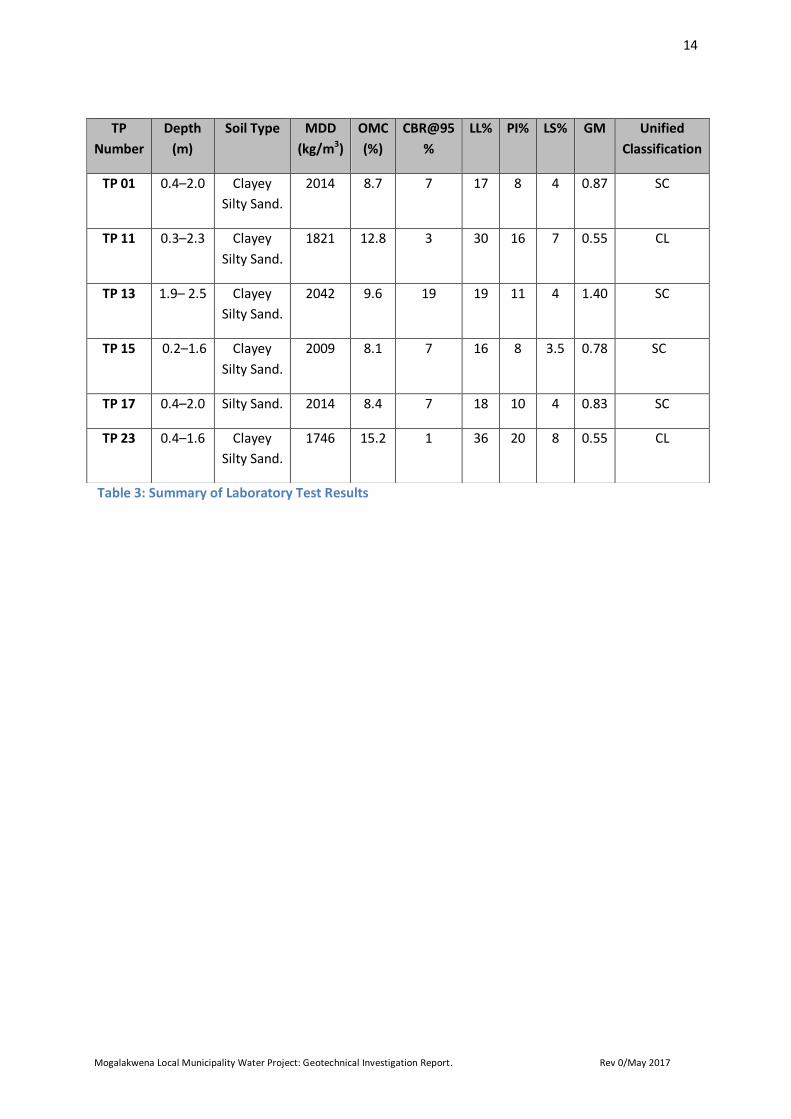
Table 3: Summary of Laboratory Test Results
TP
Number
Depth
(m)
Soil Type MDD
(kg/m3)
OMC
(%)
CBR@95
%
LL% PI% LS% GM Unified
Classification
TP 01 0.4–2.0 Clayey
Silty Sand.
2014 8.7 7 17 8 4 0.87 SC
TP 11 0.3–2.3 Clayey
Silty Sand.
1821 12.8 3 30 16 7 0.55 CL
TP 13 1.9– 2.5 Clayey
Silty Sand.
2042 9.6 19 19 11 4 1.40 SC
TP 15 0.2–1.6 Clayey
Silty Sand.
2009 8.1 7 16 8 3.5 0.78 SC
TP 17 0.4–2.0 Silty Sand. 2014 8.4 7 18 10 4 0.83 SC
TP 23 0.4–1.6 Clayey
Silty Sand.
1746 15.2 1 36 20 8 0.55 CL
15
Mogalakwena Local Municipality Water Project: Geotechnical Investigation Report. Rev 0/May 2017
5 Geotechnical Evaluation
The geotechnical assessment of the proposed site is required to provide a broad overview and
classification of the suitability of the land for the proposed development and outline obvious
constraints to the development of the area.
The following constraints for the classification sites were evaluated:
Materials properties
Groundwater condition
Erodability of the soil profile
Excavation condition
Corrosiveness of soils
Stability of sidewalls
Potential borrow areas
Buried services
Spoiled and stockpile material
Instability of areas of soluble rock
Steep slopes and unstable natural slopes
Areas subject to flooding/drainage
Expansive of soil profile
5.1. Materials properties
The proposed site is generally underlain by a thickly developed soil profile comprising of topsoil to an
average depth 0m to 0.5m below ground level, which is underlain by colluvium to an average depth
of 0.5m to 2.0m below ground level. Residual sandstone layer was observed in TP 09 at 1.4m to 2.0m
depth. The pedogenic horizon with a well cemented calcrete material was also observed in TP 13 and
TP 14 at average depths of 1.9m to 2.5m respectively. Soft to medium hard rock sandstone was
observed in TP 18 at 0.8m to 1.0m.
Topsoil
The transported soils underlying the proposed Pipeline Route, Sand Pit Pump Station, Booster Pump
Station and the Diphitshi Steel Tank have an average depths ranging from 0m to 0.5m and can be
typically described as fine to medium silty sand with plants roots with a consistency of loose to
medium dense with increasing depth.
16
Mogalakwena Local Municipality Water Project: Geotechnical Investigation Report. Rev 0/May 2017
According to the TRH14 classification these materials are typically of G10 quality and are considered
not suitable for reuse in the pipeline engineered fill/bedding but could be used as general fill for
rehabilitation purposes.
Colluvium
Colluvium underlying the proposed Pipeline Route, Sand Pit Pump Station, Booster Pump Station and
the Diphitshi Steel Tank with average depths ranging from 0.5m to 2.0m and can be typically
described as medium to coarse silty sand with plants roots material with a consistency of medium
dense. According to the TRH14 classification these materials are typically of G10 quality and are
considered not suitable for reuse in the pipeline engineered fill/bedding.
Residual Soils
Residual soils, these materials are formed from the complete in-situ weathering of the underlying
sandstone rock, this layer was encountered in TP 09, TP 11, TP 12, TP 15, TP 16, TP 19, TP 20 and TP
21 excavated on the proposed site. The residual soil is composed of silty sandy gravel material at a
depth of 1.2m to 2.2m. The residual soil was typically described as medium dense to dense in
consistency. According to the TRH14 classification, the residual sandstone is classified as G8
respectively and are considered not suitable for reuse as engineered fill/bedding.
Well cemented calcrete (Pedogenic)
The colluvium horizon is underlain by pedogenic (well-cemented calcrete) in TP 13 and TP 14 at an
average depths ranging 1.9m to 2.5m and can be typically described as silty sandy gravel with
calcrete nodules with a consistency of dense material. According to the TRH14 classification these
materials are typically of G08 quality and are considered not suitable for reuse in the pipeline
engineered fill/bedding.
Soft to medium hard rock sandstone
The soft to medium hard rock sandstone is described as slightly weathered, massive and medium to
coarse grained at 0.8m to 1.0m depth. Soft to medium hard rock sandstone was encountered in TP
18. According to the TRH14 classification these materials are typically of G7 to G08 quality and are
considered not suitable for reuse in the pipeline engineered fill/bedding.
17
Mogalakwena Local Municipality Water Project: Geotechnical Investigation Report. Rev 0/May 2017
No seepage was evident in any of the test pits excavated, although it must be noted that the test pits
were excavated during autumn season (i.e. at the end of summer/wet season) and that the site has
received some rainfall for few months prior to site investigation. During the time of the investigation,
the test pits side walls were stable and based on the consistency of the material observed, the test
pit walls can be sustain stability for several days without collapsing when dry.
5.2. Excavation Conditions
The excavation characteristics of the different soil horizons have been evaluated according to the
South African Bureau of Standards standardized excavation classification for earthworks (SABS –
1200D) and earthworks (small works – SABS 1200DA). In terms of this classification and the in-situ
soil/rock consistencies as profiled, the relationships given below are generally applicable.
1. “Soft excavation” - very loose/very soft through to dense or stiff.
2. “Intermediate excavation” - very dense/very stiff through to very soft rock.
3. “Hard excavation” - soft rock or better.
Soft excavation, material which can be efficiently removed or loaded, without prior ripping, by any of
the following plant; a bulldozer or a track type front end loader having an approximate mass of 22
tonne and a fly wheel power of 145kw and a tractor-scraper unit having an approximate mass of 20
tonne and a fly wheel power of 245kw, pushed during loading by a bulldozer equivalent to that
described above (SABS 1200D). These materials were observed on topsoil, colluvium and residual
sandstone layers at all test pits excavated.
Intermediate/Hard excavation, material which can be efficiently ripped by a bulldozer having an
appropriate mass of 35 tonne and a fly wheel power of 220kw. Intermediate excavation of materials
were observed at refusal of soft to medium hard rock sandstone in TP 18. Intermediate excavation of
calcrete materials were observed at near refusal of pedogenic in TP 13 and TP 14 respectively.
Intermediate excavation of materials were also observed at near refusal of cobbles and boulders of
sandstone in TP 15, TP 16, TP 19, TP 20 and TP 21. Intermediate/hard excavation were also observed
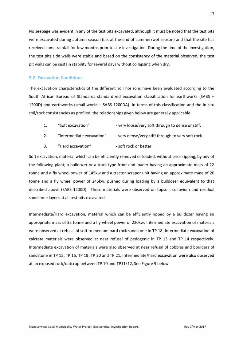
at an exposed rock/outcrop between TP 10 and TP11/12, See Figure 9 below.
18
Mogalakwena Local Municipality Water Project: Geotechnical Investigation Report. Rev 0/May 2017
Figure 9: Exposed rock/outcrop between TP 10 and TP 11
5.3 Stability of Excavation Sidewalls
All test pits excavated during the field investigation of the proposed site were reported as having
stable sidewalls and stood vertically, unsupported whilst profiling was carried out. It is therefore
recommended that all excavations in soils be adequately battered to 1v:1.5h. These
recommendations should only be applied to excavations 3m in height. All safety precautions should
be adhered to during construction.
5.4 Corrosiveness of soils
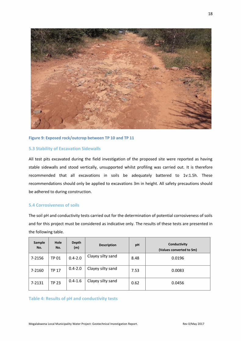
The soil pH and conductivity tests carried out for the determination of potential corrosiveness of soils
and for this project must be considered as indicative only. The results of these tests are presented in
the following table.
Sample
No.
Hole
No.
Depth
(m) Description pH
Conductivity
(Values converted to Sm)
7-2156 TP 01 0.4-2.0 Clayey silty sand 8.48 0.0196
7-2160 TP 17 0.4-2.0 Clayey silty sand 7.53 0.0083
7-2131 TP 23 0.4-1.6 Clayey silty sand 0.62 0.0456
Table 4: Results of pH and conductivity tests
19
Mogalakwena Local Municipality Water Project: Geotechnical Investigation Report. Rev 0/May 2017
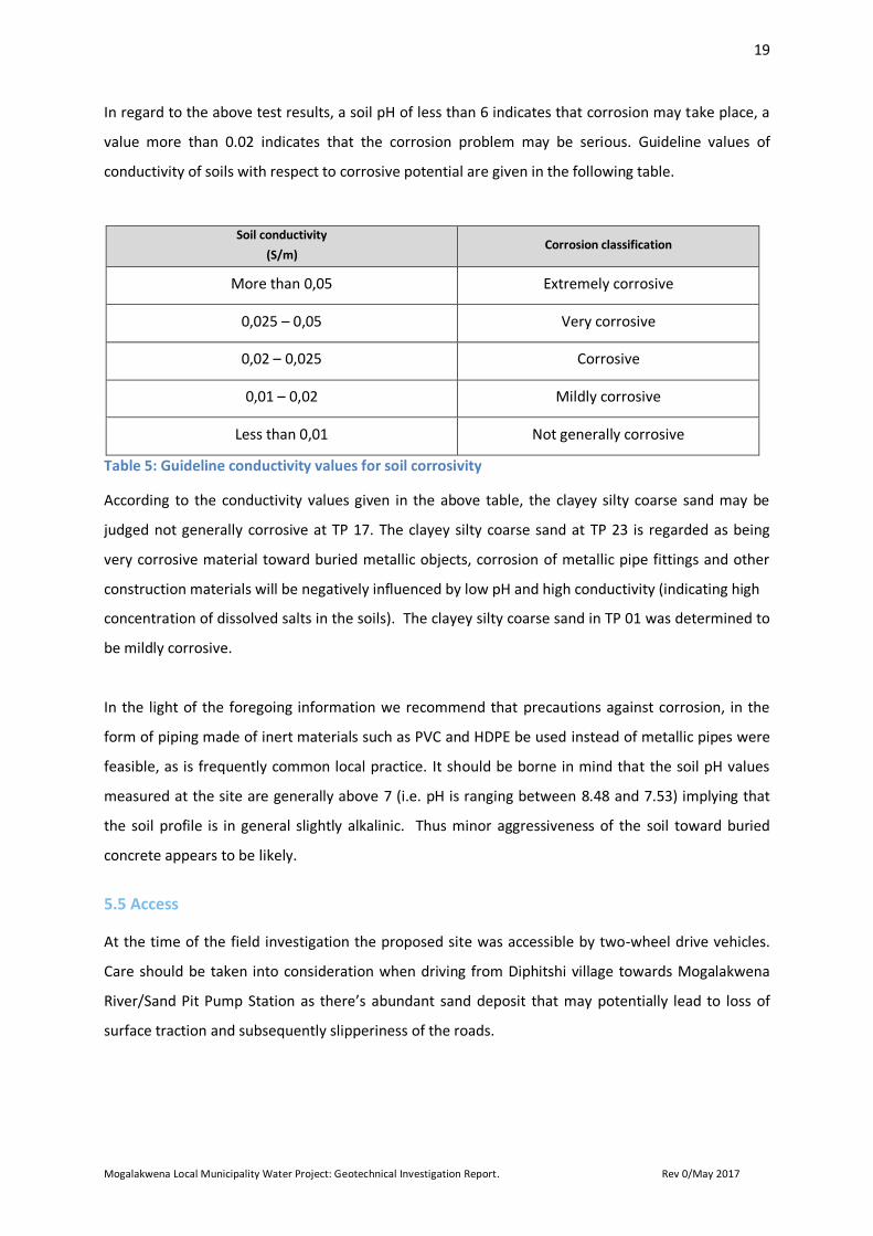
In regard to the above test results, a soil pH of less than 6 indicates that corrosion may take place, a
value more than 0.02 indicates that the corrosion problem may be serious. Guideline values of
conductivity of soils with respect to corrosive potential are given in the following table.
Soil conductivity
(S/m) Corrosion classification
More than 0,05 Extremely corrosive
0,025 – 0,05 Very corrosive
0,02 – 0,025 Corrosive
0,01 – 0,02 Mildly corrosive
Less than 0,01 Not generally corrosive
Table 5: Guideline conductivity values for soil corrosivity
According to the conductivity values given in the above table, the clayey silty coarse sand may be
judged not generally corrosive at TP 17. The clayey silty coarse sand at TP 23 is regarded as being
very corrosive material toward buried metallic objects, corrosion of metallic pipe fittings and other
construction materials will be negatively influenced by low pH and high conductivity (indicating high
concentration of dissolved salts in the soils). The clayey silty coarse sand in TP 01 was determined to
be mildly corrosive.
In the light of the foregoing information we recommend that precautions against corrosion, in the
form of piping made of inert materials such as PVC and HDPE be used instead of metallic pipes were
feasible, as is frequently common local practice. It should be borne in mind that the soil pH values
measured at the site are generally above 7 (i.e. pH is ranging between 8.48 and 7.53) implying that
the soil profile is in general slightly alkalinic. Thus minor aggressiveness of the soil toward buried
concrete appears to be likely.
5.5 Access
At the time of the field investigation the proposed site was accessible by two-wheel drive vehicles.
Care should be taken into consideration when driving from Diphitshi village towards Mogalakwena
River/Sand Pit Pump Station as there’s abundant sand deposit that may potentially lead to loss of
surface traction and subsequently slipperiness of the roads.
20
Mogalakwena Local Municipality Water Project: Geotechnical Investigation Report. Rev 0/May 2017
5.6 Buried services
Underground services exist along the proposed pipeline route between new Diphitshi steel tank and
Buffelshoek village; this includes reticulation and bulk water pipelines. Reticulation small diameter
water pipes (25mm) cross the roads to deliver water into stand house meters. All buried services
should be taken into consideration during construction.
5.7 Potential borrow areas
From the 25 excavated test pits, there is no potential borrow areas along the proposed pipeline
alignment. It is therefore recommended that materials testing of borrow areas be carried out in and
around the proposed site to confirm the availability of the G7 or better materials, alternatively
suitable materials should be brought in from commercial borrow source.
5.8 Stockpile Material (Grading and Compactability)
According to the SABS 1200 LB (pipe bedding) specification, materials with a plasticity index less than
six, (PI) <6, a compactability factor of less than four (<4), and not having lumps/ aggregate greater
than thirty millimetres in diameter (<30mm), can be accepted for use as selected fill or selected
granular material.
The test results summarised in Table 3, depict a PI above the threshold, with an estimated
compactability factor of greater than four (>4) given the material encountered and behavioural
characteristics thereof. The test results further indicate that none of the material encountered along
the pipeline alignment conform to the guidelines mentioned above. A great majority of material will
still be required to be imported from a nearby borrow sources for bedding and cladding
requirements.
5.9 Spoiled Material
The topsoil, colluvium and residual sandstone are considered not suitable for reuse as engineered fill,
and should be stockpiled for reuse in rehabilitation purposes.
5.10 Earthworks (pipeline)
The recommended earthworks for pipeline when founding should be as follows:
• Excavate to a depth of 1500mm.
• Use a roller compactor to compact the base of the excavation to at least 90% of Modified
AASHTO maximum dry density.
21
Mogalakwena Local Municipality Water Project: Geotechnical Investigation Report. Rev 0/May 2017
• Construct an engineered fill above, below and adjacent to water pipe, using G7 or better
quality material in 150mm thick layers (maximum) and compacted to 95% of Modified
AASHTO maximum dry density at +/- 1% OMC.
Suitable compaction equipment is to be utilised. G7 or better materials for use as engineered
fill/bedding on water pipeline should be free from materials that may be harmful to the pipes or to
the protective coatings of the pipes.
5.1.1 Sand pit pump station founding
The topsoil horizon is underlain by colluvium with medium dense consistency generally of clayey silty
sand with an average thickness ranging from 0.3m to 2.3m in TP 11 and TP 12 where sand pit pump
station will be constructed. The colluvium horizon is underlain by residual sandstone with dense
consistency and sandy gravel material.
According to the residential site class designations (SAICE, 1995) the horizons are designated as class
S2 based on the visual inspection and laboratory results, this indicates a site where activity may occur
with the total estimated heave being >20mm and differential movements of 50%.
Type of foundation to be considered on sand pit pump station will be stiffened strip footing with
compaction of in-situ soils below the individual footings. Stiffened strip footing, based on the
designated NHBRC site classes, the foundations should be designed to accommodate approximately
>20mm total settlement below the underside of the footing, strip all topsoil and colluvium to
stockpile for reuse as general fill. Depth for founding the proposed sand pit pump station structure
will be at approximately 1.5m where medium dense colluvium was encountered with a bearing
capacity in the region of 100kPa. Site drainage should be considered during design to circumvent the
effects that surface and or ground water fluctuations may have on consolidation settlement in the
area of construction.
5.1.2 Booster pump station founding
The colluvium horizon is underlain by pedogenic with dense consistency generally of silty sandy
gravel with calcrete nodules at an average thickness ranging from 1.9m to 2.5m in TP 13 and TP 14
where the booster pump station will be constructed. According to the residential site class
designations (SAICE, 1995) the horizons are designated as class C2 based on the visual inspection and
laboratory results, this indicates a site where activity may occur with the total estimated heave being
>10mm and differential movements of 75%.
22
Mogalakwena Local Municipality Water Project: Geotechnical Investigation Report. Rev 0/May 2017
Type of foundation to be considered on booster pump station will be stiffened strip footing with
compaction of in-situ soils below the individual footings. Stiffened strip footing, based on the
designated NHBRC site classes, the foundations should be designed to accommodate approximately
>10mm total settlement below the underside of the footing, strip all colluvium to stockpile for reuse
as general fill. The ideal depth for founding the proposed booster pump station structure is
recommended to be at approximately 2.0m where dense pedogenic (silty sandy gravel with calcrete
nodules) was encountered, with a bearing capacity in the region of +160kPa, alternatively the
material above the pedogenic horizon will have to be engineered (import inert gravel_ G7 place in 150mm
layers and compact to a minimum of 93% Mod, until required founding depth by the design engineer) accordingly to
bring the foundation of the booster station to an shallower depth near to surface. Site drainage
should be considered during design to negate the effects that surface and or ground water
fluctuations may have on consolidation settlement in the area of construction.
5.1.3 New Diphitshi steel tank founding
The topsoil horizon is underlain by colluvium with medium dense consistency generally of clayey silty
sand with sandstone cobbles at an average thickness ranging from 0.2m to 1.6 m in TP 15 and TP 16
where new Diphitshi steel tank will be constructed. The colluvium horizon is further underlain by
residual sandstone with dense consistency generally of sandy gravel with abundant sandstone
cobbles and boulders at an average thickness ranging from 1.6m to 1.8m.
According to the residential site class designations (SAICE, 1995) the horizons are designated as class
C2 based on the visual inspection and laboratory results, this indicates a site where activity may
occur with the total estimated heave being >10mm and differential movements of 75%.
Type of foundation to be considered on new Diphitshi steel tank will be stiffened strip footing with
compaction of in-situ soils below the individual footings. Stiffened strip footing, based on the
designated NHBRC site classes, the foundations should be designed to accommodate approximately
>10mm total settlement below the underside of the footing, strip all topsoil and colluvium to
stockpile for reuse as general fill. Depth for founding the proposed new Diphitshi steel tank structure
is recommended to be at approximately 1.6m where dense residual sandstone was encountered with
a bearing capacity in the region of +200kPa. Site drainage should be considered during design to
negate the effects that surface and or ground water fluctuations may have on consolidation
settlement in the area of construction.
23
Mogalakwena Local Municipality Water Project: Geotechnical Investigation Report. Rev 0/May 2017
5.11 Expansive of soil profile
Soil layers encountered on the proposed site are generally of granular material in nature. As a result
of this and based on visual inspection and laboratory test results interpretation, expansive soil layer
associated with clay minerals does not pose a threat to the proposed site, as no clay horizon was
encountered as an independent layer.
5.12 Erodability of the Soil Profile
The site has gentle to steep slopes along the proposed pipeline route and at new Diphitshi steel tank,
thus runoff water will move relatively moderate to fast in relation to surface, which for most part,
has distinguished vegetation cover and does not show evidence of significant erosion. The surface
soils are comprised of silty fine to coarse sand and sandy gravels with moderate cohesion. It is
therefore expected that erosion of the exposed surface will be minimal but possibly moderate due to
the terrain if adequate precautionary measures are not taken. Exposed excavation walls could
potentially be eroded in places by rain and surface runoff during periods of rainstorms and heavy
down pours, particularly in the case of battered excavation sidewalls.
5.13 Areas Subject to Flooding
Though we have no definitive evidence showing the 1:100 year flood lines, it would appear that since
the route of the water pipeline is parallel to the alignments of the existing gravel roads, potential
flooding would be minimal. Precaution measures must be taken into consideration where the sand
pit pump station will be constructed/located as it appears to be adjacent to Mogalakwena River.
5.14 Steep slopes and unstable natural slopes
Though steeper slopes were intercepted at some portion of the pipeline route, no indication of
unstable natural slopes was found to be present during the investigation.
24
Mogalakwena Local Municipality Water Project: Geotechnical Investigation Report. Rev 0/May 2017
6 Conclusions and Recommendation
6.1. General Comments and Recommendation
This report details the findings of the geotechnical investigation carried out for the proposed
development. The investigation carried out included the excavation of twenty five (25) test pits and
laboratory testing on disturbed soil samples. Based on the fieldwork carried out a typical soil profile
for the proposed site was obtained. The site is considered to be suitable for the proposed
development, however it is recommended that the material where sand pit pump station, booster
pump station and new Diphitshi steel tank be compacted to achieve dense to better consistency. It is
further recommended that materials testing of borrow areas be carried out in and around the
proposed site to confirm the availability of a suitable bedding material.
The geotechnical conditions referred to in this report are specifically those observed from excavated
test pits. Variant conditions with those discussed above may be encountered elsewhere. Any change
from the ground conditions should then be taken into account during design and construction phase;
hence construction supervision by a competent person is advised.
It is, therefore recommended that all excavations and foundation trenches be inspected by a
competent professional geotechnical engineer or engineering geologist to verify that founding
conditions are not at variance with those described herein.
25
Mogalakwena Local Municipality Water Project: Geotechnical Investigation Report. Rev 0/May 2017
7 References
Brink A.B.A. Engineering Geology of Southern Africa., Volume 1. The First 2000 Million Years
of Geological Time. Building publications Pretoria. ISBN 0908423152.
Brink A.B.A. Engineering Geology of Southern Africa., Volume 3. The Karoo Sequence.
Building publications Pretoria. ISBN 0908423152.
Brink A.B.A. and Bruin R.M.H. (eds) (1990) Guidelines for Soil and Rock Logging in South
Africa, 2nd Impression 2002. Proc. Geoterminology Workshop. SAIEG - AEG - SAICE 1990.
Committee of State Road Authorities, Guidelines for Road Construction Material, TRH14
(1985)
SA Explorer (Climate), 2011 - 2017
Jennings J.E., Brink A.B.A. and Williams A.A.B. (1973) Revised Guide to Soil Profiling for Civil
Engineering Purposes in South Africa. The Civil Engineer in South Africa, January 1973.
The South African Bureau of Standard, Standardised Specification of Civil Engineering
Construction, SABS 1200 D_1988
Department of mines, 1:250 0000 Geological map: 2626 West Rand, 1978.
SANS 10160-4:2011, Seismic actions and general requirements. Edition

26
Mogalakwena Local Municipality Water Project: Geotechnical Investigation Report. Rev 0/May 2017
Appendix A: Test Pit Profiles

27
Mogalakwena Local Municipality Water Project: Geotechnical Investigation Report. Rev 0/May 2017
Appendix B: Laboratory Results

28
Mogalakwena Local Municipality Water Project: Geotechnical Investigation Report. Rev 0/May 2017
Appendix C: Test Pit Photographs