Embed Size (px)
Citation preview
General DescriptionThe MAX15162/MAX15162A devices are dual-channel,circuit-breaker ICs. The devices integrate a dual-channelcontroller with dual 140mΩ (in WLP, 180mΩ in TQFN)power MOSFETs and electronic circuit-breaker protectionin a single package.These devices feature constant power control during start-up to keep the MOSFET operating under Safe OperatingArea (SOA). The devices provide robust overcurrent pro-tection with programmable current-limit level, and ad-justable overcurrent shutdown delay for better immunityagainst system noises and load transient. The currentmonitoring pins provide a current sense accuracy of ±3%for each channel. When there is short-circuit at the output,a fast current limit comparator turns off MOSFETs within200ns to isolate the load from the input. During a faultcondition, the MAX15162A enters auto-retry mode andthe MAX15162 enters latch off mode. For both devices,the ALRT pin asserts a fault indication. The MAX15162/MAX15162A can be configured as two independent chan-nels or two parallel channels for one common output.The devices feature a number of protection features in-cluding; IN-to-OUT short-circuit protection, output short-circuit protection, startup watchdog timer, input undervolt-age lockout and internal overtemperature protection.The MAX15162/MAX15162A are available in a 24-pin,4mm x 4mm TQFN package and 16-bump, 2mm x 2mmWLP package and are rated over the -40°C to +105°C op-eration temperature range.
Applications Radio Access Point System Communication Industrial
Benefits and Features 8V to 60V Wide Input Voltage Range Integrated Dual-Power MOSFET Turn-On Resistance 140mΩ (WLP), 180mΩ (TQFN)
MOSFET Dual-Channel Independent or Parallel Mode
Configuration ± 3% Accuracy Current Reporting on Individual
Channel Enable Inputs for Individual Channels Constant Power Control at Startup Startup Watchdog Timer Startup IN-to-OUT Short Protection Undervoltage-Lockout Overcurrent and Overtemperature Fault Status
indication Multilevel Overcurrent Limit Protection Built in Thermal Shutdown Protection Programmable Current Limiting Level Programmable Overcurrent Shut-down Delay time Programmable Auto-Retry Time (MAX15162A) Latch Off in a Fault Event (MAX15162) Auto-retry in a Fault Event (MAX15162A) 24-pin, 4mm x 4mm TQFN or 16-bump, 2mm x 2mm
WLP
Ordering Information appears at end of data sheet.
Click here to ask about the production status of specific part numbers.
MAX15162 8V to 60V Smart Dual 1.5A Circuit Breaker withAccurate Current Monitoring
EVALUATION KIT AVAILABLE
19-100696; Rev 2; 3/21
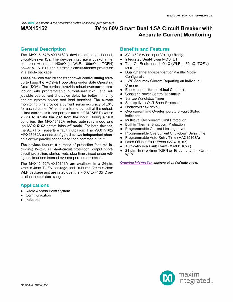
Simplified Block DiagramRU PA ARRAY
PA
PA
PA
PA
GND
DLY
IN OUT1
EN1
OUT2
IMON1
48V
IMON2
ALRT_
EN2ENABLE
CONTROLLOAD
MONITOR
MAX15162 8V to 60V Smart Dual 1.5A Circuit Breaker withAccurate Current Monitoring
www.maximintegrated.com Maxim Integrated | 2
TABLE OF CONTENTSGeneral Description. . . . . . . . . . . . . . . . . . . . . . . . . . . . . . . . . . . . . . . . . . . . . . . . . . . . . . . . . . . . . . . . . . . . . . . . . . . . . . 1Applications . . . . . . . . . . . . . . . . . . . . . . . . . . . . . . . . . . . . . . . . . . . . . . . . . . . . . . . . . . . . . . . . . . . . . . . . . . . . . . . . . . . . 1Benefits and Features . . . . . . . . . . . . . . . . . . . . . . . . . . . . . . . . . . . . . . . . . . . . . . . . . . . . . . . . . . . . . . . . . . . . . . . . . . . . 1Simplified Block Diagram . . . . . . . . . . . . . . . . . . . . . . . . . . . . . . . . . . . . . . . . . . . . . . . . . . . . . . . . . . . . . . . . . . . . . . . . . 2Absolute Maximum Ratings. . . . . . . . . . . . . . . . . . . . . . . . . . . . . . . . . . . . . . . . . . . . . . . . . . . . . . . . . . . . . . . . . . . . . . . . 7Package Information . . . . . . . . . . . . . . . . . . . . . . . . . . . . . . . . . . . . . . . . . . . . . . . . . . . . . . . . . . . . . . . . . . . . . . . . . . . . . 7
WLP . . . . . . . . . . . . . . . . . . . . . . . . . . . . . . . . . . . . . . . . . . . . . . . . . . . . . . . . . . . . . . . . . . . . . . . . . . . . . . . . . . . . . . . 724 TQFN. . . . . . . . . . . . . . . . . . . . . . . . . . . . . . . . . . . . . . . . . . . . . . . . . . . . . . . . . . . . . . . . . . . . . . . . . . . . . . . . . . . . 7
Electrical Characteristics . . . . . . . . . . . . . . . . . . . . . . . . . . . . . . . . . . . . . . . . . . . . . . . . . . . . . . . . . . . . . . . . . . . . . . . . . 8Typical Operating Characteristics . . . . . . . . . . . . . . . . . . . . . . . . . . . . . . . . . . . . . . . . . . . . . . . . . . . . . . . . . . . . . . . . . 10Pin Configurations . . . . . . . . . . . . . . . . . . . . . . . . . . . . . . . . . . . . . . . . . . . . . . . . . . . . . . . . . . . . . . . . . . . . . . . . . . . . . . 12
16 WLP. . . . . . . . . . . . . . . . . . . . . . . . . . . . . . . . . . . . . . . . . . . . . . . . . . . . . . . . . . . . . . . . . . . . . . . . . . . . . . . . . . . . 1224 TQFN. . . . . . . . . . . . . . . . . . . . . . . . . . . . . . . . . . . . . . . . . . . . . . . . . . . . . . . . . . . . . . . . . . . . . . . . . . . . . . . . . . . 12
Pin Description . . . . . . . . . . . . . . . . . . . . . . . . . . . . . . . . . . . . . . . . . . . . . . . . . . . . . . . . . . . . . . . . . . . . . . . . . . . . . . . . 13Functional Diagrams . . . . . . . . . . . . . . . . . . . . . . . . . . . . . . . . . . . . . . . . . . . . . . . . . . . . . . . . . . . . . . . . . . . . . . . . . . . . 14
Block Diagram . . . . . . . . . . . . . . . . . . . . . . . . . . . . . . . . . . . . . . . . . . . . . . . . . . . . . . . . . . . . . . . . . . . . . . . . . . . . . . 14Timing Diagram . . . . . . . . . . . . . . . . . . . . . . . . . . . . . . . . . . . . . . . . . . . . . . . . . . . . . . . . . . . . . . . . . . . . . . . . . . . . . 15
Detailed Description . . . . . . . . . . . . . . . . . . . . . . . . . . . . . . . . . . . . . . . . . . . . . . . . . . . . . . . . . . . . . . . . . . . . . . . . . . . . 16Overview . . . . . . . . . . . . . . . . . . . . . . . . . . . . . . . . . . . . . . . . . . . . . . . . . . . . . . . . . . . . . . . . . . . . . . . . . . . . . . . . . . 16Startup . . . . . . . . . . . . . . . . . . . . . . . . . . . . . . . . . . . . . . . . . . . . . . . . . . . . . . . . . . . . . . . . . . . . . . . . . . . . . . . . . . . . 16Startup in Overload or Short-Circuit Condition . . . . . . . . . . . . . . . . . . . . . . . . . . . . . . . . . . . . . . . . . . . . . . . . . . . . . . 16Undervoltage Lockout (UVLO) . . . . . . . . . . . . . . . . . . . . . . . . . . . . . . . . . . . . . . . . . . . . . . . . . . . . . . . . . . . . . . . . . . 16Input Debounce Protection. . . . . . . . . . . . . . . . . . . . . . . . . . . . . . . . . . . . . . . . . . . . . . . . . . . . . . . . . . . . . . . . . . . . . 17Enable . . . . . . . . . . . . . . . . . . . . . . . . . . . . . . . . . . . . . . . . . . . . . . . . . . . . . . . . . . . . . . . . . . . . . . . . . . . . . . . . . . . . 17IN-to-OUT Short-Circuit Protection. . . . . . . . . . . . . . . . . . . . . . . . . . . . . . . . . . . . . . . . . . . . . . . . . . . . . . . . . . . . . . . 17Overcurrent and Short-Circuit Protection . . . . . . . . . . . . . . . . . . . . . . . . . . . . . . . . . . . . . . . . . . . . . . . . . . . . . . . . . 18Current-Limit Threshold and Current Monitor (IMON_) . . . . . . . . . . . . . . . . . . . . . . . . . . . . . . . . . . . . . . . . . . . . . . . 19Overcurrent Response and Shutdown Delay (DLY). . . . . . . . . . . . . . . . . . . . . . . . . . . . . . . . . . . . . . . . . . . . . . . . . . 20ALRT_ Response . . . . . . . . . . . . . . . . . . . . . . . . . . . . . . . . . . . . . . . . . . . . . . . . . . . . . . . . . . . . . . . . . . . . . . . . . . . . 21Independent and Parallel Mode . . . . . . . . . . . . . . . . . . . . . . . . . . . . . . . . . . . . . . . . . . . . . . . . . . . . . . . . . . . . . . . . 21Fault Auto-Retry and Latch Off. . . . . . . . . . . . . . . . . . . . . . . . . . . . . . . . . . . . . . . . . . . . . . . . . . . . . . . . . . . . . . . . . . 21Thermal Protection . . . . . . . . . . . . . . . . . . . . . . . . . . . . . . . . . . . . . . . . . . . . . . . . . . . . . . . . . . . . . . . . . . . . . . . . . . . 21
Applications Information . . . . . . . . . . . . . . . . . . . . . . . . . . . . . . . . . . . . . . . . . . . . . . . . . . . . . . . . . . . . . . . . . . . . . . . . . 22IN Capacitor . . . . . . . . . . . . . . . . . . . . . . . . . . . . . . . . . . . . . . . . . . . . . . . . . . . . . . . . . . . . . . . . . . . . . . . . . . . . . . . . 22OUT Capacitor . . . . . . . . . . . . . . . . . . . . . . . . . . . . . . . . . . . . . . . . . . . . . . . . . . . . . . . . . . . . . . . . . . . . . . . . . . . . . . 22Output Diode for Inductive Hard Short to Ground . . . . . . . . . . . . . . . . . . . . . . . . . . . . . . . . . . . . . . . . . . . . . . . . . . . 22Layout and Thermal Dissipation. . . . . . . . . . . . . . . . . . . . . . . . . . . . . . . . . . . . . . . . . . . . . . . . . . . . . . . . . . . . . . . . . 22
Typical Application Circuits . . . . . . . . . . . . . . . . . . . . . . . . . . . . . . . . . . . . . . . . . . . . . . . . . . . . . . . . . . . . . . . . . . . . . . . 23
MAX15162 8V to 60V Smart Dual 1.5A Circuit Breaker withAccurate Current Monitoring
www.maximintegrated.com Maxim Integrated | 3
TABLE OF CONTENTS (CONTINUED)Typical Application Circuit—Independent Mode. . . . . . . . . . . . . . . . . . . . . . . . . . . . . . . . . . . . . . . . . . . . . . . . . . . . . 23Typical Application Circuit—Parallel Mode. . . . . . . . . . . . . . . . . . . . . . . . . . . . . . . . . . . . . . . . . . . . . . . . . . . . . . . . . 23
Ordering Information . . . . . . . . . . . . . . . . . . . . . . . . . . . . . . . . . . . . . . . . . . . . . . . . . . . . . . . . . . . . . . . . . . . . . . . . . . . . 24Revision History . . . . . . . . . . . . . . . . . . . . . . . . . . . . . . . . . . . . . . . . . . . . . . . . . . . . . . . . . . . . . . . . . . . . . . . . . . . . . . . 25
MAX15162 8V to 60V Smart Dual 1.5A Circuit Breaker withAccurate Current Monitoring
www.maximintegrated.com Maxim Integrated | 4
LIST OF FIGURESFigure 1. Input Debounce Protection. . . . . . . . . . . . . . . . . . . . . . . . . . . . . . . . . . . . . . . . . . . . . . . . . . . . . . . . . . . . . . . . 17Figure 2. Overcurrent Event . . . . . . . . . . . . . . . . . . . . . . . . . . . . . . . . . . . . . . . . . . . . . . . . . . . . . . . . . . . . . . . . . . . . . . 18Figure 3. Fast Overcurrent Event . . . . . . . . . . . . . . . . . . . . . . . . . . . . . . . . . . . . . . . . . . . . . . . . . . . . . . . . . . . . . . . . . . 19Figure 4. Overcurrent Response and Shutdown Delay. . . . . . . . . . . . . . . . . . . . . . . . . . . . . . . . . . . . . . . . . . . . . . . . . . 20
MAX15162 8V to 60V Smart Dual 1.5A Circuit Breaker withAccurate Current Monitoring
www.maximintegrated.com Maxim Integrated | 5
LIST OF TABLESTable 1. RIMON Settings for Overcurrent Limit in Independent Mode. . . . . . . . . . . . . . . . . . . . . . . . . . . . . . . . . . . . . . . 19Table 2. RIMON Settings for Overcurrent Limit in Parallel Mode. . . . . . . . . . . . . . . . . . . . . . . . . . . . . . . . . . . . . . . . . . . 19Table 3. RDLY Settings for Delay Time and Auto-Retry Time—MAX15162A . . . . . . . . . . . . . . . . . . . . . . . . . . . . . . . . . 20
MAX15162 8V to 60V Smart Dual 1.5A Circuit Breaker withAccurate Current Monitoring
www.maximintegrated.com Maxim Integrated | 6
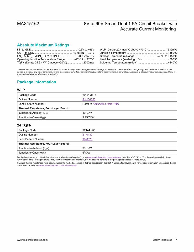
Absolute Maximum RatingsIN_ to GND............................................................. -0.3V to +65VOUT_ to GND.................................................. -1V to (IN_+ 0.3)VEN_, ALRT_, IMON_, DLY to GND ........................ -0.3 V to +6VOperating Junction Temperature Range ............ -40°C to +125°CTQFN (Derate 25.6 mW/°C above +70°C) ..................... 2000mW
WLP (Derate 20.4mW/°C above +70°C).........................1632mWJunction Temperature .......................................................+150°CStorage Temperature Range ..............................-40°C to +150°CLead Temperature (soldering, 10s)...................................+300°CSoldering Temperature (reflow) ........................................+240°C
Stresses beyond those listed under “Absolute Maximum Ratings” may cause permanent damage to the device. These are stress ratings only, and functional operation of thedevice at these or any other conditions beyond those indicated in the operational sections of the specifications is not implied. Exposure to absolute maximum rating conditions forextended periods may affect device reliability.
Package Information
WLPPackage Code W161M1+1Outline Number 21-100353Land Pattern Number Refer to Application Note 1891Thermal Resistance, Four-Layer Board:Junction to Ambient (θJA) 49°C/WJunction to Case (θJC) 9.45°C/W
24 TQFNPackage Code T2444+2COutline Number 21-0139Land Pattern Number 90-0020Thermal Resistance, Four-Layer Board:Junction to Ambient (θJA) 39°C/WJunction to Case (θJC) 6°C/W
For the latest package outline information and land patterns (footprints), go to www.maximintegrated.com/packages. Note that a “+”, “#”, or “-” in the package code indicatesRoHS status only. Package drawings may show a different suffix character, but the drawing pertains to the package regardless of RoHS status.Package thermal resistances were obtained using the method described in JEDEC specification JESD51-7, using a four-layer board. For detailed information on package thermalconsiderations, refer to www.maximintegrated.com/thermal-tutorial.
MAX15162 8V to 60V Smart Dual 1.5A Circuit Breaker withAccurate Current Monitoring
www.maximintegrated.com Maxim Integrated | 7
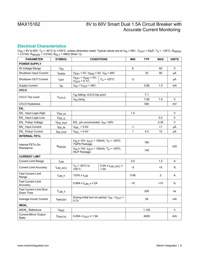
Electrical Characteristics(VIN = 8V to 60V, TA = -40°C to +105°C, unless otherwise noted. Typical values are at VIN = 48V, COUT = 22μF, TA = +25°C, RIMON1= 3.01kΩ, RIMON2 = 3.01kΩ, RDLY = 68kΩ (Note 1))
PARAMETER SYMBOL CONDITIONS MIN TYP MAX UNITSPOWER SUPPLYIN Voltage Range VIN 8 60 VShutdown Input Current ISHDN VEN1 = 0V, VEN2 = 0V, VIN = 48V 32 90 µA
Shutdown OUT Current IOFFVEN1 = VEN2 = 0V;VOUT = 0.1V; TA = +25°C -2 µA
Supply Current IIN VIN = VOUT = 48V, 0.88 1.5 mAUVLO
UVLO Trip Level VUVLOVIN falling, UVLO trip point 7.1VIN rising 7.58 7.9 V
UVLO Hysteresis 500 mVEN_EN_ Input Logic-High VEN_IH 1.4 VEN_ Input Logic-Low VEN_IL 0.4 VEN_ Pullup Voltage VEN_PUP EN_ pin unconnected, VIN = 60V 2.35 VEN_ Input Current IEN_IN VEN_ = 5.5V -1 +1 µAEN_ Pullup Current IEN_PUP VEN_ = 0.4V 1 4.5 12 μAINTERNAL FETs
Internal FETs On-Resistance RDSON
VIN ≥ 10V, IOUT = 100mA, TA = +25ºC,TQFN Package 180
mΩVIN ≥ 10V, IOUT = 100mA, TA = +25ºC,WLP Package 140
CURRENT LIMITCurrent Limit Range ILIM 0.5 1.5 A
Current Limit Accuracy ILIM_ACCTA = -40°C to105°C
0.5A ≤ ILIM_ACC ≤1.5A -5 +5 %
Fast Current LimitRange ILIM_F 133% x ILIM 0.66 2 A
Fast Current LimitAccuracy 0.66A ≤ ILIM_F ≤ 2A -10 +10 %
Fast Current Limit ShutDown Time TLIM_F 200 ns
Average Inrush Current IINRUSHDuring initial turn-on period, VIN - VOUT >0.7V 28 mA
IMON_IMON_ Reference VREF 1.125 VCurrent-Mirror OutputRatio CIRATIO 0.05A ≤ IOUT ≤ 1.5A 4000 A/A
MAX15162 8V to 60V Smart Dual 1.5A Circuit Breaker withAccurate Current Monitoring
www.maximintegrated.com Maxim Integrated | 8
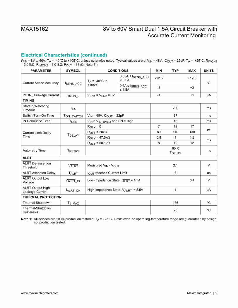
Electrical Characteristics (continued)(VIN = 8V to 60V, TA = -40°C to +105°C, unless otherwise noted. Typical values are at VIN = 48V, COUT = 22μF, TA = +25°C, RIMON1= 3.01kΩ, RIMON2 = 3.01kΩ, RDLY = 68kΩ (Note 1))
PARAMETER SYMBOL CONDITIONS MIN TYP MAX UNITS
Current Sense Accuracy ISENS_ACCTA = -40°C to+105°C
0.05A ≤ ISENS_ACC< 0.5A -12.5 +12.5
%0.5A ≤ ISENS_ACC≤ 1.5A -3 +3
IMON_ Leakage Current IIMON_L VEN1 = VEN2 = 0V -1 +1 μATIMINGStartup WatchdogTimeout TSU 250 ms
Switch Turn-On Time TON_SWITCH VIN = 48V, COUT = 22μF 37 msIN Debounce Time TDEB VIN > VIN_UVLO and EN = High 16 ms
Current Limit DelayTime TDELAY
RDLY = 0 7 12 17μs
RDLY = 28kΩ 80 110 130RDLY = 47.5kΩ 0.8 1 1.2
msRDLY = 68.1kΩ 8 10 12
Auto-retry Time TRETRY60 X
TDELAYms
ALRTALRT De-assertionThreshold VALRT Measured VIN - VOUT 2.1 V
ALRT Assertion Delay TALRT IOUT reaches Current Limit 6 usALRT Output LowVoltage VALRT_OL Low-Impedance State, IALRT = 1mA 0.4 V
ALRT Output HighLeakage Current IALRT_OH High-Impedance State, VALRT = 5.5V 1 uA
THERMAL PROTECTIONThermal Shutdown TJ_MAX 156 °CThermal-ShutdownHysteresis 20 °C
Note 1: All devices are 100% production tested at TA = +25°C. Limits over the operating-temperature range are guaranteed by design;not production tested.
MAX15162 8V to 60V Smart Dual 1.5A Circuit Breaker withAccurate Current Monitoring
www.maximintegrated.com Maxim Integrated | 9
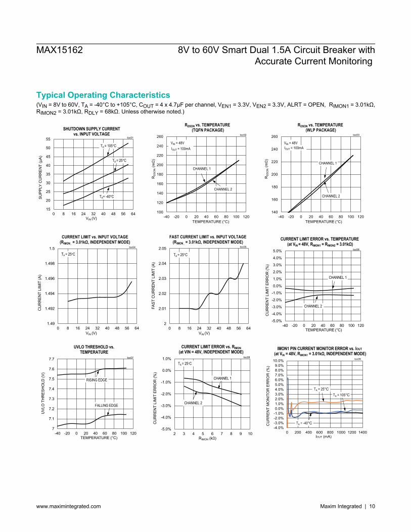
Typical Operating Characteristics(VIN = 8V to 60V, TA = -40°C to +105°C, COUT = 4 x 4.7μF per channel, VEN1 = 3.3V, VEN2 = 3.3V, ALRT = OPEN, RIMON1 = 3.01kΩ,RIMON2 = 3.01kΩ, RDLY = 68kΩ. Unless otherwise noted.)
MAX15162 8V to 60V Smart Dual 1.5A Circuit Breaker withAccurate Current Monitoring
www.maximintegrated.com Maxim Integrated | 10
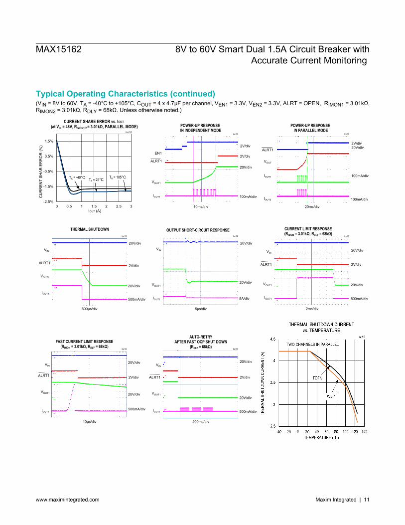
Typical Operating Characteristics (continued)(VIN = 8V to 60V, TA = -40°C to +105°C, COUT = 4 x 4.7μF per channel, VEN1 = 3.3V, VEN2 = 3.3V, ALRT = OPEN, RIMON1 = 3.01kΩ,RIMON2 = 3.01kΩ, RDLY = 68kΩ. Unless otherwise noted.)
TTHHEERRMMAALL SSHHUUTTDDOOWWNN CCUURRRREENNTT vvss.. TTEEMMPPEERRAATTUURREE
toc18
THER
MAL S
HUTD
OWN
CURR
ENT
(A)
TEMPERATURE (°C)
TWO CHANNELS IN PARALLEL
TQFN
WLP
-40 140-20 0 20 40 60 80 1201002.5
3
3.5
4.5
4
MAX15162 8V to 60V Smart Dual 1.5A Circuit Breaker withAccurate Current Monitoring
www.maximintegrated.com Maxim Integrated | 11
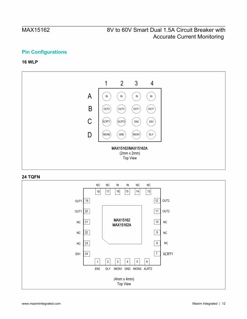
Pin Configurations
16 WLP
MAX15162/MAX15162AMAX15162/MAX15162A(2mm x 2mm)
Top View
1 2 3 4
A
B
C
D DLYIMON1
IN
GND
EN1
IN IN
OUT1
IMON2
ALRT1
OUT2
IN
OUT2 OUT1
ALRT2 EN2
24 TQFN
(4mm x 4mm)Top View
18 17 16 15
1 2 3 4
MAX15162MAX15162MAXMAX15162A15162A
NC IN IN
NC
DLY IMON1 GNDEN2
12 OUT2
11
NC10
9
19
20
21
22
NC
OUT1
NC
NC NC
8 NC
7
5 6
IMON2
EN1
23
24
NC
OUT1
NC
OUT2
1314
ALRT2
ALRT1
MAX15162 8V to 60V Smart Dual 1.5A Circuit Breaker withAccurate Current Monitoring
www.maximintegrated.com Maxim Integrated | 12
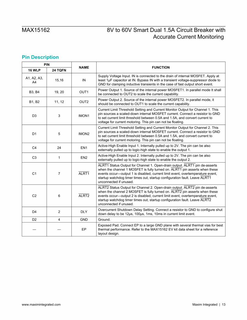
Pin DescriptionPIN
NAME FUNCTION16 WLP 24 TQFN
A1, A2, A3,A4 15,16 IN
Supply Voltage Input. IN is connected to the drain of internal MOSFET. Apply atleast 1µF capacitor at IN. Bypass IN with a transient voltage-suppressor diode toGND for clamping inductive transients in the case of fast output short event.
B3, B4 19, 20 OUT1 Power Output 1. Source of the internal power MOSFET1. In parallel mode It shallbe connected to OUT2 to scale the current capability.
B1, B2 11, 12 OUT2 Power Output 2. Source of the internal power MOSFET2. In parallel mode, itshould be connected to OUT1 to scale the current capability.
D3 3 IMON1
Current Limit Threshold Setting and Current Monitor Output for Channel 1. Thispin sources a scaled-down internal MOSFET current. Connect a resistor to GNDto set current limit threshold between 0.5A and 1.5A, and convert current tovoltage for current motoring. This pin can not be floating.
D1 5 IMON2
Current Limit Threshold Setting and Current Monitor Output for Channel 2. Thispin sources a scaled-down internal MOSFET current. Connect a resistor to GNDto set current limit threshold between 0.5A and 1.5A, and convert current tovoltage for current motoring. This pin can not be floating.
C4 24 EN1 Active-High Enable Input 1. Internally pulled up to 2V. The pin can be alsoexternally pulled up to logic-high state to enable the output 1.
C3 1 EN2 Active-High Enable Input 2. Internally pulled up to 2V. The pin can be alsoexternally pulled up to logic-high state to enable the output 2.
C1 7 ALRT1
ALRT1 Status Output for Channel 1. Open-drain output. ALRT1 pin de-assertswhen the channel 1 MOSFET is fully turned on. ALRT1 pin asserts when theseevents occur—output 1 is disabled, current limit event, overtemperature event,startup watchdog timer times out, startup configuration fault. Leave ALRT1unconnected if unused.
C2 6 ALRT2
ALRT2 Status Output for Channel 2. Open-drain output. ALRT2 pin de-assertswhen the channel 2 MOSFET is fully turned on. ALRT2 pin asserts when theseevents occur—output 2 is disabled, current limit event, overtemperature event,startup watchdog timer times out, startup configuration fault. Leave ALRT2unconnected if unused.
D4 2 DLY Overcurrent Shutdown Delay Setting. Connect a resistor to GND to configure shutdown delay to be 12µs, 100µs, 1ms, 10ms in current limit event.
D2 4 GND Ground.
— — EPExposed Pad. Connect EP to a large GND plane with several thermal vias for bestthermal performance. Refer to the MAX15162 EV kit data sheet for a referencelayout design.
MAX15162 8V to 60V Smart Dual 1.5A Circuit Breaker withAccurate Current Monitoring
www.maximintegrated.com Maxim Integrated | 13
Functional Diagrams
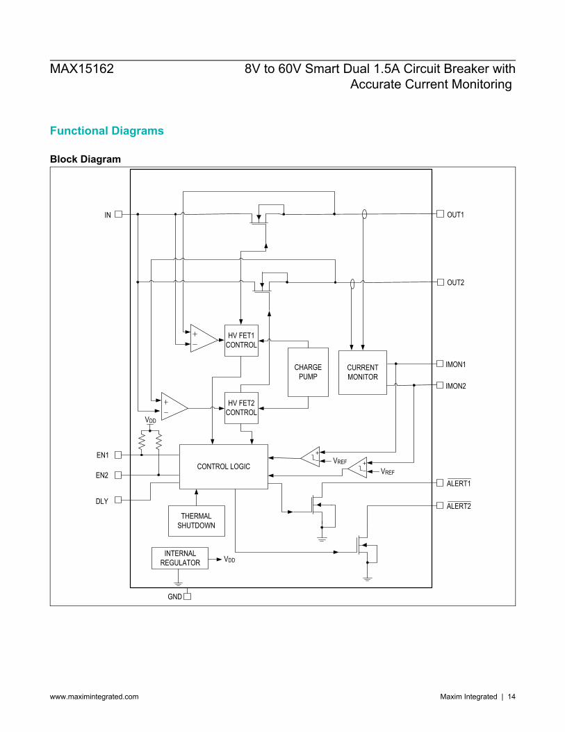
Block Diagram
IN OUT1
OUT2
HV FET1 CONTROL
HV FET2 CONTROL
CHARGE PUMP
CONTROL LOGIC
THERMAL SHUTDOWN
EN1
EN2
GND
ALERT2
ALERT1
INTERNAL REGULATOR VDD
VDD
DLY
IMON2
IMON1CURRENT MONITOR
VREFVREF
MAX15162 8V to 60V Smart Dual 1.5A Circuit Breaker withAccurate Current Monitoring
www.maximintegrated.com Maxim Integrated | 14
Functional Diagrams (continued)
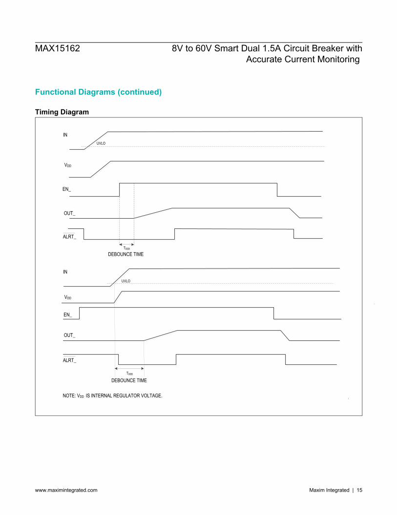
Timing Diagram
ININ
VDDVDD
EN_EN_
ALRT_ALRT_
UVLOUVLO
TDEBTDEB
DEBOUNCE TIMEDEBOUNCE TIME
OUT_OUT_
ININ
VDDVDD
EN_EN_
OUT_OUT_
ALRT_ALRT_
UVLOUVLO
DEBOUNCE TIMEDEBOUNCE TIMETDEBTDEB
NOTE: VDD IS INTERNAL REGULATOR VOLTAGE. NOTE: VDD IS INTERNAL REGULATOR VOLTAGE.
MAX15162 8V to 60V Smart Dual 1.5A Circuit Breaker withAccurate Current Monitoring
www.maximintegrated.com Maxim Integrated | 15
Detailed Description
OverviewThe MAX15162/MAX15162A are 8V to 60V integrated, dual-channel circuit breaker devices. The dual channels can beconfigured as independent mode, or parallel mode to scale up the current capability. The devices feature constant powercontrol during startup process to ensure MOSFETs operating under Safe Operating Area (SOA). The programmablecurrent limit and adjustable shutdown time for current limit event provide flexibility for various applications with differentpower levels. The fast overcurrent protection can shut down the MOSFET within 200ns when a larger current or short-circuit occurs at the output. The ±3% current monitoring over the input and temperature change can provide accuratecurrent information to the system. The ALRT response indicates the output and fault status, and it asserts when The output is disabled Current limit occurs Overtemperature occurs Startup watchdog times out Configuration fault occurs.The active-high EN pin functions make enable/disable easy to control. The input and EN debounce protection preventthe MOSFET turning on from noisy or transitioning input or EN signals. The IN-to-OUT short-circuit protection preventsthe MOSFET from turning on when the MOSFET is shorted or the input and output are in shorted condition. The devicesprovide a choice of auto-retry or latch-off mode during fault events based on MAX15162A or MAX15162.
StartupThe devices are designed to power-up the output with constant power control by actively monitoring the MOSFET powerand limiting the startup current. The startup current is a series of pulsating current whose duty cycles are controlledby constant power limit circuit. The averaged startup current with constant power control is approximately 28mA. Thisscheme is to ensure the internal MOSFET operate within SOA during the startup. Once the output ramps up to be within700mV of the input voltage, the MOSFET is switched to constant current control to expedite the startup process. Whenthe MOSFET is fully turned on, the current limit is switched to programmable normal operation current limit threshold.An internal watchdog timer starts counting when the devices enter the startup phase. The devices complete the startupphase, de-assert ALRT pin and enter normal operation mode once VIN - VOUT < 700mV. If the watchdog timer elapsesand VIN - VOUT is still greater than 700mV, the MOSFET will be turned off and the devices enter auto-retry mode inthe MAX15162A or latch mode in the MAX15162. When the auto-retry time elapses the part will restart the power-upprocess. The thermal-protection circuit is always active and the MOSFET will be immediately turned off when the thermal-shutdown threshold is reached.
Startup in Overload or Short-Circuit ConditionWhen the device powers up the MOSFET with a very large load or short circuit at the output, the duty cycles of thepulsating startup current is limited to initial values to ensure the power dissipation is not overheating the device . While theoutput is shorted to GND, the MOSFET will be turned off once the startup watchdog timer times out in 250ms. The devicethen restarts the power-up process in auto-retry mode (MAX15162A), or latches off the MOSFET until EN is toggled orthe input is cycled to cross UVLO (MAX15162).
Undervoltage Lockout (UVLO)The devices feature an undervoltage lockout functionality. When the input voltage falls below VUVLO the internalMOSFET is turned off immediately and ALRT pin asserts to indicate the fault condition. The UVLO comparator has ahysteresis of 500mV (typ).
MAX15162 8V to 60V Smart Dual 1.5A Circuit Breaker withAccurate Current Monitoring
www.maximintegrated.com Maxim Integrated | 16
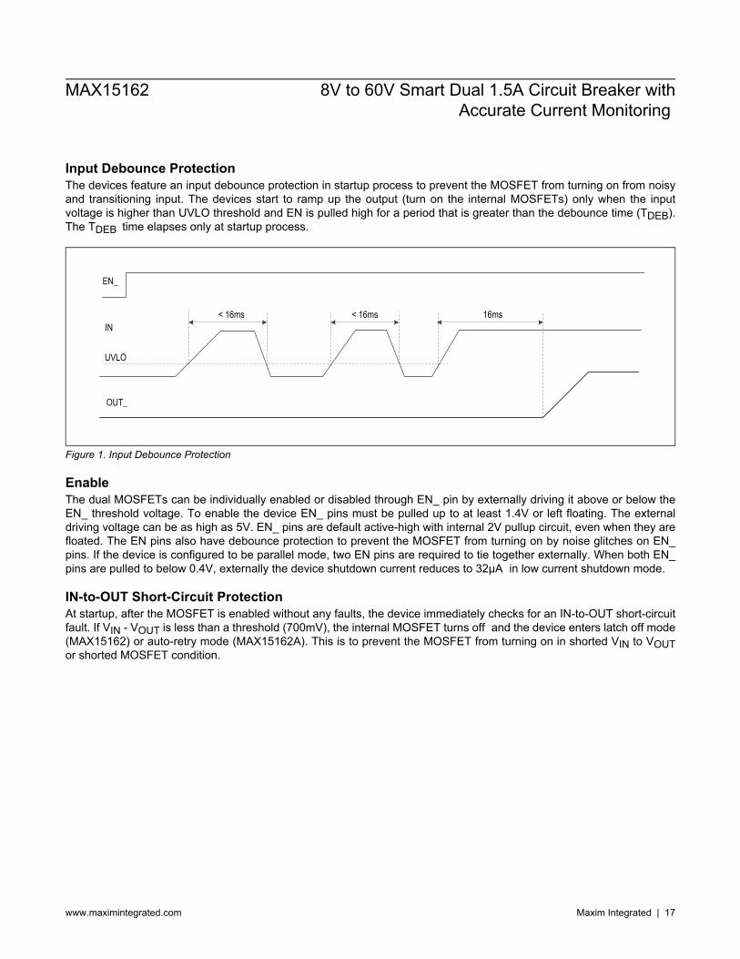
Input Debounce ProtectionThe devices feature an input debounce protection in startup process to prevent the MOSFET from turning on from noisyand transitioning input. The devices start to ramp up the output (turn on the internal MOSFETs) only when the inputvoltage is higher than UVLO threshold and EN is pulled high for a period that is greater than the debounce time (TDEB).The TDEB time elapses only at startup process.
IN
UVLO
< 16ms < 16ms 16ms
OUT_
EN_
Figure 1. Input Debounce Protection
EnableThe dual MOSFETs can be individually enabled or disabled through EN_ pin by externally driving it above or below theEN_ threshold voltage. To enable the device EN_ pins must be pulled up to at least 1.4V or left floating. The externaldriving voltage can be as high as 5V. EN_ pins are default active-high with internal 2V pullup circuit, even when they arefloated. The EN pins also have debounce protection to prevent the MOSFET from turning on by noise glitches on EN_pins. If the device is configured to be parallel mode, two EN pins are required to tie together externally. When both EN_pins are pulled to below 0.4V, externally the device shutdown current reduces to 32µA in low current shutdown mode.
IN-to-OUT Short-Circuit ProtectionAt startup, after the MOSFET is enabled without any faults, the device immediately checks for an IN-to-OUT short-circuitfault. If VIN - VOUT is less than a threshold (700mV), the internal MOSFET turns off and the device enters latch off mode(MAX15162) or auto-retry mode (MAX15162A). This is to prevent the MOSFET from turning on in shorted VIN to VOUTor shorted MOSFET condition.
MAX15162 8V to 60V Smart Dual 1.5A Circuit Breaker withAccurate Current Monitoring
www.maximintegrated.com Maxim Integrated | 17
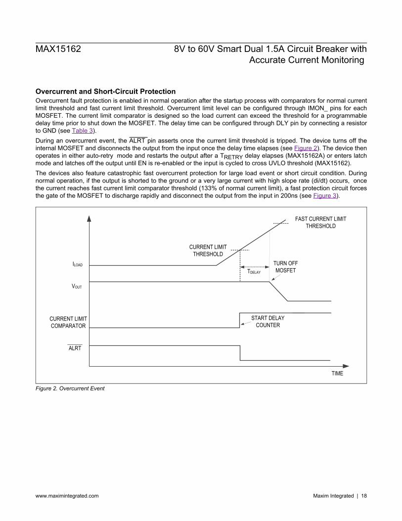
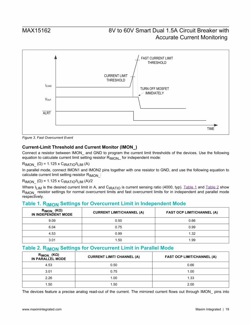
Overcurrent and Short-Circuit ProtectionOvercurrent fault protection is enabled in normal operation after the startup process with comparators for normal currentlimit threshold and fast current limit threshold. Overcurrent limit level can be configured through IMON_ pins for eachMOSFET. The current limit comparator is designed so the load current can exceed the threshold for a programmabledelay time prior to shut down the MOSFET. The delay time can be configured through DLY pin by connecting a resistorto GND (see Table 3).During an overcurrent event, the ALRT pin asserts once the current limit threshold is tripped. The device turns off theinternal MOSFET and disconnects the output from the input once the delay time elapses (see Figure 2). The device thenoperates in either auto-retry mode and restarts the output after a TRETRY delay elapses (MAX15162A) or enters latchmode and latches off the output until EN is re-enabled or the input is cycled to cross UVLO threshold (MAX15162).The devices also feature catastrophic fast overcurrent protection for large load event or short circuit condition. Duringnormal operation, if the output is shorted to the ground or a very large current with high slope rate (di/dt) occurs, oncethe current reaches fast current limit comparator threshold (133% of normal current limit), a fast protection circuit forcesthe gate of the MOSFET to discharge rapidly and disconnect the output from the input in 200ns (see Figure 3).
VOUT
CURRENT LIMIT COMPARATOR
ALRT
CURRENT LIMIT THRESHOLD
START DELAY COUNTER
TURN OFF MOSFET
FAST CURRENT LIMIT THRESHOLD
TIME
TDELAY
ILOAD
Figure 2. Overcurrent Event
MAX15162 8V to 60V Smart Dual 1.5A Circuit Breaker withAccurate Current Monitoring
www.maximintegrated.com Maxim Integrated | 18
VOUT
ILOAD
ALRT
CURRENT LIMIT THRESHOLD
TURN OFF MOSFET IMMDIATELY
FAST CURRENT LIMIT THRESHOLD
TIME
Figure 3. Fast Overcurrent Event
Current-Limit Threshold and Current Monitor (IMON_)Connect a resistor between IMON_ and GND to program the current limit thresholds of the devices. Use the followingequation to calculate current limit setting resistor RIMON_ for independent mode:RIMON_ (Ω) = 1.125 x CIRATIO/ILIM (A)In parallel mode, connect IMON1 and IMON2 pins together with one resistor to GND, and use the following equation tocalculate current limit setting resistor RIMON_:RIMON_ (Ω) = 1.125 x CIRATIO/ILIM (A)/2Where ILIM is the desired current limit in A, and CIRATIO is current sensing ratio (4000, typ). Table 1 and Table 2 showRIMON_ resistor settings for normal overcurrent limits and fast overcurrent limits for in independent and parallel moderespectively.
Table 1. RIMON Settings for Overcurrent Limit in Independent ModeRIMON_ (KΩ)
IN INDEPENDENT MODE CURRENT LIMIT/CHANNEL (A) FAST OCP LIMIT/CHANNEL (A)
9.09 0.50 0.66
6.04 0.75 0.99
4.53 0.99 1.32
3.01 1.50 1.99
Table 2. RIMON Settings for Overcurrent Limit in Parallel ModeRIMON_ (KΩ)
IN PARALLEL MODE CURRENT LIMIT/ CHANNEL (A) FAST OCP LIMIT/CHANNEL (A)
4.53 0.50 0.66
3.01 0.75 1.00
2.26 1.00 1.33
1.50 1.50 2.00
The devices feature a precise analog read-out of the current. The mirrored current flows out through IMON_ pins into
MAX15162 8V to 60V Smart Dual 1.5A Circuit Breaker withAccurate Current Monitoring
www.maximintegrated.com Maxim Integrated | 19
external current-limit resistor RIMON. The voltage on IMON_ pin VIMON provides information about the current with thefollowing relationship:IOUT (A) = VIMON (V) x CIRATIO/RIMON (Ω)In independent mode, IOUT in above equation represents the current from individual channel. In parallel mode, whileconnect IMON1 and IMON2 pins together, IOUT represents the summed current of two channels.IMON_ pins must not be left floating.
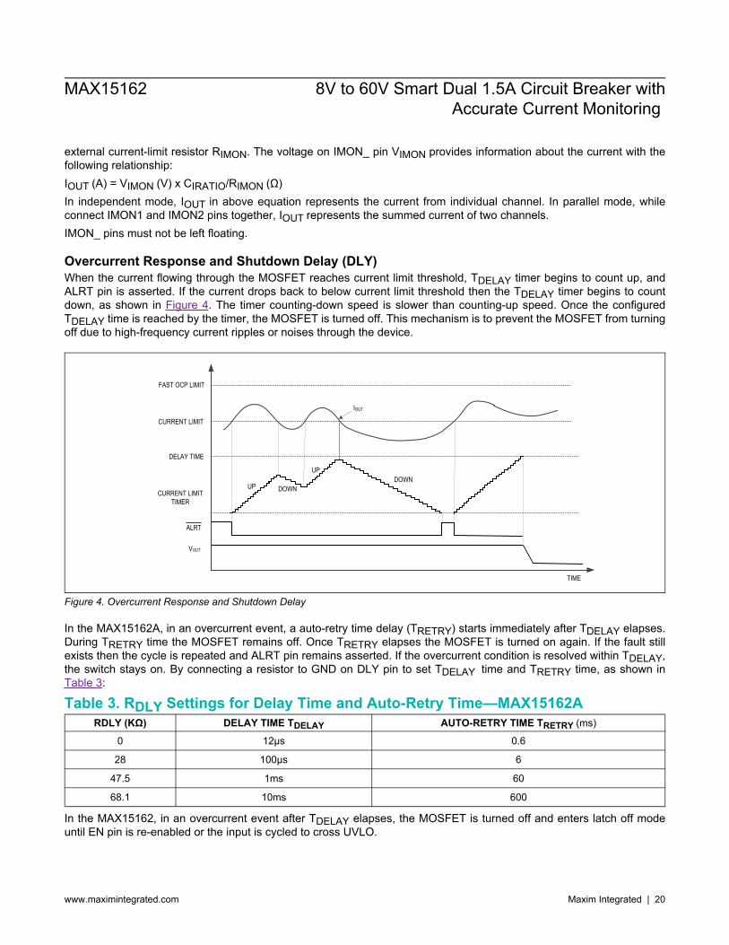
Overcurrent Response and Shutdown Delay (DLY)When the current flowing through the MOSFET reaches current limit threshold, TDELAY timer begins to count up, andALRT pin is asserted. If the current drops back to below current limit threshold then the TDELAY timer begins to countdown, as shown in Figure 4. The timer counting-down speed is slower than counting-up speed. Once the configuredTDELAY time is reached by the timer, the MOSFET is turned off. This mechanism is to prevent the MOSFET from turningoff due to high-frequency current ripples or noises through the device.
FAST OCP LIMIT
DELAY TIME
CURRENT LIMIT
UP DOWN
UP
CURRENT LIMIT TIMER
ALRT
VOUT
IOUT
TIME
DOWN
Figure 4. Overcurrent Response and Shutdown Delay
In the MAX15162A, in an overcurrent event, a auto-retry time delay (TRETRY) starts immediately after TDELAY elapses.During TRETRY time the MOSFET remains off. Once TRETRY elapses the MOSFET is turned on again. If the fault stillexists then the cycle is repeated and ALRT pin remains asserted. If the overcurrent condition is resolved within TDELAY,the switch stays on. By connecting a resistor to GND on DLY pin to set TDELAY time and TRETRY time, as shown inTable 3:
Table 3. RDLY Settings for Delay Time and Auto-Retry Time—MAX15162ARDLY (KΩ) DELAY TIME TDELAY AUTO-RETRY TIME TRETRY (ms)
0 12μs 0.6
28 100μs 6
47.5 1ms 60
68.1 10ms 600
In the MAX15162, in an overcurrent event after TDELAY elapses, the MOSFET is turned off and enters latch off modeuntil EN pin is re-enabled or the input is cycled to cross UVLO.
MAX15162 8V to 60V Smart Dual 1.5A Circuit Breaker withAccurate Current Monitoring
www.maximintegrated.com Maxim Integrated | 20
ALRT_ ResponseThe devices feature an open-drain, ALRT_ output as indication of MOSFET fully turning on and fault events. Oncethe MOSFET is fully enhanced without any faults ALERT_ pin will be de-asserted and remain de-asserted in MOSFETnormal operation. ALERT_ pin will be asserted when MOSFET VDS voltage is greater than 2V. Input voltage drops to UVLO level. Overcurrent limit threshold is tripped. Overtemperature threshold is tripped. Startup watchdog timer times out. Startup configuration fault occurs.In Parallel mode, ALERT_ pins are driven by status of both MOSFETs. Fault from either channel will assert both ALERT_pins.
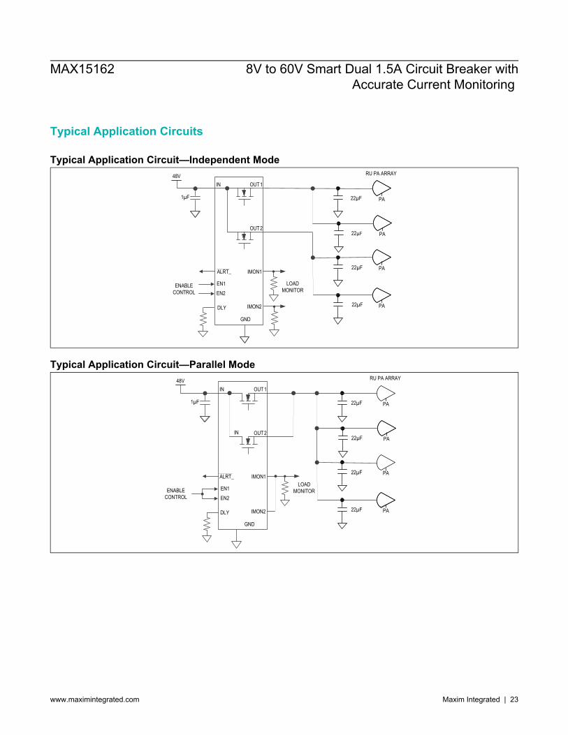
Independent and Parallel ModeThe devices can be configured as two independent channels or parallel channels for one common output. The device isconfigured as independent mode if IMON_pins are separately connecting to two resistors. To configure as parallel mode,two IMON_ pins are required to tie together and connect to one resistor across IMON_ to GND, EN1 and EN2 pins arerequired to tie together, and OUT1 and OUT2 are to be connected together. The device detects IMON_ pins connectionduring initialization process and determines independent or parallel channel configuration mode. IMON_ pins must notbe left floating; otherwise, a startup configuration fault occurs.
Fault Auto-Retry and Latch OffIn a fault condition, the MAX15162A supports auto-retry mode and the MAX15162 supports latch-off mode. When thedevice turns off the MOSFET due to below fault conditions: Overcurrent event after delay time elapses. Fast overcurrent threshold is tripped. Output hard short event. Startup watchdog timer times out.After the MOSFET is turned off, the MAX15162A enters auto-retry mode and restarts the power-up process after auto-retry delay time elapses. If the power-up is not successful in 250ms watchdog timeout, it stops and waits till the delaytime elapses and starts next power-up. The auto-retry attempts totally 3 times. After three time auto-retries if the power-up is still not successfully the device stops retrying and latches off. In auto-retry mode, the delay time is configured byDLY pin.The MAX15162 enters latch off mode once the fault events occur and the MOSFET is turned off, and it restarts thepower-up process once EN_ is re-enabled or the input is cycled to cross UVLO.
Thermal ProtectionThe devices enter a thermal-shutdown mode in the event of overheating caused by excessive power dissipation orhigh ambient temperature. When the junction temperature exceeds thermal shutdown threshold, the internal thermal-protection circuitry turns off the MOSFET and ALRT_ asserts to indicate the fault event. When the junction temperaturefalls below thermal-shutdown threshold hysteresis level, the device restarts the MOSFET power-up process.
MAX15162 8V to 60V Smart Dual 1.5A Circuit Breaker withAccurate Current Monitoring
www.maximintegrated.com Maxim Integrated | 21
Applications Information
IN CapacitorPlace at least a 1μF capacitor from the IN pin to GND to hold input voltage during any transients. If the upstreamconverter is too far away from the MAX15162, more input capacitors are recommended to be added to stabilize inputvoltage due to sudden load-current changes or MOSFET fast turn-off.
OUT CapacitorThe maximum capacitive load (CMAX) that can be connected is a function of average startup current (IINRUSH), thewatchdog time (TSU) and the input voltage (VIN). CMAX can be calculated using the following relationship:
CMAX(μF) =IINRUSH(mA) × TSU(ms)
VIN(V)
Equation 1: Maximum Output CapacitorFor example, for VIN = 48V, TSU = 250ms, and IINRUSH = 28mA, CMAX is 146µF.Output capacitor values in excess of CMAX can result in a longer charging period and startup time, hence the possibilityof watchdog timeout fault. Since the startup process is constant power limited, excessive capacitors will not cause morepower dissipation or thermally stress the device.
Output Diode for Inductive Hard Short to GroundIn applications that require protection from a sudden short to ground with an inductive load or a long cable, a diodebetween the OUT terminal and ground is recommended. This is to prevent a negative spike on the OUT due to theinductive kickback during a short-circuit event.
Layout and Thermal DissipationTo optimize the switch response time to turn off the output fast during short-circuit conditions, it is very important to keepall traces as short as possible to reduce the effect of undesirable parasitic inductance. Place the device close to the inputsupply to avoid too much parasitic inductance. Place input capacitors as close as possible to the device (no more than5mm). Place output capacitors close to the load. If there are protection devices such as TVS, or diodes, they must beplaced close to the part with short traces to reduce inductance. IN and OUT must be connected with wide short traces tothe power bus.To allow for the best cooling ability of the TQFN package, the EP (exposed pad) must be soldered directly to the boardGND plane. It is highly recommended to apply four 20mil thermal vias on EP to help power dissipation, and reducethermal resistance to the ambient. On the PCB board, the second layer from top and bottom should be continuousGND plane for electrical and thermal optimization. Place all support components close to connection pins. Connect thecomponents to the GND with shortest trace length. The trace for IMON_ pin resistor RIMON1/2 to the device must be asshort as possible to reduce parasitic effects on the current limit and current reporting accuracy. Avoid any coupling ofswitching signals from the board to RIMON traces.Refer to the MAX15162 EV kit data sheet for a reference layout design.
MAX15162 8V to 60V Smart Dual 1.5A Circuit Breaker withAccurate Current Monitoring
www.maximintegrated.com Maxim Integrated | 22
Typical Application Circuits
Typical Application Circuit—Independent ModeRU PA ARRAY
22µF PA
22µF PA
22µF PA
22µF PA
GND
DLY
IN OUT1
EN1
OUT2
IMON1
48V
IMON2
ALRT_
1µF
EN2ENABLE
CONTROLLOAD
MONITOR
Typical Application Circuit—Parallel ModeRU PA ARRAY
22µF PA
22µF PA
22µF PA
22µF PA
GND
DLY
IN OUT 1
EN1
IN OUT 2
IMON1
48V
IMON2
ALRT_
1µF
EN2ENABLE
CONTROL
LOAD MONITOR
MAX15162 8V to 60V Smart Dual 1.5A Circuit Breaker withAccurate Current Monitoring
www.maximintegrated.com Maxim Integrated | 23
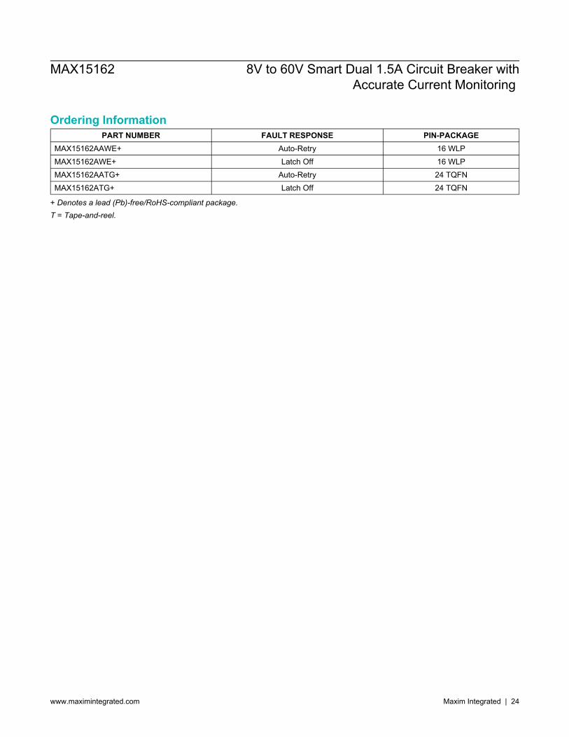
Ordering InformationPART NUMBER FAULT RESPONSE PIN-PACKAGE
MAX15162AAWE+ Auto-Retry 16 WLPMAX15162AWE+ Latch Off 16 WLPMAX15162AATG+ Auto-Retry 24 TQFNMAX15162ATG+ Latch Off 24 TQFN
+ Denotes a lead (Pb)-free/RoHS-compliant package.T = Tape-and-reel.
MAX15162 8V to 60V Smart Dual 1.5A Circuit Breaker withAccurate Current Monitoring
www.maximintegrated.com Maxim Integrated | 24
Revision HistoryREVISIONNUMBER
REVISIONDATE DESCRIPTION PAGES
CHANGED0 11/19 Initial release —1 2/20 Updated Benefits and Features, Thermal Protection, and Ordering Information 1, 16, 232 3/21 Updated Absolute Maximum Ratings and Functional Diagrams 2, 13
For pricing, delivery, and ordering information, please visit Maxim Integrated’s online storefront at https://www.maximintegrated.com/en/storefront/storefront.html.
Maxim Integrated cannot assume responsibility for use of any circuitry other than circuitry entirely embodied in a Maxim Integrated product. No circuit patentlicenses are implied. Maxim Integrated reserves the right to change the circuitry and specifications without notice at any time. The parametric values (min and maxlimits) shown in the Electrical Characteristics table are guaranteed. Other parametric values quoted in this data sheet are provided for guidance.
MAX15162 8V to 60V Smart Dual 1.5A Circuit Breaker withAccurate Current Monitoring
Maxim Integrated and the Maxim Integrated logo are trademarks of Maxim Integrated Products, Inc. © 2021 Maxim Integrated Products, Inc.


![MITSUBISHI ELECTRIC Global website...1.5A/ 6.5 [Power Supply] R61P [CPU] R04CPU RY40NT5P Total Consumption Current 1.5A / 6.5A S V DC 32 / current consumption 1.5A /s_SA /6.5A Az áramfelvétel](https://img.pdfslide.us/doc/110x75/5f36fe787071e7134c12f678/mitsubishi-electric-global-website-15a-65-power-supply-r61p-cpu-r04cpu.jpg)