Embed Size (px)
Citation preview
CLIC MAIN LINAC DDSCLIC MAIN LINAC DDSDESIGN AND FORTCOMINGDESIGN AND FORTCOMING
Vasim Khan & Roger Jones
V. Khan LC-ABD 09, Cockcroft Institute 22.09.09 1/14
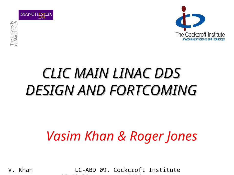
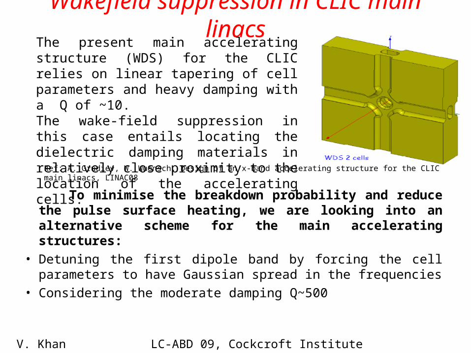
Wakefield suppression in CLIC main linacsThe present main accelerating structure (WDS) for the CLIC relies on linear tapering of cell parameters and heavy damping with a Q of ~10. The wake-field suppression in this case entails locating the dielectric damping materials in relatively close proximity to the location of the accelerating cells.
Ref: A. Grudiev, W. Wuensch, Design of an x-band accelerating structure for the CLIC main linacs, LINAC08
V. Khan LC-ABD 09, Cockcroft Institute 22.09.09 2/14
Wakefield suppression in CLIC main linacs
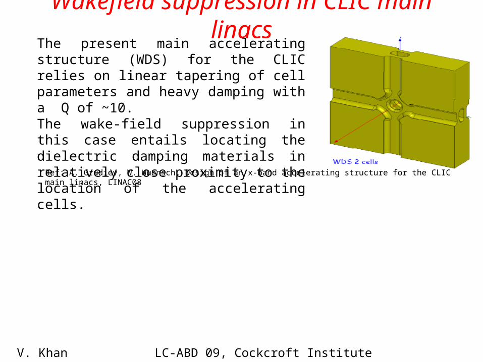
To minimise the breakdown probability and reduce the pulse surface heating, we are looking into an alternative scheme for the main accelerating structures:
The present main accelerating structure (WDS) for the CLIC relies on linear tapering of cell parameters and heavy damping with a Q of ~10. The wake-field suppression in this case entails locating the dielectric damping materials in relatively close proximity to the location of the accelerating cells.
Ref: A. Grudiev, W. Wuensch, Design of an x-band accelerating structure for the CLIC main linacs, LINAC08
V. Khan LC-ABD 09, Cockcroft Institute 22.09.09 2/14
Wakefield suppression in CLIC main linacs
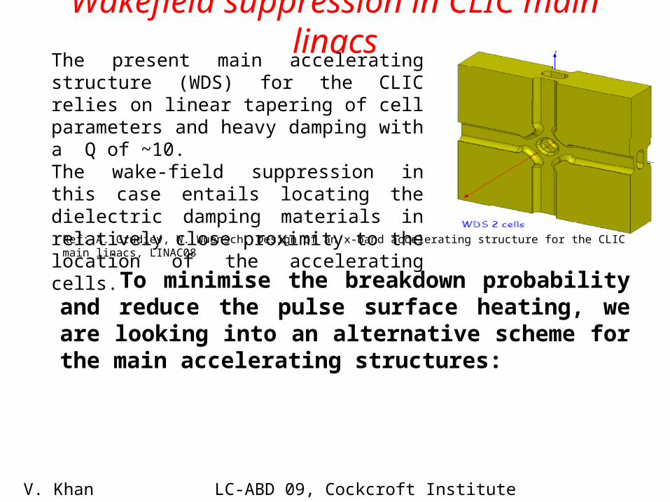
To minimise the breakdown probability and reduce the pulse surface heating, we are looking into an alternative scheme for the main accelerating structures:
• Detuning the first dipole band by forcing the cell parameters to have Gaussian spread in the frequencies
• Considering the moderate damping Q~500
The present main accelerating structure (WDS) for the CLIC relies on linear tapering of cell parameters and heavy damping with a Q of ~10. The wake-field suppression in this case entails locating the dielectric damping materials in relatively close proximity to the location of the accelerating cells.
Ref: A. Grudiev, W. Wuensch, Design of an x-band accelerating structure for the CLIC main linacs, LINAC08
V. Khan LC-ABD 09, Cockcroft Institute 22.09.09 2/14
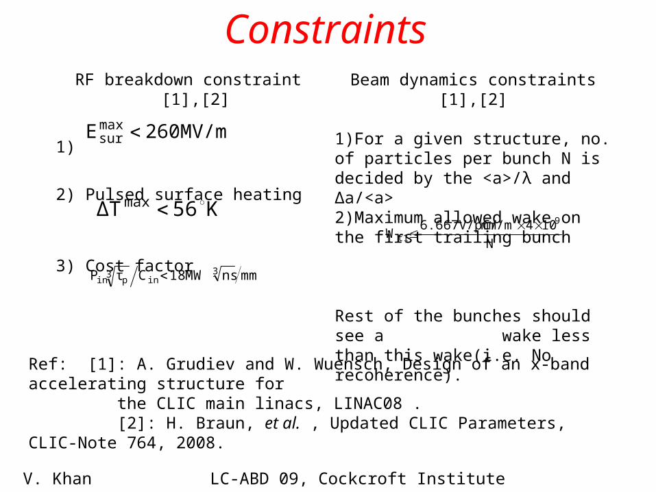
Constraints RF breakdown constraint [1],[2]
1)
2) Pulsed surface heating
3) Cost factor
Beam dynamics constraints [1],[2]
1)For a given structure, no. of particles per bunch N is decided by the <a>/λ and Δa/<a>2)Maximum allowed wake on the first trailing bunch
Rest of the bunches should see a wake less than this wake(i.e. No recoherence).
260MV/mEmaxsur
K 56ΔTmax
mmnsMW 18CτP 3in
3pin
N
10 4 mm/m6.667V/pC/W
9
t1
Ref: [1]: A. Grudiev and W. Wuensch, Design of an x-band accelerating structure for the CLIC main linacs, LINAC08 . [2]: H. Braun, et al. , Updated CLIC Parameters, CLIC-Note 764, 2008.
V. Khan LC-ABD 09, Cockcroft Institute 22.09.09 3/14
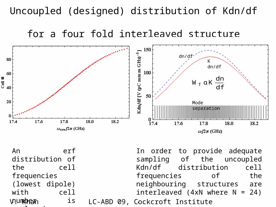
Uncoupled (designed) distribution of Kdn/df for a four fold interleaved structure
In order to provide adequate sampling of the uncoupled Kdn/df distribution cell frequencies of the neighbouring structures are interleaved (4xN where N = 24) .
An erf distribution of the cell frequencies (lowest dipole) with cell number is employed.
df
dnK α WT
Mode separation
K dn/dfdn/df
V. Khan LC-ABD 09, Cockcroft Institute 22.09.09 4/14
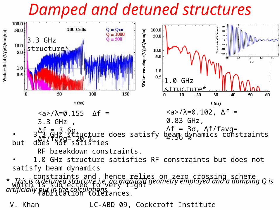
Damped and detuned structures
• 3.3 GHz structure does satisfy beam dynamics constraints but does not satisfies RF breakdown constraints.• 1.0 GHz structure satisfies RF constraints but does not satisfy beam dynamics constraints and hence relies on zero crossing scheme which is subjected to very tight fabrication tolerances.
<a>/λ=0.102, ∆f = 0.83 GHz,∆f = 3σ, ∆f/favg= 4.56 %
V. Khan LC-ABD 09, Cockcroft Institute 22.09.09 5/14
<a>/λ=0.155 ∆f = 3.3 GHz , ∆f = 3.6σ, ∆f/favg= 20 %
* This is a detuned structure i.e. no manifold geometry employed and a damping Q is artificially put in the calculations.
3.3 GHz structure*
1.0 GHz structure*
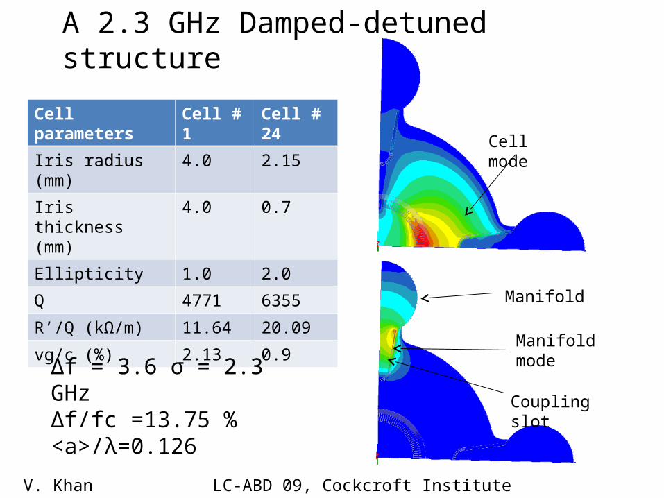
Manifold
Coupling slot
Cell mode
Manifold mode
V. Khan LC-ABD 09, Cockcroft Institute 22.09.09 6/14
Cell parameters Cell # 1 Cell # 24
Iris radius (mm) 4.0 2.15
Iris thickness (mm) 4.0 0.7
Ellipticity 1.0 2.0
Q 4771 6355
R’/Q (kΩ/m) 11.64 20.09
vg/c (%) 2.13 0.9
∆f = 3.6 σ = 2.3 GHz∆f/fc =13.75 %<a>/λ=0.126
A 2.3 GHz Damped-detuned structure
24 cellsNo interleaving
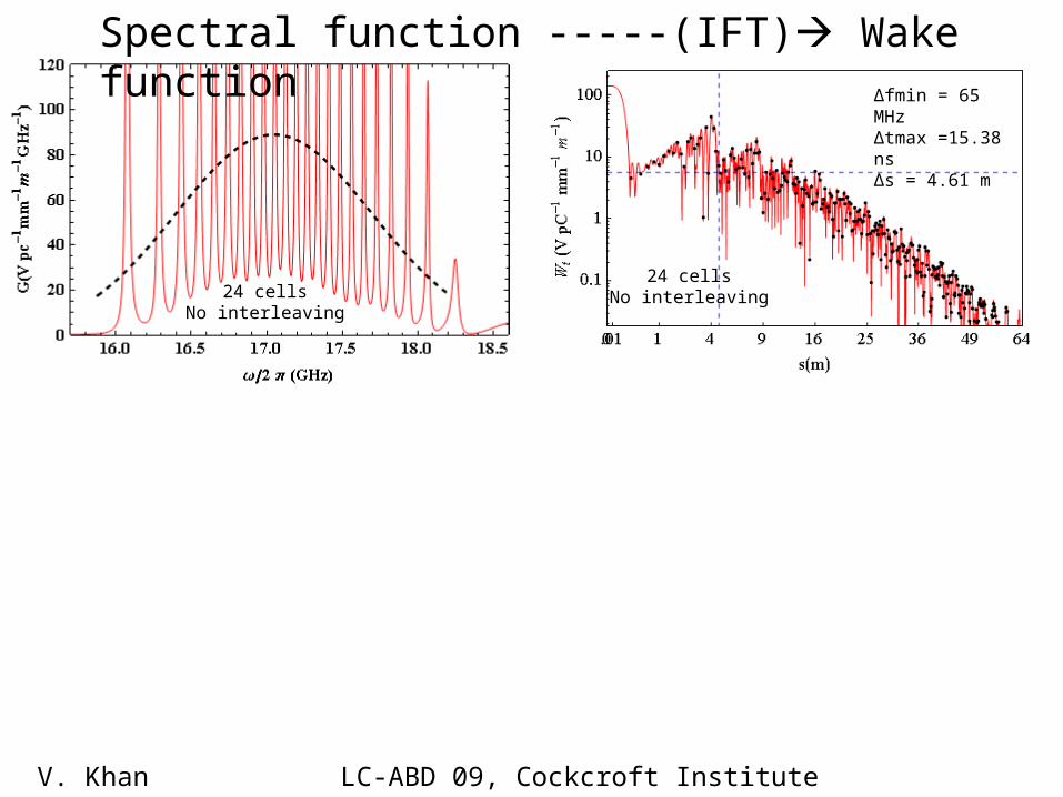
Spectral function -----(IFT) Wake function
24 cellsNo interleaving
∆fmin = 65 MHz∆tmax =15.38 ns∆s = 4.61 m
V. Khan LC-ABD 09, Cockcroft Institute 22.09.09 7/14
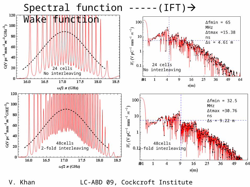
24 cellsNo interleaving
Spectral function -----(IFT) Wake function
48cells2-fold interleaving
∆fmin = 32.5 MHz∆tmax =30.76 ns∆s = 9.22 m
24 cellsNo interleaving
∆fmin = 65 MHz∆tmax =15.38 ns∆s = 4.61 m
48cells2-fold interleaving
V. Khan LC-ABD 09, Cockcroft Institute 22.09.09 8/14
96 cells4-fold interleaving
V. Khan LC-ABD 09, Cockcroft Institute 22.09.09 9/14
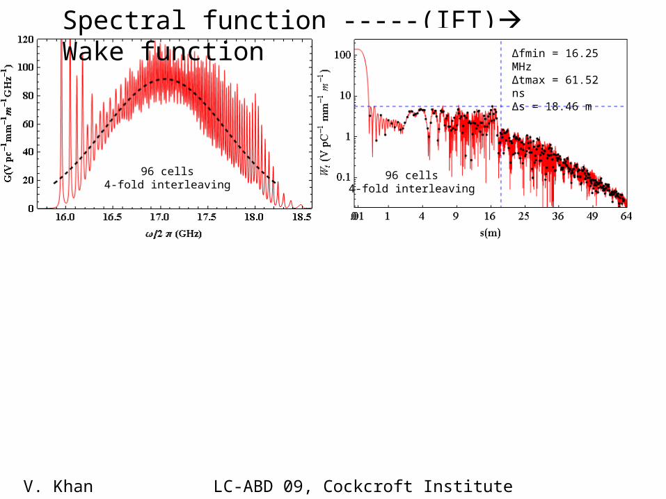
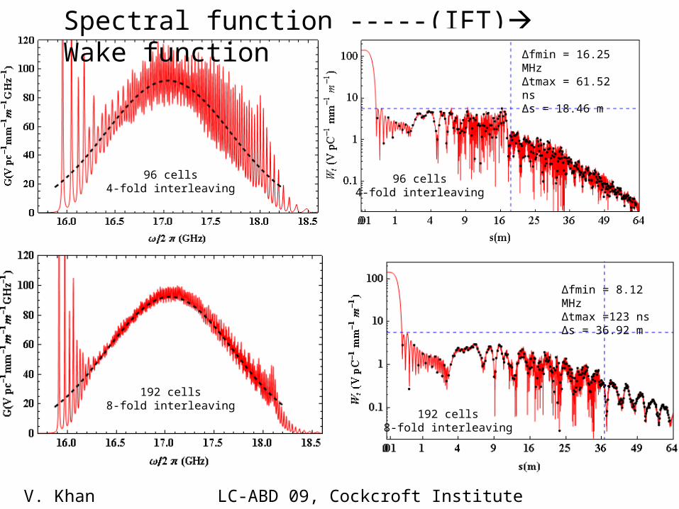
Spectral function -----(IFT) Wake function
96 cells4-fold interleaving
∆fmin = 16.25 MHz∆tmax = 61.52 ns∆s = 18.46 m
96 cells4-fold interleaving
192 cells8-fold interleaving
V. Khan LC-ABD 09, Cockcroft Institute 22.09.09 9/14
Spectral function -----(IFT) Wake function
96 cells4-fold interleaving
∆fmin = 16.25 MHz∆tmax = 61.52 ns∆s = 18.46 m
192 cells8-fold interleaving
∆fmin = 8.12 MHz∆tmax =123 ns∆s = 36.92 m
A 1.19
GHz 11.9942
6101.61072.3
I19-9
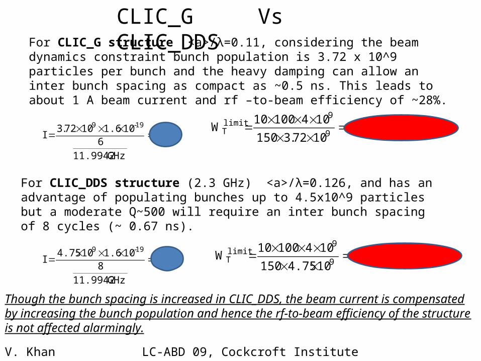
For CLIC_G structure <a>/λ=0.11, considering the beam dynamics constraint bunch population is 3.72 x 10^9 particles per bunch and the heavy damping can allow an inter bunch spacing as compact as ~0.5 ns. This leads to about 1 A beam current and rf –to-beam efficiency of ~28%.
For CLIC_DDS structure (2.3 GHz) <a>/λ=0.126, and has an advantage of populating bunches up to 4.5x10^9 particles but a moderate Q~500 will require an inter bunch spacing of 8 cycles (~ 0.67 ns).
A 1.13
GHz 11.9942
8101.6104.75
I19-9
V/pc/mm/m 1.71072.3150
10410010W
9
9limitT
V/pc/mm/m 5.6104.75150
10410010W
9
9limitT
Though the bunch spacing is increased in CLIC_DDS, the beam current is compensated by increasing the bunch population and hence the rf-to-beam efficiency of the structure is not affected alarmingly.
CLIC_G Vs CLIC_DDS
V. Khan LC-ABD 09, Cockcroft Institute 22.09.09 10/14
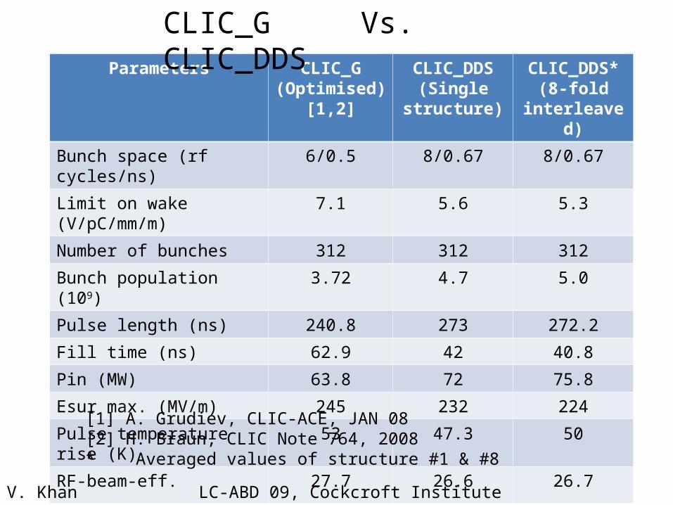
Parameters CLIC_G (Optimised)
[1,2]
CLIC_DDS(Single
structure)
CLIC_DDS*(8-fold
interleaved)
Bunch space (rf cycles/ns) 6/0.5 8/0.67 8/0.67
Limit on wake (V/pC/mm/m) 7.1 5.6 5.3
Number of bunches 312 312 312
Bunch population (109) 3.72 4.7 5.0
Pulse length (ns) 240.8 273 272.2
Fill time (ns) 62.9 42 40.8
Pin (MW) 63.8 72 75.8
Esur max. (MV/m) 245 232 224
Pulse temperature rise (K) 53 47.3 50
RF-beam-eff. 27.7 26.6 26.7
[1] A. Grudiev, CLIC-ACE, JAN 08[2] H. Braun, CLIC Note 764, 2008* Averaged values of structure #1 & #8
CLIC_G Vs. CLIC_DDS
V. Khan LC-ABD 09, Cockcroft Institute 22.09.09 11/14
V. Khan LC-ABD 09, Cockcroft Institute 22.09.09 12/14
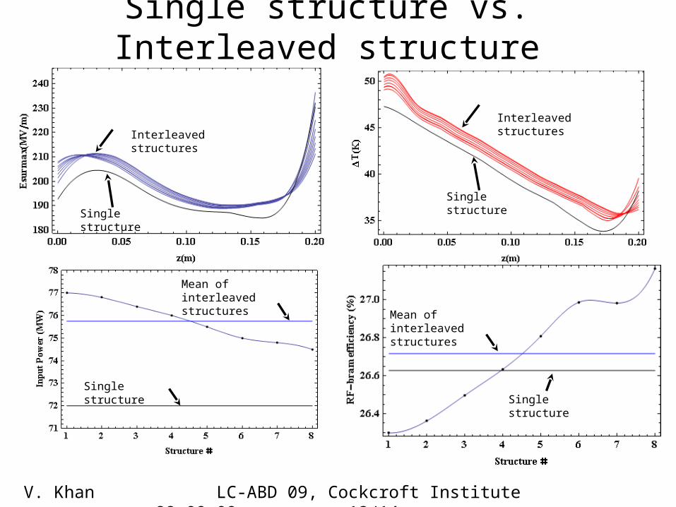
Single structure vs. Interleaved structure
Interleaved structures
Single structure
Interleaved structures
Single structure
Single structureSingle structure
Mean ofinterleaved structures
Mean ofinterleaved structures
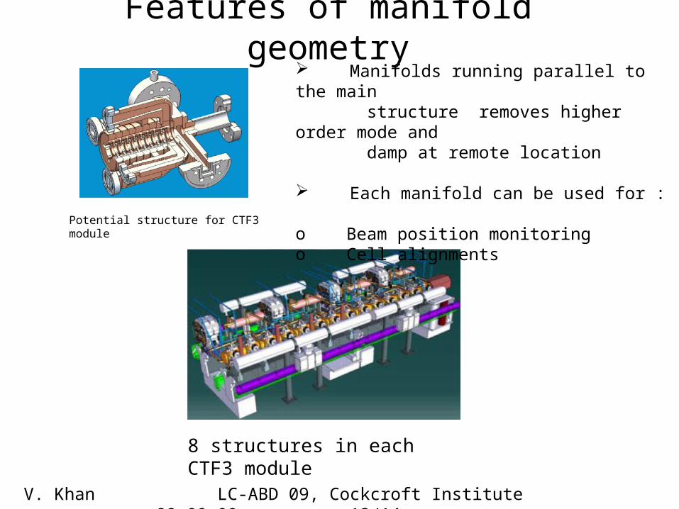
Manifolds running parallel to the main structure removes higher order mode and damp at remote location Each manifold can be used for :
o Beam position monitoringo Cell alignments
Features of manifold geometry
V. Khan LC-ABD 09, Cockcroft Institute 22.09.09 13/14
Potential structure for CTF3 module
8 structures in each CTF3 module

Thank you ........Thank you ........
V. Khan LC-ABD, Cockcroft Institute 22.09.09 14/14
We would like to thank W. Wuensch, A. Grudiev, D. Schulte, J. Wang and T. Higo for their involvement in discussions and many useful suggestions.