Embed Size (px)
Citation preview

CLIC damping rings overview
November 18th, 2008
Yannis PAPAPHILIPPOU CERN
ILC’08 Workshop
ILC'08 Workshop 2
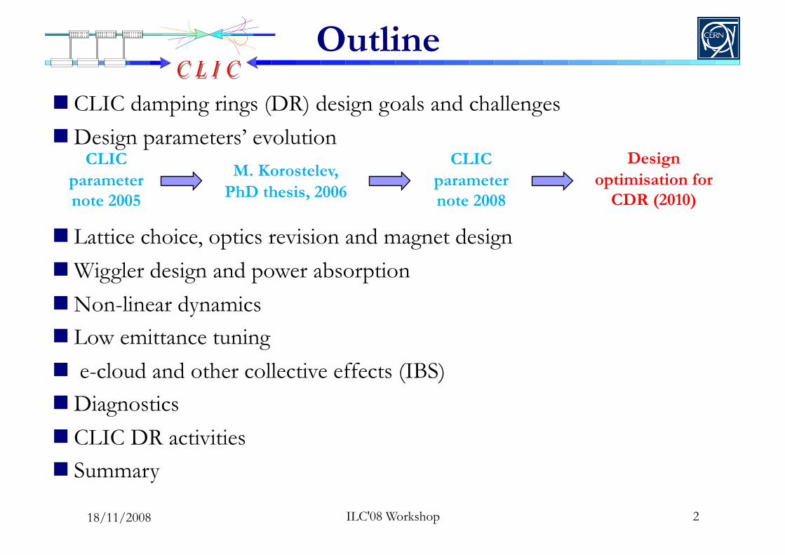
Outline
CLIC damping rings (DR) design goals and challenges Design parameters’ evolution
Lattice choice, optics revision and magnet design Wiggler design and power absorption Non-linear dynamics Low emittance tuning e-cloud and other collective effects (IBS) Diagnostics CLIC DR activities Summary
M. Korostelev, PhD thesis, 2006
CLIC parameter note 2005
CLIC parameter note 2008
Design optimisation for
CDR (2010)
18/11/2008

Damping ring design goals
Starting parameter dictated by design criteria of the collider (luminosity), injected beam characteristics or downstream system tolerances
Intra-beam scattering due to high bunch current blows-up the beam Equilibrium “IBS dominated” emittance has to be reached fast to match collider
high repetition rate
Other collective effects (e.g. e--cloud, fast ion instability) may increase beam losses
PARAMETER NLC CLIC bunch population (109) 7.5 4.1
bunch spacing [ns] 1.4 0.5
number of bunches/train 192 312
number of trains 3 1
Repetition rate [Hz] 120 50
Extracted hor. normalized emittance [nm] 2370 <550
Extracted ver. normalized emittance [nm] <30 <5
Extracted long. normalized emittance [keV.m] 10.9 <5
Injected hor. normalized emittance [µm] 150 63
Injected ver. normalized emittance [µm] 150 1.5
Injected long. normalized emittance [keV.m] 13.18 1240
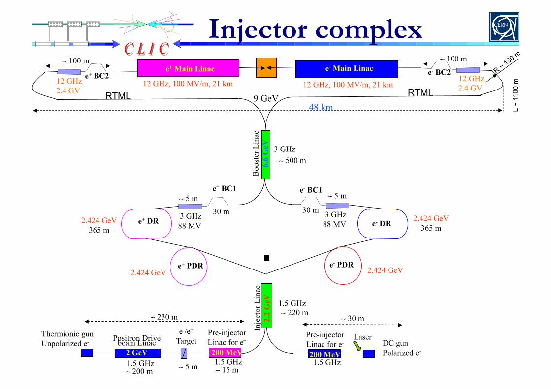
Injector complex
Thermionic gun Unpolarized e-
Laser DC gun Polarized e-
Pre-injector Linac for e-
200 MeV
e-/e+ Target Positron Drive beam Linac
2 GeV
Inje
ctor
Lin
ac
2.2
GeV
e+ DR
e+ PDR
2.424 GeV 365 m
Boo
ster
Lin
ac
6.6
GeV
3 GHz
e+ BC1 e- BC1
e+ BC2 e- BC2 e+ Main Linac e- Main Linac
12 GHz, 100 MV/m, 21 km 12 GHz, 100 MV/m, 21 km
1.5 GHz
e- DR
e- PDR
1.5 GHz 1.5 GHz 1.5 GHz
3 GHz 88 MV
3 GHz 88 MV
12 GHz 2.4 GV
12 GHz 2.4 GV
9 GeV 48 km
∼ 5 m ∼ 5 m
∼ 500 m
∼ 220 m ∼ 30 m
∼ 15 m ∼ 200 m
2.424 GeV 365 m
2.424 GeV 2.424 GeV
∼ 100 m ∼ 100 m
Pre-injector Linac for e+
200 MeV
RTML RTML
30 m 30 m
L ~
1100
m
∼ 5 m
∼ 230 m

CLIC Pre-damping rings Most critical the e+ PDR
Injected e+ emittance ~ 2 orders of magnitude larger than for e-, i.e. aperture limited if injected directly into DR
PDR for e- beam necessary as well A “zero current” linac e- beam (no
IBS) would need ~ 17ms to reach equilibrium in DR, (very close to repetition time of 20ms)
PDR main challenges Large input momentum spread
necessitates large longitudinal acceptance for good injection efficiency
Polarised positron stacking time long compared to repetition rate (need fast damping and/or staggered trains)
PDR Extracted Parameters CLIC NLC
Energy [GeV] 2.424 1.98
Bunch population [109] 4.1-4.4 7.5
Bunch length [mm] 10 5.1
Energy Spread [%] 0.5 0.09
Hor. Norm. emittance [nm] 63000 46000
Ver. Norm. emittance [nm] 1500 4600
Injected Parameters e- e+
Bunch population [109] 4.4 6.4
Bunch length [mm] 1 5
Energy Spread [%] 0.1 2.7
Hor.,Ver Norm. emittance [nm] 100 x 103 9.3 x 10⁶
5 ILC'08 Workshop
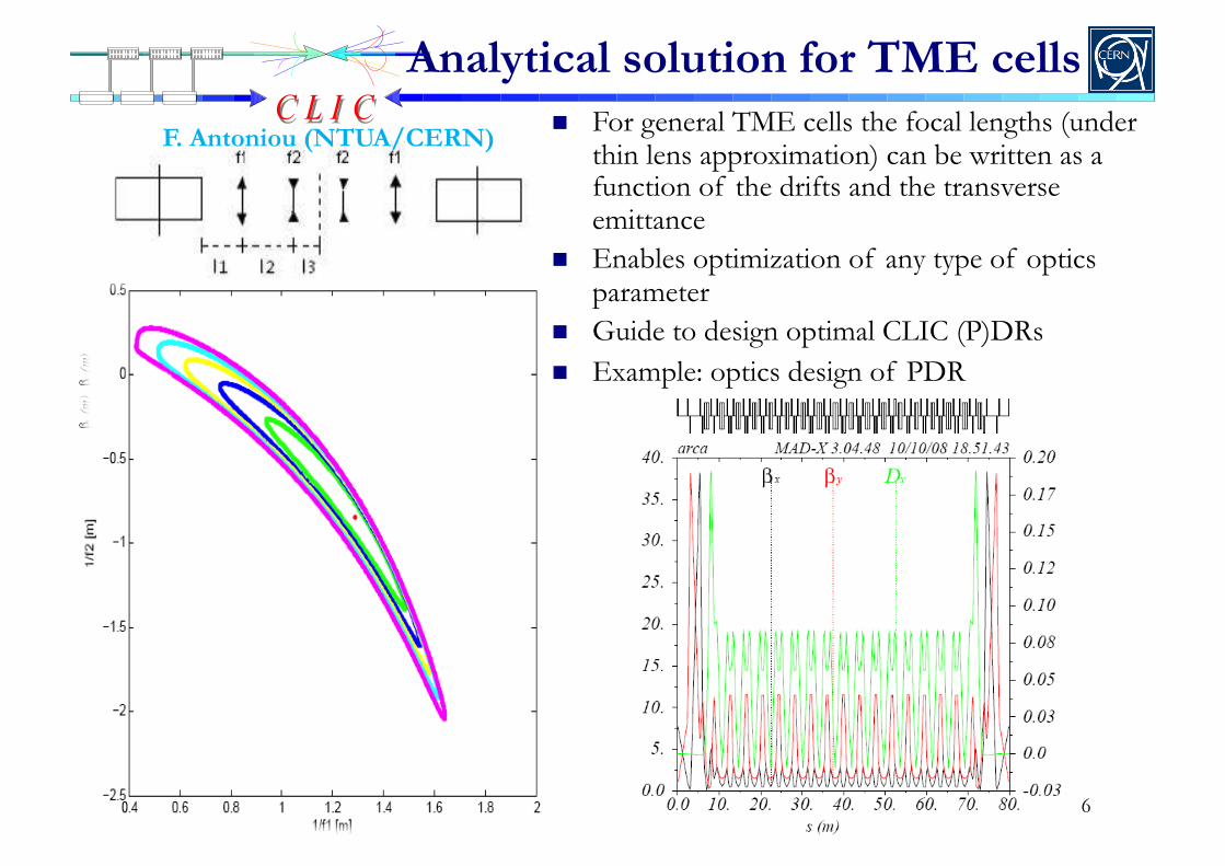
Analytical solution for TME cells For general TME cells the focal lengths (under
thin lens approximation) can be written as a function of the drifts and the transverse emittance
Enables optimization of any type of optics parameter
Guide to design optimal CLIC (P)DRs Example: optics design of PDR
F. Antoniou (NTUA/CERN)
6

Stacking of polarized e+ into the PDR
CLIC Compton source using ERL or CR e+ emittance preservation after capture CLIC PDR parameters should have a low a2 (4e-4) and high VRF (~16MV) 95% efficiency can be achieved with off-momentum off-phase injection Needs 10% of momentum acceptance in PDR (off momentum DA) Quite some flexibility (# optical cavities vs. e- bunch charge) but a few challenges for PDR design
F. Zimmermann (CERN)
unstable
stable
7 ILC'08 Workshop 18/11/2008

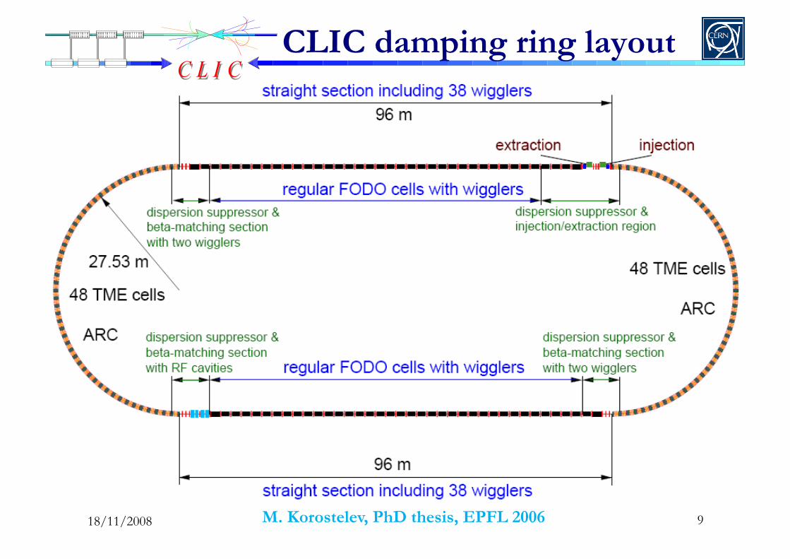
CLIC damping rings lattice
• Two rings of racetrack shape at energy of 2.424GeV • Arcs filled with 1.8m long TME cells and straight sections contain FODO cells with damping wigglers, giving total length of 365.2m • Phase advance per TME cell was kept to 210o in the horizontal and 90o in the vertical plane, providing a detuning factor of 1.8 • The chromaticity is controlled by two sextupole families.
9
CLIC damping ring layout
M. Korostelev, PhD thesis, EPFL 2006 18/11/2008
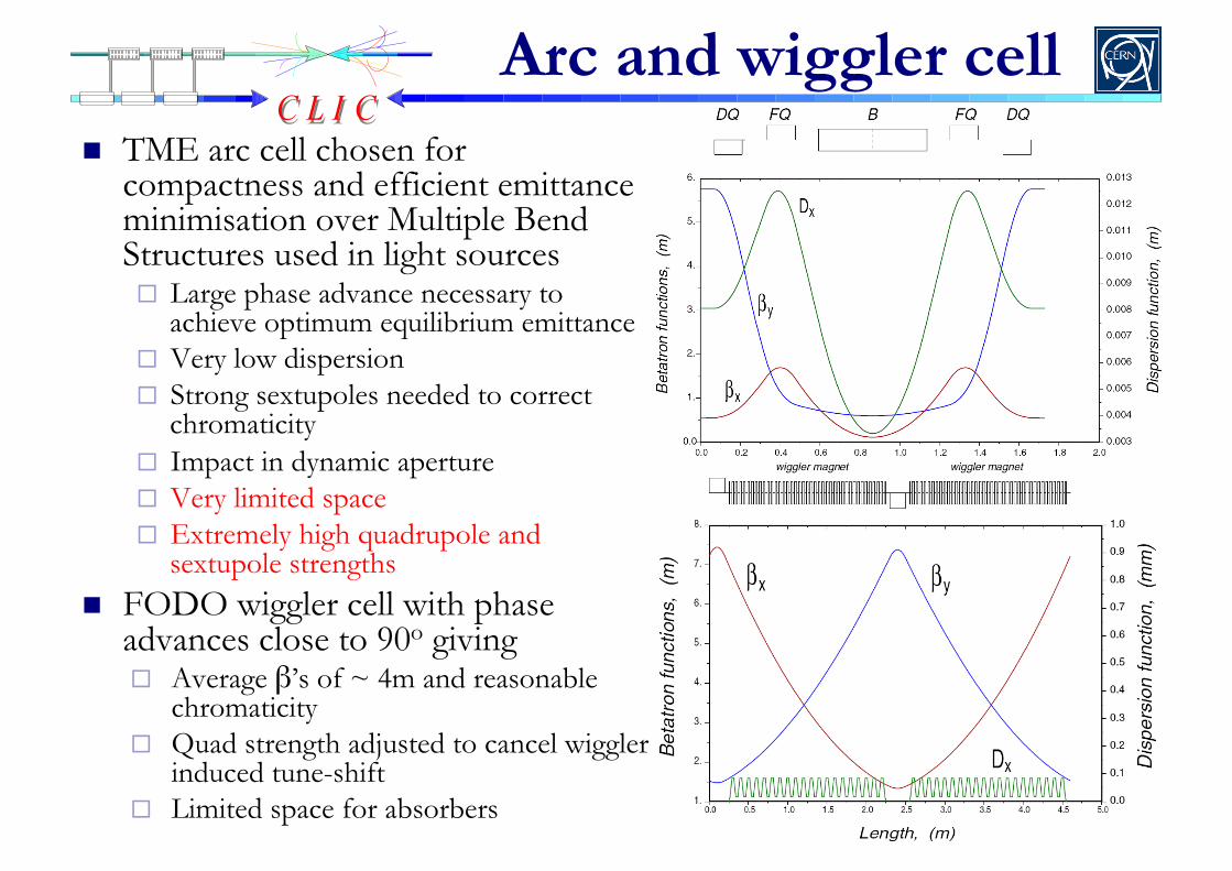
Arc and wiggler cell TME arc cell chosen for
compactness and efficient emittance minimisation over Multiple Bend Structures used in light sources Large phase advance necessary to
achieve optimum equilibrium emittance Very low dispersion Strong sextupoles needed to correct
chromaticity Impact in dynamic aperture Very limited space Extremely high quadrupole and
sextupole strengths FODO wiggler cell with phase
advances close to 90o giving Average β’s of ~ 4m and reasonable
chromaticity Quad strength adjusted to cancel wiggler
induced tune-shift Limited space for absorbers
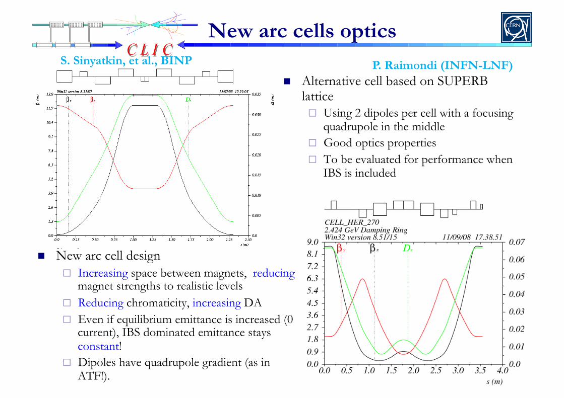
New arc cells optics S. Sinyatkin, et al., BINP
New arc cell design Increasing space between magnets, reducing
magnet strengths to realistic levels Reducing chromaticity, increasing DA Even if equilibrium emittance is increased (0
current), IBS dominated emittance stays constant!
Dipoles have quadrupole gradient (as in ATF!).
Alternative cell based on SUPERB lattice Using 2 dipoles per cell with a focusing
quadrupole in the middle Good optics properties To be evaluated for performance when
IBS is included
P. Raimondi (INFN-LNF)
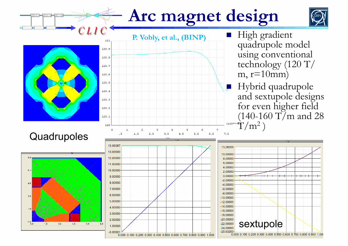
Arc magnet design High gradient
quadrupole model using conventional technology (120 T/m, r=10mm)
Hybrid quadrupole and sextupole designs for even higher field (140-160 T/m and 28 T/m2 )
P. Vobly, et al., (BINP)
sextupole
Quadrupoles
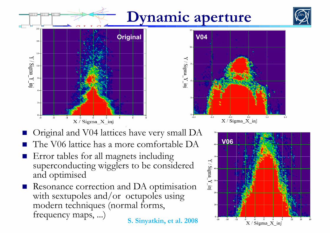
Dynamic aperture
Original and V04 lattices have very small DA The V06 lattice has a more comfortable DA Error tables for all magnets including
superconducting wigglers to be considered and optimised
Resonance correction and DA optimisation with sextupoles and/or octupoles using modern techniques (normal forms, frequency maps, ...)
Original V04
V06
S. Sinyatkin, et al. 2008
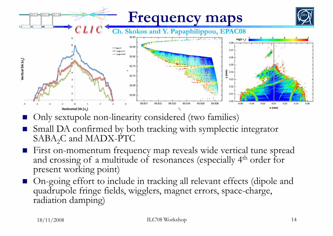
Frequency maps
Only sextupole non-linearity considered (two families) Small DA confirmed by both tracking with symplectic integrator
SABA2C and MADX-PTC First on-momentum frequency map reveals wide vertical tune spread
and crossing of a multitude of resonances (especially 4th order for present working point)
On-going effort to include in tracking all relevant effects (dipole and quadrupole fringe fields, wigglers, magnet errors, space-charge, radiation damping)
14 ILC'08 Workshop
Ch. Skokos and Y. Papaphilippou, EPAC08
18/11/2008
ILC'08 Workshop 15
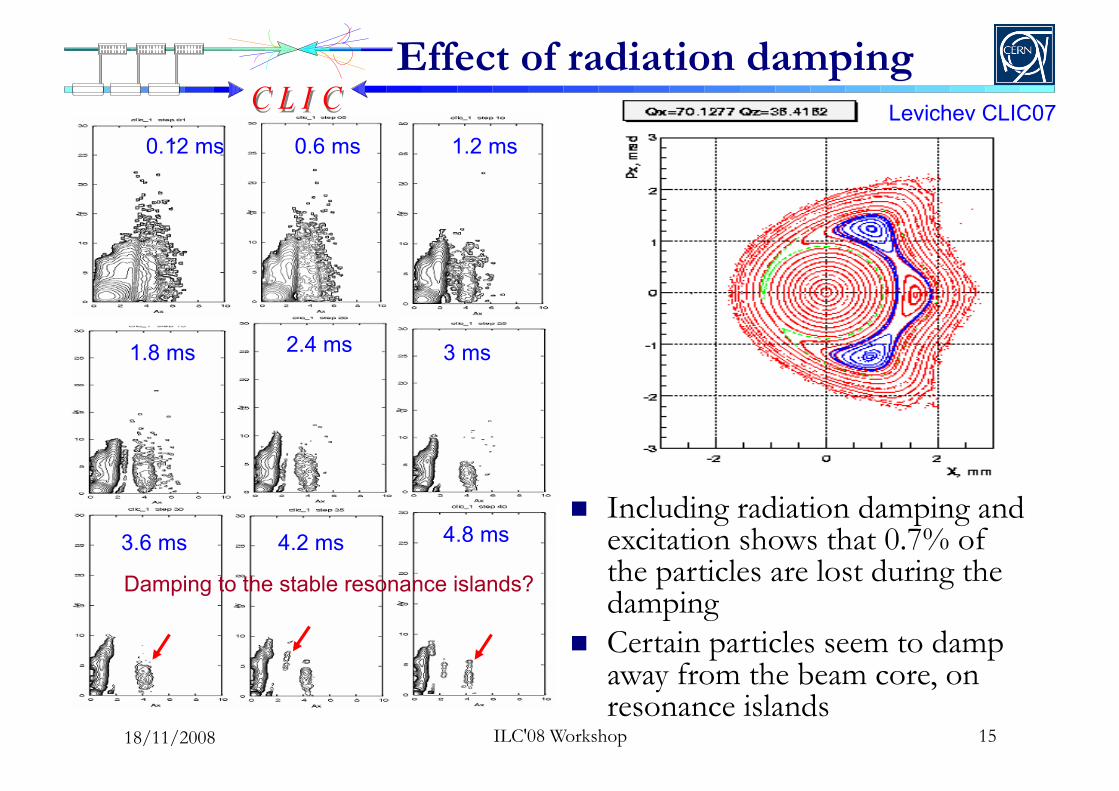
Effect of radiation damping
0.12 ms 0.6 ms 1.2 ms
1.8 ms 2.4 ms 3 ms
3.6 ms 4.2 ms 4.8 ms
Damping to the stable resonance islands?
Levichev CLIC07
Including radiation damping and excitation shows that 0.7% of the particles are lost during the damping
Certain particles seem to damp away from the beam core, on resonance islands
18/11/2008

Collective effects The electron cloud in the e+ DR impose limits in
PEY (99.9% of synchrotron radiation absorbed in the wigglers) and SEY (below 1.3) and can be cured with special chamber coatings
Fast ion instability in : In e- DR, molecules with A>13 will be trapped
(constrains vacuum pressure to around 0.1nTorr) Other collective effects in DR
Space charge (large vertical tune spread of 0.188 and 10% emittance growth)
Single bunch instabilities avoided with smooth impedance design and resistive wall coupled bunch can be controlled with feedback
G. Rumolo et al. (CERN)
Chambers PEY SEY ρ
[1012 e-/m3]
Dipole
0.000576 1.3 0.04
1.8 2
0.0576 1.3 7
1.8 40
Wiggler
0.00109 1.3 0.6
0.109
1.3 45
1.5 70
1.8 80
16
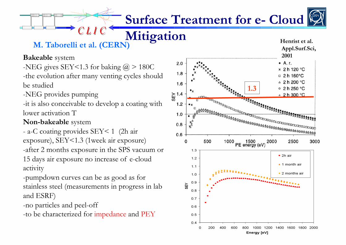
Bakeable system -NEG gives SEY<1.3 for baking @ > 180C -the evolution after many venting cycles should be studied -NEG provides pumping -it is also conceivable to develop a coating with lower activation T Non-bakeable system - a-C coating provides SEY< 1 (2h air exposure), SEY<1.3 (1week air exposure) -after 2 months exposure in the SPS vacuum or 15 days air exposure no increase of e-cloud activity -pumpdown curves can be as good as for stainless steel (measurements in progress in lab and ESRF) - no particles and peel-off - to be characterized for impedance and PEY
Surface Treatment for e- Cloud Mitigation
M. Taborelli et al. (CERN)
1.3
Henrist et al. Appl.Surf.Sci, 2001

ANKA SC wiggler
BINP SC wiggler
BINP PM wiggler
Wigglers’ effect with IBS Stronger wiggler fields and
shorter wavelengths necessary to reach target emittance due to strong IBS effect
With super-conducting wigglers of 2.5T and 5cm period, the achieved normalized horizontal emittance drops below 400nm Super-conducting magnets have to be
designed, built and tested
M. Korostelev, PhD thesis, EPFL 2006
Two wiggler prototypes 2.5T, 5cm period, NbTi coil, built
by BINP 2.8T, 4cm period, Nb3Sncoil, built
by CERN/ANKA Aperture fixed by radiation
absorption scheme Short version to be installed and
tested at ANKA
Parameters BINP ANKA/CERN
Bpeak [T] 2.5 2.8
λW [mm] 50 40
Beam aperture full gap [mm] 20* 24*
Conductor type NbTi NbSn3
Operating temperature [K] 4.2 4.2
18 ILC'08 Workshop 18/11/2008

NbTi Wiggler Design
P. Vobly (BINP)
Present design uses NbTi wet wire in separate poles clamped together (2.5T, 5cm period)
Performance tests by the end of the year on short prototype
Magnetic tolerances needed to refine design (e.g. taken from PETRA III wiggler)
Alternative design allows using Nb3Sn dry wire substantially reducing time and cost
Iron yoke Regular coil
End coils to compensate the first
and the second integral
Corrector coils with
individual PS
General view for BINP wiggler prototype
19 ILC'08 Workshop 18/11/2008
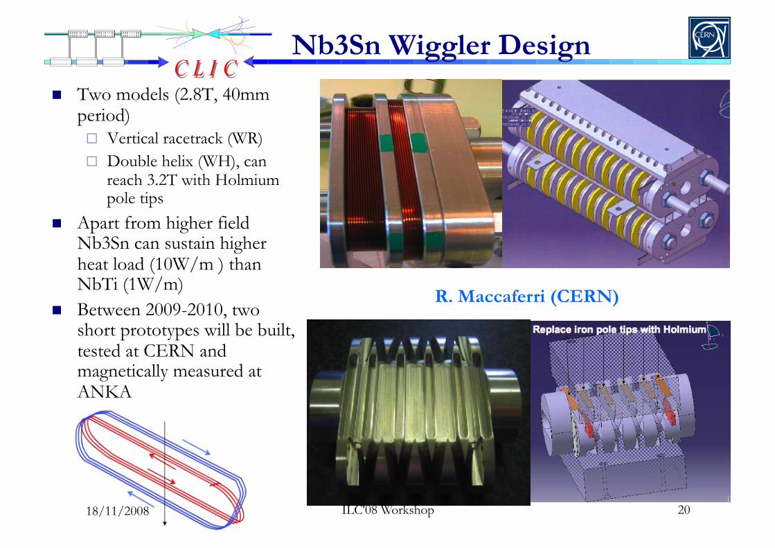
Nb3Sn Wiggler Design
R. Maccaferri (CERN)
Two models (2.8T, 40mm period) Vertical racetrack (WR) Double helix (WH), can
reach 3.2T with Holmium pole tips
Apart from higher field Nb3Sn can sustain higher heat load (10W/m ) than NbTi (1W/m)
Between 2009-2010, two short prototypes will be built, tested at CERN and magnetically measured at ANKA
20 ILC'08 Workshop 18/11/2008

A 4-wigglers scheme
Radiation absorption scheme
Gap of 13mm for NbTi wiggler and 20mm for Nb3Sn design (1W/m) or 13mm (10W/m)
K. Zolotarev (BINP)
Terminal absorber at the end of the straight section
3D radiation distribution to be used for e-cloud built up
Impedance estimation needed
18/11/2008 ILC'08 Workshop
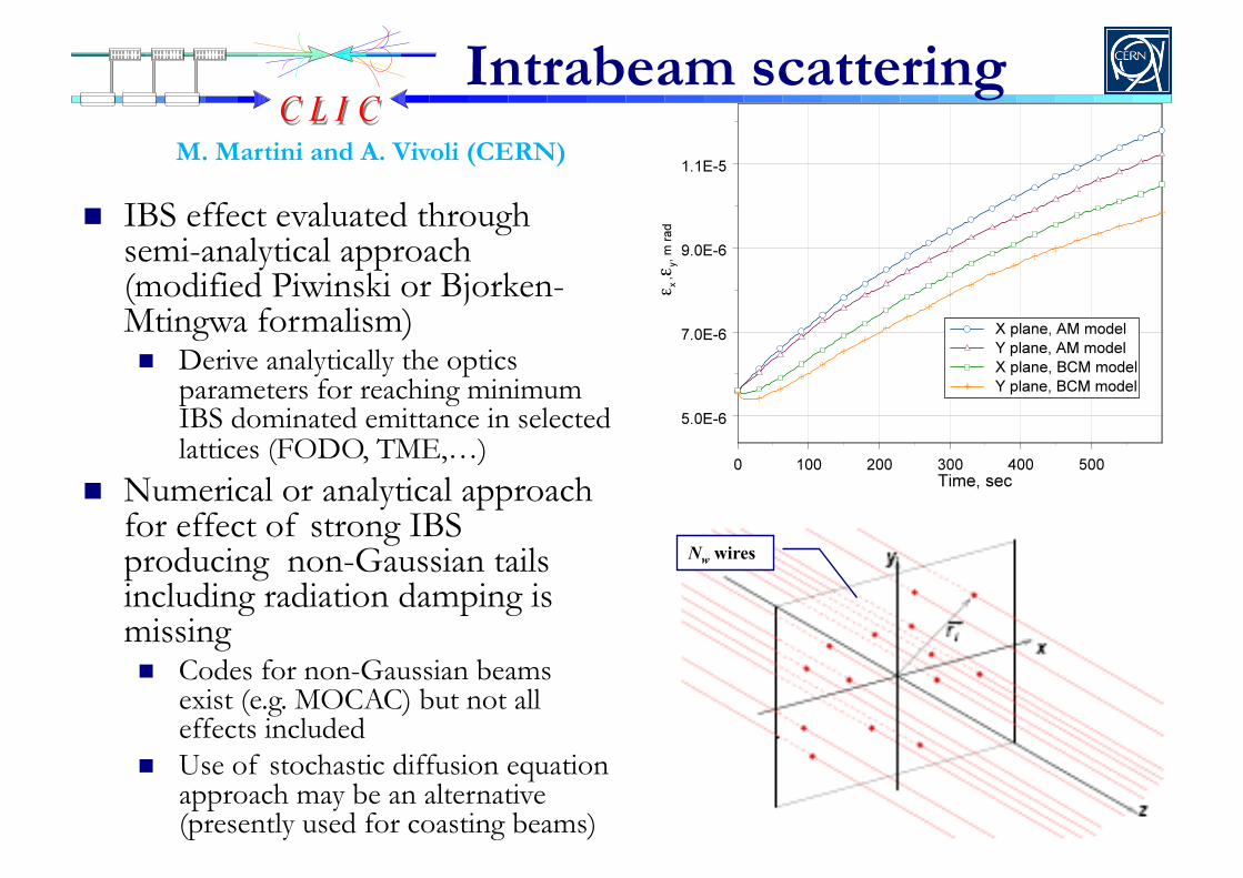
Intrabeam scattering
IBS effect evaluated through semi-analytical approach (modified Piwinski or Bjorken-Mtingwa formalism) Derive analytically the optics
parameters for reaching minimum IBS dominated emittance in selected lattices (FODO, TME,…)
Numerical or analytical approach for effect of strong IBS producing non-Gaussian tails including radiation damping is missing Codes for non-Gaussian beams
exist (e.g. MOCAC) but not all effects included
Use of stochastic diffusion equation approach may be an alternative (presently used for coasting beams)
M. Martini and A. Vivoli (CERN)
Nw wires

Coupling correction and low emittance measurement in SLS
Achieved 3pm vertical emittance Aggressive program for reaching
absolute limit (0.55pm) Correction of residual dispersion
(3mm) induced by sextupole misalignments with skew quads in dispersive regions
Beam size measurements using πpolarization method Beam image formed by vertically
polarized visible-UV synchrotron radiation
Beam sizes of a few microns can be measured
Integration time of a 100-turns limited by response of CCD camera
A. Andersson (PSI)
23 18/11/2008
Injection, extraction, timing, RF
• Interleaved bunch train scheme abandoned due to its complexity.
• Reduction of the repetition rate from 150 to 50Hz leaves enough time for the emittances to reach their equilibrium.
• Bunch spacing increased almost to the same level as for the interleaved scheme.
• 312 bunches with 0.5ns spacing, fill only 13% of the rings. • RF frequency of 2GHz with voltage of 4.1MV for enough
energy recovery while keeping longitudinal emittance below 5000eV.m
• Extraction kicker rise time is relaxed • Detailed design of RF cavity and injection/extraction
elements is pending 24 ILC'08 Workshop 18/11/2008
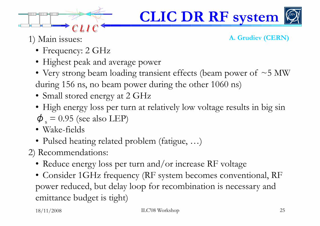
1) Main issues: • Frequency: 2 GHz • Highest peak and average power • Very strong beam loading transient effects (beam power of ~5 MW during 156 ns, no beam power during the other 1060 ns) • Small stored energy at 2 GHz • High energy loss per turn at relatively low voltage results in big sin φs = 0.95 (see also LEP) • Wake-fields • Pulsed heating related problem (fatigue, …)
2) Recommendations: • Reduce energy loss per turn and/or increase RF voltage • Consider 1GHz frequency (RF system becomes conventional, RF power reduced, but delay loop for recombination is necessary and emittance budget is tight)
A. Grudiev (CERN)
CLIC DR RF system
25 ILC'08 Workshop 18/11/2008
ILC'08 Workshop 26
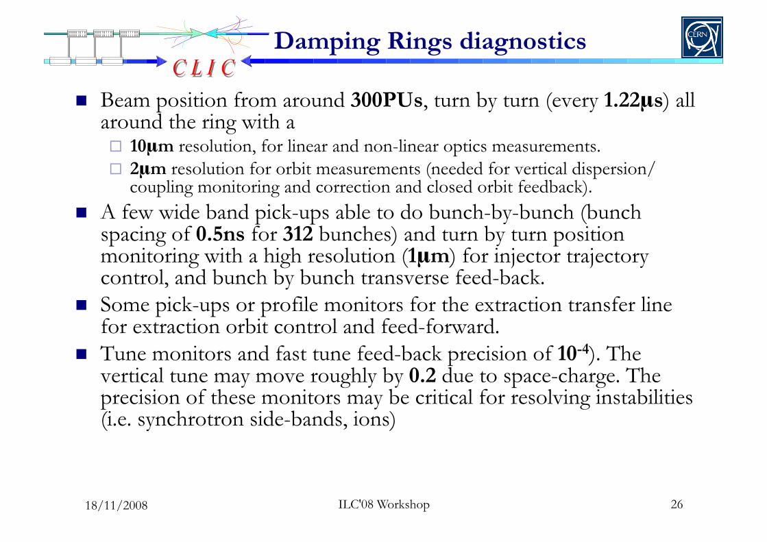
Damping Rings diagnostics
Beam position from around 300PUs, turn by turn (every 1.22μs) all around the ring with a 10μm resolution, for linear and non-linear optics measurements. 2μm resolution for orbit measurements (needed for vertical dispersion/
coupling monitoring and correction and closed orbit feedback). A few wide band pick-ups able to do bunch-by-bunch (bunch
spacing of 0.5ns for 312 bunches) and turn by turn position monitoring with a high resolution (1μm) for injector trajectory control, and bunch by bunch transverse feed-back.
Some pick-ups or profile monitors for the extraction transfer line for extraction orbit control and feed-forward.
Tune monitors and fast tune feed-back precision of 10-4). The vertical tune may move roughly by 0.2 due to space-charge. The precision of these monitors may be critical for resolving instabilities (i.e. synchrotron side-bands, ions)
18/11/2008
ILC'08 Workshop 27
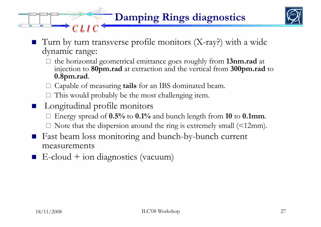
Damping Rings diagnostics
Turn by turn transverse profile monitors (X-ray?) with a wide dynamic range: the horizontal geometrical emittance goes roughly from 13nm.rad at
injection to 80pm.rad at extraction and the vertical from 300pm.rad to 0.8pm.rad.
Capable of measuring tails for an IBS dominated beam. This would probably be the most challenging item.
Longitudinal profile monitors Energy spread of 0.5% to 0.1% and bunch length from 10 to 0.1mm. Note that the dispersion around the ring is extremely small (<12mm).
Fast beam loss monitoring and bunch-by-bunch current measurements
E-cloud + ion diagnostics (vacuum)
18/11/2008
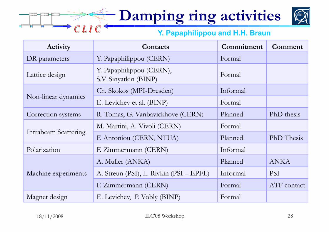
Damping ring activities Y. Papaphilippou and H.H. Braun
Activity Contacts Commitment Comment
DR parameters Y. Papaphilippou (CERN) Formal
Lattice design Y. Papaphilippou (CERN), S.V. Sinyatkin (BINP)
Formal
Non-linear dynamics Ch. Skokos (MPI-Dresden) Informal
E. Levichev et al. (BINP) Formal
Correction systems R. Tomas, G. Vanbavickhove (CERN) Planned PhD thesis
Intrabeam Scattering M. Martini, A. Vivoli (CERN) Formal
F. Antoniou (CERN, NTUA) Planned PhD Thesis
Polarization F. Zimmermann (CERN) Informal
Machine experiments
A. Muller (ANKA) Planned ANKA
A. Streun (PSI), L. Rivkin (PSI – EPFL) Informal PSI
F. Zimmermann (CERN) Formal ATF contact
Magnet design E. Levichev, P. Vobly (BINP) Formal
28 ILC'08 Workshop 18/11/2008
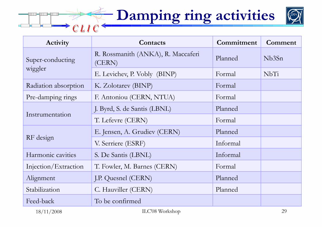
Damping ring activities
Activity Contacts Commitment Comment
Super-conducting wiggler
R. Rossmanith (ANKA), R. Maccaferi (CERN)
Planned Nb3Sn
E. Levichev, P. Vobly (BINP) Formal NbTi
Radiation absorption K. Zolotarev (BINP) Formal
Pre-damping rings F. Antoniou (CERN, NTUA) Formal
Instrumentation J. Byrd, S. de Santis (LBNL) Planned
T. Lefevre (CERN) Formal
RF design E. Jensen, A. Grudiev (CERN) Planned
V. Serriere (ESRF) Informal
Harmonic cavities S. De Santis (LBNL) Informal
Injection/Extraction T. Fowler, M. Barnes (CERN) Formal
Alignment J.P. Quesnel (CERN) Planned
Stabilization C. Hauviller (CERN) Planned
Feed-back To be confirmed 29 ILC'08 Workshop 18/11/2008

Damping ring activities
Activity Contacts Commitment Comment
e-cloud / ions G. Rumolo (CERN), W. Bruns Formal
M. Pivi (SLAC) Planned
Chamber coating P. Chiggiato (CERN), R. Kersevan(ESRF)
Planned Cut by EUCARD
Space-charge D. Quatraro (CERN), E. Levichev (BINP)
Formal
Impedances A. Wolski, M. Korostelev (Cockcroft Institute)
Planned
Instabilities G. Rumolo , D. Quatraro (CERN) Formal
Vacuum design To be confirmed
Collective effects: G. Rumolo
30 ILC'08 Workshop
36 contact persons from CERN(19), BINP(4), Cockroft(2), ESRF(2), SLAC(1), LBNL (2), ANKA(2), PSI(2), MPI(1), Private(1) 18/11/2008
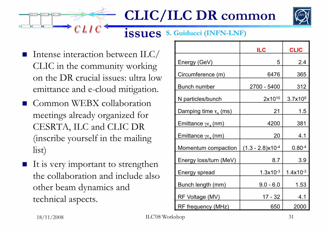
CLIC/ILC DR common issues
Intense interaction between ILC/CLIC in the community working on the DR crucial issues: ultra low emittance and e-cloud mitigation.
Common WEBX collaboration meetings already organized for CESRTA, ILC and CLIC DR (inscribe yourself in the mailing list)
It is very important to strengthen the collaboration and include also other beam dynamics and technical aspects.
S. Guiducci (INFN-LNF)
ILC CLIC
Energy (GeV) 5 2.4
Circumference (m) 6476 365
Bunch number 2700 - 5400 312
N particles/bunch 2x10¹⁰ 3.7x10⁹
Damping time τx (ms) 21 1.5
Emittance γεx (nm) 4200 381
Emittance γεx (nm) 20 4.1
Momentum compaction (1.3 - 2.8)x10-4 0.80-4
Energy loss/turn (MeV) 8.7 3.9
Energy spread 1.3x10⁻³ 1.4x10⁻³
Bunch length (mm) 9.0 - 6.0 1.53
RF Voltage (MV) 17 - 32 4.1
RF frequency (MHz) 650 2000
31 ILC'08 Workshop 18/11/2008
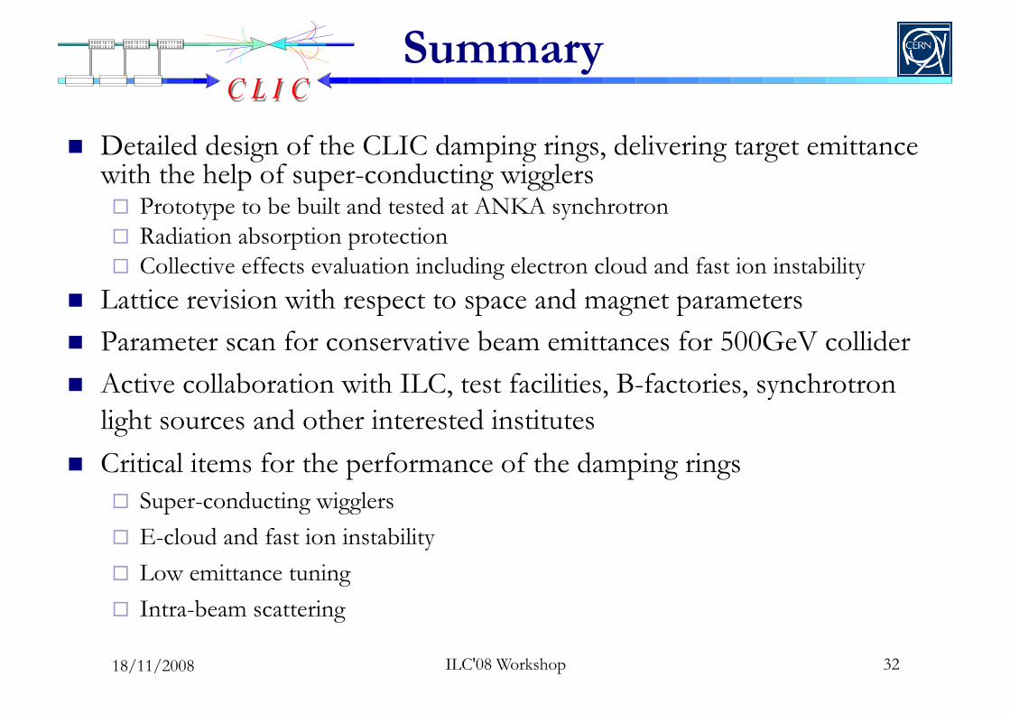
Summary
Detailed design of the CLIC damping rings, delivering target emittance with the help of super-conducting wigglers Prototype to be built and tested at ANKA synchrotron Radiation absorption protection Collective effects evaluation including electron cloud and fast ion instability
Lattice revision with respect to space and magnet parameters Parameter scan for conservative beam emittances for 500GeV collider Active collaboration with ILC, test facilities, B-factories, synchrotron
light sources and other interested institutes Critical items for the performance of the damping rings
Super-conducting wigglers E-cloud and fast ion instability Low emittance tuning Intra-beam scattering
32 ILC'08 Workshop 18/11/2008