Embed Size (px)
Citation preview
NETGEAR, Inc.350 East Plumeria DriveSan Jose, CA 95134, USA
March 2021202-12215-01
CLI Command Reference Manual
AV Line of Fully Managed Switches M4250 SeriesFirmware version 13.0.0 and later versions
AV Line of Fully Managed Switches M4250 Series
CLI Command Reference Manual2
Support and CommunityVisit netgear.com/support to get your questions answered and access the latest downloads.
You can also check out our NETGEAR Community for helpful advice at community.netgear.com.
Regulatory and LegalSi ce produit est vendu au Canada, vous pouvez accéder à ce document en français canadien à https://www.netgear.com/support/download/.
(If this product is sold in Canada, you can access this document in Canadian French at https://www.netgear.com/support/download/.)
For regulatory compliance information including the EU Declaration of Conformity, visit https://www.netgear.com/about/regulatory/.
See the regulatory compliance document before connecting the power supply.
For NETGEAR's Privacy Policy, visit https://www.netgear.com/about/privacy-policy.
By using this device, you are agreeing to NETGEAR's Terms and Conditions at https://www.netgear.com/about/terms-and-conditions. If you do not agree, return the device to your place of purchase within your return period.
Do not use this device outdoors. For products that support Power over Ethernet (PoE), the PoE source is intended for intra building connection only.
Trademarks© NETGEAR, Inc., NETGEAR, and the NETGEAR Logo are trademarks of NETGEAR, Inc. Any non-NETGEAR trademarks are used for reference purposes only.
Revision History
Publication Part Number
Publish Date Comments
202-12215-01 March 2021 • We added the following Auto-Trunk commands: switchport mode auto and show interfaces switchport trunk.
• We added the following Auto-LAG commands: port-channel auto, port-channel auto load-balance, and show port-channel auto.
202-12094-03and202-12094-02
January 2021 • We added environment fan control mode.• We changed dot1as priority 2.• We changed many commands to remove the BGP and OSPF options.• We removed the following commands:
- all OSPFv3 commands for IPv6.- all remaining OSPF commands.- all remaining BGP commands.- all iSCSI optimization commands.- all expandable port configuration commands.- the clear pass command.- the msrp talker-pruning command.- the show ipv6 protocols command.- the set local-preference command.- a few other commands that are not supported.
• We made some minor changes to various sections.
202-12094-01 October 2020 Initial publication of this manual.
Contents
Chapter 1 Introduction and Documentation
Chapter 2 How to Use the Command-Line Interface
Command syntax. . . . . . . . . . . . . . . . . . . . . . . . . . . . . . . . . . . . . . . . . . . . . . . .10Command conventions . . . . . . . . . . . . . . . . . . . . . . . . . . . . . . . . . . . . . . . . . . . 10Common parameter values . . . . . . . . . . . . . . . . . . . . . . . . . . . . . . . . . . . . . . . 11The unit/port naming convention . . . . . . . . . . . . . . . . . . . . . . . . . . . . . . . . . . 12‘no’ form of a command . . . . . . . . . . . . . . . . . . . . . . . . . . . . . . . . . . . . . . . . . .13‘show’ commands . . . . . . . . . . . . . . . . . . . . . . . . . . . . . . . . . . . . . . . . . . . . . . . . 13CLI output filtering . . . . . . . . . . . . . . . . . . . . . . . . . . . . . . . . . . . . . . . . . . . . . . . 13Command completion and abbreviation . . . . . . . . . . . . . . . . . . . . . . . . . . . . 14CLI error messages . . . . . . . . . . . . . . . . . . . . . . . . . . . . . . . . . . . . . . . . . . . . . .15CLI line-editing conventions . . . . . . . . . . . . . . . . . . . . . . . . . . . . . . . . . . . . . . . 15Use the CLI help . . . . . . . . . . . . . . . . . . . . . . . . . . . . . . . . . . . . . . . . . . . . . . . . . 16Access the CLI . . . . . . . . . . . . . . . . . . . . . . . . . . . . . . . . . . . . . . . . . . . . . . . . . . . 17
Chapter 3 CLI Organization and Command Modes
CLI command modes . . . . . . . . . . . . . . . . . . . . . . . . . . . . . . . . . . . . . . . . . . . .19How to enter or exit a command mode . . . . . . . . . . . . . . . . . . . . . . . . . . . . . 21
Chapter 4 Management Commands
Configure the Switch Management CPU . . . . . . . . . . . . . . . . . . . . . . . . . . . .25CPU Queue Commands . . . . . . . . . . . . . . . . . . . . . . . . . . . . . . . . . . . . . . . . . . 28Management Interface Commands. . . . . . . . . . . . . . . . . . . . . . . . . . . . . . . . . 29IPv6 Management Commands . . . . . . . . . . . . . . . . . . . . . . . . . . . . . . . . . . . .36Console Port Access Commands . . . . . . . . . . . . . . . . . . . . . . . . . . . . . . . . . . . 41Telnet Commands. . . . . . . . . . . . . . . . . . . . . . . . . . . . . . . . . . . . . . . . . . . . . . . . 43Secure Shell Commands . . . . . . . . . . . . . . . . . . . . . . . . . . . . . . . . . . . . . . . . . . 48Management Security Commands . . . . . . . . . . . . . . . . . . . . . . . . . . . . . . . . . 51Management Access Control List Commands. . . . . . . . . . . . . . . . . . . . . . . . 52Hypertext Transfer Protocol Commands . . . . . . . . . . . . . . . . . . . . . . . . . . . . . 56Access Commands . . . . . . . . . . . . . . . . . . . . . . . . . . . . . . . . . . . . . . . . . . . . . . . 64User Account Commands . . . . . . . . . . . . . . . . . . . . . . . . . . . . . . . . . . . . . . . . . 65
Per-Command Authorization . . . . . . . . . . . . . . . . . . . . . . . . . . . . . . . . . . . .70Exec Authorization . . . . . . . . . . . . . . . . . . . . . . . . . . . . . . . . . . . . . . . . . . . .70
SNMP Commands . . . . . . . . . . . . . . . . . . . . . . . . . . . . . . . . . . . . . . . . . . . . . . . 96RADIUS Commands . . . . . . . . . . . . . . . . . . . . . . . . . . . . . . . . . . . . . . . . . . . 115TACACS+ Commands . . . . . . . . . . . . . . . . . . . . . . . . . . . . . . . . . . . . . . . . . . .133
3
AV Line of Fully Managed Switches M4250 Series
Configuration Scripting Commands . . . . . . . . . . . . . . . . . . . . . . . . . . . . . . .138Prelogin Banner, System Prompt, and Host Name Commands . . . . . . . .140Application Commands. . . . . . . . . . . . . . . . . . . . . . . . . . . . . . . . . . . . . . . . . .142
Chapter 5 Utility Commands
AutoInstall Commands . . . . . . . . . . . . . . . . . . . . . . . . . . . . . . . . . . . . . . . . . .146CLI Output Filtering Commands. . . . . . . . . . . . . . . . . . . . . . . . . . . . . . . . . 150Dual Image Commands. . . . . . . . . . . . . . . . . . . . . . . . . . . . . . . . . . . . . . . . . .152System Information and Statistics Commands. . . . . . . . . . . . . . . . . . . . . . .153Switch Services Commands . . . . . . . . . . . . . . . . . . . . . . . . . . . . . . . . . . . . . .181Logging Commands . . . . . . . . . . . . . . . . . . . . . . . . . . . . . . . . . . . . . . . . . . . .183Email Alerting and Mail Server Commands . . . . . . . . . . . . . . . . . . . . . . . . .192System Utility and Clear Commands . . . . . . . . . . . . . . . . . . . . . . . . . . . . . . .198Simple Network Time Protocol Commands . . . . . . . . . . . . . . . . . . . . . . . . .211Time Zone Commands . . . . . . . . . . . . . . . . . . . . . . . . . . . . . . . . . . . . . . . . . .217DHCP Server Commands . . . . . . . . . . . . . . . . . . . . . . . . . . . . . . . . . . . . . . . .221DNS Client Commands . . . . . . . . . . . . . . . . . . . . . . . . . . . . . . . . . . . . . . . . . .234IP Address Conflict Commands . . . . . . . . . . . . . . . . . . . . . . . . . . . . . . . . . . .240Serviceability Packet Tracing Commands . . . . . . . . . . . . . . . . . . . . . . . . . . .241Support Mode Commands . . . . . . . . . . . . . . . . . . . . . . . . . . . . . . . . . . . . . . .273Cable Test Command. . . . . . . . . . . . . . . . . . . . . . . . . . . . . . . . . . . . . . . . . . . .275USB commands. . . . . . . . . . . . . . . . . . . . . . . . . . . . . . . . . . . . . . . . . . . . . . . . .276sFlow Commands . . . . . . . . . . . . . . . . . . . . . . . . . . . . . . . . . . . . . . . . . . . . . . .277Switch Database Management Template Commands . . . . . . . . . . . . . . . .285Green Ethernet Commands . . . . . . . . . . . . . . . . . . . . . . . . . . . . . . . . . . . . . .288Remote Monitoring Commands . . . . . . . . . . . . . . . . . . . . . . . . . . . . . . . . . .297Statistics Application Commands . . . . . . . . . . . . . . . . . . . . . . . . . . . . . . . . .312
Chapter 6 Switching Commands
Port Configuration Commands . . . . . . . . . . . . . . . . . . . . . . . . . . . . . . . . . . 322Port Link Flap Commands . . . . . . . . . . . . . . . . . . . . . . . . . . . . . . . . . . . . . . . .330Spanning Tree Protocol Commands . . . . . . . . . . . . . . . . . . . . . . . . . . . . . . .332Loop Protection Commands. . . . . . . . . . . . . . . . . . . . . . . . . . . . . . . . . . . . . .365VLAN Commands . . . . . . . . . . . . . . . . . . . . . . . . . . . . . . . . . . . . . . . . . . . . . . .367Switch Port Commands . . . . . . . . . . . . . . . . . . . . . . . . . . . . . . . . . . . . . . . . . .381Double VLAN Commands. . . . . . . . . . . . . . . . . . . . . . . . . . . . . . . . . . . . . . . .385Private VLAN Commands . . . . . . . . . . . . . . . . . . . . . . . . . . . . . . . . . . . . . . . .389Voice VLAN Commands . . . . . . . . . . . . . . . . . . . . . . . . . . . . . . . . . . . . . . . . .391Precision Time Protocol Commands . . . . . . . . . . . . . . . . . . . . . . . . . . . . . . .394Provisioning (IEEE 802.1p) Commands. . . . . . . . . . . . . . . . . . . . . . . . . . . . .396Asymmetric Flow Control Commands . . . . . . . . . . . . . . . . . . . . . . . . . . . . .396Protected Ports Commands . . . . . . . . . . . . . . . . . . . . . . . . . . . . . . . . . . . . . .398Private Group Commands. . . . . . . . . . . . . . . . . . . . . . . . . . . . . . . . . . . . . . . .400GARP Commands. . . . . . . . . . . . . . . . . . . . . . . . . . . . . . . . . . . . . . . . . . . . . . .402GVRP Commands . . . . . . . . . . . . . . . . . . . . . . . . . . . . . . . . . . . . . . . . . . . . . . .404GMRP Commands . . . . . . . . . . . . . . . . . . . . . . . . . . . . . . . . . . . . . . . . . . . . . .406
CLI Command Reference Manual4
AV Line of Fully Managed Switches M4250 Series
Port-Based Network Access Control Commands . . . . . . . . . . . . . . . . . . . .408802.1X Supplicant Commands. . . . . . . . . . . . . . . . . . . . . . . . . . . . . . . . . . . .434Storm-Control Commands . . . . . . . . . . . . . . . . . . . . . . . . . . . . . . . . . . . . . . .436Link Dependency Commands . . . . . . . . . . . . . . . . . . . . . . . . . . . . . . . . . . . .445Link Local Protocol Filtering Commands . . . . . . . . . . . . . . . . . . . . . . . . . . .448Port-Channel/LAG (802.3ad) Commands. . . . . . . . . . . . . . . . . . . . . . . . . . .449Port Mirroring Commands. . . . . . . . . . . . . . . . . . . . . . . . . . . . . . . . . . . . . . . .471Static MAC Filtering Commands . . . . . . . . . . . . . . . . . . . . . . . . . . . . . . . . . .474DHCP L2 Relay Agent Commands. . . . . . . . . . . . . . . . . . . . . . . . . . . . . . . . .478DHCP Client Commands. . . . . . . . . . . . . . . . . . . . . . . . . . . . . . . . . . . . . . . . .485DHCP Snooping Configuration Commands . . . . . . . . . . . . . . . . . . . . . . . .487Dynamic ARP Inspection Commands . . . . . . . . . . . . . . . . . . . . . . . . . . . . . .497MVR Commands . . . . . . . . . . . . . . . . . . . . . . . . . . . . . . . . . . . . . . . . . . . . . . . .504IGMP Snooping Configuration Commands . . . . . . . . . . . . . . . . . . . . . . . . .511IGMP Snooping Querier Commands . . . . . . . . . . . . . . . . . . . . . . . . . . . . . 526MLD Snooping Commands . . . . . . . . . . . . . . . . . . . . . . . . . . . . . . . . . . . . . .531MLD Snooping Querier Commands . . . . . . . . . . . . . . . . . . . . . . . . . . . . . . .541Port Security Commands . . . . . . . . . . . . . . . . . . . . . . . . . . . . . . . . . . . . . . . . .546LLDP (802.1AB) Commands . . . . . . . . . . . . . . . . . . . . . . . . . . . . . . . . . . . . . .551LLDP-MED Commands . . . . . . . . . . . . . . . . . . . . . . . . . . . . . . . . . . . . . . . . . .560Denial of Service Commands . . . . . . . . . . . . . . . . . . . . . . . . . . . . . . . . . . . 568MAC Database Commands . . . . . . . . . . . . . . . . . . . . . . . . . . . . . . . . . . . . . .578ISDP Commands . . . . . . . . . . . . . . . . . . . . . . . . . . . . . . . . . . . . . . . . . . . . . . 581Interface Error Disabling and Auto Recovery Commands . . . . . . . . . . . . .588UniDirectional Link Detection Commands . . . . . . . . . . . . . . . . . . . . . . . . . .591Link Debounce Commands . . . . . . . . . . . . . . . . . . . . . . . . . . . . . . . . . . . . . .595Bonjour Commands . . . . . . . . . . . . . . . . . . . . . . . . . . . . . . . . . . . . . . . . . . . . .596Audio Video Bridging Commands . . . . . . . . . . . . . . . . . . . . . . . . . . . . . . . .597
802.1AS Commands . . . . . . . . . . . . . . . . . . . . . . . . . . . . . . . . . . . . . . . . . 598MRP Commands . . . . . . . . . . . . . . . . . . . . . . . . . . . . . . . . . . . . . . . . . . . . 607MMRP Commands. . . . . . . . . . . . . . . . . . . . . . . . . . . . . . . . . . . . . . . . . . . 608MVRP Commands . . . . . . . . . . . . . . . . . . . . . . . . . . . . . . . . . . . . . . . . . . . 613MSRP Commands . . . . . . . . . . . . . . . . . . . . . . . . . . . . . . . . . . . . . . . . . . . 617
Chapter 7 Routing Commands
Address Resolution Protocol Commands . . . . . . . . . . . . . . . . . . . . . . . . . 626IP Routing Commands . . . . . . . . . . . . . . . . . . . . . . . . . . . . . . . . . . . . . . . . . 633Routing Policy Commands . . . . . . . . . . . . . . . . . . . . . . . . . . . . . . . . . . . . . . .656Router Discovery Protocol Commands . . . . . . . . . . . . . . . . . . . . . . . . . . . 666Virtual LAN Routing Commands . . . . . . . . . . . . . . . . . . . . . . . . . . . . . . . . . .669DHCP and BootP Relay Commands . . . . . . . . . . . . . . . . . . . . . . . . . . . . . . .673IP Helper Commands . . . . . . . . . . . . . . . . . . . . . . . . . . . . . . . . . . . . . . . . . . . .674Routing Information Protocol Commands . . . . . . . . . . . . . . . . . . . . . . . . . .682ICMP Throttling Commands . . . . . . . . . . . . . . . . . . . . . . . . . . . . . . . . . . . . . .690
Chapter 8 Captive Portal Commands
Captive Portal Global Commands. . . . . . . . . . . . . . . . . . . . . . . . . . . . . . . . 694
CLI Command Reference Manual5

AV Line of Fully Managed Switches M4250 Series
Captive Portal Configuration Commands. . . . . . . . . . . . . . . . . . . . . . . . . . .699Captive Portal Status Commands . . . . . . . . . . . . . . . . . . . . . . . . . . . . . . . . 709Captive Portal Client Connection Commands . . . . . . . . . . . . . . . . . . . . . . .711Captive Portal Interface Commands . . . . . . . . . . . . . . . . . . . . . . . . . . . . . . .714Captive Portal Local User Commands . . . . . . . . . . . . . . . . . . . . . . . . . . . . . .715Captive Portal User Group Commands. . . . . . . . . . . . . . . . . . . . . . . . . . . . .723
Chapter 9 IPv6 Commands
Tunnel Interface Commands . . . . . . . . . . . . . . . . . . . . . . . . . . . . . . . . . . . . 726Loopback Interface Commands . . . . . . . . . . . . . . . . . . . . . . . . . . . . . . . . . 728IPv6 Routing Commands. . . . . . . . . . . . . . . . . . . . . . . . . . . . . . . . . . . . . . . . .729DHCPv6 Commands . . . . . . . . . . . . . . . . . . . . . . . . . . . . . . . . . . . . . . . . . . . .762DHCPv6 Snooping Configuration Commands . . . . . . . . . . . . . . . . . . . . . .773
Chapter 10 Quality of Service Commands
Class of Service Commands . . . . . . . . . . . . . . . . . . . . . . . . . . . . . . . . . . . . 785Differentiated Services Commands . . . . . . . . . . . . . . . . . . . . . . . . . . . . . . . .793DiffServ Class Commands . . . . . . . . . . . . . . . . . . . . . . . . . . . . . . . . . . . . . . . .795DiffServ Policy Commands . . . . . . . . . . . . . . . . . . . . . . . . . . . . . . . . . . . . . . .804DiffServ Service Commands . . . . . . . . . . . . . . . . . . . . . . . . . . . . . . . . . . . . . .810DiffServ Show Commands. . . . . . . . . . . . . . . . . . . . . . . . . . . . . . . . . . . . . . . .811MAC Access Control List Commands . . . . . . . . . . . . . . . . . . . . . . . . . . . . . .817IP Access Control List Commands . . . . . . . . . . . . . . . . . . . . . . . . . . . . . . . . .826IPv6 Access Control List Commands . . . . . . . . . . . . . . . . . . . . . . . . . . . . . . .842Time Range Commands for Time-Based ACLs. . . . . . . . . . . . . . . . . . . . . 851Auto-Voice over IP Commands . . . . . . . . . . . . . . . . . . . . . . . . . . . . . . . . . . 854
Chapter 11 IP Multicast Commands
Multicast Commands . . . . . . . . . . . . . . . . . . . . . . . . . . . . . . . . . . . . . . . . . . 860PIM Commands. . . . . . . . . . . . . . . . . . . . . . . . . . . . . . . . . . . . . . . . . . . . . . . . .868Internet Group Message Protocol Commands . . . . . . . . . . . . . . . . . . . . . .886IGMP Proxy Commands. . . . . . . . . . . . . . . . . . . . . . . . . . . . . . . . . . . . . . . . . .894
Chapter 12 IPv6 Multicast Commands
IPv6 Multicast Forwarder . . . . . . . . . . . . . . . . . . . . . . . . . . . . . . . . . . . . . . . 901IPv6 PIM Commands . . . . . . . . . . . . . . . . . . . . . . . . . . . . . . . . . . . . . . . . . . . .905IPv6 MLD Commands . . . . . . . . . . . . . . . . . . . . . . . . . . . . . . . . . . . . . . . . . . .920IPv6 MLD-Proxy Commands . . . . . . . . . . . . . . . . . . . . . . . . . . . . . . . . . . . . . .928
Chapter 13 Power over Ethernet Commands
About PoE . . . . . . . . . . . . . . . . . . . . . . . . . . . . . . . . . . . . . . . . . . . . . . . . . . . . 935PoE Commands . . . . . . . . . . . . . . . . . . . . . . . . . . . . . . . . . . . . . . . . . . . . . . . 936
CLI Command Reference Manual6
AV Line of Fully Managed Switches M4250 Series
Chapter 14 Switch Software Log Messages
Core . . . . . . . . . . . . . . . . . . . . . . . . . . . . . . . . . . . . . . . . . . . . . . . . . . . . . . . . . 947Utilities . . . . . . . . . . . . . . . . . . . . . . . . . . . . . . . . . . . . . . . . . . . . . . . . . . . . . . . .949Management . . . . . . . . . . . . . . . . . . . . . . . . . . . . . . . . . . . . . . . . . . . . . . . . . . .952Switching . . . . . . . . . . . . . . . . . . . . . . . . . . . . . . . . . . . . . . . . . . . . . . . . . . . . . .956QoS . . . . . . . . . . . . . . . . . . . . . . . . . . . . . . . . . . . . . . . . . . . . . . . . . . . . . . . . . . .963Routing/IPv6 Routing . . . . . . . . . . . . . . . . . . . . . . . . . . . . . . . . . . . . . . . . . . . .964Multicast . . . . . . . . . . . . . . . . . . . . . . . . . . . . . . . . . . . . . . . . . . . . . . . . . . . . . . .966Technologies . . . . . . . . . . . . . . . . . . . . . . . . . . . . . . . . . . . . . . . . . . . . . . . . . . .970O/S Support. . . . . . . . . . . . . . . . . . . . . . . . . . . . . . . . . . . . . . . . . . . . . . . . . . . .972
Chapter 15 Command List
CLI Command Reference Manual7

1
1Introduction and DocumentationThis command-line interface (CLI) reference manual is for the AV Line of Fully Managed Switches M4250 Series and covers all M4250 switch models.
You can download the following guides and manuals for the AV Line of Fully Managed Switches M4250 Series by visiting netgear.com/support/product/m4250.aspx#download.
• Installation Guide• Hardware Installation Guide• Main User Manual• Audio Video User Manual• Software Administration Manual• CLI Command Reference Manual (this manual)
Note: For more information about the topics covered in this manual, visit the support website at netgear.com/support.
Note: Firmware updates with new features and bug fixes are made available from time to time at netgear.com/support/download/. Some products can regularly check the site and download new firmware, or you can check for and download new firmware manually. If the features or behavior of your product does not match what is described in this guide, you might need to update your firmware.
8

2
2How to Use the Command-Line InterfaceThe command-line interface (CLI) is a text-based way to manage and monitor the system. You can access the CLI by using a direct serial connection or by using a remote logical connection with telnet or SSH.
This chapter describes the CLI syntax, conventions, and modes. It contains the following sections:
• Command syntax
• Command conventions
• Common parameter values
• The unit/port naming convention
• ‘no’ form of a command
• ‘show’ commands
• CLI output filtering
• Command completion and abbreviation
• CLI error messagesCLI line-editing conventions
• Use the CLI help
• Access the CLI
9
AV Line of Fully Managed Switches M4250 Series
Command syntax
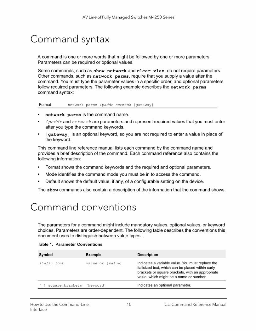
A command is one or more words that might be followed by one or more parameters. Parameters can be required or optional values.
Some commands, such as show network and clear vlan, do not require parameters. Other commands, such as network parms, require that you supply a value after the command. You must type the parameter values in a specific order, and optional parameters follow required parameters. The following example describes the network parms command syntax:
• network parms is the command name. • ipaddr and netmask are parameters and represent required values that you must enter
after you type the command keywords.• [gateway] is an optional keyword, so you are not required to enter a value in place of
the keyword.
This command line reference manual lists each command by the command name and provides a brief description of the command. Each command reference also contains the following information:
• Format shows the command keywords and the required and optional parameters.• Mode identifies the command mode you must be in to access the command.• Default shows the default value, if any, of a configurable setting on the device.
The show commands also contain a description of the information that the command shows.
Command conventions
The parameters for a command might include mandatory values, optional values, or keyword choices. Parameters are order-dependent. The following table describes the conventions this document uses to distinguish between value types.
Format network parms ipaddr netmask [gateway]
Table 1. Parameter Conventions
Symbol Example Description
italic font value or [value] Indicates a variable value. You must replace the italicized text, which can be placed within curly brackets or square brackets, with an appropriate value, which might be a name or number.
[ ] square brackets [keyword] Indicates an optional parameter.
How to Use the Command-Line Interface
CLI Command Reference Manual10

AV Line of Fully Managed Switches M4250 Series
Common parameter values
Parameter values might be names (strings) or numbers. To use spaces as part of a name parameter, enclose the name value in double quotes. For example, the expression “System Name with Spaces” forces the system to accept the spaces. Empty strings (““) are not valid user-defined strings. The following table describes common parameter values and value formatting.
{ } curly braces {choice1 | choice2} Indicates that you must select a parameter from the list of choices.
| Vertical bars choice1 | choice2 Separates the mutually exclusive choices.
[{ }] Braces within square brackets
[{choice1 | choice2}] Indicates a choice within an optional element. This format is used mainly for complicated commands
Table 2. Parameter Descriptions
Parameter Description
ipaddr This parameter is a valid IPv4 address. You can enter the IP address in the following formats:• a (32 bits)• a.b (8.24 bits)• a.b.c (8.8.16 bits)• a.b.c.d (8.8.8.8)In addition to these formats, the CLI accepts decimal, hexadecimal and octal formats through the following input formats (where n is any valid hexadecimal, octal or decimal number):• 0xn (CLI assumes hexadecimal format.)• 0n (CLI assumes octal format with leading zeros.)• n (CLI assumes decimal format.)
ipv6-addr This parameter is a valid IPv6 address. You can enter the IP address in the following formats:• FE80:0000:0000:0000:020F:24FF:FEBF:DBCB• FE80:0:0:0:20F:24FF:FEBF:DBCB• FE80::20F24FF:FEBF:DBCB• FE80:0:0:0:20F:24FF:128:141:49:32For additional information, refer to RFC 3513.
Interface or unit/port
Valid unit and port number separated by a forward slash. The unit is always 0. For example, 0/1 represents port number 1.
Table 1. Parameter Conventions (continued)
Symbol Example Description
How to Use the Command-Line Interface
CLI Command Reference Manual11
AV Line of Fully Managed Switches M4250 Series
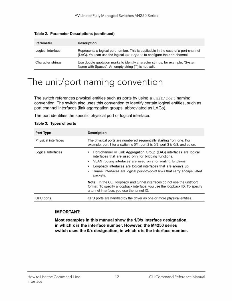
The unit/port naming convention
The switch references physical entities such as ports by using a unit/port naming convention. The switch also uses this convention to identify certain logical entities, such as port channel interfaces (link aggregation groups, abbreviated as LAGs).
The port identifies the specific physical port or logical interface.
IMPORTANT:
Most examples in this manual show the 1/0/x interface designation, in which x is the interface number. However, the M4250 series switch uses the 0/x designation, in which x is the interface number.
Logical Interface Represents a logical port number. This is applicable in the case of a port-channel (LAG). You can use the logical unit/port to configure the port-channel.
Character strings Use double quotation marks to identify character strings, for example, “System Name with Spaces”. An empty string (“”) is not valid.
Table 3. Types of ports
Port Type Description
Physical interfaces The physical ports are numbered sequentially starting from one. For example, port 1 for a switch is 0/1, port 2 is 0/2, port 3 is 0/3, and so on.
Logical Interfaces • Port-channel or Link Aggregation Group (LAG) interfaces are logical interfaces that are used only for bridging functions.
• VLAN routing interfaces are used only for routing functions.• Loopback interfaces are logical interfaces that are always up.• Tunnel interfaces are logical point-to-point links that carry encapsulated
packets.
Note: In the CLI, loopback and tunnel interfaces do not use the unit/port format. To specify a loopback interface, you use the loopback ID. To specify a tunnel interface, you use the tunnel ID.
CPU ports CPU ports are handled by the driver as one or more physical entities.
Table 2. Parameter Descriptions (continued)
Parameter Description
How to Use the Command-Line Interface
CLI Command Reference Manual12
AV Line of Fully Managed Switches M4250 Series
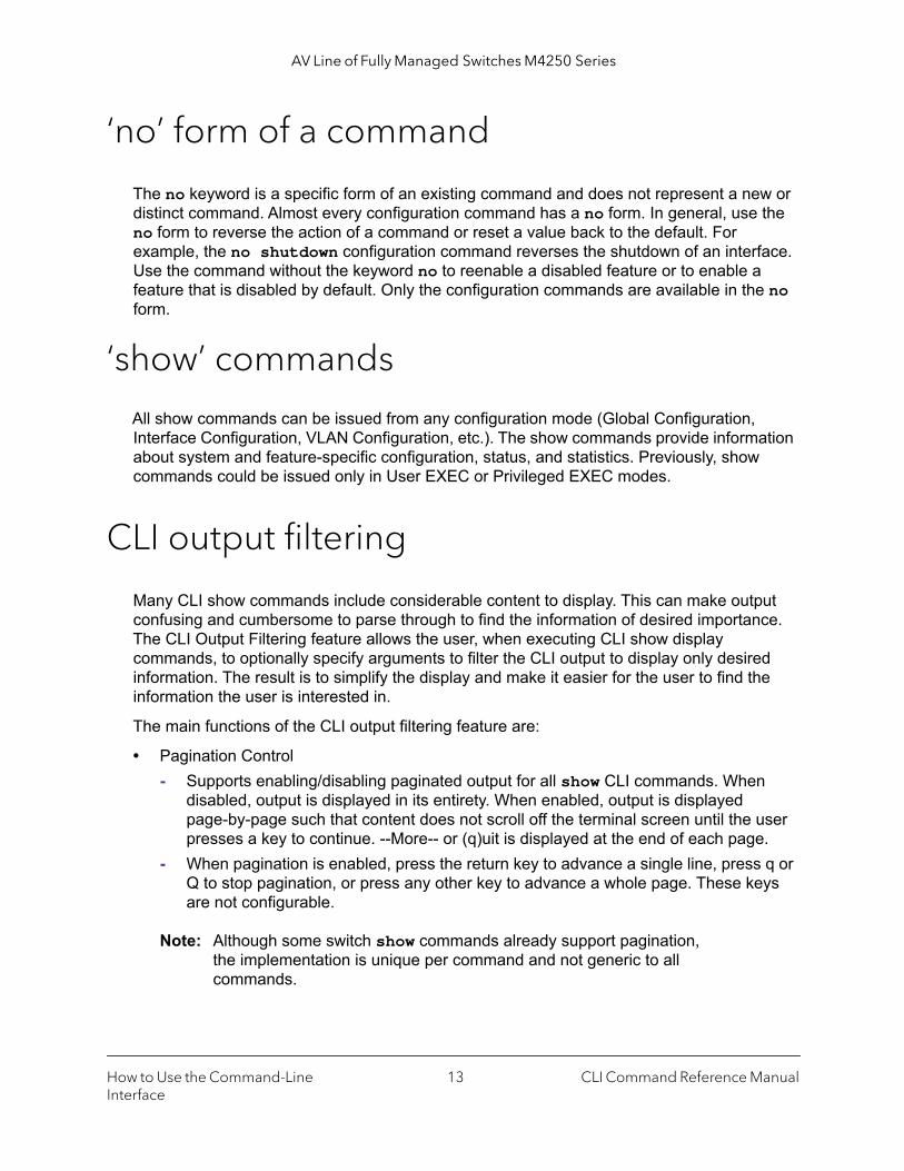
‘no’ form of a command
The no keyword is a specific form of an existing command and does not represent a new or distinct command. Almost every configuration command has a no form. In general, use the no form to reverse the action of a command or reset a value back to the default. For example, the no shutdown configuration command reverses the shutdown of an interface. Use the command without the keyword no to reenable a disabled feature or to enable a feature that is disabled by default. Only the configuration commands are available in the no form.
‘show’ commands
All show commands can be issued from any configuration mode (Global Configuration, Interface Configuration, VLAN Configuration, etc.). The show commands provide information about system and feature-specific configuration, status, and statistics. Previously, show commands could be issued only in User EXEC or Privileged EXEC modes.
CLI output filtering
Many CLI show commands include considerable content to display. This can make output confusing and cumbersome to parse through to find the information of desired importance. The CLI Output Filtering feature allows the user, when executing CLI show display commands, to optionally specify arguments to filter the CLI output to display only desired information. The result is to simplify the display and make it easier for the user to find the information the user is interested in.
The main functions of the CLI output filtering feature are:
• Pagination Control- Supports enabling/disabling paginated output for all show CLI commands. When
disabled, output is displayed in its entirety. When enabled, output is displayed page-by-page such that content does not scroll off the terminal screen until the user presses a key to continue. --More-- or (q)uit is displayed at the end of each page.
- When pagination is enabled, press the return key to advance a single line, press q or Q to stop pagination, or press any other key to advance a whole page. These keys are not configurable.
Note: Although some switch show commands already support pagination, the implementation is unique per command and not generic to all commands.
How to Use the Command-Line Interface
CLI Command Reference Manual13
AV Line of Fully Managed Switches M4250 Series
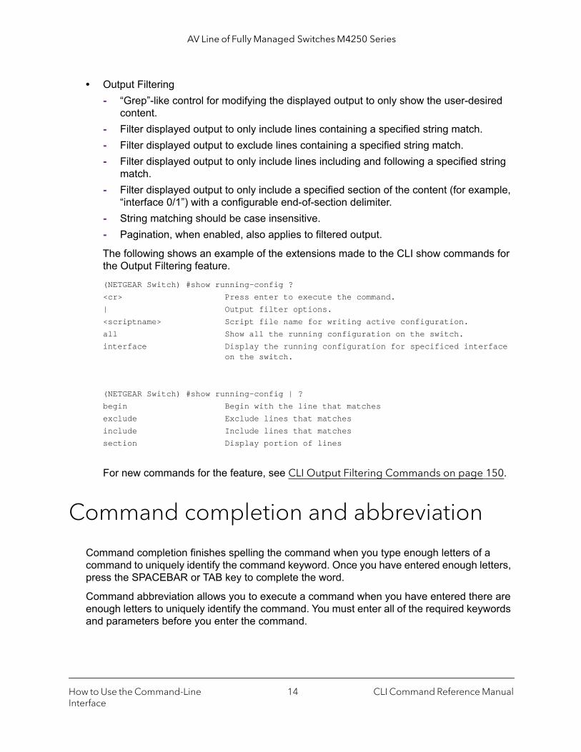
• Output Filtering- “Grep”-like control for modifying the displayed output to only show the user-desired
content.- Filter displayed output to only include lines containing a specified string match.- Filter displayed output to exclude lines containing a specified string match.- Filter displayed output to only include lines including and following a specified string
match.- Filter displayed output to only include a specified section of the content (for example,
“interface 0/1”) with a configurable end-of-section delimiter.- String matching should be case insensitive.- Pagination, when enabled, also applies to filtered output.
The following shows an example of the extensions made to the CLI show commands for the Output Filtering feature.(NETGEAR Switch) #show running-config ?<cr> Press enter to execute the command.| Output filter options.<scriptname> Script file name for writing active configuration.all Show all the running configuration on the switch.interface Display the running configuration for specificed interface on the switch.
(NETGEAR Switch) #show running-config | ?begin Begin with the line that matchesexclude Exclude lines that matchesinclude Include lines that matchessection Display portion of lines
For new commands for the feature, see CLI Output Filtering Commands on page 150.
Command completion and abbreviation
Command completion finishes spelling the command when you type enough letters of a command to uniquely identify the command keyword. Once you have entered enough letters, press the SPACEBAR or TAB key to complete the word.
Command abbreviation allows you to execute a command when you have entered there are enough letters to uniquely identify the command. You must enter all of the required keywords and parameters before you enter the command.
How to Use the Command-Line Interface
CLI Command Reference Manual14
AV Line of Fully Managed Switches M4250 Series
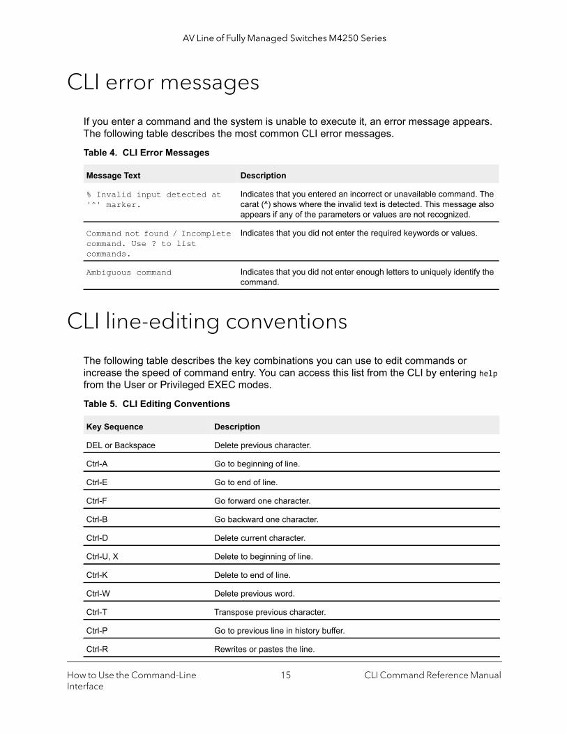
CLI error messages
If you enter a command and the system is unable to execute it, an error message appears. The following table describes the most common CLI error messages.
CLI line-editing conventions
The following table describes the key combinations you can use to edit commands or increase the speed of command entry. You can access this list from the CLI by entering help from the User or Privileged EXEC modes.
Table 4. CLI Error Messages
Message Text Description
% Invalid input detected at '^' marker.
Indicates that you entered an incorrect or unavailable command. The carat (^) shows where the invalid text is detected. This message also appears if any of the parameters or values are not recognized.
Command not found / Incomplete command. Use ? to list commands.
Indicates that you did not enter the required keywords or values.
Ambiguous command Indicates that you did not enter enough letters to uniquely identify the command.
Table 5. CLI Editing Conventions
Key Sequence Description
DEL or Backspace Delete previous character.
Ctrl-A Go to beginning of line.
Ctrl-E Go to end of line.
Ctrl-F Go forward one character.
Ctrl-B Go backward one character.
Ctrl-D Delete current character.
Ctrl-U, X Delete to beginning of line.
Ctrl-K Delete to end of line.
Ctrl-W Delete previous word.
Ctrl-T Transpose previous character.
Ctrl-P Go to previous line in history buffer.
Ctrl-R Rewrites or pastes the line.
How to Use the Command-Line Interface
CLI Command Reference Manual15

AV Line of Fully Managed Switches M4250 Series
Use the CLI help
Enter a question mark (?) at the command prompt to display the commands available in the current mode. (NETGEAR Switch) >?
enable Enter into user privilege mode.help Display help for various special keys.logout Exit this session. Any unsaved changes are lost.password Change an existing user’s password.ping Send ICMP echo packets to a specified IP address.quit Exit this session. Any unsaved changes are lost.show Display Switch Options and Settings.telnet Telnet to a remote host.
Enter a question mark (?) after each word you enter to display available command keywords or parameters.(NETGEAR Switch) #network ?
ipv6 Configure IPv6 parameters for system network.javamode Enable/Disable.mac-address Configure MAC Address.mac-type Select the locally administered or burnedin MAC address.mgmt_vlan Configure the Management VLAN ID of the switch.parms Configure Network Parameters of the device.protocol Select DHCP, BootP, or None as the network config protocol.
Ctrl-N Go to next line in history buffer.
Ctrl-Y Prints last deleted character.
Ctrl-Q Enables serial flow.
Ctrl-S Disables serial flow.
Ctrl-Z Return to root command prompt.
Tab, <SPACE> Command-line completion.
Exit Go to next lower command prompt.
? List available commands, keywords, or parameters.
Table 5. CLI Editing Conventions (continued)
Key Sequence Description
How to Use the Command-Line Interface
CLI Command Reference Manual16
AV Line of Fully Managed Switches M4250 Series
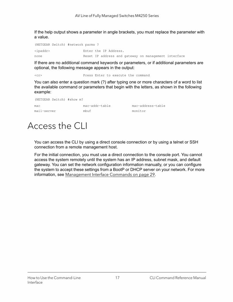
If the help output shows a parameter in angle brackets, you must replace the parameter with a value.(NETGEAR Switch) #network parms ?
<ipaddr> Enter the IP Address.none Reset IP address and gateway on management interface
If there are no additional command keywords or parameters, or if additional parameters are optional, the following message appears in the output:<cr> Press Enter to execute the command
You can also enter a question mark (?) after typing one or more characters of a word to list the available command or parameters that begin with the letters, as shown in the following example:(NETGEAR Switch) #show m?
mac mac-addr-table mac-address-tablemail-server mbuf monitor
Access the CLI
You can access the CLI by using a direct console connection or by using a telnet or SSH connection from a remote management host.
For the initial connection, you must use a direct connection to the console port. You cannot access the system remotely until the system has an IP address, subnet mask, and default gateway. You can set the network configuration information manually, or you can configure the system to accept these settings from a BootP or DHCP server on your network. For more information, see Management Interface Commands on page 29.
How to Use the Command-Line Interface
CLI Command Reference Manual17

3
3CLI Organization and Command ModesThis chapter describes the CLI organization and command modes. It contains the following sections:
• CLI command modes
• How to enter or exit a command mode
18

AV Line of Fully Managed Switches M4250 Series
CLI command modes
The CLI groups commands into modes according to the command function. Each of the command modes supports specific commands. The commands in one mode are not available until you switch to that particular mode, with the exception of the User EXEC mode commands. You can execute the User EXEC mode commands in the Privileged EXEC mode.
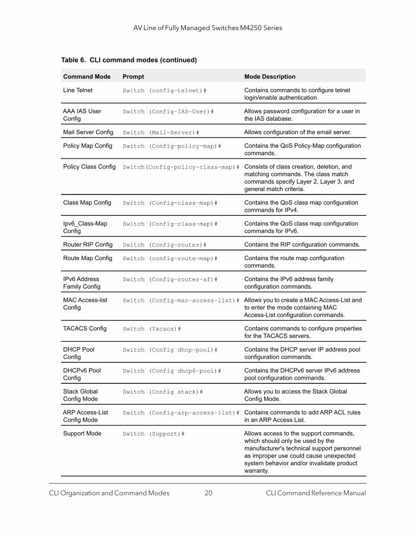
The command prompt changes in each command mode to help you identify the current mode. The following table describes the command modes and the prompts visible in that mode.
Table 6. CLI command modes
Command Mode Prompt Mode Description
User EXEC Switch> Contains a limited set of commands to view basic system information.
Privileged EXEC Switch# Allows you to issue any EXEC command, enter the VLAN mode, or enter the Global Configuration mode.
Global Config Switch (Config)# Groups general setup commands and permits you to make modifications to the running configuration.
VLAN Config Switch (Vlan)# Groups all the VLAN commands.
Interface Config Switch (Interface unit/port)# Manages the operation of an interface and provides access to the router interface configuration commands.Use this mode to set up a physical port for a specific logical connection operation.
Switch (Interface Loopback id)#
Switch (Interface Tunnel id)#
Switch (Interface unit/port (startrange)-unit/port (endrange)#
Use this mode to manage the operation of a range of interfaces. For example the prompt may display as follows:Switch (Interface 0/1-0/4) #
Switch (Interface lag lag-intf-num)#
Enters LAG Interface configuration mode for the specified LAG.
Switch (Interface vlan vlan-id)# Enters VLAN routing interface configuration mode for the specified VLAN ID.
Line Console Switch (config-line)# Contains commands to configure outbound telnet settings and console interface settings, as well as to configure console login/enable authentication.
Line SSH Switch (config-ssh)# Contains commands to configure SSH login/enable authentication.
CLI Organization and Command Modes CLI Command Reference Manual19
AV Line of Fully Managed Switches M4250 Series
Line Telnet Switch (config-telnet)# Contains commands to configure telnet login/enable authentication.
AAA IAS User Config
Switch (Config-IAS-User)# Allows password configuration for a user in the IAS database.
Mail Server Config Switch (Mail-Server)# Allows configuration of the email server.
Policy Map Config Switch (Config-policy-map)# Contains the QoS Policy-Map configuration commands.
Policy Class Config Switch(Config-policy-class-map)# Consists of class creation, deletion, and matching commands. The class match commands specify Layer 2, Layer 3, and general match criteria.
Class Map Config Switch (Config-class-map)# Contains the QoS class map configuration commands for IPv4.
Ipv6_Class-Map Config
Switch (Config-class-map)# Contains the QoS class map configuration commands for IPv6.
Router RIP Config Switch (Config-router)# Contains the RIP configuration commands.
Route Map Config Switch (config-route-map)# Contains the route map configuration commands.
IPv6 Address Family Config
Switch (Config-router-af)# Contains the IPv6 address family configuration commands.
MAC Access-list Config
Switch (Config-mac-access-list)# Allows you to create a MAC Access-List and to enter the mode containing MAC Access-List configuration commands.
TACACS Config Switch (Tacacs)# Contains commands to configure properties for the TACACS servers.
DHCP Pool Config
Switch (Config dhcp-pool)# Contains the DHCP server IP address pool configuration commands.
DHCPv6 Pool Config
Switch (Config dhcp6-pool)# Contains the DHCPv6 server IPv6 address pool configuration commands.
Stack Global Config Mode
Switch (Config stack)# Allows you to access the Stack Global Config Mode.
ARP Access-List Config Mode
Switch (Config-arp-access-list)# Contains commands to add ARP ACL rules in an ARP Access List.
Support Mode Switch (Support)# Allows access to the support commands, which should only be used by the manufacturer's technical support personnel as improper use could cause unexpected system behavior and/or invalidate product warranty.
Table 6. CLI command modes (continued)
Command Mode Prompt Mode Description
CLI Organization and Command Modes CLI Command Reference Manual20

AV Line of Fully Managed Switches M4250 Series
How to enter or exit a command mode
The following table describes how to enter or exit each mode.
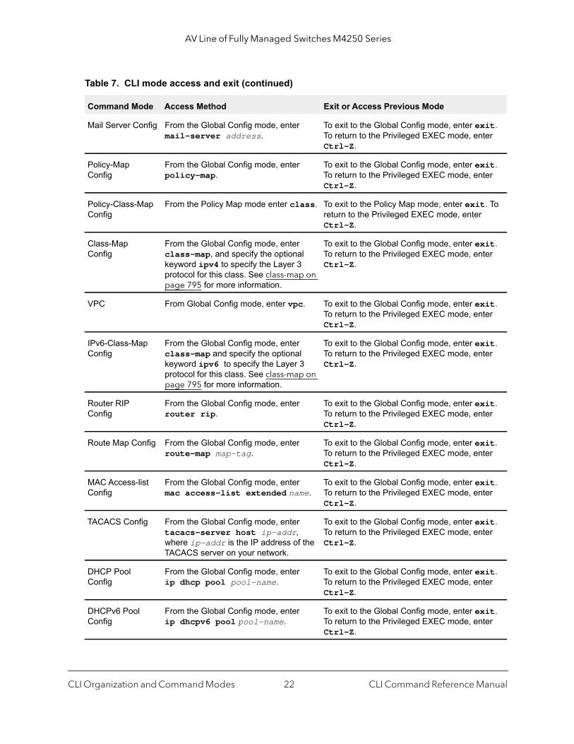
Table 7. CLI mode access and exit
Command Mode Access Method Exit or Access Previous Mode
User EXEC This is the first level of access. To exit, enter logout.
Privileged EXEC From the User EXEC mode, enter enable.
To exit to the User EXEC mode, enter exit or press Ctrl-Z.
Global Config From the Privileged EXEC mode, enter configure.
To exit to the Privileged EXEC mode, enter exit, or press Ctrl-Z.
VLAN Config From the Privileged EXEC mode, enter vlan database.
To exit to the Privileged EXEC mode, enter exit, or press Ctrl-Z.
Interface Config From the Global Config mode, enter:interface unit/port
To exit to the Global Config mode, enter exit. To return to the Privileged EXEC mode, enter Ctrl-Z.
From the Global Config mode, enter:interface loopback id
From the Global Config mode, enter:interface tunnel id
From the Global Config mode, enter:interface unit/port(startrange)- unit/port(endrange)
From the Global Config mode, enter:interface lag lag-intf-num
From the Global Config mode, enter:interface vlan vlan-id
Line Console From the Global Config mode, enter line console.
To exit to the Global Config mode, enter exit. To return to the Privileged EXEC mode, enter Ctrl-Z.
Line SSH From the Global Config mode, enter line ssh.
To exit to the Global Config mode, enter exit. To return to the Privileged EXEC mode, enter Ctrl-Z.
Line Telnet From the Global Config mode, enter line telnet.
To exit to the Global Config mode, enter exit. To return to the Privileged EXEC mode, enter Ctrl-Z.
AAA IAS User Config
From the Global Config mode, enter aaa ias-user username name.
To exit to the Global Config mode, enter exit. To return to the Privileged EXEC mode, enter Ctrl-Z.
CLI Organization and Command Modes CLI Command Reference Manual21
AV Line of Fully Managed Switches M4250 Series
Mail Server Config From the Global Config mode, enter mail-server address.
To exit to the Global Config mode, enter exit. To return to the Privileged EXEC mode, enter Ctrl-Z.
Policy-Map Config
From the Global Config mode, enter policy-map.
To exit to the Global Config mode, enter exit. To return to the Privileged EXEC mode, enter Ctrl-Z.
Policy-Class-Map Config
From the Policy Map mode enter class. To exit to the Policy Map mode, enter exit. To return to the Privileged EXEC mode, enter Ctrl-Z.
Class-Map Config
From the Global Config mode, enter class-map, and specify the optional keyword ipv4 to specify the Layer 3 protocol for this class. See class-map on page 795 for more information.
To exit to the Global Config mode, enter exit. To return to the Privileged EXEC mode, enter Ctrl-Z.
VPC From Global Config mode, enter vpc. To exit to the Global Config mode, enter exit. To return to the Privileged EXEC mode, enter Ctrl-Z.
IPv6-Class-Map Config
From the Global Config mode, enter class-map and specify the optional keyword ipv6 to specify the Layer 3 protocol for this class. See class-map on page 795 for more information.
To exit to the Global Config mode, enter exit. To return to the Privileged EXEC mode, enter Ctrl-Z.
Router RIP Config
From the Global Config mode, enter router rip.
To exit to the Global Config mode, enter exit. To return to the Privileged EXEC mode, enter Ctrl-Z.
Route Map Config From the Global Config mode, enter route-map map-tag.
To exit to the Global Config mode, enter exit. To return to the Privileged EXEC mode, enter Ctrl-Z.
MAC Access-list Config
From the Global Config mode, enter mac access-list extended name.
To exit to the Global Config mode, enter exit. To return to the Privileged EXEC mode, enter Ctrl-Z.
TACACS Config From the Global Config mode, enter tacacs-server host ip-addr, where ip-addr is the IP address of the TACACS server on your network.
To exit to the Global Config mode, enter exit. To return to the Privileged EXEC mode, enter Ctrl-Z.
DHCP Pool Config
From the Global Config mode, enter ip dhcp pool pool-name.
To exit to the Global Config mode, enter exit. To return to the Privileged EXEC mode, enter Ctrl-Z.
DHCPv6 Pool Config
From the Global Config mode, enter ip dhcpv6 pool pool-name.
To exit to the Global Config mode, enter exit. To return to the Privileged EXEC mode, enter Ctrl-Z.
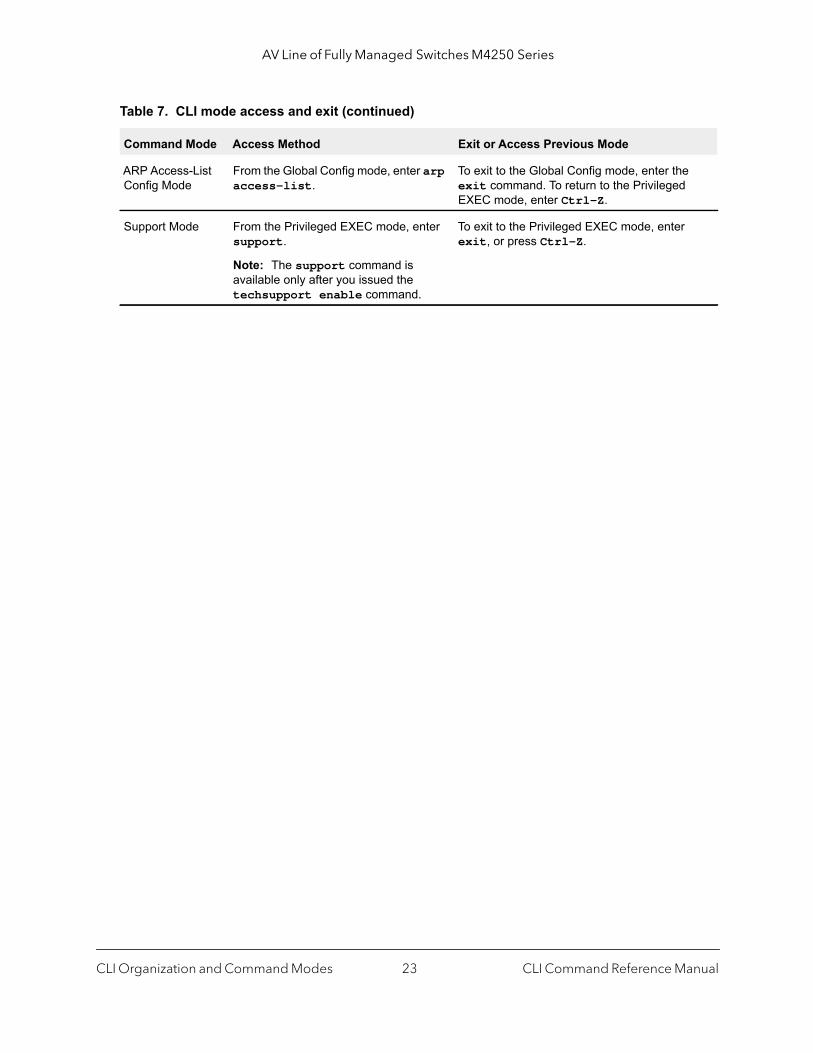
Table 7. CLI mode access and exit (continued)
Command Mode Access Method Exit or Access Previous Mode
CLI Organization and Command Modes CLI Command Reference Manual22
AV Line of Fully Managed Switches M4250 Series
ARP Access-List Config Mode
From the Global Config mode, enter arp access-list.
To exit to the Global Config mode, enter the exit command. To return to the Privileged EXEC mode, enter Ctrl-Z.
Support Mode From the Privileged EXEC mode, enter support.
Note: The support command is available only after you issued the techsupport enable command.
To exit to the Privileged EXEC mode, enter exit, or press Ctrl-Z.
Table 7. CLI mode access and exit (continued)
Command Mode Access Method Exit or Access Previous Mode
CLI Organization and Command Modes CLI Command Reference Manual23
4
4Management CommandsThis chapter describes the management commands.
The chapter contains the following sections:
• Configure the Switch Management CPU
• CPU Queue Commands
• Management Interface Commands
• IPv6 Management Commands
• Console Port Access Commands
• Telnet Commands
• Secure Shell Commands
• Management Security Commands
• Management Access Control List Commands
• Hypertext Transfer Protocol Commands
• Access Commands
• User Account Commands
• SNMP Commands
• RADIUS Commands
• TACACS+ Commands
• Configuration Scripting Commands
• Prelogin Banner, System Prompt, and Host Name Commands
• Application Commands
The commands in this chapter are in one of three functional groups:
• Show commands. Display switch settings, statistics, and other information.• Configuration commands. Configure features and options of the switch. For every
configuration command, there is a show command that displays the configuration setting.• Clear commands. Clear some or all of the settings to factory defaults.
24
AV Line of Fully Managed Switches M4250 Series
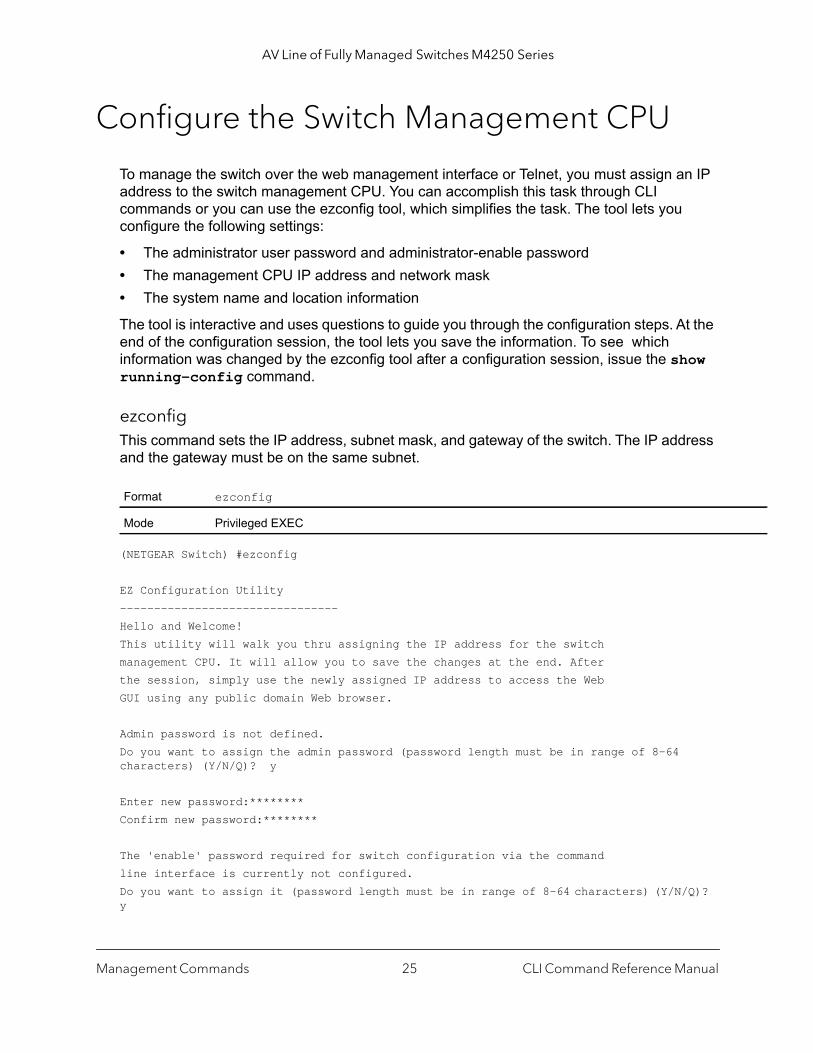
Configure the Switch Management CPU
To manage the switch over the web management interface or Telnet, you must assign an IP address to the switch management CPU. You can accomplish this task through CLI commands or you can use the ezconfig tool, which simplifies the task. The tool lets you configure the following settings:
• The administrator user password and administrator-enable password• The management CPU IP address and network mask• The system name and location information
The tool is interactive and uses questions to guide you through the configuration steps. At the end of the configuration session, the tool lets you save the information. To see which information was changed by the ezconfig tool after a configuration session, issue the show running-config command.
ezconfigThis command sets the IP address, subnet mask, and gateway of the switch. The IP address and the gateway must be on the same subnet.
(NETGEAR Switch) #ezconfig
EZ Configuration Utility--------------------------------Hello and Welcome!This utility will walk you thru assigning the IP address for the switchmanagement CPU. It will allow you to save the changes at the end. Afterthe session, simply use the newly assigned IP address to access the WebGUI using any public domain Web browser.
Admin password is not defined.Do you want to assign the admin password (password length must be in range of 8-64 characters) (Y/N/Q)? y
Enter new password:********Confirm new password:********
The 'enable' password required for switch configuration via the commandline interface is currently not configured.Do you want to assign it (password length must be in range of 8-64 characters) (Y/N/Q)? y
Format ezconfig
Mode Privileged EXEC
Management Commands CLI Command Reference Manual25

AV Line of Fully Managed Switches M4250 Series
Enter new password:********Confirm new password:********Current IPv4 Management Interface: vlan 1Do you want to set new Management VLAN ID (Y/N/Q)?y
VLAN ID: 1Assigning an IPv4 address to your switch management
Current IPv4 Address Configuration----------------------------------Management VLAN ID: vlan 1IPv4 Address Assignment Mode: NoneIPv4 Address: 0.0.0.0Subnet Mask: 0.0.0.0Gateway: 0.0.0.0Routing Mode: Enable
IPv4 address is not assigned. What do you want to do?C - Configure IPv4 address manually.D - Assign IPv4 address for the switch using DHCP Mode(current IPv4 address will belost).N - Skip this option and go to the next question.Q - Quit.? - Help.(C/D/N/Q/?)? c
IPv4 Address: 192.168.1.1Network Mask: 255.255.255.0Gateway: 192.168.254Incorrect input! Gateway must be a valid IP address.Try again (Y/N/Q)? y
Gateway: 192.168.1.254Do you want to enable global routing (Y/N)?y
Current IPv6 Management Interface: (not configured)Do you want to set new IPv6 Management VLAN ID (Y/N/Q)?yVLAN ID: 1Assigning management IPv6 address.
Current IPv6 Address Configuration----------------------------------IPv6 Address: fe80::abd:43ff:fe71:73c0/64IPv6 Current state: TENTAddress DHCP Mode: DisabledAddress Autoconfigure Mode: Disabled
Management Commands CLI Command Reference Manual26

AV Line of Fully Managed Switches M4250 Series
EUI64 : Enabled
Routing Mode: Enable
IPv6 address has been assigned manually. What do you want to do?C - Add IPv6 address.D - Assign IPv6 address for the switch using DHCP Mode.A - Assign IPv6 address for the switch using Auto Mode.N - Skip this option and go to the next question.Q - Quit.? - Help.(C/D/A/N/Q/?)? c
IPv6 Address: 2001:1::1IPv6 Prefix-length: 64IPv6 EUI64 flag (Y/N): n
IPv6 Gateway: 2001:1::fffe
Current Out of Band(service port) IPv4 Address Configuration--------------------------------IP Address Assignment Mode: DHCPIP Address: 172.26.2.104Subnet Mask: 255.255.255.0Default Router: 172.26.2.1
IPv4 address will be assigned automatically by the DHCP server in your network. Youcan disable DHCP mode and use static(fixed) IPv4 address. If fixed IPv4 Address Modeis selected, DHCP Protocol Mode will be disabled, and you will be prompted toset the values for the four fields above.Do you want to assign IPv4 address manually? (Y/N/Q/?) y
IPv4 Address: 172.26.2.1Network Mask: 255.255.255.0Gateway: 172.26.2.254Current Out of Band(Serviceport) IPv6 Address Configuration--------------------------------Service port IPv6 Address Mode: NoneIPv6 Administrative Mode: EnabledService port IPv6 Address Mode autoconfigure: DisabledIPv6 Address: fe80::abd:43ff:fe71:73be/64Service port IPv6 address gateway:EUI Flag: False
IPv6 address has been assigned manually. What do you want to do?A - Assign IPv6 address for the switch using Auto Mode.D - Assign IPv6 address for the switch using DHCP Mode.
Management Commands CLI Command Reference Manual27

AV Line of Fully Managed Switches M4250 Series
G - Assign IPv6 Gateway.C - Add IPv6 address.N - Skip this option and go to the next question.Q - Quit.? - Help.(A/D/G/C/N/Q/?)? c
Current Management Interface Configuration--------------------------------Management Interface: L3 Management VLANCurrent management interface is L3 Management VLAN. What do you want to do?O - Change to Out of Band port(service port).V - Change to L3 Management VLAN.N - Skip this option and go to the next question.Q - Quit.? - Help.(O/V/N/Q/?)?n
Assigning System Name, System Location and System Contact to your switch management
Current Configuration--------------------------------System Name:
System Location:
System Contact:
Do you want to assign switch name and location information? (Y/N/Q)
CPU Queue Commands
You can send all packets with a specified destination address to a higher priority queue (5) than the default queue for data packets and unicast packets to the CPU.
ip cpu-priorityThis command sends all packets with a specified destination IPv4 address to a higher priority queue (5) than the default queue for data packets and unicast packets to the CPU.
Format ip cpu-priority ip-address
Mode Privileged EXEC
Management Commands CLI Command Reference Manual28

AV Line of Fully Managed Switches M4250 Series
no ip cpu-priority
This command removes all packets with a specified destination IPv4 address from the higher priority queue.
ipv6 cpu-priorityThe command allows all packets with a specified destination IPv6 address into a higher priority queue (5) than the default queue for data packets and unicast packets to the CPU.
no ipv6 cpu-priority
This command removes all packets with a specified destination IPv6 address from the higher priority queue.
Management Interface Commands
This section describes the commands you use to configure a logical IPv4 interface for management access.
enable (Privileged EXEC access)This command gives you access to the Privileged EXEC mode. From the Privileged EXEC mode, you can configure the network interface.
Format no ip cpu-priority ip-address
Mode Privileged EXEC
Format ip cpu-priority ipv6-address
Mode Privileged EXEC
Format no ip cpu-priority ipv6-address
Mode Privileged EXEC
Format enable
Mode User EXEC
Management Commands CLI Command Reference Manual29
AV Line of Fully Managed Switches M4250 Series
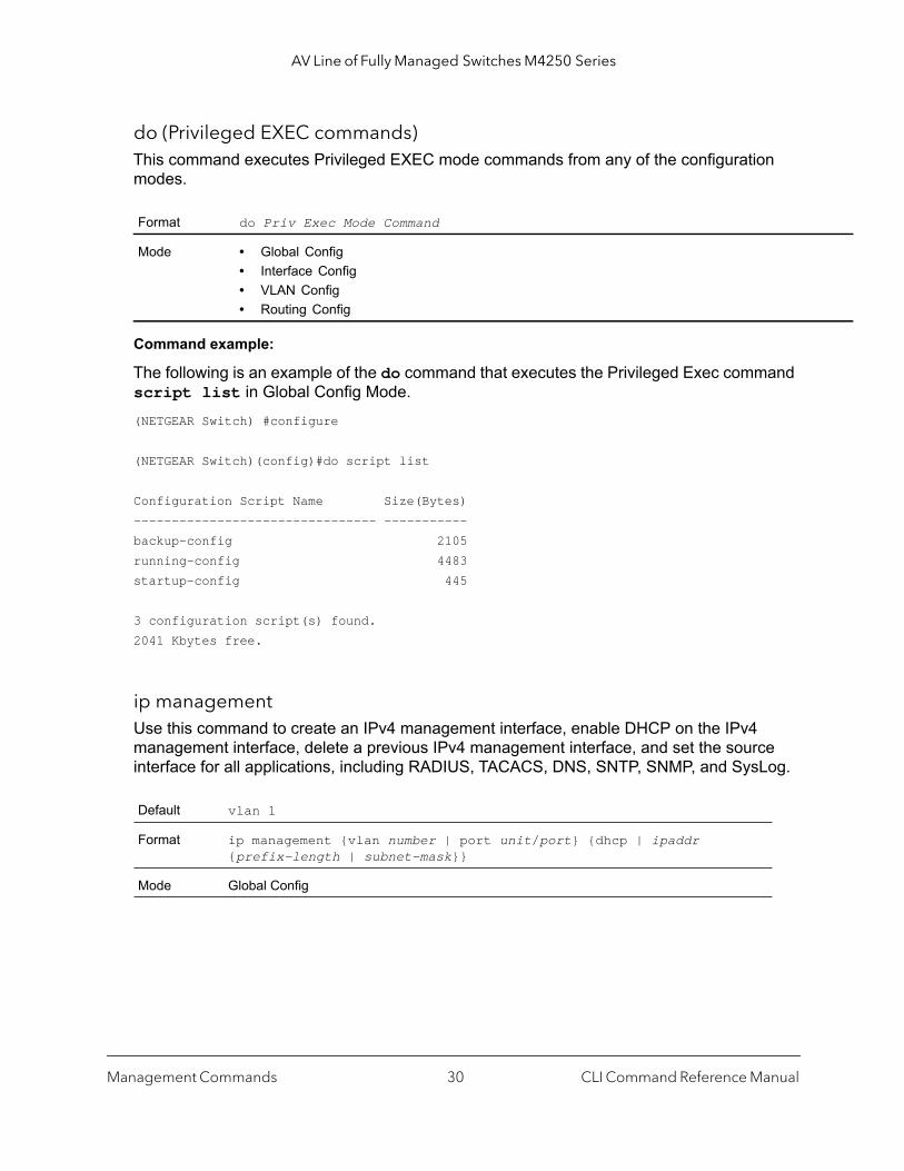
do (Privileged EXEC commands)This command executes Privileged EXEC mode commands from any of the configuration modes.
Command example:
The following is an example of the do command that executes the Privileged Exec command script list in Global Config Mode.(NETGEAR Switch) #configure
(NETGEAR Switch)(config)#do script list
Configuration Script Name Size(Bytes)-------------------------------- -----------backup-config 2105running-config 4483startup-config 445
3 configuration script(s) found.2041 Kbytes free.
ip managementUse this command to create an IPv4 management interface, enable DHCP on the IPv4 management interface, delete a previous IPv4 management interface, and set the source interface for all applications, including RADIUS, TACACS, DNS, SNTP, SNMP, and SysLog.
Format do Priv Exec Mode Command
Mode • Global Config• Interface Config• VLAN Config• Routing Config
Default vlan 1
Format ip management {vlan number | port unit/port} {dhcp | ipaddr {prefix-length | subnet-mask}}
Mode Global Config
Management Commands CLI Command Reference Manual30
AV Line of Fully Managed Switches M4250 Series
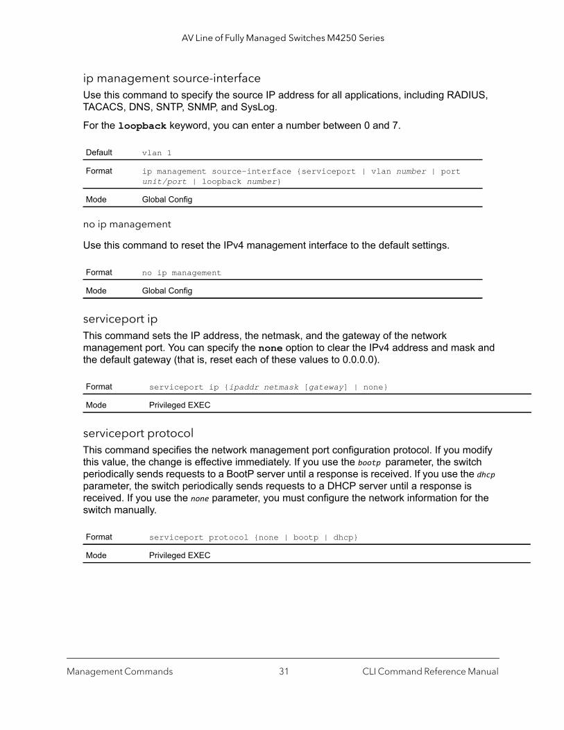
ip management source-interfaceUse this command to specify the source IP address for all applications, including RADIUS, TACACS, DNS, SNTP, SNMP, and SysLog.
For the loopback keyword, you can enter a number between 0 and 7.
no ip management
Use this command to reset the IPv4 management interface to the default settings.
serviceport ipThis command sets the IP address, the netmask, and the gateway of the network management port. You can specify the none option to clear the IPv4 address and mask and the default gateway (that is, reset each of these values to 0.0.0.0).
serviceport protocolThis command specifies the network management port configuration protocol. If you modify this value, the change is effective immediately. If you use the bootp parameter, the switch periodically sends requests to a BootP server until a response is received. If you use the dhcp parameter, the switch periodically sends requests to a DHCP server until a response is received. If you use the none parameter, you must configure the network information for the switch manually.
Default vlan 1
Format ip management source-interface {serviceport | vlan number | port unit/port | loopback number}
Mode Global Config
Format no ip management
Mode Global Config
Format serviceport ip {ipaddr netmask [gateway] | none}
Mode Privileged EXEC
Format serviceport protocol {none | bootp | dhcp}
Mode Privileged EXEC
Management Commands CLI Command Reference Manual31

AV Line of Fully Managed Switches M4250 Series
serviceport protocol dhcpThis command enables the DHCPv4 client on a Service port. If the client-id optional parameter is given, the DHCP client messages are sent with the client identifier option.
There is no support for the no form of the command serviceport protocol dhcp client-id. To remove the client-id option from the DHCP client messages, issue the command serviceport protocol dhcp without the client-id option. The command serviceport protocol none can be used to disable the DHCP client and client-id option on the interface.
Command example: (NETGEAR Switch) # serviceport protocol dhcp client-id
mac management addressThis command sets locally administered MAC addresses. The following rules apply:
• Bit 6 of byte 0 (called the U/L bit) indicates whether the address is universally administered (b'0') or locally administered (b'1').
• Bit 7 of byte 0 (called the I/G bit) indicates whether the destination address is an individual address (b'0') or a group address (b'1').
• The second character, of the twelve character macaddr, must be 2, 6, A or E.
A locally administered address must have bit 6 On (b'1') and bit 7 Off (b'0').
mac management typeThis command specifies whether the switch uses the burned in MAC address or the locally-administered MAC address.
Default none
Format serviceport protocol dhcp [client-id]
Mode Privileged Exec
Format mac management address macaddr
Mode Privileged EXEC
Default burnedin
Format mac management type {local | burnedin}
Mode Privileged EXEC
Management Commands CLI Command Reference Manual32
AV Line of Fully Managed Switches M4250 Series
his
bytes.n the
AC iority, .
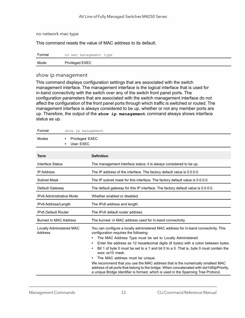
no network mac-type
This command resets the value of MAC address to its default.
show ip managementThis command displays configuration settings that are associated with the switch management interface. The management interface is the logical interface that is used for in-band connectivity with the switch over any of the switch front panel ports. The configuration parameters that are associated with the switch management interface do not affect the configuration of the front panel ports through which traffic is switched or routed. The management interface is always considered to be up, whether or not any member ports are up. Therefore, the output of the show ip management command always shows interface status as up.
Format no mac management type
Mode Privileged EXEC
Format show ip management
Modes • Privileged EXEC• User EXEC
Term Definition
Interface Status The management interface status; it is always considered to be up.
IP Address The IP address of the interface. The factory default value is 0.0.0.0.
Subnet Mask The IP subnet mask for this interface. The factory default value is 0.0.0.0.
Default Gateway The default gateway for this IP interface. The factory default value is 0.0.0.0.
IPv6 Administrative Mode Whether enabled or disabled.
IPv6 Address/Length The IPv6 address and length.
IPv6 Default Router The IPv6 default router address.
Burned In MAC Address The burned- in MAC address used for in-band connectivity.
Locally Administered MAC Address
You can configure a locally administered MAC address for in-band connectivity. Tconfiguration requires the following:• The MAC Address Type must be set to Locally Administered.• Enter the address as 12 hexadecimal digits (6 bytes) with a colon between • Bit 1 of byte 0 must be set to a 1 and bit 0 to a 0. That is, byte 0 must contai
xxxx xx10 mask.• The MAC address must be unique.We recommend that you use the MAC address that is the numerically smallest Maddress of all ports that belong to the bridge. When concatenated with dot1dStpPra unique Bridge Identifier is formed, which is used in the Spanning Tree Protocol
Management Commands CLI Command Reference Manual33
AV Line of Fully Managed Switches M4250 Series
rned
bled
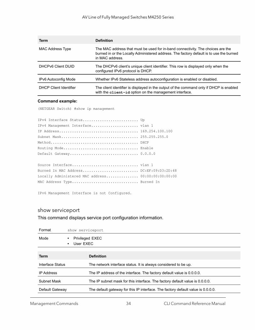
Command example: (NETGEAR Switch) #show ip management
IPv4 Interface Status.......................... UpIPv4 Management Interface...................... vlan 1IP Address..................................... 169.254.100.100Subnet Mask.................................... 255.255.255.0Method......................................... DHCPRouting Mode................................... EnableDefault Gateway................................ 0.0.0.0
Source Interface............................... vlan 1Burned In MAC Address.......................... DC:EF:09:D3:2D:48Locally Administered MAC address............... 00:00:00:00:00:00MAC Address Type............................... Burned In
IPv6 Management Interface is not Configured.
show serviceportThis command displays service port configuration information.
MAC Address Type The MAC address that must be used for in-band connectivity. The choices are theburned in or the Locally Administered address. The factory default is to use the buin MAC address.
DHCPv6 Client DUID The DHCPv6 client’s unique client identifier. This row is displayed only when the configured IPv6 protocol is DHCP.
IPv6 Autoconfig Mode Whether IPv6 Stateless address autoconfiguration is enabled or disabled.
DHCP Client Identifier The client identifier is displayed in the output of the command only if DHCP is enawith the client-id option on the management interface.
Format show serviceport
Mode • Privileged EXEC• User EXEC
Term Definition
Interface Status The network interface status. It is always considered to be up.
IP Address The IP address of the interface. The factory default value is 0.0.0.0.
Subnet Mask The IP subnet mask for this interface. The factory default value is 0.0.0.0.
Default Gateway The default gateway for this IP interface. The factory default value is 0.0.0.0.
Term Definition
Management Commands CLI Command Reference Manual34

AV Line of Fully Managed Switches M4250 Series
ured
with
Command example:
The following example displays output for the service port:(Netgear switch) #show serviceport Interface Status............................... UpIP Address..................................... 10.230.3.51Subnet Mask.................................... 255.255.255.0Default Gateway................................ 10.230.3.1IPv6 Administrative Mode....................... EnabledIPv6 Prefix is ................................ fe80::210:18ff:fe82:640/64IPv6 Prefix is ................................ 2005::21/128IPv6 Default Router is ........................ fe80::204:76ff:fe73:423aConfigured IPv4 Protocol ...................... DHCPConfigured IPv6 Protocol ...................... DHCPDHCPv6 Client DUID ............................ 00:03:00:06:00:10:18:82:06:4CIPv6 Autoconfig Mode........................... DisabledBurned In MAC Address.......................... 00:10:18:82:06:4DDHCP Client Identifier......................... 0NETGEAR-0010.1882.160C
IPv6 Administrative Mode Whether enabled or disabled. Default value is enabled.
IPv6 Address/Length The IPv6 address and length. Default is Link Local format.
IPv6 Default Router TheIPv6 default router address on the service port. The factory default value is an unspecified address.
Configured IPv4 Protocol The IPv4 network protocol being used. The options are bootp | dhcp | none.
Configured IPv6 Protocol The IPv6 network protocol being used. The options are dhcp | none.
DHCPv6 Client DUID The DHCPv6 client’s unique client identifier. This row is displayed only when the configIPv6 protocol is dhcp.
IPv6 Autoconfig Mode Whether IPv6 Stateless address autoconfiguration is enabled or disabled.
Burned in MAC Address The burned in MAC address used for in-band connectivity.
DHCP Client Identifier The client identifier is displayed in the output of the command only if DHCP is enabledthe client-id option on the service port.
Term Definition
Management Commands CLI Command Reference Manual35
AV Line of Fully Managed Switches M4250 Series
IPv6 Management Commands
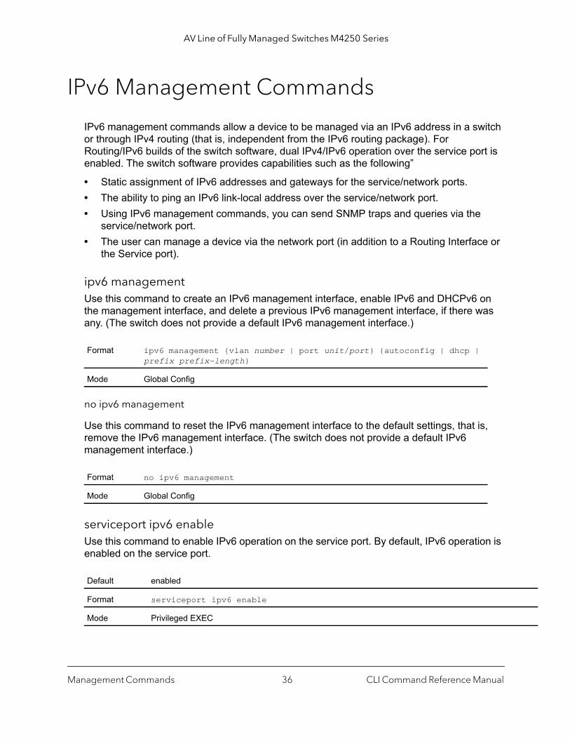
IPv6 management commands allow a device to be managed via an IPv6 address in a switch or through IPv4 routing (that is, independent from the IPv6 routing package). For Routing/IPv6 builds of the switch software, dual IPv4/IPv6 operation over the service port is enabled. The switch software provides capabilities such as the following”
• Static assignment of IPv6 addresses and gateways for the service/network ports.• The ability to ping an IPv6 link-local address over the service/network port.• Using IPv6 management commands, you can send SNMP traps and queries via the
service/network port.• The user can manage a device via the network port (in addition to a Routing Interface or
the Service port).
ipv6 managementUse this command to create an IPv6 management interface, enable IPv6 and DHCPv6 on the management interface, and delete a previous IPv6 management interface, if there was any. (The switch does not provide a default IPv6 management interface.)
no ipv6 management
Use this command to reset the IPv6 management interface to the default settings, that is, remove the IPv6 management interface. (The switch does not provide a default IPv6 management interface.)
serviceport ipv6 enableUse this command to enable IPv6 operation on the service port. By default, IPv6 operation is enabled on the service port.
Format ipv6 management {vlan number | port unit/port} {autoconfig | dhcp | prefix prefix-length}
Mode Global Config
Format no ipv6 management
Mode Global Config
Default enabled
Format serviceport ipv6 enable
Mode Privileged EXEC
Management Commands CLI Command Reference Manual36
AV Line of Fully Managed Switches M4250 Series
|
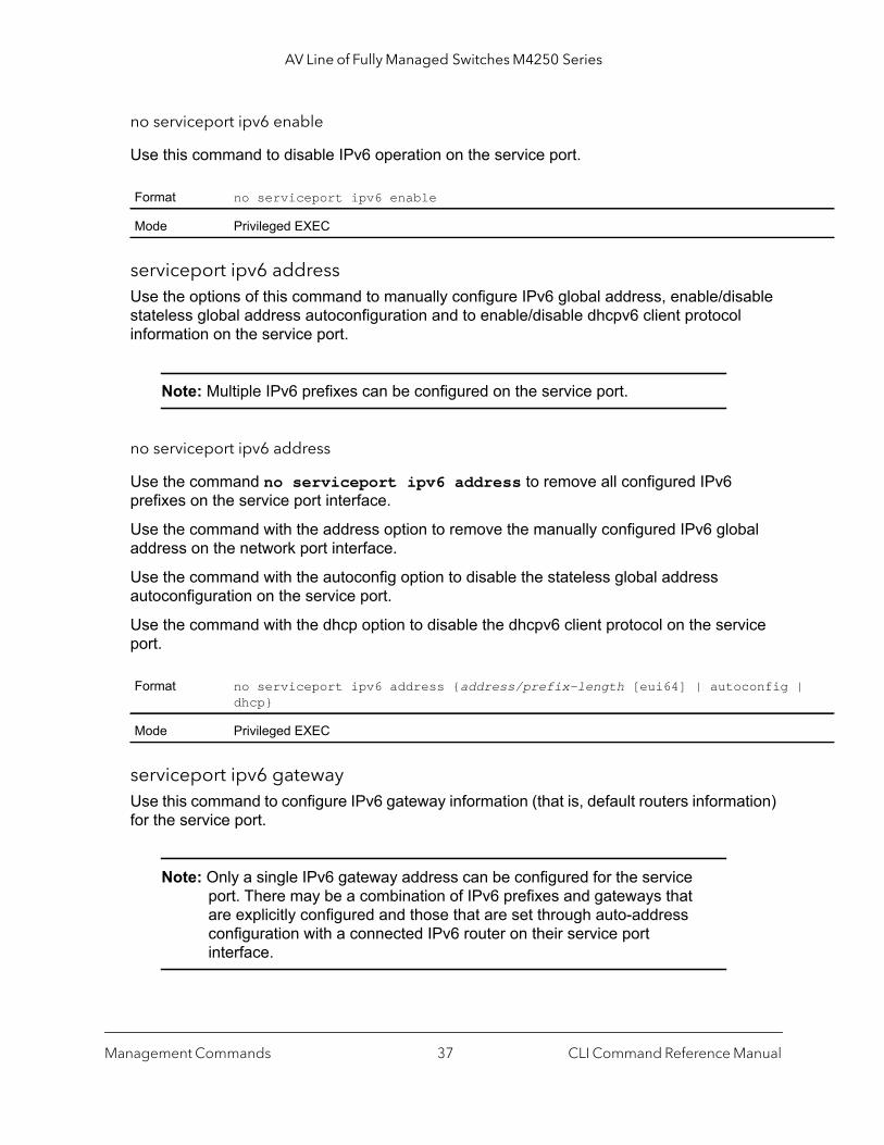
no serviceport ipv6 enable
Use this command to disable IPv6 operation on the service port.
serviceport ipv6 addressUse the options of this command to manually configure IPv6 global address, enable/disable stateless global address autoconfiguration and to enable/disable dhcpv6 client protocol information on the service port.
Note: Multiple IPv6 prefixes can be configured on the service port.
no serviceport ipv6 address
Use the command no serviceport ipv6 address to remove all configured IPv6 prefixes on the service port interface.
Use the command with the address option to remove the manually configured IPv6 global address on the network port interface.
Use the command with the autoconfig option to disable the stateless global address autoconfiguration on the service port.
Use the command with the dhcp option to disable the dhcpv6 client protocol on the service port.
serviceport ipv6 gateway Use this command to configure IPv6 gateway information (that is, default routers information) for the service port.
Note: Only a single IPv6 gateway address can be configured for the service port. There may be a combination of IPv6 prefixes and gateways that are explicitly configured and those that are set through auto-address configuration with a connected IPv6 router on their service port interface.
Format no serviceport ipv6 enable
Mode Privileged EXEC
Format no serviceport ipv6 address {address/prefix-length [eui64] | autoconfig dhcp}
Mode Privileged EXEC
Management Commands CLI Command Reference Manual37

AV Line of Fully Managed Switches M4250 Series
no serviceport ipv6 gateway
Use this command to remove IPv6 gateways on the service port interface.
serviceport ipv6 neighborUse this command to manually add IPv6 neighbors to the IPv6 neighbor table for the service port. If an IPv6 neighbor already exists in the neighbor table, the entry is automatically converted to a static entry. Static entries are not modified by the neighbor discovery process. They are, however, treated the same for IPv6 forwarding. Static IPv6 neighbor entries are applied to the hardware when the corresponding interface is operationally active.
no serviceport ipv6 neighbor
Use this command to remove IPv6 neighbors from the IPv6 neighbor table for the service port.
Format serviceport ipv6 gateway gateway-address
Mode Privileged EXEC
Parameter Description
gateway-address Gateway address in IPv6 global or link-local address format.
Format no serviceport ipv6 gateway
Mode Privileged EXEC
Format serviceport ipv6 neighbor ipv6-address macaddr
Mode Privileged EXEC
Parameter Description
ipv6-address The IPv6 address of the neighbor or interface.
macaddr The link-layer address.
Format no serviceport ipv6 neighbor ipv6-address macaddr
Mode Privileged EXEC
Management Commands CLI Command Reference Manual38

AV Line of Fully Managed Switches M4250 Series
,
if
show serviceport ipv6 neighborsUse this command to displays information about the IPv6 neighbor entries cached on the service port. The information is updated to show the type of the entry.
Command example: (NETGEAR Switch) #show serviceport ipv6 neighbors
Neighbor AgeIPv6 Address MAC Address isRtr State (Secs) Type-------------------------------- ----------------- ----- --------- ------ -------FE80::5E26:AFF:FEBD:852C 5c:26:0a:bd:85:2c FALSE Reachable 0 Dynamic
ping ipv6Use this command to determine whether another computer is on the network. Ping provides a synchronous response when initiated from the CLI and Web interfaces. To use the command, configure the switch for network (in-band) connection. The source and target devices must have the ping utility enabled and running on top of TCP/IP. The switch can be pinged from any IP workstation with which the switch is connected through the default VLAN (VLAN 1), as long as there is a physical path between the switch and the workstation. The terminal interface sends three pings to the target station. Use the ipv6-address or hostname parameter to ping an interface by using the global IPv6 address of the interface. The argument unit/port corresponds to a physical routing interface or VLAN routing interface. The vlan keyword and vland-id parameter are used to specify the VLAN ID of the routing VLAN directly instead of in the unit/port format. The vlan-id parameter is a number in the range of 1–4093.
You can utilize the ping or traceroute facilities over the service or network ports when using an IPv6 global address ipv6-global-address or hostname. Any IPv6 global address or
Default None
Format show serviceport ipv6 neighbors
Mode Privileged EXEC
Field Description
IPv6 Address The IPv6 address of the neighbor.
MAC Address The MAC Address of the neighbor.
isRtr Shows if the neighbor is a router. If TRUE, the neighbor is a router; if FALSE, it is not a router.
Neighbor State The state of the neighbor cache entry. The possible values are: Incomplete, Reachable, StaleDelay, Probe, and Unknown.
Age The time in seconds that has elapsed since an entry was added to the cache.
Type The type of neighbor entry. The type is Static if the entry is manually configured and Dynamic dynamically resolved.
Management Commands CLI Command Reference Manual39

AV Line of Fully Managed Switches M4250 Series
an
|
gateway assignments to these interfaces causes IPv6 routes to be installed such that the ping or traceroute request is routed out the service or network port properly. When referencing an IPv6 link-local address, you must specify the interface keyword with either the unit/port argument, vlan keyword and vland-id argument, or serviceport keyword.
Use the optional size keyword and datagram-size parameter to specify the size of the ping packet.
ping ipv6 interfaceUse this command to determine whether another computer is on the network. To use the command, configure the switch for network (in-band) connection. The source and target devices must have the ping utility enabled and running on top of TCP/IP. The switch can be pinged from any IP workstation with which the switch is connected through the default VLAN (VLAN 1), as long as there is a physical path between the switch and the workstation. The terminal interface sends three pings to the target station. You can use a loopback, network port, service port, tunnel, VLAN, or physical interface as the source.
The argument unit/port corresponds to a physical routing interface or VLAN routing interface. The vlan keyword and vland-id parameter are used to specify the VLAN ID of the routing VLAN directly instead of in the unit/port format. The vlan-id parameter is a number in the range of 1–4093. Use the optional size keyword and datagram-size parameter to specify the size of the ping packet.
Default The default count is 1.The default interval is 3 seconds.The default size is 0 bytes.
Format ping ipv6 {ipv6-global-address | hostname | {interface {unit/port | vlvland-id | serviceport} link-local-address} [size datagram-size]}
Mode Privileged EXECUser Exec
Format ping ipv6 interface {unit/port | vlan vland-id | loopback loopback-id serviceport | tunnel tunnel-id} {link-local-address link-local-address |ipv6-address} [size datagram-size]
Modes Privileged EXECUser Exec
Management Commands CLI Command Reference Manual40
AV Line of Fully Managed Switches M4250 Series
200}
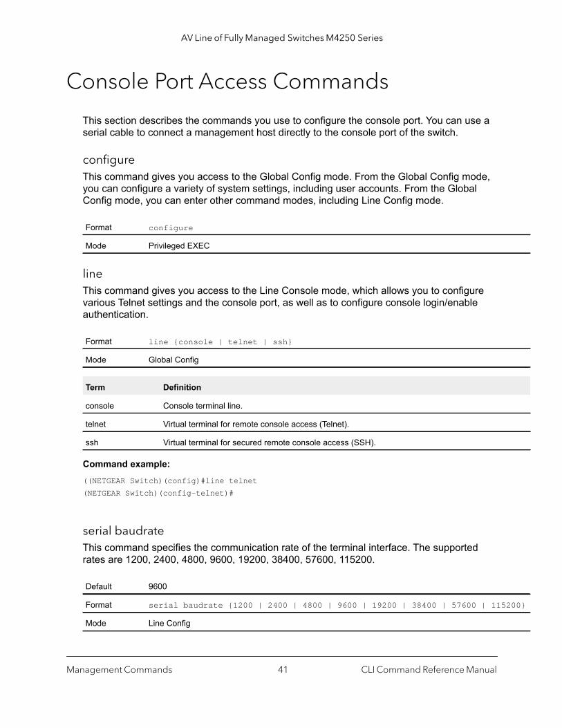
Console Port Access Commands
This section describes the commands you use to configure the console port. You can use a serial cable to connect a management host directly to the console port of the switch.
configureThis command gives you access to the Global Config mode. From the Global Config mode, you can configure a variety of system settings, including user accounts. From the Global Config mode, you can enter other command modes, including Line Config mode.
line This command gives you access to the Line Console mode, which allows you to configure various Telnet settings and the console port, as well as to configure console login/enable authentication.
Command example: ((NETGEAR Switch)(config)#line telnet(NETGEAR Switch)(config-telnet)#
serial baudrateThis command specifies the communication rate of the terminal interface. The supported rates are 1200, 2400, 4800, 9600, 19200, 38400, 57600, 115200.
Format configure
Mode Privileged EXEC
Format line {console | telnet | ssh}
Mode Global Config
Term Definition
console Console terminal line.
telnet Virtual terminal for remote console access (Telnet).
ssh Virtual terminal for secured remote console access (SSH).
Default 9600
Format serial baudrate {1200 | 2400 | 4800 | 9600 | 19200 | 38400 | 57600 | 115
Mode Line Config
Management Commands CLI Command Reference Manual41
AV Line of Fully Managed Switches M4250 Series
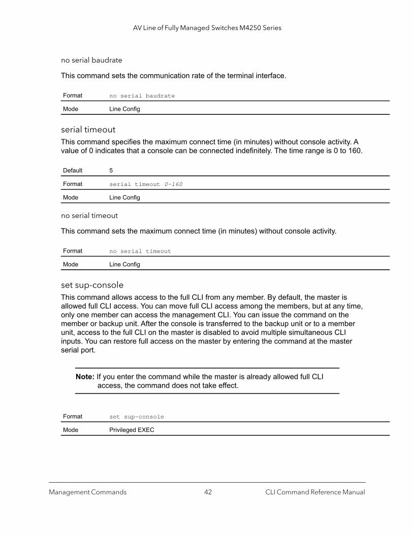
no serial baudrate
This command sets the communication rate of the terminal interface.
serial timeoutThis command specifies the maximum connect time (in minutes) without console activity. A value of 0 indicates that a console can be connected indefinitely. The time range is 0 to 160.
no serial timeout
This command sets the maximum connect time (in minutes) without console activity.
set sup-console This command allows access to the full CLI from any member. By default, the master is allowed full CLI access. You can move full CLI access among the members, but at any time, only one member can access the management CLI. You can issue the command on the member or backup unit. After the console is transferred to the backup unit or to a member unit, access to the full CLI on the master is disabled to avoid multiple simultaneous CLI inputs. You can restore full access on the master by entering the command at the master serial port.
Note: If you enter the command while the master is already allowed full CLI access, the command does not take effect.
Format no serial baudrate
Mode Line Config
Default 5
Format serial timeout 0-160
Mode Line Config
Format no serial timeout
Mode Line Config
Format set sup-console
Mode Privileged EXEC
Management Commands CLI Command Reference Manual42
AV Line of Fully Managed Switches M4250 Series
close
s
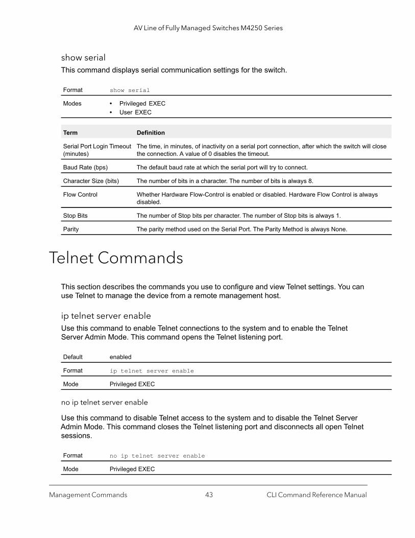
show serialThis command displays serial communication settings for the switch.
Telnet Commands
This section describes the commands you use to configure and view Telnet settings. You can use Telnet to manage the device from a remote management host.
ip telnet server enableUse this command to enable Telnet connections to the system and to enable the Telnet Server Admin Mode. This command opens the Telnet listening port.
no ip telnet server enable
Use this command to disable Telnet access to the system and to disable the Telnet Server Admin Mode. This command closes the Telnet listening port and disconnects all open Telnet sessions.
Format show serial
Modes • Privileged EXEC• User EXEC
Term Definition
Serial Port Login Timeout (minutes)
The time, in minutes, of inactivity on a serial port connection, after which the switch will the connection. A value of 0 disables the timeout.
Baud Rate (bps) The default baud rate at which the serial port will try to connect.
Character Size (bits) The number of bits in a character. The number of bits is always 8.
Flow Control Whether Hardware Flow-Control is enabled or disabled. Hardware Flow Control is alwaydisabled.
Stop Bits The number of Stop bits per character. The number of Stop bits is always 1.
Parity The parity method used on the Serial Port. The Parity Method is always None.
Default enabled
Format ip telnet server enable
Mode Privileged EXEC
Format no ip telnet server enable
Mode Privileged EXEC
Management Commands CLI Command Reference Manual43

AV Line of Fully Managed Switches M4250 Series
ip telnet portUse this command to configure the TCP port number on which the Telnet server detects requests. The number argument can be a port number in the range from 1 to 65535.
no ip telnet port
Use this command to reset the TCP port number on which the Telnet server detects requests to the default of 23.
telnetThis command establishes a new outbound Telnet connection to a remote host. The host must be a valid IP address or host name. Valid values for port should be a valid decimal integer in the range of 0 to 65535, where the default value is 23. If debug is used, the current Telnet options enabled is displayed. The optional line parameter sets the outbound Telnet operational mode as linemode where, by default, the operational mode is character mode. The localecho option enables local echo.
transport input telnetThis command regulates new Telnet sessions. If enabled, new Telnet sessions can be established until there are no more sessions available. An established session remains active until the session is ended or an abnormal network error ends the session.
Note: If the Telnet Server Admin Mode is disabled, Telnet sessions cannot be established. Use the ip telnet server enable command to enable Telnet Server Admin Mode.
Default 23
Format ip telnet port number
Mode Privileged EXEC
Format no ip telnet port
Mode Privileged EXEC
Format telnet {ip-address | hostname} port [debug] [line] [localecho]
Modes • Privileged EXEC• User EXEC
Default enabled
Format transport input telnet
Mode Line Config
Management Commands CLI Command Reference Manual44

AV Line of Fully Managed Switches M4250 Series
no transport input telnet
Use this command to prevent new Telnet sessions from being established.
transport output telnetThis command regulates new outbound Telnet connections. If enabled, new outbound Telnet sessions can be established until the system reaches the maximum number of simultaneous outbound Telnet sessions allowed. An established session remains active until the session is ended or an abnormal network error ends it.
no transport output telnet
Use this command to prevent new outbound Telnet connection from being established.
session-limitThis command specifies the maximum number of simultaneous outbound Telnet sessions. The number argument can be a number in the range from 0–5. A value of 0 indicates that no outbound Telnet session can be established.
no session-limit
This command sets the maximum number of simultaneous outbound Telnet sessions to the default value.
Format no transport input telnet
Mode Line Config
Default enabled
Format transport output telnet
Mode Line Config
Format no transport output telnet
Mode Line Config
Default 5
Format session-limit number
Mode Line Config
Format no session-limit
Mode Line Config
Management Commands CLI Command Reference Manual45
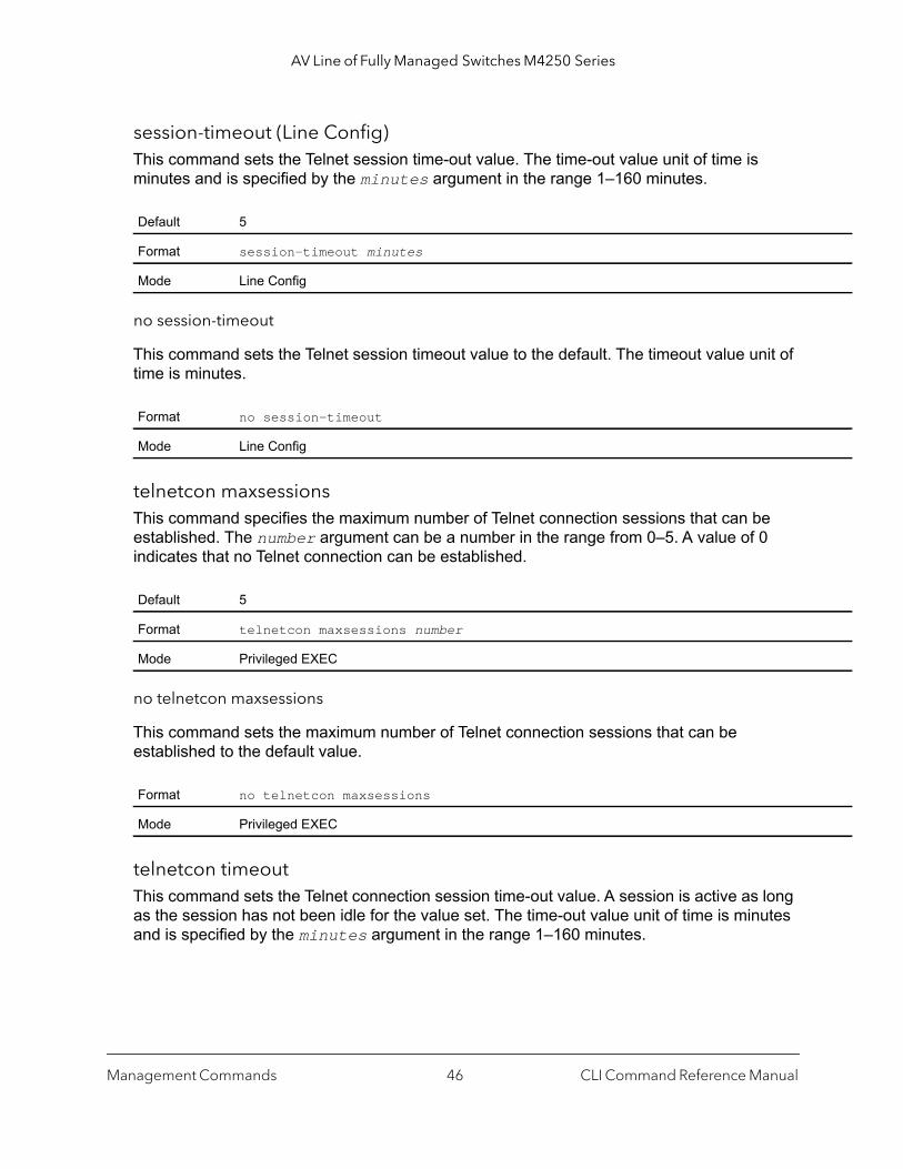
AV Line of Fully Managed Switches M4250 Series
session-timeout (Line Config)This command sets the Telnet session time-out value. The time-out value unit of time is minutes and is specified by the minutes argument in the range 1–160 minutes.
no session-timeout
This command sets the Telnet session timeout value to the default. The timeout value unit of time is minutes.
telnetcon maxsessionsThis command specifies the maximum number of Telnet connection sessions that can be established. The number argument can be a number in the range from 0–5. A value of 0 indicates that no Telnet connection can be established.
no telnetcon maxsessions
This command sets the maximum number of Telnet connection sessions that can be established to the default value.
telnetcon timeoutThis command sets the Telnet connection session time-out value. A session is active as long as the session has not been idle for the value set. The time-out value unit of time is minutes and is specified by the minutes argument in the range 1–160 minutes.
Default 5
Format session-timeout minutes
Mode Line Config
Format no session-timeout
Mode Line Config
Default 5
Format telnetcon maxsessions number
Mode Privileged EXEC
Format no telnetcon maxsessions
Mode Privileged EXEC
Management Commands CLI Command Reference Manual46

AV Line of Fully Managed Switches M4250 Series
Note: When you change the time-out value, the new value is applied to all active and inactive sessions immediately. Any sessions that have been idle longer than the new time-out value are disconnected immediately.
no telnetcon timeout
This command sets the Telnet connection session timeout value to the default.
Note: Changing the time-out value for active sessions does not become effective until the session is accessed again. Also, any keystroke activates the new time-out duration.
show telnetThis command displays the current outbound Telnet settings. In other words, these settings apply to Telnet connections initiated from the switch to a remote system.
Default 5
Format telnetcon timeout minutes
Mode Privileged EXEC
Format no telnetcon timeout
Mode Privileged EXEC
Format show telnet
Modes • Privileged EXEC• User EXEC
Term Definition
Outbound Telnet Login Timeout
The number of minutes an outbound Telnet session is allowed to remain inactive before beinglogged off.
Maximum Number of Outbound Telnet Sessions
The number of simultaneous outbound Telnet connections allowed.
Allow New Outbound Telnet Sessions
Indicates whether outbound Telnet sessions will be allowed.
Management Commands CLI Command Reference Manual47

AV Line of Fully Managed Switches M4250 Series
main ry
The
alue
show telnetconThis command displays the current inbound Telnet settings. In other words, these settings apply to Telnet connections initiated from a remote system to the switch.
Secure Shell Commands
This section describes the commands you use to configure Secure Shell (SSH) access to the switch. Use SSH to access the switch from a remote management host.
Note: The system allows a maximum of 5 SSH sessions.
ip sshUse this command to enable SSH access to the system. (This command is the short form of the ip ssh server enable command.)
Format show telnetcon
Modes • Privileged EXEC• User EXEC
Term Definition
Remote Connection Login Timeout (minutes)
This object indicates the number of minutes a remote connection session is allowed to reinactive before being logged off. May be specified as a number from 1 to 160. The factodefault is 5.
Maximum Number of Remote Connection Sessions
This object indicates the number of simultaneous remote connection sessions allowed. factory default is 5.
Allow New Telnet Sessions
New Telnet sessions will not be allowed when this field is set to no. The factory default vis yes.
Telnet Server Admin Mode
States whether the Telnet Server Admin Mode is enabled or disabled.
Telnet Server Port The port number on which the Telnet server can detect requests.
Default disabled
Format ip ssh
Mode Privileged EXEC
Management Commands CLI Command Reference Manual48
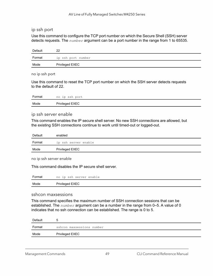
AV Line of Fully Managed Switches M4250 Series
ip ssh portUse this command to configure the TCP port number on which the Secure Shell (SSH) server detects requests. The number argument can be a port number in the range from 1 to 65535.
no ip ssh port
Use this command to reset the TCP port number on which the SSH server detects requests to the default of 22.
ip ssh server enableThis command enables the IP secure shell server. No new SSH connections are allowed, but the existing SSH connections continue to work until timed-out or logged-out.
no ip ssh server enable
This command disables the IP secure shell server.
sshcon maxsessionsThis command specifies the maximum number of SSH connection sessions that can be established. The number argument can be a number in the range from 0–5. A value of 0 indicates that no ssh connection can be established. The range is 0 to 5.
Default 22
Format ip ssh port number
Mode Privileged EXEC
Format no ip ssh port
Mode Privileged EXEC
Default enabled
Format ip ssh server enable
Mode Privileged EXEC
Format no ip ssh server enable
Mode Privileged EXEC
Default 5
Format sshcon maxsessions number
Mode Privileged EXEC
Management Commands CLI Command Reference Manual49

AV Line of Fully Managed Switches M4250 Series
no sshcon maxsessions
This command sets the maximum number of allowed SSH connection sessions to the default value.
sshcon timeoutThis command sets the SSH connection session timeout value, in minutes. A session is active as long as the session has been idle for the value set. The time-out value unit of time is minutes and is specified by the minutes argument in the range 1–160 minutes.
Changing the timeout value for active sessions does not become effective until the session is re accessed. Also, any keystroke activates the new time-out duration.
no sshcon timeout
This command sets the SSH connection session time-out value, in minutes, to the default.
Changing the time-out value for active sessions does not become effective until the session is re accessed. Also, any keystroke activates the new time-out duration.
show ip sshThis command displays the SSH settings.
Format no sshcon maxsessions
Mode Privileged EXEC
Default 5
Format sshcon timeout minutes
Mode Privileged EXEC
Format no sshcon timeout
Mode Privileged EXEC
Format show ip ssh
Mode Privileged EXEC
Term Definition
Administrative Mode
This field indicates whether the administrative mode of SSH is enabled or disabled.
Protocol Level The protocol level shows the value of version 2.
Management Commands CLI Command Reference Manual50

AV Line of Fully Managed Switches M4250 Series
Management Security Commands
This section describes commands you use to generate keys and certificates, which you can do in addition to loading them as before.
crypto certificate generateUse this command to generate a self-signed certificate for HTTPS. The generated RSA key for SSL has a length of 1024 bits. The resulting certificate is generated with a common name equal to the lowest IP address of the device and a duration of 365 days.
no crypto certificate generate
Use this command to delete the HTTPS certificate files from the device, regardless of whether they are self-signed or downloaded from an outside source.
crypto key generate rsaUse this command to generate an RSA key pair for SSH. The new key files will overwrite any existing generated or downloaded RSA key files.
SSH Sessions Currently Active
The number of SSH sessions currently active.
Max SSH Sessions Allowed
The maximum number of SSH sessions allowed.
SSH Timeout The SSH timeout value in minutes.
Keys Present Indicates whether the SSH RSA and DSA key files are present on the device.
Key Generation in Progress
Indicates whether RSA or DSA key files generation is currently in progress.
Format crypto certificate generate
Mode Global Config
Format no crypto certificate generate
Mode Global Config
Format crypto key generate rsa
Mode Global Config
Term Definition
Management Commands CLI Command Reference Manual51
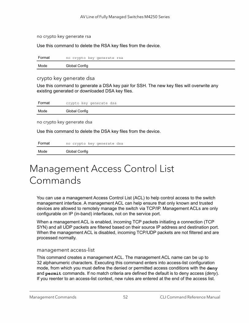
AV Line of Fully Managed Switches M4250 Series
no crypto key generate rsa
Use this command to delete the RSA key files from the device.
crypto key generate dsaUse this command to generate a DSA key pair for SSH. The new key files will overwrite any existing generated or downloaded DSA key files.
no crypto key generate dsa
Use this command to delete the DSA key files from the device.
Management Access Control List Commands
You can use a management Access Control List (ACL) to help control access to the switch management interface. A management ACL can help ensure that only known and trusted devices are allowed to remotely manage the switch via TCP/IP. Management ACLs are only configurable on IP (in-band) interfaces, not on the service port.
When a management ACL is enabled, incoming TCP packets initiating a connection (TCP SYN) and all UDP packets are filtered based on their source IP address and destination port. When the management ACL is disabled, incoming TCP/UDP packets are not filtered and are processed normally.
management access-listThis command creates a management ACL. The management ACL name can be up to 32 alphanumeric characters. Executing this command enters into access-list configuration mode, from which you must define the denied or permitted access conditions with the deny and permit commands. If no match criteria are defined the default is to deny access (deny). If you reenter to an access-list context, new rules are entered at the end of the access list.
Format no crypto key generate rsa
Mode Global Config
Format crypto key generate dsa
Mode Global Config
Format no crypto key generate dsa
Mode Global Config
Management Commands CLI Command Reference Manual52
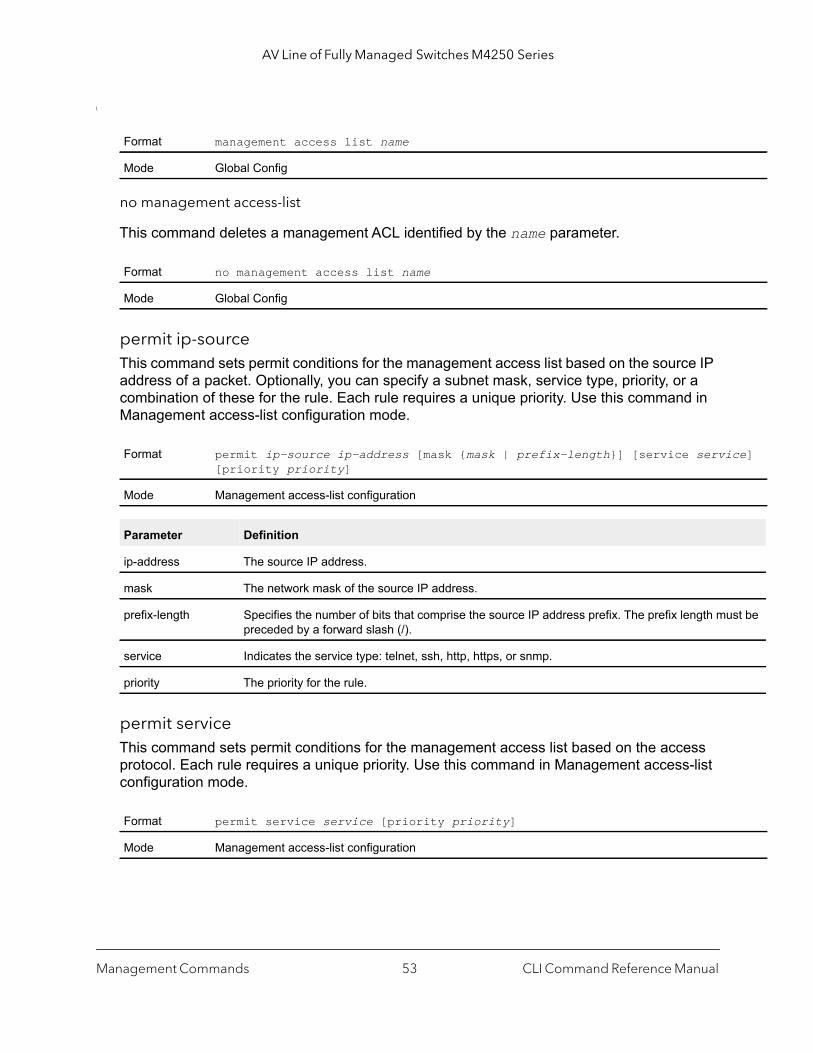
AV Line of Fully Managed Switches M4250 Series
ce]
st be
\
no management access-list
This command deletes a management ACL identified by the name parameter.
permit ip-sourceThis command sets permit conditions for the management access list based on the source IP address of a packet. Optionally, you can specify a subnet mask, service type, priority, or a combination of these for the rule. Each rule requires a unique priority. Use this command in Management access-list configuration mode.
permit serviceThis command sets permit conditions for the management access list based on the access protocol. Each rule requires a unique priority. Use this command in Management access-list configuration mode.
Format management access list name
Mode Global Config
Format no management access list name
Mode Global Config
Format permit ip-source ip-address [mask {mask | prefix-length}] [service servi[priority priority]
Mode Management access-list configuration
Parameter Definition
ip-address The source IP address.
mask The network mask of the source IP address.
prefix-length Specifies the number of bits that comprise the source IP address prefix. The prefix length mupreceded by a forward slash (/).
service Indicates the service type: telnet, ssh, http, https, or snmp.
priority The priority for the rule.
Format permit service service [priority priority]
Mode Management access-list configuration
Management Commands CLI Command Reference Manual53
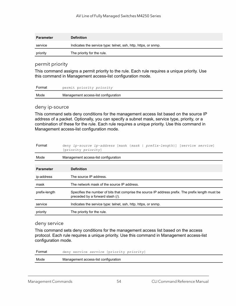
AV Line of Fully Managed Switches M4250 Series
]
st be
permit priorityThis command assigns a permit priority to the rule. Each rule requires a unique priority. Use this command in Management access-list configuration mode.
deny ip-sourceThis command sets deny conditions for the management access list based on the source IP address of a packet. Optionally, you can specify a subnet mask, service type, priority, or a combination of these for the rule. Each rule requires a unique priority. Use this command in Management access-list configuration mode.
deny serviceThis command sets deny conditions for the management access list based on the access protocol. Each rule requires a unique priority. Use this command in Management access-list configuration mode.
Parameter Definition
service Indicates the service type: telnet, ssh, http, https, or snmp.
priority The priority for the rule.
Format permit priority priority
Mode Management access-list configuration
Format deny ip-source ip-address [mask {mask | prefix-length}] [service service[priority priority]
Mode Management access-list configuration
Parameter Definition
ip-address The source IP address.
mask The network mask of the source IP address.
prefix-length Specifies the number of bits that comprise the source IP address prefix. The prefix length mupreceded by a forward slash (/).
service Indicates the service type: telnet, ssh, http, https, or snmp.
priority The priority for the rule.
Format deny service service [priority priority]
Mode Management access-list configuration
Management Commands CLI Command Reference Manual54
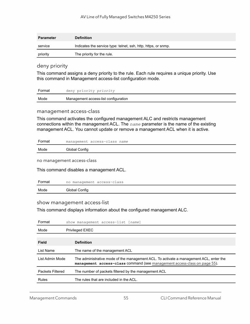
AV Line of Fully Managed Switches M4250 Series
deny priorityThis command assigns a deny priority to the rule. Each rule requires a unique priority. Use this command in Management access-list configuration mode.
management access-classThis command activates the configured management ALC and restricts management connections within the management ACL. The name parameter is the name of the existing management ACL. You cannot update or remove a management ACL when it is active.
no management access-class
This command disables a management ACL.
show management access-listThis command displays information about the configured management ALC.
Parameter Definition
service Indicates the service type: telnet, ssh, http, https, or snmp.
priority The priority for the rule.
Format deny priority priority
Mode Management access-list configuration
Format management access-class name
Mode Global Config
Format no management access-class
Mode Global Config
Format show management access-list [name]
Mode Privileged EXEC
Field Definition
List Name The name of the management ACL
List Admin Mode The administrative mode of the management ACL. To activate a management ACL, enter themanagement access-class command (see management access-class on page 55).
Packets Filtered The number of packets filtered by the management ACL
Rules The rules that are included in the ACL.
Management Commands CLI Command Reference Manual55
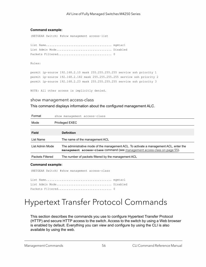
AV Line of Fully Managed Switches M4250 Series
Command example: (NETGEAR Switch) #show management access-list
List Name...................................... mgmtaclList Admin Mode................................ DisabledPackets Filtered............................... 0
Rules:
permit ip-source 192.168.2.10 mask 255.255.255.255 service ssh priority 1permit ip-source 192.168.2.182 mask 255.255.255.255 service ssh priority 2permit ip-source 192.168.2.23 mask 255.255.255.255 service ssh priority 3
NOTE: All other access is implicitly denied.
show management access-classThis command displays information about the configured management ALC.
Command example: (NETGEAR Switch) #show management access-class
List Name...................................... mgmtaclList Admin Mode................................ DisabledPackets Filtered............................... 0
Hypertext Transfer Protocol Commands
This section describes the commands you use to configure Hypertext Transfer Protocol (HTTP) and secure HTTP access to the switch. Access to the switch by using a Web browser is enabled by default. Everything you can view and configure by using the CLI is also available by using the web.
Format show management access-class
Mode Privileged EXEC
Field Definition
List Name The name of the management ACL
List Admin Mode The administrative mode of the management ACL. To activate a management ACL, enter themanagement access-class command (see management access-class on page 55).
Packets Filtered The number of packets filtered by the management ACL
Management Commands CLI Command Reference Manual56

AV Line of Fully Managed Switches M4250 Series
ip http accounting exec, ip https accounting execThis command applies user exec (start-stop/stop-only) accounting list to the line methods HTTP and HTTPS.
Note: The user exec accounting list should be created using the command aaa accounting on page 90.
no ip http/https accounting exec
This command deletes the authorization method list.
ip http authenticationUse this command to specify authentication methods for http server users. The default configuration is the local user database is checked. This action has the same effect as the command ip http authentication local. The additional methods of authentication are used only if the previous method returns an error, not if it fails. To ensure that the authentication succeeds even if all methods return an error, specify none as the final method in the command line.
For example, if none is specified as an authentication method after radius, no authentication is used if the RADIUS server is down.
Format ip {http | https} accounting exec {default | listname}
Mode Global Config
Parameter Description
http or https The line method for which the list needs to be applied.
default The default list of methods for authorization services.
listname An alphanumeric character string used to name the list of accounting methods.
Format no ip {http | https} accounting exec {default | listname}
Mode Global Config
Default local
Format ip http authentication method1 [method2...]
Mode Global Config
Management Commands CLI Command Reference Manual57
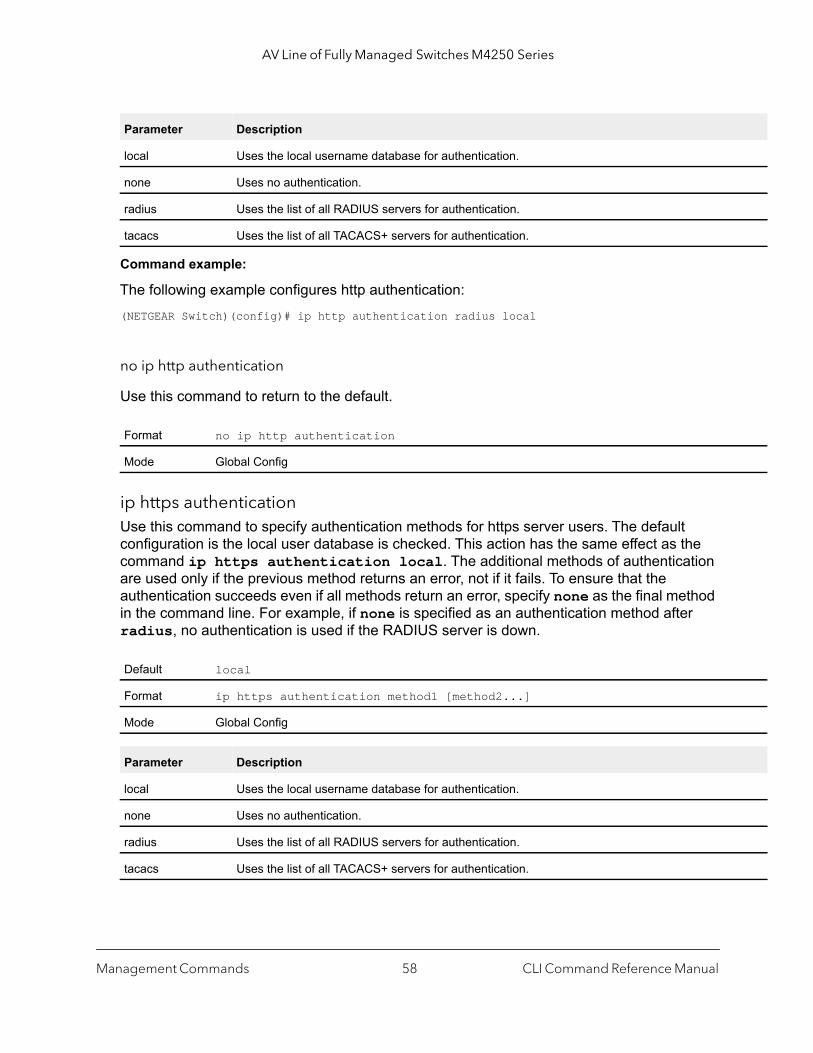
AV Line of Fully Managed Switches M4250 Series
Command example:
The following example configures http authentication:(NETGEAR Switch)(config)# ip http authentication radius local
no ip http authentication
Use this command to return to the default.
ip https authenticationUse this command to specify authentication methods for https server users. The default configuration is the local user database is checked. This action has the same effect as the command ip https authentication local. The additional methods of authentication are used only if the previous method returns an error, not if it fails. To ensure that the authentication succeeds even if all methods return an error, specify none as the final method in the command line. For example, if none is specified as an authentication method after radius, no authentication is used if the RADIUS server is down.
Parameter Description
local Uses the local username database for authentication.
none Uses no authentication.
radius Uses the list of all RADIUS servers for authentication.
tacacs Uses the list of all TACACS+ servers for authentication.
Format no ip http authentication
Mode Global Config
Default local
Format ip https authentication method1 [method2...]
Mode Global Config
Parameter Description
local Uses the local username database for authentication.
none Uses no authentication.
radius Uses the list of all RADIUS servers for authentication.
tacacs Uses the list of all TACACS+ servers for authentication.
Management Commands CLI Command Reference Manual58
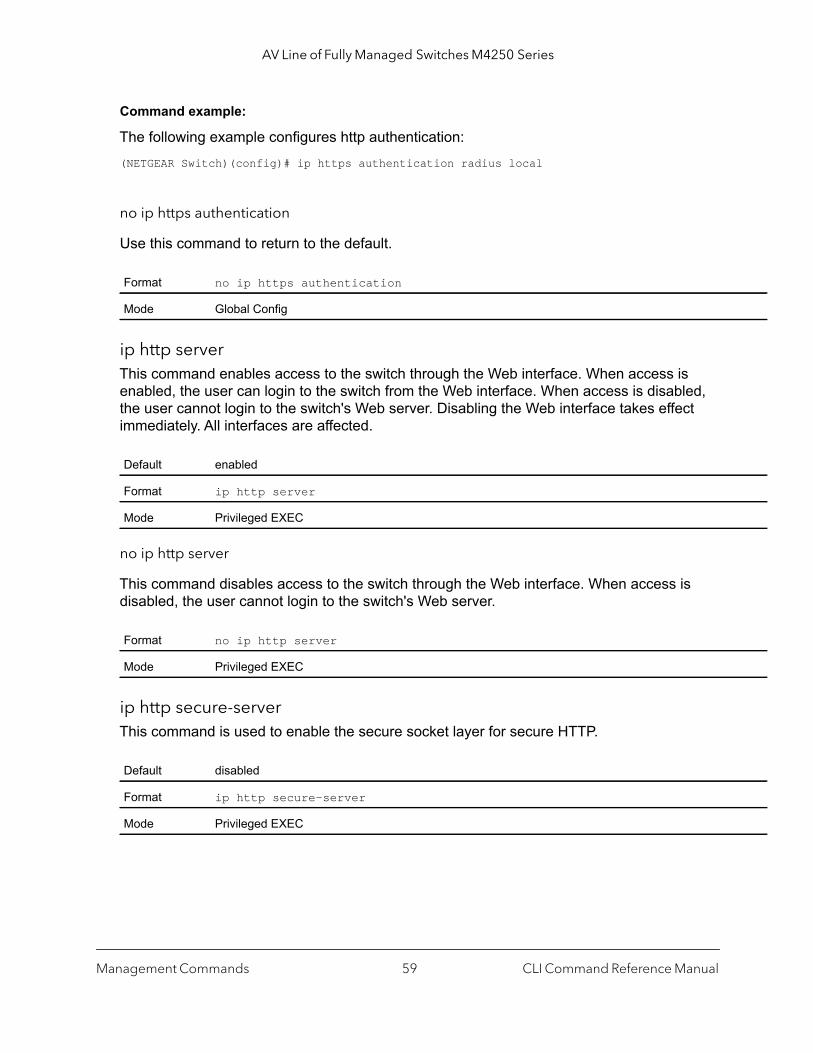
AV Line of Fully Managed Switches M4250 Series
Command example:
The following example configures http authentication:(NETGEAR Switch)(config)# ip https authentication radius local
no ip https authentication
Use this command to return to the default.
ip http serverThis command enables access to the switch through the Web interface. When access is enabled, the user can login to the switch from the Web interface. When access is disabled, the user cannot login to the switch's Web server. Disabling the Web interface takes effect immediately. All interfaces are affected.
no ip http server
This command disables access to the switch through the Web interface. When access is disabled, the user cannot login to the switch's Web server.
ip http secure-serverThis command is used to enable the secure socket layer for secure HTTP.
Format no ip https authentication
Mode Global Config
Default enabled
Format ip http server
Mode Privileged EXEC
Format no ip http server
Mode Privileged EXEC
Default disabled
Format ip http secure-server
Mode Privileged EXEC
Management Commands CLI Command Reference Manual59
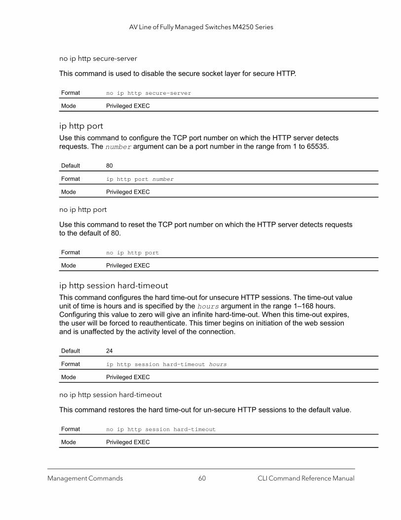
AV Line of Fully Managed Switches M4250 Series
no ip http secure-server
This command is used to disable the secure socket layer for secure HTTP.
ip http portUse this command to configure the TCP port number on which the HTTP server detects requests. The number argument can be a port number in the range from 1 to 65535.
no ip http port
Use this command to reset the TCP port number on which the HTTP server detects requests to the default of 80.
ip http session hard-timeoutThis command configures the hard time-out for unsecure HTTP sessions. The time-out value unit of time is hours and is specified by the hours argument in the range 1–168 hours. Configuring this value to zero will give an infinite hard-time-out. When this time-out expires, the user will be forced to reauthenticate. This timer begins on initiation of the web session and is unaffected by the activity level of the connection.
no ip http session hard-timeout
This command restores the hard time-out for un-secure HTTP sessions to the default value.
Format no ip http secure-server
Mode Privileged EXEC
Default 80
Format ip http port number
Mode Privileged EXEC
Format no ip http port
Mode Privileged EXEC
Default 24
Format ip http session hard-timeout hours
Mode Privileged EXEC
Format no ip http session hard-timeout
Mode Privileged EXEC
Management Commands CLI Command Reference Manual60
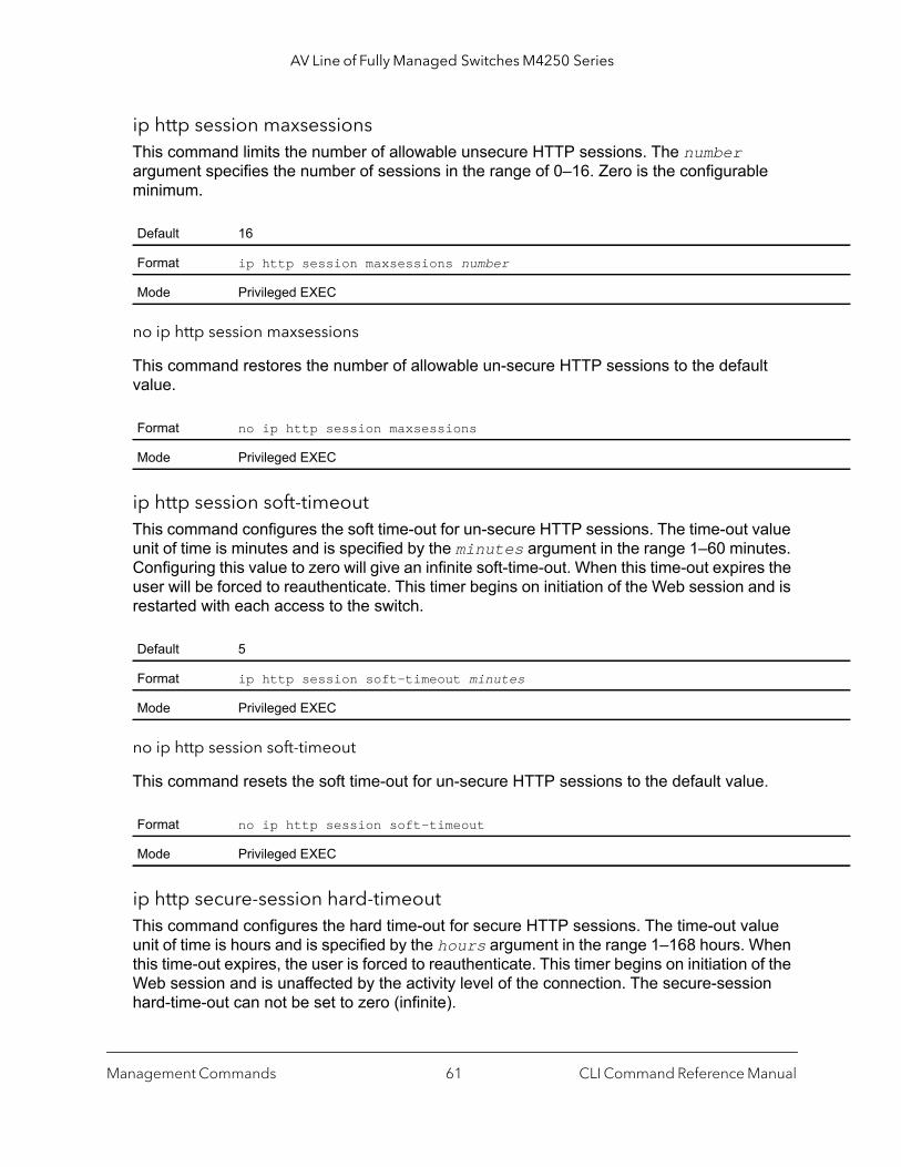
AV Line of Fully Managed Switches M4250 Series
ip http session maxsessionsThis command limits the number of allowable unsecure HTTP sessions. The number argument specifies the number of sessions in the range of 0–16. Zero is the configurable minimum.
no ip http session maxsessions
This command restores the number of allowable un-secure HTTP sessions to the default value.
ip http session soft-timeoutThis command configures the soft time-out for un-secure HTTP sessions. The time-out value unit of time is minutes and is specified by the minutes argument in the range 1–60 minutes. Configuring this value to zero will give an infinite soft-time-out. When this time-out expires the user will be forced to reauthenticate. This timer begins on initiation of the Web session and is restarted with each access to the switch.
no ip http session soft-timeout
This command resets the soft time-out for un-secure HTTP sessions to the default value.
ip http secure-session hard-timeout This command configures the hard time-out for secure HTTP sessions. The time-out value unit of time is hours and is specified by the hours argument in the range 1–168 hours. When this time-out expires, the user is forced to reauthenticate. This timer begins on initiation of the Web session and is unaffected by the activity level of the connection. The secure-session hard-time-out can not be set to zero (infinite).
Default 16
Format ip http session maxsessions number
Mode Privileged EXEC
Format no ip http session maxsessions
Mode Privileged EXEC
Default 5
Format ip http session soft-timeout minutes
Mode Privileged EXEC
Format no ip http session soft-timeout
Mode Privileged EXEC
Management Commands CLI Command Reference Manual61
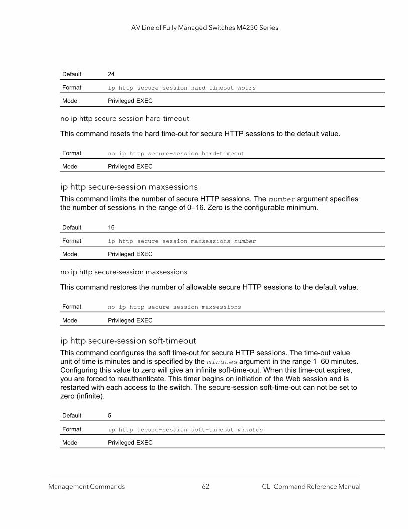
AV Line of Fully Managed Switches M4250 Series
no ip http secure-session hard-timeout
This command resets the hard time-out for secure HTTP sessions to the default value.
ip http secure-session maxsessionsThis command limits the number of secure HTTP sessions. The number argument specifies the number of sessions in the range of 0–16. Zero is the configurable minimum.
no ip http secure-session maxsessions
This command restores the number of allowable secure HTTP sessions to the default value.
ip http secure-session soft-timeoutThis command configures the soft time-out for secure HTTP sessions. The time-out value unit of time is minutes and is specified by the minutes argument in the range 1–60 minutes. Configuring this value to zero will give an infinite soft-time-out. When this time-out expires, you are forced to reauthenticate. This timer begins on initiation of the Web session and is restarted with each access to the switch. The secure-session soft-time-out can not be set to zero (infinite).
Default 24
Format ip http secure-session hard-timeout hours
Mode Privileged EXEC
Format no ip http secure-session hard-timeout
Mode Privileged EXEC
Default 16
Format ip http secure-session maxsessions number
Mode Privileged EXEC
Format no ip http secure-session maxsessions
Mode Privileged EXEC
Default 5
Format ip http secure-session soft-timeout minutes
Mode Privileged EXEC
Management Commands CLI Command Reference Manual62

AV Line of Fully Managed Switches M4250 Series
b
no ip http secure-session soft-timeout
This command restores the soft time-out for secure HTTP sessions to the default value.
ip http secure-portThis command is used to set the SSL port where port can be 1025-65535 and the default is port 443.
no ip http secure-port
This command is used to reset the SSL port to the default value.
ip http secure-protocolThis command is used to set protocol levels (versions). The protocol level can be set to TLS1, SSL3 or to both TLS1 and SSL3.
show ip httpThis command displays the http settings for the switch.
Format no ip http secure-session soft-timeout
Mode Privileged EXEC
Default 443
Format ip http secure-port portid
Mode Privileged EXEC
Format no ip http secure-port
Mode Privileged EXEC
Default SSL3 and TLS1
Format ip http secure-protocol [SSL3] [TLS1]
Mode Privileged EXEC
Format show ip http
Mode Privileged EXEC
Term Definition
HTTP Mode (Unsecure) The non-secure HTTP server administrative mode.
Java Mode The java applet administrative mode which applies to both secure and un-secure weconnections.
Management Commands CLI Command Reference Manual63
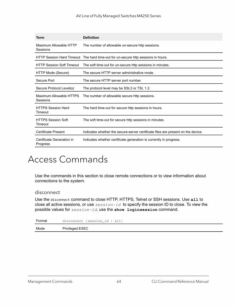
AV Line of Fully Managed Switches M4250 Series
Access Commands
Use the commands in this section to close remote connections or to view information about connections to the system.
disconnectUse the disconnect command to close HTTP, HTTPS, Telnet or SSH sessions. Use all to close all active sessions, or use session-id to specify the session ID to close. To view the possible values for session-id, use the show loginsession command.
Maximum Allowable HTTP Sessions
The number of allowable un-secure http sessions.
HTTP Session Hard Timeout The hard time-out for un-secure http sessions in hours.
HTTP Session Soft Timeout The soft time-out for un-secure http sessions in minutes.
HTTP Mode (Secure) The secure HTTP server administrative mode.
Secure Port The secure HTTP server port number.
Secure Protocol Level(s) The protocol level may be SSL3 or TSL 1.2.
Maximum Allowable HTTPS Sessions
The number of allowable secure http sessions.
HTTPS Session Hard Timeout
The hard time-out for secure http sessions in hours.
HTTPS Session Soft Timeout
The soft time-out for secure http sessions in minutes.
Certificate Present Indicates whether the secure-server certificate files are present on the device.
Certificate Generation in Progress
Indicates whether certificate generation is currently in progress.
Format disconnect {session_id | all}
Mode Privileged EXEC
Term Definition
Management Commands CLI Command Reference Manual64

AV Line of Fully Managed Switches M4250 Series
show loginsessionThis command displays current Telnet, SSH and serial port connections to the switch. This command displays truncated user names. Use the show loginsession long command to display the complete usernames.
show loginsession longThis command displays the complete user names of the users currently logged in to the switch.
Command example: (NETGEAR Switch) #show loginsession longUser Name------------admintest1111test1111test1111test1111test1111test1111test1111test1111
User Account Commands
This section describes the commands you use to add, manage, and delete switch users. The switch provides two default users: admin and guest. The admin user can view and configure the switch settings. The guest user can view the switch settings only.
The first time that you log in as an admin user, no password is required (that is, the password is blank). As of software version 12.0.9.3, after you log in for the first time, you are required to specify a new password that you must use each subsequent time that you log in. After you
Format show loginsession
Mode Privileged EXEC
Term Definition
ID Login Session ID.
User Name The name the user entered to log on to the system.
Connection From IP address of the remote client machine or EIA-232 for the serial port connection.
Idle Time Time this session has been idle.
Session Time Total time this session has been connected.
Session Type Shows the type of session, which can be HTTP, HTTPS, telnet, serial, or SSH.
Format show loginsession long
Mode Privileged EXEC
Management Commands CLI Command Reference Manual65
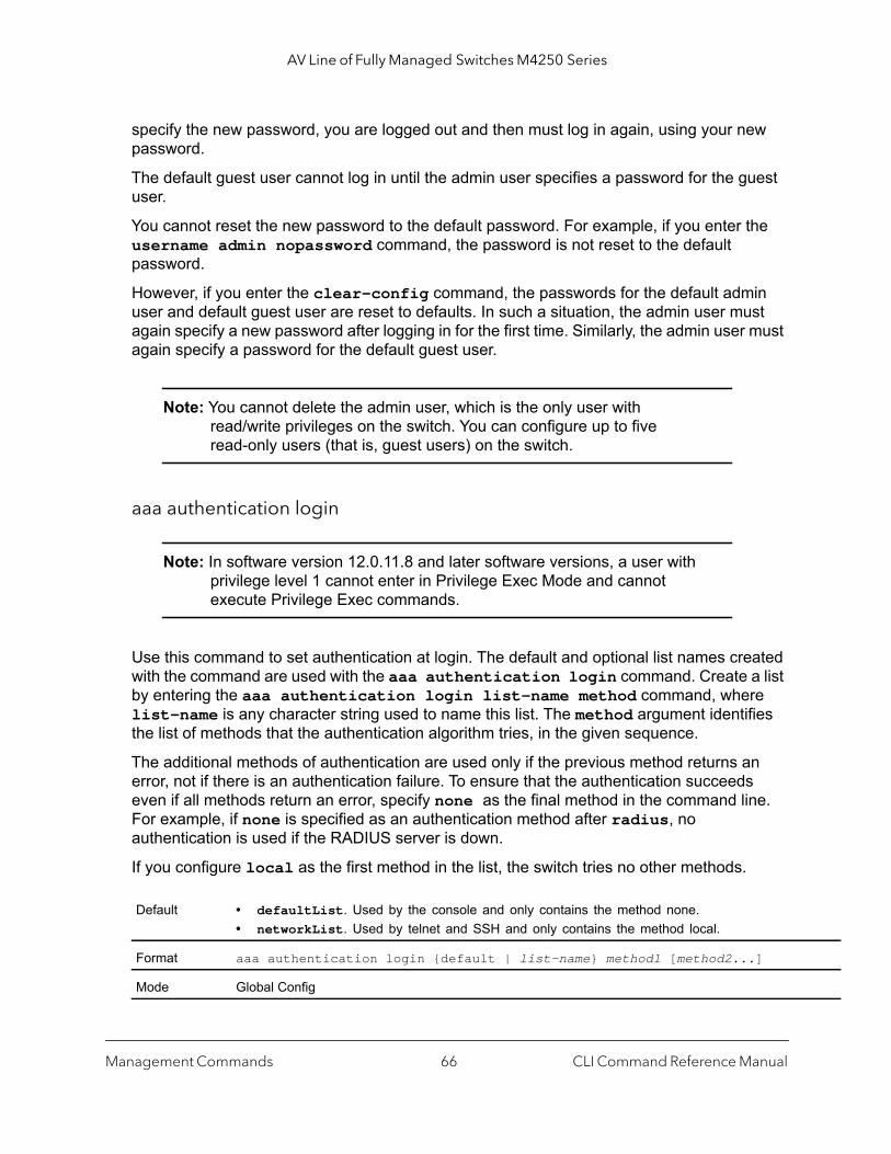
AV Line of Fully Managed Switches M4250 Series
specify the new password, you are logged out and then must log in again, using your new password.
The default guest user cannot log in until the admin user specifies a password for the guest user.
You cannot reset the new password to the default password. For example, if you enter the username admin nopassword command, the password is not reset to the default password.
However, if you enter the clear-config command, the passwords for the default admin user and default guest user are reset to defaults. In such a situation, the admin user must again specify a new password after logging in for the first time. Similarly, the admin user must again specify a password for the default guest user.
Note: You cannot delete the admin user, which is the only user with read/write privileges on the switch. You can configure up to five read-only users (that is, guest users) on the switch.
aaa authentication login
Note: In software version 12.0.11.8 and later software versions, a user with privilege level 1 cannot enter in Privilege Exec Mode and cannot execute Privilege Exec commands.
Use this command to set authentication at login. The default and optional list names created with the command are used with the aaa authentication login command. Create a list by entering the aaa authentication login list-name method command, where list-name is any character string used to name this list. The method argument identifies the list of methods that the authentication algorithm tries, in the given sequence.
The additional methods of authentication are used only if the previous method returns an error, not if there is an authentication failure. To ensure that the authentication succeeds even if all methods return an error, specify none as the final method in the command line. For example, if none is specified as an authentication method after radius, no authentication is used if the RADIUS server is down.
If you configure local as the first method in the list, the switch tries no other methods.
Default • defaultList. Used by the console and only contains the method none.• networkList. Used by telnet and SSH and only contains the method local.
Format aaa authentication login {default | list-name} method1 [method2...]
Mode Global Config
Management Commands CLI Command Reference Manual66

AV Line of Fully Managed Switches M4250 Series
when
ted
Command example: (NETGEAR Switch)(config)# aaa authentication login default radius local enable none
no aaa authentication login
This command returns to the default.
aaa authentication enableUse this command to set authentication for accessing higher privilege levels. The default enable list is enableList. It is used by console, and contains the method as enable followed by none.
A separate default enable list, enableNetList, is used for Telnet and SSH users instead of enableList. This list is applied by default for Telnet and SSH, and contains enable followed by deny methods. By default, the enable password is not configured. That means that, by default, Telnet and SSH users will not get access to Privileged EXEC mode. On the other hand, with default conditions, a console user always enter the Privileged EXEC mode without entering the enable password.
The default and optional list names created with the aaa authentication enable command are used with the enable authentication command. Create a list by entering the aaa authentication enable list-name method command where list-name is any character string used to name this list. The method argument identifies the list of methods that the authentication algorithm tries in the given sequence.
The user manager returns ERROR (not PASS or FAIL) for enable and line methods if no password is configured, and moves to the next configured method in the authentication list. The method none reflects that there is no authentication needed.
Parameter Definition
default Uses the listed authentication methods that follow this argument as the default list of methods a user logs in.
list-name Character string of up to 15 characters used to name the list of authentication methods activawhen a user logs in.
method1... [method2...]
At least one from the following:• enable. Uses the enable password for authentication.• line. Uses the line password for authentication.• local. Uses the local username database for authentication.• none. Uses no authentication.• radius. Uses the list of all RADIUS servers for authentication.• tacacs. Uses the list of all TACACS servers for authentication.
Format aaa authentication login {default | list-name}
Mode Global Config
Management Commands CLI Command Reference Manual67

AV Line of Fully Managed Switches M4250 Series
when
The user will only be prompted for an enable password if one is required. The following authentication methods do not require passwords:
• none• deny• enable (if no enable password is configured)• line (if no line password is configured)
See the examples below.
1. aaa authentication enable default enable none
2. aaa authentication enable default line none
3. aaa authentication enable default enable radius none
4. aaa authentication enable default line tacacs none
Examples 1 and 2 do not prompt for a password, however because examples 3 and 4 contain the radius and tacacs methods, the password prompt is displayed.
If the login methods include only enable, and there is no enable password configured, the switch does not prompt for a user name. In such cases, the switch prompts only for a password. The switch supports configuring methods after the local method in authentication and authorization lists. If the user is not present in the local database, then the next configured method is tried.
The additional methods of authentication are used only if the previous method returns an error, not if it fails. To ensure that the authentication succeeds even if all methods return an error, specify none as the final method in the command line.
Use the command show authorization methods on page 73 to display information about the authentication methods.
Note: Requests sent by the switch to a RADIUS or TACACS server include the username $enabx$, in which x is the requested privilege level. The login user ID is also sent to a TACACS+ server.
Default default
Format aaa authentication enable {default | list-name} method1 [method2...]
Mode Global Config
Parameter Description
default Uses the listed authentication methods that follow this argument as the default list of methods, using higher privilege levels.
list-name Character string used to name the list of authentication methods activated, when using accesshigher privilege levels. Range: 1-15 characters.
Management Commands CLI Command Reference Manual68

AV Line of Fully Managed Switches M4250 Series
Command example:
The following example sets authentication to access higher privilege levels:(NETGEAR Switch)(config)# aaa authentication enable default enable
no aaa authentication enable
Use this command to return to the default configuration.
aaa authorizationUse this command to configure command and exec authorization method lists. This list is identified by default or a user-specified list-name. If tacacs is specified as the authorization method, authorization commands are notified to a TACACS+ server. If none is specified as the authorization method, command authorization is not applicable. A maximum of five authorization method lists can be created for the commands type.
Note: The local method is not supported for command authorization. Command authorization with RADIUS functions only if the applied authentication method is also RADIUS.
method1 [method2...]
Specify at least one from the following:• deny. Used to deny access.• enable. Uses the enable password for authentication.• line. Uses the line password for authentication.• none. Uses no authentication.• radius. Uses the list of all RADIUS servers for authentication.• tacacs. Uses the list of all TACACS+ servers for authentication.
Format no aaa authentication enable {default | list-name}
Mode Global Config
Format aaa authorization {exec | commands} {default | list-name} method1 [method2…]
Mode Global Config
Term Definition
exec Provides authorization for user EXEC terminal sessions.
commands Provides authorization for all user-executed commands.
Parameter Description
Management Commands CLI Command Reference Manual69

AV Line of Fully Managed Switches M4250 Series
no aaa authorization
This command deletes the authorization method list.
Per-Command AuthorizationWhen authorization is configured for a line mode, the user manager sends information about an entered command to the AAA server. The AAA server validates the received command, and responds with either a PASS or FAIL response. If approved, the command is executed. Otherwise, the command is denied and an error message is shown to the user. The various utility commands such as tftp, ping, and outbound telnet should also pass command authorization. Applying the script is treated as a single command apply script, which also goes through authorization. Startup-config commands applied on device boot-up are not an object of the authorization process.
The per-command authorization usage scenario is this:
1. Configure Authorization Method Listaaa authorization commands listname tacacs radius none
2. Apply AML to an Access Line Mode (console, telnet, SSH)authorization commands listname
3. Commands entered by the user will go through command authorization via TACACS+ or RADIUS server and will be accepted or denied.
Exec AuthorizationWhen exec authorization is configured for a line mode, the user may not be required to use the enable command to enter Privileged EXEC mode. If the authorization response indicates that the user has sufficient privilege levels for Privileged EXEC mode, then the user bypasses User EXEC mode entirely.
default The default list of methods for authorization services.
list-name Character string used to name the list of authorization methods.
method1 [method2…] Use either tacacs or radius for authorization purpose.
Format no aaa authorization {exec | commands} {default | <list-name>} <method1> [<method2>…]
Mode Global Config
Term Definition
Management Commands CLI Command Reference Manual70

AV Line of Fully Managed Switches M4250 Series
d2]
The exec authorization usage scenario is as follows:
1. Configure Authorization Method Listaaa authorization exec listname method1 [method2....]
2. Apply AML to an Access Line Mode (console, telnet, SSH)authorization exec listname
3. When the user logs in, in addition to authentication, authorization will be performed to determine if the user is allowed direct access to Privileged EXEC mode.
(NETGEAR Switch) #(NETGEAR Switch) #configure(NETGEAR Switch) (Config)#aaa authorization exec default tacacs+ none(NETGEAR Switch) (Config)#aaa authorization commands default tacacs+ none
no aaa authorization
This command deletes the authorization method list.
authorization commandsThis command applies a command authorization method list to an access method (console, telnet, ssh). For usage scenarios on per command authorization, see the command aaa authorization on page 69.
Format aaa authorization {commands | exec} {default | list-name} method1 [metho
Mode Global Config
Parameter Description
commands Provides authorization for all user-executed commands.
exec Provides exec authorization.
default The default list of methods for authorization services.
list-name Alphanumeric character string used to name the list of authorization methods.
method TACACS+, RADIUS, Local, and none are supported.
Format no aaa authorization {commands | exec} {default | list-name}
Mode Global Config
Format authorization commands [default | list-name]
Mode Line console, Line telnet, Line SSH
Parameter Description
commands This causes command authorization for each command execution attempt.
Management Commands CLI Command Reference Manual71
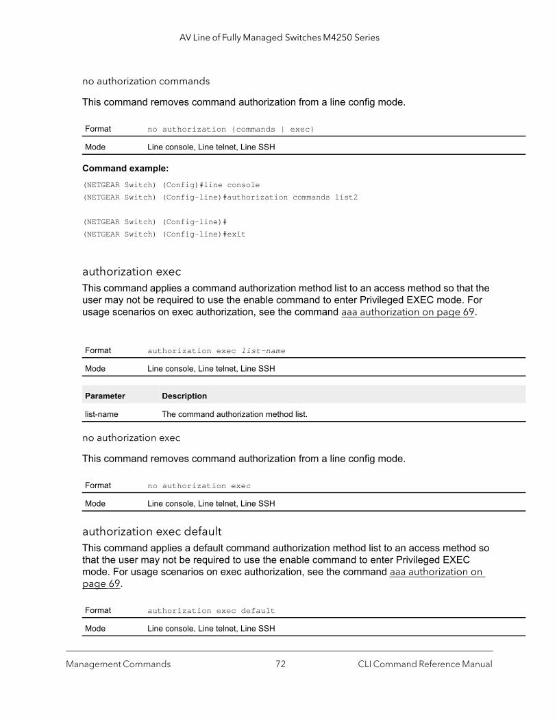
AV Line of Fully Managed Switches M4250 Series
no authorization commands
This command removes command authorization from a line config mode.
Command example: (NETGEAR Switch) (Config)#line console(NETGEAR Switch) (Config-line)#authorization commands list2
(NETGEAR Switch) (Config-line)#(NETGEAR Switch) (Config-line)#exit
authorization execThis command applies a command authorization method list to an access method so that the user may not be required to use the enable command to enter Privileged EXEC mode. For usage scenarios on exec authorization, see the command aaa authorization on page 69.
no authorization exec
This command removes command authorization from a line config mode.
authorization exec defaultThis command applies a default command authorization method list to an access method so that the user may not be required to use the enable command to enter Privileged EXEC mode. For usage scenarios on exec authorization, see the command aaa authorization on page 69.
Format no authorization {commands | exec}
Mode Line console, Line telnet, Line SSH
Format authorization exec list-name
Mode Line console, Line telnet, Line SSH
Parameter Description
list-name The command authorization method list.
Format no authorization exec
Mode Line console, Line telnet, Line SSH
Format authorization exec default
Mode Line console, Line telnet, Line SSH
Management Commands CLI Command Reference Manual72
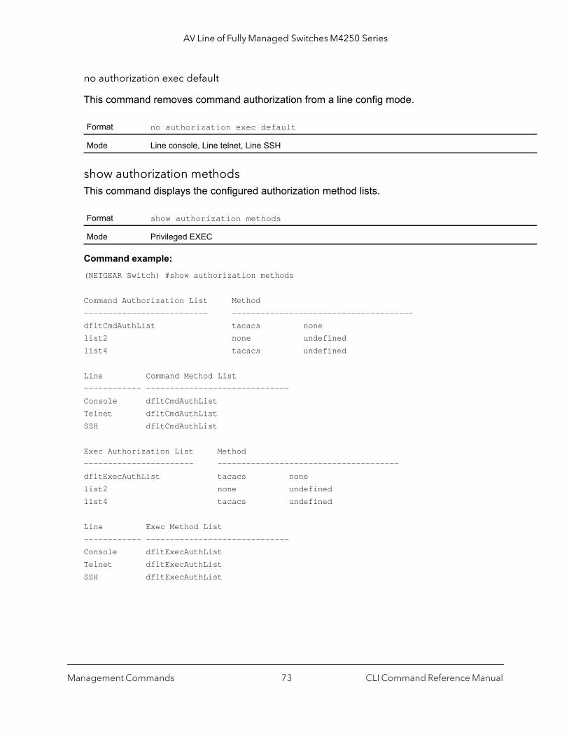
AV Line of Fully Managed Switches M4250 Series
no authorization exec default
This command removes command authorization from a line config mode.
show authorization methodsThis command displays the configured authorization method lists.
Command example: (NETGEAR Switch) #show authorization methods
Command Authorization List Method-------------------------- --------------------------------------dfltCmdAuthList tacacs nonelist2 none undefinedlist4 tacacs undefined
Line Command Method List------------ ------------------------------Console dfltCmdAuthListTelnet dfltCmdAuthListSSH dfltCmdAuthList
Exec Authorization List Method----------------------- --------------------------------------dfltExecAuthList tacacs nonelist2 none undefinedlist4 tacacs undefined
Line Exec Method List------------ ------------------------------Console dfltExecAuthListTelnet dfltExecAuthListSSH dfltExecAuthList
Format no authorization exec default
Mode Line console, Line telnet, Line SSH
Format show authorization methods
Mode Privileged EXEC
Management Commands CLI Command Reference Manual73
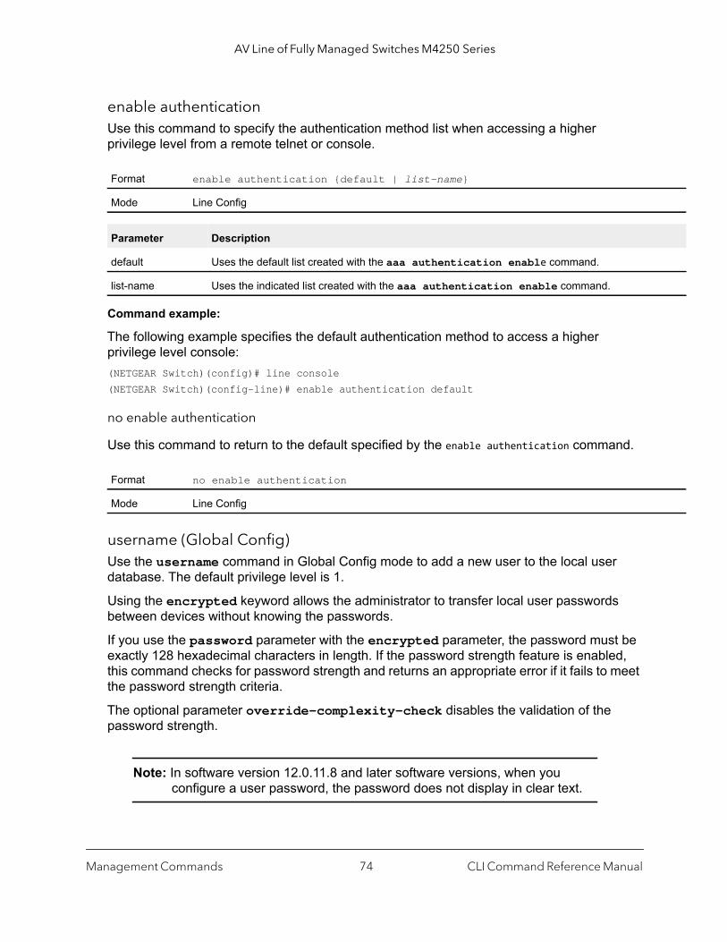
AV Line of Fully Managed Switches M4250 Series
enable authenticationUse this command to specify the authentication method list when accessing a higher privilege level from a remote telnet or console.
Command example:
The following example specifies the default authentication method to access a higher privilege level console:(NETGEAR Switch)(config)# line console(NETGEAR Switch)(config-line)# enable authentication default
no enable authentication
Use this command to return to the default specified by the enable authentication command.
username (Global Config)Use the username command in Global Config mode to add a new user to the local user database. The default privilege level is 1.
Using the encrypted keyword allows the administrator to transfer local user passwords between devices without knowing the passwords.
If you use the password parameter with the encrypted parameter, the password must be exactly 128 hexadecimal characters in length. If the password strength feature is enabled, this command checks for password strength and returns an appropriate error if it fails to meet the password strength criteria.
The optional parameter override-complexity-check disables the validation of the password strength.
Note: In software version 12.0.11.8 and later software versions, when you configure a user password, the password does not display in clear text.
Format enable authentication {default | list-name}
Mode Line Config
Parameter Description
default Uses the default list created with the aaa authentication enable command.
list-name Uses the indicated list created with the aaa authentication enable command.
Format no enable authentication
Mode Line Config
Management Commands CLI Command Reference Manual74
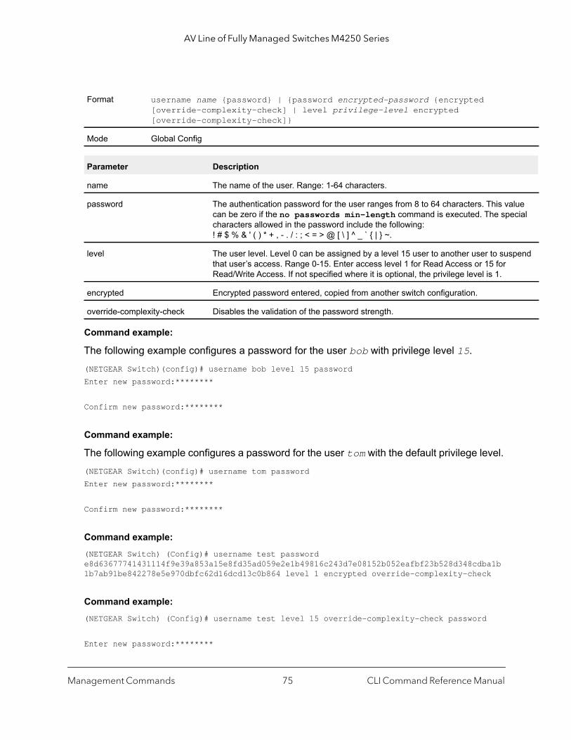
AV Line of Fully Managed Switches M4250 Series
lue cial
pend
Command example:
The following example configures a password for the user bob with privilege level 15.(NETGEAR Switch)(config)# username bob level 15 passwordEnter new password:********
Confirm new password:********
Command example:
The following example configures a password for the user tom with the default privilege level.(NETGEAR Switch)(config)# username tom passwordEnter new password:********
Confirm new password:********
Command example: (NETGEAR Switch) (Config)# username test password e8d63677741431114f9e39a853a15e8fd35ad059e2e1b49816c243d7e08152b052eafbf23b528d348cdba1b1b7ab91be842278e5e970dbfc62d16dcd13c0b864 level 1 encrypted override-complexity-check
Command example: (NETGEAR Switch) (Config)# username test level 15 override-complexity-check password
Enter new password:********
Format username name {password} | {password encrypted-password {encrypted [override-complexity-check] | level privilege-level encrypted [override-complexity-check]}
Mode Global Config
Parameter Description
name The name of the user. Range: 1-64 characters.
password The authentication password for the user ranges from 8 to 64 characters. This vacan be zero if the no passwords min-length command is executed. The specharacters allowed in the password include the following: ! # $ % & ' ( ) * + , - . / : ; < = > @ [ \ ] ^ _ ` { | } ~.
level The user level. Level 0 can be assigned by a level 15 user to another user to susthat user’s access. Range 0-15. Enter access level 1 for Read Access or 15 for Read/Write Access. If not specified where it is optional, the privilege level is 1.
encrypted Encrypted password entered, copied from another switch configuration.
override-complexity-check Disables the validation of the password strength.
Management Commands CLI Command Reference Manual75

AV Line of Fully Managed Switches M4250 Series
r’s
Confirm new password:********
no username
Use this command to remove a user name.
username name nopasswordUse this command to remove an existing user’s password (NULL password).
username name unlockUse this command to allows a locked user account to be unlocked. Only a user with read/write access can reactivate a locked user account.
username snmpv3 authenticationThis command specifies the authentication protocol to be used for the specified user. The valid authentication protocols are none, md5 or sha. If you specify md5 or sha, the login password is also used as the SNMPv3 authentication password and therefore must be at least eight characters in length. The username is the user name associated with the authentication protocol. You must enter the username in the same case you used when you added the user. To see the case of the user name, enter the show users command.
Format no username name
Mode Global Config
Format username name nopassword [level level]
Mode Global Config
Parameter Description
name The name of the user. Range: 1-32 characters.
password The authentication password for the user. Range 8-64 characters.
level The user level. Level 0 can be assigned by a level 15 user to another user to suspend that useaccess. Range 0-15.
Format username name unlock
Mode Global Config
Default no authentication
Format username snmpv3 authentication username {none | md5 | sha}
Mode Global Config
Management Commands CLI Command Reference Manual76

AV Line of Fully Managed Switches M4250 Series
no username snmpv3 authentication
This command sets the authentication protocol to be used for the specified user to none. The username is the user name for which the specified authentication protocol is used.
username snmpv3 encryptionThis command specifies the encryption protocol used for the specified user. The valid encryption protocols are des or none.
If you select des, you can specify the required key on the command line. The encryption key must be 8 to 64 characters long. If you select the des protocol but do not provide a key, the user is prompted for the key. When you use the des protocol, the login password is also used as the snmpv3 encryption password, so it must be a minimum of eight characters. If you select none, you do not need to provide a key.
The username value is the login user name associated with the specified encryption. You must enter the username in the same case you used when you added the user. To see the case of the user name, enter the show users command.
no username snmpv3 encryption
This command sets the encryption protocol to none. The username is the login user name for which the specified encryption protocol will be used.
username snmpv3 encryption encrypted This command specifies the des encryption protocol and the required encryption key for the specified user. The encryption key must be 8 to 64 characters long.
Format no username snmpv3 authentication username
Mode Global Config
Default no encryption
Format username snmpv3 encryption username {none | des [key]}
Mode Global Config
Format no username snmpv3 encryption username
Mode Global Config
Default no encryption
Format username snmpv3 encryption encrypted username des key
Mode Global Config
Management Commands CLI Command Reference Manual77
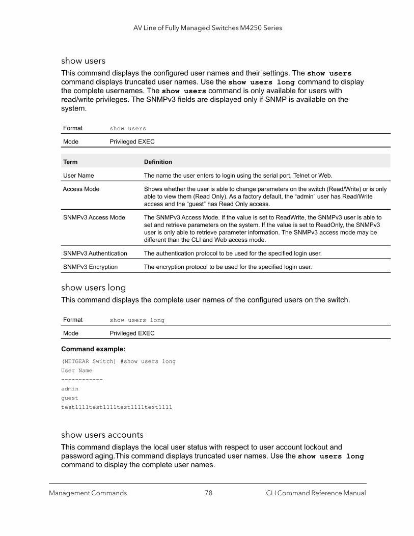
AV Line of Fully Managed Switches M4250 Series
only
to v3 e
show usersThis command displays the configured user names and their settings. The show users command displays truncated user names. Use the show users long command to display the complete usernames. The show users command is only available for users with read/write privileges. The SNMPv3 fields are displayed only if SNMP is available on the system.
show users longThis command displays the complete user names of the configured users on the switch.
Command example: (NETGEAR Switch) #show users longUser Name------------adminguesttest1111test1111test1111test1111
show users accountsThis command displays the local user status with respect to user account lockout and password aging.This command displays truncated user names. Use the show users long command to display the complete user names.
Format show users
Mode Privileged EXEC
Term Definition
User Name The name the user enters to login using the serial port, Telnet or Web.
Access Mode Shows whether the user is able to change parameters on the switch (Read/Write) or isable to view them (Read Only). As a factory default, the “admin” user has Read/Writeaccess and the “guest” has Read Only access.
SNMPv3 Access Mode The SNMPv3 Access Mode. If the value is set to ReadWrite, the SNMPv3 user is ableset and retrieve parameters on the system. If the value is set to ReadOnly, the SNMPuser is only able to retrieve parameter information. The SNMPv3 access mode may bdifferent than the CLI and Web access mode.
SNMPv3 Authentication The authentication protocol to be used for the specified login user.
SNMPv3 Encryption The encryption protocol to be used for the specified login user.
Format show users long
Mode Privileged EXEC
Management Commands CLI Command Reference Manual78
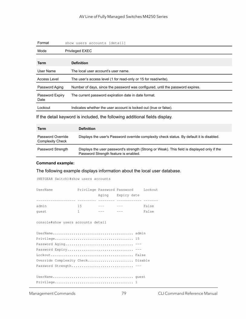
AV Line of Fully Managed Switches M4250 Series
If the detail keyword is included, the following additional fields display.
Command example:
The following example displays information about the local user database.(NETGEAR Switch)#show users accounts
UserName Privilege Password Password Lockout Aging Expiry date------------------- --------- -------- ------------ -------admin 15 --- --- Falseguest 1 --- --- False
console#show users accounts detail
UserName....................................... adminPrivilege...................................... 15Password Aging................................. ---Password Expiry................................ ---Lockout........................................ FalseOverride Complexity Check...................... DisablePassword Strength.............................. ---
UserName....................................... guestPrivilege...................................... 1
Format show users accounts [detail]
Mode Privileged EXEC
Term Definition
User Name The local user account’s user name.
Access Level The user’s access level (1 for read-only or 15 for read/write).
Password Aging Number of days, since the password was configured, until the password expires.
Password Expiry Date
The current password expiration date in date format.
Lockout Indicates whether the user account is locked out (true or false).
Term Definition
Password Override Complexity Check
Displays the user's Password override complexity check status. By default it is disabled.
Password Strength Displays the user password's strength (Strong or Weak). This field is displayed only if thePassword Strength feature is enabled.
Management Commands CLI Command Reference Manual79

AV Line of Fully Managed Switches M4250 Series
Password Aging................................. ---Password Expiry................................ ---Lockout........................................ FalseOverride Complexity Check...................... DisablePassword Strength.............................. ---
show users login-history [long]Use this command to display information about the login history of users.
show users login-history [username]Use this command to display information about the login history of users.
Command example:
The following example shows user login history outputs:Console>show users login-historyLogin Time Username Protocol Location-------------------- --------- --------- ---------------Jan 19 2005 08:23:48 Bob SerialJan 19 2005 08:29:29 Robert HTTP 172.16.0.8Jan 19 2005 08:42:31 John SSH 172.16.0.1Jan 19 2005 08:49:52 Betty Telnet 172.16.1.7
login authenticationUse this command to specify the login authentication method list for a line (console, telnet, or SSH). The default configuration uses the default set with the command aaa authentication login.
Format show users login-history [long]
Mode Privileged EXEC
Format show users login-history [username name]
Mode Privileged EXEC
Parameter Description
name Name of the user. Range: 1-20 characters.
Format login authentication {default | list-name}
Mode Line Configuration
Management Commands CLI Command Reference Manual80

AV Line of Fully Managed Switches M4250 Series
ady
Command example:
The following example specifies the default authentication method for a console:(NETGEAR Switch) (config)# line console(NETGEAR Switch) (config-line)# login authentication default
no login authentication
Use this command to return to the default specified by the authentication login command.
password (Line Configuration)Use the password command in Line Configuration mode to specify a password on a line. The default configuration is no password is specified.
Command example:
The following example specifies a password mcmxxyyy on a line.(NETGEAR Switch)(config-line)# password mcmxxyyy
Command example: (NETGEAR Switch)(Config-line)# password testtest
(NETGEAR Switch) (Config-line)# password e8d63677741431114f9e39a853a15e8fd35ad059e2e1b49816c243d7e08152b052eafbf23b528d348cdba1b1b7ab91be842278e5e970dbfc62d16dcd13c0b864 encrypted
Parameter Description
default Uses the default list created with the aaa authentication login command.
list-name Uses the indicated list created with the aaa authentication login command.
Format no login authentication {default | list-name}
Mode Line Configuration
Format password [password [encrypted]]
Mode Line Config
Parameter Definition
password Password for this level. Range: 8-64 characters
encrypted Encrypted password to be entered, copied from another switch configuration. The encrypted password should be 128 characters long because the assumption is that this password is alreencrypted with AES.
Management Commands CLI Command Reference Manual81

AV Line of Fully Managed Switches M4250 Series
ready
(NETGEAR Switch) (Config-line)# password
Enter new password:********Confirm new password:********
no password (Line Configuration)
Use this command to remove the password on a line.
password (User EXEC)This command allow a user to change the password. The user must enter this command after the password has aged. The user is prompted to enter the old password and the new password.
Command example:
The following example shows the prompt sequence for executing the password command:(NETGEAR Switch)>passwordEnter old password:********Enter new password:********Confirm new password:********
enable password (Privileged EXEC)Use the enable password configuration command to set a local password to control access to the privileged EXEC mode.
Note: In software version 12.0.11.8 and later software versions, when you configure a user password, the password does not display in clear text.
Format no password
Mode Line Config
Format password
Mode User EXEC
Format enable password [encrypted-password encrypted]
Mode Privileged EXEC
Parameter Description
encrypted-password Encrypted password you entered, copied from another switch configuration. The encrypted password should be 128 characters long because the assumption is that this password is alencrypted with AES.
Management Commands CLI Command Reference Manual82

AV Line of Fully Managed Switches M4250 Series
Command example: (NETGEAR Switch) #enable password e8d63677741431114f9e39a853a15e8fd35ad059e2e1b49816c243d7e08152b052eafbf23b528d348cdba1b1b7ab91be842278e5e970dbfc62d16dcd13c0b864 encrypted
(NETGEAR Switch) #enable password
Enter old password:********
Enter new password:********
Confirm new password:********
no enable password (Privileged EXEC)
Use the no enable password command to remove the password requirement.
passwords min-lengthUse this command to enforce a minimum password length for local users. The value also applies to the enable password. The length argument is a number in the range 8–64.
no passwords min-length
Use this command to set the minimum password length to the default value.
passwords historyUse this command to set the number of previous passwords that can be stored for each user account. When a local user changes his or her password, the user is not be able to reuse any password stored in password history. This ensures that users do not reuse their passwords often. The number argument is a number in the range 0–10.
Format no enable password
Mode Privileged EXEC
Default 8
Format passwords min-length length
Mode Global Config
Format no passwords min-length
Mode Global Config
Management Commands CLI Command Reference Manual83
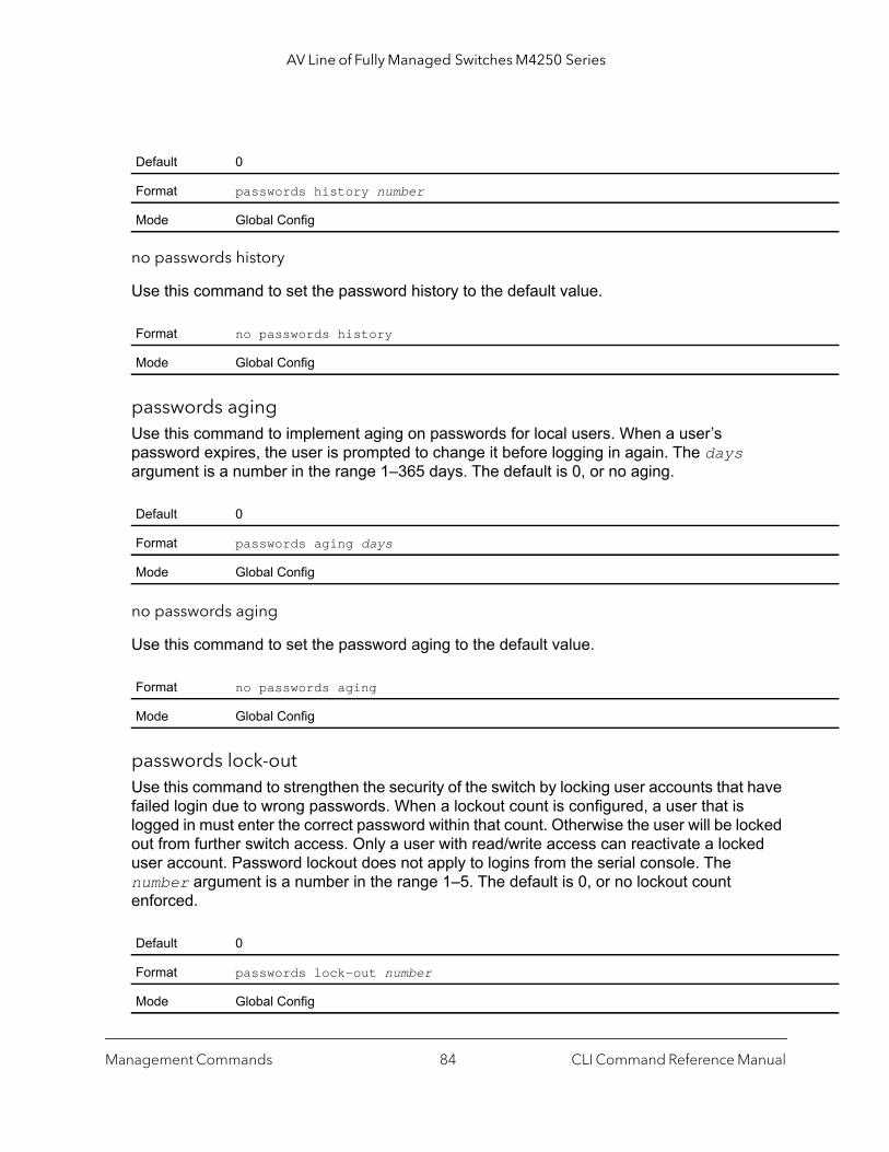
AV Line of Fully Managed Switches M4250 Series
no passwords history
Use this command to set the password history to the default value.
passwords agingUse this command to implement aging on passwords for local users. When a user’s password expires, the user is prompted to change it before logging in again. The days argument is a number in the range 1–365 days. The default is 0, or no aging.
no passwords aging
Use this command to set the password aging to the default value.
passwords lock-outUse this command to strengthen the security of the switch by locking user accounts that have failed login due to wrong passwords. When a lockout count is configured, a user that is logged in must enter the correct password within that count. Otherwise the user will be locked out from further switch access. Only a user with read/write access can reactivate a locked user account. Password lockout does not apply to logins from the serial console. The number argument is a number in the range 1–5. The default is 0, or no lockout count enforced.
Default 0
Format passwords history number
Mode Global Config
Format no passwords history
Mode Global Config
Default 0
Format passwords aging days
Mode Global Config
Format no passwords aging
Mode Global Config
Default 0
Format passwords lock-out number
Mode Global Config
Management Commands CLI Command Reference Manual84

AV Line of Fully Managed Switches M4250 Series
no passwords lock-out
Use this command to set the password lock-out count to the default value.
passwords strength-checkUse this command to enable the password strength feature. It is used to verify the strength of a password during configuration.
no passwords strength-check
Use this command to set the password strength checking to the default value.
passwords strength maximum consecutive-charactersUse this command to set the maximum number of consecutive characters to be used in password strength. The number argument is a number in the range 0–15. The default is 0. Minimum of 0 means no restriction on that set of characters.
passwords strength maximum repeated-charactersUse this command to set the maximum number of repeated characters to be used in password strength. The number argument is a number in the range 0–15. The default is 0. Minimum of 0 means no restriction on that set of characters.
Format no passwords lock-out
Mode Global Config
Default Disable
Format passwords strength-check
Mode Global Config
Format no passwords strength-check
Mode Global Config
Default 0
Format passwords strength maximum consecutive-characters number
Mode Global Config
Default 0
Format passwords strength maximum repeated-characters number
Mode Global Config
Management Commands CLI Command Reference Manual85

AV Line of Fully Managed Switches M4250 Series
passwords strength minimum uppercase-lettersUse this command to enforce a minimum number of uppercase letters that a password should contain. The number argument is a number in the range 0–16. The default is 2. Minimum of 0 means no restriction on that set of characters.
no passwords strength minimum uppercase-letters
Use this command to reset the minimum uppercase letters required in a password to the default value.
passwords strength minimum lowercase-lettersUse this command to enforce a minimum number of lowercase letters that a password should contain. The number argument is a number in the range 0–16. The default is 2. Minimum of 0 means no restriction on that set of characters.
no passwords strength minimum lowercase-letters
Use this command to reset the minimum lower letters required in a password to the default value.
Default 2
Format passwords strength minimum uppercase-letters number
Mode Global Config
Format no passwords minimum uppercase-letter
Mode Global Config
Default 2
Format passwords strength minimum lowercase-letters number
Mode Global Config
Format no passwords minimum lowercase-letter
Mode Global Config
Management Commands CLI Command Reference Manual86
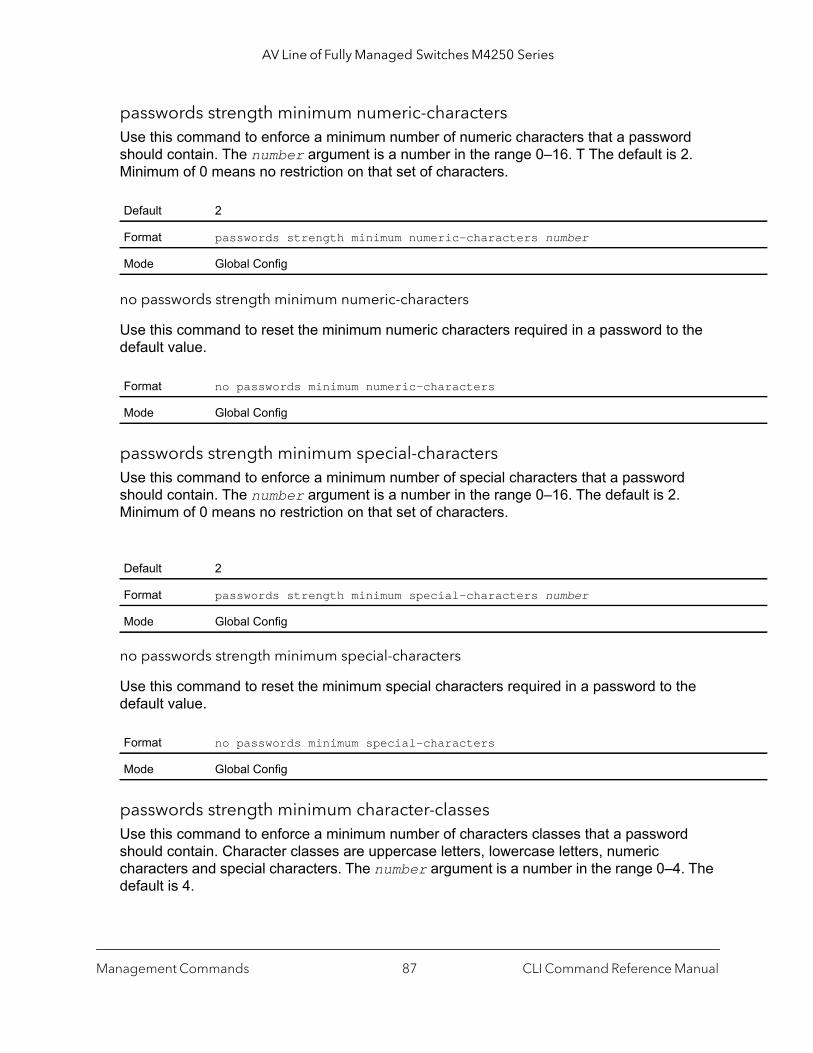
AV Line of Fully Managed Switches M4250 Series
passwords strength minimum numeric-charactersUse this command to enforce a minimum number of numeric characters that a password should contain. The number argument is a number in the range 0–16. T The default is 2. Minimum of 0 means no restriction on that set of characters.
no passwords strength minimum numeric-characters
Use this command to reset the minimum numeric characters required in a password to the default value.
passwords strength minimum special-charactersUse this command to enforce a minimum number of special characters that a password should contain. The number argument is a number in the range 0–16. The default is 2. Minimum of 0 means no restriction on that set of characters.
no passwords strength minimum special-characters
Use this command to reset the minimum special characters required in a password to the default value.
passwords strength minimum character-classesUse this command to enforce a minimum number of characters classes that a password should contain. Character classes are uppercase letters, lowercase letters, numeric characters and special characters. The number argument is a number in the range 0–4. The default is 4.
Default 2
Format passwords strength minimum numeric-characters number
Mode Global Config
Format no passwords minimum numeric-characters
Mode Global Config
Default 2
Format passwords strength minimum special-characters number
Mode Global Config
Format no passwords minimum special-characters
Mode Global Config
Management Commands CLI Command Reference Manual87

AV Line of Fully Managed Switches M4250 Series
no passwords strength minimum character-classes
Use this command to reset the minimum number of character classes required in a password to the default value.
passwords strength exclude-keywordUse this command to exclude the specified keyword while configuring the password. The password does not accept the keyword in any form (in between the string, case in-sensitive and reverse) as a substring. You can configure up to a maximum of three keywords.
no passwords strength exclude-keyword
Use this command to reset the restriction for the specified keyword or all the keywords configured.
show passwords configurationUse this command to display the configured password management settings.
Default 4
Format passwords strength minimum character-classes number
Mode Global Config
Format no passwords minimum character-classes
Mode Global Config
Format passwords strength exclude-keyword keyword
Mode Global Config
Format no passwords exclude-keyword [keyword]
Mode Global Config
Format show passwords configuration
Mode Privileged EXEC
Term Definition
Minimum Password Length Minimum number of characters required when changing passwords.
Password History Number of passwords to store for reuse prevention.
Password Aging Length in days that a password is valid.
Management Commands CLI Command Reference Manual88
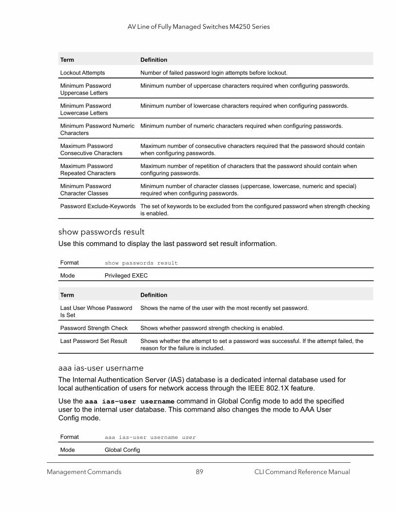
AV Line of Fully Managed Switches M4250 Series
tain
cking
the
show passwords resultUse this command to display the last password set result information.
aaa ias-user usernameThe Internal Authentication Server (IAS) database is a dedicated internal database used for local authentication of users for network access through the IEEE 802.1X feature.
Use the aaa ias-user username command in Global Config mode to add the specified user to the internal user database. This command also changes the mode to AAA User Config mode.
Lockout Attempts Number of failed password login attempts before lockout.
Minimum Password Uppercase Letters
Minimum number of uppercase characters required when configuring passwords.
Minimum Password Lowercase Letters
Minimum number of lowercase characters required when configuring passwords.
Minimum Password Numeric Characters
Minimum number of numeric characters required when configuring passwords.
Maximum Password Consecutive Characters
Maximum number of consecutive characters required that the password should conwhen configuring passwords.
Maximum Password Repeated Characters
Maximum number of repetition of characters that the password should contain whenconfiguring passwords.
Minimum Password Character Classes
Minimum number of character classes (uppercase, lowercase, numeric and special)required when configuring passwords.
Password Exclude-Keywords The set of keywords to be excluded from the configured password when strength cheis enabled.
Format show passwords result
Mode Privileged EXEC
Term Definition
Last User Whose Password Is Set
Shows the name of the user with the most recently set password.
Password Strength Check Shows whether password strength checking is enabled.
Last Password Set Result Shows whether the attempt to set a password was successful. If the attempt failed, reason for the failure is included.
Format aaa ias-user username user
Mode Global Config
Term Definition
Management Commands CLI Command Reference Manual89
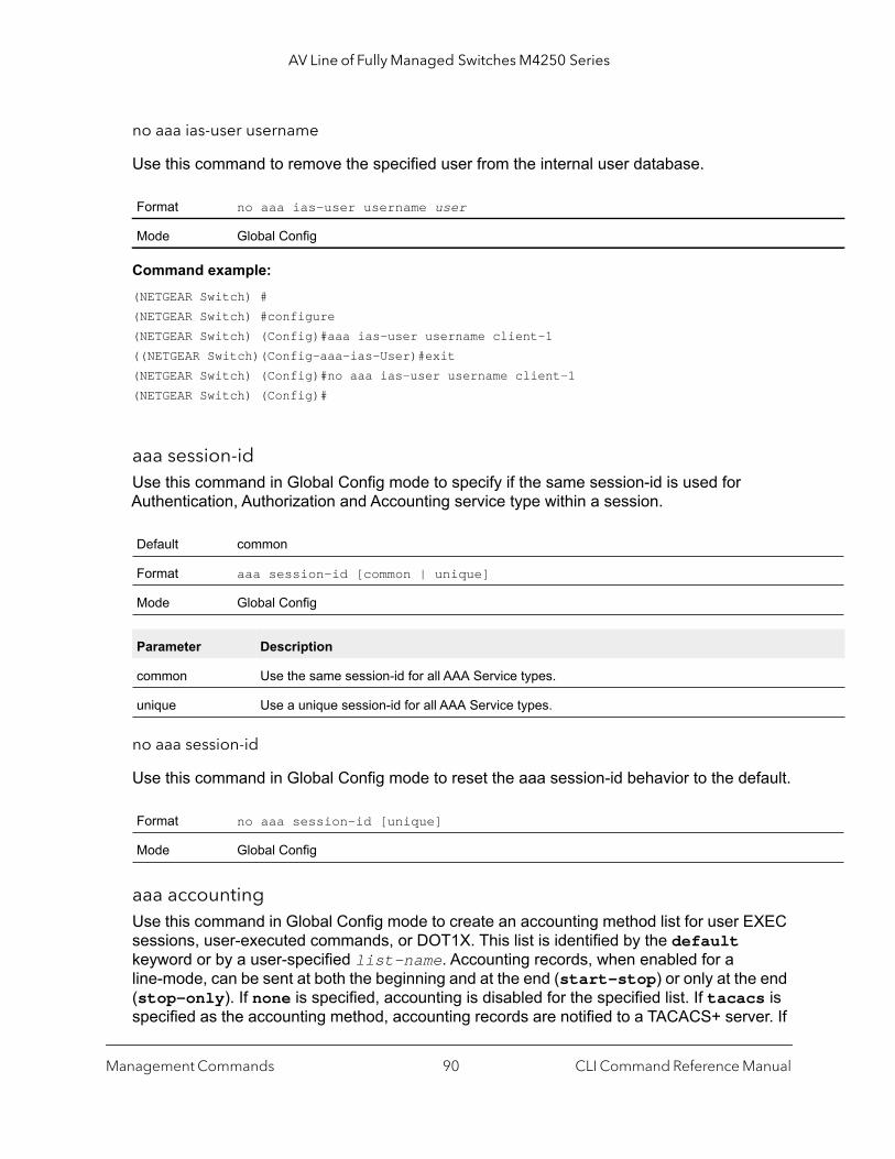
AV Line of Fully Managed Switches M4250 Series
no aaa ias-user username
Use this command to remove the specified user from the internal user database.
Command example: (NETGEAR Switch) #(NETGEAR Switch) #configure(NETGEAR Switch) (Config)#aaa ias-user username client-1((NETGEAR Switch)(Config-aaa-ias-User)#exit(NETGEAR Switch) (Config)#no aaa ias-user username client-1(NETGEAR Switch) (Config)#
aaa session-idUse this command in Global Config mode to specify if the same session-id is used for Authentication, Authorization and Accounting service type within a session.
no aaa session-id
Use this command in Global Config mode to reset the aaa session-id behavior to the default.
aaa accountingUse this command in Global Config mode to create an accounting method list for user EXEC sessions, user-executed commands, or DOT1X. This list is identified by the default keyword or by a user-specified list-name. Accounting records, when enabled for a line-mode, can be sent at both the beginning and at the end (start-stop) or only at the end (stop-only). If none is specified, accounting is disabled for the specified list. If tacacs is specified as the accounting method, accounting records are notified to a TACACS+ server. If
Format no aaa ias-user username user
Mode Global Config
Default common
Format aaa session-id [common | unique]
Mode Global Config
Parameter Description
common Use the same session-id for all AAA Service types.
unique Use a unique session-id for all AAA Service types.
Format no aaa session-id [unique]
Mode Global Config
Management Commands CLI Command Reference Manual90

AV Line of Fully Managed Switches M4250 Series
p |
the
radius is the specified accounting method, accounting records are notified to a RADIUS server.
Note the following:
• A maximum of five Accounting Method lists can be created for each exec and commands type.
• Only the default Accounting Method list can be created for DOT1X. There is no provision to create more.
• The same list-name can be used for both exec and commands accounting type• AAA Accounting for commands with RADIUS as the accounting method is not supported.• Start-stop or None are the only supported record types for DOT1X accounting. Start-stop
enables accounting and None disables accounting. • RADIUS is the only accounting method type supported for DOT1X accounting.
Command example: (NETGEAR Switch) #(NETGEAR Switch) #configure(NETGEAR Switch) #aaa accounting commands default stop-only tacacs(NETGEAR Switch) #aaa accounting exec default start-stop radius(NETGEAR Switch) #aaa accounting dot1x default start-stop radius(NETGEAR Switch) #aaa accounting dot1x default none(NETGEAR Switch) #exit
Format aaa accounting {exec | commands | dot1x} {default | list-name} {start-stostop-only |none} method1 [method2…]
Mode Global Config
Parameter Description
exec Provides accounting for a user EXEC terminal sessions.
commands Provides accounting for all user executed commands.
dot1x Provides accounting for DOT1X user commands.
default The default list of methods for accounting services.
list-name Character string used to name the list of accounting methods.
start-stop Sends a start accounting notice at the beginning of a process and a stop accounting notice atbeginning of a process and a stop accounting notice at the end of a process.
stop-only Sends a stop accounting notice at the end of the requested user process.
none Disables accounting services on this line.
method Use either TACACS or radius server for accounting purposes.
Management Commands CLI Command Reference Manual91
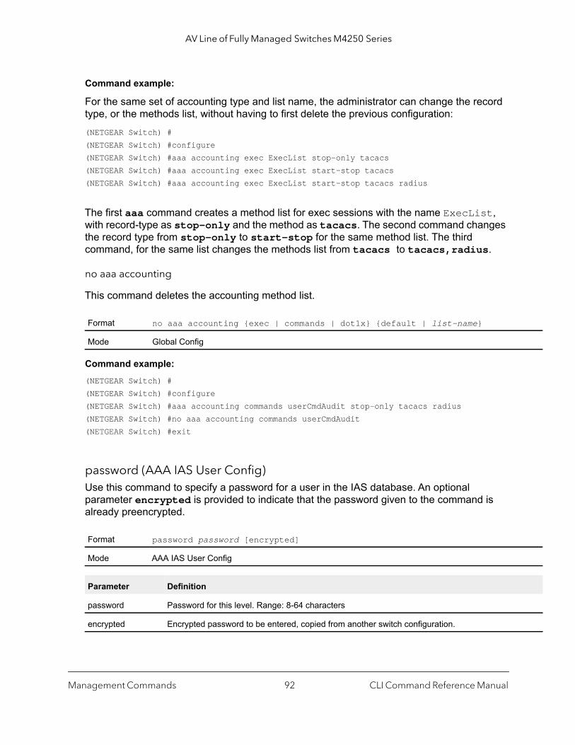
AV Line of Fully Managed Switches M4250 Series
Command example:
For the same set of accounting type and list name, the administrator can change the record type, or the methods list, without having to first delete the previous configuration:(NETGEAR Switch) #(NETGEAR Switch) #configure(NETGEAR Switch) #aaa accounting exec ExecList stop-only tacacs(NETGEAR Switch) #aaa accounting exec ExecList start-stop tacacs(NETGEAR Switch) #aaa accounting exec ExecList start-stop tacacs radius
The first aaa command creates a method list for exec sessions with the name ExecList, with record-type as stop-only and the method as tacacs. The second command changes the record type from stop-only to start-stop for the same method list. The third command, for the same list changes the methods list from tacacs to tacacs,radius.
no aaa accounting
This command deletes the accounting method list.
Command example: (NETGEAR Switch) #(NETGEAR Switch) #configure(NETGEAR Switch) #aaa accounting commands userCmdAudit stop-only tacacs radius(NETGEAR Switch) #no aaa accounting commands userCmdAudit(NETGEAR Switch) #exit
password (AAA IAS User Config)Use this command to specify a password for a user in the IAS database. An optional parameter encrypted is provided to indicate that the password given to the command is already preencrypted.
Format no aaa accounting {exec | commands | dot1x} {default | list-name}
Mode Global Config
Format password password [encrypted]
Mode AAA IAS User Config
Parameter Definition
password Password for this level. Range: 8-64 characters
encrypted Encrypted password to be entered, copied from another switch configuration.
Management Commands CLI Command Reference Manual92

AV Line of Fully Managed Switches M4250 Series
Command example: (NETGEAR Switch) #(NETGEAR Switch) #configure(NETGEAR Switch) (Config)#aaa ias-user username client-1(NETGEAR Switch) (Config-aaa-ias-User)#password client123(NETGEAR Switch) (Config-aaa-ias-User)#no password
Command example:
The following is an example of adding a MAB Client to the Internal user database:(NETGEAR Switch) #(NETGEAR Switch) #configure(NETGEAR Switch) (Config)#aaa ias-user username 1f3ccb1157(NETGEAR Switch) (Config-aaa-ias-User)#password 1f3ccb1157(NETGEAR Switch) (Config-aaa-ias-User)#exit(NETGEAR Switch) (Config)#
no password (AAA IAS User Config)
Use this command to clear the password of a user.
clear aaa ias-usersUse this command to remove all users from the IAS database.
Command example: (NETGEAR Switch) #clear aaa ias-users
show aaa ias-usersUse this command to display configured IAS users and their attributes. Passwords configured are not shown in the show command output.
Format no password
Mode AAA IAS User Config
Format clear aaa ias-users
Mode Privileged Exec
Format show aaa ias-users [username]
Mode Privileged EXEC
Management Commands CLI Command Reference Manual93

AV Line of Fully Managed Switches M4250 Series
for
Command example: (NETGEAR Switch) #show aaa ias-users
UserName ------------------- Client-1 Client-2
Following are the IAS configuration commands shown in the output of show running-config command. Passwords shown in the command output are always encrypted.aaa ias-user username client-1password a45c74fdf50a558a2b5cf05573cd633bac2c6c598d54497ad4c46104918f2c encryptedexit
accountingUse this command in Line Configuration mode to apply the accounting method list to a line config (console/telnet/ssh).
Command example: (NETGEAR Switch) #(NETGEAR Switch) #configure(NETGEAR Switch) (Config)#line telnet (NETGEAR Switch)(Config-line)# accounting exec default(NETGEAR Switch) #exit
Format accounting {exec | commands} {default | list-name}
Mode Line Configuration
Parameter Description
exec Causes accounting for an EXEC session.
commands This causes accounting for each command execution attempt. If a user is enabling accountingexec mode for the current line-configuration type, the user will be logged out.
default The default Accounting List
listname Enter a string of not more than 15 characters.
Management Commands CLI Command Reference Manual94
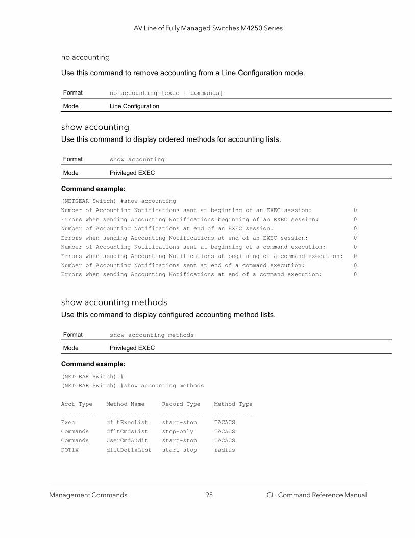
AV Line of Fully Managed Switches M4250 Series
no accounting
Use this command to remove accounting from a Line Configuration mode.
show accountingUse this command to display ordered methods for accounting lists.
Command example: (NETGEAR Switch) #show accountingNumber of Accounting Notifications sent at beginning of an EXEC session: 0Errors when sending Accounting Notifications beginning of an EXEC session: 0Number of Accounting Notifications at end of an EXEC session: 0Errors when sending Accounting Notifications at end of an EXEC session: 0Number of Accounting Notifications sent at beginning of a command execution: 0Errors when sending Accounting Notifications at beginning of a command execution: 0Number of Accounting Notifications sent at end of a command execution: 0Errors when sending Accounting Notifications at end of a command execution: 0
show accounting methodsUse this command to display configured accounting method lists.
Command example: (NETGEAR Switch) #(NETGEAR Switch) #show accounting methods
Acct Type Method Name Record Type Method Type---------- ------------ ------------ ------------Exec dfltExecList start-stop TACACSCommands dfltCmdsList stop-only TACACSCommands UserCmdAudit start-stop TACACSDOT1X dfltDot1xList start-stop radius
Format no accounting {exec | commands]
Mode Line Configuration
Format show accounting
Mode Privileged EXEC
Format show accounting methods
Mode Privileged EXEC
Management Commands CLI Command Reference Manual95

AV Line of Fully Managed Switches M4250 Series
Line EXEC Method List Command Method List------- ---------------------------------------Console dfltExecList dfltCmdsList Telnet dfltExecList dfltCmdsList SSH dfltExecList UserCmdAudit
clear accounting statisticsThis command clears the accounting statistics.
show domain-nameThis command displays the configured domain-name.
Command example: (NETGEAR Switch) #(NETGEAR Switch) #show domain-name
Domain : EnableDomain-name :abc
SNMP CommandsThis section describes the commands that you can use to configure Simple Network Management Protocol (SNMP) on the switch. You can configure the switch to act as an SNMP agent so that it can communicate with SNMP managers on your network.
snmp-server This command sets the name and the physical location of the switch and the organization responsible for the network. The range for the name, loc and con parameters is from 1 to 31 alphanumeric characters.
Format clear accounting statistics
Mode Privileged Exec
Format show domain-name
Mode Privileged Exec
Default none
Format snmp-server {sysname name | location loc | contact con}
Mode Global Config
Management Commands CLI Command Reference Manual96
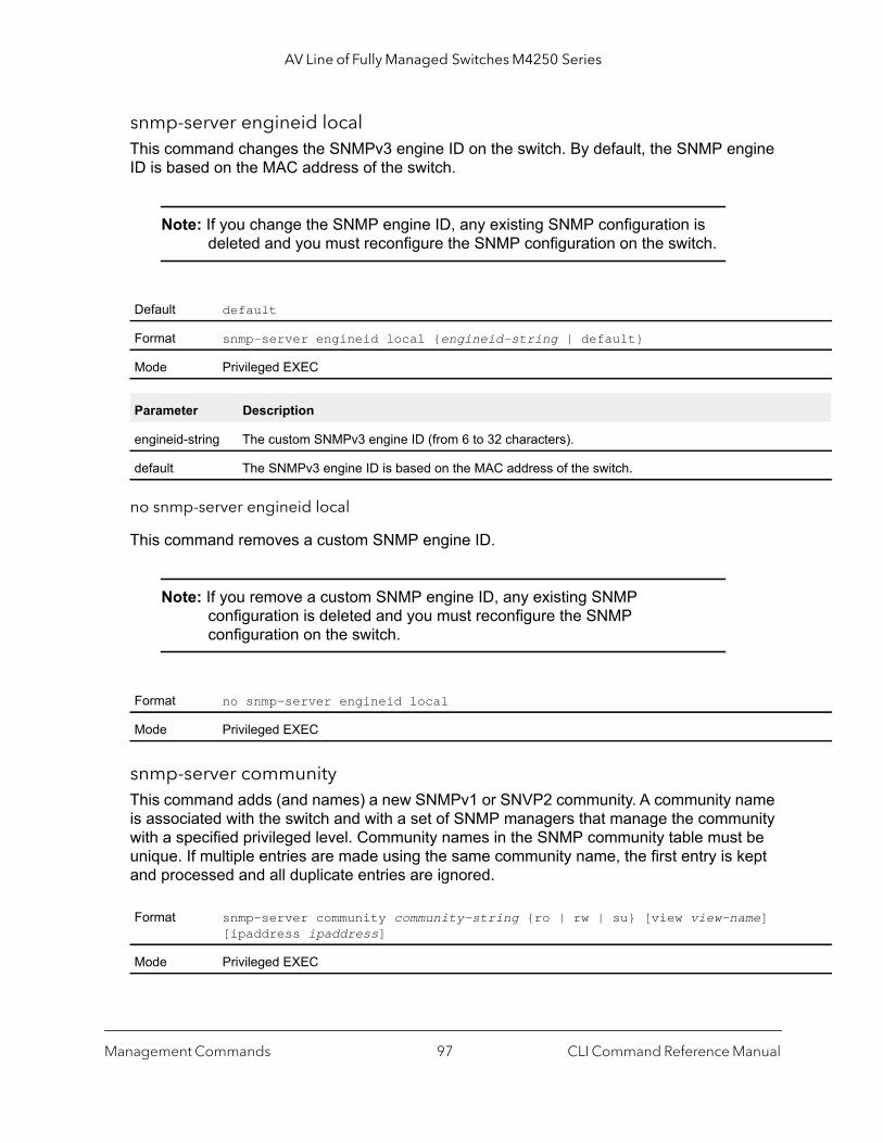
AV Line of Fully Managed Switches M4250 Series
snmp-server engineid localThis command changes the SNMPv3 engine ID on the switch. By default, the SNMP engine ID is based on the MAC address of the switch.
Note: If you change the SNMP engine ID, any existing SNMP configuration is deleted and you must reconfigure the SNMP configuration on the switch.
no snmp-server engineid local
This command removes a custom SNMP engine ID.
Note: If you remove a custom SNMP engine ID, any existing SNMP configuration is deleted and you must reconfigure the SNMP configuration on the switch.
snmp-server communityThis command adds (and names) a new SNMPv1 or SNVP2 community. A community name is associated with the switch and with a set of SNMP managers that manage the community with a specified privileged level. Community names in the SNMP community table must be unique. If multiple entries are made using the same community name, the first entry is kept and processed and all duplicate entries are ignored.
Default default
Format snmp-server engineid local {engineid-string | default}
Mode Privileged EXEC
Parameter Description
engineid-string The custom SNMPv3 engine ID (from 6 to 32 characters).
default The SNMPv3 engine ID is based on the MAC address of the switch.
Format no snmp-server engineid local
Mode Privileged EXEC
Format snmp-server community community-string {ro | rw | su} [view view-name] [ipaddress ipaddress]
Mode Privileged EXEC
Management Commands CLI Command Reference Manual97
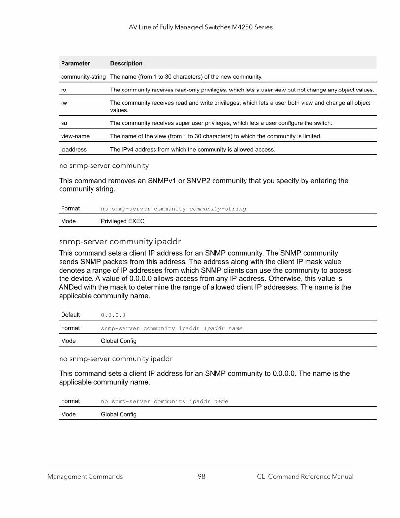
AV Line of Fully Managed Switches M4250 Series
lues.
ject
no snmp-server community
This command removes an SNMPv1 or SNVP2 community that you specify by entering the community string.
snmp-server community ipaddrThis command sets a client IP address for an SNMP community. The SNMP community sends SNMP packets from this address. The address along with the client IP mask value denotes a range of IP addresses from which SNMP clients can use the community to access the device. A value of 0.0.0.0 allows access from any IP address. Otherwise, this value is ANDed with the mask to determine the range of allowed client IP addresses. The name is the applicable community name.
no snmp-server community ipaddr
This command sets a client IP address for an SNMP community to 0.0.0.0. The name is the applicable community name.
Parameter Description
community-string The name (from 1 to 30 characters) of the new community.
ro The community receives read-only privileges, which lets a user view but not change any object va
rw The community receives read and write privileges, which lets a user both view and change all obvalues.
su The community receives super user privileges, which lets a user configure the switch.
view-name The name of the view (from 1 to 30 characters) to which the community is limited.
ipaddress The IPv4 address from which the community is allowed access.
Format no snmp-server community community-string
Mode Privileged EXEC
Default 0.0.0.0
Format snmp-server community ipaddr ipaddr name
Mode Global Config
Format no snmp-server community ipaddr name
Mode Global Config
Management Commands CLI Command Reference Manual98

AV Line of Fully Managed Switches M4250 Series
snmp-server community ipmaskThis command sets a client IP mask for an SNMP community. The SNMP community sends SNMP packets from an address with this client IP mask. The address along with the client IP mask value denotes a range of IP addresses from which SNMP clients can use the community to access the device. A value of 255.255.255.255 allows access from only one computer and specifies that computer’s IP address as the client IP address. A value of 0.0.0.0 allows access from any IP address. The name is the applicable community name.
no snmp-server community ipmask
This command sets a client IP mask for an SNMP community to 0.0.0.0. The name is the applicable community name.
snmp-server community modeThis command activates an SNMP community. If a community is enabled, an SNMP manager that is associated with this community manages the switch according to its access right. If the community is disabled, no SNMP requests using this community are accepted. In this case, the SNMP manager that is associated with this community cannot manage the switch until the status is changed back to enabled.
no snmp-server community mode
This command deactivates an SNMP community. If the community is disabled, no SNMP requests using this community are accepted. In this case, the SNMP manager that is associated with this community cannot manage the switch until the status is changed back to enabled.
Default 0.0.0.0
Format snmp-server community ipmask ipmask name
Mode Global Config
Format no snmp-server community ipmask name
Mode Global Config
Default • private and public communities - enabled• other four - disabled
Format snmp-server community mode name
Mode Global Config
Format no snmp-server community mode name
Mode Global Config
Management Commands CLI Command Reference Manual99
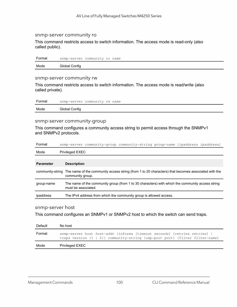
AV Line of Fully Managed Switches M4250 Series
ss]
h the
ring
e]
snmp-server community roThis command restricts access to switch information. The access mode is read-only (also called public).
snmp-server community rwThis command restricts access to switch information. The access mode is read/write (also called private).
snmp-server community-groupThis command configures a community access string to permit access through the SNMPv1 and SNMPv2 protocols.
snmp-server hostThis command configures an SNMPv1 or SNMPv2 host to which the switch can send traps.
Format snmp-server community ro name
Mode Global Config
Format snmp-server community rw name
Mode Global Config
Format snmp-server community-group community-string group-name [ipaddress ipaddre
Mode Privileged EXEC
Parameter Description
community-string The name of the community access string (from 1 to 20 characters) that becomes associated witcommunity group.
group-name The name of the community group (from 1 to 30 characters) with which the community access stmust be associated.
ipaddress The IPv4 address from which the community group is allowed access.
Default No host
Format snmp-server host host-addr {informs [timeout seconds] [retries retries] | traps version {1 | 2}} community-string [udp-port port] [filter filter-nam
Mode Privileged EXEC
Management Commands CLI Command Reference Manual100

AV Line of Fully Managed Switches M4250 Series
ore it
ult is
rt
me]
no snmp-server host
This command removes the traps or informs configuration for an SNMP host.
For information about the parameters, see the snmp-server host command.
snmp-server v3-hostThis command configures an SNMPv3 host to which the switch can send traps.
Parameter Description
host-addr The IPv4 or IPv6 address of the host.
informs The switch sends SNMPv2 informs to the host. (The switch sends either informs or traps.)
seconds The period in seconds (from 1 to 300 seconds) that the switch waits for an acknowledgement befsends the inform again. This default is 15 seconds.
retries The number of times (from 0 to 255) that the switch attempts to send the same inform. The defa3 attempts.
traps The switch sends traps to the host. (The switch sends either traps or informs.)
1 The switch sends SNMPv1 traps.
2 The switch sends SNMPv2c traps.
community-string The community string (from 1 to 20 characters) that is sent as part of the notification.
port The SNMP trap receiver port. By default, the port number is 162, but you can specify another ponumber.
filter-name The filter name (from 1 to 30 characters) that is associated with the host. (You can use a filter tospecify which traps are sent to the host.)
Format no snmp-server host host-addr {traps version {1 | 2} | informs}
Mode Privileged EXEC
Default No host
Format snmp-server v3-host host-addr username [traps | informs [timeout seconds][retries retries]] [auth | noauth | priv] [udpport port] [filter filterna
Mode Privileged EXEC
Parameter Description
host-addr The IPv4 or IPv6 address of the host.
username The name of the user (from 1 to 30 characters). The user must be associated with a group that supports SNMPv3 and the access method that you configure for this command.
traps The switch sends traps to the host. (The switch sends either traps or informs.)
Management Commands CLI Command Reference Manual101
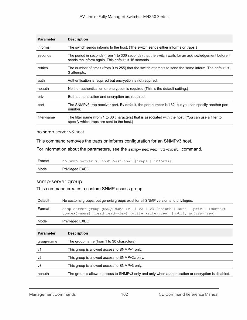
AV Line of Fully Managed Switches M4250 Series
ore it
lt is
port
t
bled.
no snmp-server v3-host
This command removes the traps or informs configuration for an SNMPv3 host.
For information about the parameters, see the snmp-server v3-host command.
snmp-server groupThis command creates a custom SNMP access group.
informs The switch sends informs to the host. (The switch sends either informs or traps.)
seconds The period in seconds (from 1 to 300 seconds) that the switch waits for an acknowledgement befsends the inform again. This default is 15 seconds.
retries The number of times (from 0 to 255) that the switch attempts to send the same inform. The defau3 attempts.
auth Authentication is required but encryption is not required.
noauth Neither authentication or encryption is required (This is the default setting.)
priv Both authentication and encryption are required.
port The SNMPv3 trap receiver port. By default, the port number is 162, but you can specify another number.
filter-name The filter name (from 1 to 30 characters) that is associated with the host. (You can use a filter to specify which traps are sent to the host.)
Format no snmp-server v3-host host-addr {traps | informs}
Mode Privileged EXEC
Default No customs groups, but generic groups exist for all SNMP version and privileges.
Format snmp-server group group-name {v1 | v2 | v3 {noauth | auth | priv}} [contexcontext-name] [read read-view] [write write-view] [notify notify-view]
Mode Privileged EXEC
Parameter Description
group-name The group name (from 1 to 30 characters).
v1 This group is allowed access to SNMPv1 only.
v2 This group is allowed access to SNMPv2c only.
v3 This group is allowed access to SNMPv3 only.
noauth The group is allowed access to SNMPv3 only and only when authentication or encryption is disa
Parameter Description
Management Commands CLI Command Reference Manual102
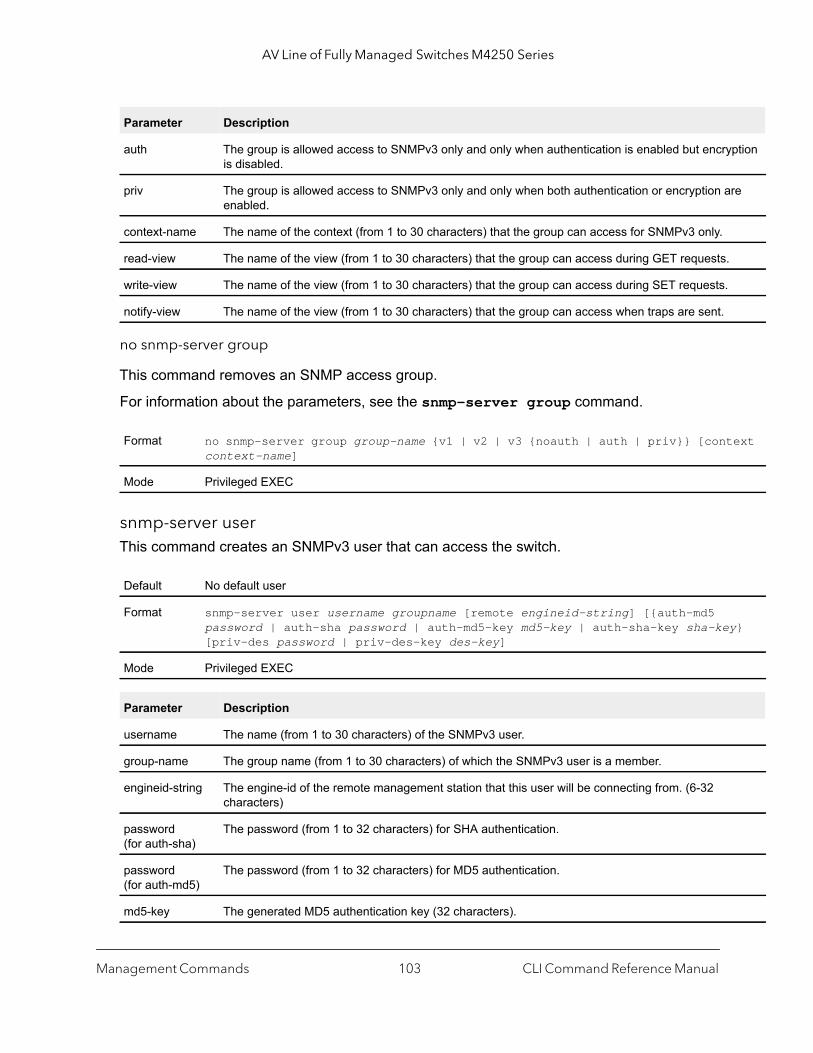
AV Line of Fully Managed Switches M4250 Series
ption
re
ext
y}
no snmp-server group
This command removes an SNMP access group.
For information about the parameters, see the snmp-server group command.
snmp-server userThis command creates an SNMPv3 user that can access the switch.
auth The group is allowed access to SNMPv3 only and only when authentication is enabled but encryis disabled.
priv The group is allowed access to SNMPv3 only and only when both authentication or encryption aenabled.
context-name The name of the context (from 1 to 30 characters) that the group can access for SNMPv3 only.
read-view The name of the view (from 1 to 30 characters) that the group can access during GET requests.
write-view The name of the view (from 1 to 30 characters) that the group can access during SET requests.
notify-view The name of the view (from 1 to 30 characters) that the group can access when traps are sent.
Format no snmp-server group group-name {v1 | v2 | v3 {noauth | auth | priv}} [contcontext-name]
Mode Privileged EXEC
Default No default user
Format snmp-server user username groupname [remote engineid-string] [{auth-md5 password | auth-sha password | auth-md5-key md5-key | auth-sha-key sha-ke[priv-des password | priv-des-key des-key]
Mode Privileged EXEC
Parameter Description
username The name (from 1 to 30 characters) of the SNMPv3 user.
group-name The group name (from 1 to 30 characters) of which the SNMPv3 user is a member.
engineid-string The engine-id of the remote management station that this user will be connecting from. (6-32 characters)
password (for auth-sha)
The password (from 1 to 32 characters) for SHA authentication.
password (for auth-md5)
The password (from 1 to 32 characters) for MD5 authentication.
md5-key The generated MD5 authentication key (32 characters).
Parameter Description
Management Commands CLI Command Reference Manual103
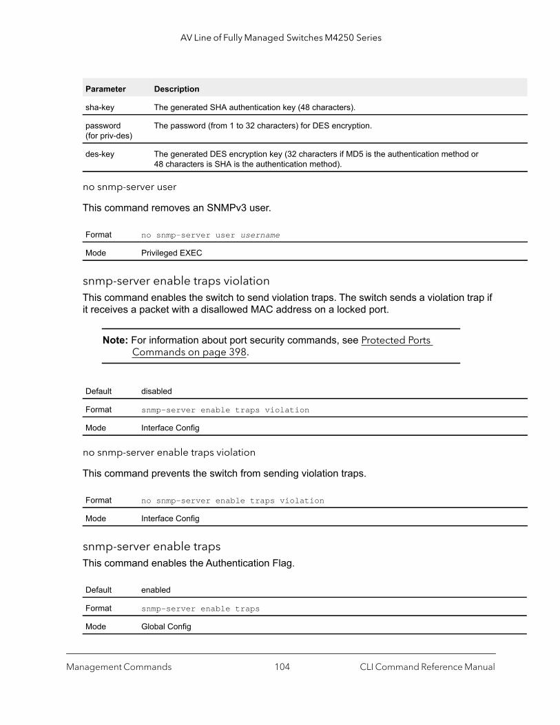
AV Line of Fully Managed Switches M4250 Series
no snmp-server user
This command removes an SNMPv3 user.
snmp-server enable traps violationThis command enables the switch to send violation traps. The switch sends a violation trap if it receives a packet with a disallowed MAC address on a locked port.
Note: For information about port security commands, see Protected Ports Commands on page 398.
no snmp-server enable traps violation
This command prevents the switch from sending violation traps.
snmp-server enable trapsThis command enables the Authentication Flag.
sha-key The generated SHA authentication key (48 characters).
password (for priv-des)
The password (from 1 to 32 characters) for DES encryption.
des-key The generated DES encryption key (32 characters if MD5 is the authentication method or 48 characters is SHA is the authentication method).
Format no snmp-server user username
Mode Privileged EXEC
Default disabled
Format snmp-server enable traps violation
Mode Interface Config
Format no snmp-server enable traps violation
Mode Interface Config
Default enabled
Format snmp-server enable traps
Mode Global Config
Parameter Description
Management Commands CLI Command Reference Manual104

AV Line of Fully Managed Switches M4250 Series
no snmp-server enable traps
This command disables the Authentication Flag.
snmp-server enable traps linkmodeThis command enables Link Up/Down traps for the entire switch. If enabled, the switch sends link traps only if the Link Trap flag setting that is associated with a port is enabled. For more information, see snmp trap link-status on page 110
no snmp-server enable traps linkmode
This command disables Link Up/Down traps for the entire switch.
snmp-server enable traps multiusersThis command enables multiple user traps. If the traps are enabled, the switch sends a multiple user trap if a user logs in to the terminal interface (EIA 232 or Telnet) while an existing terminal interface session is already established.
no snmp-server enable traps multiusers
This command disables multiple user traps.
Format no snmp-server enable traps
Mode Global Config
Default enabled
Format snmp-server enable traps linkmode
Mode Global Config
Format no snmp-server enable traps linkmode
Mode Global Config
Default enabled
Format snmp-server enable traps multiusers
Mode Global Config
Format no snmp-server enable traps multiusers
Mode Global Config
Management Commands CLI Command Reference Manual105
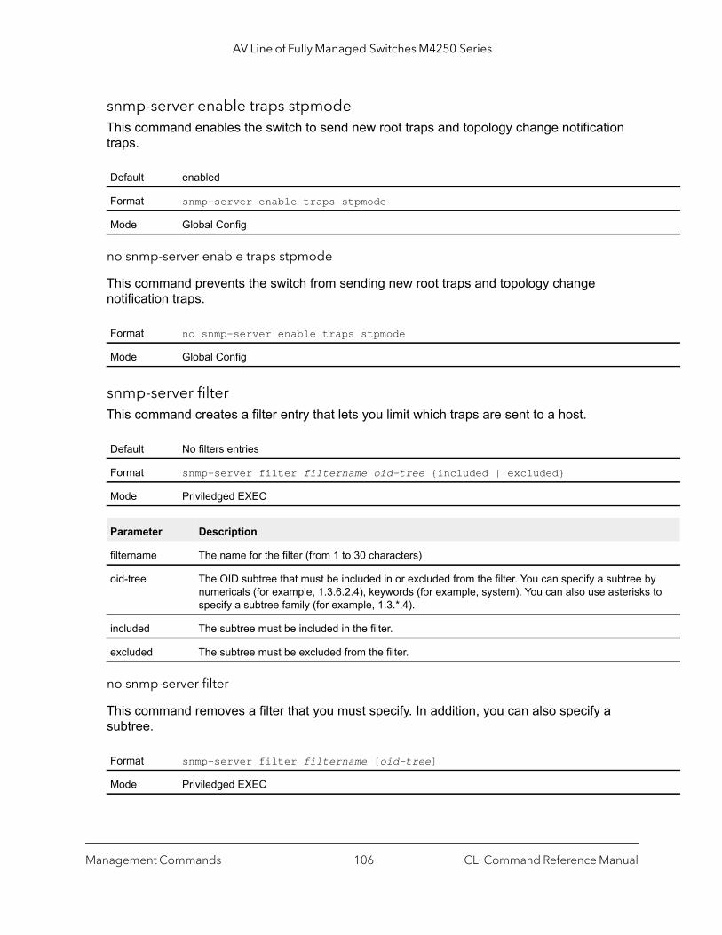
AV Line of Fully Managed Switches M4250 Series
y to
snmp-server enable traps stpmodeThis command enables the switch to send new root traps and topology change notification traps.
no snmp-server enable traps stpmode
This command prevents the switch from sending new root traps and topology change notification traps.
snmp-server filterThis command creates a filter entry that lets you limit which traps are sent to a host.
no snmp-server filter
This command removes a filter that you must specify. In addition, you can also specify a subtree.
Default enabled
Format snmp-server enable traps stpmode
Mode Global Config
Format no snmp-server enable traps stpmode
Mode Global Config
Default No filters entries
Format snmp-server filter filtername oid-tree {included | excluded}
Mode Priviledged EXEC
Parameter Description
filtername The name for the filter (from 1 to 30 characters)
oid-tree The OID subtree that must be included in or excluded from the filter. You can specify a subtree bnumericals (for example, 1.3.6.2.4), keywords (for example, system). You can also use asterisksspecify a subtree family (for example, 1.3.*.4).
included The subtree must be included in the filter.
excluded The subtree must be excluded from the filter.
Format snmp-server filter filtername [oid-tree]
Mode Priviledged EXEC
Management Commands CLI Command Reference Manual106

AV Line of Fully Managed Switches M4250 Series
y to
snmp-server viewThis command creates a new view or modifies an existing view that an SNMP group can use to determine which objects can be accessed by a community or user.
no snmp-server view
This command removes a view that you must specify. In addition, you can also specify a subtree.
snmp-server portThis command modifies the port that the switch uses to detect SNMP messages. By default, the switch uses UDP port 161 to detect SNMP messages.
no snmp-server port
This command resets the port that the switch uses to detect SNMP messages. After you enter this command, the switch uses UDP port 161 to detect SNMP messages.
Default The switch automatically creates default view for default groups.
Format snmp-server view viewname oid-tree {included | excluded}
Mode Priviledged EXEC
Parameter Description
viewname The name for the view (from 1 to 30 characters)
oid-tree The OID subtree that must be included in or excluded from the view. You can specify a subtree bnumericals (for example, 1.3.6.2.4), keywords (for example, system). You can also use asterisksspecify a subtree family (for example, 1.3.*.4).
included The subtree must be included in the view.
excluded The subtree must be excluded from the view.
Format snmp-server view viewname [oid-tree]
Mode Priviledged EXEC
Default 161
Format snmp-server port number
Mode User EXEC
Format no snmp-server port
Mode User EXEC
Management Commands CLI Command Reference Manual107
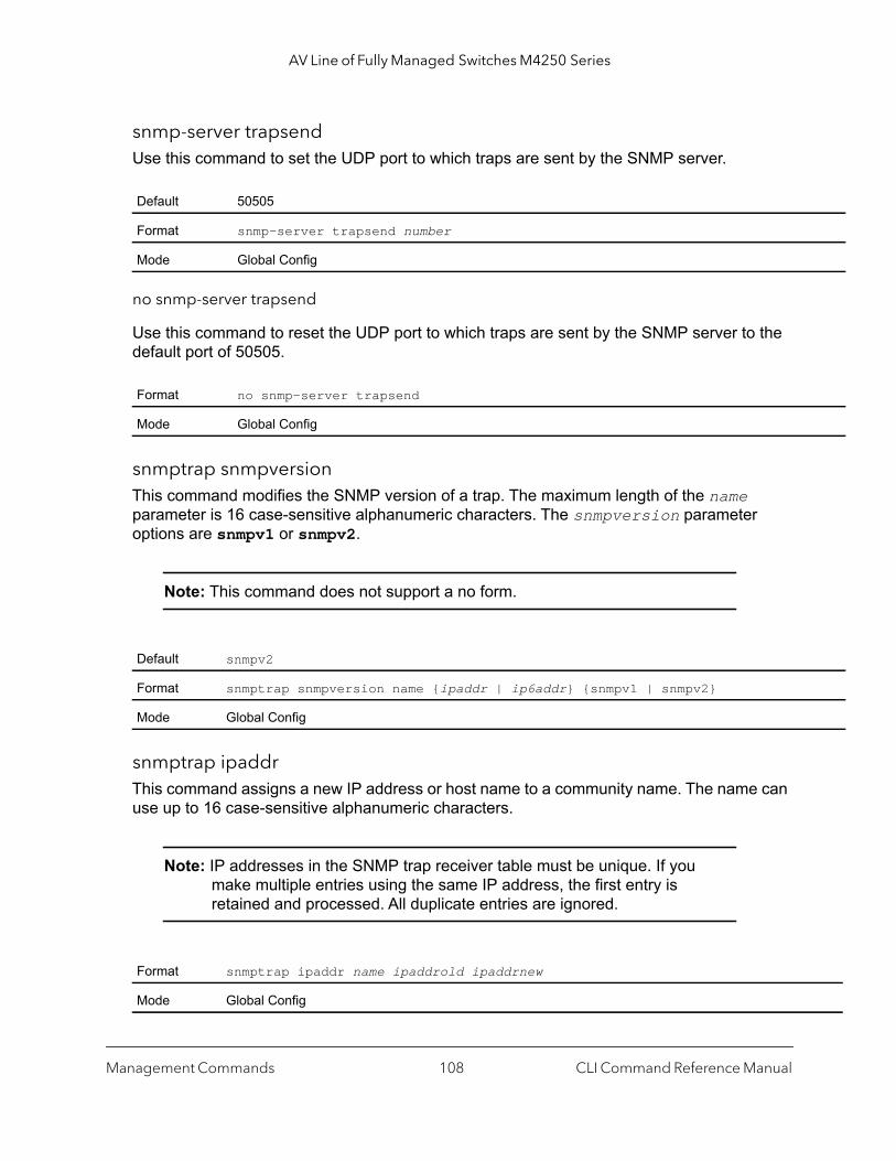
AV Line of Fully Managed Switches M4250 Series
snmp-server trapsendUse this command to set the UDP port to which traps are sent by the SNMP server.
no snmp-server trapsend
Use this command to reset the UDP port to which traps are sent by the SNMP server to the default port of 50505.
snmptrap snmpversionThis command modifies the SNMP version of a trap. The maximum length of the name parameter is 16 case-sensitive alphanumeric characters. The snmpversion parameter options are snmpv1 or snmpv2.
Note: This command does not support a no form.
snmptrap ipaddrThis command assigns a new IP address or host name to a community name. The name can use up to 16 case-sensitive alphanumeric characters.
Note: IP addresses in the SNMP trap receiver table must be unique. If you make multiple entries using the same IP address, the first entry is retained and processed. All duplicate entries are ignored.
Default 50505
Format snmp-server trapsend number
Mode Global Config
Format no snmp-server trapsend
Mode Global Config
Default snmpv2
Format snmptrap snmpversion name {ipaddr | ip6addr} {snmpv1 | snmpv2}
Mode Global Config
Format snmptrap ipaddr name ipaddrold ipaddrnew
Mode Global Config
Management Commands CLI Command Reference Manual108

AV Line of Fully Managed Switches M4250 Series
-id
ID is
from
from
snmptrap modeThis command activates an SNMP trap. Enabled trap receivers are active (that is, able to receive traps).
no snmptrap mode
This command deactivates an SNMP trap. Disabled trap receivers are inactive (that is, not able to receive traps).
snmptrap source-interfaceThis command configures the global source interface (that is, the source IP address) for all SNMP communication between the SNMP client and the server.
no snmptrap source-interface
This command removes the global source interface for all SNMP communication between the SNMP client and the server.
Format snmptrap mode name {ipaddr | ip6addr}
Mode Global Config
Format no snmptrap mode name {ipaddr | ip6addr}
Mode Global Config
Format snmptrap source-interface {unit/port | loopback loopback-id | tunnel tunnel| vlan vlan-id}
Mode Global Config
Parameter Description
unit/port The unit identifier that is assigned to the switch.
loopback-id The loopback interface that you want to use as the source IP address. The range of the loopbackfrom 0 to 7.
tunnel-id The tunnel interface that you want to use as the source IP address. The range of the tunnel ID is0 to 7.
vlan-id The VLAN interface that you want to use as the source IP address. The range of the VLAN ID is1 to 4093.
Format no snmptrap source-interface
Mode Global Config
Management Commands CLI Command Reference Manual109
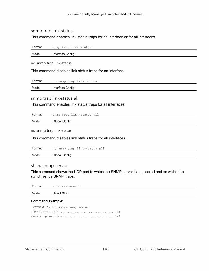
AV Line of Fully Managed Switches M4250 Series
snmp trap link-statusThis command enables link status traps for an interface or for all interfaces.
no snmp trap link-status
This command disables link status traps for an interface.
snmp trap link-status allThis command enables link status traps for all interfaces.
no snmp trap link-status
This command disables link status traps for all interfaces.
show snmp-serverThis command shows the UDP port to which the SNMP server is connected and on which the switch sends SNMP traps.
Command example: (NETGEAR Switch)#show snmp-serverSNMP Server Port............................... 161SNMP Trap Send Port............................ 162
Format snmp trap link-status
Mode Interface Config
Format no snmp trap link-status
Mode Interface Config
Format snmp trap link-status all
Mode Global Config
Format no snmp trap link-status all
Mode Global Config
Format show snmp-server
Mode User EXEC
Management Commands CLI Command Reference Manual110

AV Line of Fully Managed Switches M4250 Series
Pv2
Pv2
show snmp engineIDThis command displays the configured SNMP engine ID.
show snmpThis command displays the SNMP configuration on the switch.
Format show snmp engineID
Mode Privileged EXEC
Format show snmp
Mode Privileged EXEC
Term Definition
Community tables
Community-String The community string for the entry. The community string is used by the SNMPv1 and SNMprotocols to access the switch.
Community-Access The privilege level: Read only, Read write, or su (which means super user).
View Name The name of the view to which the community receives access.
IP Address The IP address from which access to the community is allowed.
IP Mask The IP mask associated with the IP address.
Community Group tables
Community-String The community string for the entry. The community string is used by the SNMPv1 and SNMprotocols to access the switch.
Group Name The group to which the community is assigned.
IP Address The IP address from which the group can access the community
IP Mask The IP mask associated with the IP address.
Host table for SNMPv1 and SNMPv2
Target Address The IP address of the host to which SNMPv1 or SNMPv2 traps or informs are sent.
Type The type of SNMPv1 or SNMPv2 messages that are sent (either traps or informs).
Community The community to which the SNMPv1 or SNMPv2 messages are sent.
Version The SNMP version (SNMPv1 or SNMPv2) of the messages.
UDP Port The number of the UDP port to which the SNMPv1 or SNMPv2 messages are sent.
Filter Name The name of the filter that limits the SNMPv1 or SNMPv2 messages for the host.
TO sec The period in seconds before SNMPv1 or SNMPv2 inform messages time out.
Management Commands CLI Command Reference Manual111
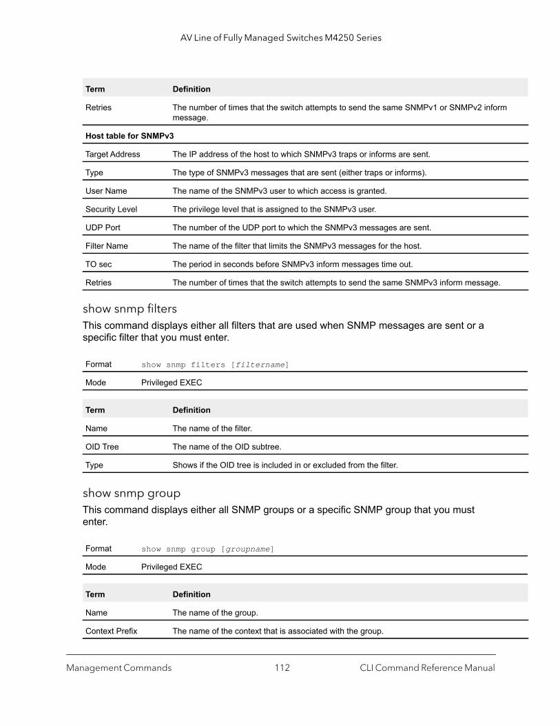
AV Line of Fully Managed Switches M4250 Series
show snmp filtersThis command displays either all filters that are used when SNMP messages are sent or a specific filter that you must enter.
show snmp groupThis command displays either all SNMP groups or a specific SNMP group that you must enter.
Retries The number of times that the switch attempts to send the same SNMPv1 or SNMPv2 informmessage.
Host table for SNMPv3
Target Address The IP address of the host to which SNMPv3 traps or informs are sent.
Type The type of SNMPv3 messages that are sent (either traps or informs).
User Name The name of the SNMPv3 user to which access is granted.
Security Level The privilege level that is assigned to the SNMPv3 user.
UDP Port The number of the UDP port to which the SNMPv3 messages are sent.
Filter Name The name of the filter that limits the SNMPv3 messages for the host.
TO sec The period in seconds before SNMPv3 inform messages time out.
Retries The number of times that the switch attempts to send the same SNMPv3 inform message.
Format show snmp filters [filtername]
Mode Privileged EXEC
Term Definition
Name The name of the filter.
OID Tree The name of the OID subtree.
Type Shows if the OID tree is included in or excluded from the filter.
Format show snmp group [groupname]
Mode Privileged EXEC
Term Definition
Name The name of the group.
Context Prefix The name of the context that is associated with the group.
Term Definition
Management Commands CLI Command Reference Manual112
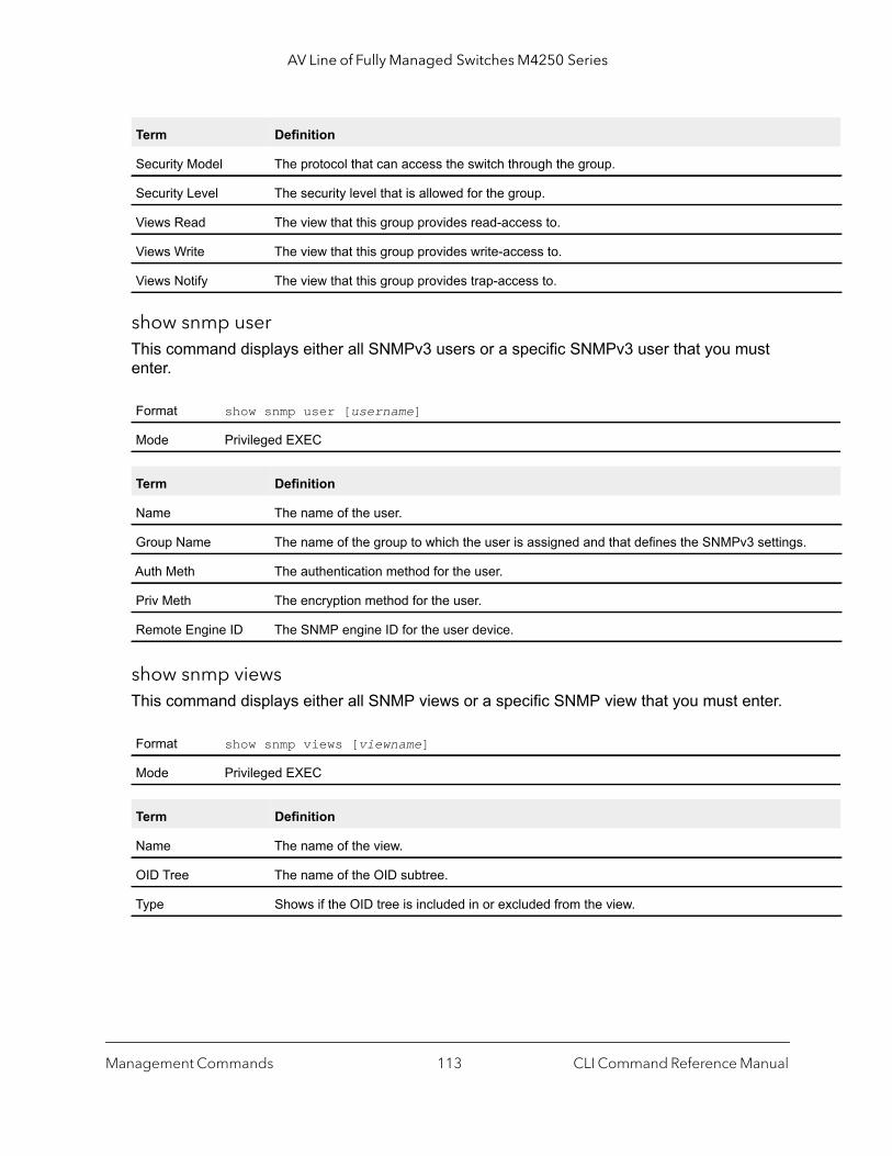
AV Line of Fully Managed Switches M4250 Series
.
show snmp userThis command displays either all SNMPv3 users or a specific SNMPv3 user that you must enter.
show snmp viewsThis command displays either all SNMP views or a specific SNMP view that you must enter.
Security Model The protocol that can access the switch through the group.
Security Level The security level that is allowed for the group.
Views Read The view that this group provides read-access to.
Views Write The view that this group provides write-access to.
Views Notify The view that this group provides trap-access to.
Format show snmp user [username]
Mode Privileged EXEC
Term Definition
Name The name of the user.
Group Name The name of the group to which the user is assigned and that defines the SNMPv3 settings
Auth Meth The authentication method for the user.
Priv Meth The encryption method for the user.
Remote Engine ID The SNMP engine ID for the user device.
Format show snmp views [viewname]
Mode Privileged EXEC
Term Definition
Name The name of the view.
OID Tree The name of the OID subtree.
Type Shows if the OID tree is included in or excluded from the view.
Term Definition
Management Commands CLI Command Reference Manual113

AV Line of Fully Managed Switches M4250 Series
ailure
will
nt gh
aps
ent.
ent.
show trapflagsThis command displays the trap conditions. The command output shows all enabled trap flags.
Note: You can configure which traps the switch must generate by enabling or disabling the trap condition. If a trap condition is enabled and the condition is detected, the SNMP agent on the switch sends the trap to all enabled trap receivers. Cold and warm start traps are always generated and cannot be disabled.
Format show trapflags
Mode Privileged EXEC
Term Definition
Authentication Flag Can be enabled or disabled. The factory default is enabled. Indicates whether authentication ftraps will be sent.
Link Up/Down Flag Can be enabled or disabled. The factory default is enabled. Indicates whether link status trapsbe sent.
Multiple Users Flag Can be enabled or disabled. The factory default is enabled. Indicates whether a trap will be sewhen the same user ID is logged into the switch more than once at the same time (either throuTelnet or the serial port).
Spanning Tree Flag
Can be enabled or disabled. The factory default is enabled. Indicates whether spanning tree trare sent.
ACL Traps May be enabled or disabled. The factory default is disabled. Indicates whether ACL traps are s
PIM Traps Can be enabled or disabled. The factory default is disabled. Indicates whether PIM traps are s
Management Commands CLI Command Reference Manual114
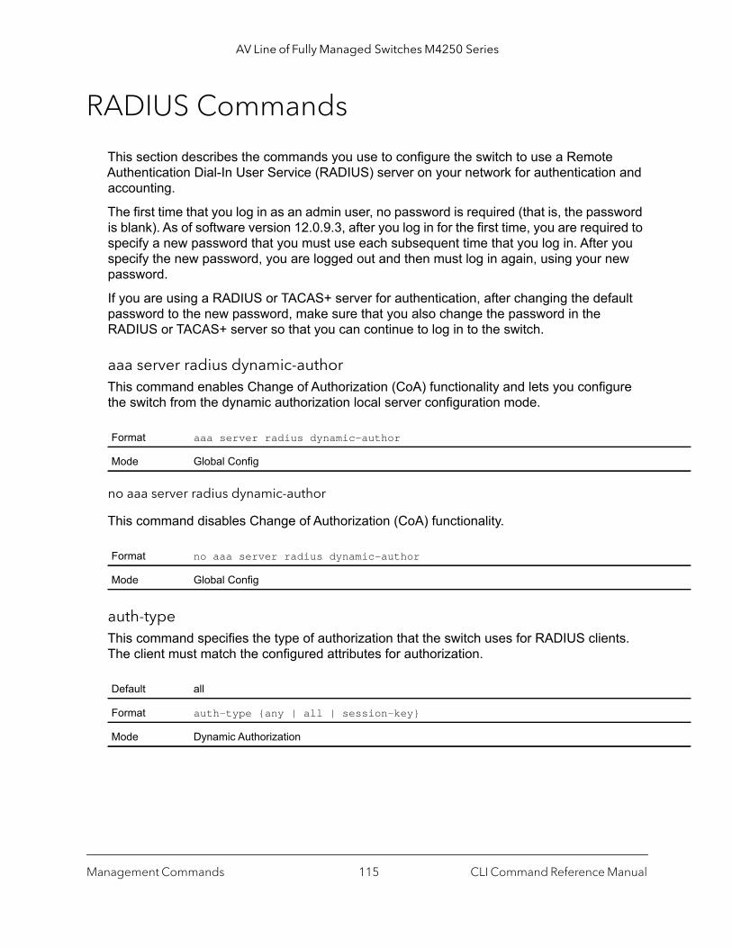
AV Line of Fully Managed Switches M4250 Series
RADIUS Commands
This section describes the commands you use to configure the switch to use a Remote Authentication Dial-In User Service (RADIUS) server on your network for authentication and accounting.
The first time that you log in as an admin user, no password is required (that is, the password is blank). As of software version 12.0.9.3, after you log in for the first time, you are required to specify a new password that you must use each subsequent time that you log in. After you specify the new password, you are logged out and then must log in again, using your new password.
If you are using a RADIUS or TACAS+ server for authentication, after changing the default password to the new password, make sure that you also change the password in the RADIUS or TACAS+ server so that you can continue to log in to the switch.
aaa server radius dynamic-authorThis command enables Change of Authorization (CoA) functionality and lets you configure the switch from the dynamic authorization local server configuration mode.
no aaa server radius dynamic-author
This command disables Change of Authorization (CoA) functionality.
auth-typeThis command specifies the type of authorization that the switch uses for RADIUS clients. The client must match the configured attributes for authorization.
Format aaa server radius dynamic-author
Mode Global Config
Format no aaa server radius dynamic-author
Mode Global Config
Default all
Format auth-type {any | all | session-key}
Mode Dynamic Authorization
Management Commands CLI Command Reference Manual115
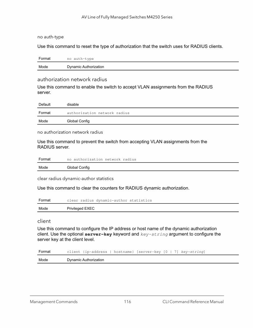
AV Line of Fully Managed Switches M4250 Series
no auth-type
Use this command to reset the type of authorization that the switch uses for RADIUS clients.
authorization network radiusUse this command to enable the switch to accept VLAN assignments from the RADIUS server.
no authorization network radius
Use this command to prevent the switch from accepting VLAN assignments from the RADIUS server.
clear radius dynamic-author statistics
Use this command to clear the counters for RADIUS dynamic authorization.
clientUse this command to configure the IP address or host name of the dynamic authorization client. Use the optional server-key keyword and key-string argument to configure the server key at the client level.
Format no auth-type
Mode Dynamic Authorization
Default disable
Format authorization network radius
Mode Global Config
Format no authorization network radius
Mode Global Config
Format clear radius dynamic-author statistics
Mode Privileged EXEC
Format client {ip-address | hostname} [server-key [0 | 7] key-string]
Mode Dynamic Authorization
Management Commands CLI Command Reference Manual116
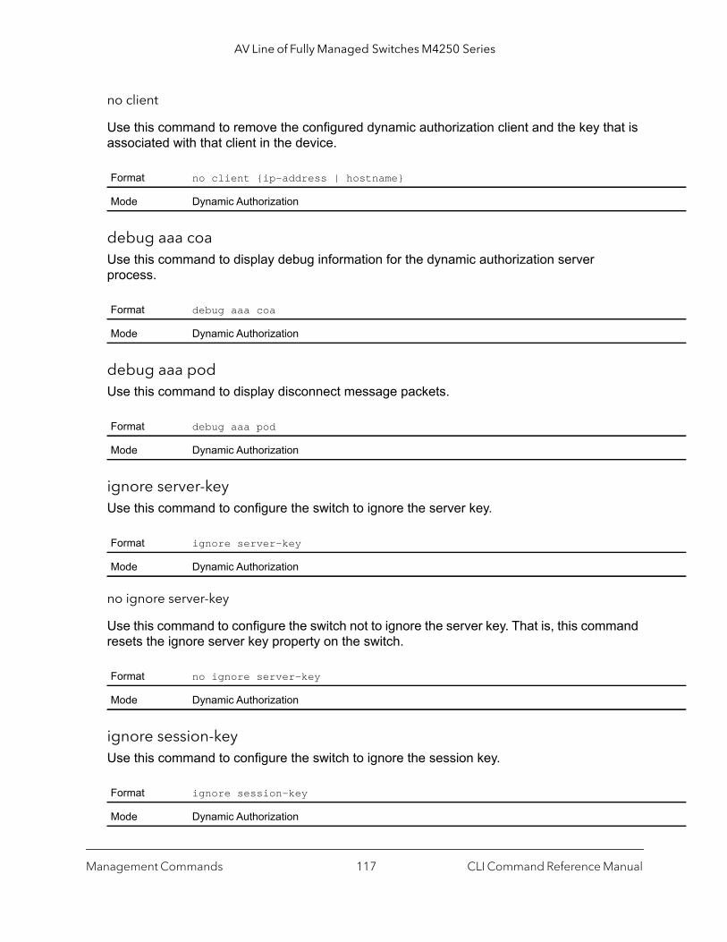
AV Line of Fully Managed Switches M4250 Series
no client
Use this command to remove the configured dynamic authorization client and the key that is associated with that client in the device.
debug aaa coaUse this command to display debug information for the dynamic authorization server process.
debug aaa podUse this command to display disconnect message packets.
ignore server-keyUse this command to configure the switch to ignore the server key.
no ignore server-key
Use this command to configure the switch not to ignore the server key. That is, this command resets the ignore server key property on the switch.
ignore session-keyUse this command to configure the switch to ignore the session key.
Format no client {ip-address | hostname}
Mode Dynamic Authorization
Format debug aaa coa
Mode Dynamic Authorization
Format debug aaa pod
Mode Dynamic Authorization
Format ignore server-key
Mode Dynamic Authorization
Format no ignore server-key
Mode Dynamic Authorization
Format ignore session-key
Mode Dynamic Authorization
Management Commands CLI Command Reference Manual117
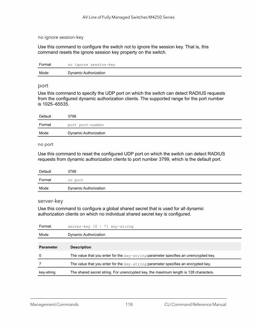
AV Line of Fully Managed Switches M4250 Series
no ignore session-key
Use this command to configure the switch not to ignore the session key. That is, this command resets the ignore session key property on the switch.
portUse this command to specify the UDP port on which the switch can detect RADIUS requests from the configured dynamic authorization clients. The supported range for the port number is 1025–65535.
no port
Use this command to reset the configured UDP port on which the switch can detect RADIUS requests from dynamic authorization clients to port number 3799, which is the default port.
server-keyUse this command to configure a global shared secret that is used for all dynamic authorization clients on which no individual shared secret key is configured.
Format no ignore session-key
Mode Dynamic Authorization
Default 3799
Format port port-number
Mode Dynamic Authorization
Default 3799
Format no port
Mode Dynamic Authorization
Format server-key [0 | 7] key-string
Mode Dynamic Authorization
Parameter Description
0 The value that you enter for the key-string parameter specifies an unencrypted key.
7 The value that you enter for the key-string parameter specifies an encrypted key.
key-string The shared secret string. For unencrypted key, the maximum length is 128 characters.
Management Commands CLI Command Reference Manual118
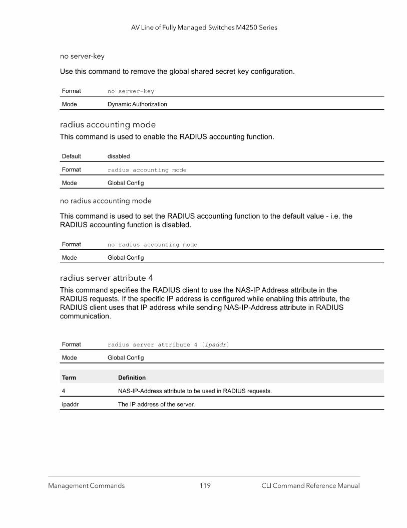
AV Line of Fully Managed Switches M4250 Series
no server-key
Use this command to remove the global shared secret key configuration.
radius accounting modeThis command is used to enable the RADIUS accounting function.
no radius accounting mode
This command is used to set the RADIUS accounting function to the default value - i.e. the RADIUS accounting function is disabled.
radius server attribute 4This command specifies the RADIUS client to use the NAS-IP Address attribute in the RADIUS requests. If the specific IP address is configured while enabling this attribute, the RADIUS client uses that IP address while sending NAS-IP-Address attribute in RADIUS communication.
Format no server-key
Mode Dynamic Authorization
Default disabled
Format radius accounting mode
Mode Global Config
Format no radius accounting mode
Mode Global Config
Format radius server attribute 4 [ipaddr]
Mode Global Config
Term Definition
4 NAS-IP-Address attribute to be used in RADIUS requests.
ipaddr The IP address of the server.
Management Commands CLI Command Reference Manual119

AV Line of Fully Managed Switches M4250 Series
no radius server attribute 4
The no radius server attribute 4 command disables the NAS-IP-Address attribute global parameter for RADIUS client. When this parameter is disabled, the RADIUS client does not send the NAS-IP-Address attribute in RADIUS requests.
Command example: (NETGEAR Switch) (Config) #radius server attribute 4 192.168.37.60(NETGEAR Switch) (Config) #radius server attribute 4
radius server hostThis command configures the IP address or DNS name to use for communicating with the RADIUS server of a selected server type. While configuring the IP address or DNS name for the authenticating or accounting servers, you can also configure the port number and server name. If the authenticating and accounting servers are configured without a name, the command uses the Default_RADIUS_Auth_Server and Default_RADIUS_Acct_Server as the default names, respectively. The same name can be configured for more than one authenticating servers and the name should be unique for accounting servers. The RADIUS client allows the configuration of a maximum 32 authenticating and accounting servers.
If you use the auth parameter, the command configures the IP address or host name to use to connect to a RADIUS authentication server. You can configure up to three servers per RADIUS client. If the maximum number of configured servers is reached, the command fails until you remove one of the servers by issuing the no form of the command. If you use the optional port parameter, the command configures the UDP port number to use when connecting to the configured RADIUS server. For the port keyword, the number argument must be a value in the range 0–65535, with 1813 being the default.
Note: To reconfigure a RADIUS authentication server to use the default UDP port, set the number argument to 1812.
If you use the acct token, the command configures the IP address or host name to use for the RADIUS accounting server. You can only configure one accounting server. If an accounting server is currently configured, use the no form of the command to remove it from the configuration. The IP address or host name you specify must match that of a previously configured accounting server. If you use the optional port parameter, the command configures the UDP port to use when connecting to the RADIUS accounting server. If a port is already configured for the accounting server, the new port replaces the previously configured port. For the port keyword, the number argument must be a value in the range 0–65535, with 1813 being the default.
Format no radius server attribute 4 [ipaddr]
Mode Global Config
Management Commands CLI Command Reference Manual120

AV Line of Fully Managed Switches M4250 Series
rt
Note: To reconfigure a RADIUS accounting server to use the default UDP port, set the number argument to 1813.
no radius server host
The no radius server host command deletes the configured server entry from the list of configured RADIUS servers. If the RADIUS authenticating server being removed is the active server in the servers that are identified by the same server name, then the RADIUS client selects another server for making RADIUS transactions. If the 'auth' token is used, the previously configured RADIUS authentication server is removed from the configuration. Similarly, if the 'acct' token is used, the previously configured RADIUS accounting server is removed from the configuration. The ipaddr or dnsname argument must match the IP address or DNS name of the previously configured RADIUS authentication or accounting server.
Command example: (NETGEAR Switch) (Config) #radius server host acct 192.168.37.60(NETGEAR Switch) (Config) #radius server host acct 192.168.37.60 port 1813(NETGEAR Switch) (Config) #radius server host auth 192.168.37.60 name Network1_RS port 1813(NETGEAR Switch) (Config) #radius server host acct 192.168.37.60 name Network2_RS(NETGEAR Switch) (Config) #no radius server host acct 192.168.37.60
Format radius server host {auth | acct} {ipaddr | dnsname} [name servername] [ponumber] [type server-type]
Mode Global Config
Field Description
ipaddr The IP address of the server.
dnsname The DNS name of the server.
0-65535 The port number that is used to connect to the specified RADIUS server.
servername The alias name to identify the server.
server-type Enter one of the following options:• 0. Specifies a standard server.• 1. Specifies a NETGEAR server.
Format no radius server host {auth | acct} {ipaddr | dnsname}
Mode Global Config
Management Commands CLI Command Reference Manual121

AV Line of Fully Managed Switches M4250 Series
radius server keyThis command configures the key to be used in RADIUS client communication with the specified server. Depending on whether the auth or acct token is used, the shared secret is configured for the RADIUS authentication or RADIUS accounting server. The IP address or hostname provided must match a previously configured server. When this command is executed, the secret is prompted.
Text-based configuration supports Radius server’s secrets in encrypted and non-encrypted format. When you save the configuration, these secret keys are stored in encrypted format only. If you want to enter the key in encrypted format, enter the key along with the encrypted keyword. In the output of the show running-config command (for information about the command, see show running-config on page 174), these secret keys are displayed in encrypted format. You cannot show these keys in plain text format.
Note: The secret must be an alphanumeric value not exceeding 16 characters.
radius server key acct 10.240.4.10 encrypted encrypt-string
radius server msgauthThis command enables the message authenticator attribute to be used for the specified RADIUS Authenticating server.
Format radius server key {auth | acct} {ipaddr | dnsname} encrypted password
Mode Global Config
Field Description
ipaddr The IP address of the server.
dnsname The DNS name of the server.
password The password in encrypted format.
Format radius server msgauth [ipaddr | dnsname]
Mode Global Config
Field Description
ip addr The IP address of the server.
dnsname The DNS name of the server.
Management Commands CLI Command Reference Manual122

AV Line of Fully Managed Switches M4250 Series
no radius server msgauth
The no version of this command disables the message authenticator attribute to be used for the specified RADIUS Authenticating server.
radius server primaryThis command specifies a configured server that should be the primary server in the group of servers which have the same server name. Multiple primary servers can be configured for each number of servers that have the same name. When the RADIUS client has to perform transactions with an authenticating RADIUS server of specified name, the client uses the primary server that has the specified server name by default. If the RADIUS client fails to communicate with the primary server for any reason, the client uses the backup servers configured with the same server name. These backup servers are identified as the Secondary type.
radius server retransmitThis command configures the global parameter for the RADIUS client that specifies the number of transmissions of the messages to be made before attempting the fall back server upon unsuccessful communication with the current RADIUS authenticating server. When the maximum number of retries are exhausted for the RADIUS accounting server and no response is received, the client does not communicate with any other server.
Format no radius server msgauth [ipaddr | dnsname]
Mode Global Config
Format radius server primary {ipaddr | dnsname}
Mode Global Config
Field Description
ip addr The IP address of the RADIUS Authenticating server.
dnsname The DNS name of the server.
Default 4
Format radius server retransmit retries
Mode Global Config
Field Description
retries The maximum number of transmission attempts in the range of 1 to 15.
Management Commands CLI Command Reference Manual123
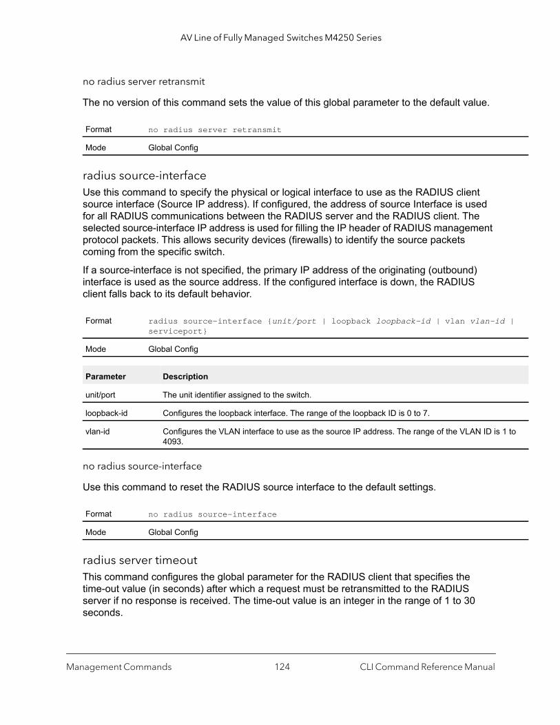
AV Line of Fully Managed Switches M4250 Series
|
to
no radius server retransmit
The no version of this command sets the value of this global parameter to the default value.
radius source-interfaceUse this command to specify the physical or logical interface to use as the RADIUS client source interface (Source IP address). If configured, the address of source Interface is used for all RADIUS communications between the RADIUS server and the RADIUS client. The selected source-interface IP address is used for filling the IP header of RADIUS management protocol packets. This allows security devices (firewalls) to identify the source packets coming from the specific switch.
If a source-interface is not specified, the primary IP address of the originating (outbound) interface is used as the source address. If the configured interface is down, the RADIUS client falls back to its default behavior.
no radius source-interface
Use this command to reset the RADIUS source interface to the default settings.
radius server timeoutThis command configures the global parameter for the RADIUS client that specifies the time-out value (in seconds) after which a request must be retransmitted to the RADIUS server if no response is received. The time-out value is an integer in the range of 1 to 30 seconds.
Format no radius server retransmit
Mode Global Config
Format radius source-interface {unit/port | loopback loopback-id | vlan vlan-idserviceport}
Mode Global Config
Parameter Description
unit/port The unit identifier assigned to the switch.
loopback-id Configures the loopback interface. The range of the loopback ID is 0 to 7.
vlan-id Configures the VLAN interface to use as the source IP address. The range of the VLAN ID is 14093.
Format no radius source-interface
Mode Global Config
Management Commands CLI Command Reference Manual124
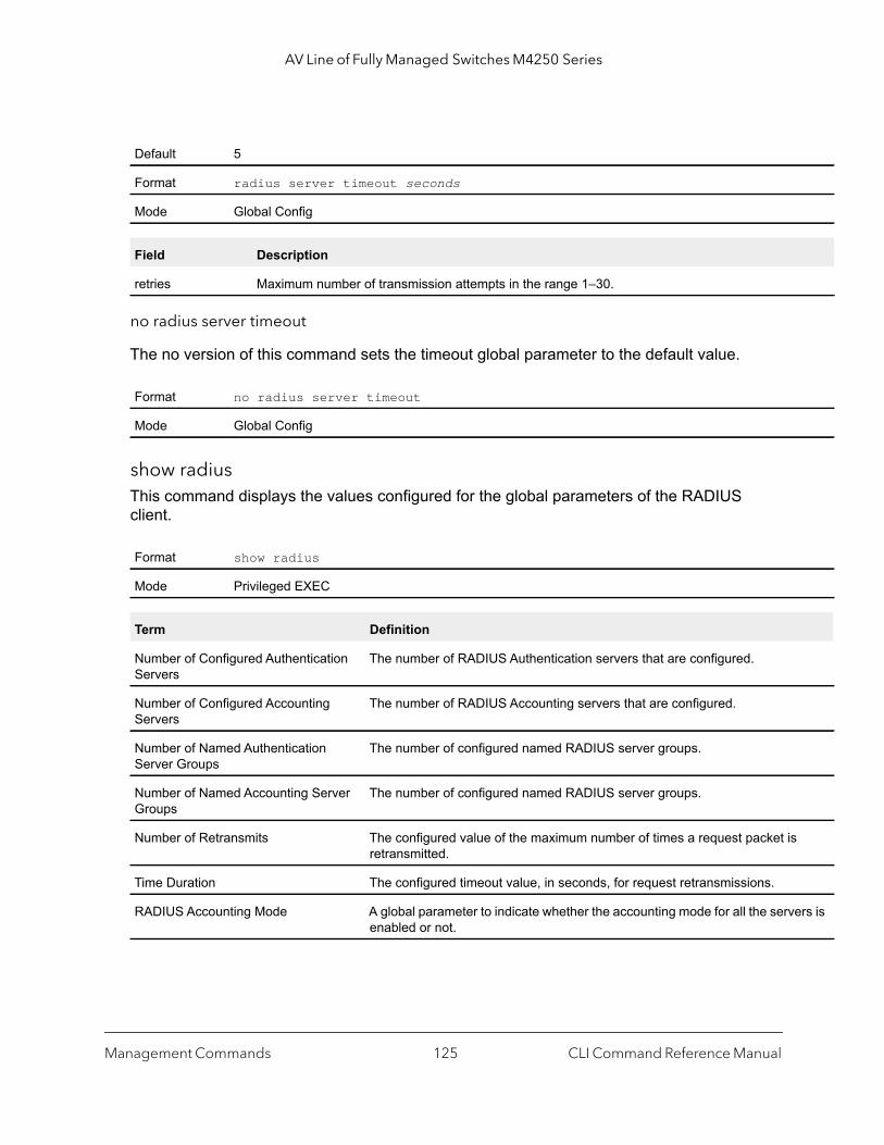
AV Line of Fully Managed Switches M4250 Series
ers is
no radius server timeout
The no version of this command sets the timeout global parameter to the default value.
show radiusThis command displays the values configured for the global parameters of the RADIUS client.
Default 5
Format radius server timeout seconds
Mode Global Config
Field Description
retries Maximum number of transmission attempts in the range 1–30.
Format no radius server timeout
Mode Global Config
Format show radius
Mode Privileged EXEC
Term Definition
Number of Configured Authentication Servers
The number of RADIUS Authentication servers that are configured.
Number of Configured Accounting Servers
The number of RADIUS Accounting servers that are configured.
Number of Named Authentication Server Groups
The number of configured named RADIUS server groups.
Number of Named Accounting Server Groups
The number of configured named RADIUS server groups.
Number of Retransmits The configured value of the maximum number of times a request packet isretransmitted.
Time Duration The configured timeout value, in seconds, for request retransmissions.
RADIUS Accounting Mode A global parameter to indicate whether the accounting mode for all the servenabled or not.
Management Commands CLI Command Reference Manual125
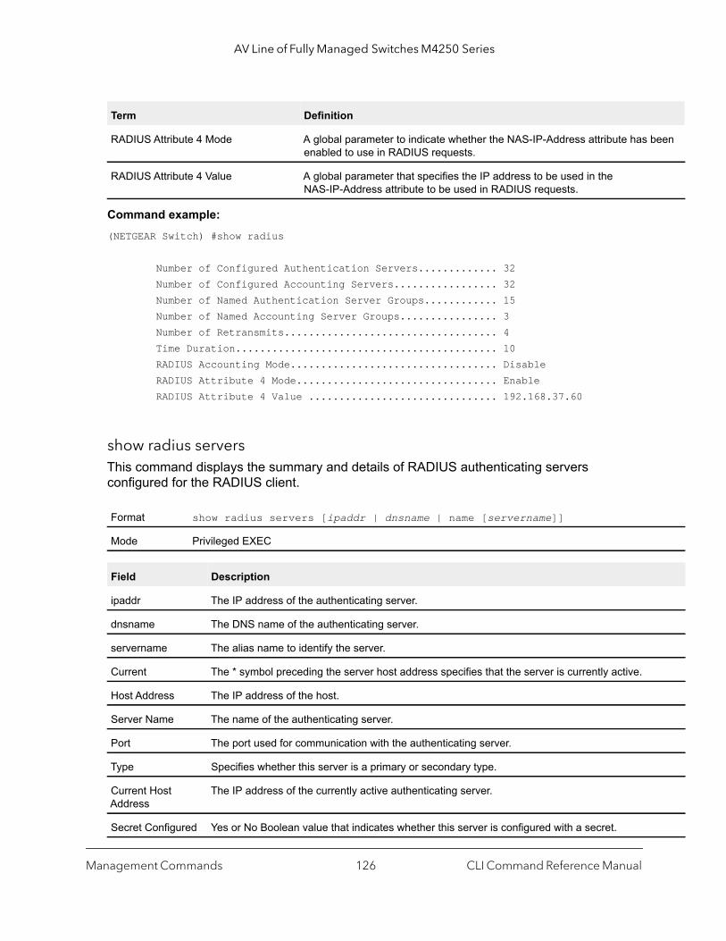
AV Line of Fully Managed Switches M4250 Series
een
Command example: (NETGEAR Switch) #show radius
Number of Configured Authentication Servers............. 32 Number of Configured Accounting Servers................. 32 Number of Named Authentication Server Groups............ 15 Number of Named Accounting Server Groups................ 3 Number of Retransmits................................... 4 Time Duration........................................... 10 RADIUS Accounting Mode.................................. Disable RADIUS Attribute 4 Mode................................. Enable RADIUS Attribute 4 Value ............................... 192.168.37.60
show radius serversThis command displays the summary and details of RADIUS authenticating servers configured for the RADIUS client.
RADIUS Attribute 4 Mode A global parameter to indicate whether the NAS-IP-Address attribute has benabled to use in RADIUS requests.
RADIUS Attribute 4 Value A global parameter that specifies the IP address to be used in the NAS-IP-Address attribute to be used in RADIUS requests.
Format show radius servers [ipaddr | dnsname | name [servername]]
Mode Privileged EXEC
Field Description
ipaddr The IP address of the authenticating server.
dnsname The DNS name of the authenticating server.
servername The alias name to identify the server.
Current The * symbol preceding the server host address specifies that the server is currently active.
Host Address The IP address of the host.
Server Name The name of the authenticating server.
Port The port used for communication with the authenticating server.
Type Specifies whether this server is a primary or secondary type.
Current Host Address
The IP address of the currently active authenticating server.
Secret Configured Yes or No Boolean value that indicates whether this server is configured with a secret.
Term Definition
Management Commands CLI Command Reference Manual126
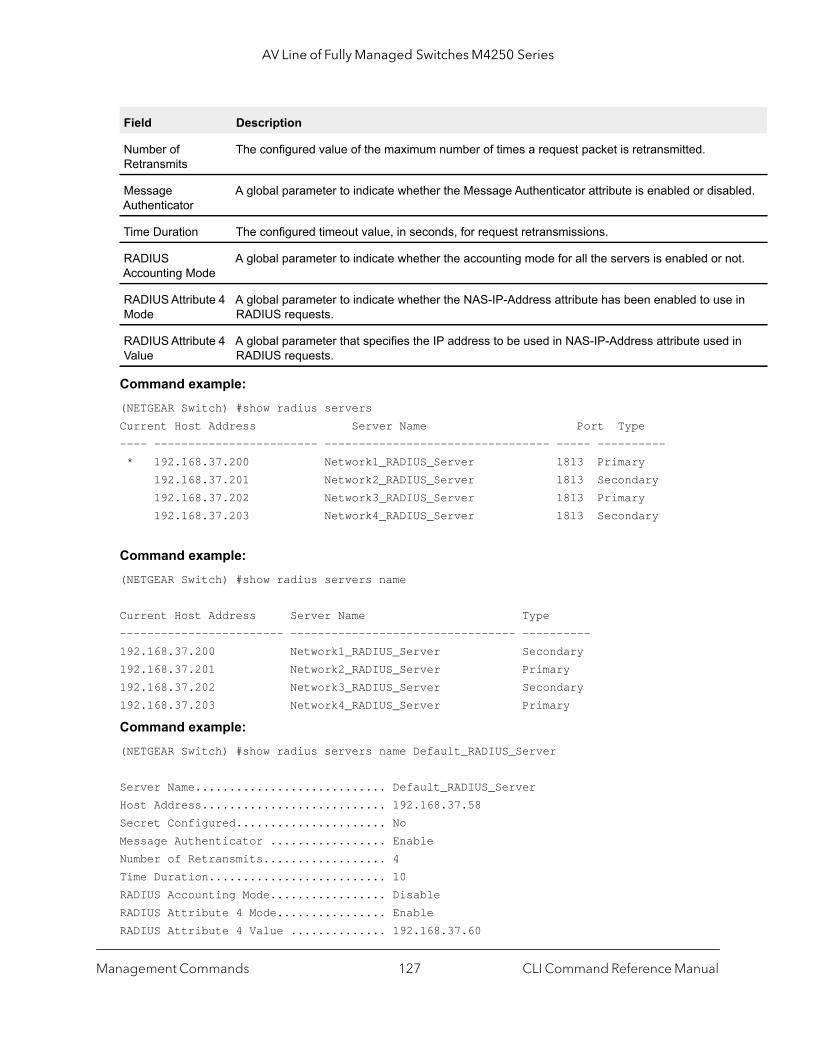
AV Line of Fully Managed Switches M4250 Series
bled.
ot.
in
in
Command example: (NETGEAR Switch) #show radius serversCurrent Host Address Server Name Port Type ---- ------------------------ --------------------------------- ----- ---------- * 192.168.37.200 Network1_RADIUS_Server 1813 Primary 192.168.37.201 Network2_RADIUS_Server 1813 Secondary 192.168.37.202 Network3_RADIUS_Server 1813 Primary 192.168.37.203 Network4_RADIUS_Server 1813 Secondary
Command example: (NETGEAR Switch) #show radius servers name
Current Host Address Server Name Type ------------------------ --------------------------------- ----------192.168.37.200 Network1_RADIUS_Server Secondary192.168.37.201 Network2_RADIUS_Server Primary192.168.37.202 Network3_RADIUS_Server Secondary192.168.37.203 Network4_RADIUS_Server Primary
Command example: (NETGEAR Switch) #show radius servers name Default_RADIUS_Server
Server Name............................ Default_RADIUS_ServerHost Address........................... 192.168.37.58Secret Configured...................... NoMessage Authenticator ................. EnableNumber of Retransmits.................. 4Time Duration.......................... 10RADIUS Accounting Mode................. DisableRADIUS Attribute 4 Mode................ EnableRADIUS Attribute 4 Value .............. 192.168.37.60
Number of Retransmits
The configured value of the maximum number of times a request packet is retransmitted.
Message Authenticator
A global parameter to indicate whether the Message Authenticator attribute is enabled or disa
Time Duration The configured timeout value, in seconds, for request retransmissions.
RADIUS Accounting Mode
A global parameter to indicate whether the accounting mode for all the servers is enabled or n
RADIUS Attribute 4 Mode
A global parameter to indicate whether the NAS-IP-Address attribute has been enabled to useRADIUS requests.
RADIUS Attribute 4 Value
A global parameter that specifies the IP address to be used in NAS-IP-Address attribute usedRADIUS requests.
Field Description
Management Commands CLI Command Reference Manual127
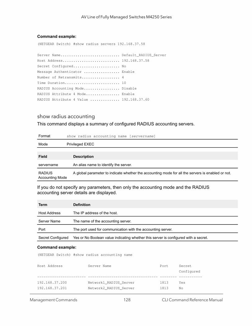
AV Line of Fully Managed Switches M4250 Series
ot.
Command example: (NETGEAR Switch) #show radius servers 192.168.37.58
Server Name............................ Default_RADIUS_ServerHost Address........................... 192.168.37.58Secret Configured...................... NoMessage Authenticator ................. EnableNumber of Retransmits.................. 4Time Duration.......................... 10RADIUS Accounting Mode................. DisableRADIUS Attribute 4 Mode................ EnableRADIUS Attribute 4 Value .............. 192.168.37.60
show radius accountingThis command displays a summary of configured RADIUS accounting servers.
If you do not specify any parameters, then only the accounting mode and the RADIUS accounting server details are displayed.
Command example: (NETGEAR Switch) #show radius accounting name
Host Address Server Name Port Secret Configured----------------------- --------------------------------- -------- -----------192.168.37.200 Network1_RADIUS_Server 1813 Yes192.168.37.201 Network2_RADIUS_Server 1813 No
Format show radius accounting name [servername]
Mode Privileged EXEC
Field Description
servername An alias name to identify the server.
RADIUS Accounting Mode
A global parameter to indicate whether the accounting mode for all the servers is enabled or n
Term Definition
Host Address The IP address of the host.
Server Name The name of the accounting server.
Port The port used for communication with the accounting server.
Secret Configured Yes or No Boolean value indicating whether this server is configured with a secret.
Management Commands CLI Command Reference Manual128

AV Line of Fully Managed Switches M4250 Series
this
This
is
is
ed th. ded
192.168.37.202 Network3_RADIUS_Server 1813 Yes192.168.37.203 Network4_RADIUS_Server 1813 No
Command example: (NETGEAR Switch) #show radius accounting name Default_RADIUS_Server
Server Name............................ Default_RADIUS_ServerHost Address........................... 192.168.37.200RADIUS Accounting Mode................. DisablePort .................................. 1813Secret Configured ..................... Yes
show radius accounting statisticsThis command displays a summary of statistics for the configured RADIUS accounting servers.
Format show radius accounting statistics {ipaddr | dnsname | name servername}
Mode Privileged EXEC
Term Definition
ipaddr The IP address of the server.
dnsname The DNS name of the server.
servername The alias name to identify the server.
RADIUS Accounting Server Name The name of the accounting server.
Server Host Address The IP address of the host.
Round Trip Time The time interval, in hundredths of a second, between the most recent Accounting-Response and the Accounting-Request that matched it from RADIUS accounting server.
Requests The number of RADIUS Accounting-Request packets sent to this server.number does not include retransmissions.
Retransmission The number of RADIUS Accounting-Request packets retransmitted to thRADIUS accounting server.
Responses The number of RADIUS packets received on the accounting port from thserver.
Malformed Responses The number of malformed RADIUS Accounting-Response packets receivfrom this server. Malformed packets include packets with an invalid lengBad authenticators or signature attributes or unknown types are not incluas malformed accounting responses.
Bad Authenticators The number of RADIUS Accounting-Response packets containing invalidauthenticators received from this accounting server.
Management Commands CLI Command Reference Manual129

AV Line of Fully Managed Switches M4250 Series
that
from
ting
Command example: (NETGEAR Switch) #show radius accounting statistics 192.168.37.200
RADIUS Accounting Server Name................. Default_RADIUS_ServerHost Address.................................. 192.168.37.200Round Trip Time............................... 0.00Requests...................................... 0Retransmissions............................... 0Responses..................................... 0Malformed Responses........................... 0Bad Authenticators............................ 0Pending Requests.............................. 0Timeouts...................................... 0Unknown Types................................. 0Packets Dropped............................... 0
Command example: (NETGEAR Switch) #show radius accounting statistics name Default_RADIUS_Server
RADIUS Accounting Server Name................. Default_RADIUS_ServerHost Address.................................. 192.168.37.200Round Trip Time............................... 0.00Requests...................................... 0Retransmissions............................... 0Responses..................................... 0Malformed Responses........................... 0Bad Authenticators............................ 0Pending Requests.............................. 0Timeouts...................................... 0Unknown Types................................. 0Packets Dropped............................... 0
Pending Requests The number of RADIUS Accounting-Request packets sent to this server have not yet timed out or received a response.
Timeouts The number of accounting timeouts to this server.
Unknown Types The number of RADIUS packets of unknown types, which were receivedthis server on the accounting port.
Packets Dropped The number of RADIUS packets received from this server on the accounport and dropped for some other reason.
Term Definition
Management Commands CLI Command Reference Manual130

AV Line of Fully Managed Switches M4250 Series
lude
were
were
hat
rmed
show radius source-interfaceUse this command in Privileged EXEC mode to display the configured RADIUS client source-interface (Source IP address) information.
Command example: (NETGEAR Switch)# show radius source-interfaceRADIUS Client Source Interface.............. (not configured)
show radius statisticsThis command displays the summary statistics of configured RADIUS Authenticating servers.
Format show radius source-interface
Mode Privileged Exec
Format show radius statistics {ipaddr | dnsname | name servername}
Mode Privileged EXEC
Term Definition
ipaddr The IP address of the server.
dnsname The DNS name of the server.
servername The alias name to identify the server.
RADIUS Server Name
The name of the authenticating server.
Server Host Address
The IP address of the host.
Access Requests The number of RADIUS Access-Request packets sent to this server. This number does not incretransmissions.
Access Retransmissions
The number of RADIUS Access-Request packets retransmitted to this RADIUS authenticationserver.
Access Accepts The number of RADIUS Access-Accept packets, including both valid and invalid packets, that received from this server.
Access Rejects The number of RADIUS Access-Reject packets, including both valid and invalid packets, that received from this server.
Access Challenges The number of RADIUS Access-Challenge packets, including both valid and invalid packets, twere received from this server.
Malformed Access Responses
The number of malformed RADIUS Access-Response packets received from this server. Malfopackets include packets with an invalid length. Bad authenticators or signature attributes or unknown types are not included as malformed access responses.
Management Commands CLI Command Reference Manual131

AV Line of Fully Managed Switches M4250 Series
re
d out
tion
ed for
Command example: (NETGEAR Switch) #show radius statistics 192.168.37.200 RADIUS Server Name............................ Default_RADIUS_ServerServer Host Address........................... 192.168.37.200Access Requests............................... 0.00Access Retransmissions........................ 0Access Accepts................................ 0Access Rejects................................ 0Access Challenges............................. 0Malformed Access Responses.................... 0Bad Authenticators............................ 0Pending Requests.............................. 0Timeouts...................................... 0Unknown Types................................. 0Packets Dropped............................... 0
Command example: (NETGEAR Switch) #show radius statistics name Default_RADIUS_ServerRADIUS Server Name............................ Default_RADIUS_ServerServer Host Address........................... 192.168.37.200Access Requests............................... 0.00Access Retransmissions........................ 0Access Accepts................................ 0Access Rejects................................ 0Access Challenges............................. 0Malformed Access Responses.................... 0Bad Authenticators............................ 0Pending Requests.............................. 0Timeouts...................................... 0Unknown Types................................. 0Packets Dropped............................... 0
Bad Authenticators The number of RADIUS Access-Response packets containing invalid authenticators or signatuattributes received from this server.
Pending Requests The number of RADIUS Access-Request packets destined for this server that have not yet timeor received a response.
Timeouts The number of authentication timeouts to this server.
Unknown Types The number of packets of unknown type that were received from this server on the authenticaport.
Packets Dropped The number of RADIUS packets received from this server on the authentication port and droppsome other reason.
Term Definition
Management Commands CLI Command Reference Manual132

AV Line of Fully Managed Switches M4250 Series
TACACS+ Commands
TACACS+ provides access control for networked devices via one or more centralized servers. Similar to RADIUS, this protocol simplifies authentication by making use of a single database that can be shared by many clients on a large network. TACACS+ is based on the TACACS protocol (described in RFC1492) but additionally provides for separate authentication, authorization, and accounting services. The original protocol was UDP based with messages passed in clear text over the network; TACACS+ uses TCP to ensure reliable delivery and a shared key configured on the client and server to encrypt all messages.
The first time that you log in as an admin user, no password is required (that is, the password is blank). As of software version 12.0.9.3, after you log in for the first time, you are required to specify a new password that you must use each subsequent time that you log in. After you specify the new password, you are logged out and then must log in again, using your new password.
If you are using a RADIUS or TACAS+ server for authentication, after changing the default password to the new password, make sure that you also change the password in the RADIUS or TACAS+ server so that you can continue to log in to the switch.
tacacs-server hostUse the tacacs-server host command in Global Configuration mode to configure a TACACS+ server. This command enters into the TACACS+ configuration mode. The ip-address or hostname argument is the IP address or host name of the TACACS+ server. To specify multiple hosts, multiple tacacs-server host commands can be used.
no tacacs-server host
Use the no tacacs-server host command to delete the specified hostname or IP address. The ip-address or hostname argument is the IP address or host name of the TACACS+ server.
tacacs-server keyUse the tacacs-server key command to set the authentication and encryption key for all TACACS+ communications between the switch and the TACACS+ daemon. The key-string parameter has a range of 0–128 characters and specifies the authentication and encryption key for all TACACS communications between the switch and the TACACS+ server. This key must match the key used on the TACACS+ daemon.
Format tacacs-server host {ip-address | hostname}
Mode Global Config
Format no tacacs-server host {ip-address | hostname}
Mode Global Config
Management Commands CLI Command Reference Manual133

AV Line of Fully Managed Switches M4250 Series
Text-based configuration supports TACACS server’s secrets in encrypted and non-encrypted format. When you save the configuration, these secret keys are stored in encrypted format only. If you want to enter the key in encrypted format, enter the key along with the encrypted keyword. In the output of the show running-config command (for information about the command, see show running-config on page 174), these secret keys are displayed in encrypted format. You cannot show these keys in plain text format.
no tacacs-server key
Use the no tacacs-server key command to disable the authentication and encryption key for all TACACS+ communications between the switch and the TACACS+ daemon. The key-string parameter has a range of 0–128 characters This key must match the key used on the TACACS+ daemon.
tacacs-server keystringUse the tacacs-server keystring command to set the global authentication encryption key used for all TACACS+ communications between the TACACS+ server and the client.
Command example: (NETGEAR Switch)(Config)#tacacs-server keystringEnter tacacs key:********Re-enter tacacs key:********
tacacs-server source-interfaceUse this command in Global Configuration mode to configure the source interface (Source IP address) for TACACS+ server configuration. The selected source-interface IP address is used for filling the IP header of management protocol packets. This allows security devices (firewalls) to identify the source packets coming from the specific switch.
If a source-interface is not specified, the primary IP address of the originating (outbound) interface is used as the source address.
Format tacacs-server key [key-string | encrypted key-string]
Mode Global Config
Format no tacacs-server key key-string
Mode Global Config
Format tacacs-server keystring
Mode Global Config
Format tacacs-server source-interface {unit/port | loopback loopback-id | vlan vlan-id}
Mode Global Config
Management Commands CLI Command Reference Manual134
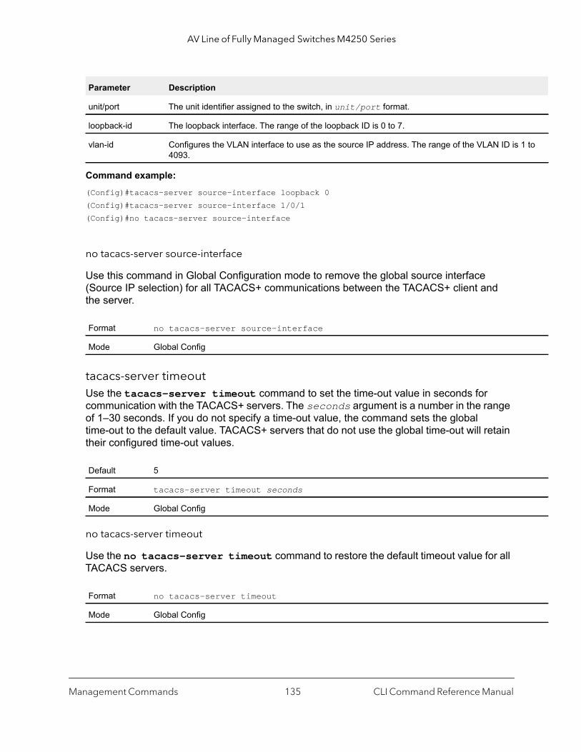
AV Line of Fully Managed Switches M4250 Series
to
Command example: (Config)#tacacs-server source-interface loopback 0 (Config)#tacacs-server source-interface 1/0/1(Config)#no tacacs-server source-interface
no tacacs-server source-interface
Use this command in Global Configuration mode to remove the global source interface (Source IP selection) for all TACACS+ communications between the TACACS+ client and the server.
tacacs-server timeoutUse the tacacs-server timeout command to set the time-out value in seconds for communication with the TACACS+ servers. The seconds argument is a number in the range of 1–30 seconds. If you do not specify a time-out value, the command sets the global time-out to the default value. TACACS+ servers that do not use the global time-out will retain their configured time-out values.
no tacacs-server timeout
Use the no tacacs-server timeout command to restore the default timeout value for all TACACS servers.
Parameter Description
unit/port The unit identifier assigned to the switch, in unit/port format.
loopback-id The loopback interface. The range of the loopback ID is 0 to 7.
vlan-id Configures the VLAN interface to use as the source IP address. The range of the VLAN ID is 14093.
Format no tacacs-server source-interface
Mode Global Config
Default 5
Format tacacs-server timeout seconds
Mode Global Config
Format no tacacs-server timeout
Mode Global Config
Management Commands CLI Command Reference Manual135

AV Line of Fully Managed Switches M4250 Series
key (TACACS Config)Use the key command in TACACS Configuration mode to specify the authentication and encryption key for all TACACS communications between the device and the TACACS server. This key must match the key used on the TACACS daemon. The key-string argument specifies the key name. For an empty string use “ ”. (Range: 0 - 128 characters).
Text-based configuration supports TACACS server’s secrets in encrypted and non-encrypted format. When you save the configuration, these secret keys are stored in encrypted format only. If you want to enter the key in encrypted format, enter the key along with the encrypted keyword. In the output of the show running-config command (for information about the command, see show running-config on page 174), these secret keys are displayed in encrypted format. You cannot show these keys in plain text format.
keystring (TACACS Config)Use the keystring command in TACACS Server Configuration mode to set the TACACS+ server-specific authentication encryption key used for all TACACS+ communications between the TACACS+ server and the client.
Command example: (NETGEAR Switch)(Config)#tacacs-server host 1.1.1.1(NETGEAR Switch)(Tacacs)#keystring
Enter tacacs key:********Re-enter tacacs key:********
port (TACACS Config)Use the port command in TACACS Configuration mode to specify a server port number. The server port-number argument is a number in the range 0–65535.
Format key [key-string | encrypted key-string]
Mode TACACS Config
Format keystring
Mode TACACS Server Config
Default 49
Format port port-number
Mode TACACS Config
Management Commands CLI Command Reference Manual136
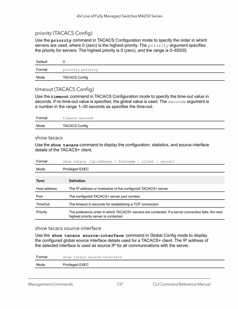
AV Line of Fully Managed Switches M4250 Series
next
priority (TACACS Config)Use the priority command in TACACS Configuration mode to specify the order in which servers are used, where 0 (zero) is the highest priority. The priority argument specifies the priority for servers. The highest priority is 0 (zero), and the range is 0–65535.
timeout (TACACS Config)Use the timeout command in TACACS Configuration mode to specify the time-out value in seconds. If no time-out value is specified, the global value is used. The seconds argument is a number in the range 1–30 seconds as specifies the time-out.
show tacacsUse the show tacacs command to display the configuration, statistics, and source interface details of the TACACS+ client.
show tacacs source-interfaceUse the show tacacs source-interface command in Global Config mode to display the configured global source interface details used for a TACACS+ client. The IP address of the selected interface is used as source IP for all communications with the server.
Default 0
Format priority priorityMode TACACS Config
Format timeout seconds
Mode TACACS Config
Format show tacacs [ip-address | hostname | client | server]
Mode Privileged EXEC
Term Definition
Host address The IP address or hostname of the configured TACACS+ server.
Port The configured TACACS+ server port number.
TimeOut The timeout in seconds for establishing a TCP connection.
Priority The preference order in which TACACS+ servers are contacted. If a server connection fails, thehighest priority server is contacted.
Format show tacacs source-interface
Mode Privileged EXEC
Management Commands CLI Command Reference Manual137

AV Line of Fully Managed Switches M4250 Series
Command example: (Config)# show tacacs source-interface
TACACS Client Source Interface : loopback 0TACACS Client Source IPv4 Address : 1.1.1.1 [UP]
Configuration Scripting Commands
Configuration Scripting allows you to generate text-formatted script files representing the current configuration of a system. You can upload these configuration script files to a PC or UNIX system and edit them. Then, you can download the edited files to the system and apply the new configuration. You can apply configuration scripts to one or more switches with no or minor modifications.
Use the show running-config command (see show running-config on page 174) to capture the running configuration into a script. Use the copy command (see copy on page 206) to transfer the configuration script to or from the switch.
Use the show command to view the configuration stored in the startup-config, backup-config, or factory-defaults file (see show (Privileged EXEC) on page 176).
Use scripts on systems with default configurations; however, you are not prevented from applying scripts on systems with non-default configurations.
Scripts must conform to the following rules:
• Script files are not distributed across the stack and remain only in the unit that is the master at the time of the file download.
• The file extension must be “.scr”.• A maximum of ten scripts are allowed on the switch.• The combined size of all script files on the switch shall not exceed 2048 KB.• The maximum number of configuration file command lines is 2000.
You can type single-line annotations at the command prompt to use when you write test or configuration scripts to improve script readability. The exclamation point (!) character flags the beginning of a comment. The comment flag character can begin a word anywhere on the command line, and all input following this character is ignored. Any command line that begins with the “!” character is recognized as a comment line and ignored by the parser.
The following lines show an example of a script:! Script file for displaying management access
show telnet !Displays the information about remote connections
! Display information about direct connections
Management Commands CLI Command Reference Manual138
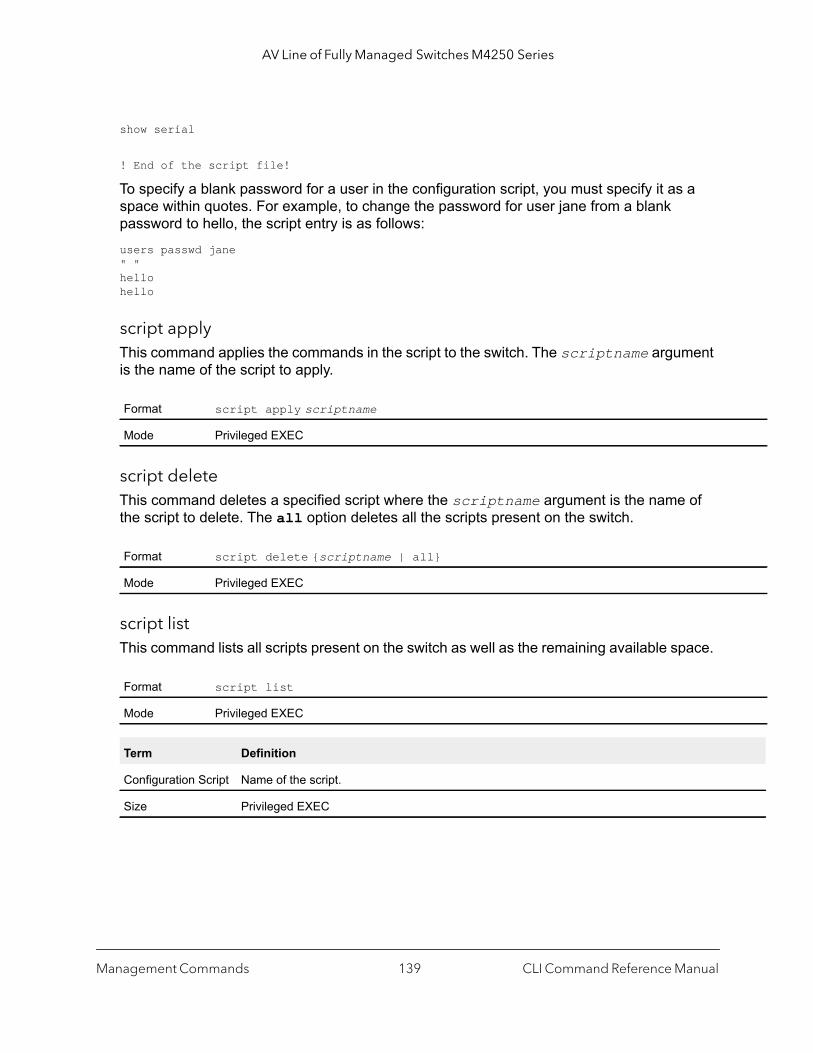
AV Line of Fully Managed Switches M4250 Series
show serial
! End of the script file!
To specify a blank password for a user in the configuration script, you must specify it as a space within quotes. For example, to change the password for user jane from a blank password to hello, the script entry is as follows:users passwd jane " " hello hello
script applyThis command applies the commands in the script to the switch. The scriptname argument is the name of the script to apply.
script deleteThis command deletes a specified script where the scriptname argument is the name of the script to delete. The all option deletes all the scripts present on the switch.
script listThis command lists all scripts present on the switch as well as the remaining available space.
Format script apply scriptname
Mode Privileged EXEC
Format script delete {scriptname | all}
Mode Privileged EXEC
Format script list
Mode Privileged EXEC
Term Definition
Configuration Script Name of the script.
Size Privileged EXEC
Management Commands CLI Command Reference Manual139
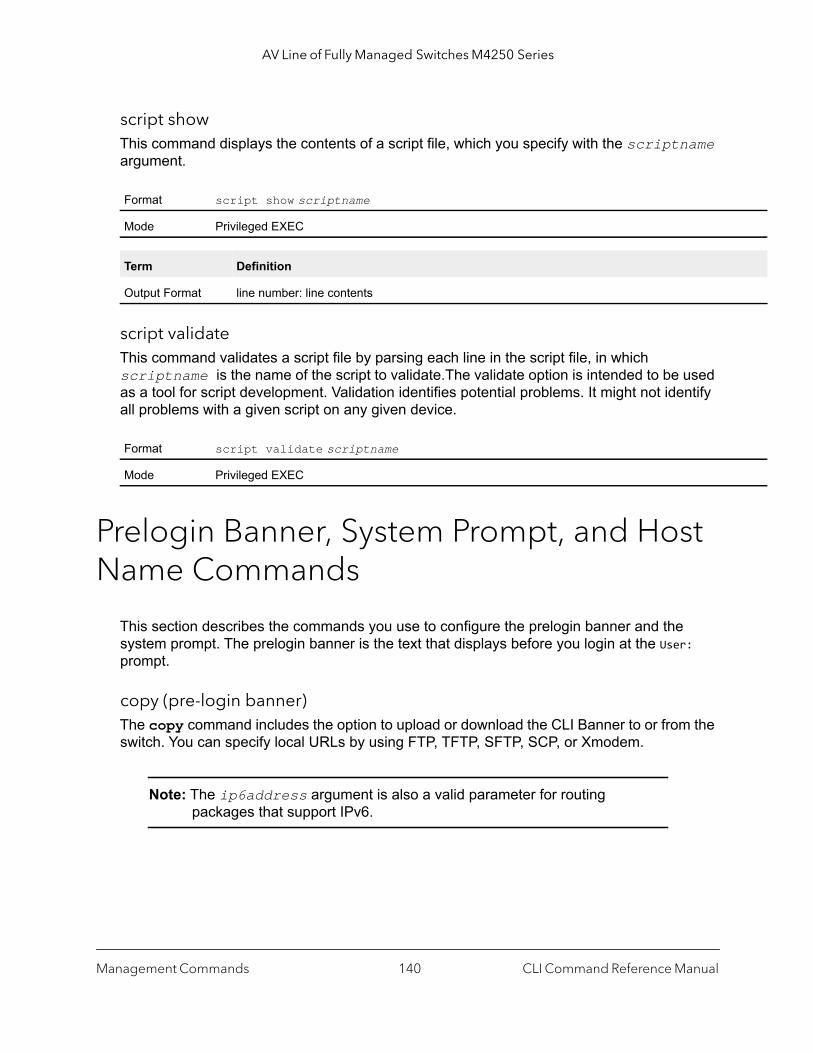
AV Line of Fully Managed Switches M4250 Series
script showThis command displays the contents of a script file, which you specify with the scriptname argument.
script validateThis command validates a script file by parsing each line in the script file, in which scriptname is the name of the script to validate.The validate option is intended to be used as a tool for script development. Validation identifies potential problems. It might not identify all problems with a given script on any given device.
Prelogin Banner, System Prompt, and Host Name Commands
This section describes the commands you use to configure the prelogin banner and the system prompt. The prelogin banner is the text that displays before you login at the User: prompt.
copy (pre-login banner)The copy command includes the option to upload or download the CLI Banner to or from the switch. You can specify local URLs by using FTP, TFTP, SFTP, SCP, or Xmodem.
Note: The ip6address argument is also a valid parameter for routing packages that support IPv6.
Format script show scriptname
Mode Privileged EXEC
Term Definition
Output Format line number: line contents
Format script validate scriptname
Mode Privileged EXEC
Management Commands CLI Command Reference Manual140

AV Line of Fully Managed Switches M4250 Series
set promptThis command changes the name of the prompt. The length of name may be up to 64 alphanumeric characters.
hostnameThis command sets the system host name. It also changes the prompt. The length of name may be up to 64 alphanumeric, case-sensitive characters.
show clibannerUse this command to display the configured prelogin CLI banner. The prelogin banner is the text that displays before displaying the CLI prompt.
Command example: (NETGEAR Switch) #show clibanner
Banner Message configured:=========================
-------------------------- TEST--------------------------
Default none
Format copy <tftp://<ipaddr>/<filepath>/<filename>> nvram:clibanner
copy nvram:clibanner <tftp://<ipaddr>/<filepath>/<filename>>
Mode Privileged EXEC
Format set prompt prompt-string
Mode Privileged EXEC
Format hostname hostname
Mode Privileged EXEC
Default No contents to display before displaying the login prompt.
Format show clibanner
Mode Privileged Exec
Management Commands CLI Command Reference Manual141

AV Line of Fully Managed Switches M4250 Series
to
e
set clibannerUse this command to configure the prelogin CLI banner before displaying the login prompt.
no set clibanner
Use this command to unconfigure the prelogin CLI banner.
Application Commands
Application commands enable you to manage applications that run on the switch.
application installThis command specifies how an executable file must start an application on the switch and how the application must run on the switch. You can enter the command (that is, preconfigure the command) for an executable file that is not yet present on the switch. The configuration does not take into effect until the executable file is present on the switch.
Format set clibanner line
Mode Global Config
Parameter Description
line Banner text where ““ (double quote) is a delimiting character. The banner message can be up 2000 characters.
Format no set clibanner
Mode Global Config
Format application install filename [start-on-boot] [auto-restart] [cpu-sharingnumber] [max-megabytes megabytes]
Mode Global Config
Parameter Description
filename The name of the file that contains the executable or script that is started as a Linux process for thapplication.
start-on-boot Starts the application each time the switch boots. When you specify this keyword, the application start the first time that the switch boots after you saved the command.
auto-restart Automatically restarts the application’s processes if they stop running.
Management Commands CLI Command Reference Manual142
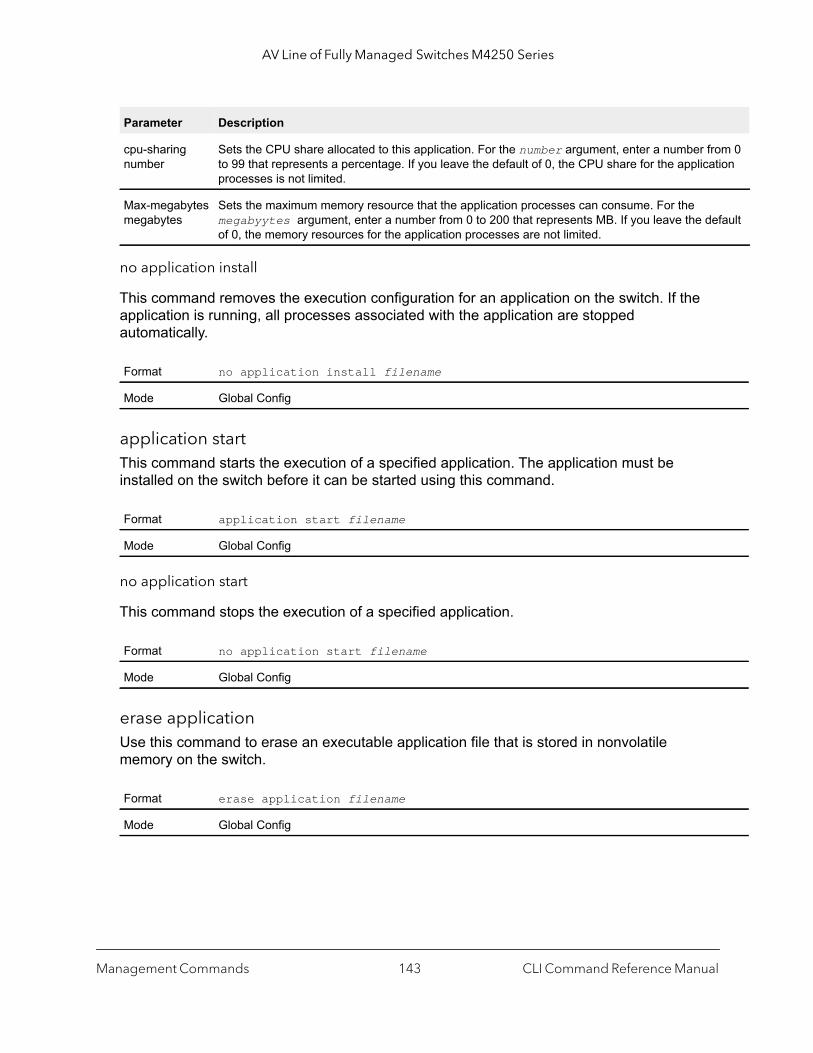
AV Line of Fully Managed Switches M4250 Series
0
lt
no application install
This command removes the execution configuration for an application on the switch. If the application is running, all processes associated with the application are stopped automatically.
application startThis command starts the execution of a specified application. The application must be installed on the switch before it can be started using this command.
no application start
This command stops the execution of a specified application.
erase applicationUse this command to erase an executable application file that is stored in nonvolatile memory on the switch.
cpu-sharing number
Sets the CPU share allocated to this application. For the number argument, enter a number fromto 99 that represents a percentage. If you leave the default of 0, the CPU share for the applicationprocesses is not limited.
Max-megabytes megabytes
Sets the maximum memory resource that the application processes can consume. For the megabyytes argument, enter a number from 0 to 200 that represents MB. If you leave the defauof 0, the memory resources for the application processes are not limited.
Format no application install filename
Mode Global Config
Format application start filename
Mode Global Config
Format no application start filename
Mode Global Config
Format erase application filename
Mode Global Config
Parameter Description
Management Commands CLI Command Reference Manual143

AV Line of Fully Managed Switches M4250 Series
show applicationThis command displays the applications that are installed on the switch and execution configurations of the applications.
show application filesThis command displays the files in the application directory of the switch file system.
Format show application
Mode Privileged EXEC
Field Description
filename The name of the application.
start-on-boot Indicates whether the application is configured to start when the switch boots:• Yes. The application starts when the switch boots.• No. The application does not start when the switch boots.
auto-restart Indicates whether the application is configured to restart when the application process stops:• Yes. The application restarts when the application process stops.• No. The application does not restart when the application process stops.
max-CPU-Util The command application CPU utilization limit expressed as a percentage. If the utilization is not limited, None is displayed.
max-Memory The application memory usage limit in megabytes. If the memory usage is not limited, None is displayed.
Format show application files
Mode Privileged EXEC
Field Description
filename The name of the application.
file size The number of bytes that the file uses in the file system.
directory size The number of bytes that all files in the application directory use.
Management Commands CLI Command Reference Manual144

5
5Utility CommandsThis chapter describes the utility commands.
The chapter includes the following sections:
• AutoInstall Commands
• CLI Output Filtering Commands
• Dual Image Commands
• System Information and Statistics Commands
• Logging Commands
• Email Alerting and Mail Server Commands
• System Utility and Clear Commands
• Simple Network Time Protocol Commands
• Time Zone Commands
• DHCP Server Commands
• DNS Client Commands
• IP Address Conflict Commands
• Serviceability Packet Tracing Commands
• Cable Test Command
• USB commands
• sFlow Commands
• Switch Database Management Template Commands
• Green Ethernet Commands
• Remote Monitoring Commands
• Statistics Application Commands
The commands in this chapter are in one of four functional groups:
• Show commands. Display switch settings, statistics, and other information.• Configuration commands. Configure features and options of the switch. For every
configuration command, there is a show command that displays the configuration setting.
145
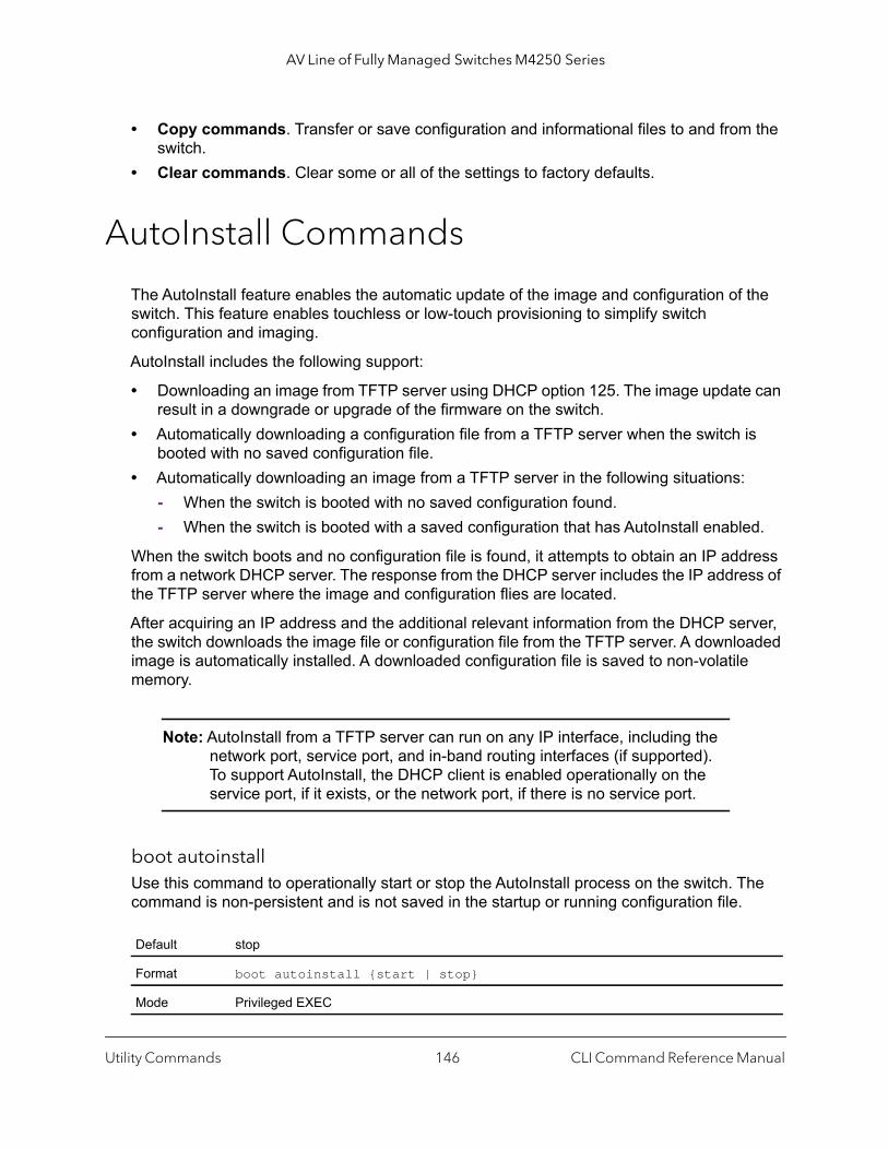
AV Line of Fully Managed Switches M4250 Series
• Copy commands. Transfer or save configuration and informational files to and from the switch.
• Clear commands. Clear some or all of the settings to factory defaults.
AutoInstall Commands
The AutoInstall feature enables the automatic update of the image and configuration of the switch. This feature enables touchless or low-touch provisioning to simplify switch configuration and imaging.
AutoInstall includes the following support:
• Downloading an image from TFTP server using DHCP option 125. The image update can result in a downgrade or upgrade of the firmware on the switch.
• Automatically downloading a configuration file from a TFTP server when the switch is booted with no saved configuration file.
• Automatically downloading an image from a TFTP server in the following situations:- When the switch is booted with no saved configuration found.- When the switch is booted with a saved configuration that has AutoInstall enabled.
When the switch boots and no configuration file is found, it attempts to obtain an IP address from a network DHCP server. The response from the DHCP server includes the IP address of the TFTP server where the image and configuration flies are located.
After acquiring an IP address and the additional relevant information from the DHCP server, the switch downloads the image file or configuration file from the TFTP server. A downloaded image is automatically installed. A downloaded configuration file is saved to non-volatile memory.
Note: AutoInstall from a TFTP server can run on any IP interface, including the network port, service port, and in-band routing interfaces (if supported). To support AutoInstall, the DHCP client is enabled operationally on the service port, if it exists, or the network port, if there is no service port.
boot autoinstallUse this command to operationally start or stop the AutoInstall process on the switch. The command is non-persistent and is not saved in the startup or running configuration file.
Default stop
Format boot autoinstall {start | stop}
Mode Privileged EXEC
Utility Commands CLI Command Reference Manual146
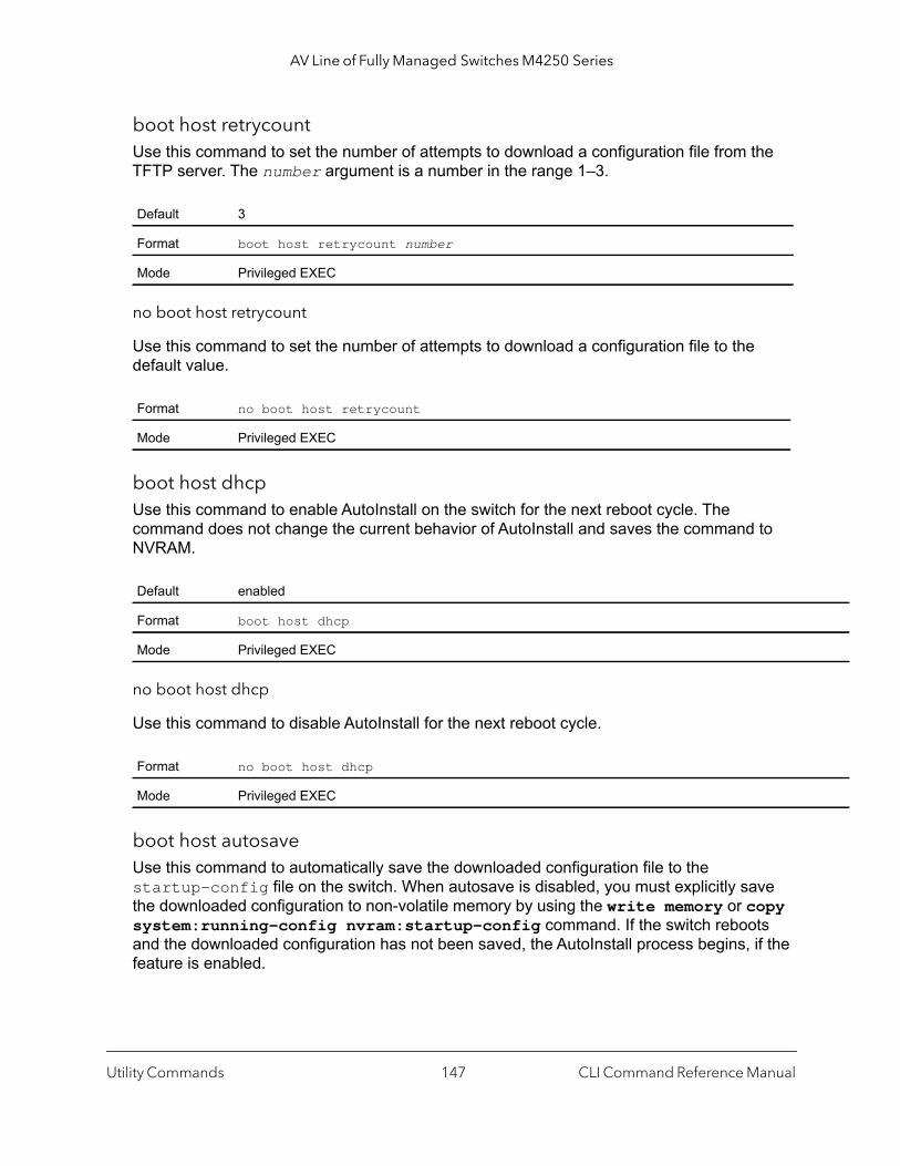
AV Line of Fully Managed Switches M4250 Series
boot host retrycount Use this command to set the number of attempts to download a configuration file from the TFTP server. The number argument is a number in the range 1–3.
no boot host retrycount
Use this command to set the number of attempts to download a configuration file to the default value.
boot host dhcpUse this command to enable AutoInstall on the switch for the next reboot cycle. The command does not change the current behavior of AutoInstall and saves the command to NVRAM.
no boot host dhcp
Use this command to disable AutoInstall for the next reboot cycle.
boot host autosaveUse this command to automatically save the downloaded configuration file to the startup-config file on the switch. When autosave is disabled, you must explicitly save the downloaded configuration to non-volatile memory by using the write memory or copy system:running-config nvram:startup-config command. If the switch reboots and the downloaded configuration has not been saved, the AutoInstall process begins, if the feature is enabled.
Default 3
Format boot host retrycount number
Mode Privileged EXEC
Format no boot host retrycount
Mode Privileged EXEC
Default enabled
Format boot host dhcp
Mode Privileged EXEC
Format no boot host dhcp
Mode Privileged EXEC
Utility Commands CLI Command Reference Manual147

AV Line of Fully Managed Switches M4250 Series
no boot host autosave
Use this command to disable automatically saving the downloaded configuration on the switch.
boot host autorebootUse this command to allow the switch to automatically reboot after successfully downloading an image. When auto reboot is enabled, no administrative action is required to activate the image and reload the switch.
no boot host autoreboot
Use this command to prevent the switch from automatically rebooting after the image is downloaded by using the AutoInstall feature.
erase startup-configUse this command to erase the text-based configuration file stored in non-volatile memory. If the switch boots and no startup-config file is found, the AutoInstall process automatically begins.
Default disabled
Format boot host autosave
Mode Privileged EXEC
Format no boot host autosave
Mode Privileged EXEC
Default enabled
Format boot host autoreboot
Mode Privileged EXEC
Format no boot host autoreboot
Mode Privileged EXEC
Format erase startup-config
Mode Privileged EXEC
Utility Commands CLI Command Reference Manual148

AV Line of Fully Managed Switches M4250 Series
erase factory-defaultsThis command erases the text-based factory default file that is stored in non-volatile memory.
erase stack-configThis command erases the stacking configuration file This configuration file cannot be erased using the clear config command.
show autoinstallThis command displays the current status of the AutoInstall process.
Command example: (NETGEAR Switch) #show autoinstall
AutoInstall Mode............................... StoppedAutoInstall Persistent Mode.................... DisabledAutoSave Mode.................................. DisabledAutoReboot Mode................................ EnabledAutoInstall Retry Count........................ 3
Format erase factory-defaults
Mode Privileged EXEC
Format erase stack-config
Mode Privileged EXEC
Format show autoinstall
Mode Privileged EXEC
Utility Commands CLI Command Reference Manual149
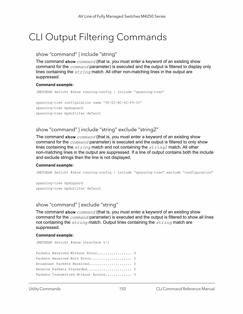
AV Line of Fully Managed Switches M4250 Series
CLI Output Filtering Commands
show “command” | include “string”The command show command (that is, you must enter a keyword of an existing show command for the command parameter) is executed and the output is filtered to display only lines containing the string match. All other non-matching lines in the output are suppressed.
Command example: (NETGEAR Switch) #show running-config | include “spanning-tree”
spanning-tree configuration name "00-02-BC-42-F9-33"spanning-tree bpduguardspanning-tree bpdufilter default
show “command” | include “string” exclude “string2”The command show command (that is, you must enter a keyword of an existing show command for the command parameter) is executed and the output is filtered to only show lines containing the string match and not containing the string2 match. All other non-matching lines in the output are suppressed. If a line of output contains both the include and exclude strings then the line is not displayed.
Command example: (NETGEAR Switch) #show running-config | include “spanning-tree” exclude “configuration”
spanning-tree bpduguardspanning-tree bpdufilter default
show “command” | exclude “string”The command show command (that is, you must enter a keyword of an existing show command for the command parameter) is executed and the output is filtered to show all lines not containing the string match. Output lines containing the string match are suppressed.
Command example: (NETGEAR Switch) #show interface 0/1
Packets Received Without Error................. 0Packets Received With Error.................... 0Broadcast Packets Received..................... 0Receive Packets Discarded...................... 0Packets Transmitted Without Errors............. 0
Utility Commands CLI Command Reference Manual150
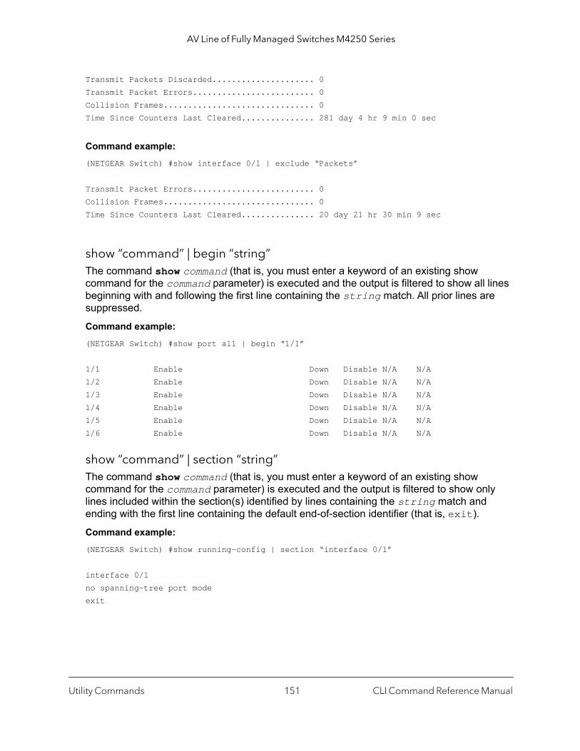
AV Line of Fully Managed Switches M4250 Series
Transmit Packets Discarded..................... 0Transmit Packet Errors......................... 0Collision Frames............................... 0Time Since Counters Last Cleared............... 281 day 4 hr 9 min 0 sec
Command example: (NETGEAR Switch) #show interface 0/1 | exclude “Packets”
Transmit Packet Errors......................... 0Collision Frames............................... 0Time Since Counters Last Cleared............... 20 day 21 hr 30 min 9 sec
show “command” | begin “string”The command show command (that is, you must enter a keyword of an existing show command for the command parameter) is executed and the output is filtered to show all lines beginning with and following the first line containing the string match. All prior lines are suppressed.
Command example: (NETGEAR Switch) #show port all | begin “1/1”
1/1 Enable Down Disable N/A N/A1/2 Enable Down Disable N/A N/A1/3 Enable Down Disable N/A N/A1/4 Enable Down Disable N/A N/A1/5 Enable Down Disable N/A N/A1/6 Enable Down Disable N/A N/A
show “command” | section “string”The command show command (that is, you must enter a keyword of an existing show command for the command parameter) is executed and the output is filtered to show only lines included within the section(s) identified by lines containing the string match and ending with the first line containing the default end-of-section identifier (that is, exit).
Command example: (NETGEAR Switch) #show running-config | section “interface 0/1”
interface 0/1no spanning-tree port modeexit
Utility Commands CLI Command Reference Manual151

AV Line of Fully Managed Switches M4250 Series
show “command” | section “string” “string2”The command show command (that is, you must enter a keyword of an existing show command for the command parameter) is executed and the output is filtered to only show lines included within the section(s) identified by lines containing the string match and ending with the first line containing the string2 match. If multiple sessions matching the specified string match criteria are part of the base output, then all instances are displayed.
show “command” | section “string” include “string2”The command show command (that is, you must enter a keyword of an existing show command for the command parameter) is executed and the output is filtered to only show lines included within the section(s) identified by lines containing the string match and ending with the first line containing the default end-of-section identifier (that is, exit) and that include the string2 match. This type of filter command could also include “exclude” or user-defined end-of-section identifier parameters as well.
Dual Image Commands
The switch supports a dual image feature that allows the switch to have two software images in the permanent storage. You can specify which image is the active image to be loaded in subsequent reboots. This feature allows reduced down-time when you upgrade or downgrade the software.
deleteThis command deletes the image1 or image 2 file from the permanent storage. The optional unit parameter is valid only for members. The unit parameter identifies the member on which you must execute this command. When you do not enter this parameter, the command is executed on all members in the stack.
boot systemThis command activates the specified image. It will be the active-image for subsequent reboots and will be loaded by the boot loader. The current active-image is marked as the backup-image for subsequent reboots. If the specified image doesn't exist on the system, this command returns an error message. The optional unit parameter identifies the member on which you must execute this command. When you do not enter this parameter, the command is executed on all members in the stack.
Format delete [unit] {image1 | image2}
Mode Privileged EXEC
Format boot system [unit] {image1 | image2}
Mode Privileged EXEC
Utility Commands CLI Command Reference Manual152

AV Line of Fully Managed Switches M4250 Series
show bootvarThis command displays the version information and the activation status for the current images on the supplied unit of the stack. If you do not specify a unit number, the command displays image details for all nodes in the stack. The command also displays any text description associated with an image. This command, when used on a standalone system, displays the switch activation status. For a standalone system, the unit parameter is not valid.
filedescrThis command associates a given text description with an image and replaces any existing description. The command is executed on all units in a stack.
update bootcodeThis command updates the bootcode (boot loader) on the switch. The bootcode is read from the active image for subsequent reboots. The unit parameter identifies the member on which this command must be executed. When this parameter is not supplied, the command is executed on all units in a stack.
System Information and Statistics Commands
This section describes the commands you use to view information about system features, components, and configurations.
show arp switch (system information and statistics commands)This command displays the contents of the Address Resolution Protocol (ARP) table that is associated with the IP address of the switch. This IP address learns only ARP entries that are associated with the management interfaces (network or service ports). ARP entries that are associated with routing interfaces are not listed.
Format show bootvar [unit]
Mode Privileged EXEC
Format filedescr {image1 | image2} text-description
Mode Privileged EXEC
Format update bootcode [unit]
Mode Privileged EXEC
Utility Commands CLI Command Reference Manual153

AV Line of Fully Managed Switches M4250 Series
of the
show eventlogThis command displays the event log, which contains error messages from the system. The event log is not cleared on a system reset. The unit is the switch identifier.
Note: Event log information is retained across a switch reset.
show hardwareThis command displays inventory information for the switch.
Note: The show version command and the show hardware command display the same information. In future releases of the software, the show hardware command will not be available. For a description of the command output, see the command show version on page 155.
Format show arp switch
Mode Privileged EXEC
Term Definition
IP Address IP address of the management interface or another device on the management network.
MAC Address Hardware MAC address of that device.
Interface For a service port the output is Management. For a network port, the output is the unit/port physical interface.
Format show eventlog [unit]
Mode Privileged EXEC
Term Definition
File The file in which the event originated.
Line The line number of the event.
Task Id The task ID of the event.
Code The event code.
Time The time this event occurred.
Unit The unit for the event.
Utility Commands CLI Command Reference Manual154

AV Line of Fully Managed Switches M4250 Series
show environmentThis command displays information about the temperature and status of the power supplies and fans in the system chassis.
Command example: (Netgear Switch) #show environmentFan Control Mode............................... QuietTemp (C)....................................... 23Temperature traps range: 0 to 90 degrees (Celsius)
Temperature Sensors:Unit Sensor Description Temp (C) State Max_Temp (C)---- ------ ---------------- ---------- ----------------- --------------1 1 sensor-1 23 Normal 53
Fans:Unit Fan Description Type Speed Duty level State---- --- -------------- --------- ------------- ------------- --------------1 1 FAN-1 Fixed 2500 25% Operational1 2 FAN-2 Fixed 2500 25% Operational
Power Modules:Unit Power supply Description Type State---- ------------ ---------------- ---------- --------------1 1 PS-1 Fixed Operational
show versionThis command displays inventory information for the switch.
Note: The show version command replaces the show hardware command in future releases of the software.
Format show hardware
Mode Privileged EXEC
Format show environment
Mode Privileged EXEC
Utility Commands CLI Command Reference Manual155
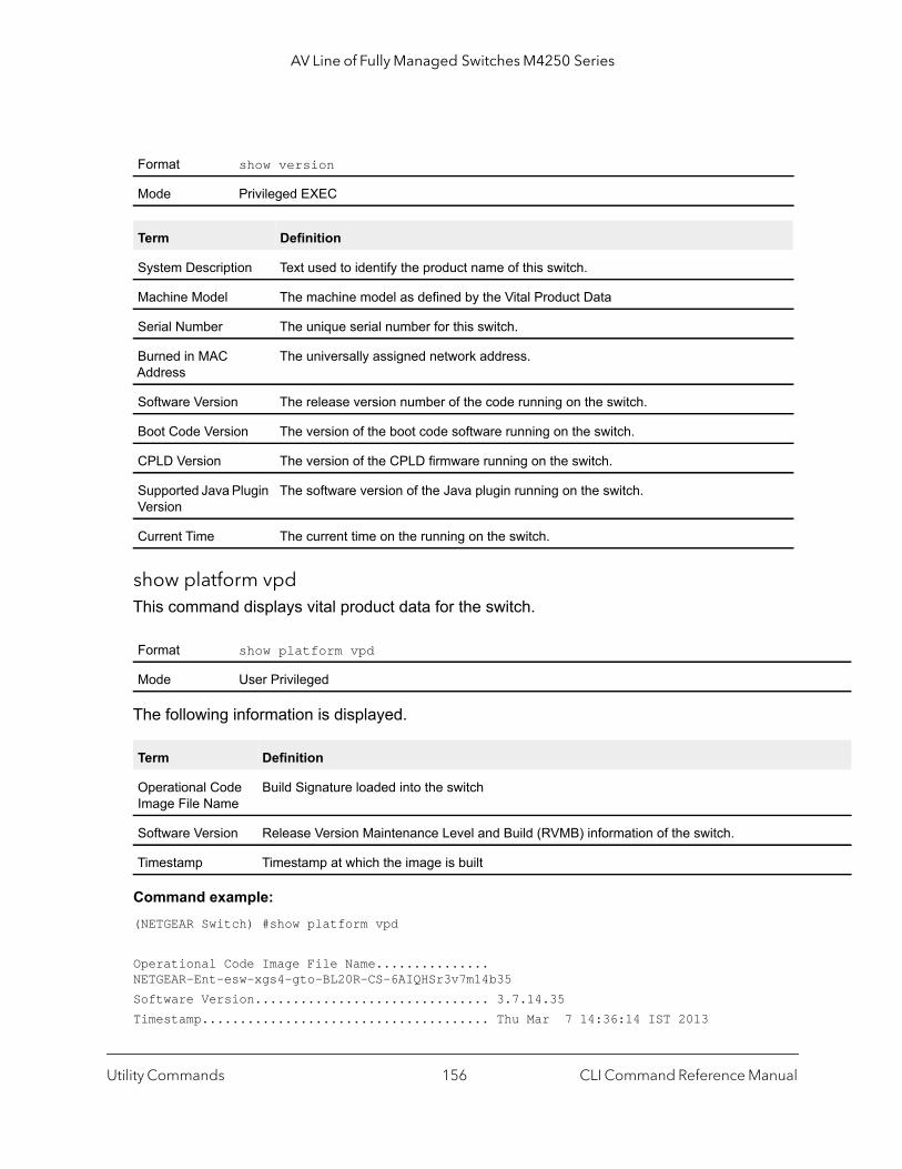
AV Line of Fully Managed Switches M4250 Series
show platform vpdThis command displays vital product data for the switch.
The following information is displayed.
Command example: (NETGEAR Switch) #show platform vpd
Operational Code Image File Name............... NETGEAR-Ent-esw-xgs4-gto-BL20R-CS-6AIQHSr3v7m14b35Software Version............................... 3.7.14.35Timestamp...................................... Thu Mar 7 14:36:14 IST 2013
Format show version
Mode Privileged EXEC
Term Definition
System Description Text used to identify the product name of this switch.
Machine Model The machine model as defined by the Vital Product Data
Serial Number The unique serial number for this switch.
Burned in MAC Address
The universally assigned network address.
Software Version The release version number of the code running on the switch.
Boot Code Version The version of the boot code software running on the switch.
CPLD Version The version of the CPLD firmware running on the switch.
Supported Java Plugin Version
The software version of the Java plugin running on the switch.
Current Time The current time on the running on the switch.
Format show platform vpd
Mode User Privileged
Term Definition
Operational Code Image File Name
Build Signature loaded into the switch
Software Version Release Version Maintenance Level and Build (RVMB) information of the switch.
Timestamp Timestamp at which the image is built
Utility Commands CLI Command Reference Manual156

AV Line of Fully Managed Switches M4250 Series
the
to a
is
been
ad for
hat is
ed
ghted
show interfaceThis command displays a summary of statistics for a specific interface or a count of all CPU traffic based upon the argument.
The display parameters, when the argument is unit/port, are as follows.
Format show interface {unit/port | switchport}
Mode Privileged EXEC
Field Definition
Packets Received Without Error
The total number of packets (including broadcast packets and multicast packets) received by processor.
Packets Received With Error
The number of inbound packets that contained errors preventing them from being deliverable higher-layer protocol.
Broadcast Packets Received
The total number of packets received that were directed to the broadcast address. Note that thdoes not include multicast packets.
Receive Packets Discarded
The number of inbound packets which were chosen to be discarded even though no errors haddetected to prevent their being deliverable to a higher-layer protocol. One possible reason for discarding such a packet could be to free up buffered space.
Packets Transmitted Without Error
The total number of packets transmitted out of the interface.
Transmit Packets Discarded
The number of outbound packets which were chosen to be discarded even though no errors hbeen detected to prevent their being deliverable to a higher-layer protocol. A possible reason discarding a packet could be to free up buffer space.
Transmit Packets Errors
The number of outbound packets that could not be transmitted because of errors.
Collisions Frames The best estimate of the total number of collisions on this Ethernet segment.
Number of link down events
The number of down events for the link since the switch restarted.
Load Interval The period in seconds for which data is used to compute the load statistics. You must enter a ta multiple of 30. The allowable range is from 30 to 600 seconds.
Received Rate (Mbps)
The approximate number of bits per second received. This value is an exponentially-weightedaverage and is affected by the configured load interval.
Transmitted Rate (Mbps)
The approximate number of bits per second transmitted. This value is an exponentially-weightaverage and is affected by the configured load interval.
Received Error Rate
The approximate number of error bits per second received. This value is an exponentially-weiaverage and is affected by the configured load interval.
Transmitted Error Rate
The approximate number of error bits per second transmitted. This value is an exponentially-weighted average and is affected by the configured load interval.
Utility Commands CLI Command Reference Manual157
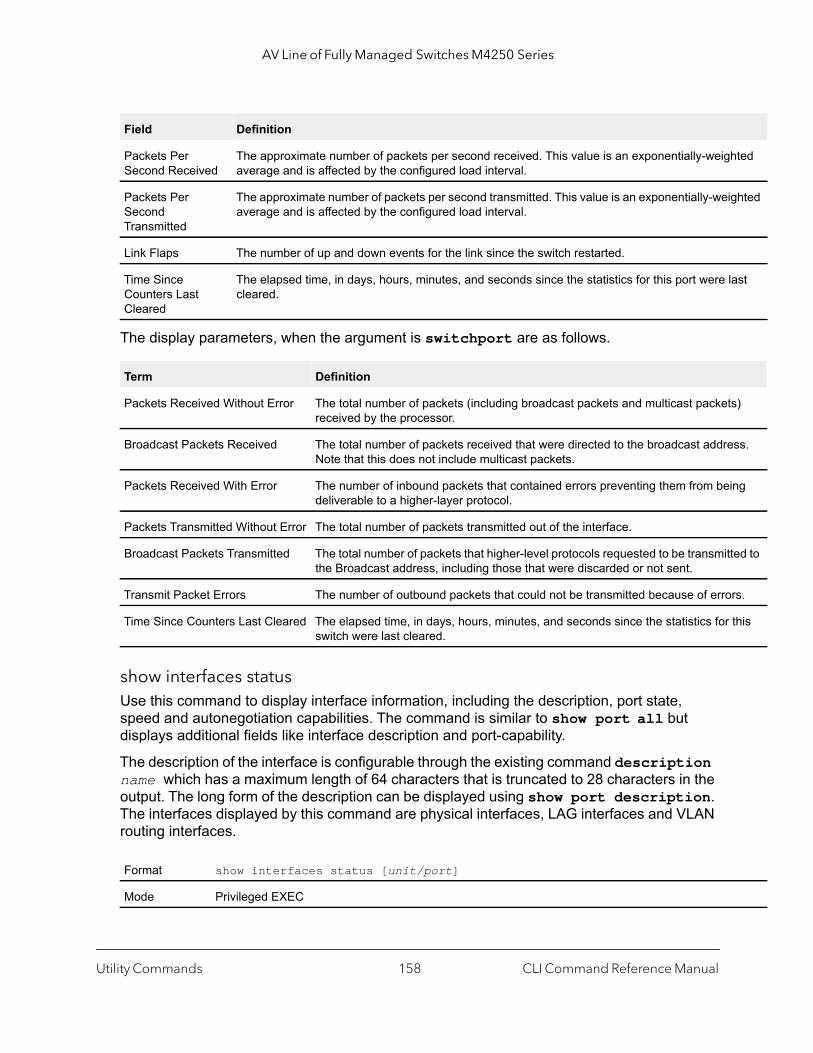
AV Line of Fully Managed Switches M4250 Series
hted
ghted
ast
s)
ss.
ng
ed to
rs.
this
The display parameters, when the argument is switchport are as follows.
show interfaces statusUse this command to display interface information, including the description, port state, speed and autonegotiation capabilities. The command is similar to show port all but displays additional fields like interface description and port-capability.
The description of the interface is configurable through the existing command description name which has a maximum length of 64 characters that is truncated to 28 characters in the output. The long form of the description can be displayed using show port description. The interfaces displayed by this command are physical interfaces, LAG interfaces and VLAN routing interfaces.
Packets Per Second Received
The approximate number of packets per second received. This value is an exponentially-weigaverage and is affected by the configured load interval.
Packets Per Second Transmitted
The approximate number of packets per second transmitted. This value is an exponentially-weiaverage and is affected by the configured load interval.
Link Flaps The number of up and down events for the link since the switch restarted.
Time Since Counters Last Cleared
The elapsed time, in days, hours, minutes, and seconds since the statistics for this port were lcleared.
Term Definition
Packets Received Without Error The total number of packets (including broadcast packets and multicast packetreceived by the processor.
Broadcast Packets Received The total number of packets received that were directed to the broadcast addreNote that this does not include multicast packets.
Packets Received With Error The number of inbound packets that contained errors preventing them from beideliverable to a higher-layer protocol.
Packets Transmitted Without Error The total number of packets transmitted out of the interface.
Broadcast Packets Transmitted The total number of packets that higher-level protocols requested to be transmittthe Broadcast address, including those that were discarded or not sent.
Transmit Packet Errors The number of outbound packets that could not be transmitted because of erro
Time Since Counters Last Cleared The elapsed time, in days, hours, minutes, and seconds since the statistics for switch were last cleared.
Format show interfaces status [unit/port]
Mode Privileged EXEC
Field Definition
Utility Commands CLI Command Reference Manual158
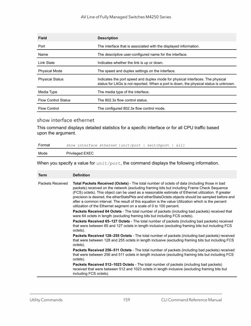
AV Line of Fully Managed Switches M4250 Series
l nown.
e ter e and t
that
ived CS
eived FCS
eived FCS
t
show interface ethernetThis command displays detailed statistics for a specific interface or for all CPU traffic based upon the argument.
When you specify a value for unit/port, the command displays the following information.
Field Description
Port The interface that is associated with the displayed information.
Name The descriptive user-configured name for the interface.
Link State Indicates whether the link is up or down.
Physical Mode The speed and duplex settings on the interface.
Physical Status Indicates the port speed and duplex mode for physical interfaces. The physicastatus for LAGs is not reported. When a port is down, the physical status is unk
Media Type The media type of the interface.
Flow Control Status The 802.3x flow control status.
Flow Control The configured 802.3x flow control mode.
Format show interface ethernet {unit/port | switchport | all}
Mode Privileged EXEC
Term Definition
Packets Received Total Packets Received (Octets) - The total number of octets of data (including those in badpackets) received on the network (excluding framing bits but including Frame Check Sequenc(FCS) octets). This object can be used as a reasonable estimate of Ethernet utilization. If greaprecision is desired, the etherStatsPkts and etherStatsOctets objects should be sampled beforafter a common interval. The result of this equation is the value Utilization which is the percenutilization of the Ethernet segment on a scale of 0 to 100 percent. Packets Received 64 Octets - The total number of packets (including bad packets) received were 64 octets in length (excluding framing bits but including FCS octets). Packets Received 65–127 Octets - The total number of packets (including bad packets) recethat were between 65 and 127 octets in length inclusive (excluding framing bits but including Foctets). Packets Received 128–255 Octets - The total number of packets (including bad packets) recthat were between 128 and 255 octets in length inclusive (excluding framing bits but includingoctets). Packets Received 256–511 Octets - The total number of packets (including bad packets) recthat were between 256 and 511 octets in length inclusive (excluding framing bits but includingoctets).Packets Received 512–1023 Octets - The total number of packets (including bad packets) received that were between 512 and 1023 octets in length inclusive (excluding framing bits buincluding FCS octets).
Utility Commands CLI Command Reference Manual159
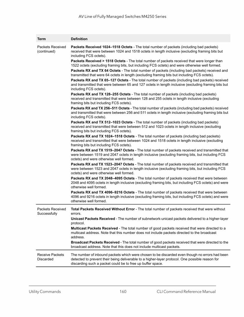
AV Line of Fully Managed Switches M4250 Series
ut
n . and
eived s but
eived ts but
g
d that CS
d that CS
een were
een were
out
-layer
to a
to the
been
Packets Received (continued)
Packets Received 1024–1518 Octets - The total number of packets (including bad packets) received that were between 1024 and 1518 octets in length inclusive (excluding framing bits bincluding FCS octets). Packets Received > 1518 Octets - The total number of packets received that were longer tha1522 octets (excluding framing bits, but including FCS octets) and were otherwise well formedPackets RX and TX 64 Octets - The total number of packets (including bad packets) receivedtransmitted that were 64 octets in length (excluding framing bits but including FCS octets). Packets RX and TX 65–127 Octets - The total number of packets (including bad packets) recand transmitted that were between 65 and 127 octets in length inclusive (excluding framing bitincluding FCS octets). Packets RX and TX 128–255 Octets - The total number of packets (including bad packets) received and transmitted that were between 128 and 255 octets in length inclusive (excluding framing bits but including FCS octets).Packets RX and TX 256–511 Octets - The total number of packets (including bad packets) recand transmitted that were between 256 and 511 octets in length inclusive (excluding framing biincluding FCS octets). Packets RX and TX 512–1023 Octets - The total number of packets (including bad packets) received and transmitted that were between 512 and 1023 octets in length inclusive (excludingframing bits but including FCS octets).Packets RX and TX 1024–1518 Octets - The total number of packets (including bad packets)received and transmitted that were between 1024 and 1518 octets in length inclusive (excludinframing bits but including FCS octets). Packets RX and TX 1519–2047 Octets - The total number of packets received and transmittewere between 1519 and 2047 octets in length inclusive (excluding framing bits, but including Foctets) and were otherwise well formed.Packets RX and TX 1523–2047 Octets - The total number of packets received and transmittewere between 1523 and 2047 octets in length inclusive (excluding framing bits, but including Foctets) and were otherwise well formed. Packets RX and TX 2048–4095 Octets - The total number of packets received that were betw2048 and 4095 octets in length inclusive (excluding framing bits, but including FCS octets) andotherwise well formed.Packets RX and TX 4096–9216 Octets - The total number of packets received that were betw4096 and 9216 octets in length inclusive (excluding framing bits, but including FCS octets) andotherwise well formed.
Packets Received Successfully
Total Packets Received Without Error - The total number of packets received that were witherrors. Unicast Packets Received - The number of subnetwork-unicast packets delivered to a higherprotocol. Multicast Packets Received - The total number of good packets received that were directed multicast address. Note that this number does not include packets directed to the broadcast address.Broadcast Packets Received - The total number of good packets received that were directed broadcast address. Note that this does not include multicast packets.
Receive Packets Discarded
The number of inbound packets which were chosen to be discarded even though no errors haddetected to prevent their being deliverable to a higher-layer protocol. One possible reason for discarding such a packet could be to free up buffer space.
Term Definition
Utility Commands CLI Command Reference Manual160

AV Line of Fully Managed Switches M4250 Series
ed
ce of
fine is
4
bits, ck
ut
rded
ith an s
ad t can
erval.
d that
t
Packets Received with MAC Errors
Total Packets Received with MAC Errors - The total number of inbound packets that containerrors preventing them from being deliverable to a higher-layer protocol. Jabbers Received - The total number of packets received that were longer than 1518 octets (excluding framing bits, but including FCS octets), and had either a bad Frame Check Sequen(FCS) with an integral number of octets (FCS Error) or a bad FCS with a non-integral numberoctets (Alignment Error). Note that this definition of jabber is different than the definition in IEEE-802.3 section 8.2.1.5 (10BASE5) and section 10.3.1.4 (10BASE2). These documents dejabber as the condition where any packet exceeds 20 ms. The allowed range to detect jabber between 20 ms and 150 ms. Fragments/Undersize Received - The total number of packets received that were less than 6octets in length (excluding framing bits but including FCS octets). Alignment Errors - The total number of packets received that had a length (excluding framingbut including FCS octets) of between 64 and 1518 octets, inclusive, but had a bad Frame CheSequence (FCS) with a non-integral number of octets. FCS Errors - The total number of packets received that had a length (excluding framing bits, bincluding FCS octets) of between 64 and 1518 octets, inclusive, but had a bad Frame Check Sequence (FCS) with an integral number of octets. Overruns - The total number of frames discarded as this port was overloaded with incoming packets, and could not keep up with the inflow.
Received Packets Not Forwarded
Total Received Packets Not Forwarded - A count of valid frames received which were disca(in other words, filtered) by the forwarding process802.3x Pause Frames Received - A count of MAC Control frames received on this interface wopcode indicating the PAUSE operation. This counter does not increment when the interface ioperating in half-duplex mode.Unacceptable Frame Type - The number of frames discarded from this port due to being an unacceptable frame type.
Packets Transmitted Octets
Total Packets Transmitted (Octets) - The total number of octets of data (including those in bpackets) received on the network (excluding framing bits but including FCS octets). This objecbe used as a reasonable estimate of Ethernet utilization. If greater precision is desired, the etherStatsPkts and etherStatsOctets objects should be sampled before and after a common int----- Packets Transmitted 64 Octets - The total number of packets (including bad packets) receivewere 64 octets in length (excluding framing bits but including FCS octets). Packets Transmitted 65-127 Octets - The total number of packets (including bad packets) received that were between 65 and 127 octets in length inclusive (excluding framing bits but including FCS octets). Packets Transmitted 128-255 Octets - The total number of packets (including bad packets) received that were between 128 and 255 octets in length inclusive (excluding framing bits but including FCS octets). Packets Transmitted 256-511 Octets - The total number of packets (including bad packets) received that were between 256 and 511 octets in length inclusive (excluding framing bits but including FCS octets). Packets Transmitted 512-1023 Octets - The total number of packets (including bad packets)received that were between 512 and 1023 octets in length inclusive (excluding framing bits buincluding FCS octets).
Term Definition
Utility Commands CLI Command Reference Manual161
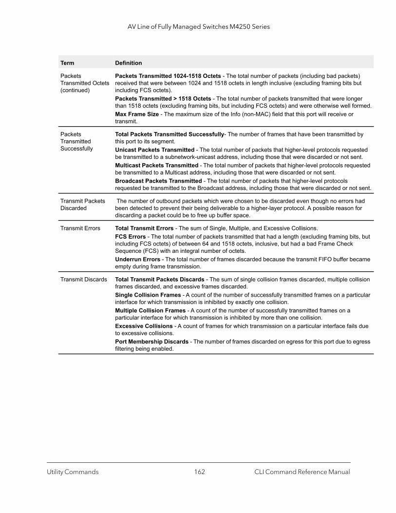
AV Line of Fully Managed Switches M4250 Series
) ut
er rmed.
by
sted nt. ested
sent.
ad or
s, but
came
lision
icular
due
gress
Packets Transmitted Octets (continued)
Packets Transmitted 1024-1518 Octets - The total number of packets (including bad packetsreceived that were between 1024 and 1518 octets in length inclusive (excluding framing bits bincluding FCS octets). Packets Transmitted > 1518 Octets - The total number of packets transmitted that were longthan 1518 octets (excluding framing bits, but including FCS octets) and were otherwise well foMax Frame Size - The maximum size of the Info (non-MAC) field that this port will receive or transmit.
Packets Transmitted Successfully
Total Packets Transmitted Successfully- The number of frames that have been transmittedthis port to its segment. Unicast Packets Transmitted - The total number of packets that higher-level protocols requebe transmitted to a subnetwork-unicast address, including those that were discarded or not seMulticast Packets Transmitted - The total number of packets that higher-level protocols reqube transmitted to a Multicast address, including those that were discarded or not sent. Broadcast Packets Transmitted - The total number of packets that higher-level protocols requested be transmitted to the Broadcast address, including those that were discarded or not
Transmit Packets Discarded
The number of outbound packets which were chosen to be discarded even though no errors hbeen detected to prevent their being deliverable to a higher-layer protocol. A possible reason fdiscarding a packet could be to free up buffer space.
Transmit Errors Total Transmit Errors - The sum of Single, Multiple, and Excessive Collisions. FCS Errors - The total number of packets transmitted that had a length (excluding framing bitincluding FCS octets) of between 64 and 1518 octets, inclusive, but had a bad Frame Check Sequence (FCS) with an integral number of octets. Underrun Errors - The total number of frames discarded because the transmit FIFO buffer beempty during frame transmission.
Transmit Discards Total Transmit Packets Discards - The sum of single collision frames discarded, multiple colframes discarded, and excessive frames discarded. Single Collision Frames - A count of the number of successfully transmitted frames on a partinterface for which transmission is inhibited by exactly one collision. Multiple Collision Frames - A count of the number of successfully transmitted frames on a particular interface for which transmission is inhibited by more than one collision. Excessive Collisions - A count of frames for which transmission on a particular interface failsto excessive collisions. Port Membership Discards - The number of frames discarded on egress for this port due to efiltering being enabled.
Term Definition
Utility Commands CLI Command Reference Manual162

AV Line of Fully Managed Switches M4250 Series
face rface
e
be
.t.ed.
eived
ast
ed by
that
kets)
If you use the switchport keyword, the following information displays.
Protocol Statistics 802.3x Pause Frames Transmitted - A count of MAC Control frames transmitted on this interwith an opcode indicating the PAUSE operation. This counter does not increment when the inteis operating in half-duplex mode. GVRP PDUs Received - The count of GVRP PDUs received in the GARP layer.GVRP PDUs Transmitted - The count of GVRP PDUs transmitted from the GARP layer. GVRP Failed Registrations - The number of times attempted GVRP registrations could not bcompleted. GMRP PDUs Received - The count of GMRP PDUs received in the GARP layer. GMRP PDUs Transmitted - The count of GMRP PDUs transmitted from the GARP layer. GMRP Failed Registrations - The number of times attempted GMRP registrations could not completed. STP BPDUs Transmitted - Spanning Tree Protocol Bridge Protocol Data Units sent.STP BPDUs Received - Spanning Tree Protocol Bridge Protocol Data Units received.RST BPDUs Transmitted - Rapid Spanning Tree Protocol Bridge Protocol Data Units sent.RSTP BPDUs Received - Rapid Spanning Tree Protocol Bridge Protocol Data Units receivedMSTP BPDUs Transmitted - Multiple Spanning Tree Protocol Bridge Protocol Data Units senMSTP BPDUs Received - Multiple Spanning Tree Protocol Bridge Protocol Data Units receiv
Dot1x Statistics EAPOL Frames Transmitted - The number of EAPOL frames of any type that have been transmitted by this authenticator.EAPOL Start Frames Received - The number of valid EAPOL start frames that have been recby this authenticator.
Time Since Counters Last Cleared
The elapsed time, in days, hours, minutes, and seconds since the statistics for this port were lcleared.
Term Definition
Packets Received Without Error
The total number of packets (including broadcast packets and multicast packets) receivthe processor.
Broadcast Packets Received
The total number of packets received that were directed to the broadcast address. Notethis does not include multicast packets.
Packets Received With Error
The total number of packets with errors (including broadcast packets and multicast pacreceived by the processor.
Packets Transmitted without Errors
The total number of packets transmitted out of the interface.
Broadcast Packets Transmitted
The total number of packets that higher-level protocols requested be transmitted to theBroadcast address, including those that were discarded or not sent.
Transmit Packet Errors The number of outbound packets that could not be transmitted because of errors.
Number of Port Link Down Events
The number of occurrences that a port link went down.
Term Definition
Utility Commands CLI Command Reference Manual163
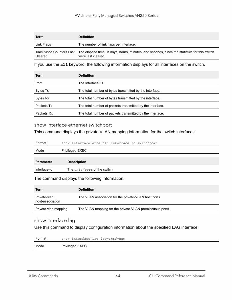
AV Line of Fully Managed Switches M4250 Series
itch
If you use the all keyword, the following information displays for all interfaces on the switch.
show interface ethernet switchportThis command displays the private VLAN mapping information for the switch interfaces.
The command displays the following information.
show interface lagUse this command to display configuration information about the specified LAG interface.
Link Flaps The number of link flaps per interface.
Time Since Counters Last Cleared
The elapsed time, in days, hours, minutes, and seconds, since the statistics for this swwere last cleared.
Term Definition
Port The Interface ID.
Bytes Tx The total number of bytes transmitted by the interface.
Bytes Rx The total number of bytes transmitted by the interface.
Packets Tx The total number of packets transmitted by the interface.
Packets Rx The total number of packets transmitted by the interface.
Format show interface ethernet interface-id switchport
Mode Privileged EXEC
Parameter Description
interface-id The unit/port of the switch.
Term Definition
Private-vlan host-association
The VLAN association for the private-VLAN host ports.
Private-vlan mapping The VLAN mapping for the private-VLAN promiscuous ports.
Format show interface lag lag-intf-num
Mode Privileged EXEC
Term Definition
Utility Commands CLI Command Reference Manual164
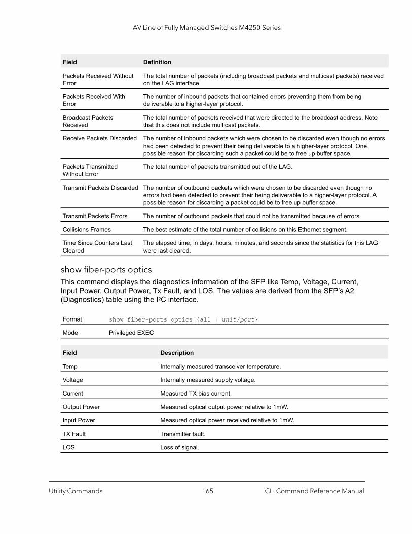
AV Line of Fully Managed Switches M4250 Series
ived
te
rrors
. A
G
show fiber-ports opticsThis command displays the diagnostics information of the SFP like Temp, Voltage, Current, Input Power, Output Power, Tx Fault, and LOS. The values are derived from the SFP’s A2 (Diagnostics) table using the I2C interface.
Field Definition
Packets Received Without Error
The total number of packets (including broadcast packets and multicast packets) receon the LAG interface
Packets Received With Error
The number of inbound packets that contained errors preventing them from being deliverable to a higher-layer protocol.
Broadcast Packets Received
The total number of packets received that were directed to the broadcast address. Nothat this does not include multicast packets.
Receive Packets Discarded The number of inbound packets which were chosen to be discarded even though no ehad been detected to prevent their being deliverable to a higher-layer protocol. One possible reason for discarding such a packet could be to free up buffer space.
Packets Transmitted Without Error
The total number of packets transmitted out of the LAG.
Transmit Packets Discarded The number of outbound packets which were chosen to be discarded even though noerrors had been detected to prevent their being deliverable to a higher-layer protocolpossible reason for discarding a packet could be to free up buffer space.
Transmit Packets Errors The number of outbound packets that could not be transmitted because of errors.
Collisions Frames The best estimate of the total number of collisions on this Ethernet segment.
Time Since Counters Last Cleared
The elapsed time, in days, hours, minutes, and seconds since the statistics for this LAwere last cleared.
Format show fiber-ports optics {all | unit/port}
Mode Privileged EXEC
Field Description
Temp Internally measured transceiver temperature.
Voltage Internally measured supply voltage.
Current Measured TX bias current.
Output Power Measured optical output power relative to 1mW.
Input Power Measured optical power received relative to 1mW.
TX Fault Transmitter fault.
LOS Loss of signal.
Utility Commands CLI Command Reference Manual165
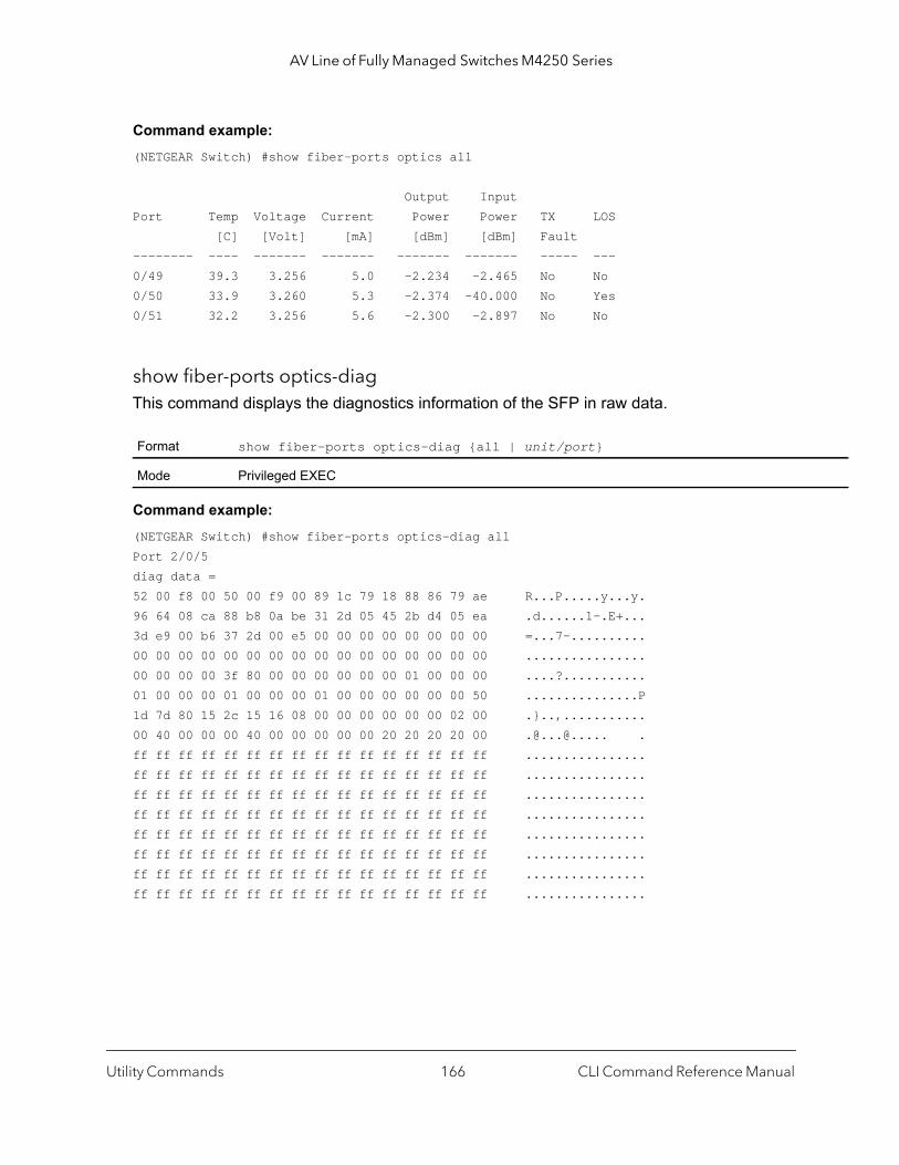
AV Line of Fully Managed Switches M4250 Series
Command example: (NETGEAR Switch) #show fiber-ports optics all
Output InputPort Temp Voltage Current Power Power TX LOS [C] [Volt] [mA] [dBm] [dBm] Fault-------- ---- ------- ------- ------- ------- ----- ---0/49 39.3 3.256 5.0 -2.234 -2.465 No No0/50 33.9 3.260 5.3 -2.374 -40.000 No Yes0/51 32.2 3.256 5.6 -2.300 -2.897 No No
show fiber-ports optics-diagThis command displays the diagnostics information of the SFP in raw data.
Command example: (NETGEAR Switch) #show fiber-ports optics-diag allPort 2/0/5diag data =52 00 f8 00 50 00 f9 00 89 1c 79 18 88 86 79 ae R...P.....y...y.96 64 08 ca 88 b8 0a be 31 2d 05 45 2b d4 05 ea .d......1-.E+...3d e9 00 b6 37 2d 00 e5 00 00 00 00 00 00 00 00 =...7-..........00 00 00 00 00 00 00 00 00 00 00 00 00 00 00 00 ................00 00 00 00 3f 80 00 00 00 00 00 00 01 00 00 00 ....?...........01 00 00 00 01 00 00 00 01 00 00 00 00 00 00 50 ...............P1d 7d 80 15 2c 15 16 08 00 00 00 00 00 00 02 00 .}..,...........00 40 00 00 00 40 00 00 00 00 00 20 20 20 20 00 .@...@..... .ff ff ff ff ff ff ff ff ff ff ff ff ff ff ff ff ................ff ff ff ff ff ff ff ff ff ff ff ff ff ff ff ff ................ff ff ff ff ff ff ff ff ff ff ff ff ff ff ff ff ................ff ff ff ff ff ff ff ff ff ff ff ff ff ff ff ff ................ff ff ff ff ff ff ff ff ff ff ff ff ff ff ff ff ................ff ff ff ff ff ff ff ff ff ff ff ff ff ff ff ff ................ff ff ff ff ff ff ff ff ff ff ff ff ff ff ff ff ................ff ff ff ff ff ff ff ff ff ff ff ff ff ff ff ff ................
Format show fiber-ports optics-diag {all | unit/port}
Mode Privileged EXEC
Utility Commands CLI Command Reference Manual166

AV Line of Fully Managed Switches M4250 Series
show fiber-ports optics-eepromThis command displays the Electrically Erasable Programmable Read-Only Memory (EEPROM) of the SFP.
Command example: (NETGEAR Switch) #show fiber-ports optics-eeprom 1/0/3
Port 1/0/3 vendor_name = NETGEAR vendor_sn = A7N2018312 date_code = 100625 vend_pn = AXM761 vend_rev = 10 eeprom data = 03 04 07 10 00 00 00 00 00 00 00 03 67 00 00 00 ............g... 08 03 00 1e 4e 45 54 47 45 41 52 20 20 20 20 20 ....NETGEAR 20 20 20 20 00 00 1f 22 41 58 4d 37 36 31 20 20 ..."AXM761 20 20 20 20 20 20 20 20 31 30 20 20 03 52 00 d2 10 .R.. 00 1a 00 00 41 37 4e 32 30 31 38 33 31 32 20 20 ....A7N2018312 20 20 20 20 31 30 30 36 32 35 20 20 68 f0 03 ca 100625 h... ff ff ff ff ff ff ff ff ff ff ff ff ff ff ff ff ................ ff ff ff ff ff ff ff ff ff ff ff ff ff ff ff 00 ................ ff ff ff ff ff ff ff ff ff ff ff ff ff ff ff ff ................ ff ff ff ff ff ff ff ff ff ff ff ff ff ff ff ff ................ ff ff ff ff ff ff ff ff ff ff ff ff ff ff ff ff ................ ff ff ff ff ff ff ff ff ff ff ff ff ff ff ff ff ................ ff ff ff ff ff ff ff ff ff ff ff ff ff ff ff ff ................ ff ff ff ff ff ff ff ff ff ff ff ff ff ff ff ff ................ ff ff ff ff ff ff ff ff ff ff ff ff ff ff ff ff ................ ff ff ff ff ff ff ff ff ff ff ff ff ff ff ff ff ................
show fiber-ports optics-infoThis command displays the SFP vendor related information like Vendor Name, Serial Number of the SFP, Part Number of the SFP. The values are derived from the SFP’s A0 table using the I2C interface.
Format show fiber-ports optics-eeprom {unit/port | all}
Mode Privileged EXEC
Format show fiber-ports optics-info {all | unit/port}
Mode Privileged EXEC
Utility Commands CLI Command Reference Manual167

AV Line of Fully Managed Switches M4250 Series
gned e full
code
ing in z*km the
ing in
the
II ing field
g the cates
to value
and ision
Command example: (NETGEAR Switch) #show fiber-ports optics-info all
Link Link Nominal Length Length Bit 50um 62.5um RatePort Vendor Name [m] [m] Serial Number Part Number [Mbps] Rev-------- ---------------- --- ---- ---------------- ---------------- ----- ----0/49 NETGEAR 8 3 A7N2018414 AXM761 10300 100/51 NETGEAR 8 3 A7N2018472 AXM761 10300 100/52 NETGEAR 8 3 A7N2018501 AXM761 10300 10
Field Description
Vendor Name The vendor name is a 16 character field that contains ASCII characters, left-aliand padded on the right with ASCII spaces (20h). The vendor name shall be thname of the corporation, a commonly accepted abbreviation of the name of thecorporation, the SCSI company code for the corporation, or the stock exchangefor the corporation.
Length (50um, OM2) This value specifies link length that is supported by the transceiver while operatcompliance with applicable standards using 50 micron multimode OM2 [500MHat 850nm] fiber. A value of zero means that the transceiver does not support 50micron multimode fiber or that the length information must be determined from transceiver technology.
Length (62.5um, OM1) This value specifies link length that is supported by the transceiver while operatcompliance with applicable standards using 62.5 micron multimode OM1 [200 MHz*km at 850nm, 500 MHz*km at 1310nm] fiber. A value of zero means that transceiver does not support 62.5 micron multimode fiber or that the length information must determined from the transceiver technology
Vendor SN The vendor serial number (vendor SN) is a 16 character field that contains ASCcharacters, left-aligned and padded on the right with ASCII spaces (20h), definthe vendor's serial number for the transceiver. A value of all zero in the 16-byteindicates that the vendor SN is unspecified.
Vendor PN The vendor part number (vendor PN) is a 16-byte field that contains ASCII characters, left aligned and added on the right with ASCII spaces (20h), defininvendor part number or product name. A value of all zero in the 16-byte field indithat the vendor PN is unspecified.
BR, nominal The nominal bit (signaling) rate (BR, nominal) is specified in units of 100 MBd, rounded off to the nearest 100 MBd. The bit rate includes those bits necessaryencode and delimit the signal as well as those bits carrying data information. A of 0 indicates that the bit rate is not specified and must be determined from thetransceiver technology. The actual information transfer rate will depend on the encoding of the data, as defined by the encoding value.
Vendor Rev The vendor revision number (vendor rev) contains ASCII characters, left alignedpadded on the right with ASCII spaces (20h), defining the vendor's product revnumber. A value of all zero in this field indicates that the vendor revision is unspecified.
Utility Commands CLI Command Reference Manual168
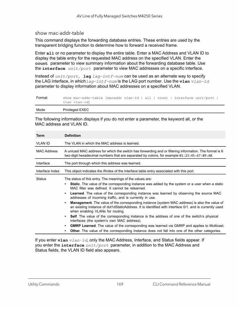
AV Line of Fully Managed Switches M4250 Series
|
at is 6
static
MAC
lue of used
cal
lticast.ries.
show mac-addr-tableThis command displays the forwarding database entries. These entries are used by the transparent bridging function to determine how to forward a received frame.
Enter all or no parameter to display the entire table. Enter a MAC Address and VLAN ID to display the table entry for the requested MAC address on the specified VLAN. Enter the count parameter to view summary information about the forwarding database table. Use the interface unit/port parameter to view MAC addresses on a specific interface.
Instead of unit/port, lag lag-intf-num can be used as an alternate way to specify the LAG interface, in whichlag-intf-num is the LAG port number. Use the vlan vlan-id parameter to display information about MAC addresses on a specified VLAN.
The following information displays if you do not enter a parameter, the keyword all, or the MAC address and VLAN ID.
If you enter vlan vlan-id, only the MAC Address, Interface, and Status fields appear. If you enter the interface unit/port parameter, in addition to the MAC Address and Status fields, the VLAN ID field also appears.
Format show mac-addr-table [macaddr vlan-id | all | count | interface unit/portvlan vlan-id]
Mode Privileged EXEC
Term Definition
VLAN ID The VLAN in which the MAC address is learned.
MAC Address A unicast MAC address for which the switch has forwarding and or filtering information. The formtwo-digit hexadecimal numbers that are separated by colons, for example 01:23:45:67:89:AB.
Interface The port through which this address was learned.
Interface Index This object indicates the ifIndex of the interface table entry associated with this port.
Status The status of this entry. The meanings of the values are:• Static. The value of the corresponding instance was added by the system or a user when a
MAC filter was defined. It cannot be relearned.• Learned. The value of the corresponding instance was learned by observing the source
addresses of incoming traffic, and is currently in use.• Management. The value of the corresponding instance (system MAC address) is also the va
an existing instance of dot1dStaticAddress. It is identified with interface 0/1. and is currentlywhen enabling VLANs for routing.
• Self. The value of the corresponding instance is the address of one of the switch’s physiinterfaces (the system’s own MAC address).
• GMRP Learned. The value of the corresponding was learned via GMRP and applies to Mu• Other. The value of the corresponding instance does not fall into one of the other catego
Utility Commands CLI Command Reference Manual169

AV Line of Fully Managed Switches M4250 Series
ing
ers a
erval,
eriod was
g
. The
The following information displays if you enter the count parameter.
process cpu thresholdUse this command to configure the CPU utilization thresholds. The Rising and Falling thresholds are specified as a percentage of CPU resources. The utilization monitoring time period can be configured from 5 seconds to 86400 seconds in multiples of 5 seconds. The CPU utilization threshold configuration is saved across a switch reboot. Configuring the falling utilization threshold is optional. If the falling CPU utilization parameters are not configured, then they take the same value as the rising CPU utilization parameters.
Term Definition
Dynamic Address count
Number of MAC addresses in the forwarding database that were automatically learned.
Static Address (User-defined) count
Number of MAC addresses in the forwarding database that were manually entered by a user.
Total MAC Addresses in use
Number of MAC addresses currently in the forwarding database.
Total MAC Addresses available
Number of MAC addresses the forwarding database can handle.
Format process cpu threshold type total rising threshold interval seconds [fallthreshold interval seconds]
Mode Global Config
Term Description
rising threshold The percentage of CPU resources that, when exceeded for the configured rising interval, triggnotification. The range is 1 to 100. The default is 0 (disabled).
rising interval seconds
The duration of the CPU rising threshold violation, in seconds, that must be met to trigger a notification. The range is 5 to 86400. The default is 0 (disabled).
falling threshold The percentage of CPU resources that, when usage falls below this level for the configured inttriggers a notification. The range is 1 to 100. The default is 0 (disabled).A notification is triggered when the total CPU utilization falls below this level for a configured pof time. The falling utilization threshold notification is made only if a rising threshold notificationpreviously done. The falling utilization threshold must always be equal or less than the rising threshold value. The CLI does not allow setting the falling threshold to be greater than the risinthreshold.
falling interval seconds
The duration of the CPU falling threshold, in seconds, that must be met to trigger a notificationrange is 5 to 86400. The default is 0 (disabled).
Utility Commands CLI Command Reference Manual170
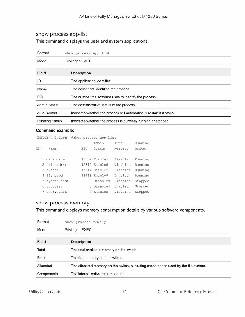
AV Line of Fully Managed Switches M4250 Series
show process app-listThis command displays the user and system applications.
Command example: (NETGEAR Switch) #show process app-list Admin Auto RunningID Name PID Status Restart Status---- ---------------- ----- --------- --------- ------- 1 dataplane 15309 Enabled Disabled Running 2 switchdrvr 15310 Enabled Disabled Running 3 syncdb 15314 Enabled Disabled Running 4 lighttpd 18718 Enabled Enabled Running 5 syncdb-test 0 Disabled Disabled Stopped 6 proctest 0 Disabled Enabled Stopped 7 user.start 0 Enabled Disabled Stopped
show process memoryThis command displays memory consumption details by various software components.
Format show process app-list
Mode Privileged EXEC
Field Description
ID The application identifier.
Name The name that identifies the process.
PID The number the software uses to identify the process.
Admin Status The administrative status of the process.
Auto Restart Indicates whether the process will automatically restart if it stops.
Running Status Indicates whether the process is currently running or stopped.
Format show process memory
Mode Privileged EXEC
Field Description
Total The total available memory on the switch.
Free The free memory on the switch.
Allocated The allocated memory on the switch, excluding cache space used by the file system.
Components The internal software component.
Utility Commands CLI Command Reference Manual171

AV Line of Fully Managed Switches M4250 Series
show process cpuThis command provides the percentage utilization of the CPU by different tasks. The number argument can be a number from 1 to 8.
Note: A busy CPU might not be caused by traffic processing but by various tasks that run simultaneously.
(NETGEAR Switch) #show process cpu Memory Utilization Reportstatus bytes------ ----------free 106450944alloc 423227392
CPU Utilization:
CurrentAllocated The amount of memory that a component is using.
Change The increase or decrease of the memory that a component consumes since the last time this command was executed. This field shows the difference in memory allocation between two successive executions of the command.
MaxAllocated The maximum amount of memory allocation by a component.
Allocs/Frees The number of memory allocation and free calls made by a component.
Format show process cpu [number | all]
Mode Privileged EXEC
Parameter Description
Free The system-wide free memory.
Alloc The system-wide allocated memory (excluding cache, file system used space).
Pid The process or thread ID.
Name The process or thread name.
5Secs The CPU utilization sampling in 5-second intervals.
60Secs The CPU utilization sampling in 60-second intervals.
300Secs The CPU utilization sampling in 300-second intervals.
Total CPU Utilization Total CPU utilization in percentage within the specified window of 5, 60, and 300 seconds.
Field Description
Utility Commands CLI Command Reference Manual172

AV Line of Fully Managed Switches M4250 Series
PID Name 5 Secs 60 Secs 300 Secs----------------------------------------------------------------- 765 _interrupt_thread 0.00% 0.01% 0.02% 767 bcmL2X.0 0.58% 0.35% 0.28% 768 bcmCNTR.0 0.77% 0.73% 0.72% 773 bcmRX 0.00% 0.04% 0.05% 786 cpuUtilMonitorTask 0.19% 0.23% 0.23% 834 dot1s_task 0.00% 0.01% 0.01% 810 hapiRxTask 0.00% 0.01% 0.01% 805 dtlTask 0.00% 0.02% 0.02% 863 spmTask 0.00% 0.01% 0.00% 894 ip6MapLocalDataTask 0.00% 0.01% 0.01% 908 RMONTask 0.00% 0.11% 0.12%----------------------------------------------------------------- Total CPU Utilization 1.55% 1.58% 1.50%
show process proc-listThis application displays the processes started by applications created by the Process Manager.
Command example: (NETGEAR Switch) #show process proc-list
Process Application VM Size VM PeakPID Name ID-Name Chld (KB) (KB) FD Count---- ---------------- -------------------- ---- -------- -------- --------15260 procmgr 0-procmgr No 1984 1984 815309 dataplane 1-dataplane No 293556 293560 11
Format show process proc-list
Mode Privileged EXEC
Parameter Description
PID The number the software uses to identify the process.
Process Name The name that identifies the process.
Application ID-Name
The application identifier and its associated name.
Child Indicates whether the process has spawned a child process.
VM Size Virtual memory size.
VM Peak The maximum amount of virtual memory the process has used at a given time.
FD Count The file descriptors count for the process.
Utility Commands CLI Command Reference Manual173

AV Line of Fully Managed Switches M4250 Series
15310 switchdrvr 2-switchdrvr No 177220 177408 5715314 syncdb 3-syncdb No 2060 2080 818718 lighttpd 4-lighttpd No 5508 5644 1118720 lua_magnet 4-lighttpd Yes 12112 12112 718721 lua_magnet 4-lighttpd Yes 25704 25708 7
show running-configUse this command to display or capture the current setting of different protocol packages supported on the switch. This command displays or captures commands with settings and configurations that differ from the default value. To display or capture the commands with settings and configurations that are equal to the default value, include the all option.
Note: The show running-config command does not display the User Password, even if you set one different from the default.
The output is displayed in script format, which can be used to configure another switch with the same configuration. If the optional scriptname is provided with a file name extension of .scr, the output is redirected to a script file.
Note: If you issue the show running-config command from a serial connection, access to the switch through remote connections (such as Telnet) is suspended while the output is being generated and displayed.
Note: If you use a text-based configuration file, the show running-config command only displays configured physical interfaces (i.e. if any interface only contains the default configuration, that interface will be skipped from the show running-config command output). This is true for any configuration mode that contains nothing but default configuration. That is, the command to enter a particular config mode, followed immediately by its exit command, are both omitted from the show running-config command output (and hence from the startup-config file when the system configuration is saved.)
Utility Commands CLI Command Reference Manual174

AV Line of Fully Managed Switches M4250 Series
Use the following keys to navigate the command output.
Note that --More-- or (q)uit is displayed at the bottom of the output screen until you reach the end of the output.
show running-config interfaceUse this command to display the running configuration for a specific interface. Valid interfaces include physical, LAG, loopback, tunnel and VLAN interfaces.
The following information is displayed for the command.
Key Action
Enter Advance one line.
Space Bar Advance one page.
q Stop the output and return to the prompt.
Format show running-config [all | scriptname]
Mode Privileged EXEC
Format show running-config interface {unit/port | lag lag-intf-num | loopback loopback-id | tunnel tunnel-id | vlan vlan-id}
Mode Privileged EXEC
Parameter Description
interface Running configuration for the specified interface.
lag-intf-num Running configuration for the LAG interface.
loopback-id Running configuration for the loopback interface.
tunnel-id Running configuration for the tunnel interface.
vlan-id Running configuration for the VLAN routing interface.
Parameter Description
unit/port Enter an interface in unit/port format.
lag Display the running config for a specified lag interface.
loopback Display the running config for a specified loopback interface.
tunnel Display the running config for a specified tunnel interface.
vlan Display the running config for a specified vlan routing interface.
Utility Commands CLI Command Reference Manual175
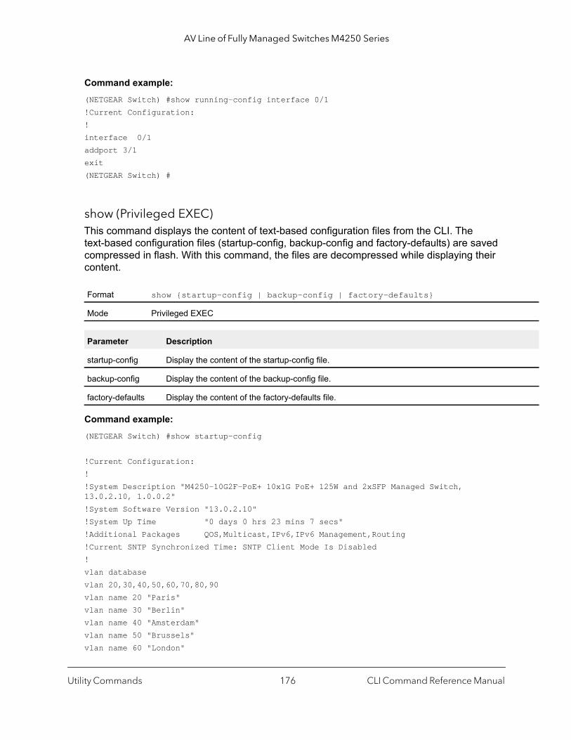
AV Line of Fully Managed Switches M4250 Series
Command example: (NETGEAR Switch) #show running-config interface 0/1!Current Configuration:!interface 0/1addport 3/1exit(NETGEAR Switch) #
show (Privileged EXEC)This command displays the content of text-based configuration files from the CLI. The text-based configuration files (startup-config, backup-config and factory-defaults) are saved compressed in flash. With this command, the files are decompressed while displaying their content.
Command example: (NETGEAR Switch) #show startup-config
!Current Configuration:!!System Description "M4250-10G2F-PoE+ 10x1G PoE+ 125W and 2xSFP Managed Switch, 13.0.2.10, 1.0.0.2"!System Software Version "13.0.2.10"!System Up Time "0 days 0 hrs 23 mins 7 secs"!Additional Packages QOS,Multicast,IPv6,IPv6 Management,Routing!Current SNTP Synchronized Time: SNTP Client Mode Is Disabled!vlan databasevlan 20,30,40,50,60,70,80,90vlan name 20 "Paris"vlan name 30 "Berlin"vlan name 40 "Amsterdam"vlan name 50 "Brussels"vlan name 60 "London"
Format show {startup-config | backup-config | factory-defaults}
Mode Privileged EXEC
Parameter Description
startup-config Display the content of the startup-config file.
backup-config Display the content of the backup-config file.
factory-defaults Display the content of the factory-defaults file.
Utility Commands CLI Command Reference Manual176
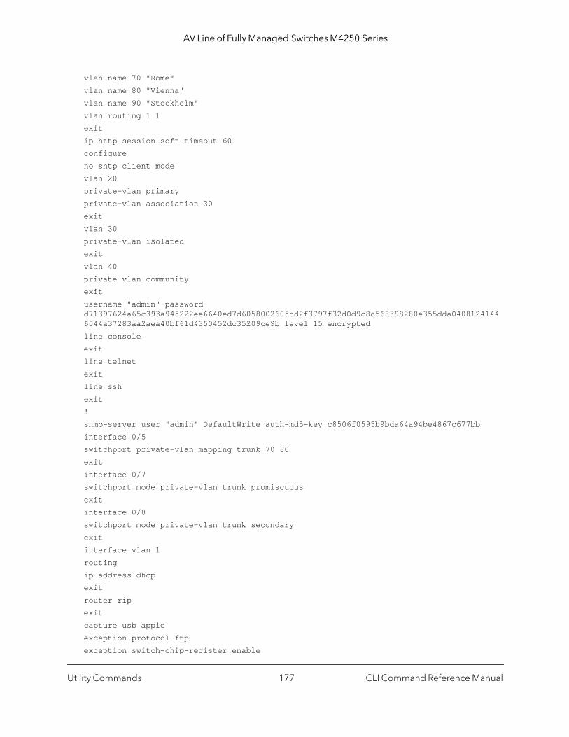
AV Line of Fully Managed Switches M4250 Series
vlan name 70 "Rome"vlan name 80 "Vienna"vlan name 90 "Stockholm"vlan routing 1 1exitip http session soft-timeout 60configureno sntp client modevlan 20private-vlan primaryprivate-vlan association 30exitvlan 30private-vlan isolatedexitvlan 40private-vlan communityexitusername "admin" password d71397624a65c393a945222ee6640ed7d6058002605cd2f3797f32d0d9c8c568398280e355dda04081241446044a37283aa2aea40bf61d4350452dc35209ce9b level 15 encryptedline consoleexitline telnetexitline sshexit!snmp-server user "admin" DefaultWrite auth-md5-key c8506f0595b9bda64a94be4867c677bbinterface 0/5switchport private-vlan mapping trunk 70 80exitinterface 0/7switchport mode private-vlan trunk promiscuousexitinterface 0/8switchport mode private-vlan trunk secondaryexitinterface vlan 1routingip address dhcpexitrouter ripexitcapture usb appieexception protocol ftpexception switch-chip-register enable
Utility Commands CLI Command Reference Manual177

AV Line of Fully Managed Switches M4250 Series
exception dump ftp-server 10.12.13.14 username "admin" password "Password1!"exitip http secure-session soft-timeout 60
dirUse this command to list the files in flash from the CLI.
Command example: (NETGEAR Switch) #dir
0 drwx 2048 May 09 2002 16:47:30 . 0 drwx 2048 May 09 2002 16:45:28 .. 0 -rwx 592 May 09 2002 14:50:24 slog2.txt 0 -rwx 72 May 09 2002 16:45:28 boot.dim 0 -rwx 0 May 09 2002 14:46:36 olog2.txt 0 -rwx 13376020 May 09 2002 14:49:10 image1 0 -rwx 0 Apr 06 2001 19:58:28 fsyssize 0 -rwx 1776 May 09 2002 16:44:38 slog1.txt 0 -rwx 356 Jun 17 2001 10:43:18 crashdump.ctl 0 -rwx 1024 May 09 2002 16:45:44 sslt.rnd 0 -rwx 14328276 May 09 2002 16:01:06 image2 0 -rwx 148 May 09 2002 16:46:06 hpc_broad.cfg 0 -rwx 0 May 09 2002 14:51:28 olog1.txt 0 -rwx 517 Jul 23 2001 17:24:00 ssh_host_key 0 -rwx 69040 Jun 17 2001 10:43:04 log_error_crashdump 0 -rwx 891 Apr 08 2000 11:14:28 sslt_key1.pem 0 -rwx 887 Jul 23 2001 17:24:00 ssh_host_rsa_key 0 -rwx 668 Jul 23 2001 17:24:34 ssh_host_dsa_key 0 -rwx 156 Apr 26 2001 13:57:46 dh512.pem 0 -rwx 245 Apr 26 2001 13:57:46 dh1024.pem 0 -rwx 0 May 09 2002 16:45:30 slog0.txt
show sysinfoThis command displays switch information.
Format dir
Mode Privileged EXEC
Format show sysinfo
Mode Privileged EXEC
Utility Commands CLI Command Reference Manual178

AV Line of Fully Managed Switches M4250 Series
show tech-supportUse the show tech-support command to display system and configuration information when you contact technical support. The output of the show tech-support command combines the output of the following commands and includes log history files from previous runs:
• show version
• show sysinfo
• show port all
• show isdp neighbors
• show logging
• show event log
• show logging buffered
• show trap log
• show running-config
• show igmpsnooping
• show mac-address-table multicast
• show mac-address-table igmpsnooping
• show igmpsnooping querier detail
• show igmpsnooping ssm stats
• show igmpsnooping ssm groups
• show igmpsnooping ssm entries
• show igmpsnooping group
Field Definition
Switch Description Text used to identify this switch.
System Name Name used to identify the switch.The factory default is blank. To configure the system name, see snmp-server on page 96.
System Location Text used to identify the location of the switch. The factory default is blank. To configure the system location, see snmp-server on page 96.
System Contact Text used to identify a contact person for this switch. The factory default is blank. To configure the system location, see snmp-server on page 96.
System ObjectID The base object ID for the switch’s enterprise MIB.
System Up Time The time in days, hours and minutes since the last switch reboot.
Current SNTP Synchronized Time
The system time acquired from a network SNTP server.
MIBs Supported A list of MIBs supported by this agent.
Utility Commands CLI Command Reference Manual179
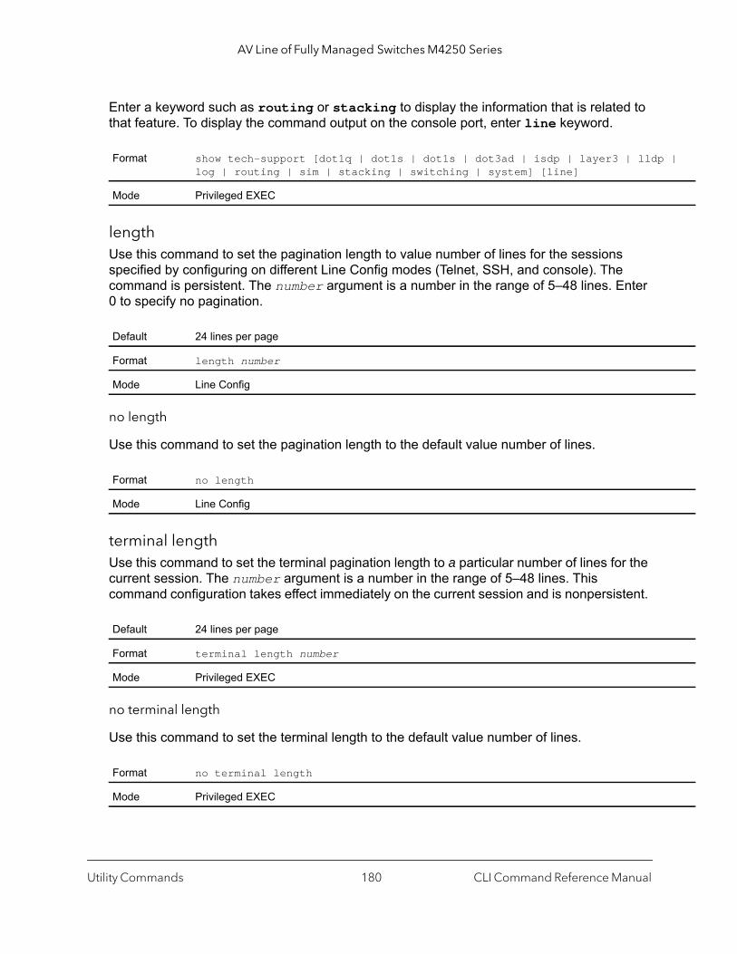
AV Line of Fully Managed Switches M4250 Series
|
Enter a keyword such as routing or stacking to display the information that is related to that feature. To display the command output on the console port, enter line keyword.
lengthUse this command to set the pagination length to value number of lines for the sessions specified by configuring on different Line Config modes (Telnet, SSH, and console). The command is persistent. The number argument is a number in the range of 5–48 lines. Enter 0 to specify no pagination.
no length
Use this command to set the pagination length to the default value number of lines.
terminal lengthUse this command to set the terminal pagination length to a particular number of lines for the current session. The number argument is a number in the range of 5–48 lines. This command configuration takes effect immediately on the current session and is nonpersistent.
no terminal length
Use this command to set the terminal length to the default value number of lines.
Format show tech-support [dot1q | dot1s | dot1s | dot3ad | isdp | layer3 | lldplog | routing | sim | stacking | switching | system] [line]
Mode Privileged EXEC
Default 24 lines per page
Format length number
Mode Line Config
Format no length
Mode Line Config
Default 24 lines per page
Format terminal length number
Mode Privileged EXEC
Format no terminal length
Mode Privileged EXEC
Utility Commands CLI Command Reference Manual180

AV Line of Fully Managed Switches M4250 Series
ge is
show terminal lengthUse this command to display all the configured terminal length values.
Command example: (NETGEAR Switch) #show terminal length Terminal Length:----------------------For Current Session………………….24For Serial Console…………………… 24For Telnet Sessions………………….24For SSH Sessions…………………….. 24
memory free low-watermark processorUse this command to get notifications when the CPU free memory falls below the configured threshold. A notification is generated when the free memory falls below the threshold. Another notification is generated once the available free memory rises to 10 percent above the specified threshold. To prevent generation of excessive notifications when the CPU free memory fluctuates around the configured threshold, only one Rising or Falling memory notification is generated over a period of 60 seconds. The threshold is specified in kilobytes. The CPU free memory threshold configuration is saved across a switch reboot.
Switch Services Commands
This section describes the switch services commands. Switch services are services that provide support for features such as temperature, power supply status, fan control, and others. Each of these services is platform dependent. (For example, some platforms may have temperature sensors, but no fan controller. Or, others may have both while others have neither.)
Format show terminal length
Mode Privileged EXEC
Format memory free low-watermark processor threshold
Mode Global Config
Parameter Description
threshold When CPU free memory falls below this threshold, a notification message is triggered. The ran1–1017416 (the maximum available memory on the switch). The default is 0 (disabled).
Utility Commands CLI Command Reference Manual181

AV Line of Fully Managed Switches M4250 Series
, and
ode holds.
mode
the block
peed rable
by
environment fan control mode Use this command to set the fan mode.
Note: The fan setting changes immediately. However, depending on the switch model, if the temperature detected by the temperature sensor exceeds its threshold, a PoE budget is exceeded, or a traffic load condition is exceeded, the switch automatically overrides your manual setting.
environment temprangeUse this command to set the allowed temperature range for normal operation.
Format environment fan control mode {auto | cool | off | quiet}
Mode Global Config
Parameter Definition
auto Sets the fans to Auto mode, which, in this firmware version, is identical to quiet mode.
cool Sets the fans to Cool mode.In Cool mode, the fans consistently function at 100 percent speed, provide maximum coolingproduce considerable noise.
Note: In Quiet mode, the switch might automatically change back and forth between Cool mand Quiet mode until a temperature, PoE budget, or traffic load condition returns within thres
off Sets the fans to Off mode.In Off mode, the fans produce no noise. You can only manually set the fans in Off mode. Off is not supported on some models.
quiet Sets the fans to Quiet mode, which is the default mode. In Quiet mode, the following applies:• The fans support intelligent operation, which enables the switch to automatically start
operation of the fans, gradually increase the speed of the fans, and either halt PoE or traffic if the temperature exceeds a critical level.
• The fans function from 25 to 75 percent speed and can reach 100 percent speed. At 25 percent speed, the fans produce minimal noise. Fan noise increases at 50 percent sand even more so at 75 percent speed. At 100 percent speed, the fans produce considenoise.
Note: For detailed information about temperature thresholds, PoE budgets, and traffic load conditions that affect the fans, see the hardware installation guide, which you can download visiting netgear.com/support/download.
Format environment temprange min temperature max temperature
Mode Global Config
Utility Commands CLI Command Reference Manual182
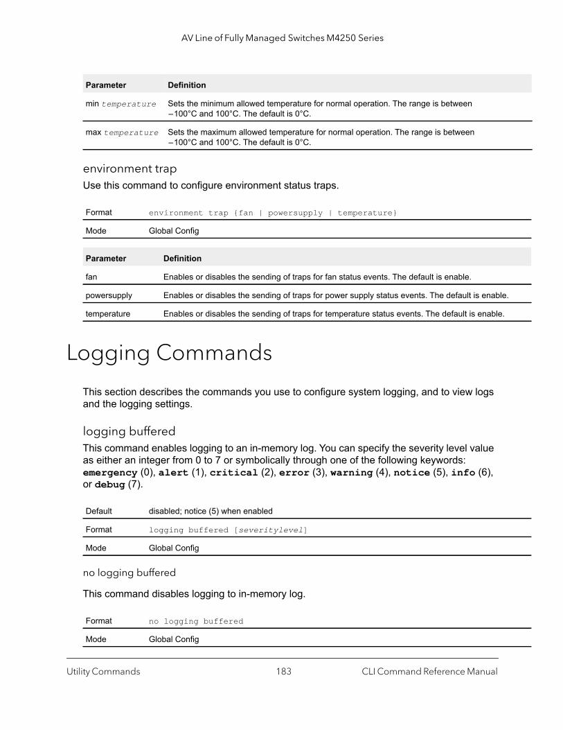
AV Line of Fully Managed Switches M4250 Series
.
environment trapUse this command to configure environment status traps.
Logging Commands
This section describes the commands you use to configure system logging, and to view logs and the logging settings.
logging bufferedThis command enables logging to an in-memory log. You can specify the severity level value as either an integer from 0 to 7 or symbolically through one of the following keywords: emergency (0), alert (1), critical (2), error (3), warning (4), notice (5), info (6), or debug (7).
no logging buffered
This command disables logging to in-memory log.
Parameter Definition
min temperature Sets the minimum allowed temperature for normal operation. The range is between – 100°C and 100°C. The default is 0°C.
max temperature Sets the maximum allowed temperature for normal operation. The range is between – 100°C and 100°C. The default is 0°C.
Format environment trap {fan | powersupply | temperature}
Mode Global Config
Parameter Definition
fan Enables or disables the sending of traps for fan status events. The default is enable.
powersupply Enables or disables the sending of traps for power supply status events. The default is enable
temperature Enables or disables the sending of traps for temperature status events. The default is enable.
Default disabled; notice (5) when enabled
Format logging buffered [severitylevel]
Mode Global Config
Format no logging buffered
Mode Global Config
Utility Commands CLI Command Reference Manual183
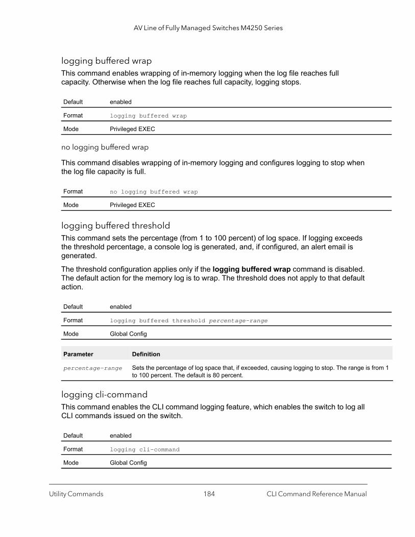
AV Line of Fully Managed Switches M4250 Series
rom 1
logging buffered wrapThis command enables wrapping of in-memory logging when the log file reaches full capacity. Otherwise when the log file reaches full capacity, logging stops.
no logging buffered wrap
This command disables wrapping of in-memory logging and configures logging to stop when the log file capacity is full.
logging buffered thresholdThis command sets the percentage (from 1 to 100 percent) of log space. If logging exceeds the threshold percentage, a console log is generated, and, if configured, an alert email is generated.
The threshold configuration applies only if the logging buffered wrap command is disabled. The default action for the memory log is to wrap. The threshold does not apply to that default action.
logging cli-commandThis command enables the CLI command logging feature, which enables the switch to log all CLI commands issued on the switch.
Default enabled
Format logging buffered wrap
Mode Privileged EXEC
Format no logging buffered wrap
Mode Privileged EXEC
Default enabled
Format logging buffered threshold percentage-range
Mode Global Config
Parameter Definition
percentage-range Sets the percentage of log space that, if exceeded, causing logging to stop. The range is fto 100 percent. The default is 80 percent.
Default enabled
Format logging cli-command
Mode Global Config
Utility Commands CLI Command Reference Manual184

AV Line of Fully Managed Switches M4250 Series
ame,
no logging cli-command
This command disables the CLI command Logging feature.
logging consoleThis command enables logging to the console. You can specify the severitylevel value as either an integer from 0 to 7 or symbolically through one of the following keywords:
emergency (0), alert (1), critical (2), error (3), warning (4), notice (5), info (6), or debug (7).
no logging console
This command disables logging to the console.
logging hostThis command configures the logging host parameters. You can configure up to eight hosts.
Format no logging cli-command
Mode Global Config
Default disabled; error (3) when enabled
Format logging console [severitylevel]
Mode Global Config
Format no logging console
Mode Global Config
Default • port-number. 514• severitylevel. 2
Format logging host {hostaddress | hostname} addresstype [tls {anon | x509name certificate-index}] {port-number severitylevel}
Mode Global Config
Parameter Description
hostaddress | hostname
The IP address or name of the logging host.
address-type Indicates the type of address (IPv4, IPv6, or DNS) being passed.
tls [anon | x509name]
Enables TLS security for the host through either anon (which stands for anonymous) or x509nin which you must specify a certificate number.
Utility Commands CLI Command Reference Manual185

AV Line of Fully Managed Switches M4250 Series
ber
6), or
Command example: (NETGEAR Switch) (Config)# logging host google.com dns 214 (NETGEAR Switch) (Config)# logging host 10.130.64.88 ipv4 214 6(NETGEAR Switch) (Config)# logging host 2000::150 ipv6 214 7
logging host reconfigureThis command enables logging host reconfiguration.
logging host removeThis command disables logging to host. See show logging hosts on page 190 for a list of host indexes.
logging protocolThis command configures the logging protocol version number as 0 or 1. RFC 3164 uses version 0 and RFC 5424 uses version 1.
certificate-index If you select x509name, use the certificate-index argument to specify the certificate numthat must be used for authentication. The valid range is from 0 to 8. Use 0 for the default file.
port-number A port number from 1 to 65535.
severitylevel Specify this value as either an integer from 0 to 7, or symbolically through one of the followingkeywords: emergency (0), alert (1), critical (2), error (3), warning (4), notice (5), info (debug (7).
Format logging host reconfigure hostindex
Mode Global Config
Parameter Description
hostindex Enter the Logging Host Index for which to change the IP address.
Format logging host remove hostindex
Mode Global Config
Default 0
Format logging protocol {0 | 1}
Mode Global Config
Parameter Description
Utility Commands CLI Command Reference Manual186
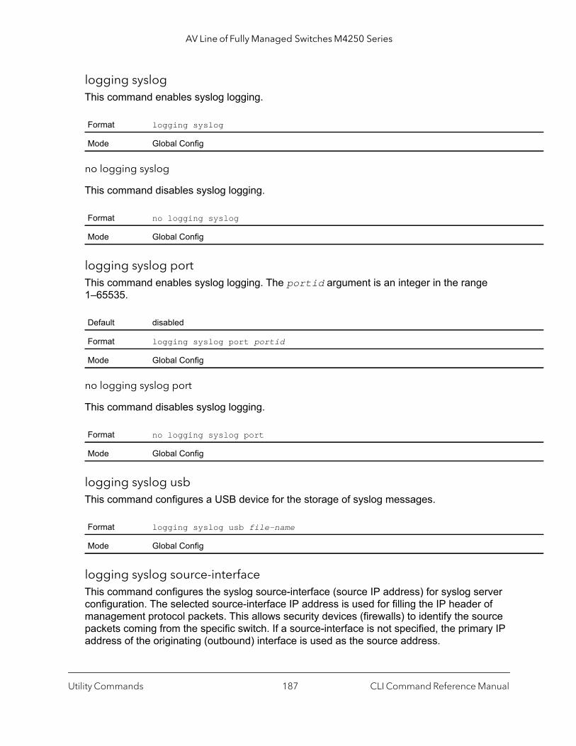
AV Line of Fully Managed Switches M4250 Series
logging syslogThis command enables syslog logging.
no logging syslog
This command disables syslog logging.
logging syslog portThis command enables syslog logging. The portid argument is an integer in the range 1–65535.
no logging syslog port
This command disables syslog logging.
logging syslog usbThis command configures a USB device for the storage of syslog messages.
logging syslog source-interfaceThis command configures the syslog source-interface (source IP address) for syslog server configuration. The selected source-interface IP address is used for filling the IP header of management protocol packets. This allows security devices (firewalls) to identify the source packets coming from the specific switch. If a source-interface is not specified, the primary IP address of the originating (outbound) interface is used as the source address.
Format logging syslog
Mode Global Config
Format no logging syslog
Mode Global Config
Default disabled
Format logging syslog port portid
Mode Global Config
Format no logging syslog port
Mode Global Config
Format logging syslog usb file-name
Mode Global Config
Utility Commands CLI Command Reference Manual187
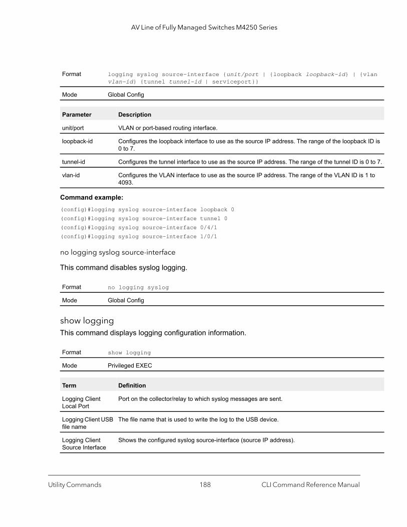
AV Line of Fully Managed Switches M4250 Series
lan
ID is
0 to 7.
to
Command example: (config)#logging syslog source-interface loopback 0(config)#logging syslog source-interface tunnel 0(config)#logging syslog source-interface 0/4/1(config)#logging syslog source-interface 1/0/1
no logging syslog source-interface
This command disables syslog logging.
show logging This command displays logging configuration information.
Format logging syslog source-interface {unit/port | {loopback loopback-id} | {vvlan-id} {tunnel tunnel-id | serviceport}}
Mode Global Config
Parameter Description
unit/port VLAN or port-based routing interface.
loopback-id Configures the loopback interface to use as the source IP address. The range of the loopback0 to 7.
tunnel-id Configures the tunnel interface to use as the source IP address. The range of the tunnel ID is
vlan-id Configures the VLAN interface to use as the source IP address. The range of the VLAN ID is 14093.
Format no logging syslog
Mode Global Config
Format show logging
Mode Privileged EXEC
Term Definition
Logging Client Local Port
Port on the collector/relay to which syslog messages are sent.
Logging Client USB file name
The file name that is used to write the log to the USB device.
Logging Client Source Interface
Shows the configured syslog source-interface (source IP address).
Utility Commands CLI Command Reference Manual188
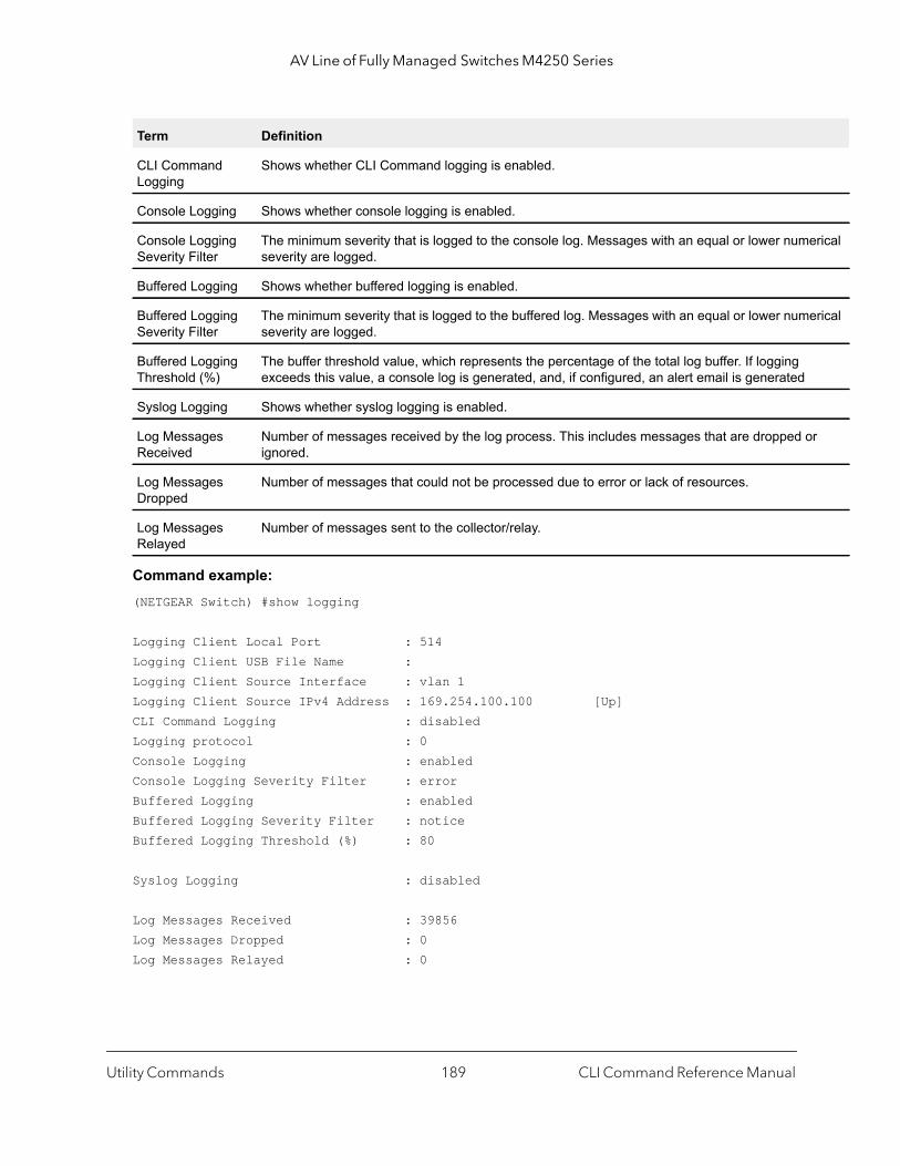
AV Line of Fully Managed Switches M4250 Series
erical
erical
r
Command example: (NETGEAR Switch) #show logging
Logging Client Local Port : 514Logging Client USB File Name :Logging Client Source Interface : vlan 1Logging Client Source IPv4 Address : 169.254.100.100 [Up]CLI Command Logging : disabledLogging protocol : 0Console Logging : enabledConsole Logging Severity Filter : errorBuffered Logging : enabledBuffered Logging Severity Filter : noticeBuffered Logging Threshold (%) : 80
Syslog Logging : disabled
Log Messages Received : 39856Log Messages Dropped : 0Log Messages Relayed : 0
CLI Command Logging
Shows whether CLI Command logging is enabled.
Console Logging Shows whether console logging is enabled.
Console Logging Severity Filter
The minimum severity that is logged to the console log. Messages with an equal or lower numseverity are logged.
Buffered Logging Shows whether buffered logging is enabled.
Buffered Logging Severity Filter
The minimum severity that is logged to the buffered log. Messages with an equal or lower numseverity are logged.
Buffered Logging Threshold (%)
The buffer threshold value, which represents the percentage of the total log buffer. If logging exceeds this value, a console log is generated, and, if configured, an alert email is generated
Syslog Logging Shows whether syslog logging is enabled.
Log Messages Received
Number of messages received by the log process. This includes messages that are dropped oignored.
Log Messages Dropped
Number of messages that could not be processed due to error or lack of resources.
Log Messages Relayed
Number of messages sent to the collector/relay.
Term Definition
Utility Commands CLI Command Reference Manual189

AV Line of Fully Managed Switches M4250 Series
alert
ent.
used
show logging bufferedThis command displays buffered logging (system startup and system operation logs).
show logging hostsThis command displays all configured logging hosts. Use the “|” character to display the output filter options.
Format show logging buffered
Mode Privileged EXEC
Term Definition
Buffered (In-Memory) Logging
Shows whether the In-Memory log is enabled or disabled.
Buffered Logging Wrapping Behavior
The behavior of the In Memory log when faced with a log full situation.
Buffered Log Count The count of valid entries in the buffered log.
Buffered Log Threshold (lines)
The configured threshold value expressed as the number of log lines.
Format show logging hosts
Mode Privileged EXEC
Term Definition
Host Index Used for deleting hosts.
IP Address / Hostname
IP address or hostname of the logging host.
Severity Level The minimum severity to log to the specified address. The possible values are emergency (0),(1), critical (2), error (3), warning (4), notice (5), info (6), or debug (7).
Port The server port number, which is the port on the local host from which syslog messages are s
Status The status of SNMP (Active, Not in Service, or Not Ready).
Mode The type of security: UDP or TLS.
Auth The type of authentication mode: anonymous or x509name.
Cert# The certificate number to be used for authentication. The valid range is from 0 to 8. Index 0 is for the default file.
Utility Commands CLI Command Reference Manual190
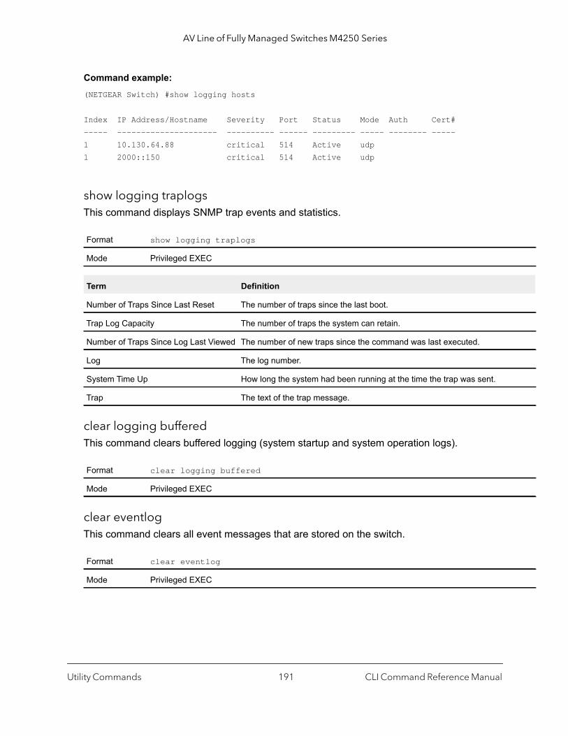
AV Line of Fully Managed Switches M4250 Series
Command example: (NETGEAR Switch) #show logging hosts
Index IP Address/Hostname Severity Port Status Mode Auth Cert#----- --------------------- ---------- ------ --------- ----- -------- -----1 10.130.64.88 critical 514 Active udp1 2000::150 critical 514 Active udp
show logging traplogsThis command displays SNMP trap events and statistics.
clear logging bufferedThis command clears buffered logging (system startup and system operation logs).
clear eventlogThis command clears all event messages that are stored on the switch.
Format show logging traplogs
Mode Privileged EXEC
Term Definition
Number of Traps Since Last Reset The number of traps since the last boot.
Trap Log Capacity The number of traps the system can retain.
Number of Traps Since Log Last Viewed The number of new traps since the command was last executed.
Log The log number.
System Time Up How long the system had been running at the time the trap was sent.
Trap The text of the trap message.
Format clear logging buffered
Mode Privileged EXEC
Format clear eventlog
Mode Privileged EXEC
Utility Commands CLI Command Reference Manual191
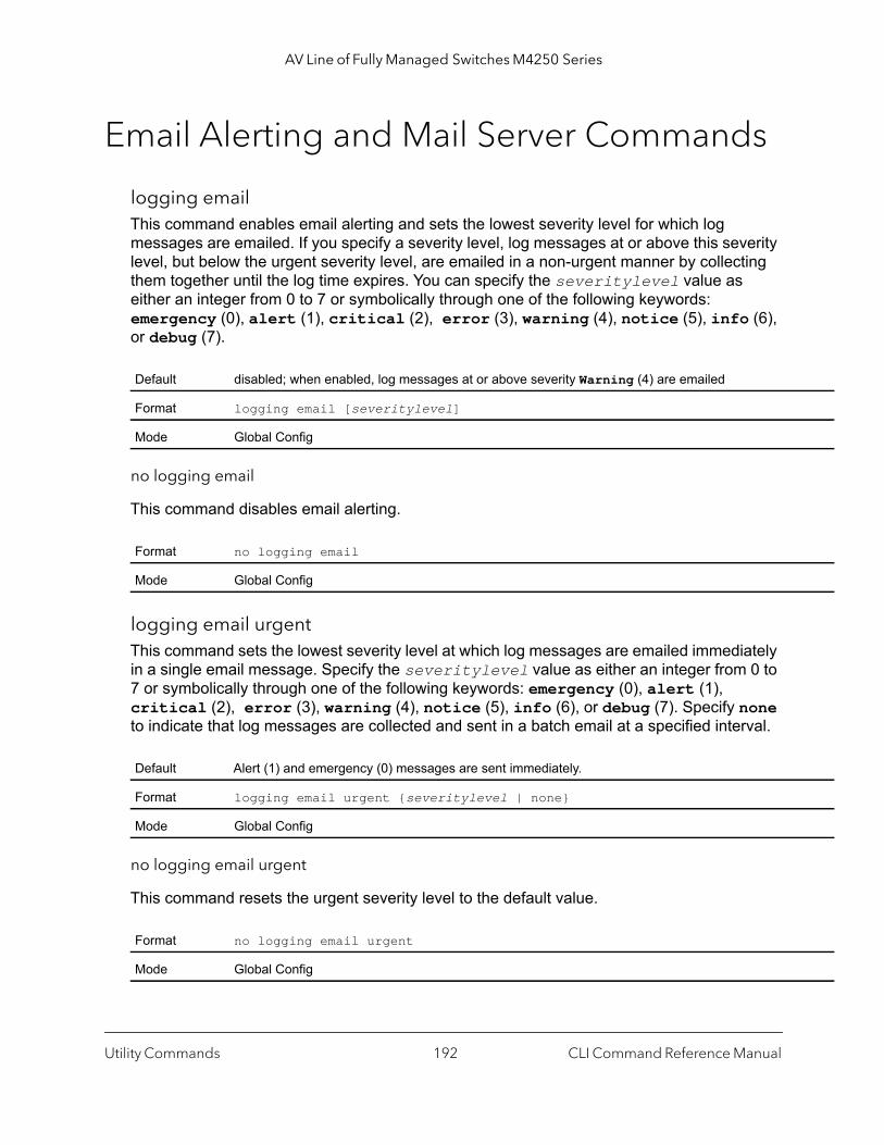
AV Line of Fully Managed Switches M4250 Series
Email Alerting and Mail Server Commands
logging emailThis command enables email alerting and sets the lowest severity level for which log messages are emailed. If you specify a severity level, log messages at or above this severity level, but below the urgent severity level, are emailed in a non-urgent manner by collecting them together until the log time expires. You can specify the severitylevel value as either an integer from 0 to 7 or symbolically through one of the following keywords: emergency (0), alert (1), critical (2), error (3), warning (4), notice (5), info (6), or debug (7).
no logging email
This command disables email alerting.
logging email urgentThis command sets the lowest severity level at which log messages are emailed immediately in a single email message. Specify the severitylevel value as either an integer from 0 to 7 or symbolically through one of the following keywords: emergency (0), alert (1), critical (2), error (3), warning (4), notice (5), info (6), or debug (7). Specify none to indicate that log messages are collected and sent in a batch email at a specified interval.
no logging email urgent
This command resets the urgent severity level to the default value.
Default disabled; when enabled, log messages at or above severity Warning (4) are emailed
Format logging email [severitylevel]
Mode Global Config
Format no logging email
Mode Global Config
Default Alert (1) and emergency (0) messages are sent immediately.
Format logging email urgent {severitylevel | none}
Mode Global Config
Format no logging email urgent
Mode Global Config
Utility Commands CLI Command Reference Manual192
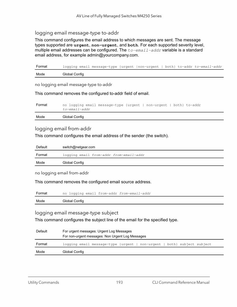
AV Line of Fully Managed Switches M4250 Series
addr
logging email message-type to-addrThis command configures the email address to which messages are sent. The message types supported are urgent, non-urgent, and both. For each supported severity level, multiple email addresses can be configured. The to-email-addr variable is a standard email address, for example [email protected].
no logging email message-type to-addr
This command removes the configured to-addr field of email.
logging email from-addrThis command configures the email address of the sender (the switch).
no logging email from-addr
This command removes the configured email source address.
logging email message-type subjectThis command configures the subject line of the email for the specified type.
Format logging email message-type {urgent |non-urgent | both} to-addr to-email-
Mode Global Config
Format no logging email message-type {urgent | non-urgent | both} to-addr to-email-addr
Mode Global Config
Default [email protected]
Format logging email from-addr from-email-addr
Mode Global Config
Format no logging email from-addr from-email-addr
Mode Global Config
Default For urgent messages: Urgent Log MessagesFor non-urgent messages: Non Urgent Log Messages
Format logging email message-type {urgent | non-urgent | both} subject subject
Mode Global Config
Utility Commands CLI Command Reference Manual193

AV Line of Fully Managed Switches M4250 Series
no logging email message-type subject
This command removes the configured email subject for the specified message type and restores it to the default email subject.
logging email logtimeThis command configures how frequently non-urgent email messages are sent. Non-urgent messages are collected and sent in a batch email at the specified interval. The minutes argument is a number in the range 30–1440 minutes.
no logging email logtime
This command resets the non-urgent log time to the default value.
logging trapsThis command sets the severity at which SNMP traps are logged and sent in an email. Specify the severitylevel value as either an integer from 0 to 7 or symbolically through one of the following keywords: emergency (0), alert (1), critical (2), error (3), warning (4), notice (5), info (6), or debug (7).
no logging traps
This command resets the SNMP trap logging severity level to the default value.
Format no logging email message-type {urgent |non-urgent | both} subject
Mode Global Config
Default 30 minutes
Format logging email logtime minutes
Mode Global Config
Format no logging email logtime
Mode Global Config
Default Info (6) messages and higher are logged.
Format logging traps severitylevel
Mode Global Config
Format no logging traps
Mode Global Config
Utility Commands CLI Command Reference Manual194

AV Line of Fully Managed Switches M4250 Series
y
sent
, up t are
es.
logging email test message-typeThis command sends an email to the SMTP server to test the email alerting function.
show logging email configThis command displays information about the email alert configuration.
show logging email statisticsThis command displays email alerting statistics.
Format logging email test message-type {urgent | non-urgent | both} message-bodmessage-body
Mode Global Config
Format show logging email config
Mode Privileged EXEC
Term Definition
Email Alert Logging The administrative status of the feature: enabled or disabled
Email Alert From Address The email address of the sender (the switch).
Email Alert Urgent Severity Level The lowest severity level that is considered urgent. Messages of this type areimmediately.
Email Alert Non Urgent Severity Level
The lowest severity level that is considered non-urgent. Messages of this typeto the urgent level, are collected and sent in a batch email. Log messages thaless severe are not sent in an email message at all.
Email Alert Trap Severity Level The lowest severity level at which traps are logged.
Email Alert Notification Period The amount of time to wait between non-urgent messages.
Email Alert To Address Table The configured email recipients.
Email Alert Subject Table The subject lines included in urgent (Type 1) and non-urgent (Type 2) messag
For Msg Type urgent, subject is The configured email subject for sending urgent messages.
For Msg Type non-urgent, subject is The configured email subject for sending non-urgent messages.
Format show logging email statistics
Mode Privileged EXEC
Utility Commands CLI Command Reference Manual195
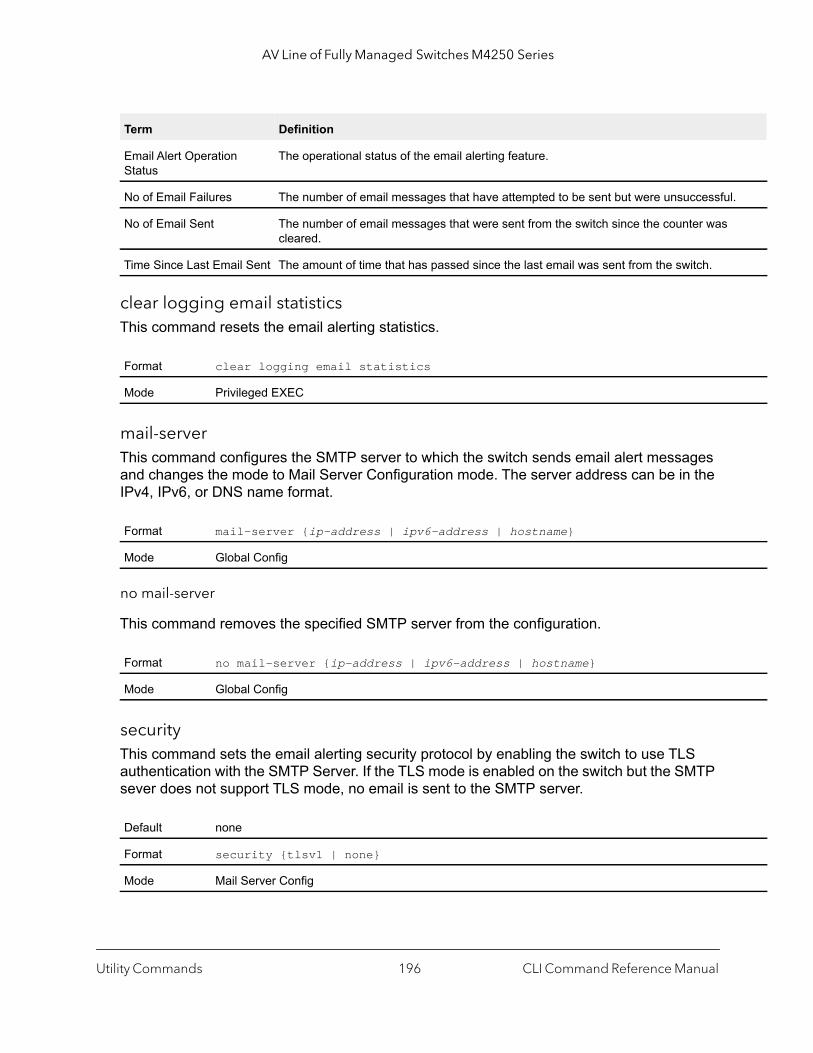
AV Line of Fully Managed Switches M4250 Series
l.
clear logging email statisticsThis command resets the email alerting statistics.
mail-serverThis command configures the SMTP server to which the switch sends email alert messages and changes the mode to Mail Server Configuration mode. The server address can be in the IPv4, IPv6, or DNS name format.
no mail-server
This command removes the specified SMTP server from the configuration.
securityThis command sets the email alerting security protocol by enabling the switch to use TLS authentication with the SMTP Server. If the TLS mode is enabled on the switch but the SMTP sever does not support TLS mode, no email is sent to the SMTP server.
Term Definition
Email Alert Operation Status
The operational status of the email alerting feature.
No of Email Failures The number of email messages that have attempted to be sent but were unsuccessfu
No of Email Sent The number of email messages that were sent from the switch since the counter was cleared.
Time Since Last Email Sent The amount of time that has passed since the last email was sent from the switch.
Format clear logging email statistics
Mode Privileged EXEC
Format mail-server {ip-address | ipv6-address | hostname}
Mode Global Config
Format no mail-server {ip-address | ipv6-address | hostname}
Mode Global Config
Default none
Format security {tlsv1 | none}
Mode Mail Server Config
Utility Commands CLI Command Reference Manual196
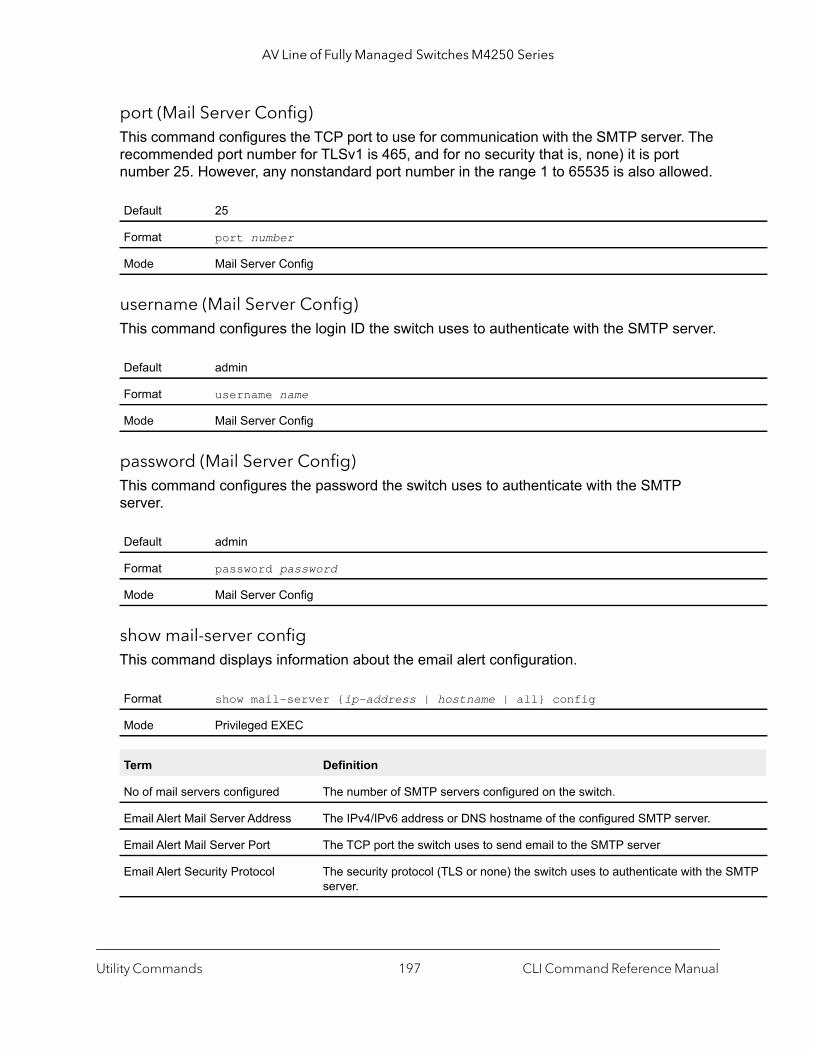
AV Line of Fully Managed Switches M4250 Series
MTP
port (Mail Server Config)This command configures the TCP port to use for communication with the SMTP server. The recommended port number for TLSv1 is 465, and for no security that is, none) it is port number 25. However, any nonstandard port number in the range 1 to 65535 is also allowed.
username (Mail Server Config)This command configures the login ID the switch uses to authenticate with the SMTP server.
password (Mail Server Config)This command configures the password the switch uses to authenticate with the SMTP server.
show mail-server configThis command displays information about the email alert configuration.
Default 25
Format port number
Mode Mail Server Config
Default admin
Format username name
Mode Mail Server Config
Default admin
Format password password
Mode Mail Server Config
Format show mail-server {ip-address | hostname | all} config
Mode Privileged EXEC
Term Definition
No of mail servers configured The number of SMTP servers configured on the switch.
Email Alert Mail Server Address The IPv4/IPv6 address or DNS hostname of the configured SMTP server.
Email Alert Mail Server Port The TCP port the switch uses to send email to the SMTP server
Email Alert Security Protocol The security protocol (TLS or none) the switch uses to authenticate with the Sserver.
Utility Commands CLI Command Reference Manual197

AV Line of Fully Managed Switches M4250 Series
System Utility and Clear Commands
This section describes the commands you use to help troubleshoot connectivity issues and to restore various configurations to their factory defaults.
traceroute Use the traceroute command to discover the routes that IPv4 or IPv6 packets actually take when traveling to their destination through the network on a hop-by-hop basis. Traceroute continues to provide a synchronous response when initiated from the CLI.
The user may specify the source IP address of the traceroute probes. Recall that traceroute works by sending packets that are expected not to reach their final destination, but instead trigger ICMP error messages back to the source address from each hop along the forward path to the destination. By specifying the source address, the user can determine where along the forward path there is no route back to the source address. Note that this is only useful if the route from source to destination and destination to source is symmetric.) It would be common, for example, to send a traceroute from an edge router to a target higher in the network using a source address from a host subnet on the edge router. This would test reachability from within the network back to hosts attached to the edge router. Alternatively, one might send a traceroute with an address on a loopback interface as a source to test reachability back to the loopback interface address.
In the CLI, the user may specify the source either as an IPv4 address, IPv6 address, or as a routing interface. When the source is specified as a routing interface, the traceroute is sent using the primary IPv4 address on the source interface. With SNMP, the source must be specified as an address. The source cannot be specified in the web UI.
The switch does not accept an incoming packet that arrives on a routing interface if the packet’s destination address is on one of the out-of-band management interfaces (service port or network port). An example of such a packet is a traceroute response. Similarly, the switch does not accept a packet that arrives on a management interface if the packet’s destination is an address on a routing interface. Thus, it would be futile to send a traceroute on a management interface using a routing interface address as source, or to send a traceroute on a routing interface using a management interface as source. When sending a traceroute on a routing interface, the source must be that routing interface or another routing interface. When sending a traceroute on a management interface, the source must be on that management interface. For this reason, the user cannot specify the source as a management interface or management interface address. When sending a traceroute on a management
Email Alert Username The username the switch uses to authenticate with the SMTP server.
Email Alert Password The password the switch uses to authenticate with the SMTP server.
Term Definition
Utility Commands CLI Command Reference Manual198
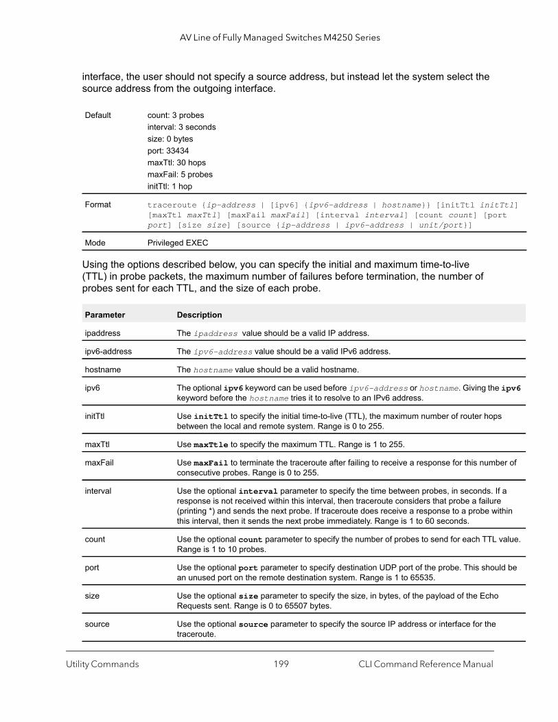
AV Line of Fully Managed Switches M4250 Series
tl] t
ipv6
r of
a hin
alue.
d be
interface, the user should not specify a source address, but instead let the system select the source address from the outgoing interface.
Using the options described below, you can specify the initial and maximum time-to-live (TTL) in probe packets, the maximum number of failures before termination, the number of probes sent for each TTL, and the size of each probe.
Default count: 3 probesinterval: 3 secondssize: 0 bytesport: 33434maxTtl: 30 hopsmaxFail: 5 probesinitTtl: 1 hop
Format traceroute {ip-address | [ipv6] {ipv6-address | hostname}} [initTtl initT[maxTtl maxTtl] [maxFail maxFail] [interval interval] [count count] [porport] [size size] [source {ip-address | ipv6-address | unit/port}]
Mode Privileged EXEC
Parameter Description
ipaddress The ipaddress value should be a valid IP address.
ipv6-address The ipv6-address value should be a valid IPv6 address.
hostname The hostname value should be a valid hostname.
ipv6 The optional ipv6 keyword can be used before ipv6-address or hostname. Giving the keyword before the hostname tries it to resolve to an IPv6 address.
initTtl Use initTtl to specify the initial time-to-live (TTL), the maximum number of router hopsbetween the local and remote system. Range is 0 to 255.
maxTtl Use maxTtle to specify the maximum TTL. Range is 1 to 255.
maxFail Use maxFail to terminate the traceroute after failing to receive a response for this numbeconsecutive probes. Range is 0 to 255.
interval Use the optional interval parameter to specify the time between probes, in seconds. If response is not received within this interval, then traceroute considers that probe a failure(printing *) and sends the next probe. If traceroute does receive a response to a probe witthis interval, then it sends the next probe immediately. Range is 1 to 60 seconds.
count Use the optional count parameter to specify the number of probes to send for each TTL vRange is 1 to 10 probes.
port Use the optional port parameter to specify destination UDP port of the probe. This shoulan unused port on the remote destination system. Range is 1 to 65535.
size Use the optional size parameter to specify the size, in bytes, of the payload of the Echo Requests sent. Range is 0 to 65507 bytes.
source Use the optional source parameter to specify the source IP address or interface for the traceroute.
Utility Commands CLI Command Reference Manual199

AV Line of Fully Managed Switches M4250 Series
The following are examples of the CLI command.
Command example:
The following example shows that the traceroute is a success:(NETGEAR Switch) # traceroute 10.240.10.115 initTtl 1 maxTtl 4 maxFail 0 interval 1 count 3 port 33434 size 43Traceroute to 10.240.10.115 ,4 hops max 43 byte packets:1 10.240.4.1 708 msec 41 msec 11 msec2 10.240.10.115 0 msec 0 msec 0 msec
Hop Count = 1 Last TTL = 2 Test attempt = 6 Test Success = 6
Command example:
The following example shows that the IPv6 traceroute is a success:(NETGEAR Switch) # traceroute 2001::2 initTtl 1 maxTtl 4 maxFail 0 interval 1 count 3 port 33434 size 43
Traceroute to 2001::2 hops max 43 byte packets:1 2001::2 708 msec 41 msec 11 msec
The above command can also be execute with the optional ipv6 parameter as follows:(NETGEAR Switch) # traceroute ipv6 2001::2 initTtl 1 maxTtl 4 maxFail 0 interval 1 count 3 port 33434 size 43
Command example:
The following example shows that the traceroute fails:(NETGEAR Switch) # traceroute 10.40.1.1 initTtl 1 maxFail 0 interval 1 count 3port 33434 size 43Traceroute to 10.40.1.1 ,30 hops max 43 byte packets:1 10.240.4.1 19 msec 18 msec 9 msec2 10.240.1.252 0 msec 0 msec 1 msec3 172.31.0.9 277 msec 276 msec 277 msec4 10.254.1.1 289 msec 327 msec 282 msec5 10.254.21.2 287 msec 293 msec 296 msec6 192.168.76.2 290 msec 291 msec 289 msec7 0.0.0.0 0 msec *Hop Count = 6 Last TTL = 7 Test attempt = 19 Test Success = 18
Command example:
The following example shows that the IPv6 traceroute fails:(NETGEAR Switch)# traceroute 2001::2 initTtl 1 maxFail 0 interval 1 count 3 port 33434 size 43
Traceroute to 2001::2 hops max 43 byte packets:1 3001::1 708 msec 41 msec 11 msec
Utility Commands CLI Command Reference Manual200

AV Line of Fully Managed Switches M4250 Series
AC
rding
2 4001::2 250 msec 200 msec 193 msec3 5001::3 289 msec 313 msec 278 msec4 6001::4 651 msec 41 msec 270 msec5 0 0 msec *Hop Count = 4 Last TTL = 5 Test attempt = 1 Test Success = 0
clear configThis command resets the configuration to the factory defaults without powering off the switch. When you issue this command, a prompt appears to confirm that the reset should proceed. When you enter y, you automatically reset the current configuration on the switch to the default values. It does not reset the switch.
clear countersThis command clears the statistics for a specified unit/port, for all ports, for a specified VLAN, for a specified LAG, or for the entire switch based on the argument.
clear mac-addr-tableThis command clears the dynamically learned MAC addresses for all ports, for a specified VLAN, for a specified unit/port, or for the entire switch based on the argument. You can also clear a specific MAC address.
Format clear config
Mode Privileged EXEC
Format clear counters {unit/port | all | vlan vlan-id | lag lag-intf-num}
Mode Privileged EXEC
Format clear mac-addr-table {all | vlan vlan-id | interface unit/port | macaddr[macmask]}
Mode Privileged EXEC
Parameter Description
all All dynamically learned forwarding database entries in the forwarding database table.
vlan-id The dynamically learned forwarding database entries for the VLAN ID.
unit/port The dynamically learned forwarding database entries for the interface.
macaddr macmask The dynamically learned forwarding database entries that match the range specified by the Maddress and MAC mask. If you do not specify the MAC mask, only the specified MAC address is removed from the forwadatabase table.
Utility Commands CLI Command Reference Manual201
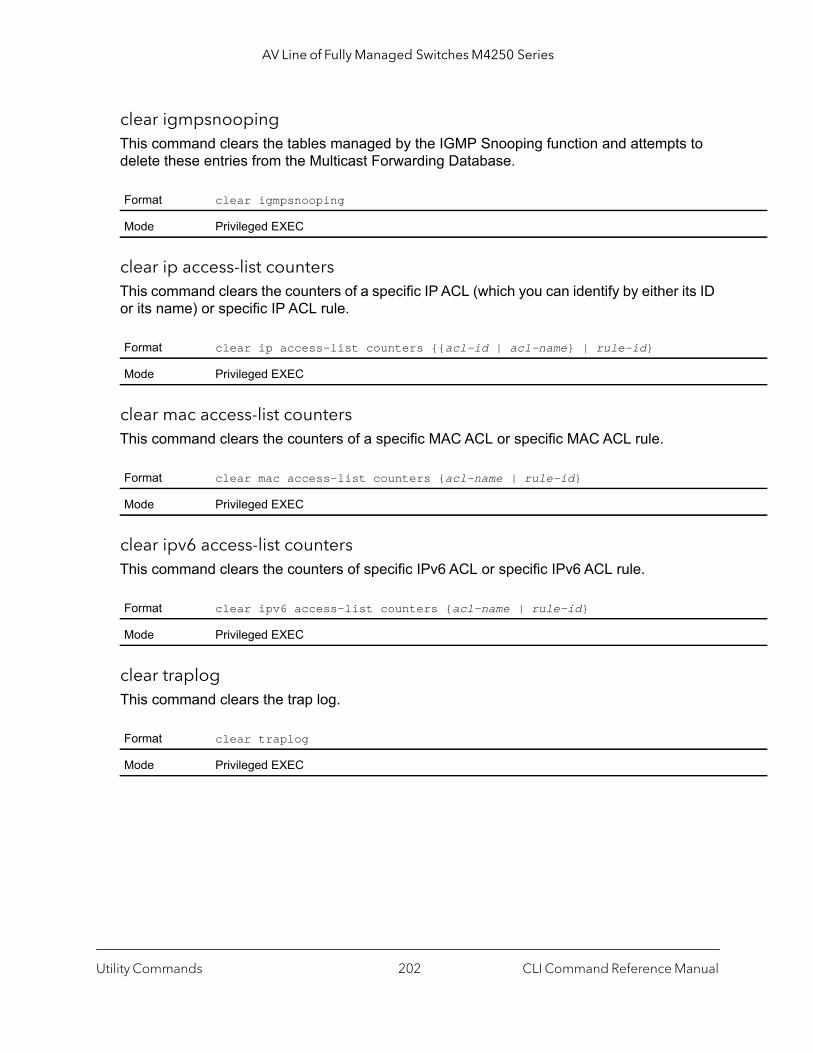
AV Line of Fully Managed Switches M4250 Series
clear igmpsnooping This command clears the tables managed by the IGMP Snooping function and attempts to delete these entries from the Multicast Forwarding Database.
clear ip access-list countersThis command clears the counters of a specific IP ACL (which you can identify by either its ID or its name) or specific IP ACL rule.
clear mac access-list countersThis command clears the counters of a specific MAC ACL or specific MAC ACL rule.
clear ipv6 access-list countersThis command clears the counters of specific IPv6 ACL or specific IPv6 ACL rule.
clear traplogThis command clears the trap log.
Format clear igmpsnooping
Mode Privileged EXEC
Format clear ip access-list counters {{acl-id | acl-name} | rule-id}
Mode Privileged EXEC
Format clear mac access-list counters {acl-name | rule-id}
Mode Privileged EXEC
Format clear ipv6 access-list counters {acl-name | rule-id}
Mode Privileged EXEC
Format clear traplog
Mode Privileged EXEC
Utility Commands CLI Command Reference Manual202
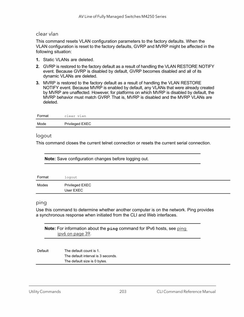
AV Line of Fully Managed Switches M4250 Series
clear vlanThis command resets VLAN configuration parameters to the factory defaults. When the VLAN configuration is reset to the factory defaults, GVRP and MVRP might be affected in the following situation:
1. Static VLANs are deleted.2. GVRP is restored to the factory default as a result of handling the VLAN RESTORE NOTIFY
event. Because GVRP is disabled by default, GVRP becomes disabled and all of its dynamic VLANs are deleted.
3. MVRP is restored to the factory default as a result of handling the VLAN RESTORE NOTIFY event. Because MVRP is enabled by default, any VLANs that were already created by MVRP are unaffected. However, for platforms on which MVRP is disabled by default, the MVRP behavior must match GVRP. That is, MVRP is disabled and the MVRP VLANs are deleted.
logoutThis command closes the current telnet connection or resets the current serial connection.
Note: Save configuration changes before logging out.
pingUse this command to determine whether another computer is on the network. Ping provides a synchronous response when initiated from the CLI and Web interfaces.
Note: For information about the ping command for IPv6 hosts, see ping ipv6 on page 39.
Format clear vlan
Mode Privileged EXEC
Format logout
Modes Privileged EXECUser EXEC
Default The default count is 1.The default interval is 3 seconds.The default size is 0 bytes.
Utility Commands CLI Command Reference Manual203
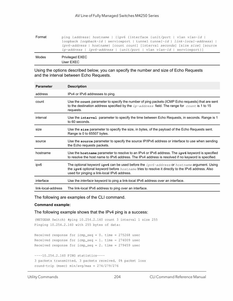
AV Line of Fully Managed Switches M4250 Series
} | rce
sent
e is 1
t.
ding
cified fied.
sing so
Using the options described below, you can specify the number and size of Echo Requests and the interval between Echo Requests.
The following are examples of the CLI command.
Command example:
The following example shows that the IPv4 ping is a success:(NETGEAR Switch) #ping 10.254.2.160 count 3 interval 1 size 255Pinging 10.254.2.160 with 255 bytes of data:
Received response for icmp_seq = 0. time = 275268 usecReceived response for icmp_seq = 1. time = 274009 usecReceived response for icmp_seq = 2. time = 279459 usec
----10.254.2.160 PING statistics----3 packets transmitted, 3 packets received, 0% packet lossround-trip (msec) min/avg/max = 274/279/276
Format ping {address| hostname | {ipv6 {interface {unit/port | vlan vlan-id | loopback loopback-id | serviceport | tunnel tunnel-id } link-local-addressipv6-address | hostname} [count count] [interval seconds] [size size] [souip-address | ipv6-address | {unit/port | vlan vlan-id | serviceport}]
Modes Privileged EXECUser EXEC
Parameter Description
address IPv4 or IPv6 addresses to ping.
count Use the count parameter to specify the number of ping packets (ICMP Echo requests) that areto the destination address specified by the ip-address field. The range for count is 1 to 15requests.
interval Use the interval parameter to specify the time between Echo Requests, in seconds. Rangto 60 seconds.
size Use the size parameter to specify the size, in bytes, of the payload of the Echo Requests senRange is 0 to 65507 bytes.
source Use the source parameter to specify the source IP/IPv6 address or interface to use when senthe Echo requests packets.
hostname Use the hostname parameter to resolve to an IPv4 or IPv6 address. The ipv6 keyword is speto resolve the host name to IPv6 address. The IPv4 address is resolved if no keyword is speci
ipv6 The optional keyword ipv6 can be used before the ipv6-address or hostname argument. Uthe ipv6 optional keyword before hostname tries to resolve it directly to the IPv6 address. Alused for pinging a link-local IPv6 address.
interface Use the interface keyword to ping a link-local IPv6 address over an interface.
link-local-address The link-local IPv6 address to ping over an interface.
Utility Commands CLI Command Reference Manual204
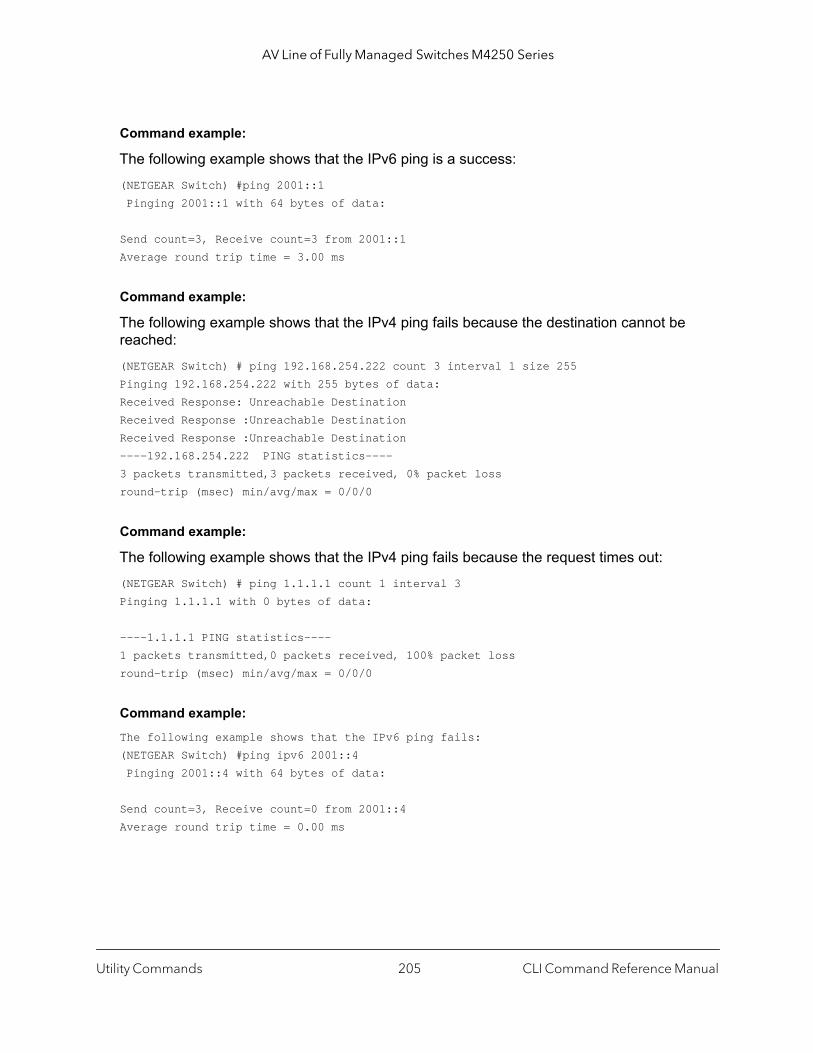
AV Line of Fully Managed Switches M4250 Series
Command example:
The following example shows that the IPv6 ping is a success:(NETGEAR Switch) #ping 2001::1 Pinging 2001::1 with 64 bytes of data:
Send count=3, Receive count=3 from 2001::1Average round trip time = 3.00 ms
Command example:
The following example shows that the IPv4 ping fails because the destination cannot be reached:(NETGEAR Switch) # ping 192.168.254.222 count 3 interval 1 size 255Pinging 192.168.254.222 with 255 bytes of data:Received Response: Unreachable DestinationReceived Response :Unreachable DestinationReceived Response :Unreachable Destination----192.168.254.222 PING statistics----3 packets transmitted,3 packets received, 0% packet lossround-trip (msec) min/avg/max = 0/0/0
Command example:
The following example shows that the IPv4 ping fails because the request times out:(NETGEAR Switch) # ping 1.1.1.1 count 1 interval 3 Pinging 1.1.1.1 with 0 bytes of data: ----1.1.1.1 PING statistics----1 packets transmitted,0 packets received, 100% packet lossround-trip (msec) min/avg/max = 0/0/0
Command example: The following example shows that the IPv6 ping fails:(NETGEAR Switch) #ping ipv6 2001::4 Pinging 2001::4 with 64 bytes of data:
Send count=3, Receive count=0 from 2001::4Average round trip time = 0.00 ms
Utility Commands CLI Command Reference Manual205

AV Line of Fully Managed Switches M4250 Series
quitThis command closes the current telnet connection or resets the current serial connection. The system asks you whether to save configuration changes before quitting.
reload (Privileged EXEC)This command resets the switch without powering it off. Reset means that all network connections are terminated and the boot code executes. The switch uses the stored configuration to initialize the switch. You are prompted to confirm that the reset should proceed. The LEDs on the switch indicate a successful reset.
configurationThis command gracefully reloads the configuration. If you do not specify a script name, the switch reloads the existing startup-config file. If you specify a script name, you must include the extension.
copyThe copy command uploads and downloads files to and from the switch. You can also use the copy command to manage the dual images (image 1 and image 2) on the file system. Upload and download files from a server using FTP, TFTP, Xmodem, Ymodem, or Zmodem. SFTP and SCP are available as additional transfer methods if the software package supports secure management. If FTP is used, a password is required.
Replace the source and destination parameters with the options in the table on page 208 or the url source and destination arguments that are listed in the table on page 208, use one of the following values:
• xmodem
• ymodem
• zmodem
Format quit
Modes Privileged EXECUser EXEC
Format reload
Mode Privileged EXEC
Format configuration [scriptname]
Mode Privileged EXEC
Format copy source destination {verify | noverify}
Mode Privileged EXEC
Utility Commands CLI Command Reference Manual206

AV Line of Fully Managed Switches M4250 Series
• tftp://{ipaddress | hostname}/filepath/filename
• ftp://{user@ipaddr | hostname}/path/filename
• scp://{user@ipaddr | hostname}/path/filename
• sftp://{user@ipaddr | hostname}/path/filename
• usb://filepath/filename
The verify and noverify keywords are available only if the image/configuration verify options feature is enabled (see file verify on page 211); verify specifies that digital signature verification will be performed for the specified downloaded image or configuration file. noverify specifies that no verification will be performed.
The keyword ias-users supports the downloading of the IAS user database file. When the IAS users file is downloaded, the switch IAS user’s database is replaced with the users and its attributes available in the downloaded file. In the command copy url ias-users, for url one of the following is used for IAS users file:{{tftp://<ipaddr> | <ipv6address> | <hostname>/<filepath>/<filename>} | {sftp | scp://<username>@<ipaddress>/<filepath>/<filename>}}
Note: The maximum length for the file path is 160 characters, and the maximum length for the file name is 31 characters.
For FTP, TFTP, SFTP and SCP, the ipaddr or hostname parameter is the IP address or host name of the server, filepath is the path to the file, and filename is the name of the file you want to upload or download. For SFTP and SCP, the username parameter is the user name for logging into the remote server via SSH.
Note: ip6address is also a valid parameter for routing packages that support IPv6.
To copy OpenFlow SSL certificates to the switch using TFTP or XMODEM, using only the following options pertinent to the OpenFlow SSL certificates.
Format copy [mode/file] nvram:{openflow-ssl-ca-cert | openflow-ssl-cert | openflow-ssl-priv-key}
Mode Privileged Exec
Utility Commands CLI Command Reference Manual207
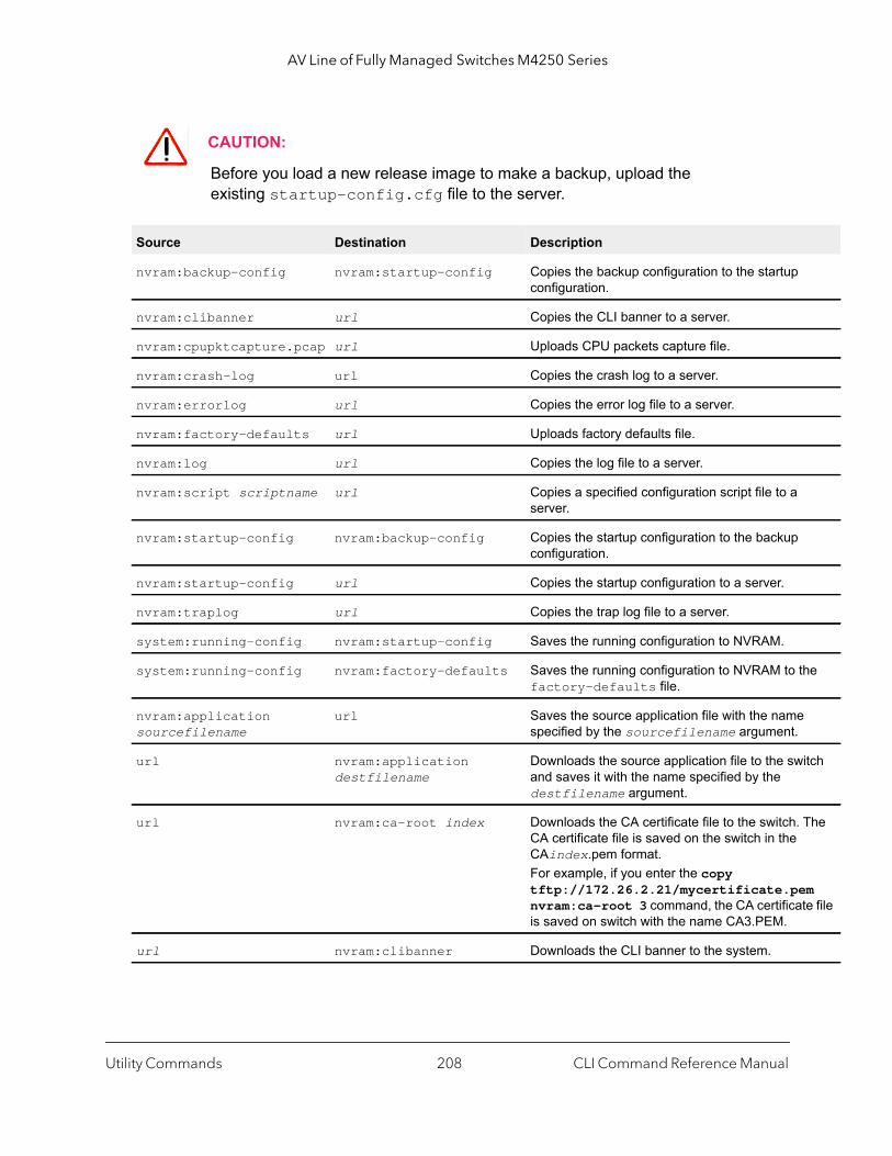
AV Line of Fully Managed Switches M4250 Series
he
itch
The
m te file
CAUTION:
Before you load a new release image to make a backup, upload the existing startup-config.cfg file to the server.
Source Destination Description
nvram:backup-config nvram:startup-config Copies the backup configuration to the startup configuration.
nvram:clibanner url Copies the CLI banner to a server.
nvram:cpupktcapture.pcap url Uploads CPU packets capture file.
nvram:crash-log url Copies the crash log to a server.
nvram:errorlog url Copies the error log file to a server.
nvram:factory-defaults url Uploads factory defaults file.
nvram:log url Copies the log file to a server.
nvram:script scriptname url Copies a specified configuration script file to a server.
nvram:startup-config nvram:backup-config Copies the startup configuration to the backup configuration.
nvram:startup-config url Copies the startup configuration to a server.
nvram:traplog url Copies the trap log file to a server.
system:running-config nvram:startup-config Saves the running configuration to NVRAM.
system:running-config nvram:factory-defaults Saves the running configuration to NVRAM to tfactory-defaults file.
nvram:application sourcefilename
url Saves the source application file with the namespecified by the sourcefilename argument.
url nvram:application destfilename
Downloads the source application file to the swand saves it with the name specified by the destfilename argument.
url nvram:ca-root index Downloads the CA certificate file to the switch. CA certificate file is saved on the switch in the CAindex.pem format.For example, if you enter the copy tftp://172.26.2.21/mycertificate.penvram:ca-root 3 command, the CA certificais saved on switch with the name CA3.PEM.
url nvram:clibanner Downloads the CLI banner to the system.
Utility Commands CLI Command Reference Manual208
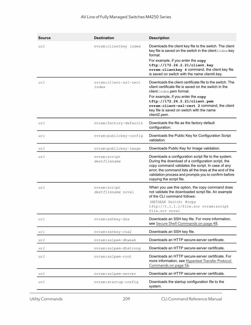
AV Line of Fully Managed Switches M4250 Series
client x.key
y file
. The e
client
ript
tem. he ny
of the efore
oes ple
t
ion,
For col
url nvram:clientkey index Downloads the client key file to the switch. The key file is saved on the switch in the clientindeformat.For example, if you enter the copy tftp://172.26.2.21/client.key nvram:clientkey 4 command, the client keis saved on switch with the name client4.key.
url nvram:client-ssl-cert index
Downloads the client certificate file to the switchclient certificate file is saved on the switch in thclientindex.pem format.For example, if you enter the copy tftp://172.26.2.21/client.pem nvram:client-ssl-cert 2 command, the key file is saved on switch with the name client2.pem.
url nvram:factory-defaults Downloads the file as the factory default configuration.
url nvram:publickey-config Downloads the Public Key for Configuration Scvalidation.
url nvram:publickey-image Downloads Public Key for Image validation.
url nvram:script destfilename
Downloads a configuration script file to the sysDuring the download of a configuration script, tcopy command validates the script. In case of aerror, the command lists all the lines at the end validation process and prompts you to confirm bcopying the script file.
url nvram:script destfilename noval
When you use this option, the copy command dnot validate the downloaded script file. An examof the CLI command follows:(NETGEAR Switch) #copy tftp://1.1.1.1/file.scr nvram:scripfile.scr noval
url nvram:sshkey-dsa Downloads an SSH key file. For more informatsee Secure Shell Commands on page 48.
url nvram:sshkey-rsa2 Downloads an SSH key file.
url nvram:sslpem-dhweak Downloads an HTTP secure-server certificate.
url nvram:sslpem-dhstrong Downloads an HTTP secure-server certificate.
url nvram:sslpem-root Downloads an HTTP secure-server certificate. more information, see Hypertext Transfer ProtoCommands on page 56.
url nvram:sslpem-server Downloads an HTTP secure-server certificate.
url nvram:startup-config Downloads the startup configuration file to the system.
Source Destination Description
Utility Commands CLI Command Reference Manual209
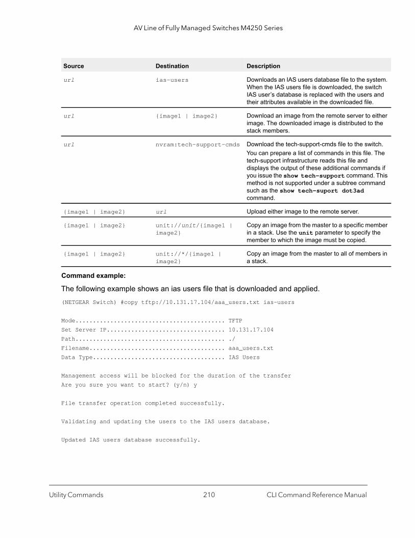
AV Line of Fully Managed Switches M4250 Series
tem. tch and
ither the
tch. The
ds if . This and
mber he
rs in
Command example:
The following example shows an ias users file that is downloaded and applied.(NETGEAR Switch) #copy tftp://10.131.17.104/aaa_users.txt ias-users
Mode........................................... TFTPSet Server IP.................................. 10.131.17.104Path........................................... ./Filename....................................... aaa_users.txtData Type...................................... IAS Users
Management access will be blocked for the duration of the transferAre you sure you want to start? (y/n) y
File transfer operation completed successfully.
Validating and updating the users to the IAS users database.
Updated IAS users database successfully.
url ias-users Downloads an IAS users database file to the sysWhen the IAS users file is downloaded, the swiIAS user’s database is replaced with the users their attributes available in the downloaded file.
url {image1 | image2} Download an image from the remote server to eimage. The downloaded image is distributed tostack members.
url nvram:tech-support-cmds Download the tech-support-cmds file to the swiYou can prepare a list of commands in this file. tech-support infrastructure reads this file and displays the output of these additional commanyou issue the show tech-support commandmethod is not supported under a subtree commsuch as the show tech-suport dot3ad command.
{image1 | image2} url Upload either image to the remote server.
{image1 | image2} unit://unit/{image1 | image2}
Copy an image from the master to a specific mein a stack. Use the unit parameter to specify tmember to which the image must be copied.
{image1 | image2} unit://*/{image1 | image2}
Copy an image from the master to all of membea stack.
Source Destination Description
Utility Commands CLI Command Reference Manual210

AV Line of Fully Managed Switches M4250 Series
file verifyThis command enables digital signature verification while an image and/or configuration file is downloaded to the switch.
no file verify
Resets the configured digital signature verification value to the factory default value.
write memoryUse this command to save running configuration changes to NVRAM so that the changes you make will persist across a reboot. This command is the same as copy system:running-config nvram:startup-config. Use the confirm keyword to directly save the configuration to NVRAM without prompting for a confirmation.
Simple Network Time Protocol Commands
This section describes the commands you use to automatically configure the system time and date by using Simple Network Time Protocol (SNTP).
sntp broadcast client poll-intervalThis command sets the poll interval for SNTP broadcast clients in seconds as a power of two where poll-interval can be a value from 6 to 10.
Format file verify {all | image | none | script}
Mode Global Config
Parameter Description
All Verifies the digital signature of both image and configuration files.
Image Verifies the digital signature of image files only.
None Disables digital signature verification for both images and configuration files.
Script Verifies the digital signature of configuration files.
Format no file verify
Mode Global Config
Format write memory [confirm]
Mode Privileged EXEC
Utility Commands CLI Command Reference Manual211

AV Line of Fully Managed Switches M4250 Series
no sntp broadcast client poll-interval
This command resets the poll interval for SNTP broadcast client back to the default value.
sntp client modeThis command enables Simple Network Time Protocol (SNTP) client mode and may set the mode to either broadcast or unicast.
no sntp client mode
This command disables Simple Network Time Protocol (SNTP) client mode.
sntp client portThis command sets the SNTP client port ID to a value in the range 1025–65535, represented by the portid argument. The default value is 0, which means that the SNTP port is not configured by the user. In the default case, the actual client port value used in SNTP packets is assigned by the underlying OS.
Default 6
Format sntp broadcast client poll-interval poll-interval
Mode Global Config
Format no sntp broadcast client poll-interval
Mode Global Config
Default disabled
Format sntp client mode [broadcast | unicast]
Mode Global Config
Format no sntp client mode
Mode Global Config
Default 0
Format sntp client port portid
Mode Global Config
Utility Commands CLI Command Reference Manual212
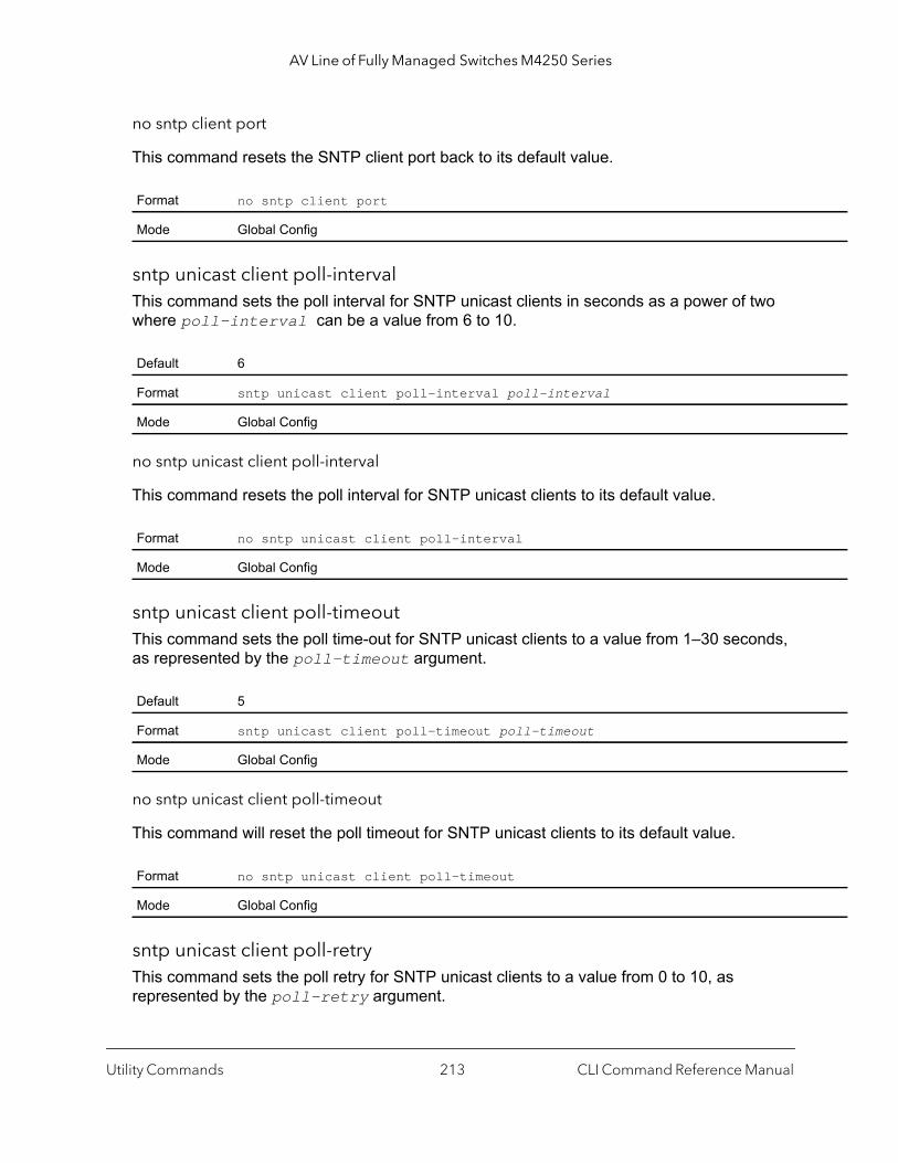
AV Line of Fully Managed Switches M4250 Series
no sntp client port
This command resets the SNTP client port back to its default value.
sntp unicast client poll-intervalThis command sets the poll interval for SNTP unicast clients in seconds as a power of two where poll-interval can be a value from 6 to 10.
no sntp unicast client poll-interval
This command resets the poll interval for SNTP unicast clients to its default value.
sntp unicast client poll-timeoutThis command sets the poll time-out for SNTP unicast clients to a value from 1–30 seconds, as represented by the poll-timeout argument.
no sntp unicast client poll-timeout
This command will reset the poll timeout for SNTP unicast clients to its default value.
sntp unicast client poll-retryThis command sets the poll retry for SNTP unicast clients to a value from 0 to 10, as represented by the poll-retry argument.
Format no sntp client port
Mode Global Config
Default 6
Format sntp unicast client poll-interval poll-interval
Mode Global Config
Format no sntp unicast client poll-interval
Mode Global Config
Default 5
Format sntp unicast client poll-timeout poll-timeout
Mode Global Config
Format no sntp unicast client poll-timeout
Mode Global Config
Utility Commands CLI Command Reference Manual213

AV Line of Fully Managed Switches M4250 Series
no sntp unicast client poll-retry
This command will reset the poll retry for SNTP unicast clients to its default value.
sntp serverThis command configures an SNTP server (a maximum of three). The server address can be either an IPv4 address or an IPv6 address. The optional priority can be a value of 1–3, the version a value of 1–4, and the portid a value of 1–65535.
no sntp server
This command deletes an server from the configured SNTP servers.
sntp source-interfaceUse this command to specify the physical or logical interface to use as the source interface (source IP address) for SNTP unicast server configuration. If configured, the address of source Interface is used for all SNTP communications between the SNTP server and the SNTP client. The selected source-interface IP address is used for filling the IP header of management protocol packets. This allows security devices (firewalls) to identify the source packets coming from the specific switch. If a source-interface is not specified, the primary IP address of the originating (outbound) interface is used as the source address. If the configured interface is down, the SNTP client falls back to its default behavior.
Default 1
Format sntp unicast client poll-retry poll-retry
Mode Global Config
Format no sntp unicast client poll-retry
Mode Global Config
Format sntp server {ipaddress | ipv6address | hostname} [priority [version [portid]]]
Mode Global Config
Format no sntp server remove {ipaddress | ipv6address | hostname}
Mode Global Config
Format sntp source-interface {unit/port | loopback loopback-id | vlan vlan-id}
Mode Global Config
Utility Commands CLI Command Reference Manual214
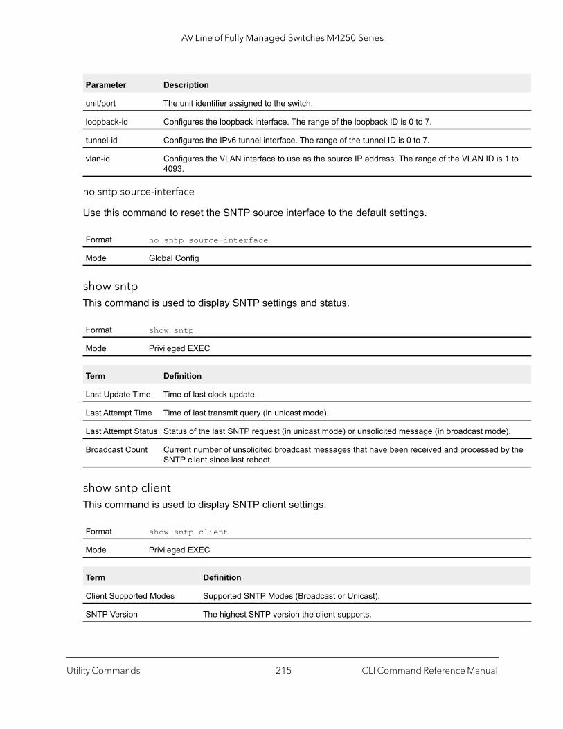
AV Line of Fully Managed Switches M4250 Series
to
).
y the
no sntp source-interface
Use this command to reset the SNTP source interface to the default settings.
show sntp This command is used to display SNTP settings and status.
show sntp clientThis command is used to display SNTP client settings.
Parameter Description
unit/port The unit identifier assigned to the switch.
loopback-id Configures the loopback interface. The range of the loopback ID is 0 to 7.
tunnel-id Configures the IPv6 tunnel interface. The range of the tunnel ID is 0 to 7.
vlan-id Configures the VLAN interface to use as the source IP address. The range of the VLAN ID is 14093.
Format no sntp source-interface
Mode Global Config
Format show sntp
Mode Privileged EXEC
Term Definition
Last Update Time Time of last clock update.
Last Attempt Time Time of last transmit query (in unicast mode).
Last Attempt Status Status of the last SNTP request (in unicast mode) or unsolicited message (in broadcast mode
Broadcast Count Current number of unsolicited broadcast messages that have been received and processed bSNTP client since last reboot.
Format show sntp client
Mode Privileged EXEC
Term Definition
Client Supported Modes Supported SNTP Modes (Broadcast or Unicast).
SNTP Version The highest SNTP version the client supports.
Utility Commands CLI Command Reference Manual215
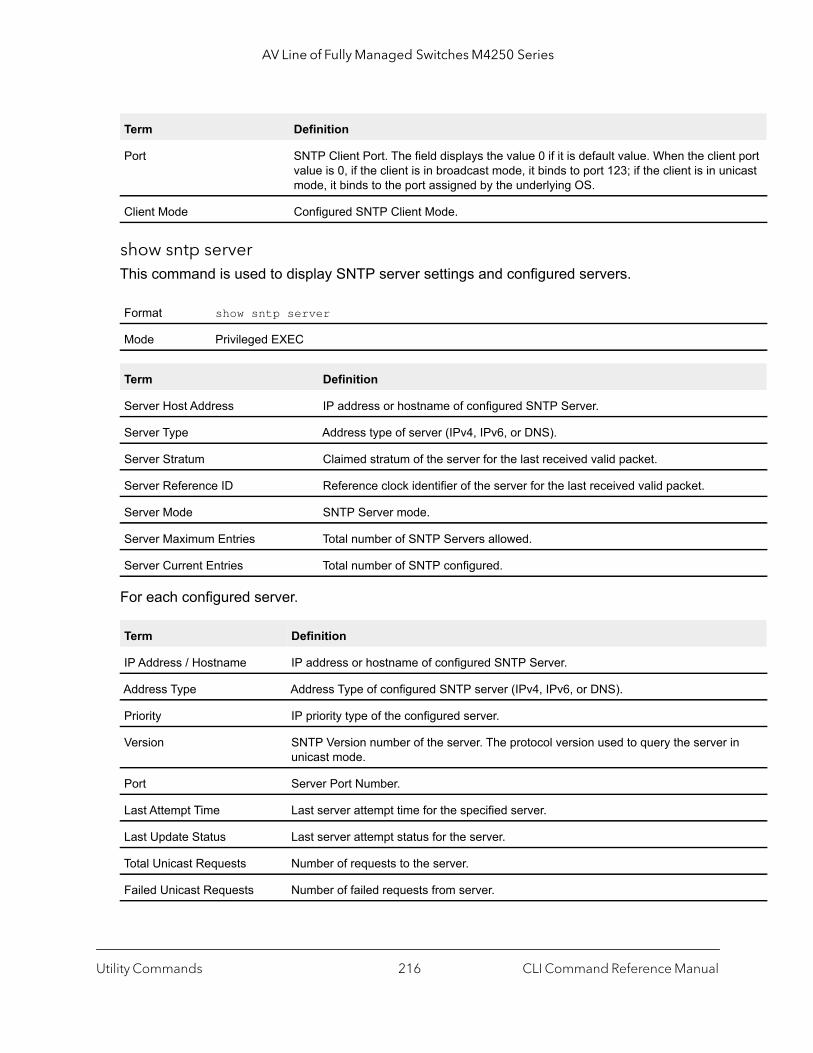
AV Line of Fully Managed Switches M4250 Series
t port icast
n
show sntp serverThis command is used to display SNTP server settings and configured servers.
For each configured server.
Port SNTP Client Port. The field displays the value 0 if it is default value. When the clienvalue is 0, if the client is in broadcast mode, it binds to port 123; if the client is in unmode, it binds to the port assigned by the underlying OS.
Client Mode Configured SNTP Client Mode.
Format show sntp server
Mode Privileged EXEC
Term Definition
Server Host Address IP address or hostname of configured SNTP Server.
Server Type Address type of server (IPv4, IPv6, or DNS).
Server Stratum Claimed stratum of the server for the last received valid packet.
Server Reference ID Reference clock identifier of the server for the last received valid packet.
Server Mode SNTP Server mode.
Server Maximum Entries Total number of SNTP Servers allowed.
Server Current Entries Total number of SNTP configured.
Term Definition
IP Address / Hostname IP address or hostname of configured SNTP Server.
Address Type Address Type of configured SNTP server (IPv4, IPv6, or DNS).
Priority IP priority type of the configured server.
Version SNTP Version number of the server. The protocol version used to query the server iunicast mode.
Port Server Port Number.
Last Attempt Time Last server attempt time for the specified server.
Last Update Status Last server attempt status for the server.
Total Unicast Requests Number of requests to the server.
Failed Unicast Requests Number of failed requests from server.
Term Definition
Utility Commands CLI Command Reference Manual216

AV Line of Fully Managed Switches M4250 Series
urce
ours:
range
show sntp source-interfaceUse this command to display the SNTP client source interface configured on the switch.
Command example: (NETGEAR Switch) #show sntp source-interface
SNTP Client Source Interface................... (not configured)
Time Zone Commands
Use the Time Zone commands to configure system time and date, Time Zone and Summer Time (that is, Daylight Saving Time). Summer time can be recurring or non-recurring.
clock setThis command sets the system time and date.
Command example: (NETGEAR Switch) (Config)# clock set 03:17:00(NETGEAR Switch) (Config)# clock set 11/01/2011
Format show sntp source-interface
Mode Privileged EXEC
Field Description
SNTP Client Source Interface The interface ID of the physical or logical interface configured as the SNTP client sointerface.
SNTP Client Source IPv4 Address
The IP address of the interface configured as the SNTP client source interface.
Format clock set hh:mm:ssclock set mm/dd/yyyy
Mode Global Config
Parameter Description
hh:mm:ss Enter the current system time in 24-hour format in hours, minutes, and seconds. The range is h0 to 23, minutes: 0 to 59, seconds: 0 to 59.
mm/dd/yyyy Enter the current system date the format month, day, year. The range for month is 1 to 12. The for the day of the month is 1 to 31. The range for year is 2010 to 2079.
Utility Commands CLI Command Reference Manual217
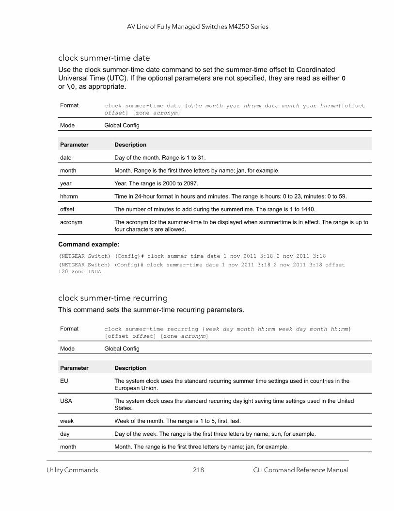
AV Line of Fully Managed Switches M4250 Series
set
up to
clock summer-time dateUse the clock summer-time date command to set the summer-time offset to Coordinated Universal Time (UTC). If the optional parameters are not specified, they are read as either 0 or \0, as appropriate.
Command example: (NETGEAR Switch) (Config)# clock summer-time date 1 nov 2011 3:18 2 nov 2011 3:18(NETGEAR Switch) (Config)# clock summer-time date 1 nov 2011 3:18 2 nov 2011 3:18 offset 120 zone INDA
clock summer-time recurringThis command sets the summer-time recurring parameters.
Format clock summer-time date {date month year hh:mm date month year hh:mm}[offoffset] [zone acronym]
Mode Global Config
Parameter Description
date Day of the month. Range is 1 to 31.
month Month. Range is the first three letters by name; jan, for example.
year Year. The range is 2000 to 2097.
hh:mm Time in 24-hour format in hours and minutes. The range is hours: 0 to 23, minutes: 0 to 59.
offset The number of minutes to add during the summertime. The range is 1 to 1440.
acronym The acronym for the summer-time to be displayed when summertime is in effect. The range is four characters are allowed.
Format clock summer-time recurring {week day month hh:mm week day month hh:mm} [offset offset] [zone acronym]
Mode Global Config
Parameter Description
EU The system clock uses the standard recurring summer time settings used in countries in the European Union.
USA The system clock uses the standard recurring daylight saving time settings used in the UnitedStates.
week Week of the month. The range is 1 to 5, first, last.
day Day of the week. The range is the first three letters by name; sun, for example.
month Month. The range is the first three letters by name; jan, for example.
Utility Commands CLI Command Reference Manual218

AV Line of Fully Managed Switches M4250 Series
Command example: (NETGEAR Switch) (Config)# clock summer-time recurring 2 sun nov 3:18 2 mon nov 3:18 (NETGEAR Switch) (Config)# clock summer-time recurring 2 sun nov 3:18 2 mon nov 3:18 offset 120 zone INDA
no clock summer-time
This command disables the summer time settings.
Command example: (NETGEAR Switch) (Config)# no clock summer-time
clock timezoneUse this command to set the offset to Coordinated Universal Time (UTC). If the optional parameters are not specified, they will be read as either 0 or \0 as appropriate.
Command example: (NETGEAR Switch) (Config)# clock timezone 5 minutes 30 zone INDA
hh:mm Time in 24-hour format in hours and minutes. The range is hours: 0 to 23, minutes: 0 to 59.
offset The number of minutes to add during the summertime. The range is 1 to 1440.
acronym The acronym for the summertime to be displayed when summertime is in effect. Up to four characters are allowed.
Format no clock summer-time
Mode Global Config
Format clock timezone {hours} [minutes minutes] [zone acronym]
Mode Global Config
Parameter Description
hours Hours difference from UTC. The range is -12 to +13.
minutes Minutes difference from UTC. The range is 0 to 59.
acronym The acronym for the time zone. The range is up to four characters.
Parameter Description
Utility Commands CLI Command Reference Manual219
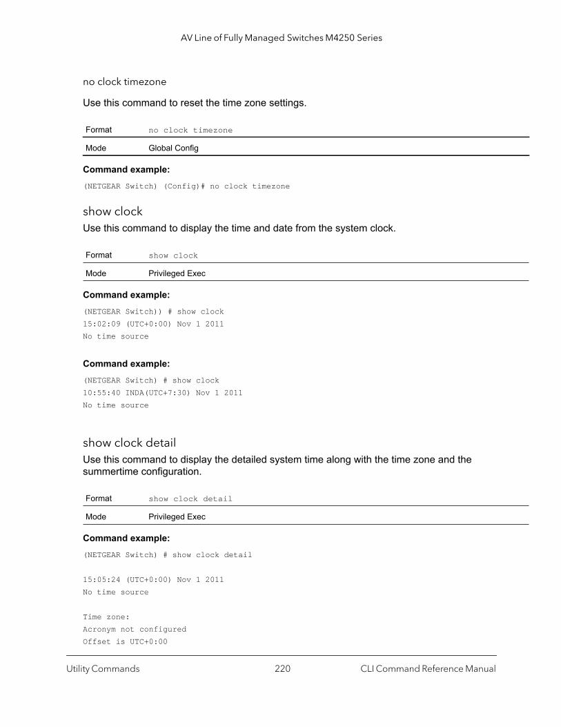
AV Line of Fully Managed Switches M4250 Series
no clock timezone
Use this command to reset the time zone settings.
Command example: (NETGEAR Switch) (Config)# no clock timezone
show clock Use this command to display the time and date from the system clock.
Command example: (NETGEAR Switch)) # show clock15:02:09 (UTC+0:00) Nov 1 2011No time source
Command example: (NETGEAR Switch) # show clock10:55:40 INDA(UTC+7:30) Nov 1 2011No time source
show clock detailUse this command to display the detailed system time along with the time zone and the summertime configuration.
Command example: (NETGEAR Switch) # show clock detail
15:05:24 (UTC+0:00) Nov 1 2011No time source
Time zone:Acronym not configuredOffset is UTC+0:00
Format no clock timezone
Mode Global Config
Format show clock
Mode Privileged Exec
Format show clock detail
Mode Privileged Exec
Utility Commands CLI Command Reference Manual220
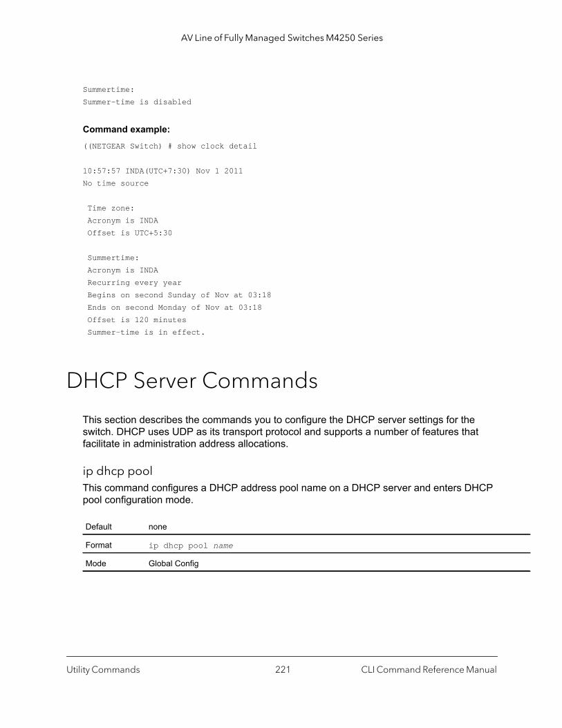
AV Line of Fully Managed Switches M4250 Series
Summertime:Summer-time is disabled
Command example: ((NETGEAR Switch) # show clock detail
10:57:57 INDA(UTC+7:30) Nov 1 2011No time source
Time zone: Acronym is INDA Offset is UTC+5:30
Summertime: Acronym is INDA Recurring every year Begins on second Sunday of Nov at 03:18 Ends on second Monday of Nov at 03:18 Offset is 120 minutes Summer-time is in effect.
DHCP Server Commands
This section describes the commands you to configure the DHCP server settings for the switch. DHCP uses UDP as its transport protocol and supports a number of features that facilitate in administration address allocations.
ip dhcp poolThis command configures a DHCP address pool name on a DHCP server and enters DHCP pool configuration mode.
Default none
Format ip dhcp pool name
Mode Global Config
Utility Commands CLI Command Reference Manual221

AV Line of Fully Managed Switches M4250 Series
no ip dhcp pool
This command removes the DHCP address pool. The name should be previously configured pool name.
client-identifierThis command specifies the unique identifier for a DHCP client. Unique-identifier is a valid notation in hexadecimal format. In some systems, such as Microsoft® DHCP clients, the client identifier is required instead of hardware addresses. The unique-identifier is a concatenation of the media type and the MAC address. For example, the Microsoft client identifier for Ethernet address c819.2488.f177 is 01c8.1924.88f1.77 where 01 represents the Ethernet media type. For more information, refer to the “Address Resolution Protocol Parameters” section of RFC 1700, Assigned Numbers for a list of media type codes.
no client-identifier
This command deletes the client identifier.
client-nameThis command specifies the name for a DHCP client. Name is a string consisting of standard ASCII characters.
no client-name
This command removes the client name.
Format no ip dhcp pool name
Mode Global Config
Default none
Format client-identifier uniqueidentifier
Mode DHCP Pool Config
Format no client-identifier
Mode DHCP Pool Config
Default none
Format client-name name
Mode DHCP Pool Config
Format no client-name
Mode DHCP Pool Config
Utility Commands CLI Command Reference Manual222
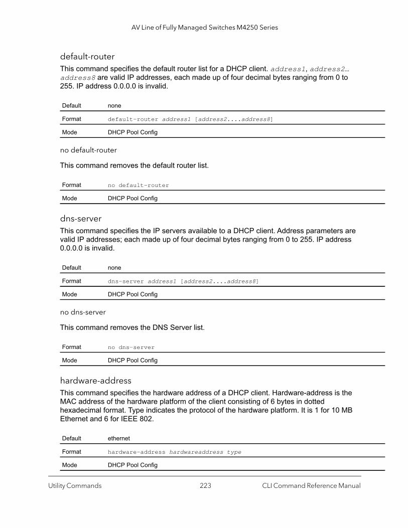
AV Line of Fully Managed Switches M4250 Series
default-routerThis command specifies the default router list for a DHCP client. address1, address2… address8 are valid IP addresses, each made up of four decimal bytes ranging from 0 to 255. IP address 0.0.0.0 is invalid.
no default-router
This command removes the default router list.
dns-serverThis command specifies the IP servers available to a DHCP client. Address parameters are valid IP addresses; each made up of four decimal bytes ranging from 0 to 255. IP address 0.0.0.0 is invalid.
no dns-server
This command removes the DNS Server list.
hardware-addressThis command specifies the hardware address of a DHCP client. Hardware-address is the MAC address of the hardware platform of the client consisting of 6 bytes in dotted hexadecimal format. Type indicates the protocol of the hardware platform. It is 1 for 10 MB Ethernet and 6 for IEEE 802.
Default none
Format default-router address1 [address2....address8]
Mode DHCP Pool Config
Format no default-router
Mode DHCP Pool Config
Default none
Format dns-server address1 [address2....address8]
Mode DHCP Pool Config
Format no dns-server
Mode DHCP Pool Config
Default ethernet
Format hardware-address hardwareaddress type
Mode DHCP Pool Config
Utility Commands CLI Command Reference Manual223

AV Line of Fully Managed Switches M4250 Series
no hardware-address
This command removes the hardware address of the DHCP client.
hostThis command specifies the IP address and network mask for a manual binding to a DHCP client. Address and Mask are valid IP addresses; each made up of four decimal bytes ranging from 0 to 255. IP address 0.0.0.0 is invalid. The prefix-length is an integer from 0 to 32.
no host
This command removes the IP address of the DHCP client.
leaseThis command configures the duration of the lease for an IP address that is assigned from a DHCP server to a DHCP client. The overall lease time must be between 1–-86400 minutes. If you specify infinite, the lease is set for 60 days. You can also specify a lease duration: days is an integer from 0 to 59; hours is an integer from 0 to 23; minutes is an integer from 0 to 59.
no lease
This command restores the default value of the lease time for DHCP Server.
Format no hardware-address
Mode DHCP Pool Config
Default none
Format host address [mask | prefix-length]
Mode DHCP Pool Config
Format no host
Mode DHCP Pool Config
Default 1 (day)
Format lease [{days [hours] [minutes] | infinite}]
Mode DHCP Pool Config
Format no lease
Mode DHCP Pool Config
Utility Commands CLI Command Reference Manual224
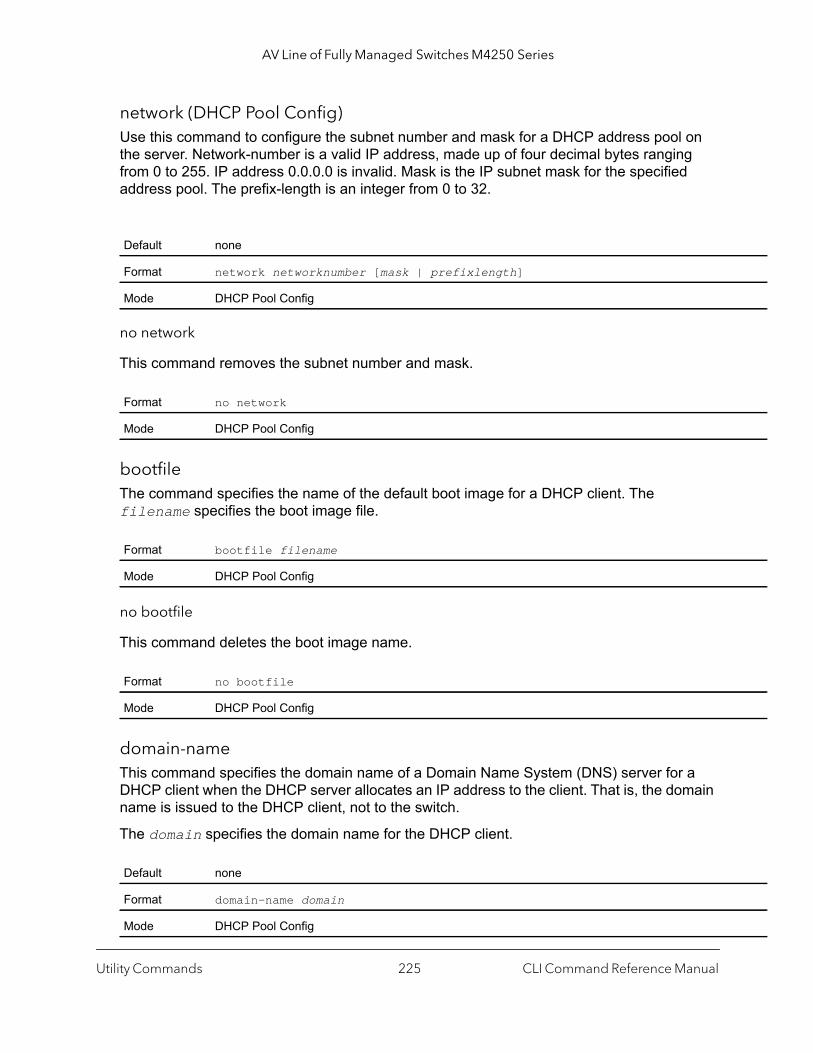
AV Line of Fully Managed Switches M4250 Series
network (DHCP Pool Config)Use this command to configure the subnet number and mask for a DHCP address pool on the server. Network-number is a valid IP address, made up of four decimal bytes ranging from 0 to 255. IP address 0.0.0.0 is invalid. Mask is the IP subnet mask for the specified address pool. The prefix-length is an integer from 0 to 32.
no network
This command removes the subnet number and mask.
bootfileThe command specifies the name of the default boot image for a DHCP client. The filename specifies the boot image file.
no bootfile
This command deletes the boot image name.
domain-nameThis command specifies the domain name of a Domain Name System (DNS) server for a DHCP client when the DHCP server allocates an IP address to the client. That is, the domain name is issued to the DHCP client, not to the switch.
The domain specifies the domain name for the DHCP client.
Default none
Format network networknumber [mask | prefixlength]
Mode DHCP Pool Config
Format no network
Mode DHCP Pool Config
Format bootfile filename
Mode DHCP Pool Config
Format no bootfile
Mode DHCP Pool Config
Default none
Format domain-name domain
Mode DHCP Pool Config
Utility Commands CLI Command Reference Manual225
AV Line of Fully Managed Switches M4250 Series
no domain-name
This command removes the domain name of a DNS server for a DHCP client.
domain-name nameThis command specifies the domain name of a DNS server that the switch sends to the RADIUS server for authentication. Use this command in combination with the domain-name enable command.
The name argument specifies the domain name.
no domain-name name
This command removes the domain name of a DNS server that the switch sends to the RADIUS server.
domain-name enableThis command enables the switch to send the domain name of a DNS server that you specify with the domain-name name command to a RADIUIS server. By default, the switch sends only the domain name of the DNS server. If you specify a user name with the optional name keyword and name argument, the switch also sends the user name along with the domain name to a RADIUS server. (The switch sends this information in the format domain-name\username.)
Command example: (NETGEAR Switch) (Config)#domain-name enable(NETGEAR Switch) (Config)#exit
Format no domain-name
Mode DHCP Pool Config
Default none
Format domain-name name name
Mode Global Config
Format no domain-name name name
Mode Global Config
Default Disabled
Format domain-name enable [name name]
Mode Global Config
Utility Commands CLI Command Reference Manual226
AV Line of Fully Managed Switches M4250 Series
no domain-name enable
This command disables sending of the domain name of a DNS server (and, if configured, a user name) to a RADIUS server.
netbios-name-serverThis command configures NetBIOS Windows Internet Naming Service (WINS) name servers that are available to DHCP clients.
One IP address is required, although one can specify up to eight addresses in one command line. Servers are listed in order of preference (address1 is the most preferred server, address2 is the next most preferred server, and so on).
no netbios-name-server
This command removes the NetBIOS name server list.
netbios-node-typeThe command configures the NetBIOS node type for Microsoft Dynamic Host Configuration Protocol (DHCP) clients.type Specifies the NetBIOS node type. Valid types are:
• b-node. Broadcast• p-node. Peer-to-peer• m-node. Mixed• h-node. Hybrid (recommended)
Format no domain-name enable
Mode Global Config
Default none
Format netbios-name-server address [address2...address8]
Mode DHCP Pool Config
Format no netbios-name-server
Mode DHCP Pool Config
Default none
Format netbios-node-type type
Mode DHCP Pool Config
Utility Commands CLI Command Reference Manual227
AV Line of Fully Managed Switches M4250 Series
1
no netbios-node-type
This command removes the NetBIOS node Type.
next-serverThis command configures the next server in the boot process of a DHCP client.The address parameter is the IP address of the next server in the boot process, which is typically a TFTP server.
no next-server
This command removes the boot server list.
optionThe option command configures DHCP Server options. The code parameter specifies the DHCP option code and ranges from 1-254. The ascii string parameter specifies an NVT ASCII character string. ASCII character strings that contain white space must be delimited by quotation marks. The hex string parameter specifies hexadecimal data. In hexadecimal, character strings are two hexadecimal digits. You can separate each byte by a period (for example, a3.4f.22.0c), colon (for example, a3:4f:22:0c), or white space (for example, a3 4f 22 0c).
Format no netbios-node-type
Mode DHCP Pool Config
Default inbound interface helper addresses
Format next-server address
Mode DHCP Pool Config
Format no next-server
Mode DHCP Pool Config
Default none
Format option code {ascii string | hex string1 [string2...string8] | ip address[address2...address8]}
Mode DHCP Pool Config
Utility Commands CLI Command Reference Manual228
AV Line of Fully Managed Switches M4250 Series
no option
This command removes the DHCP Server options. The code parameter specifies the DHCP option code.
ip dhcp excluded-addressThis command specifies the IP addresses that a DHCP server should not assign to DHCP clients. Low-address and high-address are valid IP addresses; each made up of four decimal bytes ranging from 0 to 255. IP address 0.0.0.0 is invalid.
no ip dhcp excluded-address
This command removes the excluded IP addresses for a DHCP client. Low-address and high-address are valid IP addresses; each made up of four decimal bytes ranging from 0 to 255. IP address 0.0.0.0 is invalid.
ip dhcp ping packetsUse this command to specify the number, in a range from 2–10, of packets a DHCP server sends to a pool address as part of a ping operation. By default the number of packets sent to a pool address is 2, which is the smallest allowed number when sending packets. Setting the number of packets to 0 disables this command.
no ip dhcp ping packets
This command restores the number of ping packets to the default value.
Format no option code
Mode DHCP Pool Config
Default none
Format ip dhcp excluded-address lowaddress [highaddress]
Mode Global Config
Format no ip dhcp excluded-address lowaddress [highaddress]
Mode Global Config
Default 2
Format ip dhcp ping packets number
Mode Global Config
Format no ip dhcp ping packets
Mode Global Config
Utility Commands CLI Command Reference Manual229
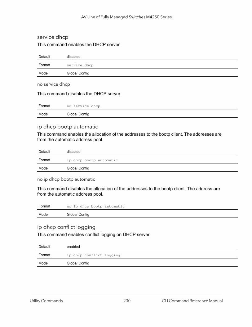
AV Line of Fully Managed Switches M4250 Series
service dhcpThis command enables the DHCP server.
no service dhcp
This command disables the DHCP server.
ip dhcp bootp automaticThis command enables the allocation of the addresses to the bootp client. The addresses are from the automatic address pool.
no ip dhcp bootp automatic
This command disables the allocation of the addresses to the bootp client. The address are from the automatic address pool.
ip dhcp conflict loggingThis command enables conflict logging on DHCP server.
Default disabled
Format service dhcp
Mode Global Config
Format no service dhcp
Mode Global Config
Default disabled
Format ip dhcp bootp automatic
Mode Global Config
Format no ip dhcp bootp automatic
Mode Global Config
Default enabled
Format ip dhcp conflict logging
Mode Global Config
Utility Commands CLI Command Reference Manual230

AV Line of Fully Managed Switches M4250 Series
no ip dhcp conflict logging
This command disables conflict logging on DHCP server.
clear ip dhcp bindingThis command deletes an automatic address binding from the DHCP server database. If * (the asterisk character) is specified, the bindings corresponding to all the addresses are deleted. address is a valid IP address made up of four decimal bytes ranging from 0 to 255. IP address 0.0.0.0 is invalid.
clear ip dhcp server statisticsThis command clears DHCP server statistics counters.
clear ip dhcp conflictThe command is used to clear an address conflict from the DHCP Server database. The server detects conflicts using a ping. DHCP server clears all conflicts If * (the asterisk character) is used as the address parameter.
show ip dhcp bindingThis command displays address bindings for the specific IP address on the DHCP server. If no IP address is specified, the bindings corresponding to all the addresses are displayed.
Format no ip dhcp conflict logging
Mode Global Config
Format clear ip dhcp binding {address | *}
Mode Privileged EXEC
Format clear ip dhcp server statistics
Mode Privileged EXEC
Default none
Format clear ip dhcp conflict {address | *}
Mode Privileged EXEC
Format show ip dhcp binding [address]
Modes Privileged EXECUser EXEC
Utility Commands CLI Command Reference Manual231

AV Line of Fully Managed Switches M4250 Series
dy
show ip dhcp global configurationThis command displays address bindings for the specific IP address on the DHCP server. If no IP address is specified, the bindings corresponding to all the addresses are displayed.
show ip dhcp pool configurationThis command displays pool configuration. If all is specified, configuration for all the pools is displayed.
Term Definition
IP address The IP address of the client.
Hardware Address The MAC Address or the client identifier.
Lease expiration The lease expiration time of the IP address assigned to the client.
Type The manner in which IP address was assigned to the client.
Format show ip dhcp global configuration
Modes Privileged EXECUser EXEC
Term Definition
Service DHCP The field to display the status of dhcp protocol.
Number of Ping Packets
The maximum number of Ping Packets that will be sent to verify that an ip address id not alreaassigned.
Conflict Logging Shows whether conflict logging is enabled or disabled.
BootP Automatic Shows whether BootP for dynamic pools is enabled or disabled.
Format show ip dhcp pool configuration {name | all}
Modes Privileged EXECUser EXEC
Field Definition
Pool Name The name of the configured pool.
Pool Type The pool type.
Lease Time The lease expiration time of the IP address assigned to the client.
DNS Servers The list of DNS servers available to the DHCP client.
Default Routers The list of the default routers available to the DHCP client
Utility Commands CLI Command Reference Manual232

AV Line of Fully Managed Switches M4250 Series
osts
The following additional field is displayed for Dynamic pool type.
The following additional fields are displayed for Manual pool type.
show ip dhcp server statisticsThis command displays DHCP server statistics.
Message Received.
Field Definition
Network The network number and the mask for the DHCP address pool.
Field Definition
Client Name The name of a DHCP client.
Client Identifier The unique identifier of a DHCP client.
Hardware Address The hardware address of a DHCP client.
Hardware Address Type
The protocol of the hardware platform.
Host The IP address and the mask for a manual binding to a DHCP client.
Format show ip dhcp server statistics
Modes Privileged EXECUser EXEC
Field Definition
Automatic Bindings The number of IP addresses that have been automatically mapped to the MAC addresses of hthat are found in the DHCP database.
Expired Bindings The number of expired leases.
Malformed Bindings
The number of truncated or corrupted messages that were received by the DHCP server.
Message Definition
DHCP DISCOVER The number of DHCPDISCOVER messages the server has received.
DHCP REQUEST The number of DHCPREQUEST messages the server has received.
DHCP DECLINE The number of DHCPDECLINE messages the server has received.
DHCP RELEASE The number of DHCPRELEASE messages the server has received.
DHCP INFORM The number of DHCPINFORM messages the server has received.
Utility Commands CLI Command Reference Manual233
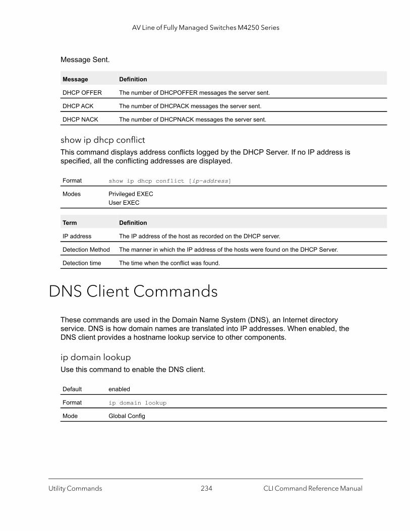
AV Line of Fully Managed Switches M4250 Series
Message Sent.
show ip dhcp conflictThis command displays address conflicts logged by the DHCP Server. If no IP address is specified, all the conflicting addresses are displayed.
DNS Client Commands
These commands are used in the Domain Name System (DNS), an Internet directory service. DNS is how domain names are translated into IP addresses. When enabled, the DNS client provides a hostname lookup service to other components.
ip domain lookupUse this command to enable the DNS client.
Message Definition
DHCP OFFER The number of DHCPOFFER messages the server sent.
DHCP ACK The number of DHCPACK messages the server sent.
DHCP NACK The number of DHCPNACK messages the server sent.
Format show ip dhcp conflict [ip-address]
Modes Privileged EXECUser EXEC
Term Definition
IP address The IP address of the host as recorded on the DHCP server.
Detection Method The manner in which the IP address of the hosts were found on the DHCP Server.
Detection time The time when the conflict was found.
Default enabled
Format ip domain lookup
Mode Global Config
Utility Commands CLI Command Reference Manual234
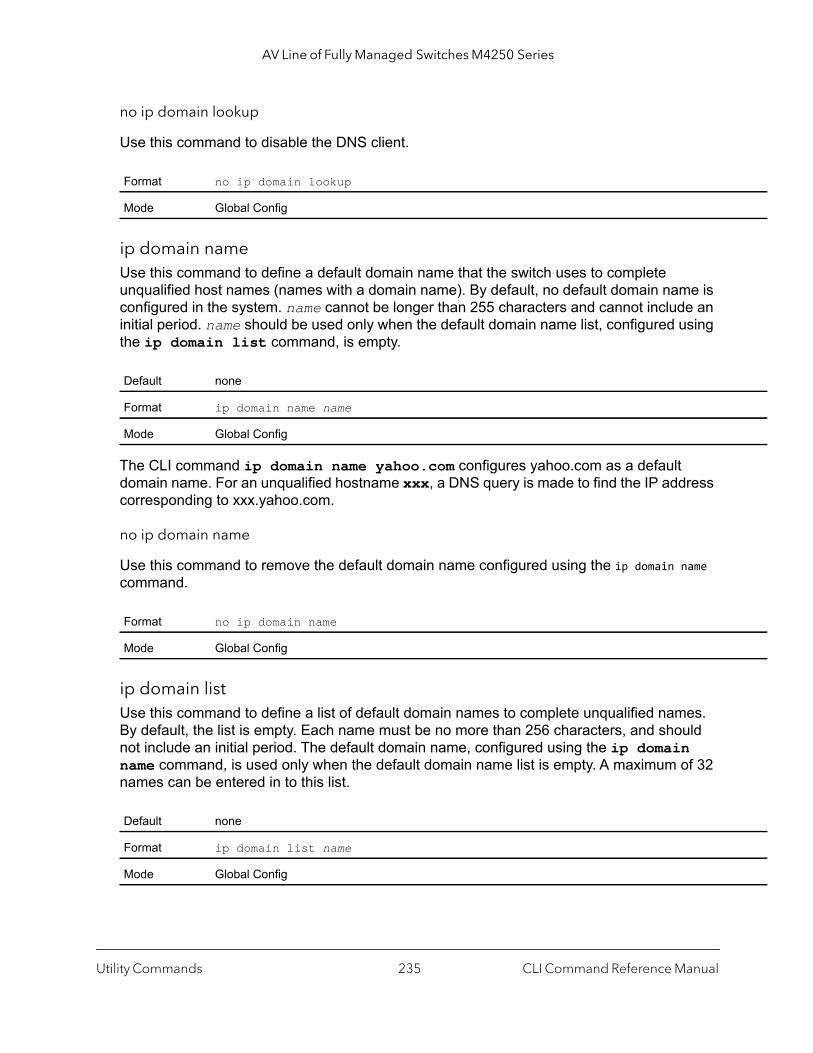
AV Line of Fully Managed Switches M4250 Series
no ip domain lookup
Use this command to disable the DNS client.
ip domain nameUse this command to define a default domain name that the switch uses to complete unqualified host names (names with a domain name). By default, no default domain name is configured in the system. name cannot be longer than 255 characters and cannot include an initial period. name should be used only when the default domain name list, configured using the ip domain list command, is empty.
The CLI command ip domain name yahoo.com configures yahoo.com as a default domain name. For an unqualified hostname xxx, a DNS query is made to find the IP address corresponding to xxx.yahoo.com.
no ip domain name
Use this command to remove the default domain name configured using the ip domain name command.
ip domain listUse this command to define a list of default domain names to complete unqualified names. By default, the list is empty. Each name must be no more than 256 characters, and should not include an initial period. The default domain name, configured using the ip domain name command, is used only when the default domain name list is empty. A maximum of 32 names can be entered in to this list.
Format no ip domain lookup
Mode Global Config
Default none
Format ip domain name name
Mode Global Config
Format no ip domain name
Mode Global Config
Default none
Format ip domain list name
Mode Global Config
Utility Commands CLI Command Reference Manual235
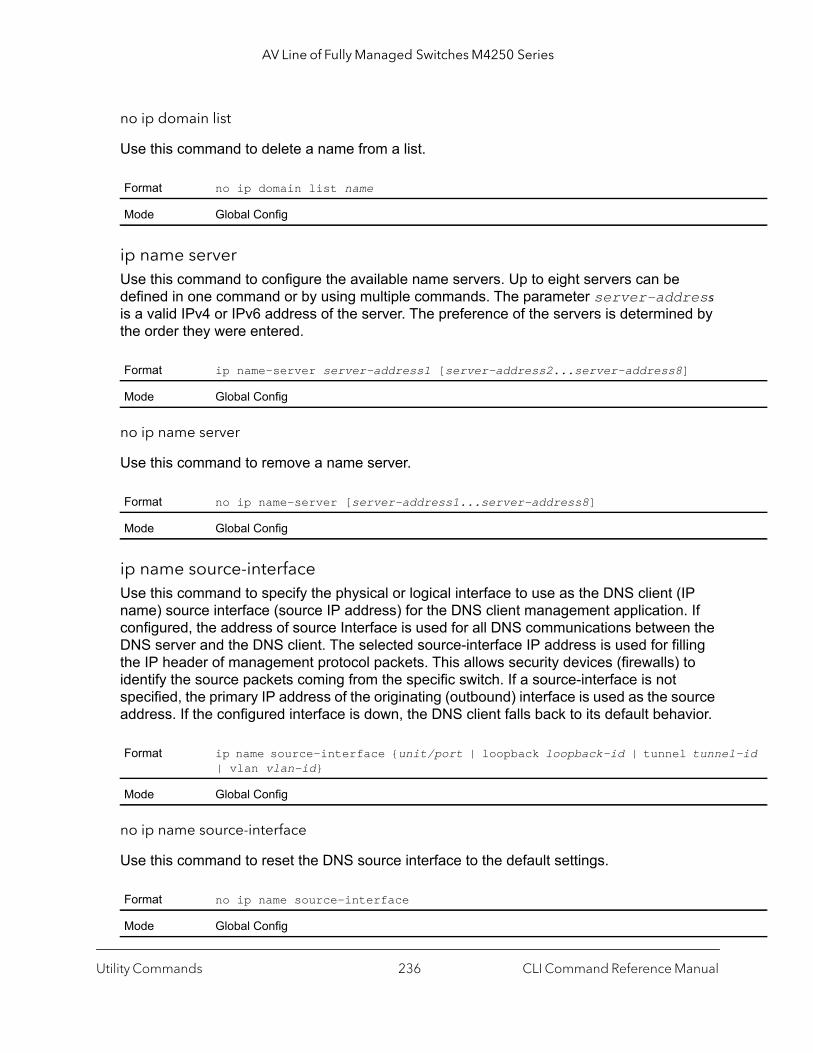
AV Line of Fully Managed Switches M4250 Series
-id
no ip domain list
Use this command to delete a name from a list.
ip name serverUse this command to configure the available name servers. Up to eight servers can be defined in one command or by using multiple commands. The parameter server-address is a valid IPv4 or IPv6 address of the server. The preference of the servers is determined by the order they were entered.
no ip name server
Use this command to remove a name server.
ip name source-interfaceUse this command to specify the physical or logical interface to use as the DNS client (IP name) source interface (source IP address) for the DNS client management application. If configured, the address of source Interface is used for all DNS communications between the DNS server and the DNS client. The selected source-interface IP address is used for filling the IP header of management protocol packets. This allows security devices (firewalls) to identify the source packets coming from the specific switch. If a source-interface is not specified, the primary IP address of the originating (outbound) interface is used as the source address. If the configured interface is down, the DNS client falls back to its default behavior.
no ip name source-interface
Use this command to reset the DNS source interface to the default settings.
Format no ip domain list name
Mode Global Config
Format ip name-server server-address1 [server-address2...server-address8]
Mode Global Config
Format no ip name-server [server-address1...server-address8]
Mode Global Config
Format ip name source-interface {unit/port | loopback loopback-id | tunnel tunnel| vlan vlan-id}
Mode Global Config
Format no ip name source-interface
Mode Global Config
Utility Commands CLI Command Reference Manual236

AV Line of Fully Managed Switches M4250 Series
ip hostUse this command to define static host name-to-address mapping in the host cache. The parameter name is host name and ipaddress is the IP address of the host. The host name can include 1–255 alphanumeric characters, periods, hyphens, underscores, and non-consecutive spaces. Hostnames that include one or more space must be enclosed in quotation marks, for example “lab-pc 45”.
no ip host
Use this command to remove the name-to-address mapping.
ipv6 hostUse this command to define static host name-to-IPv6 address mapping in the host cache. The parameter name is host name and v6 address is the IPv6 address of the host. The host name can include 1–255 alphanumeric characters, periods, hyphens, and spaces. Host names that include one or more space must be enclosed in quotation marks, for example “lab-pc 45”.
no ipv6 host
Use this command to remove the static host name-to-IPv6 address mapping in the host cache.
Default none
Format ip host name ipaddress
Mode Global Config
Format no ip host name
Mode Global Config
Default none
Format ipv6 host name v6 address
Mode Global Config
Format no ipv6 host name
Mode Global Config
Utility Commands CLI Command Reference Manual237

AV Line of Fully Managed Switches M4250 Series
ip domain retryUse this command to specify the number of times to retry sending Domain Name System (DNS) queries. The number argument indicates the number of times to retry sending a DNS query to the DNS server. This number is in the range from 0 to 100.
no ip domain retry
Use this command to return to the default.
ip domain timeoutUse this command to specify the amount of time to wait for a response to a DNS query. The parameter seconds specifies the time, in seconds, to wait for a response to a DNS query. The parameter seconds ranges from 0 to 3600.
no ip domain timeout
Use this command to return to the default setting.
clear hostUse this command to delete entries from the host name-to-address cache. This command clears the entries from the DNS cache maintained by the software. This command clears both IPv4 and IPv6 entries.
Default 2
Format ip domain retry number
Mode Global Config
Format no ip domain retry
Mode Global Config
Default 3
Format ip domain timeout seconds
Mode Global Config
Format no ip domain timeout
Mode Global Config
Format clear host {name | all}
Mode Privileged EXEC
Utility Commands CLI Command Reference Manual238
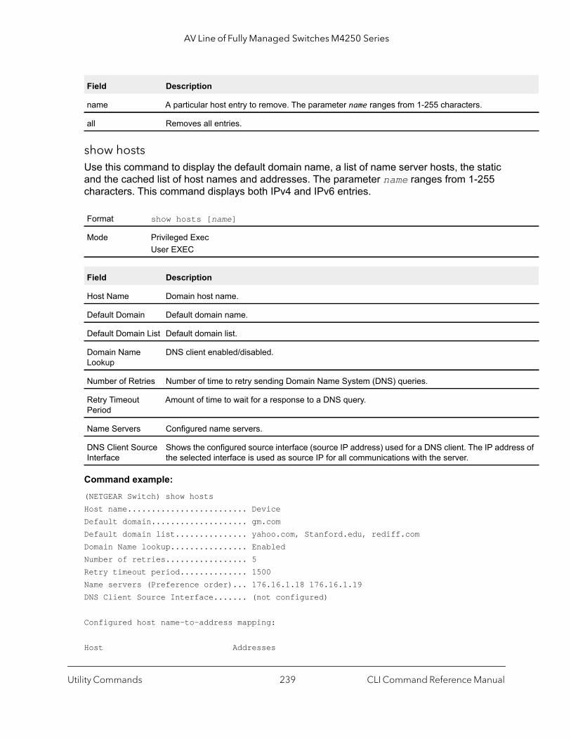
AV Line of Fully Managed Switches M4250 Series
ss of
show hostsUse this command to display the default domain name, a list of name server hosts, the static and the cached list of host names and addresses. The parameter name ranges from 1-255 characters. This command displays both IPv4 and IPv6 entries.
Command example: (NETGEAR Switch) show hostsHost name......................... DeviceDefault domain.................... gm.comDefault domain list............... yahoo.com, Stanford.edu, rediff.com Domain Name lookup................ EnabledNumber of retries................. 5Retry timeout period.............. 1500Name servers (Preference order)... 176.16.1.18 176.16.1.19DNS Client Source Interface....... (not configured)
Configured host name-to-address mapping:
Host Addresses
Field Description
name A particular host entry to remove. The parameter name ranges from 1-255 characters.
all Removes all entries.
Format show hosts [name]
Mode Privileged ExecUser EXEC
Field Description
Host Name Domain host name.
Default Domain Default domain name.
Default Domain List Default domain list.
Domain Name Lookup
DNS client enabled/disabled.
Number of Retries Number of time to retry sending Domain Name System (DNS) queries.
Retry Timeout Period
Amount of time to wait for a response to a DNS query.
Name Servers Configured name servers.
DNS Client Source Interface
Shows the configured source interface (source IP address) used for a DNS client. The IP addrethe selected interface is used as source IP for all communications with the server.
Utility Commands CLI Command Reference Manual239

AV Line of Fully Managed Switches M4250 Series
s.
e.
as
------------------------------ ------------------------------accounting.gm.com 176.16.8.8
Host Total Elapsed Type Addresses--------------- -------- ------ -------- ---------------www.stanford.edu 72 3 IP 171.64.14.203
IP Address Conflict Commands
The commands in this section help troubleshoot IP address conflicts.
ip address-conflict-detect runThis command triggers the switch to run active address conflict detection by sending gratuitous ARP packets for IPv4 addresses on the switch.
show ip address-conflictThis command displays the status information corresponding to the last detected address conflict.
clear ip address-conflict-detectThis command clears the detected address conflict status information.
Format ip address-conflict-detect run
Mode Global Config
Format show ip address-conflict
Modes Privileged EXEC
Term Definition
Address Conflict Detection Status Identifies whether the switch has detected an address conflict on any IP addres
Last Conflicting IP Address The IP Address that was last detected as conflicting on any interface.
Last Conflicting MAC Address The MAC Address of the conflicting host that was last detected on any interfac
Time Since Conflict Detected The time in days, hours, minutes and seconds since the last address conflict wdetected.
Format clear ip address-conflict-detect
Modes Privileged EXEC
Utility Commands CLI Command Reference Manual240

AV Line of Fully Managed Switches M4250 Series
Serviceability Packet Tracing Commands
These commands improve the capability to diagnose conditions that affect the switch.
CAUTION:
The output of debug commands can be long and may adversely affect system performance.
capture startUse the capture start command to manually start capturing CPU packets for packet trace.
The packet capture operates in three modes:
• capture file• remote capture• capture line
The command is not persistent across a reboot cycle.
capture stopUse the capture stop command to manually stop capturing CPU packets for packet trace.
Format capture start [all | receive | transmit]
Mode Privileged EXEC
Parameter Description
all Capture all traffic.
receive Capture only received traffic.
transmit Capture only transmitted traffic.
Format capture stop
Mode Privileged EXEC
Utility Commands CLI Command Reference Manual241
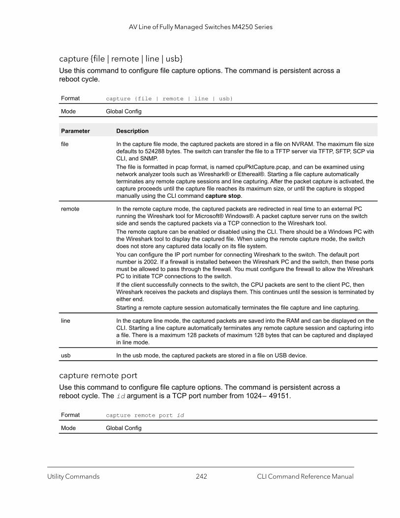
AV Line of Fully Managed Switches M4250 Series
size P via
g
d, the d
tch
with h
ports hark
n ed by
n the into
ayed
capture {file | remote | line | usb}Use this command to configure file capture options. The command is persistent across a reboot cycle.
capture remote portUse this command to configure file capture options. The command is persistent across a reboot cycle. The id argument is a TCP port number from 1024 – 49151.
Format capture {file | remote | line | usb}
Mode Global Config
Parameter Description
file In the capture file mode, the captured packets are stored in a file on NVRAM. The maximum filedefaults to 524288 bytes. The switch can transfer the file to a TFTP server via TFTP, SFTP, SCCLI, and SNMP. The file is formatted in pcap format, is named cpuPktCapture.pcap, and can be examined usinnetwork analyzer tools such as Wireshark® or Ethereal®. Starting a file capture automatically terminates any remote capture sessions and line capturing. After the packet capture is activatecapture proceeds until the capture file reaches its maximum size, or until the capture is stoppemanually using the CLI command capture stop.
remote In the remote capture mode, the captured packets are redirected in real time to an external PCrunning the Wireshark tool for Microsoft® Windows®. A packet capture server runs on the swiside and sends the captured packets via a TCP connection to the Wireshark tool. The remote capture can be enabled or disabled using the CLI. There should be a Windows PCthe Wireshark tool to display the captured file. When using the remote capture mode, the switcdoes not store any captured data locally on its file system.You can configure the IP port number for connecting Wireshark to the switch. The default port number is 2002. If a firewall is installed between the Wireshark PC and the switch, then these must be allowed to pass through the firewall. You must configure the firewall to allow the WiresPC to initiate TCP connections to the switch.If the client successfully connects to the switch, the CPU packets are sent to the client PC, theWireshark receives the packets and displays them. This continues until the session is terminateither end.Starting a remote capture session automatically terminates the file capture and line capturing.
line In the capture line mode, the captured packets are saved into the RAM and can be displayed oCLI. Starting a line capture automatically terminates any remote capture session and capturinga file. There is a maximum 128 packets of maximum 128 bytes that can be captured and displin line mode.
usb In the usb mode, the captured packets are stored in a file on USB device.
Format capture remote port id
Mode Global Config
Utility Commands CLI Command Reference Manual242
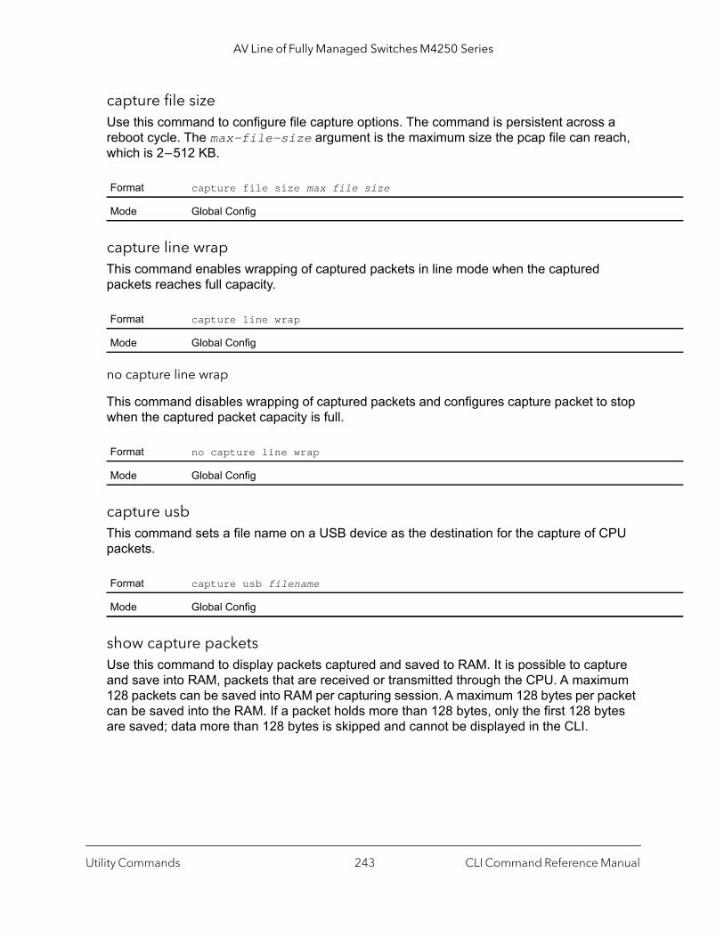
AV Line of Fully Managed Switches M4250 Series
capture file sizeUse this command to configure file capture options. The command is persistent across a reboot cycle. The max-file-size argument is the maximum size the pcap file can reach, which is 2 – 512 KB.
capture line wrapThis command enables wrapping of captured packets in line mode when the captured packets reaches full capacity.
no capture line wrap
This command disables wrapping of captured packets and configures capture packet to stop when the captured packet capacity is full.
capture usbThis command sets a file name on a USB device as the destination for the capture of CPU packets.
show capture packetsUse this command to display packets captured and saved to RAM. It is possible to capture and save into RAM, packets that are received or transmitted through the CPU. A maximum 128 packets can be saved into RAM per capturing session. A maximum 128 bytes per packet can be saved into the RAM. If a packet holds more than 128 bytes, only the first 128 bytes are saved; data more than 128 bytes is skipped and cannot be displayed in the CLI.
Format capture file size max file size
Mode Global Config
Format capture line wrap
Mode Global Config
Format no capture line wrap
Mode Global Config
Format capture usb filename
Mode Global Config
Utility Commands CLI Command Reference Manual243

AV Line of Fully Managed Switches M4250 Series
Capturing packets is stopped automatically when 128 packets are captured and have not yet been displayed during a capture session. Captured packets are not retained after a reload cycle.
debug aaa accountingThis command is useful to debug accounting configuration and functionality in User Manager
Note: To display the debug trace, enable the debug console command.
no debug aaa accounting
Use this command to turn off debugging of User Manager accounting functionality.
debug aaa authorizationUse this command to enable the tracing for AAA in User Manager. This is useful to debug authorization configuration and functionality in the User Manager. Each of the parameters are used to configure authorization debug flags.
Note: To display the debug trace, enable the debug console command.
no debug aaa authorization
Use this command to turn off debugging of the User Manager authorization functionality.
Format show capture packets
Mode Privileged EXEC
Format debug aaa accounting
Mode Privileged EXEC
Format no debug aaa accounting
Mode Privileged EXEC
Format debug aaa authorization [commands | exec]
Mode Privileged EXEC
Format no debug aaa authorization
Mode Privileged EXEC
Utility Commands CLI Command Reference Manual244

AV Line of Fully Managed Switches M4250 Series
Command example: (NETGEAR Switch) #debug aaa authorization Tacacs authorization receive packet tracing enabled.
(NETGEAR Switch) #debug tacacs authorization packet transmit
authorization tracing enabled.
(NETGEAR Switch) #no debug aaa authorization
AAA authorization tracing enabled
(NETGEAR Switch) #
debug arpUse this command to enable ARP debug protocol messages.
Note: To display the debug trace, enable the debug console command.
no debug arp
Use this command to disable ARP debug protocol messages.
debug authenticationThis command displays either the debug trace for either a single event or all events for an interface.
Note: To display the debug trace, enable the debug console command.
Default disabled
Format debug arp
Mode Privileged EXEC
Format no debug arp
Mode Privileged EXEC
Default none
Format debug authentication packet {all | event} interface unit/port
Mode Privileged EXEC
Utility Commands CLI Command Reference Manual245

AV Line of Fully Managed Switches M4250 Series
debug auto-voipUse this command to enable Auto VoIP debug messages. Use the optional parameters to trace H323, SCCP, SIP, OUI packets respectively.
Note: To display the debug trace, enable the debug console command.
no debug auto-voip
Use this command to disable Auto VOIP debug messages.
debug clearThis command disables all previously enabled “debug” traces.
Note: To display the debug trace, enable the debug console command.
debug consoleThis command enables the display of “debug” trace output on the login session in which it is executed. Debug console display must be enabled in order to view any trace output. The output of debug trace commands will appear on all login sessions for which debug console has been enabled. The configuration of this command remains in effect for the life of the login session. The effect of this command is not persistent across resets.
Note: To display the debug trace, enable the debug console command.
Default disabled
Format debug auto-voip [H323 | SCCP |SIP | oui]
Mode Privileged EXEC
Format no debug auto-voip
Mode Privileged EXEC
Default disabled
Format debug clear
Mode Privileged EXEC
Default disabled
Format debug console
Mode Privileged EXEC
Utility Commands CLI Command Reference Manual246

AV Line of Fully Managed Switches M4250 Series
oad
range
d
no debug console
This command disables the display of “debug” trace output on the login session in which it is executed.
debug crashlogUse this command to view information contained in the crash log file that the system maintains when it experiences an unexpected reset. The crash log file contains the following information:
• Call stack information in both primitive and verbose forms• Log Status• Buffered logging• Event logging• Persistent logging• System Information (output of sysapiMbufDump)• Message Queue Debug Information• Memory Debug Information• Memory Debug Status• OS Information (output of osapiShowTasks)• process information (meminfo, cpuinfo, interrupts, version and net/sockstat)
Note: To display the debug trace, enable the debug console command.
Format no debug console
Mode Privileged EXEC
Default disabled
Format debug crashlog {proc |verbose | deteteall | [kernel] crashlog-number [uplurl]| data crashlog-number [download url | upload url | component-id item-number additional-parameter]} [unit unit]
Mode Privileged EXEC
Parameter Description
kernel View the crash log file for the kernel
crashlog-number Specifies the file number to view. The system maintains up to four copies, and the valid is 1 – 4.
upload url To upload the crash log (or crash dump) to a TFTP server, use the upload keyword anspecify the required TFTP server information.
proc View the application process crashlog.
Utility Commands CLI Command Reference Manual247

AV Line of Fully Managed Switches M4250 Series
debug debug-configUse this command to download or upload the debug-config.ini file. The debug-config. ini file executes CLI commands (including devshell and drivshell commands) on specific predefined events. The debug config file is created manually and downloaded to the switch.
Note: To display the debug trace, enable the debug console command.
debug dhcp packetThis command displays “debug” information about DHCPv4 client activities and traces DHCPv4 packets to and from the local DHCPv4 client.
Note: To display the debug trace, enable the debug console command.
verbose Enable the verbose crashlog.
deleteall Delete all crash log files on the system.
data Crash log data recorder.
crashdump-number Specifies the crash dump number to view. The valid range is 0 – 2.
download url To download a crash dump to the switch, use the download keyword and specify the required TFTP server information.
component-id The ID of the component that caused the crash.
item-number The item number.
additional-parameter Additional parameters to include.
unit The unit number for the unit on which the crashlog is located.
Default disabled
Format debug debug-config {download url | upload url}
Mode Privileged EXEC
Default disabled
Format debug dhcp packet [transmit | receive]
Mode Privileged EXEC
Parameter Description
Utility Commands CLI Command Reference Manual248
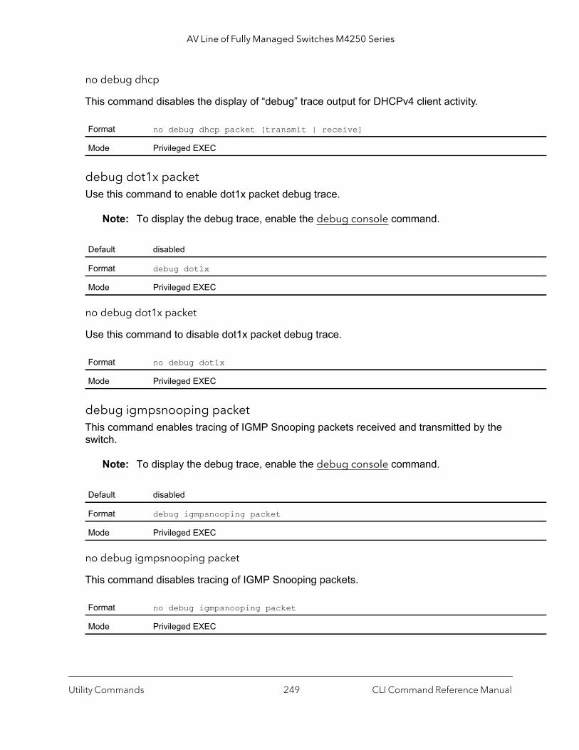
AV Line of Fully Managed Switches M4250 Series
no debug dhcp
This command disables the display of “debug” trace output for DHCPv4 client activity.
debug dot1x packetUse this command to enable dot1x packet debug trace.
Note: To display the debug trace, enable the debug console command.
no debug dot1x packet
Use this command to disable dot1x packet debug trace.
debug igmpsnooping packetThis command enables tracing of IGMP Snooping packets received and transmitted by the switch.
Note: To display the debug trace, enable the debug console command.
no debug igmpsnooping packet
This command disables tracing of IGMP Snooping packets.
Format no debug dhcp packet [transmit | receive]
Mode Privileged EXEC
Default disabled
Format debug dot1x
Mode Privileged EXEC
Format no debug dot1x
Mode Privileged EXEC
Default disabled
Format debug igmpsnooping packet
Mode Privileged EXEC
Format no debug igmpsnooping packet
Mode Privileged EXEC
Utility Commands CLI Command Reference Manual249
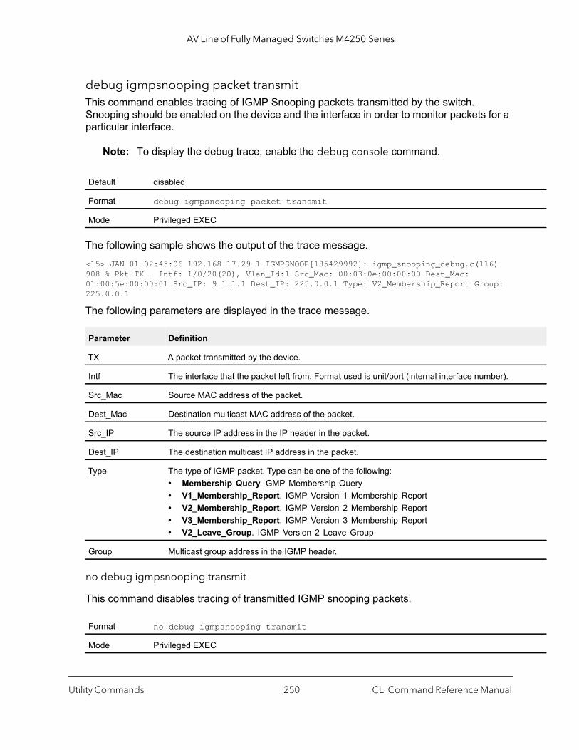
AV Line of Fully Managed Switches M4250 Series
debug igmpsnooping packet transmitThis command enables tracing of IGMP Snooping packets transmitted by the switch. Snooping should be enabled on the device and the interface in order to monitor packets for a particular interface.
Note: To display the debug trace, enable the debug console command.
The following sample shows the output of the trace message.<15> JAN 01 02:45:06 192.168.17.29-1 IGMPSNOOP[185429992]: igmp_snooping_debug.c(116) 908 % Pkt TX - Intf: 1/0/20(20), Vlan_Id:1 Src_Mac: 00:03:0e:00:00:00 Dest_Mac: 01:00:5e:00:00:01 Src_IP: 9.1.1.1 Dest_IP: 225.0.0.1 Type: V2_Membership_Report Group: 225.0.0.1
The following parameters are displayed in the trace message.
no debug igmpsnooping transmit
This command disables tracing of transmitted IGMP snooping packets.
Default disabled
Format debug igmpsnooping packet transmit
Mode Privileged EXEC
Parameter Definition
TX A packet transmitted by the device.
Intf The interface that the packet left from. Format used is unit/port (internal interface number).
Src_Mac Source MAC address of the packet.
Dest_Mac Destination multicast MAC address of the packet.
Src_IP The source IP address in the IP header in the packet.
Dest_IP The destination multicast IP address in the packet.
Type The type of IGMP packet. Type can be one of the following:• Membership Query. GMP Membership Query• V1_Membership_Report. IGMP Version 1 Membership Report• V2_Membership_Report. IGMP Version 2 Membership Report• V3_Membership_Report. IGMP Version 3 Membership Report• V2_Leave_Group. IGMP Version 2 Leave Group
Group Multicast group address in the IGMP header.
Format no debug igmpsnooping transmit
Mode Privileged EXEC
Utility Commands CLI Command Reference Manual250
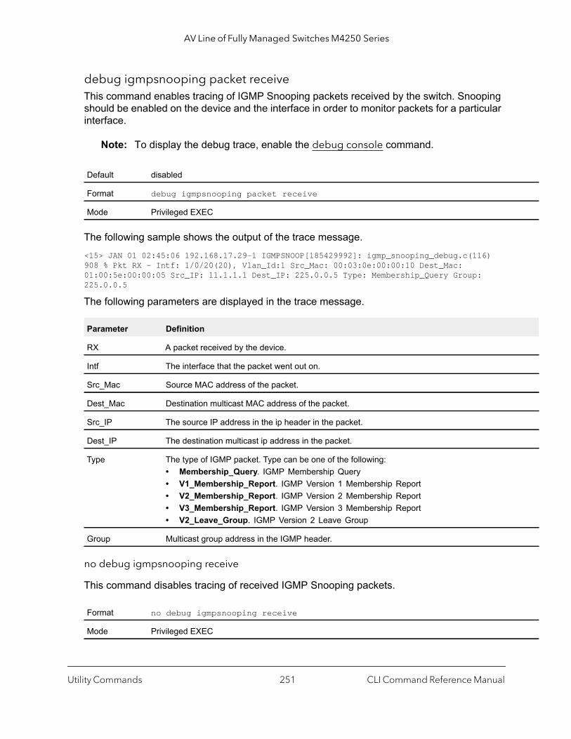
AV Line of Fully Managed Switches M4250 Series
debug igmpsnooping packet receiveThis command enables tracing of IGMP Snooping packets received by the switch. Snooping should be enabled on the device and the interface in order to monitor packets for a particular interface.
Note: To display the debug trace, enable the debug console command.
The following sample shows the output of the trace message.<15> JAN 01 02:45:06 192.168.17.29-1 IGMPSNOOP[185429992]: igmp_snooping_debug.c(116) 908 % Pkt RX - Intf: 1/0/20(20), Vlan_Id:1 Src_Mac: 00:03:0e:00:00:10 Dest_Mac: 01:00:5e:00:00:05 Src_IP: 11.1.1.1 Dest_IP: 225.0.0.5 Type: Membership_Query Group: 225.0.0.5
The following parameters are displayed in the trace message.
no debug igmpsnooping receive
This command disables tracing of received IGMP Snooping packets.
Default disabled
Format debug igmpsnooping packet receive
Mode Privileged EXEC
Parameter Definition
RX A packet received by the device.
Intf The interface that the packet went out on.
Src_Mac Source MAC address of the packet.
Dest_Mac Destination multicast MAC address of the packet.
Src_IP The source IP address in the ip header in the packet.
Dest_IP The destination multicast ip address in the packet.
Type The type of IGMP packet. Type can be one of the following:• Membership_Query. IGMP Membership Query• V1_Membership_Report. IGMP Version 1 Membership Report• V2_Membership_Report. IGMP Version 2 Membership Report• V3_Membership_Report. IGMP Version 3 Membership Report• V2_Leave_Group. IGMP Version 2 Leave Group
Group Multicast group address in the IGMP header.
Format no debug igmpsnooping receive
Mode Privileged EXEC
Utility Commands CLI Command Reference Manual251
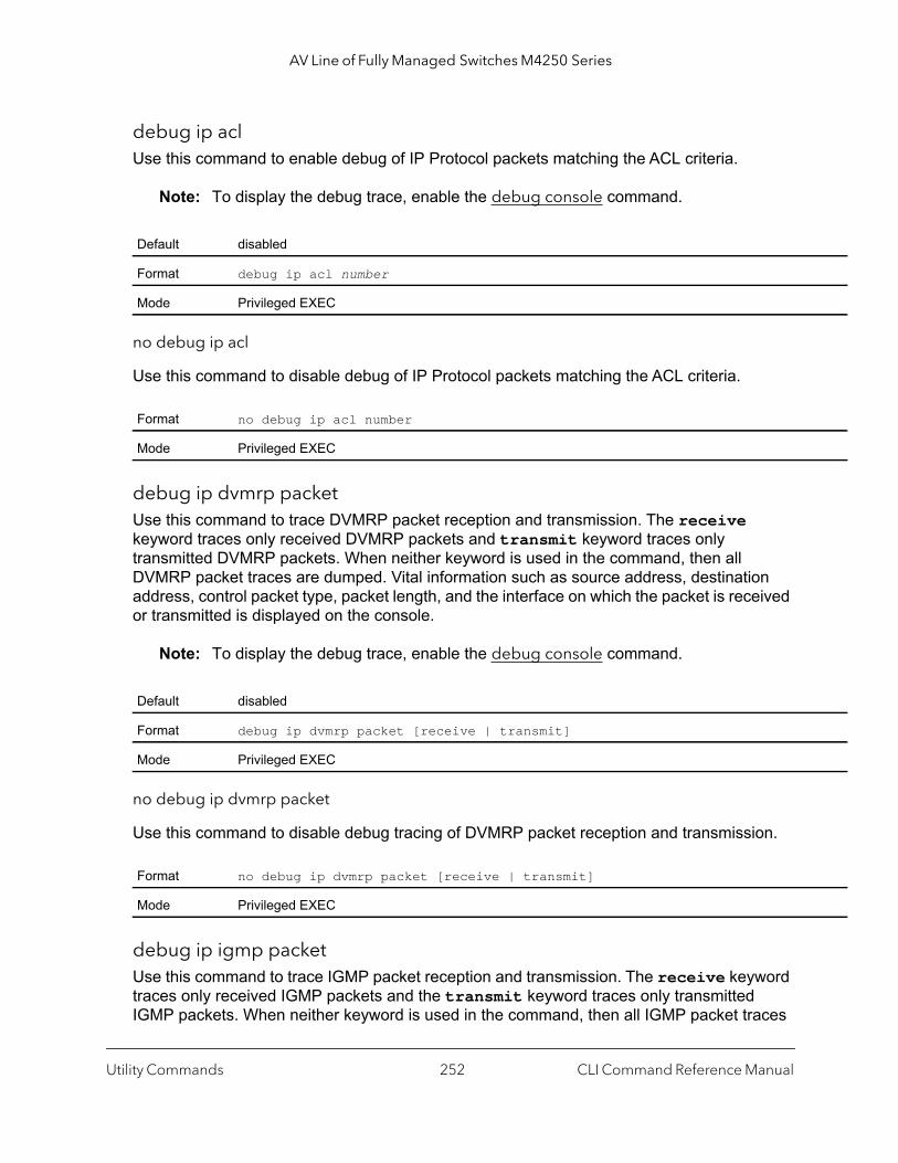
AV Line of Fully Managed Switches M4250 Series
debug ip aclUse this command to enable debug of IP Protocol packets matching the ACL criteria.
Note: To display the debug trace, enable the debug console command.
no debug ip acl
Use this command to disable debug of IP Protocol packets matching the ACL criteria.
debug ip dvmrp packetUse this command to trace DVMRP packet reception and transmission. The receive keyword traces only received DVMRP packets and transmit keyword traces only transmitted DVMRP packets. When neither keyword is used in the command, then all DVMRP packet traces are dumped. Vital information such as source address, destination address, control packet type, packet length, and the interface on which the packet is received or transmitted is displayed on the console.
Note: To display the debug trace, enable the debug console command.
no debug ip dvmrp packet
Use this command to disable debug tracing of DVMRP packet reception and transmission.
debug ip igmp packetUse this command to trace IGMP packet reception and transmission. The receive keyword traces only received IGMP packets and the transmit keyword traces only transmitted IGMP packets. When neither keyword is used in the command, then all IGMP packet traces
Default disabled
Format debug ip acl number
Mode Privileged EXEC
Format no debug ip acl number
Mode Privileged EXEC
Default disabled
Format debug ip dvmrp packet [receive | transmit]
Mode Privileged EXEC
Format no debug ip dvmrp packet [receive | transmit]
Mode Privileged EXEC
Utility Commands CLI Command Reference Manual252
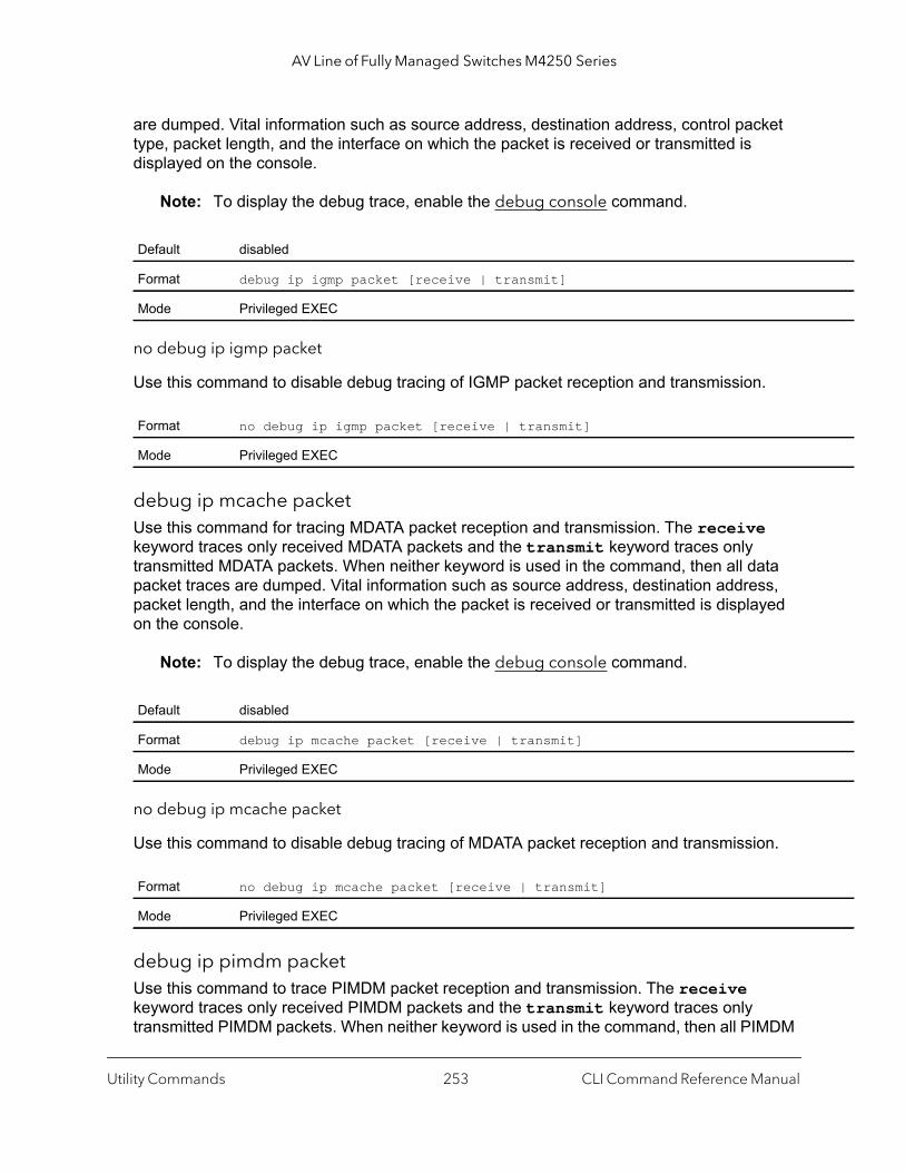
AV Line of Fully Managed Switches M4250 Series
are dumped. Vital information such as source address, destination address, control packet type, packet length, and the interface on which the packet is received or transmitted is displayed on the console.
Note: To display the debug trace, enable the debug console command.
no debug ip igmp packet
Use this command to disable debug tracing of IGMP packet reception and transmission.
debug ip mcache packetUse this command for tracing MDATA packet reception and transmission. The receive keyword traces only received MDATA packets and the transmit keyword traces only transmitted MDATA packets. When neither keyword is used in the command, then all data packet traces are dumped. Vital information such as source address, destination address, packet length, and the interface on which the packet is received or transmitted is displayed on the console.
Note: To display the debug trace, enable the debug console command.
no debug ip mcache packet
Use this command to disable debug tracing of MDATA packet reception and transmission.
debug ip pimdm packetUse this command to trace PIMDM packet reception and transmission. The receive keyword traces only received PIMDM packets and the transmit keyword traces only transmitted PIMDM packets. When neither keyword is used in the command, then all PIMDM
Default disabled
Format debug ip igmp packet [receive | transmit]
Mode Privileged EXEC
Format no debug ip igmp packet [receive | transmit]
Mode Privileged EXEC
Default disabled
Format debug ip mcache packet [receive | transmit]
Mode Privileged EXEC
Format no debug ip mcache packet [receive | transmit]
Mode Privileged EXEC
Utility Commands CLI Command Reference Manual253
AV Line of Fully Managed Switches M4250 Series
packet traces are dumped. Vital information such as source address, destination address, control packet type, packet length, and the interface on which the packet is received or transmitted is displayed on the console.
Note: To display the debug trace, enable the debug console command.
no debug ip pimdm packet
Use this command to disable debug tracing of PIMDM packet reception and transmission.
debug ip pimsm packetUse this command to trace PIMSM packet reception and transmission. The receive keyword traces only received PIMSM packets and the transmit keyword traces only transmitted PIMSM packets. When neither keyword is used in the command, then all PIMSM packet traces are dumped. Vital information such as source address, destination address, control packet type, packet length, and the interface on which the packet is received or transmitted is displayed on the console.
Note: To display the debug trace, enable the debug console command.
no debug ip pimsm packet
Use this command to disable debug tracing of PIMSM packet reception and transmission.
debug ipv6 dhcpThis command displays “debug” information about DHCPv6 client activities and traces DHCPv6 packets to and from the local DHCPv6 client.
Default disabled
Format debug ip pimdm packet [receive | transmit]
Mode Privileged EXEC
Format no debug ip pimdm packet [receive | transmit]
Mode Privileged EXEC
Default disabled
Format debug ip pimsm packet [receive | transmit]
Mode Privileged EXEC
Format no debug ip pimsm packet [receive | transmit]
Mode Privileged EXEC
Utility Commands CLI Command Reference Manual254
AV Line of Fully Managed Switches M4250 Series
Note: To display the debug trace, enable the debug console command.
no debug ipv6 dhcp
This command disables the display of “debug” trace output for DHCPv6 client activity.
debug ipv6 mcache packetUse this command for tracing MDATAv6 packet reception and transmission. The receive keyword traces only received MDATAv6 packets and the transmit keyword traces only transmitted MDATAv6 packets. When neither keyword is used in the command, then all data packet traces are dumped. Vital information such as source address, destination address, packet length, and the interface on which the packet is received or transmitted is displayed on the console.
Note: To display the debug trace, enable the debug console command.
no debug ipv6 mcache packet
Use this command to disable debug tracing of MDATAv6 packet reception and transmission.
debug ipv6 mld packetUse this command to trace MLDv6 packet reception and transmission. The receive keyword traces only received MLDv6 packets and the transmit keyword traces only transmitted MLDv6 packets. When neither keyword is used in the command, then all MLDv6 packet traces are dumped. Vital information such as source address, destination address, control packet type, packet length, and the interface on which the packet is received or transmitted is displayed on the console.
Default disabled
Format debug ipv6 dhcp
Mode Privileged EXEC
Format no debug ipv6 dhcp
Mode Privileged EXEC
Default disabled
Format debug ipv6 mcache packet [receive | transmit]
Mode Privileged EXEC
Format no debug ipv6 mcache packet [receive | transmit]
Mode Privileged EXEC
Utility Commands CLI Command Reference Manual255
AV Line of Fully Managed Switches M4250 Series
Note: To display the debug trace, enable the debug console command.
no debug ipv6 mld packet
Use this command to disable debug tracing of MLDv6 packet reception and transmission.
debug ipv6 pimdm packetUse this command to trace PIMDMv6 packet reception and transmission. The receive keyword traces only received PIMDMv6 packets and the transmit keyword traces only transmitted PIMDMv6 packets. If neither keyword is used in the command, all PIMDMv6 packet traces are dumped. Vital information such as source address, destination address, control packet type, packet length, and the interface on which the packet is received or transmitted is displayed on the console.
Note: To display the debug trace, enable the debug console command.
no debug ipv6 pimdm packet
Use this command to disable debug tracing of PIMDMv6 packet reception and transmission.
debug ipv6 pimsm packetUse this command to trace PIMSMv6 packet reception and transmission. The receive keyword traces only received PIMSMv6 packets and the transmit keyword traces only transmitted PIMSMv6 packets. If neither keyword is used in the command, all PIMSMv6 packet traces are dumped. Vital information such as source address, destination address, control packet type, packet length, and the interface on which the packet is received or transmitted is displayed on the console.
Default disabled
Format debug ipv6 mld packet [receive | transmit]
Mode Privileged EXEC
Format no debug ipv6 mld packet [receive | transmit]
Mode Privileged EXEC
Default disabled
Format debug ipv6 pimdm packet [receive | transmit]
Mode Privileged EXEC
Format no debug ipv6 pimdm packet [receive | transmit]
Mode Privileged EXEC
Utility Commands CLI Command Reference Manual256
AV Line of Fully Managed Switches M4250 Series
Note: To display the debug trace, enable the debug console command.
no debug ipv6 pimsm packet
Use this command to disable debug tracing of PIMSMv6 packet reception and transmission.
debug lacp packetThis command enables tracing of LACP packets received and transmitted by the switch.
Note: To display the debug trace, enable the debug console command.
The following sample shows the output of the trace message.<15> JAN 01 14:04:51 10.254.24.31-1 DOT3AD[183697744]: dot3ad_debug.c(385) 58 %% Pkt TX - Intf: 1/0/1(1), Type: LACP, Sys: 00:11:88:14:62:e1, State: 0x47, Key: 0x36
no debug lacp packet
This command disables tracing of LACP packets.
debug mldsnooping packetUse this command to trace MLD snooping packet reception and transmission. The receive keyword traces only received MLD packets and the transmit keyword traces only transmitted MLD snooping packets. When neither keyword is used in the command, then all MLD snooping packet traces are dumped. Vital information such as source address, destination address, control packet type, packet length, and the interface on which the packet is received or transmitted is displayed on the console.
Default disabled
Format debug ipv6 pimsm packet [receive | transmit]
Mode Privileged EXEC
Format no debug ipv6 pimsm packet [receive | transmit]
Mode Privileged EXEC
Default disabled
Format debug lacp packet
Mode Privileged EXEC
Format no debug lacp packet
Mode Privileged EXEC
Utility Commands CLI Command Reference Manual257
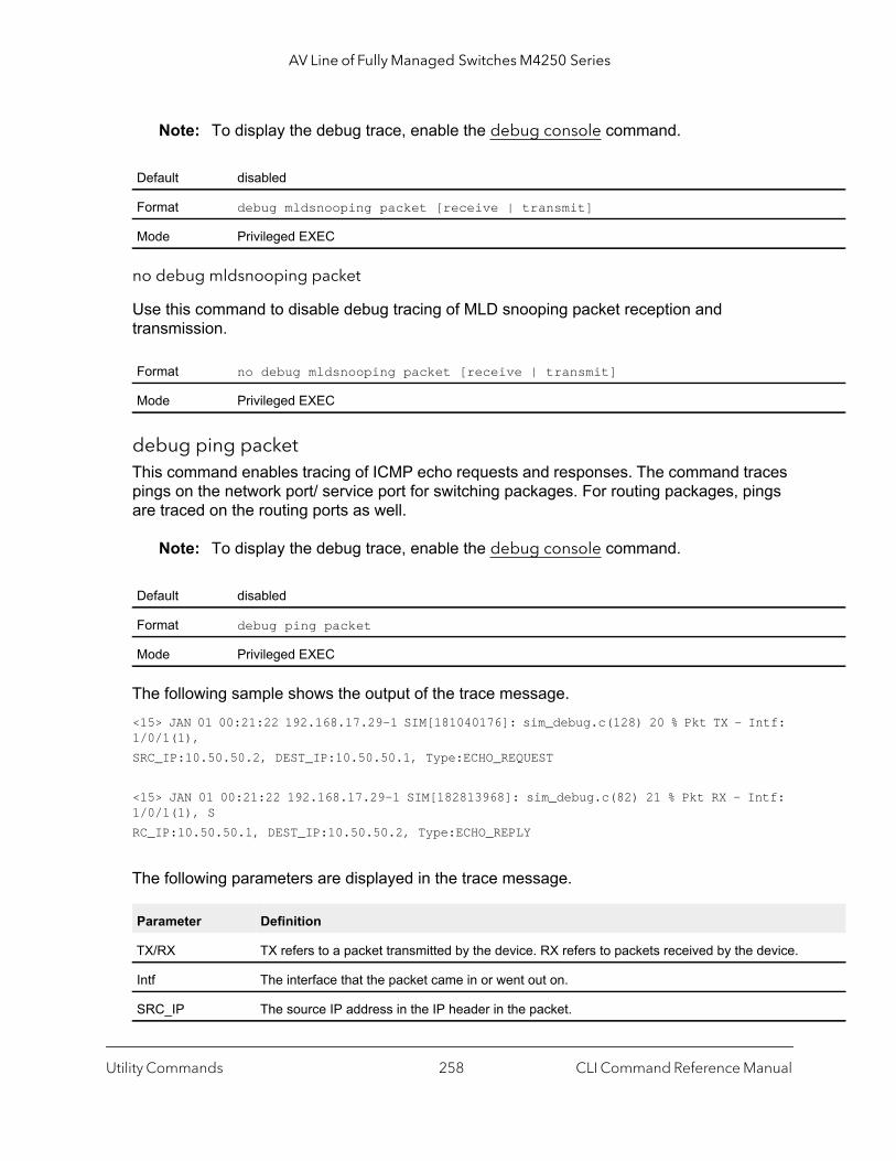
AV Line of Fully Managed Switches M4250 Series
Note: To display the debug trace, enable the debug console command.
no debug mldsnooping packet
Use this command to disable debug tracing of MLD snooping packet reception and transmission.
debug ping packetThis command enables tracing of ICMP echo requests and responses. The command traces pings on the network port/ service port for switching packages. For routing packages, pings are traced on the routing ports as well.
Note: To display the debug trace, enable the debug console command.
The following sample shows the output of the trace message.<15> JAN 01 00:21:22 192.168.17.29-1 SIM[181040176]: sim_debug.c(128) 20 % Pkt TX - Intf: 1/0/1(1),SRC_IP:10.50.50.2, DEST_IP:10.50.50.1, Type:ECHO_REQUEST
<15> JAN 01 00:21:22 192.168.17.29-1 SIM[182813968]: sim_debug.c(82) 21 % Pkt RX - Intf: 1/0/1(1), SRC_IP:10.50.50.1, DEST_IP:10.50.50.2, Type:ECHO_REPLY
The following parameters are displayed in the trace message.
Default disabled
Format debug mldsnooping packet [receive | transmit]
Mode Privileged EXEC
Format no debug mldsnooping packet [receive | transmit]
Mode Privileged EXEC
Default disabled
Format debug ping packet
Mode Privileged EXEC
Parameter Definition
TX/RX TX refers to a packet transmitted by the device. RX refers to packets received by the device.
Intf The interface that the packet came in or went out on.
SRC_IP The source IP address in the IP header in the packet.
Utility Commands CLI Command Reference Manual258
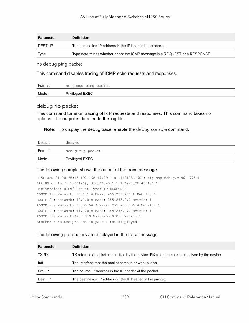
AV Line of Fully Managed Switches M4250 Series
no debug ping packet
This command disables tracing of ICMP echo requests and responses.
debug rip packetThis command turns on tracing of RIP requests and responses. This command takes no options. The output is directed to the log file.
Note: To display the debug trace, enable the debug console command.
The following sample shows the output of the trace message.<15> JAN 01 00:35:15 192.168.17.29-1 RIP[181783160]: rip_map_debug.c(96) 775 % Pkt RX on Intf: 1/0/1(1), Src_IP:43.1.1.1 Dest_IP:43.1.1.2Rip_Version: RIPv2 Packet_Type:RIP_RESPONSEROUTE 1): Network: 10.1.1.0 Mask: 255.255.255.0 Metric: 1ROUTE 2): Network: 40.1.0.0 Mask: 255.255.0.0 Metric: 1ROUTE 3): Network: 10.50.50.0 Mask: 255.255.255.0 Metric: 1ROUTE 4): Network: 41.1.0.0 Mask: 255.255.0.0 Metric: 1ROUTE 5): Network:42.0.0.0 Mask:255.0.0.0 Metric:1Another 6 routes present in packet not displayed.
The following parameters are displayed in the trace message.
DEST_IP The destination IP address in the IP header in the packet.
Type Type determines whether or not the ICMP message is a REQUEST or a RESPONSE.
Format no debug ping packet
Mode Privileged EXEC
Default disabled
Format debug rip packet
Mode Privileged EXEC
Parameter Definition
TX/RX TX refers to a packet transmitted by the device. RX refers to packets received by the device.
Intf The interface that the packet came in or went out on.
Src_IP The source IP address in the IP header of the packet.
Dest_IP The destination IP address in the IP header of the packet.
Parameter Definition
Utility Commands CLI Command Reference Manual259
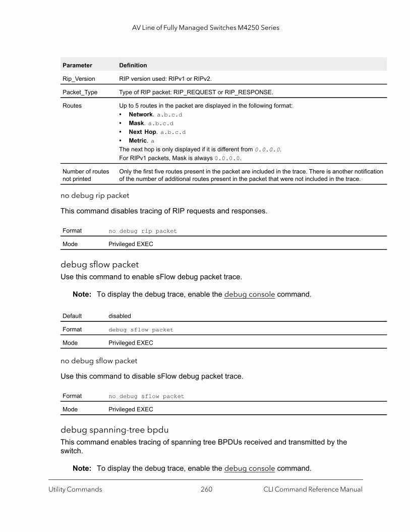
AV Line of Fully Managed Switches M4250 Series
ation
no debug rip packet
This command disables tracing of RIP requests and responses.
debug sflow packetUse this command to enable sFlow debug packet trace.
Note: To display the debug trace, enable the debug console command.
no debug sflow packet
Use this command to disable sFlow debug packet trace.
debug spanning-tree bpduThis command enables tracing of spanning tree BPDUs received and transmitted by the switch.
Note: To display the debug trace, enable the debug console command.
Rip_Version RIP version used: RIPv1 or RIPv2.
Packet_Type Type of RIP packet: RIP_REQUEST or RIP_RESPONSE.
Routes Up to 5 routes in the packet are displayed in the following format:• Network. a.b.c.d• Mask. a.b.c.d • Next Hop. a.b.c.d• Metric. aThe next hop is only displayed if it is different from 0.0.0.0.For RIPv1 packets, Mask is always 0.0.0.0.
Number of routes not printed
Only the first five routes present in the packet are included in the trace. There is another notificof the number of additional routes present in the packet that were not included in the trace.
Format no debug rip packet
Mode Privileged EXEC
Default disabled
Format debug sflow packet
Mode Privileged EXEC
Format no debug sflow packet
Mode Privileged EXEC
Parameter Definition
Utility Commands CLI Command Reference Manual260
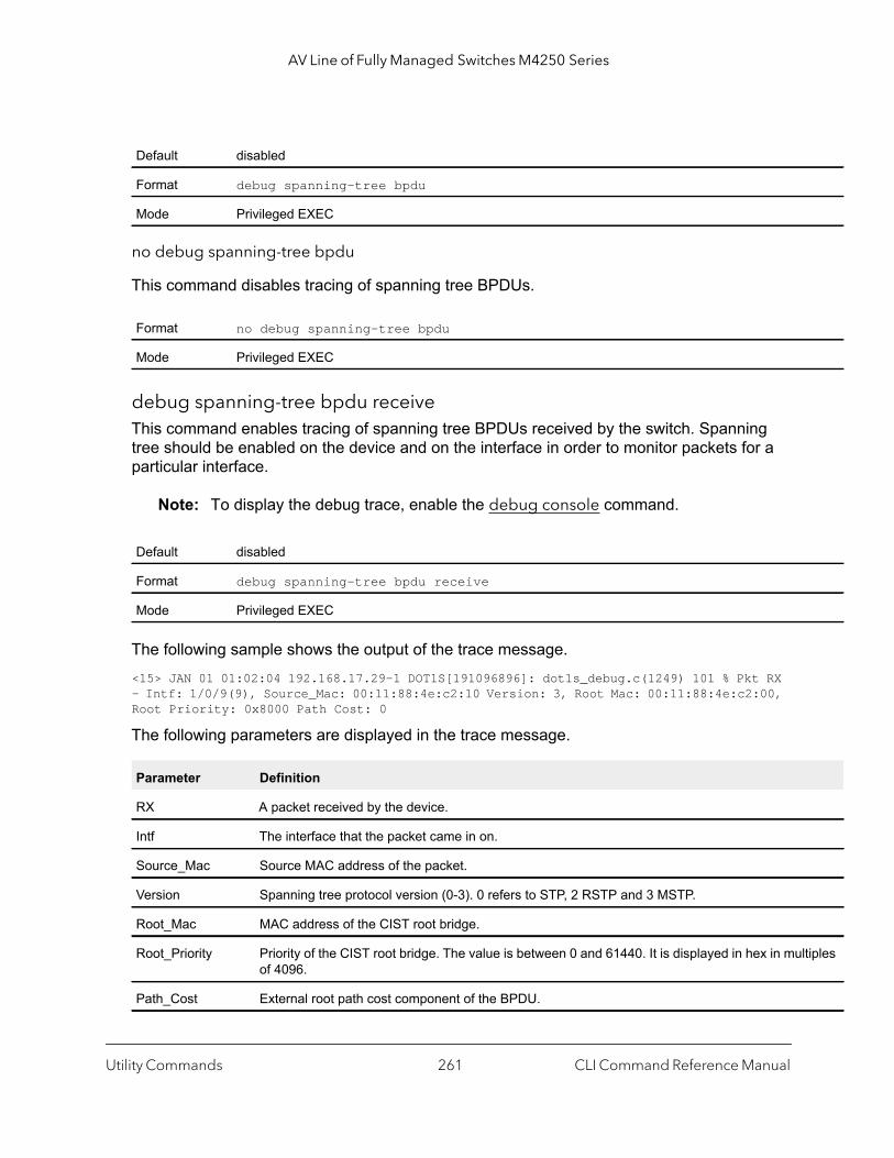
AV Line of Fully Managed Switches M4250 Series
ltiples
no debug spanning-tree bpdu
This command disables tracing of spanning tree BPDUs.
debug spanning-tree bpdu receiveThis command enables tracing of spanning tree BPDUs received by the switch. Spanning tree should be enabled on the device and on the interface in order to monitor packets for a particular interface.
Note: To display the debug trace, enable the debug console command.
The following sample shows the output of the trace message.<15> JAN 01 01:02:04 192.168.17.29-1 DOT1S[191096896]: dot1s_debug.c(1249) 101 % Pkt RX - Intf: 1/0/9(9), Source_Mac: 00:11:88:4e:c2:10 Version: 3, Root Mac: 00:11:88:4e:c2:00, Root Priority: 0x8000 Path Cost: 0
The following parameters are displayed in the trace message.
Default disabled
Format debug spanning-tree bpdu
Mode Privileged EXEC
Format no debug spanning-tree bpdu
Mode Privileged EXEC
Default disabled
Format debug spanning-tree bpdu receive
Mode Privileged EXEC
Parameter Definition
RX A packet received by the device.
Intf The interface that the packet came in on.
Source_Mac Source MAC address of the packet.
Version Spanning tree protocol version (0-3). 0 refers to STP, 2 RSTP and 3 MSTP.
Root_Mac MAC address of the CIST root bridge.
Root_Priority Priority of the CIST root bridge. The value is between 0 and 61440. It is displayed in hex in muof 4096.
Path_Cost External root path cost component of the BPDU.
Utility Commands CLI Command Reference Manual261
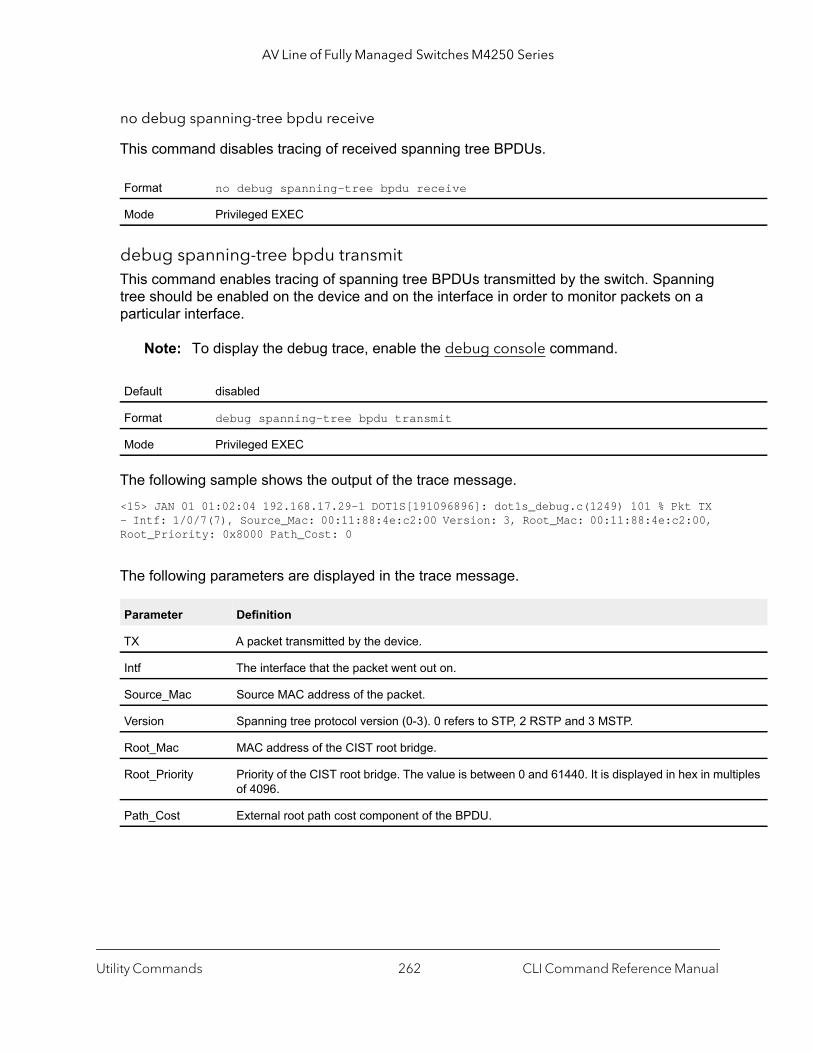
AV Line of Fully Managed Switches M4250 Series
tiples
no debug spanning-tree bpdu receive
This command disables tracing of received spanning tree BPDUs.
debug spanning-tree bpdu transmitThis command enables tracing of spanning tree BPDUs transmitted by the switch. Spanning tree should be enabled on the device and on the interface in order to monitor packets on a particular interface.
Note: To display the debug trace, enable the debug console command.
The following sample shows the output of the trace message.<15> JAN 01 01:02:04 192.168.17.29-1 DOT1S[191096896]: dot1s_debug.c(1249) 101 % Pkt TX - Intf: 1/0/7(7), Source_Mac: 00:11:88:4e:c2:00 Version: 3, Root_Mac: 00:11:88:4e:c2:00, Root_Priority: 0x8000 Path_Cost: 0
The following parameters are displayed in the trace message.
Format no debug spanning-tree bpdu receive
Mode Privileged EXEC
Default disabled
Format debug spanning-tree bpdu transmit
Mode Privileged EXEC
Parameter Definition
TX A packet transmitted by the device.
Intf The interface that the packet went out on.
Source_Mac Source MAC address of the packet.
Version Spanning tree protocol version (0-3). 0 refers to STP, 2 RSTP and 3 MSTP.
Root_Mac MAC address of the CIST root bridge.
Root_Priority Priority of the CIST root bridge. The value is between 0 and 61440. It is displayed in hex in mulof 4096.
Path_Cost External root path cost component of the BPDU.
Utility Commands CLI Command Reference Manual262
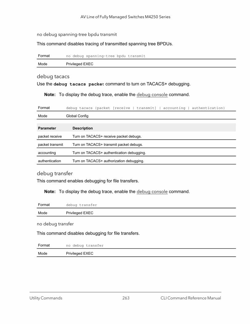
AV Line of Fully Managed Switches M4250 Series
no debug spanning-tree bpdu transmit
This command disables tracing of transmitted spanning tree BPDUs.
debug tacacsUse the debug tacacs packet command to turn on TACACS+ debugging.
Note: To display the debug trace, enable the debug console command.
debug transferThis command enables debugging for file transfers.
Note: To display the debug trace, enable the debug console command.
no debug transfer
This command disables debugging for file transfers.
Format no debug spanning-tree bpdu transmit
Mode Privileged EXEC
Format debug tacacs {packet [receive | transmit] | accounting | authentication}
Mode Global Config
Parameter Description
packet receive Turn on TACACS+ receive packet debugs.
packet transmit Turn on TACACS+ transmit packet debugs.
accounting Turn on TACACS+ authentication debugging.
authentication Turn on TACACS+ authorization debugging.
Format debug transfer
Mode Privileged EXEC
Format no debug transfer
Mode Privileged EXEC
Utility Commands CLI Command Reference Manual263
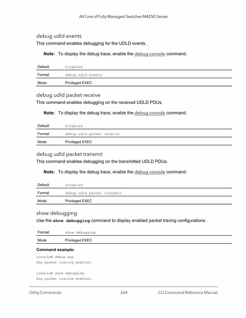
AV Line of Fully Managed Switches M4250 Series
debug udld eventsThis command enables debugging for the UDLD events.
Note: To display the debug trace, enable the debug console command.
debug udld packet receiveThis command enables debugging on the received UDLD PDUs.
Note: To display the debug trace, enable the debug console command.
debug udld packet transmitThis command enables debugging on the transmitted UDLD PDUs.
Note: To display the debug trace, enable the debug console command.
show debuggingUse the show debugging command to display enabled packet tracing configurations.
Command example: console# debug arpArp packet tracing enabled.
console# show debuggingArp packet tracing enabled.
Default Disabled
Format debug udld events
Mode Privileged EXEC
Default Disabled
Format debug udld packet receive
Mode Privileged EXEC
Default Disabled
Format debug udld packet transmit
Mode Privileged EXEC
Format show debugging
Mode Privileged EXEC
Utility Commands CLI Command Reference Manual264
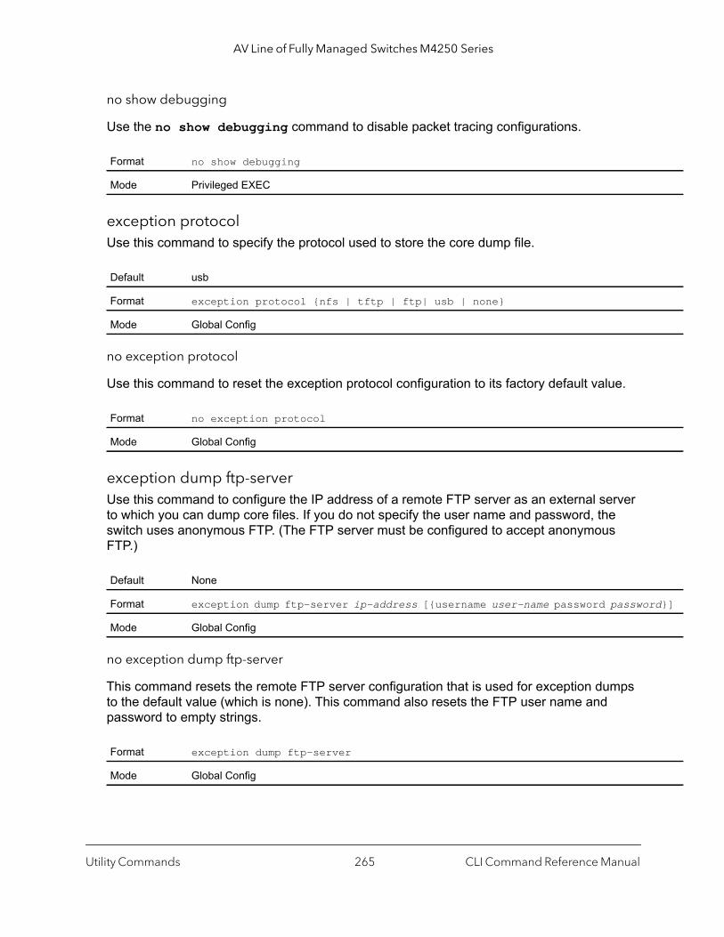
AV Line of Fully Managed Switches M4250 Series
d}]
no show debugging
Use the no show debugging command to disable packet tracing configurations.
exception protocolUse this command to specify the protocol used to store the core dump file.
no exception protocol
Use this command to reset the exception protocol configuration to its factory default value.
exception dump ftp-serverUse this command to configure the IP address of a remote FTP server as an external server to which you can dump core files. If you do not specify the user name and password, the switch uses anonymous FTP. (The FTP server must be configured to accept anonymous FTP.)
no exception dump ftp-server
This command resets the remote FTP server configuration that is used for exception dumps to the default value (which is none). This command also resets the FTP user name and password to empty strings.
Format no show debugging
Mode Privileged EXEC
Default usb
Format exception protocol {nfs | tftp | ftp| usb | none}
Mode Global Config
Format no exception protocol
Mode Global Config
Default None
Format exception dump ftp-server ip-address [{username user-name password passwor
Mode Global Config
Format exception dump ftp-server
Mode Global Config
Utility Commands CLI Command Reference Manual265

AV Line of Fully Managed Switches M4250 Series
exception dump tftp-serverUse this command to configure the IP address of a remote TFTP server in order to dump core files to an external server.
no exception dump tftp-server
Use this command to reset the exception dump remote server configuration to its factory default value.
Use this command to configure an NFS mount point in order to dump core file to the NFS file system.
no exception dump nfs
Use this command to reset the exception dump NFS mount point configuration to its factory default value.
exception dump filepathUse this command to configure a file-path to dump core file to a TFTP server, FTP server, NFS mount, or USB device subdirectory.
Default None
Format exception dump tftp-server {ip-address}
Mode Global Config
Format no exception dump tftp-server
Mode Global Config
Default None
Format exception dump nfs ip-address/dir
Mode Global Config
Format no exception dump nfs
Mode Global Config
Default None
Format exception dump filepath dir
Mode Global Config
Utility Commands CLI Command Reference Manual266
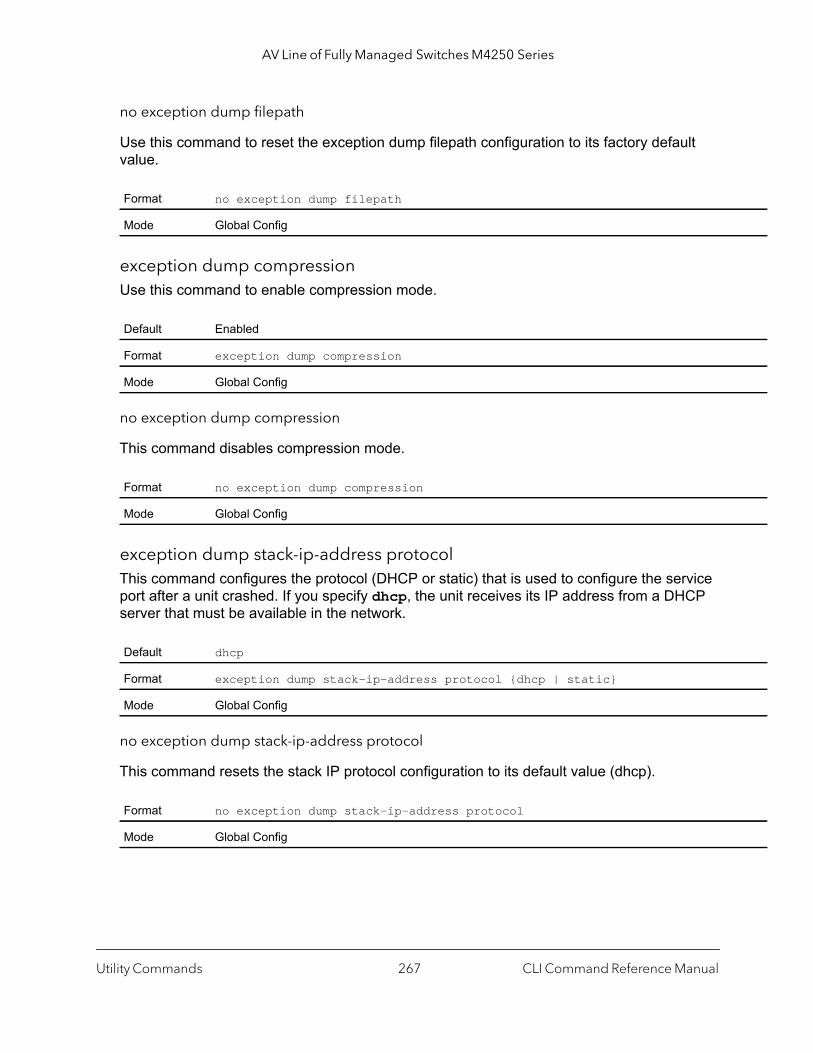
AV Line of Fully Managed Switches M4250 Series
no exception dump filepath
Use this command to reset the exception dump filepath configuration to its factory default value.
exception dump compressionUse this command to enable compression mode.
no exception dump compression
This command disables compression mode.
exception dump stack-ip-address protocolThis command configures the protocol (DHCP or static) that is used to configure the service port after a unit crashed. If you specify dhcp, the unit receives its IP address from a DHCP server that must be available in the network.
no exception dump stack-ip-address protocol
This command resets the stack IP protocol configuration to its default value (dhcp).
Format no exception dump filepath
Mode Global Config
Default Enabled
Format exception dump compression
Mode Global Config
Format no exception dump compression
Mode Global Config
Default dhcp
Format exception dump stack-ip-address protocol {dhcp | static}
Mode Global Config
Format no exception dump stack-ip-address protocol
Mode Global Config
Utility Commands CLI Command Reference Manual267
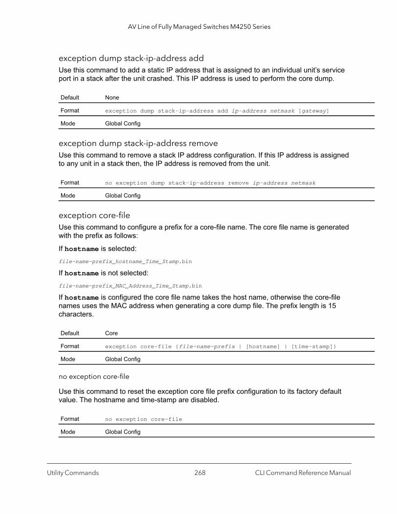
AV Line of Fully Managed Switches M4250 Series
exception dump stack-ip-address addUse this command to add a static IP address that is assigned to an individual unit’s service port in a stack after the unit crashed. This IP address is used to perform the core dump.
exception dump stack-ip-address remove Use this command to remove a stack IP address configuration. If this IP address is assigned to any unit in a stack then, the IP address is removed from the unit.
exception core-fileUse this command to configure a prefix for a core-file name. The core file name is generated with the prefix as follows:
If hostname is selected:file-name-prefix_hostname_Time_Stamp.bin
If hostname is not selected: file-name-prefix_MAC_Address_Time_Stamp.bin
If hostname is configured the core file name takes the host name, otherwise the core-file names uses the MAC address when generating a core dump file. The prefix length is 15 characters.
no exception core-file
Use this command to reset the exception core file prefix configuration to its factory default value. The hostname and time-stamp are disabled.
Default None
Format exception dump stack-ip-address add ip-address netmask [gateway]
Mode Global Config
Format no exception dump stack-ip-address remove ip-address netmask
Mode Global Config
Default Core
Format exception core-file {file-name-prefix | [hostname] | [time-stamp]}
Mode Global Config
Format no exception core-file
Mode Global Config
Utility Commands CLI Command Reference Manual268
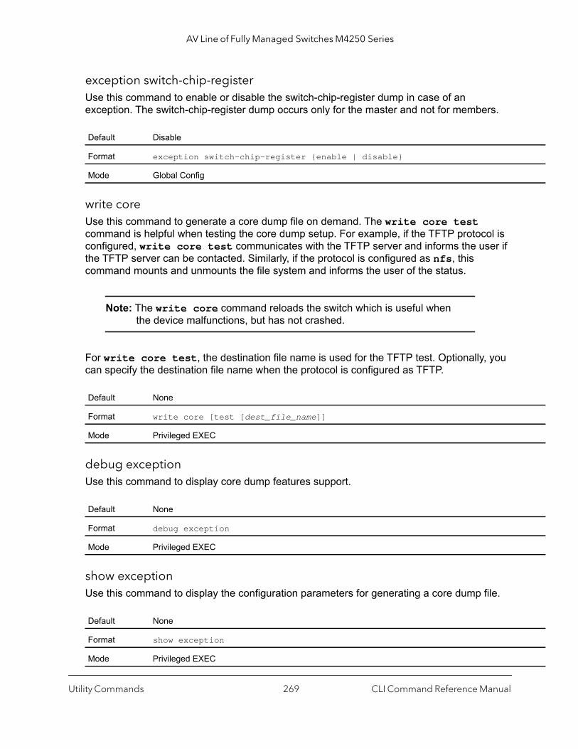
AV Line of Fully Managed Switches M4250 Series
exception switch-chip-registerUse this command to enable or disable the switch-chip-register dump in case of an exception. The switch-chip-register dump occurs only for the master and not for members.
write coreUse this command to generate a core dump file on demand. The write core test command is helpful when testing the core dump setup. For example, if the TFTP protocol is configured, write core test communicates with the TFTP server and informs the user if the TFTP server can be contacted. Similarly, if the protocol is configured as nfs, this command mounts and unmounts the file system and informs the user of the status.
Note: The write core command reloads the switch which is useful when the device malfunctions, but has not crashed.
For write core test, the destination file name is used for the TFTP test. Optionally, you can specify the destination file name when the protocol is configured as TFTP.
debug exceptionUse this command to display core dump features support.
show exceptionUse this command to display the configuration parameters for generating a core dump file.
Default Disable
Format exception switch-chip-register {enable | disable}
Mode Global Config
Default None
Format write core [test [dest_file_name]]
Mode Privileged EXEC
Default None
Format debug exception
Mode Privileged EXEC
Default None
Format show exception
Mode Privileged EXEC
Utility Commands CLI Command Reference Manual269

AV Line of Fully Managed Switches M4250 Series
Command example: (Netgear Switch) #show exception
Coredump file name............................. coreCoredump filename uses hostname................ FalseCoredump filename uses time-stamp.............. TRUENFS mount point................................TFTP server IP.................................FTP server IP..................................FTP user name..................................FTP password...................................File path......................................Protocol....................................... usbSwitch-chip-register........................... FalseCompression mode............................... TRUEStack IP Address Protocol...................... dhcpStack IP Address:IP Address Net Mask Gateway Assigned Unit--------------- --------------- --------------- ---------------
mbuf Use this command to configure memory buffer (MBUF) threshold limits and generate notifications when MBUF limits have been reached.
show mbufUse this command to display the memory buffer (MBUF) Utilization Monitoring parameters.
Format mbuf {falling-threshold | rising threshold | severity}
Mode Global Config
Field Description
Rising Threshold The percentage of the memory buffer resources that, when exceeded for the configured risinginterval, triggers a notification. The range is 1 to 100. The default is 0 (disabled).
Falling Threshold The percentage of memory buffer resources that, when usage falls below this level for the configured interval, triggers a notification. The range is 1 to 100. The default is 0 (disabled).
Severity The severity level at which Mbuf logs messages. The range is 1 to 7. The default is 5 (L7_LOG_SEVERITY_NOTICE).
Format show mbuf
Mode Privileged EXEC
Utility Commands CLI Command Reference Manual270

AV Line of Fully Managed Switches M4250 Series
show mbuf totalUse this command to display memory buffer (MBUF) information.
Field Description
Rising Threshold The percentage of the memory buffer resources that, when exceeded for the configured risinginterval, triggers a notification. The range is 1 to 100. The default is 0 (disabled).
Falling Threshold The percentage of memory buffer resources that, when usage falls below this level for the configured interval, triggers a notification. The range is 1 to 100. The default is 0 (disabled).
Severity The severity level.
Format show mbuf total
Mode Privileged EXEC
Field Description
Mbufs Total Total number of message buffers in the system.
Mbufs Free Number of message buffers currently available.
Mbufs Rx Used Number of message buffers currently in use.
Total Rx Norm Alloc Attempts
Number of times the system tried to allocate a message buffer allocation of class RX Norm.
Total Rx Mid2 Alloc Attempts
Number of times the system tried to allocate a message buffer allocation of class RX Mid2.
Total Rx Mid1 Alloc Attempts
Number of times the system tried to allocate a message buffer allocation of class RX Mid1.
Total Rx Mid0 Alloc Attempts
Number of times the system tried to allocate a message buffer allocation of class RX Mid0.
Total Rx High Alloc Attempts
Number of times the system tried to allocate a message buffer allocation of class RX High.
Total Tx Alloc Attempts
Number of times the system tried to allocate a message buffer allocation of class TX.
Total Rx Norm Alloc Failures
Number of message buffer allocation failures for RX Norm class of message buffer.
Total Rx Mid2 Alloc Failures
Number of message buffer allocation failures for RX Mid2 class of message buffer.
Total Rx Mid1 Alloc Failures
Number of message buffer allocation failures for RX Mid1 class of message buffer.
Total Rx Mid0 Alloc Failures
Number of message buffer allocation failures for RX Mid0 class of message buffer.
Utility Commands CLI Command Reference Manual271
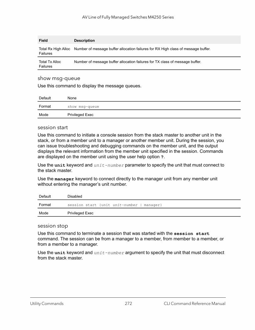
AV Line of Fully Managed Switches M4250 Series
show msg-queueUse this command to display the message queues.
session startUse this command to initiate a console session from the stack master to another unit in the stack, or from a member unit to a manager or another member unit. During the session, you can issue troubleshooting and debugging commands on the member unit, and the output displays the relevant information from the member unit specified in the session. Commands are displayed on the member unit using the user help option ?.
Use the unit keyword and unit-number parameter to specify the unit that must connect to the stack master.
Use the manager keyword to connect directly to the manager unit from any member unit without entering the manager’s unit number.
session stopUse this command to terminate a session that was started with the session start command. The session can be from a manager to a member, from member to a member, or from a member to a manager.
Use the unit keyword and unit-number argument to specify the unit that must disconnect from the stack master.
Total Rx High Alloc Failures
Number of message buffer allocation failures for RX High class of message buffer.
Total Tx Alloc Failures
Number of message buffer allocation failures for TX class of message buffer.
Default None
Format show msg-queue
Mode Privileged Exec
Default Disabled
Format session start {unit unit-number | manager}
Mode Privileged Exec
Field Description
Utility Commands CLI Command Reference Manual272
AV Line of Fully Managed Switches M4250 Series
Use the manager keyword to disconnect directly from the manager unit from any member unit without entering the manager’s unit number.
sw resetUse this command to reboot the switch after a serious error occurred.
no sw reset
Use this command to prevent the switch from rebooting after a serious error occurred. Preventing the switch from rebooting can be useful for the purpose of debugging.
show sw resetUse this command to show whether the sw reset command is enabled.
Support Mode Commands
Support mode is hidden and available when the techsupport enable command is executed. The tech support mode is disabled by default. Configurations related to support mode are shown in the show tech-support command. They can be persisted by using the command save in support mode. Support configurations are stored in a separate binary config file, which cannot be uploaded or downloaded.
Default Disabled
Format session stop {unit unit-number | manager}
Mode Global Config
Default Enabled
Format sw reset
Mode Global Config
Format no sw reset
Mode Global Config
Format show sw reset
Mode User EXEC
Utility Commands CLI Command Reference Manual273
AV Line of Fully Managed Switches M4250 Series
techsupport enableUse this command to allow access to Support mode.
consoleUse this command to enable the display of support debug for this session.
saveUse this command to save the trace configuration to non-volatile storage.
snapshot routingUse this command in Support mode to dump a set of routing debug information to capture the current state of routing on the switch. The output is written to the console and can be extensive.
snapshot multicastUse this command in Support mode to dump a set of IP multicast debug information to capture the current state of multicast on the switch. The output is written to the console and can be extensive.
Default Disabled
Format techsupport enable
Mode Privileged Exec
Default Disabled
Format console
Mode Support
Format save
Mode Support
Format snapshot routing
Mode Support
Format snapshot multicast
Mode Support
Utility Commands CLI Command Reference Manual274
AV Line of Fully Managed Switches M4250 Series
ct be
snapshot systemUse this command in Support mode to dump a set of system debug information to capture the current state of the device. The output is written to the console and can be extensive.
telnetdUse this command in Support mode to start or stop the Telnet daemon on the switch.
Cable Test Command
The cable test feature enables you to determine the cable connection status on a selected port.
Note: The cable test feature is supported only for copper cable. It is not supported for optical fiber cable.
If the port has an active link while the cable test is run, the link can go down for the duration of the test.
cablestatusThis command returns the status of the specified port.
Format snapshot system
Mode Support
Format telnetd {start | stop}
Mode Support
Format cablestatus unit/port
Mode Privileged EXEC
Field Description
Cable Status One of the following statuses is returned:• Normal. The cable is working correctly.• Open. The cable is disconnected or there is a faulty connector.• Short. There is an electrical short in the cable.• Cable Test Failed. The cable status could not be determined. The cable may in fa
working.
Utility Commands CLI Command Reference Manual275
AV Line of Fully Managed Switches M4250 Series
as a link is as nded.
USB commands
If a USB flash device is installed in the USB slot, the USB commands display the device status and content.
show usb deviceThis command displays USB flash device details.
Command example: (NETGEAR Switch) #show USB device
Device Status………………………………………………… Active
dir usbThis command displays USB device contents and memory statistics.
Cable Length If this feature is supported by the PHY for the current link speed, the cable length is displayed range between the shortest estimated length and the longest estimated length. Note that if the down and a cable is attached to a 10/100 Ethernet adapter, then the cable status may display Open or Short because some Ethernet adapters leave unused wire pairs unterminated or grouUnknown is displayed if the cable length could not be determined.
Format show USB device
Mode Privileged EXEC
Term Description
Device Status This field specifies the current status of device. Following are possible device status states:• Active. Device is plugged in and the device is recognized if device is not mounted.• Inactive. Device is not mounted.• Invalid. Device is not present or invalid device is plugged in.
Format dir usb
Mode Privileged EXEC
Term Description
Filename File name
Filesize File size
Total Size USB flash device storage size
Field Description
Utility Commands CLI Command Reference Manual276
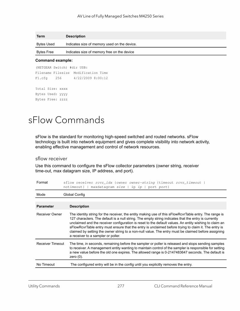
AV Line of Fully Managed Switches M4250 Series
ge is ly im an try is gning
ples etting ault is
Command example: (NETGEAR Switch) #dir USB:Filename Filesize Modification TimeF1.cfg 256 4/22/2009 8:00:12
Total Size: xxxxBytes Used: yyyyBytes Free: zzzz
sFlow Commands
sFlow is the standard for monitoring high-speed switched and routed networks. sFlow technology is built into network equipment and gives complete visibility into network activity, enabling effective management and control of network resources.
sflow receiverUse this command to configure the sFlow collector parameters (owner string, receiver time-out, max datagram size, IP address, and port).
Bytes Used Indicates size of memory used on the device.
Bytes Free Indicates size of memory free on the device
Format sflow receiver rcvr_idx {owner owner-string {timeout rcvr_timeout | notimeout} | maxdatagram size | ip ip | port port}
Mode Global Config
Parameter Description
Receiver Owner The identity string for the receiver, the entity making use of this sFlowRcvrTable entry. The ran127 characters. The default is a null string. The empty string indicates that the entry is currentunclaimed and the receiver configuration is reset to the default values. An entity wishing to clasFlowRcvrTable entry must ensure that the entry is unclaimed before trying to claim it. The enclaimed by setting the owner string to a non-null value. The entry must be claimed before assia receiver to a sampler or poller.
Receiver Timeout The time, in seconds, remaining before the sampler or poller is released and stops sending samto receiver. A management entity wanting to maintain control of the sampler is responsible for sa new value before the old one expires. The allowed range is 0-2147483647 seconds. The defzero (0).
No Timeout The configured entry will be in the config until you explicitly removes the entry.
Term Description
Utility Commands CLI Command Reference Manual277

AV Line of Fully Managed Switches M4250 Series
is
343.
tity ing. is at the
no sflow receiver
Use this command to set the sFlow collector parameters back to the defaults.
sflow receiver owner timeoutUse this command to configure a receiver as a timeout entry. As the sFlow receiver is configured as a timeout entry, information related to sampler and pollers are also shown in the running-config and are retained after reboot.
If a receiver is configured with a specific value, these configurations are not shown in the running-config file. Samplers and pollers information related to this receiver are also not shown in the running-config file.
sflow receiver owner notimeoutUse this command to configure a receiver as a non-timeout entry. Unlike entries configured with a specific timeout value, this command will be shown in show running-config and retained after reboot. As the sFlow receiver is configured as a non-timeout entry, information related to sampler and pollers will also be shown in the running-config and will be retained after reboot.
Receiver Max Datagram Size
The maximum number of data bytes that can be sent in a single sample datagram. The management entity should set this value to avoid fragmentation of the sFlow datagrams. The allowed range is 200 to 9116). The default is 1400.
Receiver IP The sFlow receiver IP address. If set to 0.0.0.0, no sFlow datagrams will be sent. The default 0.0.0.0.
Receiver Port The destination Layer4 UDP port for sFlow datagrams. The range is 1-65535. The default is 6
Format no sflow receiver rcvr_idx [owner | maxdatagram | ip | port]
Mode Global Config
Format sflow receiver index owner owner-string timeout
Mode Global Config
Field Description
index Receiver index identifier. The range is 1 to 8.
Receiver Owner The owner name corresponds to the receiver name. The identity string for the receiver, the enmaking use of this sFlowRcvrTable entry. The range is 127 characters. The default is a null strThe empty string indicates that the entry is currently unclaimed and the receiver configuration reset to the default values. An entity wishing to claim an sFlowRcvrTable entry must ensure thentry is unclaimed before trying to claim it. The entry is claimed by setting the owner string to anon-null value. The entry must be claimed before assigning a receiver to a sampler or poller.
Parameter Description
Utility Commands CLI Command Reference Manual278

AV Line of Fully Managed Switches M4250 Series
tity ing. is at the a
ro (0) set. If ues
-256. ding
If a receiver is configured with a specific value, these configurations are not shown in the running-config file. Samplers and pollers information related to this receiver are also not shown in the running-config file.
sflow samplerA data source configured to collect flow samples is called a poller. Use this command to configure a new sFlow sampler instance on an interface or range of interfaces for this data source if rcvr_indx is valid.
Format sflow receiver index owner owner-string notimeout
Mode Global Config
Field Description
index Receiver index identifier. The range is 1 to 8.
Receiver Owner The owner name corresponds to the receiver name. The identity string for the receiver, the enmaking use of this sFlowRcvrTable entry. The range is 127 characters. The default is a null strThe empty string indicates that the entry is currently unclaimed and the receiver configuration reset to the default values. An entity wishing to claim an sFlowRcvrTable entry must ensure thentry is unclaimed before trying to claim it. The entry is claimed by setting the owner string to non-null value. The entry must be claimed before assigning a receiver to a sampler or poller.
Format sflow sampler {rcvr-indx | rate sampling-rate | maxheadersize size}
Mode Interface Config
Field Description
Receiver Index The sFlow Receiver for this sFlow sampler to which flow samples are to be sent. A value of zemeans that no receiver is configured, no packets will be sampled. Only active receivers can be a receiver expires, then all samplers associated with the receiver will also expire. Possible valare 1-8. The default is 0.
Maxheadersize The maximum number of bytes that should be copied from the sampler packet. The range is 20The default is 128. When set to zero (0), all the sampler parameters are set to their correspondefault value.
Utility Commands CLI Command Reference Manual279
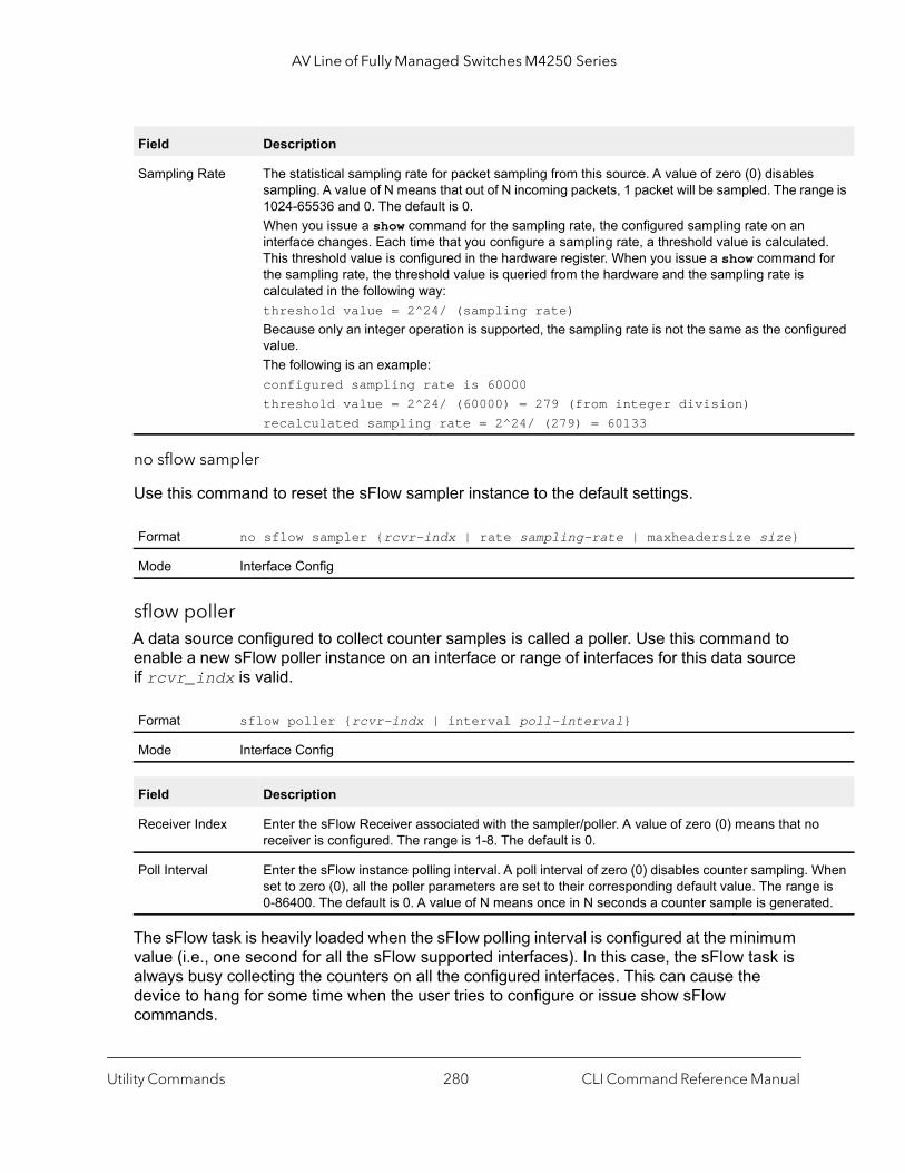
AV Line of Fully Managed Switches M4250 Series
ge is
d. for
ured
hen is
ed.
no sflow sampler
Use this command to reset the sFlow sampler instance to the default settings.
sflow pollerA data source configured to collect counter samples is called a poller. Use this command to enable a new sFlow poller instance on an interface or range of interfaces for this data source if rcvr_indx is valid.
The sFlow task is heavily loaded when the sFlow polling interval is configured at the minimum value (i.e., one second for all the sFlow supported interfaces). In this case, the sFlow task is always busy collecting the counters on all the configured interfaces. This can cause the device to hang for some time when the user tries to configure or issue show sFlow commands.
Sampling Rate The statistical sampling rate for packet sampling from this source. A value of zero (0) disablessampling. A value of N means that out of N incoming packets, 1 packet will be sampled. The ran1024-65536 and 0. The default is 0.When you issue a show command for the sampling rate, the configured sampling rate on an interface changes. Each time that you configure a sampling rate, a threshold value is calculateThis threshold value is configured in the hardware register. When you issue a show commandthe sampling rate, the threshold value is queried from the hardware and the sampling rate is calculated in the following way:threshold value = 2^24/ (sampling rate)Because only an integer operation is supported, the sampling rate is not the same as the configvalue.The following is an example:configured sampling rate is 60000threshold value = 2^24/ (60000) = 279 (from integer division)recalculated sampling rate = 2^24/ (279) = 60133
Format no sflow sampler {rcvr-indx | rate sampling-rate | maxheadersize size}
Mode Interface Config
Format sflow poller {rcvr-indx | interval poll-interval}
Mode Interface Config
Field Description
Receiver Index Enter the sFlow Receiver associated with the sampler/poller. A value of zero (0) means that noreceiver is configured. The range is 1-8. The default is 0.
Poll Interval Enter the sFlow instance polling interval. A poll interval of zero (0) disables counter sampling. Wset to zero (0), all the poller parameters are set to their corresponding default value. The range0-86400. The default is 0. A value of N means once in N seconds a counter sample is generat
Field Description
Utility Commands CLI Command Reference Manual280
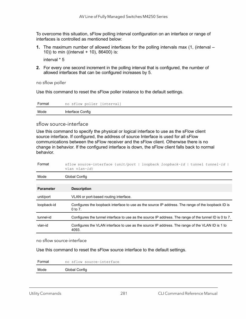
AV Line of Fully Managed Switches M4250 Series
id |
ID is
0 to 7.
to
To overcome this situation, sFlow polling interval configuration on an interface or range of interfaces is controlled as mentioned below:
1. The maximum number of allowed interfaces for the polling intervals max (1, (interval – 10)) to min ((interval + 10), 86400) is:
interval * 5
2. For every one second increment in the polling interval that is configured, the number of allowed interfaces that can be configured increases by 5.
no sflow poller
Use this command to reset the sFlow poller instance to the default settings.
sflow source-interfaceUse this command to specify the physical or logical interface to use as the sFlow client source interface. If configured, the address of source Interface is used for all sFlow communications between the sFlow receiver and the sFlow client. Otherwise there is no change in behavior. If the configured interface is down, the sFlow client falls back to normal behavior.
no sflow source-interface
Use this command to reset the sFlow source interface to the default settings.
Format no sflow poller [interval]
Mode Interface Config
Format sflow source-interface {unit/port | loopback loopback-id | tunnel tunnel-vlan vlan-id}
Mode Global Config
Parameter Description
unit/port VLAN or port-based routing interface.
loopback-id Configures the loopback interface to use as the source IP address. The range of the loopback0 to 7.
tunnel-id Configures the tunnel interface to use as the source IP address. The range of the tunnel ID is
vlan-id Configures the VLAN interface to use as the source IP address. The range of the VLAN ID is 14093.
Format no sflow source-interface
Mode Global Config
Utility Commands CLI Command Reference Manual281
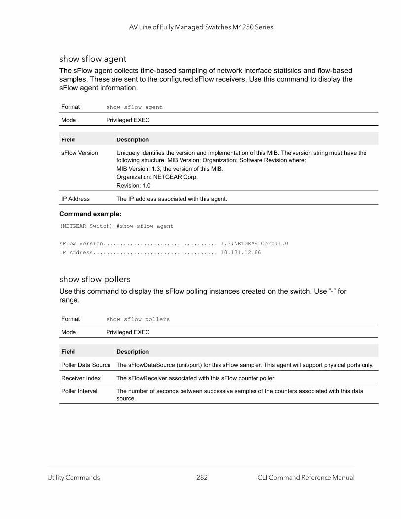
AV Line of Fully Managed Switches M4250 Series
e
only.
show sflow agentThe sFlow agent collects time-based sampling of network interface statistics and flow-based samples. These are sent to the configured sFlow receivers. Use this command to display the sFlow agent information.
Command example: (NETGEAR Switch) #show sflow agent
sFlow Version.................................. 1.3;NETGEAR Corp;1.0IP Address..................................... 10.131.12.66
show sflow pollersUse this command to display the sFlow polling instances created on the switch. Use “-” for range.
Format show sflow agent
Mode Privileged EXEC
Field Description
sFlow Version Uniquely identifies the version and implementation of this MIB. The version string must have thfollowing structure: MIB Version; Organization; Software Revision where:MIB Version: 1.3, the version of this MIB.Organization: NETGEAR Corp.Revision: 1.0
IP Address The IP address associated with this agent.
Format show sflow pollers
Mode Privileged EXEC
Field Description
Poller Data Source The sFlowDataSource (unit/port) for this sFlow sampler. This agent will support physical ports
Receiver Index The sFlowReceiver associated with this sFlow counter poller.
Poller Interval The number of seconds between successive samples of the counters associated with this datasource.
Utility Commands CLI Command Reference Manual282
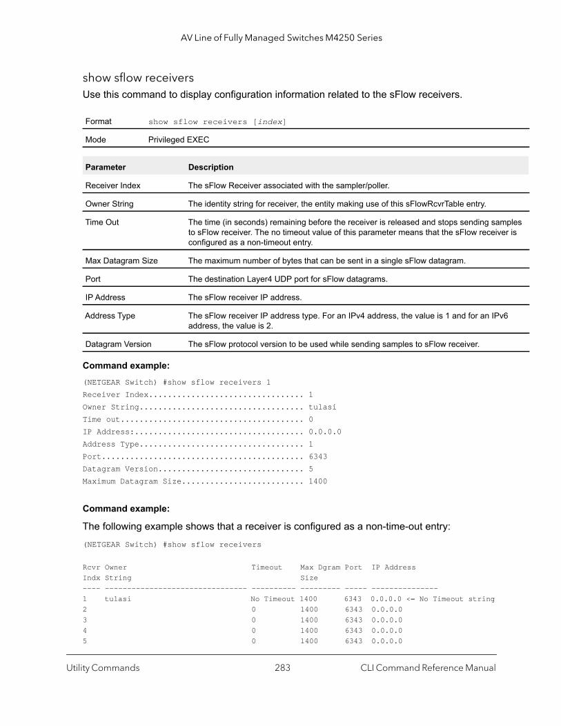
AV Line of Fully Managed Switches M4250 Series
ples r is
6
show sflow receiversUse this command to display configuration information related to the sFlow receivers.
Command example: (NETGEAR Switch) #show sflow receivers 1Receiver Index................................. 1Owner String................................... tulasiTime out....................................... 0IP Address:.................................... 0.0.0.0Address Type................................... 1Port........................................... 6343Datagram Version............................... 5Maximum Datagram Size.......................... 1400
Command example:
The following example shows that a receiver is configured as a non-time-out entry:(NETGEAR Switch) #show sflow receivers
Rcvr Owner Timeout Max Dgram Port IP AddressIndx String Size---- -------------------------------- ---------- --------- ----- ---------------1 tulasi No Timeout 1400 6343 0.0.0.0 <= No Timeout string2 0 1400 6343 0.0.0.03 0 1400 6343 0.0.0.04 0 1400 6343 0.0.0.05 0 1400 6343 0.0.0.0
Format show sflow receivers [index]
Mode Privileged EXEC
Parameter Description
Receiver Index The sFlow Receiver associated with the sampler/poller.
Owner String The identity string for receiver, the entity making use of this sFlowRcvrTable entry.
Time Out The time (in seconds) remaining before the receiver is released and stops sending samto sFlow receiver. The no timeout value of this parameter means that the sFlow receiveconfigured as a non-timeout entry.
Max Datagram Size The maximum number of bytes that can be sent in a single sFlow datagram.
Port The destination Layer4 UDP port for sFlow datagrams.
IP Address The sFlow receiver IP address.
Address Type The sFlow receiver IP address type. For an IPv4 address, the value is 1 and for an IPvaddress, the value is 2.
Datagram Version The sFlow protocol version to be used while sending samples to sFlow receiver.
Utility Commands CLI Command Reference Manual283
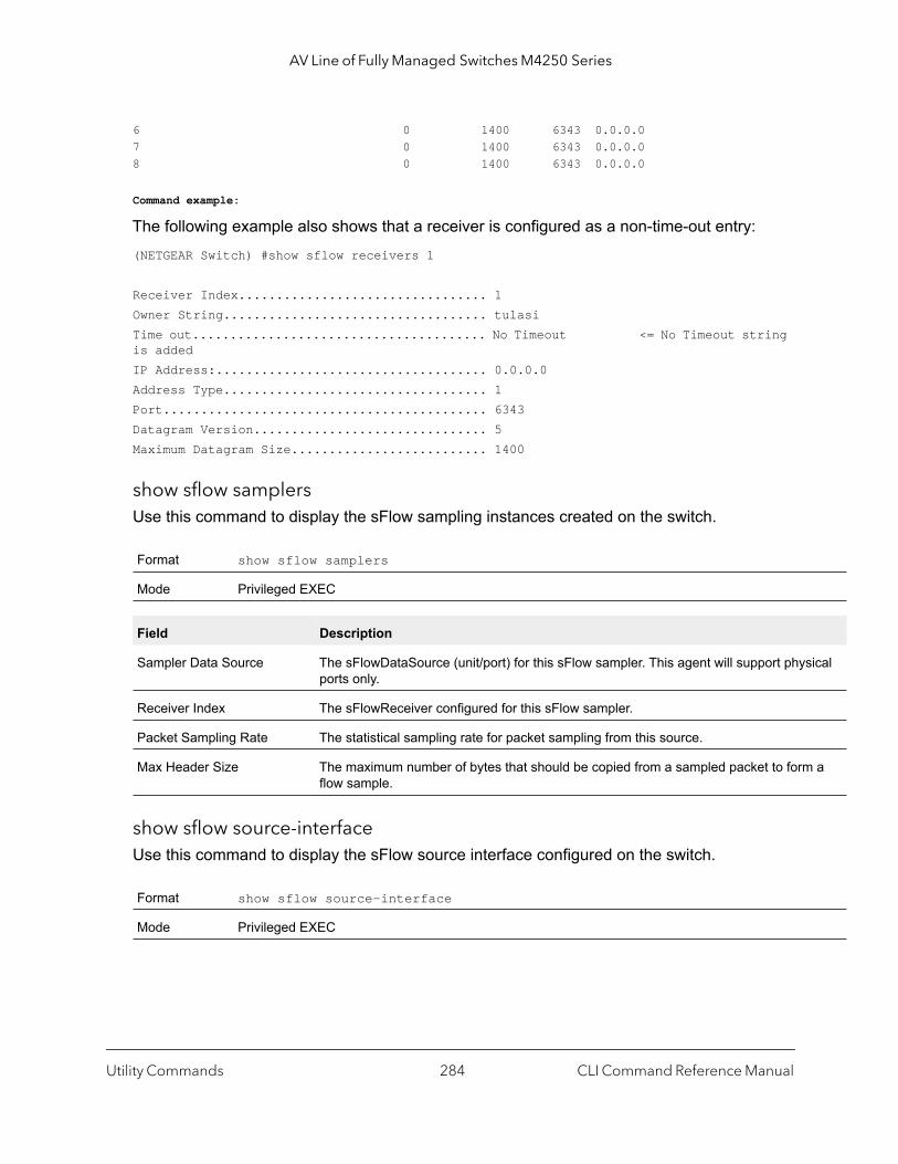
AV Line of Fully Managed Switches M4250 Series
ical
a
6 0 1400 6343 0.0.0.07 0 1400 6343 0.0.0.08 0 1400 6343 0.0.0.0
Command example:
The following example also shows that a receiver is configured as a non-time-out entry:(NETGEAR Switch) #show sflow receivers 1
Receiver Index................................. 1Owner String................................... tulasiTime out....................................... No Timeout <= No Timeout string is addedIP Address:.................................... 0.0.0.0Address Type................................... 1Port........................................... 6343Datagram Version............................... 5Maximum Datagram Size.......................... 1400
show sflow samplersUse this command to display the sFlow sampling instances created on the switch.
show sflow source-interfaceUse this command to display the sFlow source interface configured on the switch.
Format show sflow samplers
Mode Privileged EXEC
Field Description
Sampler Data Source The sFlowDataSource (unit/port) for this sFlow sampler. This agent will support physports only.
Receiver Index The sFlowReceiver configured for this sFlow sampler.
Packet Sampling Rate The statistical sampling rate for packet sampling from this source.
Max Header Size The maximum number of bytes that should be copied from a sampled packet to formflow sample.
Format show sflow source-interface
Mode Privileged EXEC
Utility Commands CLI Command Reference Manual284
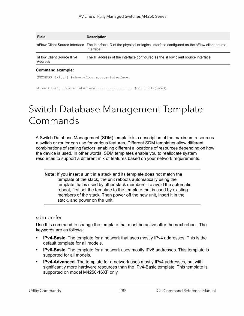
AV Line of Fully Managed Switches M4250 Series
urce
Command example: (NETGEAR Switch) #show sflow source-interface
sFlow Client Source Interface.................. (not configured)
Switch Database Management Template Commands
A Switch Database Management (SDM) template is a description of the maximum resources a switch or router can use for various features. Different SDM templates allow different combinations of scaling factors, enabling different allocations of resources depending on how the device is used. In other words, SDM templates enable you to reallocate system resources to support a different mix of features based on your network requirements.
Note: If you insert a unit in a stack and its template does not match the template of the stack, the unit reboots automatically using the template that is used by other stack members. To avoid the automatic reboot, first set the template to the template that is used by existing members of the stack. Then power off the new unit, insert it in the stack, and power on the unit.
sdm preferUse this command to change the template that must be active after the next reboot. The keywords are as follows:
• IPv4-Basic. The template for a network that uses mostly IPv4 addresses. This is the default template for all models.
• IPv6-Basic. The template for a network uses mostly IPv6 addresses. This template is supported for all models.
• IPv4-Advanced. The template for a network uses mostly IPv4 addresses, but with significantly more hardware resources than the IPv4-Basic template. This template is supported on model M4250-16XF only.
Field Description
sFlow Client Source Interface The interface ID of the physical or logical interface configured as the sFlow client sointerface.
sFlow Client Source IPv4 Address
The IP address of the interface configured as the sFlow client source interface.
Utility Commands CLI Command Reference Manual285
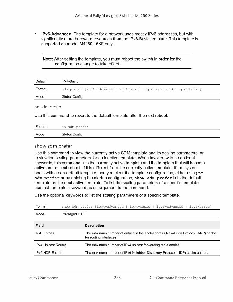
AV Line of Fully Managed Switches M4250 Series
]
che
• IPv6-Advanced. The template for a network uses mostly IPv6 addresses, but with significantly more hardware resources than the IPv6-Basic template. This template is supported on model M4250-16XF only.
Note: After setting the template, you must reboot the switch in order for the configuration change to take effect.
no sdm prefer
Use this command to revert to the default template after the next reboot.
show sdm preferUse this command to view the currently active SDM template and its scaling parameters, or to view the scaling parameters for an inactive template. When invoked with no optional keywords, this command lists the currently active template and the template that will become active on the next reboot, if it is different from the currently active template. If the system boots with a non-default template, and you clear the template configuration, either using no sdm prefer or by deleting the startup configuration, show sdm prefer lists the default template as the next active template. To list the scaling parameters of a specific template, use that template’s keyword as an argument to the command.
Use the optional keywords to list the scaling parameters of a specific template.
Default IPv4-Basic
Format sdm prefer {ipv4-advanced | ipv4-basic | ipv6-advanced | ipv6-basic}
Mode Global Config
Format no sdm prefer
Mode Global Config
Format show sdm prefer [ipv4-advanced | ipv4-basic | ipv6-advanced | ipv6-basic
Mode Privileged EXEC
Field Description
ARP Entries The maximum number of entries in the IPv4 Address Resolution Protocol (ARP) cafor routing interfaces.
IPv4 Unicast Routes The maximum number of IPv4 unicast forwarding table entries.
IPv6 NDP Entries The maximum number of IPv6 Neighbor Discovery Protocol (NDP) cache entries.
Utility Commands CLI Command Reference Manual286
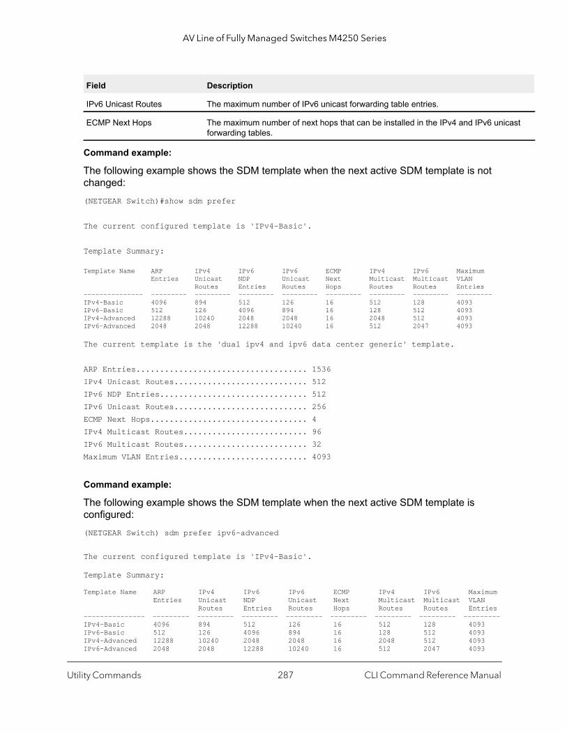
AV Line of Fully Managed Switches M4250 Series
ast
Command example:
The following example shows the SDM template when the next active SDM template is not changed:(NETGEAR Switch)#show sdm prefer
The current configured template is 'IPv4-Basic'.
Template Summary:
Template Name ARP IPv4 IPv6 IPv6 ECMP IPv4 IPv6 Maximum Entries Unicast NDP Unicast Next Multicast Multicast VLAN Routes Entries Routes Hops Routes Routes Entries--------------- --------- --------- --------- --------- --------- --------- --------- ---------IPv4-Basic 4096 894 512 126 16 512 128 4093IPv6-Basic 512 126 4096 894 16 128 512 4093IPv4-Advanced 12288 10240 2048 2048 16 2048 512 4093IPv6-Advanced 2048 2048 12288 10240 16 512 2047 4093
The current template is the 'dual ipv4 and ipv6 data center generic' template.
ARP Entries.................................... 1536IPv4 Unicast Routes............................ 512IPv6 NDP Entries............................... 512IPv6 Unicast Routes............................ 256ECMP Next Hops................................. 4IPv4 Multicast Routes.......................... 96IPv6 Multicast Routes.......................... 32Maximum VLAN Entries........................... 4093
Command example:
The following example shows the SDM template when the next active SDM template is configured:(NETGEAR Switch) sdm prefer ipv6-advanced
The current configured template is 'IPv4-Basic'.
Template Summary:
Template Name ARP IPv4 IPv6 IPv6 ECMP IPv4 IPv6 Maximum Entries Unicast NDP Unicast Next Multicast Multicast VLAN Routes Entries Routes Hops Routes Routes Entries--------------- --------- --------- --------- --------- --------- --------- --------- ---------IPv4-Basic 4096 894 512 126 16 512 128 4093IPv6-Basic 512 126 4096 894 16 128 512 4093IPv4-Advanced 12288 10240 2048 2048 16 2048 512 4093IPv6-Advanced 2048 2048 12288 10240 16 512 2047 4093
IPv6 Unicast Routes The maximum number of IPv6 unicast forwarding table entries.
ECMP Next Hops The maximum number of next hops that can be installed in the IPv4 and IPv6 unicforwarding tables.
Field Description
Utility Commands CLI Command Reference Manual287
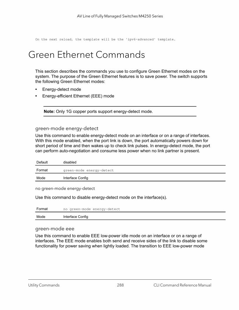
AV Line of Fully Managed Switches M4250 Series
On the next reload, the template will be the 'ipv6-advanced' template.
Green Ethernet Commands
This section describes the commands you use to configure Green Ethernet modes on the system. The purpose of the Green Ethernet features is to save power. The switch supports the following Green Ethernet modes:
• Energy-detect mode• Energy-efficient Ethernet (EEE) mode
Note: Only 1G copper ports support energy-detect mode.
green-mode energy-detectUse this command to enable energy-detect mode on an interface or on a range of interfaces. With this mode enabled, when the port link is down, the port automatically powers down for short period of time and then wakes up to check link pulses. In energy-detect mode, the port can perform auto-negotiation and consume less power when no link partner is present.
no green-mode energy-detect
Use this command to disable energy-detect mode on the interface(s).
green-mode eeeUse this command to enable EEE low-power idle mode on an interface or on a range of interfaces. The EEE mode enables both send and receive sides of the link to disable some functionality for power saving when lightly loaded. The transition to EEE low-power mode
Default disabled
Format green-mode energy-detect
Mode Interface Config
Format no green-mode energy-detect
Mode Interface Config
Utility Commands CLI Command Reference Manual288
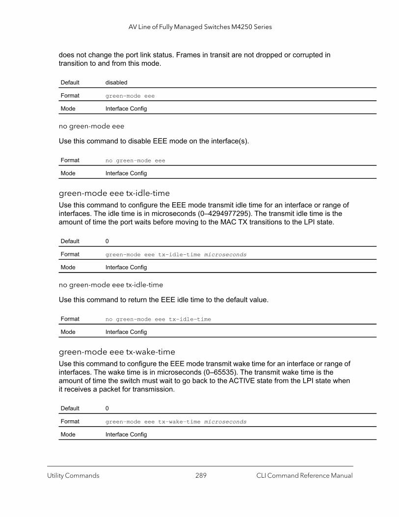
AV Line of Fully Managed Switches M4250 Series
does not change the port link status. Frames in transit are not dropped or corrupted in transition to and from this mode.
no green-mode eee
Use this command to disable EEE mode on the interface(s).
green-mode eee tx-idle-timeUse this command to configure the EEE mode transmit idle time for an interface or range of interfaces. The idle time is in microseconds (0–4294977295). The transmit idle time is the amount of time the port waits before moving to the MAC TX transitions to the LPI state.
no green-mode eee tx-idle-time
Use this command to return the EEE idle time to the default value.
green-mode eee tx-wake-timeUse this command to configure the EEE mode transmit wake time for an interface or range of interfaces. The wake time is in microseconds (0–65535). The transmit wake time is the amount of time the switch must wait to go back to the ACTIVE state from the LPI state when it receives a packet for transmission.
Default disabled
Format green-mode eee
Mode Interface Config
Format no green-mode eee
Mode Interface Config
Default 0
Format green-mode eee tx-idle-time microseconds
Mode Interface Config
Format no green-mode eee tx-idle-time
Mode Interface Config
Default 0
Format green-mode eee tx-wake-time microseconds
Mode Interface Config
Utility Commands CLI Command Reference Manual289
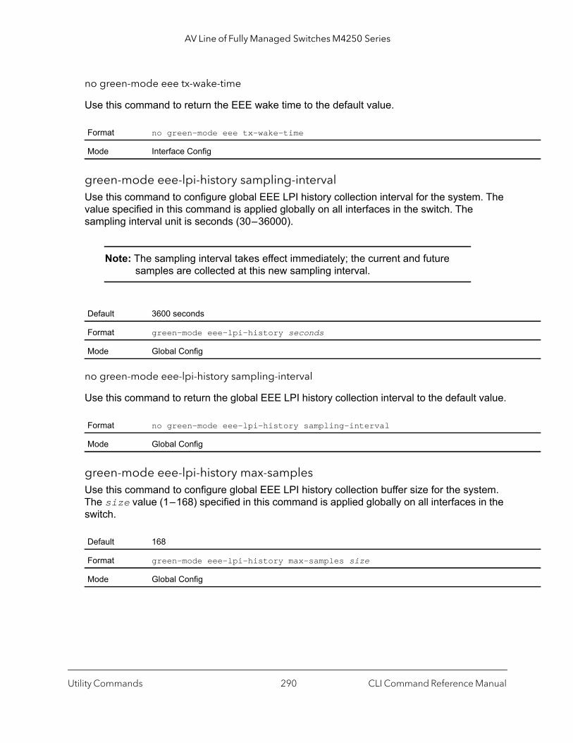
AV Line of Fully Managed Switches M4250 Series
no green-mode eee tx-wake-time
Use this command to return the EEE wake time to the default value.
green-mode eee-lpi-history sampling-intervalUse this command to configure global EEE LPI history collection interval for the system. The value specified in this command is applied globally on all interfaces in the switch. The sampling interval unit is seconds (30 – 36000).
Note: The sampling interval takes effect immediately; the current and future samples are collected at this new sampling interval.
no green-mode eee-lpi-history sampling-interval
Use this command to return the global EEE LPI history collection interval to the default value.
green-mode eee-lpi-history max-samplesUse this command to configure global EEE LPI history collection buffer size for the system. The size value (1 – 168) specified in this command is applied globally on all interfaces in the switch.
Format no green-mode eee tx-wake-time
Mode Interface Config
Default 3600 seconds
Format green-mode eee-lpi-history seconds
Mode Global Config
Format no green-mode eee-lpi-history sampling-interval
Mode Global Config
Default 168
Format green-mode eee-lpi-history max-samples size
Mode Global Config
Utility Commands CLI Command Reference Manual290

AV Line of Fully Managed Switches M4250 Series
een
e(s)
e of , bility
ay be
no green-mode eee-lpi-history max samples
Use this command to return the global EEE LPI history collection buffer size to the default value.
show green-mode Use this command to display the green-mode configuration and operational status on all ports or on the specified port.
Note: The fields that display in the show green-mode command output depend on the Green Ethernet modes available on the hardware platform.
If you do not specify a port, the command displays the information in the following table.
Format no green-mode eee-lpi-history max-samples
Mode Global Config
Format show green-mode [unit/port]
Mode Privileged EXEC
Term Definition
Global
Cumulative Energy Saving per Stack
Estimated cumulative energy saved in the stack in (watts * hours) due to all grmodes enabled.
Current Power Consumption per Stack
Power consumption by all ports in the stack in mWatts.
Power Saving Estimated percentage power saved on all ports in the stack due to Green modenabled.
Unit Unit Index of the stack member.
Green Ethernet Features supported List of Green Features supported on the given unit which could be one or morthe following: Energy-Detect (Energy Detect), EEE (Energy Efficient Ethernet)LPI-History (EEE Low Power Idle History), LLDP-Cap-Exchg (EEE LLDP CapaExchange), Pwr-Usg-Est (Power Usage Estimates).
Energy Detect
Energy-detect Config Energy-detect Admin mode is enabled or disabled
Energy-detect Opr Energy detect mode is currently active or inactive. The energy detect mode madministratively enabled, but the operational status may be inactive.
Utility Commands CLI Command Reference Manual291
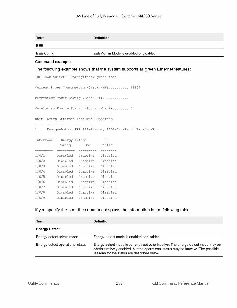
AV Line of Fully Managed Switches M4250 Series
y be ible
Command example:
The following example shows that the system supports all green Ethernet features:(NETGEAR Switch) (Config)#show green-mode
Current Power Consumption /Stack (mW).......... 12259
Percentage Power Saving /Stack (%)............. 0
Cumulative Energy Saving /Stack (W * H)........ 0
Unit Green Ethernet Features Supported---- ---------------------------------1 Energy-Detect EEE LPI-History LLDP-Cap-Exchg Pwr-Usg-Est
Interface Energy-Detect EEE Config Opr Config--------- --------- --------- --------1/0/1 Disabled Inactive Disabled1/0/2 Disabled Inactive Disabled1/0/3 Disabled Inactive Disabled1/0/4 Disabled Inactive Disabled1/0/5 Disabled Inactive Disabled1/0/6 Disabled Inactive Disabled1/0/7 Disabled Inactive Disabled1/0/8 Disabled Inactive Disabled1/0/9 Disabled Inactive Disabled
If you specify the port, the command displays the information in the following table.
EEE
EEE Config EEE Admin Mode is enabled or disabled.
Term Definition
Energy Detect
Energy-detect admin mode Energy-detect mode is enabled or disabled
Energy-detect operational status Energy detect mode is currently active or inactive. The energy-detect mode maadministratively enabled, but the operational status may be inactive. The possreasons for the status are described below.
Term Definition
Utility Commands CLI Command Reference Manual292
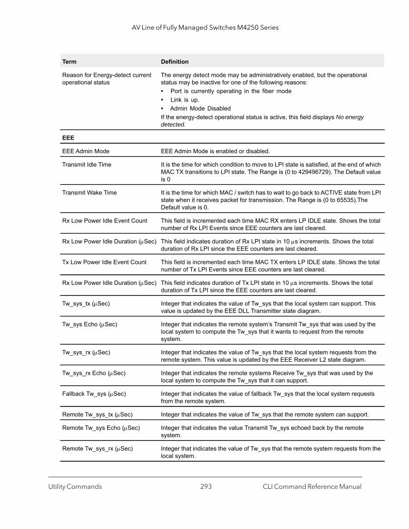
AV Line of Fully Managed Switches M4250 Series
hich alue
LPI
total
tal
total
al
his
the
the
e
sts
.
the
Reason for Energy-detect current operational status
The energy detect mode may be administratively enabled, but the operationalstatus may be inactive for one of the following reasons:• Port is currently operating in the fiber mode• Link is up.• Admin Mode Disabled If the energy-detect operational status is active, this field displays No energy detected.
EEE
EEE Admin Mode EEE Admin Mode is enabled or disabled.
Transmit Idle Time It is the time for which condition to move to LPI state is satisfied, at the end of wMAC TX transitions to LPI state. The Range is (0 to 429496729). The Default vis 0
Transmit Wake Time It is the time for which MAC / switch has to wait to go back to ACTIVE state fromstate when it receives packet for transmission. The Range is (0 to 65535).TheDefault value is 0.
Rx Low Power Idle Event Count This field is incremented each time MAC RX enters LP IDLE state. Shows thenumber of Rx LPI Events since EEE counters are last cleared.
Rx Low Power Idle Duration (Sec) This field indicates duration of Rx LPI state in 10 s increments. Shows the toduration of Rx LPI since the EEE counters are last cleared.
Tx Low Power Idle Event Count This field is incremented each time MAC TX enters LP IDLE state. Shows the number of Tx LPI Events since EEE counters are last cleared.
Rx Low Power Idle Duration (Sec) This field indicates duration of Tx LPI state in 10 s increments. Shows the totduration of Tx LPI since the EEE counters are last cleared.
Tw_sys_tx (Sec) Integer that indicates the value of Tw_sys that the local system can support. Tvalue is updated by the EEE DLL Transmitter state diagram.
Tw_sys Echo (Sec) Integer that indicates the remote system’s Transmit Tw_sys that was used by local system to compute the Tw_sys that it wants to request from the remote system.
Tw_sys_rx (Sec) Integer that indicates the value of Tw_sys that the local system requests from remote system. This value is updated by the EEE Receiver L2 state diagram.
Tw_sys_rx Echo (Sec) Integer that indicates the remote systems Receive Tw_sys that was used by thlocal system to compute the Tw_sys that it can support.
Fallback Tw_sys (Sec) Integer that indicates the value of fallback Tw_sys that the local system requefrom the remote system.
Remote Tw_sys_tx (Sec) Integer that indicates the value of Tw_sys that the remote system can support
Remote Tw_sys Echo (Sec) Integer that indicates the value Transmit Tw_sys echoed back by the remote system.
Remote Tw_sys_rx (Sec) Integer that indicates the value of Tw_sys that the remote system requests fromlocal system.
Term Definition
Utility Commands CLI Command Reference Manual293
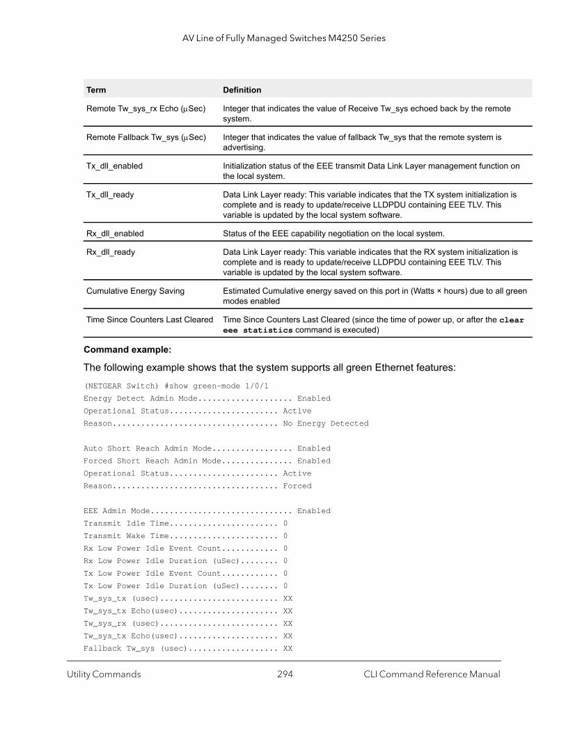
AV Line of Fully Managed Switches M4250 Series
on
is
is
reen
ear
Command example:
The following example shows that the system supports all green Ethernet features:(NETGEAR Switch) #show green-mode 1/0/1Energy Detect Admin Mode.................... Enabled Operational Status....................... ActiveReason................................... No Energy Detected
Auto Short Reach Admin Mode................. Enabled Forced Short Reach Admin Mode............... Enabled Operational Status....................... Active Reason................................... Forced
EEE Admin Mode.............................. Enabled Transmit Idle Time....................... 0 Transmit Wake Time....................... 0 Rx Low Power Idle Event Count............ 0 Rx Low Power Idle Duration (uSec)........ 0 Tx Low Power Idle Event Count............ 0 Tx Low Power Idle Duration (uSec)........ 0 Tw_sys_tx (usec)......................... XX Tw_sys_tx Echo(usec)..................... XX Tw_sys_rx (usec)......................... XX Tw_sys_tx Echo(usec)..................... XX Fallback Tw_sys (usec)................... XX
Remote Tw_sys_rx Echo (Sec) Integer that indicates the value of Receive Tw_sys echoed back by the remotesystem.
Remote Fallback Tw_sys (Sec) Integer that indicates the value of fallback Tw_sys that the remote system is advertising.
Tx_dll_enabled Initialization status of the EEE transmit Data Link Layer management functionthe local system.
Tx_dll_ready Data Link Layer ready: This variable indicates that the TX system initializationcomplete and is ready to update/receive LLDPDU containing EEE TLV. This variable is updated by the local system software.
Rx_dll_enabled Status of the EEE capability negotiation on the local system.
Rx_dll_ready Data Link Layer ready: This variable indicates that the RX system initializationcomplete and is ready to update/receive LLDPDU containing EEE TLV. This variable is updated by the local system software.
Cumulative Energy Saving Estimated Cumulative energy saved on this port in (Watts × hours) due to all gmodes enabled
Time Since Counters Last Cleared Time Since Counters Last Cleared (since the time of power up, or after the cleee statistics command is executed)
Term Definition
Utility Commands CLI Command Reference Manual294
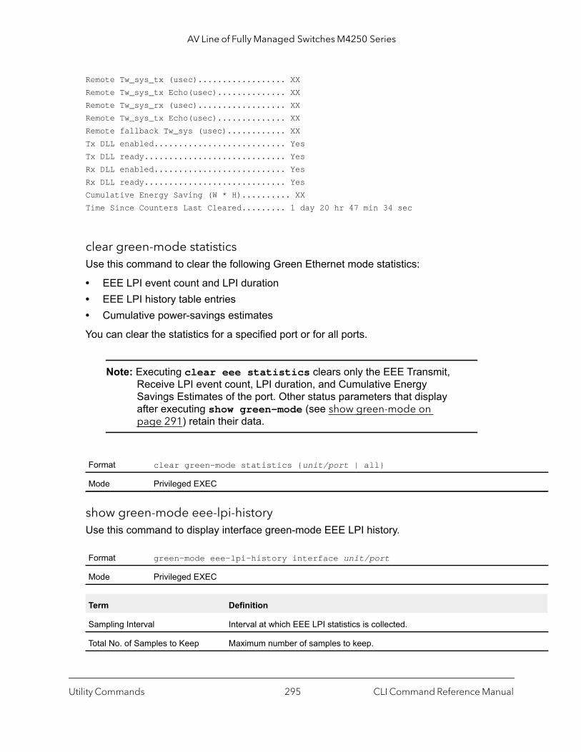
AV Line of Fully Managed Switches M4250 Series
Remote Tw_sys_tx (usec).................. XX Remote Tw_sys_tx Echo(usec).............. XX Remote Tw_sys_rx (usec).................. XX Remote Tw_sys_tx Echo(usec).............. XX Remote fallback Tw_sys (usec)............ XX Tx DLL enabled........................... Yes Tx DLL ready............................. Yes Rx DLL enabled........................... Yes Rx DLL ready............................. Yes Cumulative Energy Saving (W * H).......... XX Time Since Counters Last Cleared......... 1 day 20 hr 47 min 34 sec
clear green-mode statisticsUse this command to clear the following Green Ethernet mode statistics:
• EEE LPI event count and LPI duration• EEE LPI history table entries• Cumulative power-savings estimates
You can clear the statistics for a specified port or for all ports.
Note: Executing clear eee statistics clears only the EEE Transmit, Receive LPI event count, LPI duration, and Cumulative Energy Savings Estimates of the port. Other status parameters that display after executing show green-mode (see show green-mode on page 291) retain their data.
show green-mode eee-lpi-history Use this command to display interface green-mode EEE LPI history.
Format clear green-mode statistics {unit/port | all}
Mode Privileged EXEC
Format green-mode eee-lpi-history interface unit/port
Mode Privileged EXEC
Term Definition
Sampling Interval Interval at which EEE LPI statistics is collected.
Total No. of Samples to Keep Maximum number of samples to keep.
Utility Commands CLI Command Reference Manual295

AV Line of Fully Managed Switches M4250 Series
ed to
since
Command example:
The following example shows that the system has the EEE feature enabled:(NETGEAR Switch) #show green-mode eee-lpi-history interface 1/0/1
Sampling Interval (sec)........................ 30Total No. of Samples to Keep................... 168Percentage LPI time per Stack.................. 29
Percentage of Percentage of Sample Time Since Time spent in Time spent in No. The Sample LPI mode since LPI mode since Was Recorded last sample last reset------ -------------------- -------------- --------------10 0d:00:00:13 3 29 0d:00:00:44 3 28 0d:00:01:15 3 27 0d:00:01:46 3 26 0d:00:02:18 3 25 0d:00:02:49 3 24 0d:00:03:20 3 23 0d:00:03:51 3 12 0d:00:04:22 3 11 0d:00:04:53 3 1
Percentage LPI time per switch Percentage of total time spent in LPI mode by all port in a switch when compartotal time since reset.
Sample No. Sample Index.
Sample Time Time since last reset.
%time spent in LPI mode since last sample
Percentage of time spent in LPI mode on this port when compared to samplinginterval.
%time spent in LPI mode since last reset
Percentage of total time spent in LPI mode on this port when compared to time reset.
Term Definition
Utility Commands CLI Command Reference Manual296

AV Line of Fully Managed Switches M4250 Series
er
mple
SN.1
g
ed
efault
5535.
efault
5535.
lt is
Remote Monitoring Commands
Remote Monitoring (RMON) is a method of collecting a variety of data about network traffic. RMON supports 64-bit counters (RFC 3273) and High Capacity Alarm Table (RFC 3434).
Note: There is no configuration command for ether stats and high capacity ether stats. The data source for ether stats and high capacity ether stats are configured during initialization.rmon alarm
rmon alarmThis command sets the RMON alarm entry in the RMON alarm MIB group.
Format rmon alarm alarm-number variable sample-interval {absolute | delta} rising-threshold value [rising-event-index] falling-threshold value [falling-event-index] [startup {rising | falling | rising-falling}] [ownstring]
Mode Global Config
Parameter Description
Alarm Index An index that uniquely identifies an entry in the alarm table. Each entry defines a diagnostic saat a particular interval for an object on the device. The range is 1 to 65535.
Alarm Variable The object identifier of the particular variable to be sampled. Only variables that resolve to an Aprimitive type of integer.
Alarm Interval The interval in seconds over which the data is sampled and compared with the rising and fallinthresholds. The range is 1 to 2147483647. The default is 1.
Alarm Absolute Value
The value of the statistic during the last sampling period. This object is a read-only, 32-bit signvalue.
Alarm Rising Threshold
The rising threshold for the sample statistics. The range is 2147483648 to 2147483647. The dis 1.
Alarm Rising Event Index
The index of the eventEntry that is used when a rising threshold is crossed. The range is 1 to 6The default is 1.
Alarm Falling Threshold
The falling threshold for the sample statistics. The range is 2147483648 to 2147483647. The dis 1.
Alarm Falling Event Index
The index of the eventEntry that is used when a falling threshold is crossed. The range is 1 to 6The default is 2.
Alarm Startup Alarm
The alarm that may be sent. Possible values are rising, falling or both rising-falling. The defaurising-falling.
Alarm Owner The owner string associated with the alarm entry. The default is monitorAlarm.
Utility Commands CLI Command Reference Manual297
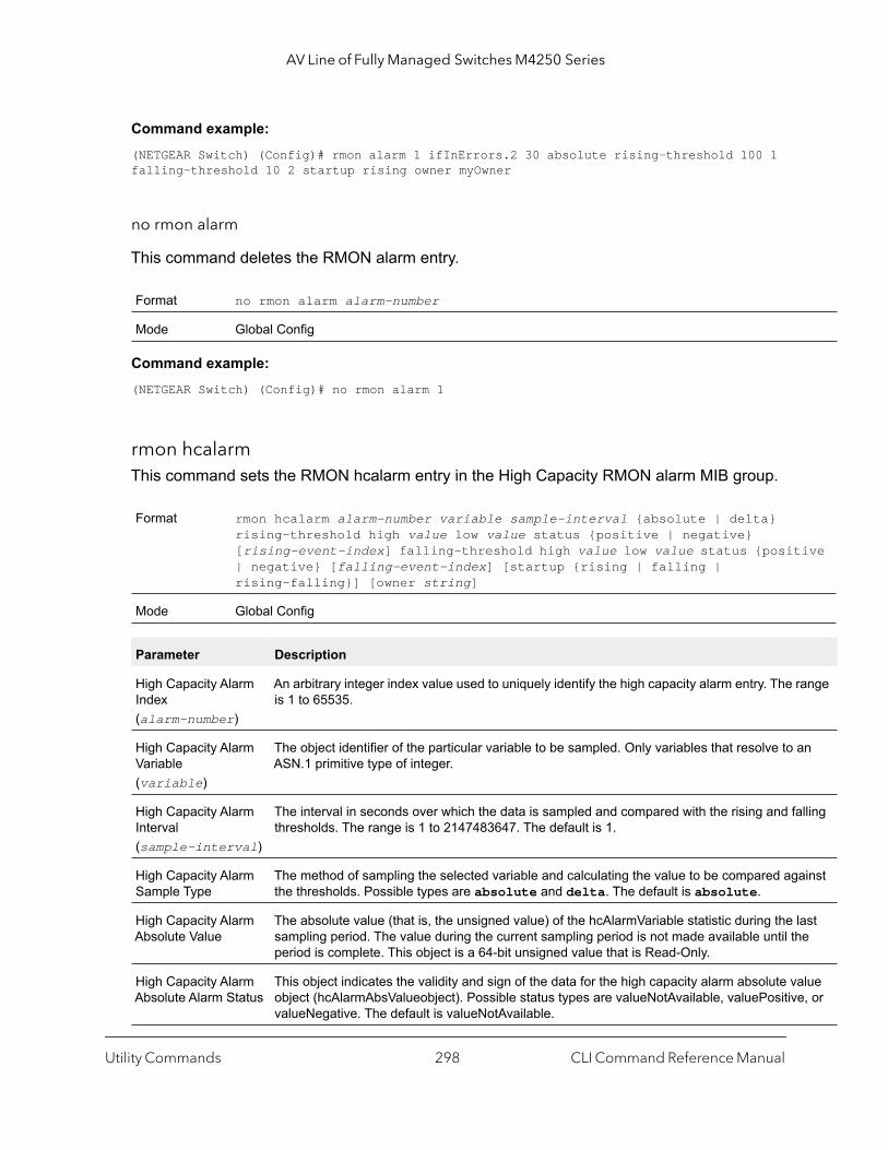
AV Line of Fully Managed Switches M4250 Series
ive
ange
n
lling
ainst
ast e
lue , or
Command example: (NETGEAR Switch) (Config)# rmon alarm 1 ifInErrors.2 30 absolute rising-threshold 100 1 falling-threshold 10 2 startup rising owner myOwner
no rmon alarm
This command deletes the RMON alarm entry.
Command example: (NETGEAR Switch) (Config)# no rmon alarm 1
rmon hcalarmThis command sets the RMON hcalarm entry in the High Capacity RMON alarm MIB group.
Format no rmon alarm alarm-number
Mode Global Config
Format rmon hcalarm alarm-number variable sample-interval {absolute | delta} rising-threshold high value low value status {positive | negative} [rising-event-index] falling-threshold high value low value status {posit| negative} [falling-event-index] [startup {rising | falling | rising-falling}] [owner string]
Mode Global Config
Parameter Description
High Capacity Alarm Index(alarm-number)
An arbitrary integer index value used to uniquely identify the high capacity alarm entry. The ris 1 to 65535.
High Capacity Alarm Variable(variable)
The object identifier of the particular variable to be sampled. Only variables that resolve to aASN.1 primitive type of integer.
High Capacity Alarm Interval(sample-interval)
The interval in seconds over which the data is sampled and compared with the rising and fathresholds. The range is 1 to 2147483647. The default is 1.
High Capacity Alarm Sample Type
The method of sampling the selected variable and calculating the value to be compared agthe thresholds. Possible types are absolute and delta. The default is absolute.
High Capacity Alarm Absolute Value
The absolute value (that is, the unsigned value) of the hcAlarmVariable statistic during the lsampling period. The value during the current sampling period is not made available until thperiod is complete. This object is a 64-bit unsigned value that is Read-Only.
High Capacity Alarm Absolute Alarm Status
This object indicates the validity and sign of the data for the high capacity alarm absolute vaobject (hcAlarmAbsValueobject). Possible status types are valueNotAvailable, valuePositivevalueNegative. The default is valueNotAvailable.
Utility Commands CLI Command Reference Manual298
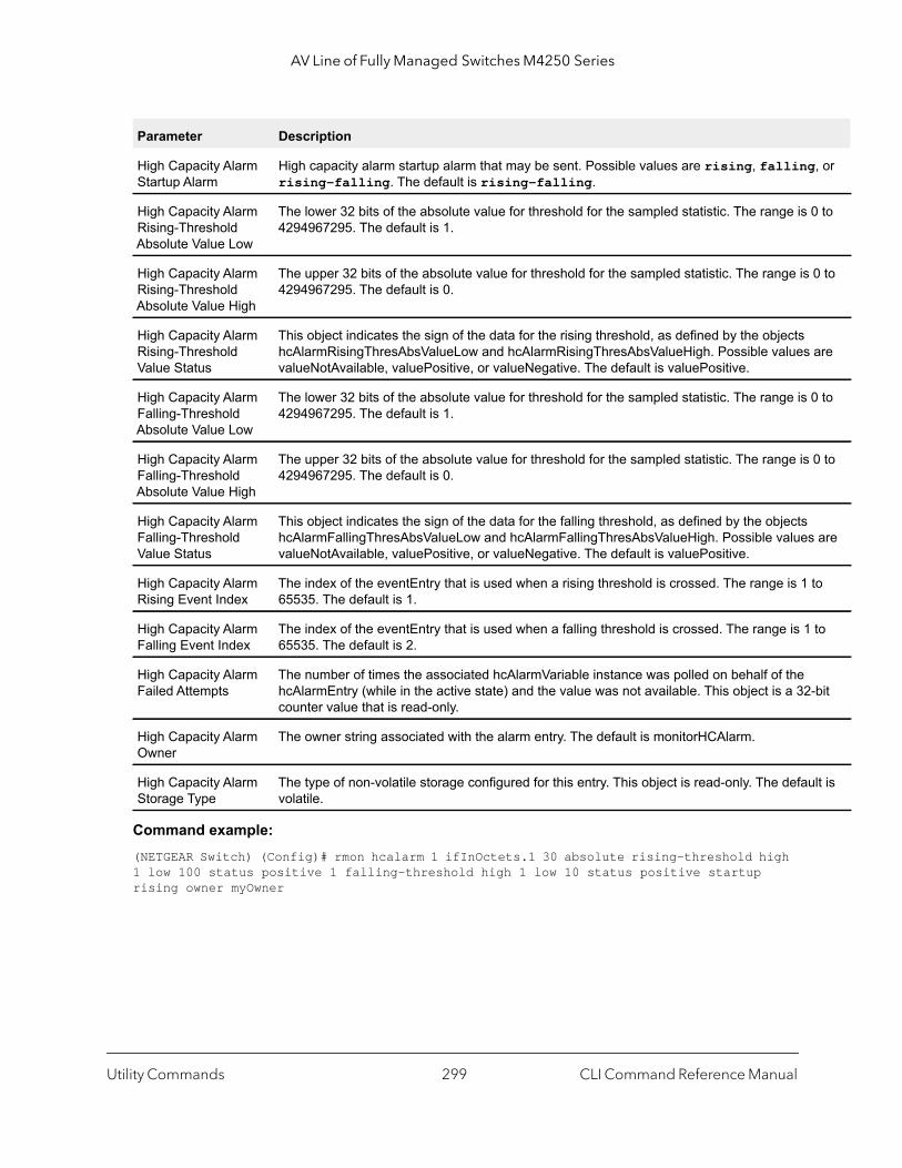
AV Line of Fully Managed Switches M4250 Series
, or
0 to
0 to
are
0 to
0 to
are
to
to
-bit
lt is
Command example: (NETGEAR Switch) (Config)# rmon hcalarm 1 ifInOctets.1 30 absolute rising-threshold high 1 low 100 status positive 1 falling-threshold high 1 low 10 status positive startup rising owner myOwner
High Capacity Alarm Startup Alarm
High capacity alarm startup alarm that may be sent. Possible values are rising, fallingrising-falling. The default is rising-falling.
High Capacity Alarm Rising-Threshold Absolute Value Low
The lower 32 bits of the absolute value for threshold for the sampled statistic. The range is 4294967295. The default is 1.
High Capacity Alarm Rising-Threshold Absolute Value High
The upper 32 bits of the absolute value for threshold for the sampled statistic. The range is4294967295. The default is 0.
High Capacity Alarm Rising-Threshold Value Status
This object indicates the sign of the data for the rising threshold, as defined by the objects hcAlarmRisingThresAbsValueLow and hcAlarmRisingThresAbsValueHigh. Possible valuesvalueNotAvailable, valuePositive, or valueNegative. The default is valuePositive.
High Capacity Alarm Falling-Threshold Absolute Value Low
The lower 32 bits of the absolute value for threshold for the sampled statistic. The range is 4294967295. The default is 1.
High Capacity Alarm Falling-Threshold Absolute Value High
The upper 32 bits of the absolute value for threshold for the sampled statistic. The range is4294967295. The default is 0.
High Capacity Alarm Falling-Threshold Value Status
This object indicates the sign of the data for the falling threshold, as defined by the objects hcAlarmFallingThresAbsValueLow and hcAlarmFallingThresAbsValueHigh. Possible valuesvalueNotAvailable, valuePositive, or valueNegative. The default is valuePositive.
High Capacity Alarm Rising Event Index
The index of the eventEntry that is used when a rising threshold is crossed. The range is 1 65535. The default is 1.
High Capacity Alarm Falling Event Index
The index of the eventEntry that is used when a falling threshold is crossed. The range is 165535. The default is 2.
High Capacity Alarm Failed Attempts
The number of times the associated hcAlarmVariable instance was polled on behalf of the hcAlarmEntry (while in the active state) and the value was not available. This object is a 32counter value that is read-only.
High Capacity Alarm Owner
The owner string associated with the alarm entry. The default is monitorHCAlarm.
High Capacity Alarm Storage Type
The type of non-volatile storage configured for this entry. This object is read-only. The defauvolatile.
Parameter Description
Utility Commands CLI Command Reference Manual299
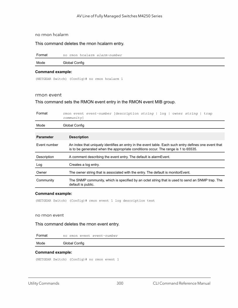
AV Line of Fully Managed Switches M4250 Series
t that
. The
no rmon hcalarm
This command deletes the rmon hcalarm entry.
Command example: (NETGEAR Switch) (Config)# no rmon hcalarm 1
rmon eventThis command sets the RMON event entry in the RMON event MIB group.
Command example: (NETGEAR Switch) (Config)# rmon event 1 log description test
no rmon event
This command deletes the rmon event entry.
Command example: (NETGEAR Switch) (Config)# no rmon event 1
Format no rmon hcalarm alarm-number
Mode Global Config
Format rmon event event-number [description string | log | owner string | trap community]
Mode Global Config
Parameter Description
Event number An index that uniquely identifies an entry in the event table. Each such entry defines one evenis to be generated when the appropriate conditions occur. The range is 1 to 65535.
Description A comment describing the event entry. The default is alarmEvent.
Log Creates a log entry.
Owner The owner string that is associated with the entry. The default is monitorEvent.
Community The SNMP community, which is specified by an octet string that is used to send an SNMP trapdefault is public.
Format no rmon event event-number
Mode Global Config
Utility Commands CLI Command Reference Manual300
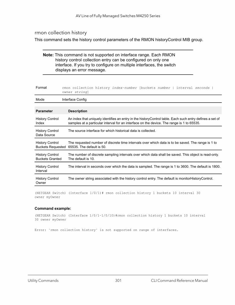
AV Line of Fully Managed Switches M4250 Series
|
set of
1 to
only.
1800.
l.
rmon collection historyThis command sets the history control parameters of the RMON historyControl MIB group.
Note: This command is not supported on interface range. Each RMON history control collection entry can be configured on only one interface. If you try to configure on multiple interfaces, the switch displays an error message.
(NETGEAR Switch) (Interface 1/0/1)# rmon collection history 1 buckets 10 interval 30 owner myOwner
Command example: (NETGEAR Switch) (Interface 1/0/1-1/0/10)#rmon collection history 1 buckets 10 interval 30 owner myOwner
Error: 'rmon collection history' is not supported on range of interfaces.
Format rmon collection history index-number [buckets number | interval seconds owner string]
Mode Interface Config
Parameter Description
History Control Index
An index that uniquely identifies an entry in the historyControl table. Each such entry defines a samples at a particular interval for an interface on the device. The range is 1 to 65535.
History Control Data Source
The source interface for which historical data is collected.
History Control Buckets Requested
The requested number of discrete time intervals over which data is to be saved. The range is 65535. The default is 50.
History Control Buckets Granted
The number of discrete sampling intervals over which data shall be saved. This object is read-The default is 10.
History Control Interval
The interval in seconds over which the data is sampled. The range is 1 to 3600. The default is
History Control Owner
The owner string associated with the history control entry. The default is monitorHistoryContro
Utility Commands CLI Command Reference Manual301
AV Line of Fully Managed Switches M4250 Series
mple
SN.1
g
ed
efault
5535.
efault
5535.
lt is
no rmon collection history
This command will delete the history control group entry with the specified index number.
Command example: (NETGEAR Switch) (Interface 1/0/1-1/0/10)# no rmon collection history 1
show rmon This command displays the entries in the RMON alarm table.
Format no rmon collection history index-number
Mode Interface Config
Format show rmon {alarms | alarm alarm-index}
Mode Privileged Exec
Term Description
Alarm Index An index that uniquely identifies an entry in the alarm table. Each entry defines a diagnostic saat a particular interval for an object on the device. The range is 1 to 65535.
Alarm Variable The object identifier of the particular variable to be sampled. Only variables that resolve to an Aprimitive type of integer.
Alarm Interval The interval in seconds over which the data is sampled and compared with the rising and fallinthresholds. The range is 1 to 2147483647. The default is 1.
Alarm Absolute Value
The value of the statistic during the last sampling period. This object is a read-only, 32-bit signvalue.
Alarm Rising Threshold
The rising threshold for the sample statistics. The range is 2147483648 to 2147483647. The dis 1.
Alarm Rising Event Index
The index of the eventEntry that is used when a rising threshold is crossed. The range is 1 to 6The default is 1.
Alarm Falling Threshold
The falling threshold for the sample statistics. The range is 2147483648 to 2147483647. The dis 1.
Alarm Falling Event Index
The index of the eventEntry that is used when a falling threshold is crossed. The range is 1 to 6The default is 2.
Alarm Startup Alarm
The alarm that may be sent. Possible values are rising, falling or both rising-falling. The defaurising-falling.
Alarm Owner The owner string associated with the alarm entry. The default is monitorAlarm.
Utility Commands CLI Command Reference Manual302

AV Line of Fully Managed Switches M4250 Series
set of
1 to
only.
Command example: (NETGEAR Switch) #show rmon alarms
Index OID Owner----------------------------------------------1 alarmInterval.1 MibBrowser2 alarmInterval.1 MibBrowser
Command example: (NETGEAR Switch) #show rmon alarm 1
Alarm 1 ----------OID: alarmInterval.1Last Sample Value: 1Interval: 1 Sample Type: absoluteStartup Alarm: rising-fallingRising Threshold: 1 Falling Threshold: 1Rising Event: 1Falling Event: 2Owner: MibBrowser
show rmon collection historyThis command displays the entries in the RMON history control table.
Format show rmon collection history [interfaces unit/port]
Mode Privileged Exec
Term Description
History Control Index
An index that uniquely identifies an entry in the historyControl table. Each such entry defines a samples at a particular interval for an interface on the device. The range is 1 to 65535.
History Control Data Source
The source interface for which historical data is collected.
History Control Buckets Requested
The requested number of discrete time intervals over which data is to be saved. The range is 65535. The default is 50.
History Control Buckets Granted
The number of discrete sampling intervals over which data shall be saved. This object is read-The default is 10.
Utility Commands CLI Command Reference Manual303
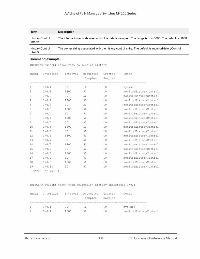
AV Line of Fully Managed Switches M4250 Series
1800.
l.
Command example: (NETGEAR Switch) #show rmon collection history
Index Interface Interval Requested Granted Owner Samples Samples----------------------------------------------------------------------1 1/0/1 30 10 10 myowner2 1/0/1 1800 50 10 monitorHistoryControl3 1/0/2 30 50 10 monitorHistoryControl4 1/0/2 1800 50 10 monitorHistoryControl5 1/0/3 30 50 10 monitorHistoryControl6 1/0/3 1800 50 10 monitorHistoryControl7 1/0/4 30 50 10 monitorHistoryControl8 1/0/4 1800 50 10 monitorHistoryControl9 1/0/5 30 50 10 monitorHistoryControl10 1/0/5 1800 50 10 monitorHistoryControl11 1/0/6 30 50 10 monitorHistoryControl12 1/0/6 1800 50 10 monitorHistoryControl13 1/0/7 30 50 10 monitorHistoryControl14 1/0/7 1800 50 10 monitorHistoryControl15 1/0/8 30 50 10 monitorHistoryControl16 1/0/8 1800 50 10 monitorHistoryControl17 1/0/9 30 50 10 monitorHistoryControl18 1/0/9 1800 50 10 monitorHistoryControl19 1/0/10 30 50 10 monitorHistoryControl--More-- or (q)uit
(NETGEAR Switch) #show rmon collection history interfaces 1/0/1
Index Interface Interval Requested Granted Owner Samples Samples----------------------------------------------------------------------1 1/0/1 30 10 10 myowner2 1/0/1 1800 50 10 monitorHistoryControl
History Control Interval
The interval in seconds over which the data is sampled. The range is 1 to 3600. The default is
History Control Owner
The owner string associated with the history control entry. The default is monitorHistoryContro
Term Description
Utility Commands CLI Command Reference Manual304

AV Line of Fully Managed Switches M4250 Series
t that
NMP
efault
] |
s a 5.
s 1 to
show rmon eventsThis command displays the entries in the RMON event table.
Command example: (NETGEAR Switch) # show rmon events
Index Description Type Community Owner Last time sent-------------------------------------------------------------------------------1 test log public MIB 0 days 0 h:0 m:0 s
show rmon historyThis command displays the specified entry in the RMON history table.
Format show rmon events
Mode Privileged Exec
Term Description
Event Index An index that uniquely identifies an entry in the event table. Each such entry defines one evenis to be generated when the appropriate conditions occur. The range is 1 to 65535.
Event Description A comment describing the event entry. The default is alarmEvent.
Event Type The type of notification that the probe makes about the event. Possible values are None, Log, STrap, Log and SNMP Trap. The default is None.
Event Owner Owner string associated with the entry. The default is monitorEvent.
Event Community The SNMP community specific by this octet string which is used to send an SNMP trap. The dis public.
Owner Event owner. The owner string associated with the entry.
Last time sent The last time over which a log or a SNMP trap message is generated.
Format show rmon history index {errors [period seconds] | other [period secondsthroughput [period seconds]}
Mode Privileged Exec
Term Description
History Control Index An index that uniquely identifies an entry in the historyControl table. Each such entry defineset of samples at a particular interval for an interface on the device. The range is 1 to 6553
History Control Data Source
The source interface for which historical data is collected.
History Control Buckets Requested
The requested number of discrete time intervals over which data is to be saved. The range i65535. The default is 50.
Utility Commands CLI Command Reference Manual305
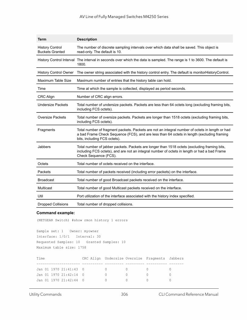
AV Line of Fully Managed Switches M4250 Series
lt is
trol.
bits,
bits,
r had ing
s, e
Command example: (NETGEAR Switch) #show rmon history 1 errors
Sample set: 1 Owner: myownerInterface: 1/0/1 Interval: 30Requested Samples: 10 Granted Samples: 10Maximum table size: 1758
Time CRC Align Undersize Oversize Fragments Jabbers--------------------- ---------- --------- --------- ---------- -------Jan 01 1970 21:41:43 0 0 0 0 0Jan 01 1970 21:42:14 0 0 0 0 0Jan 01 1970 21:42:44 0 0 0 0 0
History Control Buckets Granted
The number of discrete sampling intervals over which data shall be saved. This object is read-only. The default is 10.
History Control Interval The interval in seconds over which the data is sampled. The range is 1 to 3600. The defau1800.
History Control Owner The owner string associated with the history control entry. The default is monitorHistoryCon
Maximum Table Size Maximum number of entries that the history table can hold.
Time Time at which the sample is collected, displayed as period seconds.
CRC Align Number of CRC align errors.
Undersize Packets Total number of undersize packets. Packets are less than 64 octets long (excluding framingincluding FCS octets).
Oversize Packets Total number of oversize packets. Packets are longer than 1518 octets (excluding framing including FCS octets).
Fragments Total number of fragment packets. Packets are not an integral number of octets in length oa bad Frame Check Sequence (FCS), and are less than 64 octets in length (excluding frambits, including FCS octets).
Jabbers Total number of jabber packets. Packets are longer than 1518 octets (excluding framing bitincluding FCS octets), and are not an integral number of octets in length or had a bad FramCheck Sequence (FCS).
Octets Total number of octets received on the interface.
Packets Total number of packets received (including error packets) on the interface.
Broadcast Total number of good Broadcast packets received on the interface.
Multicast Total number of good Multicast packets received on the interface.
Util Port utilization of the interface associated with the history index specified.
Dropped Collisions Total number of dropped collisions.
Term Description
Utility Commands CLI Command Reference Manual306
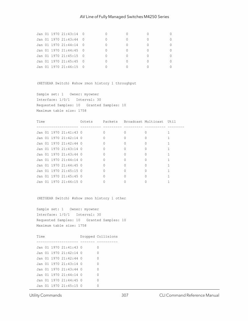
AV Line of Fully Managed Switches M4250 Series
Jan 01 1970 21:43:14 0 0 0 0 0Jan 01 1970 21:43:44 0 0 0 0 0Jan 01 1970 21:44:14 0 0 0 0 0Jan 01 1970 21:44:45 0 0 0 0 0Jan 01 1970 21:45:15 0 0 0 0 0Jan 01 1970 21:45:45 0 0 0 0 0Jan 01 1970 21:46:15 0 0 0 0 0
(NETGEAR Switch) #show rmon history 1 throughput
Sample set: 1 Owner: myownerInterface: 1/0/1 Interval: 30Requested Samples: 10 Granted Samples: 10Maximum table size: 1758
Time Octets Packets Broadcast Multicast Util-------------------- ---------- --------- --------- ---------- --------Jan 01 1970 21:41:43 0 0 0 0 1Jan 01 1970 21:42:14 0 0 0 0 1Jan 01 1970 21:42:44 0 0 0 0 1Jan 01 1970 21:43:14 0 0 0 0 1Jan 01 1970 21:43:44 0 0 0 0 1Jan 01 1970 21:44:14 0 0 0 0 1Jan 01 1970 21:44:45 0 0 0 0 1Jan 01 1970 21:45:15 0 0 0 0 1Jan 01 1970 21:45:45 0 0 0 0 1Jan 01 1970 21:46:15 0 0 0 0 1
(NETGEAR Switch) #show rmon history 1 other
Sample set: 1 Owner: myownerInterface: 1/0/1 Interval: 30Requested Samples: 10 Granted Samples: 10Maximum table size: 1758
Time Dropped Collisions-------------------- ------- ----------Jan 01 1970 21:41:43 0 0Jan 01 1970 21:42:14 0 0Jan 01 1970 21:42:44 0 0Jan 01 1970 21:43:14 0 0Jan 01 1970 21:43:44 0 0Jan 01 1970 21:44:14 0 0Jan 01 1970 21:44:45 0 0Jan 01 1970 21:45:15 0 0
Utility Commands CLI Command Reference Manual307
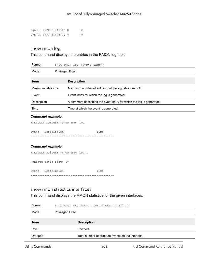
AV Line of Fully Managed Switches M4250 Series
Jan 01 1970 21:45:45 0 0Jan 01 1970 21:46:15 0 0
show rmon logThis command displays the entries in the RMON log table.
Command example: (NETGEAR Switch) #show rmon log
Event Description Time------------------------------------------------
Command example: (NETGEAR Switch) #show rmon log 1
Maximum table size: 10
Event Description Time------------------------------------------------
show rmon statistics interfacesThis command displays the RMON statistics for the given interfaces.
Format show rmon log [event-index]
Mode Privileged Exec
Term Description
Maximum table size Maximum number of entries that the log table can hold.
Event Event index for which the log is generated.
Description A comment describing the event entry for which the log is generated.
Time Time at which the event is generated.
Format show rmon statistics interfaces unit/port
Mode Privileged Exec
Term Description
Port unit/port
Dropped Total number of dropped events on the interface.
Utility Commands CLI Command Reference Manual308
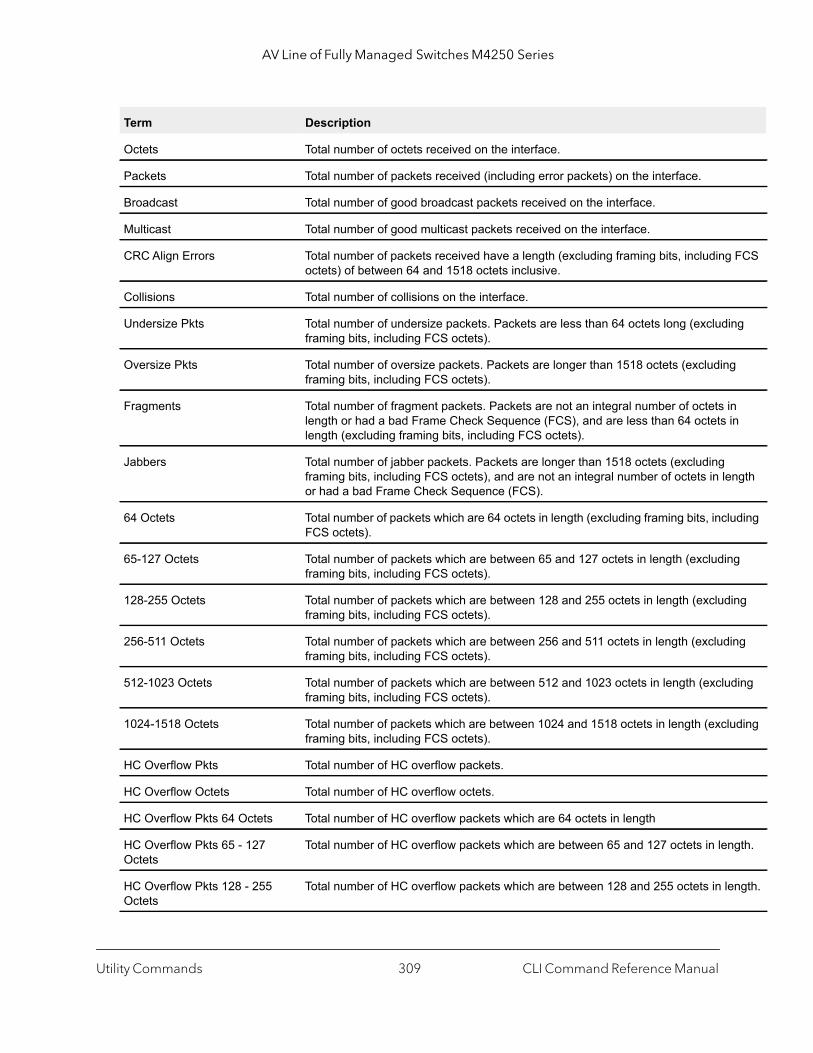
AV Line of Fully Managed Switches M4250 Series
FCS
ng
g
n in
ngth
uding
g
ing
ing
ding
uding
gth.
ngth.
Octets Total number of octets received on the interface.
Packets Total number of packets received (including error packets) on the interface.
Broadcast Total number of good broadcast packets received on the interface.
Multicast Total number of good multicast packets received on the interface.
CRC Align Errors Total number of packets received have a length (excluding framing bits, includingoctets) of between 64 and 1518 octets inclusive.
Collisions Total number of collisions on the interface.
Undersize Pkts Total number of undersize packets. Packets are less than 64 octets long (excludiframing bits, including FCS octets).
Oversize Pkts Total number of oversize packets. Packets are longer than 1518 octets (excludinframing bits, including FCS octets).
Fragments Total number of fragment packets. Packets are not an integral number of octets ilength or had a bad Frame Check Sequence (FCS), and are less than 64 octets length (excluding framing bits, including FCS octets).
Jabbers Total number of jabber packets. Packets are longer than 1518 octets (excluding framing bits, including FCS octets), and are not an integral number of octets in leor had a bad Frame Check Sequence (FCS).
64 Octets Total number of packets which are 64 octets in length (excluding framing bits, inclFCS octets).
65-127 Octets Total number of packets which are between 65 and 127 octets in length (excludinframing bits, including FCS octets).
128-255 Octets Total number of packets which are between 128 and 255 octets in length (excludframing bits, including FCS octets).
256-511 Octets Total number of packets which are between 256 and 511 octets in length (excludframing bits, including FCS octets).
512-1023 Octets Total number of packets which are between 512 and 1023 octets in length (excluframing bits, including FCS octets).
1024-1518 Octets Total number of packets which are between 1024 and 1518 octets in length (exclframing bits, including FCS octets).
HC Overflow Pkts Total number of HC overflow packets.
HC Overflow Octets Total number of HC overflow octets.
HC Overflow Pkts 64 Octets Total number of HC overflow packets which are 64 octets in length
HC Overflow Pkts 65 - 127 Octets
Total number of HC overflow packets which are between 65 and 127 octets in len
HC Overflow Pkts 128 - 255 Octets
Total number of HC overflow packets which are between 128 and 255 octets in le
Term Description
Utility Commands CLI Command Reference Manual309

AV Line of Fully Managed Switches M4250 Series
ngth.
The
to an
Command example: (NETGEAR Switch) # show rmon statistics interfaces 1/0/1Port: 1/0/1Dropped: 0Octets: 0 Packets: 0Broadcast: 0 Multicast: 0CRC Align Errors: 0 Collisions: 0Undersize Pkts: 0 Oversize Pkts: 0Fragments: 0 Jabbers: 064 Octets: 0 65 - 127 Octets: 0128 - 255 Octets: 0 256 - 511 Octets: 0512 - 1023 Octets: 0 1024 - 1518 Octets: 0HC Overflow Pkts: 0 HC Pkts: 0HC Overflow Octets: 0 HC Octets: 0HC Overflow Pkts 64 Octets: 0 HC Pkts 64 Octets: 0HC Overflow Pkts 65 - 127 Octets: 0 HC Pkts 65 - 127 Octets: 0HC Overflow Pkts 128 - 255 Octets: 0 HC Pkts 128 - 255 Octets: 0HC Overflow Pkts 256 - 511 Octets: 0 HC Pkts 256 - 511 Octets: 0HC Overflow Pkts 512 - 1023 Octets: 0 HC Pkts 512 - 1023 Octets: 0HC Overflow Pkts 1024 - 1518 Octets: 0 HC Pkts 1024 - 1518 Octets: 0
show rmon hcalarmsThis command displays all entries or a specific entry in the RMON high-capacity alarm table.
HC Overflow Pkts 256 - 511 Octets
Total number of HC overflow packets which are between 256 and 511 octets in le
HC Overflow Pkts 512 - 1023 Octets
Total number of HC overflow packets which are between 512 and 1023 octets in length.
HC Overflow Pkts 1024 - 1518 Octets
Total number of HC overflow packets which are between 1024 and 1518 octets inlength.
Format show rmon {hcalarms | hcalarm alarm-index}
Mode Privileged Exec
Term Description
High Capacity Alarm Index An arbitrary integer index value used to uniquely identify the high capacity alarm entry. range is 1 to 65535.
High Capacity Alarm Variable
The object identifier of the particular variable to be sampled. Only variables that resolve ASN.1 primitive type of integer.
Term Description
Utility Commands CLI Command Reference Manual310
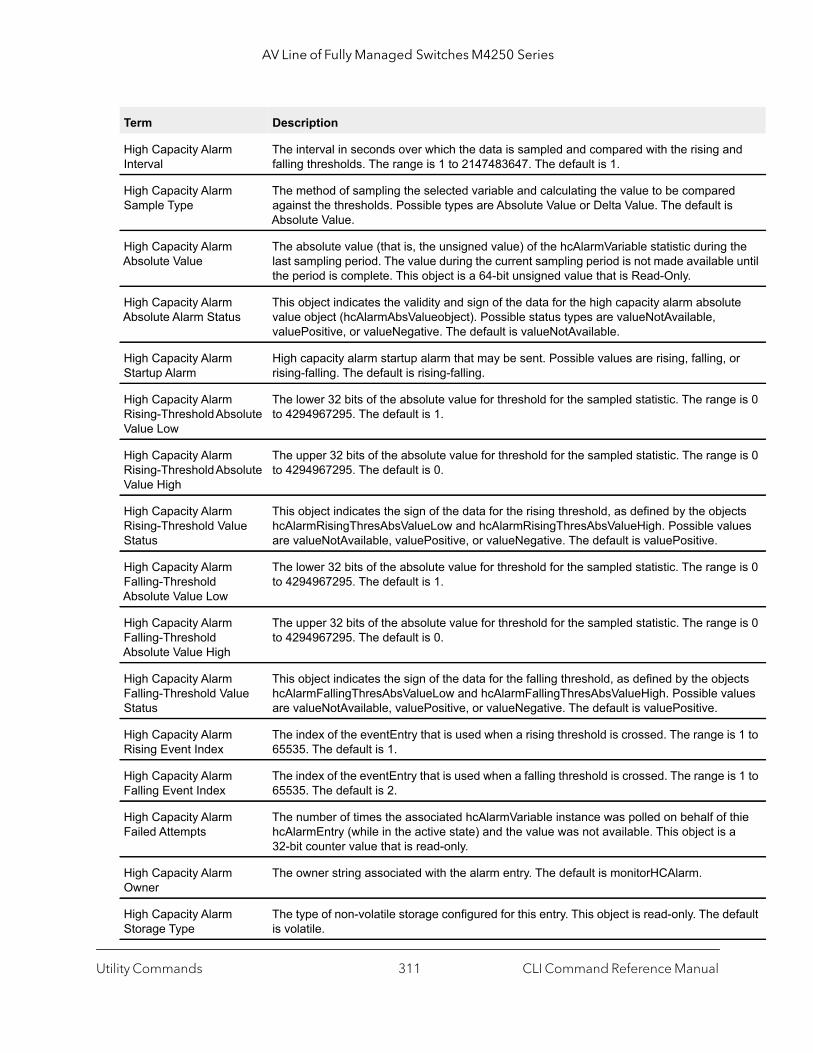
AV Line of Fully Managed Switches M4250 Series
nd
the until
te
or
e is 0
e is 0
cts lues
e is 0
e is 0
cts lues
s 1 to
s 1 to
thie a
efault
High Capacity Alarm Interval
The interval in seconds over which the data is sampled and compared with the rising afalling thresholds. The range is 1 to 2147483647. The default is 1.
High Capacity Alarm Sample Type
The method of sampling the selected variable and calculating the value to be comparedagainst the thresholds. Possible types are Absolute Value or Delta Value. The default isAbsolute Value.
High Capacity Alarm Absolute Value
The absolute value (that is, the unsigned value) of the hcAlarmVariable statistic during last sampling period. The value during the current sampling period is not made availablethe period is complete. This object is a 64-bit unsigned value that is Read-Only.
High Capacity Alarm Absolute Alarm Status
This object indicates the validity and sign of the data for the high capacity alarm absoluvalue object (hcAlarmAbsValueobject). Possible status types are valueNotAvailable, valuePositive, or valueNegative. The default is valueNotAvailable.
High Capacity Alarm Startup Alarm
High capacity alarm startup alarm that may be sent. Possible values are rising, falling, rising-falling. The default is rising-falling.
High Capacity Alarm Rising-Threshold Absolute Value Low
The lower 32 bits of the absolute value for threshold for the sampled statistic. The rangto 4294967295. The default is 1.
High Capacity Alarm Rising-Threshold Absolute Value High
The upper 32 bits of the absolute value for threshold for the sampled statistic. The rangto 4294967295. The default is 0.
High Capacity Alarm Rising-Threshold Value Status
This object indicates the sign of the data for the rising threshold, as defined by the objehcAlarmRisingThresAbsValueLow and hcAlarmRisingThresAbsValueHigh. Possible vaare valueNotAvailable, valuePositive, or valueNegative. The default is valuePositive.
High Capacity Alarm Falling-Threshold Absolute Value Low
The lower 32 bits of the absolute value for threshold for the sampled statistic. The rangto 4294967295. The default is 1.
High Capacity Alarm Falling-Threshold Absolute Value High
The upper 32 bits of the absolute value for threshold for the sampled statistic. The rangto 4294967295. The default is 0.
High Capacity Alarm Falling-Threshold Value Status
This object indicates the sign of the data for the falling threshold, as defined by the objehcAlarmFallingThresAbsValueLow and hcAlarmFallingThresAbsValueHigh. Possible vaare valueNotAvailable, valuePositive, or valueNegative. The default is valuePositive.
High Capacity Alarm Rising Event Index
The index of the eventEntry that is used when a rising threshold is crossed. The range i65535. The default is 1.
High Capacity Alarm Falling Event Index
The index of the eventEntry that is used when a falling threshold is crossed. The range i65535. The default is 2.
High Capacity Alarm Failed Attempts
The number of times the associated hcAlarmVariable instance was polled on behalf of hcAlarmEntry (while in the active state) and the value was not available. This object is 32-bit counter value that is read-only.
High Capacity Alarm Owner
The owner string associated with the alarm entry. The default is monitorHCAlarm.
High Capacity Alarm Storage Type
The type of non-volatile storage configured for this entry. This object is read-only. The dis volatile.
Term Description
Utility Commands CLI Command Reference Manual311
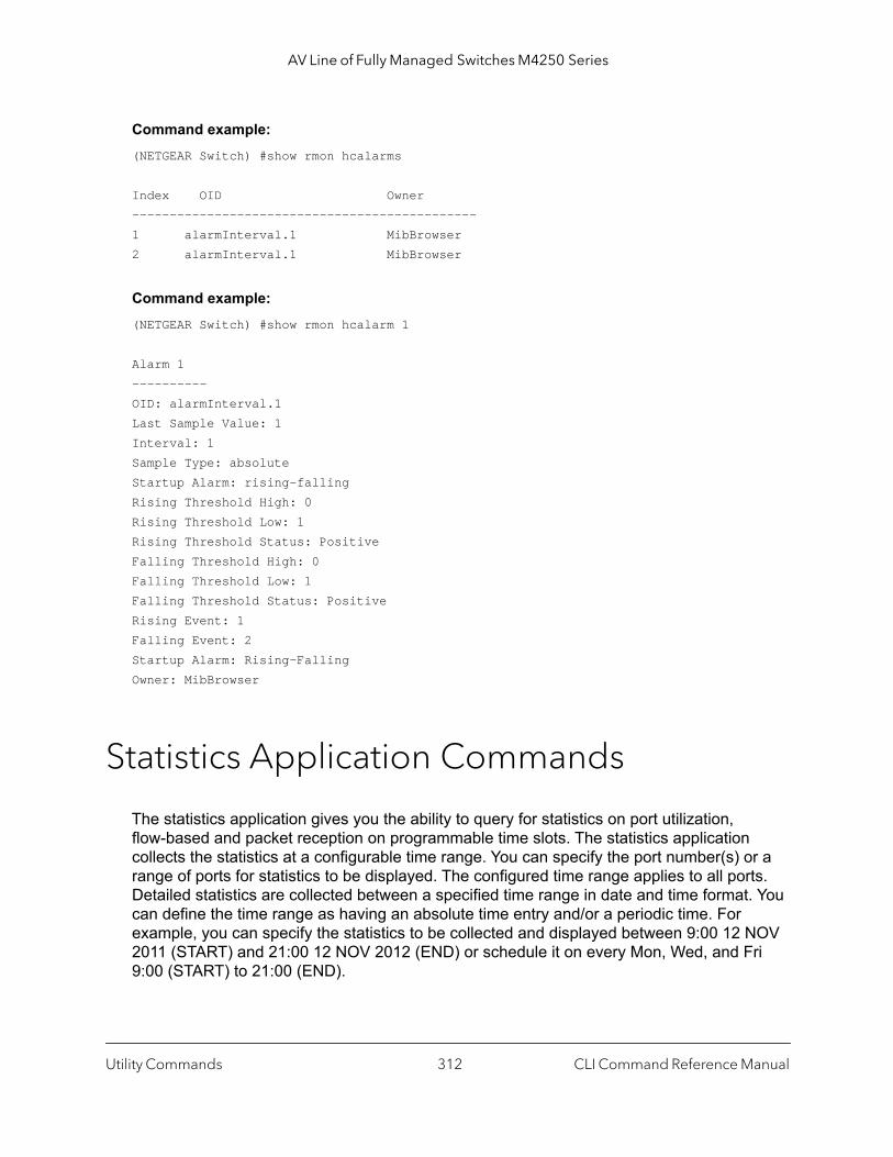
AV Line of Fully Managed Switches M4250 Series
Command example: (NETGEAR Switch) #show rmon hcalarms
Index OID Owner----------------------------------------------1 alarmInterval.1 MibBrowser2 alarmInterval.1 MibBrowser
Command example: (NETGEAR Switch) #show rmon hcalarm 1
Alarm 1 ----------OID: alarmInterval.1Last Sample Value: 1 Interval: 1 Sample Type: absoluteStartup Alarm: rising-fallingRising Threshold High: 0 Rising Threshold Low: 1 Rising Threshold Status: PositiveFalling Threshold High: 0 Falling Threshold Low: 1 Falling Threshold Status: PositiveRising Event: 1Falling Event: 2Startup Alarm: Rising-FallingOwner: MibBrowser
Statistics Application Commands
The statistics application gives you the ability to query for statistics on port utilization, flow-based and packet reception on programmable time slots. The statistics application collects the statistics at a configurable time range. You can specify the port number(s) or a range of ports for statistics to be displayed. The configured time range applies to all ports. Detailed statistics are collected between a specified time range in date and time format. You can define the time range as having an absolute time entry and/or a periodic time. For example, you can specify the statistics to be collected and displayed between 9:00 12 NOV 2011 (START) and 21:00 12 NOV 2012 (END) or schedule it on every Mon, Wed, and Fri 9:00 (START) to 21:00 (END).
Utility Commands CLI Command Reference Manual312
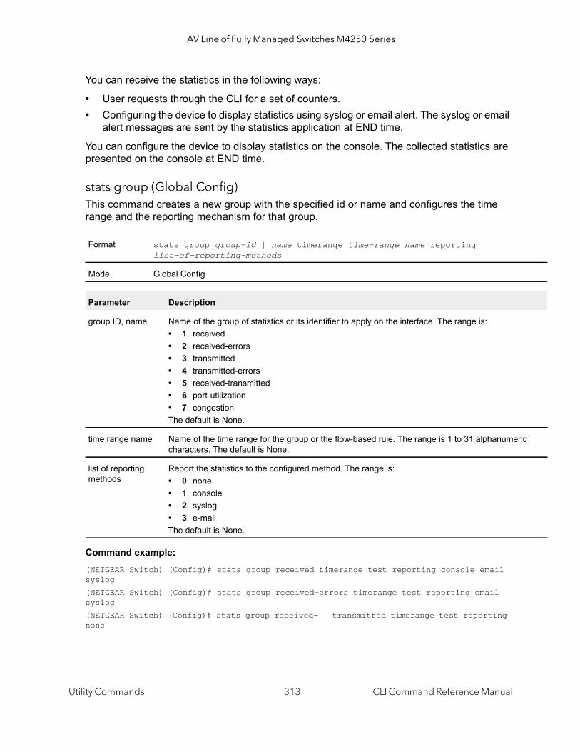
AV Line of Fully Managed Switches M4250 Series
ic
You can receive the statistics in the following ways:
• User requests through the CLI for a set of counters.• Configuring the device to display statistics using syslog or email alert. The syslog or email
alert messages are sent by the statistics application at END time.
You can configure the device to display statistics on the console. The collected statistics are presented on the console at END time.
stats group (Global Config)This command creates a new group with the specified id or name and configures the time range and the reporting mechanism for that group.
Command example: (NETGEAR Switch) (Config)# stats group received timerange test reporting console email syslog(NETGEAR Switch) (Config)# stats group received-errors timerange test reporting email syslog(NETGEAR Switch) (Config)# stats group received- transmitted timerange test reporting none
Format stats group group-id | name timerange time-range name reporting list-of-reporting-methods
Mode Global Config
Parameter Description
group ID, name Name of the group of statistics or its identifier to apply on the interface. The range is:• 1. received• 2. received-errors• 3. transmitted• 4. transmitted-errors• 5. received-transmitted• 6. port-utilization• 7. congestionThe default is None.
time range name Name of the time range for the group or the flow-based rule. The range is 1 to 31 alphanumercharacters. The default is None.
list of reporting methods
Report the statistics to the configured method. The range is:• 0. none• 1. console• 2. syslog• 3. e-mailThe default is None.
Utility Commands CLI Command Reference Manual313
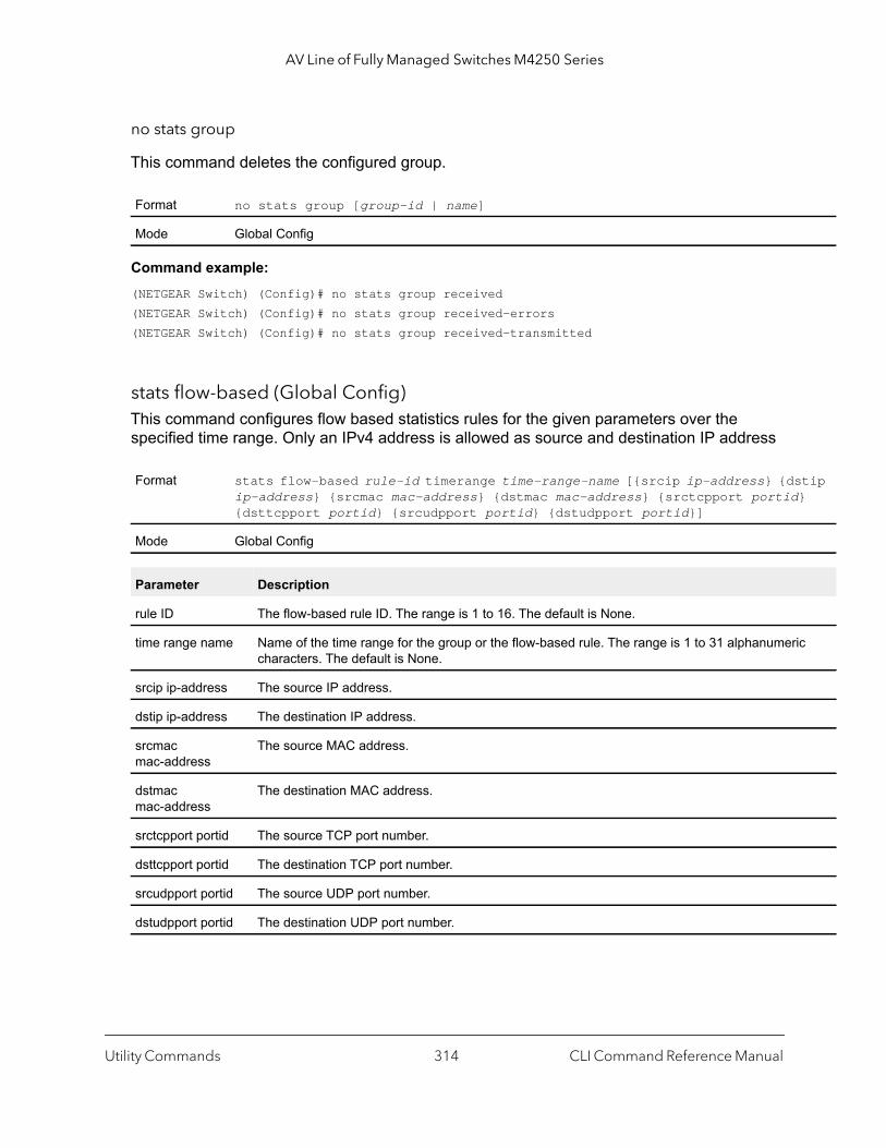
AV Line of Fully Managed Switches M4250 Series
tip }
ic
no stats group
This command deletes the configured group.
Command example: (NETGEAR Switch) (Config)# no stats group received(NETGEAR Switch) (Config)# no stats group received-errors(NETGEAR Switch) (Config)# no stats group received-transmitted
stats flow-based (Global Config)This command configures flow based statistics rules for the given parameters over the specified time range. Only an IPv4 address is allowed as source and destination IP address
Format no stats group [group-id | name]
Mode Global Config
Format stats flow-based rule-id timerange time-range-name [{srcip ip-address} {dsip-address} {srcmac mac-address} {dstmac mac-address} {srctcpport portid{dsttcpport portid} {srcudpport portid} {dstudpport portid}]
Mode Global Config
Parameter Description
rule ID The flow-based rule ID. The range is 1 to 16. The default is None.
time range name Name of the time range for the group or the flow-based rule. The range is 1 to 31 alphanumercharacters. The default is None.
srcip ip-address The source IP address.
dstip ip-address The destination IP address.
srcmac mac-address
The source MAC address.
dstmac mac-address
The destination MAC address.
srctcpport portid The source TCP port number.
dsttcpport portid The destination TCP port number.
srcudpport portid The source UDP port number.
dstudpport portid The destination UDP port number.
Utility Commands CLI Command Reference Manual314
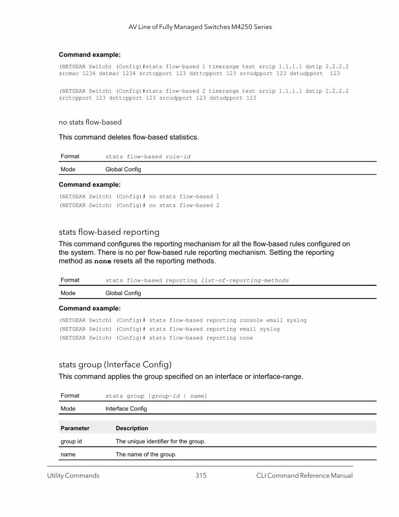
AV Line of Fully Managed Switches M4250 Series
Command example: (NETGEAR Switch) (Config)#stats flow-based 1 timerange test srcip 1.1.1.1 dstip 2.2.2.2 srcmac 1234 dstmac 1234 srctcpport 123 dsttcpport 123 srcudpport 123 dstudpport 123
(NETGEAR Switch) (Config)#stats flow-based 2 timerange test srcip 1.1.1.1 dstip 2.2.2.2 srctcpport 123 dsttcpport 123 srcudpport 123 dstudpport 123
no stats flow-based
This command deletes flow-based statistics.
Command example: (NETGEAR Switch) (Config)# no stats flow-based 1(NETGEAR Switch) (Config)# no stats flow-based 2
stats flow-based reportingThis command configures the reporting mechanism for all the flow-based rules configured on the system. There is no per flow-based rule reporting mechanism. Setting the reporting method as none resets all the reporting methods.
Command example: (NETGEAR Switch) (Config)# stats flow-based reporting console email syslog(NETGEAR Switch) (Config)# stats flow-based reporting email syslog(NETGEAR Switch) (Config)# stats flow-based reporting none
stats group (Interface Config)This command applies the group specified on an interface or interface-range.
Format stats flow-based rule-id
Mode Global Config
Format stats flow-based reporting list-of-reporting-methods
Mode Global Config
Format stats group [group-id | name]
Mode Interface Config
Parameter Description
group id The unique identifier for the group.
name The name of the group.
Utility Commands CLI Command Reference Manual315

AV Line of Fully Managed Switches M4250 Series
Command example: (NETGEAR Switch) (Interface 1/0/1-1/0/10)# stats group 1(NETGEAR Switch) (Interface 1/0/1-1/0/10)# stats group 2
no stats group
This command deletes the interface or interface-range from the group specified.
Command example: .(NETGEAR Switch) (Interface 1/0/1-1/0/10)# no stats group 1(NETGEAR Switch) (Interface 1/0/1-1/0/10)# no stats group 2
stats flow-based (Interface Config)This command applies the flow-based rule specified by the ID on an interface or interface-range.
Command example: (NETGEAR Switch) (Interface 1/0/1-1/0/10)# stats flow-based 1(NETGEAR Switch) (Interface 1/0/1-1/0/10)# stats flow-based 2
no stats flow-based
This command deletes the interface or interface-range from the flow-based rule specified.
Command example: (NETGEAR Switch) (Interface 1/0/1-1/0/10)# no stats flow-based 1(NETGEAR Switch) (Interface 1/0/1-1/0/10)# no stats flow-based 2
Format no stats group [group-id | name]
Mode Interface Config
Format stats flow-based rule-id
Mode Interface Config
Parameter Description
rule-id The unique identifier for the flow-based rule.
Format no stats flow-based rule-id
Mode Interface Config
Utility Commands CLI Command Reference Manual316
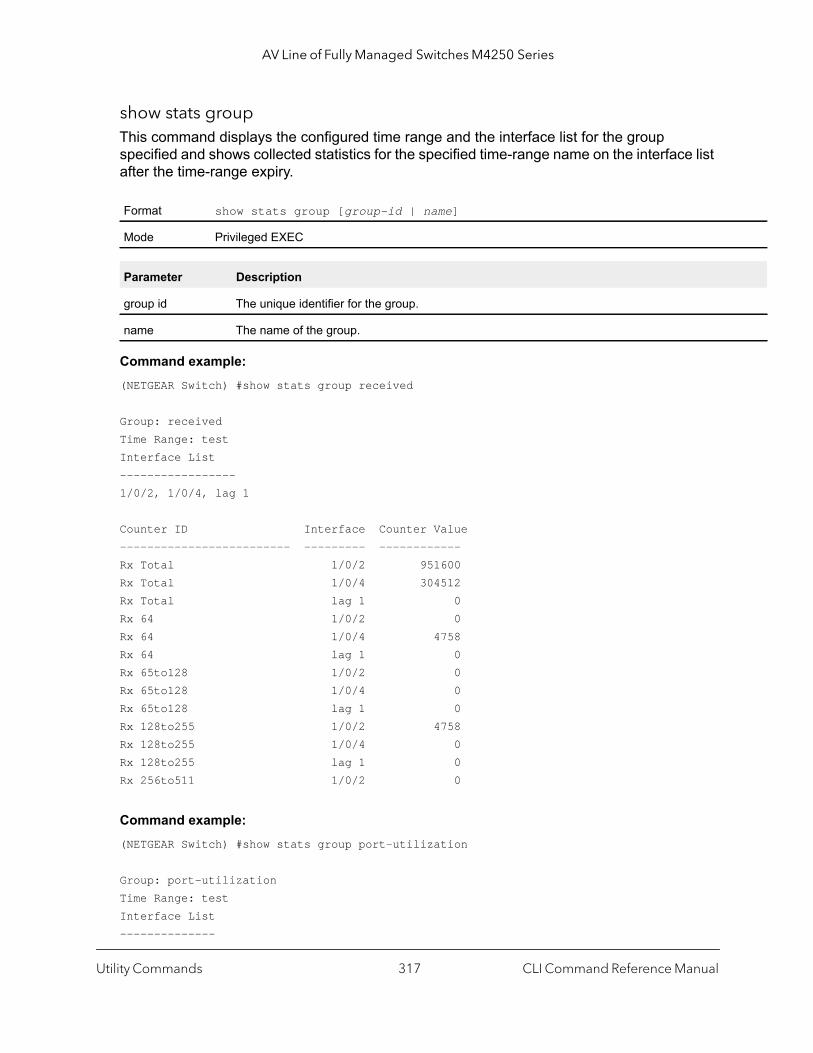
AV Line of Fully Managed Switches M4250 Series
show stats groupThis command displays the configured time range and the interface list for the group specified and shows collected statistics for the specified time-range name on the interface list after the time-range expiry.
Command example: (NETGEAR Switch) #show stats group received
Group: receivedTime Range: testInterface List-----------------1/0/2, 1/0/4, lag 1
Counter ID Interface Counter Value------------------------- --------- ------------Rx Total 1/0/2 951600Rx Total 1/0/4 304512Rx Total lag 1 0Rx 64 1/0/2 0Rx 64 1/0/4 4758Rx 64 lag 1 0Rx 65to128 1/0/2 0Rx 65to128 1/0/4 0Rx 65to128 lag 1 0Rx 128to255 1/0/2 4758Rx 128to255 1/0/4 0Rx 128to255 lag 1 0Rx 256to511 1/0/2 0
Command example: (NETGEAR Switch) #show stats group port-utilization
Group: port-utilizationTime Range: testInterface List--------------
Format show stats group [group-id | name]
Mode Privileged EXEC
Parameter Description
group id The unique identifier for the group.
name The name of the group.
Utility Commands CLI Command Reference Manual317
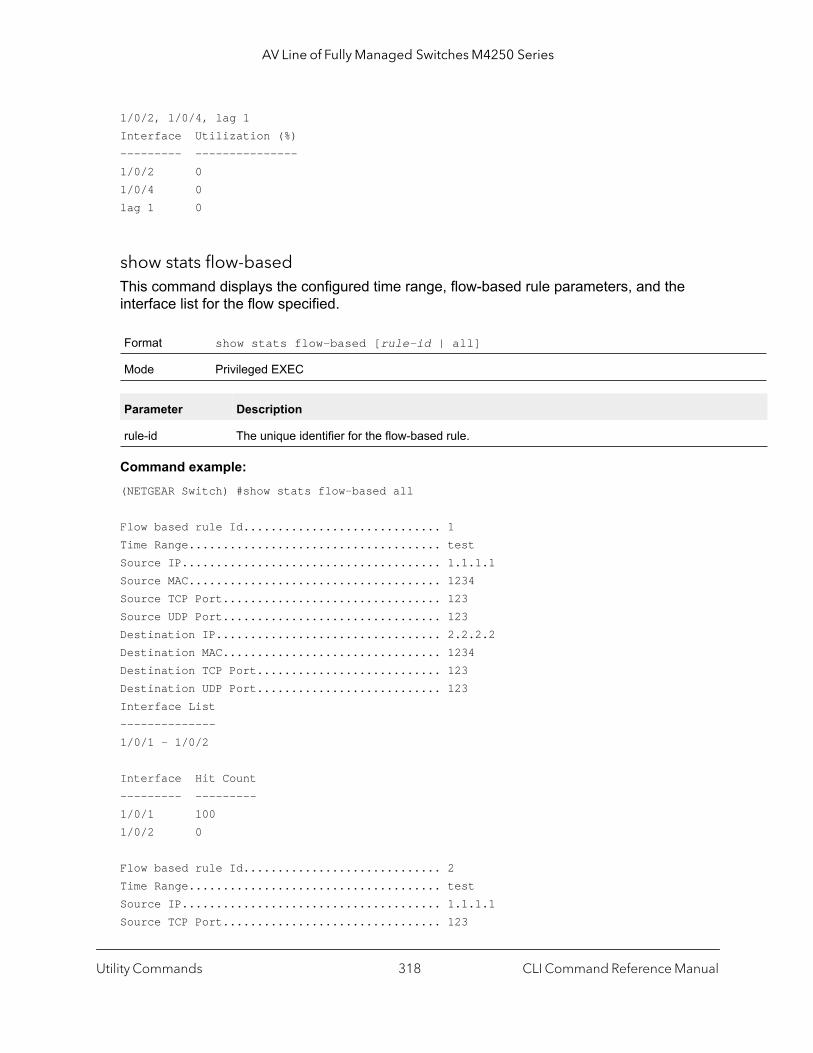
AV Line of Fully Managed Switches M4250 Series
1/0/2, 1/0/4, lag 1Interface Utilization (%)--------- ---------------1/0/2 01/0/4 0lag 1 0
show stats flow-basedThis command displays the configured time range, flow-based rule parameters, and the interface list for the flow specified.
Command example: (NETGEAR Switch) #show stats flow-based all
Flow based rule Id............................. 1Time Range..................................... testSource IP...................................... 1.1.1.1Source MAC..................................... 1234Source TCP Port................................ 123Source UDP Port................................ 123Destination IP................................. 2.2.2.2Destination MAC................................ 1234Destination TCP Port........................... 123Destination UDP Port........................... 123Interface List--------------1/0/1 - 1/0/2
Interface Hit Count--------- ---------1/0/1 1001/0/2 0
Flow based rule Id............................. 2Time Range..................................... testSource IP...................................... 1.1.1.1Source TCP Port................................ 123
Format show stats flow-based [rule-id | all]
Mode Privileged EXEC
Parameter Description
rule-id The unique identifier for the flow-based rule.
Utility Commands CLI Command Reference Manual318
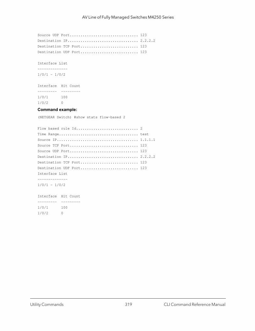
AV Line of Fully Managed Switches M4250 Series
Source UDP Port................................ 123Destination IP................................. 2.2.2.2Destination TCP Port........................... 123Destination UDP Port........................... 123
Interface List--------------1/0/1 - 1/0/2
Interface Hit Count--------- ---------1/0/1 1001/0/2 0
Command example: (NETGEAR Switch) #show stats flow-based 2
Flow based rule Id............................. 2Time Range..................................... testSource IP...................................... 1.1.1.1Source TCP Port................................ 123Source UDP Port................................ 123Destination IP................................. 2.2.2.2Destination TCP Port........................... 123Destination UDP Port........................... 123Interface List--------------1/0/1 - 1/0/2
Interface Hit Count--------- ---------1/0/1 1001/0/2 0
Utility Commands CLI Command Reference Manual319
6
6Switching CommandsThis chapter describes the switching commands.
The Switching Commands chapter includes the following sections:
• Port Configuration Commands
• Port Link Flap Commands
• Spanning Tree Protocol Commands
• Loop Protection Commands
• VLAN Commands
• Switch Port Commands
• Double VLAN Commands
• Private VLAN Commands
• Voice VLAN Commands
• Precision Time Protocol Commands
• Provisioning (IEEE 802.1p) Commands
• Asymmetric Flow Control Commands
• Protected Ports Commands
• Private Group Commands
• GARP Commands
• GVRP Commands
• GMRP Commands
• Port-Based Network Access Control Commands
• 802.1X Supplicant Commands
• Storm-Control Commands
• Link Dependency Commands
• Link Local Protocol Filtering Commands
• Port-Channel/LAG (802.3ad) Commands
• Port Mirroring Commands
• Static MAC Filtering Commands
320

AV Line of Fully Managed Switches M4250 Series
• DHCP L2 Relay Agent Commands
• DHCP Client Commands
• DHCP Snooping Configuration Commands
• Dynamic ARP Inspection Commands
• MVR Commands
• IGMP Snooping Configuration Commands
• IGMP Snooping Querier Commands
• MLD Snooping Commands
• MLD Snooping Querier Commands
• Port Security Commands
• LLDP (802.1AB) Commands
• LLDP-MED Commands
• Denial of Service Commands
• MAC Database Commands
• ISDP Commands
• Interface Error Disabling and Auto Recovery Commands
• UniDirectional Link Detection Commands
• Link Debounce Commands
• Audio Video Bridging Commands
The commands in this chapter are in one of three functional groups:
• Show commands. Display switch settings, statistics, and other information.• Configuration commands. Configure features and options of the switch. For every
configuration command, there is a show command that displays the configuration setting.• Clear commands. Clear some or all of the settings to factory defaults.
Switching Commands CLI Command Reference Manual321
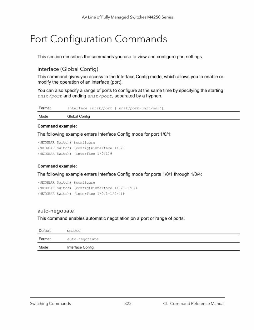
AV Line of Fully Managed Switches M4250 Series
Port Configuration Commands
This section describes the commands you use to view and configure port settings.
interface (Global Config)This command gives you access to the Interface Config mode, which allows you to enable or modify the operation of an interface (port).
You can also specify a range of ports to configure at the same time by specifying the starting unit/port and ending unit/port, separated by a hyphen.
Command example:
The following example enters Interface Config mode for port 1/0/1:(NETGEAR Switch) #configure(NETGEAR Switch) (config)#interface 1/0/1(NETGEAR Switch) (interface 1/0/1)#
Command example:
The following example enters Interface Config mode for ports 1/0/1 through 1/0/4:(NETGEAR Switch) #configure(NETGEAR Switch) (config)#interface 1/0/1-1/0/4(NETGEAR Switch) (interface 1/0/1-1/0/4)#
auto-negotiateThis command enables automatic negotiation on a port or range of ports.
Format interface {unit/port | unit/port-unit/port}
Mode Global Config
Default enabled
Format auto-negotiate
Mode Interface Config
Switching Commands CLI Command Reference Manual322
AV Line of Fully Managed Switches M4250 Series
no auto-negotiate
This command disables automatic negotiation on a port.Automatic sensing is disabled when automatic negotiation is disabled.
auto-negotiate allThis command enables automatic negotiation on all ports.
no auto-negotiate all
This command disables automatic negotiation on all ports.
description (Interface Config)Use this command to create an alpha-numeric description of an interface or range of interfaces.
mtuUse the mtu command to set the maximum transmission unit (MTU) size, in bytes, for frames that ingress or egress the interface. You can use the mtu command to configure jumbo frame support for physical and port-channel (LAG) interfaces. The MTU size is a valid integer between 1522–9216 for tagged packets and a valid integer between 1518 - 9216 for untagged packets.
Note: To receive and process packets, the Ethernet MTU must include any extra bytes that Layer-2 headers might require. To configure the IP MTU size, which is the maximum size of the IP packet (IP Header + IP payload), see ip mtu on page 642.
Format no auto-negotiate
Mode Interface Config
Default enabled
Format auto-negotiate all
Mode Global Config
Format no auto-negotiate all
Mode Global Config
Format description description
Mode Interface Config
Switching Commands CLI Command Reference Manual323

AV Line of Fully Managed Switches M4250 Series
no mtu
This command sets the default MTU size (in bytes) for the interface.
shutdown (Interface Config)This command disables a port or range of ports.
Note: You can use the shutdown command on physical and port-channel (LAG) interfaces, but not on VLAN routing interfaces.
no shutdown
This command enables a port.
shutdown allThis command disables all ports.
Note: You can use the shutdown all command on physical and port-channel (LAG) interfaces, but not on VLAN routing interfaces.
Default 1518 (untagged)
Format mtu size
Mode Interface Config
Format no mtu
Mode Interface Config
Default enabled
Format shutdown
Mode Interface Config
Format no shutdown
Mode Interface Config
Default enabled
Switching Commands CLI Command Reference Manual324
AV Line of Fully Managed Switches M4250 Series
10G
no shutdown all
This command enables all ports.
speedUse this command to enable or disable auto-negotiation and set the speed that will be advertised by that port. The duplex parameter allows you to set the advertised speed for both half as well as full duplex mode.
Use the auto keyword to enable auto-negotiation on the port. Use the command without the auto keyword to ensure auto-negotiation is disabled and to set the port speed and mode according to the command values. If auto-negotiation is disabled, the speed and duplex mode must be set.
speed all 100This command sets the speed to 100 Mbps and sets the duplex setting for all interfaces.
show portThis command displays port information.
Format shutdown all
Mode Global Config
Format no shutdown all
Mode Global Config
Default Auto-negotiation is enabled.
Format speed {auto {10G | 5G | 2.5G | 1000 | 100} [half-duplex | full-duplex] | {| 5G | 2.5G | 1000 | 100} {half-duplex | full-duplex}}
Mode Interface Config
Format speed all 100 {half-duplex | full-duplex}
Mode Global Config
Format show port {intf-range | all}
Mode Privileged EXEC
Switching Commands CLI Command Reference Manual325
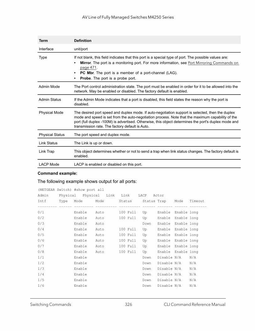
AV Line of Fully Managed Switches M4250 Series
s on
o the
lex f the e and
ult is
Command example:
The following example shows output for all ports:(NETGEAR Switch) #show port allAdmin Physical Physical Link Link LACP ActorIntf Type Mode Mode Status Status Trap Mode Timeout--------- ------ --------- ---------- ---------- ------ ------- ------ --------0/1 Enable Auto 100 Full Up Enable Enable long0/2 Enable Auto 100 Full Up Enable Enable long0/3 Enable Auto Down Enable Enable long0/4 Enable Auto 100 Full Up Enable Enable long0/5 Enable Auto 100 Full Up Enable Enable long0/6 Enable Auto 100 Full Up Enable Enable long0/7 Enable Auto 100 Full Up Enable Enable long0/8 Enable Auto 100 Full Up Enable Enable long1/1 Enable Down Disable N/A N/A1/2 Enable Down Disable N/A N/A1/3 Enable Down Disable N/A N/A1/4 Enable Down Disable N/A N/A1/5 Enable Down Disable N/A N/A1/6 Enable Down Disable N/A N/A
Term Definition
Interface unit/port
Type If not blank, this field indicates that this port is a special type of port. The possible values are:• Mirror. The port is a monitoring port. For more information, see Port Mirroring Command
page 471.• PC Mbr. The port is a member of a port-channel (LAG).• Probe. The port is a probe port.
Admin Mode The Port control administration state. The port must be enabled in order for it to be allowed intnetwork. May be enabled or disabled. The factory default is enabled.
Admin Status If the Admin Mode indicates that a port is disabled, this field states the reason why the port is disabled.
Physical Mode The desired port speed and duplex mode. If auto-negotiation support is selected, then the dupmode and speed is set from the auto-negotiation process. Note that the maximum capability oport (full duplex -100M) is advertised. Otherwise, this object determines the port's duplex modtransmission rate. The factory default is Auto.
Physical Status The port speed and duplex mode.
Link Status The Link is up or down.
Link Trap This object determines whether or not to send a trap when link status changes. The factory defaenabled.
LACP Mode LACP is enabled or disabled on this port.
Switching Commands CLI Command Reference Manual326
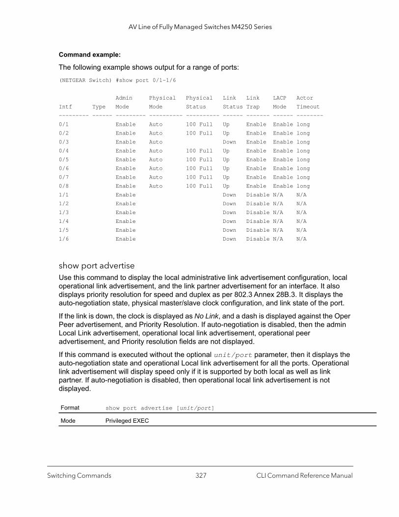
AV Line of Fully Managed Switches M4250 Series
Command example:
The following example shows output for a range of ports:(NETGEAR Switch) #show port 0/1-1/6
Admin Physical Physical Link Link LACP ActorIntf Type Mode Mode Status Status Trap Mode Timeout--------- ------ --------- ---------- ---------- ------ ------- ------ --------0/1 Enable Auto 100 Full Up Enable Enable long0/2 Enable Auto 100 Full Up Enable Enable long0/3 Enable Auto Down Enable Enable long0/4 Enable Auto 100 Full Up Enable Enable long0/5 Enable Auto 100 Full Up Enable Enable long0/6 Enable Auto 100 Full Up Enable Enable long0/7 Enable Auto 100 Full Up Enable Enable long0/8 Enable Auto 100 Full Up Enable Enable long1/1 Enable Down Disable N/A N/A1/2 Enable Down Disable N/A N/A1/3 Enable Down Disable N/A N/A1/4 Enable Down Disable N/A N/A1/5 Enable Down Disable N/A N/A1/6 Enable Down Disable N/A N/A
show port advertiseUse this command to display the local administrative link advertisement configuration, local operational link advertisement, and the link partner advertisement for an interface. It also displays priority resolution for speed and duplex as per 802.3 Annex 28B.3. It displays the auto-negotiation state, physical master/slave clock configuration, and link state of the port.
If the link is down, the clock is displayed as No Link, and a dash is displayed against the Oper Peer advertisement, and Priority Resolution. If auto-negotiation is disabled, then the admin Local Link advertisement, operational local link advertisement, operational peer advertisement, and Priority resolution fields are not displayed.
If this command is executed without the optional unit/port parameter, then it displays the auto-negotiation state and operational Local link advertisement for all the ports. Operational link advertisement will display speed only if it is supported by both local as well as link partner. If auto-negotiation is disabled, then operational local link advertisement is not displayed.
Format show port advertise [unit/port]
Mode Privileged EXEC
Switching Commands CLI Command Reference Manual327
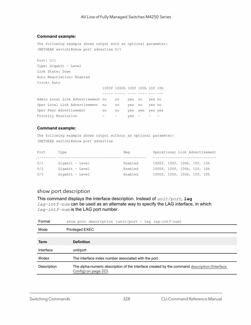
AV Line of Fully Managed Switches M4250 Series
Command example: The following example shows output with an optional parameter:(NETGEAR switch)#show port advertise 0/1
Port: 0/1Type: Gigabit - LevelLink State: DownAuto Negotiation: EnabledClock: Auto 1000f 1000h 100f 100h 10f 10h ----- ----- ---- ---- --- --- Admin Local Link Advertisement no no yes no yes no Oper Local Link Advertisement no no yes no yes no Oper Peer Advertisement no no yes yes yes yes Priority Resolution - - yes - - -
Command example: The following example shows output without an optional parameter:(NETGEAR switch)#show port advertise
Port Type Neg Operational Link Advertisement--------- ------------------------------ ----------- ------------------------------0/1 Gigabit - Level Enabled 1000f, 100f, 100h, 10f, 10h0/2 Gigabit - Level Enabled 1000f, 100f, 100h, 10f, 10h0/3 Gigabit - Level Enabled 1000f, 100f, 100h, 10f, 10h
show port descriptionThis command displays the interface description. Instead of unit/port, lag lag-intf-num can be used as an alternate way to specify the LAG interface, in which lag-intf-num is the LAG port number.
Format show port description [unit/port | lag lag-intf-num]
Mode Privileged EXEC
Term Definition
Interface unit/port
ifIndex The interface index number associated with the port.
Description The alpha-numeric description of the interface created by the command description (InterfaceConfig) on page 323.
Switching Commands CLI Command Reference Manual328

AV Line of Fully Managed Switches M4250 Series
ed by
Command example: (NETGEAR switch) #show port description 0/1
Interface...........0/1ifIndex.............1Description.........MAC address.........00:10:18:82:0C:10Bit Offset Val......1
show port statusThis command displays the status for and the state of all or specified networking ports.
MAC address The MAC address of the port. The format is 6 two-digit hexadecimal numbers that are separatcolons, for example 01:23:45:67:89:AB.
Bit Offset Val The bit offset value.
Format show port status [unit/port | all | lag]
Mode Privileged EXEC
Term Definition
Intf The interface in the unit/port format.
Media Type • auto-select. The media type is automatically selected. The preferred media type is displayed.
• RJ45. The media type is RJ45.• SFP. The media type is SFP.
STP Mode Indicates whether spanning tree mode is enabled or disabled.
Physical Mode The port speed and duplex mode. The maximum capability of the port is advertised. If autonegotiation support is enabled, the duplex mode and speed are set through the autonegotiation process.
Physical Status The port speed and duplex mode.
Link Status Indicates whether the link is up or down.
Loop Status Indicates whether a loop was diagnosed.
Partner Flow Control Indicates whether flow control at the remote end is enabled or disabled.
Term Definition
Switching Commands CLI Command Reference Manual329
AV Line of Fully Managed Switches M4250 Series
debug dynamic portsThis command enables debug messages that are related to dynamic ports, that is, combo ports that are capable of detecting the media type (SFP [fiber] or Ethernet [copper]).
no debug dynamic ports
This command disables debug messages that are related to dynamic ports, that is, combo ports that are capable of detecting the media type (SFP [fiber] or Ethernet [copper]).
Port Link Flap Commands
The switch can detect the number of link-flaps that occur on all ports. If the number of link-flaps on a port exceeds a configured threshold during a configured period, the port can be placed in the D-Disable state.
By enabling auto-recovery, the port can automatically be activated again. You can also activate the port manually.
link-flap d-disableThis command enables the link-flap feature on the switch. When enabled, the switch counts the number of link flaps on a port during a configured period. If the number of link flaps on a port exceeds a configured threshold, the port is placed in the D-Disable state.
no link-flap d-disable
This command disables the link-flap feature on the switch.
Format debug dynamic ports
Mode Privileged EXEC
Format no debug dynamic ports
Mode Privileged EXEC
Default enabled
Format link-flap d-disable
Mode Global Config
Format no link-flap d-disable
Mode Global Config
Switching Commands CLI Command Reference Manual330

AV Line of Fully Managed Switches M4250 Series
link-flap d-disable durationThis command configures the maximum period that a port is allowed to flap before the port is placed in the D-Disable state.
The duration argument can be from 3 to 200 seconds. The default is 10 seconds.
no link-flap d-disable duration
This command sets the link-flap duration to its defaults of 10 seconds.
link-flap d-disable max-countThis command configures the maximum number of flaps that are allowed before the port is placed in the D-Disable state.
The count argument can be a number from 2 to 100. The default number is 5.
no link-flap d-disable max-count
This command sets the maximum number of allowed link flaps to its defaults of 5.
show link-flap d-disableThis command displays the link-flap settings.
Default 10 seconds
Format link-flap d-disable duration duration
Mode Global Config
Format no link-flap d-disable duration
Mode Global Config
Default 5
Format link-flap d-disable max-count count
Mode Global Config
Format no link-flap d-disable max-count
Mode Global Config
Format show link-flap d-disable
Mode Global Config
Switching Commands CLI Command Reference Manual331
AV Line of Fully Managed Switches M4250 Series
Spanning Tree Protocol Commands
This section describes the commands you use to configure Spanning Tree Protocol (STP). STP helps prevent network loops, duplicate messages, and network instability.
Note: STP is enabled on the switch and on all ports and LAGs by default. If STP is disabled, the system does not forward BPDU messages.
spanning-treeThis command sets the spanning-tree operational mode to enabled.
no spanning-tree
This command sets the spanning-tree operational mode to disabled. While disabled, the spanning-tree configuration is retained and can be changed, but is not activated.
spanning-tree auto-edgeUse this command to allow the interface to become an edge port if it does not receive any BPDUs within a given amount of time.
Term Definition
Admin State Shows whether the link-flap feature is enabled or not.
Duration (in seconds) The maximum period that link flaps are allowed.
Max-Count The maximum number of link flaps that are allowed.
Default enabled
Format spanning-tree
Mode Global Config
Format no spanning-tree
Mode Global Config
Default Enabled
Format spanning-tree auto-edge
Mode Interface Config
Switching Commands CLI Command Reference Manual332
AV Line of Fully Managed Switches M4250 Series
no spanning-tree auto-edge
This command resets the auto-edge status of the port to the default value.
spanning-tree backbonefastUse this command to enable the detection of indirect link failures and accelerate spanning tree convergence on PVSTP configured switches.
Backbonefast accelerates finding an alternate path when an indirect link to the root port goes down.
Backbonefast can be configured even if the switch is configured for MST(RSTP) or PVST mode. It only has an effect when the switch is configured for the PVST mode.
If a backbonefast-enabled switch receives an inferior BPDU from its designated switch on a root or blocked port, it sets the maximum aging time on the interfaces on which it received the inferior BPDU if there are alternate paths to the designated switch. This allows a blocked port to immediately move to the listening state where the port can be transitioned to the forwarding state in the normal manner.
On receipt of an inferior BPDU from a designated bridge, backbonefast enabled switches send a Root Link Query (RLQ) request to all non-designated ports except the port from which it received the inferior BPDU. This check validates that the switch can receive packets from the root on ports where it expects to receive BPDUs. The port from which the original inferior BPDU was received is excluded because it has already encountered a failure. Designated ports are excluded as they do not lead to the root.
On receipt of an RLQ response, if the answer is negative, the receiving port has lost connection to the root and its BPDU is immediately aged out. If all nondesignated ports have already received a negative answer, the whole bridge has lost the root and can start the STP calculation from scratch.
If the answer confirms the switch can access the root bridge on a port, it can immediately age out the port on which it initially received the inferior BPDU.
A bridge that sends an RLQ puts its bridge ID in the PDU. This ensures that it does not flood the response on designated ports.
A bridge that receives an RLQ and has connectivity to the root forwards the query toward the root through its root port.
A bridge that receives a RLQ request and does not have connectivity to the root (switch bridge ID is different from the root bridge ID in the query) or is the root bridge immediately answers the query with its root bridge ID.
Format no spanning-tree auto-edge
Mode Interface Config
Switching Commands CLI Command Reference Manual333
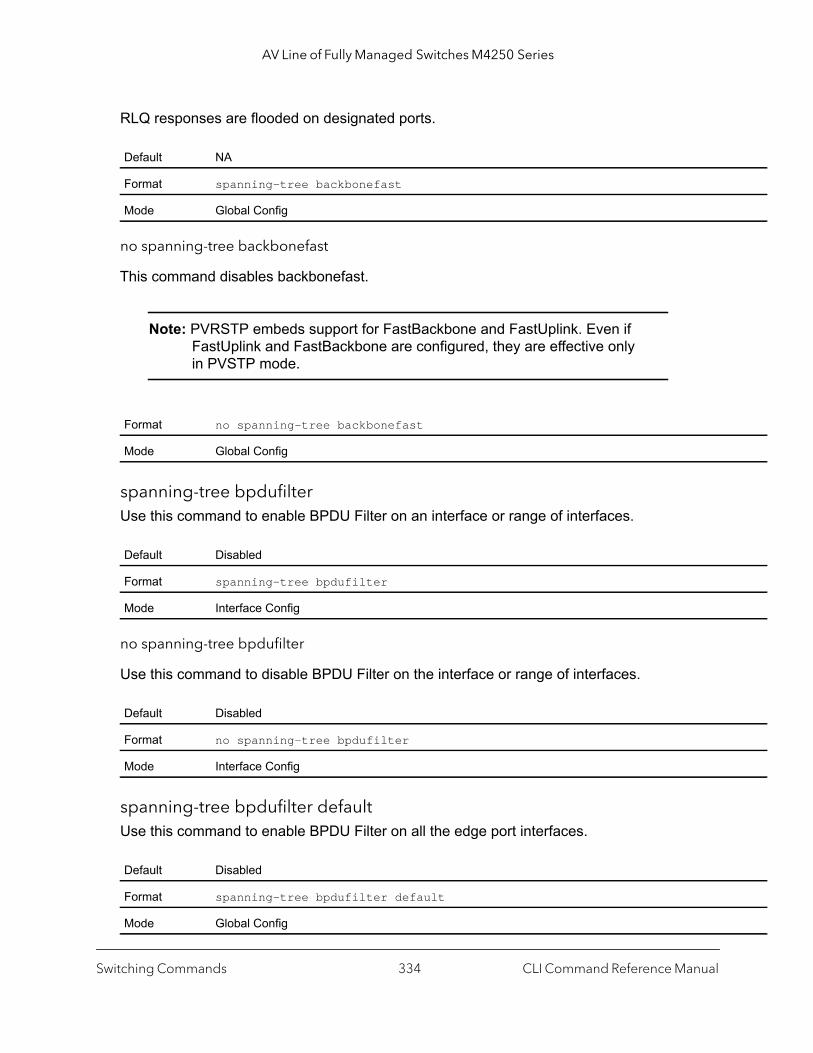
AV Line of Fully Managed Switches M4250 Series
RLQ responses are flooded on designated ports.
no spanning-tree backbonefast
This command disables backbonefast.
Note: PVRSTP embeds support for FastBackbone and FastUplink. Even if FastUplink and FastBackbone are configured, they are effective only in PVSTP mode.
spanning-tree bpdufilterUse this command to enable BPDU Filter on an interface or range of interfaces.
no spanning-tree bpdufilter
Use this command to disable BPDU Filter on the interface or range of interfaces.
spanning-tree bpdufilter defaultUse this command to enable BPDU Filter on all the edge port interfaces.
Default NA
Format spanning-tree backbonefast
Mode Global Config
Format no spanning-tree backbonefast
Mode Global Config
Default Disabled
Format spanning-tree bpdufilter
Mode Interface Config
Default Disabled
Format no spanning-tree bpdufilter
Mode Interface Config
Default Disabled
Format spanning-tree bpdufilter default
Mode Global Config
Switching Commands CLI Command Reference Manual334

AV Line of Fully Managed Switches M4250 Series
no spanning-tree bpdufilter default
Use this command to disable BPDU Filter on all the edge port interfaces.
spanning-tree bpdufloodUse this command to enable BPDU Flood on an interface or range of interfaces.
no spanning-tree bpduflood
Use this command to disable BPDU Flood on the interface or range of interfaces.
spanning-tree bpduguardUse this command to enable BPDU Guard on the switch.
no spanning-tree bpduguard
Use this command to disable BPDU Guard on the switch.
Default Disabled
Format no spanning-tree bpdufilter default
Mode Global Config
Default Disabled
Format spanning-tree bpduflood
Mode Interface Config
Default Disabled
Format no spanning-tree bpduflood
Mode Interface Config
Default Disabled
Format spanning-tree bpduguard
Mode Global Config
Default Disabled
Format no spanning-tree bpduguard
Mode Global Config
Switching Commands CLI Command Reference Manual335
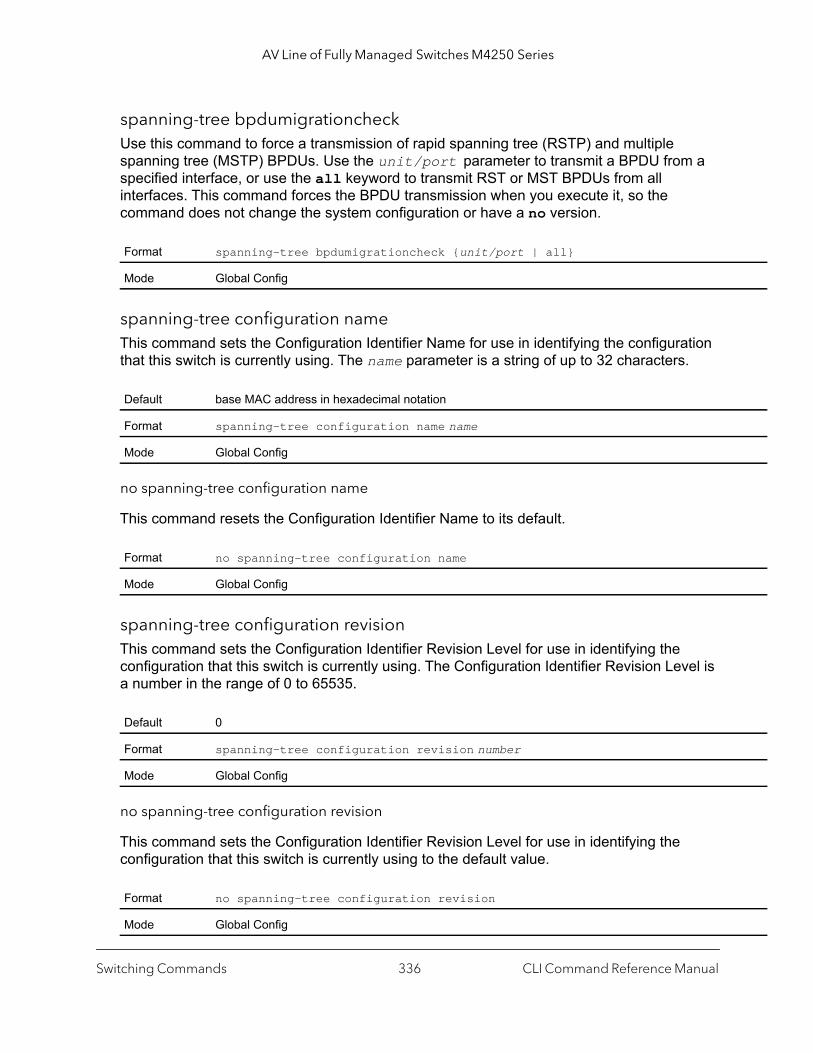
AV Line of Fully Managed Switches M4250 Series
spanning-tree bpdumigrationcheckUse this command to force a transmission of rapid spanning tree (RSTP) and multiple spanning tree (MSTP) BPDUs. Use the unit/port parameter to transmit a BPDU from a specified interface, or use the all keyword to transmit RST or MST BPDUs from all interfaces. This command forces the BPDU transmission when you execute it, so the command does not change the system configuration or have a no version.
spanning-tree configuration nameThis command sets the Configuration Identifier Name for use in identifying the configuration that this switch is currently using. The name parameter is a string of up to 32 characters.
no spanning-tree configuration name
This command resets the Configuration Identifier Name to its default.
spanning-tree configuration revisionThis command sets the Configuration Identifier Revision Level for use in identifying the configuration that this switch is currently using. The Configuration Identifier Revision Level is a number in the range of 0 to 65535.
no spanning-tree configuration revision
This command sets the Configuration Identifier Revision Level for use in identifying the configuration that this switch is currently using to the default value.
Format spanning-tree bpdumigrationcheck {unit/port | all}
Mode Global Config
Default base MAC address in hexadecimal notation
Format spanning-tree configuration name name
Mode Global Config
Format no spanning-tree configuration name
Mode Global Config
Default 0
Format spanning-tree configuration revision number
Mode Global Config
Format no spanning-tree configuration revision
Mode Global Config
Switching Commands CLI Command Reference Manual336

AV Line of Fully Managed Switches M4250 Series
spanning-tree costUse this command to configure the external path cost for port used by a MST instance. When the auto keyword is used, the path cost from the port to the root bridge is automatically determined by the speed of the interface. To configure the cost manually, specify a cost value from 1–200000000.
no spanning-tree cost
This command resets the auto-edge status of the port to the default value.
spanning-tree edgeportThis command specifies that an interface (or range of interfaces) is an Edge Port within the common and internal spanning tree. This allows this port to transition to Forwarding State without delay.
no spanning-tree edgeport
This command specifies that this port is not an Edge Port within the common and internal spanning tree.
spanning-tree forward-timeThis command sets the Bridge Forward Delay parameter to a new value for the common and internal spanning tree. The forward-time value is in seconds within a range of 4 to 30, with the value being greater than or equal to “(Bridge Max Age / 2) + 1”.
Default auto
Format spanning-tree cost {cost | auto}
Mode Interface Config
Format no spanning-tree cost
Mode Interface Config
Format spanning-tree edgeport
Mode Interface Config
Format no spanning-tree edgeport
Mode Interface Config
Default 15
Format spanning-tree forward-time value
Mode Global Config
Switching Commands CLI Command Reference Manual337
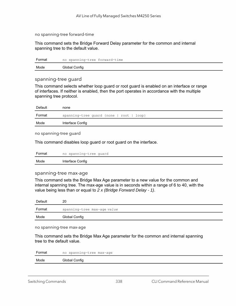
AV Line of Fully Managed Switches M4250 Series
no spanning-tree forward-time
This command sets the Bridge Forward Delay parameter for the common and internal spanning tree to the default value.
spanning-tree guardThis command selects whether loop guard or root guard is enabled on an interface or range of interfaces. If neither is enabled, then the port operates in accordance with the multiple spanning tree protocol.
no spanning-tree guard
This command disables loop guard or root guard on the interface.
spanning-tree max-ageThis command sets the Bridge Max Age parameter to a new value for the common and internal spanning tree. The max-age value is in seconds within a range of 6 to 40, with the value being less than or equal to 2 x (Bridge Forward Delay - 1).
no spanning-tree max-age
This command sets the Bridge Max Age parameter for the common and internal spanning tree to the default value.
Format no spanning-tree forward-time
Mode Global Config
Default none
Format spanning-tree guard {none | root | loop}
Mode Interface Config
Format no spanning-tree guard
Mode Interface Config
Default 20
Format spanning-tree max-age value
Mode Global Config
Format no spanning-tree max-age
Mode Global Config
Switching Commands CLI Command Reference Manual338
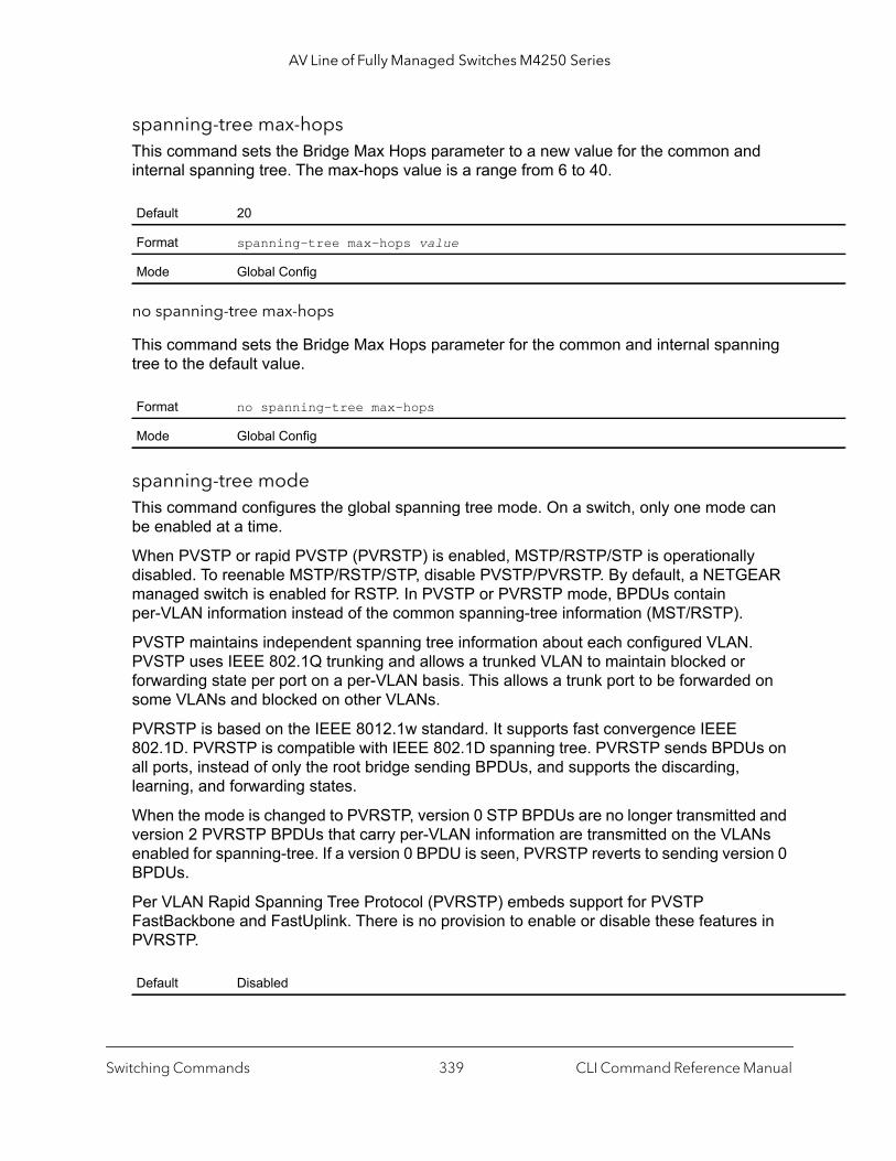
AV Line of Fully Managed Switches M4250 Series
spanning-tree max-hopsThis command sets the Bridge Max Hops parameter to a new value for the common and internal spanning tree. The max-hops value is a range from 6 to 40.
no spanning-tree max-hops
This command sets the Bridge Max Hops parameter for the common and internal spanning tree to the default value.
spanning-tree modeThis command configures the global spanning tree mode. On a switch, only one mode can be enabled at a time.
When PVSTP or rapid PVSTP (PVRSTP) is enabled, MSTP/RSTP/STP is operationally disabled. To reenable MSTP/RSTP/STP, disable PVSTP/PVRSTP. By default, a NETGEAR managed switch is enabled for RSTP. In PVSTP or PVRSTP mode, BPDUs contain per-VLAN information instead of the common spanning-tree information (MST/RSTP).
PVSTP maintains independent spanning tree information about each configured VLAN. PVSTP uses IEEE 802.1Q trunking and allows a trunked VLAN to maintain blocked or forwarding state per port on a per-VLAN basis. This allows a trunk port to be forwarded on some VLANs and blocked on other VLANs.
PVRSTP is based on the IEEE 8012.1w standard. It supports fast convergence IEEE 802.1D. PVRSTP is compatible with IEEE 802.1D spanning tree. PVRSTP sends BPDUs on all ports, instead of only the root bridge sending BPDUs, and supports the discarding, learning, and forwarding states.
When the mode is changed to PVRSTP, version 0 STP BPDUs are no longer transmitted and version 2 PVRSTP BPDUs that carry per-VLAN information are transmitted on the VLANs enabled for spanning-tree. If a version 0 BPDU is seen, PVRSTP reverts to sending version 0 BPDUs.
Per VLAN Rapid Spanning Tree Protocol (PVRSTP) embeds support for PVSTP FastBackbone and FastUplink. There is no provision to enable or disable these features in PVRSTP.
Default 20
Format spanning-tree max-hops value
Mode Global Config
Format no spanning-tree max-hops
Mode Global Config
Default Disabled
Switching Commands CLI Command Reference Manual339
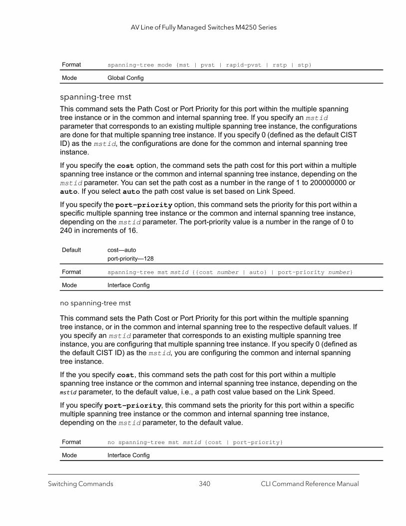
AV Line of Fully Managed Switches M4250 Series
spanning-tree mstThis command sets the Path Cost or Port Priority for this port within the multiple spanning tree instance or in the common and internal spanning tree. If you specify an mstid parameter that corresponds to an existing multiple spanning tree instance, the configurations are done for that multiple spanning tree instance. If you specify 0 (defined as the default CIST ID) as the mstid, the configurations are done for the common and internal spanning tree instance.
If you specify the cost option, the command sets the path cost for this port within a multiple spanning tree instance or the common and internal spanning tree instance, depending on the mstid parameter. You can set the path cost as a number in the range of 1 to 200000000 or auto. If you select auto the path cost value is set based on Link Speed.
If you specify the port-priority option, this command sets the priority for this port within a specific multiple spanning tree instance or the common and internal spanning tree instance, depending on the mstid parameter. The port-priority value is a number in the range of 0 to 240 in increments of 16.
no spanning-tree mst
This command sets the Path Cost or Port Priority for this port within the multiple spanning tree instance, or in the common and internal spanning tree to the respective default values. If you specify an mstid parameter that corresponds to an existing multiple spanning tree instance, you are configuring that multiple spanning tree instance. If you specify 0 (defined as the default CIST ID) as the mstid, you are configuring the common and internal spanning tree instance.
If the you specify cost, this command sets the path cost for this port within a multiple spanning tree instance or the common and internal spanning tree instance, depending on the mstid parameter, to the default value, i.e., a path cost value based on the Link Speed.
If you specify port-priority, this command sets the priority for this port within a specific multiple spanning tree instance or the common and internal spanning tree instance, depending on the mstid parameter, to the default value.
Format spanning-tree mode {mst | pvst | rapid-pvst | rstp | stp}
Mode Global Config
Default cost—autoport-priority—128
Format spanning-tree mst mstid {{cost number | auto} | port-priority number}
Mode Interface Config
Format no spanning-tree mst mstid {cost | port-priority}
Mode Interface Config
Switching Commands CLI Command Reference Manual340

AV Line of Fully Managed Switches M4250 Series
spanning-tree mst instanceThis command adds a multiple spanning tree instance to the switch. The parameter mstid is a number within a range of 1 to 4094, that corresponds to the new instance ID to be added. The maximum number of multiple instances supported by the switch is 4.
no spanning-tree mst instance
This command removes a multiple spanning tree instance from the switch and reallocates all VLANs allocated to the deleted instance to the common and internal spanning tree. The parameter mstid is a number that corresponds to the desired existing multiple spanning tree instance to be removed.
spanning-tree mst priorityThis command sets the bridge priority for a specific multiple spanning tree instance. The parameter mstid is a number that corresponds to the desired existing multiple spanning tree instance. The priority value is a number within a range of 0 to 4094.
If you specify 0 (defined as the default CIST ID) as the mstid, this command sets the Bridge Priority parameter to a new value for the common and internal spanning tree. The bridge priority value is a number within a range of 0 to 4094. The twelve least significant bits are masked according to the 802.1s specification. This causes the priority to be rounded down to the next lower valid priority.
no spanning-tree mst priority
This command sets the bridge priority for a specific multiple spanning tree instance to the default value. The parameter mstid is a number that corresponds to the desired existing multiple spanning tree instance.
Default none
Format spanning-tree mst instance mstid
Mode Global Config
Format no spanning-tree mst instance mstid
Mode Global Config
Default 32768
Format spanning-tree mst priority mstid value
Mode Global Config
Switching Commands CLI Command Reference Manual341

AV Line of Fully Managed Switches M4250 Series
If 0 (defined as the default CIST ID) is passed as the mstid, this command sets the Bridge Priority parameter for the common and internal spanning tree to the default value.
spanning-tree mst vlanThis command adds an association between a multiple spanning tree instance and one or more VLANs so that the VLAN(s) are no longer associated with the common and internal spanning tree. The parameter mstid is a multiple spanning tree instance identifier, in the range of 0 to 4094, that corresponds to the desired existing multiple spanning tree instance. The vlanid can be specified as a single VLAN, a list, or a range of values. To specify a list of VLANs, enter a list of VLAN IDs in the range 1 to 4093, each separated by a comma with no spaces in between. To specify a range of VLANs, separate the beginning and ending VLAN ID with a dash (-). Spaces and zeros are not permitted. The VLAN IDs may or may not exist in the system.
no spanning-tree mst vlan
This command removes an association between a multiple spanning tree instance and one or more VLANs so that the VLAN(s) are again associated with the common and internal spanning tree.
spanning-tree port modeThis command sets the Administrative Switch Port State for this port to enabled for use by spanning tree.
Format no spanning-tree mst priority mstid
Mode Global Config
Format spanning-tree mst vlan mstid vlanid
Mode Global Config
Format no spanning-tree mst vlan mstid vlanid
Mode Global Config
Default enabled
Format spanning-tree port mode
Mode Interface Config
Switching Commands CLI Command Reference Manual342

AV Line of Fully Managed Switches M4250 Series
no spanning-tree port mode
This command sets the Administrative Switch Port State for this port to disabled, disabling the port for use by spanning tree.
spanning-tree port mode allThis command sets the Administrative Switch Port State for all ports to enabled.
no spanning-tree port mode all
This command sets the Administrative Switch Port State for all ports to disabled.
spanning-tree port-priorityUse this command to change the priority value of the port to allow the operator to select the relative importance of the port in the forwarding process. The value range is 0–240. Set this value to a lower number to prefer a port for forwarding of frames.
All LAN ports have 128 as priority value by default. PVSTP/PVRSTP puts the LAN port with the lowest LAN port number in the forwarding state and blocks other LAN ports.
The application uses the port priority value when the LAN port is configured as an edge port.
spanning-tree tcnguardUse this command to enable TCN guard on the interface. When enabled, TCN Guard restricts the interface from propagating any topology change information received through that interface.
Format no spanning-tree port mode
Mode Interface Config
Default enabled
Format spanning-tree port mode all
Mode Global Config
Format no spanning-tree port mode all
Mode Global Config
Default enabled
Format spanning-tree port-priority value
Mode Interface Config
Switching Commands CLI Command Reference Manual343
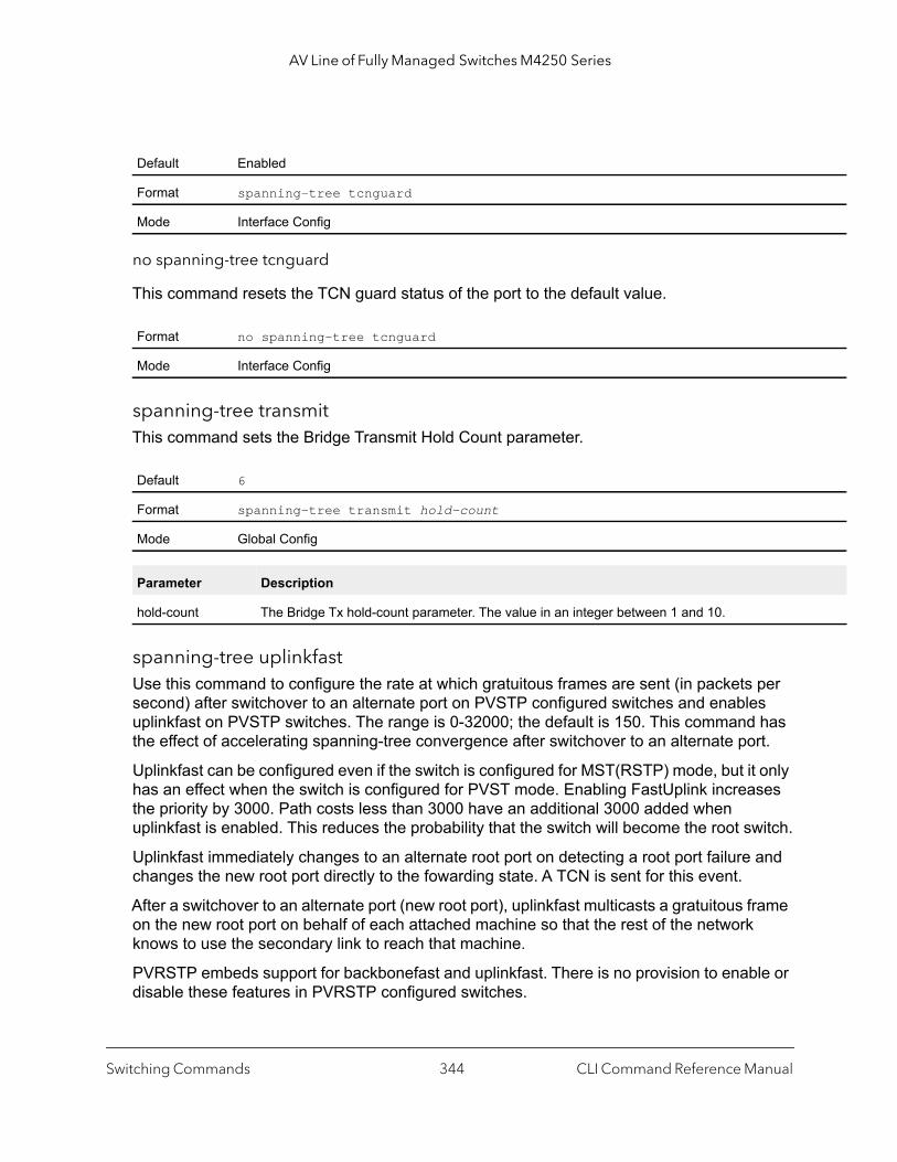
AV Line of Fully Managed Switches M4250 Series
no spanning-tree tcnguard
This command resets the TCN guard status of the port to the default value.
spanning-tree transmitThis command sets the Bridge Transmit Hold Count parameter.
spanning-tree uplinkfastUse this command to configure the rate at which gratuitous frames are sent (in packets per second) after switchover to an alternate port on PVSTP configured switches and enables uplinkfast on PVSTP switches. The range is 0-32000; the default is 150. This command has the effect of accelerating spanning-tree convergence after switchover to an alternate port.
Uplinkfast can be configured even if the switch is configured for MST(RSTP) mode, but it only has an effect when the switch is configured for PVST mode. Enabling FastUplink increases the priority by 3000. Path costs less than 3000 have an additional 3000 added when uplinkfast is enabled. This reduces the probability that the switch will become the root switch.
Uplinkfast immediately changes to an alternate root port on detecting a root port failure and changes the new root port directly to the fowarding state. A TCN is sent for this event.
After a switchover to an alternate port (new root port), uplinkfast multicasts a gratuitous frame on the new root port on behalf of each attached machine so that the rest of the network knows to use the secondary link to reach that machine.
PVRSTP embeds support for backbonefast and uplinkfast. There is no provision to enable or disable these features in PVRSTP configured switches.
Default Enabled
Format spanning-tree tcnguard
Mode Interface Config
Format no spanning-tree tcnguard
Mode Interface Config
Default 6
Format spanning-tree transmit hold-count
Mode Global Config
Parameter Description
hold-count The Bridge Tx hold-count parameter. The value in an integer between 1 and 10.
Switching Commands CLI Command Reference Manual344
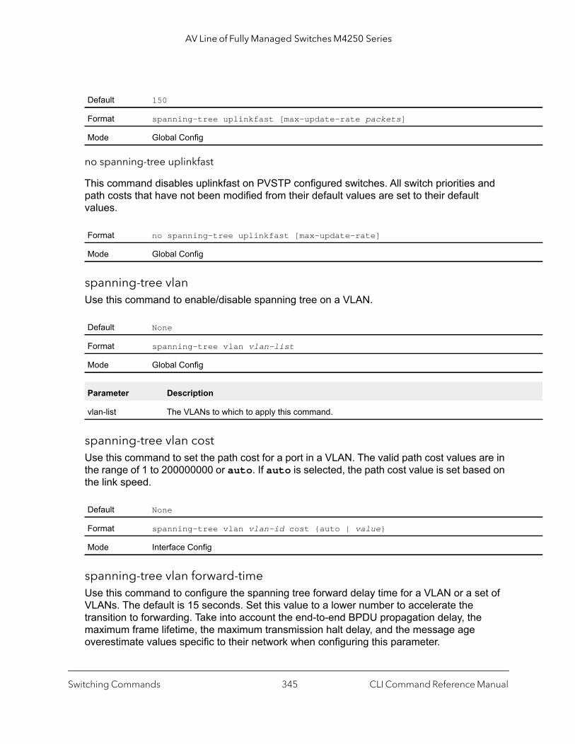
AV Line of Fully Managed Switches M4250 Series
no spanning-tree uplinkfast
This command disables uplinkfast on PVSTP configured switches. All switch priorities and path costs that have not been modified from their default values are set to their default values.
spanning-tree vlanUse this command to enable/disable spanning tree on a VLAN.
spanning-tree vlan costUse this command to set the path cost for a port in a VLAN. The valid path cost values are in the range of 1 to 200000000 or auto. If auto is selected, the path cost value is set based on the link speed.
spanning-tree vlan forward-timeUse this command to configure the spanning tree forward delay time for a VLAN or a set of VLANs. The default is 15 seconds. Set this value to a lower number to accelerate the transition to forwarding. Take into account the end-to-end BPDU propagation delay, the maximum frame lifetime, the maximum transmission halt delay, and the message age overestimate values specific to their network when configuring this parameter.
Default 150
Format spanning-tree uplinkfast [max-update-rate packets]
Mode Global Config
Format no spanning-tree uplinkfast [max-update-rate]
Mode Global Config
Default None
Format spanning-tree vlan vlan-list
Mode Global Config
Parameter Description
vlan-list The VLANs to which to apply this command.
Default None
Format spanning-tree vlan vlan-id cost {auto | value}
Mode Interface Config
Switching Commands CLI Command Reference Manual345

AV Line of Fully Managed Switches M4250 Series
spanning-tree vlan hello-timeUse this command to configure the spanning tree hello time for a specified VLAN or a range of VLANs. The default is 2 seconds. Set this value to a lower number to accelerate the discovery of topology changes.
spanning-tree vlan max-ageUse this command to configure the spanning tree maximum age time for a set of VLANs. The default is 20 seconds.
Set this value to a lower number to accelerate the discovery of topology changes. The network operator must take into account the end-to-end BPDU propagation delay and message age overestimate for their specific topology when configuring this value.
The default setting of 20 seconds is suitable for a network of diameter 7, lost message value of 3, transit delay of 1, hello interval of 2 seconds, overestimate per bridge of 1 second, and a BPDU delay of 1 second. For a network of diameter 4, a setting of 16 seconds is appropriate if all other timers remain at their default values.
Default 15 seconds
Format spanning-tree vlan vlan-list forward-time seconds
Mode Global Config
Parameter Description
vlan-list The VLANs to which to apply this command.
forward-time The spanning tree forward delay time. The range is 4-30 seconds.
Default 2 seconds
Format spanning-tree vlan vlan-list hello-time seconds
Mode Global Config
Parameter Description
vlan-list The VLANs to which to apply this command.
hello-time The spanning tree forward hello time. The range is 1-10 seconds.
Default 20 seconds
Format spanning-tree vlan vlan-list max-age seconds
Mode Global Config
Switching Commands CLI Command Reference Manual346
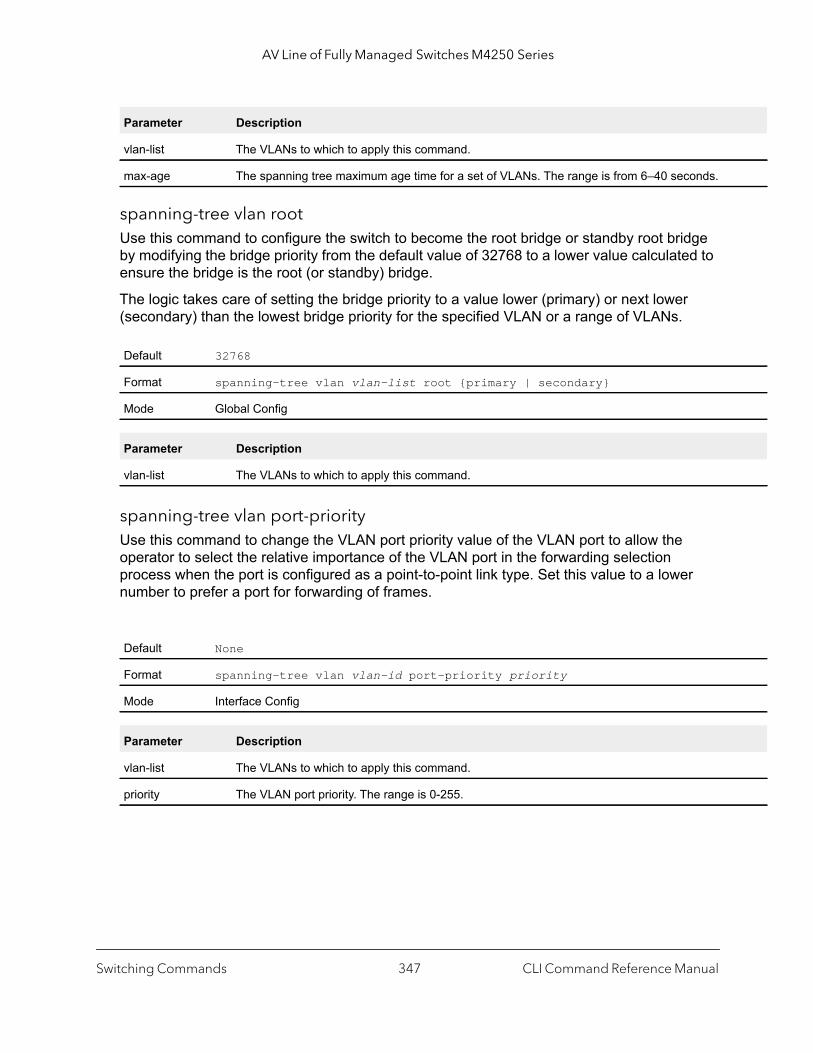
AV Line of Fully Managed Switches M4250 Series
spanning-tree vlan rootUse this command to configure the switch to become the root bridge or standby root bridge by modifying the bridge priority from the default value of 32768 to a lower value calculated to ensure the bridge is the root (or standby) bridge.
The logic takes care of setting the bridge priority to a value lower (primary) or next lower (secondary) than the lowest bridge priority for the specified VLAN or a range of VLANs.
spanning-tree vlan port-priorityUse this command to change the VLAN port priority value of the VLAN port to allow the operator to select the relative importance of the VLAN port in the forwarding selection process when the port is configured as a point-to-point link type. Set this value to a lower number to prefer a port for forwarding of frames.
Parameter Description
vlan-list The VLANs to which to apply this command.
max-age The spanning tree maximum age time for a set of VLANs. The range is from 6–40 seconds.
Default 32768
Format spanning-tree vlan vlan-list root {primary | secondary}
Mode Global Config
Parameter Description
vlan-list The VLANs to which to apply this command.
Default None
Format spanning-tree vlan vlan-id port-priority priority
Mode Interface Config
Parameter Description
vlan-list The VLANs to which to apply this command.
priority The VLAN port priority. The range is 0-255.
Switching Commands CLI Command Reference Manual347
AV Line of Fully Managed Switches M4250 Series
,
ss of
is in
spanning-tree vlan priorityUse this command to configure the bridge priority of a VLAN. The default value is 32768.
If the value configured is not among the specified values, it will be rounded off to the nearest valid value.
show spanning-treeThis command displays spanning tree settings for the common and internal spanning tree. The following details are displayed.
Default 32768
Format spanning-tree vlan vlan-list priority priority
Mode Global Config
Parameter Description
vlan-list The VLANs to which to apply this command.
priority The VLAN bridge priority. Valid values are 0, 4096, 8192, 12288, 16384, 20480, 24576, 2867232768, 36864, 40960, 45056, 49152, 53248, 57344, and 61440.
Format show spanning-tree
Mode Privileged EXECUser EXEC
Term Definition
Bridge Priority Specifies the bridge priority for the Common and Internal Spanning tree (CST). The value lies between 0 and 61440. It is displayed in multiples of 4096.
Bridge Identifier The bridge identifier for the CST. It is made up using the bridge priority and the base MAC addrethe bridge.
Time Since Topology Change
Time in seconds.
Topology Change Count
Number of times changed.
Topology Change in Progress
Boolean value of the Topology Change parameter for the switch indicating if a topology changeprogress on any port assigned to the common and internal spanning tree.
Designated Root The bridge identifier of the root bridge. It is made up from the bridge priority and the base MACaddress of the bridge.
Root Path Cost Value of the Root Path Cost parameter for the common and internal spanning tree.
Root Port Identifier Identifier of the port to access the Designated Root for the CST
Bridge Max Age Derived value.
Switching Commands CLI Command Reference Manual348

AV Line of Fully Managed Switches M4250 Series
MAC
Command example: (NETGEAR switch) #show spanning-tree
Bridge Priority................................ 32768Bridge Identifier.............................. 80:00:00:10:18:48:FC:07Time Since Topology Change..................... 8 day 3 hr 22 min 37 secTopology Change Count.......................... 0Topology Change in progress.................... FALSEDesignated Root................................ 80:00:00:10:18:48:FC:07Root Path Cost................................. 0Root Port Identifier........................... 00:00Bridge Max Age................................. 20Bridge Max Hops................................ 20Bridge Tx Hold Count........................... 6Bridge Forwarding Delay........................ 15Hello Time..................................... 2Bridge Hold Time............................... 6CST Regional Root.............................. 80:00:00:10:18:48:FC:07Regional Root Path Cost........................ 0
Associated FIDs Associated VLANs --------------- ----------------
Bridge Max Hops Bridge max-hops count for the device.
Root Port Bridge Forward Delay
Derived value.
Hello Time Configured value of the parameter for the CST.
Bridge Hold Time Minimum time between transmission of Configuration Bridge Protocol Data Units (BPDUs).
CST Regional Root Bridge Identifier of the CST Regional Root. It is made up using the bridge priority and the baseaddress of the bridge.
Regional Root Path Cost
Path Cost to the CST Regional Root.
Associated FIDs List of forwarding database identifiers currently associated with this instance.
Associated VLANs List of VLAN IDs currently associated with this instance.
Term Definition
Switching Commands CLI Command Reference Manual349

AV Line of Fully Managed Switches M4250 Series
show spanning-tree activeThis command displays the spanning tree values on active ports for the modes xSTP and PV(R)STP.
Command example: (NETGEAR switch) #show spanning-tree active
Spanning Tree: Enabled (BPDU Flooding: Disabled) Portfast BPDU Filtering: DisabledMode: rstpCST Regional Root: 80:00:00:01:85:48:F0:0FRegional Root Path Cost: 0
###### MST 0 Vlan Mapped: 3ROOT ID Priority 32768 Address 00:00:EE:EE:EE:EE This Switch is the Root. Hello Time: 2s Max Age: 20s Forward Delay: 15sInterfaces
Name State Prio.Nbr Cost Sts Role RestrictedPort--------- -------- --------- --------- ------------- ----- --------------0/49 Enabled 128.49 2000 Forwarding Desg No3/1 Enabled 96.66 5000 Forwarding Desg No3/2 Enabled 96.67 5000 Forwarding Desg No3/10 Enabled 96.75 0 Forwarding Desg No
Command example: (NETGEAR switch) #show spanning-tree active
Spanning-tree enabled protocol rpvst
VLAN 1 RootID Priority 32769 Address 00:00:EE:EE:EE:EE Cost 0 Port This switch is the root Hello Time 2 Sec Max Age 20 sec Forward Delay 15 sec BridgeID Priority 32769 (priority 32768 sys-id-ext 1) Address 00:00:EE:EE:EE:EE
Format show spanning-tree active
Mode Privileged EXECUser EXEC
Switching Commands CLI Command Reference Manual350

AV Line of Fully Managed Switches M4250 Series
Hello Time 2 Sec Max Age 20 sec Forward Delay 15 sec Aging Time 300 sec
Interface State Prio.Nbr Cost Status Role--------- --------- --------- ------- ------------- -----------0/49 Enabled 128.49 2000 Forwarding Designated3/1 Enabled 128.66 5000 Forwarding Designated3/2 Enabled 128.67 5000 Forwarding Designated3/10 Enabled 128.75 0 Forwarding Designated
VLAN 3 RootID Priority 32771 Address 00:00:EE:EE:EE:EE Cost 0 Port This switch is the root Hello Time 2 Sec Max Age 20 sec Forward Delay 15 sec BridgeID Priority 32771 (priority 32768 sys-id-ext 3) Address 00:00:EE:EE:EE:EE Hello Time 2 Sec Max Age 20 sec Forward Delay 15 sec Aging Time 300 sec
Interface State Prio.Nbr Cost Status Role--------- --------- --------- ------- ------------- -----------3/1 Enabled 128.66 5000 Forwarding Designated3/2 Enabled 128.67 5000 Forwarding Designated3/10 Enabled 128.75 0 Forwarding Designated
Command example: (NETGEAR switch) #show spanning-tree active
Spanning-tree enabled protocol rpvst
VLAN 1 RootID Priority 32769 Address 00:00:EE:EE:EE:EE Cost 0 Port 10(3/10 ) Hello Time 2 Sec Max Age 20 sec Forward Delay 15 sec BridgeID Priority 32769 (priority 32768 sys-id-ext 1) Address 00:00:EE:EE:EE:EE Hello Time 2 Sec Max Age 20 sec Forward Delay 15 sec Aging Time 300 sec
Switching Commands CLI Command Reference Manual351
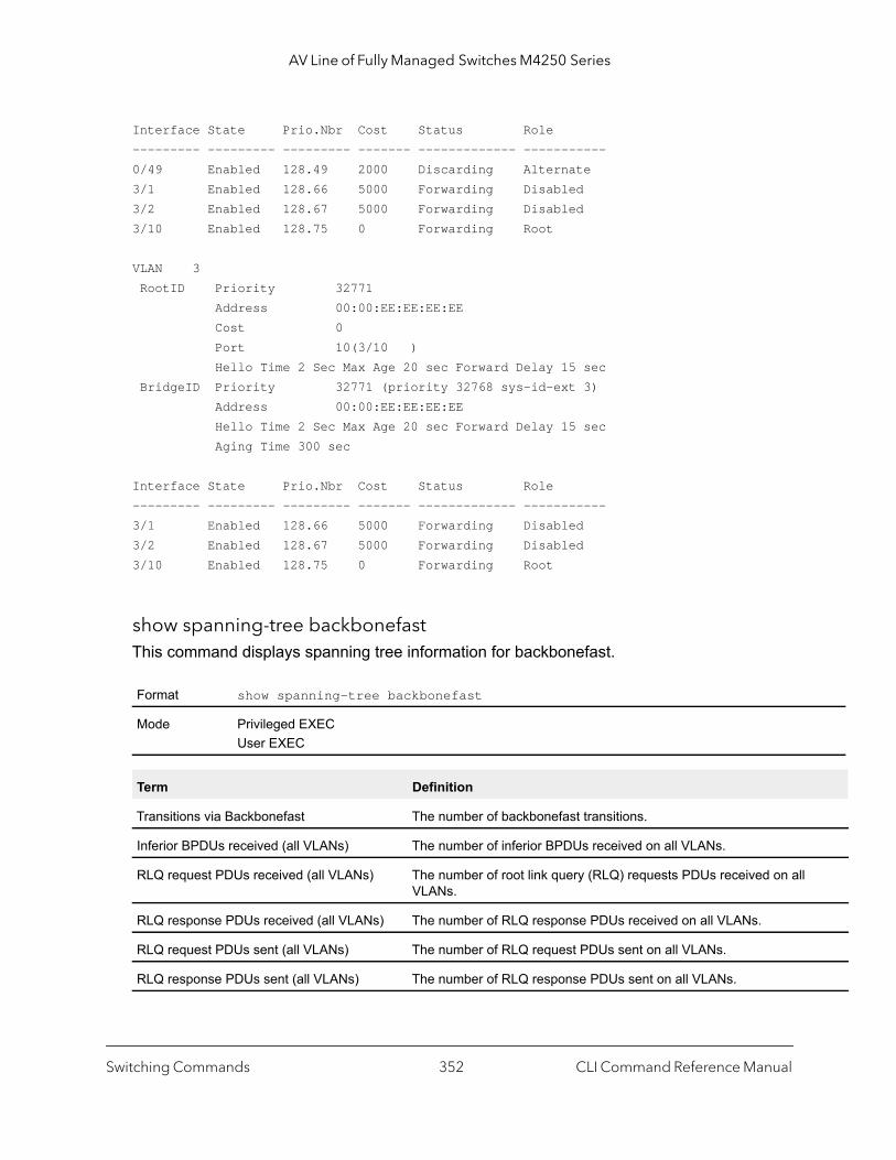
AV Line of Fully Managed Switches M4250 Series
Interface State Prio.Nbr Cost Status Role--------- --------- --------- ------- ------------- -----------0/49 Enabled 128.49 2000 Discarding Alternate3/1 Enabled 128.66 5000 Forwarding Disabled3/2 Enabled 128.67 5000 Forwarding Disabled3/10 Enabled 128.75 0 Forwarding Root
VLAN 3 RootID Priority 32771 Address 00:00:EE:EE:EE:EE Cost 0 Port 10(3/10 ) Hello Time 2 Sec Max Age 20 sec Forward Delay 15 sec BridgeID Priority 32771 (priority 32768 sys-id-ext 3) Address 00:00:EE:EE:EE:EE Hello Time 2 Sec Max Age 20 sec Forward Delay 15 sec Aging Time 300 sec
Interface State Prio.Nbr Cost Status Role--------- --------- --------- ------- ------------- -----------3/1 Enabled 128.66 5000 Forwarding Disabled3/2 Enabled 128.67 5000 Forwarding Disabled3/10 Enabled 128.75 0 Forwarding Root
show spanning-tree backbonefastThis command displays spanning tree information for backbonefast.
Format show spanning-tree backbonefast
Mode Privileged EXECUser EXEC
Term Definition
Transitions via Backbonefast The number of backbonefast transitions.
Inferior BPDUs received (all VLANs) The number of inferior BPDUs received on all VLANs.
RLQ request PDUs received (all VLANs) The number of root link query (RLQ) requests PDUs received on allVLANs.
RLQ response PDUs received (all VLANs) The number of RLQ response PDUs received on all VLANs.
RLQ request PDUs sent (all VLANs) The number of RLQ request PDUs sent on all VLANs.
RLQ response PDUs sent (all VLANs) The number of RLQ response PDUs sent on all VLANs.
Switching Commands CLI Command Reference Manual352

AV Line of Fully Managed Switches M4250 Series
the
Command example: (NETGEAR Switch)#show spanning-tree backbonefast
Backbonefast Statistics-----------------------Transitions via Backbonefast (all VLANs) : 0Inferior BPDUs received (all VLANs) : 0RLQ request PDUs received (all VLANs) : 0RLQ response PDUs received (all VLANs) : 0RLQ request PDUs sent (all VLANs) : 0RLQ response PDUs sent (all VLANs) : 0
show spanning-tree briefThis command displays spanning tree settings for the bridge. The following information appears.
Command example: (NETGEAR Switch) #show spanning-tree brief
Bridge Priority................................ 32768Bridge Identifier.............................. 80:00:00:10:18:48:FC:07Bridge Max Age................................. 20Bridge Max Hops................................ 20Bridge Hello Time.............................. 2Bridge Forward Delay........................... 15Bridge Hold Time............................... 6
Format show spanning-tree brief
Mode Privileged EXECUser EXEC
Term Definition
Bridge Priority Configured value.
Bridge Identifier The bridge identifier for the selected MST instance. It is made up using the bridge priority andbase MAC address of the bridge.
Bridge Max Age Configured value.
Bridge Max Hops Bridge max-hops count for the device.
Bridge Hello Time Configured value.
Bridge Forward Delay
Configured value.
Bridge Hold Time Minimum time between transmission of Configuration Bridge Protocol Data Units (BPDUs).
Switching Commands CLI Command Reference Manual353
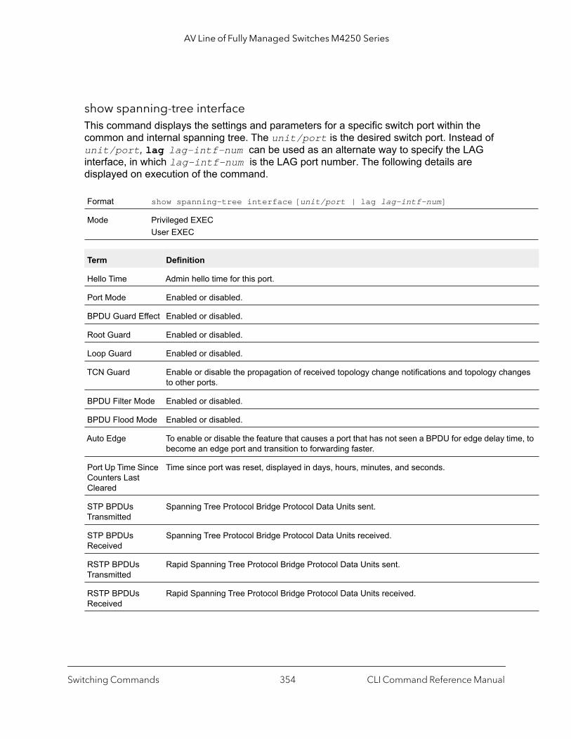
AV Line of Fully Managed Switches M4250 Series
ges
e, to
show spanning-tree interfaceThis command displays the settings and parameters for a specific switch port within the common and internal spanning tree. The unit/port is the desired switch port. Instead of unit/port, lag lag-intf-num can be used as an alternate way to specify the LAG interface, in which lag-intf-num is the LAG port number. The following details are displayed on execution of the command.
Format show spanning-tree interface [unit/port | lag lag-intf-num]
Mode Privileged EXECUser EXEC
Term Definition
Hello Time Admin hello time for this port.
Port Mode Enabled or disabled.
BPDU Guard Effect Enabled or disabled.
Root Guard Enabled or disabled.
Loop Guard Enabled or disabled.
TCN Guard Enable or disable the propagation of received topology change notifications and topology chanto other ports.
BPDU Filter Mode Enabled or disabled.
BPDU Flood Mode Enabled or disabled.
Auto Edge To enable or disable the feature that causes a port that has not seen a BPDU for edge delay timbecome an edge port and transition to forwarding faster.
Port Up Time Since Counters Last Cleared
Time since port was reset, displayed in days, hours, minutes, and seconds.
STP BPDUs Transmitted
Spanning Tree Protocol Bridge Protocol Data Units sent.
STP BPDUs Received
Spanning Tree Protocol Bridge Protocol Data Units received.
RSTP BPDUs Transmitted
Rapid Spanning Tree Protocol Bridge Protocol Data Units sent.
RSTP BPDUs Received
Rapid Spanning Tree Protocol Bridge Protocol Data Units received.
Switching Commands CLI Command Reference Manual354
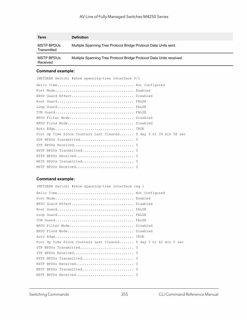
AV Line of Fully Managed Switches M4250 Series
Command example: (NETGEAR Switch) #show spanning-tree interface 0/1
Hello Time..................................... Not ConfiguredPort Mode...................................... EnabledBPDU Guard Effect.............................. DisabledRoot Guard..................................... FALSELoop Guard..................................... FALSETCN Guard...................................... FALSEBPDU Filter Mode............................... DisabledBPDU Flood Mode................................ DisabledAuto Edge...................................... TRUEPort Up Time Since Counters Last Cleared....... 8 day 3 hr 39 min 58 secSTP BPDUs Transmitted.......................... 0STP BPDUs Received............................. 0RSTP BPDUs Transmitted......................... 0RSTP BPDUs Received............................ 0MSTP BPDUs Transmitted......................... 0MSTP BPDUs Received............................ 0
Command example: (NETGEAR Switch) #show spanning-tree interface lag 1
Hello Time..................................... Not ConfiguredPort Mode...................................... EnabledBPDU Guard Effect.............................. Disabled
Root Guard..................................... FALSELoop Guard..................................... FALSETCN Guard...................................... FALSEBPDU Filter Mode............................... DisabledBPDU Flood Mode................................ DisabledAuto Edge...................................... TRUEPort Up Time Since Counters Last Cleared....... 8 day 3 hr 42 min 5 secSTP BPDUs Transmitted.......................... 0STP BPDUs Received............................. 0RSTP BPDUs Transmitted......................... 0RSTP BPDUs Received............................ 0MSTP BPDUs Transmitted......................... 0MSTP BPDUs Received............................ 0
MSTP BPDUs Transmitted
Multiple Spanning Tree Protocol Bridge Protocol Data Units sent.
MSTP BPDUs Received
Multiple Spanning Tree Protocol Bridge Protocol Data Units received.
Term Definition
Switching Commands CLI Command Reference Manual355

AV Line of Fully Managed Switches M4250 Series
]
show spanning-tree mst detailedThis command displays the detailed settings for an MST instance.
Command example: (NETGEAR Switch) #show spanning-tree mst detailed 0
MST Instance ID................................ 0MST Bridge Priority............................ 32768MST Bridge Identifier.......................... 80:00:00:10:18:48:FC:07Time Since Topology Change..................... 8 day 3 hr 47 min 7 secTopology Change Count.......................... 0Topology Change in progress.................... FALSEDesignated Root................................ 80:00:00:10:18:48:FC:07Root Path Cost................................. 0Root Port Identifier........................... 00:00
Associated FIDs Associated VLANs --------------- ----------------
show spanning-tree mst port detailedThis command displays the detailed settings and parameters for a specific switch port within a particular multiple spanning tree instance. The parameter mstid is a number that corresponds to the desired existing multiple spanning tree instance. The unit/port is the desired switch port. Instead of unit/port, lag lag-intf-num can be used as an alternate way to specify the LAG interface, in which lag-intf-num is the LAG port number.
Format show spanning-tree mst detailed mstid
Mode Privileged EXECUser EXEC
Parameter Description
mstid A multiple spanning tree instance identifier. The value is 0–4094.
Format show spanning-tree mst port detailed mstid [unit/port | lag lag-intf-num
Mode Privileged EXECUser EXEC
Switching Commands CLI Command Reference Manual356
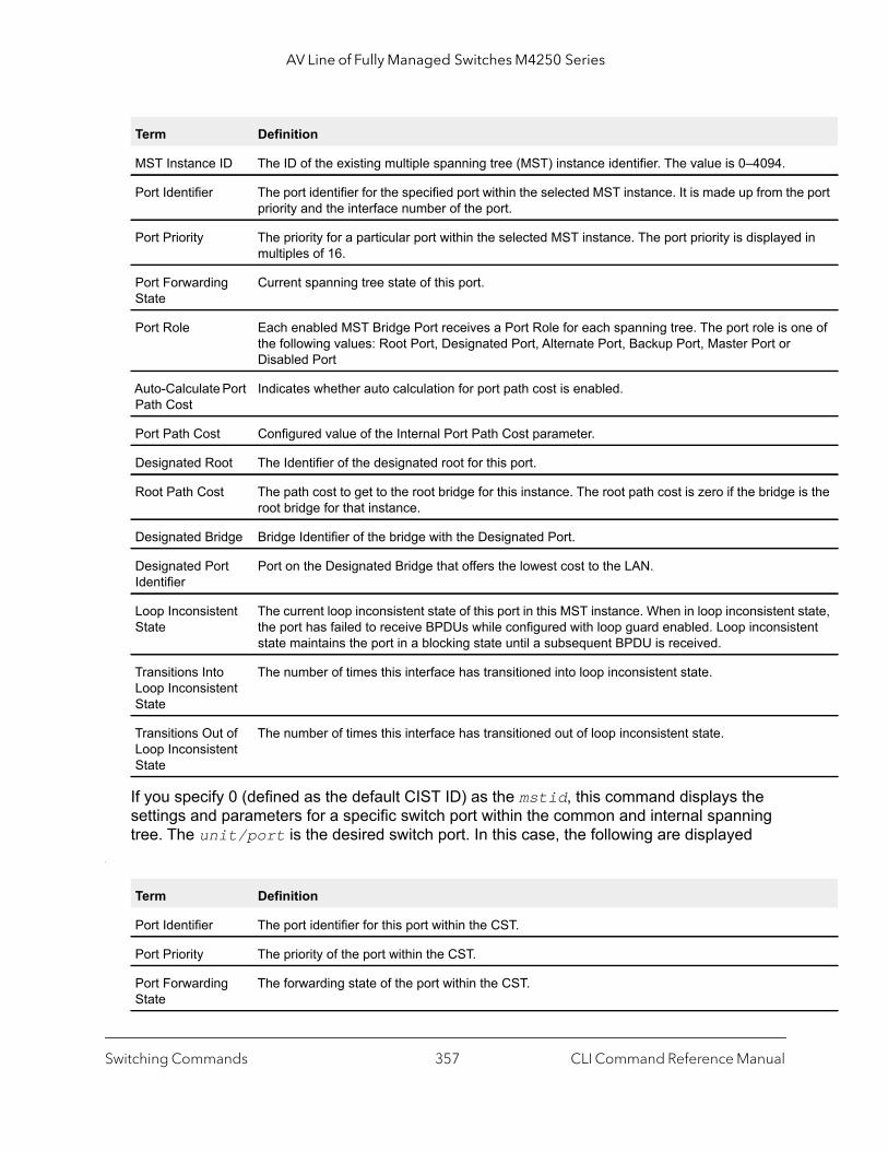
AV Line of Fully Managed Switches M4250 Series
e port
in
ne of
is the
state, tent
If you specify 0 (defined as the default CIST ID) as the mstid, this command displays the settings and parameters for a specific switch port within the common and internal spanning tree. The unit/port is the desired switch port. In this case, the following are displayed
.
Term Definition
MST Instance ID The ID of the existing multiple spanning tree (MST) instance identifier. The value is 0–4094.
Port Identifier The port identifier for the specified port within the selected MST instance. It is made up from thpriority and the interface number of the port.
Port Priority The priority for a particular port within the selected MST instance. The port priority is displayedmultiples of 16.
Port Forwarding State
Current spanning tree state of this port.
Port Role Each enabled MST Bridge Port receives a Port Role for each spanning tree. The port role is othe following values: Root Port, Designated Port, Alternate Port, Backup Port, Master Port or Disabled Port
Auto-Calculate Port Path Cost
Indicates whether auto calculation for port path cost is enabled.
Port Path Cost Configured value of the Internal Port Path Cost parameter.
Designated Root The Identifier of the designated root for this port.
Root Path Cost The path cost to get to the root bridge for this instance. The root path cost is zero if the bridge root bridge for that instance.
Designated Bridge Bridge Identifier of the bridge with the Designated Port.
Designated Port Identifier
Port on the Designated Bridge that offers the lowest cost to the LAN.
Loop Inconsistent State
The current loop inconsistent state of this port in this MST instance. When in loop inconsistent the port has failed to receive BPDUs while configured with loop guard enabled. Loop inconsisstate maintains the port in a blocking state until a subsequent BPDU is received.
Transitions Into Loop Inconsistent State
The number of times this interface has transitioned into loop inconsistent state.
Transitions Out of Loop Inconsistent State
The number of times this interface has transitioned out of loop inconsistent state.
Term Definition
Port Identifier The port identifier for this port within the CST.
Port Priority The priority of the port within the CST.
Port Forwarding State
The forwarding state of the port within the CST.
Switching Commands CLI Command Reference Manual357
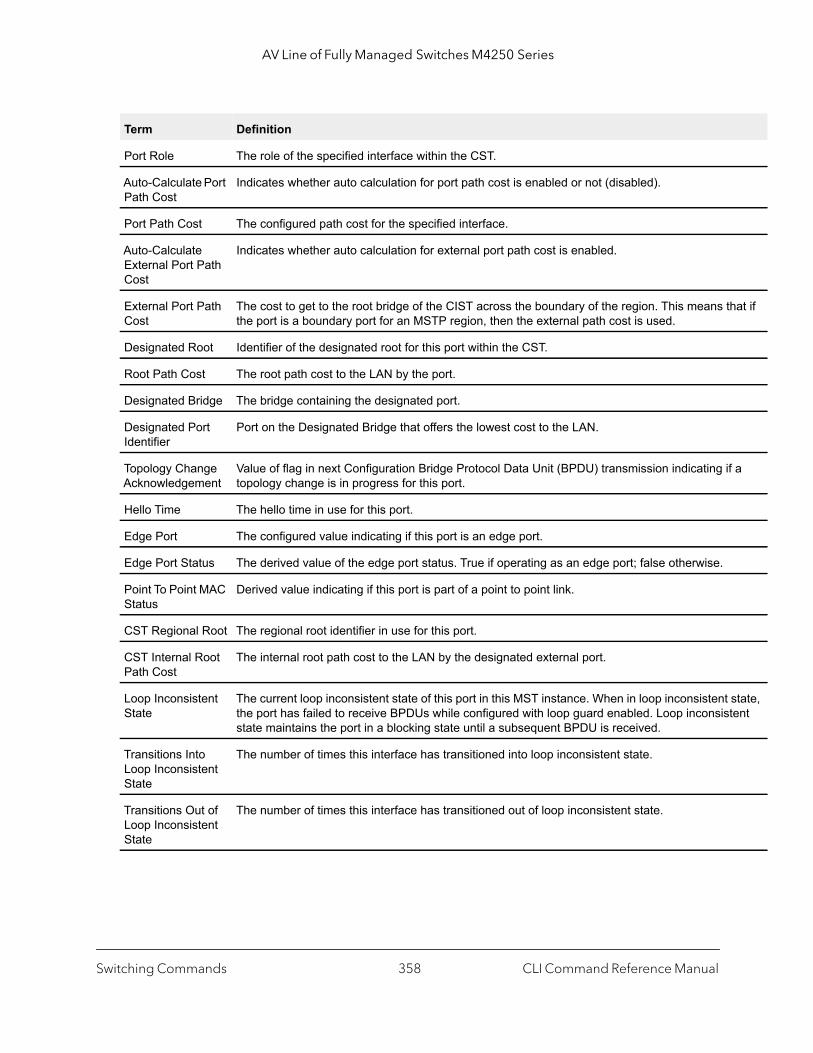
AV Line of Fully Managed Switches M4250 Series
at if
a
state, ent
Port Role The role of the specified interface within the CST.
Auto-Calculate Port Path Cost
Indicates whether auto calculation for port path cost is enabled or not (disabled).
Port Path Cost The configured path cost for the specified interface.
Auto-Calculate External Port Path Cost
Indicates whether auto calculation for external port path cost is enabled.
External Port Path Cost
The cost to get to the root bridge of the CIST across the boundary of the region. This means ththe port is a boundary port for an MSTP region, then the external path cost is used.
Designated Root Identifier of the designated root for this port within the CST.
Root Path Cost The root path cost to the LAN by the port.
Designated Bridge The bridge containing the designated port.
Designated Port Identifier
Port on the Designated Bridge that offers the lowest cost to the LAN.
Topology Change Acknowledgement
Value of flag in next Configuration Bridge Protocol Data Unit (BPDU) transmission indicating iftopology change is in progress for this port.
Hello Time The hello time in use for this port.
Edge Port The configured value indicating if this port is an edge port.
Edge Port Status The derived value of the edge port status. True if operating as an edge port; false otherwise.
Point To Point MAC Status
Derived value indicating if this port is part of a point to point link.
CST Regional Root The regional root identifier in use for this port.
CST Internal Root Path Cost
The internal root path cost to the LAN by the designated external port.
Loop Inconsistent State
The current loop inconsistent state of this port in this MST instance. When in loop inconsistent the port has failed to receive BPDUs while configured with loop guard enabled. Loop inconsiststate maintains the port in a blocking state until a subsequent BPDU is received.
Transitions Into Loop Inconsistent State
The number of times this interface has transitioned into loop inconsistent state.
Transitions Out of Loop Inconsistent State
The number of times this interface has transitioned out of loop inconsistent state.
Term Definition
Switching Commands CLI Command Reference Manual358

AV Line of Fully Managed Switches M4250 Series
Command example:
The following example shows output for the command in the unit/port format:(NETGEAR Switch) #show spanning-tree mst port detailed 0 0/1
Port Identifier................................ 80:01Port Priority.................................. 128Port Forwarding State.......................... DisabledPort Role...................................... DisabledAuto-calculate Port Path Cost.................. EnabledPort Path Cost................................. 0Auto-Calculate External Port Path Cost......... EnabledExternal Port Path Cost........................ 0Designated Root................................ 80:00:00:10:18:48:FC:07Root Path Cost................................. 0Designated Bridge.............................. 80:00:00:10:18:48:FC:07Designated Port Identifier..................... 00:00Topology Change Acknowledge.................... FALSEHello Time..................................... 2Edge Port...................................... FALSEEdge Port Status............................... FALSEPoint to Point MAC Status...................... TRUECST Regional Root.............................. 80:00:00:10:18:48:FC:07CST Internal Root Path Cost.................... 0Loop Inconsistent State........................ FALSETransitions Into Loop Inconsistent State....... 0Transitions Out Of Loop Inconsistent State..... 0
Command example:
The following example shows output using a LAG interface number:(NETGEAR Switch) #show spanning-tree mst port detailed 0 lag 1
Port Identifier................................ 60:42Port Priority.................................. 96Port Forwarding State.......................... DisabledPort Role...................................... DisabledAuto-calculate Port Path Cost.................. EnabledPort Path Cost................................. 0Auto-Calculate External Port Path Cost......... EnabledExternal Port Path Cost........................ 0Designated Root................................ 80:00:00:10:18:48:FC:07Root Path Cost................................. 0Designated Bridge.............................. 80:00:00:10:18:48:FC:07Designated Port Identifier..................... 00:00Topology Change Acknowledge.................... FALSEHello Time..................................... 2
Switching Commands CLI Command Reference Manual359
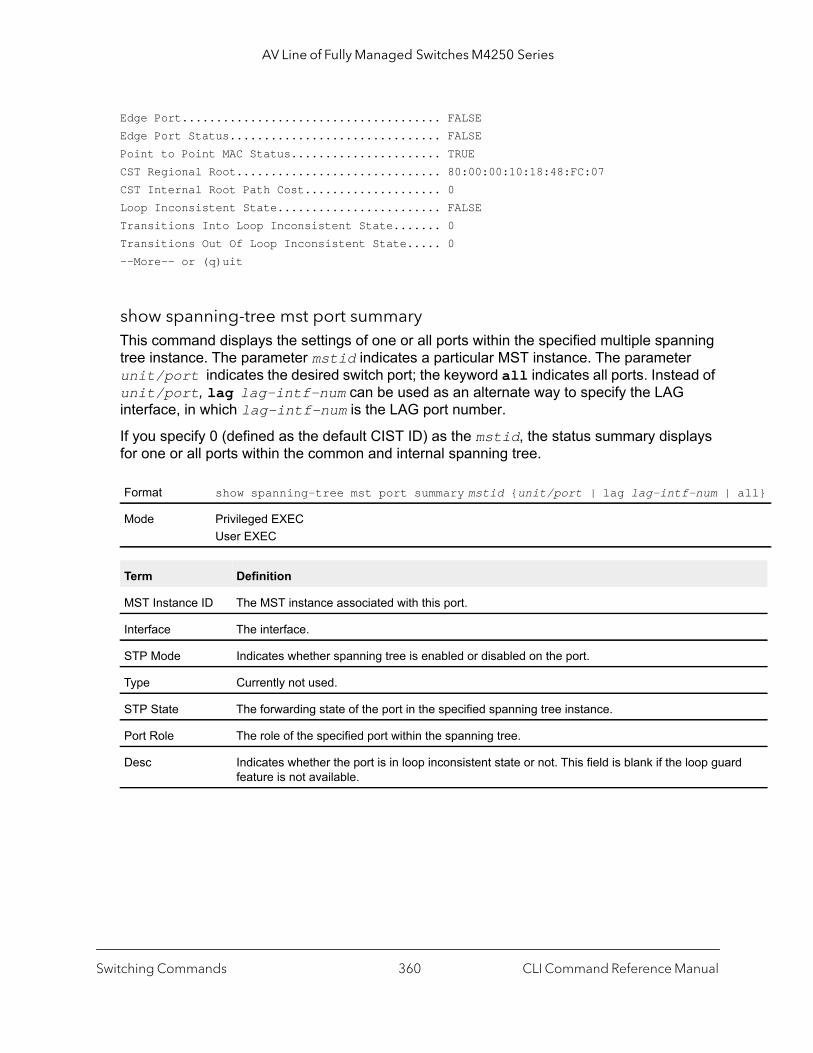
AV Line of Fully Managed Switches M4250 Series
all}
rd
Edge Port...................................... FALSEEdge Port Status............................... FALSEPoint to Point MAC Status...................... TRUECST Regional Root.............................. 80:00:00:10:18:48:FC:07CST Internal Root Path Cost.................... 0Loop Inconsistent State........................ FALSETransitions Into Loop Inconsistent State....... 0Transitions Out Of Loop Inconsistent State..... 0--More-- or (q)uit
show spanning-tree mst port summaryThis command displays the settings of one or all ports within the specified multiple spanning tree instance. The parameter mstid indicates a particular MST instance. The parameter unit/port indicates the desired switch port; the keyword all indicates all ports. Instead of unit/port, lag lag-intf-num can be used as an alternate way to specify the LAG interface, in which lag-intf-num is the LAG port number.
If you specify 0 (defined as the default CIST ID) as the mstid, the status summary displays for one or all ports within the common and internal spanning tree.
Format show spanning-tree mst port summary mstid {unit/port | lag lag-intf-num |
Mode Privileged EXECUser EXEC
Term Definition
MST Instance ID The MST instance associated with this port.
Interface The interface.
STP Mode Indicates whether spanning tree is enabled or disabled on the port.
Type Currently not used.
STP State The forwarding state of the port in the specified spanning tree instance.
Port Role The role of the specified port within the spanning tree.
Desc Indicates whether the port is in loop inconsistent state or not. This field is blank if the loop guafeature is not available.
Switching Commands CLI Command Reference Manual360
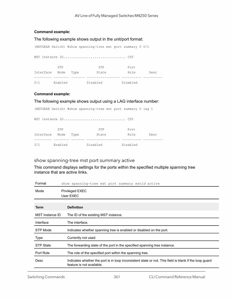
AV Line of Fully Managed Switches M4250 Series
rd
Command example:
The following example shows output in the unit/port format:(NETGEAR Switch) #show spanning-tree mst port summary 0 0/1
MST Instance ID................................ CST
STP STP PortInterface Mode Type State Role Desc--------- -------- ------- ----------------- ---------- ----------0/1 Enabled Disabled Disabled
Command example:
The following example shows output using a LAG interface number:(NETGEAR Switch) #show spanning-tree mst port summary 0 lag 1
MST Instance ID................................ CST
STP STP PortInterface Mode Type State Role Desc--------- -------- ------- ----------------- ---------- ----------3/1 Enabled Disabled Disabled
show spanning-tree mst port summary activeThis command displays settings for the ports within the specified multiple spanning tree instance that are active links.
Format show spanning-tree mst port summary mstid active
Mode Privileged EXECUser EXEC
Term Definition
MST Instance ID The ID of the existing MST instance.
Interface The interface.
STP Mode Indicates whether spanning tree is enabled or disabled on the port.
Type Currently not used.
STP State The forwarding state of the port in the specified spanning tree instance.
Port Role The role of the specified port within the spanning tree.
Desc Indicates whether the port is in loop inconsistent state or not. This field is blank if the loop guafeature is not available.
Switching Commands CLI Command Reference Manual361
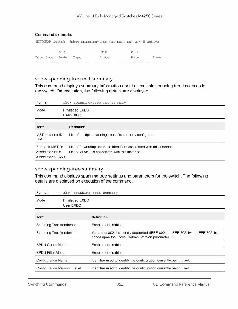
AV Line of Fully Managed Switches M4250 Series
d)
Command example: (NETGEAR Switch) #show spanning-tree mst port summary 0 active
STP STP PortInterface Mode Type State Role Desc--------- -------- ------- ----------------- ---------- ---------
show spanning-tree mst summaryThis command displays summary information about all multiple spanning tree instances in the switch. On execution, the following details are displayed.
show spanning-tree summaryThis command displays spanning tree settings and parameters for the switch. The following details are displayed on execution of the command.
Format show spanning-tree mst summary
Mode Privileged EXECUser EXEC
Term Definition
MST Instance ID List
List of multiple spanning trees IDs currently configured.
For each MSTID:Associated FIDsAssociated VLANs
List of forwarding database identifiers associated with this instance.List of VLAN IDs associated with this instance.
Format show spanning-tree summary
Mode Privileged EXECUser EXEC
Term Definition
Spanning Tree Adminmode Enabled or disabled.
Spanning Tree Version Version of 802.1 currently supported (IEEE 802.1s, IEEE 802.1w, or IEEE 802.1based upon the Force Protocol Version parameter.
BPDU Guard Mode Enabled or disabled.
BPDU Filter Mode Enabled or disabled.
Configuration Name Identifier used to identify the configuration currently being used.
Configuration Revision Level Identifier used to identify the configuration currently being used.
Switching Commands CLI Command Reference Manual362

AV Line of Fully Managed Switches M4250 Series
Command example: (NETGEAR Switch) #show spanning-tree summary
Spanning Tree Adminmode........... EnabledSpanning Tree Version............. IEEE 802.1sBPDU Guard Mode................... DisabledBPDU Filter Mode.................. DisabledConfiguration Name................ ****Configuration Revision Level...... ****Configuration Digest Key.......... ****Configuration Format Selector..... 0No MST instances to display.
show spanning-tree uplinkfastThis command displays spanning tree information for uplinkfast.
Command example: (NETGEAR Switch) #show spanning-tree uplinkfastUplinkfast is enabled.BPDU update rate : 150 packets/sec
Uplinkfast Statistics---------------------Uplinkfast transitions (all VLANs)................. 0Proxy multicast addresses transmitted (all VLANs).. 0
Configuration Digest Key A generated Key used in the exchange of the BPDUs.
Configuration Format Selector Specifies the version of the configuration format being used in the exchange of BPDUs. The default value is zero.
MST Instances List of all multiple spanning tree instances configured on the switch.
Format show spanning-tree uplinkfast
Mode Privileged EXECUser EXEC
Term Definition
Uplinkfast transitions (all VLANs) The number of uplinkfast transitions on all VLANs.
Proxy multicast addresses transmitted (all VLANs)
The number of proxy multicast addresses transmitted on all VLANs.
Term Definition
Switching Commands CLI Command Reference Manual363

AV Line of Fully Managed Switches M4250 Series
show spanning-tree vlanThis command displays spanning tree information per VLAN and also lists out the port roles and states along with port cost. The vlan-list parameter is a list of VLANs or VLAN-ranges separated by commas and with no embedded blank spaces. VLAN ranges are of the form “X-Y” where X and Y are valid VLAN identifiers and X< Y. The vlanid corresponds to an existing VLAN ID.
Command example: (NETGEAR Switch) show spanning-tree vlan 1
VLAN 1 Spanning-tree enabled protocol rpvst RootID Priority 32769 Address 00:0C:29:D3:80:EA Cost 0 Port This switch is the root Hello Time 2 Sec Max Age 15 sec Forward Delay 15 sec BridgeID Priority 32769 (priority 32768 sys-id-ext 1) Address 00:0C:29:D3:80:EA Hello Time 2 Sec Max Age 15 sec Forward Delay 15 sec Aging Time 300Interface Role Sts Cost Prio.Nbr--------- ---------- ------------- --------- --------1/0/1 Designated Forwarding 3000 128.11/0/2 Designated Forwarding 3000 128.21/0/3 Disabled Disabled 3000 128.31/0/4 Designated Forwarding 3000 128.41/0/5 Designated Forwarding 3000 128.51/0/6 Designated Forwarding 3000 128.61/0/7 Designated Forwarding 3000 128.71/0/8 Designated Forwarding 3000 128.80/1/1 Disabled Disabled 3000 128.10260/1/2 Disabled Disabled 3000 128.10270/1/3 Disabled Disabled 3000 128.10280/1/4 Disabled Disabled 3000 128.10290/1/5 Disabled Disabled 3000 128.10300/1/6 Disabled Disabled 3000 128.1031
Format show spanning-tree vlan {vlanid | vlan-list}
Mode Privileged EXECUser EXEC
Switching Commands CLI Command Reference Manual364
AV Line of Fully Managed Switches M4250 Series
Loop Protection Commands
This section describes the commands that you can use to configure loop protection. Loop protection detects physical and logical loops between Ethernet ports on a device. You must enable loop protection globally before you can enable it at the interface level.
keepalive (Global Config)This command enables loop protection globally on the switch. As an option, you can configure the time in seconds between the transmission of keep-alive packets (that is, the transmit interval) and the maximum number of keep-alive packets (that is, the packet count) that the switch can receive before an action is taken.
no keepalive (Global Config)
This command disables loop protection globally on the switch. This command also sets the transmit interval and packet count to the default value.
keepalive (Interface Config)This command enables loop protection on an interface.
no keepalive (Interface Config)
This command disables loop protection on an interface.
Default DisabledInterval is 5 secondsPacket count is 1
Format keepalive [interval] [packet-count]
Mode Global Config
Format no keepalive
Mode Global Config
Default Disabled
Format keepalive
Mode Interface Config
Format no keepalive
Mode Interface Config
Switching Commands CLI Command Reference Manual365
AV Line of Fully Managed Switches M4250 Series
keepalive actionThis command configures the action that must follow when a loop is detected on a port.
no keepalive action
This command returns the command to the default action of disabling an interface when a loop is detected.
errdisable recovery cause keep-aliveThis command enables the autorecovery of interfaces on which a loop was detected.
no errdisable recovery cause keep-alive
This command disables the autorecovery of interfaces on which a loop was detected.
show keepaliveThis command displays the global keep-alive configuration.
Default Disable
Format keepalive receive-action {log | disable | both}
Mode Interface Config
Parameter Description
log The message is logged to a buffer log but the interface is not brought down.
disable The interface is brought down but the message is not logged.
both The interface is brought down and the message is logged.
Format no keepalive receive-action
Mode Interface Config
Format errdisable recovery cause keep-alive
Mode Global Config
Format no errdisable recovery cause keep-alive
Mode Global Config
Format show keepalive
Mode Privileged EXEC
Switching Commands CLI Command Reference Manual366

AV Line of Fully Managed Switches M4250 Series
Command example: (NETGEAR Switch) #show keepaliveKeepalive...................................... EnabledTransmit interval.............................. 1Max PDU Receive................................ 1
show keepalive statisticsThis command displays the keep-alive statistics for a specific interface or for all interfaces.
Command example: (NETGEAR Switch) #show keepalive statistics all Keep Loop Loop Time Since Rx PortPort Alive Detected Count Last Loop Action Status------ --------- ----------- -------- ------------- ------------- --------0/1 Yes Yes 1 85 shut-down D-Disable0/3 Yes No log-shutdown Enable
clear counters keepaliveThis command clears keep-alive statistics that are associated with the interfaces, such as the number of transmitted packets, the number of received packets, and the number of loop packets.
VLAN Commands
This section describes the commands you use to configure VLAN settings.
switchport mode autoThis command globally enables the Auto-Trunk feature. If enabled, the switch can automatically configure a port as a trunk (that is, an Auto-Trunk) with an interconnected partner device that supports the Auto-Trunk feature.
After a port or an Auto-LAG becomes an Auto-Trunk, all VLANs on the switch become part of the trunk, allowing automatic configuration of all VLANs on the switch and partner device with which the trunk is established.
Format show keepalive statistics {port-number | all}
Mode Privileged EXEC
Format clear counters keepalive
Mode Privileged EXEC
Switching Commands CLI Command Reference Manual367
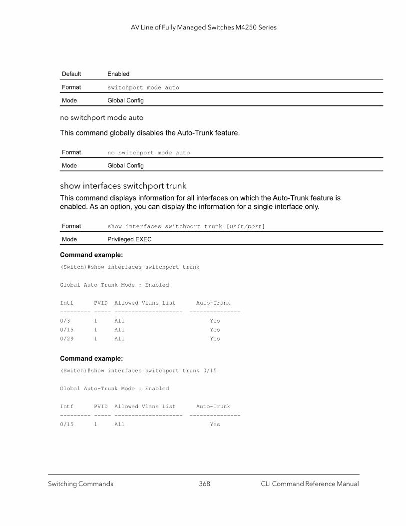
AV Line of Fully Managed Switches M4250 Series
no switchport mode auto
This command globally disables the Auto-Trunk feature.
show interfaces switchport trunkThis command displays information for all interfaces on which the Auto-Trunk feature is enabled. As an option, you can display the information for a single interface only.
Command example: (Switch)#show interfaces switchport trunk
Global Auto-Trunk Mode : Enabled
Intf PVID Allowed Vlans List Auto-Trunk--------- ----- -------------------- ---------------0/3 1 All Yes0/15 1 All Yes0/29 1 All Yes
Command example: (Switch)#show interfaces switchport trunk 0/15
Global Auto-Trunk Mode : Enabled
Intf PVID Allowed Vlans List Auto-Trunk--------- ----- -------------------- ---------------0/15 1 All Yes
Default Enabled
Format switchport mode auto
Mode Global Config
Format no switchport mode auto
Mode Global Config
Format show interfaces switchport trunk [unit/port]
Mode Privileged EXEC
Switching Commands CLI Command Reference Manual368
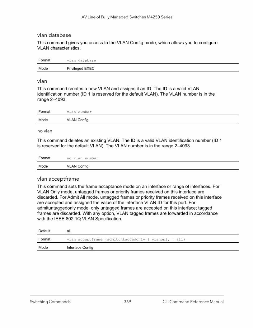
AV Line of Fully Managed Switches M4250 Series
vlan databaseThis command gives you access to the VLAN Config mode, which allows you to configure VLAN characteristics.
vlan This command creates a new VLAN and assigns it an ID. The ID is a valid VLAN identification number (ID 1 is reserved for the default VLAN). The VLAN number is in the range 2–4093.
no vlan
This command deletes an existing VLAN. The ID is a valid VLAN identification number (ID 1 is reserved for the default VLAN). The VLAN number is in the range 2–4093.
vlan acceptframeThis command sets the frame acceptance mode on an interface or range of interfaces. For VLAN Only mode, untagged frames or priority frames received on this interface are discarded. For Admit All mode, untagged frames or priority frames received on this interface are accepted and assigned the value of the interface VLAN ID for this port. For admituntaggedonly mode, only untagged frames are accepted on this interface; tagged frames are discarded. With any option, VLAN tagged frames are forwarded in accordance with the IEEE 802.1Q VLAN Specification.
Format vlan database
Mode Privileged EXEC
Format vlan number
Mode VLAN Config
Format no vlan number
Mode VLAN Config
Default all
Format vlan acceptframe {admituntaggedonly | vlanonly | all}
Mode Interface Config
Switching Commands CLI Command Reference Manual369
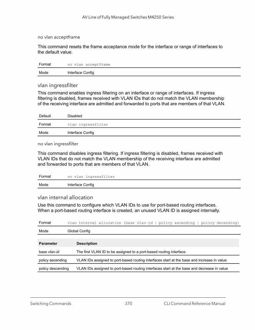
AV Line of Fully Managed Switches M4250 Series
ing}
no vlan acceptframe
This command resets the frame acceptance mode for the interface or range of interfaces to the default value.
vlan ingressfilterThis command enables ingress filtering on an interface or range of interfaces. If ingress filtering is disabled, frames received with VLAN IDs that do not match the VLAN membership of the receiving interface are admitted and forwarded to ports that are members of that VLAN.
no vlan ingressfilter
This command disables ingress filtering. If ingress filtering is disabled, frames received with VLAN IDs that do not match the VLAN membership of the receiving interface are admitted and forwarded to ports that are members of that VLAN.
vlan internal allocationUse this command to configure which VLAN IDs to use for port-based routing interfaces. When a port-based routing interface is created, an unused VLAN ID is assigned internally.
Format no vlan acceptframe
Mode Interface Config
Default Disabled
Format vlan ingressfilter
Mode Interface Config
Format no vlan ingressfilter
Mode Interface Config
Format vlan internal allocation {base vlan-id | policy ascending | policy decend
Mode Global Config
Parameter Description
base vlan-id The first VLAN ID to be assigned to a port-based routing interface.
policy ascending VLAN IDs assigned to port-based routing interfaces start at the base and increase in value
policy descending VLAN IDs assigned to port-based routing interfaces start at the base and decrease in value
Switching Commands CLI Command Reference Manual370
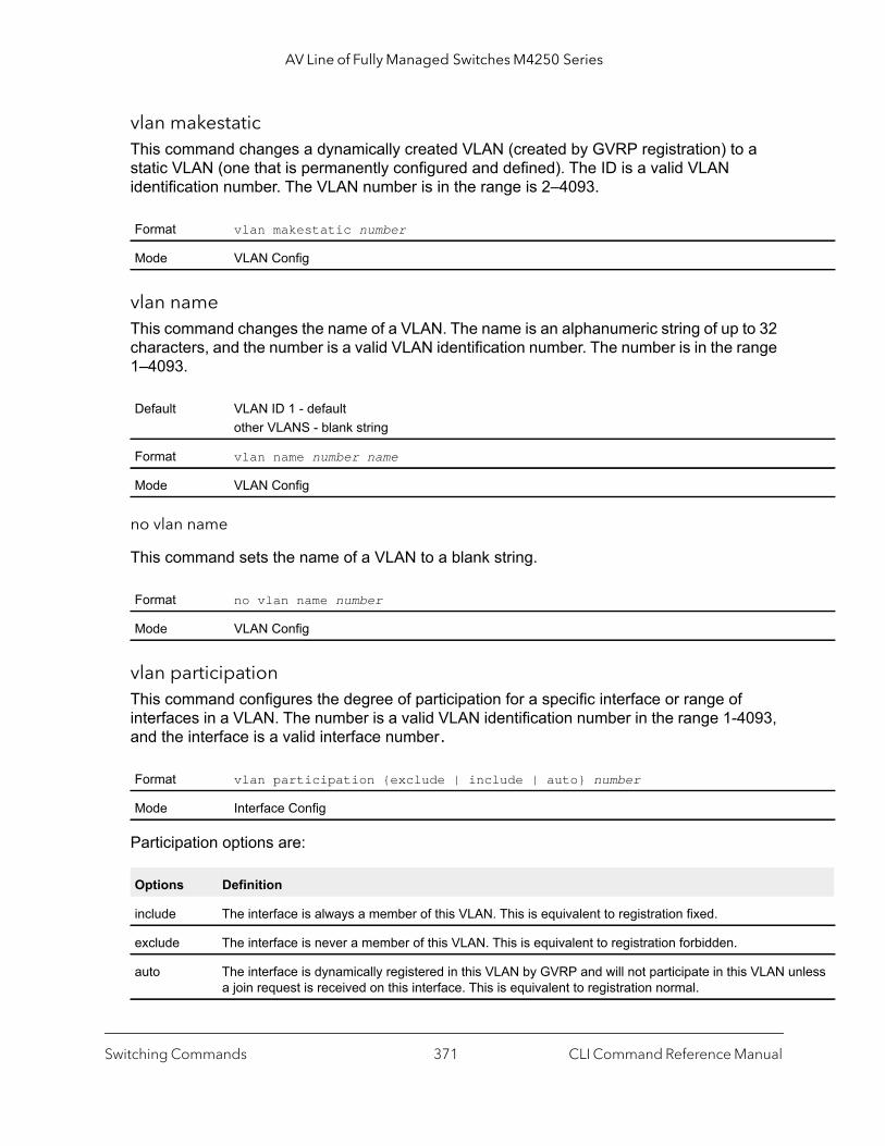
AV Line of Fully Managed Switches M4250 Series
nless
vlan makestaticThis command changes a dynamically created VLAN (created by GVRP registration) to a static VLAN (one that is permanently configured and defined). The ID is a valid VLAN identification number. The VLAN number is in the range is 2–4093.
vlan nameThis command changes the name of a VLAN. The name is an alphanumeric string of up to 32 characters, and the number is a valid VLAN identification number. The number is in the range 1–4093.
no vlan name
This command sets the name of a VLAN to a blank string.
vlan participationThis command configures the degree of participation for a specific interface or range of interfaces in a VLAN. The number is a valid VLAN identification number in the range 1-4093, and the interface is a valid interface number.
Participation options are:
Format vlan makestatic number
Mode VLAN Config
Default VLAN ID 1 - defaultother VLANS - blank string
Format vlan name number name
Mode VLAN Config
Format no vlan name number
Mode VLAN Config
Format vlan participation {exclude | include | auto} number
Mode Interface Config
Options Definition
include The interface is always a member of this VLAN. This is equivalent to registration fixed.
exclude The interface is never a member of this VLAN. This is equivalent to registration forbidden.
auto The interface is dynamically registered in this VLAN by GVRP and will not participate in this VLAN ua join request is received on this interface. This is equivalent to registration normal.
Switching Commands CLI Command Reference Manual371

AV Line of Fully Managed Switches M4250 Series
in rmal.
rded.
rface
and
vlan participation allThis command configures the degree of participation for all interfaces in a VLAN. The number is a valid VLAN identification number in the range 1–4093.
You can use the following participation options:
vlan port acceptframe allThis command sets the frame acceptance mode for all interfaces.
For the all mode, untagged frames or priority frames that enter on an interface are accepted and assigned the VLAN ID of the interface. With any of the three modes, VLAN-tagged frames are forwarded in accordance with the IEEE 802.1Q VLAN specification.
The modes are defined as follows:
Format vlan participation all {exclude | include | auto} number
Mode Global Config
Participation Options
Definition
include The interface is always a member of this VLAN. This is equivalent to registration fixed.
exclude The interface is never a member of this VLAN. This is equivalent to registration forbidden.
auto The interface is dynamically registered in this VLAN by GVRP. The interface will not participatethis VLAN unless a join request is received on this interface. This is equivalent to registration no
Default all
Format vlan port acceptframe all {vlanonly | admituntaggedonly | all}
Mode Global Config
Mode Definition
vlanonly VLAN-only mode. Untagged frames or priority frames received on this interface are disca
admituntaggedonly Admit untagged-only mode. VLAN-tagged and priority tagged frames received on this inteare discarded.
all Admit all mode. Untagged frames or priority frames received on this interface are acceptedassigned the value of the interface VLAN ID for this port.
Switching Commands CLI Command Reference Manual372
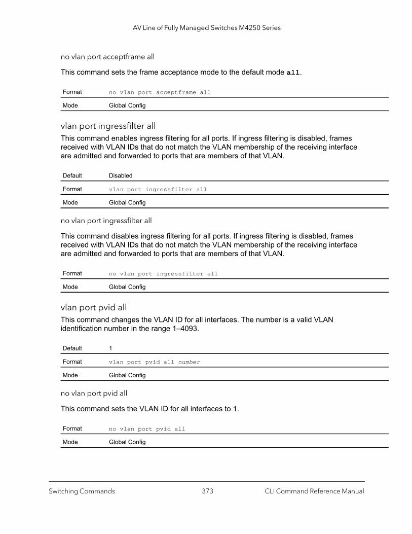
AV Line of Fully Managed Switches M4250 Series
no vlan port acceptframe all
This command sets the frame acceptance mode to the default mode all.
vlan port ingressfilter allThis command enables ingress filtering for all ports. If ingress filtering is disabled, frames received with VLAN IDs that do not match the VLAN membership of the receiving interface are admitted and forwarded to ports that are members of that VLAN.
no vlan port ingressfilter all
This command disables ingress filtering for all ports. If ingress filtering is disabled, frames received with VLAN IDs that do not match the VLAN membership of the receiving interface are admitted and forwarded to ports that are members of that VLAN.
vlan port pvid allThis command changes the VLAN ID for all interfaces. The number is a valid VLAN identification number in the range 1–4093.
no vlan port pvid all
This command sets the VLAN ID for all interfaces to 1.
Format no vlan port acceptframe all
Mode Global Config
Default Disabled
Format vlan port ingressfilter all
Mode Global Config
Format no vlan port ingressfilter all
Mode Global Config
Default 1
Format vlan port pvid all number
Mode Global Config
Format no vlan port pvid all
Mode Global Config
Switching Commands CLI Command Reference Manual373

AV Line of Fully Managed Switches M4250 Series
vlan port tagging allThis command configures the tagging behavior for all interfaces in a VLAN to enabled. If tagging is enabled, traffic is transmitted as tagged frames. If tagging is disabled, traffic is transmitted as untagged frames. The number is a valid VLAN identification number in the range 1–4093.
no vlan port tagging all
This command configures the tagging behavior for all interfaces in a VLAN to disabled. If tagging is disabled, traffic is transmitted as untagged frames. The number is a valid VLAN identification number in the range 1–4093.
vlan protocol groupThis command adds protocol-based VLAN groups to the system. The groupid is a unique number from 1–128 that is used to identify the group in subsequent commands.
vlan protocol group nameThis command assigns a name to a protocol-based VLAN group. The groupname variable can be a character string of 0 to 16 characters.
no vlan protocol group name
This command removes the name from the group identified by groupid.
Format vlan port tagging all number
Mode Global Config
Format no vlan port tagging all number
Mode Global Config
Format vlan protocol group groupid
Mode Global Config
Format vlan protocol group name groupid groupname
Mode Global Config
Format no vlan protocol group name groupid
Mode Global Config
Switching Commands CLI Command Reference Manual374

AV Line of Fully Managed Switches M4250 Series
vlan protocol group add protocol This command adds the protocol to the protocol-based VLAN identified by groupid. A group may have more than one protocol associated with it. Each interface and protocol combination can only be associated with one group. If adding a protocol to a group causes any conflicts with interfaces currently associated with the group, this command fails and the protocol is not added to the group. The possible values for protocol-list includes the keywords ip, arp, and ipx and hexadecimal or decimal values ranging from 0x0600 (1536) to 0xFFFF (65535). The protocol list can accept up to 16 protocols separated by a comma.
no vlan protocol group add protocol
This command removes the protocols specified in the protocol-list from this protocol-based VLAN group that is identified by this groupid.
protocol groupThis command attaches a vlanid to the protocol-based VLAN identified by groupid. A group can only be associated with one VLAN at a time, however the VLAN association can be changed.
no protocol group
This command removes the vlanid from this protocol-based VLAN group that is identified by this groupid.
protocol vlan groupThis command adds a physical interface or a range of interfaces to the protocol-based VLAN identified by groupid. You can associate multiple interfaces with a group, but you can only associate each interface and protocol combination with one group. If adding an interface to a
Default none
Format vlan protocol group add protocol groupid ethertype protocol-list
Mode Global Config
Format no vlan protocol group add protocol groupid ethertype protocol-list
Mode Global Config
Default none
Format protocol group groupid vlanid
Mode VLAN Config
Format no protocol group groupid vlanid
Mode VLAN Config
Switching Commands CLI Command Reference Manual375

AV Line of Fully Managed Switches M4250 Series
group causes any conflicts with protocols currently associated with the group, this command fails and the interface or interfaces are not added to the group.
no protocol vlan group
This command removes the interface from this protocol-based VLAN group that is identified by this groupid.
protocol vlan group allThis command adds all physical interfaces to the protocol-based VLAN identified by groupid. You can associate multiple interfaces with a group, but you can only associate each interface and protocol combination with one group. If adding an interface to a group causes any conflicts with protocols currently associated with the group, this command will fail and the interface or interfaces are not added to the group.
no protocol vlan group all
This command removes all interfaces from this protocol-based VLAN group that is identified by this groupid.
show port protocol This command displays the protocol-based VLAN information for either the entire system, or for the indicated group.
Default none
Format protocol vlan group groupid
Mode Interface Config
Format no protocol vlan group groupid
Mode Interface Config
Default none
Format protocol vlan group all groupid
Mode Global Config
Format no protocol vlan group all groupid
Mode Global Config
Format show port protocol {groupid | all}
Mode Privileged EXEC
Switching Commands CLI Command Reference Manual376
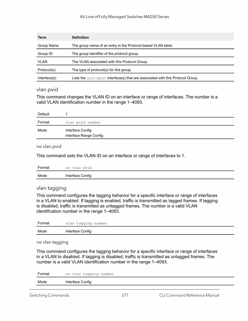
AV Line of Fully Managed Switches M4250 Series
vlan pvidThis command changes the VLAN ID on an interface or range of interfaces. The number is a valid VLAN identification number in the range 1–4093.
no vlan pvid
This command sets the VLAN ID on an interface or range of interfaces to 1.
vlan taggingThis command configures the tagging behavior for a specific interface or range of interfaces in a VLAN to enabled. If tagging is enabled, traffic is transmitted as tagged frames. If tagging is disabled, traffic is transmitted as untagged frames. The number is a valid VLAN identification number in the range 1–4093.
no vlan tagging
This command configures the tagging behavior for a specific interface or range of interfaces in a VLAN to disabled. If tagging is disabled, traffic is transmitted as untagged frames. The number is a valid VLAN identification number in the range 1–4093.
Term Definition
Group Name The group name of an entry in the Protocol-based VLAN table.
Group ID The group identifier of the protocol group.
VLAN The VLAN associated with this Protocol Group.
Protocol(s) The type of protocol(s) for this group.
Interface(s) Lists the unit/port interface(s) that are associated with this Protocol Group.
Default 1
Format vlan pvid number
Mode Interface ConfigInterface Range Config
Format no vlan pvid
Mode Interface Config
Format vlan tagging number
Mode Interface Config
Format no vlan tagging number
Mode Interface Config
Switching Commands CLI Command Reference Manual377

AV Line of Fully Managed Switches M4250 Series
vlan association subnetThis command associates a VLAN to a specific IP-subnet.
no vlan association subnet
This command removes association of a specific IP-subnet to a VLAN.
vlan association macThis command associates a MAC address to a VLAN.
no vlan association mac
This command removes the association of a MAC address to a VLAN.
remote-spanThis command identifies the VLAN as the RSPAN VLAN.
Format vlan association subnet ipaddr netmask vlanid
Mode VLAN Config
Format no vlan association subnet ipaddr netmask
Mode VLAN Config
Format vlan association mac macaddr vlanid
Mode VLAN database
Format no vlan association mac macaddr
Mode VLAN database
Default None
Format remote-span
Mode VLAN configuration
Switching Commands CLI Command Reference Manual378
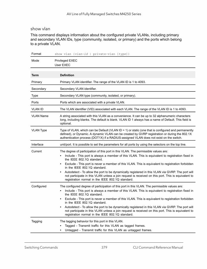
AV Line of Fully Managed Switches M4250 Series
.
ers ld is
ently .1X
ed in
idden
rt will nt to
ed in
idden
rt will nt to
show vlan This command displays information about the configured private VLANs, including primary and secondary VLAN IDs, type (community, isolated, or primary) and the ports which belong to a private VLAN.
Format show vlan {vlan-id | private-vlan [type]}
Mode Privileged EXECUser EXEC
Term Definition
Primary Primary VLAN identifier. The range of the VLAN ID is 1 to 4093.
Secondary Secondary VLAN identifier.
Type Secondary VLAN type (community, isolated, or primary).
Ports Ports which are associated with a private VLAN.
VLAN ID The VLAN identifier (VID) associated with each VLAN. The range of the VLAN ID is 1 to 4093
VLAN Name A string associated with this VLAN as a convenience. It can be up to 32 alphanumeric charactlong, including blanks. The default is blank. VLAN ID 1 always has a name of Default. This fieoptional.
VLAN Type Type of VLAN, which can be Default (VLAN ID = 1) or static (one that is configured and permandefined), or Dynamic. A dynamic VLAN can be created by GVRP registration or during the 802authentication process (DOT1X) if a RADIUS-assigned VLAN does not exist on the switch.
Interface unit/port. It is possible to set the parameters for all ports by using the selectors on the top line.
Current The degree of participation of this port in this VLAN. The permissible values are: • Include - This port is always a member of this VLAN. This is equivalent to registration fix
the IEEE 802.1Q standard.• Exclude - This port is never a member of this VLAN. This is equivalent to registration forb
in the IEEE 802.1Q standard.• Autodetect - To allow the port to be dynamically registered in this VLAN via GVRP. The po
not participate in this VLAN unless a join request is received on this port. This is equivaleregistration normal in the IEEE 802.1Q standard.
Configured The configured degree of participation of this port in this VLAN. The permissible values are: • Include - This port is always a member of this VLAN. This is equivalent to registration fix
the IEEE 802.1Q standard.• Exclude - This port is never a member of this VLAN. This is equivalent to registration forb
in the IEEE 802.1Q standard. • Autodetect - To allow the port to be dynamically registered in this VLAN via GVRP. The po
not participate in this VLAN unless a join request is received on this port. This is equivaleregistration normal in the IEEE 802.1Q standard.
Tagging The tagging behavior for this port in this VLAN.• Tagged - Transmit traffic for this VLAN as tagged frames.• Untagged - Transmit traffic for this VLAN as untagged frames.
Switching Commands CLI Command Reference Manual379

AV Line of Fully Managed Switches M4250 Series
n this
All'.
port N
of the N ID
ived ge
show vlan internal usageThis command displays information about the VLAN ID allocation on the switch.
show vlan portThis command displays VLAN port information.
Format show vlan internal usage
Mode Privileged EXECUser EXEC
Term Definition
Base VLAN ID Identifies the base VLAN ID for Internal allocation of VLANs to the routing interface.
Allocation policy Identifies whether the system allocates VLAN IDs in ascending or descending order.
Format show vlan port {unit/port | all}
Mode Privileged EXECUser EXEC
Term Definition
Interface It is possible to set the parameters for all ports by using the selectors on the top line.
Port VLAN ID The VLAN ID that this port will assign to untagged frames or priority tagged frames received oport. The value must be for an existing VLAN. The factory default is 1.
Acceptable Frame Types
The types of frames that may be received on this port. The options are 'VLAN only' and 'AdmitWhen set to 'VLAN only', untagged frames or priority tagged frames received on this port are discarded. When set to 'Admit All', untagged frames or priority tagged frames received on this are accepted and assigned the value of the Port VLAN ID for this port. With either option, VLAtagged frames are forwarded in accordance to the 802.1Q VLAN specification.
Ingress Filtering May be enabled or disabled. When enabled, the frame is discarded if this port is not a member VLAN with which this frame is associated. In a tagged frame, the VLAN is identified by the VLAin the tag. In an untagged frame, the VLAN is the Port VLAN ID specified for the port that recethis frame. When disabled, all frames are forwarded in accordance with the 802.1Q VLAN bridspecification. The factory default is disabled.
GVRP May be enabled or disabled.
Default Priority The 802.1p priority assigned to tagged packets arriving on the port.
Switching Commands CLI Command Reference Manual380
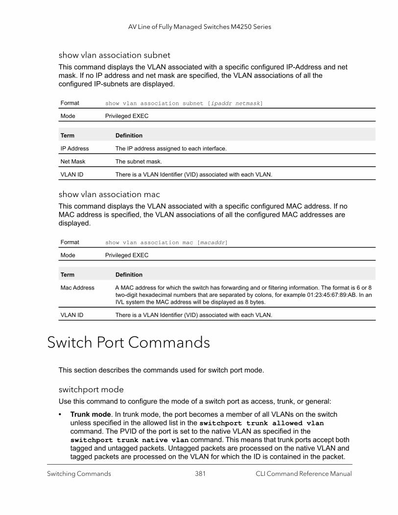
AV Line of Fully Managed Switches M4250 Series
or 8 In an
show vlan association subnet This command displays the VLAN associated with a specific configured IP-Address and net mask. If no IP address and net mask are specified, the VLAN associations of all the configured IP-subnets are displayed.
show vlan association macThis command displays the VLAN associated with a specific configured MAC address. If no MAC address is specified, the VLAN associations of all the configured MAC addresses are displayed.
Switch Port Commands
This section describes the commands used for switch port mode.
switchport modeUse this command to configure the mode of a switch port as access, trunk, or general:
• Trunk mode. In trunk mode, the port becomes a member of all VLANs on the switch unless specified in the allowed list in the switchport trunk allowed vlan command. The PVID of the port is set to the native VLAN as specified in the switchport trunk native vlan command. This means that trunk ports accept both tagged and untagged packets. Untagged packets are processed on the native VLAN and tagged packets are processed on the VLAN for which the ID is contained in the packet.
Format show vlan association subnet [ipaddr netmask]
Mode Privileged EXEC
Term Definition
IP Address The IP address assigned to each interface.
Net Mask The subnet mask.
VLAN ID There is a VLAN Identifier (VID) associated with each VLAN.
Format show vlan association mac [macaddr]
Mode Privileged EXEC
Term Definition
Mac Address A MAC address for which the switch has forwarding and or filtering information. The format is 6two-digit hexadecimal numbers that are separated by colons, for example 01:23:45:67:89:AB.IVL system the MAC address will be displayed as 8 bytes.
VLAN ID There is a VLAN Identifier (VID) associated with each VLAN.
Switching Commands CLI Command Reference Manual381

AV Line of Fully Managed Switches M4250 Series
MAC learning is performed on both tagged and untagged packets. Tagged packets that are received with a VLAN ID of which the port is not a member are discarded and MAC learning is not performed.
The trunk ports always transmit packets untagged on a native VLAN.
• Access mode. In access mode, the port becomes a member of only one VLAN. The port sends and receives untagged traffic. The port can also receive tagged traffic. Ingress filtering is enabled on the port. This means that when the VLAN ID of a received packet is not identical to the access VLAN ID, the packet is discarded.
• General mode. In general mode, you can perform custom configuration of the VLAN membership, PVID, tagging, ingress filtering, and so on. The general mode is legacy behavior of the switch port configuration and you use legacy CLI commands to configure the port in general mode.
no switchport mode
This command resets the switch port mode to its default value.
switchport trunk allowed vlanUse this command to configure the list of allowed VLANs that can receive and send traffic on this interface in tagged format when in trunking mode. The default is all.
You can modify the VLAN list by using the add and remove options and replace the VLAN list with another list by using the all or except options. If you use the all option, all VLANs are added to the list of allowed VLANs. The except option provides an exclusion list.
Default General mode
Format switchport mode {access | trunk | general}
Mode Interface Config
Format no switchport mode
Mode Interface Config
Default all
Format switchport trunk allowed vlan {vlan-list | all | {add vlan-list} | {remove vlan-list} | {except vlan-list}}
Mode Interface Config
Parameter Description
all Specifies all VLANs from 1 to 4093. This keyword is not allowed for commands that do not permit all VLANs in the list to be set at the same time.
add Adds the defined list of VLANs to those currently set instead of replacing the list.
Switching Commands CLI Command Reference Manual382

AV Line of Fully Managed Switches M4250 Series
no switchport trunk allowed vlan
This command resets the list of allowed VLANs on the trunk port to its default value.
switchport trunk native vlanUse this command to configure the trunk port native VLAN (PVID) parameter of the switch port. Any ingress untagged packets on the port are tagged with the value of the native VLAN. The native VLAN must be in the allowed VLAN list for tagging of received untagged packets. Otherwise, untagged packets are discarded. Packets marked with the native VLAN are transmitted untagged from the trunk port. The default ID is 1, the default VLAN.
no switchport trunk native vlan
Use this command to reset the trunk mode native VLAN of the switch port to its default value.
switchport access vlanUse this command to configure the VLAN on the access port. You can assign one VLAN only to the access port. The access port is member of VLAN 1 by default. You can assign the access port to a VLAN other than VLAN 1. If you remove the access VLAN on the switch, the access port becomes a member of VLAN 1. If you configure the access port as a member of a VLAN that does not exist, an error occurs and the configuration does not change.
remove Removes the defined list of VLANs from those currently set instead of replacing the list. Valid IDs are from 1 to 4093. Extended-range VLAN IDs of the form XY or X,Y,Z are valid in this command
except Lists the VLANs that must be calculated by inverting the defined list of VLANs. (VLANs are added except the ones specified.)
van-list Either a single VLAN number from 1 to 4093 or a continuous range of VLANs described by two VLAN numbers, the lesser one first, separated by a hyphen.
Format no switchport trunk allowed vlan
Mode Interface Config
Default 1 (default VLAN)
Format switchport trunk native vlan vlan-id
Mode Interface Config
Format no switchport trunk native vlan
Mode Interface Config
Parameter Description
Switching Commands CLI Command Reference Manual383
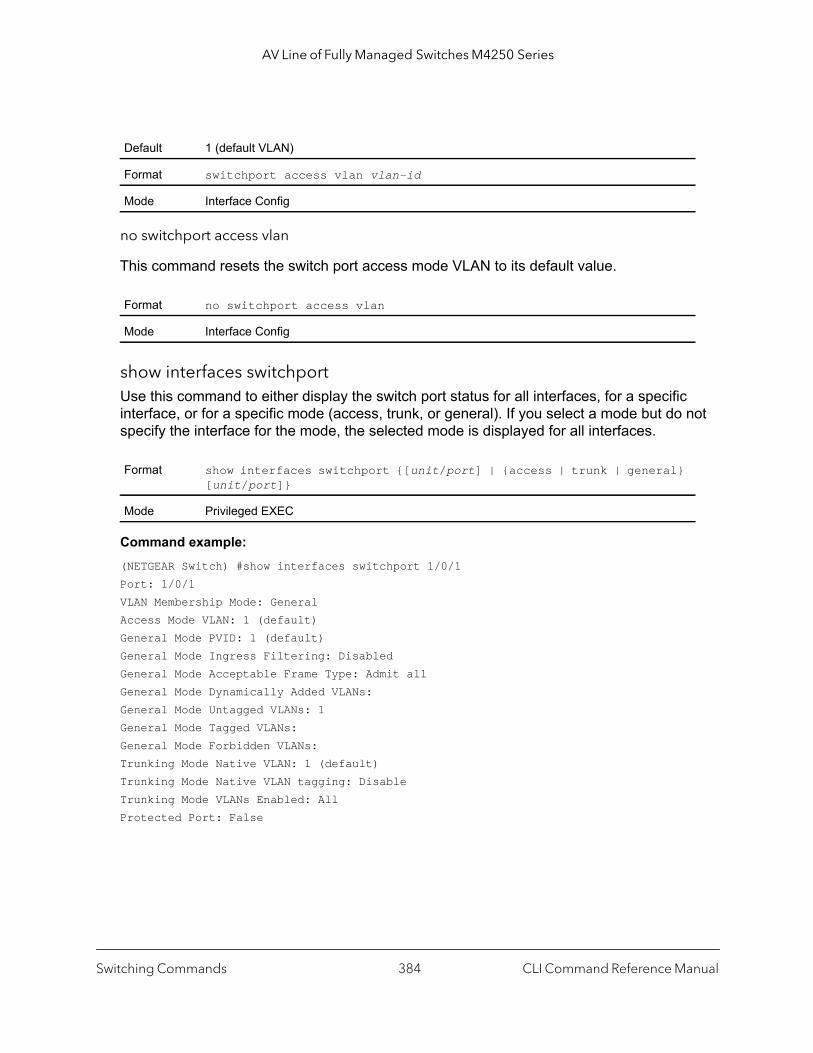
AV Line of Fully Managed Switches M4250 Series
no switchport access vlan
This command resets the switch port access mode VLAN to its default value.
show interfaces switchportUse this command to either display the switch port status for all interfaces, for a specific interface, or for a specific mode (access, trunk, or general). If you select a mode but do not specify the interface for the mode, the selected mode is displayed for all interfaces.
Command example: (NETGEAR Switch) #show interfaces switchport 1/0/1Port: 1/0/1VLAN Membership Mode: GeneralAccess Mode VLAN: 1 (default)General Mode PVID: 1 (default)General Mode Ingress Filtering: DisabledGeneral Mode Acceptable Frame Type: Admit allGeneral Mode Dynamically Added VLANs:General Mode Untagged VLANs: 1General Mode Tagged VLANs:General Mode Forbidden VLANs:Trunking Mode Native VLAN: 1 (default)Trunking Mode Native VLAN tagging: DisableTrunking Mode VLANs Enabled: AllProtected Port: False
Default 1 (default VLAN)
Format switchport access vlan vlan-id
Mode Interface Config
Format no switchport access vlan
Mode Interface Config
Format show interfaces switchport {[unit/port] | {access | trunk | general} [unit/port]}
Mode Privileged EXEC
Switching Commands CLI Command Reference Manual384

AV Line of Fully Managed Switches M4250 Series
Command example: (NETGEAR Switch) #show interfaces switchport access 1/0/1
Intf PVID--------- ----1/0/1 1
Command example: (NETGEAR Switch) #show interfaces switchport trunk 1/0/6
Intf PVID Allowed Vlans List--------- ----- -------------------1/0/6 1 All
Command example: (NETGEAR Switch) #show interfaces switchport general 1/0/5
Intf PVID Ingress Acceptable Untagged Tagged Forbidden Dynamic Filtering Frame Type Vlans Vlans Vlans Vlans--------- ----- ---------- ----------- --------- --------- --------- ---------1/0/5 1 Enabled Admit All 7 10-50,55 9,100-200 88,96
Command example: (NETGEAR Switch) #show interfaces switchport general
Intf PVID Ingress Acceptable Untagged Tagged Forbidden Dynamic Filtering Frame Type Vlans Vlans Vlans Vlans--------- ----- ---------- ----------- --------- --------- --------- ---------1/0/1 1 Enabled Admit All 1,4-7 30-40,55 3,100-200 88,961/0/2 1 Disabled Admit All 1 30-40,55 none none
Double VLAN CommandsThis section describes the commands you use to configure double VLAN (DVLAN). Double VLAN tagging is a way to pass VLAN traffic from one customer domain to another through a Metro Core in a simple and cost effective manner. The additional tag on the traffic helps differentiate between customers in the MAN while preserving the VLAN identification of the individual customers when they enter their own IEEE 802.1Q domain.
dvlan-tunnel ethertype (Interface Config)This command configures the ethertype for the specified interface. The two-byte hex ethertype is used as the first 16 bits of the DVLAN tag. The ethertype can have the values of 802.1Q, vman, or custom. If the ethertype has an optional value of custom, then it is a custom tunnel value, and ethertype must be set to a value in the range of 1 to 65535.
Switching Commands CLI Command Reference Manual385
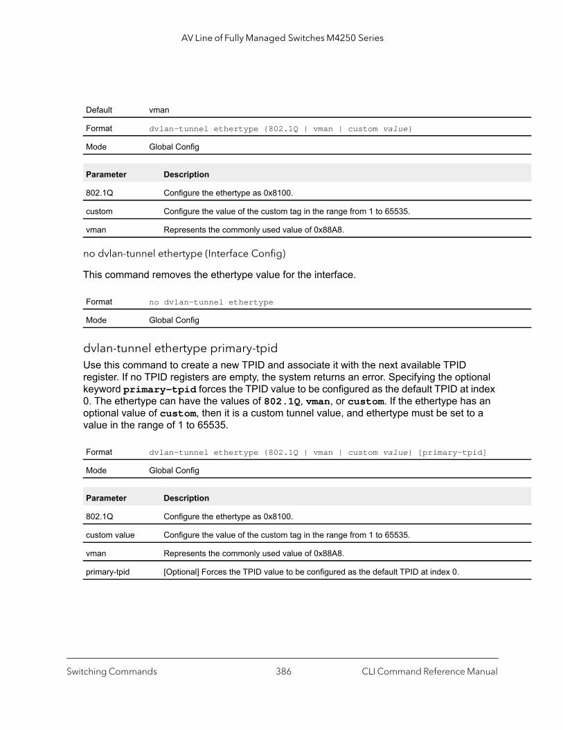
AV Line of Fully Managed Switches M4250 Series
no dvlan-tunnel ethertype (Interface Config)
This command removes the ethertype value for the interface.
dvlan-tunnel ethertype primary-tpidUse this command to create a new TPID and associate it with the next available TPID register. If no TPID registers are empty, the system returns an error. Specifying the optional keyword primary–tpid forces the TPID value to be configured as the default TPID at index 0. The ethertype can have the values of 802.1Q, vman, or custom. If the ethertype has an optional value of custom, then it is a custom tunnel value, and ethertype must be set to a value in the range of 1 to 65535.
Default vman
Format dvlan-tunnel ethertype {802.1Q | vman | custom value}
Mode Global Config
Parameter Description
802.1Q Configure the ethertype as 0x8100.
custom Configure the value of the custom tag in the range from 1 to 65535.
vman Represents the commonly used value of 0x88A8.
Format no dvlan-tunnel ethertype
Mode Global Config
Format dvlan-tunnel ethertype {802.1Q | vman | custom value} [primary-tpid]
Mode Global Config
Parameter Description
802.1Q Configure the ethertype as 0x8100.
custom value Configure the value of the custom tag in the range from 1 to 65535.
vman Represents the commonly used value of 0x88A8.
primary-tpid [Optional] Forces the TPID value to be configured as the default TPID at index 0.
Switching Commands CLI Command Reference Manual386
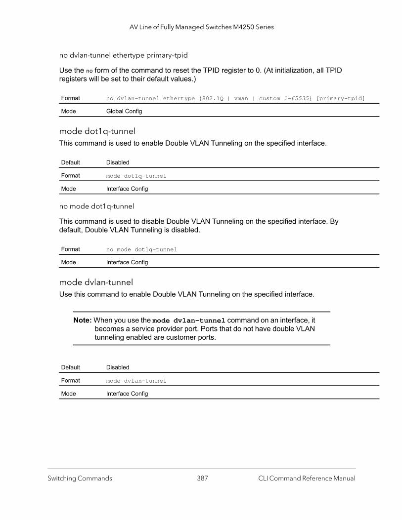
AV Line of Fully Managed Switches M4250 Series
]
no dvlan-tunnel ethertype primary–tpid
Use the no form of the command to reset the TPID register to 0. (At initialization, all TPID registers will be set to their default values.)
mode dot1q-tunnelThis command is used to enable Double VLAN Tunneling on the specified interface.
no mode dot1q-tunnel
This command is used to disable Double VLAN Tunneling on the specified interface. By default, Double VLAN Tunneling is disabled.
mode dvlan-tunnelUse this command to enable Double VLAN Tunneling on the specified interface.
Note: When you use the mode dvlan-tunnel command on an interface, it becomes a service provider port. Ports that do not have double VLAN tunneling enabled are customer ports.
Format no dvlan-tunnel ethertype {802.1Q | vman | custom 1–65535} [primary-tpid
Mode Global Config
Default Disabled
Format mode dot1q-tunnel
Mode Interface Config
Format no mode dot1q-tunnel
Mode Interface Config
Default Disabled
Format mode dvlan-tunnel
Mode Interface Config
Switching Commands CLI Command Reference Manual387
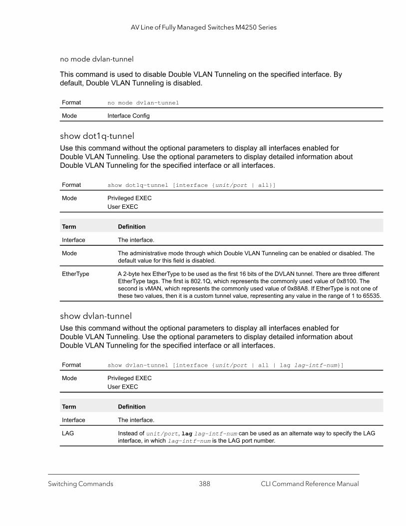
AV Line of Fully Managed Switches M4250 Series
he
erent e e of 5535.
AG
no mode dvlan-tunnel
This command is used to disable Double VLAN Tunneling on the specified interface. By default, Double VLAN Tunneling is disabled.
show dot1q-tunnelUse this command without the optional parameters to display all interfaces enabled for Double VLAN Tunneling. Use the optional parameters to display detailed information about Double VLAN Tunneling for the specified interface or all interfaces.
show dvlan-tunnelUse this command without the optional parameters to display all interfaces enabled for Double VLAN Tunneling. Use the optional parameters to display detailed information about Double VLAN Tunneling for the specified interface or all interfaces.
Format no mode dvlan-tunnel
Mode Interface Config
Format show dot1q-tunnel [interface {unit/port | all}]
Mode Privileged EXECUser EXEC
Term Definition
Interface The interface.
Mode The administrative mode through which Double VLAN Tunneling can be enabled or disabled. Tdefault value for this field is disabled.
EtherType A 2-byte hex EtherType to be used as the first 16 bits of the DVLAN tunnel. There are three diffEtherType tags. The first is 802.1Q, which represents the commonly used value of 0x8100. Thsecond is vMAN, which represents the commonly used value of 0x88A8. If EtherType is not onthese two values, then it is a custom tunnel value, representing any value in the range of 1 to 6
Format show dvlan-tunnel [interface {unit/port | all | lag lag-intf-num}]
Mode Privileged EXECUser EXEC
Term Definition
Interface The interface.
LAG Instead of unit/port, lag lag-intf-num can be used as an alternate way to specify the Linterface, in which lag-intf-num is the LAG port number.
Switching Commands CLI Command Reference Manual388

AV Line of Fully Managed Switches M4250 Series
The
erent e
ne of 5535.
-id
Command example: (NETGEAR Switch) #show dvlan-tunnel
TPIDs Configured............................... 0x88a8Default TPID................................... 0x88a8Interfaces Enabled for DVLAN Tunneling......... None
(NETGEAR Switch) #
(NETGEAR Switch) #show dvlan-tunnel interface 1/0/1
Interface Mode EtherType--------- ------- ------------1/0/1 Disable 0x88a8
Private VLAN Commands
This section describes the commands you use for private VLANs. Private VLANs provides Layer 2 isolation between ports that share the same broadcast domain. In other words, it allows a VLAN broadcast domain to be partitioned into smaller point-to-multipoint subdomains. The ports participating in a private VLAN can be located anywhere in the Layer 2 network.
switchport private-vlanThis command defines a private-VLAN association for an isolated or community port or a mapping for a promiscuous port.
Mode The administrative mode through which Double VLAN Tunneling can be enabled or disabled. default value for this field is disabled.
EtherType A 2-byte hex EtherType to be used as the first 16 bits of the DVLAN tunnel. There are three diffEtherType tags. The first is 802.1Q, which represents the commonly used value of 0x8100. Thsecond is vMAN, which represents the commonly used value of 0x88A8. If EtherType is not othese two values, then it is a custom tunnel value, representing any value in the range of 1 to 6
Format switchport private-vlan {host-association primary-vlan-id secondary-vlan| mapping primary-vlan-id {add | remove} secondary-vlan-list}
Mode Interface Config
Term Definition
Switching Commands CLI Command Reference Manual389
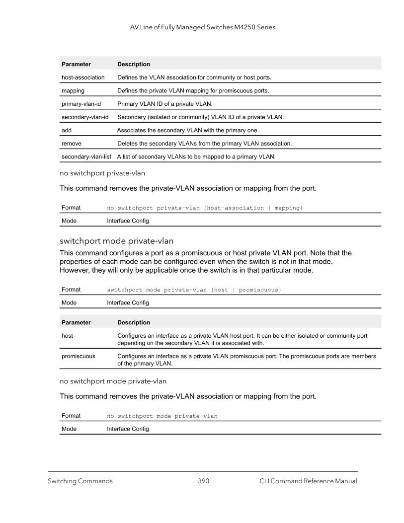
AV Line of Fully Managed Switches M4250 Series
rt
bers
no switchport private-vlan
This command removes the private-VLAN association or mapping from the port.
switchport mode private-vlanThis command configures a port as a promiscuous or host private VLAN port. Note that the properties of each mode can be configured even when the switch is not in that mode. However, they will only be applicable once the switch is in that particular mode.
no switchport mode private-vlan
This command removes the private-VLAN association or mapping from the port.
Parameter Description
host-association Defines the VLAN association for community or host ports.
mapping Defines the private VLAN mapping for promiscuous ports.
primary-vlan-id Primary VLAN ID of a private VLAN.
secondary-vlan-id Secondary (isolated or community) VLAN ID of a private VLAN.
add Associates the secondary VLAN with the primary one.
remove Deletes the secondary VLANs from the primary VLAN association.
secondary-vlan-list A list of secondary VLANs to be mapped to a primary VLAN.
Format no switchport private-vlan {host-association | mapping}
Mode Interface Config
Format switchport mode private-vlan {host | promiscuous}
Mode Interface Config
Parameter Description
host Configures an interface as a private VLAN host port. It can be either isolated or community podepending on the secondary VLAN it is associated with.
promiscuous Configures an interface as a private VLAN promiscuous port. The promiscuous ports are memof the primary VLAN.
Format no switchport mode private-vlan
Mode Interface Config
Switching Commands CLI Command Reference Manual390
AV Line of Fully Managed Switches M4250 Series
|
private-vlanThis command configures the private VLANs and configures the association between the primary private VLAN and secondary VLANs.
no private-vlan
This command restores normal VLAN configuration.
Voice VLAN Commands
This section describes the commands you use for Voice VLAN. Voice VLAN enables switch ports to carry voice traffic with defined priority so as to enable separation of voice and data traffic coming onto the port. The benefits of using Voice VLAN is to ensure that the sound quality of an IP phone could be safeguarded from deteriorating when the data traffic on the port is high.
Also the inherent isolation provided by VLANs ensures that inter-VLAN traffic is under management control and that network- attached clients cannot initiate a direct attack on voice components. QoS-based on IEEE 802.1P class of service (CoS) uses classification and scheduling to sent network traffic from the switch in a predictable manner. The system uses the source MAC of the traffic traveling through the port to identify the IP phone data flow.
The switch can be configured to support voice VLAN on a port connecting to the VoIP phone. When a VLAN is associated with the voice VLAN port, then the VLAN id info is passed onto the VoIP phone using the LLDP-MED mechanism. The voice data coming from the VoIP phone is tagged with the exchanged VLAN ID; thus, regular data arriving on the switch is given the default PVID of the port, and the voice traffic is received on a predefined VLAN.
Format private-vlan {association [add | remove] secondary-vlan-list | communityisolated | primary}
Mode VLAN Config
Parameter Description
association Associates the primary and secondary VLAN.
secondary-vlan-list A list of secondary VLANs to be mapped to a primary VLAN.
community Designates a VLAN as a community VLAN.
isolated Designates a VLAN as the isolated VLAN.
primary Designates a VLAN as the primary VLAN.
Format no private-vlan [association]
Mode VLAN Config
Switching Commands CLI Command Reference Manual391
AV Line of Fully Managed Switches M4250 Series
The two types of traffic are therefore segregated so that better service can be provided to the voice traffic.
When a dot1p priority is associated with the voice VLAN port instead of VLAN ID, the priority information is passed onto the VoIP phone using the LLDP-MED mechanism. Thus, the voice data coming from the VoIP phone is tagged with VLAN 0 and with the exchanged priority. Regular data arriving on the switch is given the default priority of the port (default 0), and the voice traffic is received with higher priority, thus segregating both the traffic to provide better service to the voice traffic.
The switch can be configured to override the data traffic CoS. This feature enables overriding the 802.1P priority of the data traffic packets arriving at the port enabled for voice VLAN. Thus, a rogue client that is also connected to the voice VLAN port does not deteriorate the voice traffic.
When a VLAN ID is configured on the voice VLAN port, the VLAN ID information is passed onto the VoIP phone using the LLDP-MED mechanism. The voice data coming from the VoIP phone is tagged with the exchanged VLAN ID; thus, regular data arriving on the switch is given the default PVID of the port, and the voice traffic is received on a predefined VLAN. The two types of traffic are segregated so that better service can be provided to the voice traffic.
Note: The IP phone must support LLDP-MED to accept the VLAN ID and CoS information from the switch.
voice vlan (Global Config)Use this command to enable the Voice VLAN capability on the switch.
no voice vlan (Global Config)
Use this command to disable the Voice VLAN capability on the switch.
Default Disabled
Format voice vlan
Mode Global Config
Format no voice vlan
Mode Global Config
Switching Commands CLI Command Reference Manual392

AV Line of Fully Managed Switches M4250 Series
are
tive
voice vlan (Interface Config)Use this command to enable the Voice VLAN capability on the interface or range of interfaces.
You can configure Voice VLAN in one of four different ways.
no voice vlan (Interface Config)
Use this command to disable the Voice VLAN capability on the interface.
voice vlan authThis command lets the switch accept or reject voice traffic when the port is in an unauthorized state. By default, the switch rejects voice traffic when the port is in an unauthorized state.
voice vlan data priorityUse this command to either trust or untrust the data traffic arriving on the Voice VLAN interface or range of interfaces being configured.
Default Disabled
Format voice vlan {vlan-id | dot1p priority | none | untagged}
Mode Interface Config
Parameter Description
vlan-id Configure the IP phone to forward all voice traffic through the specified VLAN. Valid VLAN ID’sfrom 1 to 4093 (the max supported by the platform).
dot1p Configure the IP phone to use 802.1p priority tagging for voice traffic and to use the default naVLAN (VLAN 0) to carry all traffic. Valid priority range is 0 to 7.
none Allow the IP phone to use its own configuration to send untagged voice traffic.
untagged Configure the phone to send untagged voice traffic.
Format no voice vlan
Mode Interface Config
Default disable
Format voice vlan auth [disable | enable]
Mode Interface Config
Default trust
Switching Commands CLI Command Reference Manual393

AV Line of Fully Managed Switches M4250 Series
show voice vlanUse this command to display information about the voice VLAN.
When the interface parameter is not specified, only the global mode of the Voice VLAN is displayed.
When the interface parameter is specified..
Precision Time Protocol Commands
Note: Precision Time Protocol (PTP)-transparent clocks (TC) and audio-video bridging (AVB) are mutually exclusive. You can either specify the settings for PTP-TC, as described in this section, or for 802.1AS and MRP, both of which configure the switch for AVB (see Audio Video Bridging Commands on page 597).
This section describes the commands you use to configure the Precision Time Protocol (PTP) end-to-end (E2E) transparent clock.
Format voice vlan data priority {untrust | trust}
Mode Interface Config
Format show voice vlan [interface {unit/port | all}]
Mode Privileged EXEC
Term Definition
Administrative Mode The Global Voice VLAN mode.
Term Definition
Voice VLAN Mode The admin mode of the Voice VLAN on the interface.
Voice VLAN ID The Voice VLAN ID
Voice VLAN Priority The do1p priority for the Voice VLAN on the port.
Voice VLAN Untagged The tagging option for the Voice VLAN traffic.
Voice VLAN CoS Override The Override option for the voice traffic arriving on the port.
Voice VLAN Status The operational status of Voice VLAN on the port.
Switching Commands CLI Command Reference Manual394

AV Line of Fully Managed Switches M4250 Series
ptp clock e2e-transparentThis command enables the PTP E2E transparent clock at system level (that is, globaly) or for an interface.
In Global Config mode, the command applies the PTP transparent clock configuration to all physical ports and LAG on the switch. In Interface Config mode, the command provides a next-level control so you can disable this feature selectively for an individual physical port or LAG.
You can configure the PTP transparent clock for physical ports and LAGs, but not for a VLAN. When you configure the PTP transparent clock on a LAG, the configuration is applied to all member ports.
no ptp clock e2e-transparent
This command disables the PTP E2E transparent clock at system level or for an interface.
show ptp clock e2e-transparentUse this command to display the operational and configuration status of the PTP E2E transparent clock, both at system level and at interface level.
Command example: (NETGEAR Switch) #show ptp clock e2e-transparent
PTP TC mode.................................... Enabled
Default Enabled at system level and for all interfaces
Format ptp clock e2e-transparent
Mode Global ConfigInterface Config
Format no ptp clock e2e-transparent
Mode Global ConfigInterface Config
Format show ptp clock e2e-transparent
Mode Privileged Exec
Term Definition
Interface The interface on which the feature is configured.
Configured Mode The configuration status of the PTP E2E transparent clock on the interface
Operational Mode The operational status of the PTP E2E transparent clock on the interface.
Switching Commands CLI Command Reference Manual395
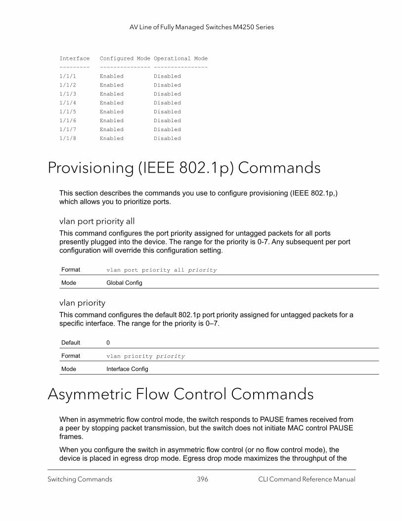
AV Line of Fully Managed Switches M4250 Series
Interface Configured Mode Operational Mode--------- --------------- ----------------1/1/1 Enabled Disabled1/1/2 Enabled Disabled1/1/3 Enabled Disabled1/1/4 Enabled Disabled1/1/5 Enabled Disabled1/1/6 Enabled Disabled1/1/7 Enabled Disabled1/1/8 Enabled Disabled
Provisioning (IEEE 802.1p) CommandsThis section describes the commands you use to configure provisioning (IEEE 802.1p,) which allows you to prioritize ports.
vlan port priority allThis command configures the port priority assigned for untagged packets for all ports presently plugged into the device. The range for the priority is 0-7. Any subsequent per port configuration will override this configuration setting.
vlan priorityThis command configures the default 802.1p port priority assigned for untagged packets for a specific interface. The range for the priority is 0–7.
Asymmetric Flow Control CommandsWhen in asymmetric flow control mode, the switch responds to PAUSE frames received from a peer by stopping packet transmission, but the switch does not initiate MAC control PAUSE frames.
When you configure the switch in asymmetric flow control (or no flow control mode), the device is placed in egress drop mode. Egress drop mode maximizes the throughput of the
Format vlan port priority all priority
Mode Global Config
Default 0
Format vlan priority priority
Mode Interface Config
Switching Commands CLI Command Reference Manual396

AV Line of Fully Managed Switches M4250 Series
system at the expense of packet loss in a heavily congested system, and this mode avoids head-of-line blocking.
flowcontrolUse this command to enable the symmetric or asymmetric flow control on the switch. Asymmetric flow control means you can enable Rx Pause only but not Tx Pause.
no flowcontrol
This command disables flow control.
show flowcontrolUse this command to display the IEEE 802.3 Annex 31B flow control settings and status for a specific interface or all interfaces. The command also displays 802.3 Tx and Rx pause counts. Priority Flow Control frames counts are not displayed. If the port is enabled for priority flow control, operational flow control status is displayed as Inactive. Operational flow control status for stacking ports is always displayed as N/A.
Command example: (NETGEAR Switch) #show flowcontrol
Admin Flow Control: Symmetric
Port Flow Control RxPause TxPause Oper ------ ------------ -------- ---------0/1 Active 310 611 0/2 Inactive 0 0
Default Flow control is disabled.
Format flowcontrol {symmetric | asymmetric}
Mode Interface Config
Format no flowcontrol
Mode Global Config
Format show flowcontrol [interface unit/port]
Mode Privileged Exec
Switching Commands CLI Command Reference Manual397
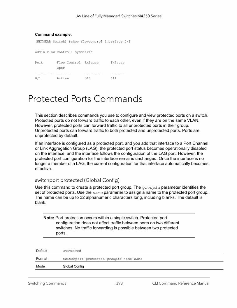
AV Line of Fully Managed Switches M4250 Series
Command example: (NETGEAR Switch) #show flowcontrol interface 0/1
Admin Flow Control: Symmetric
Port Flow Control RxPause TxPause Oper --------- ------- -------- -------0/1 Active 310 611
Protected Ports Commands
This section describes commands you use to configure and view protected ports on a switch. Protected ports do not forward traffic to each other, even if they are on the same VLAN. However, protected ports can forward traffic to all unprotected ports in their group. Unprotected ports can forward traffic to both protected and unprotected ports. Ports are unprotected by default.
If an interface is configured as a protected port, and you add that interface to a Port Channel or Link Aggregation Group (LAG), the protected port status becomes operationally disabled on the interface, and the interface follows the configuration of the LAG port. However, the protected port configuration for the interface remains unchanged. Once the interface is no longer a member of a LAG, the current configuration for that interface automatically becomes effective.
switchport protected (Global Config)Use this command to create a protected port group. The groupid parameter identifies the set of protected ports. Use the name parameter to assign a name to the protected port group. The name can be up to 32 alphanumeric characters long, including blanks. The default is blank.
Note: Port protection occurs within a single switch. Protected port configuration does not affect traffic between ports on two different switches. No traffic forwarding is possible between two protected ports.
Default unprotected
Format switchport protected groupid name name
Mode Global Config
Switching Commands CLI Command Reference Manual398
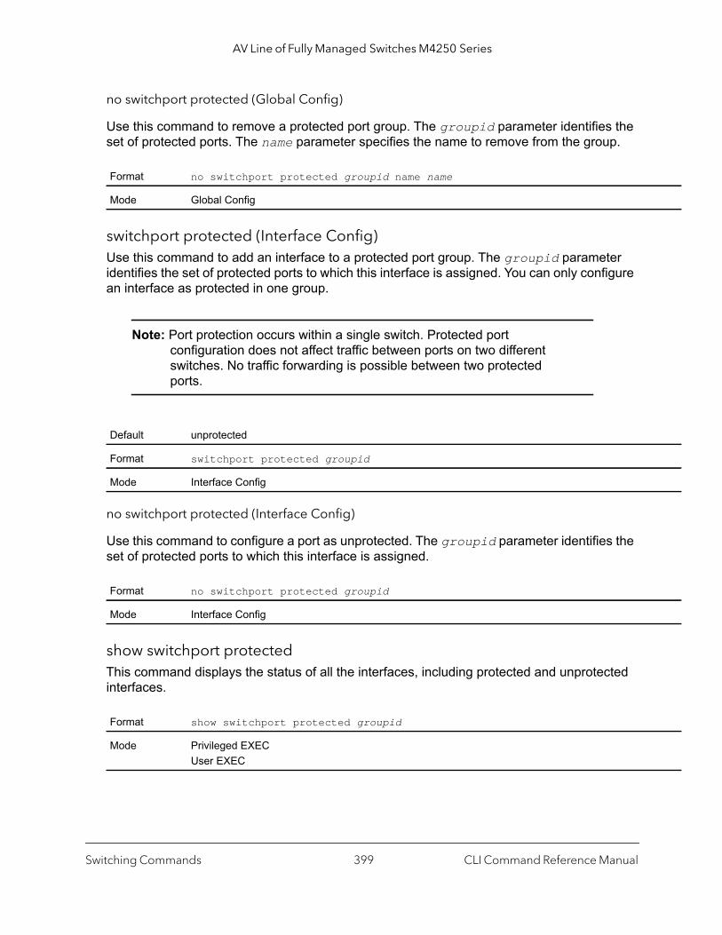
AV Line of Fully Managed Switches M4250 Series
no switchport protected (Global Config)
Use this command to remove a protected port group. The groupid parameter identifies the set of protected ports. The name parameter specifies the name to remove from the group.
switchport protected (Interface Config)Use this command to add an interface to a protected port group. The groupid parameter identifies the set of protected ports to which this interface is assigned. You can only configure an interface as protected in one group.
Note: Port protection occurs within a single switch. Protected port configuration does not affect traffic between ports on two different switches. No traffic forwarding is possible between two protected ports.
no switchport protected (Interface Config)
Use this command to configure a port as unprotected. The groupid parameter identifies the set of protected ports to which this interface is assigned.
show switchport protectedThis command displays the status of all the interfaces, including protected and unprotected interfaces.
Format no switchport protected groupid name name
Mode Global Config
Default unprotected
Format switchport protected groupid
Mode Interface Config
Format no switchport protected groupid
Mode Interface Config
Format show switchport protected groupid
Mode Privileged EXECUser EXEC
Switching Commands CLI Command Reference Manual399
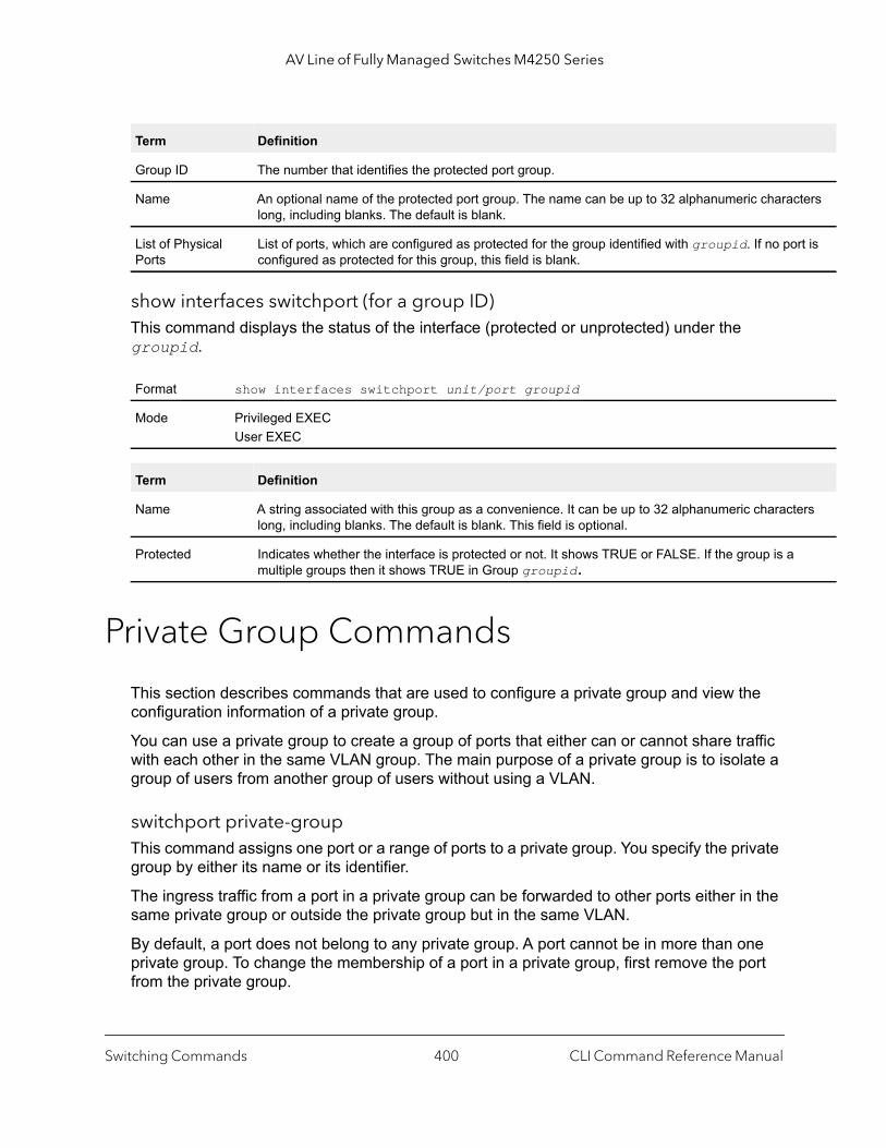
AV Line of Fully Managed Switches M4250 Series
ters
rt is
ers
show interfaces switchport (for a group ID)This command displays the status of the interface (protected or unprotected) under the groupid.
Private Group Commands
This section describes commands that are used to configure a private group and view the configuration information of a private group.
You can use a private group to create a group of ports that either can or cannot share traffic with each other in the same VLAN group. The main purpose of a private group is to isolate a group of users from another group of users without using a VLAN.
switchport private-groupThis command assigns one port or a range of ports to a private group. You specify the private group by either its name or its identifier.
The ingress traffic from a port in a private group can be forwarded to other ports either in the same private group or outside the private group but in the same VLAN.
By default, a port does not belong to any private group. A port cannot be in more than one private group. To change the membership of a port in a private group, first remove the port from the private group.
Term Definition
Group ID The number that identifies the protected port group.
Name An optional name of the protected port group. The name can be up to 32 alphanumeric characlong, including blanks. The default is blank.
List of Physical Ports
List of ports, which are configured as protected for the group identified with groupid. If no poconfigured as protected for this group, this field is blank.
Format show interfaces switchport unit/port groupid
Mode Privileged EXECUser EXEC
Term Definition
Name A string associated with this group as a convenience. It can be up to 32 alphanumeric charactlong, including blanks. The default is blank. This field is optional.
Protected Indicates whether the interface is protected or not. It shows TRUE or FALSE. If the group is a multiple groups then it shows TRUE in Group groupid.
Switching Commands CLI Command Reference Manual400

AV Line of Fully Managed Switches M4250 Series
|
t]
no switchport private-group
This command removes a port from to a private group.
private-group nameThis command creates a private group with a name or an identifier. The name string can be up to 24 bytes of non-blank characters. A total number of 192 of private groups is supported. Therefore, the group identifier can be from 1 to 192.
The private-group-id parameter is optional. If you do not specify a group identifier, the identifier is assigned automatically.
The optional mode for the group can be either isolated or community. If the private group is in isolated mode, the member port in the group cannot forward its egress traffic to any other members in the same group. By default, the mode for the private group is community mode, allowing each member port to forward traffic to other members in the same group, but not to members in other groups.
no private-group name
This command removes a private group.
show private-groupThis command displays information about a private group. If you do not specify a group name, group identifier, or port, the command displays information about all private groups.
Format switchport private-group [privategroup-name | privategroup-id]
Mode Interface Config
Format no switchport private-group [privategroup-name | privategroup-id]
Mode Interface Config
Format private-group name privategroup-name [private-group-id] [mode {community isolated}]
Mode Global Config
Format no private-group name privategroup-name
Mode Global Config
Format show private-group [private-group-name | private-group-id | port unit/por
Mode Privileged EXEC
Switching Commands CLI Command Reference Manual401

AV Line of Fully Managed Switches M4250 Series
GARP Commands
This section describes the commands you use to configure Generic Attribute Registration Protocol (GARP) and view GARP status. The commands in this section affect both GARP VLAN Registration Protocol (GVRP) and GARP Multicast Registration Protocol (GMRP). GARP is a protocol that allows client stations to register with the switch for membership in VLANS (by using GVMP) or multicast groups (by using GVMP).
set garp timer join This command sets the GVRP join time per GARP for one interface, a range of interfaces, or all interfaces. Join time is the interval between the transmission of GARP Protocol Data Units (PDUs) registering (or reregistering) membership for a VLAN or multicast group. This command has an effect only when GVRP is enabled. The time is from 10 to 100 centiseconds. The value 20 centiseconds is 0.2 seconds.
no set garp timer join
This command sets the GVRP join time to the default and only has an effect when GVRP is enabled.
Term Description
Interface A valid unit and port number separated by a forward slash.
Port VLANID The VLAN ID that is associated with the port.
Private Group ID The identifier of the private group (from 1 to 192).
Private Group Name
The name of the private group. The name string can be up to 24 bytes of non-blank characters.
Private Group Mode
The mode of the private group. The mode can be either isolated or community.
Default 20
Format set garp timer join centiseconds
Mode Interface ConfigGlobal Config
Format no set garp timer join
Mode Interface ConfigGlobal Config
Switching Commands CLI Command Reference Manual402

AV Line of Fully Managed Switches M4250 Series
set garp timer leaveThis command sets the GVRP leave time for one interface, a range of interfaces, or all interfaces or all ports and only has an effect when GVRP is enabled. Leave time is the time to wait after receiving an unregister request for a VLAN or a multicast group before deleting the VLAN entry. This can be considered a buffer time for another station to assert registration for the same attribute in order to maintain uninterrupted service. The leave time is 20 to 600 centiseconds. The value 60 centiseconds is 0.6 seconds. The leave time must be greater than or equal to three times the join time.
no set garp timer leave
This command sets the GVRP leave time on all ports or a single port to the default and only has an effect when GVRP is enabled.
set garp timer leaveallThis command sets how frequently Leave All PDUs are generated. A Leave All PDU indicates that all registrations will be unregistered. Participants would need to rejoin in order to maintain registration. The value applies per port and per GARP participation. The time may range from 200 to 6000 centiseconds. The value 1000 centiseconds is 10 seconds. You can use this command on all ports (Global Config mode), or on a single port or a range of ports (Interface Config mode) and it only has an effect only when GVRP is enabled. The leave all time must be greater than the leave time.
Default 60
Format set garp timer leave centiseconds
Mode Interface ConfigGlobal Config
Format no set garp timer leave
Mode Interface ConfigGlobal Config
Default 1000
Format set garp timer leaveall centiseconds
Mode Interface ConfigGlobal Config
Switching Commands CLI Command Reference Manual403
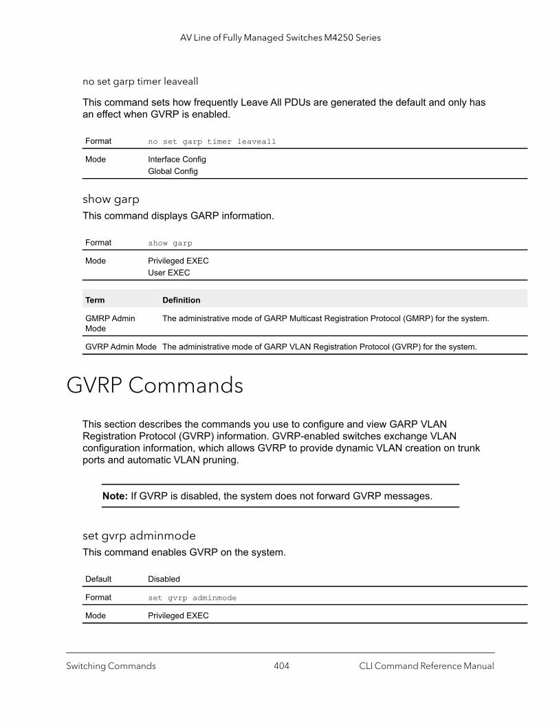
AV Line of Fully Managed Switches M4250 Series
no set garp timer leaveall
This command sets how frequently Leave All PDUs are generated the default and only has an effect when GVRP is enabled.
show garpThis command displays GARP information.
GVRP Commands
This section describes the commands you use to configure and view GARP VLAN Registration Protocol (GVRP) information. GVRP-enabled switches exchange VLAN configuration information, which allows GVRP to provide dynamic VLAN creation on trunk ports and automatic VLAN pruning.
Note: If GVRP is disabled, the system does not forward GVRP messages.
set gvrp adminmode This command enables GVRP on the system.
Format no set garp timer leaveall
Mode Interface ConfigGlobal Config
Format show garp
Mode Privileged EXECUser EXEC
Term Definition
GMRP Admin Mode
The administrative mode of GARP Multicast Registration Protocol (GMRP) for the system.
GVRP Admin Mode The administrative mode of GARP VLAN Registration Protocol (GVRP) for the system.
Default Disabled
Format set gvrp adminmode
Mode Privileged EXEC
Switching Commands CLI Command Reference Manual404

AV Line of Fully Managed Switches M4250 Series
ip for r on a .0
no set gvrp adminmode
This command disables GVRP.
set gvrp interfacemodeThis command enables GVRP on a single port (Interface Config mode), a range of ports (Interface Range mode), or all ports (Global Config mode).
no set gvrp interfacemode
This command disables GVRP on a single port (Interface Config mode) or all ports (Global Config mode). If GVRP is disabled, Join Time, Leave Time and Leave All Time have no effect.
show gvrp configurationThis command displays Generic Attributes Registration Protocol (GARP) information for one or all interfaces.
Format no set gvrp adminmode
Mode Privileged EXEC
Default Disabled
Format set gvrp interfacemode
Mode Interface ConfigInterface RangeGlobal Config
Format no set gvrp interfacemode
Mode Interface ConfigGlobal Config
Format show gvrp configuration {unit/port | all}
Mode Privileged EXECUser EXEC
Term Definition
Interface unit/port
Join Timer The interval between the transmission of GARP PDUs registering (or reregistering) membershan attribute. Current attributes are a VLAN or multicast group. There is an instance of this timeper-Port, per-GARP participant basis. Permissible values are 10 to 100 centiseconds (0.1 to 1seconds). The factory default is 20 centiseconds (0.2 seconds). The finest granularity of specification is one centisecond (0.01 seconds).
Switching Commands CLI Command Reference Manual405
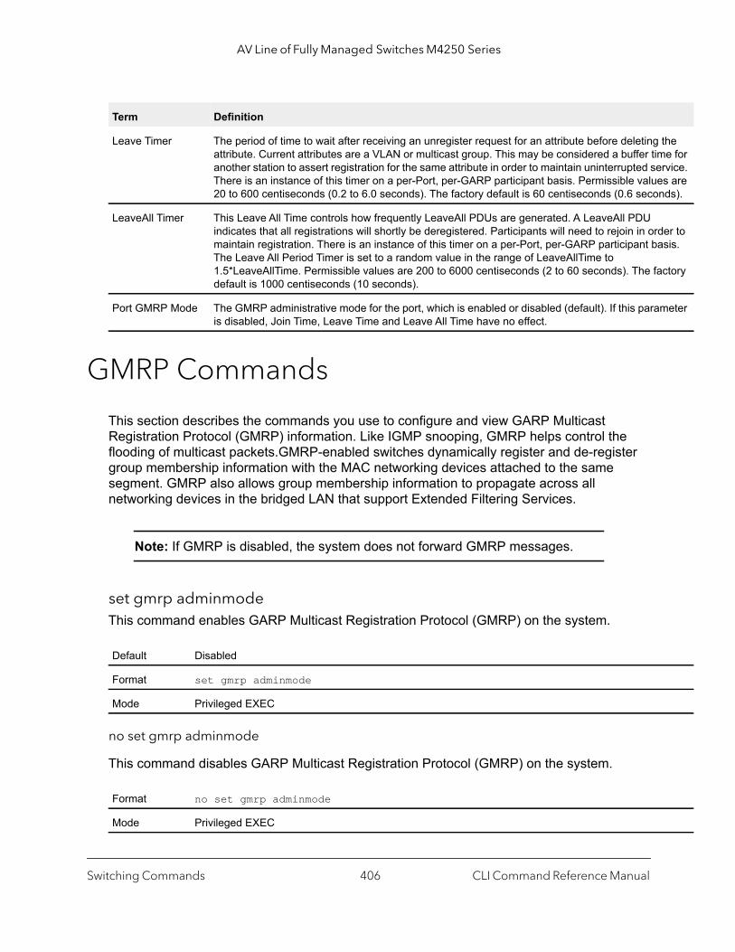
AV Line of Fully Managed Switches M4250 Series
the e for
rvice. s are ds).
er to sis.
ctory
eter
GMRP Commands
This section describes the commands you use to configure and view GARP Multicast Registration Protocol (GMRP) information. Like IGMP snooping, GMRP helps control the flooding of multicast packets.GMRP-enabled switches dynamically register and de-register group membership information with the MAC networking devices attached to the same segment. GMRP also allows group membership information to propagate across all networking devices in the bridged LAN that support Extended Filtering Services.
Note: If GMRP is disabled, the system does not forward GMRP messages.
set gmrp adminmodeThis command enables GARP Multicast Registration Protocol (GMRP) on the system.
no set gmrp adminmode
This command disables GARP Multicast Registration Protocol (GMRP) on the system.
Leave Timer The period of time to wait after receiving an unregister request for an attribute before deleting attribute. Current attributes are a VLAN or multicast group. This may be considered a buffer timanother station to assert registration for the same attribute in order to maintain uninterrupted seThere is an instance of this timer on a per-Port, per-GARP participant basis. Permissible value20 to 600 centiseconds (0.2 to 6.0 seconds). The factory default is 60 centiseconds (0.6 secon
LeaveAll Timer This Leave All Time controls how frequently LeaveAll PDUs are generated. A LeaveAll PDU indicates that all registrations will shortly be deregistered. Participants will need to rejoin in ordmaintain registration. There is an instance of this timer on a per-Port, per-GARP participant baThe Leave All Period Timer is set to a random value in the range of LeaveAllTime to 1.5*LeaveAllTime. Permissible values are 200 to 6000 centiseconds (2 to 60 seconds). The fadefault is 1000 centiseconds (10 seconds).
Port GMRP Mode The GMRP administrative mode for the port, which is enabled or disabled (default). If this paramis disabled, Join Time, Leave Time and Leave All Time have no effect.
Default Disabled
Format set gmrp adminmode
Mode Privileged EXEC
Format no set gmrp adminmode
Mode Privileged EXEC
Term Definition
Switching Commands CLI Command Reference Manual406

AV Line of Fully Managed Switches M4250 Series
ip for r on a .0
set gmrp interfacemodeThis command enables GARP Multicast Registration Protocol on a single interface (Interface Config mode), a range of interfaces, or all interfaces (Global Config mode). If an interface which has GARP enabled is enabled for routing or is enlisted as a member of a port-channel (LAG), GARP functionality is disabled on that interface. GARP functionality is subsequently re-enabled if routing is disabled and port-channel (LAG) membership is removed from an interface that has GARP enabled.
no set gmrp interfacemode
This command disables GARP Multicast Registration Protocol on a single interface or all interfaces. If an interface which has GARP enabled is enabled for routing or is enlisted as a member of a port-channel (LAG), GARP functionality is disabled. GARP functionality is subsequently re-enabled if routing is disabled and port-channel (LAG) membership is removed from an interface that has GARP enabled.
show gmrp configurationThis command displays Generic Attributes Registration Protocol (GARP) information for one or all interfaces.
Default Disabled
Format set gmrp interfacemode
Mode Interface Config Global Config
Format no set gmrp interfacemode
Mode Interface ConfigGlobal Config
Format show gmrp configuration {unit/port | all}
Mode Privileged EXECUser EXEC
Term Definition
Interface The unit/port of the interface that this row in the table describes.
Join Timer The interval between the transmission of GARP PDUs registering (or reregistering) membershan attribute. Current attributes are a VLAN or multicast group. There is an instance of this timeper-port, per-GARP participant basis. Permissible values are 10 to 100 centiseconds (0.1 to 1seconds). The factory default is 20 centiseconds (0.2 seconds). The finest granularity of specification is 1 centisecond (0.01 seconds).
Switching Commands CLI Command Reference Manual407
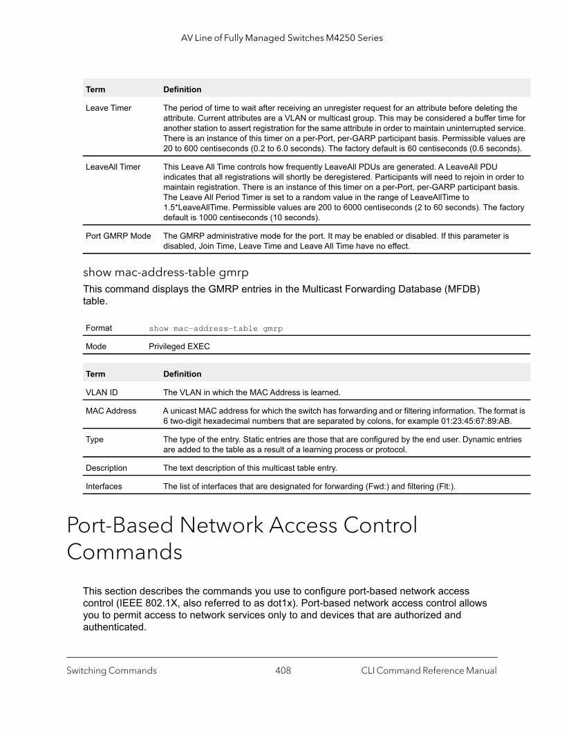
AV Line of Fully Managed Switches M4250 Series
the e for
rvice. s are ds).
er to sis.
ctory
s
at is .
tries
show mac-address-table gmrpThis command displays the GMRP entries in the Multicast Forwarding Database (MFDB) table.
Port-Based Network Access Control Commands
This section describes the commands you use to configure port-based network access control (IEEE 802.1X, also referred to as dot1x). Port-based network access control allows you to permit access to network services only to and devices that are authorized and authenticated.
Leave Timer The period of time to wait after receiving an unregister request for an attribute before deleting attribute. Current attributes are a VLAN or multicast group. This may be considered a buffer timanother station to assert registration for the same attribute in order to maintain uninterrupted seThere is an instance of this timer on a per-Port, per-GARP participant basis. Permissible value20 to 600 centiseconds (0.2 to 6.0 seconds). The factory default is 60 centiseconds (0.6 secon
LeaveAll Timer This Leave All Time controls how frequently LeaveAll PDUs are generated. A LeaveAll PDU indicates that all registrations will shortly be deregistered. Participants will need to rejoin in ordmaintain registration. There is an instance of this timer on a per-Port, per-GARP participant baThe Leave All Period Timer is set to a random value in the range of LeaveAllTime to 1.5*LeaveAllTime. Permissible values are 200 to 6000 centiseconds (2 to 60 seconds). The fadefault is 1000 centiseconds (10 seconds).
Port GMRP Mode The GMRP administrative mode for the port. It may be enabled or disabled. If this parameter idisabled, Join Time, Leave Time and Leave All Time have no effect.
Format show mac-address-table gmrp
Mode Privileged EXEC
Term Definition
VLAN ID The VLAN in which the MAC Address is learned.
MAC Address A unicast MAC address for which the switch has forwarding and or filtering information. The form6 two-digit hexadecimal numbers that are separated by colons, for example 01:23:45:67:89:AB
Type The type of the entry. Static entries are those that are configured by the end user. Dynamic enare added to the table as a result of a learning process or protocol.
Description The text description of this multicast table entry.
Interfaces The list of interfaces that are designated for forwarding (Fwd:) and filtering (Flt:).
Term Definition
Switching Commands CLI Command Reference Manual408
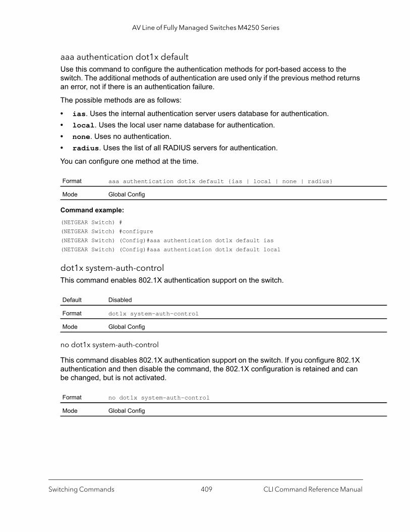
AV Line of Fully Managed Switches M4250 Series
aaa authentication dot1x defaultUse this command to configure the authentication methods for port-based access to the switch. The additional methods of authentication are used only if the previous method returns an error, not if there is an authentication failure.
The possible methods are as follows:
• ias. Uses the internal authentication server users database for authentication. • local. Uses the local user name database for authentication.• none. Uses no authentication.• radius. Uses the list of all RADIUS servers for authentication.
You can configure one method at the time.
Command example: (NETGEAR Switch) #(NETGEAR Switch) #configure(NETGEAR Switch) (Config)#aaa authentication dot1x default ias(NETGEAR Switch) (Config)#aaa authentication dot1x default local
dot1x system-auth-controlThis command enables 802.1X authentication support on the switch.
no dot1x system-auth-control
This command disables 802.1X authentication support on the switch. If you configure 802.1X authentication and then disable the command, the 802.1X configuration is retained and can be changed, but is not activated.
Format aaa authentication dot1x default {ias | local | none | radius}
Mode Global Config
Default Disabled
Format dot1x system-auth-control
Mode Global Config
Format no dot1x system-auth-control
Mode Global Config
Switching Commands CLI Command Reference Manual409
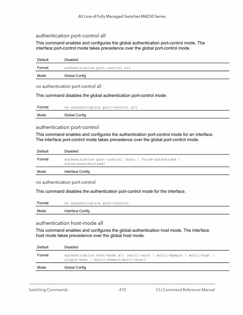
AV Line of Fully Managed Switches M4250 Series
authentication port-control allThis command enables and configures the global authentication port-control mode. The interface port-control mode takes precedence over the global port-control mode.
no authentication port-control all
This command disables the global authentication port-control mode.
authentication port-controlThis command enables and configures the authentication port-control mode for an interface. The interface port-control mode takes precedence over the global port-control mode.
no authentication port-control
This command disables the authentication port-control mode for the interface.
authentication host-mode allThis command enables and configures the global authentication host mode. The interface host mode takes precedence over the global host mode.
Default Disabled
Format authentication port-control all
Mode Global Config
Format no authentication port-control all
Mode Global Config
Default Disabled
Format authentication port-control {auto | force-authorized | force-unauthorized}
Mode Interface Config
Format no authentication port-control
Mode Interface Config
Default Disabled
Format authentication host-mode all {multi-auth | multi-domain | multi-host | single-host | multi-domain-multi-host}
Mode Global Config
Switching Commands CLI Command Reference Manual410
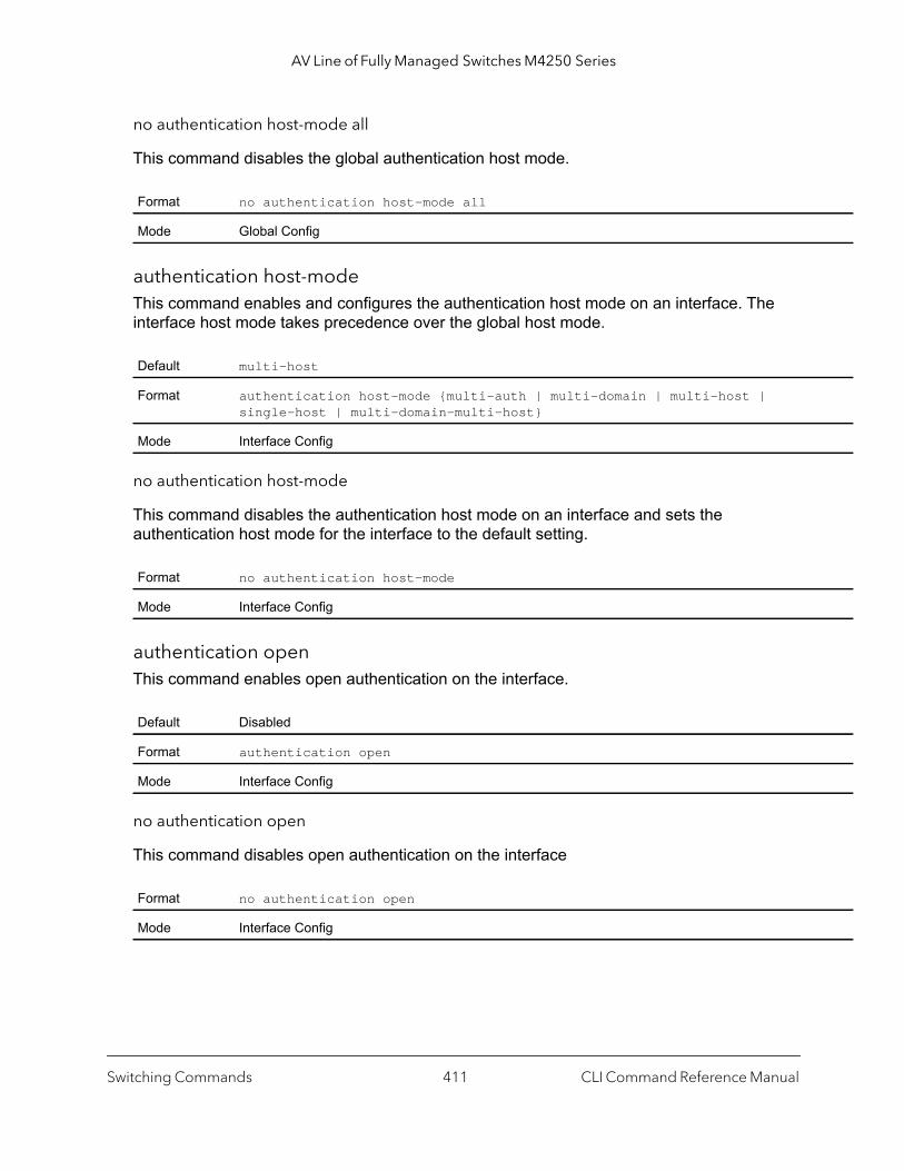
AV Line of Fully Managed Switches M4250 Series
no authentication host-mode all
This command disables the global authentication host mode.
authentication host-modeThis command enables and configures the authentication host mode on an interface. The interface host mode takes precedence over the global host mode.
no authentication host-mode
This command disables the authentication host mode on an interface and sets the authentication host mode for the interface to the default setting.
authentication openThis command enables open authentication on the interface.
no authentication open
This command disables open authentication on the interface
Format no authentication host-mode all
Mode Global Config
Default multi-host
Format authentication host-mode {multi-auth | multi-domain | multi-host | single-host | multi-domain-multi-host}
Mode Interface Config
Format no authentication host-mode
Mode Interface Config
Default Disabled
Format authentication open
Mode Interface Config
Format no authentication open
Mode Interface Config
Switching Commands CLI Command Reference Manual411

AV Line of Fully Managed Switches M4250 Series
clear authentication sessionsThis command clears information for all authentication manager sessions on the switch or, as an option, on a specific interface. All authenticated clients are re-initialized and forced to authenticate again.
clear dot1x statisticsThis command resets the 802.1X statistics for the specified port or for all ports.
clear radius statisticsThis command is used to clear all RADIUS statistics.
dot1x eapolflood Use this command to enable EAPOL flood support on the switch.
no dot1x eapolflood
This command disables EAPOL flooding on the switch.
Format clear authentication sessions [unit/port]
Mode Privileged EXEC
Format clear dot1x statistics {unit/port | all}
Mode Privileged EXEC
Format clear radius statistics
Mode Privileged EXEC
Default Disabled
Format dot1x eapolflood
Mode Global Config
Format no dot1x eapolflood
Mode Global Config
Switching Commands CLI Command Reference Manual412
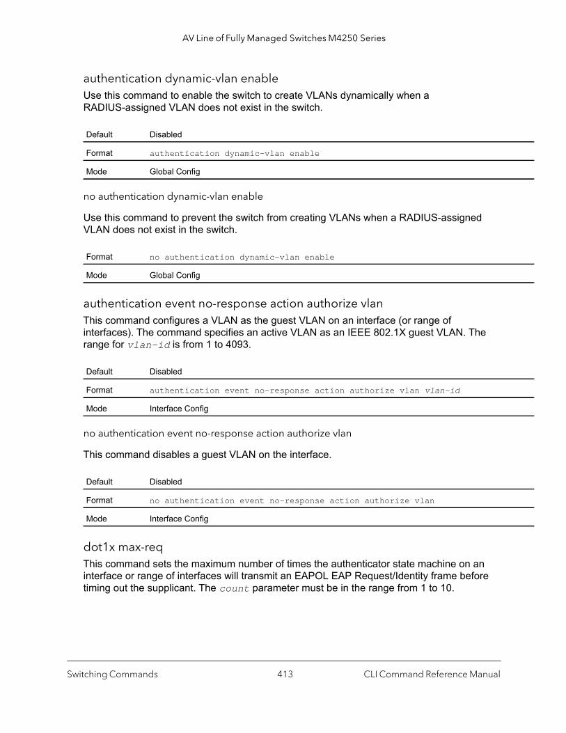
AV Line of Fully Managed Switches M4250 Series
authentication dynamic-vlan enableUse this command to enable the switch to create VLANs dynamically when a RADIUS-assigned VLAN does not exist in the switch.
no authentication dynamic-vlan enable
Use this command to prevent the switch from creating VLANs when a RADIUS-assigned VLAN does not exist in the switch.
authentication event no-response action authorize vlanThis command configures a VLAN as the guest VLAN on an interface (or range of interfaces). The command specifies an active VLAN as an IEEE 802.1X guest VLAN. The range for vlan-id is from 1 to 4093.
no authentication event no-response action authorize vlan
This command disables a guest VLAN on the interface.
dot1x max-reqThis command sets the maximum number of times the authenticator state machine on an interface or range of interfaces will transmit an EAPOL EAP Request/Identity frame before timing out the supplicant. The count parameter must be in the range from 1 to 10.
Default Disabled
Format authentication dynamic-vlan enable
Mode Global Config
Format no authentication dynamic-vlan enable
Mode Global Config
Default Disabled
Format authentication event no-response action authorize vlan vlan-id
Mode Interface Config
Default Disabled
Format no authentication event no-response action authorize vlan
Mode Interface Config
Switching Commands CLI Command Reference Manual413
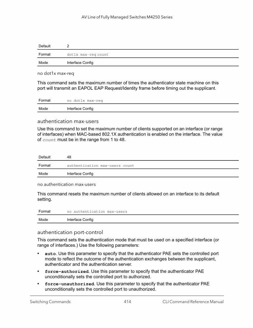
AV Line of Fully Managed Switches M4250 Series
no dot1x max-req
This command sets the maximum number of times the authenticator state machine on this port will transmit an EAPOL EAP Request/Identity frame before timing out the supplicant.
authentication max-usersUse this command to set the maximum number of clients supported on an interface (or range of interfaces) when MAC-based 802.1X authentication is enabled on the interface. The value of count must be in the range from 1 to 48.
no authentication max-users
This command resets the maximum number of clients allowed on an interface to its default setting.
authentication port-controlThis command sets the authentication mode that must be used on a specified interface (or range of interfaces.) Use the following parameters:
• auto. Use this parameter to specify that the authenticator PAE sets the controlled port mode to reflect the outcome of the authentication exchanges between the supplicant, authenticator and the authentication server.
• force-authorized. Use this parameter to specify that the authenticator PAE unconditionally sets the controlled port to authorized.
• force-unauthorized. Use this parameter to specify that the authenticator PAE unconditionally sets the controlled port to unauthorized.
Default 2
Format dot1x max-req count
Mode Interface Config
Format no dot1x max-req
Mode Interface Config
Default 48
Format authentication max-users count
Mode Interface Config
Format no authentication max-users
Mode Interface Config
Switching Commands CLI Command Reference Manual414

AV Line of Fully Managed Switches M4250 Series
d}
no authentication port-control
This command sets the 802.1X port control mode on a specified interface to the default setting.
mabIf the 802.1X mode on the interface is MAC-based, you can use this command to enable MAC Authentication Bypass (MAB) on an interface. MAB is a supplemental authentication mechanism that allows 802.1X-unaware clients, such as printers, fax machines, and some IP phones, to authenticate to the network using the client MAC address as an identifier. However, you can also use MAB to authenticate 802.1x-aware clients. This command also provides options to specify the type of authentication that must be used, which can be EAP-MD5, PAP, or CHAP. If enabled, EAP-MD5 is the default setting.
no mab
This command disables MAB on the interface
authentication periodicThis command enables reauthentication of a supplicant on the interface (or range of interfaces.)
Default auto
Format authentication port-control {auto | force-authorized | force-unauthorize
Mode Interface Config
Format no authentication port-control
Mode Interface Config
Default Disabled
Format mab [auth-type {pap | eap-md5 | chap}]
Mode Interface Config
Format no mab
Mode Interface Config
Default Disabled
Format authentication periodic
Mode Interface Config
Switching Commands CLI Command Reference Manual415
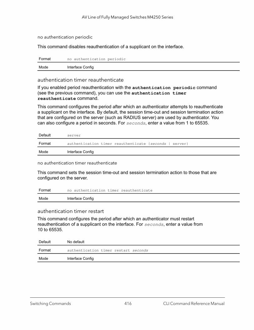
AV Line of Fully Managed Switches M4250 Series
no authentication periodic
This command disables reauthentication of a supplicant on the interface.
authentication timer reauthenticateIf you enabled period reauthentication with the authentication periodic command (see the previous command), you can use the authentication timer reauthenticate command.
This command configures the period after which an authenticator attempts to reauthenticate a supplicant on the interface. By default, the session time-out and session termination action that are configured on the server (such as RADIUS server) are used by authenticator. You can also configure a period in seconds. For seconds, enter a value from 1 to 65535.
no authentication timer reauthenticate
This command sets the session time-out and session termination action to those that are configured on the server.
authentication timer restartThis command configures the period after which an authenticator must restart reauthentication of a supplicant on the interface. For seconds, enter a value from 10 to 65535.
Format no authentication periodic
Mode Interface Config
Default server
Format authentication timer reauthenticate {seconds | server}
Mode Interface Config
Format no authentication timer reauthenticate
Mode Interface Config
Default No default
Format authentication timer restart seconds
Mode Interface Config
Switching Commands CLI Command Reference Manual416
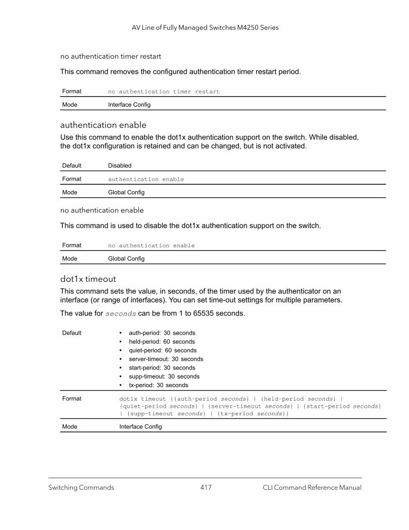
AV Line of Fully Managed Switches M4250 Series
nds}
no authentication timer restart
This command removes the configured authentication timer restart period.
authentication enableUse this command to enable the dot1x authentication support on the switch. While disabled, the dot1x configuration is retained and can be changed, but is not activated.
no authentication enable
This command is used to disable the dot1x authentication support on the switch.
dot1x timeoutThis command sets the value, in seconds, of the timer used by the authenticator on an interface (or range of interfaces). You can set time-out settings for multiple parameters.
The value for seconds can be from 1 to 65535 seconds.
Format no authentication timer restart
Mode Interface Config
Default Disabled
Format authentication enable
Mode Global Config
Format no authentication enable
Mode Global Config
Default • auth-period: 30 seconds• held-period: 60 seconds• quiet-period: 60 seconds• server-timeout: 30 seconds• start-period: 30 seconds• supp-timeout: 30 seconds• tx-period: 30 seconds
Format dot1x timeout {{auth-period seconds} | {held-period seconds} | {quiet-period seconds} | {server-timeout seconds} | {start-period seco| {supp-timeout seconds} | {tx-period seconds}}
Mode Interface Config
Switching Commands CLI Command Reference Manual417
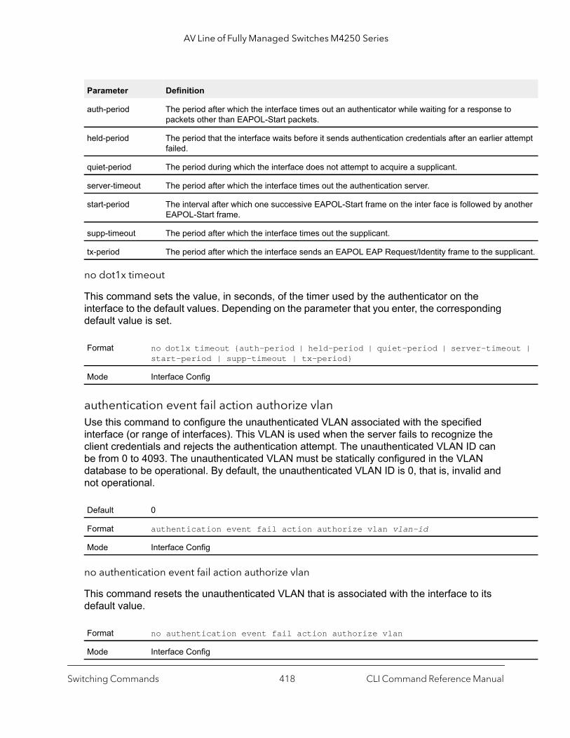
AV Line of Fully Managed Switches M4250 Series
empt
other
licant.
t |
no dot1x timeout
This command sets the value, in seconds, of the timer used by the authenticator on the interface to the default values. Depending on the parameter that you enter, the corresponding default value is set.
authentication event fail action authorize vlanUse this command to configure the unauthenticated VLAN associated with the specified interface (or range of interfaces). This VLAN is used when the server fails to recognize the client credentials and rejects the authentication attempt. The unauthenticated VLAN ID can be from 0 to 4093. The unauthenticated VLAN must be statically configured in the VLAN database to be operational. By default, the unauthenticated VLAN ID is 0, that is, invalid and not operational.
no authentication event fail action authorize vlan
This command resets the unauthenticated VLAN that is associated with the interface to its default value.
Parameter Definition
auth-period The period after which the interface times out an authenticator while waiting for a response to packets other than EAPOL-Start packets.
held-period The period that the interface waits before it sends authentication credentials after an earlier attfailed.
quiet-period The period during which the interface does not attempt to acquire a supplicant.
server-timeout The period after which the interface times out the authentication server.
start-period The interval after which one successive EAPOL-Start frame on the inter face is followed by anEAPOL-Start frame.
supp-timeout The period after which the interface times out the supplicant.
tx-period The period after which the interface sends an EAPOL EAP Request/Identity frame to the supp
Format no dot1x timeout {auth-period | held-period | quiet-period | server-timeoustart-period | supp-timeout | tx-period}
Mode Interface Config
Default 0
Format authentication event fail action authorize vlan vlan-id
Mode Interface Config
Format no authentication event fail action authorize vlan
Mode Interface Config
Switching Commands CLI Command Reference Manual418

AV Line of Fully Managed Switches M4250 Series
authentication event fail retryThis command configures the number of times authentication can be reattempted by a client before an interface enter the authentication fail VLAN state. The number of maximum attempts can be from 1 to 5.
no authentication event fail retry
This command set the number of times authentication can be reattempted to its default value.
dot1x userThis command adds the specified user to the list of users with access to the specified port or all ports. The user argument must be a configured user.
no dot1x user
This command removes the user from the list of users with access to the specified port or all ports.
authentication enableThis command globally enables the authentication manager. Interface configuration takes effect only if the authentication manager is enabled with this command.
Default 3
Format authentication event fail retry max-attempts
Mode Interface Config
Format no authentication event fail retry
Mode Interface Config
Format dot1x user user {unit/port | all}
Mode Global Config
Format no dot1x user user {unit/port | all}
Mode Global Config
Default Disabled
Format authentication enable
Mode Global Config
Switching Commands CLI Command Reference Manual419
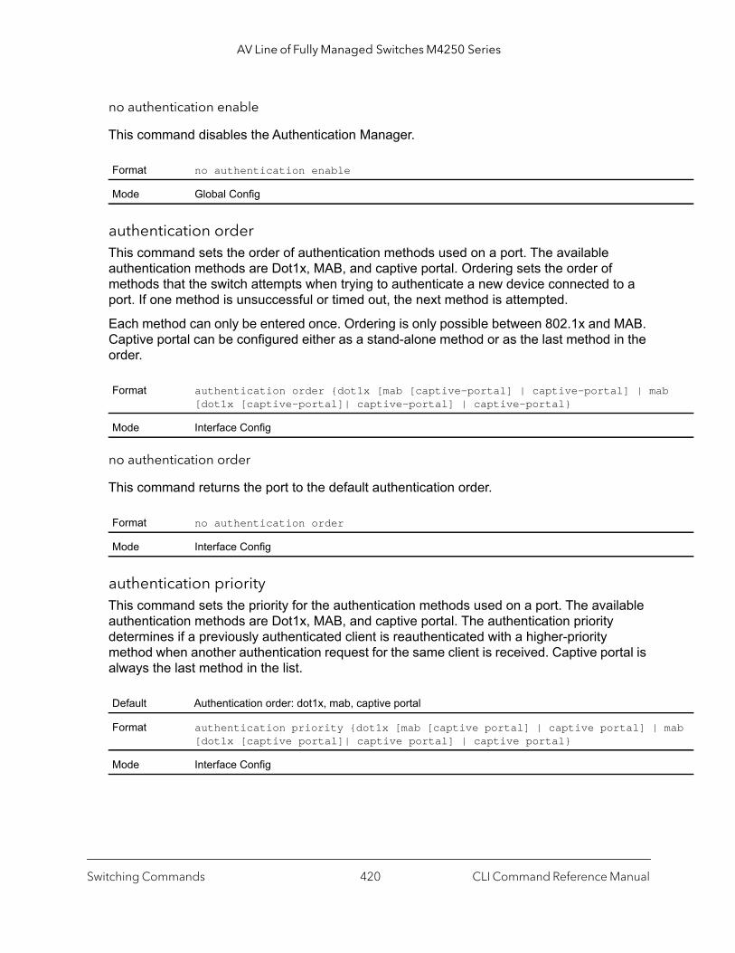
AV Line of Fully Managed Switches M4250 Series
b
mab
no authentication enable
This command disables the Authentication Manager.
authentication orderThis command sets the order of authentication methods used on a port. The available authentication methods are Dot1x, MAB, and captive portal. Ordering sets the order of methods that the switch attempts when trying to authenticate a new device connected to a port. If one method is unsuccessful or timed out, the next method is attempted.
Each method can only be entered once. Ordering is only possible between 802.1x and MAB. Captive portal can be configured either as a stand-alone method or as the last method in the order.
no authentication order
This command returns the port to the default authentication order.
authentication priorityThis command sets the priority for the authentication methods used on a port. The available authentication methods are Dot1x, MAB, and captive portal. The authentication priority determines if a previously authenticated client is reauthenticated with a higher-priority method when another authentication request for the same client is received. Captive portal is always the last method in the list.
Format no authentication enable
Mode Global Config
Format authentication order {dot1x [mab [captive-portal] | captive-portal] | ma[dot1x [captive-portal]| captive-portal] | captive-portal}
Mode Interface Config
Format no authentication order
Mode Interface Config
Default Authentication order: dot1x, mab, captive portal
Format authentication priority {dot1x [mab [captive portal] | captive portal] | [dot1x [captive portal]| captive portal] | captive portal}
Mode Interface Config
Switching Commands CLI Command Reference Manual420

AV Line of Fully Managed Switches M4250 Series
no authentication priority
This command returns the port to the default order of priority for the authentication methods.
authentication restartThis command sets the time, in seconds, after which reauthentication starts. The range is 300–65535 seconds and the default time is 300 seconds. The timer restarts the authentication only after all the authentication methods fail. At the expiration of this timer, authentication is reinitiated for the port.
no authentication restart
This command sets the reauthentication value to the default value of 3600 seconds.
authentication allow-unauth dhcpThis command enables DHCP packets for unauthorized clients on the interface.
no authentication allow-unauth dhcp
This command disables DHCP packets for unauthorized clients on the interface.
authentication monitorThis command enables the authentication monitor mode on the switch. The purpose of the monitor mode is to help troubleshoot port-based authentication configuration issues without disrupting network access for hosts that are connected to the switch. In monitor mode, a host
Format no authentication priority
Mode Interface Config
Format authentication restart seconds
Mode Interface Config
Format no authentication restart
Mode Interface Config
Default Disabled
Format authentication allow-unauth dhcp
Mode Interface Config
Format no authentication allow-unauth dhcp
Mode Interface Config
Switching Commands CLI Command Reference Manual421
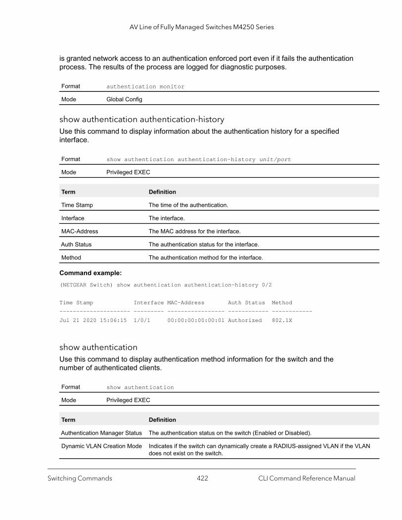
AV Line of Fully Managed Switches M4250 Series
AN
is granted network access to an authentication enforced port even if it fails the authentication process. The results of the process are logged for diagnostic purposes.
show authentication authentication-historyUse this command to display information about the authentication history for a specified interface.
Command example: (NETGEAR Switch) show authentication authentication-history 0/2
Time Stamp Interface MAC-Address Auth Status Method--------------------- --------- ----------------- ------------ ------------Jul 21 2020 15:06:15 1/0/1 00:00:00:00:00:01 Authorized 802.1X
show authenticationUse this command to display authentication method information for the switch and the number of authenticated clients.
Format authentication monitor
Mode Global Config
Format show authentication authentication-history unit/port
Mode Privileged EXEC
Term Definition
Time Stamp The time of the authentication.
Interface The interface.
MAC-Address The MAC address for the interface.
Auth Status The authentication status for the interface.
Method The authentication method for the interface.
Format show authentication
Mode Privileged EXEC
Term Definition
Authentication Manager Status The authentication status on the switch (Enabled or Disabled).
Dynamic VLAN Creation Mode Indicates if the switch can dynamically create a RADIUS-assigned VLAN if the VLdoes not exist on the switch.
Switching Commands CLI Command Reference Manual422
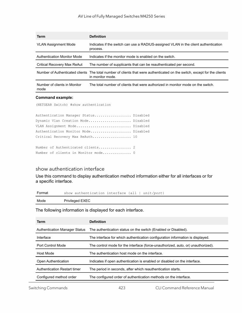
AV Line of Fully Managed Switches M4250 Series
ion
lients
Command example: (NETGEAR Switch) #show authentication
Authentication Manager Status.................. DisabledDynamic Vlan Creation Mode..................... DisabledVLAN Assignment Mode........................... DisabledAuthentication Monitor Mode.................... DisabledCritical Recovery Max ReAuth................... 10
Number of Authenticated clients................ 2Number of clients in Monitor mode.............. 0
show authentication interfaceUse this command to display authentication method information either for all interfaces or for a specific interface.
The following information is displayed for each interface.
VLAN Assignment Mode Indicates if the switch can use a RADIUS-assigned VLAN in the client authenticatprocess.
Authentication Monitor Mode Indicates if the monitor mode is enabled on the switch.
Critical Recovery Max ReAut The number of supplicants that can be reauthenticated per second.
Number of Authenticated clients The total number of clients that were authenticated on the switch, except for the cin monitor mode.
Number of clients in Monitor mode
The total number of clients that were authorized in monitor mode on the switch.
Format show authentication interface {all | unit/port}
Mode Privileged EXEC
Term Definition
Authentication Manager Status The authentication status on the switch (Enabled or Disabled).
Interface The interface for which authentication configuration information is displayed.
Port Control Mode The control mode for the interface (force-unauthorized, auto, or| unauthorized).
Host Mode The authentication host mode on the interface.
Open Authentication Indicates if open authentication is enabled or disabled on the interface.
Authentication Restart timer The period in seconds, after which reauthentication starts.
Configured method order The configured order of authentication methods on the interface.
Term Definition
Switching Commands CLI Command Reference Manual423
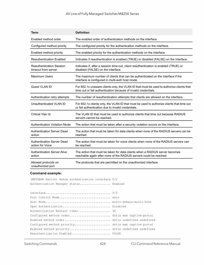
AV Line of Fully Managed Switches M4250 Series
ce.
s that
e out
S
n be
can
Command example: (NETGEAR Switch) #show authentication interface 0/2Authentication Manager Status.................. Enabled
Interface...................................... 0/2Port Control Mode.............................. autoHost Mode...................................... multi-domain-multi-hostOpen Authentication............................ DisabledAuthentication Restart timer................... 30Configured method order........................ dot1x mab captive-portalEnabled method order........................... dot1x undefined undefinedConfigured method priority..................... dot1x mab captive-portalEnabled method priority........................ dot1x undefined undefinedReauthentication Enabled....................... FALSE
Enabled method order The enabled order of authentication methods on the interface.
Configured method priority The configured priority for the authentication methods on the interface.
Enabled method priority The enabled priority for the authentication methods on the interface.
Reauthentication Enabled Indicates if reauthentication is enabled (TRUE) or disabled (FALSE) on the interfa
Reauthentication Session timeout from server
Indicates if, after a session time-out, client reauthentication is enabled (TRUE) or disabled (FALSE) on the interface.
Maximum Users The maximum number of clients that can be authenticated on the interface if the interface is configured in multi-auth host mode.
Guest VLAN ID For 802.1x unaware clients only, the VLAN ID that must be used to authorize clienttime out or fail authentication because of invalid credentials.
Authentication retry attempts The number of reauthentication attempts that clients are allowed on the interface.
Unauthenticated VLAN ID For 802.1x clients only, the VLAN ID that must be used to authorize clients that timor fail authentication due to invalid credentials.
Critical Vlan Id The VLAN ID that must be used to authorize clients that time out because RADIUservers cannot be reached.
Authentication Violation Mode The action that must be taken after a security violation occurs on the interface.
Authentication Server Dead action
The action that must be taken for data clients when none of the RADIUS servers careached.
Authentication Server Dead action for Voice
The action that must be taken for voice clients when none of the RADIUS serversbe reached.
Authentication Server Alive action
The action that must be taken for data clients when a RADIUS server becomes reachable again after none of the RADIUS servers could be reached.
Allowed protocols on unauthorized port
The protocols that are permitted on the unauthorized interface.
Term Definition
Switching Commands CLI Command Reference Manual424
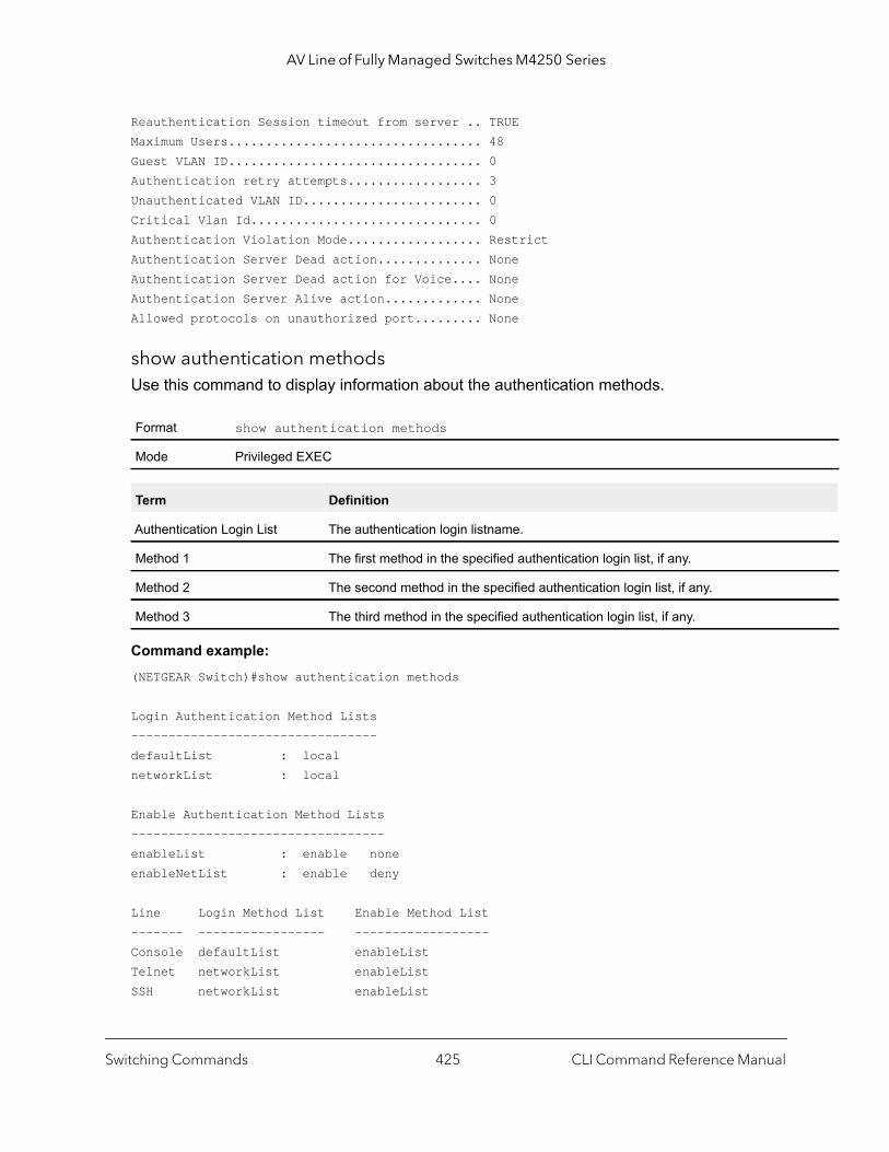
AV Line of Fully Managed Switches M4250 Series
Reauthentication Session timeout from server .. TRUEMaximum Users.................................. 48Guest VLAN ID.................................. 0Authentication retry attempts.................. 3Unauthenticated VLAN ID........................ 0Critical Vlan Id............................... 0Authentication Violation Mode.................. RestrictAuthentication Server Dead action.............. NoneAuthentication Server Dead action for Voice.... NoneAuthentication Server Alive action............. NoneAllowed protocols on unauthorized port......... None
show authentication methodsUse this command to display information about the authentication methods.
Command example: (NETGEAR Switch)#show authentication methods
Login Authentication Method Lists---------------------------------defaultList : localnetworkList : local
Enable Authentication Method Lists----------------------------------enableList : enable noneenableNetList : enable deny
Line Login Method List Enable Method List------- ----------------- ------------------Console defaultList enableListTelnet networkList enableListSSH networkList enableList
Format show authentication methods
Mode Privileged EXEC
Term Definition
Authentication Login List The authentication login listname.
Method 1 The first method in the specified authentication login list, if any.
Method 2 The second method in the specified authentication login list, if any.
Method 3 The third method in the specified authentication login list, if any.
Switching Commands CLI Command Reference Manual425
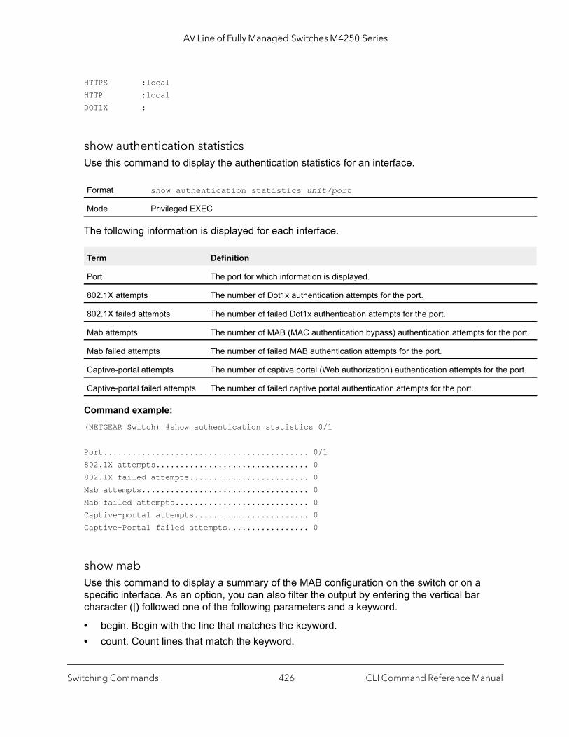
AV Line of Fully Managed Switches M4250 Series
port.
ort.
HTTPS :localHTTP :localDOT1X :
show authentication statisticsUse this command to display the authentication statistics for an interface.
The following information is displayed for each interface.
Command example: (NETGEAR Switch) #show authentication statistics 0/1
Port........................................... 0/1802.1X attempts................................ 0802.1X failed attempts......................... 0Mab attempts................................... 0Mab failed attempts............................ 0Captive-portal attempts........................ 0Captive-Portal failed attempts................. 0
show mabUse this command to display a summary of the MAB configuration on the switch or on a specific interface. As an option, you can also filter the output by entering the vertical bar character (|) followed one of the following parameters and a keyword.
• begin. Begin with the line that matches the keyword.• count. Count lines that match the keyword.
Format show authentication statistics unit/port
Mode Privileged EXEC
Term Definition
Port The port for which information is displayed.
802.1X attempts The number of Dot1x authentication attempts for the port.
802.1X failed attempts The number of failed Dot1x authentication attempts for the port.
Mab attempts The number of MAB (MAC authentication bypass) authentication attempts for the
Mab failed attempts The number of failed MAB authentication attempts for the port.
Captive-portal attempts The number of captive portal (Web authorization) authentication attempts for the p
Captive-portal failed attempts The number of failed captive portal authentication attempts for the port.
Switching Commands CLI Command Reference Manual426
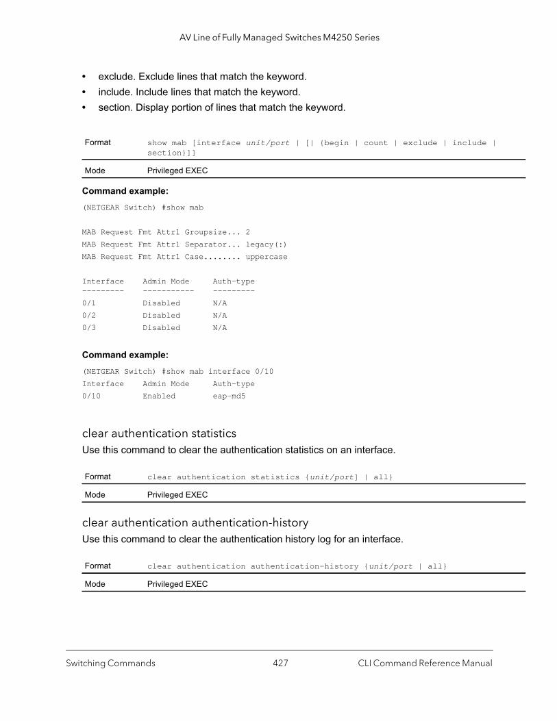
AV Line of Fully Managed Switches M4250 Series
• exclude. Exclude lines that match the keyword.• include. Include lines that match the keyword.• section. Display portion of lines that match the keyword.
Command example: (NETGEAR Switch) #show mab
MAB Request Fmt Attr1 Groupsize... 2MAB Request Fmt Attr1 Separator... legacy(:)MAB Request Fmt Attr1 Case........ uppercase
Interface Admin Mode Auth-type --------- ----------- ---------0/1 Disabled N/A0/2 Disabled N/A0/3 Disabled N/A
Command example: (NETGEAR Switch) #show mab interface 0/10Interface Admin Mode Auth-type 0/10 Enabled eap-md5
clear authentication statisticsUse this command to clear the authentication statistics on an interface.
clear authentication authentication-historyUse this command to clear the authentication history log for an interface.
Format show mab [interface unit/port | [| {begin | count | exclude | include | section}]]
Mode Privileged EXEC
Format clear authentication statistics {unit/port] | all}
Mode Privileged EXEC
Format clear authentication authentication-history {unit/port | all}
Mode Privileged EXEC
Switching Commands CLI Command Reference Manual427
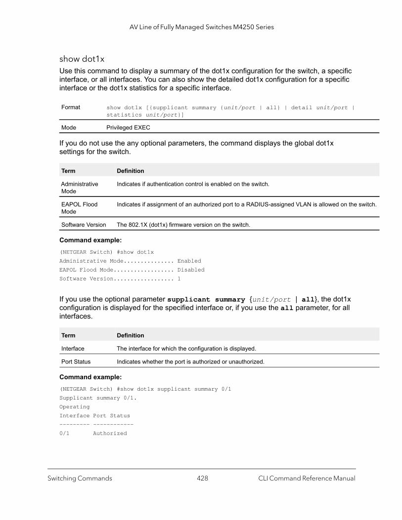
AV Line of Fully Managed Switches M4250 Series
witch.
show dot1xUse this command to display a summary of the dot1x configuration for the switch, a specific interface, or all interfaces. You can also show the detailed dot1x configuration for a specific interface or the dot1x statistics for a specific interface.
If you do not use the any optional parameters, the command displays the global dot1x settings for the switch.
Command example: (NETGEAR Switch) #show dot1xAdministrative Mode............... EnabledEAPOL Flood Mode.................. DisabledSoftware Version.................. 1
If you use the optional parameter supplicant summary {unit/port | all}, the dot1x configuration is displayed for the specified interface or, if you use the all parameter, for all interfaces.
Command example: (NETGEAR Switch) #show dot1x supplicant summary 0/1Supplicant summary 0/1.OperatingInterface Port Status--------- ------------0/1 Authorized
Format show dot1x [{supplicant summary {unit/port | all} | detail unit/port | statistics unit/port}]
Mode Privileged EXEC
Term Definition
Administrative Mode
Indicates if authentication control is enabled on the switch.
EAPOL Flood Mode
Indicates if assignment of an authorized port to a RADIUS-assigned VLAN is allowed on the s
Software Version The 802.1X (dot1x) firmware version on the switch.
Term Definition
Interface The interface for which the configuration is displayed.
Port Status Indicates whether the port is authorized or unauthorized.
Switching Commands CLI Command Reference Manual428
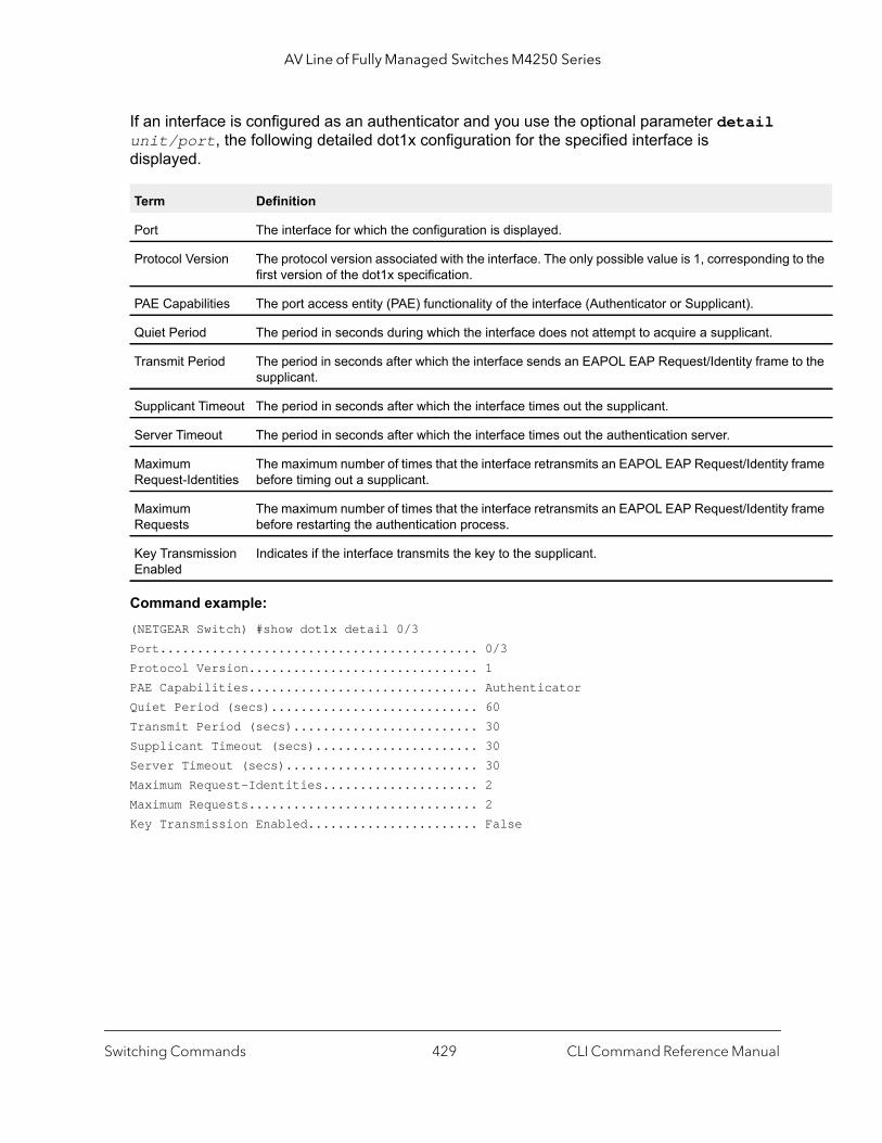
AV Line of Fully Managed Switches M4250 Series
to the
to the
frame
frame
If an interface is configured as an authenticator and you use the optional parameter detail unit/port, the following detailed dot1x configuration for the specified interface is displayed.
Command example: (NETGEAR Switch) #show dot1x detail 0/3Port........................................... 0/3Protocol Version............................... 1PAE Capabilities............................... AuthenticatorQuiet Period (secs)............................ 60Transmit Period (secs)......................... 30Supplicant Timeout (secs)...................... 30Server Timeout (secs).......................... 30Maximum Request-Identities..................... 2Maximum Requests............................... 2Key Transmission Enabled....................... False
Term Definition
Port The interface for which the configuration is displayed.
Protocol Version The protocol version associated with the interface. The only possible value is 1, corresponding first version of the dot1x specification.
PAE Capabilities The port access entity (PAE) functionality of the interface (Authenticator or Supplicant).
Quiet Period The period in seconds during which the interface does not attempt to acquire a supplicant.
Transmit Period The period in seconds after which the interface sends an EAPOL EAP Request/Identity frame supplicant.
Supplicant Timeout The period in seconds after which the interface times out the supplicant.
Server Timeout The period in seconds after which the interface times out the authentication server.
Maximum Request-Identities
The maximum number of times that the interface retransmits an EAPOL EAP Request/Identity before timing out a supplicant.
Maximum Requests
The maximum number of times that the interface retransmits an EAPOL EAP Request/Identity before restarting the authentication process.
Key Transmission Enabled
Indicates if the interface transmits the key to the supplicant.
Switching Commands CLI Command Reference Manual429
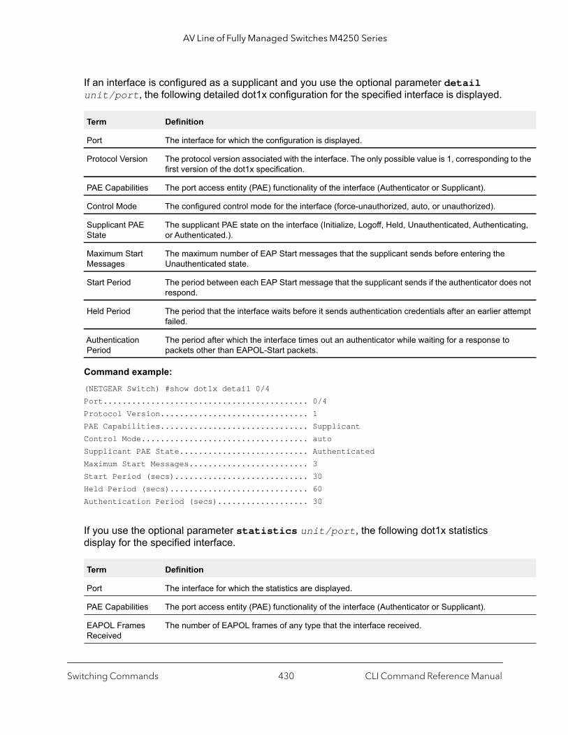
AV Line of Fully Managed Switches M4250 Series
to the
ting,
s not
empt
If an interface is configured as a supplicant and you use the optional parameter detail unit/port, the following detailed dot1x configuration for the specified interface is displayed.
Command example: (NETGEAR Switch) #show dot1x detail 0/4Port........................................... 0/4Protocol Version............................... 1PAE Capabilities............................... SupplicantControl Mode................................... autoSupplicant PAE State........................... AuthenticatedMaximum Start Messages......................... 3Start Period (secs)............................ 30Held Period (secs)............................. 60Authentication Period (secs)................... 30
If you use the optional parameter statistics unit/port, the following dot1x statistics display for the specified interface.
Term Definition
Port The interface for which the configuration is displayed.
Protocol Version The protocol version associated with the interface. The only possible value is 1, corresponding first version of the dot1x specification.
PAE Capabilities The port access entity (PAE) functionality of the interface (Authenticator or Supplicant).
Control Mode The configured control mode for the interface (force-unauthorized, auto, or unauthorized).
Supplicant PAE State
The supplicant PAE state on the interface (Initialize, Logoff, Held, Unauthenticated, Authenticaor Authenticated.).
Maximum Start Messages
The maximum number of EAP Start messages that the supplicant sends before entering the Unauthenticated state.
Start Period The period between each EAP Start message that the supplicant sends if the authenticator doerespond.
Held Period The period that the interface waits before it sends authentication credentials after an earlier attfailed.
Authentication Period
The period after which the interface times out an authenticator while waiting for a response to packets other than EAPOL-Start packets.
Term Definition
Port The interface for which the statistics are displayed.
PAE Capabilities The port access entity (PAE) functionality of the interface (Authenticator or Supplicant).
EAPOL Frames Received
The number of EAPOL frames of any type that the interface received.
Switching Commands CLI Command Reference Manual430
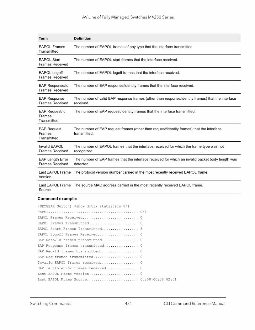
AV Line of Fully Managed Switches M4250 Series
face
was
Command example: (NETGEAR Switch) #show dot1x statistics 0/1Port........................................... 0/1EAPOL Frames Received.......................... 0EAPOL Frames Transmitted....................... 0EAPOL Start Frames Transmitted................. 3EAPOL Logoff Frames Received................... 0EAP Resp/Id frames transmitted................. 0EAP Response frames transmitted................ 0EAP Req/Id frames transmitted.................. 0EAP Req frames transmitted..................... 0Invalid EAPOL frames received.................. 0EAP length error frames received............... 0Last EAPOL Frame Version....................... 0Last EAPOL Frame Source........................ 00:00:00:00:02:01
EAPOL Frames Transmitted
The number of EAPOL frames of any type that the interface transmitted.
EAPOL Start Frames Received
The number of EAPOL start frames that the interface received.
EAPOL Logoff Frames Received
The number of EAPOL logoff frames that the interface received.
EAP Response/Id Frames Received
The number of EAP response/identity frames that the interface received.
EAP Response Frames Received
The number of valid EAP response frames (other than response/identity frames) that the interreceived.
EAP Request/Id Frames Transmitted
The number of EAP request/identity frames that the interface transmitted.
EAP Request Frames Transmitted
The number of EAP request frames (other than request/identity frames) that the interface transmitted.
Invalid EAPOL Frames Received
The number of EAPOL frames that the interface received for which the frame type was not recognized.
EAP Length Error Frames Received
The number of EAP frames that the interface received for which an invalid packet body lengthdetected.
Last EAPOL Frame Version
The protocol version number carried in the most recently received EAPOL frame.
Last EAPOL Frame Source
The source MAC address carried in the most recently received EAPOL frame.
Term Definition
Switching Commands CLI Command Reference Manual431
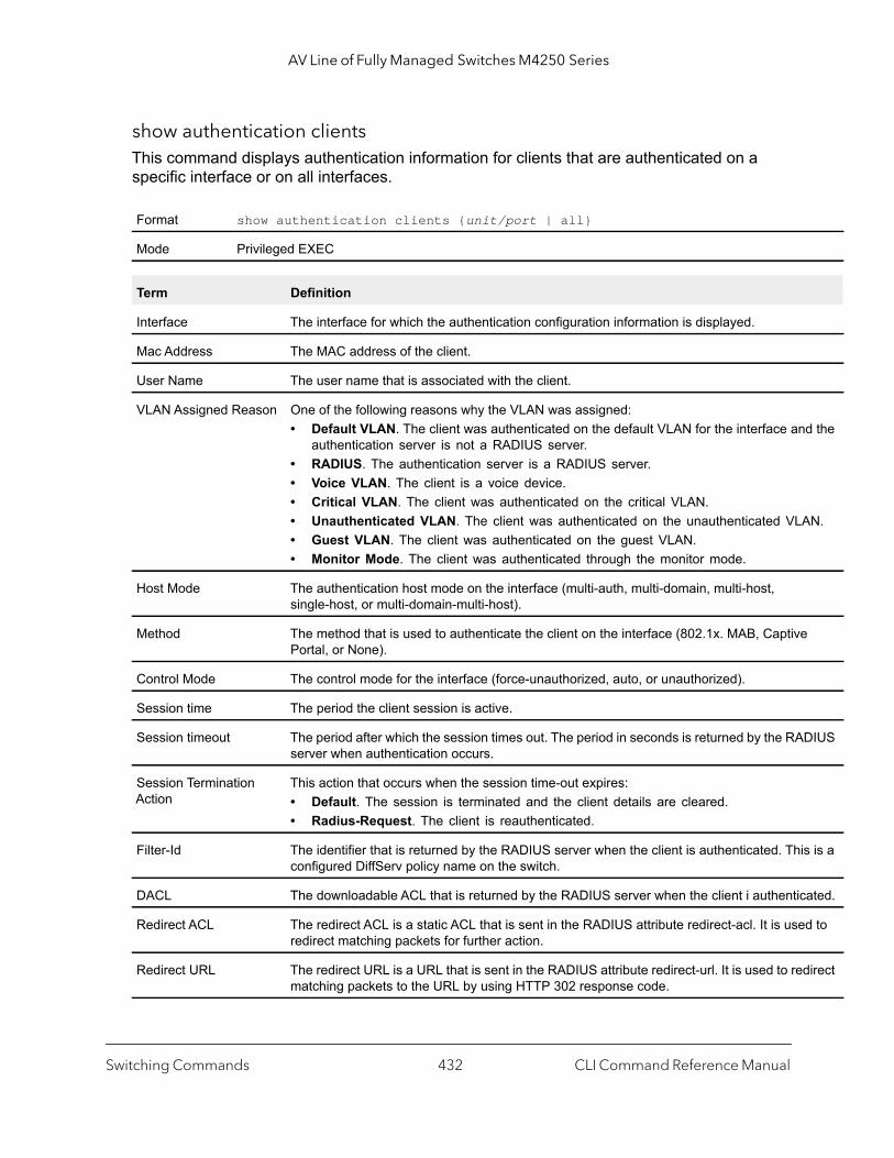
AV Line of Fully Managed Switches M4250 Series
d the
N.
DIUS
s is a
ated.
d to
irect
show authentication clientsThis command displays authentication information for clients that are authenticated on a specific interface or on all interfaces.
Format show authentication clients {unit/port | all}
Mode Privileged EXEC
Term Definition
Interface The interface for which the authentication configuration information is displayed.
Mac Address The MAC address of the client.
User Name The user name that is associated with the client.
VLAN Assigned Reason One of the following reasons why the VLAN was assigned:• Default VLAN. The client was authenticated on the default VLAN for the interface an
authentication server is not a RADIUS server.• RADIUS. The authentication server is a RADIUS server.• Voice VLAN. The client is a voice device.• Critical VLAN. The client was authenticated on the critical VLAN.• Unauthenticated VLAN. The client was authenticated on the unauthenticated VLA• Guest VLAN. The client was authenticated on the guest VLAN.• Monitor Mode. The client was authenticated through the monitor mode.
Host Mode The authentication host mode on the interface (multi-auth, multi-domain, multi-host, single-host, or multi-domain-multi-host).
Method The method that is used to authenticate the client on the interface (802.1x. MAB, CaptivePortal, or None).
Control Mode The control mode for the interface (force-unauthorized, auto, or unauthorized).
Session time The period the client session is active.
Session timeout The period after which the session times out. The period in seconds is returned by the RAserver when authentication occurs.
Session Termination Action
This action that occurs when the session time-out expires:• Default. The session is terminated and the client details are cleared.• Radius-Request. The client is reauthenticated.
Filter-Id The identifier that is returned by the RADIUS server when the client is authenticated. Thiconfigured DiffServ policy name on the switch.
DACL The downloadable ACL that is returned by the RADIUS server when the client i authentic
Redirect ACL The redirect ACL is a static ACL that is sent in the RADIUS attribute redirect-acl. It is useredirect matching packets for further action.
Redirect URL The redirect URL is a URL that is sent in the RADIUS attribute redirect-url. It is used to redmatching packets to the URL by using HTTP 302 response code.
Switching Commands CLI Command Reference Manual432

AV Line of Fully Managed Switches M4250 Series
Command example: (NETGEAR Switch) #show authentication clients 0/2
Mac Address.................................... 58:05:94:1C:00:00User Name...................................... testixiaVLAN Assigned Reason........................... Voice VLAN (100)Host Mode ..................................... multi-authMethod......................................... 802.1XControl Mode................................... autoSession time ... .............................. 0Session timeout ............................... 0Session Termination Action..................... DefaultFilter-Id ..................................... NoneDACL........................................... NoneRedirect ACL................................... IP-REDIRECT-IN-00000001#dRedirect URL................................... http://netgear.com:8080Session Termination Action..................... DefaultAcct SessionId:................................ testixia:200000003
Command example: (NETGEAR Switch) (Interface 0/10)#show authentication clients all
Interface MAC-Address Method Host Mode Control Mode VLAN Assigned Reason--------- ----------------- ------- ------------ ------------ --------------------------0/12 10:8D:B6:C6:00:00 802.1X multi-host auto RADIUS Assigned VLAN (10)
show dot1x usersThis command displays 802.1X port security user information for locally configured users.
Session Termination Action
This action that occurs when the session time-out expires:• Default. The session is terminated and the client details are cleared.• Radius-Request. The client is reauthenticated.
Acct SessionId The accounting session identifier that is associated with the client session.
Format show dot1x users unit/port
Mode Privileged EXEC
Term Definition
Users Users configured locally to have access to the specified port.
Term Definition
Switching Commands CLI Command Reference Manual433

AV Line of Fully Managed Switches M4250 Series
ed}
to an
s.
Command example: (NETGEAR Switch) #show dot1x users 0/12
Users-----------------adminguesttest4
802.1X Supplicant Commands
The switch supports 802.1X (dot1x) supplicant functionality on point-to-point ports. The administrator can configure the user name and password used in authentication and capabilities of the supplicant port.
dot1x paeThis command sets the dot1x role of the interface. The interface can serve as a supplicant, authenticator (the default settings), or neither.
dot1x supplicant port-controlThis command sets the ports authorization state (Authorized or Unauthorized) either manually or by setting the port to auto-authorize upon startup. By default all the ports are authenticators. If the port’s attribute needs to be moved from authenticator to supplicant or from supplicant to authenticator, use this command.
Default authenticator
Format dot1x pae {supplicant | authenticator | none}
Mode Interface Config
Format dot1x supplicant port-control {auto | force-authorized | force-unauthoriz
Mode Interface Config
Parameter Description
auto The port is in the Unauthorized state until it presents its user name and password credentials authenticator. If the authenticator authorizes the port, then it is placed in the Authorized state.
force-authorized Sets the authorization state of the port to Authorized, bypassing the authentication process.
force-unauthorized Sets the authorization state of the port to Unauthorized, bypassing the authentication proces
Switching Commands CLI Command Reference Manual434
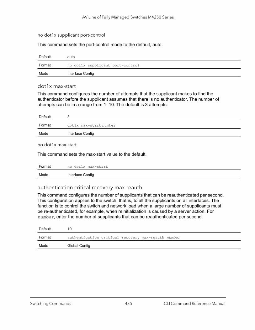
AV Line of Fully Managed Switches M4250 Series
no dot1x supplicant port-control
This command sets the port-control mode to the default, auto.
dot1x max-startThis command configures the number of attempts that the supplicant makes to find the authenticator before the supplicant assumes that there is no authenticator. The number of attempts can be in a range from 1–10. The default is 3 attempts.
no dot1x max-start
This command sets the max-start value to the default.
authentication critical recovery max-reauthThis command configures the number of supplicants that can be reauthenticated per second. This configuration applies to the switch, that is, to all the supplicants on all interfaces. The function is to control the switch and network load when a large number of supplicants must be re-authenticated, for example, when reinitialization is caused by a server action. For number, enter the number of supplicants that can be reauthenticated per second.
Default auto
Format no dot1x supplicant port-control
Mode Interface Config
Default 3
Format dot1x max-start number
Mode Interface Config
Format no dot1x max-start
Mode Interface Config
Default 10
Format authentication critical recovery max-reauth number
Mode Global Config
Switching Commands CLI Command Reference Manual435
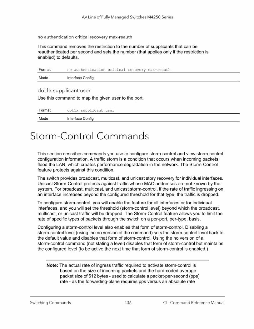
AV Line of Fully Managed Switches M4250 Series
no authentication critical recovery max-reauth
This command removes the restriction to the number of supplicants that can be reauthenticated per second and sets the number (that applies only if the restriction is enabled) to defaults.
dot1x supplicant userUse this command to map the given user to the port.
Storm-Control Commands
This section describes commands you use to configure storm-control and view storm-control configuration information. A traffic storm is a condition that occurs when incoming packets flood the LAN, which creates performance degradation in the network. The Storm-Control feature protects against this condition.
The switch provides broadcast, multicast, and unicast story recovery for individual interfaces. Unicast Storm-Control protects against traffic whose MAC addresses are not known by the system. For broadcast, multicast, and unicast storm-control, if the rate of traffic ingressing on an interface increases beyond the configured threshold for that type, the traffic is dropped.
To configure storm-control, you will enable the feature for all interfaces or for individual interfaces, and you will set the threshold (storm-control level) beyond which the broadcast, multicast, or unicast traffic will be dropped. The Storm-Control feature allows you to limit the rate of specific types of packets through the switch on a per-port, per-type, basis.
Configuring a storm-control level also enables that form of storm-control. Disabling a storm-control level (using the no version of the command) sets the storm-control level back to the default value and disables that form of storm-control. Using the no version of a storm-control command (not stating a level) disables that form of storm-control but maintains the configured level (to be active the next time that form of storm-control is enabled.)
Note: The actual rate of ingress traffic required to activate storm-control is based on the size of incoming packets and the hard-coded average packet size of 512 bytes - used to calculate a packet-per-second (pps) rate - as the forwarding-plane requires pps versus an absolute rate
Format no authentication critical recovery max-reauth
Mode Interface Config
Format dot1x supplicant user
Mode Interface Config
Switching Commands CLI Command Reference Manual436

AV Line of Fully Managed Switches M4250 Series
kbps. For example, if the configured limit is 10 percent, this is converted to ~25000 pps, and this pps limit is set in forwarding plane (hardware). You get the approximate desired output when 512bytes packets are used.
storm-control broadcastUse this command to enable broadcast storm recovery mode for all interfaces (Global Config mode) or one or more interfaces (Interface Config mode). If the mode is enabled, broadcast storm recovery is active and, if the rate of L2 broadcast traffic ingressing on an interface increases beyond the configured threshold, the traffic will be dropped. Therefore, the rate of broadcast traffic will be limited to the configured threshold.
no storm-control broadcast
Use this command to disable broadcast storm recovery mode for all interfaces (Global Config mode) or one or more interfaces (Interface Config mode).
storm-control broadcast actionThis command configures the broadcast storm recovery action to either shut down or send traps for one, several, or all interfaces. If you enter the command in Global Config mode, the action applies to all interfaces. If you enter the command in Interface Config mode, the action applies to or one or more interfaces.
If you specify the shutdown keyword, the interface that receives the broadcast packets at a rate above the threshold is diagnostically disabled. If you specify the trap keyword, the interface sends trap messages approximately every 30 seconds until broadcast storm control recovers.
Default Enabled
Format storm-control broadcast
Mode Global ConfigInterface Config
Format no storm-control broadcast
Mode Global ConfigInterface Config
Format storm-control broadcast action {shutdown | trap}
Mode Global ConfigInterface Config
Switching Commands CLI Command Reference Manual437
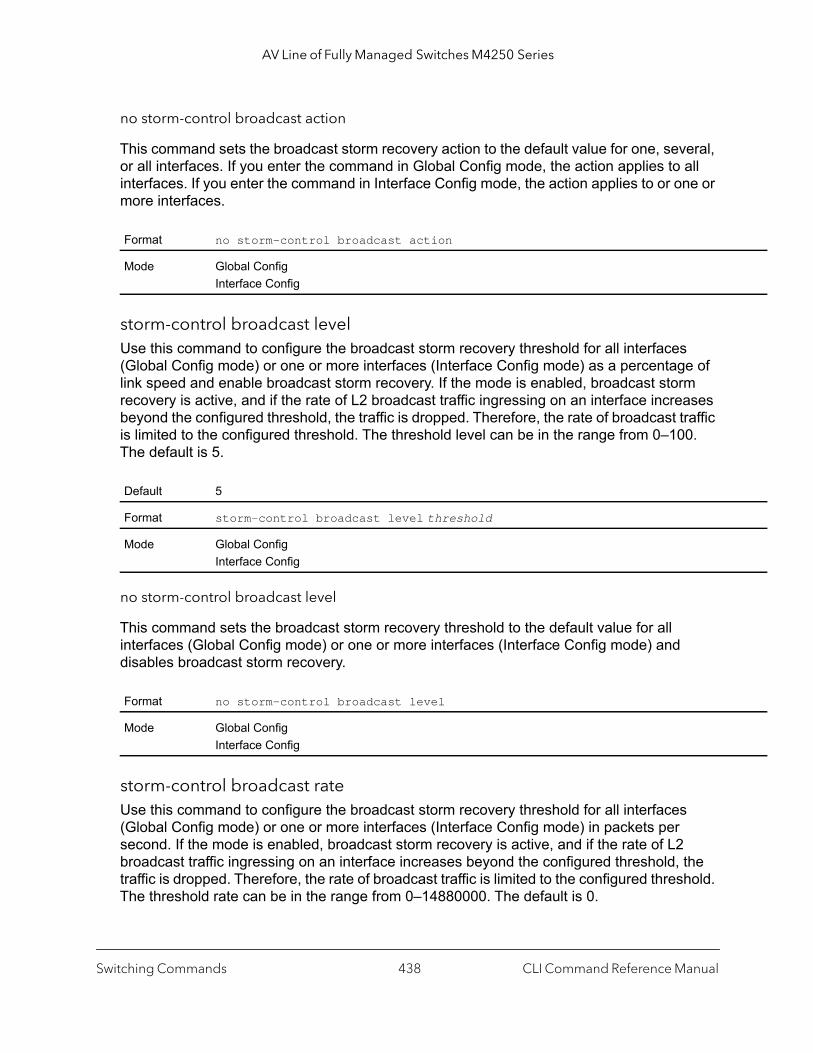
AV Line of Fully Managed Switches M4250 Series
no storm-control broadcast action
This command sets the broadcast storm recovery action to the default value for one, several, or all interfaces. If you enter the command in Global Config mode, the action applies to all interfaces. If you enter the command in Interface Config mode, the action applies to or one or more interfaces.
storm-control broadcast levelUse this command to configure the broadcast storm recovery threshold for all interfaces (Global Config mode) or one or more interfaces (Interface Config mode) as a percentage of link speed and enable broadcast storm recovery. If the mode is enabled, broadcast storm recovery is active, and if the rate of L2 broadcast traffic ingressing on an interface increases beyond the configured threshold, the traffic is dropped. Therefore, the rate of broadcast traffic is limited to the configured threshold. The threshold level can be in the range from 0–100. The default is 5.
no storm-control broadcast level
This command sets the broadcast storm recovery threshold to the default value for all interfaces (Global Config mode) or one or more interfaces (Interface Config mode) and disables broadcast storm recovery.
storm-control broadcast rateUse this command to configure the broadcast storm recovery threshold for all interfaces (Global Config mode) or one or more interfaces (Interface Config mode) in packets per second. If the mode is enabled, broadcast storm recovery is active, and if the rate of L2 broadcast traffic ingressing on an interface increases beyond the configured threshold, the traffic is dropped. Therefore, the rate of broadcast traffic is limited to the configured threshold. The threshold rate can be in the range from 0–14880000. The default is 0.
Format no storm-control broadcast action
Mode Global ConfigInterface Config
Default 5
Format storm-control broadcast level threshold
Mode Global ConfigInterface Config
Format no storm-control broadcast level
Mode Global ConfigInterface Config
Switching Commands CLI Command Reference Manual438
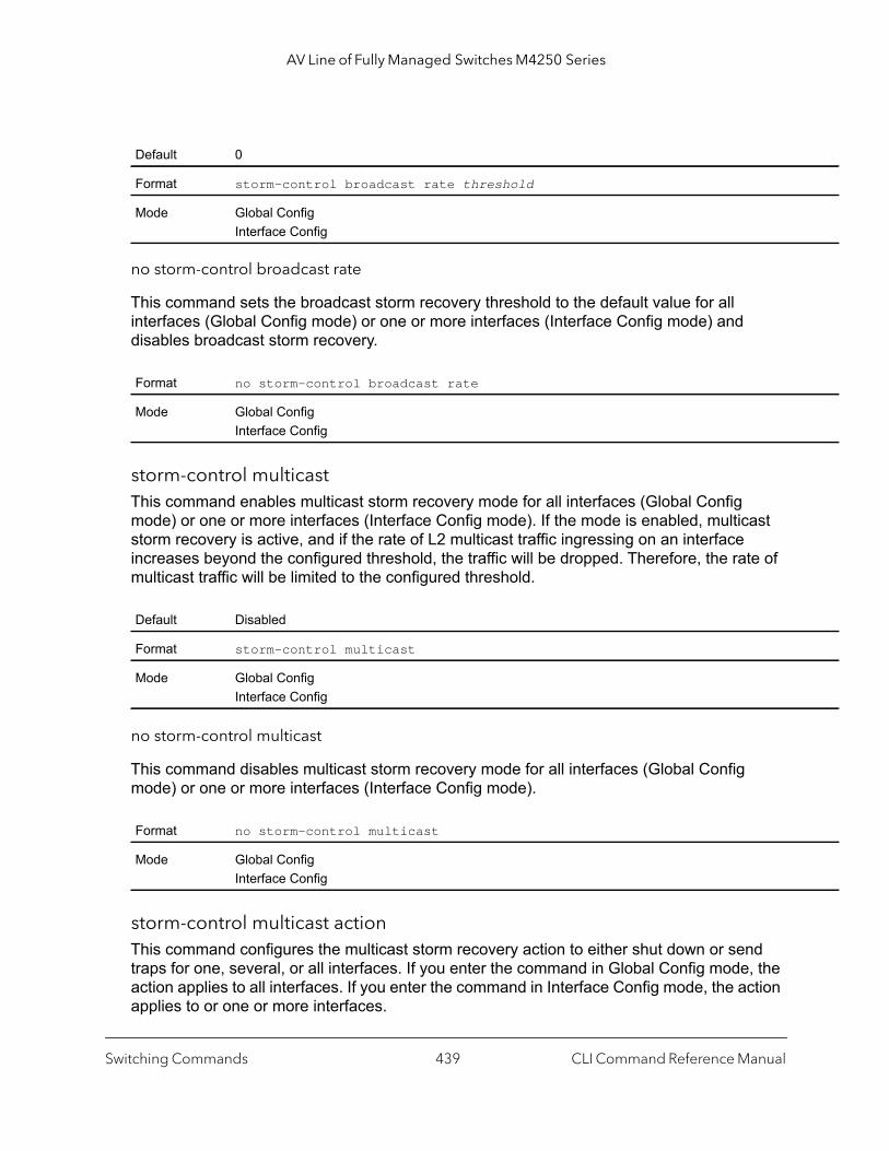
AV Line of Fully Managed Switches M4250 Series
no storm-control broadcast rate
This command sets the broadcast storm recovery threshold to the default value for all interfaces (Global Config mode) or one or more interfaces (Interface Config mode) and disables broadcast storm recovery.
storm-control multicastThis command enables multicast storm recovery mode for all interfaces (Global Config mode) or one or more interfaces (Interface Config mode). If the mode is enabled, multicast storm recovery is active, and if the rate of L2 multicast traffic ingressing on an interface increases beyond the configured threshold, the traffic will be dropped. Therefore, the rate of multicast traffic will be limited to the configured threshold.
no storm-control multicast
This command disables multicast storm recovery mode for all interfaces (Global Config mode) or one or more interfaces (Interface Config mode).
storm-control multicast actionThis command configures the multicast storm recovery action to either shut down or send traps for one, several, or all interfaces. If you enter the command in Global Config mode, the action applies to all interfaces. If you enter the command in Interface Config mode, the action applies to or one or more interfaces.
Default 0
Format storm-control broadcast rate threshold
Mode Global ConfigInterface Config
Format no storm-control broadcast rate
Mode Global ConfigInterface Config
Default Disabled
Format storm-control multicast
Mode Global ConfigInterface Config
Format no storm-control multicast
Mode Global ConfigInterface Config
Switching Commands CLI Command Reference Manual439
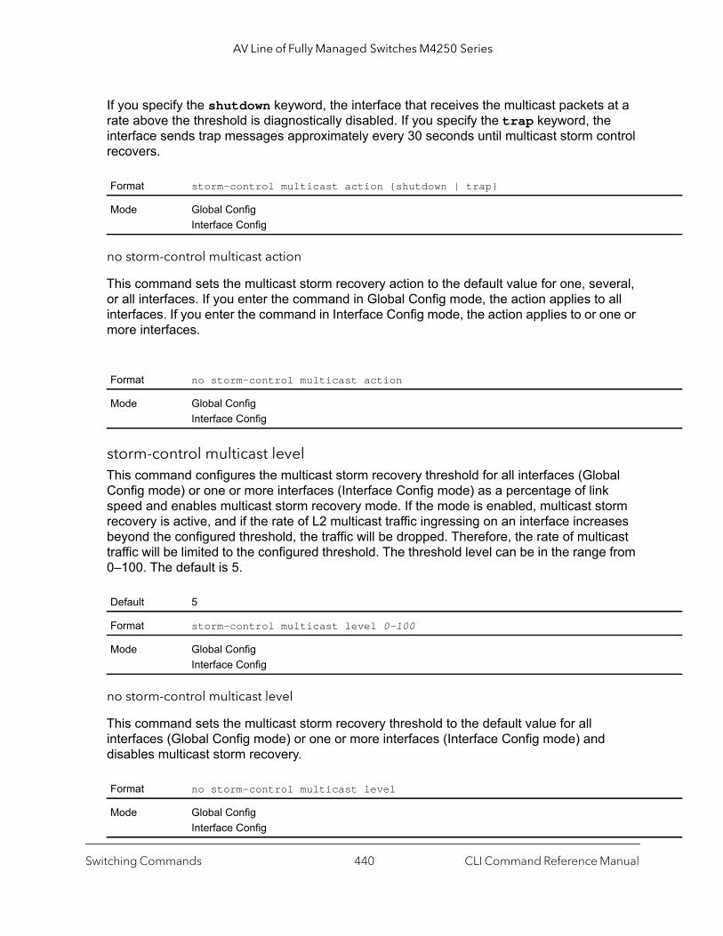
AV Line of Fully Managed Switches M4250 Series
If you specify the shutdown keyword, the interface that receives the multicast packets at a rate above the threshold is diagnostically disabled. If you specify the trap keyword, the interface sends trap messages approximately every 30 seconds until multicast storm control recovers.
no storm-control multicast action
This command sets the multicast storm recovery action to the default value for one, several, or all interfaces. If you enter the command in Global Config mode, the action applies to all interfaces. If you enter the command in Interface Config mode, the action applies to or one or more interfaces.
storm-control multicast levelThis command configures the multicast storm recovery threshold for all interfaces (Global Config mode) or one or more interfaces (Interface Config mode) as a percentage of link speed and enables multicast storm recovery mode. If the mode is enabled, multicast storm recovery is active, and if the rate of L2 multicast traffic ingressing on an interface increases beyond the configured threshold, the traffic will be dropped. Therefore, the rate of multicast traffic will be limited to the configured threshold. The threshold level can be in the range from 0–100. The default is 5.
no storm-control multicast level
This command sets the multicast storm recovery threshold to the default value for all interfaces (Global Config mode) or one or more interfaces (Interface Config mode) and disables multicast storm recovery.
Format storm-control multicast action {shutdown | trap}
Mode Global ConfigInterface Config
Format no storm-control multicast action
Mode Global ConfigInterface Config
Default 5
Format storm-control multicast level 0-100
Mode Global ConfigInterface Config
Format no storm-control multicast level
Mode Global ConfigInterface Config
Switching Commands CLI Command Reference Manual440
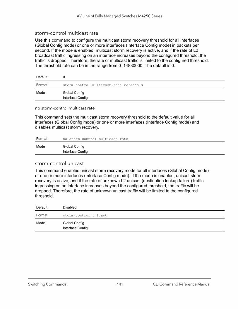
AV Line of Fully Managed Switches M4250 Series
storm-control multicast rateUse this command to configure the multicast storm recovery threshold for all interfaces (Global Config mode) or one or more interfaces (Interface Config mode) in packets per second. If the mode is enabled, multicast storm recovery is active, and if the rate of L2 broadcast traffic ingressing on an interface increases beyond the configured threshold, the traffic is dropped. Therefore, the rate of multicast traffic is limited to the configured threshold. The threshold rate can be in the range from 0–14880000. The default is 0.
no storm-control multicast rate
This command sets the multicast storm recovery threshold to the default value for all interfaces (Global Config mode) or one or more interfaces (Interface Config mode) and disables multicast storm recovery.
storm-control unicastThis command enables unicast storm recovery mode for all interfaces (Global Config mode) or one or more interfaces (Interface Config mode). If the mode is enabled, unicast storm recovery is active, and if the rate of unknown L2 unicast (destination lookup failure) traffic ingressing on an interface increases beyond the configured threshold, the traffic will be dropped. Therefore, the rate of unknown unicast traffic will be limited to the configured threshold.
Default 0
Format storm-control multicast rate threshold
Mode Global ConfigInterface Config
Format no storm-control multicast rate
Mode Global ConfigInterface Config
Default Disabled
Format storm-control unicast
Mode Global ConfigInterface Config
Switching Commands CLI Command Reference Manual441
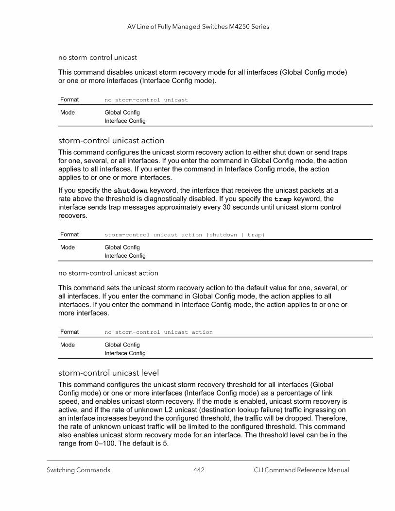
AV Line of Fully Managed Switches M4250 Series
no storm-control unicast
This command disables unicast storm recovery mode for all interfaces (Global Config mode) or one or more interfaces (Interface Config mode).
storm-control unicast actionThis command configures the unicast storm recovery action to either shut down or send traps for one, several, or all interfaces. If you enter the command in Global Config mode, the action applies to all interfaces. If you enter the command in Interface Config mode, the action applies to or one or more interfaces.
If you specify the shutdown keyword, the interface that receives the unicast packets at a rate above the threshold is diagnostically disabled. If you specify the trap keyword, the interface sends trap messages approximately every 30 seconds until unicast storm control recovers.
no storm-control unicast action
This command sets the unicast storm recovery action to the default value for one, several, or all interfaces. If you enter the command in Global Config mode, the action applies to all interfaces. If you enter the command in Interface Config mode, the action applies to or one or more interfaces.
storm-control unicast levelThis command configures the unicast storm recovery threshold for all interfaces (Global Config mode) or one or more interfaces (Interface Config mode) as a percentage of link speed, and enables unicast storm recovery. If the mode is enabled, unicast storm recovery is active, and if the rate of unknown L2 unicast (destination lookup failure) traffic ingressing on an interface increases beyond the configured threshold, the traffic will be dropped. Therefore, the rate of unknown unicast traffic will be limited to the configured threshold. This command also enables unicast storm recovery mode for an interface. The threshold level can be in the range from 0–100. The default is 5.
Format no storm-control unicast
Mode Global ConfigInterface Config
Format storm-control unicast action {shutdown | trap}
Mode Global ConfigInterface Config
Format no storm-control unicast action
Mode Global ConfigInterface Config
Switching Commands CLI Command Reference Manual442
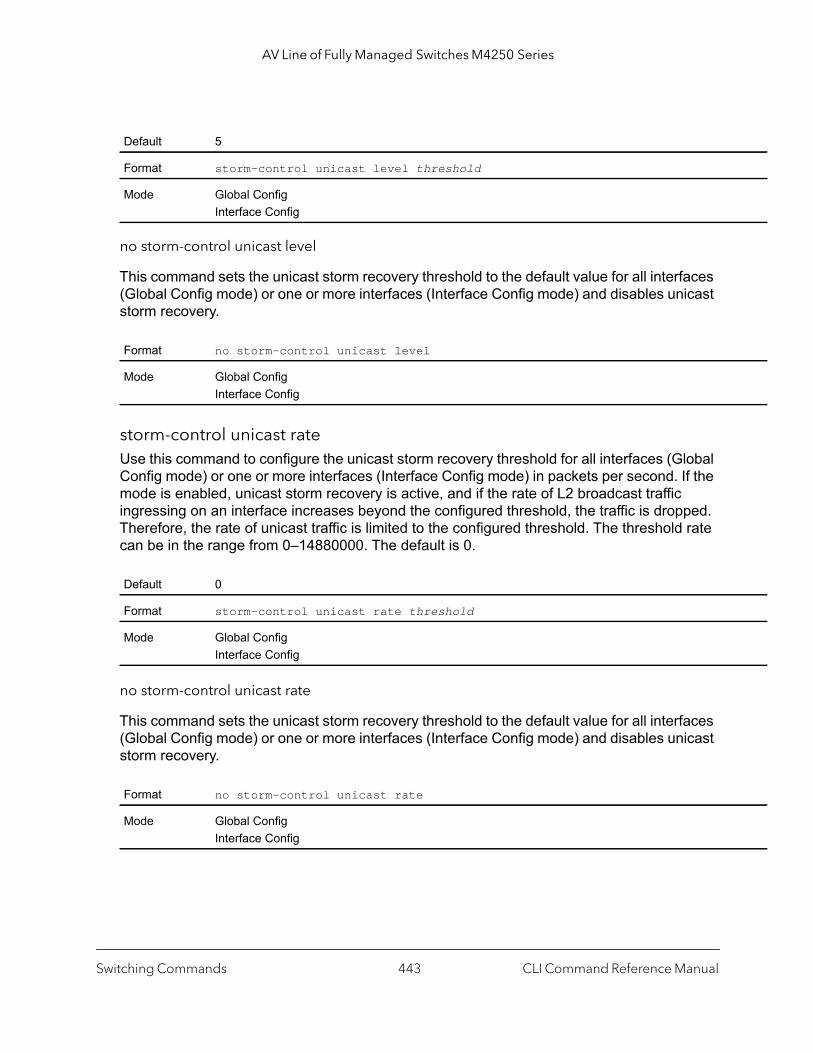
AV Line of Fully Managed Switches M4250 Series
no storm-control unicast level
This command sets the unicast storm recovery threshold to the default value for all interfaces (Global Config mode) or one or more interfaces (Interface Config mode) and disables unicast storm recovery.
storm-control unicast rateUse this command to configure the unicast storm recovery threshold for all interfaces (Global Config mode) or one or more interfaces (Interface Config mode) in packets per second. If the mode is enabled, unicast storm recovery is active, and if the rate of L2 broadcast traffic ingressing on an interface increases beyond the configured threshold, the traffic is dropped. Therefore, the rate of unicast traffic is limited to the configured threshold. The threshold rate can be in the range from 0–14880000. The default is 0.
no storm-control unicast rate
This command sets the unicast storm recovery threshold to the default value for all interfaces (Global Config mode) or one or more interfaces (Interface Config mode) and disables unicast storm recovery.
Default 5
Format storm-control unicast level threshold
Mode Global ConfigInterface Config
Format no storm-control unicast level
Mode Global ConfigInterface Config
Default 0
Format storm-control unicast rate threshold
Mode Global ConfigInterface Config
Format no storm-control unicast rate
Mode Global ConfigInterface Config
Switching Commands CLI Command Reference Manual443

AV Line of Fully Managed Switches M4250 Series
s
is
show storm-control This command displays switch configuration information. If you do not use any of the optional parameters, this command displays global storm control configuration parameters:
• Broadcast Storm Recovery Mode may be enabled or disabled. The factory default is disabled.
• 802.3x Flow Control Mode may be enabled or disabled. The factory default is disabled.
Use the all keyword to display the per-port configuration parameters for all interfaces, or specify the unit/port to display information about a specific interface.
Command example: (NETGEAR Switch) #show storm-control
Broadcast Storm Control Mode................... EnableBroadcast Storm Control Level.................. 5 percentBroadcast Storm Control Action................. NoneMulticast Storm Control Mode................... DisableMulticast Storm Control Level.................. 5 percentMulticast Storm Control Action................. NoneUnicast Storm Control Mode..................... DisableUnicast Storm Control Level.................... 5 percentUnicast Storm Control Action................... None
Format show storm-control [all | unit/port]
Mode Privileged EXEC
Parameter Definition
Bcast Mode Shows whether the broadcast storm control mode is enabled or disabled. The factory default idisabled.
Bcast Level The broadcast storm control level.
Bcast Action The broadcast storm recovery acton.
Mcast Mode Shows whether the multicast storm control mode is enabled or disabled.
Mcast Level The multicast storm control level.
Mcast Action The multicast storm recovery acton.
Ucast Mode Shows whether the Unknown Unicast or DLF (Destination Lookup Failure) storm control modeenabled or disabled.
Ucast Level The Unknown Unicast or DLF (Destination Lookup Failure) storm control level.
Ucast Action The unicast storm recovery acton.
Switching Commands CLI Command Reference Manual444
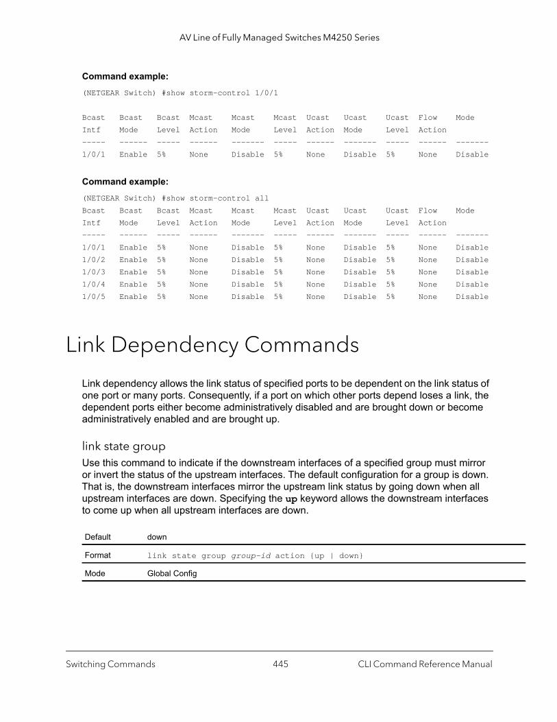
AV Line of Fully Managed Switches M4250 Series
Command example: (NETGEAR Switch) #show storm-control 1/0/1
Bcast Bcast Bcast Mcast Mcast Mcast Ucast Ucast Ucast Flow ModeIntf Mode Level Action Mode Level Action Mode Level Action----- ------ ----- ------ ------- ----- ------ ------- ----- ------ -------1/0/1 Enable 5% None Disable 5% None Disable 5% None Disable
Command example: (NETGEAR Switch) #show storm-control allBcast Bcast Bcast Mcast Mcast Mcast Ucast Ucast Ucast Flow ModeIntf Mode Level Action Mode Level Action Mode Level Action----- ------ ----- ------ ------- ----- ------ ------- ----- ------ -------1/0/1 Enable 5% None Disable 5% None Disable 5% None Disable1/0/2 Enable 5% None Disable 5% None Disable 5% None Disable1/0/3 Enable 5% None Disable 5% None Disable 5% None Disable1/0/4 Enable 5% None Disable 5% None Disable 5% None Disable1/0/5 Enable 5% None Disable 5% None Disable 5% None Disable
Link Dependency Commands
Link dependency allows the link status of specified ports to be dependent on the link status of one port or many ports. Consequently, if a port on which other ports depend loses a link, the dependent ports either become administratively disabled and are brought down or become administratively enabled and are brought up.
link state groupUse this command to indicate if the downstream interfaces of a specified group must mirror or invert the status of the upstream interfaces. The default configuration for a group is down. That is, the downstream interfaces mirror the upstream link status by going down when all upstream interfaces are down. Specifying the up keyword allows the downstream interfaces to come up when all upstream interfaces are down.
Default down
Format link state group group-id action {up | down}
Mode Global Config
Switching Commands CLI Command Reference Manual445
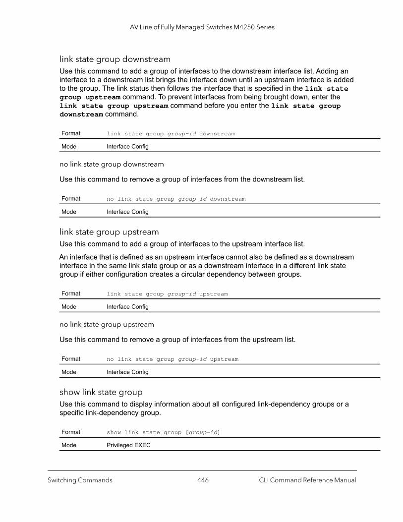
AV Line of Fully Managed Switches M4250 Series
link state group downstreamUse this command to add a group of interfaces to the downstream interface list. Adding an interface to a downstream list brings the interface down until an upstream interface is added to the group. The link status then follows the interface that is specified in the link state group upstream command. To prevent interfaces from being brought down, enter the link state group upstream command before you enter the link state group downstream command.
no link state group downstream
Use this command to remove a group of interfaces from the downstream list.
link state group upstreamUse this command to add a group of interfaces to the upstream interface list.
An interface that is defined as an upstream interface cannot also be defined as a downstream interface in the same link state group or as a downstream interface in a different link state group if either configuration creates a circular dependency between groups.
no link state group upstream
Use this command to remove a group of interfaces from the upstream list.
show link state groupUse this command to display information about all configured link-dependency groups or a specific link-dependency group.
Format link state group group-id downstream
Mode Interface Config
Format no link state group group-id downstream
Mode Interface Config
Format link state group group-id upstream
Mode Interface Config
Format no link state group group-id upstream
Mode Interface Config
Format show link state group [group-id]
Mode Privileged EXEC
Switching Commands CLI Command Reference Manual446

AV Line of Fully Managed Switches M4250 Series
Command example:
This example displays information about all configured link-dependency groups.(Switching) #show link-state groupGroupId Downstream Interfaces Upstream Interfaces Link Action Group State------- -------------------------- -------------------- ----------- -----------1 2/0/3-2/0/7,2/0/12-2/0/17 2/0/12-2/0/32,0/3/5 Link Up Up4 2/0/18,2/0/27 2/0/22-2/0/33,0/3/1 Link Up Down
Command example:
This example displays information about a specific link-dependency group.(Switching) #show link state group 1GroupId Downstream Interfaces Upstream Interfaces Link Action Group State------- -------------------------- -------------------- ----------- -----------1 2/0/3-2/0/7,2/0/12-2/0/17 2/0/12-2/0/32,0/3/5 Link Up Up
show link state group detailUse this command to display detailed information about the state of upstream and downstream interfaces for a selected link-dependency group. The Group Transitions field shows a count of the number of times that the downstream interface went into its action state as a result of the upstream interfaces link state.
Command example: (Switching) #show link state group 1 detailGroupId: 1Link Action: UpGroup State: Up
Downstream Interface State:Link Up: 2/0/3Link Down: 2/0/4-2/0/7,2/0/12-2/0/17
Upstream Interface State:Link Up: -Link Down: 2/0/12-2/0/32,0/3/5
Group Transitions: 0 Last Transition Time: 00:52:35 (UTC+0:00) Nov 3 2015
Format show link state group group-id detail
Mode Privileged EXEC
Switching Commands CLI Command Reference Manual447

AV Line of Fully Managed Switches M4250 Series
p |
stp
Link Local Protocol Filtering Commands
Link Local Protocol Filtering (LLPF) allows the switch to filter out multiple proprietary protocol PDUs, such as Port Aggregation Protocol (PAgP), if the problems occur with proprietary protocols running on standards-based switches. If certain protocol PDUs cause unexpected results, LLPF can be enabled to prevent those protocol PDUs from being processed by the switch.
llpfUse this command to block LLPF protocol(s) on a port.
no llpf
Use this command to unblock LLPF protocol(s) on a port.
show llpf interfaceUse this command to display the status of LLPF rules configured on a particular port or on all ports..
Default disable
Format llpf {blockisdp | blockvtp | blockdtp | blockudld | blockpagp | blocksstblockall}
Mode Interface Config
Format no llpf {blockisdp | blockvtp | blockdtp | blockudld | blockpagp | blocks| blockall }
Mode Interface Config
Format show llpf interface [all | unit/port]
Mode Privileged EXEC
Term Definition
Block ISDP Shows whether the port blocks ISDP PDUs.
Block VTP Shows whether the port blocks VTP PDUs.
Block DTP Shows whether the port blocks DTP PDUs.
Block UDLD Shows whether the port blocks UDLD PDUs.
Block PAGP Shows whether the port blocks PAgP PDUs.
Switching Commands CLI Command Reference Manual448
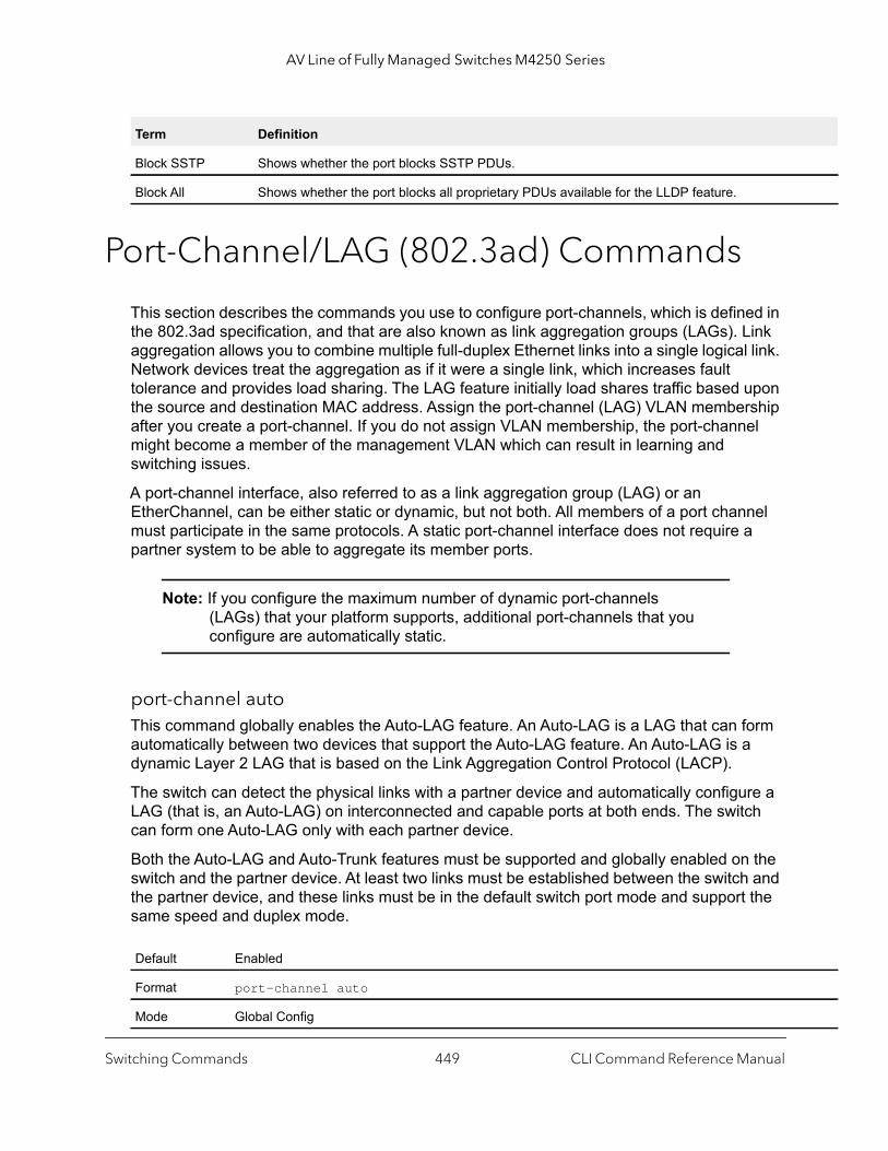
AV Line of Fully Managed Switches M4250 Series
Port-Channel/LAG (802.3ad) Commands
This section describes the commands you use to configure port-channels, which is defined in the 802.3ad specification, and that are also known as link aggregation groups (LAGs). Link aggregation allows you to combine multiple full-duplex Ethernet links into a single logical link. Network devices treat the aggregation as if it were a single link, which increases fault tolerance and provides load sharing. The LAG feature initially load shares traffic based upon the source and destination MAC address. Assign the port-channel (LAG) VLAN membership after you create a port-channel. If you do not assign VLAN membership, the port-channel might become a member of the management VLAN which can result in learning and switching issues.
A port-channel interface, also referred to as a link aggregation group (LAG) or an EtherChannel, can be either static or dynamic, but not both. All members of a port channel must participate in the same protocols. A static port-channel interface does not require a partner system to be able to aggregate its member ports.
Note: If you configure the maximum number of dynamic port-channels (LAGs) that your platform supports, additional port-channels that you configure are automatically static.
port-channel autoThis command globally enables the Auto-LAG feature. An Auto-LAG is a LAG that can form automatically between two devices that support the Auto-LAG feature. An Auto-LAG is a dynamic Layer 2 LAG that is based on the Link Aggregation Control Protocol (LACP).
The switch can detect the physical links with a partner device and automatically configure a LAG (that is, an Auto-LAG) on interconnected and capable ports at both ends. The switch can form one Auto-LAG only with each partner device.
Both the Auto-LAG and Auto-Trunk features must be supported and globally enabled on the switch and the partner device. At least two links must be established between the switch and the partner device, and these links must be in the default switch port mode and support the same speed and duplex mode.
Block SSTP Shows whether the port blocks SSTP PDUs.
Block All Shows whether the port blocks all proprietary PDUs available for the LLDP feature.
Default Enabled
Format port-channel auto
Mode Global Config
Term Definition
Switching Commands CLI Command Reference Manual449
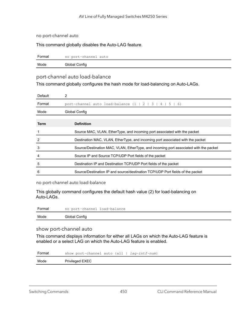
AV Line of Fully Managed Switches M4250 Series
no port-channel auto
This command globally disables the Auto-LAG feature.
port-channel auto load-balanceThis command globally configures the hash mode for load-balancing on Auto-LAGs.
no port-channel auto load-balance
This globally command configures the default hash value (2) for load-balancing on Auto-LAGs.
show port-channel autoThis command displays information for either all LAGs on which the Auto-LAG feature is enabled or a select LAG on which the Auto-LAG feature is enabled.
Format no port-channel auto
Mode Global Config
Default 2
Format port-channel auto load-balance {1 | 2 | 3 | 4 | 5 | 6}
Mode Global Config
Term Definition
1 Source MAC, VLAN, EtherType, and incoming port associated with the packet
2 Destination MAC, VLAN, EtherType, and incoming port associated with the packet
3 Source/Destination MAC, VLAN, EtherType, and incoming port associated with the packet
4 Source IP and Source TCP/UDP Port fields of the packet
5 Destination IP and Destination TCP/UDP Port fields of the packet
6 Source/Destination IP and source/destination TCP/UDP Port fields of the packet
Format no port-channel load-balance
Mode Global Config
Format show port-channel auto {all | lag-intf-num}
Mode Privileged EXEC
Switching Commands CLI Command Reference Manual450
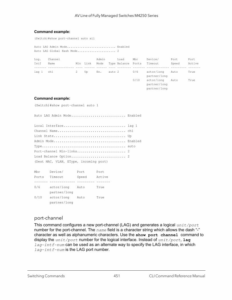
AV Line of Fully Managed Switches M4250 Series
Command example: (Switch)#show port-channel auto all
Auto LAG Admin Mode............................ EnabledAuto LAG Global Hash Mode...................... 2
Log. Channel Admin Load Mbr Device/ Port PortIntf Name Min Link Mode Type Balance Ports Timeout Speed Active------- --------------- ---- ------ ------ ---- -------- ------- ------------- --------- -------lag 1 ch1 2 Up En. auto 2 0/6 actor/long Auto True partner/long 0/10 actor/long Auto True partner/long partner/long
Command example: (Switch)#show port-channel auto 1
Auto LAG Admin Mode............................ Enabled
Local Interface................................ lag 1Channel Name................................... ch1Link State..................................... UpAdmin Mode..................................... EnabledType........................................... autoPort-channel Min-links......................... 2Load Balance Option............................ 2(Dest MAC, VLAN, EType, incoming port)
Mbr Device/ Port PortPorts Timeout Speed Active------- ------------- --------- -------0/6 actor/long Auto True partner/long0/10 actor/long Auto True partner/long
port-channelThis command configures a new port-channel (LAG) and generates a logical unit/port number for the port-channel. The name field is a character string which allows the dash “-” character as well as alphanumeric characters. Use the show port channel command to display the unit/port number for the logical interface. Instead of unit/port, lag lag-intf-num can be used as an alternate way to specify the LAG interface, in which lag-intf-num is the LAG port number.
Switching Commands CLI Command Reference Manual451

AV Line of Fully Managed Switches M4250 Series
Note: Before you include a port in a port-channel, set the port physical mode. For more information, see speed on page 325.
addportThis command adds one port to the port-channel (LAG). The first interface is a logical unit/port number of a configured port-channel. You can add a range of ports by specifying the port range when you enter Interface Config mode (for example: interface 1/0/1-1/0/4. Instead of unit/port, lag lag-intf-num can be used as an alternate way to specify the LAG interface, in which lag-intf-num is the LAG port number.
Note: Before adding a port to a port-channel, set the physical mode of the port. For more information, see speed on page 325.
deleteport (Interface Config)This command deletes a port or a range of ports from the port-channel (LAG). The interface is a logical unit/port number of a configured port-channel (or range of port-channels). Instead of unit/port, lag lag-intf-num can be used as an alternate way to specify the LAG interface, in which lag-intf-num is the LAG port number.
deleteport (Global Config)This command deletes all configured ports from the port-channel (LAG). The interface is a logical unit/port number of a configured port-channel. Instead of unit/port, lag lag-intf-num can be used as an alternate way to specify the LAG interface, in which lag-intf-num is the LAG port number.
Format port-channel name
Mode Global Config
Format addport logical unit/port
Mode Interface Config
Format deleteport logical unit/port
Mode Interface Config
Format deleteport {logical unit/port | all}
Mode Global Config
Switching Commands CLI Command Reference Manual452
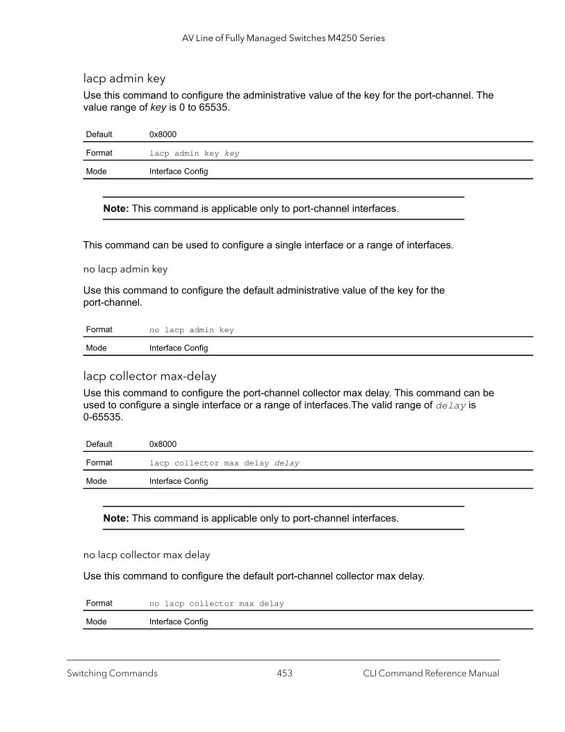
AV Line of Fully Managed Switches M4250 Series
lacp admin keyUse this command to configure the administrative value of the key for the port-channel. The value range of key is 0 to 65535.
Note: This command is applicable only to port-channel interfaces.
This command can be used to configure a single interface or a range of interfaces.
no lacp admin key
Use this command to configure the default administrative value of the key for the port-channel.
lacp collector max-delayUse this command to configure the port-channel collector max delay. This command can be used to configure a single interface or a range of interfaces.The valid range of delay is 0-65535.
Note: This command is applicable only to port-channel interfaces.
no lacp collector max delay
Use this command to configure the default port-channel collector max delay.
Default 0x8000
Format lacp admin key key
Mode Interface Config
Format no lacp admin key
Mode Interface Config
Default 0x8000
Format lacp collector max delay delay
Mode Interface Config
Format no lacp collector max delay
Mode Interface Config
Switching Commands CLI Command Reference Manual453
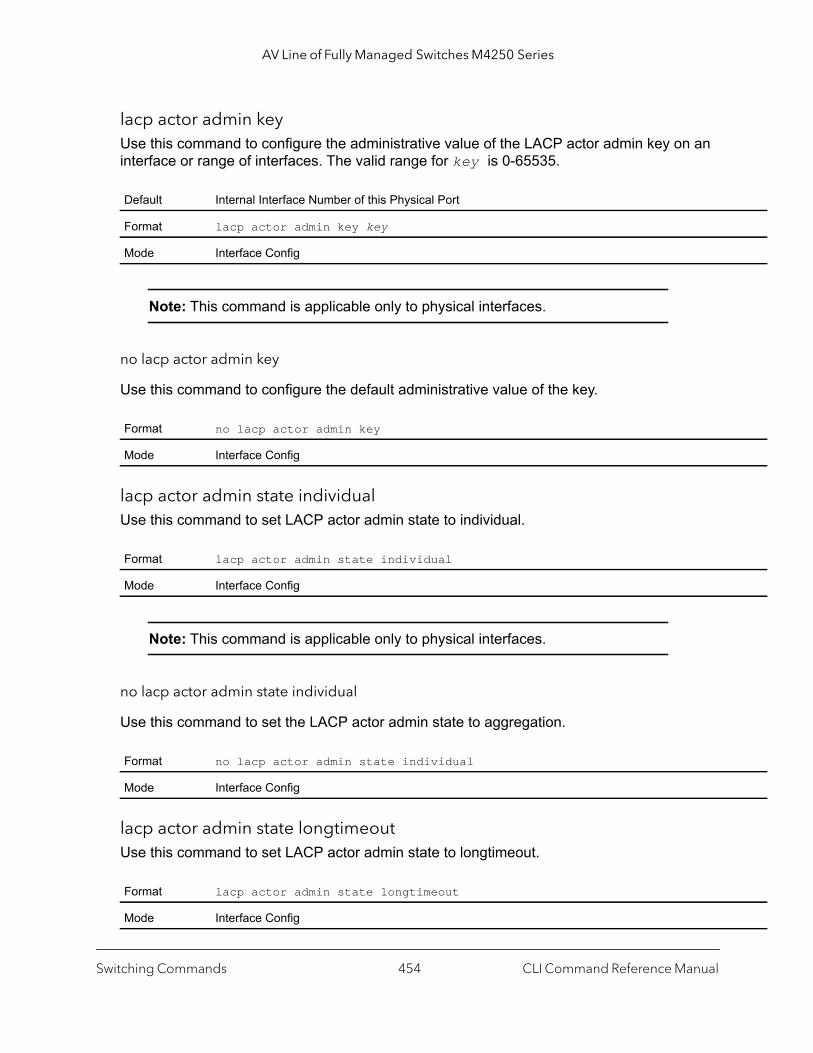
AV Line of Fully Managed Switches M4250 Series
lacp actor admin keyUse this command to configure the administrative value of the LACP actor admin key on an interface or range of interfaces. The valid range for key is 0-65535.
Note: This command is applicable only to physical interfaces.
no lacp actor admin key
Use this command to configure the default administrative value of the key.
lacp actor admin state individualUse this command to set LACP actor admin state to individual.
Note: This command is applicable only to physical interfaces.
no lacp actor admin state individual
Use this command to set the LACP actor admin state to aggregation.
lacp actor admin state longtimeoutUse this command to set LACP actor admin state to longtimeout.
Default Internal Interface Number of this Physical Port
Format lacp actor admin key key
Mode Interface Config
Format no lacp actor admin key
Mode Interface Config
Format lacp actor admin state individual
Mode Interface Config
Format no lacp actor admin state individual
Mode Interface Config
Format lacp actor admin state longtimeout
Mode Interface Config
Switching Commands CLI Command Reference Manual454
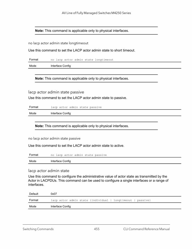
AV Line of Fully Managed Switches M4250 Series
Note: This command is applicable only to physical interfaces.
no lacp actor admin state longtimeout
Use this command to set the LACP actor admin state to short timeout.
Note: This command is applicable only to physical interfaces.
lacp actor admin state passiveUse this command to set the LACP actor admin state to passive.
Note: This command is applicable only to physical interfaces.
no lacp actor admin state passive
Use this command to set the LACP actor admin state to active.
lacp actor admin stateUse this command to configure the administrative value of actor state as transmitted by the Actor in LACPDUs. This command can be used to configure a single interfaces or a range of interfaces.
Format no lacp actor admin state longtimeout
Mode Interface Config
Format lacp actor admin state passive
Mode Interface Config
Format no lacp actor admin state passive
Mode Interface Config
Default 0x07
Format lacp actor admin state {individual | longtimeout | passive}
Mode Interface Config
Switching Commands CLI Command Reference Manual455
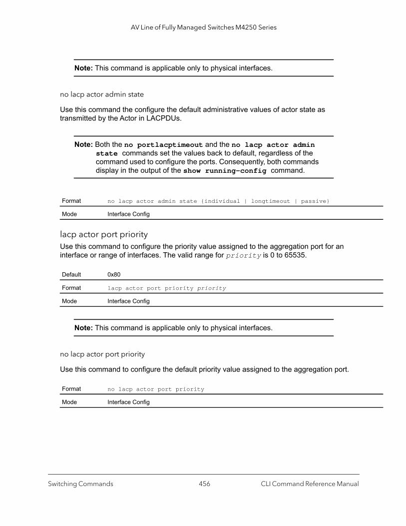
AV Line of Fully Managed Switches M4250 Series
Note: This command is applicable only to physical interfaces.
no lacp actor admin state
Use this command the configure the default administrative values of actor state as transmitted by the Actor in LACPDUs.
Note: Both the no portlacptimeout and the no lacp actor admin state commands set the values back to default, regardless of the command used to configure the ports. Consequently, both commands display in the output of the show running-config command.
lacp actor port priorityUse this command to configure the priority value assigned to the aggregation port for an interface or range of interfaces. The valid range for priority is 0 to 65535.
Note: This command is applicable only to physical interfaces.
no lacp actor port priority
Use this command to configure the default priority value assigned to the aggregation port.
Format no lacp actor admin state {individual | longtimeout | passive}
Mode Interface Config
Default 0x80
Format lacp actor port priority priority
Mode Interface Config
Format no lacp actor port priority
Mode Interface Config
Switching Commands CLI Command Reference Manual456

AV Line of Fully Managed Switches M4250 Series
lacp partner admin key Use this command to configure the administrative value of the Key for the protocol partner. This command can be used to configure a single interface or a range of interfaces. The valid range for key is 0 to 65535.
Note: This command is applicable only to physical interfaces.
no lacp partner admin key
Use this command to set the administrative value of the key for the protocol partner to the default.
lacp partner admin state individualUse this command to set LACP partner admin state to individual.
Note: This command is applicable only to physical interfaces.
no lacp partner admin state individual
Use this command to set the LACP partner admin state to aggregation.
Default 0x0
Format lacp partner admin key key
Mode Interface Config
Format no lacp partner admin key
Mode Interface Config
Format lacp partner admin state individual
Mode Interface Config
Format no lacp partner admin state individual
Mode Interface Config
Switching Commands CLI Command Reference Manual457
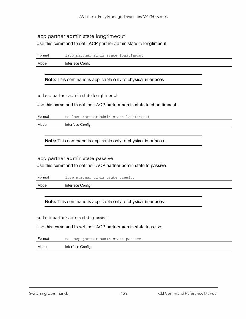
AV Line of Fully Managed Switches M4250 Series
lacp partner admin state longtimeoutUse this command to set LACP partner admin state to longtimeout.
Note: This command is applicable only to physical interfaces.
no lacp partner admin state longtimeout
Use this command to set the LACP partner admin state to short timeout.
Note: This command is applicable only to physical interfaces.
lacp partner admin state passiveUse this command to set the LACP partner admin state to passive.
Note: This command is applicable only to physical interfaces.
no lacp partner admin state passive
Use this command to set the LACP partner admin state to active.
Format lacp partner admin state longtimeout
Mode Interface Config
Format no lacp partner admin state longtimeout
Mode Interface Config
Format lacp partner admin state passive
Mode Interface Config
Format no lacp partner admin state passive
Mode Interface Config
Switching Commands CLI Command Reference Manual458
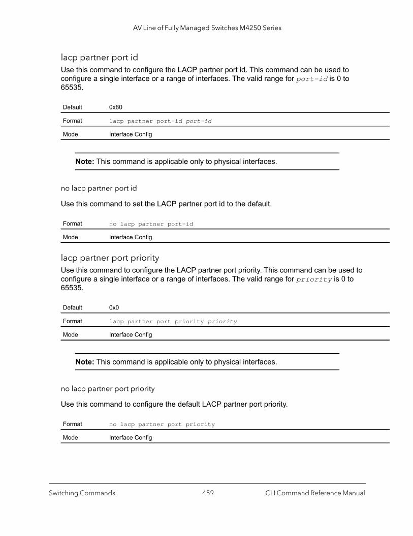
AV Line of Fully Managed Switches M4250 Series
lacp partner port idUse this command to configure the LACP partner port id. This command can be used to configure a single interface or a range of interfaces. The valid range for port-id is 0 to 65535.
Note: This command is applicable only to physical interfaces.
no lacp partner port id
Use this command to set the LACP partner port id to the default.
lacp partner port priorityUse this command to configure the LACP partner port priority. This command can be used to configure a single interface or a range of interfaces. The valid range for priority is 0 to 65535.
Note: This command is applicable only to physical interfaces.
no lacp partner port priority
Use this command to configure the default LACP partner port priority.
Default 0x80
Format lacp partner port-id port-id
Mode Interface Config
Format no lacp partner port-id
Mode Interface Config
Default 0x0
Format lacp partner port priority priority
Mode Interface Config
Format no lacp partner port priority
Mode Interface Config
Switching Commands CLI Command Reference Manual459

AV Line of Fully Managed Switches M4250 Series
lacp partner system idUse this command to configure the 6-octet MAC Address value representing the administrative value of the Aggregation Port’s protocol Partner’s System ID. This command can be used to configure a single interface or a range of interfaces. The valid range of system-id is 00:00:00:00:00:00 - FF:FF:FF:FF:FF.
Note: This command is applicable only to physical interfaces.
no lacp partner system id
Use this command to configure the default value representing the administrative value of the Aggregation Port’s protocol Partner’s System ID.
lacp partner system priorityUse this command to configure the administrative value of the priority associated with the Partner’s System ID. This command can be used to configure a single interface or a range of interfaces. The valid range for priority is 0 to 65535.
Note: This command is applicable only to physical interfaces.
no lacp partner system priority
Use this command to configure the default administrative value of priority associated with the Partner’s System ID.
Default 00:00:00:00:00:00
Format lacp partner system id system-id
Mode Interface Config
Format no lacp partner system id
Mode Interface Config
Default 0x0
Format lacp partner system priority priority
Mode Interface Config
Format no lacp partner system priority
Mode Interface Config
Switching Commands CLI Command Reference Manual460
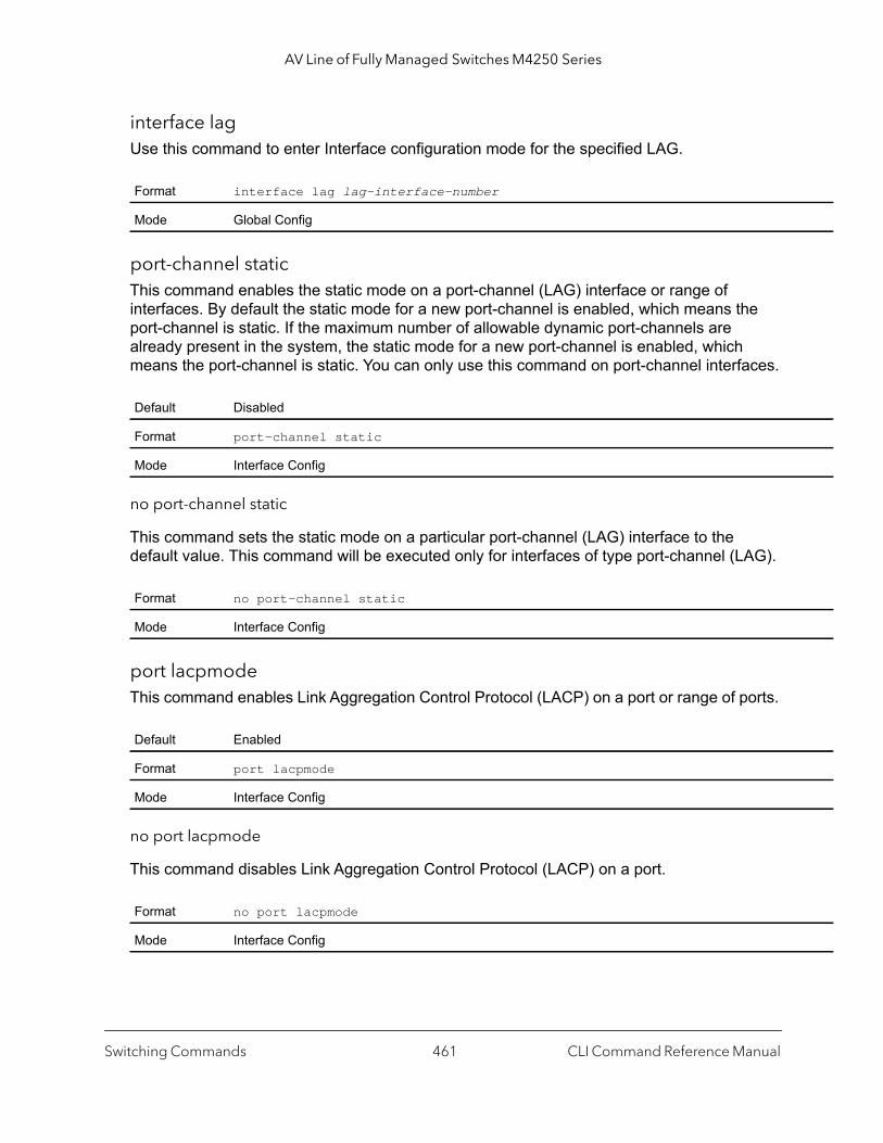
AV Line of Fully Managed Switches M4250 Series
interface lagUse this command to enter Interface configuration mode for the specified LAG.
port-channel staticThis command enables the static mode on a port-channel (LAG) interface or range of interfaces. By default the static mode for a new port-channel is enabled, which means the port-channel is static. If the maximum number of allowable dynamic port-channels are already present in the system, the static mode for a new port-channel is enabled, which means the port-channel is static. You can only use this command on port-channel interfaces.
no port-channel static
This command sets the static mode on a particular port-channel (LAG) interface to the default value. This command will be executed only for interfaces of type port-channel (LAG).
port lacpmode This command enables Link Aggregation Control Protocol (LACP) on a port or range of ports.
no port lacpmode
This command disables Link Aggregation Control Protocol (LACP) on a port.
Format interface lag lag-interface-number
Mode Global Config
Default Disabled
Format port-channel static
Mode Interface Config
Format no port-channel static
Mode Interface Config
Default Enabled
Format port lacpmode
Mode Interface Config
Format no port lacpmode
Mode Interface Config
Switching Commands CLI Command Reference Manual461

AV Line of Fully Managed Switches M4250 Series
port lacpmode enable all This command enables Link Aggregation Control Protocol (LACP) on all ports.
no port lacpmode enable all
This command disables Link Aggregation Control Protocol (LACP) on all ports.
port lacptimeout (Interface Config)This command sets the timeout on a physical interface or range of interfaces of a particular device type (actor or partner) to either long or short timeout.
no port lacptimeout
This command sets the timeout back to its default value on a physical interface of a particular device type (actor or partner).
Note: Both the no portlacptimeout and the no lacp actor admin state commands set the values back to default, regardless of the command used to configure the ports. Consequently, both commands display in the output of the show running-config command.
Format port lacpmode enable all
Mode Global Config
Format no port lacpmode enable all
Mode Global Config
Default long
Format port lacptimeout {actor | partner} {long | short}
Mode Interface Config
Format no port lacptimeout {actor | partner}
Mode Interface Config
Switching Commands CLI Command Reference Manual462

AV Line of Fully Managed Switches M4250 Series
port lacptimeout (Global Config)This command sets the timeout for all interfaces of a particular device type (actor or partner) to either long or short timeout.
no port lacptimeout
This command sets the timeout for all physical interfaces of a particular device type (actor or partner) back to their default values.
Note: Both the no portlacptimeout and the no lacp actor admin state commands set the values back to default, regardless of the command used to configure the ports. Consequently, both commands display in the output of the show running-config command.
port-channel adminmode This command enables all configured port-channels with the same administrative mode setting.
no port-channel adminmode
This command disables all configured port-channels with the same administrative mode setting.
port-channel linktrapThis command enables link trap notifications for the port-channel (LAG). The interface is a logical unit/port for a configured port-channel. The option all sets every configured port-channel with the same administrative mode setting. Instead of unit/port, lag
Default long
Format port lacptimeout {actor | partner} {long | short}
Mode Global Config
Format no port lacptimeout {actor | partner}
Mode Global Config
Format port-channel adminmode all
Mode Global Config
Format no port-channel adminmode all
Mode Global Config
Switching Commands CLI Command Reference Manual463
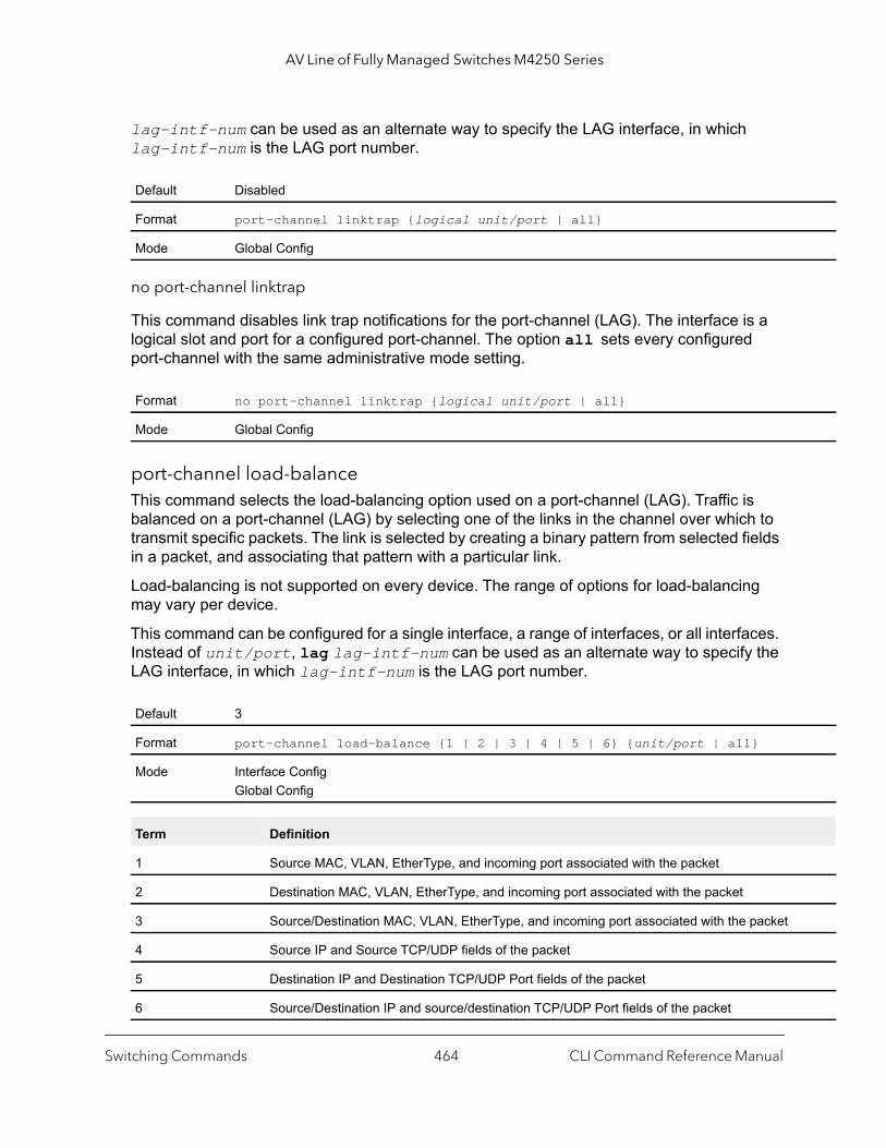
AV Line of Fully Managed Switches M4250 Series
lag-intf-num can be used as an alternate way to specify the LAG interface, in which lag-intf-num is the LAG port number.
no port-channel linktrap
This command disables link trap notifications for the port-channel (LAG). The interface is a logical slot and port for a configured port-channel. The option all sets every configured port-channel with the same administrative mode setting.
port-channel load-balanceThis command selects the load-balancing option used on a port-channel (LAG). Traffic is balanced on a port-channel (LAG) by selecting one of the links in the channel over which to transmit specific packets. The link is selected by creating a binary pattern from selected fields in a packet, and associating that pattern with a particular link.
Load-balancing is not supported on every device. The range of options for load-balancing may vary per device.
This command can be configured for a single interface, a range of interfaces, or all interfaces. Instead of unit/port, lag lag-intf-num can be used as an alternate way to specify the LAG interface, in which lag-intf-num is the LAG port number.
Default Disabled
Format port-channel linktrap {logical unit/port | all}
Mode Global Config
Format no port-channel linktrap {logical unit/port | all}
Mode Global Config
Default 3
Format port-channel load-balance {1 | 2 | 3 | 4 | 5 | 6} {unit/port | all}
Mode Interface ConfigGlobal Config
Term Definition
1 Source MAC, VLAN, EtherType, and incoming port associated with the packet
2 Destination MAC, VLAN, EtherType, and incoming port associated with the packet
3 Source/Destination MAC, VLAN, EtherType, and incoming port associated with the packet
4 Source IP and Source TCP/UDP fields of the packet
5 Destination IP and Destination TCP/UDP Port fields of the packet
6 Source/Destination IP and source/destination TCP/UDP Port fields of the packet
Switching Commands CLI Command Reference Manual464

AV Line of Fully Managed Switches M4250 Series
nnel.
s.
no port-channel load-balance
This command reverts to the default load balancing configuration.
port-channel local-preferenceThis command enables the local-preference mode on a port-channel (LAG) interface or range of interfaces. By default, the local-preference mode for a port-channel is disabled. This command can be used only on port-channel interfaces.
no port-channel local-preference
This command disables the local-preference mode on a port-channel.
port-channel min-linksThis command configures the port-channel’s minimum links for lag interfaces. The number parameter can be in the range 1–8. The default is 1.
unit/port Global Config Mode only: The interface is a logical unit/port number of a configured port-cha
all Global Config Mode only: all applies the command to all currently configured port-channel
Format no port-channel load-balance {unit/port | all}
Mode Interface ConfigGlobal Config
Term Definition
unit/port Global Config Mode only: The interface is a logical unit/port number of a configured port-channel.
all Global Config Mode only: all applies the command to all currently configured port-channels.
Default Disabled
Format port-channel local-preference
Mode Interface Config
Format no port-channel local-preference
Mode Interface Config
Default 1
Format port-channel min-links number
Mode Interface Config
Term Definition
Switching Commands CLI Command Reference Manual465
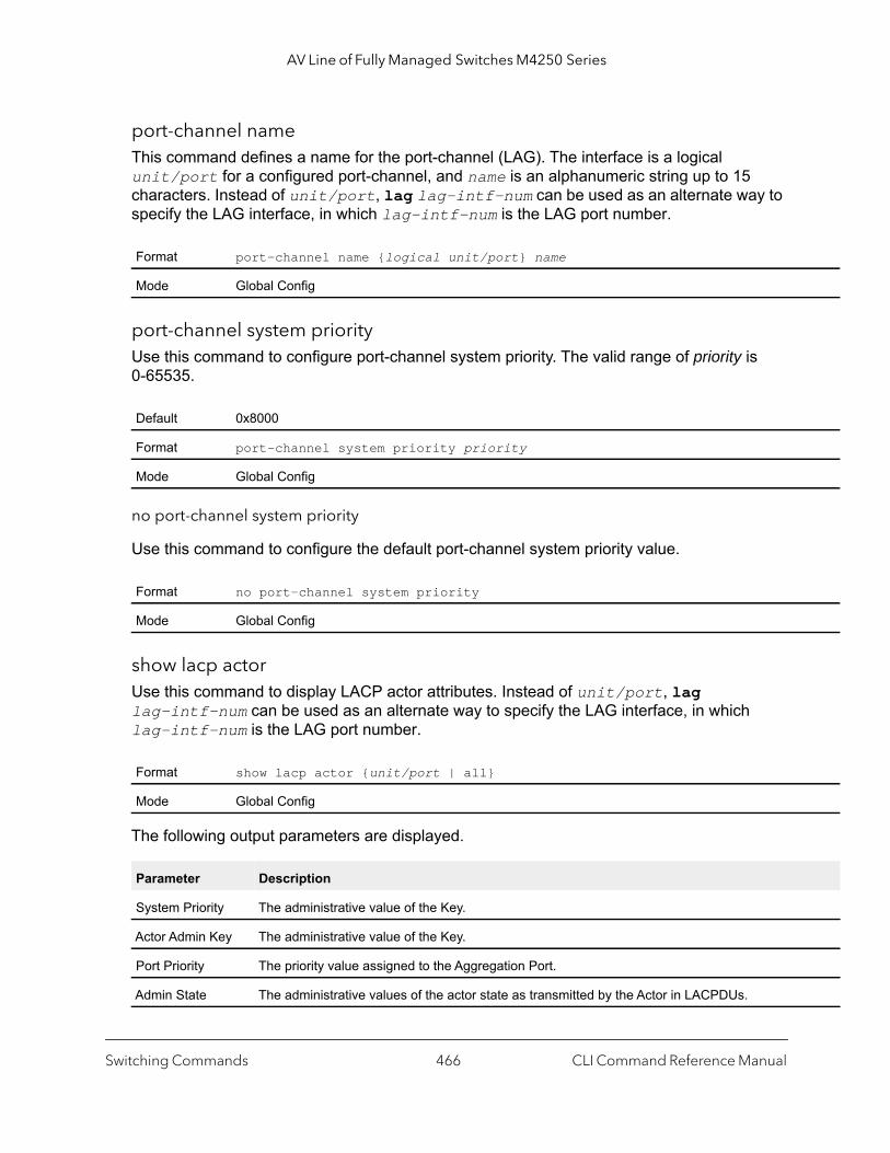
AV Line of Fully Managed Switches M4250 Series
port-channel nameThis command defines a name for the port-channel (LAG). The interface is a logical unit/port for a configured port-channel, and name is an alphanumeric string up to 15 characters. Instead of unit/port, lag lag-intf-num can be used as an alternate way to specify the LAG interface, in which lag-intf-num is the LAG port number.
port-channel system priorityUse this command to configure port-channel system priority. The valid range of priority is 0-65535.
no port-channel system priority
Use this command to configure the default port-channel system priority value.
show lacp actorUse this command to display LACP actor attributes. Instead of unit/port, lag lag-intf-num can be used as an alternate way to specify the LAG interface, in which lag-intf-num is the LAG port number.
The following output parameters are displayed.
Format port-channel name {logical unit/port} name
Mode Global Config
Default 0x8000
Format port-channel system priority priority
Mode Global Config
Format no port-channel system priority
Mode Global Config
Format show lacp actor {unit/port | all}
Mode Global Config
Parameter Description
System Priority The administrative value of the Key.
Actor Admin Key The administrative value of the Key.
Port Priority The priority value assigned to the Aggregation Port.
Admin State The administrative values of the actor state as transmitted by the Actor in LACPDUs.
Switching Commands CLI Command Reference Manual466

AV Line of Fully Managed Switches M4250 Series
show lacp partnerUse this command to display LACP partner attributes. Instead of unit/port, lag lag-intf-num can be used as an alternate way to specify the LAG interface, in which lag-intf-num is the LAG port number.
The following output parameters are displayed.
show port-channel briefThis command displays the static capability of all port-channel (LAG) interfaces on the device as well as a summary of individual port-channel interfaces.
For each port-channel the following information is displayed.
Format show lacp actor {unit/port | all}
Mode Privileged EXEC
Parameter Description
System Priority The administrative value of priority associated with the Partner’s System ID.
System-ID Represents the administrative value of the Aggregation Port’s protocol Partner’s System ID.
Admin Key The administrative value of the Key for the protocol Partner.
Port Priority The administrative value of the Key for protocol Partner.
Port-ID The administrative value of the port number for the protocol Partner.
Admin State The administrative values of the actor state for the protocol Partner.
Format show port-channel brief
Mode User EXEC
Term Definition
Logical Interface The unit/port of the logical interface.
Port-channel Name The name of port-channel (LAG) interface.
Link-State Shows whether the link is up or down.
Trap Flag Shows whether trap flags are enabled or disabled.
Type Shows whether the port-channel is statically or dynamically maintained.
Mbr Ports The members of this port-channel.
Active Ports The ports that are actively participating in the port-channel.
Switching Commands CLI Command Reference Manual467

AV Line of Fully Managed Switches M4250 Series
cters.
64.
e can
show port-channel This command displays an overview of all port-channels (LAGs) on the switch.
Command example: (NETGEAR Switch) #show port-channel 0/3/1
Local Interface................................ 0/3/1Channel Name................................... ch1Link State..................................... UpAdmin Mode..................................... EnabledType........................................... StaticLoad Balance Option............................ 3(Src/Dest MAC, VLAN, EType, incoming port)Local Preference Mode.......................... Enabled
Format show port-channel
Mode Privileged EXEC
Term Definition
Logical Interface The valid unit/port number.
Port-Channel Name
The name of this port-channel (LAG). You may enter any string of up to 15 alphanumeric chara
Link State Indicates whether the Link is up or down.
Admin Mode May be enabled or disabled. The factory default is enabled.
Type The status designating whether a particular port-channel (LAG) is statically or dynamically maintained. • Static. The port-channel is statically maintained.• Dynamic. The port-channel is dynamically maintained.
Load Balance Option
The load balance option associated with this LAG. See port-channel load-balance on page 4
Local Preference Mode
Indicates whether the local preference mode is enabled or disabled.
Mbr Ports A listing of the ports that are members of this port-channel (LAG), in unit/port notation. Therbe a maximum of eight ports assigned to a given port-channel (LAG).
Device Timeout For each port, lists the timeout (long or short) for Device Type (actor or partner).
Port Speed Speed of the port-channel port.
Active Ports This field lists ports that are actively participating in the port-channel (LAG).
Switching Commands CLI Command Reference Manual468

AV Line of Fully Managed Switches M4250 Series
ate is
Mbr Device/ Port PortPorts Timeout Speed Active------ ------------- --------- -------1/0/1 actor/long Auto True partner/long 1/0/2 actor/long Auto True partner/long 1/0/3 actor/long Auto False partner/long 1/0/4 actor/long Auto False partner/long
show port-channel system priorityUse this command to display the port-channel system priority.
show port-channel countersUse this command to display port-channel counters for the specified port.
Format show port-channel system priority
Mode Privileged EXEC
Format show port-channel unit/port counters
Mode Privileged EXEC
Term Definition
Local Interface The valid unit/port number.
Channel Name The name of this port-channel (LAG).
Link State Indicates whether the Link is up or down.
Admin Mode May be enabled or disabled. The factory default is enabled.
Port Channel Flap Count
The number of times the port-channel was inactive.
Mbr Ports The unit/port for the port member.
Mbr Flap Counters The number of times a port member is inactive, either because the link is down, or the admin stdisabled.
Switching Commands CLI Command Reference Manual469
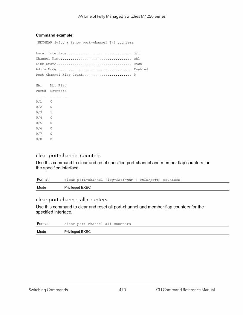
AV Line of Fully Managed Switches M4250 Series
Command example: (NETGEAR Switch) #show port-channel 3/1 counters
Local Interface................................ 3/1Channel Name................................... ch1Link State..................................... DownAdmin Mode..................................... EnabledPort Channel Flap Count........................ 0
Mbr Mbr FlapPorts Counters------ ---------0/1 00/2 00/3 10/4 00/5 00/6 00/7 00/8 0
clear port-channel countersUse this command to clear and reset specified port-channel and member flap counters for the specified interface.
clear port-channel all countersUse this command to clear and reset all port-channel and member flap counters for the specified interface.
Format clear port-channel {lag-intf-num | unit/port} counters
Mode Privileged EXEC
Format clear port-channel all counters
Mode Privileged EXEC
Switching Commands CLI Command Reference Manual470

AV Line of Fully Managed Switches M4250 Series
} [rx |
Port Mirroring Commands
Port mirroring, which is also known as port monitoring, selects network traffic that you can analyze with a network analyzer, such as a SwitchProbe device or other Remote Monitoring (RMON) probe.
monitor session sourceThis command adds a source interface for a port mirroring session that is identified by the session-id argument (an integer value).
Use the source interface {unit/port | cpu | lag lag-group-id} parameters to specify the interface to monitor. You can also configure a VLAN as the source for the session (all member ports of that VLAN are monitored).
Note: If an interface is a member of both a VLAN and a LAG, you cannot assign the VLAN as a source VLAN for a monitor session. However, if an interface is a member of a VLAN and you assign the VLAN as a source VLAN for a monitor session, afterwards you can add the interface as a member to a LAG.
You can configure remote port mirroring by specifying the remote vlan keywords and an RSPAN VLAN ID. At the source switch, you must specify the destination as the RSPAN VLAN. At the destination switch, you must specify the source as the RSPAN VLAN. You cannot configure the source and destination as remote on the same switch.
Note: On an intermediate switch, you must create an RSPAN VLAN, make sure that the ports that are connected to the source and destination switches are members of the RSPAN VLAN, and enable RSPAN VLAN egress tagging on the port that is connected to the destination switch.
Use rx to monitor only ingress packets or use tx to monitor only egress packets. If you do not specify an rx or tx option, the destination port monitors both ingress and egress packets.
Format monitor session session-id source {interface {unit/port | cpu | lag} | vlan vlan-id | remote vlan vlan-idtx]
Mode Global Config
Switching Commands CLI Command Reference Manual471

AV Line of Fully Managed Switches M4250 Series
d}
port}
no monitor session source
This command removes a source interface for a port mirroring session that is identified by the session-id argument (an integer value).
monitor session destinationThis command adds a destination interface for a port mirroring session that is identified by the session-id argument (an integer value).
Use the destination interface unit/port parameter to specify the interface to monitor.
You can configure remote port mirroring by specifying the remote vlan keywords and an RSPAN VLAN ID. At the source switch, you must specify the destination as the RSPAN VLAN. At the destination switch, you must specify the source as the RSPAN VLAN. You cannot configure the source and destination as remote on the same switch.
Note: If an interface is a member of both a VLAN and a LAG, you cannot assign the VLAN as a destination VLAN for a monitor session. However, if an interface is a member of a VLAN and you assign the VLAN as a destination VLAN for a monitor session, afterwards you can add the interface as a member to a LAG.
Note: On an intermediate switch, you must create an RSPAN VLAN, make sure that the ports that are connected to the source and destination switches are members of the RSPAN VLAN, and enable RSPAN VLAN egress tagging on the port that is connected to the destination switch.
If you specify an RSPAN VLAN ID, you must also specify the reflector port at the source switch. The reflector port, which must be a member of the RSPAN VLAN, forwards the mirrored traffic to the destination switch. You specify the reflector port by entering the reflector-port keyword and the unit/port argument.
Format monitor session session-id source {interface {unit/port | cpu | lag} | vlan vlan-id | remote vlan vlan-i
Mode Global Config
Format monitor session session-id destination {interface {unit/port} | remote vlan vlan-id reflector-port unit/
Mode Global Config
Switching Commands CLI Command Reference Manual472
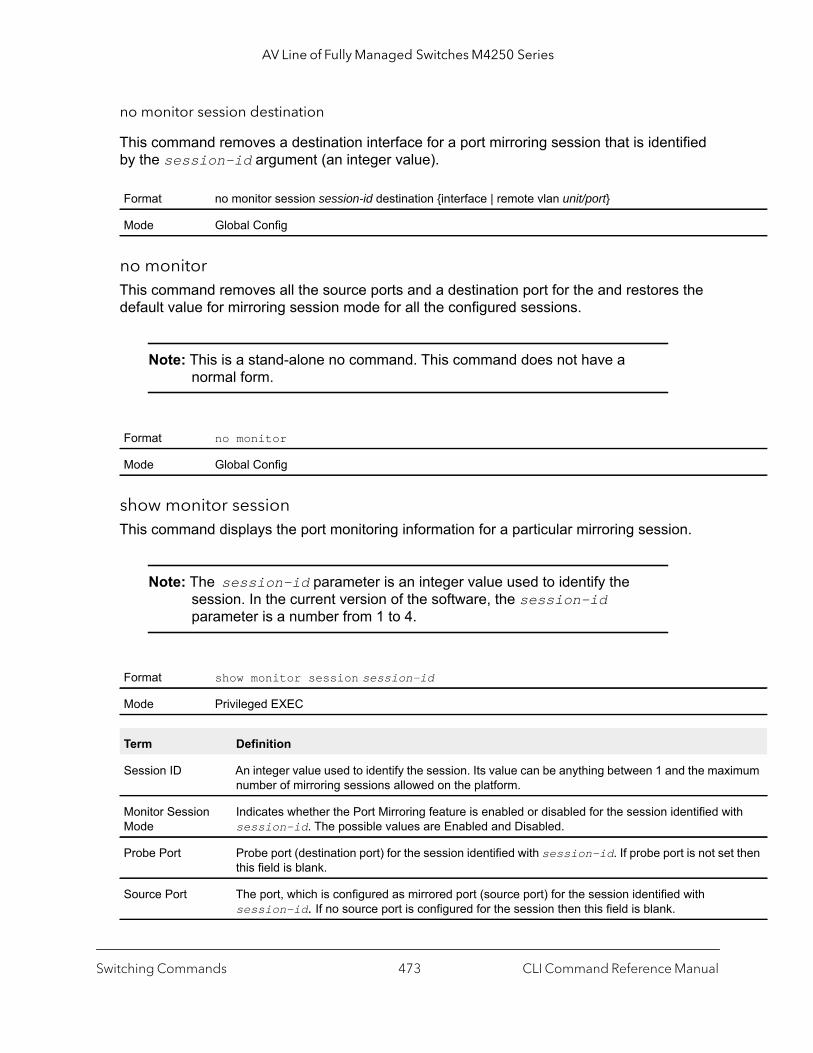
AV Line of Fully Managed Switches M4250 Series
imum
ith
t then
no monitor session destination
This command removes a destination interface for a port mirroring session that is identified by the session-id argument (an integer value).
no monitorThis command removes all the source ports and a destination port for the and restores the default value for mirroring session mode for all the configured sessions.
Note: This is a stand-alone no command. This command does not have a normal form.
show monitor sessionThis command displays the port monitoring information for a particular mirroring session.
Note: The session-id parameter is an integer value used to identify the session. In the current version of the software, the session-id parameter is a number from 1 to 4.
Format no monitor session session-id destination {interface | remote vlan unit/port}
Mode Global Config
Format no monitor
Mode Global Config
Format show monitor session session-id
Mode Privileged EXEC
Term Definition
Session ID An integer value used to identify the session. Its value can be anything between 1 and the maxnumber of mirroring sessions allowed on the platform.
Monitor Session Mode
Indicates whether the Port Mirroring feature is enabled or disabled for the session identified wsession-id. The possible values are Enabled and Disabled.
Probe Port Probe port (destination port) for the session identified with session-id. If probe port is not sethis field is blank.
Source Port The port, which is configured as mirrored port (source port) for the session identified with session-id. If no source port is configured for the session then this field is blank.
Switching Commands CLI Command Reference Manual473
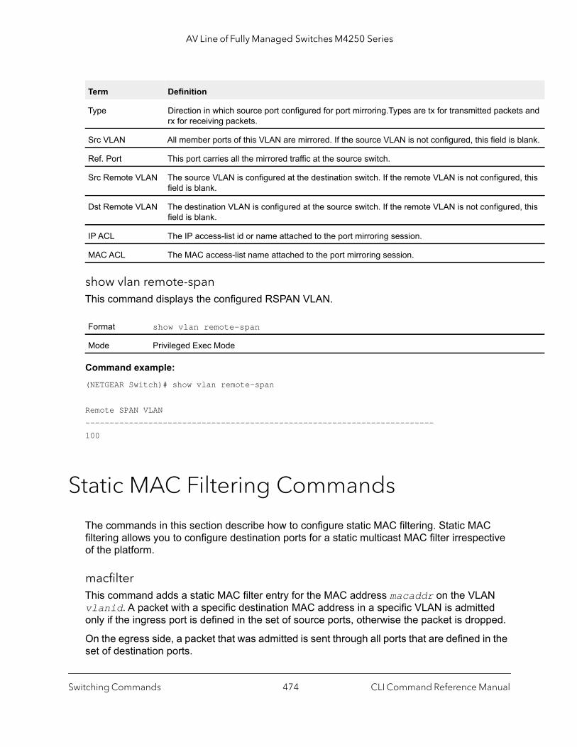
AV Line of Fully Managed Switches M4250 Series
s and
lank.
, this
, this
show vlan remote-spanThis command displays the configured RSPAN VLAN.
Command example: (NETGEAR Switch)# show vlan remote-span
Remote SPAN VLAN------------------------------------------------------------------------100
Static MAC Filtering Commands
The commands in this section describe how to configure static MAC filtering. Static MAC filtering allows you to configure destination ports for a static multicast MAC filter irrespective of the platform.
macfilter This command adds a static MAC filter entry for the MAC address macaddr on the VLAN vlanid. A packet with a specific destination MAC address in a specific VLAN is admitted only if the ingress port is defined in the set of source ports, otherwise the packet is dropped.
On the egress side, a packet that was admitted is sent through all ports that are defined in the set of destination ports.
Type Direction in which source port configured for port mirroring.Types are tx for transmitted packetrx for receiving packets.
Src VLAN All member ports of this VLAN are mirrored. If the source VLAN is not configured, this field is b
Ref. Port This port carries all the mirrored traffic at the source switch.
Src Remote VLAN The source VLAN is configured at the destination switch. If the remote VLAN is not configuredfield is blank.
Dst Remote VLAN The destination VLAN is configured at the source switch. If the remote VLAN is not configuredfield is blank.
IP ACL The IP access-list id or name attached to the port mirroring session.
MAC ACL The MAC access-list name attached to the port mirroring session.
Format show vlan remote-span
Mode Privileged Exec Mode
Term Definition
Switching Commands CLI Command Reference Manual474
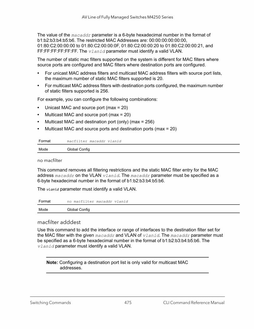
AV Line of Fully Managed Switches M4250 Series
The value of the macaddr parameter is a 6-byte hexadecimal number in the format of b1:b2:b3:b4:b5:b6. The restricted MAC Addresses are: 00:00:00:00:00:00, 01:80:C2:00:00:00 to 01:80:C2:00:00:0F, 01:80:C2:00:00:20 to 01:80:C2:00:00:21, and FF:FF:FF:FF:FF:FF. The vlanid parameter must identify a valid VLAN.
The number of static mac filters supported on the system is different for MAC filters where source ports are configured and MAC filters where destination ports are configured.
• For unicast MAC address filters and multicast MAC address filters with source port lists, the maximum number of static MAC filters supported is 20.
• For multicast MAC address filters with destination ports configured, the maximum number of static filters supported is 256.
For example, you can configure the following combinations:
• Unicast MAC and source port (max = 20)• Multicast MAC and source port (max = 20)• Multicast MAC and destination port (only) (max = 256)• Multicast MAC and source ports and destination ports (max = 20)
no macfilter
This command removes all filtering restrictions and the static MAC filter entry for the MAC address macaddr on the VLAN vlanid. The macaddr parameter must be specified as a 6-byte hexadecimal number in the format of b1:b2:b3:b4:b5:b6.
The vlanid parameter must identify a valid VLAN.
macfilter adddestUse this command to add the interface or range of interfaces to the destination filter set for the MAC filter with the given macaddr and VLAN of vlanid. The macaddr parameter must be specified as a 6-byte hexadecimal number in the format of b1:b2:b3:b4:b5:b6. The vlanid parameter must identify a valid VLAN.
Note: Configuring a destination port list is only valid for multicast MAC addresses.
Format macfilter macaddr vlanid
Mode Global Config
Format no macfilter macaddr vlanid
Mode Global Config
Switching Commands CLI Command Reference Manual475

AV Line of Fully Managed Switches M4250 Series
no macfilter adddest
This command removes a port from the destination filter set for the MAC filter with the given macaddr and VLAN of vlanid. The macaddr parameter must be specified as a 6-byte hexadecimal number in the format of b1:b2:b3:b4:b5:b6. The vlanid parameter must identify a valid VLAN.
macfilter adddest allThis command adds all interfaces to the destination filter set for the MAC filter with the given macaddr and VLAN of vlanid. The macaddr parameter must be specified as a 6-byte hexadecimal number in the format of b1:b2:b3:b4:b5:b6. The vlanid parameter must identify a valid VLAN.
Note: Configuring a destination port list is only valid for multicast MAC addresses.
no macfilter adddest all
This command removes all ports from the destination filter set for the MAC filter with the given macaddr and VLAN of vlanid. The macaddr parameter must be specified as a 6-byte hexadecimal number in the format of b1:b2:b3:b4:b5:b6. The vlanid parameter must identify a valid VLAN.
macfilter addsrcThis command adds the interface or range of interfaces to the source filter set for the MAC filter with the MAC filter with the given macaddr and VLAN of vlanid. The macaddr parameter must be specified as a 6-byte hexadecimal number in the format of b1:b2:b3:b4:b5:b6. The vlanid parameter must identify a valid VLAN.
Format macfilter adddest macaddr vlanid
Mode Interface Config
Format no macfilter adddest macaddr vlanid
Mode Interface Config
Format macfilter adddest all macaddr vlanid
Mode Global Config
Format no macfilter adddest all macaddr vlanid
Mode Global Config
Switching Commands CLI Command Reference Manual476
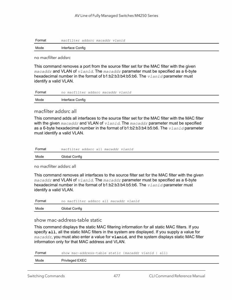
AV Line of Fully Managed Switches M4250 Series
no macfilter addsrc
This command removes a port from the source filter set for the MAC filter with the given macaddr and VLAN of vlanid. The macaddr parameter must be specified as a 6-byte hexadecimal number in the format of b1:b2:b3:b4:b5:b6. The vlanid parameter must identify a valid VLAN.
macfilter addsrc allThis command adds all interfaces to the source filter set for the MAC filter with the MAC filter with the given macaddr and VLAN of vlanid. The macaddr parameter must be specified as a 6-byte hexadecimal number in the format of b1:b2:b3:b4:b5:b6. The vlanid parameter must identify a valid VLAN.
no macfilter addsrc all
This command removes all interfaces to the source filter set for the MAC filter with the given macaddr and VLAN of vlanid. The macaddr parameter must be specified as a 6-byte hexadecimal number in the format of b1:b2:b3:b4:b5:b6. The vlanid parameter must identify a valid VLAN.
show mac-address-table static This command displays the static MAC filtering information for all static MAC filters. If you specify all, all the static MAC filters in the system are displayed. If you supply a value for macaddr, you must also enter a value for vlanid, and the system displays static MAC filter information only for that MAC address and VLAN.
Format macfilter addsrc macaddr vlanid
Mode Interface Config
Format no macfilter addsrc macaddr vlanid
Mode Interface Config
Format macfilter addsrc all macaddr vlanid
Mode Global Config
Format no macfilter addsrc all macaddr vlanid
Mode Global Config
Format show mac-address-table static {macaddr vlanid | all}
Mode Privileged EXEC
Switching Commands CLI Command Reference Manual477

AV Line of Fully Managed Switches M4250 Series
data
tries
Note: Only multicast address filters can have destination port lists.
show mac-address-table staticfilteringThis command displays the Static Filtering entries in the Multicast Forwarding Database (MFDB) table.
DHCP L2 Relay Agent Commands
You can enable the switch to operate as a DHCP Layer 2 relay agent to relay DHCP requests from clients to a Layer 3 relay agent or server. The Circuit ID and Remote ID can be added to DHCP requests relayed from clients to a DHCP server. This information is included in DHCP Option 82, as specified in sections 3.1 and 3.2 of RFC3046.
Term Definition
MAC Address The MAC address of the static MAC filter entry.
VLAN ID The VLAN ID of the static MAC filter entry.
Source Ports The source port of the static MAC filter entry.
Format show mac-address-table staticfiltering
Mode Privileged EXEC
Term Definition
VLAN ID The VLAN in which the MAC Address is learned.
MAC Address A unicast MAC address for which the switch has forwarding and or filtering information. As theis gleaned from the MFDB, the address will be a multicast address. The format is 6 two-digit hexadecimal numbers that are separated by colons, for example 01:23:45:67:89:AB.
Type The type of the entry. Static entries are those that are configured by the end user. Dynamic enare added to the table as a result of a learning process or protocol.
Description The text description of this multicast table entry.
Interfaces The list of interfaces that are designated for forwarding (Fwd:) and filtering (Flt:).
Switching Commands CLI Command Reference Manual478
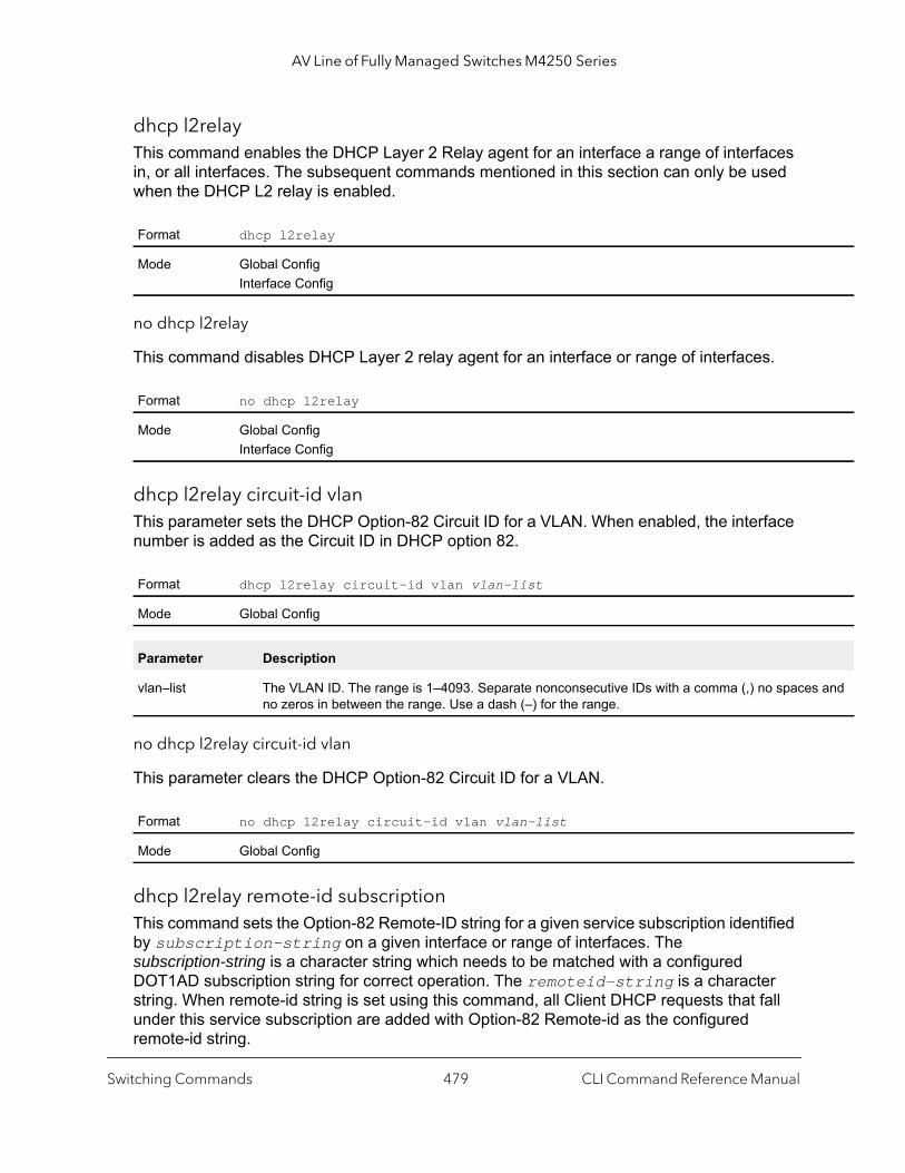
AV Line of Fully Managed Switches M4250 Series
s and
dhcp l2relayThis command enables the DHCP Layer 2 Relay agent for an interface a range of interfaces in, or all interfaces. The subsequent commands mentioned in this section can only be used when the DHCP L2 relay is enabled.
no dhcp l2relay
This command disables DHCP Layer 2 relay agent for an interface or range of interfaces.
dhcp l2relay circuit-id vlanThis parameter sets the DHCP Option-82 Circuit ID for a VLAN. When enabled, the interface number is added as the Circuit ID in DHCP option 82.
no dhcp l2relay circuit-id vlan
This parameter clears the DHCP Option-82 Circuit ID for a VLAN.
dhcp l2relay remote-id subscriptionThis command sets the Option-82 Remote-ID string for a given service subscription identified by subscription-string on a given interface or range of interfaces. The subscription-string is a character string which needs to be matched with a configured DOT1AD subscription string for correct operation. The remoteid-string is a character string. When remote-id string is set using this command, all Client DHCP requests that fall under this service subscription are added with Option-82 Remote-id as the configured remote-id string.
Format dhcp l2relay
Mode Global ConfigInterface Config
Format no dhcp l2relay
Mode Global ConfigInterface Config
Format dhcp l2relay circuit-id vlan vlan-list
Mode Global Config
Parameter Description
vlan–list The VLAN ID. The range is 1–4093. Separate nonconsecutive IDs with a comma (,) no spaceno zeros in between the range. Use a dash (–) for the range.
Format no dhcp l2relay circuit-id vlan vlan-list
Mode Global Config
Switching Commands CLI Command Reference Manual479
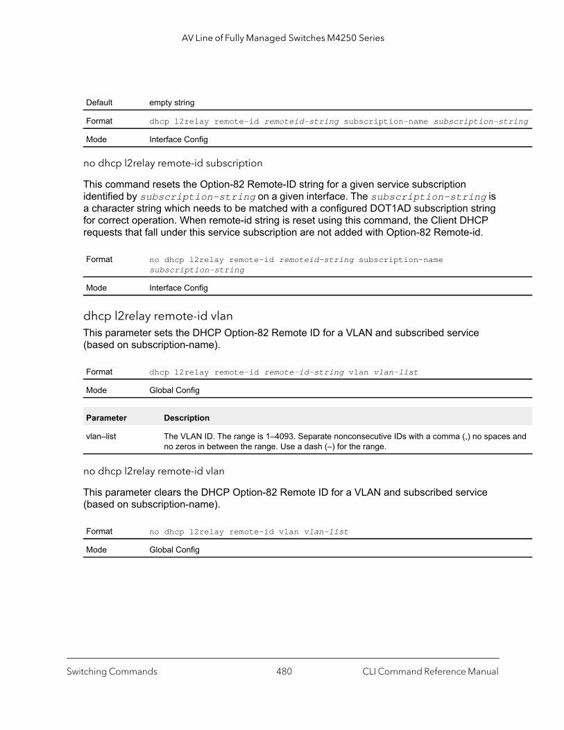
AV Line of Fully Managed Switches M4250 Series
ring
and
no dhcp l2relay remote-id subscription
This command resets the Option-82 Remote-ID string for a given service subscription identified by subscription-string on a given interface. The subscription-string is a character string which needs to be matched with a configured DOT1AD subscription string for correct operation. When remote-id string is reset using this command, the Client DHCP requests that fall under this service subscription are not added with Option-82 Remote-id.
dhcp l2relay remote-id vlanThis parameter sets the DHCP Option-82 Remote ID for a VLAN and subscribed service (based on subscription-name).
no dhcp l2relay remote-id vlan
This parameter clears the DHCP Option-82 Remote ID for a VLAN and subscribed service (based on subscription-name).
Default empty string
Format dhcp l2relay remote-id remoteid-string subscription-name subscription-st
Mode Interface Config
Format no dhcp l2relay remote-id remoteid-string subscription-name subscription-string
Mode Interface Config
Format dhcp l2relay remote-id remote-id-string vlan vlan-list
Mode Global Config
Parameter Description
vlan–list The VLAN ID. The range is 1–4093. Separate nonconsecutive IDs with a comma (,) no spacesno zeros in between the range. Use a dash (–) for the range.
Format no dhcp l2relay remote-id vlan vlan-list
Mode Global Config
Switching Commands CLI Command Reference Manual480

AV Line of Fully Managed Switches M4250 Series
dhcp l2relay subscriptionThis command enables relaying DHCP packets on an interface or range of interfaces that fall under the specified service subscription. The subscription-string is a character string that must be matched with the configured DOT1AD subscription-string for correct operation.
no dhcp l2relay subscription
This command disables relaying DHCP packets that fall under the specified service subscription. The subscription-string is a character string that must be matched with the configured DOT1AD subscription string for correct operation.
dhcp l2relay trustUse this command to configure an interface or range of interfaces as trusted for Option-82 reception.
no dhcp l2relay trust
Use this command to configure an interface to the default untrusted for Option-82 reception.
dhcp l2relay vlanUse this command to enable the DHCP L2 Relay agent for a set of VLANs. All DHCP packets which arrive on interfaces in the configured VLAN are subject to L2 Relay processing.
Default Disabled (that is, no DHCP packets are relayed)
Format dhcp l2relay subscription-name subscription-string
Mode Interface Config
Format no dhcp l2relay subscription-name subscription-string
Mode Interface Config
Default Untrusted
Format dhcp l2relay trust
Mode Interface Config
Format no dhcp l2relay trust
Mode Interface Config
Default Disabled
Format dhcp l2relay vlan vlan-list
Mode Global Config
Switching Commands CLI Command Reference Manual481

AV Line of Fully Managed Switches M4250 Series
and
no dhcp l2relay vlan
Use this command to disable the DHCP L2 Relay agent for a set of VLANs.
show dhcp l2relay allThis command displays the summary of DHCP L2 Relay configuration.
Command example: (NETGEAR Switch) #show dhcp l2relay all
DHCP L2 Relay is Enabled.
Interface L2RelayMode TrustMode---------- ----------- -------------- 0/2 Enabled untrusted 0/4 Disabled trusted
VLAN Id L2 Relay CircuitId RemoteId--------- ---------- ----------- ------------ 3 Disabled Enabled --NULL-- 5 Enabled Enabled --NULL-- 6 Enabled Enabled NETGEAR 7 Enabled Disabled --NULL-- 8 Enabled Disabled --NULL-- 9 Enabled Disabled --NULL-- 10 Enabled Disabled --NULL--
show dhcp l2relay circuit-id vlanThis command displays DHCP circuit-id vlan configuration.
Parameter Description
vlan–list The VLAN ID. The range is 1–4093. Separate nonconsecutive IDs with a comma (,) no spacesno zeros in between the range. Use a dash (–) for the range.
Format no dhcp l2relay vlan vlan-list
Mode Global Config
Format show dhcp l2relay all
Mode Privileged EXEC
Format show dhcp l2relay circuit-id vlan vlan-list
Mode Privileged EXEC
Switching Commands CLI Command Reference Manual482
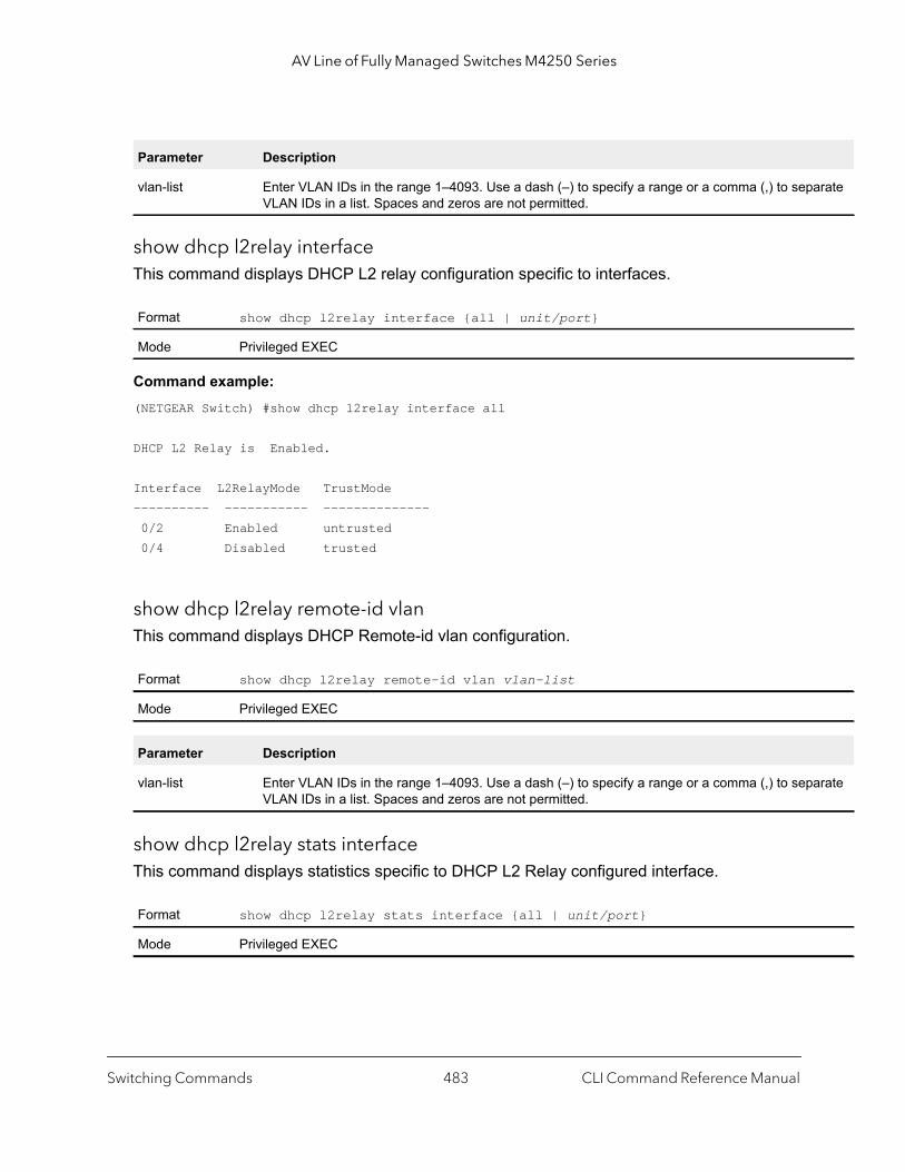
AV Line of Fully Managed Switches M4250 Series
arate
arate
show dhcp l2relay interfaceThis command displays DHCP L2 relay configuration specific to interfaces.
Command example: (NETGEAR Switch) #show dhcp l2relay interface all
DHCP L2 Relay is Enabled.
Interface L2RelayMode TrustMode---------- ----------- -------------- 0/2 Enabled untrusted 0/4 Disabled trusted
show dhcp l2relay remote-id vlanThis command displays DHCP Remote-id vlan configuration.
show dhcp l2relay stats interfaceThis command displays statistics specific to DHCP L2 Relay configured interface.
Parameter Description
vlan-list Enter VLAN IDs in the range 1–4093. Use a dash (–) to specify a range or a comma (,) to sepVLAN IDs in a list. Spaces and zeros are not permitted.
Format show dhcp l2relay interface {all | unit/port}
Mode Privileged EXEC
Format show dhcp l2relay remote-id vlan vlan-list
Mode Privileged EXEC
Parameter Description
vlan-list Enter VLAN IDs in the range 1–4093. Use a dash (–) to specify a range or a comma (,) to sepVLAN IDs in a list. Spaces and zeros are not permitted.
Format show dhcp l2relay stats interface {all | unit/port}
Mode Privileged EXEC
Switching Commands CLI Command Reference Manual483

AV Line of Fully Managed Switches M4250 Series
Command example: ((NETGEAR Switch)) #show dhcp l2relay stats interface all
DHCP L2 Relay is Enabled.
Interface UntrustedServer UntrustedClient TrustedServer TrustedClient MsgsWithOpt82 MsgsWithOpt82 MsgsWithoutOpt82 MsgsWithoutOpt82--------- --------------- --------------- ---------------- -------------- 0/1 0 0 0 0 0/2 0 0 3 7 0/3 0 0 0 0 0/4 0 12 0 0 0/5 0 0 0 0 0/6 3 0 0 0 0/7 0 0 0 0 0/8 0 0 0 0 0/9 0 0 0 0
show dhcp l2relay subscription interfaceThis command displays DHCP L2 Relay configuration specific to a service subscription on an interface.
Command example: (NETGEAR Switch) #show dhcp l2relay subscription interface allInterface SubscriptionName L2Relay mode Circuit-Id mode Remote-Id mode----------- ---------------- -------------- --------------- ---------------- 0/1 sub1 Enabled Disabled --NULL-- 0/2 sub3 Enabled Disabled EnterpriseSwitch 0/2 sub22 Disabled Enabled --NULL-- 0/4 sub4 Enabled Enabled --NULL--
show dhcp l2relay agent-option vlan This command displays the DHCP L2 Relay Option-82 configuration specific to VLAN.
Format show dhcp l2relay subscription interface {all | unit/port}
Mode Privileged EXEC
Format show dhcp l2relay agent-option vlan vlan-range
Mode Privileged EXEC
Switching Commands CLI Command Reference Manual484
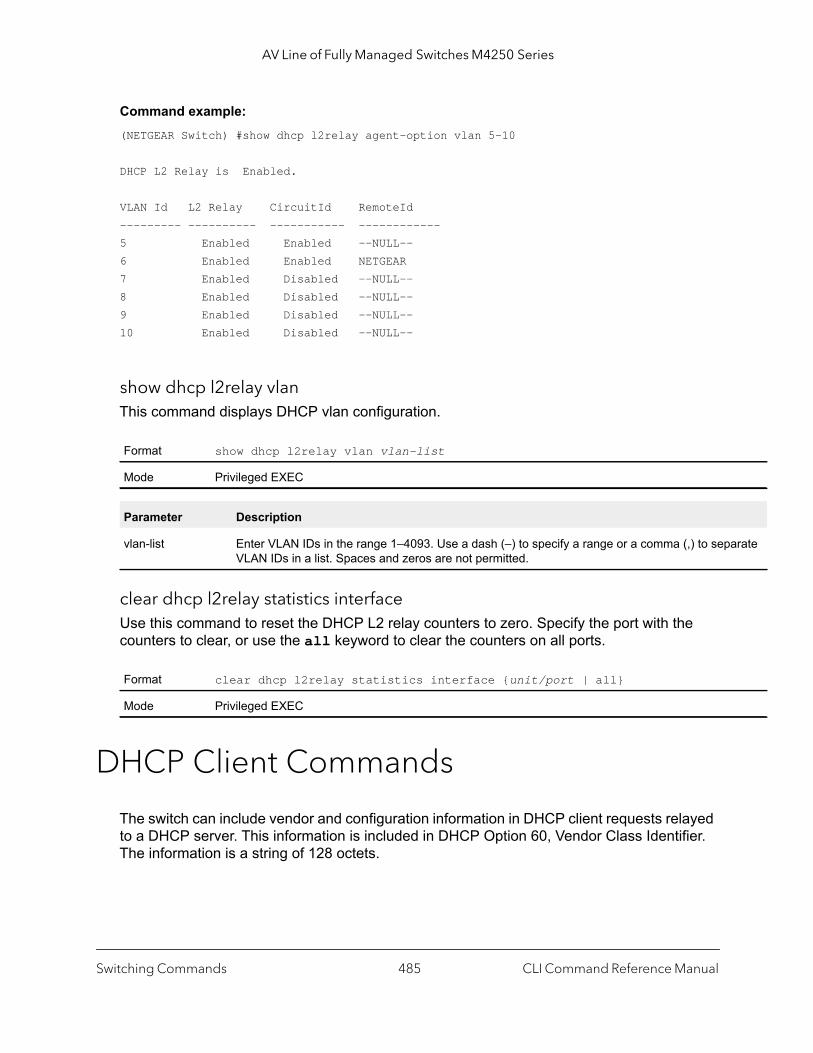
AV Line of Fully Managed Switches M4250 Series
arate
Command example: (NETGEAR Switch) #show dhcp l2relay agent-option vlan 5-10
DHCP L2 Relay is Enabled.
VLAN Id L2 Relay CircuitId RemoteId--------- ---------- ----------- ------------5 Enabled Enabled --NULL--6 Enabled Enabled NETGEAR7 Enabled Disabled --NULL--8 Enabled Disabled --NULL--9 Enabled Disabled --NULL--10 Enabled Disabled --NULL--
show dhcp l2relay vlanThis command displays DHCP vlan configuration.
clear dhcp l2relay statistics interfaceUse this command to reset the DHCP L2 relay counters to zero. Specify the port with the counters to clear, or use the all keyword to clear the counters on all ports.
DHCP Client Commands
The switch can include vendor and configuration information in DHCP client requests relayed to a DHCP server. This information is included in DHCP Option 60, Vendor Class Identifier. The information is a string of 128 octets.
Format show dhcp l2relay vlan vlan-list
Mode Privileged EXEC
Parameter Description
vlan-list Enter VLAN IDs in the range 1–4093. Use a dash (–) to specify a range or a comma (,) to sepVLAN IDs in a list. Spaces and zeros are not permitted.
Format clear dhcp l2relay statistics interface {unit/port | all}
Mode Privileged EXEC
Switching Commands CLI Command Reference Manual485
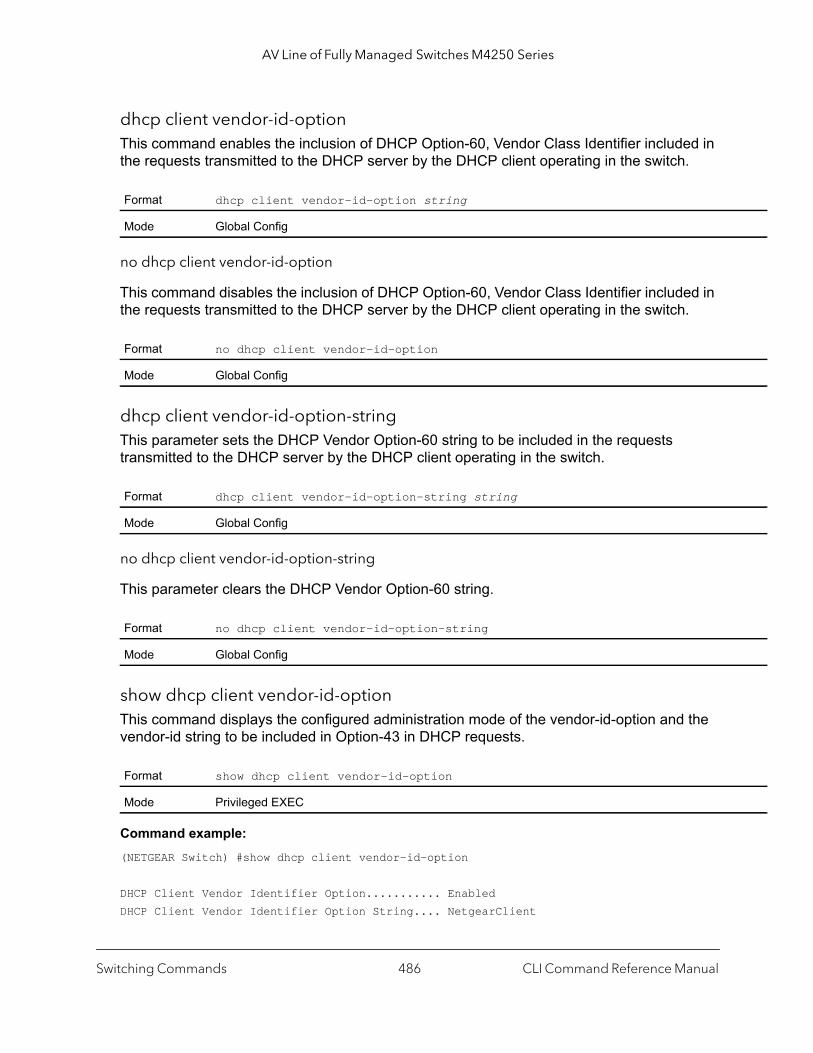
AV Line of Fully Managed Switches M4250 Series
dhcp client vendor-id-optionThis command enables the inclusion of DHCP Option-60, Vendor Class Identifier included in the requests transmitted to the DHCP server by the DHCP client operating in the switch.
no dhcp client vendor-id-option
This command disables the inclusion of DHCP Option-60, Vendor Class Identifier included in the requests transmitted to the DHCP server by the DHCP client operating in the switch.
dhcp client vendor-id-option-stringThis parameter sets the DHCP Vendor Option-60 string to be included in the requests transmitted to the DHCP server by the DHCP client operating in the switch.
no dhcp client vendor-id-option-string
This parameter clears the DHCP Vendor Option-60 string.
show dhcp client vendor-id-optionThis command displays the configured administration mode of the vendor-id-option and the vendor-id string to be included in Option-43 in DHCP requests.
Command example: (NETGEAR Switch) #show dhcp client vendor-id-option
DHCP Client Vendor Identifier Option........... EnabledDHCP Client Vendor Identifier Option String.... NetgearClient
Format dhcp client vendor-id-option string
Mode Global Config
Format no dhcp client vendor-id-option
Mode Global Config
Format dhcp client vendor-id-option-string string
Mode Global Config
Format no dhcp client vendor-id-option-string
Mode Global Config
Format show dhcp client vendor-id-option
Mode Privileged EXEC
Switching Commands CLI Command Reference Manual486
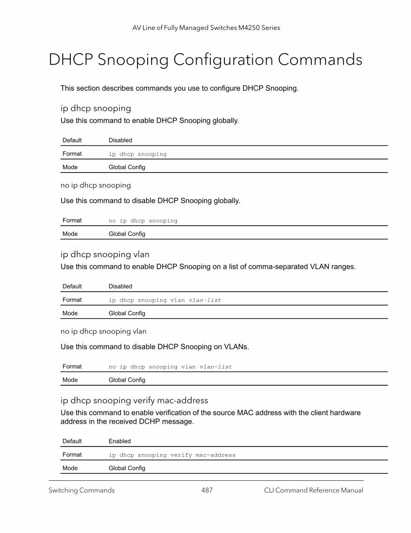
AV Line of Fully Managed Switches M4250 Series
DHCP Snooping Configuration Commands
This section describes commands you use to configure DHCP Snooping.
ip dhcp snoopingUse this command to enable DHCP Snooping globally.
no ip dhcp snooping
Use this command to disable DHCP Snooping globally.
ip dhcp snooping vlanUse this command to enable DHCP Snooping on a list of comma-separated VLAN ranges.
no ip dhcp snooping vlan
Use this command to disable DHCP Snooping on VLANs.
ip dhcp snooping verify mac-addressUse this command to enable verification of the source MAC address with the client hardware address in the received DCHP message.
Default Disabled
Format ip dhcp snooping
Mode Global Config
Format no ip dhcp snooping
Mode Global Config
Default Disabled
Format ip dhcp snooping vlan vlan-list
Mode Global Config
Format no ip dhcp snooping vlan vlan-list
Mode Global Config
Default Enabled
Format ip dhcp snooping verify mac-address
Mode Global Config
Switching Commands CLI Command Reference Manual487

AV Line of Fully Managed Switches M4250 Series
no ip dhcp snooping verify mac-address
Use this command to disable verification of the source MAC address with the client hardware address.
ip dhcp snooping databaseUse this command to configure the persistent location of the DHCP Snooping database. This can be local or a remote file on a given IP machine.
ip dhcp snooping database write-delay (DHCP)Use this command to configure the interval in seconds at which the DHCP Snooping database persists. The interval value ranges from 15 to 86400 seconds.
no ip dhcp snooping database write-delay
Use this command to set the write delay value to the default value.
ip dhcp snooping bindingUse this command to configure static DHCP Snooping binding.
Format no ip dhcp snooping verify mac-address
Mode Global Config
Default Local
Format ip dhcp snooping database {local | tftp://hostIP/filename}
Mode Global Config
Default 300 seconds
Format ip dhcp snooping database write-delay seconds
Mode Global Config
Format no ip dhcp snooping database write-delay
Mode Global Config
Format ip dhcp snooping binding mac-address vlan vlan-id ipaddress interface interface-id
Mode Global Config
Switching Commands CLI Command Reference Manual488
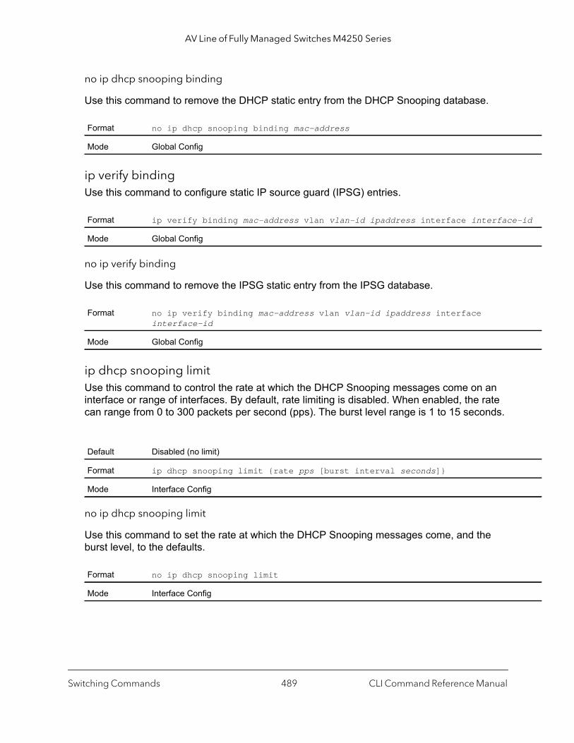
AV Line of Fully Managed Switches M4250 Series
-id
no ip dhcp snooping binding
Use this command to remove the DHCP static entry from the DHCP Snooping database.
ip verify bindingUse this command to configure static IP source guard (IPSG) entries.
no ip verify binding
Use this command to remove the IPSG static entry from the IPSG database.
ip dhcp snooping limitUse this command to control the rate at which the DHCP Snooping messages come on an interface or range of interfaces. By default, rate limiting is disabled. When enabled, the rate can range from 0 to 300 packets per second (pps). The burst level range is 1 to 15 seconds.
no ip dhcp snooping limit
Use this command to set the rate at which the DHCP Snooping messages come, and the burst level, to the defaults.
Format no ip dhcp snooping binding mac-address
Mode Global Config
Format ip verify binding mac-address vlan vlan-id ipaddress interface interface
Mode Global Config
Format no ip verify binding mac-address vlan vlan-id ipaddress interface interface-id
Mode Global Config
Default Disabled (no limit)
Format ip dhcp snooping limit {rate pps [burst interval seconds]}
Mode Interface Config
Format no ip dhcp snooping limit
Mode Interface Config
Switching Commands CLI Command Reference Manual489
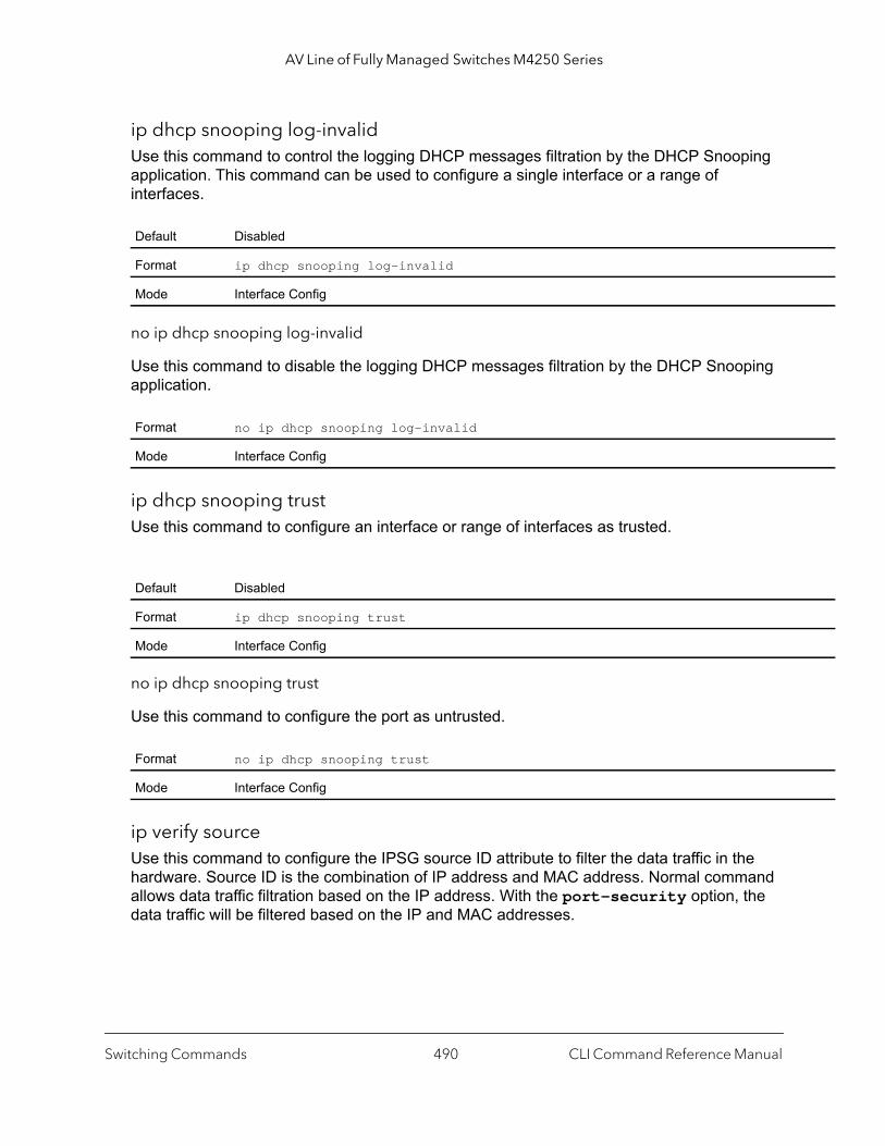
AV Line of Fully Managed Switches M4250 Series
ip dhcp snooping log-invalidUse this command to control the logging DHCP messages filtration by the DHCP Snooping application. This command can be used to configure a single interface or a range of interfaces.
no ip dhcp snooping log-invalid
Use this command to disable the logging DHCP messages filtration by the DHCP Snooping application.
ip dhcp snooping trustUse this command to configure an interface or range of interfaces as trusted.
no ip dhcp snooping trust
Use this command to configure the port as untrusted.
ip verify sourceUse this command to configure the IPSG source ID attribute to filter the data traffic in the hardware. Source ID is the combination of IP address and MAC address. Normal command allows data traffic filtration based on the IP address. With the port-security option, the data traffic will be filtered based on the IP and MAC addresses.
Default Disabled
Format ip dhcp snooping log-invalid
Mode Interface Config
Format no ip dhcp snooping log-invalid
Mode Interface Config
Default Disabled
Format ip dhcp snooping trust
Mode Interface Config
Format no ip dhcp snooping trust
Mode Interface Config
Switching Commands CLI Command Reference Manual490
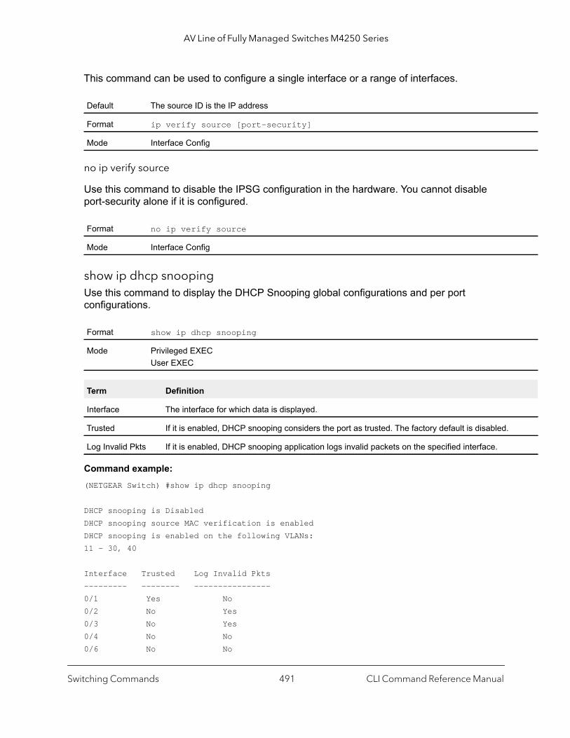
AV Line of Fully Managed Switches M4250 Series
This command can be used to configure a single interface or a range of interfaces.
no ip verify source
Use this command to disable the IPSG configuration in the hardware. You cannot disable port-security alone if it is configured.
show ip dhcp snoopingUse this command to display the DHCP Snooping global configurations and per port configurations.
Command example: (NETGEAR Switch) #show ip dhcp snooping
DHCP snooping is DisabledDHCP snooping source MAC verification is enabledDHCP snooping is enabled on the following VLANs:11 - 30, 40
Interface Trusted Log Invalid Pkts --------- -------- ----------------0/1 Yes No 0/2 No Yes 0/3 No Yes 0/4 No No0/6 No No
Default The source ID is the IP address
Format ip verify source [port-security]
Mode Interface Config
Format no ip verify source
Mode Interface Config
Format show ip dhcp snooping
Mode Privileged EXECUser EXEC
Term Definition
Interface The interface for which data is displayed.
Trusted If it is enabled, DHCP snooping considers the port as trusted. The factory default is disabled.
Log Invalid Pkts If it is enabled, DHCP snooping application logs invalid packets on the specified interface.
Switching Commands CLI Command Reference Manual491
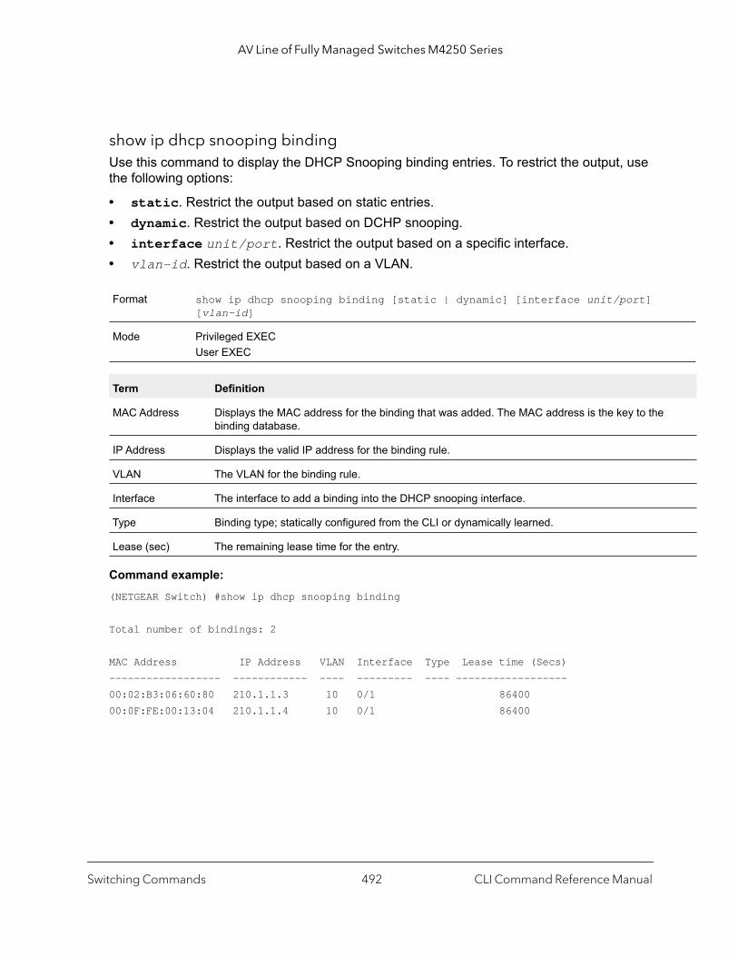
AV Line of Fully Managed Switches M4250 Series
show ip dhcp snooping binding Use this command to display the DHCP Snooping binding entries. To restrict the output, use the following options:
• static. Restrict the output based on static entries.• dynamic. Restrict the output based on DCHP snooping.• interface unit/port. Restrict the output based on a specific interface.• vlan-id. Restrict the output based on a VLAN.
Command example: (NETGEAR Switch) #show ip dhcp snooping binding
Total number of bindings: 2
MAC Address IP Address VLAN Interface Type Lease time (Secs)------------------ ------------ ---- --------- ---- ------------------00:02:B3:06:60:80 210.1.1.3 10 0/1 8640000:0F:FE:00:13:04 210.1.1.4 10 0/1 86400
Format show ip dhcp snooping binding [static | dynamic] [interface unit/port] [vlan-id]
Mode Privileged EXECUser EXEC
Term Definition
MAC Address Displays the MAC address for the binding that was added. The MAC address is the key to thebinding database.
IP Address Displays the valid IP address for the binding rule.
VLAN The VLAN for the binding rule.
Interface The interface to add a binding into the DHCP snooping interface.
Type Binding type; statically configured from the CLI or dynamically learned.
Lease (sec) The remaining lease time for the entry.
Switching Commands CLI Command Reference Manual492

AV Line of Fully Managed Switches M4250 Series
show ip dhcp snooping databaseUse this command to display the DHCP Snooping configuration related to the database persistency.
Command example: (NETGEAR Switch) #show ip dhcp snooping databaseagent url: /10.131.13.79:/sai1.txtwrite-delay: 5000
show ip dhcp snooping interfacesUse this command to show the DHCP Snooping status of the interfaces.
Command example: (NETGEAR Switch) #show ip dhcp snooping interfaces
Interface Trust State Rate Limit Burst Interval (pps) (seconds)----------- ---------- ---------- --------------1/0/1 No 15 11/0/2 No 15 11/0/3 No 15 1
Command example: (NETGEAR Switch) #show ip dhcp snooping interfaces ethernet 1/0/15
Interface Trust State Rate Limit Burst Interval (pps) (seconds)----------- ---------- ---------- --------------1/0/15 Yes 15 1
Format show ip dhcp snooping database
Mode Privileged EXECUser EXEC
Term Definition
Agent URL Bindings database agent URL.
Write Delay The maximum write time to write the database into local or remote.
Format show ip dhcp snooping interfaces
Mode Privileged EXEC
Switching Commands CLI Command Reference Manual493
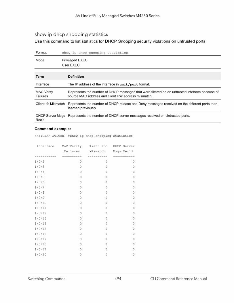
AV Line of Fully Managed Switches M4250 Series
se of
than
show ip dhcp snooping statisticsUse this command to list statistics for DHCP Snooping security violations on untrusted ports.
Command example: (NETGEAR Switch) #show ip dhcp snooping statistics
Interface MAC Verify Client Ifc DHCP Server Failures Mismatch Msgs Rec'd----------- ---------- ---------- -----------1/0/2 0 0 01/0/3 0 0 01/0/4 0 0 01/0/5 0 0 01/0/6 0 0 01/0/7 0 0 01/0/8 0 0 01/0/9 0 0 01/0/10 0 0 01/0/11 0 0 01/0/12 0 0 01/0/13 0 0 01/0/14 0 0 01/0/15 0 0 01/0/16 0 0 01/0/17 0 0 01/0/18 0 0 01/0/19 0 0 01/0/20 0 0 0
Format show ip dhcp snooping statistics
Mode Privileged EXECUser EXEC
Term Definition
Interface The IP address of the interface in unit/port format.
MAC Verify Failures
Represents the number of DHCP messages that were filtered on an untrusted interface becausource MAC address and client HW address mismatch.
Client Ifc Mismatch Represents the number of DHCP release and Deny messages received on the different ports learned previously.
DHCP Server Msgs Rec’d
Represents the number of DHCP server messages received on Untrusted ports.
Switching Commands CLI Command Reference Manual494
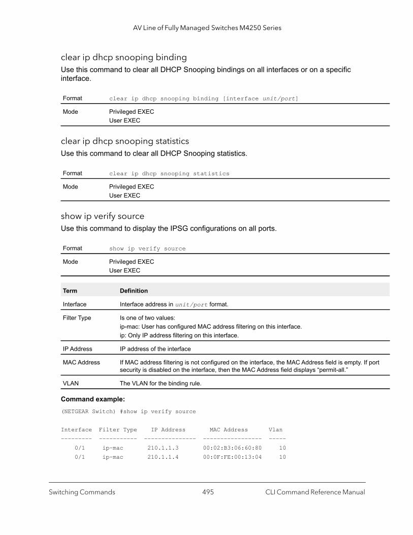
AV Line of Fully Managed Switches M4250 Series
ort
clear ip dhcp snooping binding Use this command to clear all DHCP Snooping bindings on all interfaces or on a specific interface.
clear ip dhcp snooping statisticsUse this command to clear all DHCP Snooping statistics.
show ip verify sourceUse this command to display the IPSG configurations on all ports.
Command example: (NETGEAR Switch) #show ip verify source
Interface Filter Type IP Address MAC Address Vlan--------- ----------- --------------- ----------------- ----- 0/1 ip-mac 210.1.1.3 00:02:B3:06:60:80 10 0/1 ip-mac 210.1.1.4 00:0F:FE:00:13:04 10
Format clear ip dhcp snooping binding [interface unit/port]
Mode Privileged EXECUser EXEC
Format clear ip dhcp snooping statistics
Mode Privileged EXECUser EXEC
Format show ip verify source
Mode Privileged EXECUser EXEC
Term Definition
Interface Interface address in unit/port format.
Filter Type Is one of two values:ip-mac: User has configured MAC address filtering on this interface.ip: Only IP address filtering on this interface.
IP Address IP address of the interface
MAC Address If MAC address filtering is not configured on the interface, the MAC Address field is empty. If psecurity is disabled on the interface, then the MAC Address field displays “permit-all.”
VLAN The VLAN for the binding rule.
Switching Commands CLI Command Reference Manual495

AV Line of Fully Managed Switches M4250 Series
show ip verify interfaceUse this command to display the IPSG filter type for a specific interface.
show ip source bindingUse this command to display the IPSG bindings.
Command example: (NETGEAR Switch) #show ip source binding
MAC Address IP Address Type Vlan Interface----------------- --------------- ------------- ----- -------------00:00:00:00:00:08 1.2.3.4 dhcp-snooping 2 1/0/100:00:00:00:00:09 1.2.3.4 dhcp-snooping 3 1/0/100:00:00:00:00:0A 1.2.3.4 dhcp-snooping 4 1/0/1
Format show ip verify interface unit/port
Mode Privileged EXECUser EXEC
Term Definition
Interface Interface address in unit/port format.
Filter Type Is one of two values:ip-mac: User has configured MAC address filtering on this interface.ip: Only IP address filtering on this interface.
Format show ip source binding [dhcp-snooping | static] [interface unit/port] [vlan-id]
Mode Privileged EXECUser EXEC
Term Definition
MAC Address The MAC address for the entry that is added.
IP Address The IP address of the entry that is added.
Type Entry type; statically configured from CLI or dynamically learned from DHCP Snooping.
VLAN VLAN for the entry.
Interface IP address of the interface in unit/port format.
Switching Commands CLI Command Reference Manual496
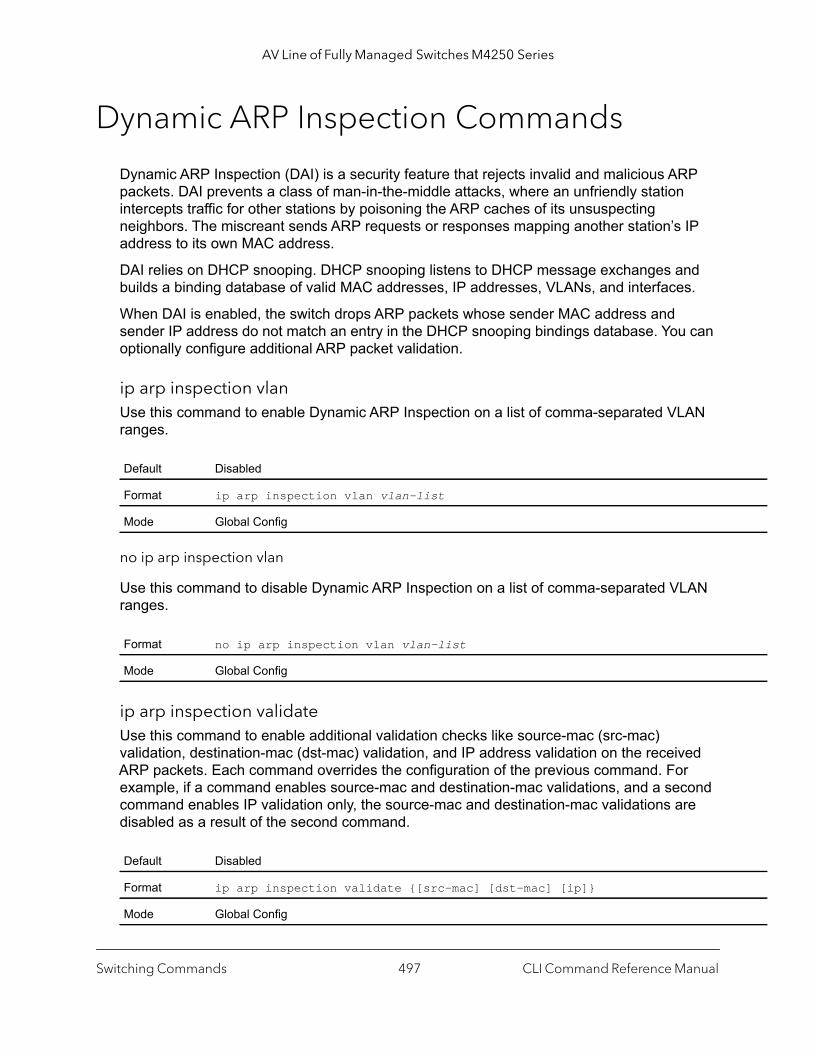
AV Line of Fully Managed Switches M4250 Series
Dynamic ARP Inspection Commands
Dynamic ARP Inspection (DAI) is a security feature that rejects invalid and malicious ARP packets. DAI prevents a class of man-in-the-middle attacks, where an unfriendly station intercepts traffic for other stations by poisoning the ARP caches of its unsuspecting neighbors. The miscreant sends ARP requests or responses mapping another station’s IP address to its own MAC address.
DAI relies on DHCP snooping. DHCP snooping listens to DHCP message exchanges and builds a binding database of valid MAC addresses, IP addresses, VLANs, and interfaces.
When DAI is enabled, the switch drops ARP packets whose sender MAC address and sender IP address do not match an entry in the DHCP snooping bindings database. You can optionally configure additional ARP packet validation.
ip arp inspection vlanUse this command to enable Dynamic ARP Inspection on a list of comma-separated VLAN ranges.
no ip arp inspection vlan
Use this command to disable Dynamic ARP Inspection on a list of comma-separated VLAN ranges.
ip arp inspection validateUse this command to enable additional validation checks like source-mac (src-mac) validation, destination-mac (dst-mac) validation, and IP address validation on the received ARP packets. Each command overrides the configuration of the previous command. For example, if a command enables source-mac and destination-mac validations, and a second command enables IP validation only, the source-mac and destination-mac validations are disabled as a result of the second command.
Default Disabled
Format ip arp inspection vlan vlan-list
Mode Global Config
Format no ip arp inspection vlan vlan-list
Mode Global Config
Default Disabled
Format ip arp inspection validate {[src-mac] [dst-mac] [ip]}
Mode Global Config
Switching Commands CLI Command Reference Manual497
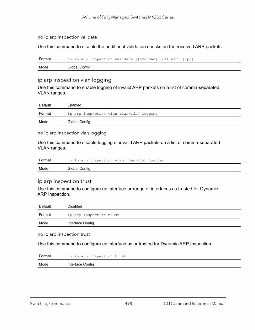
AV Line of Fully Managed Switches M4250 Series
no ip arp inspection validate
Use this command to disable the additional validation checks on the received ARP packets.
ip arp inspection vlan loggingUse this command to enable logging of invalid ARP packets on a list of comma-separated VLAN ranges.
no ip arp inspection vlan logging
Use this command to disable logging of invalid ARP packets on a list of comma-separated VLAN ranges.
ip arp inspection trustUse this command to configure an interface or range of interfaces as trusted for Dynamic ARP Inspection.
no ip arp inspection trust
Use this command to configure an interface as untrusted for Dynamic ARP Inspection.
Format no ip arp inspection validate {[src-mac] [dst-mac] [ip]}
Mode Global Config
Default Enabled
Format ip arp inspection vlan vlan-list logging
Mode Global Config
Format no ip arp inspection vlan vlan-list logging
Mode Global Config
Default Disabled
Format ip arp inspection trust
Mode Interface Config
Format no ip arp inspection trust
Mode Interface Config
Switching Commands CLI Command Reference Manual498
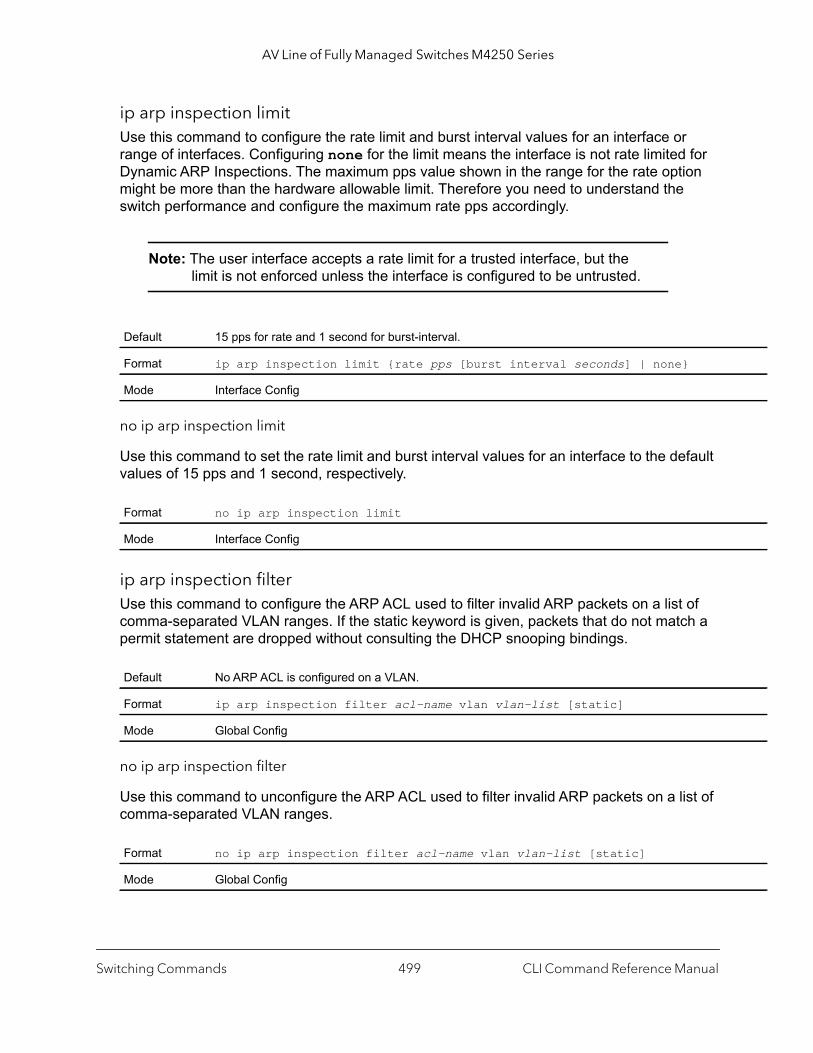
AV Line of Fully Managed Switches M4250 Series
ip arp inspection limitUse this command to configure the rate limit and burst interval values for an interface or range of interfaces. Configuring none for the limit means the interface is not rate limited for Dynamic ARP Inspections. The maximum pps value shown in the range for the rate option might be more than the hardware allowable limit. Therefore you need to understand the switch performance and configure the maximum rate pps accordingly.
Note: The user interface accepts a rate limit for a trusted interface, but the limit is not enforced unless the interface is configured to be untrusted.
no ip arp inspection limit
Use this command to set the rate limit and burst interval values for an interface to the default values of 15 pps and 1 second, respectively.
ip arp inspection filterUse this command to configure the ARP ACL used to filter invalid ARP packets on a list of comma-separated VLAN ranges. If the static keyword is given, packets that do not match a permit statement are dropped without consulting the DHCP snooping bindings.
no ip arp inspection filter
Use this command to unconfigure the ARP ACL used to filter invalid ARP packets on a list of comma-separated VLAN ranges.
Default 15 pps for rate and 1 second for burst-interval.
Format ip arp inspection limit {rate pps [burst interval seconds] | none}
Mode Interface Config
Format no ip arp inspection limit
Mode Interface Config
Default No ARP ACL is configured on a VLAN.
Format ip arp inspection filter acl-name vlan vlan-list [static]
Mode Global Config
Format no ip arp inspection filter acl-name vlan vlan-list [static]
Mode Global Config
Switching Commands CLI Command Reference Manual499

AV Line of Fully Managed Switches M4250 Series
arp access-listUse this command to create an ARP ACL.
no arp access-list
Use this command to delete a configured ARP ACL.
permit ip host mac hostUse this command to configure a rule for a valid IP address and MAC address combination used in ARP packet validation.
no permit ip host mac host
Use this command to delete a rule for a valid IP and MAC combination.
show ip arp inspection Use this command to display the Dynamic ARP Inspection global configuration and configuration on all the VLANs. With the vlan keyword and vlan-list argument (that is, comma separated VLAN ranges), the command displays the global configuration and configuration on all the VLANs in the given VLAN list. For the vlan-list argument, you can enter a list of VLANs (for example, 12-18 or 12,14) to display the statistics on all DAI-enabled VLANs in the list, or enter a single VLAN to display the statistics for only that VLAN. The global configuration includes the source mac validation, destination mac validation and invalid IP validation information.
Format arp access-list acl-name
Mode Global Config
Format no arp access-list acl-name
Mode Global Config
Format permit ip host sender-ipaddress mac host sender-mac
Mode ARP Access-list Config
Format no permit ip host sender-ipaddress mac host sender-mac
Mode ARP Access-list Config
Format show ip arp inspection [vlan vlan-list]
Mode Privileged EXECUser EXEC
Switching Commands CLI Command Reference Manual500

AV Line of Fully Managed Switches M4250 Series
Command example: (NETGEAR Switch) #show ip arp inspection vlan 10-12
Source Mac Validation : DisabledDestination Mac Validation : DisabledIP Address Validation : Disabled
Vlan Configuration Log Invalid ACL Name Static flag ---- ------------- ----------- --------- ---------- 10 Enabled Enabled H2 Enabled 11 Disabled Enabled 12 Enabled Disabled
show ip arp inspection statisticsUse this command to display the statistics of the ARP packets that are processed by Dynamic ARP Inspection (DAI). For the vlan-list argument, you can enter a list of VLANs (for example, 12-18 or 12,14) to display the statistics on all DAI-enabled VLANs in the list, or enter a single VLAN to display the statistics for only that VLAN. If you do not include the vlan keyword and vlan-list argument, the command output displays a summary of the forwarded and dropped ARP packets.
Term Definition
Source MAC Validation
Displays whether Source MAC Validation of ARP frame is enabled or disabled.
Destination MAC Validation
Displays whether Destination MAC Validation is enabled or disabled.
IP Address Validation
Displays whether IP Address Validation is enabled or disabled.
VLAN The VLAN ID for each displayed row.
Configuration Displays whether DAI is enabled or disabled on the VLAN.
Log Invalid Displays whether logging of invalid ARP packets is enabled on the VLAN.
ACL Name The ARP ACL Name, if configured on the VLAN.
Static Flag If the ARP ACL is configured static on the VLAN.
Format show ip arp inspection statistics [vlan vlan-list]
Mode Privileged EXECUser EXEC
Switching Commands CLI Command Reference Manual501
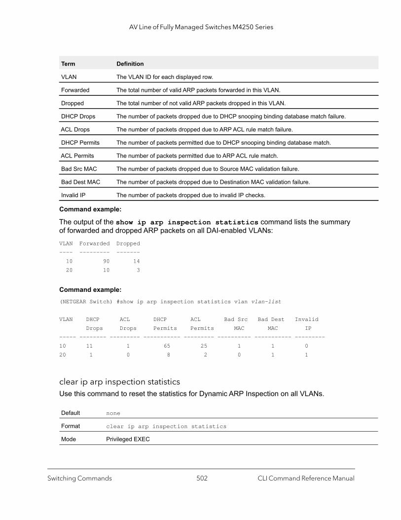
AV Line of Fully Managed Switches M4250 Series
Command example:
The output of the show ip arp inspection statistics command lists the summary of forwarded and dropped ARP packets on all DAI-enabled VLANs:VLAN Forwarded Dropped---- --------- ------- 10 90 14 20 10 3
Command example: (NETGEAR Switch) #show ip arp inspection statistics vlan vlan-list
VLAN DHCP ACL DHCP ACL Bad Src Bad Dest Invalid Drops Drops Permits Permits MAC MAC IP----- -------- --------- ----------- --------- ---------- ----------- ---------10 11 1 65 25 1 1 020 1 0 8 2 0 1 1
clear ip arp inspection statisticsUse this command to reset the statistics for Dynamic ARP Inspection on all VLANs.
Term Definition
VLAN The VLAN ID for each displayed row.
Forwarded The total number of valid ARP packets forwarded in this VLAN.
Dropped The total number of not valid ARP packets dropped in this VLAN.
DHCP Drops The number of packets dropped due to DHCP snooping binding database match failure.
ACL Drops The number of packets dropped due to ARP ACL rule match failure.
DHCP Permits The number of packets permitted due to DHCP snooping binding database match.
ACL Permits The number of packets permitted due to ARP ACL rule match.
Bad Src MAC The number of packets dropped due to Source MAC validation failure.
Bad Dest MAC The number of packets dropped due to Destination MAC validation failure.
Invalid IP The number of packets dropped due to invalid IP checks.
Default none
Format clear ip arp inspection statistics
Mode Privileged EXEC
Switching Commands CLI Command Reference Manual502

AV Line of Fully Managed Switches M4250 Series
show ip arp inspection interfacesUse this command to display the Dynamic ARP Inspection configuration on all the DAI-enabled interfaces. An interface is said to be enabled for DAI if at least one VLAN, that the interface is a member of, is enabled for DAI. Given a unit/port interface argument, the command displays the values for that interface whether the interface is enabled for DAI or not.
Command example: (NETGEAR Switch) #show ip arp inspection interfaces
Interface Trust State Rate Limit Burst Interval (pps) (seconds) --------------- ----------- ---------- --------------- 0/1 Untrusted 15 1 0/2 Untrusted 10 10
show arp access-listUse this command to display the configured ARP ACLs with the rules. Giving an ARP ACL name as the argument displays only the rules in that ARP ACL.
Command example: (NETGEAR Switch) #show arp access-listARP access list H2 permit ip host 1.1.1.1 mac host 00:01:02:03:04:05 permit ip host 1.1.1.2 mac host 00:03:04:05:06:07ARP access list H3ARP access list H4 permit ip host 2.1.1.2 mac host 00:03:04:05:06:08
Format show ip arp inspection interfaces [unit/port]
Mode Privileged EXECUser EXEC
Term Definition
Interface The interface ID for each displayed row.
Trust State Whether the interface is trusted or untrusted for DAI.
Rate Limit The configured rate limit value in packets per second.
Burst Interval The configured burst interval value in seconds.
Format show arp access-list [acl-name]
Mode Privileged EXECUser EXEC
Switching Commands CLI Command Reference Manual503

AV Line of Fully Managed Switches M4250 Series
MVR Commands
Internet Group Management Protocol (IGMP) Layer 3 is widely used for IPv4 network multicasting. In Layer 2 networks, IGMP uses resources inefficiently. For example, a Layer 2 switch multicast traffic to all ports, even if there are receivers connected to only a few ports.
To address this problem, the IGMP Snooping protocol was developed. The problem still appears, though, when receivers are in different VLANs.
MVR is intended to solve the problem of receivers in different VLANs. It uses a dedicated manually configured VLAN, called the multicast VLAN, to forward multicast traffic over a Layer 2 network with IGMP snooping.
mvrThis command enables MVR.
no mvr
This command disables MVR.
mvr groupThis command adds an MVR membership group. A.B.C.D is the IP multicast group being added.
The count is the number of incremental multicast groups being added (the first multicast group is A.B.C.D). If a count is not specified, only one multicast group is added.
Default Disabled
Format mvr
Mode Global Config Interface Config
Format no mvr
Mode Global Config Interface Config
Format mvr group A.B.C.D [count]
Mode Global Config
Switching Commands CLI Command Reference Manual504

AV Line of Fully Managed Switches M4250 Series
no mvr group
This command removes the MVR membership group.
mvr mode This command changes the MVR mode type. If the mode is set to compatible, the switch does not learn multicast groups; they need to be configured by the operator as the protocol does not forward joins from the hosts to the router. To operate in this mode, the IGMP router needs to be statically configured to transmit all required multicast streams to the MVR switch. If the mode is set to dynamic, the switch learns existing multicast groups by snooping the IGMP queries from the router on source ports and forwarding the IGMP joins from the hosts to the IGMP router on the multicast VLAN (with appropriate translation of the VLAN ID).
no mvr mode
This command sets the mode type to the default value.
mvr querytimeThis command sets the MVR query response time in deciseconds. The time is in the range 1–100 deciseconds (one decisecond is one tenth of a second).
no mvr querytime
This command sets the MVR query response time to the default value.
Format no mvr group A.B.C.D [count]
Mode Global Config
Default Compatible
Format mvr mode {compatible | dynamic}
Mode Global Config
Format no mvr mode
Mode Global Config
Default 5
Format mvr querytime deciseconds
Mode Global Config
Format no mvr querytime
Mode Global Config
Switching Commands CLI Command Reference Manual505

AV Line of Fully Managed Switches M4250 Series
mvr vlanThis command sets the MVR multicast VLAN.
no mvr vlan
This command sets the MVR multicast VLAN to the default value.
mvr immediateThis command enables MVR immediate leave mode. MVR provides two modes of operating with the IGMP Leave messages: normal leave and immediate leave.
• In normal leave mode, when a leave is received, the general IGMP query is sent from a Layer 2 switch to the receiver port, where the leave was received. Then reports are received from other interested hosts that are also connected to that port, for example, using hub.
• In immediate leave mode, when a leave is received, the switch is immediately reconfigured not to forward a specific multicast stream to the port where a message is received. This mode is used only for ports where only one client might be connected.
no mvr immediate
This command sets the MVR multicast VLAN to the default value.
Default 1
Format mvr vlan vlan-id
Mode Global Config
Format no mvr vlan
Mode Global Config
Default Disabled
Format mvr immediate
Mode Interface Config
Format no mvr immediate
Mode Interface Config
Switching Commands CLI Command Reference Manual506
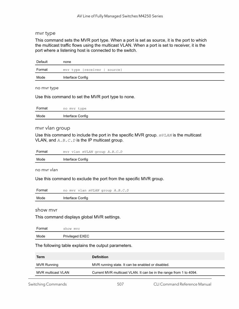
AV Line of Fully Managed Switches M4250 Series
mvr typeThis command sets the MVR port type. When a port is set as source, it is the port to which the multicast traffic flows using the multicast VLAN. When a port is set to receiver, it is the port where a listening host is connected to the switch.
no mvr type
Use this command to set the MVR port type to none.
mvr vlan groupUse this command to include the port in the specific MVR group. mVLAN is the multicast VLAN, and A.B.C.D is the IP multicast group.
no mvr vlan
Use this command to exclude the port from the specific MVR group.
show mvrThis command displays global MVR settings.
The following table explains the output parameters.
Default none
Format mvr type {receiver | source}
Mode Interface Config
Format no mvr type
Mode Interface Config
Format mvr vlan mVLAN group A.B.C.D
Mode Interface Config
Format no mvr vlan mVLAN group A.B.C.D
Mode Interface Config
Format show mvr
Mode Privileged EXEC
Term Definition
MVR Running MVR running state. It can be enabled or disabled.
MVR multicast VLAN Current MVR multicast VLAN. It can be in the range from 1 to 4094.
Switching Commands CLI Command Reference Manual507
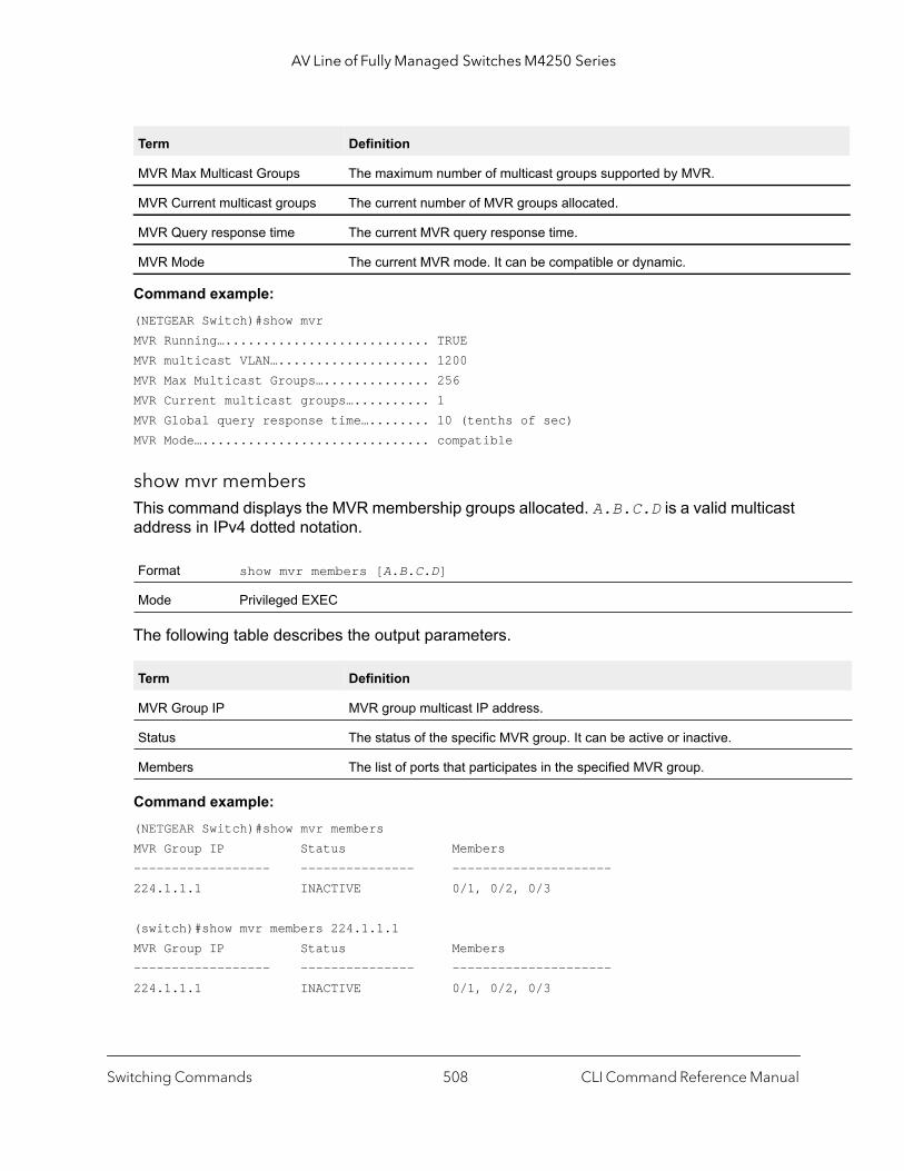
AV Line of Fully Managed Switches M4250 Series
Command example: (NETGEAR Switch)#show mvrMVR Running…........................... TRUEMVR multicast VLAN….................... 1200MVR Max Multicast Groups….............. 256MVR Current multicast groups….......... 1MVR Global query response time…........ 10 (tenths of sec)MVR Mode….............................. compatible
show mvr membersThis command displays the MVR membership groups allocated. A.B.C.D is a valid multicast address in IPv4 dotted notation.
The following table describes the output parameters.
Command example: (NETGEAR Switch)#show mvr membersMVR Group IP Status Members------------------ --------------- ---------------------224.1.1.1 INACTIVE 0/1, 0/2, 0/3
(switch)#show mvr members 224.1.1.1MVR Group IP Status Members------------------ --------------- ---------------------224.1.1.1 INACTIVE 0/1, 0/2, 0/3
MVR Max Multicast Groups The maximum number of multicast groups supported by MVR.
MVR Current multicast groups The current number of MVR groups allocated.
MVR Query response time The current MVR query response time.
MVR Mode The current MVR mode. It can be compatible or dynamic.
Format show mvr members [A.B.C.D]
Mode Privileged EXEC
Term Definition
MVR Group IP MVR group multicast IP address.
Status The status of the specific MVR group. It can be active or inactive.
Members The list of ports that participates in the specified MVR group.
Term Definition
Switching Commands CLI Command Reference Manual508

AV Line of Fully Managed Switches M4250 Series
show mvr interfaceThis command displays the MVR-enabled interfaces configuration.
The following table explains the output parameters.
Command example: (NETGEAR Switch)#show mvr interfacePort Type Status Immediate Leave--------- --------------- --------------------- -------------------- 0/9 RECEIVER ACTIVE/inVLAN DISABLED
(switch)#show mvr interface 0/9Type: RECEIVER Status: ACTIVE Immediate Leave: DISABLED
(switch)#show mvr interface 0/23 members235.0.0.1 STATIC ACTIVE
(switch)#show mvr interface 0/23 members vlan 12235.0.0.1 STATIC ACTIVE235.1.1.1 STATIC ACTIVE
show mvr trafficThis command displays global MVR statistics.
Format show mvr interface [interface-id [members [vlan vid]]]
Mode Privileged EXEC
Term Description
Port Interface number
Type The MVR port type. It can be none, receiver, or source type.
Status The interface status. It consists of two characteristics: • active or inactive indicates whether the port is forwarding.• inVLAN or notInVLAN indicates whether the port is part of any VLAN.
Immediate Leave The state of immediate mode. It can be enabled or disabled.
Format show mvr traffic
Mode Privileged EXEC
Switching Commands CLI Command Reference Manual509
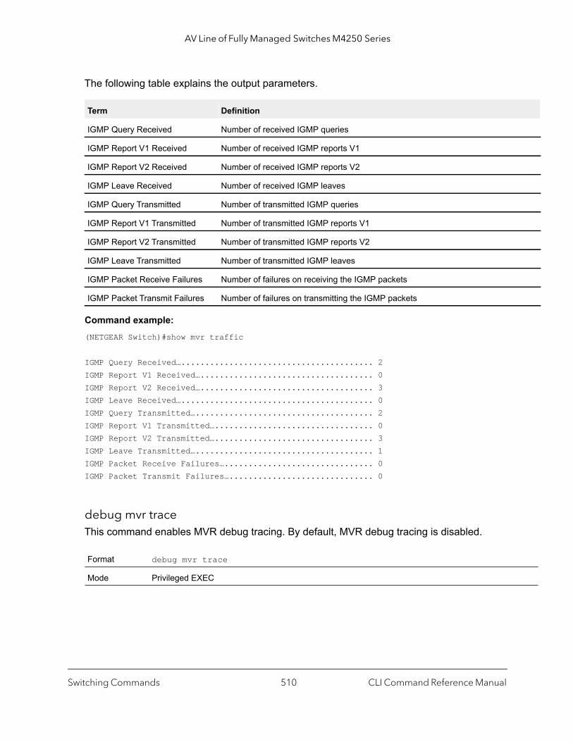
AV Line of Fully Managed Switches M4250 Series
The following table explains the output parameters.
Command example: (NETGEAR Switch)#show mvr traffic
IGMP Query Received…........................................ 2IGMP Report V1 Received….................................... 0IGMP Report V2 Received….................................... 3IGMP Leave Received…........................................ 0IGMP Query Transmitted…..................................... 2IGMP Report V1 Transmitted…................................. 0IGMP Report V2 Transmitted…................................. 3IGMP Leave Transmitted…..................................... 1IGMP Packet Receive Failures…............................... 0IGMP Packet Transmit Failures….............................. 0
debug mvr traceThis command enables MVR debug tracing. By default, MVR debug tracing is disabled.
Term Definition
IGMP Query Received Number of received IGMP queries
IGMP Report V1 Received Number of received IGMP reports V1
IGMP Report V2 Received Number of received IGMP reports V2
IGMP Leave Received Number of received IGMP leaves
IGMP Query Transmitted Number of transmitted IGMP queries
IGMP Report V1 Transmitted Number of transmitted IGMP reports V1
IGMP Report V2 Transmitted Number of transmitted IGMP reports V2
IGMP Leave Transmitted Number of transmitted IGMP leaves
IGMP Packet Receive Failures Number of failures on receiving the IGMP packets
IGMP Packet Transmit Failures Number of failures on transmitting the IGMP packets
Format debug mvr trace
Mode Privileged EXEC
Switching Commands CLI Command Reference Manual510

AV Line of Fully Managed Switches M4250 Series
no debug mvr trace
This command disables MVR debug tracing.
debug mvr packetThis command enables debug tracing of MVR packets on the receiving side, transmitting side, or both sides. By default, debug tracing of MVR packets is enabled.
no debug mvr packet
This command disables debug tracing of MVR packets on the receiving side, transmitting side, or both sides.
IGMP Snooping Configuration Commands
This section describes the commands you use to configure IGMP snooping. The switch supports IGMP Versions 1, 2, and 3. The IGMP snooping feature can help conserve bandwidth because it allows the switch to forward IP multicast traffic only to connected hosts that request multicast traffic. IGMPv3 adds source filtering capabilities to IGMP versions 1 and 2.
Note: This note clarifies the prioritization of MGMD Snooping Configurations. Many of the IGMP/MLD Snooping commands are available both in the Interface and VLAN modes. Operationally the system chooses or prefers the VLAN configured values over the Interface configured values for most configurations when the interface participates in the VLAN.
Format no debug mvr trace
Mode Privileged EXEC
Format debug mvr packet [receive | transmit]
Mode Privileged EXEC
Format no debug mvr packet [receive | transmit]
Mode Privileged EXEC
Switching Commands CLI Command Reference Manual511
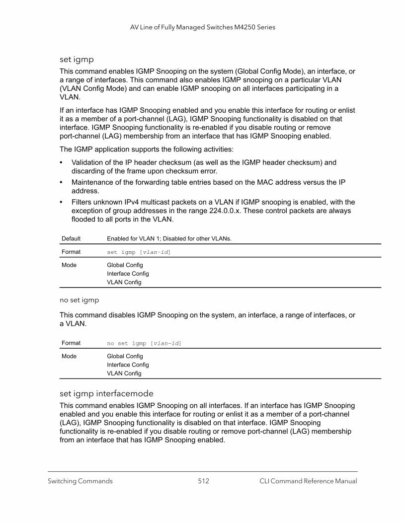
AV Line of Fully Managed Switches M4250 Series
set igmpThis command enables IGMP Snooping on the system (Global Config Mode), an interface, or a range of interfaces. This command also enables IGMP snooping on a particular VLAN (VLAN Config Mode) and can enable IGMP snooping on all interfaces participating in a VLAN.
If an interface has IGMP Snooping enabled and you enable this interface for routing or enlist it as a member of a port-channel (LAG), IGMP Snooping functionality is disabled on that interface. IGMP Snooping functionality is re-enabled if you disable routing or remove port-channel (LAG) membership from an interface that has IGMP Snooping enabled.
The IGMP application supports the following activities:
• Validation of the IP header checksum (as well as the IGMP header checksum) and discarding of the frame upon checksum error.
• Maintenance of the forwarding table entries based on the MAC address versus the IP address.
• Filters unknown IPv4 multicast packets on a VLAN if IGMP snooping is enabled, with the exception of group addresses in the range 224.0.0.x. These control packets are always flooded to all ports in the VLAN.
no set igmp
This command disables IGMP Snooping on the system, an interface, a range of interfaces, or a VLAN.
set igmp interfacemode This command enables IGMP Snooping on all interfaces. If an interface has IGMP Snooping enabled and you enable this interface for routing or enlist it as a member of a port-channel (LAG), IGMP Snooping functionality is disabled on that interface. IGMP Snooping functionality is re-enabled if you disable routing or remove port-channel (LAG) membership from an interface that has IGMP Snooping enabled.
Default Enabled for VLAN 1; Disabled for other VLANs.
Format set igmp [vlan-id]
Mode Global ConfigInterface ConfigVLAN Config
Format no set igmp [vlan-id]
Mode Global ConfigInterface ConfigVLAN Config
Switching Commands CLI Command Reference Manual512

AV Line of Fully Managed Switches M4250 Series
no set igmp interfacemode
This command disables IGMP Snooping on all interfaces on the switch at the same time. It is disabled by default. This command does not take effect on the interface where routing is enabled or is a member of a port-channel (LAG). Disable routingon the interface before setting IGMP Snooping. The interface that is a member of a port-channel (LAG) must be removed before setting IGMP Snooping
set igmp fast-leaveThis command enables or disables IGMP Snooping fast-leave on a selected interface, a range of interfaces, or a VLAN.
When you enable fast-leave, the switch immediately removes a layer 2 LAN interface from its forwarding table if the following situation occurs:
1. The switch does not send MAC-based general queries to the layer 2 LAN interface.2. The switch receives an IGMP leave message for the associated multicast group.
Enable fast-leave only on VLANs for which a single host is connected to each layer 2 LAN interface. Doing so prevents the inadvertent dropping of other hosts that are connected to the same layer 2 LAN interface but are still interested in receiving multicast traffic that is directed to the multicast group.
Fast-leave processing is supported for IGMPv2 hosts only.
Default Disabled
Format set igmp interfacemode
Mode Global Config
Default Disabled
Format no set igmp interfacemode
Mode Global Config
Default Enabled for VLAN 1; Disabled for other VLANs.
Format set igmp fast-leave [vlan-id]
Mode Interface ConfigInterface RangeVLAN Config
Switching Commands CLI Command Reference Manual513
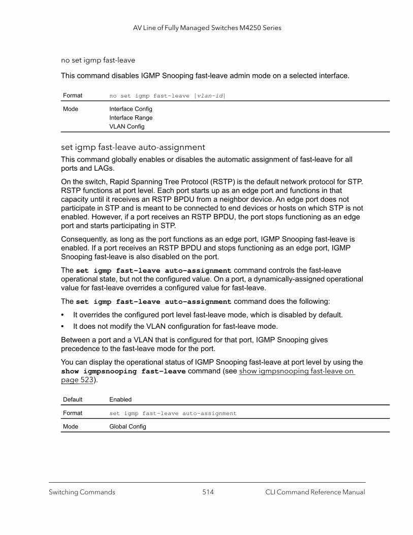
AV Line of Fully Managed Switches M4250 Series
no set igmp fast-leave
This command disables IGMP Snooping fast-leave admin mode on a selected interface.
set igmp fast-leave auto-assignmentThis command globally enables or disables the automatic assignment of fast-leave for all ports and LAGs.
On the switch, Rapid Spanning Tree Protocol (RSTP) is the default network protocol for STP. RSTP functions at port level. Each port starts up as an edge port and functions in that capacity until it receives an RSTP BPDU from a neighbor device. An edge port does not participate in STP and is meant to be connected to end devices or hosts on which STP is not enabled. However, if a port receives an RSTP BPDU, the port stops functioning as an edge port and starts participating in STP.
Consequently, as long as the port functions as an edge port, IGMP Snooping fast-leave is enabled. If a port receives an RSTP BPDU and stops functioning as an edge port, IGMP Snooping fast-leave is also disabled on the port.
The set igmp fast-leave auto-assignment command controls the fast-leave operational state, but not the configured value. On a port, a dynamically-assigned operational value for fast-leave overrides a configured value for fast-leave.
The set igmp fast-leave auto-assignment command does the following:
• It overrides the configured port level fast-leave mode, which is disabled by default.• It does not modify the VLAN configuration for fast-leave mode.
Between a port and a VLAN that is configured for that port, IGMP Snooping gives precedence to the fast-leave mode for the port.
You can display the operational status of IGMP Snooping fast-leave at port level by using the show igmpsnooping fast-leave command (see show igmpsnooping fast-leave on page 523).
Format no set igmp fast-leave [vlan-id]
Mode Interface ConfigInterface RangeVLAN Config
Default Enabled
Format set igmp fast-leave auto-assignment
Mode Global Config
Switching Commands CLI Command Reference Manual514

AV Line of Fully Managed Switches M4250 Series
set igmp groupmembership-intervalThis command sets the IGMP group membership interval time on a VLAN, one interface, a range of interfaces, or all interfaces. The group membership interval time is the amount of time in seconds that a switch waits for a report from a particular group on a particular interface before deleting the interface from the entry. This value must be greater than the IGMPv3 maximum response time value. The range is 2 to 3600 seconds.
no set igmp groupmembership-interval
This command sets the IGMPv3 group membership interval time to the default value.
set igmp maxresponseThis command sets the IGMP maximum response time for the system, on a particular interface or VLAN, or on a range of interfaces. The maximum response time is the amount of time in seconds that a switch will wait after sending a query on an interface because it did not receive a report for a particular group in that interface. This value must be less than the IGMP query Interval time value. The range is 1 to 300 seconds.
no set igmp maxresponse
This command sets the max response time (on the interface or VLAN) to the default value.
Default 260 seconds
Format set igmp groupmembership-interval [vlan-id] seconds
Mode Interface ConfigGlobal ConfigVLAN Config
Format no set igmp groupmembership-interval [vlan-id]
Mode Interface ConfigGlobal ConfigVLAN Config
Default 600 seconds
Format set igmp maxresponse [vlan-id] seconds
Mode Global ConfigInterface ConfigVLAN Config
Format no set igmp maxresponse [vlan-id]
Mode Global ConfigInterface ConfigVLAN Config
Switching Commands CLI Command Reference Manual515

AV Line of Fully Managed Switches M4250 Series
set igmp mcrtrexpiretimeThis command sets the multicast router present expiration time. The time is set for the system, on a particular interface or VLAN, or on a range of interfaces. This is the amount of time in seconds that a switch waits for a query to be received on an interface before the interface is removed from the list of interfaces with multicast routers attached. The range is 0 to 3600 seconds. A value of 0 indicates an infinite time-out, that is, no expiration.
no set igmp mcrtrexpiretime
This command sets the multicast router present expiration time to 0. The time is set for the system, on a particular interface or a VLAN.
set igmp mrouter This command configures the VLAN ID that has the multicast router mode enabled.
no set igmp mrouter
This command disables multicast router mode for a particular VLAN ID.
Default 0
Format set igmp mcrtrexpiretime [vlan-id] seconds
Mode Global ConfigInterface ConfigVLAN Config
Format no set igmp mcrtrexpiretime [vlan-id]
Mode Global ConfigInterface ConfigVLAN Config
Format set igmp mrouter vlan-id
Mode Interface Config
Format no set igmp mrouter vlan-id
Mode Interface Config
Switching Commands CLI Command Reference Manual516
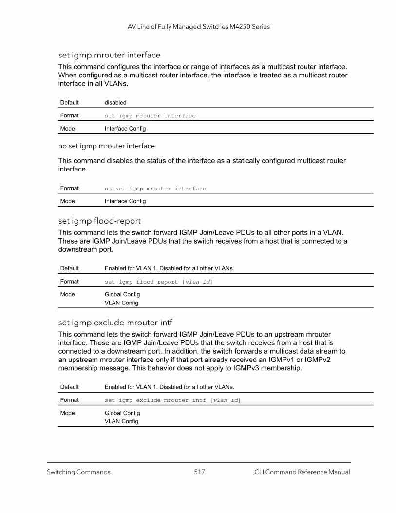
AV Line of Fully Managed Switches M4250 Series
set igmp mrouter interfaceThis command configures the interface or range of interfaces as a multicast router interface. When configured as a multicast router interface, the interface is treated as a multicast router interface in all VLANs.
no set igmp mrouter interface
This command disables the status of the interface as a statically configured multicast router interface.
set igmp flood-reportThis command lets the switch forward IGMP Join/Leave PDUs to all other ports in a VLAN. These are IGMP Join/Leave PDUs that the switch receives from a host that is connected to a downstream port.
set igmp exclude-mrouter-intfThis command lets the switch forward IGMP Join/Leave PDUs to an upstream mrouter interface. These are IGMP Join/Leave PDUs that the switch receives from a host that is connected to a downstream port. In addition, the switch forwards a multicast data stream to an upstream mrouter interface only if that port already received an IGMPv1 or IGMPv2 membership message. This behavior does not apply to IGMPv3 membership.
Default disabled
Format set igmp mrouter interface
Mode Interface Config
Format no set igmp mrouter interface
Mode Interface Config
Default Enabled for VLAN 1. Disabled for all other VLANs.
Format set igmp flood report [vlan-id]
Mode Global ConfigVLAN Config
Default Enabled for VLAN 1. Disabled for all other VLANs.
Format set igmp exclude-mrouter-intf [vlan-id]
Mode Global ConfigVLAN Config
Switching Commands CLI Command Reference Manual517
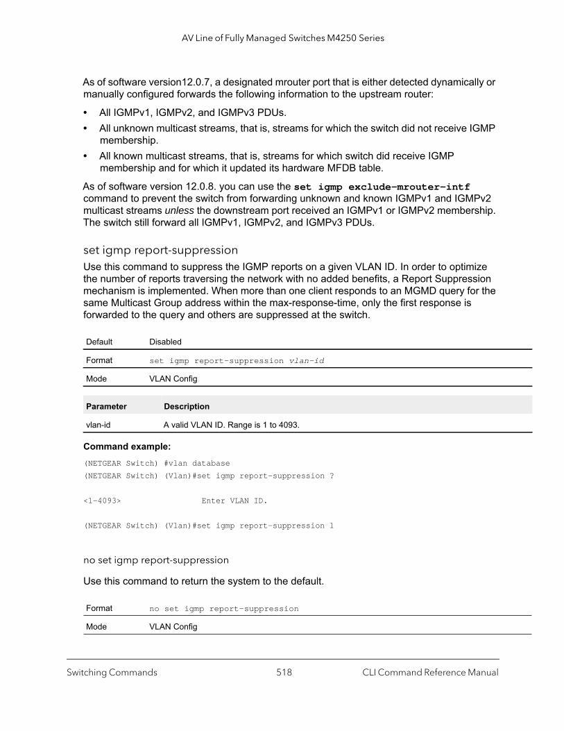
AV Line of Fully Managed Switches M4250 Series
As of software version12.0.7, a designated mrouter port that is either detected dynamically or manually configured forwards the following information to the upstream router:
• All IGMPv1, IGMPv2, and IGMPv3 PDUs.• All unknown multicast streams, that is, streams for which the switch did not receive IGMP
membership.• All known multicast streams, that is, streams for which switch did receive IGMP
membership and for which it updated its hardware MFDB table.
As of software version 12.0.8. you can use the set igmp exclude-mrouter-intf command to prevent the switch from forwarding unknown and known IGMPv1 and IGMPv2 multicast streams unless the downstream port received an IGMPv1 or IGMPv2 membership. The switch still forward all IGMPv1, IGMPv2, and IGMPv3 PDUs.
set igmp report-suppressionUse this command to suppress the IGMP reports on a given VLAN ID. In order to optimize the number of reports traversing the network with no added benefits, a Report Suppression mechanism is implemented. When more than one client responds to an MGMD query for the same Multicast Group address within the max-response-time, only the first response is forwarded to the query and others are suppressed at the switch.
Command example: (NETGEAR Switch) #vlan database(NETGEAR Switch) (Vlan)#set igmp report-suppression ?
<1-4093> Enter VLAN ID.
(NETGEAR Switch) (Vlan)#set igmp report-suppression 1
no set igmp report-suppression
Use this command to return the system to the default.
Default Disabled
Format set igmp report-suppression vlan-id
Mode VLAN Config
Parameter Description
vlan-id A valid VLAN ID. Range is 1 to 4093.
Format no set igmp report-suppression
Mode VLAN Config
Switching Commands CLI Command Reference Manual518

AV Line of Fully Managed Switches M4250 Series
set igmp header-validationThis command enables IGMP IP header validation.
If IGMP IP header validation is enabled, three fields, TTL (Time To Live), ToS (Type of Service), and Router Alert options, are checked. The actual validated fields depend on the IGMP version. The TTL field is validated in all the versions (IGMPv1, IGMPv2, and IGMPv3). The Router Alert field is validated in IGMPv2 and IGMPv3. The ToS field is validated only in IGMP version3.
no set igmp header-validation
This command disables the IGMP IP header validation.
set igmp-plusThis command enables all of the following global IGMP Snooping configuration commands:
• set igmp
• set igmp querier
• set igmp flood-report
• set igmp exclude-mrouter-intf
• set igmp fast-leave auto-assignment
no set igmp-plus
This command disables all of the following global IGMP Snooping configuration commands:
• set igmp
• set igmp querier
• set igmp flood-report
• set igmp exclude-mrouter-intf
• set igmp fast-leave auto-assignment
Default Enabled
Format set igmp header-validation
Mode Global Config
Format no set igmp header-validation
Mode Global Config
Default Enabled
Format set igmp-plus
Mode Global Config
Switching Commands CLI Command Reference Manual519

AV Line of Fully Managed Switches M4250 Series
set igmp-plus vlanAfter you enable the set igmp-plus command, you can enable the set igmp-plus vlan command to enable all of the following global IGMP Snooping configuration commands at the VLAN level for a particular VLAN:
• set igmp vlan
• set igmp exclude-mrouter-intf vlan
• set igmp fast-leave vlan
• set igmp flood-report vlan
• set igmp querier vlan
• set igmp querier election participate vlan
The vlan argument in the set igmp-plus vlan command can be a VLAN from 1 to 4093.
no set igmp-plus vlan
This command disables all of the following global IGMP Snooping configuration commands at the VLAN level for a particular VLAN:
• set igmp vlan
• set igmp exclude-mrouter-intf vlan
• set igmp fast-leave vlan
• set igmp flood-report vlan
• set igmp querier vlan
• set igmp querier election participate vlan
The vlan argument in the no set igmp-plus vlan command can be a VLAN from 1 to 4093.
Format no set igmp-plus
Mode Global Config
Default Enabled for VLAN 1
Format set igmp-plus vlan
Mode VLAN Config
Format no set igmp-plus vlan
Mode VLAN Config
Switching Commands CLI Command Reference Manual520
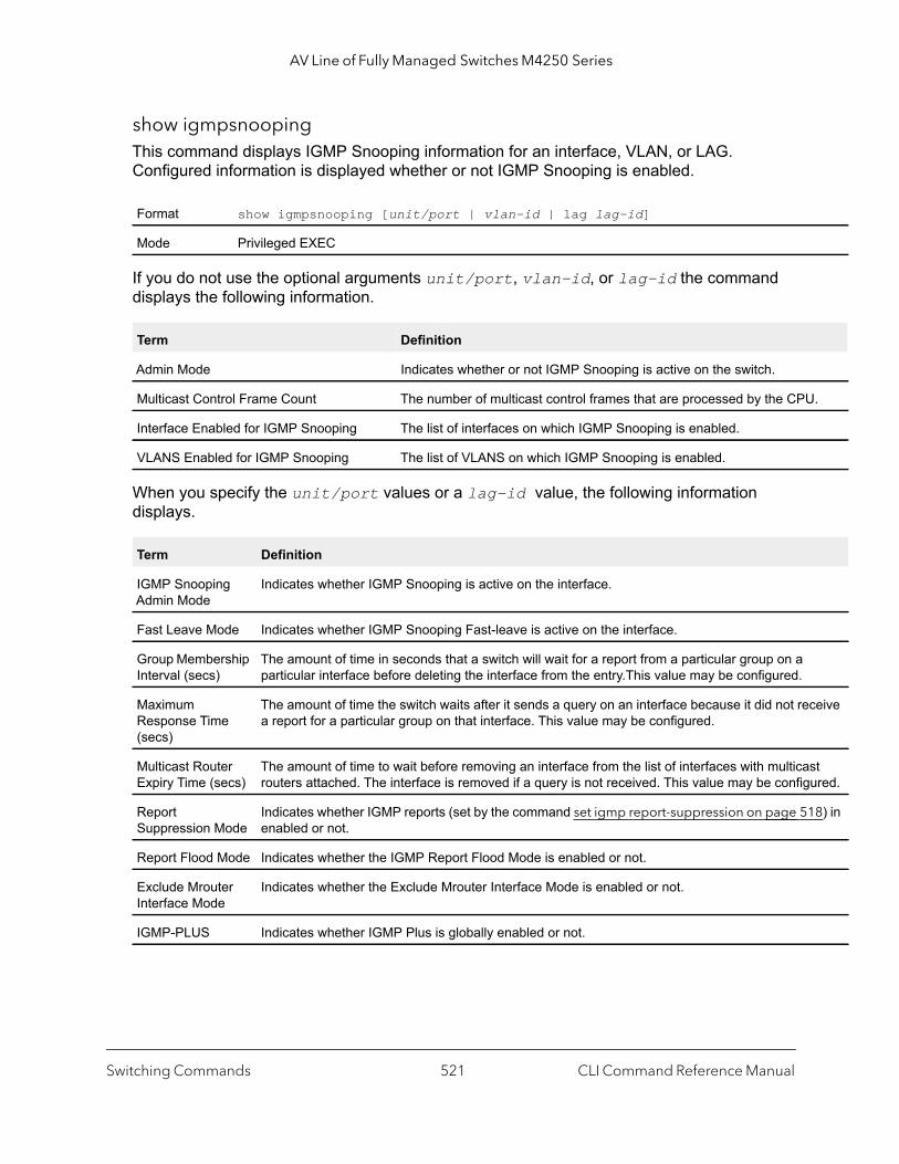
AV Line of Fully Managed Switches M4250 Series
.
ceive
st ured.
18) in
show igmpsnoopingThis command displays IGMP Snooping information for an interface, VLAN, or LAG. Configured information is displayed whether or not IGMP Snooping is enabled.
If you do not use the optional arguments unit/port, vlan-id, or lag-id the command displays the following information.
When you specify the unit/port values or a lag-id value, the following information displays.
Format show igmpsnooping [unit/port | vlan-id | lag lag-id]
Mode Privileged EXEC
Term Definition
Admin Mode Indicates whether or not IGMP Snooping is active on the switch.
Multicast Control Frame Count The number of multicast control frames that are processed by the CPU
Interface Enabled for IGMP Snooping The list of interfaces on which IGMP Snooping is enabled.
VLANS Enabled for IGMP Snooping The list of VLANS on which IGMP Snooping is enabled.
Term Definition
IGMP Snooping Admin Mode
Indicates whether IGMP Snooping is active on the interface.
Fast Leave Mode Indicates whether IGMP Snooping Fast-leave is active on the interface.
Group Membership Interval (secs)
The amount of time in seconds that a switch will wait for a report from a particular group on a particular interface before deleting the interface from the entry.This value may be configured.
Maximum Response Time (secs)
The amount of time the switch waits after it sends a query on an interface because it did not rea report for a particular group on that interface. This value may be configured.
Multicast Router Expiry Time (secs)
The amount of time to wait before removing an interface from the list of interfaces with multicarouters attached. The interface is removed if a query is not received. This value may be config
Report Suppression Mode
Indicates whether IGMP reports (set by the command set igmp report-suppression on page 5enabled or not.
Report Flood Mode Indicates whether the IGMP Report Flood Mode is enabled or not.
Exclude Mrouter Interface Mode
Indicates whether the Exclude Mrouter Interface Mode is enabled or not.
IGMP-PLUS Indicates whether IGMP Plus is globally enabled or not.
Switching Commands CLI Command Reference Manual521
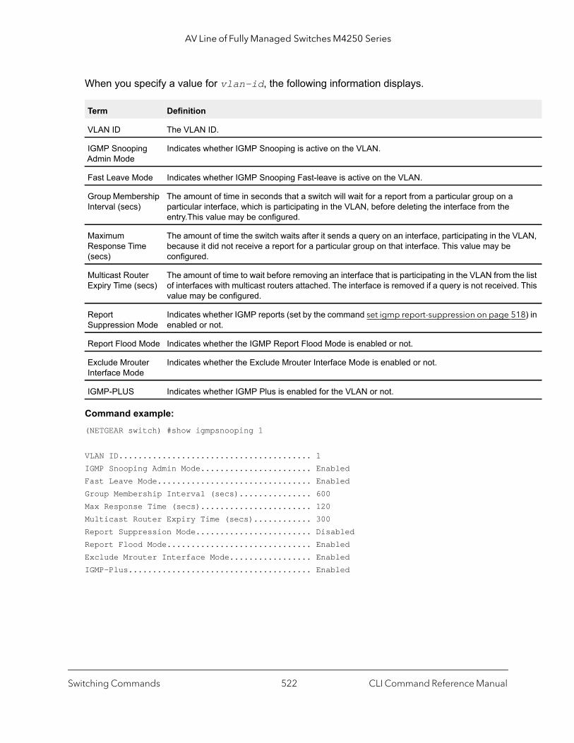
AV Line of Fully Managed Switches M4250 Series
LAN,
e list . This
18) in
When you specify a value for vlan-id, the following information displays.
Command example: (NETGEAR switch) #show igmpsnooping 1
VLAN ID........................................ 1IGMP Snooping Admin Mode....................... EnabledFast Leave Mode................................ EnabledGroup Membership Interval (secs)............... 600Max Response Time (secs)....................... 120Multicast Router Expiry Time (secs)............ 300Report Suppression Mode........................ DisabledReport Flood Mode.............................. EnabledExclude Mrouter Interface Mode................. EnabledIGMP-Plus...................................... Enabled
Term Definition
VLAN ID The VLAN ID.
IGMP Snooping Admin Mode
Indicates whether IGMP Snooping is active on the VLAN.
Fast Leave Mode Indicates whether IGMP Snooping Fast-leave is active on the VLAN.
Group Membership Interval (secs)
The amount of time in seconds that a switch will wait for a report from a particular group on a particular interface, which is participating in the VLAN, before deleting the interface from the entry.This value may be configured.
Maximum Response Time (secs)
The amount of time the switch waits after it sends a query on an interface, participating in the Vbecause it did not receive a report for a particular group on that interface. This value may be configured.
Multicast Router Expiry Time (secs)
The amount of time to wait before removing an interface that is participating in the VLAN from thof interfaces with multicast routers attached. The interface is removed if a query is not receivedvalue may be configured.
Report Suppression Mode
Indicates whether IGMP reports (set by the command set igmp report-suppression on page 5enabled or not.
Report Flood Mode Indicates whether the IGMP Report Flood Mode is enabled or not.
Exclude Mrouter Interface Mode
Indicates whether the Exclude Mrouter Interface Mode is enabled or not.
IGMP-PLUS Indicates whether IGMP Plus is enabled for the VLAN or not.
Switching Commands CLI Command Reference Manual522
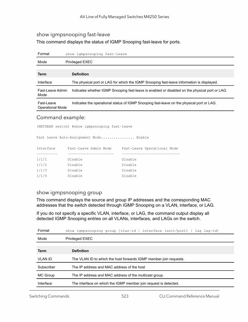
AV Line of Fully Managed Switches M4250 Series
G.
show igmpsnooping fast-leaveThis command displays the status of IGMP Snooping fast-leave for ports.
Command example:
(NETGEAR switch) #show igmpsnooping fast-leave
Fast Leave Auto-Assignment Mode................ Enable
Interface Fast-Leave Admin Mode Fast-Leave Operational Mode---------- ---------------------- ----------------------------1/1/1 Disable Disable1/1/2 Disable Disable1/1/3 Disable Disable1/1/4 Disable Disable
show igmpsnooping groupThis command displays the source and group IP addresses and the corresponding MAC addresses that the switch detected through IGMP Snooping on a VLAN, interface, or LAG.
If you do not specify a specific VLAN, interface, or LAG, the command output display all detected IGMP Snooping entries on all VLANs, interfaces, and LAGs on the switch.
Format show igmpsnooping fast-leave
Mode Privileged EXEC
Term Definition
Interface The physical port or LAG for which the IGMP Snooping fast-leave information is displayed.
Fast-Leave Admin Mode
Indicates whether IGMP Snooping fast-leave is enabled or disabled on the physical port or LA
Fast-Leave Operational Mode
Indicates the operational status of IGMP Snooping fast-leave on the physical port or LAG.
Format show igmpsnooping group [vlan-id | interface (unit/port) | lag lag-id]
Mode Privileged EXEC
Term Definition
VLAN ID The VLAN ID to which the host forwards IGMP member join requests.
Subscriber The IP address and MAC address of the host
MC Group The IP address and MAC address of the multicast group.
Interface The interface on which the IGMP member join request is detected.
Switching Commands CLI Command Reference Manual523
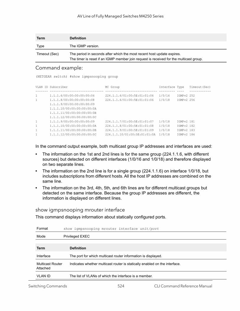
AV Line of Fully Managed Switches M4250 Series
Command example:
(NETGEAR switch) #show igmpsnooping group
VLAN ID Subscriber MC Group Interface Type Timeout(Sec)------- ------------------------------ ----------------------------- --------- ---- ------------1 1.1.1.6/00:00:00:00:00:06 224.1.1.6/01:00:5E:01:01:06 1/0/16 IGMPv2 252 1 1.1.1.8/00:00:00:00:00:08 224.1.1.6/01:00:5E:01:01:06 1/0/18 IGMPv2 256 1.1.1.9/00:00:00:00:00:09 1.1.1.10/00:00:00:00:00:0A 1.1.1.11/00:00:00:00:00:0B 1.1.1.12/00:00:00:00:00:0C1 1.1.1.9/00:00:00:00:00:09 224.1.1.7/01:00:5E:01:01:07 1/0/18 IGMPv2 1811 1.1.1.10/00:00:00:00:00:0A 224.1.1.8/01:00:5E:01:01:08 1/0/18 IGMPv2 1821 1.1.1.11/00:00:00:00:00:0B 224.1.1.9/01:00:5E:01:01:09 1/0/18 IGMPv2 1831 1.1.1.12/00:00:00:00:00:0C 224.1.1.10/01:00:5E:01:01:0A 1/0/18 IGMPv2 184
In the command output example, both multicast group IP addresses and interfaces are used:
• The information on the 1st and 2nd lines is for the same group (224.1.1.6, with different sources) but detected on different interfaces (1/0/16 and 1/0/18) and therefore displayed on two separate lines.
• The information on the 2nd line is for a single group (224.1.1.6) on interface 1/0/18, but includes subscriptions from different hosts. All the host IP addresses are combined on the same line.
• The information on the 3rd, 4th, 5th, and 6th lines are for different multicast groups but detected on the same interface. Because the group IP addresses are different, the information is displayed on different lines.
show igmpsnooping mrouter interfaceThis command displays information about statically configured ports.
Type The IGMP version.
Timeout (Sec) The period in seconds after which the most recent host update expires.The timer is reset if an IGMP member join request is received for the multicast group.
Format show igmpsnooping mrouter interface unit/port
Mode Privileged EXEC
Term Definition
Interface The port for which multicast router information is displayed.
Multicast Router Attached
Indicates whether multicast router is statically enabled on the interface.
VLAN ID The list of VLANs of which the interface is a member.
Term Definition
Switching Commands CLI Command Reference Manual524
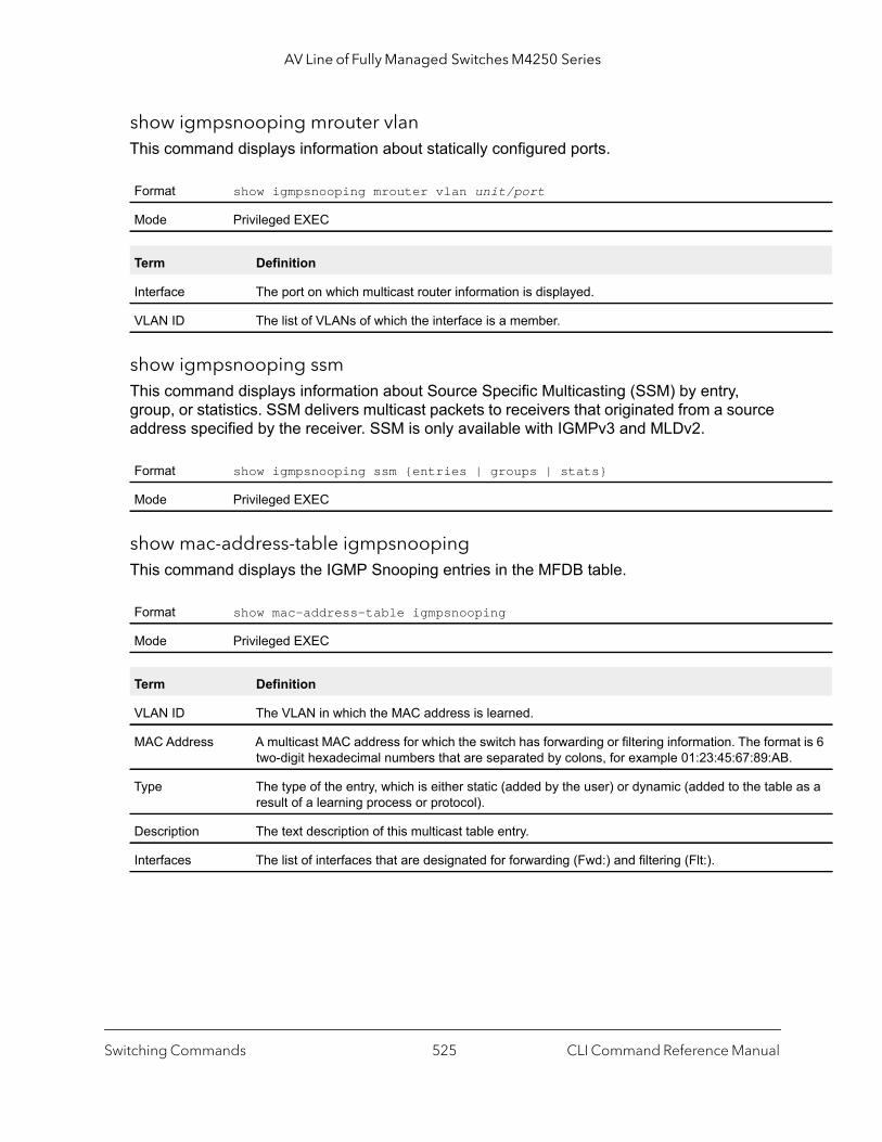
AV Line of Fully Managed Switches M4250 Series
t is 6
as a
show igmpsnooping mrouter vlanThis command displays information about statically configured ports.
show igmpsnooping ssmThis command displays information about Source Specific Multicasting (SSM) by entry, group, or statistics. SSM delivers multicast packets to receivers that originated from a source address specified by the receiver. SSM is only available with IGMPv3 and MLDv2.
show mac-address-table igmpsnoopingThis command displays the IGMP Snooping entries in the MFDB table.
Format show igmpsnooping mrouter vlan unit/port
Mode Privileged EXEC
Term Definition
Interface The port on which multicast router information is displayed.
VLAN ID The list of VLANs of which the interface is a member.
Format show igmpsnooping ssm {entries | groups | stats}
Mode Privileged EXEC
Format show mac-address-table igmpsnooping
Mode Privileged EXEC
Term Definition
VLAN ID The VLAN in which the MAC address is learned.
MAC Address A multicast MAC address for which the switch has forwarding or filtering information. The formatwo-digit hexadecimal numbers that are separated by colons, for example 01:23:45:67:89:AB.
Type The type of the entry, which is either static (added by the user) or dynamic (added to the tableresult of a learning process or protocol).
Description The text description of this multicast table entry.
Interfaces The list of interfaces that are designated for forwarding (Fwd:) and filtering (Flt:).
Switching Commands CLI Command Reference Manual525
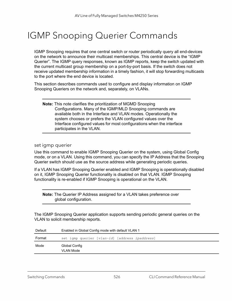
AV Line of Fully Managed Switches M4250 Series
IGMP Snooping Querier Commands
IGMP Snooping requires that one central switch or router periodically query all end-devices on the network to announce their multicast memberships. This central device is the “IGMP Querier”. The IGMP query responses, known as IGMP reports, keep the switch updated with the current multicast group membership on a port-by-port basis. If the switch does not receive updated membership information in a timely fashion, it will stop forwarding multicasts to the port where the end device is located.
This section describes commands used to configure and display information on IGMP Snooping Queriers on the network and, separately, on VLANs.
Note: This note clarifies the prioritization of MGMD Snooping Configurations. Many of the IGMP/MLD Snooping commands are available both in the Interface and VLAN modes. Operationally the system chooses or prefers the VLAN configured values over the Interface configured values for most configurations when the interface participates in the VLAN.
set igmp querierUse this command to enable IGMP Snooping Querier on the system, using Global Config mode, or on a VLAN. Using this command, you can specify the IP Address that the Snooping Querier switch should use as the source address while generating periodic queries.
If a VLAN has IGMP Snooping Querier enabled and IGMP Snooping is operationally disabled on it, IGMP Snooping Querier functionality is disabled on that VLAN. IGMP Snooping functionality is re-enabled if IGMP Snooping is operational on the VLAN.
Note: The Querier IP Address assigned for a VLAN takes preference over global configuration.
The IGMP Snooping Querier application supports sending periodic general queries on the VLAN to solicit membership reports.
Default Enabled in Global Config mode with default VLAN 1
Format set igmp querier [vlan-id] [address ipaddress]
Mode Global ConfigVLAN Mode
Switching Commands CLI Command Reference Manual526

AV Line of Fully Managed Switches M4250 Series
no set igmp querier
Use this command to disable IGMP Snooping Querier on the system. Use the optional address parameter to reset the querier address to 0.0.0.0.
set igmp querier query-intervalUse this command to set the IGMP querier query interval time. It is the period in seconds, from 1–1800 seconds, that the switch waits before sending another general query.
no set igmp querier query-interval
Use this command to set the IGMP querier query interval time to its default value.
set igmp querier timer expiryUse this command to set the IGMP querier timer expiration period in seconds, from 60–300 seconds. This is the period that the switch remains in non-querier mode after it has discovered a multicast querier in the network.
no set igmp querier timer expiry
Use this command to set the IGMP querier timer expiration period to its default value.
Format no set igmp querier [vlan-id] [address]
Mode Global ConfigVLAN Mode
Default 60 seconds
Format set igmp querier query-interval seconds
Mode Global Config
Format no set igmp querier query-interval
Mode Global Config
Default 60 seconds
Format set igmp querier timer expiry seconds
Mode Global Config
Format no set igmp querier timer expiry
Mode Global Config
Switching Commands CLI Command Reference Manual527
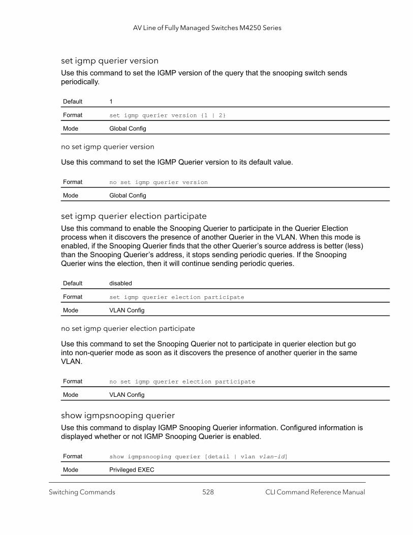
AV Line of Fully Managed Switches M4250 Series
set igmp querier versionUse this command to set the IGMP version of the query that the snooping switch sends periodically.
no set igmp querier version
Use this command to set the IGMP Querier version to its default value.
set igmp querier election participateUse this command to enable the Snooping Querier to participate in the Querier Election process when it discovers the presence of another Querier in the VLAN. When this mode is enabled, if the Snooping Querier finds that the other Querier’s source address is better (less) than the Snooping Querier’s address, it stops sending periodic queries. If the Snooping Querier wins the election, then it will continue sending periodic queries.
no set igmp querier election participate
Use this command to set the Snooping Querier not to participate in querier election but go into non-querier mode as soon as it discovers the presence of another querier in the same VLAN.
show igmpsnooping querierUse this command to display IGMP Snooping Querier information. Configured information is displayed whether or not IGMP Snooping Querier is enabled.
Default 1
Format set igmp querier version {1 | 2}
Mode Global Config
Format no set igmp querier version
Mode Global Config
Default disabled
Format set igmp querier election participate
Mode VLAN Config
Format no set igmp querier election participate
Mode VLAN Config
Format show igmpsnooping querier [detail | vlan vlan-id]
Mode Privileged EXEC
Switching Commands CLI Command Reference Manual528
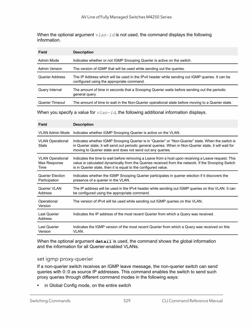
AV Line of Fully Managed Switches M4250 Series
be
te.
itch is it for
. This witch
e
It can
is
When the optional argument vlan-id is not used, the command displays the following information.
When you specify a value for vlan-id, the following additional information displays.
When the optional argument detail is used, the command shows the global information and the information for all Querier-enabled VLANs.
set igmp proxy-querierIf a non-querier switch receives an IGMP leave message, the non-querier switch can send queries with 0::0 as source IP addresses. This command enables the switch to send such proxy queries through different command modes in the following ways:
• in Global Config mode, on the entire switch
Field Description
Admin Mode Indicates whether or not IGMP Snooping Querier is active on the switch.
Admin Version The version of IGMP that will be used while sending out the queries.
Querier Address The IP Address which will be used in the IPv4 header while sending out IGMP queries. It can configured using the appropriate command.
Query Interval The amount of time in seconds that a Snooping Querier waits before sending out the periodic general query.
Querier Timeout The amount of time to wait in the Non-Querier operational state before moving to a Querier sta
Field Description
VLAN Admin Mode Indicates whether iGMP Snooping Querier is active on the VLAN.
VLAN Operational State
Indicates whether IGMP Snooping Querier is in “Querier” or “Non-Querier” state. When the swin Querier state, it will send out periodic general queries. When in Non-Querier state, it will wamoving to Querier state and does not send out any queries.
VLAN Operational Max Response Time
Indicates the time to wait before removing a Leave from a host upon receiving a Leave requestvalue is calculated dynamically from the Queries received from the network. If the Snooping Sis in Querier state, then it is equal to the configured value.
Querier Election Participation
Indicates whether the IGMP Snooping Querier participates in querier election if it discovers thpresence of a querier in the VLAN.
Querier VLAN Address
The IP address will be used in the IPv4 header while sending out IGMP queries on this VLAN. be configured using the appropriate command.
Operational Version
The version of IPv4 will be used while sending out IGMP queries on this VLAN.
Last Querier Address
Indicates the IP address of the most recent Querier from which a Query was received.
Last Querier Version
Indicates the IGMP version of the most recent Querier from which a Query was received on thVLAN.
Switching Commands CLI Command Reference Manual529

AV Line of Fully Managed Switches M4250 Series
• in Interface Config mode, on an interface• in VLAN Config mode, on a particular VLAN and all interfaces participating in the VLAN.
By default, the proxy querrier is enabled.
no set igmp proxy-querier
This command stops the switch from sending proxy queries through different command modes in the following ways:
• in Global Config mode, on the entire switch• in Interface Config mode, on an interface• in VLAN Config mode, on a particular VLAN and all interfaces participating in the VLAN.
This command is specific to IGMP.
show igmpsnooping proxy-querierThis command shows the global admin mode of the IGMP snooping proxy-querier and the interface on which it is enabled.
Command example: (Netgear Switch) #show igmpsnooping proxy-querierAdmin Mode..................................... EnableInterfaces Enabled for IGMP Proxy Querier...... 1/0/1 1/0/2 1/0/3 1/0/4
Default enabled
Format set igmp proxy-querier [vlan-id]
Mode Global ConfigInterface ConfigVLAN Config
Format no set igmp proxy-querier [vlan-id]
Mode Global ConfigInterface ConfigVLAN Config
Format show igmpsnooping proxy-querier
Mode Privileged EXEC
Switching Commands CLI Command Reference Manual530

AV Line of Fully Managed Switches M4250 Series
MLD Snooping Commands
This section describes commands used for MLD Snooping. In IPv4, Layer 2 switches can use IGMP Snooping to limit the flooding of multicast traffic by dynamically configuring Layer 2 interfaces so that multicast traffic is forwarded only to those interfaces associated with IP multicast addresses. In IPv6, MLD Snooping performs a similar function. With MLD Snooping, IPv6 multicast data is selectively forwarded to a list of ports that want to receive the data, instead of being flooded to all ports in a VLAN. This list is constructed by snooping IPv6 multicast control packets.
Note: This note clarifies the prioritization of MGMD Snooping Configurations. Many of the IGMP/MLD Snooping commands are available both in the Interface and VLAN modes. Operationally the system chooses or prefers the VLAN configured values over the Interface configured values for most configurations when the interface participates in the VLAN.
set mldThis command enables MLD Snooping on the system (Global Config Mode) or an interface (Interface Config Mode). This command also enables MLD Snooping on a particular VLAN and enables MLD Snooping on all interfaces participating in a VLAN.
If an interface has MLD Snooping enabled and you enable this interface for routing or enlist it as a member of a port-channel (LAG), MLD Snooping functionality is disabled on that interface. MLD Snooping functionality is re-enabled if you disable routing or remove port channel (LAG) membership from an interface that has MLD Snooping enabled.
MLD Snooping supports the following activities:
• Validation of address version, payload length consistencies and discarding of the frame upon error.
• Maintenance of the forwarding table entries based on the MAC address versus the IPv6 address.
• Filters out unknown IPv6 multicast packets on a VLAN if MLD snooping is enabled, with the exception of group addresses in the range ffx2::/16 and FF05::X. These control packets are always flooded to all ports in the VLAN.
Default Enabled for VLAN 1; Disabled for other VLANs.
Format set mld vlan-id
Mode Global ConfigInterface ConfigVLAN Mode
Switching Commands CLI Command Reference Manual531
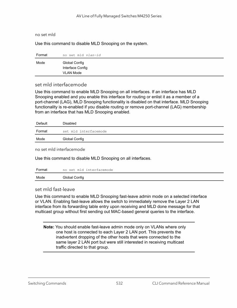
AV Line of Fully Managed Switches M4250 Series
no set mld
Use this command to disable MLD Snooping on the system.
set mld interfacemodeUse this command to enable MLD Snooping on all interfaces. If an interface has MLD Snooping enabled and you enable this interface for routing or enlist it as a member of a port-channel (LAG), MLD Snooping functionality is disabled on that interface. MLD Snooping functionality is re-enabled if you disable routing or remove port-channel (LAG) membership from an interface that has MLD Snooping enabled.
no set mld interfacemode
Use this command to disable MLD Snooping on all interfaces.
set mld fast-leaveUse this command to enable MLD Snooping fast-leave admin mode on a selected interface or VLAN. Enabling fast-leave allows the switch to immediately remove the Layer 2 LAN interface from its forwarding table entry upon receiving and MLD done message for that multicast group without first sending out MAC-based general queries to the interface.
Note: You should enable fast-leave admin mode only on VLANs where only one host is connected to each Layer 2 LAN port. This prevents the inadvertent dropping of the other hosts that were connected to the same layer 2 LAN port but were still interested in receiving multicast traffic directed to that group.
Format no set mld vlan-id
Mode Global ConfigInterface ConfigVLAN Mode
Default Disabled
Format set mld interfacemode
Mode Global Config
Format no set mld interfacemode
Mode Global Config
Switching Commands CLI Command Reference Manual532

AV Line of Fully Managed Switches M4250 Series
Note: Fast-leave processing is supported only with MLD version 1 hosts.
no set mld fast-leave
Use this command to disable MLD Snooping fast-leave admin mode on a selected interface.
set mld groupmembership-intervalUse this command to set the MLD Group Membership Interval time on a VLAN, one interface or all interfaces. The Group Membership Interval time is the amount of time in seconds that a switch waits for a report from a particular group on a particular interface before deleting the interface from the entry. This value must be greater than the MLDv2 maximum response time value. The range is 2 to 3600 seconds.
no set groupmembership-interval
Use this command to set the MLDv2 group membership Interval time to the default value.
Default Enabled for VLAN 1; Disabled for other VLANs.
Format set mld fast-leave vlan-id
Mode Interface ConfigVLAN Mode
Format no set mld fast-leave vlan-id
Mode Interface ConfigVLAN Mode
Default 260 seconds
Format set mld groupmembership-interval vlan-id seconds
Mode Interface ConfigGlobal ConfigVLAN Mode
Format no set mld groupmembership-interval
Mode Interface ConfigGlobal ConfigVLAN Mode
Switching Commands CLI Command Reference Manual533

AV Line of Fully Managed Switches M4250 Series
set mld maxresponseUse this command to set the MLD maximum response time for the system, on a particular interface or VLAN. The maximum response time is the amount of time in seconds that a switch will wait after sending a query on an interface because it did not receive a report for a particular group in that interface. This value must be less than the MLD query interval time value. The range is 1 to 65 seconds.
no set mld maxresponse
Use this command to set the max response time (on the interface or VLAN) to the default value.
set mld mcrtexpiretimeUse this command to set the multicast router present expiration time. The time is set for the system, on a particular interface or VLAN. This is the amount of time in seconds that a switch waits for a query to be received on an interface before the interface is removed from the list of interfaces with multicast routers attached. The range is 0 to 3600 seconds. A value of 0 indicates an infinite time-out, that is, no expiration.
no set mld mcrtexpiretime
Use this command to set the multicast router present expiration time to 0. The time is set for the system, on a particular interface or a VLAN.
Default 10 seconds
Format set mld maxresponse seconds
Mode Global ConfigInterface ConfigVLAN Mode
Format no set mld maxresponse
Mode Global ConfigInterface ConfigVLAN Mode
Default 0
Format set mld mcrtexpiretime vlan-id seconds
Mode Global ConfigInterface Config
Format no set mld mcrtexpiretime vlan-id
Mode Global ConfigInterface Config
Switching Commands CLI Command Reference Manual534

AV Line of Fully Managed Switches M4250 Series
set mld mrouterUse this command to configure the VLAN ID for the VLAN that has the multicast router attached mode enabled.
no set mld mrouter
Use this command to disable multicast router attached mode for a VLAN with a particular VLAN ID.
set mld mrouter interfaceUse this command to configure the interface as a multicast router-attached interface. When configured as a multicast router interface, the interface is treated as a multicast router-attached interface in all VLANs.
no set mld mrouter interface
Use this command to disable the status of the interface as a statically configured multicast router-attached interface.
set mld exclude-mrouter-intfUse this command to control whether unknown multicast data is sent to an mrouter interface.
If either IGMP Snooping or MLD Snooping is enabled on a VLAN, by default, dynamic mrouter mode is enabled on the interface that receives MLD PDUs from the upstream router. When the mrouter mode is enabled on the interface, unknown multicast data is sent to that interface.
If you enter the command, the switch blocks all unknown multicast data through the mrouter port, whether the port is configured dynamically or statically. Only MLD PDUs are allowed to pass through the mrouter port to the upstream router interface.
Format set mld mrouter vlan-id
Mode Interface Config
Format no set mld mrouter vlan-id
Mode Interface Config
Default disabled
Format set mld mrouter interface
Mode Interface Config
Format no set mld mrouter interface
Mode Interface Config
Switching Commands CLI Command Reference Manual535
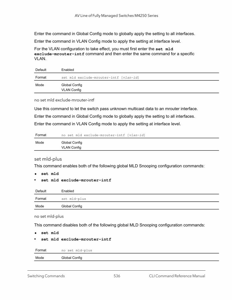
AV Line of Fully Managed Switches M4250 Series
Enter the command in Global Config mode to globally apply the setting to all interfaces.
Enter the command in VLAN Config mode to apply the setting at interface level.
For the VLAN configuration to take effect, you must first enter the set mld exclude-mrouter-intf command and then enter the same command for a specific VLAN.
no set mld exclude-mrouter-intf
Use this command to let the switch pass unknown multicast data to an mrouter interface.
Enter the command in Global Config mode to globally apply the setting to all interfaces.
Enter the command in VLAN Config mode to apply the setting at interface level.
set mld-plusThis command enables both of the following global MLD Snooping configuration commands:
• set mld
• set mld exclude-mrouter-intf
no set mld-plus
This command disables both of the following global MLD Snooping configuration commands:
• set mld
• set mld exclude-mrouter-intf
Default Enabled
Format set mld exclude-mrouter-intf [vlan-id]
Mode Global ConfigVLAN Config
Format no set mld exclude-mrouter-intf [vlan-id]
Mode Global ConfigVLAN Config
Default Enabled
Format set mld-plus
Mode Global Config
Format no set mld-plus
Mode Global Config
Switching Commands CLI Command Reference Manual536
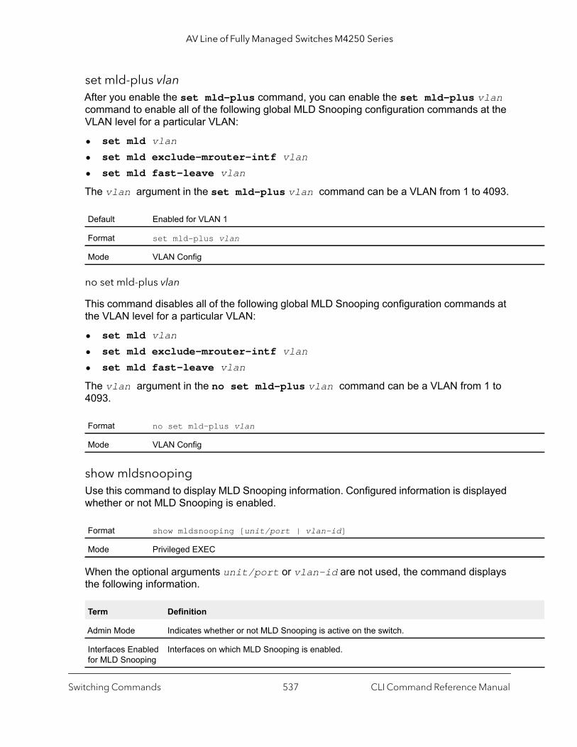
AV Line of Fully Managed Switches M4250 Series
set mld-plus vlanAfter you enable the set mld-plus command, you can enable the set mld-plus vlan command to enable all of the following global MLD Snooping configuration commands at the VLAN level for a particular VLAN:
• set mld vlan
• set mld exclude-mrouter-intf vlan
• set mld fast-leave vlan
The vlan argument in the set mld-plus vlan command can be a VLAN from 1 to 4093.
no set mld-plus vlan
This command disables all of the following global MLD Snooping configuration commands at the VLAN level for a particular VLAN:
• set mld vlan
• set mld exclude-mrouter-intf vlan
• set mld fast-leave vlan
The vlan argument in the no set mld-plus vlan command can be a VLAN from 1 to 4093.
show mldsnoopingUse this command to display MLD Snooping information. Configured information is displayed whether or not MLD Snooping is enabled.
When the optional arguments unit/port or vlan-id are not used, the command displays the following information.
Default Enabled for VLAN 1
Format set mld-plus vlan
Mode VLAN Config
Format no set mld-plus vlan
Mode VLAN Config
Format show mldsnooping [unit/port | vlan-id]
Mode Privileged EXEC
Term Definition
Admin Mode Indicates whether or not MLD Snooping is active on the switch.
Interfaces Enabled for MLD Snooping
Interfaces on which MLD Snooping is enabled.
Switching Commands CLI Command Reference Manual537
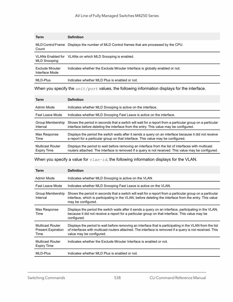
AV Line of Fully Managed Switches M4250 Series
icular
ceive
st ured.
icular value
LAN,
e list . This
When you specify the unit/port values, the following information displays for the interface.
When you specify a value for vlan-id, the following information displays for the VLAN.
MLD Control Frame Count
Displays the number of MLD Control frames that are processed by the CPU.
VLANs Enabled for MLD Snooping
VLANs on which MLD Snooping is enabled.
Exclude Mrouter Interface Mode
Indicates whether the Exclude Mrouter Interface is globally enabled or not.
MLD-Plus Indicates whether MLD Plus is enabled or not.
Term Definition
Admin Mode Indicates whether MLD Snooping is active on the interface.
Fast Leave Mode Indicates whether MLD Snooping Fast Leave is active on the interface.
Group Membership Interval
Shows the period in seconds that a switch will wait for a report from a particular group on a partinterface before deleting the interface from the entry. This value may be configured.
Max Response Time
Displays the period the switch waits after it sends a query on an interface because it did not rea report for a particular group on that interface. This value may be configured.
Multicast Router Expiry Time
Displays the period to wait before removing an interface from the list of interfaces with multicarouters attached. The interface is removed if a query is not received. This value may be config
Term Definition
Admin Mode Indicates whether MLD Snooping is active on the VLAN.
Fast Leave Mode Indicates whether MLD Snooping Fast Leave is active on the VLAN.
Group Membership Interval
Shows the period in seconds that a switch will wait for a report from a particular group on a partinterface, which is participating in the VLAN, before deleting the interface from the entry. This may be configured.
Max Response Time
Displays the period the switch waits after it sends a query on an interface, participating in the Vbecause it did not receive a report for a particular group on that interface. This value may be configured.
Multicast Router Present Expiration Time
Displays the period to wait before removing an interface that is participating in the VLAN from thof interfaces with multicast routers attached. The interface is removed if a query is not receivedvalue may be configured.
Multicast Router Expiry Time
Indicates whether the Exclude Mrouter Interface is enabled or not.
MLD-Plus Indicates whether MLD Plus is enabled or not.
Term Definition
Switching Commands CLI Command Reference Manual538
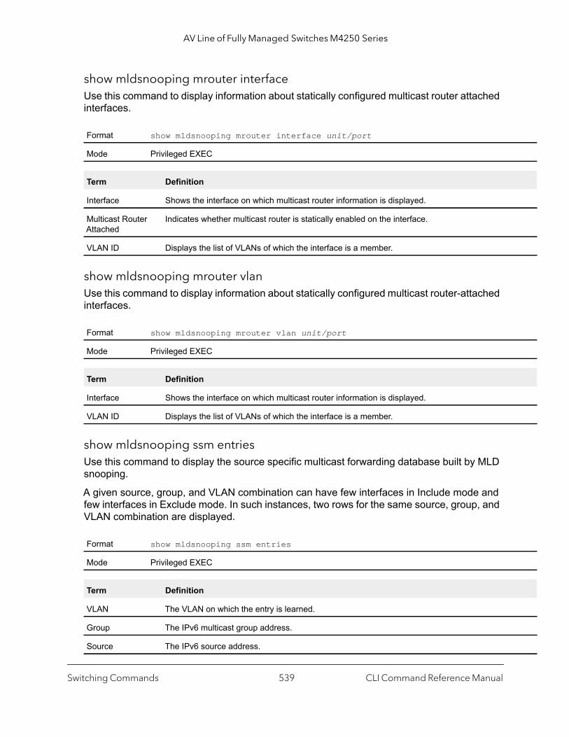
AV Line of Fully Managed Switches M4250 Series
show mldsnooping mrouter interfaceUse this command to display information about statically configured multicast router attached interfaces.
show mldsnooping mrouter vlanUse this command to display information about statically configured multicast router-attached interfaces.
show mldsnooping ssm entriesUse this command to display the source specific multicast forwarding database built by MLD snooping.
A given source, group, and VLAN combination can have few interfaces in Include mode and few interfaces in Exclude mode. In such instances, two rows for the same source, group, and VLAN combination are displayed.
Format show mldsnooping mrouter interface unit/port
Mode Privileged EXEC
Term Definition
Interface Shows the interface on which multicast router information is displayed.
Multicast Router Attached
Indicates whether multicast router is statically enabled on the interface.
VLAN ID Displays the list of VLANs of which the interface is a member.
Format show mldsnooping mrouter vlan unit/port
Mode Privileged EXEC
Term Definition
Interface Shows the interface on which multicast router information is displayed.
VLAN ID Displays the list of VLANs of which the interface is a member.
Format show mldsnooping ssm entries
Mode Privileged EXEC
Term Definition
VLAN The VLAN on which the entry is learned.
Group The IPv6 multicast group address.
Source The IPv6 source address.
Switching Commands CLI Command Reference Manual539

AV Line of Fully Managed Switches M4250 Series
ket is n IP rrent
ket is ation ntry’s
show mldsnooping ssm statsUse this command to display the statistics of MLD snooping’s SSMFDB. This command takes no options.
show mldsnooping ssm groupsUse this command to display the MLD SSM group membership information.
Source Filter Mode The source filter mode (Include/Exclude) for the specified group.
Interfaces • If Source Filter Mode is “Include,” specifies the list of interfaces on which a incoming pacforwarded. If it’s source IP address is equal to the current entry’s Source, the destinatioaddress is equal to the current entry’s Group and the VLAN ID on which it arrived is cuentry’s VLAN.
• If Source Filter Mode is “Exclude,” specifies the list of interfaces on which a incoming pacforwarded. If it’s source IP address is *not* equal to the current entry’s Source, the destinIP address is equal to current entry’s Group and VLAN ID on which it arrived is current eVLAN.
Format show mldsnooping ssm stats
Mode Privileged EXEC
Term Definition
Total Entries The total number of entries that can possibly be in the MLD snooping’s SSMFDB.
Most SSMFDB Entries Ever Used
The largest number of entries that have been present in the MLD snooping’s SSMFDB.
Current Entries The current number of entries in the MLD snooping’s SSMFDB.
Format show mldsnooping ssm groups
Mode Privileged EXEC
Term Definition
VLAN VLAN on which the MLD v2 report is received.
Group The IPv6 multicast group address.
Interface The interface on which the MLD v2 report is received.
Reporter The IPv6 address of the host that sent the MLDv2 report.
Source Filter Mode The source filter mode (Include/Exclude) for the specified group.
Source Address List
List of source IP addresses for which source filtering is requested.
Term Definition
Switching Commands CLI Command Reference Manual540

AV Line of Fully Managed Switches M4250 Series
t is 6
result
show mac-address-table mldsnoopingUse this command to display the MLD Snooping entries in the Multicast Forwarding Database (MFDB) table.
clear mldsnoopingUse this command to delete all MLD snooping entries from the MFDB table.
MLD Snooping Querier Commands
In an IPv6 environment, MLD Snooping requires that one central switch or router periodically query all end-devices on the network to announce their multicast memberships. This central device is the MLD Querier. The MLD query responses, known as MLD reports, keep the switch updated with the current multicast group membership on a port-by-port basis. If the switch does not receive updated membership information in a timely fashion, it will stop forwarding multicasts to the port where the end device is located.
This section describes the commands you use to configure and display information on MLD Snooping queries on the network and, separately, on VLANs.
Note: This note clarifies the prioritization of MGMD Snooping Configurations. Many of the IGMP/MLD Snooping commands are available both in the Interface and VLAN modes. Operationally the system chooses or prefers the VLAN configured values over the Interface configured values for most configurations when the interface participates in the VLAN.
Format show mac-address-table mldsnooping
Mode Privileged EXEC
Term Definition
VLAN ID The VLAN in which the MAC address is learned.
MAC Address A multicast MAC address for which the switch has forwarding or filtering information. The formatwo-digit hexadecimal numbers that are separated by colons, for example 01:23:45:67:89:AB.
Type The type of entry, which is either static (added by the user) or dynamic (added to the table as a of a learning process or protocol.)
Description The text description of this multicast table entry.
Interfaces The list of interfaces that are designated for forwarding (Fwd:) and filtering (Flt:).
Format clear mldsnooping
Mode Privileged EXEC
Switching Commands CLI Command Reference Manual541

AV Line of Fully Managed Switches M4250 Series
set mld querierUse this command to enable MLD Snooping Querier on the system (Global Config Mode) or on a VLAN. Using this command, you can specify the IP address that the snooping querier switch should use as a source address while generating periodic queries.
If a VLAN has MLD Snooping Querier enabled and MLD Snooping is operationally disabled on it, MLD Snooping Querier functionality is disabled on that VLAN. MLD Snooping functionality is re-enabled if MLD Snooping is operational on the VLAN.
The MLD Snooping Querier sends periodic general queries on the VLAN to solicit membership reports.
no set mld querier
Use this command to disable MLD Snooping Querier on the system. Use the optional parameter address to reset the querier address.
set mld querier query_intervalUse this command to set the MLD querier query interval time. It is the time in seconds, from 1–1800 seconds, that the switch waits before sending another general query.
no set mld querier query_interval
Use this command to set the MLD Querier Query Interval time to its default value.
Default disabled
Format set mld querier [vlan-id] [address ipv6-address]
Mode Global ConfigVLAN Mode
Format no set mld querier [vlan-id] [address]
Mode Global ConfigVLAN Mode
Default disabled
Format set mld querier query_interval seconds
Mode Global Config
Format no set mld querier query-interval
Mode Global Config
Switching Commands CLI Command Reference Manual542

AV Line of Fully Managed Switches M4250 Series
set mld querier timer expiryUse this command to set the MLD querier timer expiration period. It is the period in seconds, from 60–300 seconds, that the switch remains in non-querier mode after it has discovered a multicast querier in the network.
no set mld querier timer expiry
Use this command to set the MLD querier timer expiration period to its default value.
set mld querier election participateUse this command to enable the Snooping Querier to participate in the Querier Election process when it discovers the presence of another Querier in the VLAN. When this mode is enabled, if the Snooping Querier finds that the other Querier’s source address is better (less) than the Snooping Querier’s address, it stops sending periodic queries. If the Snooping Querier wins the election, then it will continue sending periodic queries.
no set mld querier election participate
Use this command to set the snooping querier not to participate in querier election but go into a non-querier mode as soon as it discovers the presence of another querier in the same VLAN.
Default 60 seconds
Format set mld querier timer expiry seconds
Mode Global Config
Format no set mld querier timer expiry
Mode Global Config
Default disabled
Format set mld querier election participate
Mode VLAN Config
Format no set mld querier election participate
Mode VLAN Config
Switching Commands CLI Command Reference Manual543
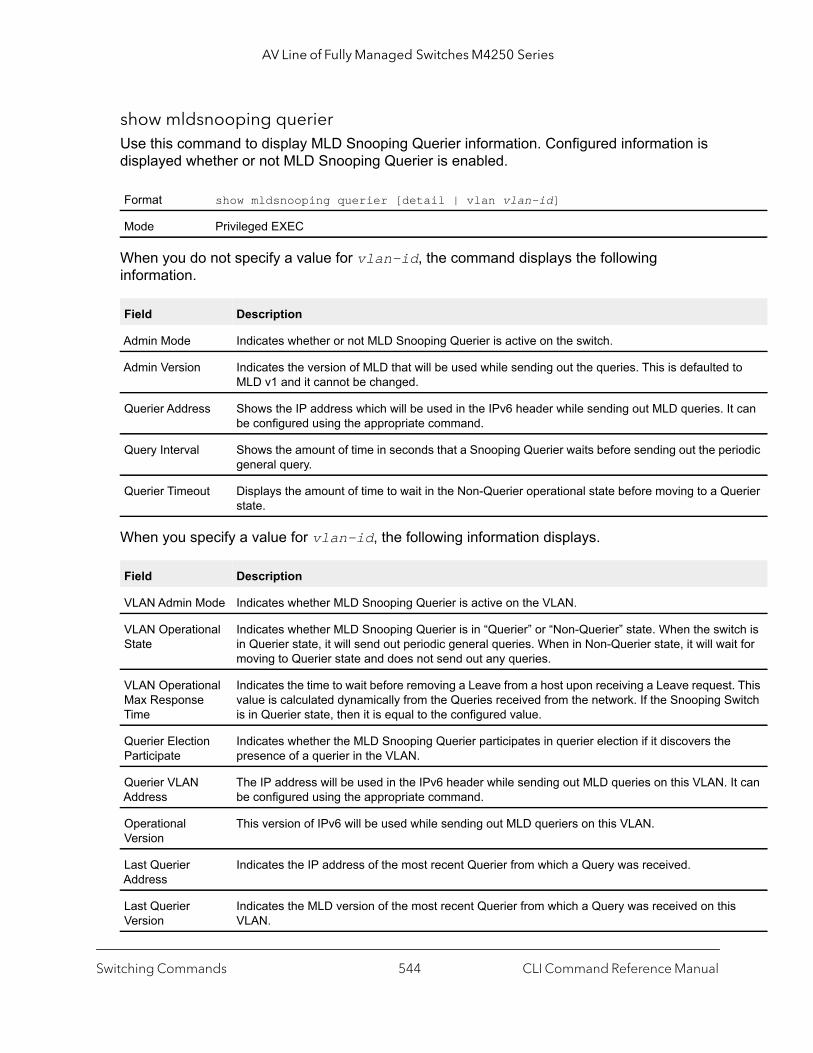
AV Line of Fully Managed Switches M4250 Series
to
can
riodic
erier
tch is it for
. This witch
It can
show mldsnooping querierUse this command to display MLD Snooping Querier information. Configured information is displayed whether or not MLD Snooping Querier is enabled.
When you do not specify a value for vlan-id, the command displays the following information.
When you specify a value for vlan-id, the following information displays.
Format show mldsnooping querier [detail | vlan vlan-id]
Mode Privileged EXEC
Field Description
Admin Mode Indicates whether or not MLD Snooping Querier is active on the switch.
Admin Version Indicates the version of MLD that will be used while sending out the queries. This is defaulted MLD v1 and it cannot be changed.
Querier Address Shows the IP address which will be used in the IPv6 header while sending out MLD queries. Itbe configured using the appropriate command.
Query Interval Shows the amount of time in seconds that a Snooping Querier waits before sending out the pegeneral query.
Querier Timeout Displays the amount of time to wait in the Non-Querier operational state before moving to a Qustate.
Field Description
VLAN Admin Mode Indicates whether MLD Snooping Querier is active on the VLAN.
VLAN Operational State
Indicates whether MLD Snooping Querier is in “Querier” or “Non-Querier” state. When the swiin Querier state, it will send out periodic general queries. When in Non-Querier state, it will wamoving to Querier state and does not send out any queries.
VLAN Operational Max Response Time
Indicates the time to wait before removing a Leave from a host upon receiving a Leave requestvalue is calculated dynamically from the Queries received from the network. If the Snooping Sis in Querier state, then it is equal to the configured value.
Querier Election Participate
Indicates whether the MLD Snooping Querier participates in querier election if it discovers thepresence of a querier in the VLAN.
Querier VLAN Address
The IP address will be used in the IPv6 header while sending out MLD queries on this VLAN. be configured using the appropriate command.
Operational Version
This version of IPv6 will be used while sending out MLD queriers on this VLAN.
Last Querier Address
Indicates the IP address of the most recent Querier from which a Query was received.
Last Querier Version
Indicates the MLD version of the most recent Querier from which a Query was received on thisVLAN.
Switching Commands CLI Command Reference Manual544
AV Line of Fully Managed Switches M4250 Series
When the optional detail keyword is used, the command shows the global information and the information for all Querier-enabled VLANs.
set mld proxy-querierIf a non-querier switch receives an MLD leave message, the non-querier switch can send queries with 0::0 as the source IP addresses. This command enables the switch to send such proxy queries through different command modes the following ways:
• in Global Config mode, on the entire switch• in Interface Config mode, on an interface• in VLAN Config mode, on a particular VLAN and all interfaces participating in the VLAN.
By default, the proxy-querier is enabled.
no set mld proxy-querier
This command stops the switch from sending proxy queries through different command modes in the following ways:
• in Global Config mode, on the entire switch• in Interface Config mode, on an interface• in VLAN Config mode, on a particular VLAN and all interfaces participating in the VLAN.
This command is specific to MLD.
show mldsnooping proxy-querierThis command shows the global admin mode of the MLD snooping proxy-querier and the interface on which it is enabled.
Default enabled
Format set mld proxy-querier [vlan-id]
Mode Global ConfigInterface ConfigVLAN Config
Format no set mld proxy-querier [vlan-id]
Mode Global ConfigInterface ConfigVLAN Config
Format show mldsnooping proxy-querier
Mode Privileged EXEC
Switching Commands CLI Command Reference Manual545

AV Line of Fully Managed Switches M4250 Series
Command example: (Netgear Switch) #show mldsnooping proxy-querierAdmin Mode..................................... EnableInterfaces Enabled for MLD Proxy Querier....... 1/0/1 1/0/2 1/0/3
Port Security Commands
This section describes the command you use to configure Port Security on the switch. Port security, which is also known as port MAC locking, allows you to secure the network by locking allowable MAC addresses on a given port. Packets with a matching source MAC address are forwarded normally, and all other packets are discarded.
Note: To enable the SNMP trap specific to port security, see snmp-server enable traps violation on page 104.
port-securityThis command enables port locking on an interface, a range of interfaces, or at the system level.
no port-security
This command disables port locking for one (Interface Config) or all (Global Config) ports.
Default disabled
Format port-security
Mode Global Config (to enable port locking globally)Interface Config (to enable port locking on an interface or range of interfaces)
Format no port-security
Mode Global ConfigInterface Config
Switching Commands CLI Command Reference Manual546

AV Line of Fully Managed Switches M4250 Series
port-security max-dynamicThis command sets the maximum number of dynamically locked MAC addresses allowed on a specific port. The valid range is 0–4096.
no port-security max-dynamic
This command resets the maximum number of dynamically locked MAC addresses allowed on a specific port to its default value.
port-security max-staticThis command sets the maximum number of statically locked MAC addresses allowed on a port. The valid range is 0–20.
no port-security max-static
This command sets maximum number of statically locked MAC addresses to the default value.
port-security mac-addressThis command adds a MAC address to the list of statically locked MAC addresses for an interface or range of interfaces. The vid is the VLAN ID.
Default 4096
Format port-security max-dynamic maxvalue
Mode Interface Config
Format no port-security max-dynamic
Mode Interface Config
Default 1
Format port-security max-static maxvalue
Mode Interface Config
Format no port-security max-static
Mode Interface Config
Format port-security mac-address mac-address vid
Mode Interface Config
Switching Commands CLI Command Reference Manual547
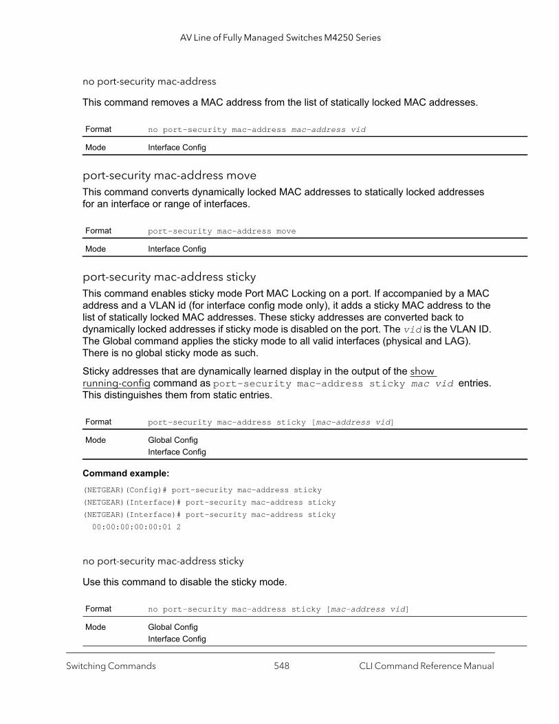
AV Line of Fully Managed Switches M4250 Series
no port-security mac-address
This command removes a MAC address from the list of statically locked MAC addresses.
port-security mac-address moveThis command converts dynamically locked MAC addresses to statically locked addresses for an interface or range of interfaces.
port-security mac-address stickyThis command enables sticky mode Port MAC Locking on a port. If accompanied by a MAC address and a VLAN id (for interface config mode only), it adds a sticky MAC address to the list of statically locked MAC addresses. These sticky addresses are converted back to dynamically locked addresses if sticky mode is disabled on the port. The vid is the VLAN ID. The Global command applies the sticky mode to all valid interfaces (physical and LAG). There is no global sticky mode as such.
Sticky addresses that are dynamically learned display in the output of the show running-config command as port-security mac-address sticky mac vid entries. This distinguishes them from static entries.
Command example: (NETGEAR)(Config)# port-security mac-address sticky(NETGEAR)(Interface)# port-security mac-address sticky(NETGEAR)(Interface)# port-security mac-address sticky 00:00:00:00:00:01 2
no port-security mac-address sticky
Use this command to disable the sticky mode.
Format no port-security mac-address mac-address vid
Mode Interface Config
Format port-security mac-address move
Mode Interface Config
Format port-security mac-address sticky [mac-address vid]
Mode Global ConfigInterface Config
Format no port-security mac-address sticky [mac-address vid]
Mode Global ConfigInterface Config
Switching Commands CLI Command Reference Manual548

AV Line of Fully Managed Switches M4250 Series
rs.
port-security violation shutdownThis command allows an interface to be diagnostically disabled when a violation occurs for port MAC locking.
no port-security violation shutdown
This command prevents an interface from being diagnostically disabled when a violation occurs for port MAC locking.
show port-security This command displays the port-security settings for the port or ports. If you do not use a parameter, the command displays the Port Security Administrative mode. Use the optional parameters to display the settings on a specific interface or on all interfaces. Instead of unit/port, lag lag-intf-num can be used as an alternate way to specify the LAG interface, in which lag-intf-num is the LAG port number.
For each interface, or for the interface you specify, the following information displays.
Format port-security violation shutdown
Mode Interface Config
Format no port-security violation shutdown
Mode Interface Config
Format show port-security [unit/port | all]
Mode Privileged EXEC
Term Definition
Admin Mode Port Locking mode for the entire system. This field displays if you do not supply any paramete
Term Definition
Admin Mode Port Locking mode for the Interface.
Dynamic Limit Maximum dynamically allocated MAC Addresses.
Static Limit Maximum statically allocated MAC Addresses.
Violation Trap Mode
Whether violation traps are enabled.
Sticky Mode The administrative mode of the port security Sticky Mode feature on the interface.
Switching Commands CLI Command Reference Manual549
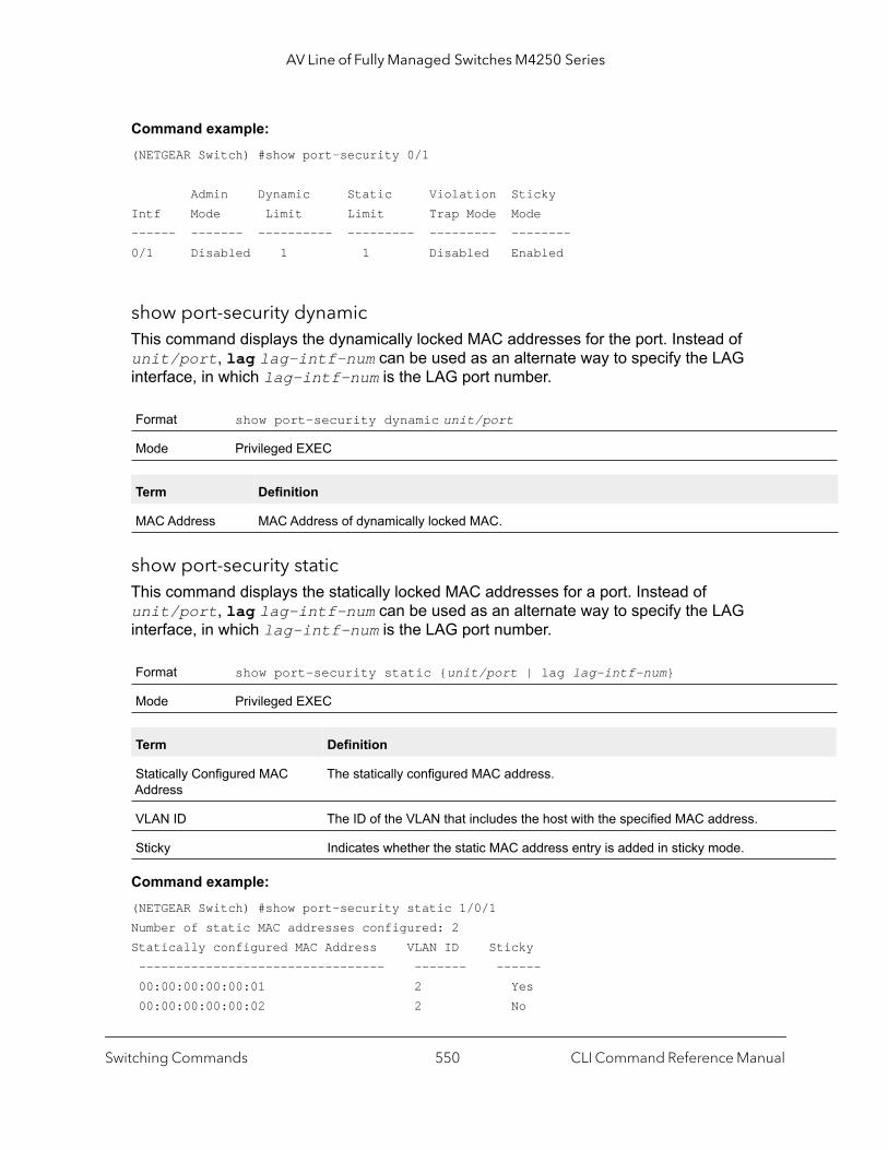
AV Line of Fully Managed Switches M4250 Series
Command example: (NETGEAR Switch) #show port-security 0/1
Admin Dynamic Static Violation StickyIntf Mode Limit Limit Trap Mode Mode------ ------- ---------- --------- --------- --------0/1 Disabled 1 1 Disabled Enabled
show port-security dynamicThis command displays the dynamically locked MAC addresses for the port. Instead of unit/port, lag lag-intf-num can be used as an alternate way to specify the LAG interface, in which lag-intf-num is the LAG port number.
show port-security staticThis command displays the statically locked MAC addresses for a port. Instead of unit/port, lag lag-intf-num can be used as an alternate way to specify the LAG interface, in which lag-intf-num is the LAG port number.
Command example: (NETGEAR Switch) #show port-security static 1/0/1Number of static MAC addresses configured: 2Statically configured MAC Address VLAN ID Sticky --------------------------------- ------- ------ 00:00:00:00:00:01 2 Yes 00:00:00:00:00:02 2 No
Format show port-security dynamic unit/port
Mode Privileged EXEC
Term Definition
MAC Address MAC Address of dynamically locked MAC.
Format show port-security static {unit/port | lag lag-intf-num}
Mode Privileged EXEC
Term Definition
Statically Configured MAC Address
The statically configured MAC address.
VLAN ID The ID of the VLAN that includes the host with the specified MAC address.
Sticky Indicates whether the static MAC address entry is added in sticky mode.
Switching Commands CLI Command Reference Manual550

AV Line of Fully Managed Switches M4250 Series
ed at
show port-security violationThis command displays the source MAC address of the last packet discarded on a locked port. Instead of unit/port, lag lag-intf-num can be used as an alternate way to specify the LAG interface, in which lag-intf-num is the LAG port number.
LLDP (802.1AB) Commands
This section describes the command you use to configure Link Layer Discovery Protocol (LLDP), which is defined in the IEEE 802.1AB specification. LLDP allows stations on an 802 LAN to advertise major capabilities and physical descriptions. The advertisements allow a network management system (NMS) to access and display this information.
lldp transmitUse this command to enable the LLDP advertise capability on an interface or a range of interfaces.
no lldp transmit
Use this command to return the local data transmission capability to the default.
Format show port-security violation {unit/port | lag lag-intf-num}
Mode Privileged EXEC
Term Definition
MAC Address The source MAC address of the last frame that was discarded at a locked port.
VLAN ID The VLAN ID, if applicable, associated with the MAC address of the last frame that was discarda locked port.
Default disabled
Format lldp transmit
Mode Interface Config
Format no lldp transmit
Mode Interface Config
Switching Commands CLI Command Reference Manual551

AV Line of Fully Managed Switches M4250 Series
lldp receiveUse this command to enable the LLDP receive capability on an interface or a range of interfaces.
no lldp receive
Use this command to return the reception of LLDPDUs to the default value.
lldp timersUse this command to set the timing parameters for local data transmission on ports enabled for LLDP. The interval-seconds determines the number of seconds to wait between transmitting local data LLDPDUs. The range is 1–32768 seconds. The hold-value is the multiplier on the transmit interval that sets the TTL in local data LLDPDUs. The multiplier range is 2–10. The reinit-seconds is the delay before reinitialization, and the range is 1–0 seconds.
no lldp timers
Use this command to return any or all timing parameters for local data transmission on ports enabled for LLDP to the default values.
lldp transmit-tlvUse this command to specify which optional type length values (TLVs) in the 802.1AB basic management set are transmitted in the LLDPDUs from an interface or range of interfaces. Use sys-name to transmit the system name TLV.
Default disabled
Format lldp receive
Mode Interface Config
Format no lldp receive
Mode Interface Config
Default interval—30 secondshold—4reinit—2 seconds
Format lldp timers [interval interval-seconds] [hold hold-value] [reinit reinit-seconds]
Mode Global Config
Format no lldp timers [interval] [hold] [reinit]
Mode Global Config
Switching Commands CLI Command Reference Manual552

AV Line of Fully Managed Switches M4250 Series
To configure the system name, see snmp-server on page 96. Use sys-desc to transmit the system description TLV. Use sys-cap to transmit the system capabilities TLV. Use port-desc to transmit the port description TLV. To configure the port description, see description (Interface Config) on page 323
no lldp transmit-tlv
Use this command to remove an optional TLV from the LLDPDUs. Use the command without parameters to remove all optional TLVs from the LLDPDU.
lldp transmit-mgmtUse this command to include transmission of the local system management address information in the LLDPDUs. This command can be used to configure a single interface or a range of interfaces.
no lldp transmit-mgmt
Use this command to include transmission of the local system management address information in the LLDPDUs. Use this command to cancel inclusion of the management information in LLDPDUs.
lldp notificationUse this command to enable remote data change notifications on an interface or a range of interfaces.
Default no optional TLVs are included
Format lldp transmit-tlv [sys-desc] [sys-name] [sys-cap] [port-desc]
Mode Interface Config
Format no lldp transmit-tlv [sys-desc] [sys-name] [sys-cap] [port-desc]
Mode Interface Config
Format lldp transmit-mgmt
Mode Interface Config
Format no lldp transmit-mgmt
Mode Interface Config
Default disabled
Format lldp notification
Mode Interface Config
Switching Commands CLI Command Reference Manual553

AV Line of Fully Managed Switches M4250 Series
no lldp notification
Use this command to disable notifications.
lldp notification-intervalUse this command to configure how frequently the system sends remote data change notifications. The interval parameter is the number of seconds to wait between sending notifications. The valid interval range is 5–3600 seconds.
no lldp notification-interval
Use this command to return the notification interval to the default value.
clear lldp statisticsUse this command to reset all LLDP statistics, including MED-related information.
clear lldp remote-dataUse this command to delete all information from the LLDP remote data table, including MED-related information.
Default disabled
Format no lldp notification
Mode Interface Config
Default 5
Format lldp notification-interval interval
Mode Global Config
Format no lldp notification-interval
Mode Global Config
Format clear lldp statistics
Mode Privileged Exec
Format clear lldp remote-data
Mode Global Config
Switching Commands CLI Command Reference Manual554

AV Line of Fully Managed Switches M4250 Series
Port
Us.
show lldpUse this command to display a summary of the current LLDP configuration.
show lldp interfaceUse this command to display a summary of the current LLDP configuration for a specific interface or for all interfaces.
show lldp statisticsUse this command to display the current LLDP traffic and remote table statistics for a specific interface or for all interfaces.
Format show lldp
Mode Privileged Exec
Term Definition
Transmit Interval How frequently the system transmits local data LLDPDUs, in seconds.
Transmit Hold Multiplier
The multiplier on the transmit interval that sets the TTL in local data LLDPDUs.
Re-initialization Delay
The delay before reinitialization, in seconds.
Notification Interval How frequently the system sends remote data change notifications, in seconds.
Format show lldp interface {unit/port | all}
Mode Privileged Exec
Term Definition
Interface The interface in a unit/port format.
Link Shows whether the link is up or down.
Transmit Shows whether the interface transmits LLDPDUs.
Receive Shows whether the interface receives LLDPDUs.
Notify Shows whether the interface sends remote data change notifications.
TLVs Shows whether the interface sends optional TLVs in the LLDPDUs. The TLV codes can be 0 (Description), 1 (System Name), 2 (System Description), or 3 (System Capability).
Mgmt Shows whether the interface transmits system management address information in the LLDPD
Format show lldp statistics {unit/port | all}
Mode Privileged Exec
Switching Commands CLI Command Reference Manual555

AV Line of Fully Managed Switches M4250 Series
onds.
rval
to
, and
The table contains the following column headings.
show lldp remote-deviceUse this command to display summary information about remote devices that transmit current LLDP data to the system. You can show information about LLDP remote data received on all ports or on a specific port.
Term Definition
Last Update The amount of time since the last update to the remote table in days, hours, minutes, and sec
Total Inserts Total number of inserts to the remote data table.
Total Deletes Total number of deletes from the remote data table.
Total Drops Total number of times the complete remote data received was not inserted due to insufficient resources.
Total Ageouts Total number of times a complete remote data entry was deleted because the Time to Live inteexpired.
Term Definition
Interface The interface in unit/port format.
TX Total Total number of LLDP packets transmitted on the port.
RX Total Total number of LLDP packets received on the port.
Discards Total number of LLDP frames discarded on the port for any reason.
Errors The number of invalid LLDP frames received on the port.
Ageouts Total number of times a complete remote data entry was deleted for the port because the TimeLive interval expired.
TVL Discards The number of TLVs discarded.
TVL Unknowns Total number of LLDP TLVs received on the port where the type value is in the reserved rangenot recognized.
TLV MED The total number of LLDP-MED TLVs received on the interface.
TLV 802.1 The total number of LLDP TLVs received on the interface which are of type 802.1.
TLV 802.3 The total number of LLDP TLVs received on the interface which are of type 802.3.
Format show lldp remote-device {unit/port | all}
Mode Privileged EXEC
Switching Commands CLI Command Reference Manual556

AV Line of Fully Managed Switches M4250 Series
ss of
Command example: (NETGEAR switch) #show lldp remote-device all
LLDP Remote Device Summary
LocalInterface RemID Chassis ID Port ID System Name------- ------- -------------------- ------------------ ------------------0/10/20/30/40/50/60/7 2 00:FC:E3:90:01:0F 00:FC:E3:90:01:110/7 3 00:FC:E3:90:01:0F 00:FC:E3:90:01:120/7 4 00:FC:E3:90:01:0F 00:FC:E3:90:01:130/7 5 00:FC:E3:90:01:0F 00:FC:E3:90:01:140/7 1 00:FC:E3:90:01:0F 00:FC:E3:90:03:110/7 6 00:FC:E3:90:01:0F 00:FC:E3:90:04:110/80/90/100/110/12
show lldp remote-device detailUse this command to display detailed information about remote devices that transmit current LLDP data to an interface on the system.
Term Definition
Local Interface The interface that received the LLDPDU from the remote device.
RemID An internal identifier to the switch to mark each remote device to the system.
Chassis ID The ID that is sent by a remote device as part of the LLDP message, it is usually a MAC addrethe device.
Port ID The port number that transmitted the LLDPDU.
System Name The system name of the remote device.
Format show lldp remote-device detail unit/port
Mode Privileged EXEC
Switching Commands CLI Command Reference Manual557
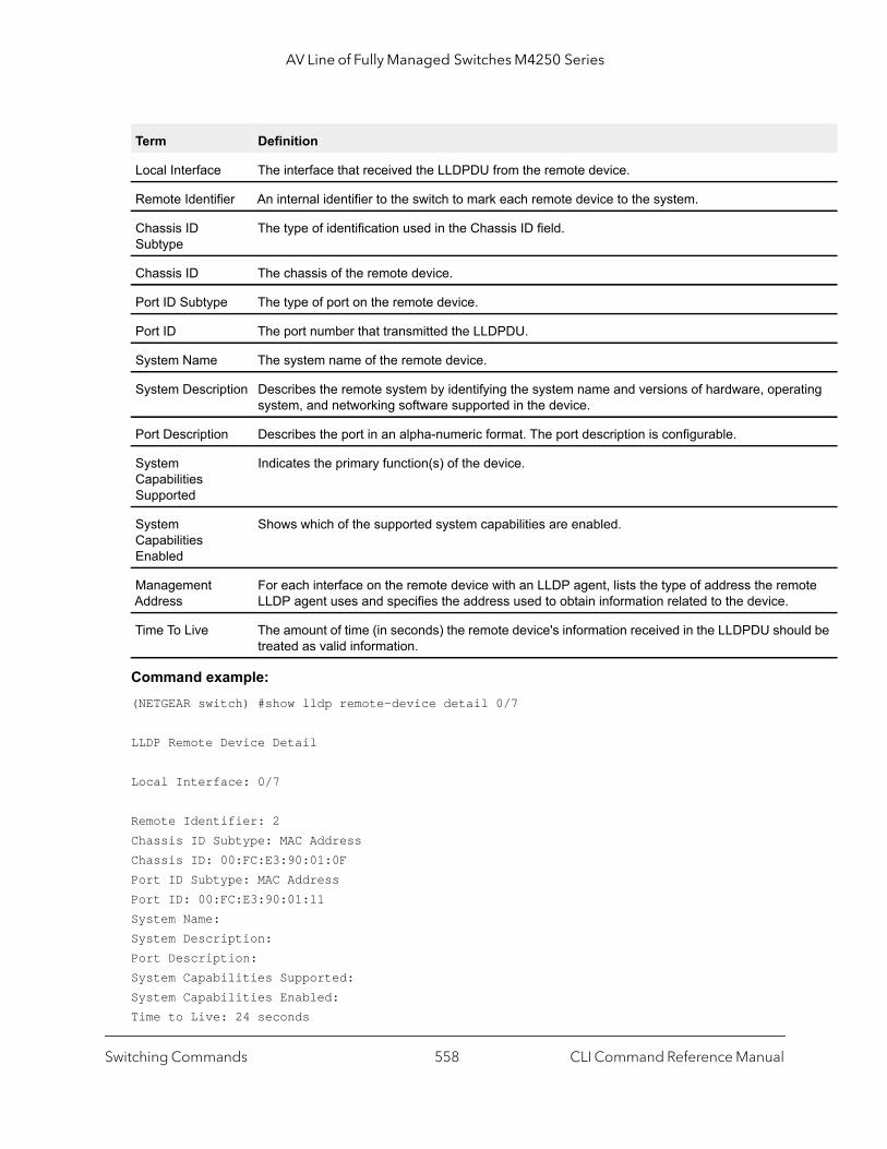
AV Line of Fully Managed Switches M4250 Series
ting
ote
ld be
Command example: (NETGEAR switch) #show lldp remote-device detail 0/7
LLDP Remote Device Detail
Local Interface: 0/7
Remote Identifier: 2Chassis ID Subtype: MAC AddressChassis ID: 00:FC:E3:90:01:0FPort ID Subtype: MAC AddressPort ID: 00:FC:E3:90:01:11System Name:System Description:Port Description:System Capabilities Supported:System Capabilities Enabled:Time to Live: 24 seconds
Term Definition
Local Interface The interface that received the LLDPDU from the remote device.
Remote Identifier An internal identifier to the switch to mark each remote device to the system.
Chassis ID Subtype
The type of identification used in the Chassis ID field.
Chassis ID The chassis of the remote device.
Port ID Subtype The type of port on the remote device.
Port ID The port number that transmitted the LLDPDU.
System Name The system name of the remote device.
System Description Describes the remote system by identifying the system name and versions of hardware, operasystem, and networking software supported in the device.
Port Description Describes the port in an alpha-numeric format. The port description is configurable.
System Capabilities Supported
Indicates the primary function(s) of the device.
System Capabilities Enabled
Shows which of the supported system capabilities are enabled.
Management Address
For each interface on the remote device with an LLDP agent, lists the type of address the remLLDP agent uses and specifies the address used to obtain information related to the device.
Time To Live The amount of time (in seconds) the remote device's information received in the LLDPDU shoutreated as valid information.
Switching Commands CLI Command Reference Manual558
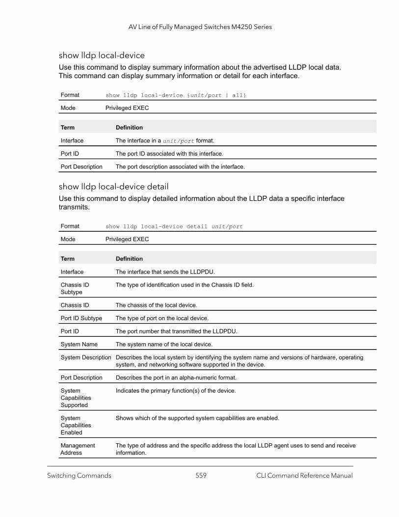
AV Line of Fully Managed Switches M4250 Series
g
show lldp local-deviceUse this command to display summary information about the advertised LLDP local data. This command can display summary information or detail for each interface.
show lldp local-device detailUse this command to display detailed information about the LLDP data a specific interface transmits.
Format show lldp local-device {unit/port | all}
Mode Privileged EXEC
Term Definition
Interface The interface in a unit/port format.
Port ID The port ID associated with this interface.
Port Description The port description associated with the interface.
Format show lldp local-device detail unit/port
Mode Privileged EXEC
Term Definition
Interface The interface that sends the LLDPDU.
Chassis ID Subtype
The type of identification used in the Chassis ID field.
Chassis ID The chassis of the local device.
Port ID Subtype The type of port on the local device.
Port ID The port number that transmitted the LLDPDU.
System Name The system name of the local device.
System Description Describes the local system by identifying the system name and versions of hardware, operatinsystem, and networking software supported in the device.
Port Description Describes the port in an alpha-numeric format.
System Capabilities Supported
Indicates the primary function(s) of the device.
System Capabilities Enabled
Shows which of the supported system capabilities are enabled.
Management Address
The type of address and the specific address the local LLDP agent uses to send and receive information.
Switching Commands CLI Command Reference Manual559
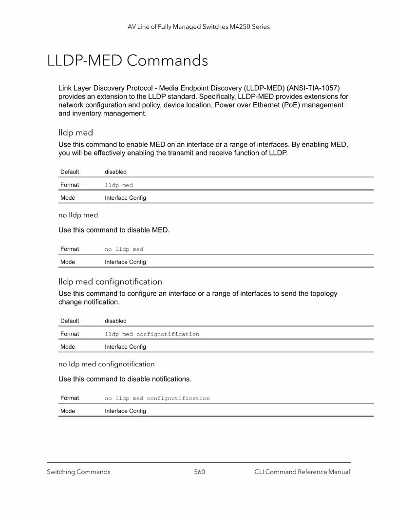
AV Line of Fully Managed Switches M4250 Series
LLDP-MED Commands
Link Layer Discovery Protocol - Media Endpoint Discovery (LLDP-MED) (ANSI-TIA-1057) provides an extension to the LLDP standard. Specifically, LLDP-MED provides extensions for network configuration and policy, device location, Power over Ethernet (PoE) management and inventory management.
lldp medUse this command to enable MED on an interface or a range of interfaces. By enabling MED, you will be effectively enabling the transmit and receive function of LLDP.
no lldp med
Use this command to disable MED.
lldp med confignotification Use this command to configure an interface or a range of interfaces to send the topology change notification.
no ldp med confignotification
Use this command to disable notifications.
Default disabled
Format lldp med
Mode Interface Config
Format no lldp med
Mode Interface Config
Default disabled
Format lldp med confignotification
Mode Interface Config
Format no lldp med confignotification
Mode Interface Config
Switching Commands CLI Command Reference Manual560
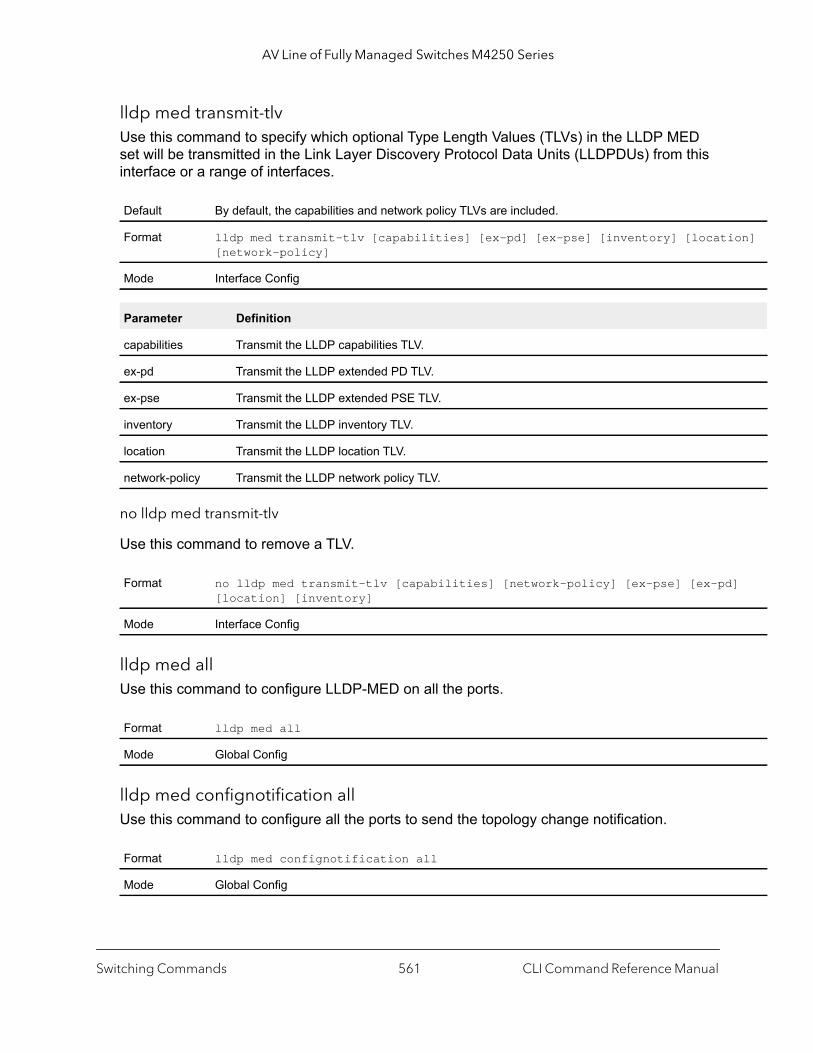
AV Line of Fully Managed Switches M4250 Series
on]
]
lldp med transmit-tlvUse this command to specify which optional Type Length Values (TLVs) in the LLDP MED set will be transmitted in the Link Layer Discovery Protocol Data Units (LLDPDUs) from this interface or a range of interfaces.
no lldp med transmit-tlv
Use this command to remove a TLV.
lldp med allUse this command to configure LLDP-MED on all the ports.
lldp med confignotification allUse this command to configure all the ports to send the topology change notification.
Default By default, the capabilities and network policy TLVs are included.
Format lldp med transmit-tlv [capabilities] [ex-pd] [ex-pse] [inventory] [locati[network-policy]
Mode Interface Config
Parameter Definition
capabilities Transmit the LLDP capabilities TLV.
ex-pd Transmit the LLDP extended PD TLV.
ex-pse Transmit the LLDP extended PSE TLV.
inventory Transmit the LLDP inventory TLV.
location Transmit the LLDP location TLV.
network-policy Transmit the LLDP network policy TLV.
Format no lldp med transmit-tlv [capabilities] [network-policy] [ex-pse] [ex-pd[location] [inventory]
Mode Interface Config
Format lldp med all
Mode Global Config
Format lldp med confignotification all
Mode Global Config
Switching Commands CLI Command Reference Manual561

AV Line of Fully Managed Switches M4250 Series
]
lldp med faststartrepeatcountUse this command to set the value of the fast start repeat count. count is the number of LLDP PDUs that are transmitted when the product is enabled. The range is 1 to 10.
no lldp med faststartrepeatcount
Use this command to return to the factory default value.
lldp med transmit-tlv allUse this command to specify which optional Type Length Values (TLVs) in the LLDP MED set will be transmitted in the Link Layer Discovery Protocol Data Units (LLDPDUs).
no lldp med transmit-tlv
Use this command to remove a TLV.
Default 3
Format lldp med faststartrepeatcount [count]
Mode Global Config
Format no lldp med faststartrepeatcount
Mode Global Config
Default By default, the capabilities and network policy TLVs are included.
Format lldp med transmit-tlv all [capabilities] [ex-pd] [ex-pse] [inventory] [location] [network-policy]
Mode Global Config
Term Definition
capabilities Transmit the LLDP capabilities TLV.
ex-pd Transmit the LLDP extended PD TLV.
ex-pse Transmit the LLDP extended PSE TLV.
inventory Transmit the LLDP inventory TLV.
location Transmit the LLDP location TLV.
network-policy Transmit the LLDP network policy TLV.
Format no lldp med transmit-tlv [capabilities] [network-policy] [ex-pse] [ex-pd[location] [inventory]
Mode Global Config
Switching Commands CLI Command Reference Manual562
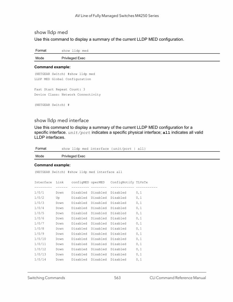
AV Line of Fully Managed Switches M4250 Series
show lldp medUse this command to display a summary of the current LLDP MED configuration.
Command example: (NETGEAR Switch) #show lldp medLLDP MED Global Configuration
Fast Start Repeat Count: 3Device Class: Network Connectivity
(NETGEAR Switch) #
show lldp med interfaceUse this command to display a summary of the current LLDP MED configuration for a specific interface. unit/port indicates a specific physical interface; all indicates all valid LLDP interfaces.
Command example: (NETGEAR Switch) #show lldp med interface all
Interface Link configMED operMED ConfigNotify TLVsTx--------- ------ --------- -------- ------------ -----------1/0/1 Down Disabled Disabled Disabled 0,11/0/2 Up Disabled Disabled Disabled 0,11/0/3 Down Disabled Disabled Disabled 0,11/0/4 Down Disabled Disabled Disabled 0,11/0/5 Down Disabled Disabled Disabled 0,11/0/6 Down Disabled Disabled Disabled 0,11/0/7 Down Disabled Disabled Disabled 0,11/0/8 Down Disabled Disabled Disabled 0,11/0/9 Down Disabled Disabled Disabled 0,11/0/10 Down Disabled Disabled Disabled 0,11/0/11 Down Disabled Disabled Disabled 0,11/0/12 Down Disabled Disabled Disabled 0,11/0/13 Down Disabled Disabled Disabled 0,11/0/14 Down Disabled Disabled Disabled 0,1
Format show lldp med
Mode Privileged Exec
Format show lldp med interface {unit/port | all}
Mode Privileged Exec
Switching Commands CLI Command Reference Manual563
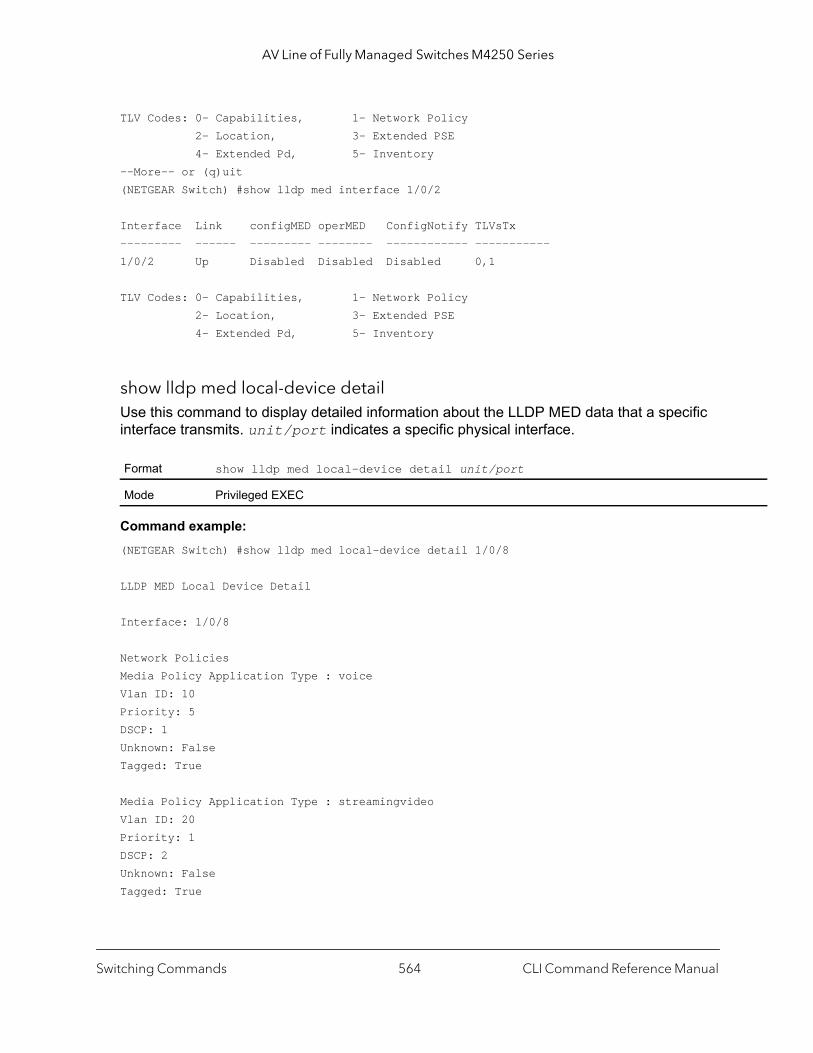
AV Line of Fully Managed Switches M4250 Series
TLV Codes: 0- Capabilities, 1- Network Policy 2- Location, 3- Extended PSE 4- Extended Pd, 5- Inventory--More-- or (q)uit(NETGEAR Switch) #show lldp med interface 1/0/2
Interface Link configMED operMED ConfigNotify TLVsTx--------- ------ --------- -------- ------------ -----------1/0/2 Up Disabled Disabled Disabled 0,1
TLV Codes: 0- Capabilities, 1- Network Policy 2- Location, 3- Extended PSE 4- Extended Pd, 5- Inventory
show lldp med local-device detailUse this command to display detailed information about the LLDP MED data that a specific interface transmits. unit/port indicates a specific physical interface.
Command example: (NETGEAR Switch) #show lldp med local-device detail 1/0/8
LLDP MED Local Device Detail
Interface: 1/0/8
Network PoliciesMedia Policy Application Type : voiceVlan ID: 10Priority: 5DSCP: 1Unknown: FalseTagged: True
Media Policy Application Type : streamingvideoVlan ID: 20Priority: 1DSCP: 2Unknown: FalseTagged: True
Format show lldp med local-device detail unit/port
Mode Privileged EXEC
Switching Commands CLI Command Reference Manual564

AV Line of Fully Managed Switches M4250 Series
InventoryHardware Rev: xxx xxx xxxFirmware Rev: xxx xxx xxxSoftware Rev: xxx xxx xxxSerial Num: xxx xxx xxxMfg Name: xxx xxx xxx Model Name: xxx xxx xxxAsset ID: xxx xxx xxx
LocationSubtype: elinInfo: xxx xxx xxx
Extended POEDevice Type: pseDevice
Extended POE PSEAvailable: 0.3 WattsSource: primaryPriority: critical
Extended POE PD
Required: 0.2 WattsSource: localPriority: low
show lldp med remote-deviceUse this command to display the summary information about remote devices that transmit current LLDP MED data to the system. You can show information about LLDP MED remote data received on all valid LLDP interfaces or on a specific physical interface.
Format show lldp med remote-device {unit/port | all}
Mode Privileged EXEC
Term Definition
Local Interface The interface that received the LLDPDU from the remote device.
Remote ID An internal identifier to the switch to mark each remote device to the system.
Device Class Device classification of the remote device.
Switching Commands CLI Command Reference Manual565
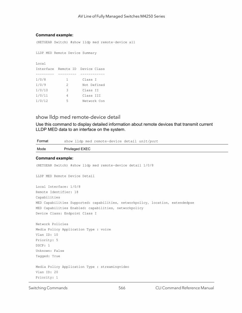
AV Line of Fully Managed Switches M4250 Series
Command example: (NETGEAR Switch) #show lldp med remote-device all
LLDP MED Remote Device Summary
Local Interface Remote ID Device Class --------- --------- ------------ 1/0/8 1 Class I 1/0/9 2 Not Defined 1/0/10 3 Class II1/0/11 4 Class III1/0/12 5 Network Con
show lldp med remote-device detailUse this command to display detailed information about remote devices that transmit current LLDP MED data to an interface on the system.
Command example: (NETGEAR Switch) #show lldp med remote-device detail 1/0/8
LLDP MED Remote Device Detail
Local Interface: 1/0/8Remote Identifier: 18CapabilitiesMED Capabilities Supported: capabilities, networkpolicy, location, extendedpseMED Capabilities Enabled: capabilities, networkpolicyDevice Class: Endpoint Class I
Network PoliciesMedia Policy Application Type : voiceVlan ID: 10Priority: 5DSCP: 1Unknown: FalseTagged: True
Media Policy Application Type : streamingvideoVlan ID: 20Priority: 1
Format show lldp med remote-device detail unit/port
Mode Privileged EXEC
Switching Commands CLI Command Reference Manual566
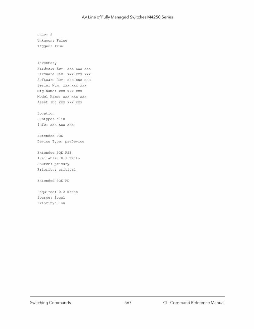
AV Line of Fully Managed Switches M4250 Series
DSCP: 2Unknown: FalseTagged: True
InventoryHardware Rev: xxx xxx xxxFirmware Rev: xxx xxx xxxSoftware Rev: xxx xxx xxxSerial Num: xxx xxx xxxMfg Name: xxx xxx xxx Model Name: xxx xxx xxxAsset ID: xxx xxx xxx
LocationSubtype: elinInfo: xxx xxx xxx
Extended POEDevice Type: pseDevice
Extended POE PSEAvailable: 0.3 WattsSource: primaryPriority: critical
Extended POE PD
Required: 0.2 WattsSource: localPriority: low
Switching Commands CLI Command Reference Manual567
AV Line of Fully Managed Switches M4250 Series
Denial of Service Commands
This section describes the commands you use to configure Denial of Service (DoS) Control. The switch provides support for classifying and blocking specific types of Denial of Service attacks. You can configure your system to monitor and block these types of attacks:
• SIP = DIP. Source IP address = Destination IP address.• First Fragment. TCP Header size smaller then configured value.• TCP Fragment. Allows the device to drop packets that have a TCP payload where the IP
payload length minus the IP header size is less than the minimum allowed TCP header size.
• TCP Flag. TCP Flag SYN set and Source Port < 1024 or TCP Control Flags = 0 and TCP Sequence Number = 0 or TCP Flags FIN, URG, and PSH set and TCP Sequence Number = 0 or TCP Flags SYN and FIN set.
• L4 Port. Source TCP/UDP Port = Destination TCP/UDP Port.• ICMP. Limiting the size of ICMP Ping packets.• SMAC = DMAC. Source MAC address = Destination MAC address.• TCP Port. Source TCP Port = Destination TCP Port.• UDP Port. Source UDP Port = Destination UDP Port.• TCP Flag & Sequence. TCP Flag SYN set and Source Port < 1024 or TCP Control Flags
= 0 and TCP Sequence Number = 0 or TCP Flags FIN, URG, and PSH set and TCP Sequence Number = 0 or TCP Flags SYN and FIN set.
• TCP Offset. Allows the device to drop packets that have a TCP header Offset set to 1.• TCP SYN. TCP Flag SYN set.• TCP SYN & FIN. TCP Flags SYN and FIN set.• TCP FIN & URG & PSH. TCP Flags FIN and URG and PSH set and TCP Sequence
Number = 0.• ICMP V6. Limiting the size of ICMPv6 Ping packets.• ICMP Fragment. Checks for fragmented ICMP packets.
dos-control allThis command enables Denial of Service protection checks globally.
Default disabled
Format dos-control all
Mode Global Config
Switching Commands CLI Command Reference Manual568

AV Line of Fully Managed Switches M4250 Series
no dos-control all
This command disables Denial of Service prevention checks globally.
dos-control sipdipThis command enables Source IP address = Destination IP address (SIP = DIP) Denial of Service protection. If the mode is enabled, Denial of Service prevention is active for this type of attack. If packets ingress with SIP = DIP, the packets will be dropped if the mode is enabled.
no dos-control sipdip
This command disables Source IP address = Destination IP address (SIP = DIP) Denial of Service prevention.
dos-control firstfragThis command enables Minimum TCP Header Size Denial of Service protection. If the mode is enabled, Denial of Service prevention is active for this type of attack. If packets ingress having a TCP Header Size smaller then the configured value, the packets will be dropped if the mode is enabled. The default is disabled. The range is 0–255. If you enable dos-control firstfrag, but do not provide a Minimum TCP Header Size, the system sets that value to 20.
Format no dos-control all
Mode Global Config
Default disabled
Format dos-control sipdip
Mode Global Config
Format no dos-control sipdip
Mode Global Config
Default disabled (20)
Format dos-control firstfrag [size]
Mode Global Config
Switching Commands CLI Command Reference Manual569
AV Line of Fully Managed Switches M4250 Series
no dos-control firstfrag
This command sets Minimum TCP Header Size Denial of Service protection to the default value of disabled.
dos-control tcpfragThis command enables TCP Fragment Denial of Service protection. If the mode is enabled, Denial of Service prevention is active for this type of attack and packets that have a TCP payload in which the IP payload length minus the IP header size is less than the minimum allowed TCP header size are dropped.
no dos-control tcpfrag
This command disables TCP Fragment Denial of Service protection.
dos-control tcpflagThis command enables TCP Flag Denial of Service protections. If the mode is enabled, Denial of Service prevention is active for this type of attacks. If packets ingress having TCP Flag SYN set and a source port less than 1024 or having TCP Control Flags set to 0 and TCP Sequence Number set to 0 or having TCP Flags FIN, URG, and PSH set and TCP Sequence Number set to 0 or having TCP Flags SYN and FIN both set, the packets will be dropped if the mode is enabled.
Format no dos-control firstfrag
Mode Global Config
Default disabled
Format dos-control tcpfrag
Mode Global Config
Format no dos-control tcpfrag
Mode Global Config
Default disabled
Format dos-control tcpflag
Mode Global Config
Switching Commands CLI Command Reference Manual570
AV Line of Fully Managed Switches M4250 Series
no dos-control tcpflag
This command sets disables TCP Flag Denial of Service protections.
dos-control l4portThis command enables L4 Port Denial of Service protections. If the mode is enabled, Denial of Service prevention is active for this type of attack. If packets ingress having Source TCP/UDP Port Number equal to Destination TCP/UDP Port Number, the packets will be dropped if the mode is enabled.
Note: Some applications mirror source and destination L4 ports - RIP for example uses 520 for both. If you enable dos-control l4port, applications such as RIP may experience packet loss which would render the application inoperable.
no dos-control l4port
This command disables L4 Port Denial of Service protections.
dos-control smacdmacThis command enables Source MAC address = Destination MAC address (SMAC = DMAC) Denial of Service protection. If the mode is enabled, Denial of Service prevention is active for this type of attack. If packets ingress with SMAC = DMAC, the packets will be dropped if the mode is enabled.
Format no dos-control tcpflag
Mode Global Config
Default Disabled
Format dos-control l4port
Mode Global Config
Format no dos-control l4port
Mode Global Config
Default disabled
Format dos-control smacdmac
Mode Global Config
Switching Commands CLI Command Reference Manual571
AV Line of Fully Managed Switches M4250 Series
no dos-control smacdmac
This command disables Source MAC address = Destination MAC address (SMAC = DMAC) DoS protection.
dos-control tcpportThis command enables TCP L4 source = destination port number (Source TCP Port = Destination TCP Port) Denial of Service protection. If the mode is enabled, Denial of Service prevention is active for this type of attack. If packets ingress with Source TCP Port = Destination TCP Port, the packets will be dropped if the mode is enabled.
no dos-control tcpport
This command disables TCP L4 source = destination port number (Source TCP Port = Destination TCP Port) Denial of Service protection.
dos-control udpportThis command enables UDP L4 source = destination port number (Source UDP Port = Destination UDP Port) DoS protection. If the mode is enabled, Denial of Service prevention is active for this type of attack. If packets ingress with Source UDP Port = Destination UDP Port, the packets will be dropped if the mode is enabled.
Format no dos-control smacdmac
Mode Global Config
Default Disabled
Format dos-control tcpport
Mode Global Config
Format no dos-control tcpport
Mode Global Config
Default Disabled
Format dos-control udpport
Mode Global Config
Switching Commands CLI Command Reference Manual572
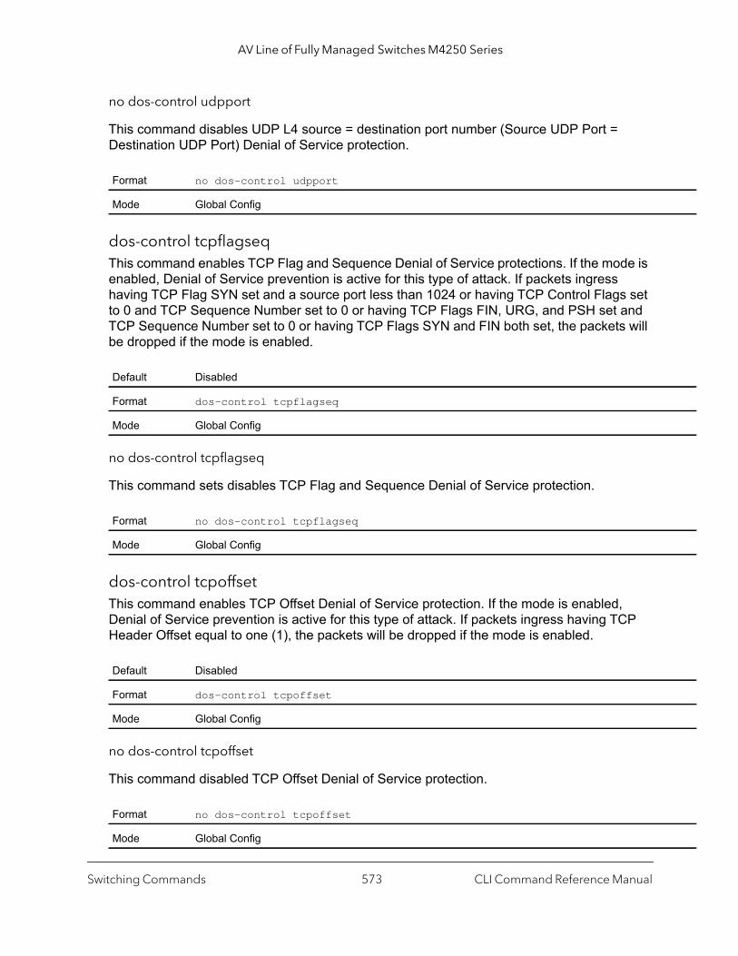
AV Line of Fully Managed Switches M4250 Series
no dos-control udpport
This command disables UDP L4 source = destination port number (Source UDP Port = Destination UDP Port) Denial of Service protection.
dos-control tcpflagseqThis command enables TCP Flag and Sequence Denial of Service protections. If the mode is enabled, Denial of Service prevention is active for this type of attack. If packets ingress having TCP Flag SYN set and a source port less than 1024 or having TCP Control Flags set to 0 and TCP Sequence Number set to 0 or having TCP Flags FIN, URG, and PSH set and TCP Sequence Number set to 0 or having TCP Flags SYN and FIN both set, the packets will be dropped if the mode is enabled.
no dos-control tcpflagseq
This command sets disables TCP Flag and Sequence Denial of Service protection.
dos-control tcpoffsetThis command enables TCP Offset Denial of Service protection. If the mode is enabled, Denial of Service prevention is active for this type of attack. If packets ingress having TCP Header Offset equal to one (1), the packets will be dropped if the mode is enabled.
no dos-control tcpoffset
This command disabled TCP Offset Denial of Service protection.
Format no dos-control udpport
Mode Global Config
Default Disabled
Format dos-control tcpflagseq
Mode Global Config
Format no dos-control tcpflagseq
Mode Global Config
Default Disabled
Format dos-control tcpoffset
Mode Global Config
Format no dos-control tcpoffset
Mode Global Config
Switching Commands CLI Command Reference Manual573
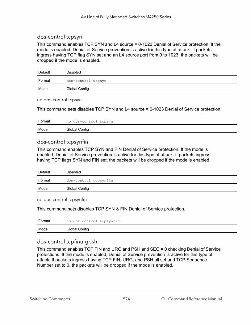
AV Line of Fully Managed Switches M4250 Series
dos-control tcpsynThis command enables TCP SYN and L4 source = 0-1023 Denial of Service protection. If the mode is enabled, Denial of Service prevention is active for this type of attack. If packets ingress having TCP flag SYN set and an L4 source port from 0 to 1023, the packets will be dropped if the mode is enabled.
no dos-control tcpsyn
This command sets disables TCP SYN and L4 source = 0-1023 Denial of Service protection.
dos-control tcpsynfinThis command enables TCP SYN and FIN Denial of Service protection. If the mode is enabled, Denial of Service prevention is active for this type of attack. If packets ingress having TCP flags SYN and FIN set, the packets will be dropped if the mode is enabled.
no dos-control tcpsynfin
This command sets disables TCP SYN & FIN Denial of Service protection.
dos-control tcpfinurgpshThis command enables TCP FIN and URG and PSH and SEQ = 0 checking Denial of Service protections. If the mode is enabled, Denial of Service prevention is active for this type of attack. If packets ingress having TCP FIN, URG, and PSH all set and TCP Sequence Number set to 0, the packets will be dropped if the mode is enabled.
Default Disabled
Format dos-control tcpsyn
Mode Global Config
Format no dos-control tcpsyn
Mode Global Config
Default Disabled
Format dos-control tcpsynfin
Mode Global Config
Format no dos-control tcpsynfin
Mode Global Config
Switching Commands CLI Command Reference Manual574
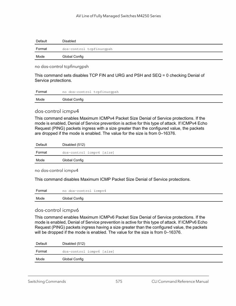
AV Line of Fully Managed Switches M4250 Series
no dos-control tcpfinurgpsh
This command sets disables TCP FIN and URG and PSH and SEQ = 0 checking Denial of Service protections.
dos-control icmpv4This command enables Maximum ICMPv4 Packet Size Denial of Service protections. If the mode is enabled, Denial of Service prevention is active for this type of attack. If ICMPv4 Echo Request (PING) packets ingress with a size greater than the configured value, the packets are dropped if the mode is enabled. The value for the size is from 0–16376.
no dos-control icmpv4
This command disables Maximum ICMP Packet Size Denial of Service protections.
dos-control icmpv6This command enables Maximum ICMPv6 Packet Size Denial of Service protections. If the mode is enabled, Denial of Service prevention is active for this type of attack. If ICMPv6 Echo Request (PING) packets ingress having a size greater than the configured value, the packets will be dropped if the mode is enabled. The value for the size is from 0–16376.
Default Disabled
Format dos-control tcpfinurgpsh
Mode Global Config
Format no dos-control tcpfinurgpsh
Mode Global Config
Default Disabled (512)
Format dos-control icmpv4 [size]
Mode Global Config
Format no dos-control icmpv4
Mode Global Config
Default Disabled (512)
Format dos-control icmpv6 [size]
Mode Global Config
Switching Commands CLI Command Reference Manual575

AV Line of Fully Managed Switches M4250 Series
s the dr
is
witch n the
d.
no dos-control icmpv6
This command disables Maximum ICMP Packet Size Denial of Service protections.
dos-control icmpfragThis command enables ICMP Fragment Denial of Service protection. If the mode is enabled, Denial of Service prevention is active for this type of attack. If packets ingress having fragmented ICMP packets, the packets will be dropped if the mode is enabled.
no dos-control icmpfrag
This command disabled ICMP Fragment Denial of Service protection.
show dos-controlThis command displays Denial of Service configuration information.
Format no dos-control icmpv6
Mode Global Config
Default disabled
Format dos-control icmpfrag
Mode Global Config
Format no dos-control icmpfrag
Mode Global Config
Format show dos-control
Mode Privileged EXEC
Term Definition
First Fragment Mode The administrative mode of First Fragment DoS prevention. When enabled, this causeswitch to drop packets that have a TCP header smaller then the configured Min TCP HSize.
Min TCP Hdr Size The minimum TCP header size the switch will accept if First Fragment DoS preventionenabled.
ICMPv4 Mode The administrative mode of ICMPv4 DoS prevention. When enabled, this causes the sto drop ICMP packets that have a type set to ECHO_REQ (ping) and a size greater thaconfigured ICMPv4 Payload Size.
Max ICMPv4 Payload Size The maximum ICMPv4 payload size to accept when ICMPv4 DoS protection is enable
Switching Commands CLI Command Reference Manual576

AV Line of Fully Managed Switches M4250 Series
witch n the
d.
uses
rt.
rt.
to ctory
witch ss.
uses ence
h to .
h to
witch
ch to
auto-dosThis command enables Auto-DoS on the switch. By default, Auto-Dos is disabled.
When you enable Auto-DoS, all denial of service (DoS) checks are activated. If the switch detects a DoS attack, the offending packets are copied to the CPU and Auto-DoS shuts down the port and moves the port to the diagnostically disabled state. To use the port again, you must manually reenable the port.
ICMPv6 Mode The administrative mode of ICMPv6 DoS prevention. When enabled, this causes the sto drop ICMP packets that have a type set to ECHO_REQ (ping) and a size greater thaconfigured ICMPv6 Payload Size.
Max ICMPv6 Payload Size The maximum ICMPv6 payload size to accept when ICMPv6 DoS protection is enable
ICMPv4 Fragment Mode The administrative mode of ICMPv4 Fragment DoS prevention. When enabled, this cathe switch to drop fragmented ICMPv4 packets.
TCP Port Mode The administrative mode of TCP Port DoS prevention. When enabled, this causes theswitch to drop packets that have the TCP source port equal to the TCP destination po
UDP Port Mode The administrative mode of UDP Port DoS prevention. When enabled, this causes theswitch to drop packets that have the UDP source port equal to the UDP destination po
SIPDIP Mode The administrative mode of SIP=DIP DoS prevention. Enabling this causes the switchdrop packets that have a source IP address equal to the destination IP address. The fadefault is disabled.
SMACDMAC Mode The administrative mode of SMAC=DMAC DoS prevention. Enabling this causes the sto drop packets that have a source MAC address equal to the destination MAC addre
TCP FIN&URG& PSH Mode
The administrative mode of TCP FIN & URG & PSH DoS prevention. Enabling this cathe switch to drop packets that have TCP flags FIN, URG, and PSH set and TCP SequNumber = 0.
TCP Flag & Sequence Mode
The administrative mode of TCP Flag DoS prevention. Enabling this causes the switcdrop packets that have TCP control flags set to 0 and TCP sequence number set to 0
TCP SYN Mode The administrative mode of TCP SYN DoS prevention. Enabling this causes the switcdrop packets that have TCP Flags SYN set.
TCP SYN & FIN Mode The administrative mode of TCP SYN & FIN DoS prevention. Enabling this causes theswitch to drop packets that have TCP Flags SYN and FIN set.
TCP Fragment Mode The administrative mode of TCP Fragment DoS prevention. Enabling this causes the sto drop packets that have a TCP payload in which the IP payload length minus the IP header size is less than the minimum allowed TCP header size.
TCP Offset Mode The administrative mode of TCP Offset DoS prevention. Enabling this causes the switdrop packets that have a TCP header Offset equal to 1.
Format auto-dos
Mode Global Config
Term Definition
Switching Commands CLI Command Reference Manual577
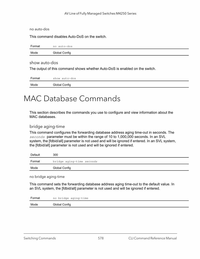
AV Line of Fully Managed Switches M4250 Series
no auto-dos
This command disables Auto-DoS on the switch.
show auto-dosThe output of this command shows whether Auto-DoS is enabled on the switch.
MAC Database Commands
This section describes the commands you use to configure and view information about the MAC databases.
bridge aging-timeThis command configures the forwarding database address aging time-out in seconds. The seconds parameter must be within the range of 10 to 1,000,000 seconds. In an SVL system, the [fdbid/all] parameter is not used and will be ignored if entered. In an SVL system, the [fdbid/all] parameter is not used and will be ignored if entered.
no bridge aging-time
This command sets the forwarding database address aging time-out to the default value. In an SVL system, the [fdbid/all] parameter is not used and will be ignored if entered.
Format no auto-dos
Mode Global Config
Format show auto-dos
Mode Global Config
Default 300
Format bridge aging-time seconds
Mode Global Config
Format no bridge aging-time
Mode Global Config
Switching Commands CLI Command Reference Manual578
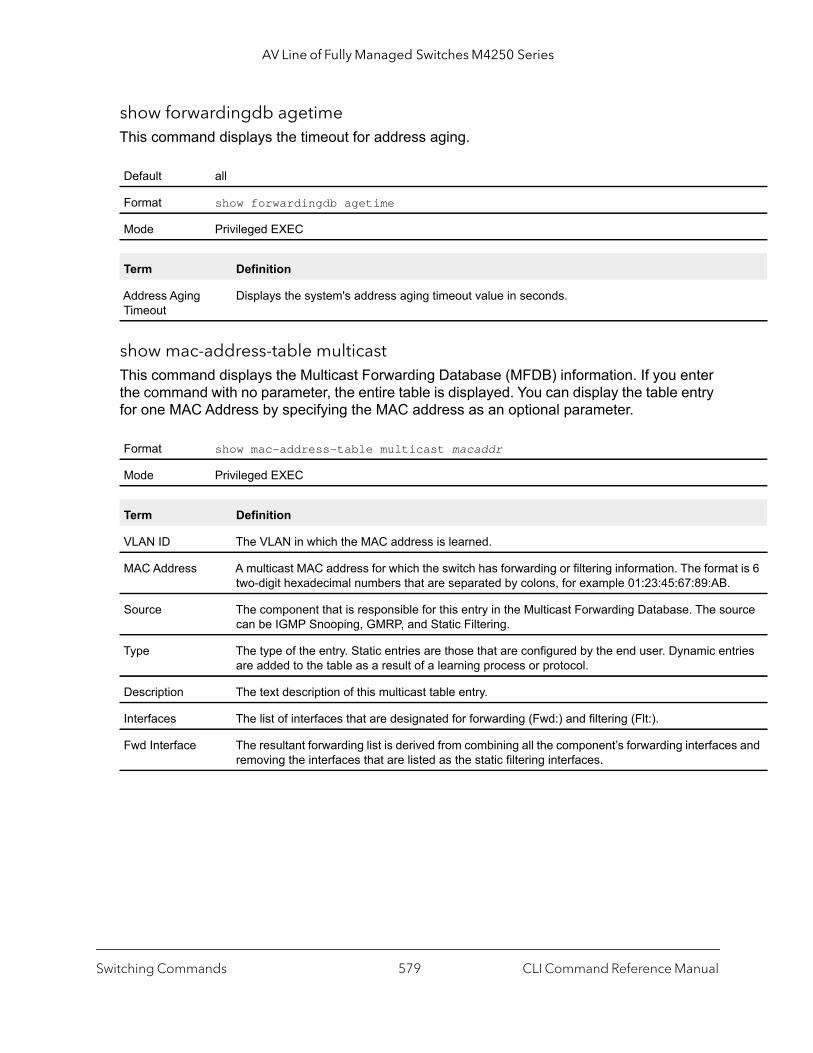
AV Line of Fully Managed Switches M4250 Series
t is 6
urce
tries
s and
show forwardingdb agetime This command displays the timeout for address aging.
show mac-address-table multicastThis command displays the Multicast Forwarding Database (MFDB) information. If you enter the command with no parameter, the entire table is displayed. You can display the table entry for one MAC Address by specifying the MAC address as an optional parameter.
Default all
Format show forwardingdb agetime
Mode Privileged EXEC
Term Definition
Address Aging Timeout
Displays the system's address aging timeout value in seconds.
Format show mac-address-table multicast macaddr
Mode Privileged EXEC
Term Definition
VLAN ID The VLAN in which the MAC address is learned.
MAC Address A multicast MAC address for which the switch has forwarding or filtering information. The formatwo-digit hexadecimal numbers that are separated by colons, for example 01:23:45:67:89:AB.
Source The component that is responsible for this entry in the Multicast Forwarding Database. The socan be IGMP Snooping, GMRP, and Static Filtering.
Type The type of the entry. Static entries are those that are configured by the end user. Dynamic enare added to the table as a result of a learning process or protocol.
Description The text description of this multicast table entry.
Interfaces The list of interfaces that are designated for forwarding (Fwd:) and filtering (Flt:).
Fwd Interface The resultant forwarding list is derived from combining all the component’s forwarding interfaceremoving the interfaces that are listed as the static filtering interfaces.
Switching Commands CLI Command Reference Manual579
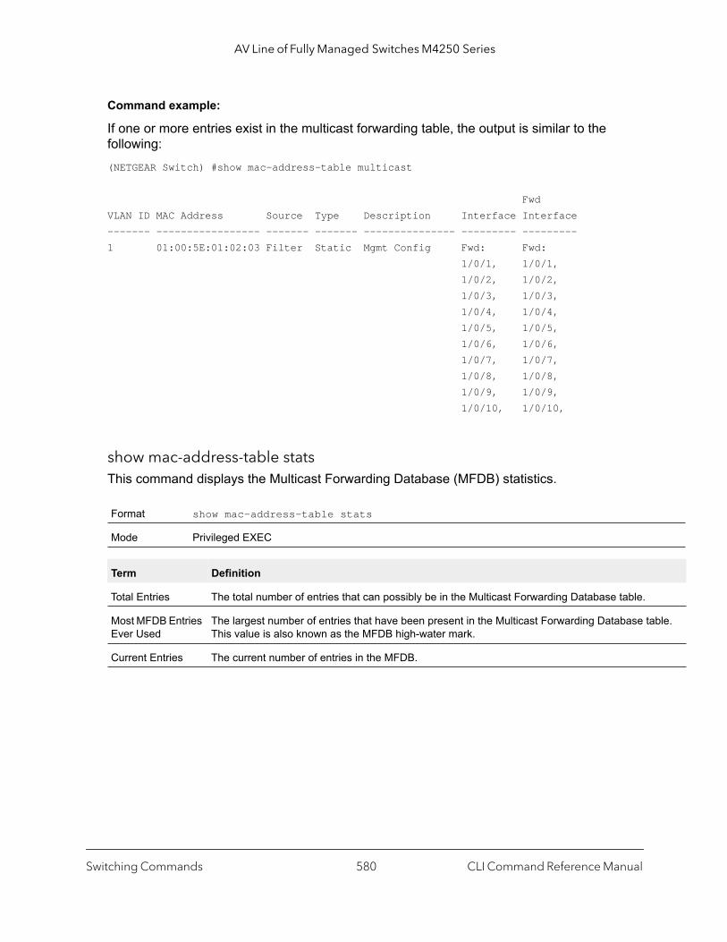
AV Line of Fully Managed Switches M4250 Series
ble.
Command example:
If one or more entries exist in the multicast forwarding table, the output is similar to the following:(NETGEAR Switch) #show mac-address-table multicast
FwdVLAN ID MAC Address Source Type Description Interface Interface------- ----------------- ------- ------- --------------- --------- ---------1 01:00:5E:01:02:03 Filter Static Mgmt Config Fwd: Fwd: 1/0/1, 1/0/1, 1/0/2, 1/0/2, 1/0/3, 1/0/3, 1/0/4, 1/0/4, 1/0/5, 1/0/5, 1/0/6, 1/0/6, 1/0/7, 1/0/7, 1/0/8, 1/0/8, 1/0/9, 1/0/9, 1/0/10, 1/0/10,
show mac-address-table statsThis command displays the Multicast Forwarding Database (MFDB) statistics.
Format show mac-address-table stats
Mode Privileged EXEC
Term Definition
Total Entries The total number of entries that can possibly be in the Multicast Forwarding Database table.
Most MFDB Entries Ever Used
The largest number of entries that have been present in the Multicast Forwarding Database taThis value is also known as the MFDB high-water mark.
Current Entries The current number of entries in the MFDB.
Switching Commands CLI Command Reference Manual580

AV Line of Fully Managed Switches M4250 Series
ISDP Commands
This section describes the commands you use to configure the industry standard Discovery Protocol (ISDP).
isdp runThis command enables ISDP on the switch.
no isdp run
This command disables ISDP on the switch.
isdp holdtimeThis command configures the hold time for ISDP packets that the switch transmits. The hold time specifies how long a receiving device should store information sent in the ISDP packet before discarding it. The period is in the range 10–255 seconds.
isdp timerThis command sets the period of time between sending new ISDP packets. The period is in the range 5–254 seconds.
Default Enabled
Format isdp run
Mode Global Config
Format no isdp run
Mode Global Config
Default 180 seconds
Format isdp holdtime seconds
Mode Global Config
Default 60 seconds
Format isdp timer seconds
Mode Global Config
Switching Commands CLI Command Reference Manual581
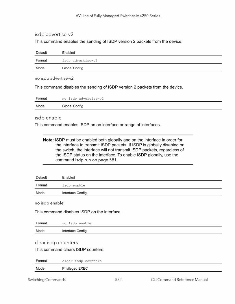
AV Line of Fully Managed Switches M4250 Series
isdp advertise-v2This command enables the sending of ISDP version 2 packets from the device.
no isdp advertise-v2
This command disables the sending of ISDP version 2 packets from the device.
isdp enableThis command enables ISDP on an interface or range of interfaces.
Note: ISDP must be enabled both globally and on the interface in order for the interface to transmit ISDP packets. If ISDP is globally disabled on the switch, the interface will not transmit ISDP packets, regardless of the ISDP status on the interface. To enable ISDP globally, use the command isdp run on page 581.
no isdp enable
This command disables ISDP on the interface.
clear isdp countersThis command clears ISDP counters.
Default Enabled
Format isdp advertise-v2
Mode Global Config
Format no isdp advertise-v2
Mode Global Config
Default Enabled
Format isdp enable
Mode Interface Config
Format no isdp enable
Mode Interface Config
Format clear isdp counters
Mode Privileged EXEC
Switching Commands CLI Command Reference Manual582

AV Line of Fully Managed Switches M4250 Series
is
lue of
ce ID.evice
ce ID.
evice
g info
clear isdp tableThis command clears entries in the ISDP table.
show isdpThis command displays global ISDP settings.
Command example: (NETGEAR Switch) #show isdp
Timer.......................................... 30Hold Time...................................... 180Version 2 Advertisements....................... Enabled
Format clear isdp table
Mode Privileged EXEC
Format show isdp
Mode Privileged EXEC
Term Definition
Timer The frequency with which this device sends ISDP packets. This value is given in seconds.
Hold Time The length of time the receiving device should save information sent by this device. This valuegiven in seconds.
Version 2 Advertisements
The setting for sending ISDPv2 packets. If disabled, version 1 packets are transmitted.
Neighbors table time since last change
The amount of time that has passed since the ISPD neighbor table changed.
Device ID The Device ID advertised by this device. The format of this Device ID is characterized by the vathe Device ID Format object.
Device ID Format Capability
Indicates the Device ID format capability of the device.• serialNumber indicates that the device uses a serial number as the format for its Devi• macAddress indicates that the device uses a Layer 2 MAC address as the format for its D
ID.• other indicates that the device uses its platform-specific format as the format for its Devi
Device ID Format Indicates the Device ID format of the device.• serialNumber indicates that the value is in the form of an ASCII string containing the d
serial number.• macAddress indicates that the value is in the form of a Layer 2 MAC address.• other indicates that the value is in the form of a platform specific ASCII string containin
that identifies the device. For example, ASCII string contains serialNumber appended/prepended with system name.
Switching Commands CLI Command Reference Manual583

AV Line of Fully Managed Switches M4250 Series
Neighbors table time since last change......... 0 days 00:00:00Device ID...................................... 1114728Device ID format capability.................... Serial Number, Host NameDevice ID format............................... Serial Number
show isdp interfaceThis command displays ISDP settings for the specified interface.
Command example: (NETGEAR Switch) #show isdp interface 0/1
Interface Mode--------------- ----------0/1 Enabled
Command example: (NETGEAR Switch) #show isdp interface all
Interface Mode --------------- ----------0/1 Enabled 0/2 Enabled 0/3 Enabled 0/4 Enabled 0/5 Enabled 0/6 Enabled 0/7 Enabled 0/8 Enabled
Format show isdp interface {all | unit/port}
Mode Privileged EXEC
Term Definition
Interface The unit/port of the specified interface.
Mode ISDP mode enabled/disabled status for the interface(s).
Switching Commands CLI Command Reference Manual584
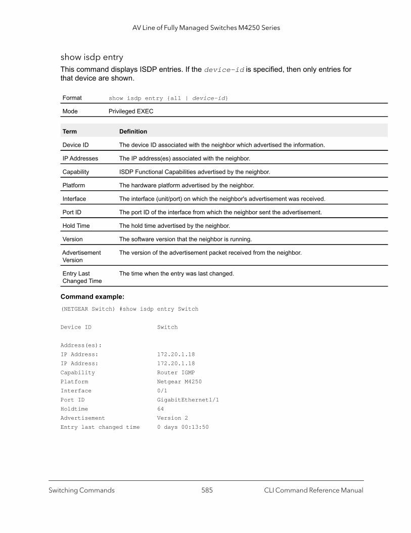
AV Line of Fully Managed Switches M4250 Series
show isdp entryThis command displays ISDP entries. If the device-id is specified, then only entries for that device are shown.
Command example: (NETGEAR Switch) #show isdp entry Switch
Device ID Switch
Address(es):IP Address: 172.20.1.18 IP Address: 172.20.1.18 Capability Router IGMP Platform Netgear M4250Interface 0/1 Port ID GigabitEthernet1/1 Holdtime 64Advertisement Version 2Entry last changed time 0 days 00:13:50
Format show isdp entry {all | device-id}
Mode Privileged EXEC
Term Definition
Device ID The device ID associated with the neighbor which advertised the information.
IP Addresses The IP address(es) associated with the neighbor.
Capability ISDP Functional Capabilities advertised by the neighbor.
Platform The hardware platform advertised by the neighbor.
Interface The interface (unit/port) on which the neighbor's advertisement was received.
Port ID The port ID of the interface from which the neighbor sent the advertisement.
Hold Time The hold time advertised by the neighbor.
Version The software version that the neighbor is running.
Advertisement Version
The version of the advertisement packet received from the neighbor.
Entry Last Changed Time
The time when the entry was last changed.
Switching Commands CLI Command Reference Manual585
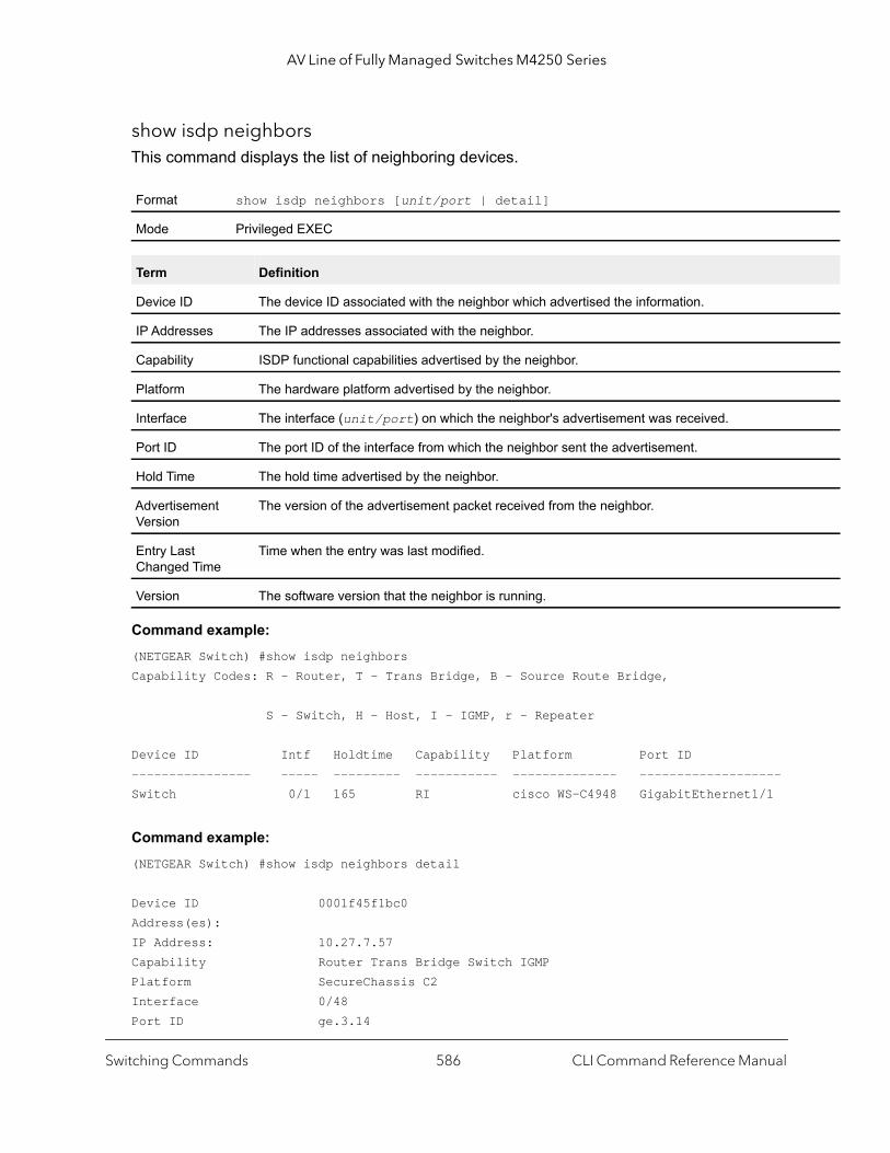
AV Line of Fully Managed Switches M4250 Series
show isdp neighborsThis command displays the list of neighboring devices.
Command example: (NETGEAR Switch) #show isdp neighborsCapability Codes: R - Router, T - Trans Bridge, B - Source Route Bridge,
S - Switch, H - Host, I - IGMP, r - Repeater
Device ID Intf Holdtime Capability Platform Port ID ---------------- ----- --------- ----------- -------------- -------------------Switch 0/1 165 RI cisco WS-C4948 GigabitEthernet1/1
Command example: (NETGEAR Switch) #show isdp neighbors detail
Device ID 0001f45f1bc0Address(es):IP Address: 10.27.7.57Capability Router Trans Bridge Switch IGMPPlatform SecureChassis C2Interface 0/48Port ID ge.3.14
Format show isdp neighbors [unit/port | detail]
Mode Privileged EXEC
Term Definition
Device ID The device ID associated with the neighbor which advertised the information.
IP Addresses The IP addresses associated with the neighbor.
Capability ISDP functional capabilities advertised by the neighbor.
Platform The hardware platform advertised by the neighbor.
Interface The interface (unit/port) on which the neighbor's advertisement was received.
Port ID The port ID of the interface from which the neighbor sent the advertisement.
Hold Time The hold time advertised by the neighbor.
Advertisement Version
The version of the advertisement packet received from the neighbor.
Entry Last Changed Time
Time when the entry was last modified.
Version The software version that the neighbor is running.
Switching Commands CLI Command Reference Manual586
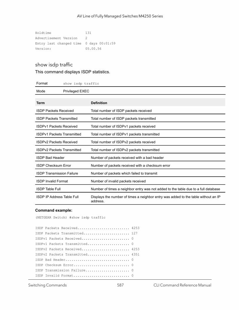
AV Line of Fully Managed Switches M4250 Series
ase
IP
Holdtime 131Advertisement Version 2Entry last changed time 0 days 00:01:59Version: 05.00.56
show isdp trafficThis command displays ISDP statistics.
Command example: (NETGEAR Switch) #show isdp traffic
ISDP Packets Received.......................... 4253ISDP Packets Transmitted....................... 127ISDPv1 Packets Received........................ 0ISDPv1 Packets Transmitted..................... 0ISDPv2 Packets Received........................ 4253ISDPv2 Packets Transmitted..................... 4351ISDP Bad Header................................ 0ISDP Checksum Error............................ 0ISDP Transmission Failure...................... 0ISDP Invalid Format............................ 0
Format show isdp traffic
Mode Privileged EXEC
Term Definition
ISDP Packets Received Total number of ISDP packets received
ISDP Packets Transmitted Total number of ISDP packets transmitted
ISDPv1 Packets Received Total number of ISDPv1 packets received
ISDPv1 Packets Transmitted Total number of ISDPv1 packets transmitted
ISDPv2 Packets Received Total number of ISDPv2 packets received
ISDPv2 Packets Transmitted Total number of ISDPv2 packets transmitted
ISDP Bad Header Number of packets received with a bad header
ISDP Checksum Error Number of packets received with a checksum error
ISDP Transmission Failure Number of packets which failed to transmit
ISDP Invalid Format Number of invalid packets received
ISDP Table Full Number of times a neighbor entry was not added to the table due to a full datab
ISDP IP Address Table Full Displays the number of times a neighbor entry was added to the table without anaddress.
Switching Commands CLI Command Reference Manual587

AV Line of Fully Managed Switches M4250 Series
ISDP Table Full................................ 392ISDP IP Address Table Full..................... 737
debug isdp packetThis command enables tracing of ISDP packets processed by the switch. ISDP must be enabled on both the device and the interface in order to monitor packets for a particular interface.
Note: To display the debug trace, enable the debug console command.
no debug isdp packet
This command disables tracing of ISDP packets on the receive or the transmit sides or on both sides.
Interface Error Disabling and Auto Recovery Commands
Interface error disabling automatically disables an interface when an error is detected. No traffic is allowed until the interface is either manually reenabled or, if auto recovery is configured, the configured auto recovery interval expires.
If an error condition is detected for an interface, the switch places the interface in an error-disabled state (also referred to as a diagnostic-disabled state) by shutting down the interface. The error-disabled interface does not allow any traffic until the interface is reenabled. You can manually enable the error-disabled interface. Alternatively, you can enable auto recovery, which automatically reenables the interface after the expiration of the configured interval.
errdisable recovery causeThis command enables auto recovery for a specific cause or for all causes. If auto recovery is enabled, interfaces in the error-disabled state are reenabled when the recovery interval expires. If errors continue on the interface, the interface can be placed back in the error-disabled state and disabled. You can manually reenable an interface in the error-disabled state by entering the no shutdown command for the interface.
Format debug isdp packet [receive | transmit]
Mode Privileged EXEC
Format no debug isdp packet [receive | transmit]
Mode Privileged EXEC
Switching Commands CLI Command Reference Manual588
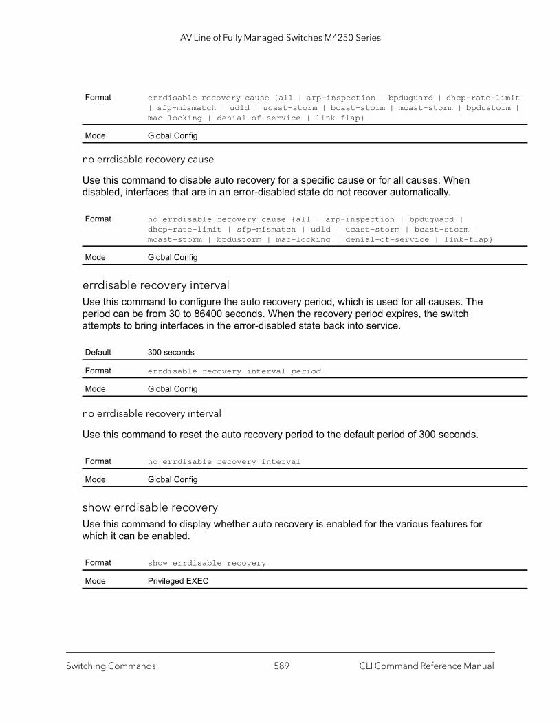
AV Line of Fully Managed Switches M4250 Series
mit m |
no errdisable recovery cause
Use this command to disable auto recovery for a specific cause or for all causes. When disabled, interfaces that are in an error-disabled state do not recover automatically.
errdisable recovery intervalUse this command to configure the auto recovery period, which is used for all causes. The period can be from 30 to 86400 seconds. When the recovery period expires, the switch attempts to bring interfaces in the error-disabled state back into service.
no errdisable recovery interval
Use this command to reset the auto recovery period to the default period of 300 seconds.
show errdisable recoveryUse this command to display whether auto recovery is enabled for the various features for which it can be enabled.
Format errdisable recovery cause {all | arp-inspection | bpduguard | dhcp-rate-li| sfp-mismatch | udld | ucast-storm | bcast-storm | mcast-storm | bpdustormac-locking | denial-of-service | link-flap}
Mode Global Config
Format no errdisable recovery cause {all | arp-inspection | bpduguard | dhcp-rate-limit | sfp-mismatch | udld | ucast-storm | bcast-storm | mcast-storm | bpdustorm | mac-locking | denial-of-service | link-flap}
Mode Global Config
Default 300 seconds
Format errdisable recovery interval period
Mode Global Config
Format no errdisable recovery interval
Mode Global Config
Format show errdisable recovery
Mode Privileged EXEC
Switching Commands CLI Command Reference Manual589
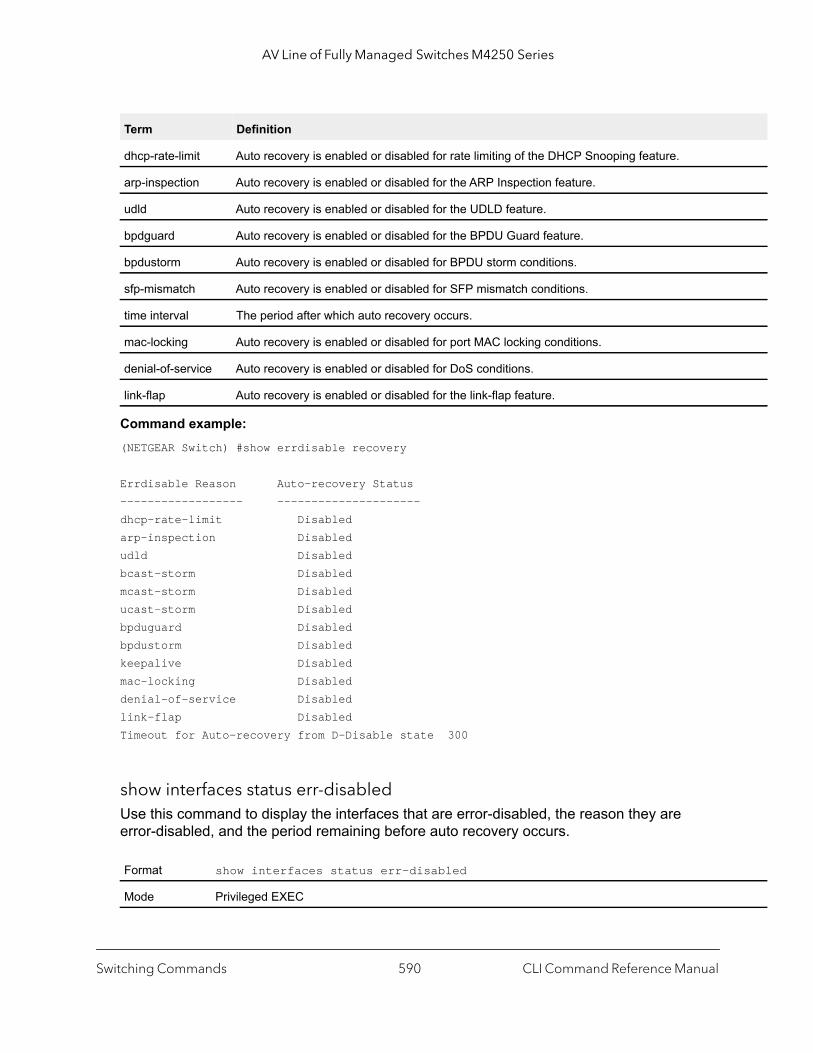
AV Line of Fully Managed Switches M4250 Series
Command example: (NETGEAR Switch) #show errdisable recovery
Errdisable Reason Auto-recovery Status------------------ ---------------------dhcp-rate-limit Disabledarp-inspection Disabledudld Disabledbcast-storm Disabledmcast-storm Disableducast-storm Disabledbpduguard Disabledbpdustorm Disabledkeepalive Disabledmac-locking Disableddenial-of-service Disabledlink-flap DisabledTimeout for Auto-recovery from D-Disable state 300
show interfaces status err-disabledUse this command to display the interfaces that are error-disabled, the reason they are error-disabled, and the period remaining before auto recovery occurs.
Term Definition
dhcp-rate-limit Auto recovery is enabled or disabled for rate limiting of the DHCP Snooping feature.
arp-inspection Auto recovery is enabled or disabled for the ARP Inspection feature.
udld Auto recovery is enabled or disabled for the UDLD feature.
bpdguard Auto recovery is enabled or disabled for the BPDU Guard feature.
bpdustorm Auto recovery is enabled or disabled for BPDU storm conditions.
sfp-mismatch Auto recovery is enabled or disabled for SFP mismatch conditions.
time interval The period after which auto recovery occurs.
mac-locking Auto recovery is enabled or disabled for port MAC locking conditions.
denial-of-service Auto recovery is enabled or disabled for DoS conditions.
link-flap Auto recovery is enabled or disabled for the link-flap feature.
Format show interfaces status err-disabled
Mode Privileged EXEC
Switching Commands CLI Command Reference Manual590

AV Line of Fully Managed Switches M4250 Series
Command example: (NETGEAR Switch) #show interfaces status err-disabledInterface Errdisable Reason Auto-Recovery Time Left(sec)---------- ----------------- ------------------0/1 udld 2790/2 bpduguard 2850/3 bpdustorm 2910/4 keepalive 11
UniDirectional Link Detection Commands
The purpose of the UniDirectional Link Detection (UDLD) feature is to detect and avoid unidirectional links. A unidirectional link is a forwarding anomaly in a Layer 2 communication channel in which a bi-directional link stops passing traffic in one direction. Use the UDLD commands to detect unidirectional links’ physical ports. UDLD must be enabled on both sides of the link in order to detect a unidirectional link. The UDLD protocol operates by exchanging packets containing information about neighboring devices.
udld enable (Global Config)This command enables UDLD globally on the switch.
no udld enable (Global Config)
This command disables udld globally on the switch.
Term Definition
interface An interface that is error-disabled.
Errdisable Reason The reason the interface is error-disabled.
Auto-Recovery Time Left
The period that is remaining before auto recovery occurs.
Default Disabled
Format udld enable
Mode Global Config
Format no udld enable
Mode Global Config
Switching Commands CLI Command Reference Manual591

AV Line of Fully Managed Switches M4250 Series
udld message timeThis command configures the interval between UDLD probe messages on ports that are in the advertisement phase. The range is from 7 to 90 seconds.
udld timeout intervalThis command configures the time interval after which UDLD link is considered to be unidirectional. The range is from 5 to 60 seconds.
udld resetThis command resets all interfaces that have been shutdown by UDLD.
udld enable (Interface Config)This command enables UDLD on the specified interface.
no udld enable (Interface Config)
This command disables UDLD on the specified interface.
Default 15 seconds
Format udld message time seconds
Mode Global Config
Default 5 seconds
Format udld timeout interval seconds
Mode Global Config
Default None
Format udld reset
Mode Privileged EXEC
Default disable
Format udld enable
Mode Interface Config
Format no udld enable
Mode Interface Config
Switching Commands CLI Command Reference Manual592

AV Line of Fully Managed Switches M4250 Series
led.
port.
ort is
k de by
udld portThis command selects the UDLD mode operating on this interface. If the aggressive keyword is not entered, the port operates in normal mode.
show udldThis command displays either the global settings of UDLD or the UDLD settings for the specified unit/port. If the all keyword is entered, the command displays information for all ports.
If you do not enter a value for the unit/port parameter, the command output displays the fields that are shown in the following table.
If you enter a value for the unit/port parameter or you use the all keyword, the command output displays the fields that are shown in the following table.
Default normal
Format udld port [aggressive]
Mode Interface Config
Format show udld [unit/port | all]
Mode User EXECPrivileged EXEC
Parameter Description
Admin Mode The global administrative mode of UDLD.
Message Interval The time period (in seconds) between the transmission of UDLD probe packets.
Timeout Interval The time period (in seconds) before making a decision that the link is unidirectional.
Parameter Description
Port The identifying port of the interface.
Admin Mode The administrative mode of UDLD configured on this interface. This is either Enabled or Disab
UDLD Mode The UDLD mode configured on this interface. This is either Normal or Aggressive.
UDLD Status The status of the link as determined by UDLD. The options are:• Undetermined. UDLD has not collected enough information to determine the state of the• Not applicable. UDLD is disabled, either globally or on the port.• Shutdown. UDLD has detected a unidirectional link and shutdown the port. That is, the p
in an errDisabled state.• Bidirectional. UDLD has detected a bidirectional link.• Undetermined (Link Down). The port would transition into this state when the port lin
physically goes down due to any reasons other than the port been put into D-Disable mothe UDLD protocol on the switch.
Switching Commands CLI Command Reference Manual593
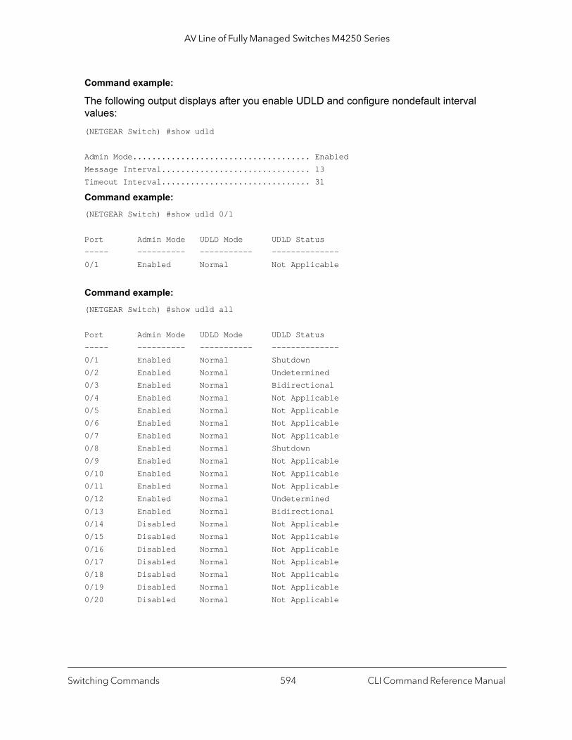
AV Line of Fully Managed Switches M4250 Series
Command example:
The following output displays after you enable UDLD and configure nondefault interval values:(NETGEAR Switch) #show udld
Admin Mode..................................... EnabledMessage Interval............................... 13Timeout Interval............................... 31
Command example: (NETGEAR Switch) #show udld 0/1
Port Admin Mode UDLD Mode UDLD Status----- ---------- ----------- --------------0/1 Enabled Normal Not Applicable
Command example: (NETGEAR Switch) #show udld all
Port Admin Mode UDLD Mode UDLD Status----- ---------- ----------- --------------0/1 Enabled Normal Shutdown0/2 Enabled Normal Undetermined0/3 Enabled Normal Bidirectional0/4 Enabled Normal Not Applicable0/5 Enabled Normal Not Applicable0/6 Enabled Normal Not Applicable0/7 Enabled Normal Not Applicable0/8 Enabled Normal Shutdown0/9 Enabled Normal Not Applicable0/10 Enabled Normal Not Applicable0/11 Enabled Normal Not Applicable0/12 Enabled Normal Undetermined0/13 Enabled Normal Bidirectional0/14 Disabled Normal Not Applicable0/15 Disabled Normal Not Applicable0/16 Disabled Normal Not Applicable0/17 Disabled Normal Not Applicable0/18 Disabled Normal Not Applicable0/19 Disabled Normal Not Applicable0/20 Disabled Normal Not Applicable
Switching Commands CLI Command Reference Manual594

AV Line of Fully Managed Switches M4250 Series
Link Debounce Commands
Link debouncing functions on a per-port basis on physical interfaces. After you configure link debouncing, if the switch receives a link-down notification, the switch starts monitoring the link event by starting a timer with the configured debounce time. Any intermediate link-down and link-up events are ignored hereafter. When the timer expires, link debounce checks if the current state of the link is still down; if so, it forwards a link-down notification to the upper layer applications.
You must explicitly enable link debounce per interface with an appropriate debounce timer value, taking into consideration the network topology and the features enabled on the switch, such as LAG or spanning tree.
Note: Link debouncing is disabled by default.
link debounce timeThis command configures the debounce time. The possible values for the milliseconds parameter are in the 100–5000 range.
no link debounce time
This command disables the debounce time.
show interface debounceThis command displays the flap counts for all interfaces.
Format link debounce time milliseconds
Mode Interface Config
Format no link debounce time
Mode Interface Config
Format show interface debounce
Mode Privileged EXEC
Switching Commands CLI Command Reference Manual595
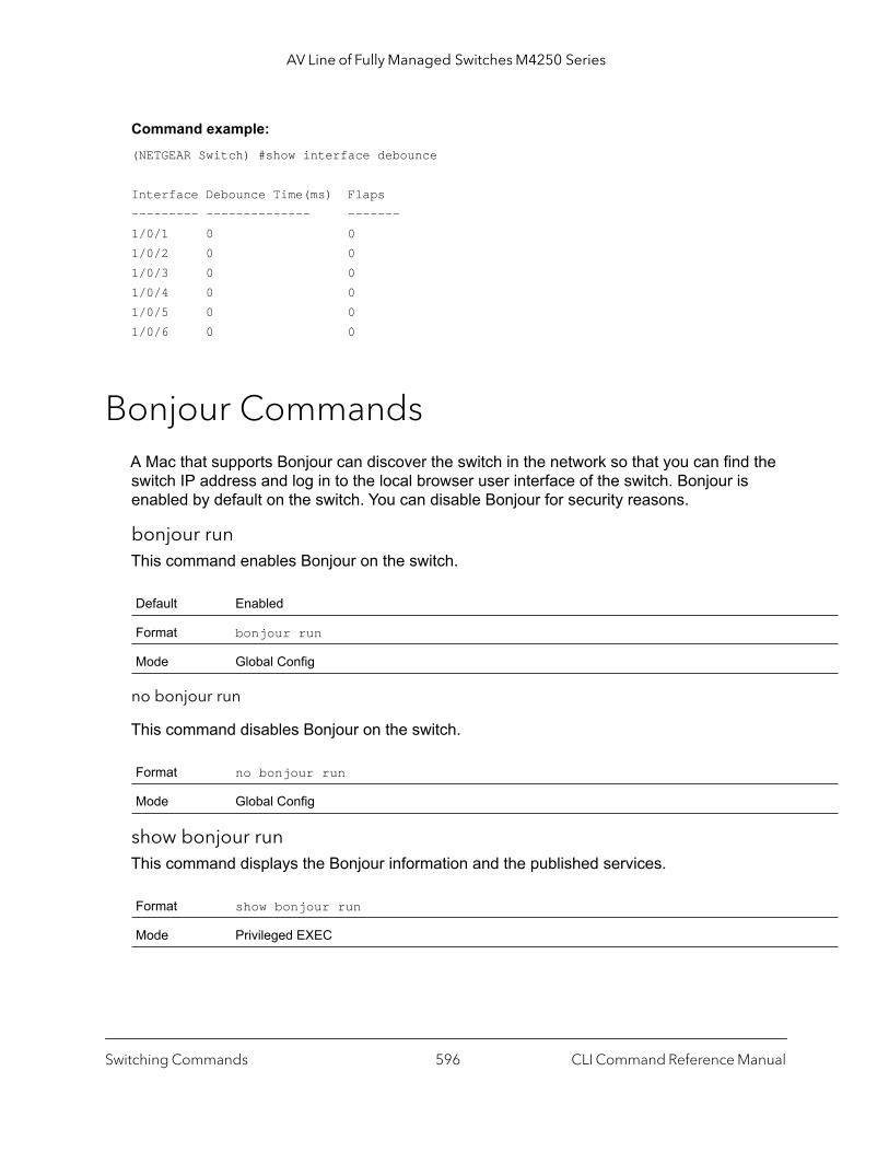
AV Line of Fully Managed Switches M4250 Series
Command example: (NETGEAR Switch) #show interface debounce
Interface Debounce Time(ms) Flaps--------- -------------- -------1/0/1 0 01/0/2 0 01/0/3 0 01/0/4 0 01/0/5 0 01/0/6 0 0
Bonjour CommandsA Mac that supports Bonjour can discover the switch in the network so that you can find the switch IP address and log in to the local browser user interface of the switch. Bonjour is enabled by default on the switch. You can disable Bonjour for security reasons.
bonjour runThis command enables Bonjour on the switch.
no bonjour run
This command disables Bonjour on the switch.
show bonjour runThis command displays the Bonjour information and the published services.
Default Enabled
Format bonjour run
Mode Global Config
Format no bonjour run
Mode Global Config
Format show bonjour run
Mode Privileged EXEC
Switching Commands CLI Command Reference Manual596
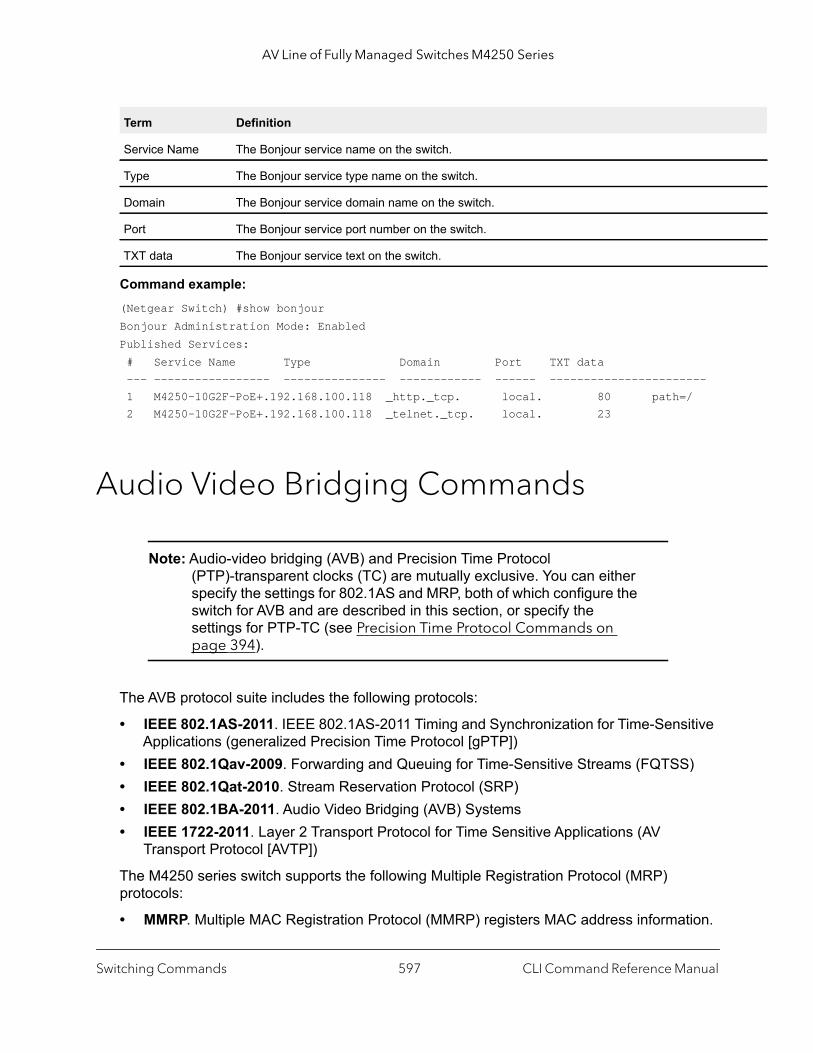
AV Line of Fully Managed Switches M4250 Series
Command example: (Netgear Switch) #show bonjourBonjour Administration Mode: EnabledPublished Services: # Service Name Type Domain Port TXT data --- ----------------- --------------- ------------ ------ ----------------------- 1 M4250-10G2F-PoE+.192.168.100.118 _http._tcp. local. 80 path=/ 2 M4250-10G2F-PoE+.192.168.100.118 _telnet._tcp. local. 23
Audio Video Bridging Commands
Note: Audio-video bridging (AVB) and Precision Time Protocol (PTP)-transparent clocks (TC) are mutually exclusive. You can either specify the settings for 802.1AS and MRP, both of which configure the switch for AVB and are described in this section, or specify the settings for PTP-TC (see Precision Time Protocol Commands on page 394).
The AVB protocol suite includes the following protocols:
• IEEE 802.1AS-2011. IEEE 802.1AS-2011 Timing and Synchronization for Time-Sensitive Applications (generalized Precision Time Protocol [gPTP])
• IEEE 802.1Qav-2009. Forwarding and Queuing for Time-Sensitive Streams (FQTSS)• IEEE 802.1Qat-2010. Stream Reservation Protocol (SRP)• IEEE 802.1BA-2011. Audio Video Bridging (AVB) Systems• IEEE 1722-2011. Layer 2 Transport Protocol for Time Sensitive Applications (AV
Transport Protocol [AVTP])
The M4250 series switch supports the following Multiple Registration Protocol (MRP) protocols:
• MMRP. Multiple MAC Registration Protocol (MMRP) registers MAC address information.
Term Definition
Service Name The Bonjour service name on the switch.
Type The Bonjour service type name on the switch.
Domain The Bonjour service domain name on the switch.
Port The Bonjour service port number on the switch.
TXT data The Bonjour service text on the switch.
Switching Commands CLI Command Reference Manual597

AV Line of Fully Managed Switches M4250 Series
• MVRP. Multiple VLAN Registration Protocol (MVRP) registers VLAN membership.• MSRP. Multiple Stream Reservation Protocol (MSRP) registers bandwidth requirement
for an AV stream.
MRP lets devices register attributes to other devices in a network. MRP is the base registration protocol that is then used by MMRP and MSRP to propagate the registration.
MRP replaces Generic Attribute Registration Protocol (GARP), which is still supported on the switch. The following related protocols are also replaced:
• GARP Multicast Registration Protocol (GMRP) is replaced by MMRP but still supported on the switch.
• GARP VLAN Registration Protocol (GVRP) is replaced by MVRP but still supported on the switch.
Note: To configure the AVB features, the switch must include an AVB license that is activated. Without a license, you cannot use the commands that are associated with 802.1AS, MRP, MMRP, and MVRP.
802.1AS Commands802.1AS can ensure that QoS requirements are guaranteed for time-sensitive applications such as audio and video. Precision Time Protocol (PTP) forms the basis for 802.1AS. PTP can provide precise clock synchronization that relies on time-stamped packets. PTP is applicable to a distributed system that consist of one or more communicating nodes. The distribution of synchronous time information occurs hierarchically with a grandmaster clock. The grandmaster clock provides a common and precise time reference by exchanging timing information with one or more directly-attached devices. Such as attached device synchronizes its clocks with the grandmaster clock and, in turn, can function as master clock for a hierarchical layer of attached devices.
Time synchronization provides a common time base for sampling data streams at a source device and presenting those streams at a destination device with the same relative timing. End-to-end synchronization of clocks is critical for traffic that is highly time-sensitive with stringent latency and jitter requirements.
802.1AS supports the following:
• Network clock synchronization in the sub-microsecond range• Synchronization of clocks with different precision, resolution and stability• Fast convergence when topology changes occur
Switching Commands CLI Command Reference Manual598

AV Line of Fully Managed Switches M4250 Series
dot1asThis command enables 802.1AS on the switch.
no dot1as
This command disables 802.1AS on the switch.
dot1as priority 2This command configures the 802.1AS priority value for the switch.
no dot1as priority 2
This command sets the 802.1AS priority value for the switch to its default setting of 248.
dot1as interval announceThis command configures the initial mean time interval between successive Announce messages in the format of logarithms to base 2 (log base 2). The value of interval can be from –5 to 5.
Default Disabled
Format dot1as
Mode Global Config
Format no dot1as
Mode Global Config
Default 248
Format dot1as priority 2 value
Mode Global Config
Parameter Description
value The value for the best clock priority is in the range from 0 to 255. The default value is 248.
Format no dot1as 2 priority
Mode Global Config
Default 0
Format dot1as interval announce interval
Mode Interface Config
Switching Commands CLI Command Reference Manual599

AV Line of Fully Managed Switches M4250 Series
no dot1as interval announce
This command sets the initial mean time interval between successive Announce messages to its default value of 0.
dot1as interval syncThis command configures the initial mean time interval between successive Sync messages in the format of logarithms to base 2 (log base 2). The value of interval can be from –5 to 5.
no dot1as interval sync
This command sets the initial mean time interval between successive Sync messages to its default value of 0.
dot1as interval pdelayThis command configures the initial mean time interval between successive Pdelay messages in the format of logarithms to base 2 (log base 2). The value of interval can be from –5 to 5.
no dot1as interval pdelay
This command sets the initial mean time interval between successive Pdelay messages to its default value of 0.
Format no dot1as interval announce
Mode Interface Config
Default 0
Format dot1as interval sync interval
Mode Interface Config
Format no dot1as interval sync
Mode Interface Config
Default 0
Format dot1as interval pdelay interval
Mode Interface Config
Format no dot1as interval pdelay
Mode Interface Config
Switching Commands CLI Command Reference Manual600
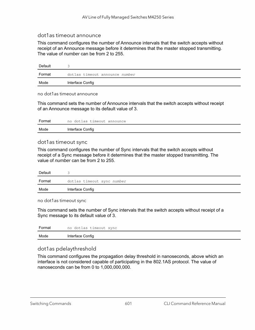
AV Line of Fully Managed Switches M4250 Series
dot1as timeout announceThis command configures the number of Announce intervals that the switch accepts without receipt of an Announce message before it determines that the master stopped transmitting. The value of number can be from 2 to 255.
no dot1as timeout announce
This command sets the number of Announce intervals that the switch accepts without receipt of an Announce message to its default value of 3.
dot1as timeout syncThis command configures the number of Sync intervals that the switch accepts without receipt of a Sync message before it determines that the master stopped transmitting. The value of number can be from 2 to 255.
no dot1as timeout sync
This command sets the number of Sync intervals that the switch accepts without receipt of a Sync message to its default value of 3.
dot1as pdelaythresholdThis command configures the propagation delay threshold in nanoseconds, above which an interface is not considered capable of participating in the 802.1AS protocol. The value of nanoseconds can be from 0 to 1,000,000,000.
Default 3
Format dot1as timeout announce number
Mode Interface Config
Format no dot1as timeout announce
Mode Interface Config
Default 3
Format dot1as timeout sync number
Mode Interface Config
Format no dot1as timeout sync
Mode Interface Config
Switching Commands CLI Command Reference Manual601

AV Line of Fully Managed Switches M4250 Series
no dot1as pdelaythreshold
This command sets the propagation delay threshold in nanoseconds to its default value of 2500.
dot1as allowedlostrespThis command configures the maximum number of Pdelay_Req messages for which the switch does not receive a response. Above that number, an interface is considered to not be exchanging peer delay messages with its neighbor. The value of number can be from 0 to 65535.
no dot1as allowedlostresp
This command sets the maximum number of Pdelay_Req messages for which the switch does not receive a response to its default value of 3.
show dot1as summaryThis command displays a summary of the 802.1AS configuration on the switch.
Default 2500
Format dot1as pdelaythreshold nanoseconds
Mode Interface Config
Format no dot1as pdelaythreshold
Mode Interface Config
Default 3
Format dot1as allowedlostresp number
Mode Interface Config
Format no dot1as allowedlostresp
Mode Interface Config
Format show dot1as summary
Mode Privileged EXEC
Term Definition
802.1AS Global Admin Mode Indicates if the 802.1AS global admin mode is enabled or disabled.
Grandmaster Capable Indicates if the 802.1AS global admin mode is enabled or disabled.
Switching Commands CLI Command Reference Manual602
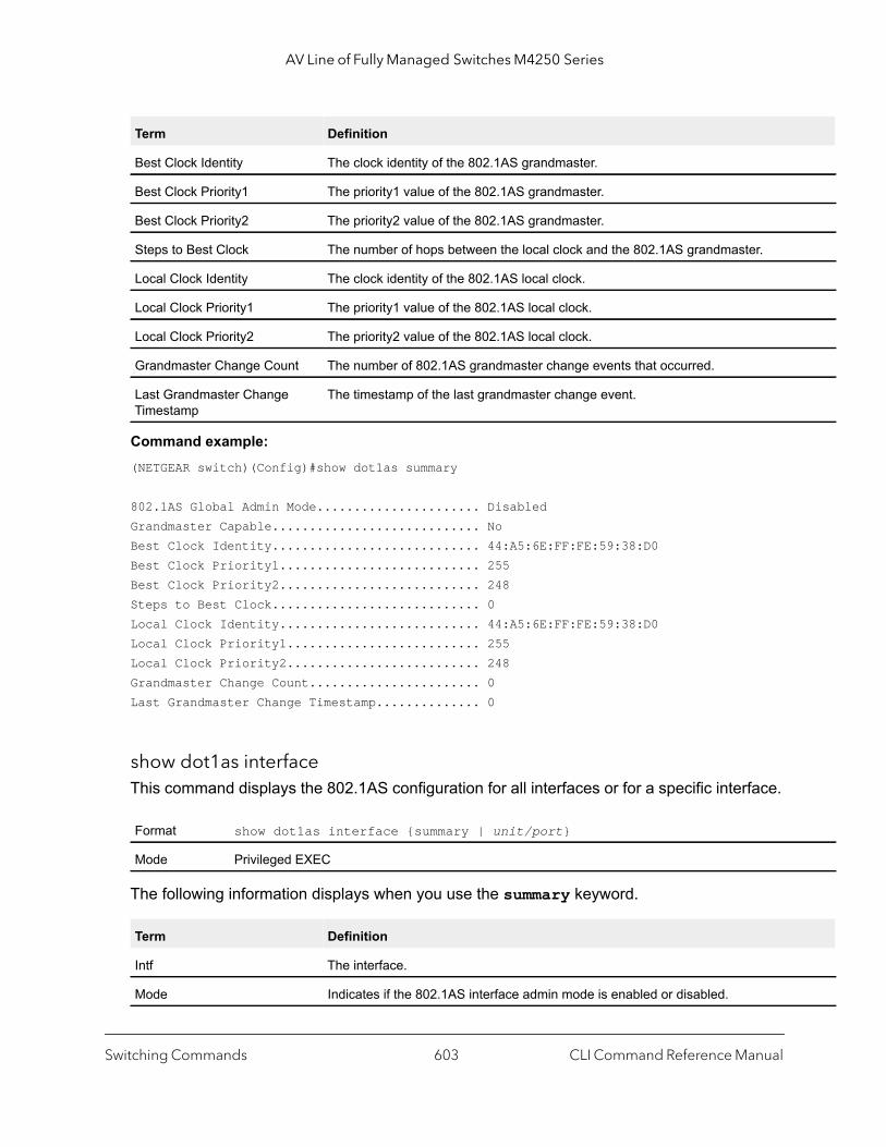
AV Line of Fully Managed Switches M4250 Series
Command example: (NETGEAR switch)(Config)#show dot1as summary
802.1AS Global Admin Mode...................... DisabledGrandmaster Capable............................ NoBest Clock Identity............................ 44:A5:6E:FF:FE:59:38:D0Best Clock Priority1........................... 255Best Clock Priority2........................... 248Steps to Best Clock............................ 0Local Clock Identity........................... 44:A5:6E:FF:FE:59:38:D0Local Clock Priority1.......................... 255Local Clock Priority2.......................... 248Grandmaster Change Count....................... 0Last Grandmaster Change Timestamp.............. 0
show dot1as interfaceThis command displays the 802.1AS configuration for all interfaces or for a specific interface.
The following information displays when you use the summary keyword.
Best Clock Identity The clock identity of the 802.1AS grandmaster.
Best Clock Priority1 The priority1 value of the 802.1AS grandmaster.
Best Clock Priority2 The priority2 value of the 802.1AS grandmaster.
Steps to Best Clock The number of hops between the local clock and the 802.1AS grandmaster.
Local Clock Identity The clock identity of the 802.1AS local clock.
Local Clock Priority1 The priority1 value of the 802.1AS local clock.
Local Clock Priority2 The priority2 value of the 802.1AS local clock.
Grandmaster Change Count The number of 802.1AS grandmaster change events that occurred.
Last Grandmaster Change Timestamp
The timestamp of the last grandmaster change event.
Format show dot1as interface {summary | unit/port}
Mode Privileged EXEC
Term Definition
Intf The interface.
Mode Indicates if the 802.1AS interface admin mode is enabled or disabled.
Term Definition
Switching Commands CLI Command Reference Manual603
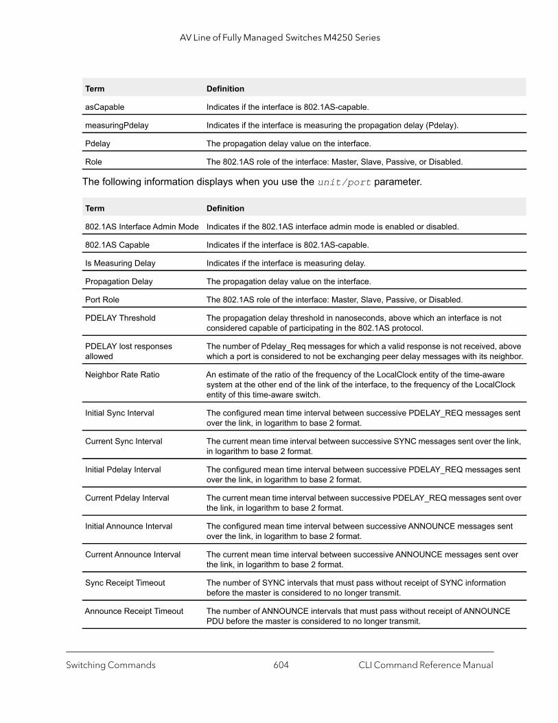
AV Line of Fully Managed Switches M4250 Series
bove hbor.
ock
sent
link,
sent
t over
ent
over
n
E
The following information displays when you use the unit/port parameter.
asCapable Indicates if the interface is 802.1AS-capable.
measuringPdelay Indicates if the interface is measuring the propagation delay (Pdelay).
Pdelay The propagation delay value on the interface.
Role The 802.1AS role of the interface: Master, Slave, Passive, or Disabled.
Term Definition
802.1AS Interface Admin Mode Indicates if the 802.1AS interface admin mode is enabled or disabled.
802.1AS Capable Indicates if the interface is 802.1AS-capable.
Is Measuring Delay Indicates if the interface is measuring delay.
Propagation Delay The propagation delay value on the interface.
Port Role The 802.1AS role of the interface: Master, Slave, Passive, or Disabled.
PDELAY Threshold The propagation delay threshold in nanoseconds, above which an interface is notconsidered capable of participating in the 802.1AS protocol.
PDELAY lost responses allowed
The number of Pdelay_Req messages for which a valid response is not received, awhich a port is considered to not be exchanging peer delay messages with its neig
Neighbor Rate Ratio An estimate of the ratio of the frequency of the LocalClock entity of the time-awaresystem at the other end of the link of the interface, to the frequency of the LocalClentity of this time-aware switch.
Initial Sync Interval The configured mean time interval between successive PDELAY_REQ messagesover the link, in logarithm to base 2 format.
Current Sync Interval The current mean time interval between successive SYNC messages sent over thein logarithm to base 2 format.
Initial Pdelay Interval The configured mean time interval between successive PDELAY_REQ messagesover the link, in logarithm to base 2 format.
Current Pdelay Interval The current mean time interval between successive PDELAY_REQ messages senthe link, in logarithm to base 2 format.
Initial Announce Interval The configured mean time interval between successive ANNOUNCE messages sover the link, in logarithm to base 2 format.
Current Announce Interval The current mean time interval between successive ANNOUNCE messages sent the link, in logarithm to base 2 format.
Sync Receipt Timeout The number of SYNC intervals that must pass without receipt of SYNC informatiobefore the master is considered to no longer transmit.
Announce Receipt Timeout The number of ANNOUNCE intervals that must pass without receipt of ANNOUNCPDU before the master is considered to no longer transmit.
Term Definition
Switching Commands CLI Command Reference Manual604
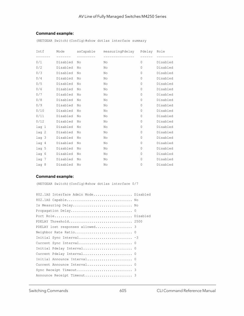
AV Line of Fully Managed Switches M4250 Series
Command example: (NETGEAR Switch)(Config)#show dot1as interface summary
Intf Mode asCapable measuringPdelay Pdelay Role------- ------- --------- --------------- ------ --------0/1 Disabled No No 0 Disabled0/2 Disabled No No 0 Disabled0/3 Disabled No No 0 Disabled0/4 Disabled No No 0 Disabled0/5 Disabled No No 0 Disabled0/6 Disabled No No 0 Disabled0/7 Disabled No No 0 Disabled0/8 Disabled No No 0 Disabled0/9 Disabled No No 0 Disabled0/10 Disabled No No 0 Disabled0/11 Disabled No No 0 Disabled0/12 Disabled No No 0 Disabledlag 1 Disabled No No 0 Disabledlag 2 Disabled No No 0 Disabledlag 3 Disabled No No 0 Disabledlag 4 Disabled No No 0 Disabledlag 5 Disabled No No 0 Disabledlag 6 Disabled No No 0 Disabledlag 7 Disabled No No 0 Disabledlag 8 Disabled No No 0 Disabled
Command example: (NETGEAR Switch)(Config)#show dot1as interface 0/7
802.1AS Interface Admin Mode................... Disabled802.1AS Capable................................ NoIs Measuring Delay............................. NoPropagation Delay.............................. 0Port Role...................................... DisabledPDELAY Threshold............................... 2500PDELAY lost responses allowed.................. 3Neighbor Rate Ratio............................ 0Initial Sync Interval.......................... -3Current Sync Interval.......................... 0Initial Pdelay Interval........................ 0Current Pdelay Interval........................ 0Initial Announce Interval...................... 0Current Announce Interval...................... 0Sync Receipt Timeout........................... 3Announce Receipt Timeout....................... 3
Switching Commands CLI Command Reference Manual605
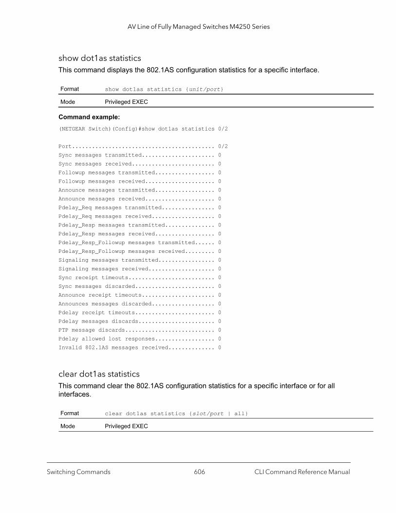
AV Line of Fully Managed Switches M4250 Series
show dot1as statisticsThis command displays the 802.1AS configuration statistics for a specific interface.
Command example: (NETGEAR Switch)(Config)#show dot1as statistics 0/2
Port........................................... 0/2Sync messages transmitted...................... 0Sync messages received......................... 0Followup messages transmitted.................. 0Followup messages received..................... 0Announce messages transmitted.................. 0Announce messages received..................... 0Pdelay_Req messages transmitted................ 0Pdelay_Req messages received................... 0Pdelay_Resp messages transmitted............... 0Pdelay_Resp messages received.................. 0Pdelay_Resp_Followup messages transmitted...... 0Pdelay_Resp_Followup messages received......... 0Signaling messages transmitted................. 0Signaling messages received.................... 0Sync receipt timeouts.......................... 0Sync messages discarded........................ 0Announce receipt timeouts...................... 0Announces messages discarded................... 0Pdelay receipt timeouts........................ 0Pdelay messages discards....................... 0PTP message discards........................... 0Pdelay allowed lost responses.................. 0Invalid 802.1AS messages received.............. 0
clear dot1as statisticsThis command clear the 802.1AS configuration statistics for a specific interface or for all interfaces.
Format show dot1as statistics {unit/port}
Mode Privileged EXEC
Format clear dot1as statistics {slot/port | all}
Mode Privileged EXEC
Switching Commands CLI Command Reference Manual606

AV Line of Fully Managed Switches M4250 Series
ip for
g the same
er to asis.
MRP CommandsMultiple Registration Protocol (MRP) provides the same functionality as GARP, which it replaces.
MRP consist of an application and a declaration component. In addition, a distribution component is called the MRP Attribute Declaration (MAD), which transmits and processes incoming MRP Protocol Data Units (MRPPDUs). The application component keeps track of attributes via registrations, and enforces any associated rules such as attribute restrictions. An AVB bridge such as a switch includes an MRP Attribute Propagation (MAP) component that propagates information among participating interfaces.
mrpThis command sets the MRP protocol timers on an interface.
show mrpThis command displays MRP leave, join, and leaveall intervals configured on interfaces. If you specify the summary parameter, the output shows interval values for all interfaces. If you specify the unit/port parameter, the output shows the MRP intervals for the specified interface.
Format mrp {jointime centiseconds | leavetime centiseconds | leavealltime centiseconds}
Mode Interface Config
Parameter Description
jointime centiseconds
The interval between the transmission of MRP PDUs registering (or reregistering) membershan attribute. There is an instance of this timer on a per-port, per-MRP participant basis. Permissible values are 10 to 100 centiseconds (0.1 to 1.0 seconds). The default is 20 centiseconds (0.2 seconds). The finest granularity of specification is one centisecond (0.01 seconds).
leavetime centiseconds
The period of time to wait after receiving an unregister request for an attribute before deletinattribute. You can consider this a buffer time for another station to assert registration for the attribute in order to maintain uninterrupted service. There is an instance of this timer on a per-Port, per-MRP participant basis. Permissible values are 20 to 600 centiseconds (0.2 to 6 seconds). The default is 300 centiseconds (3.0 seconds).
leavealltime centiseconds
The LeaveAllTime controls how frequently LeaveAll PDUs are generated. A LeaveAll PDU indicates that all registrations are shortly to be deregistered. Participants must to rejoin in ordmaintain registration. There is an instance of this timer on a per-port, per-MRP participant bThe Leave All Period Timer is set to a random value in the range of LeaveAllTime to 1.5*LeaveAllTime. Permissible values are 200 to 6000 centiseconds (2 to 60 seconds). Thedefault is 2000 centiseconds (20 seconds).
Format show mrp interface {summary | unit/port}
Mode Privileged Exec
Switching Commands CLI Command Reference Manual607

AV Line of Fully Managed Switches M4250 Series
Command example: (Netgear switch) #show mrp interface summary
Intf JoinTimer LeaveTimer LeaveAllTimer--------- --------- ---------- -------------0/1 20 300 20000/2 20 300 20000/3 20 300 20000/4 20 300 20000/5 20 300 20000/6 20 300 20000/7 20 300 20000/8 20 300 20000/9 20 300 20000/10 20 300 20000/11 20 300 20000/12 20 300 2000lag 1 20 300 2000lag 2 20 300 2000lag 3 20 300 2000lag 4 20 300 2000lag 5 20 300 2000lag 6 20 300 2000lag 7 20 300 2000lag 8 20 300 2000
MMRP CommandsMultiple MAC Registration Protocol (MMRP) propagates MAC address information in a network. MMRP replaces GMRP.
MMRP can register and deregister both individual MAC addresses and group MAC address memberships. This differs from GMRP, which supports only the propagation of group MAC address memberships.
MMRP lets end stations join or leave a multicast group or register an individual MAC address with a specific VLAN. If you enable MMRP, the switch can dynamically register and deregister MAC addresses.
mmrp (Global Config)Use this command in Global Config mode to enable MMRP. MMRP must also be enabled on the individual interfaces.
Switching Commands CLI Command Reference Manual608
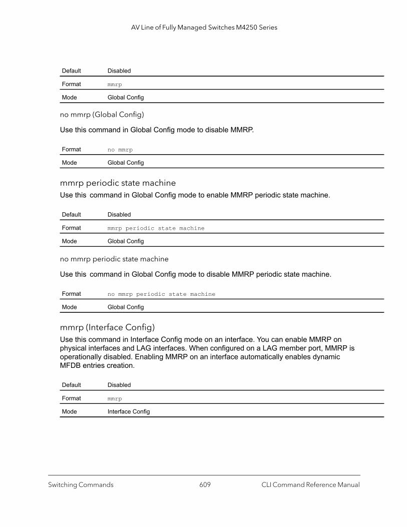
AV Line of Fully Managed Switches M4250 Series
no mmrp (Global Config)
Use this command in Global Config mode to disable MMRP.
mmrp periodic state machineUse this command in Global Config mode to enable MMRP periodic state machine.
no mmrp periodic state machine
Use this command in Global Config mode to disable MMRP periodic state machine.
mmrp (Interface Config)Use this command in Interface Config mode on an interface. You can enable MMRP on physical interfaces and LAG interfaces. When configured on a LAG member port, MMRP is operationally disabled. Enabling MMRP on an interface automatically enables dynamic MFDB entries creation.
Default Disabled
Format mmrp
Mode Global Config
Format no mmrp
Mode Global Config
Default Disabled
Format mmrp periodic state machine
Mode Global Config
Format no mmrp periodic state machine
Mode Global Config
Default Disabled
Format mmrp
Mode Interface Config
Switching Commands CLI Command Reference Manual609
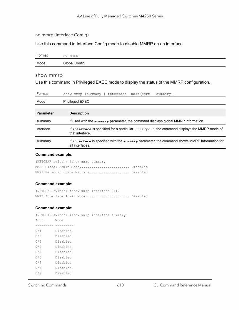
AV Line of Fully Managed Switches M4250 Series
de of
on for
no mmrp (Interface Config)
Use this command in Interface Config mode to disable MMRP on an interface.
show mmrpUse this command in Privileged EXEC mode to display the status of the MMRP configuration.
Command example: (NETGEAR switch) #show mmrp summaryMMRP Global Admin Mode......................... DisabledMMRP Periodic State Machine.................... Disabled
Command example: (NETGEAR switch) #show mmrp interface 0/12MMRP Interface Admin Mode...................... Disabled
Command example: (NETGEAR switch) #show mmrp interface summaryIntf Mode--------- ---------0/1 Disabled0/2 Disabled0/3 Disabled0/4 Disabled0/5 Disabled0/6 Disabled0/7 Disabled0/8 Disabled0/9 Disabled
Format no mmrp
Mode Global Config
Format show mmrp [summary | interface [unit/port | summary]]
Mode Privileged EXEC
Parameter Description
summary If used with the summary parameter, the command displays global MMRP information.
interface If interface is specified for a particular unit/port, the command displays the MMRP mothat interface.
summary If interface is specified with the summary parameter, the command shows MMRP Informatiall interfaces.
Switching Commands CLI Command Reference Manual610

AV Line of Fully Managed Switches M4250 Series
0/10 Disabled0/11 Disabled0/12 Disabledlag 1 Disabledlag 2 Disabledlag 3 Disabledlag 4 Disabledlag 5 Disabledlag 6 Disabledlag 7 Disabledlag 8 Disabled
show mmrp statisticsUse this command in Privileged EXEC mode to display statistical information about the MMRP PDUs sent and received on the interface.
The following statistics display when the summary keyword or unit/port parameter is used. Using the summary keyword displays global statistics. The unit/port parameter displays per-interface statistics.
The following statistics display when the all keyword is used.
Format show mmrp statistics {summary | [unit/port | all]}
Mode Privileged EXEC
Parameter Description
MMRP messages received Total number of MMRP messages received.
MMRP messages received with bad header
Total number of MMRP frames with bad headers received
MMRP messages received with bad format
Total number of MMRP frames with bad PDUs body formats received
MMRP messages transmitted Total number of MMRP frames that sent
MMRP messages failed to transmit
Total number of MMRP frames that failed to be transmitted
Parameter Description
Intf The interface associated with the rest of the data in the row.
Rx Total number of MMRP messages received.
Bad Header Total number of MMRP frames with bad headers received
Bad Format Total number of MMRP frames with bad PDUs body formats received
Switching Commands CLI Command Reference Manual611
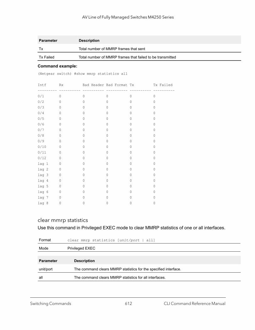
AV Line of Fully Managed Switches M4250 Series
Command example: (Netgear switch) #show mmrp statistics all
Intf Rx Bad Header Bad Format Tx Tx Failed--------- ---------- ---------- ---------- ---------- ----------0/1 0 0 0 0 00/2 0 0 0 0 00/3 0 0 0 0 00/4 0 0 0 0 00/5 0 0 0 0 00/6 0 0 0 0 00/7 0 0 0 0 00/8 0 0 0 0 00/9 0 0 0 0 00/10 0 0 0 0 00/11 0 0 0 0 00/12 0 0 0 0 0lag 1 0 0 0 0 0lag 2 0 0 0 0 0lag 3 0 0 0 0 0lag 4 0 0 0 0 0lag 5 0 0 0 0 0lag 6 0 0 0 0 0lag 7 0 0 0 0 0lag 8 0 0 0 0 0
clear mmrp statisticsUse this command in Privileged EXEC mode to clear MMRP statistics of one or all interfaces.
Tx Total number of MMRP frames that sent
Tx Failed Total number of MMRP frames that failed to be transmitted
Format clear mmrp statistics [unit/port | all]
Mode Privileged EXEC
Parameter Description
unit/port The command clears MMRP statistics for the specified interface.
all The command clears MMRP statistics for all interfaces.
Parameter Description
Switching Commands CLI Command Reference Manual612
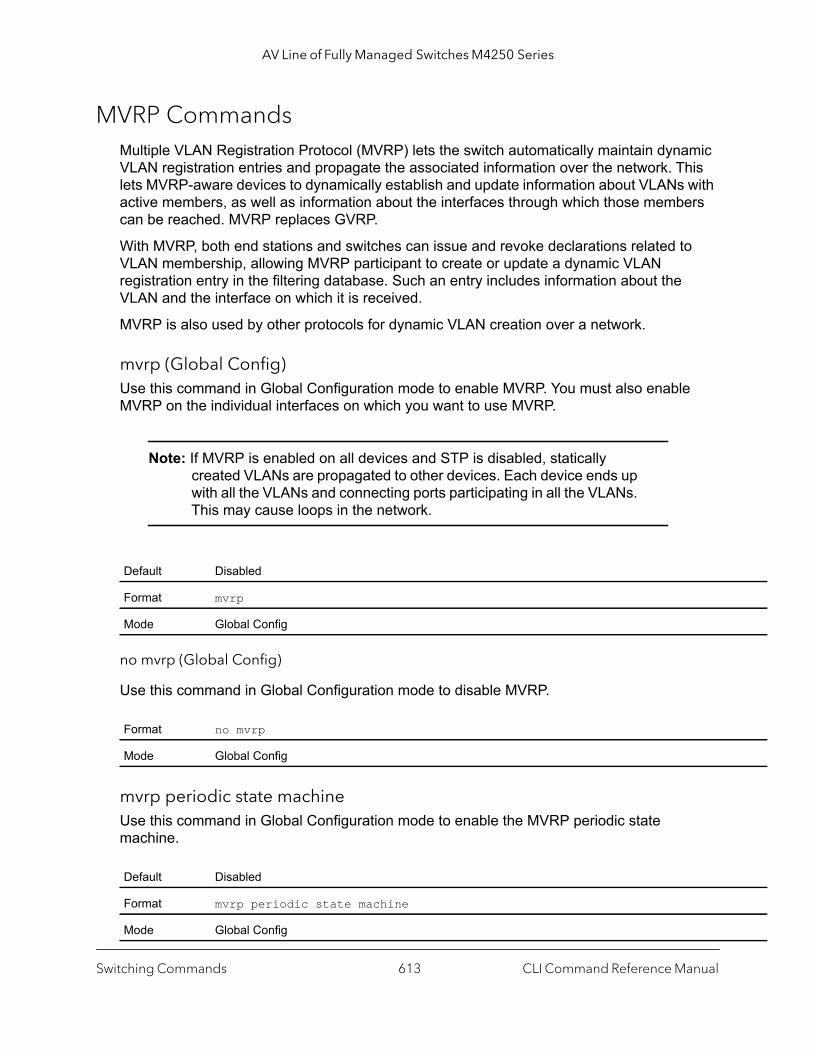
AV Line of Fully Managed Switches M4250 Series
MVRP CommandsMultiple VLAN Registration Protocol (MVRP) lets the switch automatically maintain dynamic VLAN registration entries and propagate the associated information over the network. This lets MVRP-aware devices to dynamically establish and update information about VLANs with active members, as well as information about the interfaces through which those members can be reached. MVRP replaces GVRP.
With MVRP, both end stations and switches can issue and revoke declarations related to VLAN membership, allowing MVRP participant to create or update a dynamic VLAN registration entry in the filtering database. Such an entry includes information about the VLAN and the interface on which it is received.
MVRP is also used by other protocols for dynamic VLAN creation over a network.
mvrp (Global Config)Use this command in Global Configuration mode to enable MVRP. You must also enable MVRP on the individual interfaces on which you want to use MVRP.
Note: If MVRP is enabled on all devices and STP is disabled, statically created VLANs are propagated to other devices. Each device ends up with all the VLANs and connecting ports participating in all the VLANs. This may cause loops in the network.
no mvrp (Global Config)
Use this command in Global Configuration mode to disable MVRP.
mvrp periodic state machineUse this command in Global Configuration mode to enable the MVRP periodic state machine.
Default Disabled
Format mvrp
Mode Global Config
Format no mvrp
Mode Global Config
Default Disabled
Format mvrp periodic state machine
Mode Global Config
Switching Commands CLI Command Reference Manual613

AV Line of Fully Managed Switches M4250 Series
hat
the
no mvrp periodic state machine
Use this command in Global Configuration mode to disable the MVRP periodic state machine.
mvrp (Interface Config)Use this command in Interface Configuration mode to enable MVRP on the interface, which must be configured in trunk mode or general mode. You can enable MVRP on physical interfaces or LAG interfaces. When configured on a LAG member port, MVRP is operationally disabled. Enabling MVRP on an interface automatically enables dynamic VLAN creation.
no mvrp (Interface Config)
Use this command in Interface Configuration mode to disable MVRP on the interface.
show mvrpUse this command in Privileged EXEC mode to display the status of the MVRP configuration.
Format no mvrp periodic state machine
Mode Global Config
Default Disabled
Format mvrp
Mode Interface Config
Format no mvrp
Mode Interface Config
Format show mvrp [summary | interface [unit/port | all]]
Mode Privileged EXEC
Parameter Description
summary If the summary parameter is used, the command shows global MVRP information.
interface If the interface is specified as unit/port, the command shows MVRP mode information for tinterface.
all If the interface is specified with the all parameter, the command shows MVRP interfaces for switch and for all interfaces.
Switching Commands CLI Command Reference Manual614
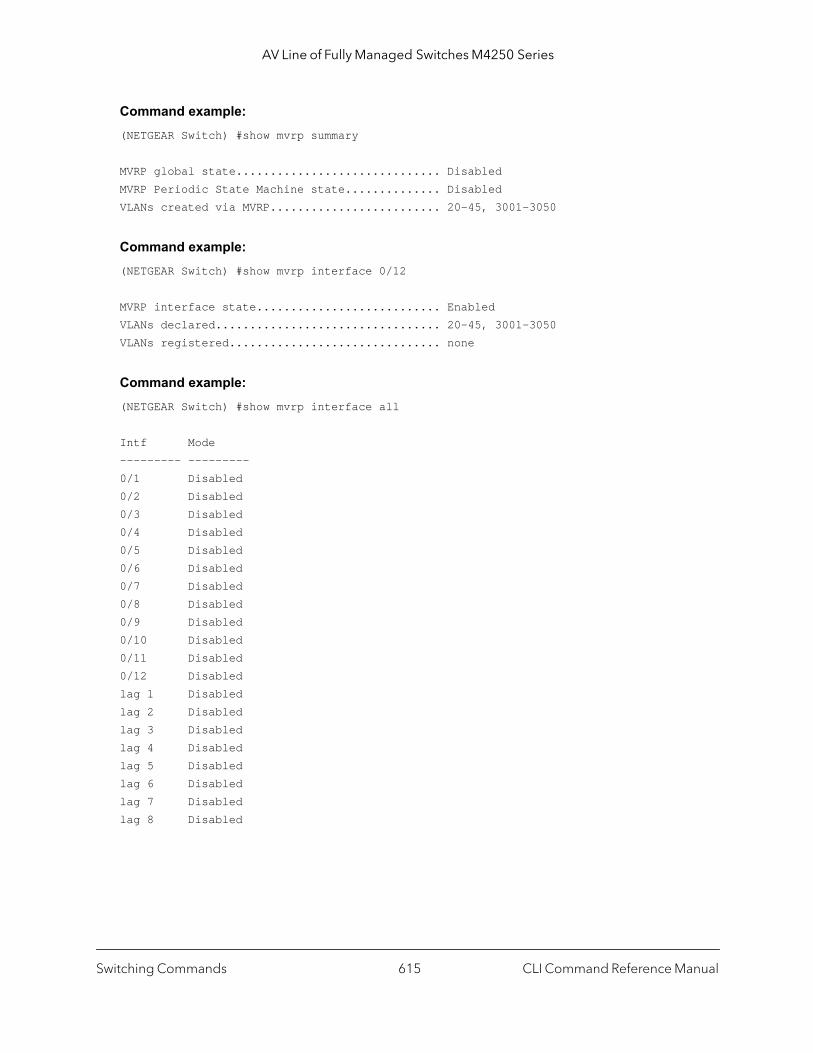
AV Line of Fully Managed Switches M4250 Series
Command example: (NETGEAR Switch) #show mvrp summary
MVRP global state.............................. DisabledMVRP Periodic State Machine state.............. DisabledVLANs created via MVRP......................... 20-45, 3001-3050
Command example: (NETGEAR Switch) #show mvrp interface 0/12
MVRP interface state........................... EnabledVLANs declared................................. 20-45, 3001-3050VLANs registered............................... none
Command example: (NETGEAR Switch) #show mvrp interface all
Intf Mode--------- ---------0/1 Disabled0/2 Disabled0/3 Disabled0/4 Disabled0/5 Disabled0/6 Disabled0/7 Disabled0/8 Disabled0/9 Disabled0/10 Disabled0/11 Disabled0/12 Disabledlag 1 Disabledlag 2 Disabledlag 3 Disabledlag 4 Disabledlag 5 Disabledlag 6 Disabledlag 7 Disabledlag 8 Disabled
Switching Commands CLI Command Reference Manual615

AV Line of Fully Managed Switches M4250 Series
ces
show mvrp statisticsUse this command in Privileged EXEC mode to display MVRP statistics.
Command example: (NETGEAR Switch) #show mvrp statistics summary
MVRP messages received......................... 45MVRP messages received with bad header......... 0MVRP messages received with bad format......... 0MVRP messages transmitted...................... 16MVRP messages failed to transmit............... 0MVRP Message Queue Failures.................... 0
Command example: (NETGEAR Switch) #show mvrp statistics 0/12
Port........................................... 0/12MVRP messages received......................... 21MVRP messages received with bad header......... 0MVRP messages received with bad format......... 0MVRP messages transmitted...................... 8MVRP messages failed to transmit............... 0MVRP failed reservations....................... 0
Command example: (NETGEAR Switch) #show mvrp statistics all
Intf Rx BadHeader BadFormat Tx Tx Failed RegFails--------- ---------- ---------- ---------- ---------- ---------- ----------0/1 0 0 0 0 0 00/2 0 0 0 0 0 00/3 0 0 0 0 0 00/4 0 0 0 0 0 0
Format show mvrp statistics {summary | unit/port | all}
Mode Privileged EXEC
Parameter Description
summary If used with the summary parameter, the command shows global MVRP statistics.
interface If the unit/port is specified, the command shows MVRP statistics for that interface.
all If used with the all parameter, the command shows a table with MVRP statistics for all interfaon which MVRP is enabled.
Switching Commands CLI Command Reference Manual616

AV Line of Fully Managed Switches M4250 Series
rface.
0/5 0 0 0 0 0 00/6 0 0 0 0 0 00/7 0 0 0 0 0 00/8 0 0 0 0 0 00/9 0 0 0 0 0 00/10 0 0 0 0 0 00/11 0 0 0 0 0 00/12 0 0 0 0 0 0lag 1 0 0 0 0 0 0lag 2 0 0 0 0 0 0lag 3 0 0 0 0 0 0lag 4 0 0 0 0 0 0lag 5 0 0 0 0 0 0lag 6 0 0 0 0 0 0lag 7 0 0 0 0 0 0lag 8 0 0 0 0 0 0
clear mvrp Use this command in Privileged EXEC mode to clear the MVRP statistics of one or all interfaces.
MSRP CommandsMultiple Stream Reservation Protocol (MSRP) reserves resources in a network so that time-sensitive traffic can flow from end to end. A typical network includes flows for multiple talkers (devices that transmit streams) and multiple listeners (devices that receive streams from one or more talkers). Each of these flows requires a specific bandwidth, frame rate, and time synchronization. MSRP can guarantee the resources through all intermediate devices between a talker and a listener.
For example, if a particular stream requires 1000 kbps, a frame rate of 128 kbps, and not more than a maximum delay of 120 micro seconds, the requirements must be guaranteed on each device between a talker and a listener. At each bridge, the delay component is increased with the delay that is associated with that particular link. (These streams use multicast MAC addresses as directory agents [DAs] so that source pruning can occur through MMRP. Time synchronization is handled by the 802.1AS protocol, which calculates the time delay between devices on a link and maintains an accurate network clock.) The end device
Format clear mvrp statistics {unit/port | all}
Mode Privileged EXEC
Parameter Description
unit/port If used with the unit/port parameter, the command clears MVRP statistics for the given inte
all If the all parameter is specified, the command clears MVRP statistics for all the interfaces.
Switching Commands CLI Command Reference Manual617
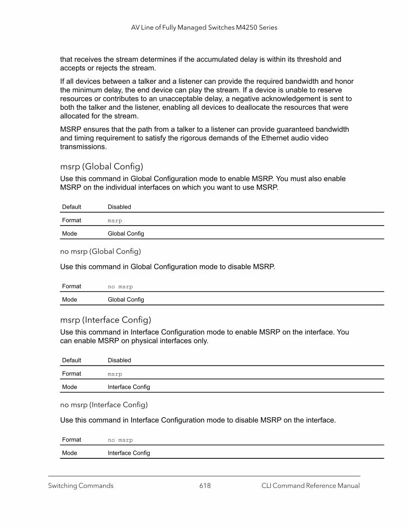
AV Line of Fully Managed Switches M4250 Series
that receives the stream determines if the accumulated delay is within its threshold and accepts or rejects the stream.
If all devices between a talker and a listener can provide the required bandwidth and honor the minimum delay, the end device can play the stream. If a device is unable to reserve resources or contributes to an unacceptable delay, a negative acknowledgement is sent to both the talker and the listener, enabling all devices to deallocate the resources that were allocated for the stream.
MSRP ensures that the path from a talker to a listener can provide guaranteed bandwidth and timing requirement to satisfy the rigorous demands of the Ethernet audio video transmissions.
msrp (Global Config)Use this command in Global Configuration mode to enable MSRP. You must also enable MSRP on the individual interfaces on which you want to use MSRP.
no msrp (Global Config)
Use this command in Global Configuration mode to disable MSRP.
msrp (Interface Config)Use this command in Interface Configuration mode to enable MSRP on the interface. You can enable MSRP on physical interfaces only.
no msrp (Interface Config)
Use this command in Interface Configuration mode to disable MSRP on the interface.
Default Disabled
Format msrp
Mode Global Config
Format no msrp
Mode Global Config
Default Disabled
Format msrp
Mode Interface Config
Format no msrp
Mode Interface Config
Switching Commands CLI Command Reference Manual618
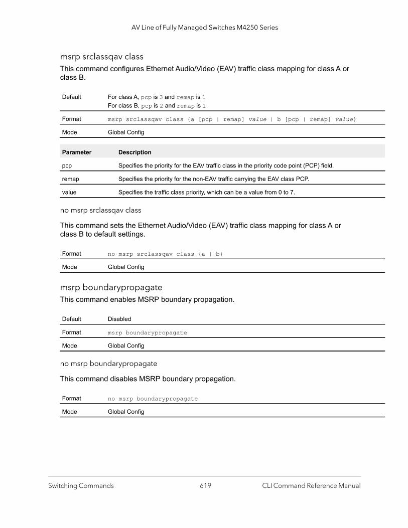
AV Line of Fully Managed Switches M4250 Series
msrp srclassqav classThis command configures Ethernet Audio/Video (EAV) traffic class mapping for class A or class B.
no msrp srclassqav class
This command sets the Ethernet Audio/Video (EAV) traffic class mapping for class A or class B to default settings.
msrp boundarypropagateThis command enables MSRP boundary propagation.
no msrp boundarypropagate
This command disables MSRP boundary propagation.
Default For class A, pcp is 3 and remap is 1For class B, pcp is 2 and remap is 1
Format msrp srclassqav class {a [pcp | remap] value | b [pcp | remap] value}
Mode Global Config
Parameter Description
pcp Specifies the priority for the EAV traffic class in the priority code point (PCP) field.
remap Specifies the priority for the non-EAV traffic carrying the EAV class PCP.
value Specifies the traffic class priority, which can be a value from 0 to 7.
Format no msrp srclassqav class {a | b}
Mode Global Config
Default Disabled
Format msrp boundarypropagate
Mode Global Config
Format no msrp boundarypropagate
Mode Global Config
Switching Commands CLI Command Reference Manual619
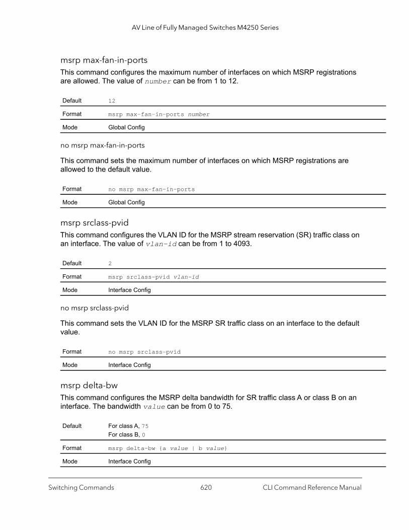
AV Line of Fully Managed Switches M4250 Series
msrp max-fan-in-portsThis command configures the maximum number of interfaces on which MSRP registrations are allowed. The value of number can be from 1 to 12.
no msrp max-fan-in-ports
This command sets the maximum number of interfaces on which MSRP registrations are allowed to the default value.
msrp srclass-pvidThis command configures the VLAN ID for the MSRP stream reservation (SR) traffic class on an interface. The value of vlan-id can be from 1 to 4093.
no msrp srclass-pvid
This command sets the VLAN ID for the MSRP SR traffic class on an interface to the default value.
msrp delta-bwThis command configures the MSRP delta bandwidth for SR traffic class A or class B on an interface. The bandwidth value can be from 0 to 75.
Default 12
Format msrp max-fan-in-ports number
Mode Global Config
Format no msrp max-fan-in-ports
Mode Global Config
Default 2
Format msrp srclass-pvid vlan-id
Mode Interface Config
Format no msrp srclass-pvid
Mode Interface Config
Default For class A, 75For class B, 0
Format msrp delta-bw {a value | b value}
Mode Interface Config
Switching Commands CLI Command Reference Manual620
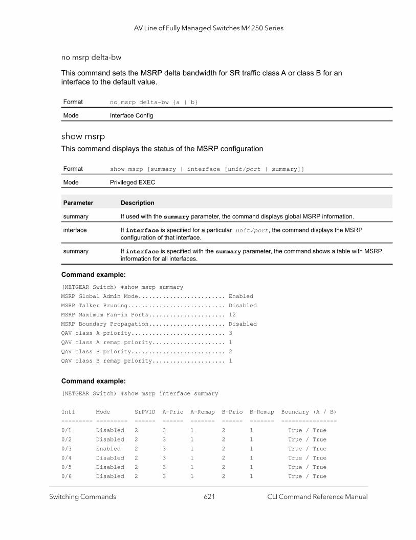
AV Line of Fully Managed Switches M4250 Series
RP
no msrp delta-bw
This command sets the MSRP delta bandwidth for SR traffic class A or class B for an interface to the default value.
show msrpThis command displays the status of the MSRP configuration
Command example: (NETGEAR Switch) #show msrp summaryMSRP Global Admin Mode......................... EnabledMSRP Talker Pruning............................ DisabledMSRP Maximum Fan-in Ports...................... 12MSRP Boundary Propagation...................... DisabledQAV class A priority........................... 3QAV class A remap priority..................... 1QAV class B priority........................... 2QAV class B remap priority..................... 1
Command example: (NETGEAR Switch) #show msrp interface summary
Intf Mode SrPVID A-Prio A-Remap B-Prio B-Remap Boundary (A / B)--------- --------- ------ ------ ------- ------ ------- ----------------0/1 Disabled 2 3 1 2 1 True / True0/2 Disabled 2 3 1 2 1 True / True0/3 Enabled 2 3 1 2 1 True / True0/4 Disabled 2 3 1 2 1 True / True0/5 Disabled 2 3 1 2 1 True / True0/6 Disabled 2 3 1 2 1 True / True
Format no msrp delta-bw {a | b}
Mode Interface Config
Format show msrp [summary | interface [unit/port | summary]]
Mode Privileged EXEC
Parameter Description
summary If used with the summary parameter, the command displays global MSRP information.
interface If interface is specified for a particular unit/port, the command displays the MSRP configuration of that interface.
summary If interface is specified with the summary parameter, the command shows a table with MSinformation for all interfaces.
Switching Commands CLI Command Reference Manual621
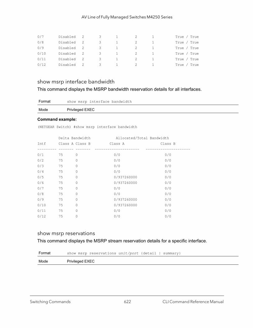
AV Line of Fully Managed Switches M4250 Series
0/7 Disabled 2 3 1 2 1 True / True0/8 Disabled 2 3 1 2 1 True / True0/9 Disabled 2 3 1 2 1 True / True0/10 Disabled 2 3 1 2 1 True / True0/11 Disabled 2 3 1 2 1 True / True0/12 Disabled 2 3 1 2 1 True / True
show msrp interface bandwidthThis command displays the MSRP bandwidth reservation details for all interfaces.
Command example: (NETGEAR Switch) #show msrp interface bandwidth
Delta Bandwidth Allocated/Total BandwidthIntf Class A Class B Class A Class B--------- ------- ------- --------------------- ---------------------0/1 75 0 0/0 0/00/2 75 0 0/0 0/00/3 75 0 0/0 0/00/4 75 0 0/0 0/00/5 75 0 0/937260000 0/00/6 75 0 0/937260000 0/00/7 75 0 0/0 0/00/8 75 0 0/0 0/00/9 75 0 0/937260000 0/00/10 75 0 0/937260000 0/00/11 75 0 0/0 0/00/12 75 0 0/0 0/0
show msrp reservationsThis command displays the MSRP stream reservation details for a specific interface.
Format show msrp interface bandwidth
Mode Privileged EXEC
Format show msrp reservations unit/port {detail | summary}
Mode Privileged EXEC
Switching Commands CLI Command Reference Manual622
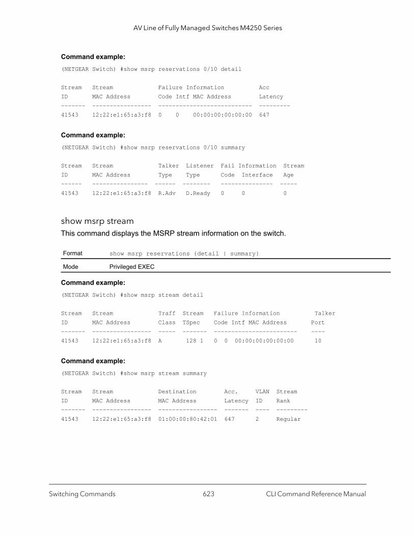
AV Line of Fully Managed Switches M4250 Series
Command example: (NETGEAR Switch) #show msrp reservations 0/10 detail
Stream Stream Failure Information AccID MAC Address Code Intf MAC Address Latency------- ----------------- --------------------------- ---------41543 12:22:e1:65:a3:f8 0 0 00:00:00:00:00:00 647
Command example: (NETGEAR Switch) #show msrp reservations 0/10 summary
Stream Stream Talker Listener Fail Information StreamID MAC Address Type Type Code Interface Age------ ---------------- ------ -------- --------------- -----41543 12:22:e1:65:a3:f8 R.Adv D.Ready 0 0 0
show msrp streamThis command displays the MSRP stream information on the switch.
Command example: (NETGEAR Switch) #show msrp stream detail
Stream Stream Traff Stream Failure Information TalkerID MAC Address Class TSpec Code Intf MAC Address Port------- ----------------- ----- ------- ------------------------ ----41543 12:22:e1:65:a3:f8 A 128 1 0 0 00:00:00:00:00:00 10
Command example: (NETGEAR Switch) #show msrp stream summary
Stream Stream Destination Acc. VLAN StreamID MAC Address MAC Address Latency ID Rank------- ----------------- ----------------- ------- ---- ---------41543 12:22:e1:65:a3:f8 01:00:00:80:42:01 647 2 Regular
Format show msrp reservations {detail | summary}
Mode Privileged EXEC
Switching Commands CLI Command Reference Manual623
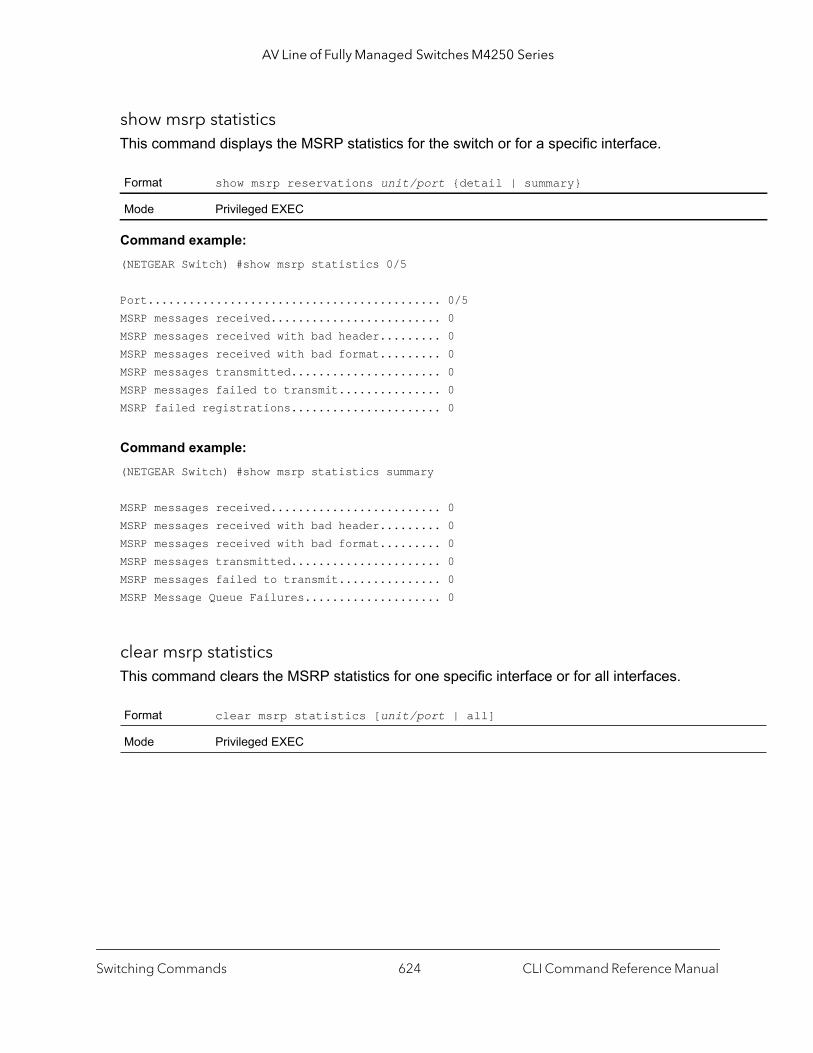
AV Line of Fully Managed Switches M4250 Series
show msrp statisticsThis command displays the MSRP statistics for the switch or for a specific interface.
Command example: (NETGEAR Switch) #show msrp statistics 0/5
Port........................................... 0/5MSRP messages received......................... 0MSRP messages received with bad header......... 0MSRP messages received with bad format......... 0MSRP messages transmitted...................... 0MSRP messages failed to transmit............... 0MSRP failed registrations...................... 0
Command example: (NETGEAR Switch) #show msrp statistics summary
MSRP messages received......................... 0MSRP messages received with bad header......... 0MSRP messages received with bad format......... 0MSRP messages transmitted...................... 0MSRP messages failed to transmit............... 0MSRP Message Queue Failures.................... 0
clear msrp statisticsThis command clears the MSRP statistics for one specific interface or for all interfaces.
Format show msrp reservations unit/port {detail | summary}
Mode Privileged EXEC
Format clear msrp statistics [unit/port | all]
Mode Privileged EXEC
Switching Commands CLI Command Reference Manual624
7
7Routing CommandsThis chapter describes the routing commands.
The chapter contains the following sections:
• Address Resolution Protocol Commands
• IP Routing Commands
• Routing Policy Commands
• Router Discovery Protocol Commands
• Virtual LAN Routing Commands
• DHCP and BootP Relay Commands
• IP Helper Commands
• Routing Information Protocol Commands
• ICMP Throttling Commands
The commands in this chapter are in one of three functional groups:
• Show commands. Display switch settings, statistics, and other information.• Configuration commands. Configure features and options of the switch. For every
configuration command, there is a show command that displays the configuration setting.• Clear commands. Clear some or all of the settings to factory defaults.
625

AV Line of Fully Managed Switches M4250 Series
Address Resolution Protocol Commands
This section describes the commands you use to configure Address Resolution Protocol (ARP) and to view ARP information on the switch. ARP associates IP addresses with MAC addresses and stores the information as ARP entries in the ARP cache.
arpThis command creates an ARP entry. The value for ipaddress is the IP address of a device on a subnet attached to an existing routing interface. The parameter macaddr is a unicast MAC address for that device. The interface parameter specifies the next hop interface.
The format of the MAC address is 6 two-digit hexadecimal numbers that are separated by colons, for example 00:06:29:32:81:40
no arp
This command deletes an ARP entry. The value for ipaddress is the IP address of a device on a subnet attached to an existing routing interface. The parameter macaddr is a unicast MAC address for that device. The interface parameter specifies the next hop interface.
ip proxy-arpThis command enables proxy ARP on a router interface or range of interfaces. Without proxy ARP, a device only responds to an ARP request if the target IP address is an address configured on the interface where the ARP request arrived. With proxy ARP, the device may also respond if the target IP address is reachable. The device only responds if all next hops in its route to the destination are through interfaces other than the interface that received the ARP request.
Format arp ipaddress macaddr interface {unit/port | vlan id}
Mode Global Config
Format arp ipaddress macaddr interface {unit/port}
Mode Global Config
Default enabled
Format ip proxy-arp
Mode Interface Config
Routing Commands CLI Command Reference Manual626

AV Line of Fully Managed Switches M4250 Series
no ip proxy-arp
This command disables proxy ARP on a router interface.
ip local-proxy-arpUse this command to allow an interface to respond to ARP requests for IP addresses within the subnet and to forward traffic between hosts in the subnet.
no ip local-proxy-arp
This command resets the local proxy ARP mode on the interface to the default value.
arp cachesizeThis command configures the ARP cache size. The ARP cache size value is a platform specific integer value. The default size also varies depending on the platform.
no arp cachesize
This command configures the default ARP cache size.
arp dynamicrenewThis command enables the ARP component to automatically renew dynamic ARP entries when they age out. When an ARP entry reaches its maximum age, the system must decide whether to retain or delete the entry. If the entry has recently been used to forward data packets, the system will renew the entry by sending an ARP request to the neighbor. If the neighbor responds, the age of the ARP cache entry is reset to 0 without removing the entry
Format no ip proxy-arp
Mode Interface Config
Default disabled
Format ip local-proxy-arp
Mode Interface Config
Format no ip local-proxy-arp
Mode Interface Config
Format arp cachesize platform-specific-integer-value
Mode Global Config
Format no arp cachesize
Mode Global Config
Routing Commands CLI Command Reference Manual627
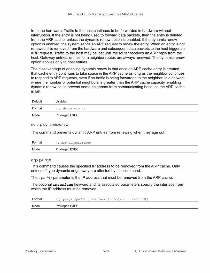
AV Line of Fully Managed Switches M4250 Series
from the hardware. Traffic to the host continues to be forwarded in hardware without interruption. If the entry is not being used to forward data packets, then the entry is deleted from the ARP cache, unless the dynamic renew option is enabled. If the dynamic renew option is enabled, the system sends an ARP request to renew the entry. When an entry is not renewed, it is removed from the hardware and subsequent data packets to the host trigger an ARP request. Traffic to the host may be lost until the router receives an ARP reply from the host. Gateway entries, entries for a neighbor router, are always renewed. The dynamic renew option applies only to host entries.
The disadvantage of enabling dynamic renew is that once an ARP cache entry is created, that cache entry continues to take space in the ARP cache as long as the neighbor continues to respond to ARP requests, even if no traffic is being forwarded to the neighbor. In a network where the number of potential neighbors is greater than the ARP cache capacity, enabling dynamic renew could prevent some neighbors from communicating because the ARP cache is full.
no arp dynamicrenew
This command prevents dynamic ARP entries from renewing when they age out.
arp purgeThis command causes the specified IP address to be removed from the ARP cache. Only entries of type dynamic or gateway are affected by this command.
The ipaddr parameter is the IP address that must be removed from the ARP cache.
The optional interface keyword and its associated parameters specify the interface from which the IP address must be removed.
Default disabled
Format arp dynamicrenew
Mode Privileged EXEC
Format no arp dynamicrenew
Mode Privileged EXEC
Format arp purge ipaddr [interface {unit/port | vlan-id}]
Mode Privileged EXEC
Routing Commands CLI Command Reference Manual628

AV Line of Fully Managed Switches M4250 Series
arp resptimeThis command configures the ARP request response time-out.
The value for seconds is a valid positive integer, which represents the IP ARP entry response time-out time in seconds. The range for seconds is between 1-10 seconds.
no arp resptime
This command configures the default ARP request response timeout.
arp retriesThis command configures the ARP count of maximum request for retries.
The value for retries is an integer, which represents the maximum number of request for retries. The range for retries is an integer between 0-10 retries.
no arp retries
This command configures the default ARP count of maximum request for retries.
arp timeoutThis command configures the ARP entry ageout time.
The value for seconds is a valid positive integer, which represents the IP ARP entry ageout time in seconds. The range for seconds is between 15-21600 seconds.
Default 1
Format arp resptime seconds
Mode Global Config
Format no arp resptime
Mode Global Config
Default 4
Format arp retries retries
Mode Global Config
Format no arp retries
Mode Global Config
Routing Commands CLI Command Reference Manual629
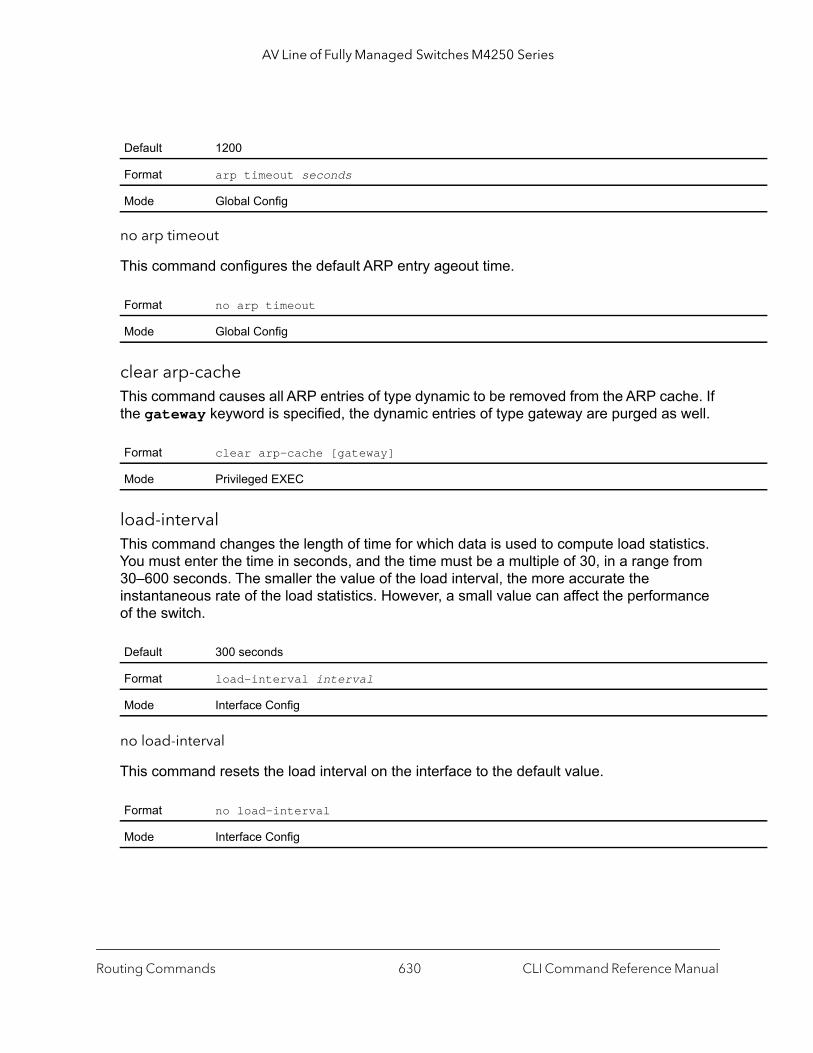
AV Line of Fully Managed Switches M4250 Series
no arp timeout
This command configures the default ARP entry ageout time.
clear arp-cacheThis command causes all ARP entries of type dynamic to be removed from the ARP cache. If the gateway keyword is specified, the dynamic entries of type gateway are purged as well.
load-intervalThis command changes the length of time for which data is used to compute load statistics. You must enter the time in seconds, and the time must be a multiple of 30, in a range from 30–600 seconds. The smaller the value of the load interval, the more accurate the instantaneous rate of the load statistics. However, a small value can affect the performance of the switch.
no load-interval
This command resets the load interval on the interface to the default value.
Default 1200
Format arp timeout seconds
Mode Global Config
Format no arp timeout
Mode Global Config
Format clear arp-cache [gateway]
Mode Privileged EXEC
Default 300 seconds
Format load-interval interval
Mode Interface Config
Format no load-interval
Mode Interface Config
Routing Commands CLI Command Reference Manual630

AV Line of Fully Managed Switches M4250 Series
when
clear arp-switchUse this command to clear the contents of the switch’s Address Resolution Protocol (ARP) table that contains entries learned through the Management port. To observe whether this command is successful, ping from the remote system to the switch. Issue the show arp switch command to see the ARP entries. Then issue the clear arp-switch command and check the show arp switch entries: ARP entries are no longer shown.
show arpThis command displays the Address Resolution Protocol (ARP) cache. The displayed results are not the total ARP entries. To view the total ARP entries, the view the output of the show arp command in conjunction with the output of the show arp switch command.
The following are displayed for each ARP entry:
Format clear arp-switch
Mode Privileged EXEC
Format show arp
Mode Privileged EXEC
Term Definition
Age Time (seconds) The time it takes for an ARP entry to age out. This is configurable. Age time is measured in seconds.
Response Time (seconds)
The time it takes for an ARP request timeout. This value is configurable. Response time is measured in seconds.
Retries The maximum number of times an ARP request is retried. This value is configurable.
Cache Size The maximum number of entries in the ARP table. This value is configurable.
Dynamic Renew Mode
Displays whether the ARP component automatically attempts to renew dynamic ARP entries they age out.
Total Entry Count Current / Peak
The total entries in the ARP table and the peak entry count in the ARP table.
Static Entry Count Current / Max
The static entry count in the ARP table and maximum static entry count in the ARP table.
Term Definition
IP Address The IP address of a device on a subnet attached to an existing routing interface.
MAC Address The hardware MAC address of that device.
Interface The routing unit/port associated with the device ARP entry.
Routing Commands CLI Command Reference Manual631
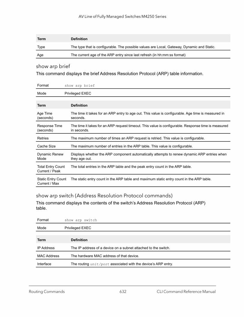
AV Line of Fully Managed Switches M4250 Series
in
sured
hen
show arp briefThis command displays the brief Address Resolution Protocol (ARP) table information.
show arp switch (Address Resolution Protocol commands)This command displays the contents of the switch’s Address Resolution Protocol (ARP) table.
Type The type that is configurable. The possible values are Local, Gateway, Dynamic and Static.
Age The current age of the ARP entry since last refresh (in hh:mm:ss format)
Format show arp brief
Mode Privileged EXEC
Term Definition
Age Time (seconds)
The time it takes for an ARP entry to age out. This value is configurable. Age time is measuredseconds.
Response Time (seconds)
The time it takes for an ARP request timeout. This value is configurable. Response time is meain seconds.
Retries The maximum number of times an ARP request is retried. This value is configurable.
Cache Size The maximum number of entries in the ARP table. This value is configurable.
Dynamic Renew Mode
Displays whether the ARP component automatically attempts to renew dynamic ARP entries wthey age out.
Total Entry Count Current / Peak
The total entries in the ARP table and the peak entry count in the ARP table.
Static Entry Count Current / Max
The static entry count in the ARP table and maximum static entry count in the ARP table.
Format show arp switch
Mode Privileged EXEC
Term Definition
IP Address The IP address of a device on a subnet attached to the switch.
MAC Address The hardware MAC address of that device.
Interface The routing unit/port associated with the device’s ARP entry.
Term Definition
Routing Commands CLI Command Reference Manual632

AV Line of Fully Managed Switches M4250 Series
IP Routing Commands
This section describes the commands you use to enable and configure IP routing on the switch.
autostateThis command enables AutoState for a VLAN routing interface. AutoState changes the state of a VLAN routing interface automatically based on link state events (up or down).
By default, AutoState is disabled, which means that a VLAN routing interface could remain up even if the link is down.
no autostate
This command disables AutoState for a VLAN routing interface.
routing This command enables IPv4 and IPv6 routing for an interface or range of interfaces. You can view the current value for this function with the show ip brief command. The value is labeled as Routing Mode.
no routing
This command disables routing for an interface.
You can view the current value for this function with the show ip brief command. The value is labeled as Routing Mode.
Format autostate
Mode Interface Config
Format no autostate
Mode Interface Config
Default disabled
Format routing
Mode Interface Config
Format no routing
Mode Interface Config
Routing Commands CLI Command Reference Manual633
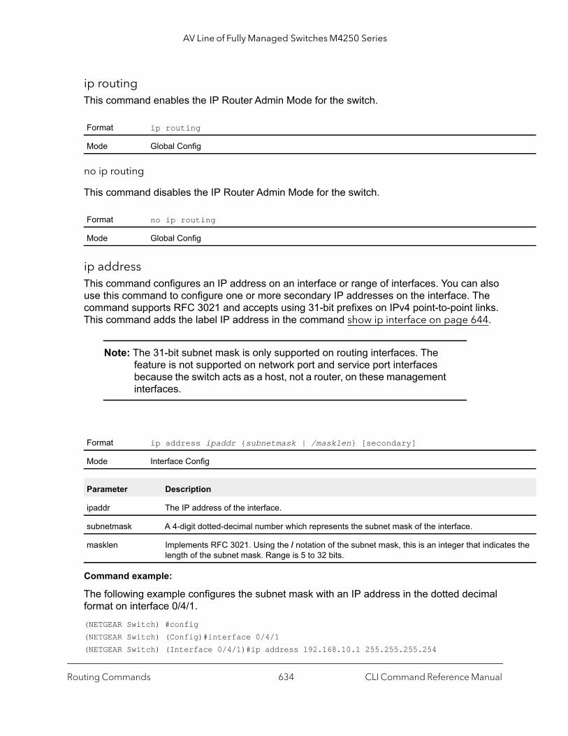
AV Line of Fully Managed Switches M4250 Series
s the
ip routing This command enables the IP Router Admin Mode for the switch.
no ip routing
This command disables the IP Router Admin Mode for the switch.
ip addressThis command configures an IP address on an interface or range of interfaces. You can also use this command to configure one or more secondary IP addresses on the interface. The command supports RFC 3021 and accepts using 31-bit prefixes on IPv4 point-to-point links. This command adds the label IP address in the command show ip interface on page 644.
Note: The 31-bit subnet mask is only supported on routing interfaces. The feature is not supported on network port and service port interfaces because the switch acts as a host, not a router, on these management interfaces.
Command example:
The following example configures the subnet mask with an IP address in the dotted decimal format on interface 0/4/1.(NETGEAR Switch) #config(NETGEAR Switch) (Config)#interface 0/4/1(NETGEAR Switch) (Interface 0/4/1)#ip address 192.168.10.1 255.255.255.254
Format ip routing
Mode Global Config
Format no ip routing
Mode Global Config
Format ip address ipaddr {subnetmask | /masklen} [secondary]
Mode Interface Config
Parameter Description
ipaddr The IP address of the interface.
subnetmask A 4-digit dotted-decimal number which represents the subnet mask of the interface.
masklen Implements RFC 3021. Using the / notation of the subnet mask, this is an integer that indicatelength of the subnet mask. Range is 5 to 32 bits.
Routing Commands CLI Command Reference Manual634

AV Line of Fully Managed Switches M4250 Series
Command example:
The following example configures the subnet mask with an IP address in the / notation on interface 0/4/1.(NETGEAR Switch) #config(NETGEAR Switch) (Config)#interface 0/4/1(NETGEAR Switch) (Interface 0/4/1)#ip address 192.168.10.1 /31
no ip address
This command deletes an IP address from an interface. The value for ipaddr is the IP address of the interface in a.b.c.d format where the range for a, b, c, and d is 1-255. The value for subnetmask is a 4-digit dotted-decimal number which represents the Subnet Mask of the interface. To remove all of the IP addresses (primary and secondary) configured on the interface, enter the command no ip address.
ip address dhcpThis command enables the DHCPv4 client on an in-band interface so that it can acquire network information, such as the IP address, subnet mask, and default gateway, from a network DHCP server. When DHCP is enabled on the interface, the system automatically deletes all manually configured IPv4 addresses on the interface.
To enable the DHCPv4 client on an in-band interface and send DHCP client messages with the client identifier option, use the ip address dhcp client-id configuration command in interface configuration mode.
Command example:
The following example enables DHCPv4 on interface 0/4/1:(NETGEAR Switch) #config(NETGEAR Switch) (Config)#interface 0/4/1(NETGEAR Switch) (Interface 0/4/1)#ip address dhcp
Format no ip address [ipaddr subnetmask [secondary]]
Mode Interface Config
Default disabled
Format ip address dhcp [client-id]
Mode Interface Config
Routing Commands CLI Command Reference Manual635
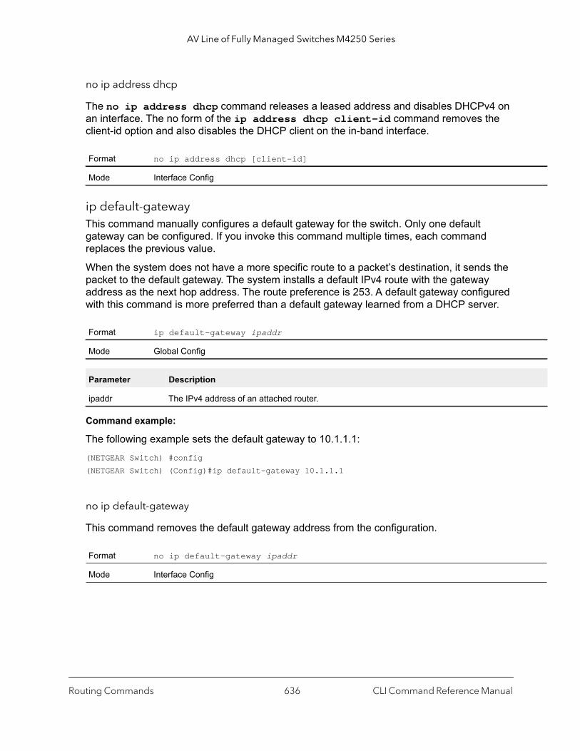
AV Line of Fully Managed Switches M4250 Series
no ip address dhcp
The no ip address dhcp command releases a leased address and disables DHCPv4 on an interface. The no form of the ip address dhcp client-id command removes the client-id option and also disables the DHCP client on the in-band interface.
ip default-gatewayThis command manually configures a default gateway for the switch. Only one default gateway can be configured. If you invoke this command multiple times, each command replaces the previous value.
When the system does not have a more specific route to a packet’s destination, it sends the packet to the default gateway. The system installs a default IPv4 route with the gateway address as the next hop address. The route preference is 253. A default gateway configured with this command is more preferred than a default gateway learned from a DHCP server.
Command example:
The following example sets the default gateway to 10.1.1.1:(NETGEAR Switch) #config(NETGEAR Switch) (Config)#ip default-gateway 10.1.1.1
no ip default-gateway
This command removes the default gateway address from the configuration.
Format no ip address dhcp [client-id]
Mode Interface Config
Format ip default-gateway ipaddr
Mode Global Config
Parameter Description
ipaddr The IPv4 address of an attached router.
Format no ip default-gateway ipaddr
Mode Interface Config
Routing Commands CLI Command Reference Manual636

AV Line of Fully Managed Switches M4250 Series
acket. Port
/UDP
ource
ip load-sharingThis command configures the IP equal-cost multipath (ECMP) load balancing mode.
no ip load-sharingThis command resets the IP ECMP load balancing mode to default mode (6).
ip unnumbered gratuitous-arp acceptThis command enables the switch to automatically configure static interface routes to an unnumbered peer when the switch dynamically receives gratuitous ARP messages. The switch uses the IP address of the loopback interface (see the ip unnumbered loopback command) as the IP address for the unnumbered peer. This behavior is enabled by default.
no ip unnumbered gratuitous-arp accept
This command prevents the switch from automatically configuring static interface routes to an unnumbered peer when the switch dynamically receives gratuitous ARP messages.
Default 6
Format ip load-sharing mode {inner | outer}
Mode Global Config
Parameter Description
mode • 1. The mode is based on a hash using the source IP address of the packet.• 2. The mode is based on a hash using the destination IP address of the packet.• 3. The mode is based on a hash using the source and destination IP addresses of the p• 4. The mode is based on a hash using the source IP address and the Source TCP/UDP
field of the packet.• 5. The mode is based on a hash using the destination IP address and the Destination TCP
Port field of the packet.• 6. The mode is based on a hash using the source and destination IP addresses and the S
and Destination TCP/UDP Port fields of the packet.
inner The inner IP header is used for tunneled packets.
outer The outer IP header is used for tunneled packets.
Format no ip load-sharing
Mode Global Config
Format ip unnumbered gratuitous-arp accept
Mode Interface Config
Format no ip unnumbered gratuitous-arp accept
Mode Interface Config
Routing Commands CLI Command Reference Manual637

AV Line of Fully Managed Switches M4250 Series
ip unnumbered loopbackThis command enables the switch to identify an unnumbered interface and specifies the numbered loopback interface from which the unnumbered interface can borrow an address.
The interface argument specifies the loopback interface number.
no ip unnumbered loopback
This removes an unnumbered interface configuration.
release dhcpUse this command to force the DHCPv4 client to release the leased address from a specified interface or VLAN. The DHCP client sends a DHCP Release message telling the DHCP server that it no longer needs the IP address, and that the IP address can be reassigned to another.
renew dhcpUse this command to force the DHCPv4 client to immediately renew an IPv4 address lease for a specified interface or VLAN.
Note: This command can be used on in-band ports as well as the service or network (out-of-band) port.
Format ip unnumbered loopback interface
Mode Interface Config
Format no ip unnumbered loopback
Mode Interface Config
Format release dhcp {unit/port | vlan vlan-id}
Mode Privileged EXEC
Format renew dhcp {unit/port | vlan vlan-id}
Mode Privileged EXEC
Routing Commands CLI Command Reference Manual638
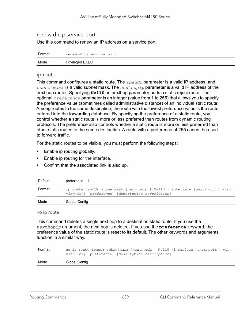
AV Line of Fully Managed Switches M4250 Series
lan
lan
renew dhcp service-portUse this command to renew an IP address on a service port.
ip routeThis command configures a static route. The ipaddr parameter is a valid IP address, and subnetmask is a valid subnet mask. The nexthopip parameter is a valid IP address of the next hop router. Specifying Null0 as nexthop parameter adds a static reject route. The optional preference parameter is an integer (value from 1 to 255) that allows you to specify the preference value (sometimes called administrative distance) of an individual static route. Among routes to the same destination, the route with the lowest preference value is the route entered into the forwarding database. By specifying the preference of a static route, you control whether a static route is more or less preferred than routes from dynamic routing protocols. The preference also controls whether a static route is more or less preferred than other static routes to the same destination. A route with a preference of 255 cannot be used to forward traffic.
For the static routes to be visible, you must perform the following steps:
• Enable ip routing globally.• Enable ip routing for the interface. • Confirm that the associated link is also up.
no ip route
This command deletes a single next hop to a destination static route. If you use the nexthopip argument, the next hop is deleted. If you use the preference keyword, the preference value of the static route is reset to its default. The other keywords and arguments function in a similar way.
Format renew dhcp service-port
Mode Privileged EXEC
Default preference—1
Format ip route ipaddr subnetmask [nexthopip | Null0 | interface {unit/port | vvlan-id}] [preference] [description description]
Mode Global Config
Format no ip route ipaddr subnetmask [nexthopip | Null0 |interface {unit/port | vvlan-id}] [preference] [description description]
Mode Global Config
Routing Commands CLI Command Reference Manual639
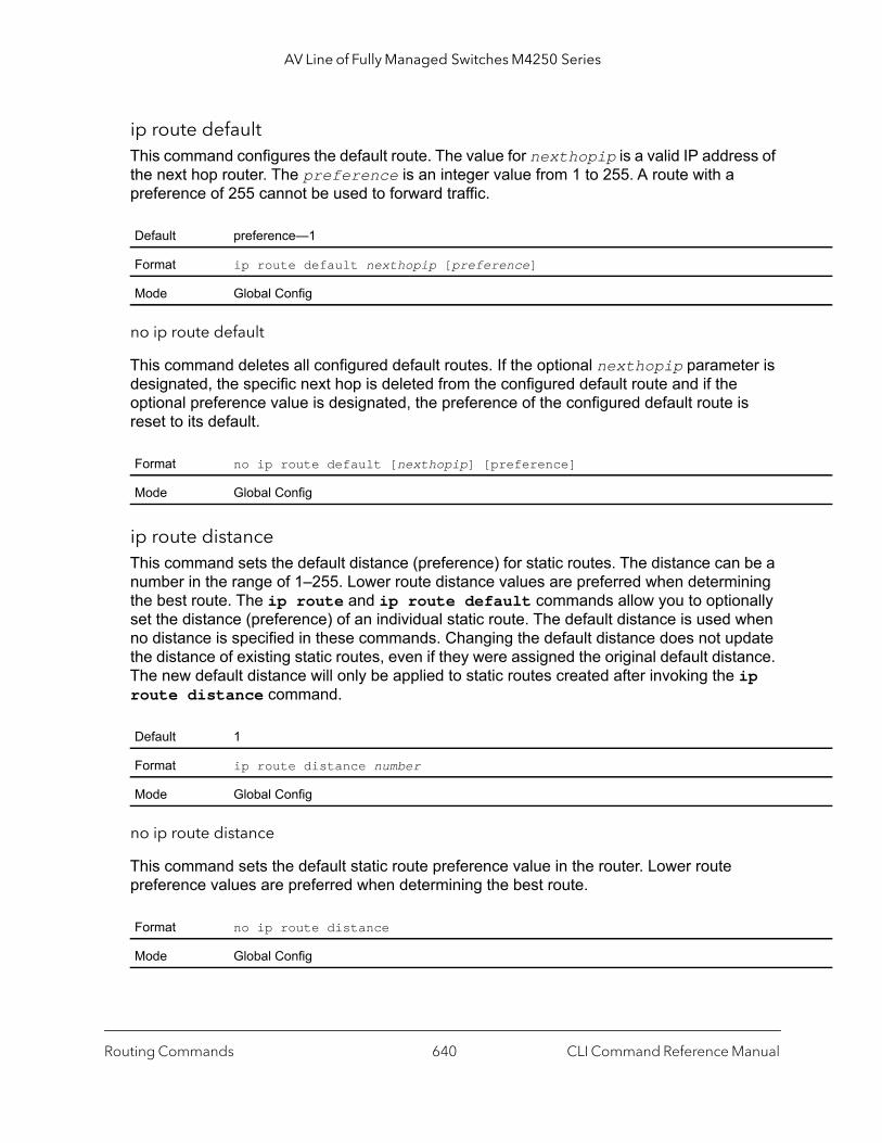
AV Line of Fully Managed Switches M4250 Series
ip route defaultThis command configures the default route. The value for nexthopip is a valid IP address of the next hop router. The preference is an integer value from 1 to 255. A route with a preference of 255 cannot be used to forward traffic.
no ip route default
This command deletes all configured default routes. If the optional nexthopip parameter is designated, the specific next hop is deleted from the configured default route and if the optional preference value is designated, the preference of the configured default route is reset to its default.
ip route distance This command sets the default distance (preference) for static routes. The distance can be a number in the range of 1–255. Lower route distance values are preferred when determining the best route. The ip route and ip route default commands allow you to optionally set the distance (preference) of an individual static route. The default distance is used when no distance is specified in these commands. Changing the default distance does not update the distance of existing static routes, even if they were assigned the original default distance. The new default distance will only be applied to static routes created after invoking the ip route distance command.
no ip route distance
This command sets the default static route preference value in the router. Lower route preference values are preferred when determining the best route.
Default preference—1
Format ip route default nexthopip [preference]
Mode Global Config
Format no ip route default [nexthopip] [preference]
Mode Global Config
Default 1
Format ip route distance number
Mode Global Config
Format no ip route distance
Mode Global Config
Routing Commands CLI Command Reference Manual640
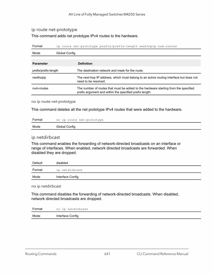
AV Line of Fully Managed Switches M4250 Series
not
d
ip route net-prototypeThis command adds net prototype IPv4 routes to the hardware.
no ip route net-prototype
This command deletes all the net prototype IPv4 routes that were added to the hardware.
ip netdirbcast This command enables the forwarding of network-directed broadcasts on an interface or range of interfaces. When enabled, network directed broadcasts are forwarded. When disabled they are dropped.
no ip netdirbcast
This command disables the forwarding of network-directed broadcasts. When disabled, network directed broadcasts are dropped.
Format ip route net-prototype prefix/prefix-length nexthopip num-routes
Mode Global Config
Parameter Definition
prefix/prefix-length The destination network and mask for the route.
nexthopip The next-hop IP address, which must belong to an active routing interface but doesneed to be resolved.
num-routes The number of routes that must be added to the hardware starting from the specifieprefix argument and within the specified prefix length.
Format no ip route net-prototype
Mode Global Config
Default disabled
Format ip netdirbcast
Mode Interface Config
Format no ip netdirbcast
Mode Interface Config
Routing Commands CLI Command Reference Manual641
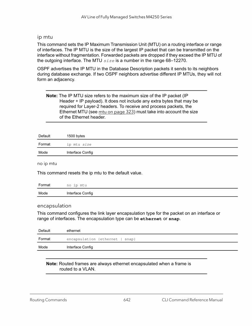
AV Line of Fully Managed Switches M4250 Series
ip mtuThis command sets the IP Maximum Transmission Unit (MTU) on a routing interface or range of interfaces. The IP MTU is the size of the largest IP packet that can be transmitted on the interface without fragmentation. Forwarded packets are dropped if they exceed the IP MTU of the outgoing interface. The MTU size is a number in the range 68–12270.
OSPF advertises the IP MTU in the Database Description packets it sends to its neighbors during database exchange. If two OSPF neighbors advertise different IP MTUs, they will not form an adjacency.
Note: The IP MTU size refers to the maximum size of the IP packet (IP Header + IP payload). It does not include any extra bytes that may be required for Layer-2 headers. To receive and process packets, the Ethernet MTU (see mtu on page 323) must take into account the size of the Ethernet header.
no ip mtu
This command resets the ip mtu to the default value.
encapsulation This command configures the link layer encapsulation type for the packet on an interface or range of interfaces. The encapsulation type can be ethernet or snap.
Note: Routed frames are always ethernet encapsulated when a frame is routed to a VLAN.
Default 1500 bytes
Format ip mtu size
Mode Interface Config
Format no ip mtu
Mode Interface Config
Default ethernet
Format encapsulation {ethernet | snap}
Mode Interface Config
Routing Commands CLI Command Reference Manual642
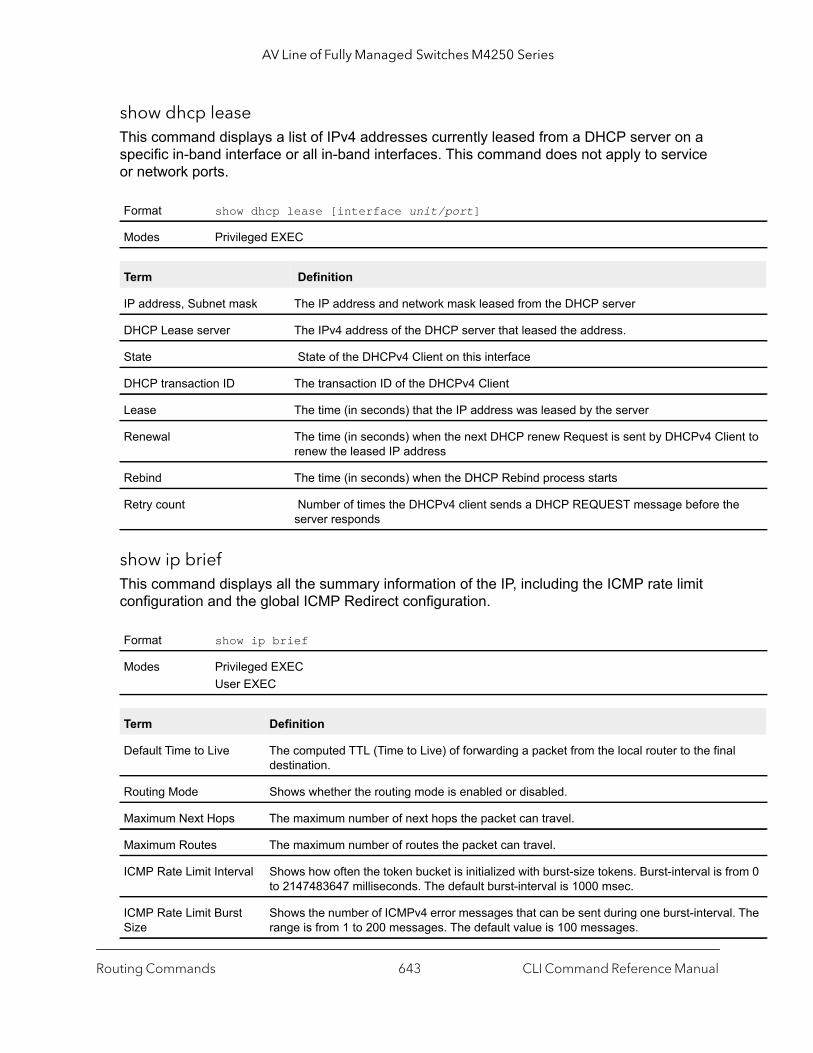
AV Line of Fully Managed Switches M4250 Series
nt to
e
l
om 0
l. The
show dhcp leaseThis command displays a list of IPv4 addresses currently leased from a DHCP server on a specific in-band interface or all in-band interfaces. This command does not apply to service or network ports.
show ip briefThis command displays all the summary information of the IP, including the ICMP rate limit configuration and the global ICMP Redirect configuration.
Format show dhcp lease [interface unit/port]
Modes Privileged EXEC
Term Definition
IP address, Subnet mask The IP address and network mask leased from the DHCP server
DHCP Lease server The IPv4 address of the DHCP server that leased the address.
State State of the DHCPv4 Client on this interface
DHCP transaction ID The transaction ID of the DHCPv4 Client
Lease The time (in seconds) that the IP address was leased by the server
Renewal The time (in seconds) when the next DHCP renew Request is sent by DHCPv4 Clierenew the leased IP address
Rebind The time (in seconds) when the DHCP Rebind process starts
Retry count Number of times the DHCPv4 client sends a DHCP REQUEST message before thserver responds
Format show ip brief
Modes Privileged EXECUser EXEC
Term Definition
Default Time to Live The computed TTL (Time to Live) of forwarding a packet from the local router to the finadestination.
Routing Mode Shows whether the routing mode is enabled or disabled.
Maximum Next Hops The maximum number of next hops the packet can travel.
Maximum Routes The maximum number of routes the packet can travel.
ICMP Rate Limit Interval Shows how often the token bucket is initialized with burst-size tokens. Burst-interval is frto 2147483647 milliseconds. The default burst-interval is 1000 msec.
ICMP Rate Limit Burst Size
Shows the number of ICMPv4 error messages that can be sent during one burst-intervarange is from 1 to 200 messages. The default value is 100 messages.
Routing Commands CLI Command Reference Manual643

AV Line of Fully Managed Switches M4250 Series
n.
figure
nly if
able.
Command example: (NETGEAR Switch) #show ip brief
Default Time to Live........................... 64Routing Mode................................... DisabledMaximum Next Hops.............................. 4Maximum Routes................................. 128ICMP Rate Limit Interval....................... 1000 msecICMP Rate Limit Burst Size..................... 100 messagesICMP Echo Replies.............................. EnabledICMP Redirects................................. Enabled
show ip interface This command displays all pertinent information about the IP interface. The argument unit/port corresponds to a physical routing interface or VLAN routing interface. The keyword vlan is used to specify the VLAN ID of the routing VLAN directly instead of in a unit/port format.
The vlan-id is a number in the range 1–4093. The loopback number is in the range 0–7.
ICMP Echo Replies Shows whether ICMP Echo Replies are enabled or disabled.
ICMP Redirects Shows whether ICMP Redirects are enabled or disabled.
Format show ip interface {unit/port | vlan vland-id | loopback number}
Modes Privileged EXECUser EXEC
Term Definition
Routing Interface Status
Determine the operational status of IPv4 routing Interface. The possible values are Up or Dow
Primary IP Address The primary IP address and subnet masks for the interface. This value appears only if you conit.
Method Shows whether the IP address was configured manually or acquired from a DHCP server.
Secondary IP Address
One or more secondary IP addresses and subnet masks for the interface. This value appears oyou configure it.
Helper IP Address The helper IP addresses configured by the command ip helper-address (Interface Config) onpage 678.
Routing Mode The administrative mode of router interface participation. The possible values are enable or disThis value is configurable.
Term Definition
Routing Commands CLI Command Reference Manual644
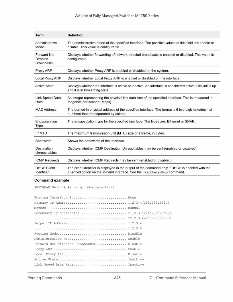
AV Line of Fully Managed Switches M4250 Series
or
is
s up
in
al
Command example: (NETGEAR Switch) #show ip interface 1/0/2
Routing Interface Status....................... DownPrimary IP Address............................. 1.2.3.4/255.255.255.0Method......................................... ManualSecondary IP Address(es)....................... 21.2.3.4/255.255.255.0............................................... 22.2.3.4/255.255.255.0Helper IP Address.............................. 1.2.3.4............................................... 1.2.3.5Routing Mode................................... DisableAdministrative Mode............................ EnableForward Net Directed Broadcasts................ DisableProxy ARP...................................... EnableLocal Proxy ARP................................ DisableActive State................................... InactiveLink Speed Data Rate........................... Inactive
Administrative Mode
The administrative mode of the specified interface. The possible values of this field are enabledisable. This value is configurable.
Forward Net Directed Broadcasts
Displays whether forwarding of network-directed broadcasts is enabled or disabled. This valueconfigurable.
Proxy ARP Displays whether Proxy ARP is enabled or disabled on the system.
Local Proxy ARP Displays whether Local Proxy ARP is enabled or disabled on the interface.
Active State Displays whether the interface is active or inactive. An interface is considered active if its link iand it is in forwarding state.
Link Speed Data Rate
An integer representing the physical link data rate of the specified interface. This is measured Megabits per second (Mbps).
MAC Address The burned in physical address of the specified interface. The format is 6 two-digit hexadecimnumbers that are separated by colons.
Encapsulation Type
The encapsulation type for the specified interface. The types are: Ethernet or SNAP.
IP MTU The maximum transmission unit (MTU) size of a frame, in bytes.
Bandwidth Shows the bandwidth of the interface.
Destination Unreachables
Displays whether ICMP Destination Unreachables may be sent (enabled or disabled).
ICMP Redirects Displays whether ICMP Redirects may be sent (enabled or disabled).
DHCP Client Identifier
The client identifier is displayed in the output of the command only if DHCP is enabled with theclient-id option on the in-band interface. See the ip address dhcp command.
Term Definition
Routing Commands CLI Command Reference Manual645
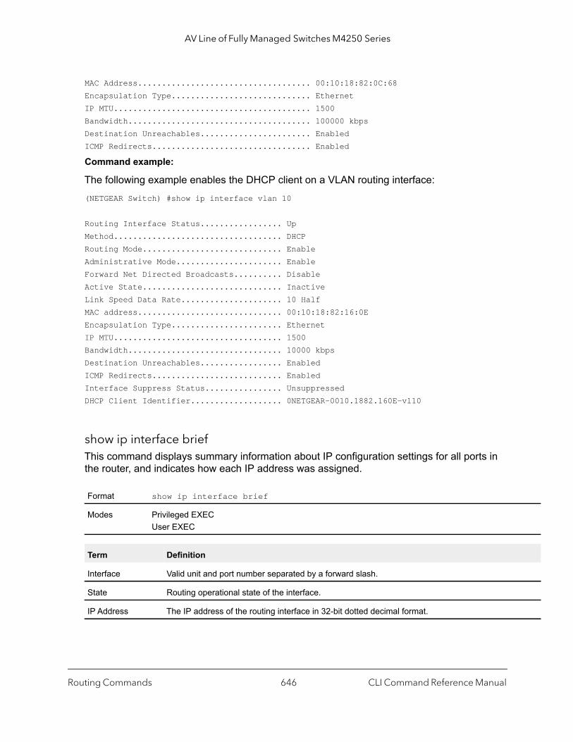
AV Line of Fully Managed Switches M4250 Series
MAC Address.................................... 00:10:18:82:0C:68Encapsulation Type............................. EthernetIP MTU......................................... 1500Bandwidth...................................... 100000 kbpsDestination Unreachables....................... EnabledICMP Redirects................................. Enabled
Command example:
The following example enables the DHCP client on a VLAN routing interface:(NETGEAR Switch) #show ip interface vlan 10
Routing Interface Status................. UpMethod................................... DHCPRouting Mode............................. EnableAdministrative Mode...................... EnableForward Net Directed Broadcasts.......... DisableActive State............................. InactiveLink Speed Data Rate..................... 10 HalfMAC address.............................. 00:10:18:82:16:0EEncapsulation Type....................... EthernetIP MTU................................... 1500Bandwidth................................ 10000 kbpsDestination Unreachables................. EnabledICMP Redirects........................... EnabledInterface Suppress Status................ UnsuppressedDHCP Client Identifier................... 0NETGEAR-0010.1882.160E-vl10
show ip interface briefThis command displays summary information about IP configuration settings for all ports in the router, and indicates how each IP address was assigned.
Format show ip interface brief
Modes Privileged EXECUser EXEC
Term Definition
Interface Valid unit and port number separated by a forward slash.
State Routing operational state of the interface.
IP Address The IP address of the routing interface in 32-bit dotted decimal format.
Routing Commands CLI Command Reference Manual646

AV Line of Fully Managed Switches M4250 Series
Command example: (alpha1) #show ip interface brief Interface State IP Address IP Mask Method ---------- ----- --------------- --------------- -------- 1/0/17 Up 192.168.75.1 255.255.255.0 DHCP
show ip load-sharingThis command displays the configured IP ECMP load balancing mode.
Command example: (NETGEAR Switch) #show ip load-sharingip load-sharing 6 inner
show ip protocolsThis command lists a summary of the configuration and status for each unicast routing protocol that is running. The command lists routing protocols that are configured and enabled. If you specify a protocol, the command output is limited to the protocol.
IP Mask The IP mask of the routing interface in 32-bit dotted decimal format.
Method Indicates how each IP address was assigned. The field contains one of the following values:• DHCP. The address is leased from a DHCP server.• Manual. The address is manually configured.
Format show ip load-sharing
Mode Privileged Exec
Format show ip protocols [rip]
Mode Privileged Exec
Term Description
RIP Admin Mode Whether RIP is globally enabled.
Split Horizon Mode Whether RIP advertises routes on the interface on which the routes are received.
Default Metric The metric assigned to redistributed routes.
Default Route Advertise
Whether the switch is originating a default route.
Distance The administrative distance for RIP routes.
Term Definition
Routing Commands CLI Command Reference Manual647
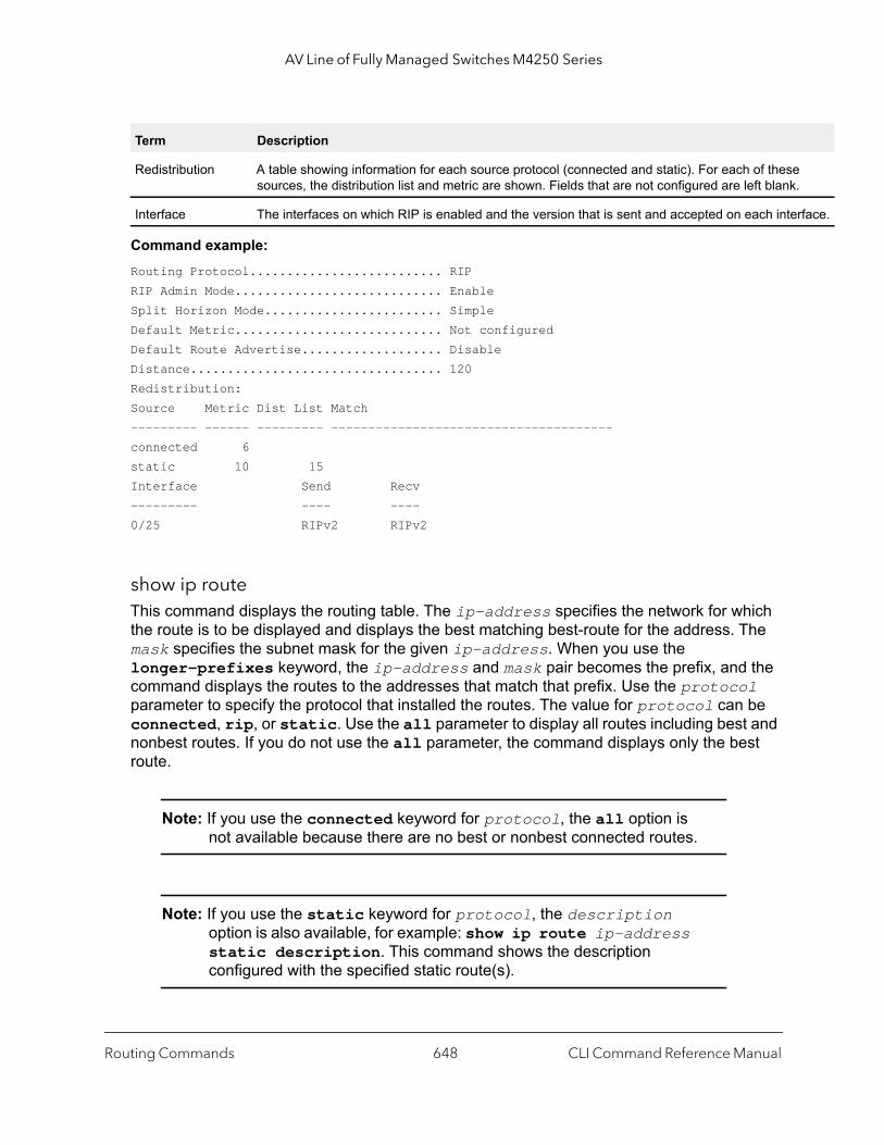
AV Line of Fully Managed Switches M4250 Series
.
rface.
Command example: Routing Protocol.......................... RIPRIP Admin Mode............................ EnableSplit Horizon Mode........................ SimpleDefault Metric............................ Not configuredDefault Route Advertise................... DisableDistance.................................. 120Redistribution:Source Metric Dist List Match--------- ------ --------- --------------------------------------connected 6static 10 15Interface Send Recv--------- ---- ----0/25 RIPv2 RIPv2
show ip route This command displays the routing table. The ip-address specifies the network for which the route is to be displayed and displays the best matching best-route for the address. The mask specifies the subnet mask for the given ip-address. When you use the longer-prefixes keyword, the ip-address and mask pair becomes the prefix, and the command displays the routes to the addresses that match that prefix. Use the protocol parameter to specify the protocol that installed the routes. The value for protocol can be connected, rip, or static. Use the all parameter to display all routes including best and nonbest routes. If you do not use the all parameter, the command displays only the best route.
Note: If you use the connected keyword for protocol, the all option is not available because there are no best or nonbest connected routes.
Note: If you use the static keyword for protocol, the description option is also available, for example: show ip route ip-address static description. This command shows the description configured with the specified static route(s).
Redistribution A table showing information for each source protocol (connected and static). For each of thesesources, the distribution list and metric are shown. Fields that are not configured are left blank
Interface The interfaces on which RIP is enabled and the version that is sent and accepted on each inte
Term Description
Routing Commands CLI Command Reference Manual648
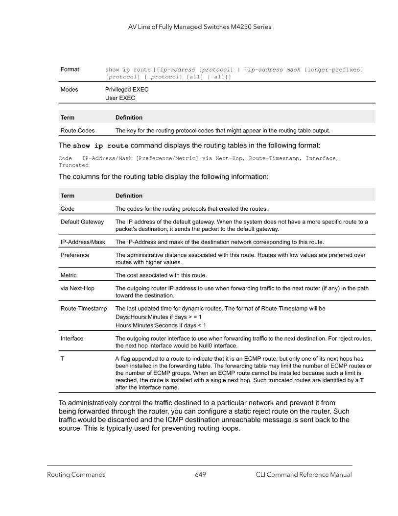
AV Line of Fully Managed Switches M4250 Series
]
to a
ver
path
utes,
as tes or is T
The show ip route command displays the routing tables in the following format:Code IP-Address/Mask [Preference/Metric] via Next-Hop, Route-Timestamp, Interface, Truncated
The columns for the routing table display the following information:
To administratively control the traffic destined to a particular network and prevent it from being forwarded through the router, you can configure a static reject route on the router. Such traffic would be discarded and the ICMP destination unreachable message is sent back to the source. This is typically used for preventing routing loops.
Format show ip route [{ip-address [protocol] | {ip-address mask [longer-prefixes[protocol] | protocol} [all] | all}]
Modes Privileged EXECUser EXEC
Term Definition
Route Codes The key for the routing protocol codes that might appear in the routing table output.
Term Definition
Code The codes for the routing protocols that created the routes.
Default Gateway The IP address of the default gateway. When the system does not have a more specific route packet's destination, it sends the packet to the default gateway.
IP-Address/Mask The IP-Address and mask of the destination network corresponding to this route.
Preference The administrative distance associated with this route. Routes with low values are preferred oroutes with higher values.
Metric The cost associated with this route.
via Next-Hop The outgoing router IP address to use when forwarding traffic to the next router (if any) in the toward the destination.
Route-Timestamp The last updated time for dynamic routes. The format of Route-Timestamp will be Days:Hours:Minutes if days > = 1Hours:Minutes:Seconds if days < 1
Interface The outgoing router interface to use when forwarding traffic to the next destination. For reject rothe next hop interface would be Null0 interface.
T A flag appended to a route to indicate that it is an ECMP route, but only one of its next hops hbeen installed in the forwarding table. The forwarding table may limit the number of ECMP routhe number of ECMP groups. When an ECMP route cannot be installed because such a limit reached, the route is installed with a single next hop. Such truncated routes are identified by aafter the interface name.
Routing Commands CLI Command Reference Manual649

AV Line of Fully Managed Switches M4250 Series
Command example: (NETGEAR Switch) #show ip route
Route Codes: R - RIP Derived, C - Connected, S - Static
Default gateway is 1.1.1.2C 1.1.1.0/24 [0/1] directly connected, 0/11C 2.2.2.0/24 [0/1] directly connected, 0/1C 5.5.5.0/24 [0/1] directly connected, 0/5S 7.0.0.0/8 [1/0] directly connected, Null0C 11.11.11.0/24 [0/1] directly connected, 0/11S 12.0.0.0/8 [5/0] directly connected, Null0S 23.0.0.0/8 [3/0] directly connected, Null0C 1.1.1.0/24 [0/1] directly connected, 0/11C 2.2.2.0/24 [0/1] directly connected, 0/1C 5.5.5.0/24 [0/1] directly connected, 0/5C 11.11.11.0/24 [0/1] directly connected, 0/11S 10.3.2.0/24 [1/0] via 1.1.1.2, 0/11
show ip route ecmp-groupsThis command reports all current ECMP groups in the IPv4 routing table. An ECMP group is a set of two or more next hops used in one or more routes. The groups are numbered arbitrarily from 1 to n. The output indicates the number of next hops in the group and the number of routes that use the set of next hops. The output lists the IPv4 address and outgoing interface of each next hop in each group.
Command example: (NETGEAR Switch) #show ip route ecmp-groups
ECMP Group 1 with 2 next hops (used by 1 route) 172.20.33.100 on interface 2/33 172.20.34.100 on interface 2/34ECMP Group 2 with 3 next hops (used by 1 route) 172.20.32.100 on interface 2/32 172.20.33.100 on interface 2/33 172.20.34.100 on interface 2/34ECMP Group 3 with 4 next hops (used by 1 route) 172.20.31.100 on interface 2/31 172.20.32.100 on interface 2/32 172.20.33.100 on interface 2/33 172.20.34.100 on interface 2/34
Format show ip route ecmp-groups
Mode Privileged Exec
Routing Commands CLI Command Reference Manual650
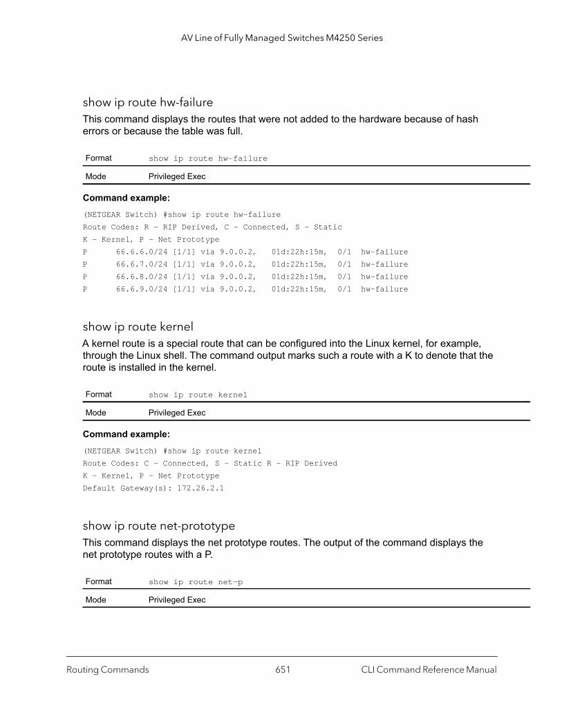
AV Line of Fully Managed Switches M4250 Series
show ip route hw-failureThis command displays the routes that were not added to the hardware because of hash errors or because the table was full.
Command example: (NETGEAR Switch) #show ip route hw-failureRoute Codes: R - RIP Derived, C - Connected, S - StaticK - Kernel, P - Net PrototypeP 66.6.6.0/24 [1/1] via 9.0.0.2, 01d:22h:15m, 0/1 hw-failureP 66.6.7.0/24 [1/1] via 9.0.0.2, 01d:22h:15m, 0/1 hw-failureP 66.6.8.0/24 [1/1] via 9.0.0.2, 01d:22h:15m, 0/1 hw-failureP 66.6.9.0/24 [1/1] via 9.0.0.2, 01d:22h:15m, 0/1 hw-failure
show ip route kernelA kernel route is a special route that can be configured into the Linux kernel, for example, through the Linux shell. The command output marks such a route with a K to denote that the route is installed in the kernel.
Command example: (NETGEAR Switch) #show ip route kernelRoute Codes: C - Connected, S - Static R - RIP DerivedK - Kernel, P - Net PrototypeDefault Gateway(s): 172.26.2.1
show ip route net-prototypeThis command displays the net prototype routes. The output of the command displays the net prototype routes with a P.
Format show ip route hw-failure
Mode Privileged Exec
Format show ip route kernel
Mode Privileged Exec
Format show ip route net-p
Mode Privileged Exec
Routing Commands CLI Command Reference Manual651

AV Line of Fully Managed Switches M4250 Series
te to ince
was
le.
bnet.
dded
Command example: (NETGEAR Switch) #show ip route net-prototypeRoute Codes: R - RIP Derived, C - Connected, S - Static, K - Kernel, P - Net PrototypeP 56.6.6.0/24 [1/1] via 9.0.0.2, 01d:22h:15m, 0/1P 56.6.7.0/24 [1/1] via 9.0.0.2, 01d:22h:15m, 0/1
show ip route summaryThis command displays a summary of the state of the routing table. When the optional all keyword is given, some statistics, such as the number of routes from each source, include counts for alternate routes. An alternate route is a route that is not the most preferred route to its destination and therefore is not installed in the forwarding table. To include only the number of best routes, do not use the optional keyword.
Format show ip route summary [all]
Modes Privileged EXECUser EXEC
Term Definition
Connected Routes The total number of connected routes in the routing table.
Static Routes Total number of static routes in the routing table.
RIP Routes Total number of routes installed by RIP protocol.
Reject Routes Total number of reject routes installed by all protocols.
Net Prototype Routes
The number of net prototype routes.
Total Routes Total number of routes in the routing table.
Best Routes (High) The number of best routes currently in the routing table. This number only counts the best roueach destination. The value in parentheses indicates the highest count of unique best routes scounters were last cleared.
Alternate Routes The number of alternate routes currently in the routing table. An alternate route is a route that not selected as the best route to its destination.
Route Adds The number of routes that have been added to the routing table.
Route Modifies The number of routes that have been changed after they were initially added to the routing tab
Route Deletes The number of routes that have been deleted from the routing table.
Unresolved Route Adds
The number of route adds that failed because none of the route’s next hops were on a local suNote that static routes can fail to be added to the routing table at startup because the routing interfaces are not yet up. In such a situation, the counter is incremented. The static routes are ato the routing table when the routing interfaces come up.
Routing Commands CLI Command Reference Manual652

AV Line of Fully Managed Switches M4250 Series
A log
ion in
wn.
clude cates
ludes ps
e
ext ps. d with
g
Command example: (NETGEAR Switch) #show ip route summaryConnected Routes............................... 7Static Routes.................................. 1RIP Routes..................................... 20Reject Routes.................................. 0Total routes................................... 1032
Best Routes (High)............................. 1032 (1032)Alternate Routes............................... 0Route Adds..................................... 1010Route Modifies................................. 1Route Deletes.................................. 10Unresolved Route Adds.......................... 0
Invalid Route Adds The number of routes that failed to be added to the routing table because the route was invalid.message is written for each of these failures.
Failed Route Adds The number of routes that failed to be added to the routing table because of a resource limitatthe routing table.
Hardware Failed Route Adds
The number of routes that failed to be inserted into the hardware because of a hash error or atable-full condition.
Reserved Locals The number of routing table entries reserved for a local subnet on a routing interface that is doSpace for local routes is always reserved so that local routes can be installed when a routing interface bounces.
Unique Next Hops (High)
The number of distinct next hops used among all routes currently in the routing table. These inlocal interfaces for local routes and neighbors for indirect routes. The value in parentheses indithe highest count of unique next hops since counters were last cleared.
Next Hop Groups (High)
The current number of next hop groups in use by one or more routes. Each next hop group incone or more next hops. The value in parentheses indicates the highest count of next hop grousince counters were last cleared.
ECMP Groups (High)
The number of next hop groups with multiple next hops. The value in parentheses indicates thhighest count of next hop groups since counters were last cleared.
ECMP Groups The number of next hop groups with multiple next hops.
ECMP Routes The number of routes with multiple next hops currently in the routing table.
Truncated ECMP Routes
The number of ECMP routes that are currently installed in the forwarding table with just one nhop. The forwarding table may limit the number of ECMP routes or the number of ECMP grouWhen an ECMP route cannot be installed because such a limit is reached, the route is installea single next hop.
ECMP Retries The number of ECMP routes that have been installed in the forwarding table after initially beininstalled with a single next hop.
Routes with n Next Hops
The current number of routes with each number of next hops.
Term Definition
Routing Commands CLI Command Reference Manual653

AV Line of Fully Managed Switches M4250 Series
route e
mask es
Invalid Route Adds............................. 0Failed Route Adds.............................. 0Reserved Locals................................ 0
Unique Next Hops (High)........................ 13 (13)Next Hop Groups (High)......................... 13 (14)ECMP Groups (High)............................. 2 (3)ECMP Routes.................................... 1001Truncated ECMP Routes.......................... 0ECMP Retries................................... 0Routes with 1 Next Hop......................... 31Routes with 2 Next Hops........................ 1Routes with 4 Next Hops........................ 1000
clear ip routeThis command lets you reset the IPv4 routing table counters or remove various types of routes in the IPv4 routing table.
show ip route preferencesThis command displays detailed information about the route preferences for each type of route. Route preferences are used in determining the best route. Lower router preference values are preferred over higher router preference values. A route with a preference of 255 cannot be used to forward traffic.
Format clear ip route {all | counters | rip [ip-address subnet-mask [interface unit/port]]}
Mode Privileged EXEC
Term Definition
all Removes all dynamic routes from the IPv4 routing table. Static routes are not removed.
counters The command resets the IPv4 routing table counters to zero. These are the IPv4 routing tablecounters that display in the output of the show ip route summary command (see show ip summary on page 652). The command resets event counters only. Counters that display in thcurrent state of the routing table, such as the number of routes of each type, are not reset.
rip Removes all RIP routes from the IPv4 routing table. By using the ip-address and subnet-parameters you can remove specific RIP routes. In addition, you can remove specific RIP routfrom specific next hop interfaces by using the interface option and unit/port parameter.
Format show ip route preferences
Modes Privileged EXECUser EXEC
Routing Commands CLI Command Reference Manual654

AV Line of Fully Managed Switches M4250 Series
r.
is
Command example: (NETGEAR Switch) #show ip route preferences
Local.......................................... 0Static......................................... 1RIP............................................ 120Configured Default Gateway..................... 253DHCP Default Gateway........................... 254
show ip statsThis command displays IP statistical information. Refer to RFC 1213 for more information about the fields that are displayed.
show routing heap summaryThis command displays a summary of the memory allocation from the routing heap. The routing heap is a chunk of memory set aside when the system boots for use by the routing applications.
Term Definition
Local The local route preference value.
Static The static route preference value.
RIP The RIP route preference value.
Configured Default Gateway The route preference value of the statically-configured default gateway
DHCP Default Gateway The route preference value of the default gateway learned from the DHCP serve
Format show ip stats
Modes Privileged EXECUser EXEC
Format show routing heap summary
Mode Privileged Exec
Parameter Description
Heap Size The amount of memory, in bytes, allocated at startup for the routing heap.
Memory In Use The number of bytes currently allocated.
Memory on Free List
The number of bytes currently on the free list. When a chunk of memory from the routing heapfreed, it is placed on a free list for future reuse.
Routing Commands CLI Command Reference Manual655
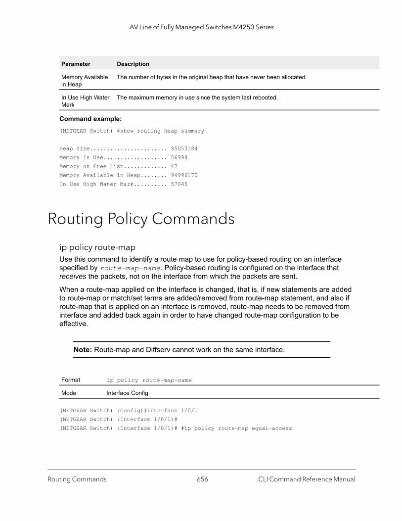
AV Line of Fully Managed Switches M4250 Series
Command example: (NETGEAR Switch) #show routing heap summary
Heap Size....................... 95053184Memory In Use................... 56998Memory on Free List............. 47Memory Available in Heap........ 94996170In Use High Water Mark.......... 57045
Routing Policy Commands
ip policy route-mapUse this command to identify a route map to use for policy-based routing on an interface specified by route-map-name. Policy-based routing is configured on the interface that receives the packets, not on the interface from which the packets are sent.
When a route-map applied on the interface is changed, that is, if new statements are added to route-map or match/set terms are added/removed from route-map statement, and also if route-map that is applied on an interface is removed, route-map needs to be removed from interface and added back again in order to have changed route-map configuration to be effective.
Note: Route-map and Diffserv cannot work on the same interface.
(NETGEAR Switch) (Config)#interface 1/0/1(NETGEAR Switch) (Interface 1/0/1)#(NETGEAR Switch) (Interface 1/0/1)# #ip policy route-map equal-access
Memory Available in Heap
The number of bytes in the original heap that have never been allocated.
In Use High Water Mark
The maximum memory in use since the system last rebooted.
Format ip policy route-map-name
Mode Interface Config
Parameter Description
Routing Commands CLI Command Reference Manual656

AV Line of Fully Managed Switches M4250 Series
f their
e dered
no ip policy route-map
Use this command to disable policy-based routing on an interface.
route-mapTo create a route map and enter Route Map Configuration mode, use the route-map command in Global Configuration mode. One use of a route map is to limit the redistribution of routes to a specified range of route prefixes. The redistribution command specifies a route map which refers to a prefix list. The prefix list identifies the prefixes that may be redistributed. The switch accepts up to 64 route maps.
Command example:
The following example configures BGP to redistribute all prefixes within 172.20.0.0 and reject all others:(NETGEAR Switch)(config)# ip prefix-list redist-pl permit 172.20.0.0/16 le 32(NETGEAR Switch)(config)# route-map redist-rm permit(NETGEAR Switch)(config-route-map)# match ip address prefix-list redist-pl(NETGEAR Switch)(config-route-map)# exit
Format no ip policy route-map-name
Mode Interface Config
Default No route maps are configured by default. If no permit or deny tag is given, permit is the default.
Format route-map map-tag [permit | deny] [sequence-number]
Mode Global Configuration
Parameter Description
map-tag Text name of the route map. Route maps with the same name are grouped together in order osequence numbers. A route map name may be up to 32 characters long.
permit (Optional) Permit routes that match all of the match conditions in the route map.
deny (Optional) Deny routes that match all of the match conditions in the route map.
sequence-number (Optional) An integer used to order the set of route maps with the same name. Route maps arordered from lowest to greatest sequence number, with lower sequence numbers being consifirst. If no sequence number is specified, the system assigns a value ten greater than the last statement in the route map. The range is 0 to 65,535.
Routing Commands CLI Command Reference Manual657

AV Line of Fully Managed Switches M4250 Series
ber is
no route-map
To delete a route map or one of its statements, use the no route-map command.
match ip address {access-list-number | access-list-name}Use this command to configure a route map in order to match based on the match criteria configured in an IP access-list. Note that an IP ACL must be configured before it is linked to a route-map. Actions present in an IP ACL configuration are applied with other actions involved in route-map. If an IP ACL referenced by a route-map is removed or rules are added or deleted from that ACL, the configuration is rejected.
If there are a list of IP access-lists specified in this command and the packet matches at least one of these access-list match criteria, the corresponding set of actions in route-map are applied to packet.
If there are duplicate IP access-list numbers/names in this command, the duplicate configuration is ignored.
Command example:
The following example creates a route-map with a match clause on ACL number and applies that route-map on an interface:(NETGEAR Switch) (config)#access-list 1 permit ip 10.1.0.0 0.0.255.255(NETGEAR Switch) (config)#access-list 2 permit ip 10.2.0.0 0.0.255.255(NETGEAR Switch) (config)#route-map equal-access permit 10(NETGEAR Switch) (config-route-map)#match ip address 1(NETGEAR Switch) (config-route-map)#set ip default next-hop 192.168.6.6(NETGEAR Switch) (config-route-map)#route-map equal-access permit 20(NETGEAR Switch) (config-route-map)#match ip address 2(NETGEAR Switch) (config-route-map)#set ip default next-hop 172.16.7.7
Format no route-map map-tag [permit | deny] [sequence-number]
Mode Global Configuration
Default No match criteria are defined by default.
Format match ip address {access-list-number | access-list-name} [...access-list-number | access-list-name]
Mode Route Map Configuration
Parameter Description
access-list-number The access-list number that identifies an access-list configured through access-list CLI configuration commands. This number is 1 to 99 for standard access list number. This num100 to 199 for extended access list number.
access-list-name The access-list name that identifies named IP ACLs. Access-list name can be up to 31 characters in length. A maximum of 16 ACLs can be specified in this match clause.
Routing Commands CLI Command Reference Manual658

AV Line of Fully Managed Switches M4250 Series
(NETGEAR Switch) (config)#interface 1/0/1(NETGEAR Switch) (Interface 1/0/1)#ip address 10.1.1.1 255.255.255.0(NETGEAR Switch) (Interface 1/0/1)#ip policy route-map equal-access(NETGEAR Switch) (config)#interface 1/0/2(NETGEAR Switch) (Interface 1/0/2)#ip address 192.168.6.5 255.255.255.0(NETGEAR Switch) (config)#interface 1/0/3(NETGEAR Switch) (Interface 1/0/3)#ip address 172.16.7.6 255.255.255.0
The ip policy route-map equal-access command is applied to interface 1/0/1. All packets coming inside 1/0/1 are policy-routed.
Sequence number 10 in route map equal-access is used to match all packets sourced from any host in subnet 10.1.0.0. If there is a match, and if the router has no explicit route for the packet’s destination, it is sent to next-hop address 192.168.6.6.
Sequence number 20 in route map equal-access is used to match all packets sourced from any host in subnet 10.2.0.0. If there is a match, and if the router has no explicit route for the packet’s destination, it is sent to next-hop address 172.16.7.7.
All other packets are forwarded as per normal L3 destination-based routing.
Command example:
The following example shows a scenario in which an IP ACL that is referenced by a route-map is removed or rules are added or deleted from that ACL:(NETGEAR Switch) #show ip access-lists
Current number of ACLs: 9 Maximum number of ACLs: 100ACL ID/Name Rules Direction Interface(s) VLAN(s)------------------------------- ----- --------- ---------------- ----------1 12 13 14 15 1madan 1
(NETGEAR Switch) #show mac access-lists
Current number of all ACLs: 9 Maximum number of all ACLs: 100MAC ACL Name Rules Direction Interface(s) VLAN(s)------------------------------- ----- --------- ---------------- ----------madan 1mohan 1goud 1
(NETGEAR Switch) #(NETGEAR Switch) #configure(NETGEAR Switch) (Config)#route-map madan
Routing Commands CLI Command Reference Manual659

AV Line of Fully Managed Switches M4250 Series
(NETGEAR Switch) (route-map)#match ip address 1 2 3 4 5 madan(NETGEAR Switch) (route-map)#match mac-list madan mohan goud(NETGEAR Switch) (route-map)#exit(NETGEAR Switch) (Config)#exit(NETGEAR Switch) #show route-maproute-map madan permit 10 Match clauses: ip address (access-lists) : 1 2 3 4 5 madan mac-list (access-lists) : madan mohan goud Set clauses:
(NETGEAR Switch) (Config)#access-list 2 permit everyRequest denied. Another application using this ACL restricts the number of rules allowed.(NETGEAR Switch) (Config)#ip access-list madan(NETGEAR Switch) (Config-ipv4-acl)#permit udp any anyRequest denied. Another application using this ACL restricts the number of rules allowed.
no match ip address (for an access list)
To delete a match statement for an access list from a route map, use the no match ip address command.
match lengthUse this command to configure a route map to match based on the Layer 3 packet length between specified minimum and maximum values. min specifies the packet’s minimum Layer 3 length, inclusive, allowed for a match. max specifies the packet’s maximum Layer 3 length, inclusive, allowed for a match. Each route-map statement can contain one ‘match’ statement on packet length range.
Command example: (NETGEAR Switch) (config-route-map)# match length 64 1500
Format no match ip address [access-list-number | access-list-name]
Mode Route Map Configuration
Default No match criteria are defined by default.
Format match length min max
Mode Route Map Configuration
Routing Commands CLI Command Reference Manual660
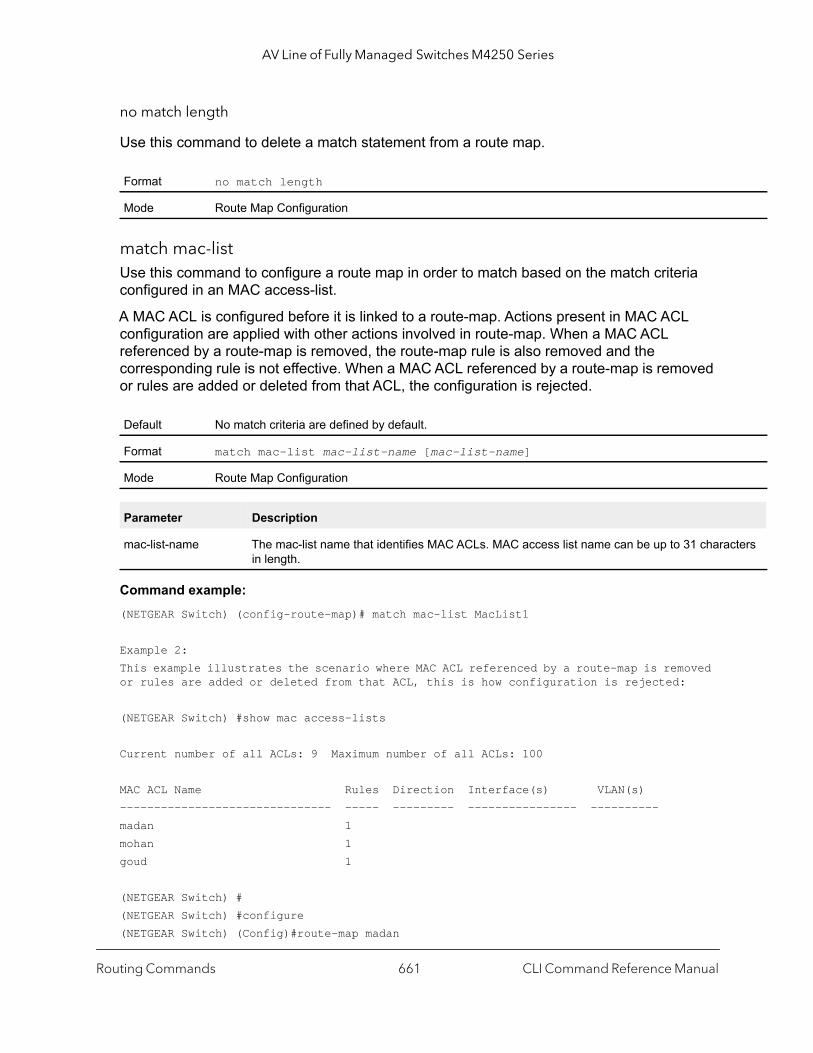
AV Line of Fully Managed Switches M4250 Series
cters
no match length
Use this command to delete a match statement from a route map.
match mac-listUse this command to configure a route map in order to match based on the match criteria configured in an MAC access-list.
A MAC ACL is configured before it is linked to a route-map. Actions present in MAC ACL configuration are applied with other actions involved in route-map. When a MAC ACL referenced by a route-map is removed, the route-map rule is also removed and the corresponding rule is not effective. When a MAC ACL referenced by a route-map is removed or rules are added or deleted from that ACL, the configuration is rejected.
Command example: (NETGEAR Switch) (config-route-map)# match mac-list MacList1
Example 2:This example illustrates the scenario where MAC ACL referenced by a route-map is removed or rules are added or deleted from that ACL, this is how configuration is rejected:
(NETGEAR Switch) #show mac access-lists
Current number of all ACLs: 9 Maximum number of all ACLs: 100
MAC ACL Name Rules Direction Interface(s) VLAN(s)------------------------------- ----- --------- ---------------- ----------madan 1mohan 1goud 1
(NETGEAR Switch) #(NETGEAR Switch) #configure(NETGEAR Switch) (Config)#route-map madan
Format no match length
Mode Route Map Configuration
Default No match criteria are defined by default.
Format match mac-list mac-list-name [mac-list-name]
Mode Route Map Configuration
Parameter Description
mac-list-name The mac-list name that identifies MAC ACLs. MAC access list name can be up to 31 charain length.
Routing Commands CLI Command Reference Manual661
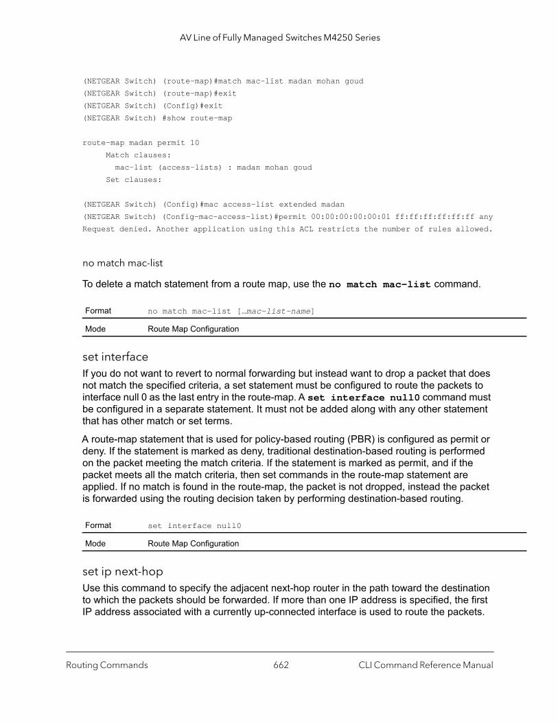
AV Line of Fully Managed Switches M4250 Series
(NETGEAR Switch) (route-map)#match mac-list madan mohan goud(NETGEAR Switch) (route-map)#exit(NETGEAR Switch) (Config)#exit(NETGEAR Switch) #show route-map
route-map madan permit 10 Match clauses: mac-list (access-lists) : madan mohan goud Set clauses:
(NETGEAR Switch) (Config)#mac access-list extended madan(NETGEAR Switch) (Config-mac-access-list)#permit 00:00:00:00:00:01 ff:ff:ff:ff:ff:ff anyRequest denied. Another application using this ACL restricts the number of rules allowed.
no match mac-list
To delete a match statement from a route map, use the no match mac-list command.
set interfaceIf you do not want to revert to normal forwarding but instead want to drop a packet that does not match the specified criteria, a set statement must be configured to route the packets to interface null 0 as the last entry in the route-map. A set interface null0 command must be configured in a separate statement. It must not be added along with any other statement that has other match or set terms.
A route-map statement that is used for policy-based routing (PBR) is configured as permit or deny. If the statement is marked as deny, traditional destination-based routing is performed on the packet meeting the match criteria. If the statement is marked as permit, and if the packet meets all the match criteria, then set commands in the route-map statement are applied. If no match is found in the route-map, the packet is not dropped, instead the packet is forwarded using the routing decision taken by performing destination-based routing.
set ip next-hopUse this command to specify the adjacent next-hop router in the path toward the destination to which the packets should be forwarded. If more than one IP address is specified, the first IP address associated with a currently up-connected interface is used to route the packets.
Format no match mac-list […mac-list-name]
Mode Route Map Configuration
Format set interface null0
Mode Route Map Configuration
Routing Commands CLI Command Reference Manual662

AV Line of Fully Managed Switches M4250 Series
acent
acent
This command affects all incoming packet types and is always used if configured. If configured next-hop is not present in the routing table, an ARP request is sent from the router.
In a route-map statement, the set ip next-hop and set ip default next-hop commands are mutually exclusive. However, the set ip default next-hop command can be configured in a separate route-map statement.
no set ip next-hop
Use this command to remove a set command from a route map.
set ip default next-hopUse this command to set a list of default next-hop IP addresses. If more than one IP address is specified, the first next hop specified that appears to be adjacent to the router is used. The optional specified IP addresses are tried in turn.
A packet is routed to the next hop specified by this command only if there is no active route for the packet’s destination address in the routing table. A default route in the routing table is not considered an active route for an unknown destination address for policy-based routing (PBR).
In a route-map statement, the set ip next-hop and set ip default next-hop commands are mutually exclusive. However, the set ip default next-hop command can be configured in a separate route-map statement.
Format set ip next-hop ip-address [...ip-address]
Mode Route Map Configuration
Parameter Description
ip-address The IP address of the next hop to which packets are output. It must be the address of an adjrouter. A maximum of 16 next-hop IP addresses can be specified in this se clause.
Format no set ip next-hop ip-address [...ip-address]
Mode Route Map Configuration
Format set ip default next-hop ip-address [...ip-address]
Mode Route Map Configuration
Parameter Description
ip-address The IP address of the next hop to which packets are output. It must be the address of an adjrouter. A maximum of 16 next-hop IP addresses can be specified in this set clause.
Routing Commands CLI Command Reference Manual663

AV Line of Fully Managed Switches M4250 Series
no set ip default next-hop
Use this command to remove a set command from a route map.
set ip precedenceUse this command to set the three IP precedence bits in the IP packet header. With three bits, you have eight possible values for the IP precedence; value can be a number from 0 through 7. This command is used when implementing QoS and can be used by other QoS services, such as weighted fair queuing (WFQ) and weighted random early detection (WRED).
no set ip precedence
Use this command to reset the three IP precedence bits in the IP packet header to the default.
Format no set ip default next-hop ip-address [...ip-address]
Mode Route Map Configuration
Format set ip precedence value
Mode Route Map Configuration
Parameter Description
0 Sets the routine precedence
1 Sets the priority precedence
2 Sets the immediate precedence
3 Sets the Flash precedence
4 Sets the Flash override precedence
5 Sets the critical precedence
6 Sets the internetwork control precedence
7 Sets the network control precedence
Format no set ip precedence
Mode Route Map Configuration
Routing Commands CLI Command Reference Manual664
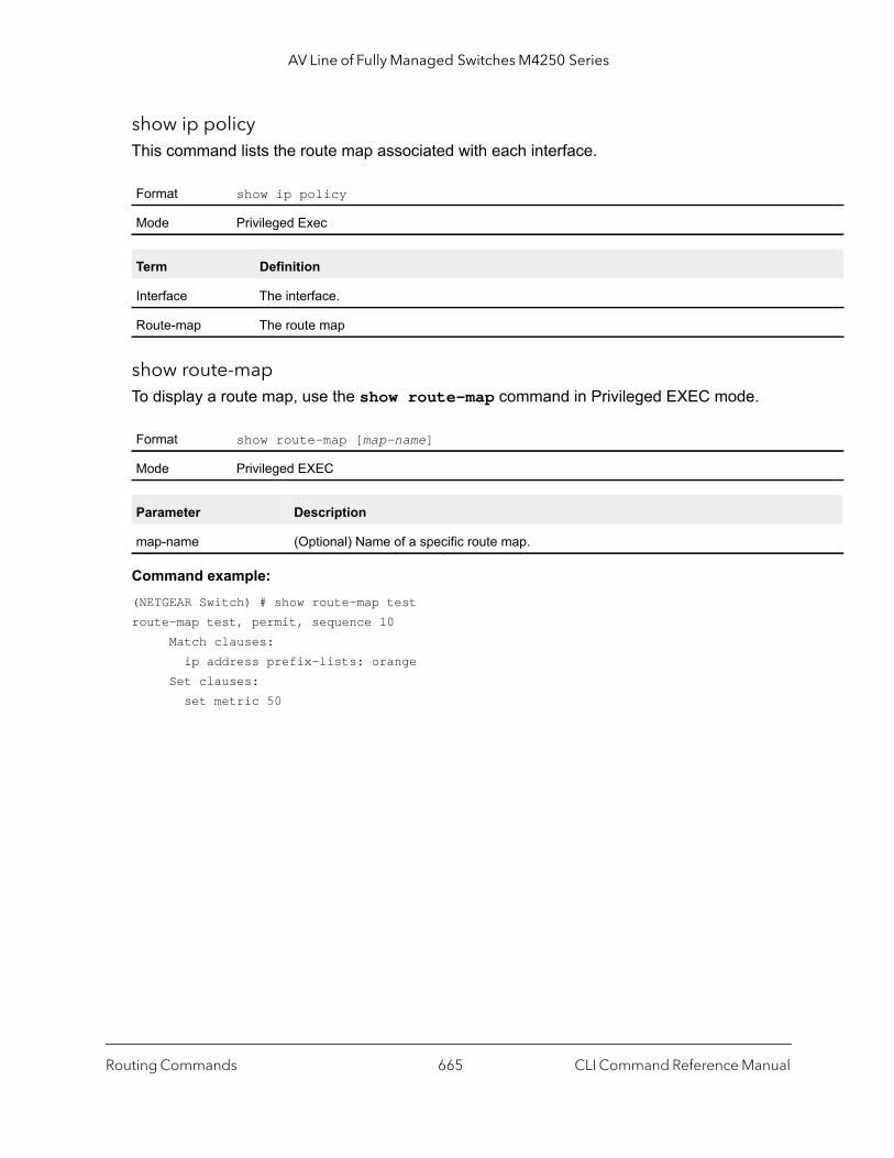
AV Line of Fully Managed Switches M4250 Series
show ip policyThis command lists the route map associated with each interface.
show route-mapTo display a route map, use the show route-map command in Privileged EXEC mode.
Command example: (NETGEAR Switch) # show route-map testroute-map test, permit, sequence 10 Match clauses: ip address prefix-lists: orange Set clauses: set metric 50
Format show ip policy
Mode Privileged Exec
Term Definition
Interface The interface.
Route-map The route map
Format show route-map [map-name]
Mode Privileged EXEC
Parameter Description
map-name (Optional) Name of a specific route map.
Routing Commands CLI Command Reference Manual665
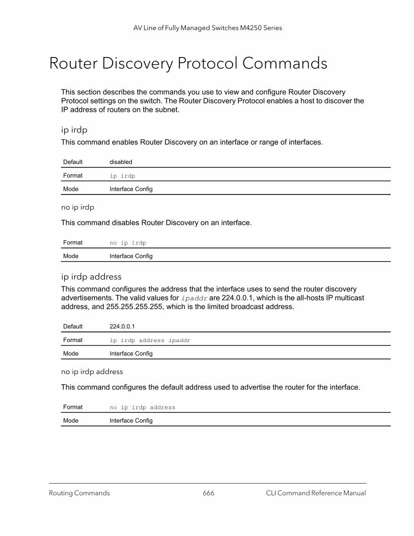
AV Line of Fully Managed Switches M4250 Series
Router Discovery Protocol Commands
This section describes the commands you use to view and configure Router Discovery Protocol settings on the switch. The Router Discovery Protocol enables a host to discover the IP address of routers on the subnet.
ip irdp This command enables Router Discovery on an interface or range of interfaces.
no ip irdp
This command disables Router Discovery on an interface.
ip irdp address This command configures the address that the interface uses to send the router discovery advertisements. The valid values for ipaddr are 224.0.0.1, which is the all-hosts IP multicast address, and 255.255.255.255, which is the limited broadcast address.
no ip irdp address
This command configures the default address used to advertise the router for the interface.
Default disabled
Format ip irdp
Mode Interface Config
Format no ip irdp
Mode Interface Config
Default 224.0.0.1
Format ip irdp address ipaddr
Mode Interface Config
Format no ip irdp address
Mode Interface Config
Routing Commands CLI Command Reference Manual666
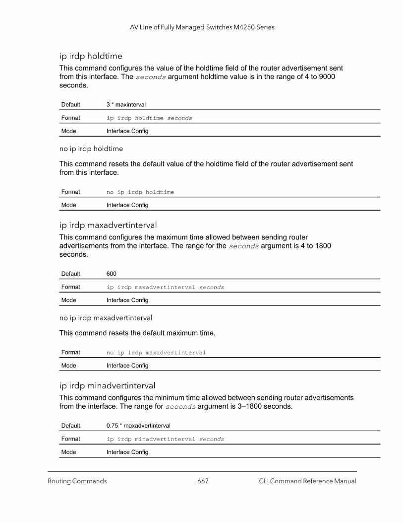
AV Line of Fully Managed Switches M4250 Series
ip irdp holdtime This command configures the value of the holdtime field of the router advertisement sent from this interface. The seconds argument holdtime value is in the range of 4 to 9000 seconds.
no ip irdp holdtime
This command resets the default value of the holdtime field of the router advertisement sent from this interface.
ip irdp maxadvertinterval This command configures the maximum time allowed between sending router advertisements from the interface. The range for the seconds argument is 4 to 1800 seconds.
no ip irdp maxadvertinterval
This command resets the default maximum time.
ip irdp minadvertinterval This command configures the minimum time allowed between sending router advertisements from the interface. The range for seconds argument is 3–1800 seconds.
Default 3 * maxinterval
Format ip irdp holdtime seconds
Mode Interface Config
Format no ip irdp holdtime
Mode Interface Config
Default 600
Format ip irdp maxadvertinterval seconds
Mode Interface Config
Format no ip irdp maxadvertinterval
Mode Interface Config
Default 0.75 * maxadvertinterval
Format ip irdp minadvertinterval seconds
Mode Interface Config
Routing Commands CLI Command Reference Manual667

AV Line of Fully Managed Switches M4250 Series
no ip irdp minadvertinterval
This command resets the default minimum time to the default.
ip irdp multicastThis command configures the destination IP address for router advertisements as 224.0.0.1, which is the default address. The no form of the command configures the IP address as 255.255.255.255 to instead send router advertisements to the limited broadcast address.
no ip irdp multicast
By default, router advertisements are sent to 224.0.0.1. To instead send router advertisements to the limited broadcast address, 255.255.255.255, use the no form of this command.
ip irdp preferenceThis command configures the preferability of the address as a default router address, relative to other router addresses on the same subnet. The preference number can be a number from -2147483648 to 2147483647.
no ip irdp preference
This command configures the default preferability of the address as a default router address, relative to other router addresses on the same subnet.
Format no ip irdp minadvertinterval
Mode Interface Config
Format ip irdp multicast ip address
Mode Interface Config
Format no ip irdp multicast
Mode Interface Config
Default 0
Format ip irdp preference number
Mode Interface Config
Format no ip irdp preference
Mode Interface Config
Routing Commands CLI Command Reference Manual668
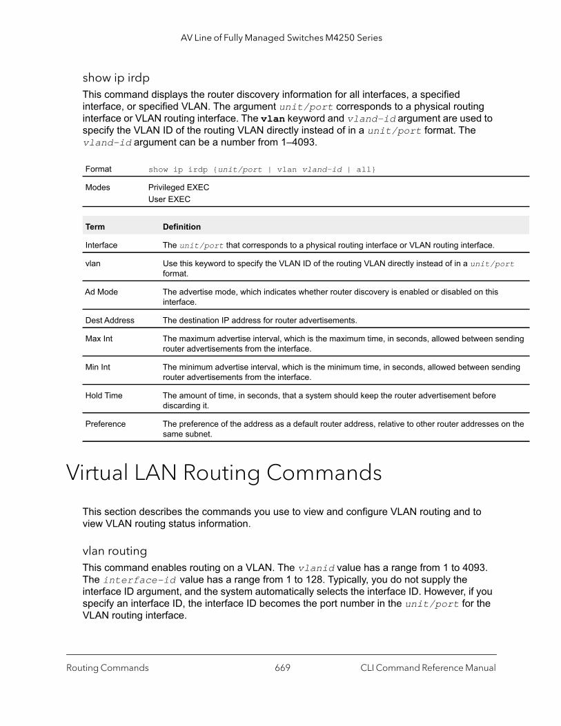
AV Line of Fully Managed Switches M4250 Series
rt
nding
ding
n the
show ip irdp This command displays the router discovery information for all interfaces, a specified interface, or specified VLAN. The argument unit/port corresponds to a physical routing interface or VLAN routing interface. The vlan keyword and vland-id argument are used to specify the VLAN ID of the routing VLAN directly instead of in a unit/port format. The vland-id argument can be a number from 1–4093.
Virtual LAN Routing Commands
This section describes the commands you use to view and configure VLAN routing and to view VLAN routing status information.
vlan routing This command enables routing on a VLAN. The vlanid value has a range from 1 to 4093. The interface-id value has a range from 1 to 128. Typically, you do not supply the interface ID argument, and the system automatically selects the interface ID. However, if you specify an interface ID, the interface ID becomes the port number in the unit/port for the VLAN routing interface.
Format show ip irdp {unit/port | vlan vland-id | all}
Modes Privileged EXECUser EXEC
Term Definition
Interface The unit/port that corresponds to a physical routing interface or VLAN routing interface.
vlan Use this keyword to specify the VLAN ID of the routing VLAN directly instead of in a unit/poformat.
Ad Mode The advertise mode, which indicates whether router discovery is enabled or disabled on this interface.
Dest Address The destination IP address for router advertisements.
Max Int The maximum advertise interval, which is the maximum time, in seconds, allowed between serouter advertisements from the interface.
Min Int The minimum advertise interval, which is the minimum time, in seconds, allowed between senrouter advertisements from the interface.
Hold Time The amount of time, in seconds, that a system should keep the router advertisement before discarding it.
Preference The preference of the address as a default router address, relative to other router addresses osame subnet.
Routing Commands CLI Command Reference Manual669
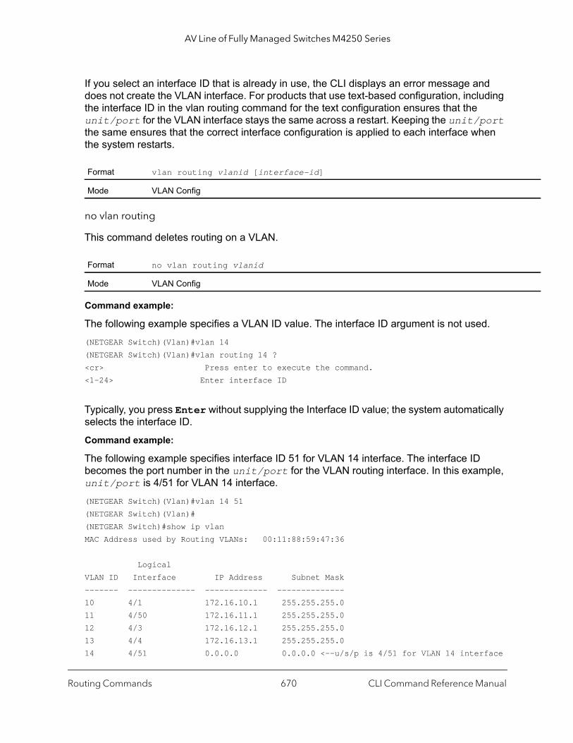
AV Line of Fully Managed Switches M4250 Series
If you select an interface ID that is already in use, the CLI displays an error message and does not create the VLAN interface. For products that use text-based configuration, including the interface ID in the vlan routing command for the text configuration ensures that the unit/port for the VLAN interface stays the same across a restart. Keeping the unit/port the same ensures that the correct interface configuration is applied to each interface when the system restarts.
no vlan routing
This command deletes routing on a VLAN.
Command example:
The following example specifies a VLAN ID value. The interface ID argument is not used.(NETGEAR Switch)(Vlan)#vlan 14(NETGEAR Switch)(Vlan)#vlan routing 14 ?<cr> Press enter to execute the command.<1-24> Enter interface ID
Typically, you press Enter without supplying the Interface ID value; the system automatically selects the interface ID.
Command example:
The following example specifies interface ID 51 for VLAN 14 interface. The interface ID becomes the port number in the unit/port for the VLAN routing interface. In this example, unit/port is 4/51 for VLAN 14 interface. (NETGEAR Switch)(Vlan)#vlan 14 51(NETGEAR Switch)(Vlan)#(NETGEAR Switch)#show ip vlan MAC Address used by Routing VLANs: 00:11:88:59:47:36
LogicalVLAN ID Interface IP Address Subnet Mask------- -------------- ------------- --------------10 4/1 172.16.10.1 255.255.255.011 4/50 172.16.11.1 255.255.255.012 4/3 172.16.12.1 255.255.255.013 4/4 172.16.13.1 255.255.255.014 4/51 0.0.0.0 0.0.0.0 <--u/s/p is 4/51 for VLAN 14 interface
Format vlan routing vlanid [interface-id]
Mode VLAN Config
Format no vlan routing vlanid
Mode VLAN Config
Routing Commands CLI Command Reference Manual670

AV Line of Fully Managed Switches M4250 Series
Command example:
The following example selects an interface ID that is already in use. In this case, the CLI displays an error message and does not create the VLAN interface.(NETGEAR Switch) #show ip vlan
MAC Address used by Routing VLANs: 00:11:88:59:47:36
LogicalVLAN ID Interface IP Address Subnet Mask------- -------------- --------------- ---------------10 4/1 172.16.10.1 255.255.255.011 4/50 172.16.11.1 255.255.255.012 4/3 172.16.12.1 255.255.255.013 4/4 172.16.13.1 255.255.255.014 4/51 0.0.0.0 0.0.0.0
(NETGEAR Switch)#config(NETGEAR Switch)(Config)#exit(NETGEAR Switch)#vlan database(NETGEAR Switch)(Vlan)#vlan 15(NETGEAR Switch)(Vlan)#vlan routing 15 1Interface ID 1 is already assigned to another interface
Command example:
The show running-config command lists the interface ID for each routing VLAN:(NETGEAR Switch) #show running-config!!Current Configuration:!!System Description "M4250-10G2F-PoE+ 10x1G PoE+ 125W and 2xSFP Managed Switch, 13.0.2.10, 1.0.0.2"!System Software Version "13.0.2.10"!System Up Time "0 days 0 hrs 23 mins 7 secs"!Additional Packages QOS,Multicast,IPv6,IPv6 Management,Routing!Current SNTP Synchronized Time: SNTP Client Mode Is Disabled!vlan databaseexit
configureno logging consoleaaa authentication enable "enableNetList" noneline consoleserial timeout 0exit
Routing Commands CLI Command Reference Manual671

AV Line of Fully Managed Switches M4250 Series
ation.
line telnetexit
line sshexit
!router ripexitexit
interface vlanUse this command to enter Interface configuration mode for the specified VLAN. The vlan-id range is 1 to 4093.
show ip vlan This command displays the VLAN routing information for all VLANs with routing enabled.
Format interface vlan vlan-id
Mode Global Config
Format show ip vlan
Modes Privileged EXECUser EXEC
Term Definition
MAC Address used by Routing VLANs
The MAC Address associated with the internal bridge-router interface (IBRI). The same MAC Address is used by all VLAN routing interfaces. It will be displayed above the per-VLAN inform
VLAN ID The identifier of the VLAN.
Logical Interface The logical unit/port associated with the VLAN routing interface.
IP Address The IP address associated with this VLAN.
Subnet Mask The subnet mask that is associated with this VLAN.
Routing Commands CLI Command Reference Manual672

AV Line of Fully Managed Switches M4250 Series
DHCP and BootP Relay Commands
This section describes the commands you use to configure BootP/DHCP Relay on the switch. A DHCP relay agent operates at Layer 3 and forwards DHCP requests and replies between clients and servers when they are not on the same physical subnet.
bootpdhcprelay cidoptmodeThis command enables the circuit ID option mode for BootP/DHCP Relay on the system.
no bootpdhcprelay cidoptmode
This command disables the circuit ID option mode for BootP/DHCP Relay on the system.
bootpdhcprelay maxhopcount This command configures the maximum allowable relay agent hops for BootP/DHCP Relay on the system. The hops parameter has a range of 1 to 16.
no bootpdhcprelay maxhopcount
This command configures the default maximum allowable relay agent hops for BootP/DHCP Relay on the system.
bootpdhcprelay minwaittimeThis command configures the minimum wait time in seconds for BootP/DHCP Relay on the system. When the BootP relay agent receives a BOOTREQUEST message, it can use the seconds-since-client-began-booting field of the request as a factor in deciding whether to
Default disabled
Format bootpdhcprelay cidoptmode
Mode Global Config
Format no bootpdhcprelay cidoptmode
Mode Global Config
Default 4
Format bootpdhcprelay maxhopcount hops
Mode Global Config
Format no bootpdhcprelay maxhopcount
Mode Global Config
Routing Commands CLI Command Reference Manual673
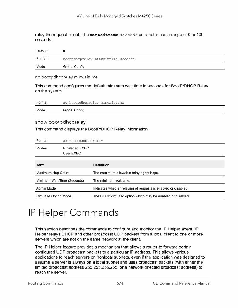
AV Line of Fully Managed Switches M4250 Series
relay the request or not. The minwaittime seconds parameter has a range of 0 to 100 seconds.
no bootpdhcprelay minwaittime
This command configures the default minimum wait time in seconds for BootP/DHCP Relay on the system.
show bootpdhcprelayThis command displays the BootP/DHCP Relay information.
IP Helper Commands
This section describes the commands to configure and monitor the IP Helper agent. IP Helper relays DHCP and other broadcast UDP packets from a local client to one or more servers which are not on the same network at the client.
The IP Helper feature provides a mechanism that allows a router to forward certain configured UDP broadcast packets to a particular IP address. This allows various applications to reach servers on nonlocal subnets, even if the application was designed to assume a server is always on a local subnet and uses broadcast packets (with either the limited broadcast address 255.255.255.255, or a network directed broadcast address) to reach the server.
Default 0
Format bootpdhcprelay minwaittime seconds
Mode Global Config
Format no bootpdhcprelay minwaittime
Mode Global Config
Format show bootpdhcprelay
Modes Privileged EXECUser EXEC
Term Definition
Maximum Hop Count The maximum allowable relay agent hops.
Minimum Wait Time (Seconds) The minimum wait time.
Admin Mode Indicates whether relaying of requests is enabled or disabled.
Circuit Id Option Mode The DHCP circuit Id option which may be enabled or disabled.
Routing Commands CLI Command Reference Manual674
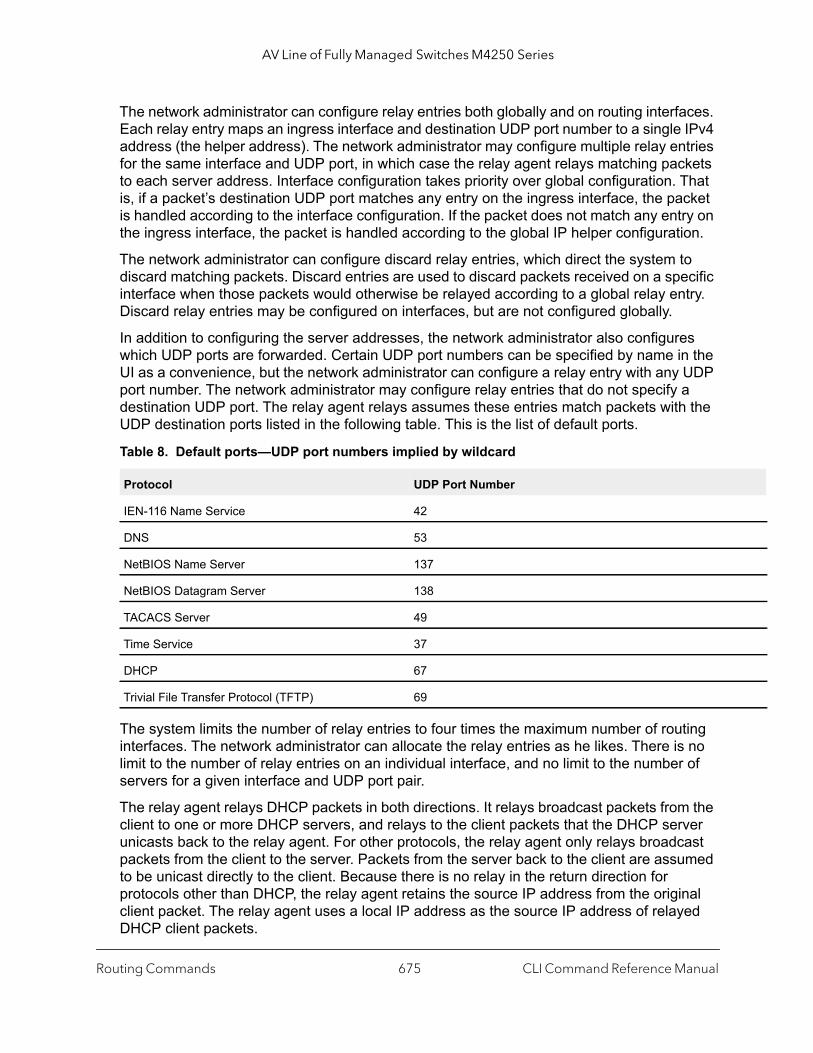
AV Line of Fully Managed Switches M4250 Series
The network administrator can configure relay entries both globally and on routing interfaces. Each relay entry maps an ingress interface and destination UDP port number to a single IPv4 address (the helper address). The network administrator may configure multiple relay entries for the same interface and UDP port, in which case the relay agent relays matching packets to each server address. Interface configuration takes priority over global configuration. That is, if a packet’s destination UDP port matches any entry on the ingress interface, the packet is handled according to the interface configuration. If the packet does not match any entry on the ingress interface, the packet is handled according to the global IP helper configuration.
The network administrator can configure discard relay entries, which direct the system to discard matching packets. Discard entries are used to discard packets received on a specific interface when those packets would otherwise be relayed according to a global relay entry. Discard relay entries may be configured on interfaces, but are not configured globally.
In addition to configuring the server addresses, the network administrator also configures which UDP ports are forwarded. Certain UDP port numbers can be specified by name in the UI as a convenience, but the network administrator can configure a relay entry with any UDP port number. The network administrator may configure relay entries that do not specify a destination UDP port. The relay agent relays assumes these entries match packets with the UDP destination ports listed in the following table. This is the list of default ports.
The system limits the number of relay entries to four times the maximum number of routing interfaces. The network administrator can allocate the relay entries as he likes. There is no limit to the number of relay entries on an individual interface, and no limit to the number of servers for a given interface and UDP port pair.
The relay agent relays DHCP packets in both directions. It relays broadcast packets from the client to one or more DHCP servers, and relays to the client packets that the DHCP server unicasts back to the relay agent. For other protocols, the relay agent only relays broadcast packets from the client to the server. Packets from the server back to the client are assumed to be unicast directly to the client. Because there is no relay in the return direction for protocols other than DHCP, the relay agent retains the source IP address from the original client packet. The relay agent uses a local IP address as the source IP address of relayed DHCP client packets.
Table 8. Default ports—UDP port numbers implied by wildcard
Protocol UDP Port Number
IEN-116 Name Service 42
DNS 53
NetBIOS Name Server 137
NetBIOS Datagram Server 138
TACACS Server 49
Time Service 37
DHCP 67
Trivial File Transfer Protocol (TFTP) 69
Routing Commands CLI Command Reference Manual675

AV Line of Fully Managed Switches M4250 Series
| p |
When a switch receives a broadcast UDP packet on a routing interface, the relay agent checks if the interface is configured to relay the destination UDP port. If so, the relay agent unicasts the packet to the configured server IP addresses. Otherwise, the relay agent checks if there is a global configuration for the destination UDP port. If so, the relay agent unicasts the packet to the configured server IP addresses. Otherwise the packet is not relayed. Note that if the packet matches a discard relay entry on the ingress interface, then the packet is not forwarded, regardless of the global configuration.
The relay agent only relays packets that meet the following conditions:
• The destination MAC address must be the all-ones broadcast address (FF:FF:FF:FF:FF:FF)
• The destination IP address must be the limited broadcast address (255.255.255.255) or a directed broadcast address for the receive interface.
• The IP time-to-live (TTL) must be greater than 1.• The protocol field in the IP header must be UDP (17).• The destination UDP port must match a configured relay entry.
clear ip helper statisticsUse this command to reset to zero the statistics displayed in the output of the show ip helper statistics command.
Command example: (NETGEAR Switch) #clear ip helper statistics
ip helper-address (Global Config)Use this command to configure the relay of certain UDP broadcast packets received on any interface. This command can be invoked multiple times, either to specify multiple server addresses for a given UDP port number or to specify multiple UDP port numbers handled by a specific server.
Format clear ip helper statistics
Mode Privileged EXEC
Default No helper addresses are configured.
Format ip helper-address server-address [dest-udp-port | dhcp | domain | isakmpmobile-ip | nameserver | netbios-dgm | netbios-ns | ntp | pim-auto-rp | ritacacs | tftp | time]
Mode Global Config
Routing Commands CLI Command Reference Manual676

AV Line of Fully Managed Switches M4250 Series
sent.
rt by lows:
kmp rip
Command example:
The following example relays DHCP packets that are received on any interface to two DHCP servers, 10.1.1.1 and 10.1.2.1:(NETGEAR Switch)#config(NETGEAR Switch)(config)#ip helper-address 10.1.1.1 dhcp(NETGEAR Switch)(config)#ip helper-address 10.1.2.1 dhcp
Command example:
The following example relays UDP packets that are received on any interface for all default ports to the server at 20.1.1.1:(NETGEAR Switch)#config(NETGEAR Switch)(config)#ip helper-address 20.1.1.1
no ip helper-address (Global Config)
Use the no ip helper-address command to delete an IP helper entry. Use the command without any arguments to clear all global IP helper addresses.
Parameter Description
server-address The IPv4 unicast or directed broadcast address to which relayed UDP broadcast packets are The server address cannot be an IP address configured on any interface of the local router.
dest-udp-port A destination UDP port number from 0 to 65535.
port-name As an option, you can specify the destination UDP port by its name. Whether you specify a poits number or its name does not matter for the configuration. The names recognized are as fol• dhcp (port 67)• domain (port 53)• isakmp (port 500)• mobile-ip (port 434)• nameserver (port 42)• netbios-dgm (port 138)• netbios-ns (port 137)• ntp (port 123)• pim-auto-rp (port 496)• rip (port 520)• tacacs (port 49)• tftp (port 69)• time (port 37)Other ports must be specified by number.
Format no ip helper-address [server-address] [dest-udp-port | dhcp | domain | isa| mobile-ip | nameserver | netbios-dgm | netbios-ns | ntp | pim-auto-rp | | tacacs | tftp | time]
Mode Global Config
Routing Commands CLI Command Reference Manual677
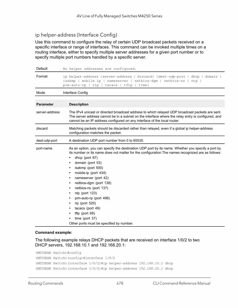
AV Line of Fully Managed Switches M4250 Series
n |
ent. and
rt by ows:
ip helper-address (Interface Config)Use this command to configure the relay of certain UDP broadcast packets received on a specific interface or range of interfaces. This command can be invoked multiple times on a routing interface, either to specify multiple server addresses for a given port number or to specify multiple port numbers handled by a specific server.
Command example:
The following example relays DHCP packets that are received on interface 1/0/2 to two DHCP servers, 192.168.10.1 and 192.168.20.1:(NETGEAR Switch)#config(NETGEAR Switch)(config)#interface 1/0/2(NETGEAR Switch)(interface 1/0/2)#ip helper-address 192.168.10.1 dhcp(NETGEAR Switch)(interface 1/0/2)#ip helper-address 192.168.20.1 dhcp
Default No helper addresses are configured.
Format ip helper-address {server-address | discard} [dest-udp-port | dhcp | domaiisakmp | mobile ip | nameserver | netbios-dgm | netbios-ns | ntp | pim-auto-rp | rip | tacacs | tftp | time]
Mode Interface Config
Parameter Description
server-address The IPv4 unicast or directed broadcast address to which relayed UDP broadcast packets are sThe server address cannot be in a subnet on the interface where the relay entry is configured,cannot be an IP address configured on any interface of the local router.
discard Matching packets should be discarded rather than relayed, even if a global ip helper-address configuration matches the packet.
dest-udp-port A destination UDP port number from 0 to 65535.
port-name As an option, you can specify the destination UDP port by its name. Whether you specify a poits number or its name does not matter for the configuration.The names recognized are as foll• dhcp (port 67)• domain (port 53)• isakmp (port 500)• mobile-ip (port 434)• nameserver (port 42)• netbios-dgm (port 138)• netbios-ns (port 137)• ntp (port 123)• pim-auto-rp (port 496)• rip (port 520)• tacacs (port 49)• tftp (port 69)• time (port 37)Other ports must be specified by number.
Routing Commands CLI Command Reference Manual678

AV Line of Fully Managed Switches M4250 Series
p |
Command example:
The following example relays DHCP and DNS packets to 192.168.30.1:(NETGEAR Switch)#config (NETGEAR Switch)(config)#interface 1/0/2(NETGEAR Switch)(interface 1/0/2)#ip helper-address 192.168.30.1 dhcp(NETGEAR Switch)(interface 1/0/2)#ip helper-address 192.168.30.1 dns
Command example:
The following example takes precedence over the ip helper-address command that you enter in global configuration mode. With the following configuration, the relay agent relays DHCP packets that are received on any interface other than 1/0/2 and 1/0/17 to 192.168.40.1, relays DHCP and DNS packets that are received on 1/0/2 to 192.168.40.2, relays SNMP traps (port 162) that are received on interface 1/0/17 to 192.168.23.1, and drops DHCP packets that are received on 1/0/17:(NETGEAR Switch)#config(NETGEAR Switch)(config)#ip helper-address 192.168.40.1 dhcp(NETGEAR Switch)(config)#interface 1/0/2(NETGEAR Switch)(interface 1/0/2)#ip helper-address 192.168.40.2 dhcp(NETGEAR Switch)(interface 1/0/2)#ip helper-address 192.168.40.2 domain(NETGEAR Switch)(interface 1/0/2)#exit(NETGEAR Switch)(config)#interface 1/0/17(NETGEAR Switch)(interface 1/0/17)#ip helper-address 192.168.23.1 162(NETGEAR Switch)(interface 1/0/17)#ip helper-address discard dhcp
no ip helper-address (Interface Config)
Use this command to delete a relay entry on an interface. The command without any arguments clears all helper addresses on the interface.
ip helper enableUse this command to enable relay of UDP packets. This command can be used to temporarily disable IP helper without deleting all IP helper addresses. This command replaces the bootpdhcprelay enable command, but affects not only relay of DHCP packets, but also relay of any other protocols for which an IP helper address has been configured.
Format no ip helper-address [server-address | discard] [dest-udp-port | dhcp | domain | isakmp | mobile ip | nameserver | netbios-dgm | netbios-ns | ntpim-auto-rp | rip | tacacs | tftp | time]
Mode Interface Config
Routing Commands CLI Command Reference Manual679

AV Line of Fully Managed Switches M4250 Series
y for
hose ble 4.
d h
Command example: (NETGEAR Switch)(config)#ip helper enable
no ip helper enable
Use the no form of this command to disable relay of all UDP packets.
show ip helper-addressUse this command to display the IP helper address configuration. The argument unit/port corresponds to a physical routing interface or VLAN routing interface. The argument unit/port corresponds to a physical routing interface or VLAN routing interface. The vlan keyword and vlan-id parameter are used to specify the VLAN ID of the routing VLAN directly instead of in a unit/port format. The vlan-id can be a number from 1–4093.
Default disabled
Format ip helper enable
Mode Global Config
Format no ip helper enable
Mode Global Config
Format show ip helper-address [unit/port | vlan vlan-id]
Mode Privileged EXEC
Parameter Description
interface The relay configuration is applied to packets that arrive on this interface. This field is set to anglobal IP helper entries.
UDP Port The relay configuration is applied to packets whose destination UDP port is this port. Entries wUDP port is identified as any are applied to packets with the destination UDP ports listed in Ta
Discard If Yes, packets arriving on the given interface with the given destination UDP port are discarderather than relayed. Discard entries are used to override global IP helper address entries whicotherwise might apply to a packet.
Hit Count The number of times the IP helper entry has been used to relay or discard a packet.
Server Address The IPv4 address of the server to which packets are relayed.
Routing Commands CLI Command Reference Manual680
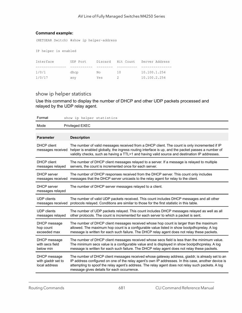
AV Line of Fully Managed Switches M4250 Series
IP r of .
r
all
lue. g
to an ice is log
Command example: (NETGEAR Switch) #show ip helper-address
IP helper is enabled
Interface UDP Port Discard Hit Count Server Address--------------- ----------- -------- ---------- ---------------1/0/1 dhcp No 10 10.100.1.2541/0/17 any Yes 2 10.100.2.254
show ip helper statisticsUse this command to display the number of DHCP and other UDP packets processed and relayed by the UDP relay agent.
Format show ip helper statistics
Mode Privileged EXEC
Parameter Description
DHCP client messages received
The number of valid messages received from a DHCP client. The count is only incremented ifhelper is enabled globally, the ingress routing interface is up, and the packet passes a numbevalidity checks, such as having a TTL>1 and having valid source and destination IP addresses
DHCP client messages relayed
The number of DHCP client messages relayed to a server. If a message is relayed to multipleservers, the count is incremented once for each server.
DHCP server messages received
The number of DHCP responses received from the DHCP server. This count only includes messages that the DHCP server unicasts to the relay agent for relay to the client.
DHCP server messages relayed
The number of DHCP server messages relayed to a client.
UDP clients messages received
The number of valid UDP packets received. This count includes DHCP messages and all otheprotocols relayed. Conditions are similar to those for the first statistic in this table.
UDP clients messages relayed
The number of UDP packets relayed. This count includes DHCP messages relayed as well asother protocols. The count is incremented for each server to which a packet is sent.
DHCP message hop count exceeded max
The number of DHCP client messages received whose hop count is larger than the maximumallowed. The maximum hop count is a configurable value listed in show bootpdhcprelay. A logmessage is written for each such failure. The DHCP relay agent does not relay these packets.
DHCP message with secs field below min
The number of DHCP client messages received whose secs field is less than the minimum vaThe minimum secs value is a configurable value and is displayed in show bootpdhcprelay. A lomessage is written for each such failure. The DHCP relay agent does not relay these packets.
DHCP message with giaddr set to local address
The number of DHCP client messages received whose gateway address, giaddr, is already setIP address configured on one of the relay agent’s own IP addresses. In this case, another devattempting to spoof the relay agent’s address. The relay agent does not relay such packets. Amessage gives details for each occurrence.
Routing Commands CLI Command Reference Manual681

AV Line of Fully Managed Switches M4250 Series
Command example: (NETGEAR Switch)#show ip helper statisticsDHCP client messages received.................. 8DHCP client messages relayed................... 2DHCP server messages received.................. 2DHCP server messages relayed................... 2UDP client messages received................... 8UDP client messages relayed.................... 2DHCP message hop count exceeded max............ 0DHCP message with secs field below min......... 0DHCP message with giaddr set to local address.. 0Packets with expired TTL....................... 0Packets that matched a discard entry........... 0
Routing Information Protocol Commands
This section describes the commands you use to view and configure Routing Information Protocol (RIP), which is a distance-vector routing protocol that you use to route traffic within a small network.
router ripUse this command to enter Router RIP mode.
enable (RIP)This command resets the default administrative mode of RIP in the router (active).
Packets with expired TTL
The number of packets received with TTL of 0 or 1 that might otherwise have been relayed.
Packets that matched a discard entry
The number of packets ignored by the relay agent because they match a discard relay entry.
Format router rip
Mode Global Config
Default enabled
Format enable
Mode Router RIP Config
Parameter Description
Routing Commands CLI Command Reference Manual682

AV Line of Fully Managed Switches M4250 Series
no enable (RIP)
This command sets the administrative mode of RIP in the router to inactive.
ip ripThis command enables RIP on a router interface or range of interfaces.
no ip rip
This command disables RIP on a router interface.
auto-summaryThis command enables the RIP auto-summarization mode.
no auto-summary
This command disables the RIP auto-summarization mode.
default-information originate (RIP)This command is used to control the advertisement of default routes.
Format no enable
Mode Router RIP Config
Default disabled
Format ip rip
Mode Interface Config
Format no ip rip
Mode Interface Config
Default disabled
Format auto-summary
Mode Router RIP Config
Format no auto-summary
Mode Router RIP Config
Format default-information originate
Mode Router RIP Config
Routing Commands CLI Command Reference Manual683

AV Line of Fully Managed Switches M4250 Series
no default-information originate (RIP)
This command is used to control the advertisement of default routes.
default-metric (RIP)This command is used to set a default for the metric of distributed routes. The value for the metric argument can be from 0–15.
no default-metric (RIP)
This command is used to reset the default metric of distributed routes to its default value.
distance ripThis command sets the route preference value of RIP in the router. Lower route preference values are preferred when determining the best route. A route with a preference of 255 cannot be used to forward traffic. The value for the preference argument can be from 1–255.
no distance rip
This command sets the default route preference value of RIP in the router.
Format no default-information originate
Mode Router RIP Config
Format default-metric metric
Mode Router RIP Config
Format no default-metric
Mode Router RIP Config
Default 15
Format distance rip preference
Mode Router RIP Config
Format no distance rip
Mode Router RIP Config
Routing Commands CLI Command Reference Manual684
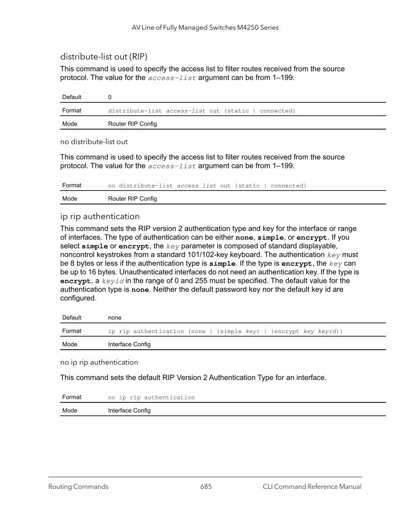
AV Line of Fully Managed Switches M4250 Series
distribute-list out (RIP)This command is used to specify the access list to filter routes received from the source protocol. The value for the access-list argument can be from 1–199.
no distribute-list out
This command is used to specify the access list to filter routes received from the source protocol. The value for the access-list argument can be from 1–199.
ip rip authentication This command sets the RIP version 2 authentication type and key for the interface or range of interfaces. The type of authentication can be either none, simple, or encrypt. If you select simple or encrypt, the key parameter is composed of standard displayable, noncontrol keystrokes from a standard 101/102-key keyboard. The authentication key must be 8 bytes or less if the authentication type is simple. If the type is encrypt, the key can be up to 16 bytes. Unauthenticated interfaces do not need an authentication key. If the type is encrypt, a keyid in the range of 0 and 255 must be specified. The default value for the authentication type is none. Neither the default password key nor the default key id are configured.
no ip rip authentication
This command sets the default RIP Version 2 Authentication Type for an interface.
Default 0
Format distribute-list access-list out {static | connected}
Mode Router RIP Config
Format no distribute-list access list out {static | connected}
Mode Router RIP Config
Default none
Format ip rip authentication {none | {simple key} | {encrypt key keyid}}
Mode Interface Config
Format no ip rip authentication
Mode Interface Config
Routing Commands CLI Command Reference Manual685
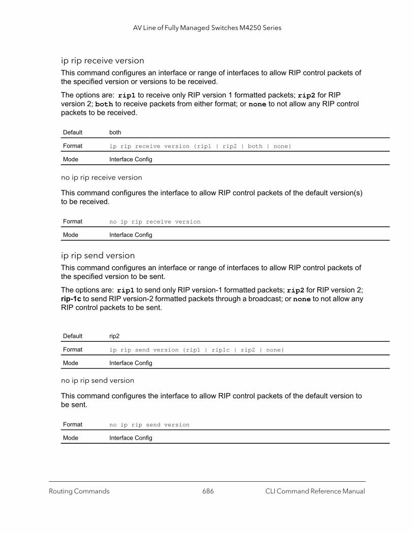
AV Line of Fully Managed Switches M4250 Series
ip rip receive version This command configures an interface or range of interfaces to allow RIP control packets of the specified version or versions to be received.
The options are: rip1 to receive only RIP version 1 formatted packets; rip2 for RIP version 2; both to receive packets from either format; or none to not allow any RIP control packets to be received.
no ip rip receive version
This command configures the interface to allow RIP control packets of the default version(s) to be received.
ip rip send version This command configures an interface or range of interfaces to allow RIP control packets of the specified version to be sent.
The options are: rip1 to send only RIP version-1 formatted packets; rip2 for RIP version 2; rip-1c to send RIP version-2 formatted packets through a broadcast; or none to not allow any RIP control packets to be sent.
no ip rip send version
This command configures the interface to allow RIP control packets of the default version to be sent.
Default both
Format ip rip receive version {rip1 | rip2 | both | none}
Mode Interface Config
Format no ip rip receive version
Mode Interface Config
Default rip2
Format ip rip send version {rip1 | rip1c | rip2 | none}
Mode Interface Config
Format no ip rip send version
Mode Interface Config
Routing Commands CLI Command Reference Manual686

AV Line of Fully Managed Switches M4250 Series
hostroutesacceptThis command enables the RIP hostroutesaccept mode.
no hostroutesaccept
This command disables the RIP hostroutesaccept mode.
split-horizonThis command sets the RIP split horizon mode. Split horizon is a technique for avoiding problems caused by including routes in updates sent to the router from which the route was originally learned. The options are: none, no special processing; simple, a route is not included in updates sent to the router from which it was learned; poison, a route is included in updates sent to the router from which it was learned, but the metric is set to infinity.
no split-horizon
This command sets the default RIP split horizon mode.
redistribute (RIP)This command configures RIP protocol to redistribute routes from the specified source protocol or routers. Five possible match options exist. The metric argument can have a value in the range from 0–15.
Default enabled
Format hostroutesaccept
Mode Router RIP Config
Format no hostroutesaccept
Mode Router RIP Config
Default simple
Format split-horizon {none | simple | poison}
Mode Router RIP Config
Format no split-horizon
Mode Router RIP Config
Default metric—not-configuredmatch—internal
Routing Commands CLI Command Reference Manual687

AV Line of Fully Managed Switches M4250 Series
1]
tries,
no redistribute
This command deconfigures RIP protocol to redistribute routes from the specified source protocol or routers.
show ip rip This command displays information relevant to the RIP router.
Format for other source protocols
redistribute {static | connected} [metric metric]
Mode Router RIP Config
Format no redistribute {static | connected} [metric] [match [[internal] [external[external 2] [nssa-external 1] [nssa-external 2]]
Mode Router RIP Config
Format show ip rip
Modes Privileged EXECUser EXEC
Term Definition
RIP Admin Mode Enable or disable.
Split Horizon Mode None, simple or poison reverse.
Auto Summary Mode Enable or disable. If enabled, groups of adjacent routes are summarized into single enin order to reduce the total number of entries The default is enable.
Host Routes Accept Mode Enable or disable. If enabled the router accepts host routes. The default is enable.
Global Route Changes The number of route changes made to the IP Route Database by RIP. This does not include the refresh of a route's age.
Global queries The number of responses sent to RIP queries from other systems.
Default Metric The default metric of redistributed routes if one has already been set, or blank if not configured earlier. The valid values are 1 to 15.
Default Route Advertise The default route.
Routing Commands CLI Command Reference Manual688

AV Line of Fully Managed Switches M4250 Series
,
,
is a
show ip rip interface briefThis command displays general information for each RIP interface. For this command to display successful results, routing must be enabled per interface (for example, through the ip rip command).
show ip rip interface This command displays information related to a particular RIP interface.
The argument unit/port corresponds to a physical routing interface or VLAN routing interface. The vlan keyword and vlan-id parameter are used to specify the VLAN ID of the routing VLAN directly instead of in a unit/port format. The vlan-id can be a number from 1–4093.
Format show ip rip interface brief
Modes Privileged EXECUser EXEC
Term Definition
Interface unit/port
IP Address The IP source address used by the specified RIP interface.
Send Version The RIP version(s) used when sending updates on the specified interface. The types are noneRIP-1, RIP-1c, RIP-2
Receive Version The RIP version(s) allowed when receiving updates from the specified interface. The types arenone, RIP-1, RIP-2, Both
RIP Mode The administrative mode of router RIP operation (enabled or disabled).
Link State The mode of the interface (up or down).
Format show ip rip interface {unit/port | vlan vlan-id}
Modes Privileged EXECUser EXEC
Term Definition
Interface unit/port This is a configured value.
IP Address The IP source address used by the specified RIP interface. This is a configured value.
Send Version The RIP version(s) used when sending updates on the specified interface. The types are noneRIP-1, RIP-1c, RIP-2. This is a configured value.
Receive Version The RIP version(s) allowed when receiving updates from the specified interface. The types arenone, RIP-1, RIP-2, Both. This is a configured value.
RIP Admin Mode RIP administrative mode of router RIP operation; enable activates, disable de-activates it. Thisconfigured value.
Routing Commands CLI Command Reference Manual689
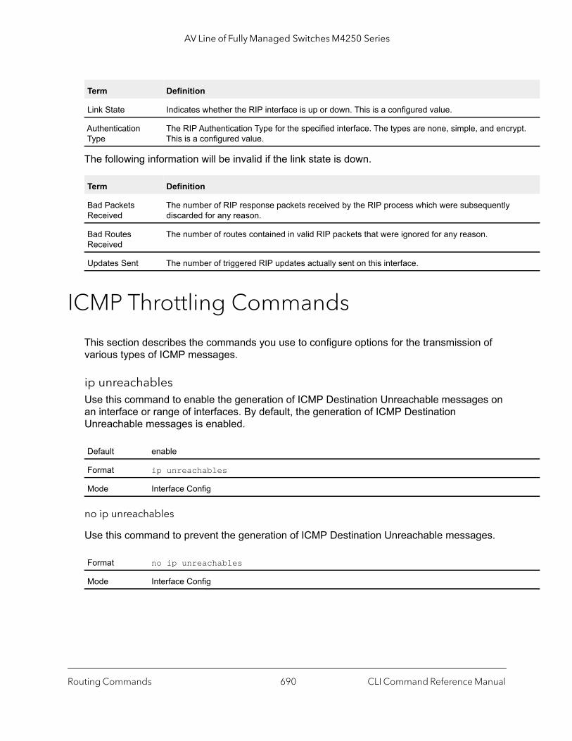
AV Line of Fully Managed Switches M4250 Series
pt.
The following information will be invalid if the link state is down.
ICMP Throttling Commands
This section describes the commands you use to configure options for the transmission of various types of ICMP messages.
ip unreachablesUse this command to enable the generation of ICMP Destination Unreachable messages on an interface or range of interfaces. By default, the generation of ICMP Destination Unreachable messages is enabled.
no ip unreachables
Use this command to prevent the generation of ICMP Destination Unreachable messages.
Link State Indicates whether the RIP interface is up or down. This is a configured value.
Authentication Type
The RIP Authentication Type for the specified interface. The types are none, simple, and encryThis is a configured value.
Term Definition
Bad Packets Received
The number of RIP response packets received by the RIP process which were subsequently discarded for any reason.
Bad Routes Received
The number of routes contained in valid RIP packets that were ignored for any reason.
Updates Sent The number of triggered RIP updates actually sent on this interface.
Default enable
Format ip unreachables
Mode Interface Config
Format no ip unreachables
Mode Interface Config
Term Definition
Routing Commands CLI Command Reference Manual690
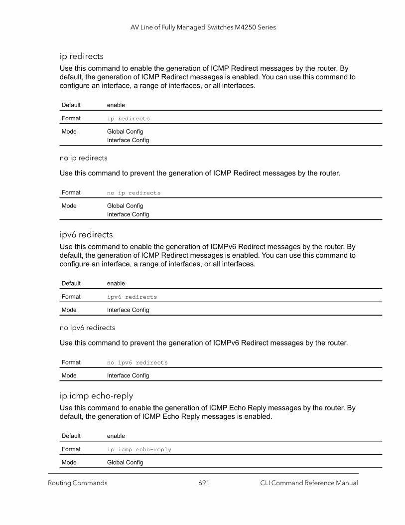
AV Line of Fully Managed Switches M4250 Series
ip redirectsUse this command to enable the generation of ICMP Redirect messages by the router. By default, the generation of ICMP Redirect messages is enabled. You can use this command to configure an interface, a range of interfaces, or all interfaces.
no ip redirects
Use this command to prevent the generation of ICMP Redirect messages by the router.
ipv6 redirectsUse this command to enable the generation of ICMPv6 Redirect messages by the router. By default, the generation of ICMP Redirect messages is enabled. You can use this command to configure an interface, a range of interfaces, or all interfaces.
no ipv6 redirects
Use this command to prevent the generation of ICMPv6 Redirect messages by the router.
ip icmp echo-replyUse this command to enable the generation of ICMP Echo Reply messages by the router. By default, the generation of ICMP Echo Reply messages is enabled.
Default enable
Format ip redirects
Mode Global ConfigInterface Config
Format no ip redirects
Mode Global ConfigInterface Config
Default enable
Format ipv6 redirects
Mode Interface Config
Format no ipv6 redirects
Mode Interface Config
Default enable
Format ip icmp echo-reply
Mode Global Config
Routing Commands CLI Command Reference Manual691
AV Line of Fully Managed Switches M4250 Series
no ip icmp echo-reply
Use this command to prevent the generation of ICMP Echo Reply messages by the router.
ip icmp error-intervalUse this command to limit the rate at which IPv4 ICMP error messages are sent. The rate limit is configured as a token bucket, with two configurable parameters, burst-size and burst-interval.
The burst-interval specifies how often the token bucket is initialized with burst-size tokens. burst-interval is from 0 to 2147483647 milliseconds (msec). The burst-size is the number of ICMP error messages that can be sent during one burst-interval. The range is from 1 to 200 messages. To disable ICMP rate limiting, set the burst-interval to zero (0).
no ip icmp error-interval
Use the no ip icmp error-interval command to return the burst-interval and burst-size to their default values.
Format no ip icmp echo-reply
Mode Global Config
Default burst-interval of 1000 msec.burst-size of 100 messages
Format ip icmp error-interval burst-interval [burst-size]
Mode Global Config
Format no ip icmp error-interval
Mode Global Config
Routing Commands CLI Command Reference Manual692
8
8Captive Portal CommandsThis section describes the CLI commands that you can use to manage the captive portal features on the switch. The chapter contains the following sections:
• Captive Portal Global Commands
• Captive Portal Configuration Commands
• Captive Portal Status Commands
• Captive Portal Client Connection Commands
• Captive Portal Interface Commands
• Captive Portal Local User Commands
• Captive Portal User Group Commands
693
AV Line of Fully Managed Switches M4250 Series
Captive Portal Global Commands
The commands in this section enable you to configure the captive portal settings that affect the captive portal feature on the switch and all captive portal instances.
captive-portalUse this command to enter the Captive Portal Configuration Mode.
enable (Captive Portal Config Mode)This command globally enables the captive portal feature on the switch.
no enable (Captive Portal Config Mode)
The no enable command disables the captive portal functionality.
http portThis command configures an additional HTTP port. Valid port numbers are in the range of 0-65535, excluding port numbers 80 and 443 which are reserved. The HTTP port default is 0 which denotes no additional port and the default port (80) is used.
Command example: (NETGEAR Switch) (Config-CP) #http port 8080(NETGEAR Switch) (Config-CP) #no http port
Format captive-portal
Mode Global Config
Default Disable
Format enable
Mode Captive Portal Config
Format no enable
Mode Captive Portal Config
Default 0
Format http port port-number
Mode Captive Portal Config
Captive Portal Commands CLI Command Reference Manual694

AV Line of Fully Managed Switches M4250 Series
no http port
This command removes the specified additional HTTP port.
https portThis command configures an additional HTTPS secure port. The HTTPS secure port default is 0 which denotes no additional port and the default port (443) is used. Port number 80 is reserved.
Command example: (NETGEAR Switch) (Config-CP) #https port 60000(NETGEAR Switch) (Config-CP) #no https port
no https port
This command set the HTTPS secure port to the default.
snmp-server enable traps captive-portalThis command globally enables the captive portal traps. The specific captive portal traps are configured using the trapflags command in Captive Portal Config Mode.
Format no http port port-number
Mode Captive Portal Config
Default 0
Format https port port-number
Mode Captive Portal Config
Parameter Description
port-num Port number in the range of 0-65535.
Format no https port port-number
Mode Captive Portal Config
Default Disable
Format snmp-server enable traps captive-portal
Mode Global Config
Captive Portal Commands CLI Command Reference Manual695

AV Line of Fully Managed Switches M4250 Series
no snmp-server enable traps captive-portal
This command globally disables all the captive portal traps.
trapflags (Captive Portal Config Mode)This command enables captive portal SNMP traps. If no parameters are specified, then all traps are enabled. SNMP traps can also be enabled individually by supplying the optional parameters.
The client-auth-failure option allows the SNMP agent to send a trap when a client attempts to authenticate with a captive portal but is unsuccessful.
The client-connect option allows the SNMP agent to send a trap when a client authenticates with and connects to a captive portal.
The client-db-full option allows the SNMP agent to send a trap each time an entry cannot be added to the client database because it is full.
The client-disconnect option allows the SNMP agent to send a trap when a client disconnects from a captive portal.
no trapflags
This command disables all captive portal SNMP traps when no parameters are specified. The optional parameters specify individual traps to disable.
authentication timeoutThis command configures the authentication time-out. If the captive portal user does not enter valid credentials within this time limit, the authentication page needs to be served again in order for the client to gain access to the network. The seconds variable is the authentication time-out and is a number in the range of 60-600 seconds.
Format no snmp-server enable traps captive-portal
Mode Global Config
Default Disabled
Format trapflags [client-auth-failure | client-connect | client-db-full | client-disconnect]
Mode Captive Portal Config
Format no trapflags [client-auth-failure | client-connect | client-db-full | client-disconnect]
Mode Captive Portal Config
Captive Portal Commands CLI Command Reference Manual696
AV Line of Fully Managed Switches M4250 Series
s that
onal
no authentication timeout
This command sets the authentication timeout to the default value.
show captive-portalThis command reports status of the captive portal feature.
show captive-portal statusThis command reports status of all captive portal instances in the system.
Default 300
Format authentication timeout seconds
Mode Captive Portal Config
Format no authentication timeout
Mode Captive Portal Config
Format show captive-portal
Mode Privileged EXEC
Term Description
Administrative Mode
Shows whether the CP is enabled.
Operational Status Indicates whether the CP operational status is enabled or disabled.
Disable Reason If CP is disabled, this field displays the reason, which can be None, Administratively Disabled, No IPv4 Address, or Routing Enabled, but no IPv4 routing interface.
Captive Portal IP Address
Shows the IP address that the captive portal feature uses.
Format show captive-portal status
Mode Privileged EXEC
Term Description
Additional HTTP Port
Displays the port number of the additional HTTP port configured for traffic. A value of 0 indicateonly port 80 is configured for HTTP traffic.
Additional HTTP Secure Port
Displays the port number of the additional HTTPS secure port. A value of 0 indicates no additiport and the default port (443) is used.
Captive Portal Commands CLI Command Reference Manual697
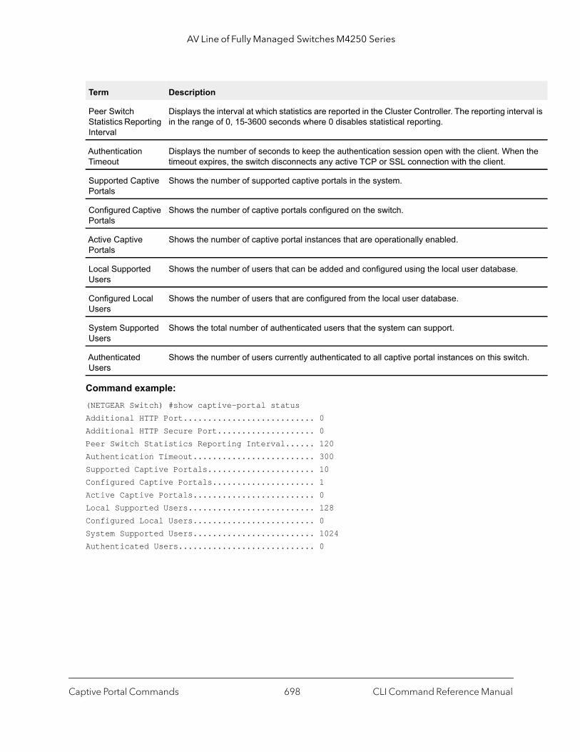
AV Line of Fully Managed Switches M4250 Series
val is
the
h.
Command example: (NETGEAR Switch) #show captive-portal statusAdditional HTTP Port........................... 0Additional HTTP Secure Port.................... 0Peer Switch Statistics Reporting Interval...... 120Authentication Timeout......................... 300Supported Captive Portals...................... 10Configured Captive Portals..................... 1Active Captive Portals......................... 0Local Supported Users.......................... 128Configured Local Users......................... 0System Supported Users......................... 1024Authenticated Users............................ 0
Peer Switch Statistics Reporting Interval
Displays the interval at which statistics are reported in the Cluster Controller. The reporting interin the range of 0, 15-3600 seconds where 0 disables statistical reporting.
Authentication Timeout
Displays the number of seconds to keep the authentication session open with the client. Whentimeout expires, the switch disconnects any active TCP or SSL connection with the client.
Supported Captive Portals
Shows the number of supported captive portals in the system.
Configured Captive Portals
Shows the number of captive portals configured on the switch.
Active Captive Portals
Shows the number of captive portal instances that are operationally enabled.
Local Supported Users
Shows the number of users that can be added and configured using the local user database.
Configured Local Users
Shows the number of users that are configured from the local user database.
System Supported Users
Shows the total number of authenticated users that the system can support.
Authenticated Users
Shows the number of users currently authenticated to all captive portal instances on this switc
Term Description
Captive Portal Commands CLI Command Reference Manual698

AV Line of Fully Managed Switches M4250 Series
ptive
o a
t
.
show captive-portal trapflagsThis command shows which captive portal SNMP traps are enabled. The show trapflags command shows the global captive portal traps configuration. For more information, see the sample output of show trapflags on page 114.
Captive Portal Configuration Commands
The commands in this section are related to captive portal configurations.
configuration (for captive portal)Use this command to enter the Captive Portal Instance Mode.
The captive portal configuration, identified by CP ID 1, is the default CP configuration. You can create up to nine additional captive portal configurations. The system supports a total of ten CP configurations. The Captive Portal ID cp-id variable is a number in the range of 1-10.
Format show captive-portal trapflags
Mode Privileged EXEC
Term Description
Client Authentication Failure Traps
Shows whether the SNMP agent sends a trap when a client attempts to authenticate with a caportal but is unsuccessful.
Client Connection Traps
Shows whether the SNMP agent sends a trap when a client authenticates with and connects tcaptive portal.
Client Database Full Traps
Shows whether the SNMP agent sends a trap each time an entry cannot be added to the cliendatabase because it is full.
Client Disconnection Traps
Shows whether the SNMP agent sends a trap when a client disconnects from a captive portal
Format configuration cp-id
Mode Captive Portal Config
Captive Portal Commands CLI Command Reference Manual699
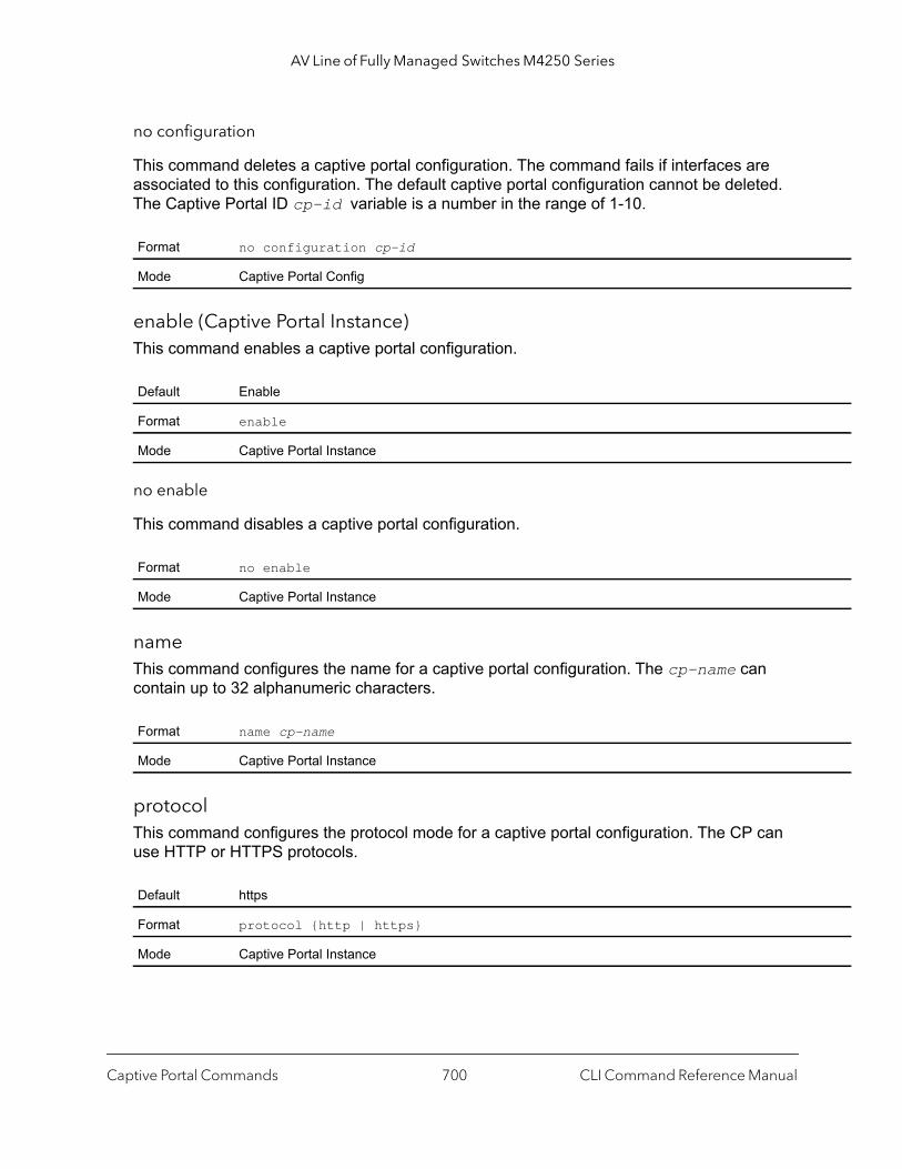
AV Line of Fully Managed Switches M4250 Series
no configuration
This command deletes a captive portal configuration. The command fails if interfaces are associated to this configuration. The default captive portal configuration cannot be deleted. The Captive Portal ID cp-id variable is a number in the range of 1-10.
enable (Captive Portal Instance)This command enables a captive portal configuration.
no enable
This command disables a captive portal configuration.
nameThis command configures the name for a captive portal configuration. The cp-name can contain up to 32 alphanumeric characters.
protocolThis command configures the protocol mode for a captive portal configuration. The CP can use HTTP or HTTPS protocols.
Format no configuration cp-id
Mode Captive Portal Config
Default Enable
Format enable
Mode Captive Portal Instance
Format no enable
Mode Captive Portal Instance
Format name cp-name
Mode Captive Portal Instance
Default https
Format protocol {http | https}
Mode Captive Portal Instance
Captive Portal Commands CLI Command Reference Manual700

AV Line of Fully Managed Switches M4250 Series
verificationThis command configures the verification mode for a captive portal configuration. The type of user verification to perform can be one of the following:
• guest. The user does not need to be authenticated by a database. • local. The switch uses a local database to authenticated users.• radius. The switch uses a database on a remote RADIUS server to authenticate users.
groupThis command assigns a group ID to a captive portal configuration. Each Captive Portal configuration must contain at least one group ID. The group-id can have a number in the 1–1024 range. Group ID 1 is the default.
radius-auth-serverUse this command to configure a captive portal configuration RADIUS authentication server.
no radius-auth-server
This command disables a captive portal configuration RADIUS authentication server.
Default guest
Format verification {guest | local | radius}
Mode Captive Portal Instance
Default group-ID 1
Format group group-id
Mode Captive Portal Instance
Default Disable
Format radius-auth-server server-name
Mode Captive Portal Instance
Format no radius-auth-server
Mode Captive Portal Instance
Captive Portal Commands CLI Command Reference Manual701
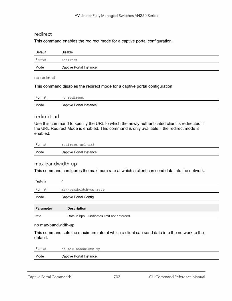
AV Line of Fully Managed Switches M4250 Series
redirectThis command enables the redirect mode for a captive portal configuration.
no redirect
This command disables the redirect mode for a captive portal configuration.
redirect-urlUse this command to specify the URL to which the newly authenticated client is redirected if the URL Redirect Mode is enabled. This command is only available if the redirect mode is enabled.
max-bandwidth-upThis command configures the maximum rate at which a client can send data into the network.
no max-bandwidth-up
This command sets the maximum rate at which a client can send data into the network to the default.
Default Disable
Format redirect
Mode Captive Portal Instance
Format no redirect
Mode Captive Portal Instance
Format redirect-url url
Mode Captive Portal Instance
Default 0
Format max-bandwidth-up rate
Mode Captive Portal Config
Parameter Description
rate Rate in bps. 0 indicates limit not enforced.
Format no max-bandwidth-up
Mode Captive Portal Instance
Captive Portal Commands CLI Command Reference Manual702
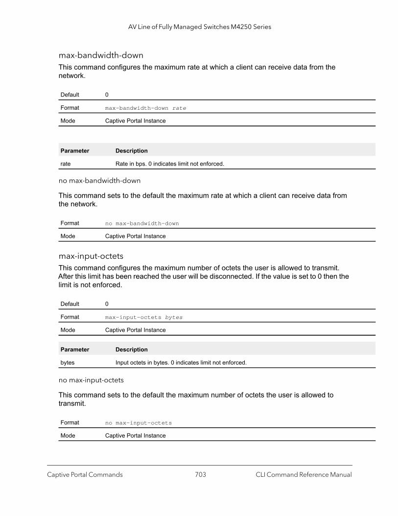
AV Line of Fully Managed Switches M4250 Series
max-bandwidth-downThis command configures the maximum rate at which a client can receive data from the network.
no max-bandwidth-down
This command sets to the default the maximum rate at which a client can receive data from the network.
max-input-octetsThis command configures the maximum number of octets the user is allowed to transmit. After this limit has been reached the user will be disconnected. If the value is set to 0 then the limit is not enforced.
no max-input-octets
This command sets to the default the maximum number of octets the user is allowed to transmit.
Default 0
Format max-bandwidth-down rate
Mode Captive Portal Instance
Parameter Description
rate Rate in bps. 0 indicates limit not enforced.
Format no max-bandwidth-down
Mode Captive Portal Instance
Default 0
Format max-input-octets bytes
Mode Captive Portal Instance
Parameter Description
bytes Input octets in bytes. 0 indicates limit not enforced.
Format no max-input-octets
Mode Captive Portal Instance
Captive Portal Commands CLI Command Reference Manual703
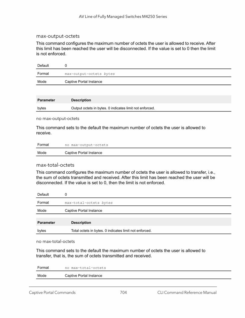
AV Line of Fully Managed Switches M4250 Series
max-output-octetsThis command configures the maximum number of octets the user is allowed to receive. After this limit has been reached the user will be disconnected. If the value is set to 0 then the limit is not enforced.
no max-output-octets
This command sets to the default the maximum number of octets the user is allowed to receive.
max-total-octetsThis command configures the maximum number of octets the user is allowed to transfer, i.e., the sum of octets transmitted and received. After this limit has been reached the user will be disconnected. If the value is set to 0, then the limit is not enforced.
no max-total-octets
This command sets to the default the maximum number of octets the user is allowed to transfer, that is, the sum of octets transmitted and received.
Default 0
Format max-output-octets bytes
Mode Captive Portal Instance
Parameter Description
bytes Output octets in bytes. 0 indicates limit not enforced.
Format no max-output-octets
Mode Captive Portal Instance
Default 0
Format max-total-octets bytes
Mode Captive Portal Instance
Parameter Description
bytes Total octets in bytes. 0 indicates limit not enforced.
Format no max-total-octets
Mode Captive Portal Instance
Captive Portal Commands CLI Command Reference Manual704
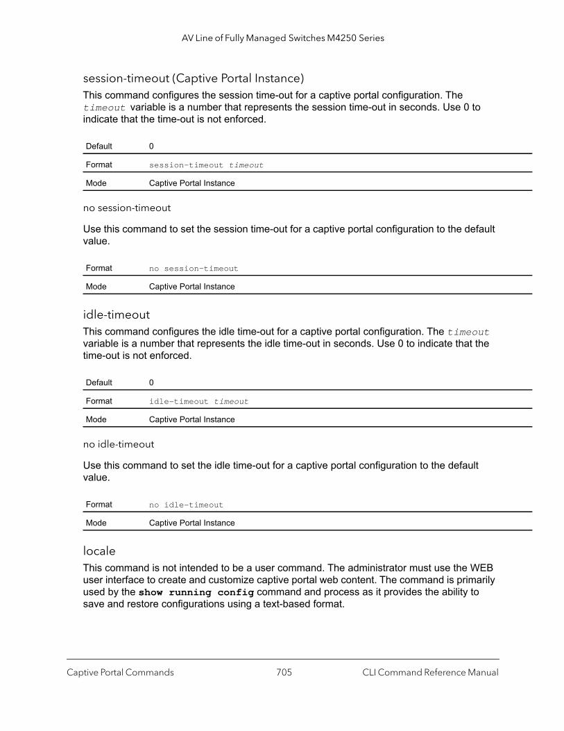
AV Line of Fully Managed Switches M4250 Series
session-timeout (Captive Portal Instance)This command configures the session time-out for a captive portal configuration. The timeout variable is a number that represents the session time-out in seconds. Use 0 to indicate that the time-out is not enforced.
no session-timeout
Use this command to set the session time-out for a captive portal configuration to the default value.
idle-timeoutThis command configures the idle time-out for a captive portal configuration. The timeout variable is a number that represents the idle time-out in seconds. Use 0 to indicate that the time-out is not enforced.
no idle-timeout
Use this command to set the idle time-out for a captive portal configuration to the default value.
localeThis command is not intended to be a user command. The administrator must use the WEB user interface to create and customize captive portal web content. The command is primarily used by the show running config command and process as it provides the ability to save and restore configurations using a text-based format.
Default 0
Format session-timeout timeout
Mode Captive Portal Instance
Format no session-timeout
Mode Captive Portal Instance
Default 0
Format idle-timeout timeout
Mode Captive Portal Instance
Format no idle-timeout
Mode Captive Portal Instance
Captive Portal Commands CLI Command Reference Manual705

AV Line of Fully Managed Switches M4250 Series
do (Captive Portal Instance mode)Use this command to run Privileged Exec mode commands.
script-textUse this command to specify, in UTF-16 byte stream format, the text that is displayed if javascript is disabled in the users browser.
show (Captive Portal Instance)Use this command to display the switches options and settings.
wip-msgUse this command to specify, in UTF-16 byte stream format, the message displayed when authentication is in progress.
interface (Captive Portal Instance)This command associates an interface to a captive portal configuration or removes the interface captive portal association.
Format locale web-id
Mode Captive Portal Instance
Format do
Mode Captive Portal Instance
Format script-text UTF-16
Mode Captive Portal Instance
Format show
Mode Captive Portal Instance
Format wip-msg UTF-16
Mode Captive Portal Instance
Format interface unit/port
Mode Captive Portal Instance
Captive Portal Commands CLI Command Reference Manual706
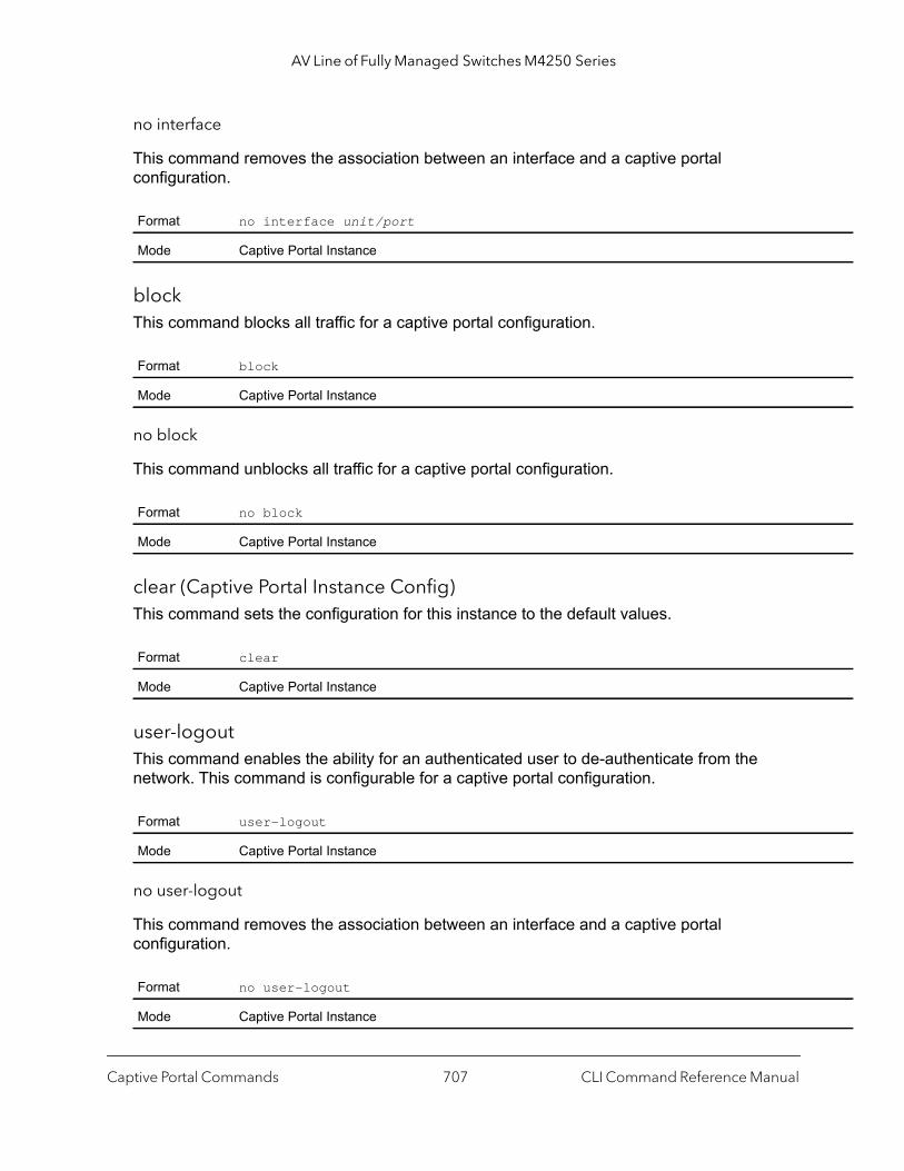
AV Line of Fully Managed Switches M4250 Series
no interface
This command removes the association between an interface and a captive portal configuration.
blockThis command blocks all traffic for a captive portal configuration.
no block
This command unblocks all traffic for a captive portal configuration.
clear (Captive Portal Instance Config)This command sets the configuration for this instance to the default values.
user-logoutThis command enables the ability for an authenticated user to de-authenticate from the network. This command is configurable for a captive portal configuration.
no user-logout
This command removes the association between an interface and a captive portal configuration.
Format no interface unit/port
Mode Captive Portal Instance
Format block
Mode Captive Portal Instance
Format no block
Mode Captive Portal Instance
Format clear
Mode Captive Portal Instance
Format user-logout
Mode Captive Portal Instance
Format no user-logout
Mode Captive Portal Instance
Captive Portal Commands CLI Command Reference Manual707

AV Line of Fully Managed Switches M4250 Series
background-colorUse this command to customize the background color of the Captive Portal authentication page using a well-known color name or RGB value. For example, red or RGB hex-code, that is, #FF0000. The range of color-code is 1-32 characters.
foreground-colorUse this command to customize the foreground color of the Captive Portal authentication page using a well-known color name or RGB value. For example, red or RGB hex-code, that is, #FF0000. The range of color-code is 1-32 characters.
separator-colorUse this command to customize the separator bar color of the Captive Portal authentication page using a well-known color name or RGB value. For example, red or RGB hex-code; that is, #FF0000.The range of color-code is 1-32 characters.
Default #BFBFBF
Format background-color color-code
Mode Captive Portal Instance
Default #999999
Format foreground-color color-code
Mode Captive Portal Instance
Default #BFBFBF
Format separator-color color-code
Mode Captive Portal Instance
Captive Portal Commands CLI Command Reference Manual708
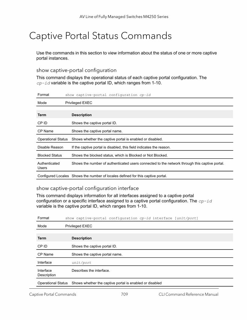
AV Line of Fully Managed Switches M4250 Series
l.
Captive Portal Status Commands
Use the commands in this section to view information about the status of one or more captive portal instances.
show captive-portal configurationThis command displays the operational status of each captive portal configuration. The cp-id variable is the captive portal ID, which ranges from 1-10.
show captive-portal configuration interfaceThis command displays information for all interfaces assigned to a captive portal configuration or a specific interface assigned to a captive portal configuration. The cp-id variable is the captive portal ID, which ranges from 1-10.
Format show captive-portal configuration cp-id
Mode Privileged EXEC
Term Description
CP ID Shows the captive portal ID.
CP Name Shows the captive portal name.
Operational Status Shows whether the captive portal is enabled or disabled.
Disable Reason If the captive portal is disabled, this field indicates the reason.
Blocked Status Shows the blocked status, which is Blocked or Not Blocked.
Authenticated Users
Shows the number of authenticated users connected to the network through this captive porta
Configured Locales Shows the number of locales defined for this captive portal.
Format show captive-portal configuration cp-id interface [unit/port]
Mode Privileged EXEC
Term Description
CP ID Shows the captive portal ID.
CP Name Shows the captive portal name.
Interface unit/port
Interface Description
Describes the interface.
Operational Status Shows whether the captive portal is enabled or disabled
Captive Portal Commands CLI Command Reference Manual709
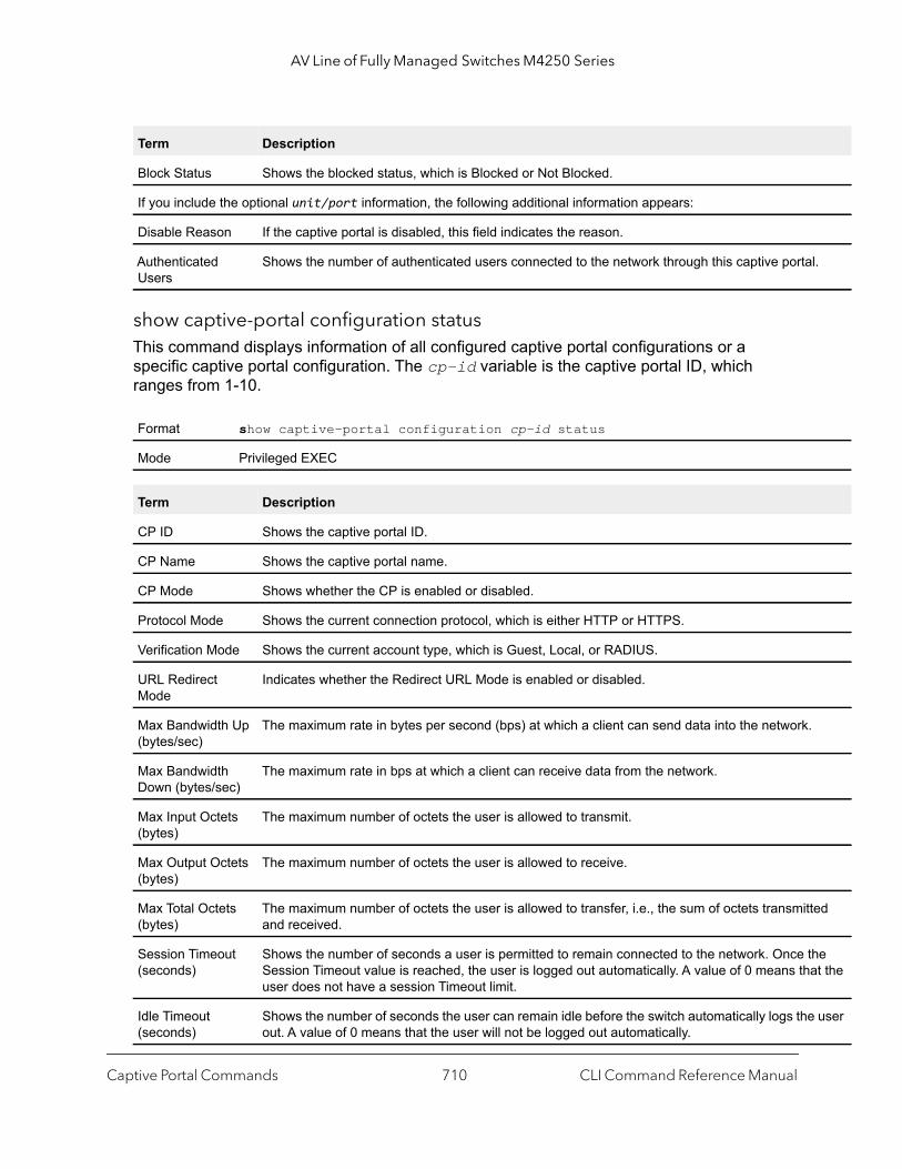
AV Line of Fully Managed Switches M4250 Series
l.
ed
he at the
user
show captive-portal configuration statusThis command displays information of all configured captive portal configurations or a specific captive portal configuration. The cp-id variable is the captive portal ID, which ranges from 1-10.
Block Status Shows the blocked status, which is Blocked or Not Blocked.
If you include the optional unit/port information, the following additional information appears:
Disable Reason If the captive portal is disabled, this field indicates the reason.
Authenticated Users
Shows the number of authenticated users connected to the network through this captive porta
Format show captive-portal configuration cp-id status
Mode Privileged EXEC
Term Description
CP ID Shows the captive portal ID.
CP Name Shows the captive portal name.
CP Mode Shows whether the CP is enabled or disabled.
Protocol Mode Shows the current connection protocol, which is either HTTP or HTTPS.
Verification Mode Shows the current account type, which is Guest, Local, or RADIUS.
URL Redirect Mode
Indicates whether the Redirect URL Mode is enabled or disabled.
Max Bandwidth Up (bytes/sec)
The maximum rate in bytes per second (bps) at which a client can send data into the network.
Max Bandwidth Down (bytes/sec)
The maximum rate in bps at which a client can receive data from the network.
Max Input Octets (bytes)
The maximum number of octets the user is allowed to transmit.
Max Output Octets (bytes)
The maximum number of octets the user is allowed to receive.
Max Total Octets (bytes)
The maximum number of octets the user is allowed to transfer, i.e., the sum of octets transmittand received.
Session Timeout (seconds)
Shows the number of seconds a user is permitted to remain connected to the network. Once tSession Timeout value is reached, the user is logged out automatically. A value of 0 means thuser does not have a session Timeout limit.
Idle Timeout (seconds)
Shows the number of seconds the user can remain idle before the switch automatically logs theout. A value of 0 means that the user will not be logged out automatically.
Term Description
Captive Portal Commands CLI Command Reference Manual710

AV Line of Fully Managed Switches M4250 Series
show captive-portal configuration localesThis command displays locales associated with a specific captive portal configuration. The cp-id variable is the captive portal ID, which ranges from 1-10.
Captive Portal Client Connection Commands
Use the commands in this section to view information about the clients connected to the captive portals configured on the switch.
show captive-portal client statusThis command displays client connection details or a connection summary for connected captive portal users. Use the optional macaddr keyword, which is the MAC address of a client, to view additional information about that client.
Format show captive-portal configuration cp-id locales
Mode Privileged EXEC
Term Description
Locale Code Two-letter abbreviation for languages.
Locale Link The names of the languages.
Format show captive-portal client [macaddr] status
Mode Privileged EXEC
Term Description
Client MAC Address
Identifies the MAC address of the wireless client (if applicable).
Client IP Address Identifies the IP address of the wireless client (if applicable).
Protocol Mode Shows the current connection protocol, which is either HTTP or HTTPS.
Verification Mode Shows the current account type, which is Guest, Local, or RADIUS.
Session Time Shows the amount of time that has passed since the client was authorized.
If you specify a client MAC address, the following additional information displays:
CP ID Shows the captive portal ID the connected client is using.
CP Name Shows the name of the captive portal the connected client is using.
Captive Portal Commands CLI Command Reference Manual711

AV Line of Fully Managed Switches M4250 Series
show captive-portal client statisticsThis command displays the statistics for a specific captive portal client.
show captive-portal interface client statusThis command displays information about clients authenticated on all interfaces or a specific interface.
Interface Valid unit and port number separated by a forward slash.
Interface Description
Describes the interface.
User Name Displays the user name (or Guest ID) of the connected client.
If cluster support is available, the following fields display:
Switch MAC Address
Identifies the MAC address of the switch (if applicable).
Switch IP Address Identifies the IP address of the switch (if applicable).
Switch Type (local or peer)
Shows the current switch type, which is local or peer.
Format show captive-portal client macaddr statistics
Mode Privileged EXEC
Term Description
Client MAC Address
Identifies the MAC address of the wireless client (if applicable).
Bytes Received Total bytes the client has received.
Bytes Transmitted Total bytes the client has transmitted.
Packets Transmitted
Total packets the client has transmitted.
Packets Received Total packets the client has received.
Format show captive-portal interface [unit/port] client status
Mode Privileged EXEC
Term Description
Captive Portal Commands CLI Command Reference Manual712
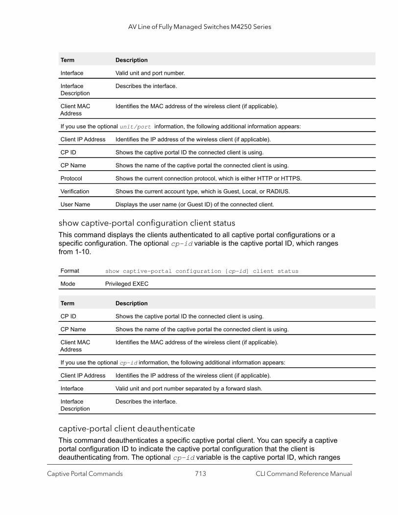
AV Line of Fully Managed Switches M4250 Series
show captive-portal configuration client statusThis command displays the clients authenticated to all captive portal configurations or a specific configuration. The optional cp-id variable is the captive portal ID, which ranges from 1-10.
captive-portal client deauthenticateThis command deauthenticates a specific captive portal client. You can specify a captive portal configuration ID to indicate the captive portal configuration that the client is deauthenticating from. The optional cp-id variable is the captive portal ID, which ranges
Term Description
Interface Valid unit and port number.
Interface Description
Describes the interface.
Client MAC Address
Identifies the MAC address of the wireless client (if applicable).
If you use the optional unit/port information, the following additional information appears:
Client IP Address Identifies the IP address of the wireless client (if applicable).
CP ID Shows the captive portal ID the connected client is using.
CP Name Shows the name of the captive portal the connected client is using.
Protocol Shows the current connection protocol, which is either HTTP or HTTPS.
Verification Shows the current account type, which is Guest, Local, or RADIUS.
User Name Displays the user name (or Guest ID) of the connected client.
Format show captive-portal configuration [cp-id] client status
Mode Privileged EXEC
Term Description
CP ID Shows the captive portal ID the connected client is using.
CP Name Shows the name of the captive portal the connected client is using.
Client MAC Address
Identifies the MAC address of the wireless client (if applicable).
If you use the optional cp-id information, the following additional information appears:
Client IP Address Identifies the IP address of the wireless client (if applicable).
Interface Valid unit and port number separated by a forward slash.
Interface Description
Describes the interface.
Captive Portal Commands CLI Command Reference Manual713

AV Line of Fully Managed Switches M4250 Series
from 1-10. If no value is entered, then the specified clients (or all clients) are deauthenticated from all captive portal configurations.
You can use the optional macaddr variable to specify the MAC address of the client to deauthenticate. If no value is specified, then all clients are deauthenticated from the specified captive portal configuration (or all configurations).
Captive Portal Interface Commands
Use the commands in this section to view information about the interfaces on the switch that are associated with captive portals or that are capable of supporting a captive portal.
show captive-portal interface configuration statusThis command displays the interface to configuration assignments for all captive portal configurations or a specific configuration. The optional cp-id variable is the captive portal ID, which ranges from 1-10.
show captive-portal interface capabilityThis command displays all the captive portal eligible interfaces or the interface capabilities for a specific captive portal interface.
Format captive-portal client deauthenticate [cp-id] [macaddr]
Mode Privileged EXEC
Format show captive-portal interface configuration [cp-id] status
Mode Privileged EXEC
Term Description
CP ID Shows the captive portal ID the connected client is using.
CP Name Shows the name of the captive portal the connected client is using.
Interface Valid unit and port number separated by a forward slash.
Interface Description
Describes the interface.
Type Shows the type of interface.
Format show captive-portal interface capability [unit/port]
Mode Privileged EXEC
Captive Portal Commands CLI Command Reference Manual714
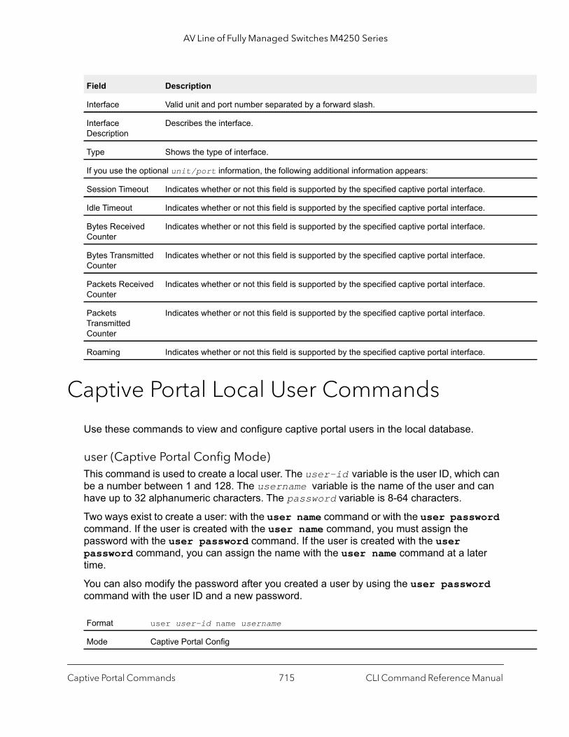
AV Line of Fully Managed Switches M4250 Series
Captive Portal Local User Commands
Use these commands to view and configure captive portal users in the local database.
user (Captive Portal Config Mode)This command is used to create a local user. The user-id variable is the user ID, which can be a number between 1 and 128. The username variable is the name of the user and can have up to 32 alphanumeric characters. The password variable is 8-64 characters.
Two ways exist to create a user: with the user name command or with the user password command. If the user is created with the user name command, you must assign the password with the user password command. If the user is created with the user password command, you can assign the name with the user name command at a later time.
You can also modify the password after you created a user by using the user password command with the user ID and a new password.
Field Description
Interface Valid unit and port number separated by a forward slash.
Interface Description
Describes the interface.
Type Shows the type of interface.
If you use the optional unit/port information, the following additional information appears:
Session Timeout Indicates whether or not this field is supported by the specified captive portal interface.
Idle Timeout Indicates whether or not this field is supported by the specified captive portal interface.
Bytes Received Counter
Indicates whether or not this field is supported by the specified captive portal interface.
Bytes Transmitted Counter
Indicates whether or not this field is supported by the specified captive portal interface.
Packets Received Counter
Indicates whether or not this field is supported by the specified captive portal interface.
Packets Transmitted Counter
Indicates whether or not this field is supported by the specified captive portal interface.
Roaming Indicates whether or not this field is supported by the specified captive portal interface.
Format user user-id name username
Mode Captive Portal Config
Captive Portal Commands CLI Command Reference Manual715

AV Line of Fully Managed Switches M4250 Series
Command example:
The following example uses name to create the user.(NETGEAR Switch)(Config-CP) #user 1 name test
Command example:
The following example uses password to create the user:(NETGEAR Switch)(Config-CP) #user 1 password test1234
no user
This command deletes a user from the local user database. If the user has an existing session, it is disconnected. The user-id variable is the user ID, which can be a number between 1 and 128.
Command example: (NETGEAR Switch)(Config-CP) #no user 1
user name (Captive Portal Config)This command assigns a name to the User ID. This name is used at the client station for authentication. The user-id variable is the local user ID created with the user command and can be from 1 to 128 characters. The username variable is the name of the user and can have up to 32 alphanumeric characters.
Command example: (NETGEAR Switch)(Config-CP) #user 1 name johnsmith
Format user user-id password password
Mode Captive Portal Config
Format no user user-id
Mode Captive Portal Config
Format user user-id name username
Mode Captive Portal Config
Captive Portal Commands CLI Command Reference Manual716
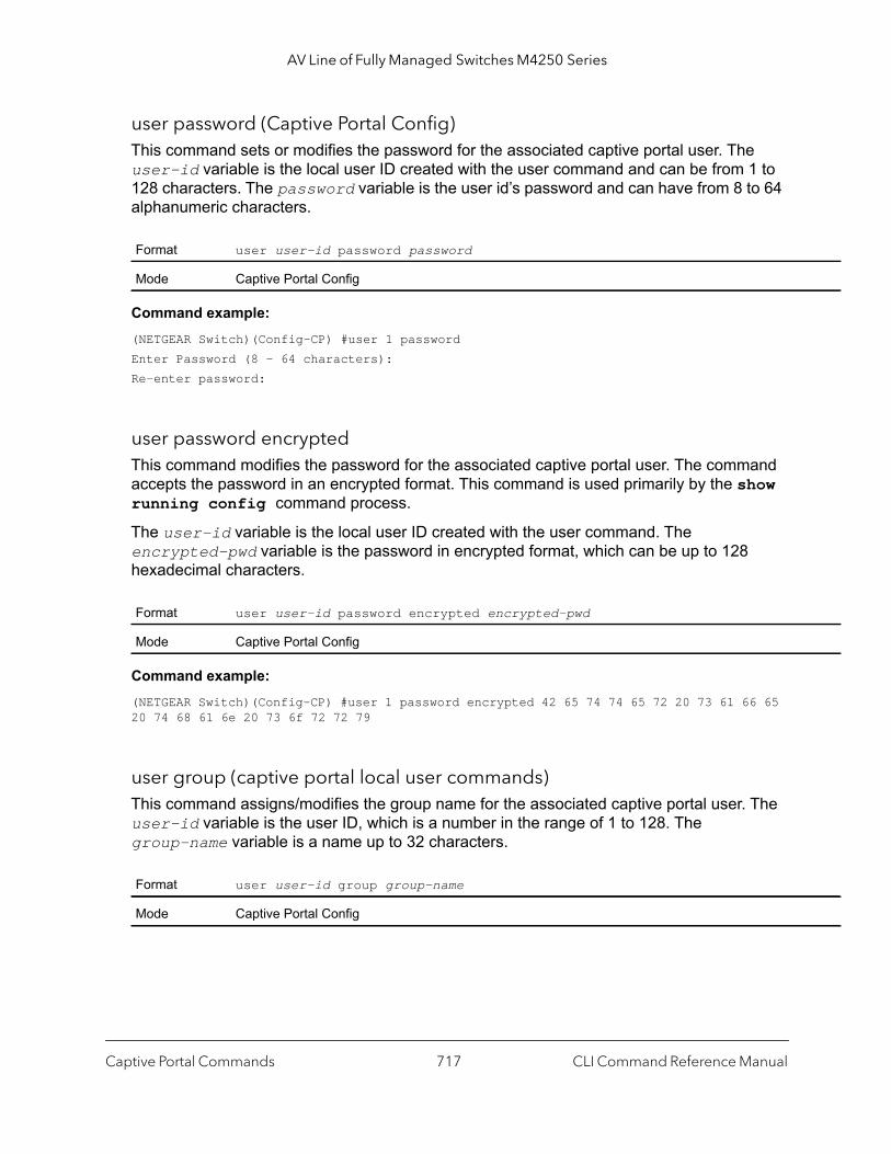
AV Line of Fully Managed Switches M4250 Series
user password (Captive Portal Config)This command sets or modifies the password for the associated captive portal user. The user-id variable is the local user ID created with the user command and can be from 1 to 128 characters. The password variable is the user id’s password and can have from 8 to 64 alphanumeric characters.
Command example: (NETGEAR Switch)(Config-CP) #user 1 passwordEnter Password (8 - 64 characters):Re-enter password:
user password encryptedThis command modifies the password for the associated captive portal user. The command accepts the password in an encrypted format. This command is used primarily by the show running config command process.
The user-id variable is the local user ID created with the user command. The encrypted-pwd variable is the password in encrypted format, which can be up to 128 hexadecimal characters.
Command example: (NETGEAR Switch)(Config-CP) #user 1 password encrypted 42 65 74 74 65 72 20 73 61 66 65 20 74 68 61 6e 20 73 6f 72 72 79
user group (captive portal local user commands)This command assigns/modifies the group name for the associated captive portal user. The user-id variable is the user ID, which is a number in the range of 1 to 128. The group-name variable is a name up to 32 characters.
Format user user-id password password
Mode Captive Portal Config
Format user user-id password encrypted encrypted-pwd
Mode Captive Portal Config
Format user user-id group group-name
Mode Captive Portal Config
Captive Portal Commands CLI Command Reference Manual717
AV Line of Fully Managed Switches M4250 Series
Command example: (NETGEAR Switch)(Config-CP) #user 1 group 123
user session-timeoutThis command sets the session timeout value for the associated captive portal user. The user-id variable is the ID of a user configured in the local database, and is a number in the range of 1 to 128. The timeout variable is a number that represents the session time-out in seconds. Use 0 to indicate that the time-out is not enforced.
Command example: (NETGEAR Switch)(Config-CP) #user 1 session-timeout 86400
no user session-timeout
This command sets the session timeout value for the associated captive portal user to the default value. The user-id variable is the ID of a user configured in the local database, and is a number in the range of 1 to 128.
Command example: (NETGEAR Switch)(Config-CP) #no user 1 session-timeout
user idle-timeoutThis command sets the session idle timeout value for the associated captive portal user. The user-id variable is the ID of a user configured in the local database, and is a number in the range of 1 to 128. The timeout variable is a number that represents the idle time-out in seconds. Use 0 to indicate that the time-out is not enforced.
Default 0
Format user user-id session-timeout timeout
Mode Captive Portal Config
Format no user user-id session-timeout
Mode Captive Portal Config
Default 0
Format user user-id idle-timeout timeout
Mode Captive Portal Config
Captive Portal Commands CLI Command Reference Manual718
AV Line of Fully Managed Switches M4250 Series
Command example: (NETGEAR Switch)(Config-CP) #user 1 idle-timeout 600
no user idle-timeout
This command sets the session idle timeout value for the associated captive portal user to the default value. The user-id variable is the ID of a user configured in the local database, and is a number in the range of 1 to 128.
Command example: (NETGEAR Switch)(Config-CP) #no user 1 idle-timeout
user max-bandwidth-upThis command is used to configure the bandwidth in bytes per second (bps, with the bps variable) at which the client can send data into the network. 0 denotes using the default value configured for the captive portal. The user-id variable is the ID of a user configured in the local database, and is a number in the range of 1 to 128.
no user max-bandwidth-up
Use this command to set to the default the bandwidth at which the client can send data into the network. The user-id variable is the ID of a user configured in the local database, and is a number in the range of 1 to 128.
Format no user user-id idle-timeout
Mode Captive Portal Config
Default 0
Format user user-id max-bandwidth-up bps
Mode Captive Portal Config
Parameter Description
user-id User ID from 1 to 128 characters.
bps Client transmit rate in bytes per second (bps). 0 denotes unlimited bandwidth.
Format no user user-id max-bandwidth-up
Mode Captive Portal Config
Captive Portal Commands CLI Command Reference Manual719

AV Line of Fully Managed Switches M4250 Series
user max-bandwidth-downThis command is used configure the bandwidth in bytes per second (bps, with the variable) at which the client can receive data from the network. 0 denotes using the default value configured for the captive portal. The user-id variable is the ID of a user configured in the local database, and is a number in the range of 1 to 128.
no user max-bandwidth down
Use this command to set to the default value the bandwidth at which the client can receive data from the network. The user-id variable is the ID of a user configured in the local database, and is a number in the range of 1 to 128.
user max-input-octetsThis command is used to limit the number of octets in bytes that the user is allowed to transmit. After this limit has been reached, the user will be disconnected. 0 octets denote unlimited transmission. The user-id variable is the ID of a user configured in the local database, and is a number in the range of 1 to 128.
Default 0
Format user user-id max-bandwidth-down bps
Mode Captive Portal Config
Parameter Description
user-id User ID from 1 to 128 characters.
bps Client receive rate in bps. 0 denotes unlimited bandwidth.
Format no user user-id max-bandwidth-down
Mode Captive Portal Config
Default 0
Format user user-id max-input-octets octets
Mode Captive Portal Config
Parameter Description
user-id User ID from 1 to 128 characters.
octets Number of bytes.
Captive Portal Commands CLI Command Reference Manual720
AV Line of Fully Managed Switches M4250 Series
no user max-input-octets
Use this command to set to the default the number of octets in bytes that the user is allowed to transmit. The user-id variable is the ID of a user configured in the local database, and is a number in the range of 1 to 128.
user max-output-octetsThis command is used to limit the number of octets in bytes that the user is allowed to receive. After this limit has been reached, the user will be disconnected. 0 octets denote unlimited transmission. The user-id variable is the ID of a user configured in the local database, and is a number in the range of 1 to 128.
no user max-output-octets
Use this command to set to the default the number of octets in bytes that the user is allowed to receive. The user-id variable is the ID of a user configured in the local database, and is a number in the range of 1 to 128.
user max-total-octetsThis command is used to limit the number of octets in bytes that the user is allowed to transmit and receive. The maximum number of octets is the sum of octets transmitted and received. After this limit has been reached, the user will be disconnected. 0 octets denote unlimited transmission. The user-id variable is the ID of a user configured in the local database, and is a number in the range of 1 to 128.
Format no user user-id max-input-octets
Mode Captive Portal Config
Default 0
Format user user-id max-output-octets octets
Mode Captive Portal Config
Parameter Description
user-id User ID from 1 to 128 characters.
octets Number of bytes.
Format no user user-id max-output-octets
Mode Captive Portal Config
Captive Portal Commands CLI Command Reference Manual721

AV Line of Fully Managed Switches M4250 Series
rom
no user max-total-octets
Use this command to set to the default the number of octets in bytes that the user is allowed to transmit and receive. The user-id variable is the ID of a user configured in the local database, and is a number in the range of 1 to 128.
show captive-portal userThis command displays all configured users or a specific user in the captive portal local user database. Enter the optional user ID to view information about the specified user. The optional user-id variable is the ID of a user configured in the local database, and is a number in the range of 1 to 128. Enter the group keyword or the group keyword and group-id variable to view the user information organized by groups.
Default 0
Format user user-id max-total-octets octets
Mode Captive Portal Config
Parameter Description
user-id User ID from 1 to 128 characters.
octets Number of bytes.
Format no user user-id max-total-octets
Mode Captive Portal Config
Format show captive-portal user [user-id] [group [group-id]]
Mode Privileged EXEC
Field Description
User ID Displays the ID of the user.
User Name Displays the user name.
Session Timeout Displays the number of seconds the user can remain in a session before being disconnected fthe Captive Portal.
Idle Timeout Displays the number of seconds the user can remain idle before being disconnected from the Captive Portal.
Group ID Displays the group identifier for the group to which the user belongs.
When you include the [user-id] variable, the following information also displays:
Password Configured
Indicates whether a password has been configured for the user.
Captive Portal Commands CLI Command Reference Manual722

AV Line of Fully Managed Switches M4250 Series
ted
clear captive-portal usersThis command deletes all captive portal user entries.
Captive Portal User Group Commands
Use the following commands to configure CP user groups.
user group (captive portal user group commands)Use this command to create a user group. The group-id variable is a number in the range of 1–10.
no user group
Use this command to delete a user group. The group-id variable is a number in the range of 1–10.
Max Bandwidth Up (bps)
The maximum rate in bytes per second (bps) at which a client can send data into the network.
Max Bandwidth Down (bps)
The maximum rate in bps at which a client can receive data from the network.
Max Bandwidth Input Octets (bytes)
The maximum number of octets the user is allowed to transmit.
Max Bandwidth Output Octets (bytes)
The maximum number of octets the user is allowed to receive.
Max Bandwidth Total Octets (bytes)
The maximum number of octets the user is allowed to transfer, i.e., the sum of octets transmitand received.
Format clear captive-portal users
Mode Privileged EXEC
Format user group group-id
Mode Captive Portal Config
Format no user group group-id
Mode Captive Portal Config
Field Description
Captive Portal Commands CLI Command Reference Manual723

AV Line of Fully Managed Switches M4250 Series
user group nameUse this command to configure a group name. The group-id variable is a number in the range of 1–10. The name variable can be up to 32 alphanumeric characters.
user group moveusersThis command moves existing users from one user group to another. Note that the destination group must already exist before a move can be successful. The group-id and destination-group-id variables are each a number in the range of 1-10.
Command example: (NETGEAR Switch)(Config-CP) #user group 2 moveusers 3
Format user group group-id name name
Mode Captive Portal Config
Format user group group-id moveusers destination-group-id
Mode Captive Portal Config
Captive Portal Commands CLI Command Reference Manual724
9
9IPv6 CommandsThis chapter describes the IPv6 commands. The chapter contains the following sections:
• Tunnel Interface Commands
• Loopback Interface Commands
• IPv6 Routing Commands
• DHCPv6 Commands
The commands in this chapter are in one of three functional groups:
• Show commands. Display switch settings, statistics, and other information.• Configuration commands. Configure features and options of the switch. For every
configuration command, there is a show command that displays the configuration setting.• Clear commands. Clear some or all of the settings to factory defaults.
Note: For information about IPv6 management commands, see IPv6 Management Commands.
725

AV Line of Fully Managed Switches M4250 Series
Tunnel Interface Commands
The commands in this section describe how to create, delete, and manage tunnel interfaces.Several different types of tunnels provide functionality to facilitate the transition of IPv4 networks to IPv6 networks. These tunnels are divided into two classes: configured and automatic. The distinction is that configured tunnels are explicitly configured with a destination or endpoint of the tunnel. Automatic tunnels, in contrast, infer the endpoint of the tunnel from the destination address of packets routed into the tunnel. To assign an IP address to the tunnel interface, see ip address on page 634. To assign an IPv6 address to the tunnel interface, see ipv6 address on page 730.
interface tunnel Use this command to enter the Interface Config mode for a tunnel interface. The tunnel-id range is 0 to 7.
no interface tunnel
This command removes the tunnel interface and associated configuration parameters for the specified tunnel interface.
tunnel sourceThis command specifies the source transport address of the tunnel, either explicitly or by reference to an interface.
tunnel destinationThis command specifies the destination transport address of the tunnel.
Format interface tunnel tunnel-id
Mode Global Config
Format no interface tunnel tunnel-id
Mode Global Config
Format tunnel source {ipv4-address | ethernet unit/port}
Mode Interface Config
Format tunnel destination ipv4-address
Mode Interface Config
IPv6 Commands CLI Command Reference Manual726
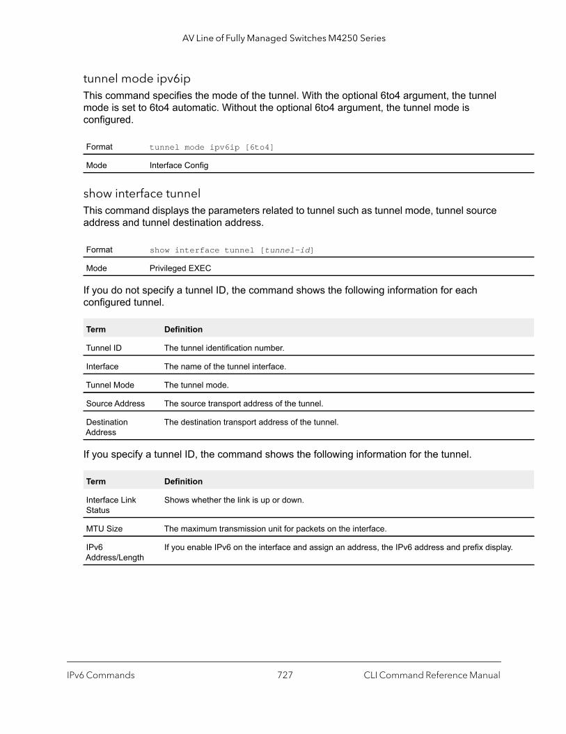
AV Line of Fully Managed Switches M4250 Series
.
tunnel mode ipv6ipThis command specifies the mode of the tunnel. With the optional 6to4 argument, the tunnel mode is set to 6to4 automatic. Without the optional 6to4 argument, the tunnel mode is configured.
show interface tunnelThis command displays the parameters related to tunnel such as tunnel mode, tunnel source address and tunnel destination address.
If you do not specify a tunnel ID, the command shows the following information for each configured tunnel.
If you specify a tunnel ID, the command shows the following information for the tunnel.
Format tunnel mode ipv6ip [6to4]
Mode Interface Config
Format show interface tunnel [tunnel-id]
Mode Privileged EXEC
Term Definition
Tunnel ID The tunnel identification number.
Interface The name of the tunnel interface.
Tunnel Mode The tunnel mode.
Source Address The source transport address of the tunnel.
Destination Address
The destination transport address of the tunnel.
Term Definition
Interface Link Status
Shows whether the link is up or down.
MTU Size The maximum transmission unit for packets on the interface.
IPv6 Address/Length
If you enable IPv6 on the interface and assign an address, the IPv6 address and prefix display
IPv6 Commands CLI Command Reference Manual727
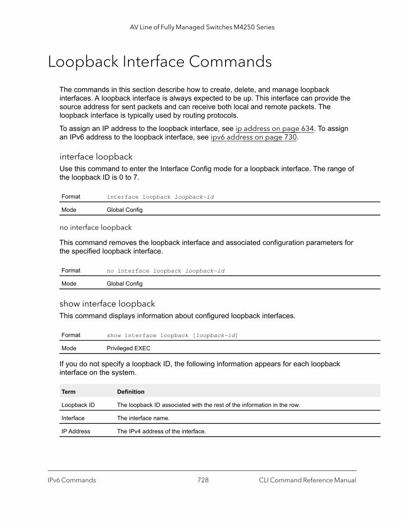
AV Line of Fully Managed Switches M4250 Series
Loopback Interface Commands
The commands in this section describe how to create, delete, and manage loopback interfaces. A loopback interface is always expected to be up. This interface can provide the source address for sent packets and can receive both local and remote packets. The loopback interface is typically used by routing protocols.
To assign an IP address to the loopback interface, see ip address on page 634. To assign an IPv6 address to the loopback interface, see ipv6 address on page 730.
interface loopbackUse this command to enter the Interface Config mode for a loopback interface. The range of the loopback ID is 0 to 7.
no interface loopback
This command removes the loopback interface and associated configuration parameters for the specified loopback interface.
show interface loopbackThis command displays information about configured loopback interfaces.
If you do not specify a loopback ID, the following information appears for each loopback interface on the system.
Format interface loopback loopback-id
Mode Global Config
Format no interface loopback loopback-id
Mode Global Config
Format show interface loopback [loopback-id]
Mode Privileged EXEC
Term Definition
Loopback ID The loopback ID associated with the rest of the information in the row.
Interface The interface name.
IP Address The IPv4 address of the interface.
IPv6 Commands CLI Command Reference Manual728

AV Line of Fully Managed Switches M4250 Series
If you specify a loopback ID, the following information appears.
IPv6 Routing Commands
This section describes the IPv6 commands you use to configure IPv6 on the system and on the interfaces. This section also describes IPv6 management commands and show commands.
ipv6 hop-limitThis command defines the unicast hop count used in ipv6 packets originated by the node. The value is also included in router advertisements. Valid values for hops are 1-255 inclusive. The default “not configured” means that a value of zero is sent in router advertisements and a value of 64 is sent in packets originated by the node. Note that this is not the same as configuring a value of 64.
no ipv6 hop-limit
This command returns the unicast hop count to the default.
ipv6 unicast-routingUse this command to enable the forwarding of IPv6 unicast datagrams.
Term Definition
Interface Link Status
Shows whether the link is up or down.
IP Address The IPv4 address of the interface.
MTU size The maximum transmission size for packets on this interface, in bytes.
Default not configured
Format ipv6 hop-limit hops
Mode Global Config
Format no ipv6 hop-limit
Mode Global Config
Default disabled
Format ipv6 unicast-routing
Mode Global Config
IPv6 Commands CLI Command Reference Manual729

AV Line of Fully Managed Switches M4250 Series
no ipv6 unicast-routing
Use this command to disable the forwarding of IPv6 unicast datagrams.
ipv6 enableUse this command to enable IPv6 routing on an interface or range of interfaces, including tunnel and loopback interfaces, that has not been configured with an explicit IPv6 address. When you use this command, the interface is automatically configured with a link-local address. You do not need to use this command if you configured an IPv6 global address on the interface.
no ipv6 enable
Use this command to disable IPv6 routing on an interface.
ipv6 addressUse this command to configure an IPv6 address on an interface or range of interfaces, including tunnel and loopback interfaces, and to enable IPv6 processing on this interface. You can assign multiple globally reachable addresses to an interface by using this command. You do not need to assign a link-local address by using this command since one is automatically created. The prefix field consists of the bits of the address to be configured. The prefix_length designates how many of the high-order contiguous bits of the address make up the prefix.
You can express IPv6 addresses in eight blocks. Also of note is that instead of a period, a colon now separates each block. For simplification, leading zeros of each 16 bit block can be omitted. One sequence of 16 bit blocks containing only zeros can be replaced with a double colon “::”, but not more than one at a time (otherwise it is no longer a unique representation).
• Dropping zeros: 3ffe:ffff:100:f101:0:0:0:1 becomes 3ffe:ffff:100:f101::1• Local host: 0000:0000:0000:0000:0000:0000:0000:0001 becomes ::1• Any host: 0000:0000:0000:0000:0000:0000:0000:0000 becomes ::
The hexadecimal letters in the IPv6 addresses are not case-sensitive. An example of an IPv6 prefix and prefix length is 3ffe:1::1234/64.
Format no ipv6 unicast-routing
Mode Global Config
Default disabled
Format ipv6 enable
Mode Interface Config
Format no ipv6 enable
Mode Interface Config
IPv6 Commands CLI Command Reference Manual730
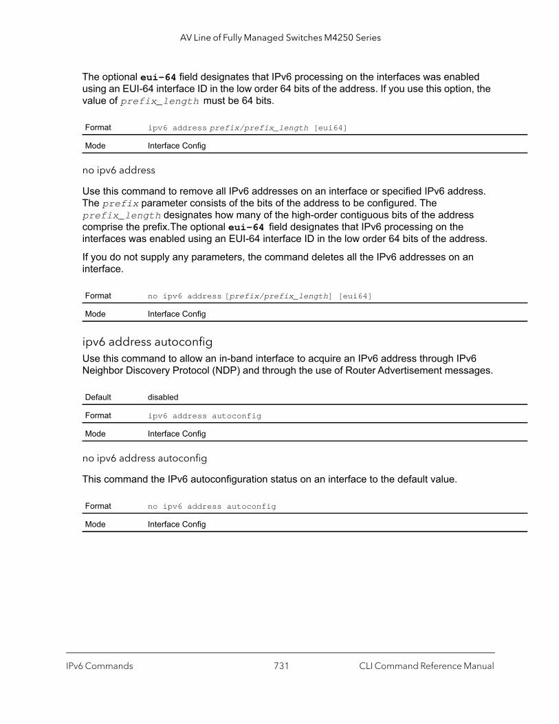
AV Line of Fully Managed Switches M4250 Series
The optional eui-64 field designates that IPv6 processing on the interfaces was enabled using an EUI-64 interface ID in the low order 64 bits of the address. If you use this option, the value of prefix_length must be 64 bits.
no ipv6 address
Use this command to remove all IPv6 addresses on an interface or specified IPv6 address. The prefix parameter consists of the bits of the address to be configured. The prefix_length designates how many of the high-order contiguous bits of the address comprise the prefix.The optional eui-64 field designates that IPv6 processing on the interfaces was enabled using an EUI-64 interface ID in the low order 64 bits of the address.
If you do not supply any parameters, the command deletes all the IPv6 addresses on an interface.
ipv6 address autoconfigUse this command to allow an in-band interface to acquire an IPv6 address through IPv6 Neighbor Discovery Protocol (NDP) and through the use of Router Advertisement messages.
no ipv6 address autoconfig
This command the IPv6 autoconfiguration status on an interface to the default value.
Format ipv6 address prefix/prefix_length [eui64]
Mode Interface Config
Format no ipv6 address [prefix/prefix_length] [eui64]
Mode Interface Config
Default disabled
Format ipv6 address autoconfig
Mode Interface Config
Format no ipv6 address autoconfig
Mode Interface Config
IPv6 Commands CLI Command Reference Manual731

AV Line of Fully Managed Switches M4250 Series
ce nce]
ipv6 address dhcpThis command enables the DHCPv6 client on an in-band interface so that it can acquire network information, such as the IPv6 address, from a network DHCP server.
no ipv6 address dhcp
This command releases a leased address and disables DHCPv6 on an interface.
ipv6 routeUse this command to configure an IPv6 static route. The ipv6-prefix is the IPv6 network that is the destination of the static route. The prefix_length is the length of the IPv6 prefix—a decimal value (usually 0-64) that shows how many of the high-order contiguous bits of the address comprise the prefix (the network portion of the address). A slash mark must precede the prefix_length. The next-hop-address is the IPv6 address of the next hop that can be used to reach the specified network. Specifying Null0 as nexthop parameter adds a static reject route.
The preference parameter is a value the router uses to compare this route with routes from other route sources that have the same destination. The range for preference is 1–255, and the default value is 1.
You can specify a unit/port or vlan-id or tunnel_id interface to identify direct static routes from point-to-point and broadcast interfaces.
The argument unit/port corresponds to a physical routing interface or VLAN routing interface. The vlan keyword and vland-id parameter are used to specify the VLAN ID of the routing VLAN directly instead of in the unit/port format. The vlan-id parameter is a number in the range of 1–4093.
The interface must be specified when using a link-local address as the next hop. A route with a preference of 255 cannot be used to forward traffic.
Default disabled
Format ipv6 address dhcp
Mode Interface Config
Format no ipv6 address dhcp
Mode Interface Config
Default disabled
Format ipv6 route ipv6-prefix/prefix_length {next-hop-address | Null0 | interfa{unit/port | vlan vlan-id | tunnel tunnel_id} next-hop-address} [prefere
Mode Global Config
IPv6 Commands CLI Command Reference Manual732

AV Line of Fully Managed Switches M4250 Series
}
no ipv6 route
Use this command to delete an IPv6 static route. Use the command without the optional parameters to delete all static routes to the specified destination. Use the preference parameter to revert the preference of a route to the default preference.
ipv6 route distance This command sets the default distance (preference) for IPv6 static routes. Lower route distance values are preferred when determining the best route. The ipv6 route distance command lets you optionally set the distance (preference) of an individual static route. The default distance is used when no distance is specified in this command. The preference can be a number in the range 1–255.
Changing the default distance does not update the distance of existing static routes, even if they were assigned the original default distance. The new default distance will only be applied to static routes created after entering the ipv6 route distance command.
no ipv6 route distance
This command resets the default static route preference value in the router to the original default preference. Lower route preference values are preferred when determining the best route.
ipv6 route net-prototypeThis command adds net prototype IPv6 routes to the hardware.
Use the prefix/prefix-length argument to specify the The destination network and mask for the route.
Use the nexthopip argument to specify the next-hop IP address, which must belong to an active routing interface but it does not need to be resolved. The routes are added starting from the specified prefix and prefix-length.
Format no ipv6 route ipv6-prefix/prefix_length [{next-hop-address | Null0 | interface {unit/port| vlan vland-id | tunnel tunnel_id} next-hop-address[preference]]
Mode Global Config
Default 1
Format ipv6 route distance preference
Mode Global Config
Format no ipv6 route distance
Mode Global Config
IPv6 Commands CLI Command Reference Manual733

AV Line of Fully Managed Switches M4250 Series
Use the num-routes argument to specify the number of routes that you want to add to the hardware.
no ipv6 route net-prototype
This command removes all net prototype IPv6 routes from the hardware.
ipv6 mtuThis command sets the maximum transmission unit (MTU) size, in bytes, of IPv6 packets on an interface or range of interfaces. This command replaces the default or link MTU with a new MTU value. The size variable is a number in the range 1280–1500.
Note: The default MTU value for a tunnel interface is 1480. You cannot change this value.
no ipv6 mtu
This command resets maximum transmission unit value to default value.
Format ipv6 route net-prototype prefix/prefix-length nexthopip num-routes
Mode Global Config
Format no ipv6 route net-prototype
Mode Global Config
Default 0 or link speed (MTU value (1500))
Format ipv6 mtu size
Mode Interface Config
Format no ipv6 mtu
Mode Interface Config
IPv6 Commands CLI Command Reference Manual734
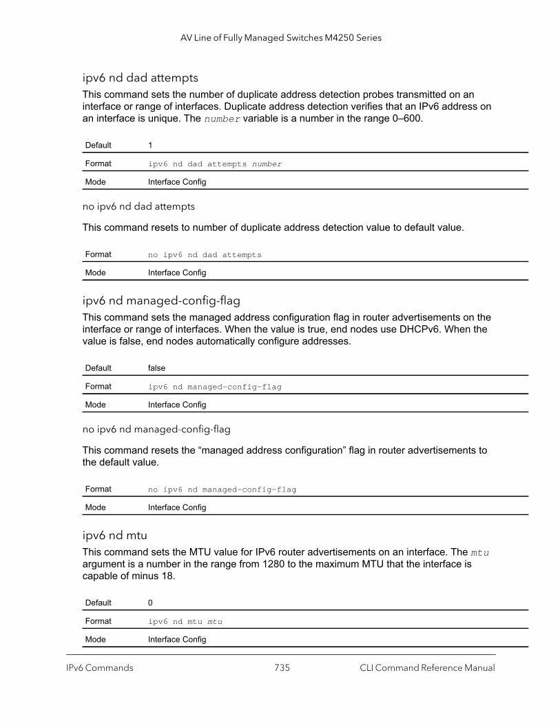
AV Line of Fully Managed Switches M4250 Series
ipv6 nd dad attempts This command sets the number of duplicate address detection probes transmitted on an interface or range of interfaces. Duplicate address detection verifies that an IPv6 address on an interface is unique. The number variable is a number in the range 0–600.
no ipv6 nd dad attempts
This command resets to number of duplicate address detection value to default value.
ipv6 nd managed-config-flagThis command sets the managed address configuration flag in router advertisements on the interface or range of interfaces. When the value is true, end nodes use DHCPv6. When the value is false, end nodes automatically configure addresses.
no ipv6 nd managed-config-flag
This command resets the “managed address configuration” flag in router advertisements to the default value.
ipv6 nd mtuThis command sets the MTU value for IPv6 router advertisements on an interface. The mtu argument is a number in the range from 1280 to the maximum MTU that the interface is capable of minus 18.
Default 1
Format ipv6 nd dad attempts number
Mode Interface Config
Format no ipv6 nd dad attempts
Mode Interface Config
Default false
Format ipv6 nd managed-config-flag
Mode Interface Config
Format no ipv6 nd managed-config-flag
Mode Interface Config
Default 0
Format ipv6 nd mtu mtu
Mode Interface Config
IPv6 Commands CLI Command Reference Manual735

AV Line of Fully Managed Switches M4250 Series
no ipv6 nd mtu
This command resets the MTU value for IPv6 router advertisements on an interface to 0.
ipv6 nd ns-intervalThis command sets the interval between router advertisements for advertised neighbor solicitations, in milliseconds. An advertised value of 0 means the interval is unspecified. This command can configure a single interface or a range of interfaces. The milliseconds variable is a period in milliseconds in the range of 1000–4294967295.
no ipv6 nd ns-interval
This command resets the neighbor solicit retransmission interval of the specified interface to the default value.
ipv6 nd other-config-flagThis command sets the other stateful configuration flag in router advertisements sent from the interface.
no ipv6 nd other-config-flag
This command resets the “other stateful configuration” flag back to its default value in router advertisements sent from the interface.
Format no ipv6 nd mtu
Mode Interface Config
Default 0
Format ipv6 nd ns-interval {milliseconds | 0}
Mode Interface Config
Format no ipv6 nd ns-interval
Mode Interface Config
Default false
Format ipv6 nd other-config-flag
Mode Interface Config
Format no ipv6 nd other-config-flag
Mode Interface Config
IPv6 Commands CLI Command Reference Manual736

AV Line of Fully Managed Switches M4250 Series
ipv6 nd ra-interval This command sets the transmission interval between router advertisements on the interface or range of interfaces. The seconds variable is a number in the range 4–1800 seconds.
no ipv6 nd ra-interval
This command sets router advertisement interval to the default.
ipv6 nd ra-lifetimeThis command sets the value, in seconds, that is placed in the Router Lifetime field of the router advertisements sent from the interface or range of interfaces. The lifetime variable can be zero, or it must be an integer between the value of the router advertisement transmission interval and 9000. A value of zero means this router is not to be used as the default router.
no ipv6 nd ra-lifetime
This command resets router lifetime to the default value.
ipv6 nd raguard attach-policyThis command enables the IPv6 RA guard host mode on the configured interface. All router advertisement (RAs) and router redirect packets that are received on this interface are dropped.
Default 600
Format ipv6 nd ra-interval-max seconds
Mode Interface Config
Format no ipv6 nd ra-interval-max
Mode Interface Config
Default 1800
Format ipv6 nd ra-lifetime lifetime
Mode Interface Config
Format no ipv6 nd ra-lifetime
Mode Interface Config
Format ipv6 nd raguard attach-policy
Mode Interface Config
IPv6 Commands CLI Command Reference Manual737
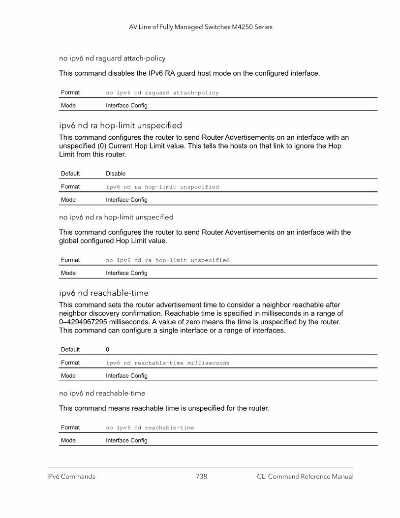
AV Line of Fully Managed Switches M4250 Series
no ipv6 nd raguard attach-policy
This command disables the IPv6 RA guard host mode on the configured interface.
ipv6 nd ra hop-limit unspecifiedThis command configures the router to send Router Advertisements on an interface with an unspecified (0) Current Hop Limit value. This tells the hosts on that link to ignore the Hop Limit from this router.
no ipv6 nd ra hop-limit unspecified
This command configures the router to send Router Advertisements on an interface with the global configured Hop Limit value.
ipv6 nd reachable-timeThis command sets the router advertisement time to consider a neighbor reachable after neighbor discovery confirmation. Reachable time is specified in milliseconds in a range of 0–4294967295 milliseconds. A value of zero means the time is unspecified by the router. This command can configure a single interface or a range of interfaces.
no ipv6 nd reachable-time
This command means reachable time is unspecified for the router.
Format no ipv6 nd raguard attach-policy
Mode Interface Config
Default Disable
Format ipv6 nd ra hop-limit unspecified
Mode Interface Config
Format no ipv6 nd ra hop-limit unspecified
Mode Interface Config
Default 0
Format ipv6 nd reachable-time milliseconds
Mode Interface Config
Format no ipv6 nd reachable-time
Mode Interface Config
IPv6 Commands CLI Command Reference Manual738
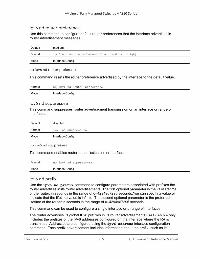
AV Line of Fully Managed Switches M4250 Series
ipv6 nd router-preferenceUse this command to configure default router preferences that the interface advertises in router advertisement messages.
no ipv6 nd router-preference
This command resets the router preference advertised by the interface to the default value.
ipv6 nd suppress-raThis command suppresses router advertisement transmission on an interface or range of interfaces.
no ipv6 nd suppress-ra
This command enables router transmission on an interface.
ipv6 nd prefix Use the ipv6 nd prefix command to configure parameters associated with prefixes the router advertises in its router advertisements. The first optional parameter is the valid lifetime of the router, in seconds in the range of 0–4294967295 seconds.You can specify a value or indicate that the lifetime value is infinite. The second optional parameter is the preferred lifetime of the router in seconds in the range of 0–4294967295 seconds.
This command can be used to configure a single interface or a range of interfaces.
The router advertises its global IPv6 prefixes in its router advertisements (RAs). An RA only includes the prefixes of the IPv6 addresses configured on the interface where the RA is transmitted. Addresses are configured using the ipv6 address interface configuration command. Each prefix advertisement includes information about the prefix, such as its
Default medium
Format ipv6 nd router-preference {low | medium | high}
Mode Interface Config
Format no ipv6 nd router-preference
Mode Interface Config
Default disabled
Format ipv6 nd suppress-ra
Mode Interface Config
Format no ipv6 nd suppress-ra
Mode Interface Config
IPv6 Commands CLI Command Reference Manual739
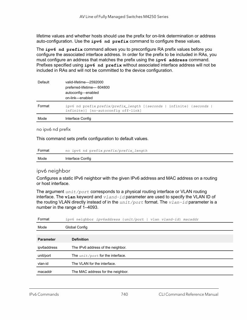
AV Line of Fully Managed Switches M4250 Series
lifetime values and whether hosts should use the prefix for on-link determination or address auto-configuration. Use the ipv6 nd prefix command to configure these values.
The ipv6 nd prefix command allows you to preconfigure RA prefix values before you configure the associated interface address. In order for the prefix to be included in RAs, you must configure an address that matches the prefix using the ipv6 address command. Prefixes specified using ipv6 nd prefix without associated interface address will not be included in RAs and will not be committed to the device configuration.
no ipv6 nd prefix
This command sets prefix configuration to default values.
ipv6 neighborConfigures a static IPv6 neighbor with the given IPv6 address and MAC address on a routing or host interface.
The argument unit/port corresponds to a physical routing interface or VLAN routing interface. The vlan keyword and vland-id parameter are used to specify the VLAN ID of the routing VLAN directly instead of in the unit/port format. The vlan-id parameter is a number in the range of 1–4093.
Default valid-lifetime—2592000preferred-lifetime— 604800autoconfig—enabledon-link—enabled
Format ipv6 nd prefix prefix/prefix_length [{seconds | infinite} {seconds | infinite}] [no-autoconfig off-link]
Mode Interface Config
Format no ipv6 nd prefix prefix/prefix_length
Mode Interface Config
Format ipv6 neighbor ipv6address {unit/port | vlan vland-id} macaddr
Mode Global Config
Parameter Definition
ipv6address The IPv6 address of the neighbor.
unit/port The unit/port for the interface.
vlan-id The VLAN for the interface.
macaddr The MAC address for the neighbor.
IPv6 Commands CLI Command Reference Manual740

AV Line of Fully Managed Switches M4250 Series
ts}
he of 60
. The
he
no ipv6 neighbor
Removes a static IPv6 neighbor with the given IPv6 address on a routing or host interface.
ipv6 neighbors dynamicrenewUse this command to automatically renew the IPv6 neighbor entries. Enables/disables the periodic NUD (neighbor unreachability detection) to be run on the existing IPv6 neighbor entries based on the activity of the entries in the hardware. If the setting is disabled, only those entries that are actively used in the hardware are triggered for NUD at the end of STALE timeout of 1200 seconds. If the setting is enabled, periodically every 40 seconds a set of 300 entries are triggered for NUD irrespective of their usage in the hardware.
no ipv6 neighbors dynamicrenew
Disables automatic renewing of IPv6 neighbor entries.
ipv6 nudUse this command to configure Neighbor Unreachability Detection (NUD). NUD verifies that communication with a neighbor exists.
Format no ipv6 neighbor ipv6address {unit/port | vlan vland-id}
Mode Global Config
Default Disabled
Format ipv6 neighbors dynamicrenew
Mode Global Config
Format no ipv6 neighbors dynamicrenew
Mode Global Config
Format ipv6 nud {backoff-multiple | max-multicast-solicits | max-unicast-solici
Mode Global Config
Term Definition
backoff-multiple Sets the exponential backoff multiple to calculate time outs in NS transmissions during NUD. Tvalue ranges from 1 to 5. 1 is the default. The next timeout value is limited to a maximum valueseconds if the value with exponential backoff calculation is greater than 60 seconds.
max-multicast-solicits
Sets the maximum number of multicast solicits sent during Neighbor Unreachability Detectionvalue ranges from 3 to 255. 3 is the default.
max-unicast-solicits Sets the maximum number of unicast solicits sent during Neighbor Unreachability Detection. Tvalue ranges from 3 to 10. 3 is the default.
IPv6 Commands CLI Command Reference Manual741
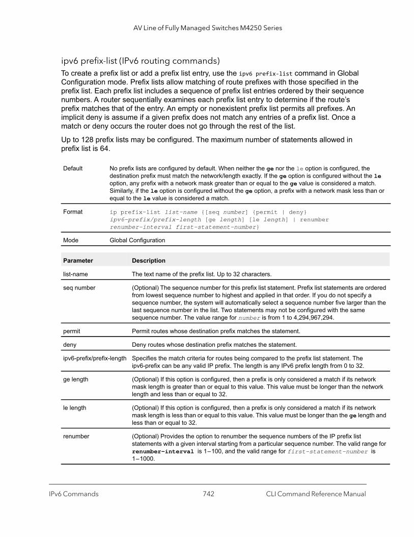
AV Line of Fully Managed Switches M4250 Series
le . n or
ered
n the
k ork
k and
e for s
ipv6 prefix-list (IPv6 routing commands)To create a prefix list or add a prefix list entry, use the ipv6 prefix-list command in Global Configuration mode. Prefix lists allow matching of route prefixes with those specified in the prefix list. Each prefix list includes a sequence of prefix list entries ordered by their sequence numbers. A router sequentially examines each prefix list entry to determine if the route’s prefix matches that of the entry. An empty or nonexistent prefix list permits all prefixes. An implicit deny is assume if a given prefix does not match any entries of a prefix list. Once a match or deny occurs the router does not go through the rest of the list.
Up to 128 prefix lists may be configured. The maximum number of statements allowed in prefix list is 64.
Default No prefix lists are configured by default. When neither the ge nor the le option is configured, the destination prefix must match the network/length exactly. If the ge option is configured without theoption, any prefix with a network mask greater than or equal to the ge value is considered a matchSimilarly, if the le option is configured without the ge option, a prefix with a network mask less thaequal to the le value is considered a match.
Format ip prefix-list list-name {[seq number] {permit | deny} ipv6-prefix/prefix-length [ge length] [le length] | renumber renumber-interval first-statement-number}
Mode Global Configuration
Parameter Description
list-name The text name of the prefix list. Up to 32 characters.
seq number (Optional) The sequence number for this prefix list statement. Prefix list statements are ordfrom lowest sequence number to highest and applied in that order. If you do not specify a sequence number, the system will automatically select a sequence number five larger thalast sequence number in the list. Two statements may not be configured with the same sequence number. The value range for number is from 1 to 4,294,967,294.
permit Permit routes whose destination prefix matches the statement.
deny Deny routes whose destination prefix matches the statement.
ipv6-prefix/prefix-length Specifies the match criteria for routes being compared to the prefix list statement. The ipv6-prefix can be any valid IP prefix. The length is any IPv6 prefix length from 0 to 32.
ge length (Optional) If this option is configured, then a prefix is only considered a match if its networmask length is greater than or equal to this value. This value must be longer than the netwlength and less than or equal to 32.
le length (Optional) If this option is configured, then a prefix is only considered a match if its networmask length is less than or equal to this value. This value must be longer than the ge lengthless than or equal to 32.
renumber (Optional) Provides the option to renumber the sequence numbers of the IP prefix list statements with a given interval starting from a particular sequence number. The valid rangrenumber-interval is 1 – 100, and the valid range for first-statement-number i1 – 1000.
IPv6 Commands CLI Command Reference Manual742
AV Line of Fully Managed Switches M4250 Series
[ge
no ip prefix-list
To delete a prefix list or a statement in a prefix list, use the no ip prefix-list command. The no ip prefix-list list-name command deletes the entire prefix list. To remove an individual statement from a prefix list, you must specify the statement exactly, with all its options.
ipv6 unreachablesUse this command to enable the generation of ICMPv6 Destination Unreachable messages on the interface or range of interfaces. By default, the generation of ICMPv6 Destination Unreachable messages is enabled.
no ipv6 unreachables
Use this command to prevent the generation of ICMPv6 Destination Unreachable messages.
ipv6 unresolved-trafficUse this command to control the rate at which IPv6 data packets come into the CPU. By default, rate limiting is disabled. When enabled, the rate, expressed by the seconds variable, can range from 50 to 1024 packets per second.
Format no ip prefix-list list-name [[seq number] {permit | deny} network/length length] [le length]]
Mode Global Configuration
Default enable
Format ipv6 unreachables
Mode Interface Config
Format no ipv6 unreachables
Mode Interface Config
Default enable
Format ipv6 unresolved-traffic rate-limit seconds
Mode Global Config
IPv6 Commands CLI Command Reference Manual743
AV Line of Fully Managed Switches M4250 Series
no ipv6 unresolved-traffic
Use this command to disable the rate limiting.
ipv6 icmp error-intervalUse this command to limit the rate at which ICMPv6 error messages are sent. The rate limit is configured as a token bucket, with two configurable parameters, burst-size and burst-interval.
The burst-interval specifies how often the token bucket is initialized with burst-size tokens. burst-interval is from 0 to 2147483647 milliseconds (msec).
The burst-size is the number of ICMPv6 error messages that can be sent during one burst-interval. The range is from 1 to 200 messages.
To disable ICMP rate limiting, set burst-interval to zero (0).
no ipv6 icmp error-interval
Use the no ipv6 icmp error-interval command to return the burst-interval and burst-size to their default values.
show ipv6 briefUse this command to display the IPv6 status of forwarding mode and IPv6 unicast routing mode.
Format no ipv6 unresolved-traffic rate-limit
Mode Global Config
Default burst-interval of 1000 msec.burst-size of 100 messages
Format ipv6 icmp error-interval burst-interval [burst-size]
Mode Global Config
Format no ipv6 icmp error-interval
Mode Global Config
Format show ipv6 brief
Mode Privileged EXEC
IPv6 Commands CLI Command Reference Manual744
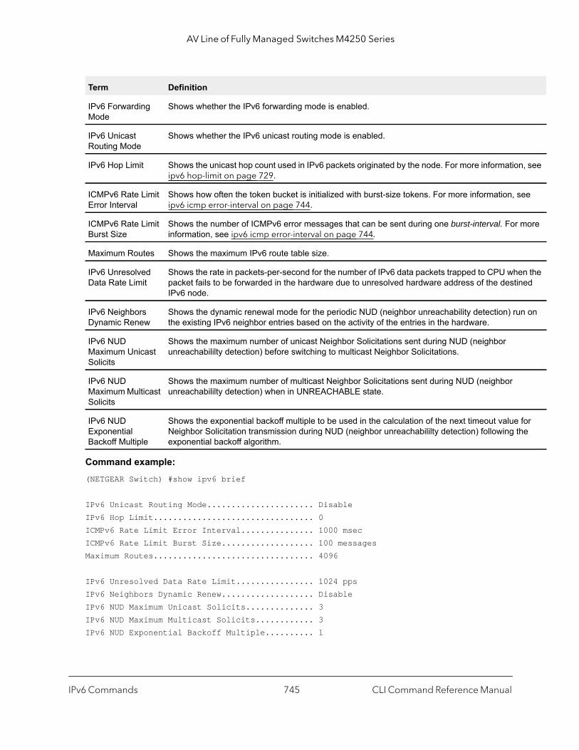
AV Line of Fully Managed Switches M4250 Series
, see
ee
more
n the ed
n on
for e
Command example: (NETGEAR Switch) #show ipv6 brief
IPv6 Unicast Routing Mode...................... DisableIPv6 Hop Limit................................. 0ICMPv6 Rate Limit Error Interval............... 1000 msecICMPv6 Rate Limit Burst Size................... 100 messagesMaximum Routes................................. 4096
IPv6 Unresolved Data Rate Limit................ 1024 ppsIPv6 Neighbors Dynamic Renew................... DisableIPv6 NUD Maximum Unicast Solicits.............. 3IPv6 NUD Maximum Multicast Solicits............ 3IPv6 NUD Exponential Backoff Multiple.......... 1
Term Definition
IPv6 Forwarding Mode
Shows whether the IPv6 forwarding mode is enabled.
IPv6 Unicast Routing Mode
Shows whether the IPv6 unicast routing mode is enabled.
IPv6 Hop Limit Shows the unicast hop count used in IPv6 packets originated by the node. For more informationipv6 hop-limit on page 729.
ICMPv6 Rate Limit Error Interval
Shows how often the token bucket is initialized with burst-size tokens. For more information, sipv6 icmp error-interval on page 744.
ICMPv6 Rate Limit Burst Size
Shows the number of ICMPv6 error messages that can be sent during one burst-interval. For information, see ipv6 icmp error-interval on page 744.
Maximum Routes Shows the maximum IPv6 route table size.
IPv6 Unresolved Data Rate Limit
Shows the rate in packets-per-second for the number of IPv6 data packets trapped to CPU whepacket fails to be forwarded in the hardware due to unresolved hardware address of the destinIPv6 node.
IPv6 Neighbors Dynamic Renew
Shows the dynamic renewal mode for the periodic NUD (neighbor unreachability detection) ruthe existing IPv6 neighbor entries based on the activity of the entries in the hardware.
IPv6 NUD Maximum Unicast Solicits
Shows the maximum number of unicast Neighbor Solicitations sent during NUD (neighbor unreachabililty detection) before switching to multicast Neighbor Solicitations.
IPv6 NUD Maximum Multicast Solicits
Shows the maximum number of multicast Neighbor Solicitations sent during NUD (neighbor unreachabililty detection) when in UNREACHABLE state.
IPv6 NUD Exponential Backoff Multiple
Shows the exponential backoff multiple to be used in the calculation of the next timeout value Neighbor Solicitation transmission during NUD (neighbor unreachabililty detection) following thexponential backoff algorithm.
IPv6 Commands CLI Command Reference Manual745

AV Line of Fully Managed Switches M4250 Series
|
show ipv6 interfaceUse this command to show the usability status of IPv6 interfaces and whether ICMPv6 Destination Unreachable messages may be sent.
The argument unit/port corresponds to a physical routing interface or VLAN routing interface. The vlan keyword and vland-id parameter are used to specify the VLAN ID of the routing VLAN directly instead of in the unit/port format. The vlan-id parameter is a number in the range of 1–4093.
The loopback keyword with the number variable specifies the loopback interface directly and is a number in the range 0–7. The tunnel keyword with the number variable specifies the IPv6 tunnel interface and is a number in the range 0–7.
If you use the brief parameter, the following information displays for all configured IPv6 interfaces.
If you specify an interface, the following information also displays.
Format show ipv6 interface [brief | unit/port | vlan vlan-id | loopback number tunnel number]
Mode Privileged EXEC
Term Definition
Interface The interface in unit/port format.
IPv6 Operational Mode
Shows whether the mode is enabled or disabled.
IPv6 Address/Length
Shows the IPv6 address and length on interfaces with IPv6 enabled.
Method Indicates how each IP address was assigned. The field contains one of the following values:• DHCP. The address is leased from a DHCP server.• Manual. The address is manually configured.Global addresses with no annotation are assumed to be manually configured.
Term Definition
Routing Mode Shows whether IPv6 routing is enabled or disabled.
IPv6 Enable Mode Shows whether IPv6 is enabled on the interface.
Administrative Mode Shows whether the interface administrative mode is enabled or disabled.
Bandwidth Shows bandwidth of the interface.
Interface Maximum Transmission Unit
The MTU size, in bytes.
Router Duplicate Address Detection Transmits
The number of consecutive duplicate address detection probes to transmit.
IPv6 Commands CLI Command Reference Manual746

AV Line of Fully Managed Switches M4250 Series
ents
bled).
ter in
If an IPv6 prefix is configured on the interface, the following information also displays.
Address Autoconfigure Mode Shows whether the autoconfigure mode is enabled or disabled.
Address DHCP Mode Shows whether the DHCPv6 client is enabled on the interface.
IPv6 Hop Limit Unspecified Indicates if the router is configured on this interface to send Router Advertisemwith unspecified (0) as the Current Hop Limit value.
Router Advertisement NS Interval The interval, in milliseconds, between router advertisements for advertised neighbor solicitations.
Router Advertisement Lifetime Shows the router lifetime value of the interface in router advertisements.
Router Advertisement Reachable Time
The amount of time, in milliseconds, to consider a neighbor reachable after neighbor discovery confirmation.
Router Advertisement Interval The frequency, in seconds, that router advertisements are sent.
Router Advertisement Managed Config Flag
Shows whether the managed configuration flag is set (enabled) for router advertisements on this interface.
Router Advertisement Other Config Flag
Shows whether the other configuration flag is set (enabled) for router advertisements on this interface.
Router Advertisement Router Preference
Shows the router preference.
Router Advertisement Suppress Flag
Shows whether router advertisements are suppressed (enabled) or sent (disa
IPv6 Destination Unreachables Shows whether ICMPv6 Destination Unreachable messages may be sent (enabled) or not (disabled). For more information, see ipv6 unreachables onpage 743.
ICMPv6 Redirect Specifies if ICMPv6 redirect messages are sent back to the sender by the Routhe redirect scenario is enabled on this interface.
Term Definition
IPv6 Prefix is The IPv6 prefix for the specified interface.
Preferred Lifetime The amount of time the advertised prefix is a preferred prefix.
Valid Lifetime The amount of time the advertised prefix is valid.
Onlink Flag Shows whether the onlink flag is set (enabled) in the prefix.
Autonomous Flag Shows whether the autonomous address-configuration flag (autoconfig) is set (enabled) in theprefix.
Term Definition
IPv6 Commands CLI Command Reference Manual747
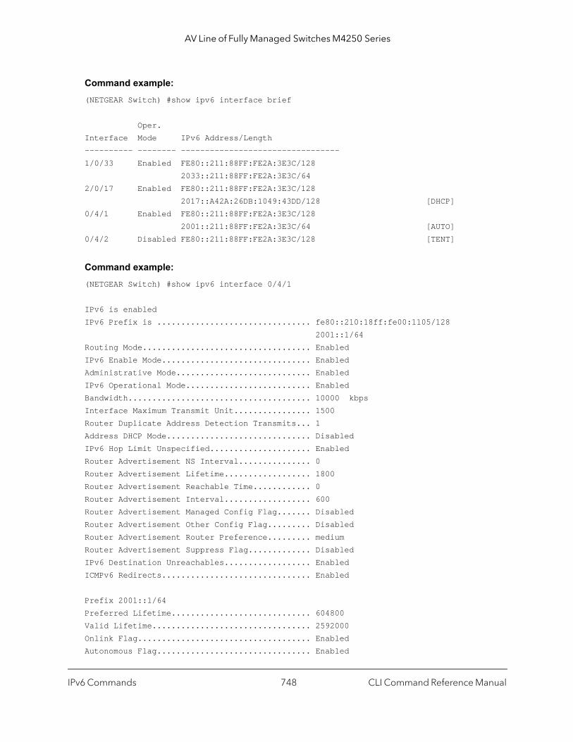
AV Line of Fully Managed Switches M4250 Series
Command example: (NETGEAR Switch) #show ipv6 interface brief
Oper.Interface Mode IPv6 Address/Length---------- -------- ---------------------------------1/0/33 Enabled FE80::211:88FF:FE2A:3E3C/128 2033::211:88FF:FE2A:3E3C/642/0/17 Enabled FE80::211:88FF:FE2A:3E3C/128 2017::A42A:26DB:1049:43DD/128 [DHCP]0/4/1 Enabled FE80::211:88FF:FE2A:3E3C/128 2001::211:88FF:FE2A:3E3C/64 [AUTO]0/4/2 Disabled FE80::211:88FF:FE2A:3E3C/128 [TENT]
Command example: (NETGEAR Switch) #show ipv6 interface 0/4/1
IPv6 is enabledIPv6 Prefix is ................................ fe80::210:18ff:fe00:1105/128 2001::1/64Routing Mode................................... EnabledIPv6 Enable Mode............................... EnabledAdministrative Mode............................ EnabledIPv6 Operational Mode.......................... EnabledBandwidth...................................... 10000 kbpsInterface Maximum Transmit Unit................ 1500Router Duplicate Address Detection Transmits... 1Address DHCP Mode.............................. DisabledIPv6 Hop Limit Unspecified..................... EnabledRouter Advertisement NS Interval............... 0Router Advertisement Lifetime.................. 1800Router Advertisement Reachable Time............ 0Router Advertisement Interval.................. 600Router Advertisement Managed Config Flag....... DisabledRouter Advertisement Other Config Flag......... DisabledRouter Advertisement Router Preference......... mediumRouter Advertisement Suppress Flag............. DisabledIPv6 Destination Unreachables.................. EnabledICMPv6 Redirects............................... Enabled
Prefix 2001::1/64Preferred Lifetime............................. 604800Valid Lifetime................................. 2592000Onlink Flag.................................... EnabledAutonomous Flag................................ Enabled
IPv6 Commands CLI Command Reference Manual748
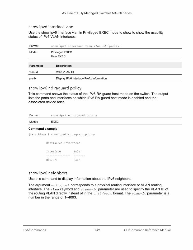
AV Line of Fully Managed Switches M4250 Series
show ipv6 interface vlanUse the show ipv6 interface vlan in Privileged EXEC mode to show to show the usability status of IPv6 VLAN interfaces.
show ipv6 nd raguard policyThis command shows the status of the IPv6 RA guard host mode on the switch. The output lists the ports and interfaces on which IPv6 RA guard host mode is enabled and the associated device roles.
Command example: (Switching) # show ipv6 nd raguard policy
Configured Interfaces
Interface Role --------------- ------- Gi1/0/1 Host
show ipv6 neighborsUse this command to display information about the IPv6 neighbors.
The argument unit/port corresponds to a physical routing interface or VLAN routing interface. The vlan keyword and vland-id parameter are used to specify the VLAN ID of the routing VLAN directly instead of in the unit/port format. The vlan-id parameter is a number in the range of 1–4093.
Format show ipv6 interface vlan vlan-id [prefix]
Mode Privileged EXECUser EXEC
Parameter Description
vlan-id Valid VLAN ID
prefix Display IPv6 Interface Prefix Information
Format show ipv6 nd raguard policy
Modes EXEC
IPv6 Commands CLI Command Reference Manual749

AV Line of Fully Managed Switches M4250 Series
|
uter,
, and
if
The tunnel keyword with the number variable specifies the IPv6 tunnel interface and is a number in the range 0–7.
clear ipv6 neighborsUse this command to clear all entries IPv6 neighbor table or an entry on a specific interface. Use the optional unit/port parameter to specify an interface.
show ipv6 routeThis command displays the IPv6 routing table The ipv6-address specifies a specific IPv6 address for which the best-matching route would be displayed. The ipv6-prefix/ipv6-prefix-length specifies a specific IPv6 network for which the matching route would be displayed.
The argument unit/port corresponds to a physical routing interface or VLAN routing interface. The vlan keyword and vland-id parameter are used to specify the VLAN ID of the routing VLAN directly instead of in the unit/port format. The vlan-id parameter is a number in the range of 1–4093.
The protocol specifies the protocol that installed the routes. The protocol is one of the following keywords: connected or static. The all keyword specifies that all routes including best and non-best routes are displayed. Otherwise, only the best routes are displayed.
Format show ipv6 neighbor [interface {unit/port | vlan vlan-id | tunnel number ipv6-address]
Mode Privileged EXEC
Term Definition
Interface The interface in unit/port format.
IPv6 Address IPV6 address of neighbor or interface.
MAC Address Link-layer Address.
IsRtr Shows whether the neighbor is a router. If the value is TRUE, the neighbor is known to be a roand FALSE otherwise. A value of FALSE might mean that routers are not always known to be routers.
Neighbor State State of neighbor cache entry. Possible values are Incomplete, Reachable, Stale, Delay, ProbeUnknown.
Last Updated The time in seconds that has elapsed since an entry was added to the cache.
Type The type of neighbor entry. The type is Static if the entry is manually configured and Dynamic dynamically resolved.
Format clear ipv6 neighbors [unit/port]
Mode Privileged EXEC
IPv6 Commands CLI Command Reference Manual750
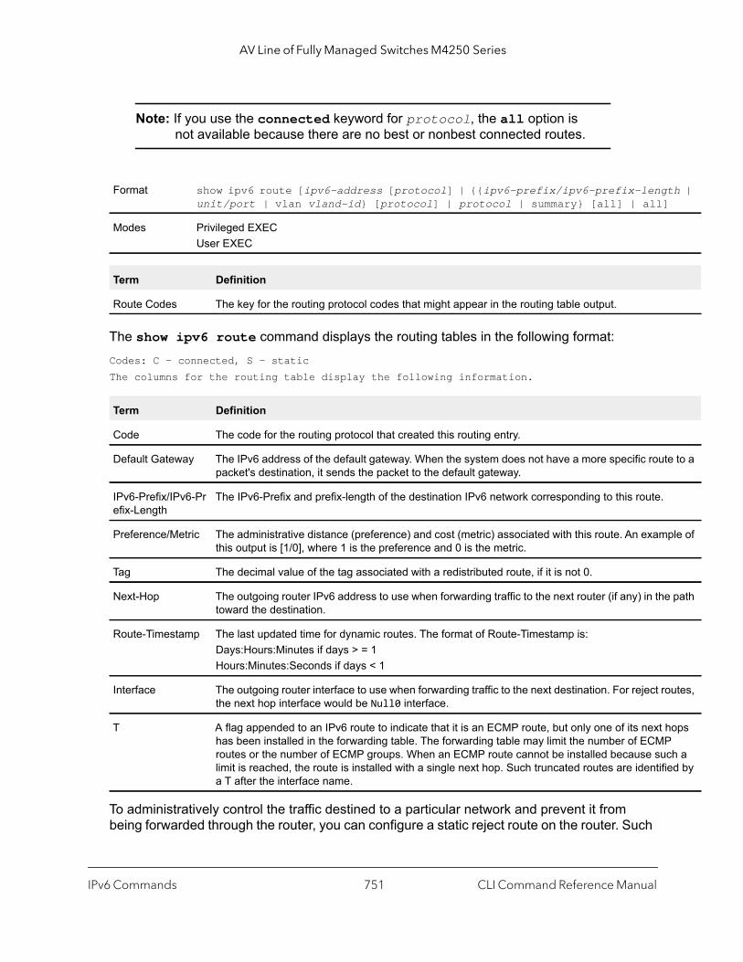
AV Line of Fully Managed Switches M4250 Series
th |
e to a
ple of
path
utes,
ops
ch a ed by
Note: If you use the connected keyword for protocol, the all option is not available because there are no best or nonbest connected routes.
The show ipv6 route command displays the routing tables in the following format:Codes: C - connected, S - staticThe columns for the routing table display the following information.
To administratively control the traffic destined to a particular network and prevent it from being forwarded through the router, you can configure a static reject route on the router. Such
Format show ipv6 route [ipv6-address [protocol] | {{ipv6-prefix/ipv6-prefix-lengunit/port | vlan vland-id} [protocol] | protocol | summary} [all] | all]
Modes Privileged EXECUser EXEC
Term Definition
Route Codes The key for the routing protocol codes that might appear in the routing table output.
Term Definition
Code The code for the routing protocol that created this routing entry.
Default Gateway The IPv6 address of the default gateway. When the system does not have a more specific routpacket's destination, it sends the packet to the default gateway.
IPv6-Prefix/IPv6-Prefix-Length
The IPv6-Prefix and prefix-length of the destination IPv6 network corresponding to this route.
Preference/Metric The administrative distance (preference) and cost (metric) associated with this route. An examthis output is [1/0], where 1 is the preference and 0 is the metric.
Tag The decimal value of the tag associated with a redistributed route, if it is not 0.
Next-Hop The outgoing router IPv6 address to use when forwarding traffic to the next router (if any) in thetoward the destination.
Route-Timestamp The last updated time for dynamic routes. The format of Route-Timestamp is:Days:Hours:Minutes if days > = 1Hours:Minutes:Seconds if days < 1
Interface The outgoing router interface to use when forwarding traffic to the next destination. For reject rothe next hop interface would be Null0 interface.
T A flag appended to an IPv6 route to indicate that it is an ECMP route, but only one of its next hhas been installed in the forwarding table. The forwarding table may limit the number of ECMProutes or the number of ECMP groups. When an ECMP route cannot be installed because sulimit is reached, the route is installed with a single next hop. Such truncated routes are identifia T after the interface name.
IPv6 Commands CLI Command Reference Manual751

AV Line of Fully Managed Switches M4250 Series
traffic would be discarded and the ICMP destination unreachable message is sent back to the source. This is typically used for preventing routing loops.
Command example: (NETGEAR Switch) #show ipv6 route
IPv6 Routing Table - 3 entriesCodes: C - connected, S - static
S 2001::/64 [10/0] directly connected, Null0C 2003::/64 [0/0] via ::, 0/11S 2005::/64 [1/0] via 2003::2, 0/11C 5001::/64 [0/0] via ::, 0/5
Command example:
The following example displays a truncated route:(NETGEAR Switch) #show ipv6 route
IPv6 Routing Table - 2 entriesCodes: C - connected, S - static, 6To4 - 6to4 Route
C 2001:db9:1::/64 [0/0] via ::, 0/1
show ipv6 route ecmp-groupsThis command reports all current ECMP groups in the IPv6 routing table. An ECMP group is a set of two or more next hops used in one or more routes. The groups are numbered arbitrarily from 1 to n. The output indicates the number of next hops in the group and the number of routes that use the set of next hops. The output lists the IPv6 address and outgoing interface of each next hop in each group.
Command example: (NETGEAR Switch) #show ipv6 route ecmp-groupsECMP Group 1 with 2 next hops (used by 1 route) 2001:DB8:1::1 on interface 2/1 2001:DB8:2::14 on interface 2/2ECMP Group 2 with 3 next hops (used by 1 route)
Format show ipv6 route ecmp-groups
Mode Privileged EXEC
IPv6 Commands CLI Command Reference Manual752

AV Line of Fully Managed Switches M4250 Series
2001:DB8:4::15 on interface 2/32 2001:DB8:7::12 on interface 2/33 2001:DB8:9::45 on interface 2/34
show ipv6 route hw-failureThis command displays the routes that were not added to the hardware because of hash errors or because the table was full.
Command example: (NETGEAR Switch) #show ipv6 route hw-failureIPv6 Routing Table - 4 entriesCodes: C - connected, S - static, 6To4 - 6to4 Route, K - kernelP - Net PrototypeP 3001::/64 [0/1] via 2001::4, 00h:00m:04s, 0/1 hw-failureP 3001:0:0:1::/64 [0/1] via 2001::4, 00h:00m:04s, 0/1 hw-failureP 3001:0:0:2::/64 [0/1] via 2001::4, 00h:00m:04s, 0/1 hw-failureP 3001:0:0:3::/64 [0/1] via 2001::4, 00h:00m:04s, 0/1 hw-failure
show ipv6 route kernelThis command displays kernel routes, if any exist.
show ipv6 route 6to4This command displays IPv6-over-IPv4 tunnels that are manually configured in the switch.
Format show ipv6 route hw-failure
Mode Privileged EXEC
Format show ipv6 route kernel
Mode Privileged EXEC
Format show ipv6 route 6to4
Mode Privileged EXEC
IPv6 Commands CLI Command Reference Manual753
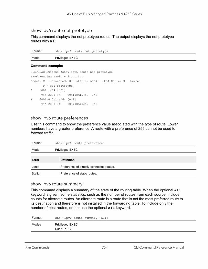
AV Line of Fully Managed Switches M4250 Series
show ipv6 route net-prototypeThis command displays the net prototype routes. The output displays the net prototype routes with a P.
Command example: (NETGEAR Switch) #show ipv6 route net-prototypeIPv6 Routing Table - 2 entriesCodes: C - connected, S - static, 6To4 - 6to4 Route, K - kernel P - Net PrototypeP 3001::/64 [0/1] via 2001::4, 00h:00m:04s, 0/1P 3001:0:0:1::/64 [0/1] via 2001::4, 00h:00m:04s, 0/1
show ipv6 route preferencesUse this command to show the preference value associated with the type of route. Lower numbers have a greater preference. A route with a preference of 255 cannot be used to forward traffic.
show ipv6 route summaryThis command displays a summary of the state of the routing table. When the optional all keyword is given, some statistics, such as the number of routes from each source, include counts for alternate routes. An alternate route is a route that is not the most preferred route to its destination and therefore is not installed in the forwarding table. To include only the number of best routes, do not use the optional all keyword.
Format show ipv6 route net-prototype
Mode Privileged EXEC
Format show ipv6 route preferences
Mode Privileged EXEC
Term Definition
Local Preference of directly-connected routes.
Static Preference of static routes.
Format show ipv6 route summary [all]
Modes Privileged EXECUser EXEC
IPv6 Commands CLI Command Reference Manual754

AV Line of Fully Managed Switches M4250 Series
s the
s a
he
on a artup his come
te
ource
ash
face e
able.
hop
Term Definition
Connected Routes Total number of connected routes in the routing table.
Static Routes Total number of static routes in the routing table.
Reject Routes Total number of reject routes installed by all protocols.
Net Prototype Routes The total number of net prototype routes.
Number of Prefixes Summarizes the number of routes with prefixes of different lengths.
Total Routes The total number of routes in the routing table.
Best Routes The number of best routes currently in the routing table. This number only countbest route to each destination.
Alternate Routes The number of alternate routes currently in the routing table. An alternate route iroute that was not selected as the best route to its destination.
Route Adds The number of routes that have been added to the routing table.
Route Modifies The number of routes that have been changed after they were initially added to trouting table.
Route Deletes The number of routes that have been deleted from the routing table.
Unresolved Route Adds The number of route adds that failed because none of the route’s next hops werelocal subnet. Note that static routes can fail to be added to the routing table at stbecause the routing interfaces are not yet up. This counter gets incremented in tcase. The static routes are added to the routing table when the routing interfaces up.
Invalid Route Adds The number of routes that failed to be added to the routing table because the rouwas invalid. A log message is written for each of these failures.
Failed Route Adds The number of routes that failed to be added to the routing table because of a reslimitation in the routing table.
Hardware Failed Route Adds The number of routes that failed to be inserted into the hardware because of a herror or a table-full condition.
Reserved Locals The number of routing table entries reserved for a local subnet on a routing interthat is down. Space for local routes is always reserved so that local routes can binstalled when a routing interface bounces.
Unique Next Hops The number of distinct next hops used among all routes currently in the routing tThese include local interfaces for local routes and neighbors for indirect routes.
Unique Next Hops High Water The highest count of unique next hops since counters were last cleared.
Next Hop Groups The current number of next hop groups in use by one or more routes. Each nextgroup includes one or more next hops.
Next Hop Groups High Water The highest count of next hop groups since counters were last cleared.
ECMP Groups The number of next hop groups with multiple next hops.
ECMP Routes The number of routes with multiple next hops currently in the routing table.
IPv6 Commands CLI Command Reference Manual755

AV Line of Fully Managed Switches M4250 Series
ith the ch a
r
Command example: (NETGEAR Switch) #show ipv6 route summary
Connected Routes............................... 4Static Routes.................................. 06To4 Routes.................................... 0Reject Routes.................................. 0Total routes................................... 17
Best Routes (High)............................. 17 (17)Alternate Routes............................... 0Route Adds..................................... 44Route Deletes.................................. 27Unresolved Route Adds.......................... 0Invalid Route Adds............................. 0Failed Route Adds.............................. 0Reserved Locals................................ 0
Unique Next Hops (High)........................ 8 (8)Next Hop Groups (High)......................... 8 (8)ECMP Groups (High)............................. 3 (3)ECMP Routes.................................... 12Truncated ECMP Routes.......................... 0ECMP Retries................................... 0Routes with 1 Next Hop......................... 5Routes with 2 Next Hops........................ 1Routes with 3 Next Hops........................ 1Routes with 4 Next Hops........................ 10
Number of Prefixes: /64: 17
Truncated ECMP Routes The number of ECMP routes that are currently installed in the forwarding table wjust one next hop. The forwarding table may limit the number of ECMP routes ornumber of ECMP groups. When an ECMP route cannot be installed because sulimit is reached, the route is installed with a single next hop.
ECMP Retries The number of ECMP routes that have been installed in the forwarding table afteinitially being installed with a single next hop.
Routes with n Next Hops The current number of routes with each number of next hops.
Term Definition
IPv6 Commands CLI Command Reference Manual756
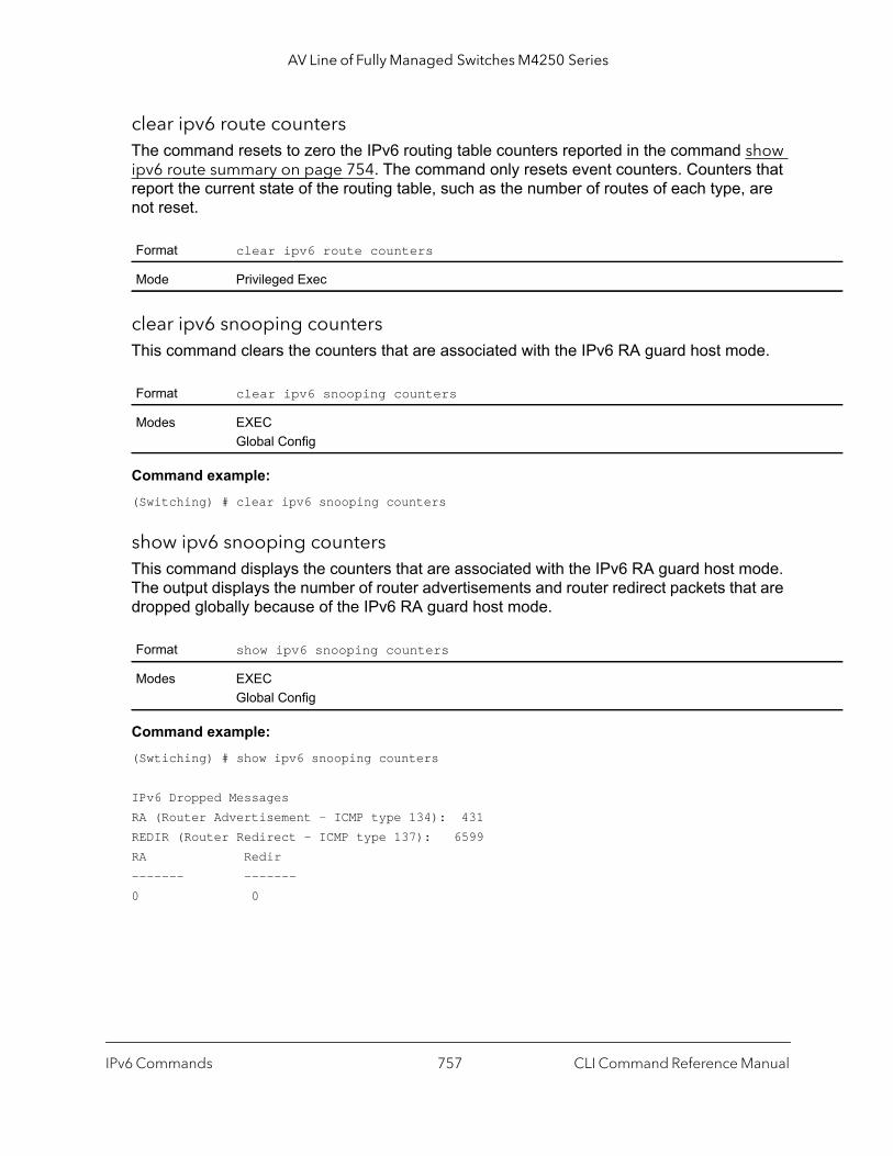
AV Line of Fully Managed Switches M4250 Series
clear ipv6 route countersThe command resets to zero the IPv6 routing table counters reported in the command show ipv6 route summary on page 754. The command only resets event counters. Counters that report the current state of the routing table, such as the number of routes of each type, are not reset.
clear ipv6 snooping countersThis command clears the counters that are associated with the IPv6 RA guard host mode.
Command example: (Switching) # clear ipv6 snooping counters
show ipv6 snooping countersThis command displays the counters that are associated with the IPv6 RA guard host mode. The output displays the number of router advertisements and router redirect packets that are dropped globally because of the IPv6 RA guard host mode.
Command example: (Swtiching) # show ipv6 snooping counters
IPv6 Dropped MessagesRA (Router Advertisement - ICMP type 134): 431REDIR (Router Redirect - ICMP type 137): 6599 RA Redir------- -------0 0
Format clear ipv6 route counters
Mode Privileged Exec
Format clear ipv6 snooping counters
Modes EXECGlobal Config
Format show ipv6 snooping counters
Modes EXECGlobal Config
IPv6 Commands CLI Command Reference Manual757

AV Line of Fully Managed Switches M4250 Series
nel
eived
ding re
show ipv6 vlanThis command displays IPv6 VLAN routing interface addresses.
The rest of the output for this command is displayed in a table with the following column headings.
show ipv6 trafficUse this command to show traffic and statistics for IPv6 and ICMPv6. Specify a logical, loopback, or tunnel interface to view information about traffic on a specific interface.
The argument unit/port corresponds to a physical routing interface or VLAN routing interface. The vlan keyword and vland-id parameter are used to specify the VLAN ID of the routing VLAN directly instead of in the unit/port format. The vlan-id parameter is a number in the range of 1–4093.
If you do not specify an interface, the command displays information about traffic on all interfaces.
Format show ipv6 vlan
Modes Privileged EXECUser EXEC
Term Definition
MAC Address used by Routing VLANs Shows the MAC address.
Column Headings Definition
VLAN ID The VLAN ID of a configured VLAN.
Logical Interface The interface in unit/port format that is associated with the VLAN ID.
IPv6 Address/Prefix Length
The IPv6 prefix and prefix length associated with the VLAN ID.
Format show ipv6 traffic [{unit/port | vlan vlan-id | loopback loopback-id | tuntunnel-id}]
Mode Privileged EXEC
Term Definition
Total Datagrams Received Total number of input datagrams received by the interface, including those recin error.
Received Datagrams Locally Delivered
Total number of datagrams successfully delivered to IPv6 user-protocols (incluICMP). This counter increments at the interface to which these datagrams weaddressed, which might not necessarily be the input interface for some of the datagrams.
IPv6 Commands CLI Command Reference Manual758

AV Line of Fully Managed Switches M4250 Series
uding
nsmit
the sarily
This ses IPv6 ms
ough
uffer aiting
for
might
ason: Pv6 as
for
final de oute
he
MP)
Received Datagrams Discarded Due To Header Errors
Number of input datagrams discarded due to errors in their IPv6 headers, inclversion number mismatch, other format errors, hop count exceeded, errors discovered in processing their IPv6 options, etc.
Received Datagrams Discarded Due To MTU
Number of input datagrams that could not be forwarded because their size exceeded the link MTU of outgoing interface.
Received Datagrams Discarded Due To No Route
Number of input datagrams discarded because no route could be found to trathem to their destination.
Received Datagrams With Unknown Protocol
Number of locally-addressed datagrams received successfully but discarded because of an unknown or unsupported protocol. This counter increments at interface to which these datagrams were addressed, which might not be necesthe input interface for some of the datagrams.
Received Datagrams Discarded Due To Invalid Address
Number of input datagrams discarded because the IPv6 address in their IPv6header's destination field was not a valid address to be received at this entity.count includes invalid addresses (for example, ::0) and unsupported addres(for example, addresses with unallocated prefixes). Forentities which are not routers and therefore do not forward datagrams, this counter includes datagradiscarded because the destination address was not a local address.
Received Datagrams Discarded Due To Truncated Data
Number of input datagrams discarded because datagram frame didn't carry endata.
Received Datagrams Discarded Other
Number of input IPv6 datagrams for which no problems were encountered to prevent their continue processing, but which were discarded (e.g., for lack of bspace). Note that this counter does not include datagrams discarded while awre-assembly.
Received Datagrams Reassembly Required
Number of IPv6 fragments received which needed to be reassembled at this interface. Note that this counter increments at the interface to which these fragments were addressed, which might not be necessarily the input interfacesome of the fragments.
Datagrams Successfully Reassembled
Number of IPv6 datagrams successfully reassembled. Note that this counter increments at the interface to which these datagrams were addressed, which not be necessarily the input interface for some of the fragments.
Datagrams Failed To Reassemble Number of failures detected by the IPv6 reassembly algorithm (for whatever retimed out, errors, etc.). Note that this is not necessarily a count of discarded Ifragments since some algorithms (notably the algorithm in by combining themthey are received. This counter increments at the interface to which these fragments were addressed, which might not be necessarily the input interfacesome of the fragments.
Datagrams Forwarded Number of output datagrams which this entity received and forwarded to theirdestinations. In entities which do not act as IPv6 routers, this counter will incluonly those packets which were Source-Routed via this entity, and the Source-Rprocessing was successful. Note that for a successfully forwarded datagram tcounter of the outgoing interface increments.
Datagrams Locally Transmitted Total number of IPv6 datagrams which local IPv6 user-protocols (including ICsupplied to IPv6 in requests for transmission. Note that this counter does not include any datagrams counted in ipv6IfStatsOutForwDatagrams.
Term Definition
IPv6 Commands CLI Command Reference Manual759
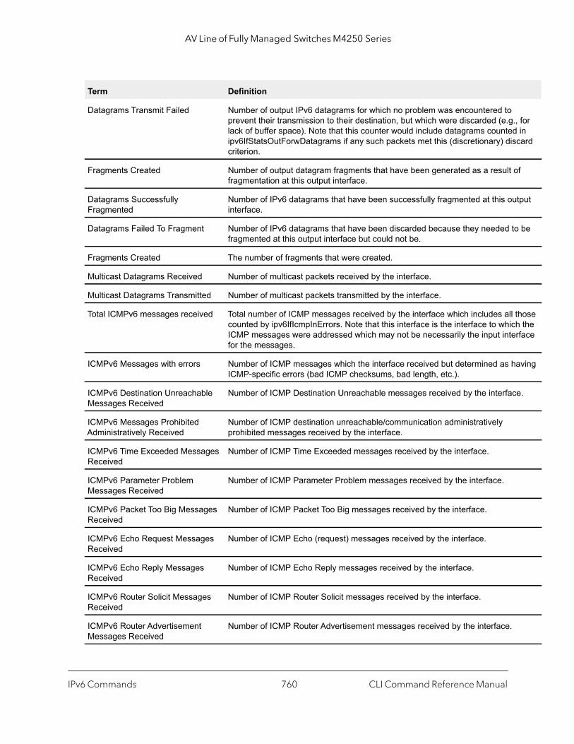
AV Line of Fully Managed Switches M4250 Series
for in card
f
tput
be
hose the
rface
aving
e.
Datagrams Transmit Failed Number of output IPv6 datagrams for which no problem was encountered to prevent their transmission to their destination, but which were discarded (e.g.,lack of buffer space). Note that this counter would include datagrams countedipv6IfStatsOutForwDatagrams if any such packets met this (discretionary) discriterion.
Fragments Created Number of output datagram fragments that have been generated as a result ofragmentation at this output interface.
Datagrams Successfully Fragmented
Number of IPv6 datagrams that have been successfully fragmented at this ouinterface.
Datagrams Failed To Fragment Number of IPv6 datagrams that have been discarded because they needed tofragmented at this output interface but could not be.
Fragments Created The number of fragments that were created.
Multicast Datagrams Received Number of multicast packets received by the interface.
Multicast Datagrams Transmitted Number of multicast packets transmitted by the interface.
Total ICMPv6 messages received Total number of ICMP messages received by the interface which includes all tcounted by ipv6IfIcmpInErrors. Note that this interface is the interface to whichICMP messages were addressed which may not be necessarily the input intefor the messages.
ICMPv6 Messages with errors Number of ICMP messages which the interface received but determined as hICMP-specific errors (bad ICMP checksums, bad length, etc.).
ICMPv6 Destination Unreachable Messages Received
Number of ICMP Destination Unreachable messages received by the interfac
ICMPv6 Messages Prohibited Administratively Received
Number of ICMP destination unreachable/communication administratively prohibited messages received by the interface.
ICMPv6 Time Exceeded Messages Received
Number of ICMP Time Exceeded messages received by the interface.
ICMPv6 Parameter Problem Messages Received
Number of ICMP Parameter Problem messages received by the interface.
ICMPv6 Packet Too Big Messages Received
Number of ICMP Packet Too Big messages received by the interface.
ICMPv6 Echo Request Messages Received
Number of ICMP Echo (request) messages received by the interface.
ICMPv6 Echo Reply Messages Received
Number of ICMP Echo Reply messages received by the interface.
ICMPv6 Router Solicit Messages Received
Number of ICMP Router Solicit messages received by the interface.
ICMPv6 Router Advertisement Messages Received
Number of ICMP Router Advertisement messages received by the interface.
Term Definition
IPv6 Commands CLI Command Reference Manual760

AV Line of Fully Managed Switches M4250 Series
.
rface.
that
e the hich
ICMPv6 Neighbor Solicit Messages Received
Number of ICMP Neighbor Solicit messages received by the interface.
ICMPv6 Neighbor Advertisement Messages Received
Number of ICMP Neighbor Advertisement messages received by the interface
ICMPv6 Redirect Messages Received
Number of Redirect messages received by the interface.
ICMPv6 Group Membership Query Messages Received
Number of ICMPv6 Group Membership Query messages received by the inte
ICMPv6 Group Membership Response Messages Received
Number of ICMPv6 Group Membership response messages received by the interface.
ICMPv6 Group Membership Reduction Messages Received
Number of ICMPv6 Group Membership reduction messages received by the interface.
Total ICMPv6 Messages Transmitted
Total number of ICMP messages which this interface attempted to send. Notethis counter includes all those counted by icmpOutErrors.
ICMPv6 Messages Not Transmitted Due To Error
Number of ICMP messages which this interface did not send due to problemsdiscovered within ICMP such as a lack of buffers. This value should not includerrors discovered outside the ICMP layer such as the inability of IPv6 to routeresultant datagram. In some implementations there may be no types of error wcontribute to this counter's value.
ICMPv6 Destination Unreachable Messages Transmitted
Number of ICMP Destination Unreachable messages sent by the interface.
ICMPv6 Messages Prohibited Administratively Transmitted
Number of ICMP destination unreachable/communication administratively prohibited messages sent.
ICMPv6 Time Exceeded Messages Transmitted
Number of ICMP Time Exceeded messages sent by the interface.
ICMPv6 Parameter Problem Messages Transmitted
Number of ICMP Parameter Problem messages sent by the interface.
ICMPv6 Packet Too Big Messages Transmitted
Number of ICMP Packet Too Big messages sent by the interface.
ICMPv6 Echo Request Messages Transmitted
Number of ICMP Echo (request) messages sent by the interface.ICMP echo messages sent.
ICMPv6 Echo Reply Messages Transmitted
Number of ICMP Echo Reply messages sent by the interface.
ICMPv6 Router Solicit Messages Transmitted
Number of ICMP Router Solicitation messages sent by the interface.
ICMPv6 Router Advertisement Messages Transmitted
Number of ICMP Router Advertisement messages sent by the interface.
ICMPv6 Neighbor Solicit Messages Transmitted
Number of ICMP Neighbor Solicitation messages sent by the interface.
Term Definition
IPv6 Commands CLI Command Reference Manual761

AV Line of Fully Managed Switches M4250 Series
,
id}]
clear ipv6 statisticsUse this command to clear IPv6 statistics for all interfaces or for a specific interface, including loopback and tunnel interfaces. IPv6 statistics display in the output of the show ipv6 traffic command. If you do not specify an interface, the counters for all IPv6 traffic statistics reset to zero.
DHCPv6 Commands
This section describes the commands you use to configure the DHCPv6 server on the system and to view DHCPv6 information.
service dhcpv6 This command enables DHCPv6 configuration on the router.
ICMPv6 Neighbor Advertisement Messages Transmitted
Number of ICMP Neighbor Advertisement messages sent by the interface.
ICMPv6 Redirect Messages Received
Number of Redirect messages sent. For a host, this object will always be zerosince hosts do not send redirects.
ICMPv6 Group Membership Query Messages Transmitted
Number of ICMPv6 Group Membership Query messages sent.
ICMPv6 Group Membership Response Messages Transmitted
Number of ICMPv6 Group Membership Response messages sent.
ICMPv6 Group Membership Reduction Messages Transmitted
Number of ICMPv6 Group Membership Reduction messages sent.
ICMPv6 Duplicate Address Detects Number of duplicate addresses detected by the interface.
Format clear ipv6 statistics [{unit/port | loopback loopback-id | tunnel tunnel-
Mode Privileged EXEC
Default enabled
Format service dhcpv6
Mode Global Config
Term Definition
IPv6 Commands CLI Command Reference Manual762

AV Line of Fully Managed Switches M4250 Series
no service dhcpv6
This command disables DHCPv6 configuration on router.
ipv6 dhcp client pdUse this command to enable the Dynamic Host Configuration Protocol (DHCP) for IPv6 client process (if the process is not currently running) and to enable requests for prefix delegation through a specified interface. When prefix delegation is enabled and a prefix is successfully acquired, the prefix is stored in the IPv6 general prefix pool with an internal name defined by the automatic argument.
Note: The Prefix Delegation client is supported on only one IP interface.
The optional rapid-commit keyword enables the use of a two-message exchange method for prefix delegation and other configuration. If enabled, the client includes the rapid commit option in a solicit message.
The DHCP for IPv6 client, server, and relay functions are mutually exclusive on an interface. If one of these functions is already enabled and a user tries to configure a different function on the same interface, a message is displayed.
Command example: The following examples enable prefix delegation on interface 1/0/1:(NETGEAR Switch) #configure(NETGEAR Switch) (Config)#interface 1/0/1(NETGEAR Switch) (Interface 1/0/1)# ipv6 dhcp client pd
(NETGEAR Switch) #configure(NETGEAR Switch) (Config)#interface 1/0/1(NETGEAR Switch) (Interface 1/0/1)# ipv6 dhcp client pd rapid-commit
Format no service dhcpv6
Mode Global Config
Default Prefix delegation is disabled on an interface.
Format ipv6 dhcp client pd [rapid-commit]
Mode Interface Config
IPv6 Commands CLI Command Reference Manual763

AV Line of Fully Managed Switches M4250 Series
no ipv6 dhcp client pd
This command disables requests for prefix delegation.
ipv6 dhcp server Use this command to configure DHCPv6 server functionality on an interface or range of interfaces. The pool-name is the DHCPv6 pool containing stateless and/or prefix delegation parameters, automatic enables the server to automatically determine which pool to use when allocating addresses for a client, rapid-commit is an option that allows for an abbreviated exchange between the client and server, and pref-value is a value used by clients to determine preference between multiple DHCPv6 servers. For a particular interface, DHCPv6 server and DHCPv6 relay functions are mutually exclusive.
ipv6 dhcp relay destinationUse this command to configure an interface for DHCPv6 relay functionality on an interface or range of interfaces.
• Use the destination keyword to set the relay server IPv6 address. • The relay-address parameter is an IPv6 address of a DHCPv6 relay server. • Use the interface keyword to set the relay server interface. • The relay-interface parameter is an interface (unit/port) to reach a relay server. • The optional remote-id is the Relay Agent Information Option remote ID suboption to
be added to relayed messages.This can either be the special keyword duid-ifid, which causes the remote ID to be derived from the DHCPv6 server DUID and the relay interface number, or it can be specified as a user-defined string.
Note: If relay-address is an IPv6 global address, then relay-interface is not required. If relay-address is a link-local or multicast address, then relay-interface is required. Finally, if you do not specify a value for relay-address, then you must specify a value for relay-interface and the DHCPV6-ALL-AGENTS multicast address (for example, FF02::1:2) is used to relay DHCPv6 messages to the relay server.
Format no ipv6 dhcp client pd
Mode Interface Config
Format ipv6 dhcp server {pool-name | automatic} [rapid-commit] [preference pref-value]
Mode Interface Config
IPv6 Commands CLI Command Reference Manual764
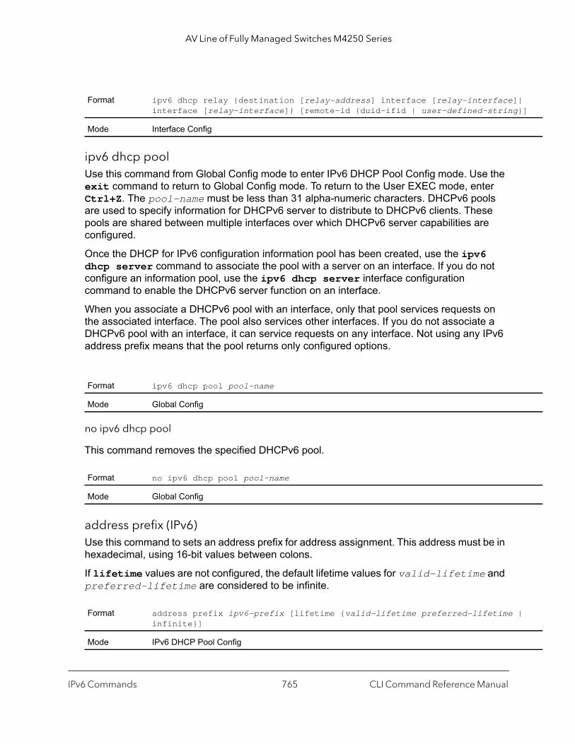
AV Line of Fully Managed Switches M4250 Series
| }]
|
ipv6 dhcp poolUse this command from Global Config mode to enter IPv6 DHCP Pool Config mode. Use the exit command to return to Global Config mode. To return to the User EXEC mode, enter Ctrl+Z. The pool-name must be less than 31 alpha-numeric characters. DHCPv6 pools are used to specify information for DHCPv6 server to distribute to DHCPv6 clients. These pools are shared between multiple interfaces over which DHCPv6 server capabilities are configured.
Once the DHCP for IPv6 configuration information pool has been created, use the ipv6 dhcp server command to associate the pool with a server on an interface. If you do not configure an information pool, use the ipv6 dhcp server interface configuration command to enable the DHCPv6 server function on an interface.
When you associate a DHCPv6 pool with an interface, only that pool services requests on the associated interface. The pool also services other interfaces. If you do not associate a DHCPv6 pool with an interface, it can service requests on any interface. Not using any IPv6 address prefix means that the pool returns only configured options.
no ipv6 dhcp pool
This command removes the specified DHCPv6 pool.
address prefix (IPv6)Use this command to sets an address prefix for address assignment. This address must be in hexadecimal, using 16-bit values between colons.
If lifetime values are not configured, the default lifetime values for valid-lifetime and preferred-lifetime are considered to be infinite.
Format ipv6 dhcp relay {destination [relay-address] interface [relay-interface]interface [relay-interface]} [remote-id {duid-ifid | user-defined-string
Mode Interface Config
Format ipv6 dhcp pool pool-name
Mode Global Config
Format no ipv6 dhcp pool pool-name
Mode Global Config
Format address prefix ipv6-prefix [lifetime {valid-lifetime preferred-lifetime infinite}]
Mode IPv6 DHCP Pool Config
IPv6 Commands CLI Command Reference Manual765
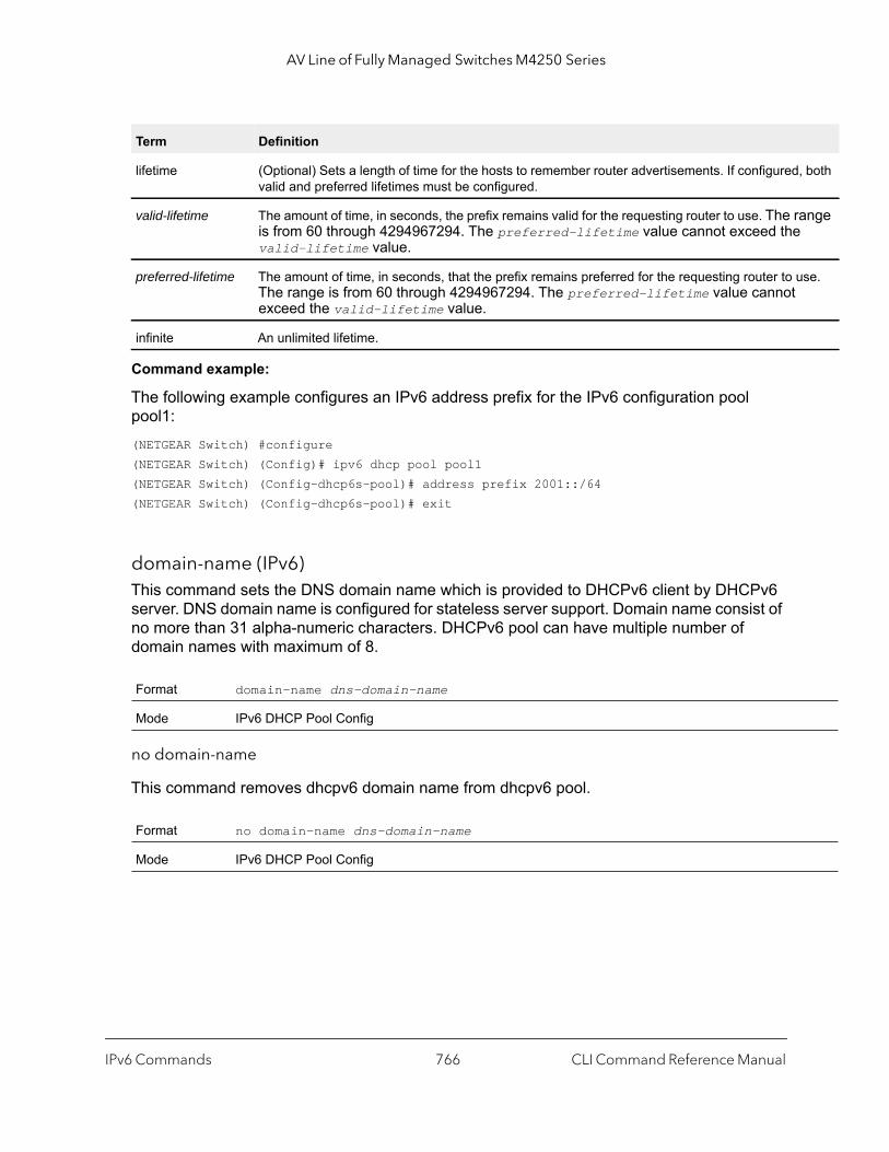
AV Line of Fully Managed Switches M4250 Series
, both
ange
se.
Command example:
The following example configures an IPv6 address prefix for the IPv6 configuration pool pool1:(NETGEAR Switch) #configure(NETGEAR Switch) (Config)# ipv6 dhcp pool pool1(NETGEAR Switch) (Config-dhcp6s-pool)# address prefix 2001::/64(NETGEAR Switch) (Config-dhcp6s-pool)# exit
domain-name (IPv6)This command sets the DNS domain name which is provided to DHCPv6 client by DHCPv6 server. DNS domain name is configured for stateless server support. Domain name consist of no more than 31 alpha-numeric characters. DHCPv6 pool can have multiple number of domain names with maximum of 8.
no domain-name
This command removes dhcpv6 domain name from dhcpv6 pool.
Term Definition
lifetime (Optional) Sets a length of time for the hosts to remember router advertisements. If configuredvalid and preferred lifetimes must be configured.
valid-lifetime The amount of time, in seconds, the prefix remains valid for the requesting router to use. The ris from 60 through 4294967294. The preferred-lifetime value cannot exceed thevalid-lifetime value.
preferred-lifetime The amount of time, in seconds, that the prefix remains preferred for the requesting router to uThe range is from 60 through 4294967294. The preferred-lifetime value cannot exceed the valid-lifetime value.
infinite An unlimited lifetime.
Format domain-name dns-domain-name
Mode IPv6 DHCP Pool Config
Format no domain-name dns-domain-name
Mode IPv6 DHCP Pool Config
IPv6 Commands CLI Command Reference Manual766

AV Line of Fully Managed Switches M4250 Series
e
dns-server (IPv6)This command sets the IPv6 DNS server address, which is provided to DHCPv6 clients by the DHCPv6 server. The DNS server address is configured for stateless server support. The DHCPv6 pool can contains a maximum of eight domain names.
no dns-server
This command removes a DHCPv6 server address from a DHCPv6 server.
prefix-delegation (IPv6)Multiple IPv6 prefixes can be defined within a pool for distributing to specific DHCPv6 prefix delegation clients.
• prefix is the delegated IPv6 prefix and prefixlength is the associated prefix length.• duid is the client's unique DUID value, for example,
00:01:00:09:f8:79:4e:00:04:76:73:43:76.• hostname is 31 characters textual client’s name which is useful for logging or tracing
only. • valid lifetime is the valid lifetime for the delegated prefix in seconds, in a range from
0–4294967295 seconds.• preferred lifetime is the preferred lifetime for the delegated prefix in seconds, in a range
from 0–4294967295 seconds.
no prefix-delegation
This command deletes a specific prefix-delegation client.
Format dns-server dns-server-address
Mode IPv6 DHCP Pool Config
Format no dns-server dns-server-address
Mode IPv6 DHCP Pool Config
Default valid-lifetime seconds: 2592000preferred-lifetime seconds: 604800
Format prefix-delegation prefix/prefixlength duid [name hostname] [valid-lifetimseconds] [preferred-lifetime seconds]
Mode IPv6 DHCP Pool Config
Format no prefix-delegation prefix/prefix-delegation duid
Mode IPv6 DHCP Pool Config
IPv6 Commands CLI Command Reference Manual767
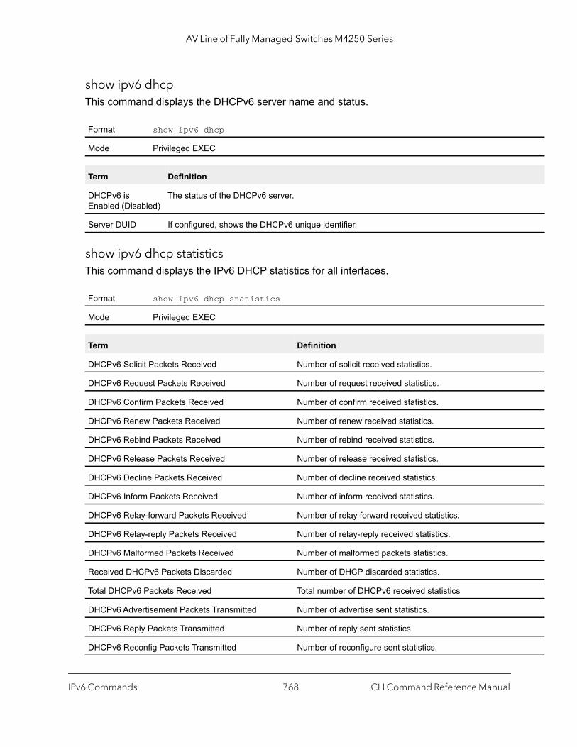
AV Line of Fully Managed Switches M4250 Series
show ipv6 dhcp This command displays the DHCPv6 server name and status.
show ipv6 dhcp statisticsThis command displays the IPv6 DHCP statistics for all interfaces.
Format show ipv6 dhcp
Mode Privileged EXEC
Term Definition
DHCPv6 is Enabled (Disabled)
The status of the DHCPv6 server.
Server DUID If configured, shows the DHCPv6 unique identifier.
Format show ipv6 dhcp statistics
Mode Privileged EXEC
Term Definition
DHCPv6 Solicit Packets Received Number of solicit received statistics.
DHCPv6 Request Packets Received Number of request received statistics.
DHCPv6 Confirm Packets Received Number of confirm received statistics.
DHCPv6 Renew Packets Received Number of renew received statistics.
DHCPv6 Rebind Packets Received Number of rebind received statistics.
DHCPv6 Release Packets Received Number of release received statistics.
DHCPv6 Decline Packets Received Number of decline received statistics.
DHCPv6 Inform Packets Received Number of inform received statistics.
DHCPv6 Relay-forward Packets Received Number of relay forward received statistics.
DHCPv6 Relay-reply Packets Received Number of relay-reply received statistics.
DHCPv6 Malformed Packets Received Number of malformed packets statistics.
Received DHCPv6 Packets Discarded Number of DHCP discarded statistics.
Total DHCPv6 Packets Received Total number of DHCPv6 received statistics
DHCPv6 Advertisement Packets Transmitted Number of advertise sent statistics.
DHCPv6 Reply Packets Transmitted Number of reply sent statistics.
DHCPv6 Reconfig Packets Transmitted Number of reconfigure sent statistics.
IPv6 Commands CLI Command Reference Manual768
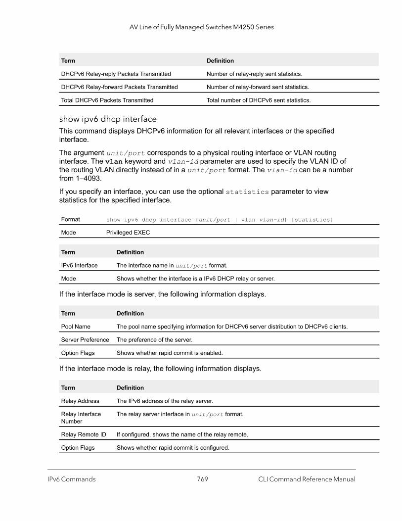
AV Line of Fully Managed Switches M4250 Series
show ipv6 dhcp interfaceThis command displays DHCPv6 information for all relevant interfaces or the specified interface.
The argument unit/port corresponds to a physical routing interface or VLAN routing interface. The vlan keyword and vlan-id parameter are used to specify the VLAN ID of the routing VLAN directly instead of in a unit/port format. The vlan-id can be a number from 1–4093.
If you specify an interface, you can use the optional statistics parameter to view statistics for the specified interface.
If the interface mode is server, the following information displays.
If the interface mode is relay, the following information displays.
DHCPv6 Relay-reply Packets Transmitted Number of relay-reply sent statistics.
DHCPv6 Relay-forward Packets Transmitted Number of relay-forward sent statistics.
Total DHCPv6 Packets Transmitted Total number of DHCPv6 sent statistics.
Format show ipv6 dhcp interface {unit/port | vlan vlan-id} [statistics]
Mode Privileged EXEC
Term Definition
IPv6 Interface The interface name in unit/port format.
Mode Shows whether the interface is a IPv6 DHCP relay or server.
Term Definition
Pool Name The pool name specifying information for DHCPv6 server distribution to DHCPv6 clients.
Server Preference The preference of the server.
Option Flags Shows whether rapid commit is enabled.
Term Definition
Relay Address The IPv6 address of the relay server.
Relay Interface Number
The relay server interface in unit/port format.
Relay Remote ID If configured, shows the name of the relay remote.
Option Flags Shows whether rapid commit is configured.
Term Definition
IPv6 Commands CLI Command Reference Manual769

AV Line of Fully Managed Switches M4250 Series
If you use the statistics parameter, the command displays the IPv6 DHCP statistics for the specified interface. See show ipv6 dhcp statistics on page 768 for information about the output.
show ipv6 dhcp bindingThis command displays configured DHCP pool.
show ipv6 dhcp poolThis command displays configured DHCP pool.
Format show ipv6 dhcp binding [ipv6-address]
Mode Privileged EXEC
Term Definition
DHCP Client Address
Address of DHCP Client.
DUID String that represents the Client DUID.
IAID Identity Association ID.
Prefix/Prefix Length IPv6 address and mask length for delegated prefix.
Prefix Type IPV6 Prefix type (IAPD, IANA, or IATA).
Client Address Address of DHCP Client.
Client Interface IPv6 Address of DHCP Client.
Expiration Address of DNS server address.
Valid Lifetime Valid lifetime in seconds for delegated prefix.
Preferred Lifetime Preferred lifetime in seconds for delegated prefix.
Format show ipv6 dhcp pool pool-name
Mode Privileged EXEC
Term Definition
DHCP Pool Name Unique pool name configuration.
Client DUID Client’s DHCP unique identifier. DUID is generated using the combination of the localsystem burned-in MAC address and a timestamp value.
Host Name of the client.
Prefix/Prefix Length IPv6 address and mask length for delegated prefix.
Preferred Lifetime Preferred lifetime in seconds for delegated prefix.
IPv6 Commands CLI Command Reference Manual770

AV Line of Fully Managed Switches M4250 Series
.
e.
rface.
show serviceport ipv6 dhcp statisticsThis command displays the statistics of the DHCPv6 client running on the serviceport management interface.
Valid Lifetime Valid lifetime in seconds for delegated prefix.
DNS Server Address Address of DNS server address.
Domain Name DNS domain name.
Format show serviceport ipv6 dhcp statistics
Mode Privileged EXECUser EXEC
Field Description
DHCPv6 Advertisement Packets Received
The number of DHCPv6 Advertisement packets received on the service port interface
DHCPv6 Reply Packets Received
The number of DHCPv6 Reply packets received on the service port interface.
Received DHCPv6 Advertisement Packets Discarded
The number of DHCPv6 Advertisement packets discarded on the service port interfac
Received DHCPv6 Reply Packets Discarded
The number of DHCPv6 Reply packets discarded on the service port interface.
DHCPv6 Malformed Packets Received
The number of DHCPv6 packets that are received malformed on the service port inte
Total DHCPv6 Packets Received
The total number of DHCPv6 packets received on the service port interface.
DHCPv6 Solicit Packets Transmitted
The number of DHCPv6 Solicit packets transmitted on the service port interface.
DHCPv6 Request Packets Transmitted
The number of DHCPv6 Request packets transmitted on the service port interface.
DHCPv6 Renew Packets Transmitted
The number of DHCPv6 Renew packets transmitted on the service port interface.
DHCPv6 Rebind Packets Transmitted
The number of DHCPv6 Rebind packets transmitted on the service port interface.
DHCPv6 Release Packets Transmitted
The number of DHCPv6 Release packets transmitted on the service port interface.
Total DHCPv6 Packets Transmitted
The total number of DHCPv6 packets transmitted on the service port interface.
Term Definition
IPv6 Commands CLI Command Reference Manual771
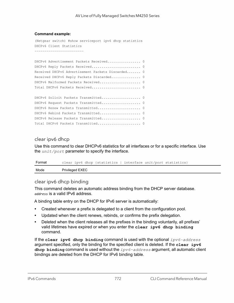
AV Line of Fully Managed Switches M4250 Series
Command example: (Netgear switch) #show serviceport ipv6 dhcp statisticsDHCPv6 Client Statistics------------------------- DHCPv6 Advertisement Packets Received................. 0DHCPv6 Reply Packets Received......................... 0Received DHCPv6 Advertisement Packets Discarded....... 0Received DHCPv6 Reply Packets Discarded............... 0DHCPv6 Malformed Packets Received..................... 0Total DHCPv6 Packets Received......................... 0 DHCPv6 Solicit Packets Transmitted.................... 0DHCPv6 Request Packets Transmitted.................... 0DHCPv6 Renew Packets Transmitted...................... 0DHCPv6 Rebind Packets Transmitted..................... 0DHCPv6 Release Packets Transmitted.................... 0Total DHCPv6 Packets Transmitted...................... 0
clear ipv6 dhcpUse this command to clear DHCPv6 statistics for all interfaces or for a specific interface. Use the unit/port parameter to specify the interface.
clear ipv6 dhcp bindingThis command deletes an automatic address binding from the DHCP server database. address is a valid IPv6 address.
A binding table entry on the DHCP for IPv6 server is automatically:
• Created whenever a prefix is delegated to a client from the configuration pool.• Updated when the client renews, rebinds, or confirms the prefix delegation.• Deleted when the client releases all the prefixes in the binding voluntarily, all prefixes’
valid lifetimes have expired or when you enter the clear ipv6 dhcp binding command.
If the clear ipv6 dhcp binding command is used with the optional ipv6-address argument specified, only the binding for the specified client is deleted. If the clear ipv6 dhcp binding command is used without the ipv6-address argument, all automatic client bindings are deleted from the DHCP for IPv6 binding table.
Format clear ipv6 dhcp {statistics | interface unit/port statistics}
Mode Privileged EXEC
IPv6 Commands CLI Command Reference Manual772

AV Line of Fully Managed Switches M4250 Series
clear network ipv6 dhcp statisticsUse this command to clear the DHCPv6 statistics on the network management interface.
clear serviceport ipv6 dhcp statisticsUse this command to clear the DHCPv6 client statistics on the service port interface.
DHCPv6 Snooping Configuration Commands
This section describes commands you use to configure IPv6 DHCP Snooping.
ipv6 dhcp snoopingUse this command to globally enable IPv6 DHCP Snooping.
no ipv6 dhcp snooping
Use this command to globally disable IPv6 DHCP Snooping.
Format clear ipv6 dhcp binding [ipv6-address]
Mode Privileged EXEC
Format clear network ipv6 dhcp statistics
Mode Privileged EXEC
Format clear serviceport ipv6 dhcp statistics
Mode Privileged EXEC
Default disabled
Format ipv6 dhcp snooping
Mode Global Config
Format no ipv6 dhcp snooping
Mode Global Config
IPv6 Commands CLI Command Reference Manual773

AV Line of Fully Managed Switches M4250 Series
ipv6 dhcp snooping vlanUse this command to enable DHCP Snooping on a list of comma-separated VLAN ranges.
no ipv6 dhcp snooping vlan
Use this command to disable DHCP Snooping on VLANs.
ipv6 dhcp snooping verify mac-addressUse this command to enable verification of the source MAC address with the client hardware address in the received DCHP message.
no ipv6 dhcp snooping verify mac-address
Use this command to disable verification of the source MAC address with the client hardware address.
ipv6 dhcp snooping databaseUse this command to configure the persistent location of the DHCP Snooping database. This can be local or a remote file on a given IP machine.
Default disabled
Format ipv6 dhcp snooping vlan vlan-list
Mode Global Config
Format no ipv6 dhcp snooping vlan vlan-list
Mode Global Config
Default enabled
Format ipv6 dhcp snooping verify mac-address
Mode Global Config
Format no ipv6 dhcp snooping verify mac-address
Mode Global Config
Default local
Format ipv6 dhcp snooping database {local | tftp://hostIP/filename}
Mode Global Config
IPv6 Commands CLI Command Reference Manual774

AV Line of Fully Managed Switches M4250 Series
ip dhcp snooping database write-delay (DHCPv6)Use this command to configure the interval in seconds at which the DHCP Snooping database is persisted. For the seconds argument, the interval value is in a range from 15 to 86400 seconds.
no ip dhcp snooping database write-delay
Use this command to set the write delay value to the default value.
ipv6 dhcp snooping bindingUse this command to configure static DHCP Snooping binding.
no ipv6 dhcp snooping binding
Use this command to remove the DHCP static entry from the DHCP Snooping database.
ipv6 dhcp snooping trustUse this command to configure an interface or range of interfaces as trusted.
Default 300 seconds
Format ip dhcp snooping database write-delay seconds
Mode Global Config
Format no ip dhcp snooping database write-delay
Mode Global Config
Format ipv6 dhcp snooping binding mac-address vlan vlan-id ipaddress interface interface-id
Mode Global Config
Format no ipv6 dhcp snooping binding mac-address
Mode Global Config
Default disabled
Format ipv6 dhcp snooping trust
Mode Interface Config
IPv6 Commands CLI Command Reference Manual775
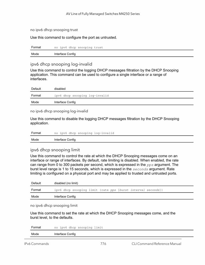
AV Line of Fully Managed Switches M4250 Series
no ipv6 dhcp snooping trust
Use this command to configure the port as untrusted.
ipv6 dhcp snooping log-invalidUse this command to control the logging DHCP messages filtration by the DHCP Snooping application. This command can be used to configure a single interface or a range of interfaces.
no ipv6 dhcp snooping log-invalid
Use this command to disable the logging DHCP messages filtration by the DHCP Snooping application.
ipv6 dhcp snooping limitUse this command to control the rate at which the DHCP Snooping messages come on an interface or range of interfaces. By default, rate limiting is disabled. When enabled, the rate can range from 0 to 300 packets per second, which is expressed in the pps argument. The burst level range is 1 to 15 seconds, which is expressed in the seconds argument. Rate limiting is configured on a physical port and may be applied to trusted and untrusted ports.
no ipv6 dhcp snooping limit
Use this command to set the rate at which the DHCP Snooping messages come, and the burst level, to the defaults.
Format no ipv6 dhcp snooping trust
Mode Interface Config
Default disabled
Format ipv6 dhcp snooping log-invalid
Mode Interface Config
Format no ipv6 dhcp snooping log-invalid
Mode Interface Config
Default disabled (no limit)
Format ipv6 dhcp snooping limit {rate pps [burst interval seconds]}
Mode Interface Config
Format no ipv6 dhcp snooping limit
Mode Interface Config
IPv6 Commands CLI Command Reference Manual776

AV Line of Fully Managed Switches M4250 Series
ipv6 verify sourceUse this command to configure the IPv6SG source ID attribute to filter the data traffic in the hardware. Source ID is the combination of IP address and MAC address. Normal command allows data traffic filtration based on the IP address. With the port-security option, the data traffic is filtered based on the IP and MAC addresses.
This command can be used to configure a single interface or a range of interfaces.
no ipv6 verify source
Use this command to disable the IPv6SG configuration in the hardware. You cannot disable port-security alone if it is configured.
ipv6 verify bindingUse this command to configure static IPv6 source guard (IPv6SG) entries.
no ipv6 verify binding
Use this command to remove the IPv6SG static entry from the IPv6SG database.
show ipv6 dhcp snoopingUse this command to display the DHCP Snooping global configurations and per port configurations.
Default the source ID is the IP address
Format ipv6 verify source {port-security}
Mode Interface Config
Format no ipv6 verify source
Mode Interface Config
Format ipv6 verify binding mac-address vlan vlan-id ipv6-address interface interface-id
Mode Global Config
Format no ipv6 verify binding mac-address vlan vlan-id ipv6-address interface interface-id
Mode Global Config
Format show ipv6 dhcp snooping
Mode Privileged EXECUser EXEC
IPv6 Commands CLI Command Reference Manual777

AV Line of Fully Managed Switches M4250 Series
Command example: (NETGEAR Switch) #show ipv6 dhcp snooping
DHCP snooping is DisabledDHCP snooping source MAC verification is enabledDHCP snooping is enabled on the following VLANs:11 - 30, 40
Interface Trusted Log Invalid Pkts --------- -------- ----------------0/1 Yes No 0/2 No Yes 0/3 No Yes 0/4 No No0/6 No No
show ipv6 dhcp snooping binding Use this command to display the DHCP Snooping binding entries. To restrict the output, use the following options:
• static. Restrict the output based on static entries.• dynamic. Restrict the output based on DCHP snooping.• interface unit/port. Restrict the output based on a specific interface.• vlan-id. Restrict the output based on a VLAN.
Term Definition
Interface The interface for which data is displayed.
Trusted If it is enabled, DHCP snooping considers the port as trusted. The factory default is disabled.
Log Invalid Pkts If it is enabled, DHCP snooping application logs invalid packets on the specified interface.
Format show ipv6 dhcp snooping binding [static | dynamic] [interface unit/port][vlan-id]
Mode Privileged EXECUser EXEC
Term Definition
MAC Address Displays the MAC address for the binding that was added. The MAC address is the key to thebinding database.
IPv6 Address Displays the valid IPv6 address for the binding rule.
VLAN The VLAN for the binding rule.
IPv6 Commands CLI Command Reference Manual778

AV Line of Fully Managed Switches M4250 Series
Command example: (NETGEAR Switch) #show ipv6 dhcp snooping bindingTotal number of bindings: 2
MAC Address IPv6 Address VLAN Interface Type Lease time (Secs)------------------ -------------- ---- --------- ---- ------------------00:02:B3:06:60:80 2000::1/64 10 0/1 8640000:0F:FE:00:13:04 3000::1/64 10 0/1 86400
show ipv6 dhcp snooping databaseUse this command to display the DHCP Snooping configuration related to the database persistency.
Command example: (NETGEAR Switch) #show ipv6 dhcp snooping databaseagent url: /10.131.13.79:/sai1.txtwrite-delay: 5000
show ipv6 dhcp snooping interfacesUse this command to show the DHCP Snooping status of all interfaces or a specified interface.
Interface The interface to add a binding into the DHCP snooping interface.
Type Binding type; statically configured from the CLI or dynamically learned.
Lease (sec) The remaining lease time for the entry.
Format show ipv6 dhcp snooping database
Mode Privileged EXECUser EXEC
Term Definition
Agent URL Bindings database agent URL.
Write Delay The maximum write time to write the database into local or remote.
Format show ipv6 dhcp snooping interfaces [interface unit/port]
Mode Privileged EXEC
Term Definition
IPv6 Commands CLI Command Reference Manual779

AV Line of Fully Managed Switches M4250 Series
se of
than
Command example: (NETGEAR Switch) #show ipv6 dhcp snooping interfacesInterface Trust State Rate Limit Burst Interval (pps) (seconds)----------- ---------- ----------- --------------1/0/1 No 1511/0/2 No 1511/0/3 No 151
(NETGEAR Switch) #show ip dhcp snooping interfaces ethernet 1/0/1Interface Trust State Rate Limit Burst Interval (pps) (seconds)----------- ---------- ----------- --------------1/0/1 Yes 151
show ipv6 dhcp snooping statisticsUse this command to list statistics for IPv6 DHCP Snooping security violations on untrusted ports.
Command example: (NETGEAR Switch) #show ipv6 dhcp snooping statistics
Interface MAC Verify Client Ifc DHCP Server Failures Mismatch Msgs Rec'd----------- ---------- ---------- -----------1/0/2 0 0 01/0/3 0 0 01/0/4 0 0 01/0/5 0 0 0
Format show ipv6 dhcp snooping statistics
Mode Privileged EXECUser EXEC
Term Definition
Interface The IPv6 address of the interface in unit/port format.
MAC Verify Failures
Represents the number of DHCP messages that were filtered on an untrusted interface becausource MAC address and client hardware address mismatch.
Client Ifc Mismatch Represents the number of DHCP release and Deny messages received on the different ports learned previously.
DHCP Server Msgs Rec’d
Represents the number of DHCP server messages received on Untrusted ports.
IPv6 Commands CLI Command Reference Manual780

AV Line of Fully Managed Switches M4250 Series
1/0/6 0 0 01/0/7 0 0 01/0/8 0 0 01/0/9 0 0 01/0/10 0 0 01/0/11 0 0 01/0/12 0 0 01/0/13 0 0 01/0/14 0 0 01/0/15 0 0 01/0/16 0 0 01/0/17 0 0 01/0/18 0 0 01/0/19 0 0 01/0/20 0 0 0
clear ipv6 dhcp snooping binding Use this command to clear all DHCPv6 Snooping bindings on all interfaces or on a specific interface.
clear ipv6 dhcp snooping statisticsUse this command to clear all DHCPv6 Snooping statistics.
show ipv6 verifyUse this command to display the IPv6 configuration on a specified interface in the unit/port format.
Format clear ipv6 dhcp snooping binding [interface unit/port]
Mode Privileged EXECUser EXEC
Format clear ipv6 dhcp snooping statistics
Mode Privileged EXECUser EXEC
Format show ipv6 verify unit/port
Mode Privileged EXECUser EXEC
IPv6 Commands CLI Command Reference Manual781
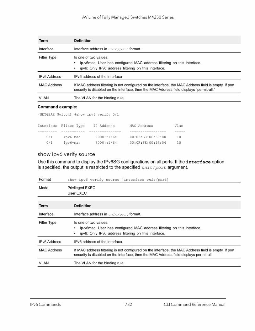
AV Line of Fully Managed Switches M4250 Series
ort
ort
Command example: (NETGEAR Switch) #show ipv6 verify 0/1
Interface Filter Type IP Address MAC Address Vlan--------- ----------- --------------- ----------------- ----- 0/1 ipv6-mac 2000::1/64 00:02:B3:06:60:80 10 0/1 ipv6-mac 3000::1/64 00:0F:FE:00:13:04 10
show ipv6 verify sourceUse this command to display the IPv6SG configurations on all ports. If the interface option is specified, the output is restricted to the specified unit/port argument.
Term Definition
Interface Interface address in unit/port format.
Filter Type Is one of two values:• ip-v6mac: User has configured MAC address filtering on this interface.• ipv6: Only IPv6 address filtering on this interface.
IPv6 Address IPv6 address of the interface
MAC Address If MAC address filtering is not configured on the interface, the MAC Address field is empty. If psecurity is disabled on the interface, then the MAC Address field displays “permit-all.”
VLAN The VLAN for the binding rule.
Format show ipv6 verify source [interface unit/port]
Mode Privileged EXECUser EXEC
Term Definition
Interface Interface address in unit/port format.
Filter Type Is one of two values:• ip-v6mac: User has configured MAC address filtering on this interface.• ipv6: Only IPv6 address filtering on this interface.
IPv6 Address IPv6 address of the interface
MAC Address If MAC address filtering is not configured on the interface, the MAC Address field is empty. If psecurity is disabled on the interface, then the MAC Address field displays permit-all.
VLAN The VLAN for the binding rule.
IPv6 Commands CLI Command Reference Manual782

AV Line of Fully Managed Switches M4250 Series
Command example: (NETGEAR Switch) #show ipv6 verify source
Interface Filter Type IP Address MAC Address Vlan--------- ----------- --------------- ----------------- ----- 0/1 ipv6-mac 2000::1/64 00:02:B3:06:60:80 10 0/1 ipv6-mac 3000::1/64 00:0F:FE:00:13:04 10
show ipv6 source bindingUse this command to display the IPv6SG bindings.
Command example: (NETGEAR Switch) #show ipv6 source binding
MAC Address IP Address Type Vlan Interface----------------- --------------- ------------- ----- -------------00:00:00:00:00:08 2000::1 dhcp-snooping 2 1/0/100:00:00:00:00:09 3000::1 dhcp-snooping 3 1/0/100:00:00:00:00:0A 4000::1 dhcp-snooping 4 1/0/1
Format show ipv6 source binding [dhcp-snooping | static] [interface unit/port] [vlan-id]
Mode Privileged EXECUser EXEC
Term Definition
MAC Address The MAC address for the entry that is added.
IP Address The IP address of the entry that is added.
Type Entry type; statically configured from CLI or dynamically learned from DHCP Snooping.
VLAN VLAN for the entry.
Interface IP address of the interface in unit/port format.
IPv6 Commands CLI Command Reference Manual783
10
10Quality of Service CommandsThis chapter describes the Quality of Service (QoS) commands.
The chapter contains the following sections:
• Class of Service Commands
• Differentiated Services Commands
• DiffServ Class Commands
• DiffServ Policy Commands
• DiffServ Service Commands
• DiffServ Show Commands
• MAC Access Control List Commands
• IP Access Control List Commands
• IPv6 Access Control List Commands
• Time Range Commands for Time-Based ACLs
• Auto-Voice over IP Commands
The commands in this chapter are in one of two functional groups:
• Show commands. Display switch settings, statistics, and other information.• Configuration commands. Configure features and options of the switch. For every
configuration command, there is a show command that displays the configuration setting.
784

AV Line of Fully Managed Switches M4250 Series
Class of Service Commands
This section describes the commands you use to configure and view Class of Service (CoS) settings for the switch. The commands in this section allow you to control the priority and transmission rate of traffic.
Note: Commands you issue in the Interface Config mode only affect a single interface. Commands you issue in the Global Config mode affect all interfaces.
classofservice dot1p-mappingThis command maps an 802.1p priority to an internal traffic class. The userpriority values can range from 0-7. The trafficclass values range from 0-6, although the actual number of available traffic classes depends on the platform.
no classofservice dot1p-mapping
This command maps each 802.1p priority to its default internal traffic class value.
classofservice ip-dscp-mappingThis command maps an IP DSCP value to an internal traffic class. The ipdscp value is specified as either an integer from 0 to 63, or symbolically through one of the following keywords: af11, af12, af13, af21, af22, af23, af31, af32, af33, af41, af42, af43, be, cs0, cs1, cs2, cs3, cs4, cs5, cs6, cs7, ef.
The trafficclass values can range from 0-6, although the actual number of available traffic classes depends on the platform.
Format classofservice dot1p-mapping userpriority trafficclass
Modes Global ConfigInterface Config
Format no classofservice dot1p-mapping
Modes Global ConfigInterface Config
Format classofservice ip-dscp-mapping ipdscp trafficclass
Mode Global Config
Quality of Service Commands CLI Command Reference Manual785
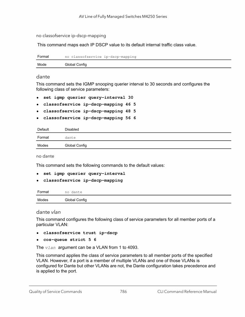
AV Line of Fully Managed Switches M4250 Series
no classofservice ip-dscp-mapping
This command maps each IP DSCP value to its default internal traffic class value.
danteThis command sets the IGMP snooping querier interval to 30 seconds and configures the following class of service parameters:
• set igmp querier query-interval 30
• classofservice ip-dscp-mapping 46 5
• classofservice ip-dscp-mapping 48 5
• classofservice ip-dscp-mapping 56 6
no dante
This command sets the following commands to the default values:
• set igmp querier query-interval
• classofservice ip-dscp-mapping
dante vlanThis command configures the following class of service parameters for all member ports of a particular VLAN:
• classofservice trust ip-dscp
• cos-queue strict 5 6
The vlan argument can be a VLAN from 1 to 4093.
This command applies the class of service parameters to all member ports of the specified VLAN. However, if a port is a member of multiple VLANs and one of those VLANs is configured for Dante but other VLANs are not, the Dante configuration takes precedence and is applied to the port.
Format no classofservice ip-dscp-mapping
Mode Global Config
Default Disabled
Format dante
Modes Global Config
Format no dante
Modes Global Config
Quality of Service Commands CLI Command Reference Manual786
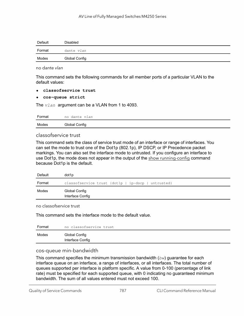
AV Line of Fully Managed Switches M4250 Series
no dante vlan
This command sets the following commands for all member ports of a particular VLAN to the default values:
• classofservice trust
• cos-queue strict
The vlan argument can be a VLAN from 1 to 4093.
classofservice trustThis command sets the class of service trust mode of an interface or range of interfaces. You can set the mode to trust one of the Dot1p (802.1p), IP DSCP, or IP Precedence packet markings. You can also set the interface mode to untrusted. If you configure an interface to use Dot1p, the mode does not appear in the output of the show running-config command because Dot1p is the default.
no classofservice trust
This command sets the interface mode to the default value.
cos-queue min-bandwidthThis command specifies the minimum transmission bandwidth (bw) guarantee for each interface queue on an interface, a range of interfaces, or all interfaces. The total number of queues supported per interface is platform specific. A value from 0-100 (percentage of link rate) must be specified for each supported queue, with 0 indicating no guaranteed minimum bandwidth. The sum of all values entered must not exceed 100.
Default Disabled
Format dante vlan
Modes Global Config
Format no dante vlan
Modes Global Config
Default dot1p
Format classofservice trust {dot1p | ip-dscp | untrusted}
Modes Global ConfigInterface Config
Format no classofservice trust
Modes Global ConfigInterface Config
Quality of Service Commands CLI Command Reference Manual787

AV Line of Fully Managed Switches M4250 Series
no cos-queue min-bandwidth
This command restores the default for each queue's minimum bandwidth value.
cos-queue random-detectThis command activates weighted random early discard (WRED) for each specified queue on the interface. Specific WRED parameters are configured using the random-detect queue-parms and the random-detect exponential-weighting-constant commands.
When specified in Interface Config mode, this command affects a single interface only, whereas in Global Config mode, it applies to all interfaces.
At least one, but no more than n queue-id values are specified with this command. Duplicate queue-id values are ignored. Each queue-id value ranges from 0 to (n–1), in which n is the total number of queues supported per interface. In the queue-id-n argument, the number n = 7 and corresponds to the number of supported queues (traffic classes).
no cos-queue random-detect
Use this command to disable WRED, thereby restoring the default tail drop operation for the specified queues on the interface.
Format cos-queue min-bandwidth bw-0 bw-1 … bw-n
Modes Global ConfigInterface Config
Format no cos-queue min-bandwidth
Modes Global ConfigInterface Config
Format cos-queue random-detect queue-id-1 [queue-id-2 … queue-id-n]
Modes Global ConfigInterface Config
Format no cos-queue random-detect queue-id-1 [queue-id-2 … queue-id-n]
Modes Global ConfigInterface Config
Quality of Service Commands CLI Command Reference Manual788
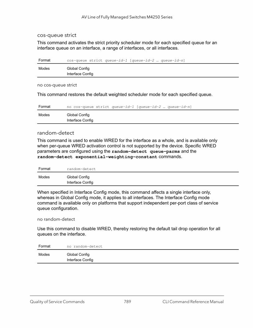
AV Line of Fully Managed Switches M4250 Series
cos-queue strictThis command activates the strict priority scheduler mode for each specified queue for an interface queue on an interface, a range of interfaces, or all interfaces.
no cos-queue strict
This command restores the default weighted scheduler mode for each specified queue.
random-detectThis command is used to enable WRED for the interface as a whole, and is available only when per-queue WRED activation control is not supported by the device. Specific WRED parameters are configured using the random-detect queue-parms and the random-detect exponential-weighting-constant commands.
When specified in Interface Config mode, this command affects a single interface only, whereas in Global Config mode, it applies to all interfaces. The Interface Config mode command is available only on platforms that support independent per-port class of service queue configuration.
no random-detect
Use this command to disable WRED, thereby restoring the default tail drop operation for all queues on the interface.
Format cos-queue strict queue-id-1 [queue-id-2 … queue-id-n]
Modes Global ConfigInterface Config
Format no cos-queue strict queue-id-1 [queue-id-2 … queue-id-n]
Modes Global ConfigInterface Config
Format random-detect
Modes Global ConfigInterface Config
Format no random-detect
Modes Global ConfigInterface Config
Quality of Service Commands CLI Command Reference Manual789
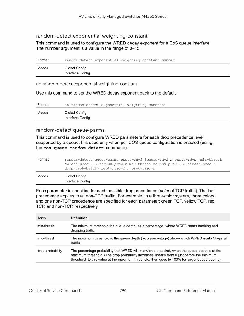
AV Line of Fully Managed Switches M4250 Series
h
s all
e
).
random-detect exponential weighting-constantThis command is used to configure the WRED decay exponent for a CoS queue interface. The number argument is a value in the range of 0–15.
no random-detect exponential-weighting-constant
Use this command to set the WRED decay exponent back to the default.
random-detect queue-parmsThis command is used to configure WRED parameters for each drop precedence level supported by a queue. It is used only when per-COS queue configuration is enabled (using the cos-queue random-detect command).
Each parameter is specified for each possible drop precedence (color of TCP traffic). The last precedence applies to all non-TCP traffic. For example, in a three-color system, three colors and one non-TCP precedence are specified for each parameter: green TCP, yellow TCP, red TCP, and non-TCP, respectively.
Format random-detect exponential-weighting-constant number
Modes Global ConfigInterface Config
Format no random-detect exponential-weighting-constant
Modes Global ConfigInterface Config
Format random-detect queue-parms queue-id-1 [queue-id-2 … queue-id-n] min-thresthresh-prec-1 … thresh-prec-n max-thresh thresh-prec-1 … thresh-prec-n drop-probability prob-prec-1 … prob-prec-n
Modes Global ConfigInterface Config
Term Definition
min-thresh The minimum threshold the queue depth (as a percentage) where WRED starts marking and dropping traffic.
max-thresh The maximum threshold is the queue depth (as a percentage) above which WRED marks/droptraffic.
drop-probability The percentage probability that WRED will mark/drop a packet, when the queue depth is at thmaximum threshold. (The drop probability increases linearly from 0 just before the minimum threshold, to this value at the maximum threshold, then goes to 100% for larger queue depths
Quality of Service Commands CLI Command Reference Manual790

AV Line of Fully Managed Switches M4250 Series
no random-detect queue-parms
Use this command to set the WRED configuration back to the default.
traffic-shapeThis command specifies the maximum transmission bandwidth (bw) limit for the interface as a whole. The bandwidth values are from 0-100 in increments of 1. You can also specify this value for a range of interfaces or all interfaces. Also known as rate shaping, traffic shaping has the effect of smoothing temporary traffic bursts over time so that the transmitted traffic rate is bounded.
no traffic-shape
This command restores the interface shaping rate to the default value.
show classofservice dot1p-mappingThis command displays the current Dot1p (802.1p) priority mapping to internal traffic classes for a specific interface. The unit/port parameter is optional and is only valid on platforms that support independent per-port class of service mappings. If specified, the 802.1p mapping table of the interface is displayed. If omitted, the most recent global configuration settings are displayed. For more information, see Voice VLAN Commands on page 391.
The following information is repeated for each user priority.
Format no random-detect queue-parms queue-id-1 [queue-id-2 … queue-id-n]
Modes Global ConfigInterface Config
Format traffic-shape bw
Modes Global ConfigInterface Config
Format no traffic-shape
Modes Global ConfigInterface Config
Format show classofservice dot1p-mapping [unit/port]
Mode Privileged EXEC
Term Definition
User Priority The 802.1p user priority value.
Traffic Class The traffic class internal queue identifier to which the user priority value is mapped.
Quality of Service Commands CLI Command Reference Manual791
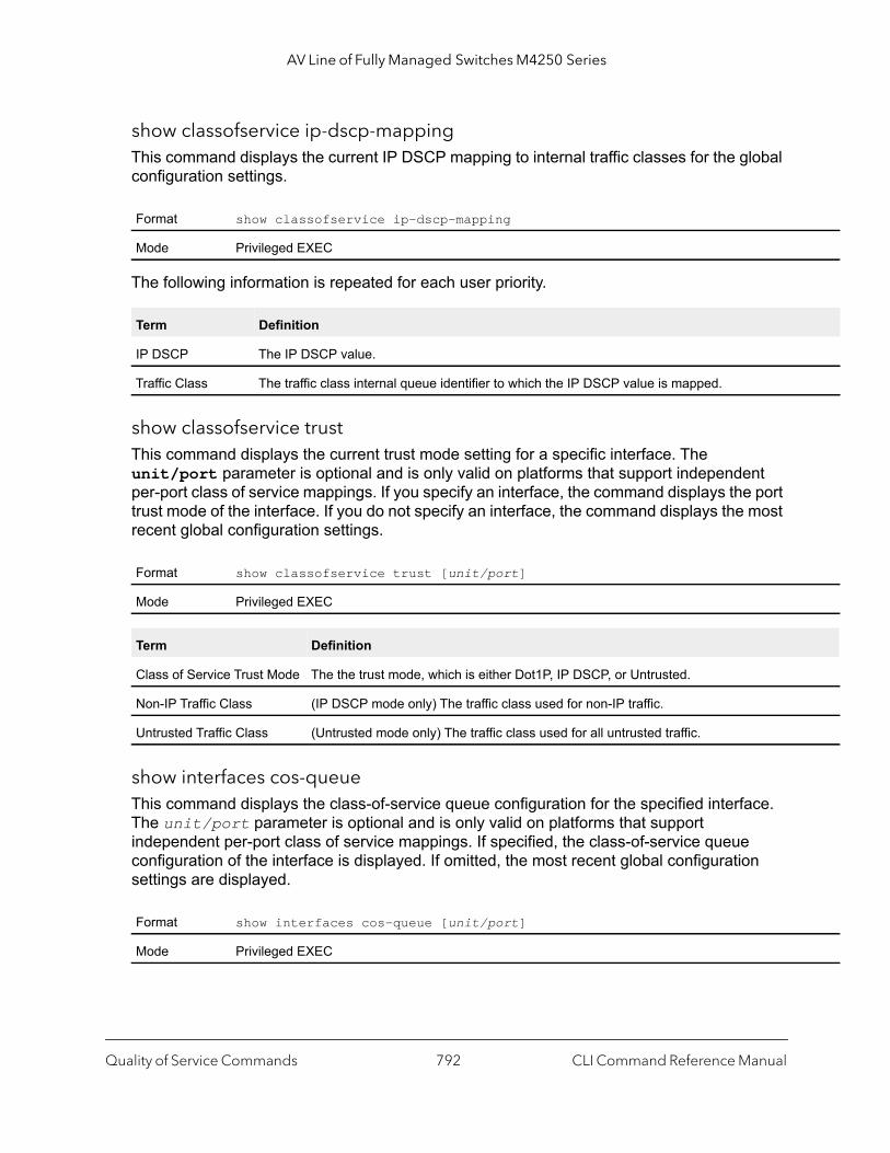
AV Line of Fully Managed Switches M4250 Series
show classofservice ip-dscp-mappingThis command displays the current IP DSCP mapping to internal traffic classes for the global configuration settings.
The following information is repeated for each user priority.
show classofservice trustThis command displays the current trust mode setting for a specific interface. The unit/port parameter is optional and is only valid on platforms that support independent per-port class of service mappings. If you specify an interface, the command displays the port trust mode of the interface. If you do not specify an interface, the command displays the most recent global configuration settings.
show interfaces cos-queueThis command displays the class-of-service queue configuration for the specified interface. The unit/port parameter is optional and is only valid on platforms that support independent per-port class of service mappings. If specified, the class-of-service queue configuration of the interface is displayed. If omitted, the most recent global configuration settings are displayed.
Format show classofservice ip-dscp-mapping
Mode Privileged EXEC
Term Definition
IP DSCP The IP DSCP value.
Traffic Class The traffic class internal queue identifier to which the IP DSCP value is mapped.
Format show classofservice trust [unit/port]
Mode Privileged EXEC
Term Definition
Class of Service Trust Mode The the trust mode, which is either Dot1P, IP DSCP, or Untrusted.
Non-IP Traffic Class (IP DSCP mode only) The traffic class used for non-IP traffic.
Untrusted Traffic Class (Untrusted mode only) The traffic class used for all untrusted traffic.
Format show interfaces cos-queue [unit/port]
Mode Privileged EXEC
Quality of Service Commands CLI Command Reference Manual792
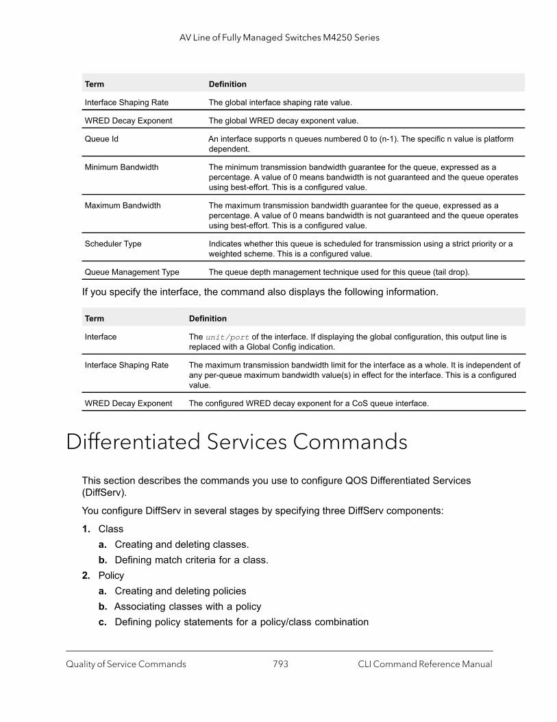
AV Line of Fully Managed Switches M4250 Series
orm
rates
rates
r a
is
ent of ured
If you specify the interface, the command also displays the following information.
Differentiated Services Commands
This section describes the commands you use to configure QOS Differentiated Services (DiffServ).
You configure DiffServ in several stages by specifying three DiffServ components:
1. Classa. Creating and deleting classes.b. Defining match criteria for a class.
2. Policya. Creating and deleting policiesb. Associating classes with a policyc. Defining policy statements for a policy/class combination
Term Definition
Interface Shaping Rate The global interface shaping rate value.
WRED Decay Exponent The global WRED decay exponent value.
Queue Id An interface supports n queues numbered 0 to (n-1). The specific n value is platfdependent.
Minimum Bandwidth The minimum transmission bandwidth guarantee for the queue, expressed as a percentage. A value of 0 means bandwidth is not guaranteed and the queue opeusing best-effort. This is a configured value.
Maximum Bandwidth The maximum transmission bandwidth guarantee for the queue, expressed as a percentage. A value of 0 means bandwidth is not guaranteed and the queue opeusing best-effort. This is a configured value.
Scheduler Type Indicates whether this queue is scheduled for transmission using a strict priority oweighted scheme. This is a configured value.
Queue Management Type The queue depth management technique used for this queue (tail drop).
Term Definition
Interface The unit/port of the interface. If displaying the global configuration, this output line replaced with a Global Config indication.
Interface Shaping Rate The maximum transmission bandwidth limit for the interface as a whole. It is independany per-queue maximum bandwidth value(s) in effect for the interface. This is a configvalue.
WRED Decay Exponent The configured WRED decay exponent for a CoS queue interface.
Quality of Service Commands CLI Command Reference Manual793
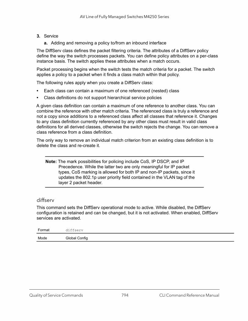
AV Line of Fully Managed Switches M4250 Series
3. Servicea. Adding and removing a policy to/from an inbound interface
The DiffServ class defines the packet filtering criteria. The attributes of a DiffServ policy define the way the switch processes packets. You can define policy attributes on a per-class instance basis. The switch applies these attributes when a match occurs.
Packet processing begins when the switch tests the match criteria for a packet. The switch applies a policy to a packet when it finds a class match within that policy.
The following rules apply when you create a DiffServ class:
• Each class can contain a maximum of one referenced (nested) class• Class definitions do not support hierarchical service policies
A given class definition can contain a maximum of one reference to another class. You can combine the reference with other match criteria. The referenced class is truly a reference and not a copy since additions to a referenced class affect all classes that reference it. Changes to any class definition currently referenced by any other class must result in valid class definitions for all derived classes, otherwise the switch rejects the change. You can remove a class reference from a class definition.
The only way to remove an individual match criterion from an existing class definition is to delete the class and re-create it.
Note: The mark possibilities for policing include CoS, IP DSCP, and IP Precedence. While the latter two are only meaningful for IP packet types, CoS marking is allowed for both IP and non-IP packets, since it updates the 802.1p user priority field contained in the VLAN tag of the layer 2 packet header.
diffserv This command sets the DiffServ operational mode to active. While disabled, the DiffServ configuration is retained and can be changed, but it is not activated. When enabled, DiffServ services are activated.
Format diffserv
Mode Global Config
Quality of Service Commands CLI Command Reference Manual794

AV Line of Fully Managed Switches M4250 Series
no diffserv
This command sets the DiffServ operational mode to inactive. While disabled, the DiffServ configuration is retained and can be changed, but it is not activated. When enabled, DiffServ services are activated.
DiffServ Class Commands
Use the DiffServ class commands to define traffic classification. To classify traffic, you specify Behavior Aggregate (BA), based on DSCP and Multi-Field (MF) classes of traffic (name, match criteria)
This set of commands consists of class creation/deletion and matching, with the class match commands specifying Layer 3, Layer 2, and general match criteria. The class match criteria are also known as class rules, with a class definition consisting of one or more rules to identify the traffic that belongs to the class.
Note: After you create a class match criterion for a class, you cannot change or delete the criterion. To change or delete a class match criterion, you must delete and re-create the entire class.
The CLI command root is class-map.
class-mapThis command defines a DiffServ class of type match-all. When used without any match condition, this command enters the class-map mode. The class-map-name is a case sensitive alphanumeric string from 1 to 31 characters uniquely identifying an existing DiffServ class.
Note: The class-map-name default is reserved. Do not use it.
The class type of match-all indicates all of the individual match conditions must be true for a packet to be considered a member of the class.This command may be used without specifying a class type to enter the Class-Map Config mode for an existing DiffServ class.
Format no diffserv
Mode Global Config
Quality of Service Commands CLI Command Reference Manual795
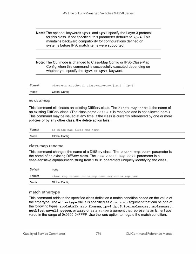
AV Line of Fully Managed Switches M4250 Series
Note: The optional keywords ipv4 and ipv6 specify the Layer 3 protocol for this class. If not specified, this parameter defaults to ipv4. This maintains backward compatibility for configurations defined on systems before IPv6 match items were supported.
Note: The CLI mode is changed to Class-Map Config or IPv6-Class-Map Config when this command is successfully executed depending on whether you specify the ipv4 or ipv6 keyword.
no class-map
This command eliminates an existing DiffServ class. The class-map-name is the name of an existing DiffServ class. (The class name default is reserved and is not allowed here.) This command may be issued at any time; if the class is currently referenced by one or more policies or by any other class, the delete action fails.
class-map renameThis command changes the name of a DiffServ class. The class-map-name parameter is the name of an existing DiffServ class. The new-class-map-name parameter is a case-sensitive alphanumeric string from 1 to 31 characters uniquely identifying the class.
match ethertypeThis command adds to the specified class definition a match condition based on the value of the ethertype. The ethertype value is specified as a keyword argument that can be one of the following types: appletalk, arp, ibmsna, ipv4, ipv6, ipx, mplsmcast, mplsucast, netbios, novell, pppoe, or rarp or as a range argument that represents an EtherType value in the range of 0x0600-0xFFFF. Use the not option to negate the match condition.
Format class-map match-all class-map-name [ipv4 | ipv6]
Mode Global Config
Format no class-map class-map-name
Mode Global Config
Default none
Format class-map rename class-map-name new-class-map-name
Mode Global Config
Quality of Service Commands CLI Command Reference Manual796

AV Line of Fully Managed Switches M4250 Series
match anyThis command adds to the specified class definition a match condition whereby all packets are considered to belong to the class. Use the not option to negate the match condition.
match class-mapThis command adds to the specified class definition the set of match conditions defined for another class. The refclassname is the name of an existing DiffServ class whose match conditions are being referenced by the specified class definition.
The requirements for the match class-map command are as follows:
• The parameters refclassname and class-map-name can not be the same.• Only one other class may be referenced by a class.• Any attempts to delete the refclassname class while the class is still referenced by any
class-map-name fails. • The combined match criteria of class-map-name and refclassname must be an
allowed combination based on the class type. • Any subsequent changes to the refclassname class match criteria must maintain this
validity, or the change attempt fails.• The total number of class rules formed by the complete reference class chain (including
both predecessor and successor classes) must not exceed a platform-specific maximum. In some cases, each removal of a refclass rule reduces the maximum number of available rules in the class definition by one.
Format match [not] ethertype {keyword | custom range}
Mode Class-Map Config Ipv6-Class-Map Config
Default none
Format match [not] any
Mode Class-Map Config Ipv6-Class-Map Config
Default none
Format match class-map refclassname
Mode Class-Map Config Ipv6-Class-Map Config
Quality of Service Commands CLI Command Reference Manual797
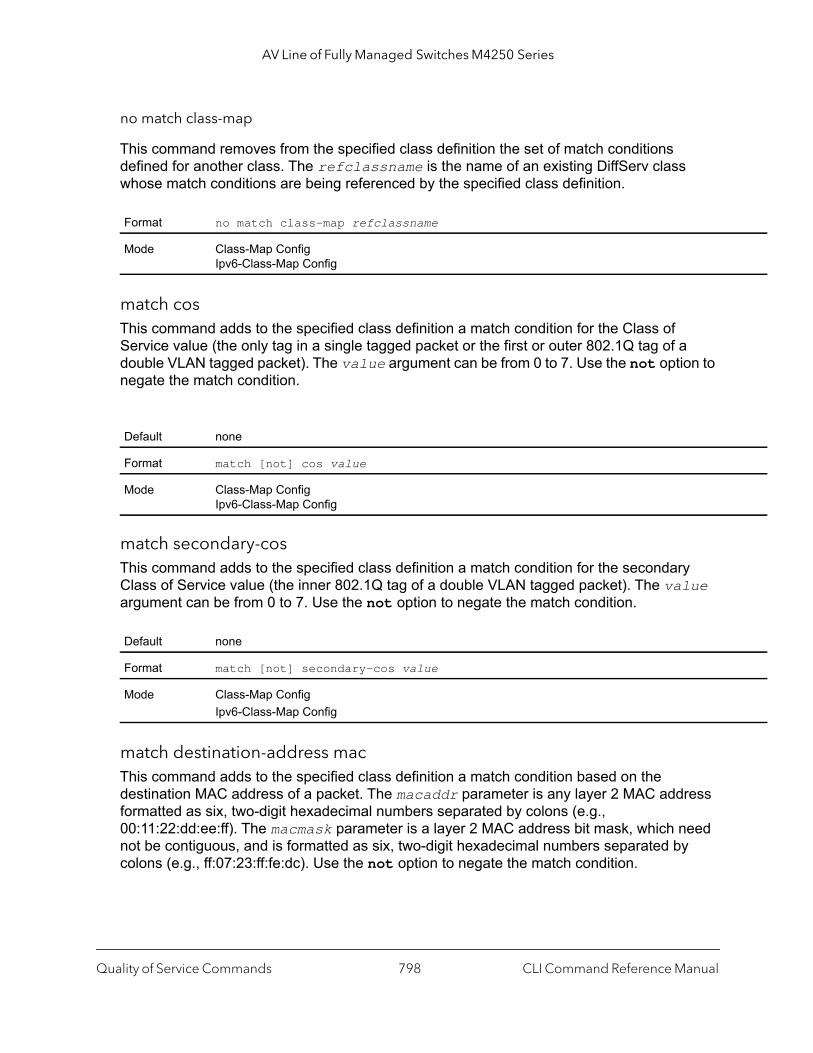
AV Line of Fully Managed Switches M4250 Series
no match class-map
This command removes from the specified class definition the set of match conditions defined for another class. The refclassname is the name of an existing DiffServ class whose match conditions are being referenced by the specified class definition.
match cosThis command adds to the specified class definition a match condition for the Class of Service value (the only tag in a single tagged packet or the first or outer 802.1Q tag of a double VLAN tagged packet). The value argument can be from 0 to 7. Use the not option to negate the match condition.
match secondary-cosThis command adds to the specified class definition a match condition for the secondary Class of Service value (the inner 802.1Q tag of a double VLAN tagged packet). The value argument can be from 0 to 7. Use the not option to negate the match condition.
match destination-address macThis command adds to the specified class definition a match condition based on the destination MAC address of a packet. The macaddr parameter is any layer 2 MAC address formatted as six, two-digit hexadecimal numbers separated by colons (e.g., 00:11:22:dd:ee:ff). The macmask parameter is a layer 2 MAC address bit mask, which need not be contiguous, and is formatted as six, two-digit hexadecimal numbers separated by colons (e.g., ff:07:23:ff:fe:dc). Use the not option to negate the match condition.
Format no match class-map refclassname
Mode Class-Map Config Ipv6-Class-Map Config
Default none
Format match [not] cos value
Mode Class-Map Config Ipv6-Class-Map Config
Default none
Format match [not] secondary-cos value
Mode Class-Map ConfigIpv6-Class-Map Config
Quality of Service Commands CLI Command Reference Manual798

AV Line of Fully Managed Switches M4250 Series
match dstipThis command adds to the specified class definition a match condition based on the destination IP address of a packet. The ipaddr parameter specifies an IP address. The ipmask parameter specifies an IP address bit mask and must consist of a contiguous set of leading 1 bits. Use the not option to negate the match condition.
match dstip6This command adds to the specified class definition a match condition based on the destination IPv6 address of a packet. Use the not option to negate the match condition.
match dstl4port This command adds to the specified class definition a match condition based on the destination layer 4 port of a packet using a single keyword or numeric notation. To specify the match condition as a single keyword, the value for portkey is one of the supported port name keywords. The portkey argument can be: domain, echo, ftp, ftpdata, http, smtp, snmp, telnet, tftp, or www. Each of these translates into its equivalent port number. To specify the match condition using a numeric notation, one layer 4 port number is required. The port-number argument is an integer from 0 to 65535. Use the not option to negate the match condition.
Default none
Format match [not] destination-address mac macaddr macmask
Mode Class-Map ConfigIpv6-Class-Map Config
Default none
Format match [not] dstip ipaddr ipmask
Mode Class-Map Config
Default none
Format match [not] dstip6 destination-ipv6-prefix/prefix-length
Mode Ipv6-Class-Map Config
Default none
Format match [not] dstl4port {portkey | port-number}
Mode Class-Map ConfigIpv6-Class-Map Config
Quality of Service Commands CLI Command Reference Manual799
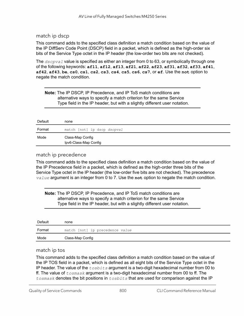
AV Line of Fully Managed Switches M4250 Series
match ip dscpThis command adds to the specified class definition a match condition based on the value of the IP DiffServ Code Point (DSCP) field in a packet, which is defined as the high-order six bits of the Service Type octet in the IP header (the low-order two bits are not checked).
The dscpval value is specified as either an integer from 0 to 63, or symbolically through one of the following keywords: af11, af12, af13, af21, af22, af23, af31, af32, af33, af41, af42, af43, be, cs0, cs1, cs2, cs3, cs4, cs5, cs6, cs7, or ef. Use the not option to negate the match condition.
Note: The IP DSCP, IP Precedence, and IP ToS match conditions are alternative ways to specify a match criterion for the same Service Type field in the IP header, but with a slightly different user notation.
match ip precedenceThis command adds to the specified class definition a match condition based on the value of the IP Precedence field in a packet, which is defined as the high-order three bits of the Service Type octet in the IP header (the low-order five bits are not checked). The precedence value argument is an integer from 0 to 7. Use the not option to negate the match condition.
Note: The IP DSCP, IP Precedence, and IP ToS match conditions are alternative ways to specify a match criterion for the same Service Type field in the IP header, but with a slightly different user notation.
match ip tosThis command adds to the specified class definition a match condition based on the value of the IP TOS field in a packet, which is defined as all eight bits of the Service Type octet in the IP header. The value of the tosbits argument is a two-digit hexadecimal number from 00 to ff. The value of tosmask argument is a two-digit hexadecimal number from 00 to ff. The tosmask denotes the bit positions in tosbits that are used for comparison against the IP
Default none
Format match [not] ip dscp dscpval
Mode Class-Map ConfigIpv6-Class-Map Config
Default none
Format match [not] ip precedence value
Mode Class-Map Config
Quality of Service Commands CLI Command Reference Manual800

AV Line of Fully Managed Switches M4250 Series
ToS field in a packet. For example, to check for an IP TOS value having bits 7 and 5 set and bit 1 clear, where bit 7 is most significant, use a tosbits value of a0 (hex) and a tosmask of a2 (hex). Use the not option to negate the match condition.
Note: The IP DSCP, IP Precedence, and IP ToS match conditions are alternative ways to specify a match criterion for the same Service Type field in the IP header, but with a slightly different user notation.
Note: This free form version of the IP DSCP/Precedence/ToS match specification gives the user complete control when specifying which bits of the IP Service Type field are checked.
match ip6flowlblUse this command to enter an IPv6 flow label value. Use the not option to negate the match condition. The value argument can be in the range of 0–1048575.
match protocol This command adds to the specified class definition a match condition based on the value of the IP Protocol field in a packet using a single keyword notation or a numeric value notation.
To specify the match condition using a single keyword notation, the value for protocol-name is one of the supported protocol name keywords. The currently supported values are: icmp, igmp, ip, tcp, udp. A value of ip matches all protocol number values.
To specify the match condition using a numeric value notation, the protocol number argument is a standard value assigned by IANA and is interpreted as an integer from 0 to 255. Use the [not] option to negate the match condition.
Note: This command does not validate the protocol number value against the current list defined by IANA.
Default none
Format match [not] ip tos tosbits tosmask
Mode Class-Map Config
Default none
Format match [not] ip6flowlbl label value
Mode IPv6-Class-Map Config
Quality of Service Commands CLI Command Reference Manual801
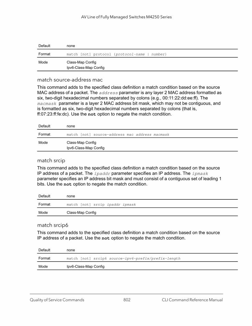
AV Line of Fully Managed Switches M4250 Series
match source-address macThis command adds to the specified class definition a match condition based on the source MAC address of a packet. The address parameter is any layer 2 MAC address formatted as six, two-digit hexadecimal numbers separated by colons (e.g., 00:11:22:dd:ee:ff). The macmask parameter is a layer 2 MAC address bit mask, which may not be contiguous, and is formatted as six, two-digit hexadecimal numbers separated by colons (that is, ff:07:23:ff:fe:dc). Use the not option to negate the match condition.
match srcipThis command adds to the specified class definition a match condition based on the source IP address of a packet. The ipaddr parameter specifies an IP address. The ipmask parameter specifies an IP address bit mask and must consist of a contiguous set of leading 1 bits. Use the not option to negate the match condition.
match srcip6This command adds to the specified class definition a match condition based on the source IP address of a packet. Use the not option to negate the match condition.
Default none
Format match [not] protocol {protocol-name | number}
Mode Class-Map ConfigIpv6-Class-Map Config
Default none
Format match [not] source-address mac address macmask
Mode Class-Map ConfigIpv6-Class-Map Config
Default none
Format match [not] srcip ipaddr ipmask
Mode Class-Map Config
Default none
Format match [not] srcip6 source-ipv6-prefix/prefix-length
Mode Ipv6-Class-Map Config
Quality of Service Commands CLI Command Reference Manual802

AV Line of Fully Managed Switches M4250 Series
match srcl4portThis command adds to the specified class definition a match condition based on the source layer 4 port of a packet using a single keyword or numeric notation. To specify the match condition as a single keyword notation, the value for portkey is one of the supported port name keywords (listed below). The currently supported portkey values are: domain, echo, ftp, ftpdata, http, smtp, snmp, telnet, tftp, and www. Each of these translates into its equivalent port number, which is used as both the start and end of a port range.
To specify the match condition as a numeric value, one layer 4 port number is required. The port-number argument is an integer from 0 to 65535. Use the not option to negate the match condition.
match vlanThis command adds to the specified class definition a match condition based on the value of the layer 2 VLAN Identifier field (the only tag in a single tagged packet or the first or outer tag of a double VLAN tagged packet). The vlan-id argument is an integer from 0 to 4093. Use the not option to negate the match condition.
match secondary-vlanThis command adds to the specified class definition a match condition based on the value of the layer 2 secondary VLAN Identifier field (the inner 802.1Q tag of a double VLAN tagged packet). The secondary vlan-id argument is an integer from 0 to 4093. Use the not option to negate the match condition.
Default none
Format match [not] srcl4port {portkey | port-number}
Mode Class-Map ConfigIpv6-Class-Map Config
Default none
Format match [not] vlan vland-id
Mode Class-Map ConfigIpv6-Class-Map Config
Default none
Format match [not] secondary-vlan vlan-id
Mode Class-Map ConfigIpv6-Class-Map Config
Quality of Service Commands CLI Command Reference Manual803

AV Line of Fully Managed Switches M4250 Series
DiffServ Policy Commands
Use the DiffServ policy commands to specify traffic conditioning actions, such as policing and marking, to apply to traffic classes
Use the policy commands to associate a traffic class that you define by using the class command set with one or more QoS policy attributes. Assign the class/policy association to an interface to form a service. Specify the policy name when you create the policy.
Each traffic class defines a particular treatment for packets that match the class definition. You can associate multiple traffic classes with a single policy. When a packet satisfies the conditions of more than one class, preference is based on the order in which you add the classes to the policy. The first class you add has the highest precedence.
This set of commands consists of policy creation/deletion, class addition/removal, and individual policy attributes.
Note: The only way to remove an individual policy attribute from a class instance within a policy is to remove the class instance and re-add it to the policy. The values associated with an existing policy attribute can be changed without removing the class instance.
The CLI command root is policy-map.
assign-queueThis command modifies the queue id to which the associated traffic stream is assigned. The queueid is an integer from 0 to n-1, in which n is the number of egress queues supported by the device.
dropThis command specifies that all packets for the associated traffic stream are to be dropped at ingress.
Format assign-queue queueid
Mode Policy-Class-Map Config
Incompatibilities Drop
Format drop
Mode Policy-Class-Map Config
Incompatibilities Assign Queue, Mark (all forms), Mirror, Police, Redirect
Quality of Service Commands CLI Command Reference Manual804
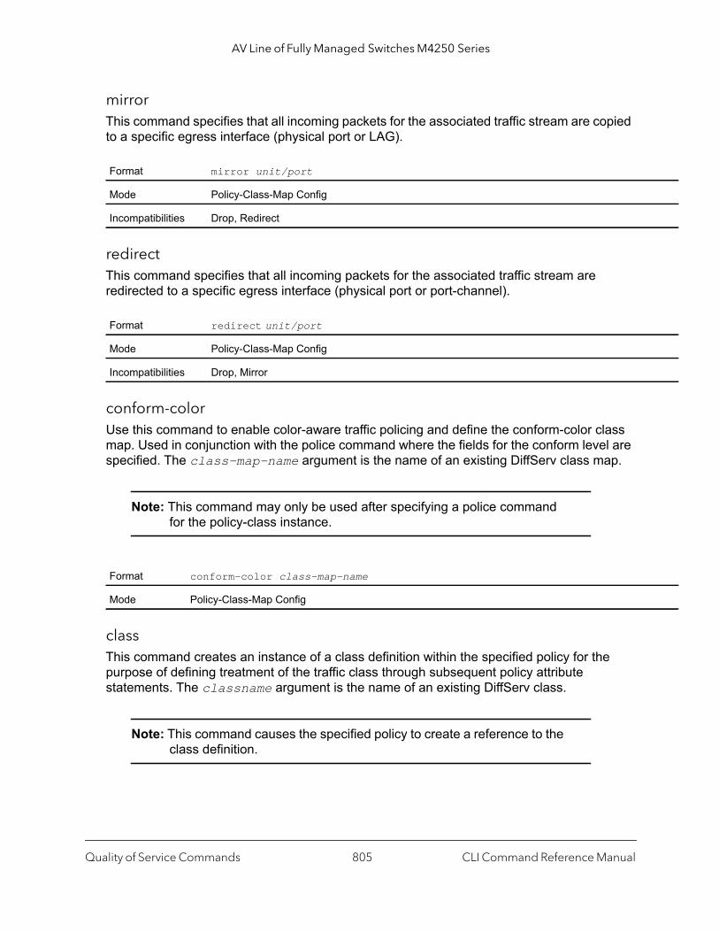
AV Line of Fully Managed Switches M4250 Series
mirrorThis command specifies that all incoming packets for the associated traffic stream are copied to a specific egress interface (physical port or LAG).
redirectThis command specifies that all incoming packets for the associated traffic stream are redirected to a specific egress interface (physical port or port-channel).
conform-colorUse this command to enable color-aware traffic policing and define the conform-color class map. Used in conjunction with the police command where the fields for the conform level are specified. The class-map-name argument is the name of an existing DiffServ class map.
Note: This command may only be used after specifying a police command for the policy-class instance.
class This command creates an instance of a class definition within the specified policy for the purpose of defining treatment of the traffic class through subsequent policy attribute statements. The classname argument is the name of an existing DiffServ class.
Note: This command causes the specified policy to create a reference to the class definition.
Format mirror unit/port
Mode Policy-Class-Map Config
Incompatibilities Drop, Redirect
Format redirect unit/port
Mode Policy-Class-Map Config
Incompatibilities Drop, Mirror
Format conform-color class-map-name
Mode Policy-Class-Map Config
Quality of Service Commands CLI Command Reference Manual805
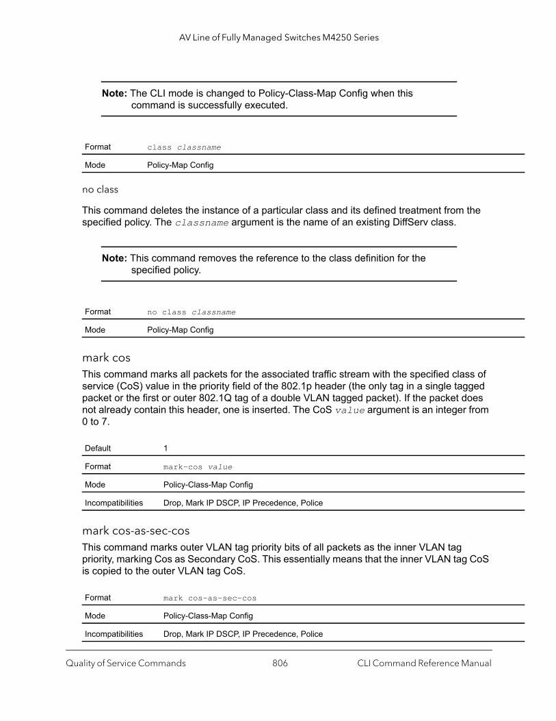
AV Line of Fully Managed Switches M4250 Series
Note: The CLI mode is changed to Policy-Class-Map Config when this command is successfully executed.
no class
This command deletes the instance of a particular class and its defined treatment from the specified policy. The classname argument is the name of an existing DiffServ class.
Note: This command removes the reference to the class definition for the specified policy.
mark cosThis command marks all packets for the associated traffic stream with the specified class of service (CoS) value in the priority field of the 802.1p header (the only tag in a single tagged packet or the first or outer 802.1Q tag of a double VLAN tagged packet). If the packet does not already contain this header, one is inserted. The CoS value argument is an integer from 0 to 7.
mark cos-as-sec-cosThis command marks outer VLAN tag priority bits of all packets as the inner VLAN tag priority, marking Cos as Secondary CoS. This essentially means that the inner VLAN tag CoS is copied to the outer VLAN tag CoS.
Format class classname
Mode Policy-Map Config
Format no class classname
Mode Policy-Map Config
Default 1
Format mark-cos value
Mode Policy-Class-Map Config
Incompatibilities Drop, Mark IP DSCP, IP Precedence, Police
Format mark cos-as-sec-cos
Mode Policy-Class-Map Config
Incompatibilities Drop, Mark IP DSCP, IP Precedence, Police
Quality of Service Commands CLI Command Reference Manual806

AV Line of Fully Managed Switches M4250 Series
Command example: (NETGEAR Switch) (Config-policy-classmap)#mark cos-as-sec-cos
mark ip-dscpThis command marks all packets for the associated traffic stream with the specified IP DSCP value. The dscpval value is specified as either an integer from 0 to 63, or symbolically through one of the following keywords: af11, af12, af13, af21, af22, af23, af31, af32, af33, af41, af42, af43, be, cs0, cs1, cs2, cs3, cs4, cs5, cs6, cs7, or ef.
mark ip-precedenceThis command marks all packets for the associated traffic stream with the specified IP Precedence value. The IP Precedence value argument is an integer from 0 to 7.
Note: This command may not be used on IPv6 classes. IPv6 does not have a precedence field.
police-simpleThis command is used to establish the traffic policing style for the specified class. The simple form of the police command uses a single data rate and burst size, resulting in two outcomes: conform and violate. The conforming data rate is specified in kilobits-per-second (Kbps) and is an integer from 1 to 4294967295. The conforming burst size is specified in kilobytes (KB) and is an integer from 1 to 128.
For each outcome, the only possible actions are drop, set-cos-as-sec-cos, set-cos-transmit, set-sec-cos-transmit, set-dscp-transmit, set-prec-transmit, or transmit. In this simple form of the police command, the conform action defaults to transmit and the violate action defaults to drop. These actions can be set with this command once the style is configured.
For set-dscp-transmit, a value is required and is specified as either an integer from 0 to 63, or symbolically through one of the following keywords: af11, af12, af13, af21, af22,
Format mark ip-dscp dscpval
Mode Policy-Class-Map Config
Incompatibilities Drop, Mark CoS, Mark IP Precedence, Police
Format mark ip-precedence value
Mode Policy-Class-Map Config
Incompatibilities Drop, Mark CoS, Mark IP Precedence, Police
Policy Type In
Quality of Service Commands CLI Command Reference Manual807

AV Line of Fully Managed Switches M4250 Series
|
-63
| ion mit
t
af23, af31, af32, af33, af41, af42, af43, be, cs0, cs1, cs2, cs3, cs4, cs5, cs6, cs7, or ef.
For set-prec-transmit, an IP Precedence value is required and is specified as an integer from 0-7.
For set-cos-transmit an 802.1p priority value is required and is specified as an integer from 0-7.
Command example: (NETGEAR Switch) (Config-policy-classmap)#police-simple 1 128 conform-action transmit violate-action drop
police-single-rateThis command is the single-rate form of the police command and is used to establish the traffic policing style for the specified class. For each outcome, the only possible actions are drop, set-cos-as-sec-cost, set-cos-transmit, set-sec-cos-transmit, set-dscp-transmit, set-prec-transmit, or transmit. In this single-rate form of the police command, the conform action defaults to send, the exceed action defaults to drop, and the violate action defaults to drop. These actions can be set with this command once the style has been configured.
police-two-rateThis command is the two-rate form of the police command and is used to establish the traffic policing style for the specified class. For each outcome, the only possible actions are drop, set-cos-as-sec-cos, set-cos-transmit, set-sec-cos-transmit, set-dscp-transmit, set-prec-transmit, or transmit. In this two-rate form of the police command, the conform
Format police-simple {1-4294967295 1-128 conform-action {drop | set-cos-as-sec-cos | set-cos-transmit 0-7 | set-sec-cos-transmit 0-7 set-prec-transmit 0-7 | set-dscp-transmit 0-63 | transmit} [violate-action {drop | set-cos-as-sec-cos | set-cos-transmit 0-7 | set-sec-cos-transmit 0-7 | set-prec-transmit 0-7 | set-dscp-transmit 0| transmit}]}
Mode Policy-Class-Map Config
Incompatibilities Drop, Mark (all forms)
Format police-single-rate {1-4294967295 1-128 1-128 conform-action {drop | set-cos-as-sec-cos | set-cos-transmit 0-7 | set-sec-cos-transmit 0-7 set-prec-transmit 0-7 | set-dscp-transmit 0-63 | transmit} exceed-act{drop | set-cos-as-sec-cos | set-cos-transmit 0-7 | set-sec-cos-trans0-7 | set-prec-transmit 0-7 | set-dscp-transmit 0-63 | transmit} [violate-action {drop | set-cos-as-sec-cos-transmit | set-cos-transmi0-7 | set-sec-cos-transmit 0-7 | set-prec-transmit 0-7 | set-dscp-transmit 0-63 | transmit}]}
Mode Policy-Class-Map Config
Quality of Service Commands CLI Command Reference Manual808

AV Line of Fully Managed Switches M4250 Series
mit
-63 mit
action defaults to send, the exceed action defaults to drop, and the violate action defaults to drop. These actions can be set with this command once the style has been configured.
policy-mapThis command establishes a new DiffServ policy. The policyname parameter is a case-sensitive alphanumeric string from 1 to 31 characters uniquely identifying the policy. The type of policy is specific to the inbound traffic direction as indicated by the in parameter, or the outbound traffic direction as indicated by the out parameter, respectively.
Note: The CLI mode is changed to Policy-Map Config when this command is successfully executed.
no policy-map
This command eliminates an existing DiffServ policy. The policyname parameter is the name of an existing DiffServ policy. This command may be issued at any time. If the policy is currently referenced by one or more interface service attachments, this delete attempt fails.
policy-map renameThis command changes the name of a DiffServ policy. The policyname is the name of an existing DiffServ class. The newpolicyname parameter is a case-sensitive alphanumeric string from 1 to 31 characters uniquely identifying the policy.
Format police-two-rate {1-4294967295 1-4294967295 1-128 1-128 conform-action{drop | set-cos-as-sec-cos | set-cos-transmit 0-7 | set-sec-cos-trans0-7 | set-prec-transmit 0-7 | set-dscp-transmit 0-63 | transmit} exceed-action {drop | set-cos-as-sec-cos | set-cos-transmit 0-7 | set-sec-cos-transmit 0-7 | set-prec-transmit 0-7 | set-dscp-transmit 0| transmit} [violate-action {drop | set-cos-as-sec-cos | set-cos-trans0-7 | set-sec-cos-transmit 0-7 | set-prec-transmit 0-7 | set-dscp-transmit 0-63 | transmit}]}
Mode Policy-Class-Map Config
Format policy-map policyname {in | out}
Mode Global Config
Format no policy-map policyname
Mode Global Config
Format policy-map rename policyname newpolicyname
Mode Global Config
Quality of Service Commands CLI Command Reference Manual809

AV Line of Fully Managed Switches M4250 Series
DiffServ Service Commands
Use the DiffServ service commands to assign a DiffServ traffic conditioning policy, which you specified by using the policy commands, to an interface in the incoming direction
The service commands attach a defined policy to a directional interface. You can assign only one policy at any one time to an interface in the inbound direction. DiffServ is not used in the outbound direction.
This set of commands consists of service addition or removal.
The CLI command root is service-policy.
service-policyThis command attaches a policy to an interface in the inbound direction as indicated by the in parameter, or the outbound direction as indicated by the out parameter, respectively. The policyname parameter is the name of an existing DiffServ policy. This command causes a service to create a reference to the policy.
Note: This command effectively enables DiffServ on an interface in the inbound direction. There is no separate interface administrative mode command for DiffServ.
Note: This command fails if any attributes within the policy definition exceed the capabilities of the interface. Once a policy is successfully attached to an interface, any attempt to change the policy definition, that would result in a violation of the interface capabilities, causes the policy change attempt to fail.
Note: Each interface can have one policy attached.
no service-policy
This command detaches a policy from an interface in the inbound direction as indicated by the in parameter, or the outbound direction as indicated by the out parameter, respectively. The policyname parameter is the name of an existing DiffServ policy.
Format service-policy {in | out} policymapname
Modes Global Config Interface Config
Quality of Service Commands CLI Command Reference Manual810

AV Line of Fully Managed Switches M4250 Series
y and
port
n IP s, ce
Note: This command causes a service to remove its reference to the policy. This command effectively disables DiffServ on an interface in the inbound direction or an interface in the outbound direction. There is no separate interface administrative 'mode' command for DiffServ.
DiffServ Show Commands
Use the DiffServ show commands to display configuration and status information for classes, policies, and services. You can display DiffServ information in summary or detailed formats. The status information is only shown when the DiffServ administrative mode is enabled.
show class-mapThis command displays all configuration information for the specified class. The class-name is the name of an existing DiffServ class.
If the class-name is specified the following fields are displayed.
Format no service-policy {in | out} policymapname
Modes Global Config Interface Config
Format show class-map class-name
Modes Privileged EXECUser EXEC
Term Definition
Class Name The name of this class.
Class Type A class type of all means every match criterion defined for the class is evaluated simultaneouslmust all be true to indicate a class match.
Class Layer3 Protocol
The Layer 3 protocol for this class. Possible values are IPv4 and IPv6.
Match Criteria The Match Criteria fields are only displayed if they have been configured. Not all platforms supall match criteria values. They are displayed in the order entered by the user. The fields are evaluated in accordance with the class type. The possible Match Criteria fields are: DestinatioAddress, Destination Layer 4 Port, Destination MAC Address, Ethertype, Source MAC AddresVLAN, Class of Service, Every, IP DSCP, IP Precedence, IP TOS, Protocol Keyword, ReferenClass, Source IP Address, and Source Layer 4 Port.
Values The values of the Match Criteria.
Quality of Service Commands CLI Command Reference Manual811
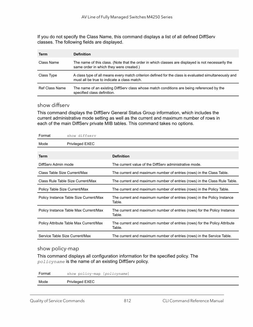
AV Line of Fully Managed Switches M4250 Series
he
y and
.
Table.
.
nce
nce
ute
le.
If you do not specify the Class Name, this command displays a list of all defined DiffServ classes. The following fields are displayed.
show diffservThis command displays the DiffServ General Status Group information, which includes the current administrative mode setting as well as the current and maximum number of rows in each of the main DiffServ private MIB tables. This command takes no options.
show policy-mapThis command displays all configuration information for the specified policy. The policyname is the name of an existing DiffServ policy.
Term Definition
Class Name The name of this class. (Note that the order in which classes are displayed is not necessarily tsame order in which they were created.)
Class Type A class type of all means every match criterion defined for the class is evaluated simultaneouslmust all be true to indicate a class match.
Ref Class Name The name of an existing DiffServ class whose match conditions are being referenced by the specified class definition.
Format show diffserv
Mode Privileged EXEC
Term Definition
DiffServ Admin mode The current value of the DiffServ administrative mode.
Class Table Size Current/Max The current and maximum number of entries (rows) in the Class Table
Class Rule Table Size Current/Max The current and maximum number of entries (rows) in the Class Rule
Policy Table Size Current/Max The current and maximum number of entries (rows) in the Policy Table
Policy Instance Table Size Current/Max The current and maximum number of entries (rows) in the Policy InstaTable.
Policy Instance Table Max Current/Max The current and maximum number of entries (rows) for the Policy InstaTable.
Policy Attribute Table Max Current/Max The current and maximum number of entries (rows) for the Policy AttribTable.
Service Table Size Current/Max The current and maximum number of entries (rows) in the Service Tab
Format show policy-map [policyname]
Mode Privileged EXEC
Quality of Service Commands CLI Command Reference Manual812
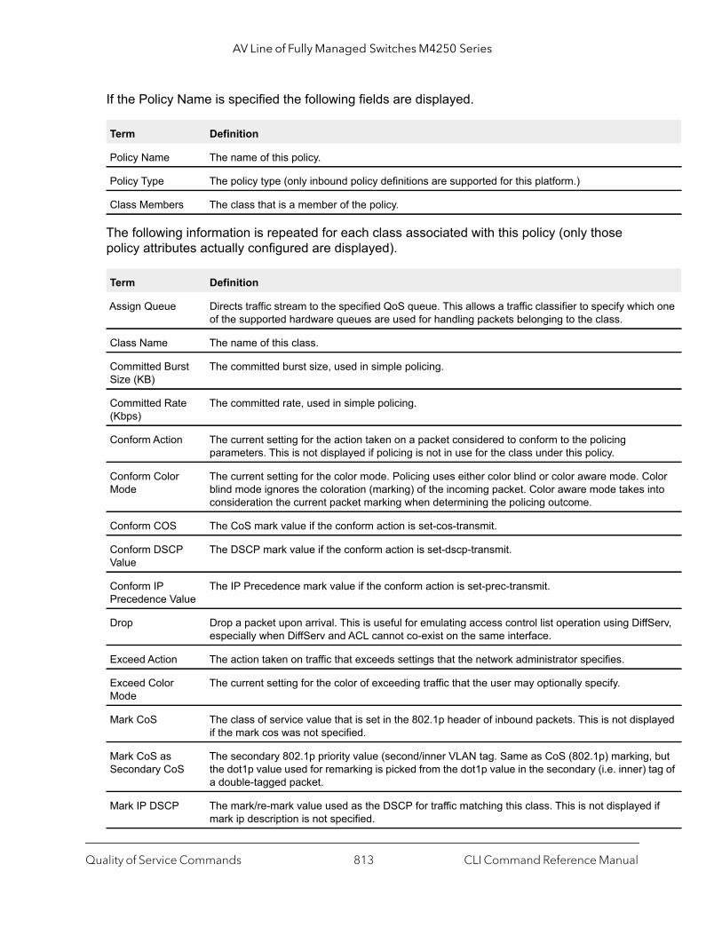
AV Line of Fully Managed Switches M4250 Series
h one
olor into
Serv,
layed
, but tag of
if
If the Policy Name is specified the following fields are displayed.
The following information is repeated for each class associated with this policy (only those policy attributes actually configured are displayed).
Term Definition
Policy Name The name of this policy.
Policy Type The policy type (only inbound policy definitions are supported for this platform.)
Class Members The class that is a member of the policy.
Term Definition
Assign Queue Directs traffic stream to the specified QoS queue. This allows a traffic classifier to specify whicof the supported hardware queues are used for handling packets belonging to the class.
Class Name The name of this class.
Committed Burst Size (KB)
The committed burst size, used in simple policing.
Committed Rate (Kbps)
The committed rate, used in simple policing.
Conform Action The current setting for the action taken on a packet considered to conform to the policing parameters. This is not displayed if policing is not in use for the class under this policy.
Conform Color Mode
The current setting for the color mode. Policing uses either color blind or color aware mode. Cblind mode ignores the coloration (marking) of the incoming packet. Color aware mode takes consideration the current packet marking when determining the policing outcome.
Conform COS The CoS mark value if the conform action is set-cos-transmit.
Conform DSCP Value
The DSCP mark value if the conform action is set-dscp-transmit.
Conform IP Precedence Value
The IP Precedence mark value if the conform action is set-prec-transmit.
Drop Drop a packet upon arrival. This is useful for emulating access control list operation using Diffespecially when DiffServ and ACL cannot co-exist on the same interface.
Exceed Action The action taken on traffic that exceeds settings that the network administrator specifies.
Exceed Color Mode
The current setting for the color of exceeding traffic that the user may optionally specify.
Mark CoS The class of service value that is set in the 802.1p header of inbound packets. This is not dispif the mark cos was not specified.
Mark CoS as Secondary CoS
The secondary 802.1p priority value (second/inner VLAN tag. Same as CoS (802.1p) markingthe dot1p value used for remarking is picked from the dot1p value in the secondary (i.e. inner) a double-tagged packet.
Mark IP DSCP The mark/re-mark value used as the DSCP for traffic matching this class. This is not displayedmark ip description is not specified.
Quality of Service Commands CLI Command Reference Manual813

AV Line of Fully Managed Switches M4250 Series
cur in
the r
be
ds
cur in
me
If the Policy Name is not specified this command displays a list of all defined DiffServ policies. The following fields are displayed.
Command example:
The following example includes the mark-cos-as-sec-cos option that is specified in the policy action.(NETGEAR Switch) #show policy-map p1 Policy Name.................................... p1Policy Type.................................... In
Mark IP Precedence
The mark/re-mark value used as the IP Precedence for traffic matching this class. This is not displayed if mark ip precedence is not specified.
Mirror Copies a classified traffic stream to a specified egress port (physical port or LAG). This can ocaddition to any marking or policing action. It may also be specified along with a QoS queue assignment.
Non-Conform Action
The current setting for the action taken on a packet considered to not conform to the policing parameters. This is not displayed if policing not in use for the class under this policy.
Non-Conform COS The CoS mark value if the non-conform action is set-cos-transmit.
Non-Conform DSCP Value
The DSCP mark value if the non-conform action is set-dscp-transmit.
Non-Conform IP Precedence Value
The IP Precedence mark value if the non-conform action is set-prec-transmit.
Peak Rate Guarantees a committed rate for transmission, but also transmits excess traffic bursts up to a user-specified peak rate, with the understanding that a downstream network element (such asnext hop’s policer) might drop this excess traffic. Traffic is held in queue until it is transmitted odropped (per type of queue depth management.) Peak rate shaping can be configured for the outgoing transmission stream for an AP traffic class (although average rate shaping could alsoused.)
Peak Burst Size (PBS). The network administrator can set the PBS as a means to limit the damage expedited forwarding traffic could inflict on other traffic (e.g., a token bucket rate limiter) Traffic that exceethis limit is discarded.
Policing Style The style of policing, if any, used (simple).
Redirect Forces a classified traffic stream to a specified egress port (physical port or LAG). This can ocaddition to any marking or policing action. It may also be specified along with a QoS queue assignment.
Term Definition
Policy Name The name of this policy. (The order in which the policies are displayed is not necessarily the saorder in which they were created.)
Policy Type The policy type (Only inbound is supported).
Class Members List of all class names associated with this policy.
Term Definition
Quality of Service Commands CLI Command Reference Manual814

AV Line of Fully Managed Switches M4250 Series
an
Class Name..................................... c1 Mark CoS as Secondary CoS...................... Yes
Command example:
The following example includes the mark-cos-as-sec-cos action that is used in the policing (simple-police, police-single-rate, police two-rate) command.(NETGEAR Switch) #show policy-map p2 Policy Name....................... p2 Policy Type....................... In Class Name........................ c2 Policing Style.................... Police Two Rate Committed Rate.................... 1 Committed Burst Size.............. 1 Peak Rate......................... 1 Peak Burst Size................... 1 Conform Action.................... Mark CoS as Secondary CoS Exceed Action..................... Mark CoS as Secondary CoS Non-Conform Action................ Mark CoS as Secondary CoS Conform Color Mode................ Blind Exceed Color Mode................. Blind
show diffserv serviceThis command displays policy service information for the specified interface and direction. The unit/port parameter specifies a valid unit/port number for the system.
Format show diffserv service unit/port in
Mode Privileged EXEC
Term Definition
DiffServ Admin Mode
The current setting of the DiffServ administrative mode. An attached policy is only in effect on interface while DiffServ is in an enabled mode.
Interface unit/port
Direction The traffic direction of this interface service.
Operational Status The current operational status of this DiffServ service interface.
Policy Name The name of the policy attached to the interface in the indicated direction.
Policy Details Attached policy details, whose content is identical to that described for the show policy-map policymapname command (content not repeated here for brevity).
Quality of Service Commands CLI Command Reference Manual815
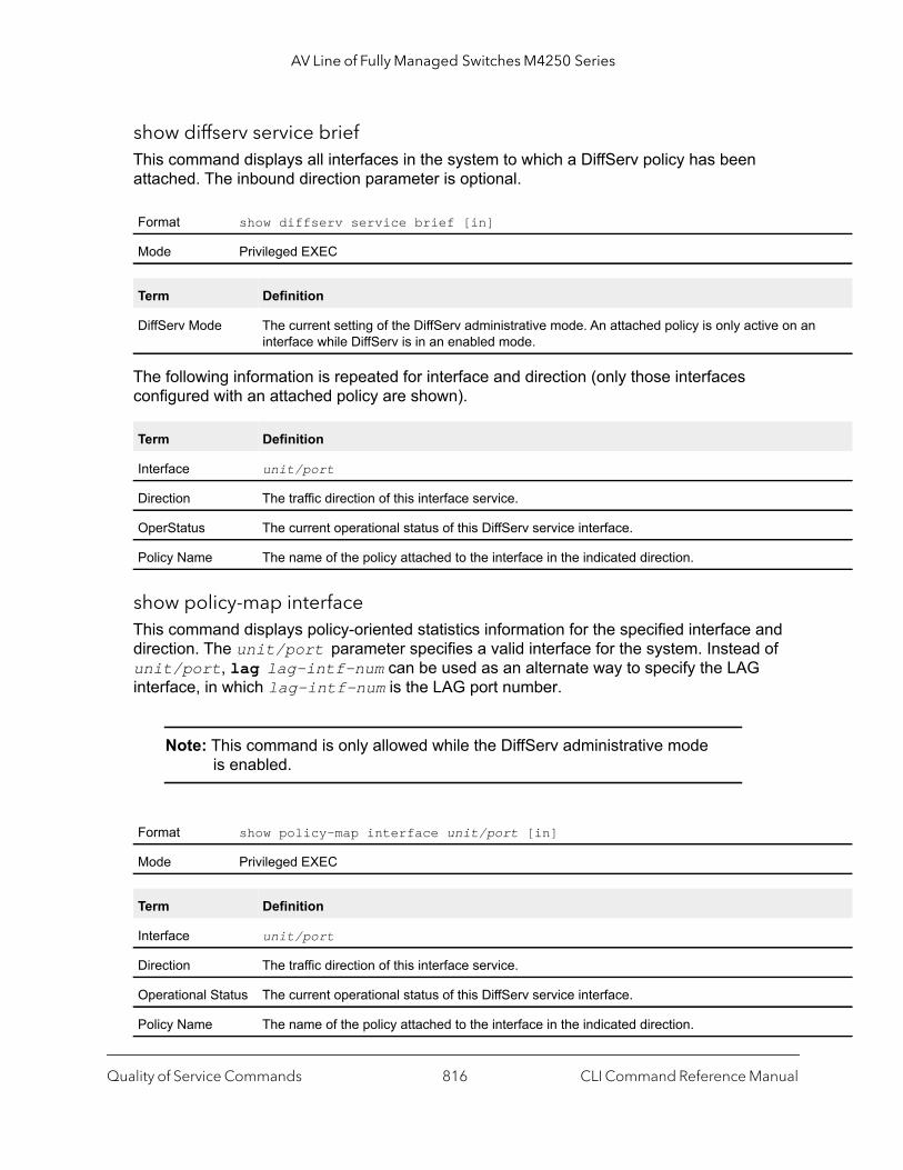
AV Line of Fully Managed Switches M4250 Series
show diffserv service briefThis command displays all interfaces in the system to which a DiffServ policy has been attached. The inbound direction parameter is optional.
The following information is repeated for interface and direction (only those interfaces configured with an attached policy are shown).
show policy-map interfaceThis command displays policy-oriented statistics information for the specified interface and direction. The unit/port parameter specifies a valid interface for the system. Instead of unit/port, lag lag-intf-num can be used as an alternate way to specify the LAG interface, in which lag-intf-num is the LAG port number.
Note: This command is only allowed while the DiffServ administrative mode is enabled.
Format show diffserv service brief [in]
Mode Privileged EXEC
Term Definition
DiffServ Mode The current setting of the DiffServ administrative mode. An attached policy is only active on aninterface while DiffServ is in an enabled mode.
Term Definition
Interface unit/port
Direction The traffic direction of this interface service.
OperStatus The current operational status of this DiffServ service interface.
Policy Name The name of the policy attached to the interface in the indicated direction.
Format show policy-map interface unit/port [in]
Mode Privileged EXEC
Term Definition
Interface unit/port
Direction The traffic direction of this interface service.
Operational Status The current operational status of this DiffServ service interface.
Policy Name The name of the policy attached to the interface in the indicated direction.
Quality of Service Commands CLI Command Reference Manual816

AV Line of Fully Managed Switches M4250 Series
nt of
The following information is repeated for each class instance within this policy:
show service-policyThis command displays a summary of policy-oriented statistics information for all interfaces in the specified direction.
The following information is repeated for each interface and direction (only those interfaces configured with an attached policy are shown):
MAC Access Control List CommandsThis section describes the commands you use to configure MAC Access Control List (ACL) settings. MAC ACLs ensure that only authorized users have access to specific resources and block any unwarranted attempts to reach network resources.
The following rules apply to MAC ACLs:
• The maximum number of ACLs you can create is hardware dependent. The limit applies to all ACLs, regardless of type.
• The system supports only Ethernet II frame types.• The maximum number of rules per MAC ACL is hardware dependent.
mac access-list extended This command creates a MAC Access Control List (ACL) identified by name, consisting of classification fields defined for the Layer 2 header of an Ethernet frame. The name parameter is a case-sensitive alphanumeric string from 1 to 31 characters uniquely identifying the MAC access list. The rate-limit attribute configures the committed rate and the committed burst size.
Term Definition
Class Name The name of this class instance.
In Discarded Packets
A count of the packets discarded for this class instance for any reason due to DiffServ treatmethe traffic class.
Format show service-policy {in | out}
Mode Privileged EXEC
Term Definition
Interface unit/port
Operational Status The current operational status of this DiffServ service interface.
Policy Name The name of the policy attached to the interface.
Quality of Service Commands CLI Command Reference Manual817
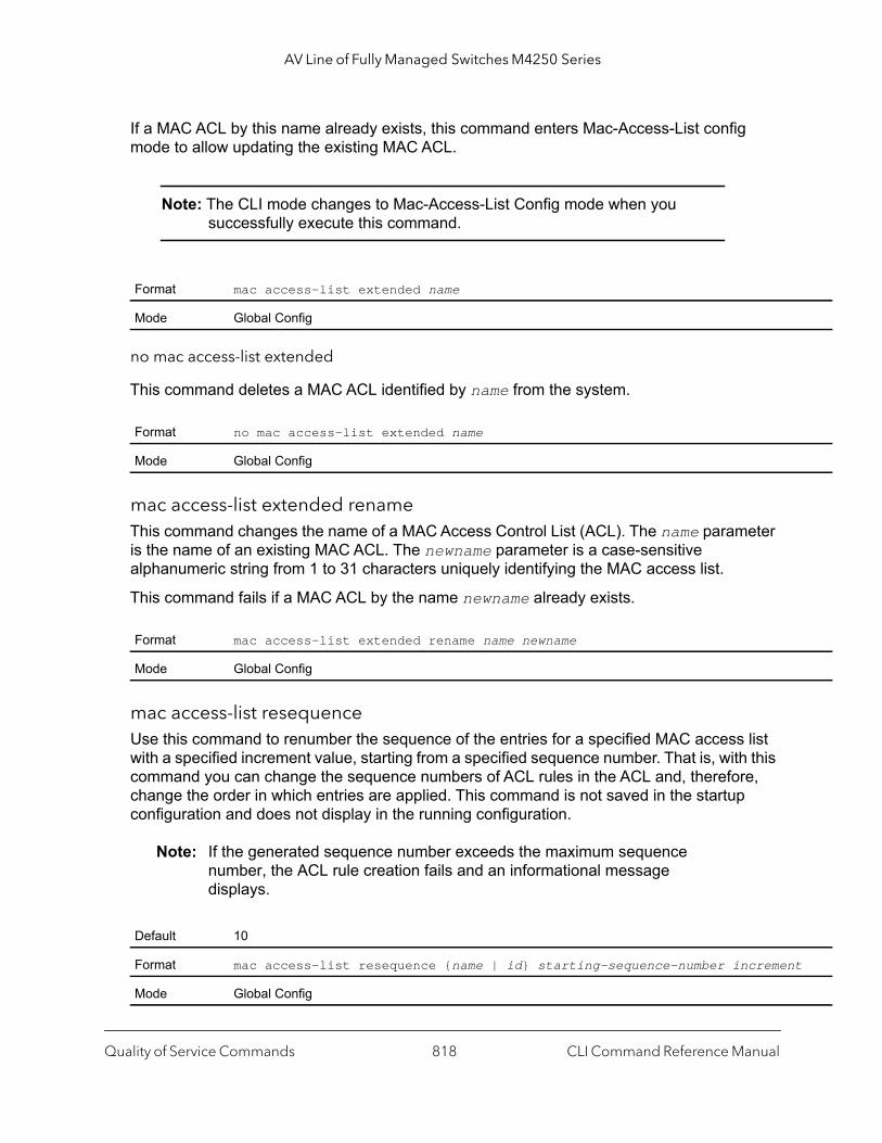
AV Line of Fully Managed Switches M4250 Series
t
If a MAC ACL by this name already exists, this command enters Mac-Access-List config mode to allow updating the existing MAC ACL.
Note: The CLI mode changes to Mac-Access-List Config mode when you successfully execute this command.
no mac access-list extended
This command deletes a MAC ACL identified by name from the system.
mac access-list extended rename This command changes the name of a MAC Access Control List (ACL). The name parameter is the name of an existing MAC ACL. The newname parameter is a case-sensitive alphanumeric string from 1 to 31 characters uniquely identifying the MAC access list.
This command fails if a MAC ACL by the name newname already exists.
mac access-list resequenceUse this command to renumber the sequence of the entries for a specified MAC access list with a specified increment value, starting from a specified sequence number. That is, with this command you can change the sequence numbers of ACL rules in the ACL and, therefore, change the order in which entries are applied. This command is not saved in the startup configuration and does not display in the running configuration.
Note: If the generated sequence number exceeds the maximum sequence number, the ACL rule creation fails and an informational message displays.
Format mac access-list extended name
Mode Global Config
Format no mac access-list extended name
Mode Global Config
Format mac access-list extended rename name newname
Mode Global Config
Default 10
Format mac access-list resequence {name | id} starting-sequence-number incremen
Mode Global Config
Quality of Service Commands CLI Command Reference Manual818
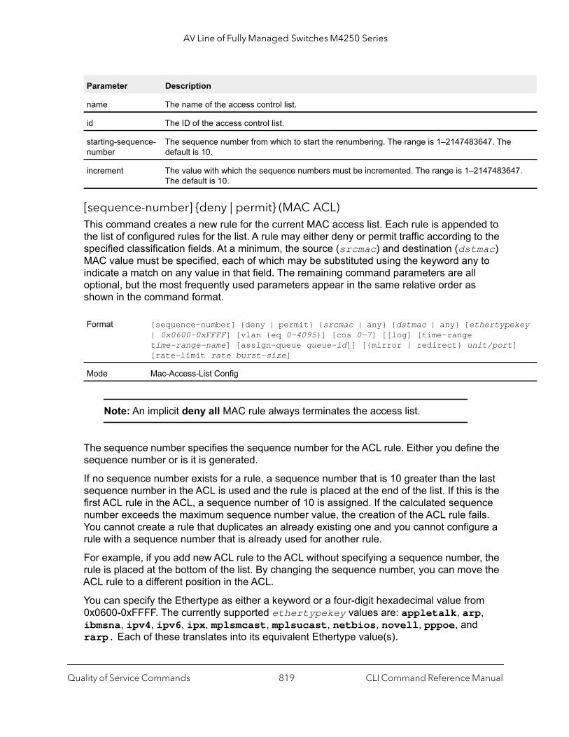
AV Line of Fully Managed Switches M4250 Series
47.
key
]
[sequence-number] {deny | permit} (MAC ACL)This command creates a new rule for the current MAC access list. Each rule is appended to the list of configured rules for the list. A rule may either deny or permit traffic according to the specified classification fields. At a minimum, the source (srcmac) and destination (dstmac) MAC value must be specified, each of which may be substituted using the keyword any to indicate a match on any value in that field. The remaining command parameters are all optional, but the most frequently used parameters appear in the same relative order as shown in the command format.
Note: An implicit deny all MAC rule always terminates the access list.
The sequence number specifies the sequence number for the ACL rule. Either you define the sequence number or is it is generated.
If no sequence number exists for a rule, a sequence number that is 10 greater than the last sequence number in the ACL is used and the rule is placed at the end of the list. If this is the first ACL rule in the ACL, a sequence number of 10 is assigned. If the calculated sequence number exceeds the maximum sequence number value, the creation of the ACL rule fails. You cannot create a rule that duplicates an already existing one and you cannot configure a rule with a sequence number that is already used for another rule.
For example, if you add new ACL rule to the ACL without specifying a sequence number, the rule is placed at the bottom of the list. By changing the sequence number, you can move the ACL rule to a different position in the ACL.
You can specify the Ethertype as either a keyword or a four-digit hexadecimal value from 0x0600-0xFFFF. The currently supported ethertypekey values are: appletalk, arp, ibmsna, ipv4, ipv6, ipx, mplsmcast, mplsucast, netbios, novell, pppoe, and rarp. Each of these translates into its equivalent Ethertype value(s).
Parameter Description
name The name of the access control list.
id The ID of the access control list.
starting-sequence-number
The sequence number from which to start the renumbering. The range is 1–2147483647. Thedefault is 10.
increment The value with which the sequence numbers must be incremented. The range is 1–21474836The default is 10.
Format [sequence-number] {deny | permit} {srcmac | any} {dstmac | any} [ethertype| 0x0600-0xFFFF] [vlan {eq 0-4095}] [cos 0-7] [[log] [time-range time-range-name] [assign-queue queue-id]] [{mirror | redirect} unit/port[rate-limit rate burst-size]
Mode Mac-Access-List Config
Quality of Service Commands CLI Command Reference Manual819

AV Line of Fully Managed Switches M4250 Series
The vlan and cos parameters refer to the VLAN identifier and 802.1p user priority fields, respectively, of the VLAN tag. For packets containing a double VLAN tag, this is the first (or outer) tag.
The time-range parameter allows imposing time limitation on the MAC ACL rule as defined by the parameter time-range-name. If a time range with the specified name does not exist and the MAC ACL containing this ACL rule is applied to an interface or bound to a VLAN, then the ACL rule is applied immediately. If a time range with specified name exists and the MAC ACL containing this ACL rule is applied to an interface or bound to a VLAN, then the ACL rule is applied when the time-range with specified name becomes active. The ACL rule is removed when the time-range with specified name becomes inactive. For information about configuring time ranges, see Time Range Commands for Time-Based ACLs on page 851.
The assign-queue parameter allows specification of a particular hardware queue for handling traffic that matches this rule. The allowed queue-id value is 0-(n-1), in which n is the number of user configurable queues available for the hardware platform. The assign-queue parameter is valid only for a permit rule.
The mirror parameter allows the traffic matching this rule to be copied to the specified unit/port, while the redirect parameter allows the traffic matching this rule to be forwarded to the specified unit/port. The assign-queue and redirect parameters are only valid for a permit rule.
Table 9. Ethertype keyword and 4-digit hexadecimal value
Ethertype Keyword Corresponding Value
appletalk 0x809B
arp 0x0806
ibmsna 0x80D5
ipv4 0x0800
ipv6 0x86DD
ipx 0x8037
mplsmcast 0x8848
mplsucast 0x8847
netbios 0x8191
novell 0x8137, 0x8138
pppoe 0x8863, 0x8864
rarp 0x8035
Quality of Service Commands CLI Command Reference Manual820

AV Line of Fully Managed Switches M4250 Series
Note: The special command form {deny | permit} any any is used to match all Ethernet layer 2 packets, and is the equivalent of the IP access list “match every” rule.
The permit command’s optional attribute rate-limit allows you to permit only the allowed rate of traffic as per the configured rate in kbps, and burst-size in kbytes.
Command example: (NETGEAR Switch) (Config)#mac access-list extended mac1(NETGEAR Switch) (Config-mac-access-list)#permit 00:00:00:00:aa:bb ff:ff:ff:ff:00:00 any rate-limit 32 16(NETGEAR Switch) (Config-mac-access-list)#exit
no sequence-number (MAC ACL)
Use this command to remove the ACL rule with the specified sequence number from the ACL.
mac access-groupThis command either attaches a specific MAC Access Control List (ACL) identified by name to an interface or range of interfaces, or associates it with a VLAN ID, in a given direction. The name parameter must be the name of an existing MAC ACL.
An optional sequence number may be specified to indicate the order of this mac access list relative to other mac access lists already assigned to this interface and direction. A lower number indicates higher precedence order. If a sequence number is already in use for this interface and direction, the specified mac access list replaces the currently attached mac access list using that sequence number. If the sequence number is not specified for this command, a sequence number that is one greater than the highest sequence number currently in use for this interface and direction is used.
This command specified in Interface Config mode only affects a single interface, whereas the Global Config mode setting is applied to all interfaces. The vlan keyword and vlan-id argument are valid only in the Global Config mode. The Interface Config mode command is only available on platforms that support independent per-port class of service queue configuration.
An optional control-plane is specified to apply the MAC ACL on CPU port. The control packets like BPDU are also dropped because of the implicit deny all rule added to the end of the list. To overcome this, permit rules must be added to allow the control packets.
Format no sequence-number
Modes MAC-Access-List Config
Quality of Service Commands CLI Command Reference Manual821

AV Line of Fully Managed Switches M4250 Series
}}
IP
ut}}
Note: The control-plane keyword is available only in Global Config mode.
Note: Depending on the platform, the out option might not be available.
(NETGEAR Switch)(Config)#mac access-group mac1 control-plane
no mac access-group
This command removes a MAC ACL identified by name from the interface in a given direction.
Command example: (NETGEAR Switch)(Config)#no mac access-group mac1 control-plane
remarkThis command adds a new comment to an ACL rule.
Use the remark keyword to add comments (remarks) to an ACL rule entry that belongs to an IPv4, IPv6, MAC, or ARP ACL. You can add up to 10 * (maximum number of ACL rules per list) remarks per ACL and up to 10 remarks per ACL rule. For all QoS ACLs (IPv4, IPv6, and MAC ACLs) together, you can up to add 2 * (maximum number of ACL rules).
Format mac access-group name {{control-plane | in | out} vlan vlan-id {in | out[sequence 1–4294967295]
Modes Global ConfigInterface Config
Parameter Description
name The name of the Access Control List.
vlan-id A VLAN ID associated with a specific IP ACL in a given direction.
sequence A optional sequence number that indicates the order of this IP access list relative to the other access lists already assigned to this interface and direction. The range is 1 to 4294967295.
Format no mac access-group name {{control-plane | in | out} vlan vlan-id {in | o
Modes Global ConfigInterface Config
Quality of Service Commands CLI Command Reference Manual822
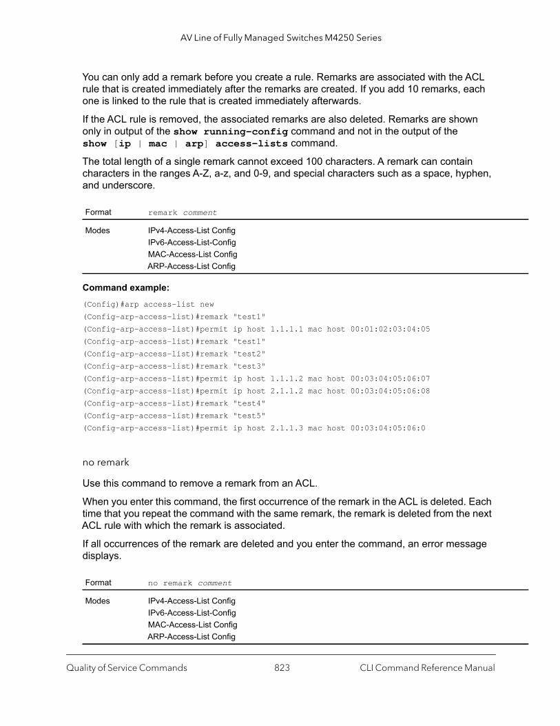
AV Line of Fully Managed Switches M4250 Series
You can only add a remark before you create a rule. Remarks are associated with the ACL rule that is created immediately after the remarks are created. If you add 10 remarks, each one is linked to the rule that is created immediately afterwards.
If the ACL rule is removed, the associated remarks are also deleted. Remarks are shown only in output of the show running-config command and not in the output of the show [ip | mac | arp] access-lists command.
The total length of a single remark cannot exceed 100 characters. A remark can contain characters in the ranges A-Z, a-z, and 0-9, and special characters such as a space, hyphen, and underscore.
Command example: (Config)#arp access-list new(Config-arp-access-list)#remark "test1"(Config-arp-access-list)#permit ip host 1.1.1.1 mac host 00:01:02:03:04:05(Config-arp-access-list)#remark "test1"(Config-arp-access-list)#remark "test2"(Config-arp-access-list)#remark "test3"(Config-arp-access-list)#permit ip host 1.1.1.2 mac host 00:03:04:05:06:07(Config-arp-access-list)#permit ip host 2.1.1.2 mac host 00:03:04:05:06:08(Config-arp-access-list)#remark "test4"(Config-arp-access-list)#remark "test5"(Config-arp-access-list)#permit ip host 2.1.1.3 mac host 00:03:04:05:06:0
no remark
Use this command to remove a remark from an ACL.
When you enter this command, the first occurrence of the remark in the ACL is deleted. Each time that you repeat the command with the same remark, the remark is deleted from the next ACL rule with which the remark is associated.
If all occurrences of the remark are deleted and you enter the command, an error message displays.
Format remark comment
Modes IPv4-Access-List ConfigIPv6-Access-List-ConfigMAC-Access-List ConfigARP-Access-List Config
Format no remark comment
Modes IPv4-Access-List ConfigIPv6-Access-List-ConfigMAC-Access-List ConfigARP-Access-List Config
Quality of Service Commands CLI Command Reference Manual823

AV Line of Fully Managed Switches M4250 Series
show mac access-listsThis command displays summary information for all MAC access lists and shows the number of packets that match a configured ACL rule within an ACL (referred to as ACL hit count).
To view more detailed information about a specific access list, specify the ACL name that is used to identify the MAC ACL.
Note: The command output varies based on the match criteria configured within the rules of an ACL.
Format show mac access-lists [name]
Mode Privileged EXEC
Term Definition
Rule Number The ordered rule number identifier defined within the MAC ACL.
Action The action associated with each rule. The possible values are Permit or Deny.
Source MAC Address
The source MAC address for this rule.
Source MAC Mask The source MAC mask for this rule.
Committed Rate The committed rate defined by the rate-limit attribute.
Committed Burst Size
The committed burst size defined by the rate-limit attribute.
Destination MAC Address
The destination MAC address for this rule.
Ethertype The Ethertype keyword or custom value for this rule.
VLAN ID The VLAN identifier value or range for this rule.
COS The COS (802.1p) value for this rule.
Log Displays when you enable logging for the rule.
Assign Queue The queue identifier to which packets matching this rule are assigned.
Mirror Interface The unit/port to which packets matching this rule are copied.
Redirect Interface The unit/port to which packets matching this rule are forwarded.
Time Range Name Displays the name of the time-range if the MAC ACL rule has referenced a time range.
Quality of Service Commands CLI Command Reference Manual824
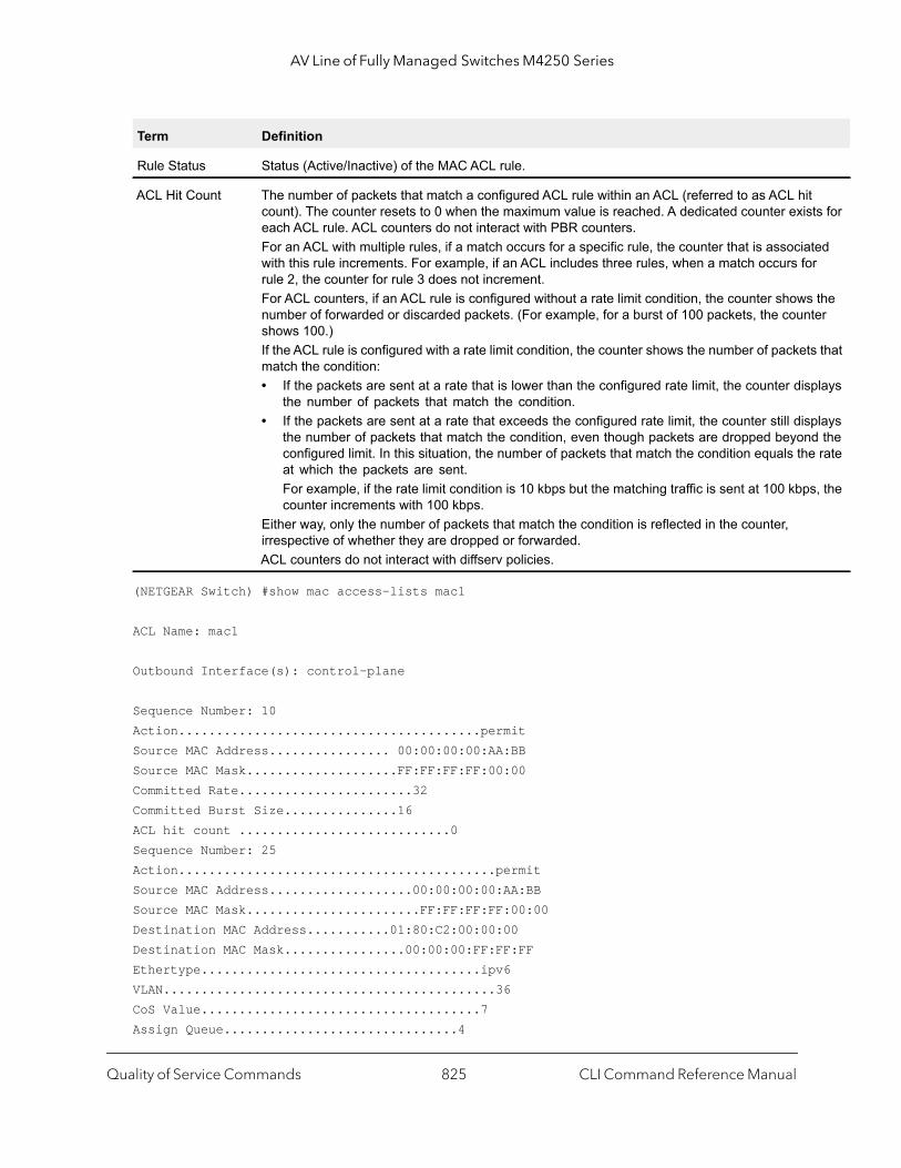
AV Line of Fully Managed Switches M4250 Series
t ts for
ted r
the ter
s that
plays
plays d the e rate
s, the
(NETGEAR Switch) #show mac access-lists mac1
ACL Name: mac1
Outbound Interface(s): control-plane
Sequence Number: 10Action........................................permitSource MAC Address................ 00:00:00:00:AA:BBSource MAC Mask....................FF:FF:FF:FF:00:00Committed Rate.......................32Committed Burst Size...............16ACL hit count ............................0Sequence Number: 25Action..........................................permitSource MAC Address...................00:00:00:00:AA:BBSource MAC Mask.......................FF:FF:FF:FF:00:00Destination MAC Address...........01:80:C2:00:00:00Destination MAC Mask................00:00:00:FF:FF:FFEthertype.....................................ipv6VLAN............................................36CoS Value.....................................7Assign Queue...............................4
Rule Status Status (Active/Inactive) of the MAC ACL rule.
ACL Hit Count The number of packets that match a configured ACL rule within an ACL (referred to as ACL hicount). The counter resets to 0 when the maximum value is reached. A dedicated counter exiseach ACL rule. ACL counters do not interact with PBR counters.For an ACL with multiple rules, if a match occurs for a specific rule, the counter that is associawith this rule increments. For example, if an ACL includes three rules, when a match occurs forule 2, the counter for rule 3 does not increment.For ACL counters, if an ACL rule is configured without a rate limit condition, the counter showsnumber of forwarded or discarded packets. (For example, for a burst of 100 packets, the counshows 100.)If the ACL rule is configured with a rate limit condition, the counter shows the number of packetmatch the condition:• If the packets are sent at a rate that is lower than the configured rate limit, the counter dis
the number of packets that match the condition.• If the packets are sent at a rate that exceeds the configured rate limit, the counter still dis
the number of packets that match the condition, even though packets are dropped beyonconfigured limit. In this situation, the number of packets that match the condition equals that which the packets are sent.For example, if the rate limit condition is 10 kbps but the matching traffic is sent at 100 kbpcounter increments with 100 kbps.
Either way, only the number of packets that match the condition is reflected in the counter, irrespective of whether they are dropped or forwarded.ACL counters do not interact with diffserv policies.
Term Definition
Quality of Service Commands CLI Command Reference Manual825

AV Line of Fully Managed Switches M4250 Series
d}]
Redirect Interface........................0/34Committed Rate...........................32Committed Burst Size..................16ACL hit count ...............................0
IP Access Control List Commands
This section describes the commands you use to configure IP Access Control List (ACL) settings. IP ACLs ensure that only authorized users have access to specific resources and block any unwarranted attempts to reach network resources.
The following rules apply to IP ACLs:
• The maximum number of ACLs you can create is hardware dependent. The limit applies to all ACLs, regardless of type.
• The maximum number of rules per IP ACL is hardware dependent.• If you configure a MAC ACL on an interface, you cannot configure an IP ACL on the same
interface.• Wildcard masking for ACLs operates differently from a subnet mask. A wildcard mask is
in essence the inverse of a subnet mask. With a subnet mask, the mask has ones (1's) in the bit positions that are used for the network address, and has zeros (0's) for the bit positions that are not used. In contrast, a wildcard mask has (0’s) in a bit position that must be checked. A 1 in a bit position of the ACL mask indicates the corresponding bit can be ignored.
access-listThis command creates an IP Access Control List (ACL) that is identified by the access list number, which is 1-99 for standard ACLs or 100-199 for extended ACLs. The table with parameters and descriptions on page 827 describes the parameters for the access-list command.
IP Standard ACL:
Format access-list 1-99 {remark comment} | {[sequence-number]}] {deny | permit}{every | srcip srcmask | host srcip} [time-range time-range-name] [log] [assign-queue queue-id] [{mirror | redirect} {unit/port | lag lag-group-i[rate-limit rate burst-size]
Mode Global Config
Quality of Service Commands CLI Command Reference Manual826
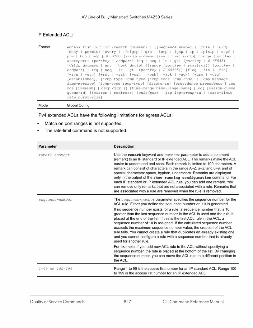
AV Line of Fully Managed Switches M4250 Series
f | y |
y |
tos eue it
t ACL rs. A of
ed . For
You s that
r the .0 e is
er CL one dy
ging ion in
e 100
IP Extended ACL:
IPv4 extended ACLs have the following limitations for egress ACLs:
• Match on port ranges is not supported.• The rate-limit command is not supported.
Format access-list 100-199 {remark comment} | {[sequence-number]} [rule 1-1023]{deny | permit} {every | {{eigrp | gre | icmp | igmp | ip | ipinip | osppim | tcp | udp | 0 -255} {srcip srcmask |any | host srcip} [range {portkestartport} {portkey | endport} {eq | neq | lt | gt} {portkey | 0-65535} {dstip dstmask | any | host dstip} [{range {portkey | startport} {portkeendport} | {eq | neq | lt | gt} {portkey | 0-65535}] [flag [+fin | -fin][+syn | -syn] [+rst | -rst] [+psh | -psh] [+ack | -ack] [+urg | -urg] [established]] [icmp-type icmp-type [icmp-code icmp-code] | icmp-messageicmp-message] [igmp-type igmp-type] [fragments] [precedence precedence | tos [tosmask] | dscp dscp]}} [time-range time-range-name] [log] [assign-ququeue-id] [{mirror | redirect} {unit/port | lag lag-group-id}] [rate-limrate burst-size]
Mode Global Config
Parameter Description
remark comment Use the remark keyword and comment parameter to add a commen(remark) to an IP standard or IP extended ACL. The remarks make theeasier to understand and scan. Each remark is limited to 100 characteremark can consist of characters in the range A–Z, a–z, and 0–9, andspecial characters: space, hyphen, underscore. Remarks are displayonly in the output of the show running configuration commandeach IP standard or IP extended ACL rule, you can add one remark. can remove only remarks that are not associated with a rule. Remarkare associated with a rule are removed when the rule is removed.
sequence-number The sequence-number parameter specifies the sequence number foACL rule. Either you define the sequence number or is it is generatedIf no sequence number exists for a rule, a sequence number that is 1greater than the last sequence number in the ACL is used and the rulplaced at the end of the list. If this is the first ACL rule in the ACL, a sequence number of 10 is assigned. If the calculated sequence numbexceeds the maximum sequence number value, the creation of the Arule fails. You cannot create a rule that duplicates an already existingand you cannot configure a rule with a sequence number that is alreaused for another rule. For example, if you add new ACL rule to the ACL without specifying asequence number, the rule is placed at the bottom of the list. By chanthe sequence number, you can move the ACL rule to a different positthe ACL.
1-99 or 100-199 Range 1 to 99 is the access list number for an IP standard ACL. Rangto 199 is the access list number for an IP extended ACL.
Quality of Service Commands CLI Command Reference Manual827

AV Line of Fully Managed Switches M4250 Series
and
n of
s
You the
net,
o.
ort
port ge. e nd all
less the
ber is
mber
ort
ents.
{deny | permit} Specifies whether the IP ACL rule permits or denies an action.
Note: For 5630x and 5650x-based systems, assign-queue, redirect, mirror attributes are configurable for a deny rule, but they have no operational effect.
every Match every packet.
{eigrp | gre | icmp | igmp | ip | ipinip | ospf | pim | tcp | udp | 0-255}
Specifies the protocol to filter for an extended IP ACL rule.
srcip srcmask | any | host scrip Specifies a source IP address and source netmask for match conditiothe IP ACL rule.Specifying any specifies srcip as 0.0.0.0 and srcmask as 255.255.255.255. Specifying host A.B.C.D specifies srcip as A.B.C.D and srcmask a0.0.0.0.
[{range {portkey | startport} {portkey | endport} | {eq | neq | lt | gt} {portkey | 0-65535}]
Note: This option is available only if the protocol is TCP or UDP.
Specifies the source layer 4 port match condition for the IP ACL rule. can use the port number, which ranges from 0-65535, or you specify portkey, which can be one of the following keywords:• For TCP: bgp, domain, echo, ftp, ftp-data, http, smtp, tel
www, pop2, or pop3. • For UDP: domain, echo, ntp, rip, snmp, tftp, time, or whFor both TCP and UDP, each of these keywords translates into its equivalent port number, which is used as both the start and end of a prange. If range is specified, the IP ACL rule matches only if the layer 4 port number falls within the specified portrange. The startport and endparameters identify the first and last ports that are part of the port ranThey have values from 0 to 65535. The ending port must have a valuequal or greater than the starting port. The starting port, ending port, aports in between will be part of the layer 4 port range.When eq is specified, the IP ACL rule matches only if the layer 4 portnumber is equal to the specified port number or portkey.When lt is specified, IP ACL rule matches if the layer 4 port number isthan the specified port number or portkey. It is equivalent to specifyingrange as 0 to <specified port number – 1>.When gt is specified, the IP ACL rule matches if the layer 4 port numgreater than the specified port number or portkey. It is equivalent to specifying the range as <specified port number + 1> to 65535.When neq is specified, IP ACL rule matches only if the layer 4 port nuis not equal to the specified port number or portkey.Two rules are added in the hardware one with range equal to 0 to <specified port number - 1> and one with range equal to <specified pnumber + 1 to 65535>.
Note: Port number matches only apply to unfragmented or first fragm
Parameter Description
Quality of Service Commands CLI Command Reference Manual828

AV Line of Fully Managed Switches M4250 Series
f the
ence
ACK e
fied
fied
code cho, ct,
fied
e
y. If a L rule when
. For ds for
dstip dstmask |any | host dstip Specifies a destination IP address and netmask for match condition oIP ACL rule.Specifying any implies specifying dstip as 0.0.0.0 and dstmask as255.255.255.255.Specifying host A.B.C.D implies dstip as A.B.C.D and dstmask as 0.0.0.0.
[precedence precedence | tos tos [tosmask] | dscp dscp]
Specifies the TOS for an IP ACL rule depending on a match of precedor DSCP values using the parameters precedence, tos or dscp. tosmask is an optional parameter.
flag [+fin | -fin] [+syn | -syn] [+rst | -rst] [+psh | -psh] [+ack | -ack] [+urg | -urg] [established]
Note: This option is available only if the protocol is tcp.
Specifies that the IP ACL rule matches on the TCP flags. When +<tcpflagname> is specified, a match occurs if the specified <tcpflagname> flag is set in the TCP header.When -<tcpflagname> is specified, a match occurs if the specified <tcpflagname> flag is not set in the TCP header.When established is specified, a match occurs if the specified RST orbits are set in the TCP header. Two rules are installed in the hardwarwhen the established option is specified.
[icmp-type icmp-type [icmp-code icmp-code] | icmp-message icmp-message]
Note: This option is available only if the protocol is icmp.
Specifies a match condition for ICMP packets.When icmp-type is specified, the IP ACL rule matches on the speciICMP message type, a number from 0 to 255. When icmp-code is specified, the IP ACL rule matches on the speciICMP message code, a number from 0 to 255. Specifying icmp-message implies that both icmp-type and icmp-are specified. The following icmp-message options are supported: eecho-reply, host-redirect, mobile-redirect, net-redirenet-unreachable, redirect, packet-too-big, port-unreachable, source-quench, router-solicitation, router-advertisement, time-exceeded, ttl-exceeded, andunreachable.
igmp-type igmp-type This option is available only if the protocol is igmp.When igmp-type is specified, the IP ACL rule matches on the speciIGMP message type, a number from 0 to 255.
fragments Specifies that the IP ACL rule matches on fragmented IP packets.
[log] Specifies that this rule is to be logged.
[time-range time-range-name] Allows imposing time limitation on the ACL rule as defined by the parameter time-range-name. If a time range with the specified namdoes not exist and the ACL containing this ACL rule is applied to an interface or bound to a VLAN, then the ACL rule is applied immediateltime range with specified name exists and the ACL containing this ACis applied to an interface or bound to a VLAN, the ACL rule is applied the time-range with specified name becomes active. The ACL rule is removed when the time-range with specified name becomes inactiveinformation about configuring time ranges, see Time Range CommanTime-Based ACLs on page 851.
Parameter Description
Quality of Service Commands CLI Command Reference Manual829

AV Line of Fully Managed Switches M4250 Series
kets
and
no access-list
This command deletes an IP ACL that is identified by the parameter accesslistnumber from the system. The range for accesslistnumber is 1–99 for standard access lists and 100–199 for extended access lists.
ip access-listThis command creates an extended IP Access Control List (ACL) identified by name, consisting of classification fields defined for the IP header of an IPv4 frame. The name parameter is a case-sensitive alphanumeric string from 1 to 31 characters uniquely identifying the IP access list. The rate-limit attribute configures the committed rate and the committed burst size.
If an IP ACL by this name already exists, this command enters IPv4-Access_List config mode to allow updating the existing IP ACL.
Note: The CLI mode changes to IPv4-Access-List Config mode when you successfully execute this command.
no ip access-list
This command deletes the IP ACL identified by name from the system.
[assign-queue queue-id] Specifies the assign-queue, which is the queue identifier to which pacmatching this rule are assigned.
[{mirror | redirect} {unit/port | lag lag-group-id}]
Specifies the mirror or redirect interface that is the unit/port or lag-group-id to which packets matching this rule are copied or forwarded.
[rate-limit rate burst-size] Specifies the allowed rate of traffic as per the configured rate in kbps,burst-size in kbytes.
Format no access-list accesslistnumber
Mode Global Config
Format ip access-list name
Mode Global Config
Format no ip access-list name
Mode Global Config
Parameter Description
Quality of Service Commands CLI Command Reference Manual830
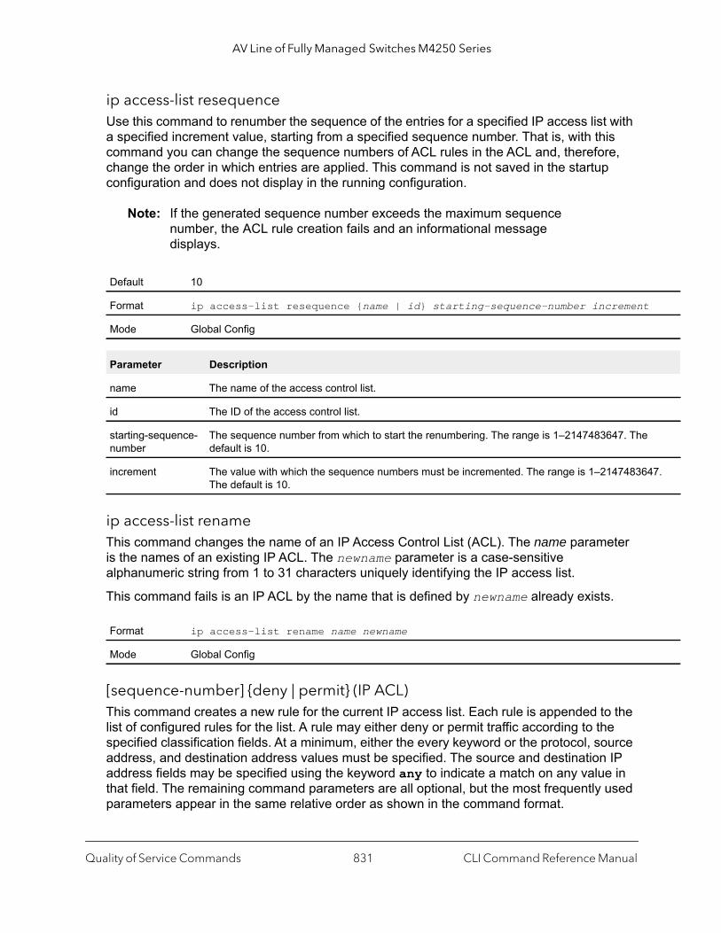
AV Line of Fully Managed Switches M4250 Series
47.
ip access-list resequenceUse this command to renumber the sequence of the entries for a specified IP access list with a specified increment value, starting from a specified sequence number. That is, with this command you can change the sequence numbers of ACL rules in the ACL and, therefore, change the order in which entries are applied. This command is not saved in the startup configuration and does not display in the running configuration.
Note: If the generated sequence number exceeds the maximum sequence number, the ACL rule creation fails and an informational message displays.
ip access-list renameThis command changes the name of an IP Access Control List (ACL). The name parameter is the names of an existing IP ACL. The newname parameter is a case-sensitive alphanumeric string from 1 to 31 characters uniquely identifying the IP access list.
This command fails is an IP ACL by the name that is defined by newname already exists.
[sequence-number] {deny | permit} (IP ACL)This command creates a new rule for the current IP access list. Each rule is appended to the list of configured rules for the list. A rule may either deny or permit traffic according to the specified classification fields. At a minimum, either the every keyword or the protocol, source address, and destination address values must be specified. The source and destination IP address fields may be specified using the keyword any to indicate a match on any value in that field. The remaining command parameters are all optional, but the most frequently used parameters appear in the same relative order as shown in the command format.
Default 10
Format ip access-list resequence {name | id} starting-sequence-number increment
Mode Global Config
Parameter Description
name The name of the access control list.
id The ID of the access control list.
starting-sequence-number
The sequence number from which to start the renumbering. The range is 1–2147483647. Thedefault is 10.
increment The value with which the sequence numbers must be incremented. The range is 1–21474836The default is 10.
Format ip access-list rename name newname
Mode Global Config
Quality of Service Commands CLI Command Reference Manual831

AV Line of Fully Managed Switches M4250 Series
| udp ort} | n | code
ueue ze]
Note: An implicit deny all IP rule always terminates the access list.
Note: The mirror parameter allows the traffic matching this rule to be copied to the specified unit/port, while the redirect parameter allows the traffic matching this rule to be forwarded to the specified unit/port. The assign-queue and redirect parameters are only valid for a permit rule.
For IPv4, the following are not supported for egress ACLs:
• A match on port ranges. • The rate-limit command.
The time-range parameter allows imposing time limitation on the IP ACL rule as defined by the specified time range. If a time range with the specified name does not exist and the ACL containing this ACL rule is applied to an interface or bound to a VLAN, then the ACL rule is applied immediately. If a time range with specified name exists and the ACL containing this ACL rule is applied to an interface or bound to a VLAN, then the ACL rule is applied when the time-range with specified name becomes active. The ACL rule is removed when the time-range with specified name becomes inactive. For information about configuring time ranges, see Time Range Commands for Time-Based ACLs on page 851.
The assign-queue parameter allows specification of a particular hardware queue for handling traffic that matches this rule. The allowed queue-id value is 0-(n-1), in which n is the number of user configurable queues available for the hardware platform. The assign-queue parameter is valid only for a permit rule.
Format [sequence-number] {deny | permit} {every | {{eigrp | gre | icmp | igmp | ip | ipinip | ospf | pim | tcp| 0-255} {srcip srcmask | any | host srcip} [{range {portkey | startport} {portkey | endp| {eq | neq | lt | gt} {portkey | 0-65535}] {dstip dstmask | any | host dstip} [{range {portkeystartport} {portkey | endport} | {eq | neq | lt | gt} {portkey | 0-65535}] [flag [+fin | -fin] [+sy-syn] [+rst | -rst] [+psh | -psh] [+ack | -ack] [+urg | -urg] [established]] [icmp-type icmp-type [icmp-icmp-code] | icmp-message icmp-message] [igmp-type igmp-type] [fragments] [precedence precedence | tos tos [tosmask] | dscp dscp]}} [time-range time-range-name] [log] [assign-qqueue-id] [{mirror | redirect} {unit/port | lag lag-group-id}] [rate-limit rate burst-si
Mode Ipv4-Access-List Config
Quality of Service Commands CLI Command Reference Manual832

AV Line of Fully Managed Switches M4250 Series
mber
10 d the
in the d r
a rule figure ther
om of he
ching
h for
The permit command’s optional attribute rate-limit allows you to permit only the allowed rate of traffic as per the configured rate in kbps, and burst-size in kbytes.
Table 10. IP ACL command parameters
Parameter Description
sequence-number The sequence-number parameter specifies the sequencenumber for the ACL rule. Either you define the sequence nuor is it is generated.If no sequence number exists for a rule, a sequence that isgreater than the last sequence number in the ACL is used anrule is placed at the end of the list. If this is the first ACL ruleACL, a sequence number of 10 is assigned. If the calculatesequence number exceeds the maximum sequence numbevalue, the creation of the ACL rule fails. You cannot create that duplicates an already existing one and you cannot cona rule with a sequence number that is already used for anorule. For example, if you add new ACL rule to the ACL without specifying a sequence number, the rule is placed at the bottthe list. By changing the sequence number, you can move tACL rule to a different position in the ACL.
{deny | permit} Specifies whether the IP ACL rule permits or denies the mattraffic.
every Match every packet.
{eigrp | gre | icmp | igmp | ip | ipinip | ospf | pim | tcp | udp | 0-255}
Specifies the protocol to match for the IP ACL rule.
srcip srcmask | any | host srcip Specifies a source IP address and source netmask to matcthe IP ACL rule.Specifying “any” implies specifying srcip as “0.0.0.0” and srcmask as “255.255.255.255”.Specifying “host A.B.C.D” implies srcip as “A.B.C.D” and srcmask as “0.0.0.0”.
Quality of Service Commands CLI Command Reference Manual833
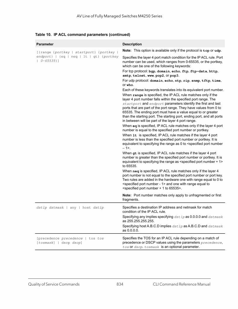
AV Line of Fully Managed Switches M4250 Series
udp.
. Port rtkey,
p,
ime,
mber.e
last 0 to er ports
4 port
rt is mber
rt . It is r + 1>
r 4 t key. o 0 to
first
mask
mask
of nce,
[{range {portkey | startport} {portkey | endport} | {eq | neq | lt | gt} {portkey | 0-65535}]
Note: This option is available only if the protocol is tcp or
Specifies the layer 4 port match condition for the IP ACL rulenumber can be used, which ranges from 0-65535, or the powhich can be one of the following keywords: For tcp protocol: bgp, domain, echo, ftp, ftp-data, httsmtp, telnet, www, pop2, or pop3.For udp protocol: domain, echo, ntp, rip, snmp, tftp, tor who.Each of these keywords translates into its equivalent port nuWhen range is specified, the IP ACL rule matches only if thlayer 4 port number falls within the specified port range. Thestartport and endport parameters identify the first andports that are part of the port range. They have values from65535. The ending port must have a value equal to or greatthan the starting port. The starting port, ending port, and allin between will be part of the layer 4 port range.When eq is specified, IP ACL rule matches only if the layer number is equal to the specified port number or portkey.When lt is specified, IP ACL rule matches if the layer 4 ponumber is less than the specified port number or portkey. It equivalent to specifying the range as 0 to <specified port nu– 1>.When gt is specified, IP ACL rule matches if the layer 4 ponumber is greater than the specified port number or portkeyequivalent to specifying the range as <specified port numbeto 65535.When neq is specified, IP ACL rule matches only if the layeport number is not equal to the specified port number or porTwo rules are added in the hardware one with range equal t<specified port number - 1> and one with range equal to <specified port number + 1 to 65535>.
Note: Port number matches only apply to unfragmented orfragments.
dstip dstmask | any | host dstip Specifies a destination IP address and netmask for match condition of the IP ACL rule.Specifying any implies specifying dstip as 0.0.0.0 and dstas 255.255.255.255.Specifying host A.B.C.D implies dstip as A.B.C.D and dstas 0.0.0.0.
[precedence precedence | tos tos [tosmask] | dscp dscp]
Specifies the TOS for an IP ACL rule depending on a matchprecedence or DSCP values using the parameters precedetos or dscp. tosmask is an optional parameter.
Table 10. IP ACL command parameters (continued)
Parameter Description
Quality of Service Commands CLI Command Reference Manual834

AV Line of Fully Managed Switches M4250 Series
fied
ied
ules
tions
,
ded,
pe
the
nted nzero the re not
by CL ule is ists ce or ge ed .
which
flag [+fin | -fin] [+syn | -syn] [+rst | -rst] [+psh | -psh] [+ack | -ack] [+urg | -urg] [established]
Specifies that the IP ACL rule matches on the tcp flags. When +<tcpflagname> is specified, a match occurs if speci<tcpflagname> flag is set in the TCP header.When -<tcpflagname> is specified, a match occurs if specif<tcpflagname> flag is NOT set in the TCP header.When established is specified, a match occurs if either the specified RST or ACK bits are set in the TCP header. Two rare installed in hardware to when the established option is specified.This option is available only if protocol is tcp.
[icmp-type icmp-type [icmp-code icmp-code] | icmp-message icmp-message]
Note: This option is available only if the protocol is ICMP.
Specifies a match condition for ICMP packets.When icmp-type is specified, IP ACL rule matches on thespecified ICMP message type, a number from 0 to 255. When icmp-code is specified, IP ACL rule matches on thespecified ICMP message code, a number from 0 to 255.Specifying icmp-message implies both icmp-type and icmp-code are specified. The following icmp-message opare supported: echo, echo-reply, host-redirect, mobile-redirect, net-redirect, net-unreachableredirect, packet-too-big, port-unreachable, source-quench, router-solicitation, router-advertisement, time-exceeded, ttl-exceeand unreachable.The ICMP message is decoded into corresponding ICMP tyand ICMP code within that ICMP type.
igmp-type igmp-type Note: This option is visible only if the protocol is IGMP.
When igmp-type is specified, the IP ACL rule matches onspecified IGMP message type, a number from 0 to 255.
fragments Specifies that the IP ACL rule matches on noninitial fragmepackets where the fragment extension header contains a nofragment offset. The fragments keyword is an option only if protocol is ipv6 and the operator port-number arguments aspecified.
log Specifies that this rule is to be logged.
time-range time-range-name Allows imposing a time limitation on the ACL rule as definedthe parameter time-range-name. If a time range with thespecified name does not exist and the ACL containing this Arule is applied to an interface or bound to a VLAN, the ACL rapplied immediately. If a time range with specified name exand the ACL containing this ACL rule is applied to an interfabound to a VLAN, the ACL rule is applied when the time-ranwith specified name becomes active. The ACL rule is removwhen the time-range with specified name becomes inactive
assign-queue queue-id Specifies the assign-queue, which is the queue identifier to packets matching this rule are assigned.
Table 10. IP ACL command parameters (continued)
Parameter Description
Quality of Service Commands CLI Command Reference Manual835

AV Line of Fully Managed Switches M4250 Series
rt or ied or
te in
Command example: (NETGEAR Switch) (Config)#ip access-list ip1
(NETGEAR Switch) (Config-ipv4-acl)#permit icmp any any rate-limit 32 16
(NETGEAR Switch) (Config-ipv4-acl)#exit
no sequence-number (IP ACL)
Use this command to remove the ACL rule with the specified sequence number from the ACL.
ip access-groupThis command either attaches a specific IP Access Control List (ACL) identified by accesslistnumber or name to an interface, range of interfaces, or all interfaces; or associates it with a VLAN ID in a given direction. The parameter name is the name of the Access Control List.
An optional sequence number may be specified to indicate the order of this IP access list relative to other IP access lists already assigned to this interface and direction. A lower number indicates higher precedence order. If a sequence number is already in use for this interface and direction, the specified access list replaces the currently attached IP access list using that sequence number. If the sequence number is not specified for this command, a sequence number that is one greater than the highest sequence number currently in use for this interface and direction is used.
An optional control-plane is specified to apply the ACL on CPU port. The IPv4 control packets like RADIUS and TACACS+ are also dropped because of the implicit deny all rule added at the end of the list. To overcome this, permit rules must be added to allow the IPv4 control packets.
[{mirror | redirect} {unit/port | lag lag-group-id}]
Specifies the mirror or redirect interface that is the unit/polag-group-id to which packets matching this rule are copforwarded.
rate-limit rate burst-size Specifies the allowed rate of traffic as per the configured rakbps, and burst-size in kbytes.
Format no sequence-number
Modes MAC-Access-List Config
Table 10. IP ACL command parameters (continued)
Parameter Description
Quality of Service Commands CLI Command Reference Manual836

AV Line of Fully Managed Switches M4250 Series
lan
IP
|
Note: The control-plane keyword is available only in Global Config mode.
Note: Depending on the platform, the out option might not be available.
(NETGEAR Switch) (Config)#ip access-group ip1 control-plane
no ip access-group
This command removes a specified IP ACL from an interface.
Command example: (NETGEAR Switch)(Config)#no ip access-group ip1 control-plane
Default none
Format ip access-group {accesslistnumber | name} {{control-plane| in | out} | vvlan-id {in | out}} [sequence 1-4294967295]
Modes Interface ConfigGlobal Config
Parameter Description
accesslistnumber Identifies a specific IP ACL. The range is 1 to 199.
name The name of the Access Control List.
vlan-id A VLAN ID associated with a specific IP ACL in a given direction.
sequence A optional sequence number that indicates the order of this IP access list relative to the other access lists already assigned to this interface and direction. The range is 1 to 4294967295.
Default none
Format no ip access-group {accesslistnumber | name} {{control-plane | in | out}vlan vlan-id {in | out}}
Mode Interface ConfigGlobal Config
Quality of Service Commands CLI Command Reference Manual837

AV Line of Fully Managed Switches M4250 Series
r
acl-trapflagsThis command enables the ACL trap mode.
no acl-trapflags
This command disables the ACL trap mode.
show ip access-listsUse this command to view summary information about all IP ACLs that are configured on the switch. To view more detailed information about a specific access list, specify the ACL number or name that is used to identify the IP ACL. The command output displays the committed rate, committed burst size, and the number of packets that match a configured ACL rule within an ACL (referred to as ACL hit count).
If you specify an IP ACL number or name, the following information displays:
Note: Only the access list fields that you configure are displayed. Thus, the command output varies based on the match criteria configured within the rules of an ACL.
Default disabled
Format acl-trapflags
Mode Global Config
Format no acl-trapflags
Mode Global Config
Format show ip access-lists [accesslistnumber | name]
Mode Privileged EXEC
Term Definition
ACL ID/Name Identifies the configured ACL number or name.
Rules Identifies the number of rules configured for the ACL.
Direction Shows whether the ACL is applied to traffic coming into the interface (ingress) oleaving the interface (egress).
Interface(s) Identifies the interface(s) to which the ACL is applied (ACL interface bindings).
VLAN(s) Identifies the VLANs to which the ACL is applied (ACL VLAN bindings).
Quality of Service Commands CLI Command Reference Manual838
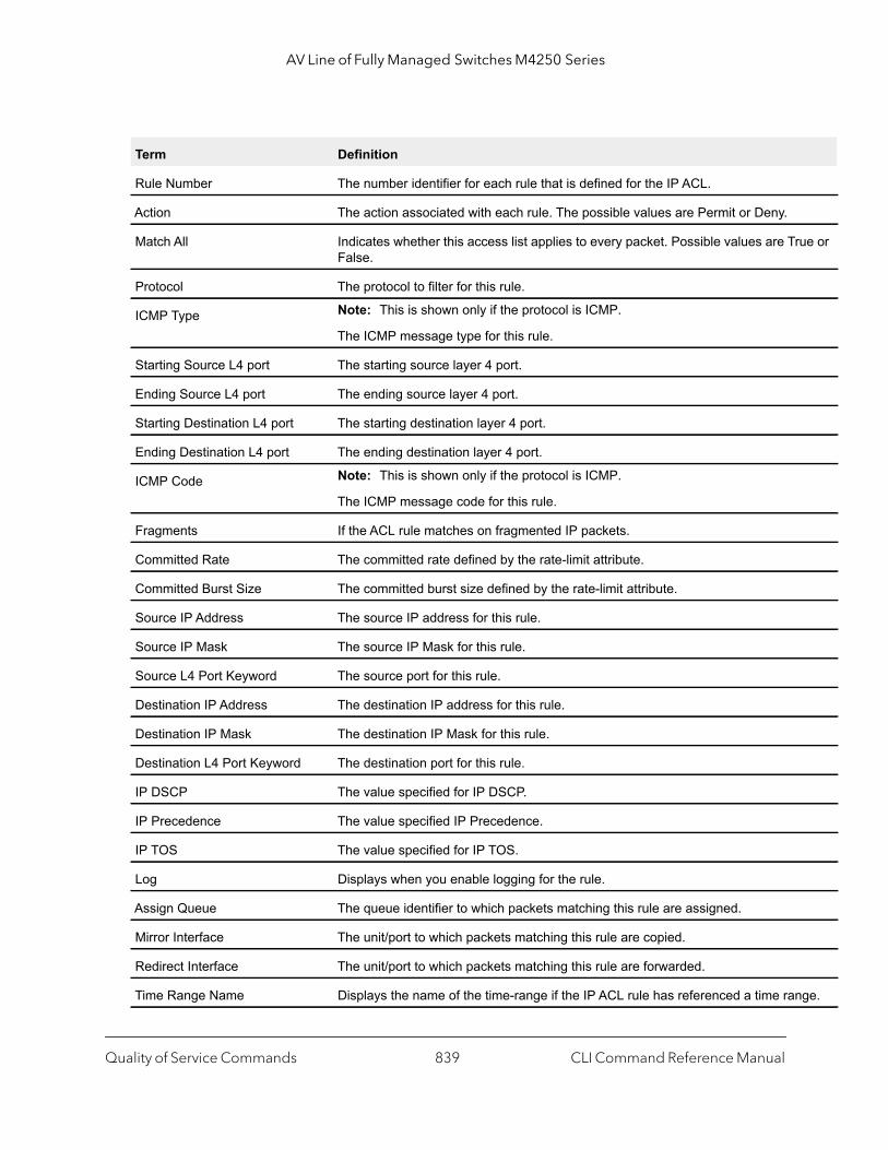
AV Line of Fully Managed Switches M4250 Series
ue or
ge.
Term Definition
Rule Number The number identifier for each rule that is defined for the IP ACL.
Action The action associated with each rule. The possible values are Permit or Deny.
Match All Indicates whether this access list applies to every packet. Possible values are TrFalse.
Protocol The protocol to filter for this rule.
ICMP Type Note: This is shown only if the protocol is ICMP.
The ICMP message type for this rule.
Starting Source L4 port The starting source layer 4 port.
Ending Source L4 port The ending source layer 4 port.
Starting Destination L4 port The starting destination layer 4 port.
Ending Destination L4 port The ending destination layer 4 port.
ICMP Code Note: This is shown only if the protocol is ICMP.
The ICMP message code for this rule.
Fragments If the ACL rule matches on fragmented IP packets.
Committed Rate The committed rate defined by the rate-limit attribute.
Committed Burst Size The committed burst size defined by the rate-limit attribute.
Source IP Address The source IP address for this rule.
Source IP Mask The source IP Mask for this rule.
Source L4 Port Keyword The source port for this rule.
Destination IP Address The destination IP address for this rule.
Destination IP Mask The destination IP Mask for this rule.
Destination L4 Port Keyword The destination port for this rule.
IP DSCP The value specified for IP DSCP.
IP Precedence The value specified IP Precedence.
IP TOS The value specified for IP TOS.
Log Displays when you enable logging for the rule.
Assign Queue The queue identifier to which packets matching this rule are assigned.
Mirror Interface The unit/port to which packets matching this rule are copied.
Redirect Interface The unit/port to which packets matching this rule are forwarded.
Time Range Name Displays the name of the time-range if the IP ACL rule has referenced a time ran
Quality of Service Commands CLI Command Reference Manual839

AV Line of Fully Managed Switches M4250 Series
to as
R
hat is ,
for a
mber
, the
unter ckets ckets
nt at
e
(NETGEAR Switch) #show ip access-lists ip1
ACL Name: ip1Inbound Interface(s): 1/0/30
Rule Number: 1Action......................................... permitMatch All...................................... FALSEProtocol....................................... 1(icmp)Committed Rate................................. 32Committed Burst Size........................... 16 ACL hit count ...............................0
show access-listsThis command displays IP ACLs, IPv6 ACLs, and MAC access control lists information for a designated interface and direction. The unit/port parameter specifies a valid interface for the system. Instead of unit/port, lag lag-intf-num can be used as an alternate way to specify the LAG interface, in which lag-intf-num is the LAG port number.
Rule Status Status (Active/Inactive) of the IP ACL rule.
ACL Hit Count The number of packets that match a configured ACL rule within an ACL (referredACL hit count). The counter resets to 0 when the maximum value is reached. A dedicated counter exists for each ACL rule. ACL counters do not interact with PBcounters.For an ACL with multiple rules, if a match occurs for a specific rule, the counter tassociated with this rule increments. For example, if an ACL includes three ruleswhen a match occurs for rule 2, the counter for rule 3 does not increment.For ACL counters, if an ACL rule is configured without a rate limit condition, the counter shows the number of forwarded and or discarded packets. (For example,burst of 100 packets, the counter shows 100.)If the ACL rule is configured with a rate limit condition, the counter shows the nuof packets that match the condition:• If the packets are sent at a rate that is lower than the configured rate limit
counter displays the number of packets that match the condition.• If the packets are sent at a rate that exceeds the configured rate limit, the co
still displays the number of packets that match the condition, even though paare dropped beyond the configured limit. In this situation, the number of pathat match the condition equals the rate at which the packets are sent. For example, if the rate limit condition is 10 kbps but the matching traffic is se100 kbps, the counter increments with 100 kbps.
Either way, only the number of packets that match the condition is reflected in thcounter, irrespective of whether they are dropped or forwarded.ACL counters do not interact with diffserv policies.
Term Definition
Quality of Service Commands CLI Command Reference Manual840
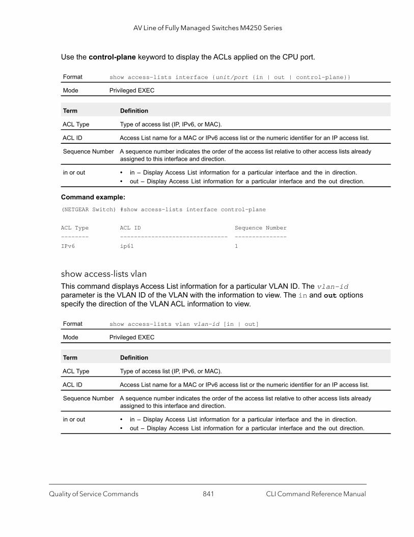
AV Line of Fully Managed Switches M4250 Series
Use the control-plane keyword to display the ACLs applied on the CPU port.
Command example: (NETGEAR Switch) #show access-lists interface control-plane
ACL Type ACL ID Sequence Number-------- ------------------------------- ---------------IPv6 ip61 1
show access-lists vlan This command displays Access List information for a particular VLAN ID. The vlan-id parameter is the VLAN ID of the VLAN with the information to view. The in and out options specify the direction of the VLAN ACL information to view.
Format show access-lists interface {unit/port {in | out | control-plane}}
Mode Privileged EXEC
Term Definition
ACL Type Type of access list (IP, IPv6, or MAC).
ACL ID Access List name for a MAC or IPv6 access list or the numeric identifier for an IP access list.
Sequence Number A sequence number indicates the order of the access list relative to other access lists alreadyassigned to this interface and direction.
in or out • in – Display Access List information for a particular interface and the in direction.• out – Display Access List information for a particular interface and the out direction.
Format show access-lists vlan vlan-id [in | out]
Mode Privileged EXEC
Term Definition
ACL Type Type of access list (IP, IPv6, or MAC).
ACL ID Access List name for a MAC or IPv6 access list or the numeric identifier for an IP access list.
Sequence Number A sequence number indicates the order of the access list relative to other access lists alreadyassigned to this interface and direction.
in or out • in – Display Access List information for a particular interface and the in direction.• out – Display Access List information for a particular interface and the out direction.
Quality of Service Commands CLI Command Reference Manual841

AV Line of Fully Managed Switches M4250 Series
IPv6 Access Control List Commands
This section describes the commands you use to configure IPv6 Access Control List (ACL) settings. IPv6 ACLs ensure that only authorized users have access to specific resources and block any unwarranted attempts to reach network resources.
The following rules apply to IPv6 ACLs:
• The maximum number of ACLs you create is 100, regardless of type.• The system supports only Ethernet II frame types.• The maximum number of rules per IPv6 ACL is hardware dependent.
ipv6 access-listThis command creates an IPv6 Access Control List (ACL) identified by name, consisting of classification fields defined for the IP header of an IPv6 frame. The name parameter is a case-sensitive alphanumeric string from 1 to 31 characters uniquely identifying the IPv6 access list. The rate-limit attribute configures the committed rate and the committed burst size.
If an IPv6 ACL by this name already exists, this command enters IPv6-Access-List config mode to allow updating the existing IPv6 ACL.
Note: The CLI mode changes to IPv6-Access-List Config mode when you successfully execute this command.
no ipv6 access-list
This command deletes the IPv6 ACL identified by name from the system.
ipv6 access-list renameThis command changes the name of an IPv6 ACL. The name parameter is the name of an existing IPv6 ACL. The newname parameter is a case-sensitive alphanumeric string from 1 to 31 characters uniquely identifying the IPv6 access list.
This command fails is an IPv6 ACL by the name that is specified by the newname argument already exists.
Format ipv6 access-list name
Mode Global Config
Format no ipv6 access-list name
Mode Global Config
Quality of Service Commands CLI Command Reference Manual842
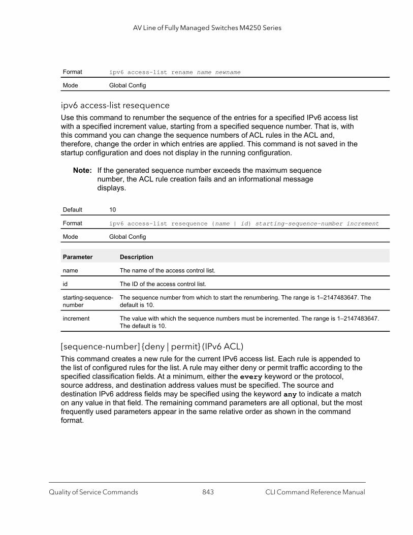
AV Line of Fully Managed Switches M4250 Series
nt
47.
ipv6 access-list resequenceUse this command to renumber the sequence of the entries for a specified IPv6 access list with a specified increment value, starting from a specified sequence number. That is, with this command you can change the sequence numbers of ACL rules in the ACL and, therefore, change the order in which entries are applied. This command is not saved in the startup configuration and does not display in the running configuration.
Note: If the generated sequence number exceeds the maximum sequence number, the ACL rule creation fails and an informational message displays.
[sequence-number] {deny | permit} (IPv6 ACL)This command creates a new rule for the current IPv6 access list. Each rule is appended to the list of configured rules for the list. A rule may either deny or permit traffic according to the specified classification fields. At a minimum, either the every keyword or the protocol, source address, and destination address values must be specified. The source and destination IPv6 address fields may be specified using the keyword any to indicate a match on any value in that field. The remaining command parameters are all optional, but the most frequently used parameters appear in the same relative order as shown in the command format.
Format ipv6 access-list rename name newname
Mode Global Config
Default 10
Format ipv6 access-list resequence {name | id} starting-sequence-number increme
Mode Global Config
Parameter Description
name The name of the access control list.
id The ID of the access control list.
starting-sequence-number
The sequence number from which to start the renumbering. The range is 1–2147483647. Thedefault is 10.
increment The value with which the sequence numbers must be incremented. The range is 1–21474836The default is 10.
Quality of Service Commands CLI Command Reference Manual843

AV Line of Fully Managed Switches M4250 Series
y |
st]
]
Note: An implicit deny all IPv6 rule always terminates the access list.
The time-range parameter allows imposing time limitation on the IPv6 ACL rule as defined by the parameter time-range-name. If a time range with the specified name does not exist and the IPv6 ACL containing this ACL rule is applied to an interface or bound to a VLAN, then the ACL rule is applied immediately. If a time range with specified name exists and the IPv6 ACL containing this ACL rule is applied to an interface or bound to a VLAN, then the ACL rule is applied when the time-range with specified name becomes active. The ACL rule is removed when the time-range with specified name becomes inactive. For information about configuring time ranges, see Time Range Commands for Time-Based ACLs on page 851.
The assign-queue parameter allows specification of a particular hardware queue for handling traffic that matches this rule. The allowed queue-id value is 0-(n-1), in which n is the number of user configurable queues available for the hardware platform. The assign-queue parameter is valid only for a permit rule.
The mirror parameter allows the traffic matching this rule to be copied to the specified unit/port, while the redirect parameter allows the traffic matching this rule to be forwarded to the specified unit/port. The assign-queue and redirect parameters are only valid for a permit rule.
The permit command’s optional attribute rate-limit allows you to permit only the allowed rate of traffic as per the configured rate in kbps, and burst-size in kbytes.
IPv6 ACLs have the following limitations:
• Port ranges are not supported for egress IPv6 ACLs.• The rate-limit command is not supported for egress IPv6 ACLs.
Format [sequence-number] {deny | permit} {every | {{icmpv6 | ipv6 | tcp | udp | 0-255} {source-ipv6-prefix/prefix-length | any | host source-ipv6-address} [eq {portke0-65535}] {destination-ipv6-prefix/prefix-length | any | host destination-ipv6-address} [eq {portkey | 0-65535}] [flag [+fin | -fin] [+syn | -syn] [+rst | -r[+psh | -psh] [+ack | -ack] [+urg | -urg] [established]] [flow-label value] [icmp-type icmp-type [icmp-code icmp-code] | icmp-message icmp-message] [routing] [fragments] [sequence sequence-number] [dscp dscp]}} [log] [assign-queue queue-id] [{mirror | redirect} unit/port[rate-limit rate burst-size]
Mode IPv6-Access-List Config
Quality of Service Commands CLI Command Reference Manual844

AV Line of Fully Managed Switches M4250 Series
mber
r that ed CL
ce
dy
m of e
rrent
urce ACL
g the
DP.
ule. A key,
,
r who.mber.
0 to
Table 11. IPv6 ACL command parameters
Parameter Description
sequence-number The sequence-number parameter specifies the sequence number for the ACL rule. Either you define the sequence nuor is it is generated.If no sequence number exists for a rule, a sequence numbeis 10 greater than the last sequence number in the ACL is usand the rule is placed at the end of the list. If this is the first Arule in the ACL, a sequence number of 10 is assigned. If thecalculated sequence number exceeds the maximum sequennumber value, the creation of the ACL rule fails. You cannot create a rule that duplicates an already existing one and youcannot configure a rule with a sequence number that is alreaused for another rule. For example, if you add new ACL rule to the ACL without specifying a sequence number, the rule is placed at the bottothe list. By changing the sequence number, you can move thACL rule to a different position in the ACL.
{deny | permit} Specifies whether the IPv6 ACL rule permits or denies the matching traffic.
every Specifies to match every packet.
{protocolkey | number} Specifies the protocol to match for the IPv6 ACL rule. The culist is: icmpv6, ipv6, tcp, and udp.
source-ipv6-prefix/prefix-length | any | host source-ipv6-address
For source-ipv6-prefix/prefix-length, specify a soIPv6 source address and prefix length to match for the IPv6 rule.Specifying any implies specifying ::/0Specifying host source-ipv6-address implies matchinspecified IPv6 address.The source-ipv6-address argument must be in the formdocumented in RFC 2373 where the address is specified in hexadecimal using 16-bit values between colons.
[eq {portkey | 0-65535}] Note: This option is available only if the protocol is TCP or U
Specifies the layer 4 port match condition for the IPv6 ACL rport number can be used, in the range 0-65535, or the portwhich can be one of the following keywords: For TCP: bgp, domain, echo, ftp, ftp-data, http, smtptelnet, www, pop2, or pop3.For UDP: domain, echo, ntp, rip, snmp, tftp, time, oEach of these keywords translates into its equivalent port nuWhen eq is specified, the IPv6 ACL rule matches only if the layer 4 port number is equal to the specified port number or portkey.Two rules are added in the hardware one with range equal to<specified port number - 1> and one with range equal to <specified port number + 1 to 65535>
Quality of Service Commands CLI Command Reference Manual845
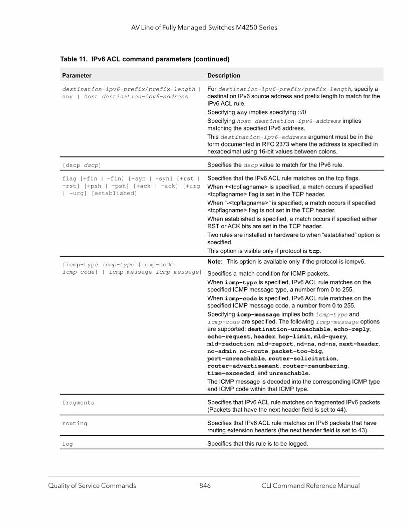
AV Line of Fully Managed Switches M4250 Series
ify a r the
he d in
ed
fied
ther
ion is
e
e
tions y,
der,
type
ckets
ave .
destination-ipv6-prefix/prefix-length | any | host destination-ipv6-address
For destination-ipv6-prefix/prefix-length, specdestination IPv6 source address and prefix length to match foIPv6 ACL rule.Specifying any implies specifying ::/0 Specifying host destination-ipv6-address implies matching the specified IPv6 address.This destination-ipv6-address argument must be in tform documented in RFC 2373 where the address is specifiehexadecimal using 16-bit values between colons.
[dscp dscp] Specifies the dscp value to match for the IPv6 rule.
flag [+fin | -fin] [+syn | -syn] [+rst | -rst] [+psh | -psh] [+ack | -ack] [+urg | -urg] [established]
Specifies that the IPv6 ACL rule matches on the tcp flags. When +<tcpflagname> is specified, a match occurs if specifi<tcpflagname> flag is set in the TCP header.When “-<tcpflagname>” is specified, a match occurs if speci<tcpflagname> flag is not set in the TCP header.When established is specified, a match occurs if specified eiRST or ACK bits are set in the TCP header.Two rules are installed in hardware to when “established” optspecified.This option is visible only if protocol is tcp.
[icmp-type icmp-type [icmp-code icmp-code] | icmp-message icmp-message]
Note: This option is available only if the protocol is icmpv6.
Specifies a match condition for ICMP packets.When icmp-type is specified, IPv6 ACL rule matches on thspecified ICMP message type, a number from 0 to 255. When icmp-code is specified, IPv6 ACL rule matches on thspecified ICMP message code, a number from 0 to 255. Specifying icmp-message implies both icmp-type and icmp-code are specified. The following icmp-message opare supported: destination-unreachable, echo-replecho-request, header, hop-limit, mld-query, mld-reduction, mld-report, nd-na, nd-ns, next-heano-admin, no-route, packet-too-big, port-unreachable, router-solicitation, router-advertisement, router-renumbering, time-exceeded, and unreachable.The ICMP message is decoded into the corresponding ICMPand ICMP code within that ICMP type.
fragments Specifies that IPv6 ACL rule matches on fragmented IPv6 pa(Packets that have the next header field is set to 44).
routing Specifies that IPv6 ACL rule matches on IPv6 packets that hrouting extension headers (the next header field is set to 43)
log Specifies that this rule is to be logged.
Table 11. IPv6 ACL command parameters (continued)
Parameter Description
Quality of Service Commands CLI Command Reference Manual846
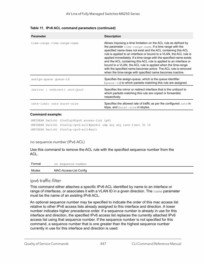
AV Line of Fully Managed Switches M4250 Series
by
CL ule is xists
ce or ge oved
d.
o
te in
Command example: (NETGEAR Switch) (Config)#ipv6 access-list ip61(NETGEAR Switch) (Config-ipv6-acl)#permit udp any any rate-limit 32 16(NETGEAR Switch) (Config-ipv6-acl)#exit
no sequence-number (IPv6 ACL)
Use this command to remove the ACL rule with the specified sequence number from the ACL.
ipv6 traffic-filterThis command either attaches a specific IPv6 ACL identified by name to an interface or range of interfaces, or associates it with a VLAN ID in a given direction. The name parameter must be the name of an existing IPv6 ACL.
An optional sequence number may be specified to indicate the order of this mac access list relative to other IPv6 access lists already assigned to this interface and direction. A lower number indicates higher precedence order. If a sequence number is already in use for this interface and direction, the specified IPv6 access list replaces the currently attached IPv6 access list using that sequence number. If the sequence number is not specified for this command, a sequence number that is one greater than the highest sequence number currently in use for this interface and direction is used.
time-range time-range-name Allows imposing a time limitation on the ACL rule as definedthe parameter time-range-name. If a time range with the specified name does not exist and the ACL containing this Arule is applied to an interface or bound to a VLAN, the ACL rapplied immediately. If a time range with the specified name eand the ACL containing this ACL rule is applied to an interfabound to a VLAN, the ACL rule is applied when the time-ranwith the specified name becomes active. The ACL rule is remwhen the time-range with specified name becomes inactive.
assign-queue queue-id Specifies the assign-queue, which is the queue identifier (queue-id) to which packets matching this rule are assigne
{mirror | redirect} unit/port Specifies the mirror or redirect interface that is the unit/port twhich packets matching this rule are copied or forwarded, respectively.
rate-limit rate burst-size Specifies the allowed rate of traffic as per the configured rakbps, and burst-size in kbytes.
Format no sequence-number
Modes MAC-Access-List Config
Table 11. IPv6 ACL command parameters (continued)
Parameter Description
Quality of Service Commands CLI Command Reference Manual847

AV Line of Fully Managed Switches M4250 Series
t}}
n |
This command specified in Interface Config mode only affects a single interface, whereas the Global Config mode setting is applied to all interfaces. The vlan keyword and vlan-id argument are valid only in the Global Config mode. The Interface Config mode command is only available on platforms that support independent per-port class of service queue configuration.
An optional control-plane is specified to apply the ACL on CPU port. The IPv6 control packets like IGMPv6 are also dropped because of the implicit deny all rule added at the end of the list. To overcome this, permit rules must be added to allow the IPv6 control packets.
Note: The control-plane keyword is available only in Global Config mode.
Note: Depending on the platform, the out option might not be available.
(NETGEAR Switch)(Config)#ipv6 traffic-filter ip61 control-plane
no ipv6 traffic-filter
This command removes an IPv6 ACL identified by name from the interface(s) in a given direction.
Command example: (NETGEAR Switch) (Config)#no ipv6 traffic-filter ip61 control-plane
show ipv6 access-listsUse this command to view summary information about all IPv6 ACLs that are configured on the switch. To view more detailed information about a specific access list, specify the ACL name that is used to identify the IP ACL. The command output displays the ICMP type, ICMP code, fragments, routing, and TCP flags attributes, the source and destination L4 port
Format ipv6 traffic-filter name {{control-plane |in | out} |vlan vlan-id {in | ou[sequence 1-4294967295]
Modes Global Config Interface Config
Format no ipv6 traffic-filter name {{control-plane | in | out} | vlan vlan-id {iout}}
Modes Global ConfigInterface Config
Quality of Service Commands CLI Command Reference Manual848

AV Line of Fully Managed Switches M4250 Series
ranges, and the number of packets that match a configured ACL rule within an ACL (referred to as ACL hit count).
Note: Only the access list fields that you configure are displayed. Thus, the command output varies based on the match criteria configured within the rules of an ACL.
Format show ipv6 access-lists [name]
Mode Privileged EXEC
Term Definition
Action The action associated with each rule. The possible values are Permit or Deny.
Match All Indicates whether this access list applies to every packet. Possible values are True or False.
Protocol The protocol to filter for this rule.
Committed Rate The committed rate defined by the rate-limit attribute.
Committed Burst Size
The committed burst size defined by the rate-limit attribute.
Source IP Address The source IP address for this rule.
Source L4 Port Keyword
The source port for this rule.
Destination IP Address
The destination IP address for this rule.
Destination L4 Port Keyword
The destination port for this rule.
IP DSCP The value specified for IP DSCP.
Flow Label The value specified for IPv6 Flow Label.
Log Displays when you enable logging for the rule.
Assign Queue The queue identifier to which packets matching this rule are assigned.
Mirror Interface The unit/port to which packets matching this rule are copied.
Redirect Interface The unit/port to which packets matching this rule are forwarded.
Time Range Name Displays the name of the time-range if the IPv6 ACL rule has referenced a time range.
Quality of Service Commands CLI Command Reference Manual849
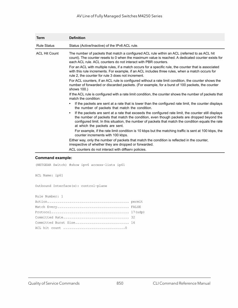
AV Line of Fully Managed Switches M4250 Series
ts for
ted r
the ter
s that
plays
plays d the rate
s, the
Command example: (NETGEAR Switch) #show ipv6 access-lists ip61
ACL Name: ip61
Outbound Interface(s): control-plane
Rule Number: 1Action......................................... permitMatch Every.................................... FALSEProtocol....................................... 17(udp)Committed Rate................................. 32Committed Burst Size........................... 16ACL hit count ...............................0
Rule Status Status (Active/Inactive) of the IPv6 ACL rule.
ACL Hit Count The number of packets that match a configured ACL rule within an ACL (referred to as ACL hitcount). The counter resets to 0 when the maximum value is reached. A dedicated counter exiseach ACL rule. ACL counters do not interact with PBR counters.For an ACL with multiple rules, if a match occurs for a specific rule, the counter that is associawith this rule increments. For example, if an ACL includes three rules, when a match occurs forule 2, the counter for rule 3 does not increment.For ACL counters, if an ACL rule is configured without a rate limit condition, the counter showsnumber of forwarded or discarded packets. (For example, for a burst of 100 packets, the counshows 100.)If the ACL rule is configured with a rate limit condition, the counter shows the number of packetmatch the condition:• If the packets are sent at a rate that is lower than the configured rate limit, the counter dis
the number of packets that match the condition.• If the packets are sent at a rate that exceeds the configured rate limit, the counter still dis
the number of packets that match the condition, even though packets are dropped beyonconfigured limit. In this situation, the number of packets that match the condition equals theat which the packets are sent. For example, if the rate limit condition is 10 kbps but the matching traffic is sent at 100 kbpcounter increments with 100 kbps.
Either way, only the number of packets that match the condition is reflected in the counter, irrespective of whether they are dropped or forwarded.ACL counters do not interact with diffserv policies.
Term Definition
Quality of Service Commands CLI Command Reference Manual850
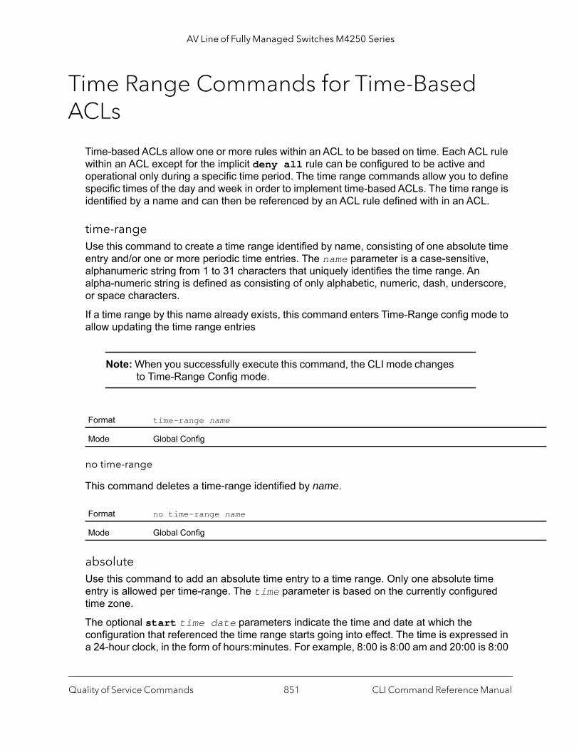
AV Line of Fully Managed Switches M4250 Series
Time Range Commands for Time-Based ACLs
Time-based ACLs allow one or more rules within an ACL to be based on time. Each ACL rule within an ACL except for the implicit deny all rule can be configured to be active and operational only during a specific time period. The time range commands allow you to define specific times of the day and week in order to implement time-based ACLs. The time range is identified by a name and can then be referenced by an ACL rule defined with in an ACL.
time-rangeUse this command to create a time range identified by name, consisting of one absolute time entry and/or one or more periodic time entries. The name parameter is a case-sensitive, alphanumeric string from 1 to 31 characters that uniquely identifies the time range. An alpha-numeric string is defined as consisting of only alphabetic, numeric, dash, underscore, or space characters.
If a time range by this name already exists, this command enters Time-Range config mode to allow updating the time range entries
Note: When you successfully execute this command, the CLI mode changes to Time-Range Config mode.
no time-range
This command deletes a time-range identified by name.
absoluteUse this command to add an absolute time entry to a time range. Only one absolute time entry is allowed per time-range. The time parameter is based on the currently configured time zone.
The optional start time date parameters indicate the time and date at which the configuration that referenced the time range starts going into effect. The time is expressed in a 24-hour clock, in the form of hours:minutes. For example, 8:00 is 8:00 am and 20:00 is 8:00
Format time-range name
Mode Global Config
Format no time-range name
Mode Global Config
Quality of Service Commands CLI Command Reference Manual851

AV Line of Fully Managed Switches M4250 Series
pm. The date is expressed in the format day month year. If no start time and date are specified, the configuration statement is in effect immediately.
The optional end time date parameters indicate the time and date at which the configuration that referenced the time range is no longer in effect. The end time and date must be after the start time and date. If no end time and date are specified, the configuration statement is in effect indefinitely.
no absolute
This command deletes the absolute time entry in the time range.
periodicUse this command to add a periodic time entry to a time range. The time parameter is based off of the currently configured time zone.
The first occurrence of the days-of-the-week argument is the starting day(s) from which the configuration that referenced the time range starts going into effect. The second occurrence is the ending day or days from which the configuration that referenced the time range is no longer in effect. If the end days-of-the-week are the same as the start, they can be omitted
This argument can be any single day or combinations of days: Monday, Tuesday, Wednesday, Thursday, Friday, Saturday, Sunday. Other possible values are:
• daily — Monday through Sunday • weekdays — Monday through Friday • weekend — Saturday and Sunday
If the ending days of the week are the same as the starting days of the week, they can be omitted.
The first occurrence of the time argument is the starting hours:minutes which the configuration that referenced the time range starts going into effect. The second occurrence of the time argument is the ending hours:minutes at which the configuration that referenced the time range is no longer in effect.
Format absolute [start time date] [end time date]
Mode Time-Range Config
Format no absolute
Mode Time-Range Config
Quality of Service Commands CLI Command Reference Manual852
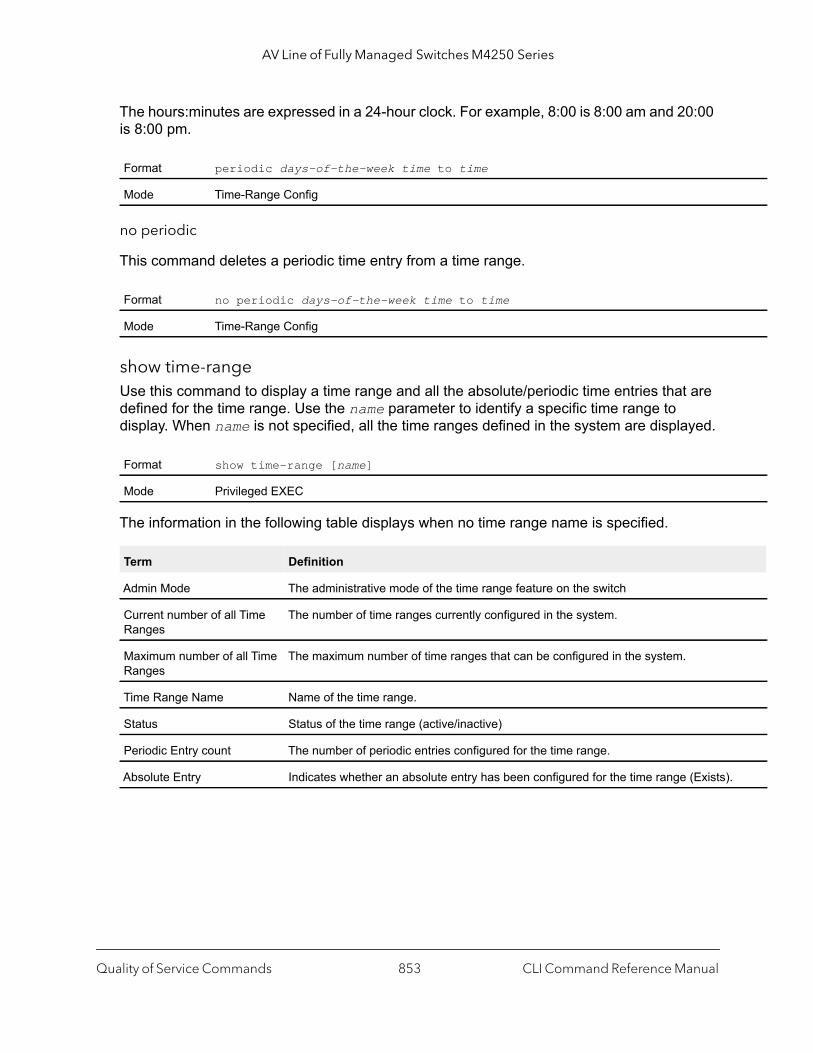
AV Line of Fully Managed Switches M4250 Series
.
The hours:minutes are expressed in a 24-hour clock. For example, 8:00 is 8:00 am and 20:00 is 8:00 pm.
no periodic
This command deletes a periodic time entry from a time range.
show time-rangeUse this command to display a time range and all the absolute/periodic time entries that are defined for the time range. Use the name parameter to identify a specific time range to display. When name is not specified, all the time ranges defined in the system are displayed.
The information in the following table displays when no time range name is specified.
Format periodic days-of-the-week time to time
Mode Time-Range Config
Format no periodic days-of-the-week time to time
Mode Time-Range Config
Format show time-range [name]
Mode Privileged EXEC
Term Definition
Admin Mode The administrative mode of the time range feature on the switch
Current number of all Time Ranges
The number of time ranges currently configured in the system.
Maximum number of all Time Ranges
The maximum number of time ranges that can be configured in the system.
Time Range Name Name of the time range.
Status Status of the time range (active/inactive)
Periodic Entry count The number of periodic entries configured for the time range.
Absolute Entry Indicates whether an absolute entry has been configured for the time range (Exists)
Quality of Service Commands CLI Command Reference Manual853

AV Line of Fully Managed Switches M4250 Series
Auto-Voice over IP Commands
This section describes the commands you use to configure Auto-Voice over IP (VoIP) commands. The Auto-VoIP feature explicitly matches VoIP streams in Ethernet switches and provides them with a better class-of-service than ordinary traffic. When you enable the Auto-VoIP feature on an interface, the interface scans incoming traffic for the following call-control protocols:
• Session Initiation Protocol (SIP)• H.323• Skinny Client Control Protocol (SCCP)
When a call-control protocol is detected, the switch assigns the traffic in that session to the highest CoS queue, which is generally used for time-sensitive traffic.
auto-voip Use this command to configure auto VoIP mode. The supported modes are protocol-based and oui-based. Protocol-based auto VoIP prioritizes the voice data based on the layer 4 port used for the voice session. OUI based auto VoIP prioritizes the phone traffic based on the known OUI of the phone.
When both modes are enabled, if the connected phone OUI is one of the configured OUI, then the voice data is prioritized using OUI Auto VoIP, otherwise protocol-based Auto VoIP is used to prioritize the voice data.
Active sessions are cleared if protocol-based auto VoIP is disabled on the port.
no auto-voip
Use the no form of the command to set the default mode.
auto-voip ouiUse this command to configure an OUI for Auto VoIP. The traffic from the configured OUI will get the highest priority over the other traffic. The oui-prefix is a unique OUI that identifies the device manufacturer or vendor. The OUI is specified in three octet values (each octets represented as two hexadecimal digits) separated by colons. The string is a description of the OUI that identifies the manufacturer or vendor associated with the OUI.
Default oui-based
Format auto-voip [protocol-based | oui-based]
Mode Global ConfigInterface Config
Quality of Service Commands CLI Command Reference Manual854
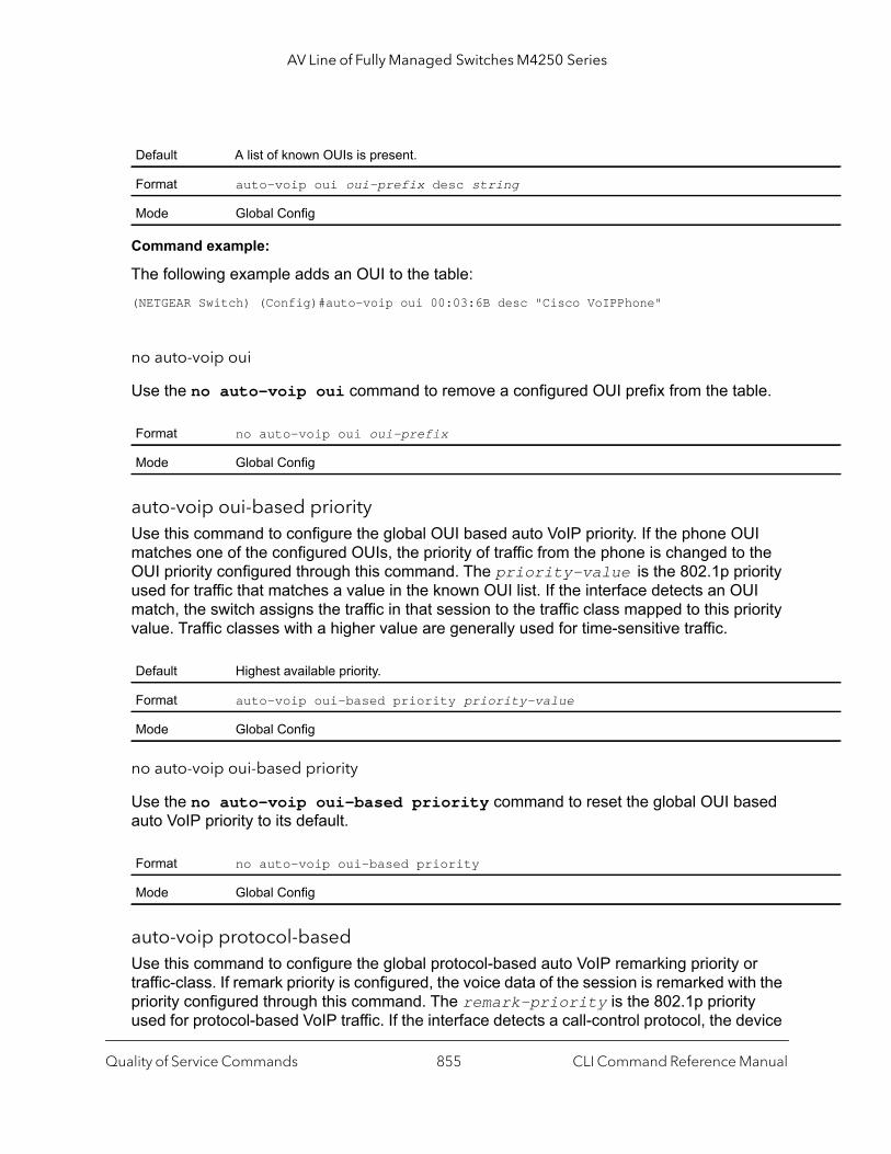
AV Line of Fully Managed Switches M4250 Series
Command example:
The following example adds an OUI to the table:(NETGEAR Switch) (Config)#auto-voip oui 00:03:6B desc "Cisco VoIPPhone"
no auto-voip oui
Use the no auto-voip oui command to remove a configured OUI prefix from the table.
auto-voip oui-based priorityUse this command to configure the global OUI based auto VoIP priority. If the phone OUI matches one of the configured OUIs, the priority of traffic from the phone is changed to the OUI priority configured through this command. The priority-value is the 802.1p priority used for traffic that matches a value in the known OUI list. If the interface detects an OUI match, the switch assigns the traffic in that session to the traffic class mapped to this priority value. Traffic classes with a higher value are generally used for time-sensitive traffic.
no auto-voip oui-based priority
Use the no auto-voip oui-based priority command to reset the global OUI based auto VoIP priority to its default.
auto-voip protocol-basedUse this command to configure the global protocol-based auto VoIP remarking priority or traffic-class. If remark priority is configured, the voice data of the session is remarked with the priority configured through this command. The remark-priority is the 802.1p priority used for protocol-based VoIP traffic. If the interface detects a call-control protocol, the device
Default A list of known OUIs is present.
Format auto-voip oui oui-prefix desc string
Mode Global Config
Format no auto-voip oui oui-prefix
Mode Global Config
Default Highest available priority.
Format auto-voip oui-based priority priority-value
Mode Global Config
Format no auto-voip oui-based priority
Mode Global Config
Quality of Service Commands CLI Command Reference Manual855
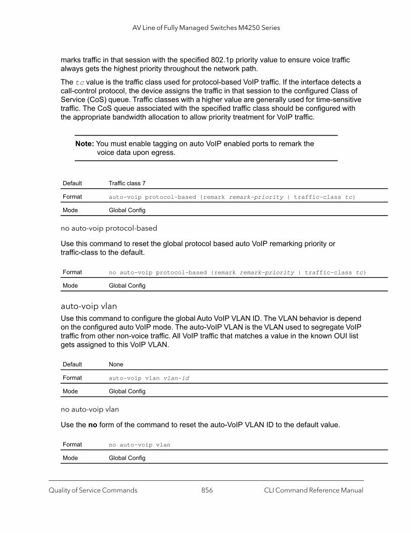
AV Line of Fully Managed Switches M4250 Series
marks traffic in that session with the specified 802.1p priority value to ensure voice traffic always gets the highest priority throughout the network path.
The tc value is the traffic class used for protocol-based VoIP traffic. If the interface detects a call-control protocol, the device assigns the traffic in that session to the configured Class of Service (CoS) queue. Traffic classes with a higher value are generally used for time-sensitive traffic. The CoS queue associated with the specified traffic class should be configured with the appropriate bandwidth allocation to allow priority treatment for VoIP traffic.
Note: You must enable tagging on auto VoIP enabled ports to remark the voice data upon egress.
no auto-voip protocol-based
Use this command to reset the global protocol based auto VoIP remarking priority or traffic-class to the default.
auto-voip vlanUse this command to configure the global Auto VoIP VLAN ID. The VLAN behavior is depend on the configured auto VoIP mode. The auto-VoIP VLAN is the VLAN used to segregate VoIP traffic from other non-voice traffic. All VoIP traffic that matches a value in the known OUI list gets assigned to this VoIP VLAN.
no auto-voip vlan
Use the no form of the command to reset the auto-VoIP VLAN ID to the default value.
Default Traffic class 7
Format auto-voip protocol-based {remark remark-priority | traffic-class tc}
Mode Global Config
Format no auto-voip protocol-based {remark remark-priority | traffic-class tc}
Mode Global Config
Default None
Format auto-voip vlan vlan-id
Mode Global Config
Format no auto-voip vlan
Mode Global Config
Quality of Service Commands CLI Command Reference Manual856
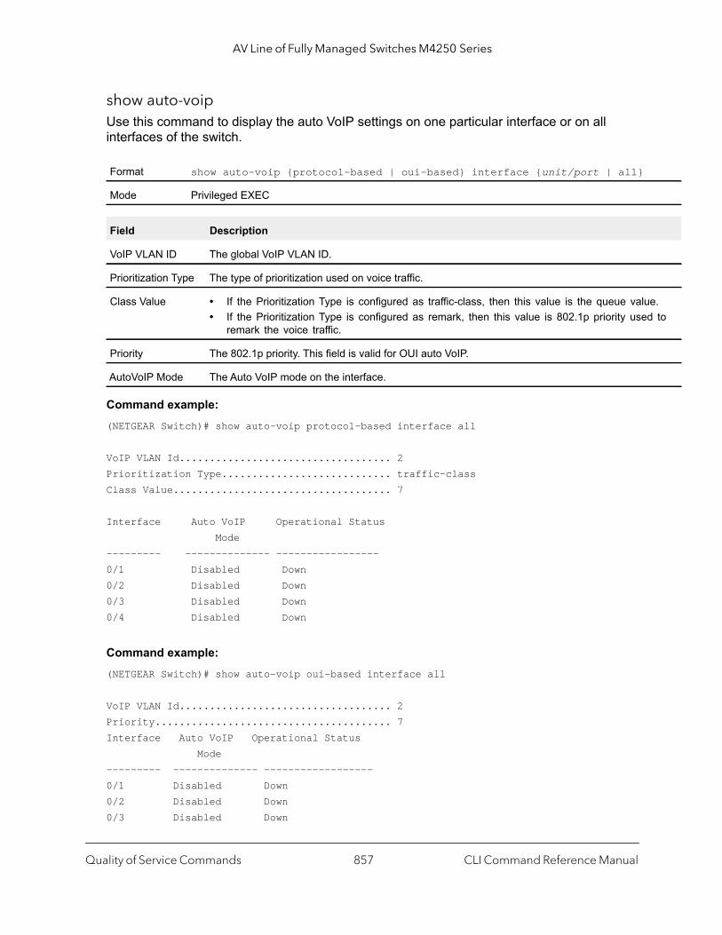
AV Line of Fully Managed Switches M4250 Series
e. to
show auto-voipUse this command to display the auto VoIP settings on one particular interface or on all interfaces of the switch.
Command example: (NETGEAR Switch)# show auto-voip protocol-based interface all
VoIP VLAN Id................................... 2Prioritization Type............................ traffic-classClass Value.................................... 7
Interface Auto VoIP Operational Status Mode --------- -------------- -----------------0/1 Disabled Down0/2 Disabled Down0/3 Disabled Down0/4 Disabled Down
Command example: (NETGEAR Switch)# show auto-voip oui-based interface all
VoIP VLAN Id................................... 2Priority....................................... 7Interface Auto VoIP Operational Status Mode --------- -------------- ------------------0/1 Disabled Down0/2 Disabled Down0/3 Disabled Down
Format show auto-voip {protocol-based | oui-based} interface {unit/port | all}
Mode Privileged EXEC
Field Description
VoIP VLAN ID The global VoIP VLAN ID.
Prioritization Type The type of prioritization used on voice traffic.
Class Value • If the Prioritization Type is configured as traffic-class, then this value is the queue valu• If the Prioritization Type is configured as remark, then this value is 802.1p priority used
remark the voice traffic.
Priority The 802.1p priority. This field is valid for OUI auto VoIP.
AutoVoIP Mode The Auto VoIP mode on the interface.
Quality of Service Commands CLI Command Reference Manual857

AV Line of Fully Managed Switches M4250 Series
0/4 Disabled Down0/5 Disabled Down
show auto-voip oui-tableUse this command to display the VoIP OUI table information.
Command example: (NETGEAR Switch)# show auto-voip oui-table
OUI Status Description--------- ---------- ---------00:01:E3 Default SIEMENS00:03:6B Default CISCO100:01:01 Configured VoIP phone
Format show auto-voip oui-table
Mode Privileged EXEC
Parameter Description
OUI OUI of the source MAC address.
Status Default or configured entry.
OUI Description Description of the OUI.
Quality of Service Commands CLI Command Reference Manual858
11
11IP Multicast CommandsThis chapter describes the IP multicast commands. The chapter contains the following sections:
• Multicast Commands
• PIM Commands
• Internet Group Message Protocol Commands
• IGMP Proxy Commands
The commands in this chapter are in one of two functional groups:
• Show commands. Display switch settings, statistics, and other information.• Configuration commands. Configure features and options of the switch. For every
configuration command, there is a show command that displays the configuration setting.
859

AV Line of Fully Managed Switches M4250 Series
1 to
Multicast Commands
This section describes the commands you use to configure IP Multicast and to view IP Multicast settings and statistics.
ip mcast boundaryThis command adds an administrative scope multicast boundary specified by groupipaddr and mask for which this multicast administrative boundary is applicable. groupipaddr is a group IP address and mask is a group IP mask. This command can be used to configure a single interface or a range of interfaces.
no ip mcast boundary
This command deletes an administrative scope multicast boundary specified by groupipaddr and mask for which this multicast administrative boundary is applicable. groupipaddr is a group IP address and mask is a group IP mask.
ip mrouteThis command configures an IPv4 multicast static route for a source.
Format ip mcast boundary groupipaddr mask
Mode Interface Config
Format no ip mcast boundary groupipaddr mask
Mode Interface Config
Default No MRoute is configured on the system.
Format ip mroute src-ip-addr src-mask rpf-addr preference
Mode Global Config
Parameter Description
src-ip-addr The IP address of the multicast source network.
src-mask The IP mask of the multicast data source.
rpf-ip-addr The IP address of the RPF next-hop router toward the source.
preference The administrative distance for this Static MRoute, that is, the preference value. The range is 255.
IP Multicast Commands CLI Command Reference Manual860
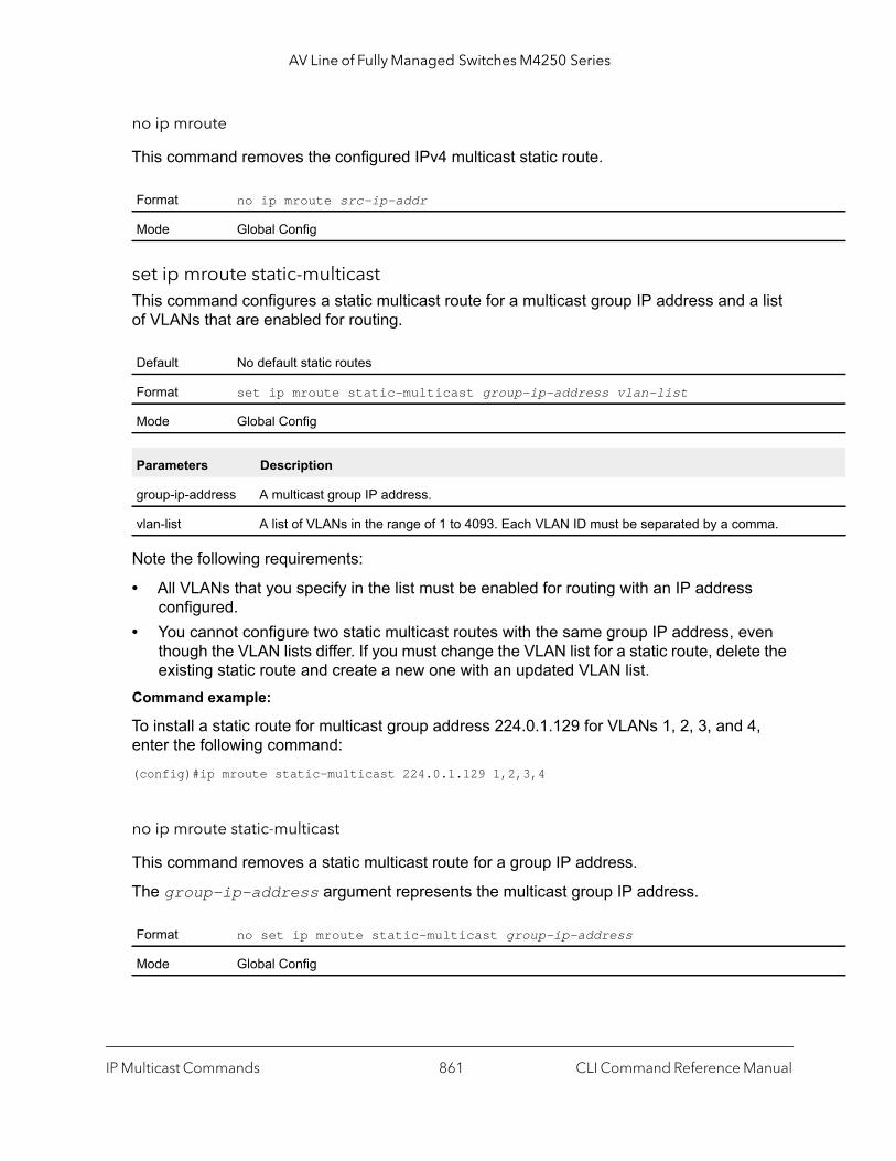
AV Line of Fully Managed Switches M4250 Series
no ip mroute
This command removes the configured IPv4 multicast static route.
set ip mroute static-multicastThis command configures a static multicast route for a multicast group IP address and a list of VLANs that are enabled for routing.
Note the following requirements:
• All VLANs that you specify in the list must be enabled for routing with an IP address configured.
• You cannot configure two static multicast routes with the same group IP address, even though the VLAN lists differ. If you must change the VLAN list for a static route, delete the existing static route and create a new one with an updated VLAN list.
Command example:
To install a static route for multicast group address 224.0.1.129 for VLANs 1, 2, 3, and 4, enter the following command:(config)#ip mroute static-multicast 224.0.1.129 1,2,3,4
no ip mroute static-multicast
This command removes a static multicast route for a group IP address.
The group-ip-address argument represents the multicast group IP address.
Format no ip mroute src-ip-addr
Mode Global Config
Default No default static routes
Format set ip mroute static-multicast group-ip-address vlan-list
Mode Global Config
Parameters Description
group-ip-address A multicast group IP address.
vlan-list A list of VLANs in the range of 1 to 4093. Each VLAN ID must be separated by a comma.
Format no set ip mroute static-multicast group-ip-address
Mode Global Config
IP Multicast Commands CLI Command Reference Manual861

AV Line of Fully Managed Switches M4250 Series
ip multicastThis command sets the administrative mode of the IP multicast forwarder in the router to active.
no ip multicast
This command sets the administrative mode of the IP multicast forwarder in the router to inactive.
ip multicast ttl-thresholdThis command is specific to IPv4. Use this command to apply the given Time-to-Live threshold value to a routing interface or range of interfaces. The ttlvalue is the TTL threshold which is to be applied to the multicast Data packets which are to be forwarded from the interface. This command sets the Time-to-Live threshold value such that any data packets forwarded over the interface having TTL value above the configured value are dropped. The value for ttlvalue ranges from 0 to 255.
no ip multicast ttl-threshold
This command applies the default TTL threshold to a routing interface. The TTL threshold is the TTL threshold which is to be applied to the multicast Data packets which are to be forwarded from the interface.
Default disabled
Format ip multicast
Mode Global Config
Format no ip multicast
Mode Global Config
Default 1
Format ip multicast ttl-threshold ttlvalue
Mode Interface Config
Format no ip multicast ttl-threshold
Mode Interface Config
IP Multicast Commands CLI Command Reference Manual862
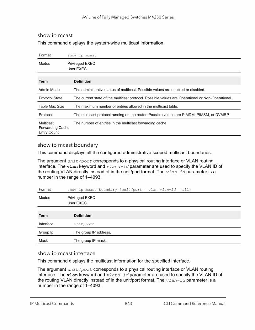
AV Line of Fully Managed Switches M4250 Series
l.
show ip mcastThis command displays the system-wide multicast information.
show ip mcast boundaryThis command displays all the configured administrative scoped multicast boundaries.
The argument unit/port corresponds to a physical routing interface or VLAN routing interface. The vlan keyword and vland-id parameter are used to specify the VLAN ID of the routing VLAN directly instead of in the unit/port format. The vlan-id parameter is a number in the range of 1–4093.
show ip mcast interfaceThis command displays the multicast information for the specified interface.
The argument unit/port corresponds to a physical routing interface or VLAN routing interface. The vlan keyword and vland-id parameter are used to specify the VLAN ID of the routing VLAN directly instead of in the unit/port format. The vlan-id parameter is a number in the range of 1–4093.
Format show ip mcast
Modes Privileged EXECUser EXEC
Term Definition
Admin Mode The administrative status of multicast. Possible values are enabled or disabled.
Protocol State The current state of the multicast protocol. Possible values are Operational or Non-Operationa
Table Max Size The maximum number of entries allowed in the multicast table.
Protocol The multicast protocol running on the router. Possible values are PIMDM, PIMSM, or DVMRP.
Multicast Forwarding Cache Entry Count
The number of entries in the multicast forwarding cache.
Format show ip mcast boundary {unit/port | vlan vlan-id | all}
Modes Privileged EXECUser EXEC
Term Definition
Interface unit/port
Group Ip The group IP address.
Mask The group IP mask.
IP Multicast Commands CLI Command Reference Manual863
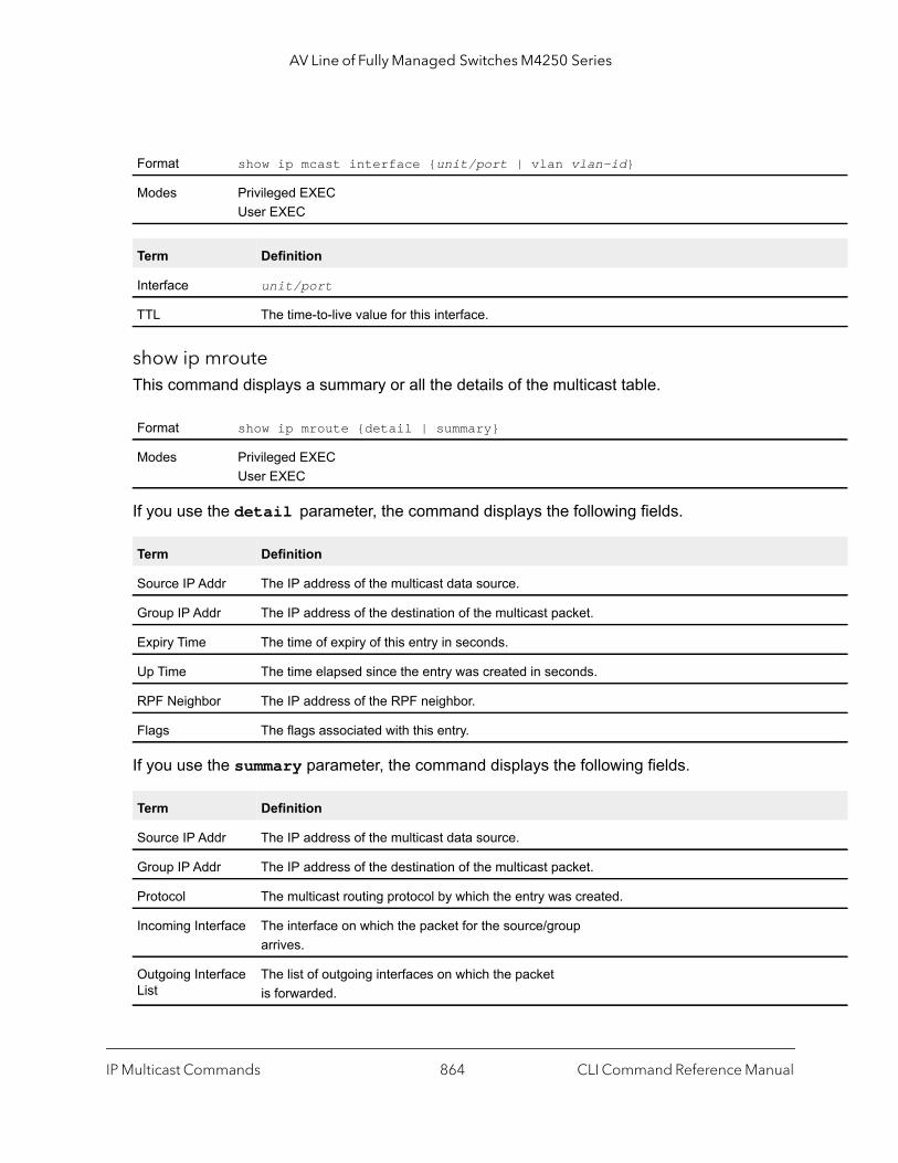
AV Line of Fully Managed Switches M4250 Series
show ip mrouteThis command displays a summary or all the details of the multicast table.
If you use the detail parameter, the command displays the following fields.
If you use the summary parameter, the command displays the following fields.
Format show ip mcast interface {unit/port | vlan vlan-id}
Modes Privileged EXECUser EXEC
Term Definition
Interface unit/port
TTL The time-to-live value for this interface.
Format show ip mroute {detail | summary}
Modes Privileged EXECUser EXEC
Term Definition
Source IP Addr The IP address of the multicast data source.
Group IP Addr The IP address of the destination of the multicast packet.
Expiry Time The time of expiry of this entry in seconds.
Up Time The time elapsed since the entry was created in seconds.
RPF Neighbor The IP address of the RPF neighbor.
Flags The flags associated with this entry.
Term Definition
Source IP Addr The IP address of the multicast data source.
Group IP Addr The IP address of the destination of the multicast packet.
Protocol The multicast routing protocol by which the entry was created.
Incoming Interface The interface on which the packet for the source/grouparrives.
Outgoing Interface List
The list of outgoing interfaces on which the packetis forwarded.
IP Multicast Commands CLI Command Reference Manual864

AV Line of Fully Managed Switches M4250 Series
show ip mroute groupThis command displays the multicast configuration settings such as flags, timer settings, incoming and outgoing interfaces, RPF neighboring routers, and expiration times of all the entries in the multicast route table containing the given groupipaddr.
show ip mroute sourceThis command displays the multicast configuration settings such as flags, timer settings, incoming and outgoing interfaces, RPF neighboring routers, and expiration times of all the entries in the multicast route table containing the given source IP address (sourceipaddr) or source IP address and group IP address (groupipaddr) pair.
If you use the groupipaddr parameter, the command displays the following column headings in the output table.
Format show ip mroute group groupipaddr {detail | summary}
Modes Privileged EXECUser EXEC
Term Definition
Source IP Addr The IP address of the multicast data source.
Group IP Addr The IP address of the destination of the multicast packet.
Protocol The multicast routing protocol by which this entry was created.
Incoming Interface The interface on which the packet for this group arrives.
Outgoing Interface List
The list of outgoing interfaces on which this packet is forwarded.
Format show ip mroute source sourceipaddr {summary | groupipaddr}
Modes Privileged EXECUser EXEC
Term Definition
Source IP Addr The IP address of the multicast data source.
Group IP Addr The IP address of the destination of the multicast packet.
Expiry Time The time of expiry of this entry in seconds.
Up Time The time elapsed since the entry was created in seconds.
RPF Neighbor The IP address of the RPF neighbor.
Flags The flags associated with this entry.
IP Multicast Commands CLI Command Reference Manual865

AV Line of Fully Managed Switches M4250 Series
If you use the summary parameter, the command displays the following column headings in the output table.
show ip mroute staticUse this command in Privileged EXEC or User EXEC mode to display all the static routes configured in the static mcast table, if it is specified, or display the static route associated with the particular sourceipaddr.
Command example: console#show ip mroute static
MULTICAST STATIC ROUTESSource IP Source Mask RPF Address Preference--------------- --------------- --------------- ----------1.1.1.1 255.255.255.0 2.2.2.2 23
Term Definition
Source IP Addr The IP address of the multicast data source.
Group IP Addr The IP address of the destination of the multicast packet.
Protocol The multicast routing protocol by which this entry was created.
Incoming Interface The interface on which the packet for this source arrives.
Outgoing Interface List
The list of outgoing interfaces on which this packet is forwarded.
Format show ip mroute static [sourceipaddr]
Modes Privileged EXECUser EXEC
Parameter Description
Source IP IP address of the multicast source network.
Source Mask The subnetwork mask pertaining to the sourceIP.
RPF Address The IP address of the RPF next-hop router toward the source.
Preference The administrative distance for this Static MRoute.
IP Multicast Commands CLI Command Reference Manual866

AV Line of Fully Managed Switches M4250 Series
show ip mroute static-multicastUse this command in Privileged EXEC or User EXEC mode to display the manually added static multicast routes.
Command example: (NETGEAR Switch) #show ip mroute static-multicast
Maximum Multicast Static Address Count ........ 32Current Multicast Static Address Count ........ 4
Group Address Egress VLAN List---------------------- -----------------------------------225.1.1.1 1-2225.1.1.5 1225.1.1.2 1-2225.1.1.3 1
clear ip mrouteThis command deletes all or the specified IP multicast route entries.This command clears only dynamic mroute entries. It does not clear static mroutes.
Format show ip mroute static-multicast
Modes Privileged EXECUser EXEC
Parameter Description
Maximum Multicast Static Address Count
The maximum number of allowed static multicast routes.
Current Multicast Static Address Count
The number of configured static multicast routes.
Group Address The configured multicast group IP address.
Egress VLAN List The VLANs that are associated with the static multicast route.
Format clear ip mroute {* | group-address [source-address]}
Modes Privileged EXEC
Parameter Description
* Deletes all IPv4 entries from the IP multicast routing table.
group-address IP address of the multicast group.
source-address The optional IP address of a multicast source that is sending multicast traffic to the group.
IP Multicast Commands CLI Command Reference Manual867
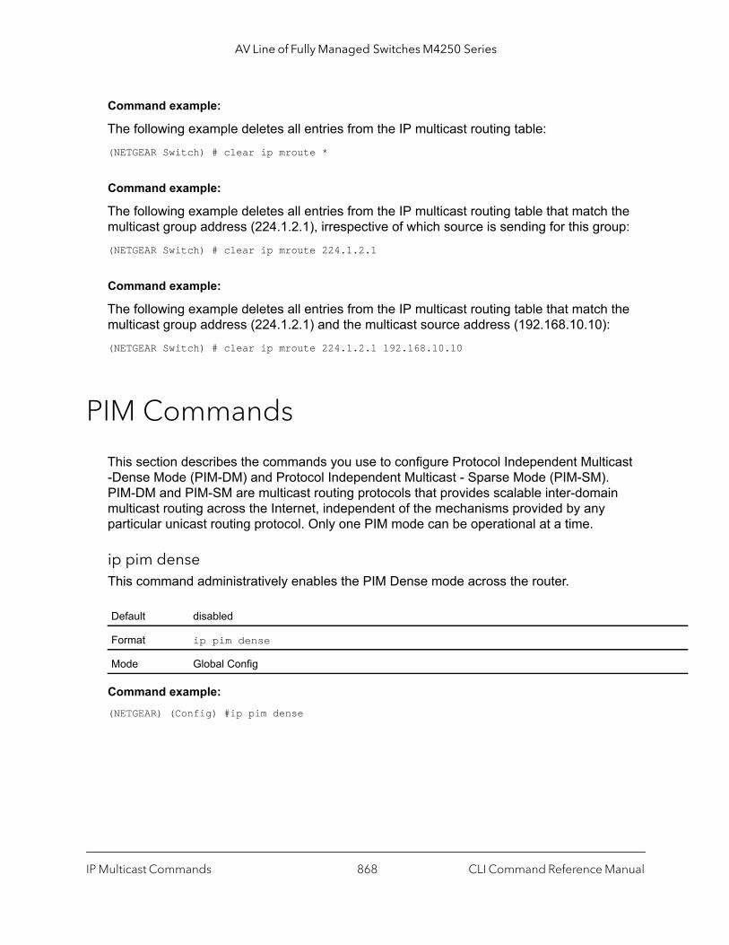
AV Line of Fully Managed Switches M4250 Series
Command example:
The following example deletes all entries from the IP multicast routing table:(NETGEAR Switch) # clear ip mroute *
Command example:
The following example deletes all entries from the IP multicast routing table that match the multicast group address (224.1.2.1), irrespective of which source is sending for this group:(NETGEAR Switch) # clear ip mroute 224.1.2.1
Command example:
The following example deletes all entries from the IP multicast routing table that match the multicast group address (224.1.2.1) and the multicast source address (192.168.10.10):(NETGEAR Switch) # clear ip mroute 224.1.2.1 192.168.10.10
PIM Commands
This section describes the commands you use to configure Protocol Independent Multicast -Dense Mode (PIM-DM) and Protocol Independent Multicast - Sparse Mode (PIM-SM). PIM-DM and PIM-SM are multicast routing protocols that provides scalable inter-domain multicast routing across the Internet, independent of the mechanisms provided by any particular unicast routing protocol. Only one PIM mode can be operational at a time.
ip pim denseThis command administratively enables the PIM Dense mode across the router.
Command example: (NETGEAR) (Config) #ip pim dense
Default disabled
Format ip pim dense
Mode Global Config
IP Multicast Commands CLI Command Reference Manual868

AV Line of Fully Managed Switches M4250 Series
no ip pim dense
This command administratively disables the PIM Dense mode across the router.
ip pim sparseThis command administratively enables the PIM Sparse mode across the router.
Command example: (NETGEAR) (Config) #ip pim sparse
no ip pim sparse
This command administratively disables the PIM Sparse mode across the router.
ip pimUse this command to administratively enable PIM on the specified interface.
Command example: (NETGEAR) (Interface 1/0/1) #ip pim
no ip pim
Use this command to disable PIM on the specified interface.
Format no ip pim dense
Mode Global Config
Default disabled
Format ip pim sparse
Mode Global Config
Format no ip pim sparse
Mode Global Config
Default disabled
Format ip pim
Mode Interface Config
Format no ip pim
Mode Interface Config
IP Multicast Commands CLI Command Reference Manual869

AV Line of Fully Managed Switches M4250 Series
ip pim hello-intervalThis command configures the transmission frequency of PIM hello messages the specified interface. The seconds argument is a value in a range of 0 to 18000 seconds.
Command example: (NETGEAR) (Interface 1/0/1) #ip pim hello-interval 50
no ip pim hello-interval
This command resets the transmission frequency of hello messages between PIM enabled neighbors to the default value.
ip pim bsr-borderUse this command to prevent bootstrap router (BSR) messages from being sent or received on the specified interface.
Note: This command takes effect only when Sparse mode in enabled in the Global mode.
Command example: (NETGEAR) (Interface 1/0/1) #ip pim bsr-border
Default 30
Format ip pim hello-interval seconds
Mode Interface Config
Format no ip pim hello-interval
Mode Interface Config
Default disabled
Format ip pim bsr-border
Mode Interface Config
IP Multicast Commands CLI Command Reference Manual870

AV Line of Fully Managed Switches M4250 Series
th
sh le, if P for
the ess is
no ip pim bsr-border
Use this command to disable the specified interface from being the BSR border.
ip pim bsr-candidateThis command is used to configure the router to announce its candidacy as a bootstrap router (BSR).
The argument unit/port corresponds to a physical routing interface or VLAN routing interface. The vlan keyword and vland-id parameter are used to specify the VLAN ID of the routing VLAN directly instead of in the unit/port format. The vlan-id parameter is a number in the range of 1–4093.
Note: This command takes effect only when PIM-SM is configured as the PIM mode.
Command example: The following shows examples of the command.(NETGEAR) (Config) #ip pim bsr-candidate interface 1/0/1 32 5(NETGEAR) (Config) #ip pim bsr-candidate interface 1/0/1 32 5 interval 100
Format no ip pim bsr-border
Mode Interface Config
Default Disabled
Format ip pim bsr-candidate interface {unit/port | vlan vlan-id} hash-mask-leng[bsr-priority] [interval interval]
Mode Global Config
Parameters Description
unit/port Interface or VLAN number on this router from which the BSR address is derived, to make it a candidate. This interface or VLAN must be enabled with PIM.
hash-mask-length Length of a mask (32 bits maximum) that is to be ANDed with the group address before the hafunction is called. All groups with the same seed hash correspond to the same RP. For exampthis value is 24, only the first 24 bits of the group addresses matter. This allows you to get one Rmultiple groups.
bsr-priority [Optional] Priority of the candidate BSR. The range is an integer from 0 to 255. The BSR with larger priority is preferred. If the priority values are the same, the router with the larger IP addrthe BSR. The default value is 0.
interval [Optional] Indicates the BSR candidate advertisement interval. The range is from 1 to 16383 seconds. The default value is 60 seconds.
IP Multicast Commands CLI Command Reference Manual871
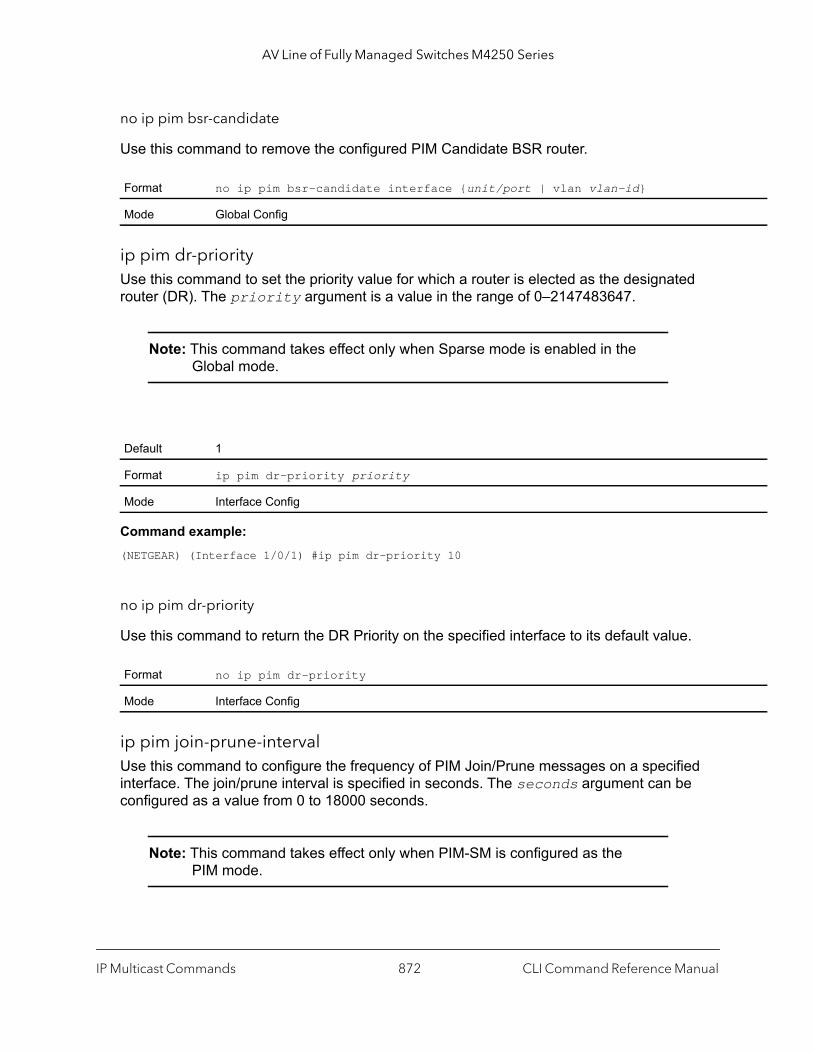
AV Line of Fully Managed Switches M4250 Series
no ip pim bsr-candidate
Use this command to remove the configured PIM Candidate BSR router.
ip pim dr-priorityUse this command to set the priority value for which a router is elected as the designated router (DR). The priority argument is a value in the range of 0–2147483647.
Note: This command takes effect only when Sparse mode is enabled in the Global mode.
Command example: (NETGEAR) (Interface 1/0/1) #ip pim dr-priority 10
no ip pim dr-priority
Use this command to return the DR Priority on the specified interface to its default value.
ip pim join-prune-intervalUse this command to configure the frequency of PIM Join/Prune messages on a specified interface. The join/prune interval is specified in seconds. The seconds argument can be configured as a value from 0 to 18000 seconds.
Note: This command takes effect only when PIM-SM is configured as the PIM mode.
Format no ip pim bsr-candidate interface {unit/port | vlan vlan-id}
Mode Global Config
Default 1
Format ip pim dr-priority priority
Mode Interface Config
Format no ip pim dr-priority
Mode Interface Config
IP Multicast Commands CLI Command Reference Manual872

AV Line of Fully Managed Switches M4250 Series
er the
Command example: (NETGEAR) (Interface 1/0/1) #ip pim join-prune-interval 90
no ip pim join-prune-interval
Use this command to set the join/prune interval on the specified interface to the default value.
ip pim rp-addressThis command defines the address of a PIM Rendezvous point (RP) for a specific multicast group range.
Note: This command takes effect only when PIM-SM is configured as the PIM mode.
Command example: (NETGEAR) (Config) #ip pim rp-address 192.168.10.1 224.1.2.0 255.255.255.0
Default 60
Format ip pim join-prune-interval seconds
Mode Interface Config
Format no ip pim join-prune-interval
Mode Interface Config
Default 0
Format ip pim rp-address rp-address group-address group-mask [override]
Mode Global Config
Parameter Description
rp-address The IP address of the RP.
group-address The group address supported by the RP.
group-mask The group mask for the group address.
override [Optional] Indicates that if there is a conflict, the RP configured with this command prevails ovRP learned by BSR.
IP Multicast Commands CLI Command Reference Manual873
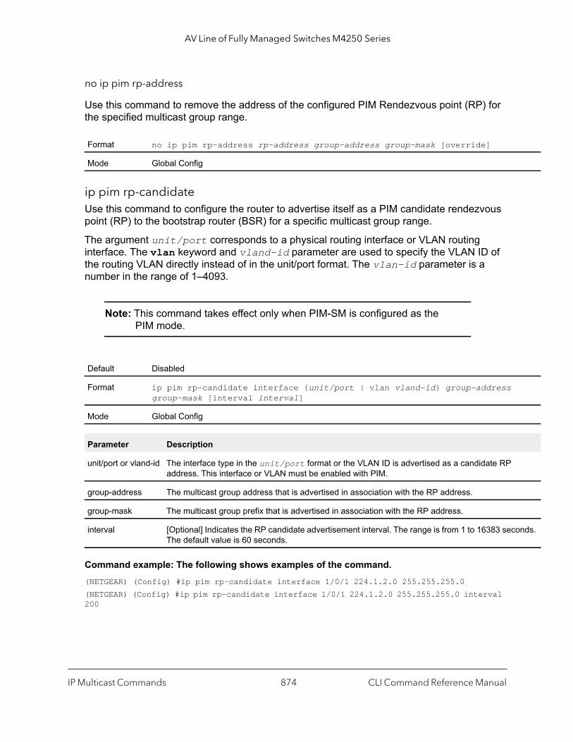
AV Line of Fully Managed Switches M4250 Series
onds.
no ip pim rp-address
Use this command to remove the address of the configured PIM Rendezvous point (RP) for the specified multicast group range.
ip pim rp-candidateUse this command to configure the router to advertise itself as a PIM candidate rendezvous point (RP) to the bootstrap router (BSR) for a specific multicast group range.
The argument unit/port corresponds to a physical routing interface or VLAN routing interface. The vlan keyword and vland-id parameter are used to specify the VLAN ID of the routing VLAN directly instead of in the unit/port format. The vlan-id parameter is a number in the range of 1–4093.
Note: This command takes effect only when PIM-SM is configured as the PIM mode.
Command example: The following shows examples of the command.(NETGEAR) (Config) #ip pim rp-candidate interface 1/0/1 224.1.2.0 255.255.255.0(NETGEAR) (Config) #ip pim rp-candidate interface 1/0/1 224.1.2.0 255.255.255.0 interval 200
Format no ip pim rp-address rp-address group-address group-mask [override]
Mode Global Config
Default Disabled
Format ip pim rp-candidate interface {unit/port | vlan vland-id} group-address group-mask [interval interval]
Mode Global Config
Parameter Description
unit/port or vland-id The interface type in the unit/port format or the VLAN ID is advertised as a candidate RP address. This interface or VLAN must be enabled with PIM.
group-address The multicast group address that is advertised in association with the RP address.
group-mask The multicast group prefix that is advertised in association with the RP address.
interval [Optional] Indicates the RP candidate advertisement interval. The range is from 1 to 16383 secThe default value is 60 seconds.
IP Multicast Commands CLI Command Reference Manual874
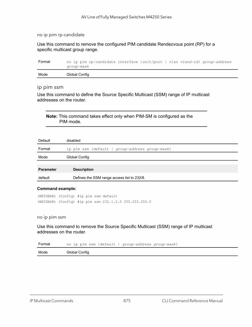
AV Line of Fully Managed Switches M4250 Series
ss
no ip pim rp-candidate
Use this command to remove the configured PIM candidate Rendezvous point (RP) for a specific multicast group range.
ip pim ssmUse this command to define the Source Specific Multicast (SSM) range of IP multicast addresses on the router.
Note: This command takes effect only when PIM-SM is configured as the PIM mode.
Command example: (NETGEAR) (Config) #ip pim ssm default(NETGEAR) (Config) #ip pim ssm 232.1.2.0 255.255.255.0
no ip pim ssm
Use this command to remove the Source Specific Multicast (SSM) range of IP multicast addresses on the router.
Format no ip pim rp-candidate interface {unit/port | vlan vland-id} group-addregroup-mask
Mode Global Config
Default disabled
Format ip pim ssm {default | group-address group-mask}
Mode Global Config
Parameter Description
default Defines the SSM range access list to 232/8.
Format no ip pim ssm {default | group-address group-mask}
Mode Global Config
IP Multicast Commands CLI Command Reference Manual875
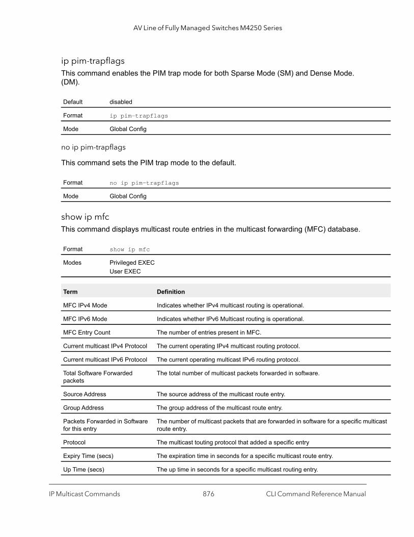
AV Line of Fully Managed Switches M4250 Series
ticast
ip pim-trapflagsThis command enables the PIM trap mode for both Sparse Mode (SM) and Dense Mode. (DM).
no ip pim-trapflags
This command sets the PIM trap mode to the default.
show ip mfcThis command displays multicast route entries in the multicast forwarding (MFC) database.
Default disabled
Format ip pim-trapflags
Mode Global Config
Format no ip pim-trapflags
Mode Global Config
Format show ip mfc
Modes Privileged EXECUser EXEC
Term Definition
MFC IPv4 Mode Indicates whether IPv4 multicast routing is operational.
MFC IPv6 Mode Indicates whether IPv6 Multicast routing is operational.
MFC Entry Count The number of entries present in MFC.
Current multicast IPv4 Protocol The current operating IPv4 multicast routing protocol.
Current multicast IPv6 Protocol The current operating multicast IPv6 routing protocol.
Total Software Forwarded packets
The total number of multicast packets forwarded in software.
Source Address The source address of the multicast route entry.
Group Address The group address of the multicast route entry.
Packets Forwarded in Software for this entry
The number of multicast packets that are forwarded in software for a specific mulroute entry.
Protocol The multicast touting protocol that added a specific entry
Expiry Time (secs) The expiration time in seconds for a specific multicast route entry.
Up Time (secs) The up time in seconds for a specific multicast routing entry.
IP Multicast Commands CLI Command Reference Manual876

AV Line of Fully Managed Switches M4250 Series
Command example: (NETGEAR) #show ip mfc
MFC IPv4 Mode.................................. EnabledMFC IPv6 Mode.................................. DisabledMFC Entry Count ............................... 1Current multicast IPv4 protocol................ PIMSMCurrent multicast IPv6 protocol................ No protocol enabled.Total software forwarded packets .............. 0Source address: 192.168.10.5Group address: 225.1.1.1Packets forwarded in software for this entry: 0 Protocol: PIM-SMExpiry Time (secs): 206 Up Time (secs): 4Incoming interface: 1/0/10 Outgoing interface list: None
show ip pimThis command displays the system-wide information for PIM-DM or PIM-SM.
Note: If the PIM mode is PIM-DM (dense), some of the fields in the following table do not display in the command output because they are applicable only to PIM-SM.
Incoming interface The incoming interface for a specific multicast route entry.
Outgoing interface list The outgoing interface list for a specific multicast route entry.
Format show ip pim
Modes Privileged EXECUser EXEC
Term Definition
PIM Mode Indicates the configured mode of the PIM protocol as dense (PIM-DM) or sparse(PIM-SM)
Interface unit/port
Interface Mode Indicates whether PIM is enabled or disabled on this interface.
Operational Status The current state of PIM on this interface: Operational or Non-Operational.
Term Definition
IP Multicast Commands CLI Command Reference Manual877

AV Line of Fully Managed Switches M4250 Series
The following example shows PIM Mode - Dense:(NETGEAR) #show ip pim
PIM Mode Dense
Interface Interface-Mode Operational-Status--------- -------------- ------------------1/0/1 Enabled Operational1/0/3 Disabled Non-Operational
Command example:
The following example shows PIM Mode - Sparse(NETGEAR) #show ip pim
PIM Mode Sparse
Interface Interface-Mode Operational-Status--------- -------------- ------------------1/0/1 Enabled Operational1/0/3 Disabled Non-Operational
Command example:
The following example shows that PIM is not configured:(NETGEAR) #show ip pim
PIM Mode None
None of the routing interfaces are enabled for PIM.
show ip pim ssmThis command displays the configured source specific IP multicast addresses.
Format show ip pim ssm
Modes Privileged EXECUser EXEC
Term Definition
Group Address The IP multicast address of the SSM group.
Prefix Length The network prefix length.
IP Multicast Commands CLI Command Reference Manual878
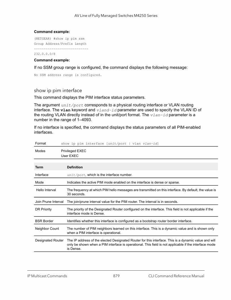
AV Line of Fully Managed Switches M4250 Series
lue is
the
only
d will ode
Command example: (NETGEAR) #show ip pim ssmGroup Address/Prefix Length----------------------------232.0.0.0/8
Command example:
If no SSM group range is configured, the command displays the following message: No SSM address range is configured.
show ip pim interfaceThis command displays the PIM interface status parameters.
The argument unit/port corresponds to a physical routing interface or VLAN routing interface. The vlan keyword and vland-id parameter are used to specify the VLAN ID of the routing VLAN directly instead of in the unit/port format. The vlan-id parameter is a number in the range of 1–4093.
If no interface is specified, the command displays the status parameters of all PIM-enabled interfaces.
Format show ip pim interface [unit/port | vlan vlan-id]
Modes Privileged EXECUser EXEC
Term Definition
Interface unit/port, which is the interface number.
Mode Indicates the active PIM mode enabled on the interface is dense or sparse.
Hello Interval The frequency at which PIM hello messages are transmitted on this interface. By default, the va30 seconds.
Join Prune Interval The join/prune interval value for the PIM router. The interval is in seconds.
DR Priority The priority of the Designated Router configured on the interface. This field is not applicable ifinterface mode is Dense.
BSR Border Identifies whether this interface is configured as a bootstrap router border interface.
Neighbor Count The number of PIM neighbors learned on this interface. This is a dynamic value and is shownwhen a PIM interface is operational.
Designated Router The IP address of the elected Designated Router for this interface. This is a dynamic value anonly be shown when a PIM interface is operational. This field is not applicable if the interface mis Dense.
IP Multicast Commands CLI Command Reference Manual879

AV Line of Fully Managed Switches M4250 Series
Command example: (NETGEAR) #show ip pim interface
Interface.........................................1/0/1 Mode............................................Sparse Hello Interval (secs)...........................30 Join Prune Interval (secs)......................60 DR Priority.....................................1 BSR Border......................................Disabled Neighbor Count..................................1 Designated Router...............................192.168.10.1
Interface.........................................1/0/2 Mode............................................Sparse Hello Interval (secs)...........................30 Join Prune Interval (secs)......................60 DR Priority.....................................1 BSR Border......................................Disabled Neighbor Count..................................1 Designated Router...............................192.168.10.1
Command example:
If none of the interfaces are enabled for PIM, the following message is displayed:None of the routing interfaces are enabled for PIM.
show ip pim neighborThis command displays PIM neighbors discovered by PIMv2 Hello messages.
The argument unit/port corresponds to a physical routing interface or VLAN routing interface. The vlan keyword and vland-id parameter are used to specify the VLAN ID of the routing VLAN directly instead of in the unit/port format. The vlan-id parameter is a number in the range of 1–4093.
If the interface number is not specified, the command displays the status parameters of all PIM-enabled interfaces.
Format show ip pim neighbor [unit/port | vlan vlan-id]
Modes Privileged EXECUser EXEC
Term Definition
Neighbor Address The IP address of the PIM neighbor on an interface.
Interface unit/port
IP Multicast Commands CLI Command Reference Manual880

AV Line of Fully Managed Switches M4250 Series
rs.
Command example: (NETGEAR) #show ip pim neighbor 1/0/1
Neighbor Addr Interface Uptime Expiry Time DR (hh:mm:ss) (hh:mm:ss) Priority--------------- --------- ----------- ----------- --------192.168.10.2 1/0/1 00:02:55 00:01:15 NA
Command example: (NETGEAR) #show ip pim neighbor
Neighbor Addr Interface Uptime Expiry Time DR (hh:mm:ss) (hh:mm:ss) Priority--------------- --------- ----------- ----------- --------192.168.10.2 1/0/1 00:02:55 00:01:15 1192.168.20.2 1/0/2 00:03:50 00:02:10 1
Command example:
If no neighbors were learned on any of the interfaces, the following message is displayed:No neighbors exist on the router.
show ip pim bsr-routerThis command displays the bootstrap router (BSR) information.
Up Time The time since this neighbor has become active on this interface.
Expiry Time Time remaining for the neighbor to expire.
DR Priority The DR Priority configured on this Interface (PIM-SM only).
Note: DR Priority is applicable only when sparse-mode configured routers are neighboOtherwise, NA is displayed in this field.
Format show ip pim bsr-router {candidate | elected}
Mode Privileged EXECUser EXEC
Parameter Definition
BSR Address IP address of the BSR.
BSR Priority Priority as configured in the ip pim bsr-candidate command.
Term Definition
IP Multicast Commands CLI Command Reference Manual881
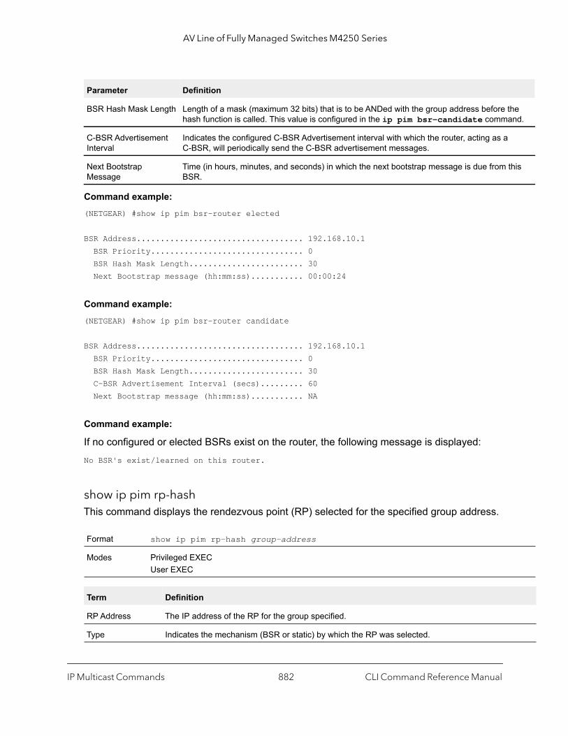
AV Line of Fully Managed Switches M4250 Series
e nd.
his
Command example: (NETGEAR) #show ip pim bsr-router elected
BSR Address................................... 192.168.10.1 BSR Priority................................ 0 BSR Hash Mask Length........................ 30 Next Bootstrap message (hh:mm:ss)........... 00:00:24
Command example: (NETGEAR) #show ip pim bsr-router candidate
BSR Address................................... 192.168.10.1 BSR Priority................................ 0 BSR Hash Mask Length........................ 30 C-BSR Advertisement Interval (secs)......... 60 Next Bootstrap message (hh:mm:ss)........... NA
Command example:
If no configured or elected BSRs exist on the router, the following message is displayed:No BSR's exist/learned on this router.
show ip pim rp-hashThis command displays the rendezvous point (RP) selected for the specified group address.
BSR Hash Mask Length Length of a mask (maximum 32 bits) that is to be ANDed with the group address before thhash function is called. This value is configured in the ip pim bsr-candidate comma
C-BSR Advertisement Interval
Indicates the configured C-BSR Advertisement interval with which the router, acting as a C-BSR, will periodically send the C-BSR advertisement messages.
Next Bootstrap Message
Time (in hours, minutes, and seconds) in which the next bootstrap message is due from tBSR.
Format show ip pim rp-hash group-address
Modes Privileged EXECUser EXEC
Term Definition
RP Address The IP address of the RP for the group specified.
Type Indicates the mechanism (BSR or static) by which the RP was selected.
Parameter Definition
IP Multicast Commands CLI Command Reference Manual882

AV Line of Fully Managed Switches M4250 Series
ate
Command example: (NETGEAR) #show ip pim rp-hash 224.1.2.0
RP Address 192.168.10.1 Type Static
Command example:
If no RP Group mapping exist on the router, the following message is displayed:No RP-Group mappings exist/learned on this router.
show ip pim rp mappingUse this command to display the mapping for the PIM group to the active Rendezvous points (RP) of which the router is a aware (either configured or learned from the bootstrap router (BSR)). Use the optional parameters to limit the display to a specific RP address (rp-address) or to view group-to-candidate RP (candidate) or group to Static RP mapping information (static).
Command example: (NETGEAR) #show ip pim rp mapping 192.168.10.1
RP Address 192.168.10.1 Group Address 224.1.2.1 Group Mask 255.255.255.0 Origin Static
Format show ip pim rp mapping [rp-address | candidate | static]
Modes Privileged EXECUser EXEC
Term Definition
RP Address The IP address of the RP for the group specified.
Group Address The IP address of the multicast group.
Group Mask The subnet mask associated with the group.
Origin Indicates the mechanism (BSR or static) by which the RP was selected.
C-RP Advertisement Interval
Indicates the configured C-RP Advertisement interval with which the router acting as a CandidRP will periodically send the C-RP advertisement messages to the elected BSR.
IP Multicast Commands CLI Command Reference Manual883
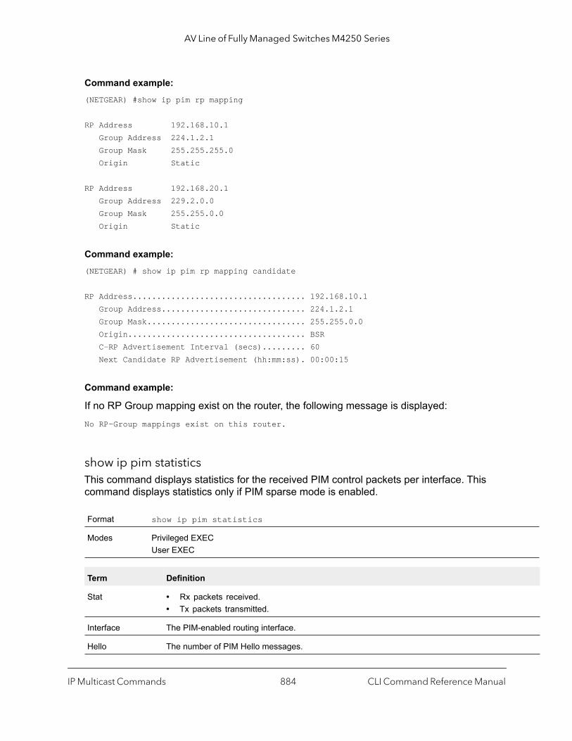
AV Line of Fully Managed Switches M4250 Series
Command example: (NETGEAR) #show ip pim rp mapping
RP Address 192.168.10.1 Group Address 224.1.2.1 Group Mask 255.255.255.0 Origin Static
RP Address 192.168.20.1 Group Address 229.2.0.0 Group Mask 255.255.0.0 Origin Static
Command example: (NETGEAR) # show ip pim rp mapping candidate
RP Address.................................... 192.168.10.1 Group Address.............................. 224.1.2.1 Group Mask................................. 255.255.0.0 Origin..................................... BSR C-RP Advertisement Interval (secs)......... 60 Next Candidate RP Advertisement (hh:mm:ss). 00:00:15
Command example:
If no RP Group mapping exist on the router, the following message is displayed:No RP-Group mappings exist on this router.
show ip pim statisticsThis command displays statistics for the received PIM control packets per interface. This command displays statistics only if PIM sparse mode is enabled.
Format show ip pim statistics
Modes Privileged EXECUser EXEC
Term Definition
Stat • Rx packets received.• Tx packets transmitted.
Interface The PIM-enabled routing interface.
Hello The number of PIM Hello messages.
IP Multicast Commands CLI Command Reference Manual884
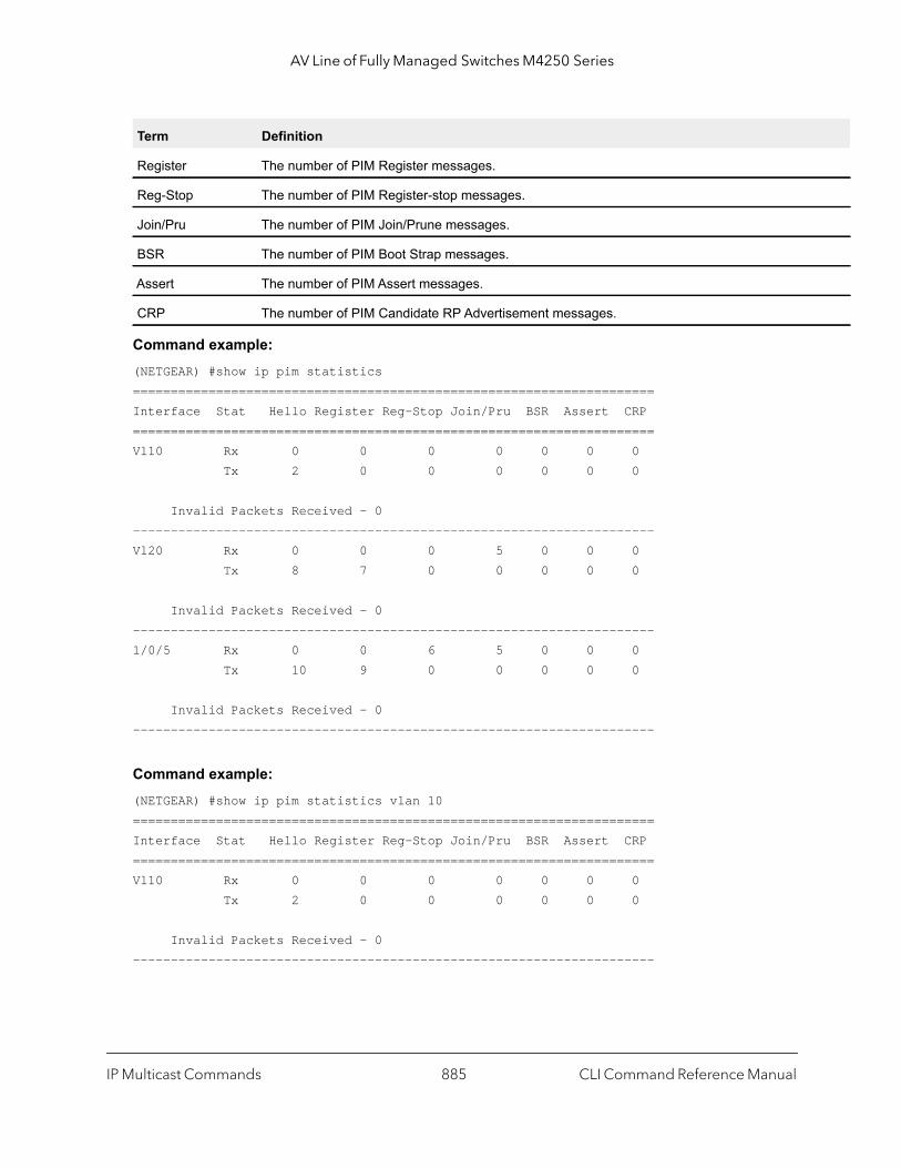
AV Line of Fully Managed Switches M4250 Series
Command example: (NETGEAR) #show ip pim statistics=====================================================================Interface Stat Hello Register Reg-Stop Join/Pru BSR Assert CRP =====================================================================Vl10 Rx 0 0 0 0 0 0 0 Tx 2 0 0 0 0 0 0
Invalid Packets Received - 0---------------------------------------------------------------------Vl20 Rx 0 0 0 5 0 0 0 Tx 8 7 0 0 0 0 0
Invalid Packets Received - 0---------------------------------------------------------------------1/0/5 Rx 0 0 6 5 0 0 0 Tx 10 9 0 0 0 0 0
Invalid Packets Received - 0---------------------------------------------------------------------
Command example: (NETGEAR) #show ip pim statistics vlan 10=====================================================================Interface Stat Hello Register Reg-Stop Join/Pru BSR Assert CRP =====================================================================Vl10 Rx 0 0 0 0 0 0 0 Tx 2 0 0 0 0 0 0
Invalid Packets Received - 0---------------------------------------------------------------------
Register The number of PIM Register messages.
Reg-Stop The number of PIM Register-stop messages.
Join/Pru The number of PIM Join/Prune messages.
BSR The number of PIM Boot Strap messages.
Assert The number of PIM Assert messages.
CRP The number of PIM Candidate RP Advertisement messages.
Term Definition
IP Multicast Commands CLI Command Reference Manual885

AV Line of Fully Managed Switches M4250 Series
Command example: (NETGEAR) #show ip pim statistics 1/0/5=====================================================================Interface Stat Hello Register Reg-Stop Join/Pru BSR Assert CRP =====================================================================1/0/5 Rx 0 0 6 5 0 0 0 Tx 10 9 0 0 0 0 0
Invalid Packets Received - 0
Internet Group Message Protocol Commands
This section describes the commands you use to view and configure Internet Group Message Protocol (IGMP) settings.
ip igmpThis command sets the administrative mode of IGMP in the system to active on an interface, range of interfaces, or on all interfaces.
no ip igmp
This command sets the administrative mode of IGMP in the system to inactive.
Default disabled
Format ip igmp
Modes Global ConfigInterface Config
Format no ip igmp
Modes Global ConfigInterface Config
IP Multicast Commands CLI Command Reference Manual886
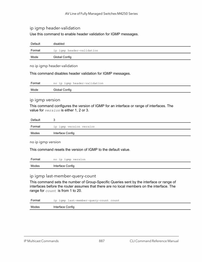
AV Line of Fully Managed Switches M4250 Series
ip igmp header-validationUse this command to enable header validation for IGMP messages.
no ip igmp header-validation
This command disables header validation for IGMP messages.
ip igmp versionThis command configures the version of IGMP for an interface or range of interfaces. The value for version is either 1, 2 or 3.
no ip igmp version
This command resets the version of IGMP to the default value.
ip igmp last-member-query-countThis command sets the number of Group-Specific Queries sent by the interface or range of interfaces before the router assumes that there are no local members on the interface. The range for count is from 1 to 20.
Default disabled
Format ip igmp header-validation
Mode Global Config
Format no ip igmp header-validation
Mode Global Config
Default 3
Format ip igmp version version
Modes Interface Config
Format no ip igmp version
Modes Interface Config
Format ip igmp last-member-query-count count
Modes Interface Config
IP Multicast Commands CLI Command Reference Manual887
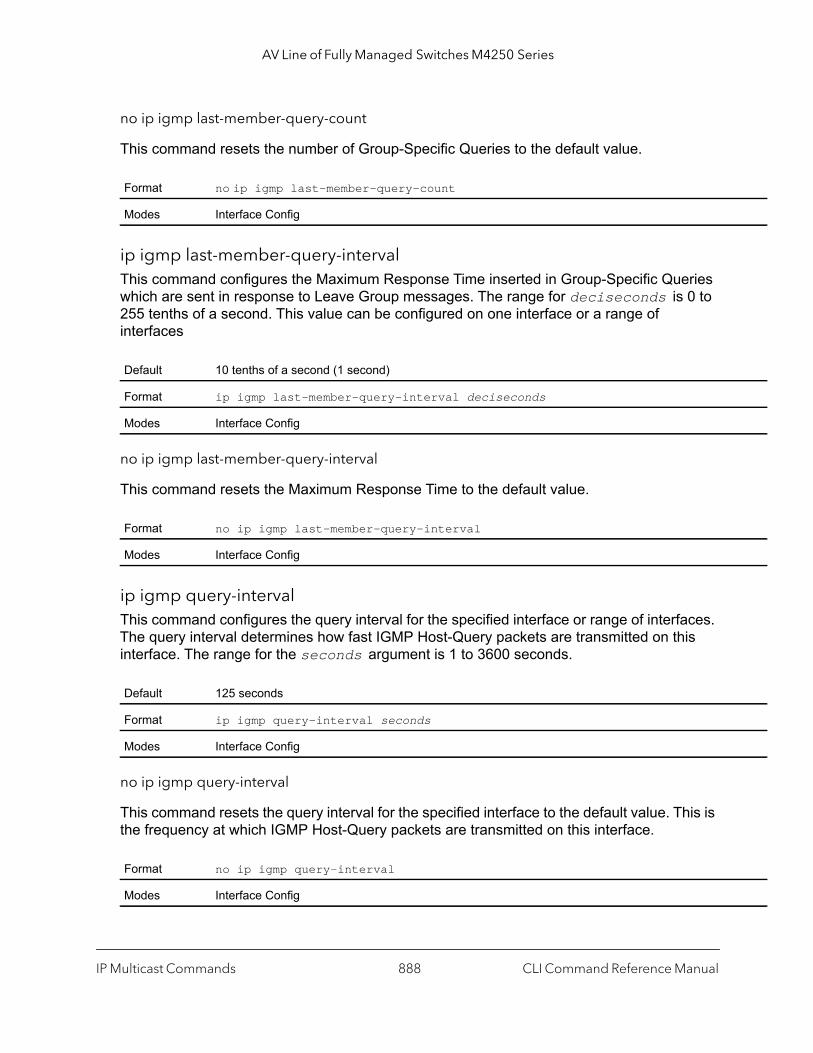
AV Line of Fully Managed Switches M4250 Series
no ip igmp last-member-query-count
This command resets the number of Group-Specific Queries to the default value.
ip igmp last-member-query-intervalThis command configures the Maximum Response Time inserted in Group-Specific Queries which are sent in response to Leave Group messages. The range for deciseconds is 0 to 255 tenths of a second. This value can be configured on one interface or a range of interfaces
no ip igmp last-member-query-interval
This command resets the Maximum Response Time to the default value.
ip igmp query-intervalThis command configures the query interval for the specified interface or range of interfaces. The query interval determines how fast IGMP Host-Query packets are transmitted on this interface. The range for the seconds argument is 1 to 3600 seconds.
no ip igmp query-interval
This command resets the query interval for the specified interface to the default value. This is the frequency at which IGMP Host-Query packets are transmitted on this interface.
Format no ip igmp last-member-query-count
Modes Interface Config
Default 10 tenths of a second (1 second)
Format ip igmp last-member-query-interval deciseconds
Modes Interface Config
Format no ip igmp last-member-query-interval
Modes Interface Config
Default 125 seconds
Format ip igmp query-interval seconds
Modes Interface Config
Format no ip igmp query-interval
Modes Interface Config
IP Multicast Commands CLI Command Reference Manual888
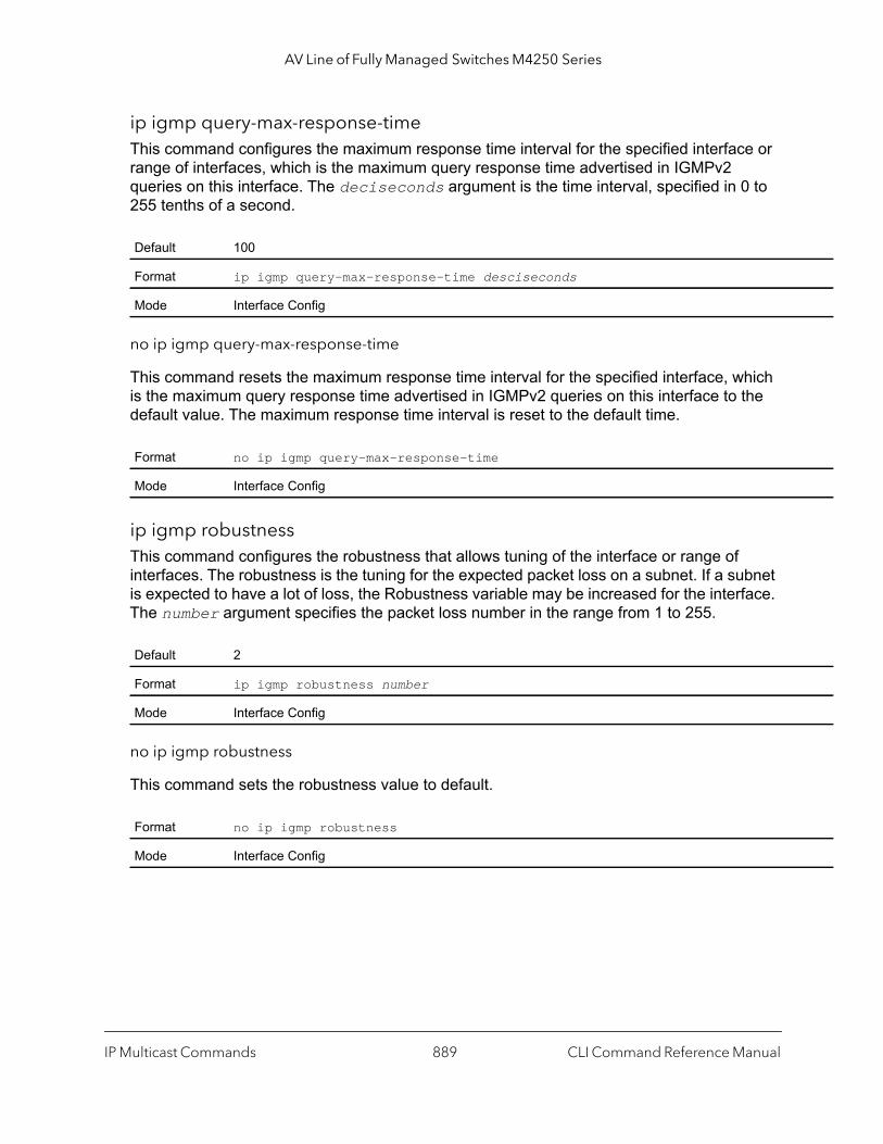
AV Line of Fully Managed Switches M4250 Series
ip igmp query-max-response-timeThis command configures the maximum response time interval for the specified interface or range of interfaces, which is the maximum query response time advertised in IGMPv2 queries on this interface. The deciseconds argument is the time interval, specified in 0 to 255 tenths of a second.
no ip igmp query-max-response-time
This command resets the maximum response time interval for the specified interface, which is the maximum query response time advertised in IGMPv2 queries on this interface to the default value. The maximum response time interval is reset to the default time.
ip igmp robustnessThis command configures the robustness that allows tuning of the interface or range of interfaces. The robustness is the tuning for the expected packet loss on a subnet. If a subnet is expected to have a lot of loss, the Robustness variable may be increased for the interface. The number argument specifies the packet loss number in the range from 1 to 255.
no ip igmp robustness
This command sets the robustness value to default.
Default 100
Format ip igmp query-max-response-time desciseconds
Mode Interface Config
Format no ip igmp query-max-response-time
Mode Interface Config
Default 2
Format ip igmp robustness number
Mode Interface Config
Format no ip igmp robustness
Mode Interface Config
IP Multicast Commands CLI Command Reference Manual889

AV Line of Fully Managed Switches M4250 Series
ip igmp startup-query-countThis command sets the number of Queries sent out on startup, separated by the Startup Query Interval on the interface or range of interfaces. The range for the number argument is 1 to 20.
no ip igmp startup-query-count
This command resets the number of Queries sent out on startup, separated by the Startup Query Interval on the interface to the default value.
ip igmp startup-query-intervalThis command sets the interval between General Queries sent on startup on the interface or range of interfaces. The time interval value is in seconds. The range for the seconds argument is 1 to 300 seconds.
no ip igmp startup-query-interval
This command resets the interval between General Queries sent on startup on the interface to the default value.
show ip igmpThis command displays the system-wide IGMP information.
Default 2
Format ip igmp startup-query-count number
Mode Interface Config
Format no ip igmp startup-query-count
Mode Interface Config
Default 31
Format ip igmp startup-query-interval seconds
Mode Interface Config
Format no ip igmp startup-query-interval
Mode Interface Config
Format show ip igmp
Modes Privileged EXECUser EXEC
IP Multicast Commands CLI Command Reference Manual890

AV Line of Fully Managed Switches M4250 Series
al.
t
show ip igmp groupsThis command displays the registered multicast groups on the interface.
The argument unit/port corresponds to a physical routing interface or VLAN routing interface. The vlan keyword and vland-id parameter are used to specify the VLAN ID of the routing VLAN directly instead of in the unit/port format. The vlan-id parameter is a number in the range of 1–4093.
If detail is specified this command displays the registered multicast groups on the interface in detail.
If you do not use the detail keyword, the following fields display.
The following fields are not displayed if the interface is not enabled.
If you use the detail keyword, the following fields display.
Term Definition
IGMP Admin Mode The administrative status of IGMP. This is a configured value.
Interface unit/port
Interface Mode Indicates whether IGMP is enabled or disabled on the interface. This is a configured value.
Protocol State The current state of IGMP on this interface. Possible values are Operational or Non-Operation
Format show ip igmp groups {unit/port | vlan vland-id} [detail]
Mode Privileged EXEC
Term Definition
IP Address The IP address of the interface participating in the multicast group.
Subnet Mask The subnet mask of the interface participating in the multicast group.
Interface Mode This displays whether IGMP is enabled or disabled on this interface.
Term Definition
Querier Status This displays whether the interface has IGMP in Querier mode or Non-Querier mode.
Groups The list of multicast groups that are registered on this interface.
Term Definition
Multicast IP Address
The IP address of the registered multicast group on this interface.
Last Reporter The IP address of the source of the last membership report received for the specified multicasgroup address on this interface.
IP Multicast Commands CLI Command Reference Manual891
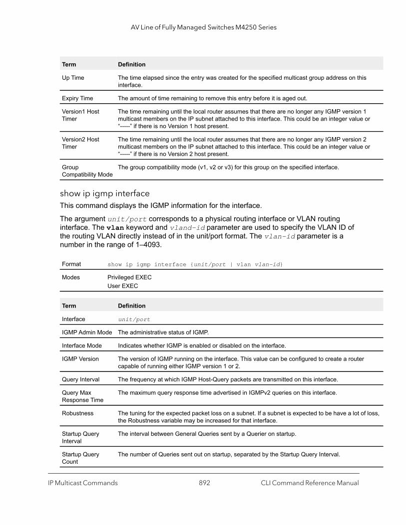
AV Line of Fully Managed Switches M4250 Series
or
or
loss,
show ip igmp interfaceThis command displays the IGMP information for the interface.
The argument unit/port corresponds to a physical routing interface or VLAN routing interface. The vlan keyword and vland-id parameter are used to specify the VLAN ID of the routing VLAN directly instead of in the unit/port format. The vlan-id parameter is a number in the range of 1–4093.
Up Time The time elapsed since the entry was created for the specified multicast group address on thisinterface.
Expiry Time The amount of time remaining to remove this entry before it is aged out.
Version1 Host Timer
The time remaining until the local router assumes that there are no longer any IGMP version 1multicast members on the IP subnet attached to this interface. This could be an integer value “-----” if there is no Version 1 host present.
Version2 Host Timer
The time remaining until the local router assumes that there are no longer any IGMP version 2multicast members on the IP subnet attached to this interface. This could be an integer value “-----” if there is no Version 2 host present.
Group Compatibility Mode
The group compatibility mode (v1, v2 or v3) for this group on the specified interface.
Format show ip igmp interface {unit/port | vlan vlan-id}
Modes Privileged EXECUser EXEC
Term Definition
Interface unit/port
IGMP Admin Mode The administrative status of IGMP.
Interface Mode Indicates whether IGMP is enabled or disabled on the interface.
IGMP Version The version of IGMP running on the interface. This value can be configured to create a router capable of running either IGMP version 1 or 2.
Query Interval The frequency at which IGMP Host-Query packets are transmitted on this interface.
Query Max Response Time
The maximum query response time advertised in IGMPv2 queries on this interface.
Robustness The tuning for the expected packet loss on a subnet. If a subnet is expected to be have a lot ofthe Robustness variable may be increased for that interface.
Startup Query Interval
The interval between General Queries sent by a Querier on startup.
Startup Query Count
The number of Queries sent out on startup, separated by the Startup Query Interval.
Term Definition
IP Multicast Commands CLI Command Reference Manual892
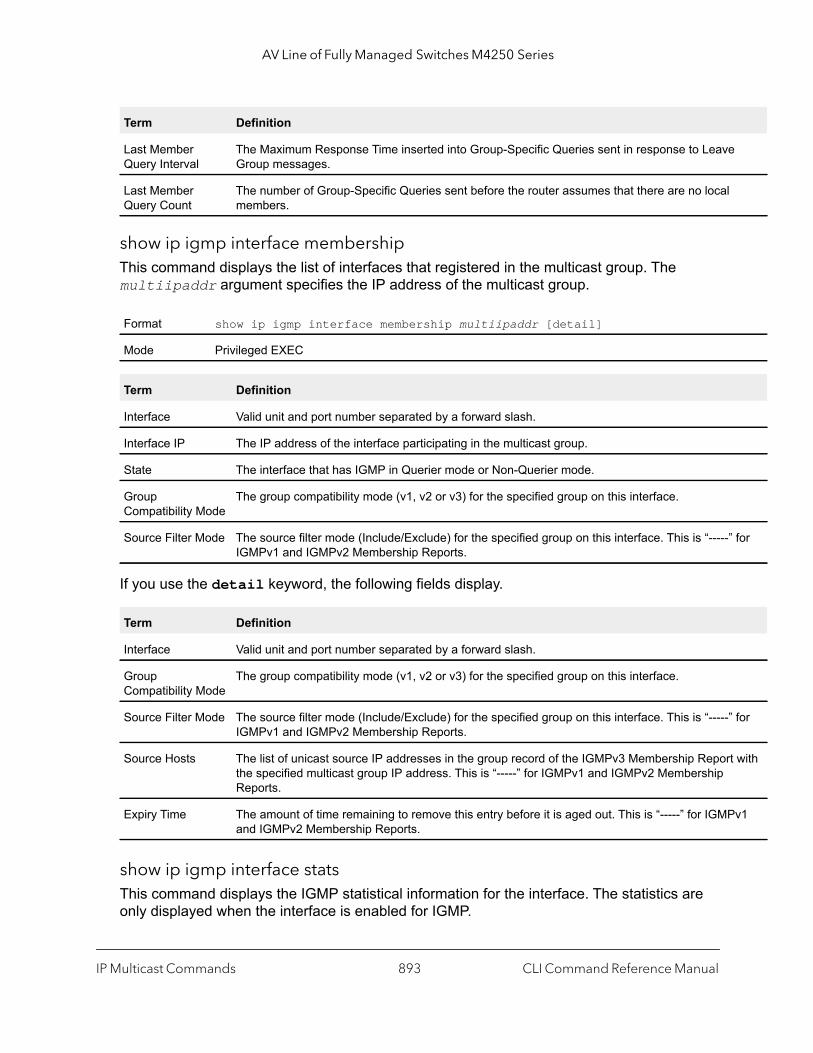
AV Line of Fully Managed Switches M4250 Series
for
for
t with
v1
show ip igmp interface membershipThis command displays the list of interfaces that registered in the multicast group. The multiipaddr argument specifies the IP address of the multicast group.
If you use the detail keyword, the following fields display.
show ip igmp interface statsThis command displays the IGMP statistical information for the interface. The statistics are only displayed when the interface is enabled for IGMP.
Last Member Query Interval
The Maximum Response Time inserted into Group-Specific Queries sent in response to LeaveGroup messages.
Last Member Query Count
The number of Group-Specific Queries sent before the router assumes that there are no localmembers.
Format show ip igmp interface membership multiipaddr [detail]
Mode Privileged EXEC
Term Definition
Interface Valid unit and port number separated by a forward slash.
Interface IP The IP address of the interface participating in the multicast group.
State The interface that has IGMP in Querier mode or Non-Querier mode.
Group Compatibility Mode
The group compatibility mode (v1, v2 or v3) for the specified group on this interface.
Source Filter Mode The source filter mode (Include/Exclude) for the specified group on this interface. This is “-----”IGMPv1 and IGMPv2 Membership Reports.
Term Definition
Interface Valid unit and port number separated by a forward slash.
Group Compatibility Mode
The group compatibility mode (v1, v2 or v3) for the specified group on this interface.
Source Filter Mode The source filter mode (Include/Exclude) for the specified group on this interface. This is “-----”IGMPv1 and IGMPv2 Membership Reports.
Source Hosts The list of unicast source IP addresses in the group record of the IGMPv3 Membership Reporthe specified multicast group IP address. This is “-----” for IGMPv1 and IGMPv2 Membership Reports.
Expiry Time The amount of time remaining to remove this entry before it is aged out. This is “-----” for IGMPand IGMPv2 Membership Reports.
Term Definition
IP Multicast Commands CLI Command Reference Manual893
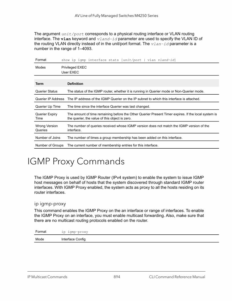
AV Line of Fully Managed Switches M4250 Series
em is
The argument unit/port corresponds to a physical routing interface or VLAN routing interface. The vlan keyword and vland-id parameter are used to specify the VLAN ID of the routing VLAN directly instead of in the unit/port format. The vlan-id parameter is a number in the range of 1–4093.
IGMP Proxy Commands
The IGMP Proxy is used by IGMP Router (IPv4 system) to enable the system to issue IGMP host messages on behalf of hosts that the system discovered through standard IGMP router interfaces. With IGMP Proxy enabled, the system acts as proxy to all the hosts residing on its router interfaces.
ip igmp-proxy This command enables the IGMP Proxy on the an interface or range of interfaces. To enable the IGMP Proxy on an interface, you must enable multicast forwarding. Also, make sure that there are no multicast routing protocols enabled on the router.
Format show ip igmp interface stats [unit/port | vlan vland-id]
Modes Privileged EXECUser EXEC
Term Definition
Querier Status The status of the IGMP router, whether it is running in Querier mode or Non-Querier mode.
Querier IP Address The IP address of the IGMP Querier on the IP subnet to which this interface is attached.
Querier Up Time The time since the interface Querier was last changed.
Querier Expiry Time
The amount of time remaining before the Other Querier Present Timer expires. If the local systthe querier, the value of this object is zero.
Wrong Version Queries
The number of queries received whose IGMP version does not match the IGMP version of theinterface.
Number of Joins The number of times a group membership has been added on this interface.
Number of Groups The current number of membership entries for this interface.
Format ip igmp-proxy
Mode Interface Config
IP Multicast Commands CLI Command Reference Manual894

AV Line of Fully Managed Switches M4250 Series
no ip igmp-proxy
This command disables the IGMP Proxy on the router.
ip igmp-proxy unsolicit-rprt-intervalThis command sets the unsolicited report interval for the IGMP Proxy interface or range of interfaces. This command is valid only when you enable IGMP Proxy on the interface or range of interfaces. The value for the seconds argument is a number in the range 1–260 seconds.
no ip igmp-proxy unsolicit-rprt-interval
This command resets the unsolicited report interval of the IGMP Proxy router to the default value.
ip igmp-proxy reset-status This command resets the host interface status parameters of the IGMP Proxy interface (or range of interfaces). This command is valid only when you enable IGMP Proxy on the interface.
show ip igmp-proxy This command displays a summary of the host interface status parameters. It displays the following parameters only when you enable IGMP Proxy.
Format no ip igmp-proxy
Mode Interface Config
Default 1
Format ip igmp-proxy unsolicit-rprt-interval seconds
Mode Interface Config
Format no ip igmp-proxy unsolicit-rprt-interval
Mode Interface Config
Format ip igmp-proxy reset-status
Mode Interface Config
Format show ip igmp-proxy
Modes Privileged EXECUser EXEC
IP Multicast Commands CLI Command Reference Manual895
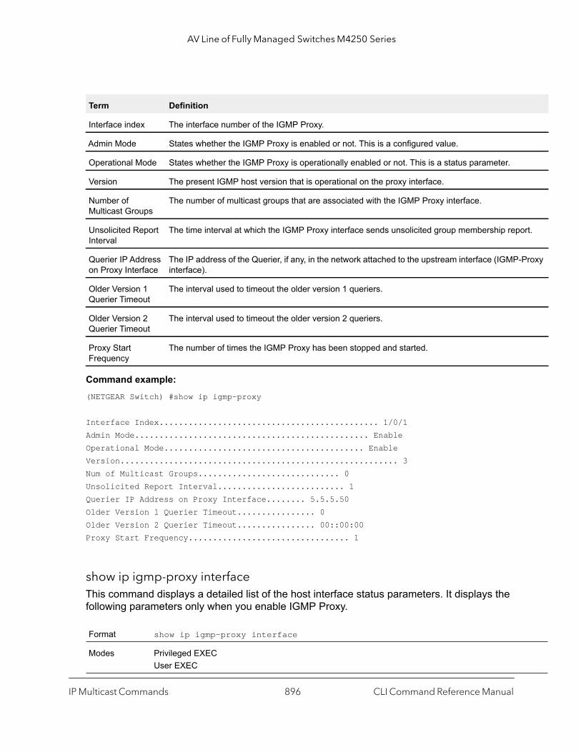
AV Line of Fully Managed Switches M4250 Series
rt.
roxy
Command example: (NETGEAR Switch) #show ip igmp-proxy
Interface Index............................................. 1/0/1Admin Mode................................................ EnableOperational Mode......................................... EnableVersion......................................................... 3Num of Multicast Groups............................. 0Unsolicited Report Interval.......................... 1Querier IP Address on Proxy Interface........ 5.5.5.50Older Version 1 Querier Timeout................ 0Older Version 2 Querier Timeout................ 00::00:00Proxy Start Frequency................................. 1
show ip igmp-proxy interfaceThis command displays a detailed list of the host interface status parameters. It displays the following parameters only when you enable IGMP Proxy.
Term Definition
Interface index The interface number of the IGMP Proxy.
Admin Mode States whether the IGMP Proxy is enabled or not. This is a configured value.
Operational Mode States whether the IGMP Proxy is operationally enabled or not. This is a status parameter.
Version The present IGMP host version that is operational on the proxy interface.
Number of Multicast Groups
The number of multicast groups that are associated with the IGMP Proxy interface.
Unsolicited Report Interval
The time interval at which the IGMP Proxy interface sends unsolicited group membership repo
Querier IP Address on Proxy Interface
The IP address of the Querier, if any, in the network attached to the upstream interface (IGMP-Pinterface).
Older Version 1 Querier Timeout
The interval used to timeout the older version 1 queriers.
Older Version 2 Querier Timeout
The interval used to timeout the older version 2 queriers.
Proxy Start Frequency
The number of times the IGMP Proxy has been stopped and started.
Format show ip igmp-proxy interface
Modes Privileged EXECUser EXEC
IP Multicast Commands CLI Command Reference Manual896
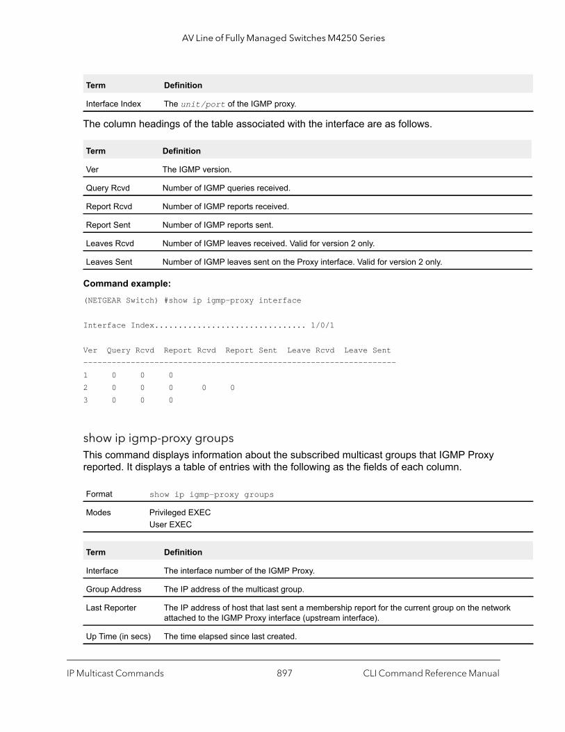
AV Line of Fully Managed Switches M4250 Series
The column headings of the table associated with the interface are as follows.
Command example: (NETGEAR Switch) #show ip igmp-proxy interface
Interface Index................................ 1/0/1
Ver Query Rcvd Report Rcvd Report Sent Leave Rcvd Leave Sent------------------------------------------------------------------1 0 0 02 0 0 0 0 03 0 0 0
show ip igmp-proxy groupsThis command displays information about the subscribed multicast groups that IGMP Proxy reported. It displays a table of entries with the following as the fields of each column.
Term Definition
Interface Index The unit/port of the IGMP proxy.
Term Definition
Ver The IGMP version.
Query Rcvd Number of IGMP queries received.
Report Rcvd Number of IGMP reports received.
Report Sent Number of IGMP reports sent.
Leaves Rcvd Number of IGMP leaves received. Valid for version 2 only.
Leaves Sent Number of IGMP leaves sent on the Proxy interface. Valid for version 2 only.
Format show ip igmp-proxy groups
Modes Privileged EXECUser EXEC
Term Definition
Interface The interface number of the IGMP Proxy.
Group Address The IP address of the multicast group.
Last Reporter The IP address of host that last sent a membership report for the current group on the networkattached to the IGMP Proxy interface (upstream interface).
Up Time (in secs) The time elapsed since last created.
IP Multicast Commands CLI Command Reference Manual897
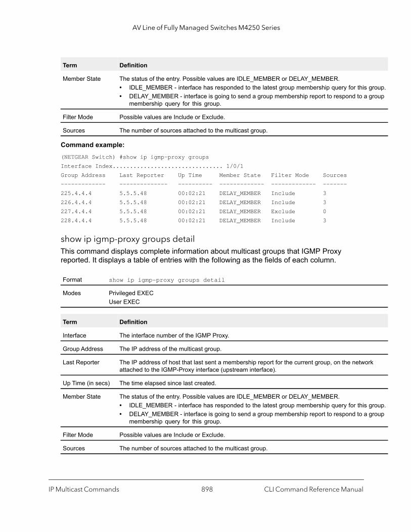
AV Line of Fully Managed Switches M4250 Series
roup.roup
k
roup.roup
Command example: (NETGEAR Switch) #show ip igmp-proxy groupsInterface Index................................ 1/0/1Group Address Last Reporter Up Time Member State Filter Mode Sources------------- -------------- ---------- ------------- ------------- -------225.4.4.4 5.5.5.48 00:02:21 DELAY_MEMBER Include 3226.4.4.4 5.5.5.48 00:02:21 DELAY_MEMBER Include 3227.4.4.4 5.5.5.48 00:02:21 DELAY_MEMBER Exclude 0228.4.4.4 5.5.5.48 00:02:21 DELAY_MEMBER Include 3
show ip igmp-proxy groups detailThis command displays complete information about multicast groups that IGMP Proxy reported. It displays a table of entries with the following as the fields of each column.
Member State The status of the entry. Possible values are IDLE_MEMBER or DELAY_MEMBER.• IDLE_MEMBER - interface has responded to the latest group membership query for this g• DELAY_MEMBER - interface is going to send a group membership report to respond to a g
membership query for this group.
Filter Mode Possible values are Include or Exclude.
Sources The number of sources attached to the multicast group.
Format show ip igmp-proxy groups detail
Modes Privileged EXECUser EXEC
Term Definition
Interface The interface number of the IGMP Proxy.
Group Address The IP address of the multicast group.
Last Reporter The IP address of host that last sent a membership report for the current group, on the networattached to the IGMP-Proxy interface (upstream interface).
Up Time (in secs) The time elapsed since last created.
Member State The status of the entry. Possible values are IDLE_MEMBER or DELAY_MEMBER.• IDLE_MEMBER - interface has responded to the latest group membership query for this g• DELAY_MEMBER - interface is going to send a group membership report to respond to a g
membership query for this group.
Filter Mode Possible values are Include or Exclude.
Sources The number of sources attached to the multicast group.
Term Definition
IP Multicast Commands CLI Command Reference Manual898
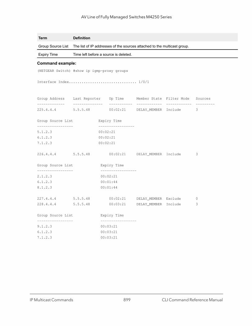
AV Line of Fully Managed Switches M4250 Series
Command example: (NETGEAR Switch) #show ip igmp-proxy groups
Interface Index................................ 1/0/1
Group Address Last Reporter Up Time Member State Filter Mode Sources------------- -------------- ----------- ------------ ------------ --------- 225.4.4.4 5.5.5.48 00:02:21 DELAY_MEMBER Include 3
Group Source List Expiry Time----------------- -----------------5.1.2.3 00:02:21 6.1.2.3 00:02:21 7.1.2.3 00:02:21
226.4.4.4 5.5.5.48 00:02:21 DELAY_MEMBER Include 3
Group Source List Expiry Time----------------- -----------------2.1.2.3 00:02:21 6.1.2.3 00:01:44 8.1.2.3 00:01:44
227.4.4.4 5.5.5.48 00:02:21 DELAY_MEMBER Exclude 0228.4.4.4 5.5.5.48 00:03:21 DELAY_MEMBER Include 3
Group Source List Expiry Time----------------- -----------------9.1.2.3 00:03:21 6.1.2.3 00:03:21 7.1.2.3 00:03:21
Group Source List The list of IP addresses of the sources attached to the multicast group.
Expiry Time Time left before a source is deleted.
Term Definition
IP Multicast Commands CLI Command Reference Manual899
12
12IPv6 Multicast CommandsThis chapter describes the IPv6 multicast commands.
The chapter contains the following sections:
• IPv6 Multicast Forwarder
• IPv6 PIM Commands
• IPv6 MLD Commands
• IPv6 MLD-Proxy Commands
Note: No specific command exists to enable multicast for IPv6. If you enable multicast with a global config command, multicast is enabled for both IPv4 and IPv6.
The commands in this chapter are in one of three functional groups:
• Show commands. Display switch settings, statistics, and other information.• Configuration commands. Configure features and options of the switch. For every
configuration command, there is a show command that displays the configuration setting.• Clear commands. Clear some or all of the settings to factory defaults.
900
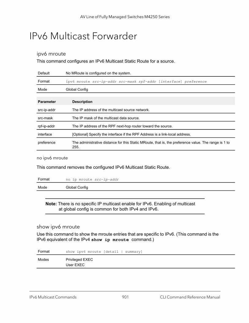
AV Line of Fully Managed Switches M4250 Series
1 to
IPv6 Multicast Forwarder
ipv6 mrouteThis command configures an IPv6 Multicast Static Route for a source.
no ipv6 mroute
This command removes the configured IPv6 Multicast Static Route.
Note: There is no specific IP multicast enable for IPv6. Enabling of multicast at global config is common for both IPv4 and IPv6.
show ipv6 mrouteUse this command to show the mroute entries that are specific to IPv6. (This command is the IPv6 equivalent of the IPv4 show ip mroute command.)
Default No MRoute is configured on the system.
Format ipv6 mroute src-ip-addr src-mask rpf-addr [interface] preference
Mode Global Config
Parameter Description
src-ip-addr The IP address of the multicast source network.
src-mask The IP mask of the multicast data source.
rpf-ip-addr The IP address of the RPF next-hop router toward the source.
interface [Optional] Specify the interface if the RPF Address is a link-local address.
preference The administrative distance for this Static MRoute, that is, the preference value. The range is 255.
Format no ip mroute src-ip-addr
Mode Global Config
Format show ipv6 mroute [detail | summary]
Modes Privileged EXECUser EXEC
IPv6 Multicast Commands CLI Command Reference Manual901
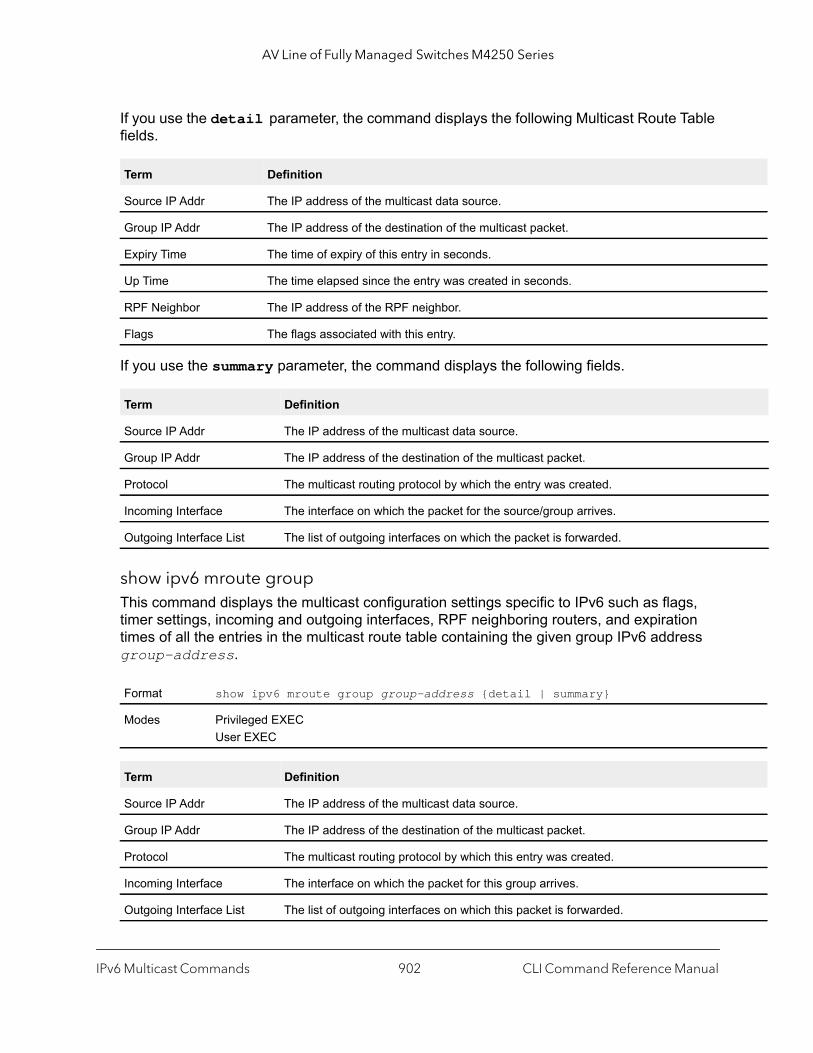
AV Line of Fully Managed Switches M4250 Series
If you use the detail parameter, the command displays the following Multicast Route Table fields.
If you use the summary parameter, the command displays the following fields.
show ipv6 mroute groupThis command displays the multicast configuration settings specific to IPv6 such as flags, timer settings, incoming and outgoing interfaces, RPF neighboring routers, and expiration times of all the entries in the multicast route table containing the given group IPv6 address group-address.
Term Definition
Source IP Addr The IP address of the multicast data source.
Group IP Addr The IP address of the destination of the multicast packet.
Expiry Time The time of expiry of this entry in seconds.
Up Time The time elapsed since the entry was created in seconds.
RPF Neighbor The IP address of the RPF neighbor.
Flags The flags associated with this entry.
Term Definition
Source IP Addr The IP address of the multicast data source.
Group IP Addr The IP address of the destination of the multicast packet.
Protocol The multicast routing protocol by which the entry was created.
Incoming Interface The interface on which the packet for the source/group arrives.
Outgoing Interface List The list of outgoing interfaces on which the packet is forwarded.
Format show ipv6 mroute group group-address {detail | summary}
Modes Privileged EXECUser EXEC
Term Definition
Source IP Addr The IP address of the multicast data source.
Group IP Addr The IP address of the destination of the multicast packet.
Protocol The multicast routing protocol by which this entry was created.
Incoming Interface The interface on which the packet for this group arrives.
Outgoing Interface List The list of outgoing interfaces on which this packet is forwarded.
IPv6 Multicast Commands CLI Command Reference Manual902
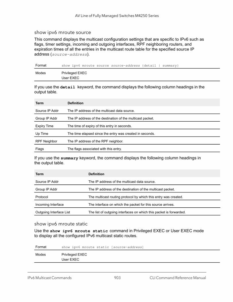
AV Line of Fully Managed Switches M4250 Series
show ipv6 mroute sourceThis command displays the multicast configuration settings that are specific to IPv6 such as flags, timer settings, incoming and outgoing interfaces, RPF neighboring routers, and expiration times of all the entries in the multicast route table for the specified source IP address (source-address).
If you use the detail keyword, the command displays the following column headings in the output table.
If you use the summary keyword, the command displays the following column headings in the output table.
show ipv6 mroute staticUse the show ipv6 mroute static command in Privileged EXEC or User EXEC mode to display all the configured IPv6 multicast static routes.
Format show ipv6 mroute source source-address {detail | summary}
Modes Privileged EXECUser EXEC
Term Definition
Source IP Addr The IP address of the multicast data source.
Group IP Addr The IP address of the destination of the multicast packet.
Expiry Time The time of expiry of this entry in seconds.
Up Time The time elapsed since the entry was created in seconds.
RPF Neighbor The IP address of the RPF neighbor.
Flags The flags associated with this entry.
Term Definition
Source IP Addr The IP address of the multicast data source.
Group IP Addr The IP address of the destination of the multicast packet.
Protocol The multicast routing protocol by which this entry was created.
Incoming Interface The interface on which the packet for this source arrives.
Outgoing Interface List The list of outgoing interfaces on which this packet is forwarded.
Format show ipv6 mroute static [source-address]
Modes Privileged EXECUser EXEC
IPv6 Multicast Commands CLI Command Reference Manual903

AV Line of Fully Managed Switches M4250 Series
local
clear ipv6 mrouteThis command deletes all or the specified IPv6 multicast route entries.
Note: This command clears only dynamic mroute entries. It does not clear static mroutes.
The following example deletes all entries from the IPv6 multicast routing table:(NETGEAR Switch) # clear ipv6 mroute *
Command example:
The following example deletes all entries from the IPv6 multicast routing table that match the multicast group address (FF4E::1), irrespective of which source is sending for this group:(NETGEAR Switch) # clear ipv6 mroute FF4E::1
Command example:
The following example deletes all entries from the IPv6 multicast routing table that match the multicast group address (FF4E::1) and the multicast source address (2001::2):(NETGEAR Switch) # clear ipv6 mroute FF4E::1 2001::2
Parameter Description
Source Address IP address of the multicast source network.
Source Mask The subnetwork mask pertaining to the sourceIP.
RPF Address The IP address of the RPF next-hop router toward the source.
Interface The interface that is used to reach the RPF next-hop. This is valid if the RPF address is a link-address.
Preference The administrative distance for this Static MRoute.
Format clear ipv6 mroute {* | group-address [source-address]}
Modes Privileged EXEC
Parameter Description
* Deletes all IPv6 entries from the IPv6 multicast routing table.
group-address IPv6 address of the multicast group.
source-address The IPv6 address of a multicast source that is sending multicast traffic to the group.
IPv6 Multicast Commands CLI Command Reference Manual904
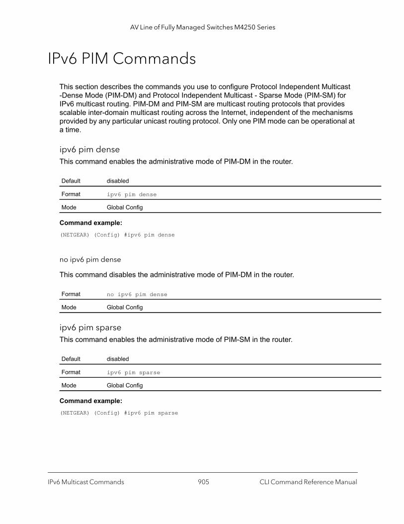
AV Line of Fully Managed Switches M4250 Series
IPv6 PIM Commands
This section describes the commands you use to configure Protocol Independent Multicast -Dense Mode (PIM-DM) and Protocol Independent Multicast - Sparse Mode (PIM-SM) for IPv6 multicast routing. PIM-DM and PIM-SM are multicast routing protocols that provides scalable inter-domain multicast routing across the Internet, independent of the mechanisms provided by any particular unicast routing protocol. Only one PIM mode can be operational at a time.
ipv6 pim denseThis command enables the administrative mode of PIM-DM in the router.
Command example: (NETGEAR) (Config) #ipv6 pim dense
no ipv6 pim dense
This command disables the administrative mode of PIM-DM in the router.
ipv6 pim sparseThis command enables the administrative mode of PIM-SM in the router.
Command example: (NETGEAR) (Config) #ipv6 pim sparse
Default disabled
Format ipv6 pim dense
Mode Global Config
Format no ipv6 pim dense
Mode Global Config
Default disabled
Format ipv6 pim sparse
Mode Global Config
IPv6 Multicast Commands CLI Command Reference Manual905
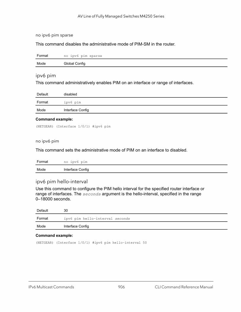
AV Line of Fully Managed Switches M4250 Series
no ipv6 pim sparse
This command disables the administrative mode of PIM-SM in the router.
ipv6 pimThis command administratively enables PIM on an interface or range of interfaces.
Command example: (NETGEAR) (Interface 1/0/1) #ipv6 pim
no ipv6 pim
This command sets the administrative mode of PIM on an interface to disabled.
ipv6 pim hello-intervalUse this command to configure the PIM hello interval for the specified router interface or range of interfaces. The seconds argument is the hello-interval, specified in the range 0–18000 seconds.
Command example: (NETGEAR) (Interface 1/0/1) #ipv6 pim hello-interval 50
Format no ipv6 pim sparse
Mode Global Config
Default disabled
Format ipv6 pim
Mode Interface Config
Format no ipv6 pim
Mode Interface Config
Default 30
Format ipv6 pim hello-interval seconds
Mode Interface Config
IPv6 Multicast Commands CLI Command Reference Manual906
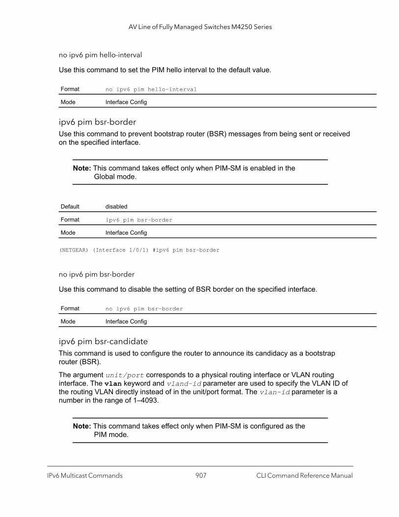
AV Line of Fully Managed Switches M4250 Series
no ipv6 pim hello-interval
Use this command to set the PIM hello interval to the default value.
ipv6 pim bsr-borderUse this command to prevent bootstrap router (BSR) messages from being sent or received on the specified interface.
Note: This command takes effect only when PIM-SM is enabled in the Global mode.
(NETGEAR) (Interface 1/0/1) #ipv6 pim bsr-border
no ipv6 pim bsr-border
Use this command to disable the setting of BSR border on the specified interface.
ipv6 pim bsr-candidateThis command is used to configure the router to announce its candidacy as a bootstrap router (BSR).
The argument unit/port corresponds to a physical routing interface or VLAN routing interface. The vlan keyword and vland-id parameter are used to specify the VLAN ID of the routing VLAN directly instead of in the unit/port format. The vlan-id parameter is a number in the range of 1–4093.
Note: This command takes effect only when PIM-SM is configured as the PIM mode.
Format no ipv6 pim hello-interval
Mode Interface Config
Default disabled
Format ipv6 pim bsr-border
Mode Interface Config
Format no ipv6 pim bsr-border
Mode Interface Config
IPv6 Multicast Commands CLI Command Reference Manual907

AV Line of Fully Managed Switches M4250 Series
gth
sh le, if e RP
the dress
Command example: (NETGEAR) (Config) #ipv6 pim bsr-candidate interface 1/0/1 32 5(NETGEAR) (Config) #ipv6 pim bsr-candidate interface 1/0/1 32 5 interval 100
no ipv6 pim bsr-candidate
This command is used to remove the configured PIM Candidate BSR router.
ipv6 pim dr-priorityUse this command to set the priority value for which a router is elected as the designated router (DR). The priority argument is a value in the range of 0–2147483647.
Note: This command takes effect only when PIM-SM is enabled in the Global mode.
Default Disabled
Format ipv6 pim bsr-candidate interface {unit/port | vlan vland-id} hash-mask-len[bsr-priority] [interval interval]
Mode Global Config
Parameters Description
unit/port Interface or VLAN number on this router from which the BSR address is derived, to make it a candidate. This interface or VLAN must be enabled with PIM.
hash-mask-length Length of a mask (32 bits maximum) that is to be ANDed with the group address before the hafunction is called. All groups with the same seed hash correspond to the same RP. For exampthis value was 24, only the first 24 bits of the group addresses matter. This allows you to get onfor multiple groups.
bsr-priority [Optional] Priority of the candidate BSR. The range is an integer from 0 to 255. The BSR with larger priority is preferred. If the priority values are the same, the router with the larger IPv6 adis the BSR. The default value is 0.
interval [Optional] Indicates the BSR candidate advertisement interval. The range is from 1 to 16383 seconds. The default value is 60 seconds.
Format no ipv6 pim bsr-candidate interface {unit/port | vlan vland-id}
Mode Global Config
IPv6 Multicast Commands CLI Command Reference Manual908
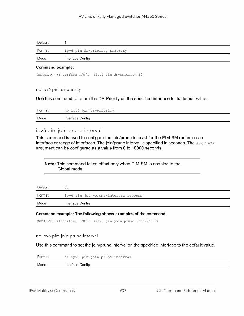
AV Line of Fully Managed Switches M4250 Series
Command example: (NETGEAR) (Interface 1/0/1) #ipv6 pim dr-priority 10
no ipv6 pim dr-priority
Use this command to return the DR Priority on the specified interface to its default value.
ipv6 pim join-prune-intervalThis command is used to configure the join/prune interval for the PIM-SM router on an interface or range of interfaces. The join/prune interval is specified in seconds. The seconds argument can be configured as a value from 0 to 18000 seconds.
Note: This command takes effect only when PIM-SM is enabled in the Global mode.
Command example: The following shows examples of the command.(NETGEAR) (Interface 1/0/1) #ipv6 pim join-prune-interval 90
no ipv6 pim join-prune-interval
Use this command to set the join/prune interval on the specified interface to the default value.
Default 1
Format ipv6 pim dr-priority priority
Mode Interface Config
Format no ipv6 pim dr-priority
Mode Interface Config
Default 60
Format ipv6 pim join-prune-interval seconds
Mode Interface Config
Format no ipv6 pim join-prune-interval
Mode Interface Config
IPv6 Multicast Commands CLI Command Reference Manual909

AV Line of Fully Managed Switches M4250 Series
r the
ipv6 pim rp-addressThis command defines the address of a PIM Rendezvous point (RP) for a specific multicast group range.
Note: This command takes effect only when PIM-SM is configured as the PIM mode.
no ipv6 pim rp-address
This command is used to remove the address of the configured PIM Rendezvous point (RP) for the specified multicast group range.
ipv6 pim rp-candidateThis command is used to configure the router to advertise itself as a PIM candidate rendezvous point (RP) to the bootstrap router (BSR) for a specific multicast group range.
The argument unit/port corresponds to a physical routing interface or VLAN routing interface. The vlan keyword and vland-id parameter are used to specify the VLAN ID of the routing VLAN directly instead of in the unit/port format. The vlan-id parameter is a number in the range of 1–4093.
Note: This command takes effect only when PIM-SM is configured as the PIM mode.
Default 0
Format ipv6 pim rp-address rp-address group-address/prefix-length [override]
Mode Global Config
Parameter Description
rp-address The IPv6 address of the RP.
group-address/prefix-length
The group address and prefix length supported by the RP.
override [Optional] Indicates that if there is a conflict, the RP configured with this command prevails oveRP learned by BSR.
Format no ipv6 pim rp-address rp-address group-address/prefix-length [override]
Mode Global Config
IPv6 Multicast Commands CLI Command Reference Manual910

AV Line of Fully Managed Switches M4250 Series
s
onds.
ess
no ipv6 pim rp-candidate
This command is used to disable the router to advertise itself as a PIM candidate rendezvous point (RP) to the bootstrap router (BSR).
ipv6 pim ssmUse this command to define the Source Specific Multicast (SSM) range of IPv6 multicast addresses on the router.
Note: This command takes effect only when PIM-SM is configured as the PIM mode.
Note: Some platforms do not support a non-zero data threshold rate. For these platforms, only a “Switch on First Packet” policy is supported.
Default Disabled
Format ipv6 pim rp-candidate interface {unit/port | vlan vland-id} group-addresgroup-mask [interval interval]
Mode Global Config
Parameter Description
unit/port or vland-id The interface type in the unit/port format or the VLAN ID is advertised as a candidate RP address. This interface or VLAN must be enabled with PIM.
group-address The multicast group address that is advertised in association with the RP address.
group-mask The multicast group prefix that is advertised in association with the RP address.
interval [Optional] Indicates the RP candidate advertisement interval. The range is from 1 to 16383 secThe default value is 60 seconds.
Format no ipv6 pim rp-candidate interface {unit/port | vlan vlan-id} group-addrgroup-mask
Mode Global Config
Default disabled
Format ipv6 pim ssm {default | group-address group-mask}
Mode Global Config
IPv6 Multicast Commands CLI Command Reference Manual911
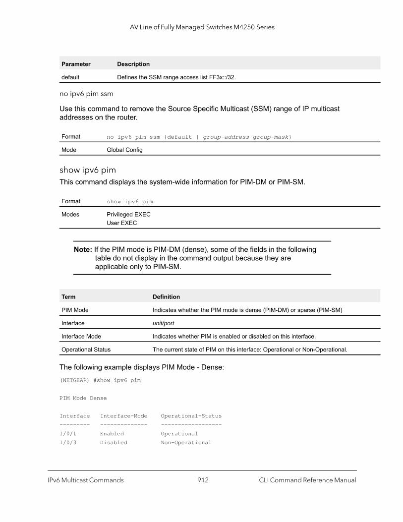
AV Line of Fully Managed Switches M4250 Series
no ipv6 pim ssm
Use this command to remove the Source Specific Multicast (SSM) range of IP multicast addresses on the router.
show ipv6 pimThis command displays the system-wide information for PIM-DM or PIM-SM.
Note: If the PIM mode is PIM-DM (dense), some of the fields in the following table do not display in the command output because they are applicable only to PIM-SM.
The following example displays PIM Mode - Dense:(NETGEAR) #show ipv6 pim
PIM Mode Dense
Interface Interface-Mode Operational-Status--------- -------------- ------------------1/0/1 Enabled Operational1/0/3 Disabled Non-Operational
Parameter Description
default Defines the SSM range access list FF3x::/32.
Format no ipv6 pim ssm {default | group-address group-mask}
Mode Global Config
Format show ipv6 pim
Modes Privileged EXECUser EXEC
Term Definition
PIM Mode Indicates whether the PIM mode is dense (PIM-DM) or sparse (PIM-SM)
Interface unit/port
Interface Mode Indicates whether PIM is enabled or disabled on this interface.
Operational Status The current state of PIM on this interface: Operational or Non-Operational.
IPv6 Multicast Commands CLI Command Reference Manual912
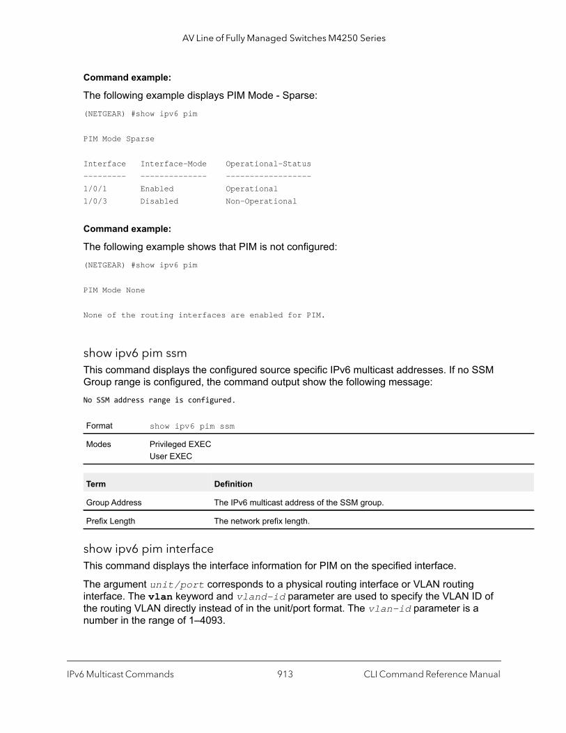
AV Line of Fully Managed Switches M4250 Series
Command example:
The following example displays PIM Mode - Sparse:(NETGEAR) #show ipv6 pim
PIM Mode Sparse
Interface Interface-Mode Operational-Status--------- -------------- ------------------1/0/1 Enabled Operational1/0/3 Disabled Non-Operational
Command example:
The following example shows that PIM is not configured:(NETGEAR) #show ipv6 pim
PIM Mode None
None of the routing interfaces are enabled for PIM.
show ipv6 pim ssmThis command displays the configured source specific IPv6 multicast addresses. If no SSM Group range is configured, the command output show the following message:No SSM address range is configured.
show ipv6 pim interfaceThis command displays the interface information for PIM on the specified interface.
The argument unit/port corresponds to a physical routing interface or VLAN routing interface. The vlan keyword and vland-id parameter are used to specify the VLAN ID of the routing VLAN directly instead of in the unit/port format. The vlan-id parameter is a number in the range of 1–4093.
Format show ipv6 pim ssm
Modes Privileged EXECUser EXEC
Term Definition
Group Address The IPv6 multicast address of the SSM group.
Prefix Length The network prefix length.
IPv6 Multicast Commands CLI Command Reference Manual913
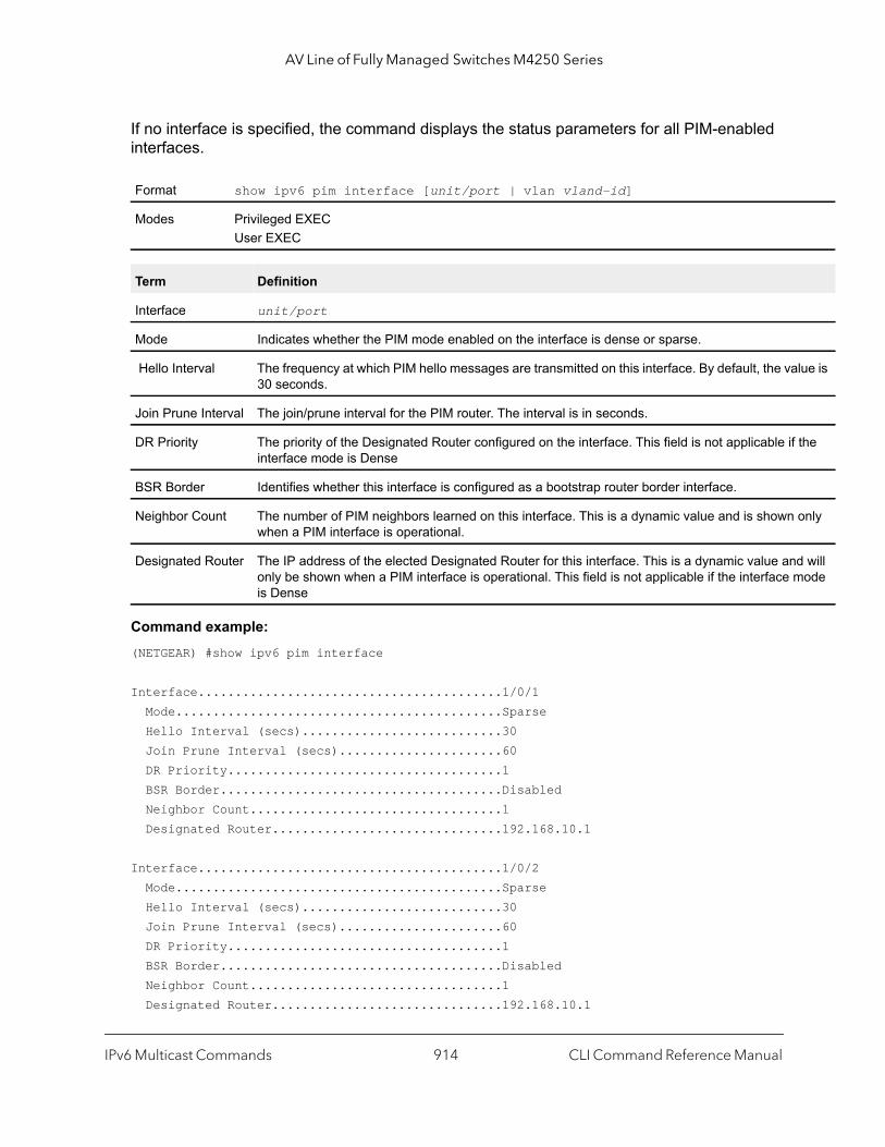
AV Line of Fully Managed Switches M4250 Series
lue is
the
only
d will ode
If no interface is specified, the command displays the status parameters for all PIM-enabled interfaces.
Command example: (NETGEAR) #show ipv6 pim interface
Interface.........................................1/0/1 Mode............................................Sparse Hello Interval (secs)...........................30 Join Prune Interval (secs)......................60 DR Priority.....................................1 BSR Border......................................Disabled Neighbor Count..................................1 Designated Router...............................192.168.10.1
Interface.........................................1/0/2 Mode............................................Sparse Hello Interval (secs)...........................30 Join Prune Interval (secs)......................60 DR Priority.....................................1 BSR Border......................................Disabled Neighbor Count..................................1 Designated Router...............................192.168.10.1
Format show ipv6 pim interface [unit/port | vlan vland-id]
Modes Privileged EXECUser EXEC
Term Definition
Interface unit/port
Mode Indicates whether the PIM mode enabled on the interface is dense or sparse.
Hello Interval The frequency at which PIM hello messages are transmitted on this interface. By default, the va30 seconds.
Join Prune Interval The join/prune interval for the PIM router. The interval is in seconds.
DR Priority The priority of the Designated Router configured on the interface. This field is not applicable ifinterface mode is Dense
BSR Border Identifies whether this interface is configured as a bootstrap router border interface.
Neighbor Count The number of PIM neighbors learned on this interface. This is a dynamic value and is shown when a PIM interface is operational.
Designated Router The IP address of the elected Designated Router for this interface. This is a dynamic value anonly be shown when a PIM interface is operational. This field is not applicable if the interface mis Dense
IPv6 Multicast Commands CLI Command Reference Manual914

AV Line of Fully Managed Switches M4250 Series
rs.
Command example:
If none of the interfaces are enabled for PIM, the following message is displayed:None of the routing interfaces are enabled for PIM.
show ipv6 pim neighborThis command displays PIM neighbors discovered by PIMv2 Hello messages.
The argument unit/port corresponds to a physical routing interface or VLAN routing interface. The vlan keyword and vland-id parameter are used to specify the VLAN ID of the routing VLAN directly instead of in the unit/port format. The vlan-id parameter is a number in the range of 1–4093.
If the interface number is not specified, this command displays the neighbors discovered on all the PIM-enabled interfaces.
Command example: (NETGEAR) #show ipv6 pim neighbor
Neighbor Addr Interface Uptime Expiry Time (HH:MM::SS) (HH:MM::SS)----------------- --------- ----------- -----------2001:DB8:39::/32 1/0/1 00:02:55 00:01:152001:DB8:A3::/32 1/0/2 00:03:50 00:02:10
Command example:
If no neighbors were learned on any of the interfaces, the following message is displayed:No neighbors are learnt on any interface.
Format show ipv6 pim neighbor [{unit/port | vlan vland-id]
Modes Privileged EXECUser EXEC
Term Definition
Neighbor Address The IPv6 address of the PIM neighbor on an interface.
Interface unit/port
Up Time The time since this neighbor has become active on this interface.
Expiry Time Time remaining for the neighbor to expire.
DR Priority The DR Priority configured on this Interface (PIM-SM only).
Note: DR Priority is applicable only when sparse-mode configured routers are neighboOtherwise, NA is displayed in this field.
IPv6 Multicast Commands CLI Command Reference Manual915

AV Line of Fully Managed Switches M4250 Series
e and.
his
show ipv6 pim bsr-routerThis command displays the bootstrap router (BSR) information.
Command example: (NETGEAR) #show ipv6 pim bsr-router elected
BSR Address................................... 192.168.10.1 BSR Priority................................ 0 BSR Hash Mask Length........................ 30 Next Bootstrap message (hh:mm:ss)........... 00:00:24
Command example: (NETGEAR) #show ipv6 pim bsr-router candidate
BSR Address................................... 192.168.10.1 BSR Priority................................ 0 BSR Hash Mask Length........................ 30 C-BSR Advertisement Interval (secs)......... 60 Next Bootstrap message (hh:mm:ss)........... NA
Command example:
If no configured or elected BSRs exist on the router, the following message is displayed:No BSR's exist/learned on this router.
Format show ipv6 pim bsr-router {candidate | elected}
Mode Privileged EXECUser EXEC
Term Definition
BSR Address IPv6 address of the BSR.
BSR Priority Priority as configured in the ipv6 pim bsr-candidate command.
BSR Hash Mask Length Length of a mask (maximum 32 bits) that is to be ANDed with the group address before thhash function is called. This value is configured in the ipv6 pim bsr-candidate comm
C-BSR Advertisement Interval
Indicates the configured C-BSR Advertisement interval with which the router, acting as a C-BSR, will periodically send the C-BSR advertisement messages.
Next Bootstrap Message
Time (in hours, minutes, and seconds) in which the next bootstrap message is due from tBSR.
IPv6 Multicast Commands CLI Command Reference Manual916

AV Line of Fully Managed Switches M4250 Series
show ipv6 pim rp-hashThis command displays which rendezvous point (RP) is being used for a specified group that you must specify with the group-address argument.
Command example: (NETGEAR) #show ipv6 pim rp-hash 224.1.2.0
RP Address192.168.10.1 Type Static
Command example:
If no RP Group mapping exists on the router, the following message is displayed:No RP-Group mappings exist/learned on this router.
show ipv6 pim rp mappingUse this command to display the mapping for the PIM group to the active Rendezvous points (RP) of which the router is a aware (either configured or learned from the bootstrap router [BSR]). Use the optional parameters to limit the display to a specific RP address (rp-address) or to view group-to-candidate RP (candidate) or group to Static RP mapping information (static).
Format show ipv6 pim rp-hash group-address
Modes Privileged EXECUser EXEC
Term Definition
RP Address The IPv6 address of the RP for the group specified.
Type Indicates the mechanism (BSR or static) by which the RP was selected.
Format show ipv6 pim rp mapping [rp-address | candidate | static]
Modes Privileged EXECUser EXEC
Term Definition
RP Address The IPv6 address of the RP for the group specified.
Group Address The IPv6 address and prefix length of the multicast group.
IPv6 Multicast Commands CLI Command Reference Manual917

AV Line of Fully Managed Switches M4250 Series
ate
Command example: (NETGEAR) #show ipv6 pim rp mapping 192.168.10.1
RP Address 192.168.10.1 Group Address 224.1.2.1 Group Mask 255.255.255.0 Origin Static
Command example: (NETGEAR) #show ipv6 pim rp mapping
RP Address 192.168.10.1 Group Address 224.1.2.1 Group Mask 255.255.255.0 Origin Static
RP Address 192.168.20.1 Group Address 229.2.0.0 Group Mask 255.255.0.0 Origin Static
Command example: (NETGEAR) # show ipv6 pim rp mapping candidate
RP Address.................................... 192.168.10.1 Group Address.............................. 224.1.2.1 Group Mask................................. 255.255.0.0 Origin..................................... BSR C-RP Advertisement Interval (secs)......... 60 Next Candidate RP Advertisement (hh:mm:ss). 00:00:15
Command example:
If no RP Group mapping exist on the router, the following message is displayed:No RP-Group mappings exist on this router.
Origin Indicates the mechanism (BSR or static) by which the RP was selected.
C-RP Advertisement Interval
Indicates the configured C-RP Advertisement interval with which the router acting as a CandidRP will periodically send the C-RP advertisement messages to the elected BSR.
Term Definition
IPv6 Multicast Commands CLI Command Reference Manual918
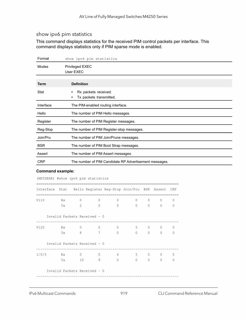
AV Line of Fully Managed Switches M4250 Series
show ipv6 pim statisticsThis command displays statistics for the received PIM control packets per interface. This command displays statistics only if PIM sparse mode is enabled.
Command example: (NETGEAR) #show ipv6 pim statistics=====================================================================Interface Stat Hello Register Reg-Stop Join/Pru BSR Assert CRP =====================================================================Vl10 Rx 0 0 0 0 0 0 0 Tx 2 0 0 0 0 0 0
Invalid Packets Received - 0---------------------------------------------------------------------Vl20 Rx 0 0 0 5 0 0 0 Tx 8 7 0 0 0 0 0
Invalid Packets Received - 0---------------------------------------------------------------------1/0/5 Rx 0 0 6 5 0 0 0 Tx 10 9 0 0 0 0 0
Invalid Packets Received - 0---------------------------------------------------------------------
Format show ipv6 pim statistics
Modes Privileged EXECUser EXEC
Term Definition
Stat • Rx packets received.• Tx packets transmitted.
Interface The PIM-enabled routing interface.
Hello The number of PIM Hello messages.
Register The number of PIM Register messages.
Reg-Stop The number of PIM Register-stop messages.
Join/Pru The number of PIM Join/Prune messages.
BSR The number of PIM Boot Strap messages.
Assert The number of PIM Assert messages.
CRP The number of PIM Candidate RP Advertisement messages.
IPv6 Multicast Commands CLI Command Reference Manual919

AV Line of Fully Managed Switches M4250 Series
Command example: (NETGEAR) #show ipv6 pim statistics vlan 10=====================================================================Interface Stat Hello Register Reg-Stop Join/Pru BSR Assert CRP =====================================================================Vl10 Rx 0 0 0 0 0 0 0 Tx 2 0 0 0 0 0 0
Invalid Packets Received - 0---------------------------------------------------------------------
Command example: (NETGEAR) #show ipv6 pim statistics 1/0/5=====================================================================Interface Stat Hello Register Reg-Stop Join/Pru BSR Assert CRP =====================================================================1/0/5 Rx 0 0 6 5 0 0 0 Tx 10 9 0 0 0 0 0
Invalid Packets Received - 0
IPv6 MLD Commands
IGMP and MLD snooping are Layer 2 functionalities but IGMP and MLD are Layer 3 multicast protocols. If you want to use IGMP and MLD snooping, a network must include a multicast router that can function as a querier to solicit multicast group registrations. However, if multicast traffic is destined to hosts within the same network, a multicast router is not required but an IGMP and MLD snooping querier must be running on one of the switches in the network and snooping must be enabled on all switches in the network. For more information, see IGMP Snooping Configuration Commands on page 511 and MLD Snooping Commands on page 531.
ipv6 mld routerUse this command, in the administrative mode of the router, to enable MLD in the router.
Default Disabled
Format ipv6 mld router
Mode Global Config
IPv6 Multicast Commands CLI Command Reference Manual920

AV Line of Fully Managed Switches M4250 Series
no ipv6 mld router
Use this command, in the administrative mode of the router, to disable MLD in the router.
ipv6 mld query-intervalUse this command to set the MLD router’s query interval for the interface or range of interfaces. The query-interval is the amount of time between the general queries sent when the router is the querier on that interface. The range for the seconds argument is from 1 to 3600 seconds.
no ipv6 mld query-interval
Use this command to reset the MLD query interval to the default value for that interface.
ipv6 mld query-max-response-timeUse this command to set the MLD querier’s maximum response time for the interface or range of interfaces and this value is used in assigning the maximum response time in the query messages that are sent on that interface. The range for the milliseconds argument is from 0 to 65535 milliseconds.
no ipv6 mld query-max-response-time
This command resets the MLD query max response time for the interface to the default value.
Default Disabled
Format no ipv6 mld router
Mode Global Config
Default 125
Format ipv6 mld query-interval seconds
Mode Interface Config
Format no ipv6 mld query-interval
Mode Interface Config
Default 10000 milliseconds
Format ipv6 mld query-max-response-time milliseconds
Mode Interface Config
Format no ipv6 mld query-max-response-time
Mode Interface Config
IPv6 Multicast Commands CLI Command Reference Manual921

AV Line of Fully Managed Switches M4250 Series
ipv6 mld startup-query-intervalUse this command to set the interval between general IPv6 MLD queries that are sent when the MLP process starts on the interface or range of interfaces. The range for the seconds argument is 1 to 300 seconds. The default is 31 seconds.
no ipv6 mld startup-query-interval
Use this command to reset the startup query interval for IPv6 MLD to the default value of 31 seconds.
ipv6 mld startup-query-countUse this command to specify the number of IPv6 MLD queries that are sent when the MLP process starts on the interface or range of interfaces and that is separated by the startup query interval on the interface or range of interfaces. The range for the number argument is 1 to 20. The default is 2.
no ipv6 mld startup-query-count
Use this command to reset the startup query count for IPv6 MLD to the default value of 2.
ipv6 mld last-member-query-intervalUse this command to set the last member query interval for an MLD interface or range of interfaces, which is the value of the maximum response time parameter in the group specific queries sent out of this interface. The range for the milliseconds argument is from 0 to 65535 milliseconds.
Default 31
Format ipv6 mld startup-query-interval seconds
Mode Interface Config
Format no ipv6 mld startup-query-interval
Mode Interface Config
Default 2
Format ipv6 mld startup-query-count number
Mode Interface Config
Format no ipv6 mld startup-query-count
Mode Interface Config
IPv6 Multicast Commands CLI Command Reference Manual922

AV Line of Fully Managed Switches M4250 Series
no ipv6 mld last-member-query-interval
Use this command to reset the last member query interval of the interface to the default value.
ipv6 mld last-member-query-countUse this command to set the number of listener-specific queries sent before the router assumes that there are no local members on an interface or range of interfaces. The range for the number argument is 1 to 20.
no ipv6 mld last-member-query-count
Use this command to reset the last-member-query-count of the interface to the default value.
ipv6 mld versionUse this command to configure the MLD version that the interface uses.
Default 1000 milliseconds
Format ipv6 mld last-member-query-interval milliseconds
Mode Interface Config
Format no ipv6 mld last-member-query-interval
Mode Interface Config
Default 2
Format ipv6 mld last-member-query-count number
Mode Interface Config
Format no ipv6 mld last-member-query-count
Mode Interface Config
Default 2
Format ipv6 mld version {1 | 2}
Mode Interface Config
IPv6 Multicast Commands CLI Command Reference Manual923

AV Line of Fully Managed Switches M4250 Series
ip
dress
no ipv6 mld version
This command resets the MLD version used by the interface to the default value.
show ipv6 mld groupsUse this command to display information about multicast groups that MLD reported. The information is displayed only when MLD is enabled on at least one interface. If MLD was not enabled on even one interface, there is no group information to be displayed.
The argument unit/port corresponds to a physical routing interface or VLAN routing interface. The vlan keyword and vland-id parameter are used to specify the VLAN ID of the routing VLAN directly instead of in the unit/port format. The vlan-id parameter is a number in the range of 1–4093. You can also specify a group address (group-address).
The following fields are displayed as a table when unit/port is specified.
When group-address is specified, the following fields are displayed for each multicast group and each interface.
Format no ipv6 mld
Mode Interface Config
Format show ipv6 mld groups {unit/port | vlan vland-id | group-address}
Mode Privileged EXECUser EXEC
Field Description
Group Address The address of the multicast group.
Interface Interface through which the multicast group is reachable.
Up Time Time elapsed in hours, minutes, and seconds since the multicast group has been known.
Expiry Time Time left in hours, minutes, and seconds before the entry is removed from the MLD membershtable.
Field Description
Interface Interface through which the multicast group is reachable.
Group Address The address of the multicast group.
Last Reporter The IP Address of the source of the last membership report received for this multicast group adon that interface.
Filter Mode The filter mode of the multicast group on this interface. The values it can take are include and exclude.
IPv6 Multicast Commands CLI Command Reference Manual924

AV Line of Fully Managed Switches M4250 Series
the
v1
The following table is displayed to indicate all the sources associated with this group.
Command example: (NETGEAR Switch) #show ipv6 mld groups ?
group-address Enter Group Address Info.<unit/port> Enter interface in unit/port format.
Command example: (NETGEAR Switch) #show ipv6 mld groups 1/0/1
Group Address.................................. FF43::3Interface...................................... 1/0/1Up Time (hh:mm:ss)............................. 00:03:04Expiry Time (hh:mm:ss)......................... ------
Command example: (NETGEAR Switch) #show ipv6 mld groups ff43::3
Interface...................................... 1/0/1Group Address.................................. FF43::3Last Reporter.................................. FE80::200:FF:FE00:3Up Time (hh:mm:ss)............................. 00:02:53Expiry Time (hh:mm:ss)......................... ------Filter Mode.................................... IncludeVersion1 Host Timer............................ ------Group compat mode.............................. v2Source Address ExpiryTime ----------------- ----------- 2003::10 00:04:17 2003::20 00:04:17
Version 1 Host Timer
The time remaining until the router assumes there are no longer any MLD version-1 Hosts on specified interface.
Group Compat Mode
The compatibility mode of the multicast group on this interface. The values it can take are MLDand MLDv2.
Field Description
Source Address The IP address of the source.
Uptime Time elapsed in hours, minutes, and seconds since the source has been known.
Expiry Time Time left in hours, minutes, and seconds before the entry is removed.
Field Description
IPv6 Multicast Commands CLI Command Reference Manual925
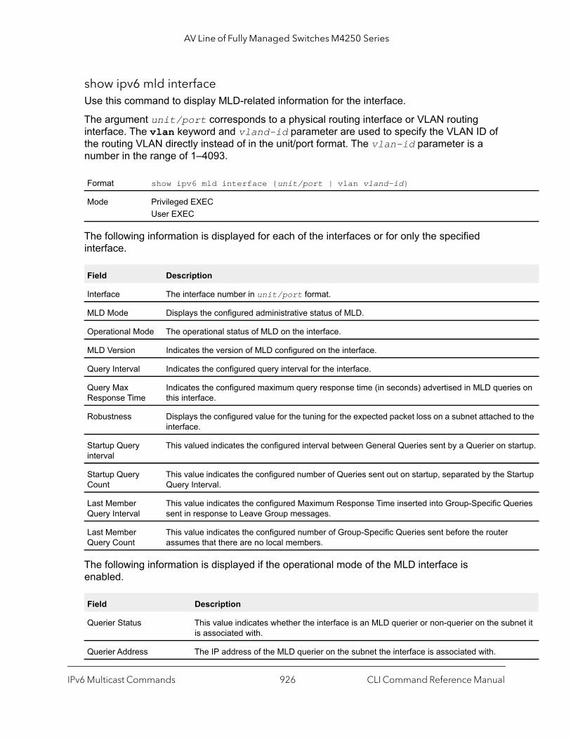
AV Line of Fully Managed Switches M4250 Series
s on
to the
artup.
artup
eries
net it
show ipv6 mld interfaceUse this command to display MLD-related information for the interface.
The argument unit/port corresponds to a physical routing interface or VLAN routing interface. The vlan keyword and vland-id parameter are used to specify the VLAN ID of the routing VLAN directly instead of in the unit/port format. The vlan-id parameter is a number in the range of 1–4093.
The following information is displayed for each of the interfaces or for only the specified interface.
The following information is displayed if the operational mode of the MLD interface is enabled.
Format show ipv6 mld interface {unit/port | vlan vland-id}
Mode Privileged EXECUser EXEC
Field Description
Interface The interface number in unit/port format.
MLD Mode Displays the configured administrative status of MLD.
Operational Mode The operational status of MLD on the interface.
MLD Version Indicates the version of MLD configured on the interface.
Query Interval Indicates the configured query interval for the interface.
Query Max Response Time
Indicates the configured maximum query response time (in seconds) advertised in MLD queriethis interface.
Robustness Displays the configured value for the tuning for the expected packet loss on a subnet attached interface.
Startup Query interval
This valued indicates the configured interval between General Queries sent by a Querier on st
Startup Query Count
This value indicates the configured number of Queries sent out on startup, separated by the StQuery Interval.
Last Member Query Interval
This value indicates the configured Maximum Response Time inserted into Group-Specific Qusent in response to Leave Group messages.
Last Member Query Count
This value indicates the configured number of Group-Specific Queries sent before the router assumes that there are no local members.
Field Description
Querier Status This value indicates whether the interface is an MLD querier or non-querier on the subis associated with.
Querier Address The IP address of the MLD querier on the subnet the interface is associated with.
IPv6 Multicast Commands CLI Command Reference Manual926

AV Line of Fully Managed Switches M4250 Series
show ipv6 mld trafficUse this command to display MLD statistical information for the router.
clear ipv6 mld countersUse this command to reset the MLD counters to zero on the specified interface.
Querier Up Time Time elapsed in seconds since the querier state has been updated.
Querier Expiry Time Time left in seconds before the Querier loses its title as querier.
Wrong Version Queries Indicates the number of queries received whose MLD version does not match the MLDversion of the interface.
Number of Joins The number of times a group membership has been added on this interface.
Number of Leaves The number of times a group membership has been removed on this interface.
Number of Groups The current number of membership entries for this interface.
Format show ipv6 mld traffic
Mode Privileged EXECUser EXEC
Field Description
Valid MLD Packets Received The number of valid MLD packets received by the router.
Valid MLD Packets Sent The number of valid MLD packets sent by the router.
Queries Received The number of valid MLD queries received by the router.
Queries Sent The number of valid MLD queries sent by the router.
Reports Received The number of valid MLD reports received by the router.
Reports Sent The number of valid MLD reports sent by the router.
Leaves Received The number of valid MLD leaves received by the router.
Leaves Sent The number of valid MLD leaves sent by the router.
Bad Checksum MLD Packets The number of bad checksum MLD packets received by the router.
Malformed MLD Packets The number of malformed MLD packets received by the router.
Format clear ipv6 mld counters unit/port
Mode Privileged Exec
Field Description
IPv6 Multicast Commands CLI Command Reference Manual927
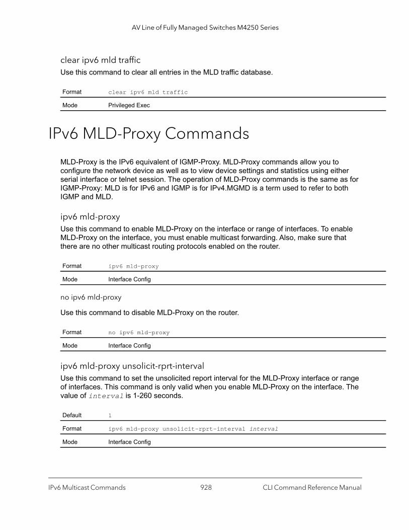
AV Line of Fully Managed Switches M4250 Series
clear ipv6 mld trafficUse this command to clear all entries in the MLD traffic database.
IPv6 MLD-Proxy Commands
MLD-Proxy is the IPv6 equivalent of IGMP-Proxy. MLD-Proxy commands allow you to configure the network device as well as to view device settings and statistics using either serial interface or telnet session. The operation of MLD-Proxy commands is the same as for IGMP-Proxy: MLD is for IPv6 and IGMP is for IPv4.MGMD is a term used to refer to both IGMP and MLD.
ipv6 mld-proxyUse this command to enable MLD-Proxy on the interface or range of interfaces. To enable MLD-Proxy on the interface, you must enable multicast forwarding. Also, make sure that there are no other multicast routing protocols enabled on the router.
no ipv6 mld-proxy
Use this command to disable MLD-Proxy on the router.
ipv6 mld-proxy unsolicit-rprt-intervalUse this command to set the unsolicited report interval for the MLD-Proxy interface or range of interfaces. This command is only valid when you enable MLD-Proxy on the interface. The value of interval is 1-260 seconds.
Format clear ipv6 mld traffic
Mode Privileged Exec
Format ipv6 mld-proxy
Mode Interface Config
Format no ipv6 mld-proxy
Mode Interface Config
Default 1
Format ipv6 mld-proxy unsolicit-rprt-interval interval
Mode Interface Config
IPv6 Multicast Commands CLI Command Reference Manual928
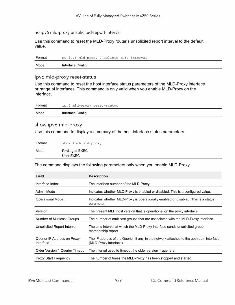
AV Line of Fully Managed Switches M4250 Series
us
e.
rface
no ipv6 mld-proxy unsolicited-report-interval
Use this command to reset the MLD-Proxy router’s unsolicited report interval to the default value.
ipv6 mld-proxy reset-statusUse this command to reset the host interface status parameters of the MLD-Proxy interface or range of interfaces. This command is only valid when you enable MLD-Proxy on the interface.
show ipv6 mld-proxyUse this command to display a summary of the host interface status parameters.
The command displays the following parameters only when you enable MLD-Proxy.
Format no ipv6 mld-proxy unsolicit-rprt-interval
Mode Interface Config
Format ipv6 mld-proxy reset-status
Mode Interface Config
Format show ipv6 mld-proxy
Mode Privileged EXECUser EXEC
Field Description
Interface Index The interface number of the MLD-Proxy.
Admin Mode Indicates whether MLD-Proxy is enabled or disabled. This is a configured value.
Operational Mode Indicates whether MLD-Proxy is operationally enabled or disabled. This is a statparameter.
Version The present MLD host version that is operational on the proxy interface.
Number of Multicast Groups The number of multicast groups that are associated with the MLD-Proxy interfac
Unsolicited Report Interval The time interval at which the MLD-Proxy interface sends unsolicited group membership report.
Querier IP Address on Proxy Interface
The IP address of the Querier, if any, in the network attached to the upstream inte(MLD-Proxy interface).
Older Version 1 Querier Timeout The interval used to timeout the older version 1 queriers.
Proxy Start Frequency The number of times the MLD-Proxy has been stopped and started.
IPv6 Multicast Commands CLI Command Reference Manual929

AV Line of Fully Managed Switches M4250 Series
Command example: (NETGEAR Switch) #show ipv6 mld-proxyInterface Index..................................... 1/0/3Admin Mode.......................................... EnableOperational Mode.................................... EnableVersion............................................. 3Num of Multicast Groups............................. 0Unsolicited Report Interval......................... 1Querier IP Address on Proxy Interface............... fe80::1:2:5Older Version 1 Querier Timeout..................... 00:00:00Proxy Start Frequency................................
show ipv6 mld-proxy interfaceThis command displays a detailed list of the host interface status parameters. It displays the following parameters only when you enable MLD-Proxy.
The column headings of the table associated with the interface are as follows.
Command example: (NETGEAR Switch) #show ipv6 mld-proxy interfaceInterface Index................................ 1/0/1
Ver Query Rcvd Report Rcvd Report Sent Leave Rcvd Leave Sent------------------------------------------------------------------1 2 0 0 0 22 3 0 4
Format show ipv6 mld-proxy interface
Modes Privileged EXECUser EXEC
Term Definition
Interface Index The unit/port of the MLD-proxy.
Term Definition
Ver The MLD version.
Query Rcvd Number of MLD queries received.
Report Rcvd Number of MLD reports received.
Report Sent Number of MLD reports sent.
Leaves Rcvd Number of MLD leaves received. Valid for version 2 only.
Leaves Sent Number of MLD leaves sent on the Proxy interface. Valid for version 2 only.
IPv6 Multicast Commands CLI Command Reference Manual930

AV Line of Fully Managed Switches M4250 Series
roup,
hip
ort to
show ipv6 mld-proxy groupsUse this command to display information about multicast groups that the MLD-Proxy reported.
Command example: (NETGEAR Switch) #show ipv6 mld-proxy groups
Interface Index................................ 1/0/3Group Address Last Reporter Up Time Member State Filter Mode Sources------------- -------------- ---------- ----------------- -------------- -------FF1E::1 FE80::100:2.3 00:01:40 DELAY_MEMBER Exclude 2FF1E::2 FE80::100:2.3 00:02:40 DELAY_MEMBER Include 1FF1E::3 FE80::100:2.3 00:01:40 DELAY_MEMBER Exclude 0FF1E::4 FE80::100:2.3 00:02:44 DELAY_MEMBER Include 4
show ipv6 mld-proxy groups detailUse this command to display information about multicast groups that MLD-Proxy reported.
Format show ipv6 mld-proxy groups
Mode Privileged EXECUser EXEC
Field Description
Interface The interface number of the MLD-Proxy.
Group Address The IP address of the multicast group.
Last Reporter The IP address of the host that last sent a membership report for the current gon the network attached to the MLD-Proxy interface (upstream interface).
Up Time (in secs) The time elapsed in seconds since last created.
Member State Possible values are:• Idle_Member. The interface has responded to the latest group members
query for this group.• Delay_Member. The interface is going to send a group membership rep
respond to a group membership query for this group.
Filter Mode Possible values are Include or Exclude.
Sources The number of sources attached to the multicast group.
Format show ipv6 mld-proxy groups detail
Mode Privileged EXECUser EXEC
IPv6 Multicast Commands CLI Command Reference Manual931
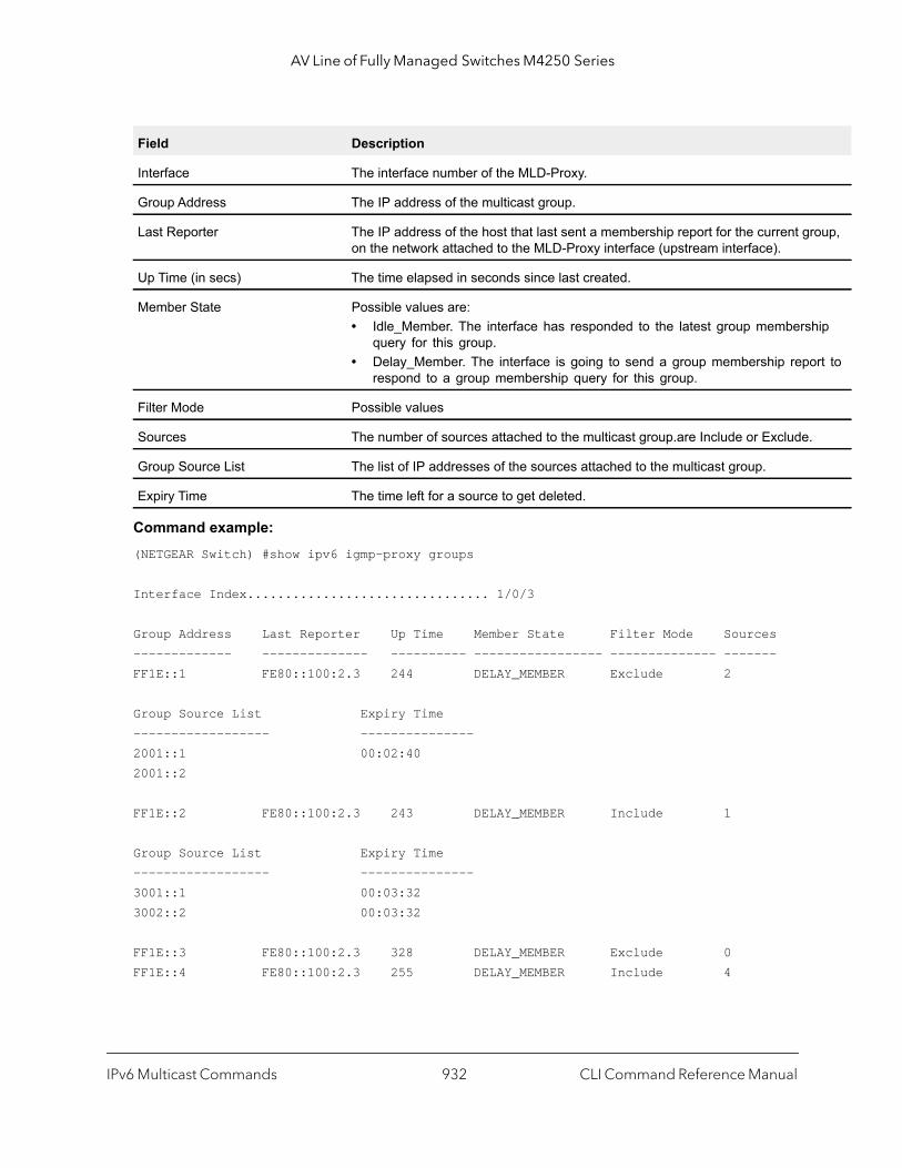
AV Line of Fully Managed Switches M4250 Series
oup,
hip
rt to
Command example: (NETGEAR Switch) #show ipv6 igmp-proxy groups
Interface Index................................ 1/0/3
Group Address Last Reporter Up Time Member State Filter Mode Sources------------- -------------- ---------- ----------------- -------------- -------FF1E::1 FE80::100:2.3 244 DELAY_MEMBER Exclude 2
Group Source List Expiry Time------------------ ---------------2001::1 00:02:402001::2
FF1E::2 FE80::100:2.3 243 DELAY_MEMBER Include 1
Group Source List Expiry Time------------------ ---------------3001::1 00:03:323002::2 00:03:32
FF1E::3 FE80::100:2.3 328 DELAY_MEMBER Exclude 0FF1E::4 FE80::100:2.3 255 DELAY_MEMBER Include 4
Field Description
Interface The interface number of the MLD-Proxy.
Group Address The IP address of the multicast group.
Last Reporter The IP address of the host that last sent a membership report for the current gron the network attached to the MLD-Proxy interface (upstream interface).
Up Time (in secs) The time elapsed in seconds since last created.
Member State Possible values are:• Idle_Member. The interface has responded to the latest group members
query for this group.• Delay_Member. The interface is going to send a group membership repo
respond to a group membership query for this group.
Filter Mode Possible values
Sources The number of sources attached to the multicast group.are Include or Exclude.
Group Source List The list of IP addresses of the sources attached to the multicast group.
Expiry Time The time left for a source to get deleted.
IPv6 Multicast Commands CLI Command Reference Manual932
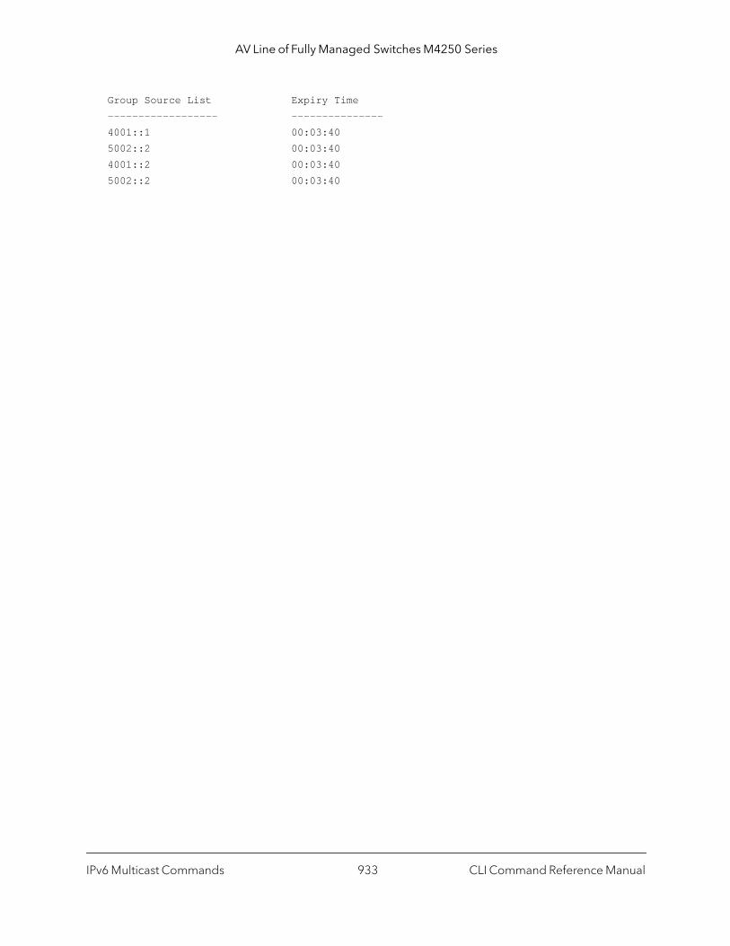
AV Line of Fully Managed Switches M4250 Series
Group Source List Expiry Time------------------ ---------------4001::1 00:03:405002::2 00:03:404001::2 00:03:405002::2 00:03:40
IPv6 Multicast Commands CLI Command Reference Manual933
13
13Power over Ethernet CommandsThis chapter contains the following sections:
• About PoE
• PoE Commands
934
AV Line of Fully Managed Switches M4250 Series
About PoE
Power over Ethernet (PoE) describes a technology to pass electrical power safely along with data on existing Ethernet cabling. The power supply equipment (PSE) is the device or switch that delivers electrical power, and the PD or powered device is the end device that powers up through the power delivered along the Ethernet cable.
The switch supports PoE, PoE+, and PoE++:
• PoE (802.3af). This is the original standard, also known as the low-power standard, which mandates delivery of up to 15.4 watts by the PSE. Because of power dissipation, only 12.95 watts are assured to be available at the powered device (PD). The PD needs to be designed so that it can accept power over Ethernet cabling. Category 3 cables can be used to deliver power to the PD. However, with the advent of 802.11n, the newer wireless APs required more power. To account for this, a newer standard was developed in 2009, known as 802.3at.
• PoE+ (802.3at). This mode is also known as the high-power standard, which mandates delivery of up to 34.2 watts by the PSE. Because of power dissipation, PoE+ provides only a maximum of 25.5 watts at the powered device. Some PSEs can provide up to 51 watts. Before this standard became available in 2009, the industry started using different implementations to allow for more power. All these needed to be brought under the purview of the newer 802.3at standard.
• PoE++ (802.3bt). This modem is also known as the ultra-power standard. On a M4250 series switch model that is capable of supporting 802.3bt, this is the default mode. The maximum PoE power supported by PoE++ is 96.5W.
Note: PoE, PoE+, and PoE++ are supported only on physical, copper interfaces. The default port mode depends on the M4250 series switch model.
Power over Ethernet Commands CLI Command Reference Manual935

AV Line of Fully Managed Switches M4250 Series
PoE Commands
poeUse this command to enable the Power over Ethernet (PoE) functionality on a global basis or per interface.
no poe
Use this command to disable the Power over Ethernet (PoE) functionality on a global basis or per interface.
poe detectionUse this command to configure the detection type on an interface. Use the command to configure which types of PDs are detected and powered by the switch.
Note: By default, an M4250 series switch that supports PoE++ power starts in 802.3bt mode. By default, a switch that support PoE+ power starts up in 802.3at mode.
The switch supports the following three detection options:
• 4ptdot3af. 4-point dot3af detection. The port performs a 4-point 802.3af resistive detection.
• 4ptdot3af+legacy. The port performs a 4-point 802.3af resistive detection, and if required, continues with legacy detection.
• legacy. Legacy detection. The port is powered using high-inrush current, which is used by legacy PDs that require more than 15W to power up.
Default enabled
Format poe
Mode Global ConfigInterface Config
Format no poe
Mode Global ConfigInterface Config
Default 4ptdot3af
Power over Ethernet Commands CLI Command Reference Manual936
AV Line of Fully Managed Switches M4250 Series
no poe detection
Use this command to set the detection mode to the default on an interface.
poe power limit user-definedUse this command to configure the PoE power limit in mW on an interface.
The value of power can be from 3000 mW to 99000 mW,
poe high-powerUse this command to manually configure the high-power mode on an interface. This mode is used to power up devices that require more power than 802.3af power (more than 12.95 watts at the PD). These are the options:
• dot3at. The port is powered in the IEEE 802.3at mode and is backward compatible with IEEE 802.3af. In this mode, if the switch detects that the attached PD requests more power than IEEE 802.3af but is not an IEEE 802.3at Class 4 device, the PD does not receive power from the switch. This mode supports LLDP.
• dot3bt. The port is powered in the IEEE 802.3bt mode and is backward compatible with IEEE 802.3at and IEEE 802.3af. In this mode, if the switch detects that the attached PD requests more power than IEEE 802.3at but is not an IEEE 802.3bt device, the PD does not receive power from the switch. This mode supports LLDP.
• dot3bt-type3. The port supports the IEEE 802.3bt Type 3 mode, the IEEE 802.3at mode, and the IEEE 802.3af mode.
• legacy. The port is powered using high-inrush current, which is used by legacy PDs that require more than 15W to power up.
• pre-dot3at. The port is initially powered in the IEEE 802.3af mode and, before 75 msec pass, is switched to the high power IEEE 802.3at mode. Select this mode if the PD does not perform Layer 2 classification or if the switch performs 2-event Layer 1 classification. This mode does not support LLDP.
• pre-dot3bt. The port supports Class 4 devices that use 4-pair PoE (4PPoE) to receive power higher than 30W but that are not compliant with IEEE 802.3bt. The port also supports the IEEE 802.3at and IEEE 802.3af modes.This mode does not support LLDP.
Format poe detection [4ptdot3af | 4ptdot3af+legacy | legacy]
Mode Interface Config
Format no poe detection
Mode Interface Config
Format poe power limit user-defined [power]
Mode Interface Config
Power over Ethernet Commands CLI Command Reference Manual937
AV Line of Fully Managed Switches M4250 Series
no poe high-power
Use this command to disable the high-power mode. The port support 802.3af devices only.
This command works on a per-interface basis.
poe power limitUse this command to configure the type of power limit for a port. If the power limit type is user-defined, the command also allows you to configure a maximum power limit.
There are three options:
• class-based. Allows the port to draw up to the maximum power based on the classification of the device connected.
• none. Allows the port to draw up to Class 0 maximum power if it is in low-power mode and up to Class 4 maximum power if it is in high-power mode.
• user-defined. Allows you to define the maximum power to the port. This can be a value from 3 through 32 watts. Therefore, the range is 3000–32000 mW.
no poe power limit
Use this command to set the power limit type to the default. It also sets the maximum power limit to the default if the power limit type is user-defined.
Default For a switch that supports PoE++: dot3btFor a switch that supports PoE+: dot3at
Format poe high-power [dot3at | dot3bt | dot3bt-type3 | legacy | pre-dot3at | pre-dot3bt]
Mode Interface Config
Format no poe high-power
Mode Interface Config
Default Class-based
Format poe power limit {class-based | none | user-defined maximum-power}
Mode Global Config Interface Config
Format no poe power limit [user-defined]
Mode Global Config Interface Config
Power over Ethernet Commands CLI Command Reference Manual938
AV Line of Fully Managed Switches M4250 Series
poe power managementUse this command to configure the power management mode based on each individual PoE unit or on all PoE units.
Both the power management modes mentioned here will power up a device based on first come, first served. When the available power is less than the power limit defined on a port, no more power will be delivered.
Static and dynamic modes differ in how the available power is calculated, as follows:
• Static Power Management
Available power = power limit of the source - total allocated power
Where total allocated power is calculated as the power limit configured on the port.
• Dynamic Power Management
Available power = power limit of the source - total allocated power
Where total allocated power is calculated as the amount of power consumed by the port.
For example:
Assume that the power limit of the source is 300 watts. One port is powered up and is drawing 3 watts of power. The power limit defined on the port is user-defined as 15 watts. In this case, the available power for static and dynamic would be as follows:
• Static Power Management
Available power = 300 watts - 15 watts = 285 watts
• Dynamic Power Management
Available power = 300 watts - 3 watts = 297 watts
no poe power management
Use this command to set the power management mode to the default.
poe priorityUse this command to configure the priority on a specific port. This is used for power management purposes. The switch might not be able to supply power to all connected devices, so the port priority is used to determine which ports will supply power if adequate
Default dynamic
Format poe power management {unit | all} {dynamic | static}
Mode Global Config
Format no poe power management {unit | all}
Mode Global Config
Power over Ethernet Commands CLI Command Reference Manual939

AV Line of Fully Managed Switches M4250 Series
power capacity is not available for all enabled ports. For ports that have the same priority level, the lower numbered port will have higher priority.
If a switch delivers peak power to a number of devices and you attach a new device to a high-priority port, the switch can shut down power to a low-priority port before it powers up the new device.
no poe priority
Use this command to set the priority to the default.
poe resetUse this command to reset the PoE state of every port (in global mode) or a specific port (in interface mode). When the PoE port status is shown to be in an error state, this command can be used to reset the PoE port. The command can also reset the power-delivering ports. Note that this command takes effect only once after it is executed and cannot be saved across power cycles.
poe timer scheduleUse this command to allow you to attach a timer schedule to a PoE port.
You can define a time schedule using the existing time range commands. This schedule has start and stop times. When this timer schedule is applied to a PoE-enabled port, the capability of the port to deliver power is affected. At the scheduled start time, the PoE port is disabled such that it cannot deliver any power. At the scheduled stop time, the PoE port is reenabled so that it can deliver power.
Note: For information about creating a timer schedule, see Time Range Commands for Time-Based ACLs on page 851.
Format no poe priority
Mode Interface Config
Format poe reset
Mode Global Config Interface Config
Format poe timer schedule name
Mode Interface Config
Power over Ethernet Commands CLI Command Reference Manual940
AV Line of Fully Managed Switches M4250 Series
no poe timer schedule name
Use this command to detach the schedule from the port.
poe usagethresholdUse this command to set a threshold (as a percentage) for the total amount of power that can be delivered by the switch. For example, if the switch can deliver up to a maximum of 300 watts, a usage threshold of 90 percent ensures that only 270 watts are used for delivering power to devices. This ensures that more power is not drawn than the switch can provide.
When the usage threshold is set, all the PDs are brought down and then brought back up. If the consumed power is less than the threshold power (in the preceding case, 270 watts), then the devices continue to power up. If the consumed power is 269 watts or less, the next device is powered up. The moment consumed power exceeds the threshold power (270 watts), no other devices can power up.
This command allows you to set the usage threshold based on each individual PoE unit or all PoE units.
no poe usagethreshold
Use this command to set the usage threshold to a default value.
poe trapsUse this command to enable logging of specific PoE-related events, such as a PoE port powering a device, the threshold being exceeded, and so on.
Format no poe timer schedule
Mode Interface Config
Default 90
Format poe usagethreshold {unit | all} percentage
Mode Global Config
Format no poe usagethreshold {unit | all}
Mode Global Config
Default Enabled
Format poe traps
Mode Global Config
Power over Ethernet Commands CLI Command Reference Manual941

AV Line of Fully Managed Switches M4250 Series
no poe traps
Use this command to disable logging the PoE traps.
show poeUse this command to get global information regarding the PoE status.
Command example: (NETGEAR Switch) #show poeFirmware Version............................... 1.2.0.8PSE Main Operational Status.................... OFFTotal Power Available.......................... 125.0 WattsThreshold Power................................ 112.5 WattsTotal Power Consumed........................... 0.0 Watts
Format no poe traps
Mode Global Config
Format show poe
Mode Privileged EXEC User EXEC
Term Definition
Firmware Version
The firmware version of the PoE controller on the switch.
PSE Main Operational Status
Indicates the status of the PoE controller:• ON. Indicates that the PoE controller is actively delivering power.• OFF. Indicates that the PoE controller is not delivering power.• FAULTY. Indicates that the PoE controller is not functioning.
Total Power Available
The maximum amount of power that can be delivered.
Threshold Power
The switch can power up one port, if consumed power is less than this power. That is, the consumed power can be between the total power and threshold power values. The threshold power value is effected by changing the system usage threshold.
Total Power Consumed
The total amount of power being delivered to all the devices plugged into the switch.
Usage Threshold
The usage threshold level.
Power Management Mode
The management mode used by the PoE controller.
Traps The configured traps.
Power over Ethernet Commands CLI Command Reference Manual942
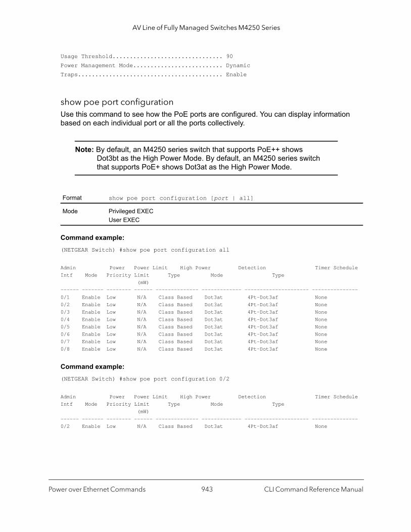
AV Line of Fully Managed Switches M4250 Series
Usage Threshold................................ 90Power Management Mode.......................... DynamicTraps.......................................... Enable
show poe port configurationUse this command to see how the PoE ports are configured. You can display information based on each individual port or all the ports collectively.
Note: By default, an M4250 series switch that supports PoE++ shows Dot3bt as the High Power Mode. By default, an M4250 series switch that supports PoE+ shows Dot3at as the High Power Mode.
Command example: (NETGEAR Switch) #show poe port configuration all
Admin Power Power Limit High Power Detection Timer ScheduleIntf Mode Priority Limit Type Mode Type (mW)------ ------- -------- ------ -------------- ------------- --------------------- ---------------0/1 Enable Low N/A Class Based Dot3at 4Pt-Dot3af None0/2 Enable Low N/A Class Based Dot3at 4Pt-Dot3af None0/3 Enable Low N/A Class Based Dot3at 4Pt-Dot3af None0/4 Enable Low N/A Class Based Dot3at 4Pt-Dot3af None0/5 Enable Low N/A Class Based Dot3at 4Pt-Dot3af None0/6 Enable Low N/A Class Based Dot3at 4Pt-Dot3af None0/7 Enable Low N/A Class Based Dot3at 4Pt-Dot3af None0/8 Enable Low N/A Class Based Dot3at 4Pt-Dot3af None
Command example: (NETGEAR Switch) #show poe port configuration 0/2
Admin Power Power Limit High Power Detection Timer ScheduleIntf Mode Priority Limit Type Mode Type (mW)------ ------- -------- ------ -------------- ------------- --------------------- ---------------0/2 Enable Low N/A Class Based Dot3at 4Pt-Dot3af None
Format show poe port configuration [port | all]
Mode Privileged EXEC User EXEC
Power over Ethernet Commands CLI Command Reference Manual943
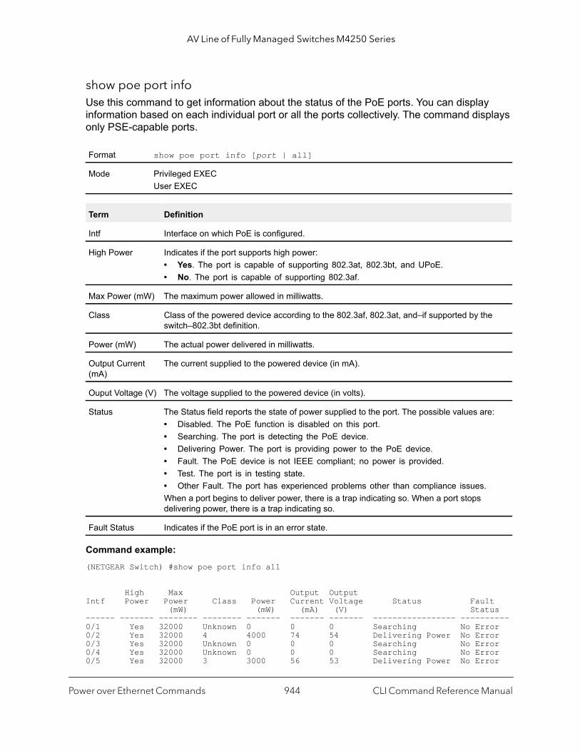
AV Line of Fully Managed Switches M4250 Series
show poe port infoUse this command to get information about the status of the PoE ports. You can display information based on each individual port or all the ports collectively. The command displays only PSE-capable ports.
Command example: (NETGEAR Switch) #show poe port info all
High Max Output OutputIntf Power Power Class Power Current Voltage Status Fault (mW) (mW) (mA) (V) Status------ ------- -------- -------- ------- ------- ------- ----------------- ----------0/1 Yes 32000 Unknown 0 0 0 Searching No Error0/2 Yes 32000 4 4000 74 54 Delivering Power No Error0/3 Yes 32000 Unknown 0 0 0 Searching No Error0/4 Yes 32000 Unknown 0 0 0 Searching No Error0/5 Yes 32000 3 3000 56 53 Delivering Power No Error
Format show poe port info [port | all]
Mode Privileged EXECUser EXEC
Term Definition
Intf Interface on which PoE is configured.
High Power Indicates if the port supports high power:• Yes. The port is capable of supporting 802.3at, 802.3bt, and UPoE.• No. The port is capable of supporting 802.3af.
Max Power (mW) The maximum power allowed in milliwatts.
Class Class of the powered device according to the 802.3af, 802.3at, and–if supported by the switch–802.3bt definition.
Power (mW) The actual power delivered in milliwatts.
Output Current (mA)
The current supplied to the powered device (in mA).
Ouput Voltage (V) The voltage supplied to the powered device (in volts).
Status The Status field reports the state of power supplied to the port. The possible values are:• Disabled. The PoE function is disabled on this port.• Searching. The port is detecting the PoE device.• Delivering Power. The port is providing power to the PoE device.• Fault. The PoE device is not IEEE compliant; no power is provided.• Test. The port is in testing state.• Other Fault. The port has experienced problems other than compliance issues.When a port begins to deliver power, there is a trap indicating so. When a port stops delivering power, there is a trap indicating so.
Fault Status Indicates if the PoE port is in an error state.
Power over Ethernet Commands CLI Command Reference Manual944
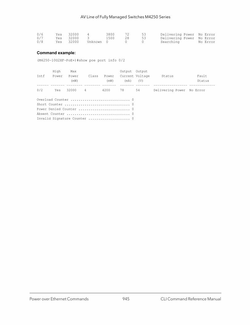
AV Line of Fully Managed Switches M4250 Series
0/6 Yes 32000 4 3800 72 53 Delivering Power No Error0/7 Yes 32000 3 1500 28 53 Delivering Power No Error0/8 Yes 32000 Unknown 0 0 0 Searching No Error
Command example: (M4250-10G2XF-PoE+)#show poe port info 0/2
High Max Output OutputIntf Power Power Class Power Current Voltage Status Fault (mW) (mW) (mA) (V) Status------ ------- -------- -------- ------- ------- ------- ----------------- -------------0/2 Yes 32000 4 4200 78 54 Delivering Power No Error
Overload Counter .............................. 0Short Counter ................................. 0Power Denied Counter .......................... 0Absent Counter ................................ 0Invalid Signature Counter ..................... 0
Power over Ethernet Commands CLI Command Reference Manual945
14
14Switch Software Log MessagesThis chapter lists common log messages that are provided by the switch, along with information regarding the cause of each message. There is no specific action that can be taken per message. When there is a problem being diagnosed, a set of these messages in the event log, along with an understanding of the system configuration and details of the problem can assist NETGEAR in determining the root cause of such a problem. The most recent log messages are displayed first.
Note: This chapter is not a complete list of all syslog messages.
The chapter includes the following sections:
• Core
• Utilities
• Management
• Switching
• QoS
• Routing/IPv6 Routing
• Multicast
• Technologies
• O/S Support
946

AV Line of Fully Managed Switches M4250 Series
tch.
ng r
ing
n for
M
Core
Table 12. BSP Log Messages
Component Message Cause
BSP Event(0xaaaaaaaa) Switch has restarted.
BSP Starting code... BSP initialization complete, starting the swi
Table 13. NIM Log Messages
Component Message Cause
NIM NIM: L7_ATTACH out of order for interface unit x port x
Interface creation out of order.
NIM NIM: Failed to find interface at unit x port x for event(x)
There is no mapping between the USP andInterface number.
NIM NIM: L7_DETACH out of order for interface unit x port x
Interface creation out of order.
NIM NIM: L7_DELETE out of order for interface unit x port x
Interface creation out of order.
NIM NIM: event(x),intf(x),component(x), in wrong phase
An event was issued to NIM during the wroconfiguration phase (probably Phase 1, 2, oWMU).
NIM NIM: Failed to notify users of interface change Event was not propagated to the system.
NIM NIM: failed to send message to NIM message Queue.
NIM message queue full or non-existent.
NIM NIM: Failed to notify the components of L7_CREATE event
Interface not created.
NIM NIM: Attempted event (x), on USP x.x.x before phase 3
A component issued an interface event durthe wrong initialization phase.
NIM NIM: incorrect phase for operation An API call was made during the wrong initialization phase.
NIM NIM: Component(x) failed on event(x) for interface
A component responded with a fail indicatioan interface event.
NIM NIM: Timeout event(x), interface remainingMask = xxxx
A component did not respond before the NItimeout occurred.
Switch Software Log Messages CLI Command Reference Manual947

AV Line of Fully Managed Switches M4250 Series
nflict
is no ich
is no ich
ead
name
s of a
the age. the
d d and sage to a
ead on
ead ually lt
Table 14. SIM Log Message
Component Message Cause
SIM IP address conflict on service port/network port for IP address x.x.x.x. Conflicting host MAC address is xx:xx:xx:xx:xx:xx
This message appears when an address cois detected in the LAN for the service port/network port IP.
Table 15. System Log Messages
Component Message Cause
SYSTEM The size of the startup-config.cfg configuration file is 0 (zero) bytes
The configuration file could not be read. Thmessage may occur on a system for which configuration has ever been saved or for whconfiguration has been erased.
SYSTEM could not separate SYSAPI_CONFIG_FILENAME
The configuration file could not be read. Thmessage may occur on a system for which configuration has ever been saved or for whconfiguration has been erased.
SYSTEM Building defaults for file file name version version num
Configuration did not exist or could not be rfor the specified feature or file. Default configuration values will be used. The file and version are indicated.
SYSTEM File filename: same version (version num) but the sizes (version size – expected version size) differ
The configuration file which was loaded wadifferent size than expected for the version number. This message indicates the configuration file needed to be migrated to version number appropriate for the code imThis message may appear after upgrading code image to a more current release.
SYSTEM Migrating config file filename from version version num to version num
The configuration file identified was migratefrom a previous version number. Both the olnew version number are specified. This mesmay appear after upgrading the code imagemore current release.
SYSTEM Building Defaults Configuration did not exist or could not be rfor the specified feature. Default configurativalues will be used.
SYSTEM sysapiCfgFileGet failed size = expected size of file version = expected version
Configuration did not exist or could not be rfor the specified feature. This message is usfollowed by a message indicating that defauconfiguration values will be used.
Switch Software Log Messages CLI Command Reference Manual948
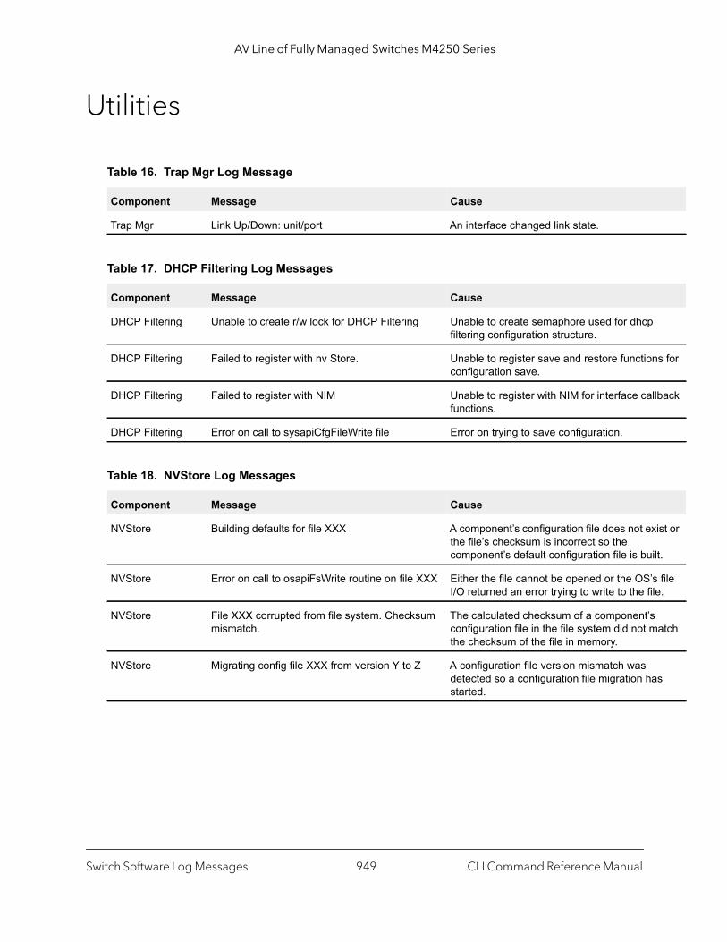
AV Line of Fully Managed Switches M4250 Series
ns for
llback
ist or
ilt.
s file le.
atch
s
Utilities
Table 16. Trap Mgr Log Message
Component Message Cause
Trap Mgr Link Up/Down: unit/port An interface changed link state.
Table 17. DHCP Filtering Log Messages
Component Message Cause
DHCP Filtering Unable to create r/w lock for DHCP Filtering Unable to create semaphore used for dhcpfiltering configuration structure.
DHCP Filtering Failed to register with nv Store. Unable to register save and restore functioconfiguration save.
DHCP Filtering Failed to register with NIM Unable to register with NIM for interface cafunctions.
DHCP Filtering Error on call to sysapiCfgFileWrite file Error on trying to save configuration.
Table 18. NVStore Log Messages
Component Message Cause
NVStore Building defaults for file XXX A component’s configuration file does not exthe file’s checksum is incorrect so the component’s default configuration file is bu
NVStore Error on call to osapiFsWrite routine on file XXX Either the file cannot be opened or the OS’I/O returned an error trying to write to the fi
NVStore File XXX corrupted from file system. Checksum mismatch.
The calculated checksum of a component’sconfiguration file in the file system did not mthe checksum of the file in memory.
NVStore Migrating config file XXX from version Y to Z A configuration file version mismatch was detected so a configuration file migration hastarted.
Switch Software Log Messages CLI Command Reference Manual949

AV Line of Fully Managed Switches M4250 Series
sage
.
se
.
.
sage
a
.
sage
sage
sage
sage
sage
from
Table 19. RADIUS Log Messages
Component Message Cause
RADIUS RADIUS: Invalid data length - xxx The RADIUS Client received an invalid mesfrom the server.
RADIUS RADIUS: Failed to send the request A problem communicating with the RADIUSserver.
RADIUS RADIUS: Failed to send all of the request A problem communicating with the RADIUSserver during transmit.
RADIUS RADIUS: Could not get the Task Sync semaphore!
Resource issue with RADIUS Client service
RADIUS RADIUS: Buffer is too small for response processing
RADIUS Client attempted to build a responlarger than resources allow.
RADIUS RADIUS: Could not allocate accounting requestInfo
Resource issue with RADIUS Client service
RADIUS RADIUS: Could not allocate requestInfo Resource issue with RADIUS Client service
RADIUS RADIUS: osapiSocketRecvFrom returned error Error while attempting to read data from theRADIUS server.
RADIUS RADIUS: Accounting-Response failed to validate, id = xxx
The RADIUS Client received an invalid mesfrom the server.
RADIUS RADIUS: User (xxx) needs to respond for challenge
An unexpected challenge was received for configured user.
RADIUS RADIUS: Could not allocate a buffer for the packet
Resource issue with RADIUS Client service
RADIUS RADIUS: Access-Challenge failed to validate, id = xxx
The RADIUS Client received an invalid mesfrom the server.
RADIUS RADIUS: Failed to validate Message-Authenticator, id = xxx
The RADIUS Client received an invalid mesfrom the server.
RADIUS RADIUS: Access-Accept failed to validate, id = xxx
The RADIUS Client received an invalid mesfrom the server.
RADIUS RADIUS: Invalid packet length – xxx The RADIUS Client received an invalid mesfrom the server.
RADIUS RADIUS: Response is missing Message-Authenticator, id = xxx
The RADIUS Client received an invalid mesfrom the server.
RADIUS RADIUS: Server address doesn't match configured server
RADIUS Client received a server responsean unconfigured server.
Switch Software Log Messages CLI Command Reference Manual950

AV Line of Fully Managed Switches M4250 Series
are
t no
.
a
a
Table 20. TACACS+ Log Messages
Component Message Cause
TACACS+ TACACS+: authentication error, no server to contact
TACACS+ request needed, but no servers configured.
TACACS+ TACACS+: connection failed to server x.x.x.x TACACS+ request sent to server x.x.x.x buresponse was received.
TACACS+ TACACS+: no key configured to encrypt packet for server x.x.x.x
No key configured for the specified server.
TACACS+ TACACS+: received invalid packet type from server.
Received packet type that is not supported
TACACS+ TACACS+: invalid major version in received packet.
Major version mismatch.
TACACS+ TACACS+: invalid minor version in received packet.
Minor version mismatch.
Table 21. LLDP Log Message
Component Message Cause
LLDP lldpTask(): invalid message type:xx. xxxxxx:xx Unsupported LLDP packet received.
Table 22. SNTP Log Message
Component Message Cause
SNTP SNTP: system clock synchronized on %s UTC Indicates that SNTP has successfully synchronized the time of the switch with theserver.
Table 23. DHCPv6 Client Log Messages
Component Message Cause
DHCP6 Client ip6Map dhcp add failed. This message appears when the update ofDHCP leased IP address to IP6Map fails.
DHCP6 Client osapiNetAddrV6Add failed on interface xxx. This message appears when the update ofDHCP leased IP address fails.
Switch Software Log Messages CLI Command Reference Manual951
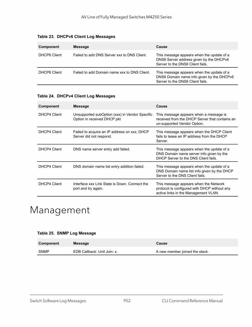
AV Line of Fully Managed Switches M4250 Series
a 6
a Pv6
ns an
ent
a
a CP
ny
Management
DHCP6 Client Failed to add DNS Server xxx to DNS Client. This message appears when the update of DNS6 Server address given by the DHCPvServer to the DNS6 Client fails.
DHCP6 Client Failed to add Domain name xxx to DNS Client. This message appears when the update of DNS6 Domain name info given by the DHCServer to the DNS6 Client fails.
Table 24. DHCPv4 Client Log Messages
Component Message Cause
DHCP4 Client Unsupported subOption (xxx) in Vendor Specific Option in received DHCP pkt
This message appears when a message isreceived from the DHCP Server that contaiun-supported Vendor Option.
DHCP4 Client Failed to acquire an IP address on xxx; DHCP Server did not respond.
This message appears when the DHCP Clifails to lease an IP address from the DHCPServer.
DHCP4 Client DNS name server entry add failed. This message appears when the update of DNS Domain name server info given by theDHCP Server to the DNS Client fails.
DHCP4 Client DNS domain name list entry addition failed. This message appears when the update of DNS Domain name list info given by the DHServer to the DNS Client fails.
DHCP4 Client Interface xxx Link State is Down. Connect the port and try again.
This message appears when the Network protocol is configured with DHCP without aactive links in the Management VLAN.
Table 25. SNMP Log Message
Component Message Cause
SNMP EDB Callback: Unit Join: x. A new member joined the stack.
Table 23. DHCPv6 Client Log Messages
Component Message Cause
Switch Software Log Messages CLI Command Reference Manual952

AV Line of Fully Managed Switches M4250 Series
n the
the ready
s are
ction
ction.
Bad
iled.
.
m a
h is
h the
Table 26. EmWeb Log Messages
Component Message Cause
EmWeb EMWEB (Telnet): Max number of Telnet login sessions exceeded
A user attempted to connect via telnet whemaximum number of telnet sessions were already active.
EmWeb EMWEB (SSH): Max number of SSH login sessions exceeded
A user attempted to connect via SSH whenmaximum number of SSH sessions were alactive.
EmWeb Handle table overflow All the available EmWeb connection handlebeing used and the connection could not bemade.
EmWeb ConnectionType EmWeb socket accept() failed: errno
Socket accept failure for the specified connetype.
EmWeb ewsNetHTTPReceive failure in NetReceiveLoop() - closing connection.
Socket receive failure.
EmWeb EmWeb: connection allocation failed Memory allocation failure for the new conne
EmWeb EMWEB TransmitPending: EWOULDBLOCK error sending data
Socket error on send.
EmWeb ewaNetHTTPEnd: internal error - handle not in Handle table
EmWeb handle index not valid.
EmWeb ewsNetHTTPReceive:recvBufCnt exceeds MAX_QUEUED_RECV_BUFS!
The receive buffer limit has been reached. request or DoS attack.
EmWeb EmWeb accept: XXXX Accept function for new SSH connection faXXXX indicates the error info.
Table 27. CLI_UTIL Log Messages
Component Message Cause
CLI_UTIL Telnet Send Failed errno = 0x%x Failed to send text string to the telnet client
CLI_UTIL osapiFsDir failed Failed to obtain the directory information frovolume's directory.
Table 28. WEB Log Messages
Component Message Cause
WEB Max clients exceeded This message is shown when the maximumallowed java client connections to the switcexceeded.
WEB Error on send to sockfd XXXX, closing connection
Failed to send data to the java clients througsocket.
Switch Software Log Messages CLI Command Reference Manual953

AV Line of Fully Managed Switches M4250 Series
file
on
ified .
s.
imum
XXX
priate X
tions.
V6.
WEB # (XXXX) Form Submission Failed. No Action Taken.
The form submission failed and no action istaken. XXXX indicates the file under consideration.
WEB ewaFormServe_file_download() - WEB Unknown return code from tftp download result
Unknown error returned while downloadingusing TFTP from web interface.
WEB ewaFormServe_file_upload() - Unknown return code from tftp upload result
Unknown error returned while uploading fileusing TFTP from web interface.
WEB Web UI Screen with unspecified access attempted to be brought up
Failed to get application-specific authorizatihandle provided to EmWeb/Server by the application in ewsAuthRegister(). The specweb page will be served in read-only mode
Table 29. CLI_WEB_MGR Log Messages
Component Message Cause
CLI_WEB_MGR File size is greater than 2K The banner file size is greater than 2K byte
CLI_WEB_MGR No. of rows greater than allowed maximum of XXXX
When the number of rows exceeds the maxallowed rows.
Table 30. SSHD Log Messages
Component Message Cause
SSHD SSHD: Unable to create the global (data) semaphore
Failed to create semaphore for global data protection.
SSHD SSHD: Msg Queue is full, event = XXXX Failed to send the message to the SSHD message queue as message queue is full. Xindicates the event to be sent.
SSHD SSHD: Unknown UI event in message, event = XXXX
Failed to dispatch the UI event to the approSSHD function as it’s an invalid event. XXXindicates the event to be dispatched.
SSHD sshdApiCnfgrCommand: Failed calling sshdIssueCmd.
Failed to send the message to the SSHD message queue.
Table 31. SSLT Log Messages
Component Message Cause
SSLT SSLT: Exceeded maximum, ssltConnectionTask Exceeded maximum allowed SSLT connec
SSLT SSLT: Error creating Secure server socket6 Failed to create secure server socket for IP
Table 28. WEB Log Messages
Component Message Cause
Switch Software Log Messages CLI Command Reference Manual954

AV Line of Fully Managed Switches M4250 Series
er. s. ction
SSLT XXX
the vent.
.
here
cates
he
e mber
SSLT SSLT: Can't connect to unsecure server at XXXX, result = YYYY, errno = ZZZZ
Failed to open connection to unsecure servXXXX is the unsecure server socket addresYYYY is the result returned from connect funand ZZZZ is the error code.
SSLT SSLT: Msg Queue is full, event = XXXX Failed to send the received message to the message queue as message queue is full. Xindicates the event to be sent.
SSLT SSLT: Unknown UI event in message, event = XXXX
Failed to dispatch the received UI event to appropriate SSLT function as it’s an invalid eXXXX indicates the event to be dispatched
SSLT ssltApiCnfgrCommand: Failed calling ssltIssueCmd.
Failed to send the message to the SSLT message queue.
SSLT SSLT: Error loading certificate from file XXXX Failed while loading the SSLcertificate fromspecified file. XXXX indicates the file from wthe certificate is being read.
SSLT SSLT: Error loading private key from file Failed while loading private key for SSL connection.
SSLT SSLT: Error setting cipher list (no valid ciphers) Failed while setting cipher list.
SSLT SSLT: Could not delete the SSL semaphores Failed to delete SSL semaphores during cleanup.of all resources associated with theOpenSSL Locking semaphores.
Table 32. User_Manager Log Messages
Component Message Cause
User_Manager User Login Failed for XXXX Failed to authenticate user login. XXXX indithe username to be authenticated.
User_Manager Access level for user XXXX could not be determined. Setting to READ_ONLY.
Invalid access level specified for the user. Taccess level is set to READ_ONLY. XXXX indicates the username.
User_Manager Could not migrate config file XXXX from version YYYY to ZZZZ. Using defaults.
Failed to migrate the config file. XXXX is thconfig file name. YYYY is the old version nuand ZZZZ is the new version number.
Table 31. SSLT Log Messages
Component Message Cause
Switch Software Log Messages CLI Command Reference Manual955

AV Line of Fully Managed Switches M4250 Series
ck
with
e
rface
up for
back ent is
nd
ation
ns
to
f this
entry
Switching
Table 33. Protected Ports Log Messages
Component Message Cause
Protected Ports Protected Port: failed to save configuration This appears when the protected port configuration cannot be saved.
Protected Ports protectedPortCnfgrInitPhase1Process: Unable to create r/w lock for protected Port
This appears when protectedPortCfgRWLoFails.
Protected Ports protectedPortCnfgrInitPhase2Process: Unable to register for VLAN change callback
This appears when nimRegisterIntfChangeVLAN fails.
Protected Ports Cannot add interface xxx to group yyy This appears when an interface could not badded to a particular group.
Protected Ports unable to set protected port group This appears when a dtl call fails to add intemask at the driver level.
Protected Ports Cannot delete interface xxx from group yyy This appears when a dtl call to delete an interface from a group fails.
Protected Ports Cannot update group YYY after deleting interface XXX
This message appears when an update groa interface deletion fails.
Protected Ports Received an interface change callback while not ready to receive it
This appears when an interface change callhas come before the protected port componready.
Table 34. IP Subnet VLANS Log Messages
Component Message Cause
IP subnet VLANs ERROR vlanIpSubnetSubnetValid:Invalid subnet This occurs when an invalid pair of subnet anetmask has come from the CLI.
IP subnet VLANs IP Subnet Vlans: failed to save configuration This message appears when save configurof subnet vlans failed.
IP subnet VLANs vlanIpSubnetCnfgrInitPhase1Process: Unable to create r/w lock for vlanIpSubnet
This appears when a read/write lock creatiofails.
IP subnet VLANs vlanIpSubnetCnfgrInitPhase2Process: Unable to register for VLAN change callback
This appears when this component unable register for vlan change notifications.
IP subnet VLANs vlanIpSubnetCnfgrFiniPhase1Process: could not delete avl semaphore
This appears when a semaphore deletion ocomponent fails.
IP subnet VLANs vlanIpSubnetDtlVlanCreate: Failed This appears when a dtl call fails to add an into the table.
Switch Software Log Messages CLI Command Reference Manual956
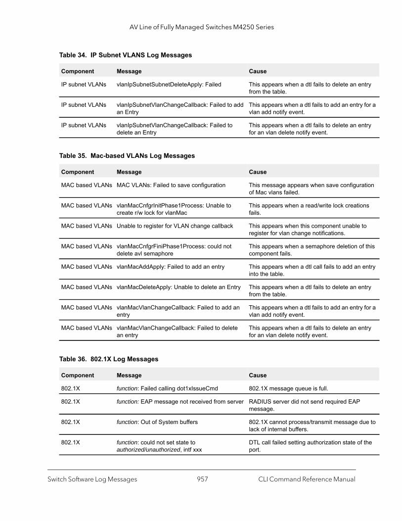
AV Line of Fully Managed Switches M4250 Series
ntry
for a
ntry
ation
ns
to
f this
entry
ntry
for a
ntry
ue to
f the
IP subnet VLANs vlanIpSubnetSubnetDeleteApply: Failed This appears when a dtl fails to delete an efrom the table.
IP subnet VLANs vlanIpSubnetVlanChangeCallback: Failed to add an Entry
This appears when a dtl fails to add an entryvlan add notify event.
IP subnet VLANs vlanIpSubnetVlanChangeCallback: Failed to delete an Entry
This appears when a dtl fails to delete an efor an vlan delete notify event.
Table 35. Mac-based VLANs Log Messages
Component Message Cause
MAC based VLANs MAC VLANs: Failed to save configuration This message appears when save configurof Mac vlans failed.
MAC based VLANs vlanMacCnfgrInitPhase1Process: Unable to create r/w lock for vlanMac
This appears when a read/write lock creatiofails.
MAC based VLANs Unable to register for VLAN change callback This appears when this component unable register for vlan change notifications.
MAC based VLANs vlanMacCnfgrFiniPhase1Process: could not delete avl semaphore
This appears when a semaphore deletion ocomponent fails.
MAC based VLANs vlanMacAddApply: Failed to add an entry This appears when a dtl call fails to add aninto the table.
MAC based VLANs vlanMacDeleteApply: Unable to delete an Entry This appears when a dtl fails to delete an efrom the table.
MAC based VLANs vlanMacVlanChangeCallback: Failed to add an entry
This appears when a dtl fails to add an entryvlan add notify event.
MAC based VLANs vlanMacVlanChangeCallback: Failed to delete an entry
This appears when a dtl fails to delete an efor an vlan delete notify event.
Table 36. 802.1X Log Messages
Component Message Cause
802.1X function: Failed calling dot1xIssueCmd 802.1X message queue is full.
802.1X function: EAP message not received from server RADIUS server did not send required EAP message.
802.1X function: Out of System buffers 802.1X cannot process/transmit message dlack of internal buffers.
802.1X function: could not set state to authorized/unauthorized, intf xxx
DTL call failed setting authorization state oport.
Table 34. IP Subnet VLANS Log Messages
Component Message Cause
Switch Software Log Messages CLI Command Reference Manual957
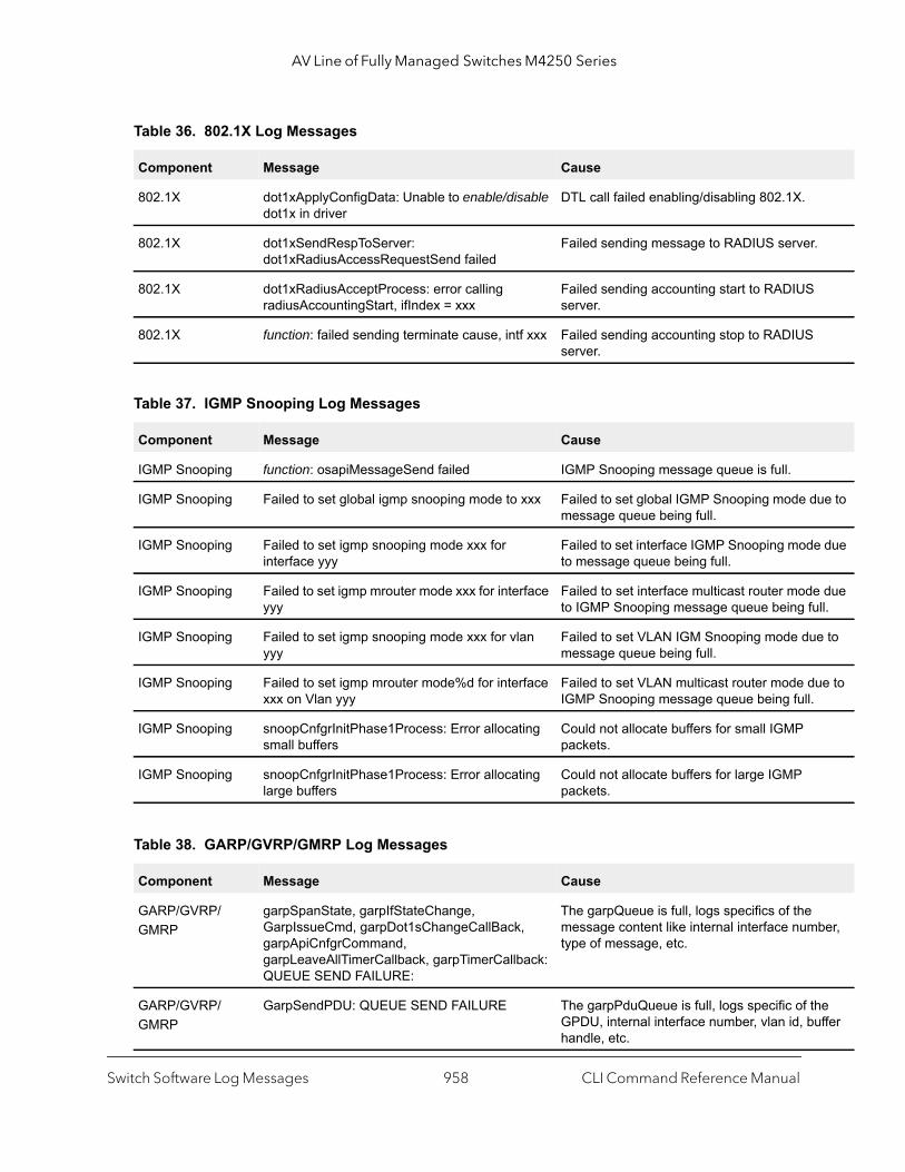
AV Line of Fully Managed Switches M4250 Series
.
ue to
e due
due ll.
e to
ue to
ber,
he uffer
802.1X dot1xApplyConfigData: Unable to enable/disable dot1x in driver
DTL call failed enabling/disabling 802.1X.
802.1X dot1xSendRespToServer: dot1xRadiusAccessRequestSend failed
Failed sending message to RADIUS server
802.1X dot1xRadiusAcceptProcess: error calling radiusAccountingStart, ifIndex = xxx
Failed sending accounting start to RADIUSserver.
802.1X function: failed sending terminate cause, intf xxx Failed sending accounting stop to RADIUSserver.
Table 37. IGMP Snooping Log Messages
Component Message Cause
IGMP Snooping function: osapiMessageSend failed IGMP Snooping message queue is full.
IGMP Snooping Failed to set global igmp snooping mode to xxx Failed to set global IGMP Snooping mode dmessage queue being full.
IGMP Snooping Failed to set igmp snooping mode xxx for interface yyy
Failed to set interface IGMP Snooping modto message queue being full.
IGMP Snooping Failed to set igmp mrouter mode xxx for interface yyy
Failed to set interface multicast router modeto IGMP Snooping message queue being fu
IGMP Snooping Failed to set igmp snooping mode xxx for vlan yyy
Failed to set VLAN IGM Snooping mode dumessage queue being full.
IGMP Snooping Failed to set igmp mrouter mode%d for interface xxx on Vlan yyy
Failed to set VLAN multicast router mode dIGMP Snooping message queue being full.
IGMP Snooping snoopCnfgrInitPhase1Process: Error allocating small buffers
Could not allocate buffers for small IGMP packets.
IGMP Snooping snoopCnfgrInitPhase1Process: Error allocating large buffers
Could not allocate buffers for large IGMP packets.
Table 38. GARP/GVRP/GMRP Log Messages
Component Message Cause
GARP/GVRP/GMRP
garpSpanState, garpIfStateChange, GarpIssueCmd, garpDot1sChangeCallBack, garpApiCnfgrCommand, garpLeaveAllTimerCallback, garpTimerCallback: QUEUE SEND FAILURE:
The garpQueue is full, logs specifics of the message content like internal interface numtype of message, etc.
GARP/GVRP/GMRP
GarpSendPDU: QUEUE SEND FAILURE The garpPduQueue is full, logs specific of tGPDU, internal interface number, vlan id, bhandle, etc.
Table 36. 802.1X Log Messages
Component Message Cause
Switch Software Log Messages CLI Command Reference Manual958

AV Line of Fully Managed Switches M4250 Series
is rface
ful in
) and
chine
.
is rface
GARP/GVRP/GMRP
garpMapIntfIsConfigurable, gmrpMapIntfIsConfigurable: Error accessing GARP/GMRP config data for interface %d in garpMapIntfIsConfigurable.
A default configuration does not exist for thinterface. Typically a case when a new inteis created and has no preconfiguration.
GARP/GVRP/GMRP
garpTraceMsgQueueUsage: garpQueue usage has exceeded fifty/eighty/ninety percent
Traces the build up of message queue. Helpdetermining the load on GARP.
GARP/GVRP/GMRP
gid_destroy_port: Error Removing port %d registration for vlan-mac %d - %02X:%02X:%02X:%02X:%02X:%02X
Mismatch between the gmd (gmrp databaseMFDB.
GARP/GVRP/GMRP
gmd_create_entry: GMRP failure adding MFDB entry: vlan %d and address %s
MFDB table is full.
Table 39. 802.3ad Log Messages
Component Message Cause
802.3ad dot3adReceiveMachine: received default event %x
Received a LAG PDU and the RX state mais ignoring this LAGPDU.
802.3ad dot3adNimEventCompletionCallback, dot3adNimEventCreateCompletionCallback: DOT3AD: notification failed for event(%d), intf(%d), reason(%d)
The event sent to NIM was not completed successfully.
Table 40. FDB Log Message
Component Message Cause
FDB fdbSetAddressAgingTimeOut: Failure setting fid %d address aging timeout to %d
Unable to set the age time in the hardware
Table 41. Double VLAN Tag Log Message
Component Message Cause
Double Vlan Tag dvlantagIntfIsConfigurable: Error accessing dvlantag config data for interface %d
A default configuration does not exist for thinterface. Typically a case when a new inteis created and has no preconfiguration.
Table 38. GARP/GVRP/GMRP Log Messages
Component Message Cause
Switch Software Log Messages CLI Command Reference Manual959

AV Line of Fully Managed Switches M4250 Series
s rface
e.
s face
clear
not
rom
m
ot1q
Table 42. IPv6 Provisioning Log Message
Component Message Cause
IPV6 Provisioning ipv6ProvIntfIsConfigurable: Error accessing IPv6 Provisioning config data for interface %d
A default configuration does not exist for thiinterface. Typically a case when a new inteis created and has no preconfiguration.
Table 43. MFDB Log Message
Component Message Cause
MFDB mfdbTreeEntryUpdate: entry does not exist Trying to update a non existing entry.
Table 44. 802.1Q Log Messages
Component Message Cause
802.1Q dot1qIssueCmd: Unable to send message %d to dot1qMsgQueue for vlan %d - %d msgs in queue
dot1qMsgQueue is full.
802.1Q dot1qVlanCreateProcess: Attempt to create a vlan with an invalid vlan id %d ;VLAN %d not in range,
This accommodates for reserved vlan ids. i.4094 - x.
802.1Q dot1qMapIntfIsConfigurable: Error accessing DOT1Q config data for interface %d in dot1qMapIntfIsConfigurable.
A default configuration does not exist for thiinterface. Typically a case when a new interis created and has no preconfiguration.
802.1Q dot1qVlanDeleteProcess: Deleting the default VLAN Typically encountered during clear Vlan andconfig.
802.1Q dot1qVlanMemberSetModify, dot1qVlanTaggedMemberSetModify: Dynamic entry %d can only be modified after it is converted to static
If this vlan is a learnt via GVRP then we canmodify its member set via management.
802.1Q dtl failure when adding ports to vlan id %d - portMask = %s
Failed to add the ports to VLAN entry in hardware.
802.1Q dtl failure when deleting ports from vlan id %d - portMask = %s
Failed to delete the ports for a VLAN entry fthe hardware.
802.1Q dtl failure when adding ports to tagged list for vlan id %d - portMask = %s
Failed to add the port to the tagged list in hardware.
802.1Q dtl failure when deleting ports from tagged list for vlan id %d - portMask = %s"
Failed to delete the port to the tagged list frothe hardware.
802.1Q dot1qTask: unsuccessful return code on receive from dot1qMsgQueue: %08x"
Failed to receive the dot1q message from dmessage queue.
802.1Q Unable to apply VLAN creation request for VLAN ID %d, Database reached MAX VLAN count!
Failed to create VLAN ID, VLAN Database reached maximum values.
Switch Software Log Messages CLI Command Reference Manual960
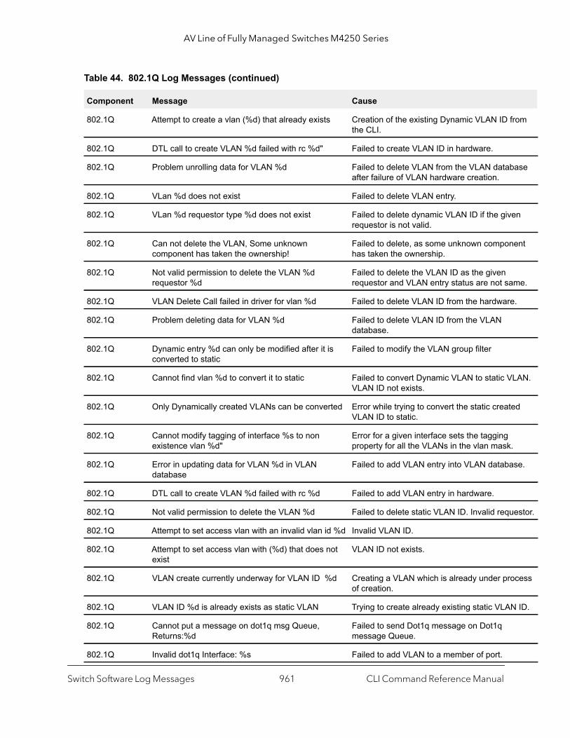
AV Line of Fully Managed Switches M4250 Series
rom
ase
en
ent
me.
.
LAN.
d
se.
estor.
cess
ID.
802.1Q Attempt to create a vlan (%d) that already exists Creation of the existing Dynamic VLAN ID fthe CLI.
802.1Q DTL call to create VLAN %d failed with rc %d" Failed to create VLAN ID in hardware.
802.1Q Problem unrolling data for VLAN %d Failed to delete VLAN from the VLAN databafter failure of VLAN hardware creation.
802.1Q VLan %d does not exist Failed to delete VLAN entry.
802.1Q VLan %d requestor type %d does not exist Failed to delete dynamic VLAN ID if the givrequestor is not valid.
802.1Q Can not delete the VLAN, Some unknown component has taken the ownership!
Failed to delete, as some unknown componhas taken the ownership.
802.1Q Not valid permission to delete the VLAN %d requestor %d
Failed to delete the VLAN ID as the given requestor and VLAN entry status are not sa
802.1Q VLAN Delete Call failed in driver for vlan %d Failed to delete VLAN ID from the hardware
802.1Q Problem deleting data for VLAN %d Failed to delete VLAN ID from the VLAN database.
802.1Q Dynamic entry %d can only be modified after it is converted to static
Failed to modify the VLAN group filter
802.1Q Cannot find vlan %d to convert it to static Failed to convert Dynamic VLAN to static VVLAN ID not exists.
802.1Q Only Dynamically created VLANs can be converted Error while trying to convert the static createVLAN ID to static.
802.1Q Cannot modify tagging of interface %s to non existence vlan %d"
Error for a given interface sets the tagging property for all the VLANs in the vlan mask.
802.1Q Error in updating data for VLAN %d in VLAN database
Failed to add VLAN entry into VLAN databa
802.1Q DTL call to create VLAN %d failed with rc %d Failed to add VLAN entry in hardware.
802.1Q Not valid permission to delete the VLAN %d Failed to delete static VLAN ID. Invalid requ
802.1Q Attempt to set access vlan with an invalid vlan id %d Invalid VLAN ID.
802.1Q Attempt to set access vlan with (%d) that does not exist
VLAN ID not exists.
802.1Q VLAN create currently underway for VLAN ID %d Creating a VLAN which is already under proof creation.
802.1Q VLAN ID %d is already exists as static VLAN Trying to create already existing static VLAN
802.1Q Cannot put a message on dot1q msg Queue, Returns:%d
Failed to send Dot1q message on Dot1q message Queue.
802.1Q Invalid dot1q Interface: %s Failed to add VLAN to a member of port.
Table 44. 802.1Q Log Messages (continued)
Component Message Cause
Switch Software Log Messages CLI Command Reference Manual961
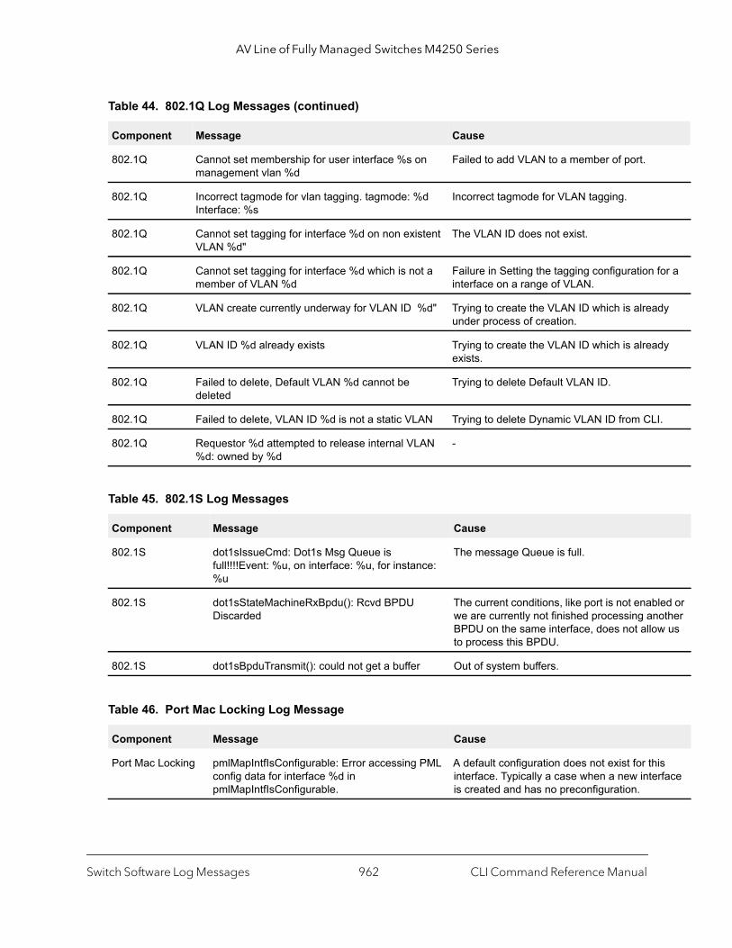
AV Line of Fully Managed Switches M4250 Series
or a
dy
dy
.
led or other
us
s rface
802.1Q Cannot set membership for user interface %s on management vlan %d
Failed to add VLAN to a member of port.
802.1Q Incorrect tagmode for vlan tagging. tagmode: %d Interface: %s
Incorrect tagmode for VLAN tagging.
802.1Q Cannot set tagging for interface %d on non existent VLAN %d"
The VLAN ID does not exist.
802.1Q Cannot set tagging for interface %d which is not a member of VLAN %d
Failure in Setting the tagging configuration finterface on a range of VLAN.
802.1Q VLAN create currently underway for VLAN ID %d" Trying to create the VLAN ID which is alreaunder process of creation.
802.1Q VLAN ID %d already exists Trying to create the VLAN ID which is alreaexists.
802.1Q Failed to delete, Default VLAN %d cannot be deleted
Trying to delete Default VLAN ID.
802.1Q Failed to delete, VLAN ID %d is not a static VLAN Trying to delete Dynamic VLAN ID from CLI
802.1Q Requestor %d attempted to release internal VLAN %d: owned by %d
-
Table 45. 802.1S Log Messages
Component Message Cause
802.1S dot1sIssueCmd: Dot1s Msg Queue is full!!!!Event: %u, on interface: %u, for instance: %u
The message Queue is full.
802.1S dot1sStateMachineRxBpdu(): Rcvd BPDU Discarded
The current conditions, like port is not enabwe are currently not finished processing anBPDU on the same interface, does not allowto process this BPDU.
802.1S dot1sBpduTransmit(): could not get a buffer Out of system buffers.
Table 46. Port Mac Locking Log Message
Component Message Cause
Port Mac Locking pmlMapIntfIsConfigurable: Error accessing PML config data for interface %d in pmlMapIntfIsConfigurable.
A default configuration does not exist for thiinterface. Typically a case when a new inteis created and has no preconfiguration.
Table 44. 802.1Q Log Messages (continued)
Component Message Cause
Switch Software Log Messages CLI Command Reference Manual962
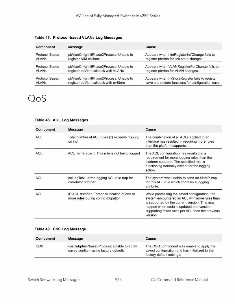
AV Line of Fully Managed Switches M4250 Series
to
ils to
ster save.
s
trap
he than
ay
vious
he e
QoS
Table 47. Protocol-based VLANs Log Messages
Component Message Cause
Protocol Based VLANs
pbVlanCnfgrInitPhase2Process: Unable to register NIM callback
Appears when nimRegisterIntfChange failsregister pbVlan for link state changes.
Protocol Based VLANs
pbVlanCnfgrInitPhase2Process: Unable to register pbVlan callback with VLANs
Appears when VLANRegisterForChange faregister pbVlan for VLAN changes.
Protocol Based VLANs
pbVlanCnfgrInitPhase2Process: Unable to register pbVlan callback with nvStore
Appears when nvStoreRegister fails to regisave and restore functions for configuration
Table 48. ACL Log Messages
Component Message Cause
ACL Total number of ACL rules (x) exceeds max (y) on intf i.
The combination of all ACLs applied to an interface has resulted in requiring more rulethan the platform supports.
ACL ACL name, rule x: This rule is not being logged The ACL configuration has resulted in a requirement for more logging rules than theplatform supports. The specified rule is functioning normally except for the logging action.
ACL aclLogTask: error logging ACL rule trap for correlator number
The system was unable to send an SNMP for this ACL rule which contains a logging attribute.
ACL IP ACL number: Forced truncation of one or more rules during config migration
While processing the saved configuration, tsystem encountered an ACL with more rulesis supported by the current version. This mhappen when code is updated to a version supporting fewer rules per ACL than the preversion.
Table 49. CoS Log Message
Component Message Cause
COS cosCnfgrInitPhase3Process: Unable to apply saved config -- using factory defaults
The COS component was unable to apply tsaved configuration and has initialized to thfactory default settings.
Switch Software Log Messages CLI Command Reference Manual963

AV Line of Fully Managed Switches M4250 Series
d to tting
ble d. ation
CP
ill not r than
CP
valid by
Routing/IPv6 Routing
Table 50. DiffServ Log Messages
Component Message Cause
DiffServ diffserv.c 165: diffServRestore Failed to reset DiffServ. Recommend resetting device
While attempting to clear the running configuration an error was encountered in removing the current settings. This may leaan inconsistent state in the system and reseis advised.
DiffServ Policy invalid for service intf: policy name, interface x, direction y
The DiffServ policy definition is not compatiwith the capabilities of the interface specifieCheck the platform release notes for informon configuration limitations.
Table 51. DHCP Relay Log Messages
Component Message Cause
DHCP relay REQUEST hops field more than config value The DHCP relay agent has processed a DHrequest whose HOPS field is larger than themaximum value allowed. The relay agent wforward a message with a hop count greate4.
DHCP relay Request's seconds field less than the config value
The DHCP relay agent has processed a DHrequest whose SECS field is larger than theconfigured minimum wait time allowed.
DHCP relay processDhcpPacket: invalid DHCP packet type: %u\n
The DHCP relay agent has processed an inDHCP packet. Such packets are discardedthe relay agent.
Switch Software Log Messages CLI Command Reference Manual964
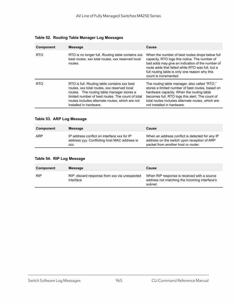
AV Line of Fully Managed Switches M4250 Series
w full of ber of ut a s
O,” ed on
t of are
y IP P
ce e’s
Table 52. Routing Table Manager Log Messages
Component Message Cause
RTO RTO is no longer full. Routing table contains xxx best routes, xxx total routes, xxx reserved local routes.
When the number of best routes drops belocapacity, RTO logs this notice. The numberbad adds may give an indication of the numroute adds that failed while RTO was full, bfull routing table is only one reason why thicount is incremented.
RTO RTO is full. Routing table contains xxx best routes, xxx total routes, xxx reserved local routes. The routing table manager stores a limited number of best routes. The count of total routes includes alternate routes, which are not installed in hardware.
The routing table manager, also called “RTstores a limited number of best routes, bashardware capacity. When the routing table becomes full, RTO logs this alert. The countotal routes includes alternate routes, whichnot installed in hardware.
Table 53. ARP Log Message
Component Message Cause
ARP IP address conflict on interface xxx for IP address yyy. Conflicting host MAC address is zzz.
When an address conflict is detected for anaddress on the switch upon reception of ARpacket from another host or router.
Table 54. RIP Log Message
Component Message Cause
RIP RIP: discard response from xxx via unexpected interface
When RIP response is received with a souraddress not matching the incoming interfacsubnet.
Switch Software Log Messages CLI Command Reference Manual965
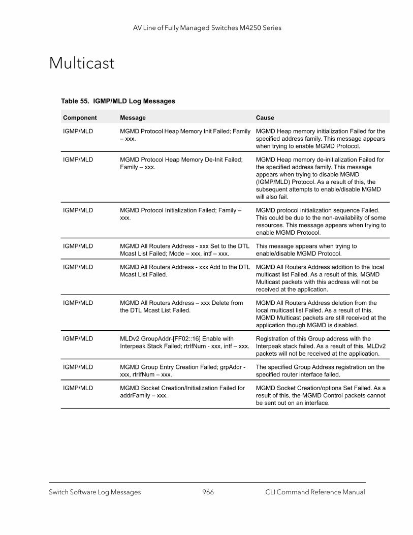
AV Line of Fully Managed Switches M4250 Series
r the ears
d for
e MD
ed. some ing to
local D
be
e , t the
LDv2 on.
n the
As a nnot
Multicast
Table 55. IGMP/MLD Log Messages
Component Message Cause
IGMP/MLD MGMD Protocol Heap Memory Init Failed; Family – xxx.
MGMD Heap memory initialization Failed fospecified address family. This message appwhen trying to enable MGMD Protocol.
IGMP/MLD MGMD Protocol Heap Memory De-Init Failed; Family – xxx.
MGMD Heap memory de-initialization Failethe specified address family. This messageappears when trying to disable MGMD (IGMP/MLD) Protocol. As a result of this, thsubsequent attempts to enable/disable MGwill also fail.
IGMP/MLD MGMD Protocol Initialization Failed; Family – xxx.
MGMD protocol initialization sequence FailThis could be due to the non-availability of resources. This message appears when tryenable MGMD Protocol.
IGMP/MLD MGMD All Routers Address - xxx Set to the DTL Mcast List Failed; Mode – xxx, intf – xxx.
This message appears when trying to enable/disable MGMD Protocol.
IGMP/MLD MGMD All Routers Address - xxx Add to the DTL Mcast List Failed.
MGMD All Routers Address addition to the multicast list Failed. As a result of this, MGMMulticast packets with this address will not received at the application.
IGMP/MLD MGMD All Routers Address – xxx Delete from the DTL Mcast List Failed.
MGMD All Routers Address deletion from thlocal multicast list Failed. As a result of thisMGMD Multicast packets are still received aapplication though MGMD is disabled.
IGMP/MLD MLDv2 GroupAddr-[FF02::16] Enable with Interpeak Stack Failed; rtrIfNum - xxx, intf – xxx.
Registration of this Group address with the Interpeak stack failed. As a result of this, Mpackets will not be received at the applicati
IGMP/MLD MGMD Group Entry Creation Failed; grpAddr - xxx, rtrIfNum – xxx.
The specified Group Address registration ospecified router interface failed.
IGMP/MLD MGMD Socket Creation/Initialization Failed for addrFamily – xxx.
MGMD Socket Creation/options Set Failed.result of this, the MGMD Control packets cabe sent out on an interface.
Switch Software Log Messages CLI Command Reference Manual966

AV Line of Fully Managed Switches M4250 Series
ce ility
when
n is
he
try for ailed
to
or the ears
d for tocol. to
led. some ing to
to
sage odate
ocal
Table 56. IGMP-Proxy Log Messages
Component Message Cause
IGMP-Proxy/MLD-Proxy
MGMD-Proxy Protocol Initialization Failed; Family – xxx.
MGMD-Proxy protocol initialization sequenFailed. This could be due to the non-availabof some resources. This message appears trying to enable MGMD-Proxy Protocol.
IGMP-Proxy/MLD-Proxy
MGMD-Proxy Protocol Heap Memory De-Init Failed; Family – xxx.
MGMD-Proxy Heap memory de-initializatioFailed for the specified address family. Thismessage appears when trying to disable MGMD-Proxy Protocol. As a result of this, tsubsequent attempts to enable/disable MGMD-Proxy will also fail.
IGMP-Proxy/MLD-Proxy
MGMD Proxy Route Entry Creation Failed; grpAddr - xxx, srcAddr – xxx, rtrIfNum – xxx.
Registration of the Multicast Forwarding enthe specified Source and Group Address Fwhen MGMD-Proxy is used.
Table 57. PIM-SM Log Messages
Component Message Cause
PIMSM Non-Zero SPT/Data Threshold Rate – xxx is currently Not Supported on this platform.
This message appears when the user tries configure the PIMSM SPT threshold value.
PIMSM PIMSM Protocol Heap Memory Init Failed; Family – xxx.
PIMSM Heap memory initialization Failed fspecified address family. This message appwhen trying to enable PIMSM Protocol.
PIMSM PIMSM Protocol Heap Memory De-Init Failed; Family –xxx.
PIMSM Heap memory de-initialization Failethe specified address family. This messageappears when trying to disable PIMSM ProAs a result of this, the subsequent attemptsenable/disable PIMSM will also fail.
PIMSM PIMSM Protocol Initialization Failed; Family –xxx. PIMSM protocol initialization sequence FaiThis could be due to the non-availability of resources. This message appears when tryenable PIMSM Protocol.
PIMSM PIMSM Protocol De-Initialization Failed; Family – xxx.
PIMSM protocol de-initialization sequence Failed. This message appears when trying disable PIMSM Protocol.
PIMSM PIMSM SSM Range Table is Full. PIMSM SSM Range Table is Full. This mesappears when the protocol cannot accommnew SSM registrations.
PIMSM PIM All Routers Address – xxx Delete from the DTL Mcast List Failed for intf – xxx.
PIM All Routers Address deletion from the lmulticast list Failed. As a result of this, PIMMulticast packets are still received at the application though PIM is disabled.
Switch Software Log Messages CLI Command Reference Manual967
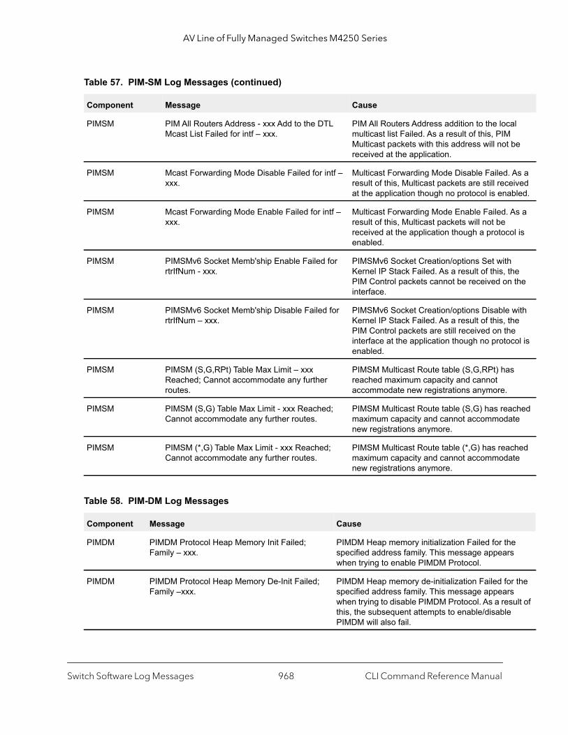
AV Line of Fully Managed Switches M4250 Series
l be
As a ived bled.
s a
l is
e
the
with e
e col is
ched te
hed te
e
r the ult of
PIMSM PIM All Routers Address - xxx Add to the DTL Mcast List Failed for intf – xxx.
PIM All Routers Address addition to the locamulticast list Failed. As a result of this, PIMMulticast packets with this address will not received at the application.
PIMSM Mcast Forwarding Mode Disable Failed for intf – xxx.
Multicast Forwarding Mode Disable Failed. result of this, Multicast packets are still receat the application though no protocol is ena
PIMSM Mcast Forwarding Mode Enable Failed for intf – xxx.
Multicast Forwarding Mode Enable Failed. Aresult of this, Multicast packets will not be received at the application though a protocoenabled.
PIMSM PIMSMv6 Socket Memb'ship Enable Failed for rtrIfNum - xxx.
PIMSMv6 Socket Creation/options Set withKernel IP Stack Failed. As a result of this, thPIM Control packets cannot be received oninterface.
PIMSM PIMSMv6 Socket Memb'ship Disable Failed for rtrIfNum – xxx.
PIMSMv6 Socket Creation/options Disable Kernel IP Stack Failed. As a result of this, thPIM Control packets are still received on thinterface at the application though no protoenabled.
PIMSM PIMSM (S,G,RPt) Table Max Limit – xxx Reached; Cannot accommodate any further routes.
PIMSM Multicast Route table (S,G,RPt) hasreached maximum capacity and cannot accommodate new registrations anymore.
PIMSM PIMSM (S,G) Table Max Limit - xxx Reached; Cannot accommodate any further routes.
PIMSM Multicast Route table (S,G) has reamaximum capacity and cannot accommodanew registrations anymore.
PIMSM PIMSM (*,G) Table Max Limit - xxx Reached; Cannot accommodate any further routes.
PIMSM Multicast Route table (*,G) has reacmaximum capacity and cannot accommodanew registrations anymore.
Table 58. PIM-DM Log Messages
Component Message Cause
PIMDM PIMDM Protocol Heap Memory Init Failed; Family – xxx.
PIMDM Heap memory initialization Failed for thspecified address family. This message appearswhen trying to enable PIMDM Protocol.
PIMDM PIMDM Protocol Heap Memory De-Init Failed; Family –xxx.
PIMDM Heap memory de-initialization Failed fospecified address family. This message appearswhen trying to disable PIMDM Protocol. As a resthis, the subsequent attempts to enable/disablePIMDM will also fail.
Table 57. PIM-SM Log Messages (continued)
Component Message Cause
Switch Software Log Messages CLI Command Reference Manual968

AV Line of Fully Managed Switches M4250 Series
This
to
d. MDM
ticast gh
ticast t the
at
result the
nel IP l
IM e at
to , the may me .
a sent
IMv6 ckets
PIMDM PIMDM Protocol Initialization Failed; Family –xxx.
PIMDM protocol initialization sequence Failed. could be due to the non-availability of some resources. This message appears when trying enable PIMDM Protocol.
PIMDM PIMDM Protocol De-Initialization Failed; Family – xxx.
PIMDM protocol de-initialization sequence FaileThis message appears when trying to disable PIProtocol.
PIMDM PIM All Routers Address – xxx Delete from the DTL Mcast List Failed for intf – xxx.
PIM All Routers Address deletion from the localmulticast list Failed. As a result of this, PIM Mulpackets are still received at the application thouPIM is disabled.
PIMDM PIM All Routers Address - xxx Add to the DTL Mcast List Failed for intf – xxx.
PIM All Routers Address addition to the local multicast list Failed. As a result of this, PIM Mulpackets with this address will not be received aapplication.
PIMDM Mcast Forwarding Mode Disable Failed for intf – xxx.
Multicast Forwarding Mode Disable Failed. As aresult of this, Multicast packets are still receivedthe application though no protocol is enabled.
PIMDM Mcast Forwarding Mode Enable Failed for intf – xxx.
Multicast Forwarding Mode Enable Failed. As a of this, Multicast packets will not be received atapplication though a protocol is enabled.
PIMDM PIMDMv6 Socket Memb'ship Enable Failed for rtrIfNum - xxx.
PIMDMv6 Socket Creation/options Set with KerStack Failed. As a result of this, the PIM Contropackets cannot be received on the interface.
PIMDM PIMDMv6 Socket Memb'ship Disable Failed for rtrIfNum – xxx.
PIMDMv6 Socket Creation/options Disable withKernel IP Stack Failed. As a result of this, the PControl packets are still received on the interfacthe application though no protocol is enabled.
PIMDM PIMDM FSM Action Invoke Failed; rtrIfNum - xxx Out of Bounds for Event – xxx.
The PIMDM FSM Action invocation Failed due invalid Routing interface number. In such casesFSM Action routine can never be invoked whichresult in abnormal behavior. The failed FSM-nacan be identified from the specified Event name
PIMDM PIMDM Socket Initialization Failed for addrFamily - xxx.
PIMDM Socket Creation/options Set Failed. As result of this, the PIM Control packets cannot beout on an interface.
PIMDM PIMDMv6 Socket Memb'ship Enable Failed for rtrIfNum - xxx.
Socket options Set to enable the reception of Ppackets Failed. As a result of this, the PIMv6 pawill not be received by the application.
Table 58. PIM-DM Log Messages (continued)
Component Message Cause
Switch Software Log Messages CLI Command Reference Manual969
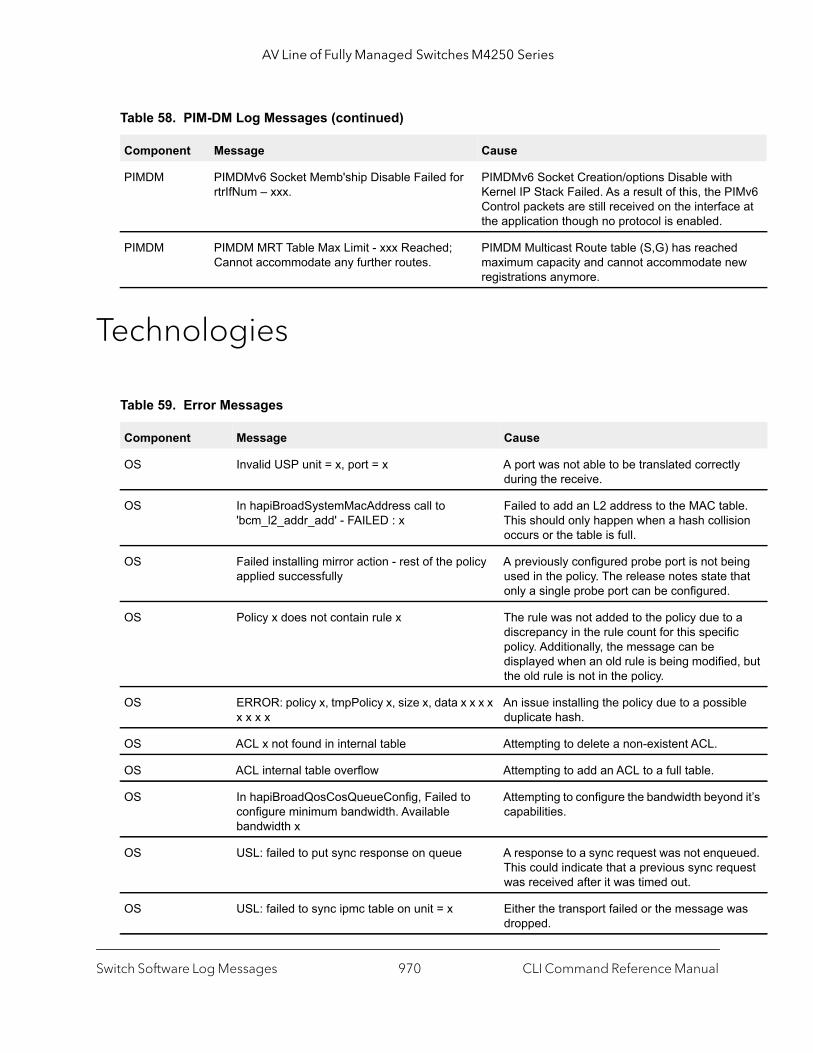
AV Line of Fully Managed Switches M4250 Series
IMv6 e at
d ew
ly
le. ion
ing that
a c
d, but
ble
d it’s
ued. uest
as
Technologies
PIMDM PIMDMv6 Socket Memb'ship Disable Failed for rtrIfNum – xxx.
PIMDMv6 Socket Creation/options Disable withKernel IP Stack Failed. As a result of this, the PControl packets are still received on the interfacthe application though no protocol is enabled.
PIMDM PIMDM MRT Table Max Limit - xxx Reached; Cannot accommodate any further routes.
PIMDM Multicast Route table (S,G) has reachemaximum capacity and cannot accommodate nregistrations anymore.
Table 59. Error Messages
Component Message Cause
OS Invalid USP unit = x, port = x A port was not able to be translated correctduring the receive.
OS In hapiBroadSystemMacAddress call to 'bcm_l2_addr_add' - FAILED : x
Failed to add an L2 address to the MAC tabThis should only happen when a hash collisoccurs or the table is full.
OS Failed installing mirror action - rest of the policy applied successfully
A previously configured probe port is not beused in the policy. The release notes state only a single probe port can be configured.
OS Policy x does not contain rule x The rule was not added to the policy due todiscrepancy in the rule count for this specifipolicy. Additionally, the message can be displayed when an old rule is being modifiethe old rule is not in the policy.
OS ERROR: policy x, tmpPolicy x, size x, data x x x x x x x x
An issue installing the policy due to a possiduplicate hash.
OS ACL x not found in internal table Attempting to delete a non-existent ACL.
OS ACL internal table overflow Attempting to add an ACL to a full table.
OS In hapiBroadQosCosQueueConfig, Failed to configure minimum bandwidth. Available bandwidth x
Attempting to configure the bandwidth beyoncapabilities.
OS USL: failed to put sync response on queue A response to a sync request was not enqueThis could indicate that a previous sync reqwas received after it was timed out.
OS USL: failed to sync ipmc table on unit = x Either the transport failed or the message wdropped.
Table 58. PIM-DM Log Messages (continued)
Component Message Cause
Switch Software Log Messages CLI Command Reference Manual970
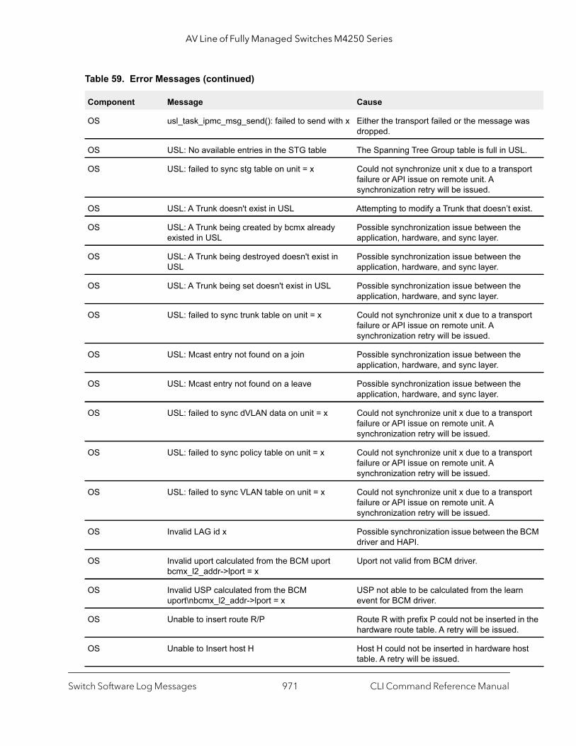
AV Line of Fully Managed Switches M4250 Series
as
L.
port
xist.
port
port
port
port
BCM
n
in the .
ost
OS usl_task_ipmc_msg_send(): failed to send with x Either the transport failed or the message wdropped.
OS USL: No available entries in the STG table The Spanning Tree Group table is full in US
OS USL: failed to sync stg table on unit = x Could not synchronize unit x due to a transfailure or API issue on remote unit. A synchronization retry will be issued.
OS USL: A Trunk doesn't exist in USL Attempting to modify a Trunk that doesn’t e
OS USL: A Trunk being created by bcmx already existed in USL
Possible synchronization issue between theapplication, hardware, and sync layer.
OS USL: A Trunk being destroyed doesn't exist in USL
Possible synchronization issue between theapplication, hardware, and sync layer.
OS USL: A Trunk being set doesn't exist in USL Possible synchronization issue between theapplication, hardware, and sync layer.
OS USL: failed to sync trunk table on unit = x Could not synchronize unit x due to a transfailure or API issue on remote unit. A synchronization retry will be issued.
OS USL: Mcast entry not found on a join Possible synchronization issue between theapplication, hardware, and sync layer.
OS USL: Mcast entry not found on a leave Possible synchronization issue between theapplication, hardware, and sync layer.
OS USL: failed to sync dVLAN data on unit = x Could not synchronize unit x due to a transfailure or API issue on remote unit. A synchronization retry will be issued.
OS USL: failed to sync policy table on unit = x Could not synchronize unit x due to a transfailure or API issue on remote unit. A synchronization retry will be issued.
OS USL: failed to sync VLAN table on unit = x Could not synchronize unit x due to a transfailure or API issue on remote unit. A synchronization retry will be issued.
OS Invalid LAG id x Possible synchronization issue between thedriver and HAPI.
OS Invalid uport calculated from the BCM uport bcmx_l2_addr->lport = x
Uport not valid from BCM driver.
OS Invalid USP calculated from the BCM uport\nbcmx_l2_addr->lport = x
USP not able to be calculated from the learevent for BCM driver.
OS Unable to insert route R/P Route R with prefix P could not be inserted hardware route table. A retry will be issued
OS Unable to Insert host H Host H could not be inserted in hardware htable. A retry will be issued.
Table 59. Error Messages (continued)
Component Message Cause
Switch Software Log Messages CLI Command Reference Manual971

AV Line of Fully Managed Switches M4250 Series
port
port
port
port
port
port
ter
ARP led in ot
ect).
O/S Support
OS USL: failed to sync L3 Intf table on unit = x Could not synchronize unit x due to a transfailure or API issue on remote unit. A synchronization retry will be issued.
OS USL: failed to sync L3 Host table on unit = x Could not synchronize unit x due to a transfailure or API issue on remote unit. A synchronization retry will be issued.
OS USL: failed to sync L3 Route table on unit = x Could not synchronize unit x due to a transfailure or API issue on remote unit. A synchronization retry will be issued.
OS USL: failed to sync initiator table on unit = x Could not synchronize unit x due to a transfailure or API issue on remote unit. A synchronization retry will be issued.
OS USL: failed to sync terminator table on unit = x Could not synchronize unit x due to a transfailure or API issue on remote unit. A synchronization retry will be issued.
OS USL: failed to sync ip-multicast table on unit = x Could not synchronize unit x due to a transfailure or API issue on remote unit. A synchronization retry will be issued.
Table 60. BSP Log Message
Component Message Cause
BSP rc = 10 Second message logged at bootup, right afStarting code…. Always logged.
Table 61. OSAPI Log Messages
Component Message Cause
OSAPI osapiNetLinkNeighDump: could not open socket! - or –ipstkNdpFlush: could not open socket! – or – osapiNetlinkDumpOpen: unable to bind socket! errno = XX
Couldn’t open a netlink socket. Make sure “Daemon support” (CONFIG_ARPD) is enabthe kernel, if the reference kernel binary is nbeing used.
OSAPI ipstkNdpFlush: sending delete failed Failed when telling the kernel to delete a neighbor table entry (the message is incorr
Table 59. Error Messages (continued)
Component Message Cause
Switch Software Log Messages CLI Command Reference Manual972
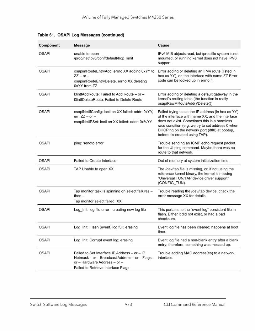
AV Line of Fully Managed Switches M4250 Series
is not PV6
d in Error
in the
s YY) rface s when up,
ket no
he g
the
le in
t boot
blank .
ork
OSAPI unable to open /proc/net/ipv6/conf/default/hop_limit
IPv6 MIB objects read, but /proc file systemmounted, or running kernel does not have Isupport.
OSAPI osapimRouteEntryAdd, errno XX adding 0xYY to ZZ – or – osapimRouteEntryDelete, errno XX deleting 0xYY from ZZ
Error adding or deleting an IPv4 route (listehex as YY), on the interface with name ZZ code can be looked up in errno.h.
OSAPI l3intfAddRoute: Failed to Add Route – or – l3intfDeleteRoute: Failed to Delete Route
Error adding or deleting a default gateway kernel’s routing table (the function is really osapiRawMRouteAdd()/Delete()).
OSAPI osapiNetIfConfig: ioctl on XX failed: addr: 0xYY, err: ZZ – or – osapiNetIPSet: ioctl on XX failed: addr: 0x%YY
Failed trying to set the IP address (in hex aof the interface with name XX, and the intedoes not exist. Sometimes this is a harmlesrace condition (e.g. we try to set address 0 DHCPing on the network port (dtl0) at bootbefore it’s created using TAP).
OSAPI ping: sendto error Trouble sending an ICMP echo request pacfor the UI ping command. Maybe there wasroute to that network.
OSAPI Failed to Create Interface Out of memory at system initialization time.
OSAPI TAP Unable to open XX The /dev/tap file is missing, or, if not using treference kernel binary, the kernel is missin“Universal TUN/TAP device driver support”(CONFIG_TUN).
OSAPI Tap monitor task is spinning on select failures – then – Tap monitor select failed: XX
Trouble reading the /dev/tap device, check error message XX for details.
OSAPI Log_Init: log file error - creating new log file This pertains to the “event log” persistent fiflash. Either it did not exist, or had a bad checksum.
OSAPI Log_Init: Flash (event) log full; erasing Event log file has been cleared; happens atime.
OSAPI Log_Init: Corrupt event log; erasing Event log file had a non-blank entry after a entry; therefore, something was messed up
OSAPI Failed to Set Interface IP Address – or – IP Netmask – or – Broadcast Address – or – Flags – or – Hardware Address – or – Failed to Retrieve Interface Flags
Trouble adding MAC address(es) to a netwinterface.
Table 61. OSAPI Log Messages (continued)
Component Message Cause
Switch Software Log Messages CLI Command Reference Manual973
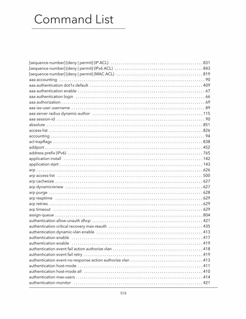
Command List15Command List
[sequence-number] {deny | permit} (IP ACL) . . . . . . . . . . . . . . . . . . . . . . . . . . . . . . . . . . . . . . . . . . . . . 831[sequence-number] {deny | permit} (IPv6 ACL) . . . . . . . . . . . . . . . . . . . . . . . . . . . . . . . . . . . . . . . . . . . 843[sequence-number] {deny | permit} (MAC ACL) . . . . . . . . . . . . . . . . . . . . . . . . . . . . . . . . . . . . . . . . . . 819aaa accounting . . . . . . . . . . . . . . . . . . . . . . . . . . . . . . . . . . . . . . . . . . . . . . . . . . . . . . . . . . . . . . . . . . . . . . . 90aaa authentication dot1x default . . . . . . . . . . . . . . . . . . . . . . . . . . . . . . . . . . . . . . . . . . . . . . . . . . . . . . . 409aaa authentication enable . . . . . . . . . . . . . . . . . . . . . . . . . . . . . . . . . . . . . . . . . . . . . . . . . . . . . . . . . . . . . . 67aaa authentication login . . . . . . . . . . . . . . . . . . . . . . . . . . . . . . . . . . . . . . . . . . . . . . . . . . . . . . . . . . . . . . . 66aaa authorization . . . . . . . . . . . . . . . . . . . . . . . . . . . . . . . . . . . . . . . . . . . . . . . . . . . . . . . . . . . . . . . . . . . . . . 69aaa ias-user username . . . . . . . . . . . . . . . . . . . . . . . . . . . . . . . . . . . . . . . . . . . . . . . . . . . . . . . . . . . . . . . . . 89aaa server radius dynamic-author . . . . . . . . . . . . . . . . . . . . . . . . . . . . . . . . . . . . . . . . . . . . . . . . . . . . . . 115aaa session-id . . . . . . . . . . . . . . . . . . . . . . . . . . . . . . . . . . . . . . . . . . . . . . . . . . . . . . . . . . . . . . . . . . . . . . . . 90absolute . . . . . . . . . . . . . . . . . . . . . . . . . . . . . . . . . . . . . . . . . . . . . . . . . . . . . . . . . . . . . . . . . . . . . . . . . . . . 851access-list . . . . . . . . . . . . . . . . . . . . . . . . . . . . . . . . . . . . . . . . . . . . . . . . . . . . . . . . . . . . . . . . . . . . . . . . . . . 826accounting . . . . . . . . . . . . . . . . . . . . . . . . . . . . . . . . . . . . . . . . . . . . . . . . . . . . . . . . . . . . . . . . . . . . . . . . . . . 94acl-trapflags . . . . . . . . . . . . . . . . . . . . . . . . . . . . . . . . . . . . . . . . . . . . . . . . . . . . . . . . . . . . . . . . . . . . . . . . . 838addport . . . . . . . . . . . . . . . . . . . . . . . . . . . . . . . . . . . . . . . . . . . . . . . . . . . . . . . . . . . . . . . . . . . . . . . . . . . . . 452address prefix (IPv6) . . . . . . . . . . . . . . . . . . . . . . . . . . . . . . . . . . . . . . . . . . . . . . . . . . . . . . . . . . . . . . . . . . 765application install . . . . . . . . . . . . . . . . . . . . . . . . . . . . . . . . . . . . . . . . . . . . . . . . . . . . . . . . . . . . . . . . . . . . 142application start . . . . . . . . . . . . . . . . . . . . . . . . . . . . . . . . . . . . . . . . . . . . . . . . . . . . . . . . . . . . . . . . . . . . . . 143arp . . . . . . . . . . . . . . . . . . . . . . . . . . . . . . . . . . . . . . . . . . . . . . . . . . . . . . . . . . . . . . . . . . . . . . . . . . . . . . . . . 626arp access-list . . . . . . . . . . . . . . . . . . . . . . . . . . . . . . . . . . . . . . . . . . . . . . . . . . . . . . . . . . . . . . . . . . . . . . . 500arp cachesize . . . . . . . . . . . . . . . . . . . . . . . . . . . . . . . . . . . . . . . . . . . . . . . . . . . . . . . . . . . . . . . . . . . . . . . . 627arp dynamicrenew . . . . . . . . . . . . . . . . . . . . . . . . . . . . . . . . . . . . . . . . . . . . . . . . . . . . . . . . . . . . . . . . . . . 627arp purge . . . . . . . . . . . . . . . . . . . . . . . . . . . . . . . . . . . . . . . . . . . . . . . . . . . . . . . . . . . . . . . . . . . . . . . . . . . 628arp resptime . . . . . . . . . . . . . . . . . . . . . . . . . . . . . . . . . . . . . . . . . . . . . . . . . . . . . . . . . . . . . . . . . . . . . . . . 629arp retries . . . . . . . . . . . . . . . . . . . . . . . . . . . . . . . . . . . . . . . . . . . . . . . . . . . . . . . . . . . . . . . . . . . . . . . . . . . 629arp timeout . . . . . . . . . . . . . . . . . . . . . . . . . . . . . . . . . . . . . . . . . . . . . . . . . . . . . . . . . . . . . . . . . . . . . . . . . 629assign-queue . . . . . . . . . . . . . . . . . . . . . . . . . . . . . . . . . . . . . . . . . . . . . . . . . . . . . . . . . . . . . . . . . . . . . . . . 804authentication allow-unauth dhcp . . . . . . . . . . . . . . . . . . . . . . . . . . . . . . . . . . . . . . . . . . . . . . . . . . . . . . 421authentication critical recovery max-reauth . . . . . . . . . . . . . . . . . . . . . . . . . . . . . . . . . . . . . . . . . . . . . . 435authentication dynamic-vlan enable . . . . . . . . . . . . . . . . . . . . . . . . . . . . . . . . . . . . . . . . . . . . . . . . . . . . 413authentication enable . . . . . . . . . . . . . . . . . . . . . . . . . . . . . . . . . . . . . . . . . . . . . . . . . . . . . . . . . . . . . . . . 417authentication enable . . . . . . . . . . . . . . . . . . . . . . . . . . . . . . . . . . . . . . . . . . . . . . . . . . . . . . . . . . . . . . . . 419authentication event fail action authorize vlan . . . . . . . . . . . . . . . . . . . . . . . . . . . . . . . . . . . . . . . . . . . . 418authentication event fail retry . . . . . . . . . . . . . . . . . . . . . . . . . . . . . . . . . . . . . . . . . . . . . . . . . . . . . . . . . . 419authentication event no-response action authorize vlan . . . . . . . . . . . . . . . . . . . . . . . . . . . . . . . . . . . 413authentication host-mode . . . . . . . . . . . . . . . . . . . . . . . . . . . . . . . . . . . . . . . . . . . . . . . . . . . . . . . . . . . . . 411authentication host-mode all . . . . . . . . . . . . . . . . . . . . . . . . . . . . . . . . . . . . . . . . . . . . . . . . . . . . . . . . . . 410authentication max-users . . . . . . . . . . . . . . . . . . . . . . . . . . . . . . . . . . . . . . . . . . . . . . . . . . . . . . . . . . . . . . 414authentication monitor . . . . . . . . . . . . . . . . . . . . . . . . . . . . . . . . . . . . . . . . . . . . . . . . . . . . . . . . . . . . . . . 421
974
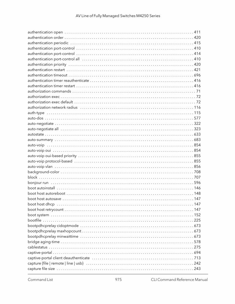
AV Line of Fully Managed Switches M4250 Series
authentication open . . . . . . . . . . . . . . . . . . . . . . . . . . . . . . . . . . . . . . . . . . . . . . . . . . . . . . . . . . . . . . . . . . 411authentication order . . . . . . . . . . . . . . . . . . . . . . . . . . . . . . . . . . . . . . . . . . . . . . . . . . . . . . . . . . . . . . . . . . 420authentication periodic . . . . . . . . . . . . . . . . . . . . . . . . . . . . . . . . . . . . . . . . . . . . . . . . . . . . . . . . . . . . . . . 415authentication port-control . . . . . . . . . . . . . . . . . . . . . . . . . . . . . . . . . . . . . . . . . . . . . . . . . . . . . . . . . . . . 410authentication port-control . . . . . . . . . . . . . . . . . . . . . . . . . . . . . . . . . . . . . . . . . . . . . . . . . . . . . . . . . . . . 414authentication port-control all . . . . . . . . . . . . . . . . . . . . . . . . . . . . . . . . . . . . . . . . . . . . . . . . . . . . . . . . . 410authentication priority . . . . . . . . . . . . . . . . . . . . . . . . . . . . . . . . . . . . . . . . . . . . . . . . . . . . . . . . . . . . . . . . 420authentication restart . . . . . . . . . . . . . . . . . . . . . . . . . . . . . . . . . . . . . . . . . . . . . . . . . . . . . . . . . . . . . . . . . 421authentication timeout . . . . . . . . . . . . . . . . . . . . . . . . . . . . . . . . . . . . . . . . . . . . . . . . . . . . . . . . . . . . . . . . 696authentication timer reauthenticate . . . . . . . . . . . . . . . . . . . . . . . . . . . . . . . . . . . . . . . . . . . . . . . . . . . . . 416authentication timer restart . . . . . . . . . . . . . . . . . . . . . . . . . . . . . . . . . . . . . . . . . . . . . . . . . . . . . . . . . . . . 416authorization commands . . . . . . . . . . . . . . . . . . . . . . . . . . . . . . . . . . . . . . . . . . . . . . . . . . . . . . . . . . . . . . . 71authorization exec . . . . . . . . . . . . . . . . . . . . . . . . . . . . . . . . . . . . . . . . . . . . . . . . . . . . . . . . . . . . . . . . . . . . . 72authorization exec default . . . . . . . . . . . . . . . . . . . . . . . . . . . . . . . . . . . . . . . . . . . . . . . . . . . . . . . . . . . . . . 72authorization network radius . . . . . . . . . . . . . . . . . . . . . . . . . . . . . . . . . . . . . . . . . . . . . . . . . . . . . . . . . . 116auth-type . . . . . . . . . . . . . . . . . . . . . . . . . . . . . . . . . . . . . . . . . . . . . . . . . . . . . . . . . . . . . . . . . . . . . . . . . . . 115auto-dos . . . . . . . . . . . . . . . . . . . . . . . . . . . . . . . . . . . . . . . . . . . . . . . . . . . . . . . . . . . . . . . . . . . . . . . . . . . . 577auto-negotiate . . . . . . . . . . . . . . . . . . . . . . . . . . . . . . . . . . . . . . . . . . . . . . . . . . . . . . . . . . . . . . . . . . . . . . . 322auto-negotiate all . . . . . . . . . . . . . . . . . . . . . . . . . . . . . . . . . . . . . . . . . . . . . . . . . . . . . . . . . . . . . . . . . . . . 323autostate . . . . . . . . . . . . . . . . . . . . . . . . . . . . . . . . . . . . . . . . . . . . . . . . . . . . . . . . . . . . . . . . . . . . . . . . . . . . 633auto-summary . . . . . . . . . . . . . . . . . . . . . . . . . . . . . . . . . . . . . . . . . . . . . . . . . . . . . . . . . . . . . . . . . . . . . . . 683auto-voip . . . . . . . . . . . . . . . . . . . . . . . . . . . . . . . . . . . . . . . . . . . . . . . . . . . . . . . . . . . . . . . . . . . . . . . . . . . 854auto-voip oui . . . . . . . . . . . . . . . . . . . . . . . . . . . . . . . . . . . . . . . . . . . . . . . . . . . . . . . . . . . . . . . . . . . . . . . . 854auto-voip oui-based priority . . . . . . . . . . . . . . . . . . . . . . . . . . . . . . . . . . . . . . . . . . . . . . . . . . . . . . . . . . . 855auto-voip protocol-based . . . . . . . . . . . . . . . . . . . . . . . . . . . . . . . . . . . . . . . . . . . . . . . . . . . . . . . . . . . . . 855auto-voip vlan . . . . . . . . . . . . . . . . . . . . . . . . . . . . . . . . . . . . . . . . . . . . . . . . . . . . . . . . . . . . . . . . . . . . . . . 856background-color . . . . . . . . . . . . . . . . . . . . . . . . . . . . . . . . . . . . . . . . . . . . . . . . . . . . . . . . . . . . . . . . . . . . 708block . . . . . . . . . . . . . . . . . . . . . . . . . . . . . . . . . . . . . . . . . . . . . . . . . . . . . . . . . . . . . . . . . . . . . . . . . . . . . . . 707bonjour run . . . . . . . . . . . . . . . . . . . . . . . . . . . . . . . . . . . . . . . . . . . . . . . . . . . . . . . . . . . . . . . . . . . . . . . . . 596boot autoinstall . . . . . . . . . . . . . . . . . . . . . . . . . . . . . . . . . . . . . . . . . . . . . . . . . . . . . . . . . . . . . . . . . . . . . . 146boot host autoreboot . . . . . . . . . . . . . . . . . . . . . . . . . . . . . . . . . . . . . . . . . . . . . . . . . . . . . . . . . . . . . . . . . 148boot host autosave . . . . . . . . . . . . . . . . . . . . . . . . . . . . . . . . . . . . . . . . . . . . . . . . . . . . . . . . . . . . . . . . . . . 147boot host dhcp . . . . . . . . . . . . . . . . . . . . . . . . . . . . . . . . . . . . . . . . . . . . . . . . . . . . . . . . . . . . . . . . . . . . . . 147boot host retrycount . . . . . . . . . . . . . . . . . . . . . . . . . . . . . . . . . . . . . . . . . . . . . . . . . . . . . . . . . . . . . . . . . . 147boot system . . . . . . . . . . . . . . . . . . . . . . . . . . . . . . . . . . . . . . . . . . . . . . . . . . . . . . . . . . . . . . . . . . . . . . . . . 152bootfile . . . . . . . . . . . . . . . . . . . . . . . . . . . . . . . . . . . . . . . . . . . . . . . . . . . . . . . . . . . . . . . . . . . . . . . . . . . . . 225bootpdhcprelay cidoptmode . . . . . . . . . . . . . . . . . . . . . . . . . . . . . . . . . . . . . . . . . . . . . . . . . . . . . . . . . . 673bootpdhcprelay maxhopcount . . . . . . . . . . . . . . . . . . . . . . . . . . . . . . . . . . . . . . . . . . . . . . . . . . . . . . . . . 673bootpdhcprelay minwaittime . . . . . . . . . . . . . . . . . . . . . . . . . . . . . . . . . . . . . . . . . . . . . . . . . . . . . . . . . . 673bridge aging-time . . . . . . . . . . . . . . . . . . . . . . . . . . . . . . . . . . . . . . . . . . . . . . . . . . . . . . . . . . . . . . . . . . . . 578cablestatus . . . . . . . . . . . . . . . . . . . . . . . . . . . . . . . . . . . . . . . . . . . . . . . . . . . . . . . . . . . . . . . . . . . . . . . . . . 275captive-portal . . . . . . . . . . . . . . . . . . . . . . . . . . . . . . . . . . . . . . . . . . . . . . . . . . . . . . . . . . . . . . . . . . . . . . . . 694captive-portal client deauthenticate . . . . . . . . . . . . . . . . . . . . . . . . . . . . . . . . . . . . . . . . . . . . . . . . . . . . 713capture {file | remote | line | usb} . . . . . . . . . . . . . . . . . . . . . . . . . . . . . . . . . . . . . . . . . . . . . . . . . . . . . . . 242capture file size . . . . . . . . . . . . . . . . . . . . . . . . . . . . . . . . . . . . . . . . . . . . . . . . . . . . . . . . . . . . . . . . . . . . . . 243
Command List CLI Command Reference Manual975
AV Line of Fully Managed Switches M4250 Series
capture line wrap . . . . . . . . . . . . . . . . . . . . . . . . . . . . . . . . . . . . . . . . . . . . . . . . . . . . . . . . . . . . . . . . . . . . 243capture remote port . . . . . . . . . . . . . . . . . . . . . . . . . . . . . . . . . . . . . . . . . . . . . . . . . . . . . . . . . . . . . . . . . . 242capture start . . . . . . . . . . . . . . . . . . . . . . . . . . . . . . . . . . . . . . . . . . . . . . . . . . . . . . . . . . . . . . . . . . . . . . . . . 241capture stop . . . . . . . . . . . . . . . . . . . . . . . . . . . . . . . . . . . . . . . . . . . . . . . . . . . . . . . . . . . . . . . . . . . . . . . . . 241capture usb . . . . . . . . . . . . . . . . . . . . . . . . . . . . . . . . . . . . . . . . . . . . . . . . . . . . . . . . . . . . . . . . . . . . . . . . . 243class . . . . . . . . . . . . . . . . . . . . . . . . . . . . . . . . . . . . . . . . . . . . . . . . . . . . . . . . . . . . . . . . . . . . . . . . . . . . . . . . 805class-map . . . . . . . . . . . . . . . . . . . . . . . . . . . . . . . . . . . . . . . . . . . . . . . . . . . . . . . . . . . . . . . . . . . . . . . . . . . 795class-map rename . . . . . . . . . . . . . . . . . . . . . . . . . . . . . . . . . . . . . . . . . . . . . . . . . . . . . . . . . . . . . . . . . . . . 796classofservice dot1p-mapping . . . . . . . . . . . . . . . . . . . . . . . . . . . . . . . . . . . . . . . . . . . . . . . . . . . . . . . . . 785classofservice ip-dscp-mapping . . . . . . . . . . . . . . . . . . . . . . . . . . . . . . . . . . . . . . . . . . . . . . . . . . . . . . . . 785classofservice trust . . . . . . . . . . . . . . . . . . . . . . . . . . . . . . . . . . . . . . . . . . . . . . . . . . . . . . . . . . . . . . . . . . . 787clear (Captive Portal Instance Config) . . . . . . . . . . . . . . . . . . . . . . . . . . . . . . . . . . . . . . . . . . . . . . . . . . . 707clear aaa ias-users . . . . . . . . . . . . . . . . . . . . . . . . . . . . . . . . . . . . . . . . . . . . . . . . . . . . . . . . . . . . . . . . . . . . . 93clear accounting statistics . . . . . . . . . . . . . . . . . . . . . . . . . . . . . . . . . . . . . . . . . . . . . . . . . . . . . . . . . . . . . . 96clear arp-cache . . . . . . . . . . . . . . . . . . . . . . . . . . . . . . . . . . . . . . . . . . . . . . . . . . . . . . . . . . . . . . . . . . . . . . 630clear arp-switch . . . . . . . . . . . . . . . . . . . . . . . . . . . . . . . . . . . . . . . . . . . . . . . . . . . . . . . . . . . . . . . . . . . . . . 631clear authentication authentication-history . . . . . . . . . . . . . . . . . . . . . . . . . . . . . . . . . . . . . . . . . . . . . . 427clear authentication sessions . . . . . . . . . . . . . . . . . . . . . . . . . . . . . . . . . . . . . . . . . . . . . . . . . . . . . . . . . . 412clear authentication statistics . . . . . . . . . . . . . . . . . . . . . . . . . . . . . . . . . . . . . . . . . . . . . . . . . . . . . . . . . . 427clear captive-portal users . . . . . . . . . . . . . . . . . . . . . . . . . . . . . . . . . . . . . . . . . . . . . . . . . . . . . . . . . . . . . 723clear config . . . . . . . . . . . . . . . . . . . . . . . . . . . . . . . . . . . . . . . . . . . . . . . . . . . . . . . . . . . . . . . . . . . . . . . . . 201clear counters . . . . . . . . . . . . . . . . . . . . . . . . . . . . . . . . . . . . . . . . . . . . . . . . . . . . . . . . . . . . . . . . . . . . . . . 201clear counters keepalive . . . . . . . . . . . . . . . . . . . . . . . . . . . . . . . . . . . . . . . . . . . . . . . . . . . . . . . . . . . . . . 367clear dhcp l2relay statistics interface . . . . . . . . . . . . . . . . . . . . . . . . . . . . . . . . . . . . . . . . . . . . . . . . . . . . 485clear dot1as statistics . . . . . . . . . . . . . . . . . . . . . . . . . . . . . . . . . . . . . . . . . . . . . . . . . . . . . . . . . . . . . . . . . 606clear dot1x statistics . . . . . . . . . . . . . . . . . . . . . . . . . . . . . . . . . . . . . . . . . . . . . . . . . . . . . . . . . . . . . . . . . . 412clear eventlog . . . . . . . . . . . . . . . . . . . . . . . . . . . . . . . . . . . . . . . . . . . . . . . . . . . . . . . . . . . . . . . . . . . . . . . 191clear green-mode statistics . . . . . . . . . . . . . . . . . . . . . . . . . . . . . . . . . . . . . . . . . . . . . . . . . . . . . . . . . . . . 295clear host . . . . . . . . . . . . . . . . . . . . . . . . . . . . . . . . . . . . . . . . . . . . . . . . . . . . . . . . . . . . . . . . . . . . . . . . . . . 238clear igmpsnooping . . . . . . . . . . . . . . . . . . . . . . . . . . . . . . . . . . . . . . . . . . . . . . . . . . . . . . . . . . . . . . . . . . 202clear ip access-list counters . . . . . . . . . . . . . . . . . . . . . . . . . . . . . . . . . . . . . . . . . . . . . . . . . . . . . . . . . . . . 202clear ip address-conflict-detect . . . . . . . . . . . . . . . . . . . . . . . . . . . . . . . . . . . . . . . . . . . . . . . . . . . . . . . . 240clear ip arp inspection statistics . . . . . . . . . . . . . . . . . . . . . . . . . . . . . . . . . . . . . . . . . . . . . . . . . . . . . . . . 502clear ip dhcp binding . . . . . . . . . . . . . . . . . . . . . . . . . . . . . . . . . . . . . . . . . . . . . . . . . . . . . . . . . . . . . . . . . 231clear ip dhcp conflict . . . . . . . . . . . . . . . . . . . . . . . . . . . . . . . . . . . . . . . . . . . . . . . . . . . . . . . . . . . . . . . . . 231clear ip dhcp server statistics . . . . . . . . . . . . . . . . . . . . . . . . . . . . . . . . . . . . . . . . . . . . . . . . . . . . . . . . . . 231clear ip dhcp snooping binding . . . . . . . . . . . . . . . . . . . . . . . . . . . . . . . . . . . . . . . . . . . . . . . . . . . . . . . . 495clear ip dhcp snooping statistics . . . . . . . . . . . . . . . . . . . . . . . . . . . . . . . . . . . . . . . . . . . . . . . . . . . . . . . 495clear ip helper statistics . . . . . . . . . . . . . . . . . . . . . . . . . . . . . . . . . . . . . . . . . . . . . . . . . . . . . . . . . . . . . . . 676clear ip mroute . . . . . . . . . . . . . . . . . . . . . . . . . . . . . . . . . . . . . . . . . . . . . . . . . . . . . . . . . . . . . . . . . . . . . . 867clear ip route . . . . . . . . . . . . . . . . . . . . . . . . . . . . . . . . . . . . . . . . . . . . . . . . . . . . . . . . . . . . . . . . . . . . . . . . 654clear ipv6 access-list counters . . . . . . . . . . . . . . . . . . . . . . . . . . . . . . . . . . . . . . . . . . . . . . . . . . . . . . . . . 202clear ipv6 dhcp . . . . . . . . . . . . . . . . . . . . . . . . . . . . . . . . . . . . . . . . . . . . . . . . . . . . . . . . . . . . . . . . . . . . . . 772clear ipv6 dhcp binding . . . . . . . . . . . . . . . . . . . . . . . . . . . . . . . . . . . . . . . . . . . . . . . . . . . . . . . . . . . . . . . 772
Command List CLI Command Reference Manual976

AV Line of Fully Managed Switches M4250 Series
clear ipv6 dhcp snooping binding . . . . . . . . . . . . . . . . . . . . . . . . . . . . . . . . . . . . . . . . . . . . . . . . . . . . . . 781clear ipv6 dhcp snooping statistics . . . . . . . . . . . . . . . . . . . . . . . . . . . . . . . . . . . . . . . . . . . . . . . . . . . . . 781clear ipv6 mld counters . . . . . . . . . . . . . . . . . . . . . . . . . . . . . . . . . . . . . . . . . . . . . . . . . . . . . . . . . . . . . . . 927clear ipv6 mld traffic . . . . . . . . . . . . . . . . . . . . . . . . . . . . . . . . . . . . . . . . . . . . . . . . . . . . . . . . . . . . . . . . . . 928clear ipv6 mroute . . . . . . . . . . . . . . . . . . . . . . . . . . . . . . . . . . . . . . . . . . . . . . . . . . . . . . . . . . . . . . . . . . . . 904clear ipv6 neighbors . . . . . . . . . . . . . . . . . . . . . . . . . . . . . . . . . . . . . . . . . . . . . . . . . . . . . . . . . . . . . . . . . . 750clear ipv6 route counters . . . . . . . . . . . . . . . . . . . . . . . . . . . . . . . . . . . . . . . . . . . . . . . . . . . . . . . . . . . . . . 757clear ipv6 snooping counters . . . . . . . . . . . . . . . . . . . . . . . . . . . . . . . . . . . . . . . . . . . . . . . . . . . . . . . . . . 757clear ipv6 statistics . . . . . . . . . . . . . . . . . . . . . . . . . . . . . . . . . . . . . . . . . . . . . . . . . . . . . . . . . . . . . . . . . . . 762clear isdp counters . . . . . . . . . . . . . . . . . . . . . . . . . . . . . . . . . . . . . . . . . . . . . . . . . . . . . . . . . . . . . . . . . . . 582clear isdp table . . . . . . . . . . . . . . . . . . . . . . . . . . . . . . . . . . . . . . . . . . . . . . . . . . . . . . . . . . . . . . . . . . . . . . 583clear lldp remote-data . . . . . . . . . . . . . . . . . . . . . . . . . . . . . . . . . . . . . . . . . . . . . . . . . . . . . . . . . . . . . . . . 554clear lldp statistics . . . . . . . . . . . . . . . . . . . . . . . . . . . . . . . . . . . . . . . . . . . . . . . . . . . . . . . . . . . . . . . . . . . . 554clear logging buffered . . . . . . . . . . . . . . . . . . . . . . . . . . . . . . . . . . . . . . . . . . . . . . . . . . . . . . . . . . . . . . . . 191clear logging email statistics . . . . . . . . . . . . . . . . . . . . . . . . . . . . . . . . . . . . . . . . . . . . . . . . . . . . . . . . . . . 196clear mac access-list counters . . . . . . . . . . . . . . . . . . . . . . . . . . . . . . . . . . . . . . . . . . . . . . . . . . . . . . . . . . 202clear mac-addr-table . . . . . . . . . . . . . . . . . . . . . . . . . . . . . . . . . . . . . . . . . . . . . . . . . . . . . . . . . . . . . . . . . 201clear mldsnooping . . . . . . . . . . . . . . . . . . . . . . . . . . . . . . . . . . . . . . . . . . . . . . . . . . . . . . . . . . . . . . . . . . . 541clear mmrp statistics . . . . . . . . . . . . . . . . . . . . . . . . . . . . . . . . . . . . . . . . . . . . . . . . . . . . . . . . . . . . . . . . . . 612clear msrp statistics . . . . . . . . . . . . . . . . . . . . . . . . . . . . . . . . . . . . . . . . . . . . . . . . . . . . . . . . . . . . . . . . . . . 624clear mvrp . . . . . . . . . . . . . . . . . . . . . . . . . . . . . . . . . . . . . . . . . . . . . . . . . . . . . . . . . . . . . . . . . . . . . . . . . . 617clear network ipv6 dhcp statistics . . . . . . . . . . . . . . . . . . . . . . . . . . . . . . . . . . . . . . . . . . . . . . . . . . . . . . 773clear port-channel all counters . . . . . . . . . . . . . . . . . . . . . . . . . . . . . . . . . . . . . . . . . . . . . . . . . . . . . . . . . 470clear port-channel counters . . . . . . . . . . . . . . . . . . . . . . . . . . . . . . . . . . . . . . . . . . . . . . . . . . . . . . . . . . . 470clear radius statistics . . . . . . . . . . . . . . . . . . . . . . . . . . . . . . . . . . . . . . . . . . . . . . . . . . . . . . . . . . . . . . . . . . 412clear serviceport ipv6 dhcp statistics . . . . . . . . . . . . . . . . . . . . . . . . . . . . . . . . . . . . . . . . . . . . . . . . . . . . 773clear traplog . . . . . . . . . . . . . . . . . . . . . . . . . . . . . . . . . . . . . . . . . . . . . . . . . . . . . . . . . . . . . . . . . . . . . . . . . 202clear vlan . . . . . . . . . . . . . . . . . . . . . . . . . . . . . . . . . . . . . . . . . . . . . . . . . . . . . . . . . . . . . . . . . . . . . . . . . . . 203client . . . . . . . . . . . . . . . . . . . . . . . . . . . . . . . . . . . . . . . . . . . . . . . . . . . . . . . . . . . . . . . . . . . . . . . . . . . . . . . 116client-identifier . . . . . . . . . . . . . . . . . . . . . . . . . . . . . . . . . . . . . . . . . . . . . . . . . . . . . . . . . . . . . . . . . . . . . . 222client-name . . . . . . . . . . . . . . . . . . . . . . . . . . . . . . . . . . . . . . . . . . . . . . . . . . . . . . . . . . . . . . . . . . . . . . . . . 222clock set . . . . . . . . . . . . . . . . . . . . . . . . . . . . . . . . . . . . . . . . . . . . . . . . . . . . . . . . . . . . . . . . . . . . . . . . . . . . 217clock summer-time date . . . . . . . . . . . . . . . . . . . . . . . . . . . . . . . . . . . . . . . . . . . . . . . . . . . . . . . . . . . . . . 218clock summer-time recurring . . . . . . . . . . . . . . . . . . . . . . . . . . . . . . . . . . . . . . . . . . . . . . . . . . . . . . . . . . 218clock timezone . . . . . . . . . . . . . . . . . . . . . . . . . . . . . . . . . . . . . . . . . . . . . . . . . . . . . . . . . . . . . . . . . . . . . . 219configuration . . . . . . . . . . . . . . . . . . . . . . . . . . . . . . . . . . . . . . . . . . . . . . . . . . . . . . . . . . . . . . . . . . . . . . . . 206configuration (for captive portal) . . . . . . . . . . . . . . . . . . . . . . . . . . . . . . . . . . . . . . . . . . . . . . . . . . . . . . . 699configure . . . . . . . . . . . . . . . . . . . . . . . . . . . . . . . . . . . . . . . . . . . . . . . . . . . . . . . . . . . . . . . . . . . . . . . . . . . . 41conform-color . . . . . . . . . . . . . . . . . . . . . . . . . . . . . . . . . . . . . . . . . . . . . . . . . . . . . . . . . . . . . . . . . . . . . . . 805console . . . . . . . . . . . . . . . . . . . . . . . . . . . . . . . . . . . . . . . . . . . . . . . . . . . . . . . . . . . . . . . . . . . . . . . . . . . . . 274copy . . . . . . . . . . . . . . . . . . . . . . . . . . . . . . . . . . . . . . . . . . . . . . . . . . . . . . . . . . . . . . . . . . . . . . . . . . . . . . . . 206copy (pre-login banner) . . . . . . . . . . . . . . . . . . . . . . . . . . . . . . . . . . . . . . . . . . . . . . . . . . . . . . . . . . . . . . . 140cos-queue min-bandwidth . . . . . . . . . . . . . . . . . . . . . . . . . . . . . . . . . . . . . . . . . . . . . . . . . . . . . . . . . . . . 787cos-queue random-detect . . . . . . . . . . . . . . . . . . . . . . . . . . . . . . . . . . . . . . . . . . . . . . . . . . . . . . . . . . . . . 788cos-queue strict . . . . . . . . . . . . . . . . . . . . . . . . . . . . . . . . . . . . . . . . . . . . . . . . . . . . . . . . . . . . . . . . . . . . . . 789
Command List CLI Command Reference Manual977
AV Line of Fully Managed Switches M4250 Series
crypto certificate generate . . . . . . . . . . . . . . . . . . . . . . . . . . . . . . . . . . . . . . . . . . . . . . . . . . . . . . . . . . . . . 51crypto key generate dsa . . . . . . . . . . . . . . . . . . . . . . . . . . . . . . . . . . . . . . . . . . . . . . . . . . . . . . . . . . . . . . . 52crypto key generate rsa . . . . . . . . . . . . . . . . . . . . . . . . . . . . . . . . . . . . . . . . . . . . . . . . . . . . . . . . . . . . . . . . 51dante . . . . . . . . . . . . . . . . . . . . . . . . . . . . . . . . . . . . . . . . . . . . . . . . . . . . . . . . . . . . . . . . . . . . . . . . . . . . . . . 786dante vlan . . . . . . . . . . . . . . . . . . . . . . . . . . . . . . . . . . . . . . . . . . . . . . . . . . . . . . . . . . . . . . . . . . . . . . . . . . . 786debug aaa accounting . . . . . . . . . . . . . . . . . . . . . . . . . . . . . . . . . . . . . . . . . . . . . . . . . . . . . . . . . . . . . . . . 244debug aaa authorization . . . . . . . . . . . . . . . . . . . . . . . . . . . . . . . . . . . . . . . . . . . . . . . . . . . . . . . . . . . . . . 244debug aaa coa . . . . . . . . . . . . . . . . . . . . . . . . . . . . . . . . . . . . . . . . . . . . . . . . . . . . . . . . . . . . . . . . . . . . . . 117debug aaa pod . . . . . . . . . . . . . . . . . . . . . . . . . . . . . . . . . . . . . . . . . . . . . . . . . . . . . . . . . . . . . . . . . . . . . . 117debug arp . . . . . . . . . . . . . . . . . . . . . . . . . . . . . . . . . . . . . . . . . . . . . . . . . . . . . . . . . . . . . . . . . . . . . . . . . . 245debug authentication . . . . . . . . . . . . . . . . . . . . . . . . . . . . . . . . . . . . . . . . . . . . . . . . . . . . . . . . . . . . . . . . . 245debug auto-voip . . . . . . . . . . . . . . . . . . . . . . . . . . . . . . . . . . . . . . . . . . . . . . . . . . . . . . . . . . . . . . . . . . . . . 246debug clear . . . . . . . . . . . . . . . . . . . . . . . . . . . . . . . . . . . . . . . . . . . . . . . . . . . . . . . . . . . . . . . . . . . . . . . . . 246debug console . . . . . . . . . . . . . . . . . . . . . . . . . . . . . . . . . . . . . . . . . . . . . . . . . . . . . . . . . . . . . . . . . . . . . . 246debug crashlog . . . . . . . . . . . . . . . . . . . . . . . . . . . . . . . . . . . . . . . . . . . . . . . . . . . . . . . . . . . . . . . . . . . . . . 247debug debug-config . . . . . . . . . . . . . . . . . . . . . . . . . . . . . . . . . . . . . . . . . . . . . . . . . . . . . . . . . . . . . . . . . 248debug dhcp packet . . . . . . . . . . . . . . . . . . . . . . . . . . . . . . . . . . . . . . . . . . . . . . . . . . . . . . . . . . . . . . . . . . 248debug dot1x packet . . . . . . . . . . . . . . . . . . . . . . . . . . . . . . . . . . . . . . . . . . . . . . . . . . . . . . . . . . . . . . . . . . 249debug dynamic ports . . . . . . . . . . . . . . . . . . . . . . . . . . . . . . . . . . . . . . . . . . . . . . . . . . . . . . . . . . . . . . . . . 330debug exception . . . . . . . . . . . . . . . . . . . . . . . . . . . . . . . . . . . . . . . . . . . . . . . . . . . . . . . . . . . . . . . . . . . . . 269debug igmpsnooping packet . . . . . . . . . . . . . . . . . . . . . . . . . . . . . . . . . . . . . . . . . . . . . . . . . . . . . . . . . . 249debug igmpsnooping packet receive . . . . . . . . . . . . . . . . . . . . . . . . . . . . . . . . . . . . . . . . . . . . . . . . . . . 251debug igmpsnooping packet transmit . . . . . . . . . . . . . . . . . . . . . . . . . . . . . . . . . . . . . . . . . . . . . . . . . . 250debug ip acl . . . . . . . . . . . . . . . . . . . . . . . . . . . . . . . . . . . . . . . . . . . . . . . . . . . . . . . . . . . . . . . . . . . . . . . . . 252debug ip dvmrp packet . . . . . . . . . . . . . . . . . . . . . . . . . . . . . . . . . . . . . . . . . . . . . . . . . . . . . . . . . . . . . . . 252debug ip igmp packet . . . . . . . . . . . . . . . . . . . . . . . . . . . . . . . . . . . . . . . . . . . . . . . . . . . . . . . . . . . . . . . . 252debug ip mcache packet . . . . . . . . . . . . . . . . . . . . . . . . . . . . . . . . . . . . . . . . . . . . . . . . . . . . . . . . . . . . . . 253debug ip pimdm packet . . . . . . . . . . . . . . . . . . . . . . . . . . . . . . . . . . . . . . . . . . . . . . . . . . . . . . . . . . . . . . 253debug ip pimsm packet . . . . . . . . . . . . . . . . . . . . . . . . . . . . . . . . . . . . . . . . . . . . . . . . . . . . . . . . . . . . . . . 254debug ipv6 dhcp . . . . . . . . . . . . . . . . . . . . . . . . . . . . . . . . . . . . . . . . . . . . . . . . . . . . . . . . . . . . . . . . . . . . 254debug ipv6 mcache packet . . . . . . . . . . . . . . . . . . . . . . . . . . . . . . . . . . . . . . . . . . . . . . . . . . . . . . . . . . . . 255debug ipv6 mld packet . . . . . . . . . . . . . . . . . . . . . . . . . . . . . . . . . . . . . . . . . . . . . . . . . . . . . . . . . . . . . . . 255debug ipv6 pimdm packet . . . . . . . . . . . . . . . . . . . . . . . . . . . . . . . . . . . . . . . . . . . . . . . . . . . . . . . . . . . . 256debug ipv6 pimsm packet . . . . . . . . . . . . . . . . . . . . . . . . . . . . . . . . . . . . . . . . . . . . . . . . . . . . . . . . . . . . 256debug isdp packet . . . . . . . . . . . . . . . . . . . . . . . . . . . . . . . . . . . . . . . . . . . . . . . . . . . . . . . . . . . . . . . . . . . 588debug lacp packet . . . . . . . . . . . . . . . . . . . . . . . . . . . . . . . . . . . . . . . . . . . . . . . . . . . . . . . . . . . . . . . . . . . 257debug mldsnooping packet . . . . . . . . . . . . . . . . . . . . . . . . . . . . . . . . . . . . . . . . . . . . . . . . . . . . . . . . . . . 257debug mvr packet . . . . . . . . . . . . . . . . . . . . . . . . . . . . . . . . . . . . . . . . . . . . . . . . . . . . . . . . . . . . . . . . . . . 511debug mvr trace . . . . . . . . . . . . . . . . . . . . . . . . . . . . . . . . . . . . . . . . . . . . . . . . . . . . . . . . . . . . . . . . . . . . . 510debug ping packet . . . . . . . . . . . . . . . . . . . . . . . . . . . . . . . . . . . . . . . . . . . . . . . . . . . . . . . . . . . . . . . . . . . 258debug rip packet . . . . . . . . . . . . . . . . . . . . . . . . . . . . . . . . . . . . . . . . . . . . . . . . . . . . . . . . . . . . . . . . . . . . 259debug sflow packet . . . . . . . . . . . . . . . . . . . . . . . . . . . . . . . . . . . . . . . . . . . . . . . . . . . . . . . . . . . . . . . . . . 260debug spanning-tree bpdu . . . . . . . . . . . . . . . . . . . . . . . . . . . . . . . . . . . . . . . . . . . . . . . . . . . . . . . . . . . 260debug spanning-tree bpdu receive . . . . . . . . . . . . . . . . . . . . . . . . . . . . . . . . . . . . . . . . . . . . . . . . . . . . . 261
Command List CLI Command Reference Manual978
AV Line of Fully Managed Switches M4250 Series
debug spanning-tree bpdu transmit . . . . . . . . . . . . . . . . . . . . . . . . . . . . . . . . . . . . . . . . . . . . . . . . . . . . 262debug tacacs . . . . . . . . . . . . . . . . . . . . . . . . . . . . . . . . . . . . . . . . . . . . . . . . . . . . . . . . . . . . . . . . . . . . . . . . 263debug transfer . . . . . . . . . . . . . . . . . . . . . . . . . . . . . . . . . . . . . . . . . . . . . . . . . . . . . . . . . . . . . . . . . . . . . . . 263debug udld events . . . . . . . . . . . . . . . . . . . . . . . . . . . . . . . . . . . . . . . . . . . . . . . . . . . . . . . . . . . . . . . . . . . 264debug udld packet receive . . . . . . . . . . . . . . . . . . . . . . . . . . . . . . . . . . . . . . . . . . . . . . . . . . . . . . . . . . . . 264debug udld packet transmit . . . . . . . . . . . . . . . . . . . . . . . . . . . . . . . . . . . . . . . . . . . . . . . . . . . . . . . . . . . 264default-information originate (RIP) . . . . . . . . . . . . . . . . . . . . . . . . . . . . . . . . . . . . . . . . . . . . . . . . . . . . . . 683default-metric (RIP) . . . . . . . . . . . . . . . . . . . . . . . . . . . . . . . . . . . . . . . . . . . . . . . . . . . . . . . . . . . . . . . . . . . 684default-router . . . . . . . . . . . . . . . . . . . . . . . . . . . . . . . . . . . . . . . . . . . . . . . . . . . . . . . . . . . . . . . . . . . . . . . . 223delete . . . . . . . . . . . . . . . . . . . . . . . . . . . . . . . . . . . . . . . . . . . . . . . . . . . . . . . . . . . . . . . . . . . . . . . . . . . . . . 152deleteport (Global Config) . . . . . . . . . . . . . . . . . . . . . . . . . . . . . . . . . . . . . . . . . . . . . . . . . . . . . . . . . . . . 452deleteport (Interface Config) . . . . . . . . . . . . . . . . . . . . . . . . . . . . . . . . . . . . . . . . . . . . . . . . . . . . . . . . . . 452deny ip-source . . . . . . . . . . . . . . . . . . . . . . . . . . . . . . . . . . . . . . . . . . . . . . . . . . . . . . . . . . . . . . . . . . . . . . . . 54deny priority . . . . . . . . . . . . . . . . . . . . . . . . . . . . . . . . . . . . . . . . . . . . . . . . . . . . . . . . . . . . . . . . . . . . . . . . . . 55deny service . . . . . . . . . . . . . . . . . . . . . . . . . . . . . . . . . . . . . . . . . . . . . . . . . . . . . . . . . . . . . . . . . . . . . . . . . . 54description (Interface Config) . . . . . . . . . . . . . . . . . . . . . . . . . . . . . . . . . . . . . . . . . . . . . . . . . . . . . . . . . . 323dhcp client vendor-id-option . . . . . . . . . . . . . . . . . . . . . . . . . . . . . . . . . . . . . . . . . . . . . . . . . . . . . . . . . . 486dhcp client vendor-id-option-string . . . . . . . . . . . . . . . . . . . . . . . . . . . . . . . . . . . . . . . . . . . . . . . . . . . . . 486dhcp l2relay . . . . . . . . . . . . . . . . . . . . . . . . . . . . . . . . . . . . . . . . . . . . . . . . . . . . . . . . . . . . . . . . . . . . . . . . . 479dhcp l2relay circuit-id vlan . . . . . . . . . . . . . . . . . . . . . . . . . . . . . . . . . . . . . . . . . . . . . . . . . . . . . . . . . . . . . 479dhcp l2relay remote-id subscription . . . . . . . . . . . . . . . . . . . . . . . . . . . . . . . . . . . . . . . . . . . . . . . . . . . . 479dhcp l2relay remote-id vlan . . . . . . . . . . . . . . . . . . . . . . . . . . . . . . . . . . . . . . . . . . . . . . . . . . . . . . . . . . . 480dhcp l2relay subscription . . . . . . . . . . . . . . . . . . . . . . . . . . . . . . . . . . . . . . . . . . . . . . . . . . . . . . . . . . . . . 481dhcp l2relay trust . . . . . . . . . . . . . . . . . . . . . . . . . . . . . . . . . . . . . . . . . . . . . . . . . . . . . . . . . . . . . . . . . . . . 481dhcp l2relay vlan . . . . . . . . . . . . . . . . . . . . . . . . . . . . . . . . . . . . . . . . . . . . . . . . . . . . . . . . . . . . . . . . . . . . . 481diffserv . . . . . . . . . . . . . . . . . . . . . . . . . . . . . . . . . . . . . . . . . . . . . . . . . . . . . . . . . . . . . . . . . . . . . . . . . . . . . 794dir . . . . . . . . . . . . . . . . . . . . . . . . . . . . . . . . . . . . . . . . . . . . . . . . . . . . . . . . . . . . . . . . . . . . . . . . . . . . . . . . . 178dir usb . . . . . . . . . . . . . . . . . . . . . . . . . . . . . . . . . . . . . . . . . . . . . . . . . . . . . . . . . . . . . . . . . . . . . . . . . . . . . . 276disconnect . . . . . . . . . . . . . . . . . . . . . . . . . . . . . . . . . . . . . . . . . . . . . . . . . . . . . . . . . . . . . . . . . . . . . . . . . . . 64distance rip . . . . . . . . . . . . . . . . . . . . . . . . . . . . . . . . . . . . . . . . . . . . . . . . . . . . . . . . . . . . . . . . . . . . . . . . . 684distribute-list out (RIP) . . . . . . . . . . . . . . . . . . . . . . . . . . . . . . . . . . . . . . . . . . . . . . . . . . . . . . . . . . . . . . . . 685dns-server . . . . . . . . . . . . . . . . . . . . . . . . . . . . . . . . . . . . . . . . . . . . . . . . . . . . . . . . . . . . . . . . . . . . . . . . . . . 223dns-server (IPv6) . . . . . . . . . . . . . . . . . . . . . . . . . . . . . . . . . . . . . . . . . . . . . . . . . . . . . . . . . . . . . . . . . . . . . 767do (Captive Portal Instance mode) . . . . . . . . . . . . . . . . . . . . . . . . . . . . . . . . . . . . . . . . . . . . . . . . . . . . . . 706do (Privileged EXEC commands) . . . . . . . . . . . . . . . . . . . . . . . . . . . . . . . . . . . . . . . . . . . . . . . . . . . . . . . . 30domain-name . . . . . . . . . . . . . . . . . . . . . . . . . . . . . . . . . . . . . . . . . . . . . . . . . . . . . . . . . . . . . . . . . . . . . . . 225domain-name (IPv6) . . . . . . . . . . . . . . . . . . . . . . . . . . . . . . . . . . . . . . . . . . . . . . . . . . . . . . . . . . . . . . . . . . 766domain-name enable . . . . . . . . . . . . . . . . . . . . . . . . . . . . . . . . . . . . . . . . . . . . . . . . . . . . . . . . . . . . . . . . . 226domain-name name . . . . . . . . . . . . . . . . . . . . . . . . . . . . . . . . . . . . . . . . . . . . . . . . . . . . . . . . . . . . . . . . . . 226dos-control all . . . . . . . . . . . . . . . . . . . . . . . . . . . . . . . . . . . . . . . . . . . . . . . . . . . . . . . . . . . . . . . . . . . . . . . 568dos-control firstfrag . . . . . . . . . . . . . . . . . . . . . . . . . . . . . . . . . . . . . . . . . . . . . . . . . . . . . . . . . . . . . . . . . . 569dos-control icmpfrag . . . . . . . . . . . . . . . . . . . . . . . . . . . . . . . . . . . . . . . . . . . . . . . . . . . . . . . . . . . . . . . . . 576dos-control icmpv4 . . . . . . . . . . . . . . . . . . . . . . . . . . . . . . . . . . . . . . . . . . . . . . . . . . . . . . . . . . . . . . . . . . . 575dos-control icmpv6 . . . . . . . . . . . . . . . . . . . . . . . . . . . . . . . . . . . . . . . . . . . . . . . . . . . . . . . . . . . . . . . . . . . 575dos-control l4port . . . . . . . . . . . . . . . . . . . . . . . . . . . . . . . . . . . . . . . . . . . . . . . . . . . . . . . . . . . . . . . . . . . . 571
Command List CLI Command Reference Manual979

AV Line of Fully Managed Switches M4250 Series
dos-control sipdip . . . . . . . . . . . . . . . . . . . . . . . . . . . . . . . . . . . . . . . . . . . . . . . . . . . . . . . . . . . . . . . . . . . . 569dos-control smacdmac . . . . . . . . . . . . . . . . . . . . . . . . . . . . . . . . . . . . . . . . . . . . . . . . . . . . . . . . . . . . . . . 571dos-control tcpfinurgpsh . . . . . . . . . . . . . . . . . . . . . . . . . . . . . . . . . . . . . . . . . . . . . . . . . . . . . . . . . . . . . . 574dos-control tcpflag . . . . . . . . . . . . . . . . . . . . . . . . . . . . . . . . . . . . . . . . . . . . . . . . . . . . . . . . . . . . . . . . . . . 570dos-control tcpflagseq . . . . . . . . . . . . . . . . . . . . . . . . . . . . . . . . . . . . . . . . . . . . . . . . . . . . . . . . . . . . . . . . 573dos-control tcpfrag . . . . . . . . . . . . . . . . . . . . . . . . . . . . . . . . . . . . . . . . . . . . . . . . . . . . . . . . . . . . . . . . . . . 570dos-control tcpoffset . . . . . . . . . . . . . . . . . . . . . . . . . . . . . . . . . . . . . . . . . . . . . . . . . . . . . . . . . . . . . . . . . 573dos-control tcpport . . . . . . . . . . . . . . . . . . . . . . . . . . . . . . . . . . . . . . . . . . . . . . . . . . . . . . . . . . . . . . . . . . . 572dos-control tcpsyn . . . . . . . . . . . . . . . . . . . . . . . . . . . . . . . . . . . . . . . . . . . . . . . . . . . . . . . . . . . . . . . . . . . 574dos-control tcpsynfin . . . . . . . . . . . . . . . . . . . . . . . . . . . . . . . . . . . . . . . . . . . . . . . . . . . . . . . . . . . . . . . . . 574dos-control udpport . . . . . . . . . . . . . . . . . . . . . . . . . . . . . . . . . . . . . . . . . . . . . . . . . . . . . . . . . . . . . . . . . . 572dot1as . . . . . . . . . . . . . . . . . . . . . . . . . . . . . . . . . . . . . . . . . . . . . . . . . . . . . . . . . . . . . . . . . . . . . . . . . . . . . . 599dot1as allowedlostresp . . . . . . . . . . . . . . . . . . . . . . . . . . . . . . . . . . . . . . . . . . . . . . . . . . . . . . . . . . . . . . . 602dot1as interval announce . . . . . . . . . . . . . . . . . . . . . . . . . . . . . . . . . . . . . . . . . . . . . . . . . . . . . . . . . . . . . 599dot1as interval pdelay . . . . . . . . . . . . . . . . . . . . . . . . . . . . . . . . . . . . . . . . . . . . . . . . . . . . . . . . . . . . . . . . 600dot1as interval sync . . . . . . . . . . . . . . . . . . . . . . . . . . . . . . . . . . . . . . . . . . . . . . . . . . . . . . . . . . . . . . . . . . 600dot1as pdelaythreshold . . . . . . . . . . . . . . . . . . . . . . . . . . . . . . . . . . . . . . . . . . . . . . . . . . . . . . . . . . . . . . . 601dot1as priority 2 . . . . . . . . . . . . . . . . . . . . . . . . . . . . . . . . . . . . . . . . . . . . . . . . . . . . . . . . . . . . . . . . . . . . . 599dot1as timeout announce . . . . . . . . . . . . . . . . . . . . . . . . . . . . . . . . . . . . . . . . . . . . . . . . . . . . . . . . . . . . . 601dot1as timeout sync . . . . . . . . . . . . . . . . . . . . . . . . . . . . . . . . . . . . . . . . . . . . . . . . . . . . . . . . . . . . . . . . . . 601dot1x eapolflood . . . . . . . . . . . . . . . . . . . . . . . . . . . . . . . . . . . . . . . . . . . . . . . . . . . . . . . . . . . . . . . . . . . . 412dot1x max-req . . . . . . . . . . . . . . . . . . . . . . . . . . . . . . . . . . . . . . . . . . . . . . . . . . . . . . . . . . . . . . . . . . . . . . . 413dot1x max-start . . . . . . . . . . . . . . . . . . . . . . . . . . . . . . . . . . . . . . . . . . . . . . . . . . . . . . . . . . . . . . . . . . . . . . 435dot1x pae . . . . . . . . . . . . . . . . . . . . . . . . . . . . . . . . . . . . . . . . . . . . . . . . . . . . . . . . . . . . . . . . . . . . . . . . . . . 434dot1x supplicant port-control . . . . . . . . . . . . . . . . . . . . . . . . . . . . . . . . . . . . . . . . . . . . . . . . . . . . . . . . . . 434dot1x supplicant user . . . . . . . . . . . . . . . . . . . . . . . . . . . . . . . . . . . . . . . . . . . . . . . . . . . . . . . . . . . . . . . . . 436dot1x system-auth-control . . . . . . . . . . . . . . . . . . . . . . . . . . . . . . . . . . . . . . . . . . . . . . . . . . . . . . . . . . . . . 409dot1x timeout . . . . . . . . . . . . . . . . . . . . . . . . . . . . . . . . . . . . . . . . . . . . . . . . . . . . . . . . . . . . . . . . . . . . . . . 417dot1x user . . . . . . . . . . . . . . . . . . . . . . . . . . . . . . . . . . . . . . . . . . . . . . . . . . . . . . . . . . . . . . . . . . . . . . . . . . 419drop . . . . . . . . . . . . . . . . . . . . . . . . . . . . . . . . . . . . . . . . . . . . . . . . . . . . . . . . . . . . . . . . . . . . . . . . . . . . . . . 804dvlan-tunnel ethertype (Interface Config) . . . . . . . . . . . . . . . . . . . . . . . . . . . . . . . . . . . . . . . . . . . . . . . . 385dvlan-tunnel ethertype primary-tpid . . . . . . . . . . . . . . . . . . . . . . . . . . . . . . . . . . . . . . . . . . . . . . . . . . . . 386enable (Captive Portal Config Mode) . . . . . . . . . . . . . . . . . . . . . . . . . . . . . . . . . . . . . . . . . . . . . . . . . . . 694enable (Captive Portal Instance) . . . . . . . . . . . . . . . . . . . . . . . . . . . . . . . . . . . . . . . . . . . . . . . . . . . . . . . . 700enable (Privileged EXEC access) . . . . . . . . . . . . . . . . . . . . . . . . . . . . . . . . . . . . . . . . . . . . . . . . . . . . . . . . 29enable (RIP) . . . . . . . . . . . . . . . . . . . . . . . . . . . . . . . . . . . . . . . . . . . . . . . . . . . . . . . . . . . . . . . . . . . . . . . . . 682enable authentication . . . . . . . . . . . . . . . . . . . . . . . . . . . . . . . . . . . . . . . . . . . . . . . . . . . . . . . . . . . . . . . . . 74enable password (Privileged EXEC) . . . . . . . . . . . . . . . . . . . . . . . . . . . . . . . . . . . . . . . . . . . . . . . . . . . . . 82encapsulation . . . . . . . . . . . . . . . . . . . . . . . . . . . . . . . . . . . . . . . . . . . . . . . . . . . . . . . . . . . . . . . . . . . . . . . 642environment fan control mode . . . . . . . . . . . . . . . . . . . . . . . . . . . . . . . . . . . . . . . . . . . . . . . . . . . . . . . . . 182environment temprange . . . . . . . . . . . . . . . . . . . . . . . . . . . . . . . . . . . . . . . . . . . . . . . . . . . . . . . . . . . . . . 182environment trap . . . . . . . . . . . . . . . . . . . . . . . . . . . . . . . . . . . . . . . . . . . . . . . . . . . . . . . . . . . . . . . . . . . . 183erase application . . . . . . . . . . . . . . . . . . . . . . . . . . . . . . . . . . . . . . . . . . . . . . . . . . . . . . . . . . . . . . . . . . . . . 143erase factory-defaults . . . . . . . . . . . . . . . . . . . . . . . . . . . . . . . . . . . . . . . . . . . . . . . . . . . . . . . . . . . . . . . . . 149
Command List CLI Command Reference Manual980

AV Line of Fully Managed Switches M4250 Series
erase stack-config . . . . . . . . . . . . . . . . . . . . . . . . . . . . . . . . . . . . . . . . . . . . . . . . . . . . . . . . . . . . . . . . . . . . 149erase startup-config . . . . . . . . . . . . . . . . . . . . . . . . . . . . . . . . . . . . . . . . . . . . . . . . . . . . . . . . . . . . . . . . . . 148errdisable recovery cause . . . . . . . . . . . . . . . . . . . . . . . . . . . . . . . . . . . . . . . . . . . . . . . . . . . . . . . . . . . . . 588errdisable recovery cause keep-alive . . . . . . . . . . . . . . . . . . . . . . . . . . . . . . . . . . . . . . . . . . . . . . . . . . . 366errdisable recovery interval . . . . . . . . . . . . . . . . . . . . . . . . . . . . . . . . . . . . . . . . . . . . . . . . . . . . . . . . . . . . 589exception core-file . . . . . . . . . . . . . . . . . . . . . . . . . . . . . . . . . . . . . . . . . . . . . . . . . . . . . . . . . . . . . . . . . . . 268exception dump compression . . . . . . . . . . . . . . . . . . . . . . . . . . . . . . . . . . . . . . . . . . . . . . . . . . . . . . . . . 267exception dump filepath . . . . . . . . . . . . . . . . . . . . . . . . . . . . . . . . . . . . . . . . . . . . . . . . . . . . . . . . . . . . . . 266exception dump ftp-server . . . . . . . . . . . . . . . . . . . . . . . . . . . . . . . . . . . . . . . . . . . . . . . . . . . . . . . . . . . . 265exception dump stack-ip-address add . . . . . . . . . . . . . . . . . . . . . . . . . . . . . . . . . . . . . . . . . . . . . . . . . . 268exception dump stack-ip-address protocol . . . . . . . . . . . . . . . . . . . . . . . . . . . . . . . . . . . . . . . . . . . . . . 267exception dump stack-ip-address remove . . . . . . . . . . . . . . . . . . . . . . . . . . . . . . . . . . . . . . . . . . . . . . . 268exception dump tftp-server . . . . . . . . . . . . . . . . . . . . . . . . . . . . . . . . . . . . . . . . . . . . . . . . . . . . . . . . . . . . 266exception protocol . . . . . . . . . . . . . . . . . . . . . . . . . . . . . . . . . . . . . . . . . . . . . . . . . . . . . . . . . . . . . . . . . . . 265exception switch-chip-register . . . . . . . . . . . . . . . . . . . . . . . . . . . . . . . . . . . . . . . . . . . . . . . . . . . . . . . . . 269ezconfig . . . . . . . . . . . . . . . . . . . . . . . . . . . . . . . . . . . . . . . . . . . . . . . . . . . . . . . . . . . . . . . . . . . . . . . . . . . . . 25file verify . . . . . . . . . . . . . . . . . . . . . . . . . . . . . . . . . . . . . . . . . . . . . . . . . . . . . . . . . . . . . . . . . . . . . . . . . . . . 211filedescr . . . . . . . . . . . . . . . . . . . . . . . . . . . . . . . . . . . . . . . . . . . . . . . . . . . . . . . . . . . . . . . . . . . . . . . . . . . . 153flowcontrol . . . . . . . . . . . . . . . . . . . . . . . . . . . . . . . . . . . . . . . . . . . . . . . . . . . . . . . . . . . . . . . . . . . . . . . . . . 397foreground-color . . . . . . . . . . . . . . . . . . . . . . . . . . . . . . . . . . . . . . . . . . . . . . . . . . . . . . . . . . . . . . . . . . . . 708green-mode eee . . . . . . . . . . . . . . . . . . . . . . . . . . . . . . . . . . . . . . . . . . . . . . . . . . . . . . . . . . . . . . . . . . . . . 288green-mode eee tx-idle-time . . . . . . . . . . . . . . . . . . . . . . . . . . . . . . . . . . . . . . . . . . . . . . . . . . . . . . . . . . 289green-mode eee tx-wake-time . . . . . . . . . . . . . . . . . . . . . . . . . . . . . . . . . . . . . . . . . . . . . . . . . . . . . . . . . 289green-mode eee-lpi-history max-samples . . . . . . . . . . . . . . . . . . . . . . . . . . . . . . . . . . . . . . . . . . . . . . . 290green-mode eee-lpi-history sampling-interval . . . . . . . . . . . . . . . . . . . . . . . . . . . . . . . . . . . . . . . . . . . 290green-mode energy-detect . . . . . . . . . . . . . . . . . . . . . . . . . . . . . . . . . . . . . . . . . . . . . . . . . . . . . . . . . . . . 288group . . . . . . . . . . . . . . . . . . . . . . . . . . . . . . . . . . . . . . . . . . . . . . . . . . . . . . . . . . . . . . . . . . . . . . . . . . . . . . 701hardware-address . . . . . . . . . . . . . . . . . . . . . . . . . . . . . . . . . . . . . . . . . . . . . . . . . . . . . . . . . . . . . . . . . . . . 223host . . . . . . . . . . . . . . . . . . . . . . . . . . . . . . . . . . . . . . . . . . . . . . . . . . . . . . . . . . . . . . . . . . . . . . . . . . . . . . . . 224hostname . . . . . . . . . . . . . . . . . . . . . . . . . . . . . . . . . . . . . . . . . . . . . . . . . . . . . . . . . . . . . . . . . . . . . . . . . . . 141hostroutesaccept . . . . . . . . . . . . . . . . . . . . . . . . . . . . . . . . . . . . . . . . . . . . . . . . . . . . . . . . . . . . . . . . . . . . 687http port . . . . . . . . . . . . . . . . . . . . . . . . . . . . . . . . . . . . . . . . . . . . . . . . . . . . . . . . . . . . . . . . . . . . . . . . . . . . 694https port . . . . . . . . . . . . . . . . . . . . . . . . . . . . . . . . . . . . . . . . . . . . . . . . . . . . . . . . . . . . . . . . . . . . . . . . . . . 695idle-timeout . . . . . . . . . . . . . . . . . . . . . . . . . . . . . . . . . . . . . . . . . . . . . . . . . . . . . . . . . . . . . . . . . . . . . . . . . 705ignore server-key . . . . . . . . . . . . . . . . . . . . . . . . . . . . . . . . . . . . . . . . . . . . . . . . . . . . . . . . . . . . . . . . . . . . 117ignore session-key . . . . . . . . . . . . . . . . . . . . . . . . . . . . . . . . . . . . . . . . . . . . . . . . . . . . . . . . . . . . . . . . . . . 117interface (Captive Portal Instance) . . . . . . . . . . . . . . . . . . . . . . . . . . . . . . . . . . . . . . . . . . . . . . . . . . . . . . 706interface (Global Config) . . . . . . . . . . . . . . . . . . . . . . . . . . . . . . . . . . . . . . . . . . . . . . . . . . . . . . . . . . . . . . 322interface lag . . . . . . . . . . . . . . . . . . . . . . . . . . . . . . . . . . . . . . . . . . . . . . . . . . . . . . . . . . . . . . . . . . . . . . . . . 461interface loopback . . . . . . . . . . . . . . . . . . . . . . . . . . . . . . . . . . . . . . . . . . . . . . . . . . . . . . . . . . . . . . . . . . . 728interface tunnel . . . . . . . . . . . . . . . . . . . . . . . . . . . . . . . . . . . . . . . . . . . . . . . . . . . . . . . . . . . . . . . . . . . . . . 726interface vlan . . . . . . . . . . . . . . . . . . . . . . . . . . . . . . . . . . . . . . . . . . . . . . . . . . . . . . . . . . . . . . . . . . . . . . . . 672ip access-group . . . . . . . . . . . . . . . . . . . . . . . . . . . . . . . . . . . . . . . . . . . . . . . . . . . . . . . . . . . . . . . . . . . . . . 836ip access-list . . . . . . . . . . . . . . . . . . . . . . . . . . . . . . . . . . . . . . . . . . . . . . . . . . . . . . . . . . . . . . . . . . . . . . . . . 830ip access-list rename . . . . . . . . . . . . . . . . . . . . . . . . . . . . . . . . . . . . . . . . . . . . . . . . . . . . . . . . . . . . . . . . . 831
Command List CLI Command Reference Manual981
AV Line of Fully Managed Switches M4250 Series
ip access-list resequence . . . . . . . . . . . . . . . . . . . . . . . . . . . . . . . . . . . . . . . . . . . . . . . . . . . . . . . . . . . . . . 831ip address . . . . . . . . . . . . . . . . . . . . . . . . . . . . . . . . . . . . . . . . . . . . . . . . . . . . . . . . . . . . . . . . . . . . . . . . . . . 634ip address dhcp . . . . . . . . . . . . . . . . . . . . . . . . . . . . . . . . . . . . . . . . . . . . . . . . . . . . . . . . . . . . . . . . . . . . . 635ip address-conflict-detect run . . . . . . . . . . . . . . . . . . . . . . . . . . . . . . . . . . . . . . . . . . . . . . . . . . . . . . . . . . 240ip arp inspection filter . . . . . . . . . . . . . . . . . . . . . . . . . . . . . . . . . . . . . . . . . . . . . . . . . . . . . . . . . . . . . . . . 499ip arp inspection limit . . . . . . . . . . . . . . . . . . . . . . . . . . . . . . . . . . . . . . . . . . . . . . . . . . . . . . . . . . . . . . . . . 499ip arp inspection trust . . . . . . . . . . . . . . . . . . . . . . . . . . . . . . . . . . . . . . . . . . . . . . . . . . . . . . . . . . . . . . . . 498ip arp inspection validate . . . . . . . . . . . . . . . . . . . . . . . . . . . . . . . . . . . . . . . . . . . . . . . . . . . . . . . . . . . . . 497ip arp inspection vlan . . . . . . . . . . . . . . . . . . . . . . . . . . . . . . . . . . . . . . . . . . . . . . . . . . . . . . . . . . . . . . . . . 497ip arp inspection vlan logging . . . . . . . . . . . . . . . . . . . . . . . . . . . . . . . . . . . . . . . . . . . . . . . . . . . . . . . . . 498ip cpu-priority . . . . . . . . . . . . . . . . . . . . . . . . . . . . . . . . . . . . . . . . . . . . . . . . . . . . . . . . . . . . . . . . . . . . . . . . 28ip default-gateway . . . . . . . . . . . . . . . . . . . . . . . . . . . . . . . . . . . . . . . . . . . . . . . . . . . . . . . . . . . . . . . . . . . 636ip dhcp bootp automatic . . . . . . . . . . . . . . . . . . . . . . . . . . . . . . . . . . . . . . . . . . . . . . . . . . . . . . . . . . . . . . 230ip dhcp conflict logging . . . . . . . . . . . . . . . . . . . . . . . . . . . . . . . . . . . . . . . . . . . . . . . . . . . . . . . . . . . . . . 230ip dhcp excluded-address . . . . . . . . . . . . . . . . . . . . . . . . . . . . . . . . . . . . . . . . . . . . . . . . . . . . . . . . . . . . . 229ip dhcp ping packets . . . . . . . . . . . . . . . . . . . . . . . . . . . . . . . . . . . . . . . . . . . . . . . . . . . . . . . . . . . . . . . . . 229ip dhcp pool . . . . . . . . . . . . . . . . . . . . . . . . . . . . . . . . . . . . . . . . . . . . . . . . . . . . . . . . . . . . . . . . . . . . . . . . 221ip dhcp snooping . . . . . . . . . . . . . . . . . . . . . . . . . . . . . . . . . . . . . . . . . . . . . . . . . . . . . . . . . . . . . . . . . . . . 487ip dhcp snooping binding . . . . . . . . . . . . . . . . . . . . . . . . . . . . . . . . . . . . . . . . . . . . . . . . . . . . . . . . . . . . 488ip dhcp snooping database . . . . . . . . . . . . . . . . . . . . . . . . . . . . . . . . . . . . . . . . . . . . . . . . . . . . . . . . . . . 488ip dhcp snooping database write-delay (DHCP) . . . . . . . . . . . . . . . . . . . . . . . . . . . . . . . . . . . . . . . . . . 488ip dhcp snooping database write-delay (DHCPv6) . . . . . . . . . . . . . . . . . . . . . . . . . . . . . . . . . . . . . . . . 775ip dhcp snooping limit . . . . . . . . . . . . . . . . . . . . . . . . . . . . . . . . . . . . . . . . . . . . . . . . . . . . . . . . . . . . . . . . 489ip dhcp snooping log-invalid . . . . . . . . . . . . . . . . . . . . . . . . . . . . . . . . . . . . . . . . . . . . . . . . . . . . . . . . . . 490ip dhcp snooping trust . . . . . . . . . . . . . . . . . . . . . . . . . . . . . . . . . . . . . . . . . . . . . . . . . . . . . . . . . . . . . . . . 490ip dhcp snooping verify mac-address . . . . . . . . . . . . . . . . . . . . . . . . . . . . . . . . . . . . . . . . . . . . . . . . . . . 487ip dhcp snooping vlan . . . . . . . . . . . . . . . . . . . . . . . . . . . . . . . . . . . . . . . . . . . . . . . . . . . . . . . . . . . . . . . . 487ip domain list . . . . . . . . . . . . . . . . . . . . . . . . . . . . . . . . . . . . . . . . . . . . . . . . . . . . . . . . . . . . . . . . . . . . . . . . 235ip domain lookup . . . . . . . . . . . . . . . . . . . . . . . . . . . . . . . . . . . . . . . . . . . . . . . . . . . . . . . . . . . . . . . . . . . . 234ip domain name . . . . . . . . . . . . . . . . . . . . . . . . . . . . . . . . . . . . . . . . . . . . . . . . . . . . . . . . . . . . . . . . . . . . . 235ip domain retry . . . . . . . . . . . . . . . . . . . . . . . . . . . . . . . . . . . . . . . . . . . . . . . . . . . . . . . . . . . . . . . . . . . . . . 238ip domain timeout . . . . . . . . . . . . . . . . . . . . . . . . . . . . . . . . . . . . . . . . . . . . . . . . . . . . . . . . . . . . . . . . . . . 238ip helper enable . . . . . . . . . . . . . . . . . . . . . . . . . . . . . . . . . . . . . . . . . . . . . . . . . . . . . . . . . . . . . . . . . . . . . 679ip helper-address (Global Config) . . . . . . . . . . . . . . . . . . . . . . . . . . . . . . . . . . . . . . . . . . . . . . . . . . . . . . 676ip helper-address (Interface Config) . . . . . . . . . . . . . . . . . . . . . . . . . . . . . . . . . . . . . . . . . . . . . . . . . . . . 678ip host . . . . . . . . . . . . . . . . . . . . . . . . . . . . . . . . . . . . . . . . . . . . . . . . . . . . . . . . . . . . . . . . . . . . . . . . . . . . . . 237ip http accounting exec, ip https accounting exec . . . . . . . . . . . . . . . . . . . . . . . . . . . . . . . . . . . . . . . . . 57ip http authentication . . . . . . . . . . . . . . . . . . . . . . . . . . . . . . . . . . . . . . . . . . . . . . . . . . . . . . . . . . . . . . . . . . 57ip http port . . . . . . . . . . . . . . . . . . . . . . . . . . . . . . . . . . . . . . . . . . . . . . . . . . . . . . . . . . . . . . . . . . . . . . . . . . . 60ip http secure-port . . . . . . . . . . . . . . . . . . . . . . . . . . . . . . . . . . . . . . . . . . . . . . . . . . . . . . . . . . . . . . . . . . . . 63ip http secure-protocol . . . . . . . . . . . . . . . . . . . . . . . . . . . . . . . . . . . . . . . . . . . . . . . . . . . . . . . . . . . . . . . . 63ip http secure-server . . . . . . . . . . . . . . . . . . . . . . . . . . . . . . . . . . . . . . . . . . . . . . . . . . . . . . . . . . . . . . . . . . 59ip http secure-session hard-timeout . . . . . . . . . . . . . . . . . . . . . . . . . . . . . . . . . . . . . . . . . . . . . . . . . . . . . 61ip http secure-session maxsessions . . . . . . . . . . . . . . . . . . . . . . . . . . . . . . . . . . . . . . . . . . . . . . . . . . . . . . 62
Command List CLI Command Reference Manual982

AV Line of Fully Managed Switches M4250 Series
ip http secure-session soft-timeout . . . . . . . . . . . . . . . . . . . . . . . . . . . . . . . . . . . . . . . . . . . . . . . . . . . . . . 62ip http server . . . . . . . . . . . . . . . . . . . . . . . . . . . . . . . . . . . . . . . . . . . . . . . . . . . . . . . . . . . . . . . . . . . . . . . . . 59ip http session hard-timeout . . . . . . . . . . . . . . . . . . . . . . . . . . . . . . . . . . . . . . . . . . . . . . . . . . . . . . . . . . . . 60ip http session maxsessions . . . . . . . . . . . . . . . . . . . . . . . . . . . . . . . . . . . . . . . . . . . . . . . . . . . . . . . . . . . . 61ip http session soft-timeout . . . . . . . . . . . . . . . . . . . . . . . . . . . . . . . . . . . . . . . . . . . . . . . . . . . . . . . . . . . . . 61ip https authentication . . . . . . . . . . . . . . . . . . . . . . . . . . . . . . . . . . . . . . . . . . . . . . . . . . . . . . . . . . . . . . . . . 58ip icmp echo-reply . . . . . . . . . . . . . . . . . . . . . . . . . . . . . . . . . . . . . . . . . . . . . . . . . . . . . . . . . . . . . . . . . . . 691ip icmp error-interval . . . . . . . . . . . . . . . . . . . . . . . . . . . . . . . . . . . . . . . . . . . . . . . . . . . . . . . . . . . . . . . . . 692ip igmp . . . . . . . . . . . . . . . . . . . . . . . . . . . . . . . . . . . . . . . . . . . . . . . . . . . . . . . . . . . . . . . . . . . . . . . . . . . . . 886ip igmp header-validation . . . . . . . . . . . . . . . . . . . . . . . . . . . . . . . . . . . . . . . . . . . . . . . . . . . . . . . . . . . . . 887ip igmp last-member-query-count . . . . . . . . . . . . . . . . . . . . . . . . . . . . . . . . . . . . . . . . . . . . . . . . . . . . . . 887ip igmp last-member-query-interval . . . . . . . . . . . . . . . . . . . . . . . . . . . . . . . . . . . . . . . . . . . . . . . . . . . . 888ip igmp query-interval . . . . . . . . . . . . . . . . . . . . . . . . . . . . . . . . . . . . . . . . . . . . . . . . . . . . . . . . . . . . . . . . 888ip igmp query-max-response-time . . . . . . . . . . . . . . . . . . . . . . . . . . . . . . . . . . . . . . . . . . . . . . . . . . . . . . 889ip igmp robustness . . . . . . . . . . . . . . . . . . . . . . . . . . . . . . . . . . . . . . . . . . . . . . . . . . . . . . . . . . . . . . . . . . . 889ip igmp startup-query-count . . . . . . . . . . . . . . . . . . . . . . . . . . . . . . . . . . . . . . . . . . . . . . . . . . . . . . . . . . . 890ip igmp startup-query-interval . . . . . . . . . . . . . . . . . . . . . . . . . . . . . . . . . . . . . . . . . . . . . . . . . . . . . . . . . 890ip igmp version . . . . . . . . . . . . . . . . . . . . . . . . . . . . . . . . . . . . . . . . . . . . . . . . . . . . . . . . . . . . . . . . . . . . . . 887ip igmp-proxy . . . . . . . . . . . . . . . . . . . . . . . . . . . . . . . . . . . . . . . . . . . . . . . . . . . . . . . . . . . . . . . . . . . . . . . 894ip igmp-proxy reset-status . . . . . . . . . . . . . . . . . . . . . . . . . . . . . . . . . . . . . . . . . . . . . . . . . . . . . . . . . . . . . 895ip igmp-proxy unsolicit-rprt-interval . . . . . . . . . . . . . . . . . . . . . . . . . . . . . . . . . . . . . . . . . . . . . . . . . . . . 895ip irdp . . . . . . . . . . . . . . . . . . . . . . . . . . . . . . . . . . . . . . . . . . . . . . . . . . . . . . . . . . . . . . . . . . . . . . . . . . . . . . 666ip irdp address . . . . . . . . . . . . . . . . . . . . . . . . . . . . . . . . . . . . . . . . . . . . . . . . . . . . . . . . . . . . . . . . . . . . . . 666ip irdp holdtime . . . . . . . . . . . . . . . . . . . . . . . . . . . . . . . . . . . . . . . . . . . . . . . . . . . . . . . . . . . . . . . . . . . . . 667ip irdp maxadvertinterval . . . . . . . . . . . . . . . . . . . . . . . . . . . . . . . . . . . . . . . . . . . . . . . . . . . . . . . . . . . . . . 667ip irdp minadvertinterval . . . . . . . . . . . . . . . . . . . . . . . . . . . . . . . . . . . . . . . . . . . . . . . . . . . . . . . . . . . . . . 667ip irdp multicast . . . . . . . . . . . . . . . . . . . . . . . . . . . . . . . . . . . . . . . . . . . . . . . . . . . . . . . . . . . . . . . . . . . . . . 668ip irdp preference . . . . . . . . . . . . . . . . . . . . . . . . . . . . . . . . . . . . . . . . . . . . . . . . . . . . . . . . . . . . . . . . . . . . 668ip load-sharing . . . . . . . . . . . . . . . . . . . . . . . . . . . . . . . . . . . . . . . . . . . . . . . . . . . . . . . . . . . . . . . . . . . . . . 637ip local-proxy-arp . . . . . . . . . . . . . . . . . . . . . . . . . . . . . . . . . . . . . . . . . . . . . . . . . . . . . . . . . . . . . . . . . . . . 627ip management . . . . . . . . . . . . . . . . . . . . . . . . . . . . . . . . . . . . . . . . . . . . . . . . . . . . . . . . . . . . . . . . . . . . . . . 30ip management source-interface . . . . . . . . . . . . . . . . . . . . . . . . . . . . . . . . . . . . . . . . . . . . . . . . . . . . . . . . 31ip mcast boundary . . . . . . . . . . . . . . . . . . . . . . . . . . . . . . . . . . . . . . . . . . . . . . . . . . . . . . . . . . . . . . . . . . . 860ip mroute . . . . . . . . . . . . . . . . . . . . . . . . . . . . . . . . . . . . . . . . . . . . . . . . . . . . . . . . . . . . . . . . . . . . . . . . . . . 860ip mtu . . . . . . . . . . . . . . . . . . . . . . . . . . . . . . . . . . . . . . . . . . . . . . . . . . . . . . . . . . . . . . . . . . . . . . . . . . . . . . 642ip multicast . . . . . . . . . . . . . . . . . . . . . . . . . . . . . . . . . . . . . . . . . . . . . . . . . . . . . . . . . . . . . . . . . . . . . . . . . . 862ip multicast ttl-threshold . . . . . . . . . . . . . . . . . . . . . . . . . . . . . . . . . . . . . . . . . . . . . . . . . . . . . . . . . . . . . . 862ip name server . . . . . . . . . . . . . . . . . . . . . . . . . . . . . . . . . . . . . . . . . . . . . . . . . . . . . . . . . . . . . . . . . . . . . . . 236ip name source-interface . . . . . . . . . . . . . . . . . . . . . . . . . . . . . . . . . . . . . . . . . . . . . . . . . . . . . . . . . . . . . . 236ip netdirbcast . . . . . . . . . . . . . . . . . . . . . . . . . . . . . . . . . . . . . . . . . . . . . . . . . . . . . . . . . . . . . . . . . . . . . . . . 641ip pim . . . . . . . . . . . . . . . . . . . . . . . . . . . . . . . . . . . . . . . . . . . . . . . . . . . . . . . . . . . . . . . . . . . . . . . . . . . . . . 869ip pim bsr-border . . . . . . . . . . . . . . . . . . . . . . . . . . . . . . . . . . . . . . . . . . . . . . . . . . . . . . . . . . . . . . . . . . . . 870ip pim bsr-candidate . . . . . . . . . . . . . . . . . . . . . . . . . . . . . . . . . . . . . . . . . . . . . . . . . . . . . . . . . . . . . . . . . 871ip pim dense . . . . . . . . . . . . . . . . . . . . . . . . . . . . . . . . . . . . . . . . . . . . . . . . . . . . . . . . . . . . . . . . . . . . . . . . 868ip pim dr-priority . . . . . . . . . . . . . . . . . . . . . . . . . . . . . . . . . . . . . . . . . . . . . . . . . . . . . . . . . . . . . . . . . . . . . 872
Command List CLI Command Reference Manual983
AV Line of Fully Managed Switches M4250 Series
ip pim hello-interval . . . . . . . . . . . . . . . . . . . . . . . . . . . . . . . . . . . . . . . . . . . . . . . . . . . . . . . . . . . . . . . . . . 870ip pim join-prune-interval . . . . . . . . . . . . . . . . . . . . . . . . . . . . . . . . . . . . . . . . . . . . . . . . . . . . . . . . . . . . . 872ip pim rp-address . . . . . . . . . . . . . . . . . . . . . . . . . . . . . . . . . . . . . . . . . . . . . . . . . . . . . . . . . . . . . . . . . . . . 873ip pim rp-candidate . . . . . . . . . . . . . . . . . . . . . . . . . . . . . . . . . . . . . . . . . . . . . . . . . . . . . . . . . . . . . . . . . . 874ip pim sparse . . . . . . . . . . . . . . . . . . . . . . . . . . . . . . . . . . . . . . . . . . . . . . . . . . . . . . . . . . . . . . . . . . . . . . . . 869ip pim ssm . . . . . . . . . . . . . . . . . . . . . . . . . . . . . . . . . . . . . . . . . . . . . . . . . . . . . . . . . . . . . . . . . . . . . . . . . . 875ip pim-trapflags . . . . . . . . . . . . . . . . . . . . . . . . . . . . . . . . . . . . . . . . . . . . . . . . . . . . . . . . . . . . . . . . . . . . . . 876ip policy route-map . . . . . . . . . . . . . . . . . . . . . . . . . . . . . . . . . . . . . . . . . . . . . . . . . . . . . . . . . . . . . . . . . . 656ip proxy-arp . . . . . . . . . . . . . . . . . . . . . . . . . . . . . . . . . . . . . . . . . . . . . . . . . . . . . . . . . . . . . . . . . . . . . . . . . 626ip redirects . . . . . . . . . . . . . . . . . . . . . . . . . . . . . . . . . . . . . . . . . . . . . . . . . . . . . . . . . . . . . . . . . . . . . . . . . . 691ip rip . . . . . . . . . . . . . . . . . . . . . . . . . . . . . . . . . . . . . . . . . . . . . . . . . . . . . . . . . . . . . . . . . . . . . . . . . . . . . . . 683ip rip authentication . . . . . . . . . . . . . . . . . . . . . . . . . . . . . . . . . . . . . . . . . . . . . . . . . . . . . . . . . . . . . . . . . . 685ip rip receive version . . . . . . . . . . . . . . . . . . . . . . . . . . . . . . . . . . . . . . . . . . . . . . . . . . . . . . . . . . . . . . . . . 686ip rip send version . . . . . . . . . . . . . . . . . . . . . . . . . . . . . . . . . . . . . . . . . . . . . . . . . . . . . . . . . . . . . . . . . . . 686ip route . . . . . . . . . . . . . . . . . . . . . . . . . . . . . . . . . . . . . . . . . . . . . . . . . . . . . . . . . . . . . . . . . . . . . . . . . . . . . 639ip route default . . . . . . . . . . . . . . . . . . . . . . . . . . . . . . . . . . . . . . . . . . . . . . . . . . . . . . . . . . . . . . . . . . . . . . 640ip route distance . . . . . . . . . . . . . . . . . . . . . . . . . . . . . . . . . . . . . . . . . . . . . . . . . . . . . . . . . . . . . . . . . . . . . 640ip route net-prototype . . . . . . . . . . . . . . . . . . . . . . . . . . . . . . . . . . . . . . . . . . . . . . . . . . . . . . . . . . . . . . . . 641ip routing . . . . . . . . . . . . . . . . . . . . . . . . . . . . . . . . . . . . . . . . . . . . . . . . . . . . . . . . . . . . . . . . . . . . . . . . . . . 634ip ssh . . . . . . . . . . . . . . . . . . . . . . . . . . . . . . . . . . . . . . . . . . . . . . . . . . . . . . . . . . . . . . . . . . . . . . . . . . . . . . . . 48ip ssh port . . . . . . . . . . . . . . . . . . . . . . . . . . . . . . . . . . . . . . . . . . . . . . . . . . . . . . . . . . . . . . . . . . . . . . . . . . . 49ip ssh server enable . . . . . . . . . . . . . . . . . . . . . . . . . . . . . . . . . . . . . . . . . . . . . . . . . . . . . . . . . . . . . . . . . . . 49ip telnet port . . . . . . . . . . . . . . . . . . . . . . . . . . . . . . . . . . . . . . . . . . . . . . . . . . . . . . . . . . . . . . . . . . . . . . . . . 44ip telnet server enable . . . . . . . . . . . . . . . . . . . . . . . . . . . . . . . . . . . . . . . . . . . . . . . . . . . . . . . . . . . . . . . . . 43ip unnumbered gratuitous-arp accept . . . . . . . . . . . . . . . . . . . . . . . . . . . . . . . . . . . . . . . . . . . . . . . . . . 637ip unnumbered loopback . . . . . . . . . . . . . . . . . . . . . . . . . . . . . . . . . . . . . . . . . . . . . . . . . . . . . . . . . . . . . 638ip unreachables . . . . . . . . . . . . . . . . . . . . . . . . . . . . . . . . . . . . . . . . . . . . . . . . . . . . . . . . . . . . . . . . . . . . . . 690ip verify binding . . . . . . . . . . . . . . . . . . . . . . . . . . . . . . . . . . . . . . . . . . . . . . . . . . . . . . . . . . . . . . . . . . . . . 489ip verify source . . . . . . . . . . . . . . . . . . . . . . . . . . . . . . . . . . . . . . . . . . . . . . . . . . . . . . . . . . . . . . . . . . . . . . 490ipv6 access-list . . . . . . . . . . . . . . . . . . . . . . . . . . . . . . . . . . . . . . . . . . . . . . . . . . . . . . . . . . . . . . . . . . . . . . . 842ipv6 access-list rename . . . . . . . . . . . . . . . . . . . . . . . . . . . . . . . . . . . . . . . . . . . . . . . . . . . . . . . . . . . . . . . 842ipv6 access-list resequence . . . . . . . . . . . . . . . . . . . . . . . . . . . . . . . . . . . . . . . . . . . . . . . . . . . . . . . . . . . . 843ipv6 address . . . . . . . . . . . . . . . . . . . . . . . . . . . . . . . . . . . . . . . . . . . . . . . . . . . . . . . . . . . . . . . . . . . . . . . . 730ipv6 address autoconfig . . . . . . . . . . . . . . . . . . . . . . . . . . . . . . . . . . . . . . . . . . . . . . . . . . . . . . . . . . . . . . 731ipv6 address dhcp . . . . . . . . . . . . . . . . . . . . . . . . . . . . . . . . . . . . . . . . . . . . . . . . . . . . . . . . . . . . . . . . . . . 732ipv6 cpu-priority . . . . . . . . . . . . . . . . . . . . . . . . . . . . . . . . . . . . . . . . . . . . . . . . . . . . . . . . . . . . . . . . . . . . . . 29ipv6 dhcp client pd . . . . . . . . . . . . . . . . . . . . . . . . . . . . . . . . . . . . . . . . . . . . . . . . . . . . . . . . . . . . . . . . . . . 763ipv6 dhcp pool . . . . . . . . . . . . . . . . . . . . . . . . . . . . . . . . . . . . . . . . . . . . . . . . . . . . . . . . . . . . . . . . . . . . . . 765ipv6 dhcp relay destination . . . . . . . . . . . . . . . . . . . . . . . . . . . . . . . . . . . . . . . . . . . . . . . . . . . . . . . . . . . . 764ipv6 dhcp server . . . . . . . . . . . . . . . . . . . . . . . . . . . . . . . . . . . . . . . . . . . . . . . . . . . . . . . . . . . . . . . . . . . . . 764ipv6 dhcp snooping . . . . . . . . . . . . . . . . . . . . . . . . . . . . . . . . . . . . . . . . . . . . . . . . . . . . . . . . . . . . . . . . . . 773ipv6 dhcp snooping binding . . . . . . . . . . . . . . . . . . . . . . . . . . . . . . . . . . . . . . . . . . . . . . . . . . . . . . . . . . 775ipv6 dhcp snooping database . . . . . . . . . . . . . . . . . . . . . . . . . . . . . . . . . . . . . . . . . . . . . . . . . . . . . . . . . 774ipv6 dhcp snooping limit . . . . . . . . . . . . . . . . . . . . . . . . . . . . . . . . . . . . . . . . . . . . . . . . . . . . . . . . . . . . . . 776
Command List CLI Command Reference Manual984

AV Line of Fully Managed Switches M4250 Series
ipv6 dhcp snooping log-invalid . . . . . . . . . . . . . . . . . . . . . . . . . . . . . . . . . . . . . . . . . . . . . . . . . . . . . . . . 776ipv6 dhcp snooping trust . . . . . . . . . . . . . . . . . . . . . . . . . . . . . . . . . . . . . . . . . . . . . . . . . . . . . . . . . . . . . 775ipv6 dhcp snooping verify mac-address . . . . . . . . . . . . . . . . . . . . . . . . . . . . . . . . . . . . . . . . . . . . . . . . . 774ipv6 dhcp snooping vlan . . . . . . . . . . . . . . . . . . . . . . . . . . . . . . . . . . . . . . . . . . . . . . . . . . . . . . . . . . . . . . 774ipv6 enable . . . . . . . . . . . . . . . . . . . . . . . . . . . . . . . . . . . . . . . . . . . . . . . . . . . . . . . . . . . . . . . . . . . . . . . . . 730ipv6 hop-limit . . . . . . . . . . . . . . . . . . . . . . . . . . . . . . . . . . . . . . . . . . . . . . . . . . . . . . . . . . . . . . . . . . . . . . . . 729ipv6 host . . . . . . . . . . . . . . . . . . . . . . . . . . . . . . . . . . . . . . . . . . . . . . . . . . . . . . . . . . . . . . . . . . . . . . . . . . . . 237ipv6 icmp error-interval . . . . . . . . . . . . . . . . . . . . . . . . . . . . . . . . . . . . . . . . . . . . . . . . . . . . . . . . . . . . . . . 744ipv6 management . . . . . . . . . . . . . . . . . . . . . . . . . . . . . . . . . . . . . . . . . . . . . . . . . . . . . . . . . . . . . . . . . . . . . 36ipv6 mld last-member-query-count . . . . . . . . . . . . . . . . . . . . . . . . . . . . . . . . . . . . . . . . . . . . . . . . . . . . . 923ipv6 mld last-member-query-interval . . . . . . . . . . . . . . . . . . . . . . . . . . . . . . . . . . . . . . . . . . . . . . . . . . . 922ipv6 mld query-interval . . . . . . . . . . . . . . . . . . . . . . . . . . . . . . . . . . . . . . . . . . . . . . . . . . . . . . . . . . . . . . . 921ipv6 mld query-max-response-time . . . . . . . . . . . . . . . . . . . . . . . . . . . . . . . . . . . . . . . . . . . . . . . . . . . . . 921ipv6 mld router . . . . . . . . . . . . . . . . . . . . . . . . . . . . . . . . . . . . . . . . . . . . . . . . . . . . . . . . . . . . . . . . . . . . . . 920ipv6 mld startup-query-count . . . . . . . . . . . . . . . . . . . . . . . . . . . . . . . . . . . . . . . . . . . . . . . . . . . . . . . . . . 922ipv6 mld startup-query-interval . . . . . . . . . . . . . . . . . . . . . . . . . . . . . . . . . . . . . . . . . . . . . . . . . . . . . . . . 922ipv6 mld version . . . . . . . . . . . . . . . . . . . . . . . . . . . . . . . . . . . . . . . . . . . . . . . . . . . . . . . . . . . . . . . . . . . . . 923ipv6 mld-proxy . . . . . . . . . . . . . . . . . . . . . . . . . . . . . . . . . . . . . . . . . . . . . . . . . . . . . . . . . . . . . . . . . . . . . . 928ipv6 mld-proxy reset-status . . . . . . . . . . . . . . . . . . . . . . . . . . . . . . . . . . . . . . . . . . . . . . . . . . . . . . . . . . . . 929ipv6 mld-proxy unsolicit-rprt-interval . . . . . . . . . . . . . . . . . . . . . . . . . . . . . . . . . . . . . . . . . . . . . . . . . . . 928ipv6 mroute . . . . . . . . . . . . . . . . . . . . . . . . . . . . . . . . . . . . . . . . . . . . . . . . . . . . . . . . . . . . . . . . . . . . . . . . . 901ipv6 mtu . . . . . . . . . . . . . . . . . . . . . . . . . . . . . . . . . . . . . . . . . . . . . . . . . . . . . . . . . . . . . . . . . . . . . . . . . . . . 734ipv6 nd dad attempts . . . . . . . . . . . . . . . . . . . . . . . . . . . . . . . . . . . . . . . . . . . . . . . . . . . . . . . . . . . . . . . . . 735ipv6 nd managed-config-flag . . . . . . . . . . . . . . . . . . . . . . . . . . . . . . . . . . . . . . . . . . . . . . . . . . . . . . . . . . 735ipv6 nd mtu . . . . . . . . . . . . . . . . . . . . . . . . . . . . . . . . . . . . . . . . . . . . . . . . . . . . . . . . . . . . . . . . . . . . . . . . . 735ipv6 nd ns-interval . . . . . . . . . . . . . . . . . . . . . . . . . . . . . . . . . . . . . . . . . . . . . . . . . . . . . . . . . . . . . . . . . . . 736ipv6 nd other-config-flag . . . . . . . . . . . . . . . . . . . . . . . . . . . . . . . . . . . . . . . . . . . . . . . . . . . . . . . . . . . . . . 736ipv6 nd prefix . . . . . . . . . . . . . . . . . . . . . . . . . . . . . . . . . . . . . . . . . . . . . . . . . . . . . . . . . . . . . . . . . . . . . . . . 739ipv6 nd ra hop-limit unspecified . . . . . . . . . . . . . . . . . . . . . . . . . . . . . . . . . . . . . . . . . . . . . . . . . . . . . . . . 738ipv6 nd raguard attach-policy . . . . . . . . . . . . . . . . . . . . . . . . . . . . . . . . . . . . . . . . . . . . . . . . . . . . . . . . . . 737ipv6 nd ra-interval . . . . . . . . . . . . . . . . . . . . . . . . . . . . . . . . . . . . . . . . . . . . . . . . . . . . . . . . . . . . . . . . . . . . 737ipv6 nd ra-lifetime . . . . . . . . . . . . . . . . . . . . . . . . . . . . . . . . . . . . . . . . . . . . . . . . . . . . . . . . . . . . . . . . . . . . 737ipv6 nd reachable-time . . . . . . . . . . . . . . . . . . . . . . . . . . . . . . . . . . . . . . . . . . . . . . . . . . . . . . . . . . . . . . . 738ipv6 nd router-preference . . . . . . . . . . . . . . . . . . . . . . . . . . . . . . . . . . . . . . . . . . . . . . . . . . . . . . . . . . . . . 739ipv6 nd suppress-ra . . . . . . . . . . . . . . . . . . . . . . . . . . . . . . . . . . . . . . . . . . . . . . . . . . . . . . . . . . . . . . . . . . 739ipv6 neighbor . . . . . . . . . . . . . . . . . . . . . . . . . . . . . . . . . . . . . . . . . . . . . . . . . . . . . . . . . . . . . . . . . . . . . . . 740ipv6 neighbors dynamicrenew . . . . . . . . . . . . . . . . . . . . . . . . . . . . . . . . . . . . . . . . . . . . . . . . . . . . . . . . . 741ipv6 nud . . . . . . . . . . . . . . . . . . . . . . . . . . . . . . . . . . . . . . . . . . . . . . . . . . . . . . . . . . . . . . . . . . . . . . . . . . . . 741ipv6 pim . . . . . . . . . . . . . . . . . . . . . . . . . . . . . . . . . . . . . . . . . . . . . . . . . . . . . . . . . . . . . . . . . . . . . . . . . . . . 906ipv6 pim bsr-border . . . . . . . . . . . . . . . . . . . . . . . . . . . . . . . . . . . . . . . . . . . . . . . . . . . . . . . . . . . . . . . . . . 907ipv6 pim bsr-candidate . . . . . . . . . . . . . . . . . . . . . . . . . . . . . . . . . . . . . . . . . . . . . . . . . . . . . . . . . . . . . . . 907ipv6 pim dense . . . . . . . . . . . . . . . . . . . . . . . . . . . . . . . . . . . . . . . . . . . . . . . . . . . . . . . . . . . . . . . . . . . . . . 905ipv6 pim dr-priority . . . . . . . . . . . . . . . . . . . . . . . . . . . . . . . . . . . . . . . . . . . . . . . . . . . . . . . . . . . . . . . . . . . 908ipv6 pim hello-interval . . . . . . . . . . . . . . . . . . . . . . . . . . . . . . . . . . . . . . . . . . . . . . . . . . . . . . . . . . . . . . . . 906ipv6 pim join-prune-interval . . . . . . . . . . . . . . . . . . . . . . . . . . . . . . . . . . . . . . . . . . . . . . . . . . . . . . . . . . . 909
Command List CLI Command Reference Manual985

AV Line of Fully Managed Switches M4250 Series
ipv6 pim rp-address . . . . . . . . . . . . . . . . . . . . . . . . . . . . . . . . . . . . . . . . . . . . . . . . . . . . . . . . . . . . . . . . . . 910ipv6 pim rp-candidate . . . . . . . . . . . . . . . . . . . . . . . . . . . . . . . . . . . . . . . . . . . . . . . . . . . . . . . . . . . . . . . . 910ipv6 pim sparse . . . . . . . . . . . . . . . . . . . . . . . . . . . . . . . . . . . . . . . . . . . . . . . . . . . . . . . . . . . . . . . . . . . . . . 905ipv6 pim ssm . . . . . . . . . . . . . . . . . . . . . . . . . . . . . . . . . . . . . . . . . . . . . . . . . . . . . . . . . . . . . . . . . . . . . . . . 911ipv6 prefix-list (IPv6 routing commands) . . . . . . . . . . . . . . . . . . . . . . . . . . . . . . . . . . . . . . . . . . . . . . . . . 742ipv6 redirects . . . . . . . . . . . . . . . . . . . . . . . . . . . . . . . . . . . . . . . . . . . . . . . . . . . . . . . . . . . . . . . . . . . . . . . . 691ipv6 route . . . . . . . . . . . . . . . . . . . . . . . . . . . . . . . . . . . . . . . . . . . . . . . . . . . . . . . . . . . . . . . . . . . . . . . . . . . 732ipv6 route distance . . . . . . . . . . . . . . . . . . . . . . . . . . . . . . . . . . . . . . . . . . . . . . . . . . . . . . . . . . . . . . . . . . . 733ipv6 route net-prototype . . . . . . . . . . . . . . . . . . . . . . . . . . . . . . . . . . . . . . . . . . . . . . . . . . . . . . . . . . . . . . 733ipv6 traffic-filter . . . . . . . . . . . . . . . . . . . . . . . . . . . . . . . . . . . . . . . . . . . . . . . . . . . . . . . . . . . . . . . . . . . . . . 847ipv6 unicast-routing . . . . . . . . . . . . . . . . . . . . . . . . . . . . . . . . . . . . . . . . . . . . . . . . . . . . . . . . . . . . . . . . . . 729ipv6 unreachables . . . . . . . . . . . . . . . . . . . . . . . . . . . . . . . . . . . . . . . . . . . . . . . . . . . . . . . . . . . . . . . . . . . . 743ipv6 unresolved-traffic . . . . . . . . . . . . . . . . . . . . . . . . . . . . . . . . . . . . . . . . . . . . . . . . . . . . . . . . . . . . . . . . 743ipv6 verify binding . . . . . . . . . . . . . . . . . . . . . . . . . . . . . . . . . . . . . . . . . . . . . . . . . . . . . . . . . . . . . . . . . . . 777ipv6 verify source . . . . . . . . . . . . . . . . . . . . . . . . . . . . . . . . . . . . . . . . . . . . . . . . . . . . . . . . . . . . . . . . . . . . 777isdp advertise-v2 . . . . . . . . . . . . . . . . . . . . . . . . . . . . . . . . . . . . . . . . . . . . . . . . . . . . . . . . . . . . . . . . . . . . . 582isdp enable . . . . . . . . . . . . . . . . . . . . . . . . . . . . . . . . . . . . . . . . . . . . . . . . . . . . . . . . . . . . . . . . . . . . . . . . . 582isdp holdtime . . . . . . . . . . . . . . . . . . . . . . . . . . . . . . . . . . . . . . . . . . . . . . . . . . . . . . . . . . . . . . . . . . . . . . . 581isdp run . . . . . . . . . . . . . . . . . . . . . . . . . . . . . . . . . . . . . . . . . . . . . . . . . . . . . . . . . . . . . . . . . . . . . . . . . . . . 581isdp timer . . . . . . . . . . . . . . . . . . . . . . . . . . . . . . . . . . . . . . . . . . . . . . . . . . . . . . . . . . . . . . . . . . . . . . . . . . . 581keepalive (Global Config) . . . . . . . . . . . . . . . . . . . . . . . . . . . . . . . . . . . . . . . . . . . . . . . . . . . . . . . . . . . . . 365keepalive (Interface Config) . . . . . . . . . . . . . . . . . . . . . . . . . . . . . . . . . . . . . . . . . . . . . . . . . . . . . . . . . . . 365keepalive action . . . . . . . . . . . . . . . . . . . . . . . . . . . . . . . . . . . . . . . . . . . . . . . . . . . . . . . . . . . . . . . . . . . . . 366key (TACACS Config) . . . . . . . . . . . . . . . . . . . . . . . . . . . . . . . . . . . . . . . . . . . . . . . . . . . . . . . . . . . . . . . . . 136keystring (TACACS Config) . . . . . . . . . . . . . . . . . . . . . . . . . . . . . . . . . . . . . . . . . . . . . . . . . . . . . . . . . . . . 136lacp actor admin key . . . . . . . . . . . . . . . . . . . . . . . . . . . . . . . . . . . . . . . . . . . . . . . . . . . . . . . . . . . . . . . . . 454lacp actor admin state . . . . . . . . . . . . . . . . . . . . . . . . . . . . . . . . . . . . . . . . . . . . . . . . . . . . . . . . . . . . . . . . 455lacp actor admin state individual . . . . . . . . . . . . . . . . . . . . . . . . . . . . . . . . . . . . . . . . . . . . . . . . . . . . . . . 454lacp actor admin state longtimeout . . . . . . . . . . . . . . . . . . . . . . . . . . . . . . . . . . . . . . . . . . . . . . . . . . . . . 454lacp actor admin state passive . . . . . . . . . . . . . . . . . . . . . . . . . . . . . . . . . . . . . . . . . . . . . . . . . . . . . . . . . 455lacp actor port priority . . . . . . . . . . . . . . . . . . . . . . . . . . . . . . . . . . . . . . . . . . . . . . . . . . . . . . . . . . . . . . . . 456lacp admin key . . . . . . . . . . . . . . . . . . . . . . . . . . . . . . . . . . . . . . . . . . . . . . . . . . . . . . . . . . . . . . . . . . . . . . 453lacp collector max-delay . . . . . . . . . . . . . . . . . . . . . . . . . . . . . . . . . . . . . . . . . . . . . . . . . . . . . . . . . . . . . . 453lacp partner admin key . . . . . . . . . . . . . . . . . . . . . . . . . . . . . . . . . . . . . . . . . . . . . . . . . . . . . . . . . . . . . . . 457lacp partner admin state individual . . . . . . . . . . . . . . . . . . . . . . . . . . . . . . . . . . . . . . . . . . . . . . . . . . . . . 457lacp partner admin state longtimeout . . . . . . . . . . . . . . . . . . . . . . . . . . . . . . . . . . . . . . . . . . . . . . . . . . . 458lacp partner admin state passive . . . . . . . . . . . . . . . . . . . . . . . . . . . . . . . . . . . . . . . . . . . . . . . . . . . . . . . 458lacp partner port id . . . . . . . . . . . . . . . . . . . . . . . . . . . . . . . . . . . . . . . . . . . . . . . . . . . . . . . . . . . . . . . . . . . 459lacp partner port priority . . . . . . . . . . . . . . . . . . . . . . . . . . . . . . . . . . . . . . . . . . . . . . . . . . . . . . . . . . . . . . 459lacp partner system id . . . . . . . . . . . . . . . . . . . . . . . . . . . . . . . . . . . . . . . . . . . . . . . . . . . . . . . . . . . . . . . . 460lacp partner system priority . . . . . . . . . . . . . . . . . . . . . . . . . . . . . . . . . . . . . . . . . . . . . . . . . . . . . . . . . . . 460lease . . . . . . . . . . . . . . . . . . . . . . . . . . . . . . . . . . . . . . . . . . . . . . . . . . . . . . . . . . . . . . . . . . . . . . . . . . . . . . . 224length . . . . . . . . . . . . . . . . . . . . . . . . . . . . . . . . . . . . . . . . . . . . . . . . . . . . . . . . . . . . . . . . . . . . . . . . . . . . . . 180line . . . . . . . . . . . . . . . . . . . . . . . . . . . . . . . . . . . . . . . . . . . . . . . . . . . . . . . . . . . . . . . . . . . . . . . . . . . . . . . . . . 41
Command List CLI Command Reference Manual986
AV Line of Fully Managed Switches M4250 Series
link debounce time . . . . . . . . . . . . . . . . . . . . . . . . . . . . . . . . . . . . . . . . . . . . . . . . . . . . . . . . . . . . . . . . . . . 595link state group . . . . . . . . . . . . . . . . . . . . . . . . . . . . . . . . . . . . . . . . . . . . . . . . . . . . . . . . . . . . . . . . . . . . . . 445link state group downstream . . . . . . . . . . . . . . . . . . . . . . . . . . . . . . . . . . . . . . . . . . . . . . . . . . . . . . . . . . 446link state group upstream . . . . . . . . . . . . . . . . . . . . . . . . . . . . . . . . . . . . . . . . . . . . . . . . . . . . . . . . . . . . . 446link-flap d-disable . . . . . . . . . . . . . . . . . . . . . . . . . . . . . . . . . . . . . . . . . . . . . . . . . . . . . . . . . . . . . . . . . . . . 330link-flap d-disable duration . . . . . . . . . . . . . . . . . . . . . . . . . . . . . . . . . . . . . . . . . . . . . . . . . . . . . . . . . . . . 331link-flap d-disable max-count . . . . . . . . . . . . . . . . . . . . . . . . . . . . . . . . . . . . . . . . . . . . . . . . . . . . . . . . . . 331lldp med . . . . . . . . . . . . . . . . . . . . . . . . . . . . . . . . . . . . . . . . . . . . . . . . . . . . . . . . . . . . . . . . . . . . . . . . . . . . 560lldp med all . . . . . . . . . . . . . . . . . . . . . . . . . . . . . . . . . . . . . . . . . . . . . . . . . . . . . . . . . . . . . . . . . . . . . . . . . 561lldp med confignotification . . . . . . . . . . . . . . . . . . . . . . . . . . . . . . . . . . . . . . . . . . . . . . . . . . . . . . . . . . . . 560lldp med confignotification all . . . . . . . . . . . . . . . . . . . . . . . . . . . . . . . . . . . . . . . . . . . . . . . . . . . . . . . . . 561lldp med faststartrepeatcount . . . . . . . . . . . . . . . . . . . . . . . . . . . . . . . . . . . . . . . . . . . . . . . . . . . . . . . . . 562lldp med transmit-tlv . . . . . . . . . . . . . . . . . . . . . . . . . . . . . . . . . . . . . . . . . . . . . . . . . . . . . . . . . . . . . . . . . 561lldp med transmit-tlv all . . . . . . . . . . . . . . . . . . . . . . . . . . . . . . . . . . . . . . . . . . . . . . . . . . . . . . . . . . . . . . . 562lldp notification . . . . . . . . . . . . . . . . . . . . . . . . . . . . . . . . . . . . . . . . . . . . . . . . . . . . . . . . . . . . . . . . . . . . . . 553lldp notification-interval . . . . . . . . . . . . . . . . . . . . . . . . . . . . . . . . . . . . . . . . . . . . . . . . . . . . . . . . . . . . . . . 554lldp receive . . . . . . . . . . . . . . . . . . . . . . . . . . . . . . . . . . . . . . . . . . . . . . . . . . . . . . . . . . . . . . . . . . . . . . . . . 552lldp timers . . . . . . . . . . . . . . . . . . . . . . . . . . . . . . . . . . . . . . . . . . . . . . . . . . . . . . . . . . . . . . . . . . . . . . . . . . 552lldp transmit . . . . . . . . . . . . . . . . . . . . . . . . . . . . . . . . . . . . . . . . . . . . . . . . . . . . . . . . . . . . . . . . . . . . . . . . . 551lldp transmit-mgmt . . . . . . . . . . . . . . . . . . . . . . . . . . . . . . . . . . . . . . . . . . . . . . . . . . . . . . . . . . . . . . . . . . . 553lldp transmit-tlv . . . . . . . . . . . . . . . . . . . . . . . . . . . . . . . . . . . . . . . . . . . . . . . . . . . . . . . . . . . . . . . . . . . . . . 552llpf . . . . . . . . . . . . . . . . . . . . . . . . . . . . . . . . . . . . . . . . . . . . . . . . . . . . . . . . . . . . . . . . . . . . . . . . . . . . . . . . . 448load-interval . . . . . . . . . . . . . . . . . . . . . . . . . . . . . . . . . . . . . . . . . . . . . . . . . . . . . . . . . . . . . . . . . . . . . . . . . 630locale . . . . . . . . . . . . . . . . . . . . . . . . . . . . . . . . . . . . . . . . . . . . . . . . . . . . . . . . . . . . . . . . . . . . . . . . . . . . . . . 705logging buffered . . . . . . . . . . . . . . . . . . . . . . . . . . . . . . . . . . . . . . . . . . . . . . . . . . . . . . . . . . . . . . . . . . . . . 183logging buffered threshold . . . . . . . . . . . . . . . . . . . . . . . . . . . . . . . . . . . . . . . . . . . . . . . . . . . . . . . . . . . . 184logging buffered wrap . . . . . . . . . . . . . . . . . . . . . . . . . . . . . . . . . . . . . . . . . . . . . . . . . . . . . . . . . . . . . . . . 184logging cli-command . . . . . . . . . . . . . . . . . . . . . . . . . . . . . . . . . . . . . . . . . . . . . . . . . . . . . . . . . . . . . . . . . 184logging console . . . . . . . . . . . . . . . . . . . . . . . . . . . . . . . . . . . . . . . . . . . . . . . . . . . . . . . . . . . . . . . . . . . . . 185logging email . . . . . . . . . . . . . . . . . . . . . . . . . . . . . . . . . . . . . . . . . . . . . . . . . . . . . . . . . . . . . . . . . . . . . . . 192logging email from-addr . . . . . . . . . . . . . . . . . . . . . . . . . . . . . . . . . . . . . . . . . . . . . . . . . . . . . . . . . . . . . . 193logging email logtime . . . . . . . . . . . . . . . . . . . . . . . . . . . . . . . . . . . . . . . . . . . . . . . . . . . . . . . . . . . . . . . . 194logging email message-type subject . . . . . . . . . . . . . . . . . . . . . . . . . . . . . . . . . . . . . . . . . . . . . . . . . . . 193logging email message-type to-addr . . . . . . . . . . . . . . . . . . . . . . . . . . . . . . . . . . . . . . . . . . . . . . . . . . . 193logging email test message-type . . . . . . . . . . . . . . . . . . . . . . . . . . . . . . . . . . . . . . . . . . . . . . . . . . . . . . . 195logging email urgent . . . . . . . . . . . . . . . . . . . . . . . . . . . . . . . . . . . . . . . . . . . . . . . . . . . . . . . . . . . . . . . . . 192logging host . . . . . . . . . . . . . . . . . . . . . . . . . . . . . . . . . . . . . . . . . . . . . . . . . . . . . . . . . . . . . . . . . . . . . . . . . 185logging host reconfigure . . . . . . . . . . . . . . . . . . . . . . . . . . . . . . . . . . . . . . . . . . . . . . . . . . . . . . . . . . . . . . 186logging host remove . . . . . . . . . . . . . . . . . . . . . . . . . . . . . . . . . . . . . . . . . . . . . . . . . . . . . . . . . . . . . . . . . 186logging protocol . . . . . . . . . . . . . . . . . . . . . . . . . . . . . . . . . . . . . . . . . . . . . . . . . . . . . . . . . . . . . . . . . . . . . 186logging syslog . . . . . . . . . . . . . . . . . . . . . . . . . . . . . . . . . . . . . . . . . . . . . . . . . . . . . . . . . . . . . . . . . . . . . . . 187logging syslog port . . . . . . . . . . . . . . . . . . . . . . . . . . . . . . . . . . . . . . . . . . . . . . . . . . . . . . . . . . . . . . . . . . 187logging syslog source-interface . . . . . . . . . . . . . . . . . . . . . . . . . . . . . . . . . . . . . . . . . . . . . . . . . . . . . . . . 187logging syslog usb . . . . . . . . . . . . . . . . . . . . . . . . . . . . . . . . . . . . . . . . . . . . . . . . . . . . . . . . . . . . . . . . . . . 187logging traps . . . . . . . . . . . . . . . . . . . . . . . . . . . . . . . . . . . . . . . . . . . . . . . . . . . . . . . . . . . . . . . . . . . . . . . . 194
Command List CLI Command Reference Manual987

AV Line of Fully Managed Switches M4250 Series
login authentication . . . . . . . . . . . . . . . . . . . . . . . . . . . . . . . . . . . . . . . . . . . . . . . . . . . . . . . . . . . . . . . . . . . 80logout . . . . . . . . . . . . . . . . . . . . . . . . . . . . . . . . . . . . . . . . . . . . . . . . . . . . . . . . . . . . . . . . . . . . . . . . . . . . . . 203mab . . . . . . . . . . . . . . . . . . . . . . . . . . . . . . . . . . . . . . . . . . . . . . . . . . . . . . . . . . . . . . . . . . . . . . . . . . . . . . . . 415mac access-group . . . . . . . . . . . . . . . . . . . . . . . . . . . . . . . . . . . . . . . . . . . . . . . . . . . . . . . . . . . . . . . . . . . . 821mac access-list extended . . . . . . . . . . . . . . . . . . . . . . . . . . . . . . . . . . . . . . . . . . . . . . . . . . . . . . . . . . . . . . 817mac access-list extended rename . . . . . . . . . . . . . . . . . . . . . . . . . . . . . . . . . . . . . . . . . . . . . . . . . . . . . . 818mac access-list resequence . . . . . . . . . . . . . . . . . . . . . . . . . . . . . . . . . . . . . . . . . . . . . . . . . . . . . . . . . . . . 818mac management address . . . . . . . . . . . . . . . . . . . . . . . . . . . . . . . . . . . . . . . . . . . . . . . . . . . . . . . . . . . . . 32mac management type . . . . . . . . . . . . . . . . . . . . . . . . . . . . . . . . . . . . . . . . . . . . . . . . . . . . . . . . . . . . . . . . 32macfilter . . . . . . . . . . . . . . . . . . . . . . . . . . . . . . . . . . . . . . . . . . . . . . . . . . . . . . . . . . . . . . . . . . . . . . . . . . . . 474macfilter adddest . . . . . . . . . . . . . . . . . . . . . . . . . . . . . . . . . . . . . . . . . . . . . . . . . . . . . . . . . . . . . . . . . . . . 475macfilter adddest all . . . . . . . . . . . . . . . . . . . . . . . . . . . . . . . . . . . . . . . . . . . . . . . . . . . . . . . . . . . . . . . . . . 476macfilter addsrc . . . . . . . . . . . . . . . . . . . . . . . . . . . . . . . . . . . . . . . . . . . . . . . . . . . . . . . . . . . . . . . . . . . . . . 476macfilter addsrc all . . . . . . . . . . . . . . . . . . . . . . . . . . . . . . . . . . . . . . . . . . . . . . . . . . . . . . . . . . . . . . . . . . . 477mail-server . . . . . . . . . . . . . . . . . . . . . . . . . . . . . . . . . . . . . . . . . . . . . . . . . . . . . . . . . . . . . . . . . . . . . . . . . . 196management access-class . . . . . . . . . . . . . . . . . . . . . . . . . . . . . . . . . . . . . . . . . . . . . . . . . . . . . . . . . . . . . . 55management access-list . . . . . . . . . . . . . . . . . . . . . . . . . . . . . . . . . . . . . . . . . . . . . . . . . . . . . . . . . . . . . . . 52mark cos . . . . . . . . . . . . . . . . . . . . . . . . . . . . . . . . . . . . . . . . . . . . . . . . . . . . . . . . . . . . . . . . . . . . . . . . . . . . 806mark cos-as-sec-cos . . . . . . . . . . . . . . . . . . . . . . . . . . . . . . . . . . . . . . . . . . . . . . . . . . . . . . . . . . . . . . . . . . 806mark ip-dscp . . . . . . . . . . . . . . . . . . . . . . . . . . . . . . . . . . . . . . . . . . . . . . . . . . . . . . . . . . . . . . . . . . . . . . . . 807mark ip-precedence . . . . . . . . . . . . . . . . . . . . . . . . . . . . . . . . . . . . . . . . . . . . . . . . . . . . . . . . . . . . . . . . . . 807match any . . . . . . . . . . . . . . . . . . . . . . . . . . . . . . . . . . . . . . . . . . . . . . . . . . . . . . . . . . . . . . . . . . . . . . . . . . . 797match class-map . . . . . . . . . . . . . . . . . . . . . . . . . . . . . . . . . . . . . . . . . . . . . . . . . . . . . . . . . . . . . . . . . . . . . 797match cos . . . . . . . . . . . . . . . . . . . . . . . . . . . . . . . . . . . . . . . . . . . . . . . . . . . . . . . . . . . . . . . . . . . . . . . . . . . 798match destination-address mac . . . . . . . . . . . . . . . . . . . . . . . . . . . . . . . . . . . . . . . . . . . . . . . . . . . . . . . . 798match dstip . . . . . . . . . . . . . . . . . . . . . . . . . . . . . . . . . . . . . . . . . . . . . . . . . . . . . . . . . . . . . . . . . . . . . . . . . 799match dstip6 . . . . . . . . . . . . . . . . . . . . . . . . . . . . . . . . . . . . . . . . . . . . . . . . . . . . . . . . . . . . . . . . . . . . . . . . 799match dstl4port . . . . . . . . . . . . . . . . . . . . . . . . . . . . . . . . . . . . . . . . . . . . . . . . . . . . . . . . . . . . . . . . . . . . . . 799match ethertype . . . . . . . . . . . . . . . . . . . . . . . . . . . . . . . . . . . . . . . . . . . . . . . . . . . . . . . . . . . . . . . . . . . . . 796match ip address {access-list-number | access-list-name} . . . . . . . . . . . . . . . . . . . . . . . . . . . . . . . . . . 658match ip dscp . . . . . . . . . . . . . . . . . . . . . . . . . . . . . . . . . . . . . . . . . . . . . . . . . . . . . . . . . . . . . . . . . . . . . . . 800match ip precedence . . . . . . . . . . . . . . . . . . . . . . . . . . . . . . . . . . . . . . . . . . . . . . . . . . . . . . . . . . . . . . . . . 800match ip tos . . . . . . . . . . . . . . . . . . . . . . . . . . . . . . . . . . . . . . . . . . . . . . . . . . . . . . . . . . . . . . . . . . . . . . . . . 800match ip6flowlbl . . . . . . . . . . . . . . . . . . . . . . . . . . . . . . . . . . . . . . . . . . . . . . . . . . . . . . . . . . . . . . . . . . . . . 801match length . . . . . . . . . . . . . . . . . . . . . . . . . . . . . . . . . . . . . . . . . . . . . . . . . . . . . . . . . . . . . . . . . . . . . . . . 660match mac-list . . . . . . . . . . . . . . . . . . . . . . . . . . . . . . . . . . . . . . . . . . . . . . . . . . . . . . . . . . . . . . . . . . . . . . . 661match protocol . . . . . . . . . . . . . . . . . . . . . . . . . . . . . . . . . . . . . . . . . . . . . . . . . . . . . . . . . . . . . . . . . . . . . . 801match secondary-cos . . . . . . . . . . . . . . . . . . . . . . . . . . . . . . . . . . . . . . . . . . . . . . . . . . . . . . . . . . . . . . . . . 798match secondary-vlan . . . . . . . . . . . . . . . . . . . . . . . . . . . . . . . . . . . . . . . . . . . . . . . . . . . . . . . . . . . . . . . . 803match source-address mac . . . . . . . . . . . . . . . . . . . . . . . . . . . . . . . . . . . . . . . . . . . . . . . . . . . . . . . . . . . . 802match srcip . . . . . . . . . . . . . . . . . . . . . . . . . . . . . . . . . . . . . . . . . . . . . . . . . . . . . . . . . . . . . . . . . . . . . . . . . . 802match srcip6 . . . . . . . . . . . . . . . . . . . . . . . . . . . . . . . . . . . . . . . . . . . . . . . . . . . . . . . . . . . . . . . . . . . . . . . . 802match srcl4port . . . . . . . . . . . . . . . . . . . . . . . . . . . . . . . . . . . . . . . . . . . . . . . . . . . . . . . . . . . . . . . . . . . . . . 803match vlan . . . . . . . . . . . . . . . . . . . . . . . . . . . . . . . . . . . . . . . . . . . . . . . . . . . . . . . . . . . . . . . . . . . . . . . . . . 803
Command List CLI Command Reference Manual988

AV Line of Fully Managed Switches M4250 Series
max-bandwidth-down . . . . . . . . . . . . . . . . . . . . . . . . . . . . . . . . . . . . . . . . . . . . . . . . . . . . . . . . . . . . . . . . 703max-bandwidth-up . . . . . . . . . . . . . . . . . . . . . . . . . . . . . . . . . . . . . . . . . . . . . . . . . . . . . . . . . . . . . . . . . . . 702max-input-octets . . . . . . . . . . . . . . . . . . . . . . . . . . . . . . . . . . . . . . . . . . . . . . . . . . . . . . . . . . . . . . . . . . . . . 703max-output-octets . . . . . . . . . . . . . . . . . . . . . . . . . . . . . . . . . . . . . . . . . . . . . . . . . . . . . . . . . . . . . . . . . . . . 704max-total-octets . . . . . . . . . . . . . . . . . . . . . . . . . . . . . . . . . . . . . . . . . . . . . . . . . . . . . . . . . . . . . . . . . . . . . . 704mbuf . . . . . . . . . . . . . . . . . . . . . . . . . . . . . . . . . . . . . . . . . . . . . . . . . . . . . . . . . . . . . . . . . . . . . . . . . . . . . . . 270memory free low-watermark processor . . . . . . . . . . . . . . . . . . . . . . . . . . . . . . . . . . . . . . . . . . . . . . . . . 181mirror . . . . . . . . . . . . . . . . . . . . . . . . . . . . . . . . . . . . . . . . . . . . . . . . . . . . . . . . . . . . . . . . . . . . . . . . . . . . . . 805mmrp (Global Config) . . . . . . . . . . . . . . . . . . . . . . . . . . . . . . . . . . . . . . . . . . . . . . . . . . . . . . . . . . . . . . . . 608mmrp (Interface Config) . . . . . . . . . . . . . . . . . . . . . . . . . . . . . . . . . . . . . . . . . . . . . . . . . . . . . . . . . . . . . . 609mmrp periodic state machine . . . . . . . . . . . . . . . . . . . . . . . . . . . . . . . . . . . . . . . . . . . . . . . . . . . . . . . . . . 609mode dot1q-tunnel . . . . . . . . . . . . . . . . . . . . . . . . . . . . . . . . . . . . . . . . . . . . . . . . . . . . . . . . . . . . . . . . . . 387mode dvlan-tunnel . . . . . . . . . . . . . . . . . . . . . . . . . . . . . . . . . . . . . . . . . . . . . . . . . . . . . . . . . . . . . . . . . . . 387monitor session destination . . . . . . . . . . . . . . . . . . . . . . . . . . . . . . . . . . . . . . . . . . . . . . . . . . . . . . . . . . . 472monitor session source . . . . . . . . . . . . . . . . . . . . . . . . . . . . . . . . . . . . . . . . . . . . . . . . . . . . . . . . . . . . . . . 471mrp . . . . . . . . . . . . . . . . . . . . . . . . . . . . . . . . . . . . . . . . . . . . . . . . . . . . . . . . . . . . . . . . . . . . . . . . . . . . . . . . 607msrp (Global Config) . . . . . . . . . . . . . . . . . . . . . . . . . . . . . . . . . . . . . . . . . . . . . . . . . . . . . . . . . . . . . . . . . 618msrp (Interface Config) . . . . . . . . . . . . . . . . . . . . . . . . . . . . . . . . . . . . . . . . . . . . . . . . . . . . . . . . . . . . . . . 618msrp boundarypropagate . . . . . . . . . . . . . . . . . . . . . . . . . . . . . . . . . . . . . . . . . . . . . . . . . . . . . . . . . . . . . 619msrp delta-bw . . . . . . . . . . . . . . . . . . . . . . . . . . . . . . . . . . . . . . . . . . . . . . . . . . . . . . . . . . . . . . . . . . . . . . . 620msrp max-fan-in-ports . . . . . . . . . . . . . . . . . . . . . . . . . . . . . . . . . . . . . . . . . . . . . . . . . . . . . . . . . . . . . . . . 620msrp srclass-pvid . . . . . . . . . . . . . . . . . . . . . . . . . . . . . . . . . . . . . . . . . . . . . . . . . . . . . . . . . . . . . . . . . . . . 620msrp srclassqav class . . . . . . . . . . . . . . . . . . . . . . . . . . . . . . . . . . . . . . . . . . . . . . . . . . . . . . . . . . . . . . . . . 619mtu . . . . . . . . . . . . . . . . . . . . . . . . . . . . . . . . . . . . . . . . . . . . . . . . . . . . . . . . . . . . . . . . . . . . . . . . . . . . . . . . 323mvr . . . . . . . . . . . . . . . . . . . . . . . . . . . . . . . . . . . . . . . . . . . . . . . . . . . . . . . . . . . . . . . . . . . . . . . . . . . . . . . . 504mvr group . . . . . . . . . . . . . . . . . . . . . . . . . . . . . . . . . . . . . . . . . . . . . . . . . . . . . . . . . . . . . . . . . . . . . . . . . . . 504mvr immediate . . . . . . . . . . . . . . . . . . . . . . . . . . . . . . . . . . . . . . . . . . . . . . . . . . . . . . . . . . . . . . . . . . . . . . 506mvr mode . . . . . . . . . . . . . . . . . . . . . . . . . . . . . . . . . . . . . . . . . . . . . . . . . . . . . . . . . . . . . . . . . . . . . . . . . . . 505mvr querytime . . . . . . . . . . . . . . . . . . . . . . . . . . . . . . . . . . . . . . . . . . . . . . . . . . . . . . . . . . . . . . . . . . . . . . . 505mvr type . . . . . . . . . . . . . . . . . . . . . . . . . . . . . . . . . . . . . . . . . . . . . . . . . . . . . . . . . . . . . . . . . . . . . . . . . . . . 507mvr vlan . . . . . . . . . . . . . . . . . . . . . . . . . . . . . . . . . . . . . . . . . . . . . . . . . . . . . . . . . . . . . . . . . . . . . . . . . . . . 506mvr vlan group . . . . . . . . . . . . . . . . . . . . . . . . . . . . . . . . . . . . . . . . . . . . . . . . . . . . . . . . . . . . . . . . . . . . . . 507mvrp (Global Config) . . . . . . . . . . . . . . . . . . . . . . . . . . . . . . . . . . . . . . . . . . . . . . . . . . . . . . . . . . . . . . . . . 613mvrp (Interface Config) . . . . . . . . . . . . . . . . . . . . . . . . . . . . . . . . . . . . . . . . . . . . . . . . . . . . . . . . . . . . . . . 614mvrp periodic state machine . . . . . . . . . . . . . . . . . . . . . . . . . . . . . . . . . . . . . . . . . . . . . . . . . . . . . . . . . . 613name . . . . . . . . . . . . . . . . . . . . . . . . . . . . . . . . . . . . . . . . . . . . . . . . . . . . . . . . . . . . . . . . . . . . . . . . . . . . . . . 700netbios-name-server . . . . . . . . . . . . . . . . . . . . . . . . . . . . . . . . . . . . . . . . . . . . . . . . . . . . . . . . . . . . . . . . . 227netbios-node-type . . . . . . . . . . . . . . . . . . . . . . . . . . . . . . . . . . . . . . . . . . . . . . . . . . . . . . . . . . . . . . . . . . . 227network (DHCP Pool Config) . . . . . . . . . . . . . . . . . . . . . . . . . . . . . . . . . . . . . . . . . . . . . . . . . . . . . . . . . . . 225next-server . . . . . . . . . . . . . . . . . . . . . . . . . . . . . . . . . . . . . . . . . . . . . . . . . . . . . . . . . . . . . . . . . . . . . . . . . . 228no monitor . . . . . . . . . . . . . . . . . . . . . . . . . . . . . . . . . . . . . . . . . . . . . . . . . . . . . . . . . . . . . . . . . . . . . . . . . . 473option . . . . . . . . . . . . . . . . . . . . . . . . . . . . . . . . . . . . . . . . . . . . . . . . . . . . . . . . . . . . . . . . . . . . . . . . . . . . . . 228password (AAA IAS User Config) . . . . . . . . . . . . . . . . . . . . . . . . . . . . . . . . . . . . . . . . . . . . . . . . . . . . . . . . 92password (Line Configuration) . . . . . . . . . . . . . . . . . . . . . . . . . . . . . . . . . . . . . . . . . . . . . . . . . . . . . . . . . . 81password (Mail Server Config) . . . . . . . . . . . . . . . . . . . . . . . . . . . . . . . . . . . . . . . . . . . . . . . . . . . . . . . . . 197
Command List CLI Command Reference Manual989
AV Line of Fully Managed Switches M4250 Series
password (User EXEC) . . . . . . . . . . . . . . . . . . . . . . . . . . . . . . . . . . . . . . . . . . . . . . . . . . . . . . . . . . . . . . . . . 82passwords aging . . . . . . . . . . . . . . . . . . . . . . . . . . . . . . . . . . . . . . . . . . . . . . . . . . . . . . . . . . . . . . . . . . . . . . 84passwords history . . . . . . . . . . . . . . . . . . . . . . . . . . . . . . . . . . . . . . . . . . . . . . . . . . . . . . . . . . . . . . . . . . . . . 83passwords lock-out . . . . . . . . . . . . . . . . . . . . . . . . . . . . . . . . . . . . . . . . . . . . . . . . . . . . . . . . . . . . . . . . . . . . 84passwords min-length . . . . . . . . . . . . . . . . . . . . . . . . . . . . . . . . . . . . . . . . . . . . . . . . . . . . . . . . . . . . . . . . . 83passwords strength exclude-keyword . . . . . . . . . . . . . . . . . . . . . . . . . . . . . . . . . . . . . . . . . . . . . . . . . . . . 88passwords strength maximum consecutive-characters . . . . . . . . . . . . . . . . . . . . . . . . . . . . . . . . . . . . . 85passwords strength maximum repeated-characters . . . . . . . . . . . . . . . . . . . . . . . . . . . . . . . . . . . . . . . . 85passwords strength minimum character-classes . . . . . . . . . . . . . . . . . . . . . . . . . . . . . . . . . . . . . . . . . . . 87passwords strength minimum lowercase-letters . . . . . . . . . . . . . . . . . . . . . . . . . . . . . . . . . . . . . . . . . . . 86passwords strength minimum numeric-characters . . . . . . . . . . . . . . . . . . . . . . . . . . . . . . . . . . . . . . . . . 87passwords strength minimum special-characters . . . . . . . . . . . . . . . . . . . . . . . . . . . . . . . . . . . . . . . . . . 87passwords strength minimum uppercase-letters . . . . . . . . . . . . . . . . . . . . . . . . . . . . . . . . . . . . . . . . . . 86passwords strength-check . . . . . . . . . . . . . . . . . . . . . . . . . . . . . . . . . . . . . . . . . . . . . . . . . . . . . . . . . . . . . . 85periodic . . . . . . . . . . . . . . . . . . . . . . . . . . . . . . . . . . . . . . . . . . . . . . . . . . . . . . . . . . . . . . . . . . . . . . . . . . . . 852permit ip host mac host . . . . . . . . . . . . . . . . . . . . . . . . . . . . . . . . . . . . . . . . . . . . . . . . . . . . . . . . . . . . . . . 500permit ip-source . . . . . . . . . . . . . . . . . . . . . . . . . . . . . . . . . . . . . . . . . . . . . . . . . . . . . . . . . . . . . . . . . . . . . . 53permit priority . . . . . . . . . . . . . . . . . . . . . . . . . . . . . . . . . . . . . . . . . . . . . . . . . . . . . . . . . . . . . . . . . . . . . . . . 54permit service . . . . . . . . . . . . . . . . . . . . . . . . . . . . . . . . . . . . . . . . . . . . . . . . . . . . . . . . . . . . . . . . . . . . . . . . 53ping . . . . . . . . . . . . . . . . . . . . . . . . . . . . . . . . . . . . . . . . . . . . . . . . . . . . . . . . . . . . . . . . . . . . . . . . . . . . . . . . 203ping ipv6 . . . . . . . . . . . . . . . . . . . . . . . . . . . . . . . . . . . . . . . . . . . . . . . . . . . . . . . . . . . . . . . . . . . . . . . . . . . . 39ping ipv6 interface . . . . . . . . . . . . . . . . . . . . . . . . . . . . . . . . . . . . . . . . . . . . . . . . . . . . . . . . . . . . . . . . . . . . 40poe . . . . . . . . . . . . . . . . . . . . . . . . . . . . . . . . . . . . . . . . . . . . . . . . . . . . . . . . . . . . . . . . . . . . . . . . . . . . . . . . 936poe detection . . . . . . . . . . . . . . . . . . . . . . . . . . . . . . . . . . . . . . . . . . . . . . . . . . . . . . . . . . . . . . . . . . . . . . . 936poe high-power . . . . . . . . . . . . . . . . . . . . . . . . . . . . . . . . . . . . . . . . . . . . . . . . . . . . . . . . . . . . . . . . . . . . . 937poe power limit . . . . . . . . . . . . . . . . . . . . . . . . . . . . . . . . . . . . . . . . . . . . . . . . . . . . . . . . . . . . . . . . . . . . . . 938poe power limit user-defined . . . . . . . . . . . . . . . . . . . . . . . . . . . . . . . . . . . . . . . . . . . . . . . . . . . . . . . . . . 937poe power management . . . . . . . . . . . . . . . . . . . . . . . . . . . . . . . . . . . . . . . . . . . . . . . . . . . . . . . . . . . . . . 939poe priority . . . . . . . . . . . . . . . . . . . . . . . . . . . . . . . . . . . . . . . . . . . . . . . . . . . . . . . . . . . . . . . . . . . . . . . . . 939poe reset . . . . . . . . . . . . . . . . . . . . . . . . . . . . . . . . . . . . . . . . . . . . . . . . . . . . . . . . . . . . . . . . . . . . . . . . . . . 940poe timer schedule . . . . . . . . . . . . . . . . . . . . . . . . . . . . . . . . . . . . . . . . . . . . . . . . . . . . . . . . . . . . . . . . . . 940poe traps . . . . . . . . . . . . . . . . . . . . . . . . . . . . . . . . . . . . . . . . . . . . . . . . . . . . . . . . . . . . . . . . . . . . . . . . . . . 941poe usagethreshold . . . . . . . . . . . . . . . . . . . . . . . . . . . . . . . . . . . . . . . . . . . . . . . . . . . . . . . . . . . . . . . . . . 941police-simple . . . . . . . . . . . . . . . . . . . . . . . . . . . . . . . . . . . . . . . . . . . . . . . . . . . . . . . . . . . . . . . . . . . . . . . . 807police-single-rate . . . . . . . . . . . . . . . . . . . . . . . . . . . . . . . . . . . . . . . . . . . . . . . . . . . . . . . . . . . . . . . . . . . . 808police-two-rate . . . . . . . . . . . . . . . . . . . . . . . . . . . . . . . . . . . . . . . . . . . . . . . . . . . . . . . . . . . . . . . . . . . . . . 808policy-map . . . . . . . . . . . . . . . . . . . . . . . . . . . . . . . . . . . . . . . . . . . . . . . . . . . . . . . . . . . . . . . . . . . . . . . . . . 809policy-map rename . . . . . . . . . . . . . . . . . . . . . . . . . . . . . . . . . . . . . . . . . . . . . . . . . . . . . . . . . . . . . . . . . . 809port . . . . . . . . . . . . . . . . . . . . . . . . . . . . . . . . . . . . . . . . . . . . . . . . . . . . . . . . . . . . . . . . . . . . . . . . . . . . . . . . 118port (Mail Server Config) . . . . . . . . . . . . . . . . . . . . . . . . . . . . . . . . . . . . . . . . . . . . . . . . . . . . . . . . . . . . . . 197port (TACACS Config) . . . . . . . . . . . . . . . . . . . . . . . . . . . . . . . . . . . . . . . . . . . . . . . . . . . . . . . . . . . . . . . . 136port lacpmode . . . . . . . . . . . . . . . . . . . . . . . . . . . . . . . . . . . . . . . . . . . . . . . . . . . . . . . . . . . . . . . . . . . . . . . 461port lacpmode enable all . . . . . . . . . . . . . . . . . . . . . . . . . . . . . . . . . . . . . . . . . . . . . . . . . . . . . . . . . . . . . 462port lacptimeout (Global Config) . . . . . . . . . . . . . . . . . . . . . . . . . . . . . . . . . . . . . . . . . . . . . . . . . . . . . . . 463
Command List CLI Command Reference Manual990

AV Line of Fully Managed Switches M4250 Series
port lacptimeout (Interface Config) . . . . . . . . . . . . . . . . . . . . . . . . . . . . . . . . . . . . . . . . . . . . . . . . . . . . . 462port-channel . . . . . . . . . . . . . . . . . . . . . . . . . . . . . . . . . . . . . . . . . . . . . . . . . . . . . . . . . . . . . . . . . . . . . . . . 451port-channel adminmode . . . . . . . . . . . . . . . . . . . . . . . . . . . . . . . . . . . . . . . . . . . . . . . . . . . . . . . . . . . . . 463port-channel auto . . . . . . . . . . . . . . . . . . . . . . . . . . . . . . . . . . . . . . . . . . . . . . . . . . . . . . . . . . . . . . . . . . . . 449port-channel auto load-balance . . . . . . . . . . . . . . . . . . . . . . . . . . . . . . . . . . . . . . . . . . . . . . . . . . . . . . . . 450port-channel linktrap . . . . . . . . . . . . . . . . . . . . . . . . . . . . . . . . . . . . . . . . . . . . . . . . . . . . . . . . . . . . . . . . . 463port-channel load-balance . . . . . . . . . . . . . . . . . . . . . . . . . . . . . . . . . . . . . . . . . . . . . . . . . . . . . . . . . . . . 464port-channel local-preference . . . . . . . . . . . . . . . . . . . . . . . . . . . . . . . . . . . . . . . . . . . . . . . . . . . . . . . . . 465port-channel min-links . . . . . . . . . . . . . . . . . . . . . . . . . . . . . . . . . . . . . . . . . . . . . . . . . . . . . . . . . . . . . . . . 465port-channel name . . . . . . . . . . . . . . . . . . . . . . . . . . . . . . . . . . . . . . . . . . . . . . . . . . . . . . . . . . . . . . . . . . . 466port-channel static . . . . . . . . . . . . . . . . . . . . . . . . . . . . . . . . . . . . . . . . . . . . . . . . . . . . . . . . . . . . . . . . . . . 461port-channel system priority . . . . . . . . . . . . . . . . . . . . . . . . . . . . . . . . . . . . . . . . . . . . . . . . . . . . . . . . . . . 466port-security . . . . . . . . . . . . . . . . . . . . . . . . . . . . . . . . . . . . . . . . . . . . . . . . . . . . . . . . . . . . . . . . . . . . . . . . . 546port-security mac-address . . . . . . . . . . . . . . . . . . . . . . . . . . . . . . . . . . . . . . . . . . . . . . . . . . . . . . . . . . . . . 547port-security mac-address move . . . . . . . . . . . . . . . . . . . . . . . . . . . . . . . . . . . . . . . . . . . . . . . . . . . . . . . 548port-security mac-address sticky . . . . . . . . . . . . . . . . . . . . . . . . . . . . . . . . . . . . . . . . . . . . . . . . . . . . . . . 548port-security max-dynamic . . . . . . . . . . . . . . . . . . . . . . . . . . . . . . . . . . . . . . . . . . . . . . . . . . . . . . . . . . . . 547port-security max-static . . . . . . . . . . . . . . . . . . . . . . . . . . . . . . . . . . . . . . . . . . . . . . . . . . . . . . . . . . . . . . . 547port-security violation shutdown . . . . . . . . . . . . . . . . . . . . . . . . . . . . . . . . . . . . . . . . . . . . . . . . . . . . . . . 549prefix-delegation (IPv6) . . . . . . . . . . . . . . . . . . . . . . . . . . . . . . . . . . . . . . . . . . . . . . . . . . . . . . . . . . . . . . . 767priority (TACACS Config) . . . . . . . . . . . . . . . . . . . . . . . . . . . . . . . . . . . . . . . . . . . . . . . . . . . . . . . . . . . . . . 137private-group name . . . . . . . . . . . . . . . . . . . . . . . . . . . . . . . . . . . . . . . . . . . . . . . . . . . . . . . . . . . . . . . . . . 401private-vlan . . . . . . . . . . . . . . . . . . . . . . . . . . . . . . . . . . . . . . . . . . . . . . . . . . . . . . . . . . . . . . . . . . . . . . . . . 391process cpu threshold . . . . . . . . . . . . . . . . . . . . . . . . . . . . . . . . . . . . . . . . . . . . . . . . . . . . . . . . . . . . . . . . 170protocol . . . . . . . . . . . . . . . . . . . . . . . . . . . . . . . . . . . . . . . . . . . . . . . . . . . . . . . . . . . . . . . . . . . . . . . . . . . . 700protocol group . . . . . . . . . . . . . . . . . . . . . . . . . . . . . . . . . . . . . . . . . . . . . . . . . . . . . . . . . . . . . . . . . . . . . . 375protocol vlan group . . . . . . . . . . . . . . . . . . . . . . . . . . . . . . . . . . . . . . . . . . . . . . . . . . . . . . . . . . . . . . . . . . 375protocol vlan group all . . . . . . . . . . . . . . . . . . . . . . . . . . . . . . . . . . . . . . . . . . . . . . . . . . . . . . . . . . . . . . . . 376ptp clock e2e-transparent . . . . . . . . . . . . . . . . . . . . . . . . . . . . . . . . . . . . . . . . . . . . . . . . . . . . . . . . . . . . . 395quit . . . . . . . . . . . . . . . . . . . . . . . . . . . . . . . . . . . . . . . . . . . . . . . . . . . . . . . . . . . . . . . . . . . . . . . . . . . . . . . . 206radius accounting mode . . . . . . . . . . . . . . . . . . . . . . . . . . . . . . . . . . . . . . . . . . . . . . . . . . . . . . . . . . . . . . 119radius server attribute 4 . . . . . . . . . . . . . . . . . . . . . . . . . . . . . . . . . . . . . . . . . . . . . . . . . . . . . . . . . . . . . . . 119radius server host . . . . . . . . . . . . . . . . . . . . . . . . . . . . . . . . . . . . . . . . . . . . . . . . . . . . . . . . . . . . . . . . . . . . 120radius server key . . . . . . . . . . . . . . . . . . . . . . . . . . . . . . . . . . . . . . . . . . . . . . . . . . . . . . . . . . . . . . . . . . . . . 122radius server msgauth . . . . . . . . . . . . . . . . . . . . . . . . . . . . . . . . . . . . . . . . . . . . . . . . . . . . . . . . . . . . . . . . 122radius server primary . . . . . . . . . . . . . . . . . . . . . . . . . . . . . . . . . . . . . . . . . . . . . . . . . . . . . . . . . . . . . . . . . 123radius server retransmit . . . . . . . . . . . . . . . . . . . . . . . . . . . . . . . . . . . . . . . . . . . . . . . . . . . . . . . . . . . . . . . 123radius server timeout . . . . . . . . . . . . . . . . . . . . . . . . . . . . . . . . . . . . . . . . . . . . . . . . . . . . . . . . . . . . . . . . . 124radius source-interface . . . . . . . . . . . . . . . . . . . . . . . . . . . . . . . . . . . . . . . . . . . . . . . . . . . . . . . . . . . . . . . . 124radius-auth-server . . . . . . . . . . . . . . . . . . . . . . . . . . . . . . . . . . . . . . . . . . . . . . . . . . . . . . . . . . . . . . . . . . . . 701random-detect . . . . . . . . . . . . . . . . . . . . . . . . . . . . . . . . . . . . . . . . . . . . . . . . . . . . . . . . . . . . . . . . . . . . . . 789random-detect exponential weighting-constant . . . . . . . . . . . . . . . . . . . . . . . . . . . . . . . . . . . . . . . . . . 790random-detect queue-parms . . . . . . . . . . . . . . . . . . . . . . . . . . . . . . . . . . . . . . . . . . . . . . . . . . . . . . . . . . 790redirect . . . . . . . . . . . . . . . . . . . . . . . . . . . . . . . . . . . . . . . . . . . . . . . . . . . . . . . . . . . . . . . . . . . . . . . . . . . . . 702redirect . . . . . . . . . . . . . . . . . . . . . . . . . . . . . . . . . . . . . . . . . . . . . . . . . . . . . . . . . . . . . . . . . . . . . . . . . . . . . 805
Command List CLI Command Reference Manual991

AV Line of Fully Managed Switches M4250 Series
redirect-url . . . . . . . . . . . . . . . . . . . . . . . . . . . . . . . . . . . . . . . . . . . . . . . . . . . . . . . . . . . . . . . . . . . . . . . . . . 702redistribute (RIP) . . . . . . . . . . . . . . . . . . . . . . . . . . . . . . . . . . . . . . . . . . . . . . . . . . . . . . . . . . . . . . . . . . . . . 687release dhcp . . . . . . . . . . . . . . . . . . . . . . . . . . . . . . . . . . . . . . . . . . . . . . . . . . . . . . . . . . . . . . . . . . . . . . . . 638reload (Privileged EXEC) . . . . . . . . . . . . . . . . . . . . . . . . . . . . . . . . . . . . . . . . . . . . . . . . . . . . . . . . . . . . . . 206remark . . . . . . . . . . . . . . . . . . . . . . . . . . . . . . . . . . . . . . . . . . . . . . . . . . . . . . . . . . . . . . . . . . . . . . . . . . . . . . 822remote-span . . . . . . . . . . . . . . . . . . . . . . . . . . . . . . . . . . . . . . . . . . . . . . . . . . . . . . . . . . . . . . . . . . . . . . . . 378renew dhcp . . . . . . . . . . . . . . . . . . . . . . . . . . . . . . . . . . . . . . . . . . . . . . . . . . . . . . . . . . . . . . . . . . . . . . . . . 638renew dhcp service-port . . . . . . . . . . . . . . . . . . . . . . . . . . . . . . . . . . . . . . . . . . . . . . . . . . . . . . . . . . . . . . 639rmon alarm . . . . . . . . . . . . . . . . . . . . . . . . . . . . . . . . . . . . . . . . . . . . . . . . . . . . . . . . . . . . . . . . . . . . . . . . . . 297rmon collection history . . . . . . . . . . . . . . . . . . . . . . . . . . . . . . . . . . . . . . . . . . . . . . . . . . . . . . . . . . . . . . . 301rmon event . . . . . . . . . . . . . . . . . . . . . . . . . . . . . . . . . . . . . . . . . . . . . . . . . . . . . . . . . . . . . . . . . . . . . . . . . . 300rmon hcalarm . . . . . . . . . . . . . . . . . . . . . . . . . . . . . . . . . . . . . . . . . . . . . . . . . . . . . . . . . . . . . . . . . . . . . . . 298route-map . . . . . . . . . . . . . . . . . . . . . . . . . . . . . . . . . . . . . . . . . . . . . . . . . . . . . . . . . . . . . . . . . . . . . . . . . . 657router rip . . . . . . . . . . . . . . . . . . . . . . . . . . . . . . . . . . . . . . . . . . . . . . . . . . . . . . . . . . . . . . . . . . . . . . . . . . . 682routing . . . . . . . . . . . . . . . . . . . . . . . . . . . . . . . . . . . . . . . . . . . . . . . . . . . . . . . . . . . . . . . . . . . . . . . . . . . . . 633save . . . . . . . . . . . . . . . . . . . . . . . . . . . . . . . . . . . . . . . . . . . . . . . . . . . . . . . . . . . . . . . . . . . . . . . . . . . . . . . . 274script apply . . . . . . . . . . . . . . . . . . . . . . . . . . . . . . . . . . . . . . . . . . . . . . . . . . . . . . . . . . . . . . . . . . . . . . . . . 139script delete . . . . . . . . . . . . . . . . . . . . . . . . . . . . . . . . . . . . . . . . . . . . . . . . . . . . . . . . . . . . . . . . . . . . . . . . . 139script list . . . . . . . . . . . . . . . . . . . . . . . . . . . . . . . . . . . . . . . . . . . . . . . . . . . . . . . . . . . . . . . . . . . . . . . . . . . . 139script show . . . . . . . . . . . . . . . . . . . . . . . . . . . . . . . . . . . . . . . . . . . . . . . . . . . . . . . . . . . . . . . . . . . . . . . . . . 140script validate . . . . . . . . . . . . . . . . . . . . . . . . . . . . . . . . . . . . . . . . . . . . . . . . . . . . . . . . . . . . . . . . . . . . . . . 140script-text . . . . . . . . . . . . . . . . . . . . . . . . . . . . . . . . . . . . . . . . . . . . . . . . . . . . . . . . . . . . . . . . . . . . . . . . . . . 706sdm prefer . . . . . . . . . . . . . . . . . . . . . . . . . . . . . . . . . . . . . . . . . . . . . . . . . . . . . . . . . . . . . . . . . . . . . . . . . . 285security . . . . . . . . . . . . . . . . . . . . . . . . . . . . . . . . . . . . . . . . . . . . . . . . . . . . . . . . . . . . . . . . . . . . . . . . . . . . . 196separator-color . . . . . . . . . . . . . . . . . . . . . . . . . . . . . . . . . . . . . . . . . . . . . . . . . . . . . . . . . . . . . . . . . . . . . . 708serial baudrate . . . . . . . . . . . . . . . . . . . . . . . . . . . . . . . . . . . . . . . . . . . . . . . . . . . . . . . . . . . . . . . . . . . . . . . 41serial timeout . . . . . . . . . . . . . . . . . . . . . . . . . . . . . . . . . . . . . . . . . . . . . . . . . . . . . . . . . . . . . . . . . . . . . . . . . 42server-key . . . . . . . . . . . . . . . . . . . . . . . . . . . . . . . . . . . . . . . . . . . . . . . . . . . . . . . . . . . . . . . . . . . . . . . . . . . 118service dhcp . . . . . . . . . . . . . . . . . . . . . . . . . . . . . . . . . . . . . . . . . . . . . . . . . . . . . . . . . . . . . . . . . . . . . . . . 230service dhcpv6 . . . . . . . . . . . . . . . . . . . . . . . . . . . . . . . . . . . . . . . . . . . . . . . . . . . . . . . . . . . . . . . . . . . . . . 762service-policy . . . . . . . . . . . . . . . . . . . . . . . . . . . . . . . . . . . . . . . . . . . . . . . . . . . . . . . . . . . . . . . . . . . . . . . . 810serviceport ip . . . . . . . . . . . . . . . . . . . . . . . . . . . . . . . . . . . . . . . . . . . . . . . . . . . . . . . . . . . . . . . . . . . . . . . . . 31serviceport ipv6 address . . . . . . . . . . . . . . . . . . . . . . . . . . . . . . . . . . . . . . . . . . . . . . . . . . . . . . . . . . . . . . . 37serviceport ipv6 enable . . . . . . . . . . . . . . . . . . . . . . . . . . . . . . . . . . . . . . . . . . . . . . . . . . . . . . . . . . . . . . . . 36serviceport ipv6 gateway . . . . . . . . . . . . . . . . . . . . . . . . . . . . . . . . . . . . . . . . . . . . . . . . . . . . . . . . . . . . . . . 37serviceport ipv6 neighbor . . . . . . . . . . . . . . . . . . . . . . . . . . . . . . . . . . . . . . . . . . . . . . . . . . . . . . . . . . . . . . 38serviceport protocol . . . . . . . . . . . . . . . . . . . . . . . . . . . . . . . . . . . . . . . . . . . . . . . . . . . . . . . . . . . . . . . . . . . 31serviceport protocol dhcp . . . . . . . . . . . . . . . . . . . . . . . . . . . . . . . . . . . . . . . . . . . . . . . . . . . . . . . . . . . . . . 32session start . . . . . . . . . . . . . . . . . . . . . . . . . . . . . . . . . . . . . . . . . . . . . . . . . . . . . . . . . . . . . . . . . . . . . . . . . 272session stop . . . . . . . . . . . . . . . . . . . . . . . . . . . . . . . . . . . . . . . . . . . . . . . . . . . . . . . . . . . . . . . . . . . . . . . . . 272session-limit . . . . . . . . . . . . . . . . . . . . . . . . . . . . . . . . . . . . . . . . . . . . . . . . . . . . . . . . . . . . . . . . . . . . . . . . . . 45session-timeout (Captive Portal Instance) . . . . . . . . . . . . . . . . . . . . . . . . . . . . . . . . . . . . . . . . . . . . . . . . 705session-timeout (Line Config) . . . . . . . . . . . . . . . . . . . . . . . . . . . . . . . . . . . . . . . . . . . . . . . . . . . . . . . . . . . 46set clibanner . . . . . . . . . . . . . . . . . . . . . . . . . . . . . . . . . . . . . . . . . . . . . . . . . . . . . . . . . . . . . . . . . . . . . . . . 142
Command List CLI Command Reference Manual992

AV Line of Fully Managed Switches M4250 Series
set garp timer join . . . . . . . . . . . . . . . . . . . . . . . . . . . . . . . . . . . . . . . . . . . . . . . . . . . . . . . . . . . . . . . . . . . . 402set garp timer leave . . . . . . . . . . . . . . . . . . . . . . . . . . . . . . . . . . . . . . . . . . . . . . . . . . . . . . . . . . . . . . . . . . 403set garp timer leaveall . . . . . . . . . . . . . . . . . . . . . . . . . . . . . . . . . . . . . . . . . . . . . . . . . . . . . . . . . . . . . . . . 403set gmrp adminmode . . . . . . . . . . . . . . . . . . . . . . . . . . . . . . . . . . . . . . . . . . . . . . . . . . . . . . . . . . . . . . . . 406set gmrp interfacemode . . . . . . . . . . . . . . . . . . . . . . . . . . . . . . . . . . . . . . . . . . . . . . . . . . . . . . . . . . . . . . 407set gvrp adminmode . . . . . . . . . . . . . . . . . . . . . . . . . . . . . . . . . . . . . . . . . . . . . . . . . . . . . . . . . . . . . . . . . 404set gvrp interfacemode . . . . . . . . . . . . . . . . . . . . . . . . . . . . . . . . . . . . . . . . . . . . . . . . . . . . . . . . . . . . . . . 405set igmp . . . . . . . . . . . . . . . . . . . . . . . . . . . . . . . . . . . . . . . . . . . . . . . . . . . . . . . . . . . . . . . . . . . . . . . . . . . . 512set igmp exclude-mrouter-intf . . . . . . . . . . . . . . . . . . . . . . . . . . . . . . . . . . . . . . . . . . . . . . . . . . . . . . . . . 517set igmp fast-leave . . . . . . . . . . . . . . . . . . . . . . . . . . . . . . . . . . . . . . . . . . . . . . . . . . . . . . . . . . . . . . . . . . . 513set igmp fast-leave auto-assignment . . . . . . . . . . . . . . . . . . . . . . . . . . . . . . . . . . . . . . . . . . . . . . . . . . . . 514set igmp flood-report . . . . . . . . . . . . . . . . . . . . . . . . . . . . . . . . . . . . . . . . . . . . . . . . . . . . . . . . . . . . . . . . . 517set igmp groupmembership-interval . . . . . . . . . . . . . . . . . . . . . . . . . . . . . . . . . . . . . . . . . . . . . . . . . . . 515set igmp header-validation . . . . . . . . . . . . . . . . . . . . . . . . . . . . . . . . . . . . . . . . . . . . . . . . . . . . . . . . . . . . 519set igmp interfacemode . . . . . . . . . . . . . . . . . . . . . . . . . . . . . . . . . . . . . . . . . . . . . . . . . . . . . . . . . . . . . . 512set igmp maxresponse . . . . . . . . . . . . . . . . . . . . . . . . . . . . . . . . . . . . . . . . . . . . . . . . . . . . . . . . . . . . . . . . 515set igmp mcrtrexpiretime . . . . . . . . . . . . . . . . . . . . . . . . . . . . . . . . . . . . . . . . . . . . . . . . . . . . . . . . . . . . . 516set igmp mrouter . . . . . . . . . . . . . . . . . . . . . . . . . . . . . . . . . . . . . . . . . . . . . . . . . . . . . . . . . . . . . . . . . . . . 516set igmp mrouter interface . . . . . . . . . . . . . . . . . . . . . . . . . . . . . . . . . . . . . . . . . . . . . . . . . . . . . . . . . . . . 517set igmp proxy-querier . . . . . . . . . . . . . . . . . . . . . . . . . . . . . . . . . . . . . . . . . . . . . . . . . . . . . . . . . . . . . . . 529set igmp querier . . . . . . . . . . . . . . . . . . . . . . . . . . . . . . . . . . . . . . . . . . . . . . . . . . . . . . . . . . . . . . . . . . . . . 526set igmp querier election participate . . . . . . . . . . . . . . . . . . . . . . . . . . . . . . . . . . . . . . . . . . . . . . . . . . . 528set igmp querier query-interval . . . . . . . . . . . . . . . . . . . . . . . . . . . . . . . . . . . . . . . . . . . . . . . . . . . . . . . . 527set igmp querier timer expiry . . . . . . . . . . . . . . . . . . . . . . . . . . . . . . . . . . . . . . . . . . . . . . . . . . . . . . . . . . 527set igmp querier version . . . . . . . . . . . . . . . . . . . . . . . . . . . . . . . . . . . . . . . . . . . . . . . . . . . . . . . . . . . . . . 528set igmp report-suppression . . . . . . . . . . . . . . . . . . . . . . . . . . . . . . . . . . . . . . . . . . . . . . . . . . . . . . . . . . . 518set igmp-plus . . . . . . . . . . . . . . . . . . . . . . . . . . . . . . . . . . . . . . . . . . . . . . . . . . . . . . . . . . . . . . . . . . . . . . . . 519set igmp-plus vlan . . . . . . . . . . . . . . . . . . . . . . . . . . . . . . . . . . . . . . . . . . . . . . . . . . . . . . . . . . . . . . . . . . . . 520set interface . . . . . . . . . . . . . . . . . . . . . . . . . . . . . . . . . . . . . . . . . . . . . . . . . . . . . . . . . . . . . . . . . . . . . . . . . 662set ip default next-hop . . . . . . . . . . . . . . . . . . . . . . . . . . . . . . . . . . . . . . . . . . . . . . . . . . . . . . . . . . . . . . . . 663set ip mroute static-multicast . . . . . . . . . . . . . . . . . . . . . . . . . . . . . . . . . . . . . . . . . . . . . . . . . . . . . . . . . . 861set ip next-hop . . . . . . . . . . . . . . . . . . . . . . . . . . . . . . . . . . . . . . . . . . . . . . . . . . . . . . . . . . . . . . . . . . . . . . . 662set ip precedence . . . . . . . . . . . . . . . . . . . . . . . . . . . . . . . . . . . . . . . . . . . . . . . . . . . . . . . . . . . . . . . . . . . . 664set mld . . . . . . . . . . . . . . . . . . . . . . . . . . . . . . . . . . . . . . . . . . . . . . . . . . . . . . . . . . . . . . . . . . . . . . . . . . . . . 531set mld exclude-mrouter-intf . . . . . . . . . . . . . . . . . . . . . . . . . . . . . . . . . . . . . . . . . . . . . . . . . . . . . . . . . . . 535set mld fast-leave . . . . . . . . . . . . . . . . . . . . . . . . . . . . . . . . . . . . . . . . . . . . . . . . . . . . . . . . . . . . . . . . . . . . 532set mld groupmembership-interval . . . . . . . . . . . . . . . . . . . . . . . . . . . . . . . . . . . . . . . . . . . . . . . . . . . . . 533set mld interfacemode . . . . . . . . . . . . . . . . . . . . . . . . . . . . . . . . . . . . . . . . . . . . . . . . . . . . . . . . . . . . . . . . 532set mld maxresponse . . . . . . . . . . . . . . . . . . . . . . . . . . . . . . . . . . . . . . . . . . . . . . . . . . . . . . . . . . . . . . . . . 534set mld mcrtexpiretime . . . . . . . . . . . . . . . . . . . . . . . . . . . . . . . . . . . . . . . . . . . . . . . . . . . . . . . . . . . . . . . 534set mld mrouter . . . . . . . . . . . . . . . . . . . . . . . . . . . . . . . . . . . . . . . . . . . . . . . . . . . . . . . . . . . . . . . . . . . . . . 535set mld mrouter interface . . . . . . . . . . . . . . . . . . . . . . . . . . . . . . . . . . . . . . . . . . . . . . . . . . . . . . . . . . . . . 535set mld proxy-querier . . . . . . . . . . . . . . . . . . . . . . . . . . . . . . . . . . . . . . . . . . . . . . . . . . . . . . . . . . . . . . . . . 545set mld querier . . . . . . . . . . . . . . . . . . . . . . . . . . . . . . . . . . . . . . . . . . . . . . . . . . . . . . . . . . . . . . . . . . . . . . 542set mld querier election participate . . . . . . . . . . . . . . . . . . . . . . . . . . . . . . . . . . . . . . . . . . . . . . . . . . . . . 543
Command List CLI Command Reference Manual993
AV Line of Fully Managed Switches M4250 Series
set mld querier query_interval . . . . . . . . . . . . . . . . . . . . . . . . . . . . . . . . . . . . . . . . . . . . . . . . . . . . . . . . . 542set mld querier timer expiry . . . . . . . . . . . . . . . . . . . . . . . . . . . . . . . . . . . . . . . . . . . . . . . . . . . . . . . . . . . 543set mld-plus . . . . . . . . . . . . . . . . . . . . . . . . . . . . . . . . . . . . . . . . . . . . . . . . . . . . . . . . . . . . . . . . . . . . . . . . . 536set mld-plus vlan . . . . . . . . . . . . . . . . . . . . . . . . . . . . . . . . . . . . . . . . . . . . . . . . . . . . . . . . . . . . . . . . . . . . . 537set prompt . . . . . . . . . . . . . . . . . . . . . . . . . . . . . . . . . . . . . . . . . . . . . . . . . . . . . . . . . . . . . . . . . . . . . . . . . . 141set sup-console . . . . . . . . . . . . . . . . . . . . . . . . . . . . . . . . . . . . . . . . . . . . . . . . . . . . . . . . . . . . . . . . . . . . . . . 42sflow poller . . . . . . . . . . . . . . . . . . . . . . . . . . . . . . . . . . . . . . . . . . . . . . . . . . . . . . . . . . . . . . . . . . . . . . . . . 280sflow receiver . . . . . . . . . . . . . . . . . . . . . . . . . . . . . . . . . . . . . . . . . . . . . . . . . . . . . . . . . . . . . . . . . . . . . . . . 277sflow receiver owner notimeout . . . . . . . . . . . . . . . . . . . . . . . . . . . . . . . . . . . . . . . . . . . . . . . . . . . . . . . . 278sflow receiver owner timeout . . . . . . . . . . . . . . . . . . . . . . . . . . . . . . . . . . . . . . . . . . . . . . . . . . . . . . . . . . 278sflow sampler . . . . . . . . . . . . . . . . . . . . . . . . . . . . . . . . . . . . . . . . . . . . . . . . . . . . . . . . . . . . . . . . . . . . . . . . 279sflow source-interface . . . . . . . . . . . . . . . . . . . . . . . . . . . . . . . . . . . . . . . . . . . . . . . . . . . . . . . . . . . . . . . . 281show “command” | begin “string” . . . . . . . . . . . . . . . . . . . . . . . . . . . . . . . . . . . . . . . . . . . . . . . . . . . . . . 151show “command” | exclude “string” . . . . . . . . . . . . . . . . . . . . . . . . . . . . . . . . . . . . . . . . . . . . . . . . . . . . . 150show “command” | include “string” . . . . . . . . . . . . . . . . . . . . . . . . . . . . . . . . . . . . . . . . . . . . . . . . . . . . . 150show “command” | include “string” exclude “string2” . . . . . . . . . . . . . . . . . . . . . . . . . . . . . . . . . . . . . 150show “command” | section “string” . . . . . . . . . . . . . . . . . . . . . . . . . . . . . . . . . . . . . . . . . . . . . . . . . . . . . 151show “command” | section “string” “string2” . . . . . . . . . . . . . . . . . . . . . . . . . . . . . . . . . . . . . . . . . . . . . 152show “command” | section “string” include “string2” . . . . . . . . . . . . . . . . . . . . . . . . . . . . . . . . . . . . . . 152show (Captive Portal Instance) . . . . . . . . . . . . . . . . . . . . . . . . . . . . . . . . . . . . . . . . . . . . . . . . . . . . . . . . . 706show (Privileged EXEC) . . . . . . . . . . . . . . . . . . . . . . . . . . . . . . . . . . . . . . . . . . . . . . . . . . . . . . . . . . . . . . . 176show aaa ias-users . . . . . . . . . . . . . . . . . . . . . . . . . . . . . . . . . . . . . . . . . . . . . . . . . . . . . . . . . . . . . . . . . . . . 93show access-lists . . . . . . . . . . . . . . . . . . . . . . . . . . . . . . . . . . . . . . . . . . . . . . . . . . . . . . . . . . . . . . . . . . . . . 840show access-lists vlan . . . . . . . . . . . . . . . . . . . . . . . . . . . . . . . . . . . . . . . . . . . . . . . . . . . . . . . . . . . . . . . . . 841show accounting . . . . . . . . . . . . . . . . . . . . . . . . . . . . . . . . . . . . . . . . . . . . . . . . . . . . . . . . . . . . . . . . . . . . . . 95show accounting methods . . . . . . . . . . . . . . . . . . . . . . . . . . . . . . . . . . . . . . . . . . . . . . . . . . . . . . . . . . . . . 95show application . . . . . . . . . . . . . . . . . . . . . . . . . . . . . . . . . . . . . . . . . . . . . . . . . . . . . . . . . . . . . . . . . . . . . 144show application files . . . . . . . . . . . . . . . . . . . . . . . . . . . . . . . . . . . . . . . . . . . . . . . . . . . . . . . . . . . . . . . . . 144show arp . . . . . . . . . . . . . . . . . . . . . . . . . . . . . . . . . . . . . . . . . . . . . . . . . . . . . . . . . . . . . . . . . . . . . . . . . . . . 631show arp access-list . . . . . . . . . . . . . . . . . . . . . . . . . . . . . . . . . . . . . . . . . . . . . . . . . . . . . . . . . . . . . . . . . . 503show arp brief . . . . . . . . . . . . . . . . . . . . . . . . . . . . . . . . . . . . . . . . . . . . . . . . . . . . . . . . . . . . . . . . . . . . . . . 632show arp switch (Address Resolution Protocol commands) . . . . . . . . . . . . . . . . . . . . . . . . . . . . . . . . 632show arp switch (system information and statistics commands) . . . . . . . . . . . . . . . . . . . . . . . . . . . . . 153show authentication . . . . . . . . . . . . . . . . . . . . . . . . . . . . . . . . . . . . . . . . . . . . . . . . . . . . . . . . . . . . . . . . . . 422show authentication authentication-history . . . . . . . . . . . . . . . . . . . . . . . . . . . . . . . . . . . . . . . . . . . . . . 422show authentication clients . . . . . . . . . . . . . . . . . . . . . . . . . . . . . . . . . . . . . . . . . . . . . . . . . . . . . . . . . . . . 432show authentication interface . . . . . . . . . . . . . . . . . . . . . . . . . . . . . . . . . . . . . . . . . . . . . . . . . . . . . . . . . . 423show authentication methods . . . . . . . . . . . . . . . . . . . . . . . . . . . . . . . . . . . . . . . . . . . . . . . . . . . . . . . . . 425show authentication statistics . . . . . . . . . . . . . . . . . . . . . . . . . . . . . . . . . . . . . . . . . . . . . . . . . . . . . . . . . . 426show authorization methods . . . . . . . . . . . . . . . . . . . . . . . . . . . . . . . . . . . . . . . . . . . . . . . . . . . . . . . . . . . . 73show auto-dos . . . . . . . . . . . . . . . . . . . . . . . . . . . . . . . . . . . . . . . . . . . . . . . . . . . . . . . . . . . . . . . . . . . . . . . 578show autoinstall . . . . . . . . . . . . . . . . . . . . . . . . . . . . . . . . . . . . . . . . . . . . . . . . . . . . . . . . . . . . . . . . . . . . . . 149show auto-voip . . . . . . . . . . . . . . . . . . . . . . . . . . . . . . . . . . . . . . . . . . . . . . . . . . . . . . . . . . . . . . . . . . . . . . 857show auto-voip oui-table . . . . . . . . . . . . . . . . . . . . . . . . . . . . . . . . . . . . . . . . . . . . . . . . . . . . . . . . . . . . . . 858
Command List CLI Command Reference Manual994

AV Line of Fully Managed Switches M4250 Series
show bonjour run . . . . . . . . . . . . . . . . . . . . . . . . . . . . . . . . . . . . . . . . . . . . . . . . . . . . . . . . . . . . . . . . . . . . 596show bootpdhcprelay . . . . . . . . . . . . . . . . . . . . . . . . . . . . . . . . . . . . . . . . . . . . . . . . . . . . . . . . . . . . . . . . 674show bootvar . . . . . . . . . . . . . . . . . . . . . . . . . . . . . . . . . . . . . . . . . . . . . . . . . . . . . . . . . . . . . . . . . . . . . . . . 153show captive-portal . . . . . . . . . . . . . . . . . . . . . . . . . . . . . . . . . . . . . . . . . . . . . . . . . . . . . . . . . . . . . . . . . . 697show captive-portal client statistics . . . . . . . . . . . . . . . . . . . . . . . . . . . . . . . . . . . . . . . . . . . . . . . . . . . . . 712show captive-portal client status . . . . . . . . . . . . . . . . . . . . . . . . . . . . . . . . . . . . . . . . . . . . . . . . . . . . . . . 711show captive-portal configuration . . . . . . . . . . . . . . . . . . . . . . . . . . . . . . . . . . . . . . . . . . . . . . . . . . . . . . 709show captive-portal configuration client status . . . . . . . . . . . . . . . . . . . . . . . . . . . . . . . . . . . . . . . . . . . 713show captive-portal configuration interface . . . . . . . . . . . . . . . . . . . . . . . . . . . . . . . . . . . . . . . . . . . . . . 709show captive-portal configuration locales . . . . . . . . . . . . . . . . . . . . . . . . . . . . . . . . . . . . . . . . . . . . . . . 711show captive-portal configuration status . . . . . . . . . . . . . . . . . . . . . . . . . . . . . . . . . . . . . . . . . . . . . . . . 710show captive-portal interface capability . . . . . . . . . . . . . . . . . . . . . . . . . . . . . . . . . . . . . . . . . . . . . . . . . 714show captive-portal interface client status . . . . . . . . . . . . . . . . . . . . . . . . . . . . . . . . . . . . . . . . . . . . . . . 712show captive-portal interface configuration status . . . . . . . . . . . . . . . . . . . . . . . . . . . . . . . . . . . . . . . . 714show captive-portal status . . . . . . . . . . . . . . . . . . . . . . . . . . . . . . . . . . . . . . . . . . . . . . . . . . . . . . . . . . . . . 697show captive-portal trapflags . . . . . . . . . . . . . . . . . . . . . . . . . . . . . . . . . . . . . . . . . . . . . . . . . . . . . . . . . . 699show captive-portal user . . . . . . . . . . . . . . . . . . . . . . . . . . . . . . . . . . . . . . . . . . . . . . . . . . . . . . . . . . . . . . 722show capture packets . . . . . . . . . . . . . . . . . . . . . . . . . . . . . . . . . . . . . . . . . . . . . . . . . . . . . . . . . . . . . . . . . 243show class-map . . . . . . . . . . . . . . . . . . . . . . . . . . . . . . . . . . . . . . . . . . . . . . . . . . . . . . . . . . . . . . . . . . . . . . 811show classofservice dot1p-mapping . . . . . . . . . . . . . . . . . . . . . . . . . . . . . . . . . . . . . . . . . . . . . . . . . . . . 791show classofservice ip-dscp-mapping . . . . . . . . . . . . . . . . . . . . . . . . . . . . . . . . . . . . . . . . . . . . . . . . . . 792show classofservice trust . . . . . . . . . . . . . . . . . . . . . . . . . . . . . . . . . . . . . . . . . . . . . . . . . . . . . . . . . . . . . . 792show clibanner . . . . . . . . . . . . . . . . . . . . . . . . . . . . . . . . . . . . . . . . . . . . . . . . . . . . . . . . . . . . . . . . . . . . . . 141show clock . . . . . . . . . . . . . . . . . . . . . . . . . . . . . . . . . . . . . . . . . . . . . . . . . . . . . . . . . . . . . . . . . . . . . . . . . . 220show clock detail . . . . . . . . . . . . . . . . . . . . . . . . . . . . . . . . . . . . . . . . . . . . . . . . . . . . . . . . . . . . . . . . . . . . . 220show debugging . . . . . . . . . . . . . . . . . . . . . . . . . . . . . . . . . . . . . . . . . . . . . . . . . . . . . . . . . . . . . . . . . . . . . 264show dhcp client vendor-id-option . . . . . . . . . . . . . . . . . . . . . . . . . . . . . . . . . . . . . . . . . . . . . . . . . . . . . 486show dhcp l2relay agent-option vlan . . . . . . . . . . . . . . . . . . . . . . . . . . . . . . . . . . . . . . . . . . . . . . . . . . . 484show dhcp l2relay all . . . . . . . . . . . . . . . . . . . . . . . . . . . . . . . . . . . . . . . . . . . . . . . . . . . . . . . . . . . . . . . . . 482show dhcp l2relay circuit-id vlan . . . . . . . . . . . . . . . . . . . . . . . . . . . . . . . . . . . . . . . . . . . . . . . . . . . . . . . 482show dhcp l2relay interface . . . . . . . . . . . . . . . . . . . . . . . . . . . . . . . . . . . . . . . . . . . . . . . . . . . . . . . . . . . 483show dhcp l2relay remote-id vlan . . . . . . . . . . . . . . . . . . . . . . . . . . . . . . . . . . . . . . . . . . . . . . . . . . . . . . 483show dhcp l2relay stats interface . . . . . . . . . . . . . . . . . . . . . . . . . . . . . . . . . . . . . . . . . . . . . . . . . . . . . . . 483show dhcp l2relay subscription interface . . . . . . . . . . . . . . . . . . . . . . . . . . . . . . . . . . . . . . . . . . . . . . . . 484show dhcp l2relay vlan . . . . . . . . . . . . . . . . . . . . . . . . . . . . . . . . . . . . . . . . . . . . . . . . . . . . . . . . . . . . . . . . 485show dhcp lease . . . . . . . . . . . . . . . . . . . . . . . . . . . . . . . . . . . . . . . . . . . . . . . . . . . . . . . . . . . . . . . . . . . . . 643show diffserv . . . . . . . . . . . . . . . . . . . . . . . . . . . . . . . . . . . . . . . . . . . . . . . . . . . . . . . . . . . . . . . . . . . . . . . . 812show diffserv service . . . . . . . . . . . . . . . . . . . . . . . . . . . . . . . . . . . . . . . . . . . . . . . . . . . . . . . . . . . . . . . . . 815show diffserv service brief . . . . . . . . . . . . . . . . . . . . . . . . . . . . . . . . . . . . . . . . . . . . . . . . . . . . . . . . . . . . . 816show domain-name . . . . . . . . . . . . . . . . . . . . . . . . . . . . . . . . . . . . . . . . . . . . . . . . . . . . . . . . . . . . . . . . . . . 96show dos-control . . . . . . . . . . . . . . . . . . . . . . . . . . . . . . . . . . . . . . . . . . . . . . . . . . . . . . . . . . . . . . . . . . . . 576show dot1as interface . . . . . . . . . . . . . . . . . . . . . . . . . . . . . . . . . . . . . . . . . . . . . . . . . . . . . . . . . . . . . . . . 603show dot1as statistics . . . . . . . . . . . . . . . . . . . . . . . . . . . . . . . . . . . . . . . . . . . . . . . . . . . . . . . . . . . . . . . . . 606show dot1as summary . . . . . . . . . . . . . . . . . . . . . . . . . . . . . . . . . . . . . . . . . . . . . . . . . . . . . . . . . . . . . . . . 602show dot1q-tunnel . . . . . . . . . . . . . . . . . . . . . . . . . . . . . . . . . . . . . . . . . . . . . . . . . . . . . . . . . . . . . . . . . . . 388
Command List CLI Command Reference Manual995
AV Line of Fully Managed Switches M4250 Series
show dot1x . . . . . . . . . . . . . . . . . . . . . . . . . . . . . . . . . . . . . . . . . . . . . . . . . . . . . . . . . . . . . . . . . . . . . . . . . . 428show dot1x users . . . . . . . . . . . . . . . . . . . . . . . . . . . . . . . . . . . . . . . . . . . . . . . . . . . . . . . . . . . . . . . . . . . . 433show dvlan-tunnel . . . . . . . . . . . . . . . . . . . . . . . . . . . . . . . . . . . . . . . . . . . . . . . . . . . . . . . . . . . . . . . . . . . 388show environment . . . . . . . . . . . . . . . . . . . . . . . . . . . . . . . . . . . . . . . . . . . . . . . . . . . . . . . . . . . . . . . . . . . 155show errdisable recovery . . . . . . . . . . . . . . . . . . . . . . . . . . . . . . . . . . . . . . . . . . . . . . . . . . . . . . . . . . . . . 589show eventlog . . . . . . . . . . . . . . . . . . . . . . . . . . . . . . . . . . . . . . . . . . . . . . . . . . . . . . . . . . . . . . . . . . . . . . . 154show exception . . . . . . . . . . . . . . . . . . . . . . . . . . . . . . . . . . . . . . . . . . . . . . . . . . . . . . . . . . . . . . . . . . . . . . 269show fiber-ports optics . . . . . . . . . . . . . . . . . . . . . . . . . . . . . . . . . . . . . . . . . . . . . . . . . . . . . . . . . . . . . . . 165show fiber-ports optics-diag . . . . . . . . . . . . . . . . . . . . . . . . . . . . . . . . . . . . . . . . . . . . . . . . . . . . . . . . . . . 166show fiber-ports optics-eeprom . . . . . . . . . . . . . . . . . . . . . . . . . . . . . . . . . . . . . . . . . . . . . . . . . . . . . . . . 167show fiber-ports optics-info . . . . . . . . . . . . . . . . . . . . . . . . . . . . . . . . . . . . . . . . . . . . . . . . . . . . . . . . . . . 167show flowcontrol . . . . . . . . . . . . . . . . . . . . . . . . . . . . . . . . . . . . . . . . . . . . . . . . . . . . . . . . . . . . . . . . . . . . . 397show forwardingdb agetime . . . . . . . . . . . . . . . . . . . . . . . . . . . . . . . . . . . . . . . . . . . . . . . . . . . . . . . . . . . 579show garp . . . . . . . . . . . . . . . . . . . . . . . . . . . . . . . . . . . . . . . . . . . . . . . . . . . . . . . . . . . . . . . . . . . . . . . . . . 404show gmrp configuration . . . . . . . . . . . . . . . . . . . . . . . . . . . . . . . . . . . . . . . . . . . . . . . . . . . . . . . . . . . . . 407show green-mode . . . . . . . . . . . . . . . . . . . . . . . . . . . . . . . . . . . . . . . . . . . . . . . . . . . . . . . . . . . . . . . . . . . 291show green-mode eee-lpi-history . . . . . . . . . . . . . . . . . . . . . . . . . . . . . . . . . . . . . . . . . . . . . . . . . . . . . . 295show gvrp configuration . . . . . . . . . . . . . . . . . . . . . . . . . . . . . . . . . . . . . . . . . . . . . . . . . . . . . . . . . . . . . . 405show hardware . . . . . . . . . . . . . . . . . . . . . . . . . . . . . . . . . . . . . . . . . . . . . . . . . . . . . . . . . . . . . . . . . . . . . . 154show hosts . . . . . . . . . . . . . . . . . . . . . . . . . . . . . . . . . . . . . . . . . . . . . . . . . . . . . . . . . . . . . . . . . . . . . . . . . . 239show igmpsnooping . . . . . . . . . . . . . . . . . . . . . . . . . . . . . . . . . . . . . . . . . . . . . . . . . . . . . . . . . . . . . . . . . 521show igmpsnooping fast-leave . . . . . . . . . . . . . . . . . . . . . . . . . . . . . . . . . . . . . . . . . . . . . . . . . . . . . . . . 523show igmpsnooping group . . . . . . . . . . . . . . . . . . . . . . . . . . . . . . . . . . . . . . . . . . . . . . . . . . . . . . . . . . . 523show igmpsnooping mrouter interface . . . . . . . . . . . . . . . . . . . . . . . . . . . . . . . . . . . . . . . . . . . . . . . . . 524show igmpsnooping mrouter vlan . . . . . . . . . . . . . . . . . . . . . . . . . . . . . . . . . . . . . . . . . . . . . . . . . . . . . . 525show igmpsnooping proxy-querier . . . . . . . . . . . . . . . . . . . . . . . . . . . . . . . . . . . . . . . . . . . . . . . . . . . . . 530show igmpsnooping querier . . . . . . . . . . . . . . . . . . . . . . . . . . . . . . . . . . . . . . . . . . . . . . . . . . . . . . . . . . 528show igmpsnooping ssm . . . . . . . . . . . . . . . . . . . . . . . . . . . . . . . . . . . . . . . . . . . . . . . . . . . . . . . . . . . . . 525show interface . . . . . . . . . . . . . . . . . . . . . . . . . . . . . . . . . . . . . . . . . . . . . . . . . . . . . . . . . . . . . . . . . . . . . . . 157show interface debounce . . . . . . . . . . . . . . . . . . . . . . . . . . . . . . . . . . . . . . . . . . . . . . . . . . . . . . . . . . . . . 595show interface ethernet . . . . . . . . . . . . . . . . . . . . . . . . . . . . . . . . . . . . . . . . . . . . . . . . . . . . . . . . . . . . . . . 159show interface ethernet switchport . . . . . . . . . . . . . . . . . . . . . . . . . . . . . . . . . . . . . . . . . . . . . . . . . . . . . 164show interface lag . . . . . . . . . . . . . . . . . . . . . . . . . . . . . . . . . . . . . . . . . . . . . . . . . . . . . . . . . . . . . . . . . . . . 164show interface loopback . . . . . . . . . . . . . . . . . . . . . . . . . . . . . . . . . . . . . . . . . . . . . . . . . . . . . . . . . . . . . . 728show interface tunnel . . . . . . . . . . . . . . . . . . . . . . . . . . . . . . . . . . . . . . . . . . . . . . . . . . . . . . . . . . . . . . . . . 727show interfaces cos-queue . . . . . . . . . . . . . . . . . . . . . . . . . . . . . . . . . . . . . . . . . . . . . . . . . . . . . . . . . . . . 792show interfaces status . . . . . . . . . . . . . . . . . . . . . . . . . . . . . . . . . . . . . . . . . . . . . . . . . . . . . . . . . . . . . . . . 158show interfaces status err-disabled . . . . . . . . . . . . . . . . . . . . . . . . . . . . . . . . . . . . . . . . . . . . . . . . . . . . . 590show interfaces switchport . . . . . . . . . . . . . . . . . . . . . . . . . . . . . . . . . . . . . . . . . . . . . . . . . . . . . . . . . . . . 384show interfaces switchport (for a group ID) . . . . . . . . . . . . . . . . . . . . . . . . . . . . . . . . . . . . . . . . . . . . . . 400show interfaces switchport trunk . . . . . . . . . . . . . . . . . . . . . . . . . . . . . . . . . . . . . . . . . . . . . . . . . . . . . . . 368show ip access-lists . . . . . . . . . . . . . . . . . . . . . . . . . . . . . . . . . . . . . . . . . . . . . . . . . . . . . . . . . . . . . . . . . . . 838show ip address-conflict . . . . . . . . . . . . . . . . . . . . . . . . . . . . . . . . . . . . . . . . . . . . . . . . . . . . . . . . . . . . . . 240show ip arp inspection . . . . . . . . . . . . . . . . . . . . . . . . . . . . . . . . . . . . . . . . . . . . . . . . . . . . . . . . . . . . . . . . 500
Command List CLI Command Reference Manual996

AV Line of Fully Managed Switches M4250 Series
show ip arp inspection interfaces . . . . . . . . . . . . . . . . . . . . . . . . . . . . . . . . . . . . . . . . . . . . . . . . . . . . . . . 503show ip arp inspection statistics . . . . . . . . . . . . . . . . . . . . . . . . . . . . . . . . . . . . . . . . . . . . . . . . . . . . . . . . 501show ip brief . . . . . . . . . . . . . . . . . . . . . . . . . . . . . . . . . . . . . . . . . . . . . . . . . . . . . . . . . . . . . . . . . . . . . . . . 643show ip dhcp binding . . . . . . . . . . . . . . . . . . . . . . . . . . . . . . . . . . . . . . . . . . . . . . . . . . . . . . . . . . . . . . . . 231show ip dhcp conflict . . . . . . . . . . . . . . . . . . . . . . . . . . . . . . . . . . . . . . . . . . . . . . . . . . . . . . . . . . . . . . . . . 234show ip dhcp global configuration . . . . . . . . . . . . . . . . . . . . . . . . . . . . . . . . . . . . . . . . . . . . . . . . . . . . . 232show ip dhcp pool configuration . . . . . . . . . . . . . . . . . . . . . . . . . . . . . . . . . . . . . . . . . . . . . . . . . . . . . . . 232show ip dhcp server statistics . . . . . . . . . . . . . . . . . . . . . . . . . . . . . . . . . . . . . . . . . . . . . . . . . . . . . . . . . . 233show ip dhcp snooping . . . . . . . . . . . . . . . . . . . . . . . . . . . . . . . . . . . . . . . . . . . . . . . . . . . . . . . . . . . . . . . 491show ip dhcp snooping binding . . . . . . . . . . . . . . . . . . . . . . . . . . . . . . . . . . . . . . . . . . . . . . . . . . . . . . . 492show ip dhcp snooping database . . . . . . . . . . . . . . . . . . . . . . . . . . . . . . . . . . . . . . . . . . . . . . . . . . . . . . 493show ip dhcp snooping interfaces . . . . . . . . . . . . . . . . . . . . . . . . . . . . . . . . . . . . . . . . . . . . . . . . . . . . . . 493show ip dhcp snooping statistics . . . . . . . . . . . . . . . . . . . . . . . . . . . . . . . . . . . . . . . . . . . . . . . . . . . . . . . 494show ip helper statistics . . . . . . . . . . . . . . . . . . . . . . . . . . . . . . . . . . . . . . . . . . . . . . . . . . . . . . . . . . . . . . . 681show ip helper-address . . . . . . . . . . . . . . . . . . . . . . . . . . . . . . . . . . . . . . . . . . . . . . . . . . . . . . . . . . . . . . . 680show ip http . . . . . . . . . . . . . . . . . . . . . . . . . . . . . . . . . . . . . . . . . . . . . . . . . . . . . . . . . . . . . . . . . . . . . . . . . . 63show ip igmp . . . . . . . . . . . . . . . . . . . . . . . . . . . . . . . . . . . . . . . . . . . . . . . . . . . . . . . . . . . . . . . . . . . . . . . . 890show ip igmp groups . . . . . . . . . . . . . . . . . . . . . . . . . . . . . . . . . . . . . . . . . . . . . . . . . . . . . . . . . . . . . . . . . 891show ip igmp interface . . . . . . . . . . . . . . . . . . . . . . . . . . . . . . . . . . . . . . . . . . . . . . . . . . . . . . . . . . . . . . . 892show ip igmp interface membership . . . . . . . . . . . . . . . . . . . . . . . . . . . . . . . . . . . . . . . . . . . . . . . . . . . . 893show ip igmp interface stats . . . . . . . . . . . . . . . . . . . . . . . . . . . . . . . . . . . . . . . . . . . . . . . . . . . . . . . . . . . 893show ip igmp-proxy . . . . . . . . . . . . . . . . . . . . . . . . . . . . . . . . . . . . . . . . . . . . . . . . . . . . . . . . . . . . . . . . . . 895show ip igmp-proxy groups . . . . . . . . . . . . . . . . . . . . . . . . . . . . . . . . . . . . . . . . . . . . . . . . . . . . . . . . . . . 897show ip igmp-proxy groups detail . . . . . . . . . . . . . . . . . . . . . . . . . . . . . . . . . . . . . . . . . . . . . . . . . . . . . . 898show ip igmp-proxy interface . . . . . . . . . . . . . . . . . . . . . . . . . . . . . . . . . . . . . . . . . . . . . . . . . . . . . . . . . . 896show ip interface . . . . . . . . . . . . . . . . . . . . . . . . . . . . . . . . . . . . . . . . . . . . . . . . . . . . . . . . . . . . . . . . . . . . . 644show ip interface brief . . . . . . . . . . . . . . . . . . . . . . . . . . . . . . . . . . . . . . . . . . . . . . . . . . . . . . . . . . . . . . . . 646show ip irdp . . . . . . . . . . . . . . . . . . . . . . . . . . . . . . . . . . . . . . . . . . . . . . . . . . . . . . . . . . . . . . . . . . . . . . . . . 669show ip load-sharing . . . . . . . . . . . . . . . . . . . . . . . . . . . . . . . . . . . . . . . . . . . . . . . . . . . . . . . . . . . . . . . . . 647show ip management . . . . . . . . . . . . . . . . . . . . . . . . . . . . . . . . . . . . . . . . . . . . . . . . . . . . . . . . . . . . . . . . . . 33show ip mcast . . . . . . . . . . . . . . . . . . . . . . . . . . . . . . . . . . . . . . . . . . . . . . . . . . . . . . . . . . . . . . . . . . . . . . . 863show ip mcast boundary . . . . . . . . . . . . . . . . . . . . . . . . . . . . . . . . . . . . . . . . . . . . . . . . . . . . . . . . . . . . . . 863show ip mcast interface . . . . . . . . . . . . . . . . . . . . . . . . . . . . . . . . . . . . . . . . . . . . . . . . . . . . . . . . . . . . . . . 863show ip mfc . . . . . . . . . . . . . . . . . . . . . . . . . . . . . . . . . . . . . . . . . . . . . . . . . . . . . . . . . . . . . . . . . . . . . . . . . 876show ip mroute . . . . . . . . . . . . . . . . . . . . . . . . . . . . . . . . . . . . . . . . . . . . . . . . . . . . . . . . . . . . . . . . . . . . . . 864show ip mroute group . . . . . . . . . . . . . . . . . . . . . . . . . . . . . . . . . . . . . . . . . . . . . . . . . . . . . . . . . . . . . . . . 865show ip mroute source . . . . . . . . . . . . . . . . . . . . . . . . . . . . . . . . . . . . . . . . . . . . . . . . . . . . . . . . . . . . . . . . 865show ip mroute static . . . . . . . . . . . . . . . . . . . . . . . . . . . . . . . . . . . . . . . . . . . . . . . . . . . . . . . . . . . . . . . . . 866show ip mroute static-multicast . . . . . . . . . . . . . . . . . . . . . . . . . . . . . . . . . . . . . . . . . . . . . . . . . . . . . . . . 867show ip pim . . . . . . . . . . . . . . . . . . . . . . . . . . . . . . . . . . . . . . . . . . . . . . . . . . . . . . . . . . . . . . . . . . . . . . . . . 877show ip pim bsr-router . . . . . . . . . . . . . . . . . . . . . . . . . . . . . . . . . . . . . . . . . . . . . . . . . . . . . . . . . . . . . . . . 881show ip pim interface . . . . . . . . . . . . . . . . . . . . . . . . . . . . . . . . . . . . . . . . . . . . . . . . . . . . . . . . . . . . . . . . . 879show ip pim neighbor . . . . . . . . . . . . . . . . . . . . . . . . . . . . . . . . . . . . . . . . . . . . . . . . . . . . . . . . . . . . . . . . 880show ip pim rp mapping . . . . . . . . . . . . . . . . . . . . . . . . . . . . . . . . . . . . . . . . . . . . . . . . . . . . . . . . . . . . . . 883show ip pim rp-hash . . . . . . . . . . . . . . . . . . . . . . . . . . . . . . . . . . . . . . . . . . . . . . . . . . . . . . . . . . . . . . . . . . 882
Command List CLI Command Reference Manual997

AV Line of Fully Managed Switches M4250 Series
show ip pim ssm . . . . . . . . . . . . . . . . . . . . . . . . . . . . . . . . . . . . . . . . . . . . . . . . . . . . . . . . . . . . . . . . . . . . . 878show ip pim statistics . . . . . . . . . . . . . . . . . . . . . . . . . . . . . . . . . . . . . . . . . . . . . . . . . . . . . . . . . . . . . . . . . 884show ip policy . . . . . . . . . . . . . . . . . . . . . . . . . . . . . . . . . . . . . . . . . . . . . . . . . . . . . . . . . . . . . . . . . . . . . . . 665show ip protocols . . . . . . . . . . . . . . . . . . . . . . . . . . . . . . . . . . . . . . . . . . . . . . . . . . . . . . . . . . . . . . . . . . . . 647show ip rip . . . . . . . . . . . . . . . . . . . . . . . . . . . . . . . . . . . . . . . . . . . . . . . . . . . . . . . . . . . . . . . . . . . . . . . . . . 688show ip rip interface . . . . . . . . . . . . . . . . . . . . . . . . . . . . . . . . . . . . . . . . . . . . . . . . . . . . . . . . . . . . . . . . . . 689show ip rip interface brief . . . . . . . . . . . . . . . . . . . . . . . . . . . . . . . . . . . . . . . . . . . . . . . . . . . . . . . . . . . . . 689show ip route . . . . . . . . . . . . . . . . . . . . . . . . . . . . . . . . . . . . . . . . . . . . . . . . . . . . . . . . . . . . . . . . . . . . . . . . 648show ip route ecmp-groups . . . . . . . . . . . . . . . . . . . . . . . . . . . . . . . . . . . . . . . . . . . . . . . . . . . . . . . . . . . 650show ip route hw-failure . . . . . . . . . . . . . . . . . . . . . . . . . . . . . . . . . . . . . . . . . . . . . . . . . . . . . . . . . . . . . . 651show ip route kernel . . . . . . . . . . . . . . . . . . . . . . . . . . . . . . . . . . . . . . . . . . . . . . . . . . . . . . . . . . . . . . . . . . 651show ip route net-prototype . . . . . . . . . . . . . . . . . . . . . . . . . . . . . . . . . . . . . . . . . . . . . . . . . . . . . . . . . . . 651show ip route preferences . . . . . . . . . . . . . . . . . . . . . . . . . . . . . . . . . . . . . . . . . . . . . . . . . . . . . . . . . . . . . 654show ip route summary . . . . . . . . . . . . . . . . . . . . . . . . . . . . . . . . . . . . . . . . . . . . . . . . . . . . . . . . . . . . . . . 652show ip source binding . . . . . . . . . . . . . . . . . . . . . . . . . . . . . . . . . . . . . . . . . . . . . . . . . . . . . . . . . . . . . . . 496show ip ssh . . . . . . . . . . . . . . . . . . . . . . . . . . . . . . . . . . . . . . . . . . . . . . . . . . . . . . . . . . . . . . . . . . . . . . . . . . . 50show ip stats . . . . . . . . . . . . . . . . . . . . . . . . . . . . . . . . . . . . . . . . . . . . . . . . . . . . . . . . . . . . . . . . . . . . . . . . 655show ip verify interface . . . . . . . . . . . . . . . . . . . . . . . . . . . . . . . . . . . . . . . . . . . . . . . . . . . . . . . . . . . . . . . 496show ip verify source . . . . . . . . . . . . . . . . . . . . . . . . . . . . . . . . . . . . . . . . . . . . . . . . . . . . . . . . . . . . . . . . . 495show ip vlan . . . . . . . . . . . . . . . . . . . . . . . . . . . . . . . . . . . . . . . . . . . . . . . . . . . . . . . . . . . . . . . . . . . . . . . . . 672show ipv6 access-lists . . . . . . . . . . . . . . . . . . . . . . . . . . . . . . . . . . . . . . . . . . . . . . . . . . . . . . . . . . . . . . . . 848show ipv6 brief . . . . . . . . . . . . . . . . . . . . . . . . . . . . . . . . . . . . . . . . . . . . . . . . . . . . . . . . . . . . . . . . . . . . . . 744show ipv6 dhcp . . . . . . . . . . . . . . . . . . . . . . . . . . . . . . . . . . . . . . . . . . . . . . . . . . . . . . . . . . . . . . . . . . . . . . 768show ipv6 dhcp binding . . . . . . . . . . . . . . . . . . . . . . . . . . . . . . . . . . . . . . . . . . . . . . . . . . . . . . . . . . . . . . 770show ipv6 dhcp interface . . . . . . . . . . . . . . . . . . . . . . . . . . . . . . . . . . . . . . . . . . . . . . . . . . . . . . . . . . . . . 769show ipv6 dhcp pool . . . . . . . . . . . . . . . . . . . . . . . . . . . . . . . . . . . . . . . . . . . . . . . . . . . . . . . . . . . . . . . . . 770show ipv6 dhcp snooping . . . . . . . . . . . . . . . . . . . . . . . . . . . . . . . . . . . . . . . . . . . . . . . . . . . . . . . . . . . . . 777show ipv6 dhcp snooping binding . . . . . . . . . . . . . . . . . . . . . . . . . . . . . . . . . . . . . . . . . . . . . . . . . . . . . 778show ipv6 dhcp snooping database . . . . . . . . . . . . . . . . . . . . . . . . . . . . . . . . . . . . . . . . . . . . . . . . . . . . 779show ipv6 dhcp snooping interfaces . . . . . . . . . . . . . . . . . . . . . . . . . . . . . . . . . . . . . . . . . . . . . . . . . . . . 779show ipv6 dhcp snooping statistics . . . . . . . . . . . . . . . . . . . . . . . . . . . . . . . . . . . . . . . . . . . . . . . . . . . . . 780show ipv6 dhcp statistics . . . . . . . . . . . . . . . . . . . . . . . . . . . . . . . . . . . . . . . . . . . . . . . . . . . . . . . . . . . . . . 768show ipv6 interface . . . . . . . . . . . . . . . . . . . . . . . . . . . . . . . . . . . . . . . . . . . . . . . . . . . . . . . . . . . . . . . . . . . 746show ipv6 interface vlan . . . . . . . . . . . . . . . . . . . . . . . . . . . . . . . . . . . . . . . . . . . . . . . . . . . . . . . . . . . . . . 749show ipv6 mld groups . . . . . . . . . . . . . . . . . . . . . . . . . . . . . . . . . . . . . . . . . . . . . . . . . . . . . . . . . . . . . . . . 924show ipv6 mld interface . . . . . . . . . . . . . . . . . . . . . . . . . . . . . . . . . . . . . . . . . . . . . . . . . . . . . . . . . . . . . . . 926show ipv6 mld traffic . . . . . . . . . . . . . . . . . . . . . . . . . . . . . . . . . . . . . . . . . . . . . . . . . . . . . . . . . . . . . . . . . 927show ipv6 mld-proxy . . . . . . . . . . . . . . . . . . . . . . . . . . . . . . . . . . . . . . . . . . . . . . . . . . . . . . . . . . . . . . . . . 929show ipv6 mld-proxy groups . . . . . . . . . . . . . . . . . . . . . . . . . . . . . . . . . . . . . . . . . . . . . . . . . . . . . . . . . . 931show ipv6 mld-proxy groups detail . . . . . . . . . . . . . . . . . . . . . . . . . . . . . . . . . . . . . . . . . . . . . . . . . . . . . 931show ipv6 mld-proxy interface . . . . . . . . . . . . . . . . . . . . . . . . . . . . . . . . . . . . . . . . . . . . . . . . . . . . . . . . . 930show ipv6 mroute . . . . . . . . . . . . . . . . . . . . . . . . . . . . . . . . . . . . . . . . . . . . . . . . . . . . . . . . . . . . . . . . . . . . 901show ipv6 mroute group . . . . . . . . . . . . . . . . . . . . . . . . . . . . . . . . . . . . . . . . . . . . . . . . . . . . . . . . . . . . . . 902show ipv6 mroute source . . . . . . . . . . . . . . . . . . . . . . . . . . . . . . . . . . . . . . . . . . . . . . . . . . . . . . . . . . . . . 903
Command List CLI Command Reference Manual998

AV Line of Fully Managed Switches M4250 Series
show ipv6 mroute static . . . . . . . . . . . . . . . . . . . . . . . . . . . . . . . . . . . . . . . . . . . . . . . . . . . . . . . . . . . . . . . 903show ipv6 nd raguard policy . . . . . . . . . . . . . . . . . . . . . . . . . . . . . . . . . . . . . . . . . . . . . . . . . . . . . . . . . . . 749show ipv6 neighbors . . . . . . . . . . . . . . . . . . . . . . . . . . . . . . . . . . . . . . . . . . . . . . . . . . . . . . . . . . . . . . . . . 749show ipv6 pim . . . . . . . . . . . . . . . . . . . . . . . . . . . . . . . . . . . . . . . . . . . . . . . . . . . . . . . . . . . . . . . . . . . . . . . 912show ipv6 pim bsr-router . . . . . . . . . . . . . . . . . . . . . . . . . . . . . . . . . . . . . . . . . . . . . . . . . . . . . . . . . . . . . . 916show ipv6 pim interface . . . . . . . . . . . . . . . . . . . . . . . . . . . . . . . . . . . . . . . . . . . . . . . . . . . . . . . . . . . . . . . 913show ipv6 pim neighbor . . . . . . . . . . . . . . . . . . . . . . . . . . . . . . . . . . . . . . . . . . . . . . . . . . . . . . . . . . . . . . 915show ipv6 pim rp mapping . . . . . . . . . . . . . . . . . . . . . . . . . . . . . . . . . . . . . . . . . . . . . . . . . . . . . . . . . . . . 917show ipv6 pim rp-hash . . . . . . . . . . . . . . . . . . . . . . . . . . . . . . . . . . . . . . . . . . . . . . . . . . . . . . . . . . . . . . . . 917show ipv6 pim ssm . . . . . . . . . . . . . . . . . . . . . . . . . . . . . . . . . . . . . . . . . . . . . . . . . . . . . . . . . . . . . . . . . . . 913show ipv6 pim statistics . . . . . . . . . . . . . . . . . . . . . . . . . . . . . . . . . . . . . . . . . . . . . . . . . . . . . . . . . . . . . . . 919show ipv6 route . . . . . . . . . . . . . . . . . . . . . . . . . . . . . . . . . . . . . . . . . . . . . . . . . . . . . . . . . . . . . . . . . . . . . . 750show ipv6 route 6to4 . . . . . . . . . . . . . . . . . . . . . . . . . . . . . . . . . . . . . . . . . . . . . . . . . . . . . . . . . . . . . . . . . 753show ipv6 route ecmp-groups . . . . . . . . . . . . . . . . . . . . . . . . . . . . . . . . . . . . . . . . . . . . . . . . . . . . . . . . . 752show ipv6 route hw-failure . . . . . . . . . . . . . . . . . . . . . . . . . . . . . . . . . . . . . . . . . . . . . . . . . . . . . . . . . . . . 753show ipv6 route kernel . . . . . . . . . . . . . . . . . . . . . . . . . . . . . . . . . . . . . . . . . . . . . . . . . . . . . . . . . . . . . . . . 753show ipv6 route net-prototype . . . . . . . . . . . . . . . . . . . . . . . . . . . . . . . . . . . . . . . . . . . . . . . . . . . . . . . . . 754show ipv6 route preferences . . . . . . . . . . . . . . . . . . . . . . . . . . . . . . . . . . . . . . . . . . . . . . . . . . . . . . . . . . . 754show ipv6 route summary . . . . . . . . . . . . . . . . . . . . . . . . . . . . . . . . . . . . . . . . . . . . . . . . . . . . . . . . . . . . . 754show ipv6 snooping counters . . . . . . . . . . . . . . . . . . . . . . . . . . . . . . . . . . . . . . . . . . . . . . . . . . . . . . . . . . 757show ipv6 source binding . . . . . . . . . . . . . . . . . . . . . . . . . . . . . . . . . . . . . . . . . . . . . . . . . . . . . . . . . . . . . 783show ipv6 traffic . . . . . . . . . . . . . . . . . . . . . . . . . . . . . . . . . . . . . . . . . . . . . . . . . . . . . . . . . . . . . . . . . . . . . 758show ipv6 verify . . . . . . . . . . . . . . . . . . . . . . . . . . . . . . . . . . . . . . . . . . . . . . . . . . . . . . . . . . . . . . . . . . . . . . 781show ipv6 verify source . . . . . . . . . . . . . . . . . . . . . . . . . . . . . . . . . . . . . . . . . . . . . . . . . . . . . . . . . . . . . . . 782show ipv6 vlan . . . . . . . . . . . . . . . . . . . . . . . . . . . . . . . . . . . . . . . . . . . . . . . . . . . . . . . . . . . . . . . . . . . . . . . 758show isdp . . . . . . . . . . . . . . . . . . . . . . . . . . . . . . . . . . . . . . . . . . . . . . . . . . . . . . . . . . . . . . . . . . . . . . . . . . . 583show isdp entry . . . . . . . . . . . . . . . . . . . . . . . . . . . . . . . . . . . . . . . . . . . . . . . . . . . . . . . . . . . . . . . . . . . . . . 585show isdp interface . . . . . . . . . . . . . . . . . . . . . . . . . . . . . . . . . . . . . . . . . . . . . . . . . . . . . . . . . . . . . . . . . . . 584show isdp neighbors . . . . . . . . . . . . . . . . . . . . . . . . . . . . . . . . . . . . . . . . . . . . . . . . . . . . . . . . . . . . . . . . . 586show isdp traffic . . . . . . . . . . . . . . . . . . . . . . . . . . . . . . . . . . . . . . . . . . . . . . . . . . . . . . . . . . . . . . . . . . . . . 587show keepalive . . . . . . . . . . . . . . . . . . . . . . . . . . . . . . . . . . . . . . . . . . . . . . . . . . . . . . . . . . . . . . . . . . . . . . 366show keepalive statistics . . . . . . . . . . . . . . . . . . . . . . . . . . . . . . . . . . . . . . . . . . . . . . . . . . . . . . . . . . . . . . 367show lacp actor . . . . . . . . . . . . . . . . . . . . . . . . . . . . . . . . . . . . . . . . . . . . . . . . . . . . . . . . . . . . . . . . . . . . . . 466show lacp partner . . . . . . . . . . . . . . . . . . . . . . . . . . . . . . . . . . . . . . . . . . . . . . . . . . . . . . . . . . . . . . . . . . . . 467show link state group . . . . . . . . . . . . . . . . . . . . . . . . . . . . . . . . . . . . . . . . . . . . . . . . . . . . . . . . . . . . . . . . . 446show link state group detail . . . . . . . . . . . . . . . . . . . . . . . . . . . . . . . . . . . . . . . . . . . . . . . . . . . . . . . . . . . 447show link-flap d-disable . . . . . . . . . . . . . . . . . . . . . . . . . . . . . . . . . . . . . . . . . . . . . . . . . . . . . . . . . . . . . . . 331show lldp . . . . . . . . . . . . . . . . . . . . . . . . . . . . . . . . . . . . . . . . . . . . . . . . . . . . . . . . . . . . . . . . . . . . . . . . . . . 555show lldp interface . . . . . . . . . . . . . . . . . . . . . . . . . . . . . . . . . . . . . . . . . . . . . . . . . . . . . . . . . . . . . . . . . . . 555show lldp local-device . . . . . . . . . . . . . . . . . . . . . . . . . . . . . . . . . . . . . . . . . . . . . . . . . . . . . . . . . . . . . . . . 559show lldp local-device detail . . . . . . . . . . . . . . . . . . . . . . . . . . . . . . . . . . . . . . . . . . . . . . . . . . . . . . . . . . 559show lldp med . . . . . . . . . . . . . . . . . . . . . . . . . . . . . . . . . . . . . . . . . . . . . . . . . . . . . . . . . . . . . . . . . . . . . . . 563show lldp med interface . . . . . . . . . . . . . . . . . . . . . . . . . . . . . . . . . . . . . . . . . . . . . . . . . . . . . . . . . . . . . . 563show lldp med local-device detail . . . . . . . . . . . . . . . . . . . . . . . . . . . . . . . . . . . . . . . . . . . . . . . . . . . . . . 564show lldp med remote-device . . . . . . . . . . . . . . . . . . . . . . . . . . . . . . . . . . . . . . . . . . . . . . . . . . . . . . . . . 565
Command List CLI Command Reference Manual999

AV Line of Fully Managed Switches M4250 Series
show lldp med remote-device detail . . . . . . . . . . . . . . . . . . . . . . . . . . . . . . . . . . . . . . . . . . . . . . . . . . . . 566show lldp remote-device . . . . . . . . . . . . . . . . . . . . . . . . . . . . . . . . . . . . . . . . . . . . . . . . . . . . . . . . . . . . . . 556show lldp remote-device detail . . . . . . . . . . . . . . . . . . . . . . . . . . . . . . . . . . . . . . . . . . . . . . . . . . . . . . . . 557show lldp statistics . . . . . . . . . . . . . . . . . . . . . . . . . . . . . . . . . . . . . . . . . . . . . . . . . . . . . . . . . . . . . . . . . . . 555show llpf interface . . . . . . . . . . . . . . . . . . . . . . . . . . . . . . . . . . . . . . . . . . . . . . . . . . . . . . . . . . . . . . . . . . . . 448show logging . . . . . . . . . . . . . . . . . . . . . . . . . . . . . . . . . . . . . . . . . . . . . . . . . . . . . . . . . . . . . . . . . . . . . . . . 188show logging buffered . . . . . . . . . . . . . . . . . . . . . . . . . . . . . . . . . . . . . . . . . . . . . . . . . . . . . . . . . . . . . . . 190show logging email config . . . . . . . . . . . . . . . . . . . . . . . . . . . . . . . . . . . . . . . . . . . . . . . . . . . . . . . . . . . . 195show logging email statistics . . . . . . . . . . . . . . . . . . . . . . . . . . . . . . . . . . . . . . . . . . . . . . . . . . . . . . . . . . 195show logging hosts . . . . . . . . . . . . . . . . . . . . . . . . . . . . . . . . . . . . . . . . . . . . . . . . . . . . . . . . . . . . . . . . . . 190show logging traplogs . . . . . . . . . . . . . . . . . . . . . . . . . . . . . . . . . . . . . . . . . . . . . . . . . . . . . . . . . . . . . . . . 191show loginsession . . . . . . . . . . . . . . . . . . . . . . . . . . . . . . . . . . . . . . . . . . . . . . . . . . . . . . . . . . . . . . . . . . . . . 65show loginsession long . . . . . . . . . . . . . . . . . . . . . . . . . . . . . . . . . . . . . . . . . . . . . . . . . . . . . . . . . . . . . . . . 65show mab . . . . . . . . . . . . . . . . . . . . . . . . . . . . . . . . . . . . . . . . . . . . . . . . . . . . . . . . . . . . . . . . . . . . . . . . . . . 426show mac access-lists . . . . . . . . . . . . . . . . . . . . . . . . . . . . . . . . . . . . . . . . . . . . . . . . . . . . . . . . . . . . . . . . . 824show mac-address-table gmrp . . . . . . . . . . . . . . . . . . . . . . . . . . . . . . . . . . . . . . . . . . . . . . . . . . . . . . . . . 408show mac-address-table igmpsnooping . . . . . . . . . . . . . . . . . . . . . . . . . . . . . . . . . . . . . . . . . . . . . . . . 525show mac-address-table mldsnooping . . . . . . . . . . . . . . . . . . . . . . . . . . . . . . . . . . . . . . . . . . . . . . . . . . 541show mac-address-table multicast . . . . . . . . . . . . . . . . . . . . . . . . . . . . . . . . . . . . . . . . . . . . . . . . . . . . . . 579show mac-address-table static . . . . . . . . . . . . . . . . . . . . . . . . . . . . . . . . . . . . . . . . . . . . . . . . . . . . . . . . . 477show mac-address-table staticfiltering . . . . . . . . . . . . . . . . . . . . . . . . . . . . . . . . . . . . . . . . . . . . . . . . . . 478show mac-address-table stats . . . . . . . . . . . . . . . . . . . . . . . . . . . . . . . . . . . . . . . . . . . . . . . . . . . . . . . . . . 580show mac-addr-table . . . . . . . . . . . . . . . . . . . . . . . . . . . . . . . . . . . . . . . . . . . . . . . . . . . . . . . . . . . . . . . . . 169show mail-server config . . . . . . . . . . . . . . . . . . . . . . . . . . . . . . . . . . . . . . . . . . . . . . . . . . . . . . . . . . . . . . . 197show management access-class . . . . . . . . . . . . . . . . . . . . . . . . . . . . . . . . . . . . . . . . . . . . . . . . . . . . . . . . 56show management access-list . . . . . . . . . . . . . . . . . . . . . . . . . . . . . . . . . . . . . . . . . . . . . . . . . . . . . . . . . . 55show mbuf . . . . . . . . . . . . . . . . . . . . . . . . . . . . . . . . . . . . . . . . . . . . . . . . . . . . . . . . . . . . . . . . . . . . . . . . . . 270show mbuf total . . . . . . . . . . . . . . . . . . . . . . . . . . . . . . . . . . . . . . . . . . . . . . . . . . . . . . . . . . . . . . . . . . . . . 271show mldsnooping . . . . . . . . . . . . . . . . . . . . . . . . . . . . . . . . . . . . . . . . . . . . . . . . . . . . . . . . . . . . . . . . . . . 537show mldsnooping mrouter interface . . . . . . . . . . . . . . . . . . . . . . . . . . . . . . . . . . . . . . . . . . . . . . . . . . . 539show mldsnooping mrouter vlan . . . . . . . . . . . . . . . . . . . . . . . . . . . . . . . . . . . . . . . . . . . . . . . . . . . . . . . 539show mldsnooping proxy-querier . . . . . . . . . . . . . . . . . . . . . . . . . . . . . . . . . . . . . . . . . . . . . . . . . . . . . . 545show mldsnooping querier . . . . . . . . . . . . . . . . . . . . . . . . . . . . . . . . . . . . . . . . . . . . . . . . . . . . . . . . . . . . 544show mldsnooping ssm entries . . . . . . . . . . . . . . . . . . . . . . . . . . . . . . . . . . . . . . . . . . . . . . . . . . . . . . . . 539show mldsnooping ssm groups . . . . . . . . . . . . . . . . . . . . . . . . . . . . . . . . . . . . . . . . . . . . . . . . . . . . . . . . 540show mldsnooping ssm stats . . . . . . . . . . . . . . . . . . . . . . . . . . . . . . . . . . . . . . . . . . . . . . . . . . . . . . . . . . 540show mmrp . . . . . . . . . . . . . . . . . . . . . . . . . . . . . . . . . . . . . . . . . . . . . . . . . . . . . . . . . . . . . . . . . . . . . . . . . 610show mmrp statistics . . . . . . . . . . . . . . . . . . . . . . . . . . . . . . . . . . . . . . . . . . . . . . . . . . . . . . . . . . . . . . . . . 611show monitor session . . . . . . . . . . . . . . . . . . . . . . . . . . . . . . . . . . . . . . . . . . . . . . . . . . . . . . . . . . . . . . . . . 473show mrp . . . . . . . . . . . . . . . . . . . . . . . . . . . . . . . . . . . . . . . . . . . . . . . . . . . . . . . . . . . . . . . . . . . . . . . . . . . 607show msg-queue . . . . . . . . . . . . . . . . . . . . . . . . . . . . . . . . . . . . . . . . . . . . . . . . . . . . . . . . . . . . . . . . . . . . 272show msrp . . . . . . . . . . . . . . . . . . . . . . . . . . . . . . . . . . . . . . . . . . . . . . . . . . . . . . . . . . . . . . . . . . . . . . . . . . 621show msrp interface bandwidth . . . . . . . . . . . . . . . . . . . . . . . . . . . . . . . . . . . . . . . . . . . . . . . . . . . . . . . . 622show msrp reservations . . . . . . . . . . . . . . . . . . . . . . . . . . . . . . . . . . . . . . . . . . . . . . . . . . . . . . . . . . . . . . . 622
Command List CLI Command Reference Manual1000
AV Line of Fully Managed Switches M4250 Series
show msrp statistics . . . . . . . . . . . . . . . . . . . . . . . . . . . . . . . . . . . . . . . . . . . . . . . . . . . . . . . . . . . . . . . . . . 624show msrp stream . . . . . . . . . . . . . . . . . . . . . . . . . . . . . . . . . . . . . . . . . . . . . . . . . . . . . . . . . . . . . . . . . . . . 623show mvr . . . . . . . . . . . . . . . . . . . . . . . . . . . . . . . . . . . . . . . . . . . . . . . . . . . . . . . . . . . . . . . . . . . . . . . . . . . 507show mvr interface . . . . . . . . . . . . . . . . . . . . . . . . . . . . . . . . . . . . . . . . . . . . . . . . . . . . . . . . . . . . . . . . . . . 509show mvr members . . . . . . . . . . . . . . . . . . . . . . . . . . . . . . . . . . . . . . . . . . . . . . . . . . . . . . . . . . . . . . . . . . 508show mvr traffic . . . . . . . . . . . . . . . . . . . . . . . . . . . . . . . . . . . . . . . . . . . . . . . . . . . . . . . . . . . . . . . . . . . . . . 509show mvrp . . . . . . . . . . . . . . . . . . . . . . . . . . . . . . . . . . . . . . . . . . . . . . . . . . . . . . . . . . . . . . . . . . . . . . . . . . 614show mvrp statistics . . . . . . . . . . . . . . . . . . . . . . . . . . . . . . . . . . . . . . . . . . . . . . . . . . . . . . . . . . . . . . . . . . 616show passwords configuration . . . . . . . . . . . . . . . . . . . . . . . . . . . . . . . . . . . . . . . . . . . . . . . . . . . . . . . . . . 88show passwords result . . . . . . . . . . . . . . . . . . . . . . . . . . . . . . . . . . . . . . . . . . . . . . . . . . . . . . . . . . . . . . . . . 89show platform vpd . . . . . . . . . . . . . . . . . . . . . . . . . . . . . . . . . . . . . . . . . . . . . . . . . . . . . . . . . . . . . . . . . . . 156show poe . . . . . . . . . . . . . . . . . . . . . . . . . . . . . . . . . . . . . . . . . . . . . . . . . . . . . . . . . . . . . . . . . . . . . . . . . . . 942show poe port configuration . . . . . . . . . . . . . . . . . . . . . . . . . . . . . . . . . . . . . . . . . . . . . . . . . . . . . . . . . . . 943show poe port info . . . . . . . . . . . . . . . . . . . . . . . . . . . . . . . . . . . . . . . . . . . . . . . . . . . . . . . . . . . . . . . . . . . 944show policy-map . . . . . . . . . . . . . . . . . . . . . . . . . . . . . . . . . . . . . . . . . . . . . . . . . . . . . . . . . . . . . . . . . . . . . 812show policy-map interface . . . . . . . . . . . . . . . . . . . . . . . . . . . . . . . . . . . . . . . . . . . . . . . . . . . . . . . . . . . . 816show port . . . . . . . . . . . . . . . . . . . . . . . . . . . . . . . . . . . . . . . . . . . . . . . . . . . . . . . . . . . . . . . . . . . . . . . . . . . 325show port advertise . . . . . . . . . . . . . . . . . . . . . . . . . . . . . . . . . . . . . . . . . . . . . . . . . . . . . . . . . . . . . . . . . . 327show port description . . . . . . . . . . . . . . . . . . . . . . . . . . . . . . . . . . . . . . . . . . . . . . . . . . . . . . . . . . . . . . . . 328show port protocol . . . . . . . . . . . . . . . . . . . . . . . . . . . . . . . . . . . . . . . . . . . . . . . . . . . . . . . . . . . . . . . . . . . 376show port status . . . . . . . . . . . . . . . . . . . . . . . . . . . . . . . . . . . . . . . . . . . . . . . . . . . . . . . . . . . . . . . . . . . . . 329show port-channel . . . . . . . . . . . . . . . . . . . . . . . . . . . . . . . . . . . . . . . . . . . . . . . . . . . . . . . . . . . . . . . . . . . 468show port-channel auto . . . . . . . . . . . . . . . . . . . . . . . . . . . . . . . . . . . . . . . . . . . . . . . . . . . . . . . . . . . . . . . 450show port-channel brief . . . . . . . . . . . . . . . . . . . . . . . . . . . . . . . . . . . . . . . . . . . . . . . . . . . . . . . . . . . . . . . 467show port-channel counters . . . . . . . . . . . . . . . . . . . . . . . . . . . . . . . . . . . . . . . . . . . . . . . . . . . . . . . . . . . 469show port-channel system priority . . . . . . . . . . . . . . . . . . . . . . . . . . . . . . . . . . . . . . . . . . . . . . . . . . . . . . 469show port-security . . . . . . . . . . . . . . . . . . . . . . . . . . . . . . . . . . . . . . . . . . . . . . . . . . . . . . . . . . . . . . . . . . . 549show port-security dynamic . . . . . . . . . . . . . . . . . . . . . . . . . . . . . . . . . . . . . . . . . . . . . . . . . . . . . . . . . . . 550show port-security static . . . . . . . . . . . . . . . . . . . . . . . . . . . . . . . . . . . . . . . . . . . . . . . . . . . . . . . . . . . . . . 550show port-security violation . . . . . . . . . . . . . . . . . . . . . . . . . . . . . . . . . . . . . . . . . . . . . . . . . . . . . . . . . . . 551show private-group . . . . . . . . . . . . . . . . . . . . . . . . . . . . . . . . . . . . . . . . . . . . . . . . . . . . . . . . . . . . . . . . . . 401show process app-list . . . . . . . . . . . . . . . . . . . . . . . . . . . . . . . . . . . . . . . . . . . . . . . . . . . . . . . . . . . . . . . . . 171show process cpu . . . . . . . . . . . . . . . . . . . . . . . . . . . . . . . . . . . . . . . . . . . . . . . . . . . . . . . . . . . . . . . . . . . . 172show process memory . . . . . . . . . . . . . . . . . . . . . . . . . . . . . . . . . . . . . . . . . . . . . . . . . . . . . . . . . . . . . . . . 171show process proc-list . . . . . . . . . . . . . . . . . . . . . . . . . . . . . . . . . . . . . . . . . . . . . . . . . . . . . . . . . . . . . . . . 173show ptp clock e2e-transparent . . . . . . . . . . . . . . . . . . . . . . . . . . . . . . . . . . . . . . . . . . . . . . . . . . . . . . . . 395show radius . . . . . . . . . . . . . . . . . . . . . . . . . . . . . . . . . . . . . . . . . . . . . . . . . . . . . . . . . . . . . . . . . . . . . . . . . 125show radius accounting . . . . . . . . . . . . . . . . . . . . . . . . . . . . . . . . . . . . . . . . . . . . . . . . . . . . . . . . . . . . . . . 128show radius accounting statistics . . . . . . . . . . . . . . . . . . . . . . . . . . . . . . . . . . . . . . . . . . . . . . . . . . . . . . . 129show radius servers . . . . . . . . . . . . . . . . . . . . . . . . . . . . . . . . . . . . . . . . . . . . . . . . . . . . . . . . . . . . . . . . . . 126show radius source-interface . . . . . . . . . . . . . . . . . . . . . . . . . . . . . . . . . . . . . . . . . . . . . . . . . . . . . . . . . . 131show radius statistics . . . . . . . . . . . . . . . . . . . . . . . . . . . . . . . . . . . . . . . . . . . . . . . . . . . . . . . . . . . . . . . . . 131show rmon . . . . . . . . . . . . . . . . . . . . . . . . . . . . . . . . . . . . . . . . . . . . . . . . . . . . . . . . . . . . . . . . . . . . . . . . . . 302show rmon collection history . . . . . . . . . . . . . . . . . . . . . . . . . . . . . . . . . . . . . . . . . . . . . . . . . . . . . . . . . . 303show rmon events . . . . . . . . . . . . . . . . . . . . . . . . . . . . . . . . . . . . . . . . . . . . . . . . . . . . . . . . . . . . . . . . . . . . 305
Command List CLI Command Reference Manual1001
AV Line of Fully Managed Switches M4250 Series
show rmon hcalarms . . . . . . . . . . . . . . . . . . . . . . . . . . . . . . . . . . . . . . . . . . . . . . . . . . . . . . . . . . . . . . . . . 310show rmon history . . . . . . . . . . . . . . . . . . . . . . . . . . . . . . . . . . . . . . . . . . . . . . . . . . . . . . . . . . . . . . . . . . . 305show rmon log . . . . . . . . . . . . . . . . . . . . . . . . . . . . . . . . . . . . . . . . . . . . . . . . . . . . . . . . . . . . . . . . . . . . . . 308show rmon statistics interfaces . . . . . . . . . . . . . . . . . . . . . . . . . . . . . . . . . . . . . . . . . . . . . . . . . . . . . . . . . 308show route-map . . . . . . . . . . . . . . . . . . . . . . . . . . . . . . . . . . . . . . . . . . . . . . . . . . . . . . . . . . . . . . . . . . . . . 665show routing heap summary . . . . . . . . . . . . . . . . . . . . . . . . . . . . . . . . . . . . . . . . . . . . . . . . . . . . . . . . . . 655show running-config . . . . . . . . . . . . . . . . . . . . . . . . . . . . . . . . . . . . . . . . . . . . . . . . . . . . . . . . . . . . . . . . . 174show running-config interface . . . . . . . . . . . . . . . . . . . . . . . . . . . . . . . . . . . . . . . . . . . . . . . . . . . . . . . . . 175show sdm prefer . . . . . . . . . . . . . . . . . . . . . . . . . . . . . . . . . . . . . . . . . . . . . . . . . . . . . . . . . . . . . . . . . . . . . 286show serial . . . . . . . . . . . . . . . . . . . . . . . . . . . . . . . . . . . . . . . . . . . . . . . . . . . . . . . . . . . . . . . . . . . . . . . . . . . 43show service-policy . . . . . . . . . . . . . . . . . . . . . . . . . . . . . . . . . . . . . . . . . . . . . . . . . . . . . . . . . . . . . . . . . . 817show serviceport . . . . . . . . . . . . . . . . . . . . . . . . . . . . . . . . . . . . . . . . . . . . . . . . . . . . . . . . . . . . . . . . . . . . . . 34show serviceport ipv6 dhcp statistics . . . . . . . . . . . . . . . . . . . . . . . . . . . . . . . . . . . . . . . . . . . . . . . . . . . 771show serviceport ipv6 neighbors . . . . . . . . . . . . . . . . . . . . . . . . . . . . . . . . . . . . . . . . . . . . . . . . . . . . . . . . 39show sflow agent . . . . . . . . . . . . . . . . . . . . . . . . . . . . . . . . . . . . . . . . . . . . . . . . . . . . . . . . . . . . . . . . . . . . 282show sflow pollers . . . . . . . . . . . . . . . . . . . . . . . . . . . . . . . . . . . . . . . . . . . . . . . . . . . . . . . . . . . . . . . . . . . 282show sflow receivers . . . . . . . . . . . . . . . . . . . . . . . . . . . . . . . . . . . . . . . . . . . . . . . . . . . . . . . . . . . . . . . . . . 283show sflow samplers . . . . . . . . . . . . . . . . . . . . . . . . . . . . . . . . . . . . . . . . . . . . . . . . . . . . . . . . . . . . . . . . . 284show sflow source-interface . . . . . . . . . . . . . . . . . . . . . . . . . . . . . . . . . . . . . . . . . . . . . . . . . . . . . . . . . . . 284show snmp . . . . . . . . . . . . . . . . . . . . . . . . . . . . . . . . . . . . . . . . . . . . . . . . . . . . . . . . . . . . . . . . . . . . . . . . . . 111show snmp engineID . . . . . . . . . . . . . . . . . . . . . . . . . . . . . . . . . . . . . . . . . . . . . . . . . . . . . . . . . . . . . . . . . 111show snmp filters . . . . . . . . . . . . . . . . . . . . . . . . . . . . . . . . . . . . . . . . . . . . . . . . . . . . . . . . . . . . . . . . . . . . 112show snmp group . . . . . . . . . . . . . . . . . . . . . . . . . . . . . . . . . . . . . . . . . . . . . . . . . . . . . . . . . . . . . . . . . . . . 112show snmp user . . . . . . . . . . . . . . . . . . . . . . . . . . . . . . . . . . . . . . . . . . . . . . . . . . . . . . . . . . . . . . . . . . . . . 113show snmp views . . . . . . . . . . . . . . . . . . . . . . . . . . . . . . . . . . . . . . . . . . . . . . . . . . . . . . . . . . . . . . . . . . . . 113show snmp-server . . . . . . . . . . . . . . . . . . . . . . . . . . . . . . . . . . . . . . . . . . . . . . . . . . . . . . . . . . . . . . . . . . . . 110show sntp . . . . . . . . . . . . . . . . . . . . . . . . . . . . . . . . . . . . . . . . . . . . . . . . . . . . . . . . . . . . . . . . . . . . . . . . . . . 215show sntp client . . . . . . . . . . . . . . . . . . . . . . . . . . . . . . . . . . . . . . . . . . . . . . . . . . . . . . . . . . . . . . . . . . . . . 215show sntp server . . . . . . . . . . . . . . . . . . . . . . . . . . . . . . . . . . . . . . . . . . . . . . . . . . . . . . . . . . . . . . . . . . . . . 216show sntp source-interface . . . . . . . . . . . . . . . . . . . . . . . . . . . . . . . . . . . . . . . . . . . . . . . . . . . . . . . . . . . . 217show spanning-tree . . . . . . . . . . . . . . . . . . . . . . . . . . . . . . . . . . . . . . . . . . . . . . . . . . . . . . . . . . . . . . . . . . 348show spanning-tree active . . . . . . . . . . . . . . . . . . . . . . . . . . . . . . . . . . . . . . . . . . . . . . . . . . . . . . . . . . . . 350show spanning-tree backbonefast . . . . . . . . . . . . . . . . . . . . . . . . . . . . . . . . . . . . . . . . . . . . . . . . . . . . . . 352show spanning-tree brief . . . . . . . . . . . . . . . . . . . . . . . . . . . . . . . . . . . . . . . . . . . . . . . . . . . . . . . . . . . . . . 353show spanning-tree interface . . . . . . . . . . . . . . . . . . . . . . . . . . . . . . . . . . . . . . . . . . . . . . . . . . . . . . . . . . 354show spanning-tree mst detailed . . . . . . . . . . . . . . . . . . . . . . . . . . . . . . . . . . . . . . . . . . . . . . . . . . . . . . . 356show spanning-tree mst port detailed . . . . . . . . . . . . . . . . . . . . . . . . . . . . . . . . . . . . . . . . . . . . . . . . . . 356show spanning-tree mst port summary . . . . . . . . . . . . . . . . . . . . . . . . . . . . . . . . . . . . . . . . . . . . . . . . . . 360show spanning-tree mst port summary active . . . . . . . . . . . . . . . . . . . . . . . . . . . . . . . . . . . . . . . . . . . . 361show spanning-tree mst summary . . . . . . . . . . . . . . . . . . . . . . . . . . . . . . . . . . . . . . . . . . . . . . . . . . . . . . 362show spanning-tree summary . . . . . . . . . . . . . . . . . . . . . . . . . . . . . . . . . . . . . . . . . . . . . . . . . . . . . . . . . . 362show spanning-tree uplinkfast . . . . . . . . . . . . . . . . . . . . . . . . . . . . . . . . . . . . . . . . . . . . . . . . . . . . . . . . . 363show spanning-tree vlan . . . . . . . . . . . . . . . . . . . . . . . . . . . . . . . . . . . . . . . . . . . . . . . . . . . . . . . . . . . . . . 364show stats flow-based . . . . . . . . . . . . . . . . . . . . . . . . . . . . . . . . . . . . . . . . . . . . . . . . . . . . . . . . . . . . . . . . 318
Command List CLI Command Reference Manual1002
AV Line of Fully Managed Switches M4250 Series
show stats group . . . . . . . . . . . . . . . . . . . . . . . . . . . . . . . . . . . . . . . . . . . . . . . . . . . . . . . . . . . . . . . . . . . . . 317show storm-control . . . . . . . . . . . . . . . . . . . . . . . . . . . . . . . . . . . . . . . . . . . . . . . . . . . . . . . . . . . . . . . . . . . 444show sw reset . . . . . . . . . . . . . . . . . . . . . . . . . . . . . . . . . . . . . . . . . . . . . . . . . . . . . . . . . . . . . . . . . . . . . . . 273show switchport protected . . . . . . . . . . . . . . . . . . . . . . . . . . . . . . . . . . . . . . . . . . . . . . . . . . . . . . . . . . . . 399show sysinfo . . . . . . . . . . . . . . . . . . . . . . . . . . . . . . . . . . . . . . . . . . . . . . . . . . . . . . . . . . . . . . . . . . . . . . . . . 178show tacacs . . . . . . . . . . . . . . . . . . . . . . . . . . . . . . . . . . . . . . . . . . . . . . . . . . . . . . . . . . . . . . . . . . . . . . . . . 137show tacacs source-interface . . . . . . . . . . . . . . . . . . . . . . . . . . . . . . . . . . . . . . . . . . . . . . . . . . . . . . . . . . 137show tech-support . . . . . . . . . . . . . . . . . . . . . . . . . . . . . . . . . . . . . . . . . . . . . . . . . . . . . . . . . . . . . . . . . . . 179show telnet . . . . . . . . . . . . . . . . . . . . . . . . . . . . . . . . . . . . . . . . . . . . . . . . . . . . . . . . . . . . . . . . . . . . . . . . . . . 47show telnetcon . . . . . . . . . . . . . . . . . . . . . . . . . . . . . . . . . . . . . . . . . . . . . . . . . . . . . . . . . . . . . . . . . . . . . . . 48show terminal length . . . . . . . . . . . . . . . . . . . . . . . . . . . . . . . . . . . . . . . . . . . . . . . . . . . . . . . . . . . . . . . . . 181show time-range . . . . . . . . . . . . . . . . . . . . . . . . . . . . . . . . . . . . . . . . . . . . . . . . . . . . . . . . . . . . . . . . . . . . . 853show trapflags . . . . . . . . . . . . . . . . . . . . . . . . . . . . . . . . . . . . . . . . . . . . . . . . . . . . . . . . . . . . . . . . . . . . . . . 114show udld . . . . . . . . . . . . . . . . . . . . . . . . . . . . . . . . . . . . . . . . . . . . . . . . . . . . . . . . . . . . . . . . . . . . . . . . . . . 593show usb device . . . . . . . . . . . . . . . . . . . . . . . . . . . . . . . . . . . . . . . . . . . . . . . . . . . . . . . . . . . . . . . . . . . . . 276show users . . . . . . . . . . . . . . . . . . . . . . . . . . . . . . . . . . . . . . . . . . . . . . . . . . . . . . . . . . . . . . . . . . . . . . . . . . . 78show users accounts . . . . . . . . . . . . . . . . . . . . . . . . . . . . . . . . . . . . . . . . . . . . . . . . . . . . . . . . . . . . . . . . . . . 78show users login-history [long] . . . . . . . . . . . . . . . . . . . . . . . . . . . . . . . . . . . . . . . . . . . . . . . . . . . . . . . . . . 80show users login-history [username] . . . . . . . . . . . . . . . . . . . . . . . . . . . . . . . . . . . . . . . . . . . . . . . . . . . . . 80show users long . . . . . . . . . . . . . . . . . . . . . . . . . . . . . . . . . . . . . . . . . . . . . . . . . . . . . . . . . . . . . . . . . . . . . . 78show version . . . . . . . . . . . . . . . . . . . . . . . . . . . . . . . . . . . . . . . . . . . . . . . . . . . . . . . . . . . . . . . . . . . . . . . . 155show vlan . . . . . . . . . . . . . . . . . . . . . . . . . . . . . . . . . . . . . . . . . . . . . . . . . . . . . . . . . . . . . . . . . . . . . . . . . . . 379show vlan association mac . . . . . . . . . . . . . . . . . . . . . . . . . . . . . . . . . . . . . . . . . . . . . . . . . . . . . . . . . . . . 381show vlan association subnet . . . . . . . . . . . . . . . . . . . . . . . . . . . . . . . . . . . . . . . . . . . . . . . . . . . . . . . . . . 381show vlan internal usage . . . . . . . . . . . . . . . . . . . . . . . . . . . . . . . . . . . . . . . . . . . . . . . . . . . . . . . . . . . . . . 380show vlan port . . . . . . . . . . . . . . . . . . . . . . . . . . . . . . . . . . . . . . . . . . . . . . . . . . . . . . . . . . . . . . . . . . . . . . . 380show vlan remote-span . . . . . . . . . . . . . . . . . . . . . . . . . . . . . . . . . . . . . . . . . . . . . . . . . . . . . . . . . . . . . . . 474show voice vlan . . . . . . . . . . . . . . . . . . . . . . . . . . . . . . . . . . . . . . . . . . . . . . . . . . . . . . . . . . . . . . . . . . . . . . 394shutdown (Interface Config) . . . . . . . . . . . . . . . . . . . . . . . . . . . . . . . . . . . . . . . . . . . . . . . . . . . . . . . . . . . 324shutdown all . . . . . . . . . . . . . . . . . . . . . . . . . . . . . . . . . . . . . . . . . . . . . . . . . . . . . . . . . . . . . . . . . . . . . . . . . 324snapshot multicast . . . . . . . . . . . . . . . . . . . . . . . . . . . . . . . . . . . . . . . . . . . . . . . . . . . . . . . . . . . . . . . . . . . 274snapshot routing . . . . . . . . . . . . . . . . . . . . . . . . . . . . . . . . . . . . . . . . . . . . . . . . . . . . . . . . . . . . . . . . . . . . . 274snapshot system . . . . . . . . . . . . . . . . . . . . . . . . . . . . . . . . . . . . . . . . . . . . . . . . . . . . . . . . . . . . . . . . . . . . . 275snmp trap link-status . . . . . . . . . . . . . . . . . . . . . . . . . . . . . . . . . . . . . . . . . . . . . . . . . . . . . . . . . . . . . . . . . 110snmp trap link-status all . . . . . . . . . . . . . . . . . . . . . . . . . . . . . . . . . . . . . . . . . . . . . . . . . . . . . . . . . . . . . . . 110snmp-server . . . . . . . . . . . . . . . . . . . . . . . . . . . . . . . . . . . . . . . . . . . . . . . . . . . . . . . . . . . . . . . . . . . . . . . . . . 96snmp-server community . . . . . . . . . . . . . . . . . . . . . . . . . . . . . . . . . . . . . . . . . . . . . . . . . . . . . . . . . . . . . . . 97snmp-server community ipaddr . . . . . . . . . . . . . . . . . . . . . . . . . . . . . . . . . . . . . . . . . . . . . . . . . . . . . . . . . 98snmp-server community ipmask . . . . . . . . . . . . . . . . . . . . . . . . . . . . . . . . . . . . . . . . . . . . . . . . . . . . . . . . 99snmp-server community mode . . . . . . . . . . . . . . . . . . . . . . . . . . . . . . . . . . . . . . . . . . . . . . . . . . . . . . . . . . 99snmp-server community ro . . . . . . . . . . . . . . . . . . . . . . . . . . . . . . . . . . . . . . . . . . . . . . . . . . . . . . . . . . . . 100snmp-server community rw . . . . . . . . . . . . . . . . . . . . . . . . . . . . . . . . . . . . . . . . . . . . . . . . . . . . . . . . . . . . 100snmp-server community-group . . . . . . . . . . . . . . . . . . . . . . . . . . . . . . . . . . . . . . . . . . . . . . . . . . . . . . . . 100snmp-server enable traps . . . . . . . . . . . . . . . . . . . . . . . . . . . . . . . . . . . . . . . . . . . . . . . . . . . . . . . . . . . . . 104snmp-server enable traps captive-portal . . . . . . . . . . . . . . . . . . . . . . . . . . . . . . . . . . . . . . . . . . . . . . . . 695
Command List CLI Command Reference Manual1003
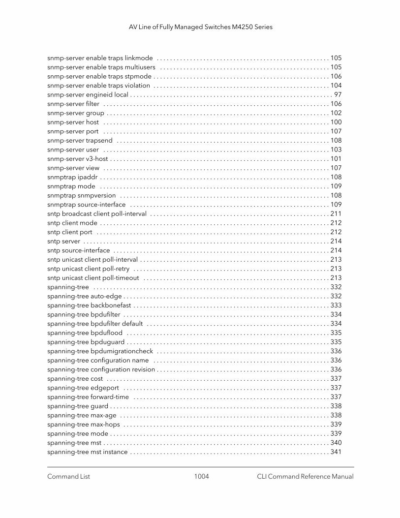
AV Line of Fully Managed Switches M4250 Series
snmp-server enable traps linkmode . . . . . . . . . . . . . . . . . . . . . . . . . . . . . . . . . . . . . . . . . . . . . . . . . . . . 105snmp-server enable traps multiusers . . . . . . . . . . . . . . . . . . . . . . . . . . . . . . . . . . . . . . . . . . . . . . . . . . . 105snmp-server enable traps stpmode . . . . . . . . . . . . . . . . . . . . . . . . . . . . . . . . . . . . . . . . . . . . . . . . . . . . . 106snmp-server enable traps violation . . . . . . . . . . . . . . . . . . . . . . . . . . . . . . . . . . . . . . . . . . . . . . . . . . . . . 104snmp-server engineid local . . . . . . . . . . . . . . . . . . . . . . . . . . . . . . . . . . . . . . . . . . . . . . . . . . . . . . . . . . . . . 97snmp-server filter . . . . . . . . . . . . . . . . . . . . . . . . . . . . . . . . . . . . . . . . . . . . . . . . . . . . . . . . . . . . . . . . . . . . 106snmp-server group . . . . . . . . . . . . . . . . . . . . . . . . . . . . . . . . . . . . . . . . . . . . . . . . . . . . . . . . . . . . . . . . . . . 102snmp-server host . . . . . . . . . . . . . . . . . . . . . . . . . . . . . . . . . . . . . . . . . . . . . . . . . . . . . . . . . . . . . . . . . . . . 100snmp-server port . . . . . . . . . . . . . . . . . . . . . . . . . . . . . . . . . . . . . . . . . . . . . . . . . . . . . . . . . . . . . . . . . . . . 107snmp-server trapsend . . . . . . . . . . . . . . . . . . . . . . . . . . . . . . . . . . . . . . . . . . . . . . . . . . . . . . . . . . . . . . . . 108snmp-server user . . . . . . . . . . . . . . . . . . . . . . . . . . . . . . . . . . . . . . . . . . . . . . . . . . . . . . . . . . . . . . . . . . . . 103snmp-server v3-host . . . . . . . . . . . . . . . . . . . . . . . . . . . . . . . . . . . . . . . . . . . . . . . . . . . . . . . . . . . . . . . . . . 101snmp-server view . . . . . . . . . . . . . . . . . . . . . . . . . . . . . . . . . . . . . . . . . . . . . . . . . . . . . . . . . . . . . . . . . . . . 107snmptrap ipaddr . . . . . . . . . . . . . . . . . . . . . . . . . . . . . . . . . . . . . . . . . . . . . . . . . . . . . . . . . . . . . . . . . . . . . 108snmptrap mode . . . . . . . . . . . . . . . . . . . . . . . . . . . . . . . . . . . . . . . . . . . . . . . . . . . . . . . . . . . . . . . . . . . . . 109snmptrap snmpversion . . . . . . . . . . . . . . . . . . . . . . . . . . . . . . . . . . . . . . . . . . . . . . . . . . . . . . . . . . . . . . . 108snmptrap source-interface . . . . . . . . . . . . . . . . . . . . . . . . . . . . . . . . . . . . . . . . . . . . . . . . . . . . . . . . . . . . 109sntp broadcast client poll-interval . . . . . . . . . . . . . . . . . . . . . . . . . . . . . . . . . . . . . . . . . . . . . . . . . . . . . . 211sntp client mode . . . . . . . . . . . . . . . . . . . . . . . . . . . . . . . . . . . . . . . . . . . . . . . . . . . . . . . . . . . . . . . . . . . . . 212sntp client port . . . . . . . . . . . . . . . . . . . . . . . . . . . . . . . . . . . . . . . . . . . . . . . . . . . . . . . . . . . . . . . . . . . . . . 212sntp server . . . . . . . . . . . . . . . . . . . . . . . . . . . . . . . . . . . . . . . . . . . . . . . . . . . . . . . . . . . . . . . . . . . . . . . . . . 214sntp source-interface . . . . . . . . . . . . . . . . . . . . . . . . . . . . . . . . . . . . . . . . . . . . . . . . . . . . . . . . . . . . . . . . . 214sntp unicast client poll-interval . . . . . . . . . . . . . . . . . . . . . . . . . . . . . . . . . . . . . . . . . . . . . . . . . . . . . . . . . 213sntp unicast client poll-retry . . . . . . . . . . . . . . . . . . . . . . . . . . . . . . . . . . . . . . . . . . . . . . . . . . . . . . . . . . . 213sntp unicast client poll-timeout . . . . . . . . . . . . . . . . . . . . . . . . . . . . . . . . . . . . . . . . . . . . . . . . . . . . . . . . 213spanning-tree . . . . . . . . . . . . . . . . . . . . . . . . . . . . . . . . . . . . . . . . . . . . . . . . . . . . . . . . . . . . . . . . . . . . . . . 332spanning-tree auto-edge . . . . . . . . . . . . . . . . . . . . . . . . . . . . . . . . . . . . . . . . . . . . . . . . . . . . . . . . . . . . . . 332spanning-tree backbonefast . . . . . . . . . . . . . . . . . . . . . . . . . . . . . . . . . . . . . . . . . . . . . . . . . . . . . . . . . . . 333spanning-tree bpdufilter . . . . . . . . . . . . . . . . . . . . . . . . . . . . . . . . . . . . . . . . . . . . . . . . . . . . . . . . . . . . . . 334spanning-tree bpdufilter default . . . . . . . . . . . . . . . . . . . . . . . . . . . . . . . . . . . . . . . . . . . . . . . . . . . . . . . 334spanning-tree bpduflood . . . . . . . . . . . . . . . . . . . . . . . . . . . . . . . . . . . . . . . . . . . . . . . . . . . . . . . . . . . . . 335spanning-tree bpduguard . . . . . . . . . . . . . . . . . . . . . . . . . . . . . . . . . . . . . . . . . . . . . . . . . . . . . . . . . . . . . 335spanning-tree bpdumigrationcheck . . . . . . . . . . . . . . . . . . . . . . . . . . . . . . . . . . . . . . . . . . . . . . . . . . . . 336spanning-tree configuration name . . . . . . . . . . . . . . . . . . . . . . . . . . . . . . . . . . . . . . . . . . . . . . . . . . . . . 336spanning-tree configuration revision . . . . . . . . . . . . . . . . . . . . . . . . . . . . . . . . . . . . . . . . . . . . . . . . . . . . 336spanning-tree cost . . . . . . . . . . . . . . . . . . . . . . . . . . . . . . . . . . . . . . . . . . . . . . . . . . . . . . . . . . . . . . . . . . . 337spanning-tree edgeport . . . . . . . . . . . . . . . . . . . . . . . . . . . . . . . . . . . . . . . . . . . . . . . . . . . . . . . . . . . . . . 337spanning-tree forward-time . . . . . . . . . . . . . . . . . . . . . . . . . . . . . . . . . . . . . . . . . . . . . . . . . . . . . . . . . . . 337spanning-tree guard . . . . . . . . . . . . . . . . . . . . . . . . . . . . . . . . . . . . . . . . . . . . . . . . . . . . . . . . . . . . . . . . . . 338spanning-tree max-age . . . . . . . . . . . . . . . . . . . . . . . . . . . . . . . . . . . . . . . . . . . . . . . . . . . . . . . . . . . . . . . 338spanning-tree max-hops . . . . . . . . . . . . . . . . . . . . . . . . . . . . . . . . . . . . . . . . . . . . . . . . . . . . . . . . . . . . . . 339spanning-tree mode . . . . . . . . . . . . . . . . . . . . . . . . . . . . . . . . . . . . . . . . . . . . . . . . . . . . . . . . . . . . . . . . . . 339spanning-tree mst . . . . . . . . . . . . . . . . . . . . . . . . . . . . . . . . . . . . . . . . . . . . . . . . . . . . . . . . . . . . . . . . . . . . 340spanning-tree mst instance . . . . . . . . . . . . . . . . . . . . . . . . . . . . . . . . . . . . . . . . . . . . . . . . . . . . . . . . . . . . 341
Command List CLI Command Reference Manual1004
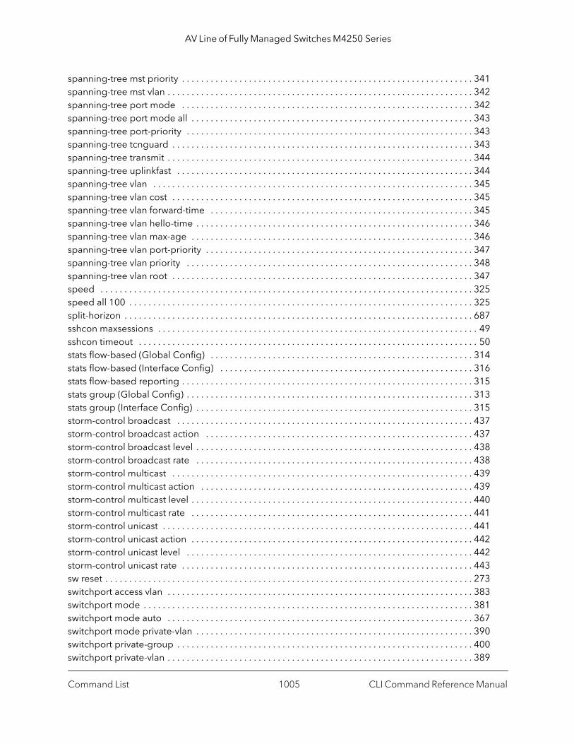
AV Line of Fully Managed Switches M4250 Series
spanning-tree mst priority . . . . . . . . . . . . . . . . . . . . . . . . . . . . . . . . . . . . . . . . . . . . . . . . . . . . . . . . . . . . . 341spanning-tree mst vlan . . . . . . . . . . . . . . . . . . . . . . . . . . . . . . . . . . . . . . . . . . . . . . . . . . . . . . . . . . . . . . . . 342spanning-tree port mode . . . . . . . . . . . . . . . . . . . . . . . . . . . . . . . . . . . . . . . . . . . . . . . . . . . . . . . . . . . . . 342spanning-tree port mode all . . . . . . . . . . . . . . . . . . . . . . . . . . . . . . . . . . . . . . . . . . . . . . . . . . . . . . . . . . . 343spanning-tree port-priority . . . . . . . . . . . . . . . . . . . . . . . . . . . . . . . . . . . . . . . . . . . . . . . . . . . . . . . . . . . . 343spanning-tree tcnguard . . . . . . . . . . . . . . . . . . . . . . . . . . . . . . . . . . . . . . . . . . . . . . . . . . . . . . . . . . . . . . . 343spanning-tree transmit . . . . . . . . . . . . . . . . . . . . . . . . . . . . . . . . . . . . . . . . . . . . . . . . . . . . . . . . . . . . . . . . 344spanning-tree uplinkfast . . . . . . . . . . . . . . . . . . . . . . . . . . . . . . . . . . . . . . . . . . . . . . . . . . . . . . . . . . . . . . 344spanning-tree vlan . . . . . . . . . . . . . . . . . . . . . . . . . . . . . . . . . . . . . . . . . . . . . . . . . . . . . . . . . . . . . . . . . . . 345spanning-tree vlan cost . . . . . . . . . . . . . . . . . . . . . . . . . . . . . . . . . . . . . . . . . . . . . . . . . . . . . . . . . . . . . . . 345spanning-tree vlan forward-time . . . . . . . . . . . . . . . . . . . . . . . . . . . . . . . . . . . . . . . . . . . . . . . . . . . . . . . 345spanning-tree vlan hello-time . . . . . . . . . . . . . . . . . . . . . . . . . . . . . . . . . . . . . . . . . . . . . . . . . . . . . . . . . . 346spanning-tree vlan max-age . . . . . . . . . . . . . . . . . . . . . . . . . . . . . . . . . . . . . . . . . . . . . . . . . . . . . . . . . . . 346spanning-tree vlan port-priority . . . . . . . . . . . . . . . . . . . . . . . . . . . . . . . . . . . . . . . . . . . . . . . . . . . . . . . . 347spanning-tree vlan priority . . . . . . . . . . . . . . . . . . . . . . . . . . . . . . . . . . . . . . . . . . . . . . . . . . . . . . . . . . . . 348spanning-tree vlan root . . . . . . . . . . . . . . . . . . . . . . . . . . . . . . . . . . . . . . . . . . . . . . . . . . . . . . . . . . . . . . . 347speed . . . . . . . . . . . . . . . . . . . . . . . . . . . . . . . . . . . . . . . . . . . . . . . . . . . . . . . . . . . . . . . . . . . . . . . . . . . . . . 325speed all 100 . . . . . . . . . . . . . . . . . . . . . . . . . . . . . . . . . . . . . . . . . . . . . . . . . . . . . . . . . . . . . . . . . . . . . . . . 325split-horizon . . . . . . . . . . . . . . . . . . . . . . . . . . . . . . . . . . . . . . . . . . . . . . . . . . . . . . . . . . . . . . . . . . . . . . . . . 687sshcon maxsessions . . . . . . . . . . . . . . . . . . . . . . . . . . . . . . . . . . . . . . . . . . . . . . . . . . . . . . . . . . . . . . . . . . . 49sshcon timeout . . . . . . . . . . . . . . . . . . . . . . . . . . . . . . . . . . . . . . . . . . . . . . . . . . . . . . . . . . . . . . . . . . . . . . . 50stats flow-based (Global Config) . . . . . . . . . . . . . . . . . . . . . . . . . . . . . . . . . . . . . . . . . . . . . . . . . . . . . . . 314stats flow-based (Interface Config) . . . . . . . . . . . . . . . . . . . . . . . . . . . . . . . . . . . . . . . . . . . . . . . . . . . . . 316stats flow-based reporting . . . . . . . . . . . . . . . . . . . . . . . . . . . . . . . . . . . . . . . . . . . . . . . . . . . . . . . . . . . . . 315stats group (Global Config) . . . . . . . . . . . . . . . . . . . . . . . . . . . . . . . . . . . . . . . . . . . . . . . . . . . . . . . . . . . . 313stats group (Interface Config) . . . . . . . . . . . . . . . . . . . . . . . . . . . . . . . . . . . . . . . . . . . . . . . . . . . . . . . . . . 315storm-control broadcast . . . . . . . . . . . . . . . . . . . . . . . . . . . . . . . . . . . . . . . . . . . . . . . . . . . . . . . . . . . . . . 437storm-control broadcast action . . . . . . . . . . . . . . . . . . . . . . . . . . . . . . . . . . . . . . . . . . . . . . . . . . . . . . . . 437storm-control broadcast level . . . . . . . . . . . . . . . . . . . . . . . . . . . . . . . . . . . . . . . . . . . . . . . . . . . . . . . . . . 438storm-control broadcast rate . . . . . . . . . . . . . . . . . . . . . . . . . . . . . . . . . . . . . . . . . . . . . . . . . . . . . . . . . . 438storm-control multicast . . . . . . . . . . . . . . . . . . . . . . . . . . . . . . . . . . . . . . . . . . . . . . . . . . . . . . . . . . . . . . . 439storm-control multicast action . . . . . . . . . . . . . . . . . . . . . . . . . . . . . . . . . . . . . . . . . . . . . . . . . . . . . . . . . 439storm-control multicast level . . . . . . . . . . . . . . . . . . . . . . . . . . . . . . . . . . . . . . . . . . . . . . . . . . . . . . . . . . . 440storm-control multicast rate . . . . . . . . . . . . . . . . . . . . . . . . . . . . . . . . . . . . . . . . . . . . . . . . . . . . . . . . . . . 441storm-control unicast . . . . . . . . . . . . . . . . . . . . . . . . . . . . . . . . . . . . . . . . . . . . . . . . . . . . . . . . . . . . . . . . . 441storm-control unicast action . . . . . . . . . . . . . . . . . . . . . . . . . . . . . . . . . . . . . . . . . . . . . . . . . . . . . . . . . . . 442storm-control unicast level . . . . . . . . . . . . . . . . . . . . . . . . . . . . . . . . . . . . . . . . . . . . . . . . . . . . . . . . . . . . 442storm-control unicast rate . . . . . . . . . . . . . . . . . . . . . . . . . . . . . . . . . . . . . . . . . . . . . . . . . . . . . . . . . . . . . 443sw reset . . . . . . . . . . . . . . . . . . . . . . . . . . . . . . . . . . . . . . . . . . . . . . . . . . . . . . . . . . . . . . . . . . . . . . . . . . . . . 273switchport access vlan . . . . . . . . . . . . . . . . . . . . . . . . . . . . . . . . . . . . . . . . . . . . . . . . . . . . . . . . . . . . . . . . 383switchport mode . . . . . . . . . . . . . . . . . . . . . . . . . . . . . . . . . . . . . . . . . . . . . . . . . . . . . . . . . . . . . . . . . . . . . 381switchport mode auto . . . . . . . . . . . . . . . . . . . . . . . . . . . . . . . . . . . . . . . . . . . . . . . . . . . . . . . . . . . . . . . . 367switchport mode private-vlan . . . . . . . . . . . . . . . . . . . . . . . . . . . . . . . . . . . . . . . . . . . . . . . . . . . . . . . . . . 390switchport private-group . . . . . . . . . . . . . . . . . . . . . . . . . . . . . . . . . . . . . . . . . . . . . . . . . . . . . . . . . . . . . . 400switchport private-vlan . . . . . . . . . . . . . . . . . . . . . . . . . . . . . . . . . . . . . . . . . . . . . . . . . . . . . . . . . . . . . . . . 389
Command List CLI Command Reference Manual1005

AV Line of Fully Managed Switches M4250 Series
switchport protected (Global Config) . . . . . . . . . . . . . . . . . . . . . . . . . . . . . . . . . . . . . . . . . . . . . . . . . . . 398switchport protected (Interface Config) . . . . . . . . . . . . . . . . . . . . . . . . . . . . . . . . . . . . . . . . . . . . . . . . . 399switchport trunk allowed vlan . . . . . . . . . . . . . . . . . . . . . . . . . . . . . . . . . . . . . . . . . . . . . . . . . . . . . . . . . . 382switchport trunk native vlan . . . . . . . . . . . . . . . . . . . . . . . . . . . . . . . . . . . . . . . . . . . . . . . . . . . . . . . . . . . 383tacacs-server host . . . . . . . . . . . . . . . . . . . . . . . . . . . . . . . . . . . . . . . . . . . . . . . . . . . . . . . . . . . . . . . . . . . . 133tacacs-server key . . . . . . . . . . . . . . . . . . . . . . . . . . . . . . . . . . . . . . . . . . . . . . . . . . . . . . . . . . . . . . . . . . . . . 133tacacs-server keystring . . . . . . . . . . . . . . . . . . . . . . . . . . . . . . . . . . . . . . . . . . . . . . . . . . . . . . . . . . . . . . . . 134tacacs-server source-interface . . . . . . . . . . . . . . . . . . . . . . . . . . . . . . . . . . . . . . . . . . . . . . . . . . . . . . . . . 134tacacs-server timeout . . . . . . . . . . . . . . . . . . . . . . . . . . . . . . . . . . . . . . . . . . . . . . . . . . . . . . . . . . . . . . . . . 135techsupport enable . . . . . . . . . . . . . . . . . . . . . . . . . . . . . . . . . . . . . . . . . . . . . . . . . . . . . . . . . . . . . . . . . . 274telnet . . . . . . . . . . . . . . . . . . . . . . . . . . . . . . . . . . . . . . . . . . . . . . . . . . . . . . . . . . . . . . . . . . . . . . . . . . . . . . . . 44telnetcon maxsessions . . . . . . . . . . . . . . . . . . . . . . . . . . . . . . . . . . . . . . . . . . . . . . . . . . . . . . . . . . . . . . . . . 46telnetcon timeout . . . . . . . . . . . . . . . . . . . . . . . . . . . . . . . . . . . . . . . . . . . . . . . . . . . . . . . . . . . . . . . . . . . . . 46telnetd . . . . . . . . . . . . . . . . . . . . . . . . . . . . . . . . . . . . . . . . . . . . . . . . . . . . . . . . . . . . . . . . . . . . . . . . . . . . . 275terminal length . . . . . . . . . . . . . . . . . . . . . . . . . . . . . . . . . . . . . . . . . . . . . . . . . . . . . . . . . . . . . . . . . . . . . . 180timeout (TACACS Config) . . . . . . . . . . . . . . . . . . . . . . . . . . . . . . . . . . . . . . . . . . . . . . . . . . . . . . . . . . . . . 137time-range . . . . . . . . . . . . . . . . . . . . . . . . . . . . . . . . . . . . . . . . . . . . . . . . . . . . . . . . . . . . . . . . . . . . . . . . . . 851traceroute . . . . . . . . . . . . . . . . . . . . . . . . . . . . . . . . . . . . . . . . . . . . . . . . . . . . . . . . . . . . . . . . . . . . . . . . . . . 198traffic-shape . . . . . . . . . . . . . . . . . . . . . . . . . . . . . . . . . . . . . . . . . . . . . . . . . . . . . . . . . . . . . . . . . . . . . . . . . 791transport input telnet . . . . . . . . . . . . . . . . . . . . . . . . . . . . . . . . . . . . . . . . . . . . . . . . . . . . . . . . . . . . . . . . . . 44transport output telnet . . . . . . . . . . . . . . . . . . . . . . . . . . . . . . . . . . . . . . . . . . . . . . . . . . . . . . . . . . . . . . . . . 45trapflags (Captive Portal Config Mode) . . . . . . . . . . . . . . . . . . . . . . . . . . . . . . . . . . . . . . . . . . . . . . . . . . 696tunnel destination . . . . . . . . . . . . . . . . . . . . . . . . . . . . . . . . . . . . . . . . . . . . . . . . . . . . . . . . . . . . . . . . . . . . 726tunnel mode ipv6ip . . . . . . . . . . . . . . . . . . . . . . . . . . . . . . . . . . . . . . . . . . . . . . . . . . . . . . . . . . . . . . . . . . 727tunnel source . . . . . . . . . . . . . . . . . . . . . . . . . . . . . . . . . . . . . . . . . . . . . . . . . . . . . . . . . . . . . . . . . . . . . . . . 726udld enable (Global Config) . . . . . . . . . . . . . . . . . . . . . . . . . . . . . . . . . . . . . . . . . . . . . . . . . . . . . . . . . . . 591udld enable (Interface Config) . . . . . . . . . . . . . . . . . . . . . . . . . . . . . . . . . . . . . . . . . . . . . . . . . . . . . . . . . 592udld message time . . . . . . . . . . . . . . . . . . . . . . . . . . . . . . . . . . . . . . . . . . . . . . . . . . . . . . . . . . . . . . . . . . . 592udld port . . . . . . . . . . . . . . . . . . . . . . . . . . . . . . . . . . . . . . . . . . . . . . . . . . . . . . . . . . . . . . . . . . . . . . . . . . . 593udld reset . . . . . . . . . . . . . . . . . . . . . . . . . . . . . . . . . . . . . . . . . . . . . . . . . . . . . . . . . . . . . . . . . . . . . . . . . . . 592udld timeout interval . . . . . . . . . . . . . . . . . . . . . . . . . . . . . . . . . . . . . . . . . . . . . . . . . . . . . . . . . . . . . . . . . 592update bootcode . . . . . . . . . . . . . . . . . . . . . . . . . . . . . . . . . . . . . . . . . . . . . . . . . . . . . . . . . . . . . . . . . . . . 153user (Captive Portal Config Mode) . . . . . . . . . . . . . . . . . . . . . . . . . . . . . . . . . . . . . . . . . . . . . . . . . . . . . . 715user group (captive portal local user commands) . . . . . . . . . . . . . . . . . . . . . . . . . . . . . . . . . . . . . . . . . 717user group (captive portal user group commands) . . . . . . . . . . . . . . . . . . . . . . . . . . . . . . . . . . . . . . . 723user group moveusers . . . . . . . . . . . . . . . . . . . . . . . . . . . . . . . . . . . . . . . . . . . . . . . . . . . . . . . . . . . . . . . . 724user group name . . . . . . . . . . . . . . . . . . . . . . . . . . . . . . . . . . . . . . . . . . . . . . . . . . . . . . . . . . . . . . . . . . . . 724user idle-timeout . . . . . . . . . . . . . . . . . . . . . . . . . . . . . . . . . . . . . . . . . . . . . . . . . . . . . . . . . . . . . . . . . . . . . 718user max-bandwidth-down . . . . . . . . . . . . . . . . . . . . . . . . . . . . . . . . . . . . . . . . . . . . . . . . . . . . . . . . . . . . 720user max-bandwidth-up . . . . . . . . . . . . . . . . . . . . . . . . . . . . . . . . . . . . . . . . . . . . . . . . . . . . . . . . . . . . . . . 719user max-input-octets . . . . . . . . . . . . . . . . . . . . . . . . . . . . . . . . . . . . . . . . . . . . . . . . . . . . . . . . . . . . . . . . 720user max-output-octets . . . . . . . . . . . . . . . . . . . . . . . . . . . . . . . . . . . . . . . . . . . . . . . . . . . . . . . . . . . . . . . 721user max-total-octets . . . . . . . . . . . . . . . . . . . . . . . . . . . . . . . . . . . . . . . . . . . . . . . . . . . . . . . . . . . . . . . . . 721user name (Captive Portal Config) . . . . . . . . . . . . . . . . . . . . . . . . . . . . . . . . . . . . . . . . . . . . . . . . . . . . . . 716
Command List CLI Command Reference Manual1006
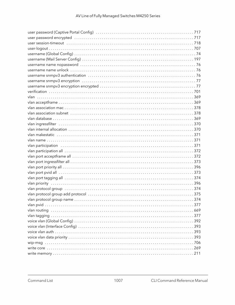
AV Line of Fully Managed Switches M4250 Series
user password (Captive Portal Config) . . . . . . . . . . . . . . . . . . . . . . . . . . . . . . . . . . . . . . . . . . . . . . . . . . 717user password encrypted . . . . . . . . . . . . . . . . . . . . . . . . . . . . . . . . . . . . . . . . . . . . . . . . . . . . . . . . . . . . . 717user session-timeout . . . . . . . . . . . . . . . . . . . . . . . . . . . . . . . . . . . . . . . . . . . . . . . . . . . . . . . . . . . . . . . . . 718user-logout . . . . . . . . . . . . . . . . . . . . . . . . . . . . . . . . . . . . . . . . . . . . . . . . . . . . . . . . . . . . . . . . . . . . . . . . . . 707username (Global Config) . . . . . . . . . . . . . . . . . . . . . . . . . . . . . . . . . . . . . . . . . . . . . . . . . . . . . . . . . . . . . . 74username (Mail Server Config) . . . . . . . . . . . . . . . . . . . . . . . . . . . . . . . . . . . . . . . . . . . . . . . . . . . . . . . . . 197username name nopassword . . . . . . . . . . . . . . . . . . . . . . . . . . . . . . . . . . . . . . . . . . . . . . . . . . . . . . . . . . . 76username name unlock . . . . . . . . . . . . . . . . . . . . . . . . . . . . . . . . . . . . . . . . . . . . . . . . . . . . . . . . . . . . . . . . 76username snmpv3 authentication . . . . . . . . . . . . . . . . . . . . . . . . . . . . . . . . . . . . . . . . . . . . . . . . . . . . . . . 76username snmpv3 encryption . . . . . . . . . . . . . . . . . . . . . . . . . . . . . . . . . . . . . . . . . . . . . . . . . . . . . . . . . . 77username snmpv3 encryption encrypted . . . . . . . . . . . . . . . . . . . . . . . . . . . . . . . . . . . . . . . . . . . . . . . . . 77verification . . . . . . . . . . . . . . . . . . . . . . . . . . . . . . . . . . . . . . . . . . . . . . . . . . . . . . . . . . . . . . . . . . . . . . . . . . 701vlan . . . . . . . . . . . . . . . . . . . . . . . . . . . . . . . . . . . . . . . . . . . . . . . . . . . . . . . . . . . . . . . . . . . . . . . . . . . . . . . . 369vlan acceptframe . . . . . . . . . . . . . . . . . . . . . . . . . . . . . . . . . . . . . . . . . . . . . . . . . . . . . . . . . . . . . . . . . . . . . 369vlan association mac . . . . . . . . . . . . . . . . . . . . . . . . . . . . . . . . . . . . . . . . . . . . . . . . . . . . . . . . . . . . . . . . . . 378vlan association subnet . . . . . . . . . . . . . . . . . . . . . . . . . . . . . . . . . . . . . . . . . . . . . . . . . . . . . . . . . . . . . . . 378vlan database . . . . . . . . . . . . . . . . . . . . . . . . . . . . . . . . . . . . . . . . . . . . . . . . . . . . . . . . . . . . . . . . . . . . . . . . 369vlan ingressfilter . . . . . . . . . . . . . . . . . . . . . . . . . . . . . . . . . . . . . . . . . . . . . . . . . . . . . . . . . . . . . . . . . . . . . 370vlan internal allocation . . . . . . . . . . . . . . . . . . . . . . . . . . . . . . . . . . . . . . . . . . . . . . . . . . . . . . . . . . . . . . . . 370vlan makestatic . . . . . . . . . . . . . . . . . . . . . . . . . . . . . . . . . . . . . . . . . . . . . . . . . . . . . . . . . . . . . . . . . . . . . . 371vlan name . . . . . . . . . . . . . . . . . . . . . . . . . . . . . . . . . . . . . . . . . . . . . . . . . . . . . . . . . . . . . . . . . . . . . . . . . . . 371vlan participation . . . . . . . . . . . . . . . . . . . . . . . . . . . . . . . . . . . . . . . . . . . . . . . . . . . . . . . . . . . . . . . . . . . . 371vlan participation all . . . . . . . . . . . . . . . . . . . . . . . . . . . . . . . . . . . . . . . . . . . . . . . . . . . . . . . . . . . . . . . . . . 372vlan port acceptframe all . . . . . . . . . . . . . . . . . . . . . . . . . . . . . . . . . . . . . . . . . . . . . . . . . . . . . . . . . . . . . . 372vlan port ingressfilter all . . . . . . . . . . . . . . . . . . . . . . . . . . . . . . . . . . . . . . . . . . . . . . . . . . . . . . . . . . . . . . . 373vlan port priority all . . . . . . . . . . . . . . . . . . . . . . . . . . . . . . . . . . . . . . . . . . . . . . . . . . . . . . . . . . . . . . . . . . . 396vlan port pvid all . . . . . . . . . . . . . . . . . . . . . . . . . . . . . . . . . . . . . . . . . . . . . . . . . . . . . . . . . . . . . . . . . . . . . 373vlan port tagging all . . . . . . . . . . . . . . . . . . . . . . . . . . . . . . . . . . . . . . . . . . . . . . . . . . . . . . . . . . . . . . . . . . 374vlan priority . . . . . . . . . . . . . . . . . . . . . . . . . . . . . . . . . . . . . . . . . . . . . . . . . . . . . . . . . . . . . . . . . . . . . . . . . 396vlan protocol group . . . . . . . . . . . . . . . . . . . . . . . . . . . . . . . . . . . . . . . . . . . . . . . . . . . . . . . . . . . . . . . . . . 374vlan protocol group add protocol . . . . . . . . . . . . . . . . . . . . . . . . . . . . . . . . . . . . . . . . . . . . . . . . . . . . . . 375vlan protocol group name . . . . . . . . . . . . . . . . . . . . . . . . . . . . . . . . . . . . . . . . . . . . . . . . . . . . . . . . . . . . . 374vlan pvid . . . . . . . . . . . . . . . . . . . . . . . . . . . . . . . . . . . . . . . . . . . . . . . . . . . . . . . . . . . . . . . . . . . . . . . . . . . . 377vlan routing . . . . . . . . . . . . . . . . . . . . . . . . . . . . . . . . . . . . . . . . . . . . . . . . . . . . . . . . . . . . . . . . . . . . . . . . . 669vlan tagging . . . . . . . . . . . . . . . . . . . . . . . . . . . . . . . . . . . . . . . . . . . . . . . . . . . . . . . . . . . . . . . . . . . . . . . . . 377voice vlan (Global Config) . . . . . . . . . . . . . . . . . . . . . . . . . . . . . . . . . . . . . . . . . . . . . . . . . . . . . . . . . . . . . 392voice vlan (Interface Config) . . . . . . . . . . . . . . . . . . . . . . . . . . . . . . . . . . . . . . . . . . . . . . . . . . . . . . . . . . . 393voice vlan auth . . . . . . . . . . . . . . . . . . . . . . . . . . . . . . . . . . . . . . . . . . . . . . . . . . . . . . . . . . . . . . . . . . . . . . . 393voice vlan data priority . . . . . . . . . . . . . . . . . . . . . . . . . . . . . . . . . . . . . . . . . . . . . . . . . . . . . . . . . . . . . . . . 393wip-msg . . . . . . . . . . . . . . . . . . . . . . . . . . . . . . . . . . . . . . . . . . . . . . . . . . . . . . . . . . . . . . . . . . . . . . . . . . . . 706write core . . . . . . . . . . . . . . . . . . . . . . . . . . . . . . . . . . . . . . . . . . . . . . . . . . . . . . . . . . . . . . . . . . . . . . . . . . . 269write memory . . . . . . . . . . . . . . . . . . . . . . . . . . . . . . . . . . . . . . . . . . . . . . . . . . . . . . . . . . . . . . . . . . . . . . . . 211
Command List CLI Command Reference Manual1007