Embed Size (px)
Citation preview
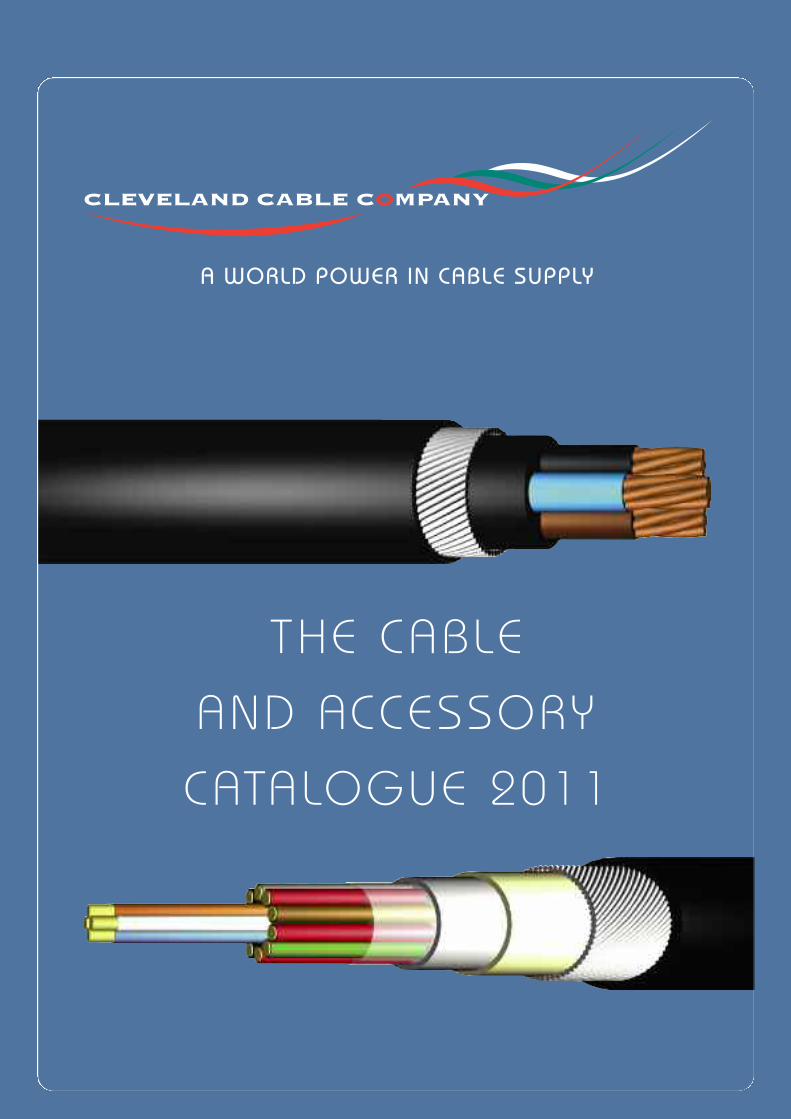
THE CABLE
AND ACCESSORY
CATALOGUE 2011
A WORLD POWER IN CABLE SUPPLY
CLE
VEL
AND
CABLE
LOCAT
IONS
2
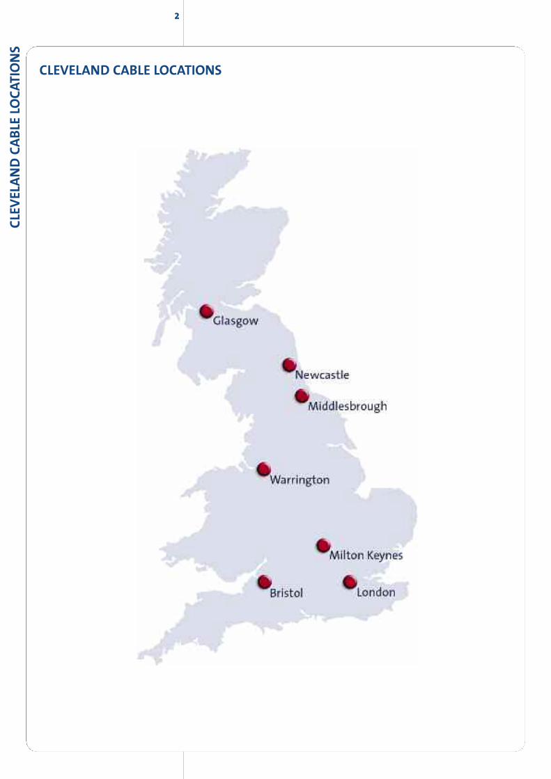
CLEVELAND CABLE LOCATIONS

3CLEV
ELAND
CABLE
COM
PANY
As is illustrated within our catalogue, we stock acomprehensive range of cables for everyconceivable application. All types shown areconsidered as standard items to our range and arealways available for immediate delivery. Our stocksare extremely large and unrivalled in the industry.
We are fortunate to have a very
experienced and dedicated team of
people who are able to assist and
advise. Additionally our policy of
continuing investment in the best
available technology, warehousing,
handling and measuring equipment
and delivery vehicles enables us to
guarantee all our customers an
extremely high quality service.
Enquiries are welcome from customers worldwide. Our export service is efficient
and reliable with the ability to ship by air or sea freight to any destination.
Please feel free to contact the distribution centreof your choice for an immediate, professionaland trouble free service.
Middlesbrough 01642 241133
Bristol 01179 382222
Glasgow 0141 6465000
Milton Keynes 01908 221414
London 0208 3114141
Newcastle 0191 2633363
Warrington 01925 655383
4CLE
VEL
AND
CABLE
COM
PANY
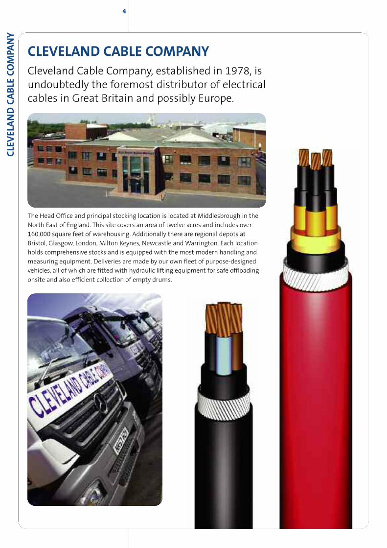
CLEVELAND CABLE COMPANYCleveland Cable Company, established in 1978, isundoubtedly the foremost distributor of electricalcables in Great Britain and possibly Europe.
The Head Office and principal stocking location is located at Middlesbrough in the
North East of England. This site covers an area of twelve acres and includes over
160,000 square feet of warehousing. Additionally there are regional depots at
Bristol, Glasgow, London, Milton Keynes, Newcastle andWarrington. Each location
holds comprehensive stocks and is equipped with the most modern handling and
measuring equipment. Deliveries are made by our own fleet of purpose-designed
vehicles, all of which are fitted with hydraulic lifting equipment for safe offloading
onsite and also efficient collection of empty drums.

MIDDLESBROUGH HEAD OFFICE - WAREHOUSES AND STOCKYARD

LANDACQUIRED FOR FUTURE
DEVELOPMENT
MIDDLESBROUGH HEAD OFFICE - WAREHOUSES AND STOCKYARD
8
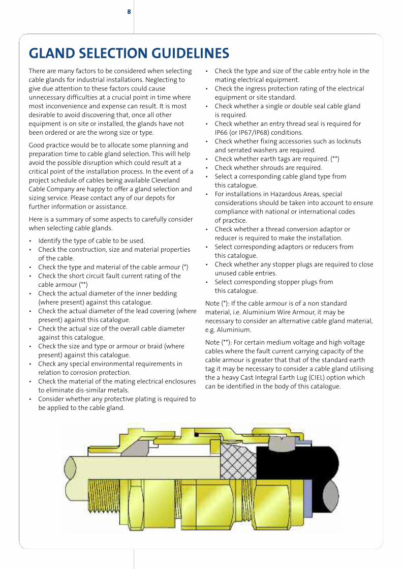
GLAND SELECTION GUIDELINESThere are many factors to be considered when selectingcable glands for industrial installations. Neglecting togive due attention to these factors could causeunnecessary difficulties at a crucial point in time wheremost inconvenience and expense can result. It is mostdesirable to avoid discovering that, once all otherequipment is on site or installed, the glands have notbeen ordered or are the wrong size or type.
Good practice would be to allocate some planning andpreparation time to cable gland selection. This will helpavoid the possible disruption which could result at acritical point of the installation process. In the event of aproject schedule of cables being available ClevelandCable Company are happy to offer a gland selection andsizing service. Please contact any of our depots forfurther information or assistance.
Here is a summary of some aspects to carefully considerwhen selecting cable glands.
• Identify the type of cable to be used.• Check the construction, size and material properties
of the cable.• Check the type and material of the cable armour (*)• Check the short circuit fault current rating of the
cable armour (**)• Check the actual diameter of the inner bedding
(where present) against this catalogue.• Check the actual diameter of the lead covering (where
present) against this catalogue.• Check the actual size of the overall cable diameter
against this catalogue.• Check the size and type or armour or braid (where
present) against this catalogue.• Check any special environmental requirements in
relation to corrosion protection.• Check the material of the mating electrical enclosures
to eliminate dis-similar metals.• Consider whether any protective plating is required to
be applied to the cable gland.
• Check the type and size of the cable entry hole in themating electrical equipment.
• Check the ingress protection rating of the electricalequipment or site standard.
• Check whether a single or double seal cable glandis required.
• Check whether an entry thread seal is required forIP66 (or IP67/IP68) conditions.
• Check whether fixing accessories such as locknutsand serrated washers are required.
• Check whether earth tags are required. (**)• Check whether shrouds are required.• Select a corresponding cable gland type from
this catalogue.• For installations in Hazardous Areas, special
considerations should be taken into account to ensurecompliance with national or international codesof practice.
• Check whether a thread conversion adaptor orreducer is required to make the installation.
• Select corresponding adaptors or reducers fromthis catalogue.
• Check whether any stopper plugs are required to closeunused cable entries.
• Select corresponding stopper plugs fromthis catalogue.
Note (*): If the cable armour is of a non standardmaterial, i.e. AluminiumWire Armour, it may benecessary to consider an alternative cable gland material,e.g. Aluminium.
Note (**): For certain medium voltage and high voltagecables where the fault current carrying capacity of thecable armour is greater that that of the standard earthtag it may be necessary to consider a cable gland utilisingthe a heavy Cast Integral Earth Lug (CIEL) option whichcan be identified in the body of this catalogue.
9CO
NTEN
TS
SECTION 1 Low Voltage PVC Fixed Wiring & Mains Cables
6491X (HO7V-R) PVC insulated wiring, 1.5mm2 – 630mm2 ............................................................14
Bare copper strand, soft drawn to BS6360/81, 6mm2 – 400mm2 ................................................14
6181Y PVC insulated, PVC sheathed surface wiring, 1.0mm2 – 120mm2..................................15
624*Y PVC insulated, PVC sheathed surface wiring, 1mm2 – 16mm2 ........................................15
BS5467 Mains & control, XLPE, PVC SWA, PVC, 1.5mm2 – 16mm2
including multicores..........................................................................................................................................16
BS5467 Mains, XLPE, PVC, SWA, PVC, copper conductors, 25mm2 – 400mm2 ........................17
BS5467 Mains, XLPE, PVC, SWA, MDPE, copper conductors 4mm2 – 16mm2 ..........................18
BS5467 Mains, XLPE, PVC, SWA, MDPE, copper conductors 25mm2– 400mm2......................19
BS5467 Mains, XLPE, PVC, SWA, PVC, aluminium conductors, 25mm2 – 300mm2................20
BS7889 Mains, single core, XLPE, PVC, non-armoured, 50mm2 –1000mm2 ............................21
BS5467 Mains, single core, XLPE, PVC, aluminium wire armoured, PVC,
50mm2 – 1000mm2 ..........................................................................................................................................22
Mines & Quarries Mains, XLPE, PVC, SWA, PVC, with 60% Conductivity in
armour, 10mm2 – 300mm2 ............................................................................................................................23
EEMUA 133 Multicore, XLPE, lead sheathed, PVC, SWA, PVC, Control cable for
petro-chemical industries, 1.5mm2 – 4mm2 ........................................................................................24
EEMUA 133 Mains, XLPE, lead sheathed, PVC,SWA, PVC, for petro-chemical
industries, 1.5mm2 – 16mm2 ........................................................................................................................25
EEMUA 133 Mains, XLPE, lead sheathed, PVC, SWA, PVC, for petro-chemical
industries, 25mm2 – 300mm2 ......................................................................................................................26
Cathodic Protection Cables. XLPE, PVC, and XLPE, PVC, SWA, PVC, 6mm2 – 185mm2 ..........27
Concentric, split & straight, single phase service cable, 4mm2 – 35mm2 ................................28
SECTION 2 3300V Mains Cable
BS5467 Mains, single core XLPE, PVC, aluminium wire armoured, PVC, 3300V,
120mm2 – 630mm2 ..........................................................................................................................................30
BS5467 Mains three core, XLPE, PVC, SWA, PVC, 3300V, 16mm2 – 400mm2 ............................31
Mines & Quarries Mains, XLPE, PVC, SWA, PVC, with 60% conductivity in armour,
3300V, 16mm2 – 300mm2 ..............................................................................................................................32
EEMUA 133 Mains, XLPE, Lead sheathed, PVC, SWA, PVC, for petro-chemical
industries, 3300V, 25mm2 – 300mm2........................................................................................................33
SECTION 3 LSZH Fixed Wiring & Mains Cables
6491B (H07Z-R) LSZH insulated wiring, 1.5mm2 – 630mm2 ..........................................................36
6181B XLPE insulated, LSZH sheathed, surface wiring, 1.5mm2 – 35mm2 ..............................37
624*B XLPE insulated, LSZH sheathed surface wiring 1.5mm2 – 16mm2 ..................................37
BS6724 Mains & control, XLPE, LSZH, SWA, LSZH, 1.5mm2 – 16mm2
including multicores .........................................................................................................................................38
BS6724 Mains, XLPE, LSZH, SWA, LSZH, 25mm2 – 400mm2 ............................................................39
BS6724 Mains, single core, XLPE, LSZH, 50mm2 – 1000mm2 ..........................................................40
10
BS6724 Mains, single core, XLPE, LSZH, aluminium wire armoured, LSZH,
50mm2 – 1000mm2 ..........................................................................................................................................41
BS8436 Protected fixed wiring cable, 1mm2 – 10mm2......................................................................42
SECTION 4 Medium Voltage 11000V & above
BS6622 Mains, single core, XLPE, CTS, PVC, aluminium wire armoured, PVC,
11000V, 50mm2 – 630mm .............................................................................................................................44
BS6622 Mains, three core, XLPE, CTS, PVC, SWA, PVC, 11000V, 25mm2 – 400mm2 ..............44
BS6622 Mains, three core, aluminium conductor XLPE, CTS, PVC, SWA, PVC,
11000V, 95mm2 – 300mm2 ..........................................................................................................................45
Triplex, BS7870, aluminium conductor XLPE, CTS,MDPE, 11000V, utility cable,
70mm2 – 300mm2..............................................................................................................................................46
Paper insulated, BS6480 Mains, three core, SWA, PVC, 11000V, 25mm2 – 400mm2 ............47
BS7835 Mains, single core, XLPE, CTS, LSZH, aluminium wire armoured, LSZH,
11000V, 50mm2 – 630mm2............................................................................................................................48
BS7835 Mains, three core, XLPE, CTS, LSZH, SWA, LSZH, 11000V,
35mm2 – 400mm2..............................................................................................................................................48
BS7835 Mains, three core, XLPE, CTS, LSZH, SWA, LSZH, 22000V and 33000v,
95mm2 – 185mm2 ............................................................................................................................................49
SECTION 5 High voltage 33000v service and windfarm cables
BS7870 Mains, single core, aluminium conductors , XLPE, CWS, MDPE, 33000v
70mm2 – 630mm2..............................................................................................................................................52
BS7870 Mains, single core, copper conductors , XLPE, CWS, MDPE,
33000v 70mm2 – 630mm2 ............................................................................................................................53
SECTION 6 Fire Protection, Alarm & Security Cables
Mineral Insulated................................................................................................................................................56
BS5839/BS7629 Fire performance alarm and security cable,
1mm2 – 4mm2......................................................................................................................................................57
BS5839/BS7629 Enhanced fire performance alarm and
security cable 1.5mm2– 4mm2 ....................................................................................................................58
BS6387 Fire performance single core cable, 1.5mm2 – 16mm2 ....................................................59
BS6387/BS7846 Mains and control, mica tape, XLPE, LSZH,SWA, LSZH,
fire resistant,1.5mm2 – 16mm2, including multicores ......................................................................60
BS6387/BS7846 Mains, mica tape, XLPE, LSZH, SWA, LSZH, fire resistant,
25mm2 – 400mm2..............................................................................................................................................61
BS6387/BS7846 Mains and control, mica tape, XLPE, LSZH,SWA, LSZH, fire resistant,
enhanced, 1.5mm2 – 16mm2, including multicores. ..........................................................................62
BS6387/BS7846 Mains, mica tape, XLPE, LSZH, SWA, LSZH, fire resistant, enhanced,
25mm2 – 400mm2 .............................................................................................................................................63
CONTE
NTS
11
SECTION 7 Flexible Cables, PVC and Rubber
PVC and LSZH flexible cables
218*Y (H03VV-F) PVC, PVC, 0.5mm2 – 0.75mm2....................................................................................66
318*Y (H05VV-F) PVC, PVC, 0.5mm2– 2.5mm2 ......................................................................................66
309*Y Heat resisting PVC, PVC, 0.5mm2 – 2.5mm2 ..............................................................................67
Arctic grade low temperature flex, 1.5mm2 – 6mm2..........................................................................67
318*B (H05ZIZI-F) LSZH, LSZH, 0.75mm2 – 2.5mm2 ............................................................................68
YY Control cable, 0.75mm2 – 1.5mm2........................................................................................................69
YY Control cable, 2.5mm2 – 50mm2............................................................................................................70
SY Control cable, 0.75mm2 – 2.5mm2 ........................................................................................................71
SY Control cable, 4.0mm2 – 95mm2............................................................................................................72
CY Control cable, 0.5mm2 – 16mm2 ..........................................................................................................73
YY Control cable, LSZH, 0.75mm2 – 25mm2 ............................................................................................74
CY Control cable, LSZH, 0.75mm2 – 1.5mm2 ..........................................................................................74
Tri-rated and Bi-rated BS6231, switchgear and control panel wire,
0.5mm2 – 400mm2 ............................................................................................................................................75
6381Y PVC, PVC, 6mm2 – 400mm2..............................................................................................................76
2491B/6701B (H05Z-K), flexible conductor, LSZH insulated wiring,
1.5mm2 – 240mm2 ............................................................................................................................................76
Solar Energy Cables 1.5mm2 – 35mm2......................................................................................................77
Rubber flexible cables
BS6500 EPR insulated, CSP sheathed, flexible power & control, 0.75 – 2.5mm2 ..................78
BS7919 EPR insulated, CSP sheathed, flexible mains 4mm2– 16mm2 ......................................79
BS7919 EPR insulated, CSP sheathed, flexible mains, 25mm2 – 630mm2 ................................80
HO7RN-F EPR insulated, PCP sheathed, flexible mains, 1.0mm2 – 50mm2 ..............................81
HO7RN-F EPR insulated, PCP sheathed, flexible mains, 70mm2 – 630mm2 ............................82
380*P EPR insulated, copper braided screen, PCP sheathed, flexible mains,
1mm2 – 16mm2 ..................................................................................................................................................83
BS6500 EPR insulated, TR sheathed, flexible power & control 0.75mm2 – 2.5mm2 ............83
Coil lead BS6195 EPR, CSP, 0.5mm2 – 400mm2 .....................................................................................84
Welding cable, O361TQ EPR, CSP, 16mm2 – 185mm2 ........................................................................85
Flatform and silicon cables
Flatform cable, PVC, PVC, 1.5mm2 – 95mm2 ..........................................................................................86
Flatform cable, EPR, PCP, 1.5mm2 – 70mm2............................................................................................86
Silicon insulated, silicon sheathed, flexible cable, 0.75mm2 – 2.5mm2......................................87
SECTION 8 Instrumentation, Control & Communication Cables
BS5308 Control and instrumentation cable, non-armoured with collective screen,
0.5mm2 – 1.5mm2, part 1 and part 2.........................................................................................................90
BS5308 Control and instrumentation cable, non-armoured with individual and
collective screen, 0.5mm2 – 1.5mm2, part 1 and part 2 ....................................................................91
BS5308 Control and instrumentation cable, armoured with collective screen,
0.5mm2 – 2.5mm2, part 1 and part 2 ........................................................................................................92
BS5308 Control and instrumentation cable, armoured with individual and collective
screen, 0.5mm2 – 1.5mm2, part 1 and part 2 ........................................................................................93
CONTEN
TS
12CO
NTE
NTS
BS5308 Control and instrumentation cable, lead sheathed, armoured with
collective screen, 0.75mm2 – 1.5mm2, part 1 and part 2..................................................................94
BS5308 Control and instrumentation cable, lead sheathed, armoured with
individual and collective screen, 0.75mm2 – 1.5mm2, part 1 and part 2 ..................................95
BS5308 part 1 core identification................................................................................................................96
BS5308 part 2 core identification................................................................................................................97
British Steel specification CES20 type 134, 0.75mm2 ........................................................................98
British Steel specification CES20 type 143, 0.75mm2 ........................................................................99
CW1308 telephone cable ............................................................................................................................100
Telephone cable to ENATS 09-6 standard..........................................................................101/102/103
Utility Industry PVC Control Cables, ENATS 09-6 2.5mm2..............................................................103
ENATS 09-6 section 3.6 core identification ..........................................................................................104
ENATS 09-6 section 4.5 core identification ..........................................................................................104
Petroleum jelly filled telephone cable to CW1128, CW1128/1198 and BS3573 ................105
Defence standard screened cable type 61-12 ....................................................................................106
Defence standard 61-12 parts 4 & 5 core identification ...............................................................107
Thermocouple extension and compensating cable, 0.75mm2 ....................................................108
Thermocouple core identification ............................................................................................................109
Traffic signal cable, loop feeder cable and loop detector cable ........................................110/111
SECTION 9 Data Cables
Belden equivalents ..........................................................................................................................................114
Coaxial cables ....................................................................................................................................................114
Cat 5 data cables ..............................................................................................................................................114
Cat 6 data cables ..............................................................................................................................................114
SECTION 10 Railway Cables
Signalling cable types A1, A2, A3, B1 and B2, 0.75mm2 – 95mm2 ............................................116
Signalling cable types C1, C2, C3, D1, D2, D3, E1, E2 and E3, 0.75mm2 – 35mm2 ..............117
Train protection warning system cable..................................................................................................118
Point heater cable ............................................................................................................................................118
Axle counting cable ..............................................................................................................................119/120
Datalink cable ....................................................................................................................................................119
Copper trackside cable ..................................................................................................................................121
Power cables, 16mm2 – 95mm2 ................................................................................................................122
Trackfeeder cables, 150mm2 – 1000mm2..............................................................................................122
SECTION 11 Marine and Offshore Cables
EPR insulated, non-armoured shipwiring cable, 1.5mm2 –6mm2 ..............................................124
EPR insulated, non-armoured shipwiring cable, 10mm2 – 630mm2 ........................................125
EPR insulated, braided armoured shipwiring cable, 1.5mm2 – 4mm2......................................126
EPR insulated, braided armoured shipwiring cable, 6mm2 – 300mm2 ....................................127
EPR insulated, single core braided shipwiring cable, 6mm2 – 630mm2 ..................................128
SECTION 12 Installation Accessories ......................................................................129
13
FIXED WIRING ANDMAINS CABLESPVC
FIXED
WIR
ING
AND
MAIN
SCABLES
PVC
FIXED
WIR
ING
AND
MAIN
SCABLE
SPV
C14
*All bending radii shown are indicative only as each individual manufacturer has their own criteria for their product. Specification ofthe minimum bending radius (MBR) of cables is not referred to in cable standards. This is a manufacturer declaration, based on theirown judgement and experience of the capabilities of their cable, it is not a specification defined in standards.
Please note that gland and cleat sizes are intended to be indicative and may vary according to different manufacturers tolerances.
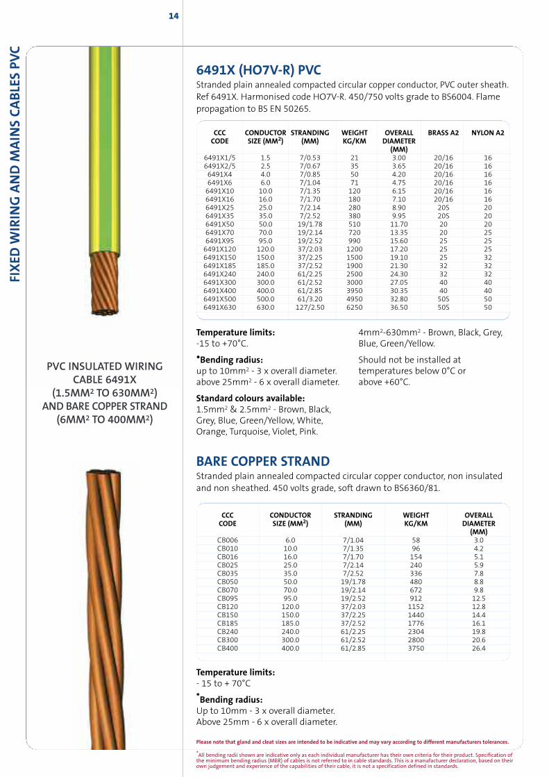
PVC INSULATED WIRINGCABLE 6491X
(1.5MM2 TO 630MM2)AND BARE COPPER STRAND
(6MM2 TO 400MM2)
6491X (HO7V-R) PVCStranded plain annealed compacted circular copper conductor, PVC outer sheath.Ref 6491X. Harmonised code HO7V-R. 450/750 volts grade to BS6004. Flamepropagation to BS EN 50265.
CCC CONDUCTOR STRANDING WEIGHT OVERALL BRASS A2 NYLON A2CODE SIZE (MM2) (MM) KG/KM DIAMETER
(MM)6491X1/5 1.5 7/0.53 21 3.00 20/16 166491X2/5 2.5 7/0.67 35 3.65 20/16 166491X4 4.0 7/0.85 50 4.20 20/16 166491X6 6.0 7/1.04 71 4.75 20/16 166491X10 10.0 7/1.35 120 6.15 20/16 166491X16 16.0 7/1.70 180 7.10 20/16 166491X25 25.0 7/2.14 280 8.90 20S 206491X35 35.0 7/2.52 380 9.95 20S 206491X50 50.0 19/1.78 510 11.70 20 206491X70 70.0 19/2.14 720 13.35 20 256491X95 95.0 19/2.52 990 15.60 25 256491X120 120.0 37/2.03 1200 17.20 25 256491X150 150.0 37/2.25 1500 19.10 25 326491X185 185.0 37/2.52 1900 21.30 32 326491X240 240.0 61/2.25 2500 24.30 32 326491X300 300.0 61/2.52 3000 27.05 40 406491X400 400.0 61/2.85 3950 30.35 40 406491X500 500.0 61/3.20 4950 32.80 50S 506491X630 630.0 127/2.50 6250 36.50 50S 50
Temperature limits:-15 to +70°C.
•Bending radius:up to 10mm2 - 3 x overall diameter.above 25mm2 - 6 x overall diameter.
Standard colours available:1.5mm2 & 2.5mm2 - Brown, Black,Grey, Blue, Green/Yellow, White,Orange, Turquoise, Violet, Pink.
4mm2-630mm2 - Brown, Black, Grey,Blue, Green/Yellow.
Should not be installed attemperatures below 0°C orabove +60°C.
BARE COPPER STRANDStranded plain annealed compacted circular copper conductor, non insulatedand non sheathed. 450 volts grade, soft drawn to BS6360/81.
CCC CONDUCTOR STRANDING WEIGHT OVERALLCODE SIZE (MM2) (MM) KG/KM DIAMETER
(MM)CB006 6.0 7/1.04 58 3.0CB010 10.0 7/1.35 96 4.2CB016 16.0 7/1.70 154 5.1CB025 25.0 7/2.14 240 5.9CB035 35.0 7/2.52 336 7.8CB050 50.0 19/1.78 480 8.8CB070 70.0 19/2.14 672 9.8CB095 95.0 19/2.52 912 12.5CB120 120.0 37/2.03 1152 12.8CB150 150.0 37/2.25 1440 14.4CB185 185.0 37/2.52 1776 16.1CB240 240.0 61/2.25 2304 19.8CB300 300.0 61/2.52 2800 20.6CB400 400.0 61/2.85 3750 26.4
Temperature limits:- 15 to + 70°C
*Bending radius:Up to 10mm - 3 x overall diameter.Above 25mm - 6 x overall diameter.
FIXED
WIR
ING
AND
MAIN
SCABLES
PVC
15
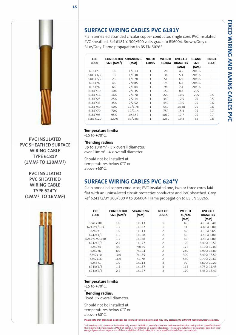
SURFACE WIRING CABLES PVC 6181YPlain annealed stranded circular copper conductor, single core, PVC insulated,PVC sheathed, Ref 6181 Y. 300/500 volts grade to BS6004. Brown/Grey orBlue/Grey. Flame propagation to BS EN 50265.
CCC CONDUCTOR STRANDING NO. OF WEIGHT OVERALL GLAND SINGLECODE SIZE (MM2) (MM) CORES KG/KM DIAMETER SIZE CLEAT
(MM) (MM)6181Y1 1.0 1/1.13 1 28 4.5 20/16 -6181Y1/5 1.5 1/1.38 1 36 5.1 20/16 -6181Y2/5 2.5 1/1.78 1 51 6.0 20/16 -6181Y4 4.0 7/0.85 1 75 6.8 20/16 -6181Y6 6.0 7/1.04 1 98 7.4 20/16 -6181Y10 10.0 7/1.35 1 150 8.8 20S -6181Y16 16.0 7/1.70 1 220 10.5 20S 0.56181Y25 25.0 7/2.14 1 340 12.5 20 0.56181Y35 35.0 7/2.52 1 440 13.5 25 0.66181Y50 50.0 19/1.78 1 540 14.38 25 0.66181Y70 70.0 19/2.14 1 750 15.3 25 0.76181Y95 95.0 19.2.52 1 1010 17.7 25 0.76181Y120 120.0 37/2.03 1 1250 19.3 32 0.8
Temperature limits:-15 to +70°C.
•Bending radius:up to 10mm2 - 3 x overall diameter.over 10mm2 - 4 x overall diameter.
Should not be installed attemperatures below 0°C orabove +60°C.
SURFACE WIRING CABLES PVC 624*YPlain annealed copper conductor, PVC insulated one, two or three cores laidflat with an uninsulated circuit protective conductor and PVC sheathed. Grey.Ref 6241/2/3Y 300/500 V to BS6004. Flame propagation to BS EN 50265.
Temperature limits:-15 to +70°C.
*Bending radius:Fixed 3 x overall diameter.
Should not be installed attemperatures below 0°C orabove +60°C.
CCC CONDUCTOR STRANDING NO. OF WEIGHT OVERALLCODE SIZE (MM2) (MM) CORES KG/KM DIAMETER
(MM) (MM)6241Y1BR 1.0 1/1.13 1 49 4.15 X 5.406241Y1/5BR 1.5 1/1.37 1 51 4.65 X 5.80
6242Y1 1.0 1/1.13 2 69 4.10 X 8.656242Y1/5 1.5 1/1.38 2 85 4.55 X 8.80
6242Y1/5BRBR 1.5 1/1.38 2 85 4.55 X 8.806242Y2/5 2.5 1/1.77 2 120 5.40 X 10.506242Y4 4.0 7/0.85 2 175 6.10 X 12.006242Y6 6.0 7/1.04 2 240 6.90 X 13.806242Y10 10.0 7/1.35 2 390 8.40 X 18.506242Y16 16.0 7.1.70 2 560 9.70 X 20.606243Y1 1.0 1/1.13 3 92 4.60 X 10.206243Y1/5 1.5 1/1.37 3 115 4.75 X 11.456243Y2/5 2.5 1/1.77 3 170 5.45 X 13.40
PVC INSULATEDPVC SHEATHED SURFACE
WIRING CABLETYPE 6181Y
(1MM2 TO 120MM2)
PVC INSULATEDPVC SHEATHEDWIRING CABLETYPE 624*Y
(1MM2 TO 16MM2)
*All bending radii shown are indicative only as each individual manufacturer has their own criteria for their product. Specification ofthe minimum bending radius (MBR) of cables is not referred to in cable standards. This is a manufacturer declaration, based on theirown judgement and experience of the capabilities of their cable, it is not a specification defined in standards.
Please note that gland and cleat sizes are intended to be indicative and may vary according to different manufacturers tolerances.
FIXED
WIR
ING
AND
MAIN
SCABLE
SPV
C16
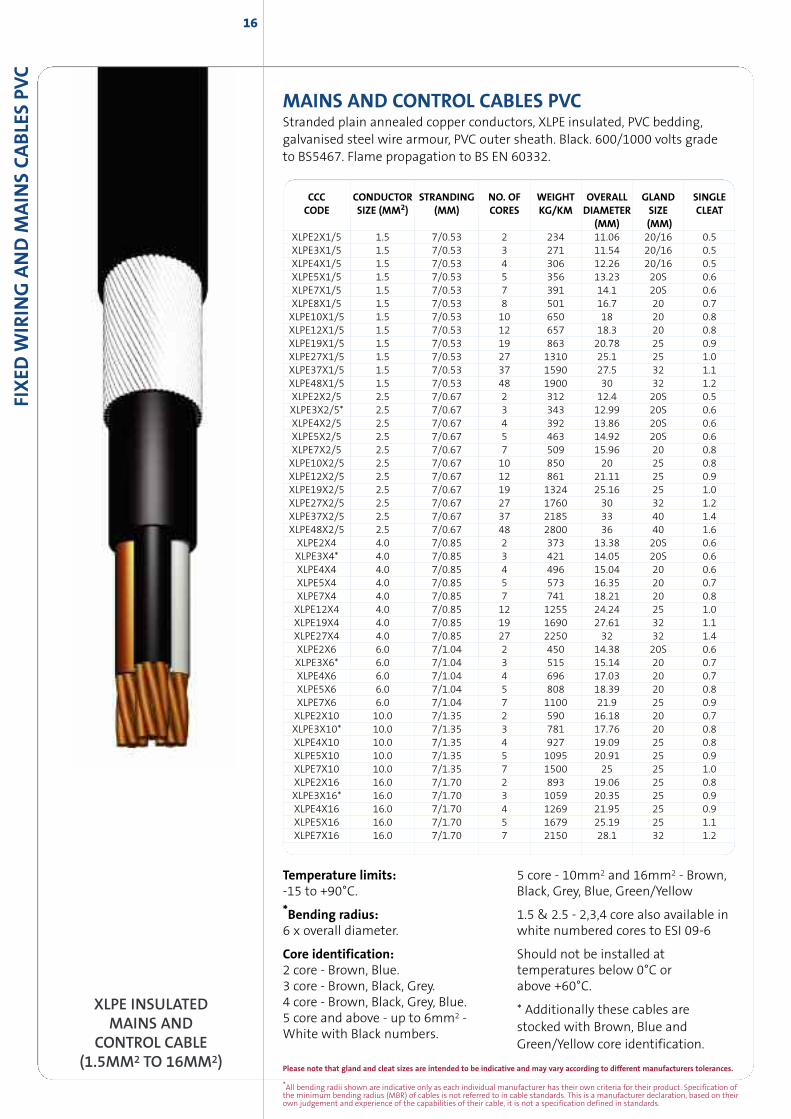
MAINS AND CONTROL CABLES PVCStranded plain annealed copper conductors, XLPE insulated, PVC bedding,galvanised steel wire armour, PVC outer sheath. Black. 600/1000 volts gradeto BS5467. Flame propagation to BS EN 60332.
CCC CONDUCTOR STRANDING NO. OF WEIGHT OVERALL GLAND SINGLECODE SIZE (MM2) (MM) CORES KG/KM DIAMETER SIZE CLEAT
(MM) (MM)XLPE2X1/5 1.5 7/0.53 2 234 11.06 20/16 0.5XLPE3X1/5 1.5 7/0.53 3 271 11.54 20/16 0.5XLPE4X1/5 1.5 7/0.53 4 306 12.26 20/16 0.5XLPE5X1/5 1.5 7/0.53 5 356 13.23 20S 0.6XLPE7X1/5 1.5 7/0.53 7 391 14.1 20S 0.6XLPE8X1/5 1.5 7/0.53 8 501 16.7 20 0.7XLPE10X1/5 1.5 7/0.53 10 650 18 20 0.8XLPE12X1/5 1.5 7/0.53 12 657 18.3 20 0.8XLPE19X1/5 1.5 7/0.53 19 863 20.78 25 0.9XLPE27X1/5 1.5 7/0.53 27 1310 25.1 25 1.0XLPE37X1/5 1.5 7/0.53 37 1590 27.5 32 1.1XLPE48X1/5 1.5 7/0.53 48 1900 30 32 1.2XLPE2X2/5 2.5 7/0.67 2 312 12.4 20S 0.5XLPE3X2/5* 2.5 7/0.67 3 343 12.99 20S 0.6XLPE4X2/5 2.5 7/0.67 4 392 13.86 20S 0.6XLPE5X2/5 2.5 7/0.67 5 463 14.92 20S 0.6XLPE7X2/5 2.5 7/0.67 7 509 15.96 20 0.8XLPE10X2/5 2.5 7/0.67 10 850 20 25 0.8XLPE12X2/5 2.5 7/0.67 12 861 21.11 25 0.9XLPE19X2/5 2.5 7/0.67 19 1324 25.16 25 1.0XLPE27X2/5 2.5 7/0.67 27 1760 30 32 1.2XLPE37X2/5 2.5 7/0.67 37 2185 33 40 1.4XLPE48X2/5 2.5 7/0.67 48 2800 36 40 1.6XLPE2X4 4.0 7/0.85 2 373 13.38 20S 0.6XLPE3X4* 4.0 7/0.85 3 421 14.05 20S 0.6XLPE4X4 4.0 7/0.85 4 496 15.04 20 0.6XLPE5X4 4.0 7/0.85 5 573 16.35 20 0.7XLPE7X4 4.0 7/0.85 7 741 18.21 20 0.8XLPE12X4 4.0 7/0.85 12 1255 24.24 25 1.0XLPE19X4 4.0 7/0.85 19 1690 27.61 32 1.1XLPE27X4 4.0 7/0.85 27 2250 32 32 1.4XLPE2X6 6.0 7/1.04 2 450 14.38 20S 0.6XLPE3X6* 6.0 7/1.04 3 515 15.14 20 0.7XLPE4X6 6.0 7/1.04 4 696 17.03 20 0.7XLPE5X6 6.0 7/1.04 5 808 18.39 20 0.8XLPE7X6 6.0 7/1.04 7 1100 21.9 25 0.9XLPE2X10 10.0 7/1.35 2 590 16.18 20 0.7XLPE3X10* 10.0 7/1.35 3 781 17.76 20 0.8XLPE4X10 10.0 7/1.35 4 927 19.09 25 0.8XLPE5X10 10.0 7/1.35 5 1095 20.91 25 0.9XLPE7X10 10.0 7/1.35 7 1500 25 25 1.0XLPE2X16 16.0 7/1.70 2 893 19.06 25 0.8XLPE3X16* 16.0 7/1.70 3 1059 20.35 25 0.9XLPE4X16 16.0 7/1.70 4 1269 21.95 25 0.9XLPE5X16 16.0 7/1.70 5 1679 25.19 25 1.1XLPE7X16 16.0 7/1.70 7 2150 28.1 32 1.2
XLPE INSULATEDMAINS AND
CONTROL CABLE(1.5MM2 TO 16MM2)
Temperature limits:-15 to +90°C.
*Bending radius:6 x overall diameter.
Core identification:2 core - Brown, Blue.3 core - Brown, Black, Grey.4 core - Brown, Black, Grey, Blue.5 core and above - up to 6mm2 -White with Black numbers.
5 core - 10mm2 and 16mm2 - Brown,Black, Grey, Blue, Green/Yellow
1.5 & 2.5 - 2,3,4 core also available inwhite numbered cores to ESI 09-6
Should not be installed attemperatures below 0°C orabove +60°C.
* Additionally these cables arestocked with Brown, Blue andGreen/Yellow core identification.
Please note that gland and cleat sizes are intended to be indicative and may vary according to different manufacturers tolerances.
*All bending radii shown are indicative only as each individual manufacturer has their own criteria for their product. Specification ofthe minimum bending radius (MBR) of cables is not referred to in cable standards. This is a manufacturer declaration, based on theirown judgement and experience of the capabilities of their cable, it is not a specification defined in standards.
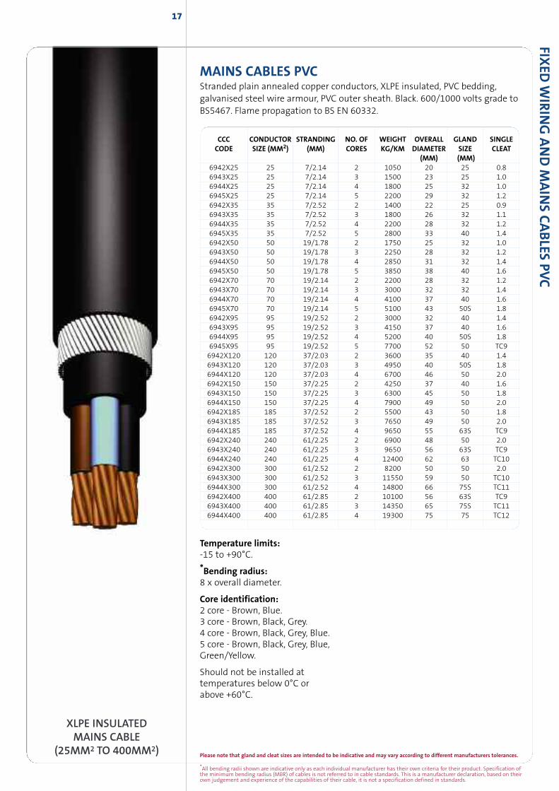
MAINS CABLES PVCStranded plain annealed copper conductors, XLPE insulated, PVC bedding,galvanised steel wire armour, PVC outer sheath. Black. 600/1000 volts grade toBS5467. Flame propagation to BS EN 60332.
17
XLPE INSULATEDMAINS CABLE
(25MM2 TO 400MM2)
FIXED
WIR
ING
AND
MAIN
SCABLES
PVC
Temperature limits:-15 to +90°C.
*Bending radius:8 x overall diameter.
Core identification:2 core - Brown, Blue.3 core - Brown, Black, Grey.4 core - Brown, Black, Grey, Blue.5 core - Brown, Black, Grey, Blue,Green/Yellow.
Should not be installed attemperatures below 0°C orabove +60°C.
CCC CONDUCTOR STRANDING NO. OF WEIGHT OVERALL GLAND SINGLECODE SIZE (MM2) (MM) CORES KG/KM DIAMETER SIZE CLEAT
(MM) (MM)6942X25 25 7/2.14 2 1050 20 25 0.86943X25 25 7/2.14 3 1500 23 25 1.06944X25 25 7/2.14 4 1800 25 32 1.06945X25 25 7/2.14 5 2200 29 32 1.26942X35 35 7/2.52 2 1400 22 25 0.96943X35 35 7/2.52 3 1800 26 32 1.16944X35 35 7/2.52 4 2200 28 32 1.26945X35 35 7/2.52 5 2800 33 40 1.46942X50 50 19/1.78 2 1750 25 32 1.06943X50 50 19/1.78 3 2250 28 32 1.26944X50 50 19/1.78 4 2850 31 32 1.46945X50 50 19/1.78 5 3850 38 40 1.66942X70 70 19/2.14 2 2200 28 32 1.26943X70 70 19/2.14 3 3000 32 32 1.46944X70 70 19/2.14 4 4100 37 40 1.66945X70 70 19/2.14 5 5100 43 50S 1.86942X95 95 19/2.52 2 3000 32 40 1.46943X95 95 19/2.52 3 4150 37 40 1.66944X95 95 19/2.52 4 5200 40 50S 1.86945X95 95 19/2.52 5 7700 52 50 TC96942X120 120 37/2.03 2 3600 35 40 1.46943X120 120 37/2.03 3 4950 40 50S 1.86944X120 120 37/2.03 4 6700 46 50 2.06942X150 150 37/2.25 2 4250 37 40 1.66943X150 150 37/2.25 3 6300 45 50 1.86944X150 150 37/2.25 4 7900 49 50 2.06942X185 185 37/2.52 2 5500 43 50 1.86943X185 185 37/2.52 3 7650 49 50 2.06944X185 185 37/2.52 4 9650 55 63S TC96942X240 240 61/2.25 2 6900 48 50 2.06943X240 240 61/2.25 3 9650 56 63S TC96944X240 240 61/2.25 4 12400 62 63 TC106942X300 300 61/2.52 2 8200 50 50 2.06943X300 300 61/2.52 3 11550 59 50 TC106944X300 300 61/2.52 4 14800 66 75S TC116942X400 400 61/2.85 2 10100 56 63S TC96943X400 400 61/2.85 3 14350 65 75S TC116944X400 400 61/2.85 4 19300 75 75 TC12
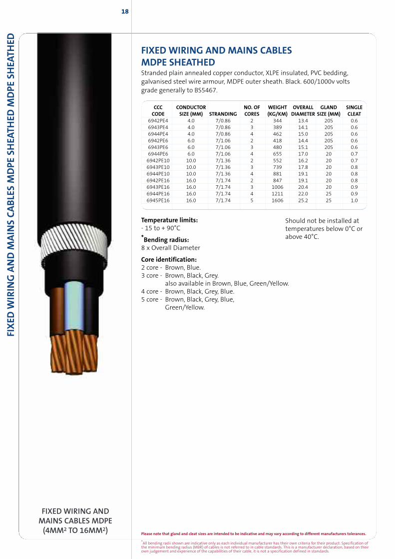
FIXED WIRING AND MAINS CABLESMDPE SHEATHEDStranded plain annealed copper conductor, XLPE insulated, PVC bedding,galvanised steel wire armour, MDPE outer sheath. Black. 600/1000v voltsgrade generally to BS5467.
Temperature limits:- 15 to + 90°C
*Bending radius:8 x Overall Diameter
Core identification:2 core - Brown, Blue.3 core - Brown, Black, Grey.
also available in Brown, Blue, Green/Yellow.4 core - Brown, Black, Grey, Blue.5 core - Brown, Black, Grey, Blue,
Green/Yellow.
Should not be installed attemperatures below 0°C orabove 40°C.
FIXED
WIR
ING
AND
MAIN
SCABLE
SM
DPE
SHEA
THED
MDPE
SHEA
THED
18
FIXED WIRING ANDMAINS CABLES MDPE(4MM2 TO 16MM2)
CCC CONDUCTOR NO. OF WEIGHT OVERALL GLAND SINGLECODE SIZE (MM) STRANDING CORES (KG/KM) DIAMETER SIZE (MM) CLEAT
6942PE4 4.0 7/0.86 2 344 13.4 20S 0.66943PE4 4.0 7/0.86 3 389 14.1 20S 0.66944PE4 4.0 7/0.86 4 462 15.0 20S 0.66942PE6 6.0 7/1.06 2 418 14.4 20S 0.66943PE6 6.0 7/1.06 3 480 15.1 20S 0.66944PE6 6.0 7/1.06 4 655 17.0 20 0.76942PE10 10.0 7/1.36 2 552 16.2 20 0.76943PE10 10.0 7/1.36 3 739 17.8 20 0.86944PE10 10.0 7/1.36 4 881 19.1 20 0.86942PE16 16.0 7/1.74 2 847 19.1 20 0.86943PE16 16.0 7/1.74 3 1006 20.4 20 0.96944PE16 16.0 7/1.74 4 1211 22.0 25 0.96945PE16 16.0 7/1.74 5 1606 25.2 25 1.0
*All bending radii shown are indicative only as each individual manufacturer has their own criteria for their product. Specification ofthe minimum bending radius (MBR) of cables is not referred to in cable standards. This is a manufacturer declaration, based on theirown judgement and experience of the capabilities of their cable, it is not a specification defined in standards.
Please note that gland and cleat sizes are intended to be indicative and may vary according to different manufacturers tolerances.
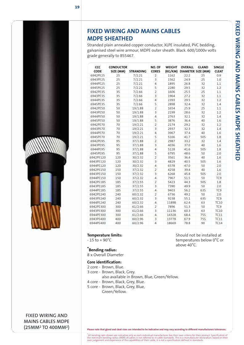
FIXED WIRING AND MAINS CABLESMDPE SHEATHEDStranded plain annealed copper conductor, XLPE insulated, PVC bedding,galvanised steel wire armour, MDPE outer sheath. Black. 600/1000v voltsgrade generally to BS5467.
CCC CONDUCTOR NO. OF WEIGHT OVERALL GLAND SINGLECODE SIZE (MM) STRANDING CORES (KG/KM) DIAMETER SIZE (MM) CLEAT
6942PE25 25 7/2.21 2 1162 22.2 25 0.96943PE25 25 7/2.21 3 1562 24.9 25 1.06944PE25 25 7/2.21 4 1895 26.8 32 1.16945PE25 25 7/2.21 5 2280 29.5 32 1.26942PE35 35 7/2.66 2 1606 25.5 25 1.16943PE35 35 7/2.66 3 1964 27.2 32 1.16944PE35 35 7/2.66 4 2393 29.5 32 1.26945PE35 35 7/2.66 5 2898 32.4 32 1.46942PE50 50 19/1.88 2 1654 25.9 25 1.16943PE50 50 19/1.88 3 2199 28.6 32 1.26944PE50 50 19/1.88 4 2763 32.1 32 1.46945PE50 50 19/1.88 5 3876 36.4 40 1.66942PE70 70 19/2.21 2 2174 29.2 32 1.26943PE70 70 19/2.21 3 2937 32.3 32 1.46944PE70 70 19/2.21 4 3967 37.4 40 1.66945PE70 70 19/2.21 5 5166 41.7 50S 1.86942PE95 95 37/1.88 2 2987 33.2 32 1.46943PE95 95 37/1.88 3 4036 37.0 40 1.66944PE95 95 37/1.88 4 5128 41.6 50S 1.86945PE95 95 37/1.88 5 6795 48.6 50 2.06942PE120 120 30/2.32 2 3561 36.4 40 1.66943PE120 120 30/2.32 3 4829 40.5 50S 1.66944PE120 120 30/2.32 4 6578 47.0 50 2.06942PE150 150 37/2.32 2 4258 39.4 40 1.66943PE150 150 37/2.32 3 6268 45.8 50S 2.06944PE150 150 37/2.32 4 7967 51.5 50 TC96942PE185 185 37/2.55 2 5423 44.3 50S 1.86943PE185 185 37/2.55 3 7390 49.9 50 2.06944PE185 185 37/2.55 4 9403 56.2 63S TC96942PE240 240 60/2.32 2 6736 49.2 50 2.06943PE240 240 60/2.32 3 9238 55.1 63S TC96944PE240 240 60/2.32 4 11898 62.4 63 TC106942PE300 300 61/2.66 2 7896 51.3 50 TC96943PE300 300 61/2.66 3 11136 60.3 63 TC106944PE300 300 61/2.66 4 14328 68.4 75S TC116943PE400 400 60/2.96 3 13778 67.9 75S TC116944PE400 400 60/2.96 4 18669 78.8 90 TC14
FIXED
WIR
ING
AND
MAIN
SCABLES
MDPE
SHEATH
ED
FIXED WIRING ANDMAINS CABLES MDPE(25MM2 TO 400MM2)
Temperature limits: Should not be installed at- 15 to + 90°C temperatures below 0°C or
above 40°C.*Bending radius:8 x Overall Diameter
Core identification:2 core - Brown, Blue.3 core - Brown, Black, Grey.
also available in Brown, Blue, Green/Yellow.4 core - Brown, Black, Grey, Blue.5 core - Brown, Black, Grey, Blue,
Green/Yellow.
19
Please note that gland and cleat sizes are intended to be indicative and may vary according to different manufacturers tolerances.
*All bending radii shown are indicative only as each individual manufacturer has their own criteria for their product. Specification ofthe minimum bending radius (MBR) of cables is not referred to in cable standards. This is a manufacturer declaration, based on theirown judgement and experience of the capabilities of their cable, it is not a specification defined in standards.
*All bending radii shown are indicative only as each individual manufacturer has their own criteria for their product. Specification ofthe minimum bending radius (MBR) of cables is not referred to in cable standards. This is a manufacturer declaration, based on theirown judgement and experience of the capabilities of their cable, it is not a specification defined in standards.
Please note that gland and cleat sizes are intended to be indicative and may vary according to different manufacturers tolerances.
FIXED
WIR
ING
AND
MAIN
SCABLE
SPV
C
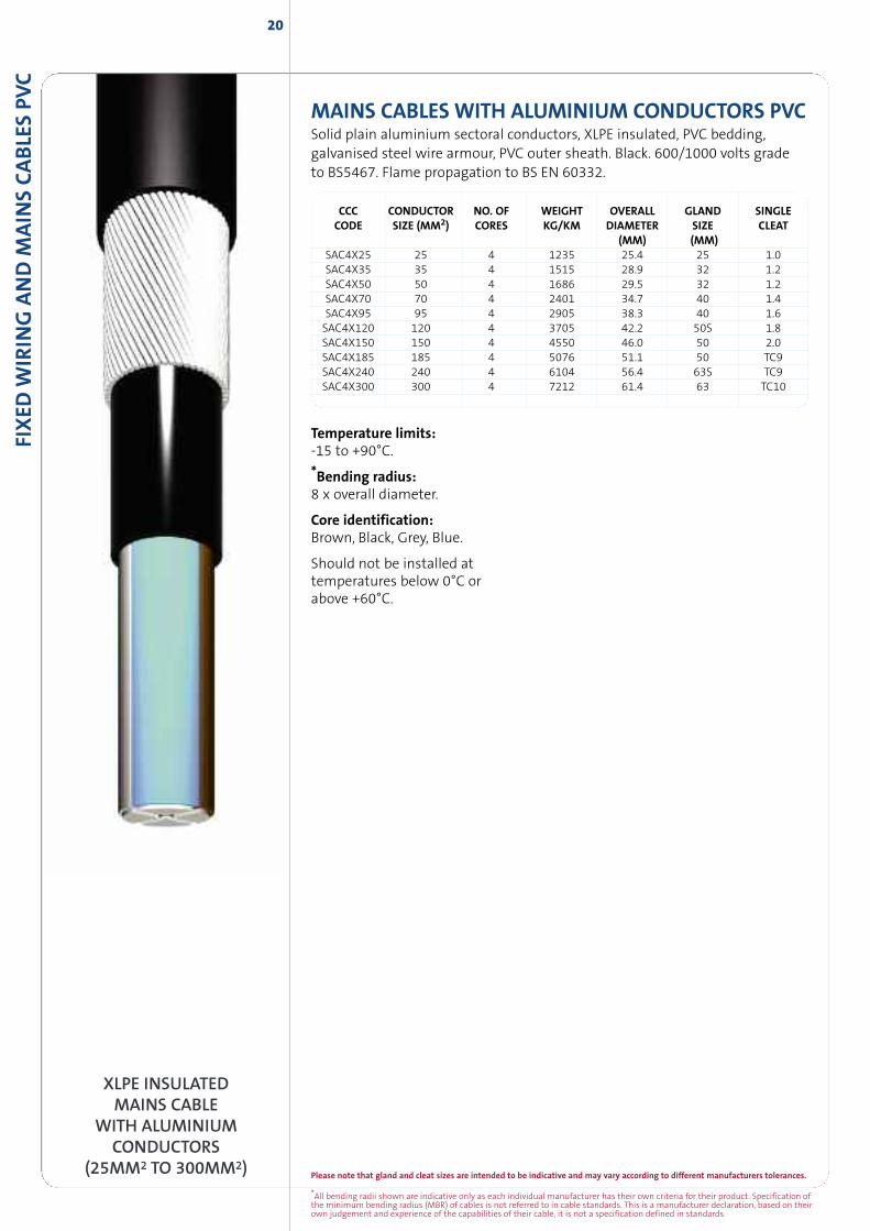
MAINS CABLESWITH ALUMINIUM CONDUCTORS PVCSolid plain aluminium sectoral conductors, XLPE insulated, PVC bedding,galvanised steel wire armour, PVC outer sheath. Black. 600/1000 volts gradeto BS5467. Flame propagation to BS EN 60332.
CCC CONDUCTOR NO. OF WEIGHT OVERALL GLAND SINGLECODE SIZE (MM2) CORES KG/KM DIAMETER SIZE CLEAT
(MM) (MM)SAC4X25 25 4 1235 25.4 25 1.0SAC4X35 35 4 1515 28.9 32 1.2SAC4X50 50 4 1686 29.5 32 1.2SAC4X70 70 4 2401 34.7 40 1.4SAC4X95 95 4 2905 38.3 40 1.6SAC4X120 120 4 3705 42.2 50S 1.8SAC4X150 150 4 4550 46.0 50 2.0SAC4X185 185 4 5076 51.1 50 TC9SAC4X240 240 4 6104 56.4 63S TC9SAC4X300 300 4 7212 61.4 63 TC10
20
XLPE INSULATEDMAINS CABLE
WITH ALUMINIUMCONDUCTORS
(25MM2 TO 300MM2)
Temperature limits:-15 to +90°C.
*Bending radius:8 x overall diameter.
Core identification:Brown, Black, Grey, Blue.
Should not be installed attemperatures below 0°C orabove +60°C.
Please note that gland and cleat sizes are intended to be indicative and may vary according to different manufacturers tolerances.
*All bending radii shown are indicative only as each individual manufacturer has their own criteria for their product. Specification ofthe minimum bending radius (MBR) of cables is not referred to in cable standards. This is a manufacturer declaration, based on theirown judgement and experience of the capabilities of their cable, it is not a specification defined in standards.
FIXED
WIR
ING
AND
MAIN
SCABLES
PVC
21
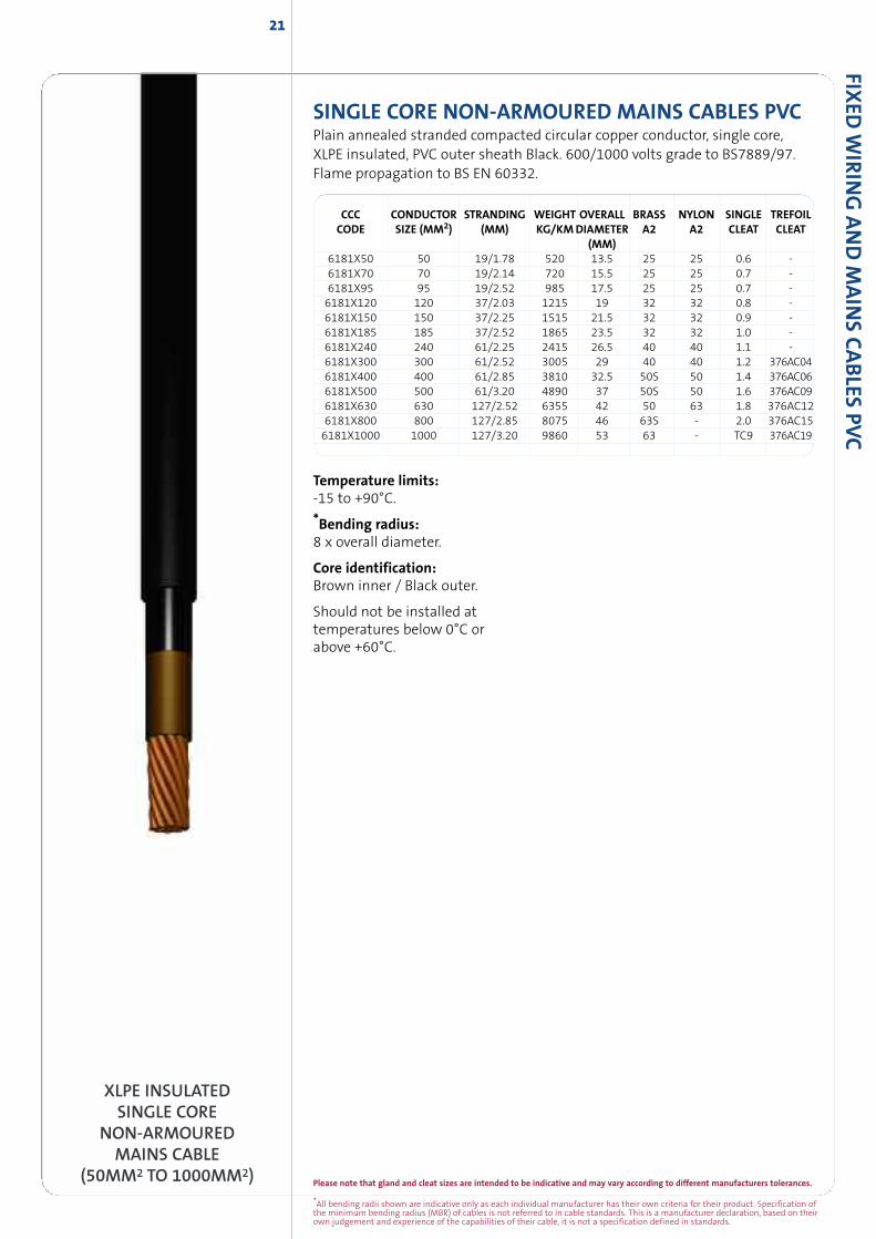
SINGLE CORE NON-ARMOURED MAINS CABLES PVCPlain annealed stranded compacted circular copper conductor, single core,XLPE insulated, PVC outer sheath Black. 600/1000 volts grade to BS7889/97.Flame propagation to BS EN 60332.
XLPE INSULATEDSINGLE CORE
NON-ARMOUREDMAINS CABLE
(50MM2 TO 1000MM2)
Temperature limits:-15 to +90°C.
*Bending radius:8 x overall diameter.
Core identification:Brown inner / Black outer.
Should not be installed attemperatures below 0°C orabove +60°C.
CCC CONDUCTOR STRANDING WEIGHT OVERALL BRASS NYLON SINGLE TREFOILCODE SIZE (MM2) (MM) KG/KMDIAMETER A2 A2 CLEAT CLEAT
(MM)6181X50 50 19/1.78 520 13.5 25 25 0.6 -6181X70 70 19/2.14 720 15.5 25 25 0.7 -6181X95 95 19/2.52 985 17.5 25 25 0.7 -6181X120 120 37/2.03 1215 19 32 32 0.8 -6181X150 150 37/2.25 1515 21.5 32 32 0.9 -6181X185 185 37/2.52 1865 23.5 32 32 1.0 -6181X240 240 61/2.25 2415 26.5 40 40 1.1 -6181X300 300 61/2.52 3005 29 40 40 1.2 376AC046181X400 400 61/2.85 3810 32.5 50S 50 1.4 376AC066181X500 500 61/3.20 4890 37 50S 50 1.6 376AC096181X630 630 127/2.52 6355 42 50 63 1.8 376AC126181X800 800 127/2.85 8075 46 63S - 2.0 376AC156181X1000 1000 127/3.20 9860 53 63 - TC9 376AC19
22
*All bending radii shown are indicative only as each individual manufacturer has their own criteria for their product. Specification ofthe minimum bending radius (MBR) of cables is not referred to in cable standards. This is a manufacturer declaration, based on theirown judgement and experience of the capabilities of their cable, it is not a specification defined in standards.
Please note that gland and cleat sizes are intended to be indicative and may vary according to different manufacturers tolerances.
FIXED
WIR
ING
AND
MAIN
SCABLE
SPV
C
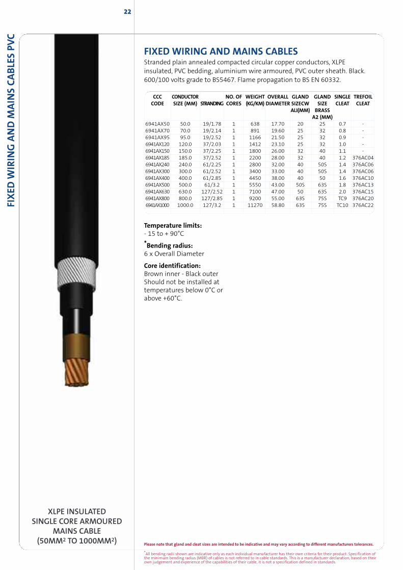
XLPE INSULATEDSINGLE CORE ARMOURED
MAINS CABLE(50MM2 TO 1000MM2)
FIXED WIRING AND MAINS CABLESStranded plain annealed compacted circular copper conductors, XLPEinsulated, PVC bedding, aluminium wire armoured, PVC outer sheath. Black.600/100 volts grade to BS5467. Flame propagation to BS EN 60332.
CCC CONDUCTOR NO. OF WEIGHT OVERALL GLAND GLAND SINGLE TREFOILCODE SIZE (MM) STRANDING CORES (KG/KM) DIAMETER SIZECW SIZE CLEAT CLEAT
ALI(MM) BRASSA2 (MM)
6941AX50 50.0 19/1.78 1 638 17.70 20 25 0.7 -6941AX70 70.0 19/2.14 1 891 19.60 25 32 0.8 -6941AX95 95.0 19/2.52 1 1166 21.50 25 32 0.9 -6941AX120 120.0 37/2.03 1 1412 23.10 25 32 1.0 -6941AX150 150.0 37/2.25 1 1800 26.00 32 40 1.1 -6941AX185 185.0 37/2.52 1 2200 28.00 32 40 1.2 376AC046941AX240 240.0 61/2.25 1 2800 32.00 40 50S 1.4 376AC066941AX300 300.0 61/2.52 1 3400 33.00 40 50S 1.4 376AC066941AX400 400.0 61/2.85 1 4450 38.00 40 50 1.6 376AC106941AX500 500.0 61/3.2 1 5550 43.00 50S 63S 1.8 376AC136941AX630 630.0 127/2.52 1 7100 47.00 50 63S 2.0 376AC156941AX800 800.0 127/2.85 1 9200 55.00 63S 75S TC9 376AC206941AX1000 1000.0 127/3.2 1 11270 58.80 63S 75S TC10 376AC22
Temperature limits:- 15 to + 90°C
*Bending radius:6 x Overall Diameter
Core identification:Brown inner - Black outerShould not be installed attemperatures below 0°C orabove +60°C.
23
Please note that gland and cleat sizes are intended to be indicative and may vary according to different manufacturers tolerances.
*All bending radii shown are indicative only as each individual manufacturer has their own criteria for their product. Specification ofthe minimum bending radius (MBR) of cables is not referred to in cable standards. This is a manufacturer declaration, based on theirown judgement and experience of the capabilities of their cable, it is not a specification defined in standards.
FIXED
WIR
ING
AND
MAIN
SCABLES
PVC
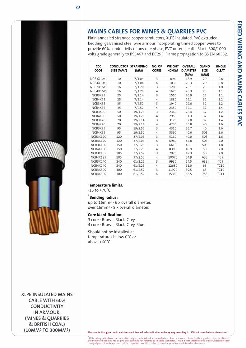
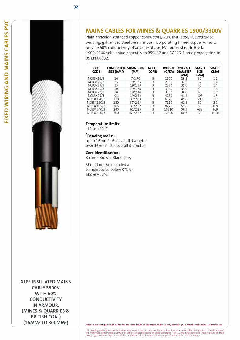
MAINS CABLES FOR MINES & QUARRIES PVCPlain annealed stranded copper conductors, XLPE insulated, PVC extrudedbedding, galvanised steel wire armour incorporating tinned copper wires toprovide 60% conductivity of any one phase, PVC outer sheath. Black. 600/1000volts grade generally to BS5467 and BC295. Flame propagation to BS EN 60332.
CCC CONDUCTOR STRANDING NO. OF WEIGHT OVERALL GLAND SINGLECODE SIZE (MM2) (MM) CORES KG/KM DIAMETER SIZE CLEAT
(MM) (MM)NCB3X10/1 10 7/1.04 3 896 18.9 20 0.8NCB4X10/1 10 7/1.04 4 1038 20.3 20 0.8NCB3X16/1 16 7/1.70 3 1205 23.1 25 1.0NCB4X16/1 16 7/1.70 4 1675 26.3 25 1.1NCB3X25 25 7/2.14 3 1550 26.9 25 1.1NCB4X25 25 7/2.14 4 1880 29.1 32 1.2NCB3X35 35 7/2.52 3 1940 29.6 32 1.2NCB4X35 35 7/2.52 4 2350 32.1 32 1.4NCB3X50 50 19/1.78 3 2360 28.4 32 1.2NCB4X50 50 19/1.78 4 2950 31.3 32 1.4NCB3X70 70 19/2.14 3 3120 32.0 32 1.4NCB4X70 70 19/2.14 4 4230 36.8 40 1.6NCB3X95 95 19/2.52 3 4310 36.7 40 1.6NCB4X95 95 19/2.52 4 5390 40.6 50S 1.6NCB3X120 120 37/2.03 3 5160 40.0 50S 1.6NCB4X120 120 37/2.03 4 6980 45.8 50S 2.0NCB3X150 150 37/2.25 3 6610 45.1 50S 1.8NCB4X150 150 37/2.25 4 8300 49.9 50 2.0NCB3X185 185 37/2.52 3 7920 49.3 50 2.0NCB4X185 185 37/2.52 4 10070 54.9 63S TC9NCB3X240 240 61/2.25 3 9930 54.5 63S TC9NCB4X240 240 61/2.25 4 12680 61.0 63 TC10NCB3X300 300 61/2.52 3 11970 59.5 63 TC10NCB4X300 300 61/2.52 4 15380 66.5 75S TC11
XLPE INSULATED MAINSCABLE WITH 60%CONDUCTIVITYIN ARMOUR.
(MINES & QUARRIES& BRITISH COAL)
(10MM2 TO 300MM2)
Temperature limits:-15 to +70°C.
*Bending radius:up to 16mm2 - 6 x overall diameter.over 16mm2 - 8 x overall diameter.
Core identification:3 core - Brown, Black, Grey.4 core - Brown, Black, Grey, Blue.
Should not be installed attemperatures below 0°C orabove +60°C.
24
*All bending radii shown are indicative only as each individual manufacturer has their own criteria for their product. Specification ofthe minimum bending radius (MBR) of cables is not referred to in cable standards. This is a manufacturer declaration, based on theirown judgement and experience of the capabilities of their cable, it is not a specification defined in standards.
Please note that gland and cleat sizes are intended to be indicative and may vary according to different manufacturers tolerances.
FIXED
WIR
ING
AND
MAIN
SCABLE
SPV
C
Temperature limits:-15 to +90°C.
*Bending radius:12 x overall diameter.
Core identification:White with Black numbers.
Should not be installed attemperatures below 0°C orabove +60°C.
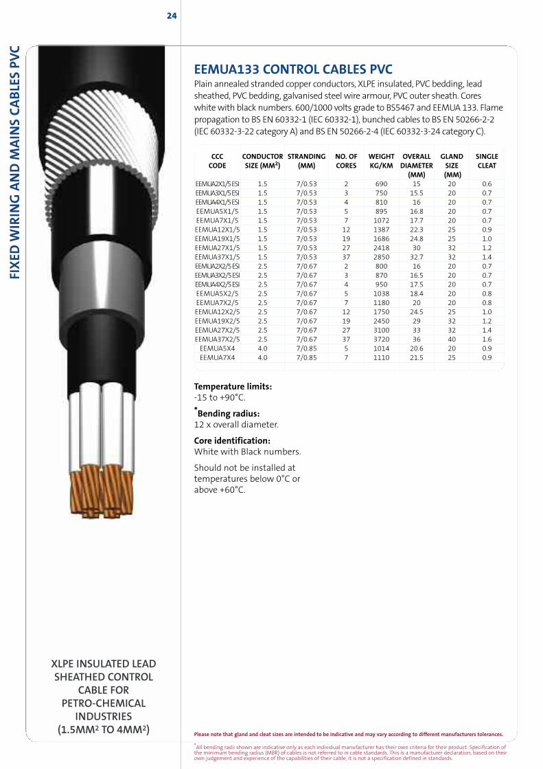
XLPE INSULATED LEADSHEATHED CONTROL
CABLE FORPETRO-CHEMICAL
INDUSTRIES(1.5MM2 TO 4MM2)
EEMUA133 CONTROL CABLES PVCPlain annealed stranded copper conductors, XLPE insulated, PVC bedding, leadsheathed, PVCbedding, galvanised steel wire armour, PVC outer sheath. Coreswhitewith black numbers. 600/1000 volts grade to BS5467 and EEMUA 133. Flamepropagation to BS EN 60332-1 (IEC 60332-1), bunched cables to BS EN 50266-2-2(IEC 60332-3-22 category A) and BS EN 50266-2-4 (IEC 60332-3-24 category C).
CCC CONDUCTOR STRANDING NO. OF WEIGHT OVERALL GLAND SINGLECODE SIZE (MM2) (MM) CORES KG/KM DIAMETER SIZE CLEAT
(MM) (MM)EEMUA2X1/5ESI 1.5 7/0.53 2 690 15 20 0.6EEMUA3X1/5ESI 1.5 7/0.53 3 750 15.5 20 0.7EEMUA4X1/5ESI 1.5 7/0.53 4 810 16 20 0.7EEMUA5X1/5 1.5 7/0.53 5 895 16.8 20 0.7EEMUA7X1/5 1.5 7/0.53 7 1072 17.7 20 0.7EEMUA12X1/5 1.5 7/0.53 12 1387 22.3 25 0.9EEMUA19X1/5 1.5 7/0.53 19 1686 24.8 25 1.0EEMUA27X1/5 1.5 7/0.53 27 2418 30 32 1.2EEMUA37X1/5 1.5 7/0.53 37 2850 32.7 32 1.4EEMUA2X2/5ESI 2.5 7/0.67 2 800 16 20 0.7EEMUA3X2/5ESI 2.5 7/0.67 3 870 16.5 20 0.7EEMUA4X2/5ESI 2.5 7/0.67 4 950 17.5 20 0.7EEMUA5X2/5 2.5 7/0.67 5 1038 18.4 20 0.8EEMUA7X2/5 2.5 7/0.67 7 1180 20 20 0.8EEMUA12X2/5 2.5 7/0.67 12 1750 24.5 25 1.0EEMUA19X2/5 2.5 7/0.67 19 2450 29 32 1.2EEMUA27X2/5 2.5 7/0.67 27 3100 33 32 1.4EEMUA37X2/5 2.5 7/0.67 37 3720 36 40 1.6EEMUA5X4 4.0 7/0.85 5 1014 20.6 20 0.9EEMUA7X4 4.0 7/0.85 7 1110 21.5 25 0.9
25
Please note that gland and cleat sizes are intended to be indicative and may vary according to different manufacturers tolerances.
*All bending radii shown are indicative only as each individual manufacturer has their own criteria for their product. Specification ofthe minimum bending radius (MBR) of cables is not referred to in cable standards. This is a manufacturer declaration, based on theirown judgement and experience of the capabilities of their cable, it is not a specification defined in standards.
FIXED
WIR
ING
AND
MAIN
SCABLES
PVC
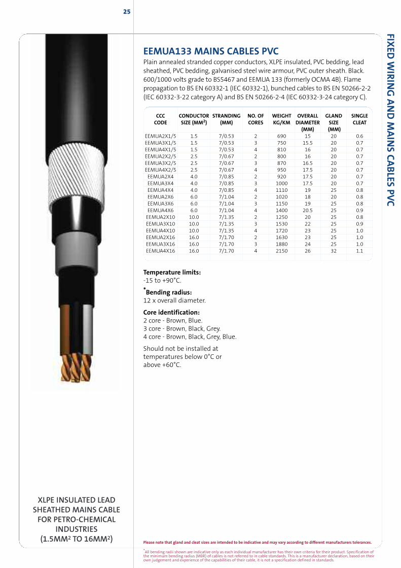
XLPE INSULATED LEADSHEATHED MAINS CABLEFOR PETRO-CHEMICAL
INDUSTRIES(1.5MM2 TO 16MM2)
CCC CONDUCTOR STRANDING NO. OF WEIGHT OVERALL GLAND SINGLECODE SIZE (MM2) (MM) CORES KG/KM DIAMETER SIZE CLEAT
(MM) (MM)EEMUA2X1/5 1.5 7/0.53 2 690 15 20 0.6EEMUA3X1/5 1.5 7/0.53 3 750 15.5 20 0.7EEMUA4X1/5 1.5 7/0.53 4 810 16 20 0.7EEMUA2X2/5 2.5 7/0.67 2 800 16 20 0.7EEMUA3X2/5 2.5 7/0.67 3 870 16.5 20 0.7EEMUA4X2/5 2.5 7/0.67 4 950 17.5 20 0.7EEMUA2X4 4.0 7/0.85 2 920 17.5 20 0.7EEMUA3X4 4.0 7/0.85 3 1000 17.5 20 0.7EEMUA4X4 4.0 7/0.85 4 1110 19 25 0.8EEMUA2X6 6.0 7/1.04 2 1020 18 20 0.8EEMUA3X6 6.0 7/1.04 3 1150 19 25 0.8EEMUA4X6 6.0 7/1.04 4 1400 20.5 25 0.9EEMUA2X10 10.0 7/1.35 2 1250 20 25 0.8EEMUA3X10 10.0 7/1.35 3 1530 22 25 0.9EEMUA4X10 10.0 7/1.35 4 1720 23 25 1.0EEMUA2X16 16.0 7/1.70 2 1630 23 25 1.0EEMUA3X16 16.0 7/1.70 3 1880 24 25 1.0EEMUA4X16 16.0 7/1.70 4 2150 26 32 1.1
Temperature limits:-15 to +90°C.
*Bending radius:12 x overall diameter.
Core identification:2 core - Brown, Blue.3 core - Brown, Black, Grey.4 core - Brown, Black, Grey, Blue.
Should not be installed attemperatures below 0°C orabove +60°C.
EEMUA133 MAINS CABLES PVCPlain annealed stranded copper conductors, XLPE insulated, PVC bedding, leadsheathed, PVC bedding, galvanised steel wire armour, PVC outer sheath. Black.600/1000 volts grade to BS5467 and EEMUA 133 (formerly OCMA 4B). Flamepropagation to BS EN 60332-1 (IEC 60332-1), bunched cables to BS EN 50266-2-2(IEC 60332-3-22 category A) and BS EN 50266-2-4 (IEC 60332-3-24 category C).
26
*All bending radii shown are indicative only as each individual manufacturer has their own criteria for their product. Specification ofthe minimum bending radius (MBR) of cables is not referred to in cable standards. This is a manufacturer declaration, based on theirown judgement and experience of the capabilities of their cable, it is not a specification defined in standards.
Please note that gland and cleat sizes are intended to be indicative and may vary according to different manufacturers tolerances.
FIXED
WIR
ING
AND
MAIN
SCABLE
SPV
C
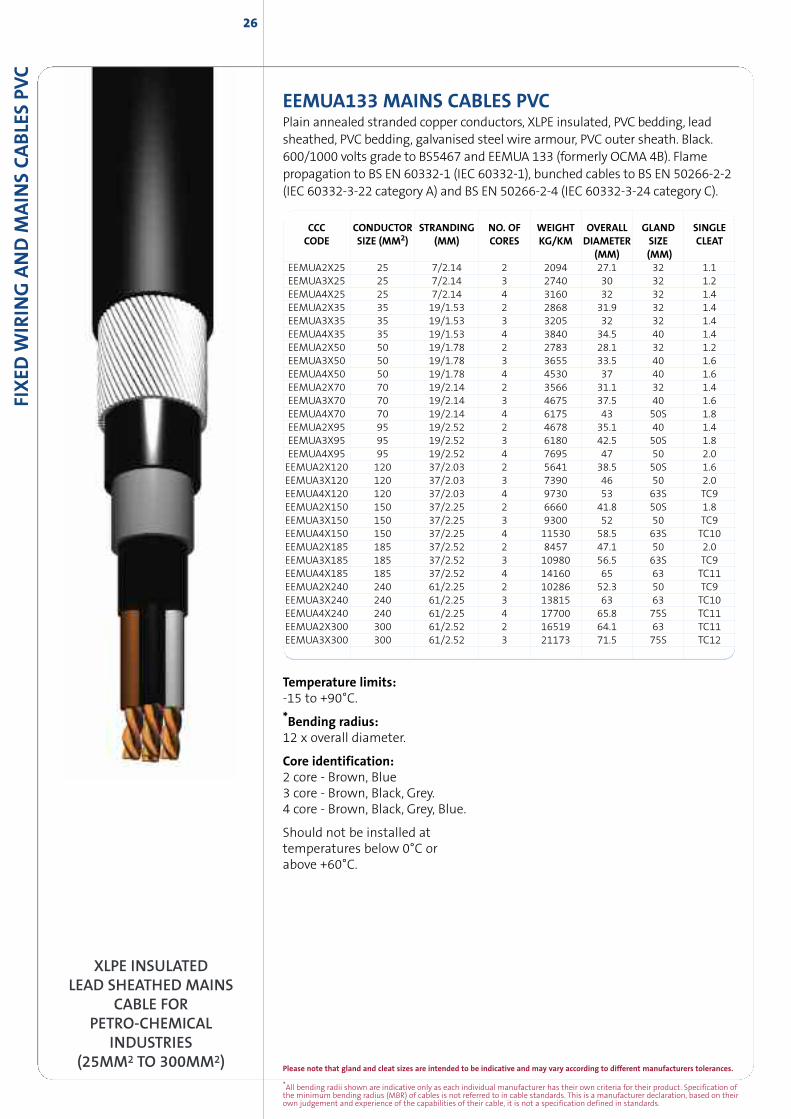
XLPE INSULATEDLEAD SHEATHED MAINS
CABLE FORPETRO-CHEMICAL
INDUSTRIES(25MM2 TO 300MM2)
CCC CONDUCTOR STRANDING NO. OF WEIGHT OVERALL GLAND SINGLECODE SIZE (MM2) (MM) CORES KG/KM DIAMETER SIZE CLEAT
(MM) (MM)EEMUA2X25 25 7/2.14 2 2094 27.1 32 1.1EEMUA3X25 25 7/2.14 3 2740 30 32 1.2EEMUA4X25 25 7/2.14 4 3160 32 32 1.4EEMUA2X35 35 19/1.53 2 2868 31.9 32 1.4EEMUA3X35 35 19/1.53 3 3205 32 32 1.4EEMUA4X35 35 19/1.53 4 3840 34.5 40 1.4EEMUA2X50 50 19/1.78 2 2783 28.1 32 1.2EEMUA3X50 50 19/1.78 3 3655 33.5 40 1.6EEMUA4X50 50 19/1.78 4 4530 37 40 1.6EEMUA2X70 70 19/2.14 2 3566 31.1 32 1.4EEMUA3X70 70 19/2.14 3 4675 37.5 40 1.6EEMUA4X70 70 19/2.14 4 6175 43 50S 1.8EEMUA2X95 95 19/2.52 2 4678 35.1 40 1.4EEMUA3X95 95 19/2.52 3 6180 42.5 50S 1.8EEMUA4X95 95 19/2.52 4 7695 47 50 2.0EEMUA2X120 120 37/2.03 2 5641 38.5 50S 1.6EEMUA3X120 120 37/2.03 3 7390 46 50 2.0EEMUA4X120 120 37/2.03 4 9730 53 63S TC9EEMUA2X150 150 37/2.25 2 6660 41.8 50S 1.8EEMUA3X150 150 37/2.25 3 9300 52 50 TC9EEMUA4X150 150 37/2.25 4 11530 58.5 63S TC10EEMUA2X185 185 37/2.52 2 8457 47.1 50 2.0EEMUA3X185 185 37/2.52 3 10980 56.5 63S TC9EEMUA4X185 185 37/2.52 4 14160 65 63 TC11EEMUA2X240 240 61/2.25 2 10286 52.3 50 TC9EEMUA3X240 240 61/2.25 3 13815 63 63 TC10EEMUA4X240 240 61/2.25 4 17700 65.8 75S TC11EEMUA2X300 300 61/2.52 2 16519 64.1 63 TC11EEMUA3X300 300 61/2.52 3 21173 71.5 75S TC12
EEMUA133 MAINS CABLES PVCPlain annealed stranded copper conductors, XLPE insulated, PVC bedding, leadsheathed, PVC bedding, galvanised steel wire armour, PVC outer sheath. Black.600/1000 volts grade to BS5467 and EEMUA 133 (formerly OCMA 4B). Flamepropagation to BS EN 60332-1 (IEC 60332-1), bunched cables to BS EN 50266-2-2(IEC 60332-3-22 category A) and BS EN 50266-2-4 (IEC 60332-3-24 category C).
Temperature limits:-15 to +90°C.
*Bending radius:12 x overall diameter.
Core identification:2 core - Brown, Blue3 core - Brown, Black, Grey.4 core - Brown, Black, Grey, Blue.
Should not be installed attemperatures below 0°C orabove +60°C.
27
Please note that gland and cleat sizes are intended to be indicative and may vary according to different manufacturers tolerances.
*All bending radii shown are indicative only as each individual manufacturer has their own criteria for their product. Specification ofthe minimum bending radius (MBR) of cables is not referred to in cable standards. This is a manufacturer declaration, based on theirown judgement and experience of the capabilities of their cable, it is not a specification defined in standards.
FIXED
WIR
ING
AND
MAIN
SCABLES
PVC
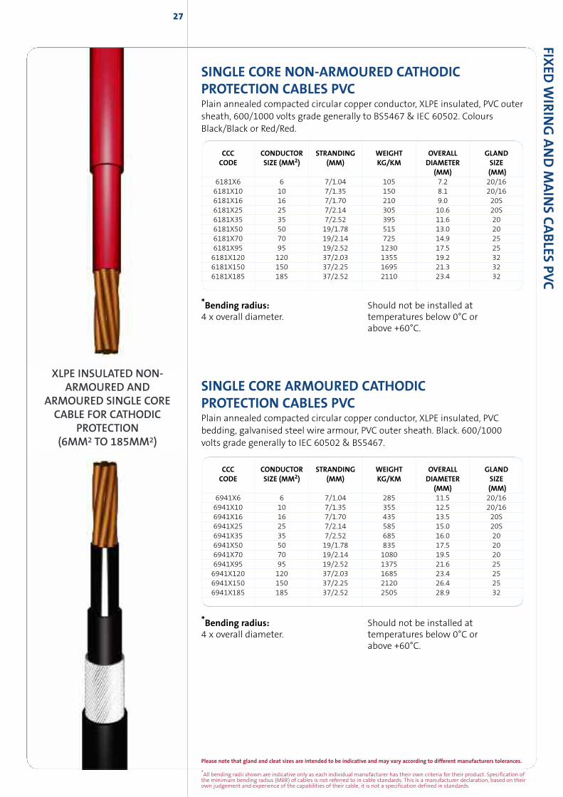
SINGLE CORE NON-ARMOURED CATHODICPROTECTION CABLES PVCPlain annealed compacted circular copper conductor, XLPE insulated, PVC outersheath, 600/1000 volts grade generally to BS5467 & IEC 60502. ColoursBlack/Black or Red/Red.
CCC CONDUCTOR STRANDING WEIGHT OVERALL GLANDCODE SIZE (MM2) (MM) KG/KM DIAMETER SIZE
(MM) (MM)6181X6 6 7/1.04 105 7.2 20/166181X10 10 7/1.35 150 8.1 20/166181X16 16 7/1.70 210 9.0 20S6181X25 25 7/2.14 305 10.6 20S6181X35 35 7/2.52 395 11.6 206181X50 50 19/1.78 515 13.0 206181X70 70 19/2.14 725 14.9 256181X95 95 19/2.52 1230 17.5 256181X120 120 37/2.03 1355 19.2 326181X150 150 37/2.25 1695 21.3 326181X185 185 37/2.52 2110 23.4 32
SINGLE CORE ARMOURED CATHODICPROTECTION CABLES PVCPlain annealed compacted circular copper conductor, XLPE insulated, PVCbedding, galvanised steel wire armour, PVC outer sheath. Black. 600/1000volts grade generally to IEC 60502 & BS5467.
CCC CONDUCTOR STRANDING WEIGHT OVERALL GLANDCODE SIZE (MM2) (MM) KG/KM DIAMETER SIZE
(MM) (MM)6941X6 6 7/1.04 285 11.5 20/166941X10 10 7/1.35 355 12.5 20/166941X16 16 7/1.70 435 13.5 20S6941X25 25 7/2.14 585 15.0 20S6941X35 35 7/2.52 685 16.0 206941X50 50 19/1.78 835 17.5 206941X70 70 19/2.14 1080 19.5 206941X95 95 19/2.52 1375 21.6 256941X120 120 37/2.03 1685 23.4 256941X150 150 37/2.25 2120 26.4 256941X185 185 37/2.52 2505 28.9 32
XLPE INSULATED NON-ARMOURED AND
ARMOURED SINGLE CORECABLE FOR CATHODIC
PROTECTION(6MM2 TO 185MM2)
*Bending radius:4 x overall diameter.
Should not be installed attemperatures below 0°C orabove +60°C.
*Bending radius:4 x overall diameter.
Should not be installed attemperatures below 0°C orabove +60°C.
28
*All bending radii shown are indicative only as each individual manufacturer has their own criteria for their product. Specification ofthe minimum bending radius (MBR) of cables is not referred to in cable standards. This is a manufacturer declaration, based on theirown judgement and experience of the capabilities of their cable, it is not a specification defined in standards.
Please note that gland and cleat sizes are intended to be indicative and may vary according to different manufacturers tolerances.
FIXED
WIR
ING
AND
MAIN
SCABLE
SPV
C
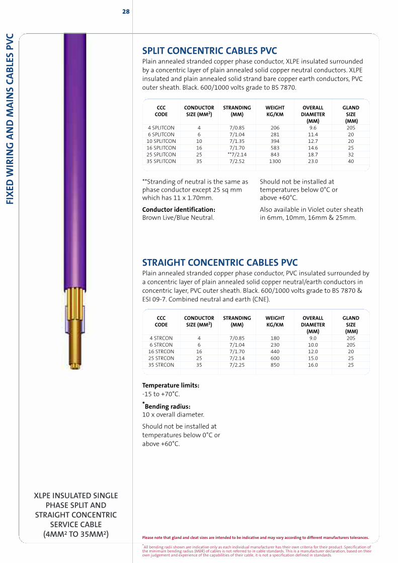
SPLIT CONCENTRIC CABLES PVCPlain annealed stranded copper phase conductor, XLPE insulated surroundedby a concentric layer of plain annealed solid copper neutral conductors. XLPEinsulated and plain annealed solid strand bare copper earth conductors, PVCouter sheath. Black. 600/1000 volts grade to BS 7870.
CCC CONDUCTOR STRANDING WEIGHT OVERALL GLANDCODE SIZE (MM2) (MM) KG/KM DIAMETER SIZE
(MM) (MM)4 SPLITCON 4 7/0.85 206 9.6 20S6 SPLITCON 6 7/1.04 281 11.4 2010 SPLITCON 10 7/1.35 394 12.7 2016 SPLITCON 16 7/1.70 583 14.6 2525 SPLITCON 25 **7/2.14 843 18.7 3235 SPLITCON 35 7/2.52 1300 23.0 40
STRAIGHT CONCENTRIC CABLES PVCPlain annealed stranded copper phase conductor, PVC insulated surrounded bya concentric layer of plain annealed solid copper neutral/earth conductors inconcentric layer, PVC outer sheath. Black. 600/1000 volts grade to BS 7870 &ESI 09-7. Combined neutral and earth (CNE).
CCC CONDUCTOR STRANDING WEIGHT OVERALL GLANDCODE SIZE (MM2) (MM) KG/KM DIAMETER SIZE
(MM) (MM)4 STRCON 4 7/0.85 180 9.0 20S6 STRCON 6 7/1.04 230 10.0 20S16 STRCON 16 7/1.70 440 12.0 2025 STRCON 25 7/2.14 600 15.0 2535 STRCON 35 7/2.25 850 16.0 25
XLPE INSULATED SINGLEPHASE SPLIT AND
STRAIGHT CONCENTRICSERVICE CABLE
(4MM2 TO 35MM2)
**Stranding of neutral is the same asphase conductor except 25 sq mmwhich has 11 x 1.70mm.
Conductor identification:Brown Live/Blue Neutral.
Should not be installed attemperatures below 0°C orabove +60°C.
Also available in Violet outer sheathin 6mm, 10mm, 16mm & 25mm.
Temperature limits:-15 to +70°C.
*Bending radius:10 x overall diameter.
Should not be installed attemperatures below 0°C orabove +60°C.
29
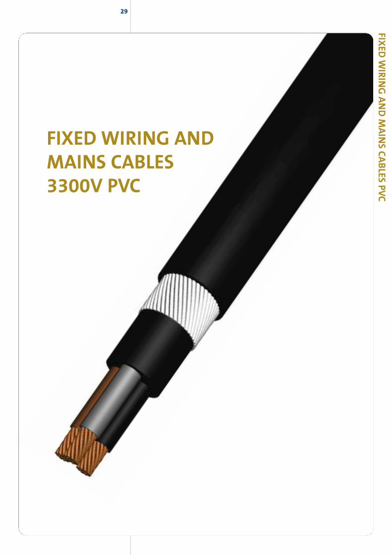
FIXED WIRING ANDMAINS CABLES3300V PVC
FIXED
WIR
ING
AND
MAIN
SCABLES
PVC
30
*All bending radii shown are indicative only as each individual manufacturer has their own criteria for their product. Specification ofthe minimum bending radius (MBR) of cables is not referred to in cable standards. This is a manufacturer declaration, based on theirown judgement and experience of the capabilities of their cable, it is not a specification defined in standards.
Please note that gland and cleat sizes are intended to be indicative and may vary according to different manufacturers tolerances.
SINGLE CORE ARMOURED MAINS CABLES 1900/3300VStranded plain annealed copper conductors, XLPE insulated, PVC bedding,Aluminium wire armour, PVC outer sheath. Black. 1900/3300 volts grade toBS5467. Flame propagation to BS EN 60332.
XLPE INSULATEDSINGLE CORE ARMOURED
MAINS CABLE3300V
(120MM2 TO 630MM2)
Temperature limits:-25 to +90°C.
*Bending radius:6 x overall diameter.
Core identification:Brown inner/Black outer.
Should not be installed attemperatures below 0°C orabove +60°C.
FIXED
WIR
ING
AND
MAIN
SCABLE
SPV
C
CCC CONDUCTOR STRANDING NO. OF WEIGHT OVERALL GLAND SINGLE TREFOILCODE SIZE (MM2) (MM) CORES KG/KM DIAMETER SIZE CLEAT CLEAT
(MM) (MM)6941AX120/3 120 37/2.03 1 1490 23.2 25 1.2 -6941AX150/3 150 37/2.25 1 1870 26.3 32 1.2 -6941AX185/3 185 37/2.52 1 2290 28.7 32 1.4 376AC046941AX240/3 240 61/2.25 1 2880 31.4 40 1.4 376AC056941AX300/3 300 61/2.52 1 3520 34.1 40 1.8 376AC076941AX400/3 400 61/2.85 1 4520 38.9 50S 1.8 376AC106941AX500/3 500 61/3.20 1 5680 42.8 50S 1.8 376AC126941AX630/3 630 127/2.52 1 7120 47.3 50 2.0 376AC15
31
Please note that gland and cleat sizes are intended to be indicative and may vary according to different manufacturers tolerances.
*All bending radii shown are indicative only as each individual manufacturer has their own criteria for their product. Specification ofthe minimum bending radius (MBR) of cables is not referred to in cable standards. This is a manufacturer declaration, based on theirown judgement and experience of the capabilities of their cable, it is not a specification defined in standards.
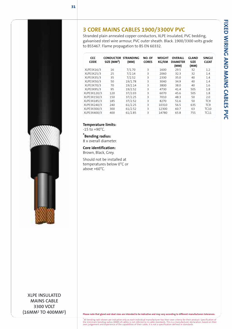
XLPE INSULATEDMAINS CABLE3300 VOLT
(16MM2 TO 400MM2)
3 CORE MAINS CABLES 1900/3300V PVCStranded plain annealed copper conductors, XLPE insulated, PVC bedding,galvanised steel wire armour, PVC outer sheath. Black. 1900/3300 volts gradeto BS5467. Flame propagation to BS EN 60332.
CCC CONDUCTOR STRANDING NO. OF WEIGHT OVERALL GLAND SINGLECODE SIZE (MM2) (MM) CORES KG/KM DIAMETER SIZE CLEAT
(MM) (MM)XLPE3X16/3 16 7/1.70 3 1600 29.5 32 1.2XLPE3X25/3 25 7/2.14 3 2060 32.3 32 1.4XLPE3X35/3 35 7/2.52 3 2330 35.0 40 1.4XLPE3X50/3 50 19/1.78 3 3040 34.9 40 1.4XLPE3X70/3 70 19/2.14 3 3800 38.0 40 1.6XLPE3X95/3 95 19/2.52 3 4730 41.4 50S 1.8XLPE3X120/3 120 37/2.03 3 6070 45.6 50S 1.8XLPE3X150/3 150 37/2.25 3 7010 48.3 50 2.0XLPE3X185/3 185 37/2.52 3 8270 51.6 50 TC9XLPE3X240/3 240 61/2.25 3 10310 56.5 63S TC9XLPE3X300/3 300 61/2.52 3 12300 60.7 63 TC10XLPE3X400/3 400 61/2.85 3 14780 65.8 75S TC11
Temperature limits:-15 to +90°C.
*Bending radius:8 x overall diameter.
Core identification:Brown, Black, Grey.
Should not be installed attemperatures below 0°C orabove +60°C.
FIXED
WIR
ING
AND
MAIN
SCABLES
PVC
32
*All bending radii shown are indicative only as each individual manufacturer has their own criteria for their product. Specification ofthe minimum bending radius (MBR) of cables is not referred to in cable standards. This is a manufacturer declaration, based on theirown judgement and experience of the capabilities of their cable, it is not a specification defined in standards.
Please note that gland and cleat sizes are intended to be indicative and may vary according to different manufacturers tolerances.
FIXED
WIR
ING
AND
MAIN
SCABLE
SPV
C
MAINS CABLES FOR MINES & QUARRIES 1900/3300VPlain annealed stranded copper conductors, XLPE insulated, PVC extrudedbedding, galvanised steel wire armour incorporating tinned copper wires toprovide 60% conductivity of any one phase, PVC outer sheath. Black.1900/3300 volts grade generally to BS5467 and BC295. Flame propagation toBS EN 60332.
CCC CONDUCTOR STRANDING NO. OF WEIGHT OVERALL GLAND SINGLECODE SIZE (MM2) (MM) CORES KG/KM DIAMETER SIZE CLEAT
(MM) (MM)NCB3X16/3 16 7/1.70 3 1600 29.5 32 1.2NCB3X25/3 25 19/1.35 3 2060 32.3 32 1.4NCB3X35/3 35 19/1.53 3 2330 35.0 40 1.4NCB3X50/3 50 19/1.78 3 3040 34.9 40 1.4NCB3X70/3 70 19/2.14 3 3800 38.0 40 1.6NCB3X95/3 95 19/2.52 3 4730 41.4 50S 1.8NCB3X120/3 120 37/2.03 3 6070 45.6 50S 1.8NCB3X150/3 150 37/2.25 3 7110 48.3 50 2.0NCB3X185/3 185 37/2.52 3 8270 51.6 50 TC9NCB3X240/3 240 61/2.25 3 10310 56.5 63S TC9NCB3X300/3 300 61/2.52 3 12300 60.7 63 TC10
XLPE INSULATED MAINSCABLE 3300VWITH 60%
CONDUCTIVITYIN ARMOUR.
(MINES & QUARRIES &BRITISH COAL)
(16MM2 TO 300MM2)
Temperature limits:-15 to +70°C.
*Bending radius:up to 16mm2 - 6 x overall diameter.over 16mm2 - 8 x overall diameter.
Core identification:3 core - Brown, Black, Grey
Should not be installed attemperatures below 0°C orabove +60°C.
33
Please note that gland and cleat sizes are intended to be indicative and may vary according to different manufacturers tolerances.
*All bending radii shown are indicative only as each individual manufacturer has their own criteria for their product. Specification ofthe minimum bending radius (MBR) of cables is not referred to in cable standards. This is a manufacturer declaration, based on theirown judgement and experience of the capabilities of their cable, it is not a specification defined in standards.
XLPE INSULATEDLEAD SHEATHED MAINS
CABLE FORPETRO-CHEMICAL
INDUSTRIES3300 VOLT
(25MM2 TO 300MM2)
FIXED
WIR
ING
AND
MAIN
SCABLES
PVC
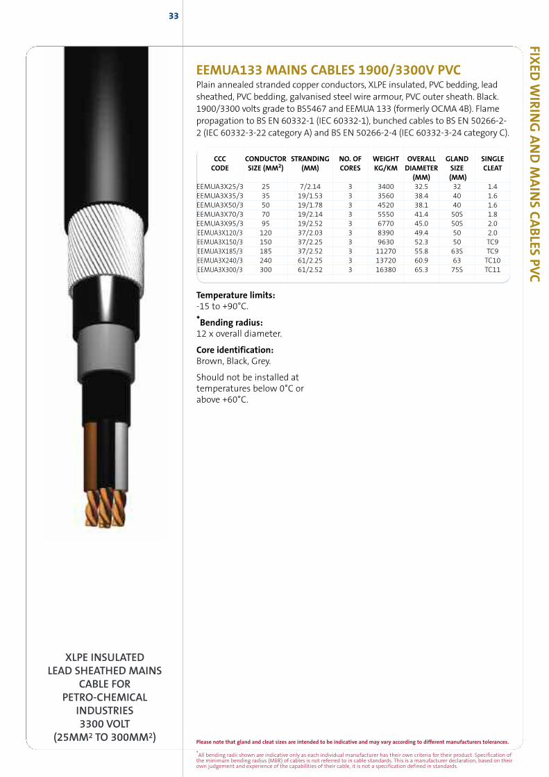
EEMUA133 MAINS CABLES 1900/3300V PVCPlain annealed stranded copper conductors, XLPE insulated, PVC bedding, leadsheathed, PVC bedding, galvanised steel wire armour, PVC outer sheath. Black.1900/3300 volts grade to BS5467 and EEMUA 133 (formerly OCMA 4B). Flamepropagation to BS EN 60332-1 (IEC 60332-1), bunched cables to BS EN 50266-2-2 (IEC 60332-3-22 category A) and BS EN 50266-2-4 (IEC 60332-3-24 category C).
CCC CONDUCTOR STRANDING NO. OF WEIGHT OVERALL GLAND SINGLECODE SIZE (MM2) (MM) CORES KG/KM DIAMETER SIZE CLEAT
(MM) (MM)EEMUA3X25/3 25 7/2.14 3 3400 32.5 32 1.4EEMUA3X35/3 35 19/1.53 3 3560 38.4 40 1.6EEMUA3X50/3 50 19/1.78 3 4520 38.1 40 1.6EEMUA3X70/3 70 19/2.14 3 5550 41.4 50S 1.8EEMUA3X95/3 95 19/2.52 3 6770 45.0 50S 2.0EEMUA3X120/3 120 37/2.03 3 8390 49.4 50 2.0EEMUA3X150/3 150 37/2.25 3 9630 52.3 50 TC9EEMUA3X185/3 185 37/2.52 3 11270 55.8 63S TC9EEMUA3X240/3 240 61/2.25 3 13720 60.9 63 TC10EEMUA3X300/3 300 61/2.52 3 16380 65.3 75S TC11
Temperature limits:-15 to +90°C.
*Bending radius:12 x overall diameter.
Core identification:Brown, Black, Grey.
Should not be installed attemperatures below 0°C orabove +60°C.
35
FIXED WIRING ANDMAINS CABLESLSZH
FIXED
WIR
ING
AND
MAIN
SCABLES
LSZH
36
*All bending radii shown are indicative only as each individual manufacturer has their own criteria for their product. Specification ofthe minimum bending radius (MBR) of cables is not referred to in cable standards. This is a manufacturer declaration, based on theirown judgement and experience of the capabilities of their cable, it is not a specification defined in standards.
Please note that gland and cleat sizes are intended to be indicative and may vary according to different manufacturers tolerances.
FIXED
WIR
ING
AND
MAIN
SCABLE
SLS
ZH
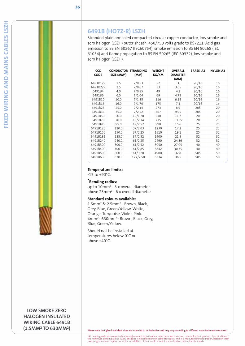
LOW SMOKE ZEROHALOGEN INSULATEDWIRING CABLE 6491B(1.5MM2 TO 630MM2)
6491B (HO7Z-R) LSZHStranded plain annealed compacted circular copper conductor, low smoke andzero halogen (LSZH) outer sheath. 450/750 volts grade to BS7211. Acid gasemission to BS EN 50267 (IEC60754), smoke emission to BS EN 50268 (IEC61034) and flame propagation to BS EN 50265 (IEC 60332), low smoke andzero halogen (LSZH).
CCC CONDUCTOR STRANDING WEIGHT OVERALL BRASS A2 NYLON A2CODE SIZE (MM2) (MM) KG/KM DIAMETER
(MM)6491B1/5 1.5 7/0.53 22 3 20/16 166491B2/5 2.5 7/0.67 33 3.65 20/16 166491B4 4.0 7/0.85 49 4.2 20/16 166491B6 6.0 7/1.04 69 4.75 20/16 166491B10 10.0 7/1.35 116 6.15 20/16 166491B16 16.0 7/1.70 175 7.1 20/16 166491B25 25.0 7/2.14 273 8.9 20S 206491B35 35.0 7/2.52 367 9.95 20S 206491B50 50.0 19/1.78 510 11.7 20 206491B70 70.0 19/2.14 715 13.35 20 256491B95 95.0 19/2.52 990 15.6 25 256491B120 120.0 37/2.03 1230 17.2 25 256491B150 150.0 37/2.25 1510 19.1 25 326491B185 185.0 37/2.52 1900 21.3 32 326491B240 240.0 61/2.25 2490 24.36 32 326491B300 300.0 61/2.52 3050 27.05 40 406491B400 400.0 61/2.85 3842 30.35 40 406491B500 500.0 61/3.20 4900 32.8 50S 506491B630 630.0 127/2.50 6334 36.5 50S 50
Temperature limits:-15 to +90°C.
*Bending radius:up to 10mm2 - 3 x overall diameterabove 25mm2 - 6 x overall diameter
Standard colours available:1.5mm2 & 2.5mm2 - Brown, Black,Grey, Blue, Green/Yellow, White,Orange, Turquoise, Violet, Pink.4mm2 - 630mm2 - Brown, Black, Grey,Blue, Green/Yellow.
Should not be installed attemperatures below 0°C orabove +40°C.
37
Please note that gland and cleat sizes are intended to be indicative and may vary according to different manufacturers tolerances.
*All bending radii shown are indicative only as each individual manufacturer has their own criteria for their product. Specification ofthe minimum bending radius (MBR) of cables is not referred to in cable standards. This is a manufacturer declaration, based on theirown judgement and experience of the capabilities of their cable, it is not a specification defined in standards.
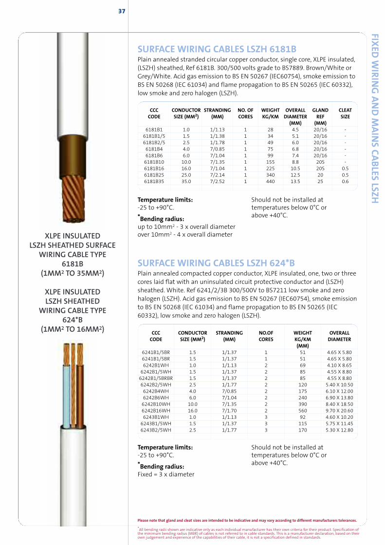
SURFACE WIRING CABLES LSZH 624*BPlain annealed compacted copper conductor, XLPE insulated, one, two or threecores laid flat with an uninsulated circuit protective conductor and (LSZH)sheathed. White. Ref 6241/2/3B 300/500V to BS7211 low smoke and zerohalogen (LSZH). Acid gas emission to BS EN 50267 (IEC60754), smoke emissionto BS EN 50268 (IEC 61034) and flame propagation to BS EN 50265 (IEC60332), low smoke and zero halogen (LSZH).
CCC CONDUCTOR STRANDING NO.OF WEIGHT OVERALLCODE SIZE (MM2) (MM) CORES KG/KM DIAMETER
(MM)6241B1/5BR 1.5 1/1.37 1 51 4.65 X 5.806241B1/5BR 1.5 1/1.37 1 51 4.65 X 5.806242B1WH 1.0 1/1.13 2 69 4.10 X 8.656242B1/5WH 1.5 1/1.37 2 85 4.55 X 8.806242B1/5BRBR 1.5 1/1.37 2 85 4.55 X 8.806242B2/5WH 2.5 1/1.77 2 120 5.40 X 10.506242B4WH 4.0 7/0.85 2 175 6.10 X 12.006242B6WH 6.0 7/1.04 2 240 6.90 X 13.806242B10WH 10.0 7/1.35 2 390 8.40 X 18.506242B16WH 16.0 7/1.70 2 560 9.70 X 20.606243B1WH 1.0 1/1.13 3 92 4.60 X 10.206243B1/5WH 1.5 1/1.37 3 115 5.75 X 11.456243B2/5WH 2.5 1/1.77 3 170 5.30 X 12.80
CCC CONDUCTOR STRANDING NO. OF WEIGHT OVERALL GLAND CLEATCODE SIZE (MM2) (MM) CORES KG/KM DIAMETER REF SIZE
(MM) (MM)6181B1 1.0 1/1.13 1 28 4.5 20/16 -6181B1/5 1.5 1/1.38 1 34 5.1 20/16 -6181B2/5 2.5 1/1.78 1 49 6.0 20/16 -6181B4 4.0 7/0.85 1 75 6.8 20/16 -6181B6 6.0 7/1.04 1 99 7.4 20/16 -6181B10 10.0 7/1.35 1 155 8.8 20S -6181B16 16.0 7/1.04 1 225 10.5 20S 0.56181B25 25.0 7/2.14 1 340 12.5 20 0.56181B35 35.0 7/2.52 1 440 13.5 25 0.6
Temperature limits:-25 to +90°C.
*Bending radius:up to 10mm2 - 3 x overall diameterover 10mm2 - 4 x overall diameter
Should not be installed attemperatures below 0°C orabove +40°C.
Temperature limits:-25 to +90°C.
*Bending radius:Fixed = 3 x diameter
Should not be installed attemperatures below 0°C orabove +40°C.
FIXED
WIR
ING
AND
MAIN
SCABLES
LSZH
XLPE INSULATEDLSZH SHEATHED SURFACE
WIRING CABLE TYPE6181B
(1MM2 TO 35MM2)
XLPE INSULATEDLSZH SHEATHED
WIRING CABLE TYPE624*B
(1MM2 TO 16MM2)
SURFACE WIRING CABLES LSZH 6181BPlain annealed stranded circular copper conductor, single core, XLPE insulated,(LSZH) sheathed, Ref 6181B. 300/500 volts grade to BS7889. Brown/White orGrey/White. Acid gas emission to BS EN 50267 (IEC60754), smoke emission toBS EN 50268 (IEC 61034) and flame propagation to BS EN 50265 (IEC 60332),low smoke and zero halogen (LSZH).
*All bending radii shown are indicative only as each individual manufacturer has their own criteria for their product. Specification ofthe minimum bending radius (MBR) of cables is not referred to in cable standards. This is a manufacturer declaration, based on theirown judgement and experience of the capabilities of their cable, it is not a specification defined in standards.
FIXED
WIR
ING
AND
MAIN
SCABLE
SLS
ZH38
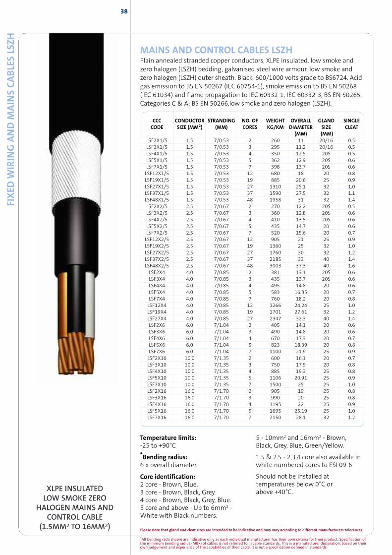
MAINS AND CONTROL CABLES LSZHPlain annealed stranded copper conductors, XLPE insulated, low smoke andzero halogen (LSZH) bedding, galvanised steel wire armour, low smoke andzero halogen (LSZH) outer sheath. Black. 600/1000 volts grade to BS6724. Acidgas emission to BS EN 50267 (IEC 60754-1), smoke emission to BS EN 50268(IEC 61034) and flame propagation to IEC 60332-1, IEC 60332-3, BS EN 50265,Categories C & A; BS EN 50266,low smoke and zero halogen (LSZH).
XLPE INSULATEDLOW SMOKE ZERO
HALOGEN MAINS ANDCONTROL CABLE
(1.5MM2 TO 16MM2)
Temperature limits:-25 to +90°C
*Bending radius:6 x overall diameter.
Core identification:2 core - Brown, Blue.3 core - Brown, Black, Grey.4 core - Brown, Black, Grey, Blue.5 core and above - Up to 6mm2 -White with Black numbers.
5 - 10mm2 and 16mm2 - Brown,Black, Grey, Blue, Green/Yellow.
1.5 & 2.5 - 2,3,4 core also available inwhite numbered cores to ESI 09-6
Should not be installed attemperatures below 0°C orabove +40°C.
CCC CONDUCTOR STRANDING NO. OF WEIGHT OVERALL GLAND SINGLECODE SIZE (MM2) (MM) CORES KG/KM DIAMETER SIZE CLEAT
(MM) (MM)LSF2X1/5 1.5 7/0.53 2 260 11 20/16 0.5LSF3X1/5 1.5 7/0.53 3 295 11.2 20/16 0.5LSF4X1/5 1.5 7/0.53 4 350 12.5 20S 0.5LSF5X1/5 1.5 7/0.53 5 362 12.9 20S 0.6LSF7X1/5 1.5 7/0.53 7 398 13.7 20S 0.6LSF12X1/5 1.5 7/0.53 12 680 18 20 0.8LSF19X1/5 1.5 7/0.53 19 885 20.6 25 0.9LSF27X1/5 1.5 7/0.53 27 1310 25.1 32 1.0LSF37X1/5 1.5 7/0.53 37 1590 27.5 32 1.1LSF48X1/5 1.5 7/0.53 48 1958 31 32 1.4LSF2X2/5 2.5 7/0.67 2 270 12.2 20S 0.5LSF3X2/5 2.5 7/0.67 3 360 12.8 20S 0.6LSF4X2/5 2.5 7/0.67 4 410 13.5 20S 0.6LSF5X2/5 2.5 7/0.67 5 435 14.7 20 0.6LSF7X2/5 2.5 7/0.67 7 520 15.6 20 0.7LSF12X2/5 2.5 7/0.67 12 905 21 25 0.9LSF19X2/5 2.5 7/0.67 19 1360 25 32 1.0LSF27X2/5 2.5 7/0.67 27 1760 30 32 1.2LSF37X2/5 2.5 7/0.67 37 2185 33 40 1.4LSF48X2/5 2.5 7/0.67 48 3003 37.3 40 1.6LSF2X4 4.0 7/0.85 2 381 13.1 20S 0.6LSF3X4 4.0 7/0.85 3 435 13.7 20S 0.6LSF4X4 4.0 7/0.85 4 495 14.8 20 0.6LSF5X4 4.0 7/0.85 5 583 16.35 20 0.7LSF7X4 4.0 7/0.85 7 760 18.2 20 0.8LSF12X4 4.0 7/0.85 12 1266 24.24 25 1.0LSF19X4 4.0 7/0.85 19 1701 27.61 32 1.2LSF27X4 4.0 7/0.85 27 2347 32.3 40 1.4LSF2X6 6.0 7/1.04 2 405 14.1 20 0.6LSF3X6 6.0 7/1.04 3 490 14.8 20 0.6LSF4X6 6.0 7/1.04 4 670 17.3 20 0.7LSF5X6 6.0 7/1.04 5 823 18.39 20 0.8LSF7X6 6.0 7/1.04 7 1100 21.9 25 0.9LSF2X10 10.0 7/1.35 2 600 16.1 20 0.7LSF3X10 10.0 7/1.35 3 750 17.9 20 0.8LSF4X10 10.0 7/1.35 4 885 19.3 25 0.8LSF5X10 10.0 7/1.35 5 1106 20.91 25 0.9LSF7X10 10.0 7/1.35 7 1500 25 25 1.0LSF2X16 16.0 7/1.70 2 905 19 25 0.8LSF3X16 16.0 7/1.70 3 990 20 25 0.8LSF4X16 16.0 7/1.70 4 1195 22 25 0.9LSF5X16 16.0 7/1.70 5 1695 25.19 25 1.0LSF7X16 16.0 7/1.70 7 2150 28.1 32 1.2
Please note that gland and cleat sizes are intended to be indicative and may vary according to different manufacturers tolerances.
Please note that gland and cleat sizes are intended to be indicative and may vary according to different manufacturers tolerances.
*All bending radii shown are indicative only as each individual manufacturer has their own criteria for their product. Specification ofthe minimum bending radius (MBR) of cables is not referred to in cable standards. This is a manufacturer declaration, based on theirown judgement and experience of the capabilities of their cable, it is not a specification defined in standards.
XLPE INSULATEDLOW SMOKE ZERO
HALOGEN MAINS CABLE(25MM2 TO 400MM2)
FIXED
WIR
ING
AND
MAIN
SCABLES
LSZH39
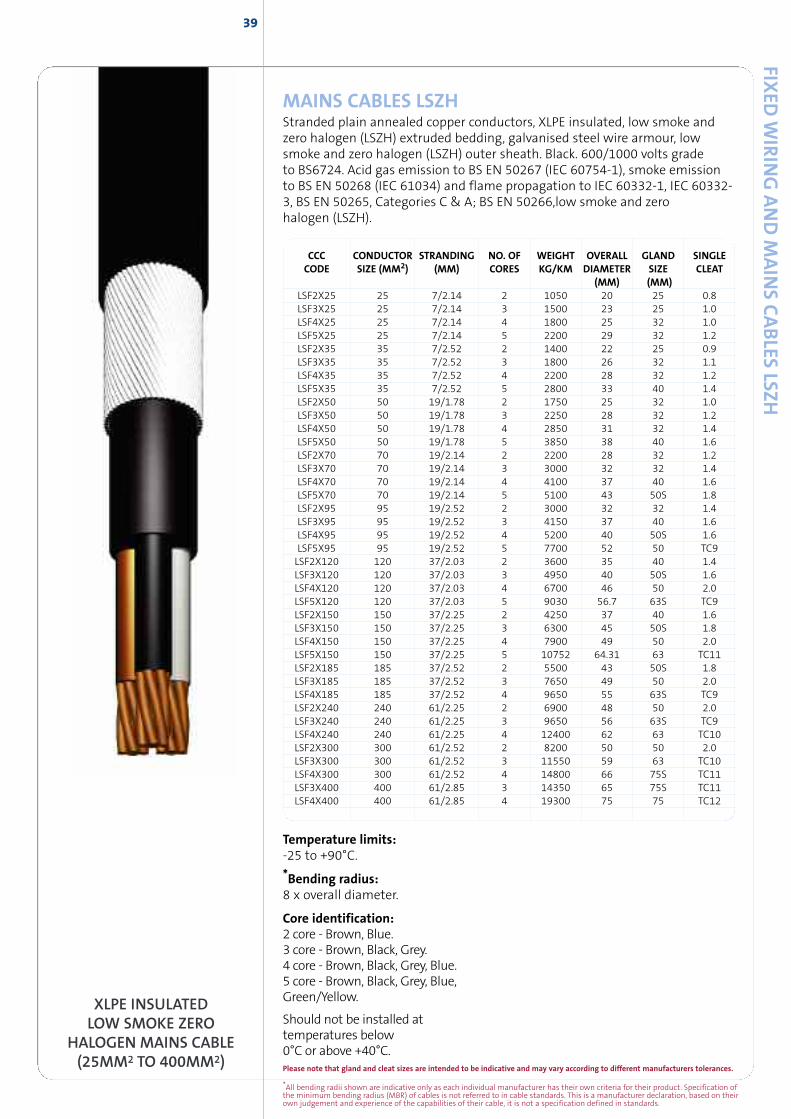
MAINS CABLES LSZHStranded plain annealed copper conductors, XLPE insulated, low smoke andzero halogen (LSZH) extruded bedding, galvanised steel wire armour, lowsmoke and zero halogen (LSZH) outer sheath. Black. 600/1000 volts gradeto BS6724. Acid gas emission to BS EN 50267 (IEC 60754-1), smoke emissionto BS EN 50268 (IEC 61034) and flame propagation to IEC 60332-1, IEC 60332-3, BS EN 50265, Categories C & A; BS EN 50266,low smoke and zerohalogen (LSZH).
Temperature limits:-25 to +90°C.
*Bending radius:8 x overall diameter.
Core identification:2 core - Brown, Blue.3 core - Brown, Black, Grey.4 core - Brown, Black, Grey, Blue.5 core - Brown, Black, Grey, Blue,Green/Yellow.
Should not be installed attemperatures below0°C or above +40°C.
CCC CONDUCTOR STRANDING NO. OF WEIGHT OVERALL GLAND SINGLECODE SIZE (MM2) (MM) CORES KG/KM DIAMETER SIZE CLEAT
(MM) (MM)LSF2X25 25 7/2.14 2 1050 20 25 0.8LSF3X25 25 7/2.14 3 1500 23 25 1.0LSF4X25 25 7/2.14 4 1800 25 32 1.0LSF5X25 25 7/2.14 5 2200 29 32 1.2LSF2X35 35 7/2.52 2 1400 22 25 0.9LSF3X35 35 7/2.52 3 1800 26 32 1.1LSF4X35 35 7/2.52 4 2200 28 32 1.2LSF5X35 35 7/2.52 5 2800 33 40 1.4LSF2X50 50 19/1.78 2 1750 25 32 1.0LSF3X50 50 19/1.78 3 2250 28 32 1.2LSF4X50 50 19/1.78 4 2850 31 32 1.4LSF5X50 50 19/1.78 5 3850 38 40 1.6LSF2X70 70 19/2.14 2 2200 28 32 1.2LSF3X70 70 19/2.14 3 3000 32 32 1.4LSF4X70 70 19/2.14 4 4100 37 40 1.6LSF5X70 70 19/2.14 5 5100 43 50S 1.8LSF2X95 95 19/2.52 2 3000 32 32 1.4LSF3X95 95 19/2.52 3 4150 37 40 1.6LSF4X95 95 19/2.52 4 5200 40 50S 1.6LSF5X95 95 19/2.52 5 7700 52 50 TC9LSF2X120 120 37/2.03 2 3600 35 40 1.4LSF3X120 120 37/2.03 3 4950 40 50S 1.6LSF4X120 120 37/2.03 4 6700 46 50 2.0LSF5X120 120 37/2.03 5 9030 56.7 63S TC9LSF2X150 150 37/2.25 2 4250 37 40 1.6LSF3X150 150 37/2.25 3 6300 45 50S 1.8LSF4X150 150 37/2.25 4 7900 49 50 2.0LSF5X150 150 37/2.25 5 10752 64.31 63 TC11LSF2X185 185 37/2.52 2 5500 43 50S 1.8LSF3X185 185 37/2.52 3 7650 49 50 2.0LSF4X185 185 37/2.52 4 9650 55 63S TC9LSF2X240 240 61/2.25 2 6900 48 50 2.0LSF3X240 240 61/2.25 3 9650 56 63S TC9LSF4X240 240 61/2.25 4 12400 62 63 TC10LSF2X300 300 61/2.52 2 8200 50 50 2.0LSF3X300 300 61/2.52 3 11550 59 63 TC10LSF4X300 300 61/2.52 4 14800 66 75S TC11LSF3X400 400 61/2.85 3 14350 65 75S TC11LSF4X400 400 61/2.85 4 19300 75 75 TC12
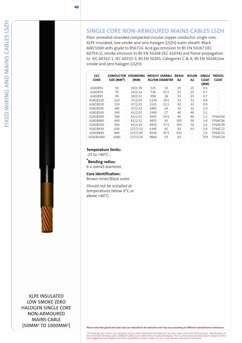
*All bending radii shown are indicative only as each individual manufacturer has their own criteria for their product. Specification ofthe minimum bending radius (MBR) of cables is not referred to in cable standards. This is a manufacturer declaration, based on theirown judgement and experience of the capabilities of their cable, it is not a specification defined in standards.
Please note that gland and cleat sizes are intended to be indicative and may vary according to different manufacturers tolerances.
FIXED
WIR
ING
AND
MAIN
SCABLE
SLS
ZH40
XLPE INSULATEDLOW SMOKE ZERO
HALOGEN SINGLE CORENON-ARMOURED
MAINS CABLE(50MM2 TO 1000MM2)
SINGLE CORE NON-ARMOURED MAINS CABLES LSZHPlain annealed stranded compacted circular copper conductor, single core,XLPE insulated, low smoke and zero halogen (LSZH) outer sheath. Black.600/1000 volts grade to BS6724. Acid gas emission to BS EN 50267 (IEC60754-1), smoke emission to BS EN 50268 (IEC 61034) and flame propagationto IEC 60332-1, IEC 60332-3, BS EN 50265, Categories C & A; BS EN 50266,lowsmoke and zero halogen (LSZH).
Temperature limits:-25 to +90°C.
*Bending radius:6 x overall diameter.
Core identification:Brown inner/Black outer.
Should not be installed attemperatures below 0°C orabove +40°C.
CCC CONDUCTOR STRANDING WEIGHT OVERALL BRASS NYLON SINGLE TREFOILCODE SIZE (MM2) (MM) KG/KM DIAMETER A2 A2 CLEAT CLEAT
(MM)6181B50 50 19/1.78 525 13 25 25 0.6 -6181B70 70 19/2.14 730 15.5 25 25 0.7 -6181B95 95 19/2.52 990 18 25 25 0.7 -6181B120 120 37/2.03 1230 19.5 32 32 0.8 -6181B150 150 37/2.25 1525 21.5 32 32 0.9 -6181B185 185 37/2.52 1885 24 32 32 1.0 -6181B240 240 61/2.25 2440 27 40 40 1.1 -6181B300 300 61/2.52 3045 29.5 40 40 1.2 376AC046181B400 400 61/2.52 3855 33 50S 50 1.4 376AC066181B500 500 61/3.20 4950 37.5 50S 50 1.6 376AC096181B630 630 127/2.52 6345 42 50 63 1.8 376AC126181B800 800 127/2.85 8140 47.5 63S - 2.0 376AC156181B1000 1000 127/3.20 9860 53 63 - TC9 376AC19
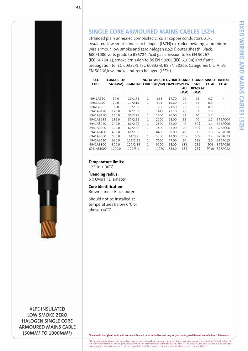
Please note that gland and cleat sizes are intended to be indicative and may vary according to different manufacturers tolerances.
*All bending radii shown are indicative only as each individual manufacturer has their own criteria for their product. Specification ofthe minimum bending radius (MBR) of cables is not referred to in cable standards. This is a manufacturer declaration, based on theirown judgement and experience of the capabilities of their cable, it is not a specification defined in standards.
41
SINGLE CORE ARMOURED MAINS CABLES LSZHStranded plain annealed compacted circular copper conductors, XLPEinsulated, low smoke and zero halogen (LSZH) extruded bedding, aluminiumwire armour, low smoke and zero halogen (LSZH) outer sheath. Black.600/1000 volts grade to BS6724. Acid gas emission to BS EN 50267(IEC 60754-1), smoke emission to BS EN 50268 (IEC 61034) and flamepropagation to IEC 60332-1, IEC 60332-3, BS EN 50265, Categories C & A; BSEN 50266,low smoke and zero halogen (LSZH).
6941AB50 50.0 19/1.78 1 638 17.70 20 25 0.7 -6941AB70 70.0 19/2.14 1 891 19.60 25 32 0.8 -6941AB95 95.0 19/2.52 1 1166 21.50 25 32 0.9 -6941AB120 120.0 37/2.03 1 1412 23.10 25 32 1.0 -6941AB150 150.0 37/2.25 1 1800 26.00 32 40 1.1 -6941AB185 185.0 37/2.52 1 2200 28.00 32 40 1.2 376AC046941AB240 240.0 61/2.25 1 2800 32.00 40 50S 1.4 376AC066941AB300 300.0 61/2.52 1 3400 33.00 40 50S 1.4 376AC066941AB400 400.0 61/2.85 1 4450 38.00 40 50 1.6 376AC106941AB500 500.0 61/3.2 1 5550 43.00 50S 63S 1.8 376AC136941AB630 630.0 127/2.52 1 7100 47.00 50 63S 2.0 376AC156941AB800 800.0 127/2.85 1 9200 55.00 63S 75S TC9 376AC206941AB1000 1000.0 127/3.2 1 11270 58.80 63S 75S TC10 376AC22
CCC CONDUCTOR NO. OF WEIGHTOVERALLGLAND GLAND SINGLE TREFOILCODE SIZE(MM) STRANDING CORES (KG/KM) DIAMETER SIZECW SIZE CLEAT CLEAT
ALI BRASS A2(MM) (MM)
FIXED
WIR
ING
AND
MAIN
SCABLES
LSZH
XLPE INSULATEDLOW SMOKE ZERO
HALOGEN SINGLE COREARMOURED MAINS CABLE(50MM2 TO 1000MM2)
Temperature limits:- 25 to + 90°C
*Bending radius:6 x Overall Diameter
Core identification:Brown inner - Black outer
Should not be installed attemperatures below 0°C orabove +40°C.
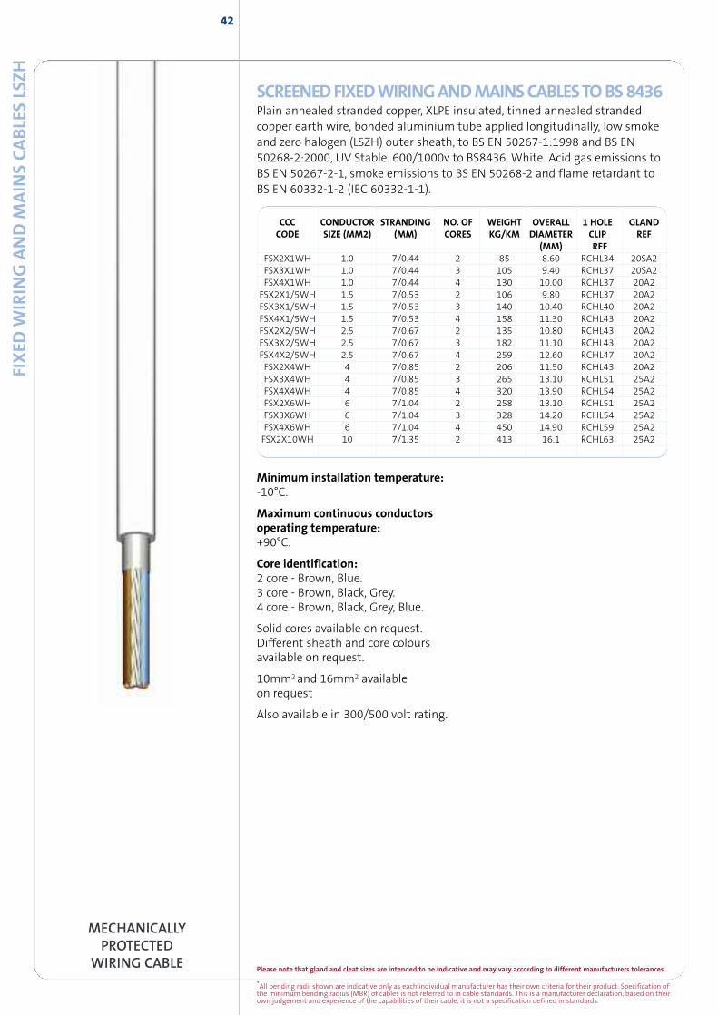
42
*All bending radii shown are indicative only as each individual manufacturer has their own criteria for their product. Specification ofthe minimum bending radius (MBR) of cables is not referred to in cable standards. This is a manufacturer declaration, based on theirown judgement and experience of the capabilities of their cable, it is not a specification defined in standards.
Please note that gland and cleat sizes are intended to be indicative and may vary according to different manufacturers tolerances.
FIXED
WIR
ING
AND
MAIN
SCABLE
SLS
ZH
MECHANICALLYPROTECTED
WIRING CABLE
SCREENEDFIXEDWIRINGANDMAINSCABLESTOBS8436Plain annealed stranded copper, XLPE insulated, tinned annealed strandedcopper earth wire, bonded aluminium tube applied longitudinally, low smokeand zero halogen (LSZH) outer sheath, to BS EN 50267-1:1998 and BS EN50268-2:2000, UV Stable. 600/1000v to BS8436, White. Acid gas emissions toBS EN 50267-2-1, smoke emissions to BS EN 50268-2 and flame retardant toBS EN 60332-1-2 (IEC 60332-1-1).
CCC CONDUCTOR STRANDING NO. OF WEIGHT OVERALL 1 HOLE GLANDCODE SIZE (MM2) (MM) CORES KG/KM DIAMETER CLIP REF
(MM) REFFSX2X1WH 1.0 7/0.44 2 85 8.60 RCHL34 20SA2FSX3X1WH 1.0 7/0.44 3 105 9.40 RCHL37 20SA2FSX4X1WH 1.0 7/0.44 4 130 10.00 RCHL37 20A2FSX2X1/5WH 1.5 7/0.53 2 106 9.80 RCHL37 20A2FSX3X1/5WH 1.5 7/0.53 3 140 10.40 RCHL40 20A2FSX4X1/5WH 1.5 7/0.53 4 158 11.30 RCHL43 20A2FSX2X2/5WH 2.5 7/0.67 2 135 10.80 RCHL43 20A2FSX3X2/5WH 2.5 7/0.67 3 182 11.10 RCHL43 20A2FSX4X2/5WH 2.5 7/0.67 4 259 12.60 RCHL47 20A2FSX2X4WH 4 7/0.85 2 206 11.50 RCHL43 20A2FSX3X4WH 4 7/0.85 3 265 13.10 RCHL51 25A2FSX4X4WH 4 7/0.85 4 320 13.90 RCHL54 25A2FSX2X6WH 6 7/1.04 2 258 13.10 RCHL51 25A2FSX3X6WH 6 7/1.04 3 328 14.20 RCHL54 25A2FSX4X6WH 6 7/1.04 4 450 14.90 RCHL59 25A2FSX2X10WH 10 7/1.35 2 413 16.1 RCHL63 25A2
Minimum installation temperature:-10°C.
Maximum continuous conductorsoperating temperature:+90°C.
Core identification:2 core - Brown, Blue.3 core - Brown, Black, Grey.4 core - Brown, Black, Grey, Blue.
Solid cores available on request.Different sheath and core coloursavailable on request.
10mm2and 16mm2 availableon request
Also available in 300/500 volt rating.
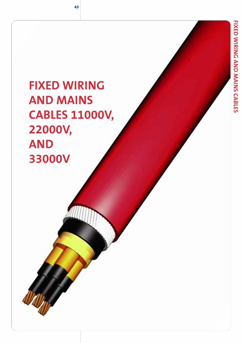
43
FIXED WIRINGAND MAINSCABLES 11000V,22000V,AND33000V
FIXED
WIR
ING
AND
MAIN
SCABLES
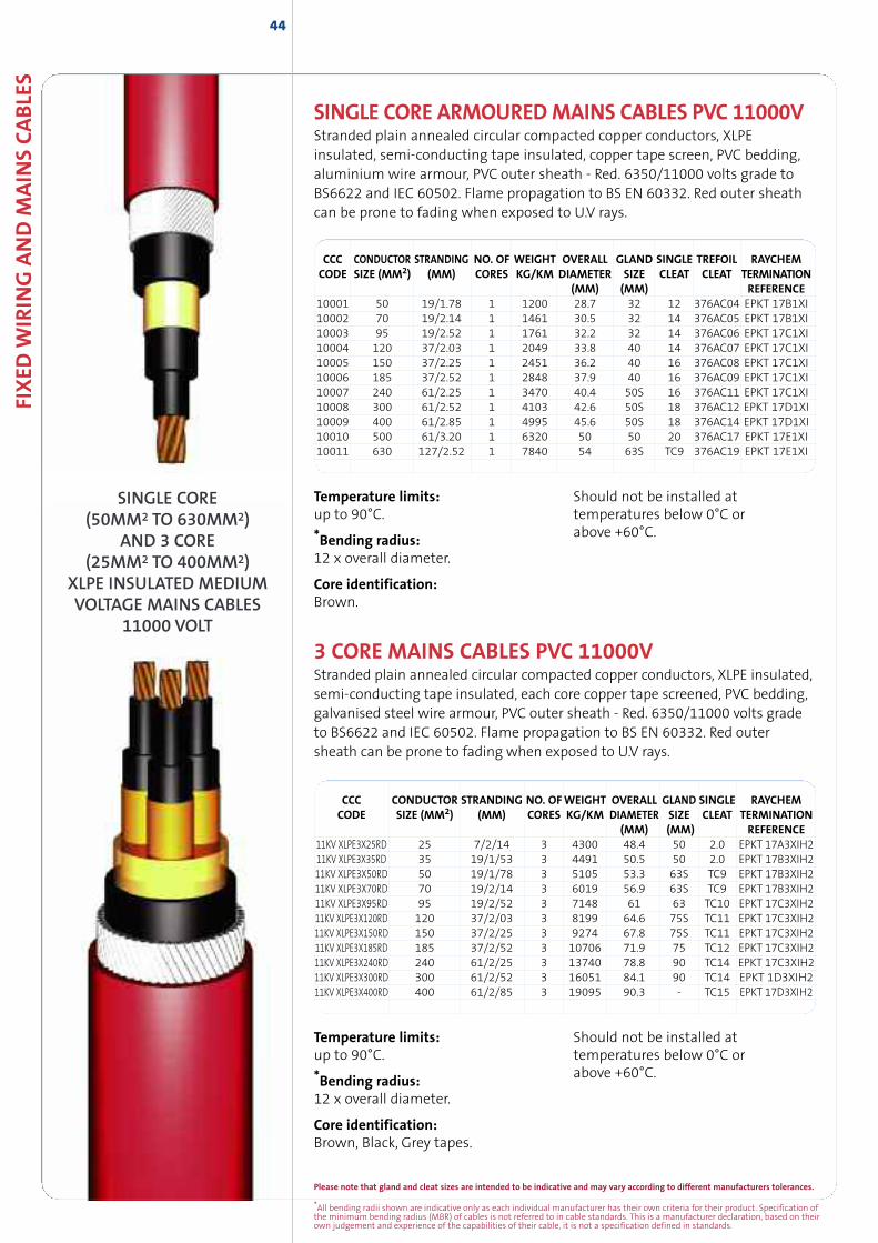
*All bending radii shown are indicative only as each individual manufacturer has their own criteria for their product. Specification ofthe minimum bending radius (MBR) of cables is not referred to in cable standards. This is a manufacturer declaration, based on theirown judgement and experience of the capabilities of their cable, it is not a specification defined in standards.
Please note that gland and cleat sizes are intended to be indicative and may vary according to different manufacturers tolerances.
44
3 CORE MAINS CABLES PVC 11000VStranded plain annealed circular compacted copper conductors, XLPE insulated,semi-conducting tape insulated, each core copper tape screened, PVC bedding,galvanised steel wire armour, PVC outer sheath - Red. 6350/11000 volts gradeto BS6622 and IEC 60502. Flame propagation to BS EN 60332. Red outersheath can be prone to fading when exposed to U.V rays.
CCC CONDUCTOR STRANDING NO. OFWEIGHT OVERALL GLAND SINGLE RAYCHEMCODE SIZE (MM2) (MM) CORES KG/KM DIAMETER SIZE CLEAT TERMINATION
(MM) (MM) REFERENCE11KV XLPE3X25RD 25 7/2/14 3 4300 48.4 50 2.0 EPKT 17A3XIH211KV XLPE3X35RD 35 19/1/53 3 4491 50.5 50 2.0 EPKT 17B3XIH211KV XLPE3X50RD 50 19/1/78 3 5105 53.3 63S TC9 EPKT 17B3XIH211KV XLPE3X70RD 70 19/2/14 3 6019 56.9 63S TC9 EPKT 17B3XIH211KV XLPE3X95RD 95 19/2/52 3 7148 61 63 TC10 EPKT 17C3XIH211KV XLPE3X120RD 120 37/2/03 3 8199 64.6 75S TC11 EPKT 17C3XIH211KV XLPE3X150RD 150 37/2/25 3 9274 67.8 75S TC11 EPKT 17C3XIH211KV XLPE3X185RD 185 37/2/52 3 10706 71.9 75 TC12 EPKT 17C3XIH211KV XLPE3X240RD 240 61/2/25 3 13740 78.8 90 TC14 EPKT 17C3XIH211KV XLPE3X300RD 300 61/2/52 3 16051 84.1 90 TC14 EPKT 1D3XIH211KV XLPE3X400RD 400 61/2/85 3 19095 90.3 - TC15 EPKT 17D3XIH2
SINGLE CORE ARMOUREDMAINS CABLES PVC 11000VStranded plain annealed circular compacted copper conductors, XLPEinsulated, semi-conducting tape insulated, copper tape screen, PVC bedding,aluminium wire armour, PVC outer sheath - Red. 6350/11000 volts grade toBS6622 and IEC 60502. Flame propagation to BS EN 60332. Red outer sheathcan be prone to fading when exposed to U.V rays.
Temperature limits:up to 90°C.
*Bending radius:12 x overall diameter.
Core identification:Brown, Black, Grey tapes.
Should not be installed attemperatures below 0°C orabove +60°C.
Temperature limits:up to 90°C.
*Bending radius:12 x overall diameter.
Core identification:Brown.
Should not be installed attemperatures below 0°C orabove +60°C.
FIXED
WIR
ING
AND
MAIN
SCABLE
S
SINGLE CORE(50MM2 TO 630MM2)
AND 3 CORE(25MM2 TO 400MM2)
XLPE INSULATED MEDIUMVOLTAGE MAINS CABLES
11000 VOLT
CCC CONDUCTOR STRANDING NO. OF WEIGHT OVERALL GLAND SINGLE TREFOIL RAYCHEMCODE SIZE (MM2) (MM) CORES KG/KM DIAMETER SIZE CLEAT CLEAT TERMINATION
(MM) (MM) REFERENCE10001 50 19/1.78 1 1200 28.7 32 12 376AC04 EPKT 17B1XI10002 70 19/2.14 1 1461 30.5 32 14 376AC05 EPKT 17B1XI10003 95 19/2.52 1 1761 32.2 32 14 376AC06 EPKT 17C1XI10004 120 37/2.03 1 2049 33.8 40 14 376AC07 EPKT 17C1XI10005 150 37/2.25 1 2451 36.2 40 16 376AC08 EPKT 17C1XI10006 185 37/2.52 1 2848 37.9 40 16 376AC09 EPKT 17C1XI10007 240 61/2.25 1 3470 40.4 50S 16 376AC11 EPKT 17C1XI10008 300 61/2.52 1 4103 42.6 50S 18 376AC12 EPKT 17D1XI10009 400 61/2.85 1 4995 45.6 50S 18 376AC14 EPKT 17D1XI10010 500 61/3.20 1 6320 50 50 20 376AC17 EPKT 17E1XI10011 630 127/2.52 1 7840 54 63S TC9 376AC19 EPKT 17E1XI
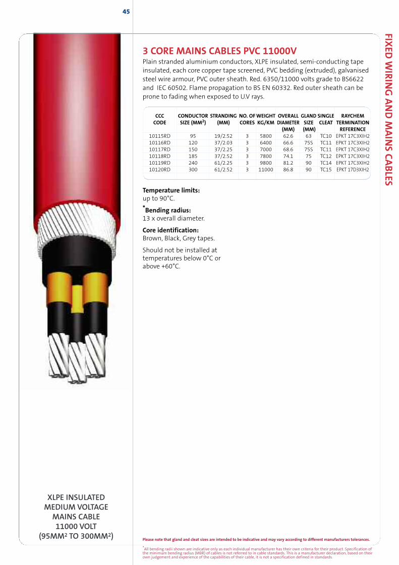
*All bending radii shown are indicative only as each individual manufacturer has their own criteria for their product. Specification ofthe minimum bending radius (MBR) of cables is not referred to in cable standards. This is a manufacturer declaration, based on theirown judgement and experience of the capabilities of their cable, it is not a specification defined in standards.
Please note that gland and cleat sizes are intended to be indicative and may vary according to different manufacturers tolerances.
FIXED
WIR
ING
AND
MAIN
SCABLES
45
CCC CONDUCTOR STRANDING NO. OFWEIGHT OVERALL GLAND SINGLE RAYCHEMCODE SIZE (MM2) (MM) CORES KG/KM DIAMETER SIZE CLEAT TERMINATION
(MM) (MM) REFERENCE10115RD 95 19/2.52 3 5800 62.6 63 TC10 EPKT 17C3XIH210116RD 120 37/2.03 3 6400 66.6 75S TC11 EPKT 17C3XIH210117RD 150 37/2.25 3 7000 68.6 75S TC11 EPKT 17C3XIH210118RD 185 37/2.52 3 7800 74.1 75 TC12 EPKT 17C3XIH210119RD 240 61/2.25 3 9800 81.2 90 TC14 EPKT 17C3XIH210120RD 300 61/2.52 3 11000 86.8 90 TC15 EPKT 17D3XIH2
3 CORE MAINS CABLES PVC 11000VPlain stranded aluminium conductors, XLPE insulated, semi-conducting tapeinsulated, each core copper tape screened, PVC bedding (extruded), galvanisedsteel wire armour, PVC outer sheath. Red. 6350/11000 volts grade to BS6622and IEC 60502. Flame propagation to BS EN 60332. Red outer sheath can beprone to fading when exposed to U.V rays.
XLPE INSULATEDMEDIUM VOLTAGE
MAINS CABLE11000 VOLT
(95MM2 TO 300MM2)
Temperature limits:up to 90°C.
*Bending radius:13 x overall diameter.
Core identification:Brown, Black, Grey tapes.
Should not be installed attemperatures below 0°C orabove +60°C.
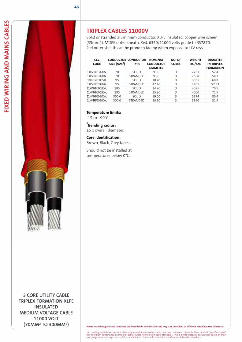
*All bending radii shown are indicative only as each individual manufacturer has their own criteria for their product. Specification ofthe minimum bending radius (MBR) of cables is not referred to in cable standards. This is a manufacturer declaration, based on theirown judgement and experience of the capabilities of their cable, it is not a specification defined in standards.
Please note that gland and cleat sizes are intended to be indicative and may vary according to different manufacturers tolerances.
FIXED
WIR
ING
AND
MAIN
SCABLE
S46
3 CORE UTILITY CABLETRIPLEX FORMATION XLPE
INSULATEDMEDIUM VOLTAGE CABLE
11000 VOLT(70MM2 TO 300MM2)
TRIPLEX CABLES 11000VSolid or stranded aluminium conductor, XLPE insulated, copper wire screen(35mm2). MDPE outer sheath. Red. 6350/11000 volts grade to BS7870.Red outer sheath can be prone to fading when exposed to U.V rays.
CCC CONDUCTOR CONDUCTOR NOMINAL NO. OF WEIGHT DIAMETERCODE SIZE (MM2) TYPE CONDUCTOR CORES KG/KM IN TRIPLEX
DIAMETER FORMATION11KVTRIP3X70AL 70 SOLID 9.30 3 2763 57.411KVTRIP3X70AL 70 STRANDED 9.80 3 2650 58.311KVTRIP3X95AL 95 SOLID 10.70 3 3055 60.811KVTRIP3X95AL 95 STRANDED 12.16 3 2901 57.8311KVTRIP3X185AL 185 SOLID 14.90 3 4095 70.511KVTRIP3X185AL 185 STRANDED 15.80 3 4060 72.511KVTRIP3X300AL 300.0 SOLID 19.00 3 5374 80.411KVTRIP3X300AL 300.0 STRANDED 20.50 3 5360 81.4
Temperature limits:-15 to +90°C.
*Bending radius:15 x overall diameter.
Core identification:Brown, Black, Grey tapes.
Should not be installed attemperatures below 0°C.
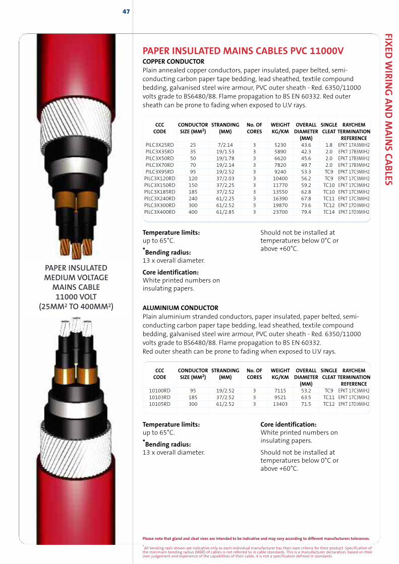
Please note that gland and cleat sizes are intended to be indicative and may vary according to different manufacturers tolerances.
*All bending radii shown are indicative only as each individual manufacturer has their own criteria for their product. Specification ofthe minimum bending radius (MBR) of cables is not referred to in cable standards. This is a manufacturer declaration, based on theirown judgement and experience of the capabilities of their cable, it is not a specification defined in standards.
FIXED
WIR
ING
AND
MAIN
SCABLES
47
PAPER INSULATED MAINS CABLES PVC 11000VCOPPER CONDUCTORPlain annealed copper conductors, paper insulated, paper belted, semi-conducting carbon paper tape bedding, lead sheathed, textile compoundbedding, galvanised steel wire armour, PVC outer sheath - Red. 6350/11000volts grade to BS6480/88. Flame propagation to BS EN 60332. Red outersheath can be prone to fading when exposed to U.V rays.
CCC CONDUCTOR STRANDING No. OF WEIGHT OVERALL SINGLE RAYCHEMCODE SIZE (MM2) (MM) CORES KG/KM DIAMETER CLEAT TERMINATION
(MM) REFERENCEPILC3X25RD 25 7/2.14 3 5230 43.6 1.8 EPKT 17A3MIH2PILC3X35RD 35 19/1.53 3 5890 42.3 2.0 EPKT 17B3MIH2PILC3X50RD 50 19/1.78 3 6620 45.6 2.0 EPKT 17B3MIH2PILC3X70RD 70 19/2.14 3 7820 49.7 2.0 EPKT 17B3MIH2PILC3X95RD 95 19/2.52 3 9240 53.3 TC9 EPKT 17C3MIH2PILC3X120RD 120 37/2.03 3 10400 56.2 TC9 EPKT 17C3MIH2PILC3X150RD 150 37/2.25 3 11770 59.2 TC10 EPKT 17C3MIH2PILC3X185RD 185 37/2.52 3 13550 62.8 TC10 EPKT 17C3MIH2PILC3X240RD 240 61/2.25 3 16390 67.8 TC11 EPKT 17C3MIH2PILC3X300RD 300 61/2.52 3 19870 73.6 TC12 EPKT 17D3MIH2PILC3X400RD 400 61/2.85 3 23700 79.4 TC14 EPKT 17D3MIH2
ALUMINIUM CONDUCTORPlain aluminium stranded conductors, paper insulated, paper belted, semi-conducting carbon paper tape bedding, lead sheathed, textile compoundbedding, galvanised steel wire armour, PVC outer sheath - Red. 6350/11000volts grade to BS6480/88. Flame propagation to BS EN 60332.Red outer sheath can be prone to fading when exposed to U.V rays.
CCC CONDUCTOR STRANDING No. OF WEIGHT OVERALL SINGLE RAYCHEMCODE SIZE (MM2) (MM) CORES KG/KM DIAMETER CLEAT TERMINATION
(MM) REFERENCE10100RD 95 19/2.52 3 7115 53.2 TC9 EPKT 17C3MIH210103RD 185 37/2.52 3 9521 63.5 TC11 EPKT 17C3MIH210105RD 300 61/2.52 3 13403 71.5 TC12 EPKT 17D3MIH2
PAPER INSULATEDMEDIUM VOLTAGE
MAINS CABLE11000 VOLT
(25MM2 TO 400MM2)
Temperature limits:up to 65°C.
*Bending radius:13 x overall diameter.
Core identification:White printed numbers oninsulating papers.
Should not be installed attemperatures below 0°C orabove +60°C.
Temperature limits:up to 65°C.
*Bending radius:13 x overall diameter.
Core identification:White printed numbers oninsulating papers.
Should not be installed attemperatures below 0°C orabove +60°C.
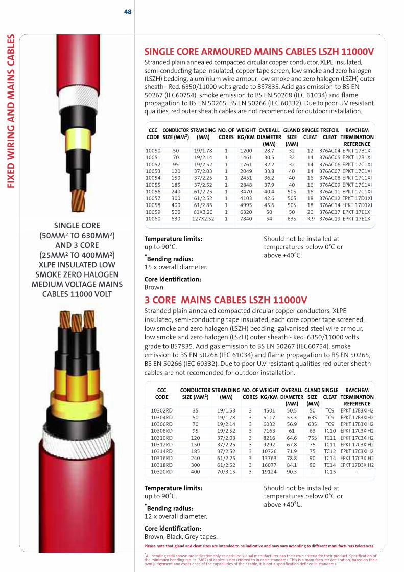
FIXED
WIR
ING
AND
MAIN
SCABLE
S48
SINGLE CORE(50MM2 TO 630MM2)
AND 3 CORE(25MM2 TO 400MM2)XLPE INSULATED LOWSMOKE ZERO HALOGEN
MEDIUM VOLTAGE MAINSCABLES 11000 VOLT
SINGLE CORE ARMOUREDMAINS CABLES LSZH 11000VStranded plain annealed compacted circular copper conductor, XLPE insulated,semi-conducting tape insulated, copper tape screen, low smoke and zero halogen(LSZH) bedding, aluminiumwire armour, low smoke and zero halogen (LSZH) outersheath - Red. 6350/11000 volts grade to BS7835. Acid gas emission to BS EN50267 (IEC60754), smoke emission to BS EN 50268 (IEC 61034) and flamepropagation to BS EN 50265, BS EN 50266 (IEC 60332). Due to poor U.V resistantqualities, red outer sheath cables are not recomended for outdoor installation.
CCC CONDUCTOR STRANDING NO. OF WEIGHT OVERALL GLAND SINGLE TREFOIL RAYCHEMCODE SIZE (MM2) (MM) CORES KG/KM DIAMETER SIZE CLEAT CLEAT TERMINATION
(MM) (MM) REFERENCE10050 50 19/1.78 1 1200 28.7 32 12 376AC04 EPKT 17B1XI10051 70 19/2.14 1 1461 30.5 32 14 376AC05 EPKT 17B1XI10052 95 19/2.52 1 1761 32.2 32 14 376AC06 EPKT 17C1XI10053 120 37/2.03 1 2049 33.8 40 14 376AC07 EPKT 17C1XI10054 150 37/2.25 1 2451 36.2 40 16 376AC08 EPKT 17C1XI10055 185 37/2.52 1 2848 37.9 40 16 376AC09 EPKT 17C1XI10056 240 61/2.25 1 3470 40.4 50S 16 376AC11 EPKT 17C1XI10057 300 61/2.52 1 4103 42.6 50S 18 376AC12 EPKT 17D1XI10058 400 61/2.85 1 4995 45.6 50S 18 376AC14 EPKT 17D1XI10059 500 61X3.20 1 6320 50 50 20 376AC17 EPKT 17E1XI10060 630 127X2.52 1 7840 54 63S TC9 376AC19 EPKT 17E1XI
Temperature limits:up to 90°C.
*Bending radius:15 x overall diameter.
Core identification:Brown.
Should not be installed attemperatures below 0°C orabove +40°C.
3 CORE MAINS CABLES LSZH 11000VStranded plain annealed compacted circular copper conductors, XLPEinsulated, semi-conducting tape insulated, each core copper tape screened,low smoke and zero halogen (LSZH) bedding, galvanised steel wire armour,low smoke and zero halogen (LSZH) outer sheath - Red. 6350/11000 voltsgrade to BS7835. Acid gas emission to BS EN 50267 (IEC60754), smokeemission to BS EN 50268 (IEC 61034) and flame propagation to BS EN 50265,BS EN 50266 (IEC 60332). Due to poor U.V resistant qualities red outer sheathcables are not recomended for outdoor installation.
CCC CONDUCTOR STRANDING NO. OFWEIGHT OVERALL GLAND SINGLE RAYCHEMCODE SIZE (MM2) (MM) CORES KG/KM DIAMETER SIZE CLEAT TERMINATION
(MM) (MM) REFERENCE10302RD 35 19/1.53 3 4501 50.5 50 TC9 EPKT 17B3XIH210304RD 50 19/1.78 3 5117 53.3 63S TC9 EPKT 17B3XIH210306RD 70 19/2.14 3 6032 56.9 63S TC9 EPKT 17B3XIH210308RD 95 19/2.52 3 7163 61 63 TC10 EPKT 17C3XIH210310RD 120 37/2.03 3 8216 64.6 75S TC11 EPKT 17C3XIH210312RD 150 37/2.25 3 9292 67.8 75 TC11 EPKT 17C3XIH210314RD 185 37/2.52 3 10726 71.9 75 TC12 EPKT 17C3XIH210316RD 240 61/2.25 3 13763 78.8 90 TC14 EPKT 17C3XIH210318RD 300 61/2.52 3 16077 84.1 90 TC14 EPKT 17D3XIH210320RD 400 70/3.15 3 19124 90.3 - TC15 -
Temperature limits:up to 90°C.
*Bending radius:12 x overall diameter.
Core identification:Brown, Black, Grey tapes.
Should not be installed attemperatures below 0°C orabove +40°C.
*All bending radii shown are indicative only as each individual manufacturer has their own criteria for their product. Specification ofthe minimum bending radius (MBR) of cables is not referred to in cable standards. This is a manufacturer declaration, based on theirown judgement and experience of the capabilities of their cable, it is not a specification defined in standards.
Please note that gland and cleat sizes are intended to be indicative and may vary according to different manufacturers tolerances.
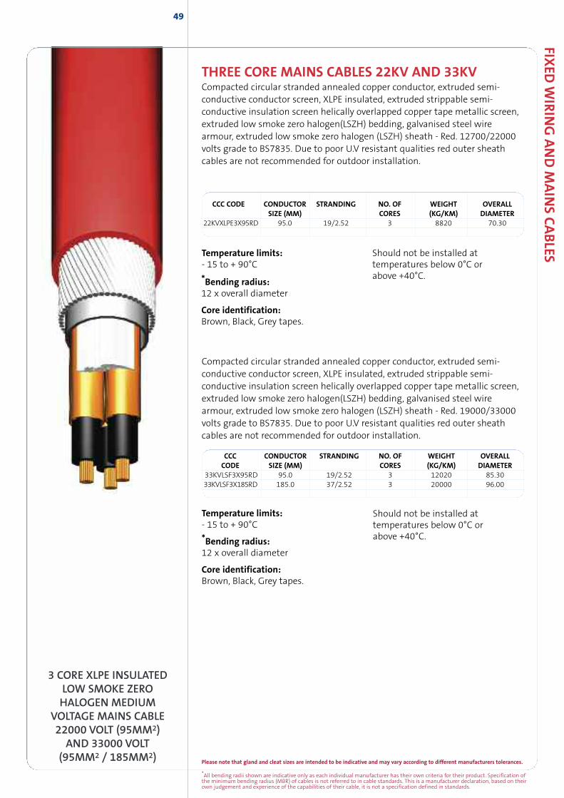
Please note that gland and cleat sizes are intended to be indicative and may vary according to different manufacturers tolerances.
*All bending radii shown are indicative only as each individual manufacturer has their own criteria for their product. Specification ofthe minimum bending radius (MBR) of cables is not referred to in cable standards. This is a manufacturer declaration, based on theirown judgement and experience of the capabilities of their cable, it is not a specification defined in standards.
FIXED
WIR
ING
AND
MAIN
SCABLES
49
Temperature limits: Should not be installed at- 15 to + 90°C temperatures below 0°C or
above +40°C.
Compacted circular stranded annealed copper conductor, extruded semi-conductive conductor screen, XLPE insulated, extruded strippable semi-conductive insulation screen helically overlapped copper tape metallic screen,extruded low smoke zero halogen(LSZH) bedding, galvanised steel wirearmour, extruded low smoke zero halogen (LSZH) sheath - Red. 19000/33000volts grade to BS7835. Due to poor U.V resistant qualities red outer sheathcables are not recommended for outdoor installation.
Temperature limits:- 15 to + 90°C
*Bending radius:12 x overall diameter
Core identification:Brown, Black, Grey tapes.
Should not be installed attemperatures below 0°C orabove +40°C.
CCC CODE CONDUCTOR STRANDING NO. OF WEIGHT OVERALLSIZE (MM) CORES (KG/KM) DIAMETER
22KVXLPE3X95RD 95.0 19/2.52 3 8820 70.30
THREE CORE MAINS CABLES 22KV AND 33KVCompacted circular stranded annealed copper conductor, extruded semi-conductive conductor screen, XLPE insulated, extruded strippable semi-conductive insulation screen helically overlapped copper tape metallic screen,extruded low smoke zero halogen(LSZH) bedding, galvanised steel wirearmour, extruded low smoke zero halogen (LSZH) sheath - Red. 12700/22000volts grade to BS7835. Due to poor U.V resistant qualities red outer sheathcables are not recommended for outdoor installation.
*Bending radius:12 x overall diameter
Core identification:Brown, Black, Grey tapes.
3 CORE XLPE INSULATEDLOW SMOKE ZEROHALOGEN MEDIUM
VOLTAGE MAINS CABLE22000 VOLT (95MM2)
AND 33000 VOLT(95MM2 / 185MM2)
CCC CONDUCTOR STRANDING NO. OF WEIGHT OVERALLCODE SIZE (MM) CORES (KG/KM) DIAMETER
33KVLSF3X95RD 95.0 19/2.52 3 12020 85.3033KVLSF3X185RD 185.0 37/2.52 3 20000 96.00

FIXED
WIR
ING
AND
MAIN
SCABLES
51
FIXED WIRING ANDMAINS CABLES33000V - SERVICEAND WINDFARM
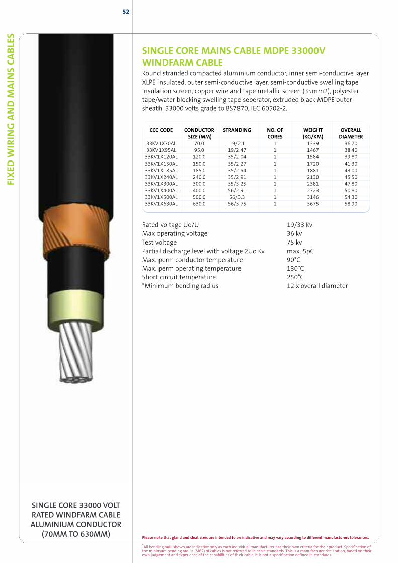
SINGLE CORE MAINS CABLE MDPE 33000VWINDFARM CABLERound stranded compacted aluminium conductor, inner semi-conductive layerXLPE insulated, outer semi-conductive layer, semi-conductive swelling tapeinsulation screen, copper wire and tape metallic screen (35mm2), polyestertape/water blocking swelling tape seperator, extruded black MDPE outersheath. 33000 volts grade to BS7870, IEC 60502-2.
Rated voltage Uo/U 19/33 KvMax operating voltage 36 kvTest voltage 75 kvPartial discharge level with voltage 2Uo Kv max. 5pCMax. perm conductor temperature 90°CMax. perm operating temperature 130°CShort circuit temperature 250°C*Minimum bending radius 12 x overall diameter
52
SINGLE CORE 33000 VOLTRATED WINDFARM CABLEALUMINIUM CONDUCTOR
(70MM TO 630MM)
CCC CODE CONDUCTOR STRANDING NO. OF WEIGHT OVERALLSIZE (MM) CORES (KG/KM) DIAMETER
33KV1X70AL 70.0 19/2.1 1 1339 36.7033KV1X95AL 95.0 19/2.47 1 1467 38.4033KV1X120AL 120.0 35/2.04 1 1584 39.8033KV1X150AL 150.0 35/2.27 1 1720 41.3033KV1X185AL 185.0 35/2.54 1 1881 43.0033KV1X240AL 240.0 35/2.91 1 2130 45.5033KV1X300AL 300.0 35/3.25 1 2381 47.8033KV1X400AL 400.0 56/2.91 1 2723 50.8033KV1X500AL 500.0 56/3.3 1 3146 54.3033KV1X630AL 630.0 56/3.75 1 3675 58.90
FIXED
WIR
ING
AND
MAIN
SCABLE
S
*All bending radii shown are indicative only as each individual manufacturer has their own criteria for their product. Specification ofthe minimum bending radius (MBR) of cables is not referred to in cable standards. This is a manufacturer declaration, based on theirown judgement and experience of the capabilities of their cable, it is not a specification defined in standards.
Please note that gland and cleat sizes are intended to be indicative and may vary according to different manufacturers tolerances.
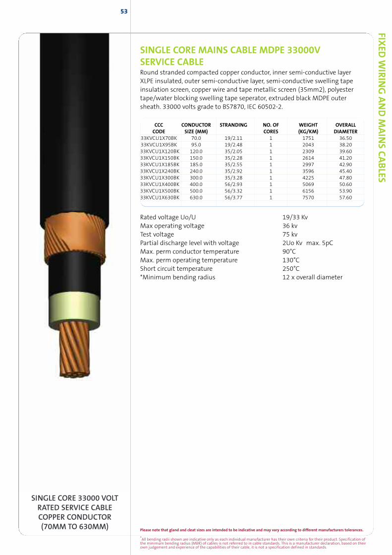
SINGLE CORE MAINS CABLE MDPE 33000VSERVICE CABLERound stranded compacted copper conductor, inner semi-conductive layerXLPE insulated, outer semi-conductive layer, semi-conductive swelling tapeinsulation screen, copper wire and tape metallic screen (35mm2), polyestertape/water blocking swelling tape seperator, extruded black MDPE outersheath. 33000 volts grade to BS7870, IEC 60502-2.
CCC CONDUCTOR STRANDING NO. OF WEIGHT OVERALLCODE SIZE (MM) CORES (KG/KM) DIAMETER
33KVCU1X70BK 70.0 19/2.11 1 1751 36.5033KVCU1X95BK 95.0 19/2.48 1 2043 38.2033KVCU1X120BK 120.0 35/2.05 1 2309 39.6033KVCU1X150BK 150.0 35/2.28 1 2614 41.2033KVCU1X185BK 185.0 35/2.55 1 2997 42.9033KVCU1X240BK 240.0 35/2.92 1 3596 45.4033KVCU1X300BK 300.0 35/3.28 1 4225 47.8033KVCU1X400BK 400.0 56/2.93 1 5069 50.6033KVCU1X500BK 500.0 56/3.32 1 6156 53.9033KVCU1X630BK 630.0 56/3.77 1 7570 57.60
SINGLE CORE 33000 VOLTRATED SERVICE CABLECOPPER CONDUCTOR(70MM TO 630MM)
Rated voltage Uo/U 19/33 KvMax operating voltage 36 kvTest voltage 75 kvPartial discharge level with voltage 2Uo Kv max. 5pCMax. perm conductor temperature 90°CMax. perm operating temperature 130°CShort circuit temperature 250°C*Minimum bending radius 12 x overall diameter
FIXED
WIR
ING
AND
MAIN
SCABLES
53
Please note that gland and cleat sizes are intended to be indicative and may vary according to different manufacturers tolerances.
*All bending radii shown are indicative only as each individual manufacturer has their own criteria for their product. Specification ofthe minimum bending radius (MBR) of cables is not referred to in cable standards. This is a manufacturer declaration, based on theirown judgement and experience of the capabilities of their cable, it is not a specification defined in standards.
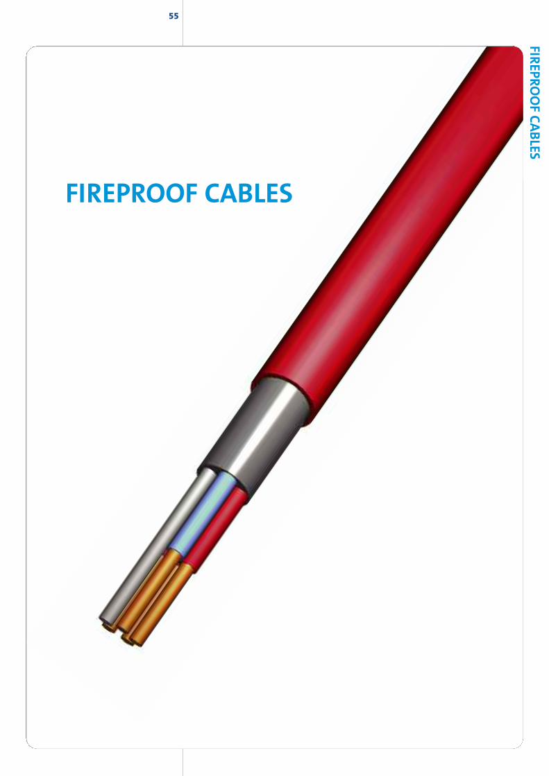
55
FIREPROOF CABLES
FIREPRO
OFCABLES
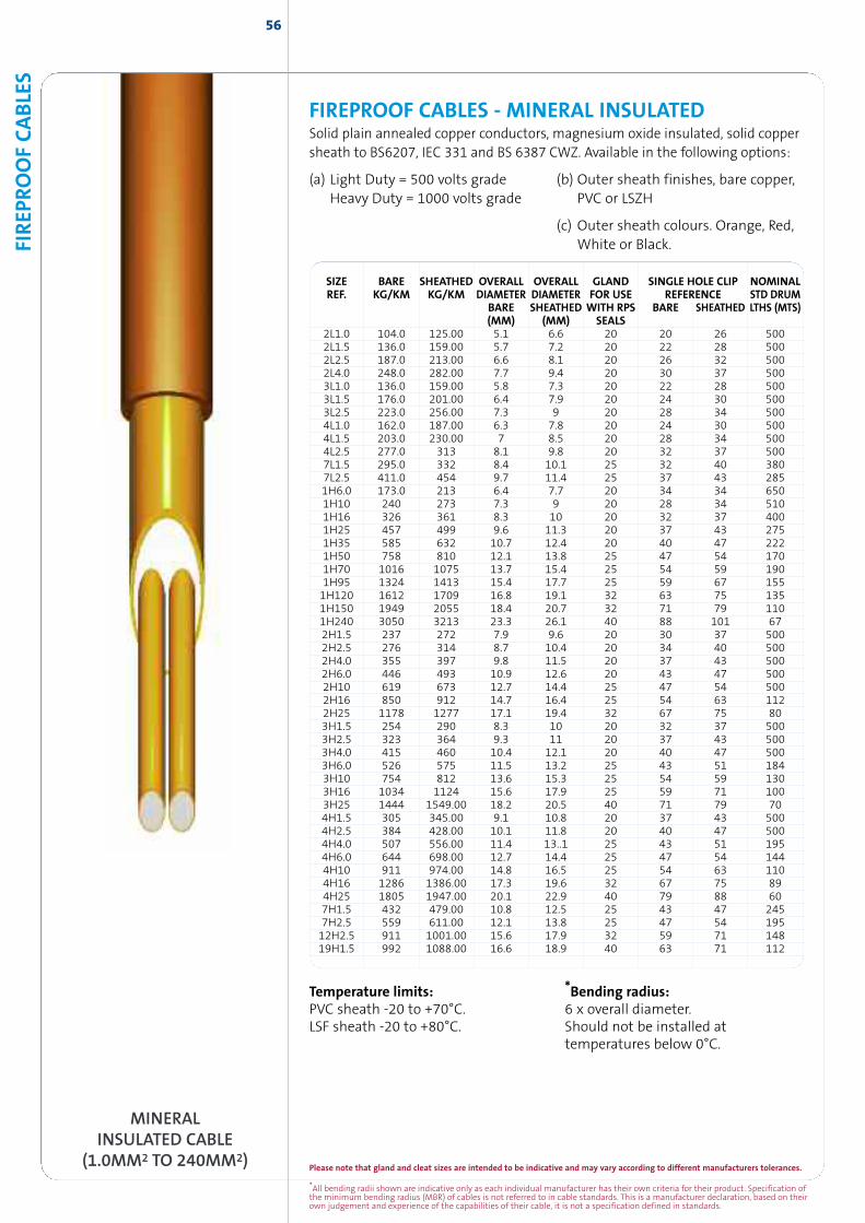
*All bending radii shown are indicative only as each individual manufacturer has their own criteria for their product. Specification ofthe minimum bending radius (MBR) of cables is not referred to in cable standards. This is a manufacturer declaration, based on theirown judgement and experience of the capabilities of their cable, it is not a specification defined in standards.
Please note that gland and cleat sizes are intended to be indicative and may vary according to different manufacturers tolerances.
56
FIREPROOF CABLES - MINERAL INSULATEDSolid plain annealed copper conductors, magnesium oxide insulated, solid coppersheath to BS6207, IEC 331 and BS 6387 CWZ. Available in the following options:
(a) Light Duty = 500 volts grade (b) Outer sheath finishes, bare copper,Heavy Duty = 1000 volts grade PVC or LSZH
(c) Outer sheath colours. Orange, Red,White or Black.
SIZE BARE SHEATHED OVERALL OVERALL GLAND SINGLE HOLE CLIP NOMINALREF. KG/KM KG/KM DIAMETER DIAMETER FOR USE REFERENCE STD DRUM
BARE SHEATHED WITH RPS BARE SHEATHED LTHS (MTS)(MM) (MM) SEALS
2L1.0 104.0 125.00 5.1 6.6 20 20 26 5002L1.5 136.0 159.00 5.7 7.2 20 22 28 5002L2.5 187.0 213.00 6.6 8.1 20 26 32 5002L4.0 248.0 282.00 7.7 9.4 20 30 37 5003L1.0 136.0 159.00 5.8 7.3 20 22 28 5003L1.5 176.0 201.00 6.4 7.9 20 24 30 5003L2.5 223.0 256.00 7.3 9 20 28 34 5004L1.0 162.0 187.00 6.3 7.8 20 24 30 5004L1.5 203.0 230.00 7 8.5 20 28 34 5004L2.5 277.0 313 8.1 9.8 20 32 37 5007L1.5 295.0 332 8.4 10.1 25 32 40 3807L2.5 411.0 454 9.7 11.4 25 37 43 2851H6.0 173.0 213 6.4 7.7 20 34 34 6501H10 240 273 7.3 9 20 28 34 5101H16 326 361 8.3 10 20 32 37 4001H25 457 499 9.6 11.3 20 37 43 2751H35 585 632 10.7 12.4 20 40 47 2221H50 758 810 12.1 13.8 25 47 54 1701H70 1016 1075 13.7 15.4 25 54 59 1901H95 1324 1413 15.4 17.7 25 59 67 1551H120 1612 1709 16.8 19.1 32 63 75 1351H150 1949 2055 18.4 20.7 32 71 79 1101H240 3050 3213 23.3 26.1 40 88 101 672H1.5 237 272 7.9 9.6 20 30 37 5002H2.5 276 314 8.7 10.4 20 34 40 5002H4.0 355 397 9.8 11.5 20 37 43 5002H6.0 446 493 10.9 12.6 20 43 47 5002H10 619 673 12.7 14.4 25 47 54 5002H16 850 912 14.7 16.4 25 54 63 1122H25 1178 1277 17.1 19.4 32 67 75 803H1.5 254 290 8.3 10 20 32 37 5003H2.5 323 364 9.3 11 20 37 43 5003H4.0 415 460 10.4 12.1 20 40 47 5003H6.0 526 575 11.5 13.2 25 43 51 1843H10 754 812 13.6 15.3 25 54 59 1303H16 1034 1124 15.6 17.9 25 59 71 1003H25 1444 1549.00 18.2 20.5 40 71 79 704H1.5 305 345.00 9.1 10.8 20 37 43 5004H2.5 384 428.00 10.1 11.8 20 40 47 5004H4.0 507 556.00 11.4 13..1 25 43 51 1954H6.0 644 698.00 12.7 14.4 25 47 54 1444H10 911 974.00 14.8 16.5 25 54 63 1104H16 1286 1386.00 17.3 19.6 32 67 75 894H25 1805 1947.00 20.1 22.9 40 79 88 607H1.5 432 479.00 10.8 12.5 25 43 47 2457H2.5 559 611.00 12.1 13.8 25 47 54 19512H2.5 911 1001.00 15.6 17.9 32 59 71 14819H1.5 992 1088.00 16.6 18.9 40 63 71 112
FIREP
ROOFCABLE
S
MINERALINSULATED CABLE
(1.0MM2 TO 240MM2)
Temperature limits:PVC sheath -20 to +70°C.LSF sheath -20 to +80°C.
*Bending radius:6 x overall diameter.Should not be installed attemperatures below 0°C.
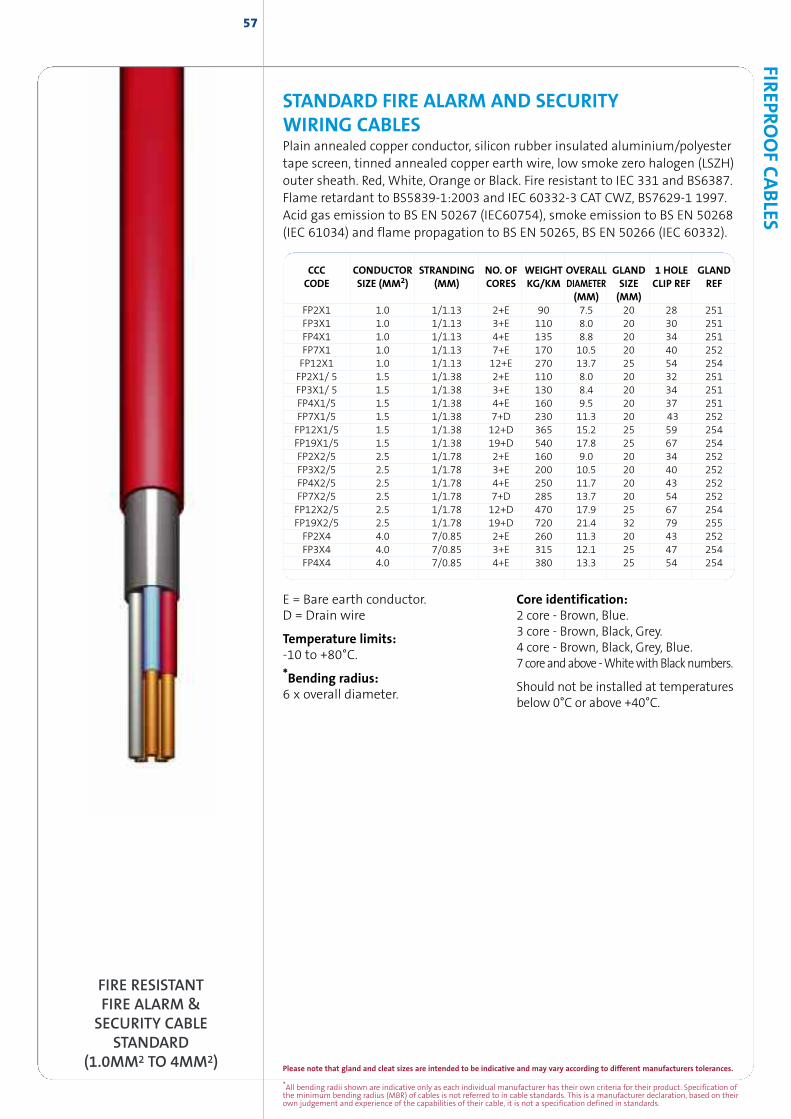
*All bending radii shown are indicative only as each individual manufacturer has their own criteria for their product. Specification ofthe minimum bending radius (MBR) of cables is not referred to in cable standards. This is a manufacturer declaration, based on theirown judgement and experience of the capabilities of their cable, it is not a specification defined in standards.
Please note that gland and cleat sizes are intended to be indicative and may vary according to different manufacturers tolerances.
57FIR
EPROOFCABLES
FIRE RESISTANTFIRE ALARM &
SECURITY CABLESTANDARD
(1.0MM2 TO 4MM2)
STANDARD FIRE ALARM AND SECURITYWIRING CABLESPlain annealed copper conductor, silicon rubber insulated aluminium/polyestertape screen, tinned annealed copper earth wire, low smoke zero halogen (LSZH)outer sheath. Red, White, Orange or Black. Fire resistant to IEC 331 and BS6387.Flame retardant to BS5839-1:2003 and IEC 60332-3 CAT CWZ, BS7629-1 1997.Acid gas emission to BS EN 50267 (IEC60754), smoke emission to BS EN 50268(IEC 61034) and flame propagation to BS EN 50265, BS EN 50266 (IEC 60332).
CCC CONDUCTOR STRANDING NO. OF WEIGHT OVERALL GLAND 1 HOLE GLANDCODE SIZE (MM2) (MM) CORES KG/KM DIAMETER SIZE CLIP REF REF
(MM) (MM)FP2X1 1.0 1/1.13 2+E 90 7.5 20 28 251FP3X1 1.0 1/1.13 3+E 110 8.0 20 30 251FP4X1 1.0 1/1.13 4+E 135 8.8 20 34 251FP7X1 1.0 1/1.13 7+E 170 10.5 20 40 252FP12X1 1.0 1/1.13 12+E 270 13.7 25 54 254FP2X1/ 5 1.5 1/1.38 2+E 110 8.0 20 32 251FP3X1/ 5 1.5 1/1.38 3+E 130 8.4 20 34 251FP4X1/5 1.5 1/1.38 4+E 160 9.5 20 37 251FP7X1/5 1.5 1/1.38 7+D 230 11.3 20 43 252FP12X1/5 1.5 1/1.38 12+D 365 15.2 25 59 254FP19X1/5 1.5 1/1.38 19+D 540 17.8 25 67 254FP2X2/5 2.5 1/1.78 2+E 160 9.0 20 34 252FP3X2/5 2.5 1/1.78 3+E 200 10.5 20 40 252FP4X2/5 2.5 1/1.78 4+E 250 11.7 20 43 252FP7X2/5 2.5 1/1.78 7+D 285 13.7 20 54 252FP12X2/5 2.5 1/1.78 12+D 470 17.9 25 67 254FP19X2/5 2.5 1/1.78 19+D 720 21.4 32 79 255FP2X4 4.0 7/0.85 2+E 260 11.3 20 43 252FP3X4 4.0 7/0.85 3+E 315 12.1 25 47 254FP4X4 4.0 7/0.85 4+E 380 13.3 25 54 254
E = Bare earth conductor.D = Drain wire
Temperature limits:-10 to +80°C.
*Bending radius:6 x overall diameter.
Core identification:2 core - Brown, Blue.3 core - Brown, Black, Grey.4 core - Brown, Black, Grey, Blue.7 core andabove -WhitewithBlacknumbers.
Should not be installed at temperaturesbelow 0°C or above +40°C.
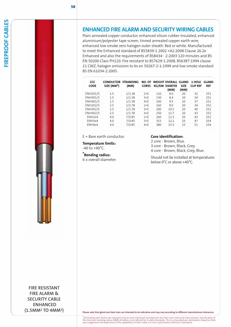
58
FIRE RESISTANTFIRE ALARM &
SECURITY CABLEENHANCED
(1.5MM2 TO 4MM2)
E = Bare earth conductor.
Temperature limits:-40 to +90°C.
*Bending radius:6 x overall diameter.
Core identification:2 core - Brown, Blue.3 core - Brown, Black, Grey.4 core - Brown, Black, Grey, Blue.
Should not be installed at temperaturesbelow 0°C or above +40°C.
CCC CONDUCTOR STRANDING NO. OF WEIGHT OVERALL GLAND 1 HOLE GLANDCODE SIZE (MM2) (MM) CORES KG/KM DIAMETER SIZE CLIP REF REF
(MM) (MM)ENH2X1/5 1.5 1/1.38 2+E 110 8.0 20 32 251ENH3X1/5 1.5 1/1.38 3+E 130 8.4 20 34 251ENH4X1/5 1.5 1/1.38 4+E 160 9.5 20 37 251ENH2X2/5 2.5 1/1.78 2+E 160 9.0 20 34 252ENH3X2/5 2.5 1/1.78 3+E 200 10.5 20 40 252ENH4X2/5 2.5 1/1.78 4+E 250 11.7 20 43 252ENH2x4 4.0 7/0.85 2+E 260 11.3 20 43 252ENH3x4 4.0 7/0.85 3+E 315 12.1 25 47 254ENH4x4 4.0 7/0.85 4+E 380 13.3 25 51 254
ENHANCED FIRE ALARMAND SECURITYWIRING CABLESPlain annealed copper conductor, enhanced silicon rubber insulated, enhancedaluminium/polyester tape screen, tinned annealed copper earth wire,enhanced low smoke zero halogen outer sheath. Red or white. Manufacturedto meet the Enhanced standard of BS5839-1 2002 +A2:2008 Clause 26.2eEnhanced and also the requirements of BS8434 - 2:2003 120 minutes and BSEN 50200 Class PH120. Fire resistant to BS7629-1:2008, BS6387:1994 clause11 CWZ, halogen emissions to bs en 50267-2-1:1999 and low smoke standardBS EN 61034-2:2005.
FIREP
ROOFCABLE
S
*All bending radii shown are indicative only as each individual manufacturer has their own criteria for their product. Specification ofthe minimum bending radius (MBR) of cables is not referred to in cable standards. This is a manufacturer declaration, based on theirown judgement and experience of the capabilities of their cable, it is not a specification defined in standards.
Please note that gland and cleat sizes are intended to be indicative and may vary according to different manufacturers tolerances.
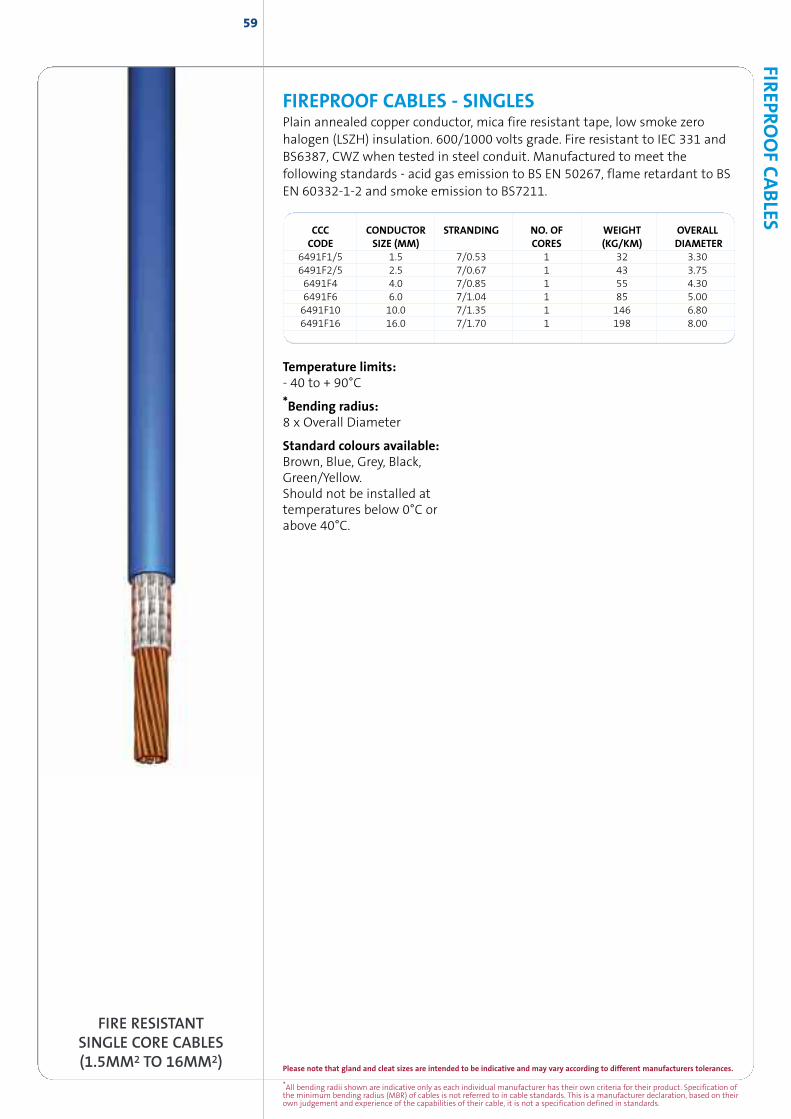
CCC CONDUCTOR STRANDING NO. OF WEIGHT OVERALLCODE SIZE (MM) CORES (KG/KM) DIAMETER
6491F1/5 1.5 7/0.53 1 32 3.306491F2/5 2.5 7/0.67 1 43 3.756491F4 4.0 7/0.85 1 55 4.306491F6 6.0 7/1.04 1 85 5.006491F10 10.0 7/1.35 1 146 6.806491F16 16.0 7/1.70 1 198 8.00
Temperature limits:- 40 to + 90°C
*Bending radius:8 x Overall Diameter
Standard colours available:Brown, Blue, Grey, Black,Green/Yellow.Should not be installed attemperatures below 0°C orabove 40°C.
FIREPROOF CABLES - SINGLESPlain annealed copper conductor, mica fire resistant tape, low smoke zerohalogen (LSZH) insulation. 600/1000 volts grade. Fire resistant to IEC 331 andBS6387, CWZ when tested in steel conduit. Manufactured to meet thefollowing standards - acid gas emission to BS EN 50267, flame retardant to BSEN 60332-1-2 and smoke emission to BS7211.
FIRE RESISTANTSINGLE CORE CABLES(1.5MM2 TO 16MM2)
FIREPRO
OFCABLES
59
Please note that gland and cleat sizes are intended to be indicative and may vary according to different manufacturers tolerances.
*All bending radii shown are indicative only as each individual manufacturer has their own criteria for their product. Specification ofthe minimum bending radius (MBR) of cables is not referred to in cable standards. This is a manufacturer declaration, based on theirown judgement and experience of the capabilities of their cable, it is not a specification defined in standards.
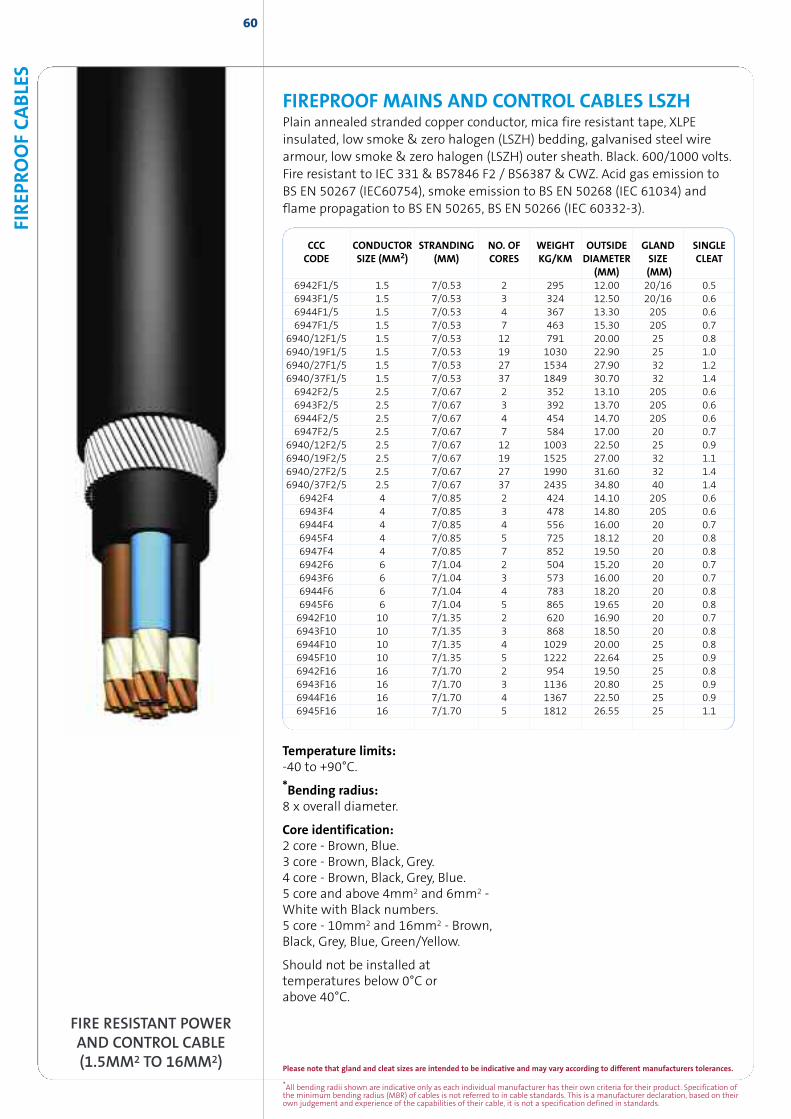
FIRE RESISTANT POWERAND CONTROL CABLE(1.5MM2 TO 16MM2)
CCC CONDUCTOR STRANDING NO. OF WEIGHT OUTSIDE GLAND SINGLECODE SIZE (MM2) (MM) CORES KG/KM DIAMETER SIZE CLEAT
(MM) (MM)6942F1/5 1.5 7/0.53 2 295 12.00 20/16 0.56943F1/5 1.5 7/0.53 3 324 12.50 20/16 0.66944F1/5 1.5 7/0.53 4 367 13.30 20S 0.66947F1/5 1.5 7/0.53 7 463 15.30 20S 0.7
6940/12F1/5 1.5 7/0.53 12 791 20.00 25 0.86940/19F1/5 1.5 7/0.53 19 1030 22.90 25 1.06940/27F1/5 1.5 7/0.53 27 1534 27.90 32 1.26940/37F1/5 1.5 7/0.53 37 1849 30.70 32 1.46942F2/5 2.5 7/0.67 2 352 13.10 20S 0.66943F2/5 2.5 7/0.67 3 392 13.70 20S 0.66944F2/5 2.5 7/0.67 4 454 14.70 20S 0.66947F2/5 2.5 7/0.67 7 584 17.00 20 0.7
6940/12F2/5 2.5 7/0.67 12 1003 22.50 25 0.96940/19F2/5 2.5 7/0.67 19 1525 27.00 32 1.16940/27F2/5 2.5 7/0.67 27 1990 31.60 32 1.46940/37F2/5 2.5 7/0.67 37 2435 34.80 40 1.4
6942F4 4 7/0.85 2 424 14.10 20S 0.66943F4 4 7/0.85 3 478 14.80 20S 0.66944F4 4 7/0.85 4 556 16.00 20 0.76945F4 4 7/0.85 5 725 18.12 20 0.86947F4 4 7/0.85 7 852 19.50 20 0.86942F6 6 7/1.04 2 504 15.20 20 0.76943F6 6 7/1.04 3 573 16.00 20 0.76944F6 6 7/1.04 4 783 18.20 20 0.86945F6 6 7/1.04 5 865 19.65 20 0.86942F10 10 7/1.35 2 620 16.90 20 0.76943F10 10 7/1.35 3 868 18.50 20 0.86944F10 10 7/1.35 4 1029 20.00 25 0.86945F10 10 7/1.35 5 1222 22.64 25 0.96942F16 16 7/1.70 2 954 19.50 25 0.86943F16 16 7/1.70 3 1136 20.80 25 0.96944F16 16 7/1.70 4 1367 22.50 25 0.96945F16 16 7/1.70 5 1812 26.55 25 1.1
FIREPROOF MAINS AND CONTROL CABLES LSZHPlain annealed stranded copper conductor, mica fire resistant tape, XLPEinsulated, low smoke & zero halogen (LSZH) bedding, galvanised steel wirearmour, low smoke & zero halogen (LSZH) outer sheath. Black. 600/1000 volts.Fire resistant to IEC 331 & BS7846 F2 / BS6387 & CWZ. Acid gas emission toBS EN 50267 (IEC60754), smoke emission to BS EN 50268 (IEC 61034) andflame propagation to BS EN 50265, BS EN 50266 (IEC 60332-3).
60FIREP
ROOFCABLE
S
*All bending radii shown are indicative only as each individual manufacturer has their own criteria for their product. Specification ofthe minimum bending radius (MBR) of cables is not referred to in cable standards. This is a manufacturer declaration, based on theirown judgement and experience of the capabilities of their cable, it is not a specification defined in standards.
Please note that gland and cleat sizes are intended to be indicative and may vary according to different manufacturers tolerances.
Temperature limits:-40 to +90°C.
*Bending radius:8 x overall diameter.
Core identification:2 core - Brown, Blue.3 core - Brown, Black, Grey.4 core - Brown, Black, Grey, Blue.5 core and above 4mm2 and 6mm2 -White with Black numbers.5 core - 10mm2 and 16mm2 - Brown,Black, Grey, Blue, Green/Yellow.
Should not be installed attemperatures below 0°C orabove 40°C.
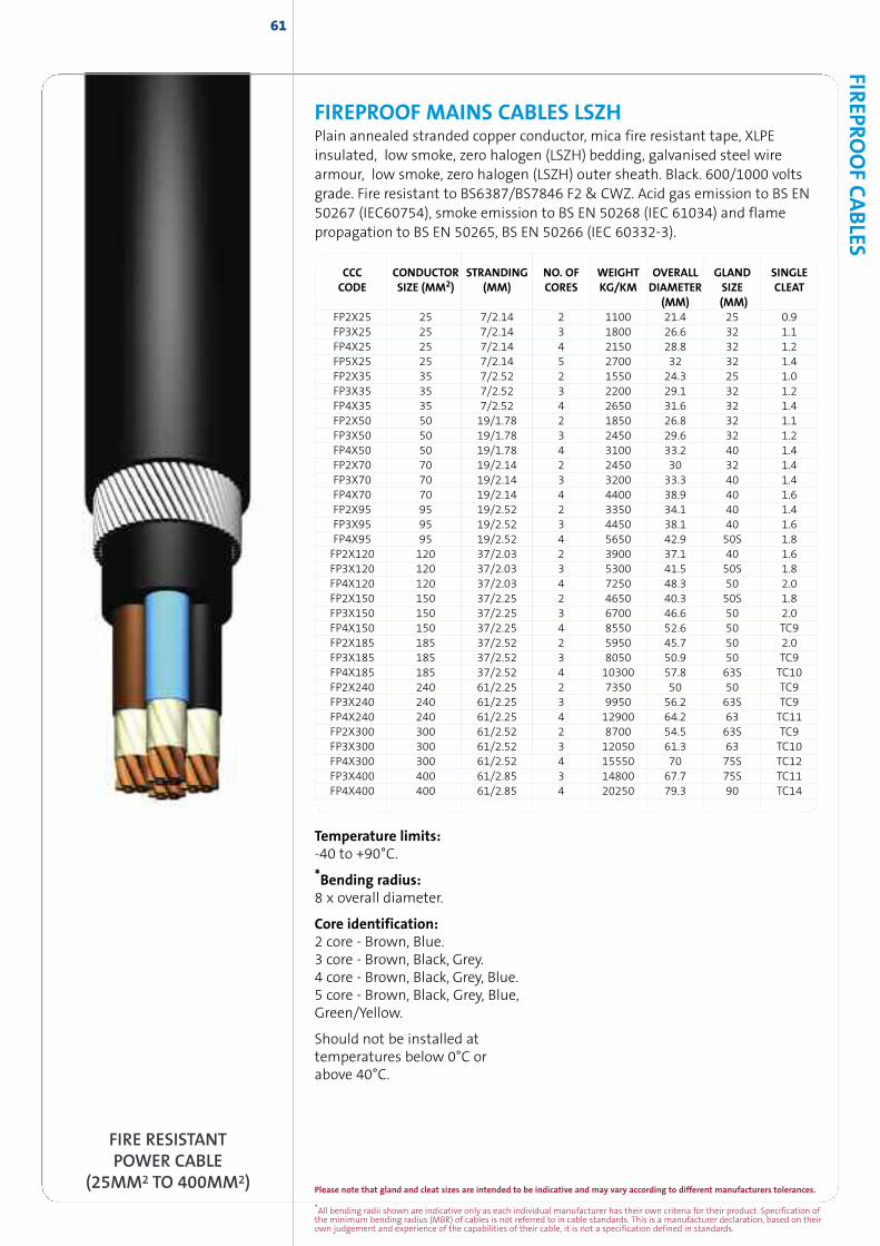
Please note that gland and cleat sizes are intended to be indicative and may vary according to different manufacturers tolerances.
*All bending radii shown are indicative only as each individual manufacturer has their own criteria for their product. Specification ofthe minimum bending radius (MBR) of cables is not referred to in cable standards. This is a manufacturer declaration, based on theirown judgement and experience of the capabilities of their cable, it is not a specification defined in standards.
FIREPRO
OFCABLES
61
FIRE RESISTANTPOWER CABLE
(25MM2 TO 400MM2)
CCC CONDUCTOR STRANDING NO. OF WEIGHT OVERALL GLAND SINGLECODE SIZE (MM2) (MM) CORES KG/KM DIAMETER SIZE CLEAT
(MM) (MM)FP2X25 25 7/2.14 2 1100 21.4 25 0.9FP3X25 25 7/2.14 3 1800 26.6 32 1.1FP4X25 25 7/2.14 4 2150 28.8 32 1.2FP5X25 25 7/2.14 5 2700 32 32 1.4FP2X35 35 7/2.52 2 1550 24.3 25 1.0FP3X35 35 7/2.52 3 2200 29.1 32 1.2FP4X35 35 7/2.52 4 2650 31.6 32 1.4FP2X50 50 19/1.78 2 1850 26.8 32 1.1FP3X50 50 19/1.78 3 2450 29.6 32 1.2FP4X50 50 19/1.78 4 3100 33.2 40 1.4FP2X70 70 19/2.14 2 2450 30 32 1.4FP3X70 70 19/2.14 3 3200 33.3 40 1.4FP4X70 70 19/2.14 4 4400 38.9 40 1.6FP2X95 95 19/2.52 2 3350 34.1 40 1.4FP3X95 95 19/2.52 3 4450 38.1 40 1.6FP4X95 95 19/2.52 4 5650 42.9 50S 1.8FP2X120 120 37/2.03 2 3900 37.1 40 1.6FP3X120 120 37/2.03 3 5300 41.5 50S 1.8FP4X120 120 37/2.03 4 7250 48.3 50 2.0FP2X150 150 37/2.25 2 4650 40.3 50S 1.8FP3X150 150 37/2.25 3 6700 46.6 50 2.0FP4X150 150 37/2.25 4 8550 52.6 50 TC9FP2X185 185 37/2.52 2 5950 45.7 50 2.0FP3X185 185 37/2.52 3 8050 50.9 50 TC9FP4X185 185 37/2.52 4 10300 57.8 63S TC10FP2X240 240 61/2.25 2 7350 50 50 TC9FP3X240 240 61/2.25 3 9950 56.2 63S TC9FP4X240 240 61/2.25 4 12900 64.2 63 TC11FP2X300 300 61/2.52 2 8700 54.5 63S TC9FP3X300 300 61/2.52 3 12050 61.3 63 TC10FP4X300 300 61/2.52 4 15550 70 75S TC12FP3X400 400 61/2.85 3 14800 67.7 75S TC11FP4X400 400 61/2.85 4 20250 79.3 90 TC14
Temperature limits:-40 to +90°C.
*Bending radius:8 x overall diameter.
Core identification:2 core - Brown, Blue.3 core - Brown, Black, Grey.4 core - Brown, Black, Grey, Blue.5 core - Brown, Black, Grey, Blue,Green/Yellow.
Should not be installed attemperatures below 0°C orabove 40°C.
FIREPROOF MAINS CABLES LSZHPlain annealed stranded copper conductor, mica fire resistant tape, XLPEinsulated, low smoke, zero halogen (LSZH) bedding, galvanised steel wirearmour, low smoke, zero halogen (LSZH) outer sheath. Black. 600/1000 voltsgrade. Fire resistant to BS6387/BS7846 F2 & CWZ. Acid gas emission to BS EN50267 (IEC60754), smoke emission to BS EN 50268 (IEC 61034) and flamepropagation to BS EN 50265, BS EN 50266 (IEC 60332-3).
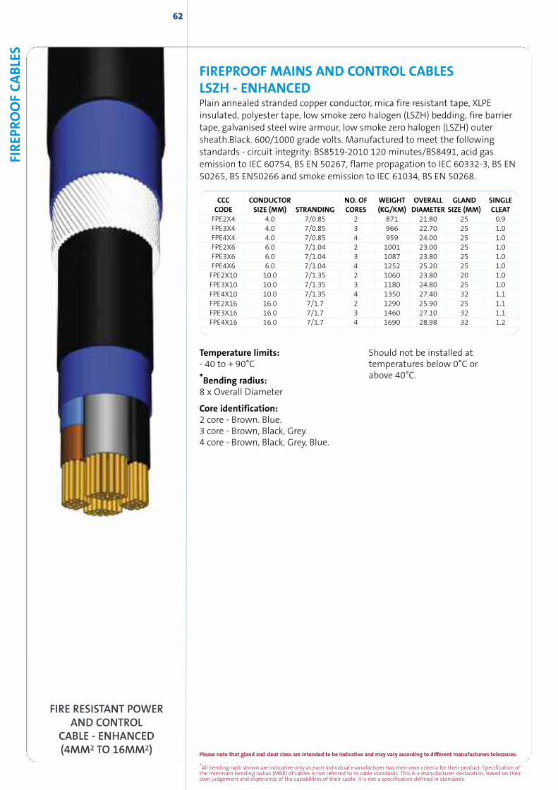
CCC CONDUCTOR NO. OF WEIGHT OVERALL GLAND SINGLECODE SIZE (MM) STRANDING CORES (KG/KM) DIAMETER SIZE (MM) CLEATFPE2X4 4.0 7/0.85 2 871 21.80 25 0.9FPE3X4 4.0 7/0.85 3 966 22.70 25 1.0FPE4X4 4.0 7/0.85 4 959 24.00 25 1.0FPE2X6 6.0 7/1.04 2 1001 23.00 25 1.0FPE3X6 6.0 7/1.04 3 1087 23.80 25 1.0FPE4X6 6.0 7/1.04 4 1252 25.20 25 1.0FPE2X10 10.0 7/1.35 2 1060 23.80 20 1.0FPE3X10 10.0 7/1.35 3 1180 24.80 25 1.0FPE4X10 10.0 7/1.35 4 1350 27.40 32 1.1FPE2X16 16.0 7/1.7 2 1290 25.90 25 1.1FPE3X16 16.0 7/1.7 3 1460 27.10 32 1.1FPE4X16 16.0 7/1.7 4 1690 28.98 32 1.2
62
FIREPROOF MAINS AND CONTROL CABLESLSZH - ENHANCEDPlain annealed stranded copper conductor, mica fire resistant tape, XLPEinsulated, polyester tape, low smoke zero halogen (LSZH) bedding, fire barriertape, galvanised steel wire armour, low smoke zero halogen (LSZH) outersheath.Black. 600/1000 grade volts. Manufactured to meet the followingstandards - circuit integrity: BS8519-2010 120 minutes/BS8491, acid gasemission to IEC 60754, BS EN 50267, flame propagation to IEC 60332-3, BS EN50265, BS EN50266 and smoke emission to IEC 61034, BS EN 50268.
Temperature limits:- 40 to + 90°C
*Bending radius:8 x Overall Diameter
Core identification:2 core - Brown. Blue.3 core - Brown, Black, Grey.4 core - Brown, Black, Grey, Blue.
Should not be installed attemperatures below 0°C orabove 40°C.
FIRE RESISTANT POWERAND CONTROL
CABLE - ENHANCED(4MM2 TO 16MM2)
FIREP
ROOFCABLE
S
*All bending radii shown are indicative only as each individual manufacturer has their own criteria for their product. Specification ofthe minimum bending radius (MBR) of cables is not referred to in cable standards. This is a manufacturer declaration, based on theirown judgement and experience of the capabilities of their cable, it is not a specification defined in standards.
Please note that gland and cleat sizes are intended to be indicative and may vary according to different manufacturers tolerances.
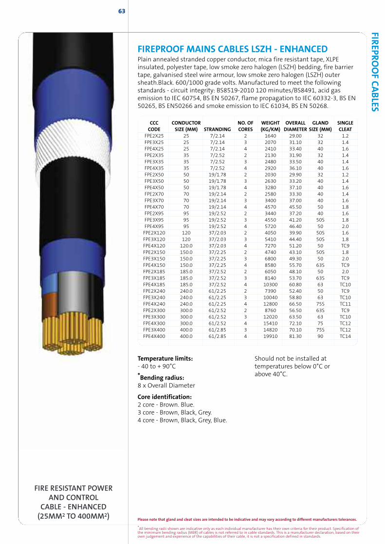
FIREPRO
OFCABLES
Please note that gland and cleat sizes are intended to be indicative and may vary according to different manufacturers tolerances.
*All bending radii shown are indicative only as each individual manufacturer has their own criteria for their product. Specification ofthe minimum bending radius (MBR) of cables is not referred to in cable standards. This is a manufacturer declaration, based on theirown judgement and experience of the capabilities of their cable, it is not a specification defined in standards.
FIREPROOF MAINS CABLES LSZH - ENHANCEDPlain annealed stranded copper conductor, mica fire resistant tape, XLPEinsulated, polyester tape, low smoke zero halogen (LSZH) bedding, fire barriertape, galvanised steel wire armour, low smoke zero halogen (LSZH) outersheath.Black. 600/1000 grade volts. Manufactured to meet the followingstandards - circuit integrity: BS8519-2010 120 minutes/BS8491, acid gasemission to IEC 60754, BS EN 50267, flame propagation to IEC 60332-3, BS EN50265, BS EN50266 and smoke emission to IEC 61034, BS EN 50268.
CCC CONDUCTOR NO. OF WEIGHT OVERALL GLAND SINGLECODE SIZE (MM) STRANDING CORES (KG/KM) DIAMETER SIZE (MM) CLEAT
FPE2X25 25 7/2.14 2 1640 29.00 32 1.2FPE3X25 25 7/2.14 3 2070 31.10 32 1.4FPE4X25 25 7/2.14 4 2410 33.40 40 1.6FPE2X35 35 7/2.52 2 2130 31.90 32 1.4FPE3X35 35 7/2.52 3 2480 33.50 40 1.4FPE4X35 35 7/2.52 4 2920 36.10 40 1.6FPE2X50 50 19/1.78 2 2030 29.90 32 1.2FPE3X50 50 19/1.78 3 2630 33.20 40 1.4FPE4X50 50 19/1.78 4 3280 37.10 40 1.6FPE2X70 70 19/2.14 2 2580 33.30 40 1.4FPE3X70 70 19/2.14 3 3400 37.00 40 1.6FPE4X70 70 19/2.14 4 4570 45.50 50 1.8FPE2X95 95 19/2.52 2 3440 37.20 40 1.6FPE3X95 95 19/2.52 3 4550 41.20 50S 1.8FPE4X95 95 19/2.52 4 5720 46.40 50 2.0FPE2X120 120 37/2.03 2 4050 39.90 50S 1.6FPE3X120 120 37/2.03 3 5410 44.40 50S 1.8FPE4X120 120.0 37/2.03 4 7270 51.20 50 TC9FPE2X150 150.0 37/2.25 2 4740 43.10 50S 1.8FPE3X150 150.0 37/2.25 3 6800 49.30 50 2.0FPE4X150 150.0 37/2.25 4 8580 55.70 63S TC9FPE2X185 185.0 37/2.52 2 6050 48.10 50 2.0FPE3X185 185.0 37/2.52 3 8140 53.70 63S TC9FPE4X185 185.0 37/2.52 4 10300 60.80 63 TC10FPE2X240 240.0 61/2.25 2 7390 52.40 50 TC9FPE3X240 240.0 61/2.25 3 10040 58.80 63 TC10FPE4X240 240.0 61/2.25 4 12800 66.50 75S TC11FPE2X300 300.0 61/2.52 2 8760 56.50 63S TC9FPE3X300 300.0 61/2.52 3 12020 63.50 63 TC10FPE4X300 300.0 61/2.52 4 15410 72.10 75 TC12FPE3X400 400.0 61/2.85 3 14820 70.10 75S TC12FPE4X400 400.0 61/2.85 4 19910 81.30 90 TC14
63
FIRE RESISTANT POWERAND CONTROL
CABLE - ENHANCED(25MM2 TO 400MM2)
Temperature limits:- 40 to + 90°C
*Bending radius:8 x Overall Diameter
Core identification:2 core - Brown. Blue.3 core - Brown, Black, Grey.4 core - Brown, Black, Grey, Blue.
Should not be installed attemperatures below 0°C orabove 40°C.
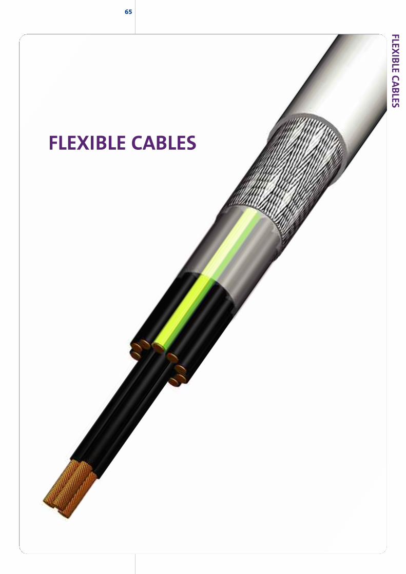
65
FLEXIBLE CABLES
FLEXIB
LECABLES
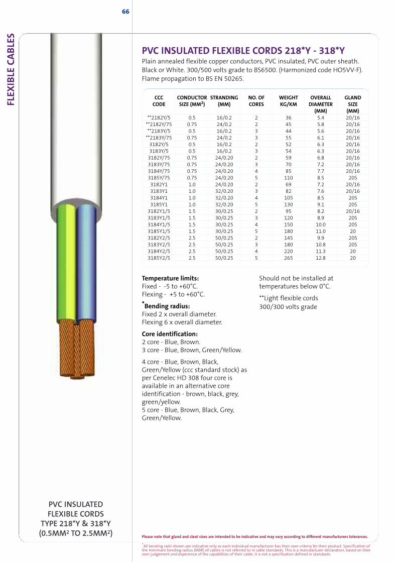
*All bending radii shown are indicative only as each individual manufacturer has their own criteria for their product. Specification ofthe minimum bending radius (MBR) of cables is not referred to in cable standards. This is a manufacturer declaration, based on theirown judgement and experience of the capabilities of their cable, it is not a specification defined in standards.
Please note that gland and cleat sizes are intended to be indicative and may vary according to different manufacturers tolerances.
FLEX
IBLE
CABLE
S66
PVC INSULATED FLEXIBLE CORDS 218*Y - 318*YPlain annealed flexible copper conductors, PVC insulated, PVC outer sheath.Black or White. 300/500 volts grade to BS6500. (Harmonized code HO5VV-F).Flame propagation to BS EN 50265.
CCC CONDUCTOR STRANDING NO. OF WEIGHT OVERALL GLANDCODE SIZE (MM2) (MM) CORES KG/KM DIAMETER SIZE
(MM) (MM)**2182Y/5 0.5 16/0.2 2 36 5.4 20/16**2182Y/75 0.75 24/0.2 2 45 5.8 20/16**2183Y/5 0.5 16/0.2 3 44 5.6 20/16**2183Y/75 0.75 24/0.2 3 55 6.1 20/163182Y/5 0.5 16/0.2 2 52 6.3 20/163183Y/5 0.5 16/0.2 3 54 6.3 20/163182Y/75 0.75 24/0.20 2 59 6.8 20/163183Y/75 0.75 24/0.20 3 70 7.2 20/163184Y/75 0.75 24/0.20 4 85 7.7 20/163185Y/75 0.75 24/0.20 5 110 8.5 20S3182Y1 1.0 24/0.20 2 69 7.2 20/163183Y1 1.0 32/0.20 3 82 7.6 20/163184Y1 1.0 32/0.20 4 105 8.5 20S3185Y1 1.0 32/0.20 5 130 9.1 20S3182Y1/5 1.5 30/0.25 2 95 8.2 20/163183Y1/5 1.5 30/0.25 3 120 8.9 20S3184Y1/5 1.5 30/0.25 4 150 10.0 20S3185Y1/5 1.5 30/0.25 5 180 11.0 203182Y2/5 2.5 50/0.25 2 145 9.9 20S3183Y2/5 2.5 50/0.25 3 180 10.8 20S3184Y2/5 2.5 50/0.25 4 220 11.3 203185Y2/5 2.5 50/0.25 5 265 12.8 20
PVC INSULATEDFLEXIBLE CORDS
TYPE 218*Y & 318*Y(0.5MM2 TO 2.5MM2)
Temperature limits:Fixed - -5 to +60°C.Flexing - +5 to +60°C.
*Bending radius:Fixed 2 x overall diameter.Flexing 6 x overall diameter.
Core identification:2 core - Blue, Brown.3 core - Blue, Brown, Green/Yellow.
4 core - Blue, Brown, Black,Green/Yellow (ccc standard stock) asper Cenelec HD 308 four core isavailable in an alternative coreidentification - brown, black, grey,green/yellow.5 core - Blue, Brown, Black, Grey,Green/Yellow.
Should not be installed attemperatures below 0°C.
**Light flexible cords300/300 volts grade
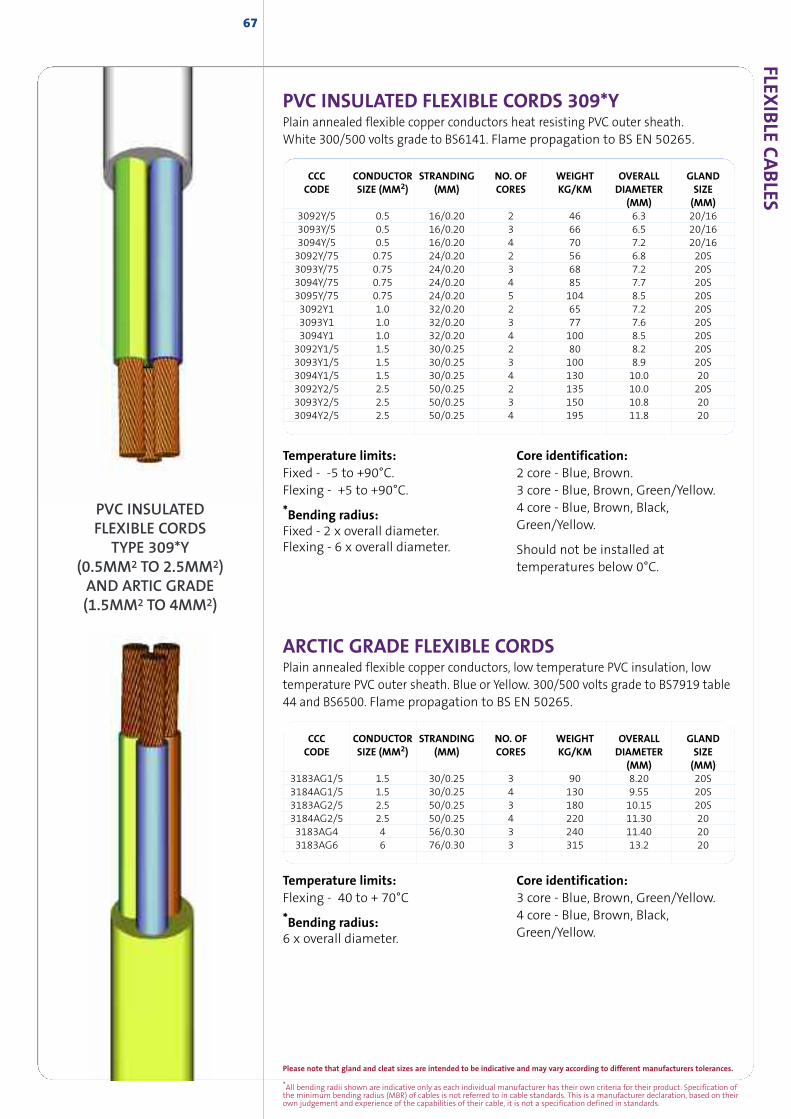
Please note that gland and cleat sizes are intended to be indicative and may vary according to different manufacturers tolerances.
*All bending radii shown are indicative only as each individual manufacturer has their own criteria for their product. Specification ofthe minimum bending radius (MBR) of cables is not referred to in cable standards. This is a manufacturer declaration, based on theirown judgement and experience of the capabilities of their cable, it is not a specification defined in standards.
FLEXIB
LECABLES
67
PVC INSULATED FLEXIBLE CORDS 309*YPlain annealed flexible copper conductors heat resisting PVC outer sheath.White 300/500 volts grade to BS6141. Flame propagation to BS EN 50265.
CCC CONDUCTOR STRANDING NO. OF WEIGHT OVERALL GLANDCODE SIZE (MM2) (MM) CORES KG/KM DIAMETER SIZE
(MM) (MM)3092Y/5 0.5 16/0.20 2 46 6.3 20/163093Y/5 0.5 16/0.20 3 66 6.5 20/163094Y/5 0.5 16/0.20 4 70 7.2 20/163092Y/75 0.75 24/0.20 2 56 6.8 20S3093Y/75 0.75 24/0.20 3 68 7.2 20S3094Y/75 0.75 24/0.20 4 85 7.7 20S3095Y/75 0.75 24/0.20 5 104 8.5 20S3092Y1 1.0 32/0.20 2 65 7.2 20S3093Y1 1.0 32/0.20 3 77 7.6 20S3094Y1 1.0 32/0.20 4 100 8.5 20S3092Y1/5 1.5 30/0.25 2 80 8.2 20S3093Y1/5 1.5 30/0.25 3 100 8.9 20S3094Y1/5 1.5 30/0.25 4 130 10.0 203092Y2/5 2.5 50/0.25 2 135 10.0 20S3093Y2/5 2.5 50/0.25 3 150 10.8 203094Y2/5 2.5 50/0.25 4 195 11.8 20
Temperature limits:Fixed - -5 to +90°C.Flexing - +5 to +90°C.
*Bending radius:Fixed - 2 x overall diameter.Flexing - 6 x overall diameter.
Core identification:2 core - Blue, Brown.3 core - Blue, Brown, Green/Yellow.4 core - Blue, Brown, Black,Green/Yellow.
Should not be installed attemperatures below 0°C.
ARCTIC GRADE FLEXIBLE CORDSPlain annealed flexible copper conductors, low temperature PVC insulation, lowtemperature PVC outer sheath. Blue or Yellow. 300/500 volts grade to BS7919 table44 and BS6500. Flame propagation to BS EN 50265.
CCC CONDUCTOR STRANDING NO. OF WEIGHT OVERALL GLANDCODE SIZE (MM2) (MM) CORES KG/KM DIAMETER SIZE
(MM) (MM)3183AG1/5 1.5 30/0.25 3 90 8.20 20S3184AG1/5 1.5 30/0.25 4 130 9.55 20S3183AG2/5 2.5 50/0.25 3 180 10.15 20S3184AG2/5 2.5 50/0.25 4 220 11.30 203183AG4 4 56/0.30 3 240 11.40 203183AG6 6 76/0.30 3 315 13.2 20
Temperature limits:Flexing - 40 to + 70°C
*Bending radius:6 x overall diameter.
Core identification:3 core - Blue, Brown, Green/Yellow.4 core - Blue, Brown, Black,Green/Yellow.
PVC INSULATEDFLEXIBLE CORDS
TYPE 309*Y(0.5MM2 TO 2.5MM2)AND ARTIC GRADE(1.5MM2 TO 4MM2)
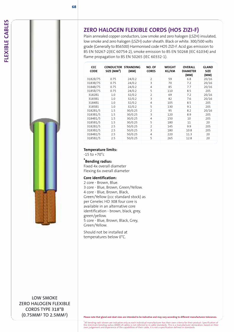
*All bending radii shown are indicative only as each individual manufacturer has their own criteria for their product. Specification ofthe minimum bending radius (MBR) of cables is not referred to in cable standards. This is a manufacturer declaration, based on theirown judgement and experience of the capabilities of their cable, it is not a specification defined in standards.
Please note that gland and cleat sizes are intended to be indicative and may vary according to different manufacturers tolerances.
FLEX
IBLE
CABLE
S68
LOW SMOKEZERO HALOGEN FLEXIBLE
CORDS TYPE 318*B(0.75MM2 TO 2.5MM2)
ZERO HALOGEN FLEXIBLE CORDS (HO5 ZIZI-F)Plain annealed copper conductors, Low smoke and zero halogen (LSZH) insulated,low smoke and zero halogen (LSZH) outer sheath. Black or white. 300/500 voltsgrade (Generally to BS6500) Harmonised code HO5 ZIZI-F. Acid gas emission toBS EN 50267-2(IEC 60754-2), smoke emission to BS EN 50268 (IEC 61034) andflame propagation to BS EN 50265 (IEC 60332-1).
CCC CONDUCTOR STRANDING NO. OF WEIGHT OVERALL GLANDCODE SIZE (MM2) (MM) CORES KG/KM DIAMETER SIZE
(MM) (MM)3182B/75 0.75 24/0.2 2 59 6.8 20/163183B/75 0.75 24/0.2 3 70 7.2 20/163184B/75 0.75 24/0.2 4 85 7.7 20/163185B/75 0.75 24/0.2 5 110 8.5 20S3182B1 1.0 32/0.2 2 69 7.2 20/163183B1 1.0 32/0.2 3 82 7.6 20/163184B1 1.0 32/0.2 4 105 8.5 20S3185B1 1.0 32/0.2 5 130 9.1 20S3182B1/5 1.5 30/0.25 2 95 8.2 20/163183B1/5 1.5 30/0.25 3 120 8.9 20S3184B1/5 1.5 30/0.25 4 150 10 20S3185B1/5 1.5 30/0.25 5 180 11 203182B2/5 2.5 50/0.25 2 145 9.9 20S3183B2/5 2.5 50/0.25 3 180 10.8 20S3184B2/5 2.5 50/0.25 4 220 11.3 203185B2/5 2.5 50/0.25 5 265 12.8 20
Temperature limits:-15 to +70°c
*Bending radius:Fixed 4x overall diameterFlexing 6x overall diameter
Core identification:2 core - Brown, Blue.3 core - Blue, Brown, Green/Yellow.4 core - Blue, Brown, Black,Green/Yellow (ccc standard stock) asper Cenelec HD 308 four core isavailable in an alternative coreidentification - brown, black, grey,green/yellow.5 core - Blue, Brown, Black, Grey,Green/Yellow.
Should not be installed attemperatures below 0°C.
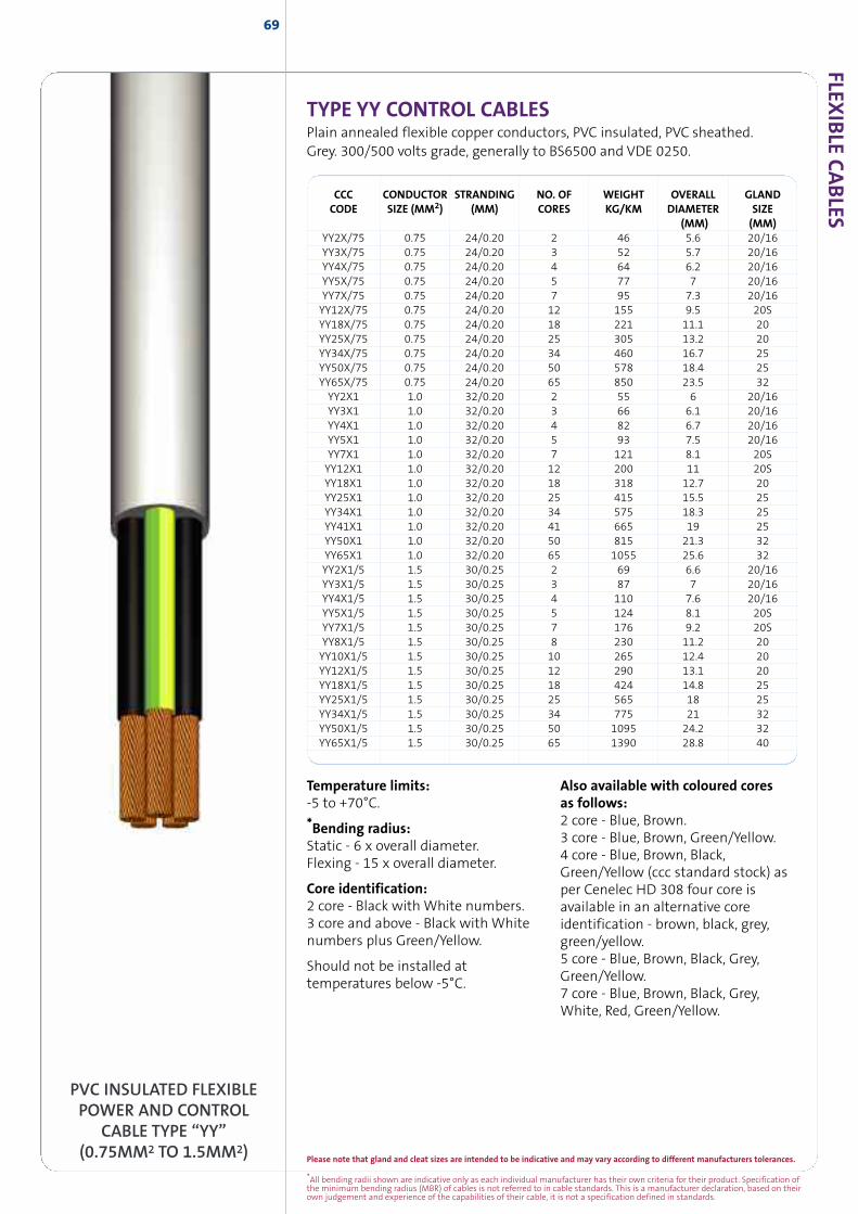
Please note that gland and cleat sizes are intended to be indicative and may vary according to different manufacturers tolerances.
*All bending radii shown are indicative only as each individual manufacturer has their own criteria for their product. Specification ofthe minimum bending radius (MBR) of cables is not referred to in cable standards. This is a manufacturer declaration, based on theirown judgement and experience of the capabilities of their cable, it is not a specification defined in standards.
FLEXIB
LECABLES
69
TYPE YY CONTROL CABLESPlain annealed flexible copper conductors, PVC insulated, PVC sheathed.Grey. 300/500 volts grade, generally to BS6500 and VDE 0250.
PVC INSULATED FLEXIBLEPOWER AND CONTROL
CABLE TYPE “YY”(0.75MM2 TO 1.5MM2)
Temperature limits:-5 to +70°C.
*Bending radius:Static - 6 x overall diameter.Flexing - 15 x overall diameter.
Core identification:2 core - Black with White numbers.3 core and above - Black with Whitenumbers plus Green/Yellow.
Should not be installed attemperatures below -5°C.
Also available with coloured coresas follows:2 core - Blue, Brown.3 core - Blue, Brown, Green/Yellow.4 core - Blue, Brown, Black,Green/Yellow (ccc standard stock) asper Cenelec HD 308 four core isavailable in an alternative coreidentification - brown, black, grey,green/yellow.5 core - Blue, Brown, Black, Grey,Green/Yellow.7 core - Blue, Brown, Black, Grey,White, Red, Green/Yellow.
CCC CONDUCTOR STRANDING NO. OF WEIGHT OVERALL GLANDCODE SIZE (MM2) (MM) CORES KG/KM DIAMETER SIZE
(MM) (MM)YY2X/75 0.75 24/0.20 2 46 5.6 20/16YY3X/75 0.75 24/0.20 3 52 5.7 20/16YY4X/75 0.75 24/0.20 4 64 6.2 20/16YY5X/75 0.75 24/0.20 5 77 7 20/16YY7X/75 0.75 24/0.20 7 95 7.3 20/16YY12X/75 0.75 24/0.20 12 155 9.5 20SYY18X/75 0.75 24/0.20 18 221 11.1 20YY25X/75 0.75 24/0.20 25 305 13.2 20YY34X/75 0.75 24/0.20 34 460 16.7 25YY50X/75 0.75 24/0.20 50 578 18.4 25YY65X/75 0.75 24/0.20 65 850 23.5 32YY2X1 1.0 32/0.20 2 55 6 20/16YY3X1 1.0 32/0.20 3 66 6.1 20/16YY4X1 1.0 32/0.20 4 82 6.7 20/16YY5X1 1.0 32/0.20 5 93 7.5 20/16YY7X1 1.0 32/0.20 7 121 8.1 20SYY12X1 1.0 32/0.20 12 200 11 20SYY18X1 1.0 32/0.20 18 318 12.7 20YY25X1 1.0 32/0.20 25 415 15.5 25YY34X1 1.0 32/0.20 34 575 18.3 25YY41X1 1.0 32/0.20 41 665 19 25YY50X1 1.0 32/0.20 50 815 21.3 32YY65X1 1.0 32/0.20 65 1055 25.6 32YY2X1/5 1.5 30/0.25 2 69 6.6 20/16YY3X1/5 1.5 30/0.25 3 87 7 20/16YY4X1/5 1.5 30/0.25 4 110 7.6 20/16YY5X1/5 1.5 30/0.25 5 124 8.1 20SYY7X1/5 1.5 30/0.25 7 176 9.2 20SYY8X1/5 1.5 30/0.25 8 230 11.2 20YY10X1/5 1.5 30/0.25 10 265 12.4 20YY12X1/5 1.5 30/0.25 12 290 13.1 20YY18X1/5 1.5 30/0.25 18 424 14.8 25YY25X1/5 1.5 30/0.25 25 565 18 25YY34X1/5 1.5 30/0.25 34 775 21 32YY50X1/5 1.5 30/0.25 50 1095 24.2 32YY65X1/5 1.5 30/0.25 65 1390 28.8 40
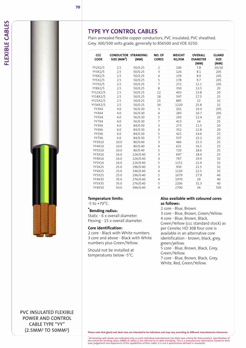
*All bending radii shown are indicative only as each individual manufacturer has their own criteria for their product. Specification ofthe minimum bending radius (MBR) of cables is not referred to in cable standards. This is a manufacturer declaration, based on theirown judgement and experience of the capabilities of their cable, it is not a specification defined in standards.
TYPE YY CONTROL CABLESPlain annealed flexible copper conductors, PVC insulated, PVC sheathed.Grey. 300/500 volts grade, generally to BS6500 and VDE 0250.
FLEX
IBLE
CABLE
S70
PVC INSULATED FLEXIBLEPOWER AND CONTROL
CABLE TYPE “YY”(2.5MM2 TO 50MM2)
Temperature limits:-5 to +70°C.
*Bending radius:Static - 6 x overall diameter.Flexing - 15 x overall diameter.
Core identification:2 core - Black with White numbers.3 core and above - Black with Whitenumbers plus Green/Yellow.
Should not be installed attemperatures below -5°C.
Also available with coloured coresas follows:2 core - Blue, Brown.3 core - Blue, Brown, Green/Yellow.4 core - Blue, Brown, Black,Green/Yellow (ccc standard stock) asper Cenelec HD 308 four core isavailable in an alternative coreidentification - brown, black, grey,green/yellow.5 core - Blue, Brown, Black, Grey,Green/Yellow.7 core - Blue, Brown, Black, Grey,White, Red, Green/Yellow.
CCC CONDUCTOR STRANDING NO. OF WEIGHT OVERALL GLANDCODE SIZE (MM2) (MM) CORES KG/KM DIAMETER SIZE
(MM) (MM)YY2X2/5 2.5 50/0.25 2 106 7.8 20/16YY3X2/5 2.5 50/0.25 3 126 8.1 20SYY4X2/5 2.5 50/0.25 4 159 8.9 20SYY5X2/5 2.5 50/0.25 5 178 9.7 20SYY7X2/5 2.5 50/0.25 7 272 11.1 20SYY8X2/5 2.5 50/0.25 8 350 13.5 20YY12X2/5 2.5 50/0.25 12 403 13.8 20YY18X2/5 2.5 50/0.25 18 597 17.5 25YY25X2/5 2.5 50/0.25 25 885 22 32YY34X2/5 2.5 50/0.25 34 1220 25.8 32YY3X4 4.0 56/0.30 3 201 10.4 20SYY4X4 4.0 56/0.30 4 283 10.7 20SYY5X4 4.0 56/0.30 5 293 12.4 20YY7X4 4.0 56/0.30 7 413 14 25YY3X6 6.0 84/0.30 3 273 11.5 20YY4X6 6.0 84/0.30 4 352 12.8 20YY5X6 6.0 84/0.30 5 415 14.6 25YY7X6 6.0 84/0.30 7 537 15.2 25YY3X10 10.0 80/0.40 3 466 15.3 25YY4X10 10.0 80/0.40 4 631 16.5 25YY5X10 10.0 80/0.40 5 720 18.6 25YY3X16 16.0 126/0.40 3 697 18.4 25YY4X16 16.0 126/0.40 4 767 19.9 32YY5X16 16.0 126/0.40 5 1151 22.4 32YY3X25 25.0 196/0.40 3 930 21.5 32YY4X25 25.0 196/0.40 4 1150 22.5 32YY5X25 25.0 196/0.40 5 1679 27.9 40YY4X35 35.0 276/0.40 4 1970 29 40YY5X35 35.0 276/0.40 5 2206 31.3 40YY4X50 50.0 396/0.40 4 2700 34 50S
Please note that gland and cleat sizes are intended to be indicative and may vary according to different manufacturers tolerances.
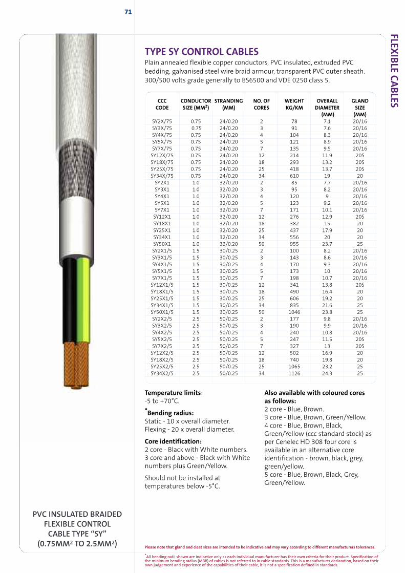
*All bending radii shown are indicative only as each individual manufacturer has their own criteria for their product. Specification ofthe minimum bending radius (MBR) of cables is not referred to in cable standards. This is a manufacturer declaration, based on theirown judgement and experience of the capabilities of their cable, it is not a specification defined in standards.
FLEXIB
LECABLES
71
TYPE SY CONTROL CABLESPlain annealed flexible copper conductors, PVC insulated, extruded PVCbedding, galvanised steel wire braid armour, transparent PVC outer sheath.300/500 volts grade generally to BS6500 and VDE 0250 class 5.
PVC INSULATED BRAIDEDFLEXIBLE CONTROLCABLE TYPE “SY”
(0.75MM2 TO 2.5MM2)
Temperature limits:-5 to +70°C.
*Bending radius:Static - 10 x overall diameter.Flexing - 20 x overall diameter.
Core identification:2 core - Black with White numbers.3 core and above - Black with Whitenumbers plus Green/Yellow.
Should not be installed attemperatures below -5°C.
Also available with coloured coresas follows:2 core - Blue, Brown.3 core - Blue, Brown, Green/Yellow.4 core - Blue, Brown, Black,Green/Yellow (ccc standard stock) asper Cenelec HD 308 four core isavailable in an alternative coreidentification - brown, black, grey,green/yellow.5 core - Blue, Brown, Black, Grey,Green/Yellow.
CCC CONDUCTOR STRANDING NO. OF WEIGHT OVERALL GLANDCODE SIZE (MM2) (MM) CORES KG/KM DIAMETER SIZE
(MM) (MM)SY2X/75 0.75 24/0.20 2 78 7.1 20/16SY3X/75 0.75 24/0.20 3 91 7.6 20/16SY4X/75 0.75 24/0.20 4 104 8.3 20/16SY5X/75 0.75 24/0.20 5 121 8.9 20/16SY7X/75 0.75 24/0.20 7 135 9.5 20/16SY12X/75 0.75 24/0.20 12 214 11.9 20SSY18X/75 0.75 24/0.20 18 293 13.2 20SSY25X/75 0.75 24/0.20 25 418 13.7 20SSY34X/75 0.75 24/0.20 34 610 19 20SY2X1 1.0 32/0.20 2 85 7.7 20/16SY3X1 1.0 32/0.20 3 95 8.2 20/16SY4X1 1.0 32/0.20 4 120 9 20/16SY5X1 1.0 32/0.20 5 123 9.2 20/16SY7X1 1.0 32/0.20 7 171 10.1 20/16SY12X1 1.0 32/0.20 12 276 12.9 20SSY18X1 1.0 32/0.20 18 382 15 20SY25X1 1.0 32/0.20 25 437 17.9 20SY34X1 1.0 32/0.20 34 556 20 20SY50X1 1.0 32/0.20 50 955 23.7 25SY2X1/5 1.5 30/0.25 2 100 8.2 20/16SY3X1/5 1.5 30/0.25 3 143 8.6 20/16SY4X1/5 1.5 30/0.25 4 170 9.3 20/16SY5X1/5 1.5 30/0.25 5 173 10 20/16SY7X1/5 1.5 30/0.25 7 198 10.7 20/16SY12X1/5 1.5 30/0.25 12 341 13.8 20SSY18X1/5 1.5 30/0.25 18 490 16.4 20SY25X1/5 1.5 30/0.25 25 606 19.2 20SY34X1/5 1.5 30/0.25 34 835 21.6 25SY50X1/5 1.5 30/0.25 50 1046 23.8 25SY2X2/5 2.5 50/0.25 2 177 9.8 20/16SY3X2/5 2.5 50/0.25 3 190 9.9 20/16SY4X2/5 2.5 50/0.25 4 240 10.8 20/16SY5X2/5 2.5 50/0.25 5 247 11.5 20SSY7X2/5 2.5 50/0.25 7 327 13 20SSY12X2/5 2.5 50/0.25 12 502 16.9 20SY18X2/5 2.5 50/0.25 18 740 19.8 20SY25X2/5 2.5 50/0.25 25 1065 23.2 25SY34X2/5 2.5 50/0.25 34 1126 24.3 25
Please note that gland and cleat sizes are intended to be indicative and may vary according to different manufacturers tolerances.
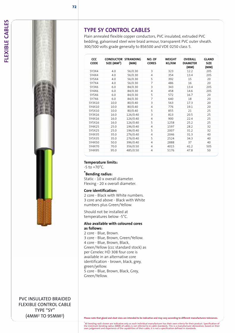
FLEX
IBLE
CABLE
S72
PVC INSULATED BRAIDEDFLEXIBLE CONTROL CABLE
TYPE “SY”(4MM2 TO 95MM2)
CCC CONDUCTOR STRANDING NO. OF WEIGHT OVERALL GLANDCODE SIZE (MM2) (MM) CORES KG/KM DIAMETER SIZE
(MM) (MM)SY3X4 4.0 56/0.30 3 323 12.2 20SSY4X4 4.0 56/0.30 4 354 13.4 20SSY5X4 4.0 56/0.30 5 392 15 20SY7X4 4.0 56/0.30 7 486 16 20SY3X6 6.0 84/0.30 3 343 13.4 20SSY4X6 6.0 84/0.30 4 458 14.6 20SSY5X6 6.0 84/0.30 5 572 16.7 20SY7X6 6.0 84/0.30 7 640 18 20SY3X10 10.0 80/0.40 3 563 17.3 20SY4X10 10.0 80/0.40 4 776 19.1 20SY5X10 10.0 80/0.40 5 855 21 25SY3X16 16.0 126/0.40 3 813 20.5 25SY4X16 16.0 126/0.40 4 900 22.4 25SY5X16 16.0 126/0.40 5 1258 25.2 25SY4X25 25.0 196/0.40 4 1597 28.2 32SY5X25 25.0 196/0.40 5 2007 31.2 32SY4X35 35.0 276/0.40 4 2046 31.3 40SY5X35 35.0 276/0.40 5 2524 34.3 40SY4X50 50.0 396/0.40 4 2888 37 40SY4X70 70.0 356/0.50 4 4015 41.2 50SSY4X95 95.0 485/0.50 4 5176 47.8 50
TYPE SY CONTROL CABLESPlain annealed flexible copper conductors, PVC insulated, extruded PVCbedding, galvanised steel wire braid armour, transparent PVC outer sheath.300/500 volts grade generally to BS6500 and VDE 0250 class 5.
Temperature limits:-5 to +70°C.
*Bending radius:Static - 10 x overall diameter.Flexing - 20 x overall diameter.
Core identification:2 core - Black with White numbers.3 core and above - Black with Whitenumbers plus Green/Yellow.
Should not be installed attemperatures below -5°C.
Also available with coloured coresas follows:2 core - Blue, Brown.3 core - Blue, Brown, Green/Yellow.4 core - Blue, Brown, Black,Green/Yellow (ccc standard stock) asper Cenelec HD 308 four core isavailable in an alternative coreidentification - brown, black, grey,green/yellow.5 core - Blue, Brown, Black, Grey,Green/Yellow.
*All bending radii shown are indicative only as each individual manufacturer has their own criteria for their product. Specification ofthe minimum bending radius (MBR) of cables is not referred to in cable standards. This is a manufacturer declaration, based on theirown judgement and experience of the capabilities of their cable, it is not a specification defined in standards.
Please note that gland and cleat sizes are intended to be indicative and may vary according to different manufacturers tolerances.
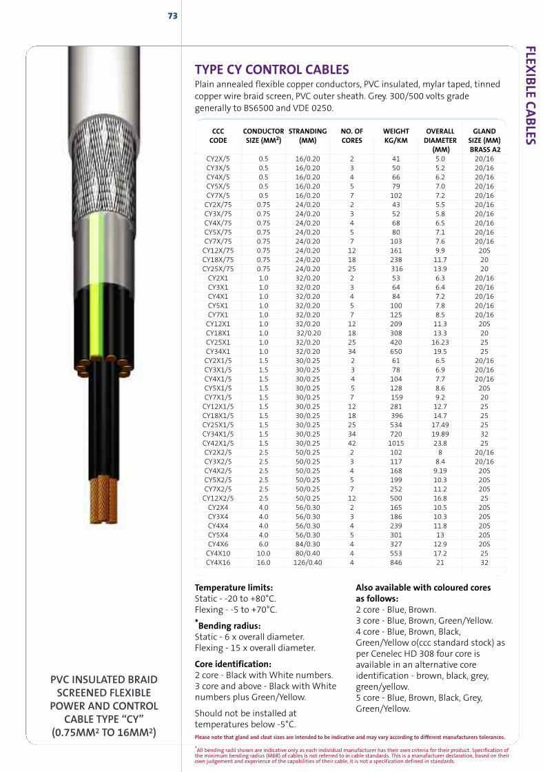
FLEXIB
LECABLES
73
TYPE CY CONTROL CABLESPlain annealed flexible copper conductors, PVC insulated, mylar taped, tinnedcopper wire braid screen, PVC outer sheath. Grey. 300/500 volts gradegenerally to BS6500 and VDE 0250.
PVC INSULATED BRAIDSCREENED FLEXIBLE
POWER AND CONTROLCABLE TYPE “CY”
(0.75MM2 TO 16MM2)
Temperature limits:Static - -20 to +80°C.Flexing - -5 to +70°C.
*Bending radius:Static - 6 x overall diameter.Flexing - 15 x overall diameter.
Core identification:2 core - Black with White numbers.3 core and above - Black with Whitenumbers plus Green/Yellow.
Should not be installed attemperatures below -5°C.
Also available with coloured coresas follows:2 core - Blue, Brown.3 core - Blue, Brown, Green/Yellow.4 core - Blue, Brown, Black,Green/Yellow o(ccc standard stock) asper Cenelec HD 308 four core isavailable in an alternative coreidentification - brown, black, grey,green/yellow.5 core - Blue, Brown, Black, Grey,Green/Yellow.
CCC CONDUCTOR STRANDING NO. OF WEIGHT OVERALL GLANDCODE SIZE (MM2) (MM) CORES KG/KM DIAMETER SIZE (MM)
(MM) BRASS A2CY2X/5 0.5 16/0.20 2 41 5.0 20/16CY3X/5 0.5 16/0.20 3 50 5.2 20/16CY4X/5 0.5 16/0.20 4 66 6.2 20/16CY5X/5 0.5 16/0.20 5 79 7.0 20/16CY7X/5 0.5 16/0.20 7 102 7.2 20/16CY2X/75 0.75 24/0.20 2 43 5.5 20/16CY3X/75 0.75 24/0.20 3 52 5.8 20/16CY4X/75 0.75 24/0.20 4 68 6.5 20/16CY5X/75 0.75 24/0.20 5 80 7.1 20/16CY7X/75 0.75 24/0.20 7 103 7.6 20/16CY12X/75 0.75 24/0.20 12 161 9.9 20SCY18X/75 0.75 24/0.20 18 238 11.7 20CY25X/75 0.75 24/0.20 25 316 13.9 20CY2X1 1.0 32/0.20 2 53 6.3 20/16CY3X1 1.0 32/0.20 3 64 6.4 20/16CY4X1 1.0 32/0.20 4 84 7.2 20/16CY5X1 1.0 32/0.20 5 100 7.8 20/16CY7X1 1.0 32/0.20 7 125 8.5 20/16CY12X1 1.0 32/0.20 12 209 11.3 20SCY18X1 1.0 32/0.20 18 308 13.3 20CY25X1 1.0 32/0.20 25 420 16.23 25CY34X1 1.0 32/0.20 34 650 19.5 25CY2X1/5 1.5 30/0.25 2 61 6.5 20/16CY3X1/5 1.5 30/0.25 3 78 6.9 20/16CY4X1/5 1.5 30/0.25 4 104 7.7 20/16CY5X1/5 1.5 30/0.25 5 128 8.6 20SCY7X1/5 1.5 30/0.25 7 159 9.2 20CY12X1/5 1.5 30/0.25 12 281 12.7 25CY18X1/5 1.5 30/0.25 18 396 14.7 25CY25X1/5 1.5 30/0.25 25 534 17.49 25CY34X1/5 1.5 30/0.25 34 720 19.89 32CY42X1/5 1.5 30/0.25 42 1015 23.8 25CY2X2/5 2.5 50/0.25 2 102 8 20/16CY3X2/5 2.5 50/0.25 3 117 8.4 20/16CY4X2/5 2.5 50/0.25 4 168 9.19 20SCY5X2/5 2.5 50/0.25 5 199 10.3 20SCY7X2/5 2.5 50/0.25 7 252 11.2 20SCY12X2/5 2.5 50/0.25 12 500 16.8 25CY2X4 4.0 56/0.30 2 165 10.5 20SCY3X4 4.0 56/0.30 3 186 10.3 20SCY4X4 4.0 56/0.30 4 239 11.8 20SCY5X4 4.0 56/0.30 5 301 13 20SCY4X6 6.0 84/0.30 4 327 12.9 20SCY4X10 10.0 80/0.40 4 553 17.2 25CY4X16 16.0 126/0.40 4 846 21 32
*All bending radii shown are indicative only as each individual manufacturer has their own criteria for their product. Specification ofthe minimum bending radius (MBR) of cables is not referred to in cable standards. This is a manufacturer declaration, based on theirown judgement and experience of the capabilities of their cable, it is not a specification defined in standards.
Please note that gland and cleat sizes are intended to be indicative and may vary according to different manufacturers tolerances.
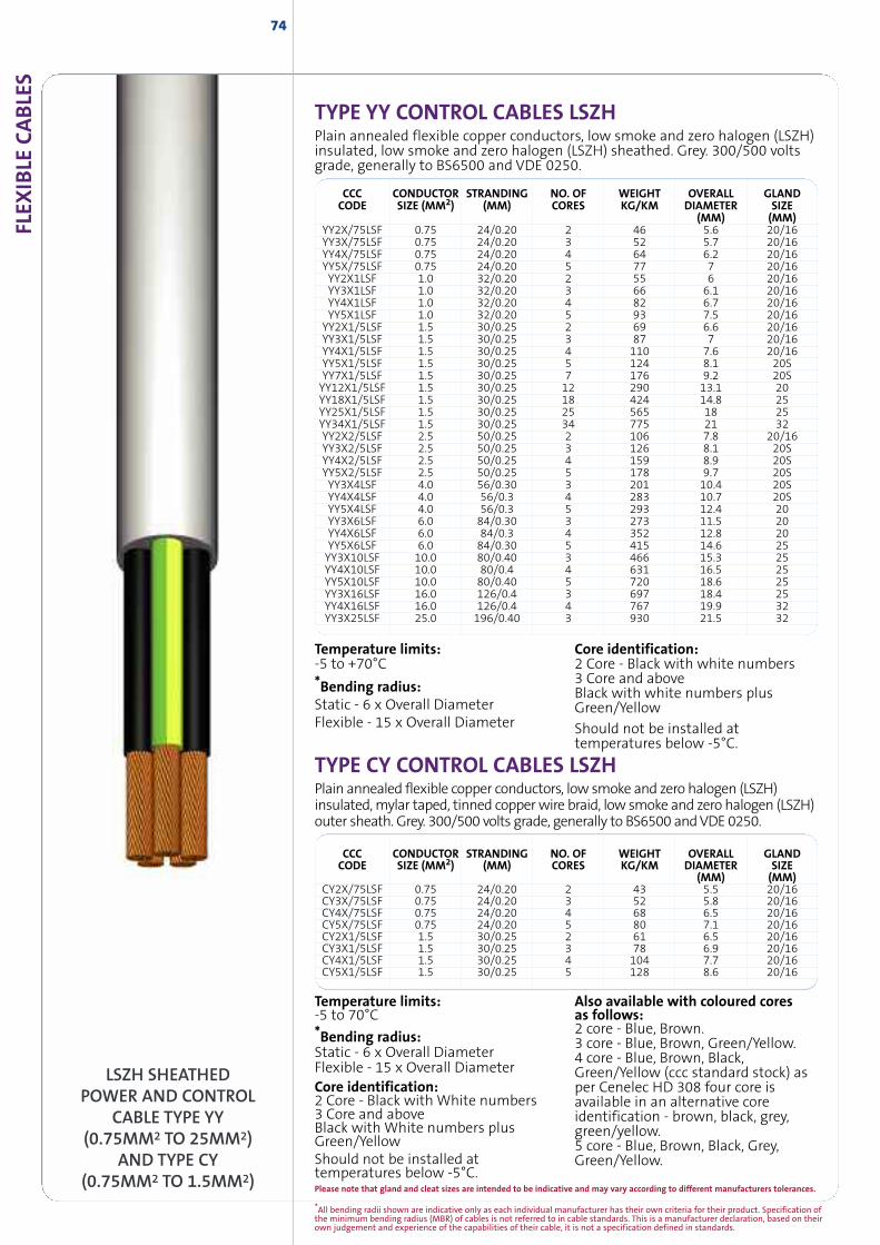
*All bending radii shown are indicative only as each individual manufacturer has their own criteria for their product. Specification ofthe minimum bending radius (MBR) of cables is not referred to in cable standards. This is a manufacturer declaration, based on theirown judgement and experience of the capabilities of their cable, it is not a specification defined in standards.
FLEX
IBLE
CABLE
S74
LSZH SHEATHEDPOWER AND CONTROL
CABLE TYPE YY(0.75MM2 TO 25MM2)
AND TYPE CY(0.75MM2 TO 1.5MM2)
CCC CONDUCTOR STRANDING NO. OF WEIGHT OVERALL GLANDCODE SIZE (MM2) (MM) CORES KG/KM DIAMETER SIZE
(MM) (MM)CY2X/75LSF 0.75 24/0.20 2 43 5.5 20/16CY3X/75LSF 0.75 24/0.20 3 52 5.8 20/16CY4X/75LSF 0.75 24/0.20 4 68 6.5 20/16CY5X/75LSF 0.75 24/0.20 5 80 7.1 20/16CY2X1/5LSF 1.5 30/0.25 2 61 6.5 20/16CY3X1/5LSF 1.5 30/0.25 3 78 6.9 20/16CY4X1/5LSF 1.5 30/0.25 4 104 7.7 20/16CY5X1/5LSF 1.5 30/0.25 5 128 8.6 20/16
Temperature limits:-5 to 70°C*Bending radius:Static - 6 x Overall DiameterFlexible - 15 x Overall DiameterCore identification:2 Core - Black with White numbers3 Core and aboveBlack with White numbers plusGreen/YellowShould not be installed attemperatures below -5°C.
Also available with coloured coresas follows:2 core - Blue, Brown.3 core - Blue, Brown, Green/Yellow.4 core - Blue, Brown, Black,Green/Yellow (ccc standard stock) asper Cenelec HD 308 four core isavailable in an alternative coreidentification - brown, black, grey,green/yellow.5 core - Blue, Brown, Black, Grey,Green/Yellow.
TYPE CY CONTROL CABLES LSZHPlain annealed flexible copper conductors, low smoke and zero halogen (LSZH)insulated,mylar taped, tinned copperwire braid, low smoke and zero halogen (LSZH)outer sheath. Grey. 300/500 volts grade, generally to BS6500 andVDE 0250.
TYPE YY CONTROL CABLES LSZHPlain annealed flexible copper conductors, low smoke and zero halogen (LSZH)insulated, low smoke and zero halogen (LSZH) sheathed. Grey. 300/500 voltsgrade, generally to BS6500 and VDE 0250.
CCC CONDUCTOR STRANDING NO. OF WEIGHT OVERALL GLANDCODE SIZE (MM2) (MM) CORES KG/KM DIAMETER SIZE
(MM) (MM)YY2X/75LSF 0.75 24/0.20 2 46 5.6 20/16YY3X/75LSF 0.75 24/0.20 3 52 5.7 20/16YY4X/75LSF 0.75 24/0.20 4 64 6.2 20/16YY5X/75LSF 0.75 24/0.20 5 77 7 20/16YY2X1LSF 1.0 32/0.20 2 55 6 20/16YY3X1LSF 1.0 32/0.20 3 66 6.1 20/16YY4X1LSF 1.0 32/0.20 4 82 6.7 20/16YY5X1LSF 1.0 32/0.20 5 93 7.5 20/16YY2X1/5LSF 1.5 30/0.25 2 69 6.6 20/16YY3X1/5LSF 1.5 30/0.25 3 87 7 20/16YY4X1/5LSF 1.5 30/0.25 4 110 7.6 20/16YY5X1/5LSF 1.5 30/0.25 5 124 8.1 20SYY7X1/5LSF 1.5 30/0.25 7 176 9.2 20SYY12X1/5LSF 1.5 30/0.25 12 290 13.1 20YY18X1/5LSF 1.5 30/0.25 18 424 14.8 25YY25X1/5LSF 1.5 30/0.25 25 565 18 25YY34X1/5LSF 1.5 30/0.25 34 775 21 32YY2X2/5LSF 2.5 50/0.25 2 106 7.8 20/16YY3X2/5LSF 2.5 50/0.25 3 126 8.1 20SYY4X2/5LSF 2.5 50/0.25 4 159 8.9 20SYY5X2/5LSF 2.5 50/0.25 5 178 9.7 20SYY3X4LSF 4.0 56/0.30 3 201 10.4 20SYY4X4LSF 4.0 56/0.3 4 283 10.7 20SYY5X4LSF 4.0 56/0.3 5 293 12.4 20YY3X6LSF 6.0 84/0.30 3 273 11.5 20YY4X6LSF 6.0 84/0.3 4 352 12.8 20YY5X6LSF 6.0 84/0.30 5 415 14.6 25YY3X10LSF 10.0 80/0.40 3 466 15.3 25YY4X10LSF 10.0 80/0.4 4 631 16.5 25YY5X10LSF 10.0 80/0.40 5 720 18.6 25YY3X16LSF 16.0 126/0.4 3 697 18.4 25YY4X16LSF 16.0 126/0.4 4 767 19.9 32YY3X25LSF 25.0 196/0.40 3 930 21.5 32
Temperature limits:-5 to +70°C*Bending radius:Static - 6 x Overall DiameterFlexible - 15 x Overall Diameter
Core identification:2 Core - Black with white numbers3 Core and aboveBlack with white numbers plusGreen/Yellow
Should not be installed attemperatures below -5°C.
Please note that gland and cleat sizes are intended to be indicative and may vary according to different manufacturers tolerances.
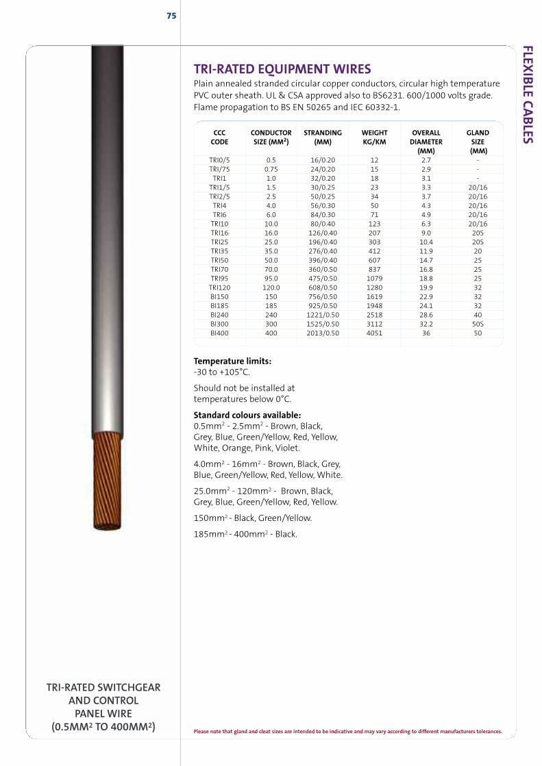
75
TRI-RATED SWITCHGEARAND CONTROLPANEL WIRE
(0.5MM2 TO 400MM2)
FLEXIB
LECABLES
TRI-RATED EQUIPMENT WIRESPlain annealed stranded circular copper conductors, circular high temperaturePVC outer sheath. UL & CSA approved also to BS6231. 600/1000 volts grade.Flame propagation to BS EN 50265 and IEC 60332-1.
CCC CONDUCTOR STRANDING WEIGHT OVERALL GLANDCODE SIZE (MM2) (MM) KG/KM DIAMETER SIZE
(MM) (MM)TRI0/5 0.5 16/0.20 12 2.7 -TRI/75 0.75 24/0.20 15 2.9 -TRI1 1.0 32/0.20 18 3.1 -TRI1/5 1.5 30/0.25 23 3.3 20/16TRI2/5 2.5 50/0.25 34 3.7 20/16TRI4 4.0 56/0.30 50 4.3 20/16TRI6 6.0 84/0.30 71 4.9 20/16TRI10 10.0 80/0.40 123 6.3 20/16TRI16 16.0 126/0.40 207 9.0 20STRI25 25.0 196/0.40 303 10.4 20STRI35 35.0 276/0.40 412 11.9 20TRI50 50.0 396/0.40 607 14.7 25TRI70 70.0 360/0.50 837 16.8 25TRI95 95.0 475/0.50 1079 18.8 25TRI120 120.0 608/0.50 1280 19.9 32BI150 150 756/0.50 1619 22.9 32BI185 185 925/0.50 1948 24.1 32BI240 240 1221/0.50 2518 28.6 40BI300 300 1525/0.50 3112 32.2 50SBI400 400 2013/0.50 4051 36 50
Temperature limits:-30 to +105°C.
Should not be installed attemperatures below 0°C.
Standard colours available:0.5mm2 - 2.5mm2 - Brown, Black,Grey, Blue, Green/Yellow, Red, Yellow,White, Orange, Pink, Violet.
4.0mm2 - 16mm2 - Brown, Black, Grey,Blue, Green/Yellow, Red, Yellow, White.
25.0mm2 - 120mm2 - Brown, Black,Grey, Blue, Green/Yellow, Red, Yellow.
150mm2 - Black, Green/Yellow.
185mm2 - 400mm2 - Black.
Please note that gland and cleat sizes are intended to be indicative and may vary according to different manufacturers tolerances.
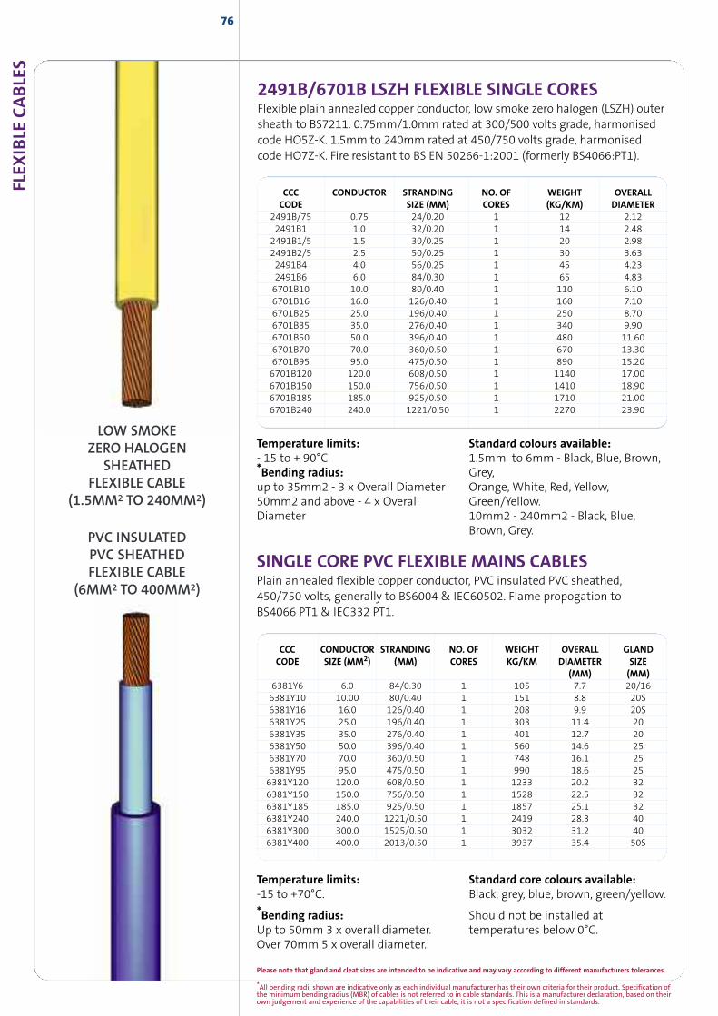
CCC CONDUCTOR STRANDING NO. OF WEIGHT OVERALLCODE SIZE (MM) CORES (KG/KM) DIAMETER
2491B/75 0.75 24/0.20 1 12 2.122491B1 1.0 32/0.20 1 14 2.482491B1/5 1.5 30/0.25 1 20 2.982491B2/5 2.5 50/0.25 1 30 3.632491B4 4.0 56/0.25 1 45 4.232491B6 6.0 84/0.30 1 65 4.836701B10 10.0 80/0.40 1 110 6.106701B16 16.0 126/0.40 1 160 7.106701B25 25.0 196/0.40 1 250 8.706701B35 35.0 276/0.40 1 340 9.906701B50 50.0 396/0.40 1 480 11.606701B70 70.0 360/0.50 1 670 13.306701B95 95.0 475/0.50 1 890 15.206701B120 120.0 608/0.50 1 1140 17.006701B150 150.0 756/0.50 1 1410 18.906701B185 185.0 925/0.50 1 1710 21.006701B240 240.0 1221/0.50 1 2270 23.90
FLEX
IBLE
CABLE
S
*All bending radii shown are indicative only as each individual manufacturer has their own criteria for their product. Specification ofthe minimum bending radius (MBR) of cables is not referred to in cable standards. This is a manufacturer declaration, based on theirown judgement and experience of the capabilities of their cable, it is not a specification defined in standards.
Please note that gland and cleat sizes are intended to be indicative and may vary according to different manufacturers tolerances.
76
Temperature limits:-15 to +70°C.
*Bending radius:Up to 50mm 3 x overall diameter.Over 70mm 5 x overall diameter.
Standard core colours available:Black, grey, blue, brown, green/yellow.
Should not be installed attemperatures below 0°C.
SINGLE CORE PVC FLEXIBLE MAINS CABLESPlain annealed flexible copper conductor, PVC insulated PVC sheathed,450/750 volts, generally to BS6004 & IEC60502. Flame propogation toBS4066 PT1 & IEC332 PT1.
CCC CONDUCTOR STRANDING NO. OF WEIGHT OVERALL GLANDCODE SIZE (MM2) (MM) CORES KG/KM DIAMETER SIZE
(MM) (MM)6381Y6 6.0 84/0.30 1 105 7.7 20/166381Y10 10.00 80/0.40 1 151 8.8 20S6381Y16 16.0 126/0.40 1 208 9.9 20S6381Y25 25.0 196/0.40 1 303 11.4 206381Y35 35.0 276/0.40 1 401 12.7 206381Y50 50.0 396/0.40 1 560 14.6 256381Y70 70.0 360/0.50 1 748 16.1 256381Y95 95.0 475/0.50 1 990 18.6 256381Y120 120.0 608/0.50 1 1233 20.2 326381Y150 150.0 756/0.50 1 1528 22.5 326381Y185 185.0 925/0.50 1 1857 25.1 326381Y240 240.0 1221/0.50 1 2419 28.3 406381Y300 300.0 1525/0.50 1 3032 31.2 406381Y400 400.0 2013/0.50 1 3937 35.4 50S
PVC INSULATEDPVC SHEATHEDFLEXIBLE CABLE
(6MM2 TO 400MM2)
LOW SMOKEZERO HALOGEN
SHEATHEDFLEXIBLE CABLE
(1.5MM2 TO 240MM2)
2491B/6701B LSZH FLEXIBLE SINGLE CORESFlexible plain annealed copper conductor, low smoke zero halogen (LSZH) outersheath to BS7211. 0.75mm/1.0mm rated at 300/500 volts grade, harmonisedcode HO5Z-K. 1.5mm to 240mm rated at 450/750 volts grade, harmonisedcode HO7Z-K. Fire resistant to BS EN 50266-1:2001 (formerly BS4066:PT1).
Temperature limits:- 15 to + 90°C*Bending radius:up to 35mm2 - 3 x Overall Diameter50mm2 and above - 4 x OverallDiameter
Standard colours available:1.5mm to 6mm - Black, Blue, Brown,Grey,Orange, White, Red, Yellow,Green/Yellow.10mm2 - 240mm2 - Black, Blue,Brown, Grey.
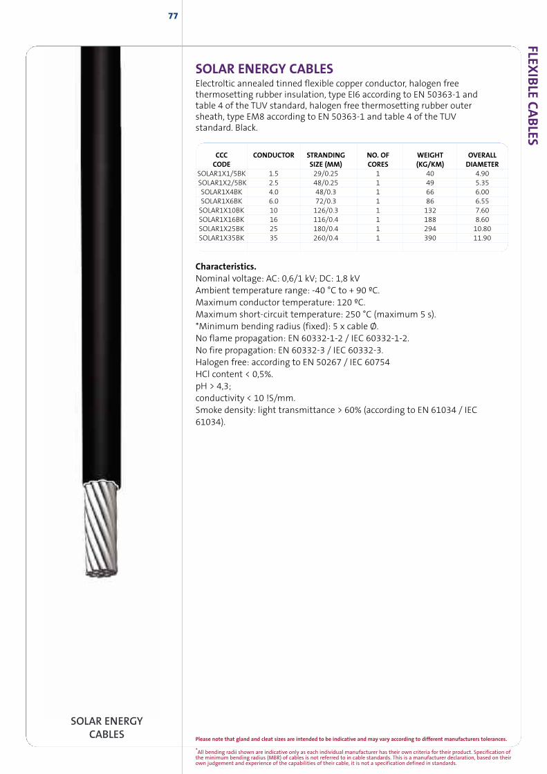
FLEXIB
LECABLES
Please note that gland and cleat sizes are intended to be indicative and may vary according to different manufacturers tolerances.
*All bending radii shown are indicative only as each individual manufacturer has their own criteria for their product. Specification ofthe minimum bending radius (MBR) of cables is not referred to in cable standards. This is a manufacturer declaration, based on theirown judgement and experience of the capabilities of their cable, it is not a specification defined in standards.
77
SOLAR ENERGYCABLES
CCC CONDUCTOR STRANDING NO. OF WEIGHT OVERALLCODE SIZE (MM) CORES (KG/KM) DIAMETER
SOLAR1X1/5BK 1.5 29/0.25 1 40 4.90SOLAR1X2/5BK 2.5 48/0.25 1 49 5.35SOLAR1X4BK 4.0 48/0.3 1 66 6.00SOLAR1X6BK 6.0 72/0.3 1 86 6.55SOLAR1X10BK 10 126/0.3 1 132 7.60SOLAR1X16BK 16 116/0.4 1 188 8.60SOLAR1X25BK 25 180/0.4 1 294 10.80SOLAR1X35BK 35 260/0.4 1 390 11.90
SOLAR ENERGY CABLESElectroltic annealed tinned flexible copper conductor, halogen freethermosetting rubber insulation, type EI6 according to EN 50363-1 andtable 4 of the TUV standard, halogen free thermosetting rubber outersheath, type EM8 according to EN 50363-1 and table 4 of the TUVstandard. Black.
Characteristics.Nominal voltage: AC: 0,6/1 kV; DC: 1,8 kVAmbient temperature range: -40 °C to + 90 ºC.Maximum conductor temperature: 120 ºC.Maximum short-circuit temperature: 250 °C (maximum 5 s).*Minimum bending radius (fixed): 5 x cable Ø.No flame propagation: EN 60332-1-2 / IEC 60332-1-2.No fire propagation: EN 60332-3 / IEC 60332-3.Halogen free: according to EN 50267 / IEC 60754HCl content < 0,5%.pH > 4,3;conductivity < 10 !S/mm.Smoke density: light transmittance > 60% (according to EN 61034 / IEC61034).
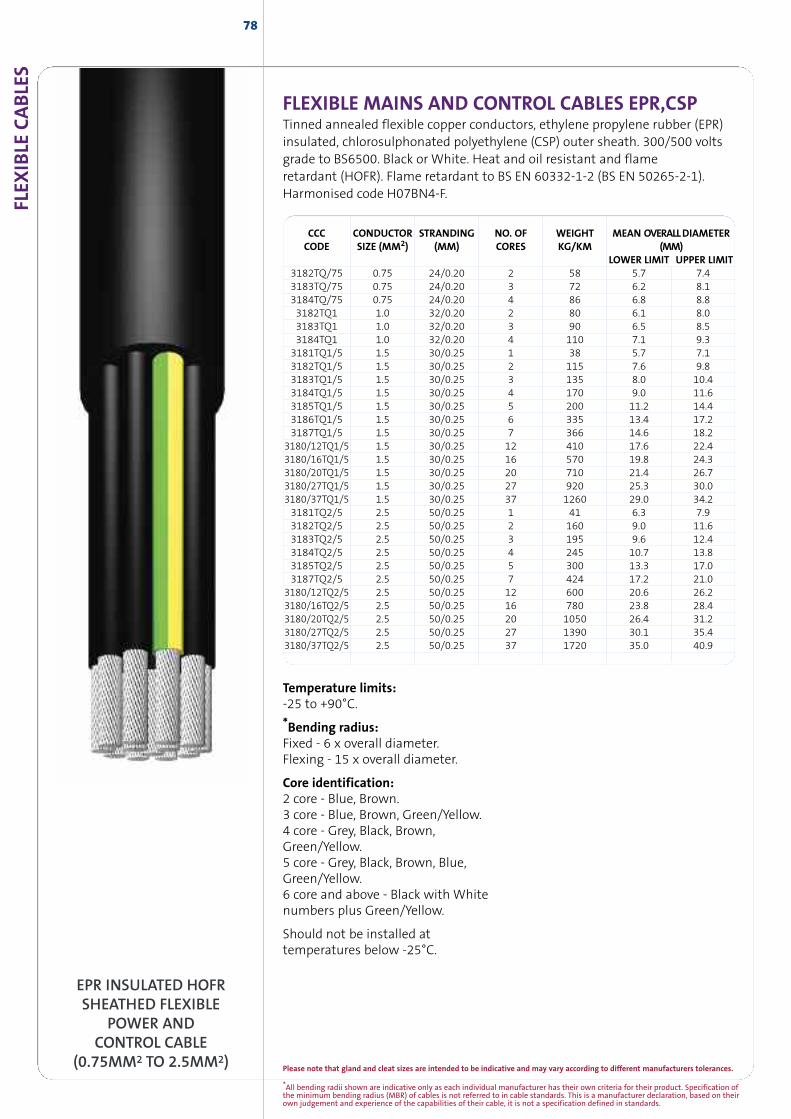
FLEX
IBLE
CABLE
S
*All bending radii shown are indicative only as each individual manufacturer has their own criteria for their product. Specification ofthe minimum bending radius (MBR) of cables is not referred to in cable standards. This is a manufacturer declaration, based on theirown judgement and experience of the capabilities of their cable, it is not a specification defined in standards.
Please note that gland and cleat sizes are intended to be indicative and may vary according to different manufacturers tolerances.
78
CCC CONDUCTOR STRANDING NO. OF WEIGHT MEAN OVERALLDIAMETERCODE SIZE (MM2) (MM) CORES KG/KM (MM)
LOWER LIMIT UPPER LIMIT3182TQ/75 0.75 24/0.20 2 58 5.7 7.43183TQ/75 0.75 24/0.20 3 72 6.2 8.13184TQ/75 0.75 24/0.20 4 86 6.8 8.83182TQ1 1.0 32/0.20 2 80 6.1 8.03183TQ1 1.0 32/0.20 3 90 6.5 8.53184TQ1 1.0 32/0.20 4 110 7.1 9.33181TQ1/5 1.5 30/0.25 1 38 5.7 7.13182TQ1/5 1.5 30/0.25 2 115 7.6 9.83183TQ1/5 1.5 30/0.25 3 135 8.0 10.43184TQ1/5 1.5 30/0.25 4 170 9.0 11.63185TQ1/5 1.5 30/0.25 5 200 11.2 14.43186TQ1/5 1.5 30/0.25 6 335 13.4 17.23187TQ1/5 1.5 30/0.25 7 366 14.6 18.2
3180/12TQ1/5 1.5 30/0.25 12 410 17.6 22.43180/16TQ1/5 1.5 30/0.25 16 570 19.8 24.33180/20TQ1/5 1.5 30/0.25 20 710 21.4 26.73180/27TQ1/5 1.5 30/0.25 27 920 25.3 30.03180/37TQ1/5 1.5 30/0.25 37 1260 29.0 34.23181TQ2/5 2.5 50/0.25 1 41 6.3 7.93182TQ2/5 2.5 50/0.25 2 160 9.0 11.63183TQ2/5 2.5 50/0.25 3 195 9.6 12.43184TQ2/5 2.5 50/0.25 4 245 10.7 13.83185TQ2/5 2.5 50/0.25 5 300 13.3 17.03187TQ2/5 2.5 50/0.25 7 424 17.2 21.0
3180/12TQ2/5 2.5 50/0.25 12 600 20.6 26.23180/16TQ2/5 2.5 50/0.25 16 780 23.8 28.43180/20TQ2/5 2.5 50/0.25 20 1050 26.4 31.23180/27TQ2/5 2.5 50/0.25 27 1390 30.1 35.43180/37TQ2/5 2.5 50/0.25 37 1720 35.0 40.9
EPR INSULATED HOFRSHEATHED FLEXIBLE
POWER ANDCONTROL CABLE
(0.75MM2 TO 2.5MM2)
Temperature limits:-25 to +90°C.
*Bending radius:Fixed - 6 x overall diameter.Flexing - 15 x overall diameter.
Core identification:2 core - Blue, Brown.3 core - Blue, Brown, Green/Yellow.4 core - Grey, Black, Brown,Green/Yellow.5 core - Grey, Black, Brown, Blue,Green/Yellow.6 core and above - Black with Whitenumbers plus Green/Yellow.
Should not be installed attemperatures below -25°C.
FLEXIBLE MAINS AND CONTROL CABLES EPR,CSPTinned annealed flexible copper conductors, ethylene propylene rubber (EPR)insulated, chlorosulphonated polyethylene (CSP) outer sheath. 300/500 voltsgrade to BS6500. Black or White. Heat and oil resistant and flameretardant (HOFR). Flame retardant to BS EN 60332-1-2 (BS EN 50265-2-1).Harmonised code H07BN4-F.
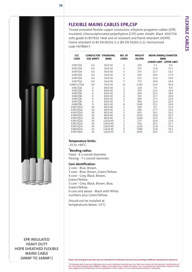
Please note that gland and cleat sizes are intended to be indicative and may vary according to different manufacturers tolerances.
79
FLEXIBLE MAINS CABLES EPR,CSPTinned annealed flexible copper conductors, ethylene propylene rubber (EPR)insulated, chlorosulphonated polyethylene (CSP) outer sheath. Black. 450/750volts grade to BS7919. Heat and oil resistant and flame retardant (HOFR).Flame retardant to BS EN 60332-1-2 (BS EN 50265-2-1). Harmonisedcode H07BN4-F.
CCC CONDUCTOR STRANDING NO. OF WEIGHT MEAN OVERALLDIAMETERCODE SIZE (MM2) (MM) CORES KG/KM (MM)
LOWER LIMIT UPPER LIMIT6381TQ4 4.0 56/0.30 1 105 7.2 9.06382TQ4 4.0 56/0.30 2 275 11.8 15.16383TQ4 4.0 56/0.30 3 335 12.7 16.26384TQ4 4.0 56/0.30 4 420 14.0 17.96385TQ4 4.0 56/0.30 5 515 15.6 19.96387TQ4 4.0 56/0.30 7 773 19.8 24.4
6380/12TQ4 4.0 56/0.30 12 1183 24.4 30.96381TQ6 6 84/0.30 1 130 7.9 9.86382TQ6 6 84/0.30 2 370 13.1 16.86383TQ6 6 84/0.30 3 450 14.1 18.06384TQ6 6 84/0.30 4 565 15.7 20.06385TQ6 6 84/0.30 5 690 17.5 22.96387TQ6 6 84/0.30 7 904 21.6 26.96388TQ6 6 84/0.30 8 1040 25.2 29.66381TQ10 10 80/0.40 1 200 9.5 11.96382TQ10 10 80/0.40 2 690 17.7 22.66383TQ10 10 80/0.40 3 835 19.1 24.26384TQ10 10 80/0.40 4 1020 20.9 26.56385TQ10 10 80/0.40 5 1240 22.9 29.16381TQ16 16 126/0.40 1 275 10.8 13.46382TQ16 16 126/0.40 2 910 20.2 25.76383TQ16 16 126/0.40 3 1120 21.8 27.66384TQ16 16 126/0.40 4 1380 23.8 30.16385TQ16 16 126/0.40 5 1695 26.4 33.3
Temperature limits:-25 to +90°C.
*Bending radius:Fixed - 6 x overall diameter.Flexing - 7 x overall diameter.
Core identification:2 core - Blue, Brown.3 core - Blue, Brown, Green/Yellow.4 core - Grey, Black, Brown,Green/Yellow.5 core - Grey, Black, Brown, Blue,Green/Yellow.6 core and above - Black with Whitenumbers plus Green/Yellow.
Should not be installed attemperatures below -25°C.
EPR INSULATEDHEAVY DUTY
HOFR SHEATHED FLEXIBLEMAINS CABLE
(4MM2TO 16MM2 )*All bending radii shown are indicative only as each individual manufacturer has their own criteria for their product. Specification ofthe minimum bending radius (MBR) of cables is not referred to in cable standards. This is a manufacturer declaration, based on theirown judgement and experience of the capabilities of their cable, it is not a specification defined in standards.
FLEXIB
LECABLES
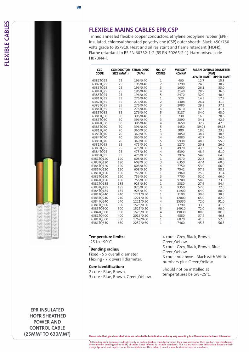
*All bending radii shown are indicative only as each individual manufacturer has their own criteria for their product. Specification ofthe minimum bending radius (MBR) of cables is not referred to in cable standards. This is a manufacturer declaration, based on theirown judgement and experience of the capabilities of their cable, it is not a specification defined in standards.
FLEX
IBLE
CABLE
S
CCC CONDUCTOR STRANDING NO. OF WEIGHT MEAN OVERALLDIAMETERCODE SIZE (MM2) (MM) CORES KG/KM (MM)
LOWER LIMIT UPPER LIMIT6381TQ25 25 196/0.40 1 400 12.7 15.86382TQ25 25 196/0.40 2 1290 24.3 30.76383TQ25 25 196/0.40 3 1600 26.1 33.06384TQ25 25 196/0.40 4 2140 28.9 36.66385TQ25 25 196/0.40 5 2470 32.0 40.46381TQ35 35 276/0.40 1 520 14.3 17.96382TQ35 35 276/0.40 2 1308 26.4 31.56383TQ35 35 276/0.40 3 2080 29.3 37.16384TQ35 35 276/0.40 4 2610 32.5 41.16385TQ35 35 276/0.40 5 3187 34.0 43.06381TQ50 50 396/0.40 1 730 16.5 20.66383TQ50 50 396/0.40 3 2890 34.1 42.96384TQ50 50 396/0.40 4 3650 37.7 47.56385TQ50 50 396/0.40 5 4450 39.03 49.186381TQ70 70 360/0.50 1 980 18.6 23.36383TQ70 70 360/0.50 3 3850 38.4 48.36384TQ70 70 360/0.50 4 4880 42.7 54.06385TQ70 70 360/0.50 5 5938 48.5 55.06381TQ95 95 475/0.50 1 1270 20.8 26.06383TQ95 95 475/0.50 3 4970 43.3 54.06384TQ95 95 475/0.50 4 6390 48.4 61.06385TQ95 95 475/0.50 5 7924 54.0 64.56381TQ120 120 608/0.50 1 1570 22.8 28.66383TQ120 120 608/0.50 3 6350 47.4 60.06384TQ120 120 608/0.50 4 7750 53.0 66.06385TQ120 120 608/0.50 5 7542 57.9 58.56381TQ150 150 756/0.50 1 1960 25.2 31.46383TQ150 150 756/0.50 3 7700 52.0 66.06384TQ150 150 756/0.50 4 9780 58.0 73.06381TQ185 185 925/0.50 1 2380 27.6 34.46383TQ185 185 925/0.50 3 9350 57.0 72.06384TQ185 185 925/0.50 4 11900 64.0 80.06381TQ240 240 1221/0.50 1 3100 30.6 38.36383TQ240 240 1221/0.50 3 12000 65.0 82.06384TQ240 240 1221/0.50 4 15330 72.0 91.06381TQ300 300 1525/0.50 1 3790 33.5 41.96383TQ300 300 1525/0.50 3 14910 72.0 90.06384TQ300 300 1525/0.50 4 19030 80.0 101.06381TQ400 400 2013/0.50 1 4880 37.4 46.86381TQ500 500 1769/0.60 1 6070 41.3 52.06381TQ630 630 2257/0.60 1 7460 45.5 56.5
80
FLEXIBLE MAINS CABLES EPR,CSPTinned annealed flexible copper conductors, ethylene propylene rubber (EPR)insulated, chlorosulphonated polyethylene (CSP) outer sheath. Black. 450/750volts grade to BS7919. Heat and oil resistant and flame retardant (HOFR).Flame retardant to BS EN 60332-1-2 (BS EN 50265-2-1). Harmonised codeH07BN4-F.
EPR INSULATEDHOFR SHEATHEDPOWER AND
CONTROL CABLE(25MM2 TO 630MM2)
Temperature limits:-25 to +90°C.
*Bending radius:Fixed - 5 x overall diameter.Flexing - 7 x overall diameter.
Core identification:2 core - Blue, Brown.3 core - Blue, Brown, Green/Yellow.
4 core - Grey, Black, Brown,Green/Yellow.5 core - Grey, Black, Brown, Blue,Green/Yellow.6 core and above - Black with Whitenumbers plus Green/Yellow.
Should not be installed attemperatures below -25°C.
Please note that gland and cleat sizes are intended to be indicative and may vary according to different manufacturers tolerances.
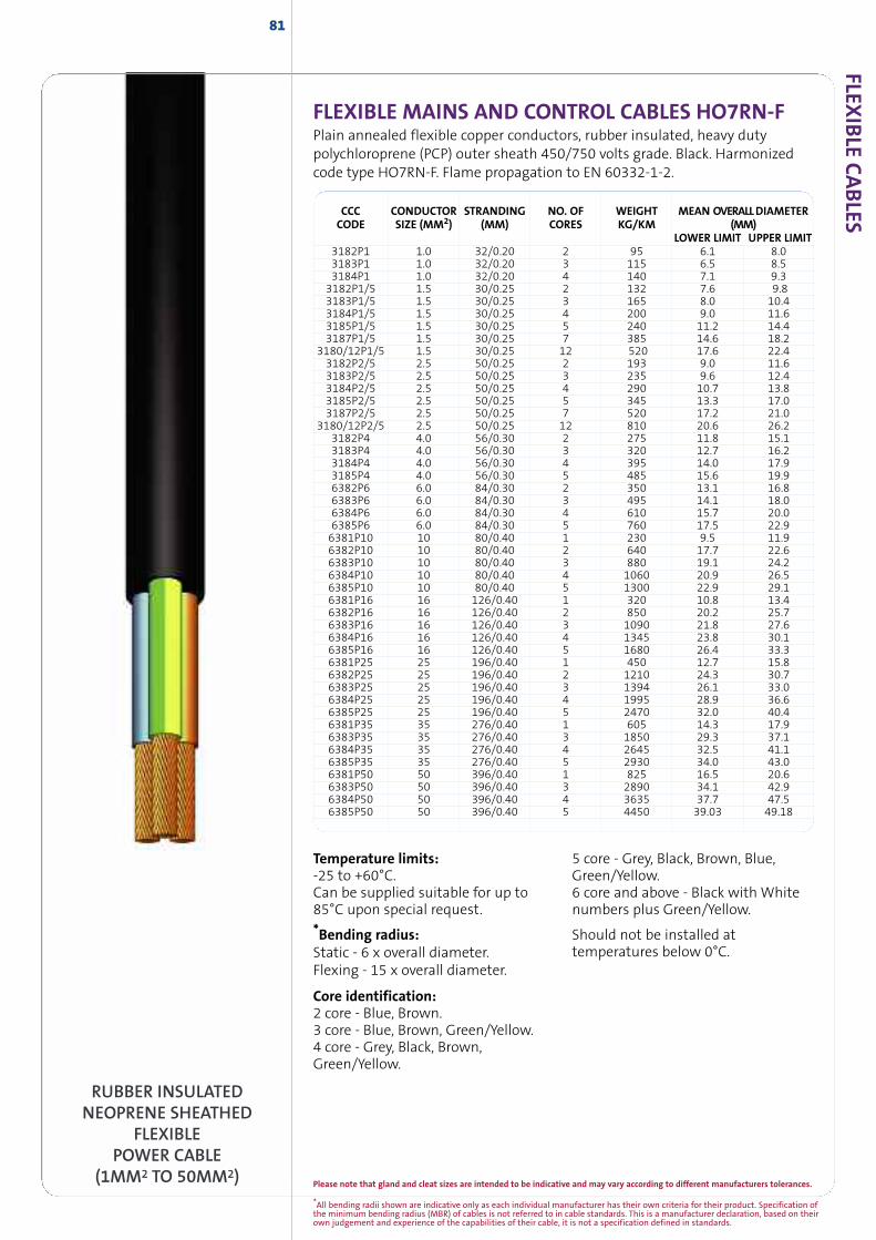
*All bending radii shown are indicative only as each individual manufacturer has their own criteria for their product. Specification ofthe minimum bending radius (MBR) of cables is not referred to in cable standards. This is a manufacturer declaration, based on theirown judgement and experience of the capabilities of their cable, it is not a specification defined in standards.
FLEXIB
LECABLES
81
FLEXIBLE MAINS AND CONTROL CABLES HO7RN-FPlain annealed flexible copper conductors, rubber insulated, heavy dutypolychloroprene (PCP) outer sheath 450/750 volts grade. Black. Harmonizedcode type HO7RN-F. Flame propagation to EN 60332-1-2.
RUBBER INSULATEDNEOPRENE SHEATHED
FLEXIBLEPOWER CABLE
(1MM2 TO 50MM2)
Temperature limits:-25 to +60°C.Can be supplied suitable for up to85°C upon special request.*Bending radius:Static - 6 x overall diameter.Flexing - 15 x overall diameter.
Core identification:2 core - Blue, Brown.3 core - Blue, Brown, Green/Yellow.4 core - Grey, Black, Brown,Green/Yellow.
5 core - Grey, Black, Brown, Blue,Green/Yellow.6 core and above - Black with Whitenumbers plus Green/Yellow.
Should not be installed attemperatures below 0°C.
CCC CONDUCTOR STRANDING NO. OF WEIGHT MEAN OVERALLDIAMETERCODE SIZE (MM2) (MM) CORES KG/KM (MM)
LOWER LIMIT UPPER LIMIT3182P1 1.0 32/0.20 2 95 6.1 8.03183P1 1.0 32/0.20 3 115 6.5 8.53184P1 1.0 32/0.20 4 140 7.1 9.33182P1/5 1.5 30/0.25 2 132 7.6 9.83183P1/5 1.5 30/0.25 3 165 8.0 10.43184P1/5 1.5 30/0.25 4 200 9.0 11.63185P1/5 1.5 30/0.25 5 240 11.2 14.43187P1/5 1.5 30/0.25 7 385 14.6 18.2
3180/12P1/5 1.5 30/0.25 12 520 17.6 22.43182P2/5 2.5 50/0.25 2 193 9.0 11.63183P2/5 2.5 50/0.25 3 235 9.6 12.43184P2/5 2.5 50/0.25 4 290 10.7 13.83185P2/5 2.5 50/0.25 5 345 13.3 17.03187P2/5 2.5 50/0.25 7 520 17.2 21.0
3180/12P2/5 2.5 50/0.25 12 810 20.6 26.23182P4 4.0 56/0.30 2 275 11.8 15.13183P4 4.0 56/0.30 3 320 12.7 16.23184P4 4.0 56/0.30 4 395 14.0 17.93185P4 4.0 56/0.30 5 485 15.6 19.96382P6 6.0 84/0.30 2 350 13.1 16.86383P6 6.0 84/0.30 3 495 14.1 18.06384P6 6.0 84/0.30 4 610 15.7 20.06385P6 6.0 84/0.30 5 760 17.5 22.96381P10 10 80/0.40 1 230 9.5 11.96382P10 10 80/0.40 2 640 17.7 22.66383P10 10 80/0.40 3 880 19.1 24.26384P10 10 80/0.40 4 1060 20.9 26.56385P10 10 80/0.40 5 1300 22.9 29.16381P16 16 126/0.40 1 320 10.8 13.46382P16 16 126/0.40 2 850 20.2 25.76383P16 16 126/0.40 3 1090 21.8 27.66384P16 16 126/0.40 4 1345 23.8 30.16385P16 16 126/0.40 5 1680 26.4 33.36381P25 25 196/0.40 1 450 12.7 15.86382P25 25 196/0.40 2 1210 24.3 30.76383P25 25 196/0.40 3 1394 26.1 33.06384P25 25 196/0.40 4 1995 28.9 36.66385P25 25 196/0.40 5 2470 32.0 40.46381P35 35 276/0.40 1 605 14.3 17.96383P35 35 276/0.40 3 1850 29.3 37.16384P35 35 276/0.40 4 2645 32.5 41.16385P35 35 276/0.40 5 2930 34.0 43.06381P50 50 396/0.40 1 825 16.5 20.66383P50 50 396/0.40 3 2890 34.1 42.96384P50 50 396/0.40 4 3635 37.7 47.56385P50 50 396/0.40 5 4450 39.03 49.18
Please note that gland and cleat sizes are intended to be indicative and may vary according to different manufacturers tolerances.
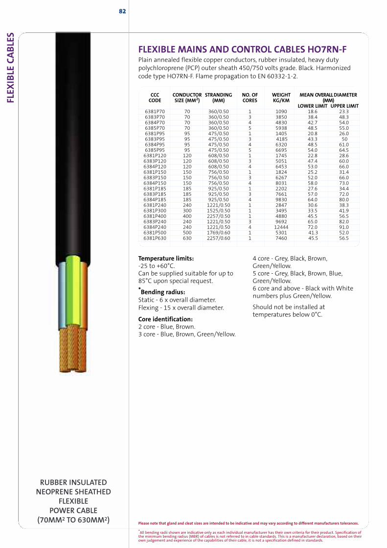
FLEX
IBLE
CABLE
S
RUBBER INSULATEDNEOPRENE SHEATHED
FLEXIBLEPOWER CABLE
(70MM2 TO 630MM2)
82
CCC CONDUCTOR STRANDING NO. OF WEIGHT MEAN OVERALLDIAMETERCODE SIZE (MM2) (MM) CORES KG/KM (MM)
LOWER LIMIT UPPER LIMIT6381P70 70 360/0.50 1 1090 18.6 23.36383P70 70 360/0.50 3 3850 38.4 48.36384P70 70 360/0.50 4 4830 42.7 54.06385P70 70 360/0.50 5 5938 48.5 55.06381P95 95 475/0.50 1 1405 20.8 26.06383P95 95 475/0.50 3 4185 43.3 506384P95 95 475/0.50 4 6320 48.5 61.06385P95 95 475/0.50 5 6695 54.0 64.56381P120 120 608/0.50 1 1745 22.8 28.66383P120 120 608/0.50 3 5051 47.4 60.06384P120 120 608/0.50 4 6453 53.0 66.06381P150 150 756/0.50 1 1824 25.2 31.46383P150 150 756/0.50 3 6267 52.0 66.06384P150 150 756/0.50 4 8031 58.0 73.06381P185 185 925/0.50 1 2202 27.6 34.46383P185 185 925/0.50 3 7661 57.0 72.06384P185 185 925/0.50 4 9830 64.0 80.06381P240 240 1221/0.50 1 2847 30.6 38.36381P300 300 1525/0.50 1 3495 33.5 41.96381P400 400 2257/0.50 1 4880 45.5 56.56383P240 240 1221/0.50 3 9692 65.0 82.06384P240 240 1221/0.50 4 12444 72.0 91.06381P500 500 1769/0.60 1 5301 41.3 52.06381P630 630 2257/0.60 1 7460 45.5 56.5
FLEXIBLE MAINS AND CONTROL CABLES HO7RN-FPlain annealed flexible copper conductors, rubber insulated, heavy dutypolychloroprene (PCP) outer sheath 450/750 volts grade. Black. Harmonizedcode type HO7RN-F. Flame propagation to EN 60332-1-2.
Temperature limits:-25 to +60°C.Can be supplied suitable for up to85°C upon special request.*Bending radius:Static - 6 x overall diameter.Flexing - 15 x overall diameter.
Core identification:2 core - Blue, Brown.3 core - Blue, Brown, Green/Yellow.
4 core - Grey, Black, Brown,Green/Yellow.5 core - Grey, Black, Brown, Blue,Green/Yellow.6 core and above - Black with Whitenumbers plus Green/Yellow.
Should not be installed attemperatures below 0°C.
*All bending radii shown are indicative only as each individual manufacturer has their own criteria for their product. Specification ofthe minimum bending radius (MBR) of cables is not referred to in cable standards. This is a manufacturer declaration, based on theirown judgement and experience of the capabilities of their cable, it is not a specification defined in standards.
Please note that gland and cleat sizes are intended to be indicative and may vary according to different manufacturers tolerances.
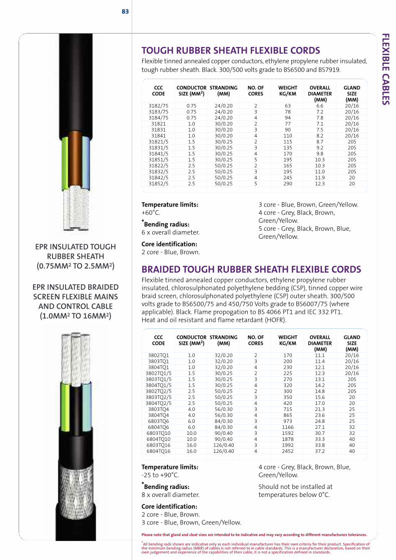
FLEXIB
LECABLES
83
CCC CONDUCTOR STRANDING NO. OF WEIGHT OVERALL GLANDCODE SIZE (MM2) (MM) CORES KG/KM DIAMETER SIZE
(MM) (MM)3802TQ1 1.0 32/0.20 2 170 11.1 20/163803TQ1 1.0 32/0.20 3 200 11.4 20/163804TQ1 1.0 32/0.20 4 230 12.1 20/163802TQ1/5 1.5 30/0.25 2 225 12.3 20/163803TQ1/5 1.5 30/0.25 3 270 13.1 20S3804TQ1/5 1.5 30/0.25 4 320 14.2 20S3802TQ2/5 2.5 50/0.25 2 300 14.8 20S3803TQ2/5 2.5 50/0.25 3 350 15.6 203804TQ2/5 2.5 50/0.25 4 420 17.0 203803TQ4 4.0 56/0.30 3 715 21.3 253804TQ4 4.0 56/0.30 4 865 23.6 256803TQ6 6.0 84/0.30 3 973 24.8 256804TQ6 6.0 84/0.30 4 1166 27.1 326803TQ10 10.0 90/0.40 3 1592 30.7 326804TQ10 10.0 90/0.40 4 1878 33.3 406803TQ16 16.0 126/0.40 3 1992 33.8 406804TQ16 16.0 126/0.40 4 2452 37.2 40
Temperature limits:-25 to +90°C.
*Bending radius:8 x overall diameter.
Core identification:2 core - Blue, Brown.3 core - Blue, Brown, Green/Yellow.
4 core - Grey, Black, Brown, Blue,Green/Yellow.
Should not be installed attemperatures below 0°C.
CCC CONDUCTOR STRANDING NO. OF WEIGHT OVERALL GLANDCODE SIZE (MM2) (MM) CORES KG/KM DIAMETER SIZE
(MM) (MM)3182/75 0.75 24/0.20 2 63 6.6 20/163183/75 0.75 24/0.20 3 78 7.2 20/163184/75 0.75 24/0.20 4 94 7.8 20/1631821 1.0 30/0.20 2 77 7.1 20/1631831 1.0 30/0.20 3 90 7.5 20/1631841 1.0 30/0.20 4 110 8.2 20/1631821/5 1.5 30/0.25 2 115 8.7 20S31831/5 1.5 30/0.25 3 135 9.2 20S31841/5 1.5 30/0.25 4 170 9.8 20S31851/5 1.5 30/0.25 5 195 10.3 20S31822/5 2.5 50/0.25 2 165 10.3 20S31832/5 2.5 50/0.25 3 195 11.0 20S31842/5 2.5 50/0.25 4 245 11.9 2031852/5 2.5 50/0.25 5 290 12.3 20
Temperature limits:+60°C.
*Bending radius:6 x overall diameter.
Core identification:2 core - Blue, Brown.
3 core - Blue, Brown, Green/Yellow.4 core - Grey, Black, Brown,Green/Yellow.5 core - Grey, Black, Brown, Blue,Green/Yellow.
EPR INSULATED BRAIDEDSCREEN FLEXIBLE MAINSAND CONTROL CABLE(1.0MM2 TO 16MM2)
EPR INSULATED TOUGHRUBBER SHEATH
(0.75MM2 TO 2.5MM2) BRAIDED TOUGH RUBBER SHEATH FLEXIBLE CORDSFlexible tinned annealed copper conductors, ethylene propylene rubberinsulated, chlorosulphonated polyethylene bedding (CSP), tinned copper wirebraid screen, chlorosulphonated polyethylene (CSP) outer sheath. 300/500volts grade to BS6500/75 and 450/750 Volts grade to BS6007/75 (whereapplicable). Black. Flame propogation to BS 4066 PT1 and IEC 332 PT1.Heat and oil resistant and flame retardant (HOFR).
TOUGH RUBBER SHEATH FLEXIBLE CORDSFlexible tinned annealed copper conductors, ethylene propylene rubber insulated,tough rubber sheath. Black. 300/500 volts grade to BS6500 and BS7919.
*All bending radii shown are indicative only as each individual manufacturer has their own criteria for their product. Specification ofthe minimum bending radius (MBR) of cables is not referred to in cable standards. This is a manufacturer declaration, based on theirown judgement and experience of the capabilities of their cable, it is not a specification defined in standards.
Please note that gland and cleat sizes are intended to be indicative and may vary according to different manufacturers tolerances.
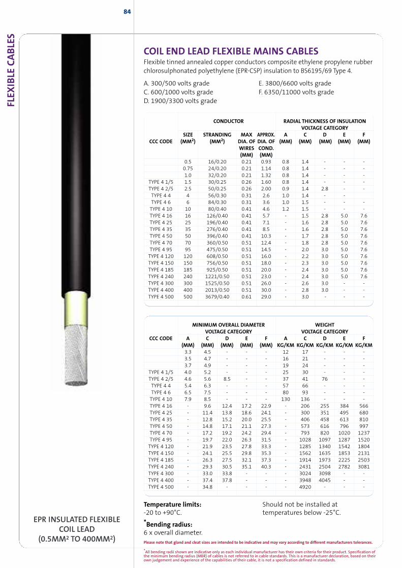
*All bending radii shown are indicative only as each individual manufacturer has their own criteria for their product. Specification ofthe minimum bending radius (MBR) of cables is not referred to in cable standards. This is a manufacturer declaration, based on theirown judgement and experience of the capabilities of their cable, it is not a specification defined in standards.
FLEX
IBLE
CABLE
S84
EPR INSULATED FLEXIBLECOIL LEAD
(0.5MM2 TO 400MM2)
COIL END LEAD FLEXIBLE MAINS CABLESFlexible tinned annealed copper conductors composite ethylene propylene rubberchlorosulphonated polyethylene (EPR-CSP) insulation to BS6195/69 Type 4.
A. 300/500 volts grade E. 3800/6600 volts gradeC. 600/1000 volts grade F. 6350/11000 volts gradeD. 1900/3300 volts grade
CONDUCTOR RADIAL THICKNESS OF INSULATIONVOLTAGE CATEGORY
SIZE STRANDING MAX APPROX. A C D E FCCC CODE (MM2) (MM2) DIA. OF DIA. OF (MM) (MM) (MM) (MM) (MM)
WIRES COND.(MM) (MM)
0.5 16/0.20 0.21 0.93 0.8 1.4 - - -0.75 24/0.20 0.21 1.14 0.8 1.4 - - -1.0 32/0.20 0.21 1.32 0.8 1.4 - - -
TYPE 4 1/5 1.5 30/0.25 0.26 1.60 0.8 1.4 - - -TYPE 4 2/5 2.5 50/0.25 0.26 2.00 0.9 1.4 2.8 - -TYPE 4 4 4 56/0.30 0.31 2.6 1.0 1.4 - -TYPE 4 6 6 84/0.30 0.31 3.6 1.0 1.5 - - -TYPE 4 10 10 80/0.40 0.41 4.6 1.2 1.5 - - -TYPE 4 16 16 126/0.40 0.41 5.7 - 1.5 2.8 5.0 7.6TYPE 4 25 25 196/0.40 0.41 7.1 - 1.6 2.8 5.0 7.6TYPE 4 35 35 276/0.40 0.41 8.5 - 1.6 2.8 5.0 7.6TYPE 4 50 50 396/0.40 0.41 10.3 - 1.7 2.8 5.0 7.6TYPE 4 70 70 360/0.50 0.51 12.4 - 1.8 2.8 5.0 7.6TYPE 4 95 95 475/0.50 0.51 14.5 - 2.0 3.0 5.0 7.6TYPE 4 120 120 608/0.50 0.51 16.0 - 2.2 3.0 5.0 7.6TYPE 4 150 150 756/0.50 0.51 18.0 - 2.3 3.0 5.0 7.6TYPE 4 185 185 925/0.50 0.51 20.0 - 2.4 3.0 5.0 7.6TYPE 4 240 240 1221/0.50 0.51 23.0 - 2.4 3.0 5.0 7.6TYPE 4 300 300 1525/0.50 0.51 26.0 - 2.6 3.0 - -TYPE 4 400 400 2013/0.50 0.51 30.0 - 2.8 3.0 - -TYPE 4 500 500 3679/0.40 0.61 29.0 - 3.0 - - -
MINIMUM OVERALL DIAMETER WEIGHTVOLTAGE CATEGORY VOLTAGE CATEGORY
CCC CODE A C D E F A C D E F(MM) (MM) (MM) (MM) (MM) KG/KM KG/KM KG/KM KG/KM KG/KM3.3 4.5 - - - 12 17 - - -3.5 4.7 - - - 16 21 - - -3.7 4.9 - - - 19 24 - - -
TYPE 4 1/5 4.0 5.2 - - - 25 30 - - -TYPE 4 2/5 4.6 5.6 8.5 - - 37 41 76 - -TYPE 4 4 5.4 6.3 - - - 57 66 - - -TYPE 4 6 6.5 7.5 - - - 80 93 - - -TYPE 4 10 7.9 8.5 - - - 130 136 - - -TYPE 4 16 - 9.6 12.4 17.2 22.9 - 206 255 384 566TYPE 4 25 - 11.4 13.8 18.6 24.1 - 300 351 495 680TYPE 4 35 - 12.8 15.2 20.0 25.5 - 406 458 613 810TYPE 4 50 - 14.8 17.1 21.1 27.3 - 573 616 796 997TYPE 4 70 - 17.2 19.2 24.2 29.4 - 793 820 1020 1237TYPE 4 95 - 19.7 22.0 26.3 31.5 - 1028 1097 1287 1520TYPE 4 120 - 21.9 23.5 27.8 33.3 - 1285 1340 1542 1804TYPE 4 150 - 24.1 25.5 29.8 35.3 - 1562 1635 1853 2131TYPE 4 185 - 26.3 27.5 32.1 37.3 - 1914 1973 2225 2503TYPE 4 240 - 29.3 30.5 35.1 40.3 - 2431 2504 2782 3081TYPE 4 300 - 33.0 33.8 - - - 3024 3098 - -TYPE 4 400 - 37.4 37.8 - - - 3948 4045 - -TYPE 4 500 - 34.8 - - - - 4920 - - -
Temperature limits:-20 to +90°C.
*Bending radius:6 x overall diameter.
Should not be installed attemperatures below -25°C.
Please note that gland and cleat sizes are intended to be indicative and may vary according to different manufacturers tolerances.
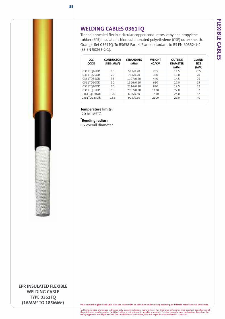
*All bending radii shown are indicative only as each individual manufacturer has their own criteria for their product. Specification ofthe minimum bending radius (MBR) of cables is not referred to in cable standards. This is a manufacturer declaration, based on theirown judgement and experience of the capabilities of their cable, it is not a specification defined in standards.
FLEXIB
LECABLES
85
WELDING CABLES 0361TQTinned annealed flexible circular copper conductors, ethylene propylenerubber (EPR) insulated, chlorosulphonated polyethylene (CSP) outer sheath.Orange. Ref 0361TQ. To BS638 Part 4. Flame retardant to BS EN 60332-1-2(BS EN 50265-2-1).
CCC CONDUCTOR STRANDING WEIGHT OUTSIDE GLANDCODE SIZE (MM2) (MM) KG/KM DIAMETER SIZE
(MM) (MM)0361TQ16OR 16 513/0.20 235 11.5 20S0361TQ25OR 25 783/0.20 330 13.0 200361TQ35OR 35 1107/0.20 440 14.5 250361TQ50OR 50 1566/0.20 610 17.0 250361TQ70OR 70 2214/0.20 840 19.5 320361TQ95OR 95 2997/0.20 1120 22.0 320361TQ120OR 120 608/0.50 1410 24.0 320361TQ185OR 185 925/0.50 2100 29.0 40
EPR INSULATED FLEXIBLEWELDING CABLETYPE 0361TQ
(16MM2 TO 185MM2)
Temperature limits:-20 to +85°C.
*Bending radius:8 x overall diameter.
Please note that gland and cleat sizes are intended to be indicative and may vary according to different manufacturers tolerances.
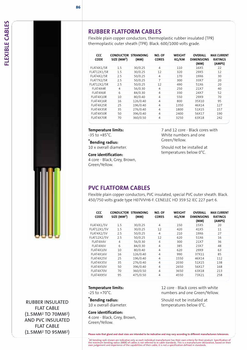
*All bending radii shown are indicative only as each individual manufacturer has their own criteria for their product. Specification ofthe minimum bending radius (MBR) of cables is not referred to in cable standards. This is a manufacturer declaration, based on theirown judgement and experience of the capabilities of their cable, it is not a specification defined in standards.
FLEX
IBLE
CABLE
S86
CCC CONDUCTOR STRANDING NO. OF WEIGHT OVERALL MAX CURRENTCODE SIZE (MM2) (MM) CORES KG/KM DIMENSIONS RATINGS
(MM) (AMPS)FLAT4X1/5R 1.5 30/0.25 4 110 16X5 22FLAT12X1/5R 1.5 30/0.25 12 320 29X5 12FLAT4X2/5R 2.5 50/0.25 4 170 19X6 30FLAT7X2/5R 2.5 50/0.25 7 300 33X7 20FLAT12X2/5R 2.5 50/0.25 12 490 51X6 20FLAT4X4R 4 56/0.30 4 250 21X7 40FLAT4X6R 6 84/0.30 4 330 24X7 52FLAT4X10R 10 80/0.40 4 550 29X9 70FLAT4X16R 16 126/0.40 4 800 35X10 95FLAT4X25R 25 196/0.40 4 1350 46X14 127FLAT4X35R 35 276/0.40 4 1800 51X15 157FLAT4X50R 50 396/0.40 4 2400 56X17 190FLAT4X70R 70 360/0.50 4 3250 63X18 242
RUBBER INSULATEDFLAT CABLE
(1.5MM2 TO 70MM2)AND PVC INSULATED
FLAT CABLE(1.5MM2 TO 95MM2)
CCC CONDUCTOR STRANDING NO. OF WEIGHT OVERALL MAX CURRENTCODE SIZE (MM2) (MM) CORES KG/KM DIMENSIONS RATINGS
(MM) (AMPS)FLAT4X1/5V 1.5 30/0.25 4 150 15X5 20FLAT12X1/5V 1.5 30/0.25 12 420 41X5 11FLAT4X2/5V 2.5 50/0.25 4 210 19X6 27FLAT12X2/5V 2.5 50/0.25 12 620 51X6 16FLAT4X4V 4 56/0.30 4 300 21X7 36FLAT4X6V 6 84/0.30 4 385 23X7 48FLAT4X10V 10 80/0.40 4 620 29X9 63FLAT4X16V 16 126/0.40 4 990 37X11 85FLAT4X25V 25 196/0.40 4 1550 46X14 112FLAT4X35V 35 276/0.40 4 2030 51X15 138FLAT4X50V 50 396/0.40 4 2650 56X17 168FLAT4X70V 70 360/0.50 4 3650 63X18 213FLAT4X95V 95 475/0.50 4 4550 73X21 258
Temperature limits:-35 to +85°C.
*Bending radius:10 x overall diameter.
Core identification:4 core - Black, Grey, Brown,Green/Yellow.
7 and 12 core - Black cores withWhite numbers and oneGreen/Yellow.
Should not be installed attemperatures below 0°C.
Temperature limits:-25 to +70°C.
*Bending radius:10 x overall diameter.
Core identification:4 core - Black, Grey, Brown,Green/Yellow.
12 core - Black cores with whitenumbers and one Green/Yellow.
Should not be installed attemperatures below 0°C.
RUBBER FLATFORM CABLESFlexible plain copper conductors, thermoplastic rubber insulated (TPR)thermoplastic outer sheath (TPR). Black. 600/1000 volts grade.
PVC FLATFORM CABLESFlexible plain copper conductors, PVC insulated, special PVC outer sheath. Black.450/750 volts grade type H07VVH6-F. CENELEC HD 359 S2 IEC 227 part 6.
Please note that gland and cleat sizes are intended to be indicative and may vary according to different manufacturers tolerances.
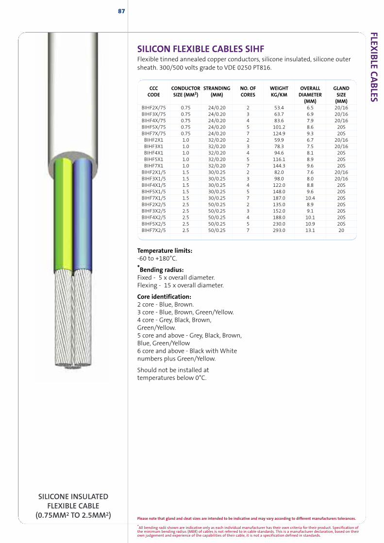
*All bending radii shown are indicative only as each individual manufacturer has their own criteria for their product. Specification ofthe minimum bending radius (MBR) of cables is not referred to in cable standards. This is a manufacturer declaration, based on theirown judgement and experience of the capabilities of their cable, it is not a specification defined in standards.
FLEXIB
LECABLES
87
SILICON FLEXIBLE CABLES SIHFFlexible tinned annealed copper conductors, silicone insulated, silicone outersheath. 300/500 volts grade to VDE 0250 PT816.
CCC CONDUCTOR STRANDING NO. OF WEIGHT OVERALL GLANDCODE SIZE (MM2) (MM) CORES KG/KM DIAMETER SIZE
(MM) (MM)BIHF2X/75 0.75 24/0.20 2 53.4 6.5 20/16BIHF3X/75 0.75 24/0.20 3 63.7 6.9 20/16BIHF4X/75 0.75 24/0.20 4 83.6 7.9 20/16BIHF5X/75 0.75 24/0.20 5 101.2 8.6 20SBIHF7X/75 0.75 24/0.20 7 124.9 9.3 20SBIHF2X1 1.0 32/0.20 2 59.9 6.7 20/16BIHF3X1 1.0 32/0.20 3 78.3 7.5 20/16BIHF4X1 1.0 32/0.20 4 94.6 8.1 20SBIHF5X1 1.0 32/0.20 5 116.1 8.9 20SBIHF7X1 1.0 32/0.20 7 144.3 9.6 20SBIHF2X1/5 1.5 30/0.25 2 82.0 7.6 20/16BIHF3X1/5 1.5 30/0.25 3 98.0 8.0 20/16BIHF4X1/5 1.5 30/0.25 4 122.0 8.8 20SBIHF5X1/5 1.5 30/0.25 5 148.0 9.6 20SBIHF7X1/5 1.5 30/0.25 7 187.0 10.4 20SBIHF2X2/5 2.5 50/0.25 2 135.0 8.9 20SBIHF3X2/5 2.5 50/0.25 3 152.0 9.1 20SBIHF4X2/5 2.5 50/0.25 4 188.0 10.1 20SBIHF5X2/5 2.5 50/0.25 5 230.0 10.9 20SBIHF7X2/5 2.5 50/0.25 7 293.0 13.1 20
SILICONE INSULATEDFLEXIBLE CABLE
(0.75MM2 TO 2.5MM2)
Temperature limits:-60 to +180°C.
*Bending radius:Fixed - 5 x overall diameter.Flexing - 15 x overall diameter.
Core identification:2 core - Blue, Brown.3 core - Blue, Brown, Green/Yellow.4 core - Grey, Black, Brown,Green/Yellow.5 core and above - Grey, Black, Brown,Blue, Green/Yellow6 core and above - Black with Whitenumbers plus Green/Yellow.
Should not be installed attemperatures below 0°C.
Please note that gland and cleat sizes are intended to be indicative and may vary according to different manufacturers tolerances.

89
INSTRUMENTATION,CONTROL ANDCOMMUNICATIONCABLES
INSTR
UM
ENTATIO
N,CO
NTRO
LAND
COM
MUNICATIO
NCABLES
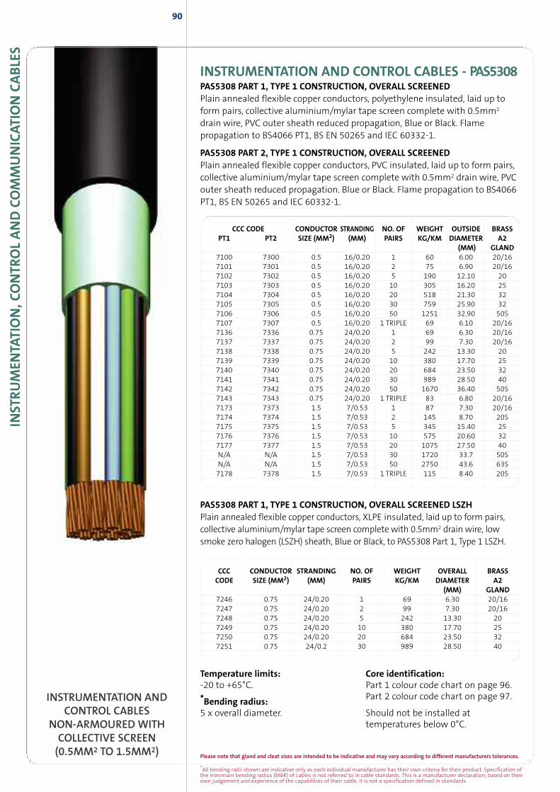
*All bending radii shown are indicative only as each individual manufacturer has their own criteria for their product. Specification ofthe minimum bending radius (MBR) of cables is not referred to in cable standards. This is a manufacturer declaration, based on theirown judgement and experience of the capabilities of their cable, it is not a specification defined in standards.
Please note that gland and cleat sizes are intended to be indicative and may vary according to different manufacturers tolerances.
INST
RUM
ENTA
TION,C
ONTR
OLAND
COM
MUNICAT
ION
CABLE
S90
PAS5308 PART 1, TYPE 1 CONSTRUCTION, OVERALL SCREENED LSZHPlain annealed flexible copper conductors, XLPE insulated, laid up to form pairs,collective aluminium/mylar tape screen complete with 0.5mm2 drain wire, lowsmoke zero halogen (LSZH) sheath, Blue or Black, to PAS5308 Part 1, Type 1 LSZH.
INSTRUMENTATION ANDCONTROL CABLES
NON-ARMOURED WITHCOLLECTIVE SCREEN(0.5MM2 TO 1.5MM2)
CCC CONDUCTOR STRANDING NO. OF WEIGHT OVERALL BRASSCODE SIZE (MM2) (MM) PAIRS KG/KM DIAMETER A2
(MM) GLAND7246 0.75 24/0.20 1 69 6.30 20/167247 0.75 24/0.20 2 99 7.30 20/167248 0.75 24/0.20 5 242 13.30 207249 0.75 24/0.20 10 380 17.70 257250 0.75 24/0.20 20 684 23.50 327251 0.75 24/0.2 30 989 28.50 40
Temperature limits:-20 to +65°C.
*Bending radius:5 x overall diameter.
Core identification:Part 1 colour code chart on page 96.Part 2 colour code chart on page 97.
Should not be installed attemperatures below 0°C.
CCC CODE CONDUCTOR STRANDING NO. OF WEIGHT OUTSIDE BRASSPT1 PT2 SIZE (MM2) (MM) PAIRS KG/KM DIAMETER A2
(MM) GLAND7100 7300 0.5 16/0.20 1 60 6.00 20/167101 7301 0.5 16/0.20 2 75 6.90 20/167102 7302 0.5 16/0.20 5 190 12.10 207103 7303 0.5 16/0.20 10 305 16.20 257104 7304 0.5 16/0.20 20 518 21.30 327105 7305 0.5 16/0.20 30 759 25.90 327106 7306 0.5 16/0.20 50 1251 32.90 50S7107 7307 0.5 16/0.20 1 TRIPLE 69 6.10 20/167136 7336 0.75 24/0.20 1 69 6.30 20/167137 7337 0.75 24/0.20 2 99 7.30 20/167138 7338 0.75 24/0.20 5 242 13.30 207139 7339 0.75 24/0.20 10 380 17.70 257140 7340 0.75 24/0.20 20 684 23.50 327141 7341 0.75 24/0.20 30 989 28.50 407142 7342 0.75 24/0.20 50 1670 36.40 50S7143 7343 0.75 24/0.20 1 TRIPLE 83 6.80 20/167173 7373 1.5 7/0.53 1 87 7.30 20/167174 7374 1.5 7/0.53 2 145 8.70 20S7175 7375 1.5 7/0.53 5 345 15.40 257176 7376 1.5 7/0.53 10 575 20.60 327177 7377 1.5 7/0.53 20 1075 27.50 40N/A N/A 1.5 7/0.53 30 1720 33.7 50SN/A N/A 1.5 7/0.53 50 2750 43.6 63S7178 7378 1.5 7/0.53 1 TRIPLE 115 8.40 20S
INSTRUMENTATION AND CONTROL CABLES - PAS5308PAS5308 PART 1, TYPE 1 CONSTRUCTION, OVERALL SCREENEDPlain annealed flexible copper conductors, polyethylene insulated, laid up toform pairs, collective aluminium/mylar tape screen complete with 0.5mm2
drain wire, PVC outer sheath reduced propagation, Blue or Black. Flamepropagation to BS4066 PT1, BS EN 50265 and IEC 60332-1.
PAS5308 PART 2, TYPE 1 CONSTRUCTION, OVERALL SCREENEDPlain annealed flexible copper conductors, PVC insulated, laid up to form pairs,collective aluminium/mylar tape screen complete with 0.5mm2 drain wire, PVCouter sheath reduced propagation. Blue or Black. Flame propagation to BS4066PT1, BS EN 50265 and IEC 60332-1.
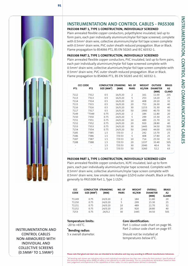
Please note that gland and cleat sizes are intended to be indicative and may vary according to different manufacturers tolerances.
*All bending radii shown are indicative only as each individual manufacturer has their own criteria for their product. Specification ofthe minimum bending radius (MBR) of cables is not referred to in cable standards. This is a manufacturer declaration, based on theirown judgement and experience of the capabilities of their cable, it is not a specification defined in standards.
91IN
STRUM
ENTATIO
N,CO
NTRO
LAND
COM
MUNICATIO
NCABLES
INSTRUMENTATION AND CONTROL CABLES - PAS5308PAS5308 PART 1, TYPE 1 CONSTRUCTION, INDIVIDUALLY SCREENEDPlain annealed flexible copper conductors, polyethylene insulated, laid up toform pairs, each pair individually aluminium/mylar foil tape screened, completewith 0.5mm2 drain wire, collective aluminium/mylar foil tape screen completewith 0.5mm2 drain wire, PVC outer sheath reduced propagation. Blue or Black.Flame propagation to BS4066 PT1, BS EN 50265 and IEC 60332-1.
PAS5308 PART 2, TYPE 1 CONSTRUCTION, INDIVIDUALLY SCREENEDPlain annealed flexible copper conductors, PVC insulated, laid up to form pairs,each pair individually aluminium/mylar foil tape screened complete with0.5mm2 drain wire, collective aluminium/mylar foil tape screen complete with0.5mm2 drain wire, PVC outer sheath reduced propagation. Blue or Black.Flame propagation to BS4066 PT1, BS EN 50265 and IEC 60332-1.
PAS5308 PART 1, TYPE 1 CONSTRUCTION, INDIVIDUALLY SCREENED LSZHPlain annealed flexible copper conductors, XLPE insulated, laid up to formpairs, each pair individually aluminium/mylar tape screened. Complete with0.5mm2 drain wire, collective aluminium/mylar tape screen complete with0.5mm2 drain wire, low smoke zero halogen (LSZH) outer sheath, Black or Blue,generally to PAS5308 Part 1, Type 1 LSZH.
CCC CODE CONDUCTOR STRANDING NO. OF WEIGHT OUTSIDE BRASSPT1 PT2 SIZE (MM2) (MM) PAIRS KG/KM DIAMETER A2
(MM) GLAND7112 7312 0.5 16/0.20 2 161 11.00 20S7113 7313 0.5 16/0.20 5 253 14.20 257114 7314 0.5 16/0.20 10 408 20.10 327115 7315 0.5 16/0.20 20 753 26.30 407116 7316 0.5 16/0.20 30 1153 31.30 407117 7317 0.5 16/0.20 50 1900 40.70 507149 *7349 0.75 24/0.20 2 184 11.80 207150 7350 0.75 24/0.20 5 299 15.30 257151 7351 0.75 24/0.20 10 489 21.70 327152 7352 0.75 24/0.20 20 920 28.80 407153 7353 0.75 24/0.20 30 1445 34.50 50S7154 7354 0.75 24/0.20 50 2460 44.00 63S7185 7385 1.5 7/0.53 2 242 13.70 257186 7386 1.5 7/0.53 5 408 17.80 257187 7387 1.5 7/0.53 10 714 25.50 327188 7388 1.5 7/0.53 20 1337 33.40 50S
- - 1.5 7/0.53 30 2040 40.4 50- - 1.5 7/0.53 50 3260 52.2 63
CCC CONDUCTOR STRANDING NO. OF WEIGHT OVERALL BRASSCODE SIZE (MM2) (MM) PAIRS KG/KM DIAMETER A2
(MM) GLAND71149 0.75 24/0.20 2 184 11.80 2071150 0.75 24/0.20 5 299 15.30 2571151 0.75 24/0.20 10 489 21.70 3271152 0.75 24/0.20 20 920 28.80 407253 0.75 24/0.2 30 1445 34.50 50S
INSTRUMENTATION ANDCONTROL CABLES
NON-ARMOURED WITHINDIVIDUAL AND
COLLECTIVE SCREENS(0.5MM2 TO 1.5MM2)
Temperature limits:-20 to +65°C.
*Bending radius:5 x overall diameter.
Core identification:Part 1 colour code chart on page 96.Part 2 colour code chart on page 97.
Should not be installed attemperatures below 0°C.
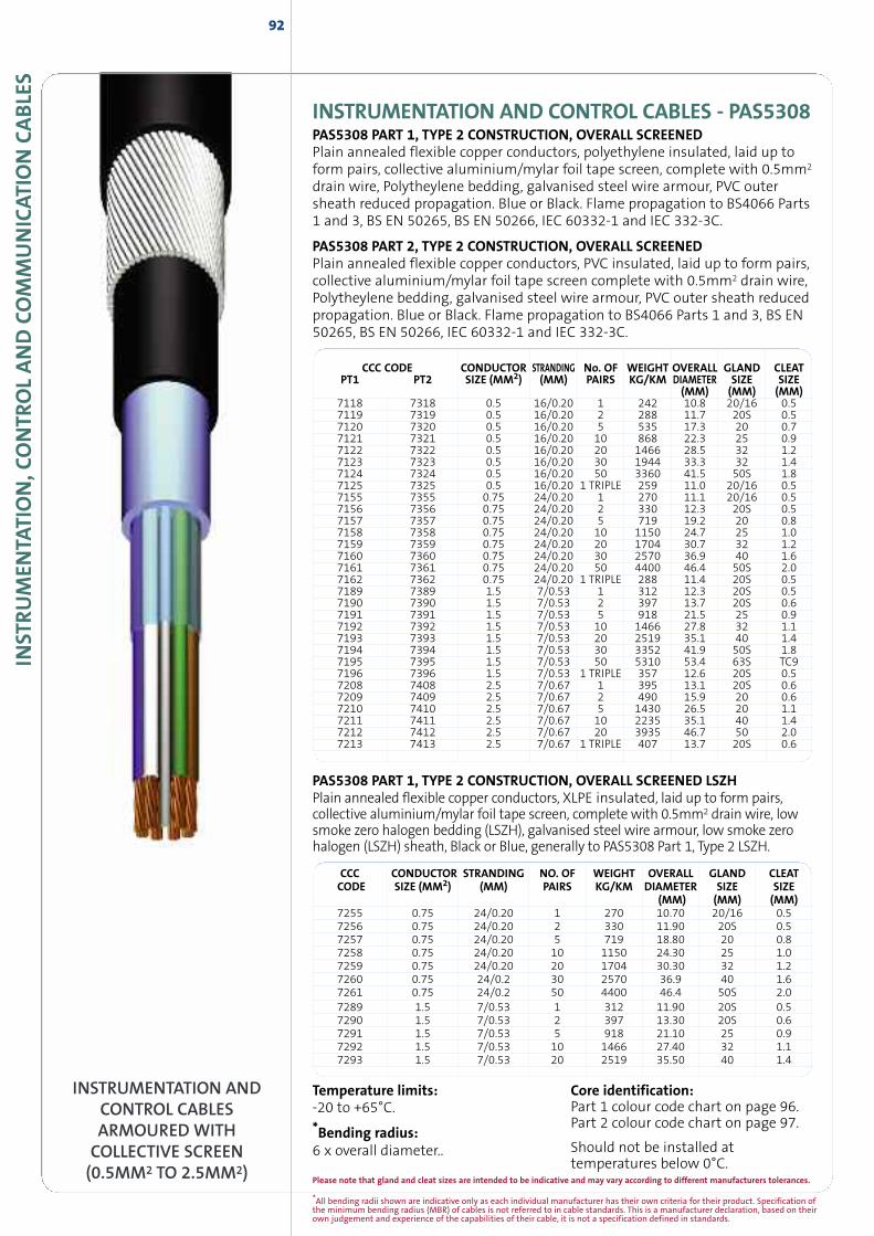
*All bending radii shown are indicative only as each individual manufacturer has their own criteria for their product. Specification ofthe minimum bending radius (MBR) of cables is not referred to in cable standards. This is a manufacturer declaration, based on theirown judgement and experience of the capabilities of their cable, it is not a specification defined in standards.
INST
RUM
ENTA
TION,C
ONTR
OLAND
COM
MUNICAT
ION
CABLE
S92
INSTRUMENTATION ANDCONTROL CABLESARMOURED WITHCOLLECTIVE SCREEN(0.5MM2 TO 2.5MM2)
Temperature limits:-20 to +65°C.
*Bending radius:6 x overall diameter..
Core identification:Part 1 colour code chart on page 96.Part 2 colour code chart on page 97.
Should not be installed attemperatures below 0°C.
PAS5308 PART 1, TYPE 2 CONSTRUCTION, OVERALL SCREENED LSZHPlain annealed flexible copper conductors, XLPE insulated, laid up to form pairs,collective aluminium/mylar foil tape screen, complete with 0.5mm2 drain wire, lowsmoke zero halogen bedding (LSZH), galvanised steel wire armour, low smoke zerohalogen (LSZH) sheath, Black or Blue, generally to PAS5308 Part 1, Type 2 LSZH.
INSTRUMENTATION AND CONTROL CABLES - PAS5308PAS5308 PART 1, TYPE 2 CONSTRUCTION, OVERALL SCREENEDPlain annealed flexible copper conductors, polyethylene insulated, laid up toform pairs, collective aluminium/mylar foil tape screen, complete with 0.5mm2
drain wire, Polytheylene bedding, galvanised steel wire armour, PVC outersheath reduced propagation. Blue or Black. Flame propagation to BS4066 Parts1 and 3, BS EN 50265, BS EN 50266, IEC 60332-1 and IEC 332-3C.
PAS5308 PART 2, TYPE 2 CONSTRUCTION, OVERALL SCREENEDPlain annealed flexible copper conductors, PVC insulated, laid up to form pairs,collective aluminium/mylar foil tape screen complete with 0.5mm2 drain wire,Polytheylene bedding, galvanised steel wire armour, PVC outer sheath reducedpropagation. Blue or Black. Flame propagation to BS4066 Parts 1 and 3, BS EN50265, BS EN 50266, IEC 60332-1 and IEC 332-3C.
CCC CODE CONDUCTOR STRANDING No. OF WEIGHT OVERALL GLAND CLEATPT1 PT2 SIZE (MM2) (MM) PAIRS KG/KM DIAMETER SIZE SIZE
(MM) (MM) (MM)7118 7318 0.5 16/0.20 1 242 10.8 20/16 0.57119 7319 0.5 16/0.20 2 288 11.7 20S 0.57120 7320 0.5 16/0.20 5 535 17.3 20 0.77121 7321 0.5 16/0.20 10 868 22.3 25 0.97122 7322 0.5 16/0.20 20 1466 28.5 32 1.27123 7323 0.5 16/0.20 30 1944 33.3 32 1.47124 7324 0.5 16/0.20 50 3360 41.5 50S 1.87125 7325 0.5 16/0.20 1 TRIPLE 259 11.0 20/16 0.57155 7355 0.75 24/0.20 1 270 11.1 20/16 0.57156 7356 0.75 24/0.20 2 330 12.3 20S 0.57157 7357 0.75 24/0.20 5 719 19.2 20 0.87158 7358 0.75 24/0.20 10 1150 24.7 25 1.07159 7359 0.75 24/0.20 20 1704 30.7 32 1.27160 7360 0.75 24/0.20 30 2570 36.9 40 1.67161 7361 0.75 24/0.20 50 4400 46.4 50S 2.07162 7362 0.75 24/0.20 1 TRIPLE 288 11.4 20S 0.57189 7389 1.5 7/0.53 1 312 12.3 20S 0.57190 7390 1.5 7/0.53 2 397 13.7 20S 0.67191 7391 1.5 7/0.53 5 918 21.5 25 0.97192 7392 1.5 7/0.53 10 1466 27.8 32 1.17193 7393 1.5 7/0.53 20 2519 35.1 40 1.47194 7394 1.5 7/0.53 30 3352 41.9 50S 1.87195 7395 1.5 7/0.53 50 5310 53.4 63S TC97196 7396 1.5 7/0.53 1 TRIPLE 357 12.6 20S 0.57208 7408 2.5 7/0.67 1 395 13.1 20S 0.67209 7409 2.5 7/0.67 2 490 15.9 20 0.67210 7410 2.5 7/0.67 5 1430 26.5 20 1.17211 7411 2.5 7/0.67 10 2235 35.1 40 1.47212 7412 2.5 7/0.67 20 3935 46.7 50 2.07213 7413 2.5 7/0.67 1 TRIPLE 407 13.7 20S 0.6
CCC CONDUCTOR STRANDING NO. OF WEIGHT OVERALL GLAND CLEATCODE SIZE (MM2) (MM) PAIRS KG/KM DIAMETER SIZE SIZE
(MM) (MM) (MM)7255 0.75 24/0.20 1 270 10.70 20/16 0.57256 0.75 24/0.20 2 330 11.90 20S 0.57257 0.75 24/0.20 5 719 18.80 20 0.87258 0.75 24/0.20 10 1150 24.30 25 1.07259 0.75 24/0.20 20 1704 30.30 32 1.27260 0.75 24/0.2 30 2570 36.9 40 1.67261 0.75 24/0.2 50 4400 46.4 50S 2.07289 1.5 7/0.53 1 312 11.90 20S 0.57290 1.5 7/0.53 2 397 13.30 20S 0.67291 1.5 7/0.53 5 918 21.10 25 0.97292 1.5 7/0.53 10 1466 27.40 32 1.17293 1.5 7/0.53 20 2519 35.50 40 1.4
Please note that gland and cleat sizes are intended to be indicative and may vary according to different manufacturers tolerances.
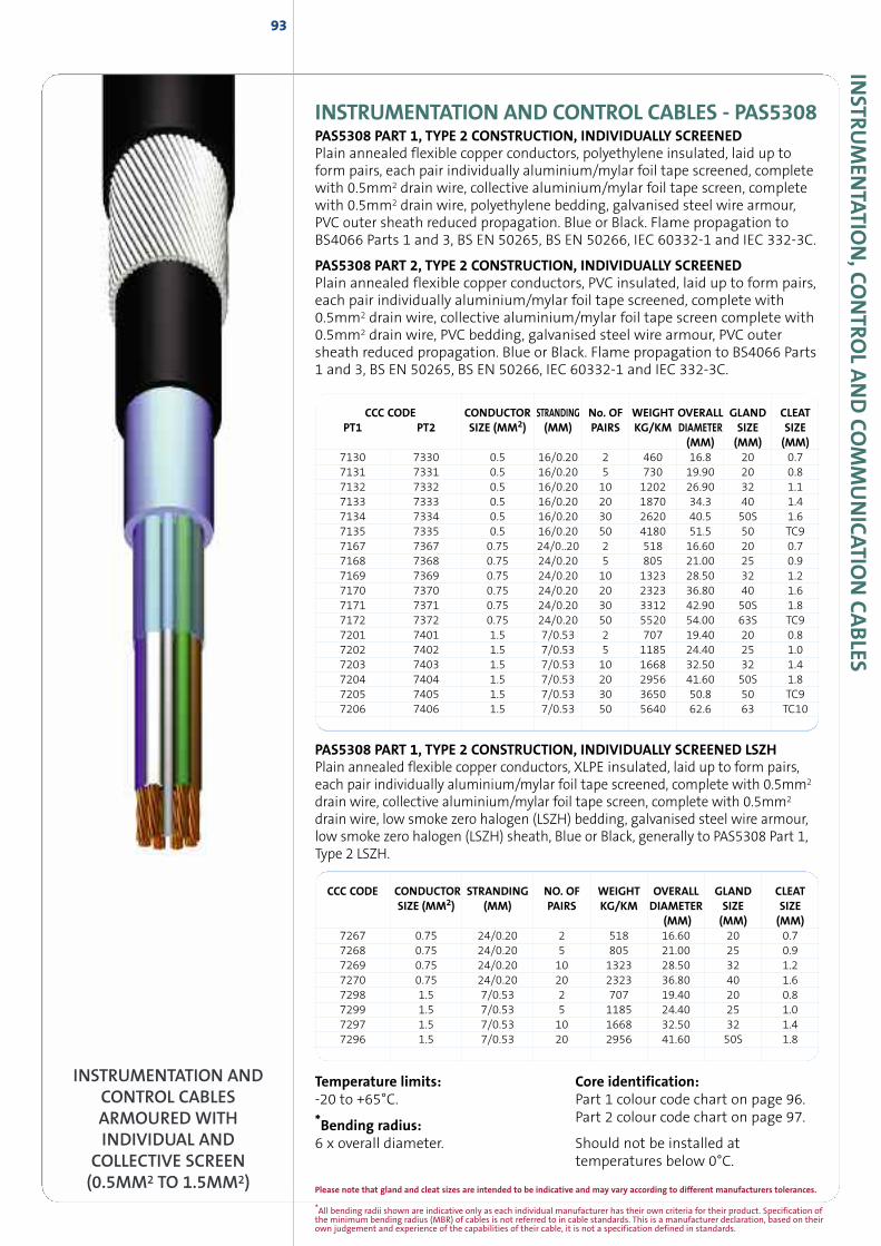
INSTR
UM
ENTATIO
N,CO
NTRO
LAND
COM
MUNICATIO
NCABLES
INSTRUMENTATION AND CONTROL CABLES - PAS5308PAS5308 PART 1, TYPE 2 CONSTRUCTION, INDIVIDUALLY SCREENEDPlain annealed flexible copper conductors, polyethylene insulated, laid up toform pairs, each pair individually aluminium/mylar foil tape screened, completewith 0.5mm2 drain wire, collective aluminium/mylar foil tape screen, completewith 0.5mm2 drain wire, polyethylene bedding, galvanised steel wire armour,PVC outer sheath reduced propagation. Blue or Black. Flame propagation toBS4066 Parts 1 and 3, BS EN 50265, BS EN 50266, IEC 60332-1 and IEC 332-3C.
PAS5308 PART 2, TYPE 2 CONSTRUCTION, INDIVIDUALLY SCREENEDPlain annealed flexible copper conductors, PVC insulated, laid up to form pairs,each pair individually aluminium/mylar foil tape screened, complete with0.5mm2 drain wire, collective aluminium/mylar foil tape screen complete with0.5mm2 drain wire, PVC bedding, galvanised steel wire armour, PVC outersheath reduced propagation. Blue or Black. Flame propagation to BS4066 Parts1 and 3, BS EN 50265, BS EN 50266, IEC 60332-1 and IEC 332-3C.
CCC CODE CONDUCTOR STRANDING NO. OF WEIGHT OVERALL GLAND CLEATSIZE (MM2) (MM) PAIRS KG/KM DIAMETER SIZE SIZE
(MM) (MM) (MM)7267 0.75 24/0.20 2 518 16.60 20 0.77268 0.75 24/0.20 5 805 21.00 25 0.97269 0.75 24/0.20 10 1323 28.50 32 1.27270 0.75 24/0.20 20 2323 36.80 40 1.67298 1.5 7/0.53 2 707 19.40 20 0.87299 1.5 7/0.53 5 1185 24.40 25 1.07297 1.5 7/0.53 10 1668 32.50 32 1.47296 1.5 7/0.53 20 2956 41.60 50S 1.8
93
INSTRUMENTATION ANDCONTROL CABLESARMOURED WITHINDIVIDUAL AND
COLLECTIVE SCREEN(0.5MM2 TO 1.5MM2)
Temperature limits:-20 to +65°C.
*Bending radius:6 x overall diameter.
Core identification:Part 1 colour code chart on page 96.Part 2 colour code chart on page 97.
Should not be installed attemperatures below 0°C.
PAS5308 PART 1, TYPE 2 CONSTRUCTION, INDIVIDUALLY SCREENED LSZHPlain annealed flexible copper conductors, XLPE insulated, laid up to form pairs,each pair individually aluminium/mylar foil tape screened, complete with 0.5mm2
drain wire, collective aluminium/mylar foil tape screen, complete with 0.5mm2
drain wire, low smoke zero halogen (LSZH) bedding, galvanised steel wire armour,low smoke zero halogen (LSZH) sheath, Blue or Black, generally to PAS5308 Part 1,Type 2 LSZH.
CCC CODE CONDUCTOR STRANDING No. OF WEIGHT OVERALL GLAND CLEATPT1 PT2 SIZE (MM2) (MM) PAIRS KG/KM DIAMETER SIZE SIZE
(MM) (MM) (MM)7130 7330 0.5 16/0.20 2 460 16.8 20 0.77131 7331 0.5 16/0.20 5 730 19.90 20 0.87132 7332 0.5 16/0.20 10 1202 26.90 32 1.17133 7333 0.5 16/0.20 20 1870 34.3 40 1.47134 7334 0.5 16/0.20 30 2620 40.5 50S 1.67135 7335 0.5 16/0.20 50 4180 51.5 50 TC97167 7367 0.75 24/0..20 2 518 16.60 20 0.77168 7368 0.75 24/0.20 5 805 21.00 25 0.97169 7369 0.75 24/0.20 10 1323 28.50 32 1.27170 7370 0.75 24/0.20 20 2323 36.80 40 1.67171 7371 0.75 24/0.20 30 3312 42.90 50S 1.87172 7372 0.75 24/0.20 50 5520 54.00 63S TC97201 7401 1.5 7/0.53 2 707 19.40 20 0.87202 7402 1.5 7/0.53 5 1185 24.40 25 1.07203 7403 1.5 7/0.53 10 1668 32.50 32 1.47204 7404 1.5 7/0.53 20 2956 41.60 50S 1.87205 7405 1.5 7/0.53 30 3650 50.8 50 TC97206 7406 1.5 7/0.53 50 5640 62.6 63 TC10
*All bending radii shown are indicative only as each individual manufacturer has their own criteria for their product. Specification ofthe minimum bending radius (MBR) of cables is not referred to in cable standards. This is a manufacturer declaration, based on theirown judgement and experience of the capabilities of their cable, it is not a specification defined in standards.
Please note that gland and cleat sizes are intended to be indicative and may vary according to different manufacturers tolerances.
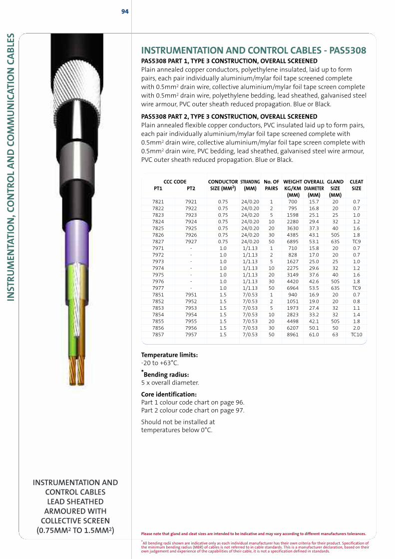
*All bending radii shown are indicative only as each individual manufacturer has their own criteria for their product. Specification ofthe minimum bending radius (MBR) of cables is not referred to in cable standards. This is a manufacturer declaration, based on theirown judgement and experience of the capabilities of their cable, it is not a specification defined in standards.
INST
RUM
ENTA
TION,C
ONTR
OLAND
COM
MUNICAT
ION
CABLE
S94
INSTRUMENTATION AND CONTROL CABLES - PAS5308PAS5308 PART 1, TYPE 3 CONSTRUCTION, OVERALL SCREENEDPlain annealed copper conductors, polyethylene insulated, laid up to formpairs, each pair individually aluminium/mylar foil tape screened completewith 0.5mm2 drain wire, collective aluminium/mylar foil tape screen completewith 0.5mm2 drain wire, polyethylene bedding, lead sheathed, galvanised steelwire armour, PVC outer sheath reduced propagation. Blue or Black.
PAS5308 PART 2, TYPE 3 CONSTRUCTION, OVERALL SCREENEDPlain annealed flexible copper conductors, PVC insulated laid up to form pairs,each pair individually aluminium/mylar foil tape screened complete with0.5mm2 drain wire, collective aluminium/mylar foil tape screen complete with0.5mm2 drain wire, PVC bedding, lead sheathed, galvanised steel wire armour,PVC outer sheath reduced propagation. Blue or Black.
INSTRUMENTATION ANDCONTROL CABLESLEAD SHEATHEDARMOURED WITHCOLLECTIVE SCREEN
(0.75MM2 TO 1.5MM2)
CCC CODE CONDUCTOR STRANDING No. OF WEIGHT OVERALL GLAND CLEATPT1 PT2 SIZE (MM2) (MM) PAIRS KG/KM DIAMETER SIZE SIZE
(MM) (MM) (MM)7821 7921 0.75 24/0.20 1 700 15.7 20 0.77822 7922 0.75 24/0.20 2 795 16.8 20 0.77823 7923 0.75 24/0.20 5 1598 25.1 25 1.07824 7924 0.75 24/0.20 10 2280 29.4 32 1.27825 7925 0.75 24/0.20 20 3630 37.3 40 1.67826 7926 0.75 24/0.20 30 4385 43.1 50S 1.87827 7927 0.75 24/0.20 50 6895 53.1 63S TC97971 - 1.0 1/1.13 1 710 15.8 20 0.77972 - 1.0 1/1.13 2 828 17.0 20 0.77973 - 1.0 1/1.13 5 1627 25.0 25 1.07974 - 1.0 1/1.13 10 2275 29.6 32 1.27975 - 1.0 1/1.13 20 3149 37.6 40 1.67976 - 1.0 1/1.13 30 4420 42.6 50S 1.87977 - 1.0 1/1.13 50 6964 53.5 63S TC97851 7951 1.5 7/0.53 1 940 16.9 20 0.77852 7952 1.5 7/0.53 2 1051 19.0 20 0.87853 7953 1.5 7/0.53 5 1973 27.4 32 1.17854 7954 1.5 7/0.53 10 2823 33.2 32 1.47855 7955 1.5 7/0.53 20 4498 42.1 50S 1.87856 7956 1.5 7/0.53 30 6207 50.1 50 2.07857 7957 1.5 7/0.53 50 8961 61.0 63 TC10
Temperature limits:-20 to +63°C.
*Bending radius:5 x overall diameter.
Core identification:Part 1 colour code chart on page 96.Part 2 colour code chart on page 97.
Should not be installed attemperatures below 0°C.
Please note that gland and cleat sizes are intended to be indicative and may vary according to different manufacturers tolerances.
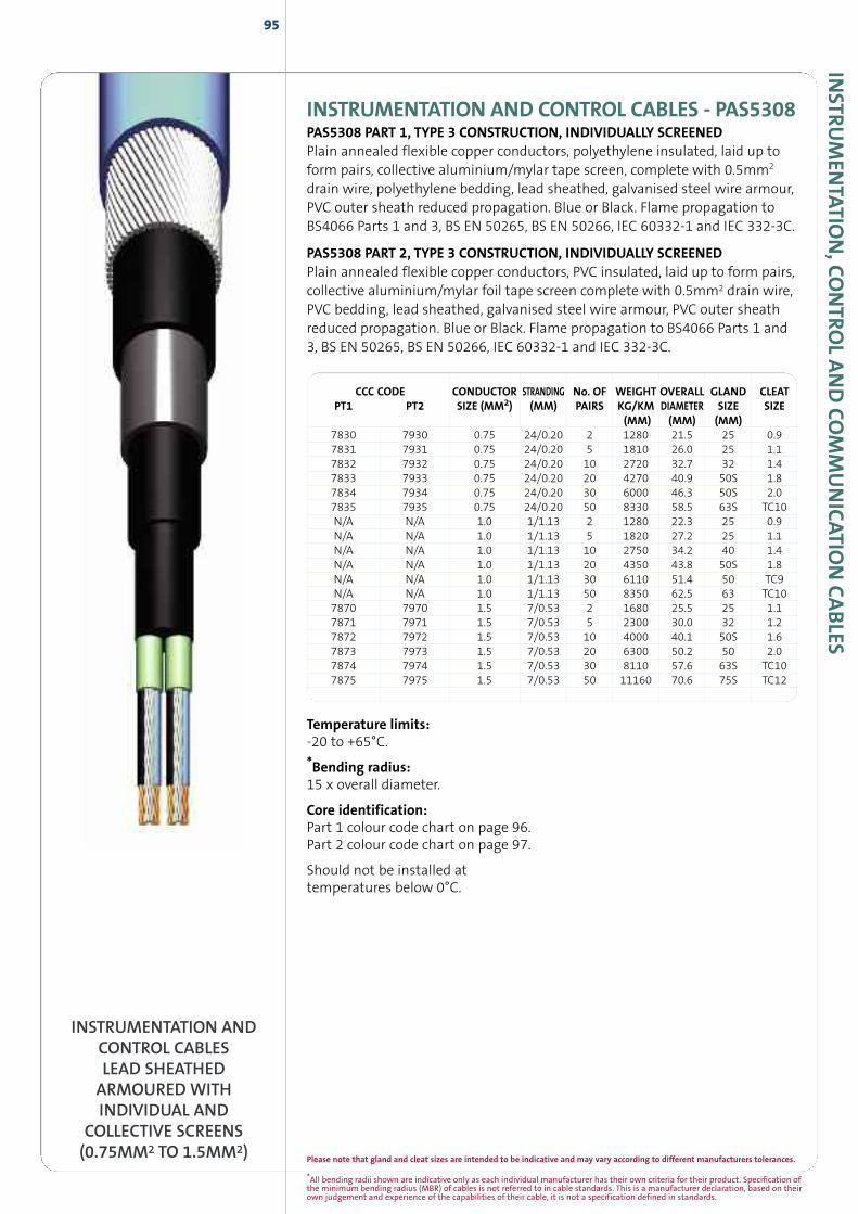
*All bending radii shown are indicative only as each individual manufacturer has their own criteria for their product. Specification ofthe minimum bending radius (MBR) of cables is not referred to in cable standards. This is a manufacturer declaration, based on theirown judgement and experience of the capabilities of their cable, it is not a specification defined in standards.
INSTR
UM
ENTATIO
N,CO
NTRO
LAND
COM
MUNICATIO
NCABLES
INSTRUMENTATION AND CONTROL CABLES - PAS5308PAS5308 PART 1, TYPE 3 CONSTRUCTION, INDIVIDUALLY SCREENEDPlain annealed flexible copper conductors, polyethylene insulated, laid up toform pairs, collective aluminium/mylar tape screen, complete with 0.5mm2
drain wire, polyethylene bedding, lead sheathed, galvanised steel wire armour,PVC outer sheath reduced propagation. Blue or Black. Flame propagation toBS4066 Parts 1 and 3, BS EN 50265, BS EN 50266, IEC 60332-1 and IEC 332-3C.
PAS5308 PART 2, TYPE 3 CONSTRUCTION, INDIVIDUALLY SCREENEDPlain annealed flexible copper conductors, PVC insulated, laid up to form pairs,collective aluminium/mylar foil tape screen complete with 0.5mm2 drain wire,PVC bedding, lead sheathed, galvanised steel wire armour, PVC outer sheathreduced propagation. Blue or Black. Flame propagation to BS4066 Parts 1 and3, BS EN 50265, BS EN 50266, IEC 60332-1 and IEC 332-3C.
95
CCC CODE CONDUCTOR STRANDING No. OF WEIGHT OVERALL GLAND CLEATPT1 PT2 SIZE (MM2) (MM) PAIRS KG/KM DIAMETER SIZE SIZE
(MM) (MM) (MM)7830 7930 0.75 24/0.20 2 1280 21.5 25 0.97831 7931 0.75 24/0.20 5 1810 26.0 25 1.17832 7932 0.75 24/0.20 10 2720 32.7 32 1.47833 7933 0.75 24/0.20 20 4270 40.9 50S 1.87834 7934 0.75 24/0.20 30 6000 46.3 50S 2.07835 7935 0.75 24/0.20 50 8330 58.5 63S TC10N/A N/A 1.0 1/1.13 2 1280 22.3 25 0.9N/A N/A 1.0 1/1.13 5 1820 27.2 25 1.1N/A N/A 1.0 1/1.13 10 2750 34.2 40 1.4N/A N/A 1.0 1/1.13 20 4350 43.8 50S 1.8N/A N/A 1.0 1/1.13 30 6110 51.4 50 TC9N/A N/A 1.0 1/1.13 50 8350 62.5 63 TC107870 7970 1.5 7/0.53 2 1680 25.5 25 1.17871 7971 1.5 7/0.53 5 2300 30.0 32 1.27872 7972 1.5 7/0.53 10 4000 40.1 50S 1.67873 7973 1.5 7/0.53 20 6300 50.2 50 2.07874 7974 1.5 7/0.53 30 8110 57.6 63S TC107875 7975 1.5 7/0.53 50 11160 70.6 75S TC12
Temperature limits:-20 to +65°C.
*Bending radius:15 x overall diameter.
Core identification:Part 1 colour code chart on page 96.Part 2 colour code chart on page 97.
Should not be installed attemperatures below 0°C.
INSTRUMENTATION ANDCONTROL CABLESLEAD SHEATHEDARMOURED WITHINDIVIDUAL AND
COLLECTIVE SCREENS(0.75MM2 TO 1.5MM2) Please note that gland and cleat sizes are intended to be indicative and may vary according to different manufacturers tolerances.
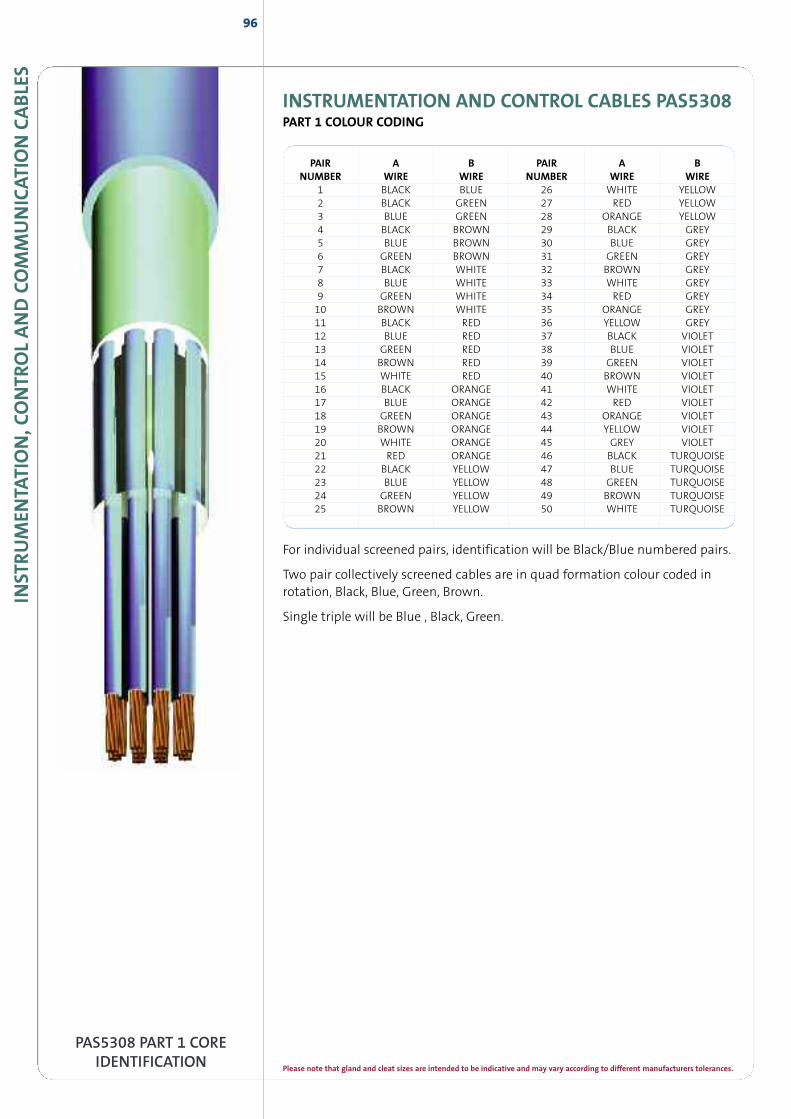
INST
RUM
ENTA
TION,C
ONTR
OLAND
COM
MUNICAT
ION
CABLE
S96
INSTRUMENTATION AND CONTROL CABLES PAS5308PART 1 COLOUR CODING
PAIR A B PAIR A BNUMBER WIRE WIRE NUMBER WIRE WIRE
1 BLACK BLUE 26 WHITE YELLOW2 BLACK GREEN 27 RED YELLOW3 BLUE GREEN 28 ORANGE YELLOW4 BLACK BROWN 29 BLACK GREY5 BLUE BROWN 30 BLUE GREY6 GREEN BROWN 31 GREEN GREY7 BLACK WHITE 32 BROWN GREY8 BLUE WHITE 33 WHITE GREY9 GREEN WHITE 34 RED GREY10 BROWN WHITE 35 ORANGE GREY11 BLACK RED 36 YELLOW GREY12 BLUE RED 37 BLACK VIOLET13 GREEN RED 38 BLUE VIOLET14 BROWN RED 39 GREEN VIOLET15 WHITE RED 40 BROWN VIOLET16 BLACK ORANGE 41 WHITE VIOLET17 BLUE ORANGE 42 RED VIOLET18 GREEN ORANGE 43 ORANGE VIOLET19 BROWN ORANGE 44 YELLOW VIOLET20 WHITE ORANGE 45 GREY VIOLET21 RED ORANGE 46 BLACK TURQUOISE22 BLACK YELLOW 47 BLUE TURQUOISE23 BLUE YELLOW 48 GREEN TURQUOISE24 GREEN YELLOW 49 BROWN TURQUOISE25 BROWN YELLOW 50 WHITE TURQUOISE
PAS5308 PART 1 COREIDENTIFICATION
For individual screened pairs, identification will be Black/Blue numbered pairs.
Two pair collectively screened cables are in quad formation colour coded inrotation, Black, Blue, Green, Brown.
Single triple will be Blue , Black, Green.
Please note that gland and cleat sizes are intended to be indicative and may vary according to different manufacturers tolerances.
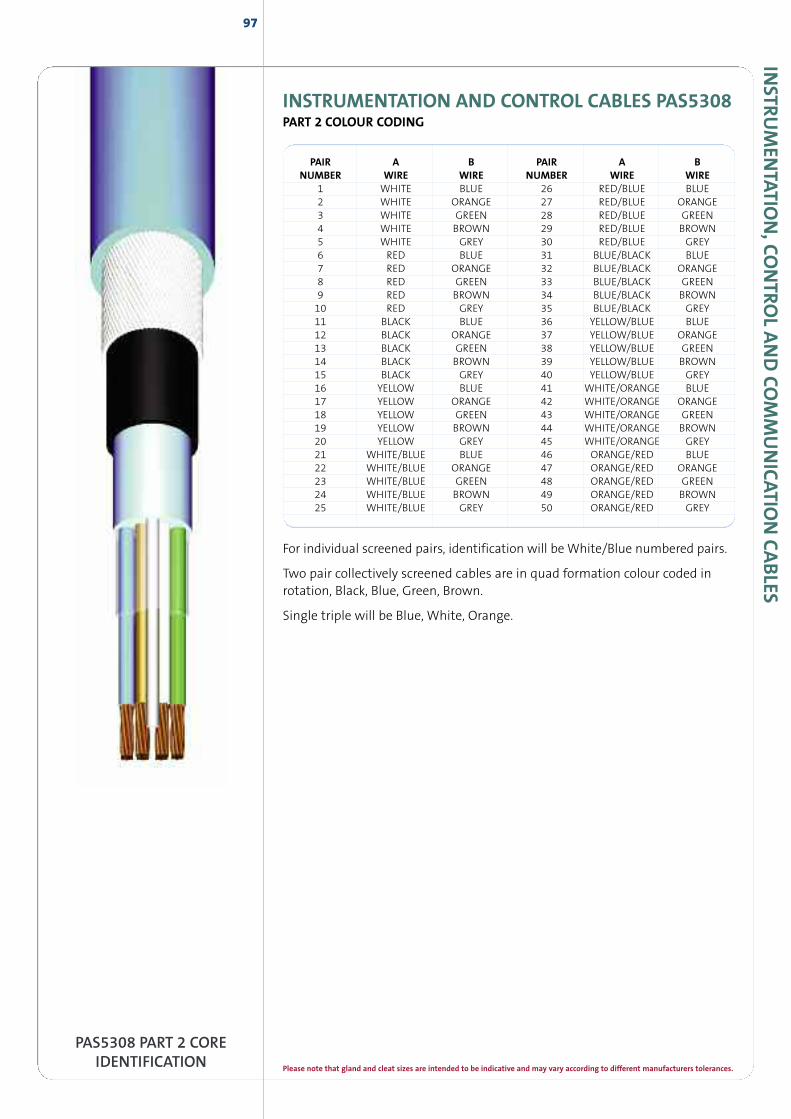
INSTR
UM
ENTATIO
N,CO
NTRO
LAND
COM
MUNICATIO
NCABLES
INSTRUMENTATION AND CONTROL CABLES PAS5308PART 2 COLOUR CODING
97
PAS5308 PART 2 COREIDENTIFICATION
PAIR A B PAIR A BNUMBER WIRE WIRE NUMBER WIRE WIRE
1 WHITE BLUE 26 RED/BLUE BLUE2 WHITE ORANGE 27 RED/BLUE ORANGE3 WHITE GREEN 28 RED/BLUE GREEN4 WHITE BROWN 29 RED/BLUE BROWN5 WHITE GREY 30 RED/BLUE GREY6 RED BLUE 31 BLUE/BLACK BLUE7 RED ORANGE 32 BLUE/BLACK ORANGE8 RED GREEN 33 BLUE/BLACK GREEN9 RED BROWN 34 BLUE/BLACK BROWN10 RED GREY 35 BLUE/BLACK GREY11 BLACK BLUE 36 YELLOW/BLUE BLUE12 BLACK ORANGE 37 YELLOW/BLUE ORANGE13 BLACK GREEN 38 YELLOW/BLUE GREEN14 BLACK BROWN 39 YELLOW/BLUE BROWN15 BLACK GREY 40 YELLOW/BLUE GREY16 YELLOW BLUE 41 WHITE/ORANGE BLUE17 YELLOW ORANGE 42 WHITE/ORANGE ORANGE18 YELLOW GREEN 43 WHITE/ORANGE GREEN19 YELLOW BROWN 44 WHITE/ORANGE BROWN20 YELLOW GREY 45 WHITE/ORANGE GREY21 WHITE/BLUE BLUE 46 ORANGE/RED BLUE22 WHITE/BLUE ORANGE 47 ORANGE/RED ORANGE23 WHITE/BLUE GREEN 48 ORANGE/RED GREEN24 WHITE/BLUE BROWN 49 ORANGE/RED BROWN25 WHITE/BLUE GREY 50 ORANGE/RED GREY
For individual screened pairs, identification will be White/Blue numbered pairs.
Two pair collectively screened cables are in quad formation colour coded inrotation, Black, Blue, Green, Brown.
Single triple will be Blue, White, Orange.
Please note that gland and cleat sizes are intended to be indicative and may vary according to different manufacturers tolerances.
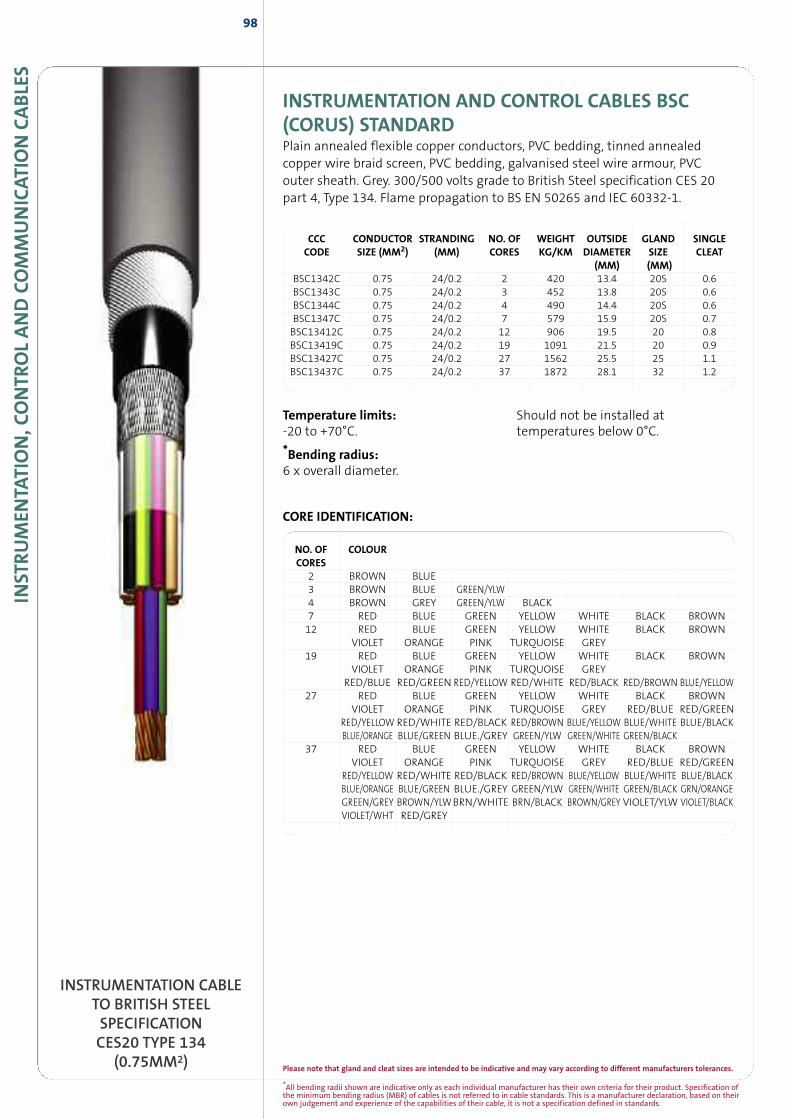
*All bending radii shown are indicative only as each individual manufacturer has their own criteria for their product. Specification ofthe minimum bending radius (MBR) of cables is not referred to in cable standards. This is a manufacturer declaration, based on theirown judgement and experience of the capabilities of their cable, it is not a specification defined in standards.
INST
RUM
ENTA
TION,C
ONTR
OLAND
COM
MUNICAT
ION
CABLE
S98
INSTRUMENTATION AND CONTROL CABLES BSC(CORUS) STANDARDPlain annealed flexible copper conductors, PVC bedding, tinned annealedcopper wire braid screen, PVC bedding, galvanised steel wire armour, PVCouter sheath. Grey. 300/500 volts grade to British Steel specification CES 20part 4, Type 134. Flame propagation to BS EN 50265 and IEC 60332-1.
CCC CONDUCTOR STRANDING NO. OF WEIGHT OUTSIDE GLAND SINGLECODE SIZE (MM2) (MM) CORES KG/KM DIAMETER SIZE CLEAT
(MM) (MM)BSC1342C 0.75 24/0.2 2 420 13.4 20S 0.6BSC1343C 0.75 24/0.2 3 452 13.8 20S 0.6BSC1344C 0.75 24/0.2 4 490 14.4 20S 0.6BSC1347C 0.75 24/0.2 7 579 15.9 20S 0.7BSC13412C 0.75 24/0.2 12 906 19.5 20 0.8BSC13419C 0.75 24/0.2 19 1091 21.5 20 0.9BSC13427C 0.75 24/0.2 27 1562 25.5 25 1.1BSC13437C 0.75 24/0.2 37 1872 28.1 32 1.2
CORE IDENTIFICATION:
INSTRUMENTATION CABLETO BRITISH STEELSPECIFICATIONCES20 TYPE 134
(0.75MM2)
NO. OF COLOURCORES
2 BROWN BLUE3 BROWN BLUE GREEN/YLW4 BROWN GREY GREEN/YLW BLACK7 RED BLUE GREEN YELLOW WHITE BLACK BROWN12 RED BLUE GREEN YELLOW WHITE BLACK BROWN
VIOLET ORANGE PINK TURQUOISE GREY19 RED BLUE GREEN YELLOW WHITE BLACK BROWN
VIOLET ORANGE PINK TURQUOISE GREYRED/BLUE RED/GREEN RED/YELLOW RED/WHITE RED/BLACK RED/BROWN BLUE/YELLOW
27 RED BLUE GREEN YELLOW WHITE BLACK BROWNVIOLET ORANGE PINK TURQUOISE GREY RED/BLUE RED/GREEN
RED/YELLOW RED/WHITE RED/BLACK RED/BROWN BLUE/YELLOW BLUE/WHITE BLUE/BLACKBLUE/ORANGE BLUE/GREEN BLUE./GREY GREEN/YLW GREEN/WHITE GREEN/BLACK
37 RED BLUE GREEN YELLOW WHITE BLACK BROWNVIOLET ORANGE PINK TURQUOISE GREY RED/BLUE RED/GREEN
RED/YELLOW RED/WHITE RED/BLACK RED/BROWN BLUE/YELLOW BLUE/WHITE BLUE/BLACKBLUE/ORANGE BLUE/GREEN BLUE./GREY GREEN/YLW GREEN/WHITE GREEN/BLACK GRN/ORANGEGREEN/GREY BROWN/YLWBRN/WHITE BRN/BLACK BROWN/GREY VIOLET/YLW VIOLET/BLACKVIOLET/WHT RED/GREY
Temperature limits:-20 to +70°C.
*Bending radius:6 x overall diameter.
Should not be installed attemperatures below 0°C.
Please note that gland and cleat sizes are intended to be indicative and may vary according to different manufacturers tolerances.
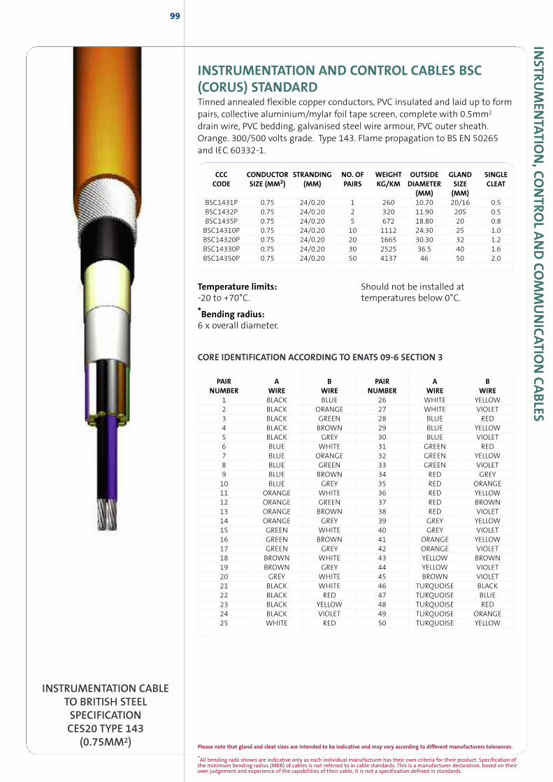
*All bending radii shown are indicative only as each individual manufacturer has their own criteria for their product. Specification ofthe minimum bending radius (MBR) of cables is not referred to in cable standards. This is a manufacturer declaration, based on theirown judgement and experience of the capabilities of their cable, it is not a specification defined in standards.
INSTR
UM
ENTATIO
N,CO
NTRO
LAND
COM
MUNICATIO
NCABLES
INSTRUMENTATION AND CONTROL CABLES BSC(CORUS) STANDARDTinned annealed flexible copper conductors, PVC insulated and laid up to formpairs, collective aluminium/mylar foil tape screen, complete with 0.5mm2
drain wire, PVC bedding, galvanised steel wire armour, PVC outer sheath.Orange. 300/500 volts grade. Type 143. Flame propagation to BS EN 50265and IEC 60332-1.
99
INSTRUMENTATION CABLETO BRITISH STEELSPECIFICATIONCES20 TYPE 143
(0.75MM2)
CCC CONDUCTOR STRANDING NO. OF WEIGHT OUTSIDE GLAND SINGLECODE SIZE (MM2) (MM) PAIRS KG/KM DIAMETER SIZE CLEAT
(MM) (MM)BSC1431P 0.75 24/0.20 1 260 10.70 20/16 0.5BSC1432P 0.75 24/0.20 2 320 11.90 20S 0.5BSC1435P 0.75 24/0.20 5 672 18.80 20 0.8BSC14310P 0.75 24/0.20 10 1112 24.30 25 1.0BSC14320P 0.75 24/0.20 20 1665 30.30 32 1.2BSC14330P 0.75 24/0.20 30 2525 36.5 40 1.6BSC14350P 0.75 24/0.20 50 4137 46 50 2.0
PAIR A B PAIR A BNUMBER WIRE WIRE NUMBER WIRE WIRE
1 BLACK BLUE 26 WHITE YELLOW2 BLACK ORANGE 27 WHITE VIOLET3 BLACK GREEN 28 BLUE RED4 BLACK BROWN 29 BLUE YELLOW5 BLACK GREY 30 BLUE VIOLET6 BLUE WHITE 31 GREEN RED7 BLUE ORANGE 32 GREEN YELLOW8 BLUE GREEN 33 GREEN VIOLET9 BLUE BROWN 34 RED GREY10 BLUE GREY 35 RED ORANGE11 ORANGE WHITE 36 RED YELLOW12 ORANGE GREEN 37 RED BROWN13 ORANGE BROWN 38 RED VIOLET14 ORANGE GREY 39 GREY YELLOW15 GREEN WHITE 40 GREY VIOLET16 GREEN BROWN 41 ORANGE YELLOW17 GREEN GREY 42 ORANGE VIOLET18 BROWN WHITE 43 YELLOW BROWN19 BROWN GREY 44 YELLOW VIOLET20 GREY WHITE 45 BROWN VIOLET21 BLACK WHITE 46 TURQUOISE BLACK22 BLACK RED 47 TURQUOISE BLUE23 BLACK YELLOW 48 TURQUOISE RED24 BLACK VIOLET 49 TURQUOISE ORANGE25 WHITE RED 50 TURQUOISE YELLOW
Temperature limits:-20 to +70°C.
*Bending radius:6 x overall diameter.
Should not be installed attemperatures below 0°C.
CORE IDENTIFICATION ACCORDING TO ENATS 09-6 SECTION 3
Please note that gland and cleat sizes are intended to be indicative and may vary according to different manufacturers tolerances.
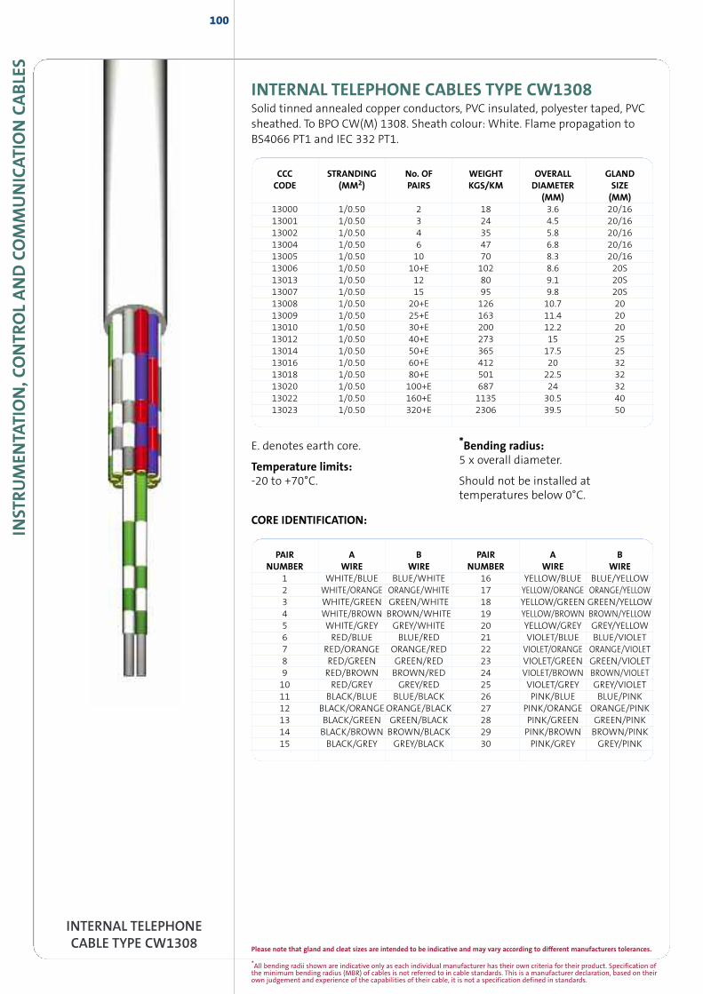
INST
RUM
ENTA
TION,C
ONTR
OLAND
COM
MUNICAT
ION
CABLE
S100
INTERNAL TELEPHONECABLE TYPE CW1308
INTERNAL TELEPHONE CABLES TYPE CW1308Solid tinned annealed copper conductors, PVC insulated, polyester taped, PVCsheathed. To BPO CW(M) 1308. Sheath colour: White. Flame propagation toBS4066 PT1 and IEC 332 PT1.
PAIR A B PAIR A BNUMBER WIRE WIRE NUMBER WIRE WIRE
1 WHITE/BLUE BLUE/WHITE 16 YELLOW/BLUE BLUE/YELLOW2 WHITE/ORANGE ORANGE/WHITE 17 YELLOW/ORANGE ORANGE/YELLOW3 WHITE/GREEN GREEN/WHITE 18 YELLOW/GREEN GREEN/YELLOW4 WHITE/BROWN BROWN/WHITE 19 YELLOW/BROWN BROWN/YELLOW5 WHITE/GREY GREY/WHITE 20 YELLOW/GREY GREY/YELLOW6 RED/BLUE BLUE/RED 21 VIOLET/BLUE BLUE/VIOLET7 RED/ORANGE ORANGE/RED 22 VIOLET/ORANGE ORANGE/VIOLET8 RED/GREEN GREEN/RED 23 VIOLET/GREEN GREEN/VIOLET9 RED/BROWN BROWN/RED 24 VIOLET/BROWN BROWN/VIOLET10 RED/GREY GREY/RED 25 VIOLET/GREY GREY/VIOLET11 BLACK/BLUE BLUE/BLACK 26 PINK/BLUE BLUE/PINK12 BLACK/ORANGEORANGE/BLACK 27 PINK/ORANGE ORANGE/PINK13 BLACK/GREEN GREEN/BLACK 28 PINK/GREEN GREEN/PINK14 BLACK/BROWN BROWN/BLACK 29 PINK/BROWN BROWN/PINK15 BLACK/GREY GREY/BLACK 30 PINK/GREY GREY/PINK
CORE IDENTIFICATION:
E. denotes earth core.
Temperature limits:-20 to +70°C.
*Bending radius:5 x overall diameter.
Should not be installed attemperatures below 0°C.
CCC STRANDING No. OF WEIGHT OVERALL GLANDCODE (MM2) PAIRS KGS/KM DIAMETER SIZE
(MM) (MM)13000 1/0.50 2 18 3.6 20/1613001 1/0.50 3 24 4.5 20/1613002 1/0.50 4 35 5.8 20/1613004 1/0.50 6 47 6.8 20/1613005 1/0.50 10 70 8.3 20/1613006 1/0.50 10+E 102 8.6 20S13013 1/0.50 12 80 9.1 20S13007 1/0.50 15 95 9.8 20S13008 1/0.50 20+E 126 10.7 2013009 1/0.50 25+E 163 11.4 2013010 1/0.50 30+E 200 12.2 2013012 1/0.50 40+E 273 15 2513014 1/0.50 50+E 365 17.5 2513016 1/0.50 60+E 412 20 3213018 1/0.50 80+E 501 22.5 3213020 1/0.50 100+E 687 24 3213022 1/0.50 160+E 1135 30.5 4013023 1/0.50 320+E 2306 39.5 50
*All bending radii shown are indicative only as each individual manufacturer has their own criteria for their product. Specification ofthe minimum bending radius (MBR) of cables is not referred to in cable standards. This is a manufacturer declaration, based on theirown judgement and experience of the capabilities of their cable, it is not a specification defined in standards.
Please note that gland and cleat sizes are intended to be indicative and may vary according to different manufacturers tolerances.
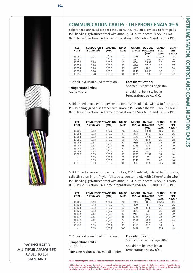
INSTR
UM
ENTATIO
N,CO
NTRO
LAND
COM
MUNICATIO
NCABLES
COMMUNICATION CABLES - TELEPHONE ENATS 09-6Solid tinned annealed copper conductors, PVC insulated, twisted to form pairs,PVC bedding, galvanised steel wire armour, PVC outer sheath. Black. To ENATS09-6: Issue 5 Section 3.6. Flame propagation to BS4066 PT1 and IEC 332 PT1.
101
PVC INSULATEDMULTIPAIR ARMOURED
CABLE TO ESISTANDARD
Solid tinned annealed copper conductors, PVC insulated, twisted to form pairs,PVC bedding, galvanised steel wire armour, PVC outer sheath. Black. To ENATS09-6: Issue 5 Section 3.6. Flame propagation to BS4066 PT1 and IEC 332 PT1.
Solid tinned annealed copper conductors, PVC insulated, twisted to form pairs,collective aluminium/mylar foil tape screen complete with 0.5mm2 drain wire,PVC bedding, galvanised steel wire armour, PVC outer sheath. Black. To ENATS09-6: Issue 5 Section 3.6. Flame propagation to BS4066 PT1 and IEC 332 PT1.
CCC CONDUCTOR STRANDING NO. OF WEIGHT OVERALL GLAND CLEATCODE SIZE (MM2) (MM) PAIRS KG/KM DIAMETER SIZE SIZE
(MM) (MM) SINGLE13050 0.28 1/0.6 **2 170 9 20/16 0.513051 0.28 1/0.6 5 238 12.07 20S 0.613052 0.28 1/0.6 10 454 15.91 20 0.713053 0.28 1/0.6 20 496 17.18 20 0.713054 0.28 1/0.6 30 697 18.1 20 0.813055 0.28 1/0.6 50 1243 26.60 32 1.113056 0.28 1/0.6 100 1825 29.8 32 1.2
** 2 pair laid up in quad formation.
Temperature limits:-20 to +70°C.
Core identification:See colour chart on page 104.
Should not be installed attemperatures below 0°C.
** 2 pair laid up in quad formation.
Temperature limits:-20 to +70°C.
*Bending radius: 6 x overall diameter.
Core identification:See colour chart on page 104.
Should not be installed attemperatures below 0°C.
CCC CONDUCTOR STRANDING NO. OF WEIGHT OVERALL GLAND CLEATCODE SIZE (MM2) (MM) PAIRS KG/KM DIAMETER SIZE SIZE
(MM) (MM) SINGLE13081 0.63 1/0.9 **2 206 10.31 20S 0.513083 0.63 1/0.9 5 333 14.1 20S 0.613084 0.63 1/0.9 10 586 17.38 20 0.713085 0.63 1/0.9 15 796 19.5 20 0.813086 0.63 1/0.9 20 939 22.48 25 0.913087 0.63 1/0.9 25 1245 21.3 25 0.913088 0.63 1/0.9 30 1400 23.9 25 1.013089 0.63 1/0.9 40 1686 28.2 32 1.213090 0.63 1/0.9 50 1952 32.87 32 1.4
- 0.63 1/0.9 60 2183 35 40 1.4- 0.63 1/0.9 75 2342 37 40 1.6
13091 0.63 1/0.9 100 3613 41.8 50S 1.8
CCC CONDUCTOR STRANDING NO. OF WEIGHT OVERALL GLAND CLEATCODE SIZE (MM2) (MM) PAIRS KG/KM DIAMETER SIZE SIZE
(MM) (MM) SINGLE13101 0.63 1/0.9 **2 213 10.4 20/16 0.513103 0.63 1/0.9 5 379 14 20S 0.613104 0.63 1/0.9 10 650 17.8 20 0.813105 0.63 1/0.9 15 805 20 20 0.813106 0.63 1/0.9 20 955 21.7 25 0.913107 0.63 1/0.9 25 1256 24.3 25 1.013108 0.63 1/0.9 30 1413 25.9 25 1.113109 0.63 1/0.9 40 1700 28.6 32 1.213110 0.63 1/0.9 50 2110 31.5 32 1.4
- 0.63 1/0.9 100 3628 42 50S 1.8
*All bending radii shown are indicative only as each individual manufacturer has their own criteria for their product. Specification ofthe minimum bending radius (MBR) of cables is not referred to in cable standards. This is a manufacturer declaration, based on theirown judgement and experience of the capabilities of their cable, it is not a specification defined in standards.
Please note that gland and cleat sizes are intended to be indicative and may vary according to different manufacturers tolerances.
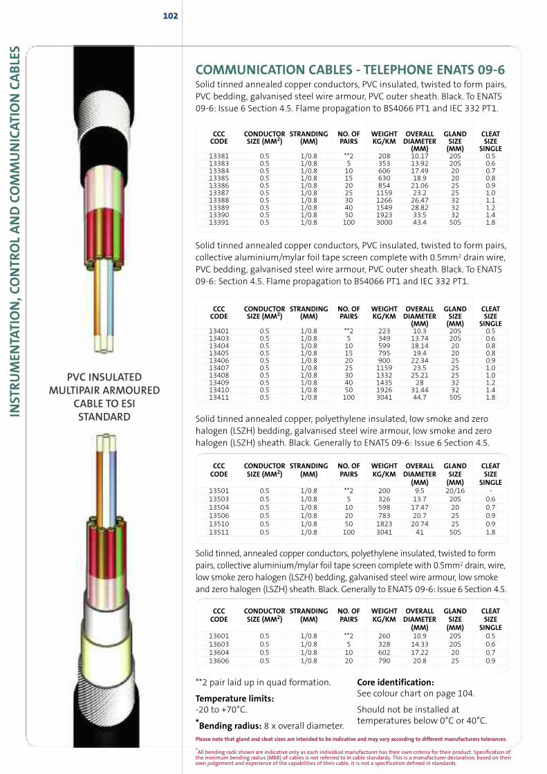
*All bending radii shown are indicative only as each individual manufacturer has their own criteria for their product. Specification ofthe minimum bending radius (MBR) of cables is not referred to in cable standards. This is a manufacturer declaration, based on theirown judgement and experience of the capabilities of their cable, it is not a specification defined in standards.
INST
RUM
ENTA
TION,C
ONTR
OLAND
COM
MUNICAT
ION
CABLE
S102
PVC INSULATEDMULTIPAIR ARMOURED
CABLE TO ESISTANDARD
Solid tinned annealed copper conductors, PVC insulated, twisted to form pairs,collective aluminium/mylar foil tape screen complete with 0.5mm2 drain wire,PVC bedding, galvanised steel wire armour, PVC outer sheath. Black. To ENATS09-6: Section 4.5. Flame propagation to BS4066 PT1 and IEC 332 PT1.
Solid tinned annealed copper, polyethylene insulated, low smoke and zerohalogen (LSZH) bedding, galvanised steel wire armour, low smoke and zerohalogen (LSZH) sheath. Black. Generally to ENATS 09-6: Issue 6 Section 4.5.
CCC CONDUCTOR STRANDING NO. OF WEIGHT OVERALL GLAND CLEATCODE SIZE (MM2) (MM) PAIRS KG/KM DIAMETER SIZE SIZE
(MM) (MM) SINGLE13381 0.5 1/0.8 **2 208 10.17 20S 0.513383 0.5 1/0.8 5 353 13.92 20S 0.613384 0.5 1/0.8 10 606 17.49 20 0.713385 0.5 1/0.8 15 630 18.9 20 0.813386 0.5 1/0.8 20 854 21.06 25 0.913387 0.5 1/0.8 25 1159 23.2 25 1.013388 0.5 1/0.8 30 1266 26.47 32 1.113389 0.5 1/0.8 40 1549 28.82 32 1.213390 0.5 1/0.8 50 1923 33.5 32 1.413391 0.5 1/0.8 100 3000 43.4 50S 1.8
CCC CONDUCTOR STRANDING NO. OF WEIGHT OVERALL GLAND CLEATCODE SIZE (MM2) (MM) PAIRS KG/KM DIAMETER SIZE SIZE
(MM) (MM) SINGLE13501 0.5 1/0.8 **2 200 9.5 20/16 -13503 0.5 1/0.8 5 326 13.7 20S 0.613504 0.5 1/0.8 10 598 17.47 20 0.713506 0.5 1/0.8 20 783 20.7 25 0.913510 0.5 1/0.8 50 1823 20.74 25 0.913511 0.5 1/0.8 100 3041 41 50S 1.8
**2 pair laid up in quad formation.
Temperature limits:-20 to +70°C.
*Bending radius: 8 x overall diameter.
Core identification:See colour chart on page 104.
Should not be installed attemperatures below 0°C or 40°C.
CCC CONDUCTOR STRANDING NO. OF WEIGHT OVERALL GLAND CLEATCODE SIZE (MM2) (MM) PAIRS KG/KM DIAMETER SIZE SIZE
(MM) (MM) SINGLE13601 0.5 1/0.8 **2 260 10.9 20S 0.513603 0.5 1/0.8 5 328 14.33 20S 0.613604 0.5 1/0.8 10 602 17.22 20 0.713606 0.5 1/0.8 20 790 20.8 25 0.9
Solid tinned, annealed copper conductors, polyethylene insulated, twisted to formpairs, collective aluminium/mylar foil tape screen complete with 0.5mm2 drain, wire,low smoke zero halogen (LSZH) bedding, galvanised steel wire armour, low smokeand zero halogen (LSZH) sheath. Black. Generally to ENATS 09-6: Issue 6 Section 4.5.
COMMUNICATION CABLES - TELEPHONE ENATS 09-6Solid tinned annealed copper conductors, PVC insulated, twisted to form pairs,PVC bedding, galvanised steel wire armour, PVC outer sheath. Black. To ENATS09-6: Issue 6 Section 4.5. Flame propagation to BS4066 PT1 and IEC 332 PT1.
CCC CONDUCTOR STRANDING NO. OF WEIGHT OVERALL GLAND CLEATCODE SIZE (MM2) (MM) PAIRS KG/KM DIAMETER SIZE SIZE
(MM) (MM) SINGLE13401 0.5 1/0.8 **2 223 10.3 20S 0.513403 0.5 1/0.8 5 349 13.74 20S 0.613404 0.5 1/0.8 10 599 18.14 20 0.813405 0.5 1/0.8 15 795 19.4 20 0.813406 0.5 1/0.8 20 900 22.34 25 0.913407 0.5 1/0.8 25 1159 23.5 25 1.013408 0.5 1/0.8 30 1332 25.21 25 1.013409 0.5 1/0.8 40 1435 28 32 1.213410 0.5 1/0.8 50 1926 31.44 32 1.413411 0.5 1/0.8 100 3041 44.7 50S 1.8
Please note that gland and cleat sizes are intended to be indicative and may vary according to different manufacturers tolerances.
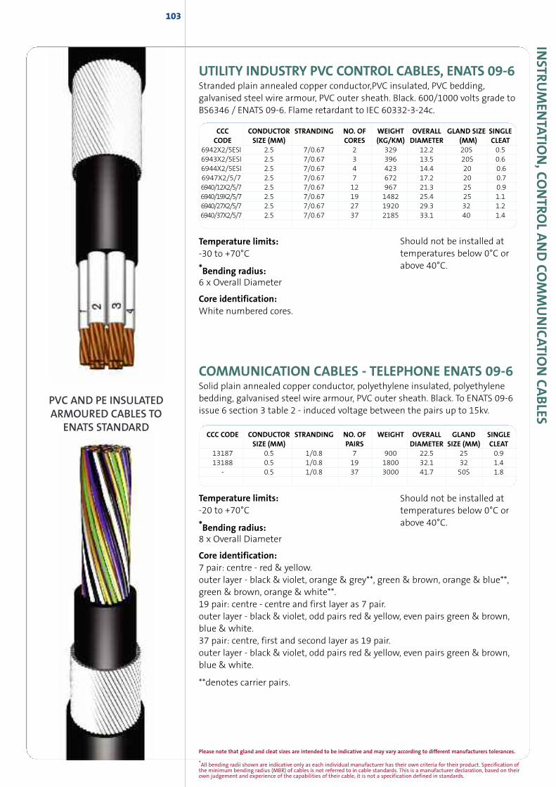
*All bending radii shown are indicative only as each individual manufacturer has their own criteria for their product. Specification ofthe minimum bending radius (MBR) of cables is not referred to in cable standards. This is a manufacturer declaration, based on theirown judgement and experience of the capabilities of their cable, it is not a specification defined in standards.
INSTR
UM
ENTATIO
N,CO
NTRO
LAND
COM
MUNICATIO
NCABLES
103
CCC CONDUCTOR STRANDING NO. OF WEIGHT OVERALL GLAND SIZE SINGLECODE SIZE (MM) CORES (KG/KM) DIAMETER (MM) CLEAT
6942X2/5ESI 2.5 7/0.67 2 329 12.2 20S 0.56943X2/5ESI 2.5 7/0.67 3 396 13.5 20S 0.66944X2/5ESI 2.5 7/0.67 4 423 14.4 20 0.66947X2/5/7 2.5 7/0.67 7 672 17.2 20 0.76940/12X2/5/7 2.5 7/0.67 12 967 21.3 25 0.96940/19X2/5/7 2.5 7/0.67 19 1482 25.4 25 1.16940/27X2/5/7 2.5 7/0.67 27 1920 29.3 32 1.26940/37X2/5/7 2.5 7/0.67 37 2185 33.1 40 1.4
Temperature limits:-30 to +70°C
*Bending radius:6 x Overall Diameter
Core identification:White numbered cores.
Should not be installed attemperatures below 0°C orabove 40°C.
UTILITY INDUSTRY PVC CONTROL CABLES, ENATS 09-6Stranded plain annealed copper conductor,PVC insulated, PVC bedding,galvanised steel wire armour, PVC outer sheath. Black. 600/1000 volts grade toBS6346 / ENATS 09-6. Flame retardant to IEC 60332-3-24c.
PVC AND PE INSULATEDARMOURED CABLES TO
ENATS STANDARDCCC CODE CONDUCTOR STRANDING NO. OF WEIGHT OVERALL GLAND SINGLE
SIZE (MM) PAIRS DIAMETER SIZE (MM) CLEAT13187 0.5 1/0.8 7 900 22.5 25 0.913188 0.5 1/0.8 19 1800 32.1 32 1.4
- 0.5 1/0.8 37 3000 41.7 50S 1.8
Temperature limits:-20 to +70°C
*Bending radius:8 x Overall Diameter
Core identification:7 pair: centre - red & yellow.outer layer - black & violet, orange & grey**, green & brown, orange & blue**,green & brown, orange & white**.19 pair: centre - centre and first layer as 7 pair.outer layer - black & violet, odd pairs red & yellow, even pairs green & brown,blue & white.37 pair: centre, first and second layer as 19 pair.outer layer - black & violet, odd pairs red & yellow, even pairs green & brown,blue & white.
**denotes carrier pairs.
Should not be installed attemperatures below 0°C orabove 40°C.
COMMUNICATION CABLES - TELEPHONE ENATS 09-6Solid plain annealed copper conductor, polyethylene insulated, polyethylenebedding, galvanised steel wire armour, PVC outer sheath. Black. To ENATS 09-6issue 6 section 3 table 2 - induced voltage between the pairs up to 15kv.
Please note that gland and cleat sizes are intended to be indicative and may vary according to different manufacturers tolerances.
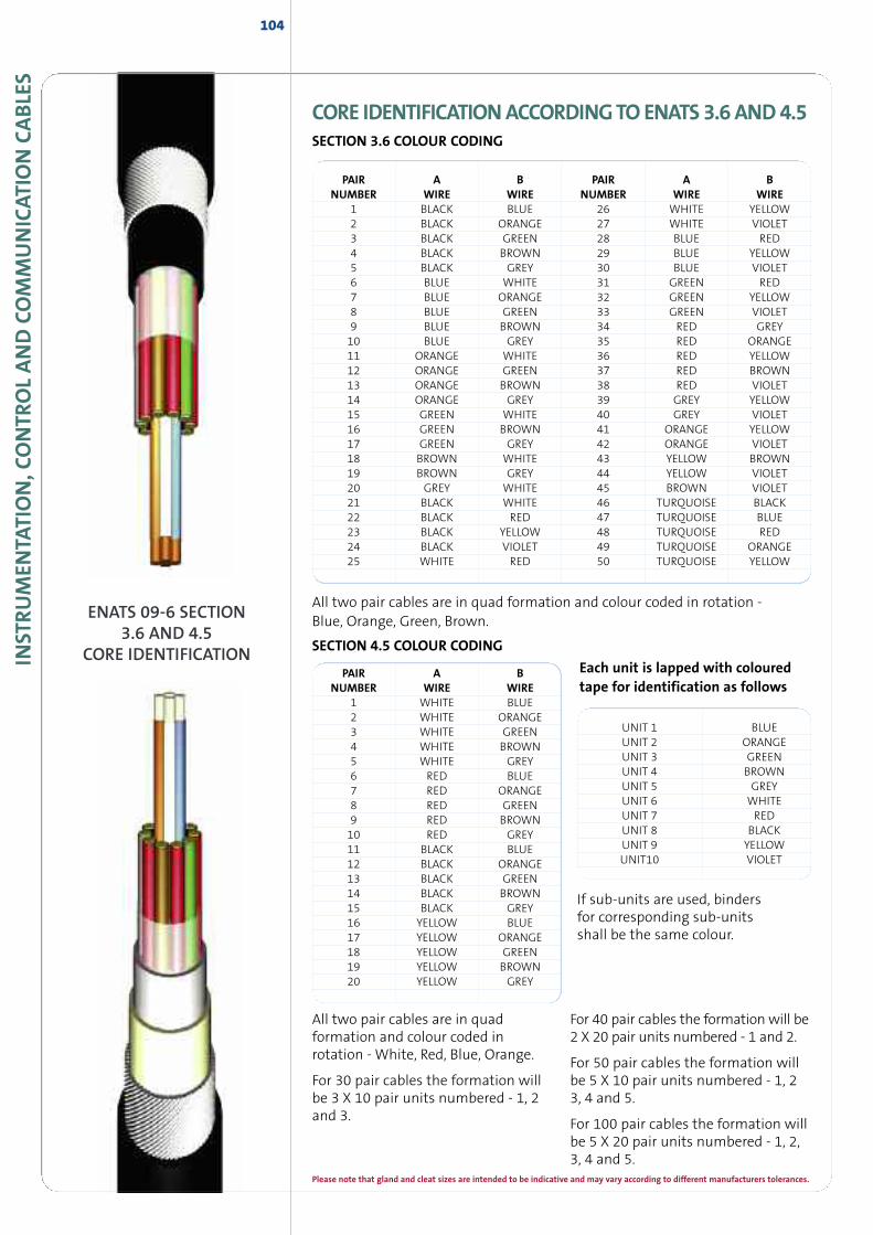
INST
RUM
ENTA
TION,C
ONTR
OLAND
COM
MUNICAT
ION
CABLE
S104
ENATS 09-6 SECTION3.6 AND 4.5
CORE IDENTIFICATION SECTION 4.5 COLOUR CODING
PAIR A BNUMBER WIRE WIRE
1 WHITE BLUE2 WHITE ORANGE3 WHITE GREEN4 WHITE BROWN5 WHITE GREY6 RED BLUE7 RED ORANGE8 RED GREEN9 RED BROWN10 RED GREY11 BLACK BLUE12 BLACK ORANGE13 BLACK GREEN14 BLACK BROWN15 BLACK GREY16 YELLOW BLUE17 YELLOW ORANGE18 YELLOW GREEN19 YELLOW BROWN20 YELLOW GREY
UNIT 1 BLUEUNIT 2 ORANGEUNIT 3 GREENUNIT 4 BROWNUNIT 5 GREYUNIT 6 WHITEUNIT 7 REDUNIT 8 BLACKUNIT 9 YELLOWUNIT10 VIOLET
Each unit is lapped with colouredtape for identification as follows
All two pair cables are in quadformation and colour coded inrotation - White, Red, Blue, Orange.
For 30 pair cables the formation willbe 3 X 10 pair units numbered - 1, 2and 3.
For 40 pair cables the formation will be2 X 20 pair units numbered - 1 and 2.
For 50 pair cables the formation willbe 5 X 10 pair units numbered - 1, 23, 4 and 5.
For 100 pair cables the formation willbe 5 X 20 pair units numbered - 1, 2,3, 4 and 5.
If sub-units are used, bindersfor corresponding sub-unitsshall be the same colour.
PAIR A B PAIR A BNUMBER WIRE WIRE NUMBER WIRE WIRE
1 BLACK BLUE 26 WHITE YELLOW2 BLACK ORANGE 27 WHITE VIOLET3 BLACK GREEN 28 BLUE RED4 BLACK BROWN 29 BLUE YELLOW5 BLACK GREY 30 BLUE VIOLET6 BLUE WHITE 31 GREEN RED7 BLUE ORANGE 32 GREEN YELLOW8 BLUE GREEN 33 GREEN VIOLET9 BLUE BROWN 34 RED GREY10 BLUE GREY 35 RED ORANGE11 ORANGE WHITE 36 RED YELLOW12 ORANGE GREEN 37 RED BROWN13 ORANGE BROWN 38 RED VIOLET14 ORANGE GREY 39 GREY YELLOW15 GREEN WHITE 40 GREY VIOLET16 GREEN BROWN 41 ORANGE YELLOW17 GREEN GREY 42 ORANGE VIOLET18 BROWN WHITE 43 YELLOW BROWN19 BROWN GREY 44 YELLOW VIOLET20 GREY WHITE 45 BROWN VIOLET21 BLACK WHITE 46 TURQUOISE BLACK22 BLACK RED 47 TURQUOISE BLUE23 BLACK YELLOW 48 TURQUOISE RED24 BLACK VIOLET 49 TURQUOISE ORANGE25 WHITE RED 50 TURQUOISE YELLOW
All two pair cables are in quad formation and colour coded in rotation -Blue, Orange, Green, Brown.
CORE IDENTIFICATIONACCORDINGTOENATS3.6AND4.5SECTION 3.6 COLOUR CODING
Please note that gland and cleat sizes are intended to be indicative and may vary according to different manufacturers tolerances.
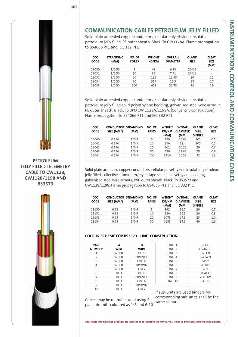
INSTR
UM
ENTATIO
N,CO
NTRO
LAND
COM
MUNICATIO
NCABLES
COMMUNICATION CABLES PETROLEUM JELLY FILLEDSolid plain annealed copper conductors, cellular polyethylene insulated,petroleum jelly filled, PE outer sheath. Black. To CW1128A. Flame propogationto BS4066 PT1 and IEC 332 PT1.
105
CCC CONDUCTOR STRANDING NO. OF WEIGHT OVERALL GLAND CLEATCODE SIZE (MM2) (MM) PAIRS KG/KM DIAMETER SIZE SIZE
(MM) (MM) SINGLE13150 0.63 1/0.9 5 392 16.7 20 0.713151 0.63 1/0.9 10 620 19.9 20 0.813153 0.63 1/0.9 20 1078 24.8 25 1.013154 0.63 1/0.9 50 2155 34.5 40 1.6
Cables may be manufactured using 5-pair sub-units coloured as 1-5 and 6-10
If sub-units are used binders forcorresponding sub-units shall be thesame colour.
COLOUR SCHEME FOR BS3573 - UNIT CONSTRUCTION
CCC CONDUCTOR STRANDING NO. OF WEIGHT OVERALL GLAND CLEATCODE SIZE (MM2) (MM) PAIRS KG/KM DIAMETER SIZE SIZE
(MM) (MM) SINGLE13040 0.196 1/0.5 5 199 10.63 20S 0.513041 0.196 1/0.5 10 276 12.4 20S 0.513042 0.196 1/0.5 20 461 16.23 20 0.713043 0.196 1/0.5 50 920 21.66 25 0.913044 0.196 1/0.5 100 1416 26.58 32 1.1
Solid plain annealed copper conductors, cellular polyethylene insulated,petroleum jelly filled solid polyethylene bedding, galvanised steel wire armour,PE outer sheath. Black. To BPO CW 1128A/1198A. (Concentric construction).Flame propagation to BS4066 PT1 and IEC 332 PT1.
PAIR A BNUMBER WIRE WIRE
1 WHITE BLUE2 WHITE ORANGE3 WHITE GREEN4 WHITE BROWN5 WHITE GREY6 RED BLUE7 RED ORANGE8 RED GREEN9 RED BROWN10 RED GREY
UNIT 1 BLUEUNIT 2 ORANGEUNIT 3 GREENUNIT 4 BROWNUNIT 5 GREYUNIT 6 WHITEUNIT 7 REDUNIT 8 BLACKUNIT 9 YELLOWUNIT 10 VIOLET
CCC STRANDING NO. OF WEIGHT OVERALL GLAND CLEATCODE (MM) CORES KG/KM DIAMETER SIZE SIZE
(MM)13030 1/0.50 5 48 6.83 20/16 -13031 1/0.50 10 82 7.41 20/16 -13032 1/0.50 20 182 11.48 20 0.513034 1/0.50 50 317 15.5 25 0.713035 1/0.50 100 613 21.78 32 0.9
Solid plain annealed copper conductors, cellular polyethylene insulated, petroleumjelly filled, collective aluminium/mylar tape screen, polyethylene bedding,galvanised steel wire armour, PVC outer sheath. Black. To BS3573 andCW1128/1198. Flame propagation to BS4066 PT1 and IEC 332 PT1.
PETROLEUMJELLY FILLED TELEMETRY
CABLE TO CW1128,CW1128/1198 AND
BS3573
Please note that gland and cleat sizes are intended to be indicative and may vary according to different manufacturers tolerances.
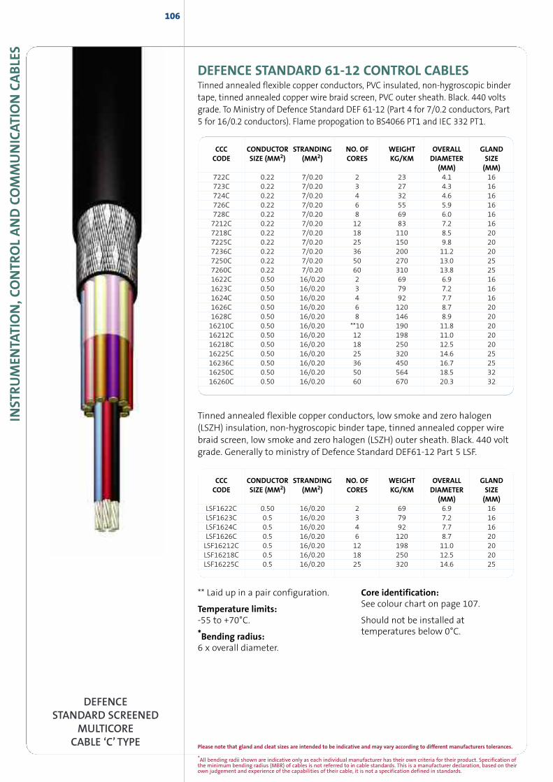
INST
RUM
ENTA
TION,C
ONTR
OLAND
COM
MUNICAT
ION
CABLE
S106
DEFENCE STANDARD 61-12 CONTROL CABLESTinned annealed flexible copper conductors, PVC insulated, non-hygroscopic bindertape, tinned annealed copper wire braid screen, PVC outer sheath. Black. 440 voltsgrade. To Ministry of Defence Standard DEF 61-12 (Part 4 for 7/0.2 conductors, Part5 for 16/0.2 conductors). Flame propogation to BS4066 PT1 and IEC 332 PT1.
Tinned annealed flexible copper conductors, low smoke and zero halogen(LSZH) insulation, non-hygroscopic binder tape, tinned annealed copper wirebraid screen, low smoke and zero halogen (LSZH) outer sheath. Black. 440 voltgrade. Generally to ministry of Defence Standard DEF61-12 Part 5 LSF.
CCC CONDUCTOR STRANDING NO. OF WEIGHT OVERALL GLANDCODE SIZE (MM2) (MM2) CORES KG/KM DIAMETER SIZE
(MM) (MM)722C 0.22 7/0.20 2 23 4.1 16723C 0.22 7/0.20 3 27 4.3 16724C 0.22 7/0.20 4 32 4.6 16726C 0.22 7/0.20 6 55 5.9 16728C 0.22 7/0.20 8 69 6.0 167212C 0.22 7/0.20 12 83 7.2 167218C 0.22 7/0.20 18 110 8.5 207225C 0.22 7/0.20 25 150 9.8 207236C 0.22 7/0.20 36 200 11.2 207250C 0.22 7/0.20 50 270 13.0 257260C 0.22 7/0.20 60 310 13.8 251622C 0.50 16/0.20 2 69 6.9 161623C 0.50 16/0.20 3 79 7.2 161624C 0.50 16/0.20 4 92 7.7 161626C 0.50 16/0.20 6 120 8.7 201628C 0.50 16/0.20 8 146 8.9 2016210C 0.50 16/0.20 **10 190 11.8 2016212C 0.50 16/0.20 12 198 11.0 2016218C 0.50 16/0.20 18 250 12.5 2016225C 0.50 16/0.20 25 320 14.6 2516236C 0.50 16/0.20 36 450 16.7 2516250C 0.50 16/0.20 50 564 18.5 3216260C 0.50 16/0.20 60 670 20.3 32
DEFENCESTANDARD SCREENED
MULTICORECABLE ‘C’ TYPE
CCC CONDUCTOR STRANDING NO. OF WEIGHT OVERALL GLANDCODE SIZE (MM2) (MM2) CORES KG/KM DIAMETER SIZE
(MM) (MM)LSF1622C 0.50 16/0.20 2 69 6.9 16LSF1623C 0.5 16/0.20 3 79 7.2 16LSF1624C 0.5 16/0.20 4 92 7.7 16LSF1626C 0.5 16/0.20 6 120 8.7 20LSF16212C 0.5 16/0.20 12 198 11.0 20LSF16218C 0.5 16/0.20 18 250 12.5 20LSF16225C 0.5 16/0.20 25 320 14.6 25
** Laid up in a pair configuration.
Temperature limits:-55 to +70°C.
*Bending radius:6 x overall diameter.
Core identification:See colour chart on page 107.
Should not be installed attemperatures below 0°C.
*All bending radii shown are indicative only as each individual manufacturer has their own criteria for their product. Specification ofthe minimum bending radius (MBR) of cables is not referred to in cable standards. This is a manufacturer declaration, based on theirown judgement and experience of the capabilities of their cable, it is not a specification defined in standards.
Please note that gland and cleat sizes are intended to be indicative and may vary according to different manufacturers tolerances.
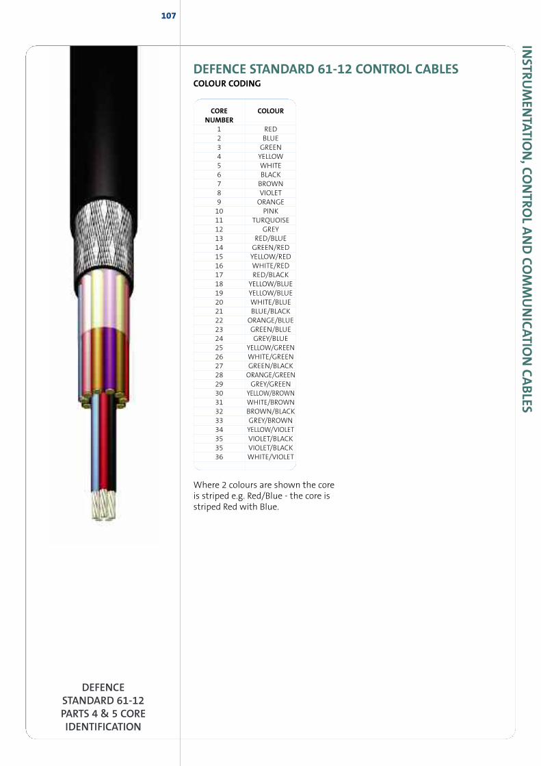
INSTR
UM
ENTATIO
N,CO
NTRO
LAND
COM
MUNICATIO
NCABLES
DEFENCE STANDARD 61-12 CONTROL CABLESCOLOUR CODING
DEFENCESTANDARD 61-12PARTS 4 & 5 COREIDENTIFICATION
107
CORE COLOURNUMBER
1 RED2 BLUE3 GREEN4 YELLOW5 WHITE6 BLACK7 BROWN8 VIOLET9 ORANGE10 PINK11 TURQUOISE12 GREY13 RED/BLUE14 GREEN/RED15 YELLOW/RED16 WHITE/RED17 RED/BLACK18 YELLOW/BLUE19 YELLOW/BLUE20 WHITE/BLUE21 BLUE/BLACK22 ORANGE/BLUE23 GREEN/BLUE24 GREY/BLUE25 YELLOW/GREEN26 WHITE/GREEN27 GREEN/BLACK28 ORANGE/GREEN29 GREY/GREEN30 YELLOW/BROWN31 WHITE/BROWN32 BROWN/BLACK33 GREY/BROWN34 YELLOW/VIOLET35 VIOLET/BLACK35 VIOLET/BLACK36 WHITE/VIOLET
Where 2 colours are shown the coreis striped e.g. Red/Blue - the core isstriped Red with Blue.
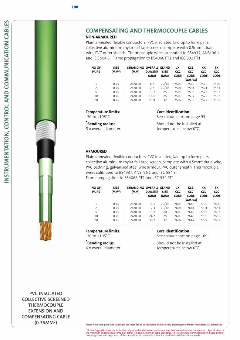
INST
RUM
ENTA
TION,C
ONTR
OLAND
COM
MUNICAT
ION
CABLE
S108
COMPENSATING AND THERMOCOUPLE CABLESNON-ARMOUREDPlain annealed flexible conductors, PVC insulated, laid up to form pairs,collective aluminium mylar foil tape screen, complete with 0.5mm2 drainwire, PVC outer sheath. Thermocouple wires calibrated to BS4937, ANSI 96.1and IEC 584.3. Flame propagation to BS4066 PT1 and IEC 332 PT1.
NO OF SIZE STRANDING OVERALL GLAND JX KCB KX TXPAIRS (MM2) (MM) DIAMETER SIZE CCC CCC CCC CCC
(MM) (MM) CODE CODE CODE CODE(WAS VX)
1 0.75 24/0.20 6.7 20/16 7500 7530 7570 75502 0.75 24/0.20 7.7 20/16 7501 7531 7571 75515 0.75 24/0.20 13.7 25 7503 7533 7573 755310 0.75 24/0.20 18.1 25 7505 7537 7575 755720 0.75 24/0.20 23.9 32 7507 7539 7577 7559
PVC INSULATEDCOLLECTIVE SCREENED
THERMOCOUPLEEXTENSION AND
COMPENSATING CABLE(0.75MM2)
ARMOUREDPlain annealed flexible conductors, PVC insulated, laid up to form pairs,collective aluminium mylar foil tape screen, complete with 0.5mm2 drain wire,PVC bedding, galvanised steel wire armour, PVC outer sheath. Thermocouplewires calibrated to BS4937, ANSI 96.1 and IEC 584.3.Flame propagation to BS4066 PT1 and IEC 332 PT1.
NO OF SIZE STRANDING OVERALL GLAND JX KCB KX TXPAIRS (MM2) (MM) DIAMETER SIZE CCC CCC CCC CCC
(MM) (MM) CODE CODE CODE CODE(WAS VX)
1 0.75 24/0.20 11.1 20/16 7600 7640 7700 76602 0.75 24/0.20 12.3 20/16 7601 7641 7701 76615 0.75 24/0.20 19.2 20 7603 7643 7703 766310 0.75 24/0.20 24.7 25 7605 7645 7705 766520 0.75 24/0.20 30.7 32 7607 7647 7707 7667
Temperature limits:-30 to +105°C.
*Bending radius:5 x overall diameter.
Core identification:See colour chart on page 93.
Should not be installed attemperatures below 0°C.
Temperature limits:-30 to +105°C.
*Bending radius:6 x overall diameter.
Core identification:See colour chart on page 109.
Should not be installed attemperatures below 0°C.
*All bending radii shown are indicative only as each individual manufacturer has their own criteria for their product. Specification ofthe minimum bending radius (MBR) of cables is not referred to in cable standards. This is a manufacturer declaration, based on theirown judgement and experience of the capabilities of their cable, it is not a specification defined in standards.
Please note that gland and cleat sizes are intended to be indicative and may vary according to different manufacturers tolerances.
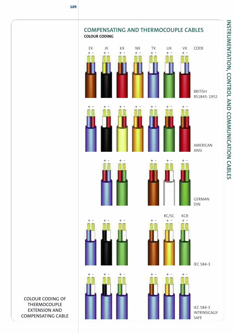
INSTR
UM
ENTATIO
N,CO
NTRO
LAND
COM
MUNICATIO
NCABLES
109
COMPENSATING AND THERMOCOUPLE CABLESCOLOUR CODING
EX JX KX NX TX UX VX
RC/SC KCB
CODE
BRITISHBS1843: 1952
+ - + - + - + - + - + - + -
AMERICANANSI
+ - + - + - + - + -
GERMANDIN
+ - + - + - + - + - + -
IEC 584-3
+ - + - + - + - + - + -
IEC 584-3INTRINSICALLYSAFE
COLOUR CODING OFTHERMOCOUPLEEXTENSION AND
COMPENSATING CABLE
+ - + - + - + - + - + - + -
INST
RUM
ENTA
TION,C
ONTR
OLAND
COM
MUNICAT
ION
CABLE
S110
TRAFFIC SIGNALLING CABLESTRAFFIC CONTROL CABLE WITH ARMOURPlain annealed solid copper conductors, PVC insulated, PVC bedding, galvanisedsteel wire armour, PVC outer sheath, colour orange, generally to BS6346/87
CCC CONDUCTOR STRANDING NO. OF WEIGHT OVERALL GLANDCODE SIZE (MM2) (MM) CORES KG/KM DIAMETER SIZE
(MM) (MM)TRAF4X1 1.0 1/1.13 4 325 13.3 20STRAF8X1 1.0 1/1.13 8 413 15.6 20STRAF12X1 1.0 1/1.13 12 567 17.9 20TRAF16X1 1.0 1/1.13 16 774 19.9 20TRAF20X1 1.0 1/1.13 20 905 22.0 25TRAF4X1/5 1.5 1/1.38 4 363 12.5 20STRAF8X1/5 1.5 1/1.38 8 534 15.8 20TRAF12X1/5 1.5 1/1.38 12 704 18.5 20TRAF16X1/5 1.5 1/1.38 16 836 20.0 20TRAF20X1/5 1.5 1/1.38 20 1040 21.5 25TRAF8X1ESWA* 1.0 1/1.13 8 533 16.3 20
LOOP FEEDER CABLE NON ARMOUREDPlain annealed solid copper conductors, PVC insulated, PVC sheathed, colourorange, generally to BS6346/87, 600/1000v grade.
CCC CONDUCTOR STRANDING NO. OF WEIGHT OVERALL BRASSCODE SIZE (MM2) (MM) CORES KG/KM DIAMETER A2
(MM) GLANDTRAF8X1NA 1.0 1/1.13 8 218 12.6 20TRAF12X1NA 1.0 1/1.13 12 305 13.5 25TRAF8X1E* 1.0 1/1.13 8 523 14.49 25
Temperature limits:-15 to +70°C.
Core identification:4 core - Red, Blue, Yellow, Green.
8 core - Brown, Yellow, Green, Red,White, Blue, Black, Orange.* includes additional 6mm2 integralearth conductor
12 core - Brown, Yellow, Green, Red,White, Blue, Black, Orange,Red/White, Grey, Red/Blue Violet.
16 core - Brown, Yellow, Green, Red,White, Blue, Black, Orange,Red/White, Grey, Red/Blue, Violet,Brown/Red, Yellow/Red, Grey/Red,Black/Red.
20 core - Brown, Yellow, Green, Red,White, Blue, Black, Orange,Red/White, Grey, Red/Blue, Violet,Brown/Red, Yellow/Red, Grey/Red,Black/Red, Violet/Red, Orange/Red,Green/Red, Blue/White.
Should not be installed attemperatures below 0°C.
PVC INSULATEDARMOURED
TRAFFIC SIGNAL CABLE,LOOP FEEDER CABLE
AND LOOPDETECTOR CABLE
Please note that gland and cleat sizes are intended to be indicative and may vary according to different manufacturers tolerances.
INSTR
UM
ENTATIO
N,CO
NTRO
LAND
COM
MUNICATIO
NCABLES
111
PVC INSULATEDARMOURED
TRAFFIC SIGNAL CABLE,LOOP FEEDER CABLE
AND LOOPDETECTOR CABLE
CCC CONDUCTOR STRANDING NO. OF WEIGHT OVERALL GLANDCODE SIZE (MM2) (MM) CORES KG/KM DIAMETER SIZE
(MM) (MM)LOOP2X1/5SWA 1.5 1/1.38 2 (1pr) 235 11.8 20SLOOP4X1/5SWA 1.5 1/1.38 4 (2pr) 300 12.7 20SLOOP2X2/5SWA 2.5 1/1.78 2 (1pr) 279 12.5 20SLOOP4X2/5SWA 2.5 1/1.78 4 (2pr) 383 15.0 20
TRAFFIC CONTROL CABLE ARMOUREDPlain annealed solid copper conductors, polyethylene insulated, polyethylenebedding, galvanised steel wire armour, polyethylene outer sheath. Generally toBS6346/87. Outer sheath colour: Orange. 600/1000 volts grade.
Temperature limits:-15 to +70°C.*Bending radius:6 x overall diameter.
Core identification:2 core - Brown, Blue4 core - Brown, Black, Grey, Blue.
Should not be installed attemperatures below 0°C.
CCC CONDUCTOR STRANDING NO. OF WEIGHT OVERALL GLANDCODE SIZE (MM2) (MM) CORES KG/KM DIAMETER SIZE
(MM) (MM)LOOP2X1/5 1.5 1/1.38 2 (1pr) 80 9.0 20SLOOP4X1/5 1.5 1/1.38 4 (2pr) 123 9.1 20SLOOP2X2/5 2.5 1/1.78 2 (1pr) 110 9.3 20SLOOP4X2/5 2.5 1/1.78 4 (2pr) 180 10.7 20S
LOOP DETECTOR CABLETinned flexible copper conductor, ethylene propylene rubber insulated (EPR),polychloroprene sheathed (PCP), 600/100v generally to BS6500 + BS6195,sheath colour black.
CCC CONDUCTOR STRANDING NO. OF WEIGHT OVERALL GLANDCODE SIZE (MM2) (MM) CORES KG/KM DIAMETER SIZE
(MM) (MM)LOOP1/5 1.5 30/.025 1 53.8 7.0 20SLOOP2/5 2.5 50/0.25 1 64.0 7.9 20S
Temperature limits:-15 to +70°C.*Bending radius:6 x overall diameter.
Core identification:2 core - Brown, Blue4 core - Brown, Black, Grey, Blue.
Should not be installed attemperatures below 0°C.
Temperature limits:-30 to +85°C.
*Bending radius: 6 x overall diameter.
Should not be installed attemperatures below -25°C.
TRAFFIC SIGNALLING CABLESLOOP FEEDER CABLE NON ARMOUREDPlain annealed solid copper conductors, polyethylene insulated, polyethyleneouter sheath, colour orange, 600/1000v grade.
*All bending radii shown are indicative only as each individual manufacturer has their own criteria for their product. Specification ofthe minimum bending radius (MBR) of cables is not referred to in cable standards. This is a manufacturer declaration, based on theirown judgement and experience of the capabilities of their cable, it is not a specification defined in standards.
Please note that gland and cleat sizes are intended to be indicative and may vary according to different manufacturers tolerances.
113
DATA ANDCOAXIAL CABLES
DATA
AND
COAXIA
LCABLES
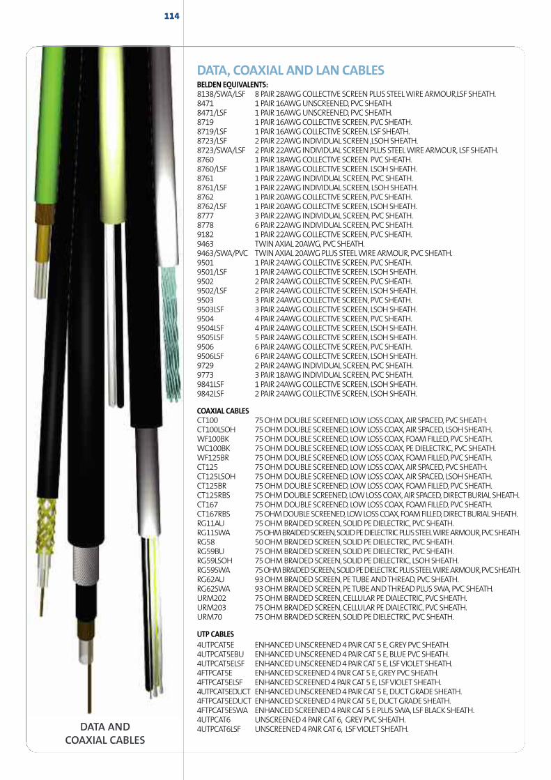
114
DATA ANDCOAXIAL CABLES
DATA, COAXIAL AND LAN CABLESBELDEN EQUIVALENTS:8138/SWA/LSF 8PAIR28AWGCOLLECTIVESCREENPLUSSTEELWIREARMOUR,LSFSHEATH.8471 1PAIR16AWGUNSCREENED,PVCSHEATH.8471/LSF 1PAIR16AWGUNSCREENED,PVCSHEATH.8719 1PAIR16AWGCOLLECTIVESCREEN,PVCSHEATH.8719/LSF 1PAIR16AWGCOLLECTIVESCREEN, LSFSHEATH.8723/LSF 2PAIR22AWGINDIVIDUALSCREEN ,LSOHSHEATH.8723/SWA/LSF 2PAIR22AWGINDIVIDUALSCREENPLUSSTEELWIREARMOUR, LSFSHEATH.8760 1PAIR18AWGCOLLECTIVESCREEN.PVCSHEATH.8760/LSF 1PAIR18AWGCOLLECTIVESCREEN. LSOHSHEATH.8761 1PAIR22AWGINDIVIDUALSCREEN,PVCSHEATH.8761/LSF 1PAIR22AWGINDIVIDUALSCREEN, LSOHSHEATH.8762 1PAIR20AWGCOLLECTIVESCREEN,PVCSHEATH.8762/LSF 1PAIR20AWGCOLLECTIVESCREEN, LSOHSHEATH.8777 3PAIR22AWGINDIVIDUALSCREEN,PVCSHEATH.8778 6PAIR22AWGINDIVIDUALSCREEN,PVCSHEATH.9182 1PAIR22AWGCOLLECTIVESCREEN,PVCSHEATH.9463 TWINAXIAL20AWG,PVCSHEATH.9463/SWA/PVC TWINAXIAL20AWGPLUSSTEELWIREARMOUR,PVCSHEATH.9501 1PAIR24AWGCOLLECTIVESCREEN,PVCSHEATH.9501/LSF 1PAIR24AWGCOLLECTIVESCREEN, LSOHSHEATH.9502 2PAIR24AWGCOLLECTIVESCREEN,PVCSHEATH.9502/LSF 2PAIR24AWGCOLLECTIVESCREEN, LSOHSHEATH.9503 3PAIR24AWGCOLLECTIVESCREEN,PVCSHEATH.9503LSF 3PAIR24AWGCOLLECTIVESCREEN, LSOHSHEATH.9504 4PAIR24AWGCOLLECTIVESCREEN,PVCSHEATH.9504LSF 4PAIR24AWGCOLLECTIVESCREEN, LSOHSHEATH.9505LSF 5PAIR24AWGCOLLECTIVESCREEN, LSOHSHEATH.9506 6PAIR24AWGCOLLECTIVESCREEN,PVCSHEATH.9506LSF 6PAIR24AWGCOLLECTIVESCREEN, LSOHSHEATH.9729 2PAIR24AWGINDIVIDUALSCREEN,PVCSHEATH.9773 3PAIR18AWGINDIVIDUALSCREEN,PVCSHEATH.9841LSF 1PAIR24AWGCOLLECTIVESCREEN, LSOHSHEATH.9842LSF 2PAIR24AWGCOLLECTIVESCREEN, LSOHSHEATH.
COAXIAL CABLESCT100 75OHMDOUBLESCREENED, LOWLOSSCOAX,AIRSPACED,PVCSHEATH.CT100LSOH 75OHMDOUBLESCREENED, LOWLOSSCOAX,AIRSPACED, LSOHSHEATH.WF100BK 75OHMDOUBLESCREENED, LOWLOSSCOAX,FOAMFILLED,PVCSHEATH.WC100BK 75OHMDOUBLESCREENED, LOWLOSSCOAX,PEDIELECTRIC,PVCSHEATH.WF125BR 75OHMDOUBLESCREENED, LOWLOSSCOAX,FOAMFILLED,PVCSHEATH.CT125 75OHMDOUBLESCREENED, LOWLOSSCOAX,AIRSPACED,PVCSHEATH.CT125LSOH 75OHMDOUBLESCREENED, LOWLOSSCOAX,AIRSPACED, LSOHSHEATH.CT125BR 75OHMDOUBLESCREENED, LOWLOSSCOAX,FOAMFILLED,PVCSHEATH.CT125RBS 75OHMDOUBLESCREENED,LOWLOSSCOAX,AIRSPACED,DIRECTBURIALSHEATH.CT167 75OHMDOUBLESCREENED, LOWLOSSCOAX,FOAMFILLED,PVCSHEATH.CT167RBS 75OHMDOUBLESCREENED,LOWLOSSCOAX,FOAMFILLED,DIRECTBURIALSHEATH.RG11AU 75OHMBRAIDEDSCREEN,SOLIDPEDIELECTRIC,PVCSHEATH.RG11SWA 75OHMBRAIDEDSCREEN,SOLIDPEDIELECTRICPLUSSTEELWIREARMOUR,PVCSHEATH.RG58 50OHMBRAIDEDSCREEN,SOLIDPEDIELECTRIC,PVCSHEATH.RG59BU 75OHMBRAIDEDSCREEN,SOLIDPEDIELECTRIC,PVCSHEATH.RG59LSOH 75OHMBRAIDEDSCREEN,SOLIDPEDIELECTRIC, LSOHSHEATH.RG59SWA 75OHMBRAIDEDSCREEN,SOLIDPEDIELECTRICPLUSSTEELWIREARMOUR,PVCSHEATH.RG62AU 93OHMBRAIDEDSCREEN,PETUBEANDTHREAD,PVCSHEATH.RG62SWA 93OHMBRAIDEDSCREEN,PETUBEANDTHREADPLUSSWA,PVCSHEATH.URM202 75OHMBRAIDEDSCREEN,CELLULARPEDIALECTRIC,PVCSHEATH.URM203 75OHMBRAIDEDSCREEN,CELLULARPEDIALECTRIC,PVCSHEATH.URM70 75OHMBRAIDEDSCREEN,SOLIDPEDIELECTRIC,PVCSHEATH.
UTP CABLES4UTPCAT5E ENHANCEDUNSCREENED4PAIRCAT5E,GREYPVCSHEATH.4UTPCAT5EBU ENHANCEDUNSCREENED4PAIRCAT5E,BLUEPVCSHEATH.4UTPCAT5ELSF ENHANCEDUNSCREENED4PAIRCAT5E, LSFVIOLETSHEATH.4FTPCAT5E ENHANCEDSCREENED4PAIRCAT5E,GREYPVCSHEATH.4FTPCAT5ELSF ENHANCEDSCREENED4PAIRCAT5E, LSFVIOLETSHEATH.4UTPCAT5EDUCT ENHANCEDUNSCREENED4PAIRCAT5E,DUCTGRADESHEATH.4FTPCAT5EDUCT ENHANCEDSCREENED4PAIRCAT5E,DUCTGRADESHEATH.4FTPCAT5ESWA ENHANCEDSCREENED4PAIRCAT5EPLUSSWA,LSFBLACKSHEATH.4UTPCAT6 UNSCREENED4PAIRCAT6, GREYPVCSHEATH.4UTPCAT6LSF UNSCREENED4PAIRCAT6, LSFVIOLETSHEATH.
RAILWAY CABLES
RAILW
AYCABLES
115
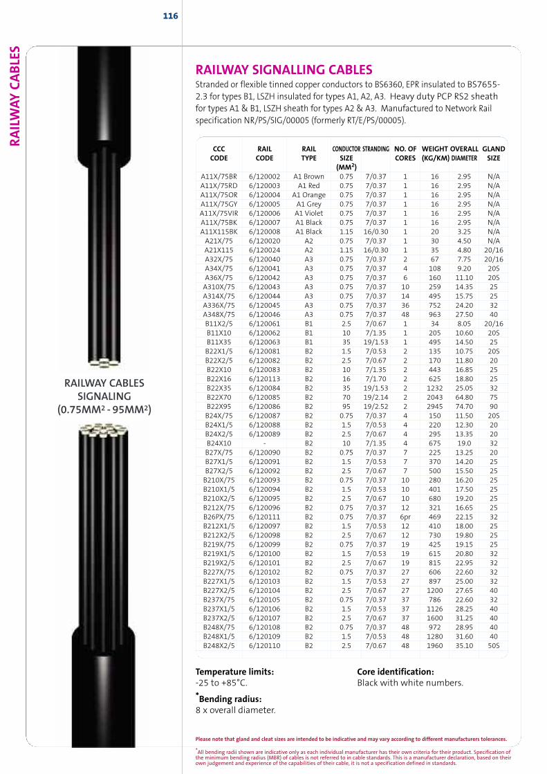
RAILW
AYCABLE
S
RAILWAY SIGNALLING CABLESStranded or flexible tinned copper conductors to BS6360, EPR insulated to BS7655-2.3 for types B1, LSZH insulated for types A1, A2, A3. Heavy duty PCP RS2 sheathfor types A1 & B1, LSZH sheath for types A2 & A3. Manufactured to Network Railspecification NR/PS/SIG/00005 (formerly RT/E/PS/00005).
CCC RAIL RAIL CONDUCTOR STRANDING NO. OF WEIGHT OVERALL GLANDCODE CODE TYPE SIZE CORES (KG/KM) DIAMETER SIZE
(MM2)A11X/75BR 6/120002 A1 Brown 0.75 7/0.37 1 16 2.95 N/AA11X/75RD 6/120003 A1 Red 0.75 7/0.37 1 16 2.95 N/AA11X/75OR 6/120004 A1 Orange 0.75 7/0.37 1 16 2.95 N/AA11X/75GY 6/120005 A1 Grey 0.75 7/0.37 1 16 2.95 N/AA11X/75VIR 6/120006 A1 Violet 0.75 7/0.37 1 16 2.95 N/AA11X/75BK 6/120007 A1 Black 0.75 7/0.37 1 16 2.95 N/AA11X115BK 6/120008 A1 Black 1.15 16/0.30 1 20 3.25 N/AA21X/75 6/120020 A2 0.75 7/0.37 1 30 4.50 N/AA21X115 6/120024 A2 1.15 16/0.30 1 35 4.80 20/16A32X/75 6/120040 A3 0.75 7/0.37 2 67 7.75 20/16A34X/75 6/120041 A3 0.75 7/0.37 4 108 9.20 20SA36X/75 6/120042 A3 0.75 7/0.37 6 160 11.10 20SA310X/75 6/120043 A3 0.75 7/0.37 10 259 14.35 25A314X/75 6/120044 A3 0.75 7/0.37 14 495 15.75 25A336X/75 6/120045 A3 0.75 7/0.37 36 752 24.20 32A348X/75 6/120046 A3 0.75 7/0.37 48 963 27.50 40B11X2/5 6/120061 B1 2.5 7/0.67 1 34 8.05 20/16B11X10 6/120062 B1 10 7/1.35 1 205 10.60 20SB11X35 6/120063 B1 35 19/1.53 1 495 14.50 25B22X1/5 6/120081 B2 1.5 7/0.53 2 135 10.75 20SB22X2/5 6/120082 B2 2.5 7/0.67 2 170 11.80 20B22X10 6/120083 B2 10 7/1.35 2 443 16.85 25B22X16 6/120113 B2 16 7/1.70 2 625 18.80 25B22X35 6/120084 B2 35 19/1.53 2 1232 25.05 32B22X70 6/120085 B2 70 19/2.14 2 2043 64.80 75B22X95 6/120086 B2 95 19/2.52 2 2945 74.70 90B24X/75 6/120087 B2 0.75 7/0.37 4 150 11.50 20SB24X1/5 6/120088 B2 1.5 7/0.53 4 220 12.30 20B24X2/5 6/120089 B2 2.5 7/0.67 4 295 13.35 20B24X10 - B2 10 7/1.35 4 675 19.0 32B27X/75 6/120090 B2 0.75 7/0.37 7 225 13.25 20B27X1/5 6/120091 B2 1.5 7/0.53 7 370 14.20 25B27X2/5 6/120092 B2 2.5 7/0.67 7 500 15.50 25B210X/75 6/120093 B2 0.75 7/0.37 10 280 16.20 25B210X1/5 6/120094 B2 1.5 7/0.53 10 401 17.50 25B210X2/5 6/120095 B2 2.5 7/0.67 10 680 19.20 25B212X/75 6/120096 B2 0.75 7/0.37 12 321 16.65 25B26PX/75 6/120111 B2 0.75 7/0.37 6pr 469 22.15 32B212X1/5 6/120097 B2 1.5 7/0.53 12 410 18.00 25B212X2/5 6/120098 B2 2.5 7/0.67 12 730 19.80 25B219X/75 6/120099 B2 0.75 7/0.37 19 425 19.15 25B219X1/5 6/120100 B2 1.5 7/0.53 19 615 20.80 32B219X2/5 6/120101 B2 2.5 7/0.67 19 815 22.95 32B227X/75 6/120102 B2 0.75 7/0.37 27 606 22.60 32B227X1/5 6/120103 B2 1.5 7/0.53 27 897 25.00 32B227X2/5 6/120104 B2 2.5 7/0.67 27 1200 27.65 40B237X/75 6/120105 B2 0.75 7/0.37 37 786 22.60 32B237X1/5 6/120106 B2 1.5 7/0.53 37 1126 28.25 40B237X2/5 6/120107 B2 2.5 7/0.67 37 1600 31.25 40B248X/75 6/120108 B2 0.75 7/0.37 48 972 28.95 40B248X1/5 6/120109 B2 1.5 7/0.53 48 1280 31.60 40B248X2/5 6/120110 B2 2.5 7/0.67 48 1960 35.10 50S
116
RAILWAY CABLESSIGNALING
(0.75MM2 - 95MM2)
Temperature limits:-25 to +85°C.
*Bending radius:8 x overall diameter.
Core identification:Black with white numbers.
*All bending radii shown are indicative only as each individual manufacturer has their own criteria for their product. Specification ofthe minimum bending radius (MBR) of cables is not referred to in cable standards. This is a manufacturer declaration, based on theirown judgement and experience of the capabilities of their cable, it is not a specification defined in standards.
Please note that gland and cleat sizes are intended to be indicative and may vary according to different manufacturers tolerances.
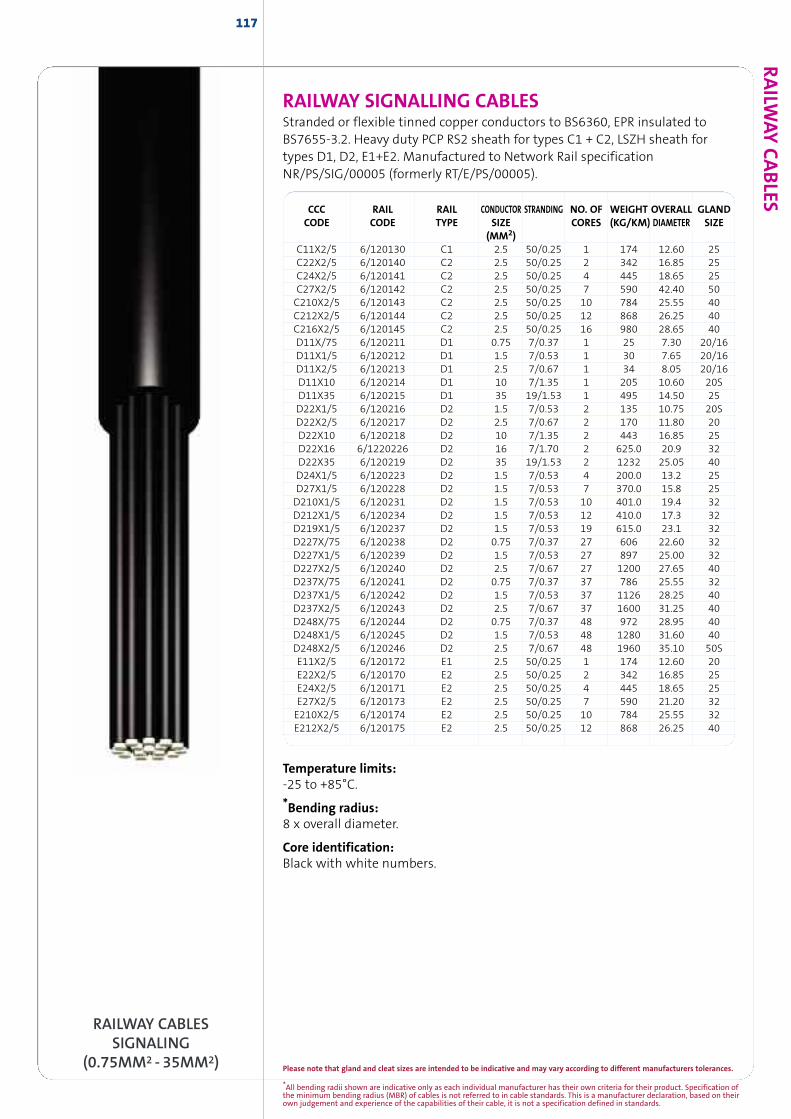
RAILW
AYCABLES
117
Temperature limits:-25 to +85°C.
*Bending radius:8 x overall diameter.
Core identification:Black with white numbers.
CCC RAIL RAIL CONDUCTOR STRANDING NO. OF WEIGHT OVERALL GLANDCODE CODE TYPE SIZE CORES (KG/KM) DIAMETER SIZE
(MM2)C11X2/5 6/120130 C1 2.5 50/0.25 1 174 12.60 25C22X2/5 6/120140 C2 2.5 50/0.25 2 342 16.85 25C24X2/5 6/120141 C2 2.5 50/0.25 4 445 18.65 25C27X2/5 6/120142 C2 2.5 50/0.25 7 590 42.40 50C210X2/5 6/120143 C2 2.5 50/0.25 10 784 25.55 40C212X2/5 6/120144 C2 2.5 50/0.25 12 868 26.25 40C216X2/5 6/120145 C2 2.5 50/0.25 16 980 28.65 40D11X/75 6/120211 D1 0.75 7/0.37 1 25 7.30 20/16D11X1/5 6/120212 D1 1.5 7/0.53 1 30 7.65 20/16D11X2/5 6/120213 D1 2.5 7/0.67 1 34 8.05 20/16D11X10 6/120214 D1 10 7/1.35 1 205 10.60 20SD11X35 6/120215 D1 35 19/1.53 1 495 14.50 25D22X1/5 6/120216 D2 1.5 7/0.53 2 135 10.75 20SD22X2/5 6/120217 D2 2.5 7/0.67 2 170 11.80 20D22X10 6/120218 D2 10 7/1.35 2 443 16.85 25D22X16 6/1220226 D2 16 7/1.70 2 625.0 20.9 32D22X35 6/120219 D2 35 19/1.53 2 1232 25.05 40D24X1/5 6/120223 D2 1.5 7/0.53 4 200.0 13.2 25D27X1/5 6/120228 D2 1.5 7/0.53 7 370.0 15.8 25D210X1/5 6/120231 D2 1.5 7/0.53 10 401.0 19.4 32D212X1/5 6/120234 D2 1.5 7/0.53 12 410.0 17.3 32D219X1/5 6/120237 D2 1.5 7/0.53 19 615.0 23.1 32D227X/75 6/120238 D2 0.75 7/0.37 27 606 22.60 32D227X1/5 6/120239 D2 1.5 7/0.53 27 897 25.00 32D227X2/5 6/120240 D2 2.5 7/0.67 27 1200 27.65 40D237X/75 6/120241 D2 0.75 7/0.37 37 786 25.55 32D237X1/5 6/120242 D2 1.5 7/0.53 37 1126 28.25 40D237X2/5 6/120243 D2 2.5 7/0.67 37 1600 31.25 40D248X/75 6/120244 D2 0.75 7/0.37 48 972 28.95 40D248X1/5 6/120245 D2 1.5 7/0.53 48 1280 31.60 40D248X2/5 6/120246 D2 2.5 7/0.67 48 1960 35.10 50SE11X2/5 6/120172 E1 2.5 50/0.25 1 174 12.60 20E22X2/5 6/120170 E2 2.5 50/0.25 2 342 16.85 25E24X2/5 6/120171 E2 2.5 50/0.25 4 445 18.65 25E27X2/5 6/120173 E2 2.5 50/0.25 7 590 21.20 32E210X2/5 6/120174 E2 2.5 50/0.25 10 784 25.55 32E212X2/5 6/120175 E2 2.5 50/0.25 12 868 26.25 40
RAILWAY SIGNALLING CABLESStranded or flexible tinned copper conductors to BS6360, EPR insulated toBS7655-3.2. Heavy duty PCP RS2 sheath for types C1 + C2, LSZH sheath fortypes D1, D2, E1+E2. Manufactured to Network Rail specificationNR/PS/SIG/00005 (formerly RT/E/PS/00005).
RAILWAY CABLESSIGNALING
(0.75MM2 - 35MM2)*All bending radii shown are indicative only as each individual manufacturer has their own criteria for their product. Specification ofthe minimum bending radius (MBR) of cables is not referred to in cable standards. This is a manufacturer declaration, based on theirown judgement and experience of the capabilities of their cable, it is not a specification defined in standards.
Please note that gland and cleat sizes are intended to be indicative and may vary according to different manufacturers tolerances.
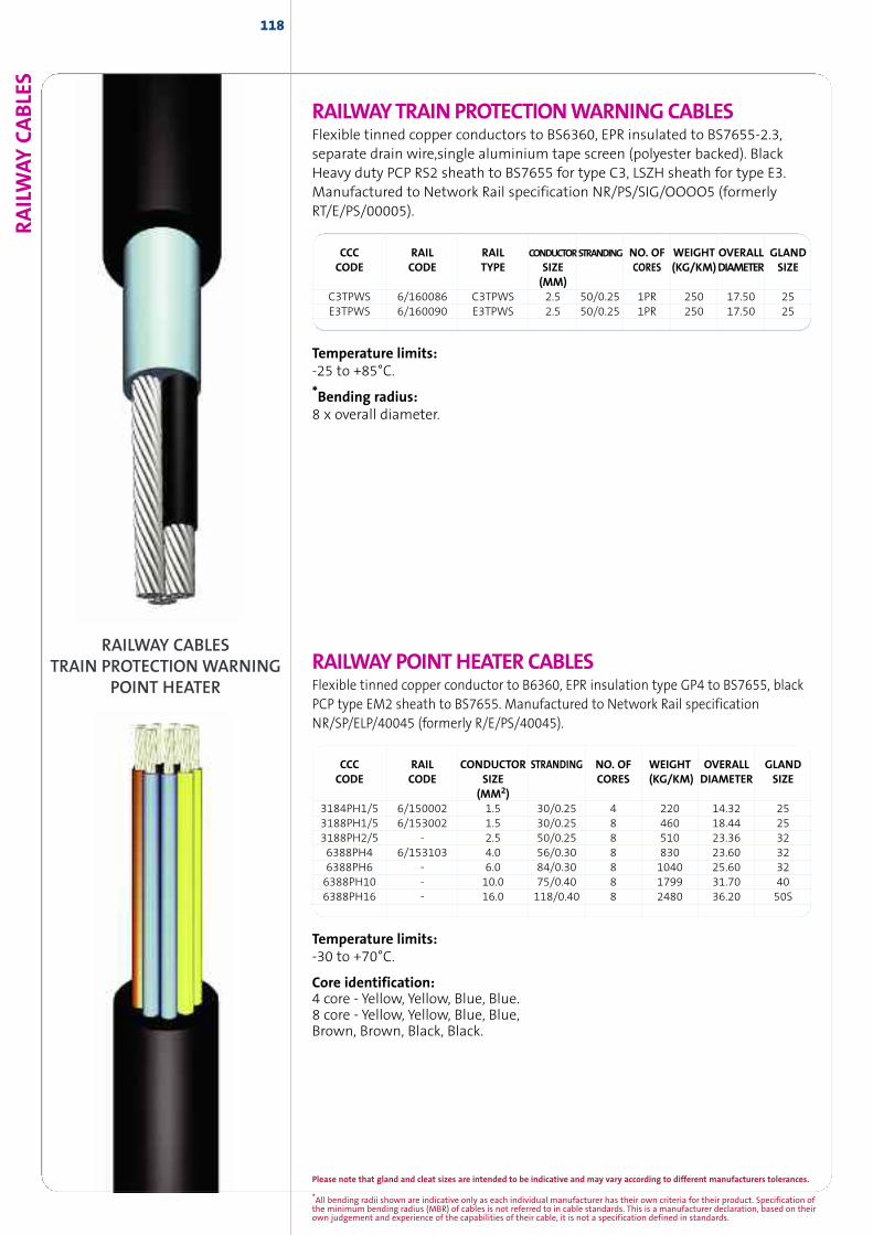
118RAILW
AYCABLE
S
CCC RAIL RAIL CONDUCTORSTRANDING NO. OF WEIGHT OVERALL GLANDCODE CODE TYPE SIZE CORES (KG/KM)DIAMETER SIZE
(MM)C3TPWS 6/160086 C3TPWS 2.5 50/0.25 1PR 250 17.50 25E3TPWS 6/160090 E3TPWS 2.5 50/0.25 1PR 250 17.50 25
Temperature limits:-25 to +85°C.
*Bending radius:8 x overall diameter.
Temperature limits:-30 to +70°C.
Core identification:4 core - Yellow, Yellow, Blue, Blue.8 core - Yellow, Yellow, Blue, Blue,Brown, Brown, Black, Black.
RAILWAYPOINTHEATERCABLESFlexible tinned copper conductor to B6360, EPR insulation type GP4 to BS7655, blackPCP type EM2 sheath to BS7655. Manufactured to Network Rail specificationNR/SP/ELP/40045 (formerly R/E/PS/40045).
CCC RAIL CONDUCTOR STRANDING NO. OF WEIGHT OVERALL GLANDCODE CODE SIZE CORES (KG/KM) DIAMETER SIZE
(MM2)3184PH1/5 6/150002 1.5 30/0.25 4 220 14.32 253188PH1/5 6/153002 1.5 30/0.25 8 460 18.44 253188PH2/5 - 2.5 50/0.25 8 510 23.36 326388PH4 6/153103 4.0 56/0.30 8 830 23.60 326388PH6 - 6.0 84/0.30 8 1040 25.60 326388PH10 - 10.0 75/0.40 8 1799 31.70 406388PH16 - 16.0 118/0.40 8 2480 36.20 50S
RAILWAY CABLESTRAIN PROTECTION WARNING
POINT HEATER
RAILWAYTRAINPROTECTIONWARNINGCABLESFlexible tinned copper conductors to BS6360, EPR insulated to BS7655-2.3,separate drain wire,single aluminium tape screen (polyester backed). BlackHeavy duty PCP RS2 sheath to BS7655 for type C3, LSZH sheath for type E3.Manufactured to Network Rail specification NR/PS/SIG/OOOO5 (formerlyRT/E/PS/00005).
*All bending radii shown are indicative only as each individual manufacturer has their own criteria for their product. Specification ofthe minimum bending radius (MBR) of cables is not referred to in cable standards. This is a manufacturer declaration, based on theirown judgement and experience of the capabilities of their cable, it is not a specification defined in standards.
Please note that gland and cleat sizes are intended to be indicative and may vary according to different manufacturers tolerances.
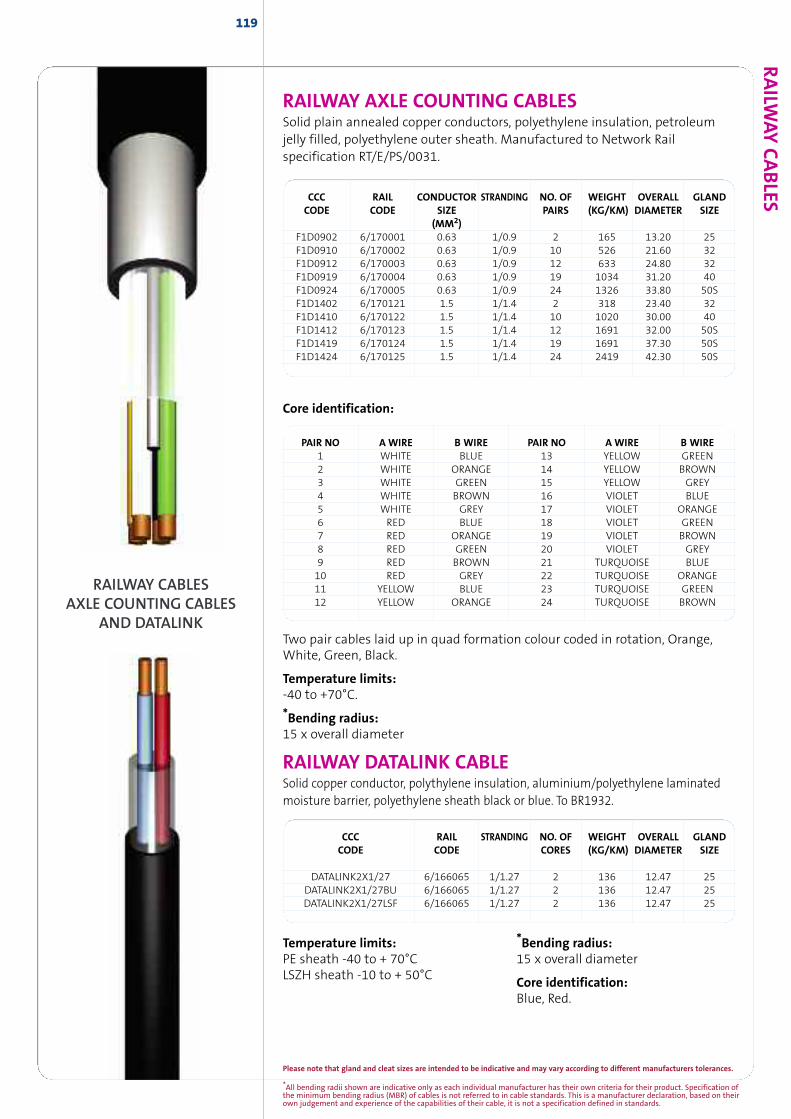
119RAILW
AYCABLESCCC RAIL CONDUCTOR STRANDING NO. OF WEIGHT OVERALL GLAND
CODE CODE SIZE PAIRS (KG/KM) DIAMETER SIZE(MM2)
F1D0902 6/170001 0.63 1/0.9 2 165 13.20 25F1D0910 6/170002 0.63 1/0.9 10 526 21.60 32F1D0912 6/170003 0.63 1/0.9 12 633 24.80 32F1D0919 6/170004 0.63 1/0.9 19 1034 31.20 40F1D0924 6/170005 0.63 1/0.9 24 1326 33.80 50SF1D1402 6/170121 1.5 1/1.4 2 318 23.40 32F1D1410 6/170122 1.5 1/1.4 10 1020 30.00 40F1D1412 6/170123 1.5 1/1.4 12 1691 32.00 50SF1D1419 6/170124 1.5 1/1.4 19 1691 37.30 50SF1D1424 6/170125 1.5 1/1.4 24 2419 42.30 50S
Core identification:
Two pair cables laid up in quad formation colour coded in rotation, Orange,White, Green, Black.
Temperature limits:-40 to +70°C.
*Bending radius:15 x overall diameter
PAIR NO A WIRE B WIRE PAIR NO A WIRE B WIRE1 WHITE BLUE 13 YELLOW GREEN2 WHITE ORANGE 14 YELLOW BROWN3 WHITE GREEN 15 YELLOW GREY4 WHITE BROWN 16 VIOLET BLUE5 WHITE GREY 17 VIOLET ORANGE6 RED BLUE 18 VIOLET GREEN7 RED ORANGE 19 VIOLET BROWN8 RED GREEN 20 VIOLET GREY9 RED BROWN 21 TURQUOISE BLUE10 RED GREY 22 TURQUOISE ORANGE11 YELLOW BLUE 23 TURQUOISE GREEN12 YELLOW ORANGE 24 TURQUOISE BROWN
RAILWAY CABLESAXLE COUNTING CABLES
AND DATALINK
RAILWAY AXLE COUNTING CABLESSolid plain annealed copper conductors, polyethylene insulation, petroleumjelly filled, polyethylene outer sheath. Manufactured to Network Railspecification RT/E/PS/0031.
CCC RAIL STRANDING NO. OF WEIGHT OVERALL GLANDCODE CODE CORES (KG/KM) DIAMETER SIZE
DATALINK2X1/27 6/166065 1/1.27 2 136 12.47 25DATALINK2X1/27BU 6/166065 1/1.27 2 136 12.47 25DATALINK2X1/27LSF 6/166065 1/1.27 2 136 12.47 25
RAILWAY DATALINK CABLESolid copper conductor, polythylene insulation, aluminium/polyethylene laminatedmoisture barrier, polyethylene sheath black or blue. To BR1932.
Temperature limits:PE sheath -40 to + 70°CLSZH sheath -10 to + 50°C
*Bending radius:15 x overall diameter
Core identification:Blue, Red.
*All bending radii shown are indicative only as each individual manufacturer has their own criteria for their product. Specification ofthe minimum bending radius (MBR) of cables is not referred to in cable standards. This is a manufacturer declaration, based on theirown judgement and experience of the capabilities of their cable, it is not a specification defined in standards.
Please note that gland and cleat sizes are intended to be indicative and may vary according to different manufacturers tolerances.
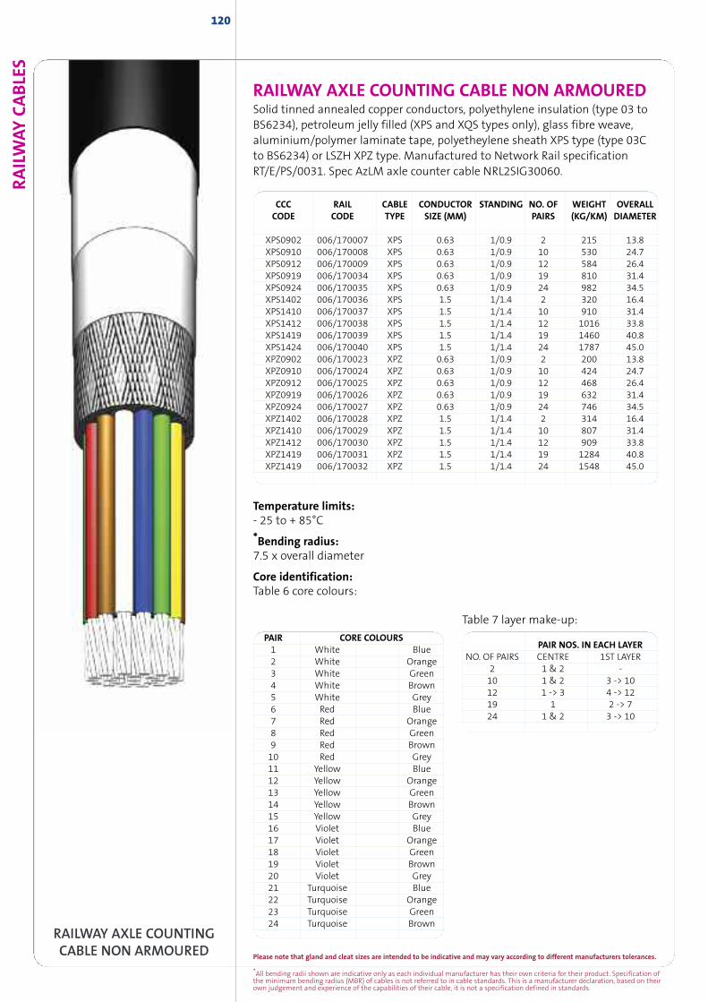
RAILW
AYCABLE
S120
RAILWAY AXLE COUNTING CABLE NON ARMOUREDSolid tinned annealed copper conductors, polyethylene insulation (type 03 toBS6234), petroleum jelly filled (XPS and XQS types only), glass fibre weave,aluminium/polymer laminate tape, polyetheylene sheath XPS type (type 03Cto BS6234) or LSZH XPZ type. Manufactured to Network Rail specificationRT/E/PS/0031. Spec AzLM axle counter cable NRL2SIG30060.
CCC RAIL CABLE CONDUCTOR STANDING NO. OF WEIGHT OVERALLCODE CODE TYPE SIZE (MM) PAIRS (KG/KM) DIAMETER
XPS0902 006/170007 XPS 0.63 1/0.9 2 215 13.8XPS0910 006/170008 XPS 0.63 1/0.9 10 530 24.7XPS0912 006/170009 XPS 0.63 1/0.9 12 584 26.4XPS0919 006/170034 XPS 0.63 1/0.9 19 810 31.4XPS0924 006/170035 XPS 0.63 1/0.9 24 982 34.5XPS1402 006/170036 XPS 1.5 1/1.4 2 320 16.4XPS1410 006/170037 XPS 1.5 1/1.4 10 910 31.4XPS1412 006/170038 XPS 1.5 1/1.4 12 1016 33.8XPS1419 006/170039 XPS 1.5 1/1.4 19 1460 40.8XPS1424 006/170040 XPS 1.5 1/1.4 24 1787 45.0XPZ0902 006/170023 XPZ 0.63 1/0.9 2 200 13.8XPZ0910 006/170024 XPZ 0.63 1/0.9 10 424 24.7XPZ0912 006/170025 XPZ 0.63 1/0.9 12 468 26.4XPZ0919 006/170026 XPZ 0.63 1/0.9 19 632 31.4XPZ0924 006/170027 XPZ 0.63 1/0.9 24 746 34.5XPZ1402 006/170028 XPZ 1.5 1/1.4 2 314 16.4XPZ1410 006/170029 XPZ 1.5 1/1.4 10 807 31.4XPZ1412 006/170030 XPZ 1.5 1/1.4 12 909 33.8XPZ1419 006/170031 XPZ 1.5 1/1.4 19 1284 40.8XPZ1419 006/170032 XPZ 1.5 1/1.4 24 1548 45.0
PAIR NOS. IN EACH LAYERNO. OF PAIRS CENTRE 1ST LAYER
2 1 & 2 -10 1 & 2 3 -> 1012 1 -> 3 4 -> 1219 1 2 -> 724 1 & 2 3 -> 10
PAIR CORE COLOURS1 White Blue2 White Orange3 White Green4 White Brown5 White Grey6 Red Blue7 Red Orange8 Red Green9 Red Brown10 Red Grey11 Yellow Blue12 Yellow Orange13 Yellow Green14 Yellow Brown15 Yellow Grey16 Violet Blue17 Violet Orange18 Violet Green19 Violet Brown20 Violet Grey21 Turquoise Blue22 Turquoise Orange23 Turquoise Green24 Turquoise Brown
Temperature limits:- 25 to + 85°C
*Bending radius:7.5 x overall diameter
Core identification:Table 6 core colours:
RAILWAY AXLE COUNTINGCABLE NON ARMOURED
Table 7 layer make-up:
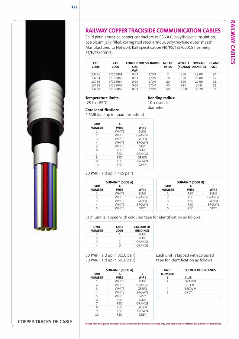
121
RAILWAY COPPER TRACKSIDE COMMUNICATION CABLESSolid plain annealed copper conductors to BS6360, polytheylene insulation,petroleum jelly filled, corrugated steel armour, polytheylene outer sheath.Manufactured to Network Rail specification NR/PS/TEL/00015 (formerlyRT/E/PS/00015).
CCC RAIL CONDUCTOR STRANDING NO. OF WEIGHT OVERALL GLANDCODE CODE SIZE PAIRS (KG/KM) DIAMETER SIZE
(MM2)13781 6/168061 0.63 1/0.9 2 250 19.00 2013784 6/168063 0.63 1/0.9 10 520 23.80 2513786 6/168064 0.63 1/0.9 20 820 27.60 3213788 6/168065 0.63 1/0.9 30 915 30.9 3213790 6/168066 0.63 1/0.9 50 1550 35.70 32
Temperature limits:-25 to +85°C.
Core identification:2 PAIR (laid up in quad formation)
Bending radius:10 x overalldiameter.
20 PAIR (laid up in 4x5 pair)
PAIR A BNUMBER WIRE WIRE
1 WHITE BLUE2 WHITE ORANGE3 WHITE GREEN4 WHITE BROWN5 WHITE GREY6 RED BLUE7 RED ORANGE8 RED GREEN9 RED BROWN10 RED GREY
UNIT UNIT COLOUR OFNUMBER CODE BINDINGS
1 A BLUE2 B BLUE3 C ORANGE4 D ORANGE
SUB-UNIT (CODE A)PAIR A B
NUMBER WIRE WIRE1 WHITE BLUE2 WHITE ORANGE3 WHITE GREEN4 WHITE BROWN5 WHITE GREY
SUB-UNIT (CODE B)PAIR A B
NUMBER WIRE WIRE1 RED BLUE2 RED ORANGE3 RED GREEN4 RED BROWN5 RED GREY
30 PAIR (laid up in 3x10 pair)50 PAIR (laid up in 5x10 pair)
Each unit is lapped with colouredtape for identification as follows:
SUB-UNIT (CODE A)PAIR A B
NUMBER WIRE WIRE1 WHITE BLUE2 WHITE ORANGE3 WHITE GREEN4 WHITE BROWN5 WHITE GREY6 RED BLUE7 RED ORANGE8 RED GREEN9 RED BROWN10 RED GREY
UNIT COLOUR OF BINDINGSNUMBER
1 BLUE2 ORANGE3 GREEN4 BROWN5 GREY
Each unit is lapped with coloured tape for identification as follows:
COPPER TRACKSIDE CABLE
RAILW
AYCABLES
Please note that gland and cleat sizes are intended to be indicative and may vary according to different manufacturers tolerances.
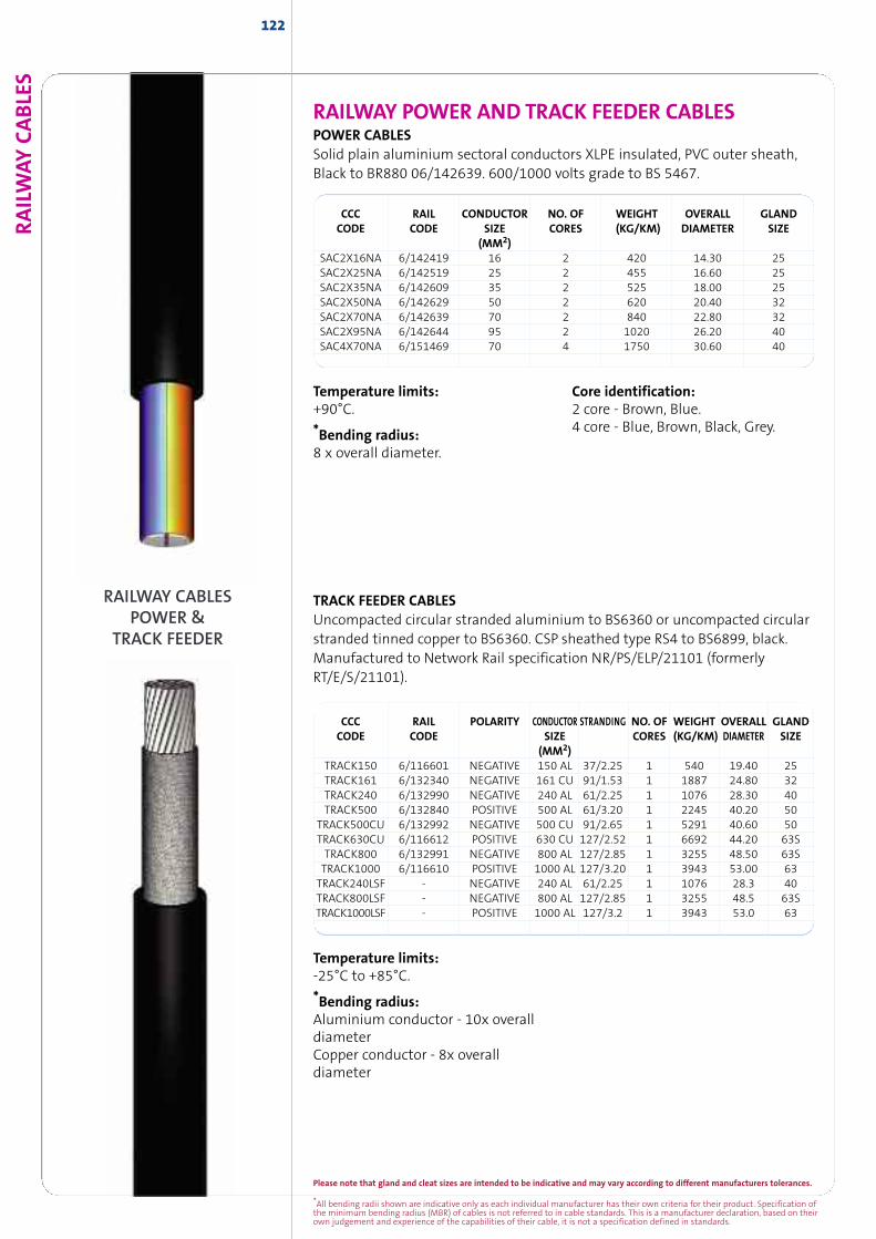
RAILW
AYCABLE
S122
RAILWAY POWER AND TRACK FEEDER CABLESPOWER CABLESSolid plain aluminium sectoral conductors XLPE insulated, PVC outer sheath,Black to BR880 06/142639. 600/1000 volts grade to BS 5467.
Temperature limits:+90°C.
*Bending radius:8 x overall diameter.
Core identification:2 core - Brown, Blue.4 core - Blue, Brown, Black, Grey.
Temperature limits:-25°C to +85°C.
*Bending radius:Aluminium conductor - 10x overalldiameterCopper conductor - 8x overalldiameter
TRACK FEEDER CABLESUncompacted circular stranded aluminium to BS6360 or uncompacted circularstranded tinned copper to BS6360. CSP sheathed type RS4 to BS6899, black.Manufactured to Network Rail specification NR/PS/ELP/21101 (formerlyRT/E/S/21101).
CCC RAIL POLARITY CONDUCTOR STRANDING NO. OF WEIGHT OVERALL GLANDCODE CODE SIZE CORES (KG/KM) DIAMETER SIZE
(MM2)TRACK150 6/116601 NEGATIVE 150 AL 37/2.25 1 540 19.40 25TRACK161 6/132340 NEGATIVE 161 CU 91/1.53 1 1887 24.80 32TRACK240 6/132990 NEGATIVE 240 AL 61/2.25 1 1076 28.30 40TRACK500 6/132840 POSITIVE 500 AL 61/3.20 1 2245 40.20 50
TRACK500CU 6/132992 NEGATIVE 500 CU 91/2.65 1 5291 40.60 50TRACK630CU 6/116612 POSITIVE 630 CU 127/2.52 1 6692 44.20 63STRACK800 6/132991 NEGATIVE 800 AL 127/2.85 1 3255 48.50 63STRACK1000 6/116610 POSITIVE 1000 AL 127/3.20 1 3943 53.00 63TRACK240LSF - NEGATIVE 240 AL 61/2.25 1 1076 28.3 40TRACK800LSF - NEGATIVE 800 AL 127/2.85 1 3255 48.5 63STRACK1000LSF - POSITIVE 1000 AL 127/3.2 1 3943 53.0 63
RAILWAY CABLESPOWER &
TRACK FEEDER
CCC RAIL CONDUCTOR NO. OF WEIGHT OVERALL GLANDCODE CODE SIZE CORES (KG/KM) DIAMETER SIZE
(MM2)SAC2X16NA 6/142419 16 2 420 14.30 25SAC2X25NA 6/142519 25 2 455 16.60 25SAC2X35NA 6/142609 35 2 525 18.00 25SAC2X50NA 6/142629 50 2 620 20.40 32SAC2X70NA 6/142639 70 2 840 22.80 32SAC2X95NA 6/142644 95 2 1020 26.20 40SAC4X70NA 6/151469 70 4 1750 30.60 40
*All bending radii shown are indicative only as each individual manufacturer has their own criteria for their product. Specification ofthe minimum bending radius (MBR) of cables is not referred to in cable standards. This is a manufacturer declaration, based on theirown judgement and experience of the capabilities of their cable, it is not a specification defined in standards.
Please note that gland and cleat sizes are intended to be indicative and may vary according to different manufacturers tolerances.
123
MARINE ANDOFFSHORE CABLES
MARIN
EAND
OFFSH
ORECABLES
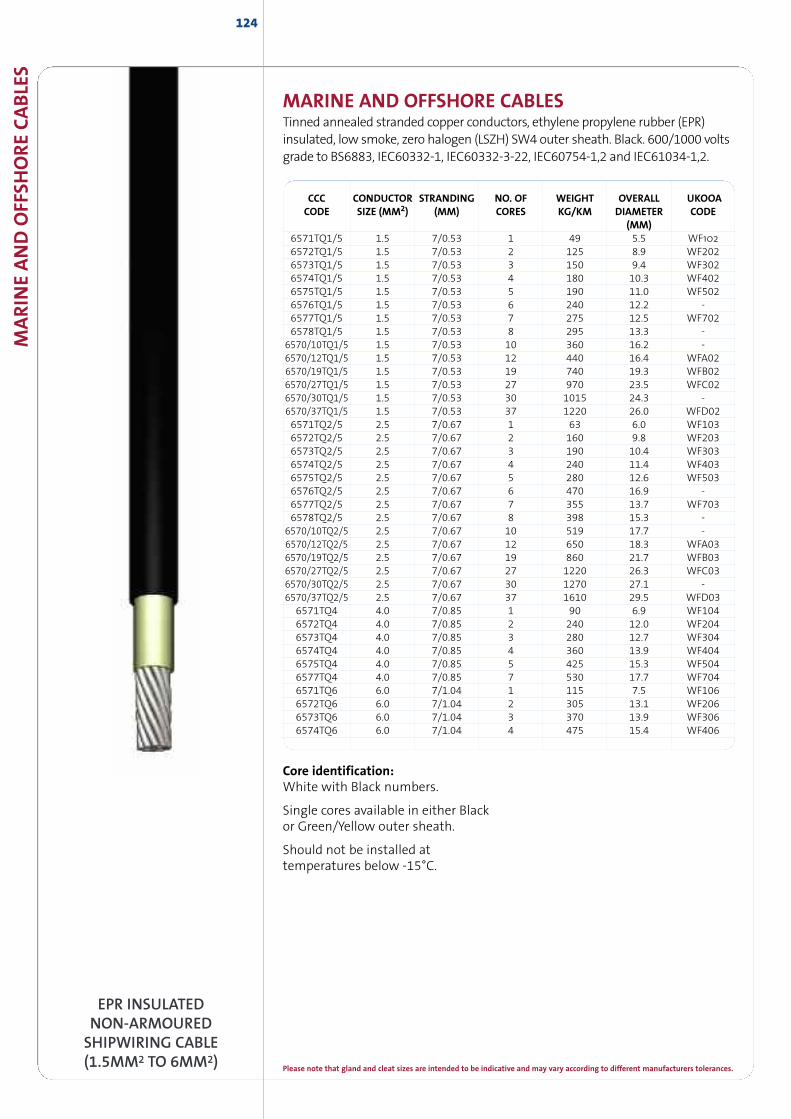
Please note that gland and cleat sizes are intended to be indicative and may vary according to different manufacturers tolerances.
CCC CONDUCTOR STRANDING NO. OF WEIGHT OVERALL UKOOACODE SIZE (MM2) (MM) CORES KG/KM DIAMETER CODE
(MM)6571TQ1/5 1.5 7/0.53 1 49 5.5 WF1026572TQ1/5 1.5 7/0.53 2 125 8.9 WF2026573TQ1/5 1.5 7/0.53 3 150 9.4 WF3026574TQ1/5 1.5 7/0.53 4 180 10.3 WF4026575TQ1/5 1.5 7/0.53 5 190 11.0 WF5026576TQ1/5 1.5 7/0.53 6 240 12.2 -6577TQ1/5 1.5 7/0.53 7 275 12.5 WF7026578TQ1/5 1.5 7/0.53 8 295 13.3 -
6570/10TQ1/5 1.5 7/0.53 10 360 16.2 -6570/12TQ1/5 1.5 7/0.53 12 440 16.4 WFA026570/19TQ1/5 1.5 7/0.53 19 740 19.3 WFB026570/27TQ1/5 1.5 7/0.53 27 970 23.5 WFC026570/30TQ1/5 1.5 7/0.53 30 1015 24.3 -6570/37TQ1/5 1.5 7/0.53 37 1220 26.0 WFD026571TQ2/5 2.5 7/0.67 1 63 6.0 WF1036572TQ2/5 2.5 7/0.67 2 160 9.8 WF2036573TQ2/5 2.5 7/0.67 3 190 10.4 WF3036574TQ2/5 2.5 7/0.67 4 240 11.4 WF4036575TQ2/5 2.5 7/0.67 5 280 12.6 WF5036576TQ2/5 2.5 7/0.67 6 470 16.9 -6577TQ2/5 2.5 7/0.67 7 355 13.7 WF7036578TQ2/5 2.5 7/0.67 8 398 15.3 -
6570/10TQ2/5 2.5 7/0.67 10 519 17.7 -6570/12TQ2/5 2.5 7/0.67 12 650 18.3 WFA036570/19TQ2/5 2.5 7/0.67 19 860 21.7 WFB036570/27TQ2/5 2.5 7/0.67 27 1220 26.3 WFC036570/30TQ2/5 2.5 7/0.67 30 1270 27.1 -6570/37TQ2/5 2.5 7/0.67 37 1610 29.5 WFD03
6571TQ4 4.0 7/0.85 1 90 6.9 WF1046572TQ4 4.0 7/0.85 2 240 12.0 WF2046573TQ4 4.0 7/0.85 3 280 12.7 WF3046574TQ4 4.0 7/0.85 4 360 13.9 WF4046575TQ4 4.0 7/0.85 5 425 15.3 WF5046577TQ4 4.0 7/0.85 7 530 17.7 WF7046571TQ6 6.0 7/1.04 1 115 7.5 WF1066572TQ6 6.0 7/1.04 2 305 13.1 WF2066573TQ6 6.0 7/1.04 3 370 13.9 WF3066574TQ6 6.0 7/1.04 4 475 15.4 WF406
124
MARINE AND OFFSHORE CABLESTinned annealed stranded copper conductors, ethylene propylene rubber (EPR)insulated, low smoke, zero halogen (LSZH) SW4 outer sheath. Black. 600/1000 voltsgrade to BS6883, IEC60332-1, IEC60332-3-22, IEC60754-1,2 and IEC61034-1,2.
MARIN
EAND
OFF
SHORECABLE
S
Core identification:White with Black numbers.
Single cores available in either Blackor Green/Yellow outer sheath.
Should not be installed attemperatures below -15°C.
EPR INSULATEDNON-ARMOUREDSHIPWIRING CABLE(1.5MM2 TO 6MM2)
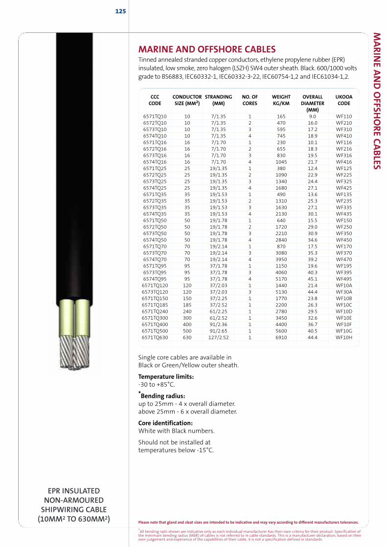
Please note that gland and cleat sizes are intended to be indicative and may vary according to different manufacturers tolerances.
*All bending radii shown are indicative only as each individual manufacturer has their own criteria for their product. Specification ofthe minimum bending radius (MBR) of cables is not referred to in cable standards. This is a manufacturer declaration, based on theirown judgement and experience of the capabilities of their cable, it is not a specification defined in standards.
MARIN
EAND
OFFSH
ORECABLES
MARINE AND OFFSHORE CABLESTinned annealed stranded copper conductors, ethylene propylene rubber (EPR)insulated, low smoke, zero halogen (LSZH) SW4 outer sheath. Black. 600/1000 voltsgrade to BS6883, IEC60332-1, IEC60332-3-22, IEC60754-1,2 and IEC61034-1,2.
CCC CONDUCTOR STRANDING NO. OF WEIGHT OVERALL UKOOACODE SIZE (MM2) (MM) CORES KG/KM DIAMETER CODE
(MM)6571TQ10 10 7/1.35 1 165 9.0 WF1106572TQ10 10 7/1.35 2 470 16.0 WF2106573TQ10 10 7/1.35 3 595 17.2 WF3106574TQ10 10 7/1.35 4 745 18.9 WF4106571TQ16 16 7/1.70 1 230 10.1 WF1166572TQ16 16 7/1.70 2 655 18.3 WF2166573TQ16 16 7/1.70 3 830 19.5 WF3166574TQ16 16 7/1.70 4 1045 21.7 WF4166571TQ25 25 19/1.35 1 380 12.4 WF1256572TQ25 25 19/1.35 2 1090 22.9 WF2256573TQ25 25 19/1.35 3 1340 24.4 WF3256574TQ25 25 19/1.35 4 1680 27.1 WF4256571TQ35 35 19/1.53 1 490 13.6 WF1356572TQ35 35 19/1.53 2 1310 25.3 WF2356573TQ35 35 19/1.53 3 1630 27.1 WF3356574TQ35 35 19/1.53 4 2130 30.1 WF4356571TQ50 50 19/1.78 1 640 15.5 WF1506572TQ50 50 19/1.78 2 1720 29.0 WF2506573TQ50 50 19/1.78 3 2210 30.9 WF3506574TQ50 50 19/1.78 4 2840 34.6 WF4506571TQ70 70 19/2.14 1 870 17.5 WF1706573TQ70 70 19/2.14 3 3080 35.3 WF3706574TQ70 70 19/2.14 4 3950 39.2 WF4706571TQ95 95 37/1.78 1 1150 19.6 WF1956573TQ95 95 37/1.78 3 4060 40.3 WF3956574TQ95 95 37/1.78 4 5170 45.1 WF4956571TQ120 120 37/2.03 1 1440 21.4 WF10A6573TQ120 120 37/2.03 3 5130 44.4 WF30A6571TQ150 150 37/2.25 1 1770 23.8 WF10B6571TQ185 185 37/2.52 1 2200 26.3 WF10C6571TQ240 240 61/2.25 1 2780 29.5 WF10D6571TQ300 300 61/2.52 1 3450 32.6 WF10E6571TQ400 400 91/2.36 1 4400 36.7 WF10F6571TQ500 500 91/2.65 1 5600 40.5 WF10G6571TQ630 630 127/2.52 1 6910 44.4 WF10H
EPR INSULATEDNON-ARMOUREDSHIPWIRING CABLE(10MM2 TO 630MM2)
125
Single core cables are available inBlack or Green/Yellow outer sheath.
Temperature limits:-30 to +85°C.
*Bending radius:up to 25mm - 4 x overall diameter.above 25mm - 6 x overall diameter.
Core identification:White with Black numbers.
Should not be installed attemperatures below -15°C.
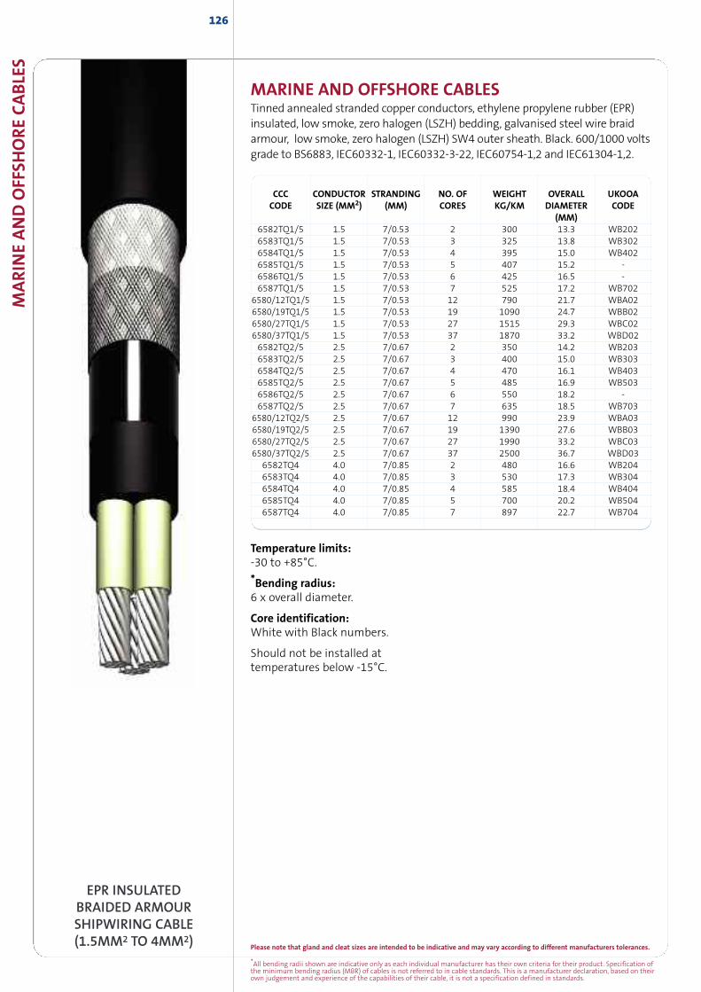
MARIN
EAND
OFF
SHORECABLE
S126
EPR INSULATEDBRAIDED ARMOURSHIPWIRING CABLE(1.5MM2 TO 4MM2)
MARINE AND OFFSHORE CABLESTinned annealed stranded copper conductors, ethylene propylene rubber (EPR)insulated, low smoke, zero halogen (LSZH) bedding, galvanised steel wire braidarmour, low smoke, zero halogen (LSZH) SW4 outer sheath. Black. 600/1000 voltsgrade to BS6883, IEC60332-1, IEC60332-3-22, IEC60754-1,2 and IEC61304-1,2.
CCC CONDUCTOR STRANDING NO. OF WEIGHT OVERALL UKOOACODE SIZE (MM2) (MM) CORES KG/KM DIAMETER CODE
(MM)6582TQ1/5 1.5 7/0.53 2 300 13.3 WB2026583TQ1/5 1.5 7/0.53 3 325 13.8 WB3026584TQ1/5 1.5 7/0.53 4 395 15.0 WB4026585TQ1/5 1.5 7/0.53 5 407 15.2 -6586TQ1/5 1.5 7/0.53 6 425 16.5 -6587TQ1/5 1.5 7/0.53 7 525 17.2 WB702
6580/12TQ1/5 1.5 7/0.53 12 790 21.7 WBA026580/19TQ1/5 1.5 7/0.53 19 1090 24.7 WBB026580/27TQ1/5 1.5 7/0.53 27 1515 29.3 WBC026580/37TQ1/5 1.5 7/0.53 37 1870 33.2 WBD026582TQ2/5 2.5 7/0.67 2 350 14.2 WB2036583TQ2/5 2.5 7/0.67 3 400 15.0 WB3036584TQ2/5 2.5 7/0.67 4 470 16.1 WB4036585TQ2/5 2.5 7/0.67 5 485 16.9 WB5036586TQ2/5 2.5 7/0.67 6 550 18.2 -6587TQ2/5 2.5 7/0.67 7 635 18.5 WB703
6580/12TQ2/5 2.5 7/0.67 12 990 23.9 WBA036580/19TQ2/5 2.5 7/0.67 19 1390 27.6 WBB036580/27TQ2/5 2.5 7/0.67 27 1990 33.2 WBC036580/37TQ2/5 2.5 7/0.67 37 2500 36.7 WBD03
6582TQ4 4.0 7/0.85 2 480 16.6 WB2046583TQ4 4.0 7/0.85 3 530 17.3 WB3046584TQ4 4.0 7/0.85 4 585 18.4 WB4046585TQ4 4.0 7/0.85 5 700 20.2 WB5046587TQ4 4.0 7/0.85 7 897 22.7 WB704
Temperature limits:-30 to +85°C.
*Bending radius:6 x overall diameter.
Core identification:White with Black numbers.
Should not be installed attemperatures below -15°C.
Please note that gland and cleat sizes are intended to be indicative and may vary according to different manufacturers tolerances.
*All bending radii shown are indicative only as each individual manufacturer has their own criteria for their product. Specification ofthe minimum bending radius (MBR) of cables is not referred to in cable standards. This is a manufacturer declaration, based on theirown judgement and experience of the capabilities of their cable, it is not a specification defined in standards.
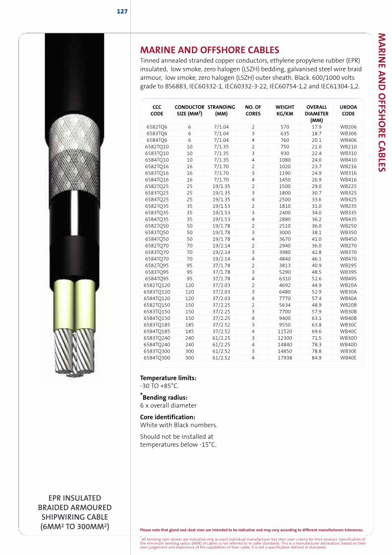
MARIN
EAND
OFFSH
ORECABLES
CCC CONDUCTOR STRANDING NO. OF WEIGHT OVERALL UKOOACODE SIZE (MM2) (MM) CORES KG/KM DIAMETER CODE
(MM)6582TQ6 6 7/1.04 2 570 17.9 WB2066583TQ6 6 7/1.04 3 635 18.7 WB3066584TQ6 6 7/1.04 4 760 20.1 WB4066582TQ10 10 7/1.35 2 750 21.0 WB2106583TQ10 10 7/1.35 3 930 22.4 WB3106584TQ10 10 7/1.35 4 1080 24.0 WB4106582TQ16 16 7/1.70 2 1020 23.7 WB2166583TQ16 16 7/1.70 3 1190 24.9 WB3166584TQ16 16 7/1.70 4 1450 26.9 WB4166582TQ25 25 19/1.35 2 1500 29.0 WB2256583TQ25 25 19/1.35 3 1800 30.7 WB3256584TQ25 25 19/1.35 4 2500 33.6 WB4256582TQ35 35 19/1.53 2 1810 31.0 WB2356583TQ35 35 19/1.53 3 2400 34.0 WB3356584TQ35 35 19/1.53 4 2880 36.2 WB4356582TQ50 50 19/1.78 2 2510 36.0 WB2506583TQ50 50 19/1.78 3 3000 38.1 WB3506584TQ50 50 19/1.78 4 3670 41.0 WB4506582TQ70 70 19/2.14 2 2940 36.0 WB2706583TQ70 70 19/2.14 3 3980 42.8 WB3706584TQ70 70 19/2.14 4 4840 46.1 WB4706582TQ95 95 37/1.78 2 3813 40.9 WB2956583TQ95 95 37/1.78 3 5290 48.5 WB3956584TQ95 95 37/1.78 4 6310 52.6 WB4956582TQ120 120 37/2.03 2 4692 44.9 WB20A6583TQ120 120 37/2.03 3 6480 52.9 WB30A6584TQ120 120 37/2.03 4 7770 57.4 WB40A6582TQ150 150 37/2.25 2 5634 48.9 WB20B6583TQ150 150 37/2.25 3 7700 57.9 WB30B6584TQ150 150 37/2.25 4 9400 63.1 WB40B6583TQ185 185 37/2.52 3 9550 63.8 WB30C6584TQ185 185 37/2.52 4 11520 69.6 WB40C6583TQ240 240 61/2.25 3 12300 71.5 WB30D6584TQ240 240 61/2.25 4 14840 78.3 WB40D6583TQ300 300 61/2.52 3 14850 78.8 WB30E6584TQ300 300 61/2.52 4 17938 84.9 WB40E
MARINE AND OFFSHORE CABLESTinned annealed stranded copper conductors, ethylene propylene rubber (EPR)insulated, low smoke, zero halogen (LSZH) bedding, galvanised steel wire braidarmour, low smoke, zero halogen (LSZH) outer sheath. Black. 600/1000 voltsgrade to BS6883, IEC60332-1, IEC60332-3-22, IEC60754-1,2 and IEC61304-1,2.
EPR INSULATEDBRAIDED ARMOUREDSHIPWIRING CABLE(6MM2 TO 300MM2)
127
Temperature limits:-30 TO +85°C.
*Bending radius:6 x overall diameter
Core identification:White with Black numbers.
Should not be installed attemperatures below -15°C.
Please note that gland and cleat sizes are intended to be indicative and may vary according to different manufacturers tolerances.
*All bending radii shown are indicative only as each individual manufacturer has their own criteria for their product. Specification ofthe minimum bending radius (MBR) of cables is not referred to in cable standards. This is a manufacturer declaration, based on theirown judgement and experience of the capabilities of their cable, it is not a specification defined in standards.
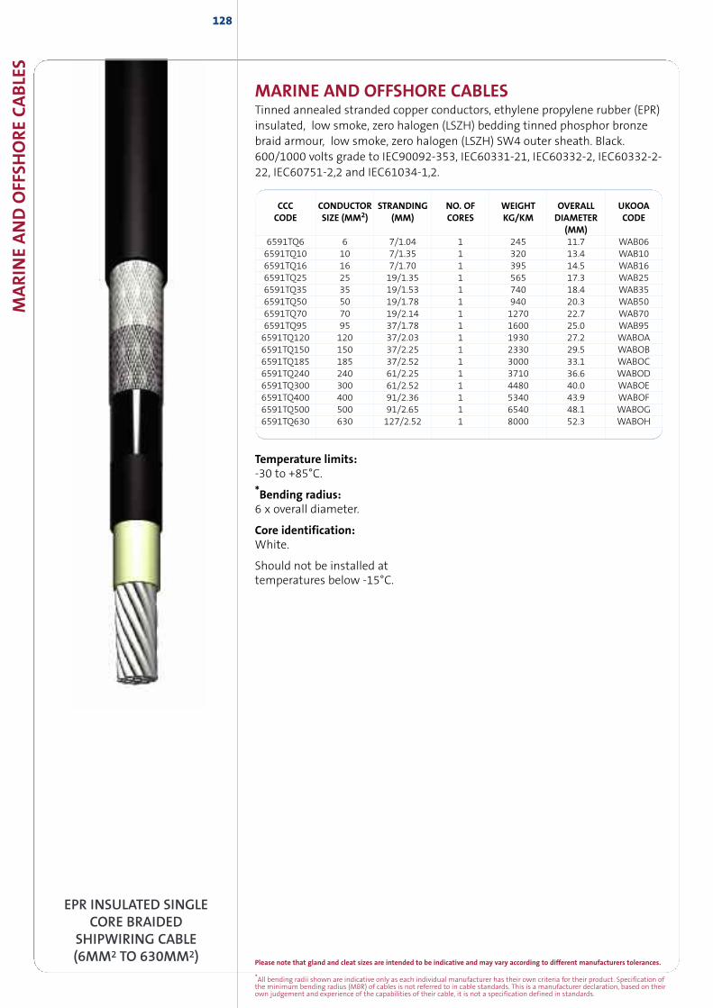
MARIN
EAND
OFF
SHORECABLE
S128
EPR INSULATED SINGLECORE BRAIDED
SHIPWIRING CABLE(6MM2 TO 630MM2)
CCC CONDUCTOR STRANDING NO. OF WEIGHT OVERALL UKOOACODE SIZE (MM2) (MM) CORES KG/KM DIAMETER CODE
(MM)6591TQ6 6 7/1.04 1 245 11.7 WAB066591TQ10 10 7/1.35 1 320 13.4 WAB106591TQ16 16 7/1.70 1 395 14.5 WAB166591TQ25 25 19/1.35 1 565 17.3 WAB256591TQ35 35 19/1.53 1 740 18.4 WAB356591TQ50 50 19/1.78 1 940 20.3 WAB506591TQ70 70 19/2.14 1 1270 22.7 WAB706591TQ95 95 37/1.78 1 1600 25.0 WAB956591TQ120 120 37/2.03 1 1930 27.2 WABOA6591TQ150 150 37/2.25 1 2330 29.5 WABOB6591TQ185 185 37/2.52 1 3000 33.1 WABOC6591TQ240 240 61/2.25 1 3710 36.6 WABOD6591TQ300 300 61/2.52 1 4480 40.0 WABOE6591TQ400 400 91/2.36 1 5340 43.9 WABOF6591TQ500 500 91/2.65 1 6540 48.1 WABOG6591TQ630 630 127/2.52 1 8000 52.3 WABOH
Temperature limits:-30 to +85°C.
*Bending radius:6 x overall diameter.
Core identification:White.
Should not be installed attemperatures below -15°C.
MARINE AND OFFSHORE CABLESTinned annealed stranded copper conductors, ethylene propylene rubber (EPR)insulated, low smoke, zero halogen (LSZH) bedding tinned phosphor bronzebraid armour, low smoke, zero halogen (LSZH) SW4 outer sheath. Black.600/1000 volts grade to IEC90092-353, IEC60331-21, IEC60332-2, IEC60332-2-22, IEC60751-2,2 and IEC61034-1,2.
Please note that gland and cleat sizes are intended to be indicative and may vary according to different manufacturers tolerances.
*All bending radii shown are indicative only as each individual manufacturer has their own criteria for their product. Specification ofthe minimum bending radius (MBR) of cables is not referred to in cable standards. This is a manufacturer declaration, based on theirown judgement and experience of the capabilities of their cable, it is not a specification defined in standards.
INSTALLATIONACCESSORIES
INSTA
LLATION
ACC
ESSORIES
129
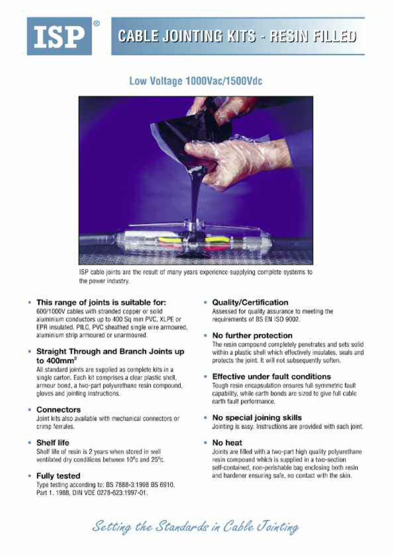
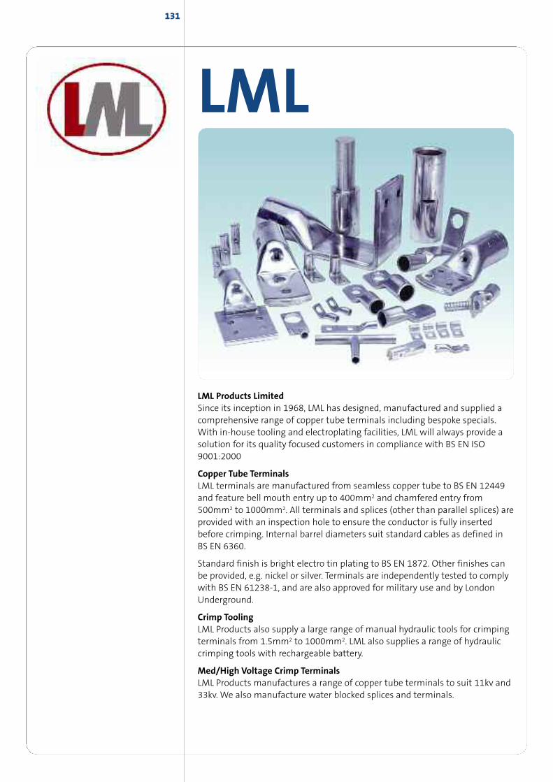
LML
LML Products LimitedSince its inception in 1968, LML has designed, manufactured and supplied acomprehensive range of copper tube terminals including bespoke specials.With in-house tooling and electroplating facilities, LML will always provide asolution for its quality focused customers in compliance with BS EN ISO9001:2000
Copper Tube TerminalsLML terminals are manufactured from seamless copper tube to BS EN 12449and feature bell mouth entry up to 400mm2 and chamfered entry from500mm2 to 1000mm2. All terminals and splices (other than parallel splices) areprovided with an inspection hole to ensure the conductor is fully insertedbefore crimping. Internal barrel diameters suit standard cables as defined inBS EN 6360.
Standard finish is bright electro tin plating to BS EN 1872. Other finishes canbe provided, e.g. nickel or silver. Terminals are independently tested to complywith BS EN 61238-1, and are also approved for military use and by LondonUnderground.
Crimp ToolingLML Products also supply a large range of manual hydraulic tools for crimpingterminals from 1.5mm2 to 1000mm2. LML also supplies a range of hydrauliccrimping tools with rechargeable battery.
Med/High Voltage Crimp TerminalsLML Products manufactures a range of copper tube terminals to suit 11kv and33kv. We also manufacture water blocked splices and terminals.
131
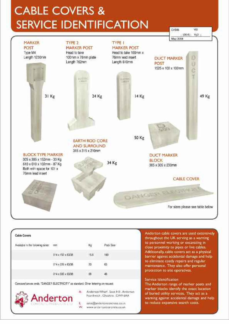
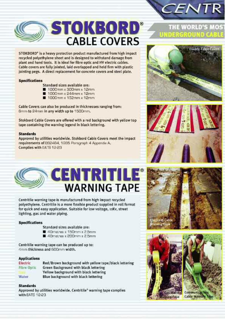

CMP Products offers a comprehensive training program for theinstallation of it's products. Whether you just need a video to showyou how it's done, require practical demonstrations at yourpremises or indeed you require training on site for large groups,CMP is able to assist. We offer certified training on all of ourproducts with all attendees receiving a training certificate followingsuccessful completion of the course to demonstrate competence.
SERVICESAND SUPPORTFROM CMP PRODUCTS
CERTIFIED TRAININGAVAILABLE• for designers/specifiers• for installers• for a QA, QC Personnel• installation video's available for all
products• in multiple languages• for design engineers to assist with
correct product selection• to keep up with the latest standards• wherever you need it, when you
need it
CMP
CMP PRODUCTS
www.cmp-products
.com
ALSOAVAILABLEfrom CMP Products
• Breather Drain Plugs• Adaptors & Reducers• Stopper Plugs• Unions• Locknuts• Serrated Washers• Earth Tags• Entry Thread Seals• Shrouds

RAXTON LIMITED
Raxton products are designed to solve the fundamental difficulties whichexist due to the variety of thread forms currently in use within the electricalindustry. These thread forms are predominantly Isometric, Imperial, N.P.T., BSPand PG.
Problems caused by dissimilar threads can occur in many environmentsincluding industrial, EExd, EExe and mining. Raxton conversions are fullyapproved to meet these requirements, being certified by leading testauthorities including BASEEFA, SIRA, ISSEP, KEMA, DET NORSKE VERITAS andStandards Association of Australia. They are marked accordingly.
Standard material is brass and readily available alternatives include mildsteel, stainless steel and aluminium. Our EExe range is also available in glassfilled nylon.
ADAPTORSREDUCERSHEXAGON HEAD PLUGSRIGHT ANGLE ADAPTORSMALE TO MALE ADAPTORSUNIONSSTOPPING PLUGSEARTH LEAD ADAPTORSTHREADED EARTH PLATES
NYLON GLANDSSCREWED NIPPLINGCOUPLERSBUSHESSHROUDSLOCKNUTS/LOCKRINGSEARTH TAGSWASHERS
135
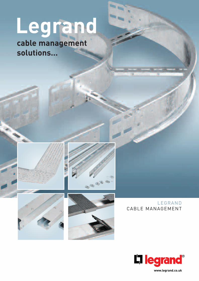
LEGRAND CABLE MANAGEMENT
www.legrand.co.uk
Legrandcable managementsolutions...
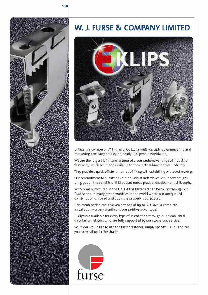
W. J. FURSE & COMPANY LIMITED
E-Klips is a division of W J Furse & Co Ltd, a multi-disciplined engineering andmarketing company employing nearly 200 people worldwide.
We are the largest UK manufacturer of a comprehensive range of industrialfasteners, which are made available to the electrical/mechanical industry.
They provide a quick, efficient method of fixing without drilling or bracket making.
Our commitment to quality has set industry standards while our new designsbring you all the benefits of E-Klips continuous product development philosophy.
Wholly manufactured in the UK, E-Klips fasteners can be found throughoutEurope and in many other countries in the world where our unequalledcombination of speed and quality is properly appreciated.
This combination can give you savings of up to 60% over a completeinstallation – a very significant competitive advantage!
E-Klips are available for every type of installation through our establisheddistributor network who are fully supported by our stocks and service.
So, if you would like to use the faster fastener, simply specify E-Klips and putyour opposition in the shade.
138
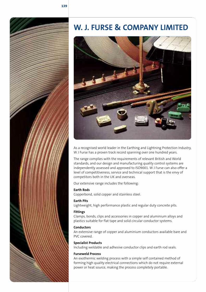
W. J. FURSE & COMPANY LIMITED
As a recognised world leader in the Earthing and Lightning Protection Industry,W J Furse has a proven track record spanning over one hundred years.
The range complies with the requirements of relevant British andWorldstandards, and our design and manufacturing quality control systems areindependently assessed and approved to ISO9001. W J Furse can also offer alevel of competitiveness, service and technical support that is the envy ofcompetitors both in the UK and overseas.
Our extensive range includes the following:
Earth RodsCopperbond, solid copper and stainless steel.
Earth PitsLightweight, high performance plastic and regular duty concrete pits.
FittingsClamps, bonds, clips and accessories in copper and aluminium alloys andplastics suitable for flat tape and solid circular conductor systems.
ConductorsAn extensive range of copper and aluminium conductors available bare andPVC covered.
Specialist ProductsIncluding weldable and adhesive conductor clips and earth rod seals.
Furseweld ProcessAn exothermic welding process with a simple self contained method offorming high quality electrical connections which do not require externalpower or heat source, making the process completely portable.
139
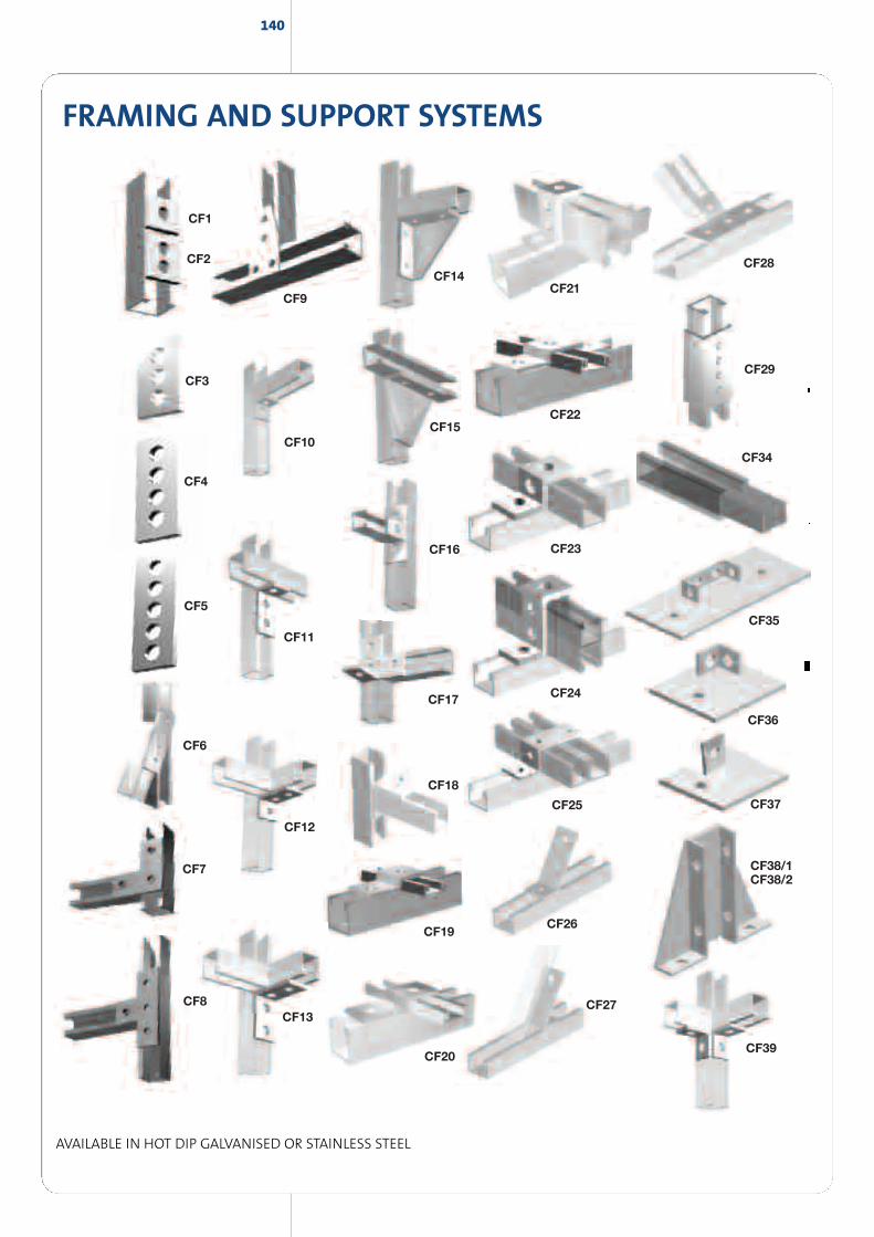
140
FRAMING AND SUPPORT SYSTEMS
AVAILABLE IN HOT DIP GALVANISED OR STAINLESS STEEL
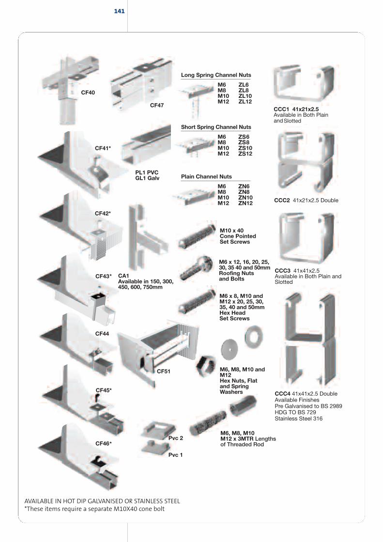
141
AVAILABLE IN HOT DIP GALVANISED OR STAINLESS STEEL*These items require a separate M10X40 cone bolt


MEMBER
offering a great deal more
• Cables & leads
• Cable management
• Heating & ventilation
• Distribution, switchgear & enclo-sures
• Lamps
• Lighting products
• Security & emergency
• Site equipment. tools & fixings
• Wiring accessories
Tel : 01642 217341 Fax: 01642 253723emai l : sa les@bi lcour t .co.uk
Middlesbrough Branch
Riverside Park Road,Middlesbrough,Cleveland TS2 1QW
Tel: Sales 01642 241133 / Admin 254234Fax: Sales 01642 226171 / Admin226474
Email: [email protected]: www.clevelandcable.com
Bristol Branch
St. Georges Industrial Estate,St. Andrews Road,Avonmouth,Bristol BS11 9HS
Tel: 01179 382222Fax: 01179 382220
Email: [email protected]
Glasgow Branch
56 Clydesmill Road,Cambuslang Investment Park,Cambuslang,Glasgow G32 8RE
Tel: 0141 646 5000Fax: 0141 646 5001
Email: [email protected]
Milton Keynes Branch
7 Fitzhamon Court,Wolverton Mill South,Milton Keynes MK12 6LB
Tel: 01908 221414Fax: 01908 221661
Email: [email protected]
London Branch
Crabtree Manorway South,Belvedere,Kent DA17 6AB
Tel: 0208 311 4141Fax: 0208 320 5454
Email: [email protected]
Newcastle Branch
Fisher Street Industrial Estate,Walker,Newcastle Upon Tyne NE6 4LT
Tel: 0191 2633363Fax: 0191 2630601
Email: [email protected]
Warrington Branch
2 Bishops Court,Calver Road,Winwick Quay,Warrington WA2 8QY
Tel: 01925 655383Fax: 01925 655989
Email: [email protected]
Bilcourt Electrical Distributors Ltd
Riverside Park Road,Middlesbrough,Cleveland TS2 1QW
Tel: 01642 217341Fax: 01642 253723
Email: [email protected]
Aberdeen Office
Westhill Business Centre,Arnhall Business Park,Westhill, Aberdeen AB32 6UF
Tel: Sales 01224 330565Fax: Sales 01224 330564


![INDEX [] · pages list of abbreviations: 2 accelerator cables: 3-26 bonnet cables: 27-29 brake cables: 30-56 clutch cables: 57-63 gear shift cables: 64-67 speedometer cables](https://img.pdfslide.us/doc/110x75/5e80d4d1ff6b4555b218bdc3/index-pages-list-of-abbreviations-2-accelerator-cables-3-26-bonnet-cables.jpg)