Embed Size (px)
Citation preview
ClearView A/V Analyzers
System Guide
Rev. 9.0 2
Table of Contents ClearView A/V ....................................................................................................................................... 1
Analyzers .............................................................................................................................................. 1
System Guide ....................................................................................................................................... 1
ClearView A/V Analyzer Systems ............................................................................................................. 4 Playback Features: .............................................................................................................4
Hardware Quick Start Guide .................................................................................................................... 5
Software Quick Start Guide ..................................................................................................................... 6
Operations ............................................................................................................................................... 8 Choose a Video Output ......................................................................................................9 Choose a Library .............................................................................................................. 12 Import a File .................................................................................................................... 14 Figure 12: ClearView File Importer Workflow .................................................................... 14 Settings and Adjustments ................................................................................................. 15 ClearView Dependencies .................................................................................................. 16
Library .................................................................................................................................... 16 Audio Root Usage .................................................................................................................. 17 Specify Resolution to store ................................................................................................... 18
Output File Allocation ...................................................................................................... 19 File Import tool in ClearView ............................................................................................ 19
Auto Load a sequence of files from an external source ........................................................ 22 Play a list of Video Sequences ............................................................................................... 22 Import Objective Metric Log File ........................................................................................... 23 Load a series of files with the same extension...................................................................... 24 Load Headerless files ............................................................................................................. 24
Hardware Input Parameters ............................................................................................. 26 Record ClearView Output ...................................................................................................... 27 Record 1 Broadcast Input ...................................................................................................... 28 ClearViewShuttle 4K or Extreme 4K: 1 Broadcast Input ....................................................... 30 Record 2 Broadcast Inputs .................................................................................................... 31 Record Broadcast Input While Playing .................................................................................. 32 Record 1 IP Input ................................................................................................................... 33 Record 2 IP Inputs ................................................................................................................. 35 Record 1 IP Input and 1 Broadcast input............................................................................... 35 Record IP While Playing from Broadcast Output .................................................................. 36
Select Thumbnail to Play or Export ................................................................................... 36 Select a View Mode ......................................................................................................... 39 Select VTR Mode .............................................................................................................. 40 Delete Current Sequences ................................................................................................ 41 Select Objective Measurements ....................................................................................... 41
AFREQ .................................................................................................................................... 41 APEAK .................................................................................................................................... 41 DMOS .................................................................................................................................... 41
Rev. 9.0 3
JND ........................................................................................................................................ 42 LKFS ....................................................................................................................................... 42 NIQE....................................................................................................................................... 42 PEAQ ...................................................................................................................................... 42 PSNR ...................................................................................................................................... 43 Spatial .................................................................................................................................... 43 Temporal ............................................................................................................................... 44 Pixel Values............................................................................................................................ 44
Objective Metric Controls ................................................................................................ 45 Align the Video Sequences ............................................................................................... 52 Adjust the Play Properties ................................................................................................ 53
Color Space Pane ................................................................................................................... 53 Preview Update Pane ............................................................................................................ 55 Split Pane ............................................................................................................................... 55 Zoom Pane............................................................................................................................. 56 Play Mode Pane ..................................................................................................................... 57 Field/Frame Mode Pane ........................................................................................................ 57 HotKeys Pane ........................................................................................................................ 58
ClearViewHardware Configurations ............................................................................................... 64
Hardware Modules ................................................................................................................................ 64 CV-SDI-IO-4K .................................................................................................................... 64
ClearView Extreme-4K: Two Board Input/Output – Pre May 2014 ...................................... 66 ClearView Extreme-4K: One Board Input/Output – Pre May 2014....................................... 66 ClearView Extreme-4K: Two Board Input/Output – Post May 2014 ..................................... 67 ClearView Extreme-4K: Two Board Input/Output – Post November 2015 ........................... 68 CV-SDI-IO-4K Capture & Playback Standards ........................................................................ 68 I/O Format ............................................................................................................................. 68
CV-SDI-IO-LHI ................................................................................................................... 68 CV-SDI-IO-LHI Capture & Playback Standards ....................................................................... 69 I/O Format ............................................................................................................................. 69
CV-SDI-IO-DL (Legacy Interface – Discontinued) ................................................................ 69 CV-SDI-IO-DL Capture Standards ........................................................................................... 69
CV-SDI-IO-CVD (Legacy Interface – Discontinued) .............................................................. 70 CV-SDI-IO-CVD Capture & Playback Standards ..................................................................... 70 I/O Format ............................................................................................................................. 70
CV-SDI-IO-CVD22 ............................................................................................................. 71 CV-SDI-IO-CVD22 Capture & Playback Standards ................................................................. 71
CV-DVI-O (Legacy Interface – Discontinued) ...................................................................... 72 CV-DVI-O Playback Standards ............................................................................................... 72
CV-DP/DVI-O ................................................................................................................... 73
File Format Import Types ....................................................................................................................... 74
Rev. 9.0 4
ClearView A/V Analyzer Systems Video Clarity created ClearView AV Analyzer Systems (ClearView) to provide video researchers, codec developers, hardware designers, TV Network operators and QA/QC engineers with the unique ability to play, view, record, and objectively analyze audio and video. ClearView allows the capture of video content from virtually any source -- file, SDI, HD-SDI, DVI, HDMI, Component, Composite, S-Video and IP. Regardless of the input, the video is, based on user choice, either recorded as is in uncompressed 4:2:2 Y’CbCr, 4:4:4 RGB, ARGB, or RGBA or converted to one of these formats from a compressed file format or stream. ClearView applies various objective and perceptual metrics to each frame of the video sequences, generates graphs, detects anomalies outside of the threshold range, and logs the results. ClearView has both No Reference and Full Reference Metrics. When there is no comparable video, no reference metrics can be used to determine anomalies like loss of video, frozen video, loss of audio, etc. With a source video comparison, quantitative scoring can occur. ClearView is constantly growing in functionality, and currently supports: (Refer to Select Objective Measurements section for definitions) Full Reference Objective Metrics
• Video PSNR • aFreq
Full Reference Perceptual Metrics
• Sarnoff’s JND • University of Texas’ MS-SSIM ported to DMOS • PEAQ
No Reference Metrics
• Number of Edges (Spatial / Sobel Filter) • Frame-to-Frame Differences (Temporal) • Loudness (aPeak and LKFS)
To aid in subjective video analysis, ClearView displays the video sequences at any rate in side-by-side, seamless split, or split mirror.
Please note that throughout this manual in most instances where a feature is described as “Video”, it will apply to both Audio andVideo.
Playback Features: Output rates are independent from input rates; so any video sequence can be output at rates up to 120Hz. The user has control over shuttle rates, jog, color look-up tables, zoom/pan, and field display. The video sequences are previewed within the ClearView Interface and sent to HD-SDI, SDI, Component, S-Video, Composite, DVI/VGA, DP, and HDMI. Normally, the video sequences are shown on the same display, ClearView systems with a dual output SD/HD video sequence can be output via a separate HD-SDI/SDI link. This excludes 4K formats in this version (8.0). Compete Video Sequence, or partial selection of the video sequence from selected in and out points, can also be exported as uncompressed BMP, RAW, AIFF, MOV or AVI files.
Rev. 9.0 5
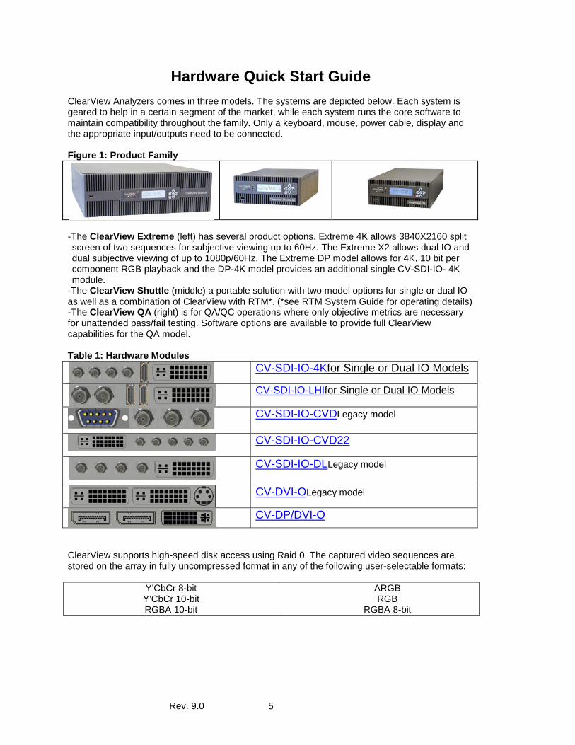
Hardware Quick Start Guide ClearView Analyzers comes in three models. The systems are depicted below. Each system is geared to help in a certain segment of the market, while each system runs the core software to maintain compatibility throughout the family. Only a keyboard, mouse, power cable, display and the appropriate input/outputs need to be connected. Figure 1: Product Family
-The ClearView Extreme (left) has several product options. Extreme 4K allows 3840X2160 split screen of two sequences for subjective viewing up to 60Hz. The Extreme X2 allows dual IO and dual subjective viewing of up to 1080p/60Hz. The Extreme DP model allows for 4K, 10 bit per component RGB playback and the DP-4K model provides an additional single CV-SDI-IO- 4K module.
-The ClearView Shuttle (middle) a portable solution with two model options for single or dual IO as well as a combination of ClearView with RTM*. (*see RTM System Guide for operating details) -The ClearView QA (right) is for QA/QC operations where only objective metrics are necessary for unattended pass/fail testing. Software options are available to provide full ClearView capabilities for the QA model. Table 1: Hardware Modules
CV-SDI-IO-4Kfor Single or Dual IO Models
CV-SDI-IO-LHIfor Single or Dual IO Models
CV-SDI-IO-CVDLegacy model
CV-SDI-IO-CVD22
CV-SDI-IO-DLLegacy model
CV-DVI-OLegacy model
CV-DP/DVI-O
ClearView supports high-speed disk access using Raid 0. The captured video sequences are stored on the array in fully uncompressed format in any of the following user-selectable formats:
Y’CbCr 8-bit Y’CbCr 10-bit RGBA 10-bit
ARGB RGB
RGBA 8-bit
Rev. 9.0 6
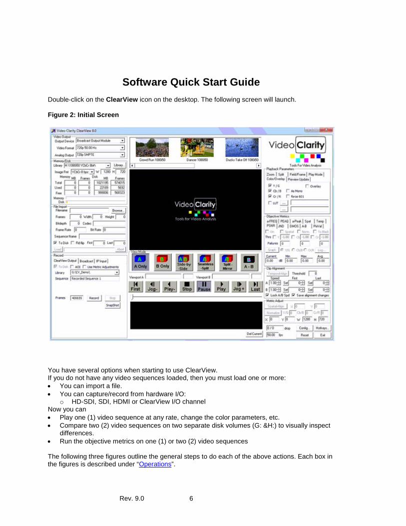
Software Quick Start Guide Double-click on the ClearView icon on the desktop. The following screen will launch. Figure 2: Initial Screen
You have several options when starting to use ClearView. If you do not have any video sequences loaded, then you must load one or more: • You can import a file. • You can capture/record from hardware I/O:
o HD-SDI, SDI, HDMI or ClearView I/O channel Now you can • Play one (1) video sequence at any rate, change the color parameters, etc. • Compare two (2) video sequences on two separate disk volumes (G: &H:) to visually inspect
differences. • Run the objective metrics on one (1) or two (2) video sequences The following three figures outline the general steps to do each of the above actions. Each box in the figures is described under “Operations”.
Rev. 9.0 7
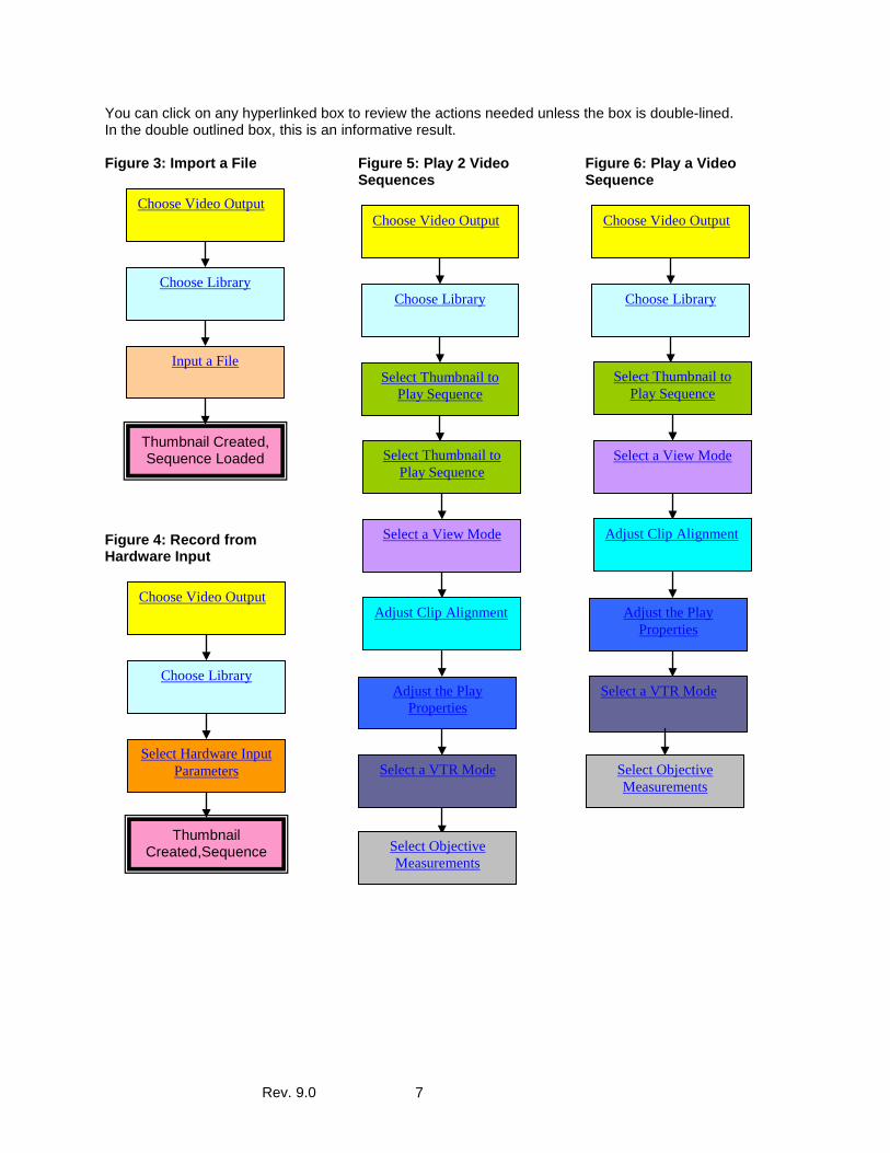
You can click on any hyperlinked box to review the actions needed unless the box is double-lined. In the double outlined box, this is an informative result. Figure 3: Import a File
Figure 4: Record from Hardware Input
Figure 5: Play 2 Video Sequences
Figure 6: Play a Video Sequence
Choose Video Output
Choose Library
Select Thumbnail to Play Sequence
Select a View Mode
Adjust Clip Alignment
Adjust the Play Properties
Select a VTR Mode
Select Objective Measurements
Choose Video Output
Choose Library
Select Thumbnail to Play Sequence
Select Thumbnail to Play Sequence
Select a View Mode
Adjust Clip Alignment
Adjust the Play Properties
Select a VTR Mode
Select Objective Measurements
Choose Video Output
Choose Library
Select Hardware Input Parameters
Thumbnail Created,Sequence
Choose Video Output
Choose Library
Input a File
Thumbnail Created, Sequence Loaded
Rev. 9.0 8
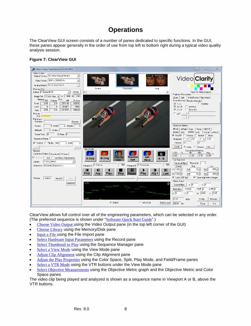
Operations The ClearView GUI screen consists of a number of panes dedicated to specific functions. In the GUI, these panes appear generally in the order of use from top left to bottom right during a typical video quality analysis session. Figure 7: ClearView GUI
ClearView allows full control over all of the engineering parameters, which can be selected in any order. (The preferred sequence is shown under "Software Quick Start Guide”.) • Choose Video Output using the Video Output pane (in the top left corner of the GUI) • Choose Library using the Memory/Disk pane • Input a File using the File Import pane • Select Hardware Input Parameters using the Record pane • Select Thumbnail to Play using the Sequence Manager pane • Select a View Mode using the View Mode pane • Adjust Clip Alignment using the Clip Alignment pane • Adjust the Play Properties using the Color Space, Split, Play Mode, and Field/Frame panes • Select a VTR Mode using the VTR buttons under the View Mode pane • Select Objective Measurements using the Objective Metric graph and the Objective Metric and Color
Space panes The video clip being played and analyzed is shown as a sequence name in Viewport A or B, above the VTR buttons.
Rev. 9.0 9
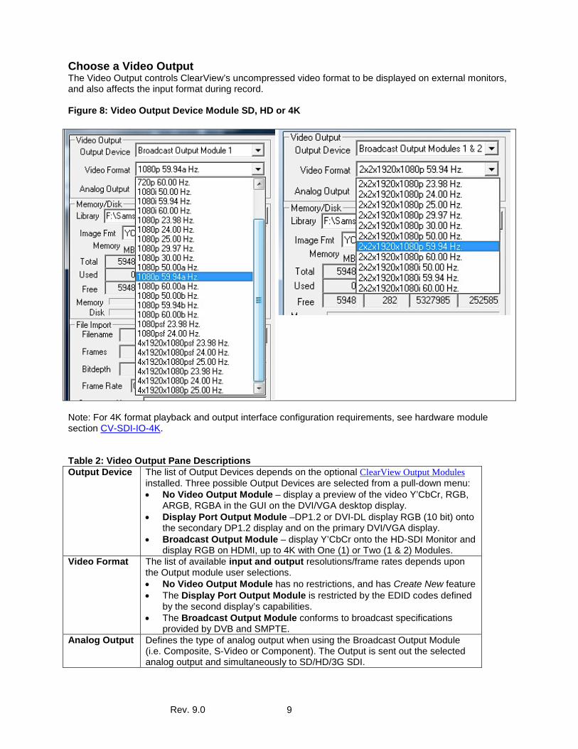
Choose a Video Output The Video Output controls ClearView’s uncompressed video format to be displayed on external monitors, and also affects the input format during record. Figure 8: Video Output Device Module SD, HD or 4K
Note: For 4K format playback and output interface configuration requirements, see hardware module section CV-SDI-IO-4K. Table 2: Video Output Pane Descriptions Output Device The list of Output Devices depends on the optional ClearView Output Modules
installed. Three possible Output Devices are selected from a pull-down menu: • No Video Output Module – display a preview of the video Y’CbCr, RGB,
ARGB, RGBA in the GUI on the DVI/VGA desktop display. • Display Port Output Module –DP1.2 or DVI-DL display RGB (10 bit) onto
the secondary DP1.2 display and on the primary DVI/VGA display. • Broadcast Output Module – display Y’CbCr onto the HD-SDI Monitor and
display RGB on HDMI, up to 4K with One (1) or Two (1 & 2) Modules. Video Format The list of available input and output resolutions/frame rates depends upon
the Output module user selections. • No Video Output Module has no restrictions, and has Create New feature • The Display Port Output Module is restricted by the EDID codes defined
by the second display’s capabilities. • The Broadcast Output Module conforms to broadcast specifications
provided by DVB and SMPTE. Analog Output Defines the type of analog output when using the Broadcast Output Module
(i.e. Composite, S-Video or Component). The Output is sent out the selected analog output and simultaneously to SD/HD/3G SDI.
Rev. 9.0 10
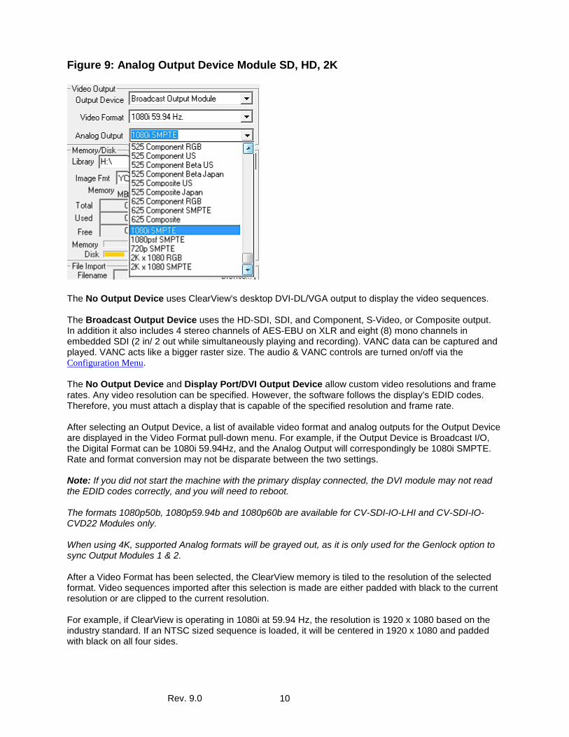
Figure 9: Analog Output Device Module SD, HD, 2K
The No Output Device uses ClearView's desktop DVI-DL/VGA output to display the video sequences. The Broadcast Output Device uses the HD-SDI, SDI, and Component, S-Video, or Composite output. In addition it also includes 4 stereo channels of AES-EBU on XLR and eight (8) mono channels in embedded SDI (2 in/ 2 out while simultaneously playing and recording). VANC data can be captured and played. VANC acts like a bigger raster size. The audio & VANC controls are turned on/off via the Configuration Menu. The No Output Device and Display Port/DVI Output Device allow custom video resolutions and frame rates. Any video resolution can be specified. However, the software follows the display’s EDID codes. Therefore, you must attach a display that is capable of the specified resolution and frame rate. After selecting an Output Device, a list of available video format and analog outputs for the Output Device are displayed in the Video Format pull-down menu. For example, if the Output Device is Broadcast I/O, the Digital Format can be 1080i 59.94Hz, and the Analog Output will correspondingly be 1080i SMPTE. Rate and format conversion may not be disparate between the two settings. Note: If you did not start the machine with the primary display connected, the DVI module may not read the EDID codes correctly, and you will need to reboot. The formats 1080p50b, 1080p59.94b and 1080p60b are available for CV-SDI-IO-LHI and CV-SDI-IO-CVD22 Modules only. When using 4K, supported Analog formats will be grayed out, as it is only used for the Genlock option to sync Output Modules 1 & 2. After a Video Format has been selected, the ClearView memory is tiled to the resolution of the selected format. Video sequences imported after this selection is made are either padded with black to the current resolution or are clipped to the current resolution. For example, if ClearView is operating in 1080i at 59.94 Hz, the resolution is 1920 x 1080 based on the industry standard. If an NTSC sized sequence is loaded, it will be centered in 1920 x 1080 and padded with black on all four sides.
Rev. 9.0 11
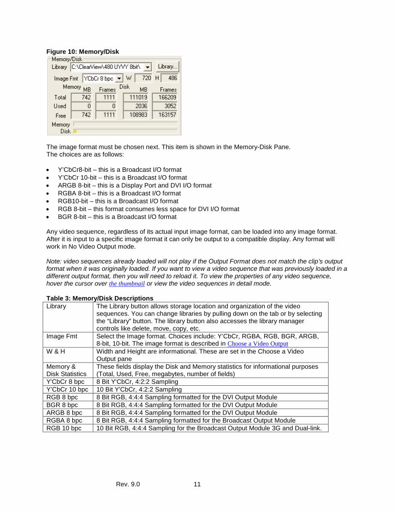
Figure 10: Memory/Disk
The image format must be chosen next. This item is shown in the Memory-Disk Pane. The choices are as follows: • Y’CbCr8-bit – this is a Broadcast I/O format • Y’CbCr 10-bit – this is a Broadcast I/O format • ARGB 8-bit – this is a Display Port and DVI I/O format • RGBA 8-bit – this is a Broadcast I/O format • RGB10-bit – this is a Broadcast I/O format • RGB 8-bit – this format consumes less space for DVI I/O format • BGR 8-bit – this is a Broadcast I/O format Any video sequence, regardless of its actual input image format, can be loaded into any image format. After it is input to a specific image format it can only be output to a compatible display. Any format will work in No Video Output mode. Note: video sequences already loaded will not play if the Output Format does not match the clip’s output format when it was originally loaded. If you want to view a video sequence that was previously loaded in a different output format, then you will need to reload it. To view the properties of any video sequence, hover the cursor over the thumbnail or view the video sequences in detail mode. Table 3: Memory/Disk Descriptions Library The Library button allows storage location and organization of the video
sequences. You can change libraries by pulling down on the tab or by selecting the “Library” button. The library button also accesses the library manager controls like delete, move, copy, etc.
Image Fmt Select the Image format. Choices include: Y’CbCr, RGBA, RGB, BGR, ARGB, 8-bit, 10-bit. The image format is described in Choose a Video Output
W & H Width and Height are informational. These are set in the Choose a Video Output pane
Memory & Disk Statistics
These fields display the Disk and Memory statistics for informational purposes (Total, Used, Free, megabytes, number of fields)
Y'CbCr 8 bpc 8 Bit Y'CbCr, 4:2:2 Sampling Y’CbCr 10 bpc 10 Bit Y'CbCr, 4:2:2 Sampling RGB 8 bpc 8 Bit RGB, 4:4:4 Sampling formatted for the DVI Output Module BGR 8 bpc 8 Bit RGB, 4:4:4 Sampling formatted for the DVI Output Module ARGB 8 bpc 8 Bit RGB, 4:4:4 Sampling formatted for the DVI Output Module RGBA 8 bpc 8 Bit RGB, 4:4:4 Sampling formatted for the Broadcast Output Module RGB 10 bpc 10 Bit RGB, 4:4:4 Sampling for the Broadcast Output Module 3G and Dual-link.
Rev. 9.0 12
Choose a Library The Memory-Disk Pane displays the Memory and Disk properties, allows the selection of image format, and lets the user control the library file system. A library acts like a Windows directory, with a few differences. Similarities: • Much like Windows directories, you should organize your video sequences together in a meaningful
way. For example, all of the 1080i, 59.94, 8-bit video sequences could be placed in a folder with a useful name about the format, like “1080i_60Hz_8bit”.
• You can copy, move, delete and sort video sequences by selecting a complete library folder.
Differences: • Libraries have an index file which catalogs metadata information about the video in a file called
“sequences.xxx”. This index file holds information like the sequence name, resolution, thumbnail to display, looped playback frequency and mark-in/mark-out points, etc.
• Each video sequences has 3 files associated with it – the uncompressed video sequence with a large file size, the uncompressed audio sequence, and a text overlay file. The text overlay file contains the text to be displayed when overlay is checked. The default names should be the same as the sequence name. Since this is a text file, it can be easily changed using any text editor.
NOTE: Do not delete these files called “sequences.xxx” as it will result in a loss of the video loaded in the entire library file system.
The ClearView file system is configured as Raid 0. Please back up the system. As long as you restore the “sequences” catalog file, you do not need to restore the entire library’s uncompressed video files, if you need to conserve space.
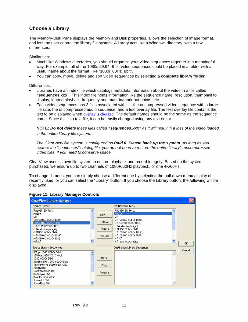
ClearView uses its own file system to ensure playback and record integrity. Based on the system purchased, we ensure up to two channels of 1080P/60Hz playback, or one 4K/60Hz. To change libraries, you can simply choose a different one by selecting the pull-down menu display of recently used, or you can select the “Library” button. If you choose the Library button, the following will be displayed. Figure 11: Library Manager Controls
Rev. 9.0 13
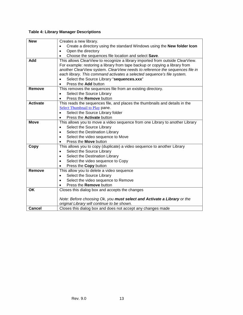
Table 4: Library Manager Descriptions New Creates a new library.
• Create a directory using the standard Windows using the New folder Icon • Open the directory • Choose the sequences file location and select Save.
Add This allows ClearView to recognize a library imported from outside ClearView. For example: restoring a library from tape backup or copying a library from another ClearView system. ClearView needs to reference the sequences file in each library. This command activates a selected sequence’s file system. • Select the Source Library “sequences.xxx” • Press the Add button
Remove This removes the sequences file from an existing directory. • Select the Source Library • Press the Remove button
Activate This reads the sequences file, and places the thumbnails and details in the Select Thumbnail to Play pane. • Select the Source Library folder • Press the Activate button
Move This allows you to move a video sequence from one Library to another Library • Select the Source Library • Select the Destination Library • Select the video sequence to Move • Press the Move button
Copy This allows you to copy (duplicate) a video sequence to another Library • Select the Source Library • Select the Destination Library • Select the video sequence to Copy • Press the Copy button
Remove This allow you to delete a video sequence • Select the Source Library • Select the video sequence to Remove • Press the Remove button
OK Closes this dialog box and accepts the changes Note: Before choosing Ok, you must select and Activate a Library or the original Library will continue to be shown.
Cancel Closes this dialog box and does not accept any changes made
Rev. 9.0 14
Import a File There are two ways to import files: 1) File Import tool pane in the left center of the ClearView GUI. 2) ClearView’s “File Importer.exe” ClearView File Importer The ClearView File Importer.exe is powerful video and audio decoding tool built to provide users the added benefit of several content processing features.
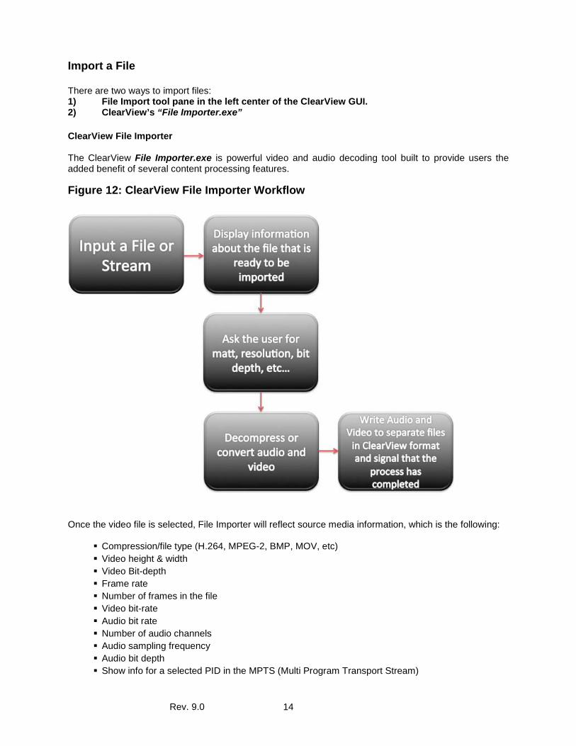
Figure 12: ClearView File Importer Workflow
Once the video file is selected, File Importer will reflect source media information, which is the following:
Compression/file type (H.264, MPEG-2, BMP, MOV, etc) Video height & width Video Bit-depth Frame rate Number of frames in the file Video bit-rate Audio bit rate Number of audio channels Audio sampling frequency Audio bit depth Show info for a selected PID in the MPTS (Multi Program Transport Stream)
Rev. 9.0 15
In the case where a (*.ts) transport stream is MPTS, the file contains multiple programs, source information will be updated with corresponding input, according to the selected Hexadecimal PID (Program ID).
Settings and Adjustments The following output adjustments are available to configure output options and start the decoding process
Output frame size Output frame rate First/last frames to import De-interlace or not Bit depth – converting 8 to 10 or 10 to 8 bits Crop source (x, y, width, height) with values or interactive graphical box Scale up or down to xmb/w,h Color Space – convert from YUV to RGB by using either SD or HD color space Import audio Yes/No Output image resolution Output canvas resolution Truncate to legal broadcast values (Yes/No)
Two screens in the top of the File Importer window reflect the input (original) and output(maintained) preview of the source video. The output preview screen will dynamically adjust according the settings defined in the Output Sequence section. In order to start the decoding process a ClearView Library, which is the target destination of theoutput file, should be selected. A Library is defined in the ClearView application and is being used as the output folder for File Importer. This process may be started by clicking on the‘ Import’ button. During the video-decoding process, a progress bar is displayed. Once the process is finished, the status bar message will indicate that Video Import has succeeded. Decoded video and audio are stored in Library folder in separate files. The Audio file’s location may be different, according to the settings in ClearView application. Upon decoding process completion, Metadata information is stored in the sequence index file called “sequences”. It contains the following information for each sequence in the library folder.
Frame-rate Resolution Bit-Depth Number of frames Audio present (or video only).
ClearView File Importer is the single-window application in which all the settings are configured on the main screen. The File Importer is also a standalone application and included module.
Rev. 9.0 16
ClearView Dependencies
Library Libraries are the maintenance folders, used in File Importer and ClearView applications. File Importer destination folder may be used as ClearView input source. Basically, Libraries may be considered as shared locations for File Importer and ClearView. ClearView Library folder specification Libraries have an index file which catalogs information about the video sequences. This index file holds information like the sequence name, the resolution, the thumbnail to display, the playing frequency, the mark-in/mark-out points, etc. The file name for this catalog is “sequences”. Please do not delete this file as it will result in a loss of the video sequences in the entire library. Each video sequences has 3 files associated with it – the uncompressed video sequence, the uncompressed audio sequence, and a text overlay file. The text overlay file contains the text to be displayed when overlay is checked. The default name is the sequence name. Since this is a text file, it can be easily changed using any text editor.
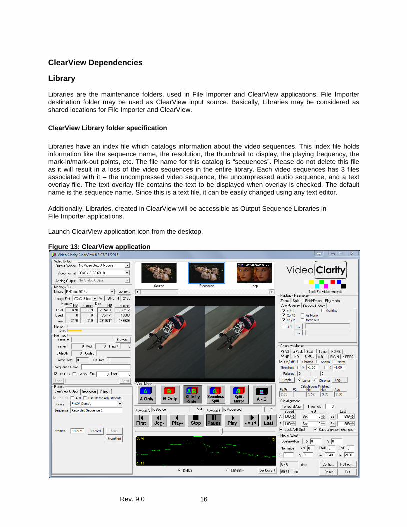
Additionally, Libraries, created in ClearView will be accessible as Output Sequence Libraries in File Importer applications. Launch ClearView application icon from the desktop. Figure 13: ClearView application
Rev. 9.0 17
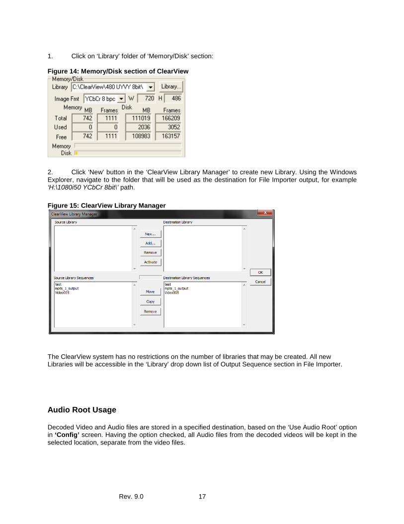
1. Click on ‘Library’ folder of ‘Memory/Disk’ section: Figure 14: Memory/Disk section of ClearView
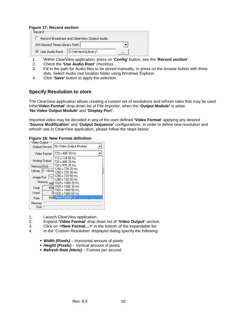
2. Click ‘New’ button in the ‘ClearView Library Manager’ to create new Library. Using the Windows Explorer, navigate to the folder that will be used as the destination for File Importer output, for example ‘H:\1080i50 YCbCr 8bit\’ path. Figure 15: ClearView Library Manager
The ClearView system has no restrictions on the number of libraries that may be created. All new Libraries will be accessible in the ‘Library’ drop down list of Output Sequence section in File Importer.
Audio Root Usage Decoded Video and Audio files are stored in a specified destination, based on the ‘Use Audio Root’ option in ‘Config’ screen. Having the option checked, all Audio files from the decoded videos will be kept in the selected location, separate from the video files.
Rev. 9.0 18
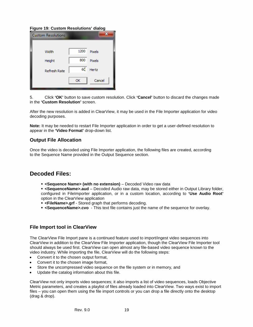
Figure 17: Record section
1. Within ClearView application, press on ‘Config’ button, see the ‘Record section’. 2. Check the ‘Use Audio Root’ checkbox. 3. Fill in the path for Audio files to be stored manually, or press on the browse button with three
dots. Select Audio root location folder using Windows Explorer. 4. Click ‘Save’ button to apply the selection.
Specify Resolution to store The ClearView application allows creating a custom set of resolutions and refresh rates that may be used inthe‘Video Format’ drop-down list of File Importer, when the ‘Output Module’ is setas ‘No Video Output Module’ and ‘Display Port’. Imported video may be decoded in any of the user-defined ‘Video Format’ applying any desired ‘Source Modification’ and ‘Output Sequence’ configurations. In order to define new resolution and refresh rate in ClearView application, please follow the steps below: Figure 18: New Format definition
1. Launch ClearView application. 2. Expand ‘Video Format’ drop down list of ‘Video Output’ section. 3. Click on ‘<New Format…>’ in the bottom of the expandable list. 4. In the ‘Custom Resolution’ displayed dialog specify the following:
Width (Pixels) – Horizontal amount of pixels Height (Pixels) – Vertical amount of pixels Refresh Rate (Hertz) – Frames per second
Rev. 9.0 19
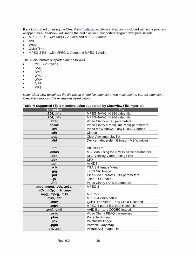
Figure 19: Custom Resolutions’ dialog
5. Click ‘OK’ button to save custom resolution. Click ‘Cancel’ button to discard the changes made in the ‘Custom Resolution’ screen. After the new resolution is added in ClearView, it may be used in the File Importer application for video decoding purposes. Note: It may be needed to restart File Importer application in order to get a user-defined resolution to appear in the ‘Video Format’ drop-down list.
Output File Allocation Once the video is decoded using File Importer application, the following files are created, according to the Sequence Name provided in the Output Sequence section. Decoded Files:
<Sequence Name> (with no extension) – Decoded Video raw data <SequenceName>.aud – Decoded Audio raw data, may be stored either in Output Library folder, configured in FileImporter application, or in a custom location, according to ‘Use Audio Root’ option in the ClearView application <FileName>.grf - Stored graph that performs decoding. <SequenceName>.cvo - This text file contains just the name of the sequence for overlay.
File Import tool in ClearView The ClearView File Import pane is a continued feature used to import/ingest video sequences into ClearView in addition to the ClearView File Importer application, though the ClearView File Importer tool should always be used first. ClearView can open almost any file-based video sequence known to the video industry. While importing the file, ClearView will do the following steps: • Convert it to the chosen output format, • Convert it to the chosen image format, • Store the uncompressed video sequence on the file system or in memory, and • Update the catalog information about this file. ClearView not only imports video sequences; it also imports a list of video sequences, loads Objective Metric parameters, and creates a playlist of files already loaded into ClearView. Two ways exist to import files – you can open them using the file import controls or you can drop a file directly onto the desktop (drag & drop).
Rev. 9.0 20
If audio is turned on using the ClearView Configuration Menu and audio is included within the program wrapper, then ClearView will import the audio as well. Supported program wrappers include: • MPEG-2 TS – with MPEG-2 Video and MPEG-1 Audio • AVI • WMV • QuickTime • MPEG-2 PS – with MPEG-2 Video and MPEG-1 Audio The Audio formats supported are as follows • MPEG-2 Layer 1 • AAC • AMR • WMA • WAV • AIFF • MP3 Note: ClearView deciphers the file based on the file extension. You must use the correct extension. ClearView supports the extensions listed below. Table 7: Supported File Extensions (also supported by ClearView File Importer)
Extension File .264, .h4v MPEG-4/AVC, H.264 video file .264, .h4v MPEG-4/AVC, H.264 video file
.afreq Video Clarity aFreq parameters .tpeak Video Clarity aPeak(TruePeak) parameters
.avi Video for Windows – any CODEC loaded
.cin Cineon .cvp ClearView auto play list .did Device Independent Bitmap – MS Windows
.dif DIF Stream .dmos MS-SSIM using the DMOS Scale parameters .dps DPS Velocity Video Editing Files .dpx DPX .gen AvidDS .icb TGA Still Image Variant .jpg JPEG Still Image .jnd ClearView Sarnoff’s JND parameters .js Jaleo – SGI editor
.lkfs Video Clarity LKFS parameters .mpg. mpeg, .vob, .m1v, .m2v, .m2p, .m2t, .mpv
MPEG-2
.mpg, .mpeg, .m1v MPEG-1 .m4v, .dat MPEG-4 video part 2
.mov QuickTime Video – any CODEC loaded
.mp4 MPEG-4 part 2 file; then H.264 file .omf, .omfi AVID file – any CODEC loaded
.peaq Video Clarity PEAQ parameters .pbm Portable Bitmap .pcx Paintbrush Image .pgm Portable Gray map
.pic, .pct Picture Still Image File
Rev. 9.0 21
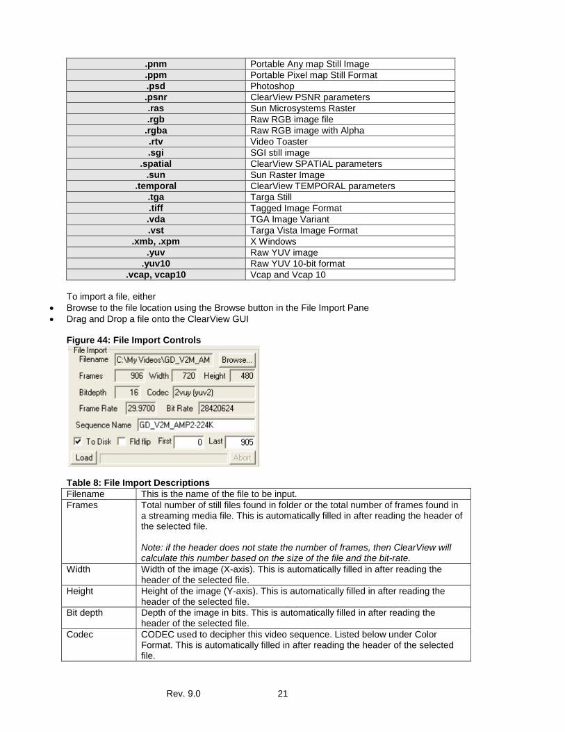
.pnm Portable Any map Still Image
.ppm Portable Pixel map Still Format .psd Photoshop .psnr ClearView PSNR parameters .ras Sun Microsystems Raster .rgb Raw RGB image file .rgba Raw RGB image with Alpha .rtv Video Toaster .sgi SGI still image
.spatial ClearView SPATIAL parameters .sun Sun Raster Image
.temporal ClearView TEMPORAL parameters .tga Targa Still .tiff Tagged Image Format .vda TGA Image Variant .vst Targa Vista Image Format
.xmb, .xpm X Windows .yuv Raw YUV image
.yuv10 Raw YUV 10-bit format .vcap, vcap10 Vcap and Vcap 10
To import a file, either
• Browse to the file location using the Browse button in the File Import Pane • Drag and Drop a file onto the ClearView GUI
Figure 44: File Import Controls
Table 8: File Import Descriptions Filename This is the name of the file to be input. Frames Total number of still files found in folder or the total number of frames found in
a streaming media file. This is automatically filled in after reading the header of the selected file. Note: if the header does not state the number of frames, then ClearView will calculate this number based on the size of the file and the bit-rate.
Width Width of the image (X-axis). This is automatically filled in after reading the header of the selected file.
Height Height of the image (Y-axis). This is automatically filled in after reading the header of the selected file.
Bit depth Depth of the image in bits. This is automatically filled in after reading the header of the selected file.
Codec CODEC used to decipher this video sequence. Listed below under Color Format. This is automatically filled in after reading the header of the selected file.
Rev. 9.0 22
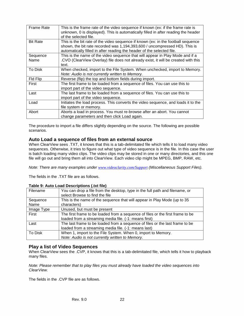
Frame Rate This is the frame rate of the video sequence if known (ex: if the frame rate is unknown, 0 is displayed). This is automatically filled in after reading the header of the selected file.
Bit Rate This is the bit rate of the video sequence if known (ex: in the football sequence shown, the bit rate recorded was 1,194,393,600 / uncompressed HD). This is automatically filled in after reading the header of the selected file.
Sequence Name
This is the name of the video sequence that will appear in Play Mode and if a .CVO (ClearView Overlay) file does not already exist, it will be created with this text.
To Disk When checked, import to the File System. When unchecked, import to Memory. Note: Audio is not currently written to Memory.
Fld Flip Reverse (flip) the top and bottom fields during import. First The first frame to be loaded from a sequence of files. You can use this to
import part of the video sequence. Last The last frame to be loaded from a sequence of files. You can use this to
import part of the video sequence. Load Initiates the load process. This converts the video sequence, and loads it to the
file system or memory. Abort Aborts a load in process. You must re-browse after an abort. You cannot
change parameters and then click Load again. The procedure to import a file differs slightly depending on the source. The following are possible scenarios.
Auto Load a sequence of files from an external source When ClearView sees .TXT, it knows that this is a tab-delimitated file which tells it to load many video sequences. Otherwise, it tries to figure out what type of video sequence is in the file. In this case the user is batch loading many video clips. The video clips may be stored in one or many directories, and this one file will go out and bring them all into ClearView. Each video clip might be MPEG, BMP, RAW, etc. Note: There are many examples under www.videoclarity.com/Support (Miscellaneous Support Files). The fields in the .TXT file are as follows. Table 9: Auto Load Descriptions (.txt file) Filename You can drop a file from the desktop, type in the full path and filename, or
select Browse to find the file Sequence Name
This is the name of the sequence that will appear in Play Mode (up to 35 characters)
Image Type Unused, but must be present First The first frame to be loaded from a sequence of files or the first frame to be
loaded from a streaming media file. (-1: means first) Last The last frame to be loaded from a sequence of files or the last frame to be
loaded from a streaming media file. (-1: means last) To Disk When 1, import to the File System. When 0, import to Memory.
Note: Audio is not currently written to Memory.
Play a list of Video Sequences When ClearView sees the .CVP, it knows that this is a tab-delimitated file, which tells it how to playback many files. Note: Please remember that to play files you must already have loaded the video sequences into ClearView. The fields in the .CVP file are as follows.
Rev. 9.0 23
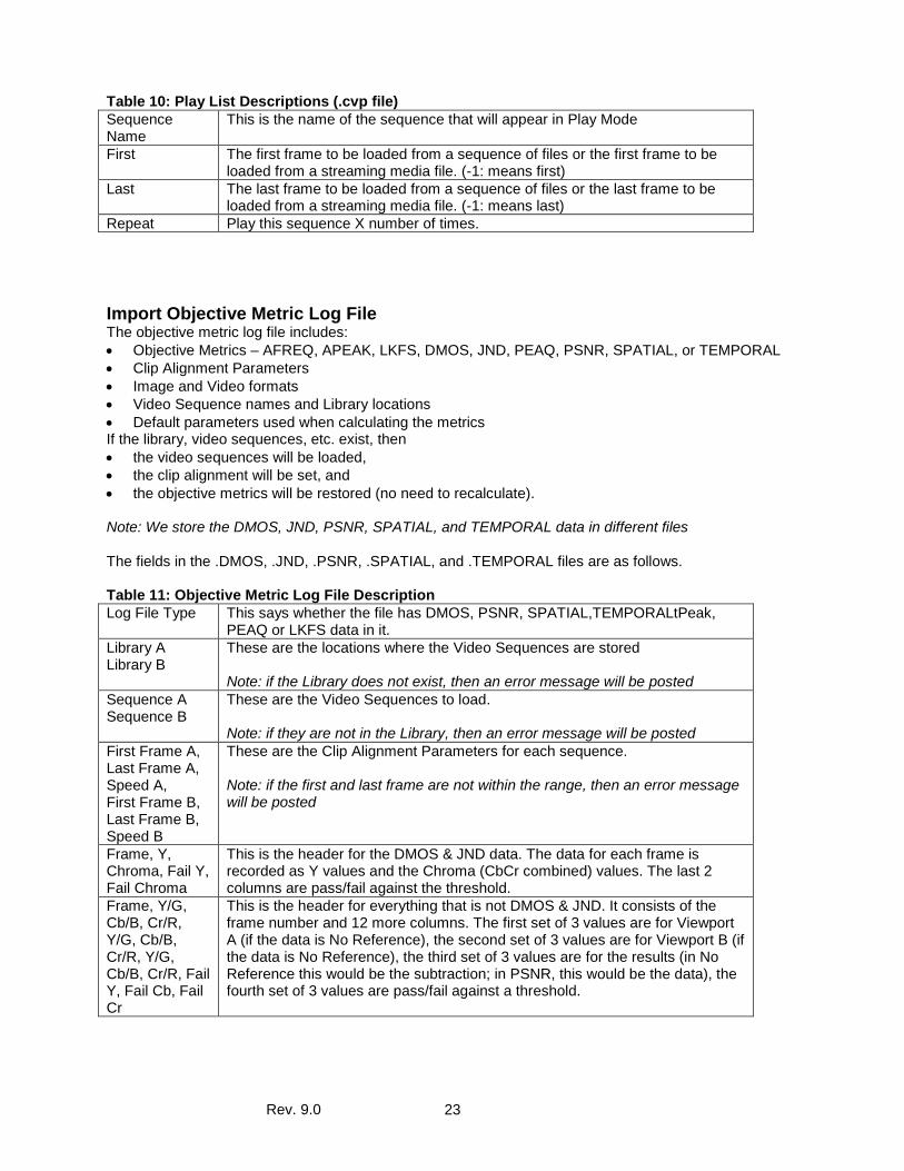
Table 10: Play List Descriptions (.cvp file) Sequence Name
This is the name of the sequence that will appear in Play Mode
First The first frame to be loaded from a sequence of files or the first frame to be loaded from a streaming media file. (-1: means first)
Last The last frame to be loaded from a sequence of files or the last frame to be loaded from a streaming media file. (-1: means last)
Repeat Play this sequence X number of times.
Import Objective Metric Log File The objective metric log file includes: • Objective Metrics – AFREQ, APEAK, LKFS, DMOS, JND, PEAQ, PSNR, SPATIAL, or TEMPORAL • Clip Alignment Parameters • Image and Video formats • Video Sequence names and Library locations • Default parameters used when calculating the metrics If the library, video sequences, etc. exist, then • the video sequences will be loaded, • the clip alignment will be set, and • the objective metrics will be restored (no need to recalculate). Note: We store the DMOS, JND, PSNR, SPATIAL, and TEMPORAL data in different files The fields in the .DMOS, .JND, .PSNR, .SPATIAL, and .TEMPORAL files are as follows. Table 11: Objective Metric Log File Description Log File Type This says whether the file has DMOS, PSNR, SPATIAL,TEMPORALtPeak,
PEAQ or LKFS data in it. Library A Library B
These are the locations where the Video Sequences are stored Note: if the Library does not exist, then an error message will be posted
Sequence A Sequence B
These are the Video Sequences to load. Note: if they are not in the Library, then an error message will be posted
First Frame A, Last Frame A, Speed A, First Frame B, Last Frame B, Speed B
These are the Clip Alignment Parameters for each sequence. Note: if the first and last frame are not within the range, then an error message will be posted
Frame, Y, Chroma, Fail Y, Fail Chroma
This is the header for the DMOS & JND data. The data for each frame is recorded as Y values and the Chroma (CbCr combined) values. The last 2 columns are pass/fail against the threshold.
Frame, Y/G, Cb/B, Cr/R, Y/G, Cb/B, Cr/R, Y/G, Cb/B, Cr/R, Fail Y, Fail Cb, Fail Cr
This is the header for everything that is not DMOS & JND. It consists of the frame number and 12 more columns. The first set of 3 values are for Viewport A (if the data is No Reference), the second set of 3 values are for Viewport B (if the data is No Reference), the third set of 3 values are for the results (in No Reference this would be the subtraction; in PSNR, this would be the data), the fourth set of 3 values are pass/fail against a threshold.
Rev. 9.0 24
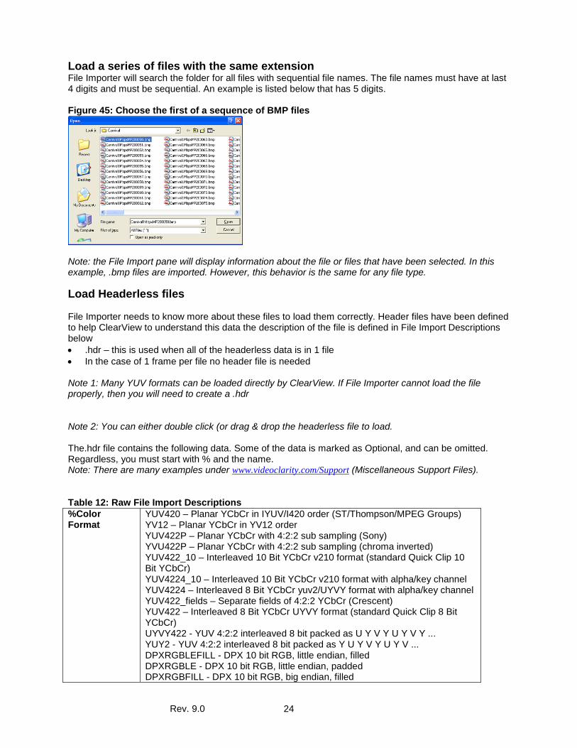
Load a series of files with the same extension File Importer will search the folder for all files with sequential file names. The file names must have at last 4 digits and must be sequential. An example is listed below that has 5 digits. Figure 45: Choose the first of a sequence of BMP files
Note: the File Import pane will display information about the file or files that have been selected. In this example, .bmp files are imported. However, this behavior is the same for any file type.
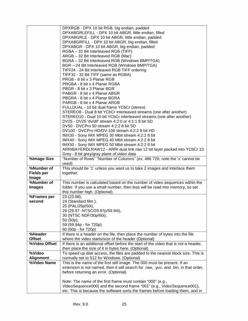
Load Headerless files File Importer needs to know more about these files to load them correctly. Header files have been defined to help ClearView to understand this data the description of the file is defined in File Import Descriptions below • .hdr – this is used when all of the headerless data is in 1 file • In the case of 1 frame per file no header file is needed Note 1: Many YUV formats can be loaded directly by ClearView. If File Importer cannot load the file properly, then you will need to create a .hdr Note 2: You can either double click (or drag & drop the headerless file to load. The.hdr file contains the following data. Some of the data is marked as Optional, and can be omitted. Regardless, you must start with % and the name. Note: There are many examples under www.videoclarity.com/Support (Miscellaneous Support Files). Table 12: Raw File Import Descriptions %Color Format
YUV420 – Planar YCbCr in IYUV/I420 order (ST/Thompson/MPEG Groups) YV12 – Planar YCbCr in YV12 order YUV422P – Planar YCbCr with 4:2:2 sub sampling (Sony) YVU422P – Planar YCbCr with 4:2:2 sub sampling (chroma inverted) YUV422_10 – Interleaved 10 Bit YCbCr v210 format (standard Quick Clip 10 Bit YCbCr) YUV4224_10 – Interleaved 10 Bit YCbCr v210 format with alpha/key channel YUV4224 – Interleaved 8 Bit YCbCr yuv2/UYVY format with alpha/key channel YUV422_fields – Separate fields of 4:2:2 YCbCr (Crescent) YUV422 – Interleaved 8 Bit YCbCr UYVY format (standard Quick Clip 8 Bit YCbCr) UYVY422 - YUV 4:2:2 interleaved 8 bit packed as U Y V Y U Y V Y ... YUY2 - YUV 4:2:2 interleaved 8 bit packed as Y U Y V Y U Y V ... DPXRGBLEFILL - DPX 10 bit RGB, little endian, filled DPXRGBLE - DPX 10 bit RGB, little endian, padded DPXRGBFILL - DPX 10 bit RGB, big endian, filled
Rev. 9.0 25
DPXRGB - DPX 10 bit RGB, big endian, padded DPXABGRLEFILL - DPX 10 bit ABGR, little endian, filled DPXABGRLE - DPX 10 bit ABGR, little endian, padded DPXABGRFILL - DPX 10 bit ABGR, big endian, filled DPXABGR - DPX 10 bit ABGR, big endian, padded RGBA – 32 Bit Interleaved RGB (TIFF) ARGB – 32 Bit Interleaved RGB (Mac) BGRA – 32 Bit Interleaved RGB (Windows BMP/TGA) BGR – 24 Bit Interleaved RGB (Windows BMP/TGA) TIFF24 - 24 Bit Interleaved RGB TIFF ordering TIFF32 - 32 Bit TIFF (same as RGBA) PRGB - 8 bit x 3 Planar RGB PRGBA - 8 bit x 4 Planar RGBA PBGR - 8 bit x 3 Planar BGR PABGR - 8 bit x 4 Planar ABGR PBGRA - 8 bit x 4 Planar BGRA PARGB - 8 bit x 4 Planar ARGB FULLDUAL - 10 bit dual frame YCbCr (stereo) STEREO8 - Dual 8 bit YCbCr interleaved streams (one after another) STEREO10 - Dual 10 bit YCbCr interleaved streams (one after another) DV25 - DV25 'dv/dif' stream 4:2:0 or 4:1:1 8 bit SD DV50 - DVCPro 50 stream 4:2:2 8 bit SD DV100 - DVCPro HD/DV-100 stream 4:2:2 8 bit HD IMX30 - Sony IMX MPEG 30 Mbit stream 4:2:2 8 bit IMX40 - Sony IMX MPEG 40 Mbit stream 4:2:2 8 bit IMX50 - Sony IMX MPEG 50 Mbit stream 4:2:2 8 bit ARRIBAYERDLRAW12 - ARRI dual link raw 12 bit layer packed into YCbCr 10 Grey - 8 bit grey/gray plane of video data
%Image Size "Number of Rows" "Number of Columns" (ex: 486 720; note the 'x' cannot be used)
%Number of Fields per Image
This should be ‘1’ unless you want us to take 2 images and interlace them together.
%Number of Images
This number is calculated based on the number of video sequences within the folder. If you use a small number, then less will be read into memory, so set this number high. (Optional).
%Frames per second
23 (23.98), 24 (Standard film ), 25 (PAL/25p/50i), 29 (29.97 -NTSC/29.97p/59.94i), 30 (NTSC NDF/30p/60i), 50 (50p), 59 (59.94p - for 720p), 60 (60p - for 720p)
%Header Offset
If there is a header on the file, then place the number of bytes into the file where the video starts/size of the header (Optional)
%Video Offset If there is an additional offset before the start of the video that is not a header, then place the size of it in bytes here. (Optional)
%Video Alignment
To speed up disk access, the files are padded to the nearest block size. This is normally set to 512 for Windows. (Optional)
%Video Name This is the name of the first still image. The 000 must be present. If an extension is not named, then it will search for .raw, .yuv, and .bin, in that order, before returning an error. (Optional) Note: The name of the first frame must contain “000” (e.g., VideoSequence000) and the second frame “001” (e.g., VideoSequence001), etc. This is because the software sorts the frames before loading them, and in
Rev. 9.0 26
Windows, the ordering would be 000, 001, 002, 003, 004, 005, 006, 007, 008, 009, 010 (in other words “1” would actually be loaded as frame 100). Of course, you could use 0000 (4 zeros) if you have more than 999 frames.
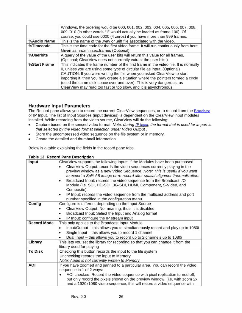
%Audio Name This is the name of the .wav or .aiff file associated with the video. %Timecode This is the time code for the first video frame. It will run continuously from here.
Given as hrs:min:sec:frames (Optional) %Userbits A query of the value of the user bits will return this value for all frames.
(Optional; ClearView does not currently extract the user bits.) %Start Frame This indicates the frame number of the first frame in the video file. It is normally
0, unless you are using some type of circular file as input. (Optional) CAUTION: If you were writing the file when you asked ClearView to start importing it, then you may create a situation where the pointers formed a circle (used the same disk space over and over). This is very dangerous, as ClearView may read too fast or too slow, and it is asynchronous.
Hardware Input Parameters The Record pane allows you to record the current ClearView sequences, or to record from the Broadcast or IP Input. The list of Input Sources (input devices) is dependent on the ClearView input modules installed. While recording from the video source, ClearView will do the following: • Capture based on the sensed video format. Note: during IP input, the format that is used for import is
that selected by the video format selection under Video Output . • Store the uncompressed video sequence on the file system or in memory. • Create the detailed and thumbnail information. Below is a table explaining the fields in the record pane tabs. Table 13: Record Pane Description Input ClearView supports the following Inputs if the Modules have been purchased
• ClearView Output: records the video sequences currently playing in the preview window as a new Video Sequence. Note: This is useful if you want to export a Split AB image or re-record after spatial alignment/normalization.
• Broadcast Input: records the video sequence from the Broadcast I/O Module (i.e. SDI, HD-SDI, 3G-SDI, HDMI, Component, S-Video, and Composite).
• IP Input: records the video sequence from the multicast address and port number specified in the configuration menu
Config Configure is different depending on the Input Source • ClearView Output: No meaning; thus, it is disabled. • Broadcast Input: Select the Input and Analog format • IP Input: configure the IP stream input
Record Mode This only applies to the Broadcast Input Module • Input/Output – this allows you to simultaneously record and play up to 1080i • Single Input – this allows you to record 1 channel • Dual Input – this allows you to record up to 2 channels up to 1080i
Library This lets you set the library for recording so that you can change it from the library used for playing
To Disk Checking this button records the input to the file system Unchecking records the input to Memory Note: Audio is not currently written to Memory.
AOI If you have zoomed and panned to a particular area. You can record the video sequence in 1 of 2 ways: • AOI checked: Record the video sequence with pixel replication turned off,
but only record the pixels shown on the preview window. (i.e. with zoom 2x and a 1920x1080 video sequence, this will record a video sequence with
Rev. 9.0 27
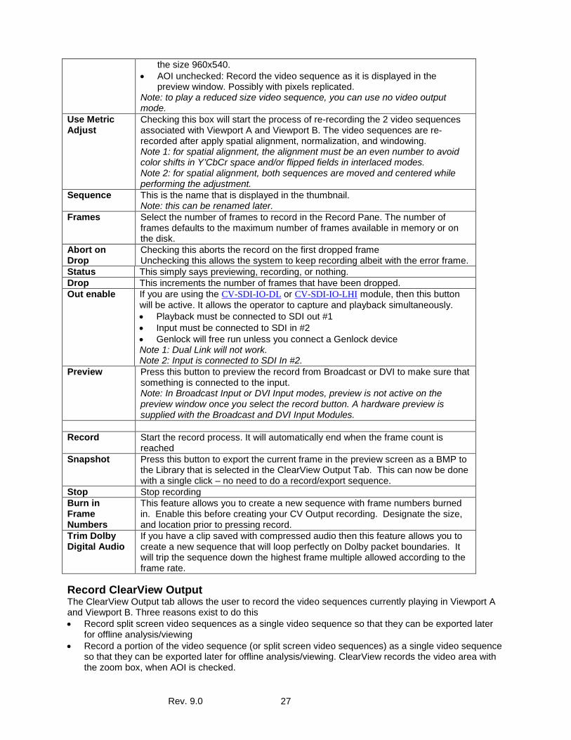
the size 960x540. • AOI unchecked: Record the video sequence as it is displayed in the
preview window. Possibly with pixels replicated. Note: to play a reduced size video sequence, you can use no video output mode.
Use Metric Adjust
Checking this box will start the process of re-recording the 2 video sequences associated with Viewport A and Viewport B. The video sequences are re-recorded after apply spatial alignment, normalization, and windowing. Note 1: for spatial alignment, the alignment must be an even number to avoid color shifts in Y’CbCr space and/or flipped fields in interlaced modes. Note 2: for spatial alignment, both sequences are moved and centered while performing the adjustment.
Sequence This is the name that is displayed in the thumbnail. Note: this can be renamed later.
Frames Select the number of frames to record in the Record Pane. The number of frames defaults to the maximum number of frames available in memory or on the disk.
Abort on Drop
Checking this aborts the record on the first dropped frame Unchecking this allows the system to keep recording albeit with the error frame.
Status This simply says previewing, recording, or nothing. Drop This increments the number of frames that have been dropped. Out enable If you are using the CV-SDI-IO-DL or CV-SDI-IO-LHI module, then this button
will be active. It allows the operator to capture and playback simultaneously. • Playback must be connected to SDI out #1 • Input must be connected to SDI in #2 • Genlock will free run unless you connect a Genlock device Note 1: Dual Link will not work. Note 2: Input is connected to SDI In #2.
Preview Press this button to preview the record from Broadcast or DVI to make sure that something is connected to the input. Note: In Broadcast Input or DVI Input modes, preview is not active on the preview window once you select the record button. A hardware preview is supplied with the Broadcast and DVI Input Modules.
Record Start the record process. It will automatically end when the frame count is
reached Snapshot Press this button to export the current frame in the preview screen as a BMP to
the Library that is selected in the ClearView Output Tab. This can now be done with a single click – no need to do a record/export sequence.
Stop Stop recording Burn in Frame Numbers
This feature allows you to create a new sequence with frame numbers burned in. Enable this before creating your CV Output recording. Designate the size, and location prior to pressing record.
Trim Dolby Digital Audio
If you have a clip saved with compressed audio then this feature allows you to create a new sequence that will loop perfectly on Dolby packet boundaries. It will trip the sequence down the highest frame multiple allowed according to the frame rate.
Record ClearView Output The ClearView Output tab allows the user to record the video sequences currently playing in Viewport A and Viewport B. Three reasons exist to do this • Record split screen video sequences as a single video sequence so that they can be exported later
for offline analysis/viewing • Record a portion of the video sequence (or split screen video sequences) as a single video sequence
so that they can be exported later for offline analysis/viewing. ClearView records the video area with the zoom box, when AOI is checked.
Rev. 9.0 28
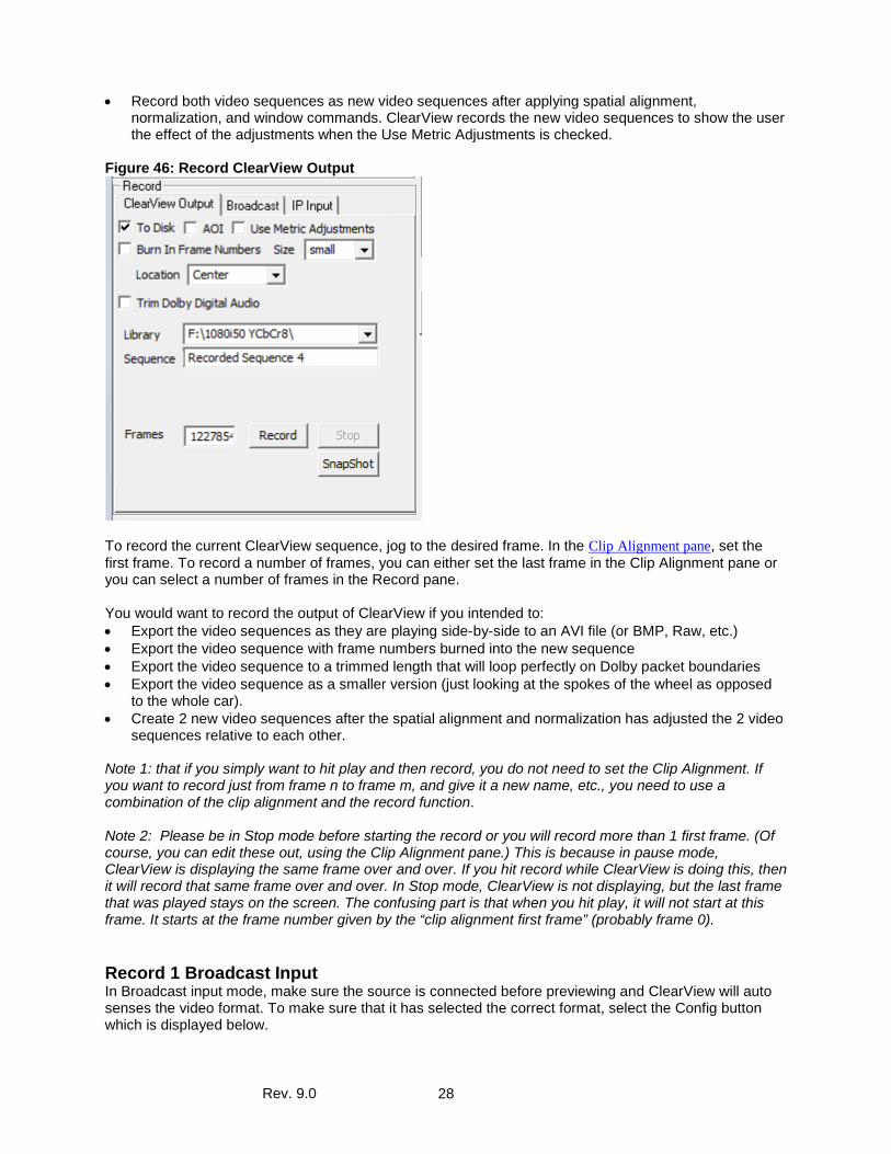
• Record both video sequences as new video sequences after applying spatial alignment, normalization, and window commands. ClearView records the new video sequences to show the user the effect of the adjustments when the Use Metric Adjustments is checked.
Figure 46: Record ClearView Output
To record the current ClearView sequence, jog to the desired frame. In the Clip Alignment pane, set the first frame. To record a number of frames, you can either set the last frame in the Clip Alignment pane or you can select a number of frames in the Record pane. You would want to record the output of ClearView if you intended to: • Export the video sequences as they are playing side-by-side to an AVI file (or BMP, Raw, etc.) • Export the video sequence with frame numbers burned into the new sequence • Export the video sequence to a trimmed length that will loop perfectly on Dolby packet boundaries • Export the video sequence as a smaller version (just looking at the spokes of the wheel as opposed
to the whole car). • Create 2 new video sequences after the spatial alignment and normalization has adjusted the 2 video
sequences relative to each other. Note 1: that if you simply want to hit play and then record, you do not need to set the Clip Alignment. If you want to record just from frame n to frame m, and give it a new name, etc., you need to use a combination of the clip alignment and the record function. Note 2: Please be in Stop mode before starting the record or you will record more than 1 first frame. (Of course, you can edit these out, using the Clip Alignment pane.) This is because in pause mode, ClearView is displaying the same frame over and over. If you hit record while ClearView is doing this, then it will record that same frame over and over. In Stop mode, ClearView is not displaying, but the last frame that was played stays on the screen. The confusing part is that when you hit play, it will not start at this frame. It starts at the frame number given by the “clip alignment first frame” (probably frame 0).
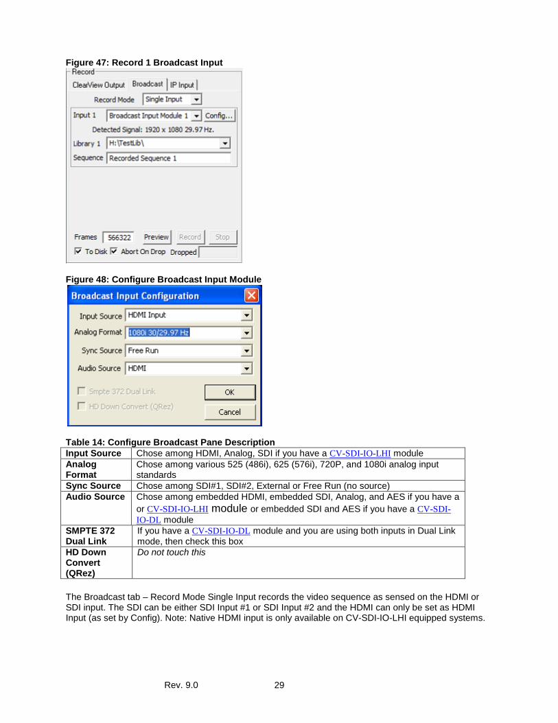
Record 1 Broadcast Input In Broadcast input mode, make sure the source is connected before previewing and ClearView will auto senses the video format. To make sure that it has selected the correct format, select the Config button which is displayed below.
Rev. 9.0 29
Figure 47: Record 1 Broadcast Input
Figure 48: Configure Broadcast Input Module
Table 14: Configure Broadcast Pane Description Input Source Chose among HDMI, Analog, SDI if you have a CV-SDI-IO-LHI module Analog Format
Chose among various 525 (486i), 625 (576i), 720P, and 1080i analog input standards
Sync Source Chose among SDI#1, SDI#2, External or Free Run (no source) Audio Source Chose among embedded HDMI, embedded SDI, Analog, and AES if you have a
or CV-SDI-IO-LHI module or embedded SDI and AES if you have a CV-SDI-IO-DL module
SMPTE 372 Dual Link
If you have a CV-SDI-IO-DL module and you are using both inputs in Dual Link mode, then check this box
HD Down Convert (QRez)
Do not touch this
The Broadcast tab – Record Mode Single Input records the video sequence as sensed on the HDMI or SDI input. The SDI can be either SDI Input #1 or SDI Input #2 and the HDMI can only be set as HDMI Input (as set by Config). Note: Native HDMI input is only available on CV-SDI-IO-LHI equipped systems.
Rev. 9.0 30
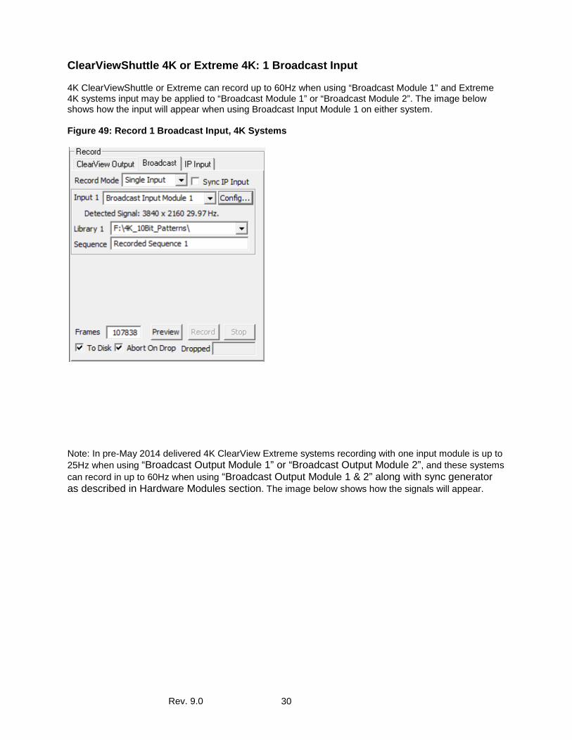
ClearViewShuttle 4K or Extreme 4K: 1 Broadcast Input 4K ClearViewShuttle or Extreme can record up to 60Hz when using “Broadcast Module 1” and Extreme 4K systems input may be applied to “Broadcast Module 1” or “Broadcast Module 2”. The image below shows how the input will appear when using Broadcast Input Module 1 on either system. Figure 49: Record 1 Broadcast Input, 4K Systems
Note: In pre-May 2014 delivered 4K ClearView Extreme systems recording with one input module is up to 25Hz when using “Broadcast Output Module 1” or “Broadcast Output Module 2”, and these systems can record in up to 60Hz when using “Broadcast Output Module 1 & 2” along with sync generator as described in Hardware Modules section. The image below shows how the signals will appear.
Rev. 9.0 31
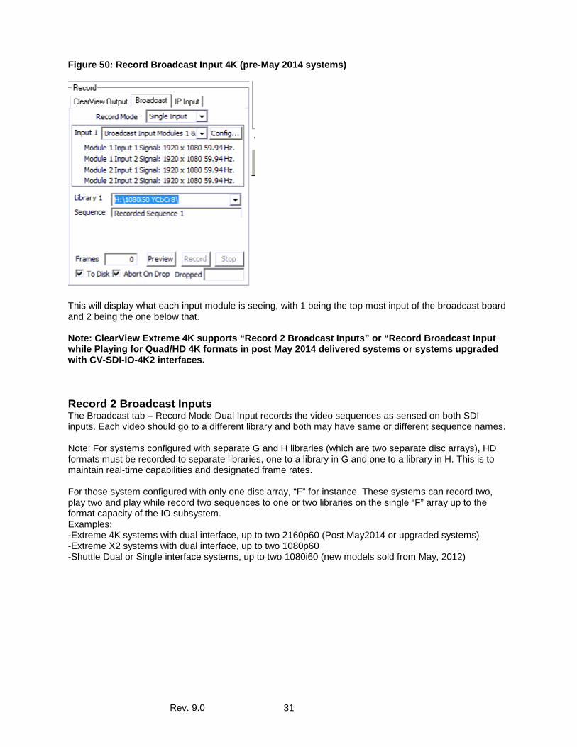
Figure 50: Record Broadcast Input 4K (pre-May 2014 systems)
This will display what each input module is seeing, with 1 being the top most input of the broadcast board and 2 being the one below that. Note: ClearView Extreme 4K supports “Record 2 Broadcast Inputs” or “Record Broadcast Input while Playing for Quad/HD 4K formats in post May 2014 delivered systems or systems upgraded with CV-SDI-IO-4K2 interfaces.
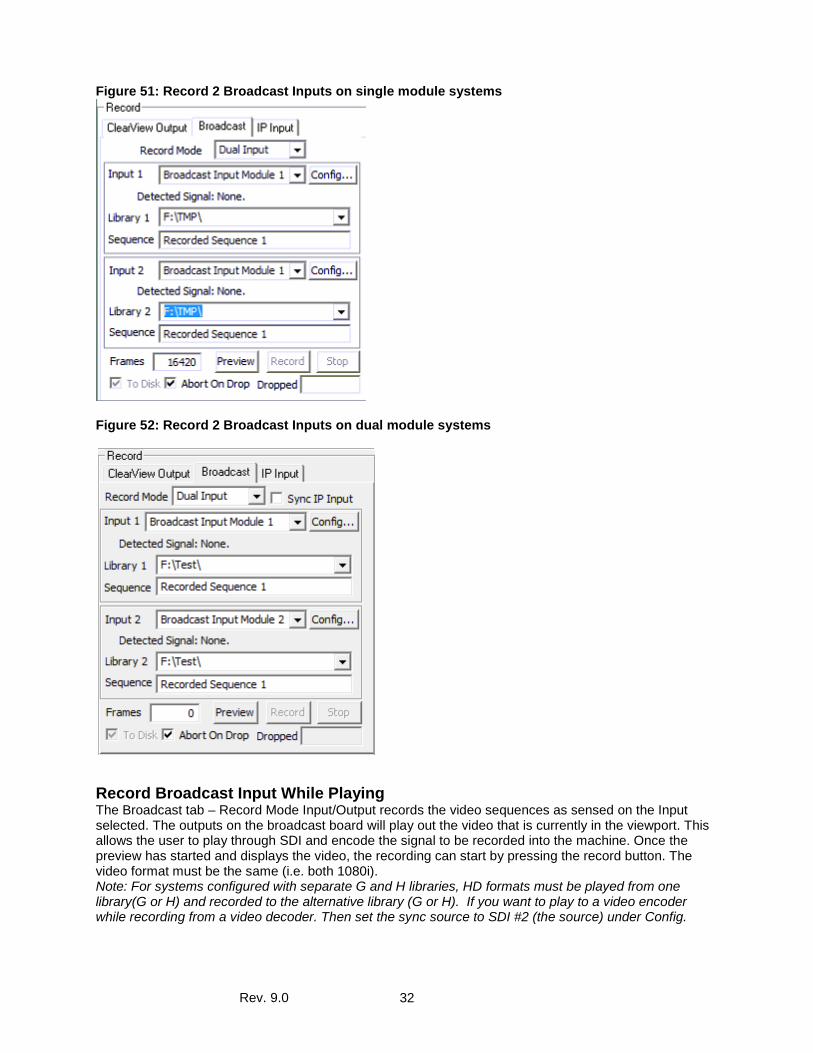
Record 2 Broadcast Inputs The Broadcast tab – Record Mode Dual Input records the video sequences as sensed on both SDI inputs. Each video should go to a different library and both may have same or different sequence names. Note: For systems configured with separate G and H libraries (which are two separate disc arrays), HD formats must be recorded to separate libraries, one to a library in G and one to a library in H. This is to maintain real-time capabilities and designated frame rates. For those system configured with only one disc array, “F” for instance. These systems can record two, play two and play while record two sequences to one or two libraries on the single “F” array up to the format capacity of the IO subsystem. Examples: -Extreme 4K systems with dual interface, up to two 2160p60 (Post May2014 or upgraded systems) -Extreme X2 systems with dual interface, up to two 1080p60 -Shuttle Dual or Single interface systems, up to two 1080i60 (new models sold from May, 2012)
Rev. 9.0 32
Figure 51: Record 2 Broadcast Inputs on single module systems
Figure 52: Record 2 Broadcast Inputs on dual module systems
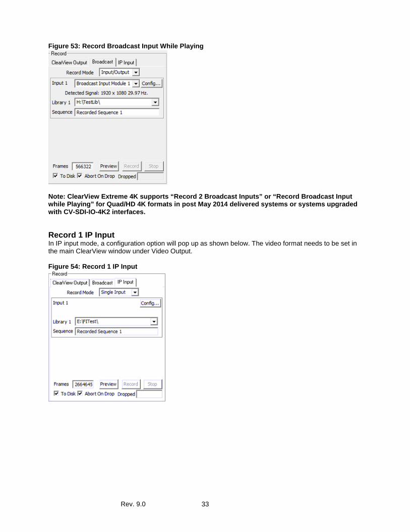
Record Broadcast Input While Playing The Broadcast tab – Record Mode Input/Output records the video sequences as sensed on the Input selected. The outputs on the broadcast board will play out the video that is currently in the viewport. This allows the user to play through SDI and encode the signal to be recorded into the machine. Once the preview has started and displays the video, the recording can start by pressing the record button. The video format must be the same (i.e. both 1080i). Note: For systems configured with separate G and H libraries, HD formats must be played from one library(G or H) and recorded to the alternative library (G or H). If you want to play to a video encoder while recording from a video decoder. Then set the sync source to SDI #2 (the source) under Config.
Rev. 9.0 33
Figure 53: Record Broadcast Input While Playing
Note: ClearView Extreme 4K supports “Record 2 Broadcast Inputs” or “Record Broadcast Input while Playing” for Quad/HD 4K formats in post May 2014 delivered systems or systems upgraded with CV-SDI-IO-4K2 interfaces.
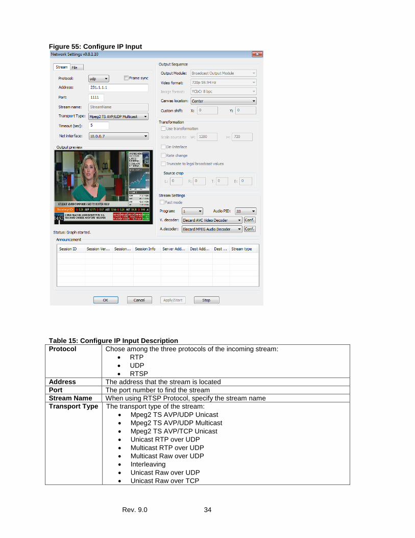
Record 1 IP Input In IP input mode, a configuration option will pop up as shown below. The video format needs to be set in the main ClearView window under Video Output. Figure 54: Record 1 IP Input
Rev. 9.0 34
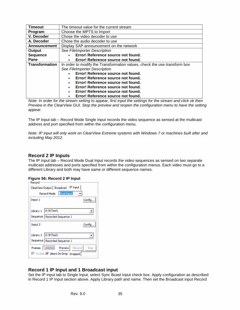
Figure 55: Configure IP Input
Table 15: Configure IP Input Description Protocol Chose among the three protocols of the incoming stream:
• RTP • UDP • RTSP
Address The address that the stream is located Port The port number to find the stream Stream Name When using RTSP Protocol, specify the stream name Transport Type The transport type of the stream:
• Mpeg2 TS AVP/UDP Unicast • Mpeg2 TS AVP/UDP Multicast • Mpeg2 TS AVP/TCP Unicast • Unicast RTP over UDP • Multicast RTP over UDP • Multicast Raw over UDP • Interleaving • Unicast Raw over UDP • Unicast Raw over TCP
Rev. 9.0 35
Timeout The timeout value for the current stream Program Choose the MPTS to Import V. Decoder Chose the video decoder to use A. Decoder Chose the audio decoder to use Announcement Display SAP announcement on the network Output Sequence Pane
See FileImporter Description • Error! Reference source not found. • Error! Reference source not found.
Transformation In order to modify the Transformation values, check the use transform box See FileImporter Description
• Error! Reference source not found. • Error! Reference source not found. • Error! Reference source not found. • Error! Reference source not found. • Error! Reference source not found. • Error! Reference source not found.
Note: In order for the stream setting to appear, first input the settings for the stream and click ok then Preview in the ClearView GUI. Stop the preview and reopen the configuration menu to have the setting appear. The IP Input tab – Record Mode Single Input records the video sequence as sensed at the multicast address and port specified from within the configuration menu. Note: IP input will only work on ClearView Extreme systems with Windows 7 or machines built after and including May 2012.
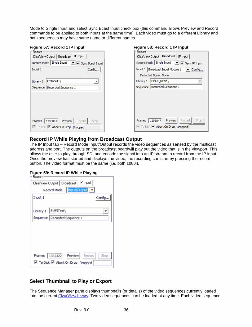
Record 2 IP Inputs The IP Input tab – Record Mode Dual Input records the video sequences as sensed on two separate multicast addresses and ports specified from within the configuration menus. Each video must go to a different Library and both may have same or different sequence names. Figure 56: Record 2 IP Input
Record 1 IP Input and 1 Broadcast input Set the IP input tab to Single Input, select Sync Bcast Input check box. Apply configuration as described in Record 1 IP Input section above. Apply Library path and name. Then set the Broadcast input Record
Rev. 9.0 36
Mode to Single Input and select Sync Bcast Input check box (this command allows Preview and Record commands to be applied to both inputs at the same time). Each video must go to a different Library and both sequences may have same name or different names. Figure 57: Record 1 IP Input
Figure 58: Record 1 IP Input
Record IP While Playing from Broadcast Output The IP Input tab – Record Mode Input/Output records the video sequences as sensed by the multicast address and port. The outputs on the broadcast boardwill play out the video that is in the viewport. This allows the user to play through SDI and encode the signal into an IP stream to record from the IP input. Once the preview has started and displays the video, the recording can start by pressing the record button. The video format must be the same (i.e. both 1080i). Figure 59: Record IP While Playing
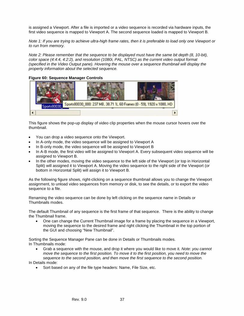
Select Thumbnail to Play or Export The Sequence Manager pane displays thumbnails (or details) of the video sequences currently loaded into the current ClearView library. Two video sequences can be loaded at any time. Each video sequence
Rev. 9.0 37
is assigned a Viewport. After a file is imported or a video sequence is recorded via hardware inputs, the first video sequence is mapped to Viewport A. The second sequence loaded is mapped to Viewport B. Note 1: If you are trying to achieve ultra-high frame rates, then it is preferable to load only one Viewport or to run from memory. Note 2: Please remember that the sequence to be displayed must have the same bit depth (8, 10-bit), color space (4:4:4, 4:2:2), and resolution (1080i, PAL, NTSC) as the current video output format (specified in the Video Output pane). Hovering the mouse over a sequence thumbnail will display the property information about the selected sequence. Figure 60: Sequence Manager Controls
This figure shows the pop-up display of video clip properties when the mouse cursor hovers over the thumbnail. • You can drop a video sequence onto the Viewport. • In A-only mode, the video sequence will be assigned to Viewport A • In B-only mode, the video sequence will be assigned to Viewport B • In A-B mode, the first video will be assigned to Viewport A. Every subsequent video sequence will be
assigned to Viewport B. • In the other modes, moving the video sequence to the left side of the Viewport (or top in Horizontal
Split) will assigned it to Viewport A. Moving the video sequence to the right side of the Viewport (or bottom in Horizontal Split) will assign it to Viewport B.
As the following figure shows, right-clicking on a sequence thumbnail allows you to change the Viewport assignment, to unload video sequences from memory or disk, to see the details, or to export the video sequence to a file. Renaming the video sequence can be done by left clicking on the sequence name in Details or Thumbnails modes. The default Thumbnail of any sequence is the first frame of that sequence. There is the ability to change the Thumbnail frame.
• One can change the Current Thumbnail image for a frame by placing the sequence in a Viewport, moving the sequence to the desired frame and right clicking the Thumbnail in the top portion of the GUI and choosing “New Thumbnail”.
Sorting the Sequence Manager Pane can be done in Details or Thumbnails modes. In Thumbnails mode:
• Grab a sequence with the mouse, and drop it where you would like to move it. Note: you cannot move the sequence to the first position. To move it to the first position, you need to move the sequence to the second position, and then move the first sequence to the second position.
In Details mode: • Sort based on any of the file type headers: Name, File Size, etc.
Rev. 9.0 38
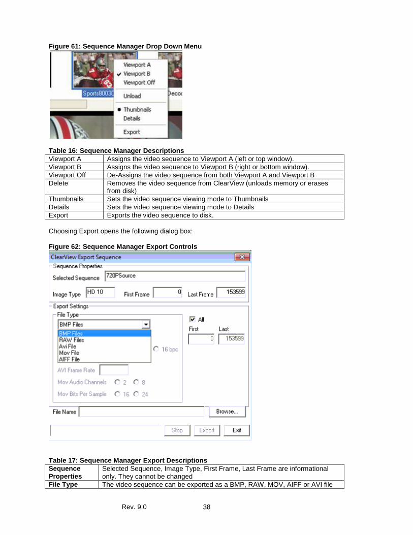
Figure 61: Sequence Manager Drop Down Menu
Table 16: Sequence Manager Descriptions Viewport A Assigns the video sequence to Viewport A (left or top window). Viewport B Assigns the video sequence to Viewport B (right or bottom window). Viewport Off De-Assigns the video sequence from both Viewport A and Viewport B Delete Removes the video sequence from ClearView (unloads memory or erases
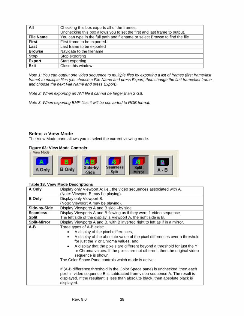
from disk) Thumbnails Sets the video sequence viewing mode to Thumbnails Details Sets the video sequence viewing mode to Details Export Exports the video sequence to disk. Choosing Export opens the following dialog box: Figure 62: Sequence Manager Export Controls
Table 17: Sequence Manager Export Descriptions Sequence Properties
Selected Sequence, Image Type, First Frame, Last Frame are informational only. They cannot be changed
File Type The video sequence can be exported as a BMP, RAW, MOV, AIFF or AVI file
Rev. 9.0 39
All Checking this box exports all of the frames. Unchecking this box allows you to set the first and last frame to output.
File Name You can type in the full path and filename or select Browse to find the file First First frame to be exported. Last Last frame to be exported Browse Navigate to the filename Stop Stop exporting Export Start exporting Exit Close this window Note 1: You can output one video sequence to multiple files by exporting a list of frames (first frame/last frame) to multiple files (i.e. choose a File Name and press Export; then change the first frame/last frame and choose the next File Name and press Export). Note 2: When exporting an AVI file it cannot be larger than 2 GB. Note 3: When exporting BMP files it will be converted to RGB format.
Select a View Mode The View Mode pane allows you to select the current viewing mode. Figure 63: View Mode Controls
Table 18: View Mode Descriptions A Only Display only Viewport A; i.e., the video sequences associated with A.
(Note: Viewport B may be playing). B Only Display only Viewport B.
(Note: Viewport A may be playing). Side-by-Side Display Viewports A and B side –by side. Seamless-Split
Display Viewports A and B flowing as if they were 1 video sequence. The left side of the display is Viewport A, the right side is B.
Split-Mirror Display Viewports A and B, with B inverted right to left as if in a mirror. A-B Three types of A-B exist:
• A display of the pixel differences, • A display of the absolute value of the pixel differences over a threshold
for just the Y or Chroma values, and • A display that the pixels are different beyond a threshold for just the Y
or Chroma values. If the pixels are not different, then the original video sequence is shown.
The Color Space Pane controls which mode is active. If (A-B difference threshold in the Color Space pane) is unchecked, then each pixel in video sequence B is subtracted from video sequence A. The result is displayed. If the resultant is less than absolute black, then absolute black is displayed.
Rev. 9.0 40
If (A-B difference threshold) is checked and (A-B Add Back) is unchecked, the luma (Chroma unchecked) or chroma (Chroma checked) pixels in video sequence B are subtracted from video sequence A. If the absolute value of the subtraction is greater than the threshold, the result is displayed. Note: In either of the above, the value is probably a small number. Using the Color Space pane, the user can load a LUT (look-up table) to enhance small differences. There are many LUT examples under www.videoclarity.com/Support (Miscellaneous Support Files). If (A-B difference threshold) is checked and (A-B Add Back) is checked, the luma (Chroma unchecked) or chroma (Chroma checked) pixels in video sequence B are subtracted from video sequence A. • If (A-B) >= Threshold, a Green pixel is displayed • If (B-A) >= Threshold, a Yellow pixel is displayed • If (((A-B) < Threshold) && ((B-A) < Threshold)), the original video sequence
is displayed Note: B-A can be achieved using the Play Control Pane's Swap A/B.
In a typical operation, the original uncompressed clip (the original source file) and the corresponding decompressed clip (a compressed version of the source file, decompressed by ClearView) are shown as successive thumbnails. Note, however, that there is no restriction on the assignment of clips to Viewports. You are free to assign any still or clip to either Viewport, whether that makes any sense or not. Thus you could do an A-B of a still and a clip, or A-B of two totally unrelated clips, and get visually entertaining but totally meaningless results.
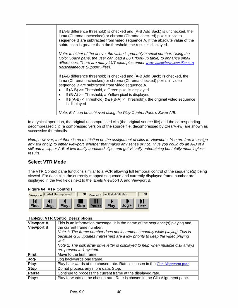
Select VTR Mode The VTR Control pane functions similar to a VCR allowing full temporal control of the sequence(s) being viewed. For each clip, the currently mapped sequence and currently displayed frame number are displayed in the two fields next to the labels Viewport A and Viewport B. Figure 64: VTR Controls
Table20: VTR Control Descriptions Viewport A, Viewport B
This is an information message. It is the name of the sequence(s) playing and the current frame number. Note 1: The frame number does not increment smoothly while playing. This is because GUI updates (refreshes) are a low priority to keep the video playing well. Note 2: The disk array drive letter is displayed to help when multiple disk arrays are present in 1 system.
First Move to the first frame. Jog- Jog backwards one frame. Play- Play backwards at the chosen rate. Rate is chosen in the Clip Alignment pane Stop Do not process any more data. Stop. Pause Continue to process the current frame at the displayed rate. Play+ Play forwards at the chosen rate. Rate is chosen in the Clip Alignment pane.
Rev. 9.0 41
Jog+ Jog forward one frame. Last Move to the last frame. Slider Bar Move to a specific frame. The frame number is displayed above the VTR
controls; next to the Viewport video sequence name. Note: the slide bar does not move when the file is playing
Delete Current Sequences The Delete Current control will delete the sequences that are currently in viewport A and viewport B from the hard disk space. If there is a log file associated with the current view that will also be deleted. Note: There is a setting in the ClearView configuration menu to ask to confirm the deletion. Figure 65: Del Current Control
Select Objective Measurements The Objective Measurement Graph pane displays the graph of the DMOS/ MS-SSIM, NIQE, JND, PSNR, PSNR No Ref, Spatial, or Temporal over time. The actual value, minimum, maximum and average values are displayed in the Objective Metric Controls pane. Examples, using the various objective measurements are on our website under www.videoclarity.com/videoqualityanalysiscasestudies/. The Objective Metrics can be used to calculate the perceived video quality (Sarnoff JND, DMOS/MS-SSIM, NIQE), perceived audio quality (PEAQ), QC a product when there are expected results (PSNR with threshold), looking for artifacts when no reference is present (PSNR No Ref, Spatial and Temporal). In all cases, the metrics are displayed and written to a LOG file for off-line analysis.
AFREQ The Audio algorithm measures the peak amplitude of an envelope of audio data. It is a full reference as it measures the differences between the original and processed video in absolute terms. This is termed an objective metric, as it does not talk about perceived quality to the human ear. It measures absolute differences.
APEAK A-Peak measures the true peak amplitude of the channels chosen and gives a value for each frame and a separate value for each channel. A-Peak is a no-reference metric. The value of the metric corresponds to the highest absolute value of a sample for a single audio channel in a single frame. Measuring in dB (decibels) the maximum value is 0 dB and the value closest to silence is -60 dB. ClearView supports the standards ATSC A/85, EBU R 128, ARIB TR-B32, and NAB T032 that control parameters and Momentary, Short Term, and Integrated that determine the timescale variable. The true peak(A-Peak) is based on the ITU-R BS. 1770.
DMOS The MS-SSIM algorithm from the University of Texas is used as a basis for a top-down way of predicting the video quality. This is a full reference algorithm as it measures the perceived structural similarity between the original and processed videos. It then correlated this data to the DMOS scale using the LIVE database at the University. The DMOS scale is between 0 and DMOS Max Value (4, 7, or 10 based in the ClearView Configuration Menu); where 0 is perfect. The MS-SSIM scale is between 0 and 1, with 1 being perfect. For more information about MS-SSIM or the DMOS scale, please refer to our website at www.videoclarity.com/videoqualityanalysiscasestudies/.
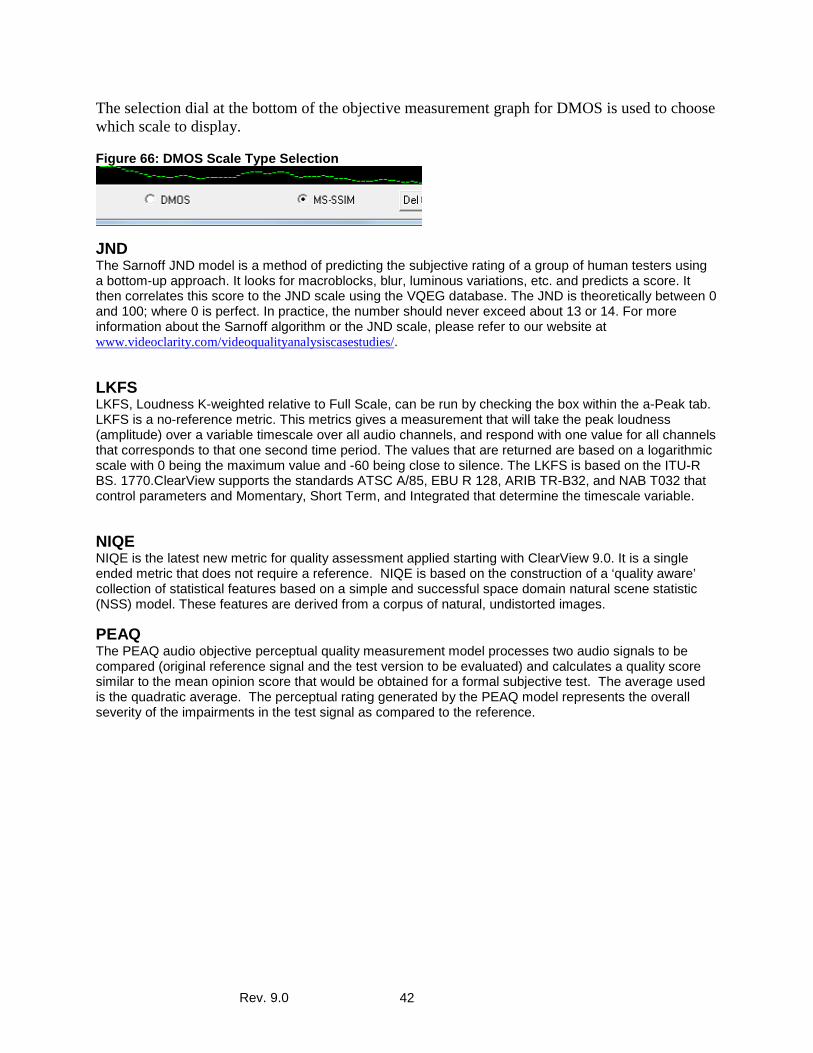
Rev. 9.0 42
The selection dial at the bottom of the objective measurement graph for DMOS is used to choose which scale to display. Figure 66: DMOS Scale Type Selection
JND The Sarnoff JND model is a method of predicting the subjective rating of a group of human testers using a bottom-up approach. It looks for macroblocks, blur, luminous variations, etc. and predicts a score. It then correlates this score to the JND scale using the VQEG database. The JND is theoretically between 0 and 100; where 0 is perfect. In practice, the number should never exceed about 13 or 14. For more information about the Sarnoff algorithm or the JND scale, please refer to our website at www.videoclarity.com/videoqualityanalysiscasestudies/.
LKFS LKFS, Loudness K-weighted relative to Full Scale, can be run by checking the box within the a-Peak tab. LKFS is a no-reference metric. This metrics gives a measurement that will take the peak loudness (amplitude) over a variable timescale over all audio channels, and respond with one value for all channels that corresponds to that one second time period. The values that are returned are based on a logarithmic scale with 0 being the maximum value and -60 being close to silence. The LKFS is based on the ITU-R BS. 1770.ClearView supports the standards ATSC A/85, EBU R 128, ARIB TR-B32, and NAB T032 that control parameters and Momentary, Short Term, and Integrated that determine the timescale variable.
NIQE NIQE is the latest new metric for quality assessment applied starting with ClearView 9.0. It is a single ended metric that does not require a reference. NIQE is based on the construction of a ‘quality aware’ collection of statistical features based on a simple and successful space domain natural scene statistic (NSS) model. These features are derived from a corpus of natural, undistorted images.
PEAQ The PEAQ audio objective perceptual quality measurement model processes two audio signals to be compared (original reference signal and the test version to be evaluated) and calculates a quality score similar to the mean opinion score that would be obtained for a formal subjective test. The average used is the quadratic average. The perceptual rating generated by the PEAQ model represents the overall severity of the impairments in the test signal as compared to the reference.
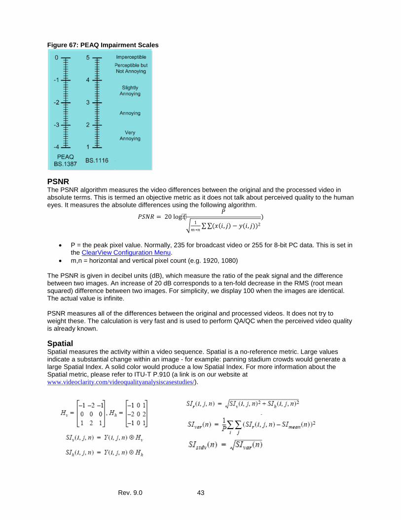
Rev. 9.0 43
Figure 67: PEAQ Impairment Scales
PSNR The PSNR algorithm measures the video differences between the original and the processed video in absolute terms. This is termed an objective metric as it does not talk about perceived quality to the human eyes. It measures the absolute differences using the following algorithm.
𝑃𝑃𝑃𝑃𝑃𝑃𝑃𝑃 = 20 log(𝑃𝑃
� 1𝑚𝑚∗𝑛𝑛
∑∑(𝑥𝑥(𝑖𝑖, 𝑗𝑗) − 𝑦𝑦(𝑖𝑖, 𝑗𝑗))2)
• P = the peak pixel value. Normally, 235 for broadcast video or 255 for 8-bit PC data. This is set in
the ClearView Configuration Menu. • m,n = horizontal and vertical pixel count (e.g. 1920, 1080)
The PSNR is given in decibel units (dB), which measure the ratio of the peak signal and the difference between two images. An increase of 20 dB corresponds to a ten-fold decrease in the RMS (root mean squared) difference between two images. For simplicity, we display 100 when the images are identical. The actual value is infinite. PSNR measures all of the differences between the original and processed videos. It does not try to weight these. The calculation is very fast and is used to perform QA/QC when the perceived video quality is already known.
Spatial Spatial measures the activity within a video sequence. Spatial is a no-reference metric. Large values indicate a substantial change within an image - for example: panning stadium crowds would generate a large Spatial Index. A solid color would produce a low Spatial Index. For more information about the Spatial metric, please refer to ITU-T P.910 (a link is on our website at www.videoclarity.com/videoqualityanalysiscasestudies/).
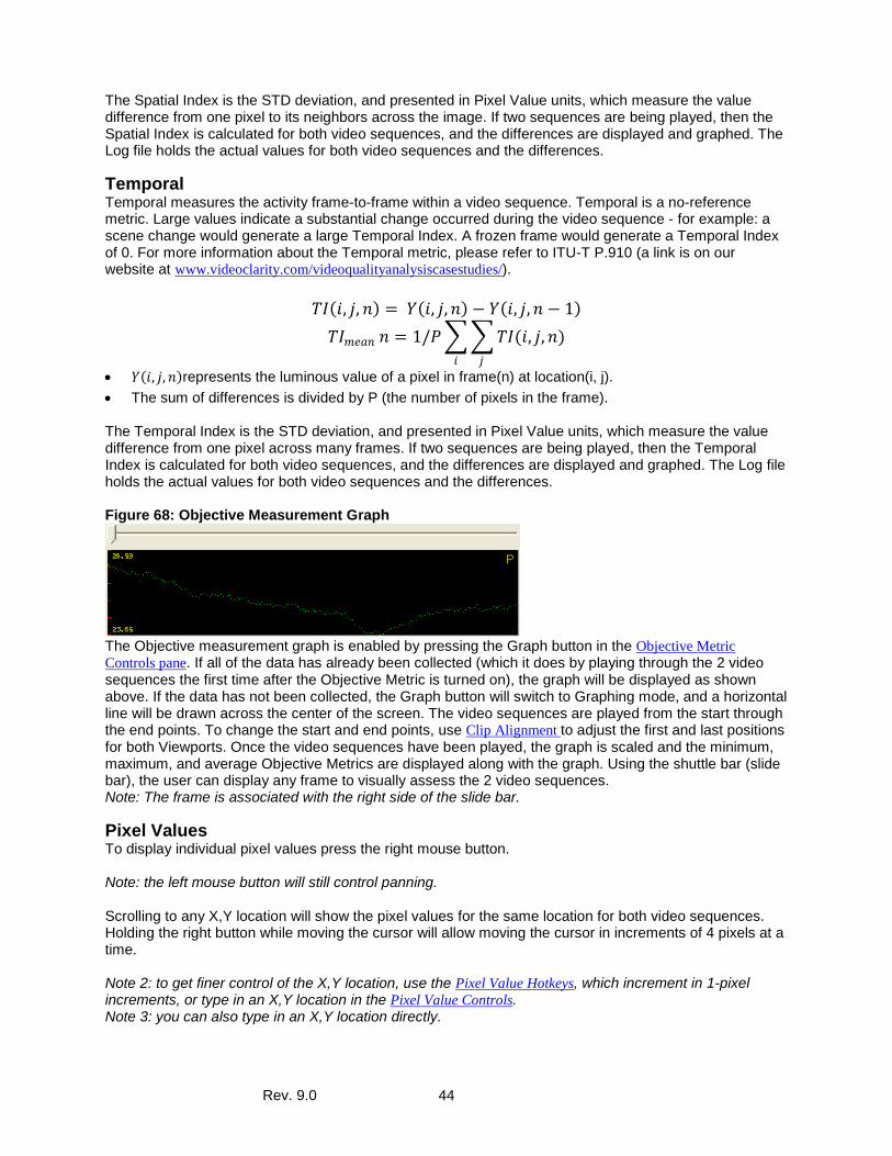
Rev. 9.0 44
The Spatial Index is the STD deviation, and presented in Pixel Value units, which measure the value difference from one pixel to its neighbors across the image. If two sequences are being played, then the Spatial Index is calculated for both video sequences, and the differences are displayed and graphed. The Log file holds the actual values for both video sequences and the differences.
Temporal Temporal measures the activity frame-to-frame within a video sequence. Temporal is a no-reference metric. Large values indicate a substantial change occurred during the video sequence - for example: a scene change would generate a large Temporal Index. A frozen frame would generate a Temporal Index of 0. For more information about the Temporal metric, please refer to ITU-T P.910 (a link is on our website at www.videoclarity.com/videoqualityanalysiscasestudies/).
𝑇𝑇𝑇𝑇(𝑖𝑖, 𝑗𝑗, 𝑛𝑛) = 𝑌𝑌(𝑖𝑖, 𝑗𝑗,𝑛𝑛) − 𝑌𝑌(𝑖𝑖, 𝑗𝑗,𝑛𝑛 − 1)
𝑇𝑇𝑇𝑇𝑚𝑚𝑚𝑚𝑚𝑚𝑛𝑛 𝑛𝑛 = 1/𝑃𝑃��𝑇𝑇𝑇𝑇(𝑖𝑖, 𝑗𝑗,𝑛𝑛)𝑗𝑗𝑖𝑖
• 𝑌𝑌(𝑖𝑖, 𝑗𝑗,𝑛𝑛)represents the luminous value of a pixel in frame(n) at location(i, j). • The sum of differences is divided by P (the number of pixels in the frame).
The Temporal Index is the STD deviation, and presented in Pixel Value units, which measure the value difference from one pixel across many frames. If two sequences are being played, then the Temporal Index is calculated for both video sequences, and the differences are displayed and graphed. The Log file holds the actual values for both video sequences and the differences. Figure 68: Objective Measurement Graph
The Objective measurement graph is enabled by pressing the Graph button in the Objective Metric Controls pane. If all of the data has already been collected (which it does by playing through the 2 video sequences the first time after the Objective Metric is turned on), the graph will be displayed as shown above. If the data has not been collected, the Graph button will switch to Graphing mode, and a horizontal line will be drawn across the center of the screen. The video sequences are played from the start through the end points. To change the start and end points, use Clip Alignment to adjust the first and last positions for both Viewports. Once the video sequences have been played, the graph is scaled and the minimum, maximum, and average Objective Metrics are displayed along with the graph. Using the shuttle bar (slide bar), the user can display any frame to visually assess the 2 video sequences. Note: The frame is associated with the right side of the slide bar.
Pixel Values To display individual pixel values press the right mouse button. Note: the left mouse button will still control panning. Scrolling to any X,Y location will show the pixel values for the same location for both video sequences. Holding the right button while moving the cursor will allow moving the cursor in increments of 4 pixels at a time. Note 2: to get finer control of the X,Y location, use the Pixel Value Hotkeys, which increment in 1-pixel increments, or type in an X,Y location in the Pixel Value Controls. Note 3: you can also type in an X,Y location directly.
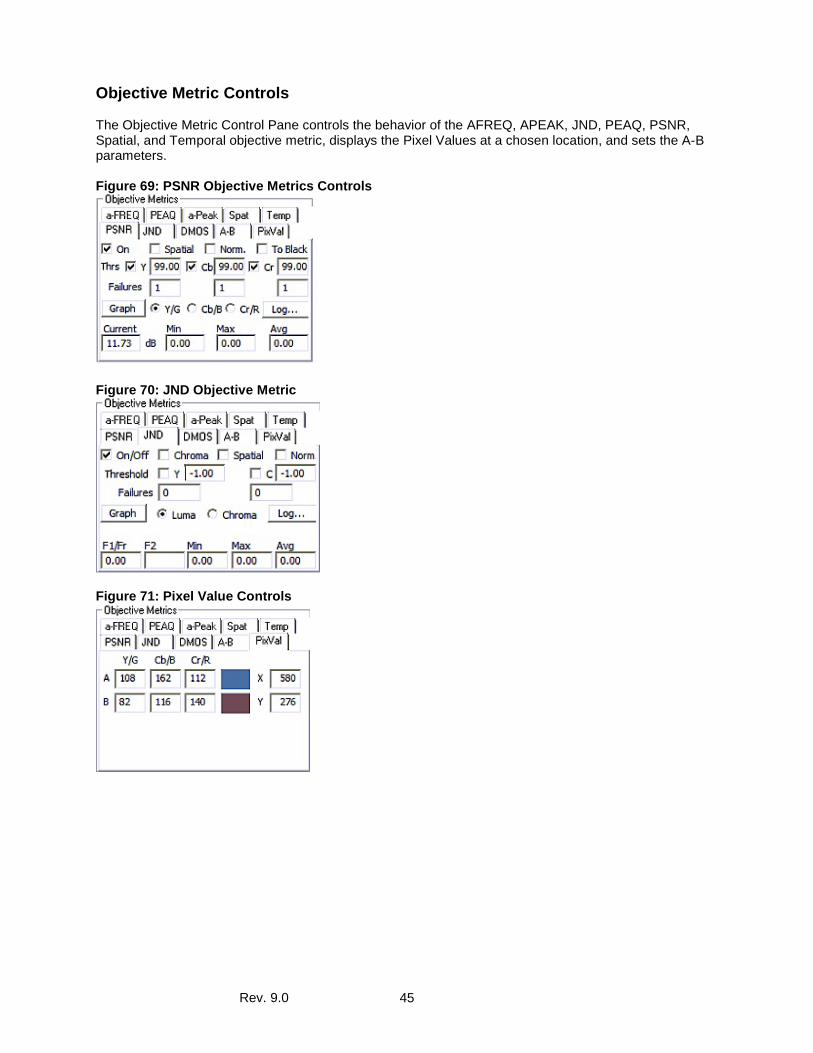
Rev. 9.0 45
Objective Metric Controls The Objective Metric Control Pane controls the behavior of the AFREQ, APEAK, JND, PEAQ, PSNR, Spatial, and Temporal objective metric, displays the Pixel Values at a chosen location, and sets the A-B parameters. Figure 69: PSNR Objective Metrics Controls
Figure 70: JND Objective Metric
Figure 71: Pixel Value Controls
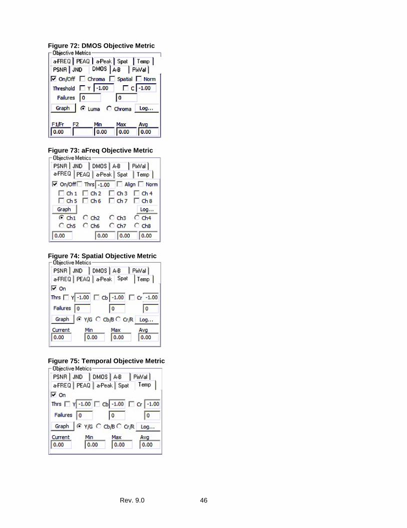
Rev. 9.0 46
Figure 72: DMOS Objective Metric
Figure 73: aFreq Objective Metric
Figure 74: Spatial Objective Metric
Figure 75: Temporal Objective Metric
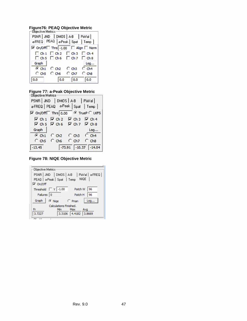
Rev. 9.0 47
Figure76: PEAQ Objective Metric
Figure 77: a-Peak Objective Metric
Figure 78: NIQE Objective Metric
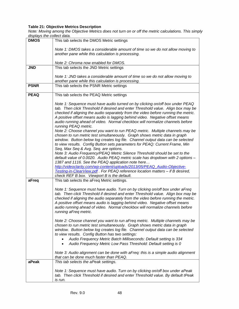
Rev. 9.0 48
Table 21: Objective Metrics Description Note: Moving among the Objective Metrics does not turn on or off the metric calculations. This simply displays the collect data. DMOS This tab selects the DMOS Metric settings
Note 1: DMOS takes a considerable amount of time so we do not allow moving to another pane while this calculation is processing. Note 2: Chroma now enabled for DMOS.
JND This tab selects the JND Metric settings Note 1: JND takes a considerable amount of time so we do not allow moving to another pane while this calculation is processing.
PSNR This tab selects the PSNR Metric settings
PEAQ This tab selects the PEAQ Metric settings Note 1: Sequence must have audio turned on by clicking on/off box under PEAQ tab. Then click Threshold if desired and enter Threshold value. Align box may be checked if aligning the audio separately from the video before running the metric. A positive offset means audio is lagging behind video. Negative offset means audio running ahead of video. Normal checkbox will normalize channels before running PEAQ metric. Note 2: Choose channel you want to run PEAQ metric. Multiple channels may be chosen to run metric test simultaneously. Graph shows metric data in graph window. Button below log creates log file. Channel output data can be selected to view results. Config Button sets parameters for PEAQ: Current Frame, Min Seq, Max Seq & Avg. Seq. are options. Note 3: Audio Frequency/PEAQ Metric Silence Threshold should be set to the default value of 0.0020. Audio PEAQ metric scale has dropdown with 2 options – 1387 and 1116. See the PEAQ application note here… http://videoclarity.com/wp-content/uploads/2013/05/PEAQ_Audio-Objective-Testing-in-ClearView.pdf . For PEAQ reference location matters – if B desired, check REF B box. Viewport B is the default.
aFreq This tab selects the aFreq Metric settings. Note 1: Sequence must have audio. Turn on by clicking on/off box under aFreq tab. Then click Threshold if desired and enter Threshold value. Align box may be checked if aligning the audio separately from the video before running the metric. A positive offset means audio is lagging behind video. Negative offset means audio running ahead of video. Normal checkbox will normalize channels before running aFreq metric. Note 2: Choose channel you want to run aFreq metric. Multiple channels may be chosen to run metric test simultaneously. Graph shows metric data in graph window. Button below log creates log file. Channel output data can be selected to view results. Config Button has two settings:
• Audio Frequency Metric Batch Milliseconds: Default setting is 334 • Audio Frequency Metric Low Pass Threshold: Default setting is 0
Note 3: Audio alignment can be done with aFreq: this is a simple audio alignment that can be done much faster than PEAQ.
aPeak This tab selects the aPeak settings. Note 1: Sequence must have audio. Turn on by clicking on/off box under aPeak tab. Then click Threshold if desired and enter Threshold value. By default tPeak is run.
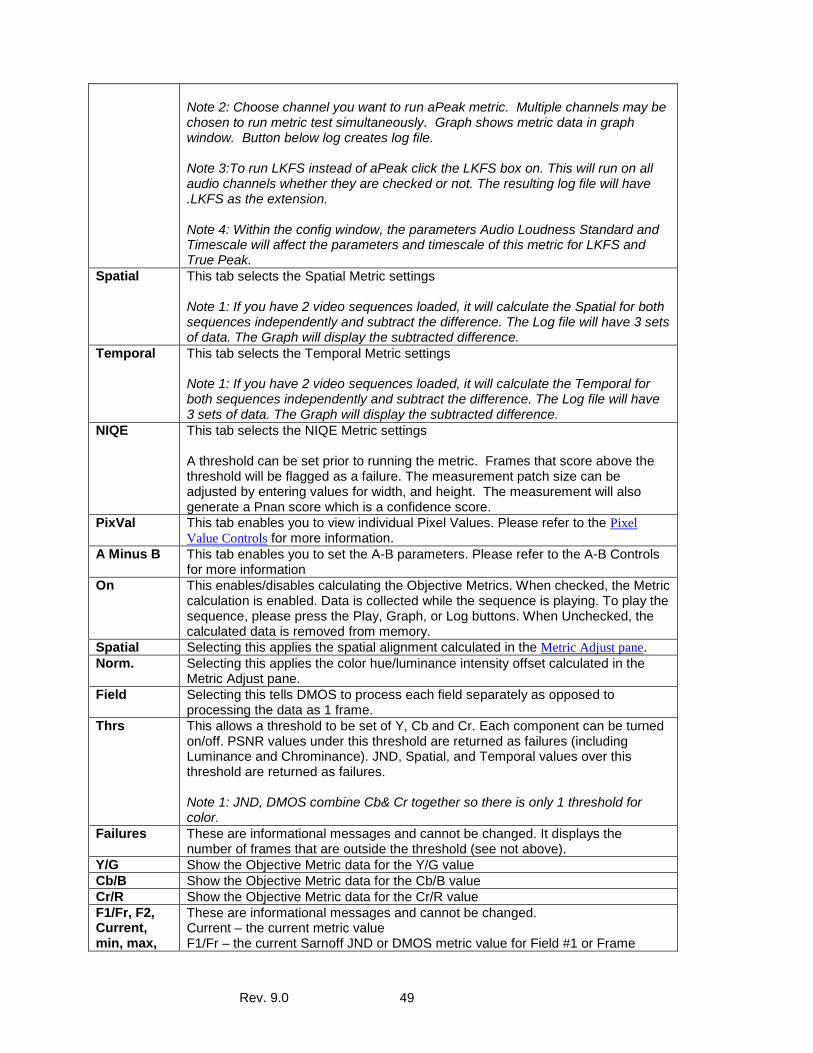
Rev. 9.0 49
Note 2: Choose channel you want to run aPeak metric. Multiple channels may be chosen to run metric test simultaneously. Graph shows metric data in graph window. Button below log creates log file. Note 3:To run LKFS instead of aPeak click the LKFS box on. This will run on all audio channels whether they are checked or not. The resulting log file will have .LKFS as the extension. Note 4: Within the config window, the parameters Audio Loudness Standard and Timescale will affect the parameters and timescale of this metric for LKFS and True Peak.
Spatial This tab selects the Spatial Metric settings Note 1: If you have 2 video sequences loaded, it will calculate the Spatial for both sequences independently and subtract the difference. The Log file will have 3 sets of data. The Graph will display the subtracted difference.
Temporal This tab selects the Temporal Metric settings Note 1: If you have 2 video sequences loaded, it will calculate the Temporal for both sequences independently and subtract the difference. The Log file will have 3 sets of data. The Graph will display the subtracted difference.
NIQE This tab selects the NIQE Metric settings A threshold can be set prior to running the metric. Frames that score above the threshold will be flagged as a failure. The measurement patch size can be adjusted by entering values for width, and height. The measurement will also generate a Pnan score which is a confidence score.
PixVal This tab enables you to view individual Pixel Values. Please refer to the Pixel Value Controls for more information.
A Minus B This tab enables you to set the A-B parameters. Please refer to the A-B Controls for more information
On This enables/disables calculating the Objective Metrics. When checked, the Metric calculation is enabled. Data is collected while the sequence is playing. To play the sequence, please press the Play, Graph, or Log buttons. When Unchecked, the calculated data is removed from memory.
Spatial Selecting this applies the spatial alignment calculated in the Metric Adjust pane. Norm. Selecting this applies the color hue/luminance intensity offset calculated in the
Metric Adjust pane. Field Selecting this tells DMOS to process each field separately as opposed to
processing the data as 1 frame. Thrs This allows a threshold to be set of Y, Cb and Cr. Each component can be turned
on/off. PSNR values under this threshold are returned as failures (including Luminance and Chrominance). JND, Spatial, and Temporal values over this threshold are returned as failures. Note 1: JND, DMOS combine Cb& Cr together so there is only 1 threshold for color.
Failures These are informational messages and cannot be changed. It displays the number of frames that are outside the threshold (see not above).
Y/G Show the Objective Metric data for the Y/G value Cb/B Show the Objective Metric data for the Cb/B value Cr/R Show the Objective Metric data for the Cr/R value F1/Fr, F2, Current, min, max,
These are informational messages and cannot be changed. Current – the current metric value F1/Fr – the current Sarnoff JND or DMOS metric value for Field #1 or Frame
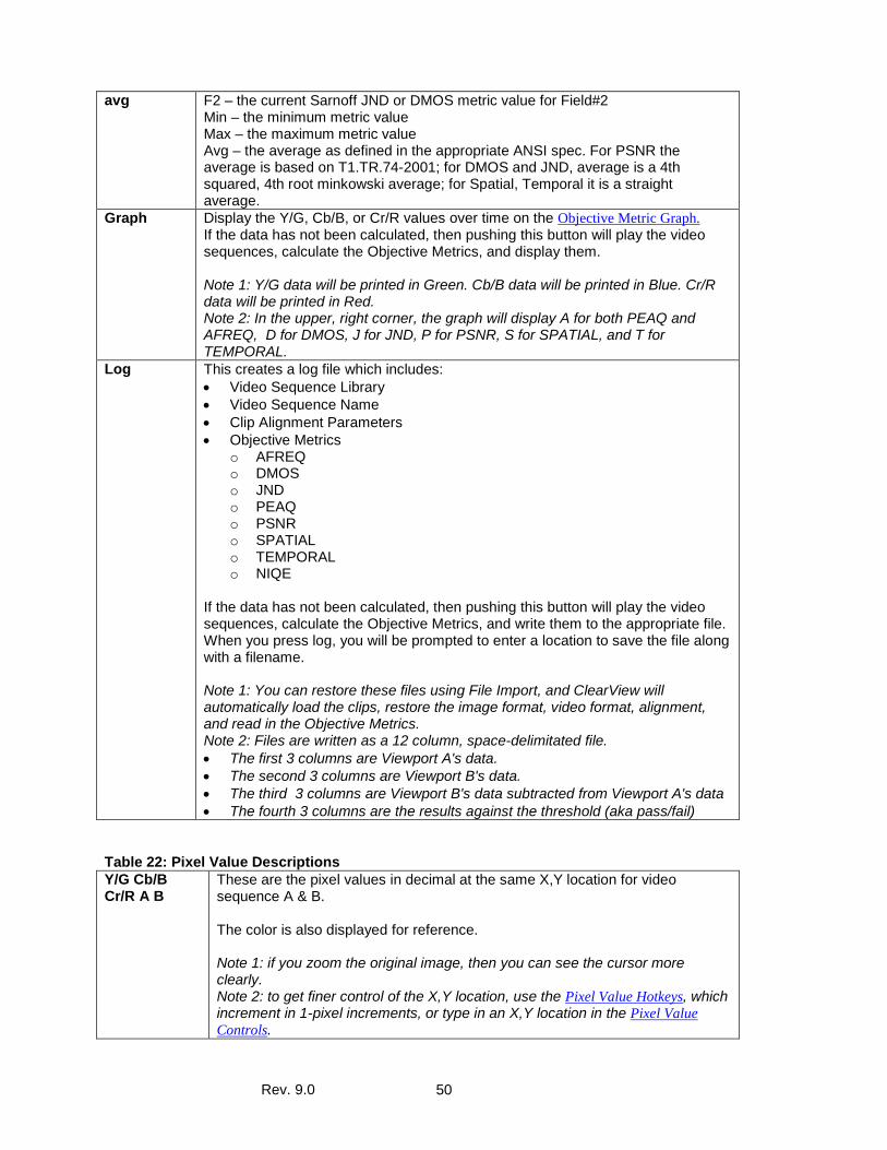
Rev. 9.0 50
avg F2 – the current Sarnoff JND or DMOS metric value for Field#2 Min – the minimum metric value Max – the maximum metric value Avg – the average as defined in the appropriate ANSI spec. For PSNR the average is based on T1.TR.74-2001; for DMOS and JND, average is a 4th squared, 4th root minkowski average; for Spatial, Temporal it is a straight average.
Graph Display the Y/G, Cb/B, or Cr/R values over time on the Objective Metric Graph. If the data has not been calculated, then pushing this button will play the video sequences, calculate the Objective Metrics, and display them. Note 1: Y/G data will be printed in Green. Cb/B data will be printed in Blue. Cr/R data will be printed in Red. Note 2: In the upper, right corner, the graph will display A for both PEAQ and AFREQ, D for DMOS, J for JND, P for PSNR, S for SPATIAL, and T for TEMPORAL.
Log This creates a log file which includes: • Video Sequence Library • Video Sequence Name • Clip Alignment Parameters • Objective Metrics
o AFREQ o DMOS o JND o PEAQ o PSNR o SPATIAL o TEMPORAL o NIQE
If the data has not been calculated, then pushing this button will play the video sequences, calculate the Objective Metrics, and write them to the appropriate file. When you press log, you will be prompted to enter a location to save the file along with a filename. Note 1: You can restore these files using File Import, and ClearView will automatically load the clips, restore the image format, video format, alignment, and read in the Objective Metrics. Note 2: Files are written as a 12 column, space-delimitated file. • The first 3 columns are Viewport A's data. • The second 3 columns are Viewport B's data. • The third 3 columns are Viewport B's data subtracted from Viewport A's data • The fourth 3 columns are the results against the threshold (aka pass/fail)
Table 22: Pixel Value Descriptions Y/G Cb/B Cr/R A B
These are the pixel values in decimal at the same X,Y location for video sequence A & B. The color is also displayed for reference. Note 1: if you zoom the original image, then you can see the cursor more clearly. Note 2: to get finer control of the X,Y location, use the Pixel Value Hotkeys, which increment in 1-pixel increments, or type in an X,Y location in the Pixel Value Controls.
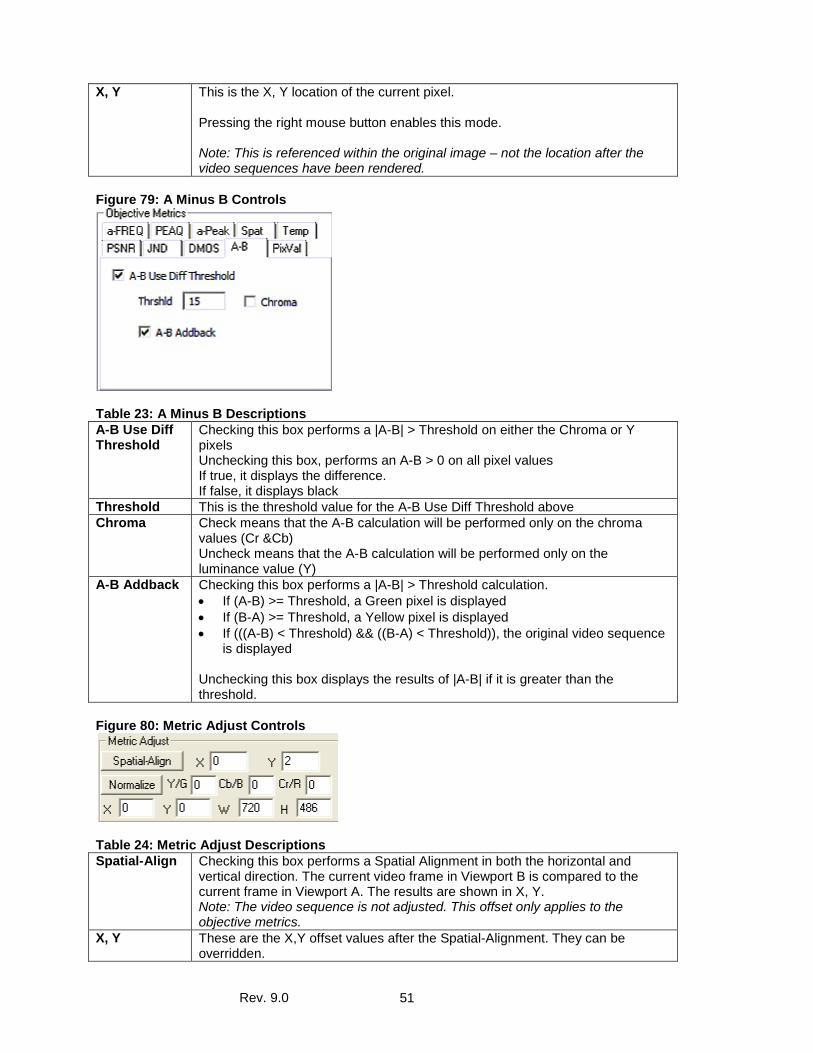
Rev. 9.0 51
X, Y This is the X, Y location of the current pixel. Pressing the right mouse button enables this mode. Note: This is referenced within the original image – not the location after the video sequences have been rendered.
Figure 79: A Minus B Controls
Table 23: A Minus B Descriptions A-B Use Diff Threshold
Checking this box performs a |A-B| > Threshold on either the Chroma or Y pixels Unchecking this box, performs an A-B > 0 on all pixel values If true, it displays the difference. If false, it displays black
Threshold This is the threshold value for the A-B Use Diff Threshold above Chroma Check means that the A-B calculation will be performed only on the chroma
values (Cr &Cb) Uncheck means that the A-B calculation will be performed only on the luminance value (Y)
A-B Addback Checking this box performs a |A-B| > Threshold calculation. • If (A-B) >= Threshold, a Green pixel is displayed • If (B-A) >= Threshold, a Yellow pixel is displayed • If (((A-B) < Threshold) && ((B-A) < Threshold)), the original video sequence
is displayed Unchecking this box displays the results of |A-B| if it is greater than the threshold.
Figure 80: Metric Adjust Controls
Table 24: Metric Adjust Descriptions Spatial-Align Checking this box performs a Spatial Alignment in both the horizontal and
vertical direction. The current video frame in Viewport B is compared to the current frame in Viewport A. The results are shown in X, Y. Note: The video sequence is not adjusted. This offset only applies to the objective metrics.
X, Y These are the X,Y offset values after the Spatial-Alignment. They can be overridden.
Rev. 9.0 52
Note 1: the offsets are restricted to be +/- 8 (X) and +/- 16 (Y). Note 2: The values must be even. An odd offset in the Y direction will result in a flipped field in Interlace mode. An odd offset in the X direction will result in a flipped color component in Y’CbCr. Note 3: The video sequences are centered after the alignment. To view the results, re-record the video sequences using the Record Pane.
Normalize Checking this box performs a Luminance Intensity and Chrominance Hue calculation. The current video frame in Viewport B is compared to the current frame in Viewport A. The results are show in Y/G, Cb/B, Cr/R. Note: The video sequence is not adjusted. This offset only applies to the objective metrics. Note2: The offset is a linear offset per frame and is used to adjust the brightness or color hue.
Y/G, Cb/B, Cr/R
These are the Y/G, Cb/B, and Cr/R luminance/chrominance offsets after the Normalization.
X, Y, W, H This allows you to set a window size for the objective metrics. By default it is full screen, but the size can be adjusted. Note: to remove borders with noise, this tool can be used to exclude the noise.
Align the Video Sequences The Clip Alignment Pane allows user control of display speed and defines the first and last frame to be played on either Viewport. This is used to line up similar clips captured at different times, at different frames rates. For example, ClearView acts as a video server to a compression engine. It then reads the results from the compression engine as a file. The compression engine takes 1-2 seconds to process the first frame and may reduce the frame rate from 30fps to 3fps. ClearView can manually or automatically align the clips, and then play them so that they appear to be playing at the same rate. Figure 81: Clip Alignment Controls
Table 25: Clip Alignment Pane Descriptions Clip Alignment Speed
This can be set to any value. If you would like to play the sequence at 3fps, and you are outputting at 30fps (or 60 fields per second), then set the speed to 3fps/30fps = 0.1. The thumb wheel moves 1/10th increments, but you can enter a more precise fractional number using the keyboard. We recognize fractional numbers in the Y.XX format. In other words 1 digit before the decimal point, and 2 digits after the decimal point. Note: Viewport A and B will run at the same speed as long as Lock A/B Spd is checked.
First This is the first frame that will play. Note 1: Viewport A and B are set independently to allow manual alignment of clips Note 2: 0 (zero) is the first frame
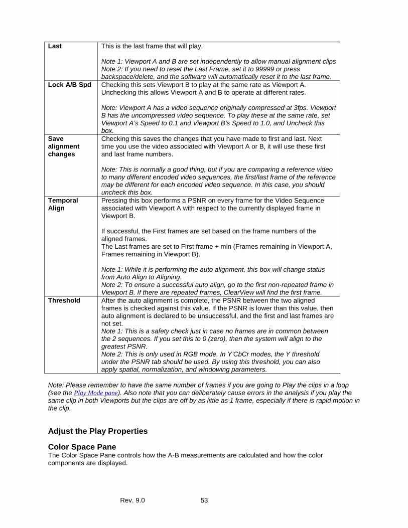
Rev. 9.0 53
Last This is the last frame that will play. Note 1: Viewport A and B are set independently to allow manual alignment clips Note 2: If you need to reset the Last Frame, set it to 99999 or press backspace/delete, and the software will automatically reset it to the last frame.
Lock A/B Spd Checking this sets Viewport B to play at the same rate as Viewport A. Unchecking this allows Viewport A and B to operate at different rates. Note: Viewport A has a video sequence originally compressed at 3fps. Viewport B has the uncompressed video sequence. To play these at the same rate, set Viewport A’s Speed to 0.1 and Viewport B’s Speed to 1.0, and Uncheck this box.
Save alignment changes
Checking this saves the changes that you have made to first and last. Next time you use the video associated with Viewport A or B, it will use these first and last frame numbers. Note: This is normally a good thing, but if you are comparing a reference video to many different encoded video sequences, the first/last frame of the reference may be different for each encoded video sequence. In this case, you should uncheck this box.
Temporal Align
Pressing this box performs a PSNR on every frame for the Video Sequence associated with Viewport A with respect to the currently displayed frame in Viewport B. If successful, the First frames are set based on the frame numbers of the aligned frames. The Last frames are set to First frame + min (Frames remaining in Viewport A, Frames remaining in Viewport B). Note 1: While it is performing the auto alignment, this box will change status from Auto Align to Aligning. Note 2: To ensure a successful auto align, go to the first non-repeated frame in Viewport B. If there are repeated frames, ClearView will find the first frame.
Threshold After the auto alignment is complete, the PSNR between the two aligned frames is checked against this value. If the PSNR is lower than this value, then auto alignment is declared to be unsuccessful, and the first and last frames are not set. Note 1: This is a safety check just in case no frames are in common between the 2 sequences. If you set this to 0 (zero), then the system will align to the greatest PSNR. Note 2: This is only used in RGB mode. In Y’CbCr modes, the Y threshold under the PSNR tab should be used. By using this threshold, you can also apply spatial, normalization, and windowing parameters.
Note: Please remember to have the same number of frames if you are going to Play the clips in a loop (see the Play Mode pane). Also note that you can deliberately cause errors in the analysis if you play the same clip in both Viewports but the clips are off by as little as 1 frame, especially if there is rapid motion in the clip.
Adjust the Play Properties
Color Space Pane The Color Space Pane controls how the A-B measurements are calculated and how the color components are displayed.
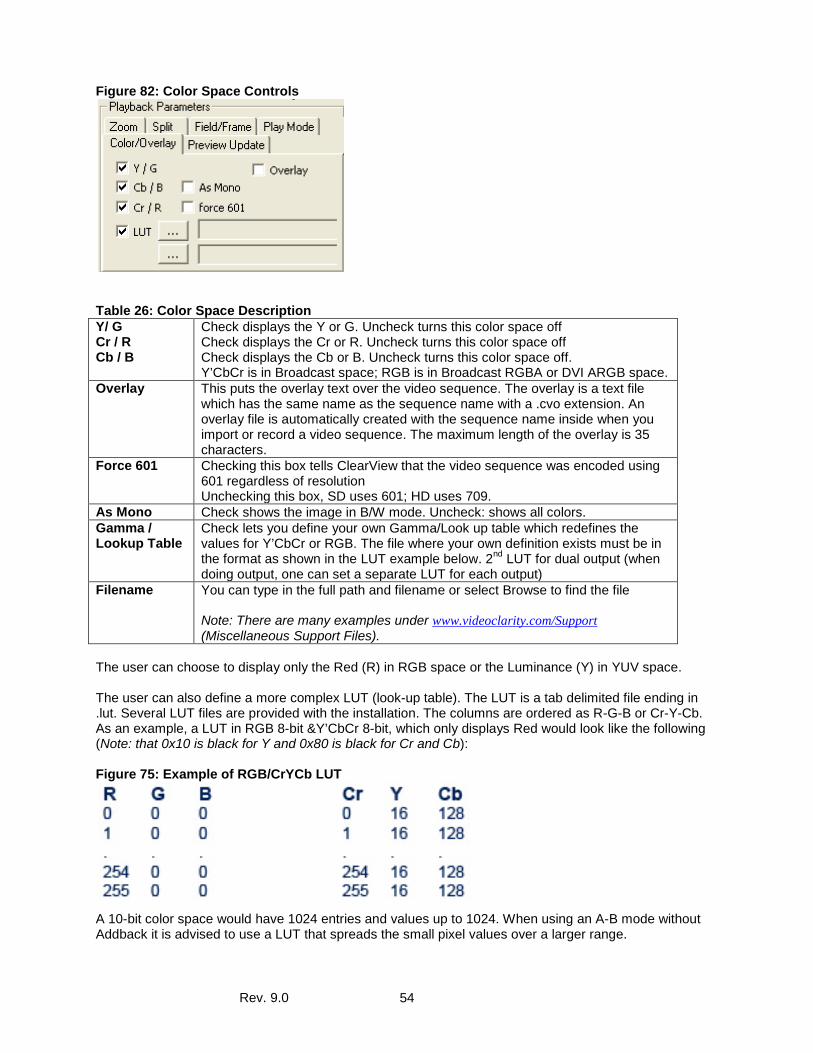
Rev. 9.0 54
Figure 82: Color Space Controls
Table 26: Color Space Description Y/ G Cr / R Cb / B
Check displays the Y or G. Uncheck turns this color space off Check displays the Cr or R. Uncheck turns this color space off Check displays the Cb or B. Uncheck turns this color space off. Y’CbCr is in Broadcast space; RGB is in Broadcast RGBA or DVI ARGB space.
Overlay This puts the overlay text over the video sequence. The overlay is a text file which has the same name as the sequence name with a .cvo extension. An overlay file is automatically created with the sequence name inside when you import or record a video sequence. The maximum length of the overlay is 35 characters.
Force 601 Checking this box tells ClearView that the video sequence was encoded using 601 regardless of resolution Unchecking this box, SD uses 601; HD uses 709.
As Mono Check shows the image in B/W mode. Uncheck: shows all colors. Gamma / Lookup Table
Check lets you define your own Gamma/Look up table which redefines the values for Y’CbCr or RGB. The file where your own definition exists must be in the format as shown in the LUT example below. 2nd LUT for dual output (when doing output, one can set a separate LUT for each output)
Filename You can type in the full path and filename or select Browse to find the file Note: There are many examples under www.videoclarity.com/Support (Miscellaneous Support Files).
The user can choose to display only the Red (R) in RGB space or the Luminance (Y) in YUV space. The user can also define a more complex LUT (look-up table). The LUT is a tab delimited file ending in .lut. Several LUT files are provided with the installation. The columns are ordered as R-G-B or Cr-Y-Cb. As an example, a LUT in RGB 8-bit &Y’CbCr 8-bit, which only displays Red would look like the following (Note: that 0x10 is black for Y and 0x80 is black for Cr and Cb): Figure 75: Example of RGB/CrYCb LUT
A 10-bit color space would have 1024 entries and values up to 1024. When using an A-B mode without Addback it is advised to use a LUT that spreads the small pixel values over a larger range.
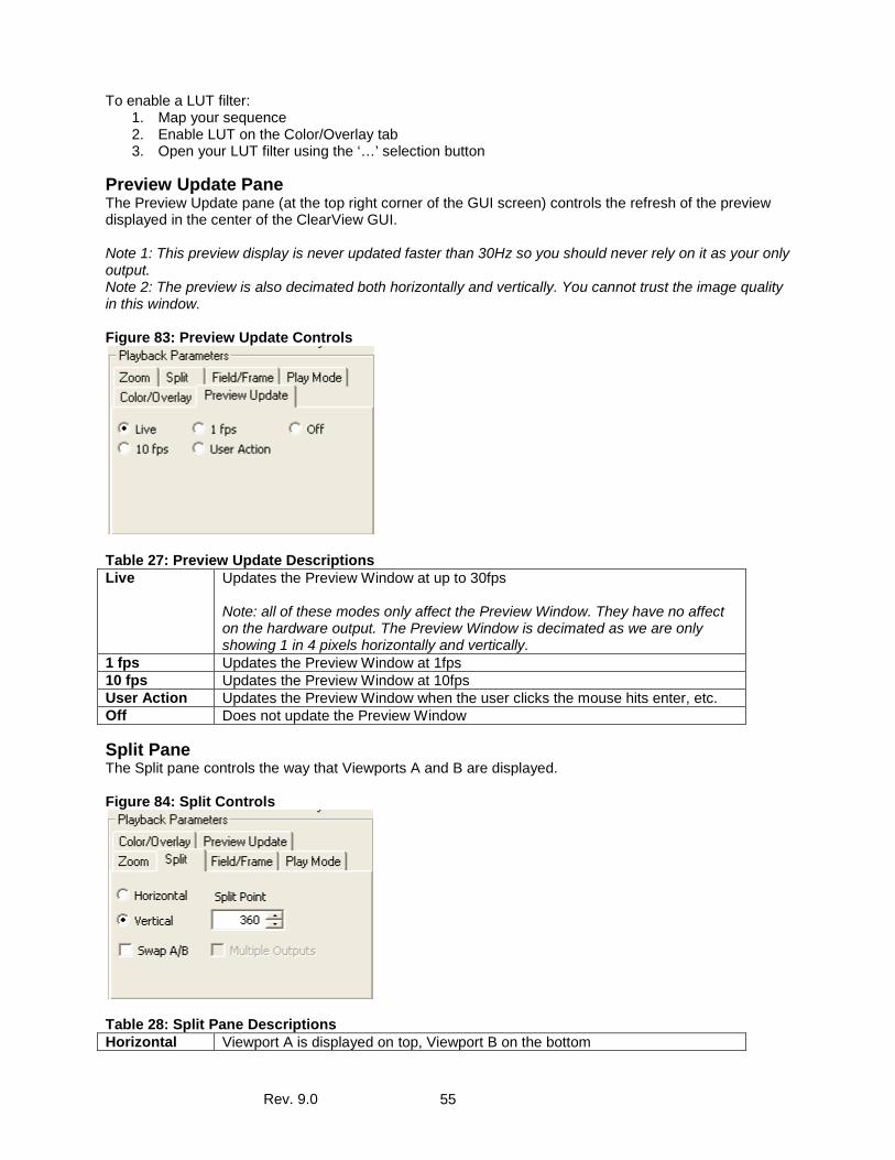
Rev. 9.0 55
To enable a LUT filter: 1. Map your sequence 2. Enable LUT on the Color/Overlay tab 3. Open your LUT filter using the ‘…’ selection button
Preview Update Pane The Preview Update pane (at the top right corner of the GUI screen) controls the refresh of the preview displayed in the center of the ClearView GUI. Note 1: This preview display is never updated faster than 30Hz so you should never rely on it as your only output. Note 2: The preview is also decimated both horizontally and vertically. You cannot trust the image quality in this window. Figure 83: Preview Update Controls
Table 27: Preview Update Descriptions Live Updates the Preview Window at up to 30fps
Note: all of these modes only affect the Preview Window. They have no affect on the hardware output. The Preview Window is decimated as we are only showing 1 in 4 pixels horizontally and vertically.
1 fps Updates the Preview Window at 1fps 10 fps Updates the Preview Window at 10fps User Action Updates the Preview Window when the user clicks the mouse hits enter, etc. Off Does not update the Preview Window
Split Pane The Split pane controls the way that Viewports A and B are displayed. Figure 84: Split Controls
Table 28: Split Pane Descriptions Horizontal Viewport A is displayed on top, Viewport B on the bottom
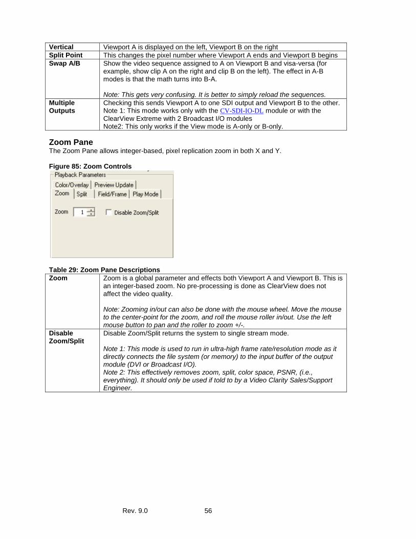
Rev. 9.0 56
Vertical Viewport A is displayed on the left, Viewport B on the right Split Point This changes the pixel number where Viewport A ends and Viewport B begins Swap A/B Show the video sequence assigned to A on Viewport B and visa-versa (for
example, show clip A on the right and clip B on the left). The effect in A-B modes is that the math turns into B-A. Note: This gets very confusing. It is better to simply reload the sequences.
Multiple Outputs
Checking this sends Viewport A to one SDI output and Viewport B to the other. Note 1: This mode works only with the CV-SDI-IO-DL module or with the ClearView Extreme with 2 Broadcast I/O modules Note2: This only works if the View mode is A-only or B-only.
Zoom Pane The Zoom Pane allows integer-based, pixel replication zoom in both X and Y. Figure 85: Zoom Controls
Table 29: Zoom Pane Descriptions Zoom Zoom is a global parameter and effects both Viewport A and Viewport B. This is
an integer-based zoom. No pre-processing is done as ClearView does not affect the video quality. Note: Zooming in/out can also be done with the mouse wheel. Move the mouse to the center-point for the zoom, and roll the mouse roller in/out. Use the left mouse button to pan and the roller to zoom +/-.
Disable Zoom/Split
Disable Zoom/Split returns the system to single stream mode. Note 1: This mode is used to run in ultra-high frame rate/resolution mode as it directly connects the file system (or memory) to the input buffer of the output module (DVI or Broadcast I/O). Note 2: This effectively removes zoom, split, color space, PSNR, (i.e., everything). It should only be used if told to by a Video Clarity Sales/Support Engineer.
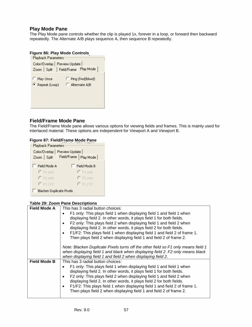
Rev. 9.0 57
Play Mode Pane The Play Mode pane controls whether the clip is played 1x, forever in a loop, or forward then backward repeatedly. The Alternate A/B plays sequence A, then sequence B repeatedly. Figure 86: Play Mode Controls
Field/Frame Mode Pane The Field/Frame Mode pane allows various options for viewing fields and frames. This is mainly used for interlaced material. These options are independent for Viewport A and Viewport B. Figure 87: Field/Frame Mode Pane
Table 29: Zoom Pane Descriptions Field Mode A This has 3 radial button choices:
• F1 only: This plays field 1 when displaying field 1 and field 1 when displaying field 2. In other words, it plays field 1 for both fields.
• F2 only: This plays field 2 when displaying field 1 and field 2 when displaying field 2. In other words, it plays field 2 for both fields.
• F1/F2: This plays field 1 when displaying field 1 and field 2 of frame 1. Then plays field 2 when displaying field 1 and field 2 of frame 2.
Note: Blacken Duplicate Pixels turns off the other field so F1 only means field 1 when displaying field 1 and black when displaying field 2. F2 only means black when displaying field 1 and field 2 when displaying field 2.
Field Mode B This has 3 radial button choices: • F1 only: This plays field 1 when displaying field 1 and field 1 when
displaying field 2. In other words, it plays field 1 for both fields. • F2 only: This plays field 2 when displaying field 1 and field 2 when
displaying field 2. In other words, it plays field 2 for both fields. • F1/F2: This plays field 1 when displaying field 1 and field 2 of frame 1.
Then plays field 2 when displaying field 1 and field 2 of frame 2.
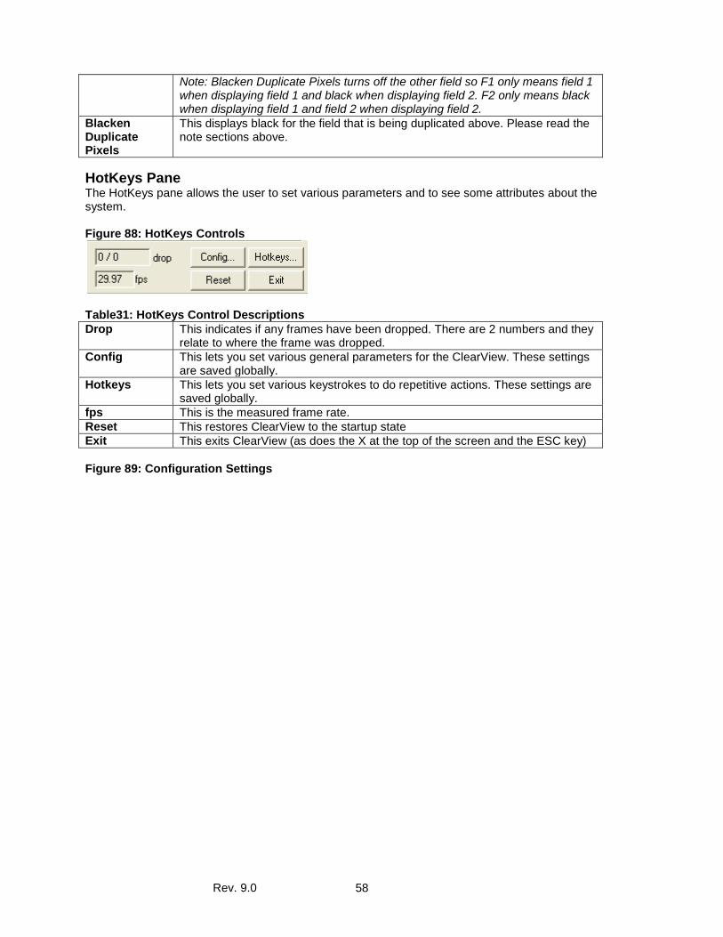
Rev. 9.0 58
Note: Blacken Duplicate Pixels turns off the other field so F1 only means field 1 when displaying field 1 and black when displaying field 2. F2 only means black when displaying field 1 and field 2 when displaying field 2.
Blacken Duplicate Pixels
This displays black for the field that is being duplicated above. Please read the note sections above.
HotKeys Pane The HotKeys pane allows the user to set various parameters and to see some attributes about the system. Figure 88: HotKeys Controls
Table31: HotKeys Control Descriptions Drop This indicates if any frames have been dropped. There are 2 numbers and they
relate to where the frame was dropped. Config This lets you set various general parameters for the ClearView. These settings
are saved globally. Hotkeys This lets you set various keystrokes to do repetitive actions. These settings are
saved globally. fps This is the measured frame rate. Reset This restores ClearView to the startup state Exit This exits ClearView (as does the X at the top of the screen and the ESC key) Figure 89: Configuration Settings
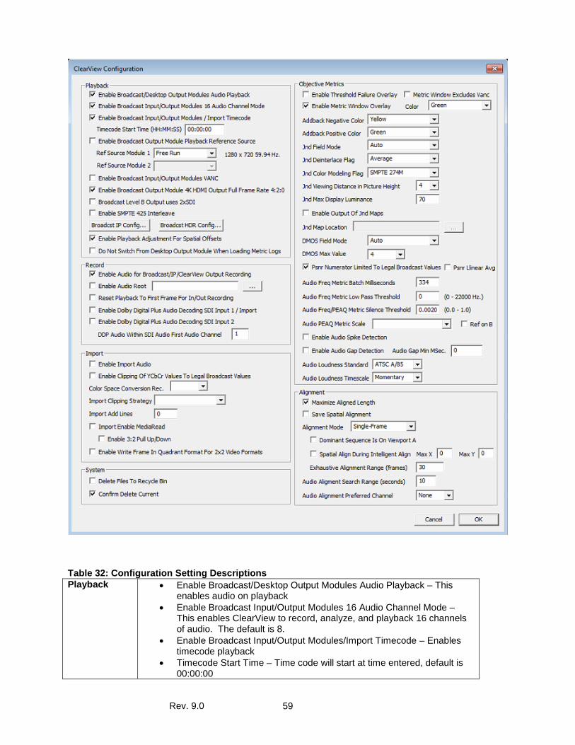
Rev. 9.0 59
Table 32: Configuration Setting Descriptions Playback • Enable Broadcast/Desktop Output Modules Audio Playback – This
enables audio on playback • Enable Broadcast Input/Output Modules 16 Audio Channel Mode –
This enables ClearView to record, analyze, and playback 16 channels of audio. The default is 8.
• Enable Broadcast Input/Output Modules/Import Timecode – Enables timecode playback
• Timecode Start Time – Time code will start at time entered, default is 00:00:00
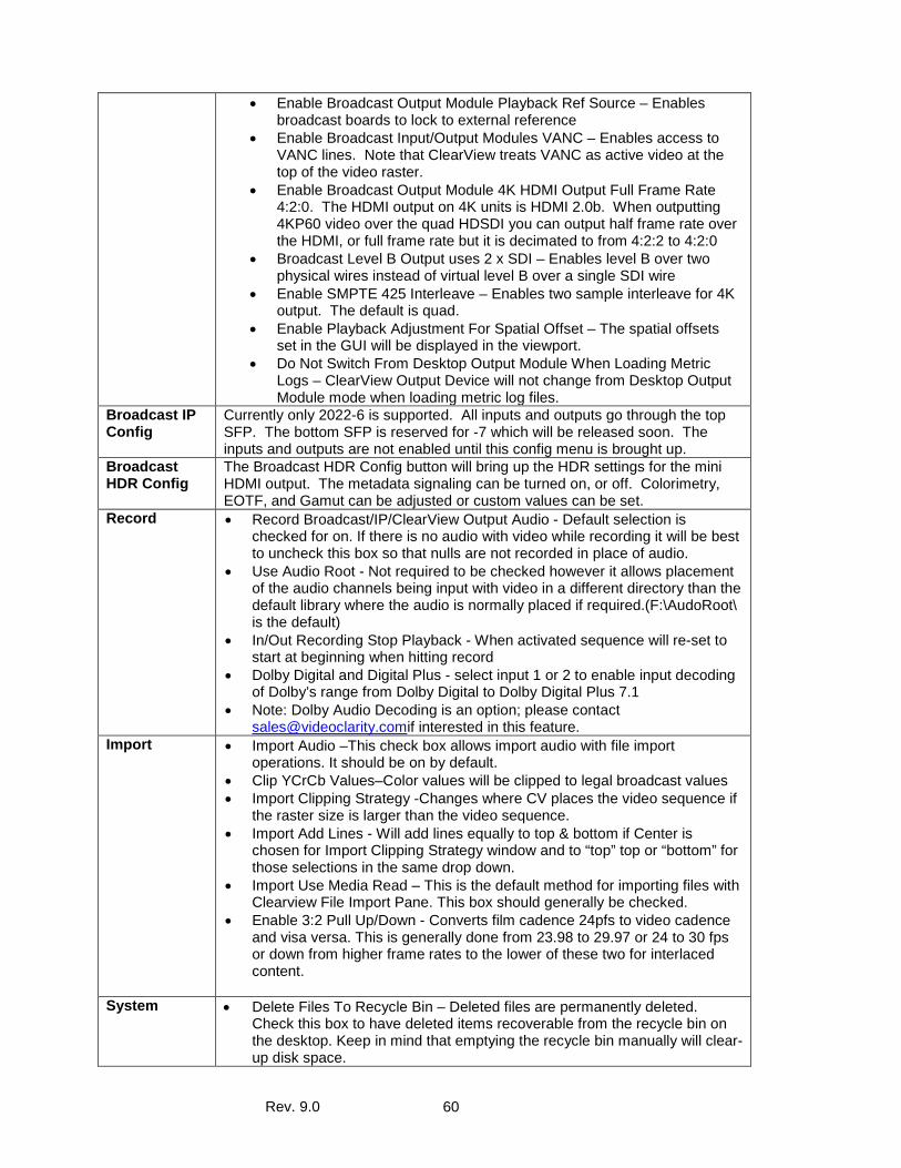
Rev. 9.0 60
• Enable Broadcast Output Module Playback Ref Source – Enables broadcast boards to lock to external reference
• Enable Broadcast Input/Output Modules VANC – Enables access to VANC lines. Note that ClearView treats VANC as active video at the top of the video raster.
• Enable Broadcast Output Module 4K HDMI Output Full Frame Rate 4:2:0. The HDMI output on 4K units is HDMI 2.0b. When outputting 4KP60 video over the quad HDSDI you can output half frame rate over the HDMI, or full frame rate but it is decimated to from 4:2:2 to 4:2:0
• Broadcast Level B Output uses 2 x SDI – Enables level B over two physical wires instead of virtual level B over a single SDI wire
• Enable SMPTE 425 Interleave – Enables two sample interleave for 4K output. The default is quad.
• Enable Playback Adjustment For Spatial Offset – The spatial offsets set in the GUI will be displayed in the viewport.
• Do Not Switch From Desktop Output Module When Loading Metric Logs – ClearView Output Device will not change from Desktop Output Module mode when loading metric log files.
Broadcast IP Config
Currently only 2022-6 is supported. All inputs and outputs go through the top SFP. The bottom SFP is reserved for -7 which will be released soon. The inputs and outputs are not enabled until this config menu is brought up.
Broadcast HDR Config
The Broadcast HDR Config button will bring up the HDR settings for the mini HDMI output. The metadata signaling can be turned on, or off. Colorimetry, EOTF, and Gamut can be adjusted or custom values can be set.
Record • Record Broadcast/IP/ClearView Output Audio - Default selection is checked for on. If there is no audio with video while recording it will be best to uncheck this box so that nulls are not recorded in place of audio.
• Use Audio Root - Not required to be checked however it allows placement of the audio channels being input with video in a different directory than the default library where the audio is normally placed if required.(F:\AudoRoot\ is the default)
• In/Out Recording Stop Playback - When activated sequence will re-set to start at beginning when hitting record
• Dolby Digital and Digital Plus - select input 1 or 2 to enable input decoding of Dolby’s range from Dolby Digital to Dolby Digital Plus 7.1
• Note: Dolby Audio Decoding is an option; please contact [email protected] interested in this feature.
Import • Import Audio –This check box allows import audio with file import operations. It should be on by default.
• Clip YCrCb Values–Color values will be clipped to legal broadcast values • Import Clipping Strategy -Changes where CV places the video sequence if
the raster size is larger than the video sequence. • Import Add Lines - Will add lines equally to top & bottom if Center is
chosen for Import Clipping Strategy window and to “top” top or “bottom” for those selections in the same drop down.
• Import Use Media Read – This is the default method for importing files with Clearview File Import Pane. This box should generally be checked.
• Enable 3:2 Pull Up/Down - Converts film cadence 24pfs to video cadence and visa versa. This is generally done from 23.98 to 29.97 or 24 to 30 fps or down from higher frame rates to the lower of these two for interlaced content.
System • Delete Files To Recycle Bin – Deleted files are permanently deleted.
Check this box to have deleted items recoverable from the recycle bin on the desktop. Keep in mind that emptying the recycle bin manually will clear-up disk space.
Rev. 9.0 61
Objective Metrics
• Threshold Failure Overlay – Places the text Failure in an overlay on the video when the threshold is passed.
• Metric Window Excludes VANC –Will effectively ignore VANC lines and CV will not report VANC metrics.
• Addback Negative Color – When B-A > Threshold in Addback mode, we show the pixel in a color. The default color is Yellow. You can change this.
• Addback Positive Color – When A-B > Threshold in Addback mode, we show the pixel in a color. The default color is Green. You can change this.JND Field Mode – This should be set to Auto which allows the system to do the right thing. For interlaced video sequences, the field mode should be field. For progressive video sequences, the field mode should be frame. If you override this, then you may want to set the De-interlace flag below.
• JND De-interlace Flag – If you are calculating interlaced data in frame mode, then you need to choose a de-interlace method. In general, you should use JND Field Mode = Auto.
o Average - averages to the top field and bottom field o Duplicate - duplicates the top field when active or the bottom field
when active o Hybrid Average - Creates a new line that is 1/4 of the summation of
the top and bottom fields o Median - calculates the median average as opposed to the
arithmetic average above • JND Color Modeling Flag – This is automatically set based on whether we
are in HD or SD. This is an override. o SMPTE274M - HD Color Mode (default) o SMPTE240M - SD Color Mode o EBU-625/50 - European Color Mode
• JND Viewing Modes in Picture Heights – This is how far the human tester was standing away from the display. JND has two defined distances based on the ANSI specification 2x (Expert) and 5x (Normal). Measure the height of the display and stand either 2x or 5x the height from the display. Video Clarity interpolated the results to achieve 3, 4, and 6x
• JND Max Display Luminance – This is the luminance of the viewed display. • Output JND Maps – This check box enables JND display maps to be
written to disk. The maps give an indication of what the algorithm “saw” when calculating the metrics. It is useful for figuring out why the score is the score for video processing vendors.
• JND Map Location – This is where the map files are stored on the hard disk array. The files are viewed using a command line program called vpseqw32.exe.
• DMOS Field Mode – This should be set to Auto which allows the system to do the right thing. For interlaced video sequences, the field mode should be field. For progressive video sequences, the field mode should be frame. You can override this.
• DMOS Max Value – DMOS is a scale from 0 (perfect) to X (very poor). The X is normally 4, but it can be 7 or 10. This sets the value to 4, 7, or 10. The numbers are linearly equivalent as we are using 4 digits of accuracy after the decimal place.
• PSNR Numerator Limited to Legal Broadcast Values – The PSNR numerator is the maximum legal value. Normally, this is set to 255 for 8-bit and 1023 for 10-bit. ANSI suggests using 235 for 8-bit and 940 for 10-bit, which is the setting used if you select this option.
• PSNR Linear Average – Setting this feature changes the average from a quadratic average to a linear average.
• Save Spatial Alignment – Setting this feature saves the temporal/spatial alignment with respect to the sequence in Viewport B. So if you change
Rev. 9.0 62
the sequence in Viewport A we will still keep the spatial changes saved. Previously if changed Viewport A the spatial offsets would be lost. This would be used if the reference was always the same but the processed clip changed, say at different bit rates or different encoders.
• Intelligent Alignment – Setting this feature instructs system to look through every frame in Viewport B and finds any frame that has high temporal change and looks for a match for that frame in Viewport A. Do this for two frames to calculate offset to make sure alignment is the same. In addition spatial align during temporal align checkbox may be used and set x and y parameters desired.
• Audio Freq Metric Batch – sets how many milliseconds we process at a given time
• Audio Freq metric Low Pass – you can skip over higher Hertz frequencies by setting what frequencies to test
• Audio Freq/PEAQ Metric Silence – Set an audio floor, silence threshold. The threshold is at zero, measuring all, set above 0 for any point between 0 and that number to be considered silence.
• Audio PEAQ Metric – sets scale perceived – audio quality • Ref on B–check if you are using B as your reference so scores reflect
correctly. • Audio Spike Detection – have notices when audio spikes, notifying you
when score may be low because of spikes. • Audio Gap Detection – have notices when audio gaps, alerting that score
may be low because of gaps. • Audio Gap Min – set the amount of milliseconds that count as a gap.
Ignoring smaller gaps so they do not affect the score. • Audio Loudness Standard - Setting the audio loudness standard for a-Peak
o ATSC A/85 o EBU R 128 o ARIB TR-B32 o NAB T032
• Audio Loudness Timescale - Setting the timescale for a-Peak o Momentary Loudness - 125 ms timescale for ATSC A/85 and 400
ms for the other standards. o Short Term Loudness - 10 second timescale for ATSC A/85 and 3
seconds for the other standards. o Integrated Loudness - a variable timescale from 1 to 60 seconds
for all standards. Alignment • Maximize Aligned Length – uncheck this box for alignment frame to be start
frame in sequence. • Save Spatial Alignment – allows to auto save so the special alignment is on
beat for future test. Saves special align offsets with the sequence. • Alignment drop-down–
--Single Frame: in this setting, pick a frame on viewport B then CV will find exact frame on viewport A for alignment. --Intelligent: finds best temporal and special match. When special alignment is check then you can set special range as well. --Exhaustive: Looks for frozen or dropped frames. Doesn't modify reference, creates a new file with dropped an duplicate frames so that testing doesn’t fall out of temporal alignment through.
• Audio Alignment Search Range – The amount of seconds to view when looking to align audio.
• Audio Alignment Preferred – Use this drop down to set which channel to start with.
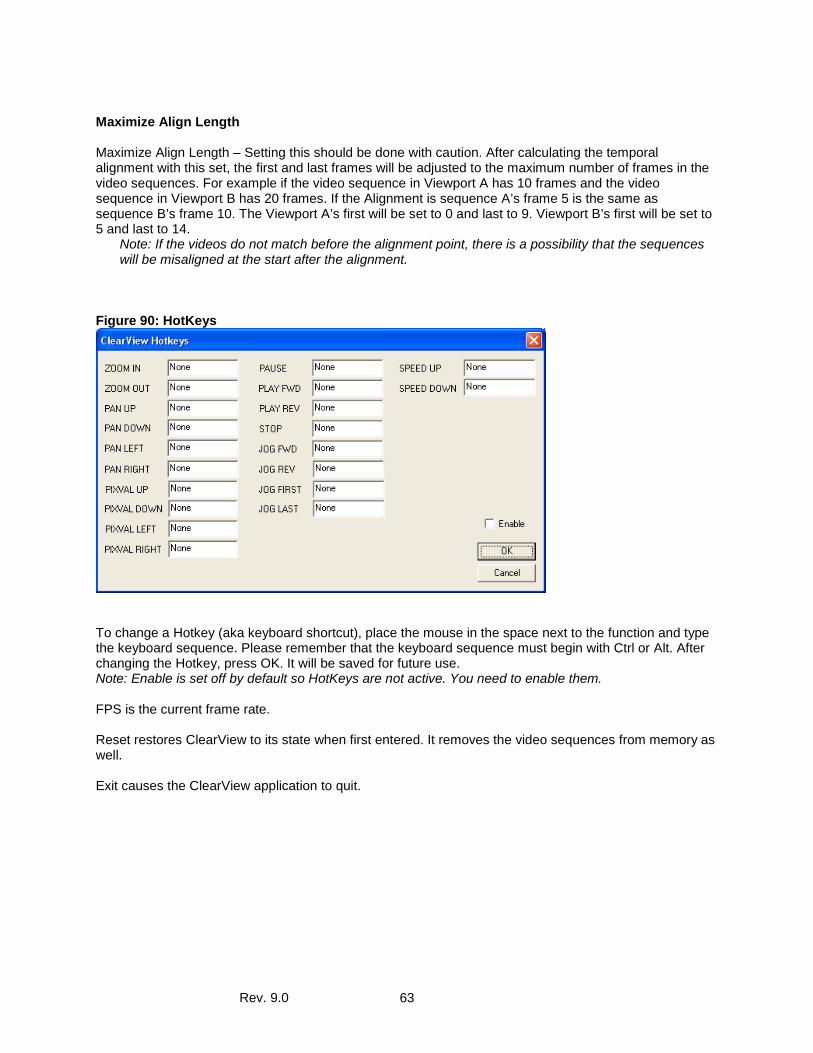
Rev. 9.0 63
Maximize Align Length Maximize Align Length – Setting this should be done with caution. After calculating the temporal alignment with this set, the first and last frames will be adjusted to the maximum number of frames in the video sequences. For example if the video sequence in Viewport A has 10 frames and the video sequence in Viewport B has 20 frames. If the Alignment is sequence A’s frame 5 is the same as sequence B’s frame 10. The Viewport A’s first will be set to 0 and last to 9. Viewport B’s first will be set to 5 and last to 14.
Note: If the videos do not match before the alignment point, there is a possibility that the sequences will be misaligned at the start after the alignment.
Figure 90: HotKeys
To change a Hotkey (aka keyboard shortcut), place the mouse in the space next to the function and type the keyboard sequence. Please remember that the keyboard sequence must begin with Ctrl or Alt. After changing the Hotkey, press OK. It will be saved for future use. Note: Enable is set off by default so HotKeys are not active. You need to enable them. FPS is the current frame rate. Reset restores ClearView to its state when first entered. It removes the video sequences from memory as well. Exit causes the ClearView application to quit.
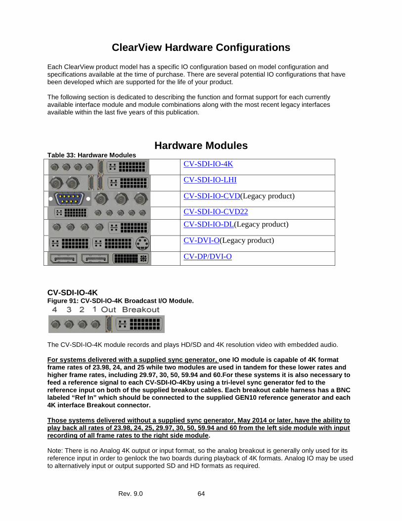
Rev. 9.0 64
ClearView Hardware Configurations Each ClearView product model has a specific IO configuration based on model configuration and specifications available at the time of purchase. There are several potential IO configurations that have been developed which are supported for the life of your product. The following section is dedicated to describing the function and format support for each currently available interface module and module combinations along with the most recent legacy interfaces available within the last five years of this publication.
Hardware Modules Table 33: Hardware Modules
CV-SDI-IO-4K
CV-SDI-IO-LHI
CV-SDI-IO-CVD(Legacy product)
CV-SDI-IO-CVD22
CV-SDI-IO-DL(Legacy product)
CV-DVI-O(Legacy product)
CV-DP/DVI-O
CV-SDI-IO-4K Figure 91: CV-SDI-IO-4K Broadcast I/O Module.
The CV-SDI-IO-4K module records and plays HD/SD and 4K resolution video with embedded audio. For systems delivered with a supplied sync generator, one IO module is capable of 4K format frame rates of 23.98, 24, and 25 while two modules are used in tandem for these lower rates and higher frame rates, including 29.97, 30, 50, 59.94 and 60.For these systems it is also necessary to feed a reference signal to each CV-SDI-IO-4Kby using a tri-level sync generator fed to the reference input on both of the supplied breakout cables. Each breakout cable harness has a BNC labeled “Ref In” which should be connected to the supplied GEN10 reference generator and each 4K interface Breakout connector. Those systems delivered without a supplied sync generator, May 2014 or later, have the ability to play back all rates of 23.98, 24, 25, 29.97, 30, 50, 59.94 and 60 from the left side module with input recording of all frame rates to the right side module. Note: There is no Analog 4K output or input format, so the analog breakout is generally only used for its reference input in order to genlock the two boards during playback of 4K formats. Analog IO may be used to alternatively input or output supported SD and HD formats as required.
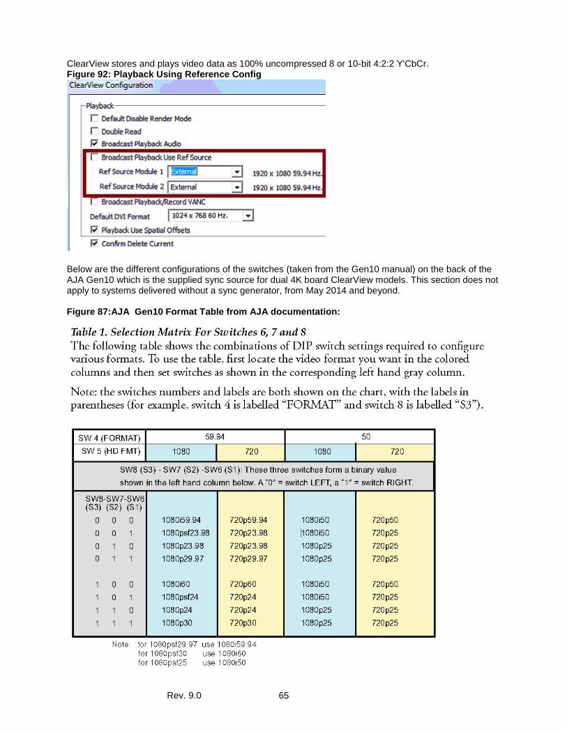
Rev. 9.0 65
ClearView stores and plays video data as 100% uncompressed 8 or 10-bit 4:2:2 Y'CbCr. Figure 92: Playback Using Reference Config
Below are the different configurations of the switches (taken from the Gen10 manual) on the back of the AJA Gen10 which is the supplied sync source for dual 4K board ClearView models. This section does not apply to systems delivered without a sync generator, from May 2014 and beyond. Figure 87:AJA Gen10 Format Table from AJA documentation:
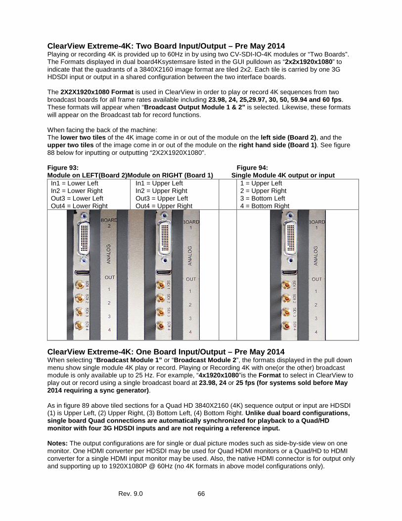
Rev. 9.0 66
ClearView Extreme-4K: Two Board Input/Output – Pre May 2014 Playing or recording 4K is provided up to 60Hz in by using two CV-SDI-IO-4K modules or “Two Boards”. The Formats displayed in dual board4Ksystemsare listed in the GUI pulldown as “2x2x1920x1080” to indicate that the quadrants of a 3840X2160 image format are tiled 2x2. Each tile is carried by one 3G HDSDI input or output in a shared configuration between the two interface boards. The 2X2X1920x1080 Format is used in ClearView in order to play or record 4K sequences from two broadcast boards for all frame rates available including 23.98, 24, 25,29.97, 30, 50, 59.94 and 60 fps. These formats will appear when “Broadcast Output Module 1 & 2” is selected. Likewise, these formats will appear on the Broadcast tab for record functions. When facing the back of the machine: The lower two tiles of the 4K image come in or out of the module on the left side (Board 2), and the upper two tiles of the image come in or out of the module on the right hand side (Board 1). See figure 88 below for inputting or outputting “2X2X1920X1080”. Figure 93: Figure 94: Module on LEFT(Board 2)Module on RIGHT (Board 1) Single Module 4K output or input In1 = Lower Left In2 = Lower Right Out3 = Lower Left Out4 = Lower Right
In1 = Upper Left In2 = Upper Right Out3 = Upper Left Out4 = Upper Right
1 = Upper Left 2 = Upper Right 3 = Bottom Left 4 = Bottom Right
ClearView Extreme-4K: One Board Input/Output – Pre May 2014 When selecting “Broadcast Module 1” or “Broadcast Module 2”, the formats displayed in the pull down menu show single module 4K play or record. Playing or Recording 4K with one(or the other) broadcast module is only available up to 25 Hz. For example, “4x1920x1080”is the Format to select in ClearView to play out or record using a single broadcast board at 23.98, 24 or 25 fps (for systems sold before May 2014 requiring a sync generator). As in figure 89 above tiled sections for a Quad HD 3840X2160 (4K) sequence output or input are HDSDI (1) is Upper Left, (2) Upper Right, (3) Bottom Left, (4) Bottom Right. Unlike dual board configurations, single board Quad connections are automatically synchronized for playback to a Quad/HD monitor with four 3G HDSDI inputs and are not requiring a reference input. Notes: The output configurations are for single or dual picture modes such as side-by-side view on one monitor. One HDMI converter per HDSDI may be used for Quad HDMI monitors or a Quad/HD to HDMI converter for a single HDMI input monitor may be used. Also, the native HDMI connector is for output only and supporting up to 1920X1080P @ 60Hz (no 4K formats in above model configurations only).
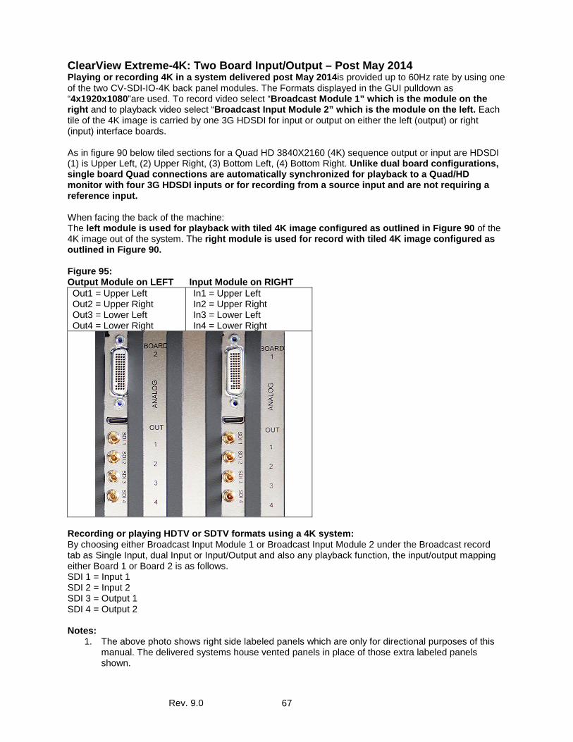
Rev. 9.0 67
ClearView Extreme-4K: Two Board Input/Output – Post May 2014 Playing or recording 4K in a system delivered post May 2014is provided up to 60Hz rate by using one of the two CV-SDI-IO-4K back panel modules. The Formats displayed in the GUI pulldown as “4x1920x1080”are used. To record video select “Broadcast Module 1” which is the module on the right and to playback video select “Broadcast Input Module 2” which is the module on the left. Each tile of the 4K image is carried by one 3G HDSDI for input or output on either the left (output) or right (input) interface boards. As in figure 90 below tiled sections for a Quad HD 3840X2160 (4K) sequence output or input are HDSDI (1) is Upper Left, (2) Upper Right, (3) Bottom Left, (4) Bottom Right. Unlike dual board configurations, single board Quad connections are automatically synchronized for playback to a Quad/HD monitor with four 3G HDSDI inputs or for recording from a source input and are not requiring a reference input. When facing the back of the machine: The left module is used for playback with tiled 4K image configured as outlined in Figure 90 of the 4K image out of the system. The right module is used for record with tiled 4K image configured as outlined in Figure 90. Figure 95: Output Module on LEFT Input Module on RIGHT Out1 = Upper Left Out2 = Upper Right Out3 = Lower Left Out4 = Lower Right
In1 = Upper Left In2 = Upper Right In3 = Lower Left In4 = Lower Right
Recording or playing HDTV or SDTV formats using a 4K system: By choosing either Broadcast Input Module 1 or Broadcast Input Module 2 under the Broadcast record tab as Single Input, dual Input or Input/Output and also any playback function, the input/output mapping either Board 1 or Board 2 is as follows. SDI 1 = Input 1 SDI 2 = Input 2 SDI 3 = Output 1 SDI 4 = Output 2 Notes:
1. The above photo shows right side labeled panels which are only for directional purposes of this manual. The delivered systems house vented panels in place of those extra labeled panels shown.
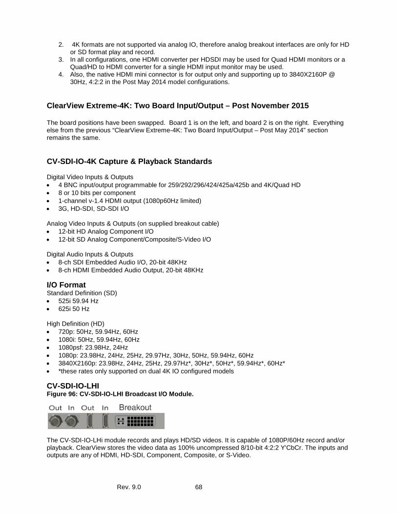
Rev. 9.0 68
2. 4K formats are not supported via analog IO, therefore analog breakout interfaces are only for HD or SD format play and record.
3. In all configurations, one HDMI converter per HDSDI may be used for Quad HDMI monitors or a Quad/HD to HDMI converter for a single HDMI input monitor may be used.
4. Also, the native HDMI mini connector is for output only and supporting up to 3840X2160P @ 30Hz, 4:2:2 in the Post May 2014 model configurations.
ClearView Extreme-4K: Two Board Input/Output – Post November 2015 The board positions have been swapped. Board 1 is on the left, and board 2 is on the right. Everything else from the previous “ClearView Extreme-4K: Two Board Input/Output – Post May 2014” section remains the same.
CV-SDI-IO-4K Capture & Playback Standards Digital Video Inputs & Outputs • 4 BNC input/output programmable for 259/292/296/424/425a/425b and 4K/Quad HD • 8 or 10 bits per component • 1-channel v-1.4 HDMI output (1080p60Hz limited) • 3G, HD-SDI, SD-SDI I/O Analog Video Inputs & Outputs (on supplied breakout cable) • 12-bit HD Analog Component I/O • 12-bit SD Analog Component/Composite/S-Video I/O Digital Audio Inputs & Outputs • 8-ch SDI Embedded Audio I/O, 20-bit 48KHz • 8-ch HDMI Embedded Audio Output, 20-bit 48KHz
I/O Format Standard Definition (SD) • 525i 59.94 Hz • 625i 50 Hz High Definition (HD) • 720p: 50Hz, 59.94Hz, 60Hz • 1080i: 50Hz, 59.94Hz, 60Hz • 1080psf: 23.98Hz, 24Hz • 1080p: 23.98Hz, 24Hz, 25Hz, 29.97Hz, 30Hz, 50Hz, 59.94Hz, 60Hz • 3840X2160p: 23.98Hz, 24Hz, 25Hz, 29.97Hz*, 30Hz*, 50Hz*, 59.94Hz*, 60Hz* • *these rates only supported on dual 4K IO configured models
CV-SDI-IO-LHI Figure 96: CV-SDI-IO-LHI Broadcast I/O Module.
The CV-SDI-IO-LHi module records and plays HD/SD videos. It is capable of 1080P/60Hz record and/or playback. ClearView stores the video data as 100% uncompressed 8/10-bit 4:2:2 Y'CbCr. The inputs and outputs are any of HDMI, HD-SDI, Component, Composite, or S-Video.
Rev. 9.0 69
CV-SDI-IO-LHI Capture & Playback Standards Digital Video Inputs & Outputs • 259/292/296/424/425a/425b • 8 or 10 bits per component • 2-channel v-1.3a HDMI I/O • 3G, HD-SDI, SD-SDI I/O Analog Video Inputs & Outputs • 12-bit HD Analog Component I/O • 12-bit SD Analog Component/Composite/S-Video I/O Digital Audio Inputs & Outputs • 2-ch Balanced XLR AES I/O, 24-bit 48KHz • 8-ch SDI Embedded Audio I/O, 20-bit 48KHz • 2-ch HDMI Embedded Audio I/O, 20-bit 48KHz Analog Audio Inputs & Outputs • 2-ch Balanced XLR Analog Audio I/O, 24-bit 48KHz
I/O Format Standard Definition (SD) • 525i 59.94 Hz • 625i 50 Hz High Definition (HD) • 720p: 50Hz, 59.94Hz, 60Hz • 1080i: 50Hz, 59.94Hz, 60Hz • 1080psf: 23.98Hz, 24Hz • 1080p: 23.98Hz, 24Hz, 25Hz, 29.97Hz, 30Hz, 50Hz, 59.94Hz, 60Hz
CV-SDI-IO-DL (Legacy Interface – Discontinued) Figure 97: CV-SDI-IO-DL Broadcast I/O Module
CV-SDI-IO-DL Capture Standards ClearView captures HD/SD digital data directly from VTRs, cameras, telecines, film scanners, or any other device. The data is stored as 100% uncompressed 8/10-bit data within ClearView. Digital Video Inputs • 2 X BNC - 75 Ohm • SD-SDI / HD-SDI selectable • Conforms to SMPTE 259/292/296M • 8 or 10 bits per component • 4:2:2 SD/HD-SDI Single-Link • 4:4:4 HD-SDI Dual-Link
Analog Video Inputs • 3 X BNC - Component (Y’PbPr or RGB) • 1 X BNC - Composite (Shared with Component BNC connections) • 2 X BNC – Y/C composite input (Shared with Component BNC connections) • 10-bit D/A
Rev. 9.0 70
Digital Video Outputs • 2 X BNC - 75 Ohm • SD-SDI / HD-SDI selectable • Conforms to SMPTE 259/292/296M • 8 or 10 bits per component • 4:2:2 HD-SDI, SDI Single-Link • 4:4:4 HD-SDI Dual-Link or dual 4:2:2 HD-SDI, SDI Single-Link Analog Video Output • 3 X BNC - Component (Y’PbPr or RGB) • 1 X BNC - Composite (Shared with Component BNC connections) • 2 X BNC – Y/C composite input (Shared with Component BNC connections) • 10-bit D/A Input Formats • 525i 59.94 Hz • 625i 50 Hz • 720p (50, 59.94, 60) Hz • 1080i (50, 59.94, 60) Hz • 1080psf (23.976, 24) Hz • 1080p (23.976, 24, 25, 29.97, 30, 50, 59.94, 60) Hz • 2048x1080p (23.98, 24) Hz • 2048x1080psf (23.98, 24) Hz • 2048x1556psf (14.98, 15) Hz Output Formats (independent from Input) • 525i 59.94 Hz • 625i 50 Hz • 720p (50, 59.94, 60) Hz • 1080i (50, 59.94, 60) Hz • 1080psf (23.976, 24) Hz • 1080p (23.976, 24, 25, 29.97, 30, 50, 59.94, 60) Hz
CV-SDI-IO-CVD (Legacy Interface – Discontinued) Figure 98: CV-SDI-IO-CVD Broadcast I/O Module.
The CV-SDI-IO-CVD module records, plays or simultaneous records and plays HD/SD videos. It is capable of 1080i/60Hz record and/or playback. ClearView stores the video data as 100% uncompressed 8/10-bit 4:2:2 Y'CbCr.
CV-SDI-IO-CVD Capture & Playback Standards Digital Video Inputs & Outputs 259/292/296/424 8 or 10 bits per component 3G, HD-SDI, SD-SDI I/O Digital Audio Inputs & Outputs 8-ch SDI Embedded Audio I/O, 20-bit 48khz
I/O Format Standard Definition (SD)
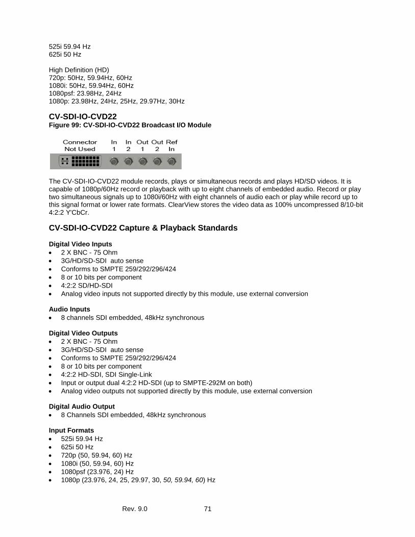
Rev. 9.0 71
525i 59.94 Hz 625i 50 Hz High Definition (HD) 720p: 50Hz, 59.94Hz, 60Hz 1080i: 50Hz, 59.94Hz, 60Hz 1080psf: 23.98Hz, 24Hz 1080p: 23.98Hz, 24Hz, 25Hz, 29.97Hz, 30Hz
CV-SDI-IO-CVD22 Figure 99: CV-SDI-IO-CVD22 Broadcast I/O Module
The CV-SDI-IO-CVD22 module records, plays or simultaneous records and plays HD/SD videos. It is capable of 1080p/60Hz record or playback with up to eight channels of embedded audio. Record or play two simultaneous signals up to 1080i/60Hz with eight channels of audio each or play while record up to this signal format or lower rate formats. ClearView stores the video data as 100% uncompressed 8/10-bit 4:2:2 Y'CbCr.
CV-SDI-IO-CVD22 Capture & Playback Standards Digital Video Inputs • 2 X BNC - 75 Ohm • 3G/HD/SD-SDI auto sense • Conforms to SMPTE 259/292/296/424 • 8 or 10 bits per component • 4:2:2 SD/HD-SDI • Analog video inputs not supported directly by this module, use external conversion
Audio Inputs • 8 channels SDI embedded, 48kHz synchronous Digital Video Outputs • 2 X BNC - 75 Ohm • 3G/HD/SD-SDI auto sense • Conforms to SMPTE 259/292/296/424 • 8 or 10 bits per component • 4:2:2 HD-SDI, SDI Single-Link • Input or output dual 4:2:2 HD-SDI (up to SMPTE-292M on both) • Analog video outputs not supported directly by this module, use external conversion Digital Audio Output • 8 Channels SDI embedded, 48kHz synchronous Input Formats • 525i 59.94 Hz • 625i 50 Hz • 720p (50, 59.94, 60) Hz • 1080i (50, 59.94, 60) Hz • 1080psf (23.976, 24) Hz • 1080p (23.976, 24, 25, 29.97, 30, 50, 59.94, 60) Hz
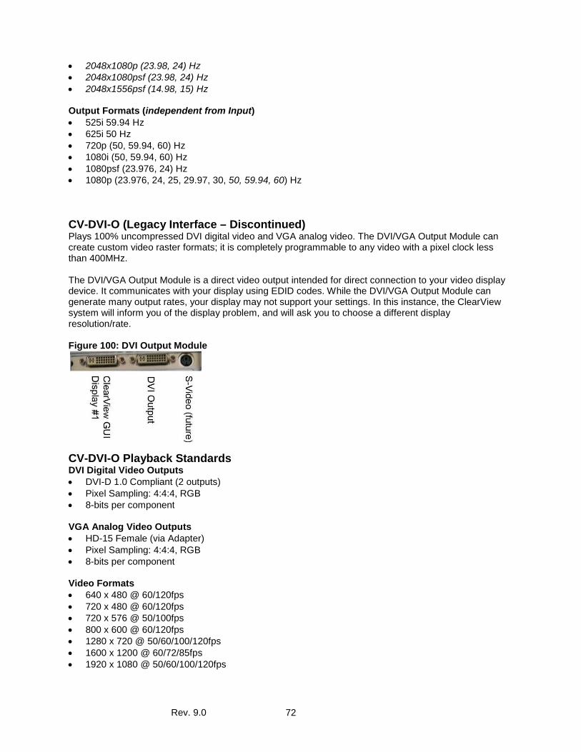
Rev. 9.0 72
• 2048x1080p (23.98, 24) Hz • 2048x1080psf (23.98, 24) Hz • 2048x1556psf (14.98, 15) Hz Output Formats (independent from Input) • 525i 59.94 Hz • 625i 50 Hz • 720p (50, 59.94, 60) Hz • 1080i (50, 59.94, 60) Hz • 1080psf (23.976, 24) Hz • 1080p (23.976, 24, 25, 29.97, 30, 50, 59.94, 60) Hz
CV-DVI-O (Legacy Interface – Discontinued) Plays 100% uncompressed DVI digital video and VGA analog video. The DVI/VGA Output Module can create custom video raster formats; it is completely programmable to any video with a pixel clock less than 400MHz. The DVI/VGA Output Module is a direct video output intended for direct connection to your video display device. It communicates with your display using EDID codes. While the DVI/VGA Output Module can generate many output rates, your display may not support your settings. In this instance, the ClearView system will inform you of the display problem, and will ask you to choose a different display resolution/rate. Figure 100: DVI Output Module
CV-DVI-O Playback Standards DVI Digital Video Outputs • DVI-D 1.0 Compliant (2 outputs) • Pixel Sampling: 4:4:4, RGB • 8-bits per component VGA Analog Video Outputs • HD-15 Female (via Adapter) • Pixel Sampling: 4:4:4, RGB • 8-bits per component Video Formats • 640 x 480 @ 60/120fps • 720 x 480 @ 60/120fps • 720 x 576 @ 50/100fps • 800 x 600 @ 60/120fps • 1280 x 720 @ 50/60/100/120fps • 1600 x 1200 @ 60/72/85fps • 1920 x 1080 @ 50/60/100/120fps
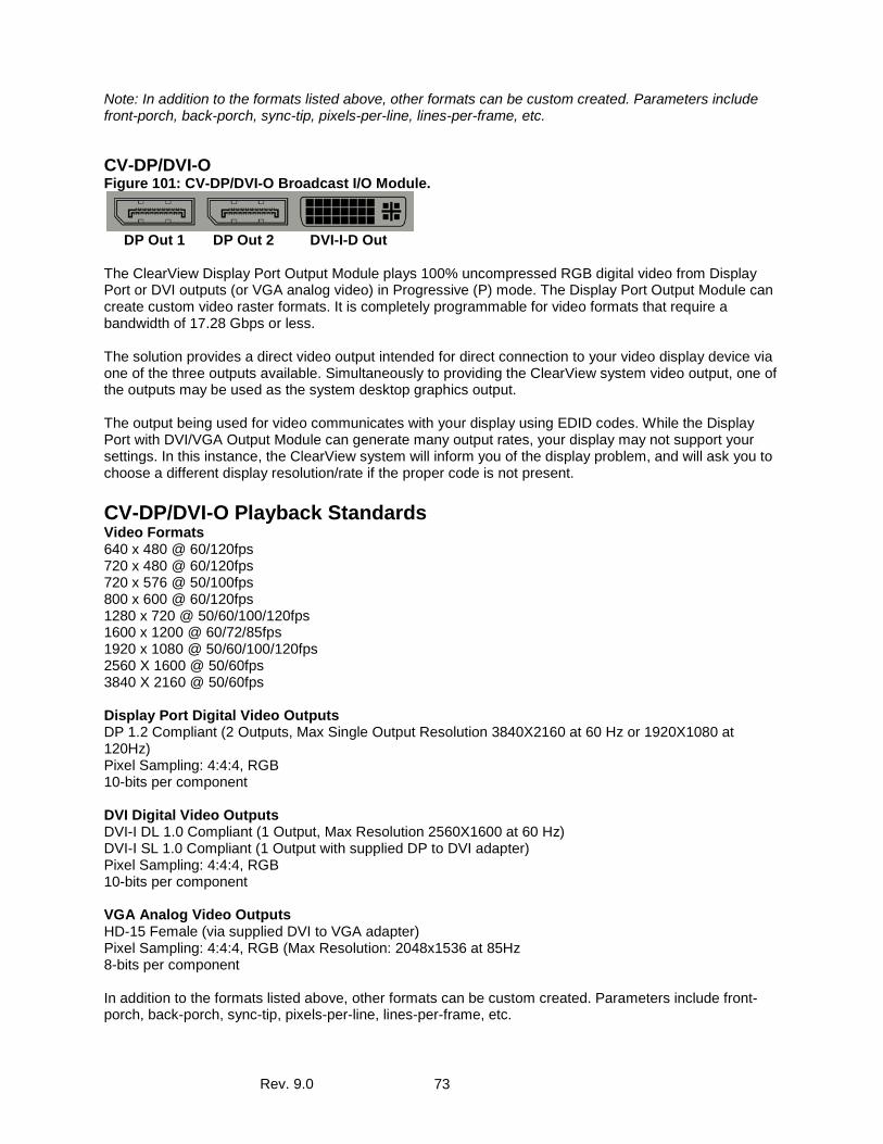
Rev. 9.0 73
Note: In addition to the formats listed above, other formats can be custom created. Parameters include front-porch, back-porch, sync-tip, pixels-per-line, lines-per-frame, etc.
CV-DP/DVI-O Figure 101: CV-DP/DVI-O Broadcast I/O Module.
DP Out 1 DP Out 2 DVI-I-D Out The ClearView Display Port Output Module plays 100% uncompressed RGB digital video from Display Port or DVI outputs (or VGA analog video) in Progressive (P) mode. The Display Port Output Module can create custom video raster formats. It is completely programmable for video formats that require a bandwidth of 17.28 Gbps or less. The solution provides a direct video output intended for direct connection to your video display device via one of the three outputs available. Simultaneously to providing the ClearView system video output, one of the outputs may be used as the system desktop graphics output. The output being used for video communicates with your display using EDID codes. While the Display Port with DVI/VGA Output Module can generate many output rates, your display may not support your settings. In this instance, the ClearView system will inform you of the display problem, and will ask you to choose a different display resolution/rate if the proper code is not present. CV-DP/DVI-O Playback Standards Video Formats 640 x 480 @ 60/120fps 720 x 480 @ 60/120fps 720 x 576 @ 50/100fps 800 x 600 @ 60/120fps 1280 x 720 @ 50/60/100/120fps 1600 x 1200 @ 60/72/85fps 1920 x 1080 @ 50/60/100/120fps 2560 X 1600 @ 50/60fps 3840 X 2160 @ 50/60fps Display Port Digital Video Outputs DP 1.2 Compliant (2 Outputs, Max Single Output Resolution 3840X2160 at 60 Hz or 1920X1080 at 120Hz) Pixel Sampling: 4:4:4, RGB 10-bits per component DVI Digital Video Outputs DVI-I DL 1.0 Compliant (1 Output, Max Resolution 2560X1600 at 60 Hz) DVI-I SL 1.0 Compliant (1 Output with supplied DP to DVI adapter) Pixel Sampling: 4:4:4, RGB 10-bits per component VGA Analog Video Outputs HD-15 Female (via supplied DVI to VGA adapter) Pixel Sampling: 4:4:4, RGB (Max Resolution: 2048x1536 at 85Hz 8-bits per component In addition to the formats listed above, other formats can be custom created. Parameters include front-porch, back-porch, sync-tip, pixels-per-line, lines-per-frame, etc.
Rev. 9.0 74
File Format Import Types Accom YUV CCIR 601 8 Bit ARI Raw Bayer Pattern Avid AVR, DS HD/SD, DV (*.gen) Avid _DNxHD Avid Meridian &Y’CbCr Avid OMFI (*.omf, *.omfi) AVR, JFIF, JPED, Meridian, RGB, Y’CbCr Cineon (CIN) CineWave Digital Negative (.dng) DPX RGB 8, RGB 10, Y’CbCr 4:2:2 DV Movies (*.dv, *.dif) DVS Direct File Format (*.dvs) DVSD, DV25, DV50, MPEG-I, MJPEG DigiSuite H.261, H.263, H.264, H.265 HDV Headerless/Raw (*.hdr, *.yuv, *.rgb, *.raw) HiCon SLB32 RFB format (*.slb) Image (gif, jpg, png) Jaleo Direct Format (*.js) JPEG JPEG2000 Media 100 MJPEG Microsoft BMP, DIB Files (*.dps) Microsoft AVI (*.avi) MJPEG MPEG-1 4:2:0 (*.mpg, *.mpeg) MPEG-2 Elem. Stream, (4:2:0/4:2:2) MPEG-2 (*.m2v) MPEG-2 Program Stream, (4:2:0/4:2:2) MPEG 2/4 in Transport Stream (4:2:0/4:2:2) MPEG-2 in TS, MPTS (4:2:0/4:2:2) MPEG-4 Part 2 MPEG-4 /AVC Elementary Stream (4:2:0/4:2:2), (*.h264)
MPEG-4 /AVC in TS, MPTS (4:2:0/4:2:2), (H.264)4:2:0/4:2:2, (*.h264) MPEG-4 (*.m4v) MPEG-H HEVC/H.265 4:2:0 Main Profile (*h.265) MPEG-H in TS, MPTS MXF Format (DV, DVCPro50, MPEG, IMX) Newtek Video Toaster (*.rtv) Phantom Support (cine) Photo CD PCD PhotoShopFilmStrip (*.flm) Photoshop PSD Portable anymap PNM Portable Bitmap Format PBM DPS Velocity Portable graymap PGM Portable pixmap PPM Profile GXF Format/SMPTE-360 (*.gxf) QuickTime Movies (*.mov) QuickTime Formats with proper codec, ProRes, etc. RealVideo (*.ra, *.rm, *.ram) Red Camera Stream (r3d) Run-Length encoding (rle) SGI Movie Format (*.mv) Silicon Image Bayer (siv) Sun Raster Sun Raster (*.ras) SGI RGB Targa TGA, ICB, VDA, VST Targa 3000, Pinnacle TIFF, TIF Transport Stream (*.ts) v210Y’CbCr 10 Bit product VC-1 Pro, Viewstore (vsr) vcap, vcap10 Windows Media (*.asf, *.wmf, *.wmv) Y’CbCr 8/10 Y’CbCr, RGB YCrCb 8/RGBA
Audio Import Formats Exported File Formats MPEG-2 Layer 1 (.mp1) QuickTime with up to 16 audio channels MPEG-2 Layer 3 (.mp3) Microsoft AVI (*.avi), BMP Waveform Audio (.wav) Headerless/Raw (*.yuv, *rgb, *.raw) Adaptive Multi-rate (.amr) Audio Interchange File Format (.aiff) Windows Media Audio (.wma) Advanced Audio Coding (.aac)