Embed Size (px)
Citation preview

ClearLink EtherNet/IP Setup and
Object Data Reference Rev. 1.08, February 7, 2022

2
Table of Contents Table of Contents .................................................................................................................................................... 2
Introduction ............................................................................................................................................................. 4
Welcome ............................................................................................................................................................. 4
What's in this Document ..................................................................................................................................... 4
Safety Information .................................................................................................................................................. 5
Precautionary Statement ..................................................................................................................................... 5
General Disclaimer ............................................................................................................................................. 5
ClearLink Network Configuration .......................................................................................................................... 6
Please Read This Before You Begin ................................................................................................................... 6
Find the IP Address for Your ClearLink............................................................................................................. 7
Setting a Static IP Address .................................................................................................................................. 8
Re-Enabling DHCP ............................................................................................................................................. 9
Using your EtherNet/IP PLC with ClearLink ....................................................................................................... 10
EDS File and Implicit Communication............................................................................................................. 11
Sending Explicit Messages ............................................................................................................................... 13
Using ClearPath Servo Motors with ClearLink .................................................................................................... 14
Configuring a ClearPath-SD Servo ................................................................................................................... 14
Configuring a ClearPath-MC Servo .................................................................................................................. 15
Configuring Third Party Step and Direction Drives ......................................................................................... 15
EtherNet/IP Object Model .................................................................................................................................... 16
Identity Object (01HEX - 1 Instance) ................................................................................................................... 16
Assembly Object (04HEX - 4 Instances) .......................................................................................................... 17
Step and Direction T2O Assembly ............................................................................................................... 18
Step and Direction O2T Assembly ............................................................................................................... 19
Step and Direction Configuration Assembly ................................................................................................ 20
Motor Connector T2O Assembly.................................................................................................................. 22
Motor Connector O2T Assembly.................................................................................................................. 23
Motor Connector Configuration Assembly .................................................................................................. 24
TCP Object (F5HEX - 1 Instance) ........................................................................................................................ 25
Ethernet Link Object (EtherNet/IP only) (F6HEX - 1 Instance) .......................................................................... 26
Discrete Input Point Object (8HEX - 13 Instances) ............................................................................................. 27
Discrete Output Point Object (9HEX - 6 Instances) ............................................................................................. 29
Analog Input Point Object (AHEX - 4 Instances) ................................................................................................ 31
Configuring A-9 through A-12 as a 0-10V analog input .............................................................................. 32
Analog Output Point Object (BHEX - 1 Instances) .............................................................................................. 33
Configuring IO-0 as a 4-20mA or 0-20mA analog output ........................................................................... 34
Position Sensor Object (23HEX - 1 Instance) ...................................................................................................... 35
Step and Direction Motor Configuration Object (64HEX - 4 Instances) ............................................................. 37
Step and Direction Motor Input Object (65HEX - 4 Instance) ............................................................................. 41
Step and Direction Motor Output Object (66HEX - 4 Instance) .......................................................................... 46
M-Connector Object (67HEX - 4 Instances) ........................................................................................................ 49
CCIO Object (68HEX - 1 Instances) .................................................................................................................... 52

3
ASCII Object (70HEX - 1 Instance) ..................................................................................................................... 54
ClearLink Board Object (69HEX - 1 Instance) .................................................................................................... 58
Appendix A: ClearLink Status Blink Codes ......................................................................................................... 60
Example Status Code Timing Diagram ............................................................................................................ 60
Appendix B: Troubleshooting Motion .................................................................................................................. 61
4
Introduction
Welcome
Thank you for purchasing a ClearLink EtherNet/IP Motion and I/O Controller. This document is an EtherNet/IP object reference manual for the following products:
• ClearLink Controller (Teknic Part # CLNK-4-13)
• I/O Expansion Board, optional (Teknic Part # CCIO-8)
• Encoder Input Board, optional (Teknic Part # CL-ENCDR-DFIN)
For the hardware reference and hook-up information, please see the ClearLink Hardware Reference Manual.
What's in this Document
• Network Configuration Setup
• ClearPath Motor Compatibility and Motor Setup Information
• Implicit Messaging Data Assemblies
• EtherNet/IP Objects and Attributes
• ClearLink Blink/Status Codes
• Troubleshooting Motion Issues

5
Safety Information
Precautionary Statement
Always follow appropriate safety precautions when installing and using any automated motion control equipment. Motion control systems should be designed and utilized to prevent personnel from coming into contact with moving parts and electrical contacts that could potentially cause injury or death. Read all cautions, warnings, and notes before attempting to install or operate this device. Follow all applicable codes and standards when using this equipment. Failure to use this equipment as described may impair or neutralize protections built into the product.
General Disclaimer
The User is responsible for determining the suitability of this product for his or her application. The User must
ensure that Teknic’s products are installed and utilized in accordance with all local, state, federal and private
governing bodies and meet all applicable health and safety standards.
Teknic has made all reasonable efforts to accurately present the information in the published documentation
and shall not be responsible for any incorrect information which may result from unintentional oversights.
Due to continuous product improvements, the product specifications as stated in the documentation are subject
to change at any time and without notice. The User is responsible for consulting a representative of Teknic for
detailed information and to determine any changes of information in the published documentation.
Should Teknic’s products be used in an application that is safety critical, the User must provide appropriate
safety testing of the products, adequate safety devices, guarding, warning notices and machine-specific
training to protect the operator and/or bystanders from injury.

6
ClearLink Network Configuration
Please Read This Before You Begin
ClearLink comes preconfigured with DHCP enabled by default; ClearLink does not ship with a pre-assigned (static) IP address. ClearLink network configuration settings can only be changed via Ethernet connection, so to get started, your ClearLink must first be connected to a DHCP server (which will automatically assign an IP address to your ClearLink). Note: Routers and office networks typically have built in DHCP servers.
After an IP address has been assigned to your ClearLink, you should be able to locate it on your network (at which point you can assign it a static IP address if you prefer). Continue reading this section for step-by-step instructions on how to do this.
Note: ClearLink cannot be assigned an IP address via direct connection to a PC or to a switch that is not connected to an upstream DHCP server.

7
Find the IP Address for Your ClearLink All steps require the ClearLink to be powered with 20-28 VDC power (24VDC typical). See ClearLink hardware manual for details.
1. Connect ClearLink to your network or router via its EtherNet/IP port. An IP address will be assigned to it automatically. (Note: this step is invisible to the user).
Important: This step will not work if ClearLink is actively communicating with another EtherNet/IP device (like a PLC).
2. Download and install the Molex IP software tool: https://www.molex.com/mx_upload/superfamily/iccc/EtherNet_IPTool.html
3. Find your ClearLink using the Molex software tool: a. From the “List Identity” tab, set Message type to Broadcast and click “Send List Identity Request on UDP” b. Select the ClearLink that you want to configure from the center panel c. Verify that you are talking to the desired ClearLink by checking the Serial Number in the right panel d. The Station field in the top left corner should be set the selected IP address

8
Setting a Static IP Address 4. In the “0xF5 TCP/IP” tab, click Get_Attribute_All to read the current settings. 5. Change Configuration Control (attr 3) Startup Configuration to “Stored Value” and click Set_Attribute in that frame. 6. Enter the desired values in Interface Configuration (attr 5) and click Set_Attribute in that frame.
7. Restart the ClearLink
a. On the “0x01 Identity” tab, set the Reset Service parameter to 0 and click Reset.
8. Verify TCP/IP changes a. Find your ClearLink again using the “List Identity” tab. b. Switch to the “0xF5 TCP/IP” tab. c. Click Get_Attribute_All. d. Verify that the settings are correct.
9
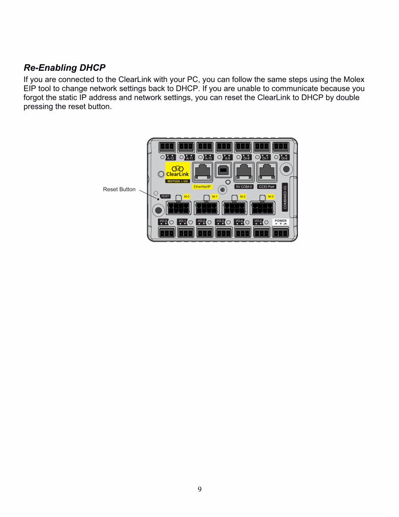
Re-Enabling DHCP
If you are connected to the ClearLink with your PC, you can follow the same steps using the Molex EIP tool to change network settings back to DHCP. If you are unable to communicate because you forgot the static IP address and network settings, you can reset the ClearLink to DHCP by double pressing the reset button.
ther et/IP
M M 3M 1M 0
A 1 A 11 A 10 A DI DI DI
5V COM 0 CCIO Port
COMBI D I/O
I/O 5I/O I/O 3I/O I/O 0 I/O 1
R S T
Reset Button

10
Using your EtherNet/IP PLC with ClearLink
ClearLink is an EtherNet/IP slave device (aka server or adapter), and as such must be controlled from an EtherNet/IP master device (aka client or scanner), typically a PLC. Exactly how you set up communication between your PLC and ClearLink depends on your answers to the following questions:
• “Can you add ClearLink’s EDS file (Electronic Data Sheet) to your PLC project?”
• “Can your PLC send Explicit Messages targeting specific Classes, Instances, and Attributes?”
If your PLC supports EDS files, the easiest way to get started is to setup an Implicit Connection using ClearLink’s DS file.
If your PLC does not support EDS files or Implicit communication, then your PLC will have to send repeated Explicit Messages to communicate with ClearLink.
Note: If your PLC does not support EDS files nor Explicit Messaging, it is not compatible with ClearLink.
11
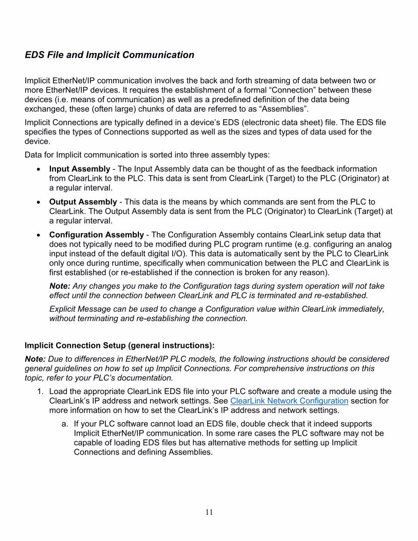
EDS File and Implicit Communication
Implicit EtherNet/IP communication involves the back and forth streaming of data between two or more ther et/IP devices. It requires the establishment of a formal “Connection” between these devices (i.e. means of communication) as well as a predefined definition of the data being exchanged, these (often large) chunks of data are referred to as “Assemblies”.
Implicit Connections are typically defined in a device’s DS (electronic data sheet) file. The DS file specifies the types of Connections supported as well as the sizes and types of data used for the device.
Data for Implicit communication is sorted into three assembly types:
• Input Assembly - The Input Assembly data can be thought of as the feedback information from ClearLink to the PLC. This data is sent from ClearLink (Target) to the PLC (Originator) at a regular interval.
• Output Assembly - This data is the means by which commands are sent from the PLC to ClearLink. The Output Assembly data is sent from the PLC (Originator) to ClearLink (Target) at a regular interval.
• Configuration Assembly - The Configuration Assembly contains ClearLink setup data that does not typically need to be modified during PLC program runtime (e.g. configuring an analog input instead of the default digital I/O). This data is automatically sent by the PLC to ClearLink only once during runtime, specifically when communication between the PLC and ClearLink is first established (or re-established if the connection is broken for any reason).
Note: Any changes you make to the Configuration tags during system operation will not take effect until the connection between ClearLink and PLC is terminated and re-established.
Explicit Message can be used to change a Configuration value within ClearLink immediately, without terminating and re-establishing the connection.
Implicit Connection Setup (general instructions):
Note: Due to differences in EtherNet/IP PLC models, the following instructions should be considered general guidelines on how to set up Implicit Connections. For comprehensive instructions on this topic, refer to your PLC’s documentation.
1. Load the appropriate ClearLink EDS file into your PLC software and create a module using the ClearLink’s IP address and network settings. See ClearLink Network Configuration section for more information on how to set the ClearLink’s IP address and network settings.
a. If your PLC software cannot load an EDS file, double check that it indeed supports Implicit EtherNet/IP communication. In some rare cases the PLC software may not be capable of loading EDS files but has alternative methods for setting up Implicit Connections and defining Assemblies.

12
2. Set the appropriate Connection type (see figure below). For ClearPath-SD servos and other Step and Direction drives, select the “Step Dir” Connection type. For ClearPath-MC servos, use the “M-Connector” type.
Note: Any application that uses a combination of SD and MC series ClearPath motors will require two separate ClearLink units, each configured with the appropriate Connection type.
a. The “ o Config”, “Listen Only”, and “Input Only” Connection types are not appropriate for most PLCs. However, for PLCs that don’t support Configuration Assemblies, the “ o Config” Connection type may be the right choice. In such a case, changing any of the default configuration data would require a (manually programmed) Explicit Message from the PLC.
3. The next steps will depend on your PLC and how much information was utilized from the EDS file. Ideally, you will have defined a Configuration Assembly, an Input Assembly, and an Output Assembly, broken out into named tags. Use these tags to interact with ClearLink.
a. If the PLC software can load EDS files, but the Configuration, Input, and Output Assemblies are not automatically broken into separate tags for each parameter, you may have to manually extract the parameters from each Assembly. Consult the Assembly Object section for this information.
13
Sending Explicit Messages
Explicit EtherNet/IP Messaging requires programming the PLC to send messages to the device, and requires a response for each message sent. Unlike with Implicit communication, data is not automatically updated without a message (originating from the PLC) requesting that data.
You can use Explicit Messages to get/set individual Attributes, or to send and receive entire data assemblies.
When a response to an Explicit Message is received, it is up to the PLC program to properly unpack the data to appropriate tags in the program.
Note: Teknic has written an example for the Allen Bradley Micro800 series PLC that does this, i.e. it packs and unpacks a set of data into named tags.
Using Explicit Messages (general instructions):
Note: Due to differences in EtherNet/IP PLC models, the following instructions should only be considered general guidelines on how to use Explicit Messages. For comprehensive instructions on this topic, refer to your PLC’s documentation.
1. Most PLCs that support Explicit Messages will have some type of ladder or function block to trigger the message. To define the message, you will need to specify some or all of the following:
a. The IP address/network settings of the ClearLink device. See ClearLink Network Configuration section for more information on how to set the ClearLink’s IP address and network settings.
b. CIP Service Code (usually 0x0 for ‘getting’ and 0x10 for ‘setting’).
c. Class number, Attribute number, Instance number for the parameter/assembly you intend to read/write. The Class, Attribute, and Instance numbers for ClearLink can be found in the tables for each type of Class in this document.
d. The size/type of the data you are requesting to read/write. Data is typically presented as an array of bytes.
2. Once the Explicit Message is defined, it is likely that the data will need to be packed/unpacked into individual named tags in order to be referenced by the rest of the PLC program.
3. During operation, the PLC program must manage when/how often to send the message.
a. Some applications might use Explicit Messaging instead of an Implicit connection to get/set assembly data. These messages should be configured to continuously repeat at a high frequency.
b. Other applications might only be changing a single parameter at a time, and Explicit Messages would only be sent as needed.
Important note for using ClearPath-MC with Explicit Messages only: you must change the default Motor Mode in the ClearLink Board Object from 0 to 1. (This is only done automatically when using an Implicit Connection.)

14
Using ClearPath Servo Motors with ClearLink
In addition to configurable analog and digital I/O, a ClearLink controller can be configured to communicate with up to four independent stepper/servo motors such as Teknic's ClearPath, All-In-One servo motors.
ClearPath servo motors have three distinct digital control series; Step and Direction (SD), Motion Control (MC), and Software Control (SC). The ClearLink controller can control up to four Step and Direction (SD) servos or up to four ClearPath-MC servos. ClearLink cannot communicate with the SC (Software Control) series of ClearPath motors.
Configuring a ClearPath-SD Servo
The ClearPath motor settings must be set using the MSP software to enable all features of ClearLink's Step and Direction control.
Note: this section is not intended to be a comprehensive setup guide for ClearPath. It will only cover the specific settings recommended for ClearLink to correctly interface with a ClearPath-SD servo. Refer to the user manual of your ClearPath series for additional configuration and setup information.
1. Configure ClearPath to use the correct High-Level Feedback (HLFB) mode
a. In MSP, click the "Advanced" tab, then "High-Level Feedback"
b. Select the HLFB mode "ASG-Position, w/Measured Torque"
c. Select the 482 Hz PWM Carrier Frequency
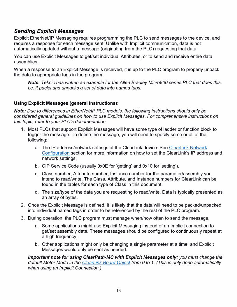
2. Configure ClearPath with the correct homing settings (this is only necessary when using hardstop homing)
a. In the Homing section of MSP, enable homing and click "Setup..."
15
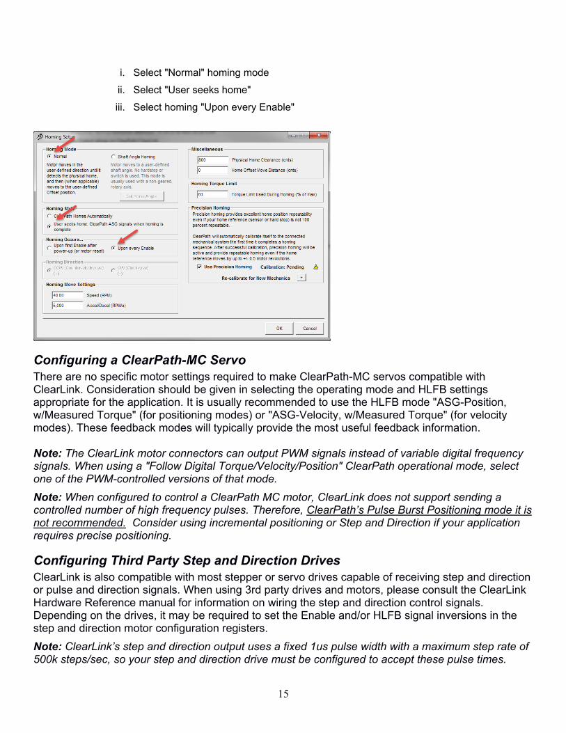
i. Select "Normal" homing mode
ii. Select "User seeks home"
iii. Select homing "Upon every Enable"
Configuring a ClearPath-MC Servo
There are no specific motor settings required to make ClearPath-MC servos compatible with ClearLink. Consideration should be given in selecting the operating mode and HLFB settings appropriate for the application. It is usually recommended to use the HLFB mode "ASG-Position, w/Measured Torque" (for positioning modes) or "ASG-Velocity, w/Measured Torque" (for velocity modes). These feedback modes will typically provide the most useful feedback information. Note: The ClearLink motor connectors can output PWM signals instead of variable digital frequency signals. When using a "Follow Digital Torque/Velocity/Position" ClearPath operational mode, select one of the PWM-controlled versions of that mode.
Note: When configured to control a ClearPath MC motor, ClearLink does not support sending a controlled number of high frequency pulses. Therefore, ClearPath’s Pulse Burst Positioning mode it is not recommended. Consider using incremental positioning or Step and Direction if your application requires precise positioning.
Configuring Third Party Step and Direction Drives
ClearLink is also compatible with most stepper or servo drives capable of receiving step and direction or pulse and direction signals. When using 3rd party drives and motors, please consult the ClearLink Hardware Reference manual for information on wiring the step and direction control signals. Depending on the drives, it may be required to set the Enable and/or HLFB signal inversions in the step and direction motor configuration registers.
Note: ClearLink’s step and direction output uses a fixed 1us pulse width with a maximum step rate of 500k steps/sec, so your step and direction drive must be configured to accept these pulse times.

16
EtherNet/IP Object Model
Identity Object (01HEX - 1 Instance)
The following tables contain the attribute, status, and common services information for the Identity Object.
Table 1 Identity Object (01HEX - 1 Instance)
Instance Attribute
ID Name
CIP Data Type
Data Value Access
Rule
Class (Instance 0)
1 Revision UINT 1.1 Get
Instance 1 1 Vendor number UINT 424 Get
2 Device type UINT 43 Get
3 Product code number UINT 1 Get
4
Product major revision Product minor revision
USINT USINT
2.91 Get
5 Status WORD 0 Get
6 Serial number UDINT Unique 32 bit value Get
7
Product name SHORT STRING32
“ClearLink” Get
Table 2 Identity Object’s common services
Service code
Implemented for Service name
Class level Instance level
05Hex No Yes Reset
0EHex Yes Yes Get_Attribute_Single
10Hex No Yes Set_Attribute_Single
17
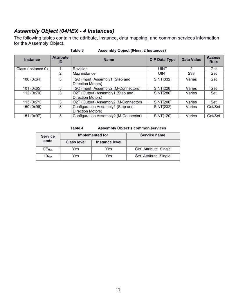
Assembly Object (04HEX - 4 Instances)
The following tables contain the attribute, instance, data mapping, and common services information for the Assembly Object.
Table 3 Assembly Object (04HEX - 2 Instances)
Instance Attribute
ID Name CIP Data Type Data Value
Access Rule
Class (Instance 0) 1 Revision UINT 2 Get 2 Max instance UINT 238 Get
100 (0x64) 3 T2O (Input) Assembly1 (Step and Direction Motors)
SINT[332] Varies Get
101 (0x65) 3 T2O (Input) Assembly2 (M-Connectors) SINT[228] Varies Get 112 (0x70) 3 O2T (Output) Assembly1 (Step and
Direction Motors) SINT[280] Varies Set
113 (0x71) 3 O2T (Output) Assembly2 (M-Connectors SINT[200] Varies Set 150 (0x96) 3 Configuration Assembly1 (Step and
Direction Motors) SINT[232] Varies Get/Set
151 (0x97) 3 Configuration Assembly2 (M-Connector) SINT[120] Varies Get/Set
Table 4 Assembly Object’s common services
Service code
Implemented for Service name
Class level Instance level
0EHex Yes Yes Get_Attribute_Single
10Hex Yes Yes Set_Attribute_Single
18
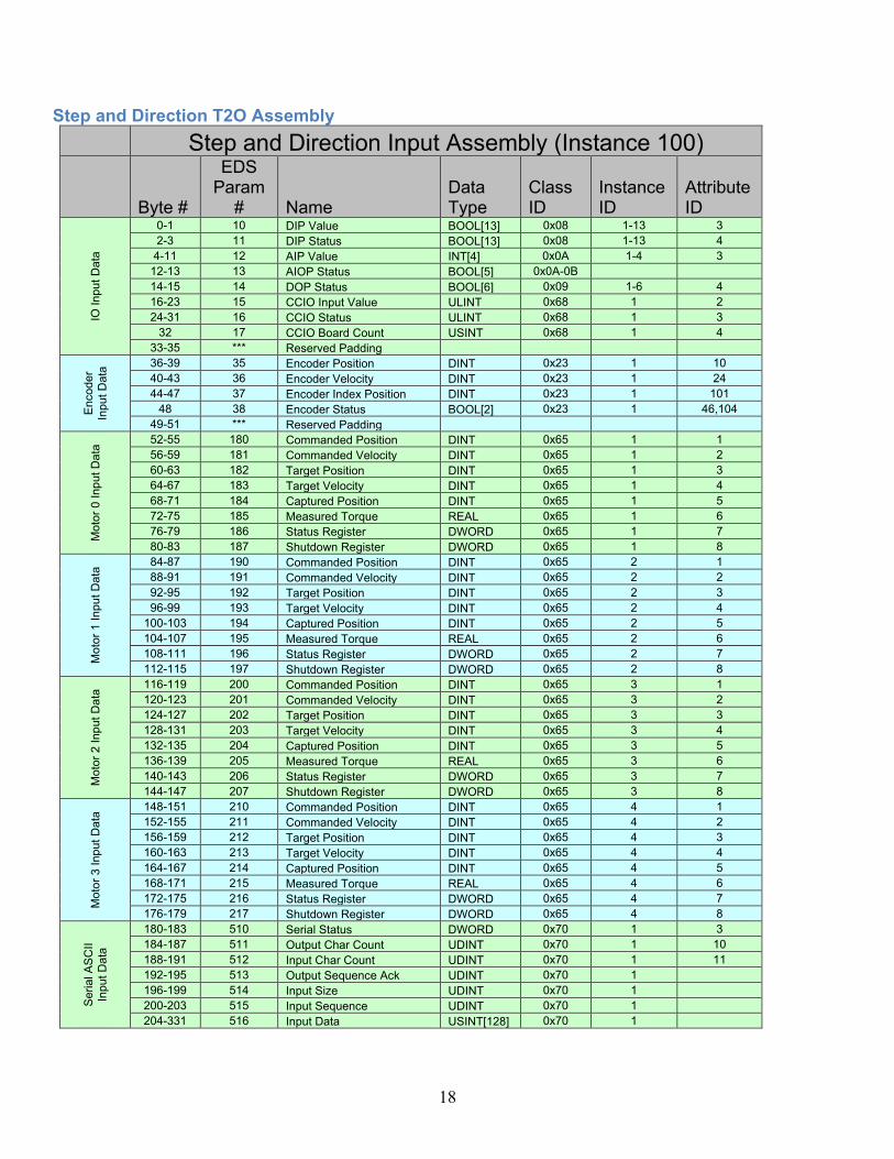
Step and Direction T2O Assembly
Step and Direction Input Assembly (Instance 100)
Byte #
EDS Param
# Name Data Type
Class ID
Instance ID
Attribute ID
IO Input
Data
0-1 10 DIP Value BOOL[13] 0x08 1-13 3
2-3 11 DIP Status BOOL[13] 0x08 1-13 4
4-11 12 AIP Value INT[4] 0x0A 1-4 3
12-13 13 AIOP Status BOOL[5] 0x0A-0B
14-15 14 DOP Status BOOL[6] 0x09 1-6 4
16-23 15 CCIO Input Value ULINT 0x68 1 2
24-31 16 CCIO Status ULINT 0x68 1 3
32 17 CCIO Board Count USINT 0x68 1 4
33-35 *** Reserved Padding
Encoder
Inp
ut
Da
ta 36-39 35 Encoder Position DINT 0x23 1 10
40-43 36 Encoder Velocity DINT 0x23 1 24
44-47 37 Encoder Index Position DINT 0x23 1 101
48 38 Encoder Status BOOL[2] 0x23 1 46,104
49-51 *** Reserved Padding
Moto
r 0 Inp
ut D
ata
52-55 180 Commanded Position DINT 0x65 1 1
56-59 181 Commanded Velocity DINT 0x65 1 2
60-63 182 Target Position DINT 0x65 1 3
64-67 183 Target Velocity DINT 0x65 1 4
68-71 184 Captured Position DINT 0x65 1 5
72-75 185 Measured Torque REAL 0x65 1 6
76-79 186 Status Register DWORD 0x65 1 7
80-83 187 Shutdown Register DWORD 0x65 1 8
Moto
r 1 Inp
ut D
ata
84-87 190 Commanded Position DINT 0x65 2 1
88-91 191 Commanded Velocity DINT 0x65 2 2
92-95 192 Target Position DINT 0x65 2 3
96-99 193 Target Velocity DINT 0x65 2 4
100-103 194 Captured Position DINT 0x65 2 5
104-107 195 Measured Torque REAL 0x65 2 6
108-111 196 Status Register DWORD 0x65 2 7
112-115 197 Shutdown Register DWORD 0x65 2 8
Moto
r 2 Inp
ut D
ata
116-119 200 Commanded Position DINT 0x65 3 1
120-123 201 Commanded Velocity DINT 0x65 3 2
124-127 202 Target Position DINT 0x65 3 3
128-131 203 Target Velocity DINT 0x65 3 4
132-135 204 Captured Position DINT 0x65 3 5
136-139 205 Measured Torque REAL 0x65 3 6
140-143 206 Status Register DWORD 0x65 3 7
144-147 207 Shutdown Register DWORD 0x65 3 8
Moto
r 3 Inp
ut D
ata
148-151 210 Commanded Position DINT 0x65 4 1
152-155 211 Commanded Velocity DINT 0x65 4 2
156-159 212 Target Position DINT 0x65 4 3
160-163 213 Target Velocity DINT 0x65 4 4
164-167 214 Captured Position DINT 0x65 4 5
168-171 215 Measured Torque REAL 0x65 4 6
172-175 216 Status Register DWORD 0x65 4 7
176-179 217 Shutdown Register DWORD 0x65 4 8
Seri
al A
SC
II
Inp
ut
Da
ta
180-183 510 Serial Status DWORD 0x70 1 3
184-187 511 Output Char Count UDINT 0x70 1 10
188-191 512 Input Char Count UDINT 0x70 1 11
192-195 513 Output Sequence Ack UDINT 0x70 1
196-199 514 Input Size UDINT 0x70 1
200-203 515 Input Sequence UDINT 0x70 1
204-331 516 Input Data USINT[128] 0x70 1

19
Step and Direction O2T Assembly
Step and Direction Output Assembly (Instance 112)
Byte #
EDS Param
# Name Data Type
Class ID
Instance ID
Attribute ID
IO O
utp
ut D
ata
0-1 20 AOP Value INT 0x0B 1 3
2-3 21 DOP Value BOOL[6] 0x09 1-6 3
4-9 22 DOP PWM USINT[6] 0x09 1-6 100
10-11 *** Reserved
12-19 23 CCIO Output Value ULINT 0x68 1 1
20-23 40 Encoder AddToPosition DINT 0x23 1 104
Moto
r 0
Outp
ut
Data
24-27 220 Move Distance DINT 0x66 1 1
28-31 221 Velocity Limit UDINT 0x66 1 3
32-35 222 Acceleration Limit UDINT 0x66 1 4
36-39 223 Deceleration Limit UDINT 0x66 1 5
40-43 224 Jog Velocity DINT 0x66 1 2
44-47 225 Add To Position DINT 0x66 1 7
48-51 226 Output Register DWORD 0x66 1 6
Moto
r 1
Outp
ut
Data
52-55 230 Move Distance DINT 0x66 2 1
56-59 231 Velocity Limit UDINT 0x66 2 3
60-63 232 Acceleration Limit UDINT 0x66 2 4
64-67 233 Deceleration Limit UDINT 0x66 2 5
68-71 234 Jog Velocity DINT 0x66 2 2
72-75 235 Add To Position DINT 0x66 2 7
76-79 236 Output Register DWORD 0x66 2 6
Moto
r 2
Outp
ut
Data
80-83 240 Move Distance DINT 0x66 3 1
84-87 241 Velocity Limit UDINT 0x66 3 3
88-91 242 Acceleration Limit UDINT 0x66 3 4
92-95 243 Deceleration Limit UDINT 0x66 3 5
96-99 244 Jog Velocity DINT 0x66 3 2
100-103 245 Add To Position DINT 0x66 3 7
104-107 246 Output Register DWORD 0x66 3 6
Moto
r 3
Outp
ut
Data
108-111 250 Move Distance DINT 0x66 4 1
112-115 251 Velocity Limit UDINT 0x66 4 3
116-119 252 Acceleration Limit UDINT 0x66 4 4
120-123 253 Deceleration Limit UDINT 0x66 4 5
124-127 254 Jog Velocity DINT 0x66 4 2
128-131 255 Add To Position DINT 0x66 4 7
132-135 256 Output Register DWORD 0x66 4 6
Seri
al A
SC
II
Outp
ut
Data
136-139 520 Serial Config DWORD 0x70 1 2
140-143 521 Input Sequence Ack UDINT 0x70 1
144-147 522 Output Size UDINT 0x70 1
148-151 523 Output Sequence UDINT 0x70 1
152-279 524 Output Data USINT[128] 0x70 1

20
Step and Direction Configuration Assembly
Step and Dir Config Assembly (Instance 150)
Byte #
EDS Param
# Name Data Type Default
Class ID
Instance ID
Attribute ID
IO M
ode
Config D
ata
0 1 AI0 Range USINT 100 0x0A 1 7
1 2 AI1 Range USINT 100 0x0A 2 7
2 3 AI2 Range USINT 100 0x0A 3 7
3 4 AI3 Range USINT 100 0x0A 4 7
4 5 AO0 Range USINT 100 0x0B 1 7
5-6 6 Bit0 DOP PWM Frequency BOOL 0 0x09 0 100
Bit 1 CCIO Enable BOOL 0 0x68 1 6
7 *** Reserved Padding
IO
Filt
ers
8-11 7 AIP Filters USINT 10 0x0A 1-4 100
12-63 8 DIP Filters*** UINT[26] 10000 0x08 1-13 5,6
64-71 9 CCIO Filters USINT[8] 10 0x68 1 5
Encoder
Config D
ata
72-75 30 Encoder Velocity Resolution UDINT
100 0x23 1 26
76 31 Reserved USINT 5 0x23 1 100
77 32 Encoder Configuration 0 0x23 1 12, 102
78-79 *** Reserved Padding
Moto
r 0 C
onfigura
tion D
ata
80-83 100 Config Register DWORD 0x0008 0x64 1 1
84-87 101 Follow Divisor DINT 1 0x64 1 12
88-91 102 Follow Multiplier DINT 1 0x64 1 13
92-95 103 Max Deceleration DINT 10000000 0x64 1 10
96-99 104 Soft Limit 1 DINT 0 0x64 1 2
100-103 105 Soft Limit 2 DINT 0 0x64 1 3
104 107 Positive Limit SINT -1 0x64 1 4
105 108 Negative Limit SINT -1 0x64 1 5
106 109 Home Sensor SINT -1 0x64 1 6
107 110 Brake SINT -1 0x64 1 7
108 111 Stop Sensor SINT -1 0x64 1 9
109 112 Position Capture Sensor SINT -1 0x64 1 8
110 106 Follow Axis SINT -1 0x64 1 11
111 *** Reserved Padding
Moto
r 1 C
onfigura
tion D
ata
112-115 120 Config Register DWORD 0x0008 0x64 2 1
116-119 121 Follow Divisor DINT 1 0x64 2 12
120-123 122 Follow Multiplier DINT 1 0x64 2 13
124-127 123 Max Deceleration DINT 10000000 0x64 2 10
128-131 124 Soft Limit 1 DINT 0 0x64 2 2
132-135 125 Soft Limit 2 DINT 0 0x64 2 3
136 127 Positive Limit SINT -1 0x64 2 4
137 128 Negative Limit SINT -1 0x64 2 5
138 129 Home Sensor SINT -1 0x64 2 6
139 130 Brake SINT -1 0x64 2 7
140 131 Stop Sensor SINT -1 0x64 2 9
141 132 Position Capture Sensor SINT -1 0x64 2 8
142 126 Follow Axis SINT -1 0x64 2 11
143 *** Reserved Padding
Moto
r 2 C
onfigura
tion D
ata
144-147 140 Config Register DWORD 0x0008 0x64 3 1
148-151 141 Follow Divisor DINT 1 0x64 3 12
152-155 142 Follow Multiplier DINT 1 0x64 3 13
156-159 143 Max Deceleration DINT 10000000 0x64 3 10
160-163 144 Soft Limit 1 DINT 0 0x64 3 2
164-167 145 Soft Limit 2 DINT 0 0x64 3 3
168 147 Positive Limit SINT -1 0x64 3 4
169 148 Negative Limit SINT -1 0x64 3 5
170 149 Home Sensor SINT -1 0x64 3 6
171 150 Brake SINT -1 0x64 3 7

21
172 151 Stop Sensor SINT -1 0x64 3 9
173 152 Position Capture Sensor SINT -1 0x64 3 8
174 146 Follow Axis SINT -1 0x64 3 11
175 *** Reserved Padding
Moto
r 3 C
onfigura
tion D
ata
176-179 160 Config Register DWORD 0x0008 0x64 4 1
180-183 161 Follow Divisor DINT 1 0x64 4 12
184-187 162 Follow Multiplier DINT 1 0x64 4 13
188-191 163 Max Deceleration DINT 10000000 0x64 4 10
192-195 164 Soft Limit 1 DINT 0 0x64 4 2
196-199 165 Soft Limit 2 DINT 0 0x64 4 3
200 167 Positive Limit SINT -1 0x64 4 4
201 168 Negative Limit SINT -1 0x64 4 5
202 169 Home Sensor SINT -1 0x64 4 6
203 170 Brake SINT -1 0x64 4 7
204 171 Stop Sensor SINT -1 0x64 4 9
205 172 Position Capture Sensor SINT -1 0x64 4 8
206 166 Follow Axis SINT -1 0x64 4 11
207 *** Reserved Padding
Seri
al C
onfig
208-211 500 Serial Baud Rate UDINT 115200 0x70 1 1
212-215 501 Input Start Delimiter DWORD 0 0x70 1 6
216-219 501 Input End Delimiter DWORD 0 0x70 1 7
220-223 501 Output Start Delimiter DWORD 0 0x70 1 8
224-227 501 Output End Delimiter DWORD 0 0x70 1 9
228-231 502 Input Timeout UDINT 10 0x70 1 12
*** DIP filters are grouped in the following order: DIP0 Off_On, DIP0 On_Off, DIP1 Off_On, DIP1, On_Off etc.

22
Motor Connector T2O Assembly
Motor Connector Input Assembly (Instance 101)
Byte #
EDS Param
# Name Data Type
Class ID
Instance ID
Attribute ID
IO Input
Data
0-1 10 DIP Value BOOL[13] 0x08 1-13 3
2-3 11 DIP Status BOOL[13] 0x08 1-13 4
4-11 12 AIP Value INT[4] 0x0A 1-4 3
12-13 13 AIOP Status BOOL[5] 0x0A-0B
14-15 14 DOP Status BOOL[6] 0x09 1-6 4
16-23 15 CCIO Input Value ULINT 0x68 1 2
24-31 16 CCIO Status ULINT 0x68 1 3
32 17 CCIO Board Count USINT 0x68 1 4
33-35 *** Reserved Padding
Encoder
Inp
ut
Da
ta 36-39 35 Encoder Position DINT 0x23 1 10
40-43 36 Encoder Velocity DINT 0x23 1 24
44-47 37 Encoder Index Position DINT 0x23 1 101
48 38 Encoder Status BOOL[2] 0x23 1 46,104
49-51 *** Reserved Padding
Moto
r In
put
Data
52-55 321 Motor 0 HLFB Duty REAL 0x67 1 6
56-59 326 Motor 1 HLFB Duty REAL 0x67 2 6
60-63 331 Motor 2 HLFB Duty REAL 0x67 3 6
64-67 336 Motor 3 HLFB Duty REAL 0x67 4 6
68-69 320 Motor 0 Status Reg WORD 0x67 1 2
70-71 325 Motor 1 Status Reg WORD 0x67 2 2
72-73 330 Motor 2 Status Reg WORD 0x67 3 2
74-75 335 Motor 3 Status Reg WORD 0x67 4 2
Seri
al A
SC
II
Inp
ut
Da
ta
76-79 510 Serial Status DWORD 0x70 1 3
80-83 511 Output Char Count UDINT 0x70 1 10
84-87 512 Input Char Count UDINT 0x70 1 11
88-91 513 Output Sequence Ack UDINT 0x70 1
92-95 514 Input Size UDINT 0x70 1
96-99 515 Input Sequence UDINT 0x70 1
100-227 516 Input Data USINT[128] 0x70 1
23
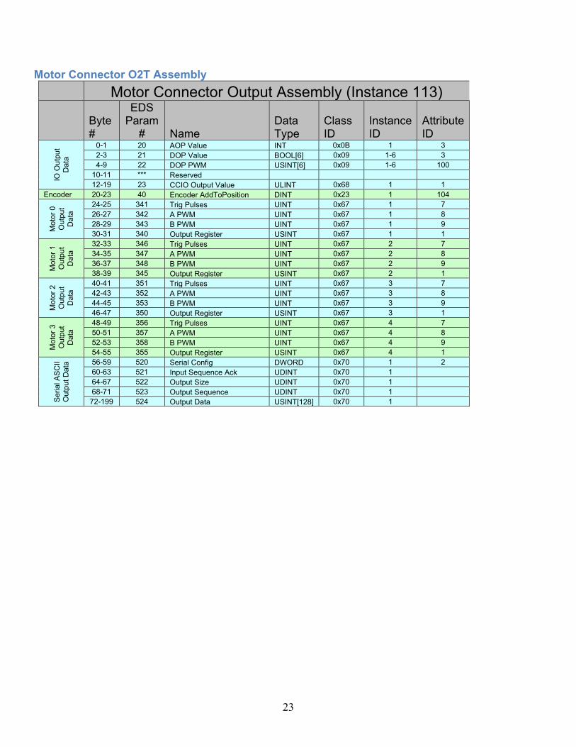
Motor Connector O2T Assembly
Motor Connector Output Assembly (Instance 113)
Byte #
EDS Param
# Name Data Type
Class ID
Instance ID
Attribute ID
IO O
utp
ut
Data
0-1 20 AOP Value INT 0x0B 1 3
2-3 21 DOP Value BOOL[6] 0x09 1-6 3
4-9 22 DOP PWM USINT[6] 0x09 1-6 100
10-11 *** Reserved
12-19 23 CCIO Output Value ULINT 0x68 1 1
Encoder 20-23 40 Encoder AddToPosition DINT 0x23 1 104
Moto
r 0
Outp
ut
Data
24-25 341 Trig Pulses UINT 0x67 1 7
26-27 342 A PWM UINT 0x67 1 8
28-29 343 B PWM UINT 0x67 1 9
30-31 340 Output Register USINT 0x67 1 1
Moto
r 1
Outp
ut
Data
32-33 346 Trig Pulses UINT 0x67 2 7
34-35 347 A PWM UINT 0x67 2 8
36-37 348 B PWM UINT 0x67 2 9
38-39 345 Output Register USINT 0x67 2 1
Moto
r 2
Outp
ut
Data
40-41 351 Trig Pulses UINT 0x67 3 7
42-43 352 A PWM UINT 0x67 3 8
44-45 353 B PWM UINT 0x67 3 9
46-47 350 Output Register USINT 0x67 3 1
Moto
r 3
Outp
ut
Data
48-49 356 Trig Pulses UINT 0x67 4 7
50-51 357 A PWM UINT 0x67 4 8
52-53 358 B PWM UINT 0x67 4 9
54-55 355 Output Register USINT 0x67 4 1
Seri
al A
SC
II
Outp
ut
Data
56-59 520 Serial Config DWORD 0x70 1 2
60-63 521 Input Sequence Ack UDINT 0x70 1
64-67 522 Output Size UDINT 0x70 1
68-71 523 Output Sequence UDINT 0x70 1
72-199 524 Output Data USINT[128] 0x70 1

24
Motor Connector Configuration Assembly
Motor Connector Config Assembly (Instance 151)
Byte #
EDS Param
# Name Data Type Default
Class ID
Instance ID
Attribute ID
IO M
ode
Config D
ata
0 1 AI0 Range USINT 100 0x0A 1 7
1 2 AI1 Range USINT 100 0x0A 2 7
2 3 AI2 Range USINT 100 0x0A 3 7
3 4 AI3 Range USINT 100 0x0A 4 7
4 5 AO0 Range USINT 100 0x0B 1 7
5-6 6 bit 0 DOP PWM Frequency BOOL 0 0x09 0 100
bit 1 CCIO Enable BOOL 0 0x68 1 6
7 *** Reserved Padding
IO
Filt
ers
8-11 7 AIP Filters USINT[4] 10 0x0A 1-4 100
12-63 8 DIP Filters*** UINT[26] 10000 0x08 1-13 5,6
64-71 9 CCIO Filters USINT[8] 10 0x68 1 5
Encoder
Config D
ata
72-75 30 Encoder Velocity Resolution
UDINT 100 0x23 1 26
76 31 Reserved USINT 5 0x23 1 100
77 32 Encoder Configuration 0 0x23 1 12, 102
78-79 *** Reserved Padding
Moto
r 0
Config
80 300 Enable Input Connector SINT -1 0x67 1 3
81 301 A Input Connector SINT -1 0x67 1 4
82 302 B Input Connector SINT -1 0x67 1 5
83 303 Trigger Pulse Time USINT 30 0x67 1 10
Moto
r 1
Config
84 300 Enable Input Connector SINT -1 0x67 2 3
85 301 A Input Connector SINT -1 0x67 2 4
86 302 B Input Connector SINT -1 0x67 2 5
87 303 Trigger Pulse Time USINT 30 0x67 2 10
Moto
r 2
Config
88 300 Enable Input Connector SINT -1 0x67 3 3
89 301 A Input Connector SINT -1 0x67 3 4
90 302 B Input Connector SINT -1 0x67 3 5
91 303 Trigger Pulse Time USINT 30 0x67 3 10
Moto
r 3
Config
92 300 Enable Input Connector SINT -1 0x67 4 3
93 301 A Input Connector SINT -1 0x67 4 4
94 302 B Input Connector SINT -1 0x67 4 5
95 303 Trigger Pulse Time USINT 30 0x67 4 10
Seri
al C
onfig
96-99 500 Serial Baud Rate UDINT 115200 0x70 1 1
100-103
501 Input Start Delimiter
DWORD 0 0x70 1 6
104-107
501 Input End Delimiter
DWORD 0 0x70 1 7
108-111
501 Output Start Delimiter
DWORD 0 0x70 1 8
112-115
501 Output End Delimiter
DWORD 0 0x70 1 9
116-119
502 Input Timeout
UDINT 10 0x70 1 12
*** DIP filters are grouped in the following order: DIP0 Off_On, DIP0 On_Off, DIP1 Off_On, DIP1, On_Off etc.

25
TCP Object (F5HEX - 1 Instance)
The following tables contain the attribute and common services information for the TCP Object.
Table 5 TCP Object (F5HEX - 1 Instance)
Instance Attribute
ID Name CIP Data Type Data Value
Access Rule
Class (Instance 0)
1 Revision UINT 4 Get
Instance 1 1 Status* DWORD Varies Get 2 Configuration capability* DWORD Varies Get 3 Configuration control* DWORD Varies Get 4 Physical Link Object *
Structure of Path Size Path
UINT Array of Word
Varies
Get
5 Interface configuration* Structure of IP Address Network Mask Gateway Address Name Server Name Server 2 Domain Name Size Domain Name
UDINT UDINT UDINT UDINT UDINT UINT STRING
Varies Varies Varies Varies Varies Varies Varies
Get
6 Host name* Structure of Host Name Size Host Name
UINT STRING
Varies Varies
Get
13 Encapsulation Inactivity Timeout
UINT Varies Get / Set (NVRAM)
* For more details on these attributes, see Volume 2: EtherNet/IP Adaptation of CIP, Section 5-4.3.2 from ODVA.
Table 6 TCP Object’s common services
Service code
Implemented for Service name
Class level Instance level
0EHex Yes Yes Get_Attribute_Single
10Hex No Yes Set_Attribute_Single

26
Ethernet Link Object (EtherNet/IP only) (F6HEX - 1 Instance)
The following tables contain the attribute and common services information for the Ethernet Link Object.
Table 7 Ethernet Link Object (F6HEX - 1 Instance)
Instance Attribute
ID Name CIP Data Type Data Value
Access Rule
Class (Instance 0)
1 Revision UINT 4 Get
Instance 1 1 Interface Speed* UDINT Varies Get 2 Interface Flags* DWORD Varies Get 3 Physical Address USINT Array (6) Varies Get 11 Interface
Capabilities STRUCT Varies Get
* For more details on these attributes, see Volume 2: EtherNet/IP Adaptation of CIP, Section 5-5.3.2 from ODVA.
Table 8 Ethernet Link Object’s common services
Service code
Implemented for Service name
Class level Instance level
0EHex Yes Yes Get_Attribute_Single
27
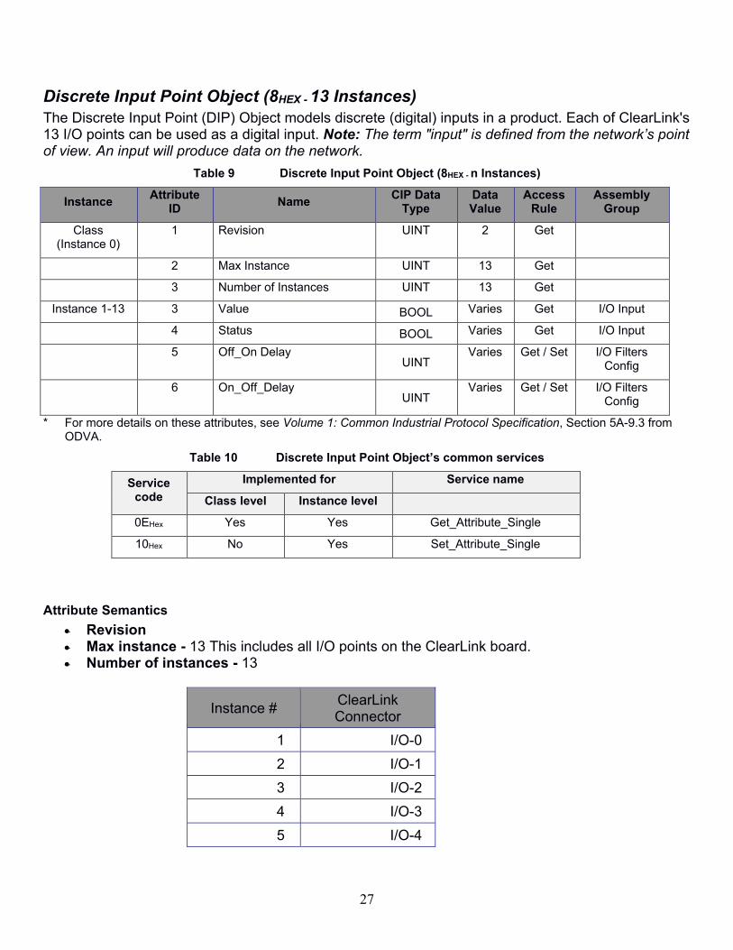
Discrete Input Point Object (8HEX - 13 Instances)
The Discrete Input Point (DIP) Object models discrete (digital) inputs in a product. Each of ClearLink's 13 I/O points can be used as a digital input. Note: The term "input" is defined from the network’s point of view. An input will produce data on the network.
Table 9 Discrete Input Point Object (8HEX - n Instances)
Instance Attribute
ID Name
CIP Data Type
Data Value
Access Rule
Assembly Group
Class (Instance 0)
1 Revision UINT 2 Get
2 Max Instance UINT 13 Get
3 Number of Instances UINT 13 Get
Instance 1-13 3 Value BOOL Varies Get I/O Input
4 Status BOOL Varies Get I/O Input
5 Off_On Delay UINT
Varies
Get / Set I/O Filters Config
6 On_Off_Delay UINT
Varies Get / Set I/O Filters Config
* For more details on these attributes, see Volume 1: Common Industrial Protocol Specification, Section 5A-9.3 from ODVA.
Table 10 Discrete Input Point Object’s common services
Service code
Implemented for Service name
Class level Instance level
0EHex Yes Yes Get_Attribute_Single
10Hex No Yes Set_Attribute_Single
Attribute Semantics
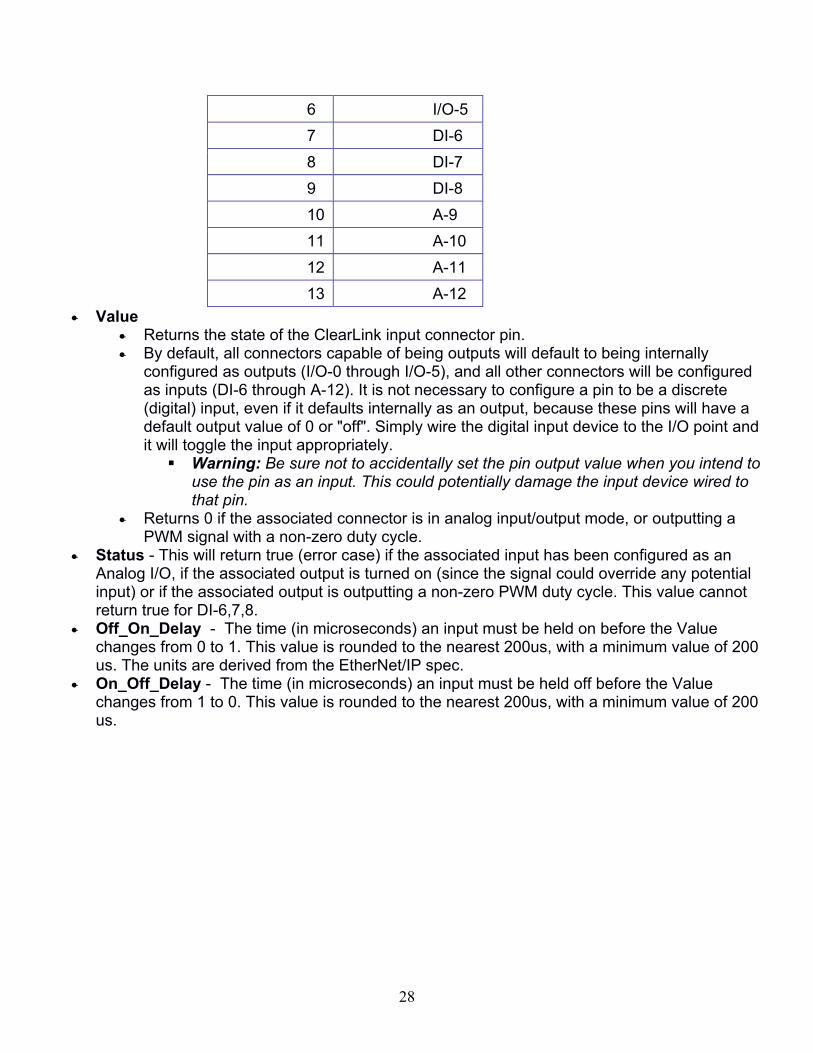
• Revision • Max instance - 13 This includes all I/O points on the ClearLink board. • Number of instances - 13
Instance # ClearLink Connector
1 I/O-0
2 I/O-1
3 I/O-2
4 I/O-3
5 I/O-4
28
6 I/O-5
7 DI-6
8 DI-7
9 DI-8
10 A-9
11 A-10
12 A-11
13 A-12
• Value • Returns the state of the ClearLink input connector pin. • By default, all connectors capable of being outputs will default to being internally
configured as outputs (I/O-0 through I/O-5), and all other connectors will be configured as inputs (DI-6 through A-12). It is not necessary to configure a pin to be a discrete (digital) input, even if it defaults internally as an output, because these pins will have a default output value of 0 or "off". Simply wire the digital input device to the I/O point and it will toggle the input appropriately.
▪ Warning: Be sure not to accidentally set the pin output value when you intend to use the pin as an input. This could potentially damage the input device wired to that pin.
• Returns 0 if the associated connector is in analog input/output mode, or outputting a PWM signal with a non-zero duty cycle.
• Status - This will return true (error case) if the associated input has been configured as an Analog I/O, if the associated output is turned on (since the signal could override any potential input) or if the associated output is outputting a non-zero PWM duty cycle. This value cannot return true for DI-6,7,8.
• Off_On_Delay - The time (in microseconds) an input must be held on before the Value changes from 0 to 1. This value is rounded to the nearest 200us, with a minimum value of 200 us. The units are derived from the EtherNet/IP spec.
• On_Off_Delay - The time (in microseconds) an input must be held off before the Value changes from 1 to 0. This value is rounded to the nearest 200us, with a minimum value of 200 us.

29
Discrete Output Point Object (9HEX - 6 Instances) A Discrete Output Point (DOP) models discrete (digital) outputs in a product. ClearLink's I/O-0 through I/O-5 can be used as digital outputs. ote that the term “output” is defined from the network’s point of view. An output will consume data from the network.
Table 11 Discrete Output Point Object (9HEX - n Instances)
Instance Attribute
ID Name
CIP Data Type
Data Value
Access Rule
Assembly Data
Class (Instance 0)
1 Revision UINT 1 Get
2 Max Instance UINT 6 Get
3 Number of Instances UINT 6 Get
100 PWM Frequency BOOL
Varies Get/Set I/O Modes Config
Instance 1-6 3 Value BOOL Varies Set I/O Output 4 Status BOOL Varies Get I/O Input 100 PWM USINT Varies Set I/O Output
* For more details on these attributes, see Volume 1: Common Industrial Protocol Specification, Section 5A-9.3 from ODVA.
Table 12 Discrete Output Point Object’s common services
Service code
Implemented for Service name
Class level Instance level
0EHex Yes Yes Get_Attribute_Single
10Hex No Yes Set_Attribute_Single
Attribute Semantics
• Revision • Max instance - 6 • Number of instances - 6
Instance # ClearLink Connector
1 I/O-0
2 I/O-1
3 I/O-2
4 I/O-3
5 I/O-4
6 I/O-5
• Value • Sets the NPN type output (0 = off, 1 = on)
30
• This attribute is ignored if the PWM attribute is non-zero or if the corresponding Analog output range is not set to 100 (disabled).
• Status - This will return true (error case) if the digital output is overloaded, or if the corresponding Analog output range is not set to 100 (disabled).
• PWM • Configured as a digital output (default) - If the PWM is set to 0 (default) the output
behavior will match what is determined by the value attribute. If the PWM != 0 then the Value attribute is ignored and the output is set to a PWM duty cycle at the selected frequency determined by the PWM Frequency attribute.
• Configured as an analog output (Based on the input range attribute of the associated instance of the Analog output point) - PWM is ignored
• PWM Frequency - This selects between two PWM carrier frequencies for all outputs (0 = 500 Hz, 1 = 8 kHz)

31
Analog Input Point Object (AHEX - 4 Instances) The Analog Input Point (AIP) Object models analog inputs in a product. ClearLink's A-9 through A-12 pins can be configured as analog inputs. Note: that the term “input” is defined from the network’s point of view (i.e. an input will produce data on the network).
Table 13 Analog Input Point Object (AHEX - n Instances)
Instance Attribute
ID Name
CIP Data Type
Data Value
Access Rule
Assembly Data
Class (Instance 0)
1 Revision UINT 2 Get
2 Max Instance UINT 4 Get
3 Number of Instances UINT 4 Get
Instance 1-n 3 Value INT Varies Get I/O Input
4 Status BOOL Varies Get I/O Input
7 Input Range USINT
2,100 Get / Set I/O Modes Config
100 Analog Filter USINT
Varies Get / Set I/O Filters Config
* For more details on these attributes, see Volume 1: Common Industrial Protocol Specification, Section 5A-11.3 from ODVA.
Table 14 Analog Input Point Object’s common services
Service code
Implemented for Service name
Class level Instance level
0EHex Yes Yes Get_Attribute_Single
10Hex No Yes Set_Attribute_Single
Attribute Semantics
• Revision • Max instance - 4 • Number of instances - 4
Instance # ClearLink Connector
1 A-9
2 A-10
3 A-11
4 A-12
• Value • If the Input range attribute is set to 100 (disabled), the Value will always return 0. • If the Input range attribute is set to 2 (0-10VDC), the Value is determined by the
measured analog voltage on the ClearLink Connector. • Status - This will return true (error case) if the Input Range is not specified as "2 = 0-10VDC".

32
• Input Range - This refers to a list of Input ranges specified in Ethernet/IP. ClearLink only supports "2=0V-10V". (Attribute defaults to "100 =Disabled").
• Analog Filter - IIR filter length in ms. Defaults to 10.
Configuring A-9 through A-12 as a 0-10V analog input
1. Change the desired Analog Input Range from 100 to 2. This is part of the Configuration assembly.
a. AI0_Range corresponds to pin A-9, AI1_Range corresponds to pin A-10, etc.
2. (Optional) Set your desired analog filter using the AIP_Filter corresponding to the analog pin. This is part of the Configuration assembly.
3. Use the AIP_Value corresponding to the analog pin to read the analog signal. This is part of the Input assembly.
a. The analog input has 12 bits of resolution, filtered and scaled between a minimum value of 0 (=0V) and a maximum value of 32,767 (=10V).

33
Analog Output Point Object (BHEX - 1 Instances) The Analog Output Point (AOP) models the point level attributes and services of the analog outputs in a product. ClearLink's I/O-0 can be configured as an analog output. Note: The term “output” is defined from the network’s point of view. An output will consume data from the network.
Table 15 Analog Output Point Object (BHEX - n Instances)
Instance Attribute
ID Name
CIP Data Type
Data Value
Access Rule
Assembly Data
Class (Instance 0)
1 Revision UINT 2 Get
2 Max Instance UINT 1 Get
3 Number of Instances UINT 1 Get
Instance 1 3 Value INT Varies Set I/O Output
4 Status BOOL Varies Get I/O Input
7 Output Range USINT
0,2,100 Get / Set I/O Modes Config
* For more details on these attributes, see Volume 1: Common Industrial Protocol Specification, Section 5A-12.2 from ODVA.
Table 16 Analog Output Point Object’s common services
Service code
Implemented for Service name
Class level Instance level
0EHex Yes Yes Get_Attribute_Single
10Hex No Yes Set_Attribute_Single
Attribute Semantics
• Revision • Max instance - 1 • Number of instances - 1
Instance # ClearLink Connector
1 I/O-0
• Value • If the Output Range attribute is set to 100 (disabled) the Value is ignored. • If the Output Range attribute is set to 0 or 2 ( 4-20 mA or 0-20 mA respectively) the
analog output current is set based on the value scaled to the specified output range. • Status - This will return true (error case) if the Output Range is set to 100 (disabled). • Output Range - Sets the Analog Output Range as follows: 0 = [4mA to 20mA] and 2 = [0mA to
20mA]. Attribute defaults to 100 (Disabled).

34
Configuring IO-0 as a 4-20mA or 0-20mA analog output
1. For a 4-20 mA signal, change the Analog Output Range from 100 to 0. For a 0-20 mA signal, change the Analog Output Range from 100 to 2. AO0_Range is part of the Configuration assembly.
2. Use AOP_Value to set the analog output signal. This is part of the Output Assembly. a. This value has a minimum input of 0 (= 0 mA or 4 mA) and a maximum input of 32,767
(= 20 mA). The analog output has 11 bits of resolution between 0 and 20 mA.
35
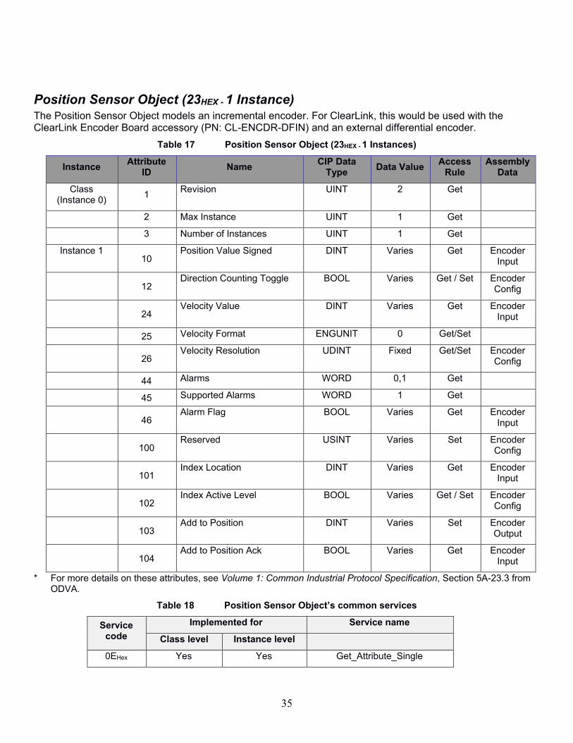
Position Sensor Object (23HEX - 1 Instance) The Position Sensor Object models an incremental encoder. For ClearLink, this would be used with the ClearLink Encoder Board accessory (PN: CL-ENCDR-DFIN) and an external differential encoder.
Table 17 Position Sensor Object (23HEX - 1 Instances)
Instance Attribute
ID Name
CIP Data Type
Data Value Access
Rule Assembly
Data
Class (Instance 0)
1 Revision UINT 2 Get
2 Max Instance UINT 1 Get
3 Number of Instances UINT 1 Get
Instance 1 10
Position Value Signed DINT Varies Get Encoder Input
12
Direction Counting Toggle BOOL Varies Get / Set Encoder Config
24
Velocity Value DINT Varies Get Encoder Input
25 Velocity Format ENGUNIT 0 Get/Set
26
Velocity Resolution UDINT Fixed Get/Set Encoder Config
44 Alarms WORD 0,1 Get
45 Supported Alarms WORD 1 Get
46
Alarm Flag BOOL Varies Get Encoder Input
100
Reserved USINT Varies Set Encoder Config
101
Index Location DINT Varies Get Encoder Input
102
Index Active Level BOOL Varies Get / Set Encoder Config
103
Add to Position DINT Varies Set Encoder Output
104
Add to Position Ack BOOL Varies Get Encoder Input
* For more details on these attributes, see Volume 1: Common Industrial Protocol Specification, Section 5A-23.3 from ODVA.
Table 18 Position Sensor Object’s common services
Service code
Implemented for Service name
Class level Instance level
0EHex Yes Yes Get_Attribute_Single

36
Service code
Implemented for Service name
Class level Instance level
10Hex No Yes Set_Attribute_Single
Attribute Semantics
• Revision • Max instance - 1 • Number of instances - 1
Instance # ClearLink Connector
1 DI-6, DI-7, and DI-8 (though the combined I/O header with CL-ENCDR-
DFIN)
• Position Value Signed - Returns the current signed position. • Direction Counting Toggle - Defines the direction of increasing position value. • Velocity Value - This reads the current measured velocity (as subject to the Velocity filter
setting). • Velocity Format - ClearLink supports only count/sec (0x1f04). • Velocity Resolution - Used to minimize velocity dither. User settable, defaults to 100. • Alarms - This shows active alarm flags. • Supported Alarms - Lists supported Alarms (ClearLink only supports Position Error). • Alarm Flag - This is the flag to indicate one of the Alarm fields is asserted (ClearLink only
supports one alarm) 0 = OK, 1 = Alarm Error. Possible causes: encoder frequency above max spec or encoder electrical noise.
• Index Location - The stored position value since the Index trigger. • Index Active level - Sets the Index input active level which determines when the index
triggers. • Add to Position - When this value is non-zero and the Add to Position Ack Attribute is de-
asserted, then the position will be adjusted by the specified amount and the Add to Position Ack will be set true.
• Add to Position Ack - This is used for handshaking with the Add to Position attribute. This value is set to true whenever the Add To position is set to be non-zero, and when true, prevents the number space from changing. This value is reset to zero when the AddToPosition value is set to 0.
37
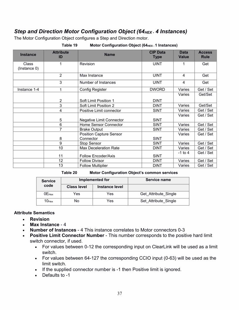
Step and Direction Motor Configuration Object (64HEX - 4 Instances) The Motor Configuration Object configures a Step and Direction motor.
Table 19 Motor Configuration Object (64HEX - 1 Instances)
Instance Attribute
ID Name
CIP Data Type
Data Value
Access Rule
Class (Instance 0)
1 Revision UINT 1 Get
2 Max Instance UINT 4 Get
3 Number of Instances UINT 4 Get
Instance 1-4 1 Config Register DWORD Varies Get / Set
2 Soft Limit Position 1 DINT
Varies Get/Set
3 Soft Limit Position 2 DINT Varies Get/Set 4 Positive Limit connector SINT Varies Get / Set
5 Negative Limit Connector SINT Varies
Get / Set
6 Home Sensor Connector SINT Varies Get / Set 7 Brake Output SINT Varies Get / Set
8 Position Capture Sensor Connector SINT
Varies Get / Set
9 Stop Sensor SINT Varies Get / Set 10 Max Deceleration Rate DINT Varies Get / Set
11 Follow Encoder/Axis SINT -1 to 4 Get / Set
12 Follow Divisor DINT Varies Get / Set 13 Follow Multiplier DINT Varies Get / Set
Table 20 Motor Configuration Object’s common services
Service code
Implemented for Service name
Class level Instance level
0EHex Yes Yes Get_Attribute_Single
10Hex No Yes Set_Attribute_Single
Attribute Semantics
• Revision • Max Instance - 4 • Number of Instances - 4 This instance correlates to Motor connectors 0-3 • Positive Limit Connector Number - This number corresponds to the positive hard limit
switch connector, if used.
• For values between 0-12 the corresponding input on ClearLink will be used as a limit
switch.
• For values between 64-127 the corresponding CCIO input (0-63) will be used as the
limit switch.
• If the supplied connector number is -1 then Positive limit is ignored.
• Defaults to -1
38
• This limit is considered Active-Low. If the value of Discrete Input Point Object returns
False, further motion in the positive direction will be prevented and the “In Positive Limit”
status bit will be set.
• If there is currently executing positive motion when the limit is asserted a SW E-Stop will
be triggered to stop current motion and the shutdown register bit “Motion Canceled
(positive limit)” will be asserted. The deceleration rate with be the higher of the last
loaded deceleration rate or the E-Stop deceleration rate.
• Negative Limit Connector Number - See previous definition except negative motion is
prevented
• Soft Limit Position 1 • The soft limit positions will limit commanded motion inclusive between these values (the
higher value is taken as a positive limit and the lower value is taken as a negative limit). Default to 0
• Soft limits will only function when both positions are set to different numbers, AND the Soft Limit nable bit is asserted, A D when the “Has Homed” Status has asserted
• If a positional move is commanded which will result in a target position that is FURTHER outside of the defined soft limits (as compared to the current commanded position), the move is ignored and the “Motion Canceled (Soft Limits xceeded)” bit of the motor shutdown register will be set. Positional moves that begin outside the limit, but end closer to the range will be accepted and executed.
• Velocity moves when commanded while the motor is in the range will execute normally however when the edge of the range is reached, the motion should terminate at the more aggressive of E-Stop deceleration rate or the loaded move Deceleration rate such that the final position is at the soft limit. Velocity moves commanded while the motor is outside of the range will only be executed if the direction would move the motor towards the range.
• If the motor has homed, and has soft limits enabled, but the current commanded position is at the boundary or outside of the defined soft limit range, then the motor status “Outside Soft Limits” will be asserted.
• Soft Limit Position 2 - See previous definition
• Home Sensor Input - This value determines whether the homing statuses will be set by a
sensor or an end of travel
• For values between 0-12 the corresponding local ClearLink input will be used as a
home switch. The homing target will be determined by looking at the Discrete input
object’s Value attribute.
• For values between 64-127 the corresponding CCIO input (0-63) will be used to supply
the home sensor signal. The homing target will be determined by looking at the CCIO’s
object’s Input Value attribute.
• For all other Values the Homing target will be assumed to be provided by an end of
travel hard stop detected when the M-Connector HLFB input fully asserts while the
Steps active flag is true.
• Brake Output - This value determines which output should be used as a power off brake for
this motor.
• For values between 0-5 the corresponding local ClearLink Output will be configured to
automatically control a power-off brake. Having this set will cause the corresponding

39
output value attributes to no longer function. User Note: if value = 0 and the Analog
output range attribute !=100, then the brake will not function on I/O-0.
• For values between 64-127 the corresponding CCIO output (0-63) will be configured to
automatically control a power-off brake. The corresponding CCIO output value bit will be
ignored.
• Brake outputs will be energized whenever the motor status bit “ nabled” is asserted
(when the M-Connector Enable signal is asserted AND the HLFB signal is NOT de-
asserted).
• Position Capture Sensor Connector - This number corresponds to the input used for
Position Capture.
• For values between 0-12 the corresponding input on ClearLink will be used to capture
position. The input delay in capturing position will be less than 200us.
• For values between 64-127 the corresponding CCIO input (0-63) will be used to capture
position. The input delay in capturing position will be more than 200us.
• Max Deceleration Rate - This value specifies a separate deceleration rate that can be used
for canceling motion. The deceleration used to cancel motion (e.g. using the Stop sensor) will
be the higher value of this and the acceleration/deceleration value for position and velocity
moves.
• Stop Sensor - When the associated discrete input/CCIO value attribute = 0 the E-Stop
sensor will cancel motion. (State based, not edge based)
• For values between 0-12 the corresponding local ClearLink input will be used as an E-
Stop Sensor.
• For values between 64-127 the corresponding CCIO input (0-63) will be used to supply
the E-Stop signal.
• All other values are ignored
• Defaults to -1
• Follow Encoder/Axis - This value determines which axis/encoder this motor should follow.
• For values between 0-3 the corresponding M-Connector command will be used as the
axis to follow. If the value is the same as this motor’s M-Connector number, then the
value is ignored (a motor can't follow itself). A value of 4 corresponds to the position
sensor object. A value of -1 will disable the feature. All other numbers are invalid.
• If the motor you have specified to follow is configured to follow another motor/encoder,
then the value is ignored. This will prevent the possibility of setting motor 1 to follow
motor 2 which is then set to follow motor 3.
• Note: calling addToPosition or otherwise changing the number-space of either the
leading Encoder/Motor or the Following motor will not cause a change to the number-
space of the other or result in motion.
• Soft Limits are ignored for a motor configured to follow another axis/encoder.
• For the encoder following feature, any stop command (E-Stop, Limits, SW-E-Stop) will
either cause an Abrupt stop or a ramped stop at E-Stop decel rate pending a real-time
calculation of the command velocity).
• For Following another axis, any stop command (E-Stop, Limits, SW-E-Stop, or a motor
in fault) will be transferred to the axis being followed in order to stop it as well. Step
commands will still be sent to the follower until the master finishes stopping.
40
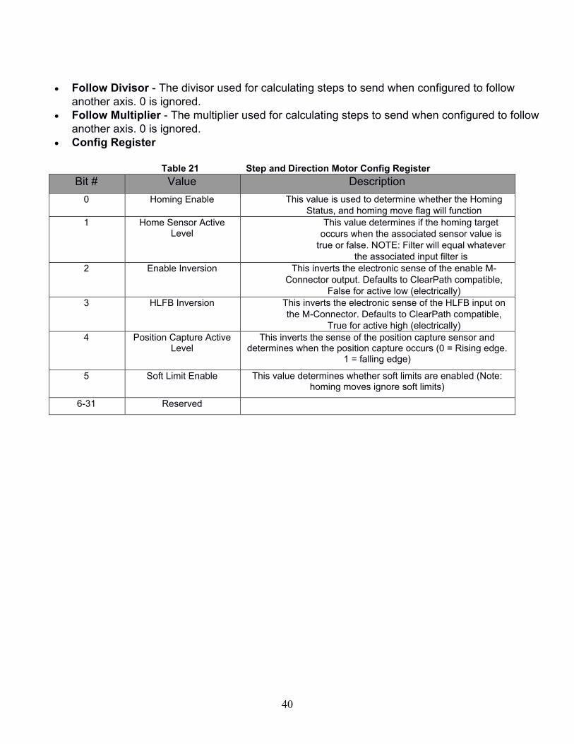
• Follow Divisor - The divisor used for calculating steps to send when configured to follow
another axis. 0 is ignored.
• Follow Multiplier - The multiplier used for calculating steps to send when configured to follow
another axis. 0 is ignored.
• Config Register
Table 21 Step and Direction Motor Config Register
Bit # Value Description
0 Homing Enable This value is used to determine whether the Homing
Status, and homing move flag will function
1 Home Sensor Active Level
This value determines if the homing target
occurs when the associated sensor value is
true or false. NOTE: Filter will equal whatever
the associated input filter is
2 Enable Inversion This inverts the electronic sense of the enable M-
Connector output. Defaults to ClearPath compatible,
False for active low (electrically)
3 HLFB Inversion This inverts the electronic sense of the HLFB input on
the M-Connector. Defaults to ClearPath compatible,
True for active high (electrically)
4 Position Capture Active Level
This inverts the sense of the position capture sensor and determines when the position capture occurs (0 = Rising edge.
1 = falling edge)
5 Soft Limit Enable This value determines whether soft limits are enabled (Note: homing moves ignore soft limits)
6-31 Reserved
41
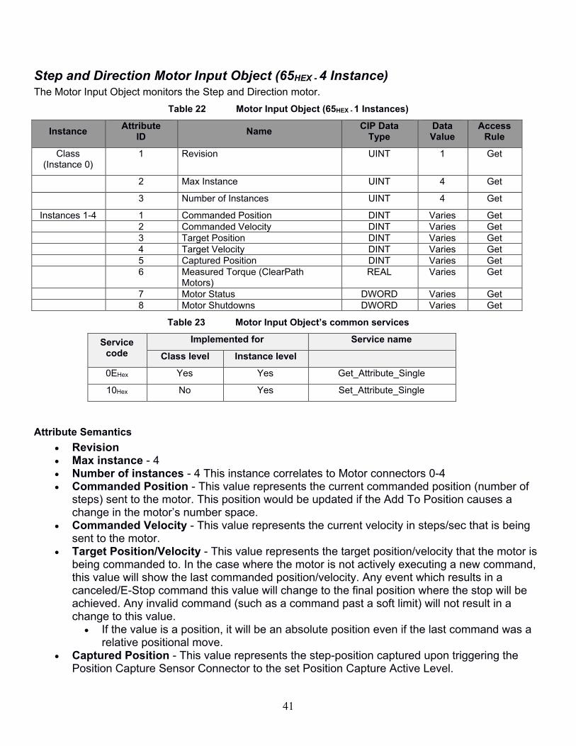
Step and Direction Motor Input Object (65HEX - 4 Instance) The Motor Input Object monitors the Step and Direction motor.
Table 22 Motor Input Object (65HEX - 1 Instances)
Instance Attribute
ID Name
CIP Data Type
Data Value
Access Rule
Class (Instance 0)
1 Revision UINT 1 Get
2 Max Instance UINT 4 Get
3 Number of Instances UINT 4 Get
Instances 1-4 1 Commanded Position DINT Varies Get 2 Commanded Velocity DINT Varies Get 3 Target Position DINT Varies Get 4 Target Velocity DINT Varies Get 5 Captured Position DINT Varies Get 6 Measured Torque (ClearPath
Motors) REAL Varies Get
7 Motor Status DWORD Varies Get 8 Motor Shutdowns DWORD Varies Get
Table 23 Motor Input Object’s common services
Service code
Implemented for Service name
Class level Instance level
0EHex Yes Yes Get_Attribute_Single
10Hex No Yes Set_Attribute_Single
Attribute Semantics
• Revision • Max instance - 4 • Number of instances - 4 This instance correlates to Motor connectors 0-4 • Commanded Position - This value represents the current commanded position (number of
steps) sent to the motor. This position would be updated if the Add To Position causes a change in the motor’s number space.
• Commanded Velocity - This value represents the current velocity in steps/sec that is being sent to the motor.
• Target Position/Velocity - This value represents the target position/velocity that the motor is being commanded to. In the case where the motor is not actively executing a new command, this value will show the last commanded position/velocity. Any event which results in a canceled/E-Stop command this value will change to the final position where the stop will be achieved. Any invalid command (such as a command past a soft limit) will not result in a change to this value.
• If the value is a position, it will be an absolute position even if the last command was a relative positional move.
• Captured Position - This value represents the step-position captured upon triggering the Position Capture Sensor Connector to the set Position Capture Active Level.

42
• Measured Torque (ClearPath Motors) - This value represents the measured duty cycle of the HLFB signal expressed as a percentage of torque between -100% and 100%. USER NOTE: This calculation is only valid during motion, and if the ClearPath's HLFB output is configured using ASG with Measured Torque.
• Motor Status - This register is a real time register.
Table 24 Step and Direction Motor Status Register
Bit # Value Description
0 At Target Position True if the “Commanded position” attribute equals the “Target Position” attribute and HLFB is Asserted
1 Steps Active True if the “Commanded Velocity” Attribute != 0
2 At Velocity True if the Commanded Velocity attribute equals the Jog Velocity attribute (for velocity moves) or the Velocity Limit (for position moves).
3 Move Direction True if the last motion was in the positive direction
4 In Positive Limit Reflects the state of the Value attribute of the Discrete Input/CCIO specified in the Positive Limit connector number attribute
5 In Negative Limit Reflects the state of the Value attribute of the Discrete Input/CCIO specified in the Negative Limit connector number attribute
6 In E-Stop Sensor Reflects the state of the Value attribute of the Discrete Input/CCIO specified in the E-Stop Sensor Connector number attribute
7 In Home Sensor Reflects the state of the Value attribute of the Discrete Input/CCIO specified in the Home Sensor Connector number attribute
8 Homing True if the last processed move command loaded had the Homing Flag asserted AND the Has Homed status is False
9 Motor in Fault True if the HLFB signal on the M-Connector is De-asserted AND the M-Connector Enable output is Asserted (This status will cancel any currently executing motion)
10 Enabled True if the M-Connector Enable output is Asserted AND the M-Connector HLFB signal is NOT de-asserted
11 At/Outside Soft Limits True if the “Commanded Position” is at the boundary, or outside the range specified by the Soft limit positions AND the Soft Limit Enable attribute is set to true
12 Positional Move True if the last commanded move was a positional move
13 Has Homed This Value is asserted whenever the position number space is changed. This value will DE-assert when any of the following occur: The M-Connector HLFB input DE-asserts. A new command is loaded with the Homing flag set.
14 HLFB_On Return true if the high level feedback signal from the Motor/drive is asserted.

43
15 Has Torque Measurement Return true if a PWM is detected from the high level feedback signal from the motor/drive.
16 Ready to Home Indicates if the axis is ready to home. If false check:
• Homing is enabled in the configuration
• The motor is enabled via the Output Register
• There are no shutdowns present
• The selected homing sensor input is valid
• If using hard-stop homing, clear motor faults or cycle enable.
17 Shutdowns Present Indicates if any ClearLink shutdowns have occurred which will prevent further motion until they are cleared.
18 Add To Position Ack This is used for handshaking with the Add to Position attribute. This value is set to true whenever the Add To position is set to be non-zero, and when true, prevents the number space from changing. This value is reset to zero when the Add to Position value is set to 0.
19 Load Position Move Ack This value is used for handshaking and loading motion commands. This value is set whenever the Load Position Move is set, and is cleared whenever the Load Position Move bit is de-asserted. When set, this value will prevent subsequent move commands from being loaded.
20 Load Velocity Move Ack This value is used for handshaking and loading motion commands. This value is set whenever the Load Velocity Move is set, and is cleared whenever the Load Velocity Move bit is de-asserted. When set, this value will prevent subsequent move commands from being loaded.
21 Clear Motor Fault Ack This value is used for handshaking and clearing motor faults by cycling the enable output. This value asserts after a “clear motor fault” command has been processed and the axes has been disabled and re-enabled (10 ms disable pulse + wait for up to 25 ms for HLFB) If set, this value will prevent further Clear Motor fault commands from being received.
22-31 Reserved

44
• Motor Shutdowns - This register is a Or-Accumulating register which is manually cleared by the Clear Alerts flag in the Step and Direction motors Output data.
Table 25 Step and Direction Motor Shutdowns
Bit # Value Description
0 Motion Canceled (Command While
Shutdown)
This shutdown will occur when a motion command is blocked due to a previously uncleared shutdown
1 Motion Canceled
(Positive Limit)
This bit will be set when executing motion is canceled due to a positive limit switch being asserted.
This would also assert if a command is sent and rejected while currently in the limit, or at a soft limit (only moves in the opposite direction are then allowed)
2 Motion Canceled
(Negative Limit)
This bit will be set when executing motion is canceled due to a negative limit switch being asserted.
This would also assert if a command is sent and rejected while currently in the limit, or at a soft limit (only moves in the opposite direction are then allowed)
3 Motion Canceled
(Sensor E-Stop)
This bit will be set when executing motion is canceled due to an E-Stop triggered by the specified E-Stop sensor.
This would also assert if a command is sent and rejected while the E-Stop is asserted
4 Motion Canceled
(SW E-Stop)
This bit will be set when executing motion is canceled due to an E-Stop commanded by the SW E-Stop flag in the motor output data
This would also assert if a command is sent and rejected while the SW E-Stop output is asserted
5 Motion Canceled
(Motor Disabled)
This bit will be set when current motion is canceled if the enable output attribute de-asserts
This would also assert if a command is sent and rejected while enable output attribute is de-asserted
6 Motion Canceled
(Soft Limits Exceeded)
This bit will be set when current motion is canceled or when a new loaded move is canceled due to the commanded position or the position target exceeding the range defined by the soft limit range
7 Motion Canceled (Follower Axis Fault)
This bit will be asserted if another motor which has been configured to follow this motor has had its motioned canceled for any reason.
8 Motion Canceled
(Command while following)
This bit will be asserted if a move is commanded to a motor while the Follow Encoder/Axis Enable parameter is true,

45
9 Motion Canceled Homing
Not Ready This bit will be asserted if a homing move is rejected due to the axis not being ready to home. Check:
• Homing is enabled in the configuration.
• The selected homing sensor input is valid. If using sensor-less homing (hard-stop), clear motor faults or cycle enable.
10 Motor Faulted This bit will be set whenever the Motor in Fault status state is set.
11 Following Overspeed This bit will be set when the required axis following speed exceeds the maximum step rate of the ClearLink (500k steps/sec). Consider lowering your following ratio or your steps/rev settings in your motor.
12-31 Reserved
46
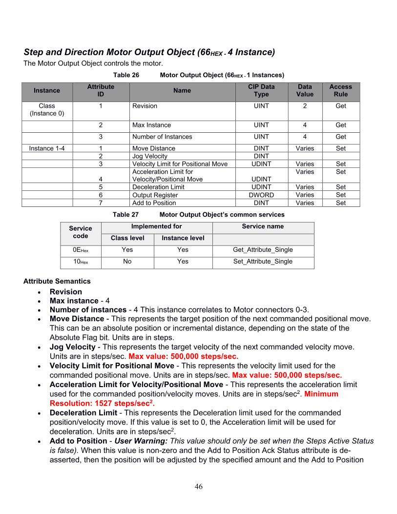
Step and Direction Motor Output Object (66HEX - 4 Instance) The Motor Output Object controls the motor.
Table 26 Motor Output Object (66HEX - 1 Instances)
Instance Attribute
ID Name
CIP Data Type
Data Value
Access Rule
Class (Instance 0)
1 Revision UINT 2 Get
2 Max Instance UINT 4 Get
3 Number of Instances UINT 4 Get
Instance 1-4 1 Move Distance DINT Varies Set 2 Jog Velocity DINT
3 Velocity Limit for Positional Move UDINT Varies Set
4 Acceleration Limit for Velocity/Positional Move UDINT
Varies Set
5 Deceleration Limit UDINT Varies Set 6 Output Register DWORD Varies Set 7 Add to Position DINT Varies Set
Table 27 Motor Output Object’s common services
Service code
Implemented for Service name
Class level Instance level
0EHex Yes Yes Get_Attribute_Single
10Hex No Yes Set_Attribute_Single
Attribute Semantics
• Revision • Max instance - 4 • Number of instances - 4 This instance correlates to Motor connectors 0-3. • Move Distance - This represents the target position of the next commanded positional move.
This can be an absolute position or incremental distance, depending on the state of the
Absolute Flag bit. Units are in steps.
• Jog Velocity - This represents the target velocity of the next commanded velocity move.
Units are in steps/sec. Max value: 500,000 steps/sec.
• Velocity Limit for Positional Move - This represents the velocity limit used for the
commanded positional move. Units are in steps/sec. Max value: 500,000 steps/sec.
• Acceleration Limit for Velocity/Positional Move - This represents the acceleration limit
used for the commanded position/velocity moves. Units are in steps/sec2. Minimum
Resolution: 1527 steps/sec2.
• Deceleration Limit - This represents the Deceleration limit used for the commanded
position/velocity move. If this value is set to 0, the Acceleration limit will be used for
deceleration. Units are in steps/sec2.
• Add to Position - User Warning: This value should only be set when the Steps Active Status
is false). When this value is non-zero and the Add to Position Ack Status attribute is de-
asserted, then the position will be adjusted by the specified amount and the Add to Position

47
Ack will be set true. Setting this value to zero will de-assert the Add to Position Ack Status to
false.
• The Following attributes WILL be changed: Commanded Position, target position (if
specified as a position).
• Soft Limit positions will NOT be adjusted.
• The Was Homed status will be set.
• Output Register
Table 28 Step and Direction Motor Output Register
Bit # Value Description
0 Enable This value directly controls the Enable output signal of the M-
Connector.
1 Absolute Flag This flag indicates whether the commanded position move will
be an incremental move vs. an absolute move. True = absolute
move
2 Homing Move Flag This flag indicates if the position/velocity move is a homing move. True = Homing move
3 Load Position Move When this value is true and both the Load Position Move ACK
status and Load Velocity Move ACK status are false, all move
parameters/flags are loaded and a position move is
commanded. After the move is loaded, the Load Position Move
ACK Status is set to true to prevent subsequent moves from
being loaded. When this value is false the Load Position Move
ACK status is set to false.
4 Load Velocity Move When this value is true and both the Load Position Move ACK
status and Load Velocity Move ACK status are false, all move
parameters/flags are loaded and a velocity move is
commanded. After the move is loaded, the Load Velocity Move
ACK Status is set to true to prevent subsequent moves from
being loaded. When this value is false the Load Velocity Move
ACK status is set to false.
5 SW E-Stop If this value is true, any currently executing move is canceled,
and subsequent move commands will be canceled until this bit
is set to false. Defaults to false
6 Clear Alerts When this value is set to True the ClearLink will clear all bits in the Shutdown register, then ClearLink will set this value equal to False.
7 Clear Motor Fault When this value is set to true, the axis is momentary disabled (10ms) and re-enabled in order to clear any motor faults. This bit will be acknowledged up to 35ms after the initial disable.
8-31 Reserved
• Homing Move Flag - This flag indicates whether the commanded move will be a homing
move. This value is ignored if the Home Enable attribute is set to false.
48
o Before a Homing move begins, if no valid Home Sensor Input is selected
(indicating ClearPath SD hard-stop homing), the enable output of the M-Connector will
momentarily de-assert and then re-assert. This makes ClearPath's User Seeks Home
feature active (when configured to home on every enable).
o A Homing move will be executed in the same way a non-homing position/velocity
move would, except when the homing target is reached, the current motion is canceled
and when the Steps Active flag = 0, ClearLink sets the addToPosition value to the
negative of the Commanded position, resulting in the current position being 0.
o If the homing target is not reached, then ClearLink does not set the addToPosition
o If no valid Home Sensor Input is selected (indicating ClearPath-SD hard-stop
homing), the homing target is considered to be reached when the M-Connector’s HLFB
input transitions from a PWM signal to become fully asserted (after the hard-stop is
reached) while the Steps Active status is true.
o If a Valid Home Sensor Input is selected, then the homing target is considered to
be achieved when the corresponding input value attribute of the digital input or CCIO
pin transitions according to the Home Sensor Active level selection.
o Use the Ready To Home bit of the Motor Status Register to determine if ClearLink
and the ClearPath-SD are both in a state to make a homing move.
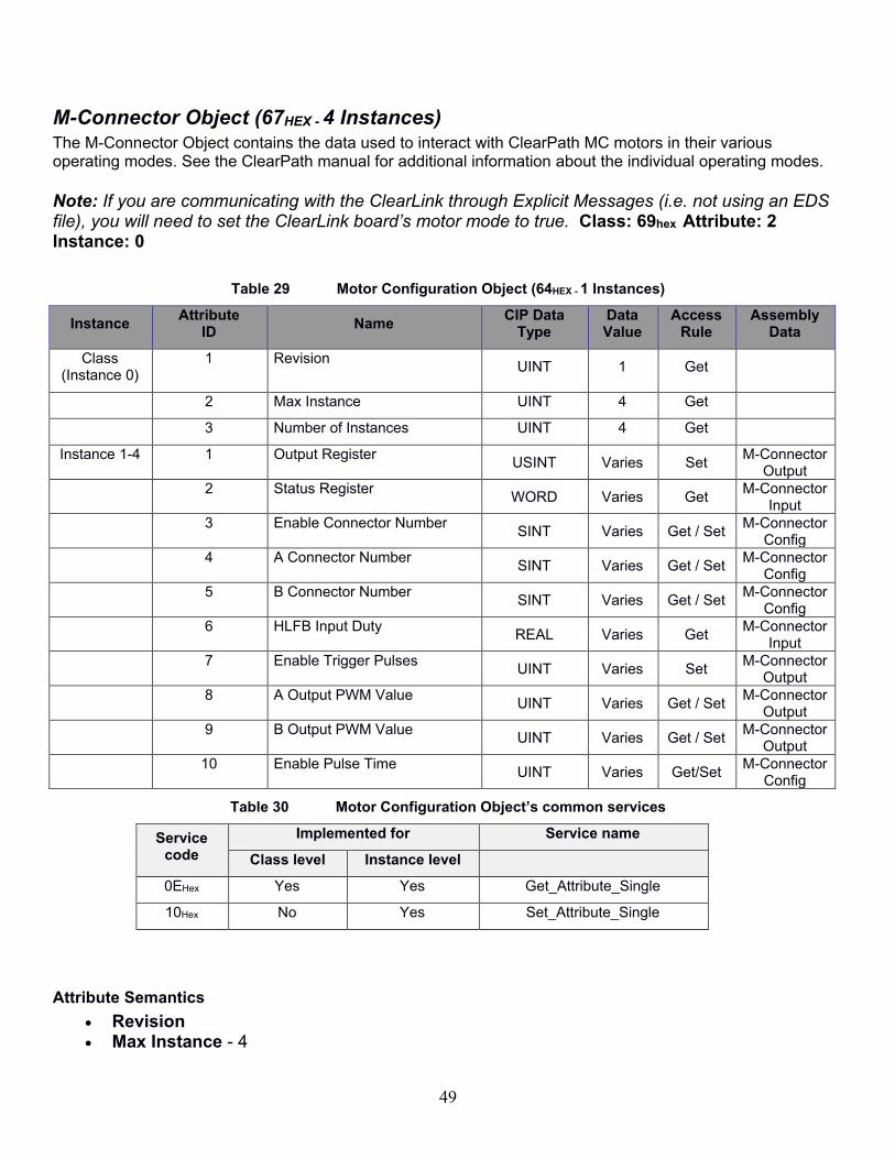
49
M-Connector Object (67HEX - 4 Instances) The M-Connector Object contains the data used to interact with ClearPath MC motors in their various operating modes. See the ClearPath manual for additional information about the individual operating modes.
Note: If you are communicating with the ClearLink through Explicit Messages (i.e. not using an EDS file), you will need to set the ClearLink board’s motor mode to true. Class: 69hex Attribute: 2 Instance: 0
Table 29 Motor Configuration Object (64HEX - 1 Instances)
Instance Attribute
ID Name
CIP Data Type
Data Value
Access Rule
Assembly Data
Class (Instance 0)
1 Revision UINT 1 Get
2 Max Instance UINT 4 Get
3 Number of Instances UINT 4 Get
Instance 1-4 1 Output Register USINT Varies Set
M-Connector Output
2 Status Register WORD Varies Get
M-Connector Input
3 Enable Connector Number SINT Varies Get / Set
M-Connector Config
4 A Connector Number SINT Varies Get / Set
M-Connector Config
5 B Connector Number SINT Varies Get / Set
M-Connector Config
6 HLFB Input Duty REAL Varies Get
M-Connector Input
7 Enable Trigger Pulses UINT Varies Set
M-Connector Output
8 A Output PWM Value UINT Varies Get / Set
M-Connector Output
9 B Output PWM Value UINT Varies Get / Set
M-Connector Output
10 Enable Pulse Time UINT Varies Get/Set
M-Connector Config
Table 30 Motor Configuration Object’s common services
Service code
Implemented for Service name
Class level Instance level
0EHex Yes Yes Get_Attribute_Single
10Hex No Yes Set_Attribute_Single
Attribute Semantics
• Revision • Max Instance - 4

50
• Number of instances - 4 This instance correlates to Motor connectors 0-3. • Enable Connector Number - This number corresponds to the ClearLink input used to control
the M-Connector Enable signal.
• For values between 0-12 the corresponding ClearLink input will control the M-Connector
Enable signal such that if the value attribute of Discrete Input Point Object returns true,
the M-Connector Enable signal will be asserted. The Enable bit of the Output Register
and Enable Trigger pulse attribute of the M-Connector output object will be ignored.
• For values between 64-127 the corresponding CCIO input (0-63) will control the M-
Connector Enable signal such that if the Input value of the corresponding CCIO Input
Value Bit returns true, the M-Connector Enable signal will be asserted. The Enable bit of
the Output Register and Enable Trigger pulse attribute of the M-Connector output object
will be ignored.
• For all other values, the M-Connector Enable signal will be determined by the Enable bit
of the Output Register and Enable Trigger pulse attribute of the M-Connector output
object.
• Input A Connector Number - See previous definition. If a valid number is specified, the A
Output bit of the Output Register, and A Output Duty cycle attributes will be ignored.
• Input B Connector Number - See previous definition. If a valid number is specified, the B
Output bit of the Output Register, and B Output Duty cycle attributes will be ignored.
• HLFB Duty - This reads the duty cycle of a detected PWM signal on the HLFB input of the M-
Connector. If no PWM is detected this value will return -9999.
• Enable Trigger Pulses - When this value changes from 0 to a new value, the ClearLink will
start sending a number of pulses on the M-Connector’s enable output equal to the new value.
Pulses will be sent at a 50% duty cycle with a pulse width equal to the Enable Pulse Time. If
the Enable Pulses ack bit is asserted then this value is ignored. Setting this value to zero will
reset the Enable Pulses Ack bit. After the pulses are sent, the enable output will return to the
state specified by the Enable bit of the output register or the specified enable connector
number. If the Enable bit is de-asserted while pulses are being sent, then the pulses will stop
sending.
• A Output PWM Value - This value adjusts the duty cycle of a fixed frequency PWM signal. 0
= 0% duty cycle, 5000 = 100% duty cycle. Note: values 0-15 and 4990-5000 will not be
readable by ClearPath motors due to electrical limitations.
• B Output PWM Value - See definition for A Output PWM value, for the B Output.
• Enable Pulse Time - Sets the pulse time used when outputting enable trigger pulses, in ms.
The pulses will be sent with a 50% duty cycle, so the period will equal 2x the specified pulse
time. Minimum 2 ms.

51
• Status Register
Table 31 M-Connecter Status Register
Bit # Value Description
0 HLFB On Return true when the high level feedback signal is asserted. HLFB is de-asserted when HLFB On and HLFB has PWM are both false.
1 HLFB has PWM Return true if a PWM is detected from the high level feedback signal from the motor/drive
2 Enable Trigger Pulses Active
Return true if currently sending enable pulses
3 Enable Trigger Pulses Ack
Used as handshaking to accept an enable pulses command.
When this value is true, the enable trigger pulses value is
ignored. This value is set to true when the enable trigger pulses
is changed from zero to a nonzero value. This value is set to
false when the enable trigger pulses is set to zero.
4 Disable Pulse Ack This value is used for handshaking and clearing motor faults by
cycling the enable output. This value asserts after a “Disable
Pulse” command has been processed and the axes has been
disabled and re-enabled . If set, this value will prevent further
Disable Pulse commands from being received.
5-32 Reserved
• Output Register
Table 32 M-Connector Output Register
Bit # Value Description
0 Enable This output determines whether the Enable output is asserted
or de-asserted. This value is ignored when the M-Connector is
configured with an Enable Connector Number
1 Output A This output determines whether the A output is asserted or de-
asserted. This value is ignored when configured with an A
Connector Number >-1. This value is also ignored if the value of
A Output Duty Cycle != 0.
2 Output B This output determines whether the B output is asserted or de-
asserted. This value is ignored when configured with an B
Connector Number >-1. This value is also ignored if the value of
A Output Duty Cycle != 0.
3 Disable Pulse Sends a disable pulse 3X longer than the Enable Pulse Time in order to clear ClearPath motor faults. Minimum 15 ms.
4-7 Reserved

52
CCIO Object (68HEX - 1 Instances) The CCIO Object models the attributes and services of the CCIO-8 I/O extension module
Table 33 Analog Output Point Object (BHEX - n Instances)
Instance Attribute
ID Name
CIP Data Type
Data Value
Access Rule
Assembly Data
Class (Instance 0)
1 Revision UINT 2 Get
2 Max Instance UINT 1 Get
3 Number of Instances UINT 1 Get
Instance 1 1 Output Value ULINT Varies Set I/O Output
2 Input Value ULINT Varies Get I/O Input
3 Output Overload Status ULINT Varies Get I/O Input
4 Number of Boards USINT 0...8 Get I/O Input
5 CCIO Board Filter USINT[8] Varies Get/Set I/O Filters
6 CCIO Enable USINT 0-1 Get/Set I/O Modes
* For more details on these attributes, see Volume 1: Common Industrial Protocol Specification, Section 5A-12.2 from ODVA.
Table 34 Analog Output Point Object’s common services
Service code
Implemented for Service name
Class level Instance level
0EHex Yes Yes Get_Attribute_Single
10Hex No Yes Set_Attribute_Single
Attribute Semantics
• Revision • Max instance - 1 • Number of instances - 1 (Corresponds to CCIO Port.) • Output Value
• Set - This will turn on the corresponding output of the bit number (up to 64). If set to 1, the output will turn on, if set to 0 the output will turn off and can be read as an input. Defaults to 0.
• Input Value • Get - This will read the corresponding input of the bit number.
• Output Overload Status - This will return the status of the corresponding output pin. This will be set only when the output is asserted but cannot be electrically turned on.
• Number of Boards - This is the count of how many CCIO boards are detected. • CCIO Board Filter - This array corresponds to the input filter setting in ms of each CCIO
board. Defaults to 10 ms. • CCIO Enable - This determines whether CCIO boards can be used. Set to 1 if using any CCIO
expansion boards. Defaults to 0.

53
Table 35 CCIO Config Register
Bit # Value Description
0 DOP Output Frequency This determines the PWM carrier frequency of any discrete
outputs configured to output PWM. (0 = 500 Hz, 1 = 8 kHz)
1 Enable This determines if the CCIO boards are enabled.
2-7 Reserved

54
ASCII Object (70HEX - 1 Instance) The ASCII Serial Object Class Attributes
Table 36 Serial Object (70HEX - 1 Instances)
Instance Attribute
ID Name
CIP Data Type
Data Value
Access Rule
Assembly
Class (Instance 0)
1 Revision UINT 2 Get
2 Max Instance UINT 1 Get
3 Number of Instances UINT 0-2 Get
Instance -1 1 Baud Rate
UDINT Varies Get / Set ASCII Config
2 Config Register
DWORD Varies Get / Set ASCII Output
3 Status Register DWORD Varies Get ASCII Input
4 Output Buffer Length UINT 128 Get
5 Input Buffer Length UINT 128 Get
6 Input Start Delimiter
DWORD Varies Get / Set ASCII Config
7 Input End Delimiter
DWORD Varies Get / Set ASCII Config
8 Output Start Delimiter
DWORD Varies Get / Set ASCII Config
9 Output End Delimiter
DWORD Varies Get / Set ASCII Config
10 Output Character Count UDINT Varies Get ASCII Input 11 Input Character Count UDINT Varies Get ASCII Input
12 Input Timeout (ms) UDINT Varies Get / Set ASCII
Config
N/A Output Sequence UDINT Varies Set ASCII
Output N/A Input Sequence UDINT Varies Get ASCII Input N/A Output Sequence Ack UDINT Varies Get ASCII Input
N/A Input Sequence Ack UDINT Varies Set ASCII
Output N/A Input Size UDINT Varies Get ASCII Input
N/A Output Size UDINT Varies Set ASCII
Output N/A Input Data USINT[128] Varies Get ASCII Input
N/A Output Data USINT[128] Varies Set ASCII
Output
Table 37 Serial Object’s common services
Service code
Implemented for Service name
Class level Instance level
0EHex Yes Yes Get_Attribute_Single
10Hex No Yes Set_Attribute_Single
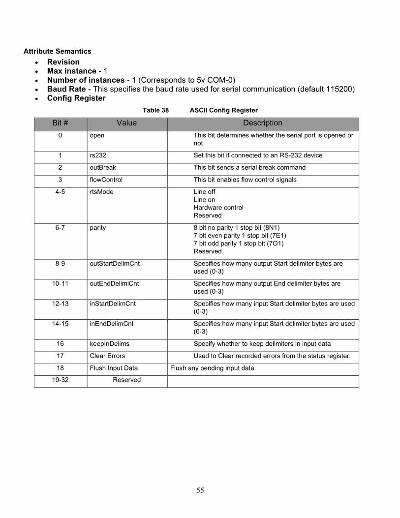
55
Attribute Semantics
• Revision • Max instance - 1 • Number of instances - 1 (Corresponds to 5v COM-0) • Baud Rate - This specifies the baud rate used for serial communication (default 115200) • Config Register
Table 38 ASCII Config Register
Bit # Value Description
0 open This bit determines whether the serial port is opened or
not
1 rs232 Set this bit if connected to an RS-232 device
2 outBreak This bit sends a serial break command
3 flowControl This bit enables flow control signals
4-5 rtsMode Line off
Line on
Hardware control
Reserved
6-7 parity 8 bit no parity 1 stop bit (8N1)
7 bit even parity 1 stop bit (7E1)
7 bit odd parity 1 stop bit (7O1)
Reserved
8-9 outStartDelimCnt Specifies how many output Start delimiter bytes are
used (0-3)
10-11 outEndDelimiCnt Specifies how many output End delimiter bytes are
used (0-3)
12-13 inStartDelimCnt Specifies how many input Start delimiter bytes are used
(0-3)
14-15 inEndDelimCnt Specifies how many input Start delimiter bytes are used
(0-3)
16 keepInDelims Specify whether to keep delimiters in input data
17 Clear Errors Used to Clear recorded errors from the status register.
18 Flush Input Data Flush any pending input data.
19-32 Reserved
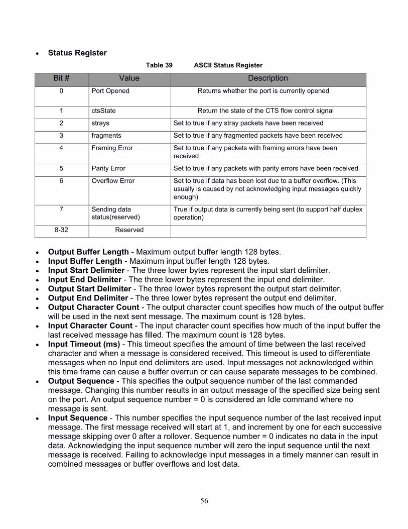
56
• Status Register
Table 39 ASCII Status Register
Bit # Value Description
0 Port Opened Returns whether the port is currently opened
1 ctsState Return the state of the CTS flow control signal
2 strays Set to true if any stray packets have been received
3 fragments Set to true if any fragmented packets have been received
4 Framing Error
Set to true if any packets with framing errors have been
received
5 Parity Error Set to true if any packets with parity errors have been received
6 Overflow Error Set to true if data has been lost due to a buffer overflow. (This
usually is caused by not acknowledging input messages quickly
enough)
7 Sending data status(reserved)
True if output data is currently being sent (to support half duplex
operation)
8-32 Reserved
• Output Buffer Length - Maximum output buffer length 128 bytes. • Input Buffer Length - Maximum input buffer length 128 bytes. • Input Start Delimiter - The three lower bytes represent the input start delimiter. • Input End Delimiter - The three lower bytes represent the input end delimiter. • Output Start Delimiter - The three lower bytes represent the output start delimiter. • Output End Delimiter - The three lower bytes represent the output end delimiter. • Output Character Count - The output character count specifies how much of the output buffer
will be used in the next sent message. The maximum count is 128 bytes. • Input Character Count - The input character count specifies how much of the input buffer the
last received message has filled. The maximum count is 128 bytes. • Input Timeout (ms) - This timeout specifies the amount of time between the last received
character and when a message is considered received. This timeout is used to differentiate messages when no Input end delimiters are used. Input messages not acknowledged within this time frame can cause a buffer overrun or can cause separate messages to be combined.
• Output Sequence - This specifies the output sequence number of the last commanded message. Changing this number results in an output message of the specified size being sent on the port. An output sequence number = 0 is considered an Idle command where no message is sent.
• Input Sequence - This number specifies the input sequence number of the last received input message. The first message received will start at 1, and increment by one for each successive message skipping over 0 after a rollover. Sequence number = 0 indicates no data in the input data. Acknowledging the input sequence number will zero the input sequence until the next message is received. Failing to acknowledge input messages in a timely manner can result in combined messages or buffer overflows and lost data.
57
• Output Sequence Ack - The Output Sequence Ack returns the last commanded message sequence number loaded into the serial buffer. Once the Output sequence Ack equals the output Sequence number no additional messages will be sent until the output sequence number is changed.
• Input Sequence Ack - The input Sequence ack is used to acknowledge the receipt and processing of the last received input message. To acknowledge the message, the Input Sequence Ack must be set to the Input Sequence number which will subsequently clear the message from the Input Data array.
• Input Size - Specifies the size of the currently stored input message. Max of 128. • Output Size - Specified the size of the next commanded output message. Max of 128. • Input Data - This array stores pending input messages. Only one input message at a time is
stored. Once the input message is acknowledged, this array is cleared. • Output Data - This array stores the message data for outgoing messages.

58
ClearLink Board Object (69HEX - 1 Instance) The ClearLink Board Object models the board-level attributes and services of the ClearLink module.
Class Attributes
Table 40 Serial Object (71HEX - 1 Instances)
Instance Attribute
ID Name
Data Type
Data Value
Access Rule
Class (Instance 0)
1 Revision UINT 2 Get
2 Max Instance UINT 1 Get
3 Number of Instances UINT 0-2 Get
1 Blink Codes BYTE[5]
Varies Get / Set
2 Motor Mode BOOL
Varies Get/Set
3 Reset Blink code BOOL
Varies Set
4 Aux Voltage level REAL
Varies Get
5 Supply Voltage REAL
Varies Get
Table 41 ClearLink Board Object’s common services
Service code
Implemented for Service name
Class level Instance level
0EHex Yes Yes Get_Attribute_Single
10Hex No Yes Set_Attribute_Single
Attribute Semantics
• Revision • Max instance - 1 • Number of instances - 1 • Blink Codes - See below for byte definitions • Motor Mode - 0 = Step & Direction, 1 = M-Connector. This will be set automatically based on
the connection type and configuration data sent to ClearLink. • Reset Blink Code - resets all latching blink codes. • Aux Voltage - the measured voltage of ClearLink's 5V auxiliary supply. • Supply Voltage - the measured voltage of ClearLink's main power input.
Blink Code Bytes

59
Byte 0: Output Connector Overload Group IO_OVERLOAD_NONE = 0x00, IO0_OVERLOAD_BOARD = 0x01, IO1_OVERLOAD_BOARD = 0x02, IO2_OVERLOAD_BOARD = 0x04, IO3_OVERLOAD_BOARD = 0x08, IO4_OVERLOAD_BOARD = 0x10, IO5_OVERLOAD_BOARD = 0x20, Byte 1: Power Supply Error Group SUPPLY_ERROR_NONE = 0x00, SUPPLY_ERROR_VSUPPLY_LOW = 0x01, SUPPLY_ERROR_VSUPPLY_HIGH = 0x02, SUPPLY_ERROR_5VOB_OVERLOAD = 0x04, Byte 2: Device Error Group DEVICE_ERROR_NONE = 0x00, Reserved = 0x01, Reserved = 0x02, DEVICE_ERROR_ETHERNET = 0x04, DEVICE_ERROR_CCIO = 0x08, Reserved = 0x10, DEVICE_ERROR_NVM = 0x20, Byte 3: CCIO Overload Group CCIO_OVERLOAD_NONE = 0x00, CCIO_OVERLOAD_BOARD0 = 0x01, CCIO_OVERLOAD_BOARD1 = 0x02, CCIO_OVERLOAD_BOARD2 = 0x04, CCIO_OVERLOAD_BOARD3 = 0x08, CCIO_OVERLOAD_BOARD4 = 0x10, CCIO_OVERLOAD_BOARD5 = 0x20, CCIO_OVERLOAD_BOARD6 = 0x40, CCIO_OVERLOAD_BOARD7 = 0x80, Byte 4: Reserved
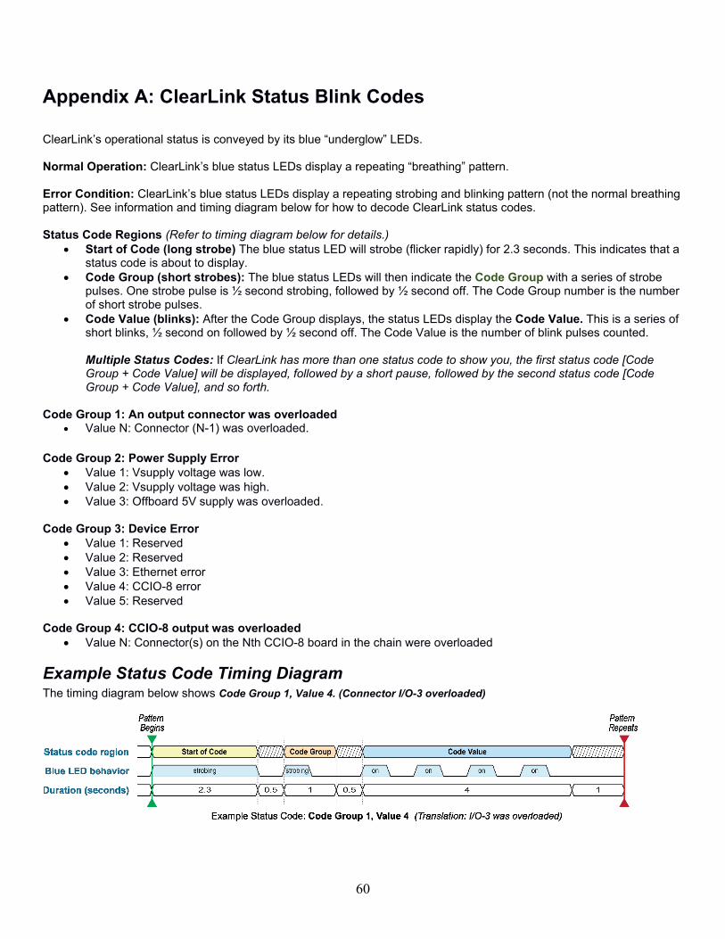
60
Appendix A: ClearLink Status Blink Codes
ClearLink’s operational status is conveyed by its blue “underglow” L Ds. Normal Operation: ClearLink’s blue status L Ds display a repeating “breathing” pattern. Error Condition: ClearLink’s blue status LEDs display a repeating strobing and blinking pattern (not the normal breathing pattern). See information and timing diagram below for how to decode ClearLink status codes. Status Code Regions (Refer to timing diagram below for details.)
• Start of Code (long strobe) The blue status LED will strobe (flicker rapidly) for 2.3 seconds. This indicates that a status code is about to display.
• Code Group (short strobes): The blue status LEDs will then indicate the Code Group with a series of strobe pulses. One strobe pulse is ½ second strobing, followed by ½ second off. The Code Group number is the number of short strobe pulses.
• Code Value (blinks): After the Code Group displays, the status LEDs display the Code Value. This is a series of short blinks, ½ second on followed by ½ second off. The Code Value is the number of blink pulses counted. Multiple Status Codes: If ClearLink has more than one status code to show you, the first status code [Code Group + Code Value] will be displayed, followed by a short pause, followed by the second status code [Code Group + Code Value], and so forth.
Code Group 1: An output connector was overloaded
• Value N: Connector (N-1) was overloaded.
Code Group 2: Power Supply Error
• Value 1: Vsupply voltage was low.
• Value 2: Vsupply voltage was high.
• Value 3: Offboard 5V supply was overloaded.
Code Group 3: Device Error
• Value 1: Reserved
• Value 2: Reserved
• Value 3: Ethernet error
• Value 4: CCIO-8 error
• Value 5: Reserved
Code Group 4: CCIO-8 output was overloaded
• Value N: Connector(s) on the Nth CCIO-8 board in the chain were overloaded
Example Status Code Timing Diagram The timing diagram below shows Code Group 1, Value 4. (Connector I/O-3 overloaded)
61
Appendix B: Troubleshooting Motion
Motor Behavior
• The motor attached to ClearLink does not move when given an appropriate move command.
• The motor attached to ClearLink stops unexpectedly and will not respond to further move commands. Most Likely Cause This is probably the result of either a motor shutdown or a ClearLink shutdown. When ClearLink enters a shutdown state, it immediately cancels motion and simultaneously prevents new moves from executing.
Potential Solutions
For ClearPath Servos:
1. Check that you are using the correct connection type for your servos. ClearPath-MC servos require a different connection type than the default option. The default connection type is Step and Direction).
2. Check to see if the Motor Shutdowns register has any bits set. Motion is inhibited if this register contains anything but zeros. Use “Clear Alerts” to clear this register. If the register does not clear, this means the shutdown condition is still present and the same bit(s) are immediately being set again.
a. If the ClearLink shutdown is a Motor Fault, use ClearPath MSP software to determine what type of motor shutdown is occurring. These ClearPath shutdowns are cleared using “Clear Motor Faults”.
i. If ClearLink thinks there is a Motor Fault but the motor is not in a shutdown state, this means ClearLink is having an issue reading the motor’s HLFB signal properly. Double check: 1. correct HLFB settings in MSP, 2. HLFB Inversion is properly turned on, 3. cable issues.
For third-party (non-Teknic) step and direction drives:
1. Ensure the drive is set to accept step frequencies of at least 500kHz (minimum step width no greater than 1 uS).
2. Check that the drive enables when the ClearLink enable signal is given. If not, you may need to use the Enable Inversion.
3. Check the Motor Shutdowns register. Motion is canceled if this register contains anything except zeros. Use “Clear Alerts” to clear this register. If the register does not clear, this means the shutdown condition is still present and the same bit(s) are immediately being set again.
b. If the ClearLink shutdown is a Motor Fault, check for drive errors. This register is cleared using “Clear Motor Faults”.
i. If ClearLink thinks there is a Motor Fault but the drive is not in a shutdown state, double check: 1. HLFB Inversion may need to be turned off, 2. fault signal cable issues.