Embed Size (px)
Citation preview
Clean Heat and Power Using Biomass Gasification for Industrial and Agricultural Projects December 2008 (Updated July 2009) Prepared by: Carolyn J. Roos, Ph.D. WSU Extension Energy Program P.O. Box 43165 • Olympia, WA 98504-3165 (360) 956-2004 • Fax (360) 236-2004 • TDD (360) 956-2218 WSUEEP08-033 Cooperating agencies: Washington State University Extension Energy Program, U.S. Department of Energy, Alaska Energy Authority, Idaho Office of Energy Resources, Montana Department of Environmental Quality Energy Program, and Oregon Department of Energy


About the Author
Carolyn Roos Ph.D. is a mechanical engineer with experience in building systems energy efficiency, mechanical design in hydroelectric facilities, and solar thermal applications. Currently she provides technical support to the Northwest Clean Heat and Power (CHP) Application Center with a focus in using biomass feedstocks. With the Washington State University Extension Energy Program, she provides technical assistance to commercial and industrial clients on energy system efficiency topics. Carolyn can be contacted by email at [email protected].
Acknowledgements
This study was funded by the Northwest CHP Application Center with support funding from the U.S. Department of Energy’s Industrial Technologies Program and from the State of Washington.
Disclaimer
While the information included in this guide may be used to begin a preliminary analysis, a professional engineer and other professionals with experience in biomass drying should be consulted for the design of a particular project. Neither the Northwest CHP Application Center nor its cooperating agencies, nor any of their employees, makes any warranty, express or implied, or assumes any legal liability or responsibility for the accuracy, completeness or usefulness of any information, apparatus, product, or process disclosed, or represents that its use would not infringe privately owned rights. Reference herein to any specific commercial product, process, or service by trade name, trademark, manufacturer, or otherwise does not necessarily constitute or imply its endorsement, recommendation, or favoring by the Northwest CHP Application Center or its cooperating agencies.
i
Executive Summary
The use of biomass to generate heat and power is crucial in achieving energy independence and increasing our use of renewable energy sources. In our transition to renewable energy, gasification promises to play a major role in large part because its products can make use of existing infrastructure and equipment associated with fossil fuel use. This guidebook is intended for use by the forest products and food processing industries. It can also be used by farmers, ranchers and others who have access to biomass materials.
Gasification is a thermal conversion process in which both heat and a combustible product gas are produced. Combustion, in contrast, produces only heat, most commonly in a boiler to generate steam for production of electricity using a steam turbine. With gasification, generation of a combustible gas is key to its importance. A gaseous fuel makes the use of reciprocating engines, gas turbines and fuels cells possible in the generation of electricity, thereby increasing electrical efficiency. Gasification also makes possible a highly efficient configuration for generating electricity, referred to as an integrated gasification combined cycle (IGCC). Further, gasification can facilitate the use of biomass for heat and power because gaseous fuels can be distributed by pipeline from a gasification plant for use in other locations, either on site or off.
Gasification of biomass and the use of the product gas in boilers and furnaces have a long and proven history. However, using the product gas for efficient electricity generation with engines, turbines and fuel cells has been hampered until recently by technical difficulties in removing tars from the product gas. Tar removal technologies have advanced in recent years and have now been successfully demonstrated and proven reliable. With these advances, biomass gasification for generation of heat and power has now emerged into commercialization. In the U.S., construction will begin in 2009 on a 42 MWe commercial-scale project in Tallahassee, Florida, and another 28 MWe gasifier is planned for Forsythe, Georgia. Around the world, more than 100 biomass gasifier projects are operating or ordered.
In addition to heat and power, there is a wide array of co-products possible with gasification. This can improve the cost effectiveness of a gasification project. The product gas can be used as a feedstock to produce hydrogen and liquid hydrocarbons, such as ethanol and chemical feedstocks. Biochar has several potential markets and also gives gasification the potential of a carbon neutral or carbon negative energy solution. Both combustion and gasification produce ash, which also can be marketed.
This guide is a practical overview of gasification on the small (<1 MW) and medium scales appropriate for food processors, farmers, forest products industries and others with access to biomass materials. The selection and application of gasifiers, engines and turbines, feedstock preparation and handling equipment, gas clean up technologies, and other ancillary equipment are discussed. Practical strategies for avoiding slagging, fouling and corrosion in the gasifier and downstream equipment are discussed.
ii
Contents About the Author .................................................................................................... i Acknowledgements................................................................................................ i Disclaimer .............................................................................................................. i Executive Summary .............................................................................................. ii Introduction ...........................................................................................................1
What is Gasification? ............................................................................................3
Why Gasification? .................................................................................................3
Comparison with Other Thermal Conversion Processes ......................................6
System Equipment................................................................................................9
Product Gas Composition ...................................................................................23
Feedstock Characteristics and Requirements ....................................................24
Reducing Slagging, Fouling and Corrosion.........................................................29
Gas Clean-Up .....................................................................................................32
Marketable Co-Products .....................................................................................35
Environmental Benefits .......................................................................................39
Industry Applications...........................................................................................41
Demonstration Projects.......................................................................................42
Other Information Resources..............................................................................52
References .........................................................................................................55
iii
List of Tables Table 1. Summary of Bioenergy Conversion Technologies .................................2 Table 2. Comparison of Combustion, Gasification and Pyrolysis.........................8 Table 3. Predominant Components of Products from Fast Pyrolysis and
Gasification..........................................................................................8 Table 4. Summary of Selected Biomass Gasifier Types ....................................15 Table 5. Typical Energy Contents of Producer Gas, Syngas and Natural Gas ..23 Table 6. Typical Heating Value, Moisture Content and Ash Content of Selected
Biomass Feedstocks..........................................................................26 Table 7. Characteristics of Common Biomass Feedstocks................................27 Table 8. Chemical Contents of Product Gas from Selected Biomass Fuels ......27 Table 9. Biomass Characteristics As Compared to Coal ...................................28 Table 10. Typical Tar and Particulate Contents of Gasifier Types .....................34 Table 11. Tolerance of End-Use Devices for Tar*..............................................34 Table 12. Examples of European Biomass Gasification Projects ......................47 Table 13. Examples of North American Biomass Gasification Projects .............49
List of Figures Figure 1. Updraft and Downdraft Fixed-Bed Gasifiers* ......................................11
iv
Introduction
Biomass feedstocks are becoming increasingly valuable as the demand for renewable fuels has increased and the supply of wood fuels has diminished with the decline in the housing market. Bark, wood chips, and shavings, once considered waste and disposal problems, are now commodities with demand coming from domestic forest products companies, as well as European markets. Other biomass residuals, such as food processing and agricultural wastes, are increasingly being looked upon as fuel sources. As cellulosic ethanol production emerges into commercialization, demand for wood and agricultural residuals will only increase. These trends will likely continue as a whole range of new technologies and uses, summarized in Table 1, are added to traditional technologies and uses. Volatile prices for conventional energy sources have significantly changed the economics of efficiently using our biomass resources. With rising electricity prices and increasing demand for renewable energy, base load biomass-fired clean heat and power1 (CHP) systems become more attractive. It is now more important than ever that we use our biomass resources efficiently. Biomass gasification can achieve higher efficiencies in generating electricity and lower emissions compared to combustion technologies. Further, gasification increases the possible uses of biomass since the product gas has value not just as a fuel in itself, but also as a feedstock to produce other fuels, such as ethanol and hydrogen, and as a chemical feedstock.
Biomass gasification has trailed coal gasification due to technical differences deriving from the characteristics of the feedstocks, as well as the typical scale of operation. Technological advances particular to biomass gasification have been successfully demonstrated and commercial-scale projects are proceeding. Around the world, more than 100 biomass gasifier projects are operating or ordered. In the U.S., construction will begin in 2009 on a 42 MWe commercial-scale project in Tallahassee, Florida, and another 28 MWe gasifier is planned for Forsythe, Georgia. Small-scale gasification is moving ahead as well in the U.S. A 300 kW farm-scale demonstration using straw as a feedstock and a 320 kW project at a sawmill have been constructed and are now beginning operation.
This publication focuses on gasification of biomass on the small and medium scales appropriate for food processors, farmers, forest products industries and others with access to biomass materials. This guide focuses primarily on woody biomass and food and agricultural residues.
1 “Clean heat and power” or CHP refers to clean, efficient local energy generation, including but not limited to combined heat and power, recycled energy, bioenergy, and other generation sources that lead to a demonstrable reduction in global greenhouse gas emissions.
1
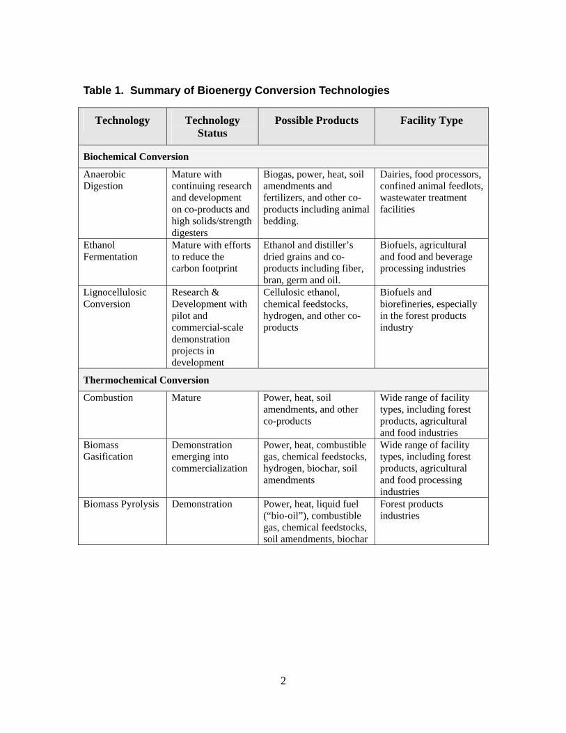
Table 1. Summary of Bioenergy Conversion Technologies
Technology Technology Status
Possible Products Facility Type
Biochemical Conversion
Anaerobic Digestion
Mature with continuing research and development on co-products and high solids/strength digesters
Biogas, power, heat, soil amendments and fertilizers, and other co-products including animal bedding.
Dairies, food processors, confined animal feedlots, wastewater treatment facilities
Ethanol Fermentation
Mature with efforts to reduce the carbon footprint
Ethanol and distiller’s dried grains and co-products including fiber, bran, germ and oil.
Biofuels, agricultural and food and beverage processing industries
Lignocellulosic Conversion
Research & Development with pilot and commercial-scale demonstration projects in development
Cellulosic ethanol, chemical feedstocks, hydrogen, and other co-products
Biofuels and biorefineries, especially in the forest products industry
Thermochemical Conversion
Combustion Mature Power, heat, soil amendments, and other co-products
Wide range of facility types, including forest products, agricultural and food industries
Biomass Gasification
Demonstration emerging into commercialization
Power, heat, combustible gas, chemical feedstocks, hydrogen, biochar, soil amendments
Wide range of facility types, including forest products, agricultural and food processing industries
Biomass Pyrolysis Demonstration Power, heat, liquid fuel (“bio-oil”), combustible gas, chemical feedstocks, soil amendments, biochar
Forest products industries
2
What is Gasification?
Gasification is a thermal conversion process – as is combustion – in which both heat and a combustible product gas are produced. One method of gasification, referred to as “partial oxidation,” is very similar to combustion except that it occurs with insufficient oxygen supply for complete combustion to occur. In a second method, the biomass is indirectly heated in the absence of oxygen or air, with steam as the oxidizing agent. The product gas is either a medium-energy content gas referred to as “synthetic gas” or “syngas” or a low-energy content gas often referred to as “producer gas.”2 Syngas consists primarily of carbon monoxide and hydrogen. Higher quality syngas can be produced by indirect heating or by using pure oxygen as the oxidizing agent (“oxygen-blowing”). Producer gas results if air is used as the oxidizing agent (“air-blowing”), which dilutes the combustible components of the gas with nitrogen. Generally, producer gas is adequate for power generation and avoids the energy use associated with oxygen production. Syngas is required for chemical production. The product gas can be burned in conventional boilers, furnaces, engines and turbines, or co-fired with natural gas, with minor modifications to conventional equipment. Since both producer gas and syngas have lower heating values than propane or natural gas, enlarging orifices and adjusting control settings may be required. The product gas can also be used in solid-fuel boilers as a reburn fuel that is injected into the boiler. As a note on terminology, the term “gasifier” has been applied to staged-air combustion appliances in which product gas generated in a first stage is burned in a second stage of an integrated unit or closely coupled unit with no provision for collecting the product gas. However, in this guide, the terms “gasifier” and “gasification” are used to refer only to equipment that is designed to obtain both a combustible product gas and heat as separate products.
Why Gasification?
Gasification has several advantages that make it an appropriate choice in certain types of projects. A variety of products are possible with gasification. The gasification process results in co-products that can result in other revenue streams for a project. Syngas can be used as a feedstock to produce other fuels (such as ethanol, methanol, naptha, hydrogen, gasoline and diesel) and as a feedstock for chemicals (such 2 It is quite common and accepted to use the term “syngas” to refer to the product gas in general, whether syngas or producer gas as defined here. However, other references make a clear distinction in terminology, as does this guide. Some references also use the term “biogas” to refer to the product gas of biomass gasification. However, this is easily confused with the methane rich-gas produced by anaerobic digestion, which is more commonly referred to as biogas.
3
as acetic acid, dimethyl ether, and ammonia). The oils, char and ash that are often generated in gasification may be marketable precursors for products such as soil amendments, filtration media and cement additive. The char in particular can have a high value as a co-product. Gasification has synergies with existing fossil fuel infrastructure. Gasification has synergies with fossil fuel use that can facilitate our transition to renewable energy. As an example of a synergistic opportunity, liquid transportation fuels produced from syngas can be distributed through our current fueling infrastructure. Also, syngas and producer gas can be co-fired with natural gas in conventional turbines and fuel cells or co-fired in coal-fired boilers to generate electricity. Bio-hydrogen produced from syngas can be used in conjunction with hydrogen produced from natural gas. Facilities that currently use coal syngas in the production of chemicals can supplement it with syngas from biomass using existing infrastructure. Gaseous fuels are easier to transport than solid biomass. Gaseous fuels can be distributed by pipeline from a gasification plant for direct use in other locations. There are various scenarios where this would be an advantage. As one example, a gasifier could be located at the most convenient point of biomass collection with the product gas piped to users located off site. As another example, available space within a manufacturing facility may prohibit locating a biomass-fired boiler or furnace and its ancillary equipment within the facility. In this case, a gasifier could be located elsewhere with the product gas piped to the point of use. As a note of caution, the gasifier should still be located where there is a use for its heat to achieve the high efficiencies possible with CHP systems. Landfill gas use in this country serves as an illustration of this potential. Of the approximately 500 landfill gas projects existing in the U.S., about a third pipe the gas in dedicated pipelines to nearby industrial customers to offset fossil fuel use. Biogas pipelines range from 200 yards to more than 20 miles. Use of turbines, engines and fuel cells increases efficiency of electricity generation. An important advantage of gasification compared to combustion is its potential to achieve higher efficiencies and lower emissions. Generating a gaseous fuel makes the use of reciprocating engines, gas turbines and fuel cells possible in the generation of electricity. Gas turbines, fuel cells and engines are more efficient electrical generation technologies than the steam cycle to which solid biomass is limited. The efficiency of a biomass-fired steam turbine system is between 20% and 25%. In comparison, syngas-fueled engines and turbines can achieve system efficiencies in the range of 30% to 40%, with higher efficiencies possible in integrated combined cycles. In considering overall efficiency, it is important to examine losses in the gasification process itself in converting biomass to the product gas in addition to improved electrical efficiency. If the chars and tars that result in gasification are reburned and the heat of gasification is recovered, high conversion efficiencies can be achieved.
4
Gasification makes biomass-fired integrated combined cycles possible. Gasification makes possible a highly efficient configuration for generating electricity (that is not possible with combustion of biomass), referred to as an integrated gasification combined cycle (IGCC). In an IGCC system, the product gas is first burned in a gas turbine to generate electricity (topping cycle). Second, waste heat from both the turbine and the gasifier is recovered in a heat recovery boiler and used to generate electricity by a steam turbine (bottoming cycle). Such a system can achieve high electrical efficiencies of 42% to 48%. If low-pressure steam is also recovered from the steam turbine and other heat recovery opportunities in the system are taken advantage of, overall efficiencies of 60% to more than 90% can be achieved. Note that IGCC systems are cost effective only on larger scales due to the high capital cost of the gasifier, gas turbine, boiler and steam turbine, plus ancillary equipment. The first project to demonstrate the IGCC technology operated from 1993 to 2000 in Varnamo, Sweden, producing 6 MWe of power and 9 MWth of heat in short stints for research and development purposes. The IGCC plant soon to begin construction in Tallahassee, Florida, will deliver both methanated syngas and high efficiency, renewable power to the City of Tallahassee. Gasification can facilitate combined heat and power. If heat from both the gasification process and electrical generation are recovered, overall efficiencies of 60% to more than 90% can be achieved. Such combined heat and power (CHP) is possible with both combustion and gasification. But because gaseous fuels can be piped over a distance, gasification can facilitate combined heat and power projects in cases where the best use of heat from the gasifier and the best or most convenient use of the product gas are not in close proximity. In the most cost effective CHP projects, heat recovery is cascaded through a series of applications with each step using a lower temperature. Heat can be recovered from the gasification process and from electrical generation equipment. Waste heat can be used in a variety of ways, such as generating steam and hot water, space heating, generating power using an organic Rankine cycle turbine, or meeting cooling and refrigerating needs with absorption chillers.
5
Comparison with Other Thermal Conversion Processes
Combustion, gasification and pyrolysis are three thermal conversion processes by which energy is obtained from biomass. Distinctions between these three processes are summarized in Tables 2 and 3. In short, combustion occurs with sufficient oxygen to completely oxidize the fuel, i.e. convert all carbon to carbon dioxide, all hydrogen to water, and all the sulfur to sulfur dioxide. Gasification occurs with insufficient oxygen or with steam such that complete oxidation does not occur. Pyrolysis occurs in the absence of an oxidizing agent (air, oxygen, or steam). As an intermediate process between combustion and pyrolysis, gasification is sometimes referred to as “partial oxidization” and sometimes as “partial pyrolysis.” Gasification, combustion and pyrolysis each have advantages and disadvantages. In any particular project, it is important to evaluate the goal of the project, the biomass resources available, and particular needs of the facility in choosing a thermal conversion process.
Gasification versus Combustion In choosing between gasification and combustion, consider if generating a product gas is an advantage. Also, consider the possibility of achieving higher electrical efficiency. Another factor to consider is that gasification projects may be eligible for more grants and incentives than the more tried and true combustion projects—at least for a time. Greater carbon emission reductions may also bring in revenue in carbon offset markets. If the primary end use is electricity generation on relatively small scales, at this point in time combustion of biomass in a biomass-fired boiler with electricity generated using a steam turbine is often more cost effective than a gasification system generating electricity with an internal combustion engine or turbine. Similarly, if the desired product is only heat, whether for industrial process heat, space heating, or water heating, a biomass-fired boiler or furnace will likely be most cost effective. Combustion technologies are well-established and widespread. While gasification has been successfully demonstrated in projects of several megawatts in size over a number of years, it is still an emerging commercial technology. As capital costs drop, operating experience increases, and the economic value of carbon emission reductions increases, cost effectiveness of gasification compared to combustion will improve.
Gasification versus Pyrolysis Another promising thermal conversion technology, sometimes confused with gasification, is pyrolysis. While gasification occurs with restricted oxygen, pyrolysis occurs in the absence of oxygen or steam. In pyrolysis, biomass is heated to the point where volatile gases and liquids are driven off and then condensed into a combustible, water soluble liquid fuel called bio-oil (not to be confused with bio-diesel.) Bio-oil from
6
fast pyrolysis3 is a low viscosity, dark-brown fluid with a high tar content and a water content of 15% to 20%. Bio-oil can be burned in a boiler, upgraded for use in engines and turbines, or used as a chemical feedstock. Being a liquid fuel, bio-oil is easier to transport than syngas but its corrosiveness makes long-term storage difficult. Both gasification and pyrolysis produce char, which can be used as a soil amendment, precursor to activated carbon, or burned. Slow pyrolysis results in a higher percentage of char (up to 35%), if that is a more desired co-product. Such uses of the biochar can make gasification and pyrolysis carbon neutral or even carbon negative (refer to the section “Environmental Advantages” below). Pyrolysis is a less mature technology compared to gasification. There are fewer manufacturers of pyrolysis reactors and a small number of demonstration projects, which have shorter histories. Manufacturers of pyrolysis reactors are Dynamotive, BEST, Lurgi and Ensyn Technologies. BEST has had one pilot project and one small demonstration project. Dynamotive has two demonstration projects. For more information on pyrolysis, refer to IEA Bioenergy’s PyNe website at http://www.pyne.co.uk/ and the Bioenergy Technology Group’s website at http://www.btgworld.com/index.php?id=22&rid=8&r=rd. In choosing between gasification and pyrolysis, consider the state of technology development, and if a liquid fuel is more advantageous in your particular application than a gaseous fuel. Also, consider if higher production of biochar is desirable in your case.
3 Fast pyrolysis occurs at a relatively low temperature of around 500°C (900°F) and the biomass has short residence times of 2 seconds or less. Intermediate and slow pyrolysis occur at higher temperatures and have longer residence times. As residence time increases, char content increases (up to about 35%), tar content decreases and water content of the bio-oil increases (up to about 75%).
7
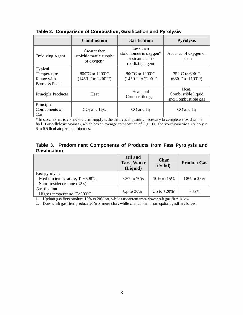
Table 2. Comparison of Combustion, Gasification and Pyrolysis
Combustion Gasification Pyrolysis
Oxidizing Agent Greater than
stoichiometric supply of oxygen*
Less than stoichiometric oxygen*
or steam as the oxidizing agent
Absence of oxygen or steam
Typical Temperature Range with Biomass Fuels
800oC to 1200oC (1450oF to 2200oF)
800oC to 1200oC (1450oF to 2200oF
350oC to 600oC (660oF to 1100oF)
Principle Products Heat Heat and Combustible gas
Heat, Combustible liquid
and Combustible gas Principle Components of Gas
CO2 and H2O CO and H2 CO and H2
* In stoichiometric combustion, air supply is the theoretical quantity necessary to completely oxidize the fuel. For cellulosic biomass, which has an average composition of C6H10O5, the stoichiometric air supply is 6 to 6.5 lb of air per lb of biomass.
Table 3. Predominant Components of Products from Fast Pyrolysis and Gasification Oil and
Tars, Water (Liquid)
Char (Solid) Product Gas
Fast pyrolysis Medium temperature, T=~500oC Short residence time (<2 s)
60% to 70% 10% to 15% 10% to 25%
Gasification Higher temperature, T>800oC Up to 20%1 Up to +20%2 ~85%
1. Updraft gasifiers produce 10% to 20% tar, while tar content from downdraft gasifiers is low. 2. Downdraft gasifiers produce 20% or more char, while char content from updraft gasifiers is low.
8
System Equipment
A gasification project will consist of various components. In addition to the gasifier, a gasification project may have a turbine or reciprocating engine, generator set, pellet mill, grinder, biomass dryer, material feeders, gas clean-up equipment, and gas storage and handling equipment.
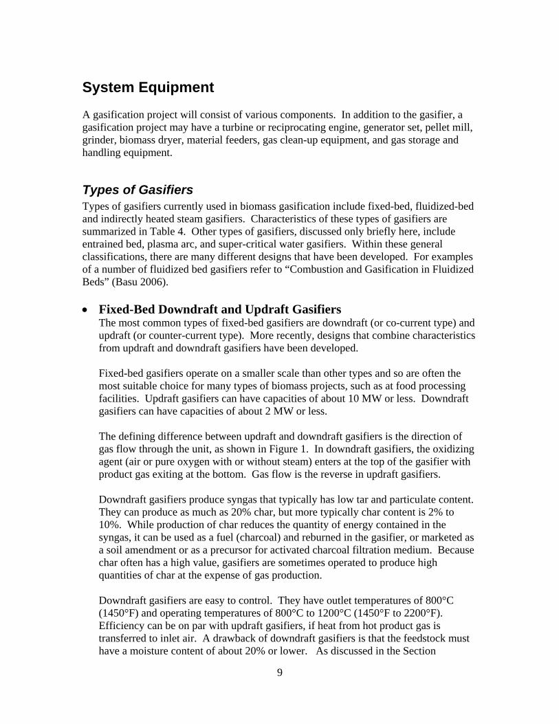
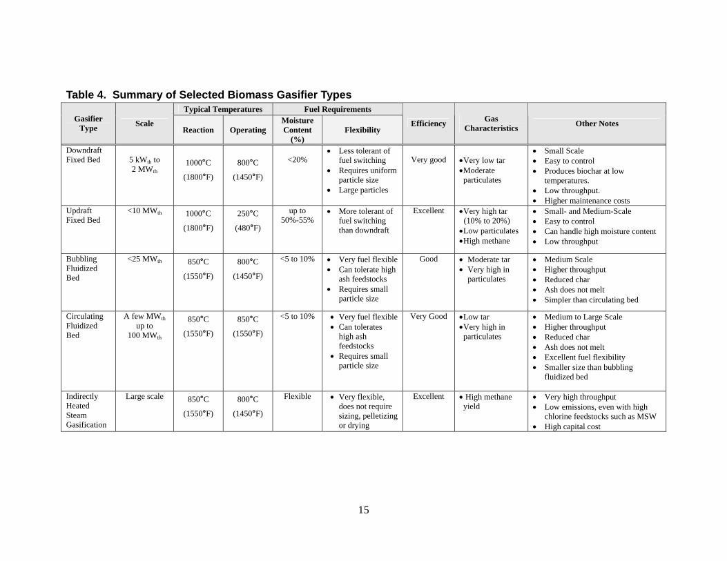
Types of Gasifiers Types of gasifiers currently used in biomass gasification include fixed-bed, fluidized-bed and indirectly heated steam gasifiers. Characteristics of these types of gasifiers are summarized in Table 4. Other types of gasifiers, discussed only briefly here, include entrained bed, plasma arc, and super-critical water gasifiers. Within these general classifications, there are many different designs that have been developed. For examples of a number of fluidized bed gasifiers refer to “Combustion and Gasification in Fluidized Beds” (Basu 2006). • Fixed-Bed Downdraft and Updraft Gasifiers
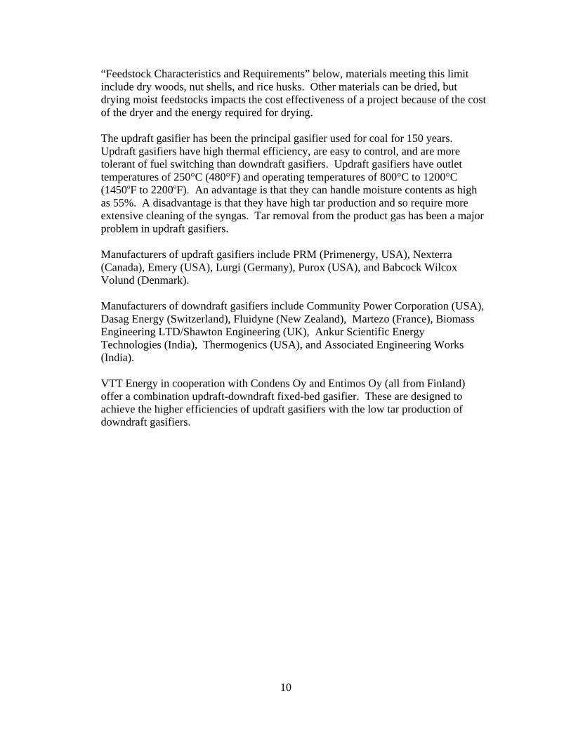
The most common types of fixed-bed gasifiers are downdraft (or co-current type) and updraft (or counter-current type). More recently, designs that combine characteristics from updraft and downdraft gasifiers have been developed. Fixed-bed gasifiers operate on a smaller scale than other types and so are often the most suitable choice for many types of biomass projects, such as at food processing facilities. Updraft gasifiers can have capacities of about 10 MW or less. Downdraft gasifiers can have capacities of about 2 MW or less. The defining difference between updraft and downdraft gasifiers is the direction of gas flow through the unit, as shown in Figure 1. In downdraft gasifiers, the oxidizing agent (air or pure oxygen with or without steam) enters at the top of the gasifier with product gas exiting at the bottom. Gas flow is the reverse in updraft gasifiers. Downdraft gasifiers produce syngas that typically has low tar and particulate content. They can produce as much as 20% char, but more typically char content is 2% to 10%. While production of char reduces the quantity of energy contained in the syngas, it can be used as a fuel (charcoal) and reburned in the gasifier, or marketed as a soil amendment or as a precursor for activated charcoal filtration medium. Because char often has a high value, gasifiers are sometimes operated to produce high quantities of char at the expense of gas production. Downdraft gasifiers are easy to control. They have outlet temperatures of 800°C (1450°F) and operating temperatures of 800°C to 1200°C (1450°F to 2200°F). Efficiency can be on par with updraft gasifiers, if heat from hot product gas is transferred to inlet air. A drawback of downdraft gasifiers is that the feedstock must have a moisture content of about 20% or lower. As discussed in the Section
9
“Feedstock Characteristics and Requirements” below, materials meeting this limit include dry woods, nut shells, and rice husks. Other materials can be dried, but drying moist feedstocks impacts the cost effectiveness of a project because of the cost of the dryer and the energy required for drying. The updraft gasifier has been the principal gasifier used for coal for 150 years. Updraft gasifiers have high thermal efficiency, are easy to control, and are more tolerant of fuel switching than downdraft gasifiers. Updraft gasifiers have outlet temperatures of 250°C (480°F) and operating temperatures of 800°C to 1200°C (1450oF to 2200oF). An advantage is that they can handle moisture contents as high as 55%. A disadvantage is that they have high tar production and so require more extensive cleaning of the syngas. Tar removal from the product gas has been a major problem in updraft gasifiers. Manufacturers of updraft gasifiers include PRM (Primenergy, USA), Nexterra (Canada), Emery (USA), Lurgi (Germany), Purox (USA), and Babcock Wilcox Volund (Denmark). Manufacturers of downdraft gasifiers include Community Power Corporation (USA), Dasag Energy (Switzerland), Fluidyne (New Zealand), Martezo (France), Biomass Engineering LTD/Shawton Engineering (UK), Ankur Scientific Energy Technologies (India), Thermogenics (USA), and Associated Engineering Works (India). VTT Energy in cooperation with Condens Oy and Entimos Oy (all from Finland) offer a combination updraft-downdraft fixed-bed gasifier. These are designed to achieve the higher efficiencies of updraft gasifiers with the low tar production of downdraft gasifiers.
10
Figure 1. Updraft and Downdraft Fixed-Bed Gasifiers*
Updraft (Counter-Current) Gasifier
Downdraft (Co-Current) Gasifier
* There are many variations in specific designs. For example, solid fuel is not fed from the top in some designs. • Fluidized Bed Gasifiers
In fluidized bed gasifiers, the oxidizing agent and fuel are mixed in a hot bed of granular solids. Solid fuel and bed particles are fluidized by gas flow. The bed is usually composed of sand, limestone, dolomite or alumina. Gases and remaining solids are separated afterwards by cyclone. There are two types of fluidized bed gasifiers: bubbling and circulating. Bubbling fluidized bed gasifiers are appropriate for medium size projects of 25 MWth or less, while circulating fluidized bed gasifiers can range from a few MWth up to very large units. Fluidized bed gasifiers are especially good for biomass gasification. They have very good fuel flexibility and so can be considered true multifuel units. Wood waste, straw, and refuse-derived fuel, as examples, can be gasified in the same unit, although the heat output varies with the heat value of the fuel. Fluidized bed gasifiers reduce gas contaminant problems often associated with agricultural biomass. Due to their lower operating temperatures, ash does not melt, which makes its removal relatively easy and reduces problems with slagging. Sulfur and chloride are absorbed in the bed material, reducing fouling and corrosion. Fluidized bed gasifiers are more compact and have higher throughput than fixed bed gasifiers. Their efficiency is lower, but can be improved by recirculating gas. The product gas has low tar content, but has a high level of particulates. Manufacturers and suppliers of fluidized bed gasifiers for biomass include Energy Products of Idaho (USA), Foster Wheeler (Finland), METSO Power (formerly Kvaerner, Finland), Carbona (formerly Tampella, Enviropower, Vattenfall, USA), Lurgi (Germany), TPS Termiska (Sweden), Cratech (USA), Stein (UK), Gas Technology Institute (USA), Southern Electric International (USA), Sur-Lite Corp.
11
(USA), Enerkem/Biosyn (Canada), Sydkraft (Sweden), Elsam/Elkraft (Denmark), Biomass Technology Group (USA), and ABB (Switzerland). Manufacturers often specialize in gasification of particular types of feedstocks. While some of these have focused on woody biomass and/or agricultural wastes, others specialize in black liquor and paper mill sludges, and others on municipal solid waste.
• Indirectly Heated Steam Fluidized Bed Gasifiers
Indirectly heated steam gasification was specifically designed to take advantage of the particular properties of biomass, such as high reactivity, low ash, low sulfur, and high volatile matter. The development of other types of biomass gasifiers was heavily influenced by coal gasification technology and so they are not optimum for biomass. For example, the high reactivity of biomass means that greater throughputs (i.e. higher rate of gasification) are possible with indirectly heated steam gasifiers, but the throughputs of other types of gasifiers are very limited. Throughputs of indirectly heated gasifiers can be several times that of other types of gasifiers. The SilvaGas or Taylor-type indirectly heated gasifier consists primarily of two chambers: the gasifier and the combustor. In the gasifier, the biomass mixes with steam and a heated solid medium, such as sand, in a circulating fluidized bed. No air or oxygen is added. The biomass is rapidly converted into syngas, char and tars at a temperature of approximately 850°C (1550°F). The solid particles – char and sand – are separated from the gas stream and directed to the combustor where the char is burned, reheating the circulating sand to 1000°C (1800°F). The reheated sand is then conveyed back to the gasifier to supply energy for gasification of the incoming biomass. The bubbling fluidized bed indirect gasifier developed by Manufacturing and Technology Conversion International, Inc (MTCI), primarily used for black liquor and paper mill sludges, is similar in that it consists of two stages, a lower combustor and an upper steam reforming stage. Indirectly heated gasifiers are inherently more complicated than directly-heated systems due to the need for a separate combustion chamber, and so have a higher capital cost. This is offset to a certain degree compared to oxygen-blown gasifiers because an oxygen separation plant (with its efficiency penalty) is not required. Indirectly heated gasifiers produce high quality syngas without the need for separation of oxygen from air for use as the oxidizing agent. The syngas has a higher percentage of methane and higher hydrocarbons, which poses a greater challenge in producing liquid fuels, chemicals and hydrogen. Significantly fewer emissions are produced in this process. In particular, not having oxygen in the gasifier makes it impossible to form dioxins if a chlorine-containing feedstock (such as processed municipal solid waste or recycled paper pulp sludges) is used. In the U.S. a 12 MW SilvaGas gasifier was demonstrated in 2000 to 2002 at the existing wood combustion facility at the McNeil Generating Station in Burlington,
12
Vermont. A 42 MWe SilvaGas-type gasifier will be installed in Tallahassee, Florida, with construction to begin in early 2009. Developers and manufacturers of this type of gasifier include FERCO/SilvaGas (USA), Manufacturing and Technology Conversion International, Inc. (USA), TRI, Inc. (USA), Taylor Biomass Energy (USA), the Technical University of Denmark, and Repotec (Austria).
• Other Types of Gasifiers
Entrained Bed Gasifiers: In entrained bed gasifiers, fine fuel particles are suspended by the movement of gas to move it through the gasifier. An example of an entrained bed gasifier is the Chemrec black liquor gasifier. A Chemrec gasifier was installed in 1996 at the Weyerhaeuser mill in New Bern, North Carolina. Entrained bed gasifiers require large scale to be cost effective and so are not practical for many biomass projects. Supercritical Water Gasifiers: Materials with moisture contents up to 95% can be gasified with the use of supercritical water. This process is still in development, but promises to widen the range of possible feedstocks. For more information on supercritical water gasification, refer to Biomass Technology Group’s website at http://www.btgworld.com/index.php?id=25&rid=8&r=rd. Plasma Arc Gasifiers: In plasma arc gasification, electricity is fed to a torch, which has two electrodes, creating an arc. Inert gas is passed through the arc, heating the process gas to internal temperatures as high as 14,000°C (25,000°F). The temperature a few feet from the torch can be as high as 3,000°C to 4,000°C (5,000° to 8000ºF.) Because of these high temperatures the waste is completely destroyed and broken down into its basic elemental components. Plasma arc gasification has been used in the gasification of municipal solid waste, especially in Asia. Close-coupled Gasifiers: “Close-coupled” or “multi-stage” gasifiers4 are essentially staged-air combustion appliances (i.e. boilers or furnaces). Staged-air combustion is a conventional technology that is widely applied in both large and small combustion appliances. In any combustion of a solid – whether in a woodstove, furnace or boiler – volatile materials are first pyrolyzed and gasified followed by full combustion of gases. Most commonly, these processes occur in a single stage. In staged-air boilers and furnaces, thermal conversion occurs in two stages of an integrated unit. In the first stage, the biomass is gasified by restricting air flow. In the second stage, sufficient air is supplied for full combustion of the gases. A product gas is not extracted from staged-air combustion appliances as a separate product. In this guide,
4 Integrated staged-air combustion appliances units are sometimes called “two-stage” or “multi-stage” gasifiers, not to be confused with indirectly heated steam gasifiers, which are also often referred to as “two-stage” or “dual-stage” gasifiers.
13
14
the term “gasifier” refers only to appliances that produce a combustible gas as a separate product. The primary advantage of staged-air combustion compared to conventional single-stage boilers and furnaces is reduced air emissions. There can be an efficiency penalty compared to single stage combustion appliances due to greater production of char. A small-scale example of a “close-coupled gasifier” is ChipTec’s Wood Energy Biomass Gasification System (see http://www.chiptec.com/). On a larger scale, Primenergy’s projects in Stuttgart, Arkansas, and Little Falls, Minnesota, combust the syngas in a closely coupled combustor to generate electricity in a steam cycle. Other Types: Many other gasifier concepts have been developed and manufactured. The reference “Initial Review and Evaluation of Process Technologies and Systems Suitable for Cost-Efficient Medium-Scale Gasification for Biomass to Liquid Fuels” (Olafsson, et al. 2005) provides a comprehensive summary with advantages and disadvantages of each. In addition to those discussed here, other types discussed are crossdraft fixed bed gasifiers, the Lurgi dry ash gasifier, slagging gasifiers, cyclone gasifiers, vertical vortex gasifiers, horizontal vortex pyrolyser, ablative pyrolysers, vacuum pyrolysers, screwing gasifiers, twin screw pyrolysers, rotary kiln gasifiers, heat pipe gasifiers, the thermal ballasted latent heat gasifier, the “Carbo-V” gasifier and the NREL thermochemical process development unit.
15
Table 4. Summary of Selected Biomass Gasifier Types Typical Temperatures Fuel Requirements
Gasifier Type Scale
Reaction Operating Moisture Content
(%) Flexibility
Efficiency Gas Characteristics Other Notes
Downdraft Fixed Bed
5 kWth to 2 MWth
1000°C
(1800°F)
800°C
(1450°F)
<20%
• Less tolerant of fuel switching
• Requires uniform particle size
• Large particles
Very good
•Very low tar •Moderate particulates
• Small Scale • Easy to control • Produces biochar at low
temperatures. • Low throughput. • Higher maintenance costs
Updraft Fixed Bed
<10 MWth 1000°C
(1800°F)
250°C
(480°F)
up to 50%-55%
• More tolerant of fuel switching than downdraft
Excellent •Very high tar (10% to 20%) •Low particulates •High methane
• Small- and Medium-Scale • Easy to control • Can handle high moisture content • Low throughput
Bubbling Fluidized Bed
<25 MWth 850°C
(1550°F)
800°C
(1450°F)
<5 to 10%
• Very fuel flexible • Can tolerate high
ash feedstocks • Requires small
particle size
Good
• Moderate tar • Very high in
particulates
• Medium Scale • Higher throughput • Reduced char • Ash does not melt • Simpler than circulating bed
Circulating Fluidized Bed
A few MWth up to
100 MWth
850°C
(1550°F)
850°C
(1550°F)
<5 to 10% • Very fuel flexible • Can tolerates
high ash feedstocks
• Requires small particle size
Very Good •Low tar •Very high in particulates
• Medium to Large Scale • Higher throughput • Reduced char • Ash does not melt • Excellent fuel flexibility • Smaller size than bubbling
fluidized bed
Indirectly Heated Steam Gasification
Large scale 850°C
(1550°F)
800°C
(1450°F)
Flexible • Very flexible, does not require sizing, pelletizing or drying
Excellent • High methane yield
• Very high throughput • Low emissions, even with high
chlorine feedstocks such as MSW • High capital cost
Engines and Turbines In addition to the steam cycle, three electricity generation technologies used in gasification power projects are: gas turbines, internal combustion engines, and fuel cells. These three technologies require gas cleaning to remove tars and particulates prior to use. Fuel cells in particular have very high gas cleaning requirements that are not discussed here. For more information, refer to Fuel Cells 2000 (http://www.fuelcells.org/.) Producer gas and syngas have lower heating values than propane or natural gas and so some modifications to combustion equipment, such as enlarging orifices in burners, may be required. If they are used to supplement natural gas or propane, rather than replacing it, orifices may not need to be enlarged, depending on the fraction of syngas or producer gas.
For a discussion of various engines, turbines, and fuel cells used with syngas or producer gas refer to the International Energy Agency’s “Review of Energy Conversion Devices” http://media.godashboard.com/gti/IEA/ReviewofEnergyConversionDevicesrev.pdf. • Reciprocating Engines
Converting a natural gas powered, internal combustion engine to run on syngas or producer gas is relatively simple. Reciprocating engines have advantages of low capital cost, small size, easy start-up, reliability, good load-following characteristics and good heat recovery potential. They have much lower requirements for gas cleaning than microturbines. Commercially available reciprocating engines for power generation range from 0.5 kW up to several megawatts. Manufacturers of reciprocating engines that have been used in biopower projects include General Motors, General Electric Jenbacher, Caterpillar, Wartsila, Guascor, Tessari Energia, and DEUTZ. As one example, a General Electric Jenbacher website states that their engines are “designed from the outset to run on gas (not diesel engine conversions) – either natural gas, biogas or special gases. All engines are able to operate with various natural gas, biogas and syngas fuel specifications.” Refer to http://www.clarke-energy.co.uk/gas_engines.html. External combustion Stirling engines can also be used in biopower applications. Manufacturers of Stirling engines include Sigma Elektroteknisk (Norway), Whisper Tech of Christchurch (New Zealand), Kockums Air Independent Propulsion System (Sweden), Sunpower (USA), STM Power (USA), and Free Breeze (Canada).
• Microturbines
Microturbines offer several potential advantages compared to engines, including compact size and lighter weight, greater efficiency, lower emissions, and low
16
operations and maintenance costs. On the downside, their tolerance for tars and particulates is lower and so require more extensive gas clean-up. Manufacturers of microturbines include Capstone, Turbec, Bowman Power Systems, Ingersoll Rand, Elliot Energy Systems, and UTC Power. In the 1993 to 2000 IGCC demonstration project at Varnamo, Sweden, power was generated with a standard gas turbine that was only slightly modified. “The modifications made, i.e. air extraction, modified burners and combustion chambers, proved to perform extremely well and no pilot flame was ever needed for maintaining a stable combustion.” Tar removal was largely accomplished by using magnesite as the fluidized bed material (Ducente 2006). Operation of a 30 kW Capstone microturbine using syngas is described in the study “Micro Gas Turbine Operation with Biomass Producer Gas,” available at http://www.ecn.nl/docs/library/report/2007/m07073.pdf:
The Capstone micro gas turbine is a standard 30 kWe version without modifications except for software settings altered to manage the lower calorific value of the gas. The required power output is entered manually. The software selects the corresponding operating conditions… A separate compressor is needed to compress gas to the required entrance pressure of about 4 bar. In our tests, the micro gas turbine starts up on natural gas. When operating conditions are stable, we gradually replace natural gas by producer gas until the gas valve is fully opened or until operation becomes unstable. For measurements requiring prolonged operation, slightly more natural gas is added than the minimum needed. That way, the operating system retains a margin to counteract fluctuations in the heating value of producer gas.
Gas clean-up in that study is summarized as follows:
The gas is cooled to 400°C before dust is removed by a cyclone. Tar is removed by the OLGA system developed by ECN and marketed by Dahlman. A water scrubber removes NH3 and reduces the water content to the water vapour pressure near the temperature of the surroundings.
17
Size Reduction Size reduction is often required before biomass can be used either for direct feed into the gasifier or prior to drying or densification into pellets or briquettes. Smaller particles take up less storage space, are easier to feed and require less energy to dry. The size of the particles fed into the gasifier must meet the requirements of the particular gasifier used. In general, fluidized-bed gasifiers require smaller size than fixed-bed gasifiers. Generally size reduction is accomplished by chopping, shredding, or impact with either portable diesel-powered or stationary electric-powered equipment. Agricultural crops and woody biomass typically have different equipment requirements. Many manufacturers and suppliers who can help with selecting the appropriate equipment can be found on the internet. Hammermills, which reduce size by impact, may be used with woody fuels and also are used as agricultural choppers to prepare hay, grasses, stalks and stovers. Rotating cutters can handle similar feedstocks, but have smaller capacities than hammermills. Chipping and hammer hogging are two preferred methods of reducing woody fuels. Hammermills, or hammer hogs, are necessary for dirty wood or bark with soil or stones. For grinding stumps or dirty small branches, use a hammermill mounted on a forwarder or on a tub grinder. Disc chippers or drum chippers are often used on clean wood, such as off-cuts, edging, and slabs. Disc chippers are also used for forest residues like large branches and tops. In small secondary processing industries like pallet manufacturers or joineries, tooth shredders are often used. Size of woody material may also need to be reduced at the point of collection. Loading into trucks and size reduction can accomplished together using balers and bundlers. Bundlers and grapplers may be equipped with chain saw blades or rotary blades, such that as material is picked up it is also cut into manageable lengths.
Pellet Mills Densification of the feedstock by pelletizing or briquetting facilitates automatic handling, increases feedstock flexibility by mixing different feedstocks, and ensures the correct particle size and uniformity. Densification also reduces transportation costs and storage requirements. Pellet mills are available from small to large sizes. Pellet mills require feedstocks with low moisture contents. As one manufacturer put it, “if the moisture content is too high, instead of pellets, you’ll have material squirting out of it.” According to manufacturer’s representatives, CPM pellet mills require about 25% moisture content (MC) or less. Bliss pellet mills require 10% to 15% MC. The material type should be consistent. Most materials will need grinding and drying prior to pelletizing.
18

Wood chips are easier to pelletize than low density biomass such as straw. Straw pellets tend to break easily if not handled with care and are more sensitive to moisture, which can cause problems when handling. Manufacturers of pellet mills include:
• Pellet Pros http://www.pelletpros.com/ • GEMCO Energy Machinery http://www.biofuelmachine.com/index.htm • Buhler (Canada) Inc. www.buhlercan.com/woodpelleting.html • CPM and Roskamp Champion
http://www.cpmroskamp.com/pdf/WoodPelleting_brochure.pdf • Bliss Industries, Inc. http://www.bliss-industries.com • Pelleting Concepts International, Inc. www.pelleting.com/pictures.html#Mill2
Biomass Dryers and Dewatering Equipment Overall efficiency can often be improved by dewatering and drying biomass prior to gasification. Drying also improves air emissions and can reduce problems with plugging of feeders. Corrosion problems due to hydrochloric acid formation are improved by burning a drier fuel. Commonly hot exhaust gases from the boiler, engine or turbine are recovered for biomass drying. Dewatering equipment includes drying beds, filters and screens, presses, and centrifuges. Passive dewatering methods, such as using filter bags that are impervious to rain but allow moisture to seep out, can achieve moisture contents as low as 30% at low cost, but long periods of time – on the order of two to three months – may be required. There are many types of dryers used in drying biomass, including direct- and indirect-fired rotary dryers, conveyor dryers, cascade dryers, flash or pneumatic dryers, and superheated steam dryers. Selecting the appropriate dryer depends on many factors including the size and characteristics of the feedstock, capital cost, operation and maintenance requirements, environmental emissions, energy efficiency, waste heat sources available, available space, and potential fire hazard. Small biomass projects may choose a simple dryer such as a perforated floor bin dryer to dry the feedstock in batches. Some materials, such as park trimmings or husks and stalks, can be allowed to dry naturally by storing in a covered, open area or by taking advantage of open-air solar drying. The final moisture content of air-dried materials usually varies from about 15% to 35%, depending on the size and characteristics of the material and ambient conditions. Open-air drying is slow and depends on weather conditions. The pile may need stirring or turning to facilitate drying. Open-air drying is generally not suitable for high water content feedstocks since they tend to decompose quickly. For more information, refer to “Biomass Drying and Dewatering for Clean Heat & Power” (Roos, 2008) available from the Northwest Clean Heat and Power Regional Application Center at http://www.chpcenternw.org/Default.aspx?tabid=34 .
19
Material Handling Equipment Feeding is required to move material into and out of storage and into the gasifier. Handling biomass fuels has proven to be difficult in general. Material handling equipment should be designed considering that the particle size and composition of the feedstock may vary. It should also be designed so maintenance and cleaning can be performed without a stoppage. This can be achieved by introducing buffer stocks of ready-treated fuel in the vicinity of the feed equipment. Types of feeders include belt feeders, gravity chutes, screw conveyors, pneumatic injection, moving hole feeders, chain conveyors, augers, and ram feeders. Material can also be moved using heavy equipment such as wheel loaders, front-end loaders and clamshell cranes. In selecting material handling equipment, the following factors should be considered: Feedstock Characteristics: Both belt conveyors and chain conveyors can transfer granular or aggregate product over a distance. Scraper chain conveyors, which move the material over a stationary surface with a chain that has scrapers attached, are often used with sawdust, bark and wood chips. For conveying fine materials such as dust or coarse grain over a short distance, a screw conveyor is generally used. If the material is very fine, such as fine dust or fine grain (0 to 5 mm), pneumatic injection devices can be used. Augers, which use a screw to feed fuel on a belt, are often used for hog fuel. Coarse materials can be transported with a scraper chain conveyor. Ram feeders, which are essentially hydraulic pushers, are used on materials that are fibrous or sticky or have long lengths. Moving hole feeders are especially used if particles such as flakes are mixed with denser solids, to avoid compaction. Proximity and Level Changes: Screw feeders are only practical for transporting material over short distances. For longer distances, consider belt conveyors or scraper chain conveyors. Scraper chain conveyers can be used for level changes while belt conveyors cannot. Fuel Metering: Scraper chain conveyors can both mix the material and meter the feed, which belt conveyors also do not. Screw feeders can meter fuel into the gasifier at a particular rate. A feeding system that cannot meter fuel, such as a belt conveyor or gravity chute, are often fed into a separate metering device, such as a screw. Gasifier pressure: Screw feeders can be used for feeding into high pressure gasifiers up to several atmospheres. In contrast, gravity chutes require slightly less than atmospheric. Fuel Dispersal: Some types of feeders, such as pneumatic feeding systems, by nature disperse fuel well as it is being fed into the gasifier. Others, such as screw feeders and gravity chutes, do not disperse the fuel well. In these cases, fuel spreaders may be required.
20
Minimizing Feeder Plugging: Screw feeders are prone to plugging, which can be reduced by drying the feedstock and using variable-pitch screws, variable diameter screws, and multiple screws. Multiple screws are especially effective in handling biomass fuels to avoid plugging. Mixing Fuel Additives: Limestone or other fuel additives to reduce slagging and fouling may also need to be fed into the gasifier or mixed with the fuel. Fuel additives may be pneumatically injected into the gasifier or may be mixed as it is fed into a hopper by a screw or scraper chain conveyor or other feeder that will mix the fuel. For more information, refer to “The Handbook of Biomass Combustion and Co-Firing” (Van Loo & Koppejan 2008) and “Combustion and Gasificaton in Fluidized Beds” (Basu 2006).
Feedstock Storage Storage options include covered or uncovered open areas, designated rooms in an existing building, hoppers and silos. Silos may have sloping floors or moving floors. Moving floor silos, in which fuel is moved into a feeder such as an auger at one end of the silo, are generally used only in large installations because of their expense. Sloping floor silos are often constructed of plywood and have a rotating arm that pushes fuel into a feeder inlet along the center of the floor. Gravity hoppers, to which material enters the top and is removed from the bottom, are suitable for dense materials such as wood pellets. Lighter materials do not flow well out of a hopper.
Gas Storage The product gas may be diverted and compressed to provide buffer storage capacity. Storage compensates for fluctuations in demand from its end use.
Other Ancillary Equipment The gasifier also will usually require ash or biochar removal equipment. Gas cleanup equipment will generally be required downstream of the gasifier, as discussed in the Section “Gas Cleaning” below. In oxygen-blown gasifiers, an oxygen plant is required. If wet scrubbers are used for tar removal, water treatment will be required. The project may also include equipment such as boilers, absorption chillers and heat exchangers for heat recovery, depending on the application.
Torrefaction Torrefaction is a biomass pre-treatment method in the research and development phase that in future projects may reduce overall costs in some cases. Biomass torrefaction is carried out at approximately 200°C to 300°C (400°F to 600°F) in the absence of oxygen. The biomass is completely dried and partially decomposes, losing its tenacious and
21

fibrous structure. Some of its volatile matter is driven off as a gas. More mass than energy is lost to the gas phase, resulting in energy densification. The gas can be recovered and used in the process, so does not represent a loss. When combined with pelletization, very energy-dense fuel pellets are produced, which reduces transportation costs if the biomass is pre-treated remotely. The grindability of the biomass is improved significantly. Biological degradation of torrefied biomass does not occur, facilitating long-term storage.
22
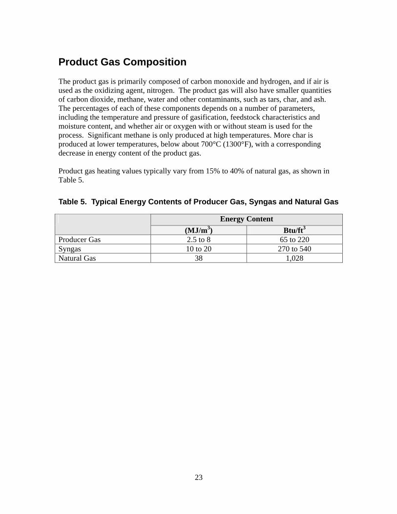
Product Gas Composition
The product gas is primarily composed of carbon monoxide and hydrogen, and if air is used as the oxidizing agent, nitrogen. The product gas will also have smaller quantities of carbon dioxide, methane, water and other contaminants, such as tars, char, and ash. The percentages of each of these components depends on a number of parameters, including the temperature and pressure of gasification, feedstock characteristics and moisture content, and whether air or oxygen with or without steam is used for the process. Significant methane is only produced at high temperatures. More char is produced at lower temperatures, below about 700°C (1300°F), with a corresponding decrease in energy content of the product gas. Product gas heating values typically vary from 15% to 40% of natural gas, as shown in Table 5.
Table 5. Typical Energy Contents of Producer Gas, Syngas and Natural Gas
Energy Content (MJ/m3) Btu/ft3
Producer Gas 2.5 to 8 65 to 220 Syngas 10 to 20 270 to 540 Natural Gas 38 1,028
23
Feedstock Characteristics and Requirements
Almost any carbon containing material can be gasified, provided the material meets requirements of the particular equipment. Moisture content and chemical content of feedstocks should be carefully considered. Also, different kinds of gasifiers have different requirements for particle size and uniformity.
Moisture Content Moisture content is critical in combustion, gasification and pelletization. Maximum moisture contents required for gasification depend on the gasifier type. Downdraft fixed bed gasifiers cannot tolerate moisture contents above about 20%. Updraft fixed bed gasifiers and fluidized bed gasifiers can tolerate higher moisture contents of 50% and 65%, respectively. Moisture contents can be as high as 95% in gasifiers using the supercritical water process, but this type of gasifier is still in the research and development phase. Pellet mills also generally require moisture contents of less than 15% to produce stable and durable pellets. Wastes with very high moisture contents often cannot be dried cost effectively except perhaps by passive dewatering methods, such as using filter bags. For these wastes, conversion technologies such as anaerobic digestion and fermentation will likely be more cost effective than combustion or gasification. The moisture contents of some common biomass feedstocks are summarized in Table 6.
Chemical Content The chemical content of biofuels influences slagging, fouling and corrosion of gasifier and heat exchanger components.5 For most biomass fuels, silicon, potassium, calcium, chlorine, sulfur and to some extent phosphorous, are the principal elements involved in the fouling of surfaces. In general feedstocks for gasification should preferably have a high carbon-to-nitrogen ratio, low sulfur content, low chlorine content, and low silica content. The molar ratio of sulfur to chlorine (S/Cl) should also be low since strong corrosion tends to occur when S/Cl is below 2 and moderate corrosion when S/Cl is 2 to 4. The ash content of common biomass materials is summarized in Table 6. Tables 7 and 8 give more detail on selected biomass fuels. Alkali salts, potassium in particular, are responsible for much of the fouling, sulfation, corrosion and silicate formation found in biomass boilers. Straws, other grasses and herbaceous materials, younger tissues of woody species, nut hulls and shells, and other annual biomass contain about 1% potassium dry weight. The leaves and branches of
5 Slagging occurs when a material is melted and then condenses on surfaces or accumulates as hard, dense particles or “clinkers”. Fouling refers to deposits on surfaces that have not melted.
24
wood have higher levels of potassium than the mature stem wood. Sodium and potassium salts in ash vaporize at temperatures of about 700oC (1300oF). As a vapor, they are not easily separated by physical methods such as filtration. Condensation begins at about 650oC (1200oF), first on particulates in the gas forming clinkers and then on cooler surfaces in the system as slag. High silica content is associated with slagging. However, high silica alone does not present much of a problem. It is the combination of high silica with alkali and alkaline metals, especially potassium, that can lead to the formation of slag. Thus, rice hulls, which may contain 20% silica by weight but have low potassium content, do not easily slag. But many types of straw, grasses and stover – which have both high silica and potassium – are very prone to slagging. Fouling and slagging seem to be worsened by the presence of chlorine which increases the mobility of inorganic compounds. Also, chlorine is absorbed by metals at high temperatures, rather than just building up on surfaces, and so results in corrosion. The ash that remains after a material is burned is indicative of the mineral content, i.e. Na, K, etc. Ash is easily measured by burning the material completely and weighing the sample before and after. Hence, much more data is available on ash content than on specific chemical contents. Low ash content also reduces disposal costs, assuming the ash isn’t put to a useful purpose such as a soil amendment or cement additive. Gasifiers especially for straw and other biofuels with high alkali and chlorine contents have been developed. Fluidized bed gasifiers are in general better suited for these materials due to their lower operating temperatures. Foster Wheeler and Energi E2 performed successful pilot projects gasifying straw in a fluidized bed gasifier 1999 to 2001. The Purox gasifier, designed for gasification of municipal solid waste, operates in “slagging mode” in which all the ash is melted on a hearth. The gasifier developed by Taylor Biomass Energy being demonstrated at the Gady Farm in Spokane, Washington, is also designed especially for straws and grasses.
25
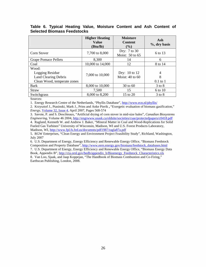
Table 6. Typical Heating Value, Moisture Content and Ash Content of Selected Biomass Feedstocks
Higher Heating Value
(Btu/lb)
Moisture Content
(%)
Ash %, dry basis
Corn Stover 7,700 to 8,000 Dry: 7 to 30 Moist: 50 to 65 6 to 13
Grape Pomace Pellets 8,300 14 6 Coal 10,000 to 14,000 12 8 to 14 Wood: Logging Residue Land Clearing Debris Clean Wood, temperate zones
7,000 to 10,000 Dry: 10 to 12 Moist: 40 to 60
4 8
0.1 to 1 Bark 8,000 to 10,000 30 to 60 3 to 8 Straw 7,500 15 6 to 10 Switchgrass 8,000 to 8,200 15 to 20 3 to 8 Sources: 1. Energy Research Centre of the Netherlands, “Phyllis Database”, http://www.ecn.nl/phyllis/2. Krzysztof J., Ptasinski, Mark J., Prins and Anke Pierik , “Exergetic evaluation of biomass gasification,” Energy, Volume 32, Issue 4, April 2007, Pages 568-574 3. Savoie, P. and S. Descôteaux, “Artificial drying of corn stover in mid-size bales”, Canadian Biosystems Engineering, Volume 46 2004, http://engrwww.usask.ca/oldsite/societies/csae/protectedpapers/c0418.pdf4. Ragland, Kenneth W. and Andrew J. Baker, “Mineral Matter in Coal and Wood-Replications for Solid Fueled Gas Turbines” University of Wisconsin, Madison, WI and U.S. Forest Products Laboratory, Madison, WI, http://www.fpl.fs.fed.us/documnts/pdf1987/ragla87a.pdf5. RGW Enterprises, “Clean Energy and Environment Project Feasibility Study”, Richland, Washington, July 2007 6. U.S. Department of Energy, Energy Efficiency and Renewable Energy Office, “Biomass Feedstock Composition and Property Database”, http://www.eere.energy.gov/biomass/feedstock_databases.html7. U.S. Department of Energy, Energy Efficiency and Renewable Energy Office, “Biomass Energy Data Book, Appendix B”, http://cta.ornl.gov/bedb/appendix_b/Bioenergy_Feedstock_Characteristics.xls8. Van Loo, Sjaak, and Jaap Koppejan, “The Handbook of Biomass Combustion and Co-Firing,” Earthscan Publishing, London, 2008.
26
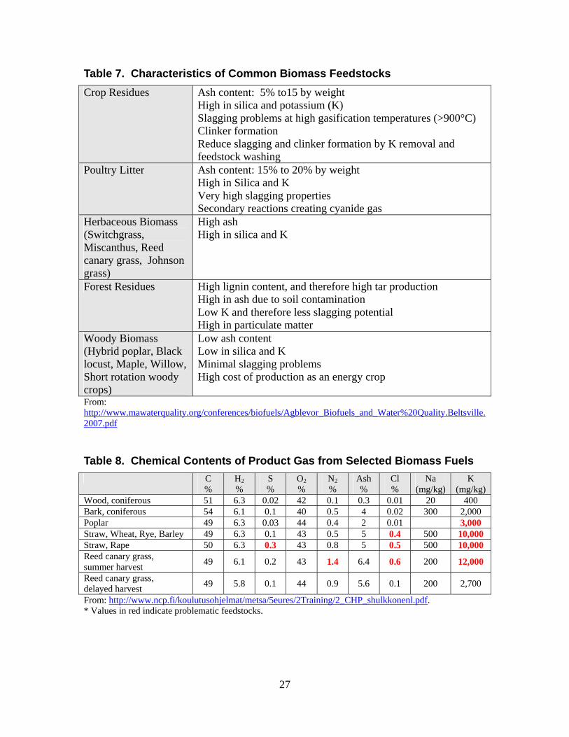
Table 7. Characteristics of Common Biomass Feedstocks Crop Residues Ash content: 5% to15 by weight
High in silica and potassium (K) Slagging problems at high gasification temperatures (>900°C) Clinker formation Reduce slagging and clinker formation by K removal and feedstock washing
Poultry Litter Ash content: 15% to 20% by weight High in Silica and K Very high slagging properties Secondary reactions creating cyanide gas
Herbaceous Biomass (Switchgrass, Miscanthus, Reed canary grass, Johnson grass)
High ash High in silica and K
Forest Residues High lignin content, and therefore high tar production High in ash due to soil contamination Low K and therefore less slagging potential High in particulate matter
Woody Biomass (Hybrid poplar, Black locust, Maple, Willow, Short rotation woody crops)
Low ash content Low in silica and K Minimal slagging problems High cost of production as an energy crop
From: http://www.mawaterquality.org/conferences/biofuels/Agblevor_Biofuels_and_Water%20Quality.Beltsville.2007.pdf Table 8. Chemical Contents of Product Gas from Selected Biomass Fuels C
% H2%
S %
O2%
N2%
Ash %
Cl %
Na (mg/kg)
K (mg/kg)
Wood, coniferous 51 6.3 0.02 42 0.1 0.3 0.01 20 400 Bark, coniferous 54 6.1 0.1 40 0.5 4 0.02 300 2,000 Poplar 49 6.3 0.03 44 0.4 2 0.01 3,000 Straw, Wheat, Rye, Barley 49 6.3 0.1 43 0.5 5 0.4 500 10,000 Straw, Rape 50 6.3 0.3 43 0.8 5 0.5 500 10,000 Reed canary grass, summer harvest 49 6.1 0.2 43 1.4 6.4 0.6 200 12,000
Reed canary grass, delayed harvest 49 5.8 0.1 44 0.9 5.6 0.1 200 2,700
From: http://www.ncp.fi/koulutusohjelmat/metsa/5eures/2Training/2_CHP_shulkkonenl.pdf. * Values in red indicate problematic feedstocks.
27
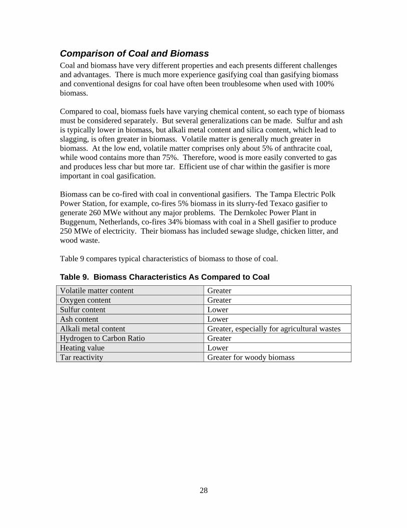
Comparison of Coal and Biomass Coal and biomass have very different properties and each presents different challenges and advantages. There is much more experience gasifying coal than gasifying biomass and conventional designs for coal have often been troublesome when used with 100% biomass. Compared to coal, biomass fuels have varying chemical content, so each type of biomass must be considered separately. But several generalizations can be made. Sulfur and ash is typically lower in biomass, but alkali metal content and silica content, which lead to slagging, is often greater in biomass. Volatile matter is generally much greater in biomass. At the low end, volatile matter comprises only about 5% of anthracite coal, while wood contains more than 75%. Therefore, wood is more easily converted to gas and produces less char but more tar. Efficient use of char within the gasifier is more important in coal gasification. Biomass can be co-fired with coal in conventional gasifiers. The Tampa Electric Polk Power Station, for example, co-fires 5% biomass in its slurry-fed Texaco gasifier to generate 260 MWe without any major problems. The Dernkolec Power Plant in Buggenum, Netherlands, co-fires 34% biomass with coal in a Shell gasifier to produce 250 MWe of electricity. Their biomass has included sewage sludge, chicken litter, and wood waste. Table 9 compares typical characteristics of biomass to those of coal. Table 9. Biomass Characteristics As Compared to Coal Volatile matter content Greater Oxygen content Greater Sulfur content Lower Ash content Lower Alkali metal content Greater, especially for agricultural wastes Hydrogen to Carbon Ratio Greater Heating value Lower Tar reactivity Greater for woody biomass
28
Reducing Slagging, Fouling and Corrosion
Combustion and gasification of biomass feedstocks have been more challenging than with coal in part due to problems with slagging, fouling and corrosion. Slagging occurs when ash and other components of the reaction gases melt and condense on surfaces. Fouling refers to deposits that build up on surfaces, but have not melted. Strategies for reducing slagging, fouling and corrosion problems in biomass boilers include use of fuel pretreatment, automatic surface cleaning, temperature control, and feedstock selection. Slagging and fouling problems will be similar in nature in both biomass boilers and gasifiers. Therefore, references on problems in biomass combustion can be useful in considering potential problems and their solutions in gasification.
Fuel Management Fuel management strategies for reducing slagging, fouling and corrosion include using fuel additives, washing the feedstock, and screening dirty fuels. Some feedstocks may need to be avoided altogether or mixed with less problematic fuels. • Fuel Additives
Fuel additives including limestone, clays, and minerals based on calcium, magnesium and/or iron have been used to reduce slagging in biopower combustion appliances. Examples are magnesium oxide, dolomite, kaolin, kaolinite, clinochlore, and ankerite. Such additives have been shown to be effective particularly in fluidized-bed boilers, which have good mixing. These materials may also be used effectively as bed materials. One commercial additive that reduces ash fouling in biomass power plants is “CoMate” produced by Atlantic Combustion Technologies (http://www.atlcombustion.com ). CoMate is not mixed with the fuel, but added directly to the unit on its own in a dedicated feeder. Site ports can be taken advantage of for inlets.
• Washing
Washing straw has been shown to reduce its amount of chlorine and potassium significantly and so reduces problems with slagging and fouling. Washing can be accomplished by controlled washing or by simply leaving the straw on the field for a time after harvest, exposing it to rain (“gray straw”). Some organic material will also be leached out. In a Danish study, the energy losses associated with controlled washing, drying and leaching of organic matter amounted to approximately 8% of the calorific content of the straw. This cost was offset by the prolonged life of the boilers.
29
• Screening Trommel screening dirty fuels can dramatically decrease ash and slagging problems in plants that burn field and urban wood residues. In wood fuels, screening out fines reduces problems because ash-forming elements tend to be concentrated in the smaller particles.
• Reducing Problematic Fuels
Dirty or problematic fuels can be mixed with cleaner burning fuels to reduce fouling. For example, nuts, shells and straws might be limited to less than 5% to 10% of the fuel mix. It is important to avoid using feedstocks, especially grasses and straws, in a gasifier for which it was not designed.
Temperature Control Temperature can be used to control deposits to a certain extent, especially as a short term or intermittent solution. Slagging can be avoided by operating the gasifier in one of two temperature regimes: Low temperature operation that keeps the temperature well below the flow
temperature of the ash. High temperature operation that keeps the temperature above the melting point of ash.
In addition, gas streams throughout the system should be maintained above the dew points of its corrosive contents. In particular, sulfur and chlorine result in low temperature corrosion if they are allowed to condense out on surfaces. Reducing temperature to control deposits also reduces the capacity and can have undesirable economic consequences.
System Design Certain system design options reduce the potential for fouling and corrosion. These include: • Corrosion-Resistant Materials
When selecting materials for components that will come in contact with reaction gases in or downstream of the gasifier, to avoid corrosion choose high chromium stainless steels, such as AC66.
• Automatic Surface Cleaning
The system should include some method of automatic surface cleaning, such as using sootblowers, acoustic horns or pulse detonation systems. Acoustic or sonic horns use relatively intense sound pressure to dislodge particulates. They have been used over the last 15 years to clean dry particulate deposits from a
30
variety of equipment, including boilers, economizers, ducts, fans, hoppers, cargo holds, dryers, electrostatic precipitators, and bag filters. Sonic horns are not effective in removing non-particulate accumulation, such as sintered ash. Acoustic horns are omni-directional, and so can clean hard to reach areas, in contrast to conventional sootblowers. The advantages of acoustic horns over sootblowers are illustrated in the article “SCR Catalyst Cleaning: Sootblowers vs. Acoustic Horns” in Power Engineering magazine, available at: http://pepei.pennnet.com/display_article/176817/6/ARTCL/none/none/1/SCR-Catalyst-Cleaning:Sootblowers-vs-Acoustic-Horns/
…acoustic horns are relatively inexpensive (one-fourth the cost of a steam sootblower), don't require structural steel for support, and have only one moving part, a titanium diaphragm that might need to be replaced after three to five years. The acoustic horns operate on standard plant compressed air, and 70-90 psi air plumbing is all that is required to make them operational. (Solenoids are used to fire the horns; from the solenoid to the horn, flex hose is usually used.)
Another option is pulse detonation, which employs a detonation-initiated blast wave to break up and remove deposits from surfaces. An advantage of pulse detonation over both acoustic horns and sootblowers is the ability to remove harder deposits. Each pulse detonation combustor can clean a relatively large area and reach areas that are inaccessible to conventional sootblowers.
For more information, refer to “A Comparison of Online Backpass Cleaning Technologies: Detonation, Acoustic and Conventional Steam or Air Sootblowing” http://topics.energycentral.com/centers/gentech/view/detail.cfm?aid=1513.
31
Gas Clean-Up
The major contaminants produced during gasification are particulates, alkali compounds, tars and char, nitrogen containing compounds, and sulfur. Gas cleaning is required before use in engines and turbines, but little or no gas cleaning is required for burner applications. Tars can clog engine valves, cause deposition on turbine blades or fouling of a turbine system leading to decreased performance and increased maintenance. In addition, tars interfere with synthesis of fuels and chemicals from syngas. For more information on gas cleaning technologies, refer to:
• “Initial Review and Evaluation of Process Technologies and Systems Suitable for Cost-Efficient Medium-Scale Gasification for Biomass to Liquid Fuels” (Olafsson et al. 2005)
• “The Handbook of Biomass Combustion & Co-Firing” (Van Loo et al. 2008) • “Biomass Gasifier Tars: Their Nature, Formation and Conversion” (Milne et al
1998) • “Gasification Technologies: A Primer for Engineers and Scientists” (Rezaiyan
and Cheremisinoff 2005)
Particulate Removal Gas emerging from gasifiers may contain particulates consisting of ash, char, and (for fluidized bed gasifiers) bed materials. Particulate control technologies include cyclones, electrostatic filters, bag filters, spray changers, and impingement scrubbers. For non-sticky particles larger than about 5 mm, a cyclone separator is the best choice. For particles smaller than 5 mm, normally electrostatic filters, bag filters and scrubbers are used.
Tar Content and Removal Syngas from downdraft gasifiers typically does not have high tar content. In fact, downdraft gasifiers were developed specifically to minimize tar. In contrast, the syngas of updraft gasifiers can contain about 100 times more tar than that of downdraft gasifiers. Fluidized bed gasifiers can produce low tar content product gas, largely depending on the bed material, as discussed below. Typical tar contents of gas produced by gasifier type are shown in Table 10. In addition to gasifier type, feedstock strongly influences tar content of the product gas. Woody biomass in particular results in high tar content syngas. Agricultural and food wastes tend to have lower tar contents. The requirement for tar removal depends on the end use of the syngas. Burners have higher tolerance for tar than engines, which in turn have higher tolerance than turbines, as shown in Table 11. Syngas from downdraft gasifiers has been used successfully with
32
internal combustion engines to generate power without significant tar removal. For example, Community Power Corporation’s Biomax syngas only requires separation and filtration of particulates before use in a reciprocating engine, which removes much of the tars as well (http://ieeexplore.ieee.org/stamp/stamp.jsp?arnumber=01373153). In general, tar is removed from the product gas by either chemical or physical methods. Chemical methods are catalytic cracking, thermal cracking, plasma reactors and use of catalytic beds. Physical methods are cyclones, filters, electrostatic precipitators and scrubbers. Using physical methods, sticky particles such as tars are usually collected in a liquid, as in a scrubber or in a cyclone, bag filter or electrostatic filter whose collecting surfaces are continually coated with a film of flowing liquid. The gasification project in Harboore, Denmark, discussed in the section “Demonstration Projects,” uses gas cooling and a wet electrostatic precipitator. The Moissannes project in France (also discussed in “Demonstration Projects”) uses the “OLGA” tar removal method, which uses an oil solvent to collect and absorb tars instead of water. For information on the OLGA tar removal method, refer to “Tar Removal from Biomass Product Gas: Development and Optimisation of the OLGA tar removal technology” (Boerrigter et al. 2005) available at http://www.ecn.nl/docs/library/report/2005/rx05186.pdf. In fluidized bed gasifiers, the bed materials can serve as a catalyst for tar reduction. Clay-derived materials, including activated clay, acidified bentonite, and clay housebrick, have worked well for this purpose. Ordinary clay housebrick captures more than twice that by sand. On the other hand, some bed materials – notably dolomite and limestone, but not magnesite – will recarbonate during cool down, which results in fouling and deposits will occur in different locations in the gasifier system and in downstream systems. In the fluidized bed gasifier in the demonstration project at Varnamo, Sweden, magnesite was chosen as the bed material to obtain a low tar content gas. Several manufacturers are in the process of developing or have developed proprietary tar removal systems. For example, Nexterra has developed a thermal cracking method to achieve engine grade syngas that is approved for use in GE Jenbacher reciprocating engines. Nexterra has signed a strategic alliance agreement with GE Energy to commercialize this application and will be starting a commercial demonstration at a BC university in 2009. Another proprietary system is the OLGA system developed by ECN and marketed by Dahlman, which uses organic solvents to remove tars. The OLGA system has been demonstrated PRM Energy’s 1.0 MWe system at Moissannes, France where cleaned syngas is burned in a Caterpillar engine.
33
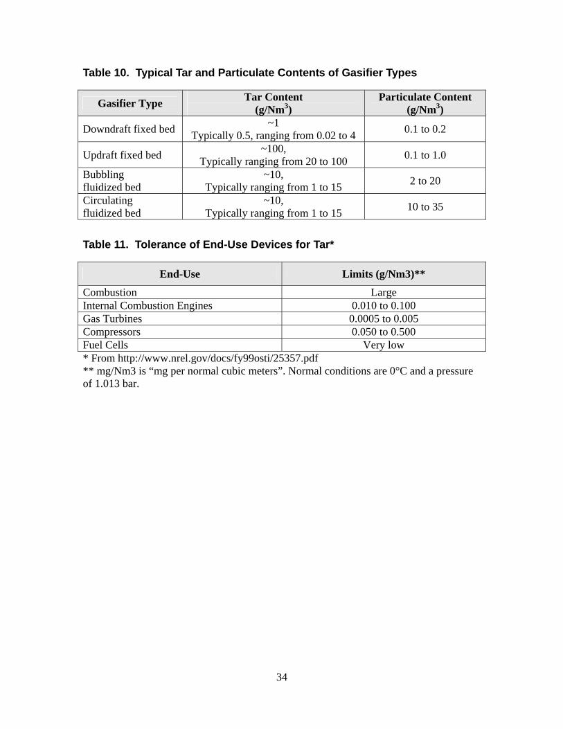
Table 10. Typical Tar and Particulate Contents of Gasifier Types
Gasifier Type Tar Content (g/Nm3)
Particulate Content (g/Nm3)
Downdraft fixed bed ~1 Typically 0.5, ranging from 0.02 to 4 0.1 to 0.2
Updraft fixed bed ~100, Typically ranging from 20 to 100 0.1 to 1.0
Bubbling fluidized bed
~10, Typically ranging from 1 to 15 2 to 20
Circulating fluidized bed
~10, Typically ranging from 1 to 15 10 to 35
Table 11. Tolerance of End-Use Devices for Tar*
End-Use Limits (g/Nm3)**
Combustion Large Internal Combustion Engines 0.010 to 0.100 Gas Turbines 0.0005 to 0.005 Compressors 0.050 to 0.500 Fuel Cells Very low * From http://www.nrel.gov/docs/fy99osti/25357.pdf ** mg/Nm3 is “mg per normal cubic meters”. Normal conditions are 0°C and a pressure of 1.013 bar.
34
Marketable Co-Products
The wide array of co-products possible with gasification can improve the cost effectiveness of a gasification project. While combustion produces only heat, gasification can be used to produce heat, as well as syngas and solid carbon char or “biochar.” Syngas can be used as a feedstock to produce hydrogen and liquid hydrocarbons, such as ethanol and chemical feedstocks. Biochar has several potential uses and gives gasification the potential of a carbon neutral or carbon negative energy solution. Both combustion and gasification produce ash, which also can be marketed.
Markets for Biochar Biochar is a fine-grained charcoal composed primarily of organic carbon (75% to 85%). Production of biochar is significant in downdraft gasifiers in particular. It is also produced in even larger quantities in pyrolysis, 10% to 15% in fast pyrolysis and as much as 35% in slow pyrolysis. Biomass-based carbon, especially from wood, has a long history of uses for its adsorption, thermal and electrical properties. Activated carbon is used in filtration media. In the metallurgical industry it is used to reduce the iron ore in pig iron, in stainless steel, and in the production of some metal alloys. Carbon black is used as an electrically conductive additive in batteries. Coke, which is essentially coal charcoal, is now used for most applications formerly served by wood products. The only significant markets for wood carbonization products in the U.S. at present are activated carbons and charcoal briquettes. However, an economic incentive to switch back from coke to wood char can be expected in the near future driven by the implementation of carbon taxes and/or carbon cap-and-trade systems, as well as by the existing, growing markets in carbon offsets. Already switching from charcoal to coke in Brazil’s steel industry is being discouraged in projects implemented under the Clean Development Mechanism of the Kyoto Protocol. The char produced in gasification and pyrolysis generally contains a significant quantity of impurities. Biochar can be considered a low grade carbon black. For many applications, the char would need to be upgraded to remove impurities, diminishing its economic value. • Biochar Soil Amendment
As a soil amendment, biochar improves soil texture, holds moisture and releases fertilizer slowly. Biochar resists decomposition, so it persists in the soil. It also sequesters carbon in the soil and so helps to mitigate global warming.
35
• Activated Carbon Precursor Biochar has high value as a precursor for activated carbon. Activated carbon is produced from charcoal by exposing it to high temperatures in an airless environment. It is then treated with oxygen, which opens up tiny pores between the carbon atoms, resulting in very high surface area per volume of material.
• Solid Fuel
Biochar can be reburned as a solid fuel in the gasifier itself. In fluidized bed systems, char in the gas may be captured in a cyclone and returned to the bottom of the bed. Alternatively, char may also be removed from the bottom of the gasifier and used elsewhere.
• Steel Manufacturing Reductant
Until the 20th century charcoal was widely used in the steel industry. Now Brazil is the only country where charcoal is still predominant over coke in steel manufacturing. Use of charcoal as a reductant in steel manufacturing significantly reduces greenhouse gas emissions, decreases emissions of sulfur dioxide, oxides of nitrogen and results in improved steel quality. On the small scale, some blacksmiths are promoting the use of wood charcoal over coal in their forging operations, despite certain advantages of coke (easy ignition, hotter flame, energy efficiency). Reasons for the switch are that wood charcoal burns more cleanly, results in fewer health hazards to the blacksmith, presents less of a disposal problem, and is a renewable resource.
Markets for Ash Ash has markets as a soil amendment, cement additive, steel industry tundish powder, and sand replacement. • Soil Amendment
Biomass ash may be added to fertilizers as a soil amendment, unlike coal ash which may contain toxic metals and other contaminants. Biomass ash can be a significant source of potassium, calcium, magnesium, sodium and sulfur. Ash contains phosphorous, also, but it is present in a form that has very poor soil solubility. The slow release of phosphorous may not be a problem if used as a fertilizer for perennials such as trees. Care must be taken to ensure that the biomass is not contaminated by, for example, paints and wood preservatives. Biomass from household, industrial and municipal solid wastes may contain organic pollutants and heavy metals. Heavy metals that may be in contaminated biomass include cadmium, zinc and arsenic. In addition, biomass ashes are less attractive in commercial fertilizers than mineral sources because their mineral content per volume is lower.
36
• Steel Industry Tundish Powder Rice hull ash has been used widely in steel mills as a tundish power, which serves as an insulating cover on tundishes and ladles containing molten steel. Rice hull ash flows over and covers the steel surface well and does not crust or cause metal sculls during use.
• Cement Additive
Biomass ash can be used in certain cement blends, mortars and aggregates. If it does not contain aggregates such as slag and clinkers, it often can be recycled to cement kilns without prior treatment. Biomass fly ash often contains alkali metals, chlorine and phosphates that can make it unsuitable for concrete. The fly ash of each type of biomass must be analyzed to evaluate its suitability. Rice hull ash (RHA) in particular has been used in the cement industry in the manufacture of low cost building blocks and in the production of high quality cement. At 35% replacement, RHA cement has improved compressive strength due to its higher percentage of silica. It also has improved resistance to acid attack compared to Portland cement. Replacing 10% Portland cement with RHA can improve resistance to chloride penetration, which has application in the marine environment. Several studies have combined fly ash and RHA in various proportions. In general, concrete made with Portland cement containing both RHA and fly ash has a higher compressive strength than concrete made with Portland cement containing either RHA or fly ash on their own.
• Sand Replacement
If sand is used as a bed material in fluidized bed gasifiers, bottom ashes will consist largely of sand and can be used to replace the sand used in road construction and landscaping.
• Solid Fuel
Fly ashes may also contain significant quantities of carbon (>35% by weight) and so can be reburned as fuel. Fly ash can be pelletized for this purpose by adding water and/or a binder.
Chemical Feedstocks A very large number of chemicals can be produced from syngas. Those with the largest markets include ethanol, methanol, naptha, gasoline, diesel, hydrogen, acetic acid, dimethyl ether, and ammonia. As an illustration of the potential, syngas from coal and natural gas is currently used to manufacture 30% of the gasoline and diesel used in South Africa.
37
For the production of chemicals, syngas that is undiluted with nitrogen must be used. This means it must be oxygen-blown or heated indirectly. Also, the methane content of the gas should be low.
Bio-Hydrogen Bio-hydrogen can be produced from biomass by several processes. Of these, gasification coupled with water gas shift is a mature commercial process with only small adaptations required for application to biomass. This process is currently near cost competitive with production of hydrogen by steam reforming of methane, depending on relative costs of natural gas and biomass. Hydrogen can be used in either internal combustion engines or fuel cells. Since fuel cell vehicles are not commercially available yet and a distribution infrastructure for hydrogen will not be realized in the short term, bio-hydrogen is considered a longer-term option for the transport sector.
38
Environmental Benefits
Environmental benefits of biomass gasification compared to combustion of solid biomass may include:
• Reduced carbon emissions by improvements in energy efficiency • Reduced carbon emissions by closing the carbon cycle and carbon sequestration • Reduced NOx emissions • Reduced use of fertilizers and runoff of nutrients from soils amended with
Biochar
Reduced Carbon Emissions by Efficiency Improvements As discussed previously, gasification has potential to increase energy efficiency compared to combustion of biomass in a steam cycle. These carbon emission reductions may be tradable in carbon offset markets. Significant production of biochar reduces energy efficiency, if the char is not reburned. But biochar offers other environmental advantages that can more than make up for its energy efficiency penalty, as discussed below.
Reduced Carbon Emissions by Closing the Carbon Cycle and Carbon Sequestration Both fossil fuels and biomass release carbon dioxide when they burn. The carbon released when burning fossil fuels originates from oil reserves, not from the atmosphere. Hence, fossil fuels are carbon positive in that they add new carbon dioxide to the atmosphere. In contrast, combustion of biomass, taken by itself, is carbon neutral because the carbon released was first absorbed from the atmosphere by the biomass as it grew. In other words, the carbon cycle is closed. Combustion of biomass may still be carbon positive overall if fossil fuels are used in their production and transportation. Use of biomass has the potential of being carbon negative if, in using or producing it, carbon is stored in a form that is not released to the atmosphere. As one example, constructing a building of wood stores carbon in the structure for as long as the building is maintained. As another example, grasses tend to build up carbonaceous material in the soil as they grow. Using biochar produced in the gasification process as a soil amendment is a third example. Biochar is largely resistant to decomposition and, once put in the soil, most of it remains there orders of magnitude longer than other organic amendments. This effectively absorbs carbon from the atmosphere and stores it in the soil. For more information on the environmental benefits of biochar, refer to the website of the International Biochar Initiative at http://www.biochar-international.org.
39
Reduced Fertilizer Use and Runoff in Biochar-Amended Soils Biochar as a soil amendment significantly increases the efficiency of and reduces the need for traditional chemical fertilizers, while greatly enhancing crop yields. Production and transportation of chemical fertilizers is fossil fuel intensive and so reducing their use reduces associated carbon emissions. Moreover, char-amended soils have shown 50% to 80% reductions in nitrous oxide emissions, reduced runoff of phosphorus into surface waters, and reduced leaching of nitrogen into groundwater.
Reduced NOx Emissions The product gas will generally have low NOx concentrations because gasification temperatures are not high enough to produce NOx in significant quantities. However, when the product gas is burned in a boiler, turbine or engine, NOx will be produced as it is in most combustion systems and with all fuels. Nevertheless, it is easier to control the combustion of a gaseous fuel than the combustion of a solid fuel. Better control of combustion provides the opportunity to reduce NOx formation.
40
Industry Applications
Pulp and Paper Industry The pulp and paper industry is a prime candidate for implementation of gasification for a number of reasons. The industry is seeking alternative products to help improve the economics of the paper-making. The industry already has a supply of woody feedstocks with the infrastructure necessary to handle them and has wide experience with wood-fired combined heat and power. The scale of pulp and paper plants is conducive to implementation of forest biorefineries. Aging wood-fired boilers in need of replacement might be considered for replacement with gasifiers. Besides production of chemical feedstocks, syngas can be used to offset natural gas use in, for example, lime kilns as in the Domtar draft pulp mill in Kamloops, BC, which uses a Nexterra updraft gasifier with hog fuel. Start up of the full-scale commercial operation of this project is expected in June 2009.
Wood Products Industry The waste wood available in lumber mills, cabinet shops, plywood plants and other wood products facilities can be gasified to generate electricity for onsite use and sale to the grid with heat recovered for process heat. Examples of process heating needs are lumber drying, veneer drying, and hot water for log conditioning. Projects are operating or in development at Tallon Lumber in North Canaan, Connecticut, Tolko Industries in Heffley Creek, British Columbia, and the Grand Forks Truss Plant in Grand Forks, North Dakota.
Petroleum and Petrochemical Industries Petroleum refineries and many petrochemical facilities have existing infrastructure that can be used in the production and/or upgrade of biofuels. The petroleum industry has become interested in biofuels largely because of recent mandatory requirements for blending of biofuels with gasoline and diesel being implemented in a number of countries and U.S. states.
Food Processing Industries and Agriculture Facilities processing dry foods or having relatively dry wastes are candidates for gasification. Examples of feedstocks that have been used include grape pomace, olive waste, rice hulls, grass and straw, distillery grain, and corn stover. The Port of Benton gasification project at the FruitSmart facility in Prosser, Washington, demonstrated the feasibility of using grape pomace to offset propane use in fruit dryers.
41
Demonstration Projects
There are many biomass gasifiers currently operating or planned in industrial applications in North America, Europe and Asia. Examples in North America and Europe are summarized in Tables 12 and 13, although this list is not all inclusive.
Small-Scale U.S. Demonstration Projects There are many small-scale biomass gasification projects of less than 1 MWe in various phases located around the world. In the U.S. small-scale projects include the following: • Mount Wachusett Community College – Gardner, Massachusetts
Mount Wachusett Community College has been gasifying wood chips to generate electricity and meet campus space heating and cooling needs since October 2006. The gasifier is a 50 kW Biomax with an 8.1 liter GM turbocharged engine and genset. The feedstock is 1.5 tons per day of green wood chips. The system is operated 24 hours per day, 6 days per week.
• Tallon Lumber – North Canaan, Connecticut
The Tallon Lumber sawmill biomass gasification project will use a downdraft gasifier and engine to generate 320 kW of electricity and 1800 MMBtu/h of heat at a midsize sawmill in North Canaan, Connecticut. Sawmill waste residue consisting of wood chips and sawdust will fuel the gasifier. The system is designed to satisfy the plant’s peak electrical demand, the peak thermal demand of the kiln, and space heat for the planer building. The startup testing and system shakedown is planned for the first quarter of 2009. The gasifier and generator were originally commissioned in 2005. However, after running the plant for only 53 hours, it was decided clean up of tars in the gas needed improvement. The original electrostatic precipitator was replaced with a wet scrubber. The Connecticut Clean Energy Fund Project Status Quarterly Update summarized the status of the project as of the end of 2008:
In Q4 of 2007, Kraftpower performed an inspection of the Schmitt Engine, performed service, and ran the engine in order to ensure proper function and readiness for the next stage in facility start-up. The Envitech venturi scrubber was installed in May 2008. The rotary airlock, which will automatically remove ash and char material produced by the gasifier, was also installed. Once the system was assembled, it was tested for two hours.
42
A new radiator was installed when higher heat output was generated from the new configuration. The plant was tested and determined to adequately remove particulates from the gas stream. However, the engine generator developed software problems that need to be resolved before a complete system shakedown occurs. Schmitt Enertec and Kraftwork have been contacted to resolve the issues by February 2009. The plant will then undergo a full test run.
• Port of Benton / FruitSmart – Prosser, Washington
A short-term pilot project was conducted in 2006 by the Port of Benton at the FruitSmart food processing facility near Prosser, Washington. Different combinations of wood pellets, sawdust and chips, mint residue, grape pomace, spent hops, cow manure, wheat straw, and waste glycerin from a nearby biodiesel plant – 60 tons total – were pelletized and gasified in a downdraft gasifier. The producer gas supplemented propane use in an industrial drying operation, offsetting 40% of FruitSmart’s propane costs. As could be expected, gasification of the wheat straw was problematic. Slagging occurred and the heat exchanger was punctured in an attempt to chip off the slag. Steps toward a permanent demonstration project with pellet mill are underway. The port’s long term goals are to use gasification to offset fossil fuels for industries within the port district and encourage a manufacturing facility for the production of gasifiers. Funding for this project has been included in a federal appropriation bill that is awaiting passage. The design is complete, but the project is on hold until the funding is released.
• Gady Farm – Spokane, Washington A one-year pilot project at the Gady Farm has begun operation to demonstrate the gasification of grass straw, a notoriously troublesome feedstock. The dual-stage gasifier developed by Taylor Biomass Energy (www.taylorbiomassenergy.com) and the Western Research Institute (WRI) is designed specifically to minimize problems associated with gasifying straw. The pilot gasifier will process 500 to 2000 pounds per hour of grass straw. The syngas, after cleaning, is being used to generate electricity using a 300 kW reciprocating engine/generator. Existing farm equipment will be utilized to collect, chop and pelletize, and store the straw, and convey it to the gasification reactor. Farm Power, the project’s developer, also plans to contract with WRI to develop ancillary technology to convert syngas into liquid fuel and to test this technology on the farm. It is estimated that 60 gallons of fuel could be synthesized from a ton of straw. Pacific Northwest farmers generate 10 million tons of waste straw annually, which is sufficient to provide 420 million gallons of liquid fuel or approximately 8% of the region’s transportation fuel usage.
43
This project illustrates the benefits of choosing a scale that is appropriate for use at the source of the feedstock, which reduces collection costs, as described in “Grass straw gasifier ready to fire up” by Scott Yates in Capital Press (http://www.capitalpress.info/main.asp?SectionID=67&SubSectionID=617&ArticleID=38915&TM=66134.16):
Costs of straw collection and transportation make long distance shipment to large, centralized conversion facilities uneconomical. Development of on-farm-scale technologies for conversion of this biomass to energy provides the potential to develop a distributed network for power and liquid fuel production in rural communities.
This pilot project is supported by a $750,000 U.S. Department of Energy grant in cooperation with the U.S. Department of Agriculture’s Agricultural Research Service, the Pacific Northwest National Laboratory and the Bonneville Power Administration. The project developer is Farm Power. Inland Power & Light will purchase electricity that is not used on site through a net metering agreement. The project is composed of three tasks: development of feedstock, processing, handling and storage cost estimates; gasifier system development; and on-farm testing of the resulting gasification and power generation system. The Taylor gasifier used in this project is similar to the FERCO SilvaGas gasifier described above in that it has two chambers, one for gasification and the other for combustion, with a fluidized bed medium that circulates between the two chambers. In the Taylor gasifier, gasification of the straw takes place in the annulus between an outer tube and an inner (draft) tube. Char remaining after the gasification – plus supplemental fuel – are oxidized with air within the inner draft tube to generate the energy needed for gasification in the outer tube. Heat is transferred from the inner tube to the annular gasification section with the aid of steel balls that are pneumatically conveyed by the combustion products. For more information on the gasifier refer to “Gasification of Kentucky bluegrass (Poa pratensis l.) straw in a farm-scale reactor” (Boeteng et al. 2006).
Medium-Scale Demonstration Projects (1 MW and Greater) There are many medium-scale biomass gasification projects in various phases located around the world, as summarized in Tables 12 and 13. Numerous gasification projects that do not burn the gas in engines or turbines have been in operation for decades. But projects generating electricity in turbines and engines have much shorter histories. Four projects are summarized here. The first two demonstrate successful gas clean-up technology with generation of electricity by burning the product gas in an internal combustion engine: the Babcock Wilcox gasifier in Harboore, Denmark, and the PRM updraft gasifier in Moissanes, France. The 40 MWe Foster Wheeler fluidized bed gasifier in Lahti, Finland, illustrates the potential to co-fire the product gas with other fuels. The 40 MWe commercial-scale project in Tallahassee, Florida, will use an
44
indirectly heated steam gasifier. Construction on the Florida project will begin in early 2009. • Harboore, Denmark – Babcock & Wilcox Volund Gasifier with Wet
ESP Gas Clean-Up At this 1.5 MWe project wood chips are gasified in an updraft gasifier. The gasifier has been operating since 1994, providing district heating. Since 2005, it has also been generating electricity by burning syngas in two gas engines. Gas clean up is accomplished by cooling the gas and then passing it through a wet electrostatic precipitator (ESP). Treating the tar-contaminated water from the wet precipitator was problematic, but a successful solution has been developed. The meeting notes of the International Energy Agency’s Second Semiannual Task Meeting held in October 2007 are available at http://media.godashboard.com/gti/IEA_NL_DraftMinutes_1-08.pdf reported:
The 1.3 MWe capacity Harboore plant is in operation, producing 0.85 MWe, and 3.3 MWth district heat. During 2005, the gasifier has logged in 8200 hours and the gas engine for 7619 hours, and in 2006, the gasifier has logged in 8146 hours and the gas engine for 7947 hours. The Volund BMG technology is licensed to JFE, a Japanese company which has built and successfully commissioned a 7.5 MWth plant in Japan, producing 2 MWe, employing the same gas cleaning as at the Harboore plant. A second plant of 10 MWth is currently being planned to produce 3 MWe. The wood tars may be used locally for sanitary applications.
Note that the capacity of this project has been increased to 1.5 MWe since this IEA summary was written.
• Moissannes, France – PRM Energy Gasifier with OLGA Gas Clean-
Up At the commercial demonstration project located in Moissannes, France (near Limoges), wood waste and distillery residue are gasified in a “pseudo updraft” gasifier. Cleaned gas is burned in a Caterpillar engine to generate 1 MWe of power (4 MWth). This project was commissioned in 2006 as a demonstration for 6 future commercial 12.5 MWe (40 MWth) plants. Despite good operation in 2006 and the first part of 2007, the plant was not operated during most of 2007 and 2008 for administrative reasons. The project’s final permit included more stringent demands than its initial temporary permit and required additional investments and downtime. Optimization and duration tests are scheduled. In this demonstration project (and in a 0.5 MWth pilot project that preceded the demonstration) the syngas was successfully cleaned using the OLGA tar removal process, previously described. Tar removal from the syngas has been a major problem in updraft gasifiers.
45
46
• Lahden Lämpövoima Oy -- Lahti, Finland Producer gas is co-fired with coal at the Lahden Lämpövoima Oy’s Kymijärvi power plant at Lahti, Finland. Paper and textiles, wood and peat, as well as shredded tires, plastics and municipal solid waste are gasified in a Foster Wheeler air-blown circulating fluidized bed gasifier that was installed in 1997. The plant has a total maximum capacity of 167 MWe. On an annual basis, approximately 15% of fuel needs are met by gasification. Capital cost of the gasification plant was $15 million. The hot product gas is led through an air preheater to two burners, which are located below the coal burners in the boiler. The bottom ash extraction system was designed to remove the non-combustibles from the municipal solid waste, as well as nails and other metals from urban wood waste. The gasifier has been in operation since 2002. Availability increased consistently in the first few years and in 2005, 2006 and 2007, the gasifier was available more than 7000 hours of the year and the engine, more than 6000 hours.
• Tallahassee Renewable Energy Center – Tallahassee, Florida
(Construction to Begin January 2009) Biomass Gas & Electric (BGE) of Tallahassee will install an indirectly heated steam gasifier using the SilvaGas process in this 42 MWe commercial-scale project. BGE will sell both electricity and 60 million Btu’s of methanated gas to the City of Tallahassee’s pipeline. Construction is proposed to commence by January 2009, with a proposed in-service date by January 2011. The feedstock will be wood chips, which will be screened and sized at a different location.
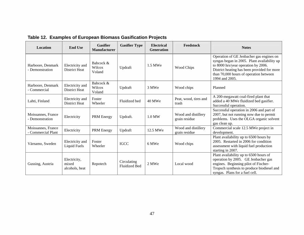
Table 12. Examples of European Biomass Gasification Projects
Location End Use Gasifier Manufacturer
Gasifier Type
Electrical Generation
Feedstock Notes
Harboore, Denmark - Demonstration
Electricity and District Heat
Babcock & Wilcox Voland
Updraft 1.5 MWe Wood Chips
Operation of GE Jenbacher gas engines on syngas began in 2005. Plant availability up to 8000 hrs/year operation by 2006. District heating has been provided for more than 70,000 hours of operation between 1994 and 2005.
Harboore, Denmark - Commercial
Electricity and District Heat
Babcock & Wilcox Voland
Updraft 3 MWe Wood chips Planned
Lahti, Finland Electricity and District Heat
Foster Wheeler Fluidized bed 40 MWe Peat, wood, tires and
trash
A 200-megawatt coal-fired plant that added a 40 MWe fluidized bed gasifier. Successful operation.
Moissannes, France - Demonstration Electricity PRM Energy Updraft. 1.0 MW Wood and distillery
grain residue
Successful operation in 2006 and part of 2007, but not running now due to permit problems. Uses the OLGA organic solvent gas clean up.
Moissannes, France - Commercial Plant Electricity PRM Energy Updraft 12.5 MWe Wood and distillery
grain residue Commercial scale 12.5 MWe project in development.
Värnamo, Sweden Electricity and Liquid Fuels
Foster Wheeler IGCC 6 MWe Wood chips
Plant availability up to 6500 hours by 2005. Restarted in 2006 for condition assessment with liquid fuel production starting in 2007.
Gussing, Austria Electricity, mixed alcohols, heat
Repotech Circulating Fluidized Bed 2 MWe Local wood
Plant availability up to 6500 hours of operation by 2005. GE Jenbacher gas engines. Beginning pilot of Fischer-Tropsch synthesis to produce biodiesel and syngas. Plans for a fuel cell.
47
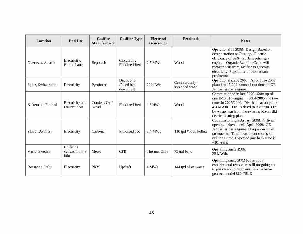
Location End Use Gasifier Manufacturer
Gasifier Type
Electrical Generation
Feedstock Notes
Oberwart, Austria Electricity. Biomethane Repotech Circulating
Fluidized Bed 2.7 MWe Wood
Operational in 2008. Design Based on demonstration at Gussing. Electric efficiency of 32%. GE Jenbacher gas engine. Organic Rankine Cycle will recover heat from gasifier to generate electricity. Possibility of biomethane production.
Spiez, Switzerland Electricity Pyroforce Dual-zone /Fixed bed downdraft
200 kWe Commercially shredded wood
Operational since 2002. As of June 2008, plant has 15,000 hours of run time on GE Jenbacher gas engines.
Kokemäki, Finland Electricity and District heat
Condens Oy / Novel Fluidized Bed 1.8MWe Wood
Commissioned in late 2006. Start up of one JMS 316 engine in 2004/2005 and two more in 2005/2006. District heat output of 4.3 MWth. Fuel is dried to less than 30% by waste heat from the existing Kokemäki district heating plant.
Skive, Denmark Electricity Carbona Fluidized bed 5.4 MWe 110 tpd Wood Pellets
Commissioning February 2008. Official opening delayed until April 2009. GE Jenbacher gas engines. Unique design of tar cracker. Total investment cost is 30 million Euros. Expected pay-back time is ~10 years.
Vario, Sweden Co-firing syngas in lime kiln
Metso CFB Thermal Only 75 tpd bark Operating since 1986. 35 MWth.
Rossanno, Italy Electricity PRM Updraft 4 MWe 144 tpd olive waste
Operating since 2002 but in 2005 experimental tests were still on-going due to gas clean-up problems. Six Guascor gensets, model 560 FBLD.
48
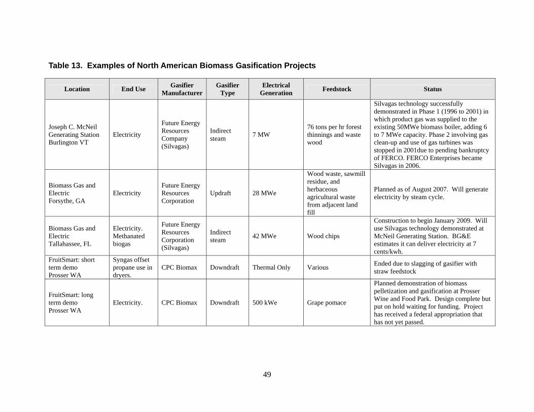
Table 13. Examples of North American Biomass Gasification Projects
Location End Use Gasifier Manufacturer
Gasifier Type
Electrical Generation Feedstock Status
Joseph C. McNeil Generating Station Burlington VT
Electricity
Future Energy Resources Company (Silvagas)
Indirect steam 7 MW
76 tons per hr forest thinnings and waste wood
Silvagas technology successfully demonstrated in Phase 1 (1996 to 2001) in which product gas was supplied to the existing 50MWe biomass boiler, adding 6 to 7 MWe capacity. Phase 2 involving gas clean-up and use of gas turbines was stopped in 2001due to pending bankruptcy of FERCO. FERCO Enterprises became Silvagas in 2006.
Biomass Gas and Electric Forsythe, GA
Electricity Future Energy Resources Corporation
Updraft 28 MWe
Wood waste, sawmill residue, and herbaceous agricultural waste from adjacent land fill
Planned as of August 2007. Will generate electricity by steam cycle.
Biomass Gas and Electric Tallahassee, FL
Electricity. Methanated biogas
Future Energy Resources Corporation (Silvagas)
Indirect steam 42 MWe Wood chips
Construction to begin January 2009. Will use Silvagas technology demonstrated at McNeil Generating Station. BG&E estimates it can deliver electricity at 7 cents/kwh.
FruitSmart: short term demo Prosser WA
Syngas offset propane use in dryers.
CPC Biomax Downdraft Thermal Only Various Ended due to slagging of gasifier with straw feedstock
FruitSmart: long term demo Prosser WA
Electricity. CPC Biomax Downdraft 500 kWe Grape pomace
Planned demonstration of biomass pelletization and gasification at Prosser Wine and Food Park. Design complete but put on hold waiting for funding. Project has received a federal appropriation that has not yet passed.
49
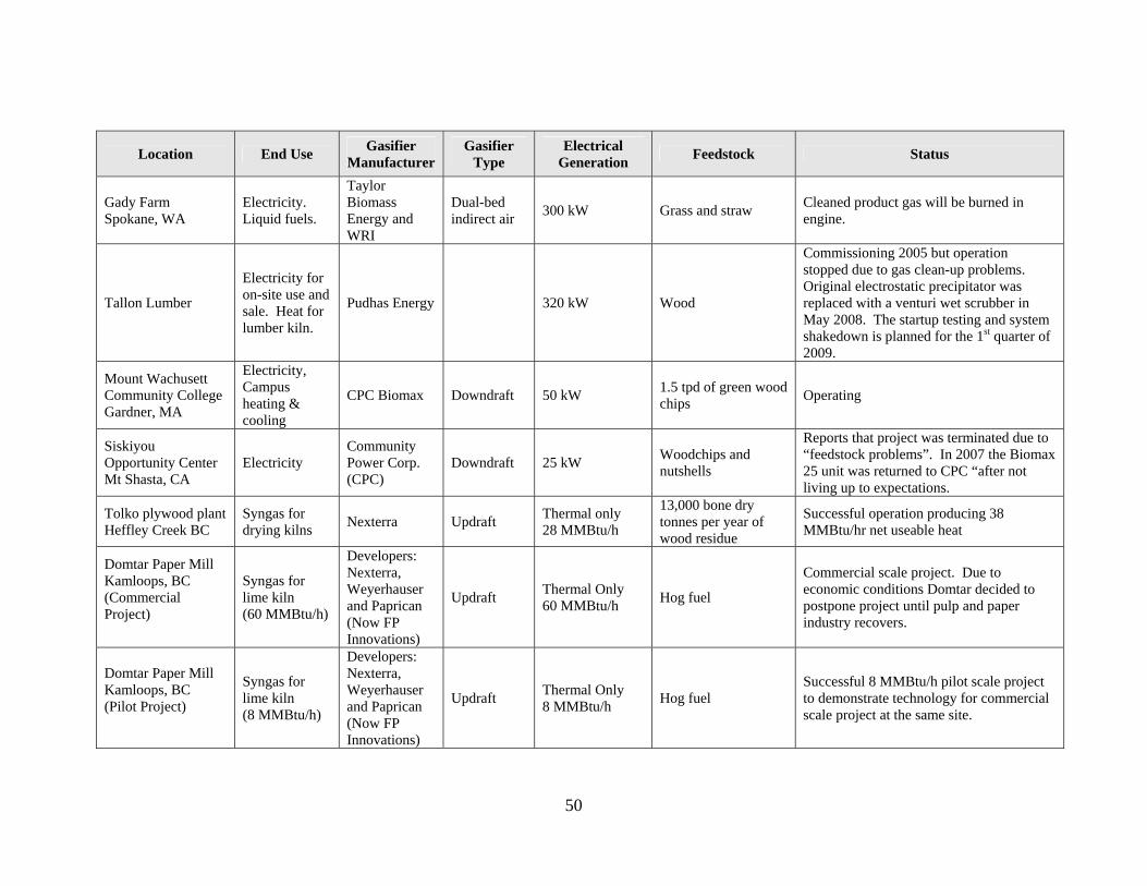
Gasifier Gasifier Electrical Location End Use Feedstock Status Manufacturer Type Generation
Gady Farm Spokane, WA
Electricity. Liquid fuels.
Taylor Biomass Energy and WRI
Dual-bed indirect air 300 kW Grass and straw Cleaned product gas will be burned in
engine.
Tallon Lumber
Electricity for on-site use and sale. Heat for lumber kiln.
Pudhas Energy 320 kW Wood
Commissioning 2005 but operation stopped due to gas clean-up problems. Original electrostatic precipitator was replaced with a venturi wet scrubber in May 2008. The startup testing and system shakedown is planned for the 1st quarter of 2009.
Mount Wachusett Community College Gardner, MA
Electricity, Campus heating & cooling
CPC Biomax Downdraft 50 kW 1.5 tpd of green wood chips Operating
Siskiyou Opportunity Center Mt Shasta, CA
Electricity Community Power Corp. (CPC)
Downdraft 25 kW Woodchips and nutshells
Reports that project was terminated due to “feedstock problems”. In 2007 the Biomax 25 unit was returned to CPC “after not living up to expectations.
Tolko plywood plant Heffley Creek BC
Syngas for drying kilns Nexterra Updraft Thermal only
28 MMBtu/h
13,000 bone dry tonnes per year of wood residue
Successful operation producing 38 MMBtu/hr net useable heat
Domtar Paper Mill Kamloops, BC (Commercial Project)
Syngas for lime kiln (60 MMBtu/h)
Developers: Nexterra, Weyerhauser and Paprican (Now FP Innovations)
Updraft Thermal Only 60 MMBtu/h Hog fuel
Commercial scale project. Due to economic conditions Domtar decided to postpone project until pulp and paper industry recovers.
Domtar Paper Mill Kamloops, BC (Pilot Project)
Syngas for lime kiln (8 MMBtu/h)
Developers: Nexterra, Weyerhauser and Paprican (Now FP Innovations)
Updraft Thermal Only 8 MMBtu/h Hog fuel
Successful 8 MMBtu/h pilot scale project to demonstrate technology for commercial scale project at the same site.
50
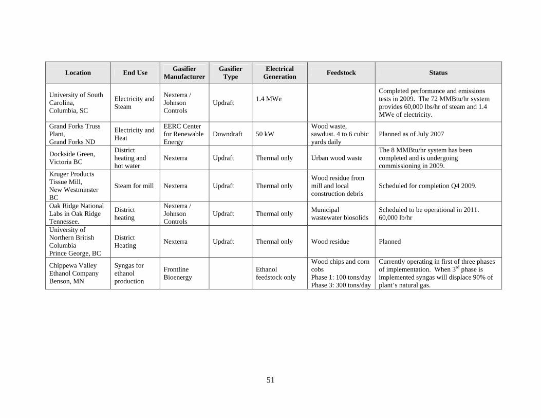
51
Location End Use Gasifier Manufacturer
Gasifier Type
Electrical Generation Feedstock Status
University of South Carolina, Columbia, SC
Electricity and Steam
Nexterra / Johnson Controls
Updraft 1.4 MWe
Completed performance and emissions tests in 2009. The 72 MMBtu/hr system provides 60,000 lbs/hr of steam and 1.4 MWe of electricity.
Grand Forks Truss Plant, Grand Forks ND
Electricity and Heat
EERC Center for Renewable Energy
Downdraft 50 kW Wood waste, sawdust. 4 to 6 cubic yards daily
Planned as of July 2007
Dockside Green, Victoria BC
District heating and hot water
Nexterra Updraft Thermal only Urban wood waste The 8 MMBtu/hr system has been completed and is undergoing commissioning in 2009.
Kruger Products Tissue Mill, New Westminster BC
Steam for mill Nexterra Updraft Thermal only Wood residue from mill and local construction debris
Scheduled for completion Q4 2009.
Oak Ridge National Labs in Oak Ridge Tennessee.
District heating
Nexterra / Johnson Controls
Updraft Thermal only Municipal wastewater biosolids
Scheduled to be operational in 2011. 60,000 lb/hr
University of Northern British Columbia Prince George, BC
District Heating Nexterra Updraft Thermal only Wood residue Planned
Chippewa Valley Ethanol Company Benson, MN
Syngas for ethanol production
Frontline Bioenergy Ethanol
feedstock only
Wood chips and corn cobs Phase 1: 100 tons/day Phase 3: 300 tons/day
Currently operating in first of three phases of implementation. When 3rd phase is implemented syngas will displace 90% of plant’s natural gas.
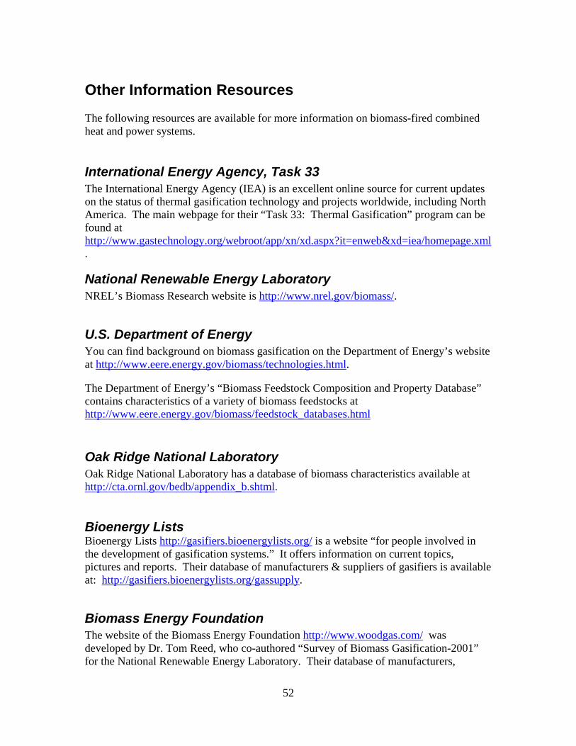
Other Information Resources
The following resources are available for more information on biomass-fired combined heat and power systems.
International Energy Agency, Task 33 The International Energy Agency (IEA) is an excellent online source for current updates on the status of thermal gasification technology and projects worldwide, including North America. The main webpage for their “Task 33: Thermal Gasification” program can be found at http://www.gastechnology.org/webroot/app/xn/xd.aspx?it=enweb&xd=iea/homepage.xml.
National Renewable Energy Laboratory NREL’s Biomass Research website is http://www.nrel.gov/biomass/.
U.S. Department of Energy You can find background on biomass gasification on the Department of Energy’s website at http://www.eere.energy.gov/biomass/technologies.html. The Department of Energy’s “Biomass Feedstock Composition and Property Database” contains characteristics of a variety of biomass feedstocks at http://www.eere.energy.gov/biomass/feedstock_databases.html
Oak Ridge National Laboratory Oak Ridge National Laboratory has a database of biomass characteristics available at http://cta.ornl.gov/bedb/appendix_b.shtml. Bioenergy Lists Bioenergy Lists http://gasifiers.bioenergylists.org/ is a website “for people involved in the development of gasification systems.” It offers information on current topics, pictures and reports. Their database of manufacturers & suppliers of gasifiers is available at: http://gasifiers.bioenergylists.org/gassupply.
Biomass Energy Foundation The website of the Biomass Energy Foundation http://www.woodgas.com/ was developed by Dr. Tom Reed, who co-authored “Survey of Biomass Gasification-2001” for the National Renewable Energy Laboratory. Their database of manufacturers,
52
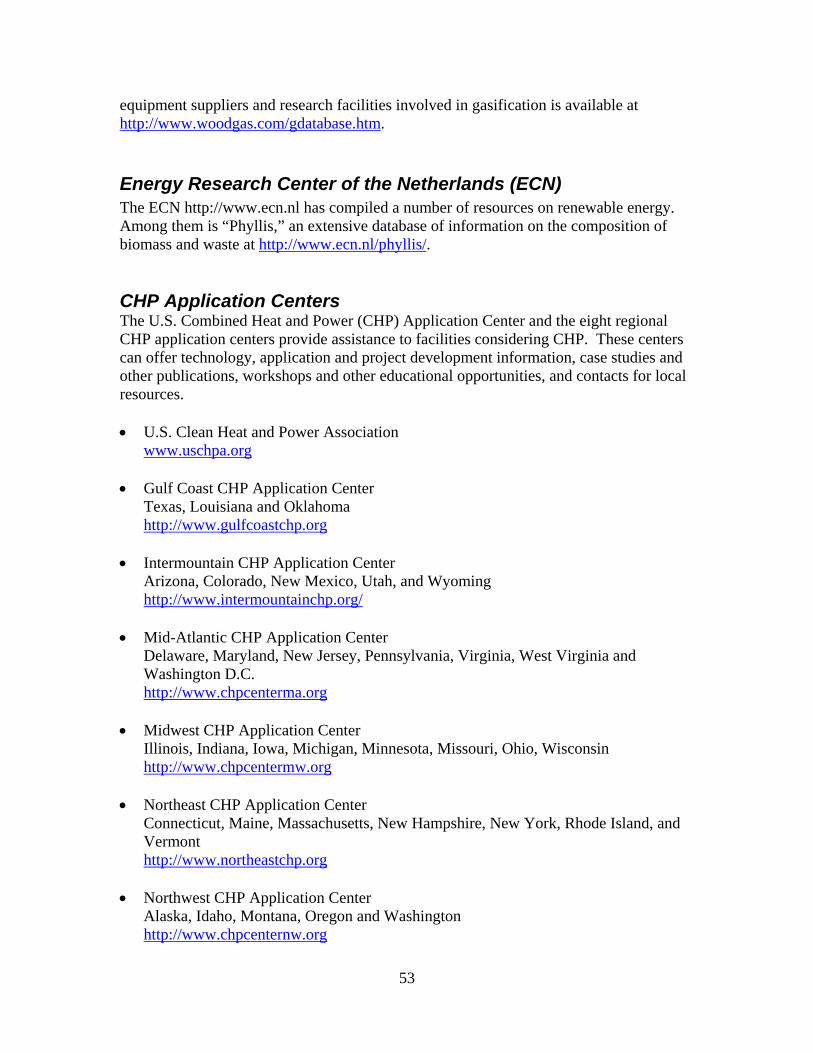
equipment suppliers and research facilities involved in gasification is available at http://www.woodgas.com/gdatabase.htm.
Energy Research Center of the Netherlands (ECN) The ECN http://www.ecn.nl has compiled a number of resources on renewable energy. Among them is “Phyllis,” an extensive database of information on the composition of biomass and waste at http://www.ecn.nl/phyllis/. CHP Application Centers The U.S. Combined Heat and Power (CHP) Application Center and the eight regional CHP application centers provide assistance to facilities considering CHP. These centers can offer technology, application and project development information, case studies and other publications, workshops and other educational opportunities, and contacts for local resources. • U.S. Clean Heat and Power Association
www.uschpa.org
• Gulf Coast CHP Application Center Texas, Louisiana and Oklahoma http://www.gulfcoastchp.org
• Intermountain CHP Application Center Arizona, Colorado, New Mexico, Utah, and Wyoming http://www.intermountainchp.org/
• Mid-Atlantic CHP Application Center Delaware, Maryland, New Jersey, Pennsylvania, Virginia, West Virginia and Washington D.C. http://www.chpcenterma.org
• Midwest CHP Application Center Illinois, Indiana, Iowa, Michigan, Minnesota, Missouri, Ohio, Wisconsin http://www.chpcentermw.org
• Northeast CHP Application Center Connecticut, Maine, Massachusetts, New Hampshire, New York, Rhode Island, and Vermont http://www.northeastchp.org
• Northwest CHP Application Center Alaska, Idaho, Montana, Oregon and Washington http://www.chpcenternw.org
53

• Pacific Region CHP Application Center
California, Hawaii and Nevada http://www.chpcenterpr.org/
• Southeast CHP Application Center Alabama, Arkansas, Florida, Georgia, Kentucky, Mississippi, South Carolina, North Carolina, Tennessee http://www.chpcenterse.org
U.S. Environmental Protection Agency The U.S. Environmental Protection Agency’s CHP Partnership (http://www.epa.gov/chp/index.html) works to support the development of new CHP projects and promote their energy, environmental, and economic benefits.
54
References
Basu, Prabir, “Combustion and Gasificaton in Fluidized Beds,” CRC Press, Boca Raton, FL, 2006. Boateng, A.A., G.M.Banowetz, J.J. Steiner, T.F. Barton, D.G. Taylor, K.B. Hicks, H. El-Nashaar, and V.K. Sethi, “Gasification of Kentucky Bluegrass (Poa Pratensis I.) Straw in a Farm-Scale Reactor” Biomass and Bioenergy, 31:153-161, 2007. http://www.ars.usda.gov/research/publications/Publications.htm?seq_no_115=187440. Boerrigter, Harold, Sander van Paasen, Patrick Bergman, Jan-Willem Konemann, and Rob Emmen, “Tar Removal from Biomass Product Gas: Development and Optimisation of the OLGA tar removal technology.” 14th European Biomass Conference & Exhibition, Paris, France, October 2005, http://www.ecn.nl/docs/library/report/2005/rx05186.pdf. Brown, Robert C., Jerod Smeenk, and Clenn Norton, “Development of analytical techniques and scrubbing options for contaminants in gasifier streams intended for use in fuel cells.” Submitted to the Chariton Valley Resource Conservation and Development and the U.S. Department of Energy Biomass Power Program, 2001. Ciferno, Jared P. and John J. Marano, “Benchmarking Biomass Gasification Technologies for Fuels, Chemicals and Hydrogen Production,” prepared for U.S. Department of Energy, National Energy Technology Laboratory,” June 2002. Ducente, AB, “Large scale gasification of Biomass for Biofuels and Power,” prepared for the European Commission Directorate-General Energy and Transport, Sweden, 2006. This report discusses the IGCC demonstration project at Varnamo, Sweden. International Energy Agency, “Review of Energy Conversion Devices” http://media.godashboard.com/gti/IEA/ReviewofEnergyConversionDevicesrev.pdf. Klass, Donald L., Biomass for Renewable Energy, Fuels, and Chemicals, Academic Press, San Diego, California, 1998. Lettner, Friedrich, Helmut Timmerer, Peter Haselbacher, “Biomass gasification – State of the art description,” Graz University of Technology - Institute of Thermal Engineering Inffeldgasse 25B, 8010 Graz, Austria, prepared for the European Union, December 2007. This document provides overviews of gas cleaning and water treatment technologies, in addition to gasifier technologies. http://www.gasification-guide.eu/gsg_uploads/documenten/Gasification_Guide_D08_State_of_the_Art_Description_V09e.pdf Mater Engineering, LTD and T.R. Miles Consulting, Inc., “Energy Conversion Systems Analysis for a Biomass Utilization Project in Central Oregon using CROP Modeling,”
55
prepared for the Bonneville Environmental Foundation, October 2005. This reference provides a discussion of market potential and demand for other value-added wood products, including biochar and bio-oil. Matsumura, Yukihiko, Tomoaki Minowa, Biljana Potic, Sascha R.A. Kersten, Wolter Prins, Willibrordus P.M. van Swaaij, Bert van de Beld, Douglas C. Elliott, Gary G. Neuenschwander, Andrea Kruse and Michael Jerry Antal Jr., “Biomass gasification in near- and super-critical water: Status and prospects,” Biomass and Bioenergy, Volume 29, pp. 269–292, 2005. McCormick, A. Tofa, “A Comparison of Online Backpass Cleaning Technologies: Detonation, Acoustic and Conventional Steam or Air Sootblowing,” Energy Central, July 13, 2007 http://www.energypulse.net/centers/article/article_display.cfm?a_id=1513 Miles, Thomas R., Thomas R. Miles Jr., Larry L. Baxter, Richard W. Bryers, Bryan M. Jenkins, and Lawrence L. Owens, “Alkali Deposits Found in Biomass Power Plants,” Summary Report prepared for the National Renewable Energy Laboratory, Golden, CO, April 15, 1995 http://www.trmiles.com/alkali/Alkali_Report.pdf. This reference includes strategies for minimizing alkali deposits. Milne, T.A., R.J. Evans and N. Abatzoglou, “Biomass Gasifier ‘Tars’: Their Nature, Formation, and Conversion,” National Renewable Energy Laboratory, Golden, CO November 1998, http://media.godashboard.com/gti/IEA/TomandNicolasreport.pdf. Olofsson, Ingemar, Anders Nordin, and Ulf Soderlind, “Initial Review and Evaluation of Process Technologies and Systems Suitable for Cost-Efficient Medium-Scale Gasification for Biomass to Liquid Fuels,” University of Ulmea, Sweden, 2005, http://www.biofuelregion.se/dokument/5_95.pdf. This reference provides a survey of all types of gasifiers: fixed bed, fluidized bed, entrained flow, indirect, plasma arc, and several other concepts. It also covers gas cleaning and processing techniques and processes for synthetic fuels and chemicals. Pels, Jan R., Danielle S. de Nie, and Jacob H.A. Kiel, “Utilization of ashes from biomass combustion and gasification,” published at the 14th European Biomass Conference & Exhibition, Paris, France, October 2005 http://www.ecn.nl/docs/library/report/2005/rx05182.pdf. Ptasinski, Krzysztof J., Mark J. Prins, and Anke Pierik, “Exergetic evaluation of biomass gasification,” Energy, Volume 32, Issue 4, April 2007, Pages 568-574. Ragland, Kenneth W., and Andrew J. Baker, “Mineral Matter in Coal and Wood-Replications for Solid Fueled Gas Turbines,” University of Wisconsin, Madison, WI and U.S. Forest Products Laboratory, Madison, WI, http://www.fpl.fs.fed.us/documnts/pdf1987/ragla87a.pdf
56
Reed, T. and A. Das, “Biomass Downdraft Gasifier Engine Systems Handbook,” Solar Energy Research Institute, 1988, available from http://www.woodgas.com/bookstore.htmThis reference provides information on small-scale and low-tech gasifiers. Reed, T. and S. Gaur, “A Survey of Biomass Gasification: 2001,” prepared for the National Renewable Energy Laboratory, 2001. Rezaiyan, John, Gasification Technologies: A Primer for Engineers and Scientists, CRC Press, Boca Raton, FL, 2005. RGW Enterprises, “Clean Energy and Environment Project Feasibility Study,” Prepared for the Port of Benton, Richland, Washington, July 2007. http://www.portofbenton.com/sidepage/newsevents.html Roos, Carolyn J., Biomass Drying and Dewatering for Clean Heat & Power, Northwest Clean Heat and Power Regional Application Center, 2008, http://chpcenternw.org/NwChpDocs/BiomassDryingAndDewateringForCleanHeatAndPower.pdf. Savoie, P. and S. Descôteaux, “Artificial drying of corn stover in mid-size bales,” Canadian Biosystems Engineering, Volume 46 2004, http://engrwww.usask.ca/oldsite/societies/csae/protectedpapers/c0418.pdf. Wright, Lynn, Bob Boundy, Bob Perlack, Stacy Davis and Bo Saulsbury, Biomass Energy Data Book: Edition 1, Prepared for the U.S. Department of Energy, Energy Efficiency and Renewable Energy Office, Prepared by the Oak Ridge National Laboratory, Oak Ridge, Tennessee, September 2006, http://cta.ornl.gov/bedb/pdf/Biomass_Energy_Data_Book.pdf Vamvuka, D., D. Zografos, and G. Alevizos, “Control methods for mitigating biomass ash-related problems in fluidized beds,” Bioresource Technology, September 2007. Van Loo, Sjaak, and Jaap Koppejan, “The Handbook of Biomass Combustion and Co-Firing,” Earthscan Publishing, London, 2008. Williams, Rob, Nathan Parker, Christopher Yang, Joan Ogden and Bryan Jenkins (UC Davis, Institute of Transportation Studies), H2 production Via Biomass Gasification, prepared for Public Interest Energy Research (PIER) Program, California Energy Commission, July 2007. Yoshida, Yoshikuni, Kiyoshi Dowaki, Yukihiko Matsumura, Ryuji Matsuhashi, Dayin Li, Hisashi Ishitani, and Hiroshi Komiyama, “Comprehensive comparison of efficiency and CO2 emissions between biomass energy conversion technologies – position of supercritical water gasification in biomass technologies,” Biomass & Energy, Volume 25, pages 257-272, 2003.
57

58