Embed Size (px)
Citation preview
Suez Canal University Faculty of engineering Mechanical department
Graduation project
Chemical looping combustion (CLC)
Under supervision of
Prof. Dr. Sayed Ibrahim Abdel-mageed
Dr. Tamer Ismail
Team work
Mohamed Abdelaty Saleh Barakat
Mohamed Ahmed Elsayed Bayoumi
Mohamed Adel Mohamed Fathy
Abdel-Rahman Samir Abd al-Sadiq
Mohamed Mohsen Mohammed
Mohamed Ibrahim Elsayed
Mohamed Ibrahim Kamel
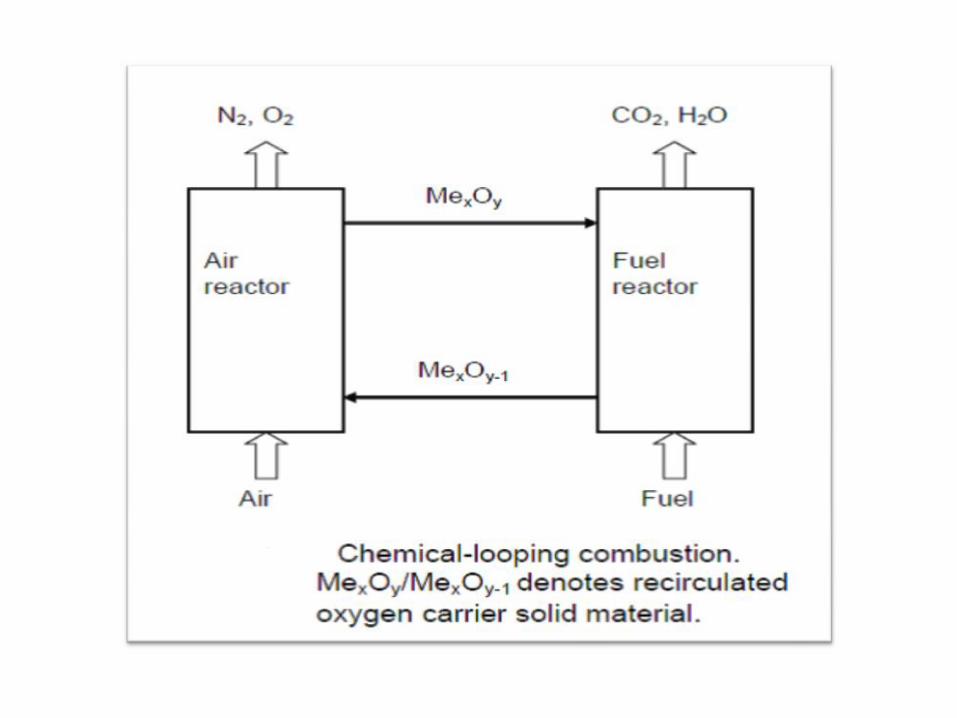
Concept of Chemical-looping combustion
-Chemical-looping combustion (CLC) is a combustion technology with separation of the greenhouse gas CO2.
-The technique involves the use of a metal oxide as an oxygen carrier which transfers oxygen from combustion air to the fuel, and hence a direct contact between air and fuel is avoided
-The defining feature of chemical-looping combustion is the circulation of oxygen carrier particles between two main reactors.
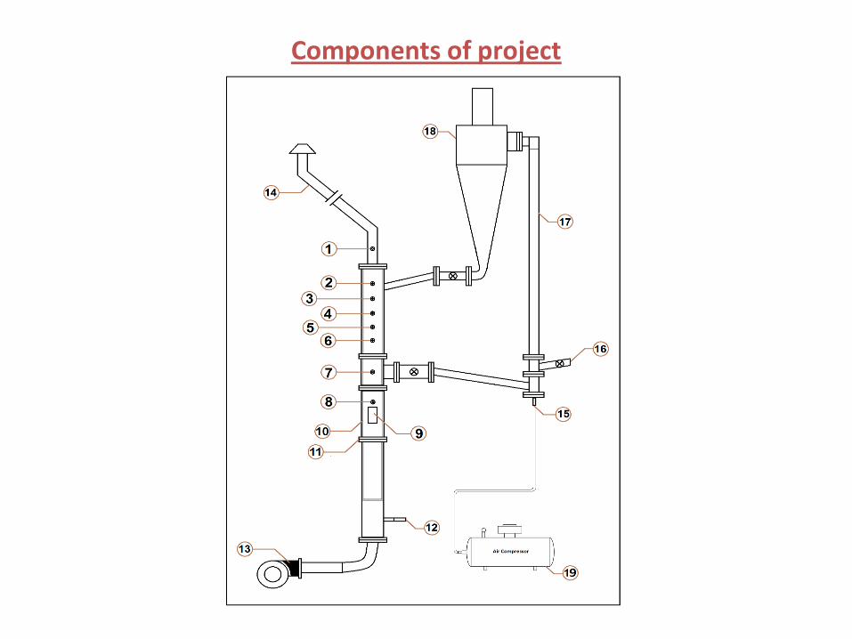
Components of project
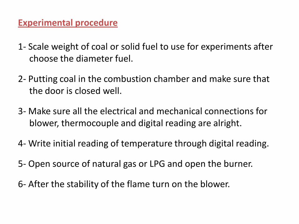
Experimental procedure
1- Scale weight of coal or solid fuel to use for experiments after choose the diameter fuel.
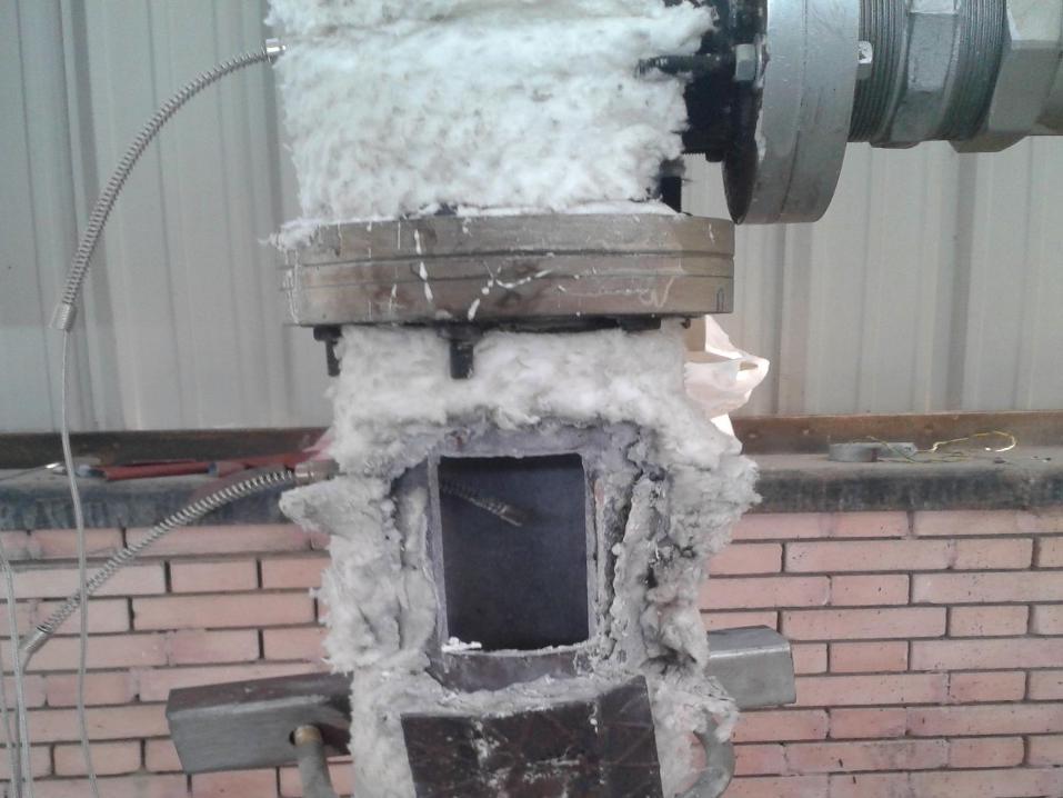
2- Putting coal in the combustion chamber and make sure that the door is closed well.
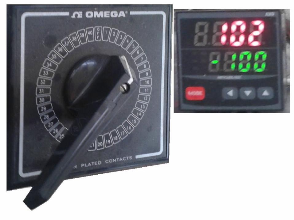
3- Make sure all the electrical and mechanical connections for blower, thermocouple and digital reading are alright.
4- Write initial reading of temperature through digital reading.
5- Open source of natural gas or LPG and open the burner.
6- After the stability of the flame turn on the blower.
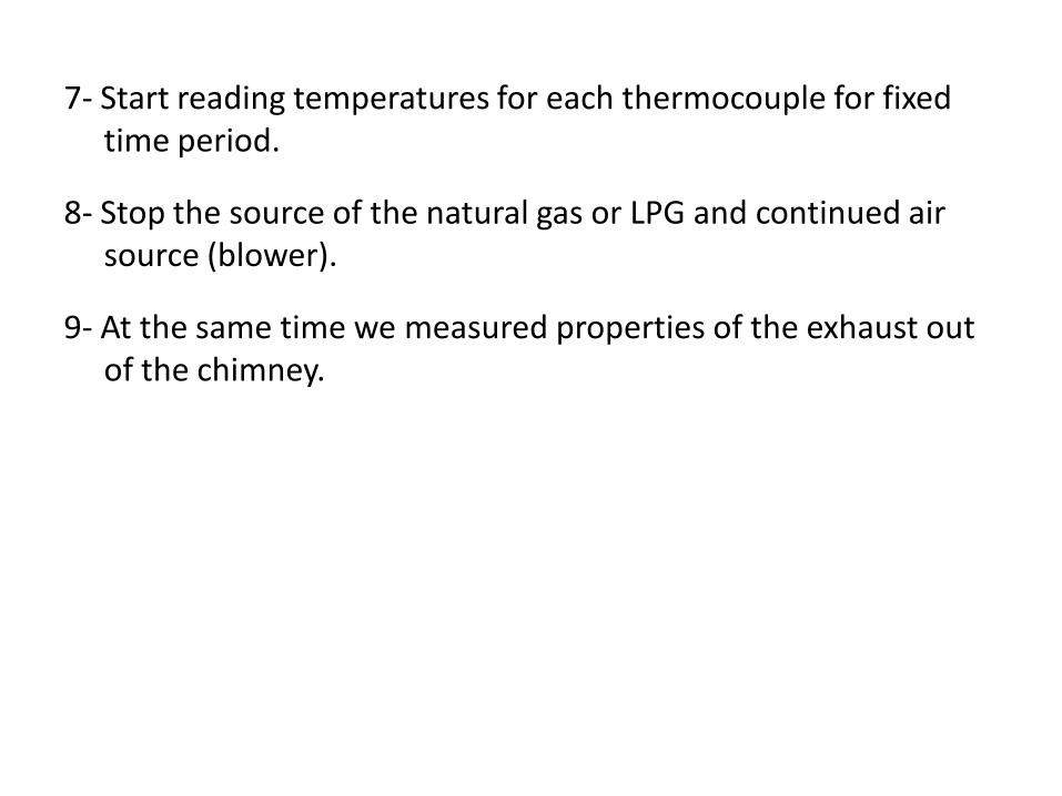
7- Start reading temperatures for each thermocouple for fixed time period.
8- Stop the source of the natural gas or LPG and continued air source (blower).
9- At the same time we measured properties of the exhaust out of the chimney.
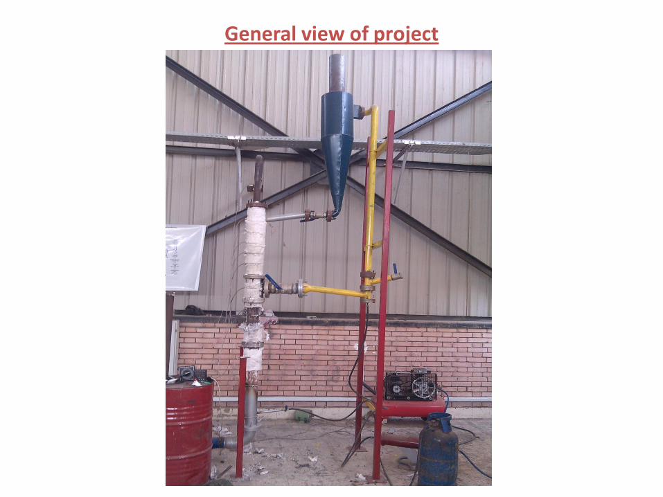
General view of project
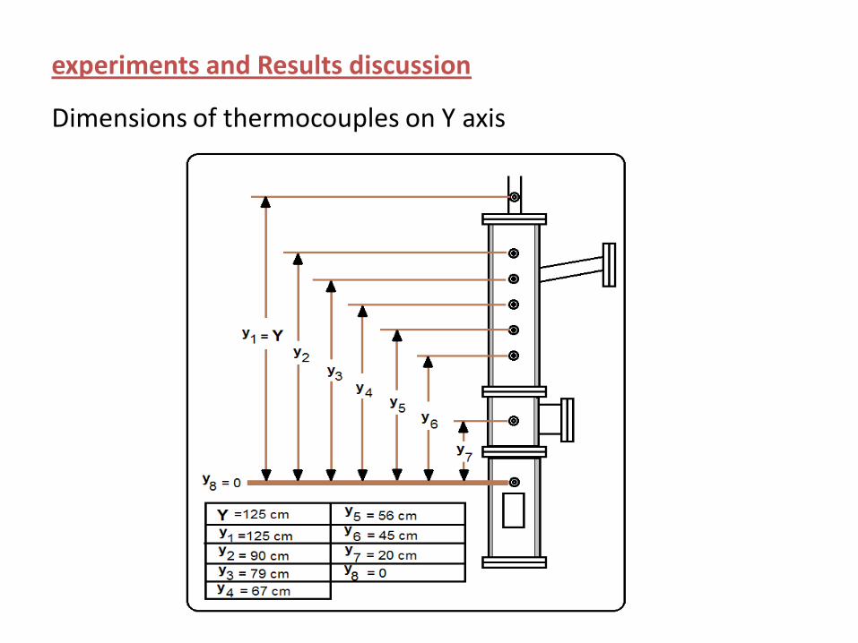
experiments and Results discussion
Dimensions of thermocouples on Y axis
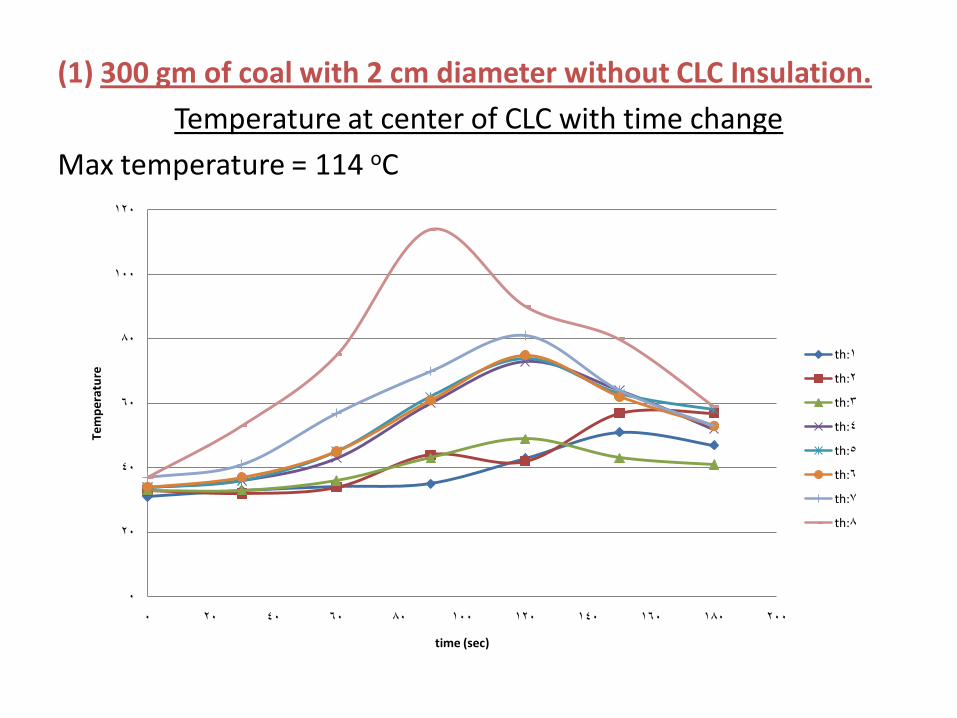
(1) 300 gm of coal with 2 cm diameter without CLC Insulation.
Temperature at center of CLC with time change
Max temperature = 114 oC
0
20
40
60
80
100
120
0 20 40 60 80 100 120 140 160 180 200
Te
mp
era
ture
time (sec)
th:1
th:2
th:3
th:4
th:5
th:6
th:7
th:8
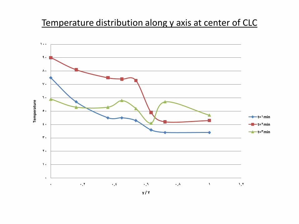
Temperature distribution along y axis at center of CLC
0
10
20
30
40
50
60
70
80
90
100
0 0.2 0.4 0.6 0.8 1 1.2
Tem
per
atu
re
y / Y
t=1min
t=2min
t=3min
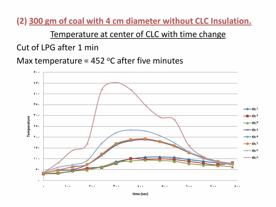
(2) 300 gm of coal with 4 cm diameter without CLC Insulation.
Temperature at center of CLC with time change
Cut of LPG after 1 min
Max temperature = 452 oC after five minutes
0
50
100
150
200
250
300
350
400
450
500
0 100 200 300 400 500 600 700 800
Tem
per
atu
re
time (sec)
th:1
th:2
th:3
th:4
th:5
th:6
th:7
th:8
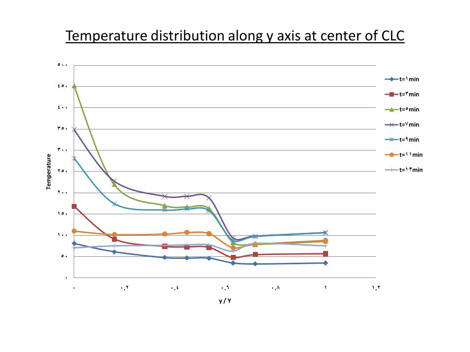
Temperature distribution along y axis at center of CLC
0
50
100
150
200
250
300
350
400
450
500
0 0.2 0.4 0.6 0.8 1 1.2
Tem
per
atu
re
y / Y
t=1min
t=3min
t=5min
t=7min
t=9min
t=11min
t=13min
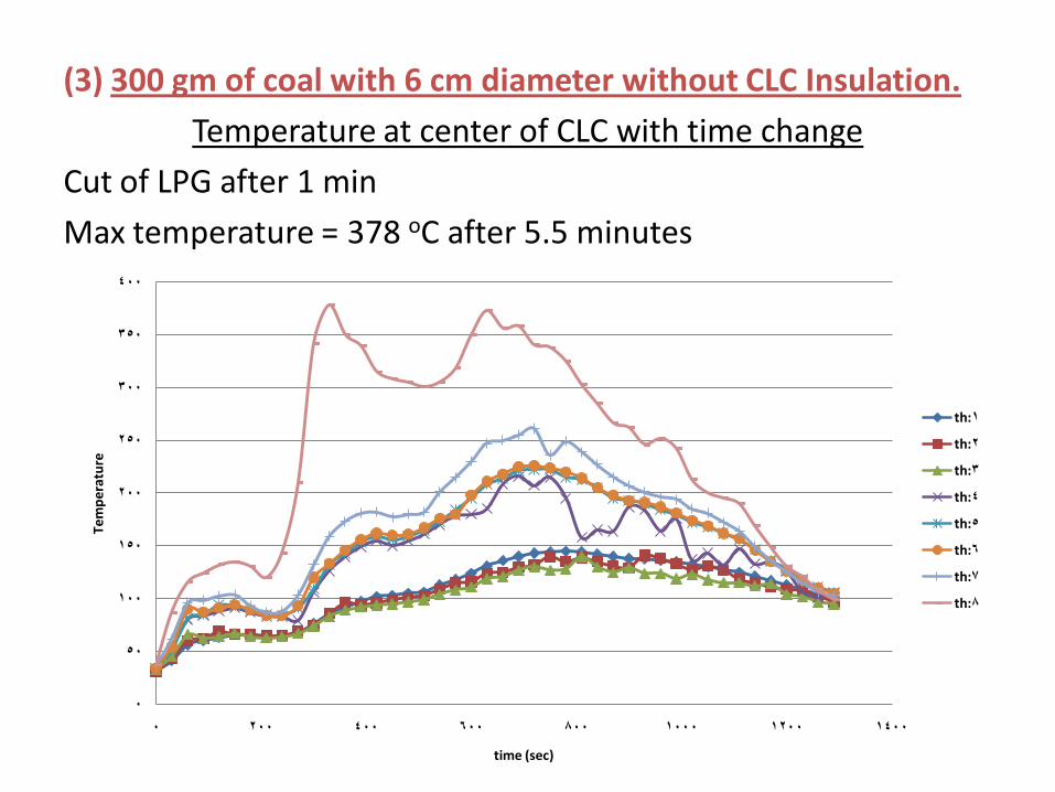
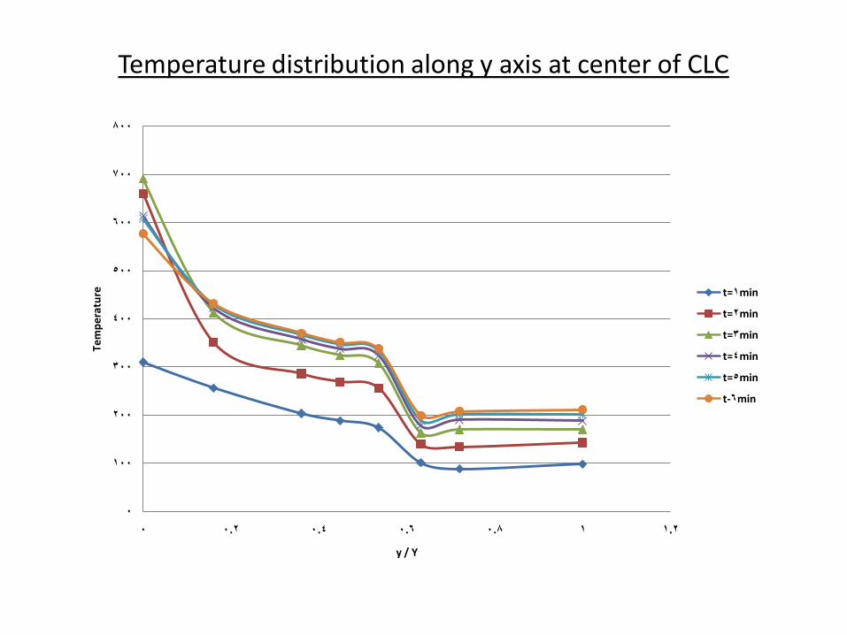
(3) 300 gm of coal with 6 cm diameter without CLC Insulation.
Temperature at center of CLC with time change
Cut of LPG after 1 min
Max temperature = 378 oC after 5.5 minutes
0
50
100
150
200
250
300
350
400
0 200 400 600 800 1000 1200 1400
Tem
per
atu
re
time (sec)
th:1
th:2
th:3
th:4
th:5
th:6
th:7
th:8
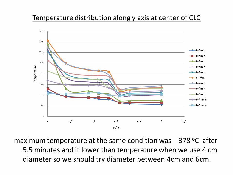
Temperature distribution along y axis at center of CLC
maximum temperature at the same condition was 378 oC after 5.5 minutes and it lower than temperature when we use 4 cm diameter so we should try diameter between 4cm and 6cm.
0
50
100
150
200
250
300
350
400
0 0.2 0.4 0.6 0.8 1 1.2
Tem
pe
ratu
re
y / Y
t=1min
t=2min
t=3min
t=4min
t=5min
t-6min
t=7min
t=8min
t=9min
t=10min
t=11min
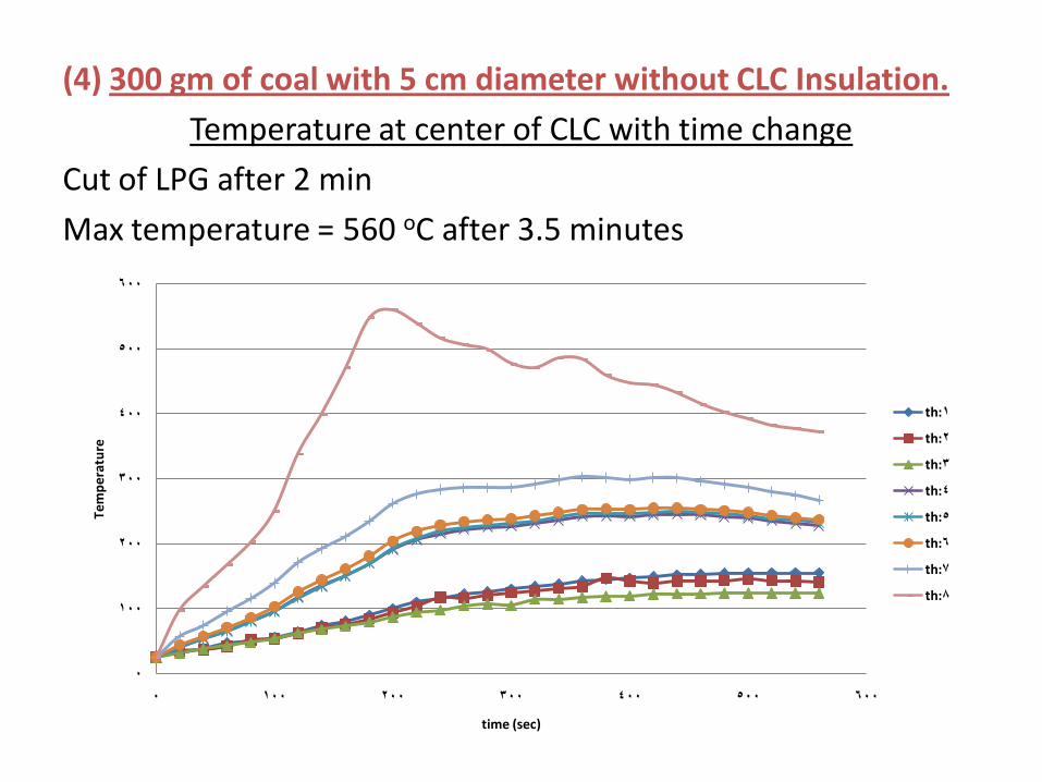
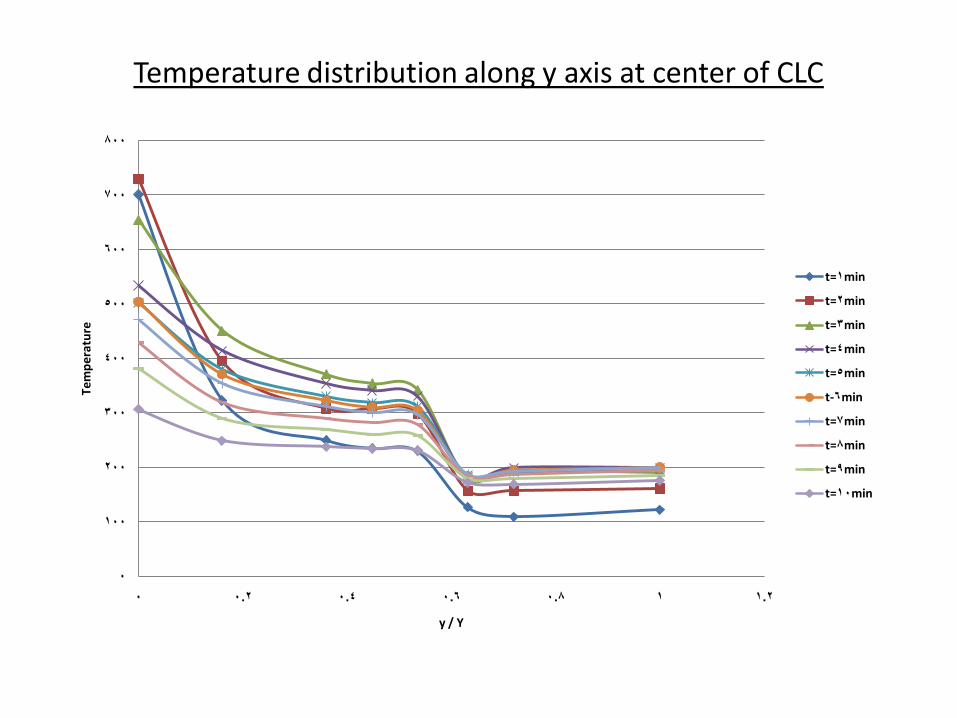
(4) 300 gm of coal with 5 cm diameter without CLC Insulation.
Temperature at center of CLC with time change
Cut of LPG after 2 min
Max temperature = 560 oC after 3.5 minutes
0
100
200
300
400
500
600
0 100 200 300 400 500 600
Tem
per
atu
re
time (sec)
th:1
th:2
th:3
th:4
th:5
th:6
th:7
th:8
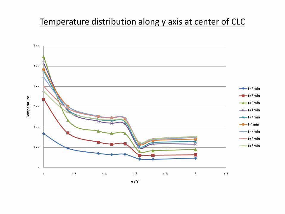
Temperature distribution along y axis at center of CLC
0
100
200
300
400
500
600
0 0.2 0.4 0.6 0.8 1 1.2
Te
mp
era
ture
y / Y
t=1min
t=2min
t=3min
t=4min
t=5min
t-6min
t=7min
t=8min
t=9min
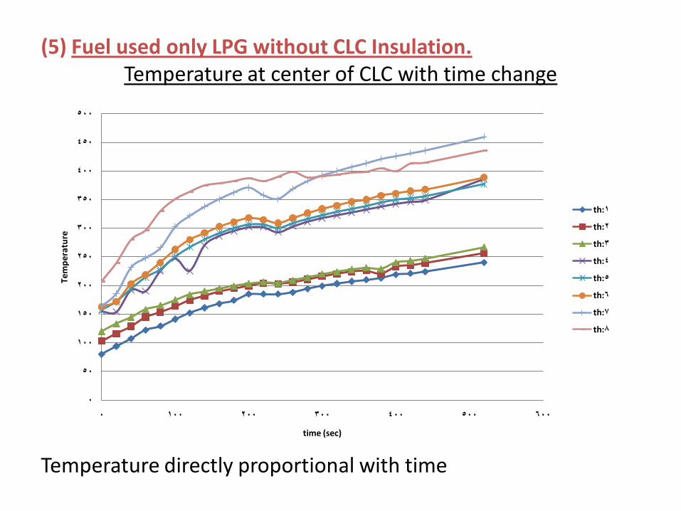
(5) Fuel used only LPG without CLC Insulation.Temperature at center of CLC with time change
Temperature directly proportional with time
0
50
100
150
200
250
300
350
400
450
500
0 100 200 300 400 500 600
Tem
per
atu
re
time (sec)
th:1
th:2
th:3
th:4
th:5
th:6
th:7
th:8
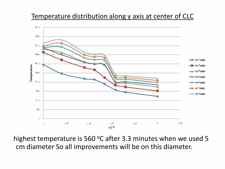
Temperature distribution along y axis at center of CLC
highest temperature is 560 oC after 3.3 minutes when we used 5 cm diameter So all improvements will be on this diameter.
0
50
100
150
200
250
300
350
400
450
500
0 0.2 0.4 0.6 0.8 1 1.2
Tem
pe
ratu
re
y / Y
t=1min
t=2min
t=3min
t=4min
t=5min
t-6min
t=7min
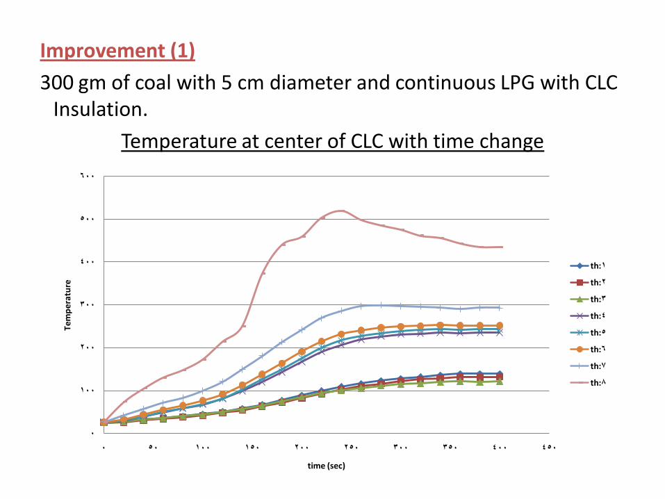
Improvement (1)
300 gm of coal with 5 cm diameter and continuous LPG with CLC Insulation.
Temperature at center of CLC with time change
0
100
200
300
400
500
600
0 50 100 150 200 250 300 350 400 450
Tem
per
atu
re
time (sec)
th:1
th:2
th:3
th:4
th:5
th:6
th:7
th:8
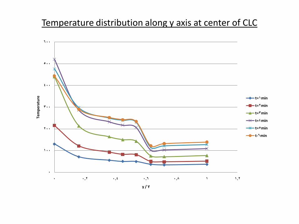
Temperature distribution along y axis at center of CLC
0
100
200
300
400
500
600
0 0.2 0.4 0.6 0.8 1 1.2
Tem
per
atu
re
y / Y
t=1min
t=2min
t=3min
t=4min
t=5min
t-6min
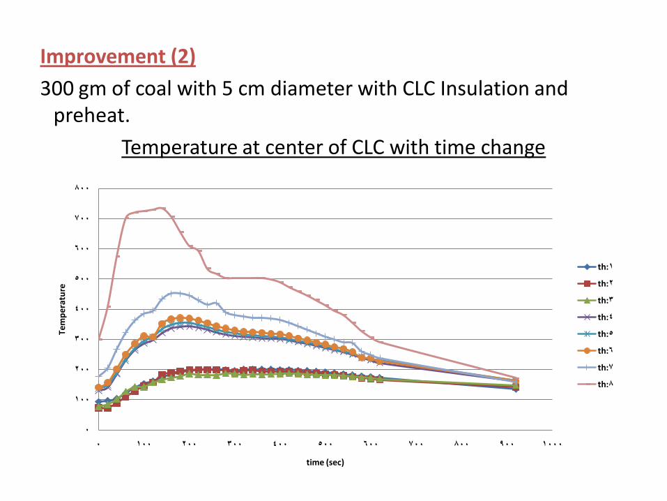
Improvement (2)
300 gm of coal with 5 cm diameter with CLC Insulation and preheat.
Temperature at center of CLC with time change
0
100
200
300
400
500
600
700
800
0 100 200 300 400 500 600 700 800 900 1000
Tem
per
atu
re
time (sec)
th:1
th:2
th:3
th:4
th:5
th:6
th:7
th:8
Temperature distribution along y axis at center of CLC
0
100
200
300
400
500
600
700
800
0 0.2 0.4 0.6 0.8 1 1.2
Tem
per
atu
re
y / Y
t=1min
t=2min
t=3min
t=4min
t=5min
t-6min
t=7min
t=8min
t=9min
t=10min
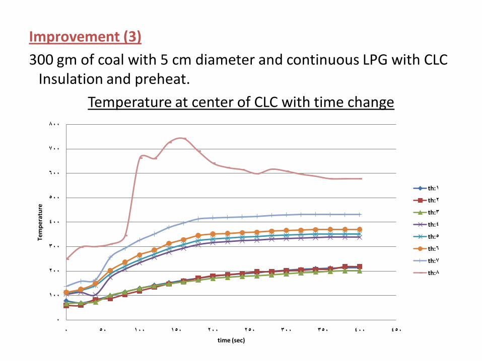
Improvement (3)
300 gm of coal with 5 cm diameter and continuous LPG with CLC Insulation and preheat.
Temperature at center of CLC with time change
0
100
200
300
400
500
600
700
800
0 50 100 150 200 250 300 350 400 450
Tem
per
atu
re
time (sec)
th:1
th:2
th:3
th:4
th:5
th:6
th:7
th:8
Temperature distribution along y axis at center of CLC
0
100
200
300
400
500
600
700
800
0 0.2 0.4 0.6 0.8 1 1.2
Tem
per
atu
re
y / Y
t=1min
t=2min
t=3min
t=4min
t=5min
t-6min
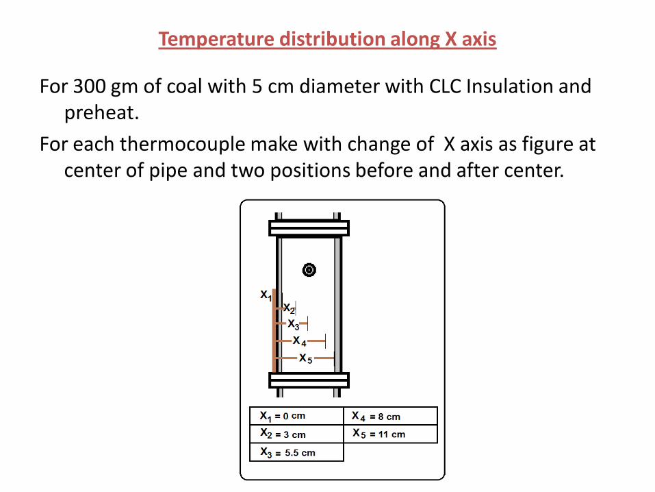
Temperature distribution along X axis
For 300 gm of coal with 5 cm diameter with CLC Insulation and preheat.
For each thermocouple make with change of X axis as figure at center of pipe and two positions before and after center.
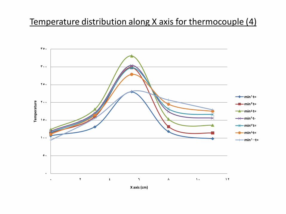
Temperature distribution along X axis for thermocouple (4)
0
50
100
150
200
250
300
350
0 2 4 6 8 10 12
Tem
per
atu
re
X axis (cm)
t=1min
t=2min
t=4min
t-6min
t=7min
t=8min
t=10min
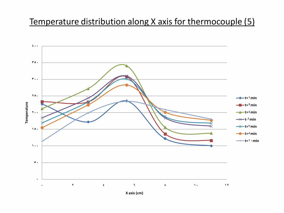
Temperature distribution along X axis for thermocouple (5)
0
50
100
150
200
250
300
350
400
0 2 4 6 8 10 12
Tem
per
atu
re
X axis (cm)
t=1min
t=2min
t=4min
t-6min
t=7min
t=8min
t=10min
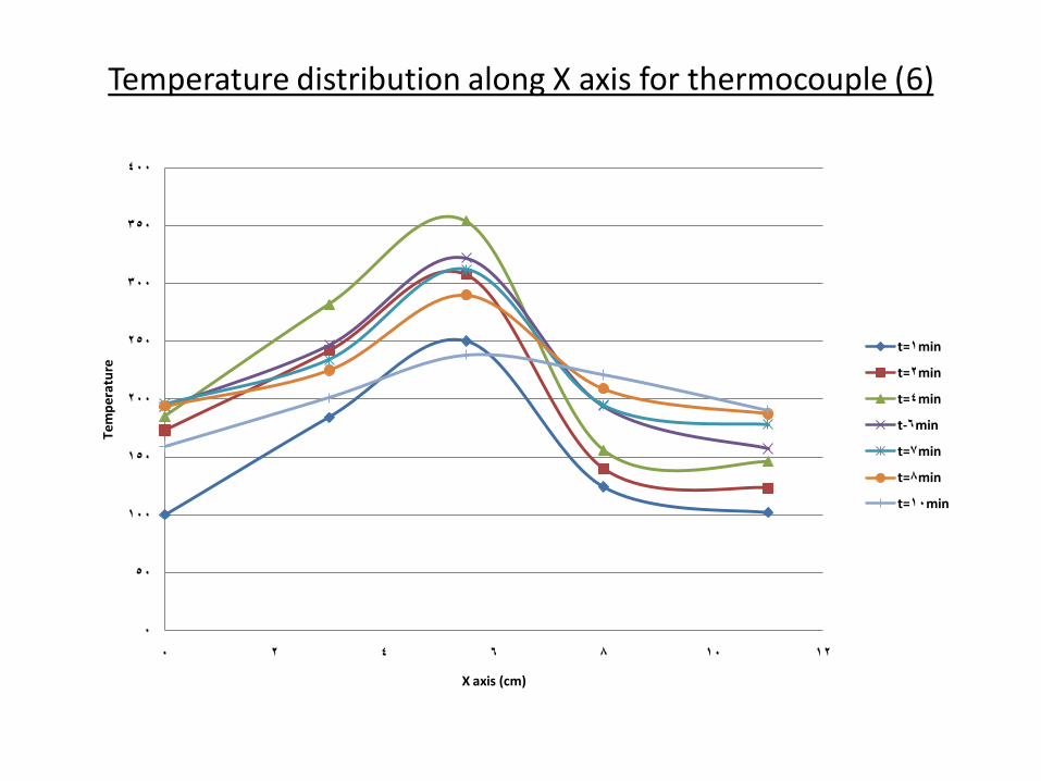
Temperature distribution along X axis for thermocouple (6)
0
50
100
150
200
250
300
350
400
0 2 4 6 8 10 12
Tem
per
atu
re
X axis (cm)
t=1min
t=2min
t=4min
t-6min
t=7min
t=8min
t=10min
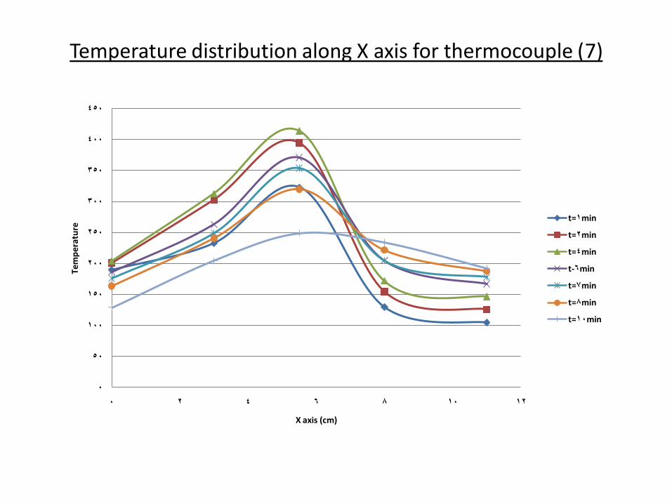
Temperature distribution along X axis for thermocouple (7)
0
50
100
150
200
250
300
350
400
450
0 2 4 6 8 10 12
Tem
per
atu
re
X axis (cm)
t=1min
t=2min
t=4min
t-6min
t=7min
t=8min
t=10min
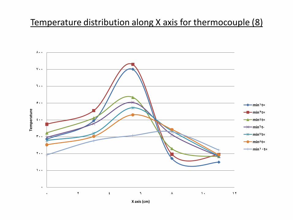
Temperature distribution along X axis for thermocouple (8)
0
100
200
300
400
500
600
700
800
0 2 4 6 8 10 12
Te
mp
era
ture
X axis (cm)
t=1min
t=2min
t=4min
t-6min
t=7min
t=8min
t=10min
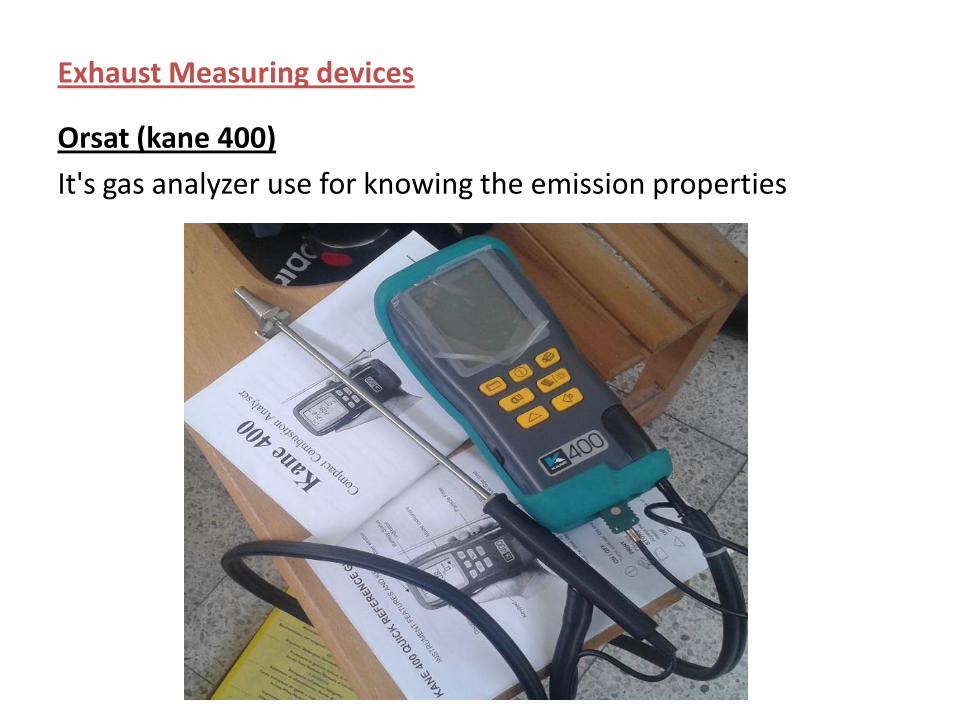
Exhaust Measuring devices
Orsat (kane 400)
It's gas analyzer use for knowing the emission properties
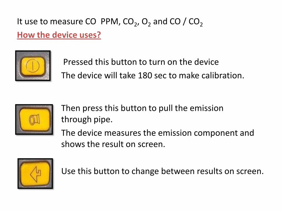
It use to measure CO PPM, CO2, O2 and CO / CO2
How the device uses?
Pressed this button to turn on the device
The device will take 180 sec to make calibration.
Then press this button to pull the emission through pipe.
The device measures the emission component and shows the result on screen.
Use this button to change between results on screen.
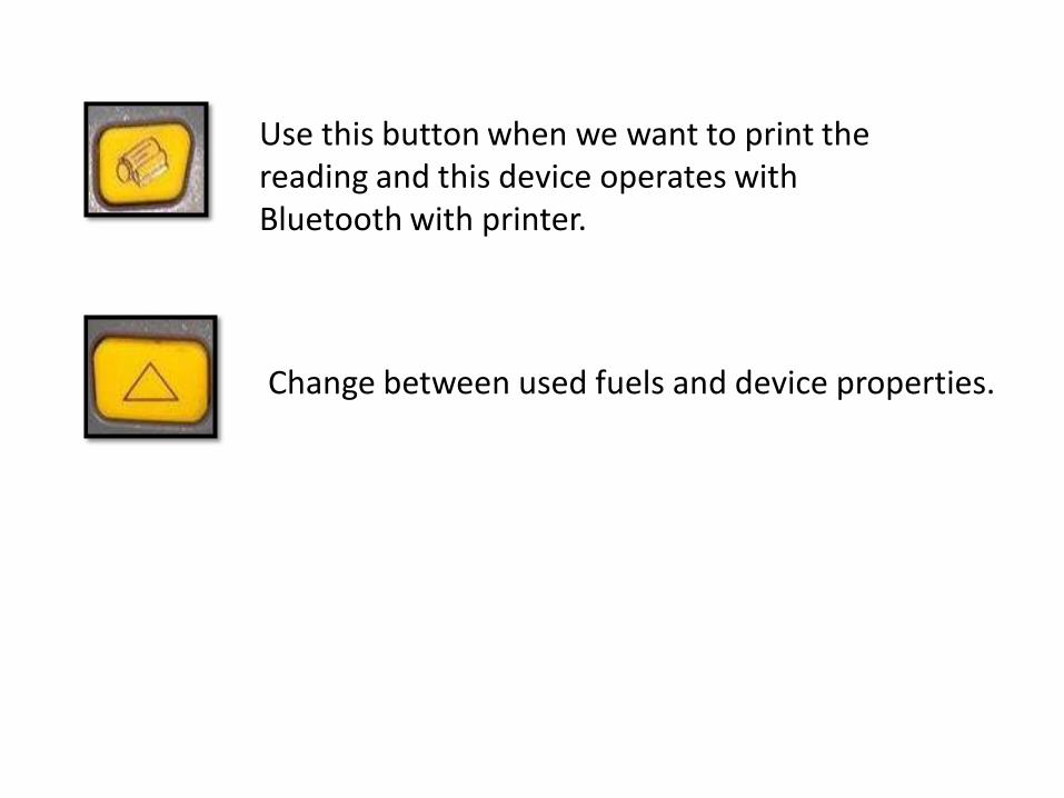
Use this button when we want to print the reading and this device operates with Bluetooth with printer.
Change between used fuels and device properties.
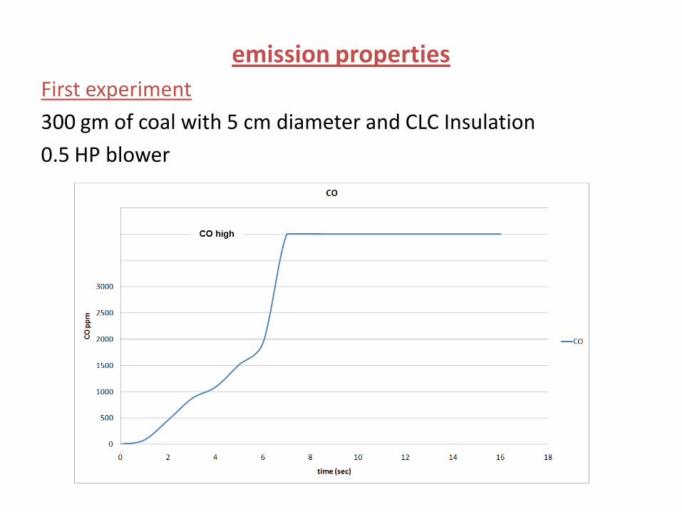
emission properties
First experiment
300 gm of coal with 5 cm diameter and CLC Insulation
0.5 HP blower
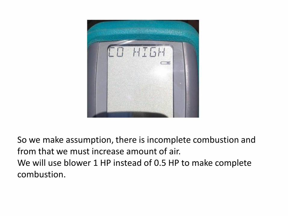
So we make assumption, there is incomplete combustion and from that we must increase amount of air. We will use blower 1 HP instead of 0.5 HP to make complete combustion.
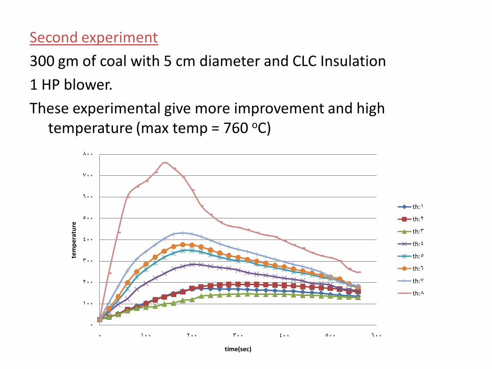
Second experiment
300 gm of coal with 5 cm diameter and CLC Insulation
1 HP blower.
These experimental give more improvement and high temperature (max temp = 760 oC)
0
100
200
300
400
500
600
700
800
0 100 200 300 400 500 600
tem
per
atu
re
time(sec)
th:1
th:2
th:3
th:4
th:5
th:6
th:7
th:8
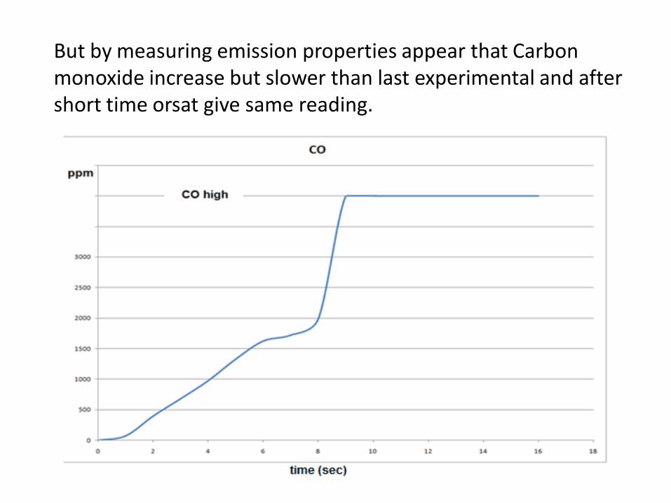
But by measuring emission properties appear that Carbon monoxide increase but slower than last experimental and after short time orsat give same reading.
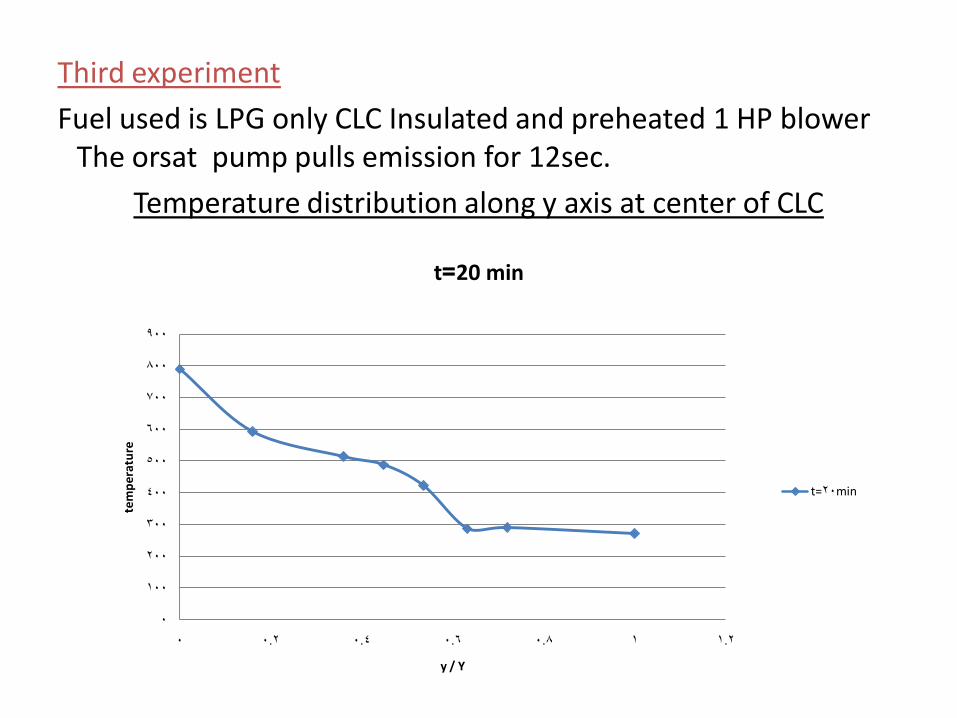
Third experiment
Fuel used is LPG only CLC Insulated and preheated 1 HP blower The orsat pump pulls emission for 12sec.
Temperature distribution along y axis at center of CLC
0
100
200
300
400
500
600
700
800
900
0 0.2 0.4 0.6 0.8 1 1.2
tem
per
atu
re
y / Y
t=20 min
t=20min
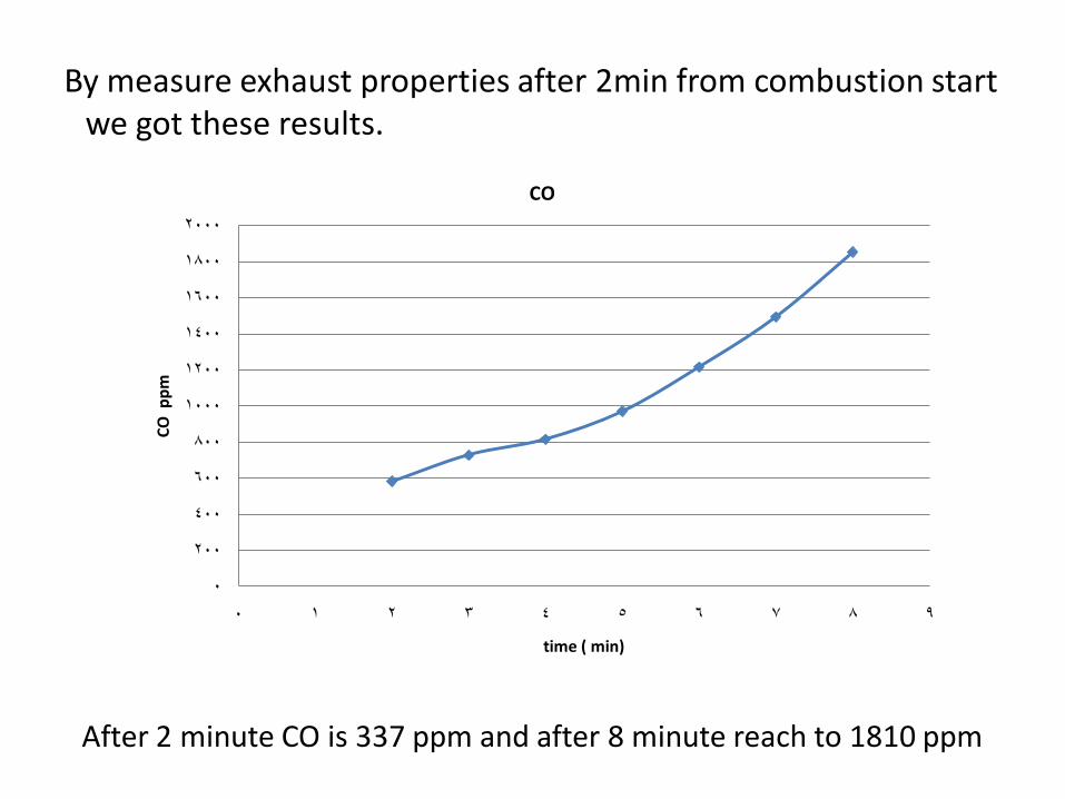
By measure exhaust properties after 2min from combustion start we got these results.
0
200
400
600
800
1000
1200
1400
1600
1800
2000
0 1 2 3 4 5 6 7 8 9
CO
pp
m
time ( min)
CO
After 2 minute CO is 337 ppm and after 8 minute reach to 1810 ppm
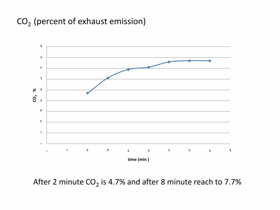
CO2 (percent of exhaust emission)
0
1
2
3
4
5
6
7
8
9
0 1 2 3 4 5 6 7 8 9
CO
2%
time (min )
After 2 minute CO2 is 4.7% and after 8 minute reach to 7.7%
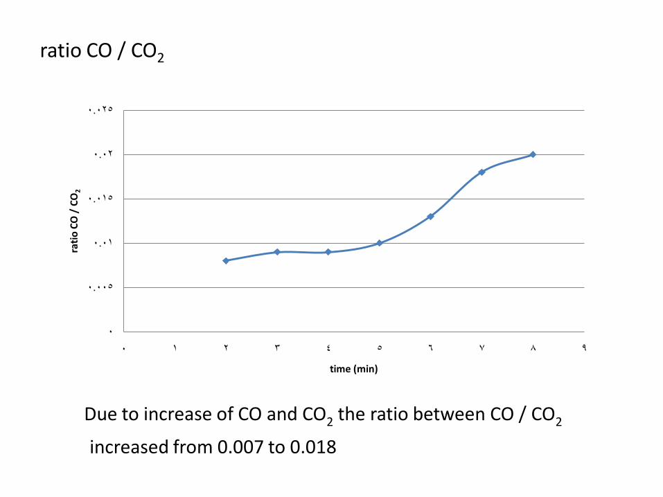
ratio CO / CO2
0
0.005
0.01
0.015
0.02
0.025
0 1 2 3 4 5 6 7 8 9
rati
o C
O /
CO
2
time (min)
Due to increase of CO and CO2 the ratio between CO / CO2
increased from 0.007 to 0.018
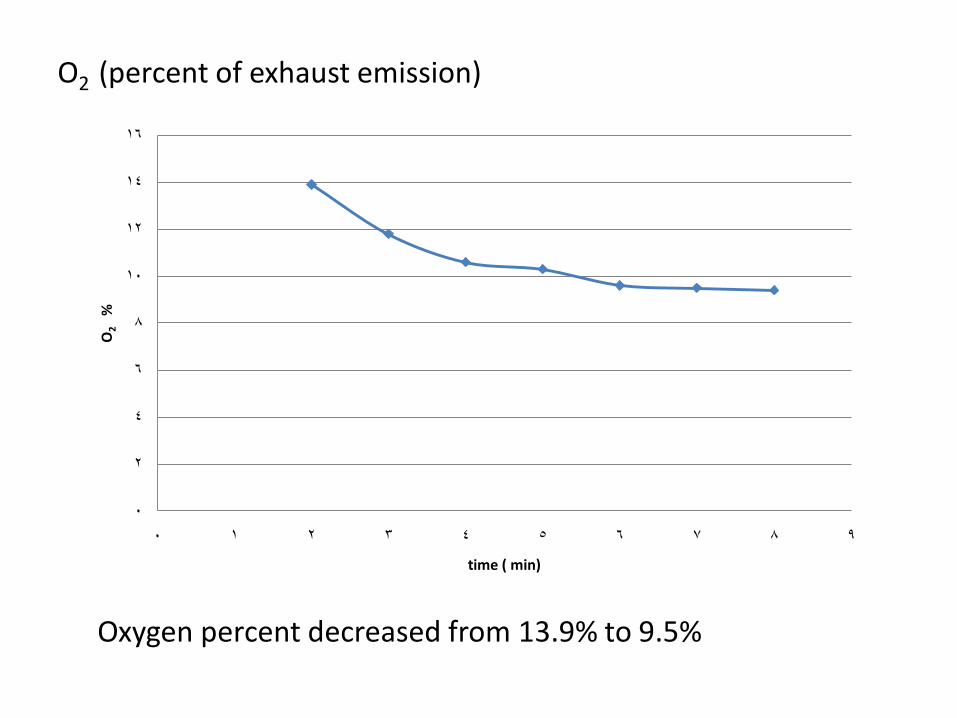
O2 (percent of exhaust emission)
0
2
4
6
8
10
12
14
16
0 1 2 3 4 5 6 7 8 9
O2
%
time ( min)
Oxygen percent decreased from 13.9% to 9.5%
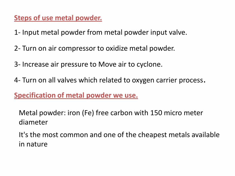
Steps of use metal powder.
1- Input metal powder from metal powder input valve.
2- Turn on air compressor to oxidize metal powder.
3- Increase air pressure to Move air to cyclone.
4- Turn on all valves which related to oxygen carrier process.
Specification of metal powder we use.
Metal powder: iron (Fe) free carbon with 150 micro meter diameter
It's the most common and one of the cheapest metals available in nature
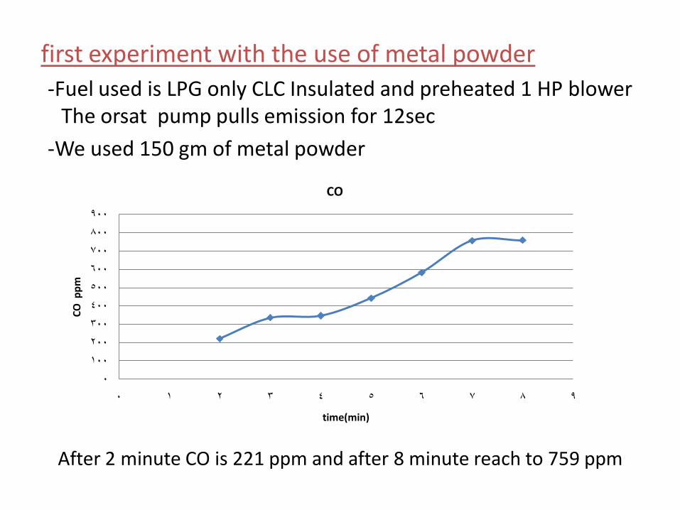
first experiment with the use of metal powder
-Fuel used is LPG only CLC Insulated and preheated 1 HP blower The orsat pump pulls emission for 12sec
-We used 150 gm of metal powder
0
100
200
300
400
500
600
700
800
900
0 1 2 3 4 5 6 7 8 9
CO
pp
m
time(min)
CO
After 2 minute CO is 221 ppm and after 8 minute reach to 759 ppm
0
2
4
6
8
10
12
14
0 1 2 3 4 5 6 7 8 9
CO
2%
time(min)
CO2
CO2
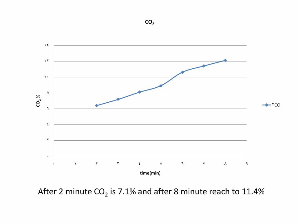
After 2 minute CO2 is 7.1% and after 8 minute reach to 11.4%
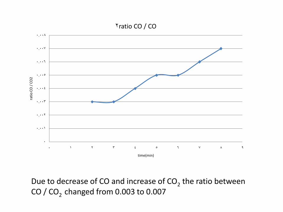
Due to decrease of CO and increase of CO2 the ratio between CO / CO2 changed from 0.003 to 0.007
0
0.001
0.002
0.003
0.004
0.005
0.006
0.007
0.008
0 1 2 3 4 5 6 7 8 9
rati
o C
O /
CO
2
time(min)
ratio CO / CO2
0
2
4
6
8
10
12
14
16
0 1 2 3 4 5 6 7 8 9
O2
%
time(min)
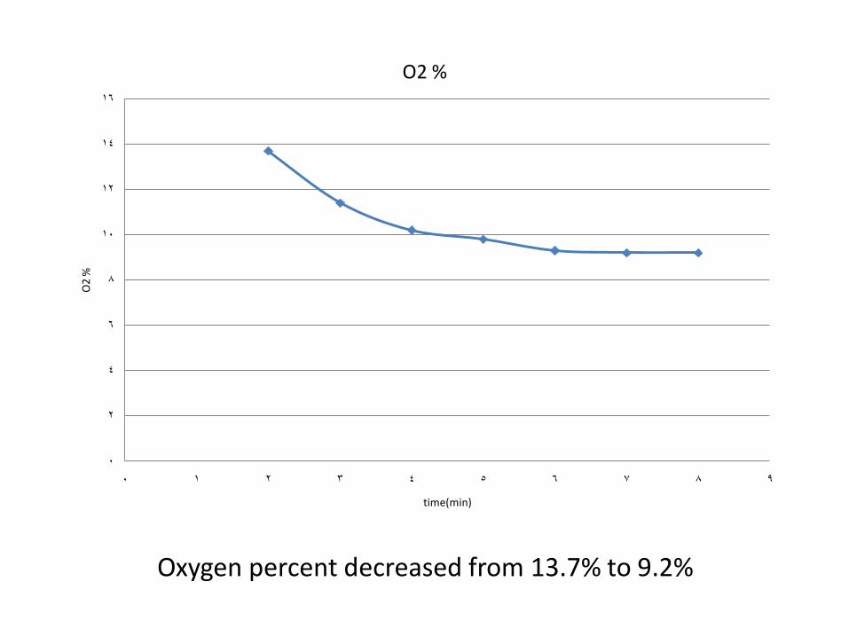
O2 %
Oxygen percent decreased from 13.7% to 9.2%
Second experiment with the use of metal powder
Fuel used is coal with 5 cm.
CLC Insulated and preheated.
1 HP blower.
The orsat pump pulls for 12sec.
200 gm of metal powder.
By measure exhaust properties after 1 min after cut off LPG source we got these results
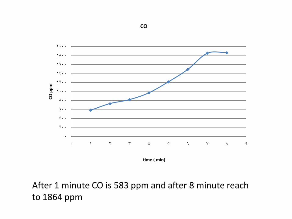
After 1 minute CO is 583 ppm and after 8 minute reach to 1864 ppm
0
200
400
600
800
1000
1200
1400
1600
1800
2000
0 1 2 3 4 5 6 7 8 9
CO
pp
m
time ( min)
CO
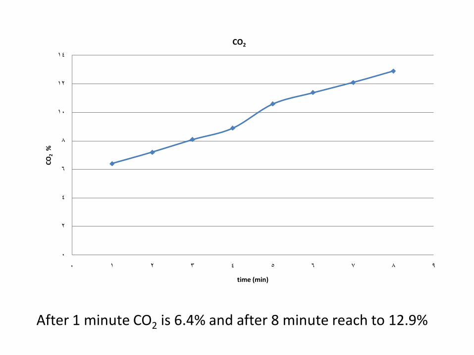
After 1 minute CO2 is 6.4% and after 8 minute reach to 12.9%
0
2
4
6
8
10
12
14
0 1 2 3 4 5 6 7 8 9
CO
2%
time (min)
CO2
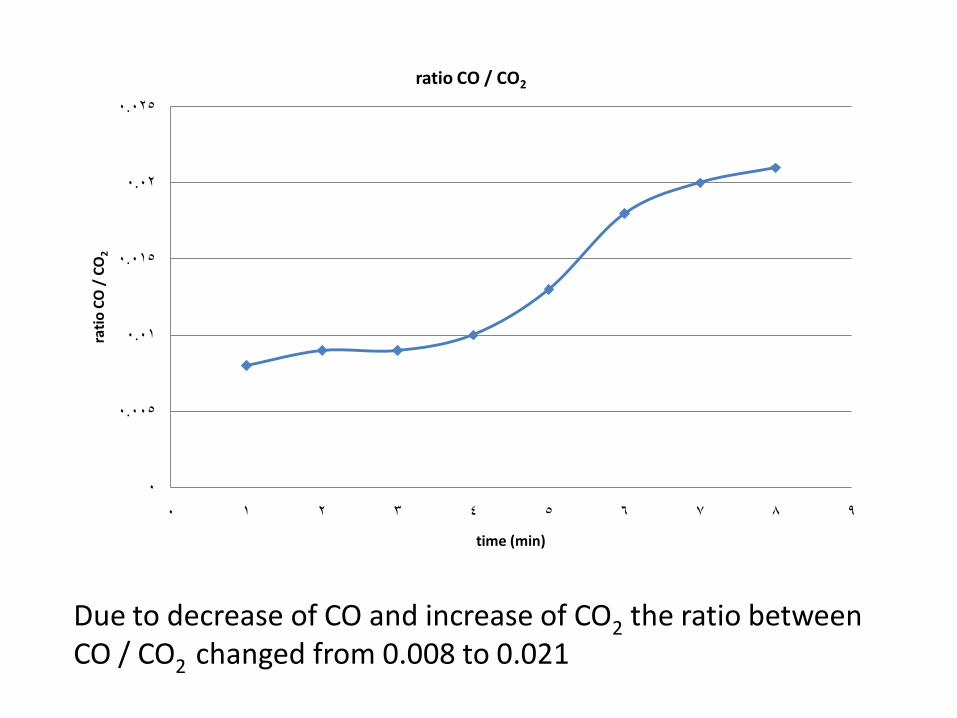
Due to decrease of CO and increase of CO2 the ratio between CO / CO2 changed from 0.008 to 0.021
0
0.005
0.01
0.015
0.02
0.025
0 1 2 3 4 5 6 7 8 9
rati
o C
O /
CO
2
time (min)
ratio CO / CO2
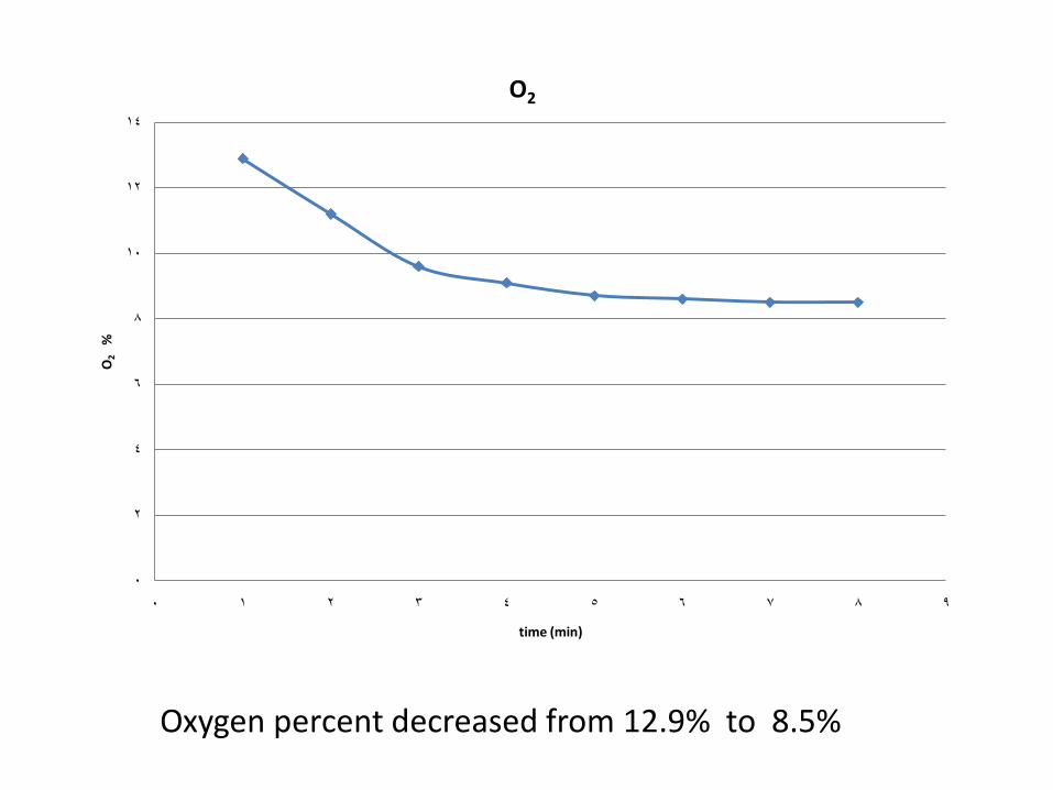
Oxygen percent decreased from 12.9% to 8.5%
0
2
4
6
8
10
12
14
0 1 2 3 4 5 6 7 8 9
O2
%
time (min)
O2
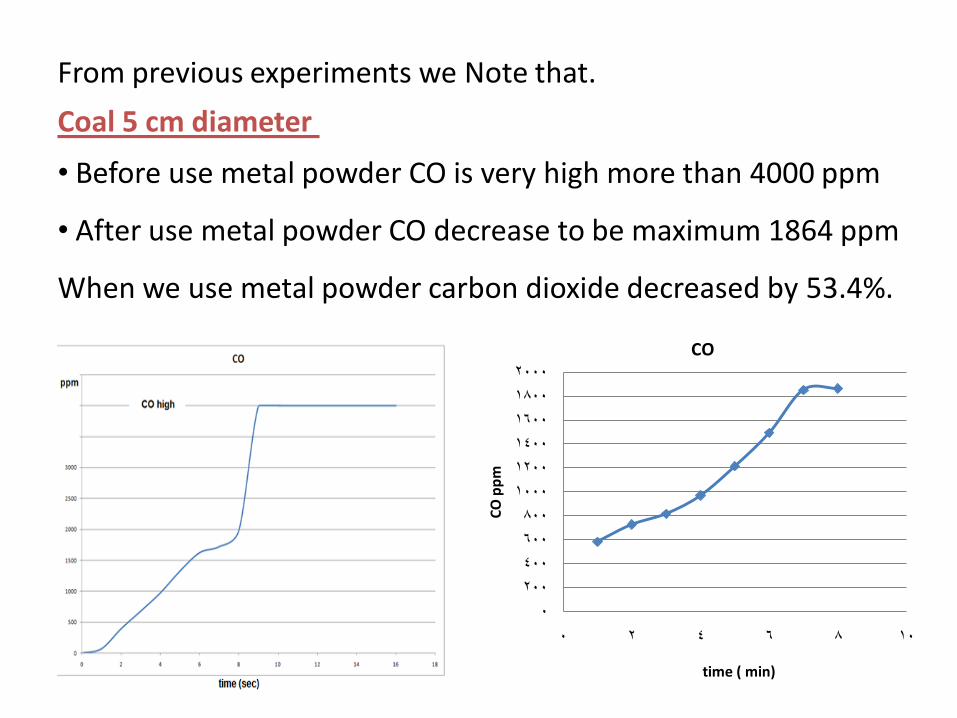
From previous experiments we Note that.
0
200
400
600
800
1000
1200
1400
1600
1800
2000
0 2 4 6 8 10
CO
pp
m
time ( min)
CO
Coal 5 cm diameter
• Before use metal powder CO is very high more than 4000 ppm
• After use metal powder CO decrease to be maximum 1864 ppm
When we use metal powder carbon dioxide decreased by 53.4%.
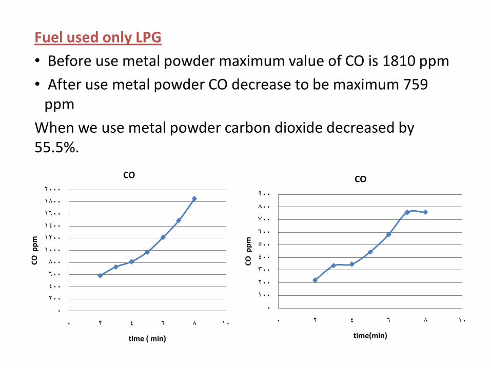
Fuel used only LPG
• Before use metal powder maximum value of CO is 1810 ppm
• After use metal powder CO decrease to be maximum 759 ppm
When we use metal powder carbon dioxide decreased by 55.5%.
0
100
200
300
400
500
600
700
800
900
0 2 4 6 8 10
CO
pp
m
time(min)
CO
0
200
400
600
800
1000
1200
1400
1600
1800
2000
0 2 4 6 8 10
CO
pp
m
time ( min)
CO
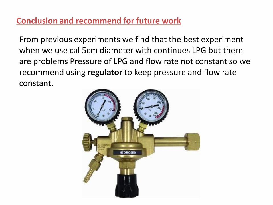
Conclusion and recommend for future work
From previous experiments we find that the best experiment when we use cal 5cm diameter with continues LPG but there are problems Pressure of LPG and flow rate not constant so we recommend using regulator to keep pressure and flow rate constant.
Troubles that may hinder the experiments and its Remedies
1- Exhaust has high percent of carbon monoxide (CO).
Possible troubles.
• Blower doesn't work effectively.
• Low amount of metal powder used.
• Insufficient time to oxidize or reoxidation metal powder.
Remedies.
• Check blower or change blower motor.
• Increase amount of metal powder.
• Decrease pressure of compressor.
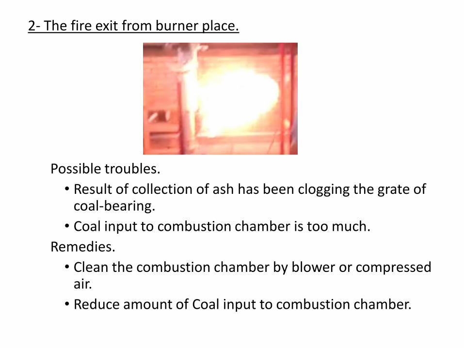
2- The fire exit from burner place.
Possible troubles.
• Result of collection of ash has been clogging the grate of coal-bearing.
• Coal input to combustion chamber is too much.
Remedies.
• Clean the combustion chamber by blower or compressed air.
• Reduce amount of Coal input to combustion chamber.
3- Extinguish burner flame after turn on blower.
Possible troubles.
• Low pressure of gas source (LPG).
• Blower make high air flow rate.
• Gas valve semi closed.
Remedies.
• Change gas source (LPG).
• Chang blower motor.
• Open gas valve.
4- Exhaust exit from cyclone.
Possible trouble.
• Back pressure from chimney.
Remedy.
• Install chimney caps to prevent Back pressure.
5- Digital reading show low temperature.
Possible troubles.• Uses low coal diameter for solid fuel.• Low flow rate of gas for LPG or natural gas.• Separate gas source early before solid fuel burned well.• Clogging the grate of coal-bearing and that prevent air to
arrive to combustion chamber.• The gate of fuel input Leaking heat.
Remedies.• Increases coal diameter.• Increase flow rate of gas for LPG or natural gas.• Don't separate gas source until make sure solid fuel burned
well.• Clean the combustion chamber by blower or compressed air.• Isolate the gate of fuel input.