Embed Size (px)
Citation preview

Clay Film Technologies
T. Ebina, Dr.
Advanced Functional Materials Team
Research Center for Compact Chemical System
National Institute of Advanced Industrial Science and Technology
(AIST)

Agenda
• Concept
• Properties
• Applications
• Acknowledgement


Concept of the clay-based-film
Ideal structure of the self-supported film
Heat durability and gas barrier performance are expected to improve if the material is mainly made of clay.
Filler (clay) ~8%
Clay-plastic nanocomposite
Gas barrier
performance
improved from twice
to five times.
Lateral dimension up
to a few hundred nm
Thickness
c.a. 1nm
Bentonite paper: E.A. Hauser and D.S. Le Beau, J. Phys. Chem. 42, 961 (1938).
40,000 stacking=40μm thick
50,000,000 array=50m long

Outlook
Transparent type
: Made from synthetic clay
Non-transparent type
: Made from natural clay
Claist®

Layer structure of clay
→2:1 type phyllosilicate
Surface structure of Cs-smectite
c.a. 1nmc.a. 1nmTetrahedral sheet
Octahedral sheet
Cation
2:1 type clay
Several hundred nm
montmorillonite
: Na0.33
[(Al1.67
Mg0.33
)Si4O
10(OH)
2]: Na
0.33[(Al
1.67Mg
0.33)Si
4O
10(OH)
2]: Na
0.33[(Al
1.67Mg
0.33)Si
4O
10(OH)
2]: Na
0.33[(Al
1.67Mg
0.33)Si
4O
10(OH)
2]

Natural clays which form films
XRD chart of a natural bentonite (Volclay)
2θ
S
M
Q
S
SCri
QFel
S S
SS
S:smectite、M:mica、Q:quartz、Cri:cristballite、Fel:feldsper
XRD chart of a natural bentonite (Volclay)
2θ
S
M
Q
S
SCri
QFel
S S
SS
2θ
S
M
Q
S
SCri
QFel
S S
SS
S:smectite、M:mica、Q:quartz、Cri:cristballite、Fel:feldsper
Bentonite mine in Miyagi, Japan
Mineral Layer
charge CEC(meq/100g)
mica 1 10~15
Sericite 0.85
Illite 0.75
Vermiculite 0.66 100~150
Smectite 0.33 60~100
Talc 0
H. Shirouzu, “Nendokoubutsugaku” Asakura shoten,1988
Various clays and its layer charge

Film formability comparison between natural
and synthetic clay
ヘクトライト(チキソピー) Hectorite (SHCa-1)
Montmorillonite (Kunipia P)
Montmorillonite (Tsukinuno)
Natural Synthetic
Hectorite (Thixopy) Stevensite (Smecton ST)
Hectorite (Laponite)
Saponite (Smecton SA)
Particle size
ca. 900nm (kunipia P) ca. 40nm (Smecton ST)
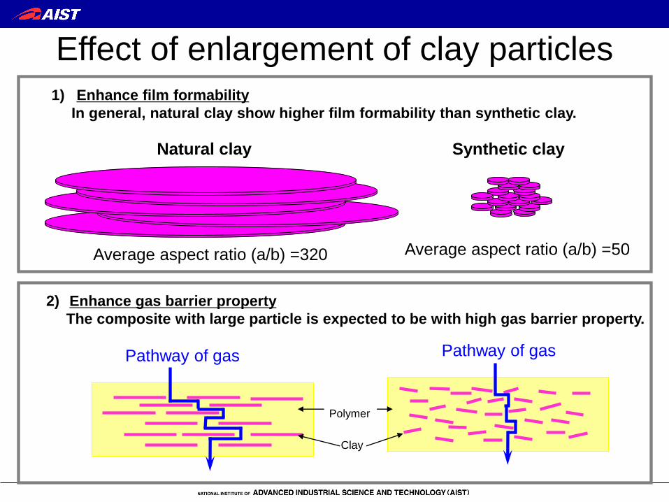
2) Enhance gas barrier property
The composite with large particle is expected to be with high gas barrier property.
Effect of enlargement of clay particles
1) Enhance film formability
In general, natural clay show higher film formability than synthetic clay.
Pathway of gas
Polymer
Clay
Pathway of gas
Natural clay
Average aspect ratio (a/b) =320
Synthetic clay
Average aspect ratio (a/b) =50
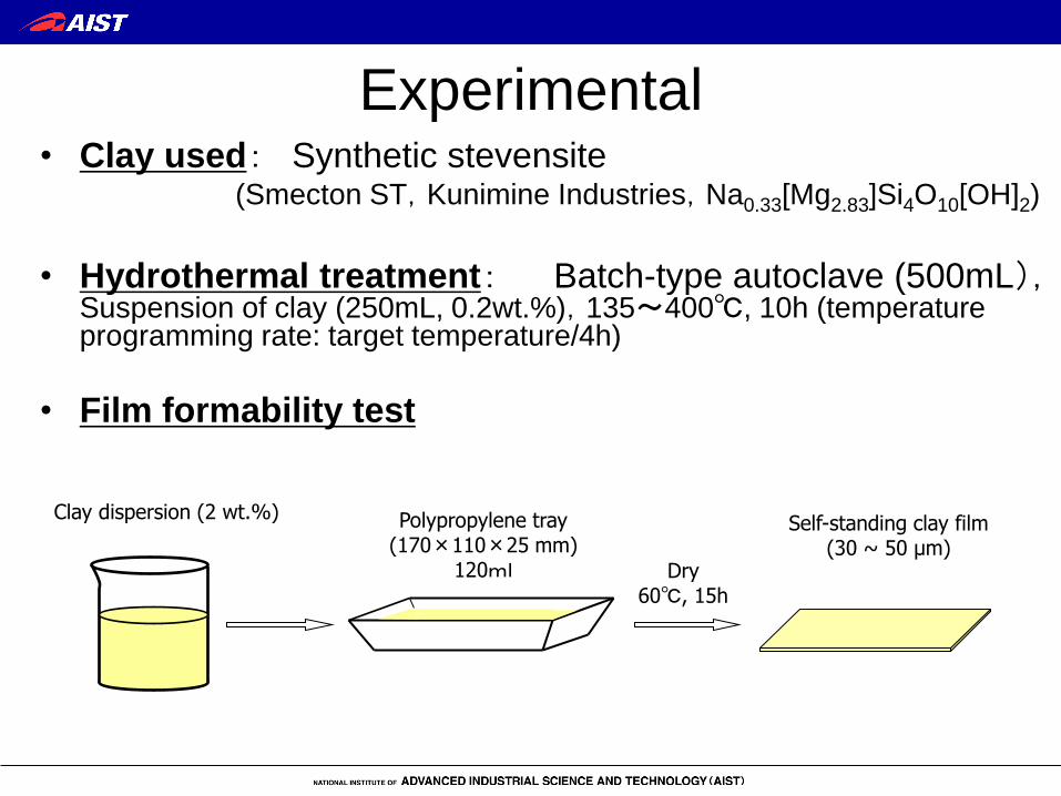
Experimental • Clay used: Synthetic stevensite (Smecton ST,Kunimine Industries,Na0.33[Mg2.83]Si4O10[OH]2)
• Hydrothermal treatment: Batch-type autoclave (500mL),Suspension of clay (250mL, 0.2wt.%),135~400℃, 10h (temperature programming rate: target temperature/4h)
• Film formability test
Clay dispersion (2 wt.%)
Dry 60℃, 15h
Self-standing clay film (30 ~ 50 μm)
Polypropylene tray (170×110×25 mm)
120ml

Particle enlargement of clay by a
hydrothermal treatment
(150℃)
10 um
(300℃)
10 um
(400℃)
10 um
(200℃)
10 um
Hydrothermal treatment is an
effective technique for particle
enlargement !
0 50 100 150 200 250 300 350 400 450
100
1000
10000
Pa
rtic
le s
ize
/ n
m
Hydrothermal temperature / oC
ca. 300 times
Natural clay
Nam, H.-J., Ishii, R., Ebina, T. and Mizukami, F. (2008): Mat. Lett., 63, 54-57.

Original Hydrothermally treated
Improvement of film formability by
hydrothermal treatment
Original 400℃ 200℃ 150℃

curing
further
processing
Typical preparation procedure of
clay-based-film
Clay: natural, synthetic, organoclay
Additive: plastics, fibers, particles
mixing spreading drying peeling
Surface treatment
Lamination
etc.
Liquid :water(1st generation)
toluene(2nd generation)
mixed solvent (3rd generation)

Clay film preparation

Mechanism of the film formation
Dry
Swelling Gelation
(Card house structure) Lamination
Dry Dry
Steps of the film formation

Lamella structure of clay films
TEM section view SEM section view
XRD pattern of clay film without
organic additive
XRD patterns of clay film type ST with
approximately 10 wt% ε-caprolactam
10 20 30 40 50 60 2θ
6.14
1.44 nm
0.311 nm
1.41 nm
0.309 nm After heated at 250℃
Before the heat treatment


Various films
• A. Heat resistant transparent film(TPP)
• B. Water vapor barrier film(SN)
• C. Heat resistant insulation film
• D. Food packaging(Oxygen barrier)
• E. Water vapor barrier coating

0
1
2
3
4
Heatdurability
Transparency
Mechanicalstrength
Oxygenbarrier
Water vaporbarrier
A.Heat resistant transparent film(TPP)

Tomoegawa Co.
Heat resistant transparent film (TPP)
Na+
Na+
Na+ Na+
Na+ Na+
Onium cation
intercalation
Clay
(Hydrophilic ) Organoclay
(Hydrophobic)
K. Kawasaki, T. Ebina et al, Appl. Clay. Sci., 2010, 48, 111-116.
Tetraphenyl phosphonium cation
(TPP)
P+ Br
-

XRD spectra of TPP-SA film
0 5 10 15 20 25 30
2 theta/deg
Inte
nsi
ty/C
ou
nts
d001=1.9nm
Flexible TPP-SA film
(Total light transmittance 90%、HAZE value 50%)
-80
-70
-60
-50
-40
-30
-20
-10
0
0 100 200 300 400 500 600 700
Temperature/℃
TG
/%
DT
A / arb
. un
it
exo
en
do
TG-DTA curve of TPP-SA film
Tomoegawa Co.

200℃
300℃
350℃
400℃
500℃
0
10
20
30
40
50
60
70
80
90
200 300 400 500 600 700
Wavelength/nm
Tra
nsm
itta
nce/
%200℃ 300℃ 350℃ 400℃ 500℃
UV-visible light transmittance of TPP-SA films treated at
different temperature
(Heating rate of 5℃/min.)
・TPP-SA films heated up to 350℃ or 400℃ exhibited some coloring.
(Their light transmittances of visible light (500nm) were 80% and 79%)
Tomoegawa Co.

0
1
2
3
4
5Heat durability
Transparency
Mechanical strengthOxygen barrier
Water vapor barrier
B.Water vapor barrier film(SN)

Water vapor barrier film (SN)
~2nmsilicate
water
soluble
polymer
~2nmsilicate
water
soluble
polymer
Lithium ion
Clay with vacant and positive
charge in the octahedral site
(Montmorillonite, and Stevensite)
1.2~2nmsilicate
polymer
Heating
>230℃ ①Migrate lithium into the
crystal structure
②Binder changes to be
waterproof
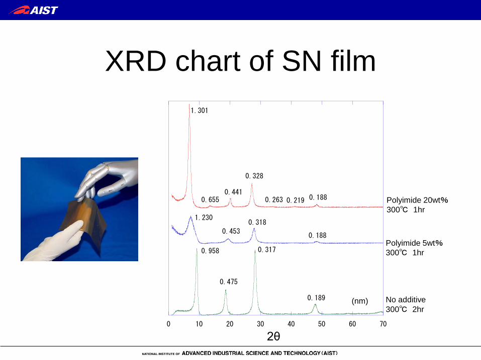
XRD chart of SN film
0 10 20 30 40 50 60 70
SN20-300d1hSN5-300d1hSiLiKunipia100%-300d2h
2thete
0.958
0.475
0.317
0.189
1.230
0.453
0.318
0.188
1.301
0.6550.441
0.328
0.263 0.219 0.188
No additive
300℃ 2hr
Polyimide 5wt%
300℃ 1hr
Polyimide 20wt%
300℃ 1hr
2θ
(nm)

Properties of SN film
Mandrel bending test <2mm Thickness15μ m
Water adsorption 0.20% 40℃90%RH
Chemical resistance
Acetone 3.98% 25℃
IPA 10.63% 25℃
Ethylene glycol 12.20% 25℃
Gas barrier property
Oxygen <0.1 cc/m2・day・atm 25℃
Water vapor
0.0012 g/m2・day1)
0.027 g/m2 day2)
0.0046 g/m2 day3)
<0.01 g/m2 day4)
85℃ 85%RH 40℃ 90%RH 40℃ 90%RH 40℃ 90%RH
1) API-MS method, 2)Mocon Aquatran、3)Technolox Deltaperm 4)GTRtec Gas chromatograph method

0
1
2
3
4
5Heat durability
Transparency
Mechanical strengthOxygen barrier
Water vapor barrier
C.Heat resistant insulation film

33
Newly developed heat-resistant
film (Toughclaist)
Outlook of Toughclaist A 57cm width TP film
Sumitomoseika Co,. Tokyo University of Science

34
PV module (rear) (front)
Proposed structure of a solar call using Toughclaist as a backsheet
Glass PV cell
EVA
Back sheet
Crystal Si solar cell
Insulating layer
Water vapor barrier layer
Structure of typical back sheet
Adhesive agent
Weather durable layer
Proposed back sheet structure
Toughclaist
Sumitomoseika Co,. Tokyo University of Science

Comparison of water vapor
barrier properties of typical films
Sumitomoseika Co,. Tokyo University of Science

Time course change in water vapor permeability of Toughclaist
(Dump heat condition 85℃, 85%RH,
WVP measurement at 40℃, 90%RH)
Sumitomoseika Co,. Tokyo University of Science

38
Example of electronic circuits drawn
by a printing method on Toughclaist
(film size 8 cm×5 cm)
Draw the pattern by
nanoparticle ink
Heat treatment 200℃
Screen printing
Cu ink used Ag ink used
Sumitomoseika Co,. Tokyo University of Science
39
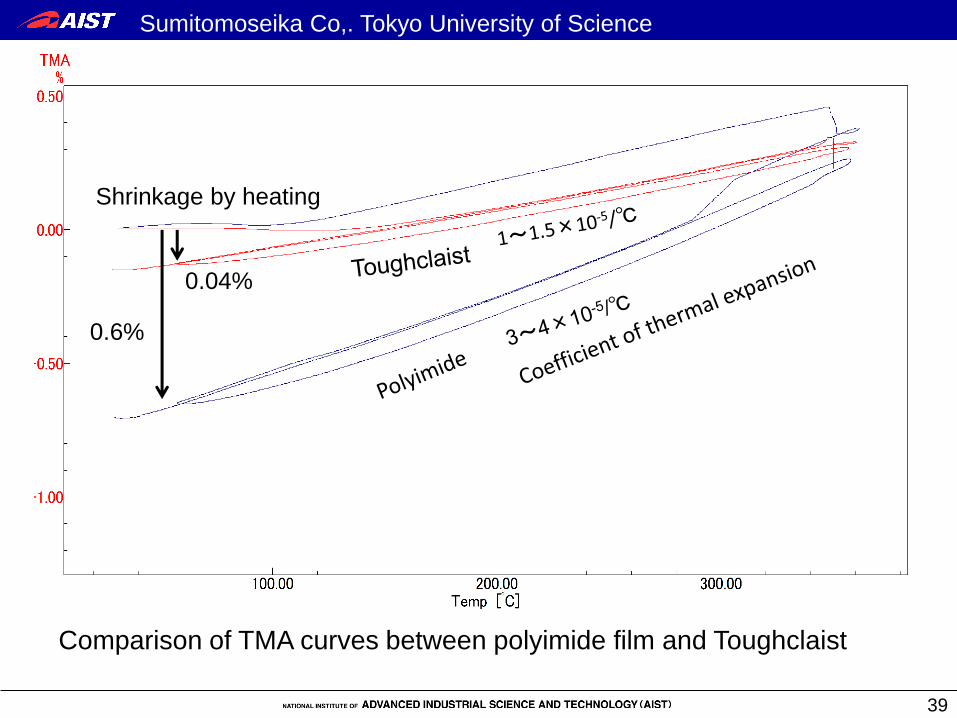
Shrinkage by heating
0.04%
0.6%
Comparison of TMA curves between polyimide film and Toughclaist
Sumitomoseika Co,. Tokyo University of Science

0
1
2
3
4
5 Heat durability
Transparency
Mechanical strength Oxygen barrier
Water vapor barrier
D.Food packaging(Oxygen barrier)
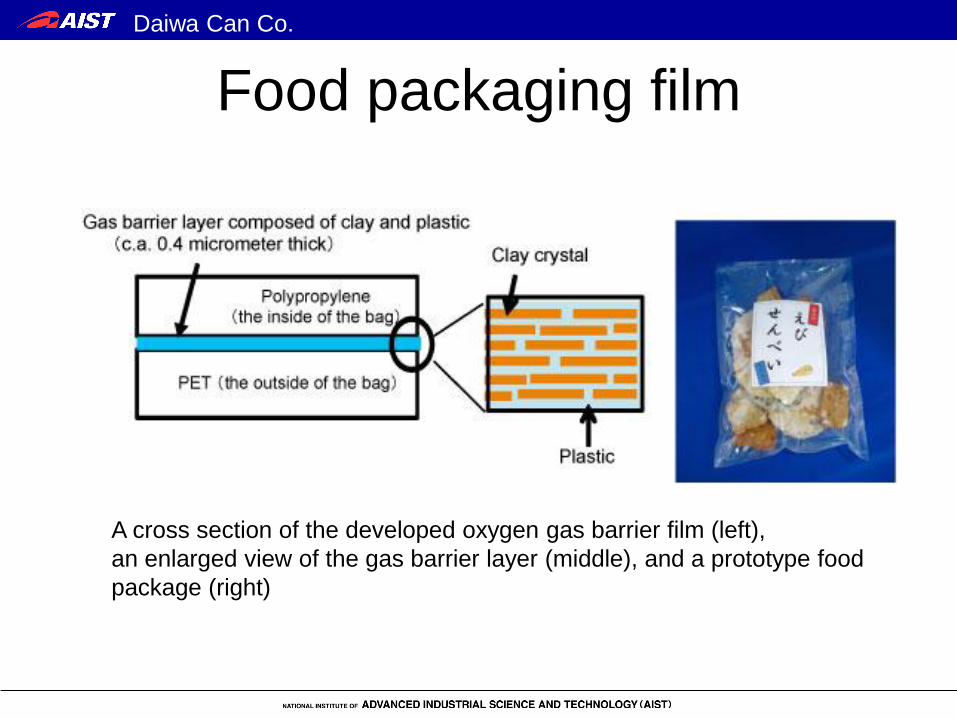
Food packaging film
A cross section of the developed oxygen gas barrier film (left),
an enlarged view of the gas barrier layer (middle), and a prototype food
package (right)
Daiwa Can Co.

Self-repair of a scratch
Optical microscope images (height 0.50 mm, width 0.62mm) of
the self-repairing process of the gas barrier layer scratched
(left: just after being scratched, center: after being left for 60
minutes in humid air, right: after drying at 50 degree centigrade
for 36 hrs) Oxygen gas barrier
3.4 【cc/m2・day・atm】 0.98 【cc/m2・day・atm】
Daiwa Can Co.

Gelbo flex test
Stretched Maximum distortion
Repetitio
n
Equipment set up Transparent vacuum deposited film
(after 20 times distortion)
Daiwa Can Co.

Oxygen permeability after gelbo flex
test (cm3/m2·day·atm)
These figures are of laminated film with 25 micrometer thick polypropylene film. The
gelbo flex tests were conducted under 23 degree centigrade and 65 percent related
humidity. The oxygen permeation tests were conducted at room temperature and dry
condition.
【cc/m2・day・atm】
Daiwa Can Co.

0
1
2
3
4
5Heat durability
Transparency
Mechanical strengthOxygen barrier
Water vapor barrier
E.Water vapor barrier coating
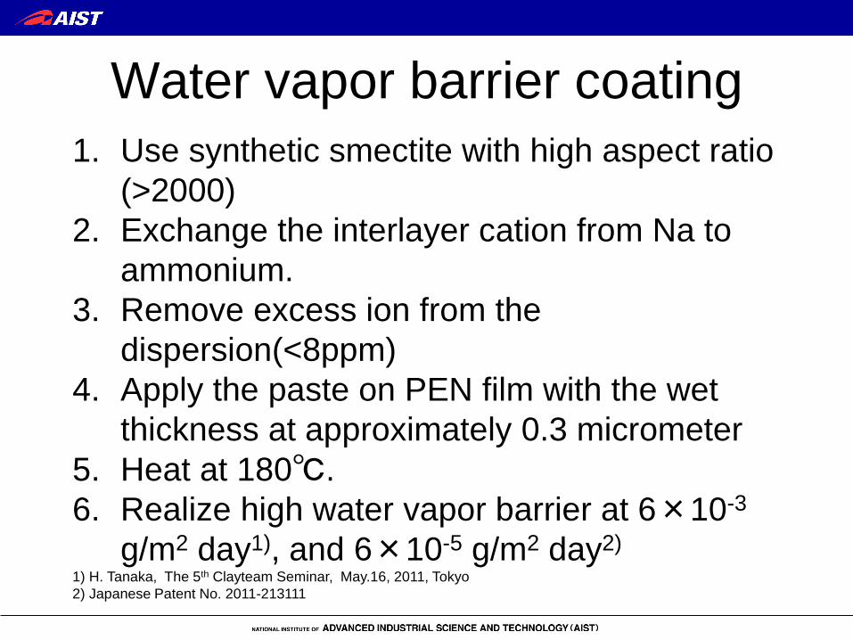
Water vapor barrier coating
1. Use synthetic smectite with high aspect ratio
(>2000)
2. Exchange the interlayer cation from Na to
ammonium.
3. Remove excess ion from the
dispersion(<8ppm)
4. Apply the paste on PEN film with the wet
thickness at approximately 0.3 micrometer
5. Heat at 180℃.
6. Realize high water vapor barrier at 6×10⁻³
g/m2 day1), and 6×10⁻⁵ g/m2 day2) 1) H. Tanaka, The 5th Clayteam Seminar, May.16, 2011, Tokyo
2) Japanese Patent No. 2011-213111

Film properties: Summary
0
1
2
3
4
5
Heatdurability
Transparency
Mechanicalstrength
Oxygenbarrier
Water vaporbarrier
A.Heat resistanttransparent film(TPP)
B.Water vapor barrierfilm(SN)
C.Heat resistant insulationfilm
D.Food packaging(Obygenbarrier)
E.Water vapor barriercoating


Application map
Heat durability Gas barrier property
Transparency
Gasket
Hydrogen tank
Food packaging
Barrier film for solar cell Substrate for solar cell
Substrate for displays
Printable electronics
substrate Fuel cell seal
Barrier film for OLED

Material design
・Self standing or coating →heat durability
・Natural clay or synthetic clay→transparency
・Clay loading→flexibility
・Multilayer→Function separation
・Solid ratio, viscosity→production process
Properties must, want
Object
Limitation of process Design
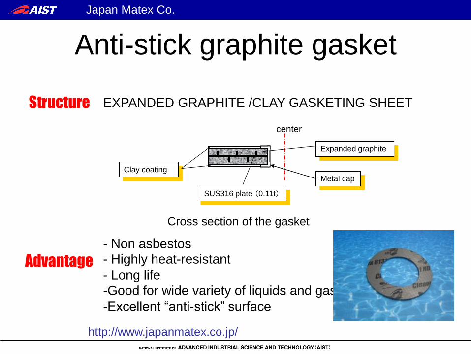
Anti-stick graphite gasket
Advantage
- Non asbestos
- Highly heat-resistant
- Long life
-Good for wide variety of liquids and gases
-Excellent “anti-stick” surface
EXPANDED GRAPHITE /CLAY GASKETING SHEET
center
Expanded graphite
SUS316 plate (0.11t)
Clay coating Metal cap
Cross section of the gasket
Structure
http://www.japanmatex.co.jp/
Japan Matex Co.
52
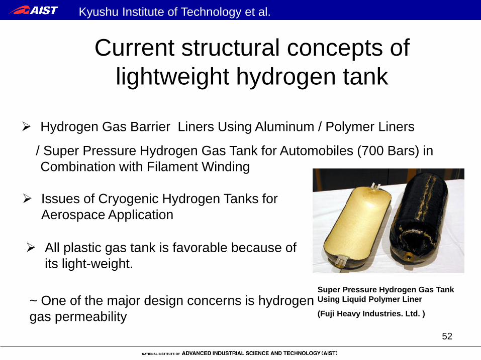
Hydrogen Gas Barrier Liners Using Aluminum / Polymer Liners
/ Super Pressure Hydrogen Gas Tank for Automobiles (700 Bars) in
Combination with Filament Winding
Super Pressure Hydrogen Gas Tank
Using Liquid Polymer Liner
(Fuji Heavy Industries. Ltd. )
Issues of Cryogenic Hydrogen Tanks for
Aerospace Application
~ One of the major design concerns is hydrogen
gas permeability
All plastic gas tank is favorable because of
its light-weight.
Current structural concepts of
lightweight hydrogen tank
Kyushu Institute of Technology et al.

Coupons Thickness
[ mm ]
Permeability
[ Pasm/mmol10 216 ]
CFRP (PYLOFIL#380) 1.061 0.529
ST 0.09 0.0009 Claist
HR 0.073 0.0046
ST 1.176 0.0078 Claist Compound
CFRP (PYLOFIL#380) HR 1.174 0.0035
Hydrogen Fuel Hose (Reference 7) - 33.49
Liquid Crystal Polyesters Resin (Reference 8) - 0.625
Virgin IM7/977-2/AF-191 (Reference 9) - 0.4
*Eval Resin (Kuraray Co. Ltd ) 0.031
Hydrogen gas permeability of different coupons
Yonemoto, K., Yamamoto, Y., Ebina, T. and Okuyama, K. (2008):. SAMPE’08.
Kyushu Institute of Technology et al.

CFRP Hydrogen tank using clay film as a
gas barrier liner
27L tank
Structure of the clay film/CFRP hydrogen tank Estimated broken pressure :70MPa
Clay film
CFRP core
CFRP winding layer
Metal connector
Hand-layupped clay
layer
CFRP filament winding
Yonemoto, K., Yamamoto, Y., Ebina, T. and Okuyama, K. (2008):. SAMPE’08.
Kyushu Institute of Technology et al.

Simple firing test
Transparent non-combustive sheet
AIST Press release “Successful development of evolutional clay film products” , September 13, 2010
Air deflector for vehicles
with flexible solar cell LED light
Kajiwara Electric Co
O2
O2
O2
O2
O2
O2
O2O2
Claist®
Plastic
Glass Fiber
Control with Clay film coating
Proposed applications
New building for transparent material
development; September 2011
Miyagikasei Co.

Fabrication of
flexible OLED
The performance of the OLED is comparable to that
of glass-base device.
● Turn on voltage 7.2V
● Electroluminescence peak at 530nm
● Luminous efficiency 2.7cd A-1
H. Tetsuka et al., Nanotechnology, 18 355701 (2007).
H. Tetsuka et al., J. Mat. Chem., 17, 3545-3550 (2007).
ITO is treated at 300℃
→4×10⁻⁴Ωcm
rf magnetron sputtering
Fabrication of
flexible organic light emitting diodes

Incorporation of hydrophilic nanocrystals into flexible and transparent
clay host using charge-charge interaction between nanocrystal surface
and clay platelet.
Quantum dot photo luminescent device
Tetsuka, H., Ebina, T. and Mizukami, F. (2008): Adv. Mater., 20, 3039-3043.

Preparation of electron (Alq3) and hole transport (NPB) layer:
Photographs of light emission under UV light (365 nm)
.
Preparation of clay
film on glass substrate
Annealed at 60 ° C for 1h
Polypropylene
substrate
Clay film
High magnification SEM images of
ZnO thin films on clay substrate.
30 40 50 60 70 80
100
200
300
400
500
P:ZnO/Clay
C-Clay C
(101)
(002)
(100)
XR
D I
nte
nsity (
a.
u.)
2 q (degree)
XRD patterns of ZnO thin film on clay substrate.
Preparation of ZnO thin film
Towards the development of flexible
optoelectronic devices
Alq3 NPB
Dr. S. Venkatachalm

Clay synthesis from rice husk
Reaction apparatus for excess
heated water vapor reaction
1. Combustion
2. Add Mg and Na
3. Hydrothermal
treatment
Rice husk Synthetic clay
Transparent film made from rice husk
oven
vessel
pump
drain
preheating
line

Hydrogen Tank
Solar Cell Material
Natural clay
Synthetic clay Organizing
committee AIST 4
Company 9
Multipurpose Sheet
Venture
New
product No. of Private Company 54
(November 18, 2011)
Established in May 2010.
New
business
Overseas Clayteam search
Takeo Ebina, Development of clay-based-film –a full research scenario from the viewpoint of encounter, Synthesiology Eng. Ed., 1, 242-2009.
An Industry-Academia-Government Consortium
Clayteam

Summary
Clay-based flexible film has excellent performance
in thermal stability, gas barrier property, and so on.
Different types of films including transparent types
have been developed to suit different applications.
Development of products using this material on
various applications will contribute to establish the
sustainable society.

Acknowledgements Authors appreciate their cooperation and supports.
Japan Matex Co. (Gasket maker)
Mr. Katsuro Tsukamoto, Mr. Toshiharu Sakura,
Mr. Yuzo Nakamura
Tomoegawa Co. (Film maker)
Mr. Katsumi Motegi, Mr. Tomohito Inoue
Mr. Hajime Tsuda
Kunimine Industries Co. (Clay supplier)
Mr. Keiichi Kurosaka, Mr. Susumu Shinoki, Mr. Munehiro Kubota
Special thanks to:
MTEC
Dr. Chureerat Prahsarn
TISTR
Ms. Panthenee Somwongsa

Authors also appreciate their cooperation and supports. Dr Hideyasu Tanaka (Asahi Kasei Co.) Dr. Takashi Yamashita (Tokyo University of Science) Mr. Takushi Yamamoto, Mr. Daisuke Mishou, Mr. Seiji Bando, Mr. Noriyuki Hayashizaka, Mr. Yuuki Umeda (Sumitomo Seika Chemicals Co., Ltd.) Mr. Jyunji Yamada (Daiwa Can Co.) Prof. Koichi Yonemoto, Mr. Yuuta Yamamoto, Mr. Koichiro Abe (Kyushu Institute of Technology )、Dr. Keiichi Okuyama (Tsuyama National College of Technology)、Mr. Mutsuya Yamamoto, Mr. Masao Nakano, Mr. Kanji Hanaoka (Chugoku Kogyo Co.) , Mr. Yoshikuni Yoshimitsu (Kure Sangyo Shinko Center)、Mr. Yasutoshi Kojima (Kouatsu System Co., Ltd) Mr. Koji Yokota (G.E.S. Co.) Dr. Hiroshi Yokota, Dr. Kazunori Yamamoto, Dr. Yasuo Kamigata, Dro Hiroyuki Ishibashi, Dr. Hiroshi Matsuoka (Hitachkasei Chem. Co.)

Authors also appreciate their cooperation and supports.
Mr. Masaru Kajirai (Hitachi Hi-technologies Co.)
Mr. Eishin Iguchi (Techno Eye Inc. )
Mr. Hirotsugu Tsujii (GTR Tech Co.)
Dr. Shiro Yukushima (Sumika Chemical Analysis Service, Ltd.)
Mr. Kensuke Iuchi, Mr. Kazuo Yano (Maruzen Petrochemical Co. Ltd.)
Mr. Masataka Sugawara, Mr. Hiroaki Kobayashi (Maruhachi Co.)
Mr. Akihiko Oyama, Mr. Yuuki Ito, Mr. Masaaki Okada (Miyagikasei Co.)、
Mr. Koichiro Kajiwara (Kajiwara Denki Co.)
Mr. Nobuhiko Teshima (South Iwate Research Center of Technology)
Mr. Takahiro Nishiguchi (Nagase ChemteX Co. )
Mr. Yoshimichi Tamura (Toyo Seiki Seisaku-Sho, Ltd.)
Dr. Susumu Minase (Hojyun Co.)
Mr. Jyunichi Yaegashi (Miyagi Sangyo Shinko Kiko)

Thanks to AIST members:
Dr. Takaaki Hanaoka,
Dr. Hiromichi Hayashi, Dr. Yoshito Wakui, Dr. Takashi Nakamura, Dr.
Yasuhisa Hasegawa, Dr. Ryo Ishii, Dr. Tatsuo Tsunoda
Dr. Fujio Mizukami, Dr. Toshihide Kamata , Dr. Manabu Yoshida
Dr. Hiroshi Nanjo, Dr. Nobuko Onozawa, Dr. Kazuhiko Sayama
Dr. S. Venkatachalm
Dr. Hiroyuki Tetsuka, Dr. Hyun-Jeong Nam, Dr. Yasushi Hoshi
Dr. Kazunori Kawasaki, Mr. Shinichi Iwata, Mr. Hideo Sekikawa, Mr. Akira
Togashi, Ms. Eriko Shoji, Ms. Yasuko Nwaneshi, Mr. Mizuki Shimura, Ms.
Fusako Nishikawa, Ms. Mayumi Natsui, Ms. Asami Suzuki
Dr. Tetsuichi Takagi, Dr. Keiichi Ikegami, Dr. Hiroshi Takashima, Dr. Atsushi
Masuda,
Authors thanks to project funds from:
METI, NEDO, JST, JSPS, Miyagi Pref.