Embed Size (px)
Citation preview

DR. RALPH W. KIEFERThe University of Wisconsin
Madison, WI 53706
Classroom 3-D Projection ofLandform Photography
A relatively inexpensive and simple system for stereoprojection for teaching airphoto interpretation for terrainanalysis.
INTRODUCTION
ACCORDING TO Arecent survey by ealeyl,courses in remote sensing, photo
interpretation and photogrammetry are offered at 166 or more universities and colleges in the United States. In many of thesecourses, especially those dealing with airphoto interpretation and photogeology,stereo projection could be utilized to improve lecture presentations. A system which
STEREO PHOTOGRAPHY
VERTICAL AERIAL PHOTOGRAPHS
Most of the stereo-pairs used in thelaboratory exercises of the above-describedcourse are 9 by 9 inch paper prints ofUSDA-ASCS or USGS panchromatic photographs at a scale of 1:20,000. Figure 1 is anexample of the kind of stereo-pair utilized toillustrate the airphoto identification of differ-
ABSTRACT: A system is described for 35mm stereo photography andstereo projection which has been successfully employed for classroom instruction in a course dealing with airphoto interpretationfor terrain analysis at the University ofWisconsin-Madison. The system is relatively inexpensive and simple to use and could beemployed at other schools teaching photo-interpretation, photogeology, and remote sensing.
has been developed and implemented for35mm stereo photography and stereo projection in conjunction with a course dealingwith airphoto interpretation for terrainanalysis will be described in this paper. Thiscourse deals with the determination of soil,bedrock, and drainage characteristics of landareas using air-photo interpretation.Laboratory exercises utilizing stereoscopicviewing of vertical airphotos have been anintegral part of this couse since its inceptionin 1964. Beginning with the Spring 1975semester, stereo-projection during lectureperiods has been employed. Student reaction has een extremely favorable and studentknowledge of the photo interpretation process has improved.
ent bedrock and land-form types. A previous article by the author2 , published inPhotogrammetric Engineering in 1967, contains additional examples and a listing of 56sets of airphotos used to illustrate landformfeatures in portions of the United States.
To prepare 35mm slides of these photographs for stereo-projection, the overlappingportions of the left and right photos arecopied using a single-lens reflex 35mm camera with a 55mm macro lens, mounted on acopy stand with the photographs illuminatedby four electronic flash units. When copyingthe vertical aerial photographs, great care isexercised in aligning the prints so that a 100percent overlap, without rotation, can be obtained on the slides. Care exercised at this
PHOTOGRAMMETRIC ENGINEERING AND REMOTE SENSING,
Vol. 43, No.3, March 1977, pp. 293-297.
293
294 PHOTOGRAMMETRIC ENGINEERING & REMOTE SENSING, 1977
FIG. 1. Vertical stereo airphotos, Island of Maui, Hawaii USDA-ASCS panchromatic photos,February 1965.
stage of the process greatly simplifies alignment of the projectors during stereoprojection. Kodachrome 25 film is normallyused for this photography. When it is desiredto call attention to certain features on thephotographs (e.g., bedrock strike and dip), asoft red pencil is used to mark the photographs before copying.
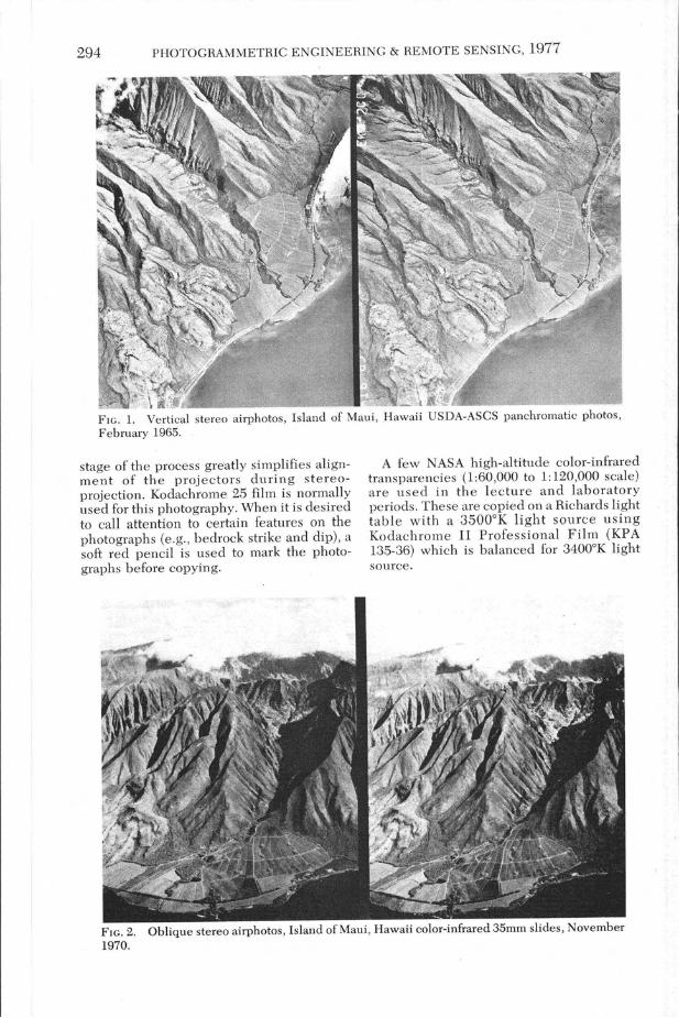
A few NASA high-altitude color-infraredtransparencies (1:60,000 to 1: 120,000 scale)are used in the lecture and laboratoryperiods. These are copied on a Richards lighttable with a 35000 K light source usingKodachrome II Professional Film (KPA135-36) which is balanced for 34000 K lightsource.
FIG. 2. Oblique stereo airphotos, Island of Maui, Hawaii color-infrared 35mm slides, November1970.
CLASSROOM 3-D PROJECTION OF LANDFORM PHOTOGRAPHY
Ground stereo photos illustrating jointing of sedimentary bedrock in Arkansas.
295
OBLIQUE AERIAL PHOTOGRAPHS
A wide "eye-base" (distance betweencamera positions from one exposure to thenext) is used for vertical aerial photography.For example, 9 by 9 inch, 1:20,000 scale vertical airphotos are generally taken from aflight height of 10,000 feet using a camerawi th a 6 inch focal length. I n order toachieve a 60 percent overlap between adjacent frames, a 1.13 mile eye-base is used!When the aircraft is flying at 150 mph, thetime between exposures is 27 seconds. Sucha long eye-base, or time delay, is neithernecessary nor desirable when taking obliqueaerial photographs.
Figure 2 is an illustration of the type of35mm format oblique stereo photographstaken by the author. Color-infrared fil m(Kodak IE 135-20) exposed through a Wratten Number 15 filter plus a CC 20R or C('20M (color correcting) filter is normally usedfor oblique stereo aerial photography for ter-
: rain analysis. For normal color photography,Kodachrome 25 is recommended. The author prefers to use a shutter speed of 1/1000second and to photograph through an openwindow whenever feasible.
Based on several years' experience, theauthor recommends the followingguidelines for the timing of exposures for oblique aerial stereo photographs:
Light Airc'raft (Cessna, etc.) at 120 MPHFor a flight height 1000-2000 feet aboveterrain, separate exposures by 5 seconds(eye-base of 900 feet).
For a flight height 2000-5000 feet aboveterrain, separate exposures by 5-10 seconds (eye-base of 900 to 1800 feet).
Jet Aircraft (commercial airliner) at 550MPH
For a flight height of 25,000 to 35,000feet, separate exposures by approximately 10 seconds (eye-base of 15,000feet).
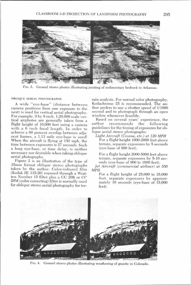
FIG, 4. Ground stereo photos illustrating weathering of granite in Colorado.
296 PHOTOGRAMMETRIC ENGINEERING & REMOTE SENSING, 1977
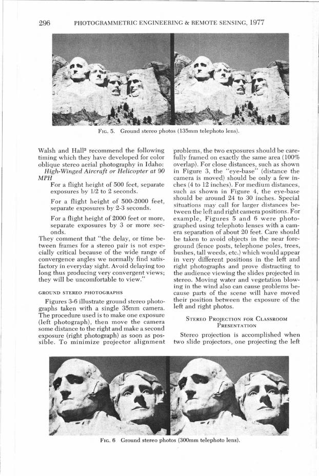
FIG. 5. Ground stereo photos (135mm telephoto lens).
Walsh and HalJ3 recommend the followingtiming which they have developed for coloroblique stereo aerial photography in Idaho:
High-Winged Aircraft or Helicopter at 90MPH
For a flight height of 500 feet, separateexposures by 1/2 to 2 seconds.
For a flight height of 500-2000 feet,separate exposures by 2-3 seconds.
For a flight height of 2000 feet or more,separate exposures by 3 or more seconds.
They comment that "the delay, or time between frames for a stereo pair is not especially critical because of the wide range ofconvergence angles we normally find satisfactory in everyday sight. Avoid delaying toolong thus producing very convergent views;they will be uncomfortable to view."
GROUND STEREO PHOTOGRAPHS
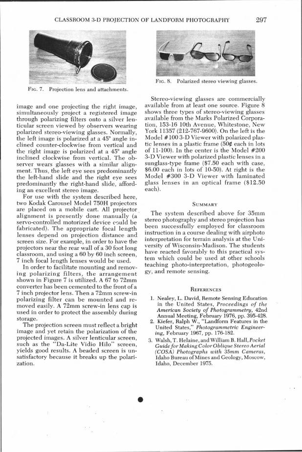
Figures 3-6 illustrate ground stereo photographs taken with a single 35mm camera.The procedure used is to make one exposure(left photograph), then move the camerasome distance to the right and make a secondexposure (right photograph) as soon as possible. To minimize projector alignment
problems, the two exposures should be carefully framed on exactly the same area (100%overlap). For close distances, such as shownin Figure 3, the "eye-base" (distance thecamera is moved) should be only a few inches (4 to 12 inches). For medium distances,such as shown in Figure 4, the eye-baseshould be around 24 to 30 inches. Specialsituations may call for larger distances between the left and right camera positions. Forexample, Figures 5 and 6 were photographed using telephoto lenses with a camera separation of about 20 feet. Care shouldbe taken to avoid objects in the near foreground (fence posts, telephone poles, trees,bushes, tall weeds, etc.) which would appearin very different positions in the left andright photographs and prove distracting tothe audience viewing the slides projected instereo. Moving water and vegetation blowing in the wind also can cause problems because parts of the scene will have movedtheir position between the exposure of theleft and right photos.
STEREO PROJECTION FOR CLASSROOM
PRESENTATION
Stereo projection is accomplished whentwo slide projectors, one projecting the left
FIG. 6 Ground stereo photos (300mm telephoto lens).
CLASSROOM 3-D PROJECTION OF LANDFORM PHOTOGRAPHY 297
FIG. 7. Projection lens and attachments.
image and one projecting the right image,simultaneously project a registered imagethrough polarizing filters onto a silver lenticular screen viewed by observers wearingpolarized stereo-viewing glasses. Normally,the left image is polarized at a 45° angle inclined counter-clockwise from vertical andthe right image is polarized at a 45° angleinclined clockwise from vertical. The observer wears glasses with a similar alignment. Thus, the left eye sees predominantlythe left-hand slide and the right eye seespredominantly the right-hand slide, affording an excellent stereo image.
For use with the system described here,two Kodak Carousel Model 750H projectorsare placed on a mobile cart. All projectoralignment is presently done manually (aservo-controlled motorized device c0uld befabricated). The appropriate focal lengthlenses depend on projection distance andscreen size. For example, in order to have theprojectors near the rear wall of a 30 foot longclassroom, and using a 60 by 60 inch screen,7 inch focal length lenses would be used.
In order to facilitate mounting and removing polarizing filters, the arrangementshown in Figure 7 is utilized. A 67 to 72mmconverter has been cemented to the front of a7 inch projector lens. Then a 72mm screw-inpolarizing filter can be mounted and removed easily. A 72mm screw-in lens cap isused in order to protect the assembly duringstorage.
The projection screen must reflect a brightimage and yet retain the polarization of theprojected images. A silver lenticular screen,such as the "Da-Lite Vidio Hilo" screen,yields good results. A beaded screen is unsatisfactory because it breaks up the polarization.
•
FIG. 8. Polarized stereo viewing glasses.
Stereo-viewing glasses are commerciallyavailable from at least one source. Figure 8shows three types of stereo-viewing glassesavailable from the Marks Polarized Corporation, 153-16 10th Avenue, Whitestone, NewYork 11357 (212-767-9600). On the left is theModel # 100 3-D Viewer with polarized plastic lenses in a plastic frame (50¢ each in lotsof 11-100). In the center is the Model #2003-D Viewer with polarized plastic lenses in asunglass-type frame ($7.50 each with case,$6.00 each in lots of 10-50). At right is theModel #300 3-D Viewer with laminatedglass lenses in an optical frame ($12.50each).
SUMMARY
The system described above for 35mmstereo photography and stereo projection hasbeen successfully employed for classroominstruction in a course dealing with airphotointerpretation for terrain analysis at the University of Wisconsin-Madison. The studentshave reacted favorably to this practical system which could be used at other schoolsteaching photo-interpretation, photogeology, and remote sensing.
REFERENCES
1. Nealey, L. David, Remote Sensing Educationin the United States, Proceedings of theAmerican Society of Photogrammetry, 42ndAnnual Meeting, February 1976, pp. 395-428.
2. Kiefer, Ralph W., "Landform Features in theUnited States," Photogrammetric Engineering, February 1967, pp. 176-182.
3. Walsh, T. Helaine, and William B. Hall, PocketGuide for Making Color Oblique Stereo Aerial(COSA) Photographs with 35mm Cameras,Idaho Bureau of Mines and Geology, Moscow,Idaho, December 1975.