Embed Size (px)
Citation preview

STEP 1: DISCONNECT YOUR BATTERY:Disconnect the battery before installing the wiring kit to prevent any accidental shorting caused by loose bare wire ends.
STEP 2: START INSTALLING KIT: This kit is broken down into individual steps that are identified by a letter printed on the instruction sheets visible through each bag. These letters are the order of operation for installaing your kit. Start with bag letter G, then M, etc. The order ofinstallation is shown below. Use this instruction sheet, 92968935, to complete the installation instructions.G - 510047 Dash Harness KitM - 510052 Rear Body KitN - 510131 Washer Wiper Harness
STEP 3: RECONNECT YOUR BATTERY:When you have completed the installation and are ready to reconnect the battery, make sure that the following electrical system grounds are in place:
A. Battery is grounded to the ENGINE BLOCK.B. Battery is grounded to the frame.C. Engine block is grounded to the frame.D. Body is grounded to the frame.
STEP 4: CHECK ALL ELECTRICAL FUNCTIONS:Any non-functioning items should be checked for proper installation. Any problems with your wiring and electrical circuit functions should be addressed to American Autowire Systems, Inc. as soon as possible to avoid any warranty problems.
If you have any questions concerning this or any of our products, please feel free to call us at 1-856-933-0801.
AMERICAN AUTOWIRE MAKES IT EASY !!
Classic Update Series1967 - 1968 Ford Mustang
INSTALLATION INSTRUCTIONS
end view of terminal proper crimp of terminal
wire core
START HERE !PLEASE READ THIS BEFORE STARTING INSTALLATION !
p/n R0067108
p/n 500523
OEM style non-stick harness tape
OEM large terminal crimping tool (12-8 gauge)
page 1
p/n 500649OEM small terminal crimping tool (18-14 gauge)
AS THIS HARNESS IS DESIGNED FOR USE IN A MODIFIED CAR REQUIRING A HIGHER RATE OF CHARGE, IT DOES NOT SUPPORT THE USE OF A STOCK (ORIGINAL) ALTERATOR. IT IS DESIGNED FOR USE WITH AN INTERNALLY REGULATED OR SINGLE WIRE STYLE ALTERNATOR. ADAPTERS (WHICH ARE NOT INCLUDED WITH THIS KIT) ARE AVAILABLE FROM SEVERAL SOURCES WILL BE NECESSARY TO USE ANY ALTERNATOR OTHER THAN A 1 WIRE UNIT.
www.americanautowire.com 856-933-0801
This wiring kit is designed for ease of installation. Please read the guidelines below, BEFORE STARTING your installation to guarantee a successful job. Use an appropriate crimping tool which folds the wings of the open barrell terminals down into the wire as shown below. ALL TERMINALS THAT YOU INSTALL SHOULD BE PROPERLY SOLDERED. Our factory crimped terminations are installed by GM approved five ton presses, and soldering these terminations is not necessary.
PART #
DESCRIPTION:510055
1967-68 Mustang Classic Update Series Kit
92968935 Rev 13.0 7/18/2014

Page 2
www.americanautowire.com 856-933-0801
turn signalswitch
instrument cluster wires
Ignition sw
4D
3F
8
31
400
9A
5
121
15B
121
500B
35
11B
35
12B
24
40131
9C
33
401
11C
6
400
30
4E
150
39D
14A
39A
15B
39B
17A,B
40E
40J
5
2B
3A
500A
99
40
43
8B
40B
28A
15A,C
53C,D
53E,F
14A,C
53D
53F
40H
150
156D
156C
93
wiper switch
50
LOW
HIGH
FOG
HORN11A - from Dimmer switch11C - high out12A - from Dimmer switch12B - low out115A - from fuse panel500A - from FOG Switch500B - to FOG Lamps
152C
12A
11D
28
2912
B11
C
500B
6
33
103
107 100
104
X 116
300
14B
29
15B,C
40A
12A10
11A,B
14B,C
17B115A,B
115B
500A
11A,D
152B,C
152A,B
2D,K
2K
152A
2A
1918
2828AXX
1627
plug into connector #3
Rear Body
Dimmerswitch
BrakeSwitch
Accessory
Headlight Switch
17A
24
40G
19
18
9B
30
XX
2F
9A,B,C
53A,B40C,D,E
10
44
XX
53E,J
53A,C
156B
156A
2J
2H2
33A
156B
156A
156D
156C
4A,E
156E
156F
156E
156F
53G
53H
53G
53H
CircuitBranch 1
CircuitBranch 2
CircuitBranch 3
CircuitBranch 4
CircuitBranch 5
CircuitBranch 6
CircuitBranch 7
CircuitBranch 8
CircuitBranch 9
Plug this wire (number 93) into the wiper/washer harness, part number 510131, as shown on that instruction sheet.
gauge cluster disconnectconnectors and terminals
install here!
cluster disconnects
See page 12 for fuse placement
PART #
DESCRIPTION:510055
1967-68 Mustang Classic Update Series Kit
NOTE: Your new underdash courtesy lamp extensions use # 631 bulbs (not included with this kit). They may be purchased at any auto parts store.
Courtesy Lamp Extensions
92968935 Rev 13.0 7/18/2014
Radio
Fog Lamp Switch
Cigarette Lighter
LH Door Jamb Switch
LH Dome Light Connector
Glove Box Lamp
CourtesyLampConnector
RH Door Jamb Switch
RH DomeLIght Connector
CourtesyLampConnector
Fusible Link
Brake Warning Extension
Fusible Link
Instrument Cluster Ground
4D
3F
5
121
500B
35
12B
24
40131
11C
6
40039D
15B
39B
50
LowBeamRelay
HighBeamRelay
FogLampsRelay
HornRelay
11A - from Dimmer switch11C - High Beam Relay out12A - from Dimmer switch12B - Low Beam Relay out115A - from fuse panel500A - from Fog Lamp Switch500B - to Fog Lamps
152C
12A
11D
28
2912
B11
C
500B
6
33
300
14B
9A
15B,C
14B,C
115A,B
115B
500A
11A,D
152B,C
152A,B
2D,K
2K
152A
2A
CircuitBranch 1
CircuitBranch 2
Page 3
B
B
BQB
E
E
33A
www.americanautowire.com 856-933-0801
Main Fuse Panel Installation Instructions The Main Fuse Panel harness is designed to be mounted under the dash at the firewall in an area close to the steering column. The enclosed representation of the main dash harness shows each circuit branch and identifies each connection by its color and function. Follow this drawing and detail drawings on pages 10 and 11 for the individual circuit connections.
Circuit Branch 1 - Engine and Alt. connections See pages 10 and 11 , “Figures B, C, and D” for typical connections. Loose piece terminals and connectors are located in kit # 510176.Wire # Wire color Printing Procedure50 Brown Heater/AC feed This is the fused Ignition power lead for the heater or AC control panel. Connect according to the instructions supplied with your aftermarket Heater / AC unit. This can also be used as the 12 volt feed wire to the stock 3 speed heater blower motor if you are utilizing your stock 1967-68 Mustang heating system. See page 11, figure E.6 Purple Starter Solenoid-S Connect the end that comes out with the 5, 24, and 39B wires to 1 terminal on the neutral safety switch. Connect the end that comes out with the heavy red power wire to the "S" terminal on your starter solenoid. (See Figure B)2 Red 12 V Battery Route this wire to your starter solenoid and connect the ring terminal end with the blue fusible link to the battery terminal on the starter solenoid. Route the other end to the alternator battery stud, install sleeve "C" followed by terminal "D" and attach this completed assembly to the battery terminal of the alternator. (See Figure B)2H Light Blue Fusible Link See the connection instructions under wire 2.2A Red 12 V Battery Route this wire to your starter solenoid. Cut to length, install terminal "B", plug into connector "E" as shown on this page. As shown on sheet 9, Figure B, plug connector "E" into the connector on the loose piece fusible link wire 2J, then attach the ring terminal on this assembly to the battery terminal on your starter solenoid. (Parts in 510047 kit) 2J Brown Fusible Link See the connection instructions under wire 2A.5 Purple Neutral Safety Switch Connect to the opposite terminal from wire 6 above to a terminal on the neutral safety switch. (See figure C) 24 Lt. Green Backup Lt Sw-Lights Connect to the backup light terminal on the neutral safety / back up switch. (See figure C)39B Pink 12 V Ignition Connect to the backup light power terminal on the neutral safety / back up switch. (See figure C)4D Brown Alterrnator Ign This wire is the exciter wire for your alternator / voltage regulator. If you are using a one wire alternator, this wire will not be used and should be capped off as it is "hot" in the ignition "on" position. If you are using an alternator that requires an internal or external voltage regulator, this exciter wire must be connected to the “switched or 12v ignition” terminal on your regulator or alternator according to the manufacturer's specifications for the type of alternator / regulator that is being being used. (AAW recommends a GEN 3 Internally Regulated or 1 wire unit)3F Pink Ignition Feed - coil This is your 12 volt switched power source for the distributor. This can be connected directly to the “bat” terminal on a typical HEI distributor, to a ballast resistor as in a points type distributor, or be used as the ignition power source for an aftermarket ignition module such as an MSD or “Duraspark” module. See the installation instructions for the type of distributor you are using for specific connection requirements (See page 10 for some examples).31 Dark Blue Oil Pressure Sender Connect to the oil pressure sender.35 Dark Green Water Temp Sender Connect to the temperature sender.39D Tan Electric Choke On carbureted cars, connect to the electric choke terminal.121 White Coil - Tach This can be connected directly to the tach terminal on a typical HEI distributor, to the negative side of the coil, or a tach connection in an aftermarket ignition module such as an MSD module. See the installation instructions for the type of ignition system you are using for specific connection requirements.400 Yellow VSS Ground Connect to the Vehicle Speed Sensor ground lead (see page 4 for typical connection).401 Purple VSS Signal Connect to the Vehicle Speed Sensor signal lead (see page 4 for typical connection).
Circuit Branch 2- Front Lighting connections See page 10, “Figure A” for typical connections. Loose piece terminals and connectors are located in kit 510176.
Wire # Wire color Printing Procedure Relay Pack The 4 gang relay panel is directly wired and requires no internal wiring. The relays control the headlight low beams, headlight high beams, fog lamps, and the horn.
152A Black Ground This is the relay pack ground. Connect to a good chassis ground.33 Tan Brake Switch This is the brake warning light switch wire for braking systems using a brake warning light. An extension to the switch, wire "33A" with a late model mold-on connector, has also been provided. Route wire 33 to the brake warning switch, cut to length, install terminal "E", plug into connector "B" (Parts in 510047 kit) , plug the completed lead into the brake warning extension wire 33A. The other end of the brake warning extension can then be plugged onto the brake warning switch.14B,C Light Blue Left Front Turn These are the connections for the hood mounted directional lights. The mating connector and terminals “B and Q” to 15B,C Dark Blue Right Front Turn complete this branch can be found in the 510047 loose piece dash kit if you are using a stock hood with these lamps.29 Dark Green Horn Connect to the horn power terminal. NOTE: If your horn has a separate ground terminal, you must supply the wire for this ground terminal as it is not included in the kit.14B Light Blue Left Front Turn Connect to the left front directional lamp socket. If you are using a single front directional light with an 1157 or dual filament bulb, this wire would be connected to the high intensity filament of the LH front running light. 15B Dark Blue Right Front Turn Connect to the right front directional lamp socket. If you are using a single front directional light with an 1157 or dual filament bulb, this wire would be connected to the high intensity filament of the RH front running light.300 Orange Electric Fan This is the 12 volt ignition feed to be connected to the trigger wire on your electric fan relay.9A Brown Park Lights Connect to both the front park / running light sockets. If you are using a single front directional light with an 1157 or dual filament bulb, this wire would be connected to the low intensity filament of each of the front running lights. An in-line splice of this wire or a double up of this wire at the left front parking lamp will be necessary to accommodate the wiring of both of the front park / running lights11C Light Green Headlight-Hi Beam Select the light green Headlight Hi Beam wire (11C) and tan Headlight Low Beam wire (12B). Route and connect 12B Tan Headlight-Low Beam these wires to the headlights. An in-line splice of these wires or a double up of these wires at the left front headlight will be necessary to accommodate wiring of both of the headlights. Using the supplied terminals and connectors, connect these wires along with the headlight ground wires to the headlight connectors according to the orientation in the diagram on page 9, Figure A.500B Black Fog Lamps Connect this wire to your fog lamp power wires. An in-line splice or double up of the wire at the left fog lamp before routing to the right fog lamp will be necessary. If the fog lamps have a separate ground wire, you must supply those wires as they are not included in the kit.
PART #
DESCRIPTION:510055
1967-68 Mustang Classic Update Series Kit
92968935 Rev 13.0 7/18/2014

Page 4
turn signalswitch
instrument cluster wires
ignition sw
8
31
400
15B
121
11B
35
9C
33
401
30
4E
150
14A
39A
17A,B
5
2B
3A
500A
99
40
43
8B
40B
28A
15A,C
14A,C
2
16
40A
12A10
11A,B
17B
1918
2828AXX
1627
4A,E
40E53C,D
53D 156D
156D
CircuitBranch 3
CircuitBranch 4
Installation instructions (cont'd)
Circuit Branch 3 - Under Dash connections
Wire # Wire color Printing Procedure 40 Orange 12V Battery Fused Connect to "Feed In" on your fog lamp switch (if so equipped).
500A Black Fog Lamps Connect to "Feed out" on your fog lamp switch (if so equipped). 43 Tan Radio Ignition power lead to radio.99 Yellow Radio Bat Battery power lead to radio.
28A Black Horn Relay Ground Used for original Ford steering column only. See Table "A' - Stock turn signal connectioninstruction table.
40B Orange 12V battery Fused Connect to cigarette lighter. 8B Gray Dash Lights Spare dash lamp feed for any accessory dash lamps needed.
Brake Switch connector 40A Orange 12V battery Fused Connect to Brake Switch.
17B White Brake Switch Connect to Brake Switch.
Ignition Switch connector 3A Pink Ignition Feed Connect to the provided 1967 style ignition switch.
5 Purple Neutral Safety Switch2B Red 12V Battery
4A,E Brown Ignition Sw Accy Install on the ignition switch stud after the main switch connector has been plugged in.
Turn Signal Switch connector
Wire # Wire color Printing Procedure
28 Black Horn Relay Ground Horn button ground to the horn relay trigger14A,C Light Blue Left Front Turn Feeds the left front turn lamp bulb high filament ,the left hood mounted turn signal bulb,
and the left turn dash indicator lamp.15A,C Dark Blue Right Front Turn Feeds the right front turn lamp bulb high filament, the right hood mounted turn signal bulb,
and the right turn dash indicator lamp.27 Brown Turn Sw - Hazard 4 way hazard power feed wire from the Hazard flasher "L" terminal.16 Purple Turn Switch Feed Turn signal power feed wire from the Turn Signal flasher "L" terminal.18 Yellow Left Rear Turn Feeds the left rear turn and brake lamp bulb high filament.19 Dark Green Right Rear Turn Feeds the right rear turn and brake lamp bulb high filament..
17A White Brake Switch Power feed wire from the output side of the brake switch.
Circuit Branch 4- Under Dash connections
Wire # Wire color Printing Procedure
Dimmer Switch connector.10 Yellow Dimmer Switch Feed Connect to Dimmer Switch.
11A,B Light Green Headlight Hi Beam Connect to Dimmer Switch.12A Tan Headlight Low Beam Connect to Dimmer Switch.
Left Hand Dome Lamp Feed Wires.53C,D Light Blue 12V Ctsy Sw Connect to Left Hand door jamb switch.
40E Orange 12V Battery Fused Connect to Left Hand door jamb switch.53D Light Blue 12V Ctsy Sw Connect to Left rear dome lamp.
156D White Ctsy Ground Connect the bullet terminal end to the left rear dome lamp. The ring terminal end must be connectedto a good chassis ground.
8 Gray Dash Lights Connect to Gauge Lights.9C Brown Park Lights Connect to any instrument cluster requiring a signal to dim a digital display.
If using regular analog gauges, this wire will not be required.11B Light Green Headlight Low Beam Connect to the high beam indicator light.14A Light Blue Left Dash Ind Connect to the left turn signal indicator light.15B Dark Blue Right Dash Ind Connect to the right turn signal indicator light.
30 Tan Gas Gauge Connect to the signal or sender terminal of the fuel gauge.31 Dark Blue Oil Pressure Sender Connect to the signal or sender terminal of the oil pressure gauge.33 Tan Brake Light Connect to the ground side of the brake warning indicator light.35 Dark Green Water Temp Sender Connect to the signal or sender terminal of the water temperature gauge.
39A Pink 12V Ignition Connect to the Ignition or power terminals of each gauge. An in line splice will be necessary tofeed each gauge in the instrument cluster.
121 White Coil-Tach Connect to the signal or sender terminal of the tachometer.150 Black Ground Connect to the Ground terminals of each gauge and dash lamp. An in line splice will be
necessary to feed each ground requirement in the instrument cluster.400 Yellow VSS Ground connect to a good chassis ground or the VSS ground terminal on the speedometer.
Mechanical speedometers do not require this connection.401 Purple VSS Signal Connect to the VSS signal or sender terminal of the speedometer.
Mechanical speedometers do not require this connection.4E Brown This wire will only be used when installing a stock instrument cluster. Connect to the Black with light green
stripe wire when using a stock 1967 or 1968 Mustang instrument cluster. This is the accessory feed for thevoltage reducer for certain stock gauges.
Dimmerswitch
BrakeSwitch
www.americanautowire.com 856-933-0801
gauge cluster disconnectconnectors and terminals
install here!
cluster disconnects
Instrument Cluster wires.See Page 9 - Table 'B' for stock 1967-68 Mustang instrument cluster wiring colors and functions. Cluster disconnects have been provided and can be found in the 510047 loose piece bag. We have provided an ample length of wire in order for you to cut an make your own gauge cluster harness.
it may be necessary to follow the connection requirements specified by the manufacturer of the gauges being used. As with all AAW kits, the use of afactory ammeter is neither supported, nor is it encouraged. The function of each AAW wire is as follows:
Page 45identifies a typical instrument cluster wiring scheme. As this kit is designed to function with many different gauge maufacturer’s products,
PART #
DESCRIPTION:510055
1967-68 Mustang Classic Update Series Kit
92968935 Rev 13.0 7/18/2014
Radio
Fog Lamp Switch
Cigarette Lighter
LH Door Jamb Switch
LH Dome Light Connector
If you are using a stock Ford turn signal switch, refer to Page 9, Diagram ‘A’ and Table”A”, AAW Turn Signal Switch wires to stock 1967-68 Mustang turn signal switch. This kit is designed to function with a GM style turn signal switch. Our connector mates to a 3 7/8 inch long plug used on 1969-1974 GM, IDIDIT, and many other aftermarket steering columns. Starting from 1975 on up, the GM switch changed the mating connector to use a 4 1/4 inch connector. That connector is from the same family and uses the same terminals. By using the supplied mating connector (L) and terminals (M) located in the loose piece kit bag of this dash harness (510047), it is easy to adapt any steering column to the kit. The function of each wire within the cavities is as follows:

4Typical 2 wire VSS connection
gasket
nut
shaft
VEHICLE SPEED SENSOR(8000 pulse)
o-ring
sensor
Typical 3 wire Autometer 5291 VSS connection
Note:This VSS requires a lead wire from the red wire to a 12 volt ignition source. This wire is notincluded in the kit.
VEHICLE SPEED SENSOR (16000 pulse)
30
30
35
3335
39A
9C
4E
39A
31
31
150
150
121
121401 401
400 11B
11B
15B
15B
8
8
14A
14A
Instrument Cluster Lead Wires
Coi
l to
Tach
omet
er
Dash
Lig
hts
12 V
Igni
tion
VSS
Gro
und
Grou
nd
Wat
er T
emp
Send
er
Left
Turn
Ind
Gas
Gau
ge S
ende
r
Rig
ht T
urn
Ind
Oil
Pres
sure
Sen
der
Hig
h Be
am In
d
Circuit Branch 4
Page 5
pink(12V ignition)
LEFT TURN IND HIGH BEAM IND RIGHT TURN IND
GRD IGRD
S
I
GRD
TYPICAL BLADE TYPE GAUGE CONNECTIONS
GRD GRD
S S
I I
GRDS
I
LAMP CONNECTIONS
white
purple
(tach - coil)
(VSS Signal)
dk blue(oil pressure)
(fuel gauge)
black(ground)
black(ground)
SI
tan
Tachometer Speedometer Oil
Oil Fuel
FuelWater
Volts
Volts
Water SpeedometerTachometer
dk green(temperature)
black(ground)
black(ground)
gray(dash lights)
gray(dash lights)
VSS
Sign
al
connect to 12 voltignition source
Blac
kW
hite
Black
Red
pink(12V ignition)
www.americanautowire.com 856-933-0801
Circuit Branch 4 - Instrument Cluster Wiring
Shown is a typical installation with electric gauges and an electronic speedometer and tachometer. Mechanical speedometers will only require the light leads. The VSS lead wires can be ignored for mechanical speedometers. Always check the manufacturers instructions for specific requirements.
White
PART #
DESCRIPTION:510055
1967-68 Mustang Classic Update Series Kit
92968935 Rev 13.0 7/18/2014

Installation instructions (cont'd)
Circuit Branch 5 - Under Dash connections
Wire # Wire color Printing Procedure
Wiper Switch connections.93 White Wiper Feed Power input to wiper and washer switch connection.
(This wire and terminal will attach to AAW harness number 510131, “Wiper Washer Harness”, to complete your stock windshield wiper harness system. The instructions for the motor and pump connections, as well as, the instructions on where to plug this wire into the “Wiper Washer Harness” can be found on instruction sheet number 510131.)
150 Black Ground Instrument Cluster ground. Connect to a good chassis ground.
Circuit Branch 6- Under Dash connections
Wire # Wire color Printing Procedure
Rear Body Wire connections.This plugs into the Rear Body Kit 510052. See that sub-kit for specific installation instructions and circuit functions.
Accessory Feed Wire connections.100 Tan Accessory Fused Accessory Fused power source.103 Tan Fuel pump Connect to the power input terminal of a fuel pump relay.104 Red Power Locks Connect to the power input of the power locks switch or any other battery
powered accessory.107 Pink Ignition Fused Ignition Fused power source.116 Pink Power Windows Connect to the power input of the power windows switch or any other ignition
powered accessory.
Headlight switch connector.The function of each wire is as follows:
2F Red 12V Battery 12 volt battery power to the switch.9A,B,C Brown Park Lights Power lead wires to the running light circuits.
44 Dark Green Power lead wire to the dash lights .10 Yellow Dimmer Sw feed Headlight power output to the Dimmer Switch.
40C,D,E Orange 12V Battery Fused Courtesy Light battery power53A,B Lt Blue 12V Ctsy Sw Courtesy Light switched battery power
Courtesy light connector.Plug in your Left Hand under dash courtesy lamp assembly here. The function of each wire is as follows:
53A,C Lt Blue 12V Ctsy Sw Courtesy Light power.156A White Crtsy ground Courtesy Light ground
Circuit Branch 7- Under Dash connections
Wire # Wire color Printing Procedure
40H Orange 12V Battery Fused Connect to the glove box lamp assembly.
Circuit Branch 8- Under Dash connections
Wire # Wire color Printing Procedure
Courtesy light connector.Plug in your Right Hand under dash courtesy lamp assembly here. The function of each wire is as follows:
53E,J Lt Blue 12V Ctsy Sw Courtesy Light power.156B White Crtsy ground Courtesy Light ground
Circuit Branch 9- Under Dash connections
Wire # Wire color Printing Procedure
Right Hand Dome Lamp Feed Wires.53E,F Light Blue 12V Ctsy Sw Connect to the Right Hand door jamb switch.40J Orange 12V Battery Fused Connect to the Right Hand door jamb switch.53F Light Blue 12V Ctsy Sw Connect to the Right rear dome lamp.156C White Ctsy Ground Connect the bullet terminal end to the right rear dome lamp.
The ring terminal end must be connected to a good chassis ground.
40J53E,F
53F
40H
150
156C
CourtesyLampConnector
CourtesyLampConnector
53E,J
53A,C
156B
156B
156A
156C
CircuitBranch 5
CircuitBranch 6
CircuitBranch 7
CircuitBranch 8
CircuitBranch 9
Headlight switch
2F
9A,B,C
53A,B40C,D,E
10
44
XX
Rear Body
17A
24
40G
19
18
9B
30
XX
103
107 100
104
X 116
plug into connector #3
Accessory
156A
Page 6
wiper switch
93
www.americanautowire.com 856-933-0801
PART #
DESCRIPTION:510055
1967-68 Mustang Classic Update Series Kit
NOTE: The courtesy lamp extensions from page 2, that plug onto the con-nectors at branches 6 and 8 on this page, use # 631 bulbs (not included
with this kit). They may be purchased at any auto parts store.
92968935 Rev 13.0 7/18/2014
Glove Box Lamp
RH Door Jamb Switch
RH DomeLIght Connector
Instrument Cluster Ground

Page 7
Engine Bay Side Under Dash Side
FactoryFirewallDimple
ExistingFactoryFirewallScrew HoleExisting
FactoryFirewallScrew Hole
NewFusebox mounting Hole 1
NewFusebox mounting Hole 2
NewFusebox mounting Hole 2
NewFusebox mounting Hole 1
ExistingFactoryFirewallScrew Hole
ExistingFactoryFirewallScrew Hole
ExistingFactoryFirewallScrew Hole
ExistingFactoryFirewallScrew Hole
FactoryFirewallDimple
FactoryFirewallDimple
FactoryFirewallDimple
Fusebox Mounting Hole Template
Hole 2 needs to be drilled in the firewall for the new fuse box. Position the template from either the engine bay side or the under dash side.
Locate the existing firewall screw hole that will set the center point for the new fuse box Hole 1. This hole is already the correct size for the new fuse box retention screw.
The template can then be used to set the center point to drill the 1/8 inch hole for the new fuse box Hole 2.
www.americanautowire.com 856-933-0801
PART #
DESCRIPTION:510055
1967-68 Mustang Classic Update Series Kit
92968935 Rev 13.0 7/18/2014
Page 8
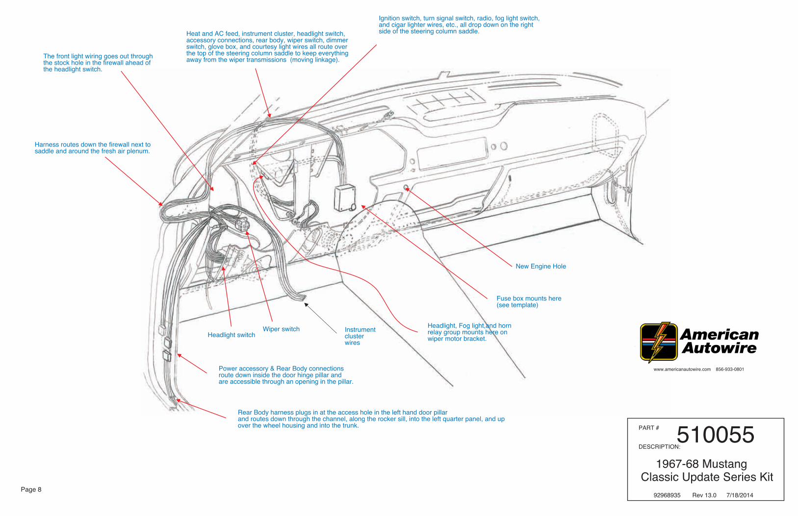
Fuse box mounts here(see template)
Headlight, Fog light,and hornrelay group mounts here onwiper motor bracket.
Power accessory & Rear Body connections route down inside the door hinge pillar and are accessible through an opening in the pillar.
Harness routes down the firewall next tosaddle and around the fresh air plenum.
Heat and AC feed, instrument cluster, headlight switch, accessory connections, rear body, wiper switch, dimmer switch, glove box, and courtesy light wires all route over the top of the steering column saddle to keep everything away from the wiper transmissions (moving linkage).
Ignition switch, turn signal switch, radio, fog light switch, and cigar lighter wires, etc., all drop down on the right side of the steering column saddle.
The front light wiring goes out through the stock hole in the firewall ahead of the headlight switch.
Rear Body harness plugs in at the access hole in the left hand door pillarand routes down through the channel, along the rocker sill, into the left quarter panel, and upover the wheel housing and into the trunk.
New Engine Hole
Instrumentclusterwires
Wiper switchHeadlight switch
www.americanautowire.com 856-933-0801
PART #
DESCRIPTION:510055
1967-68 Mustang Classic Update Series Kit
92968935 Rev 13.0 7/18/2014

www.americanautowire.com 856-933-0801
Page 9
Table 'B' - AAW Instrument Cluster Kit wires to stock 1967-68 Mustang instrument cluster wires.
AAW AAW AAW FordWire # Wire color Wire Printing Wire Color
4E Brown Black with light green stripeThis is the accessory feed for the voltage reducer for certain stockgauges.
8 Gray Dash Lights Blue with red stripe.9C Brown Park Lights Connect to any instrument cluster requiring a signal to dim a digital
display. When using analog gauges, this wire will not be required.11B Light Green Hi Beam Ind Green with black stripe.14A Light Blue Left Dash Ind Green with white stripe.15B Dark Blue Right Dash Ind White with blue stripe.30 Tan Gas Gauge Yellow with white stripe.31 Dark Blue Oil Pressure Sender White with red stripe.33 Tan Brake Light Purple with white stripe.35 Dark Green Water Temp Sender Red with white stripe.39A Pink 12V Ignition Red with yellow stripe121 White Coil-Tach Sender terminal of the tachometer.150 Black Ground Connect to the Ground terminals of each gauge and dash lamp.
An in line splice is necessary to feed each ground requirement in the instrument cluster.
400 Yellow VSS Ground Connect to a good chassis ground or the VSS ground terminal on an electronic speedometer. Mechanical speedometers do not requirethis connection.
401 Purple VSS Signal Connect to the VSS pulse signal or sender terminal of the electronicspeedometer. Mechanical speedometers do not require thisconnection.
99 Yellow Radio Bat Light blue with white stripe or light blue with black stripe.This is the 12 volt feed for the dash clock. If you are using a radio with a digital clock, it will be necessary to splice into this wire to create 2 leads. One to the dash clock, and one to the radio.
Table 'A' - AAW Turn Signal Switch wires to stock 1967-68 Mustang turn signal switch.
AAW AAW AAW FordWire # Wire color Wire Printing Wire Color
14A Light Blue Left Front Turn Green with white stripe15B Dark Blue Right Front Turn White with blue stripe.16 Purple Turn Switch Feed Blue17A White Brake Switch Green18 Yellow Left Rear Turn Green with orange stripe.19 Dark Green Right Rear Turn Orange with blue stripe.27 Brown Turn Sw - Hazard White with red stripe.28 Black Horn Relay Ground Yellow28A Black Horn Relay Ground Blue with yellow stripe.
Note: Ford originally switched power to the horns through the steerring columnhorn button. In this kit, ground is being switched through the original steering column switch to ground a horn relay which switches power to the horns.
PART #
DESCRIPTION:510055
1967-68 Mustang Classic Update Series Kit
92968935 Rev 13.0 7/18/2014
DIAGRAM ‘A’ - AAW Turn Signal Switch Wires to Stock 1967-68 Steering Columns.
ORIGINAL TURN SIGNAL
whitedk greenyellowpurplebrowndk bluelt blueblackblack
AMERICAN AUTOWIRE DASH HARNESS CONNECTION
P N M
L K J H G
F E D
SWITCH WIRINGL M
A
B
C
D
E
F
G
H
J
K
L
M
N
P

lt green
tan
black tan
tan
lt green
dk green
orange
tan
brown
brown
brown
lt blue
lt green
right headlight
left headlight
right turn signal housing
left turn signal housing
(not included)
Figure “A”
(not included)
to horn
to electric fan
recommended fan relay (not included in this kit)
to ground
to ground
to ground
rh side marker
lh side
(wide one)
(narrow one)
marker(68 only)
(67 and early 68 without side marker lamps)
(68 only)
to ground
to brake pressure sending unit
67-68 hood mounted directionals only (see page 2 for connection instructions)
ACCC
DD
E
E
C
B
B
B
B
F
F
H
H
J
K
J
M or J
M
G
L
K
A G
firewall passthru hole
Install one grommet included in the 510176 kit into the firewall pass thru opening as shown on page 8 of this instruction set, then pass the forward wiring from branch 2 thru that opening (not including relay blocks). After completing this task, apply silicone sealer to this area to make a weather tight seal.
dk blue
brown
Page 10
Figure “B”
DC
Fusible Link
StarterSolenoid
connect to 2A from branch 1, page 3Wire 2A comes thru the firewall withthe engine wires from branch 1.
"BAT"
To alternator ”BAT” stud
"BAT"
(positive cable
Main system power feed and alternator power feed connections.
to starter
2J
2H
2
Fusible Link S I
here also)attaches
stud
"BAT" stud
output stud
www.americanautowire.com 856-933-0801
NOTE: The terminals and connectors listed on this page and denoted with UPPER CASE LETTERS to help you complete the various connections to your lamps, horns, switches, etc. can be found in your loose piece grommet and parts kit, P/N 510176.
The identifications, colors, and functions for all of the wires listed in “Figures A, B, and C” on this page can be found on page 3, branches 1 and 2 of this main instruction set. AAW suggests and recommends using both pages 3 and 10 to complete the installa-tion of the foward lamp, main power, alternator power, and neutral safety connections.
AAW kits are all engineered to be used in conjunction with a high output, later model internally regulated, or one wire alternator. We do not suggest or support the use of a stock low amperage gen-erator or alternator as they do not supply sufficient current to recharge the battery in a highly modified car such as this kit was designed for. AAW suggests a Ford Gen III type alternator as a good choice of an alternator to use. An adpater to complete the connection to this style alternator, our P/N 500802, my be pur-chased separately if needed. Contact our Sales Group or your favorite retailer to purchase this alternator adapter if needed.
fog lamp feed wire black
PART #
DESCRIPTION:510055
1967-68 Mustang Classic Update Series Kit
92968935 Rev 13.0 7/18/2014
11C
11C
12B
12B
300
29
33
33A
15B
14B
9A
9A
500B
15B,C14B,C
Figure “C”Shown is a typical NSS and Back Up Switch.
wire 6 from branch 1, page 2
wire 39B from branch 1, page 2wire 24 from branch 1, page 2
wire 5 from branch 1, page 2

Page 11
dk green
(optional)
temperature sending unit
N
S I
A
C
alternator
alternatorignition wire
distributor
choke feed
ballastresistor
(resistor not included.
(this wire not supplied)
(optional typical points type system shown here)
Use on point type and someaftermarket ignition systems)
oil sending
purple
dk blue
yellow
purple
to BAT location on coil
to TACH location on coil
to coil “+” side
to VSS(electronic speedo only)
(VSS ground)
(VSS signal)
coil
pink
off
1
2
3
www.americanautowire.com 856-933-0801
white
tanbrown
firewall passengine harness
thru holeInstall one grommet included in the 510176 kit into the firewall pass thru opening as shown on page 8 of this instruction set, then pass the engine, alternator ignition, starter sloenoid, and main feed wiring from branch 1 thru this opening (except for the the heat and A/C Feed 50 wire). The neutral safety and B/U lamp wires are optional to run inside or outside the car depending on your application. For starter and main feed connections, refer to “Figure B” on page 10. After completing this task, apply silicone sealer to this area to make a weather tight seal.
You must twist these 2 wires together as shown above to create a co-ax that will filter out any outside interference to the signal on your electronic speedometer.
electric
Figure “D”
Figure “E”
P B
B
(optional)
N
P
unit
NOTE: The terminals and connectors listed on this page and denoted with UPPER CASE LETTERS to help you complete the various connections to your ignition, temp and oil senders, electric choke, starter solenoid, alternator regulator, etc. can be found in your loose piece grommet and parts kit, P/N 510176.
The identifications, colors, and functions for all of the wires listed in “Figures D, E, and F” on this page can be found on page 3, branch 1 of this main instruction set. AAW suggests and recommends using pages 3, 10, and 11 to complete the installation of the engine and alternator connections.
This AAW kit is engineered to work with most after-market manufacturer’s heating and air conditioning systems. As such, we have provided a keyed 12-volt feed to use as the “OFF / ON” (AAW brown 50 wire) power source for whatever system you choose to purchase. The manufacturer will supply you with a harness for their system and instructions on how to connect it. In the event you are utilizing a stock heater system in your car, again we have provided the keyed 12-volt feed only. Figure E below depicts the typical stock 3 speed blower motor resistor and switch connections for the the heating system used in the 1967-68 Mustangs. AAW DOES NOT provide any of the other wiring from the switches to the resis-tors, or to the blower motor.
(this wire not supplied)
Blower Motor
(these wires not supplied)
production blower
3 Speed Heater Motor Connections
motor wiring
blower switch
AAW #50, 12 volt feed wire from page 3, branch 1
resistorblower motor
PART #
DESCRIPTION:510055
1967-68 Mustang Classic Update Series Kit
92968935 Rev 13.0 7/18/2014
31
35
6
39D
4D
3F
121400
401

www.americanautowire.com 856-933-0801
Page 12
Fuse Placement and Circuit Values
PART #
DESCRIPTION:510055
1967-68 Mustang Classic Update Series Kit
92968935 Rev 13.0 7/18/2014