Embed Size (px)
Citation preview
1
(Class – XI)
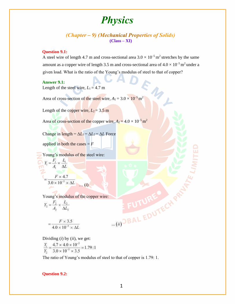
Question 9.1:
A steel wire of length 4.7 m and cross-sectional area 3.0 × 10⁻⁵ m2 stretches by the same
amount as a copper wire of length 3.5 m and cross-sectional area of 4.0 × 10⁻⁵ m2 under a
given load. What is the ratio of the Young’s modulus of steel to that of copper?
Answer 9.1:
Length of the steel wire, L1 = 4.7 m
Area of cross-section of the steel wire, A1 = 3.0 × 10⁻⁵ m2
Length of the copper wire, L2 = 3.5 m
Area of cross-section of the copper wire, A2 = 4.0 × 10⁻⁵ m2
Change in length = ΔL1 = ΔL2 = ΔL Force
applied in both the cases = F
Young’s modulus of the steel wire:
… (i)
Young’s modulus of the copper wire:
Dividing (i) by (ii), we get:
The ratio of Young’s modulus of steel to that of copper is 1.79: 1.
Question 9.2:
2
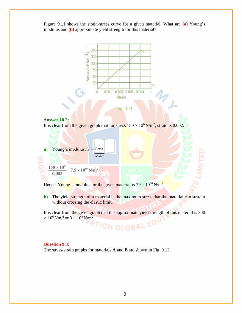
Figure 9.11 shows the strain-stress curve for a given material. What are (a) Young’s
modulus and (b) approximate yield strength for this material?
Fig. 9.11
Answer 10.2:
It is clear from the given graph that for stress 150 × 106 N/m2, strain is 0.002.
a) Young’s modulus, Y = 𝑆𝑡𝑟𝑒𝑠𝑠
Hence, Young’s modulus for the given material is 7.5 ×10¹⁰ N/m2.
b) The yield strength of a material is the maximum stress that the material can sustain
without crossing the elastic limit.
It is clear from the given graph that the approximate yield strength of this material is 300
× 106 Nm/2 or 3 × 10⁸ N/m2.
Question 9.3:
The stress-strain graphs for materials A and B are shown in Fig. 9.12.

3
Fig. 9.13
The graphs are drawn to the same scale.
a) Which of the materials has the greater Young’s modulus?
b) Which of the two is the stronger material?
Answer 9.3:
(a) A
(b) A
For a given strain, the stress for material A is more than it is for material B, as shown in
the two graphs.
Young’s modulus
For a given strain, if the stress for a material is more, then Young’s modulus is also
greater for that material. Therefore, Young’s modulus for material A is greater than it
is for material B.
The amount of stress required for fracturing a material, corresponding to its fracture point,
gives the strength of that material. Fracture point is the extreme point in a stress-strain
curve. It can be observed that material A can withstand more strain than material B.
Hence, material A is stronger than material B.
Question 9.4:
Read the following two statements below carefully and state, with reasons, if it is true or
false.
a) The Young’s modulus of rubber is greater than that of steel;
b) The stretching of a coil is determined by its shear modulus.
Answer 9.4:
(a) False
(b) True
For a given stress, the strain in rubber is more than it is in steel.
Young’s modulus, Y 𝑆𝑡𝑟𝑒𝑠𝑠

4
For a constant stress:
Hence, Young’s modulus for rubber is less than it is for steel.
Shear modulus is the ratio of the applied stress to the change in the shape of a body. The
stretching of a coil changes its shape. Hence, shear modulus of elasticity is involved in
this process.
Question 9.5:
Two wires of diameter 0.25 cm, one made of steel and the other made of brass are
loaded as shown in Fig. 9.13. The unloaded length of steel wire is 1.5 m and that of
brass wire is 1.0 m. Compute the elongations of the steel and the brass wires.
Fig. 9.13 Answer
9.5:
Elongation of the steel wire = 1.49 × 10⁻⁴ m
Elongation of the brass wire = 1.3 × 10⁻⁴ m
Diameter of the wires, d = 0.25 m
Hence, the radius of the wires, r = d/2= 0.125 cm
Length of the steel wire, L1 = 1.5 m Length
of the brass wire, L2 = 1.0 m
Total force exerted on the steel wire:
F1 = (4 + 6) g = 10 × 9.8 = 98 N Young’s
modulus for steel:
Where,

5
Elongation of the steel wire = 1.49 × 10⁻⁴ m
Elongation of the brass wire = 1.3 × 10⁻⁴ m
Question 9.6:

6
The edge of an aluminium cube is 10 cm long. One face of the cube is firmly fixed to a
vertical wall. A mass of 100 kg is then attached to the opposite face of the cube. The shear
modulus of aluminium is 25 GPa. What is the vertical deflection of this face?
Answer 9.6:
Edge of the aluminium cube, L = 10 cm = 0.1 m
The mass attached to the cube, m = 100 kg
Shear modulus (η) of aluminium = 25 GPa = 25 × 109 Pa
Shear modulus, η
Where,
F = Applied force = mg = 100 × 9.8 = 980 N
A = Area of one of the faces of the cube = 0.1 × 0.1 = 0.01 m2
ΔL = Vertical deflection of the cube
= 3.92 × 10⁻⁷ m
The vertical deflection of this face of the cube is 3.92 ×10⁻⁷ m.
Question 9.7:
Four identical hollow cylindrical columns of mild steel support a big structure of mass
50,000 kg. The inner and outer radii of each column are 30 cm and 60 cm respectively.
Assuming the load distribution to be uniform, calculate the compressional strain of each
column.
Answer 9.7:
Mass of the big structure, M = 50,000 kg
7
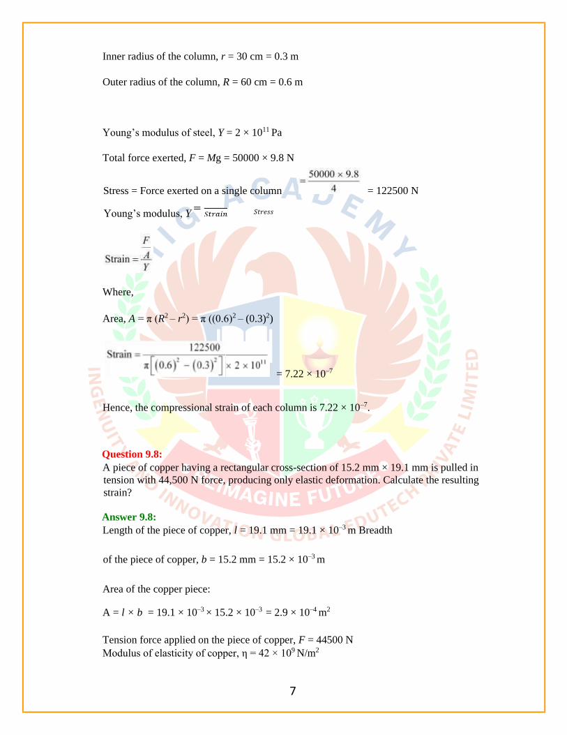
Inner radius of the column, r = 30 cm = 0.3 m
Outer radius of the column, R = 60 cm = 0.6 m
Young’s modulus of steel, Y = 2 × 10¹¹ Pa
Total force exerted, F = Mg = 50000 × 9.8 N
Stress = Force exerted on a single column = 122500 N
Young’s modulus, Y 𝑆𝑡𝑟𝑒𝑠𝑠
Where,
Area, A = π (R2 – r2) = π ((0.6)2 – (0.3)2)
= 7.22 × 10⁻⁷
Hence, the compressional strain of each column is 7.22 × 10⁻⁷.
Question 9.8:
A piece of copper having a rectangular cross-section of 15.2 mm × 19.1 mm is pulled in
tension with 44,500 N force, producing only elastic deformation. Calculate the resulting
strain?
Answer 9.8:
Length of the piece of copper, l = 19.1 mm = 19.1 × 10⁻³ m Breadth
of the piece of copper, b = 15.2 mm = 15.2 × 10⁻³ m
Area of the copper piece:
A = l × b = 19.1 × 10–3 × 15.2 × 10–3 = 2.9 × 10⁻⁴ m2
Tension force applied on the piece of copper, F = 44500 N
Modulus of elasticity of copper, η = 42 × 109 N/m2

8
= 3.65 × 10⁻³
Question 9.9:
A steel cable with a radius of 1.5 cm supports a chairlift at a ski area. If the maximum
stress is not to exceed 108 N m–2, what is the maximum load the cable can support?
Question 9.10:
A rigid bar of mass 15 kg is supported symmetrically by three wires each 2.0 m long.
Those at each end are of copper and the middle one is of iron. Determine the ratio of their
diameters if each is to have the same tension.
Answer 9.10:
The tension force acting on each wire is the same. Thus, the extension in each case is the
same. Since the wires are of the same length, the strain will also be the same.
The relation for Young’s modulus is given as:
M o d u l u s o f e l a s t i c i t y , η

9
Where,
F = Tension force
A = Area of cross-section
Question 9.11:
A 14.5 kg mass, fastened to the end of a steel wire of unstretched length 1.0 m, is whirled
in a vertical circle with an angular velocity of 2 rev/s at the bottom of the circle. The
cross-sectional area of the wire is 0.065 cm2. Calculate the elongation of the wire when
the mass is at the lowest point of its path.
Answer 9.11:
Mass, m = 14.5 kg
Length of the steel wire, l = 1.0 m
Angular velocity, ω = 2 rev/s
Cross-sectional area of the wire, a = 0.065 cm2
Let δl be the elongation of the wire when the mass is at the lowest point of its path.
When the mass is placed at the position of the vertical circle, the total force on the mass
is:
F = mg + mlω2
= 14.5 × 9.8 + 14.5 × 1 × (2)2 = 200.1 N
10
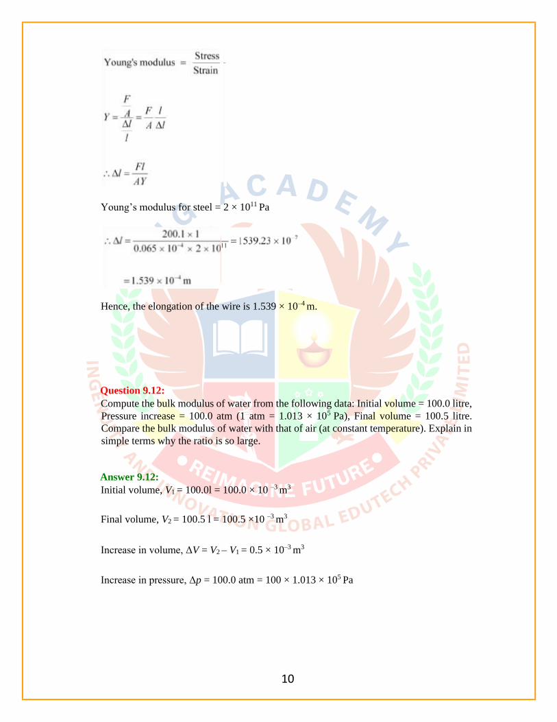
Young’s modulus for steel = 2 × 10¹¹ Pa
Hence, the elongation of the wire is 1.539 × 10⁻⁴ m.
Question 9.12:
Compute the bulk modulus of water from the following data: Initial volume = 100.0 litre,
Pressure increase = 100.0 atm (1 atm = 1.013 × 10⁵ Pa), Final volume = 100.5 litre.
Compare the bulk modulus of water with that of air (at constant temperature). Explain in
simple terms why the ratio is so large.
Answer 9.12:
Initial volume, V1 = 100.0l = 100.0 × 10 –3 m3
Final volume, V2 = 100.5 l = 100.5 ×10 –3 m3
Increase in volume, ΔV = V2 – V1 = 0.5 × 10⁻³ m3
Increase in pressure, Δp = 100.0 atm = 100 × 1.013 × 105 Pa

11
Question 9.13:
What is the density of water at a depth where pressure is 80.0 atm, given that its density
at the surface is 1.03 × 10³ kg m–3?
Answer 9.13:
Let the given depth be h.
Pressure at the given depth, p = 80.0 atm = 80 × 1.01 × 105 Pa
Density of water at the surface, ρ1 = 1.03 × 10³ kg m–3 Let
ρ2 be the density of water at the depth h.
Let V1 be the volume of water of mass m at the surface.
Let V2 be the volume of water of mass m at the depth h.
Let ΔV be the change in volume.

12
For equations (i) and (ii), we get:

13
Therefore, the density of water at the given depth (h) is 1.034 × 10³ kg m–3.
Question 9.14:
Compute the fractional change in volume of a glass slab, when subjected to a hydraulic
pressure of 10 atm.
Answer 9.14:
Hydraulic pressure exerted on the glass slab, p = 10 atm = 10 × 1.013 × 105 Pa
Bulk modulus of glass, B = 37 × 109 Nm–2
Where,
Hence, the fractional change in the volume of the glass slab is 2.73 × 10⁻⁵.
Question 9.15:
= F r a c t i o n a l c h a n g e i n v o l u m e

14
Determine the volume contraction of a solid copper cube, 10 cm on an edge, when
subjected to a hydraulic pressure of 7.0 ×10⁶ Pa.
Original volume of the cube, V = l3
Therefore, the volume contraction of the solid copper cube is 5 × 10⁻² cm–3.
Question 9.16:
How much should the pressure on a litre of water be changed to compress it by 0.10%?
Answer 9.16:
Volume of water, V = 1 L
It is given that water is to be compressed by 0.10%.

15
Therefore, the pressure on water should be 2.2 ×10⁶ Nm–2.
(Class – XI)
Question 9.17:
Anvils made of single crystals of diamond, with the shape as shown in Fig. 9.14, are used
to investigate behaviour of materials under very high pressures. Flat faces at the narrow
end of the anvil have a diameter of 0.50 mm, and the wide ends are subjected to a
compressional force of 50,000 N. What is the pressure at the tip of the anvil?
Fig. 9.14
Answer 9.17:
Diameter of the cones at the narrow ends, d = 0.50 mm = 0.5 × 10⁻³ m

16
Compressional force, F = 50000 N Pressure
at the tip of the anvil:
Therefore, the pressure at the tip of the anvil is 2.55 × 10¹¹ Pa.
Question 9.18:
A rod of length 1.05 m having negligible mass is supported at its ends by two wires of
steel (wire A) and aluminium (wire B) of equal lengths as shown in Fig. 9.15. The
crosssectional areas of wires A and B are 1.0 mm2 and 2.0 mm2, respectively. At what
point along the rod should a mass m be suspended in order to produce (a) equal stresses
and (b) equal strains in both steel and aluminium wires.
Fig. 9.15 Answer
9.18:
(a) 0.7 m from the steel-wire end 0.432 m from the steel-wire end
Cross-sectional area of wire A, a1 = 1.0 mm2 = 1.0 × 10⁻⁶ m2
Cross-sectional area of wire B, a2 = 2.0 mm2 = 2.0 × 10⁻⁶ m2
Young’s modulus for steel, Y1 = 2 × 10¹¹ Nm–2
Young’s modulus for aluminium, Y2 = 7.0 ×10¹⁰ Nm–2
Let a small mass m be suspended to the rod at a distance y from the end where wire A is
attached.
17
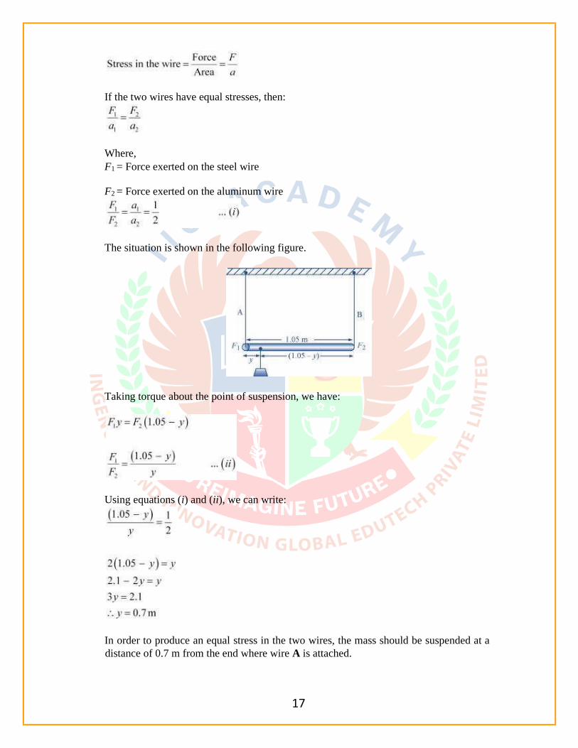
If the two wires have equal stresses, then:
Where,
F1 = Force exerted on the steel wire
F2 = Force exerted on the aluminum wire
The situation is shown in the following figure.
Taking torque about the point of suspension, we have:
Using equations (i) and (ii), we can write:
In order to produce an equal stress in the two wires, the mass should be suspended at a
distance of 0.7 m from the end where wire A is attached.
18
If the strain in the two wires is equal, then:
Taking torque about the point where mass m, is suspended at a distance y1 from the side
where wire A attached, we get:
F1y1 = F2 (1.05 – y1)
… (iii)
Using equations (iii) and (iv), we get:
In order to produce an equal strain in the two wires, the mass should be suspended at a
distance of 0.432 m from the end where wire A is attached.
Question 9.19:
A mild steel wire of length 1.0 m and cross-sectional area 0.50 × 10⁻² cm2 is stretched,
well within its elastic limit, horizontally between two pillars. A mass of 100 g is
suspended from the mid-point of the wire. Calculate the depression at the midpoint.
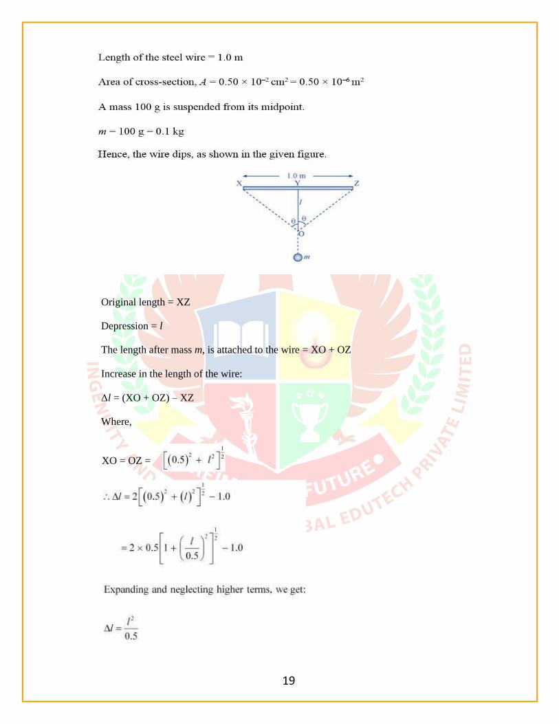
Answer 9.19:
19
Original length = XZ
Depression = l
The length after mass m, is attached to the wire = XO + OZ
Increase in the length of the wire:
Δl = (XO + OZ) – XZ
Where,
XO = OZ =

20
Let T be the tension in the wire. mg
= 2T cosθ
Using the figure, it can be written as:
Expanding the expression and eliminating the higher terms:

21
Young’s modulus of steel, Y =
Hence, the depression at the midpoint is 0.0106 m.
Question 9.20:
Two strips of metal are riveted together at their ends by four rivets, each of diameter 6.0
mm. What is the maximum tension that can be exerted by the riveted strip if the shearing
stress on the rivet is not to exceed 6.9 × 10⁷ Pa? Assume that each rivet is to carry one
quarter of the load.
Answer 9.20:
Diameter of the metal strip, d = 6.0 mm = 6.0 × 10⁻³ m
22
Question 9.21:
The Marina trench is located in the Pacific Ocean, and at one place it is nearly eleven km
beneath the surface of water. The water pressure at the bottom of the trench is about 1.1
× 108 Pa. A steel ball of initial volume 0.32 m3 is dropped into the ocean and falls to the
bottom of the trench. What is the change in the volume of the ball when it reaches to the
bottom?
Answer 9.21:

23
Therefore, the change in volume of the ball on reaching the bottom of the trench is
2.2 × 10⁻⁴ m
3.