Embed Size (px)
Citation preview

©2
01
2 S
chlu
mb
erg
er.
All
rig
hts
re
serv
ed
.©
20
12
Sch
lum
be
rge
r. A
ll ri
gh
ts r
ese
rve
d.
©2
01
2 S
chlu
mb
erg
er.
All
rig
hts
re
serv
ed
.©
20
12
Sch
lum
be
rge
r. A
ll ri
gh
ts r
ese
rve
d.
Class I Injection Wells: Technological
Opportunities for Improved Performance
Robert Maliva and William S. Manahan
Schlumberger Water Services
Fort Myers, FL
Groundwater Protection Council
2016 Annual Forum
Denver, CO February 23-25, 2016

©2
01
2 S
chlu
mb
erg
er.
All
rig
hts
re
serv
ed
.
Class I injection wells
• Advantages
- Permanent removal of liquid wastes from biosphere
- Small surface footprint
• Requirements:
- Must have sufficient capacity to accept facility’s liquid waste flows (well injection rates and reservoir size)
- Must meet regulatory requirements – no endangerment of drinking water sources
- Must maintain mechanical integrity
- Must operate reliably over planned life of the facility (> 30 years)

©2
01
2 S
chlu
mb
erg
er.
All
rig
hts
re
serv
ed
.
Challenges and Opportunities
• Optimize: “to make something as good or as effective as possible”
• Environmental protection: assure no adverse impacts- No migration of injected water into USDW aquifers- Avoid induced seismicity
• Maximize performance- Achieve target injection rates/volumes with minimum possible
injection pressure.
• Maximize reliability- Maintain mechanical integrity- Maintain injectivity (minimization of clogging)- Allow for effective rehabilitation
• Cost-effectiveness: Economical in terms of the performance achieved for the money spent

©2
01
2 S
chlu
mb
erg
er.
All
rig
hts
re
serv
ed
.
Injection Well Clogging
• Injection well design and operation are more complex than that of production wells as water is being forced into the formation
• Well and aquifer clogging is typically the primary operational challenge for injection well systems. • Chemical clogging • Biological clogging• Physical clogging

©2
01
2 S
chlu
mb
erg
er.
All
rig
hts
re
serv
ed
.
Types of Class I Injection wells
• High-capacity, low-pressure wells- Capacity => 1 Mgd- Wellhead pressure < 100 psi- Injection zone moderate to extremely high transmissivity strata
(commonly carbonate)- Example: South Florida
• Low- to moderate capacity, high-pressure wells- Capacity < 0.5 Mgd- Wellhead pressure > 1000 psi- Injection zone low transmissivity strata (commonly siliciclastic)- Examples: Texas, Colorado, California
5

©2
01
2 S
chlu
mb
erg
er.
All
rig
hts
re
serv
ed
.
Florida
• Greatest use of injection wells for municipal wastewater and desalination
• concentrate disposal occurs in South Florida using the “Boulder Zone” of the Lower Floridan Aquifer System
• Boulder zone - fractured dolomites located 2,600 to 3,500 ft; 800 to 1,060 m bls
Open-hole completions

©2
01
2 S
chlu
mb
erg
er.
All
rig
hts
re
serv
ed
.
Florida
• Single well can accept large flows of liquid wastes, commonly greater than 10 MGD (> 38,000 m3/d), with minimal pressure increase.
• Upwards migration is a concern for low density fluids (municipal wastewater) and not a problem for higher density fluids (RO desalination concentrate)
• Clogging generally not an issue
• Ideal conditions for deep injection wells
Other Florida RO concentrate disposal injection well types:
• Class I – Avon Park High-Permeability Zone (Tampa Bay region)
©2
01
2 S
chlu
mb
erg
er.
All
rig
hts
re
serv
ed
.
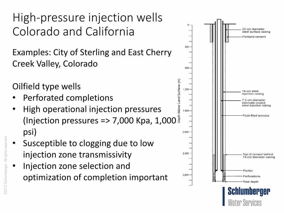
High-pressure injection wellsColorado and California
Examples: City of Sterling and East Cherry Creek Valley, Colorado
Oilfield type wells• Perforated completions• High operational injection pressures
(Injection pressures => 7,000 Kpa, 1,000 psi)
• Susceptible to clogging due to low injection zone transmissivity
• Injection zone selection and optimization of completion important

©2
01
2 S
chlu
mb
erg
er.
All
rig
hts
re
serv
ed
.
Confinement analysis- Quantitative log analysis and modelingGoal: maximize information value from data normally collected in injection well programs
9
Conventional logsCore porosity versus hydraulic conductivity transformapplied to sonic porosity.

©2
01
2 S
chlu
mb
erg
er.
All
rig
hts
re
serv
ed
.
Density-dependent solute-transport modelingTurkey Point, Miami-Dade County, Florida
10
100 year simulation was required by NRCIncludes 40-year planned plant operation, 20-year extension, 40 years post operationSensitivity analysis performed to address parametric uncertainty

©2
01
2 S
chlu
mb
erg
er.
All
rig
hts
re
serv
ed
.
Aquifer characterization opportunities:Advanced borehole geophysical logging
11
Nuclear magnetic resonanceFormation MicroImagerElemental capture spectroscopy
• Location of transmissive injection strata
• Confinement analysis

©2
01
2 S
chlu
mb
erg
er.
All
rig
hts
re
serv
ed
.
Wireline formation testers
Modular dynamic tester (MDTTM)• Single probe – measures P and collects water
sample• Dual/multiple probe configuration – sink probe
withdraws fluid, pressure is measured in one or more probes.
• Dual packer mode to withdrawal water = small version of drill stem test.
Cased Hole Dynamics Tester (CHDTTM)• Measurement of pressure and formation sampling• Drill through casing and cement; no explosives• Combinable with MDT modules• Drill and plug up to 6 holes and collect 6 samples
per trip• Seal/plug to differential pressure of 10,000 psi• 5 ½ to 9 ½ inch casings.
12
©2
01
2 S
chlu
mb
erg
er.
All
rig
hts
re
serv
ed
.
13
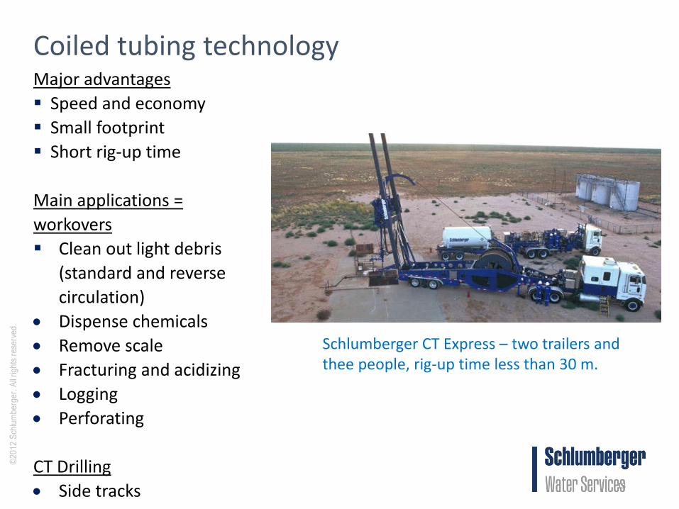
Coiled tubing technologyMajor advantages
Speed and economy
Small footprint
Short rig-up time
Main applications =
workovers
Clean out light debris
(standard and reverse
circulation)
Dispense chemicals
Remove scale
Fracturing and acidizing
Logging
Perforating
CT Drilling
Side tracks
Schlumberger CT Express – two trailers and thee people, rig-up time less than 30 m.

©2
01
2 S
chlu
mb
erg
er.
All
rig
hts
re
serv
ed
.
Coiled tubing drilling
• Sidetrack drilled to restore capacity of a clogged injection well
• Much quicker and less expensive than mobilizing a drilling rig.
14
©2
01
2 S
chlu
mb
erg
er.
All
rig
hts
re
serv
ed
.
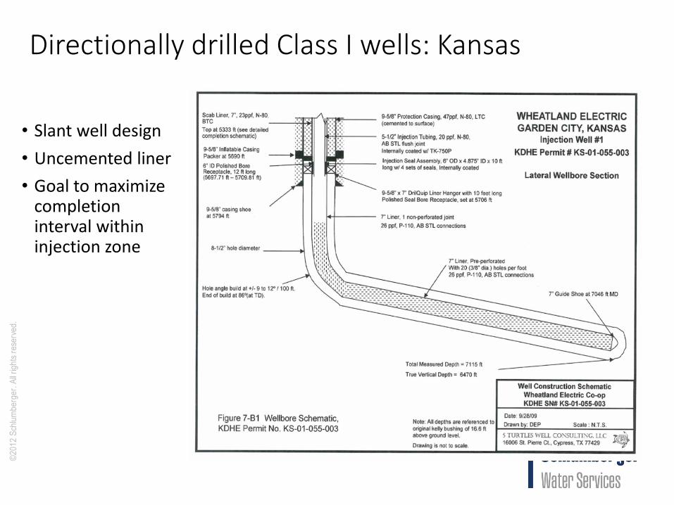
Directionally drilled Class I wells: Kansas
• Slant well design
• Uncemented liner
• Goal to maximize completion interval within injection zone

©2
01
2 S
chlu
mb
erg
er.
All
rig
hts
re
serv
ed
.
Extreme directionally drilled injection wells
16
Groundwater model was developed to simulate pressures and movement of injected waters

©2
01
2 S
chlu
mb
erg
er.
All
rig
hts
re
serv
ed
.
Completion
• Key design issue is determining completion type and optimizing completion method
• Issues include maximizing efficiency, reducing clogging potential/rate, and facilitating rehabilitation (workovers)
17

©2
01
2 S
chlu
mb
erg
er.
All
rig
hts
re
serv
ed
.
Perforatedcompletions
18
• Perforation is the result of a high-velocity jet from a shaped charge that penetrates casing, cement, and formation
Oilfield Review Spring 2010

©2
01
2 S
chlu
mb
erg
er.
All
rig
hts
re
serv
ed
.
Perforated completions
19Oilfield Review Autumn 2014
• Perforation program can make a large difference in injection well performance!
• Underbalance needed to clear holes and remove crushed material.
• Goal is maximum dynamic underbalance, which facilitates perforation cleanup.

©2
01
2 S
chlu
mb
erg
er.
All
rig
hts
re
serv
ed
.
Perforated completions
20
Oilfield Review Spring 2010
Numerous factors need to be considered!
AMTA/AWWA © 21
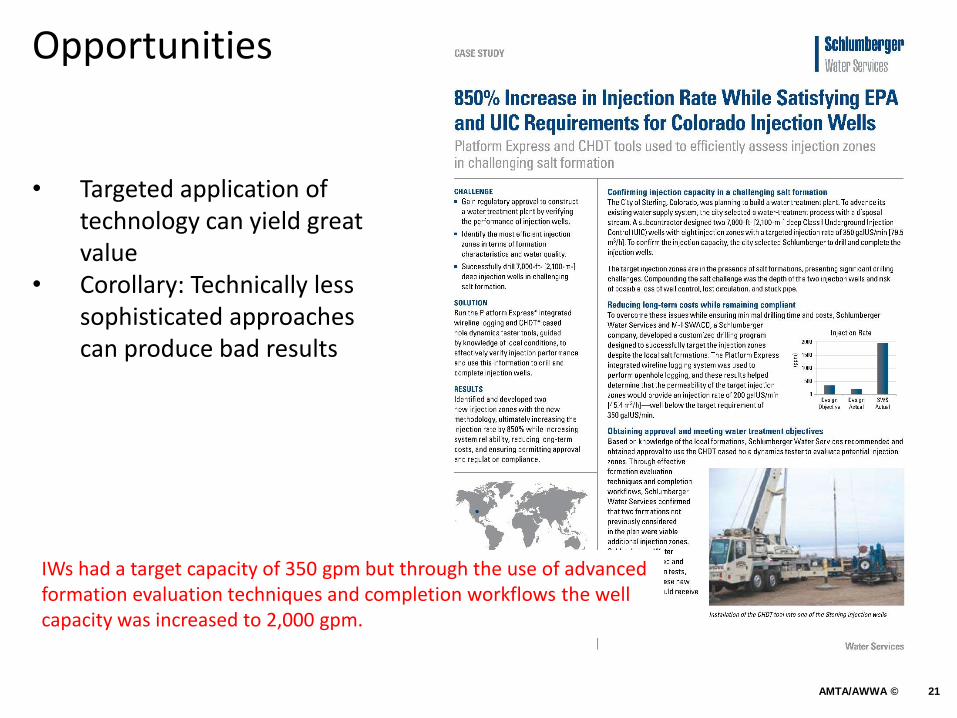
Opportunities
• Targeted application of technology can yield great value
• Corollary: Technically less sophisticated approaches can produce bad results
IWs had a target capacity of 350 gpm but through the use of advanced formation evaluation techniques and completion workflows the well capacity was increased to 2,000 gpm.

©2
01
2 S
chlu
mb
erg
er.
All
rig
hts
re
serv
ed
.
Management of cloggingNumerous factors can cause clogging and reductions in injectivity• Geochemical incompatibility • Clay swelling and dispersion (water sensitivity)• Air and gas entrainment or generation• Biological processes• Physical clogging from suspended sediments• Temperature and salinity viscosity effects
Prediction and Preventions• Geochemical modeling (site specific water chemistry, mineralogy, P and
T conditions)• Laboratory testing (core flow tests)• Pretreatment (filtration and chemical adjustments)• Optimize design so that well can accommodate some loss of
performance and can be rehabilitated.
22

©2
01
2 S
chlu
mb
erg
er.
All
rig
hts
re
serv
ed
.
Conclusions
• Injection well systems are more complex than production wells because water is forced into the formation and they are much more susceptible to loss of performance (injectivity) due to clogging.
• There are many technologies available that can cost effectively improve system performance, reliability, and O&M costs.
• Key to optimization is not to do things as they have always been done, but rather to look for incremental ways of doing things better.
• Oilfield technology and experience can be highly valuable when one considers that there are 180,000 Class II wells versus 650 Class I wells in the United States.
23

©2
01
2 S
chlu
mb
erg
er.
All
rig
hts
re
serv
ed
.
Questions?
24