Embed Size (px)
Citation preview

Advanced Class 5 SmartMotor Features Include:
TMIntroducing high-speed, transparent communications over CAN bus.The optional Combitronic™ technology uses a CAN serial port to join all SmartMotor™ servos where any motor’s program can read from, write to or control any other motor simply by tagging a local variable or command with the other motor’s CAN address. All
SmartMotor™ servos become one multi-tasking, data-sharing system without writing a single line of communications code or requiring detailed knowledge of the CAN protocol.
This significant industry advancement allows any single axis to act as master to all other axes in the system. Each servo motor is capable of full access to and control of all motion parameters and I/O of all other servo motors. Any axis may trigger on inputs or status
registers in any other axis with sub-millisecond response time, exceeding the abilities of most PLCs to control motion and I/O together. Now all SmartMotor servos on the network may freely act on system-wide conditions for efficient process control of the entire machine.
Phase Encoder
Signal
Derivative Error Limit used on Servo Controlled Spot Welder
Pre-defined Trapezoidal Gearing
SlaveGearedVelocity
SlewRatio
BitTrajectory
Bit
DescendBit
Master Encoder Input over time
Start
90
180
270
Phase Adjust ModeEnables applications (such as product tracking) where moves must be applied over a target in motion, automatically stabilizes pan & tilt applications, or allowsarm end effectors to remain parallel to base while the mid arm section moves.
Derivative Error Limit (Following error limit rate of change) This feature quickly detects jams for safer operation, ensuring less chance of damage to equipment or injury to machine operators.
Expanded Electronic Gearing FunctionalityNow includes separate, predefined Ascend, Slew and Descend distances defined by either master or slave encoder values for enhancing applications such as high-speed winders.
Modulo Count ModeThis is especially useful in rotary pan or azimuth controls for targeting systems, radar, and camera bases. Combined with the Combitronic interface, multi camera surveillance systems may easily pass off subject tracking from one pan & tilt to the next.
Phased origin stays referenced to base allowing commanded moves to be dynamically independent of the phase axis
PML= 360 (Position Modulo Limit) maintain counts between 0 and 359
PMT= 270 (Position Modulo Target) take shortest path to Target Position
On contact with metal, the jaw stops immediately for minimal product deflection and maximum balance to each side
With an array of status bits available, all portions of the move may be used for I/O triggering
Automatic transitions in and out are ideal for high speed labeling applications
Class 5SmartMotor™ TechnologyDelivering significant industry advancements in programmable integrated servo systems
TM
®
Advanced Programmable SmartMotor with D-Style Connectors
IP65 and Higher Industrial SmartMotor with M-Style Connectors
1 NC2 NC3 BUS-B4 NC5 ground
6 +5V7 NC8 BUS-A9 NC
ProfiBus Pinout:
DMX Modbus® RTU

Class 5 Motion Profiles
Dual Trajectory Path Generators The processor now has the ability to sum in Positioning, Velocity or Contouring Mode profiles on top of Electronic Gearing or Camming profiles.
This includes Virtual Axis Gearing and Camming where independent profiles may be run off of a virtual time base separate from Position or Velocity Modes or summed in on top of them.
Dancer Arm TensionVelocity Compensation Feedback
Master Nip Roller
Slave Supply Reel
Master Encoder Signal for Electronic Gearing Feedback
Velocity Mode and Electronic Gearing Summed Together:Electronic Gearing ensures instant response to master nip-roller speed, while Velocity Mode is controlled by the tension arm. The net effect provides constant tension over the change in supply reel radius.
• Carpet manufacturing• Converting and flexible packaging• Fiber optic cable• Film (photographic, packaging)• Filters • Metals, including foils and sheet• Newspapers
Applications• Nonwoven textiles• Packaging (rigid) including
corrugators• Paper• Plastic sheet and film • Printing (commercial)• Roll flooring
• Solar cells and panels• Tags and labels• Tapes (adhesive)• Textiles• Rubber and tires• Wallpaper• Wire and cable
Example
Electronic Gearing + Velocity Mode
New in Class 5
MP(1) Position Mode MV(1) Velocity Mode
RPC(1) Reports Commanded Position
Trajectory Generator 1
Trajectory Generator 2
Input Sources
SRC(1) External Enc.
SRC(2) Internal Clock PID
TrajectorySumming
∑
Motor Shaft
MFR(2)
MC(2) CAM ModeRPC(2) Reports Commanded Positon
RPA Reports Motor Position
Dual TrajectoryGenerator
ECS(value)
+
Gearing is not summed with camming; if cam length is 0, there is no motion!
Trapezoidal Move Profile

TM
Combitronic technology operates over a standard “CAN” (Controller Area Network) interface but has no need for a dedicated master. Each Moog Animatics' SmartMotor servo connected to the same network communicates on an equal footing, sharing all information and, therefore, sharing all processing resources. An array of Moog Animatics' SmartMotor servos becomes one giant parallel-processing system when equipped with the Combitronic interface.
The only configuration prerequisites for Combitronic communications are that each axis has a unique address and baud rates match.
Further, Combitronic communications have been architected to coexist invisibly with CANopen and DeviceNet protocols. This means, for example, that an array of SmartMotor™ servos can be configured as slaves to an external CANopen master. Through Combitronic technology, they can still communicate with each other without detection by the CANopen master and without data collision.
The following code holds in a WHILE loop until the position of Motor 3 exceeds the position of Motor 4.
WHILE PA:3 < PA:4 LOOP 'Wait for Motor 3 to pass Motor 4
As shown, any single SmartMotor can actively grab dynamic data from one or more SmartMotors on the network as needed, without the need for code residing in the other SmartMotor servos.
The following IF condition stops motion if Motor 5 slows down.
IF VA:5<10000 'If real time speed in Motor 5 drops below 100000 X 'Stop motion in this motor ENDIF
Communications
RS-232
CombitronicMaster
CombitronicMaster
CombitronicMaster
CombitronicMaster
Bank 1 Bank 2 Bank 3 Bank 4
CombitronicSlave
CombitronicSlave
CombitronicSlave
CombitronicSlave
CombitronicSlave
CombitronicSlave
CombitronicSlave
CombitronicSlave
ControllingPC
RX
TX
Motor 2 Motor 2 Motor 2 Motor 2
Motor 3 Motor 3 Motor 3 Motor 3
TX RX TX RX TX RX TX RX
This configuration bypasses the need for a host CAN bus device or CAN bus interface for a PC, allowing standard RS-232 ASCII to control multiple motors. Combitronic technology allows pass-through communications between RS-232 and CAN bus.
Combitronic™ with RS-232 Interface
2PT:3=1234 'Set Bank 2 Motor 3 target positon30:0=0 'Set origin to zero on all Bank 3 motors1RPA:2 'Report Bank 1 Motor 2 actual position0G 'Send Go command to RS232 motors only2G:0 'Send Go command to all Bank 2 motors0G:0 'Send Go command to all motors on all
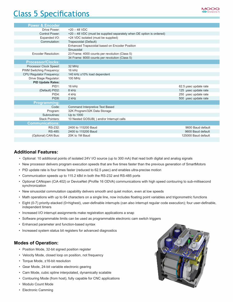
Class 5 SpecificationsPower & Encoder
Drive Power: +20 – 48 VDCControl Power: +20 – 48 VDC (must be supplied separately when DE option is ordered)Expanded I/O: +24 VDC isolated (must be supplied)Commutation: Trapezoidal (Default)
Enhanced Trapezoidal based on Encoder PositionSinusoidal
Encoder Resolution: 23 Frame: 4000 counts per revolution (Class 5)34 Frame: 8000 counts per revolution (Class 5)
Processor/Clocks:Processor Clock Speed: 32 MHz
PWM Switching Frequency: 16 kHzCPU Regulator Frequency: 140 kHz ±10% load dependent
Drive Stage Regulator: 100 MHzPID Update Rates:
PID1: 16 kHz 62.5 μsec update rate(Default) PID2: 8 kHz 125 μsec update rate
PID4: 4 kHz 250 μsec update ratePID8: 2 kHz 500 μsec update rate
Programming:Code: Command Interpretive Text Based
Program: 32K Program/32K Data StorageSubroutines: Up to 1000
Stack Pointers: 10 Nested GOSUB( ) and/or Interrupt callsCommunications:
RS-232: 2400 to 115200 Baud 9600 Baud defaultRS-485: 2400 to 115200 Baud 9600 Baud default
(Optional) CAN Bus: 20K to 1M Baud 125000 Baud default
Additional Features:• Optional: 10 additional points of isolated 24V I/O source (up to 300 mA) that read both digital and analog signals
• New processor delivers program execution speeds that are five times faster than the previous generation of SmartMotors
• PID update rate is four times faster (reduced to 62.5 μsec) and enables ultra-precise motion
• Communication speeds up to 115.2 kBd in both the RS-232 and RS-485 ports
• Optional CANopen (CiA 402) or DeviceNet (Profile 16 ODVA) communications with high speed contouring to sub-millisecond synchronization
• New sinusoidal commutation capability delivers smooth and quiet motion, even at low speeds
• Math operations with up to 64 characters on a single line, now includes floating point variables and trigonometric functions
• Eight (0-7) priority-stacked (0=highest), user-definable interrupts (can also interrupt regular code execution); four user-definable, independent timers
• Increased I/O interrupt assignments make registration applications a snap
• Software programmable limits can be used as programmable electronic cam switch triggers
• Enhanced parameter and function-based syntax
• Increased system status bit registers for advanced diagnostics
Modes of Operation:• Position Mode, 32-bit signed position register
• Velocity Mode, closed loop on position, not frequency
• Torque Mode, ±16-bit resolution
• Gear Mode, 24-bit variable electronic gearing
• Cam Mode, cubic spline interpolated, dynamically scalable
• Contouring Mode (from host), fully capable for CNC applications
• Modulo Count Mode
• Electronic Camming

15 14 13 12 11 10 9
11 10 9
A1 A21 23 4 5
8 7 6 5 4 3 2 1
PIN MAIN POWER P11 I/O – 6 GP, Index Input or “G” Command
7W2 Combo D-Sub Connector
2 +5 VDC Out3 RS-232 Transmit4 RS-232 Receive5 Common Ground (Typ. SIG Ground)A1 Main Power +20-48 VDCA2 Common Ground (Req’d POWER Ground)PIN I/O CONNECTOR (5V TTL I/O) P21 I/O – 0 GP or Encoder A or Step Input
P2 DB-15 D-Sub Connector
2 I/O – 1 GP or Encoder B or Direction Input3 I/O – 2 Positive Overtravel or GP4 I/O – 3 Negative Overtravel or GP5 I/O – 4 GP, IIC or RS-485 A (Com Ch. 1)6 I/O – 5 GP, IIC or RS-485 B (Com Ch.1)7 I/O – 6 GP, Index Input or “G” Command8 Phase A Encoder Output9 Phase B Encoder Output10 RS-232 Transmit; For -CDS, CAN-L Only11 RS-232 Receive; For -CDS, CAN-H Only12 +5 VDC Out13 Common Ground (Typ. SIG Ground)14 Common Ground15 Main Power +20-48 VDCNote: I/O ports input impedance = 5 kohm (5 kohm pull-up resistor)PIN CAN bus P31 NC M12 5-Pin
Female2 +V3 -V (Ground, Not Common)4 CAN-H5 CAN-L
PIN Isolated 24 VDC I/O Connector P41 I/O – 16 GP
M12 12-Pin Female End View
2 I/O – 17 GP3 I/O – 18 GP4 I/O – 19 GP5 I/O – 20 GP6 I/O – 21 GP7 I/O – 22 GP8 I/O – 23 GP9 I/O – 24 GP10 I/O – 25 GP11 +24 Volts Input12 Ground-I/O (Not Common)
PIN MAIN POWER P11 Control Power In M16 4 Pin Male2 Chassis Ground3 Control, Com, I/O and Amplifier Ground4 Amplifier Power In
PIN Communications Connector P21 Control, Com, I/O and Amp Ground M12 8-Pin
Female End View2 RS-485 B, Com ch. 03 RS-485 A, Com ch. 04 Encoder A+ Input/Output5 Encoder B- Input/Output6 Encoder A- Input/Output7 +5 V Out8 Encoder B+ Input/Output
PIN 24 V Isolated I/O P31 I/O – 0 GP
M12 12-Pin Female End View
2 I/O – 1 GP3 I/O – 4 GP4 I/O – 5 GP or Index5 I/O – 6 GP or “G” Command6 I/O – 7 GP7 I/O – 8 GP or Brake Line Output8 I/O – 9 GP9 Not Fault Out10 Drive Enable Input11 +24 Volts Out12 Ground CommonNote: I/O ports input impedance > 10 kohm
PIN 24 V I/O Connector P41 +24 Volts Out M12 5-Pin
Female End View2 I/O – 3 GP -Limit3 Ground4 I/O – 2 GP +Limit5 I/O – 10 GP
Note: I/O ports input impedance > 10 kohm
PIN CAN Connector P51 NC M12 5-Pin
Female (Std) Male (Opt)2 +V3 -V (Ground)4 CAN-H5 CAN-L
Class 5 Connector Pinouts
M-Style SmartMotor D-Style SmartMotor
• Advanced Motion Controller• Motor • Servo Drive • Encoder • Amplifier • I/O • Communication Busses
Male (opt)Female (std)
Kim:1. Use both the male and female for the CAN connector on the M motor2. Use just the female for the CAN connector on the D motor, and on thatmotor don’t put the (std) text.
P2 DB-15 D-sub Connector
15 14 13 12 11 10 9
8 7 6 5 4 3 2 1
Male (opt)Female (std)
Kim:1. Use both the male and female for the CAN connector on the M motor2. Use just the female for the CAN connector on the D motor, and on thatmotor don’t put the (std) text.
P2 DB-15 D-sub Connector
15 14 13 12 11 10 9
8 7 6 5 4 3 2 1
Male (opt)Female (std)
Kim:1. Use both the male and female for the CAN connector on the M motor2. Use just the female for the CAN connector on the D motor, and on thatmotor don’t put the (std) text.
P2 DB-15 D-sub Connector
15 14 13 12 11 10 9
8 7 6 5 4 3 2 1
Male (opt)Female (std)
Kim:1. Use both the male and female for the CAN connector on the M motor2. Use just the female for the CAN connector on the D motor, and on thatmotor don’t put the (std) text.
P2 DB-15 D-sub Connector
15 14 13 12 11 10 9
8 7 6 5 4 3 2 1
IP65IP65IP67IP67

Print & Die Cut AlignmentFollow Mode with PhaseOffset Electronic Gearing
Parallel Axis Gantry
Position Mode with Contouring Mode
Programmable Force Press-to-Fit
Position Mode with Derivative Error Control
High-Speed Parts Counter & Verification
Velocity Mode or FollowMode with High-SpeedCounter Input
Traverse & Take-up Spool Winders
Velocity Mode & Electronic Gearing Summed Together
Drill & Tap/Nut Runner
Follow Mode with Velocity Mode and Monitoring Position Error
Three-Position Parts Diverter
Position Mode BCD InputAbsolute PositionMode
Position ModeAbsolute Position Mode
Multi-Axis Pick & Place
Input/Output Stacker
Position ModeAbsolute Position ModeRelative Position Mode
• Anode wire welding
• Automatic web tensioning/alignment*
• Auto-progression, adjusting parts indexers
• Audio/visual mobility*
• Bearing inserters/presses
• Capacitor manufacturing
• Cappers*
• Centrifuges
• CNC applications
• CNC machining*
• CNC training*
• Compression/tension testing
• Coordinate measuring machines
• Cut-to-length gage stops
• Dashboard controls (button/switch) testing
• Destructive testing
• Dicers
• Fillers
• Flexible tooling machines*
• Gimbal-mounted accelerometer testing
• Glass tube cutting
• Glue dispensers
• GPS-guided steering/drive control*
• High-accuracy, three-axis positioning*
• High-axis-count, coordinated motion*
• High-speed indexing labelers
• Hydroelectric turbine nozzle control
• Infeed/outfeed stackers
• Input/output stacker, wafer handling*
• Linear and rotary motion*
• Manual handwheel override
• Nut/bolt/screw drivers
• Pan & tilt bases*
• Paper feeders/folders
• Parts inspection and repositioning*
• Parts redirectors
• Phase gearhead adjusting
• Pick & place palletizers
• Plasma cutting*
• Positive displacement pumps
• Shock load testing
• Step/tapered spool winders
• Tactile switch testing
• Tire tread grinding
• Topographical mapping
• Transformer coil winders
• Turbine blade grinding
• Ultrasound testing*
• Vertical load control*
• Vision-guided laser marking*
• Vision inspection
• Voice coil winders
• Wafer handlers
• Web guide
• Web tensioning
• Wire bonding
• Woodworking*
Applications Using SmartMotorsBelow are some of the many applications that can use the SmartMotor
* To read the case study or application note, visit www.animatics.com/applications
Moog Animatics • www.animatics.com • Tel West +1 650-960-4215 • Tel East +1 610-328-4000 x315 Copyright © 2012–2017, Moog Inc., Animatics.
MA1018-1017