Embed Size (px)
Citation preview
Physics 1
(ii) At very large distance i.e. r >> a Eq
r=
14 0
2πε
� Torque on an electric dipole placed in a uniform
electric field :
τ = ×p E or or sinτ θ= pE
� Potential energy of an electric dipole in a uniform electric field is U = –pE(cosq2 – cosq1)
where q1 & q1 are initial angle and final angle between
� Electric flux φ = ⋅
E dS
� Gauss’s law :
� Electric field due to thin infinitely long straight wire of uniform linear charge density l
Er
=0
λπε2
,
(i) At a point outside the shell i.e., r > R
Eq
r=
0
14 2πε
(ii) At a point on the shell i.e., r = R
Eq
R=
0
14 2πε
(iii) At a point inside the shell i.e., r < RE = 0
� Electric field due to a non conducting solid sphere of uniform volume charge density r and radius R at a point distant r from the centre of the sphere is given as follows :
(i) At a point outside the sphere i.e., r > R
E
q
r=
0
14 2πε
·
(ii) At a point on the surface of the sphere i.e., r = R
E
q
R=
0
14 2πε
·
ELECTRIC CHARGES AND FIELDS
� Coulomb’s law : Fk q q
r= 1 2
2 =1
41 2
2πεq q
r
� Relative permittivity or dielectric constant :
i e Kr. ., orεεε
=0
� Electric field intensity at a point distant r from a point charge q is E
q
r=
14 0
2πε.
� Electric dipole momentm,
� Electric field intensity on axial line (end on position) of the electric dipole
(i) At the point r from the centre of the electric
dipole, Epr
r a=
−1
42
02 2 2πε ( )
.
(ii) At very large distance i.e., (r > > a),
Ep
r=
24 0
3πε
� Electric field intensity on equatorial line (board on position) of electric dipole
(i) At the point at a distance r from the centre
of electric dipole, Ep
r a=
+1
4 0 2 2 3 2πε ( )./
(ii) At very large distance i.e., r > > a,
E
p
r=
14 0 3πε
.
� Electric field intensity at any point due to an
electric dipole Ep
r= +
14
1 30
32
πεθcos
� Electric field intensity due to a charged ring
(i) At a point on its axis at distance r from its
centre, E
qr
r a=
+1
4 02 2 3 2πε ( ) /
CLASS 12 : PHYSICS
FORMULA BOOK
2 Physics
(iii) At a point inside the sphere i.e., r < R
E
r q r
Rr R= = <
0
ρε πε3
140
3· , for
� Electric field due to a thin non conducting infinite sheet of charge with uniformly charge surface density s is E =
σε2 0
� Electric field between two infinite thin plane parallel sheets of uniform surface charge density s and – s is E = s/e0.
ELECTROSTATIC POTENTIAL AND CAPACITANCE
� Electric potential VWq
=
� Electric potential at a point distant r from a point charge q is V
qr
=4 0πε
� The electric potential at point due to an electric dipole
Vp
r=
14 0
2πεθcos
� Electric potential due to a uniformly charged spherical shell of uniform surface charge density s and radius R at a distance r from the centre the shell is given as follows :
(i) At a point outside the shell i.e., r > R
Vqr
=1
4 0πε (ii) At a point on the shell i.e., r = R
V
qR
=1
4 0πε (iii) At a point inside the shell i.e., r > R
VqR
=1
4 0πε � Electric potential due to a non-conducting solid
sphere of uniform volume charge density r and radius R distant r from the sphere is given as follows :
(i) At a point outside the sphere i.e. r > R
V q
r=
14 0πε
(ii) At a point on the sphere i.e., r = R
V
qR
=1
4 0πε (iii) At a point inside the sphere i.e., r < R
Vq R r
R=
−14
320
2 2
3πε( )
� Relationship between
E Vand
E V= −∇
where
� Electric potential energy of a system of two
point charges is Uq qr
=1
4 0
1 2
12πε
� Capacitance of a spherical conductor of radius R is C = 4pe0R
� Capacitance of an air filled parallel plate
capacitor
� Capacitance of an air filled spherical capacitor
Cab
b a=
−4 0πε
� Capacitance of an air filled cylindrical capacitor
CL
ba
=
2 0πε
ln
� Capacitance of a parallel plate capacitor with a dielectric slab of dielectric constant K, completely filled between the plates of the capacitor, is given by
� When a dielectric slab of thickness t and dielectric constant K is introduced between the plates, then the capacitance of a parallel plate
capacitor is given by CA
d tK
=− −
ε0
1 1
� When a metallic conductor of thickness t is introduced between the plates, then capacitance of a parallel plate capacitor is given by
� Energy stored in a capacitor :
U CV QVQC
= = =12
12
12
22
� Energy density : u E=12 0
2ε
� Capacitors in series : 1 1 1 11 2C C C CS n
= + + +....
� Capacitors in parallel : CP = C1 + C2 + .... + Cn
Physics 3
CURRENT ELECTRICITY
� Current, Iqt
=
� Current density JIA= (Electricity, Class 10)
� Drift velocity of electrons is given by
veEmd = − τ
� Relationship between current and drift velocityI = nAe vd
� Relationship between current density and drift velocity
J = nevd
� Mobility, µτ τ
= = =| | /vE
qE mE
qm
d
� Resistance
� Conductance : G R= 1 .
� The resistance of a conductor is
Rm
nelA
lA
mne
= = =2 2τρ ρ
τwhere
� Conductivity :
σ ρτ µ µ τ= = = = =
1 2nem ne
vE
em
dAs
� If the conductor is in the form of wire of length l and a radius r, then its resistance is
� If a conductor has mass m, volume V and density d, then its resistance R is
(Electricity, Class 10)
� A cylindrical tube of length l has inner and outer radii r1 and r2 respectively. The resistance between its end faces is
Rl
r r=
−( )ρ
π 22
12 .
� Relationship between J, s and E J = sE
� The resistance of a conductor at temperature t°C is given by Rt = R0 (1 + at + bt2)
� Resistors in series Rs = R1 + R2 + R3
� Resistors in parallel 1 1 1 11 2 3R R R Rp
= + + .
(Electricity, Class 10)
� Relationship between e, V and r
or r R V= −( )ε 1where e emf of a cell, r internal resistance and R is external resistance
� Wheatstone’s bridge PQ
RS
=
� Metre bridge or slide metre bridge The unknown resistance, R Sl
l= −100
.
� Comparison of emfs of two cells by using potentiometer ε
ε12
1
2=
ll
� Determination of internal resistance of a cell by
potentiometer rl ll
R=−
1 2
2
� Electric powerelectric work done
time takenP =
P VI I R VR
= = =2 2.
(Electricity, Class 10)
MOVING CHARGES AND MAGNETISM
� Force on a charged particle in a uniform electric field
� �F qE=
� Force on a charged particle in a uniform magnetic field
� � �F q v B F qvB= × =( ) sinor θ
� Motion of a charged particle in a uniform magnetic field
(i) Radius of circular path is
(ii) Time period of revolution is
(iii) The frequency is υ π= =12TqB
m
(iv) The angular frequency is
� Cyclotron frequency, υπ
=Bq
m2
� Biot Savart’s law
dBIdl
rdB
I dl r
r
� �� �
= =×µ
πθ µ
π0
20
34 4sin ( )
or
� The magnetic field B at a point due to a straight wire of finite length carrying current I at a perpendicular distance r is
BIr= +µ
π α β04 [sin sin ]
4 Physics
� The magnetic field at a point on the axis of the circular current carrying coil is
BNIa
a x=
+µ
ππ0
2
2 2 3 242
( ) /
� Magnetic field at the centre due to current carrying circular arc
B
Ia
=µ φ
π0
4 .
� The magnetic field at the centre of a circular coil of radius a carrying current I is
B Ia
Ia
= =µ
ππ µ0 0
42
2If the circular coil consists of N turns, then
B NIa
NIa
= =µ
ππ µ0 0
42
2
� Ampere’s circuital law� ��B dl I⋅ =∫ µ0 .
� Magnetic field due to an infinitely long straight solid cylindrical wire of radius a, carrying current I
(a) Magnetic field at a point outside the wire i.e. (r > a) is B
Ir= µ
π0
2 (b) Magnetic field at a point inside the wire
i.e. (r < a) is BIra
= µπ0
22 (c) Magnetic field at a point on the surface of a
wire i.e. (r = a) is BIa
=µ
π0
2 � Force on a current carrying conductor in a
uniform magnetic field
F I l B= ×( ) or F = IlB sinq � When two parallel conductors separated by a
distance r carry currents I1 and I2, the magnetic field of one will exert a force on the other. The force per unit length on either conductor is
fI Ir= µ
π0 1 2
42
� The force of attraction or repulsion acting on each conductor of length l due to currents in
two parallel conductor is FI Ir l= µ
π0 1 2
42 .
� When two charges q1 and q2 respectively moving with velocities v1 and v2 are at a distance r apart, then the force acting between them is
Fq q v v
r= µ
π0 1 2 1 2
24 � Torque on a current carrying coil placed in a
uniform magnetic field t = NIABsinq= MBsinq
� If a is the angle between plane of the coil and the magnetic field, then torque on the coil is
t = NIAB cosa = MB cosa � Workdone in rotating the coil through an angle qfrom the field direction is
W = MB (1 – cos q) � Potential energy of a magnetic dipole
U M B MB= − ⋅ = −
cosθ � An electron revolving around the central
nucleus in an atom has a magnetic moment and it is given by
� Conversion of galvanometer into a ammeter
SI
I I Gg
g= −
� Conversion of galvanometer into voltmeter
RVI G
g= −
� In order to increase the range of voltmeter n times the value of resistance to be connected in series with galvanometer is R = (n – 1)G.
� Magnetic dipole moment
M m l= ( )2 � The magnetic field due to a bar magnet at any
point on the axial line (end on position) is
BMr
r laxial =−
µπ0
2 2 242
( ) For short magnet l2 << r2
BMraxial = µ
π0
32
4
The direction of Baxial is along SN. � The magnetic field due to a bar magnet at any
point on the equatorial line (board-side on position) of the bar magnet is
BM
r lequatorial =+
µπ
02 2 3 24 ( ) /
For short magnet
BMrequatorial = µ
π0
34 The direction of Bequatorial is parallel to NS.
� In moving coil galvanometer the current I passing through the galvanometer is directly proportional to its deflection (q).
I ∝ q or, I = Gq.
where galvanometer constantG
kNAB= =
� Current sensitivity :
� Voltage sensitivity :
Physics 5
MAGNETISM AND MATTER
� Gauss’s law for magnetism
φ = ⋅ =∑
B SS
∆∆
0all areaelements
� Horizontal component : BH = B cosd
� Magnetic intensity B = mH
� Intensity of magnetisation
IMV= =
Magnetic momentVolume
� Magnetic susceptibility χm
IH=
� Magnetic permeability
µ = BH
� Relative permeability :
� Relationship between magnetic permeability
and susceptibility
µ χ µ µµr m r= + =1
0with
� Curie law : χm
CT=
χmC
C
CT T T T= − >( )
ELECTROMAGNETIC INDUCTION
� Magnetic Fluxφ θ= ⋅ =� �B A BA cos
� Faraday’s law of electromagnetic inductionε φ= − d
dt � When a conducting rod of length l is rotated
perpendicular to a uniform magnetic field B, then induced emf between the ends of the rod is
|e| = Bu (pl2) = BuA � The self induced emf is
ε φ= − = −ddt L
dIdt
� Self inductance of a circular coil is
LN R= µ π0
2
2 � Let IP be the current flowing through primary
coil at any instant. If fS is the flux linked with secondary coil then
fS ∝ IP or fS = MIP
where M is the coefficient of mutual inductance.The emf induced in the secondary coil is given by
εSPM
dIdt= −
where M is the coefficient of mutual inductance. � Coefficient of coupling (K) :
KML L
=1 2
� The coefficient of mutual inductance of two long co-axial solenoids, each of length l, area of cross section A, wound on air core is
MN N A
l= µ0 1 2
� Energy stored in an inductor
U LI= 12
2
� During the growth of current in a LR circuit is I = I0 (1 – e–Rt/L) = I0(1 – e–t/t)
where I0 is the maximum value of current, t = L/R = time constant of LR circuit.
� During the decay of current in a LR circuit is I = I0e–Rt/L = I0e–t/t
� During charging of capacitor through resistorq = q0(1 – e–t/RC) = q0(1 – e–t/t)
where q0 is the maximum value of charge.t = RC is the time constant of CR circuit.
� During discharging of capacitor through resistorq = q0e–t/RC = q0e–t/t
ALTERNATING CURRENT
� Mean or average value of alternating current or voltage over one complete cycle
I I II t dt
dtm av
T
Tor or = =∫
∫
00
0
0sinω
V V VV t dt
dtm av
T
Tor or = =∫
∫
00
0
0sinω
� Average value of alternating current for first half cycle is
II t dt
dt
IIav
T
T= = =∫
∫
00
2
0
20
02 0 637
sin.
/
/
ω
π
� Similarly, for alternating voltage, the average value over first half cycle is
6 Physics
VV tdt
dt
VVav
T
T= = =∫
∫
00
2
0
20
02 0 637
sin.
/
/
ω
π
� Average value of alternating current for second cycle is
II tdt
dt
IIav
T
T
T
T= = − = −∫
∫
02
2
00
2 0 637sin
./
/
ω
π
� Similarly, for alternating voltage, the average value over second half cycle is
VV tdt
dt
VVav
T
T
T
T= = − = −∫
∫
02
2
00
2 0 637sin
./
/
ω
π
� Mean value or average value of alternating current over any half cycle
II
Iav = =2 0 63700π .
II
Iav = =2 0 63700π .
� Root mean square (rms) value of alternating current
I II
Irms vor = =002
0 707.
Similarly, for alternating voltage
VV
Vrms = =002
0 707.
�
� Inductive reactance :XL = wL = 2puL
� Capacitive reactance : X C CC = =1 12ω πυ
The impedance of the series LCR circuit.
Z R X X R L CL C= + − = + −( )2 2 221( ) ω ω
∴ = =Admittance 1Impedance or Y Z
1
∴ =Susceptance Reactance1
� Inductive susceptance Inductive reactance= 1
or S X LLL
= =1 1ω
� Capacitive susceptanceCapacitive reactance
=1
or S X C CCC
= = =1 11/ ω ω
� The resonant frequency is
υπr LC
= 12
� Quality factor
� Average power (Pav) :
P V IV I
av rms rms= =cos cosφ φ0 02
� Apparent power : P V IV I
v rms rms= = 0 02
� Efficiency of a transformer,
η = =output powerinput power
V IV I
S S
P P.
ELECTROMAGNETIC WAVES
� The displacement current is given by
� Four Maxwell’s equations are :
� Gauss’s law for electrostatics
� Gauss’s law for magnetism
� Faraday’s law of electromagnetic induction
� ��E dl
ddt
B⋅ = −∫φ
� Maxwell-Ampere’s circuital law
� The amplitudes of electric and magnetic fields
in free space, in electromagnetic waves are related by
E cB BEc0 0 0
0= =or � The speed of electromagnetic wave in free
space is
c = 1
0 0µ ε � The speed of electromagnetic wave in a
medium is
� The energy density of the electric field is
u EE = 12 0
2ε
Physics 7
� The energy density of magnetic field is
uB
B = 12
2
0µ � Average energy density of the electric field is
< > =u EE
14 0 0
2ε � Average energy density of the magnetic field
is
< > = =uB
EB
14
14
02
00 0
2
µ ε
� Average energy density of electromagnetic wave is
< > =u E12 0 0
2ε
� Intensity of electromagnetic wave
I u c E c= < > = 12 0 0
2ε
� Momentum of electromagnetic wave
pUc= ( )complete absorption
pUc= 2 ( )complete reflection
� The poynting vector is
S E B= ×( )10µ
RAY OPTICS AND OPTICAL INSTRUMENTS
� When two plane mirrors are inclined at an angle q and an object is placed between them, the number of images of an object are formed due to multiple reflections.
n = °360θ
Position of object
Number of images
even anywhere n – 1odd symmetric n – 1
asymmetric n
� If 360°θ
is a fraction, the number of images
formed will be equal to its integral part.(Light, Class 8)
� The focal length of a spherical mirror of radius R is given by
� Transverse or linear magnification
mvu= = −
size of imagesize of object
� Longitudinal magnification :
mdvduL = −
� Superficial magnification :
m mS = =area of imagearea of object
2
� Mirror's formula 1 1 1u v f
+ =
� Newton’s formula is f 2 = xy,
� Laws of refraction : sinsin
ir = 1
2µ
� Absolute refractive index :
Lateral shift, sin ( )cosd t
i rr=−
(Light, Reflection and Refraction, Class 10)
� If there is an ink spot at the bottom of a glass slab, it appears to be raised by a distance
� When the object is situated in rarer medium, the relation between m1 (refractive index of rarer medium) m2 (refractive index of the spherical refracting surface) and R (radius of curvature) with the object and image distances is given by
− + =−µ µ µ µ1 2 2 1
u v R � When the object is situated in denser medium,
the relation between m1, m2, R, u and v can be obtained by interchanging m1 and m2. In that case, the relation becomes
− + =−
− + =−µ µ µ µ µ µ µ µ2 1 1 2 1 2 2 1
u v R v u Ror
� Lens maker’s formula1 1 1 1
1 2f R R= − −
( )µ
� Thin lens formula
� Linear magnification
mI
Ovu= =
size of imagesize of object
( )( ) .
� Power of a lens
� Combination of thin lenses in contact1 1 1 1
1 2 3F f f f= + + + ....
8 Physics
� The total power of the combination is given by P = P1 + P2 + P3 + ...
� The total magnification of the combination is given by
m = m1 × m2 × m3 .... � When two thin lenses of focal lengths f1 and f2
are placed coaxially and separated by a distance d, the focal length of a combination is given by
1 1 1
1 2 1 2F f fd
f f= + − .
� In terms of power P = P1 + P2 – dP1P2.(Light, Reflection and Refraction, Class 10)
� If I1, I2 are the two sizes of image of the object of size O, then O I I= 1 2
� The refractive index of the material of the prism is
µ
δ
=
+
( )sin ( )
sin
A
A
m
2
2where A is the angle of prism and dm is the angle of minimum deviation.
� Mean deviation δδ δ
=+V R
2 .
� Dispersive power, ω
δ δδ=
−angular dispersionmean deviation
( )( )V R
ωµ µ
µ=−−
V R
( ) ,1
where mean refractive indexµµ µ
=+
=V R
2
� Magnifying power, of simple microscope
M =angle subtended by image at the eye
angle subtended by thee object at the eye
= =tantan
βα
βα
� When the image is formed at infinity (far point),
MDf=
� When the image is formed at the least distance of distinct vision D (near point),
� Magnifying power of a compound microscopeM = mo × me
� When the final image is formed at infinity (normal adjustment),
Mvu
Df
o
o e=
Length of tube, L = vo + fe
� When the final image is formed at least distance of distinct vision,
where uo and vo represent the distance of object and image from the objective lens, fe is the focal length of an eye lens.
Length of the tube, L vf D
f Doe
e= + +
� Astronomial telescope
magnifying power, Mff
o
e
=
Length of tube, L = fo +f Df De
e +
WAVE OPTICS
� For constructive interference (i.e. formation of bright fringes)
� For nth bright fringe,
Path difference = =xdD nn λ
where n = 0 for central bright fringen = 1 for first bright fringe, n = 2 for second bright fringe and so ond = distance between two slitsD = distance of slits from the screen xn = distance of nth bright fringe from the centre.∴ =x n
Ddn λ
� For destructive interference (i.e. formation of dark fringes).
� For nth dark fringe,
path difference = = −xdD nn ( )2 1 2
λ
where n = 1 for first dark fringe, n = 2 for 2nd dark fringe and so on.xn = distance of nth dark fringe from the centre
∴ = −x nDdn ( )2 1 2
λ
� Fringe width, β λ= Dd
� Angular fringe width, θ β λ= =D d � If W1, W2 are widths of two slits, I1, I2 are
intensities of light coming from two slits; a, b are the amplitudes of light from these slits, then
WW
II
ab
1
2
1
2
2
2= =
Physics 9
II
a ba b
max
min
( )( )
=+−
2
2
� Fringe visibility VI II I
=−+
max min
max min
� When entire apparatus of Young’s double slit experiment is immersed in a medium of refractive index m,then fringe width becomes
′ =′
= =β λ λµ
βµ
Dd
Dd
� When a thin transparent plate of thickness t and refractive idnex m is placed in the path of one of the interfering waves, fringe width remains unaffected but the entire pattern shifts by
∆x tDd t= − = −( ) ( )µ µ β
λ1 1
� Diffraction due to a single slit Width of secondary maxima or minima
β λ λ= =D
af
awherea = width of slitD = distance of screen from the slitf = focal length of lens for diffracted light
� Width of central maximum � Angular width fringe of central maximum
= 2λa .
� Angular fringe width of secondary maxima or
minima = λa
� Fresnel distance, Za
F =2
λ � Resolving power of a microscope
Resolving power = =1 2d
µ θλsin
� Resolving power of a telescope
Resolving power = =11 22d
Dθ λ.
DUAL NATURE OF RADIATION AND MATTER
� Energy of a photon E hhc= =υ λ
� Momentum of photon is p
Ec
hc= = υ
� The moving mass m of photon is mEc
hc
= =2 2υ .
� Stopping potential
K eV mvmax max= =0
212
� Einstein’s photoelectric equation If a light of frequency u is incident on a
photosensitive material having work function
(f0), then maximum kinetic energy of the emitted electron is given as
Kmax = hu – f0 For u > u0 or eV0 = hu – f0 = hu – hu0
or eV K hc00
1 1= = −
max .λ λ
� de Broglie wavelength,
� If the rest mass of a particle is m0, its de Broglie wavelength is given by
λ =−
h
vc
m v
12
2
1 2
0
/
� In terms of kinetic energy K, de Broglie wavelength is given by λ = h
mK2.
� If a particle of charge q is accelerated through a potential difference V, its de Broglie wavelength
is given by λ = hmqV2
.
For an electron, λ = ( )150 1 2
V
/.Å
� For a gas molecule of mass m at temperature
T kelvin, its de Broglie wavelength is given by
λ = hmkT3
, where k is the Boltzmann constant.
ATOMS
� Rutherford’s nuclear model of the atom
NN ntZ er K
i( )( ) sin ( / )
θπε θ
=2 4
02 2 2 48 2
The frequency of incident alpha particles scattered by an angle q or greater
f ntZe
K=
π πε
θ2
0
22
4 2cot
� The scattering angle q of the a particle and impact parameter b are related as
bZe
K=2
0
24cot( / )θπε
� Distance of closest approach
rZe
K0
2
0
24= πε
� Angular momentum of the electron in a stationary orbit is an integral multiple of h/2p.
i.e., Lnh
mvrnh= =
2 2π πor,
10 Physics
� The frequency of a radiation from electrons makes a transition from higher to lower orbit
υ =−E Eh
2 1
� Bohr’s formulae (i) Radius of nth orbit
(ii) Velocity of electron in the nth orbit
v
Zenh
Znn = = ×1
42 2 2 10
0
2 6
πεπ . m/s.
(iii) The kinetic energy of the electron in the nth orbit
= 13 6 2
2. .Zn
eV
(iv) The potential energy of electron in nth orbit
= −27 2 2
2. Z
n eV.
(v) Total energy of electron in nth orbit
(vi) Frequency of electron in nth orbit
υ
πεπ
nZ e m
n hZ
n=
= ×1
44 6 62 10
0
2 2 2 4
3 3
15 2
3.
(vii) Wavelength of radiation in the transition from
n2 → n1 is given by 1 1 12
12
22λ
= −
RZn n
where R is called Rydberg’s constant.
� Lyman series Emission spectral lines corresponding to
the transition of electron from higher energy levels (n2 = 2, 3, ...,∞) to first energy level (n1 = 1) constitute Lyman series.
1 11
12
22λ = −
R
nwhere n2 = 2, 3, 4, ......,∞
� Balmer series Emission spectral lines corresponding to the
transition of electron from higher energy levels (n2 = 3, 4, ....∞) to second energy level (n1 = 2) constitute Balmer series.
1 12
12
22λ = −
R
nwhere n2 = 3, 4, 5...........,∞
� Paschen series Emission spectral lines corresponding to the
transition of electron from higher energy levels (n2 = 4, 5, .....,∞) to third energy level (n1 = 3) constitute Paschen series.
1 1 1
31
222λ = −
R n
� Brackett series Emission spectral lines corresponding
to the transition of electron from higher energy levels (n2 = 5, 6, 7,.....,∞) to fourth energy level (n1 = 4) constitute Brackett series. 1 1
41
222λ = −
R
nwhere n2 = 5, 6, 7..........,∞
� Pfund series Emission spectral lines corresponding to the
transition of electron from higher energy levels (n2 = 6, 7, 8,.......,∞) to fifth energy level (n1 = 5) constitute Pfund series.
1 15
12
22λ = −
R
nwhere n2 = 6, 7,...........,∞
� Number of spectral lines due to transition of electron from nth orbit to lower orbit is
Nn n
=−( ) .1
2
� Ionization energy = 13 6 2
2. .Zn
eV
� Ionization potential = 13 6 2
2. .Zn
volt
� Energy quantisation
En hmL
nn = =2 2
281 2 3where , , , .........
NUCLEI
� Nuclear radius, R = R0A1/3
where R0 is a constant and A is the mass number
� Nuclear density,
ρ = mass nuclear
volume of nucleus
Physics 11
� Mass defect is given by Dm = [Zmp + (A – Z)mn – mN]
� The binding energy of nucleus is given byEb = Dmc2 = [Zmp + (A – Z)mn – mN]c2
= [Zmp + (A – Z)mn – mN] × 931.49 MeV/u. � The binding energy per nucleon of a nucleus
= Eb/A � Law of radioactive decay
dNdt
N t N t N e t= − = −λ λ( ) ( )or 0
� Half-life of a radioactive substance is given by
T1 22 0 693
/ln .= =λ λ
� Mean life or average life of a radioactive substance is given by
τλ
= = =10 693
1 441 21 2
TT/
/..
� Activity : R = –dN/dt � Activity law R(t) = R0e–lt
where R0 = lN0 is the decay rate at t = 0 and R = Nl.
� Fraction of nuclei left undecayed after n half live isNN
n t T
0
1 212
12= ( ) = ( ) / / or t = nT1/2
� Neutron reproduction factor (K)
=rate of production of neutrons
rate of loss of neutrons
SEMICONDUCTOR ELETRONICS, MATERIALS, DEVICES AND SIMPLE CIRCUITS
� Forbidden energy gap or forbidden band
E h hg = =υ υ
λ � The intrinsic concentration ni varies with
temperature T as
n A T eiE kTg2
03= − /
� The conductivity of the semiconductor is given by s = e(neme + nhmh)
where me and mh are the electron and hole mobilities, ne and nh are the electron and hole densities, e is the electronic charge.
� The conductivity of an intrinsic semiconductor is
si = nie(me + mh) � The conductivity of n-type semiconductor is
sn = eNdme
� The conductivity of p-type semiconductor issp = eNamh
� The current in the junction diode is given byI = I0 (eeV/kT –1)
where k = Boltzmann constant, I0 = reverse saturation current.In forward biasing, V is positive and low, eeV/kT > > 1, then forward current,
If = I0 (eeV/kT )In reverse biasing, V is negative and high eeV/kT < < 1, then reverse current, Ir = – I0
� Dynamic resistance
r VId = ∆
∆ Half wave rectifier
� Peak value of current is
IV
r Rmm
f L= +
where rf is the forward diode resistance, RL is the load resistance and Vm is the peak value of the alternating voltage.
� rms value of current is
IIm
rms = 2 � dc value of current is
IIm
dc = π � Peak inverse voltage is
P.I.V = Vm
� dc value of voltage is
V I RI
RLm
Ldc dc= = πFull wave rectifier
� Peak value of current is
IV
r Rmm
f L= +
� dc value of current is
IIm
dc = 2π
� rms value of current is
IIm
rms =2
� Peak inverse voltage isP.I.V = 2Vm
� dc value of voltage is
V I RI
RLm
Ldc dc= =2
π Ripple frequency
r =rms value of the components of wave
average or dc value
rII=
−rms
dc
21
12 Physics
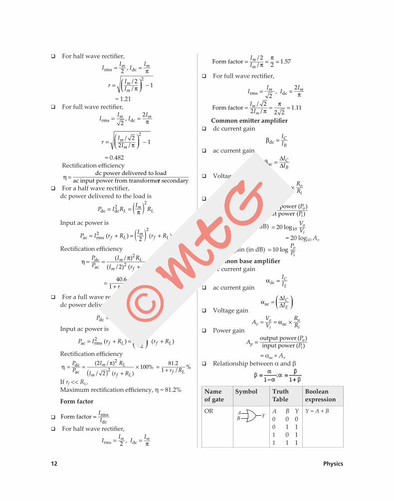
� For half wave rectifier,
II
IIm m
rms dc= =2 , π
r
II
m
m=
−
//
2 12
π
= 1.21 � For full wave rectifier,
II
IIm m
rms dc= =2
2, π
rI
Im
m=
−
//
22 1
2
π
= 0.482 Rectification efficiency
η =dc power delivered to load
ac input power from transformerr secondary � For a half wave rectifier,
dc power delivered to the load is
P I RI
RLm
Ldc dc= = ( )22
π
Input ac power is
P I r RI
r Rf Lm
f Lac rms= + = ( ) +22
2( ) ( )
Rectification efficiency
ηπ
= =+
×PP
I RI r R
m L
m f L
dcac
( / )( / ) ( )
%2
22100
= +
40 61
./ %r Rf L
� For a full wave rectifier, dc power delivered to the load is
P I RI
RLm
Ldc dc= = ( )222
πInput ac power is
P I r RI
r Rf Lm
f Lac rms= + =
+2
2
2( ) ( )
Rectification efficiency
ηπ
= =( ) +
×PP
I R
I r R
m L
m f L
dcac
( / )
/ ( )%
2
2100
2
2 = +81 2
1./ %r Rf L
If rf << RL,Maximum rectification efficiency, h = 81.2%
Form factor
Form factor rmsdc
=II �
� For half wave rectifier,
II
IIm m
rms dc= =2 , π
Form factor = = =II
m
m
// .2
2 1 57ππ
� For full wave rectifier,
II
IIm m
rms dc,= =2
2π
Form factor = = =II
m
m
// .2
2 2 21 11π
π
Common emitter amplifier � dc current gain
βdc =IIC
B � ac current gain
βac =∆∆
IIC
B
� Voltage gain
AVV
RRv
o
i
o
i= = − ×βac
� Power gain
APPp
o
i=
output power (input power (
))
� Voltage gain (in dB) = 20 10log VV
o
i = 20 log10 Av
� Power gain (in dB) = 10 log PP
o
iCommon base amplifier
� dc current gain
αdc = IIC
E � ac current gain
αac =
∆∆
IIC
E � Voltage gain
AVV
RRv
o
i
o
i= = ×αac
� Power gain
APPp
o
i=
output power (input power ( )
)
= aac × Av
� Relationship between a and b
;
Name of gate
Symbol Truth Table
Booleanexpression
OR A B Y0 0 00 1 11 0 11 1 1
Y = A + B
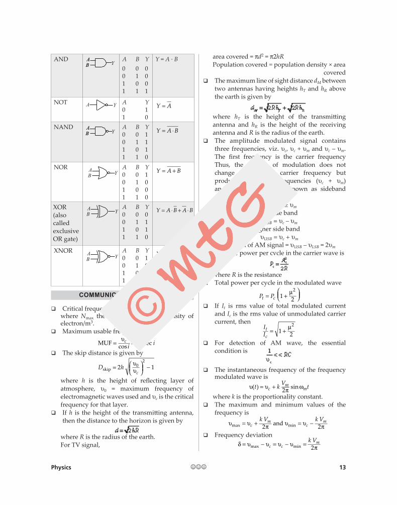
Physics 13
AND A B Y0 0 00 1 01 0 01 1 1
Y = A · B
NOT A Y0 11 0
Y A=
NAND A B Y0 0 10 1 11 0 11 1 0
Y A B= ⋅
NOR A B Y0 0 10 1 01 0 01 1 0
Y A B= +
XOR(also called exclusive OR gate)
A B Y0 0 00 1 11 0 11 1 0
Y A B A B= ⋅ + ⋅
XNOR A B Y0 0 10 1 01 0 01 1 1
Y A B A B= ⋅ + ⋅
COMMUNICATION SYSTEM
� Critical frequency, uc = g(Nmax)1/2
where Nmax the maximum number density of electron/m3.
� Maximum usable frequency
MUF = =υ
υcci icos sec
� The skip distance is given by
D hc
skip =
−2 102υ
υ
where h is the height of reflecting layer of atmosphere, u0 = maximum frequency of electromagnetic waves used and uc is the critical frequency for that layer.
� If h is the height of the transmitting antenna, then the distance to the horizon is given by
where R is the radius of the earth.For TV signal,
area covered = pd2 = p2hRPopulation covered = population density × area covered
� The maximum line of sight distance dM between two antennas having heights hT and hR above the earth is given by
where hT is the height of the transmitting antenna and hR is the height of the receiving antenna and R is the radius of the earth.
� The amplitude modulated signal contains three frequencies, viz. uc, uc + um and uc – um. The first frequency is the carrier frequency Thus, the process of modulation does not change the original carrier frequency but produces two new frequencies (uc + um) and(uc – um) which are known as sideband frequencies.
uSB = uc ± um
� Frequency of lower side banduLSB = uc – um
� Frequency of higher side banduUSB = uc + um
� Bandwidth of AM signal = uUSB – uLSB = 2um
� Average power per cycle in the carrier wave is
where R is the resistance � Total power per cycle in the modulated wave
P Pt c= +
1 2
2µ
� If It is rms value of total modulated current and Ic is the rms value of unmodulated carrier current, then
II
t
c= +1 2
2µ
� For detection of AM wave, the essential condition is
� The instantaneous frequency of the frequency modulated wave is
υ υ π ω( ) sint kV
tcm
m= + 2where k is the proportionality constant.
� The maximum and minimum values of the frequency is
υ υ π υ υ πmax min= + = −cm
cmk V k V
2 2and
� Frequency deviationδ υ υ υ υ π= − = − =max minc c
mk V2
JJJ