Embed Size (px)
Citation preview

Recursive Ray Tracing

Color Accumulation at an Intersection Point• • A shadow ray is cast to each light source, and the total contribution from all light sources is accumulated
(kR, kc, kB)(~ . Vlightliight max(O, cos (}light)+ !ambient n . ( 1 - Vzight)) Lz~h~ z~h~ • Vught = 1 for visible light sources, and Vught = 0 for occluded light sources
• Iambient is added to fully shadowed regions where Tiughts( 1 - Vught) * 0
• To summarize: (kR, kc, kB)(Ldiffuse + Lambient)
• Mirror-like reflective properties can *also* contribute to the color at an intersection point • Transparency allows other objects to show through a surface, and thus those objects can
*also* contribute color to an intersection point
• In summary: (kR, kc, kB)(Ldiffuse + Lambient) + Lreflect + Ltransmit

Additional Light•
less reflection (darker) more reflection (brighter)
• Reflection and Transmission add light to a pixel making it brighter • Thus, scaling coefficients are added in front of every lighting contribution
(kR, kG, kB)(kdLdiffuse + kalambient) + krlreflect + ktltransmit • Typically, coefficients are adjusted relative to each other to get the desired "look"; then, all the
coefficients are scaled together to get the appropriate overall brightness/darkness

Recursion• • Lreflect and Ltransmit are treated in exactly the same way as pixel colors are treated
• A ray is constructed for the reflection direction and intersected with scene geometry (in exactly the same way as was done for camera rays through pixels)
• the result is stored in Lreflect
• A ray is constructed for the transmission direction and intersected with scene geometry (in exactly the same way as was done for camera rays through pixels)
• the result is stored in Ltransmit
• Lreflect and Ltransmit depend on the color computed from whatever object geometry was intersected by their corresponding rays • Those intersection points will have colors of their own (computed as usual via shadow rays, diffuse shading, and ambient shading) • In addition, the color of those intersections can also depend on subsequent reflection and transmission, meaning that even more rays need to be spawned before a color can be computed

Ray Tree Example
a) b) light
I

Code Simplicity•Recursion allows for stunning imagery with minimal code, as demonstrated by these 1337 characters printed on the back of a business card
http://fabiensanglard.net/rayTracing_back_of_business_card/

Termination• • If every subsequently intersected point continued to depend on reflected/transmitted rays, rays would be spawned indefinitely (never terminating) • Eventually one hits the recursion limit (depending on hardware) that prevents stack overflow
• If kd and ka are nonzero frequently enough, the reflected/transmitted contributions are eventually diminished enough that one can terminate the recursion
• Just need to add a final arbitrary value for Lreflect and/or Ltransmit (without tracing the associated ray)
• In some cases (mirrors, bubbles, etc.), there is little to no diffuse/ambient lighting and nearly 100% of the lighting is recursively sought after via reflected/transmitted rays • In those cases, any arbitrary values will show up as the final pixel color • This can look terrible, e.g. a black pixel in a mist of bubbles • One often struggles to choose realistic termination colors (common choices are the sky color, the background color, etc.)

Reflected Ray• • Given an incoming ray R(t) =A+ Dt with direction D, and local (outward) unit normal to the geometry N, the angle of incidence is defined via D · N = -llD ll 2 cos (Ji
• For mirror reflection, the incoming/outgoing rays make the same angle w ith N, i.e. (}0 = (Ji ,
and those rays and the normal are all coplanar • Thus, the reflected ray direction is Dreflect = D - 2(D · N)N • Then, the reflected ray is RreflectCt) = R(tint) + Dreflectt
Dreflect 1
t N I I
(D. N)N I
.(D · N)N
I I I

Spurious Self-Occlusion• • Numerical precision issues can cause the reflected ray to incorrectly re-intersect the same object near R(tint), similar to the issues for shadow rays • Once again, one can use t E (E, oo) for some E > 0 large enough to avoid the ray incorrectly re-intersecting the same object • However, grazing rays near the object's silhouette may still incorrectly re-intersect the object
N
Dre fleet D

Spurious Self-Occlusion• • Alternatively, perturb the starting point of the reflected ray to be slightly away from the object, e.g. from R(tint) to R(tint) +EN • Perturbed reflected rays do not have the ray direction modified (unlike shadow rays) • The new reflected ray is Rreflect(t) = R(tint) +EN+ Dreflectt with t E (O,oo) • This works well, but one needs to be careful that the new starting point does not fall inside (or too close to) nearby geometry
Dre fleet

Reflections
----
I I I I I
'
t I I I I I

Transmission• • The relationship between the angle of incidence and angle of transmission (refraction) for light passing through a boundary between two different isotropic media is given by Snell's Law
• s~n : 1 = ~ = ~ where 91 and 92 are the incoming/outgoing angles, v1 and v2 are the phase sin 2 v2 n1
velocities and n1 and n2 are the indices of refraction

Transmitted Ray• • D is the (unit) incoming ray direction, N is the (outward) unit normal, and Tis the unit tangent in the plane of D and N, so that D + Ncos£J1 + Tsin£J1 = 0 • Let Dtransmit be the (unit) transmitted ray direction, then Dtransmit + Tsin£J2 + Ncos£J2 = 0
N Tsin01
D co~o ,
01 n1
T n 2

Transmitted Ray•
2 • Using Snell's Law, Dtransmit = (D + N cos81 ) '!!:1. - N 1 - (!!:!. sin81 )
nz nz
• Dtransmit = D ~ + N ( ~cos81 - 1 - (~)2 (1 - cos2 91))
• Using cos81 = -D · N gives Dtransmit = D !!:!. - N ('!!2 D · N + j 1 - (!!:!.)2
(1 - (D · N)2 ) ) nz nz nz
• If the term under the square root is negative, there is no transmitted ray, and all the light is reflected (total internal reflection)
• Note: This equation works regardless of whether n1 or n 2 is bigger • Note: Add E to avoid self intersection, or offset in the negative normal direction (respecting collisions, other geometry, etc. as usual)

Total Internal Reflection•When light is going from a higher index of refraction to lower index of refraction, no light is transmitted when the incident angle exceeds a critical angle•In such a case, all the light reflects
when θ2 < θ
2,max , both reflection and
Transmission occurwhen θ
2 > θ
2,max , only reflection occurs

Critical Angle• • When 01 = ~, which is the maximum angle for transmission, sin G) = 1 and Snell's Law
becomes . 1 e = ~ or 02 = arcsin (~)
sin 2 n 1 n 2
• So for n1 < n 2 , the critical angle is 02 = arcsin (;;:)

Total Internal Reflection
•Responsible for many interesting and impressive visuals in both glass and water

Snell’s Window
•Yes, fish can see you on the shore!

Snell’s Window
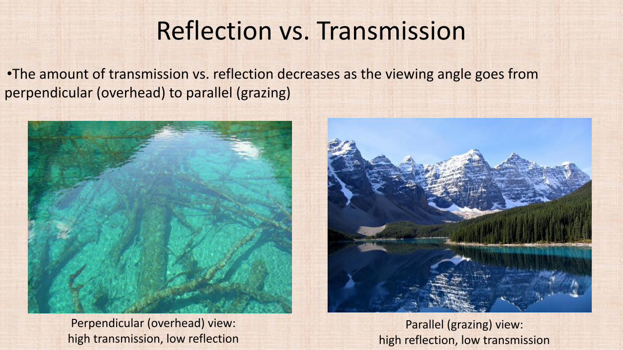
Reflection vs. Transmission
•The amount of transmission vs. reflection decreases as the viewing angle goes from perpendicular (overhead) to parallel (grazing)
Perpendicular (overhead) view:high transmission, low reflection
Parallel (grazing) view:high reflection, low transmission

Reflection vs. Transmission
•For opaque objects (without transmission) reflection still behaves similarly
As the viewing angle changes from overhead to a more grazing angle (from left to right), the amount of reflection off of the table increases (and one can better see the book’s reflection)

Fresnel Equations
•The proportion of reflection gradually increases as the viewing angle goes from perpendicular (coincident with the normal) to parallel (orthogonal to the normal)
Light entering a denser material (e.g. from air into water)
Light leaving a denser material (e.g. exiting water into air)

Fresnel Equations• Light is polarized into 2 parts based on whether the plane containing the incident, reflected,
refracted rays is parallel (p-polarized) or perpendicular (s-polarized) to the electric field• The Fresnel equations give the fraction of light reflected as:
• Transmission (if it occurs) is typically calculated as the remaining light:
• For unpolarized light (a typical assumption in ray tracing), we assume:

Schlick’s Approximation
• Approximate reflection via:
Fresnel (solid lines)
Schlick (dotted lines)

Conductors vs. Dielectrics
•
Conductor Dielectric
•Conductors of electricity (e.g. metals) mostly reflect light (low absorption, zero transmission) •The amount of light reflected doesn't change much with the viewing angle (e.g. aluminum varies from 90% to 100% as the viewing angle changes from overhead to grazing) •Thus, can approximate kr as independent of viewing direction (for conductors) • In contrast, dielectrics (e.g. glass) have significant variance in reflection vs. transmission with viewing angle

Curved Surfaces•The viewing angle can vary (from perpendicular to parallel) across the surface of an object•Thus, the amount of reflection vs. transmission can similarly vary across the object•Capturing this is especially important for visual realism when rendering dielectrics
Correct reflection vs. transmission
(based on viewing angle)
Incorrect reflection vs. transmission
(with no dependence on viewing angle)

Attenuation• Light is attenuated as it travels through media (as the light is both absorbed and scattered)• This attenuation effect is stronger over longer distances• Different colors are attenuated at different rates
• For example:• Shallow water is clear (almost no attenuation)• Deeper water attenuates all the red light and looks bluish-green• Even deeper water attenuates all the green light too, and looks blue• Eventually all the light attenuates, and the color ranges from blackish-blue to black

Beer’s Law
• • If the media is homogeneous, attenuation along a ray can be described by Beer's Law • Light with intensity I is attenuated over a distance x via the Ordinary Differential Equation
(ODE): ~ = -cl where c is the coefficient of attenuation
• The exact solution to this ODE is I(x) = I 0 e-cx where 10 is the original unattenuated amount of light
-----outgoing light e-cx10
---
incoming light 10

Beer’s Law• • The color of a transparent object is described by three independent attenuation coefficients,
one for each color channel (i.e. cR, cG, c8 )
• Shadow rays are also attenuated

Atmospheric Refraction
• Light continuously bends (following a curved path) as it passes through varying temperature gases, such as the atmosphere• This is due to continuous variations in density, and thus similar variations in the refractive
index

Inferior Mirage

Superior Mirage

Superior Mirage (March 2021, England)

Atmospheric Refraction
• Bend the rays as they go through varying air densities• Change the light direction between every interval in the vertical direction (left) or along the ray
direction (right)

Gravity can bend light too!
http://www.wired.com/2014/10/astrophysics-interstellar-black-hole/https://www.businessinsider.com/interstellar-anniversary-learned-about-black-holes-2019-11

Iridescence
• Surface can gradually change color as the viewing angle or the lighting change

Iridescence
• Various light waves are emitted in the same direction giving constructive and destructive interference
http://www.glassner.com/wp-content/uploads/2014/04/CG-CGA-PDF-00-11-Soap-Bubbles-2-Nov00.pdf