Embed Size (px)
Citation preview
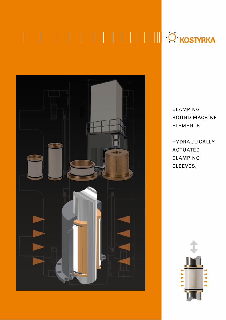
CLAMPING
ROUND MACHINE
ELEMENTS.
HYDRAULICALLY
ACTUATED
CLAMPING
SLEEVES.
2
1
2
3
4
5
6
7
1
32
4
5
6
1
32
4
5
6
7
1
2
34
5
6
7
The development of modern machine tools was
decisively infl uenced by the use of KOSTYRKA®
clamping sleeves. The allow extremely high holding
forces, are fully designed for program control, close
and open extremely quick and support the designer
with their unique space-saving concept. No wonder
that to date, Kostyrka has delivered several hundred
thousand clamping sleeves to machine and fi xture
manufacturers all over the world.
Precise and wear-free
The precision and durability of KOSTYRKA® clamping
sleeves are precondition for smooth production.
Disassembling and reassembling a 2,500-tonne press
for repairs isn‘t a simple overnight job. The high
expectations that customers have in terms of product
quality are met by using state-of-the-art production and
control procedures. So that they can rely on safe
operation day after day, year after year.
The principle: Ingeniously simple, simply
ingenious
The basic item of every KOSTYRKA® clamping
sleeve is a fl exible body made from a metal-plastic
composite that, depending on the type, surrounds
the part being held or is surrounded by it. Pressure
is built up on the sleeve jacket. This is converted via
a fl exible metal body into clamping force without
T H E P R I N C I P L E O F T H E K O S T Y R K A ® C L A M P I N G S L E E V E .
M A D E - T O - O R D E R F O R E V E RY A P P L I C AT I O N .
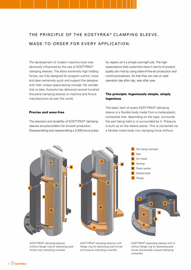
Part being clamped
Seal
Oil infeed
Venting
Plastic jacket
Slotted body
Flange
KOSTYRKA® clamping sleeves with fl ange ring for absorbing axial forces and torques (clamping inwards).
KOSTYRKA® expanding sleeves with or without fl ange ring for absorbing axial forces and possibly torques (clamping outwards).
KOSTYRKA® clamping sleeves without fl ange ring for absorbing axial forces only (clamping inwards).
3
beginning, because KOSTYRKA clamping
technology is in most cases customization. The
process starts with your specifications, such as
forces and torques, the duration and frequency of
the clamping operations, details of travel speeds
and space conditions.
Geared to customer‘s demands
Based on the customer‘s specifications, KOSTYRKA
first performs a precise calculation of all parameters.
This is followed by a 3D design. Besides a few
standard sizes, KOSTYRKA makes almost any desired
clamping sleeve – currently with inside diameters of
between six and 1,800 millimetres, lengths over 900
millimetres and for operating pressures of up to 600
bar. We almost develop for any number of installation
situations, calculate the necessary holding forces and
work out concepts for pressure generation. If desired,
we can also supply clamping sleeves complete with a
housing. In this case, you receive a clamping unit that
is ready to install.
Step by step towards a customer-orientated solution:
KOSTYRKA accompanies the development process
from the first drawing all the way to the individual
clamping solution. Contact our Development Depart-
ment or use our checklist at the end of the brochure.
loss and completely without reaction. After the oil
pressure has been released, the sleeves spring back
into their original position and the clamped part is
free again. This form of force transmission does not
damage the surfaces of the parts being clamped.
There will be three different types of clamping
sleeves:· Clamping sleeves without a flange ring-clamp
inwards. The absorb forces only in axial direction.· Clamping sleeves with a flange ring-clamp inwards.
The absorb forces in axial direction and also
torques.· Expansion sleeves with or without a flange
ring-clamp outwards. They absorb forces in axial
direction – and in the case of the version with a
flange ring, torques also.
It doesn‘t matter whether you call the products
clamping sleeves, spring collets, clamping bushes,
retaining bushes, clamping mandrels or expansion
mandrels, they all refer to the original KOSTYRKA®
clamping sleeves.
Accompanying development processes
At KOSTYRKA, partnership with the customer
means finding individual solutions and accom-
panying development processes right from the
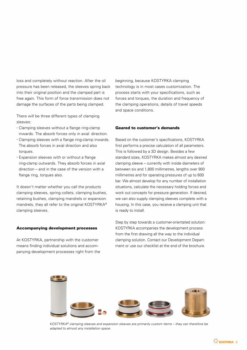
KOSTYRKA® clamping sleeves and expansion sleeves are primarily custom items – they can therefore be adapted to almost any installation space.
4
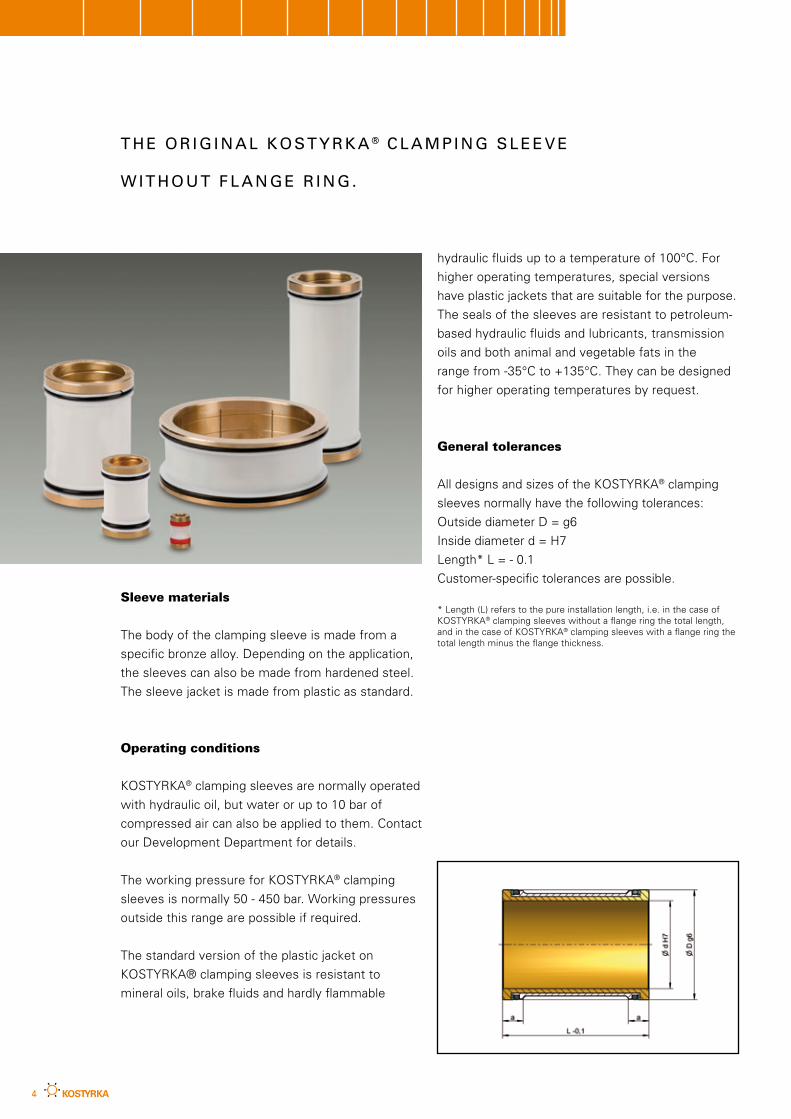
Sleeve materials
The body of the clamping sleeve is made from a
specific bronze alloy. Depending on the application,
the sleeves can also be made from hardened steel.
The sleeve jacket is made from plastic as standard.
Operating conditions
KOSTYRKA® clamping sleeves are normally operated
with hydraulic oil, but water or up to 10 bar of
compressed air can also be applied to them. Contact
our Development Department for details.
The working pressure for KOSTYRKA® clamping
sleeves is normally 50 - 450 bar. Working pressures
outside this range are possible if required.
The standard version of the plastic jacket on
KOSTYRKA® clamping sleeves is resistant to
mineral oils, brake fluids and hardly flammable
T H E O R I G I N A L K O S T Y R K A ® C L A M P I N G S L E E V E
W I T H O U T F L A N G E R I N G .
hydraulic fluids up to a temperature of 100°C. For
higher operating temperatures, special versions
have plastic jackets that are suitable for the purpose.
The seals of the sleeves are resistant to petroleum-
based hydraulic fluids and lubricants, transmission
oils and both animal and vegetable fats in the
range from -35°C to +135°C. They can be designed
for higher operating temperatures by request.
General tolerances
All designs and sizes of the KOSTYRKA® clamping
sleeves normally have the following tolerances:
Outside diameter D = g6
Inside diameter d = H7
Length* L = - 0.1
Customer-specific tolerances are possible.
* Length (L) refers to the pure installation length, i.e. in the case of KOSTYRKA® clamping sleeves without a flange ring the total length, and in the case of KOSTYRKA® clamping sleeves with a flange ring the total length minus the flange thickness.
5
5350
.010
.040
5350
.015
.050
5350
.020
.065
5350
.030
.058
5350
.040
.070
5350
.045
.100
5350
.070
.120
5350
.120
.115
5350
.150
.140
5350
.060
.100
5350
.030
.100
5350
.020
.045
5350
.025
.060
5350
.025
.080
5350
.035
.080
5350
.050
.100
5350
.080
.120
5350
.100
.140
5350
.080
.100
5350
.040
.100
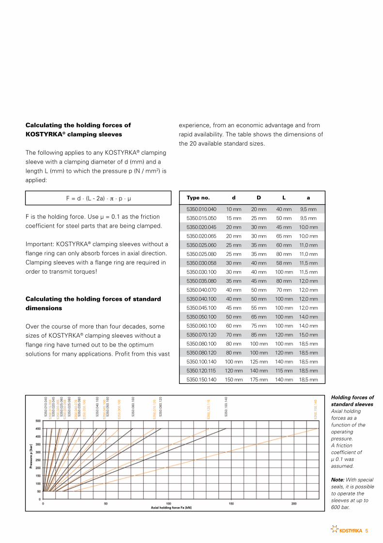
Calculating the holding forces of
KOSTYRKA® clamping sleeves
The following applies to any KOSTYRKA® clamping
sleeve with a clamping diameter of d (mm) and a
length L (mm) to which the pressure p (N / mm2) is
applied:
F = d · (L - 2a) · π · p · µ
F is the holding force. Use µ = 0.1 as the friction
coefficient for steel parts that are being clamped.
Important: KOSTYRKA® clamping sleeves without a
flange ring can only absorb forces in axial direction.
Clamping sleeves with a flange ring are required in
order to transmit torques!
Calculating the holding forces of standard
dimensions
Over the course of more than four decades, some
sizes of KOSTYRKA® clamping sleeves without a
flange ring have turned out to be the optimum
solutions for many applications. Profit from this vast
experience, from an economic advantage and from
rapid availability. The table shows the dimensions of
the 20 available standard sizes.
Holding forces of standard sleevesAxial holding forces as a function of the operating pressure. A friction coefficient of µ 0.1 was assumed.
Note: With special seals, it is possible to operate the sleeves at up to 600 bar.
Type no. d D L a
5350.010.040 10mm 20mm 40mm 9,5mm
5350.015.050 15mm 25mm 50mm 9,5mm
5350.020.045 20mm 30mm 45mm 10,0mm
5350.020.065 20mm 30mm 65mm 10,0mm
5350.025.060 25mm 35mm 60mm 11,0mm
5350.025.080 25mm 35mm 80mm 11,0mm
5350.030.058 30mm 40mm 58mm 11,5mm
5350.030.100 30mm 40mm 100mm 11,5mm
5350.035.080 35mm 45mm 80mm 12,0mm
5350.040.070 40mm 50mm 70mm 12,0mm
5350.040.100 40mm 50mm 100mm 12,0mm
5350.045.100 45mm 55mm 100mm 12,0mm
5350.050.100 50mm 65mm 100mm 14,0mm
5350.060.100 60mm 75mm 100mm 14,0mm
5350.070.120 70mm 85mm 120mm 15,0mm
5350.080.100 80mm 100mm 100mm 18,5mm
5350.080.120 80mm 100mm 120mm 18,5mm
5350.100.140 100mm 125mm 140mm 18,5mm
5350.120.115 120mm 140mm 115mm 18,5mm
5350.150.140 150mm 175mm 140mm 18,5mm
Axial holding force Fa [kN]
Pre
ssu
re p
[b
ar]
6
Ø d
H7
Ø D
g6
a
L -0,1
a
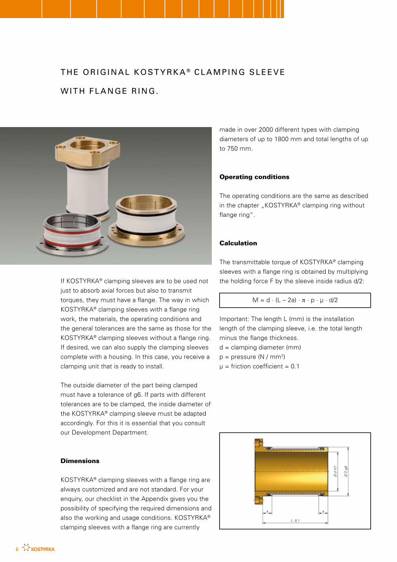
If KOSTYRKA® clamping sleeves are to be used not
just to absorb axial forces but also to transmit
torques, they must have a flange. The way in which
KOSTYRKA® clamping sleeves with a flange ring
work, the materials, the operating conditions and
the general tolerances are the same as those for the
KOSTYRKA® clamping sleeves without a flange ring.
If desired, we can also supply the clamping sleeves
complete with a housing. In this case, you receive a
clamping unit that is ready to install.
The outside diameter of the part being clamped
must have a tolerance of g6. If parts with different
tolerances are to be clamped, the inside diameter of
the KOSTYRKA® clamping sleeve must be adapted
accordingly. For this it is essential that you consult
our Development Department.
Dimensions
KOSTYRKA® clamping sleeves with a flange ring are
always customized and are not standard. For your
enquiry, our checklist in the Appendix gives you the
possibility of specifying the required dimensions and
also the working and usage conditions. KOSTYRKA®
clamping sleeves with a flange ring are currently
made in over 2000 different types with clamping
diameters of up to 1800 mm and total lengths of up
to 750 mm.
Operating conditions
The operating conditions are the same as described
in the chapter „KOSTYRKA® clamping ring without
flange ring“.
Calculation
The transmittable torque of KOSTYRKA® clamping
sleeves with a flange ring is obtained by multiplying
the holding force F by the sleeve inside radius d/2:
M = d · (L – 2a) · π · p · µ · d/2
Important: The length L (mm) is the installation
length of the clamping sleeve, i.e. the total length
minus the flange thickness.
d = clamping diameter (mm)
p = pressure (N / mm2)
µ = friction coefficient = 0.1
T H E O R I G I N A L K O S T Y R K A ® C L A M P I N G S L E E V E
W I T H F L A N G E R I N G .
7
Ø D g6
Ø d H7
aa
L -0
,1
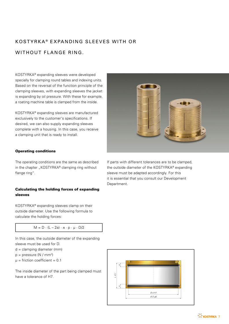
KOSTYRKA® expanding sleeves were developed
specially for clamping round tables and indexing units.
Based on the reversal of the function principle of the
clamping sleeves, with expanding sleeves the jacket
is expanding by oil pressure. With these for example,
a roating machine table is clamped from the inside.
KOSTYRKA® expanding sleeves are manufactured
exclusively to the customer‘s specifications. If
desired, we can also supply expanding sleeves
complete with a housing. In this case, you receive
a clamping unit that is ready to install.
Operating conditions
The operating conditions are the same as described
in the chapter „KOSTYRKA® clamping ring without
flange ring“.
Calculating the holding forces of expanding
sleeves
KOSTYRKA® expanding sleeves clamp on their
outside diameter. Use the following formula to
calculate the holding forces:
M = D · (L – 2a) · π · p · µ · D/2
In this case, the outside diameter of the expanding
sleeve must be used for D.
d = clamping diameter (mm)
p = pressure (N / mm2)
µ = friction coefficient = 0.1
The inside diameter of the part being clamped must
have a tolerance of H7.
K O S T Y R K A ® E X PA N D I N G S L E E V E S W I T H O R
W I T H O U T F L A N G E R I N G .
If parts with different tolerances are to be clamped,
the outside diameter of the KOSTYRKA® expanding
sleeve must be adapted accordingly. For this
it is essential that you consult our Development
Department.
8
The part being clamped
All hardened or unhardened ferrous and non-ferrous
metals can be clamped with KOSTYRKA® clamping
sleeves. With very low-strength material, pay
attention to the maximum permissible surface
pressing when selecting the operating pressure.
Important note: During the clamping operation, the
part being clamped must be in its absolute static
condition, i.e. the KOSTYRKA® clamping sleeve
must not be used as a brake.
We recommend: · Do not clamp any cast surfaces· If necessary, case harden or flame harden
clamping surfaces – Do not nitride
If necessary, it is essential that you consult our
Development Department.
Condition of the clamping surfaces
The clamping surfaces must be kept free of
preservatives, rust converters, graphite-based or
molybdenum-based solid lubricants, seal abrasion
and metal abrasion and all types of dirt. Wipers
in the covers of locating holes or in the flange
prevent dirt from infiltration.
I N S TA L L AT I O N S PA C E A N D A D J A C E N T C O M P O N E N T S .
If piston guide rings are provided, make sure that
a graphite-filled or carbon-filled carrier material is not
used under any circumstances. Its abrasion can get
onto the clamping surfaces and reduce the required
holding force. Bronze-filled guide rings can be used.
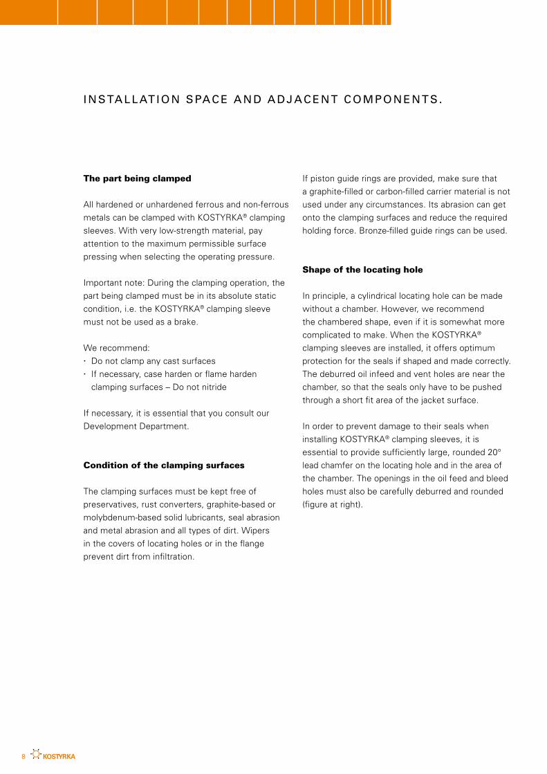
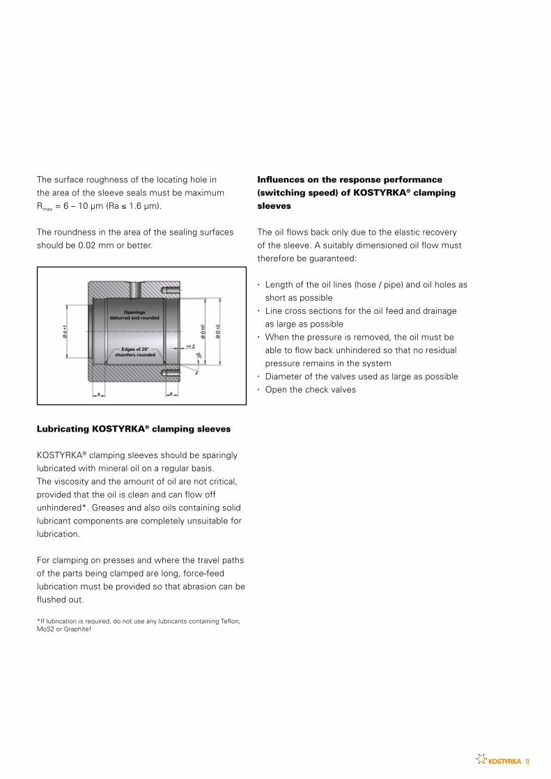
Shape of the locating hole
In principle, a cylindrical locating hole can be made
without a chamber. However, we recommend
the chambered shape, even if it is somewhat more
complicated to make. When the KOSTYRKA®
clamping sleeves are installed, it offers optimum
protection for the seals if shaped and made correctly.
The deburred oil infeed and vent holes are near the
chamber, so that the seals only have to be pushed
through a short fit area of the jacket surface.
In order to prevent damage to their seals when
installing KOSTYRKA® clamping sleeves, it is
essential to provide sufficiently large, rounded 20°
lead chamfer on the locating hole and in the area of
the chamber. The openings in the oil feed and bleed
holes must also be carefully deburred and rounded
(figure at right).
9
The surface roughness of the locating hole in
the area of the sleeve seals must be maximum
Rmax = 6 – 10 µm (Ra ≤ 1.6 µm).
The roundness in the area of the sealing surfaces
should be 0.02 mm or better.
Lubricating KOSTYRKA® clamping sleeves
KOSTYRKA® clamping sleeves should be sparingly
lubricated with mineral oil on a regular basis.
The viscosity and the amount of oil are not critical,
provided that the oil is clean and can flow off
unhindered*. Greases and also oils containing solid
lubricant components are completely unsuitable for
lubrication.
For clamping on presses and where the travel paths
of the parts being clamped are long, force-feed
lubrication must be provided so that abrasion can be
flushed out.
*If lubrication is required, do not use any lubricants containing Teflon, MoS2 or Graphite!
Influences on the response performance
(switching speed) of KOSTYRKA® clamping
sleeves
The oil flows back only due to the elastic recovery
of the sleeve. A suitably dimensioned oil flow must
therefore be guaranteed:
· Length of the oil lines (hose / pipe) and oil holes as
short as possible· Line cross sections for the oil feed and drainage
as large as possible· When the pressure is removed, the oil must be
able to flow back unhindered so that no residual
pressure remains in the system· Diameter of the valves used as large as possible· Open the check valves
Edges of 20° chamfers rounded
Openings deburred and rounded
10
Installation requirements
KOSTYRKA® clamping sleeves must never have
pressure applied to them when empty, i.e.
without the part being clamped – that would
immediately destroy them beyond repair!
Fit combinations of sleeve / housing with
locating hole and part being clamped
In practice, the shaft diameter g6 and standard bore
hole H7 fit combination has proved successful as a
clearance fit with good sliding properties. The inside
and outside diameters of all shapes and sizes of
KOSTYRKA® clamping sleeves are therefore adapted
to this fit combination. If the tolerances are different,
please consult our Development Department because
the sleeves must then be altered accordingly.
Fit combination of clamping sleeve with
locating hole
Outside diameter of the sleeve: g6
Inside diameter of the locating hole: H7
Fit combination of clamping sleeve /
part being clamped
Inside diameter of the sleeve: H7
Outside diameter of the part being clamped: g6
I N S TA L L AT I O N R E Q U I R E M E N T S .
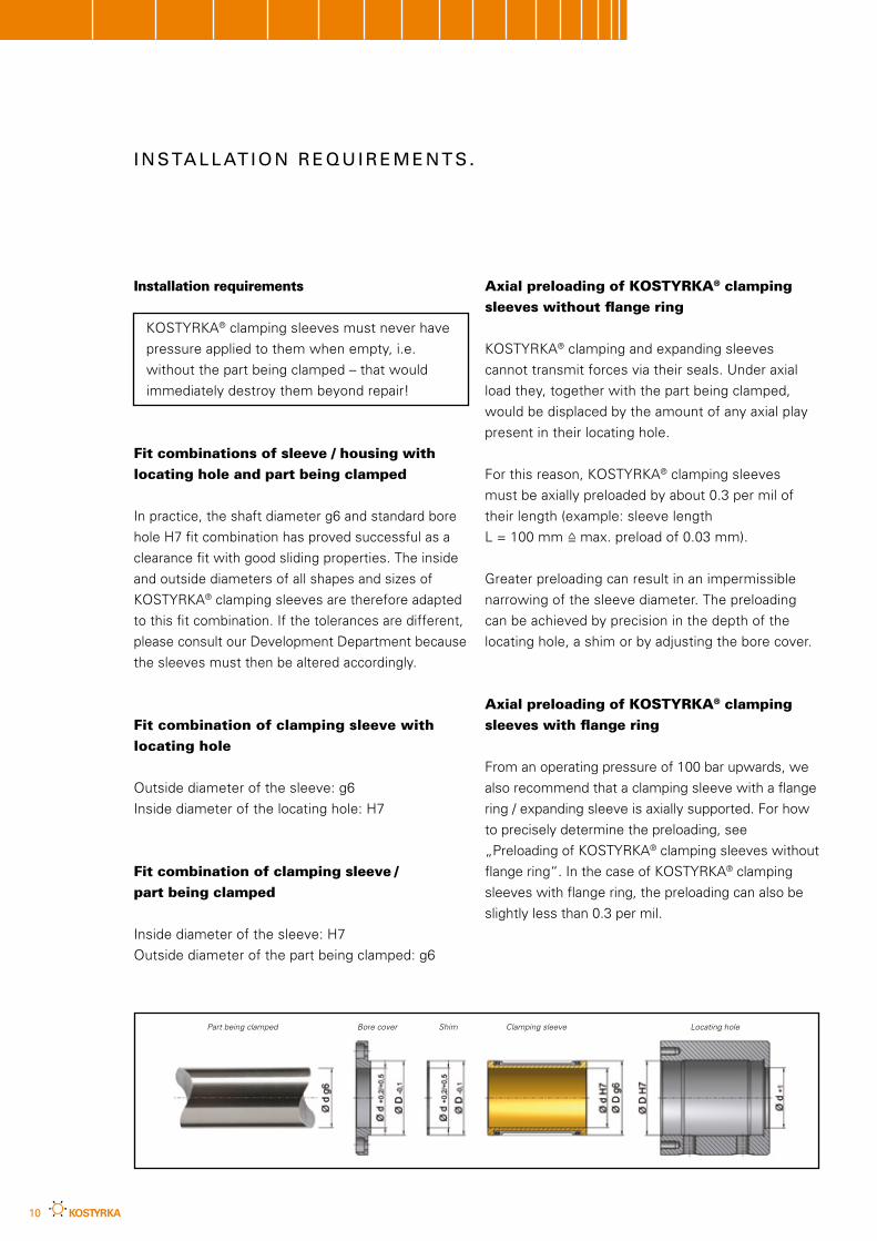
Axial preloading of KOSTYRKA® clamping
sleeves without flange ring
KOSTYRKA® clamping and expanding sleeves
cannot transmit forces via their seals. Under axial
load they, together with the part being clamped,
would be displaced by the amount of any axial play
present in their locating hole.
For this reason, KOSTYRKA® clamping sleeves
must be axially preloaded by about 0.3 per mil of
their length (example: sleeve length
L = 100 mm =̂ max. preload of 0.03 mm).
Greater preloading can result in an impermissible
narrowing of the sleeve diameter. The preloading
can be achieved by precision in the depth of the
locating hole, a shim or by adjusting the bore cover.
Axial preloading of KOSTYRKA® clamping
sleeves with flange ring
From an operating pressure of 100 bar upwards, we
also recommend that a clamping sleeve with a flange
ring / expanding sleeve is axially supported. For how
to precisely determine the preloading, see
„Preloading of KOSTYRKA® clamping sleeves without
flange ring“. In the case of KOSTYRKA® clamping
sleeves with flange ring, the preloading can also be
slightly less than 0.3 per mil.
Part being clamped Bore cover Shim Clamping sleeve Locating hole
11
Installing and removing KOSTYRKA®
clamping sleeves
Coat the lead chamfers, the fit of the locating hole
and the sleeve seals with some grease, and carefully
push the sleeve into the hole without tilting it.
KOSTYRKA® clamping sleeves with flange ring and
larger KOSTYRKA® clamping sleeves without
flange ring have at least two extraction threads for
removal. These aids are not present on smaller
versions. If technically feasible, extraction threads
are provided only at the customer‘s request.
Venting KOSTYRKA® clamping sleeves
It must be ensured that air pockets cannot be
formed either in the feed lines or in the installation
space of the sleeves. Compression causes air to
heat up to such an extent that the sleeve material
and seals could possibly be damaged.
F I T T I N G .
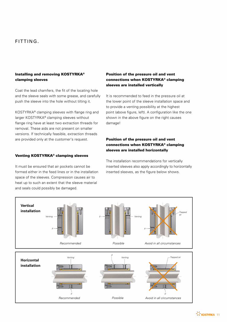
Vertical installation
Recommended
Recommended
Possible
Possible Avoid in all circumstances
Avoid in all circumstances
Horizontal installation
Venting Venting
Trapped air
Trapped airVentingVenting
Position of the pressure oil and vent
connections when KOSTYRKA® clamping
sleeves are installed vertically
It is recommended to feed in the pressure oil at
the lower point of the sleeve installation space and
to provide a venting possibility at the highest
point (above figure, left). A configuration like the one
shown in the above figure on the right causes
damage!
Position of the pressure oil and vent
connections when KOSTYRKA® clamping
sleeves are installed horizontally
The installation recommendations for vertically
inserted sleeves also apply accordingly to horizontally
inserted sleeves, as the figure below shows.
p
p
p
p
p
p
12
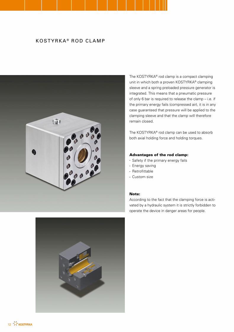
The KOSTYRKA® rod clamp is a compact clamping
unit in which both a proven KOSTYRKA® clamping
sleeve and a spring preloaded pressure generator is
integrated. This means that a pneumatic pressure
of only 6 bar is required to release the clamp – i.e. if
the primary energy fails (compressed air), it is in any
case guaranteed that pressure will be applied to the
clamping sleeve and that the clamp will therefore
remain closed.
The KOSTYRKA® rod clamp can be used to absorb
both axial holding force and holding torques.
Advantages of the rod clamp:· Safety if the primary energy fails· Energy saving
· Retrofittable
· Custom size
Note:
According to the fact that the clamping force is acti-
vated by a hydraulic system it is strictly forbidden to
operate the device in danger areas for people.
K O S T Y R K A ® R O D C L A M P
13
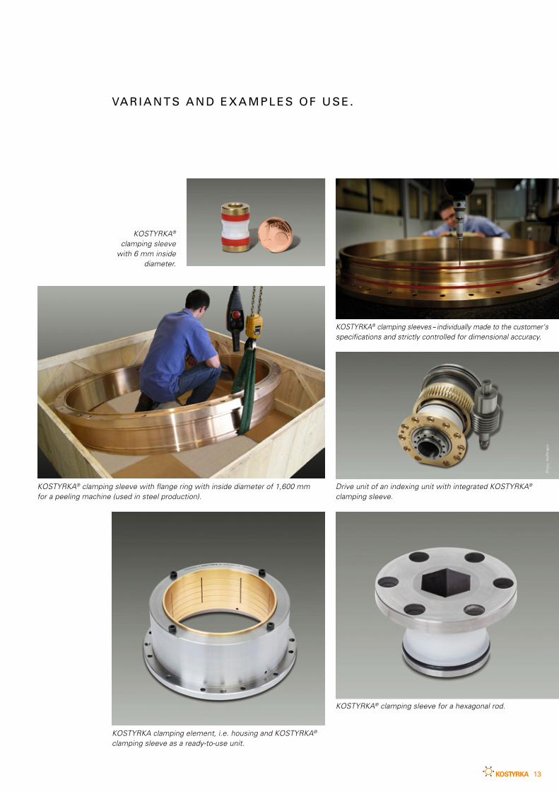
VA R I A N T S A N D E X A M P L E S O F U S E .
KOSTYRKA clamping element, i.e. housing and KOSTYRKA® clamping sleeve as a ready-to-use unit.
KOSTYRKA® clamping sleeve for a hexagonal rod.
KOSTYRKA® clamping sleeve with flange ring with inside diameter of 1,600 mm for a peeling machine (used in steel production).
Drive unit of an indexing unit with integrated KOSTYRKA® clamping sleeve.
KOSTYRKA® clamping sleeve
with 6 mm inside diameter.
KOSTYRKA® clamping sleeves – individually made to the customer‘sspecifications and strictly controlled for dimensional accuracy.
Pho
to: H
offm
ann
14
Please contact: KOSTYRKA GmbH
Dieselstraße 6
70839 Gerlingen · Germany
Telefon: +49 (0) 7156 - 1 76 73-28
Telefax: +49 (0) 7156 - 1 76 73-30
Torques are transmitted
- Expected torque
- Speed (rpm)
Company
Street / PO Box
Postal code / town
Phone
Fax
Contact partner
Which component is to be clamped?
Only axial forces arise.
- Maximum axial force
- Travel speed
- Length of the travel path
General informationWhat clamping pressure is available?
How is it generated?
Is there residual pressure in the system?
Frequency and duration of the clamping operations
Minimum and maximum operating temperature
Is there lubrication?
If so, what type?
What pressure medium is used?
Do you require a housing?
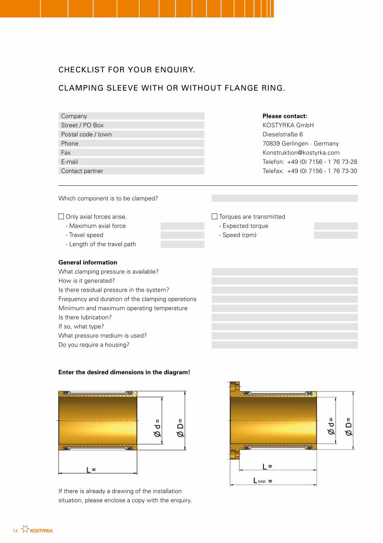
Enter the desired dimensions in the diagram!
If there is already a drawing of the installation
situation, please enclose a copy with the enquiry.
CHECKLIST FOR YOUR ENQUIRY.
CLAMPING SLEEVE WITH OR WITHOUT FLANGE RING.
total
15
Please contact: KOSTYRKA GmbH
Dieselstraße 6
70839 Gerlingen · Germany
Telefon: +49 (0) 7156 - 1 76 73-28
Telefax: +49 (0) 7156 - 1 76 73-30
Torques are transmitted
- Expected torque
- Speed (rpm)
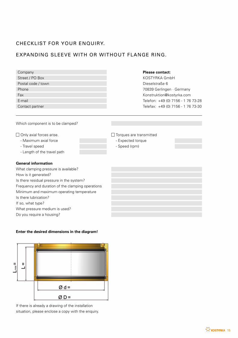
CHECKLIST FOR YOUR ENQUIRY.
EXPANDING SLEEVE WITH OR WITHOUT FLANGE RING.
Company
Street / PO Box
Postal code / town
Phone
Fax
Contact partner
Which component is to be clamped?
Only axial forces arise.
- Maximum axial force
- Travel speed
- Length of the travel path
General informationWhat clamping pressure is available?
How is it generated?
Is there residual pressure in the system?
Frequency and duration of the clamping operations
Minimum and maximum operating temperature
Is there lubrication?
If so, what type?
What pressure medium is used?
Do you require a housing?
Enter the desired dimensions in the diagram!
If there is already a drawing of the installation
situation, please enclose a copy with the enquiry.
total
KOSTYRKA GmbH
Dieselstraße 670839 GerlingenGermany
Phone +49 (0) 71 56 - 1 76 73-0
Fax +49 (0) 71 56 - 1 76 73-30
www.kostyrka.com
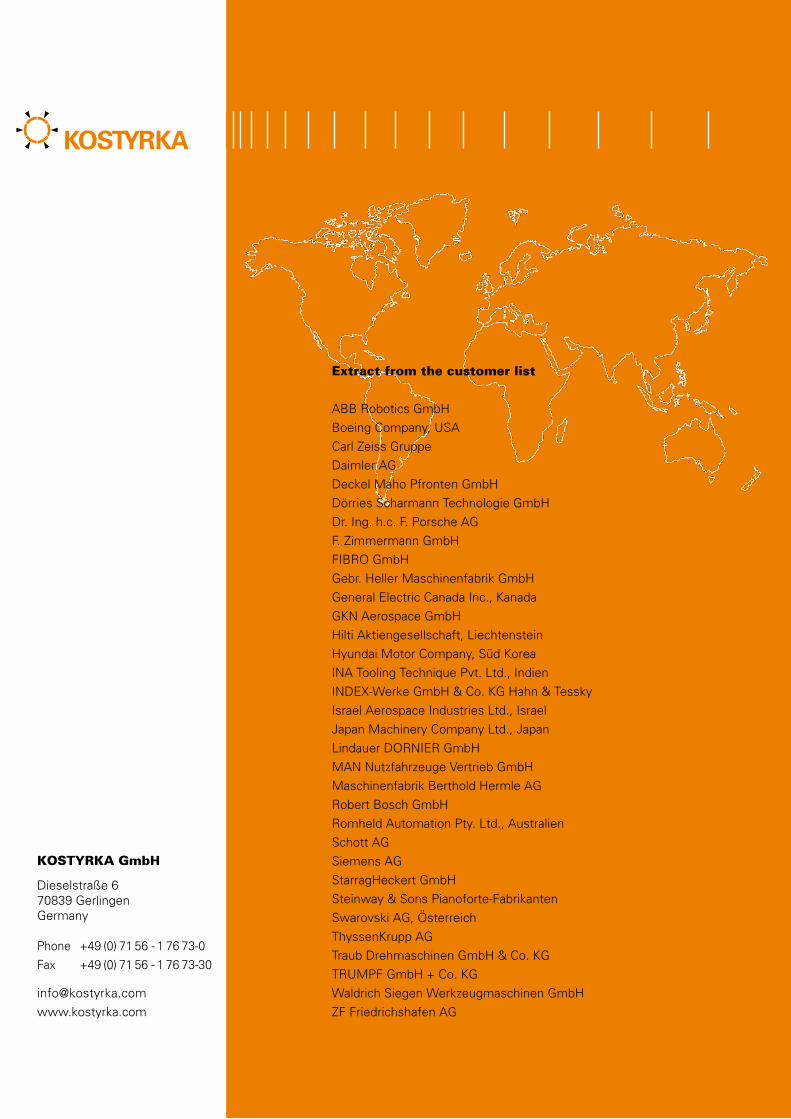
Extract from the customer list
ABB Robotics GmbH
Boeing Company, USA
Carl Zeiss Gruppe
Daimler AG
Deckel Maho Pfronten GmbH
Dörries Scharmann Technologie GmbH
Dr. Ing. h.c. F. Porsche AG
F. Zimmermann GmbH
FIBRO GmbH
Gebr. Heller Maschinenfabrik GmbH
General Electric Canada Inc., Kanada
GKN Aerospace GmbH
Hilti Aktiengesellschaft, Liechtenstein
Hyundai Motor Company, Süd Korea
INA Tooling Technique Pvt. Ltd., Indien
INDEX-Werke GmbH & Co. KG Hahn & Tessky
Israel Aerospace Industries Ltd., Israel
Japan Machinery Company Ltd., Japan
Lindauer DORNIER GmbH
MAN Nutzfahrzeuge Vertrieb GmbH
Maschinenfabrik Berthold Hermle AG
Robert Bosch GmbH
Romheld Automation Pty. Ltd., Australien
Schott AG
Siemens AG
StarragHeckert GmbH
Steinway & Sons Pianoforte-Fabrikanten
Swarovski AG, Österreich
ThyssenKrupp AG
Traub Drehmaschinen GmbH & Co. KG
TRUMPF GmbH + Co. KG
Waldrich Siegen Werkzeugmaschinen GmbH
ZF Friedrichshafen AG