Embed Size (px)
Citation preview
Clamp-on Ground TesterModel 6417
www.aemc.com
ENGLISHQuick Start Guide
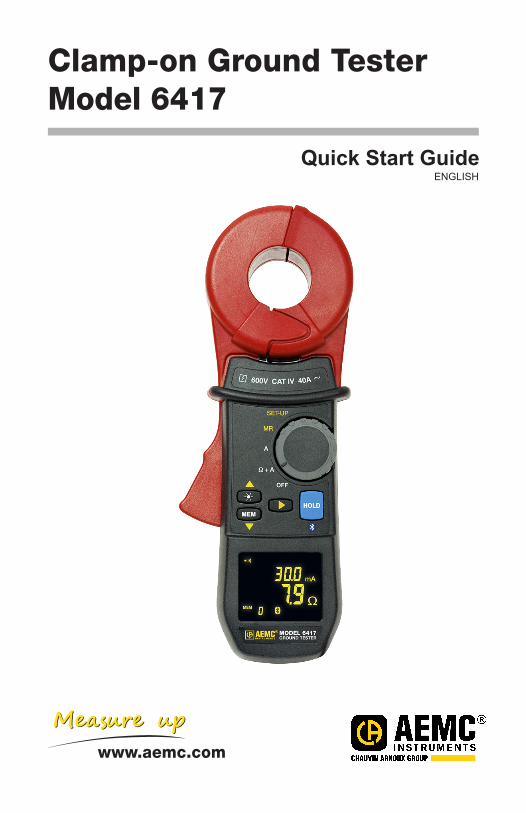
Clamp-on Ground TesterModel 6417
Cat. #2141.02
5W Calibration LoopCat. #2141.51
Bluetooth AdapterCat. #2126.45
Hard Accessory CaseCat. #2141.50
USB Stick with DataView® Software & User Manual
PRODUCT PACKAGING
Shipping Contents:
Also Included:(4) 1.5V AA Batteries(1) Wrist Strap(1) Safety Sheet (20 languages)(1) Quick Start Guide
USB STICK: DataView® software and complete user manual for the Model 6417 can be located on the USB stick supplied with the instrument.
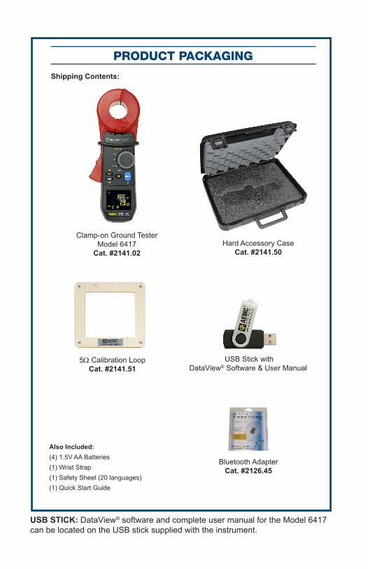
Statement of Compliance
Chauvin Arnoux®, Inc. d.b.a. AEMC® Instruments certifies that this instrument has been calibrated using standards and instruments traceable to international standards.
We guarantee that at the time of shipping your instrument has met its published specifications.
An NIST traceable certificate may be requested at the time of purchase, or obtained by returning the instrument to our repair and calibration facility, for a nominal charge.
The recommended calibration interval for this instrument is 12 months and begins on the date of receipt by the customer. For recalibration, please use our calibration services. Refer to our repair and calibration section at www.aemc.com.
Serial #: ________________________________
Catalog #: 2141.02
Model #: 6417
Please fill in the appropriate date as indicated:
Date Received: _________________________________
Date Calibration Due: _______________________
Chauvin Arnoux®, Inc.d.b.a AEMC® Instrumentswww.aemc.com
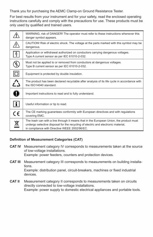
Thank you for purchasing the AEMC Clamp-on Ground Resistance Tester.For best results from your instrument and for your safety, read the enclosed operating instructions carefully and comply with the precautions for use. These products must be only used by qualified and trained users.
WARNING, risk of DANGER! The operator must refer to these instructions whenever this danger symbol appears.
CAUTION! Risk of electric shock. The voltage at the parts marked with this symbol may be dangerous.
Application or withdrawal authorized on conductors carrying dangerous voltages. Type A current sensor as per IEC 61010-2-032.
Must not be applied to or removed from conductors at dangerous voltages. Type B current sensor as per IEC 61010-2-032.
Equipment is protected by double insulation.
The product has been declared recyclable after analysis of its life cycle in accordance with the ISO14040 standard.
Important instructions to read and to fully understand.
Useful information or tip to read.
The CE marking guarantees conformity with European directives and with regulations covering EMC.The trash can with a line through it means that in the European Union, the product must undergo selective disposal for the recycling of electric and electronic material, in compliance with Directive WEEE 2002/96/EC.
Definition of Measurement Categories (CAT)
CAT IV Measurement category IV corresponds to measurements taken at the source of low-voltage installations. Example: power feeders, counters and protection devices.
CAT III Measurement category III corresponds to measurements on building installa-tions. Example: distribution panel, circuit-breakers, machines or fixed industrial devices.
CAT II Measurement category II corresponds to measurements taken on circuits directly connected to low-voltage installations. Example: power supply to domestic electrical appliances and portable tools.
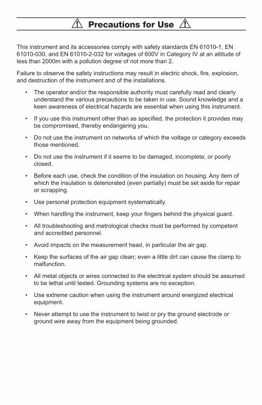
Precautions for Use
This instrument and its accessories comply with safety standards EN 61010-1, EN 61010-030, and EN 61010-2-032 for voltages of 600V in Category IV at an altitude of less than 2000m with a pollution degree of not more than 2.
Failure to observe the safety instructions may result in electric shock, fire, explosion, and destruction of the instrument and of the installations.
• The operator and/or the responsible authority must carefully read and clearlyunderstand the various precautions to be taken in use. Sound knowledge and akeen awareness of electrical hazards are essential when using this instrument.
• If you use this instrument other than as specified, the protection it provides maybe compromised, thereby endangering you.
• Do not use the instrument on networks of which the voltage or category exceedsthose mentioned.
• Do not use the instrument if it seems to be damaged, incomplete, or poorlyclosed.
• Before each use, check the condition of the insulation on housing. Any item ofwhich the insulation is deteriorated (even partially) must be set aside for repairor scrapping.
• Use personal protection equipment systematically.
• When handling the instrument, keep your fingers behind the physical guard.
• All troubleshooting and metrological checks must be performed by competentand accredited personnel.
• Avoid impacts on the measurement head, in particular the air gap.
• Keep the surfaces of the air gap clean; even a little dirt can cause the clamp tomalfunction.
• All metal objects or wires connected to the electrical system should be assumedto be lethal until tested. Grounding systems are no exception.
• Use extreme caution when using the instrument around energized electricalequipment.
• Never attempt to use the instrument to twist or pry the ground electrode orground wire away from the equipment being grounded.
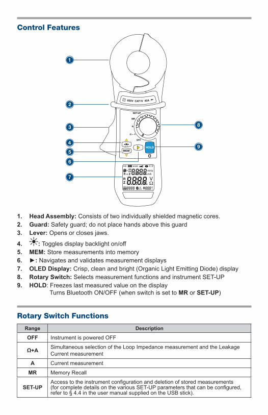
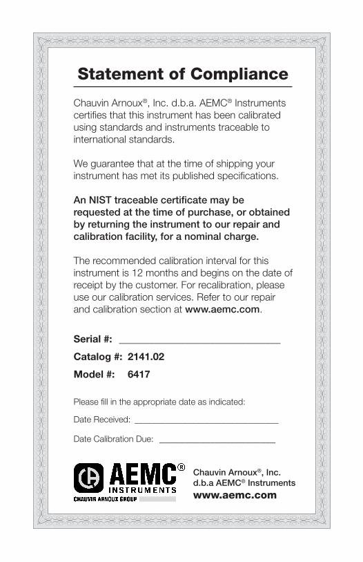
Control Features
MEMHOLD
OFF
A
MR
SET-UP
600V CAT IV 40A
1
2
3 8
94
5
6
7
1. Head Assembly: Consists of two individually shielded magnetic cores.2. Guard: Safety guard; do not place hands above this guard3. Lever: Opens or closes jaws.
4. : Toggles display backlight on/off5. MEM: Store measurements into memory6. : Navigates and validates measurement displays7. OLED Display: Crisp, clean and bright (Organic Light Emitting Diode) display8. Rotary Switch: Selects measurement functions and instrument SET-UP9. HOLD: Freezes last measured value on the display
Turns Bluetooth ON/OFF (when switch is set to MR or SET-UP)
Rotary Switch Functions
Range Description
OFF Instrument is powered OFF
Ω+A Simultaneous selection of the Loop Impedance measurement and the Leakage Current measurement
A Current measurement
MR Memory Recall
SET-UPAccess to the instrument configuration and deletion of stored measurements (for complete details on the various SET-UP parameters that can be configured, refer to § 4.4 in the user manual supplied on the USB stick).
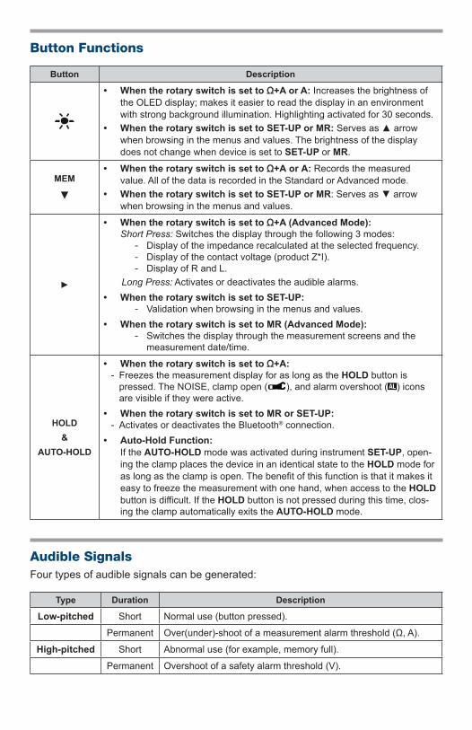
Button Functions
Button Description
• When the rotary switch is set to Ω+A or A: Increases the brightness ofthe OLED display; makes it easier to read the display in an environmentwith strong background illumination. Highlighting activated for 30 seconds.
• When the rotary switch is set to SET-UP or MR: Serves as arrowwhen browsing in the menus and values. The brightness of the displaydoes not change when device is set to SET-UP or MR.
MEM
• When the rotary switch is set to Ω+A or A: Records the measuredvalue. All of the data is recorded in the Standard or Advanced mode.
• When the rotary switch is set to SET-UP or MR: Serves as arrowwhen browsing in the menus and values.
• When the rotary switch is set to Ω+A (Advanced Mode):Short Press: Switches the display through the following 3 modes:
- Display of the impedance recalculated at the selected frequency. - Display of the contact voltage (product Z*I). - Display of R and L.
Long Press: Activates or deactivates the audible alarms.• When the rotary switch is set to SET-UP:
- Validation when browsing in the menus and values.• When the rotary switch is set to MR (Advanced Mode):
- Switches the display through the measurement screens and the measurement date/time.
HOLD&
AUTO-HOLD
• When the rotary switch is set to Ω+A: - Freezes the measurement display for as long as the HOLD button is pressed. The NOISE, clamp open ( ), and alarm overshoot ( ) iconsare visible if they were active.
• When the rotary switch is set to MR or SET-UP: - Activates or deactivates the Bluetooth® connection.
• Auto-Hold Function:If the AUTO-HOLD mode was activated during instrument SET-UP, open-ing the clamp places the device in an identical state to the HOLD mode for as long as the clamp is open. The benefit of this function is that it makes it easy to freeze the measurement with one hand, when access to the HOLD button is difficult. If the HOLD button is not pressed during this time, clos-ing the clamp automatically exits the AUTO-HOLD mode.
Audible SignalsFour types of audible signals can be generated:
Type Duration Description
Low-pitched Short Normal use (button pressed).
Permanent Over(under)-shoot of a measurement alarm threshold (Ω, A).
High-pitched Short Abnormal use (for example, memory full).
Permanent Overshoot of a safety alarm threshold (V).
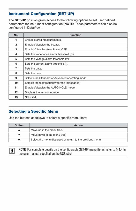
Instrument Configuration (SET-UP)
The SET-UP position gives access to the following options to set user defined parameters for instrument configuration (NOTE: These parameters can also be configured in DataView):
No. Function1 Erases stored measurements.
2 Enables/disables the buzzer.
3 Enables/disables Auto Power OFF
4 Sets the impedance alarm threshold (W).
5 Sets the voltage alarm threshold (V).
6 Sets the current alarm threshold (I).
7 Sets the date.
8 Sets the time.
9 Selects the Standard or Advanced operating mode.
10 Selects the test frequency for the impedance.
11 Enables/disables the AUTO-HOLD mode.
12 Displays the version number.
13 Not used.
Selecting a Specific Menu
Use the buttons as follows to select a specific menu item:
Button Action Move up in the menu tree.
Move down in the menu tree.
Select the menu displayed or return to the previous menu.
NOTE: For complete details on the configurable SET-UP menu items, refer to § 4.4 in the user manual supplied on the USB stick.
Getting Started
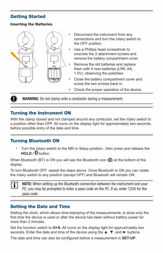
Inserting the Batteries
+
+
+
+
• Disconnect the instrument from anyconnections and turn the rotary switch tothe OFF position.
• Use a Phillips head screwdriver tounscrew the 2 attachment screws andremove the battery compartment cover.
• Remove the old batteries and replacethem with 4 new batteries (LR6, AA,1.5V), observing the polarities.
• Close the battery compartment cover andscrew the two screws back in.
• Check the proper operation of the device.
WARNING: Do not clamp onto a conductor during a measurement.
Turning the Instrument ONWith the clamp closed and not clamped around any conductor, set the rotary switch to a position other than OFF. All icons on the display light for approximately two seconds, before possible entry of the date and time.
Turning Bluetooth ON
• Turn the rotary switch to the MR or Setup position., then press and release theHOLD / button.
When Bluetooth (BT) is ON you will see the Bluetooth icon ( ) at the bottom of the display. To turn Bluetooth OFF, repeat the steps above. Once Bluetooth is ON you can rotate the rotary switch to any position (except OFF) and Bluetooth will remain ON.
NOTE: When setting up the Bluetooth connection between the instrument and your PC, you may be prompted to enter a pass code on the PC. If so, enter 1234 for the pass code.
Setting the Date and TimeSetting the clock, which allows time-stamping of the measurements, is done only the first time the device is used or after the device has been without battery power for more than 2 minutes.Set the function switch to Ω+A. All icons on the display light for approximately two seconds. Enter the date and time of the device using the , , and buttons.The date and time can also be configured before a measurement in SET-UP.
Standard and Advanced Modes
The Ground Resistance Tester has two modes:• Standard Mode: Makes the standard loop resistance/impedance and current
clamp measurements. • Advanced Mode: Used to refine and complete the measurements:
- Impedance referred to the selected frequency. - Contact voltage. - Resistive and inductive fractions of the loop impedance.
The choice of the Standard or Advanced mode and the alarm thresholds are configured in SET-UP.
Storing Measurements into Memory
The values displayed during the measurements can be stored in memory and read later. Storage of the data is available in both the Ω+A and A measurement modes, provided that memory locations are free. Data is stored as soon as the MEM button is pressed. A long audible signal confirms the storage.
Displaying Stored Measurements
• Set the function switch to the MR position.
• The type of data that is displayed is dependent on whether Standard or Advancedmode was selected during SET-UP.
Installing DataView®
DO NOT CONNECT THE INSTRUMENT TO THE PC BEFORE INSTALLING THE SOFT-WARE AND DRIVERS.
1. Insert the USB stick into an available USB port (wait for the driver to be installed).If Autorun is enabled, an AutoPlay window appears. If Autorun is disabled, openWindows Explorer, then locate and open the USB stick drive labeled DataView.
2. In the AutoPlay window, select Open folder to view files.
3. Double-click on Setup.exe to launch the Dataview® setup program.
NOTE: For more information on using the DataView® software, refer to the Model 6417 user manual supplied on the USB stick.
NOTE: You can retrieve and analyze measurement results with the DataView® soft-ware or with an Android app through the Bluetooth communication port.
Repair and CalibrationTo ensure that your instrument meets factory specifications, we recommend that it be scheduled back to our factory Service Center at one-year intervals for recalibration, or as required by other standards or internal procedures.
For instrument repair and calibration:You must contact our Service Center for a Customer Service Authorization Number (CSA#). This will ensure that when your instrument arrives, it will be tracked and processed promptly. Please write the CSA# on the outside of the shipping container. If the instrument is returned for calibration, we need to know if you want a standard calibration, or a calibration traceable to N.I.S.T. (Includes calibration certificate plus recorded calibra-tion data).
Ship To: Chauvin Arnoux®, Inc. d.b.a. AEMC® Instruments15 Faraday Drive, Dover NH 03820 USAPhone: (800) 945-2362 (Ext. 360) • (603) 749-6434 (Ext. 360)Fax: (603) 742-2346 or (603) 749-6309E-mail: [email protected]
(Or contact your authorized distributor)Costs for repair, standard calibration, and calibration traceable to N.I.S.T. are available.NOTE: You must obtain a CSA# before returning any instrument.
Limited WarrantyThe Model 6417 is warranted to the owner for a period of two years from the date of original purchase against defects in manufacture. This limited warranty is given by AEMC® Instruments, not by the distributor from whom it was purchased. This warranty is void if the unit has been tampered with, abused or if the defect is related to service not performed by AEMC® Instruments.
Full warranty coverage and registration is available on our website: www.aemc.com/warranty.htmlPlease print the online Warranty Coverage Information for your records.
What AEMC® Instruments will do: If a malfunction occurs within the warranty period, you may return the instrument to us for repair, provided we have your warranty registration information on file or a proof of purchase. AEMC® Instruments will, at its option, repair or replace the faulty material.
Warranty RepairsWhat you must do to return an Instrument for Warranty Repair: First, request a Customer Service Authorization Number (CSA#) by phone or by fax from our Service Department (see address below), then return the instru-ment along with the signed CSA Form. Please write the CSA# on the outside of the shipping container. Return the instrument, postage or shipment pre-paid to:
Ship To: Chauvin Arnoux®, Inc. d.b.a. AEMC® Instruments15 Faraday Drive, Dover NH 03820 USAPhone: (800) 945-2362 (Ext. 360) • (603) 749-6434 (Ext. 360)Fax: (603) 742-2346 or (603) 749-6309E-mail: [email protected]
NOTE: You must obtain a CSA# before returning any instrument.
Technical and Sales AssistanceIf you are experiencing any technical problems, or require any assistance with the proper operation or application of your instrument, please call, fax or e-mail our technical support team:
Chauvin Arnoux®, Inc. d.b.a. AEMC® Instruments
Phone: (800) 945-2362 (Ext. 351) • (603) 749-6434 (Ext. 351)Fax: (603) 742-2346E-mail: [email protected]
Contact:
01/1899-MAN 100396 v5
Chauvin Arnoux®, Inc. d.b.a. AEMC® Instruments15 Faraday Drive • Dover, NH 03820 USA • Phone: (603) 749-6434 • Fax: (603) 742-2346
www.aemc.com