Embed Size (px)
Citation preview
2018-07-2319915742
Clad Ultimate Outswing Bi-Fold Door Installation Instruction
After Market ProductsAlterations to Marvin products including window films, insulating or reflective interior window treatments or additionalglazings can cause excessive heat buildup and/or condensation. They may lead to premature failures not covered underwarranty by Marvin Windows and Doors.
Before purchasing or applying any product that may affect the installation or performance of Marvin windows contact themanufacturer of after market product/glazings that are not supplied by Marvin and request written product use, associ-ated warranties and damage coverage. Provide this information and warranties to the end user and/or building ownerfor future reference.
W A R N I N G !
Always practice safety! Wear the appropriate eye, ear and hand protection, especially when working with power tools.
W A R N I N G !
This product can expose you to chemicals including methanol, which is known to the state of California to cause birthdefects or other reproductive harm. This product can expose you to chemicals including titanium oxide, which is knownto the state of California to cause cancer.For more information, go to www.P65Warnings.ca.gov.
W A R N I N G !
Drilling, sawing, sanding or machining wood products can expose you to wood dust, a substance known to the State ofCalifornia to cause cancer. Avoid inhaling wood dust or use a dust mask or other safeguards for personal protection. Formore information go to www.P65Warnings.ca.gov/wood.
Note: Numbers listed in parentheses ( ) are metric equivalents in millimeters rounded to the nearest whole number
You Will Need to Supply:
• Safety Glasses
• Hearing protection
• Level and/or laser
• Square
• Hammer
• Wood shims
• 2" Roofing nails
• Insulation
• Tape measure
• Perimeter sealant
• Sill pan flashing
• Backing material (foam backing rod)
• Low expansion foam insulation
• Flashing materials
• Weather resistive barrier
• Standard hex key set
Frame Assembly
NOTE: If unit is over 23 ½’, refer to splicing section pri-or to frame assembly.
NOTE: For floor channel sill, sill track must be installedinto floor prior to frame installation.
NOTE: Floor channel sill length matches the FrameOM Width and should be aligned flush with rough open-ing side of both jambs.
1. Fasten sill to jamb. Ensure screw is in the frame cladding screw boss. See Figure 1.
Figure 1
2. Install head jamb corner keys and assemble the corners. Ensure metal leg on the jamb goes between aluminum head track and shoot bolt channel. See Figure 2 and Figure 3.
Figure 2
To watch a video on this step, click on the play button or scan the QR code with your smart phone or similar device.
Exte
rior F
ace
Of S
heat
hing
Panel
1 7/16"(37)
1 3/32"(28)
1 3/4"(44)
1 3 per side- #8 x 1 3/4" Pan head
1 Head jamb corner key
2018-07-23 2 Clad Ultimate Outswing Bi-Fold Door19915742 Installation Instruction
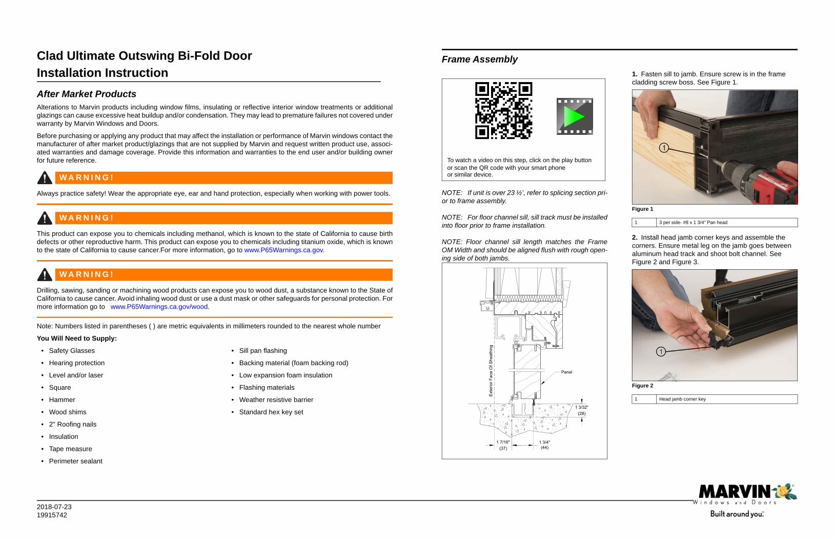
Figure 3
3. Fasten jamb to head jamb. Do not over tighten clad miter joint. See Figure 4
Figure 4
4. Inject cladding in both holes until squeeze out occurs. See Figure 5 and Figure 6.
Figure 5
Figure 6
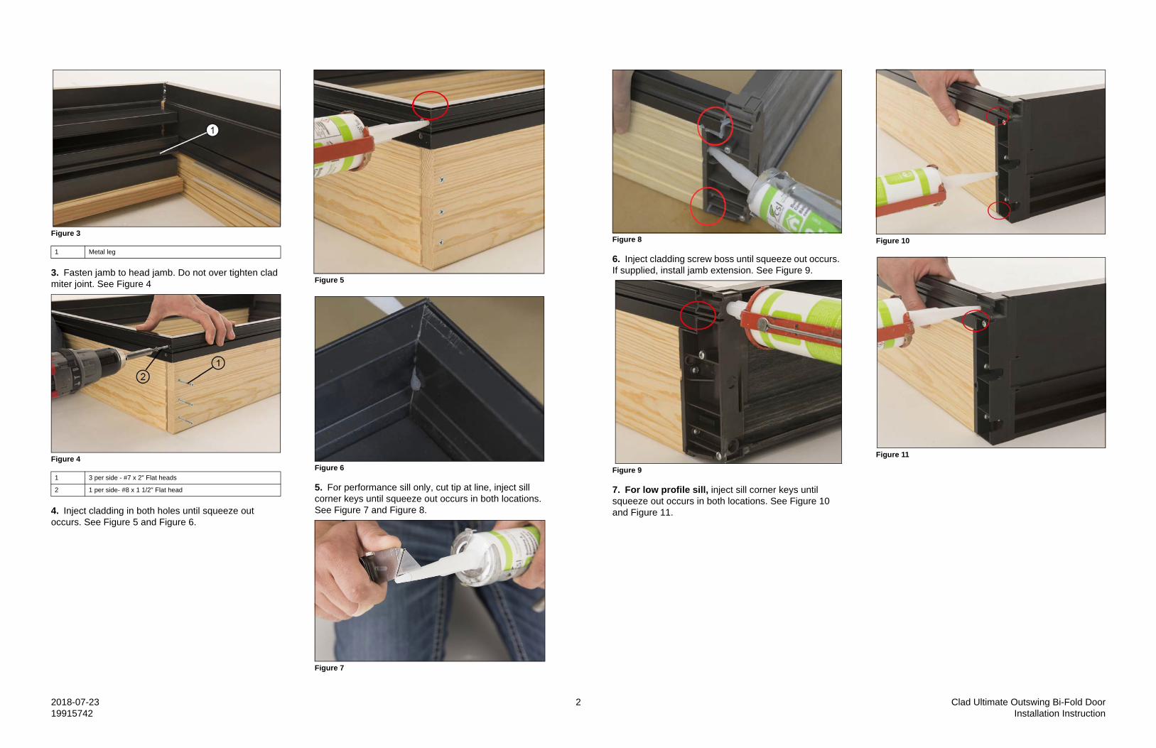
5. For performance sill only, cut tip at line, inject sill corner keys until squeeze out occurs in both locations. See Figure 7 and Figure 8.
Figure 7
1 Metal leg
1 3 per side - #7 x 2" Flat heads
2 1 per side- #8 x 1 1/2" Flat head
Figure 8
6. Inject cladding screw boss until squeeze out occurs. If supplied, install jamb extension. See Figure 9.
Figure 9
7. For low profile sill, inject sill corner keys until squeeze out occurs in both locations. See Figure 10 and Figure 11.
Figure 10
Figure 11
2018-07-23 3 Clad Ultimate Outswing Bi-Fold Door19915742 Installation Instruction
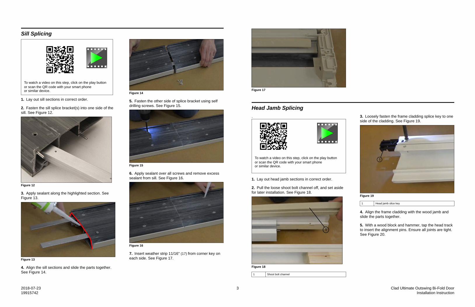
Sill Splicing
1. Lay out sill sections in correct order.
2. Fasten the sill splice bracket(s) into one side of the sill. See Figure 12.
Figure 12
3. Apply sealant along the highlighted section. See Figure 13.
Figure 13
4. Align the sill sections and slide the parts together. See Figure 14.
Figure 14
5. Fasten the other side of splice bracket using self drilling screws. See Figure 15.
Figure 15
6. Apply sealant over all screws and remove excess sealant from sill. See Figure 16.
Figure 16
7. Insert weather strip 11/16" (17) from corner key on each side. See Figure 17.
To watch a video on this step, click on the play button or scan the QR code with your smart phone or similar device.
1
Figure 17
Head Jamb Splicing
.
1. Lay out head jamb sections in correct order.
2. Pull the loose shoot bolt channel off, and set aside for later installation. See Figure 18.
Figure 18
3. Loosely fasten the frame cladding splice key to one side of the cladding. See Figure 19.
Figure 19
4. Align the frame cladding with the wood jamb and slide the parts together.
5. With a wood block and hammer, tap the head track to insert the alignment pins. Ensure all joints are tight. See Figure 20.
1 Shoot bolt channel
To watch a video on this step, click on the play button or scan the QR code with your smart phone or similar device.
1 Head jamb slice key
1

2018-07-23 4 Clad Ultimate Outswing Bi-Fold Door19915742 Installation Instruction
Figure 20
6. Fasten the support block to the head jamb. See Figure 21. Pre-drill the head jamb through holes in head track as a guide.
Figure 21
7. Install the shoot bolt channel. See Figure 22.
Figure 22
8. Flip head jamb over. Fasten the frame cladding splicing key. See Figure 23.
Figure 23
9. Pre-drill the head jamb using the hole in the frame cladding and 3/16" bit. Do not drill through the face of the frame cladding. See Figure 24.
Figure 24
10. Inject both holes until squeeze out occurs on opposite sides. See Figure 25.
1 #7 x 2" Flat head
1
1
1 #8 x 5/8" Flat head
1
1
Figure 25
11. Insert weather strip 11/16” from the end of the
support block. See Figure 26.
Figure 26
Frame Installation
NOTE: Before installation, ensure Rough Opening hasbeen prepped according to the site prep guide.
1. IMPORTANT: Sill screws must be sealed prior to installing. Fasten sill through all pre-drilled holes. See Figure 27.
1
1
To watch a video on this step, click on the play button or scan the QR code with your smart phone or similar device.
Frame toleranceHead Jamb: -0" +1/16"Square: +/- 3/16"Sill: +/- 1/16"

2018-07-23 5 Clad Ultimate Outswing Bi-Fold Door19915742 Installation Instruction
Figure 27
2. Fasten jambs through all pre-drilled holes, shims should be placed at all fastening locations. See Figure 28.
Figure 28
3. Fasten head jamb track through all pre-drilled holes. See Figure 29 and Figure 30.
Figure 29
Figure 30
4. Remove shipping screws and pre-drill 1/4" through all shipping holes. See Figure 31 and Figure 32.
Figure 31
1 #8 x 1 1/2" screws minimum supplied by others
1 #8 x 3" Flat head screws
1 1/4" x 3 1/8" Washer head screw
1
Figure 32
5. Fasten head jamb support block through all pre-drilled holes. See Figure 33.
Figure 33
6. Snap in sill insert. See Figure 34, Figure 35, and Figure 36.
Figure 34
Figure 35
Figure 36
1 #8 x 3 1/2" Flat head screws

2018-07-23 6 Clad Ultimate Outswing Bi-Fold Door19915742 Installation Instruction
Hinge Installation
For information on configuration and hinge placement,please refer to enclosed diagram. See Figure 37.
Figure 37
1. Place any top roller hinges numbered 3-5 in head track in the correct order using configuration diagram as guide for your configuration. See Figure 38.
Figure 38
WALL PIVOTHAND
1WALL PIVOT
HAND
2INTERMEDIATE
CARRIER
3END HANGER
HAND
4END HANGER
HAND
5OFFSETHINGE
6STRAIGHT
HINGE
7
PANEL HL PANEL LLM PANEL ELM PANEL JR PANEL GR
3 INTERMEDIATE CARRIER
END CARRIER - HAND
OFFSET HINGE * **
2
END CARRIER - HAND
STRAIGHT HINGE **
1
HINGE #
6
4
5
7
HINGE DESCRIPTION
*OFFSET HINGES MUST BE OFFSET TO THE CORRECT SIDE**THE CENTER HANDLE HINGE IS NOT REQUIRED, BUT IF DESIRED, USE THE PROVIDED TEMPLATE AND INSTRUCTIONS TO INSTALL.
WALL PIVOT - LEFT HAND
WALL PIVOT - RIGHT HAND
HINGE MATRIX
USE THIS DIAGRAM IN CONJUNCTION WITH THE PROVIDED INSTALLATION INSTRUCTIONS TO DETERMINE HINGE AND PANEL LOCATIONS
3L2R
6
1 3 5
7
2
To watch a video on this step, click on the play button or scan the QR code with your smart phone or similar device.
IMPORTANT: Ensure small cam doesn’t fall out duringstep 2.
2. Install top portion of any hinges 1 and 2 in correct end of head track by loosening the two outer bolts but not removing them. See Figure 39 and Figure 40.
Figure 39
Figure 40
3. Rotate clamp and tighten bolt furthest from the jamb.
See Figure 41 and Figure 42.
Figure 41
Figure 42
4. Slightly tighten the bolt closest to jamb.
5. Place hinge in the middle of its adjustment range by rotating center cam, then fully tighten the bolt closest to jamb. See Figure 43.
Figure 43
6. Install bottom portion of hinges 1 and 2 in correct end of sill ensuring shim is installed below it. See Figure 44 and Figure 45.
1 Adjustment cam
2 Outer hex bolts
3 Track clamp position
1 Track clamp position
2 Position and tighten this bolt

2018-07-23 7 Clad Ultimate Outswing Bi-Fold Door19915742 Installation Instruction
Note: On low profile and floor channel sills, the screwswill stick slightly proud of the bottom of the sill.
Note: Hinge must be adjusted out to allow screws to goin.
Figure 44
Figure 45
7. Place hinge in the middle of its adjustment range by rotating center cam, then fully tighten the bolt. See Figure 46.
Figure 46
Hanger and Wall Pivot Adjustments
1. Side to side adjustments can only be done on the wall pivot and end pivot. Top Wall Pivot: Loosen the hex bolt nearest to the jamb with a 5/32" hex wrench. See Figure 47.
1 Floor shim
2 #7x 3/4" Flat head
Figure 47
Turn the center adjustment cam with a 3/16" hexwrench to adjust the panel side to side. Tighten the hexbolt that was loosened. See Figure 48.
Figure 48
2. Bottom Wall Pivot: Loosen both 5/32" hex bolts slightly. See Figure 49.
Figure 49
3. Turn the center adjustment cam with a 3/16 hex wrench to adjust side to side. Tighten the hex bolts that were loosened in step one. See Figure 50.
Figure 50
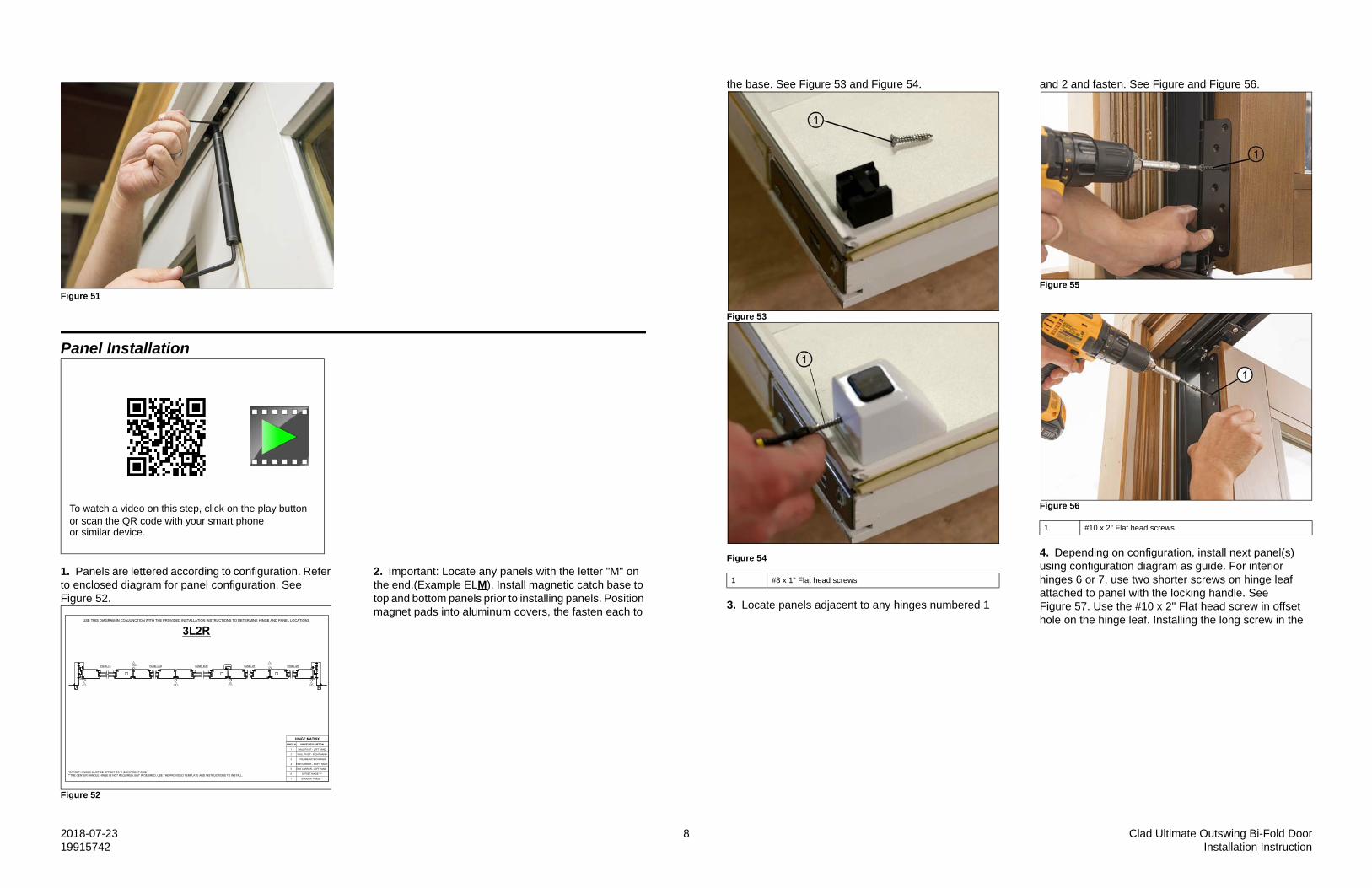
4. Up and down adjustment can only be done on the top hangers. Turn and hold the height adjustment lock at the base of the hinge with a 1/8" hex wrench. Use a 3/16" hex wrench in the end of the hinge to adjust the height. Turning Clockwise will raise the panel, while turning counter clockwise lower the panel. See Figure 51.
2018-07-23 8 Clad Ultimate Outswing Bi-Fold Door19915742 Installation Instruction
Figure 51
Panel Installation
1. Panels are lettered according to configuration. Refer to enclosed diagram for panel configuration. See Figure 52.
Figure 52
2. Important: Locate any panels with the letter "M" on the end.(Example ELM). Install magnetic catch base to top and bottom panels prior to installing panels. Position magnet pads into aluminum covers, the fasten each to
To watch a video on this step, click on the play button or scan the QR code with your smart phone or similar device.
PANEL HL PANEL LLM PANEL ELM PANEL JR PANEL GR
3 INTERMEDIATE CARRIER
END CARRIER - HAND
OFFSET HINGE * **
2
END CARRIER - HAND
STRAIGHT HINGE **
1
HINGE #
6
4
5
7
HINGE DESCRIPTION
*OFFSET HINGES MUST BE OFFSET TO THE CORRECT SIDE**THE CENTER HANDLE HINGE IS NOT REQUIRED, BUT IF DESIRED, USE THE PROVIDED TEMPLATE AND INSTRUCTIONS TO INSTALL.
WALL PIVOT - LEFT HAND
WALL PIVOT - RIGHT HAND
HINGE MATRIX
USE THIS DIAGRAM IN CONJUNCTION WITH THE PROVIDED INSTALLATION INSTRUCTIONS TO DETERMINE HINGE AND PANEL LOCATIONS
3L2R
6
1 3 5
7
2
the base. See Figure 53 and Figure 54.
Figure 53
Figure 54
3. Locate panels adjacent to any hinges numbered 1
and 2 and fasten. See Figure and Figure 56.
Figure 55
Figure 56
4. Depending on configuration, install next panel(s) using configuration diagram as guide. For interior hinges 6 or 7, use two shorter screws on hinge leaf attached to panel with the locking handle. See Figure 57. Use the #10 x 2" Flat head screw in offset hole on the hinge leaf. Installing the long screw in the
1 #8 x 1" Flat head screws
1 #10 x 2" Flat head screws

2018-07-23 9 Clad Ultimate Outswing Bi-Fold Door19915742 Installation Instruction
other hole will interfere with the panel handle operation.
Figure 57
5. Attach intermediate and end hangers (hinges 3, 4, 5), if applicable to your configuration. See Figure 58 and
Figure 59.
Figure 58
Figure 59
Hinge/Handle Optional Installation
1. Open the panels to 90 degrees. Pre-drill the holes with template provided with the handle kit. See Figure 60.
1 #10 x 1 1/4" Flat head 1 #10 x 1 1/4" Flat head Figure 60
2. Line up the handle with the pre-drilled holes. Attach the handle with the provided screws. See Figure 61.
Figure 61
3. Open hinge across to the second panel and pre-drill through the hinge. Ensure the panel gap is set using the provided template before drilling. Attach the handle with provided screws. See Figure 62.
Figure 62
4. Slice the flexible portion of the weather strip above and below the installed handle. See Figure 63 and Figure 64.
Figure 63
Figure 64

2018-07-23 10 Clad Ultimate Outswing Bi-Fold Door19915742 Installation Instruction
Final Installation
1. Measure the gap between the panel and jamb. Choose proper height support block. See Figure 65 and Figure 66.
Figure 65
Figure 66
2. Install support blocks. See Figure 67.
Figure 67
3. Pull weather strip back approximately 12" at sill and head jamb. See Figure 68 and Figure 69.
Figure 68
1 <3/4"
2 3/4" - 7/8"
3 >7/8"
To watch a video on this step, click on the play button or scan the QR code with your smart phone or similar device.
Figure 69
4. Install frame cover. Note: If locking jamb, install frame cover with pre-punched hole for strike. See Figure 70.
Figure 70
5. Install head jamb part stop. See Figure 71.
Figure 71
6. Install wood jamb part stops ensuring longer side of weather strip is towards the sill. See Figure 72 and Figure 73.
Figure 72
Figure 73

2018-07-23 11 Clad Ultimate Outswing Bi-Fold Door19915742 Installation Instruction
7. Apply corner gasket between sill and wood part stop. Reapply weather strip at side jamb and sill. See Figure 74.
Figure 74
8. Install panel alignment bolt(s) into pre-drilled holes on jambs where wall pivot hinge sets are located. See Figure 75.
Figure 75
9. If needed, install strike plate in to pre-drilled holes. Ensure support block does not interfere and there are shims behind jamb. See Figure 76.
Figure 76
10. At all shoot bolt locations, slightly open panels and measure 1 1/2" from the edge of the panel to the center of the strike location. Snap plastic sill strikes into place and ensure shoot bolt makes contact (if screw is need to hold sill strike in place, use #6 x 1/4" stainless steel flat head screw). See Figure 77 and Figure 78.
Figure 77
Figure 78
1 Corner gasket
1 #8 x 3 1/2" Flat head BLK or BG
1
1 #8 x 3 1/2" Flat head
11. For performance sill only, peel tape backing off of the interior sill liner and rotate liner on to sill. See Figure 79 and Figure 80.
Figure 79
Figure 80
12. Apply the adhesive backed hinge weather strip on
any hinges next to a jamb. See Figure 81.
Figure 81
13. Apply panel edge gasket. See Figure 82.
Figure 82
Stationary Panel Installation
1. Ensure frame covers are installed from step 4 in “Final Component Installation”
2. From the exterior side, tip the panel into place by placing the two sill bolts into the interior track of the sill. See Figure 83.
Figure 83
2018-07-23 12 Clad Ultimate Outswing Bi-Fold Door19915742 Installation Instruction
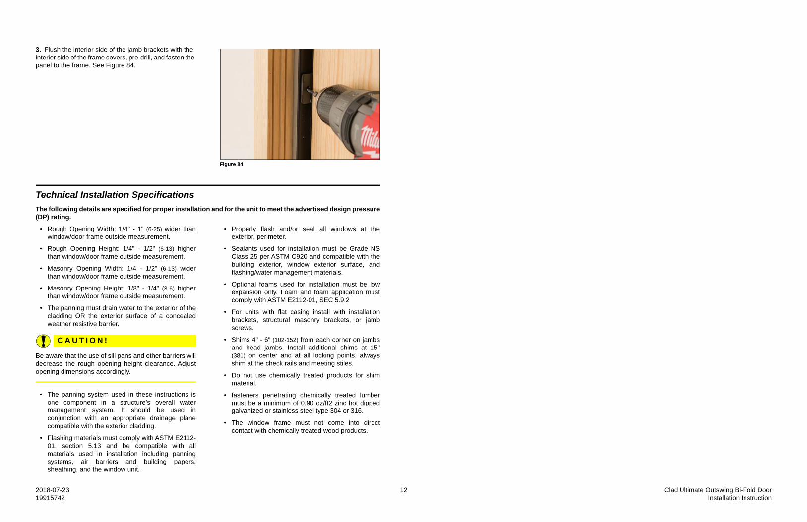
3. Flush the interior side of the jamb brackets with the interior side of the frame covers, pre-drill, and fasten the panel to the frame. See Figure 84.
Figure 84
Technical Installation Specifications
The following details are specified for proper installation and for the unit to meet the advertised design pressure(DP) rating.
• Rough Opening Width: 1/4" - 1" (6-25) wider thanwindow/door frame outside measurement.
• Rough Opening Height: 1/4" - 1/2" (6-13) higherthan window/door frame outside measurement.
• Masonry Opening Width: 1/4 - 1/2" (6-13) widerthan window/door frame outside measurement.
• Masonry Opening Height: 1/8" - 1/4" (3-6) higherthan window/door frame outside measurement.
• The panning must drain water to the exterior of thecladding OR the exterior surface of a concealedweather resistive barrier.
C A U T I O N !
Be aware that the use of sill pans and other barriers willdecrease the rough opening height clearance. Adjustopening dimensions accordingly.
• The panning system used in these instructions isone component in a structure’s overall watermanagement system. It should be used inconjunction with an appropriate drainage planecompatible with the exterior cladding.
• Flashing materials must comply with ASTM E2112-01, section 5.13 and be compatible with allmaterials used in installation including panningsystems, air barriers and building papers,sheathing, and the window unit.
• Properly flash and/or seal all windows at theexterior, perimeter.
• Sealants used for installation must be Grade NSClass 25 per ASTM C920 and compatible with thebuilding exterior, window exterior surface, andflashing/water management materials.
• Optional foams used for installation must be lowexpansion only. Foam and foam application mustcomply with ASTM E2112-01, SEC 5.9.2
• For units with flat casing install with installationbrackets, structural masonry brackets, or jambscrews.
• Shims 4" - 6" (102-152) from each corner on jambsand head jambs. Install additional shims at 15"(381) on center and at all locking points. alwaysshim at the check rails and meeting stiles.
• Do not use chemically treated products for shimmaterial.
• fasteners penetrating chemically treated lumbermust be a minimum of 0.90 oz/ft2 zinc hot dippedgalvanized or stainless steel type 304 or 316.
• The window frame must not come into directcontact with chemically treated wood products.