Embed Size (px)
Citation preview
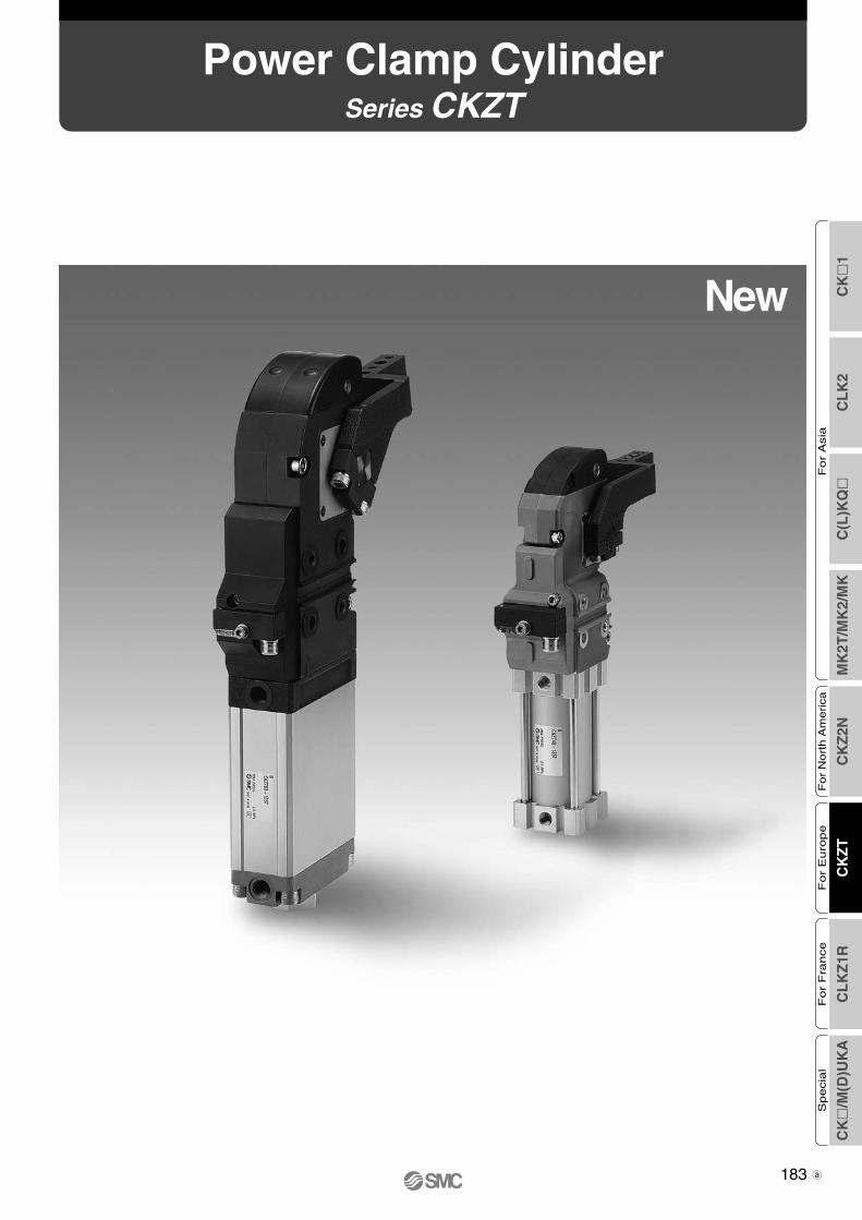
New
Series CKZTPower Clamp Cylinder
CK
�1
CL
K2
C(L
)KQ
�M
K2T
/MK
2/M
KC
KZ
2NC
KZ
TC
LK
Z1R
CK
�/M
(D)U
KA
Fo
r A
sia
For
Nort
h A
merica
For
Euro
pe
For
Fra
nce
Specia
l
183
CKZT-Clamp.qxd 10.3.30 1:13 PM Page 1
∗ For additional formats, please log on to the SMC web site www.smcusa.com and click on the E-Tech icon.
Software
CATIA
UNIGRAPHICS
FIDES
AUTO CAD
SOLID WORKS
� 3D CAD � Series Variations
Series
Bore size (mm)
Arm opening angle
Switch
Port thread type
ø50Equivalentø40 ø63
Equivalent
30°, 45°, 60°, 75°90°, 105°, 120°, 135°
TURCK/P&F
G/NPT
ø80Equivalent
CKZT
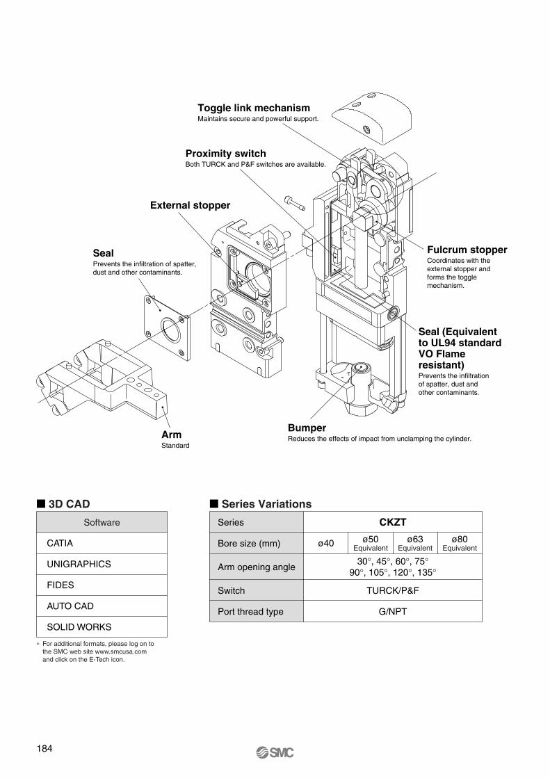
External stopper
Toggle link mechanismMaintains secure and powerful support.
Proximity switchBoth TURCK and P&F switches are available.
Fulcrum stopperCoordinates with the external stopper and forms the toggle mechanism.
Seal (Equivalent to UL94 standard VO Flame resistant)Prevents the infiltration of spatter, dust and other contaminants.
BumperReduces the effects of impact from unclamping the cylinder.
SealPrevents the infiltration of spatter, dust and other contaminants.
ArmStandard
184
Clamp-B.qxd 08.4.15 2:06 PM Page 190
Series CKZTModel Selection
1 Common precautions for each size1) Use air filtered through a 5-µm-element filter.2) Before piping is connected to the slim-line power clamp cylinder it should be thoroughly flushed with air.3) Only use the clamp arm in our catalog. Do not weld an arm to the cylinder.4) Make sure to use a speed controller and adjust it to more than 1sec. when changing from clamping to unclamping (or vice versa).
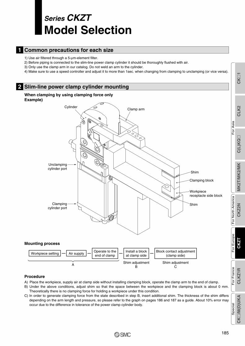
ProcedureA) Place the workpiece, supply air at clamp side without installing clamping block, operate the clamp arm to the end of clamp.B) Under the above conditions, adjust shim so that the space between the workpiece and the clamping block is about 0 mm.
Theoretically there is no clamping force for holding a workpiece under this condition.C) In order to generate clamping force from the state described in step B, insert additional shim. The thickness of the shim differs
depending on the arm length and pressure, so please refer to the graph on pages 186 and 187 as a guide. About 10% error may occur due to the difference in tolerance of the power clamp cylinder body.
2 Slim-line power clamp cylinder mountingWhen clamping by using clamping force onlyExample)
Mounting process
Clamp armCylinder
Shim
Shim
Clamping block
Workpiecereceptacle side block
Unclampingcylinder port
Clampingcylinder port
Workpiece setting Air supplyOperate to theend of clamp
Shim adjustmentB
A
Install a blockat clamp side
Shim adjustmentC
Block contact adjustment(clamp side)
CK
�1
CL
K2
C(L
)KQ
�M
K2T
/MK
2/M
KC
KZ
2NC
KZ
TC
LK
Z1R
CK
�/M
(D)U
KA
Fo
r A
sia
For
Nort
h A
merica
For
Euro
pe
For
Fra
nce
Specia
l
185
Clamp-B.qxd 08.4.15 2:06 PM Page 191
186
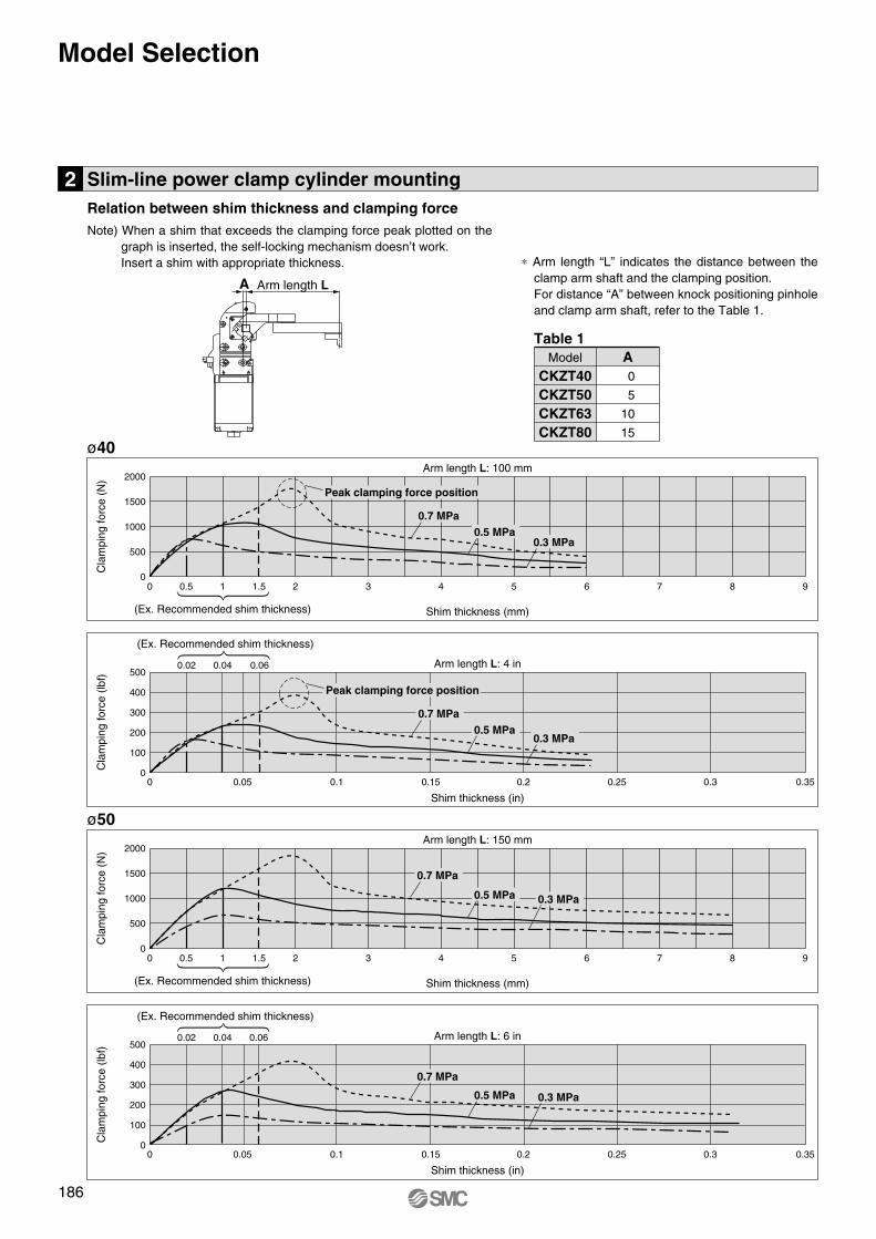
ø40
Cla
mpi
ng fo
rce
(N)
Arm length L: 100 mm
Shim thickness (mm)(Ex. Recommended shim thickness)
0.50 1 1.5 2 3 4 5 6 7 8 9
0.7 MPa0.5 MPa
0.3 MPa
2000
1500
1000
500
0
Peak clamping force position
Cla
mpi
ng fo
rce
(lbf)
Arm length L: 4 in
Shim thickness (in)
(Ex. Recommended shim thickness)
0 0.05
0.040.02 0.06
0.1 0.15 0.2 0.25 0.3 0.35
500
400
300
200
100
0
Arm length LA
0.7 MPa0.5 MPa
0.3 MPa
Peak clamping force position
ø50
Cla
mpi
ng fo
rce
(N)
Arm length L: 150 mm
Shim thickness (mm)(Ex. Recommended shim thickness)
0.50 1 1.5 2 3 4 5 6 7 8 9
0.7 MPa
0.5 MPa 0.3 MPa
2000
1500
1000
500
0
Cla
mpi
ng fo
rce
(lbf)
Arm length L: 6 in
Shim thickness (in)
(Ex. Recommended shim thickness)
0 0.05
0.040.02 0.06
0.1 0.15 0.2 0.25 0.3 0.35
500
400
300
200
100
0
0.7 MPa
0.5 MPa 0.3 MPa
2 Slim-line power clamp cylinder mounting
Note) When a shim that exceeds the clamping force peak plotted on the graph is inserted, the self-locking mechanism doesn’t work.Insert a shim with appropriate thickness. ∗ Arm length “L” indicates the distance between the
clamp arm shaft and the clamping position.For distance “A” between knock positioning pinhole and clamp arm shaft, refer to the Table 1.
Relation between shim thickness and clamping force
CKZT40CKZT50CKZT63CKZT80
0
5
10
15
AModel
Table 1
Model Selection
Clamp-B.qxd 08.4.15 2:06 PM Page 192
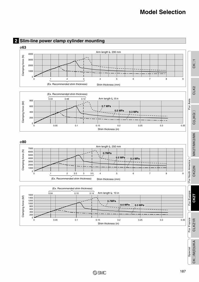
ø63
Cla
mpi
ng fo
rce
(N)
Arm length L: 200 mm
Shim thickness (mm)(Ex. Recommended shim thickness)
0 1 2 3 4 5 6 7 8 9
4000
3000
2000
1000
0
Cla
mpi
ng fo
rce
(lbf)
0 0.05 0.1 0.15 0.2 0.25 0.3 0.35
800
600
400
200
0
ø80
Cla
mpi
ng fo
rce
(N)
Arm length L: 250 mm
Shim thickness (mm)(Ex. Recommended shim thickness)
0 1 2 2.5 3.53 4 5 6 7 8 9
0.7MPa
7000
6000
5000
4000
3000
2000
1000
0
0.5 MPa 0.3 MPa
Arm length L: 8 in
Shim thickness (in)
(Ex. Recommended shim thickness)
0.080.04 0.12
Cla
mpi
ng fo
rce
(lbf)
0 0.05 0.1 0.15 0.2 0.25 0.3 0.35
1600140012001000800600400200
0
Arm length L: 10 in
Shim thickness (in)
(Ex. Recommended shim thickness)
0.140.04 0.10
0.7 MPa
0.5 MPa 0.3 MPa
0.7MPa0.5 MPa 0.3 MPa
2 Slim-line power clamp cylinder mounting
Model Selection
CK
�1
CL
K2
C(L
)KQ
�M
K2T
/MK
2/M
KC
KZ
2NC
KZ
TC
LK
Z1R
CK
�/M
(D)U
KA
Fo
r A
sia
For
Nort
h A
merica
For
Euro
pe
For
Fra
nce
Specia
l
187
Clamp-B.qxd 08.4.15 2:06 PM Page 193
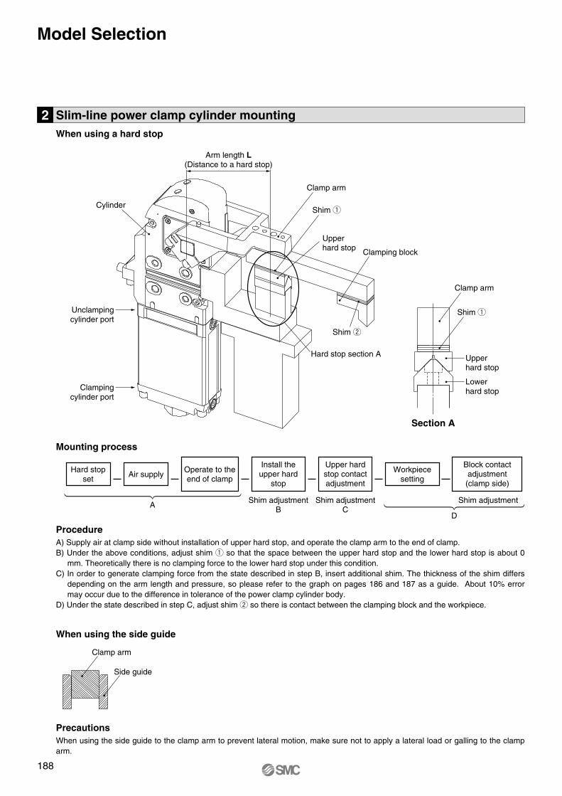
2 Slim-line power clamp cylinder mountingWhen using a hard stop
Clamp arm
Shim q
Hard stop section A
Section A
Upperhard stop
Lowerhard stop
ProcedureA) Supply air at clamp side without installation of upper hard stop, and operate the clamp arm to the end of clamp.B) Under the above conditions, adjust shim q so that the space between the upper hard stop and the lower hard stop is about 0
mm. Theoretically there is no clamping force to the lower hard stop under this condition.C) In order to generate clamping force from the state described in step B, insert additional shim. The thickness of the shim differs
depending on the arm length and pressure, so please refer to the graph on pages 186 and 187 as a guide. About 10% error may occur due to the difference in tolerance of the power clamp cylinder body.
D) Under the state described in step C, adjust shim w so there is contact between the clamping block and the workpiece.
PrecautionsWhen using the side guide to the clamp arm to prevent lateral motion, make sure not to apply a lateral load or galling to the clamparm.
When using the side guide
Arm length L(Distance to a hard stop)
D
Clamp arm
Shim q
Upperhard stop Clamping block
Shim w
Unclampingcylinder port
Clampingcylinder port
Cylinder
Clamp arm
Side guide
Mounting process
Air supplyHard stop
set
A
Operate to theend of clamp
Shim adjustmentB
Install theupper hard
stop
Shim adjustmentShim adjustmentC
Upper hardstop contactadjustment
Workpiecesetting
Block contactadjustment(clamp side)
188
Model Selection
Clamp-B.qxd 08.4.15 2:06 PM Page 194
CK
�1
CL
K2
C(L
)KQ
�M
K2T
/MK
2/M
KC
KZ
2NC
KZ
TC
LK
Z1R
CK
�/M
(D)U
KA
Fo
r A
sia
For
Nort
h A
merica
For
Euro
pe
For
Fra
nce
Specia
l
189
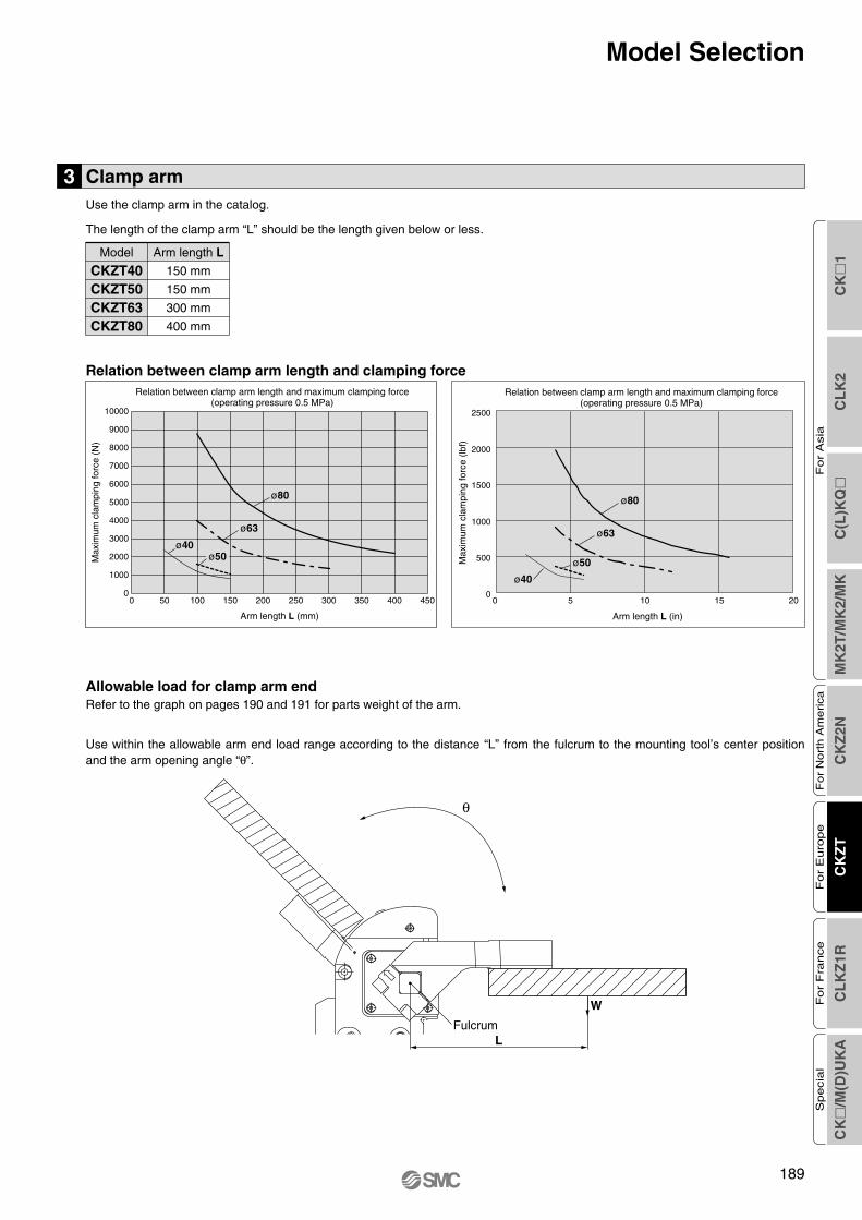
Relation between clamp arm length and clamping force
θ
W
LFulcrum
Max
imum
cla
mpi
ng fo
rce
(N)
Relation between clamp arm length and maximum clamping force(operating pressure 0.5 MPa)
Arm length L (mm)
450400350300250200150100500
ø63
ø50
ø80
Max
imum
cla
mpi
ng fo
rce
(lbf)
Relation between clamp arm length and maximum clamping force(operating pressure 0.5 MPa)
Arm length L (in)
ø63
ø80
1000
500
1500
2000
2500
0 5 10 15 200
ø50
ø40
ø40
10000
9000
8000
7000
6000
5000
4000
3000
2000
1000
0
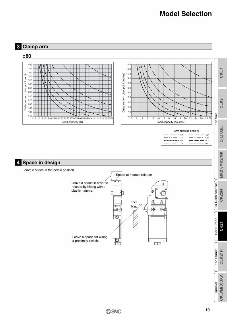
3 Clamp armUse the clamp arm in the catalog.
The length of the clamp arm “L” should be the length given below or less.
Allowable load for clamp arm endRefer to the graph on pages 190 and 191 for parts weight of the arm.
Use within the allowable arm end load range according to the distance “L” from the fulcrum to the mounting tool’s center positionand the arm opening angle “θ”.
CKZT40CKZT50CKZT63CKZT80
150 mm
150 mm
300 mm
400 mm
Arm length LModel
Model Selection
Clamp-B.qxd 08.4.15 2:06 PM Page 195
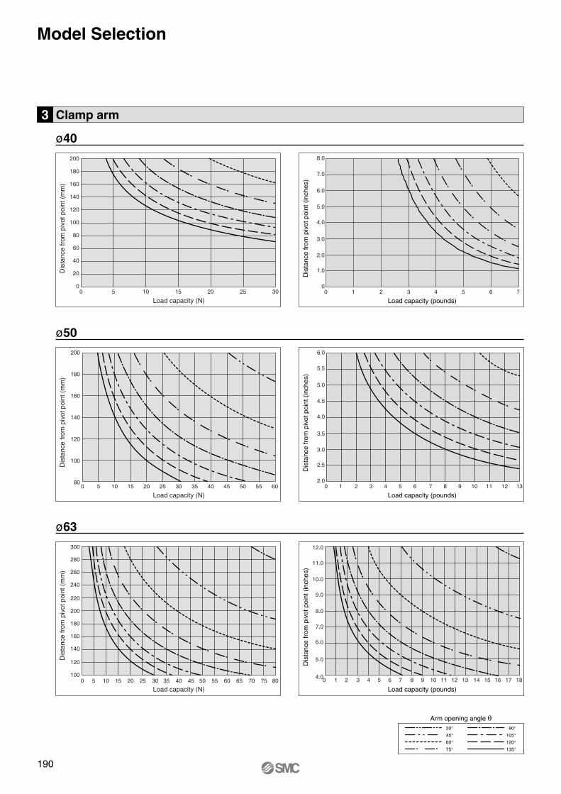
3 Clamp arm
190
Model SelectionD
ista
nce
from
piv
ot p
oint
(m
m)
Dis
tanc
e fr
om p
ivot
poi
nt (
inch
es)
Load capacity (pounds)
ø40
ø63
Dis
tanc
e fr
om p
ivot
poi
nt (
inch
es)
Load capacity (pounds)
Dis
tanc
e fr
om p
ivot
poi
nt (
inch
es)
Load capacity (pounds)
ø50
30°45°60°75°
90°105°120°135°
Arm opening angle θ
Load capacity (N)
Dis
tanc
e fr
om p
ivot
poi
nt (
mm
)
Load capacity (N)
Dis
tanc
e fr
om p
ivot
poi
nt (
mm
)
Load capacity (N)
6.0
5.5
5.0
4.5
4.0
3.5
3.0
2.5
2.00 1 2 3 4 5 6 7 8 9 10 11 12 13
12.0
11.0
10.0
9.0
8.0
7.0
6.0
5.0
4.00 1 2 3 4 5 6 7 8 9 10 11 12 13 14 15 16 17 18
8.0
7.0
6.0
5.0
4.0
3.0
2.0
1.0
00 1 2 3 4 5 6 70 5 10 15 20 25 30
200
0
20
40
60
80
100
120
140
160
180
200
180
160
140
120
100
800 5 10 15 20 25 30 35 40 45 50 55 60
300
280
260
240
220
200
180
160
140
120
1000 5 10 15 20 25 30 35 40 45 50 55 60 65 70 75 80
Clamp-B.qxd 08.4.15 2:06 PM Page 196
CK
�1
CL
K2
C(L
)KQ
�M
K2T
/MK
2/M
KC
KZ
2NC
KZ
TC
LK
Z1R
CK
�/M
(D)U
KA
Fo
r A
sia
For
Nort
h A
merica
For
Euro
pe
For
Fra
nce
Specia
l
Model Selection
Leave a space in order to release by hitting with a plastic hammer.
Space at manual release
Leave a space for wiring a proximity switch.
150Min.
4 Space in designLeave a space in the below position.
3 Clamp arm
ø80
191
Dis
tanc
e fr
om p
ivot
poi
nt (
mm
)
Load capacity (N)
30°45°60°75°
90°105°120°135°
Arm opening angle θ
Dis
tanc
e fr
om p
ivot
poi
nt (
inch
es)
Load capacity (pounds)
17.0
16.0
15.0
14.0
13.0
12.0
11.0
10.0
9.0
8.0
7.0
6.00 2 4 6 8 10 12 14 16 18 20 22 24 26 28 30
400
380
360
340
320
300
280
260
240
220
200
180
160
1400 5 10 15 20 25 30 3540 45 50 55 60 6570 75 80 85 90 95100 105 110115 120125 130135
Clamp-B.qxd 08.4.15 2:06 PM Page 197
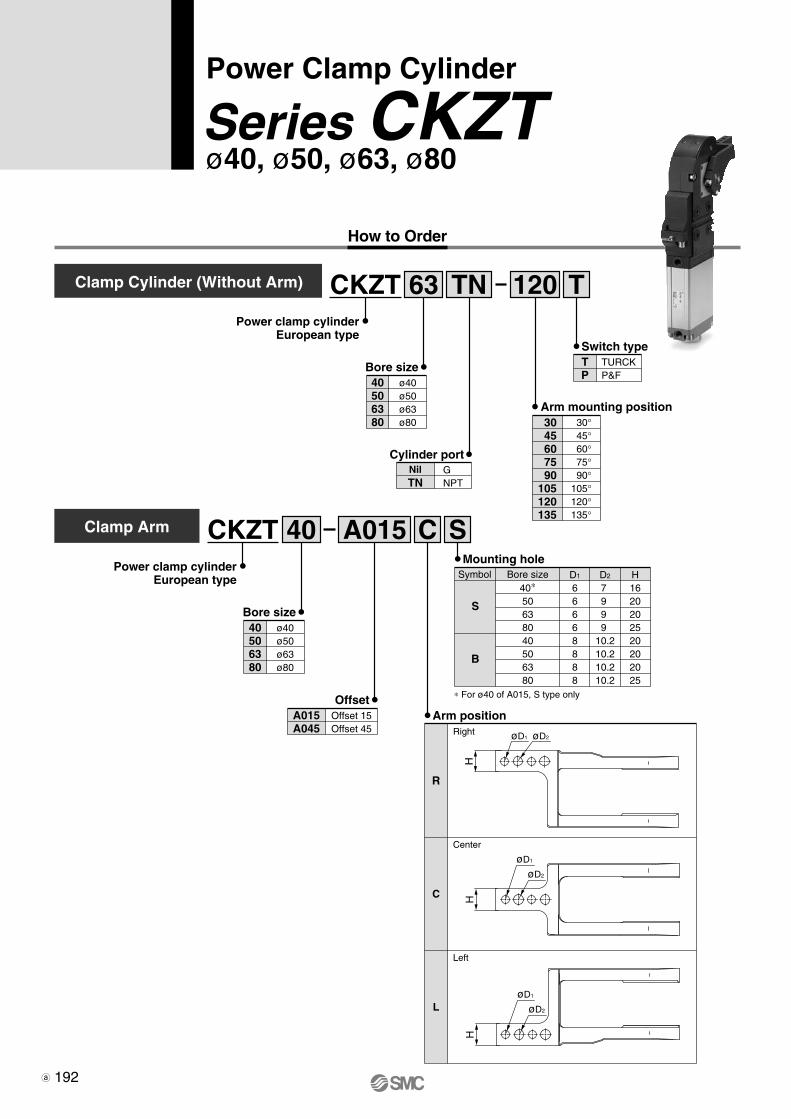
How to Order
Power Clamp Cylinder
ø40, ø50, ø63, ø80Series CKZT
CKZTClamp Cylinder (Without Arm)
Power clamp cylinderEuropean type
63 TN 120 T
Bore size40506380
ø40ø50ø63ø80
Cylinder portNilTN
GNPT
Arm mounting position3045607590
105120135
30°45°60°75°90°
105°120°135°
Switch typeTP
TURCKP&F
CKZTClamp Arm
Power clamp cylinderEuropean type
40 A015 C S
506380
ø50ø63ø80
Bore size40 ø40
OffsetA015A045
Offset 15Offset 45
øD1
H
øD2
Arm position
R
Right
C
Center
L
Left
H
øD1
øD2
H
øD1
øD2
∗ For ø40 of A015, S type only
Mounting hole
S
B
D1
66668888
40∗50638040506380
D2
7 9 9 9
10.210.210.210.2
H1620202520202025
Symbol Bore size
192
CKZT-Clamp.qxd 10.3.30 1:13 PM Page 2
CK
�1
CL
K2
C(L
)KQ
�M
K2T
/MK
2/M
KC
KZ
2NC
KZ
TC
LK
Z1R
CK
�/M
(D)U
KA
Fo
r A
sia
For
Nort
h A
merica
For
Euro
pe
For
Fra
nce
Specia
l
193
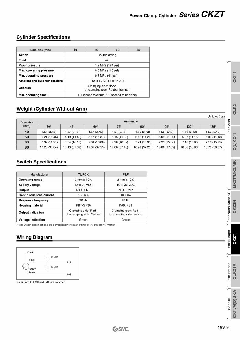
Power Clamp Cylinder Series CKZT
Cylinder Specifications
Wiring Diagram
Weight (Cylinder Without Arm)
Black
S2 Lood
S1 Lood
(–)
(+)Brown
White
Blue
2
3
1
4
Double acting
Air
1.2 MPa (174 psi)
0.8 MPa (116 psi)
0.3 MPa (44 psi)
–10 to 60°C (14 to 140°F)
1.0 second to clamp, 1.0 second to unclamp
Clamping side: None Unclamping side: Rubber bumper
Bore size (mm)
Action
Fluid
Proof pressure
Max. operating pressure
Min. operating pressure
Ambient and fluid temperature
Min. operating time
Cushion
40 50 63 80
Switch Specifications
Note) Switch specifications are corresponding to manufacturer’s technical information.
Note) Both TURCK and P&F are common.
2 mm ± 10%
10 to 30 VDC
N.O., PNP
150 mA
30 Hz
PBT-GP30
2 mm ± 10%
10 to 30 VDC
N.O., PNP
100 mA
25 Hz
PA6, PBT
Green
Clamping side: Red Unclamping side: Yellow
Green
Clamping side: Red Unclamping side: Yellow
Manufacturer
Operating range
Supply voltage
Output
Continuous load current
Response frequency
Housing material
Voltage indication
Output indication
TURCK P&F
Unit: kg (lbs)
Bore size(mm)
40
50
63
80
30°
Arm angle
1.57 (3.45)
5.21 (11.46)
7.37 (16.21)
17.20 (37.84)
45°
1.57 (3.45)
5.19 (11.42)
7.34 (16.15)
17.13 (37.69)
60°
1.57 (3.45)
5.17 (11.37)
7.31 (16.08)
17.07 (37.55)
75°
1.57 (3.45)
5.15 (11.33)
7.28 (16.02)
17.00 (37.40)
90°
1.56 (3.43)
5.12 (11.26)
7.24 (15.93)
16.93 (37.25)
105°
1.56 (3.43)
5.09 (11.20)
7.21 (15.86)
16.86 (37.09)
120°
1.56 (3.43)
5.07 (11.15)
7.18 (15.80)
16.80 (36.96)
135°
1.56 (3.43)
5.06 (11.13)
7.16 (15.75)
16.76 (36.87)
CKZT-Clamp.qxd 10.3.30 1:13 PM Page 3
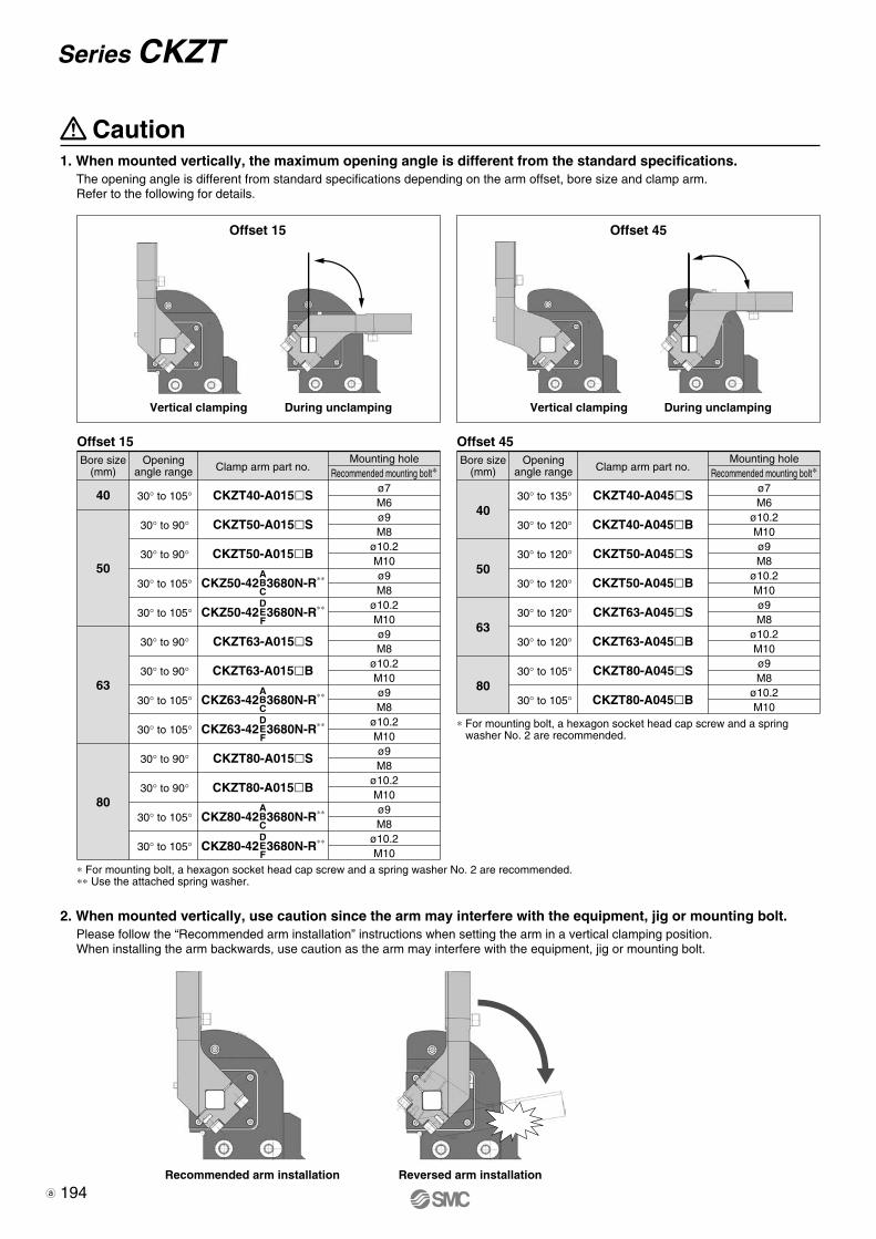
2. When mounted vertically, use caution since the arm may interfere with the equipment, jig or mounting bolt.Please follow the “Recommended arm installation” instructions when setting the arm in a vertical clamping position.When installing the arm backwards, use caution as the arm may interfere with the equipment, jig or mounting bolt.
Caution
Vertical clamping During unclamping Vertical clamping During unclamping
∗ For mounting bolt, a hexagon socket head cap screw and a spring washer No. 2 are recommended.∗∗ Use the attached spring washer.
Bore size(mm)
40
50
63
80
Openingangle range Clamp arm part no.
30° to 105°
30° to 90°
30° to 90°
30° to 105°
30° to 105°
30° to 90°
30° to 90°
30° to 105°
30° to 105°
30° to 90°
30° to 90°
30° to 105°
30° to 105°
CKZT40-A015�S
CKZT50-A015�S
CKZT50-A015�B
CKZT63-A015�S
CKZT63-A015�B
CKZT80-A015�S
CKZT80-A015�B
Mounting holeRecommended mounting bolt∗
ø7M6ø9M8
ø10.2M10ø9M8
ø10.2M10ø9M8
ø10.2M10ø9M8
ø10.2M10ø9M8
ø10.2M10ø9M8
ø10.2M10
Offset 15
∗ For mounting bolt, a hexagon socket head cap screw and a spring washer No. 2 are recommended.
Bore size(mm)
40
50
63
80
Openingangle range Clamp arm part no.
30° to 135°
30° to 120°
30° to 120°
30° to 120°
30° to 120°
30° to 120°
30° to 105°
30° to 105°
CKZT40-A045�S
CKZT40-A045�B
CKZT50-A045�S
CKZT50-A045�B
CKZT63-A045�S
CKZT63-A045�B
CKZT80-A045�S
CKZT80-A045�B
Mounting holeRecommended mounting bolt∗
ø7M6
ø10.2M10ø9M8
ø10.2M10ø9M8
ø10.2M10ø9M8
ø10.2M10
Offset 45
Offset 15 Offset 45
CKZ50-42 3680N-R∗∗ABC
CKZ50-42 3680N-R∗∗DEF
CKZ63-42 3680N-R∗∗ABC
CKZ63-42 3680N-R∗∗DEF
CKZ80-42 3680N-R∗∗ABC
CKZ80-42 3680N-R∗∗DEF
Reversed arm installationRecommended arm installation
1. When mounted vertically, the maximum opening angle is different from the standard specifications.The opening angle is different from standard specifications depending on the arm offset, bore size and clamp arm.Refer to the following for details.
194
Series CKZT
CKZT-Clamp.qxd 10.3.30 1:13 PM Page 4
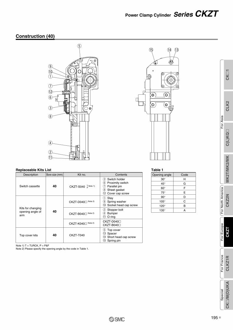
Construction (40)
Replaceable Kits List
40 CKZT-T040
CKZT-K040� Note 2)CKZT-D040�CKZT-B040�
t Top cover!3 Spacer!4 Short head cap screw!5 Spring pin
40
CKZT-D040� Note 2)
40 CKZT-S040 Note 1)
q Stayo Spring washer!0 Socket head cap screw
e Switch holdery Proximity switchu Parallel pini Sheet gasket!2 Cover cap screw
ContentsKit no.Bore size (mm)Description
CKZT-B040� Note 2)
w Stopper boltr Bumper!1 O ring
TPSwitch cassette
Kits for changingopening angle of arm
Top cover kits
Table 1
30°45°60°75°90°
105°120°135°
CodeOpening angle
H
G
F
E
D
C
B
A
Note 1) T = TURCK, P = P&FNote 2) Please specify the opening angle by the code in Table 1.
t
!2
u
!0
o
q
e
y
i
w
r
!1
!3!5 !4
CK
�1
CL
K2
C(L
)KQ
�M
K2T
/MK
2/M
KC
KZ
2NC
KZ
TC
LK
Z1R
CK
�/M
(D)U
KA
Fo
r A
sia
For
Nort
h A
merica
For
Euro
pe
For
Fra
nce
Specia
l
195
Power Clamp Cylinder Series CKZT
B
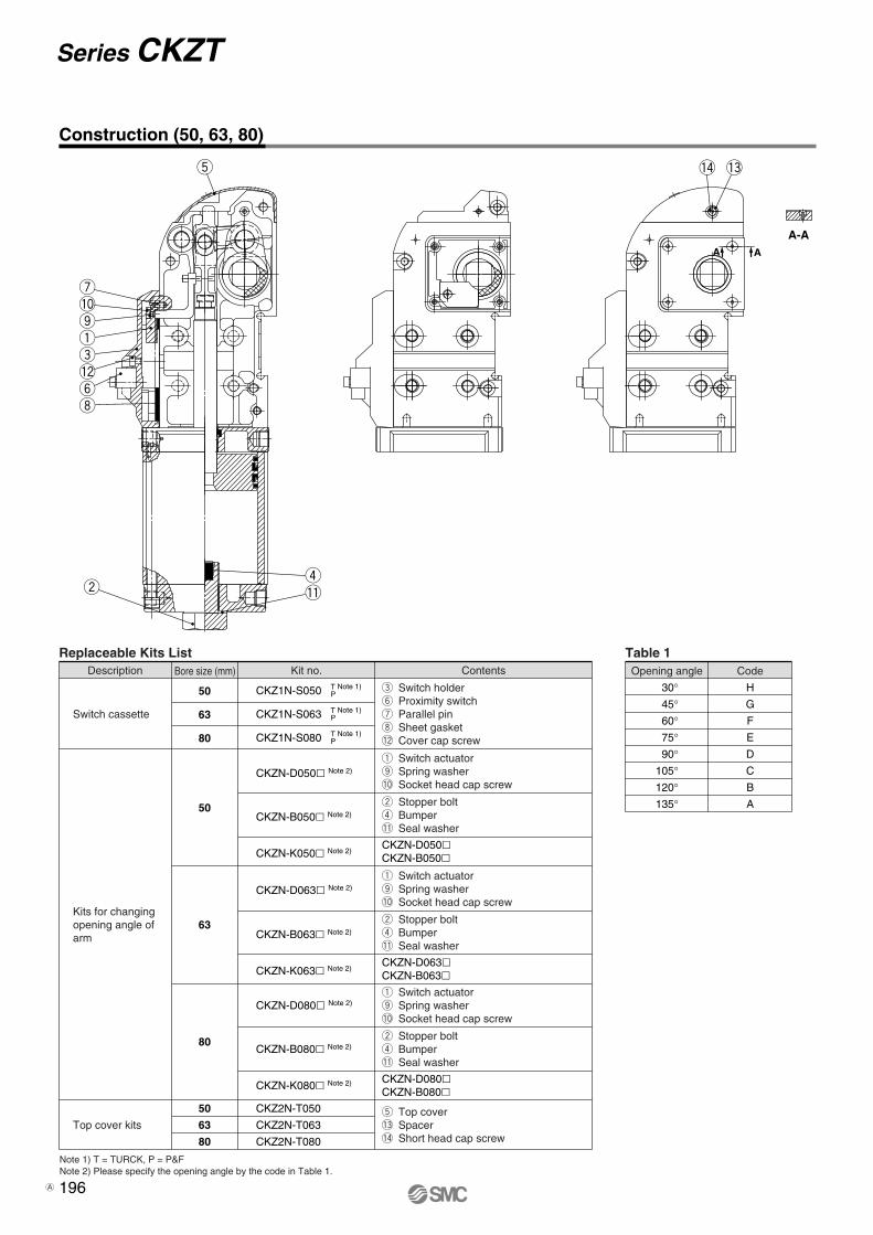
Construction (50, 63, 80)
!3!4
A-AA A
Table 1
30°45°60°75°90°
105°120°135°
CodeOpening angle
H
G
F
E
D
C
B
A
t Top cover!3 Spacer!4 Short head cap screw
Replaceable Kits List
Switch cassette
Kits for changingopening angle of arm
Top cover kits
50
63
80
50
63
80
e Switch holdery Proximity switchu Parallel pini Sheet gasket!2 Cover cap screw
q Switch actuatoro Spring washer!0 Socket head cap screw
w Stopper boltr Bumper!1 Seal washer
q Switch actuatoro Spring washer!0 Socket head cap screw
w Stopper boltr Bumper!1 Seal washer
q Switch actuatoro Spring washer!0 Socket head cap screw
w Stopper boltr Bumper!1 Seal washer
CKZN-D080�CKZN-B080�
CKZN-D063�CKZN-B063�
CKZN-D050�CKZN-B050�
ContentsKit no.Bore size (mm)Description
CKZ1N-S050 TP
Note 1)
CKZ1N-S063 TP
Note 1)
CKZ1N-S080 TP
Note 1)
CKZN-K050� Note 2)
CKZN-B050� Note 2)
CKZN-D050� Note 2)
CKZN-B063� Note 2)
CKZN-D063� Note 2)
CKZN-K063� Note 2)
CKZN-B080� Note 2)
CKZN-D080� Note 2)
CKZN-K080� Note 2)
50
63
80
CKZ2N-T050
CKZ2N-T063
CKZ2N-T080
t
!2
u!0oqe
yi
wr!1
Note 1) T = TURCK, P = P&FNote 2) Please specify the opening angle by the code in Table 1.
Series CKZT
196A
CK
�1
CL
K2
C(L
)KQ
�M
K2T
/MK
2/M
KC
KZ
2NC
KZ
TC
LK
Z1R
CK
�/M
(D)U
KA
Fo
r A
sia
For
Nort
h A
merica
For
Euro
pe
For
Fra
nce
Specia
l
197
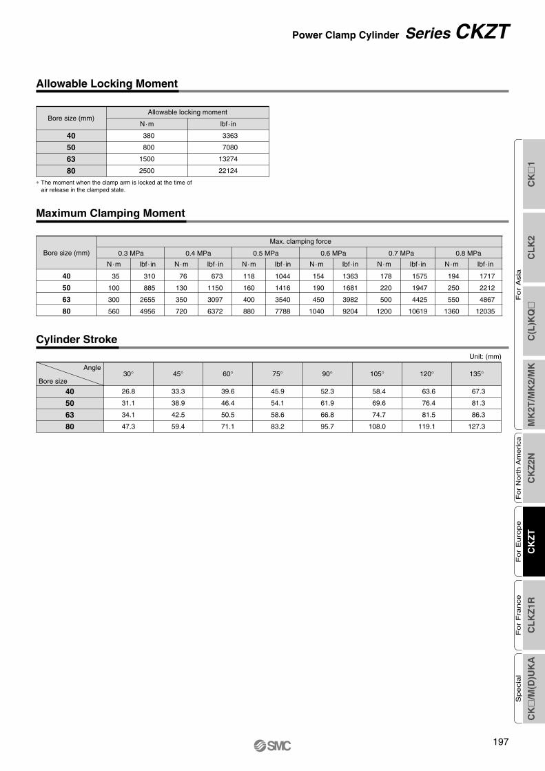
Allowable Locking Moment
Maximum Clamping Moment
Cylinder Stroke
∗ The moment when the clamp arm is locked at the time of air release in the clamped state.
Bore size (mm)Allowable locking moment
N·m
380
800
1500
2500
lbf · in
3363
7080
13274
22124
40
50
63
80
Unit: (mm)
Angle
Bore size
40
50
63
80
30°
26.8
31.1
34.1
47.3
45°
33.3
38.9
42.5
59.4
60°
39.6
46.4
50.5
71.1
75°
45.9
54.1
58.6
83.2
90°
52.3
61.9
66.8
95.7
105°
58.4
69.6
74.7
108.0
120°
63.6
76.4
81.5
119.1
135°
67.3
81.3
86.3
127.3
40
50
63
80
Bore size (mm)
Max. clamping force
35
100
300
560
N·m
0.3 MPa
310
885
2655
4956
Ibf · in
76
130
350
720
N·m
0.4 MPa
673
1150
3097
6372
Ibf · in
118
160
400
880
N·m
0.5 MPa
1044
1416
3540
7788
Ibf · in
154
190
450
1040
N·m
0.6 MPa
1363
1681
3982
9204
Ibf · in
178
220
500
1200
N·m
0.7 MPa
1575
1947
4425
10619
Ibf · in
194
250
550
1360
N·m
0.8 MPa
1717
2212
4867
12035
Ibf · in
Power Clamp Cylinder Series CKZT
Clamp-B.qxd 08.4.15 2:06 PM Page 203
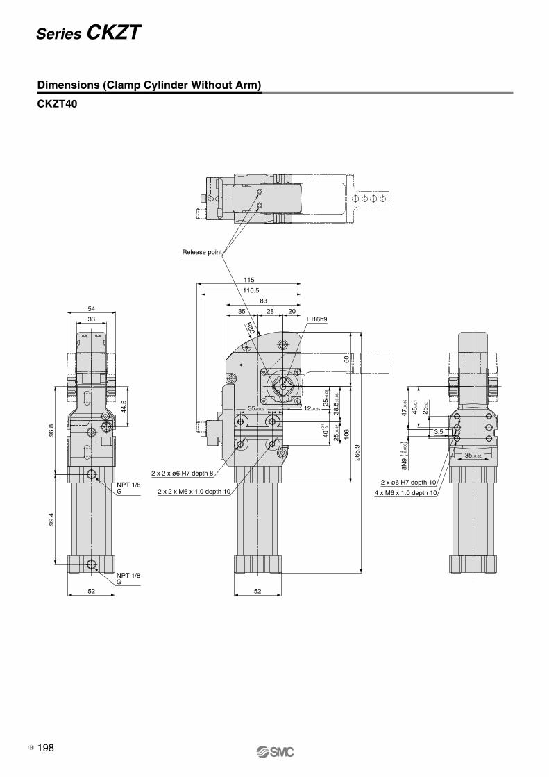
52
99.4
96.8
44.5
54
3335 28 20
83
110.5
52
265.
9
106
60
115
NPT 1/8G
NPT 1/8G
+0.
140
0
38.5
±0.0
5
�16h9
45±0
.1
47±0
.05
2 x 2 x ø6 H7 depth 8
2 x 2 x M6 x 1.0 depth 10 4 x M6 x 1.0 depth 10
2 x ø6 H7 depth 10
25±0
.1
25±0
.02
25±0
.05
R80
8N9
(
) 0 -0
.036
35±0.02 12±0.05
35±0.02
3.5
Release point
198
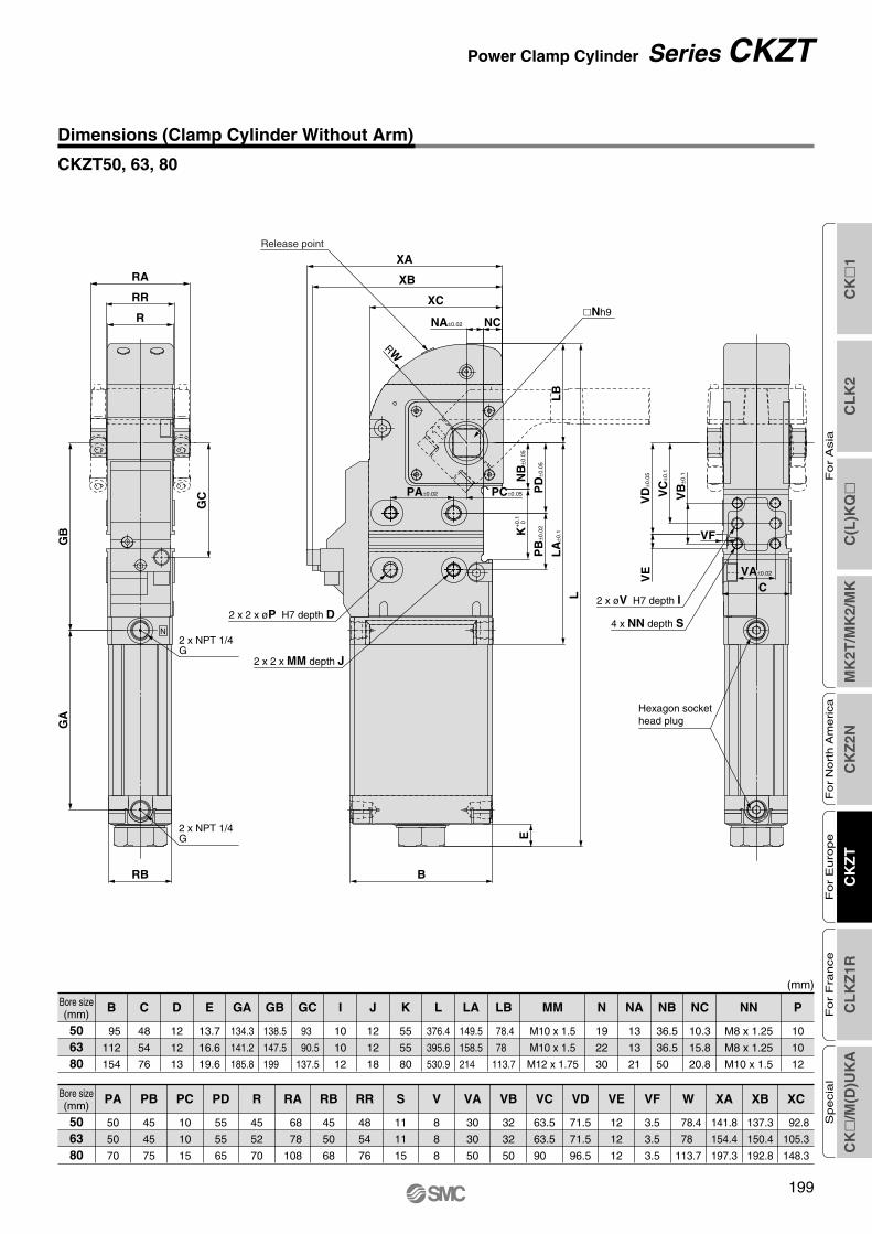
Dimensions (Clamp Cylinder Without Arm)
CKZT40
Series CKZT
B
CK
�1
CL
K2
C(L
)KQ
�M
K2T
/MK
2/M
KC
KZ
2NC
KZ
TC
LK
Z1R
CK
�/M
(D)U
KA
Fo
r A
sia
For
Nort
h A
merica
For
Euro
pe
For
Fra
nce
Specia
l
199
XC
XB
RW
LB
PD
±0.0
5
NB
±0.0
5
VD
±0.0
5
VC
±0.1
VB
±0.1
PB
±0.0
2+0.
1K
0
LA
±0.1
L
E
B
2 x 2 x øP H7 depth D2 x øV H7 depth I
2 x 2 x MM depth J
XA
NA±0.02 NC
PA±0.02 PC±0.05
RB
GA
GB
R
RR
RA
GC
2 x NPT 1/4G
2 x NPT 1/4G
4 x NN depth S
VA±0.02
C
VE
VF
Release point
�Nh9
N
Hexagon sockethead plug
Dimensions (Clamp Cylinder Without Arm)
CKZT50, 63, 80
Bore size(mm)
506380
C D E GA GB GC I J K L LA LB MM N NA NB NC NN PB
(mm)
95
112
154
48
54
76
12
12
13
13.7
16.6
19.6
134.3
141.2
185.8
138.5
147.5
199
93
90.5
137.5
10
10
12
12
12
18
55
55
80
376.4
395.6
530.9
149.5
158.5
214
78.4
78
113.7
M10 x 1.5
M10 x 1.5
M12 x 1.75
19
22
30
13
13
21
36.5
36.5
50
10.3
15.8
20.8
M8 x 1.25
M8 x 1.25
M10 x 1.5
10
10
12
Bore size(mm)
506380
XCPA PB PC PD R RA RB RR S V VA VB VC VD VE VF W XA XB
50
50
70
45
45
75
10
10
15
55
55
65
45
52
70
68
78
108
45
50
68
48
54
76
11
11
15
8
8
8
30
30
50
32
32
50
63.5
63.5
90
71.5
71.5
96.5
12
12
12
3.5
3.5
3.5
78.4
78
113.7
141.8
154.4
197.3
137.3
150.4
192.8
92.8
105.3
148.3
Power Clamp Cylinder Series CKZT
Clamp-B.qxd 08.4.15 2:06 PM Page 205
200
33 54
23
016
-0.1
31
22±0
.115
±0.2
117
�16
48
(7) 20±0.2
20±0.02 90±0.1
2 x ø6H7 through
2 x ø7 through
Center type
Left type
Right type
2 x øD1H7 through
2 x øD2 through
34
20
44
48 68
28±0
.115
±0.2
�19
144
65
(9) 30±0.2
30±0.02 105±0.1
Center type
Left type
Right type
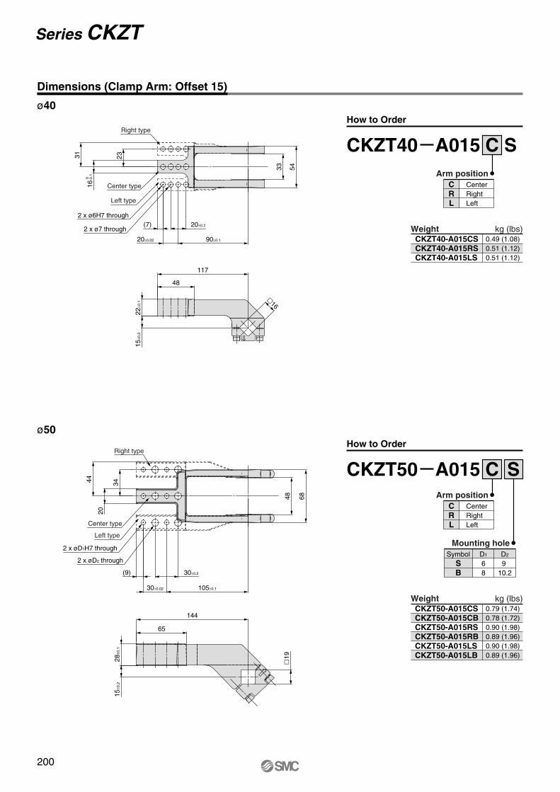
Dimensions (Clamp Arm: Offset 15)
ø40
ø50
WeightCKZT40-A015CSCKZT40-A015RSCKZT40-A015LS
0.49 (1.08)0.51 (1.12)0.51 (1.12)
CKZT40 A015 C S
CRL
CenterRightLeft
Arm position
Weight
kg (lbs)
kg (lbs)CKZT50-A015CSCKZT50-A015CBCKZT50-A015RSCKZT50-A015RBCKZT50-A015LSCKZT50-A015LB
0.79 (1.74)0.78 (1.72)0.90 (1.98)0.89 (1.96)0.90 (1.98)0.89 (1.96)
CKZT50 A015 CArm position
CRL
CenterRightLeft
S
Mounting hole
SB
D1
68
D2
910.2
Symbol
How to Order
How to Order
Series CKZT
Clamp-B.qxd 08.4.15 2:06 PM Page 206
CK
�1
CL
K2
C(L
)KQ
�M
K2T
/MK
2/M
KC
KZ
2NC
KZ
TC
LK
Z1R
CK
�/M
(D)U
KA
Fo
r A
sia
For
Nort
h A
merica
For
Euro
pe
For
Fra
nce
Specia
l
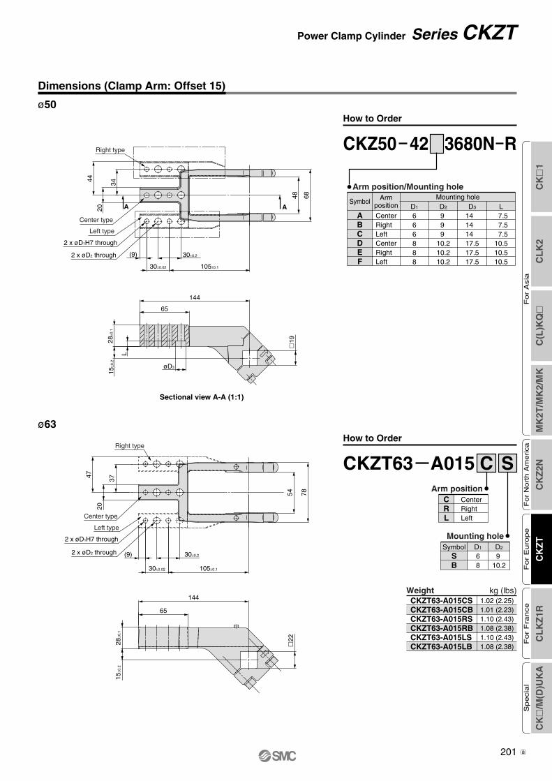
201
2 x øD1H7 through
2 x øD2 through
37
47
20
54 78
28±0
.115
±0.2
144
�22
65
(9) 30±0.2
30±0.02 105±0.1
Right type
Center type
Left type
ø63
Weight kg (lbs)CKZT63-A015CSCKZT63-A015CBCKZT63-A015RSCKZT63-A015RBCKZT63-A015LSCKZT63-A015LB
1.02 (2.25)1.01 (2.23)1.10 (2.43)1.08 (2.38)1.10 (2.43)1.08 (2.38)
CKZT63 A015 CArm position
CRL
CenterRightLeft
S
Mounting hole
SB
D1
68
D2
9 10.2
Symbol
How to Order
Dimensions (Clamp Arm: Offset 15)
Power Clamp Cylinder Series CKZT
Sectional view A-A (1:1)
ø50
CKZ50 42 3680N R
Arm position/Mounting hole
ABCDEF
D1
666888
D2
9 9 9
10.210.210.2
D3
14 14 14 17.517.517.5
L 7.5 7.5 7.510.510.510.5
CenterRightLeftCenterRightLeft
Armposition
Mounting holeSymbol
How to Order
A A
34
20
44
48 6865
144
L
(9)
øD3
2 x øD1H7 through
2 x øD2 through
28±0
.115
±0.2
�19
30±0.2
30±0.02 105±0.1
Right type
Center type
Left type
CKZT-Clamp.qxd 10.3.30 1:13 PM Page 7
Sectional view A-A (1:1)
ø63
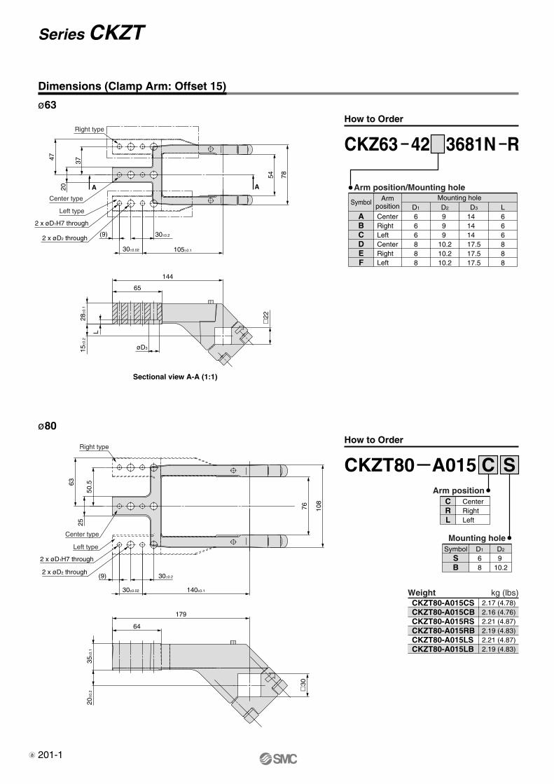
CKZ63 42 3681N R
How to Order
2 x øD1H7 through
2 x øD2 through
76 108
50.5
2563
35±0
.120
±0.2
179
�30
64
(9) 30±0.2
30±0.02 140±0.1
Center type
Left type
Right type
ø80
WeightCKZT80-A015CSCKZT80-A015CBCKZT80-A015RSCKZT80-A015RBCKZT80-A015LSCKZT80-A015LB
2.17 (4.78)2.16 (4.76)2.21 (4.87)2.19 (4.83)2.21 (4.87)2.19 (4.83)
CKZT80 A015 CArm position
CRL
CenterRightLeft
S
Mounting hole
SB
D1
68
D2
9 10.2
Symbol
kg (lbs)
How to Order
Arm position/Mounting hole
ABCDEF
D1
666888
D2
9 9 9
10.210.210.2
D3
14 14 14 17.517.517.5
L666888
CenterRightLeftCenterRightLeft
Armposition
Mounting holeSymbol
A A
37
20
47
54 7865
144
L
2 x øD1H7 through
2 x øD2 through
28±0
.115
±0.2
�22
(9) 30±0.2
30±0.02 105±0.1
Center type
Left type
Right type
øD3
201-1
Series CKZT
Dimensions (Clamp Arm: Offset 15)
CKZT-Clamp.qxd 10.3.30 1:13 PM Page 8
CK
�1
CL
K2
C(L
)KQ
�M
K2T
/MK
2/M
KC
KZ
2NC
KZ
TC
LK
Z1R
CK
�/M
(D)U
KA
Fo
r A
sia
For
Nort
h A
merica
For
Euro
pe
For
Fra
nce
Specia
l
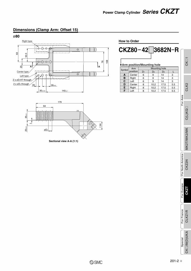
201-2
Dimensions (Clamp Arm: Offset 15)
Power Clamp Cylinder Series CKZT
CKZ80 42 3682N R
Arm position/Mounting hole
ABCDEF
D1
666888
D2
9 9 9
10.210.210.2
D3
14 14 14 17.517.517.5
L3 3 3 5.55.55.5
CenterRightLeftCenterRightLeft
Armposition
Mounting holeSymbol
How to Order
A A
50.5
25
63
76 108
64
179
Right type
Center type
Left type
2 x øD1H7 through
2 x øD2 through (9) 30±0.2
30±0.02 140±0.1
35±0
.120
±0.2 �
30
L
øD3
Sectional view A-A (1:1)
ø80
CKZT-Clamp.qxd 10.3.30 1:13 PM Page 9
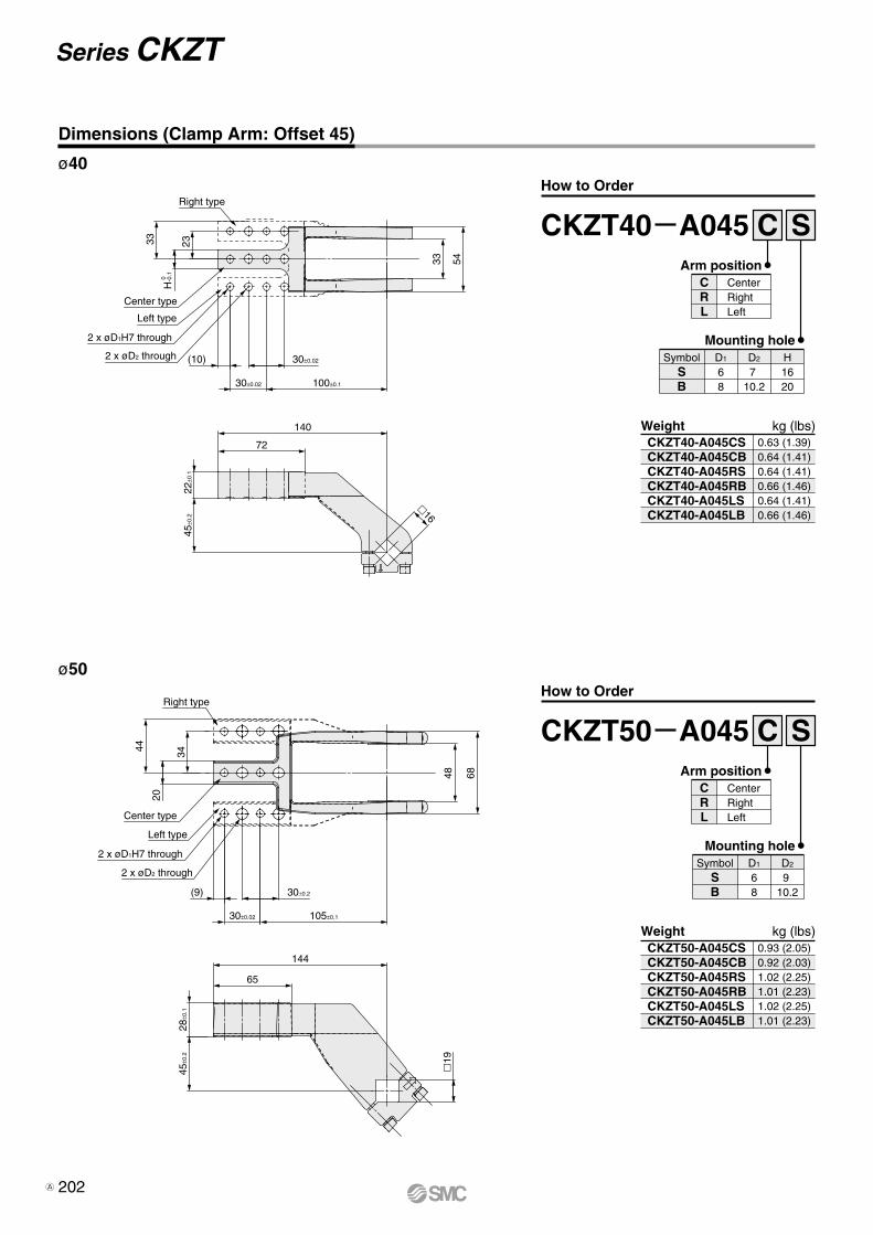
34
20
44
48 68
28±0
.145
±0.2
19
144
65
30±0.2
30±0.02 105±0.1
Center type
Left type
Right type
2 x øD1H7 through
2 x øD2 through
(9)
33 54
2333
22±0
.145
±0.2
140
16
72
30±0.02
30±0.02 100±0.1
Center type
Left type
Right type
2 x øD1H7 through
2 x øD2 through (10)
0
H-0
.1ø40
ø50
Weight CKZT50-A045CSCKZT50-A045CBCKZT50-A045RSCKZT50-A045RBCKZT50-A045LSCKZT50-A045LB
0.93 (2.05)0.92 (2.03)1.02 (2.25)1.01 (2.23)1.02 (2.25)1.01 (2.23)
CKZT50 A045 CArm position
CRL
CenterRightLeft
S
Mounting hole
SB
D1
68
Symbol D2
9 10.2
Weight
kg (lbs)
kg (lbs)CKZT40-A045CSCKZT40-A045CBCKZT40-A045RSCKZT40-A045RBCKZT40-A045LSCKZT40-A045LB
0.63 (1.39)0.64 (1.41)0.64 (1.41)0.66 (1.46)0.64 (1.41)0.66 (1.46)
CKZT40 A045 CArm position
CRL
CenterRightLeft
S
Mounting hole
SB
D1
68
Symbol D2
7 10.2
H1620
How to Order
How to Order
Series CKZT
Dimensions (Clamp Arm: Offset 45)
202A
CK
�1
CL
K2
C(L
)KQ
�M
K2T
/MK
2/M
KC
KZ
2NC
KZ
TC
LK
Z1R
CK
�/M
(D)U
KA
Fo
r A
sia
For
Nort
h A
merica
For
Euro
pe
For
Fra
nce
Specia
l
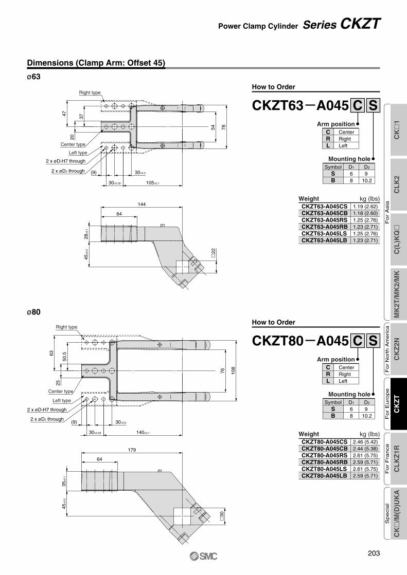
203
37
47
20
54 78
28±0
.145
±0.2
144
�22
64
30±0.2
30±0.02 105±0.1
Center type
Left type
Right type
2 x øD1H7 through
2 x øD2 through (9)
76 108
50.5
2563
35±0
.145
±0.2
179
�30
64
30±0.2
30±0.02 140±0.1
Center type
Left type
Right type
2 x øD1H7 through
2 x øD2 through(9)
ø63
ø80
WeightCKZT80-A045CSCKZT80-A045CBCKZT80-A045RSCKZT80-A045RBCKZT80-A045LSCKZT80-A045LB
2.46 (5.42)2.44 (5.38)2.61 (5.75)2.59 (5.71)2.61 (5.75)2.59 (5.71)
CKZT80 A045 CArm position
CRL
CenterRightLeft
S
Mounting hole
SB
D1
68
D2
910.2
Symbol
Weight
kg (lbs)
kg (lbs)CKZT63-A045CSCKZT63-A045CBCKZT63-A045RSCKZT63-A045RBCKZT63-A045LSCKZT63-A045LB
1.19 (2.62)1.18 (2.60)1.25 (2.76)1.23 (2.71)1.25 (2.76)1.23 (2.71)
How to Order
CKZT63 A045 CArm position
CRL
CenterRightLeft
S
Mounting hole
SB
D1
68
D2
910.2
Symbol
How to Order
Power Clamp Cylinder Series CKZT
Dimensions (Clamp Arm: Offset 45)
Clamp-B.qxd 08.4.15 2:06 PM Page 209
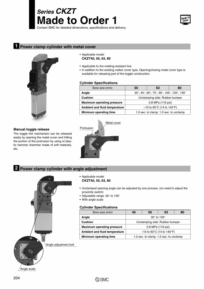
Series CKZTMade to Order 1Contact SMC for detailed dimensions, specifications and delivery.
Power clamp cylinder with metal cover1
Manual toggle releaseThe toggle link mechanism can be released easily by opening the metal cover and hitting the portion of the protrusion by using of plas-tic hammer (hammer made of soft material), etc.
• Applicable modelCKZT40, 50, 63, 80
• Applicable to Arc-melting-resistant line• In addition to the existing rubber cover type, Opening/closing metal cover type is
available for releasing part of the toggle construction.
Cylinder SpecificationsBore size (mm) 50 63 80
Angle
Cushion
Maximum operating pressure
Ambient and fluid temperature
Minimum operating time
30°, 45°, 60°, 75°, 90°, 105°, 120°, 135°
Unclamping side: Rubber bumper
0.8 MPa (116 psi)
–10 to 60°C (14 to 140°F)
1.0 sec. to clamp, 1.0 sec. to unclamp
Metal cover
Protrusion
Power clamp cylinder with angle adjustment2
• Applicable modelCKZT40, 50, 63, 80
• Unclamped opening angle can be adjusted by one process. (no need to adjust the proximity switch)
• Adjustable range: 30° to 135°• With angle scale
Cylinder SpecificationsBore size (mm) 5040 63 80
Angle
Cushion
Maximum operating pressure
Ambient and fluid temperature
Minimum operating time
30° to 135°
Unclamping side: Rubber bumper
0.8 MPa (116 psi)
–10 to 60°C (14 to 140°F)
1.0 sec. to clamp, 1.0 sec. to unclamp
Angle adjustment bolt
Angle scale
204
Clamp-B.qxd 08.4.15 2:06 PM Page 210
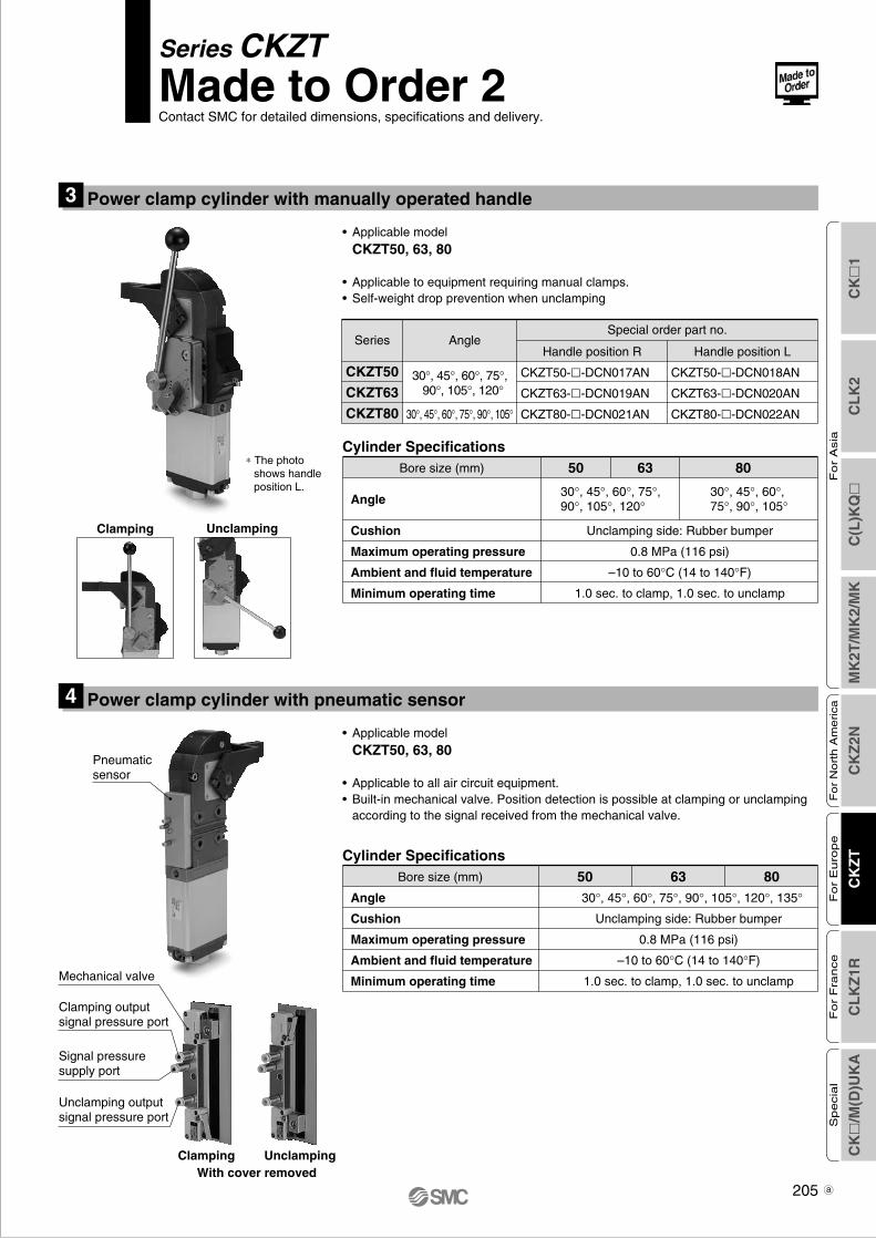
Power clamp cylinder with manually operated handle3
• Applicable modelCKZT50, 63, 80
• Applicable to equipment requiring manual clamps.• Self-weight drop prevention when unclamping
Cylinder SpecificationsBore size (mm) 50 63 80
Angle
Cushion
Maximum operating pressure
Ambient and fluid temperature
Minimum operating time
30°, 45°, 60°,75°, 90°, 105°
30°, 45°, 60°, 75°,90°, 105°, 120°
Unclamping side: Rubber bumper
0.8 MPa (116 psi)
–10 to 60°C (14 to 140°F)
1.0 sec. to clamp, 1.0 sec. to unclamp
Pneumatic sensor
Power clamp cylinder with pneumatic sensor4
• Applicable modelCKZT50, 63, 80
• Applicable to all air circuit equipment.• Built-in mechanical valve. Position detection is possible at clamping or unclamping
according to the signal received from the mechanical valve.
Clamping Unclamping
ClampingWith cover removed
Unclamping
Clamping output signal pressure port
Signal pressure supply port
Unclamping output signal pressure port
Mechanical valve
Series CKZTMade to Order 2Contact SMC for detailed dimensions, specifications and delivery.
Cylinder SpecificationsBore size (mm) 50 63 80
Angle
Cushion
Maximum operating pressure
Ambient and fluid temperature
Minimum operating time
30°, 45°, 60°, 75°, 90°, 105°, 120°, 135°
Unclamping side: Rubber bumper
0.8 MPa (116 psi)
–10 to 60°C (14 to 140°F)
1.0 sec. to clamp, 1.0 sec. to unclamp
Series AngleSpecial order part no.
Handle position R Handle position L
CKZT50
CKZT63
CKZT80
CKZT50-�-DCN017AN
CKZT63-�-DCN019AN
CKZT80-�-DCN021AN
CKZT50-�-DCN018AN
CKZT63-�-DCN020AN
CKZT80-�-DCN022AN30°, 45°, 60°, 75°, 90°, 105°
30°, 45°, 60°, 75°, 90°, 105°, 120°
∗ The photo shows handle position L.
CK
�1
CL
K2
C(L
)KQ
�M
K2T
/MK
2/M
KC
KZ
2NC
KZ
TC
LK
Z1R
CK
�/M
(D)U
KA
Fo
r A
sia
For
Nort
h A
merica
For
Euro
pe
For
Fra
nce
Specia
l
205 a
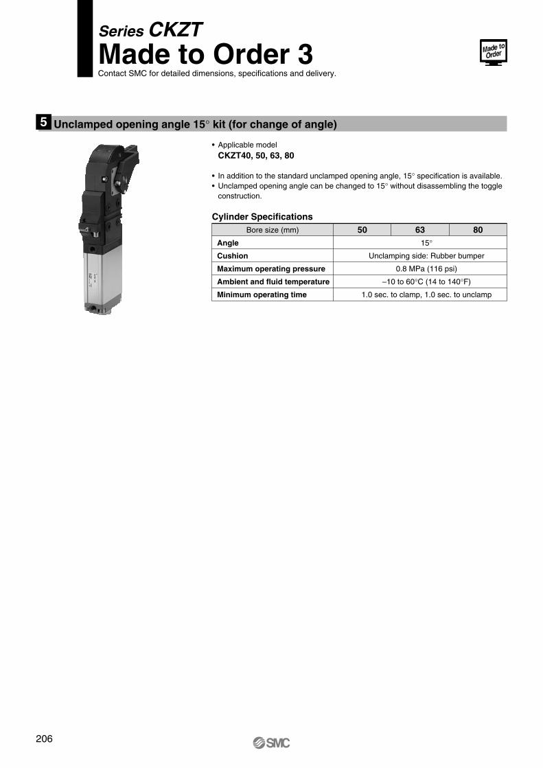
Unclamped opening angle 15° kit (for change of angle)5
• Applicable modelCKZT40, 50, 63, 80
• In addition to the standard unclamped opening angle, 15° specification is available.• Unclamped opening angle can be changed to 15° without disassembling the toggle
construction.
Cylinder SpecificationsBore size (mm) 50 63 80
Angle
Cushion
Maximum operating pressure
Ambient and fluid temperature
Minimum operating time
15°
Unclamping side: Rubber bumper
0.8 MPa (116 psi)
–10 to 60°C (14 to 140°F)
1.0 sec. to clamp, 1.0 sec. to unclamp
Series CKZTMade to Order 3Contact SMC for detailed dimensions, specifications and delivery.
206
Clamp-B.qxd 08.4.15 2:06 PM Page 212
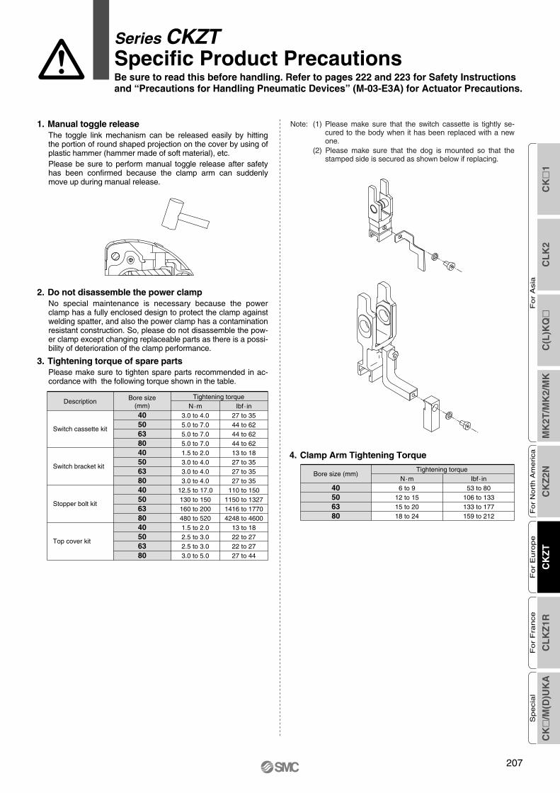
1. Manual toggle releaseThe toggle link mechanism can be released easily by hitting the portion of round shaped projection on the cover by using ofplastic hammer (hammer made of soft material), etc.Please be sure to perform manual toggle release after safety has been confirmed because the clamp arm can suddenly move up during manual release.
2. Do not disassemble the power clampNo special maintenance is necessary because the power clamp has a fully enclosed design to protect the clamp against welding spatter, and also the power clamp has a contamination resistant construction. So, please do not disassemble the pow-er clamp except changing replaceable parts as there is a possi-bility of deterioration of the clamp performance.
3. Tightening torque of spare partsPlease make sure to tighten spare parts recommended in ac-cordance with the following torque shown in the table.
40506380
Bore size (mm)Tightening torque
40506380405063804050638040506380
3.0 to 4.05.0 to 7.05.0 to 7.05.0 to 7.01.5 to 2.03.0 to 4.03.0 to 4.03.0 to 4.0
12.5 to 17.0130 to 150160 to 200480 to 5201.5 to 2.02.5 to 3.02.5 to 3.03.0 to 5.0
Bore size(mm)
Tightening torque Description
Switch cassette kit
Switch bracket kit
Stopper bolt kit
Top cover kit
N·m27 to 3544 to 6244 to 6244 to 6213 to 1827 to 3527 to 3527 to 35
110 to 1501150 to 13271416 to 17704248 to 4600
13 to 1822 to 2722 to 2727 to 44
Ibf · in
Series CKZTSpecific Product PrecautionsBe sure to read this before handling. Refer to pages 222 and 223 for Safety Instructions and “Precautions for Handling Pneumatic Devices” (M-03-E3A) for Actuator Precautions.
Note: (1) Please make sure that the switch cassette is tightly se-cured to the body when it has been replaced with a new one.
(2) Please make sure that the dog is mounted so that the stamped side is secured as shown below if replacing.
4. Clamp Arm Tightening Torque
6 to 912 to 1515 to 2018 to 24
N·m53 to 80
106 to 133133 to 177159 to 212
Ibf · in
CK
�1
CL
K2
C(L
)KQ
�M
K2T
/MK
2/M
KC
KZ
2NC
KZ
TC
LK
Z1R
CK
�/M
(D)U
KA
Fo
r A
sia
For
Nort
h A
merica
For
Euro
pe
For
Fra
nce
Specia
l
207
Clamp-B.qxd 08.4.15 2:06 PM Page 213


![INDEX [] Manual.pdf7 5- claw 6- turntable 7- turntable cylinder 8- operation panel 9- clamp pedal 10- press tire pedal 11- turntable pedal 12- crowbar 13- blade 14-bead breaking cylinder](https://img.pdfslide.us/doc/110x75/5f45d3f3686b1e75e527822f/index-manualpdf-7-5-claw-6-turntable-7-turntable-cylinder-8-operation-panel.jpg)