Embed Size (px)
Citation preview
Doornvallei Ext 5
Services Report
1
CIVIL ENGINEERING SERVICES REPORT
(WATER AND SANITATION)
DOORNVALLEI EXT 5
August 2015
Revision 0
PREPARED FOR: PREPARED BY:
CITY OF TSHWANE: SERVICES
INFRASTRUCTURE DEPARTMENT
WATER & SANITATION DIVISION
ROOM B615, CAPITOL TOWERS NORTH
225 MADIBA STREET, PRETORIA, 0001
CONTACT: MR STEVENS NOTOANE
TEL: (012) 358 3773
FAX: (012) 358 3991
LV & PARTNERS
OFFICE 10, 3RD FLOOR
476 KINGS HIGHWAY
LYNNWOOD, 0081
CONTACT: MR PIETER LINDEQUE
TEL: (012) 664 6490
FAX: (012) 349 8256

Doornvallei Ext 5
Services Report
2
TABLE OF CONTENTS
CONTENTS PAGE
1. GENERAL INFORMATION 3
1.1 Introduction 3
1.2 Site description 4
1.3 Registered land owner 6
1.4 Township establishment conditions 6
1.5 Land use 6
2. WATER SUPPLY SCHEME 8
2.1 Existing infrastructure 8
2.2 Water design criteria 8
2.3 Water demand calculations 10
2.4 Proposed new infrastructure 11
2.5 Servitudes required 12
2.6 Construction cost estimate 12
2.7 Contributions for water 12
3. SEWER DRAINAGE SCHEME 13
3.1 Existing infrastructure 13
3.2 Sewer design criteria 13
3.3 Sewer outflow calculations 17
3.4 Proposed new infrastructure 18
3.5 Servitudes required 19
3.6 Construction cost estimate 19
3.7 Contributions for sewer 19
3.8 Solid waste management 19
APPENDICES
APPENDIX 1: LOCALITY PLAN
APPENDIX 2: TOWN PLANNER’S LAYOUT
APPENDIX 3: PROOF OF OWNERSHIP
APPENDIX 4: TOWNSHIP ESTABLISHMENT CONDITIONS
APPENDIX 5: GLS REPORT
APPENDIX 6: APPLICATION FOR RAND WATER CONNETION
APPENDIX 7: DRAWINGS
Doornvallei Ext 5
Services Report
3
1. GENERAL INFORMATION
1.1 INTRODUCTION
This development is envisaged on portion 107 of the farm Doornkloof 391 – JR.
LV & Partners Consulting Civil Engineers were appointed by M-T Development
(Pty) Ltd per letter dated 25 February 2008 to investigate bulk water and
sanitation infrastructure options and to compile a civil engineering services report
for the proposed development.
The purpose of this report is to verify and confirm the requirements and design
criteria of the Water and Sanitation Division of the Services Infrastructure
Department of the City of Tshwane. It also aims at facilitating the compilation of a
Services Agreement between the Developer and the Local Authority. The report
will enable the reader to determine the level and extent of municipal engineering
services to be provided, the preferred bulk infrastructure options, as well as the
associated estimated costs.
The locality plan and town planner’s layout are appended to this report as
Appendixes 1 and 2 respectively.
Doornvallei Ext 5
Services Report
4
1.2 SITE DESCRIPTION
1.2.1 SITE LOCATION
The development falls inside the jurisdiction of the City of Tshwane. The site is
situated west of the R21 highway and south of the Hennops River (directly south
of the Irene Glen Estate). The site is 6.6479 hectares in size.
1.2.2 TOPOGRAPHY AND DRAINAGE
The site is located between 1517 masl and 1495 masl. The site slopes down in
an eastern direction initially and eventually northwards towards the Hennops
River. A watershed line is present on the western side. Drainage is in the form of
sheetflow or overland flow initially and becomes concentrated on the eastern
side.
1.2.3 FLORA
At present the site is undeveloped and covered by natural grass with some
indigenous trees present. Red data species are present on the western boundary
of the site.
1.2.4 CLIMATE AND WEATHER CONDITIONS
The site lies within the Highveld climatic region, the climate being described as
warm temperature with summer rainfall. The average daily maximum temperature
is in the order of 28ºC in January and 18ºC in July. The rainy season is from
October to March, with an average rainfall of about 750 mm per annum.
1.2.5 GEOLOGY
The site is underlain mainly by the chert rich dolomite of the eccles Formation of
the Malmani Subgroup of the Chuniespoort Group. The upper materials consist
mainly of chert gravel and in some places shallow dolomite rock is present.
Doornvallei Ext 5
Services Report
5
1.2.6 HYDROLOGY
No development is allowed below the 1:100 year flood line. The flood line study
(done by others) will confirm the position of the 1:100 year flood line.
1.2.7 ACCESS
Access to the site is via the existing road P112-1 (M57), running adjacent to the
site. The proposed access road will be off the existing access road to Irene
Glen Estate as indicated on the drawings attached as Appendix 7.
1.3 REGISTERED LAND OWNER
Refer to appendix 3 for details of the registered land owner.
1.4 TOWNSHIP ESTABLISHMENT CONDITIONS
The approved township establishment conditions are attached to this report as
Appendix 4.
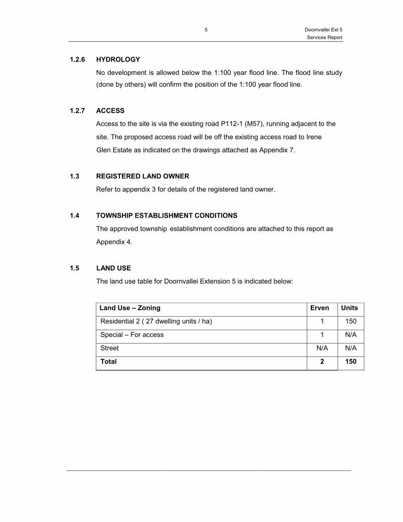
1.5 LAND USE
The land use table for Doornvallei Extension 5 is indicated below:
Land Use – Zoning Erven Units
Residential 2 ( 27 dwelling units / ha) 1 150
Special – For access 1 N/A
Street N/A N/A
Total 2 150
Doornvallei Ext 5
Services Report
6
2. WATER SUPPLY SCHEME
2.1 EXISTING INFRASTRUCTURE
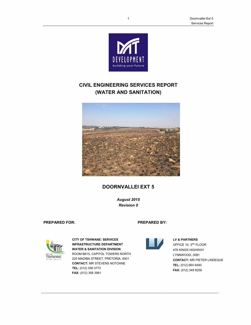
The property to be developed is currently vacant land as can be seen on the
picture on the front page of this report. The only existing water related
infrastructure is the existing Randwater pipeline running past the proposed
development along the existing provincial road P112-1 (M57).
2.2 WATER DESIGN CRITERIA
The following standards will be used in the design of the water reticulation:
• Average annual daily demand (AADD)
− Residential 2 (27 dwelling units/ha) : 0.8 kl/unit
− Gate house for access control : 0.6 kl/unit
− Street : N/A
• Peak hour demand
− Peak hour factor (PHF) : 4.6
− Peak hour demand : PHF x AADD
• System heads
− Maximum static head (no demand) : 90 m
− Minimum residual head under conditions
of peak hour demand at erf boundary
: 24 m
• Fire - fighting
− Fire risk category : Category C (residential)
− Total fire flow : 15 ℓ/s (< 30 units / ha)
− Flow at any one hydrant : 15 ℓ/s (< 30 units / ha)
− Minimum pressure at fire : 8 m (< 30 units / ha)
− Minimum pressure rest of system : 5 m (< 30 units / ha)
− Spacing of fire hydrants : 240 m max (< 30 units / ha)
• Linear pipeline velocity
− Maximum under conditions of peak hour : 1.8 m/s
− Maximum under conditions of fire-fighting : 2.2 m/s
• Dolomite risk category : Medium
Doornvallei Ext 5
Services Report
7
• Pipe material (dolomitic area) for pipes and
fittings > 75 mm Ø
: HDPE PE 100 to SANS ISO
4427
− Minimum pipe class : PN 12 (or higher pressure
class if required)
− Supply lengths : 12 m minimum
− Joints : Butt–welded to SANS 10268
– Part 1 or electro-fusion
welding as per SANS 10268
– Part 2 where butt –
welding is impossible
• Boundary roughness (k-value) : 0.1 mm
• Flow formula : D’Arcy Weissbach
• Depth of cover below final ground level
− On sidewalks : 1.0 m(min) – 1.5 m(max)
− Across streets : 1.0 m(min) – 1.5 m(max)
• Placement of pipes inside 13 m to 25 m road
reserves
: 2.2 m from erf boundary on
high side of road (16 m road
reserves)
: 1.8 m from erf boundary on
high side of road (13 m road
reserves)
• Placement of isolating valves : Opposite splay corner pegs
in networks
: So that not more than 4
valves have to be shut off to
isolate any part of the
network.
• Placement of hydrants : Fire Department to specify
type and placement
: Opposite the communal erf
pegs and between 0.3 m and
0.5 m away from them
: Not closer than one erf
length to any intersection.
Doornvallei Ext 5
Services Report
8
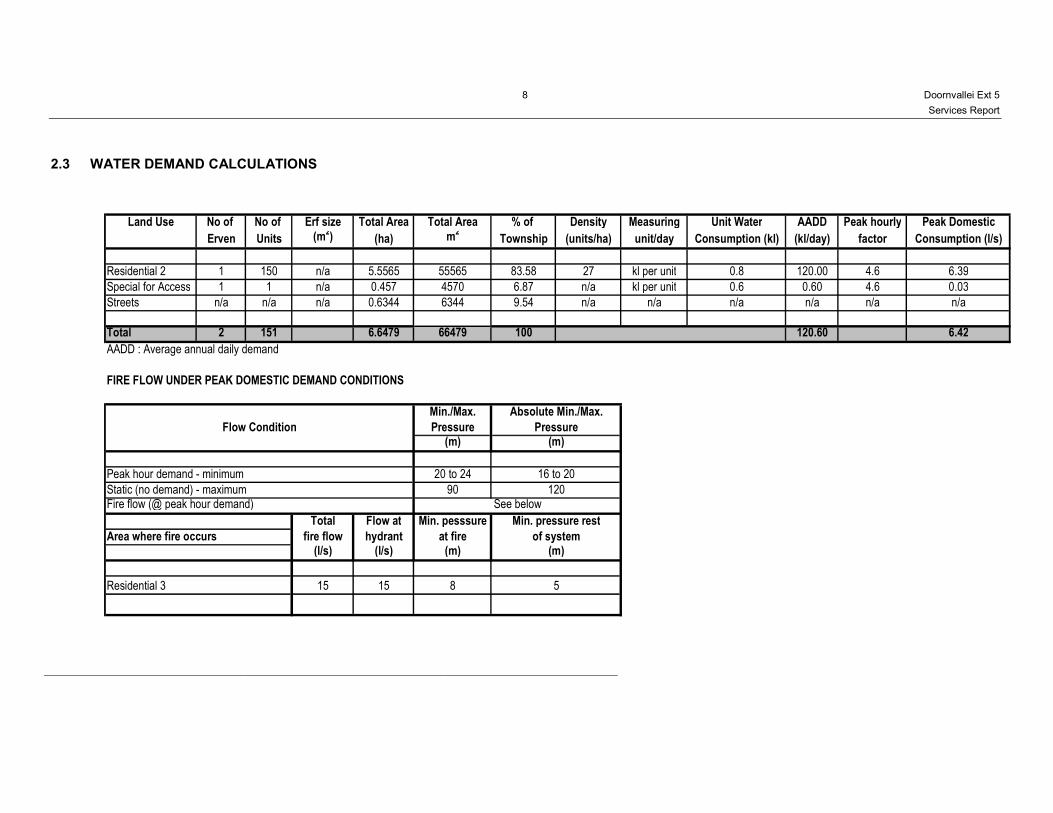
2.3 WATER DEMAND CALCULATIONS
Land Use No of No of Erf size Total Area Total Area % of Density Measuring Unit Water AADD Peak hourly Peak Domestic
Erven Units (m2) (ha) m
2Township (units/ha) unit/day Consumption (kl) (kl/day) factor Consumption (l/s)
Residential 2 1 150 n/a 5.5565 55565 83.58 27 kl per unit 0.8 120.00 4.6 6.39
Special for Access 1 1 n/a 0.457 4570 6.87 n/a kl per unit 0.6 0.60 4.6 0.03
Streets n/a n/a n/a 0.6344 6344 9.54 n/a n/a n/a n/a n/a n/a
Total 2 151 6.6479 66479 100 120.60 6.42
AADD : Average annual daily demand
FIRE FLOW UNDER PEAK DOMESTIC DEMAND CONDITIONS
Min./Max.
Pressure(m)
Peak hour demand - minimum 20 to 24
Static (no demand) - maximum 90Fire flow (@ peak hour demand)
Total Flow at Min. pesssure
Area where fire occurs fire flow hydrant at fire(l/s) (l/s) (m)
Residential 3 15 15 8
16 to 20
Absolute Min./Max.
Flow Condition Pressure(m)
5
120See below
Min. pressure rest
of system(m)
Doornvallei Ext 5
Services Report
9
2.4 PROPOSED NEW INFRASTRUCTURE
Refer to the draft GLS report enclosed in Appendix 5 regarding bulk water supply
options in the area.
The proposed township known as Doornvallei Extension 5 on portion 107 of the Farm
Doornkloof 391-JR will be supplied with potable water from a permanent connection
on the nearby Randwater Pipeline. The future Van Riebeeck High Level Reservoir will
be supplied with potable water from this very same connection.
A pressure boosting pump station and a pressure reducing valve (PRV) station will be
installed at the connection point comprising the following pressures:
• Maximum upstream static head of 135 m
• Minimum upstream dynamic head of 48 m
• Constant downstream PRV pressure setting of 30 m.
The original application for the Rand Water connection is enclosed in Appendix 6. It is
proposed that items VRH.15, VRH.16, VRH.17, VRH.18, BVR.1a and BVR.9 (shown
in red below) be installed under Doornvallei Extension 6 and items 1, 2, 3, BVR.1,
BVR.10, BVR11 and BVR.12 be installed under Doornvallei Extension 5.
2.5 SERVITUDES REQUIRED
A servitude for the installation of a Booster Pump Station and a Pressure Reducing
Valve Station will have to be secured and registered at the Rand Water connection
point. The existing Rand Water and Eskom servitudes will be crossed at the proposed
connection point. A 3m water pipeline servitude will also be required to accommodate
pipe items VRH.15, VRH.16, VRH.17 and VRH.18 as shown in the GLS report.
Doornvallei Ext 5
Services Report
10
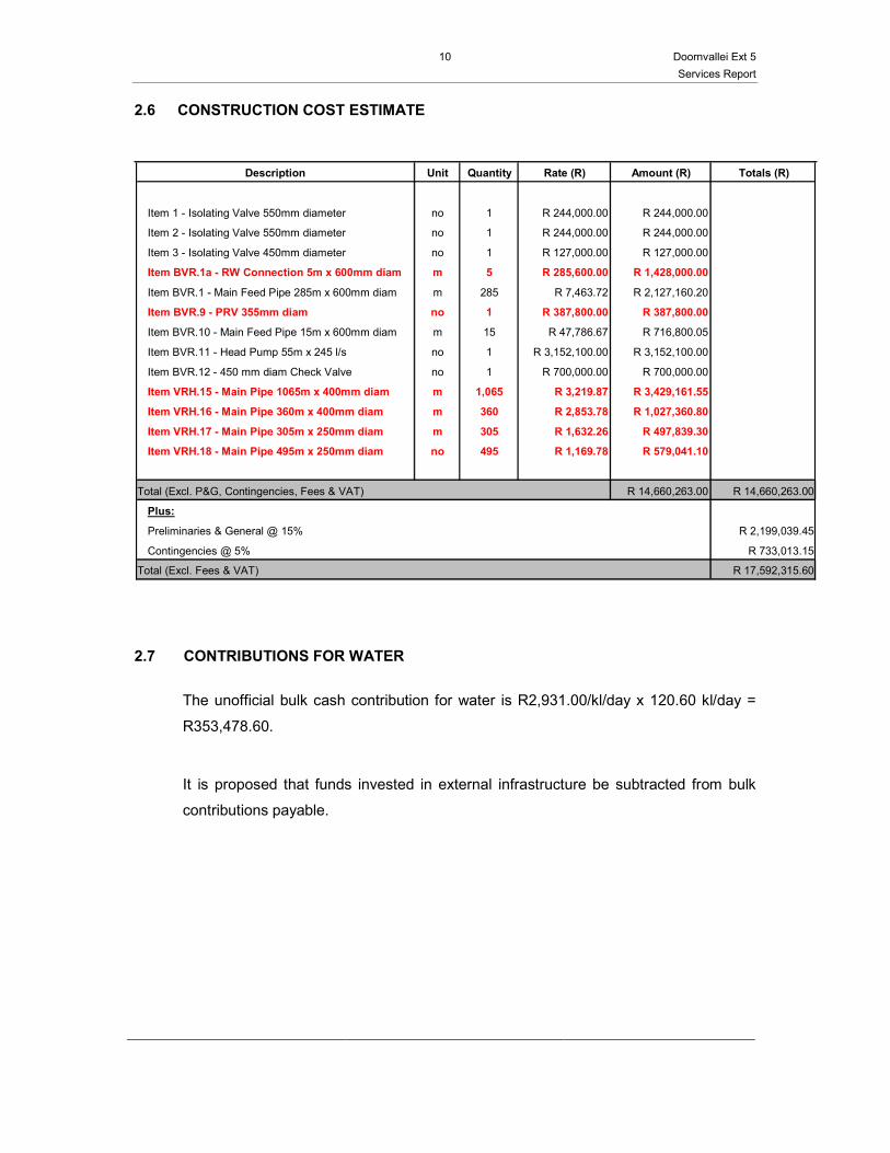
2.6 CONSTRUCTION COST ESTIMATE
Description Unit Quantity Rate (R) Amount (R) Totals (R)
Item 1 - Isolating Valve 550mm diameter no 1 R 244,000.00 R 244,000.00
Item 2 - Isolating Valve 550mm diameter no 1 R 244,000.00 R 244,000.00
Item 3 - Isolating Valve 450mm diameter no 1 R 127,000.00 R 127,000.00
Item BVR.1a - RW Connection 5m x 600mm diam m 5 R 285,600.00 R 1,428,000.00
Item BVR.1 - Main Feed Pipe 285m x 600mm diam m 285 R 7,463.72 R 2,127,160.20
Item BVR.9 - PRV 355mm diam no 1 R 387,800.00 R 387,800.00
Item BVR.10 - Main Feed Pipe 15m x 600mm diam m 15 R 47,786.67 R 716,800.05
Item BVR.11 - Head Pump 55m x 245 l/s no 1 R 3,152,100.00 R 3,152,100.00
Item BVR.12 - 450 mm diam Check Valve no 1 R 700,000.00 R 700,000.00
Item VRH.15 - Main Pipe 1065m x 400mm diam m 1,065 R 3,219.87 R 3,429,161.55
Item VRH.16 - Main Pipe 360m x 400mm diam m 360 R 2,853.78 R 1,027,360.80
Item VRH.17 - Main Pipe 305m x 250mm diam m 305 R 1,632.26 R 497,839.30
Item VRH.18 - Main Pipe 495m x 250mm diam no 495 R 1,169.78 R 579,041.10
Total (Excl. P&G, Contingencies, Fees & VAT) R 14,660,263.00 R 14,660,263.00
Plus:
Preliminaries & General @ 15% R 2,199,039.45
Contingencies @ 5% R 733,013.15
Total (Excl. Fees & VAT) R 17,592,315.60
2.7 CONTRIBUTIONS FOR WATER
The unofficial bulk cash contribution for water is R2,931.00/kl/day x 120.60 kl/day =
R353,478.60.
It is proposed that funds invested in external infrastructure be subtracted from bulk
contributions payable.
Doornvallei Ext 5
Services Report
11
3. SEWER DRAINAGE SCHEME
3.1 EXISTING INFRASTRUCTURE
The existing sewer reticulation inside Irene Glen Estate is regarded as sub-
standard. The existing City of Tshwane main outfall sewer runs north of and along
the Hennops river north of the development. An existing weir across the Hennops
river facilitates the connection between the Irene Glen Estate sewer reticulation and
the main outfall sewer pipeline, which drains toward the Sunderland Ridge Waste
Water Treatment Works.
3.2 SEWER DESIGN CRITERIA
The following standards will be used in the design of the sewer reticulation:
• Sewage outflow per day
− Residential 3 (20-40 units/ha) : 0.6 kl/unit
− Gate house for access control : 0.6 kl/unit
− Street : N/A
• Peak factor : 2.5
• Sewer capacity : Pipes shall be designed to run at
70% full, measured in terms of
flow depth
• Provision for stormwater infiltration : The remaining 30%
• Flow formula : Manning with n = 0.013
• Minimum velocities in sewers : 0.75 m/s at full flow with
absolute minimum 0.6 m/s
• Fall through manholes : 80 mm (for sewers ≤ 315 mm Ø)
• Minimum pipe size for reticulation
pipes
: 145 mm Internal diameter
• Sewer erf connections : 110 mm diameter at the lowest
point of each erf in the case of
Res 1 erven and to a distance of
500 mm inside the erf boundary
and not less than 1m from the
side boundary
Doornvallei Ext 5
Services Report
12
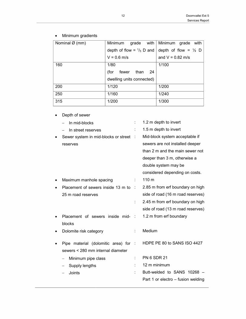
• Minimum gradients
Nominal Ø (mm) Minimum grade with
depth of flow = 1/5 D and
V = 0.6 m/s
Minimum grade with
depth of flow = ½ D
and V = 0.82 m/s
160 1/80
(for fewer than 24
dwelling units connected)
1/100
200 1/120 1/200
250 1/160 1/240
315 1/200 1/300
• Depth of sewer
− In mid-blocks : 1.2 m depth to invert
− In street reserves : 1.5 m depth to invert
• Sewer system in mid-blocks or street
reserves
: Mid-block system acceptable if
sewers are not installed deeper
than 2 m and the main sewer not
deeper than 3 m, otherwise a
double system may be
considered depending on costs.
• Maximum manhole spacing : 110 m
• Placement of sewers inside 13 m to
25 m road reserves
: 2.85 m from erf boundary on high
side of road (16 m road reserves)
: 2.45 m from erf boundary on high
side of road (13 m road reserves)
• Placement of sewers inside mid-
blocks
: 1.2 m from erf boundary
• Dolomite risk category : Medium
• Pipe material (dolomitic area) for
sewers < 280 mm internal diameter
: HDPE PE 80 to SANS ISO 4427
− Minimum pipe class : PN 6 SDR 21
− Supply lengths : 12 m minimum
− Joints : Butt-welded to SANS 10268 –
Part 1 or electro – fusion welding

Doornvallei Ext 5
Services Report
13
as per SANS 10268 – Part 2
where butt-welding is not
possible
• Sewer manholes : Precast concrete rings with “Pro-
Struct 687” sealant at joints
The following standards will be used in
the design of outfall sewers:
• Pipe material (dolomitic area) for
sewers < 280 mm
: As for reticulations
• Pipe material (dolomitic area) for
sewers ≥ 280 mm internal diameter
: HDPE structured wall sewer
pipes to ISO 9969 SANS 503
2000 X SN8 Spigot and Socket
joints without rubber seal to be
extrusion welded to SANS
18268-4, 12 m lengths
• Sewer Manholes : Precast concrete rings with “Pro-
Struct 687” sealant at joints
Doornvallei Ext 5
Services Report
14
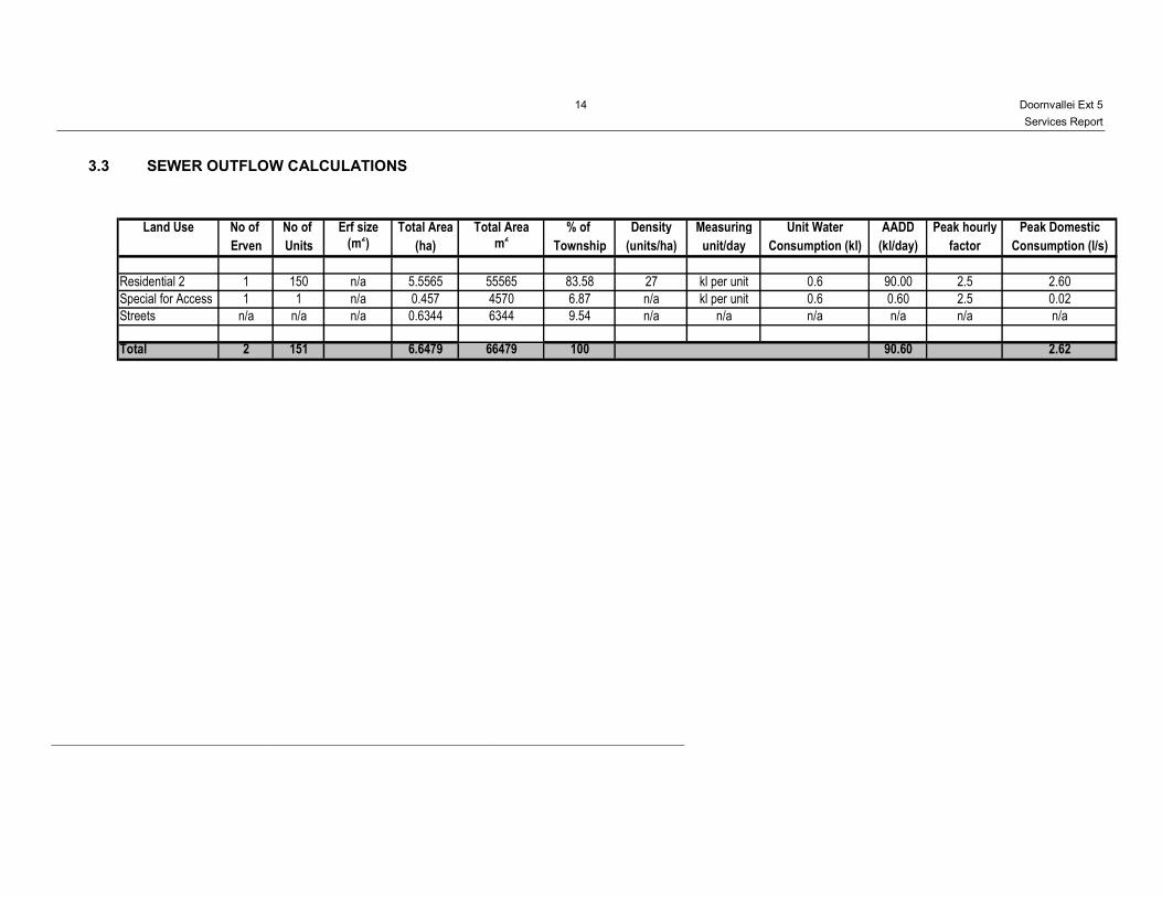
3.3 SEWER OUTFLOW CALCULATIONS
Land Use No of No of Erf size Total Area Total Area % of Density Measuring Unit Water AADD Peak hourly Peak Domestic
Erven Units (m2) (ha) m
2Township (units/ha) unit/day Consumption (kl) (kl/day) factor Consumption (l/s)
Residential 2 1 150 n/a 5.5565 55565 83.58 27 kl per unit 0.6 90.00 2.5 2.60
Special for Access 1 1 n/a 0.457 4570 6.87 n/a kl per unit 0.6 0.60 2.5 0.02
Streets n/a n/a n/a 0.6344 6344 9.54 n/a n/a n/a n/a n/a n/a
Total 2 151 6.6479 66479 100 90.60 2.62

Doornvallei Ext 5
Services Report
15
3.4 PROPOSED NEW INFRASTRUCTURE
The eastern half of Doornvallei (Ext 5) drains to the north-eastern corner of the
development where it will connect to a 160 mm ND outfall sewer. The anticipated
peak dry weather flow rate for the western portion is 2.62 ℓ/s.
In line with the GLS report (refer to Appendix 5) a new 160 and 200 mm diameter
gravity sewer pipeline is proposed from the north-eastern connection of the
development down along the eastern boundary of Irene Glen Estate towards and
across the river by means of a new weir.
It is proposed that items OF_F011.01, OF_F011.02 and OF_F011.03 (shown in
red below) be installed under Doornvallei Extension 6 and items OF_F013.02 and
OF_F013.01 be installed under Doornvallei Extension 5.
3.5 SERVITUDES REQUIRED
The topography of the site, together with the township layout, dictate to a large
extent the positioning of the sewer pipelines. Servitudes will be necessary to
accommodate mid-block sewers, as well as servitudes on the low side of some
erven.
A servitude will be required along the western boundary of Irene Glen Estate
down towards the river and along the existing weir across the river up to the
existing main outfall sewer of the City of Tshwane.
A servitude will also be required along the eastern boundary of Irene Glen Estate
down towards the river and across the Hennops river for a new weir across the
river up to the existing main outfall sewer of the City of Tshwane.
Doornvallei Ext 5
Services Report
16
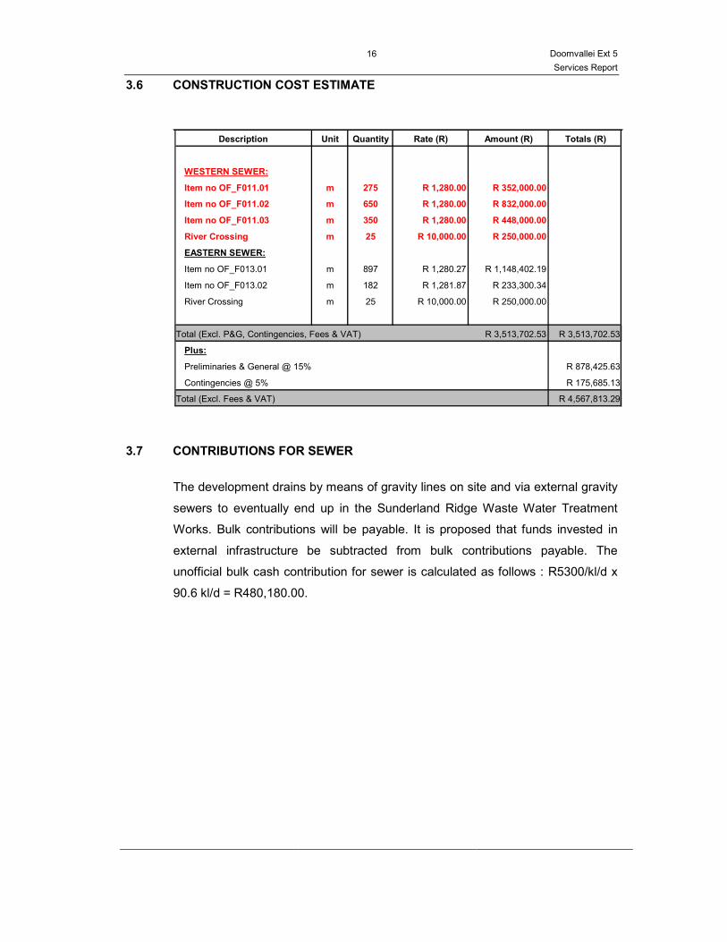
3.6 CONSTRUCTION COST ESTIMATE
Description Unit Quantity Rate (R) Amount (R) Totals (R)
WESTERN SEWER:
Item no OF_F011.01 m 275 R 1,280.00 R 352,000.00
Item no OF_F011.02 m 650 R 1,280.00 R 832,000.00
Item no OF_F011.03 m 350 R 1,280.00 R 448,000.00
River Crossing m 25 R 10,000.00 R 250,000.00
EASTERN SEWER:
Item no OF_F013.01 m 897 R 1,280.27 R 1,148,402.19
Item no OF_F013.02 m 182 R 1,281.87 R 233,300.34
River Crossing m 25 R 10,000.00 R 250,000.00
Total (Excl. P&G, Contingencies, Fees & VAT) R 3,513,702.53 R 3,513,702.53
Plus:
Preliminaries & General @ 15% R 878,425.63
Contingencies @ 5% R 175,685.13
Total (Excl. Fees & VAT) R 4,567,813.29
3.7 CONTRIBUTIONS FOR SEWER
The development drains by means of gravity lines on site and via external gravity
sewers to eventually end up in the Sunderland Ridge Waste Water Treatment
Works. Bulk contributions will be payable. It is proposed that funds invested in
external infrastructure be subtracted from bulk contributions payable. The
unofficial bulk cash contribution for sewer is calculated as follows : R5300/kl/d x
90.6 kl/d = R480,180.00.
Doornvallei Ext 5
Services Report
17
3.8 SOLID WASTE MANAGEMENT
3.8.1 Guidelines
Local Government is responsible for solid waste management in South Africa.
The objective is to monitor a sustainable waste management plan encompassing
environmental, social, technological and economical criteria. To this end the
Local Government Act (Act No. 32 of 2003) with a Solid Waste Management Bill
applies.
Soild waste collection is overseen by Local Authorities through private
contractors. The collected solid waste is then transported to landfills via transfer
stations which is managed and maintained by the government through private
contractors. Solid waste are compacted, collected and transferred through to
landfill.
The following norms and statutory requirements are utilised where applicable:
o National Solid Waste Management Plan (NSWMP) – 1994
o Government Solid Waste Management Strategy – to minimize solid waste
by recycling and composting.
3.8.2 Waste storage and processing systems
A solid waste compacter is envisaged. The waste generated will be temporarily
stored in different operational waste containers or bins. Waste will be dumped
into the static compacter to be provided. The waste will be collected from the
waste generating sites and taken directly to the compacter. The compacted
waste slugs will be stacked in a container for proposed weekly removal or if
required removed daily per arrangement in similar quantities.
3.8.3 Design data and information
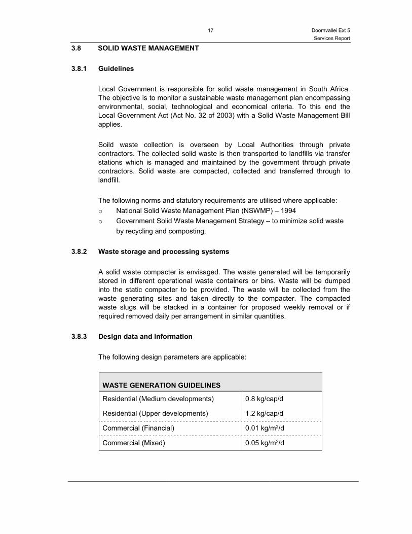
The following design parameters are applicable:
WASTE GENERATION GUIDELINES
Residential (Medium developments) 0.8 kg/cap/d
Residential (Upper developments) 1.2 kg/cap/d
Commercial (Financial) 0.01 kg/m2/d
Commercial (Mixed) 0.05 kg/m2/d

Doornvallei Ext 5
Services Report
18
3.8.4 Waste generated estimate
The daily waste generation figures for the various areas in this development are
indicated below.
WASTE GENERATION
No of erven Rate
(kg/cap/d) Occupants
Weight per day
(kg)
Res 2 (27 dwellings / ha) 0.8 300 240
Special – Gate House 0.8 2 1.6
Street N/A N/A 0
Total
241.6
Based on the assumed loose densities of waste of 100 – 150 kg/ m3, the
estimated waste generation volume is 2 m3 per day.

Doornvallei Ext 5
Services Report
19
APPENDIX 1: LOCALITY PLAN

20 Doornvallei Ext 6
Services Report
APPENDIX 2: TOWN PLANNER’S LAYOUT
21 Doornvallei Ext 6
Services Report
APPENDIX 3: PROOF OF OWNERSHIP
22 Doornvallei Ext 6
Services Report
APPENDIX 4: TOWNSHIP ESTABLISHMENT CONDITIONS
23 Doornvallei Ext 6
Services Report
APPENDIX 5: GLS REPORT

24 Doornvallei Ext 6
Services Report
APPENDIX 6: APPLICATION FOR RAND WATER CONNECTION
25 Doornvallei Ext 6
Services Report
APPENDIX 7: DRAWINGS