Embed Size (px)
Citation preview


2
Civil Engineering Practice
Formwork for Concrete
Instructor:
Dr. Attaullah Shah
Lecture # 5
Department of Civil Engineering
Swedish College of Engineering and Technology-Wah Cantt.

Formwork• Forms are molds to receive concrete in its’
plastic form.
• Formwork is temporary structure, as such, it is not normally shown on the drawings.
Formwork for Beams and Slabs

Formwork Materials
• Wood
– Either all-wood or some wood components
• Plywood
• Aluminum
• Steel
• Plastics

CONCRETE FORMWORK

• Formwork being erected

• Most of the pads and concrete footing poured

• Formwork for the parkade walls is built for each pour

• Most of the parkade walls been completed

2 TYPES OF FORMWORK
üTemporary Structure
- Temporary structure required to safely
support concrete until it reaches adequate
strength.
üPermanent Structure

DEFINITION: FORMWORKS FOR IN-SITU
CONCRETE WORK
“ A mould or box into which wet concrete can
be poured and compacted so that it will flow
and finally set to the inner profile of the box
or mould.”

ü Forms mold the concrete to desired size and shape and control its position and alignment
ü Formworks also act as a temporary structure that support:
a) it’s own weight +
b) The freshly placed concrete
c) Construction live loads (material ,
human, logistic)
FUNCTION

Formwork is a classic temporary structure in a
sense that:
a) It can be erected quickly
b) Highly loaded for a few hours during the concrete placement
c) And within a few days it is disassembled for future use

A good formwork would have the following
characteristics that is:
a)Safe
b)Cost effective or economical
c)High Quality – finished concrete surface is
of acceptable quality
- in the correct location
- able to produce the
required shape and surface

FORMWORK DESIGN
Loads include in design process are as follows
a) Fresh concrete
b) Rebar
c) Formwork material
d) Wind and lateral loads
e) Live loads due to – Formwork construction
- Reinforcing installation
- Concrete placement

MATERIAL FOR FORMWORK CONSTRUCTION
Among the material that can be used for
construction of formwork:
a) Timber
b) Steel
c) Glass Reinforced Plastic

TIMBER FORMWORK
Timber Formwork:
After Concrete Was
Poured
Timber Formwork : For The Slab

ADVANTAGES OF TIMBER FORMWORK
Among the advantages of timber formwork are
as follow:
a) Easy handling because it’s light weight
b) Easy to disassemble
c) Damaged parts can be replaced with new one
d) Very flexible

DISADVANTAGES OF TIMBER FORMWORK
Among the advantages of steel formwork are as follow:
a) Can’t be used for long. Have limited re-use. Can only be re-used 5 or 6 times
b) If the timber is dry, it will absorb moisture from wet concrete which could weaken the resultant concrete member.
c) Timber with high moisture content (more than 20 % moisture content), wet concrete will shrink & cup leading to open joints & leakage of grout.

Timber formwork used for the construction of 2nd and the 3rd floor.

ADVANTAGES OF STEEL FORMWORK
Among the advantages of steel formwork are
as follow:
a) Very strong and able to carry heavy load
b) Easy to be fixed
c) Uniform size and surface
d) Can be used for a very long time

DISADVANTAGES OF STEEL FORMWORK
Among disadvantages of steel formwork are
as follow:
a) Limited size or shape
b) Excessive loss of heat
c) A very smooth surface will be produced which would give problems for finishing process
d) Limited fixing (Pemasangan terhad)

STEEL FORMWORK

• The first floor circular columns were constructed using steel column forms. The steel column form should be oiled
before concreting.

• After concreting to the first floor columns, the steel column forms were
dismantled easily.

ADVANTAGES OF GLASS REINFORCED PLASTIC FORMWORK
Among the advantages of glass reinforced
plastic formwork are as follow:
a) Very useful for complex shape and special features
b) Easy to disassemble
c) Light (not heavy)
d) Damages on the formwork can be easily be repaired
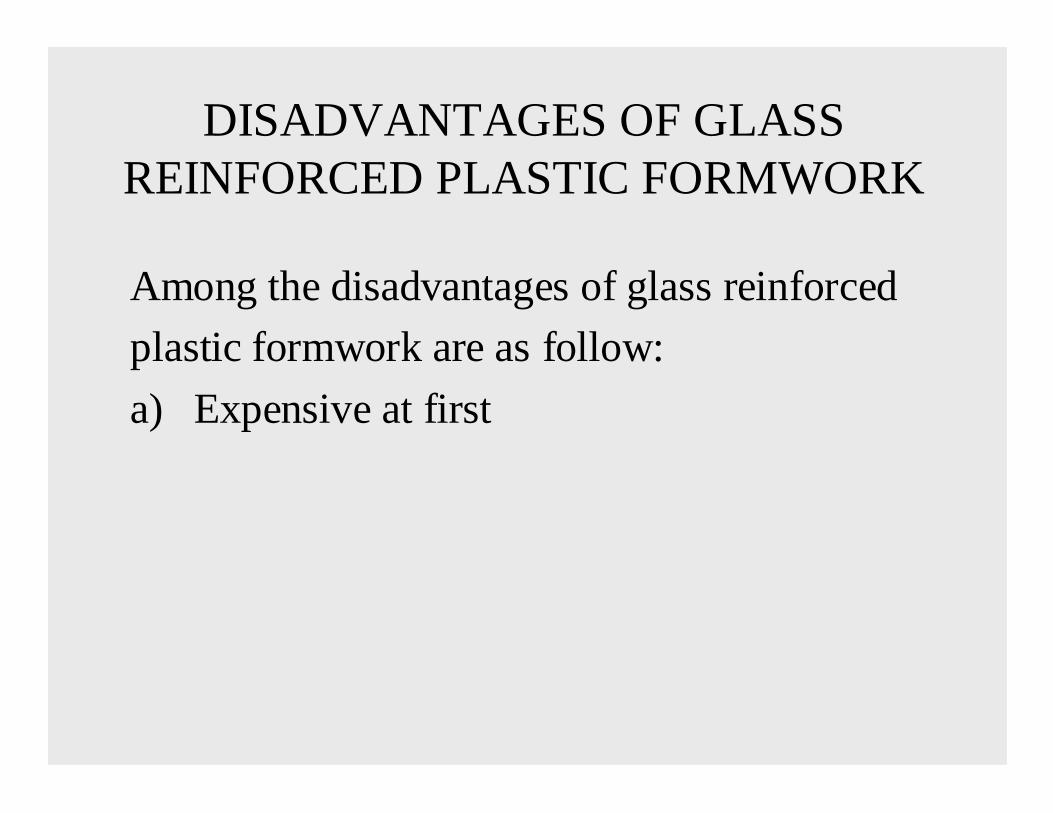
DISADVANTAGES OF GLASS REINFORCED PLASTIC FORMWORK
Among the disadvantages of glass reinforced
plastic formwork are as follow:
a) Expensive at first

Lumber
• Designated by Cross Sections, Nominal Dimensions (prior
to finishing)
– After cut length wise, finishing operations reduces actual
dimensions
• 2 x 4 Plank 1 1/2 x 3 1/2 ® 2” by 4” in S4S
– Lengths are multiples of 2 ft (8, 10, 12, 14, 16,…)
– Specified by type and grade
• Type: pine, oak, fir
• Grade: Selected (A, B, C, D) and Common (1, 2, 3, 4)
• Selected (A best, D poor quality)
– Cost ® Kind, grade, size, length, milling, quantity, freight

Plywood
• 4 ft wide - 8, 10, 12 ft long
• 1/4, 3/8, 1/2, 5/8, 3/4 inch thick

Plywood Orientation
Face Grain Direction Face Grain Direction
Weak Orientation of Plywood(Face grain parallel to span)
Strong Orientation of Plywood(Face grain perpendicular to span)

Aluminum
• Pure aluminum chemically attacked by wet concrete
• Light weight allow larger forming units
• High reuse value
Aluminum beam“nailer - type”
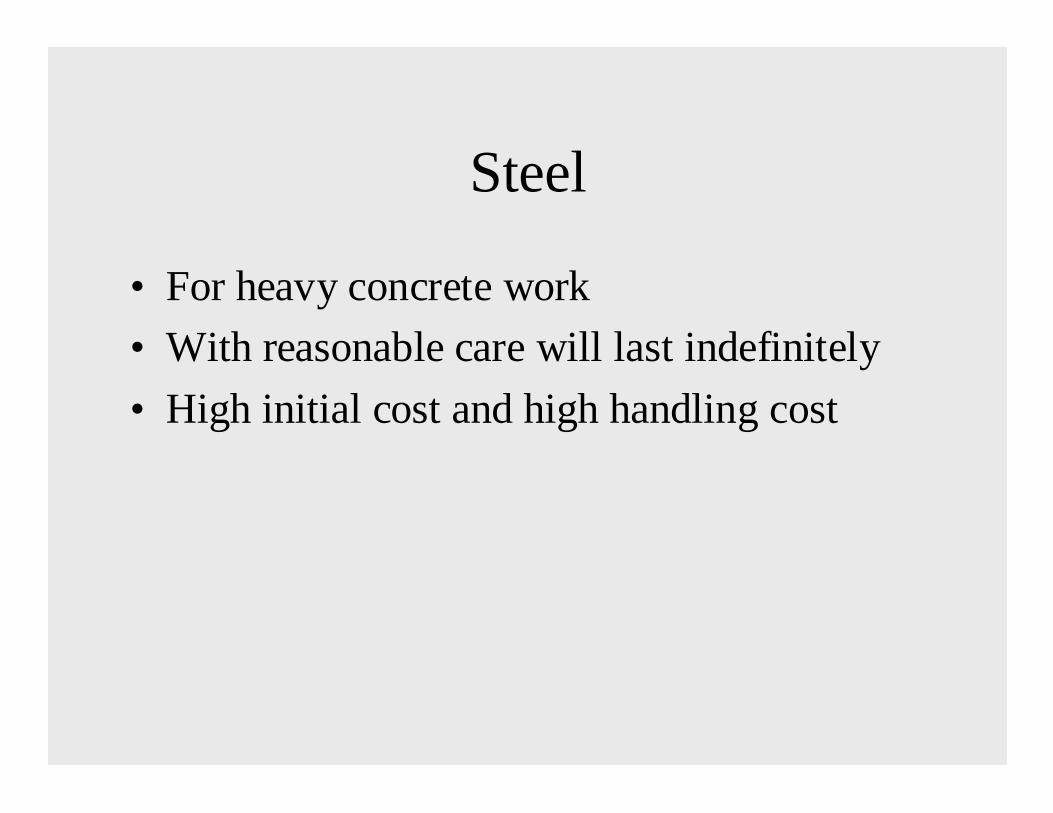
Steel
• For heavy concrete work
• With reasonable care will last indefinitely
• High initial cost and high handling cost

• Formwork is a classic temporary structure in the sense that:
– it is erected quickly
– highly loaded for a few hours during the concrete placement
– and within a few days disassembled for future use.
• Also classic in their temporary nature are the connections, braces, tie anchorages, and adjustment devices which forms need.
Formwork for Concrete

• The term "Temporary Structures" may not fully imply the temporary, since some forms, tie hardware, and accessories are used hundreds of times, which necessitates high durability and maintainability characteristics and design that maximizes productivity.
• Unlike conventional structures, the formwork disassembly characteristics are severely restricted by concrete bond, rigidity, and shrinkage, which not only restricts access to the formwork structure but causes residual loads that have to be released to allow stripping from the concrete which initiates disassembly.
Formwork for Concrete

• Lumber was once the predominant form material, but developments in the use of plywood, metal, plastics, and other materials, together with the increasing use of specialized accessories have changed the picture.
• Formwork was formerly built in place, used once, and wrecked.
• Because of high labor costs in the U.S., the trend today is toward increasing prefabrication, assembly in large units, erection by mechanical means such as “flying” forms into place by crane, and continuing reuse of the forms.
Formwork for Concrete

Formwork for Concreten In 1908 the use of wood versus steel formwork was
debated at the ACI convention. Also, the advantages of modular panel forming with its own connecting hardware, and good for extensive reuse were realized.
n By 1910 steel forms for paving were being produced commercially and used in the field.
A 1909 construction scene shows the first application of steel forms for street paving.

• Today modular panel forming is the norm.
Formwork for Concrete

• Forms mold the concrete to desired size and shape and control its position and alignment.
• But formwork is more than a mold; it is a temporary structure that supports:
– its own weight +
– the freshly placed concrete +
– construction live loads (including materials, equipment, and personel).
Objectives of Form Building
• Basic objectives in form building are three fold:
– Quality - In terms of strength, rigidity, position, and dimensions of the
forms
– Safety - for both the workers and the concrete structure
– Economy - the least cost consistent with quality and safety requirements
• Cooperation and coordination between engineer / architect and the contractor are necessary to achieve these goals.
Objectives of Form Building

Objectives of Form Building• Economy is a major concern since formwork costs
constitutes up to 60 percent of the total cost of concrete work in a project.
n In designing and building formwork, the contractor should aim for maximum economy without sacrificing quality or safety.
Formwork
material
cost
Concrete,
rebar,
footings,
placement
Formwork
Labor
Cost
How Formwork Affects Concrete Quality
• Size, shape, and alignment of slabs, beams, and other concrete structural elements depend on accurate construction of the forms.
• The forms must be:
– Sufficiently rigid under the construction loads to maintain the designed shape of the concrete,
– Stable and strong enough to maintain large members in alignment, and
– Substantially constructed to withstand handling and reuse without losing their dimensional integrity.
• The formwork must remain in place until the concrete is strong enough to carry its own weight, or the finished structure may be damaged.

Causes of Formwork Failure• Formwork failures are the cause of many accidents and failures
that occur during concrete construction which usually happen when fresh concrete is being placed.
• Generally some unexpected event causes one member to fail, then others become overloaded or misaligned and the entire formwork structure collapses.
Formwork collapse causes injuries, loss of life, property damage, and construction delays

Causes of Formwork Failure
The main causes of formwork failure are:
1 - Improper stripping and shore removal
2 - Inadequate bracing
3 - Vibration
4 - Unstable soil under mudsills*, shoring not plumb
5 - Inadequate control of concrete placement
6 - Lack of attention to formwork details.
*Mudsill: A plank, frame, or small footing on the ground used as a base for a shore or post in formwork.

Causes of Failure
Improper Stripping and Shore Removal
Case study:Too early shore removal at Bailey's Crossroads in Virginia (1972):26-stories + apartment buildingForms were supported by floors 7-days old or olderFailure occurred on the 24th floor, where it was shored to the 5-day-old 23rd floor.The overloaded 23rd floor failed in shear around one or more columns, triggering a collapse that carried through the entire height of the building.
n Premature stripping of forms, premature removal of shores, and careless practices in reshoring can produce catastrophic results.

Causes of Failure
Inadequate Bracingn The more frequent causes of formwork failure, however, are
other effects that induce lateral force components or induce displacement of supporting members.
n Inadequate cross bracing and horizontal bracing of shores is one of the factors most frequently involved in formwork accidents.
n Investigations prove that many accidents causing thousands of dollars of damage could have been prevented only if a few hundred dollars had been spent on diagonal bracing for the formwork support.

Causes of Failure
Inadequate Bracing- Use of Diagonal Bracingn High shoring with heavy load at the top is vulnerable to
eccentric or lateral loading.
n Diagonal bracing improves the stability of such a structure, as do guys or struts to solid ground or competed structures.

Causes of Failure
Inadequate Bracingn The main exhibition floor of the New York Coliseum collapsed
when concrete was being placed.
n Forms for the floor slab were supported on two tiers of shores.
Case study:New York ColiseumFormwork collapse, where rapid delivery of concrete introduced lateral forces at the top of high shoring.

Causes of FailureInadequate Bracing- Use of Diagonal BracingCase study: New York Coliseum
n Increased diagonal bracing was added to all remaining shoring, following partial collapse of formwork.

Causes of FailureInadequate Bracing- Use of Diagonal Bracing
n When a failure occurs at one part, inadequate bracing may permit the collapse to extend to a large portion of the structure and multiply the damage.
n Suppose a worker accidentally rams or wheelbarrow into some vertical shores and dislodges a couple of them. This may set up a chain of reaction that brings down the entire floor.
n One major objective of bracing is to prevent such a minor accident or failure from becoming a disaster.
Causes of Failure
Vibration
n Forms sometimes collapse when their supporting shores or jacks are displaced by vibration caused by:
npassing traffic
nmovement of workers and equipment on the formwork
n the effect of vibrating concrete to consolidate it.
n Diagonal bracing can help prevent failure due to vibration.

Causes of FailureUnstable Soil under Mudsills, Shoring not Plumb
n Formwork should be safe if it is adequately braced and constructed so all loads are carried to solid ground through vertical members.
n Shores must be set plumb and the ground must be able to carry the load without settling.
n Shores and mudsills must not rest on frozen ground; moisture and heat from the concreting operations, or changing air temperatures, may thaw the soil and allow settlement that overloads or shifts the formwork.
n Site drainage must be adequate to prevent a washout of soil supporting the mudsills.

Causes of FailureInadequate Control of Concrete Placement
n The temperature and rate of vertical placement of concrete are factors influencing the development of lateral pressures that act on the forms.
n If temperature drops during construction operations, rate of concreting often has to be slowed down to prevent a build up of lateral pressure overloading the forms. If this is not done, formwork failure may result.
H
FreshConcrete
g
n Failure to regulate properly the rate and order of placing concrete on horizontal surfaces or curved roofs may produce unbalanced loadings and consequent failures of formwork.

• Even when the basic formwork design is soundly conceived, small differences in assembly details may cause local weakness or overstress loading to form failure.
• This may be as simple as insufficient nailing, or failure to tighten the locking devices on metal shoring.
• Other details that may cause failure are:
– Inadequate provisions to prevent rotation of beam forms where slabs frame into them on the side.
– Inadequate anchorage against uplift for sloping form faces.
– Lack of bracing or tying of corners, bulkheads, or other places where unequal pressure is found.
Causes of Failure
Lack of Attention to Formwork Details
Planning for Safety• OSHA (Occupational Safety and Health
Administration) regulations, ACI recommendations, and local code requirements for formwork should be followed.
– Supervision and Inspection
– Platform and Access for Workers
– Control of Concreting Practices
– Improving Soil Bearing and Bracing
– Shoring and Reshoring
– Relationship of Architect, Engineer and Contractor
– Maintaining and Coordinating Tolerances
– Preparing a Formwork Specification
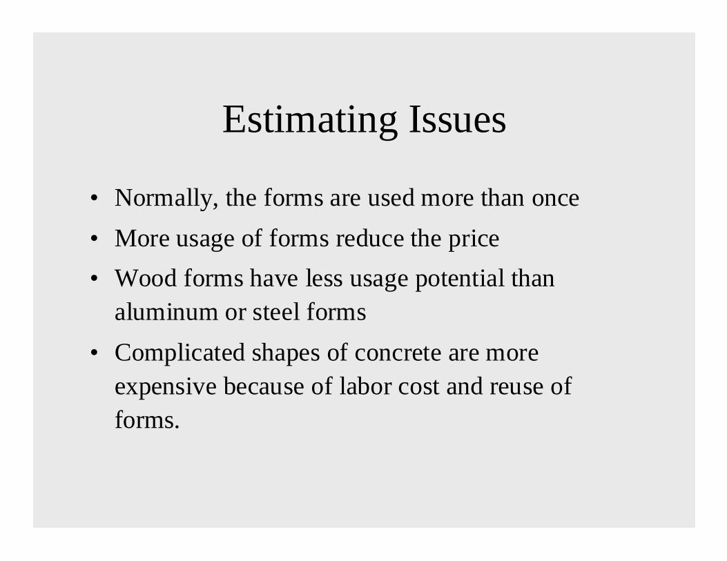
Estimating Issues
• Normally, the forms are used more than once
• More usage of forms reduce the price
• Wood forms have less usage potential than
aluminum or steel forms
• Complicated shapes of concrete are more
expensive because of labor cost and reuse of
forms.

Formwork• Unit of Measurement
Square Foot Contact Area
SFCA
• Measure just contact area, not area of formwork
Contact Area
= 2h(L+B)Concrete
L
B
h

Wood normally measured:
• Linear feet of one size
• Board Feet
– FBM (Foot Board Measure)
1”x12”x1’(long) or 144 cubic inches
– example: 2x8 x 16ft long
= 1.33 BF/LF x 16 = 21.28 FBM2” x 8”12”
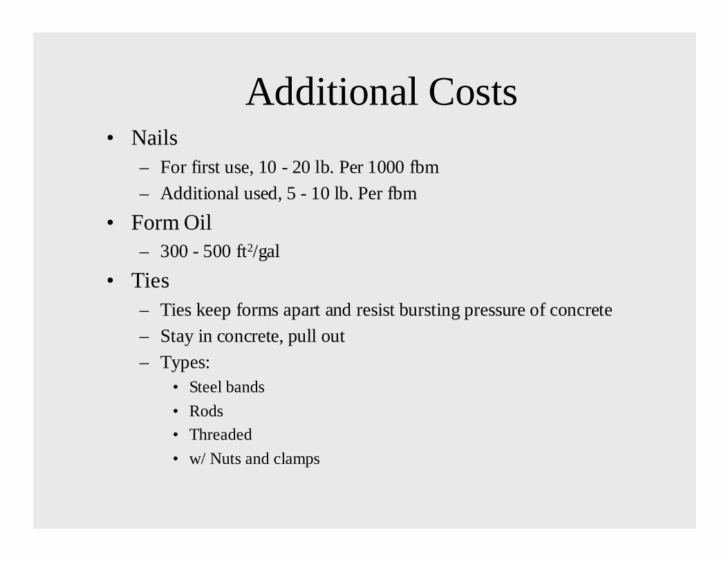
Additional Costs• Nails
– For first use, 10 - 20 lb. Per 1000 fbm
– Additional used, 5 - 10 lb. Per fbm
• Form Oil
– 300 - 500 ft2/gal
• Ties
– Ties keep forms apart and resist bursting pressure of concrete
– Stay in concrete, pull out
– Types:
• Steel bands
• Rods
• Threaded
• w/ Nuts and clamps

Design and Estimating of Forms
• “Design determine Sheathing thickness, stud size, wale size, tie size”
• Use of design tables
• Watch for
1.Rate of pour
2.Temperature and weather
3.Proportions of mix and consistency
4.Method of placement and vibration

Workshop Example
• Estimate the cost of formwork for concrete wall (9’6” x 25’4”)
• The rate of placing concrete = 4 ft/hour
• Maximum temperature of concrete = 70ºF

Concrete Footing
9’6
”
Wall tie
3/4” plywood sheathing2”x 4”x 10’- 0 “ stud2- 2”x 4”wale
2”x 4” x 10’- 0”brace @ 6’- 0”
2”x 4” sill
25’4”2”x 4”x 3’- 0”Stake @ 6’- 0”
Prof Awad S. Hanna
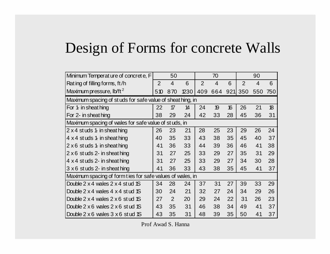
Design of Forms for concrete Walls
Minimum Temperature of concrete, F
Rat ing of filling forms, ft /h 2 4 6 2 4 6 2 4 6
Maximum pressure, lb/ft 2 510 870 1230 409 664 921 350 550 750
For 1- in sheathing 22 17 14 24 19 16 26 21 18
For 2- in sheathing 38 29 24 42 33 28 45 36 31
2 x 4 studs 1- in sheathing 26 23 21 28 25 23 29 26 24
4 x 4 studs 1- in sheathing 40 35 33 43 38 35 45 40 37
2 x 6 studs 1- in sheathing 41 36 33 44 39 36 46 41 38
2 x 6 studs 2- in sheathing 31 27 25 33 29 27 35 31 29
4 x 4 studs 2- in sheathing 31 27 25 33 29 27 34 30 28
3 x 6 studs 2- in sheathing 41 36 33 43 38 35 45 41 37
Double 2 x 4 wales 2 x 4 stud 1S 34 28 24 37 31 27 39 33 29
Double 2 x 4 wales 4 x 4 stud 1S 30 24 21 32 27 24 34 29 26
Double 2 x 4 wales 2 x 6 stud 1S 27 2 20 29 24 22 31 26 23
Double 2 x 6 wales 2 x 6 stud 1S 43 35 31 46 38 34 49 41 37
Double 2 x 6 wales 3 x 6 stud 1S 43 35 31 48 39 35 50 41 37
50 70 90
Maximum spacing of form t ies for safe values of wales, in
Maximum spacing of wales for safe value of studs, in
Maximum spacing of studs for safe value of sheathing, in

Prof Awad S. Hanna
4’
4’
4’
8’ 8’ 8’ 8’
9’-6’’
25’- 4”

The wall is 9’-6” high and 25’-4” long.
• From design table:
Max. pressure, 664 lb/ft2
Max. spacing of studs, 19 in, use 18 in
Max. spacing of wales, 25 in, use 24 in
Max. spacing of form ties, 31 in
• The 3/4“ plywood sheathing will be placed with the 4 ft wide in the vertical direction and the 8 ft length in the horizontal direction.
• The total quantity of sheathing will be:
No. sheets in vertical direction, 9’-6”¸ 4‘/sheet = 2.37, use 3 sheets
No. sheets in horizontal direction, 25’-4”¸ 8’/sheet = 3.16, use 4 sheets
No. sheets required per side, 3 x 4 = 12
No. sheets required for wall, 12 x 2 = 24
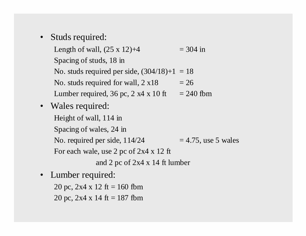
• Studs required:
Length of wall, (25 x 12)+4 = 304 in
Spacing of studs, 18 in
No. studs required per side, (304/18)+1 = 18
No. studs required for wall, 2 x18 = 26
Lumber required, 36 pc, 2 x4 x 10 ft = 240 fbm
• Wales required:
Height of wall, 114 in
Spacing of wales, 24 in
No. required per side, 114/24 = 4.75, use 5 wales
For each wale, use 2 pc of 2x4 x 12 ft
and 2 pc of 2x4 x 14 ft lumber
• Lumber required:
20 pc, 2x4 x 12 ft = 160 fbm
20 pc, 2x4 x 14 ft = 187 fbm

Total lumber = 240 + 160 +187
= 587 fbm
• Add 10 to 20% for misc. (sills, splice…etc)
Total quantity of lumber
= 587 + 0.2 x 587
= 704 fbm
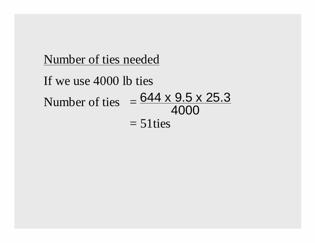
Number of ties needed
If we use 4000 lb ties
Number of ties =
= 51ties
644 x 9.5 x 25.34000

Quantity of Nails
= 704 x 10 lb/1000fbm
= 7.04 lbs

Summary of Materials to Build forms:
• Plywood required = 24 sheets
• Lumber required = 704 fbm
• Nails required = 7 lbs
• Ties required = 51