Embed Size (px)
Citation preview
CIVIL ENGINEERING MATERIALS LABORATORY
FACULTY OF ENGINEERING
CHULALONGKORN UNIVERSITY
TEST C-4
PROPERTIES OF FRESH CONCRETE
PARTY 4 Wednesday
DATE OF TEST: 3rd November 2021
รายชอสมาชก
6230479321 นายวศษฐ คมภรปกรณ
6230481521 นายวชรพงษ วงษแกว
6230497621 นายวฒภทร รตนะโชตวงศ
6230512321 นายศวช ธมมบรสทธ
6230513021 นายศวาย ตรขนธ
TEST No. C-4
PROPERTIES OF FRESH CONCRETE
Part A Mix Design and Mixing of Concrete by Mechanical Mixer
Objective To determine the appropriate mix proportion of normal concrete at specified properties and
to prepare the specimens for future testing.
Materials Fine aggregate, coarse aggregate and cement available in the laboratory.
References ASTM Designation: C 192
BS (British Standard) 1881
Recommended practice for selecting proportions for concrete (ACI 613)
Any text books on Concrete Technology
Apparatus (1) Concrete mixer
(2) Balance
(3) Molds (or forms) for casting of the test specimens for future testing.
Procedures
1. Determine the mix proportion for concrete at specified strength, durability and consistency (may
be given by the instructor). It is advisable to divide the materials and mix them into two or more batches.
2. To mix the concrete, first put some percentage1 of the required amount of water in the mixer then
add cement and sand and thoroughly mix about 1½ min. Finally add coarse aggregate, the rest amount of
water and continue mixing2 until a uniform and consistent mix is obtained.
3. Pour the freshly mixed concrete from the mixer into pan. Thoroughly mix the concrete with the
aid of trowels and shovels (if necessary). These determinations must be performed for all mixing batches.
4. Fill the concrete in the molds or forms with the aid of tamping rod or vibrator. After the filling is
completed, smooth out the surface with trowels. The concrete specimens should be kept for one day before
the forms are removed.
1 80% for concrete with w/c 0.40 or less
70% for concrete with w/c 0.41-0.54
60% for concrete with w/c greater than 0.55 2 not less than 1½ min is recommended.
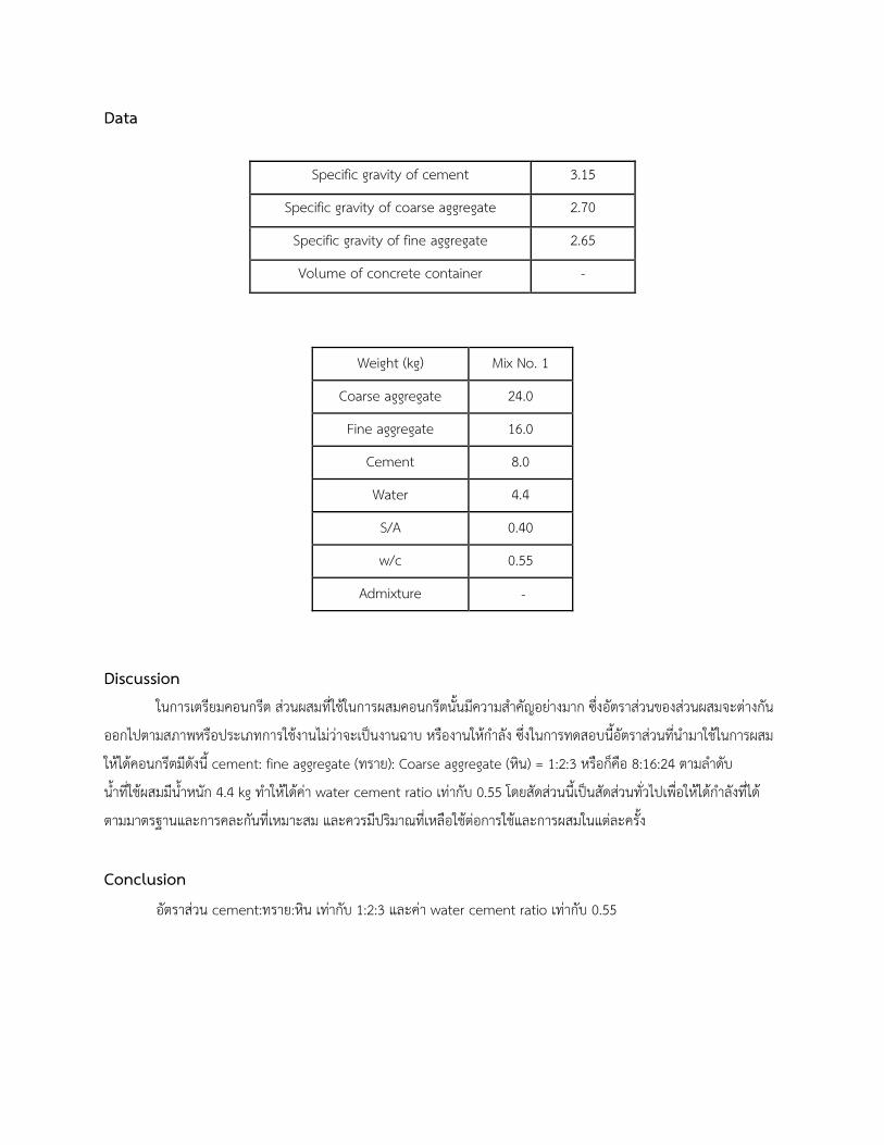
Data
Specific gravity of cement 3.15
Specific gravity of coarse aggregate 2.70
Specific gravity of fine aggregate 2.65
Volume of concrete container -
Weight (kg) Mix No. 1
Coarse aggregate 24.0
Fine aggregate 16.0
Cement 8.0
Water 4.4
S/A 0.40
w/c 0.55
Admixture -
Discussion
ในการเตรยมคอนกรต สวนผสมทใชในการผสมคอนกรตนนมความสำคญอยางมาก ซงอตราสวนของสวนผสมจะตางกน
ออกไปตามสภาพหรอประเภทการใชงานไมวาจะเป�นงานฉาบ หรองานใหกำลง ซงในการทดสอบนอตราสวนทนำมาใชในการผสม
ใหไดคอนกรตมดงน cement: fine aggregate (ทราย): Coarse aggregate (หน) = 1:2:3 หรอกคอ 8:16:24 ตามลำดบ
นำทใชผสมมนำหนก 4.4 kg ทำใหไดคา water cement ratio เทากบ 0.55 โดยสดสวนนเป�นสดสวนทวไปเพอใหไดกำลงทได
ตามมาตรฐานและการคละกนทเหมาะสม และควรมปรมาณทเหลอใชตอการใชและการผสมในแตละครง
Conclusion
อตราสวน cement:ทราย:หน เทากบ 1:2:3 และคา water cement ratio เทากบ 0.55
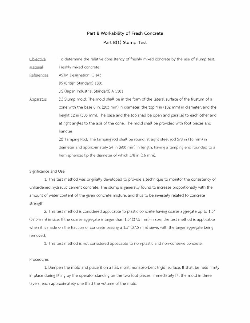
Part B Workability of Fresh Concrete
Part B(1) Slump Test
Objective To determine the relative consistency of freshly mixed concrete by the use of slump test.
Material Freshly mixed concrete.
References ASTM Designation: C 143
BS (British Standard) 1881
JIS (Japan Industrial Standard) A 1101
Apparatus (1) Slump mold: The mold shall be in the form of the lateral surface of the frustum of a
cone with the base 8 in. (203 mm) in diameter, the top 4 in (102 mm) in diameter, and the
height 12 in (305 mm). The base and the top shall be open and parallel to each other and
at right angles to the axis of the cone. The mold shall be provided with foot pieces and
handles.
(2) Tamping Rod: The tamping rod shall be round, straight steel rod 5/8 in (16 mm) in
diameter and approximately 24 in (600 mm) in length, having a tamping end rounded to a
hemispherical tip the diameter of which 5/8 in (16 mm).
Significance and Use
1. This test method was originally developed to provide a technique to monitor the consistency of
unhardened hydraulic cement concrete. The slump is generally found to increase proportionally with the
amount of water content of the given concrete mixture, and thus to be inversely related to concrete
strength.
2. This test method is considered applicable to plastic concrete having coarse aggregate up to 1.5"
(37.5 mm) in size. If the coarse aggregate is larger than 1.5" (37.5 mm) in size, the test method is applicable
when it is made on the fraction of concrete passing a 1.5" (37.5 mm) sieve, with the larger aggregate being
removed.
3. This test method is not considered applicable to non-plastic and non-cohesive concrete.
Procedures
1. Dampen the mold and place it on a flat, moist, nonabsorbent (rigid) surface. It shall be held firmly
in place during filling by the operator standing on the two foot pieces. Immediately fill the mold in three
layers, each approximately one third the volume of the mold.
2. Rod each layer with 25 strokes of the tamping rod. Uniformly distribute the strokes over the cross
section of each layer.
3. In filling and rodding the top layer, heap the concrete above the mold before rodding start. If the
rodding operation results in subsidence of the concrete below the top edge of the mold, add additional
concrete to keep an excess of concrete above the top of the mold at all time.
4. After the top layer has been rodded, strike off the surface of the concrete by means of screeding
and rolling motion of the tamping rod.
5. Remove the mold immediately from the concrete by raising it carefully in the vertical direction.
Raise the mold a distance of 12 in (300 mm) in 5 ± 2 sec by a steady upward lift with no lateral or torsional
motion.
6. Immediately measure the slump by determining the vertical difference between top of the mold
and the displaces original center of the top surface of the specimen. Complete the entire test from the start
of the filling through removal of the mold without interruption and complete it within 2½ min.
7. If a decided falling away or shearing off of concrete from one side or portion of the mass occurs,
disregard the test and make a new test on another portion of the sample. If two consecutive tests on a
sample of concrete show a falling away or shearing off of a portion of concrete from the mass of specimen,
the concrete lacks necessary plasticity and cohesiveness for the slump test to be applicable.
8. After completion of the test, the sample may be used for casting of the specimens for the future
testing.
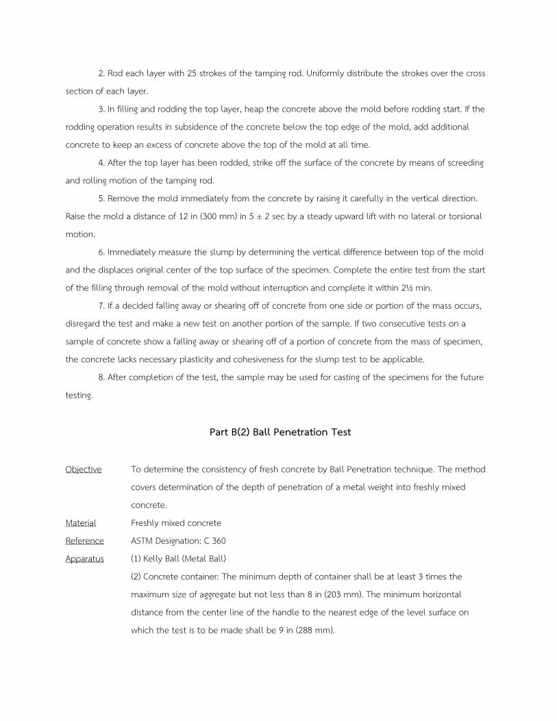
Part B(2) Ball Penetration Test
Objective To determine the consistency of fresh concrete by Ball Penetration technique. The method
covers determination of the depth of penetration of a metal weight into freshly mixed
concrete.
Material Freshly mixed concrete
Reference ASTM Designation: C 360
Apparatus (1) Kelly Ball (Metal Ball)
(2) Concrete container: The minimum depth of container shall be at least 3 times the
maximum size of aggregate but not less than 8 in (203 mm). The minimum horizontal
distance from the center line of the handle to the nearest edge of the level surface on
which the test is to be made shall be 9 in (288 mm).
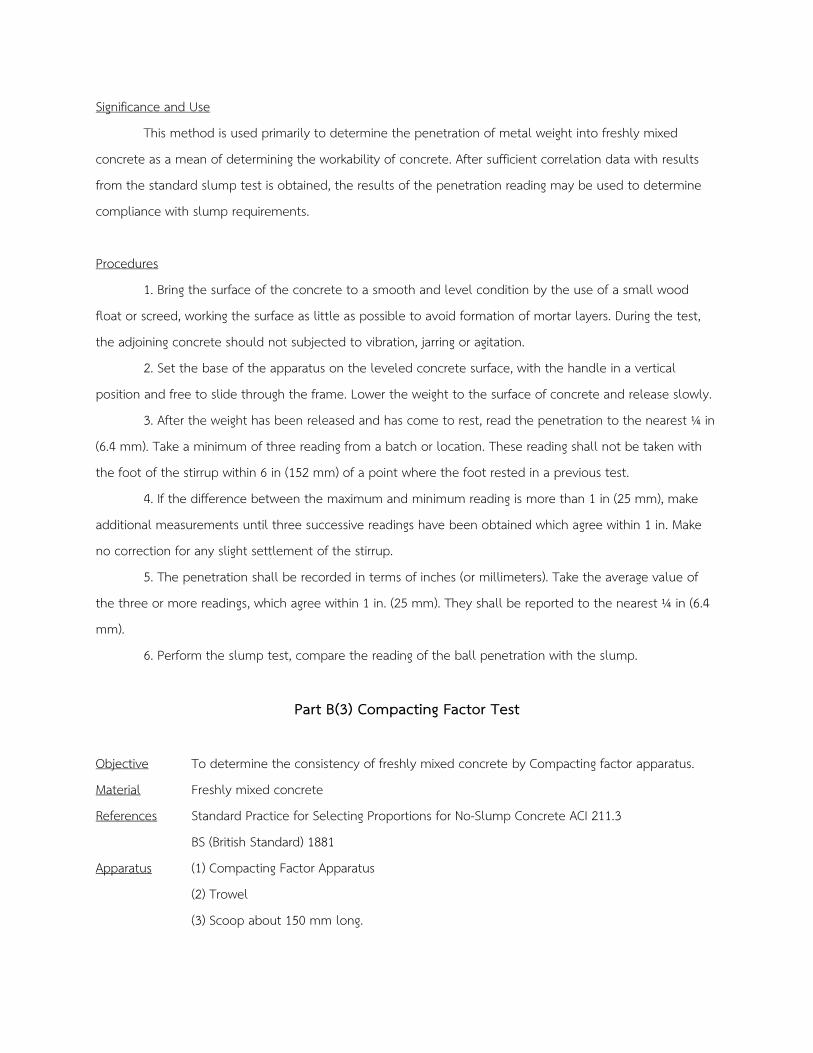
Significance and Use
This method is used primarily to determine the penetration of metal weight into freshly mixed
concrete as a mean of determining the workability of concrete. After sufficient correlation data with results
from the standard slump test is obtained, the results of the penetration reading may be used to determine
compliance with slump requirements.
Procedures
1. Bring the surface of the concrete to a smooth and level condition by the use of a small wood
float or screed, working the surface as little as possible to avoid formation of mortar layers. During the test,
the adjoining concrete should not subjected to vibration, jarring or agitation.
2. Set the base of the apparatus on the leveled concrete surface, with the handle in a vertical
position and free to slide through the frame. Lower the weight to the surface of concrete and release slowly.
3. After the weight has been released and has come to rest, read the penetration to the nearest ¼ in
(6.4 mm). Take a minimum of three reading from a batch or location. These reading shall not be taken with
the foot of the stirrup within 6 in (152 mm) of a point where the foot rested in a previous test.
4. If the difference between the maximum and minimum reading is more than 1 in (25 mm), make
additional measurements until three successive readings have been obtained which agree within 1 in. Make
no correction for any slight settlement of the stirrup.
5. The penetration shall be recorded in terms of inches (or millimeters). Take the average value of
the three or more readings, which agree within 1 in. (25 mm). They shall be reported to the nearest ¼ in (6.4
mm).
6. Perform the slump test, compare the reading of the ball penetration with the slump.
Part B(3) Compacting Factor Test
Objective To determine the consistency of freshly mixed concrete by Compacting factor apparatus.
Material Freshly mixed concrete
References Standard Practice for Selecting Proportions for No-Slump Concrete ACI 211.3
BS (British Standard) 1881
Apparatus (1) Compacting Factor Apparatus
(2) Trowel
(3) Scoop about 150 mm long.
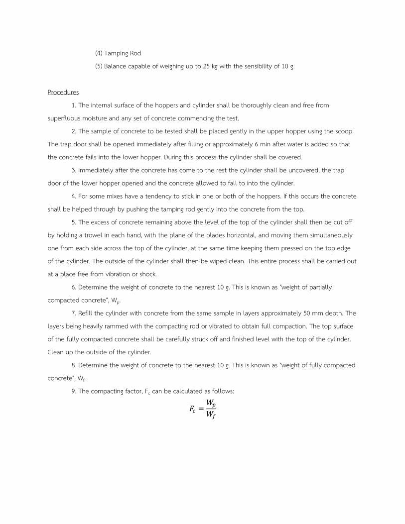
(4) Tamping Rod
(5) Balance capable of weighing up to 25 kg with the sensibility of 10 g.
Procedures
1. The internal surface of the hoppers and cylinder shall be thoroughly clean and free from
superfluous moisture and any set of concrete commencing the test.
2. The sample of concrete to be tested shall be placed gently in the upper hopper using the scoop.
The trap door shall be opened immediately after filling or approximately 6 min after water is added so that
the concrete fails into the lower hopper. During this process the cylinder shall be covered.
3. Immediately after the concrete has come to the rest the cylinder shall be uncovered, the trap
door of the lower hopper opened and the concrete allowed to fall to into the cylinder.
4. For some mixes have a tendency to stick in one or both of the hoppers. If this occurs the concrete
shall be helped through by pushing the tamping rod gently into the concrete from the top.
5. The excess of concrete remaining above the level of the top of the cylinder shall then be cut off
by holding a trowel in each hand, with the plane of the blades horizontal, and moving them simultaneously
one from each side across the top of the cylinder, at the same time keeping them pressed on the top edge
of the cylinder. The outside of the cylinder shall then be wiped clean. This entire process shall be carried out
at a place free from vibration or shock.
6. Determine the weight of concrete to the nearest 10 g. This is known as "weight of partially
compacted concrete", Wp.
7. Refill the cylinder with concrete from the same sample in layers approximately 50 mm depth. The
layers being heavily rammed with the compacting rod or vibrated to obtain full compaction. The top surface
of the fully compacted concrete shall be carefully struck off and finished level with the top of the cylinder.
Clean up the outside of the cylinder.
8. Determine the weight of concrete to the nearest 10 g. This is known as "weight of fully compacted
concrete", Wf.
9. The compacting factor, Fc can be calculated as follows:
𝐹𝐹𝑐𝑐 =𝑊𝑊𝑝𝑝
𝑊𝑊𝑓𝑓
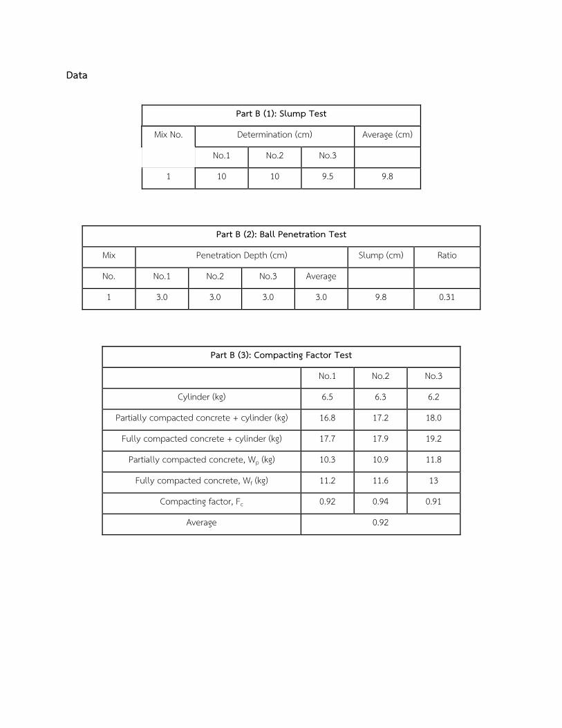
Data
Part B (1): Slump Test
Mix No. Determination (cm) Average (cm)
No.1 No.2 No.3
1 10 10 9.5 9.8
Part B (2): Ball Penetration Test
Mix Penetration Depth (cm) Slump (cm) Ratio
No. No.1 No.2 No.3 Average
1 3.0 3.0 3.0 3.0 9.8 0.31
Part B (3): Compacting Factor Test
No.1 No.2 No.3
Cylinder (kg) 6.5 6.3 6.2
Partially compacted concrete + cylinder (kg) 16.8 17.2 18.0
Fully compacted concrete + cylinder (kg) 17.7 17.9 19.2
Partially compacted concrete, Wp (kg) 10.3 10.9 11.8
Fully compacted concrete, Wf (kg) 11.2 11.6 13
Compacting factor, Fc 0.92 0.94 0.91
Average 0.92
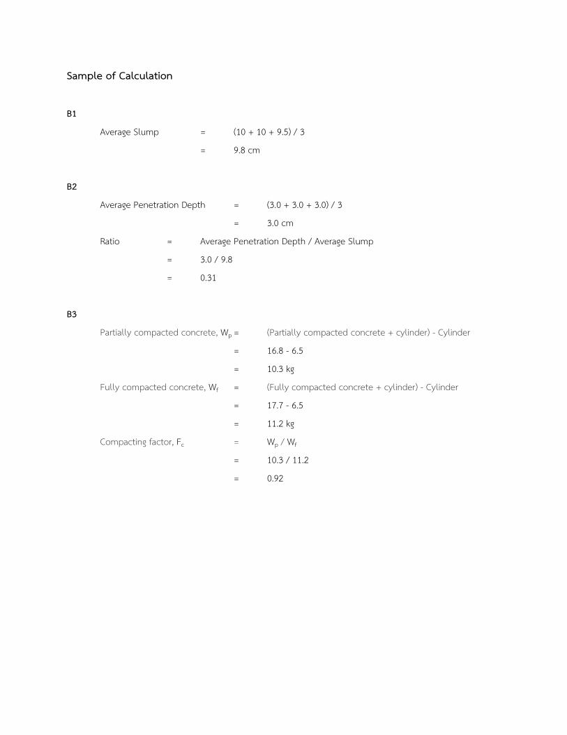
Sample of Calculation
B1
Average Slump = (10 + 10 + 9.5) / 3
= 9.8 cm
B2
Average Penetration Depth = (3.0 + 3.0 + 3.0) / 3
= 3.0 cm
Ratio = Average Penetration Depth / Average Slump
= 3.0 / 9.8
= 0.31
B3
Partially compacted concrete, Wp = (Partially compacted concrete + cylinder) - Cylinder
= 16.8 - 6.5
= 10.3 kg
Fully compacted concrete, Wf = (Fully compacted concrete + cylinder) - Cylinder
= 17.7 - 6.5
= 11.2 kg
Compacting factor, Fc = Wp / Wf
= 10.3 / 11.2
= 0.92
Discussion
Slump test
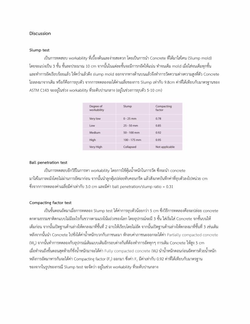
เป�นการทดสอบ workability ทเบองตนและงายสะดวก โดยเป�นการนำ Concrete ทไดมาใสโคน (Slump mold)
โดยจะแบงเป�น 3 ชน ชนละประมาณ 10 cm จากนนในแตละชนจะมการกอดใหแนน ทำจนเตม mold เมอใสจนเตมทกชน
และทำการอดเรยบรอยแลว ใหควำแลวดง slump mold ออกจากทางดานบนแลวจงทำการวดความตางความสงทตว Concrete
ไถลลงมาจากเดม หรอกคอการยบตว จากการทดลองจะไดคาเฉลยของการ Slump เทากบ 9.8cm คาทไดเทยบกบมาตรฐานของ
ASTM C143 จะอยในชวง workability ทระดบปานกลาง (อยในชวงการยบตว 5-10 cm)
Ball penetration test
เป�นการทดสอบอกวธในการหา workability โดยการใชตมนำหนกในการวด ซงจะนำ concrete
มาใสในกาละมงโดยไมผานการอดมากอน จากนนนำลกตมปลอยทบคอนกรต แลวสงเกตบนทกคาทยบตวลงไปหนวย cm
ซงจากการทดลองคาเฉลยมคาเทากบ 3.0 cm และมคา ball penetration/slump ratio = 0.31
Compacting factor test
เป�นขนตอนถดมาเมอการทดลอง Slump test ไดคาการยบตวนอยกวา 5 cm ซงวธการทดลองคอจะปลอย concrete
ตกตามธรรมชาตตกแบบไมมอะไรกนขวางตามแรงโนมถวงของโลก โดยอปกรณจะม 3 ชน ใสเรมใส Concrete จกชนบนให
เตมกอน จากนนเป�ดฐานดานลางใหตกลงมาทชนท 2 ฉาบใหเรยบโดยไมอด จากนนเป�ดฐานดานลางใหตกลงมาทชนท 3 เชนเดม
หลงจากนนนำ Concrete ไปชงไดคานำหนกบวกกบภาชนะมา หกลบคาภาชนะออกจะไดคา Partially compacted concrete
(Wp) จากนนทำการทดลองกบอปกรณเดมแบบเดมอกรอบตางกนทตองทำการอดทกๆ การเตม Concrete ใหสง 5 cm
เมอทำจนถงขนตอนสดทายกชงนำหนกมาจะไดคา Fully compacted concrete (Wf) นำนำหนกตอนกอนอดหารดวยนำหนก
หลงการอดมาหารกนจะไดคา Compacting factor (Fc) ออกมา ซงคา Fc มคาเทากบ 0.92 คาทไดเทยบกบมาตรฐาน
ของจากในรปของกรณ Slump test จะจดวา อยในชวง workability ทระดบปานกลาง
Conclusion
ในการทดสอบแบบ Slump test ไดคาการยบตวเฉลยของการ cement เทากบ 9.8 cm ในการทดสอบแบบ Ball
penetration test เฉลยมคาเทากบ 3.0 cm และมคา ball penetration/slump ratio = 0.31 และใน Compacting factor
test ไดคา Compacting factor หรอ Fc เทากบ 0.92
Reference
Universal motion Inc. Degree of workability. ออนไลน. คนหาวนท 8/11/64. คนหาไดจาก : http://universal-
motion.com/slump-test.html
Part C Air Content and Variability of Constituents of Freshly Mixed Concrete
Part C(1) Air content of Freshly mixed Concrete (Pressure Method)
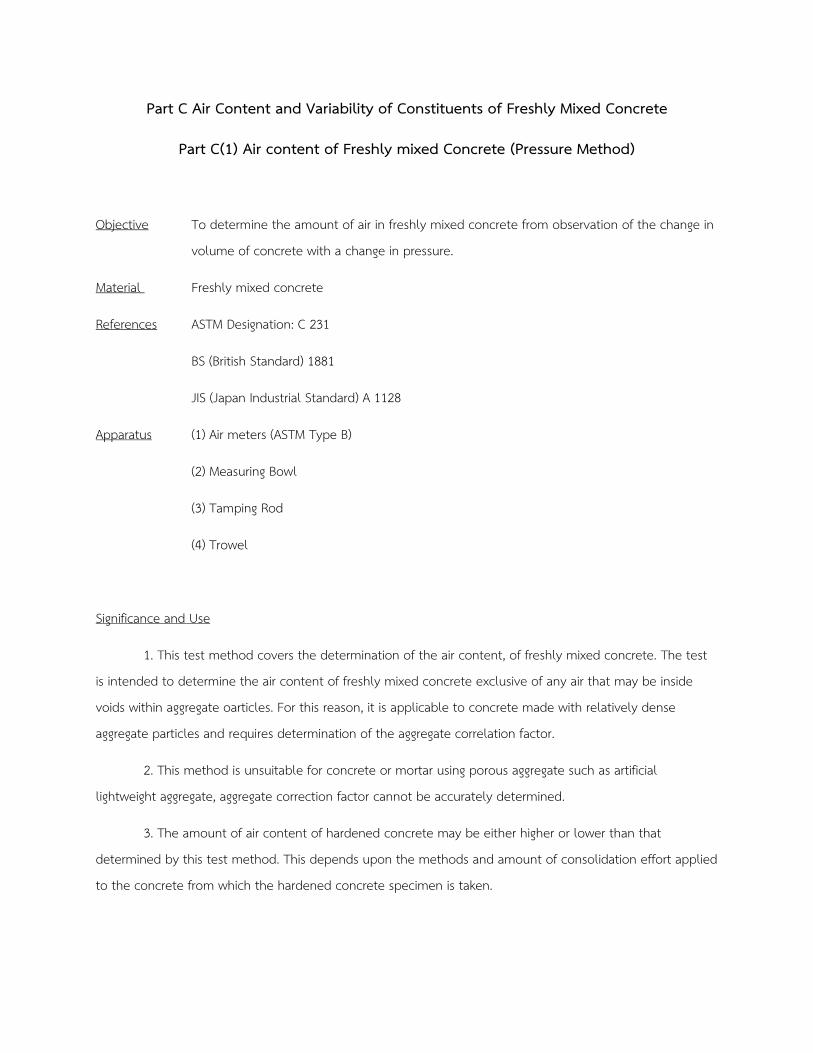
Objective To determine the amount of air in freshly mixed concrete from observation of the change in
volume of concrete with a change in pressure.
Material Freshly mixed concrete
References ASTM Designation: C 231
BS (British Standard) 1881
JIS (Japan Industrial Standard) A 1128
Apparatus (1) Air meters (ASTM Type B)
(2) Measuring Bowl
(3) Tamping Rod
(4) Trowel
Significance and Use
1. This test method covers the determination of the air content, of freshly mixed concrete. The test
is intended to determine the air content of freshly mixed concrete exclusive of any air that may be inside
voids within aggregate oarticles. For this reason, it is applicable to concrete made with relatively dense
aggregate particles and requires determination of the aggregate correlation factor.
2. This method is unsuitable for concrete or mortar using porous aggregate such as artificial
lightweight aggregate, aggregate correction factor cannot be accurately determined.
3. The amount of air content of hardened concrete may be either higher or lower than that
determined by this test method. This depends upon the methods and amount of consolidation effort applied
to the concrete from which the hardened concrete specimen is taken.
Procedures
1. The air meter should be calibrated (container, initial pressure and graduation of air content)
periodically as specified by ASTM Designation or JIS.
2. Measuring of Aggregate Correction Factor
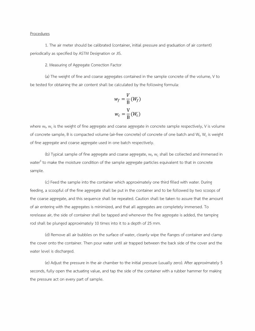
(a) The weight of fine and coarse aggregates contained in the sample concrete of the volume, V to
be tested for obtaining the air content shall be calculated by the following formula:
𝑤𝑤𝑓𝑓 =𝑉𝑉B
(𝑊𝑊𝑓𝑓)
𝑤𝑤𝑐𝑐 =VB
(𝑊𝑊𝑐𝑐)
where wf, wc is the weight of fine aggregate and coarse aggregate in concrete sample respectively, V is volume
of concrete sample, B is compacted volume (air-free concrete) of concrete of one batch and Wf, Wc is weight
of fine aggregate and coarse aggregate used in one batch respectively.
(b) Typical sample of fine aggregate and coarse aggregate, wf, wc shall be collected and immersed in
water3 to make the moisture condition of the sample aggregate particles equivalent to that in concrete
sample.
(c) Feed the sample into the container which approximately one third filled with water. During
feeding, a scoopful of the fine aggregate shall be put in the container and to be followed by two scoops of
the coarse aggregate, and this sequence shall be repeated. Caution shall be taken to assure that the amount
of air entering with the aggregates is minimized, and that all aggregates are completely immersed. To
rerelease air, the side of container shall be tapped and whenever the fine aggregate is added, the tamping
rod shall be plunged approximately 10 times into it to a depth of 25 mm.
(d) Remove all air bubbles on the surface of water, cleanly wipe the flanges of container and clamp
the cover onto the container. Then pour water until air trapped between the back side of the cover and the
water level is discharged.
(e) Adjust the pressure in the air chamber to the initial pressure (usually zero). After approximately 5
seconds, fully open the actuating value, and tap the side of the container with a rubber hammer for making
the pressure act on every part of sample.
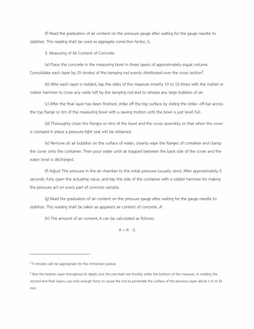
(f) Read the graduation of air content on the pressure gauge after waiting for the gauge needle to
stabilize. This reading shall be used as aggregate correction factor, G.
3. Measuring of Air Content of Concrete
(a) Place the concrete in the measuring bowl in three layers of approximately equal volume.
Consolidate each layer by 25 strokes of the tamping rod evenly distributed over the cross section4.
(b) After each layer is rodded, tap the sides of the measure smartly 10 to 15 times with the mallet or
rubber hammer to close any voids left by the tamping rod and to release any large bubbles of air.
(c) After the final layer has been finished, strike off the top surface by sliding the strike- off bar across
the top flange or rim of the measuring bowl with a sawing motion until the bowl is just level full.
(d) Thoroughly clean the flanges or rims of the bowl and the cover assembly so that when the cover
is clamped in place a pressure-tight seal will be obtained.
(e) Remove all air bubbles on the surface of water, cleanly wipe the flanges of container and clamp
the cover onto the container. Then pour water until air trapped between the back side of the cover and the
water level is discharged.
(f) Adjust The pressure in the air chamber to the initial pressure (usually zero). After approximately 5
seconds, fully open the actuating value, and tap the side of the container with a rubber hammer for making
the pressure act on every part of concrete sample.
(g) Read the graduation of air content on the pressure gauge after waiting for the gauge needle to
stabilize. This reading shall be taken as apparent air content of concrete, A'.
(h) The amount of air content, A can be calculated as follows:
A = A' −G
3 5 minutes will be appropriate for the immersion period.
4 Rod the bottom layer throughout its depth, but the rod shall not forcibly strike the bottom of the measure. In rodding the
second and final layers, use only enough force to cause the rod to penetrate the surface of the previous layer about 1 in or 25
mm.
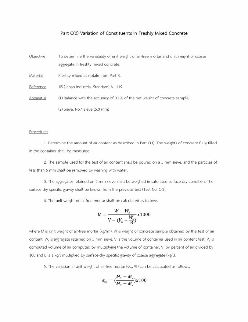
Part C(2) Variation of Constituents in Freshly Mixed Concrete
Objective To determine the variability of unit weight of air-free mortar and unit weight of coarse
aggregate in freshly mixed concrete.
Material Freshly mixed as obtain from Part B.
Reference JIS (Japan Industrial Standard) A 1119
Apparatus (1) Balance with the accuracy of 0.1% of the net weight of concrete sample.
(2) Sieve: No.4 sieve (5.0 mm)
Procedures
1. Determine the amount of air content as described in Part C(1). The weights of concrete fully filled
in the container shall be measured.
2. The sample used for the test of air content shall be poured on a 5 mm sieve, and the particles of
less than 5 mm shall be removed by washing with water.
3. The aggregates retained on 5 mm sieve shall be weighed in saturated surface-dry condition. The
surface dry specific gravity shall be known from the previous test (Test No. C-3).
4. The unit weight of air-free mortar shall be calculated as follows:
M =𝑊𝑊 −𝑊𝑊𝑠𝑠
V − (𝑉𝑉𝑎𝑎 + 𝑊𝑊𝑠𝑠B )
𝑥𝑥1000
where M is unit weight of air-free mortar (kg/m3), W is weight of concrete sample obtained by the test of air
content, Ws is aggregate retained on 5 mm sieve, V is the volume of container used in air content test, Va is
computed volume of air computed by multiplying the volume of container, V, by percent of air divided by
100 and B is 1 kg/l multiplied by surface-dry specific gravity of coarse aggregate (kg/l).
5. The variation in unit weight of air-free mortar (σm, %) can be calculated as follows;
𝜎𝜎𝑚𝑚 = (𝑀𝑀1 −𝑀𝑀2
𝑀𝑀1 + 𝑀𝑀2)𝑥𝑥100
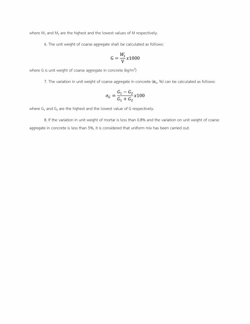
where M1 and M2 are the highest and the lowest values of M respectively.
6. The unit weight of coarse aggregate shall be calculated as follows:
G =𝑊𝑊𝑠𝑠
V𝑥𝑥1000
where G is unit weight of coarse aggregate in concrete (kg/m3)
7. The variation in unit weight of coarse aggregate in concrete (σG, %) can be calculated as follows:
𝜎𝜎𝐺𝐺 =𝐺𝐺1 − 𝐺𝐺2𝐺𝐺1 + 𝐺𝐺2
𝑥𝑥100
where G1 and G2 are the highest and the lowest value of G respectively.
8. If the variation in unit weight of mortar is less than 0.8% and the variation on unit weight of coarse
aggregate in concrete is less than 5%, it is considered that uniform mix has been carried out.
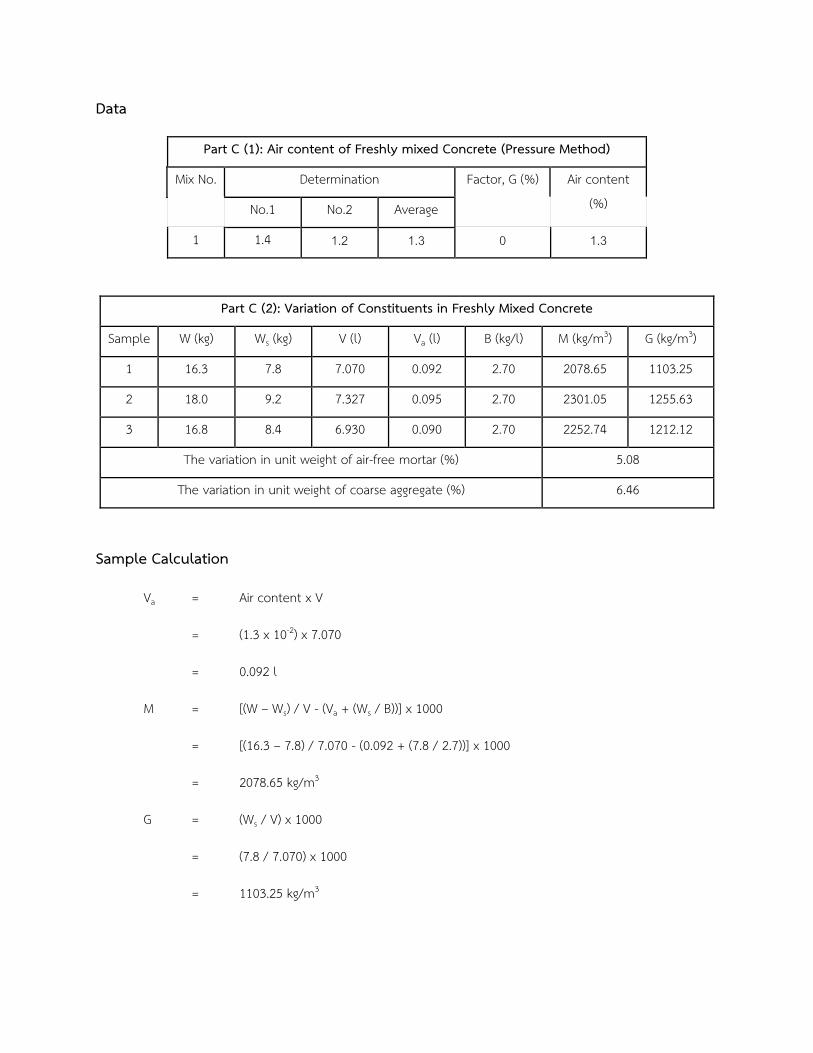
Data
Part C (1): Air content of Freshly mixed Concrete (Pressure Method)
Mix No. Determination Factor, G (%) Air content
(%) No.1 No.2 Average
1 1.4 1.2 1.3 0 1.3
Part C (2): Variation of Constituents in Freshly Mixed Concrete
Sample W (kg) Ws (kg) V (l) Va (l) B (kg/l) M (kg/m3) G (kg/m3)
1 16.3 7.8 7.070 0.092 2.70 2078.65 1103.25
2 18.0 9.2 7.327 0.095 2.70 2301.05 1255.63
3 16.8 8.4 6.930 0.090 2.70 2252.74 1212.12
The variation in unit weight of air-free mortar (%) 5.08
The variation in unit weight of coarse aggregate (%) 6.46
Sample Calculation
Va = Air content x V
= (1.3 x 10-2) x 7.070
= 0.092 l
M = [(W – Ws) / V - (Va + (Ws / B))] x 1000
= [(16.3 – 7.8) / 7.070 - (0.092 + (7.8 / 2.7))] x 1000
= 2078.65 kg/m3
G = (Ws / V) x 1000
= (7.8 / 7.070) x 1000
= 1103.25 kg/m3
Discussion
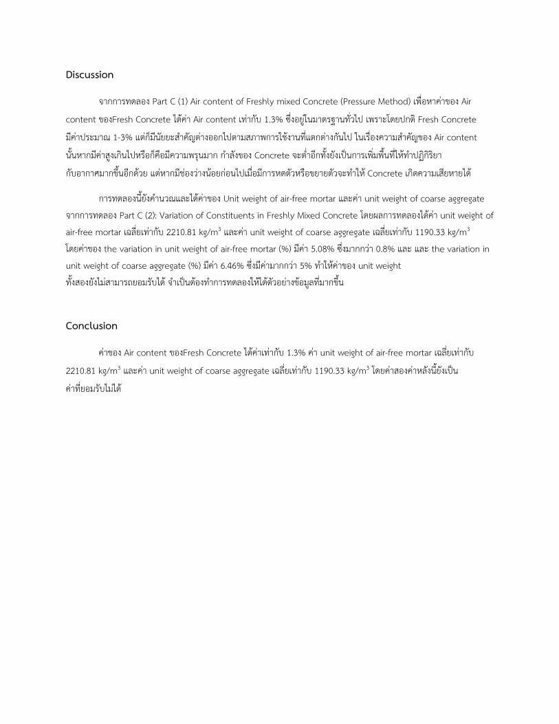
จากการทดลอง Part C (1) Air content of Freshly mixed Concrete (Pressure Method) เพอหาคาของ Air
content ของFresh Concrete ไดคา Air content เทากบ 1.3% ซงอยในมาตรฐานทวไป เพราะโดยปกต Fresh Concrete
มคาประมาณ 1-3% แตกมนยยะสำคญตางออกไปตามสภาพการใชงานทแตกตางกนไป ในเรองความสำคญของ Air content
นนหากมคาสงเกนไปหรอกคอมความพรนมาก กำลงของ Concrete จะตำอกทงยงเป�นการเพมพนทใหทำปฏกรยา
กบอากาศมากขนอกดวย แตหากมชองวางนอยกอนไปเมอมการหดตวหรอขยายตวจะทำให Concrete เกดความเสยหายได
การทดลองนยงคำนวณและไดคาของ Unit weight of air-free mortar และคา unit weight of coarse aggregate
จากการทดลอง Part C (2): Variation of Constituents in Freshly Mixed Concrete โดยผลการทดลองไดคา unit weight of
air-free mortar เฉลยเทากบ 2210.81 kg/m3 และคา unit weight of coarse aggregate เฉลยเทากบ 1190.33 kg/m3
โดยคาของ the variation in unit weight of air-free mortar (%) มคา 5.08% ซงมากกวา 0.8% และ และ the variation in
unit weight of coarse aggregate (%) มคา 6.46% ซงมคามากกวา 5% ทำใหคาของ unit weight
ทงสองยงไมสามารถยอมรบได จำเป�นตองทำการทดลองใหไดตวอยางขอมลทมากขน
Conclusion
คาของ Air content ของFresh Concrete ไดคาเทากบ 1.3% คา unit weight of air-free mortar เฉลยเทากบ
2210.81 kg/m3 และคา unit weight of coarse aggregate เฉลยเทากบ 1190.33 kg/m3 โดยคาสองคาหลงนยงเป�น
คาทยอมรบไมได
Part D Unit Weight and Air Content (Gravimetric) of Fresh Concrete
Objective To determine the unit weight and amount of air content of freshly mixed concrete by weight
analysis.
Material Freshly mixed concrete.
References ASTM Designation: C 138
BS (British Standard) 1881
JIS (Japan Industrial Standard) A 1116
Apparatus (1) Concrete container : metal cylinder with appropriate size, watertight and adequate
strength.
(2) Balance with appropriate sensibility
(3) Tamping Rod
(4) Vibrator
Procedures
1. Determine the capacity of the container, Vc by accurately weighing the weight of water required for
filling the container. Pour water until it overflows a little, then put a polished glass on the container to
remove excessive water. At this time no bubbles shall be seen under the glass plate. The capacity of the
container shall be calculated by dividing the weight of water by the density of water.
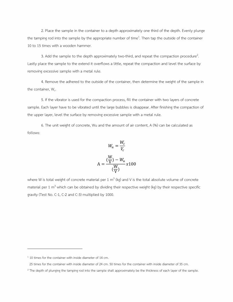
2. Place the sample in the container to a depth approximately one third of the depth. Evenly plunge
the tamping rod into the sample by the appropriate number of time1. Then tap the outside of the container
10 to 15 times with a wooden hammer.
3. Add the sample to the depth approximately two-third, and repeat the compaction procedure2.
Lastly place the sample to the extend it overflows a little, repeat the compaction and level the surface by
removing excessive sample with a metal rule.
4. Remove the adhered to the outside of the container, then determine the weight of the sample in
the container, Wc.
5. If the vibrator is used for the compaction process, fill the container with two layers of concrete
sample. Each layer have to be vibrated until the large bubbles is disappear. After finishing the compaction of
the upper layer, level the surface by removing excessive sample with a metal rule.
6. The unit weight of concrete, Wu and the amount of air content, A (%) can be calculated as
follows:
𝑊𝑊𝑢𝑢 =𝑊𝑊𝑐𝑐
𝑉𝑉𝑐𝑐
A =(W
V ) −𝑊𝑊𝑢𝑢
(WV )
𝑥𝑥100
where W is total weight of concrete material per 1 m3 (kg) and V is the total absolute volume of concrete
material per 1 m3 which can be obtained by dividing their respective weight (kg) by their respective specific
gravity (Test No. C-1, C-2 and C-3) multiplied by 1000.
1 10 times for the container with inside diameter of 14 cm.
25 times for the container with inside diameter of 24 cm. 50 times for the container with inside diameter of 35 cm. 2 The depth of plunging the tamping rod into the sample shall approximately be the thickness of each layer of the sample.
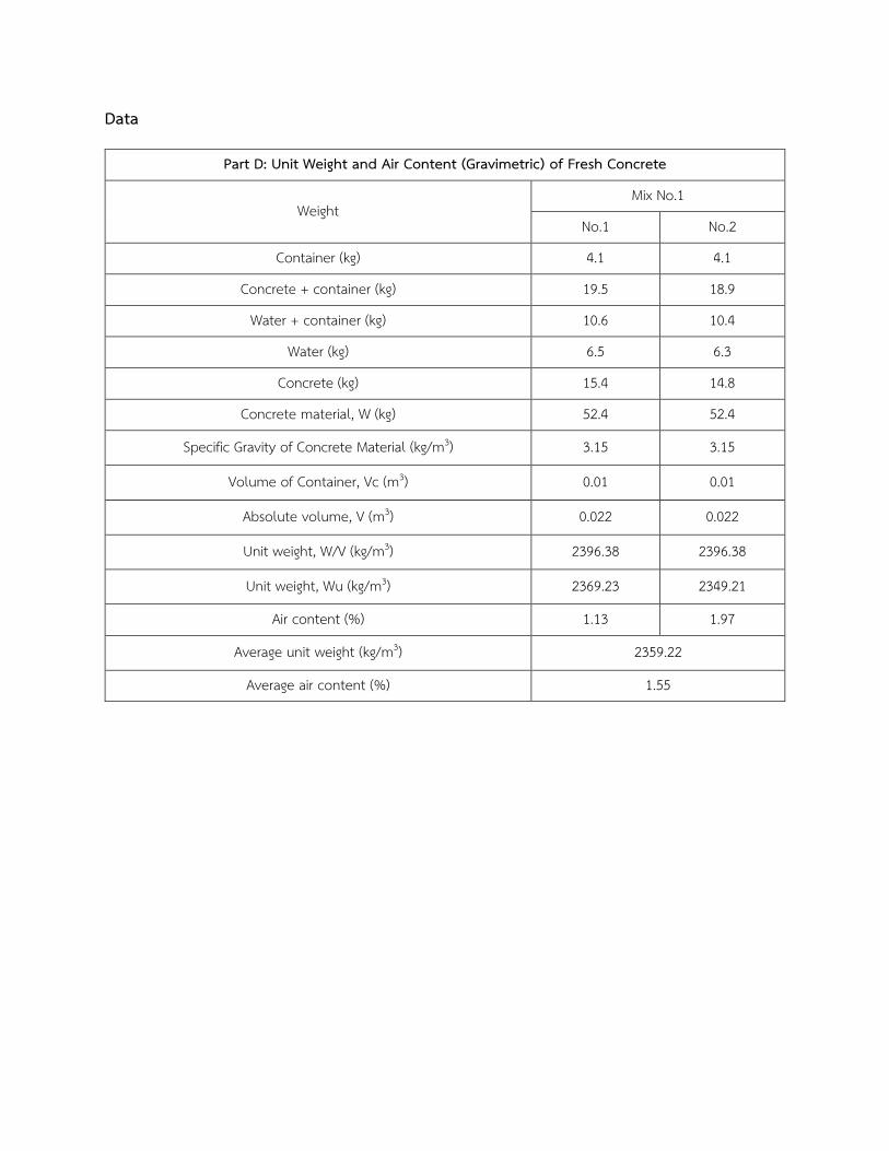
Data
Part D: Unit Weight and Air Content (Gravimetric) of Fresh Concrete
Weight Mix No.1
No.1 No.2
Container (kg) 4.1 4.1
Concrete + container (kg) 19.5 18.9
Water + container (kg) 10.6 10.4
Water (kg) 6.5 6.3
Concrete (kg) 15.4 14.8
Concrete material, W (kg) 52.4 52.4
Specific Gravity of Concrete Material (kg/m3) 3.15 3.15
Volume of Container, Vc (m3) 0.01 0.01
Absolute volume, V (m3) 0.022 0.022
Unit weight, W/V (kg/m3) 2396.38 2396.38
Unit weight, Wu (kg/m3) 2369.23 2349.21
Air content (%) 1.13 1.97
Average unit weight (kg/m3) 2359.22
Average air content (%) 1.55
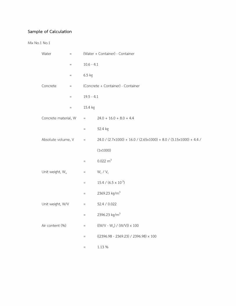
Sample of Calculation
Mix No.1 No.1
Water = (Water + Container) - Container
= 10.6 - 4.1
= 6.5 kg
Concrete = (Concrete + Container) - Container
= 19.5 - 4.1
= 15.4 kg
Concrete material, W = 24.0 + 16.0 + 8.0 + 4.4
= 52.4 kg
Absolute volume, V = 24.0 / (2.7x1000) + 16.0 / (2.65x1000) + 8.0 / (3.15x1000) + 4.4 /
(1x1000)
= 0.022 m3
Unit weight, Wu = Wc / Vc
= 15.4 / (6.5 x 10⁻³)
= 2369.23 kg/m3
Unit weight, W/V = 52.4 / 0.022
= 2396.23 kg/m3
Air content (%) = ((W/V - Wu) / (W/V)) x 100
= ((2396.98 - 2369.23) / 2396.98) x 100
= 1.13 %
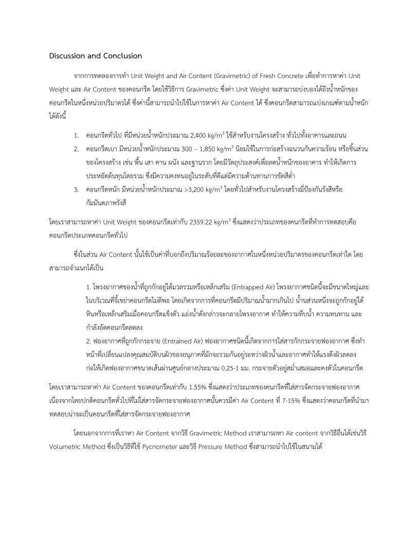
Discussion and Conclusion
จากการทดลองการทำ Unit Weight and Air Content (Gravimetric) of Fresh Concrete เพอทำการหาคา Unit
Weight และ Air Content ของคอนกรต โดยใชวธการ Gravimetric ซงคา Unit Weight จะสามารถบงบองไดถงนำหนกของ
คอนกรตในหนงหนวยปรมาตรได ซงคานสามารถนำไปใชในการหาคา Air Content ได ซงคอนกรตสามารถแบงเกณฑตามนำหนก
ไดดงน
1. คอนกรตทวไป ทมหนวยนำหนกประมาณ 2,400 kg/m3 ใชสำหรบงานโครงสราง ทวไปทงอาคารและถนน
2. คอนกรตเบา มหนวยนำหนกประมาณ 300 – 1,850 kg/m3 นยมใชในการกอสรางฉนวนกนความรอน หรอชนสวน
ของโครงสราง เชน พน เสา คาน ผนง และฐานราก โดยมวตถประสงคเพอลดนำหนกของอาคาร ทำใหเกดการ
ประหยดตนทนโดยรวม ซงมความคงทนอยในระดบทดแตมความตานทานการขดสตำ
3. คอนกรตหนก มหนวยนำหนกประมาณ >3,200 kg/m3 โดยทวไปสำหรบงานโครงสรางมปองกนรงสหรอ
กมมนตภาพรงส
โดยเราสามารถหาคา Unit Weight ของคอนกรตเทากบ 2359.22 kg/m3 ซงแสดงวาประเภทของคนกรตททำการทดสอบคอ
คอนกรตประเภทคอนกรตทวไป
ซงในสวน Air Content นนใชเป�นคาทบอกถงปรมาณรอยละของอากาศในหนงหนวยปรมาตรของคอนกรตเทาใด โดย
สามารถจำแนกไดเป�น
1. โพรงอากาศของนำทถกกกอยใตมวลรวมหรอเหลกเสรม (Entrapped Air) โพรงอากาศชนดนจะมขนาดใหญและ
ในบรเวณทจเขยาคอนกรตไมดพอ โดยเกดจากการทคอนกรตมปรมาณนำมากเกนไป นำนสวนหนงจะถกกกอยใต
หนหรอเหลกเสรมเมอคอนกรตแขงตว แองนำดงกลาวจะกลายโพรงอากาศ ทำใหความทบนำ ความทนทาน และ
กำลงอดคอนกรตลดลง
2. ฟองอากาศทถกกกกระจาย (Entrained Air) ฟองอากาศชนดนเกดจากการใสสารกกกระจายฟองอากาศ ซงทำ
หนาทเปลยนแปลงคณสมบตบนผวของอนภาคทมกจะรวมกนอยระหวางผวนำและอากาศทำใหแรงตงผวลดลง
กอใหเกดฟองอากาศขนาดเสนผานศนยกลางประมาณ 0.25-1 มม. กระจายตวอยสมำเสมอและคงตวในคอนกรต
โดยเราสามารถหาคา Air Content ของคอนกรตเทากบ 1.55% ซงแสดงวาประเภทของคนกรตทใสสารจดกระจายฟองอากาศ
เนองจากโดยปกตคอนกรตทวไปทไมใสสารจดกระจายฟองอากาศนนควรมคา Air Content ท 7-15% ซงแสดงวาคอนกรตทนำมา
ทดสอบนาจะเป�นคอนกรตทใสสารจดกระจายฟองอากาศ
โดยนอกจากการทเราหา Air Content จากวธ Gravimetric Method เราสามารถหา Air content จากวธอนไดเชนวธ
Volumetric Method ซงเป�นวธทใช Pycnometer และวธ Pressure Method ซงสามารถนำไปใชในสนามได

Reference
CPAP. Unit Weight and Air Content of Concrete. ออนไลน. คนหาวนท 7/11/64. คนหาไดจาก :
https://www.cpacacademy.com/download/cpacacademy_com/e-test%20u12.pdf
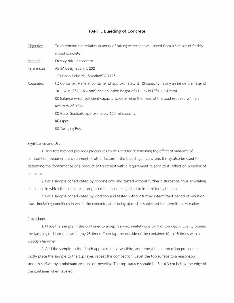
PART E Bleeding of Concrete
Objective To determine the relative quantity of mixing water that will bleed from a sample of freshly
mixed concrete.
Material Freshly mixed concrete.
References ASTM Designation: C 232
JIS (Japan Industrial Standard) A 1123
Apparatus (1) Container: A metal container of approximately ½ ft3 capacity having an inside diameter of
10 ± ¼ in (254 ± 6.4 mm) and an inside height of 11 ± ¼ in (279 ± 6.4 mm)
(2) Balance which sufficient capacity to determine the mass of the load required with an
accuracy of 0.5%
(3) Glass Graduate approximately 100 ml capacity.
(4) Pipet
(5) Tamping Rod
Significance and Use
1. This test method provides procedures to be used for determining the effect of variables of
composition, treatment, environment or other factors in the bleeding of concrete. It may also be used to
determine the conformance of a product or treatment with a requirement relating to its effect on bleeding of
concrete.
2. For a sample consolidated by rodding only and tested without further disturbance, thus simulating
conditions in which the concrete, after placement, is not subjected to intermittent vibration.
3. For a sample consolidated by vibration and tested without further intermittent period of vibration,
thus simulating conditions in which the concrete, after being placed, is subjected to intermittent vibration.
Procedures
1. Place the sample in the container to a depth approximately one third of the depth. Evenly plunge
the tamping rod into the sample by 25 times. Then tap the outside of the container 10 to 15 times with a
wooden hammer.
2. Add the sample to the depth approximately two-third, and repeat the compaction procedure.
Lastly place the sample to the top layer, repeat the compaction. Level the top surface to a reasonably
smooth surface by a minimum amount of troweling. The top surface should be 3 ± 0.3 cm below the edge of
the container when leveled.
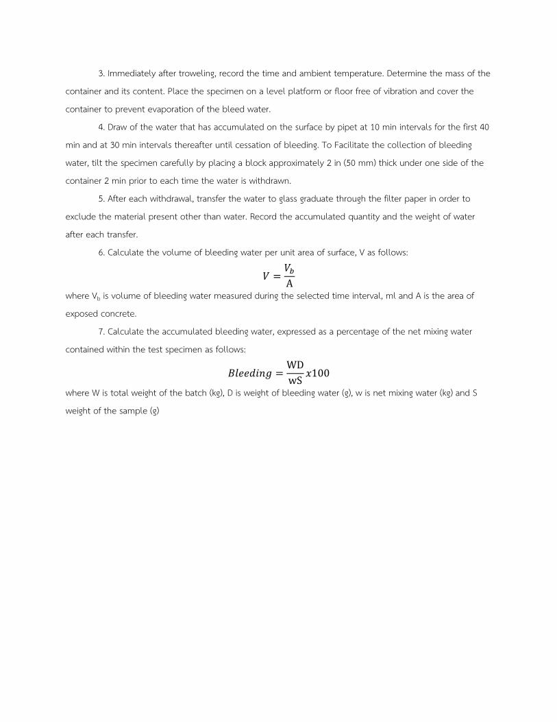
3. Immediately after troweling, record the time and ambient temperature. Determine the mass of the
container and its content. Place the specimen on a level platform or floor free of vibration and cover the
container to prevent evaporation of the bleed water.
4. Draw of the water that has accumulated on the surface by pipet at 10 min intervals for the first 40
min and at 30 min intervals thereafter until cessation of bleeding. To Facilitate the collection of bleeding
water, tilt the specimen carefully by placing a block approximately 2 in (50 mm) thick under one side of the
container 2 min prior to each time the water is withdrawn.
5. After each withdrawal, transfer the water to glass graduate through the filter paper in order to
exclude the material present other than water. Record the accumulated quantity and the weight of water
after each transfer.
6. Calculate the volume of bleeding water per unit area of surface, V as follows:
𝑉𝑉 =𝑉𝑉𝑏𝑏A
where Vb is volume of bleeding water measured during the selected time interval, ml and A is the area of
exposed concrete.
7. Calculate the accumulated bleeding water, expressed as a percentage of the net mixing water
contained within the test specimen as follows:
𝐵𝐵𝐵𝐵𝐵𝐵𝐵𝐵𝐵𝐵𝐵𝐵𝐵𝐵𝐵𝐵 =WDwS
𝑥𝑥100
where W is total weight of the batch (kg), D is weight of bleeding water (g), w is net mixing water (kg) and S
weight of the sample (g)
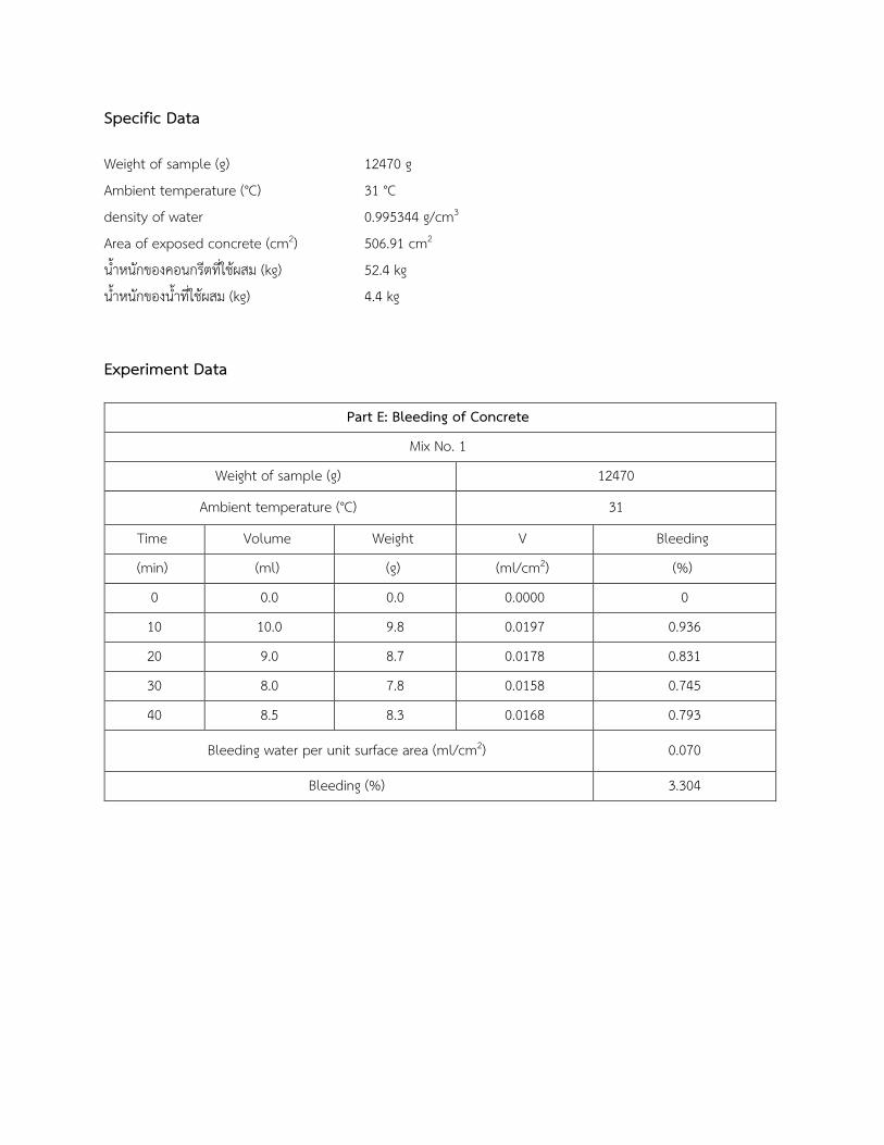
Specific Data
Weight of sample (g) 12470 g
Ambient temperature (°C) 31 °C
density of water 0.995344 g/cm3
Area of exposed concrete (cm2) 506.91 cm2
นำหนกของคอนกรตทใชผสม (kg) 52.4 kg
นำหนกของนำทใชผสม (kg) 4.4 kg
Experiment Data
Part E: Bleeding of Concrete
Mix No. 1
Weight of sample (g) 12470
Ambient temperature (°C) 31
Time Volume Weight V Bleeding
(min) (ml) (g) (ml/cm2) (%)
0 0.0 0.0 0.0000 0
10 10.0 9.8 0.0197 0.936
20 9.0 8.7 0.0178 0.831
30 8.0 7.8 0.0158 0.745
40 8.5 8.3 0.0168 0.793
Bleeding water per unit surface area (ml/cm2) 0.070
Bleeding (%) 3.304
Sample of calculation
W = นำหนกของคอนกรตทใชผสม (kg)
w = นำหนกของนำทใชผสม (kg)
D = Weight of bleeding water (g)
S = นำหนกของคอนกรตใน container (g)
ตวอยางการคำนวณท Time = 10 min
V (ml/cm2) = Volume of bleeding water / Area of exposed concrete
= 10.0 / 506.91
= 0.0197 ml/cm2
Bleeding (%) = (WD / wS) x 100
= [(52.4 x 9.8) / (4.4 x 12470)] x 100
= 0.936%
Discussion
จากการทดลอง Part E ผลการทดลอง ได % Bleeding ทเวลา 10, 20 ,30 และ 40 นาท คอ 0.936 , 0.831 , 0.745 ,
0.793 ตามลำดบ จะสงเกตไดวา คา % Bleeding มแนวโนมอยในชวงคงตวถงชวงทตำลงจนถงนาทท 40 ม อาจจะเป�นผล
เนองมาจากซเมนตเพสทเรมแขงตวเรวมากพอทจะหยดกระบวนการจมลงของมวลรวม และ ไดคา Bleeding รวมในชวง 40 นาท
แรก 3.304% คา Bleeding water per unit surface area รวม 0.07 ml/cm2
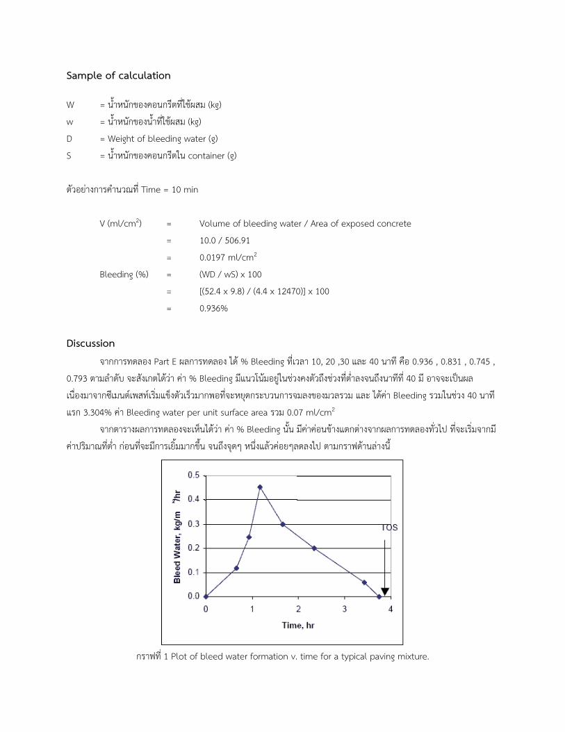
จากตารางผลการทดลองจะเหนไดวา คา % Bleeding นน มคาคอนขางแตกตางจากผลการทดลองทวไป ทจะเรมจากม
คาปรมาณทตำ กอนทจะมการเยมมากขน จนถงจดๆ หนงแลวคอยๆลดลงไป ตามกราฟดานลางน
กราฟท 1 Plot of bleed water formation v. time for a typical paving mixture.
โดยเมอพจารณาท เวลาตางๆ จะสามารถเหนคาสงสดทไดจากการ test typical paving mixture โดยเมอพจารณาจาก
คาจากตารางแลวนนยงไมเหนแนวโนมทคลายกนมาก จงอาจพจารณาไดวาเป�นคอนกรตทผสมใหแหงตวเรวเนองจากอตราการเยม
มคาสงสดชวง 10 นาทแรกแลวคอยๆลดลงมา
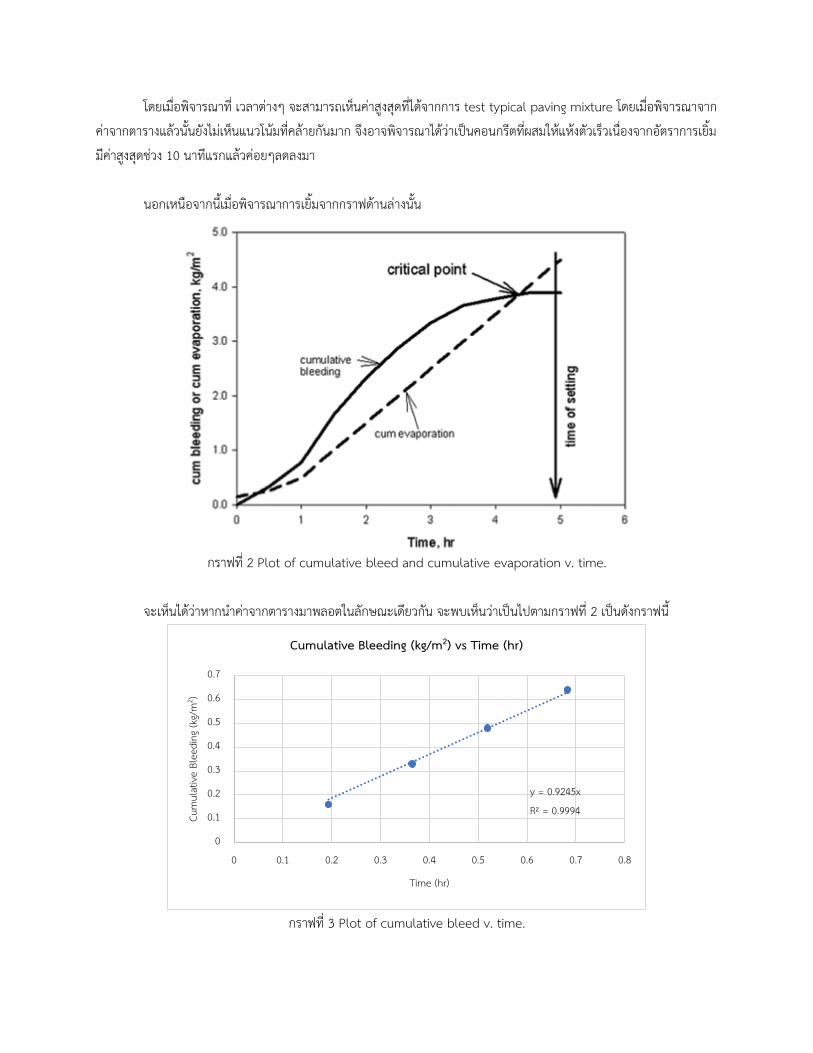
นอกเหนอจากนเมอพจารณาการเยมจากกราฟดานลางนน
กราฟท 2 Plot of cumulative bleed and cumulative evaporation v. time.
จะเหนไดวาหากนำคาจากตารางมาพลอตในลกษณะเดยวกน จะพบเหนวาเป�นไปตามกราฟท 2 เป�นดงกราฟน
กราฟท 3 Plot of cumulative bleed v. time.
y = 0.9245x
R² = 0.9994
0
0.1
0.2
0.3
0.4
0.5
0.6
0.7
0 0.1 0.2 0.3 0.4 0.5 0.6 0.7 0.8
Cum
ulat
ive
Blee
ding
(kg/
m2 )
Time (hr)
Cumulative Bleeding (kg/m2) vs Time (hr)
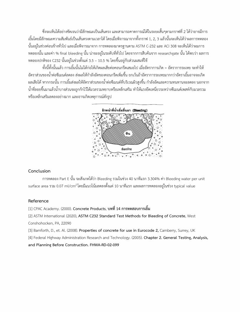
ซงจะเหนไดอยางชดเจนวามลกษณะเป�นเสนตรง และสามารถคาดการณไดในระยะสนๆตามกราฟท 2 ไดวาอาจมการ
เยมโดยมลกษณะความสมพนธเป�นเสนตรงตามเวลาได โดยเมอพจารณาจากทงกราฟ 1, 2, 3 แลวนนจะเหนไดวาผลการทดลอง
นนอยในชวงคอนขางทวไป และเมอพจารณาจาก การทดลองมาตรฐานตาม ASTM C-232 และ ACI 308 จะเหนไดวาผมการ
ทดลองนน และคา % final bleeding นน นาจะอยในระดบททวไป โดยจากการสบคนจาก researchgate นน ไดพบวา ผลการ
ทดลองปกตของ C232 นนอยในชวงตงแต 3.5 – 10.5 % โดยขนอยกบสวนผสมทใช
ทงนทงนนแลว การเยมนนไมไดกอใหเกดผลเสยตอคอนกรตเสมอไป เมออตราการเกด = อตราการระเหย จะทำให
อตราสวนของนำตอซเมนตลดลง สงผลใหกำลงอดของคอนกรตเพมขน ยกเวนถาอตราการระเหยมากกวาอตราเยมอาจจะเกด
ผลเสยได หากกระนน การเยมสงผลใหอตราสวนของนำตอซเมนตทบรเวณผวสงขน กำลงอดและความทนทานจะลดลง นอกจาก
นำทลอยขนมาแลวนำบางสวนจะถกกกไวใตมวลรวมหยาบหรอเหลกเสรม ทำใหแรงยดเหนยวระหวางซเมนตเพสทกบมวลรวม
หรอเหลกเสรมลดลงอยางมาก และอาจเกดเหตการณดงรป
Conclusion
การทดลอง Part E นน จะสงเกตไดวา Bleeding รวมในชวง 40 นาทแรก 3.304% คา Bleeding water per unit
surface area รวม 0.07 ml/cm2 โดยมแนวโนมลดลงตงแต 10 นาทแรก และผลการทดลองอยในชวง typical value
Reference
[1] CPAC Academy. (2000). Concrete Products, บทท 14 การทดสอบการเยม
[2] ASTM International (2020), ASTM C232 Standard Test Methods for Bleeding of Concrete, West
Conshohocken, PA, 22090
[3] Bamforth, D., et. Al. (2008). Properties of concrete for use in Eurocode 2, Camberry, Surrey, UK
[4] Federal Highway Administration Research and Technology. (2005). Chapter 2. General Testing, Analysis,
and Planning Before Construction. FHWA-RD-02-099
Part F Time of Setting of Concrete Mixtures by Penetration Resistance
Objective To determine the time of setting of concrete with slump greater than zero by means of
penetration resistance.
Material Freshly mixed concrete.
Reference ASTM Designation: C 403
Apparatus (1) Container for mortar specimens : The minimum lateral dimension shall be 6 in (152 mm)
and the height at least 6 in.
(2) Penetration Resistance Apparatus3
(3) Tamping Rod
(4) Pipet
Significance and Use
1. Since the setting time of concrete is a gradual process, any definition of time of setting must
necessarily be arbitrary. In this test method, the times required for the mortar to reach specificed values of
resistance to penetration are used to define times of setting.
2. This test method can be used to determine the effects of variables, such as brand, type and
content of cementatious material, water content, and admixtures, upon the time of setting of concrete. This
test method may also be used to determine compliance with specified time of setting requirements.
3. This test method may also be applied to prepared mortars and grouts. However, when the setting
time of concrete is desired, the test shall be performed on mortar sieved from the concrete mixture and not
on a prepared mortar intended to simulate the mortar fraction of the concrete; it has been shown that the
initial and final setting times may be increased when using the prepared mortar.
3 Spring reaction-type or hydraulic reaction-type with removable needles of 645, 323, 161, 65, 32 and 16 mm2 . Each needle
shank shall be scribe peripherally at a distance 1 in (25 mm) above the bearing face.
Procedures
1. Obtain the representative sample of fresh concrete with sufficient volume of mortar to fill the test
container to the depth at least 5½ in4. Determine and record the slump. The ambient temperature and
humidity should also be recorded.
2. Remove essentially all of the mortar from the sample of concrete by sieving it through a No.4
(4.75 mm) sieve onto a nonabsorbent surface.
3. Thoroughly remix the mortar by hand. Place the mortar into the container by using a single layer.
Consolidate the mortar to eliminate air pockets in the specimen by rod the mortar once for each 1 in2 (645
mm2) of top surface area of the specimen and distribute the strokes uniformly over the cross section of the
specimen and level the top surface. The mortar surface shall be at least ½ in (13 mm) below the top edge of
the container.
4. Remove the bleeding water from the surface of the mortar specimen prior to make a penetration
test by means of pipet or suitable instrument.
5. Insert a needle of appropriate size, depending upon the degree of setting of the mortar, in the
penetration resistance apparatus and bring the bearing surface of the needle into contact with the mortar
surface.
6. Gradually and uniformly apply a vertical force downward on the apparatus until the needle
penetrates the mortar to a depth of 1 in (25 ± 1.5 mm) as indicated by the scribe mark with in 10 ± 2 sec.
Record the force required.
7. Calculate the penetration resistance by dividing the recorded force by the bearing area of the
needle. In subsequent tests take care to avoid areas where the mortar has been disturbed by previous tests.
The clear distance between needle impressions shall be at least two diameters of the needle being used, but
not less than ½ in (13 mm). The clear distance between any needle impression and the side of the container
shall be not less than 1 in (25 mm).
8. Prepare a graph of penetration resistance as the ordinate versus elapsed time as abscissa. The
graph may be prepared by either normal scale or log-log scale. By fitting a smooth curve, determine the initial
setting and final setting. The time of initial setting and final setting are defined as the time when the
penetration resistance reach 500 psi (3.5 MPa) and 4000 psi (27.6 MPa) respectively.
9. Not less than six penetration resistance determinations shall be made in each time of setting test
and the time interval between penetration resistance determinations shall be such as to give a satisfactory
curve of penetration resistance versus elapsed time.
4 At least one specimen for each mix proportion.
Experiment Data
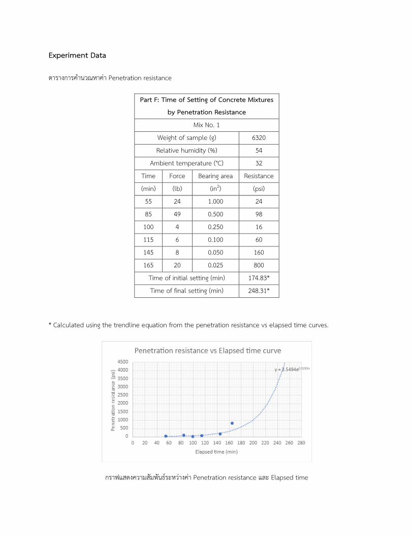
ตารางการคำนวณหาคา Penetration resistance
Part F: Time of Setting of Concrete Mixtures
by Penetration Resistance
Mix No. 1
Weight of sample (g) 6320
Relative humidity (%) 54
Ambient temperature (°C) 32
Time Force Bearing area Resistance
(min) (lb) (in2) (psi)
55 24 1.000 24
85 49 0.500 98
100 4 0.250 16
115 6 0.100 60
145 8 0.050 160
165 20 0.025 800
Time of initial setting (min) 174.83*
Time of final setting (min) 248.31*
* Calculated using the trendline equation from the penetration resistance vs elapsed time curves.
กราฟแสดงความสมพนธระหวางคา Penetration resistance และ Elapsed time
Sample Calculation
at 165 min
Penetration resistance = Force/Bearing area
= 20 lb. /0.025 in2
= 800 psi
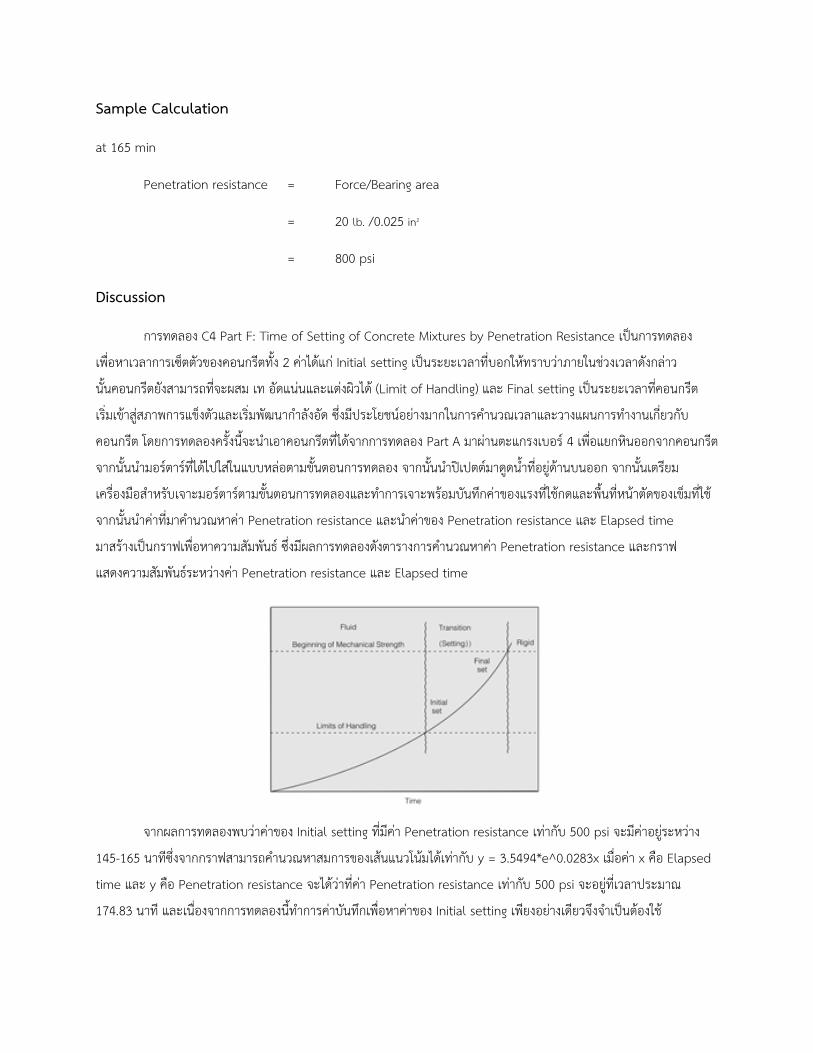
Discussion
การทดลอง C4 Part F: Time of Setting of Concrete Mixtures by Penetration Resistance เป�นการทดลอง
เพอหาเวลาการเซตตวของคอนกรตทง 2 คาไดแก Initial setting เป�นระยะเวลาทบอกใหทราบวาภายในชวงเวลาดงกลาว
นนคอนกรตยงสามารถทจะผสม เท อดแนนและแตงผวได (Limit of Handling) และ Final setting เป�นระยะเวลาทคอนกรต
เรมเขาสสภาพการแขงตวและเรมพฒนากำลงอด ซงมประโยชนอยางมากในการคำนวณเวลาและวางแผนการทำงานเกยวกบ
คอนกรต โดยการทดลองครงนจะนำเอาคอนกรตทไดจากการทดลอง Part A มาผานตะแกรงเบอร 4 เพอแยกหนออกจากคอนกรต
จากนนนำมอรตารทไดไปใสในแบบหลอตามขนตอนการทดลอง จากนนนำป�เปตตมาดดนำทอยดานบนออก จากนนเตรยม
เครองมอสำหรบเจาะมอรตารตามขนตอนการทดลองและทำการเจาะพรอมบนทกคาของแรงทใชกดและพนทหนาตดของเขมทใช
จากนนนำคาทมาคำนวณหาคา Penetration resistance และนำคาของ Penetration resistance และ Elapsed time
มาสรางเป�นกราฟเพอหาความสมพนธ ซงมผลการทดลองดงตารางการคำนวณหาคา Penetration resistance และกราฟ
แสดงความสมพนธระหวางคา Penetration resistance และ Elapsed time
จากผลการทดลองพบวาคาของ Initial setting ทมคา Penetration resistance เทากบ 500 psi จะมคาอยระหวาง
145-165 นาทซงจากกราฟสามารถคำนวณหาสมการของเสนแนวโนมไดเทากบ y = 3.5494*e^0.0283x เมอคา x คอ Elapsed
time และ y คอ Penetration resistance จะไดวาทคา Penetration resistance เทากบ 500 psi จะอยทเวลาประมาณ
174.83 นาท และเนองจากการทดลองนทำการคาบนทกเพอหาคาของ Initial setting เพยงอยางเดยวจงจำเป�นตองใช
สมการของเสนแนวโนนเพอคำนวณหาเวลาของ Final setting จะไดวาทคา Penetration resistance เทากบ 4000 psi
จะอยทเวลาประมาณ 248.31 นาท
Conclusion
จากการทดลอง C4 Part F: Time of Setting of Concrete Mixtures by Penetration Resistance
สามารถคำนวณหาคา Intial setting time ไดเทา 174.83 นาท และ Final setting time ไดเทากบ 248.31 นาท
ซงทงสองคานเป�นการประมาณเวลาจากสมการของเสนแนวโนมทไดจากกราฟแสดงความสมพนธระหวางคา Penetration
resistance และ Elapsed time
Reference
[1] CPAC Academy. (2000). Concrete Products, บทท 13 การทดสอบระยะเวลาการกอตวของคอนกรต
[2] ASTM International (2016), ASTM C403 Standard Test Method for Time of Setting of Concrete Mixtures
by Penetration Resistance, West Conshohocken, PA, 22090