Embed Size (px)
Citation preview

An-Najah Univ. J. Res. (N. Sc), Vol. 17(2), 2003
Classifying and Coding Design and Construction Information
Nabil Dmaidi
Civil Engineering Department, Faculty of Engineering,
An-Najah National University, Nablus, Palestine.
E-mail: [email protected]
Received: (10/12/2000), Accepted: (14/10/2003)
Abstract The search for new approaches to design-construction information integration
through the use of computer-based systems is invariably hindered by the need to adopt appropriate representational schemes for the design information by several professions architects, structural engineers, service engineers, quantity surveyors, and by small groups of sub-constructors. Lack of developed coding, classifying and catalogue systems has the greatest impact on the development of integration and the transfer of product information in the light of computer operation. These has been the cause of major problems in the transfer of information between these various bodies (1,14). A proposed design and construction information classifying and coding scheme that facilitates the exchange and manipulation of information in construction projects, while maintaining compatibility with existing classification systems involved in documents like specifications and bills of quantities, will be presented.
Keywords: Coding and Information transfer; Integration of building information on construction.
.
.
202
“Classifying and Coding Design and …”
An-Najah Univ. J. Res. (N. Sc), Vol. 17(2), 2003
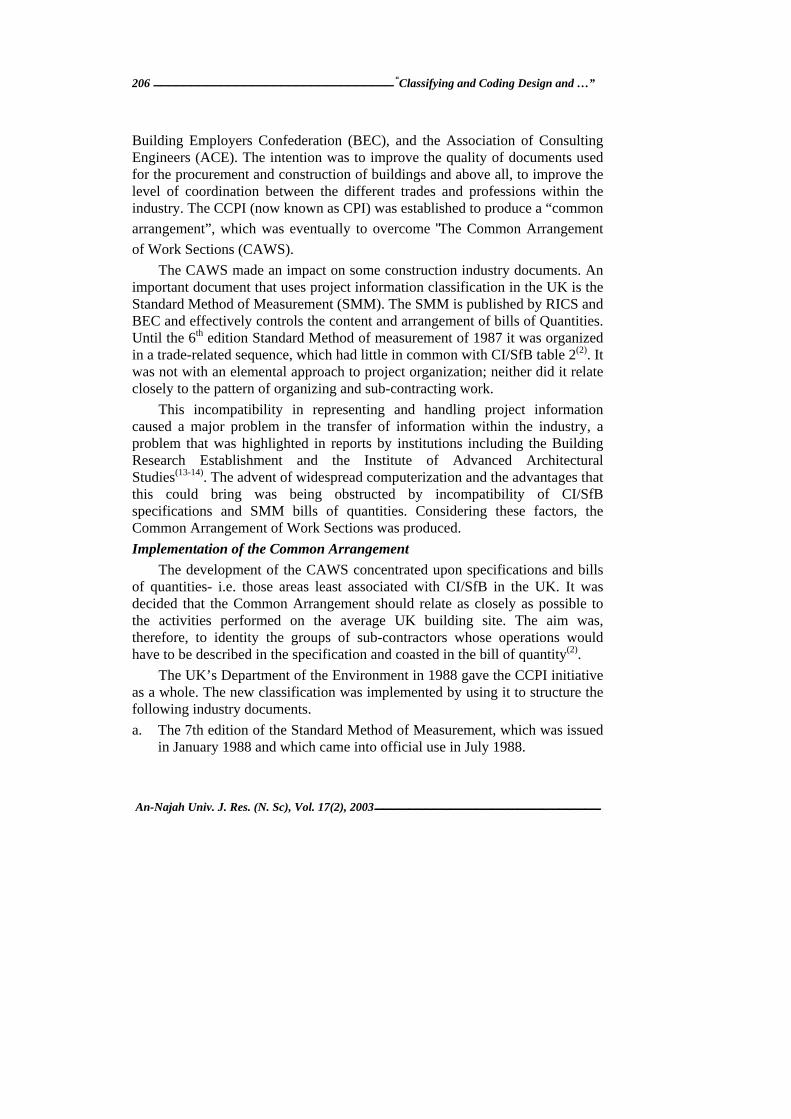
Introduction
Building and civil engineering projects include large numbers of design elements, construction activities, materials, in addition to diversity of data abstracts and complex relationships. Due to the fragmentary of the Architecture - Engineering - construction (A E C) process, each organization is likely to have its own specialized data representation and its own database of design information(1).
The search for new approaches to design-construction information integration through the use of computer-based systems is invariably hindered by the need to adopt appropriate representational schemes for the design information(1). An important factor lies in standard representation of design and construction information through classifying and coding to facilitate the exchange and manipulation of information in construction projects, while maintaining compatibility with existing classification systems involved in documents like specifications and bills of quantities.
The UK construction industry is fragmented with several different professions (architects, structural engineers, service engineers, and quantity surveyors), and with much of the site work being performed by small groups of sub-constructors. This has been the cause of major problems in the transfer of information between these various bodies, both with regards to drawn information and text documents, such as bills and specifications(2). Lack of developed coding, classifying and catalogue systems has the greatest impact on the development of integration and the transfer of product information in the light of computer operation(3). The importance of further developments in the domain of standard representation schemes and appropriate databases to deal with diversity of data types encountered in construction projects has been well identified by the industry(1,3-8, 21).
Two important steps are indispensable before making any serious move towards an integrated environment: 1. Consistent method of representing building information, through consistent
classification and coding. 2. Structuring design information data and component relationships.
This paper will present a proposed design and construction information for classifying and coding scheme. The following sections define the types of information that is the focus of this paper, various factors influencing the development of the proposed representation scheme, and description of the scheme.

Nabil Dmaidi 203
An-Najah Univ. J. Res. (N. Sc), Vol. 17(2), 2003
The Information Spectrum In building and civil engineering projects, design and construction
information encompasses a spectrum of data and knowledge(9). Figure 1 shows this spectrum which ranges from very concrete, and tangible details (basic data) to very abstract, and common principles (general knowledge).
Figure (1): Spectrum of information (Data + Knowledge) Source: Howard HC 91

204
“Classifying and Coding Design and …”
An-Najah Univ. J. Res. (N. Sc), Vol. 17(2), 2003
Basic data are the data known before starting the project. This category
may include descriptions of standard components, unit costs, site surveys, etc. while design (derived) data are the data generated by the design process. The design data include the attribute values for specific object instances in the design; e.g. cavity width of cavity wall 19 is 70 mm, and design association between object instances, e.g. concrete footing 23 supports external wall 33.
Project specifications define the purpose, function, and performance of the facility being constructed, while domain knowledge is the constraints and heuristics that belong to a profession-manifested as building codes, manuals of design practice and text books-or an individual professional-synthesized from the profession’s knowledge and experience in previous projects.
Design decisions are the combination of information (data and knowledge) that produces design data and project specifications, while the general knowledge consists of the basic principles of science and problem solving that are common many domains, e.g., physics, chemistry.
In this Paper, the main concern is for the design data. Design data are generated through design decisions made by humans or computer applications. Traditionally, design data were stored on paper in drawings and reports. Much of that data has migrated to digital form in CAD systems and databases, although paper is still the primary medium of data exchange. Classifying and coding the above defined design data is the theme of this paper.
Classification and Coding It is recognized among practitioners and researchers that classification and
coding is essential for information co-ordination and exchange in building(4). Classification provides a search pattern by relating similar items of information and separating those which are different. Examination of the structure of the classification establishes where a given item is likely to be found.
Codes are often used in constructions with headings in classification schemas. A code is one or more symbols or words, usually chosen to assist the economical storing, manipulation and exchange of information, and arrange it in a consistent order. Construction industry /strands for buildings (CI/Sf B) Project Manual).
The construction industry already has a number of classification systems which are used by different practitioners depending on the familiarity with the classification system and which suits their viewpoint. For example architects

Nabil Dmaidi 205
An-Najah Univ. J. Res. (N. Sc), Vol. 17(2), 2003
make extensive use of Construction industry / standards for buildings CI/SfB, while surveyors and engineers use or common arrangement. Cost data may be classified in various ways according to the application required such as the British Construction Industry Standards (BCIS), Wessex.
The popular classification systems in UK construction industry related studies were focused on the British Construction Industry (CI/SfB) classification system and the common arrangement of work sections for building works. Their importance and general features are discussed in the following sections.
The CI/SfB Classification System Published by Royal Institute of British Architects (RIBA) in 1971, the
CI/SfB systems comprises tables 1 to 4, tables 1 (elements) and 2 and 3 (constructions and materials) being the codes in most common use(4,6,10-11). The CI/SfB table 1 is the most important facet for many purposes since it provides a spine code, which runs through most applications of CI/SfB(11). It lists building elements as parts which particular functions. It gives each part a code consisting of two numerals, which are enclosed, in brackets.
The CI/SfB table 1(4) has been in use in a number of classification systems in Europe(4). It was recently recommended by the British Standards Institution (BSI) in structuring computer graphic information, including the organization and use of layers in CAD systems(12). With minor amendments, it was accepted that table 1(4) was the most suitable means of organizing this information, based upon its use for some years by several of the main CAD system designers in UK(2).
However, there are factors that require some modification to be made to this table before using it to develop a classification scheme. These factors are referred to in subsequent sections.
The Common Arrangement of Work Sections Development of the Common Arrangement
1988 witnessed the start of major change in the organization of project information in the United Kingdom (U.K). This change was the accumulation of nine years of work by the Co-ordination Committee for Project Information (CCPI), which was established in 1979 by the Royal Institute of British Architects (RIBA), the Royal Institute of Chartered Surveyors (RICS), the
206
“Classifying and Coding Design and …”
An-Najah Univ. J. Res. (N. Sc), Vol. 17(2), 2003
Building Employers Confederation (BEC), and the Association of Consulting Engineers (ACE). The intention was to improve the quality of documents used for the procurement and construction of buildings and above all, to improve the level of coordination between the different trades and professions within the industry. The CCPI (now known as CPI) was established to produce a “common
arrangement”, which was eventually to overcome "The Common Arrangement
of Work Sections (CAWS).
The CAWS made an impact on some construction industry documents. An important document that uses project information classification in the UK is the Standard Method of Measurement (SMM). The SMM is published by RICS and BEC and effectively controls the content and arrangement of bills of Quantities. Until the 6th edition Standard Method of measurement of 1987 it was organized in a trade-related sequence, which had little in common with CI/SfB table 2(2). It was not with an elemental approach to project organization; neither did it relate closely to the pattern of organizing and sub-contracting work.
This incompatibility in representing and handling project information caused a major problem in the transfer of information within the industry, a problem that was highlighted in reports by institutions including the Building Research Establishment and the Institute of Advanced Architectural Studies(13-14). The advent of widespread computerization and the advantages that this could bring was being obstructed by incompatibility of CI/SfB specifications and SMM bills of quantities. Considering these factors, the Common Arrangement of Work Sections was produced.
Implementation of the Common Arrangement
The development of the CAWS concentrated upon specifications and bills of quantities- i.e. those areas least associated with CI/SfB in the UK. It was decided that the Common Arrangement should relate as closely as possible to the activities performed on the average UK building site. The aim was, therefore, to identity the groups of sub-contractors whose operations would have to be described in the specification and coasted in the bill of quantity(2).
The UK’s Department of the Environment in 1988 gave the CCPI initiative as a whole. The new classification was implemented by using it to structure the following industry documents.
a. The 7th edition of the Standard Method of Measurement, which was issued in January 1988 and which came into official use in July 1988.
Nabil Dmaidi 207
An-Najah Univ. J. Res. (N. Sc), Vol. 17(2), 2003
b. Libraries of building specification clauses, including the National Building Specification and the National Engineering Specification.
The purpose of the CAWS is to define an arrangement for specifications and bills of quantities for building projects. The CAWS includes about 300 work sections following the pattern of subcontracting in the industry.
Proper assessment of the level of satisfaction about the achievement of this rearrangement within the industry was not available through, shortly after its development, the CAWS was claimed to have the full support of all the leading institutional bodies(2).
General Considerations While developing a model for classification and coding to be used in this
paper, a number of factors were taken into consideration. These include:
1. In developing ideas on product information, it is important to take into account existing industry methods of coding and specifications. They have been applied for many years within their narrow contexts. It is better to look for ways of bringing these together rather than to look for completely new ways of classifying information, which may be alien to industry tradition(3).
2. In representation of graphical elements, elemental classifications preferred to common arrangement as the use of work sections would result in most details having to be drawn several times, each time from the point of view of a different trade(2,13).
3. The citation order of the classification tables could be made flexible so that information could be classified by CI/SfB table 1 subdivided by CAWS, or by CAWS subdivided by table 1, whichever the office preferred. Experience suggests that architects would prefer the former(2).
4. A major problem is that CI/SfB table 1 and CAWS are by no means mutually exclusive. Table 1 contains classes, which are essentially work sections rather than element-oriented. Classes (5-), i.e., service (piped and ducted) and (6-), i.e., services (mainly electrical) are good examples. Equally CAWS contains many elemental sections. Class L Windows/ Doors /Stairs exemplifies this. Consequently, it seems unlikely that the two systems could be combined adequately without considerable modifications. Restructuring table 1 for better representation of elements would be a considerable improvement.

208
“Classifying and Coding Design and …”
An-Najah Univ. J. Res. (N. Sc), Vol. 17(2), 2003
5. The authors of CAWS argue that the work section is a dual concept
involving skill in using a type of material and also skill in constructing parts of the finished building(2). In some cases, the material is dominant (e.g. E10 In-situ concrete); in others, the element is dominant (e.g. H11 Curtain walling). Regardless of what the CAWS section is called, both concepts are always included, the difference being the emphasis that is given to each in this research, work sections are seen as representation of construction activities, in other words: the total process of converting materials and products into parts of the finished building.
6. Architects’ libraries in the UK are dominated by CI/SfB, with RIBA Services Ltd. alone running over one thousand and two hundred (1200). Ninety nine percent (99%) of these uses CI/SfB. In general, it is estimated that approximately sixty six percent (66%) of the three thousand 3000 construction libraries within the UK are arranged by CI/ SfB(2). Manufacturers’ catalogues mostly use CI/SfB. Cost considerations are likely to deter many, if not most, offices from changing from CI/SfB to CAWS.
7. The varying requirements of different sections of the industry suggest that true commonalty in arrangement will never be active(2,24-25). However, as some types of information are best arranged by work section and others by element, computers can play an important role in organizing project information and information databases into whatever sequence is required for the job in hand.
8. The scheme, in its classification structure and codes, is intended to provide the classes and their codes to the object model(21-23). It is also intended to support its structure (relationships among its objects).
The Proposed Classification Scheme General Features Information Categories
The classification and coding scheme proposed within the domain of this research project have been designed to provide a conceptual representation of selected parts of building products. It is meant to be compatible with the current construction practice and standards in the UK. Such representation is optimized to be used as a tool for building and prototyping data structures in an integrated object-oriented design-construction data model. It is not within the scope of this research project to provide a complete solution to the classification problem. However, as the classification and coding scheme proposed here is intended for

Nabil Dmaidi 209
An-Najah Univ. J. Res. (N. Sc), Vol. 17(2), 2003
use in support of object data model, with substantial data structure flexibility, this model may provide an adequate perception to guide future structuring of building information.
The proposed scheme deals with defined categories of information that are considered of fundamental importance to design and construction professionals. These include:
1. Elements: parts with particular functions 2. Work sections: specifications, which reflect types of construction activities. 3. Materials used in construction. 4. Geometric information: Geometric attributes of building elements, which
include shape, dimensions, location and orientation.
Building Elements Model
As explained earlier, and due to the fact that the CI/SfB table 1 and the CAWS are not exclusive, it seems unlikely that the two systems (CAWS and CI/SfB) could be combined adequately to provide an elemental table. As different professional bodies still emphasize the elemental structure of tables as being more suitable to represent elemental facts, and due to the fact that design information in the design models and drawings are created, assembled and edited as parts rather than work sections (representing activities), a model of building elements was developed by restructuring the CI/SfB table 1. Table (1): Examples of Principal Materials
Principal material Subclasses of principal material
Concrete In situ Precast
Masonry Brick Block Stone Glass
Metal Steel Aluminum Lead
Timber
Plastics
This model is referred to, as the “Building Elements Model (BEM)”. The following sections demonstrate the BEM main features.
The BEM views a building as composing of three systems where every building element belongs to one of these systems. Thus the elements are classified as:
210
“Classifying and Coding Design and …”
An-Najah Univ. J. Res. (N. Sc), Vol. 17(2), 2003
1. The sub-structure elements. 2. The super-structure elements. 3. The building services elements.
The first two categories constitute the structural elements in buildings and their classes in the BEM are structured from the CI/SfB table 1. The classes in the third category of elements are represented in the CAWS as elements. They are not properly represented in the CI/SfB table 1 (represented as work sections and not elements).
Representing them in the CAWS, therefore, is expected to be more convenient especially since they are associated with work sections in the object model, as will be discussed later. This will minimize the effect of incompatibility in the case of co-ordination building service elements in table 1 with their work sections in the CAWS.
Structural elements both the sub-structure and super-structure are classified into four categories:
1. Primary elements. 2. Elements secondary to the primary elements. 3. Finishes. 4. Other elements associated with the primary elements.
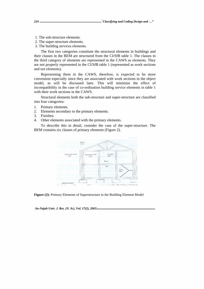
To describe this in detail, consider the case of the super-structure. The BEM contains six classes of primary elements (Figure 2).
Figure (2): Primary Elements of Superstructure in the Building Element Model

Nabil Dmaidi 211
An-Najah Univ. J. Res. (N. Sc), Vol. 17(2), 2003
Every element in the super-structure belongs to, or is associated with, one of the six primary elements. For example, external walls are a class of primary elements. Associated with them are secondary elements (doors, windows), finishing elements (plastering, painting) and any other elements that might be associated with constructing, finishing and fitting of external walls (skirting are considered here in this category).
Each primary element class is subdivided into a hierarchy of sub - classes(22-23). As in Figure 3 external walls, for example, is the top class in a hierarchy of subclasses. External cavity walls appear in the hierarchy as a subclass of external walls.
Figure (3): Class hierarchy in the Building Element Model: Superstructure Primary Elements
212
“Classifying and Coding Design and …”
An-Najah Univ. J. Res. (N. Sc), Vol. 17(2), 2003
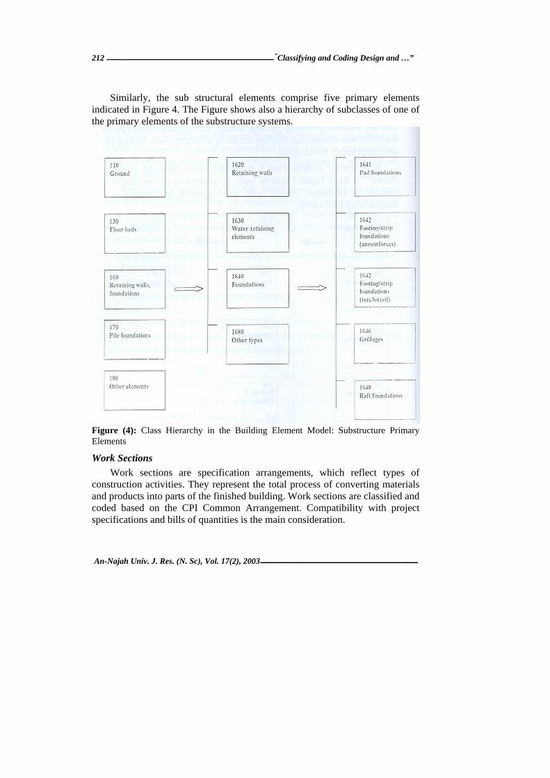
Similarly, the sub structural elements comprise five primary elements
indicated in Figure 4. The Figure shows also a hierarchy of subclasses of one of the primary elements of the substructure systems.
Figure (4): Class Hierarchy in the Building Element Model: Substructure Primary Elements
Work Sections
Work sections are specification arrangements, which reflect types of construction activities. They represent the total process of converting materials and products into parts of the finished building. Work sections are classified and coded based on the CPI Common Arrangement. Compatibility with project specifications and bills of quantities is the main consideration.
Nabil Dmaidi 213
An-Najah Univ. J. Res. (N. Sc), Vol. 17(2), 2003
To construct a primary element and various parts associated with it, one or more construction activities are required. Therefore, for every primary element, a group of work sections are associated with the primary element. These work sections indicate types of construction activities. Each work section contains a number of variables that provide the types of information describing details of the work section. These variables are derived from the information categories included in the CPI Common Arrangement. These variables, as will be demonstrated in the next sections, constitute the attributes of classes of objects of the object model.
To provide examples on the work sections, consider the cavity wall situation. For a brick/block cavity wall, work sections required to produce this primary element and its associated parts include brick/block walling. Brick/block sundry items, windows and doors work sections, finishes (plastering, painting) and skirting.
Work sections vary between one primary element and another depending on the primary element type (indicated by its subclass) and its principal material. Work sections of masonry walls are different from work sections of monolithic concrete walls, for example.
Materials
In the Common Arrangement, work sections are largely based on materials and their associated skills, e.g., in situ concrete, natural slating, aluminum framing(14). In the presented scheme, principal materials are selected initially while designing the building primary elements. Table1 shows a list of principal materials and some of their subclasses. However, options available for selecting principal materials for a particular building element depends on their citation in the CAWS to help relating materials to their appropriate work sections.
For example, masonry materials options are available for selecting a principal material to a cavity wall. These options, as cited in the CAWS Masonry class, include brick, block, glass, and natural stone and cast stone. These principal materials are used in the classification scheme to select the required group of work sections in order to produce a selected building element.
Details of materials and their properties are treated as part of the attributes of objects representing building elements. These details are specified at the detail design and specification of a building element.

214
“Classifying and Coding Design and …”
An-Najah Univ. J. Res. (N. Sc), Vol. 17(2), 2003
Once work sections are determined, details of material attributes are
selected. Detail classification of materials refers to materials class hierarchy based on the CI/SfB Table three: Materials. Examples of classification systems using table three(3) for materials include the Danish CBC System and the Japanese ACT Coding System(4,8,11,20).
More details on material specification broadly used on whether the element is a bough-in component or construction suite. Pre manufactured components need more than material type for specification. Specification standards of materials, encasement type, standard dimensions, shapes, colors, etc., as published by manufacturers are examples of a diversity of parameters, which need to be known in the process of selecting building components. In manufacturers’ catalogues, windows, for example, are typically specified and coded by material, encasement, standard sizes and so on. Material, type, size, etc., specify bricks (a different class of pre-manufactured components). In both examples manufactures’ catalogue codes may be used for identification and more details. For elements constructed on site, as in the case of in situ concrete works, specification of material type and proportion is important. Further details may be required on material type proportion, grades, method of forming/mixing, etc.
Figure 5 shows a classification and coding example combining elements, work sections and materials. The Figure also indicates how an initial selection of material for an element may help to guide the selection of work sections to produce the element. This ultimately leads to more detail selection of the materials involved.
Geometric Information
Considering that building design is represented by geometric components of physical objects, two categories of information on the geometry of an object instance will be dealt with:
General shape and measured information (dimensions and quantities).
Instance location and orientation.
This type of information assists in defining the basic shape of the building element, locating its instances in the design model and quantifying its spatial attributes.

Nabil Dmaidi 215
An-Najah Univ. J. Res. (N. Sc), Vol. 17(2), 2003
Figure (5): Classification and Coding Example
Shape and Measured Information
Although a comprehensive shape classification for construction projects is beyond the scope of this research, a basic shape class hierarchy is presented here mainly to indicate the general shape of an element and for prototyping purposes as shown in Figure 6.

216
“Classifying and Coding Design and …”
An-Najah Univ. J. Res. (N. Sc), Vol. 17(2), 2003
Figure (6): A basic Shape Classification Hierarchy
As a physical property of a design element, shapes assist to guide the search for relevant spatial parameters and other attributes. These parameters could be used to generate graphical instances of an object.
They are also helpful for quantity take off. In general, measured information includes calculated linear dimensions, surface areas and volumes, and weight’s quantities associated with standard cross-sectional areas. Examples of the latter include steel reinforcement and steel beam is calculated in tonnage. Pre-manufactured components are quantified by number of units. Location and Orientation
CAD experts and researchers emphasize the importance of 3-D modeling(15). In a 3-D CAD model, it is necessary to relate components to the 3-D space of the structure, assuming the concept of a model space(16-18). The model space X, Y, Z co-ordinate system may vary from entity to entity (or component to component), in contrast to model space. This concept plays a simplifying roll that is most apparent, especially, in connection with those entities/components, which can be contained within a single plane. Co-ordinates may later be converted to model space. A relative co-ordinate in CAD systems, like AutoCAD, is an example of definition space.
A component needs two basic pieces of information for assembling:
Nabil Dmaidi 217
An-Najah Univ. J. Res. (N. Sc), Vol. 17(2), 2003
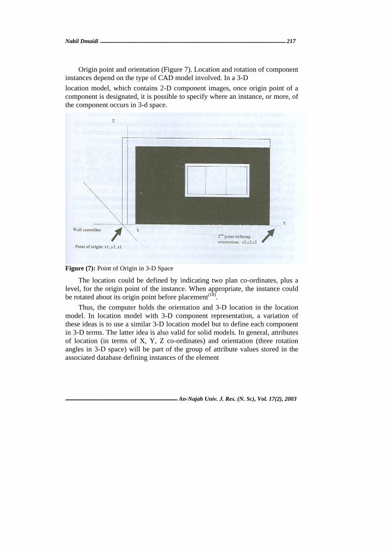
Origin point and orientation (Figure 7). Location and rotation of component instances depend on the type of CAD model involved. In a 3-D location model, which contains 2-D component images, once origin point of a component is designated, it is possible to specify where an instance, or more, of the component occurs in 3-d space.
Figure (7): Point of Origin in 3-D Space
The location could be defined by indicating two plan co-ordinates, plus a level, for the origin point of the instance. When appropriate, the instance could be rotated about its origin point before placement(18).
Thus, the computer holds the orientation and 3-D location in the location model. In location model with 3-D component representation, a variation of these ideas is to use a similar 3-D location model but to define each component in 3-D terms. The latter idea is also valid for solid models. In general, attributes of location (in terms of X, Y, Z co-ordinates) and orientation (three rotation angles in 3-D space) will be part of the group of attribute values stored in the associated database defining instances of the element

218
“Classifying and Coding Design and …”
An-Najah Univ. J. Res. (N. Sc), Vol. 17(2), 2003
The Coding System
Coding systems for engineering applications can be grouped into three basic types(19). These are:
1. Hierarchical of mono code: this system uses a tree structure using a group of characters where the meaning of each character is dependent on the meaning of the previous character.
2. Attribute or ploy code: this type of code is also called a chain code, discrete code or a fixed-digit code. The meaning of each character is an attribute of a part can be assigned a specific position in an attributer code.
3. Hybrid or mixed code: most coding systems use a hybrid code so that the advantages of each type of system can be utilized. The first digit, for example, might be used to denote the type of part, such as a steel beam. The next five positions might be reserved for an attribute code that would describe the attributes.
These coding types are popular in manufacturing departments where manufactured parts have limited and similar types of attributes. In the ACE industry, the problem is more complex for two main factors:
1. Different building elements and their associated work sections have different sets of attributes.
2. Each building primary is composite in nature and its constituent parts are different from those of another primary element.
In addition to these factors, a coding system, in this research, is assumed to meet the following requirements:
1. Coding needs to represent the composite nature of building elements. 2. A code should represent not only the building elements but also their
associated work sections. 3. A code should support the concept of object identify. In an object-oriented
implementation of the developed data model, OBIS, the computer assigns a unique identity to each object instance. The classification code of an instance is associated with the instance unique identity. For the instance that contains its class representation instead of a simple independent number assigned by the computer.
4. The codes represent the classes of objects. They do not represent attributes. Attributes are maintained as properties of individual objects and encapsulated in their respective objects.

Nabil Dmaidi 219
An-Najah Univ. J. Res. (N. Sc), Vol. 17(2), 2003
Considering the above factors and requirements, classification arrangements discussed, acceding scheme is presented here and adopted throughout the development stages of the integrated data model. The main features of the code structure are: 1. The code supports the notion that a building primary element is a
composite object and objects, which comprise the composite object, represent all its constituent and associated parts.
2. Properties common to all the classes of a particular primary element (e.g., external wall) are defined in the super class level (the top class of the composite object). The bottom-end subclasses contain variables that are indicators of the specific type of the form of construction and ultimately of the work sections associated with this form of construction.
3. The code structure depends on the level of information detail of a particular object, which is dependent on the level of abstraction of objects representing the building elements. Information on a primary building element is viewed at two levels: general information pertinent to the primary element (the composite object), and detail information, which contains details of its constituent and associated parts (the constituent objects). An object in the first level (composite object at its top level of abstraction) is indicated by a code that represents the class of the primary element. At the detail level, every object code comprises two code segments: code of the parent object, i.e., the primary element, and code of objects at the detail level, every object code comprises two code segments: code of the parent object, i.e., the primary element, and code of objects at the detail level which are representing work sections associated with the primary element.
To illustrate the above code structure in examples, consider the case of a cavity wall. A cavity wall class code, for example, is 2112. At the detail level, this coding is re planned in the following sections.
Coding Constituent Parts of the Primary Element: The two main constituent parts of the cavity wall (two skins and cavity
with all their detail) are represented by work section objects: one representing its brick/block walling (its code is 2112-f10) and its object of sundry items, which include cavity formation, and other accessory items (its code is 2112-F30).
220
“Classifying and Coding Design and …”
An-Najah Univ. J. Res. (N. Sc), Vol. 17(2), 2003
Coding Secondary Elements:
Secondary elements to primary elements are classified and represented in the CAWS. For a secondary element, its classes in the work sections class hierarchy are used to code and represent the secondary element as well as its work sections. This arrangement is made specifically for the OBIS model.
To illustrate this arrangement, consider windows as secondary elements to external walls. A window class may be coded as follows:
L1 Windows/Roof lights/Screens/Louvers
L1W Windows classes. This may be used to code a window class as an element (secondary to the external wall element).
L10 W Timber window classes. This may be used to code the Window, as a subclass, to describe its principal material (timber), which is an indicator for the classes of work sections required to be specified for this secondary element.
This is convenient when a window class is specified as an element (L1W) and then as a group of work sections. Elemental properties are mainly physical and are used to describe general dimensions (height and width), location and orientation. Such properties are inherited at the subclass level where other properties (included in work sections) are to be specified. This arrangement also reduces the possibility of conflicts in coding secondary elements in a separate element table and referring the to the same elements using different codes in the CAWS.
A window, as a secondary element, is a viewed in this scheme as a composite element. In addition to its window work section (L10W), it contains two other objects; the painting work section. Where this window is secondary to a cavity wall, the latter work sections codes are: 2112-L1W-M60 and 2112-L1W-P20 respectively.
Coding Finishes
Associated objects like painting may be coded as 2112-M60, where M60 represents painting in the CAWS.
Coding Skirting Similarly, Skirting is coded as 2112-P20.
As demonstrated above, all codes are based on the Building Element Model and the CAWS. This classification and coding scheme can be used in:

Nabil Dmaidi 221
An-Najah Univ. J. Res. (N. Sc), Vol. 17(2), 2003
1. Representing and identifying classes and objects during the development of the integrated object data model.
2. Providing classes and objects for the object mode, and
3. Providing Identities for object instances that can be processed by the computer adding database functionality in manipulating design and construction information.
Conclusion The classification and coding schemes was developed for this paper to
support the object-oriented data model, OBIS. The scheme, in its classification structure and codes, provides the classes and codes to the object model. Codes are mainly used in the model to facilitate database links between design objects, and especially to support the implementation of object identity concept. The scheme is also intended to support relationships in the model.
References 1) Omari, A., and Roy, GG., “A Representational Scheme for Design Code
Information in an Expert Systems Approach to building Design’, Proc. Civil-Comp91, International Conference on Computing in Civil Engineering, Artificial Intelligence and Civil Engineering. (1991).
2) Serjeanston, M., and Allott, T, “The British CPI Initiative, Results and Implementation”, conceptual Modeling of Buildings (CIB Proceedings, Lund, Sweden), The Swedish Building Center, Solna, Sweden), (1990).
3) National Economic Development Council, “Information Transfer in Building”, National Economic Development Office (NEDO), London, (1990).
4) Bindslev, B., “Classification of Building Cost Information for Computer Processing”, Building Cost Modeling and Computers (Proc. Building Cost Research Conference on Building Cost Modeling and Computers, Salford), Jan. (1987).
5) Karlsson, H., Classification and Coding, a Necessary Tool for Improving the Sweden and within CIB W74”, Conceptual Modeling of Buildings (CIB Proceedings, Lund, Sweden), The Swedish Building Center, Solna, Sweden), (1990).
6) Karlsson, H., “Classification of information in the Construction”, CIB Proceedings, Tokyo, Japan, The Architectural Institute of Japan, (1992).
222
“Classifying and Coding Design and …”
An-Najah Univ. J. Res. (N. Sc), Vol. 17(2), 2003
7) Macleod, L., “Representation Issues for Civil Engineering Design”, Proc. Civil-
Comp93, Fifth International Conference on Computing in Civil Engineering, part: Knowledge-Based Systems, Edinburgh (UK), Aug; (1993).
8) Terai, T., and Kaneko Y., “Coding System for ACT Advanced Building Information System”, Conceptual Modeling of Buildings, CIB Proceedings, LUND, Swedish Building Center, Solna, Sweden, (1990).
9) Howard, H., “Project - Specific Bases in ACE Industry”, Computing in Civil engineering (ASCE), 5(1), Jan. (1991), 25-41.
10) Obourn, D., “Components (Mitchell’s building Series)’, Mitchell, London, (1989).
11) Ray-Jones, A., and Clegg, D, “CI/SfB: Construction Indexing Manual”, RIBA, London, (1976).
12) B.S.I., “BS1192: Construction Drawing Practices, Part 5: Guide for Structuring of Computer Graphic Information”, BSI (British Standards Institution), London, (1990).
13) C.P.I., (CO.-Ordinated Project Information for Building works, a Guide With Examples”, CPI, (1987).
14) C.P.I., (Co-Ordinated Project Information) Committee, “Common Arrangement of Works”, Building Project Information Committee (1987).
15) Atkin, B., “Beyond Computers-Aided Drafting”, Building Cost Modeling and Computers, Salford, UK, Jan. (1987).
16) Autodesk, Ltd., “AutoCAD-Reference Manual “, Autodesk, (2001).
17) Read, K., “Product Modeling of Buildings for Data Exchange Specification (IGES) Version 5.0”, US Department of Commerce, (1990).
18) Tavakoli, A., and Klika, Kl., “Construction Management”, Auto CAD, Management in Engineering (ASCE), 7 (3), July (1991), 267-278.
19) Bedworth, D., Hendreson, MR., and Wolfe, PM., “Computer-Integrated Design and Manufacturing”, McGraw-Hill, Singapore, (1991).
20) McDonagh, N., and Shanley Design, L.F., “SFB Development”, Construction Research International, CIB Proc., (1977), 253-259.
21) El-Rayes, K., "Object Oriented Model for Repetitive Construction Scheduling", Journal of Construction Engineering and Management, ASCE, 127(3), (2001), 199-205.
22) Ramanthan, R., et al., "An Object-Oriented Model for Planning and Control of Housing Construction", Journal of Construction Management and Economics, ASCE, (2001).
23) El-Rayes, K., "A Computer Model for Scheduling of Highway Construction". 8the International Conference on Computing in Civil and Building Engineering.
Nabil Dmaidi 223
An-Najah Univ. J. Res. (N. Sc), Vol. 17(2), 2003
American Society of Civil Engineers, Stanford University, California, August (2000), 14-17.
24) Moselhi, O., "Optimized Scheduling for Highway Construction," Transactions of the 41st Annual Conference of American Association of Cost Engineers, Dallas, Texas, July (1997), 13-16,.
25) Moselhi, O., et al, "Computer-Assisted Scheduling for Repetitive Construction," Proceedings of the 25th CSCE Annual Conference, Sherbrooke, Quebec, May (1997), 27-30.