Embed Size (px)
Citation preview
City, University of London Institutional Repository
Citation: Gowree, E. R. ORCID: 0000-0001-5834-3020, Jagadeesh, C., Talboys, E., Lageman, C. and Bruecker, C. ORCID: 0000-0001-5834-3020 (2018). Vortices enable the complex aerobatics of peregrine falcons. Communications Biology, 1, 27.. doi: 10.1038/s42003-018-0029-3
This is the published version of the paper.
This version of the publication may differ from the final published version.
Permanent repository link: http://openaccess.city.ac.uk/19679/
Link to published version: http://dx.doi.org/10.1038/s42003-018-0029-3
Copyright and reuse: City Research Online aims to make research outputs of City, University of London available to a wider audience. Copyright and Moral Rights remain with the author(s) and/or copyright holders. URLs from City Research Online may be freely distributed and linked to.
City Research Online: http://openaccess.city.ac.uk/ [email protected]
City Research Online
ARTICLE
Vortices enable the complex aerobatics ofperegrine falconsErwin R. Gowree 1, Chetan Jagadeesh1, Edward Talboys1, Christian Lagemann1 & Christoph Brücker1
The peregrine falcon (Falco peregrinus) is known for its extremely high speeds during hunting
dives or stoop. Here we demonstrate that the superior manoeuvrability of peregrine falcons
during stoop is attributed to vortex-dominated flow promoted by their morphology, in the
M-shape configuration adopted towards the end of dive. Both experiments and simulations
on life-size models, derived from field observations, revealed the presence of vortices
emanating from the frontal and dorsal region due to a strong spanwise flow promoted by the
forward sweep of the radiale. These vortices enhance mixing for flow reattachment towards
the tail. The stronger wing and tail vortices provide extra aerodynamic forces through vortex-
induced lift for pitch and roll control. A vortex pair with a sense of rotation opposite to that
from conventional planar wings interacts with the main wings vortex to reduce induced drag,
which would otherwise decelerate the bird significantly during pull-out. These findings could
help in improving aircraft performance and wing suits for human flights.
DOI: 10.1038/s42003-018-0029-3 OPEN
1 Department of Mechanical Engineering and Aeronautics, City, University of London, London EC1V 0HB, UK. Correspondence and requests for materialsshould be addressed to E.R.G. (email: [email protected])
COMMUNICATIONS BIOLOGY | (2018) 1:27 | DOI: 10.1038/s42003-018-0029-3 | www.nature.com/commsbio 1
1234
5678
90():,;
During stoop, peregine falcon (Falco peregrinus), can dive at39 ms−11 to 51 ms−12, making it the world’s fastest ani-mal. Diving from high altitude is necessary to build-up
such speeds. While soaring, the falcon first climbs with the wingscompletely stretched out to increase lift, collected from verticalcolumns of rising air known as ‘thermals’3. Within the initialphase of the stoop it adopts a ‘teardrop’ shape (T-shape) wherethe wings are folded and feathers tucked in a streamlined shape,which is intuitively the lowest drag configuration. The success ofthe attack largely depends on the manoeuvrability during thesecond phase of the stoop, when the bird1 starts to pull out fromthe dive, while undergoing two important morphological trans-formations, namely the cupped-wing shape (C-shape, detailpresented in ref. 4) and the M-shape (the focus of this manu-script). In C-shape the arms are slighly untucked, creating a cavitybetween the body and the primary feathers, which are orientedvertically. During the M-shape the arm opens up further into thehorizontal plane and the primary feathers are aligned with theaxis of the bird to form an M-shaped planform when viewed fromthe top. This observation was confirmed from the live recordingsalso reported in ref. 5 and is in agreement with previouslybroadcasted live recording6–8. Despite the rapid deceleration inthis configuration, the bird is still flying at moderately high speed,which prevents it from stalling and also allows it to spiral back foranother attack if needed. This sudden alteration of morphology toachieve such a complex manoeuvre is enabled by the robustmusculo-skeletal structure and the superior mechanical strengthof the feathers9.
In the M-shape, lift increases dramatically and can even reach~ 18 times its weight10, but this theoretically derived figure shouldbe regarded with some scepticism. From a flight mechanics pointof view, in order to perform such manoeuvres the bird needs togenerate drastic forces during these ‘strenuous’ conditions. Ourwind tunnel experiment sheds light on the flow mechanisms thatassist the bird in executing this manoeuvre. First, oil flow visua-lisation technique was used to capture the flow topology andanalysis of the near-surface streamlines revealed the presence ofstrong transverse velocity component and a vortex-dominatedflow over the bird. Digital particle image velocimetry11 (DPIV)was employed to gather more detail about the development of thevortical structures in the wake of the bird, which interact toreduce the downwash effect. In this technique, the motion ofmicrometre-sized particles seeded in the flow are traced whileilluminated by a laser sheet. Their trajectories are recorded by ahigh-speed digital camera, and using image-processing algorithmthe velocity vector is determined by resolving the displacement ofthe tracer particle for a known time interval. Further post-processing of the velocity field helps in resolving the vortices andinvestigate their dynamics. Complementary Computational FluidDynamics (CFD) simulations helped in confirming the experi-mental findings and provided more details of the flow field inlocations where measurements were not possible.
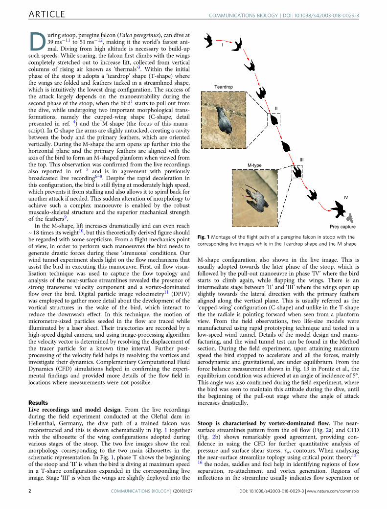
ResultsLive recordings and model design. From the live recordingsduring the field experiment conducted at the Oleftal dam inHellenthal, Germany, the dive path of a trained falcon wasreconstructed and this is shown schematically in Fig. 1 togetherwith the silhouette of the wing configurations adopted duringvarious stages of the stoop. The two live images show the realmorphology corresponding to the two main silhouettes in theschematic representation. In Fig. 1, phase ‘I’ shows the beginningof the stoop and ‘II’ is when the bird is diving at maximum speedin a T-shape configuration expanded in the corresponding liveimage. Stage ‘III’ is when the wings are slightly deployed into the
M-shape configuration, also shown in the live image. This isusually adopted towards the later phase of the stoop, which isfollowed by the pull-out manoeuvre in phase ‘IV’ where the birdstarts to climb again, while flapping the wings. There is anintermediate stage between ‘II’ and ‘III’ where the wings open upslightly towards the lateral direction with the primary feathersaligned along the vertical plane. This is usually referred as the‘cupped-wing’ configuration (C-shape) and unlike in the T-shapethe the radiale is pointing forward when seen from a planformview. From the field observations, two life-size models weremanufactured using rapid prototyping technique and tested in alow-speed wind tunnel. Details of the model design and manu-facturing, and the wind tunnel test can be found in the Methodsection. During the field experiment, upon attaining maximumspeed the bird stopped to accelerate and all the forces, mainlyaerodynamic and gravitational, are under equilibrium. From theforce balance measurement shown in Fig. 13 in Ponitz et al., theequilibrium condition was achieved at an angle of incidence of 5°.This angle was also confirmed during the field experiment, wherethe bird was seen to maintain this attitude during the dive, untilthe beginning of the pull-out stage where the angle of attackincreases drastically.
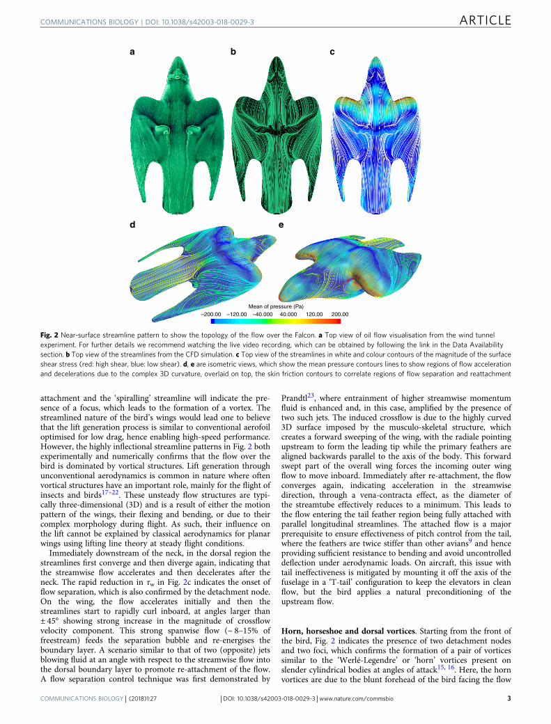
Stoop is characterised by vortex-dominated flow. The near-surface streamlines pattern from the oil flow (Fig. 2a) and CFD(Fig. 2b) shows remarkably good agreement, providing con-fidence in using the CFD for further quantitative analysis ofpressure and surface shear stress, τw, contours. When analysingthe near-surface streamline toplogy using critical point theory12–16 the nodes, saddles and foci help in identifying regions of flowseparation, re-attachment and vortex generation. Regions ofinflections in the streamline usually indicates flow seperation or
Teardrop
II
I
IIIM-type
IV
Prey capture
Fig. 1 Montage of the flight path of a peregrine falcon in stoop with thecorresponding live images while in the Teardrop-shape and the M-shape
ARTICLE COMMUNICATIONS BIOLOGY | DOI: 10.1038/s42003-018-0029-3
2 COMMUNICATIONS BIOLOGY | (2018) 1:27 | DOI: 10.1038/s42003-018-0029-3 | www.nature.com/commsbio
attachment and the ‘spiralling’ streamline will indicate the pre-sence of a focus, which leads to the formation of a vortex. Thestreamlined nature of the bird’s wings would lead one to believethat the lift generation process is similar to conventional aerofoiloptimised for low drag, hence enabling high-speed performance.However, the highly inflectional streamline patterns in Fig. 2 bothexperimentally and numerically confirms that the flow over thebird is dominated by vortical structures. Lift generation throughunconventional aerodynamics is common in nature where oftenvortical structures have an important role, mainly for the flight ofinsects and birds17–22. These unsteady flow structures are typi-cally three-dimensional (3D) and is a result of either the motionpattern of the wings, their flexing and bending, or due to theircomplex morphology during flight. As such, their influence onthe lift cannot be explained by classical aerodynamics for planarwings using lifting line theory at steady flight conditions.
Immediately downstream of the neck, in the dorsal region thestreamlines first converge and then diverge again, indicating thatthe streamwise flow accelerates and then decelerates after theneck. The rapid reduction in τw in Fig. 2c indicates the onset offlow separation, which is also confirmed by the detachment node.On the wing, the flow accelerates initially and then thestreamlines start to rapidly curl inboard, at angles larger than± 45° showing strong increase in the magnitude of crossflowvelocity component. This strong spanwise flow (~ 8–15% offreestream) feeds the separation bubble and re-energises theboundary layer. A scenario similar to that of two (opposite) jetsblowing fluid at an angle with respect to the streamwise flow intothe dorsal boundary layer to promote re-attachment of the flow.A flow separation control technique was first demonstrated by
Prandtl23, where entrainment of higher streamwise momentumfluid is enhanced and, in this case, amplified by the presence oftwo such jets. The induced crossflow is due to the highly curved3D surface imposed by the musculo-skeletal structure, whichcreates a forward sweeping of the wing, with the radiale pointingupstream to form the leading tip while the primary feathers arealigned backwards parallel to the axis of the body. This forwardswept part of the overall wing forces the incoming outer wingflow to move inboard. Immediately after re-attachment, the flowconverges again, indicating acceleration in the streamwisedirection, through a vena-contracta effect, as the diameter ofthe streamtube effectively reduces to a minimum. This leads tothe flow entering the tail feather region being fully attached withparallel longitudinal streamlines. The attached flow is a majorprerequisite to ensure effectiveness of pitch control from the tail,where the feathers are twice stiffer than other avians9 and henceproviding sufficient resistance to bending and avoid uncontrolleddeflection under aerodynamic loads. On aircraft, this issue withtail ineffectiveness is mitigated by mounting it off the axis of thefuselage in a ‘T-tail’ configuration to keep the elevators in cleanflow, but the bird applies a natural preconditioning of theupstream flow.
Horn, horseshoe and dorsal vortices. Starting from the front ofthe bird, Fig. 2 indicates the presence of two detachment nodesand two foci, which confirms the formation of a pair of vorticessimilar to the ‘Werlé-Legendre’ or ‘horn’ vortices present onslender cylindrical bodies at angles of attack15, 16. Here, the hornvortices are due to the blunt forehead of the bird facing the flow
–200.00 –120.00 –40.000 40.000Mean of pressure (Pa)
120.00 200.00
a b c
d e
Fig. 2 Near-surface streamline pattern to show the topology of the flow over the Falcon. a Top view of oil flow visualisation from the wind tunnelexperiment. For further details we recommend watching the live video recording, which can be obtained by following the link in the Data Availabilitysection. b Top view of the streamlines from the CFD simulation. c Top view of the streamlines in white and colour contours of the magnitude of the surfaceshear stress (red: high shear, blue: low shear). d, e are isometric views, which show the mean pressure contours lines to show regions of flow accelerationand decelerations due to the complex 3D curvature, overlaid on top, the skin friction contours to correlate regions of flow separation and reattachment
COMMUNICATIONS BIOLOGY | DOI: 10.1038/s42003-018-0029-3 ARTICLE
COMMUNICATIONS BIOLOGY | (2018) 1:27 | DOI: 10.1038/s42003-018-0029-3 | www.nature.com/commsbio 3
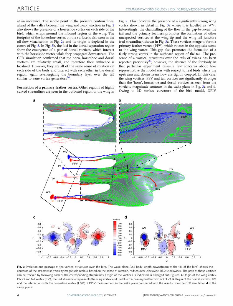
at an incidence. The saddle point in the pressure contour lines,ahead of the valley between the wing and neck junction in Fig. 2also shows the presence of a horseshoe vortex on each side of thebird, which wraps around the inboard region of the wing. Thefootprint of the horseshoe vortex on the surface is also seen in theoil flow visualisation in Fig. 2a and its origin is depicted in thecentre of Fig. 3. In Fig. 3b, the foci in the dorsal separation regionshow the emergence of a pair of dorsal vortices, which interactwith the horseshoe vortex while they propagate downstream. TheCFD simulation confirmed that the horn, horseshoe and dorsalvortices are relatively small, and therefore their influence islocalised. However, they are all of the same sense of rotation oneach side of the body and interact with each other in the dorsalregion, again re-energizing the boundary layer over the tailsimilar to vane vortex generators24.
Formation of a primary feather vortex. Other regions of highlycurved streamlines are seen in the outboard region of the wing in
Fig. 2. This indicates the presence of a significantly strong wingvortex shown in detail in Fig. 3a where it is labelled as ‘WV’.Interestingly, the channelling of the flow in the gap between thetail and the primary feathers promotes the formation of otherunexpected vortices at the wing-tip and the wing-tail juncture(red streamline), shown in Fig. 3a. These vortices merge to form aprimary feather vortex (PFV), which rotates in the opposite senseto the wing vortex. This gap also promotes the formation of afairly strong vortex in the outboard region of the tail. The pre-sence of a vortical structures over the tails of avians has beenreported previously25; however, the absence of the forebody inthat particular experiment raises a few concerns about howrepresentative the model was with respect to real birds where theupstream and downstream flow are tightly coupled. In this case,the wing vortices, PFV and tail vortices are significantly strongerthan the ‘horn’, horseshoe and dorsal vortices as seen from thevorticity magnitude contours in the wake plane in Fig. 3c and d.Owing to 3D surface curvature of the bird model, DPIV
Y
1
0.8
0.6
0.4
0.2
0
–0.2
–0.4
–0.6
–0.8
–1
Y
1
0.8
0.6
0.4
0.2
0
–0.2
–0.4
–0.6
–0.8
–1
700600500400300200100
–100–200–300–400–500–600–700
Vorticity
WV
PFV
0.6 0.8 10.40.20–0.2–0.4–0.6–0.8–1
Z
–1 0.6 0.8 10.40.20–0.2–0.4–0.6–0.8
Z
WV
TVTV
PFV
HSV
HV
DV
HSV
WV
PFV
TV
PFV
WV
TV
TV
WV
PFV
a
c d
b
Fig. 3 Evolution and passage of the vortical structures over the bird. The wake plane (0.2 body length downstream of the tail of the bird) shows thecontours of the streamwise vorticity magnitude (colour based on the sense of rotation, red: counter-clockwise, blue: clockwise). The path of these vorticescan be tracked by following each of the corresponding streamlines. Origin of the vortices is indicated in enlarged sub-figures. a Origin of the wing vortex(WV) and tail vortex (TV), the red streamline represents the wing vortex and the blue the primary feather vortex (PFV). b Origin of the dorsal vortex (DV)and the interaction with the horseshoe vortex (HSV). c DPIV measurement in the wake plane compared with the results from the CFD simulation d in thesame plane
ARTICLE COMMUNICATIONS BIOLOGY | DOI: 10.1038/s42003-018-0029-3
4 COMMUNICATIONS BIOLOGY | (2018) 1:27 | DOI: 10.1038/s42003-018-0029-3 | www.nature.com/commsbio
measurement directly over it proved to be extremely challenging,therefore the measurement plane was located in the wakedownstream. From Fig. 3c, d, the dominant vortices have beenresolved by both the DPIV measurements and the CFD simula-tion, respectively. The main difference between the experimentand the CFD lies in the middle region where contribution fromthe bird’s body wake is slightly more pronounced in Fig. 3d. Thismismatch is due to the sting mount in the experiments, whichwas not considered during the meshing for the CFD simulations.The junction between the bird’s body and the mount promotesthe formation of a horseshoe vortex, which wraps around themount, is common for surface-mounted cylinder16.
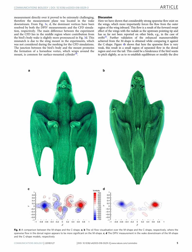
DiscussionHere we have shown that considerably strong spanwise flow exist onthe wings, which more importantly forces the flow from the outerregion of the wing inboard. This flow is a result of the forward swepteffect of the wings with the radiale as the upstream pointing tip andhas so far not been reported on other birds, e.g., in the case ofswifts22. Further validation of the enhanced manoeuvrabilityachieved from the M-shape is obtained while comparing it againstthe C-shape. Figure 4b shows that here the spanwise flow is veryweak, this result in a small region of separated flow in the dorsalregion and over the tail. This could be a hinderance if the bird wantsto pitch slightly, so as to re-establish equilibirum or modify the dive
700600500400300200100
–100–200–300–400–500–600–700
Vorticity
Y
10.80.60.40.2
0–0.2–0.4–0.6–0.8
–10.6 0.8 10.40.20–0.2–0.4–0.6–0.8–1
Z
Y
10.80.60.40.2
0–0.2–0.4–0.6–0.8
–10.6 0.8 10.40.20–0.2–0.4–0.6–0.8–1
Z
a b
c d
Fig. 4 A comparison between the M-shape and the C-shape. a, b The oil flow visualisation over the M-shape and the C-shape, respectively, where thespanwise flow in the dorsal region appears to be more significant on the M-shape. c, d The DPIV measurement in the wake downstream of the M-shapeand the C-shape models, respectively
COMMUNICATIONS BIOLOGY | DOI: 10.1038/s42003-018-0029-3 ARTICLE
COMMUNICATIONS BIOLOGY | (2018) 1:27 | DOI: 10.1038/s42003-018-0029-3 | www.nature.com/commsbio 5
path. Hence, a possible reason to why the bird is often seen to openup its primaries and tail momentarily also during the high-speeddive, thereby allowing it to trim its attitude along an efficient divepath and again confirming the importance of the M-shape formanoeuvring. Hence, the M-shape morphology can be considered asa wing with a forward swept leading edge, which directs the span-wise flow in-board to promote flow reattachment and a highlycranked outboard region generating a raked wing-tip, known toreduce induced drag26, 27. For planar wings, an increase in lift leadsto increase of the induced drag23 and in theory this effect wouldcause the bird to lose speed considerably. However, the counter-rotating PFVs reduce the downwash and hence ensures that theinduced drag is not greatly incremented. The absence of the counter-rotating PFVs in the C-shape in Fig. 4d shows further evidence ofthis mechanism of induced drag reduction.
The tail vortices generate additional loading on the tail featherswhich upon deflecting upward or downward generates pitchingmoment, whereas twisting generates rolling moment. Again, thefalcon’s tail is able to act as an empenage due to its superiormechanical property. Together with the additional lift from thepreconditioned, attached flow the pitching moment generated bytail is greatly increased, thus enhancing manoeuvrability. Fur-thermore, the suction effect induced by the strong wing vorticesalso contribute to the pitching moment, which can be tuned byextending the wing forward or backward, hence shifting the meanaerodynamic centre relative to the centre of gravity of the bird. Asmentioned above, the flow pre-conditioning plays an importantrole in ensuring that the tail sees an attached, almost parallel flow.In addition, by changing the local angle of attack of the primariesthe bird can roll and coupled with the twisting of the tail aboutthe longitudinal axis, yaw control could be established.
From a flight mechanics point of view, the manoeuvrability offalcons is greatly enhanced by the vortical structures, which controlthe flow by suppression of separation and also due to additional liftgenerated by suction from stronger vortices similar to that on delta-wings for flight control purposes. Keeping the M-shape during theflight requires a robust musculo-skeletal structure, specially toprevent lateral movement of the wrists and ensuring that the wingsare adducted close to the body. As the feathers of F. peregrinus areproven to be adapted to these high loads, we speculate that the samemust hold for the muscles, bones and the joint between thehumerus and forearm, as they have special importance for thestabilisation of the body form during a dive.
MethodsBird model. State-of-the-art high-speed optical tracking equipments employedduring the field experiment helped in resolving the flight path and wing config-urations at various intervals during the stoop5. The geometry of the bird wasobtained by a 3D scan of a stuffed peregrine falcon with its wings fixed accordinglywith the morphology observed from detailed analysis of the recordings during thefield experiment. These coordinates were imported into a CAD package for furtherfine tuning of the surface contours required to manufacture the life-size windtunnel models using rapid prototyping (3D printing) and for the CFD simulation.The surface of the 3D printed model was polished manually until it was deemedsmooth, similar to the surface texture of the feathers of a peregrine falcons. Owingto the high mechanical strength of the tail and primary feathers reported by ref. 9,we assumed that they are acting as aerodynamic surfaces with minimal deflectionand hence negligible effect to the overall meanflow due to plumage deformation.The life-size model of length 0.40 m and span 0.22 m was mounted horizontally ona sting fixed between the anal region of the bird and the floor of the test section(0.8 m high, 1.12 m wide and 1.8 m long) of the low-speed wind tunnel facility ofthe Handley Page Aeronautics Laboratory at City, University of London. It was setat an angle of incidence of 5° and the experiment was conducted at a freestreamvelocity of 22.5 m/s following ref. 5. This corresponds to a Reynolds number of ~5.8 × 10⁵, based on the length of the bird. The angle of attack is defined as the anglebetween the chord-line (here passing through the body of the bird) and thedirection of the freestream flow in the tunnel. In free flight, it is the angle betweenthe chord and the trajectory of the bird. This angle was derived from a combinationof field observations (shown schematically in Fig. 1) and wind tunnel testing inFreiberg, led by C. Brücker and reported by Ponitz et al. As we are mainly
interested in the flow physics at this relatively low incidence, the blockage effectwas assumed to be negligible. Following ref. 9, the effect of plumage was assumed tobe negligible on the mean flow.
Flow visualisation technique. Surface flow visualisation technique comprising amixture of white spirit (Naphtha), DayGlo powder and Oleic acid was employed tocapture the topology of the flow over the bird model. The mixture was applied onthe surface using a fine bristled paint brush, right before the tunnel was operated.The evolution of the oil film was recorded and the final fully developed pattern wasphotographed under ultraviolet lighting to increase definition. Owing to shearstress between the surface and the fluid near the surface a pattern of streamlinesalso known as skin friction lines is generated, indicating the trajectory of the near-surface flow. Topological representation of these near-surface streamlines helped inidentifying and interpreting regions of detached flow and the origins of vorticesusing critical point theory. Analysis of the video recordings of the transient oil-filmmotion was very helpful in identifying regions of separation and vortex formation,which was difficult to interpret only from the still image of the finally dried pattern.
Digital particle image velocimetry. A two-camera stereo version of a standard TSIDPIV system is used; illumination is done with a 4mm-thick double-pulsed Nd:YLFlaser (Litron LDY303, 527 nm wavelength, 20mJ/pulse) expanded to a sheet with acylindrical lens. Two high-speed cameras (Phantom Miro M310, Vision Research,1280 × 800 pixels) are mounted on either side of the test section and view the wake ofthe bird using Scheimpflug tilt-shift mechanism and a macro lens (Tokina 100mm f/2.8). The fields of view of the two cameras were adjusted such that a common field ofview encompassed the entire wake of the bird model, with the centreline of the birdlining up with the centre of the field of view. The cameras viewing angles wereapproximately 40 degrees each, with a Scheimpflug angle of ~ 6° each. They werecalibrated to account for the angular distortion against a two-plane target havingcalibration marker points that alternate between two depths. Olive oil droplets with anaverage size of 1 μm generated by a seeding generator (Laskin-nozzle type) were usedas seed particles, injected downstream of the bird model. DPIV image pairs wereacquired at a rate of 250Hz for 4 s resulting in a total of 1000 image pairs. The rawimage pairs from both the cameras were pre-processed using TSI Insight 4G softwareand a robust cross-correlation algorithm determined the velocity vector field. The spotsize for the first pass of the vector field computation was 64 × 64 pixels, with a 50%overlap grid spacing. The spot size was reduced to 32 × 32 pixels for the second pass,with a maximum displacement allowance of 16 pixels. A Gaussian mask wasimplemented with a FFT correlator to compute the correlation function. The com-puted vectors for each camera was then subjected to the perspective spatial calibrationto produce the three components of velocity. The vector fields were validated using alocal median filter (3 × 3) and any missing vectors were interpolated by using a localmean. Any spurious vectors were discarded and they were replaced by an interpolatedvector, as mentioned before. The amount of spurious vectors were less than 2% of theentire vector dataset. The vorticity field shown in Fig. 3c were obtained from theaverage of the full sample.
Computational fluid dynamics. All CFD simulations are conducted using thecommercial software, STAR CCM+ v.12, which is capable of implicit unsteadyReynolds-Averaged Navier-Stokes (RANS) and Large Eddy Simulation (LES) calcula-tions. The computational domain was decomposed in a global cartesian grid and near-surface prism layers were generated from a surface mesh. The initial mesh was based onan anisotropic hexahedral trimmed grid and has approximately 57 million cells wherethe minimum grid spacing was defined on the basis of y+ ≤ 1 to resolve the fine scalesof the boundary layer28. A second-order accurate scheme was selected for the spatialand temporal discretisation29. The initial RANS simulations were regarded as con-verged if the residuals of the momentums (X, Y, Z) and the energy dropped below ε=10−5. To ensure that neither timestep nor mesh induced errors influenced thenumerical results from the LES, all simulations were recalculated using a coarser andfiner mesh respectively for a smaller and bigger time step. Further detail is presentedas Supplementary Material where Supplementary Fig. 1 shows evidence of convergence.As the CAD model is an exact replica of the original falcon model design, the resultscould be directly compared with the experimental data.
Data availability. The live recording of the surface oil-flow visualisation, the DPIVand the CFD simulation results are available at ‘figshare’ under https://doi.org/10.6084/m9.figshare.5928229
Received: 13 September 2017 Accepted: 6 March 2018
References1. Alerstam, T. Radar observations of the stoop of the Peregrine Falcon Falco
peregrinus and the Goshawk Accipiter gentilis. Ibis 129, 267–273 (1987).2. Peter, D. & Kestenholz, M. Sturzflüge von wanderfalke Falco peregrinus und
wüstenfalke F. pelegrinoides. Der Ornithol. Beob. 95, 107–112 (1998).
ARTICLE COMMUNICATIONS BIOLOGY | DOI: 10.1038/s42003-018-0029-3
6 COMMUNICATIONS BIOLOGY | (2018) 1:27 | DOI: 10.1038/s42003-018-0029-3 | www.nature.com/commsbio
3. Pennycuick, C. J. Avian Biology: Mechanics of Flight 1–75. (Academic Press,Amsterdam, 1975).
4. Ponitz, B., Triep, M. & Brücker, C. Aerodynamics of the cupped wings duringperegrine falcon’s diving flight. Open J. Fluid Dyn. 4, 363–372 (2014).
5. Ponitz, B., Schmitz, A., Fischer, D., Bleckmann, H. & Brücker, C. Diving-flightaerodynamics of a peregrine falcon (Falco peregrinus). PLoS ONE 9, 1–13(2014).
6. National Geographic. High-velocity falcons (2007) https://video.nationalgeographic.com/video/falcon_peregrine_velocity.
7. National Geographic. World’s deadliest: superfast flyer makes a kill (2013)https://video.nationalgeographic.com/video/worlds-deadliest/deadliest-peregrine-falcon.
8. BBC. Peregrine falcon sky dive-inside the perfect predator (2010) https://www.youtube.com/watch?v=legzXQlFNjs.
9. Schmitz, A. et al. Morphological properties of the last primaries, the tailfeathers, and the alulae of Accipiter nisus, Columba livia, Falco peregrinus, andFalco tinnunculus. J. Morphol. 276, 33–46 (2015).
10. Tucker, V. A. Gliding flight: speed and acceleration of ideal falcons duringdiving and pull out. J. Exp. Biol. 201, 403–414 (1998).
11. Raffel, M., Willert, C. E., Wereley, S. & Kompenhans, J. Particle ImageVelocimetry: A Practical Guide (Springer, New York, 2007).
12. Poincaré, H. Les points singuliers des equations différentielles. C. R. Acad. Sci.Paris. 95, 416–418 (1882).
13. Legendre, R. Seperation de l’ecoulement lamnaire tridimensionel. Rech.Aeronaut. 54, 3–8 (1956).
14. Lighthill, J. M. Laminar Boundary Layers. (Oxford Univ. Press, London,1963).
15. Tobak, M. & Peake, D. J. Topology of three-dimensional separated flows.Annu. Rev. Fluid. Mech. 14, 61–85 (1982).
16. Délery, J. M. Robert Legendre and Henri Werlé: toward the elucidation ofthree-dimensional separation. Annu. Rev. Fluid Mech. 33, 129–154 (2001).
17. Weis-Fogh, T. Quick estimates of flight fitness in hovering animals, includingnovel mechanisms for lift production. J. Exp. Biol. 59, 169–230 (1973).
18. Lighthill, M. J. On the Weis-Fogh mechanism of lift generation. J. Fluid Mech.60, 1–17 (1973).
19. Ellington, C. P., van den Berg, C., Willmott, A. P. & Thomas, A. L. R. Leading-edge vortices in insect flight. Nature 384, 626–630 (1996).
20. Birch, M. J. & Dickinson, M. H. Spanwise flow and the attachment of theleading-vortex on insect wings. Nature 421, 729–733 (2001).
21. Srygley, R. B. & Thomas, A. L. R. Unconvetional lift-generating mechanismsin free-flying butterflies. Nature 420, 660–664 (2002).
22. Videler, J. J., Stamhuis, E. J. & Povel, G. D. E. Leading-edge vortex lifts swifts.Science 306, 1960–1962 (2004).
23. Prandtl, L. Führer Durch die Strömungslehre: Grundlagen und Phänomene.(Springer, Berlin, 1931)
24. Lin, J. C. Review of research on low-profile vortex generators to controlboundary-layer separation. Prog. Aerosp. Sci. 38, 389–420 (2002).
25. Maybury, W. J., Rayner, J. M. V. & Couldrick, L. B. Lift generation by theavian tail. Proc. R. Soc. B. 268, 1443–1448 (2001).
26. Zahm, A. F., Bear, R. M. & Hill, G. C. Lift and drag effects of wing-tip rake.NACA-TR-140 (1923).
27. Kroo, I. Drag due to lift: concepts for prediction and reduction. Annu. Rev.Fluid Mech. 33, 587–617 (2001).
28. Meyers, J, Bernhard, G. & Sagaut, P. Quality and Reliability of Large-EddySimulations. (Springer: The Netherlands, 2008).
29. Peyret, R. Handbook of Computational Fluid Mechanics. (Academic Press,London, 2011).
AcknowledgementsWe express gratitude to the team involved during the dam test in Hellenthal, Germany.We are also grateful to Mr Chris Marshall for his assistance in setting up the simulationcases on the Solon cluster. The position of Professor Christoph Brücker is co-funded byBAE SYSTEMS and the Royal Academy of Engineering (Research Chair numberRCSRF1617/4/11), which is gratefully acknowledged.
Author contributionsC.B. (Professor) is the Principal investigator of this project. He was also in charge of thefield experiment at Hellenthal in Germany, and the design and manufacturing of theexperimental model. During his time as a Research Assistant in the Handley PageLaboratory at City, E.T. was assigned with the task of setting up the model in the windtunnel and conduct the oil flow visualisation and PIV under the guidance and super-vision of C.J. (Research Fellow) and E.R.G. (Research Fellow). The CFD simulation wasconducted by C.L. (Research Assistant) who also assisted in putting together the figuresfollowing tedious postprocessing from large amount of data. The final manuscript is acontribution from all the authors, resulting from frequent meetings to discuss thetechnical content and the complex fluid mechanics, and also the structure and aestheticof this paper.
Additional informationSupplementary information accompanies this paper at https://doi.org/10.1038/s42003-018-0029-3.
Competing interests: The authors declare no competing interests.
Reprints and permission information is available online at http://npg.nature.com/reprintsandpermissions/
Publisher's note: Springer Nature remains neutral with regard to jurisdictional claims inpublished maps and institutional affiliations.
Open Access This article is licensed under a Creative CommonsAttribution 4.0 International License, which permits use, sharing,
adaptation, distribution and reproduction in any medium or format, as long as you giveappropriate credit to the original author(s) and the source, provide a link to the CreativeCommons license, and indicate if changes were made. The images or other third partymaterial in this article are included in the article’s Creative Commons license, unlessindicated otherwise in a credit line to the material. If material is not included in thearticle’s Creative Commons license and your intended use is not permitted by statutoryregulation or exceeds the permitted use, you will need to obtain permission directly fromthe copyright holder. To view a copy of this license, visit http://creativecommons.org/licenses/by/4.0/.
© The Author(s) 2018
COMMUNICATIONS BIOLOGY | DOI: 10.1038/s42003-018-0029-3 ARTICLE
COMMUNICATIONS BIOLOGY | (2018) 1:27 | DOI: 10.1038/s42003-018-0029-3 | www.nature.com/commsbio 7