Embed Size (px)
Citation preview
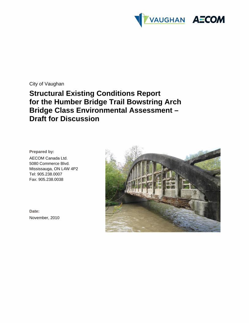
Prepared by: AECOM Canada Ltd. 5080 Commerce Blvd. Mississauga, ON L4W 4P2 Tel: 905.238.0007 Fax: 905.238.0038 Date: November, 2010
City of Vaughan
Structural Existing Conditions Report for the Humber Bridge Trail Bowstring Arch Bridge Class Environmental Assessment – Draft for Discussion
AECOM City of Vaughan Structural Existing Conditions Report for the Humber Bridge Trail Bowstring Arch Bridge Class Environmental Assessment – Draft for Discussion
Humber Bridge Trail Bridge Structural Existing Conditions.Docx 1
Table of Contents
page
1. Introduction ..................................................................................................................................... 2
2. Existing Structure ........................................................................................................................... 2
3. Visual Inspection ............................................................................................................................ 2 3.1 Deck Top ............................................................................................................................................. 2 3.2 Curb on Deck ....................................................................................................................................... 2 3.3 Deck Cross Beams .............................................................................................................................. 2 3.4 Truss Arched Top Chord ..................................................................................................................... 3 3.5 Truss Bottom Chord ............................................................................................................................. 3 3.6 Vertical Spandrel Members ................................................................................................................. 3 3.7 Horizontal Spandrel Members ............................................................................................................. 3 3.8 Handrails .............................................................................................................................................. 3 3.9 Abutments ............................................................................................................................................ 3 3.10 Wingwalls ............................................................................................................................................. 3
4. Evaluation ........................................................................................................................................ 4 4.1 Structural Analysis Model .................................................................................................................... 4 4.2 Loadings .............................................................................................................................................. 5 4.3 Other Assumptions .............................................................................................................................. 5 4.4 Results ................................................................................................................................................. 6
5. Options Comparison ...................................................................................................................... 8 5.1 Option A: Rehabilitation of the Existing Concrete Bowstring Bridge ................................................... 8 5.2 Option B: Replacement with New Concrete Bowstring Bridge ............................................................ 8 5.3 Option C: Replacement by Precast Pre-stressed Concrete Box Bridge ............................................. 8 5.4 Option D: Replacement by Steel Girder Bridge ................................................................................... 8 5.5 Option E: Replacement by Modular Bridge ......................................................................................... 8 5.6 Option F: Decommission Bridge .......................................................................................................... 9
Appendix A ................................................................................................................................................ 10 Appendix A Photos
AECOM City of Vaughan Structural Existing Conditions Report for the Humber Bridge Trail Bowstring Arch Bridge Class Environmental Assessment – Draft for Discussion
Humber Bridge Trail Bridge Structural Existing Conditions.Docx 2
1. Introduction The Humber Bridge Trail Bridge is located on the Humber Bridge Trail, 0.4km east of Highway 27. The trail spans the Humber River in the Kleinburg area of Vaughan. This report documents the findings of a visual inspection and evaluation of the bridge, and then makes recommendations as to the rehabilitation or replacement of the bridge.
2. Existing Structure The Humber Bridge Trail Bridge, built in 1914, is a single-span concrete bridge, with a bowstring arch truss on either side of the deck. The entire bridge is constructed from cast-in-situ concrete and the bridge carries one lane of traffic. The deck is approximately 20m long and 4.9m wide with a 30 degree skew. The curb-to-curb deck width is approximately 3.85m. Each concrete bowstring truss consists of a curved top chord, and a straight bottom chord at the deck level. The spandrel in between the two chords is made up of vertical and horizontal members. The bowstring trusses span onto abutments at each bank. Horizontal cross beams span between the bottom chord members and the deck is supported on these cross beams.
3. Visual Inspection A visual inspection of the Humber Bridge Trail Bridge was carried out on September 29th 2010 by Paul Kim, P.Eng and Matthew Galloway, EIT.
Photographs taken as part of the inspection are included in Appendix A. Detailed condition records for the individual bridge elements are provided in OSIM Inspection Forms in Appendix B. The following is a summary of the findings from the inspection.
3.1 Deck Top
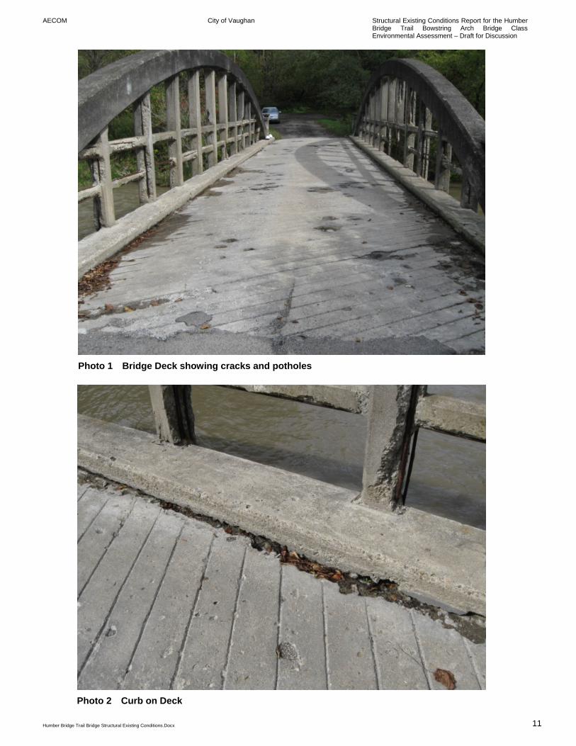
The deck top was in fair to poor condition. Half of the deck area was in poor condition with large cracks and potholes (See Photo 1 of Appendix A).
3.2 Curb on Deck
The curbs were in good to fair condition. There was some scaling, especially in the areas where the curb meets the deck (See Photo 2).
3.3 Deck Cross Beams
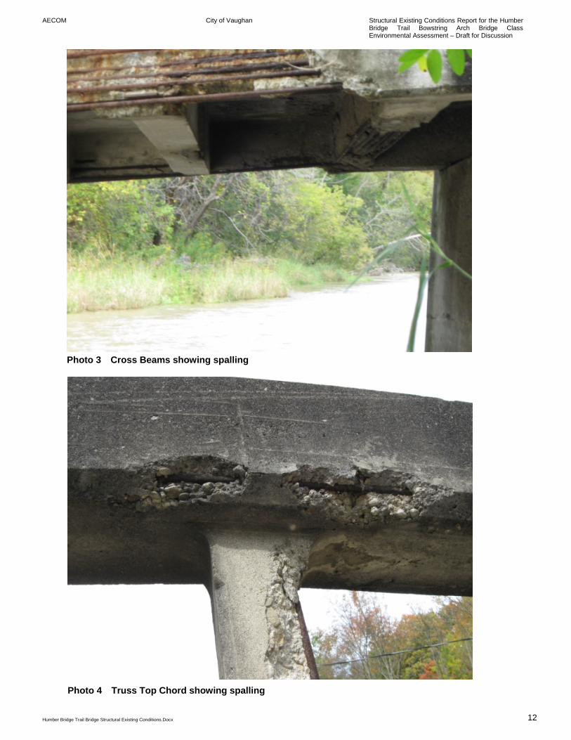
Access to the cross beams was limited due to high water condition. The cross beams seemed to be in fair to poor condition. There was scaling to the side faces. Most beams also showed delamination to the bottom face with corrosion of the bottom reinforcement bars. One beam was observed with severe delamination and exposed bottom reinforcement bars (See Photo 3).
AECOM City of Vaughan Structural Existing Conditions Report for the Humber Bridge Trail Bowstring Arch Bridge Class Environmental Assessment – Draft for Discussion
Humber Bridge Trail Bridge Structural Existing Conditions.Docx 3
3.4 Truss Arched Top Chord
The arches which make up the top chord of the truss were in fair to poor condition. There was some minor scaling to all surfaces. There were also some areas of spalling, especially where the vertical spandrel members connect in to the arch (See Photo 4).
3.5 Truss Bottom Chord
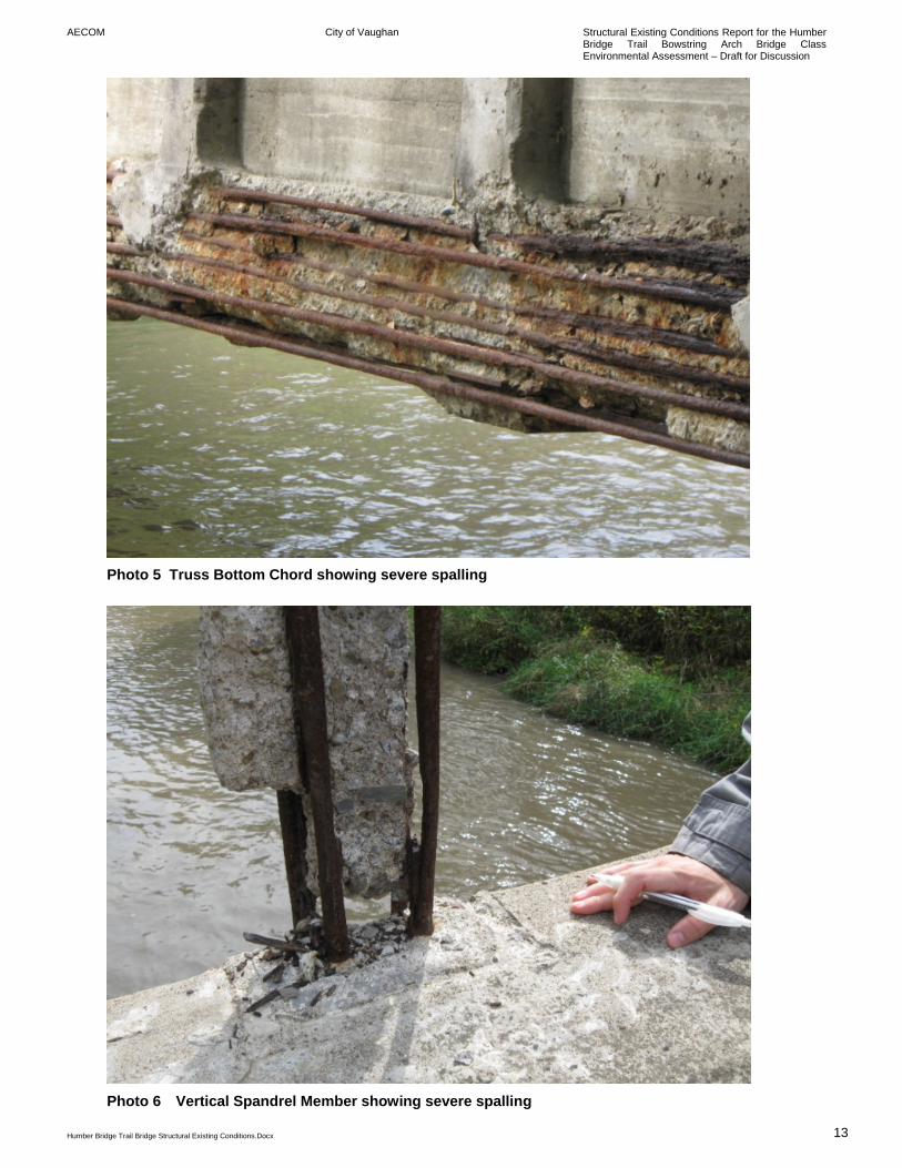
The bottom chords of the trusses were both in very poor condition, with severe delamination and scaling, and the majority of reinforcement bars were exposed and heavily corroded (See Photo 5).
3.6 Vertical Spandrel Members
The vertical spandrel members were in poor condition. All showed delamination . For many, the concrete had spalled away in entire sections, leaving reinforcement bars exposed and heavily corroded (See Photo 6).
3.7 Horizontal Spandrel Members
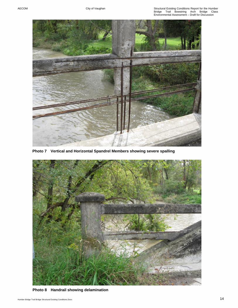
The horizontal spandrel members were in poor condition. All showed delamination. For many, the concrete had spalled away in entire sections, leaving reinforcement bars exposed and heavily corroded (See Photo 7).
3.8 Handrails
Handrails at either end of the bridge were in poor condition, suffering from delamination and spalling (See Photo 8).
3.9 Abutments
Both abutments were in good to fair condition. There was some scaling but no serious cracks or delamination. The inspectors were unable to confirm erosion in front of the abutments at this time, due to high water levels.
3.10 Wingwalls
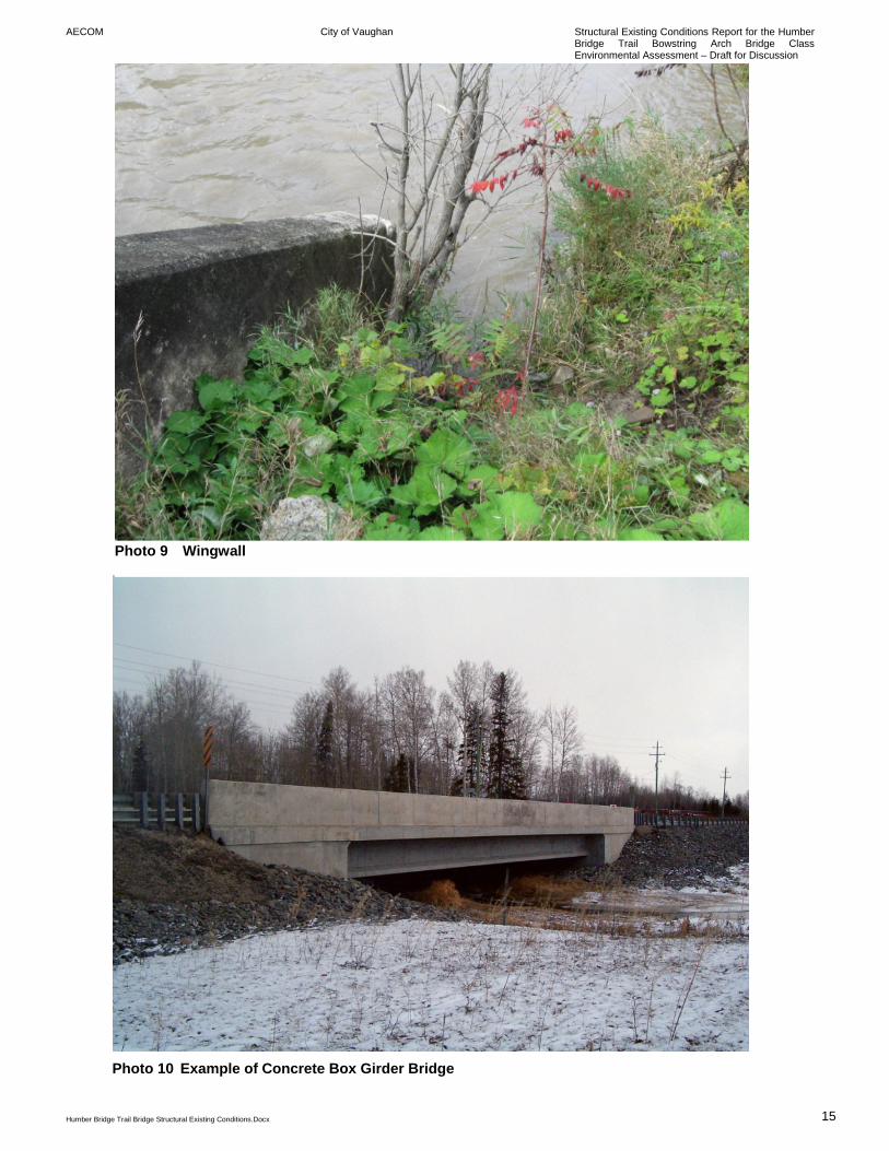
The wingwalls were in good to fair condition. There was some scaling but no delamination. There was no evidence of erosion to the concrete itself, although high water levels prevented confirmation of this. However serious erosion to the soil was observed behind the north-west wingwall (See Photo 9).
AECOM City of Vaughan Structural Existing Conditions Report for the Humber Bridge Trail Bowstring Arch Bridge Class Environmental Assessment – Draft for Discussion
Humber Bridge Trail Bridge Structural Existing Conditions.Docx 4
4. Evaluation 4.1 Structural Analysis Model
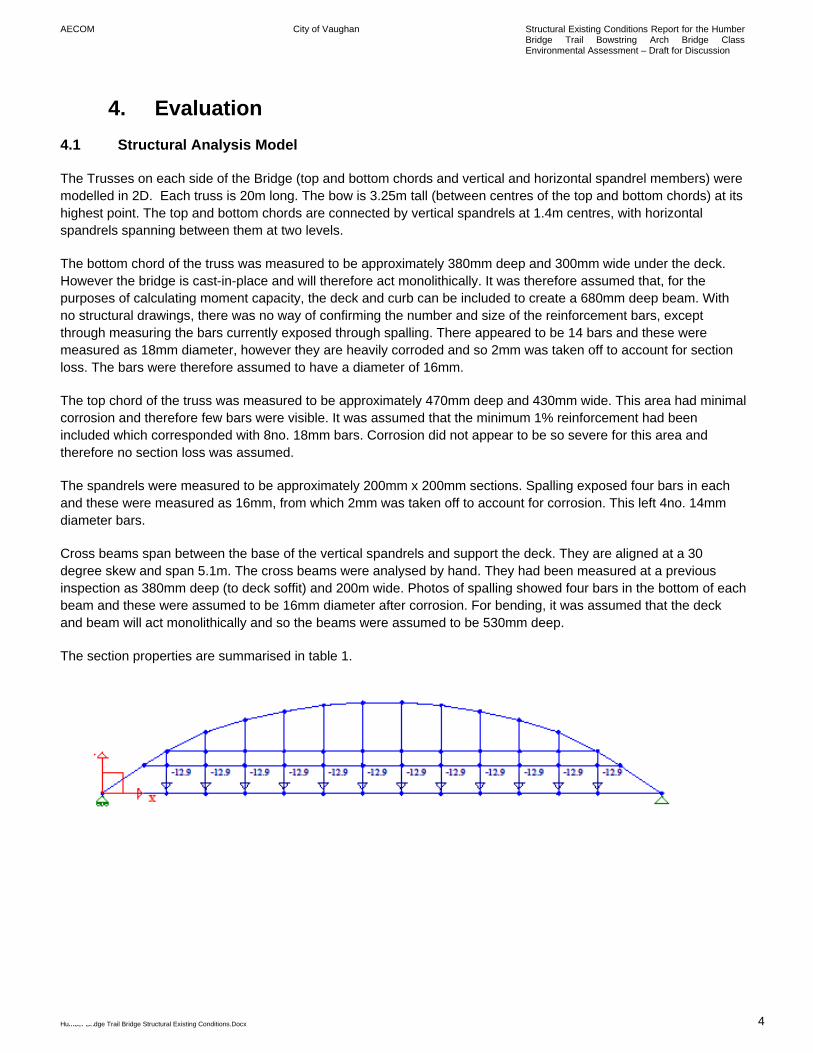
The Trusses on each side of the Bridge (top and bottom chords and vertical and horizontal spandrel members) were modelled in 2D. Each truss is 20m long. The bow is 3.25m tall (between centres of the top and bottom chords) at its highest point. The top and bottom chords are connected by vertical spandrels at 1.4m centres, with horizontal spandrels spanning between them at two levels.
The bottom chord of the truss was measured to be approximately 380mm deep and 300mm wide under the deck. However the bridge is cast-in-place and will therefore act monolithically. It was therefore assumed that, for the purposes of calculating moment capacity, the deck and curb can be included to create a 680mm deep beam. With no structural drawings, there was no way of confirming the number and size of the reinforcement bars, except through measuring the bars currently exposed through spalling. There appeared to be 14 bars and these were measured as 18mm diameter, however they are heavily corroded and so 2mm was taken off to account for section loss. The bars were therefore assumed to have a diameter of 16mm.
The top chord of the truss was measured to be approximately 470mm deep and 430mm wide. This area had minimal corrosion and therefore few bars were visible. It was assumed that the minimum 1% reinforcement had been included which corresponded with 8no. 18mm bars. Corrosion did not appear to be so severe for this area and therefore no section loss was assumed.
The spandrels were measured to be approximately 200mm x 200mm sections. Spalling exposed four bars in each and these were measured as 16mm, from which 2mm was taken off to account for corrosion. This left 4no. 14mm diameter bars.
Cross beams span between the base of the vertical spandrels and support the deck. They are aligned at a 30 degree skew and span 5.1m. The cross beams were analysed by hand. They had been measured at a previous inspection as 380mm deep (to deck soffit) and 200m wide. Photos of spalling showed four bars in the bottom of each beam and these were assumed to be 16mm diameter after corrosion. For bending, it was assumed that the deck and beam will act monolithically and so the beams were assumed to be 530mm deep.
The section properties are summarised in table 1.
AECOM City of Vaughan Structural Existing Conditions Report for the Humber Bridge Trail Bowstring Arch Bridge Class Environmental Assessment – Draft for Discussion
Humber Bridge Trail Bridge Structural Existing Conditions.Docx 5
4.2 Loadings
Dead loading includes the self weight of the truss, the cross beams and the deck. The deck is assumed to be 150mm thick. Pedestrian loading is calculated to CHBDC Section 3. For a 20m span this equates to 4.3kN/m2 over the area of the deck. The ‘SUV ONT’ and ‘CL-625 ONT’ loadings correspond to the ‘single unit vehicle’ and ‘vehicle train’ loadings for Ontario as included in the Annex to section 14 of CHBDC. Smaller vehicles, weighing 10 tonnes and 20 tonnes were also analysed. All vehicle loads are assumed to act in the centre of the 1-lane bridge, so that each truss takes half of the vehicle load.
4.3 Other Assumptions
• It is assumed that, in all members, the existing reinforcement remains, but the concrete has been repaired where necessary to provide a full bond between the concrete and reinforcement.
• The concrete (both new and existing) is assumed to have a strength of 20MPa and the existing steel
reinforcement is assumed to have a strength of 230MPa.
• In the model, the spandrels were assumed to be released from the top and bottom chords and so do not support bending moments.
• Shear is not assumed to be a governing factor and is ignored in the calculations.
• Torsion is not assumed to be a governing factor and is ignored in the calculations.
• It is assumed that supports are free to move laterally by a small amount, as this leads to conservative loads
in the trusses.
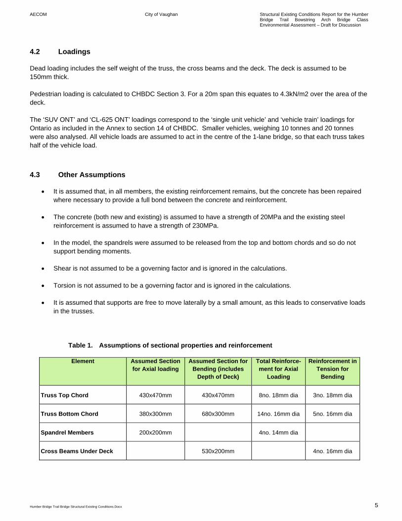
Table 1. Assumptions of sectional properties and reinforcement
Element Assumed Section for Axial loading
Assumed Section for Bending (includes
Depth of Deck)
Total Reinforce-ment for Axial
Loading
Reinforcement in Tension for
Bending
Truss Top Chord 430x470mm 430x470mm 8no. 18mm dia 3no. 18mm dia
Truss Bottom Chord 380x300mm 680x300mm 14no. 16mm dia 5no. 16mm dia
Spandrel Members 200x200mm 4no. 14mm dia
Cross Beams Under Deck 530x200mm 4no. 16mm dia
AECOM City of Vaughan Structural Existing Conditions Report for the Humber Bridge Trail Bowstring Arch Bridge Class Environmental Assessment – Draft for Discussion
Humber Bridge Trail Bridge Structural Existing Conditions.Docx 6
4.4 Results
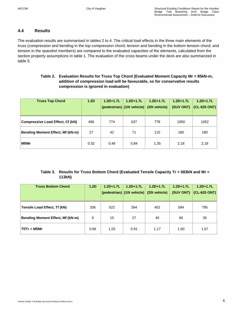
The evaluation results are summarised in tables 2 to 4. The critical load effects in the three main elements of the truss (compression and bending in the top compression chord; tension and bending in the bottom tension chord; and tension in the spandrel members) are compared to the evaluated capacities of the elements, calculated from the section property assumptions in table 1. The evaluation of the cross beams under the deck are also summarized in table 5.
Table 2. Evaluation Results for Truss Top Chord (Evaluated Moment Capacity Mr = 85kN-m; addition of compression load will be favourable, so for conservative results compression is ignored in evaluation)
Truss Top Chord 1.2D 1.2D+1.7L
(pedestrian)1.2D+1.7L
(10t vehicle)1.2D+1.7L
(20t vehicle)1.2D+1.7L (SUV ONT)
1.2D+1.7L (CL-625 ONT)
Compressive Load Effect, Cf (kN) 496 774 637 778 1050 1052
Bending Moment Effect, Mf (kN-m) 27 42 71 115 180 180
Mf/Mr 0.32 0.49 0.84 1.35 2.18 2.18
Table 3. Results for Truss Bottom Chord (Evaluated Tensile Capacity Tr = 583kN and Mr = 113kN)
Truss Bottom Chord 1.2D 1.2D+1.7L (pedestrian)
1.2D+1.7L (10t vehicle)
1.2D+1.7L (20t vehicle)
1.2D+1.7L (SUV ONT)
1.2D+1.7L (CL-625 ONT)
Tensile Load Effect, Tf (kN) 336 522 394 452 594 795
Bending Moment Effect, Mf (kN-m) 9 15 27 45 66 35
Tf/Tr + Mf/Mr 0.66 1.03 0.91 1.17 1.60 1.67
AECOM City of Vaughan Structural Existing Conditions Report for the Humber Bridge Trail Bowstring Arch Bridge Class Environmental Assessment – Draft for Discussion
Humber Bridge Trail Bridge Structural Existing Conditions.Docx 7
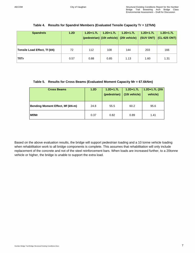
Table 4. Results for Spandrel Members (Evaluated Tensile Capacity Tr = 127kN)
Spandrels 1.2D 1.2D+1.7L (pedestrian)
1.2D+1.7L (10t vehicle)
1.2D+1.7L (20t vehicle)
1.2D+1.7L (SUV ONT)
1.2D+1.7L (CL-625 ONT)
Tensile Load Effect, Tf (kN) 72 112 108 144 203 166
Tf/Tr 0.57 0.88 0.85 1.13 1.60 1.31
Table 5. Results for Cross Beams (Evaluated Moment Capacity Mr = 67.6kNm)
Cross Beams 1.2D 1.2D+1.7L (pedestrian)
1.2D+1.7L (10t vehicle)
1.2D+1.7L (20t vehicle)
Bending Moment Effect, Mf (kN-m) 24.8 55.5 60.2 95.6
Mf/Mr 0.37 0.82 0.89 1.41
Based on the above evaluation results, the bridge will support pedestrian loading and a 10 tonne vehicle loading when rehabilitation work to all bridge components is complete. This assumes that rehabilitation will only include replacement of the concrete and not of the steel reinforcement bars. When loads are increased further, to a 20tonne vehicle or higher, the bridge is unable to support the extra load.
AECOM City of Vaughan Structural Existing Conditions Report for the Humber Bridge Trail Bowstring Arch Bridge Class Environmental Assessment – Draft for Discussion
Humber Bridge Trail Bridge Structural Existing Conditions.Docx 8
5. Options Comparison
5.1 Option A: Rehabilitation of the Existing Concrete Bowstring Bridge
The existing bridge can be rehabilitated with the 10 tonne posting. The extent of the rehabilitation work will involve replacing almost all of the superstructure concrete such as the bottom chord of the truss, the vertical and horizontal spandrels, the handrail and the cross beams, deck and curbs. The cost estimate of this work is $484,000.
5.2 Option B: Replacement with New Concrete Bowstring Bridge
The existing bridge could be removed and replaced with a new bridge with the same concrete bowstring design as the existing bridge. The new bridge will use a higher strength of concrete and higher strength reinforcement bars, and will therefore be more durable than the rehabilitated bridge. The new bridge could span between the existing abutments, or alternatively, new abutments could be constructed. The cost estimate for this work is $471,000.
5.3 Option C: Replacement by Precast Pre-stressed Concrete Box Bridge
The bridge could be replaced by a precast pre-stressed concrete box girder bridge. For the 20m span, this could consist of four 700 mm deep box girders butted up against each other. Each of these girders is a hollow 1220mm wide x 700mm deep concrete box. On top of the box girders would be installed a 150mm thick concrete distribution slab and 90mm asphalt and waterproofing. Barriers would then be built on both sides of the bridge. The box girders could span between the existing abutments, or alternatively, new abutments could be constructed. Photo 10 in Appendix A shows an existing bridge using this type of construction. The cost estimate for this work is $460,000.
5.4 Option D: Replacement by Steel Girder Bridge
The bridge could be replaced by a new steel girder bridge. The new 225mm concrete deck could be supported on three W840x176 girders. 90mm asphalt and waterproofing will be installed on top of the concrete deck, and barriers constructed on both sides of the bridge. The steel girders could span between the existing abutments, or alternatively, new abutments could be constructed. The cost estimate for this work is $390,000.
5.5 Option E: Replacement by Modular Bridge
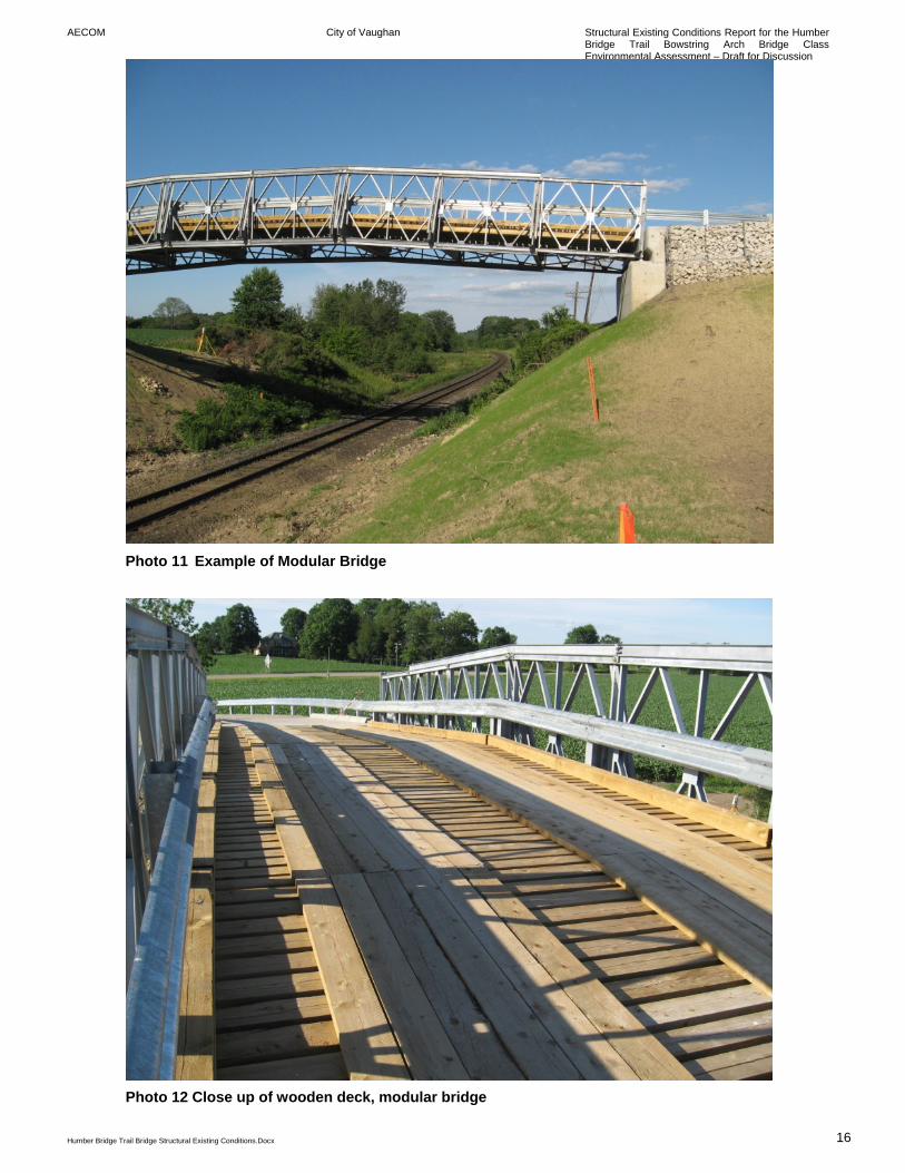
The bridge could be replaced by a modular bridge system. The modular bridge could span between the existing abutments, or alternatively, new abutments could be constructed. Photos 11 and 12 in Appendix A both show an existing bridge using this type of construction. The cost estimate for this work is $300,000.
AECOM City of Vaughan Structural Existing Conditions Report for the Humber Bridge Trail Bowstring Arch Bridge Class Environmental Assessment – Draft for Discussion
Humber Bridge Trail Bridge Structural Existing Conditions.Docx 9
5.6 Option F: Decommission Bridge
Rather than rehabilitation or replacement, the bridge could be decommissioned. The bridge would be removed and the site environmentally restored. The cost for this work is estimated to be approximately $170,000.

AECOM City of Vaughan Structural Existing Conditions Report for the Humber Bridge Trail Bowstring Arch Bridge Class Environmental Assessment – Draft for Discussion
Humber Bridge Trail Bridge Structural Existing Conditions.Docx 10
Appendix A Photos
AECOM City of Vaughan Structural Existing Conditions Report for the Humber Bridge Trail Bowstring Arch Bridge Class Environmental Assessment – Draft for Discussion
Humber Bridge Trail Bridge Structural Existing Conditions.Docx 11
Photo 1 Bridge Deck showing cracks and potholes
Photo 2 Curb on Deck
AECOM City of Vaughan Structural Existing Conditions Report for the Humber Bridge Trail Bowstring Arch Bridge Class Environmental Assessment – Draft for Discussion
Humber Bridge Trail Bridge Structural Existing Conditions.Docx 12
Photo 3 Cross Beams showing spalling
Photo 4 Truss Top Chord showing spalling
AECOM City of Vaughan Structural Existing Conditions Report for the Humber Bridge Trail Bowstring Arch Bridge Class Environmental Assessment – Draft for Discussion
Humber Bridge Trail Bridge Structural Existing Conditions.Docx 13
Photo 5 Truss Bottom Chord showing severe spalling
Photo 6 Vertical Spandrel Member showing severe spalling
AECOM City of Vaughan Structural Existing Conditions Report for the Humber Bridge Trail Bowstring Arch Bridge Class Environmental Assessment – Draft for Discussion
Humber Bridge Trail Bridge Structural Existing Conditions.Docx 14
Photo 7 Vertical and Horizontal Spandrel Members showing severe spalling
Photo 8 Handrail showing delamination
AECOM City of Vaughan Structural Existing Conditions Report for the Humber Bridge Trail Bowstring Arch Bridge Class Environmental Assessment – Draft for Discussion
Humber Bridge Trail Bridge Structural Existing Conditions.Docx 15
Photo 9 Wingwall
Photo 10 Example of Concrete Box Girder Bridge
AECOM City of Vaughan Structural Existing Conditions Report for the Humber Bridge Trail Bowstring Arch Bridge Class Environmental Assessment – Draft for Discussion
Humber Bridge Trail Bridge Structural Existing Conditions.Docx 16
Photo 11 Example of Modular Bridge
Photo 12 Close up of wooden deck, modular bridge