Embed Size (px)
Citation preview

CITY OF VANCOUVER
CONTRACT DOCUMENTS
for the
VANCOUVER LANDFILL
PHASE 1 CLOSURE
LANDFILL GAS CONTROL SYSTEM
****
****
CH2M HILL
January 2009
(Amendments Incorporated)
© CH2M HILL 2008. All rights reserved. This document and the ideas and designs incorporated herein, as an instrument of professional service, is the property of
CH2M HILL and is not to be used in whole or part, for any other project without the written authorization of CH2M HILL.
Any reuse, modification, or alteration of this document and the ideas and designs incorporated herein is at the sole risk of
the party(ies) reusing, modifying, or altering it. All references to CH2M HILL and its employees and all professional seals
shall be removed prior to any reuse, modification, or alteration of this document.

VANCOUVER LANDFILL CITY OF VANCOUVER
PHASE 1 CLOSURE
LANDFILL GAS CONTROL SYSTEM
356215
00060B i CONTENTS
LIST OF CONTENTS
Pages
SPECIFICATIONS
DIVISION 1—GENERAL REQUIREMENTS
01010B Summary of Work – LFG Control .................................................... 1 - 3
DIVISION 2—SITE CONSTRUCTION
02205 Earthwork LFG System..................................................................... 1 - 13
02458 Static Pin Pile Testing ……………………………………………...1 - 4
02459 Pin Piles …………………………………………………………….1 - 7
DIVISION 3—CONCRETE
03306 Concrete Work .................................................................................. 1 - 6
DIVISION 5—METALS
05120 Structural Steel.................................................................................. 1 - 12
DIVISION 9—FINISHINGS
09900 Painting ............................................................................................. 1 - 8
DIVISION 10—MANUFACTURED SPECIALTIES
10100 Landfill Gas Collection Systems....................................................... 1 - 11
DIVISION 11—EQUIPMENT
11400-1 Landfill Gas Flares............................................................................ 1 - 12
11400-2 Landfill Gas Blowers ....................................................................... 1 - 6
11460 Landfill Gas Condensate Knockout Tank......................................... 1 - 4
DIVISION 13—SPECIAL CONSTRUCTION
13122 Prefabricated Buildings..................................................................... 1 - 11
13390 Package Control Systems.................................................................. 1 - 11
VANCOUVER LANDFILL CITY OF VANCOUVER
PHASE 1 CLOSURE
LANDFILL GAS CONTROL SYSTEM
Pages
356215
00060 ii CONTENTS
DIVISION 15—MECHANICAL
15010 Basic Mechanical Requirements....................................................... 1 - 13
15021 High Density Polyethylene Pipe ....................................................... 1 - 7
15060 Piping Support Systems .................................................................... 1 - 9
15100 Valves ............................................................................................... 1 - 3
15200-8 Stainless Steel Pipe and Fittings – General Service.......................... 1 - 2
15482 Propane/Nitrogen Gas Piping System............................................... 1 - 3
DIVISION 16—ELECTRICAL
16010 Basic Electrical Requirements .......................................................... 1 - 11
16050 Basic Materials and Methods............................................................ 1 - 4
16111 Cable Tray Systems........................................................................... 1 - 2
16112 Conduit Systems ............................................................................... 1 - 4
16120 Wiring Systems ................................................................................. 1 - 8
16130 Electrical Boxes ................................................................................ 1 - 2
16450 Grounding Systems ........................................................................... 1 - 3
16900 Instrumentation and Control ............................................................. 1 - 14
16910 General Requirements for Programmable Equipment ...................... 1 - 3
16991 Control Panels................................................................................... 1 - 4
END OF SECTION
Attached Vancouver LandFill Expansion Project
Geotechnical Recommendations dated September 18, 2008

DIVISION 1
GENERAL REQUIREMENTS

VANCOUVER LANDFILL CITY OF VANCOUVER
PHASE 1 CLOSURE
LANDFILL GAS CONTROL SYSTEM
356215
01010B 1 SUMMARY OF WORK
SECTION 01010B
SUMMARY OF WORK – LANDFILL GAS CONTROL
PART 1 GENERAL
1.01 SCOPE OF WORK
A. This contract consists of the construction expansion of the Landfill Gas (LFG)
recovery and control system, including construction of new vertical LFG
recovery gas wells, horizontal LFG collectors under the landfill liner,
condensate traps and piping, gas collection system headers for the City of
Vancouver Landfill Site Phase 1, and upgrades to the blower/flare system
located at the Vancouver Landfill. The scope of work for the LFG control
system expansion includes, but is not limited to:
1. Drilling and installation of 20 new vertical LFG recovery wells in Phase
1 closed area of the landfill site as indicated on the drawings.
2. Supply and installation of wellhead assemblies for all new wells as
indicated in the drawings and specifications.
3. Supply and installation of underground gas recovery pipeline network
and valves tying in the new vertical LFG wells.
4. Supply and installation of a LFG collection system, including valves
and vents in the gas/leachate layer contained within the final cover
system as indicated in the drawings.
5. Supply and installation of the 400 mm diameter HDPE main LFG
header extension including LFG condensate traps and all valving and
tie-ins.
6. Demolition of existing two blowers and associated piping, electrical and
controls as shown on drawings.
7. Disconnect and removal of all existing 12.5 kV and 600 V distribution
wiring and associated equipment, including 600 V feeders.
Transformers to be removed and returned to Owner.
8. Disconnect and removal of existing lighting fixtures and wiring as per
drawings. Note: For lighting fixtures identified to be re-used are to be
fed from new lighting control panel.
9. Disconnect and removal of existing control conduits to two existing
flares as per drawings and specification. All flare wiring is to be
disconnected at the existing control panel, pulled back and reconnected
to new field junction boxes and rerouted to the new PLC panel.
10. Disconnect and relocate existing instrumentation and associated wiring
as per drawings.
11. Supply and installation of all power and control wiring for two new
flares as per drawings.
12. Disconnect and reconnection of the existing communications cables to
the Maxim Power SCADA system.

VANCOUVER LANDFILL CITY OF VANCOUVER
PHASE 1 CLOSURE
LANDFILL GAS CONTROL SYSTEM
356215
01010B 2 SUMMARY OF WORK
13. Supply and installation of lighting and grounding equipment and wiring
as per drawings.
14. Demolition of existing LFG header tie-in to current blower system as
shown on the drawing.
15. Demolition of existing fence as shown on drawing.
16. Installation of new fence as shown on drawing.
17. Installation of new foundations as indicated in the drawings and
specifications.
18. Relocate the existing inlet (vacuum) condensate knockout tank
supplying Maxim Power’s system to the new location and re-pipe as
shown on drawing.
19. Installation of new suction header, inlet manifold, discharge manifold,
valves, and flare header.
20. Supply and installation of the condensate handling system for the new
inlet knock-out tanks.
21. Supply and installation of a new 14,250 standard cubic metre per hour
(Nm3/h) automated LFG blower facility (3 x 4,750 Nm3/h centrifugal
blowers) including all equipment, controls, vessels, valves, piping, and
materials.
22. Supply and installation of two (2) new 2,375 Nm3/h LFG enclosed
packaged flare systems.
23. Installation of new flow element on the 600-LFG-SST.
24. Integration with existing blower/flare system and controls as indicated
in the detailed drawings and specifications.
25. Installation of valves and fittings associated with the installation of
equipment as shown on drawings.
26. Supply and installation of bypass line and control for LFG supply to
Maxim Power system.
27. Supply and installation of new Electrical and Control wiring and
devices as per drawings.
28. Supply and installation on new Electrical building complete with PLC
Panel, MCC, distribution equipment and building wiring as per
drawings.
29. Supply and installation of new 500 kVA 25 kV/ 600 V pad mount
MiniSub provided by PowerSystems (including transformer and main
600 V breaker).
a. MiniSub Power Station to include:
1) Primary switchgear: indoor/outdoor, 25 kV 600 A 3 phase, 3
wire, interrupting capacity 700 MVA BIL 125 to be SF6 filled
load break non fused type switch
a) Service ratings: the switch assembly shall be designed and
tested and rated per ANSI C37.71-1984, C37.72-1987;
b) Design voltage 25 kV
c) Impulse withstand voltage 125kV
d) AC withstand voltage 60kV
e) DC withstand voltage 78kV

VANCOUVER LANDFILL CITY OF VANCOUVER
PHASE 1 CLOSURE
LANDFILL GAS CONTROL SYSTEM
356215
01010B 3 SUMMARY OF WORK
f) Load break continuous amps 600
g) Momentary fault closing 40kA asymmetrical
h) Two second rating 25kA symmetrical
i) Open gap impulse withstand 200 kV BIL
j) Current limiting fuse rating 50kA
k) Temperature rating -40 to +50 °C
l) Switch shall be equipped with an external operating handle
for manual operation, and shall include:
• Quick make quick brake spring operation
• The shaft shall have triple o-ring operating design, which
can withstand pressure of up to 50 psi without leaking.
• Positive position indicators.
• Viewing window to confirm contact position for all phases
in all positions.
• Viewing window to show indicators of switch position.
• Padlock provisions for all positions.
• Provision for mounting of key interlocks on all switches.
• Removable handle
2) Cable terminators shall be 600 amp elbow connector, rated for
cable size as required.
3) Key interlock between the switch operating and fuse cover to be
provided to prevent access to fuses while they are live.
4) Accessories:
a) Liquid Celsius temperature thermometer, maximum indicating
type, dial size 150 mm without contacts.
b) Liquid level gauge without set contacts.
c) Top non-flammable insulating liquid sampling device.
d) 800 amp secondary breaker located in the secondary
compartment.
e) Primary lightning arrestors - distribution type MOV, rated for
the system voltage. As per the ANSI 386 standard for
submersible design.
f) The transformer is be supplied with a separate set of 200 amp
bushing wells and inserts for the purpose of connection to each
phase. A separate bare copper ground cable is to be provided
form the lightning arrestor to the main MiniSub ground.
30. Supply and installation of a new 25 kV Load Break switch and Power
Feeder from the existing Overhead distribution. Note the existing 12.5
kV line is to be disconnected and removed and existing transformers are
to be cleared from existing pole. Reuse the existing pole for the new 25
kV feed.
31. Supply and installation of new U/G 25 kV feeder to transformer as per
drawings.
a. 25 kV Primary Power Feeders to be three (3) runs of 1C #1 25KV,
100% Insulation, 100% Concentric Neutral.
32. Supply and installation of new 600V U/G feeders as per drawings.

VANCOUVER LANDFILL CITY OF VANCOUVER
PHASE 1 CLOSURE
LANDFILL GAS CONTROL SYSTEM
356215
01010B 4 SUMMARY OF WORK
33. Coordination with Maxim Power as required, providing at least 5
working days advance notice of Work affecting their system.
34. Coordination with other City of Vancouver and designated utilities as
required.
35. Traffic and access management for work both on and off the landfill
sites for existing streets and throughways.
36. Re-instatement of existing roads, pavement, curbs and street fixtures, if
necessary.
37. Erosion and Sediment Control Measures.
38. Existing tree protection and landscaping for all disturbed areas and
right-of-ways within the contract limits at both sites.
39. Trench stabilization and dewatering, as required.
40. Coordination with the Landfill Site for on/off-site disposal of any
surplus material and waste material. Removal of any trenched waste to
active face area of landfill site.
PART 2 PRODUCTS (NOT USED)
PART 3 EXECUTION (NOT USED)
END OF SECTION

DIVISION 2
SITE CONSTRUCTION

VANCOUVER LANDFILL CITY OF VANCOUVER
PHASE 1 CLOSURE
LANDFILL GAS CONTROL SYSTEM
356215
02205 1 EARTHWORK LFG SYSTEM
SECTION 02205B
EARTHWORK LFG SYSTEM
PART 1 GENERAL
1.01 SUMMARY
A. Section Includes
1. Excavation and backfilling for structures, buried piping, utilities,
electrical conduits or cables and concrete encased conduits.
2. Control of groundwater and surface runoff.
3. Preparation of foundation including placement of granular material,
mudmat, granular construction working surface.
4. Protection of existing structures, electrical conduits and duct banks,
buried piping, roads and utilities.
5. Rough site grading.
6. Odour control.
7. Noise control.
B. Products Installed But Not Supplied Under the Work of This Section
1. Protective covering tiles.
2. Warning tape.
1.02 REFERENCES
A. CSA A23.1 Concrete Materials and Methods of Concrete Construction.
B. CAN/CSA-G40.20-M General Requirements for Rolled or Welded Structural
Quality Steel.
C. CAN/CSA-G40.21-M Structural Quality Steels.
D. CAN/CSA-S16.1 Limit States Design of Steel Structures.
E. CSA W59-M Welded Steel Construction (Metal Arc Welding).
F. ASTM D698 Standard Test Method for Laboratory Compaction
Characteristics of Soil Using Standard Effort (600 kN-m/m³).
G. ASTM D2922 Test Methods for Density of Soil and Soil-Aggregate in Place
by Nuclear Methods (Shallow Depth).
H. ASTM D3017 Test Method for Water Content of Soil and Rock in Place by
Nuclear Methods (Shallow Depth).

VANCOUVER LANDFILL CITY OF VANCOUVER
PHASE 1 CLOSURE
LANDFILL GAS CONTROL SYSTEM
356215
02205 2 EARTHWORK LFG SYSTEM
1.03 DEFINITIONS
A. Temporary structures: Structures of a temporary nature, such as excavation
shoring systems, vertical or lateral shoring of existing structures or utilities,
and similar systems required in order to execute construction of permanent
Works.
B. Excavation material: Material, of whatsoever nature, excavated to complete
works including, but not necessarily limited to, municipal solid waste
(including asbestos), earth, trees, tree stumps, deadheads, pipes, tanks,
masonry, asphalt pavement, concrete sidewalks, concrete pavements, concrete
curbs and gutters, timber, peat, hard pan, shale, fractured shale, logs,
quicksand, fill, cinders, snow, ice, frost, any combination of these with normal
or abnormal earth conditions, or any other obstacles encountered in the
excavation.
C. Select excavated material: Excavated material that is compactible to specified
densities, and is free from cinders, ashes, refuse, vegetation or organic matter,
boulders, rocks, or stones with nominal dimensions greater than 100 mm,
paving material, timbers, unbroken or frozen masses of earth, and any other
material which in the opinion of the Engineer is unsuitable.
D. Subgrade: Surface to which excavations are made for the purpose of
construction of the Work in accordance with the Contract Documents.
Subgrade as defined does not include additional depths of excavation that may
be required or ordered to obtain suitable foundation conditions.
E. Topsoil: Friable, natural loam with an acidity range of pH of 6.0 to 7.5;
containing a minimum of 4% organic matter for clay loams and a minimum of
2% for sandy loams and up to a maximum of 25%; free from stones, roots,
and sub-soil, clay lumps, and other solid materials.
F. Compaction density: Degree of compaction is expressed as a percentage of
maximum dry density as determined in accordance with ASTM D698.
1.04 SYSTEM DESCRIPTIONS
A. Dewatering Design and Performance Requirements
1. Engage a professional engineer, registered in the Province of British
Columbia, with demonstrated competence to design, and to supervise
construction, operation, and maintenance of a dewatering system.
2. Design, construct, operate, and maintain a dewatering system, to control
groundwater. Consider also the lateral tracking of groundwater
underneath existing structures.

VANCOUVER LANDFILL CITY OF VANCOUVER
PHASE 1 CLOSURE
LANDFILL GAS CONTROL SYSTEM
356215
02205 3 EARTHWORK LFG SYSTEM
3. Co-ordinate with design and construction of excavation shoring systems,
excavation, and backfilling operations.
4. Prevent surface run-off from entering excavations. Construct ditches,
berms, and similar items as required to lead water away from
excavation. Do not allow silt laden run-off water to enter watercourses.
Direct run-off flows to siltation ponds or catchment areas.
5. Maintain groundwater level a minimum of 300 mm below subgrade
level, or lower as may be required, to permit placing geotextiles,
granular filter blankets, underdrains, granular construction working
surface, concrete and similar items, on firm dry undisturbed subgrade.
6. Maintain groundwater at required level until:
a. Structure is completely built where designed self weight of
structure resists the buoyancy forces.
b. Backfilling to final grade is complete.
c. Underdrains and other permanent devices which protect the
structures against buoyancy are operational.
7. Prevent destabilization, heaving, or shear failure of the sides and bottom
of excavation.
8. Prevent damage to or displacement of structures from groundwater
pressures.
9. Obtain the Engineer's written consent prior to allowing a rise in
groundwater level or prior to shutting down the dewatering operation.
10. Repair or replace any structure or Works damaged due to dewatering at
no expense to the Owner.
B. Dewatering Discharge Requirements
1. Provide appropriate filter screens so that no soil or foundation material
is removed, and solids concentration of less than 5 ppm in the discharge
water is achieved. Do not exceed solids concentration of 10 ppm at any
time.
2. The Contractor will carry out physical analysis of drainage water to
establish conformance with provincial regulations, if required by the
Engineer or City. If directed by the Owner, treat the drainage water
before discharging into the current leachate drainage system.
3. Discharge drainage water to existing perimeter leachate control system.
If discharging to watercourse, prevent erosion of existing banks by
energy absorption devices, such as rock dams.
C. Excavation Shoring Systems Design and Performance Requirements
1. Design based on recognized geotechnical and structural theories for
conditions present.

VANCOUVER LANDFILL CITY OF VANCOUVER
PHASE 1 CLOSURE
LANDFILL GAS CONTROL SYSTEM
356215
02205 4 EARTHWORK LFG SYSTEM
2. Consider applicable loads and load combinations, including lateral
pressures from groundwater, soil, unsymmetrical surcharge loads from
construction operations, and frost action on retained soil.
3. Bracing to remain fully effective during construction. Prestress bracing,
if required, to control deflection.
4. Coordinate design of excavation shoring system and dewatering system
to meet performance requirements specified.
5. Prevent disturbance, destabilization, or failure of sides and bottom of
excavation.
6. Protect new and existing structures, piles, services, utilities, roads, and
embankments from disturbance, displacement, settlement, or damage
during construction.
1.05 SUBMITTALS
A. Shop Drawings
1. Submit shop drawings of open excavation, excavation shoring systems,
and dewatering systems for record purposes. The Engineer will not
review shop drawings for structural adequacy.
2. Submit shop drawings for compacted engineered pad.
3. Shop drawings to bear seal and signature of a professional engineer
registered in the Province of British Columbia.
B. As constructed drawings: Record locations and elevations of new utilities
installed and existing utilities encountered.
C. Submit grading curves for all granular materials.
1.06 QUALITY CONTROL
A. A professional engineer, registered in the Province of British Columbia, who
has demonstrated competence in shoring work, to design and supervise
construction of temporary structures.
B. Personnel with demonstrated competence and experience to install excavation
shoring system, and other temporary structures.

VANCOUVER LANDFILL CITY OF VANCOUVER
PHASE 1 CLOSURE
LANDFILL GAS CONTROL SYSTEM
356215
02205 5 EARTHWORK LFG SYSTEM
1.07 SITE CONDITIONS
A. Soils
1. Refer to Information Available to Tenderers and obtain
recommendations from a Geotechnical Engineer as required for
engineered compacted pad design.
2. Information available to Tenderers may not necessarily be complete for
the area(s) where the work is to be performed.
B. Cold Weather Requirements
1. Obtain written permission from Engineer before starting excavation in
frozen ground.
2. Do not let subgrade freeze. Provide insulated blankets, heated
enclosures or similar means to suit conditions encountered.
3. Excavate to within 300 mm of subgrade level. Provide heated enclosures
prior to completing excavation to subgrade level.
PART 2 PRODUCTS
2.01 MATERIALS
A. Pea Gravel: Well rounded or fractured pea gravel conforming to the following
gradation:
Metric Sieve Size Percent Passing By Weight
20 mm 100
12 mm 60-100
10 mm 20-80
4.75 mm (#4) 0-10
2.36 mm (#8) 0-3
B. 38 mm Washed or Clear Drainage Gravel:
1. 38 mm Washed or Clear Gravel free from clay, organic matter, or other
deleterious material
2. Gravel shall consist of material which is mechanically stable and
chemically inert. In general hard rock types such as igneous are
preferred; Siltstones, Mudstones or Calcareous rock types are not
acceptable

VANCOUVER LANDFILL CITY OF VANCOUVER
PHASE 1 CLOSURE
LANDFILL GAS CONTROL SYSTEM
356215
02205 6 EARTHWORK LFG SYSTEM
3. Conforming to the following gradation:
Metric Sieve Size Percent Passing By Weight
38 mm 100
25 mm 90-100
20 mm 20-55
12 mm 0-10
10 mm 0-5
C. Crushed Gravel: The crushed gravel shall conform to the following grading:
Percent Passing By Weight
Metric Sieve Sizes 100 mm
Crushed
Gravel
50 mm
Crushed
Gravel
25 mm
Crushed
Gravel
100 mm 100
80 mm 90-100
50 mm - 100
40 mm 60-80 90-100
25 mm - - 100
20 mm 40-66 50-75 95-100
10 mm 25-54 25-52 60-80
5.0 mm 15-43 15-40 40-60
2.5 mm 10-35 10-33 28-48
630 µm 5-23 5-23 13-29
314 µm - - 9-21
160 µm 3-12 2-14 6-15
80 µm 2-10 1-10 4-10
1. Particles retained on the plus 5.0 mm sieves shall consist of durable
particles of crushed stone, gravel or slag capable of withstanding the
effects of handling, spreading and compacting without degradation
which produces deleterious fines.

VANCOUVER LANDFILL CITY OF VANCOUVER
PHASE 1 CLOSURE
LANDFILL GAS CONTROL SYSTEM
356215
02205 7 EARTHWORK LFG SYSTEM
2. Fracture Count:
a. 100 mm Crushed Gravel: Of the particles retained on the plus
5.0 mm sieves at least 13 weight percent shall have two or more
fractured faces.
b. 50 mm Crushed Gravel: Of the particles retained on the plus
5.0 mm sieves at least 25 weight percent shall have two or more
fractured faces.
c. 25 mm Crushed Gravel: Of the particles retained on the plus
5.0 mm sieves at least 50 weight percent shall have two or more
fractured faces.
D. Base Gravel: Base Gravel shall conform to the following grading:
Metric Sieve Sizes Percent Passing By Weight
200 mm 100 Total Sample
150 mm 96-100
80 mm 60-80
25 mm 70-100 Material Passing
80 mm Sieve
5 mm 25-63
1.25 mm 14-41
630 µm 7-30
160 µm 3-18
80 µm 2-9
1. Any grading variation from the above shall be at the discretion of the
City’s Engineer, however, the percent of material passing the 80 micron
sieve shall not exceed 2/3 of the material passing the 630 micron sieve.
The base gravel shall be free of any form of coating and any gravel
containing clay, loam or other deleterious materials shall be promptly
rejected.
2. No oversize material shall be tolerated.
3. All grading curves submitted shall show:
a. Grading for the total sample
b. Grading for material passing the 80 mm sieve
E. Rip Rap: Hard and durable quarry stone with no more than 35 percent wear
when tested for resistance to abrasion in conformance to ASTM C535. Size
and mass of rip rap shall be as follows and placed where shown on the
Drawings:

VANCOUVER LANDFILL CITY OF VANCOUVER
PHASE 1 CLOSURE
LANDFILL GAS CONTROL SYSTEM
356215
02205 8 EARTHWORK LFG SYSTEM
Rip Rap Size Class
d50 = 300
Nominal Mass
Nominal Diameter
(kg)
(mm)
40
300
None heavier than: (kg)
(or mm)
130
450
20 to 50% heavier than: (kg)
(or mm)
70
350
50 to 80% heavier than: (kg)
(or mm)
40
300
80 to 100% heavier than: (kg)
(or mm)
10
200
Notes:
Percentages quoted are by mass
Sizes quoted are equivalent spherical diameters, and are for guidance only
F. Granular Construction Working Surface:
1. Granular material or select excavation material.
G. Natural sand: CSA A23.1; uniformly graded.
H. Steel-sheet piling: CAN/CSA-G40.20-M; hot rolled, interlocking type, with
protective coating, and interlock sealing system.
I. Structural steel members: CAN/CSA-G40.21-M; Grade 300W for walers,
bracing, and soldier piles.
J. Welding: CSA W59-M.
K. Lumber
1. Graded lumber, sound, straight, free from cracks, shakes, and large or
loose knots.
2. Planks for sheeting: Tongued and grooved, or grooved and splined.
.

VANCOUVER LANDFILL CITY OF VANCOUVER
PHASE 1 CLOSURE
LANDFILL GAS CONTROL SYSTEM
356215
02205 9 EARTHWORK LFG SYSTEM
2.02 EQUIPMENT
A. Dewatering Equipment
1. Pipes, wells, deep wells, well-points, pumps, electrical generators, and
other equipment.
2. Standby pumps and generator with effective muffling devices to keep
noise levels at or below background noise levels. In any event, do not
exceed a noise level of 55 dB at property lines.
PART 3 EXECUTION
3.01 PREPARATION
A. Clearing the Site
1. Prevent damage to surrounding trees that are to remain, as applicable.
2. Remove logs, roots, stumps, boulders, debris, rubbish, vegetation, and
other objectionable materials from the site prior to excavation.
3. During winter remove snow and ice.
B. Stripping and Storage of Topsoil
1. Strip topsoil within limits of the excavation. Store suitable topsoil for
later use.
2. Do not contaminate topsoil with other materials.
C. Stripping and Storage of Granular Materials
1. Strip asphalt and granular material under roadways.
2. Stockpile granular materials for future use, remove asphalt from site.
3.02 DEWATERING
A. Install dewatering equipment and dewater to required level before proceeding
to excavate.
B. When directed by the Engineer to subexcavate because of unsuitable subgrade
condition, dewater and monitor effectiveness of dewatering before proceeding
to subexcavate.
C. Take corrective measures as required to maintain groundwater at a sufficiently
low level to meet performance requirements.
D. Protect completed structures or part of completed structures which would
suffer displacement or other damage as a result of dewatering equipment
failure.

VANCOUVER LANDFILL CITY OF VANCOUVER
PHASE 1 CLOSURE
LANDFILL GAS CONTROL SYSTEM
356215
02205 10 EARTHWORK LFG SYSTEM
E. Movement Monitoring Markers
1. Install and maintain markers to monitor horizontal and vertical
movements of existing structures as directed by the Engineer.
3.03 EXCAVATION SHORING SYSTEM
A. Installation
1. Install excavation shoring and bracing systems, as required by the soil
condition to prevent cave-ins of banks and sides of excavation.
2. Excavation shoring is mandatory in areas where excavation will
potentially undermine existing structures, pipes, services, utilities, or
roads.
3. Do not install excavation shoring or bracing systems until permission
has been given by Engineer to proceed.
4. Install shoring so that there is no loose material or voids between
shoring and sound undisturbed soil behind.
5. Schedule removal of bracing members and walers so that permanent
structures, excavation shoring system, or bracing members are not
overstressed.
3.04 EARTHWORK
A. Construction Procedure
1. Employ construction procedures to suit conditions encountered.
B. Excavation
1. Locate existing buried services and utilities.
2. Excavate to lines and levels required.
3. Excavate to provide adequate space for structures and connections to
structures, for formwork, bracing and supports, for excavation shoring
and dewatering systems.
4. Do not destabilize subgrade.
5. Make excavation in the dry. Provide firm subgrade.
6. Side slopes of excavation in open cuts to suit the conditions encountered
and in accordance with WCB requirements and the Geotechnical Report.
Remove slides and cave-ins, without extra compensation, at whatever
time and circumstances they may occur.
7. Excavate with care adjacent to existing facilities, and existing utilities
and pipelines. Support utilities and pipelines as required.

VANCOUVER LANDFILL CITY OF VANCOUVER
PHASE 1 CLOSURE
LANDFILL GAS CONTROL SYSTEM
356215
02205 11 EARTHWORK LFG SYSTEM
C. Unauthorized Excavation
1. Remedy unauthorized excavation made to elevation below the founding
level at no cost to the Owner as follows:
a. For structures founded on grade: Replace with Type B fill concrete
as specified in Section 03306 - Concrete to the proper level.
b. For structures founded on piles: Replace with granular material
compacted as required to support construction loads.
D. Subgrade Preparation
1. For areas subexcavated, compact bottom of subexcavation prior to
placing granular construction working surface, or engineered fill.
2. Compact subgrade by proof rolling with minimum of 10 passes of a
9 tonne roller.
E. Protection
1. Protect excavation side slopes by tarps or other suitable means.
2. Protect benchmarks, layout markers, survey markers and geodetic
monuments.
3. Do not damage existing facilities and equipment situated on site.
4. Protect roots of trees that are to remain.
F. Stockpiling and Haulage
1. Stockpile select excavated material in a location that will not interfere
with site operation or drainage, as approved by the Engineer.
2. Protect stockpile from erosion and sedimentation.
3. Haul surplus excavated material not required or suitable for backfill off
site and dispose of at an approved site as directed by the Owner.
4. Transport hauled material in tight bodied trucks with tarp covers. Do not
spill material on roads. Promptly clean up if such spill occurs.
G. Backfilling and Compaction
1. Backfill around structures evenly in 150 mm lifts compacted to 98%
Standard Proctor Density (unless otherwise noted on Drawings) 25 mm
crushed gravel. Place a 500 mm wide layer of 25 mm crushed gravel
against exterior concrete walls. Backfill the remainder with select
excavated material unless otherwise noted on Drawings.
2. Make up any shortfall of select excavation material
3. Before backfilling against concrete walls, verify that the wall concrete
has reached its specified compressive strength. Also verify that slabs,

VANCOUVER LANDFILL CITY OF VANCOUVER
PHASE 1 CLOSURE
LANDFILL GAS CONTROL SYSTEM
356215
02205 12 EARTHWORK LFG SYSTEM
struts, cross walls, and similar items which frame into the wall, and
which provide the lateral stability are in place and have reached their
specified compressive strength.
4. Do not backfill to elevation higher than the finish grades.
5. Use equipment for backfilling and compaction that would not impose
loads greater than those indicated or damage the surface finishes.
6. Puddling is not permitted.
7. Fill in low spots after settlement and regrade as necessary until
settlement ceases.
8. Repair waterproofed and damp-proofed surfaces damaged during
construction.
9. Remove debris and surplus materials from site on completion of work.
10. Below roads and paved areas, backfill and compact to requirements
shown on Drawings.
H. Trenches
1. Provide shoring systems as required by the soil condition.
2. Excavate trenches to lines and grades required to suit contours of direct
buried conduits, cables, or pipes.
3. Excavate trenches as per typical sections or a minimum of 300 mm
wider on each side than the greatest external width of conduits, cables,
or pipe joints. Width at bottom of trench not to exceed width at the top.
4. Excavate trench completely and sufficiently in advance to allow proper
installation. Do not leave the excavation open for extended periods of
time.
5. Protect excavation as per WCB regulations.
6. Maintain bedding thickness to provide continuous even bearing.
7. Direct Buried Conduits and Cables
a. Place and compact a 75 mm thick layer of natural sand on
undisturbed subgrade.
b. Backfill trench to a height of 75 mm above the conduits and
cables with compacted natural sand.
c. Install protective covering on top of compacted sand.
d. Backfill trench to a height of 300 mm minimum above protective
covering tiles with select excavated material in lifts of 150 mm
compacted to 95% Standard Proctor Density unless otherwise
noted on Drawings.
e. Install warning tape on top of compacted select excavated
material.
8. LFG Collection Piping
a. Place and compact 150 mm thick 25mm minus crushed gravel
bedding material compacted to minimum 95% Standard Proctor
Density unless otherwise noted on Drawings.

VANCOUVER LANDFILL CITY OF VANCOUVER
PHASE 1 CLOSURE
LANDFILL GAS CONTROL SYSTEM
356215
02205 13 EARTHWORK LFG SYSTEM
b. Backfill trench to a height of 300 mm minimum above the pipes
with 25mm minus crushed gravel in lifts of 150 mm compacted to
minimum 95% Standard Proctor Density unless otherwise noted
on Drawings.
c. Install detectable tracer tape 300 mm above pipe unless otherwise
noted on Drawings.
d. Backfill the trench with select excavated material from trench in
lifts of 300 mm compacted to 95% Standard Proctor Density
unless otherwise noted on Drawings.
9. Under roadways and paved areas backfill trenches with 25 mm crushed
gravel in lifts of 150 mm compacted to 100% Standard Proctor Density
to underside of road subgrade.
10. Remedy trench excavation weakened or destabilized by improper
construction procedure or inadequate dewatering at no cost to Owner.
3.05 FIELD QUALITY CONTROL
A. Inspection
1. The Contractor shall conduct all testing/inspections and provide reports
to the Engineer and the City.
2. The Contractor will retain an independent Geotechnical Consultant to
inspect foundations for its suitability prior to placement of concrete or
other materials.
3. Notify Engineer 48 hours in advance of operations, to provide field
inspection.
4. On reaching specified excavation level, request an inspection of
subgrade by the Geotechnical Consultant.
5. Provide facilities to enable proper inspection.
6. Do not excavate below the subgrade until the inspection has been
undertaken and permission granted to proceed in writing by the
Engineer.
7. Notify the Engineer if subgrade appears to be unsuitable for foundation.
Subexcavate unsuitable material and backfill as directed by the
Engineer.
B. Soil Compaction Densities
1. Field tests of soil compaction densities will be carried out in accordance
with ASTM D2922 and ASTM D3017 by a Geotechnical Consultant
retained by the Contractor.
2. Contractor shall conduct all testing & report to the Engineer.
END OF SECTION

VANCOUVER LANDFILL CITY OF VANCOUVER
PHASE 1 CLOSURE
LANDFILL GAS CONTROL SYSTEM
356215
02458 1 STATIC PILE TESTING LFG SYSTEM
SECTION 02458
STATIC PIN PILE TESTING
PART 1 GENERAL
1.01 REFERENCES
A. ASTM International (ASTM): D1143, Standard Test Method for Pile Under
Static Axial Compressive Load.
1.02 DEFINITIONS
A. Load Test: Axial load tests, witnessed by Engineer on test piles as shown on
Drawings or approved by Engineer for test loading. Tests conducted to
determine the load required to cause a plunging failure of the pile.
B. Plunging Failure: 70-mm of movement with no increase in load.
C. Production Piles: Piles incorporated into the Work which are determined
acceptable by Engineer based on observation and pile test results.
D. Test Piles: Piles constructed of same materials and workmanship, and installed
as specified for production piles.
1.03 SUBMITTALS
A. Action Submittals: Load transfer assembly design.
B. Informational Submittals:
1. Qualifications and experience of person or organization responsible for
conducting pin pile load test.
2. Load test procedures and forms.
a. Minimum (i) test descriptions, (ii) forms, and (iii) checklists to be
used to control and document each required load test.
b. Describe specific test to be performed.
c. Provide space(s) after each test description for Contractor and
Engineer to certify that successful testing, in accordance with
referenced standards, has been completed.
d. Engineer’s acceptance required prior to commencement of
respective testing.
VANCOUVER LANDFILL CITY OF VANCOUVER
PHASE 1 CLOSURE
LANDFILL GAS CONTROL SYSTEM
356215
02458 2 STATIC PILE TESTING LFG SYSTEM
3. Load System: Detailed method for developing reaction for load test and
for monitoring pile-head displacements including the arrangement of
reference beam and displacement gauges.
4. Certification of Calibration:
a. Calibrate as a unit each jacking system to be used during static
load tests, including gauges for measuring load and pressure, and
dial gauges for measuring deformation.
b. Submit at least 10 days prior to commencement of testing.
5. Load test record data within 1 day of completing load test.
6. Test record documents, including description of load test equipment and
testing methods, results of pin pile installation monitoring, and
tabulations and plots summarizing results from load tests. Submit
within 20 days of completing load tests.
1.04 QUALIFICATIONS
A. Experience on at least 5 separate contracts in the last 5 years involving the
testing of piles using ASTM D1143.
1.05 PREINSTALLATION MEETING
A. Discussion to include details and scheduling of test pile installation (including
monitoring and driving test piles), test procedures, and interpretation of test
results.
B. Attended by Contractor, individuals responsible for planning and conducting
pin pile test, pile installation personnel, and Engineer. Schedule meeting at
least 2 weeks before starting Work specified under this section.
1.06 DELIVERY, STORAGE, AND HANDLING
A. As specified for production piles.
PART 2 PRODUCTS (NOT USED)
PART 3 EXECUTION
3.01 LOAD TEST RECORD DATA
A. Conduct up to 10 pin pile load tests at the locations shown on the Drawings or
at the locations designated by Engineer.

VANCOUVER LANDFILL CITY OF VANCOUVER
PHASE 1 CLOSURE
LANDFILL GAS CONTROL SYSTEM
356215
02458 3 STATIC PILE TESTING LFG SYSTEM
B. Record for each pin pile tested as a minimum:
1. Report: In accordance with referenced standard for load test performed.
2. Schedule of loading.
3. Method of load application.
4. Method of measuring loads.
5. Load vs. pile-head displacement.
6. Load versus time for representative loads, as requested by Engineer.
3.02 TEST RECORD DOCUMENTS
A. Test Procedures: Engineer-accepted versions of load increments and durations,
certified versions.
B. See Drawings for piles to be tested.
C. Certifications of calibration.
D. Load test record data.
3.03 TEST PILE INSTALLATION
A. Meet requirements specified in Section 02459 for production pin piles.
3.04 AXIAL LOAD TEST EQUIPMENT
A. Apparatus: ASTM D1143, Section 3.3 or 3.4, capable of applying incremental
static loads to maximum load of 300 kN.
B. Calibrated Load Cell:
1. ASTM D1143, Section 3.2.3.
2. Calibrated Capacity: 1.2 times specified Test Load.
3. Digital readout.
C. Pile Movement Measuring Apparatus: ASTM D1143
3.05 LOAD TESTING
A. Provide 14 days prior notice of load test date to Engineer.
B. Install complete load system to satisfactorily perform each required pile
loading test. Erect reaction system for compression testing.

VANCOUVER LANDFILL CITY OF VANCOUVER
PHASE 1 CLOSURE
LANDFILL GAS CONTROL SYSTEM
356215
02458 4 STATIC PILE TESTING LFG SYSTEM
C. Conduct testing in presence of Engineer and only after Engineer’s acceptance
of load testing procedure and instrumentation setup
D. Construction operations producing discernible vibrations shall not be
performed within 30 m of pile test in progress.
3.06 COMPRESSION LOAD TESTING
A. Test Load: 250 kN.
B. Just prior to loading test pile, establish elevation of pin pile tops that will be
load tested.
C. Perform survey readings on test pile and reference beam at least twice during
each load increment as follows:
1. At 2 minutes after new load is applied.
2. Just prior to load increment increase.
D. Perform in general accordance with ASTM D1143, as modified herein.
E. Quick Load Test Method:
1. Test piles in general accordance with ASTM D1143, Article 5.6.
2. Apply test load in approximately 25 kN increments.
3. Maintain each load increment for 5 minutes.
4. Hold final load for 20 minutes, taking pile-head displacement and
reaction beam elevation readings at 1, 2, 5, 10, and 20 minutes after
load application.
5. After final holding time, remove test load in approximately 25 kN
increments with 5 minutes between increments unless directed
otherwise by the Engineer.
END OF SECTION
VANCOUVER LANDFILL CITY OF VANCOUVER
PHASE 1 CLOSURE
LANDFILL GAS CONTROL SYSTEM
356215
02459 1 STEEL PILE LFG SYSTEM
SECTION 02459
PIN PILES
PART 1 GENERAL
1.01 REFERENCES
A. CAN/CSA-G40.20-M General Requirements for Rolled or Welded Structural
Quality Steel.
B. CAN/CSA-G40.21-M Structural Quality Steels
C. CSA W47.1 Certification of Companies for Fusion Welding of Steel
Structures.
D. CSA W59-M Welded Steel Construction (Metal Arc Welding).
E. ASTM A36, Standard Specification for Carbon Structural Steel.
F. ASTM A53, Standard Specification for Pipe, Steel, Black and Hot-Dipped,
Zinc-Coated, Welded and Seamless
1.02 DEFINITIONS
A. Design Position: The location of the centroid of the pile at cutoff elevation (x,
y, and z coordinates) as shown or specified.
B. Elevations: Referenced to City of Vancouver datum.
C. Obstruction: Sudden and significant decrease in penetration rate and deviation
of pile out of tolerance resulting from encountering a subsurface or physical
condition.
D. Rated Hammer Energy: Rated energy from manufacturer’s literature.
D. Practical Refusal: Zero rate of penetration after 1 minutes of continuous pile
driving.
E. Restriking: Redriving pin pile after some nominal waiting period (as
specified) after initial installation. This definition applies to redriving piles
selected by Engineer for determining appropriate driving criteria requirements
or for checking pile integrity. Restriking may require mobilizing crane and
driving train from one pile to another location at opposite ends of structure(s).
F. Set: Pile penetration in inches per blow.

VANCOUVER LANDFILL CITY OF VANCOUVER
PHASE 1 CLOSURE
LANDFILL GAS CONTROL SYSTEM
356215
02459 2 STEEL PILE LFG SYSTEM
G. Sweep: Deviation from straightness measured along two perpendicular faces
of pile while not subject to bending forces.
H. Termination Penetration Resistance: Rate of penetration based on time or
blow count at which driving may be terminated, as established by Engineer.
1.03 SUBMITTALS
A. Action Submittals:
1. Splice Design Details and Calculations:
a. Welded Splices: CSA WA47.1; include documentation
establishing that each welder is currently qualified in the proposed
welding procedure.
b. Premanufactured Splices: Manufacturer’s recommendations for
installation.
B. Informational Submittals:
1. Production pile driving schedule and sequence.
2. Piling Installer Qualifications.
3. Welder Qualifications and Certifications: Source and Site welding.
4. Manufacturer’s Certification of Compliance: Manufactured Products.
5. Proposed method(s) to align and maintain pile alignment, including
methods used to measure alignment.
6. Manufacturer’s Specifications of Products, and Maintenance Manuals,
for pile hammer and auxiliary equipment.
7. Complete Pile Hammer Data Sheet, attached as Supplement to this
Specification. Refer to Part 3, or equivalent information by which pile
axial capacity can be determined from measurable pile driving system
readings.
8. Daily Log and Record: At end of each working day, submit two copies
of each record for every pile constructed that day.
1.04 QUALIFICATIONS
A. Piling Installer: Minimum of 5 years of past successful experience on ten
projects of steel pile installation.
B. Source and Site Welders: Current qualification in proposed welding
procedure(s) in accordance with CSA W59-M.
1.05 STORAGE AND HANDLING

VANCOUVER LANDFILL CITY OF VANCOUVER
PHASE 1 CLOSURE
LANDFILL GAS CONTROL SYSTEM
356215
02459 3 STEEL PILE LFG SYSTEM
A. Do not subject pin piles to damage by impact bending stresses in transporting
to and storing piles onsite.
B. Store and handle pin piles such that corrosion protection coatings will not be
damaged.
1.06 SEQUENCING AND SCHEDULING
A. Complete control of water and excavation of rough grade prior to start of pile
driving activity.
B. Production Pin Pile Driving: Begin after successful completion of testing as
specified in Section 02458
PART 2 PRODUCTS
2.01 PILES
A. Pin Piles
1. Nominal outer diameter equals 168 mm; nominal wall thickness equals
9.53 mm. Minimum pin pile section length of 5 m.
2. Size and wall thickness shown manufactured to CAN/CSA-G40.21;
pipe made to CAN/CSA-G40.21.
B. Test piles same as production pin piles.
2.02 PILE SPLICE
A. Capable of maintaining alignment of pin pile sections during driving and
transferring axial load from one pipe section to another during operational
loading.
B. Properties of splice must equal or exceed pin pile sections.
2.03 END PLATE OR CAP
A. Furnish with each pin pile.
B. Size: 15 to 20-mm thick and diameter equal to outside diameter of pile, up to
plus 10 mm.
C. Mill Tolerance: Manufacturer’s standard.

VANCOUVER LANDFILL CITY OF VANCOUVER
PHASE 1 CLOSURE
LANDFILL GAS CONTROL SYSTEM
356215
02459 4 STEEL PILE LFG SYSTEM
PART 3 EXECUTION
3.01 PILE DRIVING EQUIPMENT
A. Pile Driving Hammer and Driving System:
1. Hydraulic or vibratory hammer system capable of installing pin piles to
required toe elevation without overstressing or otherwise causing
damage to pile during installation.
2. Size and type of hammer to consistently deliver enough energy to drive
pile to required minimum toe elevation approximately 11 to 20 m below
the ground surface. However the lengths could vary and shall be
confirmed by Practical Refusal and by Static Load Testing in the field.
Contractor shall be prepared to adjust the lengths as required to achieve
Practical Refusal and as needed to meet the requirements of Static Load
Testing (Section 02458), as approved by the Engineer.
a. Soils in upper 7 m (approx.) consist of peats and soft silts located
below the water table. Cone penetrometer test (CPT) end
resistance in the peat and silt ranges from 500 to 1500 kN/m2.
b. Bearing layer consists of sand layer with CPT end resistance from
5000 to 10000 kN/m2.
B. Pile head: Free to rotate
C. Pile Driving Leads:
1. Degree of rigidity and strength acceptable will be subject to the
Engineer’s review.
2. Of sufficient length so use of follower in not necessary.
3. Straight and parallel, not deviating from straight line by more than
15 mm over 5-meter length.
4. Easily adjustable to permit axial driving without interruption if piles
deviate from required alignment.
3.02 PREPARATION
A. Contractor shall conduct load testing of pin piles far enough in advance of the
timing for pin pile installation so as to allow sufficient time for ording and
obtaining additional pin pile lengths if needed. Load testing shall be used to
confirm the total lengths and quantity of pin piles required for the project.
B. Make allowance for upheaval of grade due to driving.

VANCOUVER LANDFILL CITY OF VANCOUVER
PHASE 1 CLOSURE
LANDFILL GAS CONTROL SYSTEM
356215
02459 5 STEEL PILE LFG SYSTEM
C. Use templates or other suitable methods to ensure required degree of accuracy.
3.03 INSTALLATION
A. Notify Engineer 7 days in advance of and perform driving in presence of
Engineer.
B. Welding: Meet requirements of CSA W-59-M.
C. End Plate or Cap: Drive each pile closed toe using end plate or cap.
D. Splicing:
1. Do not splice without Engineer present.
2. Number: Maximum of 3 splices per pile.
3. Spacing: Minimum 5 meter apart, unless otherwise approved by
Engineer.
4. Welded splices:
a. Square ends of both pile sections to be joined.
b. Tolerance: Pile ends shall not be out of square by more than 15
mm.
5. Pre-Manufactured Splices or Couplers: If used, install in accordance
with manufacturer’s recommendations.
6. Spliced Pile: Straight, deviation in pile alignment shall be less than 15
mm in 10 meter.
E. Pile Marking: At 0.1 meter intervals for purpose of recording driving
resistance and depth of penetration of pile.
F. Pile Driving:
1. Perform in presence of Engineer.
2. Maintain hammer concentric with driving train in axial alignment on
pile. Do not use hammer to limit deviation of pile during driving by
exerting lateral forces or striking at angle. Where pile orientation is
essential, take special care to maintain orientation during driving.
3. Driving may be terminated when a minimum toe elevation is reached,
the piles have reached Practical Refusal as approved by the Engineer,
and the required ultimate capacity has been obtained as confirmed by
results of pile load testing (Section 02458).

VANCOUVER LANDFILL CITY OF VANCOUVER
PHASE 1 CLOSURE
LANDFILL GAS CONTROL SYSTEM
356215
02459 6 STEEL PILE LFG SYSTEM
4. Means or device suitable to indicate penetration of piles which is visible
to Engineer at reasonable and safe distance from pile driver.
5. Drive piles continuously, and without voluntary interruption, to
termination penetration resistance or to refusal driving resistance.
a. Termination penetration resistance shall only apply after pin pile
is seated in sand layer.
b. If refusal driving resistance is obtained above sand layer,
preboring, jetting, or other methods acceptable to Engineer may be
required to advance pile.
c. Proceed with alternative installation method.
6. Specified rates of driving resistance shall not apply until set resulting
from interruption in driving has been overcome, as determined by
Engineer.
7. Remove material forced up between piles above finest grade less any
allowances for surfacing, mulching, or topsoil.
8. Where jetting is required to advance pile, use following procedure:
a. Jet pile to top of sand layer.
b. Continued driving will be permitted during jetting.
c. Terminate jetting and allow pile to set up for at least 30 minutes.
d. Drive pile to required penetration resistance.
9. Redrive piles that are raised during process of driving.
10. Pulling piles into alignment or position will not be permitted.
G. Driving Tolerances:
1. Not more than 1 percent from vertical or 2 percent from batter shown.
2. Centroid of pile at cutoff elevation shall not vary from design position
shown by more than 80 mm after driving.
3.04 PILE CUTOFF
A. Cut square at required elevation with tools that will not damage area below cut
surface.
3.05 FIELD QUALITY CONTROL

VANCOUVER LANDFILL CITY OF VANCOUVER
PHASE 1 CLOSURE
LANDFILL GAS CONTROL SYSTEM
356215
02459 7 STEEL PILE LFG SYSTEM
A. Pin Pile Load Testing: Plan, coordinate, and accomplish pile load testing in
accordance with Section 02458
B. Daily Log and Record: Document for each pile showing as a minimum:
1. Pile identification/location.
2. Weather/groundwater conditions.
3. Date and time start and complete driving.
4. Respective depths of penetration.
5. Pile toe and cutoff elevations.
6. Driving resistance as a function of time for each 0.3 m of driving over
entire pile length.
7. Equipment used.
8. Installation method.
9. Final pile head position (x, y, z coordinates) after cut off indicating if
pile is installed within the specified tolerances.
10. Nature and location of obstructions encountered.
11. Other pertinent pile driving behavior.
3.06 SUPLEMENT
A. The supplement listed below, following “End of Section,” is a part of this
Specification
END OF SECTION

DIVISION 3
CONCRETE

VANCOUVER LANDFILL CITY OF VANCOUVER
PHASE 1 CLOSURE
LANDFILL GAS CONTROL SYSTEM
356215
03306 CONCRETE WORK
1
SECTION 03306
CONCRETE WORK
PART 1 GENERAL
1.01 SUMMARY
A. Comply with requirements of CSA A23.1, except where noted otherwise in
this Specification.
B. Do not use materials which are toxic in installed condition.
1.02 REFERENCES
A. CSA A5 Portland Cement.
B. CSA A23.1 Concrete Materials and Methods of Concrete Construction.
C. CSA A23.2 Methods of Test for Concrete.
D. CSA A23.5 Supplementary Cementing Materials.
E. CSA A362 Blended Hydraulic Cement.
F. CSA A363 Cementitious Hydraulic Slag.
G. CAN/CSA-G30.18-M Billet-Steel Bars for Concrete Reinforcement.
H. CAN/CSA-S269.3-M Concrete Formwork.
I. NLGA-1987 Standard Grading Rules for Canadian Lumber.
J. ACI 304.2R Placing Concrete by Pumping Methods
K. ASTM C260 Standard Specification for Air-Entraining Admixtures for
Concrete.
L. ASTM C494-M Standard Specification for Chemical Admixtures for
Concrete.
M. ASTM C1240Specification for Silica Fume used in cementitous mixtures
1.03 SYSTEM DESCRIPTION
A. Formwork: Comply with requirements of CAN/CSA-S269.3-M.

VANCOUVER LANDFILL CITY OF VANCOUVER
PHASE 1 CLOSURE
LANDFILL GAS CONTROL SYSTEM
356215
03306 CONCRETE WORK
2
B. Normal-density concrete 28-day compressive strengths:
1. Type A: 32 MPa.
2. Type B: 15 MPa.
C. Normal density 2350 ± 50 kg/m3
1.04 SUBMITTALS
A. Submit reinforcing bar placement drawings prepared in accordance with
Reinforcement Steel Manual of Standard Practice by the Reinforcing Steel
Institute of Canada.
B. Submit proposed concrete mixes, aggregate grading curves, and supplier’s
applicable standard deviations.
1.05 QUALITY CONTROL
A. Testing of concrete for materials and compression will be done by agencies
paid for by the Contractor.
B. Contractor must provide a minimum 48 hour advance notice to the City &
Engineer prior to casting.
1.06 SITE CONDITIONS
A. Comply with requirements of CSA A23.1, Clause 21.2.3 - Cold-Weather
Protection.
B. Protect freshly placed concrete from damage due to construction operations
and from cold, heat, rain, snow, running water, drying winds, and other
circumstances which would cause deterioration of concrete quality.
C. Contractor to verify that concrete has attained specified compressive strength
before backfilling or subjecting to service loads.
PART 2 PRODUCTS
2.01 MATERIALS
A. Lumber for formwork: Grade-marked sawn lumber graded in accordance with
NLGA.
B. Plywood for formwork: CSA A23.1; high density overlay grade plywood.
VANCOUVER LANDFILL CITY OF VANCOUVER
PHASE 1 CLOSURE
LANDFILL GAS CONTROL SYSTEM
356215
03306 CONCRETE WORK
3
C. Form release agent: Flashpoint 40°C minimum; freezing point -15°C
maximum; does not leave a residue, discolouration, or stain concrete surface.
D. Reinforcing bars: CAN/CSA-G30.18-M; Grade 400R.
E. Welded steel wire fabric: CSA G30.5-M: electrically welded steel wire fabric,
flat sheets only.
F. Portland cement: Type: MSb: CSA A3000
G. Cementitious Hydraulic Slag: CSA A23.5 meeting requirements of
Appendix A, Table A1 and CSA A363.
H. Aggregates:
1. Coarse aggregate: CSA A23.1; rough and angular gravel or crushed
stone.
2. Fine aggregate: CSA A23.1; natural sand.
I. Admixtures:
1. Compatible with each other and with other concrete materials.
2. Calcium chloride, thiocyanates, or admixtures containing more than
0.05% chloride ions, are not permitted.
3. Air-entraining admixture: ASTM C260; non-detergent type.
4. Chemical admixtures: ASTM C494.
J. Non-shrink non-ferrous grout:
1. In-Pakt Pre-Mix by C C Chemicals Limited.
2. Masterflow 713 Grout by Master Builders Technologies Ltd.
3. M-Bed Standard by Sika.
2.02 CONCRETE MIXES
A. Establish proportions of cement, aggregates, water, and admixtures required to
produce watertight, durable concrete with strength and other properties
specified.
B. Types of Normal-density Concrete:
1. Type A: Concrete for structures containing reinforcing bars, unless
specified otherwise.
2. Type B: Fill concrete, unless specified otherwise.
C. Mixes for Normal-density Concrete

VANCOUVER LANDFILL CITY OF VANCOUVER
PHASE 1 CLOSURE
LANDFILL GAS CONTROL SYSTEM
356215
03306 CONCRETE WORK
4
1. Minimum Content of cementing materials:
a. Type A: 330 kg/m³.
b. Type B: 180 kg/m³.
2. Coarse aggregates: Nominal size 20 mm to 5 mm.
3. Water/Cementing Materials Ratio (W/C):
a. Type A: 0.45 maximum.
b. Type B: As required for strength and workability.
4. Provide slump consistent with placement, consolidation methods
equipment and site conditions.
5. Comply with CSA A23.1, Table 10 - Requirements for the air content
categories specified in Tables 12 and 14.
2.03 FABRICATION
A. Reinforcing bars: Comply with CSA A23.1 and CSA A23.3.
B. Reinforcing bar development length: Comply with CSA A23.3 Table 12-1.
C. Reinforcing Splices:
1. Splice by lapping reinforcing bars and use Class B minimum lap splice
length for continuous reinforcing.
PART 3 EXECUTION
3.01 PREPARATION
A. Preparation of Surfaces
1. Remove water, snow, ice, loose soil, laitance, curing compound, wood,
leaves, and other debris and clean formwork surfaces before placing
concrete.
2. Clean reinforcing bars of loose rust and dried mortar from previous
concrete placements.
3. Clean reinforcing bars of loose rust, mill scale, dried cement paste, mud,
oil, or other coatings that will affect adhesion in accordance with CSA
A23.1, Clause 6.1.5 – Surface Conditions of Reinforcement, prior to
placing concrete.
4. Roughen and clean surfaces of previously placed concrete against which
subsequent concrete will be placed.

VANCOUVER LANDFILL CITY OF VANCOUVER
PHASE 1 CLOSURE
LANDFILL GAS CONTROL SYSTEM
356215
03306 CONCRETE WORK
5
3.02 ERECTION OF FORMWORK
A. Construct formwork in accordance with CSA A23.1 and CAN/CSA-S269.1,
S269.2-M, S269.3-M, so that finished concrete will comply to shape,
dimensions, tolerances, and surface finish specified.
3.03 INSTALLATION OF REINFORCING BARS
A. Provide concrete cover in accordance with requirements of CSA A23.1,
Clause 12.6 - Concrete Cover ensuring a minimum of 40mm unless otherwise
indicated.
B. Place reinforcing bars within tolerances specified in CSA A23.1, Clause 12.8 -
Tolerances for Location of Reinforcement.
3.04 PLACING CONCRETE
A. Place concrete on dry and clean substrate.
B. Do not use concrete after a period of two hours has passed since first mixing
of ingredients.
C. Consolidate the concrete during and immediately after depositing, thoroughly
and uniformly in order to obtain dense, watertight, homogeneous concrete
well bonded to reinforcing bars.
3.05 TOLERANCES
A. Comply with CSA A23.1, Clause 10 - Construction Tolerances for
Cast-In-Place Concrete.
3.06 REMOVAL OF FORMWORK
A. Remove formwork as soon as possible after concrete has attained adequate
strength to support its own weight and superimposed loads, without cracking
or deflecting excessively in order to facilitate effective finishing.
3.07 CONCRETE FINISHING
A. Concrete finishing effort is directly dependent on forming, concrete placing,
and curing techniques. Perform finishing procedures until specified finishes
are achieved.
B. Formed surfaces: Provide smooth-form finish in accordance with CSA A23.1,
Clause 24.3.6 - Smooth-Form Finish, unless noted otherwise. Provide
sack-rubbed finish on concrete surfaces exposed to view.

VANCOUVER LANDFILL CITY OF VANCOUVER
PHASE 1 CLOSURE
LANDFILL GAS CONTROL SYSTEM
356215
03306 CONCRETE WORK
6
C. Unformed surfaces (slabs): Carry out finishing operations in accordance with
CSA A23.1, Clause 22 - Treatment of Unformed Surfaces (Slabs or Floors).
After initial finishing and floating, trowel surface with steel hand or power
trowel. Leave surface smooth, dense, of fine uniform texture without a swirl
and free of blemishes.
3.08 CURING CONCRETE
A. Wet cure for 10 consecutive days at a minimum temperature of 10°C.
B. Cover with absorbent material kept continuously saturated as soon as cement
will not wash out or finish be damaged.
3.09 FIELD QUALITY CONTROL
A. Contractor shall be responsible for testing and provide reports to the Engineer.
B. Slump, air content, and standard strength tests will be made throughout
progress of the Work and will be paid for by the Contractor. Tests will be in
accordance with CSA A23.1. Contractor to provide labour, concrete and other
facilities for making the test specimens.
C. The Contractor is responsible for removing and replacing, at no cost to the
Owner, any concrete that does not conform to this specification.
D. Measure slab flatness and levelness, as applicable, in accordance with ASTM
E1155M.
END OF SECTION

DIVISION 5
METALS

VANCOUVER LANDFILL CITY OF VANCOUVER
PHASE 1 CLOSURE
LANDFILL GAS CONTROL SYSTEM
356215
05500 1 STRUCTURAL STEEL
SECTION 05120
STRUCTURAL STEEL
PART 1 GENERAL
1.01 REFERENCES
A. Comply with the latest edition of the following statutes codes and standards
and all amendments thereto. Canadian Standard Association (CSA):
1. CAN/CSA-G40.20/G40.21 General Requirements for Rolled or Welded
Structural Quality Steel/Structural Quality Steels.
2. CAN/CSA-G164-M Hot Dip Galvanizing of Irregularly Shaped
Articles.
3. CAN/CSA-S6 Canadian Highway Bridges Design Code.
4. CAN/CSA-S16 Limit States Design of Steel Structures.
5. CSA W47.1 Certification of Companies for Fusion Welding of Steel.
6. CSA W48 Filler Metals and Allied Materials for Metal Arc Welding.
7. CSA W59 Welded Steel Construction (Metal Arc Welding).
8. CAN/CGSB-1.181 Ready-Mixed Organic Zinc-Rich Coating.
9. CISC, Canadian Institute of Steel Construction “Code of Standard
Practices”.
10. ASTM International (ASTM):
a. A6, Standard Specification for General Requirements for Rolled
Structural Steel Bars, Plates, Shapes, and Steel Piling.
b. A53, Standard Specification for Pipe, Steel, Black and Hot
Dipped, Zinc-Coated Welded and Seamless.
c. A123, Standard Specification for Zinc (Hot Dip Galvanized)
Coatings on Iron and Steel Products.
d. A143, Standard Practice for Safeguarding Against Embrittlement
of Hot-Dip Galvanized Structural Steel Products and Procedure
for Detecting Embrittlement.
e. A153, Standard Specification for Zinc Coating (Hot Dip) on Iron
and Steel Hardware.
f. A307, Standard Specification for Carbon Steel Bolts and Studs,
60,000 psi Tensile Strength.
g. A325, Standard Specification for Structural Bolts Steel, Heat
Treated, 120/105 ksi Minimum Tensile Strength.
h. A384, Standard Practice for Safeguarding Against Warpage and
Distortion During Hot-Dip Galvanizing of Steel Assemblies.
i. A385, Standard Practice for Providing High-Quality Zinc
Coatings (Hot-Dip).
j. A490, Standard Specification for Structural Bolts, Alloy Steel,
Heat Treated, 150 ksi Minimum Tensile Strength.

VANCOUVER LANDFILL CITY OF VANCOUVER
PHASE 1 CLOSURE
LANDFILL GAS CONTROL SYSTEM
356215
05500 2 STRUCTURAL STEEL
k. A500, Standard Specification for Cold-Formed Welded and
Seamless Carbon Steel Structural Tubing in Rounds and Shapes.
l. A501, Standard Specification for Hot Formed Welded and
Seamless Carbon Steel Structural Tubing.
m. A563, Standard Specification for Carbon and Alloy Steel Nuts.
n. A572, Standard Specification for High Strength Low Alloy
Columbium Vanadium Structural Steel.
o. A588, Standard Specification for High Strength Low Alloy
Structural Steel, Up To 50 ksi Minimum Yield Point, with
Atmospheric Corrosion Resistance.
p. A653, Standard Specification for Steel Sheet, Zinc-Coated
(Galvanized) or Zinc-Iron Alloy-Coated (Galvanized) by the Hot
Dip Process.
q. A673, Standard Specification for Sampling Procedure for Impact
Testing of Structural Steel.
r. A780, Standard Practice for Repair of Damaged and Uncoated
Areas of Hot Dip Galvanized Coatings.
s. A992, Standard Specification for Structural Steel Shapes.
t. A1011, Standard Specification for Steel, Sheet and Strip, Hot-
Rolled, Carbon, Structural, High Strength Low-Alloy, High-
Strength Low-Alloy with Improved Formability, and Ultra-High
Strength.
u. B695, Standard Specification for Coatings of Zinc Mechanically
Deposited on Iron and Steel.
v. F436, Standard Specification for Hardened Steel Washers.
w. F959, Standard Specification for Compressible Washer Type
Direct Tension Indicators for Use with Structural Fasteners.
11. American Welding Society (AWS): D1.1, Structural Welding Code
Steel.
1.02 DESIGN REQUIREMENTS
A. Structures and Structural Items:
1. Building Structures and Structural Items have been designed on the
basis of steel sections shown. It is the intent of Contract that indicated
steel sizes, shapes, thicknesses, arrangements and grades of material be
used.
2. If for any reasons sections shown are not available, substitute sections
may be proposed for the use and must be accepted in writing by the
Engineer prior to use. Engineer may consider such substitutions only if
proposed members provide equal or greater strength with deflection
compatible with adjacent construction, and do not interfere in any way
with the architectural construction or the installation of mechanical and
electrical utilities. No increase in payment will be made because of

VANCOUVER LANDFILL CITY OF VANCOUVER
PHASE 1 CLOSURE
LANDFILL GAS CONTROL SYSTEM
356215
05500 3 STRUCTURAL STEEL
substitutions. Proposed substitutions to Class IV sections must be
accompanied by calculations sealed and signed by a professional
engineer registered in the Province of British Columbia.
B. Connections – General:
1. Design in accordance with CAN/CSA-S16, Clause 21. - Connections.
2. Connections may be bolted or welded.
3. Design connections for end reactions from torsion, bending moment,
shear, and axial load where indicated.
4. Where no end reaction is indicated, design connection on the basis of
simple construction for the end reaction of a laterally supported beam of
a given span under a uniformly distributed factored load that has
attained its maximum moment capacity in accordance with Standardized
Shear Connections published by Canadian Institute of Steel
Construction (CISC).
5. For beams with intersecting bracing members, design connections for
beam reaction plus reaction from the bracing members.
C. Bolted Connections:
1. Unless noted otherwise, use bearing type connections with snug-
tightened bolts.
2. Use pre tension bearing type bolts in accordance with CAN/CSA-S16
for: Bracing connections, moment connections.
3. Where indicated, use slip-critical connections.
4. Use high-strength bolts in accordance with CAN/CSA-S16, Clause 22. –
Design and Detailing of Bolted Connection.
5. Use pre tensioned bolts in accordance with CAN/CSA-S16, Clause
22.2.2 - Use of Pretensioned High-Strength Bolts for:
a. Slip-critical connections.
b. Connections supporting running machines or other live loads that
produce impact or cyclic loads.
c. Connections where bolts are subject to tensile axial loads or stress
reversal.
d. Connections using oversize or slotted holes, unless designed to
accommodate movement.
6. Use clipped double connections where beams of similar size are bolted
to both sides of a column at a common location.
D. For bracing and other tension and compression members, design connections,
if not finished to bear, to develop the force due to full factored loads where
indicated. Otherwise, design for minimum of 50 percent of strength of the
member in tension or 100 percent of strength of the member in compression,
whichever governs.

VANCOUVER LANDFILL CITY OF VANCOUVER
PHASE 1 CLOSURE
LANDFILL GAS CONTROL SYSTEM
356215
05500 4 STRUCTURAL STEEL
E. Design splices for the full strength of the member in torsion, bending, shear,
and axial load unless noted otherwise.
F. Provide welded stiffener plates on both sides of the web of beams or girders at
points of concentrated loads including beams supporting columns, hangers or
running over tops of columns, monorails, other beams and equipment
supports. Minimum stiffener plates thickness shall be 10 mm or flange
thickness of columns or hangers/ beam webs above or below. Minimum size
of weld shall be 5 mm double fillet weld, or shall be sufficient to develop the
full strength of the stiffener, whichever is greater.
1.03 SUBMITTALS
A. Action Submittals:
1. Provide Shop Drawing details showing:
a. Submit fabrication and erection documents. Include connection
design details, shop details, erection diagrams and erection
procedures.
b. Submit connection design details and calculations bearing seal
and signature of a professional engineer registered in the Province
of British Columbia for review and approval prior to submitting
shop details.
c. Indicate fabrication details including cuts, copes, connections, bolt
tension, holes, bearing plates, threaded fasteners, shop coatings,
galvanizing, or other surface treatments, and welds on shop
details. Indicate welds using American Welding Society (AWS)
welding symbols in accordance with ANSI/AWS A2.4.
d. On erection diagrams, mark each member with a number
corresponding to the drawing containing the shop details of the
member.
e. Submit shop details and erection diagrams together for each
structure or part of structure.
f. Shop drawings will be reviewed for general arrangement and
material specifications.
g. Shop drawings bearing seal and signature of a professional
engineer will not be reviewed for structural adequacy.
h. Dimension shop drawings in units same as Contract Drawings.
B. Informational Submittals:
1. Mill Certificates of tests made in accordance with CAN/CSA G40.20.
2. High Strength Bolts (Plain Non coated and Hot Dip Galvanized):
a. Certificates of Compliance that products meet chemical and
mechanical requirements of standards specified.

VANCOUVER LANDFILL CITY OF VANCOUVER
PHASE 1 CLOSURE
LANDFILL GAS CONTROL SYSTEM
356215
05500 5 STRUCTURAL STEEL
b. Manufacturer’s inspection test report results for production lots
furnished, to include:
1) Tensile strength.
2) Yield strength.
3) Reduction of area.
4) Elongation and hardness.
c. Certified Mill Test Reports for Bolts and Nuts:
1) Name and address of manufacturer.
2) Bolts correctly marked.
3) Marked bolts and nuts used in required mill tests and
manufacturer’s inspection tests.
3. Welding Procedures, Qualifications, and Inspection Report: in
accordance with CSA W97.1, W48, W59.
4. Hot Dip Galvanizing: Certificate of compliance signed by galvanizer
with description of material processed and ASTM standard used for
coating.
5. Diagrams/Templates: Anchor bolt diagrams and/or templates for anchor
bolt locations, in accordance with installing trade’s schedule
requirements.
1.04 QUALITY ASSURANCE
A. Identification:
1. Marking:
a. Heat number, producer's name or brand mark materials to comply
with CAN/CSA-G40.20.
b. For member identification do not use die stamping.
c. Shop mark all members for fit and match.
d. If steel is to be left in unpainted condition, place marking at
locations not visible from exterior after erection.
e. Mark galvanized materials with a stamp or wire-on tag indicating
the name of the galvanizer, the applicable code, and the weight of
zinc coating.
B. Welding Qualifications:
1. All work is to be performed by a firm certified by the Canadian Welding
Bureau to the requirements of CSA W47.1 in Division 2.
2. All welders employed for erection are to possess valid “S”
Classification Class “O” certificates issued by the Canadian Welding
Bureau.

VANCOUVER LANDFILL CITY OF VANCOUVER
PHASE 1 CLOSURE
LANDFILL GAS CONTROL SYSTEM
356215
05500 6 STRUCTURAL STEEL
PART 2 PRODUCTS
2.01 MATERIALS
A. All material shall be new and shall conform to the following:
1. W and HSS Shapes:
a. CAN/CSA-G40.20/G40.21 Grade 350W.
2. Shapes Except W and HSS-Shapes, Rolled plates and Bars:
a. CAN/CSA-G40.20/G40.21 Grade 300W.
3. Steel Pipe: ASTM A53, Type E or S, Grade B.
4. Hollow Structural Sections (HSS): CAN/CSA-G40.20/G40.21 Grade
350W Class C.
5. Cold Formed Sections:
a. ASTM A653 Grade 340 (Grade 50), Fy = 345 MPa for coated
sections.
b. ASTM A1011 Grade 340 (Grade 50), Fy=345 MPa for uncoated
sections.
2.02 FASTENERS
A. Anchor Bolts: As specified in drawings or by equipment manufacturers.
B. High Strength Bolts: ASTM A325, bolt type plain uncoated.
C. Nuts: ASTM A563, type to match bolt type and finish.
D. Hardened Steel Flat and Beveled Washers: ASTM F436, type to match bolt
finish.
E. Welded Shear Studs: As specified in Section 05502, Metal Fabrications
Structural.
F. Welding Electrodes: In accordance with CSA W98.
2.03 FABRICATION
A. General:
1. Fabricate as shown and in accordance with CAN/CSA-S16 and CISC
Code of Standard Practice for Structural Steel Buildings and Bridges.
2. Columns shall be full length members without splices, unless shown
otherwise. Mark and match mark materials for field assembly.
3. Complete assembly, including bolting and welding of units, before start
of finishing operations.
4. Field measure before fabrication.

VANCOUVER LANDFILL CITY OF VANCOUVER
PHASE 1 CLOSURE
LANDFILL GAS CONTROL SYSTEM
356215
05500 7 STRUCTURAL STEEL
B. Connections:
1. Shop Connections: Weld or bolt.
2. Meet requirements of CAN/CSA-S16.
3. Meet OSHA requirements for one independent bolt at beams framing in
to column web connections.
C. Welded Construction:
1. Groove and Butt Joint Welds: Complete penetration, unless otherwise
indicated.
D. Interface With Other Work:
1. Holes:
a. As necessary or as indicated for securing other Work to structural
steel framing, and for passage of other Work through steel
framing members.
b. Cut holes and reinforce openings only where shown.
c. No flame cut holes will be permitted without prior approval of
Engineer. Cutting of holes in structural members in the field will
not be permitted except with written approval of Engineer.
d. Prevent accumulation of water in tubular members or enclosed
sections by providing drainage holes.
E. Galvanizing: Fabricate steel to be galvanized in accordance with ASTM
A143, A384, and A385. Avoid fabrication techniques that could cause
distortion or embrittlement of steel.
1. Remove welding slag, splatter, burrs, grease, oil, paint, lacquer, and
other deleterious material prior to delivery for galvanizing.
2. Remove by blast cleaning or other methods surface contaminants and
coatings not removable by normal chemical cleaning process in the
galvanizing operation.
3. Hot dip galvanize steel members, fabrications, and assemblies after
fabrication in accordance with CAN/CSA G164-M.
4. Hot dip galvanize A325 bolts, nuts, washers, and hardware components
in accordance with ASTM A153. Oversize holes to allow for zinc alloy
growth. Shop assemble bolts, nuts, and washers with special lubricant
and test in accordance with ASTM A325.
5. Galvanize components of bolted assemblies separately before assembly.
F. Columns and Base Plates: Sawcut bottom of columns and weld to flattened
base plates. Size holes in base plates to maximum according to CISC Manual
to allow for slight field adjustment to bring columns into line. Provide seat
angles, cap plates and connection holes as required.

VANCOUVER LANDFILL CITY OF VANCOUVER
PHASE 1 CLOSURE
LANDFILL GAS CONTROL SYSTEM
356215
05500 8 STRUCTURAL STEEL
G. Beams:
1. Rolled sections and/or welded wide flange sections to be straight
without camber.
2.04 SOURCE QUALITY CONTROL
A. Shop inspection and testing is to be performed by an independent Inspection
and Testing Firm appointed and paid by the Contractor.
B. Pay all additional costs for inspection and re-inspection due to defective
workmanship or materials.
C. If requested by the Engineer, submit four (4) copies of mill test reports,
properly correlated to materials actually used.
D. Radiographic and magnetic particle inspection of welds is to be performed by
the Inspection and Testing Firm, in accordance with CSA W59, when required
by the Engineer.
E. Welds are to be considered defective if they fail to meet quality requirements
of CSA W59.
F. Additionally, all welds are to be visually inspected by the Contractor..
G. High Tensile bolted connections are to be inspected and tested in accordance
with CSA S16.
PART 3 EXECUTION
3.01 ERECTION
A. Meet requirements of CAN/CSA S16 and CISC Code of Standard Practice for
Structural Steel.
B. Install Contractor designed temporary construction bracing to provide
necessary support until components are in place and construction is complete.
C. High Strength Bolted Connections:
1. Tighten in accordance with CAN/CSA S16 Clause 23 Installation and
Inspection of Bolted Joints.
2. Hardened Washers:
a. Provide at locations required by use of washers section of
CAN/CSA S16, to include slip critical connections using slotted
or oversized holes.

VANCOUVER LANDFILL CITY OF VANCOUVER
PHASE 1 CLOSURE
LANDFILL GAS CONTROL SYSTEM
356215
05500 9 STRUCTURAL STEEL
b. Use beveled style and extra thickness where required by CISC
Specification.
c. Use square or rectangular beveled washers at inner flange surfaces
of Canadian Standard beams and channels.
3. For bearing type connections not fully tensioned (N, X), tighten to snug
tight condition. Use hardened washer over slotted or oversize holes in
outer plies.
D. Welded Connections:
1. Groove and Butt Joint Welds: Complete penetration, unless otherwise
indicated.
3.02 ANCHOR BOLTS
A. Coordinate installation of anchor bolts and other connectors required for
securing structural steel to in place work.
B. Provide templates and other devices for presetting bolts and other anchors to
accurate locations.
C. Projection of anchor bolts beyond face of concrete and threaded length shall
be adequate to allow for full engagement of all threads of hold-down nuts,
adjustment of leveling nuts, grouts blow base plate, washer thicknesses, and
construction tolerances, unless indicated otherwise.
D. Placement Tolerances:
1. As required by CAN/CSA S16, unless indicated otherwise.
2. Embedded anchor bolts shall not vary from the dimensions as shown on
Drawings by more than the following:
a. Centre to centre of any two bolts within an anchor group: 3 mm.
b. Centre to centre of adjacent anchor bolt groups: 6 mm.
c. Variation from perpendicular to theoretical bearing surface: 1:50.
3.03 SETTING BASES AND BEARING PLATES
A. Clean concrete and masonry bearing surfaces of bond reducing materials and
roughen to improve bond to surfaces.
B. Clean bottom surface of base and bearing plates.
C. Set loose and attached baseplates and bearing plates for structural members on
wedges, shims, leveling nuts, or other adjustable devices. Use leveling plates
where indicated.

VANCOUVER LANDFILL CITY OF VANCOUVER
PHASE 1 CLOSURE
LANDFILL GAS CONTROL SYSTEM
356215
05500 10 STRUCTURAL STEEL
D. Tighten anchor bolts after supported members have been positioned and
plumbed. Do not remove wedges or shims, but if protruding, cut off flush with
edge of base or bearing plate prior to placing grout. Weld plate washers to
base plates where indicated.
E. Grout Under Baseplates: prior to placing loads on structure.
3.04 FIELD ASSEMBLY
A. Set structural frames accurately to lines and elevations shown.
B. Clean bearing surfaces and other surfaces that will be in permanent contact
before assembly.
C. Align and adjust various members forming a part of a complete frame or
structure before permanently fastening.
D. Level and plumb individual members of structure within tolerances shown in
CAN/CSA S16 Clause 29.7 Erection Tolerances.
E. Establish required leveling and plumbing measurements on mean operating
temperature of structure. Make allowances for difference between temperature
at time of erection and mean temperature at which structure will be completed
and in service.
F. Perform necessary adjustments to compensate for minor discrepancies in
elevations and alignment.
G. Splice members only where indicated and accepted on shop drawings.
3.05 MISFITS AT BOLTED CONNECTIONS
A. Where misfits in erection bolting are encountered, immediately notify
Engineer for approval of one of the following methods of correction:
1. Ream holes that must be enlarged to admit bolts and use oversized bolts.
2. Plug weld misaligned holes and redrill holes to admit standard size
bolts.
3. Drill additional holes in connection, conforming with CSA Standards
for bolt spacing and end and edge distances, and add additional bolts.
4. Reject member containing misfit, incorrect sized, or misaligned holes
and fabricate new member to ensure proper fit.
5. Field weld connections to provide equivalent strength of bolts with the
approval of Engineer.

VANCOUVER LANDFILL CITY OF VANCOUVER
PHASE 1 CLOSURE
LANDFILL GAS CONTROL SYSTEM
356215
05500 11 STRUCTURAL STEEL
B. Do not enlarge incorrectly sized or misaligned holes in members by burning
or by use of drift pins.
3.06 MISFITS AT ANCHOR BOLTS
A. Resolve misalignments between anchor bolts and bolt holes in steel members
in accordance with approved submittal.
B. Do not flame cut to enlarge holes without prior approval of Engineer.
3.07 GAS CUTTING
A. Do not use gas cutting torches in field for correcting fabrication errors in
structural framing.
B. Secondary members not under stress and concealed in finished structure may
be corrected by gas cutting torches, if approved by Engineer.
C. Finish flame cut sections equivalent to sheared and punched appearance.
3.08 REPAIR AND CLEANING
A. Immediately after erection, clean field welds, bolted connections, and abraded
areas of shop primer.
B. Remove and grind smooth tack welds, fit-up-lugs, and weld runoff tabs.
C. Remove weld back-up bars and grind smooth.
D. Apply touch-up paint primer by brush or spray of same thickness and material
as that used in shop application.
3.09 REPAIR OF DAMAGED HOT DIP GALVANIZED COATING
A. Conform to ASTM A780.
B. For minor repairs at abraded areas, use sprayed zinc conforming to ASTM
A780.
3.10 FIELD QUALITY CONTROL
A. High Strength Bolted Connections:
1. An independent testing agency will be retained by Owner to perform the
following inspection and testing in accordance with CAN/CSA S16:
a. Marking identification.
b. Alignment of bolt holes.

VANCOUVER LANDFILL CITY OF VANCOUVER
PHASE 1 CLOSURE
LANDFILL GAS CONTROL SYSTEM
356215
05500 12 STRUCTURAL STEEL
c. Placement, type, and thickness of hardened washers.
d. Tightening of bolts.
2. Bearing Type Connections Not Fully Tensioned (N, X): Snug tight
condition with plies of joint in firm contact.
3. Non-destructive Testing (NDT) Report: Prepare and submit a written
NDT report identifying location of inspected bolted connections and
summary of corrections as required to meet code acceptance criteria.
4. Defective Connections: Correct and reinspect defective and improperly
tightened high strength bolted connections. Retest fully tensioned bolts
as necessary to demonstrate compliance of completed work.
B. Welded Connections:
1. Visually inspect field welds in accordance with CSA W59.
2. Defective welds will be rejected.
END OF SECTION

DIVISION 9
FINISHINGS

VANCOUVER LANDFILL CITY OF VANCOUVER
PHASE 1 CLOSURE
LANDFILL GAS CONTROL SYSTEM
356215
09900 PAINTING
1
SECTION 09900
PAINTING
PART 1 GENERAL
1.01 SUMMARY
A. Refer to Colour Schedule in this Section for items to be painted.
1.02 REFERENCES
A. ASTM D 523-89 Test Method for Specular Gloss.
B. Steel Structures Painting Manual Vol. 2 - Systems and Specifications.
C. Occupational Health and Safety Regulation.
D. National Fire Code of Canada.
1.03 SUBMITTALS
A. List of materials: Prior to commencement of work, submit three copies of list
with name of manufacturer, number, grade and quality of materials proposed
for use on this project.
B. Product and safety data sheets: Submit WHIMIS MSDS – Material Safety
Data Sheets for each paint system. Submit 3 copies of paint system data sheet
and three copies of each data sheets.
C. Samples:
1. Before painting work is started, prepare minimum 200 by 300 mm
sample with type of paint and application specified on similar substrate
to which paint is to be applied.
2. Furnish additional samples as required until colours, finishes, and
textures are approved.
3. Approved samples to be the quality standard for final finishes.
1.04 QUALITY ASSURANCE
A. Prior to commencement of painting operations meet at site with material
supplier's representative and with the Engineer to review these Specifications,
painting work to be done and following related items:

VANCOUVER LANDFILL CITY OF VANCOUVER
PHASE 1 CLOSURE
LANDFILL GAS CONTROL SYSTEM
356215
09900 PAINTING
2
1. Equipment use and servicing
2. Material storage and application techniques
3. Surface preparation and ambient temperature
4. Inspection requirements
5. Inspection reports
6. Hold points or check points
7. Safety requirements during application
8. Mock-ups or samples of coatings in highly corrosive environment
B. Submit report of alternative recommendations for adverse conditions
encountered.
C. Arrange with the paint manufacturer to visit the site at intervals during the
surface preparation and painting operations to insure that the proper surface
preparation has been completed, the specified paint products are being used,
the proper number of coats are being applied and the agreed finishing
procedures are being used, and that the paint manufacturer regularly submits
written reports.
D. Regulatory Requirements:
1. Meet requirements limiting the emission of volatile organic compounds.
2. Perform surface preparation and painting in accordance with
recommendations of the following:
a. Paint manufacturer’s instructions.
b. SSPC PA 3, Guide to Safety in Paint Applications.
c. Federal, provincial, and local agencies having jurisdiction.
1.05 SITE CONDITIONS
A. Do not paint exterior surfaces at temperatures below 10 degrees C nor in rainy
or high humidity weather. Avoid painting surfaces exposed to direct sun.
PART 2 PRODUCTS
2.01 MATERIALS
A. Paint and related materials: Glidden Paints by ICI Paints (Canada) Inc.
B. Protective coating system is based on materials manufactured by ICI Paints
(Canada) Inc and represents standard of quality. Comparable systems by PPG
Canada Inc., Carboline, Sherwin-Williams Company as noted are acceptable.

VANCOUVER LANDFILL CITY OF VANCOUVER
PHASE 1 CLOSURE
LANDFILL GAS CONTROL SYSTEM
356215
09900 PAINTING
3
PART 3 EXECUTION
3.01 EXAMINATION
A. Examine surfaces which are to be finished including existing surfaces that
require refinishing.
B. Report surfaces which are defective, or which cannot be prepared by usual
sanding and cleaning. Report unsatisfactory site and environmental conditions.
C. Commence work after corrective work has been completed.
3.02 PREPARATION
A. Protect work performed under separate Sections from paint splatter, overspray
and accidental spill.
B. Take precautions to prevent fire.
C. Comply with instructions on paint manufacturer's Safety Data Sheets.
D. Related Work: Surface preparation and prime coat of metal surfaces are
specified to form part of the permanent protective coating in Division 5 -
Metals, Division 11 - Equipment, Division 15 - Mechanical, Division 16 -
Electrical, including responsibility for surface preparation, shop painting, and
field touch-ups after erection. Be responsible for field painting of steel items
which will remain exposed, after completion of erection and touch-up of shop
primer, including items shop finished with a protective coating, unless
specified otherwise.
E. Provide surface preparation in accordance with SSPC Manual Volume 2 -
"Systems and Specifications", Chapter 2.
F. Apply primer within 4 hours after surface preparation. Comply with SSPC-
PA-1 for application techniques, requirements and precautions.
G. Remove cover plates of service devices, surface hardware, frames of lighting
fixtures and other obstructions and reinstall them after painting work is
completed. Replace units damaged while performing work under this contract.
H. Clean surfaces to be finished from machine, tool or sanding marks, dust,
grease, soiling, or any extraneous matter.

VANCOUVER LANDFILL CITY OF VANCOUVER
PHASE 1 CLOSURE
LANDFILL GAS CONTROL SYSTEM
356215
09900 PAINTING
4
I. Test surfaces for moisture content. Do not apply materials to substrate when
moisture content, exceeds 12% as determined by accepted moisture testing
device.
J. Ferrous metal surfaces - Prepare in accordance with surface preparation
specifications outlined by the "Steel Structures Painting Council". Use method
indicated in appropriate Protective Coating System.
K. Manufacturer's bituminous protective coating: Sandblast SSPC-SP-6 and shop
prime with same primer specified for coating system.
L. Shop welds: Sandblast in accordance with SSPC commercial type blasting
SP-6. Remove weld flux and other surface contaminants.
M. Field welds: Use hand wire brush followed by cleaning with solvent swab.
N. Unpassivated galvanized metal and plain aluminum surfaces: Wash thoroughly
with Trisodium Phosphate solution mixed in accordance with manufacturers
printed instructions. Rinse thoroughly. Follow instructions on Product Data
sheets.
O. Galvanized surfaces that have been passivated: On small areas use abrasive
buffing with bronze wool pad SP-2 or power wire-brush SP-3 and clean with
solvent. On large areas use brush-off blast SP-7 and clean with solvent.
P. Surfaces primed by item manufacturer: Prepare according to recommendations
on Product Data sheets.
Q. Factory finished surfaces: Sand down for adhesion.
3.03 APPLICATION
A. Apply paint materials free from defects.
B. Mask surfaces where necessary, to prevent contamination or marring of
adjacent material, or different protective coating system.
C. Prevent overspray onto adjacent surfaces or properties.
D. Do not apply paint over sealant.
E. Confirm piping and ducting systems have successfully passed tests specified,
prior to painting.

VANCOUVER LANDFILL CITY OF VANCOUVER
PHASE 1 CLOSURE
LANDFILL GAS CONTROL SYSTEM
356215
09900 PAINTING
5
3.04 APPLICATION OVER SHOP PAINTED
METAL SURFACES AND TOUCH-UP
A. Check paint coatings for compatibility with paint with which they are to be
overcoated.
B. Clean areas to be painted using appropriate method.
C. Minimum coating requirements for touch-up painting:
1. No rusting but prime coat exposed: Sand lightly and feather edges.
Apply 1 to 2 finish coats to regain specified minimum dry film
thickness.
2. No rusting but prime coat damaged: Clean area to base material, sand
lightly and feather edges. Apply prime and finish coats. Sand and feather
edges between coats.
3. Rust areas: Clean to original standard of surface preparation. Apply
coats as per 2. above. Apply spot finish coat(s) to uniform appearance.
3.05 APPLICATION - MISCELLANEOUS EXISTING SURFACES
A. Remove oil, grease, mildew, chemicals and other foreign matter from existing
surfaces to be coated.
B. If coatings on existing surfaces have failed so as to affect the performance or
appearance of coatings to be applied, or if such coatings can be scraped off,
remove them and prepare their substrates correctly. Dull hard or glossy
surfaces by sanding, sandblasting or by other abrasive methods prior to
painting.
C. Repaint surfaces entirely between changes of plane which have been
incorporated into the existing work and existing work which has been
damaged, altered or otherwise disturbed during renovation operations. Apply
two coats of paint or enamel over the existing finish to match the previous
finish.
3.06 ITEMS TO BE PAINTED
A. Equipment Items:
1. Paint shop-primed items.
2. Repaint factory finished items.
3. Do not paint PVC, rubber, copper, bronze or brass surfaces.

VANCOUVER LANDFILL CITY OF VANCOUVER
PHASE 1 CLOSURE
LANDFILL GAS CONTROL SYSTEM
356215
09900 PAINTING
6
4. Do not paint stainless steel and aluminum surfaces unless called for in
Colour Schedule.
5. Repaint existing equipment with failed existing coatings.
B. Piping (Process and Service):
1. Paint only piping and pipe supports identified on drawings.
2. Do not paint:
a. Aluminum
b. PVC or HDPE piping or fittings
c. Stainless steel
C. Flares:
1. Referred to Section 11400-01
D. Paint miscellaneous items listed in Colour Schedule in this Section.
E. Touch up field-painted building items, equipment, piping and ducting
damaged during construction.
F. Apply protective treatment to surfaces indicated.
3.07 APPLICATION - GENERAL
A. Apply finish coats of paint in thickness per coat specified.
B. If minimum dry film thickness (DFT) in micrometres (microns) is not
achieved, apply additional coat(s) until required thickness is obtained.
C. Apply paint in accordance with SSPC Manual Volume 2 - "Systems and
Specifications", Chapter 5.1.
D. Sand semi-gloss, medium and high gloss finishes lightly between coats, unless
otherwise approved by the coating manufacturer.
E. Gloss terms of following values when tested in accordance with ASTM D523
Test for Specular Gloss:

VANCOUVER LANDFILL CITY OF VANCOUVER
PHASE 1 CLOSURE
LANDFILL GAS CONTROL SYSTEM
356215
09900 PAINTING
7
Gloss Term Gloss Value
Flat 5 to 20
Eggshell 20 to 40
Semi-gloss 40 to 60
Gloss, medium 60 to 80
Gloss, high 80 to 90
F. Finish work uniformly as to sheen, gloss, colour and texture free from sags,
runs and other defects and under adequate illumination.
G. Apply materials in accordance with directions and instructions of
manufacturers of materials. Do not use adulterants.
3.08 SCHEDULE - PROTECTIVE COATING SYSTEMS
By Glidden Paints By ICI Paints (Canada) Inc.
A. STEEL & CAST IRON
SERVICE USE PROTECTIVE
COATING
SYSTEM
SURFACE
PREPARATION
NUMBER
OF COAT
MIN. D.F.T.
PER COAT
IN MICONS
1. Exterior exposure PRIME:
Devflex 4020
Acrylic Primer
FINISH:
Devflex 4208
Series
SP-6
1
2
50-75
38-50
3.09 COLOUR SCHEDULE - EQUIPMENT ITEMS
A. Aluminum Cable Trays: Unfinished.
B. Electrical Panels: Prefinished ANSI/ASA #61 Grey.
C. Galvanized Steel Conduit: Prefinished ANSI/ASA #61 Grey.
3.10 COLOUR SCHEDULE - PIPING (PROCESS AND SERVICE)
A. Stainless Steel, HDPE, PVC, and Aluminum Surfaces: Do not paint.

VANCOUVER LANDFILL CITY OF VANCOUVER
PHASE 1 CLOSURE
LANDFILL GAS CONTROL SYSTEM
356215
09900 PAINTING
8
3.11 COLOUR SCHEDULE - PIPING (PROCESS AND SERVICE)
A. Propane gas piping - paint full surface of pipe classification colour "Yellow"
B. Stainless Steel, PVC and Aluminum Surfaces: Do not paint full surface. Paint
only ferrous accessories such as flanges, valves, couplings and similar items to
match classification colour of labels. Exceptions are:
1. Propane gas piping - paint full surface of pipe classification colour
"Yellow"
END OF SECTION

DIVISION 10
MANUFACTURED SPECIALTIES

VANCOUVER LANDFILL CITY OF VANCOUVER
PHASE 1 CLOSURE
LANDFILL GAS CONTROL SYSTEM
356215
10100 1 LANDFILL GAS
COLLECTION SYSTEM
SECTION 10100
LANDFILL GAS COLLECTION SYSTEM
PART 1 GENERAL
1.01 WORK INCLUDED
A. Expansion of the landfill gas (LFG) collection system in accordance with
Phase 1 landfill cell closure. Construct LFG wells, gas vents, laterals, headers
and all appurtenances associated with the LFG collection system as indicated
in the design drawings and specifications. Construct all other piping, including
monitoring stations at well head assemblies, condensate piping, knock-out
sumps and connections to leachate collection manholes as indicated in the
design drawings and specifications. All LFG piping connections shall be gas-
tight.
1.02 REFERENCES
A. The following is a list of Standard Specifications, Codes and Authorities that
may be referenced in this section:
1. Master Municipal Construction Documents Association: Master
Municipal Construction Documents (MMCD) – Volume II - 1996.
2. Code for Digester Gas and Landfill Gas Installations, CAN/CGA B105-
M-93.
3. British Columbia Safety Authority (BCSA)
1.03 SUBMITTALS
A. Shop Drawings:
1. Catalog and manufacturer's data sheets for all pipe and pipe
appurtenances, including fittings and valves.
2. Manufacturer's installation procedures for all valves including bolt
torque specifications and tightening patterns.
B. Quality Control Submittals: Pressure Testing Plan for LFG piping.

VANCOUVER LANDFILL CITY OF VANCOUVER
PHASE 1 CLOSURE
LANDFILL GAS CONTROL SYSTEM
356215
10100 2 LANDFILL GAS
COLLECTION SYSTEM
PART 2 PRODUCTS
2.01 HIGH DENSITY POLYETHYLENE (HDPE) PIPE
A. Provide HDPE pipe and fittings for construction of the LFG collection
headers, risers, perforated, and all other piping. HDPE pipe and fittings shall
be as specified in Section 15021, HIGH DENSITY POLYETHYLENE PIPE.
2.02 FLANGES
A. Provide Type 316 stainless steel backing flanges with 125-pound,
ANSI B16.1 standard drilling. Flanges shall be complete with one-piece,
molded polyethylene flange adapters. Flanged connections shall have the
same pressure rating as the adjoining pipe or greater.
2.03 FASTENERS
A. Bolts, nuts, and washers shall be stainless steel. Provide manufacturer’s
recommended anti-seize compound for use with the fasteners.
2.04 MONITORING STATION ASSEMBLIES AT WELL HEADS
A. Quick-Disconnects: Provide quick-disconnects in the locations shown on the
Drawings. Disconnects shall be 1/4-inch nominal diameter of polypropylene
construction with Viton or Teflon-coated O-rings and/or gaskets. All metal
parts shall be Type 316 stainless steel or stainless steel with the same or better
corrosion resistance. Disconnects shall be compatible with the CES-Landtec
GEM 500 or GEM 2000+ Landfill Gas field monitor and shall be as
manufactured by Colder Products Co., 1-800-444-2474, Roseville, MN.
1. Valved Coupling Bodies: Part No. PMCD 100412.
2. Nonvalved Coupling Bodies (Straight Through): Part No. PLC 100412.
3. Hose Barb: Part No. PLC 2200412.
2.05 THERMOMETER PROBE ASSEMBLY AT WELL HEADS
A. For the temperature test port, provide a 1/4-inch full port labcock with a non-
valved female coupling P/N PLC 100412. Thermometer probe assembly (with
male quick-disconnect attachment). CES-Landtec, Colton, CA, 909-783-3636;
Part No. 2-05002, or approved equal. This assembly will be attached to a
quick-disconnect nonvalved coupling body.
2.06 GATE VALVES
A. Monitoring Stations and at Well Heads: PVC gate valves shall be the nominal
size shown on the Drawings. Gate valves shall be constructed of Type 1,

VANCOUVER LANDFILL CITY OF VANCOUVER
PHASE 1 CLOSURE
LANDFILL GAS CONTROL SYSTEM
356215
10100 3 LANDFILL GAS
COLLECTION SYSTEM
Grade 1, PVC and have no metal-to-media contact. The “gate” shall be a
tapered cylindrical plug design. Valve connections shall be flanged. Valves
for wellheads shall come standard with a sealed position indicator, EPDM
seals, and be of the nonrising stem design, as manufactured by Spears
Manufacturing Company or Asahi/ America, Inc., or approved equal
2.07 BALL VALVES
A. Condensate Trap: PVC ball valve shall be a resilient (PTFE or approved equal
seals) seated ball valve, 50mm (2-inch), for buried service. 150# ANSI
Flanged ends, comes with operator extension:
1. Operator and Valve Vault: The operator shall be housed in a 400 mm
(16-inch) diameter PVC or HDPE pipe and cover with a slip cap.
2. Manufacturers: Fabco Plastics or approved equal.
2.08 WELL FIELD BUTTERFLY ISOLATION VALVES
A. All solid thermoplastic butterfly valves (100 mm to 400 mm diameter) shall
be of the TYPE 56 lined body design and bubble type seal (meeting or
exceeding Class VI as defined by American National Standard Institute) with
only the liner and disk as wetted parts. Gear operators shall be worm gear
design, self locking with die-cast aluminum body and corrosion resistant
powder coat finish. The disk shall be of solid, abrasion resistant plastic, have
double o-ring seals on top and bottom trunnions of the same material as the
valve liner. Liner shall be molded and formed around the body, functioning
as gasket seals with convex ring design on each side of the valve for lower
bolt tightening torque. Stem shall be of 316/403 stainless steal, non wetted
and have engagement over the full length of the disc.
B. All solid thermoplastic butterfly valves (450 mm to 600 mm diameter) shall
be of the lined body design and bubble-tight seal (meeting or exceeding Class
VI as defined by American National Standard Institute) with only the liner and
disc as wetted parts. The disc shall be of solid, abrasion-resistant plastic, have
double o-ring seals on top and bottom trunnions of the same material as the
valve liner. Liner shall be molded and formed around the body, functioning as
a gasket seal with convex ring design on each side of the valve for lower bolt
tightening torque. Stem shall be of 403 stainless steel, non-wetted and have
engagement over the full length of the disc. PP shall conform to ASTM
D4101 Cell Classification PP0210B67272 and PVDF conforming to ASTM
D3222 Cell Classification Type II.
C. Valves shall have a molded IS0 bolt pattern conforming to 5211/I-5211/II on
top flange for actuator mount. PVC shall conform to ASTM D1784 Cell
Classification 12454-A, PP conforming to ASTM D4101 Cell Classification

VANCOUVER LANDFILL CITY OF VANCOUVER
PHASE 1 CLOSURE
LANDFILL GAS CONTROL SYSTEM
356215
10100 4 LANDFILL GAS
COLLECTION SYSTEM
PP0210B67272 and PVDF conforming to ASTM D 3222 Cell Classification
Type II. All PVC (37 mm thru 400 mm only), PP and PVDF body valves
shall be rated to 150 psi sizes 37 mm thru 250mm, 100 psi sizes 300 mm and
350 mm and 85 psi size 400 mm at 21 degrees C. All PP and PVDF bodies
(450 mm thru 600 mm only) shall be rated to 75 psi, size 450 mm, and 50 psi,
sizes 500 mm and 600 mm at 21 ˚C. Butterfly valves shall be wafer style, as
manufactured by Asahi/America, Hayward, or approved equivalent, and rated
for the service (LFG) as intended.
D. The gear operator shall be replaced with a 50 mm square AWWA operating
nut mounted in the vertical position to enable remote operation. All operators
shall be equipped with positioners.
E. Butterfly valve wafer must have a full 90 degree turning radius with no
restrictions. HDPE valve spacers may be used between valve body and HDPE
flange depending on wafer size in relation to flange adapter inside diameter.
2.09 BLIND FLANGES
A. Provide HDPE blind flanges (gas-tight) with equivalent thickness to the SDR
of the pipe it will be connected to.
B. Provide stainless steel backup rings and fasteners.
C. Provide neoprene gaskets for blind flanges.
2.10 DETECTABLE WARNING TAPE
A. Detectable warning tape shall be 50 mm (2-inch) wide flexible tape, printed
on one side with the words "Danger, Gas Line Buried Below" and shall be
detectable by standard pipe locating means. Tape shall be Alert Line,
Type-3A, as manufactured by Line Tech, Inc., Schaumburg, IL 60173; or
approved equal.
2.11 FLEX HOSE
A. Flexible hose shall be installed for connections in locations as shown on the
Drawings. Flexible connecting hose shall be chemically compatible with
landfill gases. The hose shall be suitable for use in a temperature range from
minus 25 to plus 70 degrees C and shall be resistant to UV, ozone, and
weathering. Flexible hose shall have an inside diameter size specifically made
to fit closely over the outside diameter of the adjoining pipe and shall be 101 PS
as manufactured by Kanaflex Corporation, 750 West Manville, Compton, CA
90220, 310-637-1616; or approved equal.

VANCOUVER LANDFILL CITY OF VANCOUVER
PHASE 1 CLOSURE
LANDFILL GAS CONTROL SYSTEM
356215
10100 5 LANDFILL GAS
COLLECTION SYSTEM
B. Hose clamps for attaching flexible tubing to pipe shall be as recommended by
the flex hose manufacturer and all parts shall be nickel plated including the
band, housing, and screw. Clamps shall be adjustable to allow tightening or
loosening with a screwdriver or socket wrench. Clamps shall be Powerlocks by
Kanaflex Corporation; or approved equal.
2.12 BUTT-FUSION WELDING
A. Pipes shall be joined to one another, to the polyethylene fittings, and to the
flange connections by means of thermal butt-fusion. Polyethylene pipe
lengths, fittings, and flanged connections to be joined by thermal butt-fusion
shall be of the same type, grade, and class of polyethylene compound and
supplied from the same raw material supplier. See Section 15021, HIGH
DENSITY POLYETHYLENE PIPE
2.13 ELECTROFUSION COUPLING
A. Electrofusion couplings shall be used in situations where welding machine
access is difficult or impossible, as determined by the Engineer. The coupling
shall be a rigid straight coupler constructed from injection-molded
polyethylene with embedded heating coils. Electrofusion coupling shall be
Frialen Straight Couplers, as manufactured by Friatec; or approved equal.
2.14 PIPE BOOTS
A. Fabricated of same material and thickness as geomembrane sheets to fit
around penetrations and shall be bonded using fusion chemical, adhesive,
thermal weld. All pipe boots shall fit snugly without wrinkles or fish mouths.
Geomembrane under the pipe boot must remain in contact with subsurface.
2.15 SEALANT CAULKING
A. Two-component sealant formulated of 100 percent polyurethane elastomer.
B. Manufacturer and Product: United Paint and Coatings, Greenacres, WA;
Elastuff 120 Mastic., or approved equal
2.16 STAINLESS STEEL BANDS
A. As manufactured by Breeze Clamp Products, Saltsburg, PA., or equivalent.
2.17 NEOPRENE RUBBER PAD
A. Compression Strip Beneath Stainless Steel Bands:
1. 50 mm wide by 6 mm thick.
2. 35 to 45 durometer, in accordance with ASTM D2240 hardness.

VANCOUVER LANDFILL CITY OF VANCOUVER
PHASE 1 CLOSURE
LANDFILL GAS CONTROL SYSTEM
356215
10100 6 LANDFILL GAS
COLLECTION SYSTEM
B. Contact Cement: As recommended by neoprene rubber pad manufacturer.
C. Manufacturer: Aero Rubber Co., Inc., Bridgeview, IL., or approved equal
2.18 BENTONITE
A. Hole Plug bentonite pellets (9.5 mm diameter) as supplied by Baroid
Industrial Drilling Products (or approved equivalent). Protect bentonite from
moisture and contamination in transit and during storage at the site.
PART 3 EXECUTION
3.01 WELL INSTALLATION
A. Landfill Gas Well drilling undertaken shall provide for safety measures as
referenced in the Contractors Health & Safety Plan.
B. Provide Drilling Equipment of suitable type and size to produce a drilled
borehole of required diameter and length as indicated in the drawings.
C. Provide Engineer five (5) days notice of and perform work in the presence of
Engineer.
D. Drill borehole to the depth and dimensions indicated on the Drawings. Load
and haul drill cuttings to the active face for landfill disposal by end of each
work day in order to minimize odour.
E. Provide complete borehole logs and survey information for each well drilled
(including abandoned wells).
F. Assemble extraction well casing and piping as shown on the Drawings and
position the well in the centre of the borehole using spacers as required.
G. Contractor shall install additional annular well monitoring instrumentation as
directed by the Engineer.
H. Backfill well annular section around the perforated well casing using 14 mm
washed, non-calcareous pea-gravel as shown on the Drawings and as specified
in Section 02205, Earthwork. Backfill and seal the upper portion of the
borehole with bentonite, as indicated on the drawings.
I. Assemble above grade well head as indicated on the Drawings.
J. Label all above grade wells as per ID numbers as indicated on the drawings.

VANCOUVER LANDFILL CITY OF VANCOUVER
PHASE 1 CLOSURE
LANDFILL GAS CONTROL SYSTEM
356215
10100 7 LANDFILL GAS
COLLECTION SYSTEM
3.02 PIPE
A. Install the landfill gas header system to the lines and grades shown on the
Drawings and in accordance with the pipe manufacturer's installation
recommendations.
B. Install landfill gas pipe as specified in Section 15021, High Density
Polyethylene Pipe.
C. Install valves, fittings, and all other appurtenances in accordance with
manufacturer's recommendations. Install all fasteners with anti-seize
compound. Torque all fastened connections with a torque wrench to the torque
specified by the manufacturer and in accordance with the recommended
tightening sequence. Recheck fastener torque at all connections a minimum of
24 hours after initial installation.
D. Label all above ground piping with media being conveyed and direction of gas
flow (with an indicating arrow).
E. Label all valves with ID numbers as indicated on the drawings.
F. Piping installation contractor must meet minimum certification requirements
as per BCSA.
G. Pressure test LFG piping system in accordance with test procedures indicated
within this section and applicable codes and regulations.
3.03 PIPE BOOT SEALS:
1. Preparation: Thoroughly clean contact surfaces.
2. Place boot around penetrations so flange is supported everywhere in full
contact with subgrade, and is free of wrinkles.
3. Seal boot to surrounding geomembrane as specified for field seams
using extrusion-welding methods.
4. Tighten steel clamping bands until neoprene rubber pads are
compressed 12 to 15 percent of total pad thickness.
5. Seal around pipe/membrane interface using sealant caulking.
3.04 PLACING PRODUCTS OVER GEOMEMBRANE
1. Prior to placing material over geomembrane, notify Engineer. Do not
cover installed geomembrane until after Engineer provides authorization
to proceed.
2. If tears, punctures, or other geomembrane damage occurs during
placement of overlying products, remove overlying products as
necessary to expose damaged geomembrane, and repair damage.

VANCOUVER LANDFILL CITY OF VANCOUVER
PHASE 1 CLOSURE
LANDFILL GAS CONTROL SYSTEM
356215
10100 8 LANDFILL GAS
COLLECTION SYSTEM
Geomembrane installer shall remain available during placement of
overlying products to repair geomembrane if damaged.
3.05 REPAIRING GEOMEMBRANE
1. Any geomembrane surface showing injury due to scuffing, penetration
by foreign objects, or distress from rough subgrade shall be replaced or
covered and sealed with an additional layer of geomembrane material of
proper size.
2. Repair damage or rejected seams with pieces of flat and unwrinkled
geomembrane material free from defects and seams. Patches shall be
tightly bonded on completion of repair work.
3. Patch shall be neat in appearance and of size 100 mm larger in all
directions than area to be repaired. Round corners of patch to minimum
25 mm radius.
4. Prepare contact surfaces and seam patch in accordance with paragraph
Field Seams.
a. Pull and hold flat receiving surface in area to be patched.
b. Seal each patch by extrusion welding continuous bead along edge,
with no free edge remaining.
c. Vacuum box test each patch on completion.
3.06 PNEUMATIC TEST FOR COMPRESSED INSTRUMENT GAS PIPING
A. Fluid: Oil-free, dry air.
B. Procedure:
1. Apply preliminary pneumatic test pressure of 175 kPag maximum to
piping system prior to final leak testing, to locate visible leaks. Apply
soap bubble mixture to joints and connections, examine for leakage.
2. Correct visible leaks and repeat preliminary test until visible leaks are
corrected.
3. Gradually increase pressure in system to half of specified test pressure.
Thereafter, increase pressure in steps of approximately one-tenth of
specified test pressure until required test pressure is reached.
4. Maintain pneumatic test pressure continuously for minimum of
10 minutes and for such additional time as necessary to conduct soap
bubble examination for leakage.
5. Correct visible leakage and retest as specified.
C. Allowable Leakage: Piping system, exclusive of possible localized instances
at pump or valve packing, shall show no visual evidence of leakage.

VANCOUVER LANDFILL CITY OF VANCOUVER
PHASE 1 CLOSURE
LANDFILL GAS CONTROL SYSTEM
356215
10100 9 LANDFILL GAS
COLLECTION SYSTEM
3.07 PNEUMATIC TEST FOR PRESSURE PIPING LANDFILL GAS SYSTEM
A. Fluid: Oil free, dry air.
B. Purge pipe with nitrogen (N2) prior to air test if piping being testing is
connected to LFG control system.
C. Procedure:
1. Apply preliminary pneumatic test pressure of 25 kPag maximum to
piping system prior to final leak testing, to locate visible leaks. Apply
soap bubble mixture to joints and connections, examine for leakage.
2. Correct visible leaks and repeat preliminary test until visible leaks are
corrected.
3. Gradually increase pressure in system to half of specified test pressure.
Thereafter, increase pressure in steps of approximately one-tenth of
specified test pressure until required test pressure is reached.
4. Maintain pneumatic test pressure continuously for minimum of
10 minutes and for such additional time as necessary to conduct soap
bubble examination for leakage.
5. Correct visible leakage and retest as specified.
D. Allowable Leakage: Piping system, exclusive of possible localized instances
at pump or valve packing, shall show no visual evidence of leakage.
3.08 PNEUMATIC TEST FOR VACUUM PIPING LFG COLLECTION SYSTEM
A. Equipment Required:
1. Pneumatic compressor separator-dryer system capable of providing
oil-free dry air and equipped with one or more full capacity safety relief
valves set at a pressure of not more than 105 percent of the required
primary test pressure.
2. Vacuum pump.
3. Calibrated pressure gauges, 115 mm diameter, minimum.
4. Calibrated temperature gauges.
5. Other miscellaneous equipment necessary to conduct the leak test .
B. Preliminary Pressure Test Procedures:
1. To be conducted with all joints and flanged connections exposed prior
to covering or burial.
2. Perform pneumatic testing using accurately calibrated instruments and
oil-free, dry air.
3. Take necessary precautions to protect test personnel and Owner's
operating personnel from hazards associated with air testing.
VANCOUVER LANDFILL CITY OF VANCOUVER
PHASE 1 CLOSURE
LANDFILL GAS CONTROL SYSTEM
356215
10100 10 LANDFILL GAS
COLLECTION SYSTEM
4. Secure piping to be tested to prevent damage to adjacent piping and
equipment in event of a joint failure.
5. Prior to test, remove or suitably isolate appurtenant instruments or
devices that could be damaged by test.
6. Apply soap bubbles to joints and connections for examining leakage.
7. Perform leak tests, in the presence of the Engineer, on piping exposed at
all fusion welded, flanged and other joints. Perform initial leak testing
by gradually bringing the piping system up to 35 kPag and hold
continuously during inspection of all joints and connections. Examine
joints and connections for leakage with soap bubbles. The piping system
shall show no visual evidence of leaking. Correct any visible leakage
and retest as directed by Engineer.
8. Correct visible leaks, and repeat the test until all visible leaks are
corrected.
9. Repair or replace any test section of pipe or joint with leakage.
C. Vacuum Test Procedures:
1. Upon satisfactory preliminary testing of all pipe sections, test the entire
system under vacuum.
2. Perform using vacuum pump or alternative such as vacuum truck as
approved by Engineer.
3. Apply vacuum at top connection immediately upstream of connection to
existing piping, and with isolation valve to existing piping closed.
4. Initially test with all isolation valves on all branches of new piping
system closed.
5. Draw a vacuum of 25 kPag on the system and isolate the system. The
testing shall not occur during ambient temperature exceeding 35 degrees
C or when any part of the pipe exceeds 36 degrees C.
6. Monitor the vacuum and temperature in the pipe every 10 minutes for a
period of at least 1/2 hour. If the vacuum continually decreases, which
cannot be accounted for by temperature change, the system will be
considered as leaking.
7. Repair or replace any test section of pipe deemed leaking, at no cost to
the Owner.
8. Upon satisfactory testing of the first legs of the piping system, open the
immediate upstream isolation valves, one at a time repeating the
1/2-hour test for each pipe leg until all valves are open.
9. Hold the entire pipe system under vacuum for another two hours to
ensure overall piping integrity.
VANCOUVER LANDFILL CITY OF VANCOUVER
PHASE 1 CLOSURE
LANDFILL GAS CONTROL SYSTEM
356215
10100 11 LANDFILL GAS
COLLECTION SYSTEM
3.09 FIELD QUALITY CONTROL
A. Test Report Documentation:
1. Test date.
2. Description and identification of piping tested.
3. Test fluid.
4. Test pressure.
5. Remarks, including:
a. Leaks (type, location).
b. Repair/replacement performed to remedy excessive leakage.
6. Signed by Contractor and Engineer to represent that test has been
satisfactorily completed.
3.10 COMMISSIONING
A. Contractor to provide detailed commissioning plan and schedule for complete
LFG collection system.
B. Contractor to submit commissioning plan and schedule to Engineer for
approval 10 working days prior to commissioning.
C. All pipe shall be purged with nitrogen prior to startup and commissioning.
END OF SECTION
DIVISION 11
EQUIPMENT
VANCOUVER LANDFILL CITY OF VANCOUVER
PHASE 1 CLOSURE
LANDFILL GAS CONTROL SYSTEM
356215
11400-01 1 LANDFILL GAS FLARE
SECTION 11400-01
LANDFILL GAS FLARE
PART 1 GENERAL
1.01 WORK INCLUDED
A. This section covers the work necessary to furnish and install the new landfill
gas enclosed flares, complete and ready for operation. The flares will be used
to incinerate landfill gas. The exhaust products of the flare shall be free of
odour and without a visible flame.
B. The system shall consist of two new enclosed flares (one refractory lined and
one non refractory lined) each rated at 2375 Nm3/hr (standard cubic meters
per hour) 1500 standard cubic feet per minute (scfm)).
C. The Contractor shall provide all materials, labour, testing, and documentation
required to produce a high quality, long lived system as depicted on the
Drawings and these Specifications.
1.02 FLARE SUBCONTRACTOR QUALIFICATIONS
A. Flare vendors should meet the following qualifications:
1. Ten years experience in providing combustion equipment and controls.
2. Five years experience in the design and fabrication of enclosed flare
systems.
3. Design, fabrication, and installation of at least three operational,
permanently installed, properly operating packaged enclosed flare
systems, of similar size. Emphasis should be on varying low BTU fuel
range applications, preferably operating on landfill gas or other types of
biogas.
4. Documentation of project locations, equipment descriptions, Owner
contacts, and reference telephone numbers must be provided.
5. Certification to be CSA & UL-listed as a Flame Safeguard Control
System panel manufacturer.
1.03 REFERENCES
A. The flare shall conform to all applicable national, provincial, and local codes;
including, but not limited to, the latest edition of:
1. CAN/CSA-B149.1 “Natural Gas and Propane Installation Code.”
2. CAN/CGA-B105.M93 “Code for Digester Gas and Landfill Gas
Installations.
3. CSA C22.1 “Canadian Electric Code.”

VANCOUVER LANDFILL CITY OF VANCOUVER
PHASE 1 CLOSURE
LANDFILL GAS CONTROL SYSTEM
356215
11400-01 2 LANDFILL GAS FLARE
4. ANSI/ASME A13.1, 2007
5. IEEE Standards.
6. British Columbia Safety Authority (BCSA)
1.04 SUBMITTALS
A. Before provision of each submittal, Contractor shall have determined and
verified all quantities, dimensions, specified performance criteria, installation
requirements, materials, catalog numbers, and similar data with respect
thereto, and reviewed or coordinated each submittal with other submittals and
with the requirements of the work and the Contract.
B. Review of submittals will be only for conformance with the design concept of
the project and for compliance with the information given in the Contract
Documents and shall not extend to means, methods, techniques, sequences, or
procedures of construction (except where a specific means, method,
technique, sequence, or procedure of construction is indicated in or required
by the Contract Documents) or to safety precautions or programs incident
thereto. The review of a separate item as such will not indicate review of the
assembly in which the item functions.
C. Review of submittals shall not relieve Contractor from responsibility for any
variation from the requirements of the Contract unless Contractor has in
writing called attention to each such variation at the time of submission and
received written approval of each such variation by a specific written notation
thereof incorporated in or accompanying the shop drawing or sample
approval; nor will any approval relieve Contractor from responsibility for
errors or omissions in the shop drawings or from responsibility for having
complied with the provisions herein.
D. Where a shop drawing or sample is required, any related work performed
prior to review and approval of the pertinent submission shall be the sole
expense and responsibility of Contractor.
E. Shop Drawings:
1. Structural calculations stamped by a licensed, registered structural
engineer in the Province of British Columbia.
2. All structural components designed to the following Structural Design
Criteria:
a. Applicable Code: Latest adopted edition of the British Columbia
Building Code.
3. Make, model, weight, and complete descriptive data on the flare.
4. Performance data (combustion calculations) showing landfill gas flow
rates, net heat rate range, exhaust temperatures.

VANCOUVER LANDFILL CITY OF VANCOUVER
PHASE 1 CLOSURE
LANDFILL GAS CONTROL SYSTEM
356215
11400-01 3 LANDFILL GAS FLARE
5. Radiant heat temperature profile around the flare and all other pertinent
operating data for various waste gas loading rates and waste gas
compositions.
6. Footprint details and dimensions, including foundation loadings, design,
calculations, drawings, and details.
7. For connection to the foundation, provide the following information:
anchor bolt size, length, threaded projection, and location.
8. Predicted pollutant emissions levels for carbon monoxide, oxides of
nitrogen, and unburned hydrocarbons, sufficient for submittal to
regulatory agency in permit applications.
9. Complete power, instrumentation and control, power, and wiring
diagrams in sufficient detail to allow installation of the instrumentation
and controls and electrical components, as specified in Sections 13390,
16900, 16991 and elsewhere in these Specifications.
10. Contractor shall provide complete and detailed information regarding
the installation and operation of the flare. Any installation or operating
conditions which they feel to be critical to the safe and reliable
operation of the flare shall be identified and described in detail.
PART 2 PRODUCTS
2.01 GENERAL
A. The flares shall be of the enclosed, heavy-duty, high-temperature design as
manufactured by John Zink, Perennial Energy, Westech Industrial Ltd. or
Engineer approved equal. The flares shall be designed for continuous
operation at landfill gas flow rates that will range from 225 Nm3/h (150 scfm)
to 2375 Nm3/h (1500 scfm) with a LFG methane range as specified in
subsection D at a supply pressure range of the blower system.
B. The flares shall be capable of reducing odorous compounds such as hydrogen
sulfide, mercaptans, and/or aromatics in the landfill gas to a nonodorous form
by the combination of high temperature, combustion in excess air, and
retention of the combustion products for a sufficient time to allow complete
oxidation prior to exhaust from the flare stacks with no visible flame and no
visible emissions.
C. The flares shall be designed and built for automatic continuous and
uninterrupted operation without operator attention for at least 30 days between
operator visits.
D. The composition range of landfill gas is anticipated to be approximately as
follows:
1. Methane, CH4: 35 to 62 percent.
2. Carbon Dioxide, CO2: 20 to 50 percent.
3. Oxygen, O2: 0 to 5 percent.

VANCOUVER LANDFILL CITY OF VANCOUVER
PHASE 1 CLOSURE
LANDFILL GAS CONTROL SYSTEM
356215
11400-01 4 LANDFILL GAS FLARE
4. Nitrogen, N2: 0 to 25 percent
5. Hydrogen Sulfide, H2S: 20 to 500 parts per million (by volume).
6. Water vapour: Saturated
7. S.G approx. 0.96 (air = 1.29 kg/m3 at 0 0C, 1 atm.)
E. The above composition percentages shall be considered approximate because
of the complexity of the gas generation and collection process. The flare shall
be complete with adjustment features which will allow odour-free operation of
the flare under significant changes in gas composition.
F. The flare shall be complete, including controls, control sensors, prewired
controls, safety systems, refractory lining, and all associated piping. All sensor
elements whose signals are integrated into the flame safeguard controllers as
well as the flame safeguard controllers themselves (refer to supplier’s shop
drawing for details), shall be provided with the flare. The entire assembled
units shall be ready for attachment of utilities and gas stream. The unit bases
shall have adequate form and foundation with bolt holes for attachment to the
concrete foundation. Refer to control drawings for the installation and
interconnection of the control into the new PLC Control Panel.
G. Contractor to provide and install the required stainless steel anchor bolts.
2.02 NON-REFRACTORY - LINED ENCLOSED FLARE
A. The flare stack shall be cylindrical and fabricated of Stainless Steel.
B. The flare burning zones shall be suitable for the service and designed to
withstand, with insignificant corrosion on a continuous and intermittent basis,
the maximum temperature that can result from combustion in air of the waste
gas specified over the range of specified flow rates, with a safety factor of 1.5.
System and internals shall be suitable for extended periods of shutdown while
exposed to the weather and capable of withstanding saturation with water
without causing any effects. Flare shall be equipped with anti-flashback, flame
stability burner tips designed to maintain a maximum pressure drop of
3.5 inches of water column across the burner.
C. The flare unit base shall be designed to protect the foundation and ground area
adjacent the foundation from excessive temperatures.
D. The flare shall have an equipment identification plate made of 16-gauge
stainless steel securely mounted on the equipment in a readily visible location.
The plates shall bear the 6.4 mm die-stamped equipment identification
number shown on the Drawings.
E. The flare shall have a venturi-type combustion air control and configured to
keep the flare temperature within the optimum target temperature to ensure
complete combustion to the required emission factors.

VANCOUVER LANDFILL CITY OF VANCOUVER
PHASE 1 CLOSURE
LANDFILL GAS CONTROL SYSTEM
356215
11400-01 5 LANDFILL GAS FLARE
2.03 REFRACTORY – LINED ENCLOSED FLARE
A. The flare stack shall be cylindrical and fabricated of carbon steel and
minimum 6.4 mm thickness. The exterior of the outside casing of the burning
zone shall be constructed with a steel cylinder with solid welded seams to
provide strength and air tightness. All metalwork shall be given a shop coat of
heat-resistant paint, as specified below.
B. The flare burning zones shall be lined with refractory suitable for the service.
The refractory and all appurtenances within the flare shall be designed to
withstand, with insignificant corrosion on a continuous and intermittent basis,
the maximum temperature that can result from combustion in air of the waste
gas specified over the range of specified flow rates, with a safety factor of 1.5.
The refractory blanket shall be constructed with an Inconel anchor system
(anchors, pins, and keepers). Pins shall be spaced no more than 300 mm apart.
System shall be suitable for extended periods of shutdown while exposed to
the weather. Refractory shall be capable of withstanding saturation with water
without tearing. Flare shall be equipped with anti-flashback, flame stability
burner tips designed to maintain a maximum pressure drop of 3.5 inches of
water column across the burner.
C. The flare unit bases and skirting shall include adequate refractory covers to
prevent damage to the concrete surface. The flare floor shield shall be
consistent with existing enclosed refractory lined flares currently on site.
D. The flare shall have an equipment identification plate made of 16-gauge
stainless steel securely mounted on the equipment in a readily visible location.
The plates shall bear the 6.4 mm die-stamped equipment identification
number shown on the Drawings.
E. The flare exterior shall be painted with a high temperature primer and top
coat, coating system by Carboline, or approved equal. No stainless steel flare
exterior surfaces shall be coated.
F. For carbon steel surfaces, surface preparation per SSPC-SP6-63, primer
coating 2-1/2 mils MPFT Carbo Zinc 11 inorganic zinc rich primer, Sherwin
Williams Zinc Clad II HS #B69VZ3, or engineer approved equivalent.
Exterior to be finish painted with 2 coats of heat resistant topcoat Carboline
Thermoline 4700. Top 1220 mm section to be painted black as per existing
enclosed flares.
G. The flare shall have a two (2) automatic combustion air control dampers
(louvers). One controlled by the City PLC system, the second controlled by
the flare control system (as required). The automatic damper shall be designed
and configured to keep the flare temperature within the target temperature
zone chosen by the operator and to maintain a uniform, constant temperature
with only minor fluctuations. Air dampers shall be high-performance with

VANCOUVER LANDFILL CITY OF VANCOUVER
PHASE 1 CLOSURE
LANDFILL GAS CONTROL SYSTEM
356215
11400-01 6 LANDFILL GAS FLARE
multiple opposed blade design. Dampers shall be located out of any line-of-
sight radiation.
2.04 REFRACTORY LINED OR NON REFRACTORY – LINED ENCLOSED FLARE
A. The flare shall each have lifting lugs provided.
B. The flare shall be self supporting style, no guy wires.
C. The flare shall be equipped with two 100 mm diameter capped test ports
located 90 degrees to each other and located a minimum of two stack
diameters below the top of the combustor shell. Test ports within flare to be
internally protected from elements.
D. The flare shall be equipped with a sight glass to allow observation of the pilot
and main flames. Safe access to the sight glass shall be provided to allow a
1.7 m person to observe the flames while standing. If this cannot be achieved
from ground level, access stairs made of carbon steel and capable of
supporting 190 kilograms pounds shall be provided in order to allow
observation.
E. Pilot Systems: The flare shall be equipped with pilot burners to be operated on
propane. Landfill gas shall be ignited in the flare by the pilot flame. The pilot
flames shall be ignited by hot surface igniter. Pilot burner fuel control system
to be tied into the existing propane system to be consistent with the pilot
burner design. The system shall include all piping, valves, and other
accessories as shown on the Drawings. The complete pilot and ignition system
shall comply with CAN/CGA-B149.2 and local fire regulations. All solenoid
valves in the pilot system will receive a remote OPEN signal. The pilot system
shall be equipped with an automated pilot fuel conservation option. All
propane piping shall be labelled as per ANSI/ASME A13.1
F. The flare shall be equipped with multiple thermocouples positioned at the
appropriate heights to reflect flare combustion temperatures throughout the
flow range and to indicate when operational adjustments need to be made. The
flare control system shall allow for manual and automated selection of control
thermocouple.
G. The flare shall be equipped with two (2) ultraviolet (UV) sensors to monitor
the main burner flame and another to supervise the pilot flame.
H. Flare Performance Requirements: At all flow rates in the operating range, the
flare shall have a combustion temperature of 700 degrees C (1,300 degrees F)
minimum and a retention time of 0.6 second minimum. The flare shall comply
with applicable Provincial and Federal emission guidelines and have the
capability to reduce non-methane organic compounds by 98% by weight or to
an outlet concentration of 20 ppm or less.

VANCOUVER LANDFILL CITY OF VANCOUVER
PHASE 1 CLOSURE
LANDFILL GAS CONTROL SYSTEM
356215
11400-01 7 LANDFILL GAS FLARE
I. Flame Arrestor & Thermal Valve: The flare shall be equipped with a flame
arrestor and thermal valve at the inlet of each flare. Each flame
arrestor/thermal valve shall be a packaged unit, designed for horizontal
installation, with 150-pound ANSI rated flanges on each end. The flame
arrestor shall be installed with drain port and plug on the bottom. The flame
arrestor shall be equipped with a differential pressure indicator (DPI) to
adequately indicate pressure drop between the upstream and downstream sides
of the entire flame arrestor in inches of water column.
2.05 SPARE PARTS
A. The Contractor shall provide all spare parts recommended by the flare
manufacturer. At a minimum, the following spare parts shall be provided:
1. One set of UV flame sensors for pilot and main flame detection (two
sensors total).
2. One set of spare thermocouple elements per flare for stack temperature
monitoring.
3. One pilot flame igniter assembly, complete.
4. All spare parts recommended by the flame arrestor and thermal valve
manufacturer, plus one replacement arrestor element.
5. One gallon each of flare primer and top coat paints for touchup and
maintenance purposes.
2.06 FLARE ELECTRICAL AND CONTROL SYSTEMS
A. General:
1. Provide all work necessary for engineering, furnishing, installing,
calibrating, adjusting, testing, documenting, and starting up the Flare
Electrical and Control Systems, complete, including the flare control
panel.
2. Major Constituents: Major constituents of this system include all
materials, equipment, and work required to implement a complete and
operating Electrical and Control System, including primary elements
and transmitters, analog display and control elements, discrete display
and control elements, control panel, and panel-mounted devices as
specified herein.
3. Major Constituents:
a. Electrical products and execution required to complete the work
under this section shall conform to the applicable requirements of
the CEC and CSA C22.1 and of Division 16, ELECTRICAL.
b. Control system products and execution required to complete the
work under this section shall conform to the requirements of
13390, 16900 and 16991.

VANCOUVER LANDFILL CITY OF VANCOUVER
PHASE 1 CLOSURE
LANDFILL GAS CONTROL SYSTEM
356215
11400-01 8 LANDFILL GAS FLARE
c. All instrumentation shall be in accordance with the Drawings and
specifications.
d. Follow area classification as indicated, or required.
e. Labelling: All electrical materials, devices, appliances, and
equipment used shall be indicated as acceptable by the established
CSA standards or other electrical product testing laboratories that
are accredited by the Province of British Columbia. Indication
shall be by a valid label affixed to the item. Panels that consist of
multiple components shall be listed and labelled as a unit in
addition to any other requirements.
f. Flame Control Panel shall be designed and fabricated by a Flame
Safeguard Control System Panel manufacturer and CSA certified.
g. Provide all ancillary components necessary to provide a safe and
operable system in conformance with this Specification, whether
or not the components are listed herein or shown on the Drawings.
h. Prior to the submittal process, attend a control system
coordination meeting in the Engineer’s office. At that meeting, the
Contractor shall describe in detail the control system panel
functions including the operator interface unit.
B. Flame Safeguard Controller:
1. Incorporate a CSA approved flame safeguard controller with each flare.
The crucial flare control operations shall be performed by the flame
safeguard controllers. The controllers are to be installed and connected
to the new PLC panel as per drawings.
2. As a minimum, the crucial operations to be carried out by the flame
safeguard controllers include:
a. Purge the flare.
b. Pilot lighting and verification for each flare.
c. Main flame lighting and verification for each flare.
d. Main flame temperature monitoring.
e. In the event of a main flame HI-TEMP condition in a flare, the
flame safeguard controller for the effected flare shall
automatically shut down that flare and cause an alarm contact to
open. A local/remote flare restart shall be allowed based on alarm
acknowledgement and cleared.
f. In the event of a main flame LOW-TEMP condition in a flare, the
flare control system shall remove the start permissive for the
affected flare.
g. In the event of a BACK-FLAME condition, the flame safeguard
controller associated with the affected flare shall automatically
shut down that flare and cause an alarm contact to open.
h. Manufacturer: Honeywell RM7895A1014, or Engineer approved
equal.

VANCOUVER LANDFILL CITY OF VANCOUVER
PHASE 1 CLOSURE
LANDFILL GAS CONTROL SYSTEM
356215
11400-01 9 LANDFILL GAS FLARE
C. The following shall be connected to inputs to the PLC:
1. Thermocouple in each flare, positioned at the appropriate heights to
represent combustion conditions in the flare and indicate when
operational adjustments should be made.
2. Two ultraviolet (UV) sensors to detect the main flame in each flare.
3. An ultraviolet flame sensor to detect the pilot light in each flare.
D. System Control Panel (CP):
1. General: All of the following functions shall be incorporated into the
flare PLC control system:
a. Provide all instrumentation, control and electrical components and
services under this section in compliance with the requirements of
Sections 13390, 16900 and 16991.
2. Provide the following functions on the HMI (human-machine interface):
a. High-temperature alarm for each temperature signal. Initial high
set point for flare stack temperatures 1035 degrees C
(1,900 degrees F).
b. Low-temperature alarm for each flare stack temperature signal;
initial low set point of 730 degrees C (1,350 degrees F).
c. Receive the following contact open inputs for each flare:
1) Low Methane concentration; initial low set point of 30
percent by volume
2) High Oxygen concentration; initial high set point of 3
percent by volume PERMISSIVE/START from burner
safety system.
d. Receive the following contact closure inputs for each flare:
1) PERMISSIVE/START from burner safety system.
2) INTERRUPT signal for each pilot valve.
3.
4. Functional Requirements:
a. Provide startup sequence for each flare unit. Upon the reception of
the PERMISSIVE/START contact from the burner safety system,
begin the purge cycle where required.
b. Energize hot surface igniter.
c. Allow delay for the igniter to reach temperature and open gas to
pilot.
d. Provide Flare FAIL alarm under conditions outlined below.
1) Maintain FAIL alarm until manual RESET of flame
safeguard controller.
2) Initiate FAIL alarm if pilot is not confirmed ON within
5 seconds of gas to the pilot. Shut down flare unit and abort
start up sequence.
VANCOUVER LANDFILL CITY OF VANCOUVER
PHASE 1 CLOSURE
LANDFILL GAS CONTROL SYSTEM
356215
11400-01 10 LANDFILL GAS FLARE
3) Initiate FAIL alarm if flare ON is not confirmed within
30 seconds of power to flare gas inlet valve. Shut down flare
unit and abort start up sequence for flare.
e. Allow delay after burner is proved, and close pilot gas valve.
f. Pilot ON status consists of detection of pilot flame for more than
an adjustable delay. This shall be signalled by closing an isolated
dry contact.
g. Flare ON status consists of detection of burner flame for more
than an adjustable delay. This shall be signalled by closing an
isolated dry contact.
h. In the event of a loss of flame while on-line, open the “ON” status
contact and close gas valve.
2.07 SPECIAL TOOLS
A. Provide any special tools required for the maintenance of the equipment
supplied.
PART 3 EXECUTION
3.01 FLARE INSTALLATION
A. The flares shall be assembled and installed in strict accordance with the
manufacturer’s written recommendations. The Contractor shall provide these
written recommendations to the Engineer prior to installation. Throughout this
Contract, the Contractor shall protect the flares from physical damage,
moisture, corrosion, and dirt.
B. The Contractor shall provide the detailed flare system startup plan, including
startup recommendations provided by the flare manufacturer to the Engineer
prior to startup. The flare manufacturer’s representative shall be present
during the startup of the equipment at the jobsite at such times as requested by
the Owner. The system controls shall be proven to respond as specified. Each
functional requirement shall be demonstrated to be met.
3.02 MANUFACTURER’S SERVICES
A. A manufacturer’s representative for the equipment specified herein shall
install and start up the equipment at the jobsite at such times as requested by
the Engineer.

VANCOUVER LANDFILL CITY OF VANCOUVER
PHASE 1 CLOSURE
LANDFILL GAS CONTROL SYSTEM
356215
11400-01 11 LANDFILL GAS FLARE
3.03 OWNER TRAINING
A. Provide an integrated training program of one day’s duration for the
Engineer’s and Owner’s personnel at the jobsite. Tailor the training program
to meet the specific needs of the Engineer’s and Owner’s personnel. Include
training sessions, classroom and field, for operators and maintenance
personnel. Course material shall be carefully prepared in advance, presented
in a clear and logical manner, and accompanied by high-quality handouts
containing reference material and illustrations.
B. The training shall be carried out by technically competent and experienced
instructors.
C. A day shall consist of 8 hours of actual instruction time. The actual training
schedule shall be coordinated with the Engineer.
D. The Owner shall have the right to make and reuse video tapes of all of the
onsite training sessions and reproduce all other materials supplied.
3.04 TESTS
A. Contractor shall conduct and pay for all testing and provide reports to the
Engineer.
B. Factory Test: The flare controls shall be tested at the manufacturer’s plant
before shipment. Complete test reports shall be made which shall show all
system controls operate correctly.
C. Field Tests: Upon completion of the installation, functional and performance
tests shall be performed by the Contractor with the assistance of the
manufacturer’s representative. These tests shall demonstrate correct operation
of the system over a range of turndown rates, including operation of all
associated equipment such as thermocouples, and control system interfaces.
Detailed emission performance requirements are to be based on regulatory
authority requirements for continuous flare system operation.
3.05 COMMISSIONING
A. Contractor to provide detailed commissioning plan and schedule for the
complete flare equipment and control system.
B. Contractor to submit commissioning plan and schedule to Engineer for
approval 10 working days prior to commissioning.
C. All new piping shall be purged with nitrogen prior to startup and
commissioning.

VANCOUVER LANDFILL CITY OF VANCOUVER
PHASE 1 CLOSURE
LANDFILL GAS CONTROL SYSTEM
356215
11400-01 12 LANDFILL GAS FLARE
END OF SECTION

VANCOUVER LANDFILL CITY OF VANCOUVER
PHASE 1 CLOSURE
LANDFILL GAS CONTROL SYSTEM
356215
11400-02 LANDFILL GAS (LFG) BLOWERS
1
SECTION 11400-02
LANDFILL GAS (LFG) BLOWERS
PART 1 GENERAL
1.01 WORK INCLUDED
A. Work and materials necessary to furnish and install three (3) landfill gas
blower systems, complete with motors, variable frequency drives (VFD’s) and
control systems.
B. Provide the specified landfill gas blower systems completely assembled,
installed, inspected, and ready for termination with electrical power supplies
and instrumentation and control wires. The landfill gas blowers shall produce
an inlet vacuum sufficient to draw landfill gas from the collection manifold
system and convey it through the process equipment into the burner zone of
the flare.
C. The system specified herein shall be the end product of one system supplier,
and like items of equipment shall be the product of one manufacturer.
1.02 SUBMITTALS
A. Shop Drawings:
1. Catalog information and cuts with model number, manufacturer’s
specifications, dimensions, and weight of equipment.
2. Performance data, including blower curves showing static pressure and
suction, flow rate, brake horsepower, and efficiency.
3. Materials of construction.
4. Motor data.
5. Drawings shall include sizes, configuration, locations, dimensions,
recommended anchor bolt locations and sizes, materials list, materials of
construction, and weights of major components.
6. Instructions as to the recommended methods for unloading, storing, and
field assembly of the components. Instructions shall include field
assembly drawing showing each component, as shipped, its location on
the finished unit, its approximate shipping weight, and recommended
lifting and handling procedures.
7. Bearing temperature sensors and controllers.

VANCOUVER LANDFILL CITY OF VANCOUVER
PHASE 1 CLOSURE
LANDFILL GAS CONTROL SYSTEM
356215
11400-02 LANDFILL GAS (LFG) BLOWERS
2
PART 2 PRODUCTS
2.01 BLOWER PERFORMANCE REQUIREMENTS
A. Application: Blowers convey landfill gas from landfill gas collection piping
and well system to the flares. Approximate gas composition is as provided in
Section 11400-01, LANDFILL GAS FLARE. Gas specific gravity is
approximately 1.0 at 20 degrees C.
B. Design Capacity (each blower): Maximum flow rate of 4750 Nm3/h (3000
scfm) and 1780 mm (70 inches) of water column vacuum at blower inlet; 510
mm (20 inches) minimum water column gauge pressure at blower outlet.
C. Provide a turn down ratio of at least 10:1.
D. Operation: Blowers to provide 150% capacity of flare system (4 flares).
Blowers to operate in lead/lag, with two primary blowers supplying 100%
capacity and one blower for standby requirement and future flare station
expansion.
2.02 BLOWER CONSTRUCTION DETAILS
A. Type: Direct-drive, multi-stage centrifugal blower; GD or Engineer approved
equal.
B. Arrangement: Single-width, single inlet, clockwise rotation, top vertical inlet,
top vertical discharge.
C. Materials: Cast iron with cast aluminum alloy impeller. Severe duty
requirement.
D. Bearings: Ball, life per AFBMA Specification B-10. Sealed grease lubrication.
E. Drive: Direct-drive, VFD driven, including safety guards meeting BC
occupational health and safety requirements. VFD shall be Allen Bradley
Powerflex Series or approved equivalent.
F. Paint: Standard factory-baked enamel finish on exterior surfaces. Provide a
baked phenolic coating on the impellers and the internal surfaces of the
blower heads and sections. The material shall be applied in multiple coats in
order to attain a minimum dry film thickness of 8 mils. The coating shall be
Heresite or approved equal.
G. Maximum Noise Level Under Normal Operating Conditions (Each Blower):
The total noise generated by each of the blowers, including the blower casing,

VANCOUVER LANDFILL CITY OF VANCOUVER
PHASE 1 CLOSURE
LANDFILL GAS CONTROL SYSTEM
356215
11400-02 LANDFILL GAS (LFG) BLOWERS
3
blower exhaust, and motor noise shall not exceed 80 dBA measured at a
distance of 3 metres when operating at the design conditions. If exhaust
silencers are required to meet the limitation, they shall be of stainless steel
construction suitable for the expected gas conditions.
H. Blower Tag Numbers
BL-1, BL-2, BL-3.
2.03 ELECTRIC MOTOR
A. Electric Motor: The motor shall be designed, manufactured, and tested in
accordance with the latest revised edition of NEMA MG 1. The motor shall be
energy-efficient type with guaranteed minimum full-load efficiency of
93.6 percent and minimum rated load power factor of 88.5 percent.
B. Motors shall be inverter-duty type, designed for use with a variable speed
drive and shall be identified as such on the nameplate. Provide motors suitable
for a turndown ratio of 3:1.
C. Type: Squirrel-cage, single winding.
D. Horsepower: As required by the driven equipment. The connected load shall
not exceed the motor nameplate horsepower rating under any anticipated
operating conditions.
E. Synchronous Speed: 3,600 rpm.
F. Volts, Phase, Frequency:
1. 600 volts, three-phase, 60 Hz.
G. Mounting: Horizontal, adjustable motor base.
H. Enclosure: Class I, Zone (Division) 2, TEFC.
I. Service Factor: 1.15.
J. Duty Cycle: Continuous.
K. Insulation Class: F.
L. Temperature Rise: Class B.
M. Ambient Temperature Rating: 40 degrees C.

VANCOUVER LANDFILL CITY OF VANCOUVER
PHASE 1 CLOSURE
LANDFILL GAS CONTROL SYSTEM
356215
11400-02 LANDFILL GAS (LFG) BLOWERS
4
N. Starting Method: Ramp via VFD.
O. Locked Rotor Code Letter: G.
P. Motor Test and Test Reports: Certified copy of test report for identical motor
tested in accordance with NEMA MG 1-12.53a and IEEE Standard 112, Test
Method B, showing full-load efficiency not less than specified value. Motors
not as specified will be rejected.
2.04 ACCESSORIES
A. Lifting Lugs: Each blower subassembly or component weighing more than
45 kg shall be provided with lifting lugs.
B. Anchor Bolts: Anchor bolts and nuts shall be stainless steel and 19mm in
diameter. Coordinate required size with final shop drawings.
C. Blower Connections: Gas inlet and outlet fittings for connection to the blower
shall be accessories recommended by the blower manufacturer.
D. Expansion Joints: Provide flanged concentric expansion joints on the blower
inlet and discharge piping as shown on the Drawings. Expansion joints shall
be Style 204 HP with Hypalon liners and cover flange faces, as manufactured
by Garlock or approved equal.
E. Sensing Elements and Controllers: Provide Vibration Sensors, Line and Load
Reactors and Blower Surge Protection in accordance with Article
ELECTRICAL AND CONTROL SYSTEM.
2.05 ELECTRICAL AND CONTROL SYSTEM
A. Electrical work shall conform to the applicable requirements of Division 16,
ELECTRICAL.
B. Control system products and execution required to complete the work under
this section shall conform to the requirements of Section 16900 and 16991,
and 13390 PACKAGE CONTROL SYSTEMS.
C. Labelling: All electrical materials, devices, appliances and equipment used
shall be indicated as acceptable by the established standards of CSA.
Indication shall be by valid label affixed to the item. Panels that consist of
multiple components shall be listed and labelled as a unit in addition to any
other requirements.

VANCOUVER LANDFILL CITY OF VANCOUVER
PHASE 1 CLOSURE
LANDFILL GAS CONTROL SYSTEM
356215
11400-02 LANDFILL GAS (LFG) BLOWERS
5
2.06 SPARE PARTS
A. Provide all spare parts recommended by the blower manufacturer. At a
minimum, the following spare parts shall be provided:
1. One complete set of all blower protection sensors/elements described
above.
2.07 SPECIAL TOOLS
A. Provide any special tools required for the maintenance of the equipment
supplied.
PART 3 EXECUTION
3.01 PREPARATION FOR SHIPMENT
A. Insofar as is practical, the equipment specified herein shall be factory
assembled. The parts and assemblies that are, of necessity, shipped
unassembled shall be packaged and tagged in a manner that will protect the
equipment from damage and facilitate the final assembly in the field.
Generally, machined and unpainted parts shall be protected from damage by
the elements of weather with the application of a strippable protective coating.
3.02 INSTALLATION
A. Install equipment in accordance with the manufacturer’s recommendations.
3.03 MANUFACTURER’S SERVICES
A. A manufacturer’s representative for the equipment specified herein shall
inspect installation and be available during start up and commissioning of the
equipment at the jobsite at such times as requested by the Engineer.
3.04 TESTS
A. Contractor shall conduct and pay for all testing and provide report to the
Engineer.
B. Field Tests: Upon completion of the installation, functional and performance
tests shall be performed by the Contractor with the assistance of the
manufacturer’s representative. These tests shall demonstrate correct operation

VANCOUVER LANDFILL CITY OF VANCOUVER
PHASE 1 CLOSURE
LANDFILL GAS CONTROL SYSTEM
356215
11400-02 LANDFILL GAS (LFG) BLOWERS
6
of the system over a range of turndown rates, including operation of all
associated equipment such as protection devices and control system interfaces.
3.05 COMMISSIONING
A. Contractor to provide detailed commissioning plan and schedule for the
complete blower equipment and controls.
B. Contractor to submit commissioning plan and schedule to Engineer for
approval 10 working days prior to commissioning.
C. All new interconnecting pipe shall be purged with nitrogen prior to startup and
commissioning.
END OF SECTION

VANCOUVER LANDFILL CITY OF VANCOUVER
PHASE 1 CLOSURE
LANDFILL GAS CONTROL SYSTEM
356215
11460 1 LANDFILL GAS CONDENSATE
KNOCKOUT TANKS
SECTION 11460
LANDFILL GAS CONDENSATE KNOCKOUT TANKS
PART 1 PRODUCTS
1.01 SECTION INCLUDES
A. This section specifies the supply, delivery, unloading, installation, and
supervision of installation, testing and commissioning of the landfill gas
condensate knockout tank equipment for the landfill gas flare system.
1.02 DEFINITIONS
A. Landfill Gas Composition
Refer to 2.01.D in Section 11400-01 LFG Flare
1.03 REFERENCE STANDARDS
A. Conform to the following reference standards:
1. CAN/CGA-B105-M93 Installation Code for Digester Gas and Landfill
Gas Installations
2. CAN-CGA-B149.1 Installation Code for Natural Gas Burning
Appliances and Equipment.
3. CSA W59-M Welded Steel Construction (Metal Arc Welding).
4. CSA W47.1 Certification of Companies for Fusion Welding of Steel
Structures.
5. ANSI B16.1, Cast Iron Pipe Flanges and Flanged Fittings.
6. ANSI B16.5, Pipe Flanges and Flanged Fittings.
7. ANSI B31.2 Fuel Gas Piping Code.
8. ASME Boiler and Pressure Vessel Code, Section VIII Pressure Vessels,
Division 1
9. NEMA 250, Enclosures for Electrical Equipment (1,000 volts,
maximum).
10. British Columbia Safety Authority (BCSA).
11. ANSI/ASME A13.1 – 2007 Identification Piping Systems
1.04 PERFORMANCE
A. Vessel design to remove 99% of 5 micron and larger liquid droplets &
particulate.

VANCOUVER LANDFILL CITY OF VANCOUVER
PHASE 1 CLOSURE
LANDFILL GAS CONTROL SYSTEM
356215
11460 2 LANDFILL GAS CONDENSATE
KNOCKOUT TANKS
1.05 SHOP DRAWINGS
A. Shop Drawings, in addition to the requirements ofthe Section 01300, include
the following:
1. Performance data
2. Pressure drop information at a range of flows from at least 30 percent of
design flow to 125 percent of design flow.
3. Dimensional fabrication drawings for tanks
4. Anchor bolt details.
1.06 CLOSEOUT SUBMITTALS
A. General arrangement and detailed drawings, parts catalogue with complete list
or repair and replacement parts with section drawings illustrating the
connections and identifying numbers.
1.07 SHIPMENT, PROTECTION, AND STORAGE
A. Ship pre-assembled to the degree possible. Inform installer of any site
assembly requirements.
B. Identify special storage requirements. Store on site until ready for
incorporation in the work using methods recommended by the manufacturer to
prevent damage, undue stress or weathering.
PART 2 PRODUCTS
2.01 GENERAL
A. Provide equipment specifically designed for landfill gas applications and
conforming to CSA and CGA standards.
B. Manufacture all parts in contact with landfill gas of HDPE.
C. End connections: Provide Type 316 stainless steel backing flanges with 125-
pound, ANSI B16.1 standard drilling. Flanges shall be complete with one-
piece, molded polyethylene flange adapters.
D. Fasteners: Bolts, nuts, and washers shall be stainless steel. Provide
manufacturer’s recommended anti-seize compound for use with the fasteners.
E. Pressures shown herein are gauge pressures unless otherwise noted.

VANCOUVER LANDFILL CITY OF VANCOUVER
PHASE 1 CLOSURE
LANDFILL GAS CONTROL SYSTEM
356215
11460 3 LANDFILL GAS CONDENSATE
KNOCKOUT TANKS
2.02 CONDENSATE KNOCKOUT TANK
A. Provide three (3) condensate knockout tanks in the blower inlet line to remove
liquid and solids from water saturated landfill gas, as detailed on the
Drawings.
B. Design condensate knockout tank for working pressure from 27 kPag
(vacuum) to 14 kPag. Normal operating pressure: 16kPa (vacuum) ~ 5 kPag.
C. Provide condensate knockout tanks for in-line installation, with flanged
connections matching the line diameter. Refer to detail in the Drawings.
D. Provide 300mm diameter inspection port complete with blind flange,
condensate drainage connection, condensate level indicator and DPI tubing
and fittings as indicated in drawings.
E. Provide 150 mm thick 316 SS demister pad. Manufacturer: ACS Mistmaster
Style 8D (TA), or approved equal
F. Flow range: 594 – 4750 Nm3/h at a maximum pressure drop of 0.1 kPad.
G. Material of construction: HDPE
H. Equipment Tag Numbers: CKT-1; CKT-2; CKT-3
I. Acceptable Manufacturers:
1. ISCO Industries, or Engineer approved equal
2.03 SPECIAL TOOLS
A. Provide any special tools required for the maintenance of the equipment
supplied.
PART 3 EXECUTION
3.01 INSTALLATION
A. Ensure the equipment is installed in accordance with manufacturer’s
recommendations, as required to provide satisfactory service.
3.02 TESTING

VANCOUVER LANDFILL CITY OF VANCOUVER
PHASE 1 CLOSURE
LANDFILL GAS CONTROL SYSTEM
356215
11460 4 LANDFILL GAS CONDENSATE
KNOCKOUT TANKS
A. Contractor shall conduct and pay for all testing and provide reports to the
Engineer
B. Perform pressure test in accordance to CAN/CGA-B105-M93.
C. Test pressure drop across condensate KO Tank and demister pad at design
flow.
3.03 TRAINING
A. Provide the services of a qualified technical representative for personnel
training as specified below.
B. Prior to or during equipment operational testing provide as a minimum:
1. Operator training: two sessions, 2 hr duration
2. Maintenance training: two sessions, 2 hr duration
3.04 COMMISSIONING
A. Contractor to provide detailed commissioning plan and schedule for the
complete blower equipment and controls.
B. Contractor to submit commissioning plan and schedule to Engineer for
approval 10 working days prior to commissioning.
C. All condensate knock out vessels and interconnecting pipe shall be purged
with nitrogen prior to startup and commissioning.
D. Have the manufacturer’s representative attend during commissioning of the
process system, which includes the equipment specified in this section and to
ensure the equipment functions as intended in the process system
END OF SECTION

DIVISION 13
SPECIAL CONSTRUCTION

VANCOUVER LANDFILL CITY OF VANCOUVER
PHASE 1 CLOSURE
LANDFILL GAS CONTROL SYSTEM
356215
13122 1 PREFABRICATED BUILDINGS
SECTION 13122
PREFABRICATED BUILDINGS
PART 1 GENERAL
1.01 PURPOSE
A. The purpose of this specification is to cover the general requirements for the
electrical building service design, construction, and delivery of prefabricated,
factory assembled, modular electrical building.
1.02 SCOPE
A. This specification applies to the City of Vancouver Landfill recovery project.
1.03 CONFLICTING REQUIREMENTS
A. In the event of conflicting requirements with other documents, the following
order of precedence shall govern:
1. Data sheets
2. This specification
3. Other project specifications and standards
4. Industry codes and standards
5. Notwithstanding the foregoing, where a legislated requirement is more
stringent than any requirements included in the above listing, the
legislated requirement shall prevail.
1.04 CODES AND STANDARDS
A. LEGISLATED REQUIREMENT Electrical systems and equipment shall meet
or exceed all legislated requirements applicable in the Province of BC. At time
of writing these requirements include, but are not limited to, the following:
1. Acts
a. O-2 RSA 2000 Occupational Health and Safety Act
b. S-1 RSA 2000 Safety Code Act
2. Regulations
a. 62/2003 Occupational Health and Safety Regulation
b. 209/2006 Electric Code Regulation
3. Codes
a. BC Electrical and Communication Utility Code - 2nd Edition,
2002
VANCOUVER LANDFILL CITY OF VANCOUVER
PHASE 1 CLOSURE
LANDFILL GAS CONTROL SYSTEM
356215
13122 2 PREFABRICATED BUILDINGS
b. Canadian Electrical Code Part 1, CSA C22.1-06
c. Occupational Health and Safety Code, 2003
d. BC Building Code
e. National Fire Code of Canada (NFC) 2005
PART 2 DESIGN AND CONSTRUCTION
2.01 SERVICE CONDITIONS AND RATINGS
A. The electrical equipment building shall be designed for site condition as per
datasheet attached with the purchase order.
2.02 USE OF CERTIFIED OR INSPECTED EQUIPMENT
A. Electrical systems shall use only certified or inspected equipment in
accordance with Section 2 of the Electrical Code Regulation, except as noted
below. All equipment shall bear a certification mark or inspection label of a
certification or inspection body accredited by the Standards Council of
Canada. Acceptable certification and inspection bodies, certification marks.
Notwithstanding the above requirements, liquid-filled transformers are not
required to be certified or inspected provided the conditions of Electrical
STANDATA VAR-CEC-2-024 are satisfied.
2.03 BUILDING DESIGN
A. General:
1. The building design shall conform to the requirements of applicable
codes and standards.
2. The description, size and layout the building with the electrical
equipment are shown in the drawings.
3. All material used in the construction of the prefabricated building shall
be noncombustible. The building shall be suitable to be installed on
elevated perimeter columns up to 2 m above grade. The perimeter
columns of the building are supplied by others.
4. The Contractor shall be responsible for checking the dimensions of the
proposed equipment layout ensuring that CEC clearance requirements
are met in front and behind the equipment, and the layout is without
conflict for all external cables entering the building.
5. The Contractor shall ensure that the overall outside building shipping
dimensions meet the shipping regulation for the transport of the building
to the jobsite. Removable lifting lugs may be provided to keep the
shipping dimensions within transportation limits.
6. The building will be designed for all external cables to enter the
building from beneath the floor.

VANCOUVER LANDFILL CITY OF VANCOUVER
PHASE 1 CLOSURE
LANDFILL GAS CONTROL SYSTEM
356215
13122 3 PREFABRICATED BUILDINGS
7. The Engineer shall approve all door locations, HVAC wall openings,
electrical cable floor openings, etc. to ensure that the building design is
coordinated with the outgoing cable / tray layout under the building and
equipment located out side the building.
B. Building Base:
1. The base structure shall form a rigid and level surface for the building
structure and shall also be used for lifting the entire structure during
transportation and installation. The base shall be provided with lifting
lugs and jacking attachments for a four point or eight point lift to
facilitate field installation. Preference shall be given to a four point lift.
Removable lugs shall be provided only if permanent lugs would
otherwise cause the shipping dimensions of the building or module to
exceed the maximum dimensions allowed for transportation.
2. The base structure of the building shall be of welded steel construction,
with cross beams, longitudinal beams, and bracing as required to ensure
structural integrity and prevent permanent building deformation and
damage to enclosed electrical equipment during shipping, installation, or
service. The maximum deflection shall not exceed 6 mm.
3. Floor support beams shall be arranged to provide maximum size floor
openings especially under motor control centers, switchgear etc., as
shown on the Drawings. Removable aluminum plates shall be provided
for floor openings to allow cable entry from the bottom of equipment.
4. The base shall be able to support and carry the additional load of the
owner’s cable trays installed underneath the floor. The load and
configuration of the cable trays under the floor will be shown on the
Drawings.
C. Floor:
1. The floor shall be welded to perimeter support members and cross
beams to produce a flat surface, free from any exposed seams, ripples,
and irregularities. The floor shall support the dead load of all present
and future equipment plus the live load of personnel.
2. All bolt holes in the floor for securing top-removable cover plates shall
be tapped. Bolts shall be welded to either the floor covers or floor
bottom for securing bottom-removable covers.
3. Floor surface shall be finished with durable nonskid, scuff-resistant
floor enamel. The Contractor shall supply four liters of this floor paint
for touch-up in the field after final installation.

VANCOUVER LANDFILL CITY OF VANCOUVER
PHASE 1 CLOSURE
LANDFILL GAS CONTROL SYSTEM
356215
13122 4 PREFABRICATED BUILDINGS
D. Walls:
1. The height of the walls shall be as specified in Drawings. Clearance
shall be provided above all equipment to allow for the installation and
maintenance of wiring raceways and mechanical equipment.
2. Exterior walls shall consist of formed interlocking vertical panels.
Interior walls shall consist of steel liner panels and shall fit snugly to the
flanges of its respective exterior panels. Interior wall panels supporting
wall-mounted equipment shall be designed to provide stable support for
the load.
3. All wall joints shall be designed to prevent the entrance of fine powder
sand, dirt, water, etc. and prevent the loss of conditioned air, using the
appropriate insulating medium.
4. Cutouts for equipment mounted through the wall shall be framed and
reinforced to support the equipment.
5. Corrosion resistant steel flashing shall be provided over all wall
openings and penetrations. Penetrations made through the walls for
electrical conduits shall be completely sealed and waterproof.
E. Roof:
1. The roof shall be galvanized steel and shall consist of formed panels.
Panel side flanges shall be formed upward. Roof panel at its junction
with the wall shall be designed such that any exposed fasteners cannot
provide a leakage path into the structure interior. The complete roof
shall be insulated to have R30 rating.
2. The roof shall be pitched along the width of the structure for drainage,
away from doors and any adjoining outdoor substation, if applicable.
Rain guards shall be provided over the doors of the structure and shall
be readily removable.
3. The roof shall be designed to prevent damage from personnel and
material (spreader bars, etc.) on the roof during installation, assembly,
and maintenance. The roof shall be capable of supporting the weight of
three (3) 110 Kg individuals working in a concentrated area without
permanent deflection or indentation of roof panels.
4. The Contractor shall take into account in the roof design that cable trays,
designed by the building vendor, will be installed over the electrical
equipment for interconnection between equipment. Cable trays shall not
be supported by electrical equipment.
F. Exterior Doors:
1. The building shall have personnel egress doors and an equipment door
as shown on the Drawings. The equipment door shall consist of

VANCOUVER LANDFILL CITY OF VANCOUVER
PHASE 1 CLOSURE
LANDFILL GAS CONTROL SYSTEM
356215
13122 5 PREFABRICATED BUILDINGS
removable wall panels sized to permit easy passage of the largest
equipment item installed in the building.
2. All doors shall swing a minimum of 110 degrees and shall open
outward.
3. Each door shall be pre-assembled into a welded steel frame and shall be
of uniform thickness, free from warps, bows, and bulges. The door shall
be positioned in the frame and gasketed to provide a positive seal
against wind-driven rain when closed.
4. Doors shall be 1.6mm Satin Cote with R-12 polyurethane core, and shall
be fire-rated where required.
5. Hardware for the interior side of doors shall consist of a panic bar
assembly, thumb latch, a cylinder lock and a pneumatic or hydraulic
door closer and door stop to lock the door in the open position.
6. Weather-stripping and thresholds shall be provided for all doors. All
thresholds and weather-stripping shall be consistent with the design of
the door.
7. For elevated buildings, each entry door shall be furnished with a set of
entry stairs, and a landing at the same elevation as the building floor.
The stairs shall be provided with removable handrails. Stair treads shall
be constructed of hot-dipped galvanized platform grating. The landing
of the equipment door shall be provided with a removable railing to
permit accessibility of equipment removed or installed in the building.
G. Insulation:
1. All walls, ceilings, roof, and floor shall be insulated with fiberglass,
polyurethane, or acceptable equivalent to a minimum of RSI 3.5 (R-20)
rating for walls and R30 rating for roofs). All materials shall have a
maximum flame spread rating of 10 and smoke developed 0 per
CAN/ULC-S102.
H. Heating Ventilation and Air Conditioning:
1. The building shall be provided with electric heating, ventilating, and air
conditioning unit(s) suitable for the control of temperature, humidity,
and air cleanliness.
2. HVAC units shall be evaluated, designed, supplied and installed by the
Contractor to limit the building inside temperature to a maximum of
30°C.
3. The overall ventilation system shall pressurize the building to a
minimum of 25 Pa to prevent ingress of dust from outside. Make up air
supply for pressurization shall be from a non-classified area and air
intake shall be elevated above grade to avoid taking in dust,
VANCOUVER LANDFILL CITY OF VANCOUVER
PHASE 1 CLOSURE
LANDFILL GAS CONTROL SYSTEM
356215
13122 6 PREFABRICATED BUILDINGS
contaminants or vapours that may be present from time to time due to
abnormal operation in adjacent hazardous areas.
4. The Contractor shall be responsible for sizing of the required air
conditioning system assuming that all equipment will be operating
simultaneously at the capacity as described on the owner’s electrical
operating demand load list. The Contractor shall also consider solar
heat gain.
5. The building electric heating units shall be sized to maintain the inside
area of the building at a minimum of 10°C. Electrical equipment, like
power-conversion VFDs and UPS systems, shall be considered in the
inside building heat generation calculations. Electrical heating is the
preferred method of heating.
6. Electrical power for the HVAC unit(s) shall be obtained from the
building main distribution panelboard.
7. Air filters shall be located so that they can be readily inspected, cleaned,
or replaced. Air filters used for the HVAC system shall be of the type
that will not burn freely or emit large volumes of smoke.
2.04 ELECTRICAL BUILDING SERVICE EQUIPMENT
A. The modular electrical building shall be designed to house the switchgear,
motor control centers, panelboards, small distribution transformers,
accessories and tools for the electrical equipment. Minimum spacing around
the electrical equipment shall be maintained for the purpose of operability,
accessibility, reliability and maintainability as per Canadian Electrical Code
requirements.
B. Transformers:
1. The Contractor shall provide a 600V-208Y/120V 3 phase, 4 wire, 60Hz
distribution transformer for 208/120V building service distribution
panel.
2. The transformer shall be dry type, general purpose, ventilated, 115°C
rise, with delta primary and wye secondary connection and two 2.5%
taps above and below nominal voltage on the primary side. The
transformer shall feed 120/208V, 3 phase, 4 wire, distribution
panelboard for lighting, receptacles, and any other 120V power needs
within the building.
C. Panelboards:
1. The 120/208V distribution panelboard shall each have main incoming
lugs and bolt-on branch circuit breakers for building lighting and

VANCOUVER LANDFILL CITY OF VANCOUVER
PHASE 1 CLOSURE
LANDFILL GAS CONTROL SYSTEM
356215
13122 7 PREFABRICATED BUILDINGS
utilities. A specific number of branch circuit breakers shall be provided
for loads outside the prefabricated building as specified on the drawings.
2. Ground fault protection circuit breakers (5 mA trip) are required for
receptacles located in outdoor or wet environments.
3. Multi-pole breakers shall be of the single trip handle. The breaker
designated for the fire detection and alarm system shall be identified red.
4. Interrupting capacity shall be as indicated on the Drawings.
2.05 ELECTRICAL BUILDING SERVICES DESIGN
A. For general requirements of design and installation of cabling, wiring (type,
size), cable tray sizes, separation distance, etc., within the modularized
electrical building, refer to the Canadian Electrical Code.
B. Lighting:
1. Interior lighting shall be twin tube, fluorescent fixtures as specified on
the lighting fixture schedule drawing. The lighting fixtures shall be
mounted in continuous rows and shall be arranged above the passage
aisles between the equipment assemblies.
2. Ballasts for fluorescent fixtures shall be rapid start, Class P thermal
protected, high power factor with a rated noise level.
3. 120V AC emergency wall pack light units with battery backup system
shall be furnished to provide minimum light for a personnel exit in the
event of power failure. The battery pack shall be able to supply the rated
load for a minimum of 30 minutes to 87.5% of the rated battery voltage.
The unit shall self-test for 1 minute every 30 days, 10 minutes on the 6th
month and 30 minutes every 12 months. Life expectancy of the battery
pack shall be 5 to 8 years.
C. Convenience Receptacles:
1. 120VAC convenience receptacles shall be provided, located near the
entrance doors and as shown in the drawings.
D. Raceways:
1. All wiring shall be installed on cable tray, channel tray, rigid metallic
conduit, and liquid tight flexible metal conduit.
2. Cable tray and cable tray fittings shall be aluminum, CSA Class E (112
kg load at 3 m spacing), 250mm rung spacing, and 150mm loading
depth. Channel tray and fittings shall be aluminum, ventilated with
40mm loading depth. Cable trays and fittings shall be supported in
accordance with CSA C22.2 No. 126.1-02.

VANCOUVER LANDFILL CITY OF VANCOUVER
PHASE 1 CLOSURE
LANDFILL GAS CONTROL SYSTEM
356215
13122 8 PREFABRICATED BUILDINGS
3. Rigid metallic conduit and fittings shall be aluminum. The minimum
size for rigid conduit is ¾” NPT.
4. Liquid tight flexible metal conduit shall be used for connections to all
instrument or equipment where adjustment or vibration requires flexible
connection. The minimum size for liquid tight flexible metal conduit is
¾”, except instrument connections may be ½”. Flexible conduit shall be
limited to a maximum length of 600mm. A ground wire shall be run
within the liquid tight conduit and bonded to ground at both ends as per
CEC.
5. Conduit unions and fittings shall be installed to facilitate the removal of
instruments and devices.
6. Separate cable tray or conduit systems shall be used for the following
systems.
a. 600V, 347V, 208V, 120V
b. instrument cable
7. Conduits and cables shall enter enclosures from the bottom or the side if
it is not practical from the bottom.
E. Wiring and Cabling:
1. Minimum power conductor size shall be #12 AWG, #14 AWG for
control wiring and current transformer (CT) circuits shall be #10 AWG.
2. Splices shall not be permitted in any wire or cable except for lighting
and receptacle circuits, which shall be done in an approved outlet box.
3. Wires shall be labeled with permanent wire markers (heat shrink or
equivalent) on each end of the wire in accordance with the schematic
and connection wiring diagrams.
4. Cables, when used instead of conduit, shall be identified on the outer
covering of the cable with stainless steel tags (13mm high, white
background with 6mm black lettering) affixed at both ends with steel
wire.
F. Grounding:
1. Two copper ground bus bars (6mm x 50mm x 450mm long, minimum)
shall be provided on opposite corners of the building. Contractor shall
interconnect all switchgear and MCC with minimum #2/0 AWG
insulated cables to the copper ground bus bar. For all the other
equipment enclosures, conduits and cable trays, minimum #2 AWG
insulated cables shall be used to interconnect to the copper ground bus
bar.
2. Four (4) external ground pads shall be provided, one on each corner of
the building, each complete with a compression lug sized for field

VANCOUVER LANDFILL CITY OF VANCOUVER
PHASE 1 CLOSURE
LANDFILL GAS CONTROL SYSTEM
356215
13122 9 PREFABRICATED BUILDINGS
connection of #4/0 AWG copper cable. The external ground pads shall
be connected to the internal building ground bus with #4/0 AWG
insulated ground wire. The external ground pads will be connected to
the plant ground grid system by others.
3. One isolated ground bus of the same size as the safety ground bus shall
be provided by the Contractor for sensitive instrument signals
4. Compression type lugs shall be used for all grounding connections.
G. Identification:
1. All instruments, panels, junction boxes and electrical equipment shall be
identified with laminated plastic nameplates including panel mounted or
separately mounted devices (pushbutton, indicating lights, switches,
etc). Cable trays shall be identified with spray painted stencils.
2. Plastic nameplates shall be white background with black lettering for
general tag items, and red background with white lettering for safety
systems/critical items.
3. Lighting fixtures and receptacles shall have their circuit number
identified with vinyl adhesive markers (heat sensitive lettering), 50mm
black lettering on yellow background.
4. All outside building doors shall be provided with a 3 layer laminated
plastic, white lettering (100mm high) on red background sign,
“DANGER – HIGH VOLTAGE. AUTHORIZED PERSONS ONLY”.
H. Fire Protection:
1. The building shall be provided with two (2) hand operated fire
extinguishers minimum 20 lb dry chemical type (A:B:C), and shall be
wall mounted and located adjacent to building exits.
I. Documentation:
1. Documentation, drawings, narratives, calculations and vendor as built
Drawings shall be provided.
PART 3 INSPECTION AND TESTING
3.01 GENERAL
A. Shop tests and field tests are to be submitted to Contractor for approval by the
bidder with the proposal.

VANCOUVER LANDFILL CITY OF VANCOUVER
PHASE 1 CLOSURE
LANDFILL GAS CONTROL SYSTEM
356215
13122 10 PREFABRICATED BUILDINGS
3.02 ELECTRICAL TESTS
A. Tests shall include the energization of the modular building service
transformer, distribution panel, and all lighting/receptacles. HVAC equipment
shall be energized with full voltage to test operation and interlock systems.
3.03 MECHANICAL TESTS
A. The building HVAC system shall be energized to verify proper operation and
balancing of the cooling/heating units as well as thermostatic temperature
control systems.
B. The pressurizing system shall be completely functional, tested, and operated.
3.04 TESTING OF OWNER SUPPLIED EQUIPMENT
A. If installation and connection of owner supplied equipment in the modular
building are part of the scope of work, functional tests shall be performed for
all owner supplied equipment.
B. Except for low energy and electronic circuits, all interconnecting and control
wiring of the equipment shall be checked for insulation resistance and must be
at least one meg ohm. The test voltage to ground shall not be less than 500V
DC for wiring with 600V insulation.
C. Contractor supplied electrical equipment including switchgears, UPS and
MCC line-ups shall be fully tested both electrically and operationally in
accordance with the individual equipment specifications.
3.05 PREPARATION FOR SHIPMENT
A. All loose items or parts shipped separately shall be crated, secured and tagged
with their proper purchase order number and equipment number to which they
belong.
B. All items and equipment shipped with the building shall be secured, braced
and tied-down to prevent damage due to movement of items during shipment.
This includes motor shafts of HVAC equipment being blocked to prevent
damage to bearings due to vibration. Blocking and bracing materials shall be
clearly identified and instruction for their removal shall be provided.
C. Equipment mounted externally on the building such as enclosures, terminal
boxes, lighting fixtures, etc. shall be wrapped in plastic to avoid damage from
debris, salt, and other objects coming in contact with them while in transit.

VANCOUVER LANDFILL CITY OF VANCOUVER
PHASE 1 CLOSURE
LANDFILL GAS CONTROL SYSTEM
356215
13122 11 PREFABRICATED BUILDINGS
END OF SECTION

VANCOUVER LANDFILL CITY OF VANCOUVER
PHASE 1 CLOSURE
LANDFILL GAS CONTROL SYSTEM
356215
13390 1 PACKAGE CONTROL SYSTEMS
SECTION 13390
PACKAGE CONTROL SYSTEMS
GENERAL
1.01 GENERAL
A. This section requires that the Contractor provide a fully functional control
system for the Landfill Gas Recovery and Control System as depicted on the
Drawings. The Contractor shall furnish all material, all installation labor, all
wiring, and everything required for calibration, check-out, start-up and testing.
The Contractor shall provide all protective packaging and preparation for
shipping, all shipping and transportation charges, all unloading at the site, all
assembly, all electrical and network connections.
B. The Contractor shall provide all appurtenances not shown in these
specifications or drawings necessary to provide a complete and fully
functional system. The Contractor shall ensure that all materials and
equipment are compatible and fully functional. The Contractor shall provide
submittal data on all materials and equipment under packaged controls.
C. The Contractor shall verify all interconnections between the Flare Vendor’s
supplied control system. The Contractor shall include all power, control and
communications wiring as well as any additional programming or
communications hardware to ensure that all Flare Vendor’s signals and data
are available to the Control System’s PLC and HMI. The Contractor shall
ensure that all permissive and shutdown interlocks to the Flare Vendor’s
control systems are provided within the Control System.
1.02 REFERENCES
A. The following is a list of standards which may be referenced in this section:
1. Instrument Society of America (ISA): S50.1, Compatibility of Analog
Signals for Electronic Process Instruments.
2. National Electrical Manufacturers Association (NEMA):
a. 250, Enclosures for Electrical Equipment (1000 Volts Maximum).
b. AB 1, Molded Case Circuit Breakers and Molded Case Switches.
c. ICS 2, Industrial Control Devices, Controllers and Assemblies.
3. Canadian Electrical Code (CSA)
1.03 SYSTEM DESCRIPTION
A. System shall be as shown on the Drawings and as described herein.
VANCOUVER LANDFILL CITY OF VANCOUVER
PHASE 1 CLOSURE
LANDFILL GAS CONTROL SYSTEM
356215
13390 2 PACKAGE CONTROL SYSTEMS
B. Assemble panels and install instruments, plumbing, and wiring in equipment
manufacturer’s factories.
C. The design as presented in the Drawings and specifications is for general
guidance only, but as such it establishes system concept and quality and
workmanship minimums. It is the Contractor’s responsibility to select
materials and assemble and interconnect them so as to produce a system that
is fully functional in all respects and will operate with a minimum of operator
intervention and maintenance.
1.04 SUBMITTALS
A. General:
1. Circuit breaker data.
2. Wiring devices.
3. Control devices.
4. Control relays.
5. All instrumentation and control devices.
B. Shop Drawings:
1. For all components or material, provide catalog information, descriptive
literature, wiring diagrams, Shop Drawings, and any other
documentation such as is required to fully describe components or
material proposed.
2. Shop Drawings, catalog material, and dimensional layout drawings for
control panels and enclosures.
3. Provide diagrams of prewired panels. Include in diagrams full details for
control devices and auxiliary devices, for example, relays, alarms, fuses,
lights, fans, and heaters.
4. Interconnection wiring diagrams that include numbered terminal
designations showing external interfaces.
5. Drafting standards and symbols shall be consistent with construction
documents.
C. Information Submittals:
1. Programmable Controller Submittals:
a. Complete set of user manuals.
b. Cross-reference listing.
2. Manufacturer’s list of proposed spares, expendables, and test
equipment.
D. All documents intended for review shall be submitted at the same time. All
such documents shall be in a three-ring binder with an index and tabs between
documents pertaining to different items. Submittals on a compact disk are

VANCOUVER LANDFILL CITY OF VANCOUVER
PHASE 1 CLOSURE
LANDFILL GAS CONTROL SYSTEM
356215
13390 3 PACKAGE CONTROL SYSTEMS
acceptable if the format is such that the review can be done easily. All
documents used to establish conformance with the requirements of the
Drawings and specifications shall be manufacturer’s printed literature. On
each and every document, the characteristics of the EXACT item proposed
shall be marked by highlighting or some other marking. Documents that
describe material that is “similar to”, or “substantially equivalent to” are not
acceptable. Any documents which are not legible or which are not marked,
will be rejected. It is acceptable if the Contractor has to have one re-submittal.
The Engineer shall be reimbursed by the Contractor for any review services
expended in excess of the first two reviews.
E. Resubmittals:
1. Clearly identify new material. Include corrections made to text and
drawings in earlier versions of that submittal.
F. Contractor proposed “or approved equal”.
1. In addition to the submittal requirements listed above, the Contractor
shall provide with its proposed substitution all engineering design and
calculations necessary to document that the proposed system will
function in accordance with the detailed design. Further, the Contractor
shall also include all engineering design and calculations necessary for
modifications to other systems that will interface with the Contractor’s
proposed “or approved equal”. The Contractor shall compensate the
Engineer for review or proposed “or approved equal” and any other
engineering time that may be necessitated by the proposed “or approved
equal”. The Engineer will use best efforts to review, within a 10
working day period, however, review time may be increased based on
level of change to review. The Contractor shall provide and allow for
the foregoing at no additional cost or time to the Owner.
1.05 DELIVERY, STORAGE, AND HANDLING
A. Prior to shipment, include corrosive-inhibitive vapor capsules in shipping
containers and related equipment as recommended by capsule manufacturer.
1.06 EXTRA MATERIALS
A. Spares, Expendables, and Test Equipment:
1. Selector Switch, Pushbutton, and Indicating Light: 20 percent, one
minimum, of each type used.
2. Light Bulb: 100 percent, 2 minimum, of each type used.
3. Fuse: 100 percent, 5 minimum, of each size and type used.
4. Surge Suppressors: 20 percent, one minimum, of each type used.
VANCOUVER LANDFILL CITY OF VANCOUVER
PHASE 1 CLOSURE
LANDFILL GAS CONTROL SYSTEM
356215
13390 4 PACKAGE CONTROL SYSTEMS
PART 2 PRODUCTS
2.01 SIGNAL CHARACTERISTICS
A. Analog Signals, Current Type:
1. 4 to 20 mA dc signals conforming to ISA S50.1.
2. Unless otherwise indicated for specific PICS Subsystem components,
use the following ISA 50.1 options:
a. Transmitter Type: Number 2, two-wire.
b. Transmitter Load Resistance Capacity: Class L.
c. Fully isolated transmitters and receivers.
3. Analog Signals, Voltage Type: 1 to 5 volts dc within panels where a
250 Ω high precision dropping resistor is used.
4. Discrete signals, two-state logic signals using dc or 120V ac sources as
indicated.
5. Millivolt signals from thermocouples.
6. Special Signals: Other types of signals used to transmit analog and
digital information between field elements, transmitters, receivers,
controllers, and digital devices.
2.02 CORROSION PROTECTION
A. Corrosion-Inhibiting Vapor Capsule Manufacturers:
1. Northern Instruments; Model Zerust VC.
2. Hoffmann Engineering; Model A-HCI.
2.03 CONTROL ENCLOSURE
A. Non-Hazardous NEMA 12.
B. Doors: Pad lockable latching mechanisms.
C. Cutouts shall be cut, punched, or drilled and finished smoothly with burrs
removed.
D. Access: Front, suitable for installation with back and sides adjacent to or in
contact with other surfaces, unless otherwise specified.
E. Minimum of one 120-volt duplex GFI receptacle for panels 12 cubic feet and
larger.
F. Enclosure Manufacturers:
1. Hoffman.
2. Hammond

VANCOUVER LANDFILL CITY OF VANCOUVER
PHASE 1 CLOSURE
LANDFILL GAS CONTROL SYSTEM
356215
13390 5 PACKAGE CONTROL SYSTEMS
3. Or approved equal.
2.04 CONTROL PANEL ELECTRICAL
A. Wiring:
1. ac Circuits:
a. Type: 600-volt, Type TEW stranded copper.
b. Size: For current to be carried, but not less than No. 14 AWG.
2. Analog Signal Circuits:
a. Type: 600-volt stranded copper, twisted shielded pairs.
b. Size: No. 18 AWG, minimum.
3. Other dc Circuits.
a. Type: 600-volt, Type TEW stranded copper.
b. Size: No. 18 AWG, minimum.
4. Separate analog and other dc circuits at least 6 inches from any ac
power and control wiring.
5. Enclose wiring in sheet metal raceways or plastic wiring ducts.
6. Wire Identification:
a. Numbered and tagged at each termination.
b. Wire Tags: Shrink sleeve wire markers with legible machine
printed markings and numbers. Do not use adhesive or taped-on
tags.
B. Wiring Interface:
1. For analog and discrete signal, terminate at numbered terminal blocks.
2. For voltages greater than 120V, terminate directly on component
terminals.
C. Terminal Blocks:
1. Quantity:
a. For external connections.
b. Wire spare or unused panel mounted components to their panels’
terminal blocks.
c. Spare Terminals: 20 percent of connected terminals, but not less
than 10.
2. General:
a. Group to keep 120V ac circuits separate from 24V dc circuits.
b. Connection Type: Screw clamp with pressure plate.
c. Compression Clamp: Guides strands of wire into terminal.
d. Screws: Captive and self-locking.
e. Current Bar: Copper or treated brass.
3. Mounting:
a. DIN rail.

VANCOUVER LANDFILL CITY OF VANCOUVER
PHASE 1 CLOSURE
LANDFILL GAS CONTROL SYSTEM
356215
13390 6 PACKAGE CONTROL SYSTEMS
b. Terminal block can be extracted from an assembly without
displacing adjacent blocks.
4. End Stops:
a. One at each end of rail, minimum.
5. Wire Preparation:
a. Stripping only.
6. Jumpers:
a. Allow jumper installation without loss of space on terminal or rail.
7. Marking System:
a. Terminal number shown on both sides of terminal block.
b. Allow use of preprinted and field marked tags.
c. Terminal strip numbers shown on end stops.
d. Mark terminal block and terminal strip numbers as shown.
8. Terminal Block, 120-Volt Power:
a. Rated Voltage: 600V ac.
b. Rated Current: 20 amp.
c. Wire Size: 22-12 AWG.
d. Spacing: 0.25 inch, maximum.
e. Finger safe.
9. Terminal Block, Ground:
a. Wire Size: 22-12 AWG.
b. Spacing: 0.25 inch, maximum.
c. Grounding: Ground terminal blocks electrically grounded to the
mounting rail.
10. Terminal Block, Blade Disconnect Switch:
a. Rated Voltage: 600V ac.
b. Rated Current: 10 amp.
c. Wire Size: 22-12 AWG.
d. Spacing: 0.25 inch, maximum.
e. Finger safe.
11. Terminal Block, Fused, 24V dc:
a. Rated Voltage: 600V dc.
b. Rated Current: 6.3 amp.
c. Wire Size: 22-12 AWG.
d. Fuse: 5 by 20 GMA fuses.
e. Fuse Marking: Fuse amperage rating shown on top of terminal
block.
f. Indication: LED diode 24V dc.
g. Leakage Current: 5.2 mA, maximum.
h. Spacing: 0.32 inch, maximum.
i. Finger safe.
12. Terminal Block, Fused, 120V ac:
a. Rated Voltage: 600 V ac.
b. Rated Current: 6.3 amp.
c. Wire Size: 22-12 AWG
d. Fuse: 5 by 20 GMA fuses.

VANCOUVER LANDFILL CITY OF VANCOUVER
PHASE 1 CLOSURE
LANDFILL GAS CONTROL SYSTEM
356215
13390 7 PACKAGE CONTROL SYSTEMS
e. Fuse Marking: Fuse amperage rating shown on top of terminal
block.
f. Indication: Neon lamp 110V ac.
g. Leakage Current: 1.8 mA, maximum.
h. Spacing: 0.32 inch, maximum
i. Finger safe.
D. Grounding: Internal copper grounding bus for ground connections on panels,
consoles, racks, and cabinets.
E. Relays:
1. General:
a. Relay Mounting: Plug-in type socket.
b. Relay Enclosure: Provide dust cover.
c. Socket Type: Screw terminal interface with wiring.
d. Socket Mounting: Rail.
e. Socket Manufacturer: Allen-Bradley, Siemens or equal.
2. Control Circuit Switching Relay:
a. Type: Compact general purpose plug-in.
b. Contact Arrangement: 3 Form C contacts.
c. Contact Rating: 10A at 28V dc or 240V ac.
d. Contact Material: Silver cadmium oxide alloy.
e. Coil Voltage: As noted or shown.
f. Coil Power: 1.8 watts (dc), 2.7VA (ac).
g. Expected Mechanical Life: 10,000,000 operations.
h. Expected Electrical Life at Rated Load: 100,000 operations.
i. Indication Type: Neon or LED indicator lamp.
j. Push-to-test button.
k. Manufacturer and Product: Allen-Bradley, Omron or equal.
F. Programmable Controllers:
1. Programmable controller is to be an Allen-Bradley SLC series with
battery back-up, and network card to match the existing unit. Relocate
all other existing control components to the new Control Panel as per
drawings. Provide new PLC, cards and wiring modules, cables, and all
other material and labor required.
2. Provide all hardware for a fully operational system, complete in all
respects including communication module.
3. Provide power supplies, interconnecting cables, terminators, etc.
Wherever possible supply interconnecting cables and power supplies as
manufactured by the PLC manufacturer. Provide interconnecting cables
of proper lengths.
a. Contractor shall use input/output cards to match the existing PLC
equipment as indicated in the drawings.

VANCOUVER LANDFILL CITY OF VANCOUVER
PHASE 1 CLOSURE
LANDFILL GAS CONTROL SYSTEM
356215
13390 8 PACKAGE CONTROL SYSTEMS
4. Contractor shall provide fully assembled and fully functional system,
including all items required whether they are specifically called out or
not.
5. Wire the datahighway as indicated on the drawings.
6. Provide additional hardware as indicated on the Drawings.
7. Provide spare cards
G. Application Software
1. Provide documented application software for a fully operational
system except where otherwise indicated
H. Human Machine Interface (HMI)
1. Contractor shall supply a computer based HMI system including
a. Desktop PC including:
1) 19” LCD monitor.
2) Ethernet Card
3) 2 x 300 GB SATA Hard drives
4) USB keyboard and mouse
5) APC Uninterruptible power supply
6) Allen-Bradley DH+ communications card
7) Intel Pentium Dual Core 2.0 GHz with 4 GB RAM
8) Windows XP Professional with Service Pack 2
2. Manufacturer and Product:
1) RSLogix 500 Professional Edition Offline/Online
Programming 9324RL0700NXENE
Includes:
a) RSLogix 500 Professional Edition (with Microsoft
VBA)
b) 9357-CNETL3 (RSNetworx for ControlNet)
c) 9357-DNETL3 (RSNetworx for DeviceNet)
d) 357-ENETL3 (RSNetworx for Ethernet/IP)
e) 9310-WE0200E (RSLogix Emulate 500)
f) RSLinx Lite communication drivers
2) FactoryTalk View Studio™
a) 9701-VWSTENE FactoryTalk View Studio for Site
Edition. Includes RSLinx for FactoryTalk View
3) 701VWSB100AENE - FactoryTalk View SE Station 100
Display
4) RSLinx Classic Gateway 9355-WABGWENE
5) Microsoft Office 2003
6) Microsoft SQL server 2005
I. Front-of-Panel Devices:

VANCOUVER LANDFILL CITY OF VANCOUVER
PHASE 1 CLOSURE
LANDFILL GAS CONTROL SYSTEM
356215
13390 9 PACKAGE CONTROL SYSTEMS
1. Indicating Lights:
a. LED, push-to-test type, oiltight, industrial type with integral
transformer for 120V ac applications.
b. Screwed on prismatic glass lenses in colors noted and factory
engraved legend plates for service legend.
c. Manufacturer: Allen-Bradley.
2. Pushbutton, Momentary:
a. Heavy-duty, oiltight, industrial type with full guard and
momentary contacts rated for 15 amperes continuous at 120V ac.
b. Standard size legend plates with black field and white markings
for service legend.
c. Manufacturer: Allen-Bradley.
3. Selector Switch:
a. Heavy-duty, oiltight, industrial type with contacts rated for
120V ac service at 15 amperes continuous.
b. Standard size, black field, legend plates with white markings, for
service legend.
c. Operators: Lever.
d. Single-hole mounting, accommodating panel thicknesses from
1/16 to 1/4 inch.
e. Manufacturer: Allen-Bradley.
2.05 INSTRUMENT TAG NUMBERS
A. As per drawings.
2.06 NAMEPLATES, NAMETAGS, AND SERVICE LEGENDS
A. Nametags: Permanently mounted bearing tag number.
1. Panel Mounted: Plastic, located adjacent instrument, outside and inside
panel.
2. Field Mounted: Engraved Type 316 stainless steel, 22-gauge minimum
thickness, attach with stainless steel screws.
B. Service Legends (Attached to Instrument) and Nameplates:
1. Engraved, rigid, laminated plastic type. Provide service legends and
nameplates to adequately describe functions of panel face mounted
instruments. Attach with high-strength industrial glue or adhesive.
Adhesive-back not allowed.
2. Color: White with black letters. Letter height 1/8 inch.
3. For each panel, face mounted laminated nameplate inscribed with the
panel name and tag number. Color shall be white with black letters
1/2-inch high.
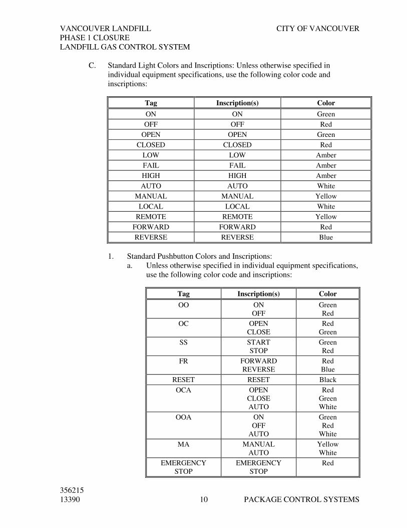
VANCOUVER LANDFILL CITY OF VANCOUVER
PHASE 1 CLOSURE
LANDFILL GAS CONTROL SYSTEM
356215
13390 10 PACKAGE CONTROL SYSTEMS
C. Standard Light Colors and Inscriptions: Unless otherwise specified in
individual equipment specifications, use the following color code and
inscriptions:
Tag Inscription(s) Color
ON ON Green
OFF OFF Red
OPEN OPEN Green
CLOSED CLOSED Red
LOW LOW Amber
FAIL FAIL Amber
HIGH HIGH Amber
AUTO AUTO White
MANUAL MANUAL Yellow
LOCAL LOCAL White
REMOTE REMOTE Yellow
FORWARD FORWARD Red
REVERSE REVERSE Blue
1. Standard Pushbutton Colors and Inscriptions:
a. Unless otherwise specified in individual equipment specifications,
use the following color code and inscriptions:
Tag Inscription(s) Color
OO ON
OFF
Green
Red
OC OPEN
CLOSE
Red
Green
SS START
STOP
Green
Red
FR FORWARD
REVERSE
Red
Blue
RESET RESET Black
OCA OPEN
CLOSE
AUTO
Red
Green
White
OOA ON
OFF
AUTO
Green
Red
White
MA MANUAL
AUTO
Yellow
White
EMERGENCY
STOP
EMERGENCY
STOP
Red
VANCOUVER LANDFILL CITY OF VANCOUVER
PHASE 1 CLOSURE
LANDFILL GAS CONTROL SYSTEM
356215
13390 11 PACKAGE CONTROL SYSTEMS
b. Unused or noninscribed buttons shall be black.
2.07 ELECTRICAL SURGE AND TRANSIENT PROTECTION
A. Not used
PART 3 EXECUTION
3.01 ELECTRICAL POWER AND SIGNAL WIRING
A. Restrain control and signal wiring in control panels by slotted wiring ducts
with cover.
B. Install wiring crossing hinge so that the opening and closing of the door twists
the wire without bending it. Protect bend area with a sleeve.
C. Arrange wiring neatly, cut to proper length, and remove surplus wire. Install
abrasion protection for wire bundles passing through holes or across edges of
sheet metal.
D. Use manufacturer’s recommended tool with sized anvil for crimp
terminations. No more than one wire may be terminated in a single crimp lug.
No more than two lugs may be installed on a single screw terminal.
E. Do not splice or tap wiring except at device terminals or terminal blocks.
F. All signal and control wiring shall be tagged as per Drawings.
3.02 PROTECTION
A. Protect enclosures and other equipment containing electrical, instrumentation
and control devices, including spare parts, from corrosion through the use of
corrosion-inhibiting vapor capsules.
B. During Work, periodically replace capsules in accordance with capsule
manufacturer’s recommendations. Replace capsules at Substantial
Completion.
3.03 TRAINING
A. Contractor to provide up to 5 days on-site training for the packaged control
system.
B. All training materials to be provided by the Contractor.

VANCOUVER LANDFILL CITY OF VANCOUVER
PHASE 1 CLOSURE
LANDFILL GAS CONTROL SYSTEM
356215
13390 12 PACKAGE CONTROL SYSTEMS
3.04 COMMISSIONING
A. Contractor to provide detailed commissioning plan and schedule for complete
Package Control System
B. Contractor to submit commissioning plan and schedule to Engineer for
approval 10 working days prior to commissioning.
END OF SECTION

356215 13390 – ATTCHMENT 1
Sec t i on 13390 – At t a chment 1
Vancouver Landfill Phase 1 Closure Landfill Gas Control System
Process Control Narrative
Prepared for
City of Vancouver
January 2009

356215 13390 – ATTCHMENT 1
i
Contents
Introduction......................................................................................................................................... 1 Primary Process Equipment ............................................................................................................. 2
Condensate Knockout (KO) Tanks ...................................................................................... 2
LFG Blowers............................................................................................................................ 2
LFG Flares................................................................................................................................ 4
Blower/Flare Control System............................................................................................... 5
HMI Screens ............................................................................................................................ 7
Tables
Table 1 Blower Startup / Shut down .................................................................................. 3
Table 2 Flare Startup / Shut down ...................................................................................... 4
Table 3 Alarm/Failure Conditions ...................................................................................... 8

356215 13390 – ATTCHMENT 1
1
Introduction
The City of Vancouver (COV) Landfill Gas (LFG) Control System is used to continuously extract LFG generated within the waste cells at the Vancouver Landfill site, reducing surface gas emissions and the associated odours. The LFG collected is routed primarily to Maxim Power Corporation’s Facility (Maxim) for beneficial use, and the excess LFG that is not used is thermally destroyed through onsite high efficiency enclosed flares.
The COV LFG control system is currently being run via a communications link to the Maxim PLC/SCADA System. Under this current arrangement, the COV blowers are not used; however, the Safety and Ignition Systems are being used to provide permissives for the onsite flares to run.
Operating as part of Maxim’s LFG utilization system, the primary stage blowers (two blowers in parallel) are providing the vacuum for the entire LFG collection wellfield. The primary blowers deliver LFG to the refrigeration system and the secondary-stage booster blowers (two blowers in parallel).
The Maxim LFG utilization system is set to maintain a minimum system pressure (approximately 8 to 8.5 psig) on the pipeline that supplies processed gas to an offsite cogeneration system. LFG is diverted to the current flares (Flares 1 and 2) when there is excess LFG and the Maxim process system discharge pressure rises above the controlled set-point.
The basis of design for the Phase 1 Closure LFG Upgrade at the COV Blower/Flare Station includes increasing the LFG control capacity of the COV blower flare station to 14,250 Nm3/h (9,000 scfm). The current COV blowers would be replaced by higher capacity blowers which would allow the COV control system to handle up to the total projected phased flow from the landfill to 2016. The plan for the new control system is based on parallel operation of both the COV control system and Maxim utilization system, maintaining a set continuous vacuum on the main LFG header system using VFD controlled blowers. The Maxim primary stage blower system will continue to draw gas from the main LFG header. The COV blowers will operate up to a point where the maximum inlet vacuum pressure is set. There will be a total of four flares, which include the two additional flares installed to enable the system to handle the total projected flow for this operation phase. By installing VFD’s on the City blowers and operating the blowers in a lead/lag configuration, the system will be able to adjust to changing pressure demands and flow conditions required to operate effectively with Maxim’s LFG utilization system.
The following process control narrative has been provided as a general example. The City of Vancouver reserves the right to make modifications and adjustments to the process control as necessary during the construction and installation phase.

PRIMARY PROCESS EQUIPMENT
356215 13390 – ATTACHMENT 1 2
Primary Process Equipment
As part of the Phase 1 Closure project, the Landfill Gas Control System upgrades to the COV blower/flare station will consist primarily of design and installation of three main types of equipment and associated equipment and controls as follows:
1. LFG condensate knockout tanks (3 new tanks) 2. LFG blowers (3 new blowers). 3. LFG flare packages (2 new enclosed flares added to the existing 2 COV flares, with the
allowance for a 5th and 6th Flare in the future)
Condensate Knockout (KO) Tanks
A total of three new LFG condensate knockout (KO) tanks are designed for the Phase 1 Closure upgrades. The three KO tanks are arranged in parallel and each has a flow rate capacity of 4,750 Nm3/h (3,000 scfm). They are used to remove free water and particulates entrained within the LFG flow stream prior to LFG entering the blowers. Each KO tank has an internal demister pad, for which the loading rate is monitored by using a pressure differential gauge installed in the knockout tanks. The normal operating pressure is between 65 inches of water column (WC) vacuum to 20 inches of WC positive pressure. Large diameter (600mm) header manifolds are installed upstream and downstream of the KO tank. A condensate drain is located at the bottom of each tank to allow for discharge of the collected liquid via gravity directly to the existing below grade condensate sumps as indicated in the drawings.
LFG Blowers
A total of three new LFG blowers are designed for the Phase 1 Closure project upgrades. The total blower capacity is 14,250 Nm3/h (9,000 scfm). Each individual blower has a flow rate capacity of 4,750 Nm3/hr (3000 scfm) at a vacuum pressure of 65 inches of WC on the blower suction side and 20 inches of WC (pressure) on the blower discharge side. The blowers are equipped with the VFDs for flow regulation. The blower capacity can be turned down to a minimum of 1000 scfm, while the process requires a minimum flow of 594 Nm3/h (375 scfm). A 200mm diameter LFG by-pass line is used to recycle about 990 Nm3/h (625 scfm) of LFG to the upstream header manifold of the KO tank to meet the minimum process flow requirement. A motorized isolation valve is installed on the by-pass branch line for each blower. This valve is interlocked with the blower operation and is open/closed when the blower speed is less/greater than its minimum flow (1000 scfm). The flow control valve (FCV-050) installed on the 200mm by-pass header is to be used to regulate the flow based on a 4-20 mA signal from the PLC.
The three blowers are configured in parallel with two operating in a lead and lag, and the third blower serving as a standby unit only. The two lead and lag blowers are selected by the Operator via the PC based control system. The blower capacity will be 150 percent of the

PRIMARY PROCESS EQUIPMENT
356215 13390 – ATTACHMENT 1 3
design flow rate capacity of the Phase 1 Closure flare capacity. Two blowers operating at full design capacity will meet the total flow rate design capacity for Flares 1, 2, 3 and 4.
The vacuum pressure at the LFG inlet manifold is to be maintained via the PLC control loop using a pressure transmitter PIT-050 input and sending a 4-20mA output to control the speed of the selected blower(s) via the VFD. Note: Both the COV blowers and the Maxim blowers will operate in parallel, the COV blowers are to ramp up and down to maintain the vacuum pressure at 65 inches of WC see Table 1:
TABLE 1
Blower Startup / Shut down
Blower to Start LFG Flow
(scfm) Blower Operating
BL-1 (Lead) 0 ~ 3000 BL-1
BL-2 (Lag) >3000 BL-1 + BL-2
BL-3 (Standby) >6000 BL-1 + BL-2 + BL-3
Blower to Shut Down LFG Flow
(scfm) Blower Operating
BL-3 (Standby) <6000 BL-1 + BL-2
BL-2 (Lag) <3000 BL-1
BL-1 (Lead) 0 ~ 3000 BL-1
The blower(s) will run at constant speed when the discharge flow rate is less than or equal to 1000 scfm. This flow initiates the by-pass isolation valve (BUV-103, BUV-203 OR BUV-303) to open and the Flow Control Valve (FVC-050) is used to maintain the vacuum pressure in suction header at 65 inches of WC.
The FCV will close and return back to normal operation (normally closed) when the flow is greater than 1000 scfm with no LFG bypassing back to the suction header.
The flow meter (FT-100) installed on the 600 mm diameter discharge header line monitors the total LFG flow to the flares. Lead and lag blowers both run when the flow is >3000 scfm and only the selected lead blower runs when the flow is <3000 scfm.
High temperature switches (TSH 102, 202, and 302) are installed in the discharge piping for each blower to protect the blowers in the event of overheating.
A temperature switch (TSH-050) is also installed on the inlet manifold (upstream of the KO tanks) to monitor the temperature of the LFG in the line. This will create a warning alarm condition when the inlet manifold temperature exceeds 40ºC.
A Pressure Transmitter (PIT-100) is installed on the blower discharge manifold to monitor the pressure of the LFG in the discharge line to the flares. The blower(s) will be shut down automatically when the header line pressure rises to the PIT-100 setting 30 inches of WC (normal operating pressure is 20 inches of WC).

PRIMARY PROCESS EQUIPMENT
356215 13390 – ATTACHMENT 1 4
A series of automatic safety shut-off valves, certified to Standard CAN/CGA-3.9, “AUTOMATIC SAFETY SHUT-OFF VALVES” (BUV-101, BUV-102, BUV-103, BUV-102, BUV-202, BUV-302), are provided to isolate (shut off) LFG feed to the blower when the blower becomes non-functional or is not in operation. These isolation valves are installed on each side (suction line and discharge line) of the blower. These isolation valves are equipped with ‘Open/Closed’ limit switches and are to be interlocked with the blower so that the blower will not run unless the inlet and outlet valves are in the open position. The valves are equipped with the visual valve position indicator and with a mandatory manual reset function to open.
LFG Flares
The future COV LFG control system design capacity for the complete blower/flare system is 9,000 scfm and will consist of six enclosed flares. Currently there are two existing (Flares 1 and 2) and two new enclosed flares will be installed within the Phase 1 Closure upgrade. The total design LFG flow rate for the new blowers is 9,000 scfm. The total design LFG flow rate to the flares is 6000 scfm of LFG, achieved through combining the two existing flares (Flares 1 and 2) with two new flares (Flares 3 and 4). The existing flare control system is to be used with modification to the program as required. The capacity is designed to cover the flow range of 375 to 1,500 scfm for each individual flare.
Flare 3 (installed in this phase) is a refractory-lined enclosed flare system matched with the existing Flares 1 and 2. Flare 4 is a non-refractory lined enclosed flare system.
The ‘Start/Stop’ sequence for Flares 1 through 4 is based on the LFG flow rate parameters in Table 2:
TABLE 2
Flare Startup / Shut down
Flare Startup
Flare to start LFG Flow
(scfm) Flare Operating
Flare 4 <400 Flare 4
Flare 1 >400 Flare 1
Flare 2 >1000 Flares 1+ 2
Flare 3 >2500 Flares 1+2+3
Flare 4 >4000 Flares 1+2+3+4
Flare Shut Down
Flare to shut down LFG Flow
(scfm) Flare Operating
Flare 4 <4000 Flare 1+2+3
Flare 3 <2500 Flare 1+2
Flare 2 <1000 Flare 1
Flare 1 <400 Fare 4

PRIMARY PROCESS EQUIPMENT
356215 13390 – ATTACHMENT 1 5
Note that Flare No. 4 is designed to handle sudden variations and increases in LFG flow rate resulting from changes in flow from Maxim’s utilization system. Flare No. 4 will be selected for sudden increases in flow rate up to 1500 scfm, and then transfer to Flare 1, 2 and/or 3 in sequence once the flares have completed their purge.
Blower/Flare Control System
The blower/flare system is designed for fully automatic, unattended operation but will also have the feature to operate in manual mode. The existing Flare Control Program is to be re-used for the existing Refractory Lined Flares 1 and 2 with the process logic copied for the new Refractory Lined Flare 3. Process logic to be modified to allow for sequential start up and shut down of individual flares based on pressure and flow rate. The control system shall allow for flexibility as well as future expandability.
The refractory-lined Flare Systems (Flares 1, 2, and 3) consist of the following components:
• Burner complete with Flame Sensor/Shutdown
• Three temperature sensors with flame temperature control
• Propane Pilot system
• Purge Air Blower
• Automated Air Control Dampers (current control scheme allows for automated control of one damper by temperature and the other by LFG flow rate).
• Flame Arrestor and high temperature safety shutdown system
Flare 4 is a non-refractory-lined flare system which consists of the following main components:
• Burner complete with Flame Sensor/Shutdown
• Minimum of three automatically combustor manifolds
• Three temperature sensors with high temperature shut down and burner control
• Propane Pilot system
• Combustion air managed through venturi system
• Flame Arrestor and high temperature safety shutdown system
Flare 4’s primary function is to operate and react instantaneously in response to sudden changes in LFG flow rate and/or pressure, primarily resulting from changes within the LFG flow rate to Maxim’s utilization system.
The flame temperature control for all four flares shall be set for automated operation. That is the thermocouples are automatically selected depending flow and minimum retention time required. The operator will have the capability to independently select the thermocouple for the flare temperature control.
The control system shall be designed, built, and programmed to provide the structure to monitor all parameters and perform all control functions remotely via the instrumentation network. All control and monitoring will be available locally via the PC based HMI (human/machine interface) and remotely via an internet connection to the HMI Computer. The HMI Computer will include a Trending Package to record all historical process and alarm data. The system shall include a call-out capability for contacting the Site Operator in

PRIMARY PROCESS EQUIPMENT
356215 13390 – ATTACHMENT 1 6
case of a system alarm. The City has a future SCADA system planned and ultimately the HMI will be connected.
The system will respond to high-level commands that relieve the Operator of the minute details of the system operation. These commands will be available remotely and locally through the HMI, and will include, but are not limited to, the following:
• Normal Startup and Shutdown
• Blower On line/Off line (for each blower)
• Control Valve Open/Close and Opened/Closed for each automated valve
• Blower Manual Speed Control (for each blower)
• Blower Variable Speed Control (for each blower)
• Control Valve % Open for FCV-050
• Flare On line/Off line (for each flare)
• Flare Temperature
• LFG composition (methane & oxygen concentration), flowrate and vacuum pressure
• Emergency Shutdown
• Maxim Utilization Facility status
The specific commands above would pertain as required in the design drawings.
Hard-wired emergency stops will be available locally on an outside wall of the control building. Emergency stops will be fully weatherproof and positioned for ease of access.
When any of these commands are invoked, the control system will change valve position and/or start motors, or initiate other sequences as necessary to safely execute the command. All operational interlock and safety features will remain fully operable during the execution of all commands.
The status of all system components will be available at all times by the selection of the proper screen of the HMI. Identical status will be available via the network.
The three operating modes will be:
1) Local manual
2) Local automatic
3) Remote manual
All functions will be password protected, and it is required that password privileges can be edited remotely with a record of user time, edits, etc. being available.
Program all status, control, alarm and trending screens for the parameters, status and control points identified in P&IDs and individual package specifications. Programming shall allow for system flexibility and variation of parameters based on City review.

PRIMARY PROCESS EQUIPMENT
356215 13390 – ATTACHMENT 1 7
HMI Screens
The PC Based Control Program and Operator Interface requirements are included in the following overview:
• Capable of at least 50 Screens
• Main screen to provide an overview of the system showing the current (Running/Off) status for the major equipment.
• Blower system screen showing the blowers and associated valves (allow for manual control of each device and show current status and operating parameters).
• Flare screen showing flares and associated valves and equipment (allow for manual control of each device and show current status and operating parameters).
• LFG piping/flow system showing the current status/position of all valves, flow rate, LFG temperatures, LFG vacuum pressure, flare header pressure and LFG composition values (Methane (CH4)and Oxygen (O2) % by volume concentration)
• Alarm screen showing current alarms, list of alarms and history. Allow for acknowledgement and silence of active alarms.
• Provide trend history for all process parameters including but not limited to flow rates, temperatures, pressures, LFG composition values, and run time for blowers.
• Maxim utilization system parameters.
Submit all screen designs for Engineer’s approval.
The start-up instructions for automatic operation is included in the following summary, however please note they are subject to change during system review process:
• Select Flare(s) to be started
• Turn Landfill Gas Blower(s) to “AUTO”
• Open the appropriate inlet and outlet valve to the blower(s) to be operated
• Open the appropriate inlet valves. For a non-operating flare, the corresponding LFG Flare Inlet Valve switch should be in the “OFF” position and the Start-Up Sequence turned to “MAN.”
• For operating flare(s), the corresponding LFG Inlet Valve should be in the “AUTO” position and the Start-Up Sequence switch turned to “AUTO”
Automatic start-up sequence for the refectory lined flares (Flares 1, 2, and 3) is as follows:
• The Purge in Progress indicators will come on for approximately one minute and the flare(s) purge blower(s) runs to purge the flare enclosure(s).
• The Purge Complete indicator will come on, the purge blower(s) are stopped and the igniter(s) light pilot gas in selected flare first and then subsequent flares (if operating multiple flares).

PRIMARY PROCESS EQUIPMENT
356215 13390 – ATTACHMENT 1 8
• If pilot flame ignition is successful the associated Flame Proved indicator will come on. The blower(s) will start and the inlet valves will open.
• If pilot flame ignition is not successful, a Flame Failure alarm is logged and the system will automatically attempt to re-purge and re-start.
• If three attempts for automatic start of any individual flare are not successful, that flare will shutdown and an alarm will be initiated by the control system to the City alarm centre. The next flare in sequence will be selected to automatically start. If that flare is unsuccessful after three attempts to start, another alarm will be initiated and the next flare in sequence will be selected to automatically start. This will continue in succession until all 4 flares have been attempted, at which time the flare system will shut down and initiate an alarm condition and a call-out.
• Pushing Emergency Shutdown (E-Stop) switch or selecting System Shutdown on the Operator’s Terminal will cause the system to shutdown.
The Non-Refractory Lined Flare (Flare 4) will include a Vendor supplied Control Panel with a ‘Flare Permissive’ signal for Start/Stop and Alarm and Fail signals back to the plant PLC.
The blower/flare system is equipped with an auto-dialer to alert operators in the event of failure. The auto-dialer signal will be sent to the City of Vancouver communications centre. See Table 3 for ALARM / FAILURE CONDITIONS & REQUIRED RESPONSES
TABLE 3
Alarm/Failure Conditions
Alarm Condition Programmed Action
1 Flame failure flare #1 • Flare shuts down automatically and then restarts • Autodialer dials City alarm centre • Alarm is logged in the control PC
2 Flame failure flare #2 • Flare shuts down automatically and then restarts • Autodialer dials City alarm centre • Alarm is logged in the control PC
3 Flame failure flare #3 • Flare shuts down automatically and then restarts • Autodialer dials City alarm centre • Alarm is logged in the control PC
4 Flare failure flare #4 • Autodialer dials City alarm centre • Alarm is logged in the control PC
5 High temperature flare #1 • Flare shuts down automatically and then restarts • Autodialer dials City alarm centre • Alarm is logged in the control PC
6 High temperature flare #2 • Flare shuts down automatically and then restarts • Autodialer dials City alarm centre • Alarm is logged in the control PC
7 High temperature flare #3 • Flare shuts down automatically and then restarts • Autodialer dials City alarm centre • Alarm is logged in the control PC
8 High oxygen • Autodialer dials City alarm centre • Alarm is logged in the control PC • Flare station does not shut down
9 Low temperature flare #2 • Flare shuts down automatically and does not restart • Autodialer dials City alarm centre • Alarm is logged in the control PC
10 Blower failure #1, #2 or #3 • Autodialer dials City alarm centre • Alarm indicator light(s) on blower panel
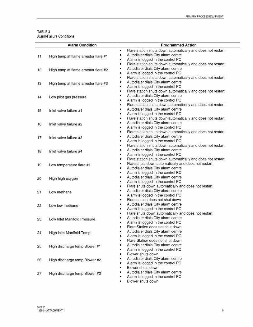
PRIMARY PROCESS EQUIPMENT
356215 13390 – ATTACHMENT 1 9
TABLE 3
Alarm/Failure Conditions
Alarm Condition Programmed Action
• Flare station shuts down automatically and does not restart
11 High temp at flame arrestor flare #1 • Autodialer dials City alarm centre • Alarm is logged in the control PC • Flare station shuts down automatically and does not restart
12 High temp at flame arrestor flare #2 • Autodialer dials City alarm centre • Alarm is logged in the control PC • Flare station shuts down automatically and does not restart
13 High temp at flame arrestor flare #3 • Autodialer dials City alarm centre • Alarm is logged in the control PC • Flare station shuts down automatically and does not restart
14 Low pilot gas pressure • Autodialer dials City alarm centre • Alarm is logged in the control PC • Flare station shuts down automatically and does not restart
15 Inlet valve failure #1 • Autodialer dials City alarm centre • Alarm is logged in the control PC • Flare station shuts down automatically and does not restart
16 Inlet valve failure #2 • Autodialer dials City alarm centre • Alarm is logged in the control PC • Flare station shuts down automatically and does not restart
17 Inlet valve failure #3 • Autodialer dials City alarm centre • Alarm is logged in the control PC • Flare station shuts down automatically and does not restart
18 Inlet valve failure #4 • Autodialer dials City alarm centre • Alarm is logged in the control PC • Flare station shuts down automatically and does not restart
19 Low temperature flare #1 • Flare shuts down automatically and does not restart • Autodialer dials City alarm centre • Alarm is logged in the control PC
20 High high oxygen • Autodialer dials City alarm centre • Alarm is logged in the control PC • Flare shuts down automatically and does not restart
21 Low methane • Autodialer dials City alarm centre • Alarm is logged in the control PC • Flare station does not shut down
22 Low low methane • Autodialer dials City alarm centre • Alarm is logged in the control PC • Flare shuts down automatically and does not restart
23 Low Inlet Manifold Pressure • Autodialer dials City alarm centre • Alarm is logged in the control PC • Flare Station does not shut down
24 High inlet Manifold Temp • Autodialer dials City alarm centre • Alarm is logged in the control PC • Flare Station does not shut down
25 High discharge temp Blower #1 • Autodialer dials City alarm centre • Alarm is logged in the control PC • Blower shuts down
26 High discharge temp Blower #2 • Autodialer dials City alarm centre • Alarm is logged in the control PC • Blower shuts down
27 High discharge temp Blower #3 • Autodialer dials City alarm centre • Alarm is logged in the control PC • Blower shuts down

DIVISION 15
MECHANICAL

VANCOUVER LANDFILL CITY OF VANCOUVER
PHASE 1 CLOSURE
LANDFILL GAS CONTROL SYSTEM
356215
15010 BASIC MECHANICAL REQUIREMENTS
2
SECTION 15010
BASIC MECHANICAL REQUIREMENTS
PART 1 GENERAL
1.01 SUMMARY
A. Section Includes:
1. Basic requirements for the supply, installation, testing and
commissioning of mechanical equipment and piping systems in Division
15 and is supplemented by other specific details shown or specified in
the respective system Sections.
B. Related Sections
1. Division 11, all sections
2. Earthwork ....................................................... Section 02205
3. Electric Conduit and Wiring Systems............. Section 16112
4. Electric Wiring Systems……………………...Section 16120
1.02 SUBMITTALS
A. Shop Drawings
1. Piping systems plans and sectional views or single line dimensioned
isometrics if applicable.
2. Valve schedule and identification list if applicable.
3. List of materials and current ANSI pressure-temperature ratings for
valve bodies, seats and stem seals.
4. General layout of equipment including anchor bolt locations, direction
of rotation for rotating equipment and electric motor terminal box
location.
5. Cross-sectional details of equipment with complete materials test.
6. For fans and blowers at rated rpm and 110% of rated rpm, certified,
non-witnessed characteristic curves of capacity versus static pressure
(discharge pressure); efficiency and power expressed in kilowatts, noise
and noise levels on the A weighted scale.
7. Dimensional drawings of motors and details including full output power
expressed in kilowatts, rpm and slip, motor nameplate details and motor
test data where required.
8. Instrument details.
9. Control panel layouts.
10. Electrical control schematics and loop diagram.

VANCOUVER LANDFILL CITY OF VANCOUVER
PHASE 1 CLOSURE
LANDFILL GAS CONTROL SYSTEM
356215
15010 BASIC MECHANICAL REQUIREMENTS
3
B. Test Reports and Certificates
1. Certified shop tests for electric motors.
2. Manufacturer's representative signed report.
C. Installation, Operation and Maintenance Manuals
1. Submit installation, operation and maintenance instructions for all
mechanical equipment, valves and appurtenances supplied under this
contract, including bill of materials, equipment schematics, general
elevation drawings, piping diagrams, foundation/installation
requirements, field interconnection piping diagrams, performance data,
curves and logic diagrams.
2. Include manufacturer’s technical data, final record drawings, data
sheets, factory and field test results, complete parts list and
recommended spare parts list.
3. Include catalogue cuts, data sheets, specification sheets, operations and
maintenance instructions for all components, valves, auxiliary devices
and ancillaries.
4. Include start-up and test procedures, trouble-shooting directions and
equipment calibration instructions.
5. Include names and addresses of equipment suppliers and local
component suppliers.
6. Submit two copies of manuals for review by Engineer before
preparation of final submission.
7. Incorporate Engineer’s comments into final manual submission.
1.03 QUALITY ASSURANCE
A. Standards
1. ANSI/ASME A13.1-2007 – Piping identification
2. ANSI/ASME Boiler and Pressure Vessel Code, Section VIII, Division 1
3. ANSI/ASME B31.3 Chemical Piping
4. CAN-CSA-B149.1 for Natural Gas and Propane Installation Code
5. ANSI B32.1 Metal Products
6. CSA CAN3-S16.1-M Steel Structures for Buildings (Limit State
Design
7. CSA W59-M Welded Stainless Steel Construction (Metal Arch Welding)
8. CSA S244 Welded Aluminum Design and workmanship (Inert Gas
Shielded Arch Processes)
9. CSA W47.1 Certification of Companies for Fusion Welding of Steel
Structures
10. British Columbia Safety Authority

VANCOUVER LANDFILL CITY OF VANCOUVER
PHASE 1 CLOSURE
LANDFILL GAS CONTROL SYSTEM
356215
15010 BASIC MECHANICAL REQUIREMENTS
4
B. Welding Procedure for Stainless Steel
1. Certify that companies which will be welding stainless steel are
CSA-approved.
2. Weld using ASME qualified welders.
3. Conform to CSA W47.1, ANSI B31.1 and Section VIII, Division 1 of
ASME Boiler and Pressure Vessel Code.
4. Submit Welding Procedure Specifications.
5. Include in welding procedures the following:
a. materials free of grease, oils and other contaminants prior to
welding
b. technique that minimizes heat input to parent metal
c. welds free of grain boundary carbide precipitation
d. stainless steel tools, grinding wheels and brushes
e. X-ray where specified in respective system Section
6. Following removal of weld spatter and slag, finish grind stainless steel
surfaces and passivate with Ferroclene 510 supplied by Surbond
Lubricants Ltd. (Milton).
7. When X-raying is specified, submit X-ray results.
8. Repair welds which do not meet the following acceptance criteria:
a. Cracks - not permitted
b. Incomplete penetration and lack of fusion: Depth - not greater than
[0.8] mm length - not more than [38] mm in [150] mm of weld
length
c. Reinforcement - maximum [3.2] mm
d. Undercut - maximum [0.8] mm deep
C. Certificates
1. Shop Finished Metal
a. Certify that the shop finished metal components received the
specified protective coating system.
1.04 LIMIT SWITCHES
A. Provide limit switches, specified for valve operators or as designated on
Electrical Drawings, with heavy-duty contacts and EEMAC 4 enclosures, to
be Honeywell heavy-duty plug-in type LS switches.
1.05 SOLENOID VALVES
A. Provide solenoid valves manufactured by ASCO with the following features:
1. coils having Class F insulation, stainless steel wetted internal parts and
Buna-N seats.

VANCOUVER LANDFILL CITY OF VANCOUVER
PHASE 1 CLOSURE
LANDFILL GAS CONTROL SYSTEM
356215
15010 BASIC MECHANICAL REQUIREMENTS
5
2. EEMAC 4 construction and suitable for the areas and services intended.
3. minimum operating pressure differential of 0 kPa and maximum
operating pressure differentials of 100 kPa.
1.06 EQUIPMENT NOISE LEVELS
A. Design equipment for quiet operation with the overall sound pressure level at
any equipment not exceeding 80 decibels when measured on the "A"
weighting network using survey and field methods conforming to ANSI S1.13
and CSA Z107.2. A more stringent requirement may be specified in the
detailed equipment Sections.
1.07 EQUIPMENT GUARDS
A. Provide, for couplings, belts, chain drives, extended shafts and exposed
moving parts, securely mounted guards with the following features:
1. reinforced and neatly formed minimum 2.8 mm sheet steel or expanded
sheet metal.
2. eliminate sharp edges with suitable borders neatly welded to perforated
sheet.
3. pivoting access covers for shaft speed measurement.
4. hot-dip galvanize the guards after fabrication.
1.08 BASEPLATES FOR MECHANICAL EQUIPMENT
A. Mount equipment and driver on a common baseplate in a compact
arrangement unless otherwise specified.
B. Construct equipment baseplates of heavy cast iron or of welded structural steel
section. Suitably stiffen structural steel baseplates to eliminate resonance and
to absorb vibration from the equipment.
C. Machine surfaces for mounting equipment and driver to an arithmetical
average roughness height of less than 3.2 micrometres.
1.09 NUTS AND BOLTS FOR PIPING
A. Use American National Standard hexagonal nuts and bolts for bolted
connections. Project bolt ends beyond the nut faces at least 3 mm but not more
than 1 bolt diameter.

VANCOUVER LANDFILL CITY OF VANCOUVER
PHASE 1 CLOSURE
LANDFILL GAS CONTROL SYSTEM
356215
15010 BASIC MECHANICAL REQUIREMENTS
6
1.10 FLANGES
A. For equipment, valves, and devices with integrally cast flanges, provide
flanges to the dimensions and drilling of ANSI B16.1 or ANSI B16.5 with
bolt-holes straddling the vertical centreline.
B. For fabricated equipment and vessels, provide forged flanges of the same
material as the equipment or vessel. Stainless steel lap-joint flanges with
carbon steel backing rings are not acceptable. Neither lap-joint nor Van Stone
flanges are acceptable on gas systems. Orient flanges with bolt-holes
straddling the vertical centreline.
C. Finish flanges in accordance with MSS standard of practice SP-6.
D. Refer to the detailed equipment and piping Specifications for working
pressures and class.
1.11 BEARINGS
A. Provide bearings, for rotating equipment, selected on the basis of a B-10 life
expectancy as defined by the Anti-Friction Bearing Manufacturers Association
at rated conditions of service of at least 100,000 working hours, unless
otherwise specified.
B. Provide buttonhead grease fittings for bearing lubrication.
1.12 EQUIPMENT NAMEPLATES
A. Securely fit, in an easily read location, corrosion-resistant metal nameplates
with impressed type lettering on equipment. Include the following
information.
1. For pumps, fans, blowers, etc.:
a. Model number
b. Serial number
c. Capacity
d. Head
e. Impeller diameter
f. Efficiency
g. Brake power
h. Other information required to uniquely identify the equipment

VANCOUVER LANDFILL CITY OF VANCOUVER
PHASE 1 CLOSURE
LANDFILL GAS CONTROL SYSTEM
356215
15010 BASIC MECHANICAL REQUIREMENTS
7
1.13 FINISHES
A. Finish piping and mechanical equipment to the following quality:
1. welds free of slag, ground and buffed.
2. surfaces of castings ground smooth.
3. stainless steel pipe free of steel wire rope marks.
4. materials, piping and equipment free of dents.
5. machined surfaces finished to specified tolerances.
1.14 EQUIPMENT AND PIPE PROTECTION
A. Where specified in the respective Sections, prepare surface, shop prime and
factory finish equipment in accordance with the requirements of Section
09900.
B. Where in the respective Sections exposed surfaces of equipment and piping,
including fittings, metal pipe supports and valves, are not specified to be
painted, prepare surfaces, and prime paint in accordance with Section 09900 -
Painting.
C. Field painting is to be done after pipes, valves and equipment have been
installed and tested.
PART 2 EXECUTION
2.01 INSTALLATION OF EQUIPMENT
A. Install, calibrate and test equipment in accordance with manufacturer's written
instructions and when specified, under supervision of competent experts
provided by the equipment manufacturer.
B. Erect mechanical equipment on foundations complete with suitably sized
anchor bolts and take special care to ensure true alignment of parts, especially
pumps and electrical drives. Align the units after their sole plates have been
shimmed at the anchor bolts. Recheck alignment after securing equipment to
its foundation before grouting sole plates in place.
C. Erect equipment level and plumb. The use of "pipe springing" and
"Dutchmen" to correct misalignment and misfitting is not allowed. In general,
install mechanical equipment directly on machined bases without shims;
provide at least 1.5 mm of steel shim stock under driver mounting feet.

VANCOUVER LANDFILL CITY OF VANCOUVER
PHASE 1 CLOSURE
LANDFILL GAS CONTROL SYSTEM
356215
15010 BASIC MECHANICAL REQUIREMENTS
8
2.02 PIPING INSTALLATION
A. Install piping parallel to building walls and ceilings.
B. Determine exact location of each pipe in the field with respect to adjacent and
interconnecting piping and equipment.
C. Design, provide and install piping systems in accordance with the ANSI code
for pressure piping, B31.1, .2, .3, .9.
D. Provide identification of media being conveyed through piping and flow
direction.
E. Provide, where shown on the Drawings, flanged joints intermittently in
welded piping systems to facilitate removal of every section of the piping
system.
F. Provide unions intermittently in all screwed piping systems to facilitate
removal of every section of the piping system without cutting any pipe or
joint.
G. Provide flanges or unions as specified for the particular piping system on both
sides of sleeved or cast-in-place pipe sections through interior walls, ceilings
and floors.
H. Provide unions on both sides of equipment such as in-line pumps, condensate
traps, separators, etc. incorporated into piping systems with screwed joints.
2.03 PIPING EXPANSION AND FLEXIBILITY
A. Install piping to permit free movement of piping caused by thermal expansion
and contraction except where it is anchored.
B. Provide for expansion and contraction by installing suitable expansion pieces
or flexible connectors as is necessary or where indicated.
C. Use only expansion pieces or flexible connectors having ratings equivalent to
the test pressures specified for the particular piping system and wetted
surfaces of material similar to that of the piping systems.
D. Design expansion pieces or flexible connectors for the lengths of straight runs
shown and the temperature differentials specified.
E. Construct expansion pieces to limit turbulence and pressure drop.

VANCOUVER LANDFILL CITY OF VANCOUVER
PHASE 1 CLOSURE
LANDFILL GAS CONTROL SYSTEM
356215
15010 BASIC MECHANICAL REQUIREMENTS
9
F. Provide anchors, supports and guides where necessary to direct expansion into
the expansion pieces or flexible connectors and to limit movements to those
directions and magnitudes permitted for the specific joint or flexible connector
selected.
G. Install expansion pieces and flexible connectors in accordance with the
standards of the Expansion Joint Manufacturer's Association, Inc.
2.04 PIPE SUPPORTS
A. Support piping in accordance with MSS SP-69, after careful alignment and
before tightly securing joints.
B. Take special care not to move pipe after tightening joints.
C. Provide hangers, supports, anchor bolts, washers and nuts to support pipes at
the lines and elevations indicated and conforming to MSS SP-58. Comply
with the requirements of Section 15060 where pipes and equipment are
supported from open web steel joists.
D. Place pipe supports where required to provide for true horizontal level or a
uniform slope in the pipe without sagging as indicated.
E. Location of sway braces, vibration dampeners, flexible connectors and
restraints to control piping movement due to vibration are indicated on the
Drawings. These locations are specific to the piping design layout shown. For
any deviation from the piping design layout shown, provide additional braces,
restraints and flexible connectors to control movements of piping due to
vibration.
F. Provide hangers, supports, anchors, guides, vibration dampeners, flexible
connectors, restraints and sway braces that will cope with the loads, moments
and stresses developed in the piping system and prevent these loads and
moments from being transferred to the equipment to which the piping is
connected.
G. Do not exceed the maximum horizontal pipe hanger and support spacings, on
straight runs having no valves or fittings listed in the following references:
1. Steel - Table 121.1.4, ANSI B31.1
2. Stainless Steel - ANSI B31.3
3. Ductile cast iron copper, cast iron soil
pipe, CPVC, PVC, FRP & ABS
- Table 3, MSS SP-69

VANCOUVER LANDFILL CITY OF VANCOUVER
PHASE 1 CLOSURE
LANDFILL GAS CONTROL SYSTEM
356215
15010 BASIC MECHANICAL REQUIREMENTS
10
H. Provide additional hangers and supports at concentrated loads such as valves,
flanges, fittings and at changes in direction.
I. Install sufficient hangers and supports to provide an adequate safety factor as
outlined in the ANSI B31.1, Chapter II Design, Part 5: Expansion, Flexibility
and Supporting.
2.05 PIPES THROUGH FLOORS AND WALLS
A. Provide sleeves of standard weight steel pipe where pipes pass through floors
or walls.
B. Provide sleeves of ample inside diameter to pass pipe and its insulation, and
allow for any expansion that may occur.
C. Install sleeves flush with finished wall faces and underside of floors and
project sleeves 50 mm above finished floor surfaces.
D. Provide 50 mm continuously welded water stop fin at midspan of pipes or
sleeves that pass through exterior walls below grade, slabs on grade and walls
that have water on either side.
E. Remove the coating from cast iron or steel pipe, including sleeves, to be cast
in concrete, to permit a good bond.
F. Set sleeves and spools accurately before concrete is placed or masonry built.
G. Where pipes pass through walls and ceilings, install split-type, chrome-plated
or spun aluminum escutcheons designed to fit around the pipe and the
insulation, neatly against the wall or ceiling, completely concealing the sleeve.
H. Fasten the escutcheons to the pipes with stainless steel set screws.
I. Couple rigid piping passing from a rigid structure to a trench condition with a
flexible coupling within 305 mm of external face of the structure. Equip such
couplings with restraining rods.
2.06 DRAINS AND VENTS FOR PIPING AND DUCTWORK SYSTEMS
A. Provide valved drains and vents of type, rating and materials as specified for
the piping and ductwork systems at low and high points respectively.
2.07 LIMIT SWITCHES
A. Set limit switches to indicate valve positions or equipment status as required
and indicated on Drawings.

VANCOUVER LANDFILL CITY OF VANCOUVER
PHASE 1 CLOSURE
LANDFILL GAS CONTROL SYSTEM
356215
15010 BASIC MECHANICAL REQUIREMENTS
11
B. Provide stem-mounted stainless steel devices to actuate limit switches.
C. Unless otherwise noted, arrange limit switches on valves to close when valve
is fully open.
D. All valve shall be fail closed unless otherwise stated on the Drawings.
2.08 INSTALLATION OF PRIMARY MEASURING ELEMENTS
A. Install primary elements and accessories supplied under Division 16, including
but not limited to the following:
1. flow meter
2. level meters
3. pressure/vacuum indicators, switches and transmitters
4. flow and level switches
5. temperature sensors, indicators, switches and transmitters
B. Install units in locations shown. Attention is directed to suggested mounting
details, flow schematics and circuit diagrams on the Drawings.
C. Provide reducers, weldolets, tapped saddles, victaulic flanges, shut-off valves,
pneumatic tubing, flushing connections, drains, bolts, nuts, washers and
gaskets necessary to complete the installation.
D. Provide and install pipe couplings for pressure sensors and pressure switch
sensors on piping systems where indicated. Use tapped saddles when
connecting to piping systems with wall thickness less than that required for
tapping size.
E. Provide necessary reducers and fittings and install level and flow switches
where indicated.
F. Provide pipe couplings and install wells for temperature sensors on piping
system where indicated.
G. Pipe couplings, tapped saddles, valves, flexible connectors and fittings must
be of material similar to that of the piping system and have
pressure-temperature ratings equivalent to that of the piping to which they are
connected.
H. Couplings, valves, wells, weldolets, tapped saddles, flexible connectors and
fittings, etc. must be suitable for installing primary elements supplied under
Section 16900 - Instrumentation and Control.

VANCOUVER LANDFILL CITY OF VANCOUVER
PHASE 1 CLOSURE
LANDFILL GAS CONTROL SYSTEM
356215
15010 BASIC MECHANICAL REQUIREMENTS
12
2.09 JOINTS
A. Apply teflon tape to male threads at screwed joints on systems which operate
at less than 21°C. Use Masters Metallic on gas piping and where the service
temperature is greater than 21°C.
B. Apply Denso paste to bolt threads at expansion pieces, flanged, victaulic and
mechanical joints. For buried piping apply paste to the fasteners.
C. Design, provide and install vent and relief pipes in accordance with ANSI
B31.1, .2, .3, CAN1-B105.
2.10 VALVE POSITION INDICATION
A. Install valve and damper operators whether manual, pneumatic or electric, to
clearly indicate whether the valve or damper is open, closed or partially open
from a point no less than 3 m away and visible from a position compatible
with normal plant operation.
2.11 ORIENTATION OF VALVE OPERATORS
A. Orient valves and valve operators to satisfy the following:
1. ease of operation
2. limit interference with structures and with any other equipment or piping
3. show valve position indicator from operating position
4. allowance for maintenance and disassembly
5. re-orient valves as required to satisfy the above conditions or any other
interference condition that may exist.
2.12 FIELD TESTS FOR PIPING SYSTEMS
A. Contractor shall conduct and pay for all testing and provide report to the
Engineer.
B. Provide necessary equipment and perform work required to field test piping
systems, including remedial and re-testing work.
C. Clean piping systems by flushing with water or blowing with air with valves
wide open prior to testing and before installing any primary element
instrumentation on the piping systems.
D. Provide temporary restraints or isolate expansion joints which cannot sustain
the reactions due to test pressure.

VANCOUVER LANDFILL CITY OF VANCOUVER
PHASE 1 CLOSURE
LANDFILL GAS CONTROL SYSTEM
356215
15010 BASIC MECHANICAL REQUIREMENTS
13
E. Isolate from the piping, equipment that is not to be subjected to the test
pressure.
F. Piping must pass field tests in presence of the Engineer.
G. No leakage will be allowed.
H. Purge with Nitrogen and air test piping at 1.5 times the maximum operating
pressure or 35 kPa above atmospheric pressure, which ever is greater (see and
Section 10100 and Section 15021 for LFG piping network).
I. Apply the test pressure for 4 hours.
J. If leaks are found, repair and retest until no leakage is found.
K. Drain piping and blow dry following successful completion of testing.
L. Do not install insulation until field testing on that piping system is completed.
M. Prepare a report for each test. Include in the report the following:
1. location or section of piping
2. time and duration of test
3. test pressure at start and completion
4. ambient temperatures
2.13 FIELD TESTS FOR VALVES
A. Contractor shall conduct and pay for all testing and provide report to the
Engineer.
B. Test randomly selected valves as directed, to demonstrate tight shut-off where
valves are so specified.
C. Test valves with rated pressure for 10 minutes, without any pressure decrease
on the pressurized side of the valves.
D. Proceed with this test in a manner that will demonstrate that the valves are not
leaking. Submit test procedure details prior to the test.
END OF SECTION

VANCOUVER LANDFILL CITY OF VANCOUVER
PHASE 1 CLOSURE
LANDFILL GAS CONTROL SYSTEM
356215
15021 1 HIGH DENSITY
POLYETHYLENE PIPE
SECTION 15021
HIGH DENSITY POLYETHYLENE PIPE
PART 1 GENERAL
1.01 WORK INCLUDED
A. This section covers the work necessary to furnish and install high density
polyethylene pipe and fittings specified herein.
1.02 GENERAL
A. Like items of material provided hereunder shall be the end products of one
manufacturer.
B. All pipe sizes shown on the Drawings and specified here are “nominal”
diameter, unless otherwise indicated.
1.03 REFERENCES
A. The following is a list of standards which may be referenced in this section.
Where this Specification section differs from these documents, the
requirements of this section shall apply.
1. American Society for Testing and Materials (ASTM):
a. D1248, Polyethylene Plastics Molding and Extrusion Materials.
b. D3350, Polyethylene Plastics Pipe and Fittings Materials.
c. F714, Polyethylene (PE) Plastic Pipe (SDR-PR) Based On
Outside Diameter.
2. British Columbia Safety Authority
1.04 SUBMITTALS
A. Administrative Submittals:
1. A statement, in writing, from the pipe manufacturer that it is listed with
the Plastic Pipe Institute as a qualified extruder for the polyethylene
resin being used to manufacture the pipe for this project.
2. Catalog information confirming that pipe, fittings, pressure rating,
thickness, size and other materials conform to the requirements of
PART 2 PRODUCTS of this Specification.
3. Manufacturer certification of personnel, equipment, and materials used
for joining of pipe.
4. Pipe fitting construction cut sheets.

VANCOUVER LANDFILL CITY OF VANCOUVER
PHASE 1 CLOSURE
LANDFILL GAS CONTROL SYSTEM
356215
15021 2 HIGH DENSITY
POLYETHYLENE PIPE
PART 2 PRODUCTS
2.01 PIPE
A. The pipe shall be extruded from a polyethylene compound and shall conform
to the following requirements.
1. The polyethylene resin shall meet or exceed the requirements of
ASTM D3350 for PE 3408 material with a cell classification of
345434C, 345534C, or 355434C.
2. The polyethylene compound shall be suitably protected against
degradation by ultraviolet light by means of carbon black, well
dispersed by precompounding in a concentration of not less than
2 percent.
3. The pipe manufacturer shall be listed with the Plastic Pipe Institute as
meeting the recipe and mixing requirements of the resin manufacturer
for the resin used to manufacture the pipe for this project.
4. Pipe sizes shall conform to ASTM F714.
5. All pipe shall have a Size Diameter Ratio (SDR) of 17 or smaller (i.e.,
thicker wall) unless noted otherwise on the Drawings or specifications.
6. Bends (both horizontal and vertical) made without fittings shall have a
minimum bending radius per manufacturer recommendation.
7. Maximum allowable hoop stress 5.5N/mm2 at 23 degrees C.
8. Minimum length for each joint of pipe delivered shall be no less than 12
m in length. Solid HDPE less than or equal to 80 mm in diameter may
be shipped on reels based on pre-approval by the Contractor.
2.02 PERFORATED PIPE (VERTICAL WELL SCREEN & LFG HORIZONTAL
COLLECTOR)
A. In addition to meeting all other requirements of this section, perforated pipe
shall have successive rows of perforations where each row consists of 10 mm
diameter holes, in six places equidistant around the pipe circumference. Rows
with be spaced 50 mm apart with the perforation pattern offset as shown on
the Drawings. Perforated pipe shall perforated prior to being delivered to the
site and shall be free of cutting debris and burrs caused during the perforating
process. There are to be no perforations within a minimum of 150mm from
the end of each pipe joint prepared fittings.
2.03 FITTINGS
A. Polyethylene fittings shall be molded for all sizes for which manufacturer
produces molded fittings unless otherwise noted. Fittings not available as a
molded product from the manufacturer shall be fabricated by means of
thermal butt-fusion welding and shall be shop fabricated. All polyethylene
fittings shall have the same or higher pressure rating as the adjoining pipe

VANCOUVER LANDFILL CITY OF VANCOUVER
PHASE 1 CLOSURE
LANDFILL GAS CONTROL SYSTEM
356215
15021 3 HIGH DENSITY
POLYETHYLENE PIPE
when installed in accordance with manufacturer’s recommendations. Molded
fittings and butt fusion joined fittings will conform to ASTM D3261 for
fittings of 150 mm (6-inches) or smaller and ASTM D3350 for fittings of 200
mm (8-inces) or larger.
2.04 JOINTS
A. Thermal butt-fuse all joints, except where flanged joints are shown. Butt-fuse
flange adapters. No mechanical couplings shall be used unless shown on the
Drawings or approved by the Engineer. At locations approved by the
Engineer, the Contractor may use electrofusion couplers; see Section 10100,
LANDFILL GAS COLLECTION SYSTEM.
2.05 FLANGES
A. Provide ASTM A240 Type 316 stainless steel backing flanges with 125-
pound, ANSI B16.1 Standard drilling or Polypropylene encapsulated ductile
iron backup rings (equivalent rating). Flanges shall be complete with one-
piece, molded polyethylene flange adapters. Flanged connections shall have
the same, or greater, pressure rating as the adjoining pipe.
2.06 GASKETS
A. Provide premanufactured, 3 mm neoprene, for all flanged connections.
2.07 FASTENERS
A. Bolts, Nuts, and Washers: Stainless steel.
PART 3 EXECUTION
3.01 GENERAL
A. All polyethylene pipe shall be cut, fabricated, and installed in strict
conformance with pipe manufacturer’s recommendations. Joining, laying, and
pulling of polyethylene pipe shall be accomplished by personnel experienced
in working with polyethylene pipe. The pipe supplier shall certify, in writing,
that the Contractor is qualified to join, lay, and pull the pipe, or representative
of the pipe manufacturer shall be onsite to oversee the pipe joining. Expenses
for the representative shall be paid for by the Contractor.
B. The pipe shall be permanently and visibly marked every 2 m with the
following information:
1. Manufacturer
2. S/N if applicable

VANCOUVER LANDFILL CITY OF VANCOUVER
PHASE 1 CLOSURE
LANDFILL GAS CONTROL SYSTEM
356215
15021 4 HIGH DENSITY
POLYETHYLENE PIPE
3. Maximum working pressure
4. PE 3408
5. Pipe Size
6. SDR
C. Pipe installed above grade shall be visibly identified with media contained and
flow direction, as per ANSI/ASME A13.1-2007.
3.02 TRANSPORTATION
A. Care shall be taken during transportation of the pipe that it is not cut, kinked,
or otherwise damaged. Transport in accordance with manufacturer’s
recommendations.
3.03 STORAGE
A. Pipe shall be stored in accordance with manufacturer’s recommendations and
on level ground, preferably turf or sand, free of sharp objects that could
damage the pipe. Stacking of the polyethylene pipe shall be limited to a height
that will not cause excessive deformation of the bottom layers of pipes under
anticipated temperature conditions. Where necessary due to ground
conditions, the pipe shall be stored on wooden sleepers, spaced suitably and of
such widths as not to allow deformation of the pipe at the point of contact
with the sleeper or between supports.
3.04 HANDLING PIPE
A. The handling of the joined pipeline shall be in such a manner that the pipe is
not damaged by dragging it over sharp and cutting objects. Ropes, fabric, or
rubber-protected slings and straps shall be used when handling pipes. Chains,
cables, or hooks inserted into the pipe ends shall not be used. Two slings
spread apart shall be used for lifting each length of pipe. Pipe or fittings shall
not be dropped onto rocky or unprepared ground. Slings for handling the
pipeline shall not be positioned at butt-fused joints. Sections of the pipes with
cuts and gouges exceeding 10 percent of the pipe wall thickness or kinked
sections shall be removed and the ends of the pipeline rejoined.
B. Pipes shall be joined to one another, to the polyethylene fittings, and to the
flange connections by means of thermal butt-fusion. Polyethylene pipe
lengths, fittings, and flanged connections to be joined by thermal butt-fusion
shall be of the same type, grade, and class of polyethylene compound and
supplied from the same raw material supplier. Polyethylene pipes shall be
fabricated and installed in conformance with ASTM D2774 and
manufacturer’s recommendations.

VANCOUVER LANDFILL CITY OF VANCOUVER
PHASE 1 CLOSURE
LANDFILL GAS CONTROL SYSTEM
356215
15021 5 HIGH DENSITY
POLYETHYLENE PIPE
C. At locations approved by the Engineer, the Contractor may use electrofusion
couplers. See Section 10100, LANDFILL GAS COLLECTION SYSTEM.
D. Mechanical connections of the polyethylene pipe to auxiliary equipment such
as valves and other piping system, shall be through flanged connections which
shall consist of the following:
1. A polyethylene “stub end” or “molded flange adapter” shall be
thermally butt-fused to the ends of the pipe.
2. Provide backing flange as specified.
3. Fasteners of sufficient length to show a minimum of three complete
threads when the joint is made and tightened to the manufacturer’s
standard. Retorque after 4 hours.
4. Gaskets as specified.
5. Fasteners shall be as specified.
E. Butt-Fusion Joining: Butt-fusion of pipes and fittings shall be performed in
accordance with the pipe manufacturer’s recommendations as to equipment
and technique. Depending on site conditions, butt-fusion joining shall be
performed in or outside of the excavation at the Contractor’s option. Butt-
fusion shall be done by manufacturer certified personnel only; certification
shall cover the butt-fusion machine, joint types, and pipe materials used
during construction.
F. Hot work permits shall be required for all pipe fusion welding and any other
hot work associated with the Work in classified area locations on the landfill
and at the blower flare station.
G. All valves and equipment shall be supported independently from pipe. Anchor
valves such that turning moment resulting from their operation will not be
transmitted to pipe.
H. Special Precautions at Flanges: Polyethylene pipe connected to heavy fittings,
monitoring stations and rigid structures shall be supported in such a manner
that no subsequent relative movement between the polyethylene pipe at the
flanged joint and the rigid structures is possible. Pipe adjacent to flanges shall
be supported by a bed of underlying soil to prevent sagging of the pipe.
3.05 PLACEMENT IN TRENCH
A. General: Care shall be exercised when lowering pipe into the trench to prevent
damage or twisting of the pipe. Remove sections of damaged pipe and replace
with undamaged pipe.
B. Pipe must be at the temperature of the surrounding soil at the time of
backfilling to compaction.

VANCOUVER LANDFILL CITY OF VANCOUVER
PHASE 1 CLOSURE
LANDFILL GAS CONTROL SYSTEM
356215
15021 6 HIGH DENSITY
POLYETHYLENE PIPE
C. Fittings: At flanges, valves, and connections, the trench bottom shall be dug
out with sufficient length, width, and depth to ensure clearance between the
undisturbed trench bottom and the flanges, valves, and such connections.
D. Polyethylene flanges must be at the ambient temperature of the surrounding
soil at the time they are bolted tight to prevent relaxation of the flange bolts
and loosening of the joint due to thermal contraction of the polyethylene.
Flange bolts must be retightened at least once a minimum of 24 hours after
initial flange bolt tightening. Bolts shall be tightened to the torque
recommended by the manufacturer for the particular bolt size and fitting.
3.06 PIPE CLEANING AND TESTING
A. Clean all piping of debris. Cleaning for tight lines shall consist of
mechanically blowing air into one end of the section, discharging debris from
the other end in a safe manner Provide mechanical blower for this cleaning.
The cleaning operation shall demonstrate air velocities in the pipe of over 23
m/s (4,500 fpm) for 1 hour at all points along the centerline of the pipe.
Alternatively, the pipe may be cleaned with a pig. The perforated LFG
collectors shall be cleaned with a pig. Pipe may be cleaned in sections.
B. Air Testing: All solid landfill gas piping (both above and below ground) shall
be air tested for leakage. The line shall be tested with the ends of the piping
temporarily closed. After all plugs are in place and securely blocked,
introduce air slowly into the pipe section to be tested until the internal air
pressure reaches 35 kPa greater than atmospheric pressure. Allow a minimum
of 2 minutes for the air temperature to stabilize. Pipe and joints being air
tested shall be considered acceptable when tested at an average pressure of
35 kPa greater than atmospheric pressure, when the section of line does not
lose air at a rate greater than 0.0030 cubic foot per minute per square foot of
internal pipe surface. Provide calculations for maximum acceptable loss
before testing and field data sheets with test results for Engineer’s approval.
C. Piping shall be tested in its final configuration. Pipe sections shall be tested
with all blind flanges and other connections in place in the same configuration
that they will be under during operation of the system. Testing shall ensure
that all pipe welds, blind flanges, and other connections are leakfree according
to the criteria listed above.
D. Pipe test failures shall require the Contractor to find and fix the point(s) of
leakage causing the failure. The section shall then be retested and the process
repeated until all sections of pipe pass the air testing criteria.
E. Contractor shall conduct and pay for all testing and provide reports to the
Engineer

VANCOUVER LANDFILL CITY OF VANCOUVER
PHASE 1 CLOSURE
LANDFILL GAS CONTROL SYSTEM
356215
15021 7 HIGH DENSITY
POLYETHYLENE PIPE
3.07 COMMISSIONING
A. Pipe must be purged with nitrogen prior to startup and commissioning.
END OF SECTION

VANCOUVER LANDFILL CITY OF VANCOUVER
PHASE 1 CLOSURE
LANDFILL GAS CONTROL SYSTEM
356215
15060 1 PIPING SUPPORT SYSTEMS
SECTION 15060
PIPING SUPPORT SYSTEMS
PART 1 GENERAL
1.01 WORK OF THIS SECTION
A. The Work of this Section includes designing, furnishing and installation of pipe
support systems for the Blower Flare Station piping system.
B. For welding, refer to Section 15010, Basic Mechanical Requirements.
1.02 REFERENCES
A. The following is a list of standards which may be referenced in this section:
1. American Society for Testing and Materials (ASTM):
a. A123/A123M, Standard Specification for Zinc (Hot-Dip Galvanized)
Coatings on Iron and Steel Products.
b. A653/A653M, Standard Specification for Steel Sheet, Zinc-Coated
(Galvanized) or Zinc-Iron Alloy-Coated (Galvanealed) by the Hot-Dip
Process.
2. Building Officials and Code Administrators (BOCA): Basic Building Code.
3. International Conference of Building Officials (ICBO): Uniform Building
Code.
4. National Building Code of Canada (NBC)
5. Manufacturers’ Standardization Society (MSS):
a. SP 58, Pipe Hangers and Supports - Materials, Design and
Manufacture.
b. SP 69, Pipe Hangers and Supports - Selection and Application.
c. SP 89, Pipe Hangers and Supports - Fabrication and Installation
Practices.
6. British Columbia Safety Authority
B. For additional welding requirements, refer to Section 15010.

VANCOUVER LANDFILL CITY OF VANCOUVER
PHASE 1 CLOSURE
LANDFILL GAS CONTROL SYSTEM
356215
15060 2 PIPING SUPPORT SYSTEMS
1.03 SUBMITTALS
A. Action Submittals:
1. Drawings of piping support system, locating each support, brace, hanger,
guide, component, and anchor. Identify support, hanger, guide, and anchor
type by catalog number and Shop Drawing detail number.
2. Revisions to support systems resulting from changes in related piping
system layout or addition of flexible joints.
B. Information Submittals: Maintenance information on piping support system.
1.04 QUALIFICATIONS
A. Piping support systems shall be designed and Shop Drawings prepared and sealed
by a Registered Professional Engineer in the province of BC.
1.05 DESIGN REQUIREMENTS
A. General:
1. Seismic Load: Seismic performance category forces with seismic loads in
accordance with local codes.
2. Design, size, and locate piping support systems throughout facility, whether
shown or not.
3. Meet requirements of MSS SP 58, MSS SP 69, and MSS SP 89, or as
modified by this section.
B. Pipe Support Systems:
1. Support Load: Dead loads imposed by weight of pipes filled with water,
except air and gas pipes, plus insulation.
2. Maximum Support Spacing and Minimum Rod Size:
a. Mild Steel or Ductile Iron Piping (Note that this spacing may require
the use of higher load pipe clamps and more than a single point
anchor point in concrete):
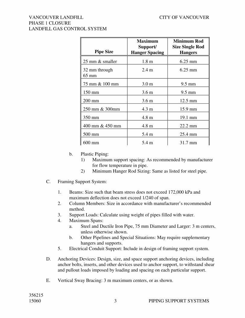
VANCOUVER LANDFILL CITY OF VANCOUVER
PHASE 1 CLOSURE
LANDFILL GAS CONTROL SYSTEM
356215
15060 3 PIPING SUPPORT SYSTEMS
Pipe Size
Maximum
Support/
Hanger Spacing
Minimum Rod
Size Single Rod
Hangers
25 mm & smaller 1.8 m 6.25 mm
32 mm through
65 mm
2.4 m 6.25 mm
75 mm & 100 mm 3.0 m 9.5 mm
150 mm 3.6 m 9.5 mm
200 mm 3.6 m 12.5 mm
250 mm & 300mm 4.3 m 15.9 mm
350 mm 4.8 m 19.1 mm
400 mm & 450 mm 4.8 m 22.2 mm
500 mm 5.4 m 25.4 mm
600 mm 5.4 m 31.7 mm
b. Plastic Piping:
1) Maximum support spacing: As recommended by manufacturer
for flow temperature in pipe.
2) Minimum Hanger Rod Sizing: Same as listed for steel pipe.
C. Framing Support System:
1. Beams: Size such that beam stress does not exceed 172,000 kPa and
maximum deflection does not exceed 1/240 of span.
2. Column Members: Size in accordance with manufacturer’s recommended
method.
3. Support Loads: Calculate using weight of pipes filled with water.
4. Maximum Spans:
a. Steel and Ductile Iron Pipe, 75 mm Diameter and Larger: 3 m centers,
unless otherwise shown.
b. Other Pipelines and Special Situations: May require supplementary
hangers and supports.
5. Electrical Conduit Support: Include in design of framing support system.
D. Anchoring Devices: Design, size, and space support anchoring devices, including
anchor bolts, inserts, and other devices used to anchor support, to withstand shear
and pullout loads imposed by loading and spacing on each particular support.
E. Vertical Sway Bracing: 3 m maximum centers, or as shown.
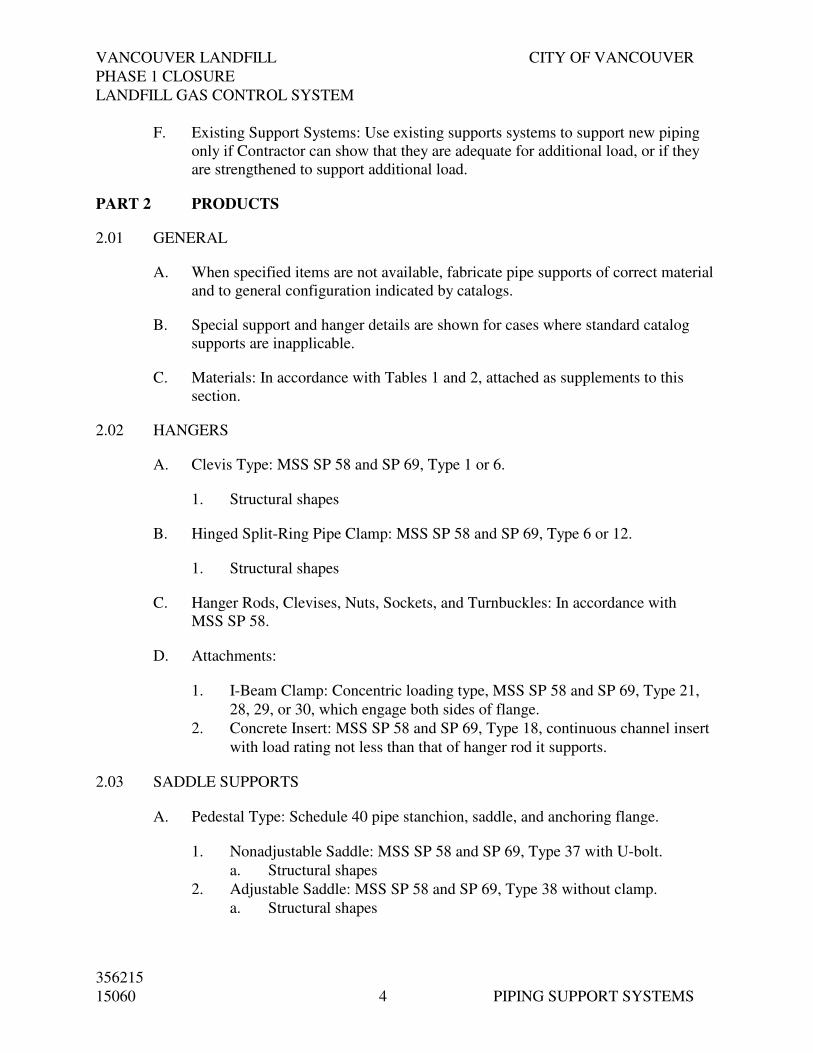
VANCOUVER LANDFILL CITY OF VANCOUVER
PHASE 1 CLOSURE
LANDFILL GAS CONTROL SYSTEM
356215
15060 4 PIPING SUPPORT SYSTEMS
F. Existing Support Systems: Use existing supports systems to support new piping
only if Contractor can show that they are adequate for additional load, or if they
are strengthened to support additional load.
PART 2 PRODUCTS
2.01 GENERAL
A. When specified items are not available, fabricate pipe supports of correct material
and to general configuration indicated by catalogs.
B. Special support and hanger details are shown for cases where standard catalog
supports are inapplicable.
C. Materials: In accordance with Tables 1 and 2, attached as supplements to this
section.
2.02 HANGERS
A. Clevis Type: MSS SP 58 and SP 69, Type 1 or 6.
1. Structural shapes
B. Hinged Split-Ring Pipe Clamp: MSS SP 58 and SP 69, Type 6 or 12.
1. Structural shapes
C. Hanger Rods, Clevises, Nuts, Sockets, and Turnbuckles: In accordance with
MSS SP 58.
D. Attachments:
1. I-Beam Clamp: Concentric loading type, MSS SP 58 and SP 69, Type 21,
28, 29, or 30, which engage both sides of flange.
2. Concrete Insert: MSS SP 58 and SP 69, Type 18, continuous channel insert
with load rating not less than that of hanger rod it supports.
2.03 SADDLE SUPPORTS
A. Pedestal Type: Schedule 40 pipe stanchion, saddle, and anchoring flange.
1. Nonadjustable Saddle: MSS SP 58 and SP 69, Type 37 with U-bolt.
a. Structural shapes
2. Adjustable Saddle: MSS SP 58 and SP 69, Type 38 without clamp.
a. Structural shapes

VANCOUVER LANDFILL CITY OF VANCOUVER
PHASE 1 CLOSURE
LANDFILL GAS CONTROL SYSTEM
356215
15060 5 PIPING SUPPORT SYSTEMS
2.04 WALL BRACKETS
A. Welded Steel Bracket: MSS SP 58 and SP 69, Type 33 (heavy-duty).
1. Structural shapes
B. Channel Type:
1. Structural shapes only.
C. Riser Clamp: MSS SP 58 and SP 69, Type 8.
1. Structural shapes only.
2.05 CHANNEL TYPE SUPPORT SYSTEMS
A. Channel Size: 12-gauge, 41.3 mm wide minimum steel, 38.1 mm wide, minimum
FRP.
B. Members and Connections: Design for all loads with safety factor of 5.
C. Hot dipped galvanized or aluminum or stainless steel structural shapes only
2.06 ACCESSORIES
A. Insulation Shields:
1. Type: Galvanized steel or stainless steel, MSS SP 58 and SP 69, Type 40.
2. Manufacturers and Products:
a. Structural shapes
B. Welding Insulation Saddles:
1. Type: MSS SP 58 and SP 69, Type 39.
2. Manufacturers and Products:
a. Structural shapes
C. Vibration Isolation Pads:
1. Type: Neoprene Waffle.
2. Manufacturers and Products:
a. Mason Industries; Type W.
b. Korfund; Korpad 40.
D. Flush Type Insert Channels: As specified in Section 05500, Metal Fabrications
and Castings.

VANCOUVER LANDFILL CITY OF VANCOUVER
PHASE 1 CLOSURE
LANDFILL GAS CONTROL SYSTEM
356215
15060 6 PIPING SUPPORT SYSTEMS
2.07 INTERMEDIATE PIPE GUIDES
A. Piping 150 mm and Smaller:
1. Type: Pipe clamp with oversized pipe sleeve to provide minimum 3.2 mm
clearance.
2. Manufacturers and Products:
a. Structural shapes
B. Piping 200 mm and Larger:
1. Type: Specially formed U-bolts with double nuts to provide 6.4 mm
minimum clearance around pipe.
2. U-Bolt Stock Size:
a. 200 mm Pipe: 15.9 mm.
b. 250 mm Pipe: 19.1 mm.
c. 300 mm Through 400 mm Pipe: 22.2 mm.
d. 450 mm Through 600 mm Pipe: 25.4 mm.
2.08 PIPE ALIGNMENT GUIDES
A. Type:
1. Piping 200 mm and Smaller: Spider or sleeve type.
2. Piping 250 mm and Larger: Roller type.
B. Manufacturers:
1. Flexonics.
2. Anvil.
3. B-Line.
2.09 PIPE ANCHORS
A. Type: Anchor chair with U-bolt strap.
B. Manufacturers and Products:
1. Anvil; Figure TBA
2. B-Line; Figure B3147A or B3147B.
2.10 ANCHORING SYSTEMS
A. Size: Sized by equipment manufacturer, 12.7 mm minimum diameter, and as
specified in Section 05500, Metal Fabrications and Castings.

VANCOUVER LANDFILL CITY OF VANCOUVER
PHASE 1 CLOSURE
LANDFILL GAS CONTROL SYSTEM
356215
15060 7 PIPING SUPPORT SYSTEMS
PART 3 EXECUTION
3.01 INSTALLATION
A. General:
1. Install support systems in accordance with MSS SP 69 and MSS SP 89,
unless shown otherwise.
2. Support piping connections to equipment by pipe support and not by
equipment.
3. Support large or heavy valves, fittings, and appurtenances independently of
connected piping.
4. Support no pipe from pipe above it.
5. Support pipe at changes in direction or in elevation, adjacent to flexible
joints and couplings, and where shown.
6. Do not install pipe supports and hangers in equipment access areas or bridge
crane runs.
7. Brace hanging pipes against horizontal movement by both longitudinal and
lateral sway bracing and to reduce movement after startup.
8. Install lateral supports for seismic loads at all changes in direction.
9. Install pipe anchors where required to withstand expansion thrust loads and
to direct and control thermal expansion.
10. Repair mounting surfaces to original condition after attachments are made.
B. Standard Pipe Supports:
1. Horizontal Suspended Piping:
a. Single Pipes: Adjustable swivel-ring, split-ring, or clevis hangers.
b. Grouped Pipes: Trapeze hanger systems.
c. Furnish galvanized steel protection shield and oversized hangers for
insulated pipe.
d. Furnish precut sections of rigid insulation with vapor barrier at
hangers for insulated pipe.
2. Horizontal Piping Supported From Walls:
a. Single Pipes: Wall brackets or wall clips attached to wall with
anchors. Clips attached to wall mounted framing also acceptable.
b. Stacked Piping:
1) Wall mounted framing system and clips acceptable for piping
smaller than 75 mm minimal diameter.
2) Piping clamps that resist axial movement of pipe through
support not acceptable.
c. Wall mounted piping clips not acceptable for insulated piping.

VANCOUVER LANDFILL CITY OF VANCOUVER
PHASE 1 CLOSURE
LANDFILL GAS CONTROL SYSTEM
356215
15060 8 PIPING SUPPORT SYSTEMS
3. Horizontal Piping Supported From Floors:
a. Stanchion Type:
1) Pedestal type; adjustable with stanchion, saddle, and anchoring
flange.
2) Use yoked saddles for piping whose centerline elevation is
450 mm or greater above floor and for exterior installations.
3) Provide neoprene waffle isolation pad under anchoring flanges,
adjacent to equipment or where otherwise required to provide
vibration isolation.
b. Floor Mounted Channel Supports:
1) Use for piping smaller than 75 mm nominal diameter running
along floors and in trenches at piping elevations lower than can
be accommodated using pedestal pipe supports.
2) Attach channel framing to floors with anchor bolts.
3) Attach pipe to channel with clips or pipe clamps.
c. Concrete Cradles: Use for piping larger than 75 mm along floor and in
trenches at piping elevations lower than can be accommodated using
stanchion type.
4. Vertical Pipe: Support with wall brackets and base elbow or riser clamps on
floor penetrations.
5. Standard Attachments:
a. To Concrete Ceilings: Concrete inserts.
b. To Steel Beams: I-beam clamp or welded attachments.
c. To Wooden Beams: Lag screws and angle clips to members not less
than 62.5 mm thick.
d. To Concrete Walls: Concrete inserts or brackets or clip angles with
anchor bolts.
6. Existing Walls and Ceilings: Install as specified for new construction,
unless shown otherwise.
C. Intermediate and Pipe Alignment Guides:
1. Provide pipe alignment guides (or pipe supports that provide same function)
at expansion joints and loops.
2. Guide piping on each side of expansion joint or loop at 4- and 14-pipe
diameters from each joint or loop.
3. Install intermediate guides on metal framing support systems not carrying
pipe anchor or alignment guide.

VANCOUVER LANDFILL CITY OF VANCOUVER
PHASE 1 CLOSURE
LANDFILL GAS CONTROL SYSTEM
356215
15060 9 PIPING SUPPORT SYSTEMS
D. Accessories:
1. Insulation Shield: Install on insulated nonsteel piping. Oversize rollers and
supports.
2. Welding Insulation Saddle: Install on insulated steel pipe. Oversize rollers
and supports.
3. Vibration Isolation Pad: Install under base flange of pedestal type pipe
supports adjacent to equipment, and where required to isolate vibration.
4. Dielectric Barrier:
a. Install between carbon steel members and copper or stainless steel
pipe.
b. Install between stainless steel supports and nonstainless steel ferrous
metal piping.
5. Electrical Isolation: Install 6.4 mm by 75 mm neoprene rubber wrap
between submerged metal pipe and oversized clamps.
3.02 PAINTING
A. Paint atmospheric exposed surfaces hot-dip galvanized steel components as
specified in Section 09900, Painting.
END OF SECTION

VANCOUVER LANDFILL CITY OF VANCOUVER
PHASE 1 CLOSURE
LANDFILL GAS CONTROL SYSTEM
356215
15100 VALVES
1
SECTION 15100
VALVES
PART 1 GENERAL
1.01 SUMMARY
A. Comply with Division 15010 – Basic Mechanical Requirements.
1.02 SUBMITTALS
A. Shop Drawings
1. Sectional details of valves and valve operators including list of materials
and current ANSI pressure-temperature ratings for valve bodies, seats
and stem seals.
2. Details, sizes, and engineering description of valves.
B. Test Reports and Certificates
C. Installation, Operation and Maintenance Manuals
1. Installation, operation and maintenance instructions for valves and
appurtenances.
1.03 QUALITY ASSURANCE
A. Standards
B. Certificates
PART 2 PRODUCTS
2.01 VALVES – CHECK
A. Landfill Gas - Blower outlet and Flare line
Service: Landfill Gas
Size: 150 mm & 350 mm
Type: Check valve (dual plate)
Ends: Wafer
Valve Body: 316 Stainless Steel
Shaft & Shaft plug: 316 Stainless Steel
Plate: 316 Stainless Steel
Thrust Washer: PTFE or equivalent for LFG service

VANCOUVER LANDFILL CITY OF VANCOUVER
PHASE 1 CLOSURE
LANDFILL GAS CONTROL SYSTEM
356215
15100 VALVES
2
Spring: 316 Stainless Steel
Manufacturer: Duo-Chek II (Crane), or Engineer Approved
Equivalent
Note: Low pressure drop required
2.02 VALVES – BALL (CSA-B105 STANDARDS)
A. Condensate Waste and Landfill Gas
Service: Landfill Gas and Condensate Waste
Size: 12 mm to 75 mm Full port Trunion or Floating
Pressure: Maximum 685 kPa
Materials: 316 stainless steel body and internals
Seal: Viton, or PTFE
Ends: FNPT 25 to 50mm; ANSI 150# Flanged >50mm
Operator: Manual Lever
Manufacturers: WKM or Engineer Approved
2.03 VALVES – BUTTERFLY (CSA-B105 STANDARDS)
A. Landfill Gas, Actuated
Service: Landfill Gas
Size: 150 ~ 450mm
Materials: 316 stainless steel internals
Ends: Lug
Seat: PTFE, or Viton
Bushing: PTFE
Rotation: Full 90° turning radius
Operator: TBD
Manufacturers: Xomox, or Engineer Approved Equivalent
B. Landfill Gas, Gear Operated
Service: Landfill Gas
Size: 150 to 600 mm
Materials: 316 stainless steel internals
Ends: Lug
Seat: PTFE, or Viton
Bushing: PTFE
Rotation: Full 90° turning radius
Operator: Manual Gear Box drive with hand wheel, position
indicator
Manufacturers: Xomox, or Engineer Approved Equivalent

VANCOUVER LANDFILL CITY OF VANCOUVER
PHASE 1 CLOSURE
LANDFILL GAS CONTROL SYSTEM
356215
15100 VALVES
3
C. Pneumatic Actuator for Butterfly Valves
Type: Scotch-Yoke, Spring Return (fail close)
Range of Motion: Quarter Turn (90°)
Actuation Method: Pneumatic. Cylinder Actuator, Spring Return
Operation: On/Off
Accessories: Open/close indication and limit switches (class 1
zone 2), Handwheel, Pilot Solenoid Valve – 3-
way, Integral OPEN-STOP-CLOSE pushbutton
controls, HAND-OFF-AUTO (Local-Off-Remote)
Selector Switch.
Rating: Suitable for full operation range of valve at
nitrogen supply pressure 550 kPa:
Manufacturers: Rotork, Fisher Controls, Limitorque , or Engineer
Approved Equivalent
D. Electrical Actuator for Butterfly Valves (ON/OFF)
Type: Rotary
Range of Motion: Quarter Turn (90°)
Actuation Method: Electrical
Operation: On/Off
Time of Travel (Open-
Close)
40 seconds.
Accessories: Open/close indication and limit switches (class 1
zone 2) Integral OPEN-STOP-CLOSE pushbutton
controls, Reversing motor starter with built-in
overload protection, Handwheel,
HAND-OFF-AUTO (Local-Off-Remote) Selector
Switch, Control power transformer
Power Supply: 208 AC-volt, three-phase
Control Power: 24 VDC
Enclosure: As defined in NEMA 4X, NEMA 7, with a
minimum of three cable entries, contain space
heater,
Manufacturers: Rotork, Fisher Controls, Limitorque , or Engineer
Approved Equivalent
E. Electrical Actuator for Butterfly Valves (Modulating)
Type: Rotary
Range of Operation: Maximum valve opening angle 60% .
Actuation Method: Electrical
Operation: Modulating

VANCOUVER LANDFILL CITY OF VANCOUVER
PHASE 1 CLOSURE
LANDFILL GAS CONTROL SYSTEM
356215
15100 VALVES
4
Signal 4-20 mA
Accessories: Feedback potentiometer and integral electronic
positioner/comparator circuit to maintain valve
position (class 1 zone 2), torque switch protection,
solid state starter, Handwheel,
HAND-OFF-AUTO (Local-Off-Remote) Selector
Switch, Control power transformer
Power Supply: 208AC-volt, three-phase
Control Power: 24 VDC
Enclosure: As defined in NEMA 4X, NEMA 7, with a
minimum of three cable entries, contain space
heater,
Manufacturers: Rotork, Fisher Controls, Limitorque , or Engineer
Approved Equivalent
END OF SECTION

VANCOUVER LANDFILL CITY OF VANCOUVER
PHASE 1 CLOSURE
LANDFILL GAS CONTROL SYSTEM
356215
15100 VALVES
1
ELECTRICAL AND MANUAL OPERATED VALVE SCHEDULE
Tag No. Valve Type
Size
(mm)
Flow
Stream
Maximum
Operating
Pressure
(kPa)
Maximum
Operating
flow
Actuator Type
Travel
Time
(seconds)
Control Features
BAV- 090 Ball Valve 50 Condensate drain 10 5 L/s manual O/C
BAV- 100 Ball Valve 50 Condensate drain 10 5 L/s manual O/C
BAV- 101 Ball Valve 10 LFG 6 N/A manual O/C
BAV- 102 Ball Valve 10 LFG 6 N/A manual O/C
BAV- 103 Ball Valve 10 LFG 6 N/A manual O/C
BAV- 104 Ball Valve 10 LFG 6 N/A manual O/C
BAV- 105 Ball Valve 20 Propane 85 7 L/s manual O/C
BAV- 106 Ball Valve 20 Propane 85 7 L/s manual O/C
BAV- 107 Ball Valve 10 Propane 85 N/A manual O/C
BAV- 108 Ball Valve 10 Propane 85 N/A manual O/C
BAV- 109 Ball Valve 10 Propane 85 N/A manual O/C
BAV- 110 Ball Valve 10 Propane 85 N/A manual O/C
BAV- 111 Ball Valve 10 LFG 6 N/A manual O/C
BAV- 112 Ball Valve 10 LFG 6 N/A manual O/C
BAV- 113 Ball Valve 20 LFG -16 N/A manual O/C
BAV- 114 Ball Valve 20 LFG -16 N/A manual O/C
BAV- 200 Ball Valve 50 Condensate drain 10 5 L/s manual O/C
BAV- 201 Ball Valve 20 LFG 6 N/A manual O/C
BAV- 202 Ball Valve 20 LFG 6 N/A manual O/C
BAV- 203 Ball Valve 20 LFG 6 N/A manual O/C
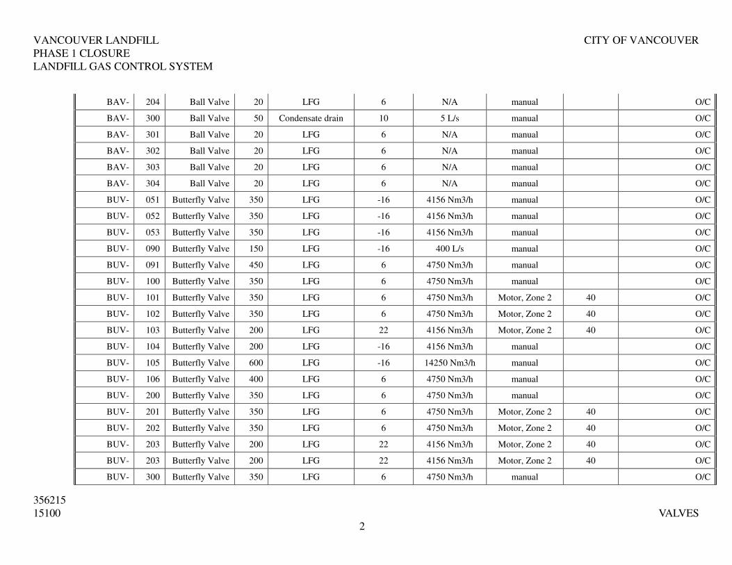
VANCOUVER LANDFILL CITY OF VANCOUVER
PHASE 1 CLOSURE
LANDFILL GAS CONTROL SYSTEM
356215
15100 VALVES
2
BAV- 204 Ball Valve 20 LFG 6 N/A manual O/C
BAV- 300 Ball Valve 50 Condensate drain 10 5 L/s manual O/C
BAV- 301 Ball Valve 20 LFG 6 N/A manual O/C
BAV- 302 Ball Valve 20 LFG 6 N/A manual O/C
BAV- 303 Ball Valve 20 LFG 6 N/A manual O/C
BAV- 304 Ball Valve 20 LFG 6 N/A manual O/C
BUV- 051 Butterfly Valve 350 LFG -16 4156 Nm3/h manual O/C
BUV- 052 Butterfly Valve 350 LFG -16 4156 Nm3/h manual O/C
BUV- 053 Butterfly Valve 350 LFG -16 4156 Nm3/h manual O/C
BUV- 090 Butterfly Valve 150 LFG -16 400 L/s manual O/C
BUV- 091 Butterfly Valve 450 LFG 6 4750 Nm3/h manual O/C
BUV- 100 Butterfly Valve 350 LFG 6 4750 Nm3/h manual O/C
BUV- 101 Butterfly Valve 350 LFG 6 4750 Nm3/h Motor, Zone 2 40 O/C
BUV- 102 Butterfly Valve 350 LFG 6 4750 Nm3/h Motor, Zone 2 40 O/C
BUV- 103 Butterfly Valve 200 LFG 22 4156 Nm3/h Motor, Zone 2 40 O/C
BUV- 104 Butterfly Valve 200 LFG -16 4156 Nm3/h manual O/C
BUV- 105 Butterfly Valve 600 LFG -16 14250 Nm3/h manual O/C
BUV- 106 Butterfly Valve 400 LFG 6 4750 Nm3/h manual O/C
BUV- 200 Butterfly Valve 350 LFG 6 4750 Nm3/h manual O/C
BUV- 201 Butterfly Valve 350 LFG 6 4750 Nm3/h Motor, Zone 2 40 O/C
BUV- 202 Butterfly Valve 350 LFG 6 4750 Nm3/h Motor, Zone 2 40 O/C
BUV- 203 Butterfly Valve 200 LFG 22 4156 Nm3/h Motor, Zone 2 40 O/C
BUV- 203 Butterfly Valve 200 LFG 22 4156 Nm3/h Motor, Zone 2 40 O/C
BUV- 300 Butterfly Valve 350 LFG 6 4750 Nm3/h manual O/C

VANCOUVER LANDFILL CITY OF VANCOUVER
PHASE 1 CLOSURE
LANDFILL GAS CONTROL SYSTEM
356215
15100 VALVES
3
BUV- 301 Butterfly Valve 350 LFG 6 4750 Nm3/h Motor, Zone 2 40 O/C
BUV- 302 Butterfly Valve 350 LFG 6 4750 Nm3/h Motor, Zone 2 40 O/C
CHV- 090 Check Valve 150 LFG -16 400 L/s N/A O/C
CHV- 100 Check Valve 350 LFG 6 4750 Nm3/h N/A O/C
CHV- 103 Check Valve 200 LFG 6 4156 Nm3/h N/A O/C
CHV- 200 Check Valve 350 LFG 6 4750 Nm3/h N/A O/C
CHV- 300 Check Valve 350 LFG 6 4750 Nm3/h N/A O/C
FCV- 050 Butterfly Valve 200 LFG 6 4156 Nm3/h Motor, Zone 2 M
FCV- 810 Butterfly Valve 250 LFG 6 4750 Nm3/h Pneumatic O/C
Service: O/C=Open - Close, T = Throttling, M= Modulating

VANCOUVER LANDFILL CITY OF VANCOUVER
PHASE 1 CLOSURE
LANDFILL GAS CONTROL SYSTEM
356215
15200-08 STAINLESS STEEL PIPE
AND FITTINGS
1
SECTION 15200-08
STAINLESS STEEL PIPE AND FITTINGS – GENERAL SERVICE
PART 1 GENERAL
1.01 PIPE
A. 50mm and smaller – Schedule 40S: ASTM A312/A312M, Type 316 seamless,
pickled and passivated.
B. 60mm to 150mm - Schedule 10S: ASTM A778, “as welded” grade, Type
316L.
C. 200mm and larger - Schedule 10S: ASTM A778, “as welded” grade, Type
316L.
D. Identify contents and flow direction as per ANSI/ASME A13.1-2007
1.02 JOINTS
A. 50mm and smaller – Threaded or flanged at equipment as required or shown.
B. 60mm and larger – Butt-welded or flanged at valves and equipment.
1.03 FITTINGS
A. 50mm and smaller – Threaded Forged: 1,000 CWP, ASTM A182/A182M,
Grade 316L.
B. 60mm and larger – Butt-Welded: ASTM A774/A774M Grade 316L
conforming to MSS SP 43, “as welded” grade, pickled and passivated; fitting
wall thickness to match adjoining pipe; long radius elbows unless shown
otherwise.
1.04 BRANCH CONNECTIONS
A. 50mm and smaller – Tee or reducing tee in conformance with Fittings above.
B. 60mm and larger – Butt-welding tee or reducing tee in accordance with
Fittings above.
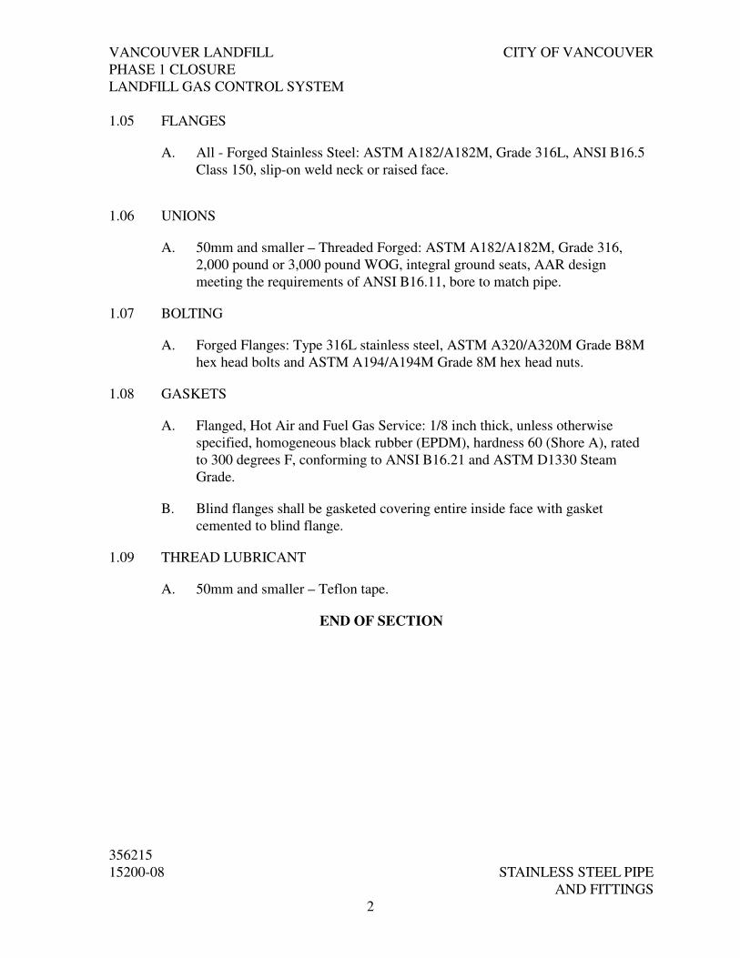
VANCOUVER LANDFILL CITY OF VANCOUVER
PHASE 1 CLOSURE
LANDFILL GAS CONTROL SYSTEM
356215
15200-08 STAINLESS STEEL PIPE
AND FITTINGS
2
1.05 FLANGES
A. All - Forged Stainless Steel: ASTM A182/A182M, Grade 316L, ANSI B16.5
Class 150, slip-on weld neck or raised face.
1.06 UNIONS
A. 50mm and smaller – Threaded Forged: ASTM A182/A182M, Grade 316,
2,000 pound or 3,000 pound WOG, integral ground seats, AAR design
meeting the requirements of ANSI B16.11, bore to match pipe.
1.07 BOLTING
A. Forged Flanges: Type 316L stainless steel, ASTM A320/A320M Grade B8M
hex head bolts and ASTM A194/A194M Grade 8M hex head nuts.
1.08 GASKETS
A. Flanged, Hot Air and Fuel Gas Service: 1/8 inch thick, unless otherwise
specified, homogeneous black rubber (EPDM), hardness 60 (Shore A), rated
to 300 degrees F, conforming to ANSI B16.21 and ASTM D1330 Steam
Grade.
B. Blind flanges shall be gasketed covering entire inside face with gasket
cemented to blind flange.
1.09 THREAD LUBRICANT
A. 50mm and smaller – Teflon tape.
END OF SECTION

VANCOUVER LANDFILL CITY OF VANCOUVER
PHASE 1 CLOSURE
LANDFILL GAS CONTROL SYSTEM
356215
15482 1 PROPANE/NITROGEN GAS PIPING
SYSTEM
SECTION 15482
PROPANE/NITROGEN GAS PIPING SYSTEM
PART 1 GENERAL
1.01 SUMMARY
A. Conform to Section 15010 - Basic Mechanical Requirements.
1.02 STANDARDS
A. CAN-CSA-B149.1 for Natural Gas and Propane Installation Code
B. ANSI B31.2 Fuel Gas Piping Code
C. ANSI/ASME A13.1, Pipe identification
D. CSA W59-M Welded Steel Construction (Metal Arc Welding)
E. CSA W47.1 Certification of Companies for Fusion Welding of Steel
Structures
F. British Columbia Safety Authority
1.03 SUBMITTALS
A. Submit the following:
1. Product Data
a. Details of components supplied.
2. Test Report.
PART 2 PRODUCTS
2.01 PIPE MATERIALS - PROPANE GAS
A. 50 mm and smaller
Pipe - ASTM A53 Grade B, or A 106 Schedule 40
Joints - threaded, tapered ANSI B1.20.1
- sealant, UL approved
Fittings - ANSI Class 2000
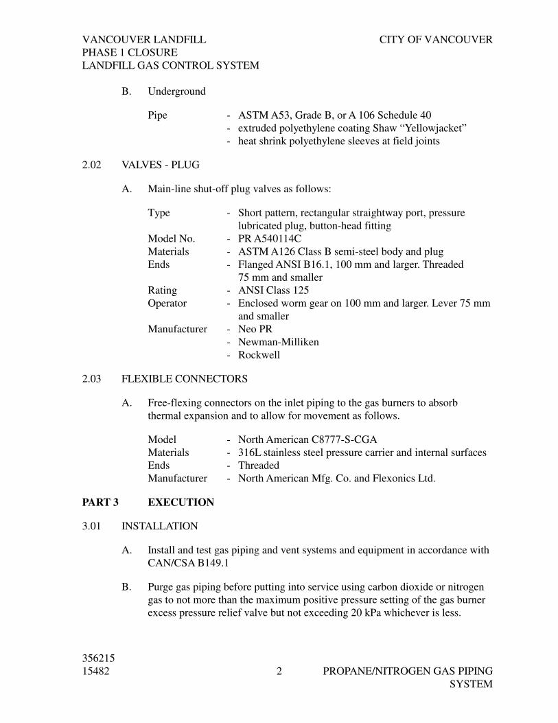
VANCOUVER LANDFILL CITY OF VANCOUVER
PHASE 1 CLOSURE
LANDFILL GAS CONTROL SYSTEM
356215
15482 2 PROPANE/NITROGEN GAS PIPING
SYSTEM
B. Underground
Pipe - ASTM A53, Grade B, or A 106 Schedule 40
- extruded polyethylene coating Shaw “Yellowjacket”
- heat shrink polyethylene sleeves at field joints
2.02 VALVES - PLUG
A. Main-line shut-off plug valves as follows:
Type - Short pattern, rectangular straightway port, pressure
lubricated plug, button-head fitting
Model No. - PR A540114C
Materials - ASTM A126 Class B semi-steel body and plug
Ends - Flanged ANSI B16.1, 100 mm and larger. Threaded
75 mm and smaller
Rating - ANSI Class 125
Operator - Enclosed worm gear on 100 mm and larger. Lever 75 mm
and smaller
Manufacturer - Neo PR
- Newman-Milliken
- Rockwell
2.03 FLEXIBLE CONNECTORS
A. Free-flexing connectors on the inlet piping to the gas burners to absorb
thermal expansion and to allow for movement as follows.
Model - North American C8777-S-CGA
Materials - 316L stainless steel pressure carrier and internal surfaces
Ends - Threaded
Manufacturer - North American Mfg. Co. and Flexonics Ltd.
PART 3 EXECUTION
3.01 INSTALLATION
A. Install and test gas piping and vent systems and equipment in accordance with
CAN/CSA B149.1
B. Purge gas piping before putting into service using carbon dioxide or nitrogen
gas to not more than the maximum positive pressure setting of the gas burner
excess pressure relief valve but not exceeding 20 kPa whichever is less.

VANCOUVER LANDFILL CITY OF VANCOUVER
PHASE 1 CLOSURE
LANDFILL GAS CONTROL SYSTEM
356215
15482 3 PROPANE/NITROGEN GAS PIPING
SYSTEM
C. Install the gas system, using skilled mechanics and certified welders, in
accordance with the manufacturers’ instructions.
D. Use only spark-proof tools when working in hazardous locations. Do not use
open flame.
3.02 CLEANING
A. Before connecting gas lines, burner, valves, instruments, etc. clean the piping
system of slag and foreign material by blowing with clean compressed air.
B. Replace any equipment damaged during initial operating period due to foreign
material not removed from the piping system.
3.03 DRIP LEGS
A. Provide drip legs fitted with plug valves as per CAN/CSA B149.1
3.04 TESTING
A. When visible leaks in the system have been stopped, pressurize each section
and maintain under pressure as required by CAN/CSA B149.1 System shall be
leak tight.
B. Disconnect or isolate any equipment damaged by the test pressure.
C. Replace any equipment damaged during the test. Test this equipment
separately at maximum allowable pressure.
D. Carry out a complete dynamic test of each piece of equipment supplied and/or
installed under this Contract, in the presence of the Engineer, or his delegate.
E. Upon completion of the above tests, tune the burners for high and low firing
rates. Follow the procedure provided by the burner manufacturer. Set to
operate 150% excess air (high fire conditions).
END OF SECTION

DIVISION 16
ELECTRICAL

VANCOUVER LANDFILL CITY OF VANCOUVER
PHASE 1 CLOSURE
LANDFILL GAS CONTROL SYSTEM
356215
16010 1 BASIC ELECTRICAL REQUIREMENTS
SECTION 16010
BASIC ELECTRICAL REQUIREMENTS
PART 1 PRODUCTS
1.01 SUMMARY OF WORK
A. Drawings indicate general location and route to be followed by conduits and
cables and electrical equipment arrangements. They do not show all structural,
architectural and mechanical details. In some cases, conduit or wiring is only
shown diagrammatically on Drawings and may not detail exact or complete
wiring or raceway requirements.
B. Refer to Drawings for accurate building dimensions.
C. To provide sufficient detail and maximum degree of clarity on Drawings,
symbols used for various electrical devices, particularly wall mounted
devices, take up more space on Drawings than devices physically do. Locate
devices with primary regard for convenience of operation and space
utilization, rather than stringing devices out so as to comply with scaled
locations of electrical symbols.
1.02 REFERENCES
A. CSA C22.2 No. 0 General Requirements - Canadian Electrical Code - Part 2.
B. Electrical and Electronic Manufacturers Association of Canada (EEMAC)
C. National Electrical Manufacturers Association (NEMA)
D. Institute of the Electrical and Electronic Engineers (IEEE)
E. Canadian Standards Association (CSA)
F. Canadian Gas Association (CGA)
G. Underwriters Laboratories Canada (ULC)
H. American National Standards Institute (ANSI)
I. National Fire Protection Agency (NFPA)
J. Comply with the latest editions of CSA C22.1 Canadian Electrical Code - Part
1, Provincial Electrical Authority Safety Codes and Bulletins, and local codes
and requirements which govern the installation. Where these regulations
conflict, comply with the most stringent condition.
K. Comply with latest editions of the CSA Certification Standards and Bulletins.

VANCOUVER LANDFILL CITY OF VANCOUVER
PHASE 1 CLOSURE
LANDFILL GAS CONTROL SYSTEM
356215
16010 2 BASIC ELECTRICAL REQUIREMENTS
1.03 DEFINITIONS
A. The following are definitions used in Division 16. Refer also to Division 1.
1. Inspection Authority means agent of any authority having jurisdiction
over construction and safety standards associated with any part of
electrical site work.
2. Supply Authority means electrical power company or commission
responsible for delivering electrical power to project site.
3. Electrical Code or Code means Provincial Electrical Code in force at
project location.
4. Prepurchased equipment means equipment supplied by the owner under
a separate contract, for installation under this contract.
1.04 DESIGN REQUIREMENTS
A. Operating voltages to be within those defined in CAN3-C235.
B. Electric equipment to operate satisfactorily at 60 Hz, within normal operating
limits established by CAN3 C235. Equipment must be able to operate in
extreme operating conditions established by CAN3 C235, without damage.
C. Verify before energization that equipment supplied under this contract or
prepurchased is compatible with related electrical power supply system.
D. Blower and Flare locations are classified (Class 1, Zone2)
1.05 SUBMITTALS
A. Schedule of Equipment
1. Submit within three weeks of contract award, a typewritten list of
materials, and equipment to be incorporated into work. Include
manufacturer name, equipment numbers, equipment name or
description, catalogue numbers and delivery date.
2. Include a blank column in the Schedule entitled Shop Drawings
Required. The Engineer will indicate in this column with Yes or No
whether shop drawings are to be submitted. A copy of this Schedule will
be returned by Engineer with required shop drawing submission
instructions.
B. Shop Drawings
1. Submit shop drawings, catalogue cuts and descriptive literature as
indicated in Schedule of Equipment. Show the following:
a. Layouts of equipment and dimensional drawings, including
weights.

VANCOUVER LANDFILL CITY OF VANCOUVER
PHASE 1 CLOSURE
LANDFILL GAS CONTROL SYSTEM
356215
16010 3 BASIC ELECTRICAL REQUIREMENTS
b. Layouts of switchgear, motor control centres, control panel, local
panels, and control station components provided under this
contract.
c. Schematic and wiring diagrams indicating wire and terminal
numbers.
d. Field interconnection wiring diagrams indicating wire numbers
and terminal block numbers. Include equipment supplied under
this and other Sections of this contract, under prepurchased
contract and is existing.
e. Bills of Material.
2. Where shop drawings show various options, selections and details,
indicate those that are applicable in pen and strike out those that are not
applicable.
3. Submit shop drawings of equipment stands, supports and fittings.
4. Fax copies of shop drawings are not acceptable.
5. For shop drawings that cannot be copied with a standard photocopier, in
addition to copies specified, submit one reproducible copy of record
drawings.
6. Include copies of shop drawings in installation, operation and
maintenance manuals.
7. Final record shop drawings to include changes marked on copy
reviewed by Engineer and field changes. Engineer’s marked up and
stamped copies are not acceptable.
C. Permits, Inspections, Test Reports, Certificates and Fees
1. Submit to Engineer necessary interim and final certificates of inspection
and approval required by Inspection Authorities having jurisdiction over
work, as evidence that work installed complies with laws and
regulations of governing authorities.
2. Submit copies of plans and specifications required by Inspection and
Supply Authorities.
3. Submit data and information necessary to allow the Engineer to apply to
the Supply Authority for approval to operate the generation system in
parallel with the Supply Authority system.
4. Notify Inspection Authorities in sufficient time to inspect work.
5. Submit Inspection Authorities approval certificates.
6. Submit electrical equipment and system warranty certificates.
7. Report motor full load amps, type and size of overload heaters installed,
breaker trip settings, fuse ratings and sizes of fuses in control circuits.
8. Report circuit insulation resistance.
9. Other requirements specified.
10. Pay associated fees and costs.

VANCOUVER LANDFILL CITY OF VANCOUVER
PHASE 1 CLOSURE
LANDFILL GAS CONTROL SYSTEM
356215
16010 4 BASIC ELECTRICAL REQUIREMENTS
D. Installation, Operation and Maintenance Manuals
1. Submit installation, operation and maintenance instructions for
electrical and instrumentation equipment supplied under this contract,
including schematic and wiring diagrams, field interconnection wiring
diagrams, performance curves and logic diagrams.
2. Include technical data, final record drawings, data sheets, factory and
field test results, complete parts list and recommended spare parts list.
3. Include catalogue cuts, data sheets, specification sheets, operations and
maintenance instructions for all components, auxiliary devices and
ancillaries.
4. Include start-up and test procedures, trouble-shooting directions and
equipment calibration instructions.
5. Include names and addresses of local component suppliers.
6. Submit two copies of manuals for review by Engineer before
preparation of final submission.
7. Incorporate Engineer’s comments into final manual submission.
E. Record Drawings
1. Include with record drawings, a list of equipment indicating equipment
numbers, service description, nameplate voltage, power (kW) and
current, size of overload, protection device rating and settings for each
piece of equipment.
2. Where cable trays are not detailed, submit scaled and dimensioned
record layout drawings of runs.
3. Include on record drawings, revisions due to engineering change orders,
site alterations, additions and field ordered changes made during
construction.
4. Record drawings in native AutoCAD format, PDF and hard copy.
1.06 QUALITY ASSURANCE
A. For work involving specialties, employ only workers fully trained, qualified
and experienced in all aspects of such work.
1.07 DELIVERY, STORAGE AND HANDLING
A. Ship equipment in accordance with manufacturers’ instructions.
B. Where required, ship channel bases and anchor stencils ahead of equipment.
C. Keep equipment doors closed. Protect equipment from damage, dust and
moisture.
D. Block moving parts where necessary to prevent damage during shipping and
handling of equipment. Clearly and conspicuously display instructions to
remove blocking before putting equipment into service.

VANCOUVER LANDFILL CITY OF VANCOUVER
PHASE 1 CLOSURE
LANDFILL GAS CONTROL SYSTEM
356215
16010 5 BASIC ELECTRICAL REQUIREMENTS
E. Supply temporary power to anti-condensation heaters of equipment, including
prepurchased equipment.
F. Store electrical and instrumentation equipment indoors in dry, heated space.
G. Upon receipt, examine prepurchased equipment for damage and verify
quantities against shipping documents. Notify Engineer of damages or missing
items.
PART 2 PRODUCTS
2.01 ACCEPTED MATERIALS
A. Materials: Approved by CSA, CUL, ULc or independent agency accepted by
Inspection Authorities for use as installed. Where equipment or material is not
approved or certified as indicated, obtain and pay for special acceptance from
Inspection Authorities or independent agency accepted by Inspection
Authorities.
B. Standards: Unless otherwise indicated, manufacture to standards of North
American Standards Agencies.
2.02 INSULATING BARRIERS
A. Barriers: Covering exposed terminals and terminal blocks against inadvertent
contact.
B. Warning labels: Lamicoid with 3 mm white letters on red background, on
front of compartments where multiple power sources are present.
2.03 IDENTIFICATION
A. Equipment Identification:
1. Nameplates: Engraved lamicoid, 3 mm thick, black face, white core,
mechanically secured to equipment with non-corroding, self-tapping
screws or rivets. Grind protruding screws flush with inside surface to
prevent injury.
2. Nameplate lettering sizes unless otherwise indicated:
a. Switchgear
1) individual components: 8 mm.
2) control devices, indicators: 3 mm.
b. MCC & GMCP individual components: 8 mm.
c. Transformers: 25 mm.
d. Control Panels
1) main nameplate: 25 mm.
2) individual devices: 3 mm.
e. Local Panels
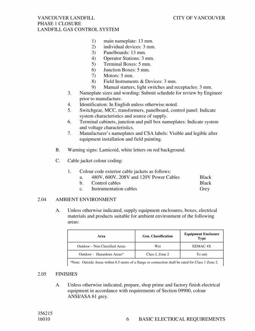
VANCOUVER LANDFILL CITY OF VANCOUVER
PHASE 1 CLOSURE
LANDFILL GAS CONTROL SYSTEM
356215
16010 6 BASIC ELECTRICAL REQUIREMENTS
1) main nameplate: 13 mm.
2) individual devices: 3 mm.
3) Panelboards: 13 mm.
4) Operator Stations: 3 mm.
5) Terminal Boxes: 5 mm.
6) Junction Boxes: 5 mm.
7) Motors: 5 mm.
8) Field Instruments & Devices: 3 mm.
9) Manual starters, light switches and receptacles: 3 mm.
3. Nameplate sizes and wording: Submit schedule for review by Engineer
prior to manufacture.
4. Identification: In English unless otherwise noted.
5. Switchgear, MCC, transformers, panelboard, control panel: Indicate
system characteristics and source of supply.
6. Terminal cabinets, junction and pull box nameplates: Indicate system
and voltage characteristics.
7. Manufacturer’s nameplates and CSA labels: Visible and legible after
equipment installation and field painting.
B. Warning signs: Lamicoid, white letters on red background.
C. Cable jacket colour coding:
1. Colour code exterior cable jackets as follows:
a. 480V, 600V, 208V and 120V Power Cables Black
b. Control cables Black
c. Instrumentation cables Grey
2.04 AMBIENT ENVIRONMENT
A. Unless otherwise indicated, supply equipment enclosures, boxes, electrical
materials and products suitable for ambient environment of the following
areas:
Area Gen. Classification Equipment Enclosure
Type
Outdoor – Non Classified Areas Wet EEMAC 4X
Outdoor – Hazardous Areas* Class I, Zone 2 To suit
*Note: Outside Areas within 0.5 metre of a flange or connection shall be rated for Class 1 Zone 2.
2.05 FINISHES
A. Unless otherwise indicated, prepare, shop prime and factory finish electrical
equipment in accordance with requirements of Section 09900, colour
ANSI/ASA 61 grey.

VANCOUVER LANDFILL CITY OF VANCOUVER
PHASE 1 CLOSURE
LANDFILL GAS CONTROL SYSTEM
356215
16010 7 BASIC ELECTRICAL REQUIREMENTS
B. Where site finishing is required, prepare and prime surfaces as specified in
Section 09900.
2.06 PENETRATION SEALS (AS REQUIRED)
A. Below grade exterior wall single conduit or cable penetration: Permanent,
watertight barrier seal, Type FSK by O-Z/Gedney Co., CS Series by O
Z/Gedney Co., RG Series fittings by Wieland Electric Inc.
B. Below grade exterior wall multiple conduit or cable penetration: Permanent,
watertight, engineered compression type, cast-in transit system, sized to
accommodate in addition to known conduits and cables, provided under this
contract and shown as future, 20% by cross section minimum spare capacity.
Multi-Cable Transit (MCT) by Wieland Electric Inc., Transit Barrier System
by Appleton Electric Ltd.
PART 3 EXECUTION
3.01 PREPARATION AND PROTECTION
A. Schedule expediting of materials and execution of work in conjunction with
associated work of other trades.
B. Install penetration seals and cable and conduit sleeves. Size sleeves through
concrete for free passage of conduit or cable.
C. Arrange for openings through exterior walls to be flashed and made
weatherproof.
D. Post engraved warning signs to meet requirements of Inspection Authorities
and Engineer.
E. Protect those working on or in vicinity of exposed electrically energized
equipment from physical danger. Shield and mark live parts “LIVE ___
VOLTS”. Indicate the appropriate voltage.
F. Arrange for installation of temporary doors, barriers and similar items for
access to rooms and areas containing electrical equipment. Keep these doors
locked at all times, except when under direct supervision.
G. Permanently identify equipment energized from multiple power sources,
noting voltages, power source locations and supply disconnect designations.
3.02 LOCATION OF ELECTRICAL AND INSTRUMENTATION ITEMS AND
RACEWAYS
A. The Engineer reserves the right to change location of electrical and
instrumentation items to within 3,000 mm of points indicated on plans without
additional charge, providing the Contractor is advised prior to installation.

VANCOUVER LANDFILL CITY OF VANCOUVER
PHASE 1 CLOSURE
LANDFILL GAS CONTROL SYSTEM
356215
16010 8 BASIC ELECTRICAL REQUIREMENTS
B. Where switches, receptacles and similar items are in the same general
location, line-up outlets vertically unless otherwise indicated.
C. Locate light switches on latch side of doors. Confirm door swing prior to
installation.
3.03 MOUNTING HEIGHTS
A. Mounting height of equipment is from finished floor to centreline of
equipment unless otherwise indicated.
B. If mounting height of equipment is not indicated, verify before proceeding
with installation.
C. Unless otherwise indicated, install electrical equipment at the following
heights:
1. Local switches: 1,400 mm
2. Wall receptacles: 1,200 mm.
3. Panelboards: 1,500 mm or as required by Code.
4. Horn and strobe lights: 2,500 mm.
5. Manual starters: 1,400 mm
6. Control stations: 1,400 mm.
7. Local control panels: 1,400 mm.
D. Height of operating handles, switches and controls, 1,400 mm maximum,
including allowance for housekeeping pads. Height of indicating devices and
instrument readouts, 500 mm minimum above floor.
E. In areas where existing equipment is located, adjust mounting heights
specified to match mounting heights of existing equipment.
3.04 PENETRATION SEALS
A. Except as indicated below, where sleeves or openings are installed in walls,
floors and roofs to accommodate raceways, cables or conduits, provide
necessary seals, fittings, barriers and fire resistant materials to permanently
restore installation to original fire rating. Refer to section 13121b Pre-
Engineered Buildings. Observe work affecting electrical installation.
B. Provide penetration seals for electrical penetrations through below grade
exterior wall.
3.05 LOAD BALANCE
A. Measure and record phase currents at panelboards with normal loads (lighting,
receptacles, heaters, single phase motors and similar items) operating at time
of acceptance. Adjust branch circuit connections as required to obtain the best

VANCOUVER LANDFILL CITY OF VANCOUVER
PHASE 1 CLOSURE
LANDFILL GAS CONTROL SYSTEM
356215
16010 9 BASIC ELECTRICAL REQUIREMENTS
phase current balance and record changes. Retype and replace panelboard
circuit directory.
B. Measure and record panelboard phase voltages during normal operation and
adjust transformer taps to within 3% of rated voltage of equipment.
3.06 TESTS
A. Test and check electrical and instrumentation systems for correct operation
and compliance with statutory and regulatory authority requirements.
B. Perform tests in presence of Engineer. Log, tabulate, sign and include test
results in Installation, Operations and Maintenance Manuals.
C. Provide assistance to prepurchased equipment supplier in the commissioning,
testing and start-up of the prepurchased equipment.
D. Test the following systems:
1. 600 V distribution systems, including cabling for correct and adequate
phasing, voltage, grounding and load balancing.
2. 24 VDC and UPS systems (as required).
3. Circuits originating from branch distribution panels.
4. Lighting and associated control.
5. Motors, heaters and associated control equipment including sequenced
operation of systems where applicable.
6. Control and instrumentation systems.
E. Refer to appropriate Sections for specific system or equipment tests.
F. Arrange for qualified personnel to conduct tests.
G. Supply instruments, meters, consumable parts (such as fuses) and equipment.
H. In cooperation with mechanical trades, take clamp on ammeter readings with
motors operating at full load. Log, tabulate and include readings in
Installation, Operations and Maintenance Manuals.
I. Check electrical system voltages after facility is fully operational. Adjust
transformer tap settings as required. Tabulate, make adjustments and record
data in Installation, Operations and Maintenance Manuals.
3.07 TOUCH UP PAINTING
A. Field touch-up shop painted electrical equipment, including equipment
supplied by the prepurchased equipment supplier.
B. Obtain necessary touch up paint of original type and quality from equipment
manufacturer.

VANCOUVER LANDFILL CITY OF VANCOUVER
PHASE 1 CLOSURE
LANDFILL GAS CONTROL SYSTEM
356215
16010 10 BASIC ELECTRICAL REQUIREMENTS
C. Apply one or more coats until damaged surface has been restored to original
finish condition.
D. Do not paint nameplates, tags, warning plates and operating instructions.
Observe field painting of electrical equipment or raceways.
3.08 SUPPORTS AND HANGERS
A. Provide supports, hangers, plates and hardware required for electrical and
instrumentation equipment.
B. Hot dip galvanize prefabricated steel supports, such as channels, struts,
brackets, hangers, slotted angles and similar items. Bolt or clamp these
supports. Do not field weld. Repaint cut sections with zinc rich galvanizing
primer.
C. Bond metallic supports to grounding electrode. Do not use metallic supports
as ground conductors for electrical equipment.
D. Provide non-corroding, 6 mm minimum, nylon or lead spacers for fastening
enclosures to masonry walls.
E. Provide expansion anchors, type HKD by Hilti (Canada) Ltd. or Redhead
Multi-Set II by Phillips and machine screws or threaded rods and nuts for
supporting hangers or straps.
F. Provide UCAN or TAPCON fasteners, or KWIK-CON II anchors by Hilti
(Canada) Ltd. for attaching conduit straps, conduit fittings, boxes, control
stations, and similar items to concrete.
G. Do not use power actuated tools without written consent of Engineer.
3.09 CUTTING AND PATCHING
A. Core and cut openings in existing structures as required. Comply with
Division 3.
B. Bear costs for cutting and patching resulting from failure to coordinate timely
installation of electrical inserts, penetration seals, sleeves, and similar items
into structures.
C. Cut and patch concrete as indicated in Division 3.
3.10 CLEANING
A. Clean construction debris and materials from enclosures.
B. Clean luminaire reflectors, lenses and other surfaces exposed to construction
dust and dirt.

VANCOUVER LANDFILL CITY OF VANCOUVER
PHASE 1 CLOSURE
LANDFILL GAS CONTROL SYSTEM
356215
16010 11 BASIC ELECTRICAL REQUIREMENTS
3.11 PROVISION FOR FUTURE EXPANSION
A. In each location where space for future equipment is indicated, leave such
space clean. Install raceways, wiring and other work in such a manner that
necessary connections can be made in future without dismantling existing
equipment, raceways or wiring. Consult with Engineer whenever necessary.
END OF SECTION

VANCOUVER LANDFILL CITY OF VANCOUVER
PHASE 1 CLOSURE
LANDFILL GAS CONTROL SYSTEM
356215
16050 1 BASIC MATERIALS AND METHODS
SECTION 16050
BASIC MATERIALS AND METHODS
PART 1 GENERAL
1.01 SUMMARY
A. Comply Section 16010 - Basic Electrical Requirements.
1.02 SUBMITTALS
A. Submit shop drawings of equipment, components and ancillaries.
PART 2 PRODUCTS
2.01 GENERAL
A. Equipment Enclosures: Compatible with room or area environment and unless
otherwise indicated, in accordance with classification specified in Section
16010.
B. Finishes: Unless otherwise indicated, factory finish equipment inside and
outside with ANSI/ASA #61 grey paint.
2.02 MOTOR CONTROL CENTRES
A. Acceptable manufacturers:
1. Allen-Bradley Canada Ltd.
2. Siemens Electric Ltd.
3. Eaton Cutler-Hammer
4. Schneider
5. Or, Engineer Approved Equal
B. Intentionally Deleted
C. Intentionally Deleted
2.03 PANELBOARDS
A. Acceptable manufacturers:
1. NLAB by Siemens Electric Ltd.
2. NQOB by Square D Canada
3. Pow-R-Line by Cutler-Hammer/Westinghouse
4. NBLP by Federal Pioneer Limited

VANCOUVER LANDFILL CITY OF VANCOUVER
PHASE 1 CLOSURE
LANDFILL GAS CONTROL SYSTEM
356215
16050 2 BASIC MATERIALS AND METHODS
B. Supply panelboards from same manufacturer.
C. Panelboards: Circuit breaker type, deadfront design, equipped with double or
single row, bolt-on, thermal magnetic, non-interchangeable, moulded case
branch circuit breakers.
D. Ratings: Panelboards and components with minimum (symmetrical) short
circuit ratings of 10,000 A at 120/208 V.
E. Busbars: Tin plated copper.
F. Doors: With spring latches and cylinder locks keyed alike, two keys per
panelboard.
G. Circuit directory: Framed plastic enclosed legend, located on inside of door.
H. Lock-on/lock-out devices: Minimum 10% of 15 to 30A circuits provided.
Turn over unused devices to Owner.
2.04 DISTRIBUTION TRANSFORMERS
A. Acceptable manufacturers:
1. Hammond Manufacturing Co. Ltd.
2. Polygon Transformer Co.
3. Square ‘D’ Canada
4. Marcus Transformer of Canada Ltd.
5. Rex Manufacturing
6. Delta Transformer of Canada Ltd.
B. Design: General purpose, dry type, ANN, ventilated 60 Hz, low sound level
with vibration isolators, four 2½% primary taps (2-FCAN, 2-FCBN).
C. Insulation: Class 220°C minimum with maximum 80°C temperature rise in
40°C ambient.
D. Windings: Copper, delta connected primary, wye connected secondary with
neutral grounding provision.
E. Mounting accessories: Mounting brackets for wall or ceiling suspension as
required.
2.05 LIGHT SWITCHES
A. Switch: Specification grade, flush mount, back and side wired, ivory high
strength toggle, rated 20 A, 120 V AC. 20 AC Series by Pass & Seymour
Canada Inc., GE595 Series by Smith & Stone Inc., 490 Series by Bryant

VANCOUVER LANDFILL CITY OF VANCOUVER
PHASE 1 CLOSURE
LANDFILL GAS CONTROL SYSTEM
356215
16050 3 BASIC MATERIALS AND METHODS
Wiring Devices, 199 Series by Arrow-Hart, 122 Series by Hubbell Canada
Inc., 122 Series by Leviton Canada Ltd.
B. Switch cover plates: Cast ferrous alloy, gasketted, toggle type, DS185 by
Crouse-Hinds, FS-1-WSCA by O-Z/Gedney Inc., FZ type by Killark Electric
Manufacturing Co.
2.06 METERING
A. Utility Metering – not required as this service is part of a Primary Metered
service.
B. Digital Power Metering Package –
1. Provide and install the Digital AC Instrumentation Package in the MCC
capable of measuring, calculating and directly displaying on the front
panel display the following information:
2. Volts on each phase plus average of all three phase.
3. Current on each phase plus average of all three phases.
4. Neutral or ground current.
5. Frequency.
6. Power factor.
7. kVA.
8. kVAR.
9. kW.
10. Total kWH as an accumulating total, providing bi-directional
(import/export) indication.
11. Total kVARH as an accumulating total, providing bi-directional
(import/export) indication.
12. kW Demand, user-programmable length of each demand period and the
number of periods averaged to match local utility billing method.
13. Amps Demand.
14. kVA Demand, user-programmable length of each demand period and
the number of periods averaged to match local utility billing method.
C. The instrumentation package to have:
1. True RMS measurement.
2. Direct connection to 600 Volt, 3 phase, 4 wire system.
3. Fourth current input for measurement of ground or neutral current.Not
used.
2.07 UNINTERRUPTABLE POWER SUPPLIES (UPS)
A. Type: On-line, no-break, batteries continuously in circuit, with static bypass,
suitable for powering loads indicated, Powerware3S3K by Best Power
Technology Inc.

VANCOUVER LANDFILL CITY OF VANCOUVER
PHASE 1 CLOSURE
LANDFILL GAS CONTROL SYSTEM
356215
16050 4 BASIC MATERIALS AND METHODS
B. Rating: Minimum 3 kW/3kVA rating, 208 VAC, single phase, 60 Hz input,
120/240 VAC, single phase, three wire, 60 Hz output.
C. Voltage regulation: ±5% maximum for line or load changes from 0 to 100%
under any battery condition.
D. Surge protection: Comply with category B, ANSI/IEEE C62.41 and UL 1449
listed.
E. Frequency: Input synchronized with supply, output 60 Hz ±0.5%.
F. Total harmonic distortion: 5% maximum.
G. Battery: Sealed, nickel cadmium, maintenance free, minimum 5 year life,
rated to supply full load output at rated voltage for 30 minutes minimum.
H. Fault indication: One normally open and one normally closed, voltage free,
common fault contact, 2 A, 120 VAC, for remote indication. Indicate
individual faults locally.
I. Input and output connections: Hard wired. Output from receptacles not
acceptable.
2.08 FLASHING LIGHTS
A. Not used
2.09 TRANSIENT VOLTAGE SURGE SUPPRESSOR (TVSS)
A. Manufacturer
1. Rayvoss
B. Transient voltage surge suppressor for the protection of downstream
electronic equipment connected to the building power supply. Provide a unit
compatible with non-linear loads, providing effective high-energy transient
voltage suppression, surge current diversion and high-frequency electrical
noise filtering while connected in parallel with a facility’s distribution system.
Utilize non-linear voltage dependent metal oxide varistors or selenium cells.
For the suppression system’s components, do not utilize gas tubes, spark gaps,
or silicon avalanche diodes. Refer to the device as a TVSS filter for the
purpose of this Specification and Drawings.
C. Provide three Strikesorb 80-D units to be installed in an MCC drawer along
with the 200 Amp breaker.
D. Operation and Environment

VANCOUVER LANDFILL CITY OF VANCOUVER
PHASE 1 CLOSURE
LANDFILL GAS CONTROL SYSTEM
356215
16050 5 BASIC MATERIALS AND METHODS
1. Voltage: Use TVSS devices suitable for the voltage and systems
configuration as indicated on the single line diagram(s).
2. MCOV: Ensure the MCOV of the suppressor is greater than 115% for
347/600 V systems.
3. Protection Modes: Provide transient voltage surge suppression paths for
all possible common and normal modes (between each line and ground,
neutral and ground, line to line and each line and neutral). Ensure the
primary suppression path is not to ground.
PART 3 EXECUTION
3.01 MANUAL MOTOR STARTER INSTALLATION
A. Provide manual starters as indicated.
3.02 PANELBOARD INSTALLATION
A. Provide panelboards of type and size indicated.
B. Terminate and connect field wiring.
3.03 DISTRIBUTION TRANSFORMER INSTALLATION
A. Provide distribution transformer as part of the MCC line-up as per drawings.
3.04 LIGHT SWITCH INSTALLATION
A. Provide light switches as indicated.
B. Install cover plates after painting of room surfaces.
3.05 UNINTERRUPTABLE POWER SUPPLY INSTALLATION
A. Provide UPS as indicated.
B. Carry out tests and start-up procedures as recommended by manufacturer.
C. Train Owner’s staff in aspects of operation and maintenance of UPS system.
D. Install UPS in the bottom of PLC control panel CP-101.
END OF SECTION

VANCOUVER LANDFILL CITY OF VANCOUVER
PHASE 1 CLOSURE
LANDFILL GAS CONTROL SYSTEM
356215
16111 1 CABLE TRAY SYSTEMS
SECTION 16111
CABLE TRAY SYSTEMS
PART 1 GENERAL
1.01 SUMMARY
A. Comply with Section 16010 - Basic Electrical Requirements.
B. Note installation of cables and cable trays is optional as an alternate to conduit
and wiring for abouve ground field wiring shown on the drawings.
1.02 REFERENCES
A. CSA C22.2 No. 126 Cable Tray Systems.
PART 2 PRODUCTS
2.01 MATERIALS
A. Acceptable cable tray manufacturers:
1. Pilgrim Technical Products Ltd.
2. ElectroTray
3. B-Line Systems, Canada.
4. Pursley 2000
B. CSA Class E load carrying capability, ladder type with 300 mm ring spacing
for armoured cables, ventilated type for unarmoured cables, aluminum,
75 mm minimum side rail height, width as indicated.
C. Barriers: Solid metal, of same material as cable tray.
D. Hanger rods and hardware: Galvanized steel, 12 mm minimum diameter.
E. Beam clamps: Hot dip galvanized steel or malleable iron, designed to clamp
onto both sides of flange. Cat. #S997BC-HG (100-230 mm flange) by Sasco
Tube & Roll Forming Inc., Cat. #S999BC-HA (175-430 mm flange) by Sasco
Tube & Roll Forming Inc., Type CS91 by Canstrut Inc.

VANCOUVER LANDFILL CITY OF VANCOUVER
PHASE 1 CLOSURE
LANDFILL GAS CONTROL SYSTEM
356215
16111 2 CABLE TRAY SYSTEMS
PART 3 EXECUTION
3.01 INSTALLATION
A. Install cables in cable tray. Do not clip cables to walls, ceiling, equipment or
similar items.
B. Provide cable tray raceway systems with fittings, accessories and hangers
required.
C. Verify cable tray dimensions and locations. Determine exact location in field.
D. Install cable tray to avoid interferences with process or service equipment and
piping. Co-ordinate location of supports and runs with other trades.
E. Provide wall supported trays with supports of type suitable to allow cables to
be laid into cable trays and not be pulled.
F. Space tray supports 6000 mm maximum. Mechanically bolt tray connections.
Install supports within 300 mm of either side of bends, cross and T-fittings.
G. Provide support system adequate to accommodate stresses imposed by cable
pulling.
H. Allow for unobstructed clamping of cables or conduits in cable trays.
I. Where cables exit cable trays, provide drop-out fittings recommended by
manufacturer.
J. After installation of trays and cables, seal openings in walls and floors to
original fire rating with fire resistant material. Refer to Section 16010.
K. Provide expansion joint type coupling connectors and bonding jumpers at
building expansion joints and on straight runs exceeding 30 m.
L. Install a bare copper conductor in each tray for equipment grounding. Comply
with Inspection Authority requirements. Attach ground conductor to each tray
section and fitting with an accepted ground clamp.
M. Install metallic separation barriers for separation of cables of different voltage
classes and different signal levels.
END OF SECTION

VANCOUVER LANDFILL CITY OF VANCOUVER
PHASE 1 CLOSURE
LANDFILL GAS CONTROL SYSTEM
356215
16112 1 CONDUIT SYSYTEMS
SECTION 16112
CONDUIT SYSTEMS
PART 1 GENERAL
1.01 SUMMARY
A. Comply with Section 16010 - Basic Electrical Requirements.
B. Refer to 16112SUP.DOC for the field conduit/cable schedule.
1.02 REFERENCE
A. CSA C22.2 No. 45 Rigid Metal Conduit.
B. CSA C22.2 No. 56 Flexible Metal Conduit and Liquid-Tight Flexible Metal
Conduit.
1.03 SUBMITTALS
A. Submit catalogue cuts of conduit, fittings, supports, boxes and similar items.
PART 2 PRODUCTS
2.01 MANUFACTURED UNITS
A. Comply with standards listed in 1.02, References.
B. Rigid steel conduit: Conduit, including threaded elbows and fittings, hot-dip
galvanized inside and outside, by Robroy Industries Ltd., Longtin Conduits
Inc., MBF Electrical Products Inc.
C. Liquid-tight flexible conduit: Aluminum or galvanized steel, spirally wound
interlocking armour construction, extruded PVC jacket overall. Metal Hose
Sealtite by Anaconda, type CSA by Eastern Wire & Conduit.
D. Conduit straps: Malleable iron, hot-dip galvanized, 1275 to 1288 series by
Thomas & Betts Ltd.
E. Beam clamps: Hot dip galvanized steel designed to clamp onto both sides of
the flange. Cat. #S997BC-HG (100-230 mm flange) by Sasco Tube & Roll
Forming Inc., Cat. #S999BC-HA (175-430 mm flange) by Sasco Tube & Roll
Forming Inc., Type CS91 by Canstrut Inc.
F. Rigid steel conduit connectors: Malleable iron or steel, hub type, with nylon
insulated throat or bushing, recessed neoprene O ring, pressure type terminals

VANCOUVER LANDFILL CITY OF VANCOUVER
PHASE 1 CLOSURE
LANDFILL GAS CONTROL SYSTEM
356215
16112 2 CONDUIT SYSYTEMS
for grounding wire connections when required, by Thomas & Betts Ltd., Swift
Devices Ltd., Elliot Electrical Manufacturing Co.
G. Liquid-tight flexible conduit connectors: With threaded grounding core, nylon
compression ring and gland, insulated throat, male thread and locknut or male
bushing with integral O ring seal, by Thomas & Betts Ltd., Elliot Electrical
Manufacturing Co.
H. Locknuts for metallic conduits: Bonding type with sharp edges for digging
into metal wall of enclosure.
I. Conduit fitting cover plates: Cast, hot-dipped galvanized steel. Pressed steel
covers are not acceptable.
J. Expansion couplings: With ground straps or clamps. Type XJ by
Crouse-Hinds.
K. Swivel couplings: Threaded, Erikson type by Thomas & Betts or one piece, by
Elliot Electrical Manufacturing Co. Running threads are not acceptable.
L. Conduit seals and fittings for hazardous locations: Suitable for application in
designated area, by Crouse-Hinds, Killark Electrical Manufacturing Co.,
Appleton Electric Ltd., O-Z/Gedney Co.
M. Hazardous area seal filling compound: As recommended by seal
manufacturer.
N. Pull cords: 6 mm polypropylene or nylon material. Pro-pull rope by Ideal.
PART 3 EXECUTION
3.01 INSTALLATION
A. Unless otherwise indicated, install unarmoured wire and cable in conduit.
B. Connect conduits to electrical boxes and electrical equipment enclosures with
watertight conduit connectors.
C. Install conduits exposed, and where possible, surface mounted. Conserve
headroom in exposed locations and cause minimum interference in spaces
through which they pass.
D. Install conduits 150 mm minimum clear of hot water pipes and 1000 mm
minimum clear of heaters.
E. Provide rigid galvanized steel conduits, minimum trade size 19 mm.

VANCOUVER LANDFILL CITY OF VANCOUVER
PHASE 1 CLOSURE
LANDFILL GAS CONTROL SYSTEM
356215
16112 3 CONDUIT SYSYTEMS
F. For conduit systems in or running through hazardous areas, provide conduit,
fittings, seals and associated components complying with requirements of
applicable Codes and Standards.
G. Install conduits symmetrical with building construction and with accepted
bends or pull boxes where conduits change direction.
H. Provide expansion fittings in straight conduit runs exceeding 60 m and at
building expansion joints.
I. Attach conduits in place with galvanized steel hangers or straps spaced at
1300 mm centres maximum. Group conduits together whenever possible. Use
galvanized steel hangers and supports. Perforated straps are not acceptable.
J. Provide conduit spacers for surface mounted conduits on concrete or masonry
walls.
K. Provide drilled-in type expansion bolts and machine screws for supporting
hangers and straps. Comply with Section 16010.
L. Locate conduits penetrating floors, permitting direct vertical connection with
minimal bending.
M. Provide flexible liquid-tight conduit between rigid conduit system and
equipment subject to vibration or adjustment, such as motors or motorized
equipment.
N. Size conduits according to Inspection Authority requirements.
O. Route conduits to avoid beams, columns and other obstructions.
P. Ream cut conduits to remove burrs; paint completed galvanized steel joints
and field cut threads with zinc rich primer paint.
Q. Clean conduit run with an accepted cleaner equipped with a mandrel.
R. Provide bushings on ends.
S. Install expansion fittings on dry side of plastic water stops where required.
T. Where possible, drain conduits toward outlets. If not possible, provide
drainage holes or C condulets.
U. Do not commence surface conduit installation work until wall and floor
finishes are completed. Finish surface mounted conduit installation work prior
to surface painting.
V. Provide pull cords in empty conduits with 1000 mm slack at each end.

VANCOUVER LANDFILL CITY OF VANCOUVER
PHASE 1 CLOSURE
LANDFILL GAS CONTROL SYSTEM
356215
16112 4 CONDUIT SYSYTEMS
3.02 INSTALLATION IN HAZARDOUS LOCATIONS
A. Connect to motors with liquid-tite flexible conduit sections.
B. Install filled conduit seals where required.
C. Install approved explosion proof drain fittings at low points in conduit system.
END OF SECTION

VANCOUVER LANDFILL CITY OF VANCOUVER
PHASE 1 CLOSURE
LANDFILL GAS CONTROL SYSTEM
356215
16112 SUPPLEMENT i CONDUIT SYSTEMS
Raceway Number - Designation Conduit Size (mm) Wire Fill NOTES
R1 - Flare No. 1 Power Conduit 25.4 6#14 RW 90 Disconnect and re-run to new JBR2 - Flare No. 2 Power Conduit 25.4 6#14 RW 90 Disconnect and re-run to new JB
R3 - FE-100 to FIT-100 25.4 Instrument Cable New run to new JB
R4 - Flare No. 1 Contro l Conduit 25.4 6#14 RW 90 Disconnect and re-run to new JB
R5 - Flare No. 2 Contro l Conduit 25.4 6#14 RW 90 Disconnect and re-run to new JBR6 - Flare No. 1 Signal Conduit 38.1 1- 2/C & 1 - 3/C #18 w/shield Disconnect and re-run to new JB
R7 - Flare No. 2 Signal Conduit 38.1 1 - 2/C & 1 - 3/C #18 w/shield Disconnect and re-run to new JB
R8 - Flare No. 1 Thermocouple Conduit 25.4 3 # Type-K Cable Disconnect and re-run to new JB
R9 - Flare No.2 Thermocouple Conduit 25.4 3 # Type-K Cable Disconnect and re-run to new JBR10 - Flare No. 1 FCV-600 19.1 6#14 RW 90 Disconnect and re-run to new JB
R11 - Flare No. 2 FCV-700 19.1 6#14 RW 90 Disconnect and re-run to new JB
R12 - Flare No. 1 BE-110 12.7 2#14 RW 90 Re-use existing
R13 - Flare No. 2 BE-120 12.7 2#14 RW 90 Re-use existingR14 - Flare No. 1 BE-110 19.1 3/C #18 w/shield Re-use existing
R15 - Flare No. 2 BE-120 19.1 3/C #18 w/shield Re-use existing
R16 - Flare No. 1 TCV-110 12.7 2#14 RW 90 Re-use existing
R17 - Flare No. 2 TCV-120 12.7 2#14 RW 90 Re-use existingR18 - Flare No. 1 TCV-110 19.1 2/C #18 w/shield Re-use existing
R19 - Flare No. 2 TCV-120 19.1 2/C #18 w/shield Re-use existing
R20 - Flare No. 1 RPI-110 12.7 2#14 RW 90 Re-use existing
R21 - Flare No. 2 RPI-120 12.7 2#14 RW 90 Re-use existing
R22 - Flare No. 1 RPI-110 to Igniter 25.4 Igniter Cable Re-use existingR23 - Flare No. 2 RPI-120 to Igniter 25.4 Igniter Cable Re-use existing
R24 - Flare No. 1 TE-110 12.7 Type-J Cable Re-use existing
R25 - Flare No. 1 TE-111 12.7 Type-J Cable Re-use existing
R26 - Flare No. 1 TE-112 12.7 Type-J Cable Re-use existingR27 - Flare No. 2 TE-120 12.7 Type-J Cable Re-use existing
R28 - Flare No. 2 TE-121 12.7 Type-J Cable Re-use existing
C29 - Flare No. 2 TE-122 12.7 Type-J Cable Re-use existing
R30 - Flare No. 1 Purge Blower BL-111 19.1 3#14, 1#14 G Disconnect and re-run to new JBR31 - Flare No. 2 Purge Blower BL-121 19.1 3#14, 1#14 G Disconnect and re-run to new JB
R32 - Existing MCC Feeder Breaker removed
RACEWAY AND CABLE SCHEDULE -EXISTING

VANCOUVER LANDFILL CITY OF VANCOUVER
PHASE 1 CLOSURE
LANDFILL GAS CONTROL SYSTEM
356215
16112 SUPPLEMENT ii CONDUIT SYSTEMS
Raceway Number - Designation Conduit Size (mm) Wire Fill
R35 - Flare No. 3 Power Condui t 25.4 6#14 RW 90 NewR36 - Flare No. 4 Power Condui t 12.7 2#14 RW 90 New
R37 -
R38 - Flare No. 3 Control Conduit 25.4 6#14 RW 90 New
R39 - Flare No. 4 Control Conduit 25.4 20#14 RW90 NewR40 - Flare No. 3 S ignal Conduit 38.1 1- 2/C & 1 - 3/C #18 w/shield New
R41 - Flare No. 4 S ignal Conduit 38.1 1 - 2/C & 1 - 3/C #18 w/shield New
R42 - Flare No. 3 Thermocouple Conduit 25.4 3 # Type-K Cable New
R43 - Flare No.2 Thermocouple Conduit 25.4 3 # Type-K Cable NewR44 - Flare No. 3 FCV-610 19.1 6#14 RW 90 New
R45 - Flare No. 4 FCV-710 19.1 6#14 RW 90 New
R46 - Flare No. 3 BE-130 12.7 2#14 RW 90 New
R47 - Flare No. 4 BE-140 12.7 TBA Info required from Flare VendorR48 - Flare No. 3 BE-130 19.1 3/C #18 w/shield New
R49 - Flare No. 4 BE-140 19.1 TBA Info required from Flare Vendor
R50 - Flare No. 3 TCV-130 12.7 2#14 RW 90 New
R51 - Flare No. 4 TCV-140 12.7 TBA Info required from Flare VendorR52 - Flare No. 3 TCV-130 19.1 2/C #18 w/shield New
R53 - Flare No. 4 TCV-140 19.1 TBA Info required from Flare Vendor
R54 - Flare No. 3 RPI-130 12.7 2#14 RW 90 New
R55 - Flare No. 4 RPI-140 12.7 TBA Info required from Flare Vendor
R56 - Flare No. 3 RPI-130 to Igniter 25.4 Igniter Cable NewR57 - Flare No. 4 RPI-140 to Igniter 25.4 TBA Info required from Flare Vendor
R58 - Flare No. 3 TE-130 12.7 Type-J Cable New
R59 - Flare No. 3 TE-131 12.7 Type-J Cable New
R60 - Flare No. 3 TE-132 12.7 Type-J Cable NewR61 - Flare No. 4 TE-140 12.7 Type-J Cable New
R62 - Flare No. 4 TE-141 12.7 Type-J Cable New
R63 - Flare No. 4 TE-142 12.7 Type-J Cable New
R64 - Flare No. 3 Purge Blower BL-131 19.1 3#14, 1#14 G NewR65 - New Blower BL-1 53 3C# 2/0 New
R66 - New Blower BL-2 53 3C# 2/0 New
R67 - Blower 1 Inlet Valve BUV-101 25.4 10#14 RW90 New
R68 - Blower 1 Oulet Valve BUV-102 25.4 10#14 RW90 NewR69 - Blower 2 Inlet Valve BUV-201 25.4 10#14 RW90 New
R70 - Blower 2 Outlet Valve BUV-202 25.4 10#14 RW90 New
R71 - Blower 1 Bypass Valve BUV-103 25.4 10#14 RW90 New
R72 - Blower 2 Bypass Valve BUV-203 25.4 10#14 RW90 NewR73 - Inlet Pressure Transmi tter PIT-050 12.7 2/C #18 w/shield New
R74 - Recycle Valve FCV-050 12.7 1- 2/C & 1 - 3/C #18 w/shield New
R75 - Blower 1 Inlet Valve BUV-101 Power 25.4 10#14 RW90 New
R76 - Blower 1 Oulet Valve BUV-102 Power 25.4 10#14 RW90 NewR77 - Blower 2 Inlet Valve BUV-201 Power 25.4 10#14 RW90 New
R78 - Blower 2 Outlet Valve BUV-202 Power 25.4 10#14 RW90 New
R79 - Blower 1 Bypass Valve BUV-103 Power 25.4 10#14 RW90 New
R80 - Blower 2 Bypass Valve BUV-203 Power 25.4 10#14 RW90 NewR81 - Inlet High Temp. Switch 12.7 2#14 RW 90 New
R82 - LFG Flow Transmitter 19.1 6/C #18 w/shield New
R83 - Blower 3 Inlet Valve BUV-301 Power 25.4 10#14 RW90 New
R84 - Blower 3 Inlet Valve BUV-301 25.4 10#14 RW90 NewR85 - New Blower BL-3 53 3C# 2/0 New
R86 - Blower 3 Bypass Valve BUV-303 Power 25.4 10#14 RW90 New
R87 - Blower 3 Bypass Valve BUV-303 25.4 10#14 RW90 New
R88 - Blower 3 Outlet Valve BUV-302 Power 25.4 10#14 RW90 NewR89 - Blower 3 Outlet Valve BUV-302 25.4 10#14 RW90 New
RACEWAY AND CABLE SCHEDULE - NEW

VANCOUVER LANDFILL CITY OF VANCOUVER
PHASE 1 CLOSURE
LANDFILL GAS CONTROL SYSTEM
356215
16112 SUPPLEMENT iii CONDUIT SYSTEMS
Raceway Number - Designation Conduit Size (mm) Wire Fill
P-P100A 50C#14 NewP-P100B 30C#14 New
P-C100 8PR#16 New
P-C100 12PRTYPE J New
P-T100 #9463BELDEN NewCOM-100 RS-232 New
COM-101 #9463BELDEN New
COM-102 5eCAT New
COM-103 #9463BELDEN NewCOM-104 5eCAT New
COM-105 5eCAT New
COM-106 New
P-B100 3C#2/O NewP-B200 3C#2/O New
P-B111 3C#12 New
P-B121 3C#12 New
P-B131 3C#12 NewP-L100A 2C#10 New
RACEWAY AND CABLE SCHEDULE - NEW

VANCOUVER LANDFILL CITY OF VANCOUVER
PHASE 1 CLOSURE
LANDFILL GAS CONTROL SYSTEM
356215
16120 1 WIRING SYSTEMS
SECTION 16120
WIRING SYSTEMS
PART 1 GENERAL
1.01 SUMMARY
A. Comply with Section 16010 - Basic Electrical Requirements.
1.02 REFERENCES
A. CSA C22.2 No. 131 Type TECK 90 Cables.
B. CSA C22.2 No. 38 Thermoset Insulated Wires and Cables.
C. CSA C22.2 No. 174 Cables and Cable Glands for use in Hazardous Locations.
D. CSA C68.3 Power Cables with Thermoset Insulation.
E. CSA C21.1 600 V Control Cable.
F. CSA C21.2 300 V Control Cable.
G. ICEA S-66-524
1.03 SUBMITTALS
A. Submit catalogue cuts and descriptive literature of wire, cable and accessories.
1.04 DESIGN REQUIREMENTS
A. Number and sizes of cables and wires (and associated raceways) indicated are
a guide only and are not necessarily the exact number and sizes required. Wire
or cable sizes smaller than indicated are not acceptable.
B. For unarmoured cable and conductor systems, supply spare conductors in
control and instrumentation circuits as follows:
1. Up to four utilized conductors in one conduit or cable: one spare
conductor.
2. Five to eight utilized conductors in one conduit or cable: two spare
conductors.
3. Nine or more utilized conductors: 20% or three spare conductors,
whichever is greater.

VANCOUVER LANDFILL CITY OF VANCOUVER
PHASE 1 CLOSURE
LANDFILL GAS CONTROL SYSTEM
356215
16120 2 WIRING SYSTEMS
1.05 STORAGE
A. Cap cable ends to prevent water penetration into cable. Reseal after cutting
length of cable.
B. Cables stored with ends unsealed will be immediately removed from site at
contractors cost. At no extra cost to the Owner, replace cables to the
satisfaction of the Engineer.
PART 2 PRODUCTS
2.01 MANUFACTURED PRODUCTS
A. Comply with standards listed in 1.02, References.
B. Low Voltage Unarmoured Wire and Cable (1000 V and Below)
1. Acceptable manufacturers: BICC Cable Inc, Alcatel Canada Wire Inc.,
Pirelli Cables Inc.
2. Construction: Stranded, annealed copper conductors, 600 V minimum
rating for #14, #12 and #10 AWG and 1000 V rating for conductors
larger than #10 AWG, RW90 cross-linked polyethylene (XLPE)
insulation, suitable for handling at minus 40°C ambient, 90°C maximum
conductor temperature, limited flame spread FT4.
3. Standard: CSA C22.2 No. 38.
4. Minimum conductor sizes: Unless otherwise indicated, #12 AWG for
power and potential transformer circuits, #10 AWG for current
transformer circuits; #14 AWG for control circuits.
5. Lighting wiring: GTF wire, 600 volt, 125°C, flexible copper conductor
for connections between luminaire and outlet boxes.
6. Colour coding: For insulated conductors, conform to the following:
a. 1-conductor power - Black (phase conductors), - White (neutral)
b. 1-conductor 120 VAC control - Red
c. 1-conductor 120 VAC interlocking control circuit - Yellow
d. 1-conductor 24 VDC control - Blue
e. 2-conductor power - Black, white
f. 3-conductor power - Red, Black, White (neutral) - Red, Black,
Blue
g. 4-conductor power - Red, Black, Blue, White
7. Insulated ground conductors forming part of a multi-conductor cable
assembly: Green
C. Low Voltage Armoured Wire and Cable (1000 V and Below)
1. Acceptable manufacturers: BICC Cable Inc, Alcatel Canada Wire Inc.,
Pirelli Cables Inc.

VANCOUVER LANDFILL CITY OF VANCOUVER
PHASE 1 CLOSURE
LANDFILL GAS CONTROL SYSTEM
356215
16120 3 WIRING SYSTEMS
2. Construction: Teck 90, stranded, annealed copper conductors, 1000 V
rating, RW90 cross-linked polyethylene (XLPE) insulation, suitable for
handling at minus 40°C ambient, 90°C maximum conductor
temperature, flame test rated FT4.
3. Minimum conductor size: Unless otherwise indicated, #12 AWG for
power and potential transformer circuits, #10 AWG for current
transformer circuits and #14 AWG for control circuits.
4. Grounding conductor: Stranded, soft, bare copper conductor in
multiconductor cables, concentric copper wires over insulation in single
conductor cable.
5. Interlocking armour: Flexible, aluminum, spirally wound over inner
jacket.
6. Outer jacket: PVC (minus 40°C), flame-retardant, flame test rated FT4,
low acid gas evolution, colour, black.
7. Colour coding: For insulated conductors, conform to the following:
a. 1-conductor power - Black
b. 1-conductor control - Red
c. 2-conductor power cable - Black, white
d. 3-conductor power cable - Red, Black, White (Neutral) - Red,
Black, Blue
e. 4-conductor cable - Red, Black, Blue, White
f. Multi-conductor cables - Manufacturer’s standard
8. Hazardous area installations: Where indicated, TECK cables and fittings
accepted for the application.
D. Instrumentation Wiring
1. Refer to Cable Schedule.
2. General purpose instrumentation cable: For cables not listed in cable
schedule or detailed elsewhere, Type #9316 by Belden Wire and Cable.
3. Armour: Unless otherwise indicated, for exposed cables, aluminum
interlocking armour with overall PVC jacket.
4. Termination fittings: Type, configuration and gender required to
connect cable directly to equipment without additional adapters or
fittings.
E. Thermocouple Wiring
1. Thermocouple extension wires: Unless otherwise noted, shielded, 90°C
rated PVC (-40°C) extension wires, jacket, type K, matching associated
thermocouple, by Belden Wire and Cable.

VANCOUVER LANDFILL CITY OF VANCOUVER
PHASE 1 CLOSURE
LANDFILL GAS CONTROL SYSTEM
356215
16120 4 WIRING SYSTEMS
F. Wiring Accessories
1. Wire markers: Plastic slip-on, black letters on white background. Field
printed heat shrink type by Critchley or Blady or Shur-Code by Thomas
& Betts Ltd., Z-Type by Wieland Electric Inc.
2. Cable markers: Strap-on type, semi-rigid PVC carrier strip. Type K by
Wieland Electric Inc.
3. Terminal blocks: 600 V, 25 A minimum rating, modular, 35 mm DIN
rail mounted, provision for circuit number labelling, individually
removable, sized to accommodate conductor size and circuit current.
Sak Series by Weidmuller Ltd., UK Series by Phoenix Terminal Blocks
Ltd., WK Series by Wieland Electric Inc., Entrelec.
4. Field wiring terminations: Where screw-type terminal blocks are
provided, supply insulated fork tongue terminals. Sta-Kon by Thomas &
Betts Ltd., Scotchlok by 3M Canada Inc.
5. Splice connectors for equipment pig-tail, lighting and receptacle
circuits: For wire sizes #12 and #10 AWG inclusive, twist-on
compression spring type. Twister DB Plus by Ideal.
6. Equipment pig-tail power circuit connections: For wire sizes #8 AWG
minimum, split-bolt type, sized to suit number and size of conductors.
Servit Type KS by Burndy Inc.
7. High voltage (above 1000 V) cable terminations: Engineered
termination kits, suitable for unshielded 5 kV cable, rated for conductor
number, size and voltage class of cable, heat shrinkable type, with heat
activated sealant, by Raychem Canada Ltd.
8. Generator terminations: Suitable for unshielded 5 kV cable, heat
shrinkable connection kits, including compression lug connectors,
sealant, cover caps and tubes, by Raychem Canada Ltd, 3M Canada Inc.
9. Low voltage (1000 V and lower) motor terminations: Heat shrinkable
connection kit, including sleeves, caps and sealant, by Raychem Canada
Ltd, 3M Canada Inc.
10. Cable ties: Nylon, one-piece, self-locking type, by Thomas & Betts Ltd.,
Burndy Inc., Wieland Electric Inc.
11. TECK cable connectors in hazardous locations: Approved for
application.
12. TECK cable connectors outdoors: Watertight type.
13. Electrical insulating tape: Scotch 33 by 3M Canada Inc.
14. Cable grips: To accommodate type and geometry of cable supported,
single weave, variable mesh design, by Thomas and Betts Ltd., Crouse
Hinds, Woodhead Canada Ltd.
15. Cable pulling lubricant: Compatible with cable covering and not to
cause damage or corrosion to conduits or ducts. Yellow 77 by Ideal.

VANCOUVER LANDFILL CITY OF VANCOUVER
PHASE 1 CLOSURE
LANDFILL GAS CONTROL SYSTEM
356215
16120 5 WIRING SYSTEMS
PART 3 EXECUTION
3.01 COORDINATION
A. Prior to installation of wiring, compare IFC Drawings with latest issue of shop
drawings. For equipment supplied under this contract and for prepurchased
equipment.
B. Report discrepancies promptly to Engineer.
3.02 INSTALLATION
A. Provide cables as listed on the Cable Schedule. Not all cables and conductors
are listed on the cable schedule. Where cables and conductors are not listed,
provide armoured cables in cable tray, or unarmoured cables and conductors
in conduit.
B. Unless otherwise indicated, install armoured cable in cable trays and
unarmoured wire and cable in conduit.
C. Provide wires of number and size (including corresponding raceways)
required, with spare conductors as indicated. Provide adequate wiring for
actual equipment installed.
D. Provide wire and cable according to the Drawings and electrical system
requirements.
E. Pull cable and conductors into conduits and cable trays in accordance with
cable manufacturer’s recommendations. Use patented cable grips suitable for
cable type, or pulling eyes fastened directly onto cable conductors.
F. Limiting pulling tension and minimum bending radii to those recommended
by manufacturer.
G. Prevent damage to conductor jackets by utilizing adequate lubricant when
pulling conductors through conduits.
H. Arrange cables in parallel rows on cable trays. Fasten cables with cable ties,
every 2000 mm minimum on straight horizontal runs and to each rung at
bends, including two rungs of adjoining straight sections. Fasten cables on
vertical tray runs every 1000 mm maximum.
I. Connect cables to electrical boxes and equipment enclosures located in engine
room and outdoors with watertight cable connectors.
J. Provide cable grips for vertical cable suspension installations to reduce cable
tension at connectors and at cable bends.

VANCOUVER LANDFILL CITY OF VANCOUVER
PHASE 1 CLOSURE
LANDFILL GAS CONTROL SYSTEM
356215
16120 6 WIRING SYSTEMS
K. Install through wiring in junction and pull boxes having no connection within
the box. Leave 150 mm minimum of slack inside box.
L. Facilitate making of joints and connections by leaving sufficient slack in each
conductor at panelboards, outlet boxes and other devices.
M. Use #10 AWG minimum for home runs to panelboards exceeding 25 m.
N. Install 24 VDC control, instrumentation signal and thermocouple extension
wires in separate raceways from power and 120 VAC control wiring.
O. Support all cables and conductors adequately. No cable or conductor may be
run without adequate support and may not be tied to equipment, piping and
such like for support
P. Provide mechanical protection for cables within 1500 mm of the floor.
Q. Identify each cable by attaching a cable marker at each end, at intermediate
points spaced a maximum of 40 m, at junction boxes and at pull boxes.
3.03 WIRING TERMINATIONS
A. Insulate equipment pig-tail power circuit connections with wire sizes #8 AWG
and larger, with heat shrink sleeving termination kits.
B. Terminate armoured cables with accepted connectors suitable for application,
size and type of cable.
C. Only install splices in power, control and instrumentation cable runs with
written permission of Engineer. Where unavoidable, install splices in junction
boxes only.
D. Where permission is granted, make power (1000 V and below), control and
instrumentation wiring taps, splices and terminations in junction boxes with
labelled terminal blocks, securely fastened to avoid loosening under vibration
or normal strain. Terminate lighting circuits and 120 V convenience
receptacle circuits with twist on or split-bolt type connectors and insulating
tape.
E. Terminate control, signal and instrumentation circuit conductors, including
spares, on terminal blocks. Label terminal blocks with unique alphanumeric
designation as indicated.
3.04 TESTING
A. Cable and Wire - 1000 Volt and Below

VANCOUVER LANDFILL CITY OF VANCOUVER
PHASE 1 CLOSURE
LANDFILL GAS CONTROL SYSTEM
356215
16120 7 WIRING SYSTEMS
1. Conduct insulation resistance measurements using a “Megger” (500 V
instrument for circuit up to 350 V systems, 1000 V instrument for
351-600 V systems).
2. Record test results in a log book and submit to Engineer for reference.
Replace or repair circuits which do not meet Inspection Authority
requirements. With equipment disconnected, measure insulation
resistance of the following circuits:
a. Power, lighting, heater and motor feeders: Phase-to-phase, phase-
to-ground.
b. Control circuits: To ground only.
3. Do not perform “Megger” tests on equipment containing solid-state
components.
4. Disconnect power factor correction capacitors from system prior to
testing.
B. Instrumentation and Thermocouple Extension Wiring
1. Check continuity of each conductor using ohmmeter or DC buzzer.
Megger or 120 volt filament lamp testing is not acceptable.
2. Test thermocouple wiring for continuity and polarity in accordance with
manufacturer’s recommendations.
3.05 WIRING IDENTIFICATION
A. Identify wiring with wire markers.
B. Colour code power, feeder and branch conductors at both ends with coloured
plastic tapes. Tapes are not required where conductors are identified by jacket
colour. Maintain phase and colour sequence throughout.
C. Panel interior control circuit wire colour coding: 120 VAC control circuits
supplied from internal 120 VAC supply, red; 120 VAC control circuits
supplied from external 120 VAC supply, yellow; 24 VDC control circuits,
blue.
D. Identify each conductor, including spares, with a unique alphanumeric
designation as indicated to facilitate troubleshooting and maintenance. Where
wire numbers are not indicated, provide wire numbers to the Owners
standards. Coordinate with the Engineer.
E. Identify PLC wiring at terminal blocks and connection points with PLC
terminal (I/O) address numbers.
3.06 WIRING SIGNAL LEVEL SEPARATION
A. To control or eliminate electrical noise in plant wiring systems, group wires of
compatible signal or power levels together and run separately or

VANCOUVER LANDFILL CITY OF VANCOUVER
PHASE 1 CLOSURE
LANDFILL GAS CONTROL SYSTEM
356215
16120 8 WIRING SYSTEMS
electromagnetically isolated from wires of incompatible signal or power level.
These groups are defined as levels.
B. In general, install low level analog signals, 50 V DC maximum or 4-20 mA,
and digital signal operating at 50 V AC or DC maximum, in raceway
electromagnetically isolated from higher power or signal wiring. Comply with
wiring separation and isolation guidelines recommended by instrument, PLC
and prepurchased equipment manufacturers.
END OF SECTION

VANCOUVER LANDFILL CITY OF VANCOUVER
PHASE 1 CLOSURE
LANDFILL GAS CONTROL SYSTEM
356215
16130 1 ELECTRICAL BOXES
SECTION 16130
ELECTRICAL BOXES
PART 1 GENERAL
1.01 SUMMARY
A. Work includes providing electrical boxes at the flare station.
1.02 SUBMITTALS
A. Mark location and size of terminal cabinets, outlet, junction and pull boxes on
record drawings.
PART 2 PRODUCTS
2.01 MANUFACTURED UNITS
A. Surface-mounted outlet, junction and pull boxes, 150 x 150 mm maximum:
Cast construction, corrosion resistant, ferrous alloy or copper free aluminum,
with epoxy finish, threaded conduit hubs and gasketted covers. Rectangular
box, FS or FD Type by Appleton Electric Ltd., Crouse-Hinds, O-Z/Gedney,
Killark Electrical Manufacturing Co. Round box, VJ Series by Killark Electric
Manufacturing Co., GRF or VXF Series by Crouse-Hinds, GS Series by
Appleton Electric Ltd.
B. General box and splitter enclosure: Insulated copper splitter bars or splitter
blocks with one spare branch terminal per phase, hinged cover with provision
for padlocking, ground stud and solderless terminations. Size as indicated. By
Stelpro Ltd., Bel Products Inc., Pursley Inc.
C. PVC coated metallic conduit system: PVC coated outlet, junction and pull
boxes 150 x 150 mm maximum, by Columbex, Robroy Industries Ltd.
Junction and pull boxes 150 x 150 mm minimum, epoxy coated, by Crouse
Hinds.
D. Hazardous locations: Products approved for the specific area classification and
wiring application, by Crouse-Hinds, Pyle National of Canada Inc., Killark
Electrical Manufacturing Co., O-Z/Gedney Co., Appleton Electric Ltd.
E. Grounding: Ground stud in outlet, junction and pull boxes.
F. Terminal blocks: Comply with Section 16120.

VANCOUVER LANDFILL CITY OF VANCOUVER
PHASE 1 CLOSURE
LANDFILL GAS CONTROL SYSTEM
356215
16130 2 ELECTRICAL BOXES
PART 3 EXECUTION
3.01 INSTALLATION
A. Where ground stud not provided by manufacturer, drill and tap enclosure
housing and install ground stud. Maintain enclosure integrity.
B. Neatly make cut-outs for outlet boxes recessed in walls of the minimum
practical size.
C. Install boxes clear of mechanical services equipment.
D. Supply all outlet boxes with covers or plaster rings.
E. Size boxes to accommodate the number of conduits, conductors and terminal
blocks in accordance with Inspection Authority requirements.
F. Supply junction boxes with space for 20 percent spare terminal blocks and
associated wiring.
G. Securely fasten surface-mounted boxes to building or mounting structure,
support independently and not from conduits entering the box.
H. For masonry wall-mounted junction and pull boxes provide 6 mm thick lead
or nylon spacers between box and wall face.
I. Install pull boxes, sized to Inspection Authority requirements, to limit length
of straight conduit runs to 60 m. Reduce length by 10 m for each 90 degree
bend or 8 m for each 45 degree bend or offset.
END OF SECTION

VANCOUVER LANDFILL CITY OF VANCOUVER
PHASE 1 CLOSURE
LANDFILL GAS CONTROL SYSTEM
356215
16450 1 GROUNDING SYSTEMS
SECTION 16450
GROUNDING SYSTEMS
PART 1 GENERAL
1.01 SUMMARY
A. Comply with Section 16010 - Basic Electrical Requirements.
1.02 REFERENCES
A. CSA C22.2 No. 0.4 Bonding and Grounding of Electrical Equipment
(Protective Grounding).
B. CSA C22.2 No. 41 Grounding and Bonding Equipment.
C. IEEE No. 80 IEEE Guide for Safety in AC Substation Grounding.
D. IEEE No. 837 IEEE Standard for Qualifying Permanent Connections Used in
Substation Grounding.
PART 2 PRODUCTS
2.01 MANUFACTURED UNITS
A. Comply with standards listed in 1.02, References.
B. Ground conductors: Concentric, stranded, soft drawn copper, insulated where
required by Inspection Authorities.
C. Insulation: 600 volt rating, green colour.
D. Ground clamps: To accommodate system ground conductor and metallic pipe
not suitable for thermit weld connections, GUV Series by Thomas & Betts
Ltd., GAR-BU Series by Burndy Inc.
E. Compression connectors: Pure wrought copper material, prefilled with oxide
inhibiting compound. Materials and tools by one manufacturer.
F. Mechanical connectors: Bronze, copper or brass construction with stainless
steel hardware, sized for application, to CSA 22.2 No. 41.
G. Thermit weld connections: Exothermic process, compatible with the materials
being interconnected, designed for the specific application and grounding
conductor size. Cadweld by Erico Canada Inc.

VANCOUVER LANDFILL CITY OF VANCOUVER
PHASE 1 CLOSURE
LANDFILL GAS CONTROL SYSTEM
356215
16450 2 GROUNDING SYSTEMS
PART 3 EXECUTION
3.01 INSTALLATION
A. Bond transformers, equipment bases and supporting frames, motor frames,
panels, switchgear, metallic raceways, cable trays and metallic piping with the
building ground bus located in the electrical room.
B. Bond instrumentation system separately from electrical distribution system
and connect to building ground bus.
C. Thermit weld ground connections to flat metallic surfaces. Locate connections
avoiding mechanical damage.
D. Bolt ground connection directly to steel using pressure connectors and 9 mm
silicon bronze alloy bolts where welding is prohibited or impractical. Peen
ends after installation. Drill maximum 12 mm diameter holes through steel
members.
E. Clean grounding metal contact surface points of paint, rust and other
detrimental materials. Lightly coat contact surfaces with oxide-preventing
agent before bolting connection to steel member.
F. Protect grounding conductors and buses subject to mechanical damage with
rigid aluminum conduit or guards grounded at both ends.
G. Connect to ground buses using mechanical clamp type connectors.
H. Bond metal enclosures and steel supports with stranded copper conductors.
I. Terminate ground conductors forming an integral part of cables to equipment
ground studs. Where a stud is not provided, install a ground fitting without
damaging the equipment.
J. Ground cable armour at both ends of single conductor cables carrying 425 A
maximum. Ground single conductor cables carrying 425 A minimum, at one
point only. Isolate exposed armour from conductive surfaces.
K. Ground instrumentation cable drain wires at one end only. Bond wires
together where two or more drain wires are supplied in one cable.
L. Install 25 mm rigid PVC conduit sleeves where ground conductors penetrate
concrete walls, floors, foundations and similar locations. Seal sleeves installed
in walls or floors below grade and make water-tight after installation of
ground conductor.

VANCOUVER LANDFILL CITY OF VANCOUVER
PHASE 1 CLOSURE
LANDFILL GAS CONTROL SYSTEM
356215
16450 3 GROUNDING SYSTEMS
3.02 FIELD QUALITY CONTROL
A. Test ground continuity and resistance prior to energizing electrical systems.
B. Test grounding system efficiency for compliance with Electrical Safety Code
and Supply Authority requirements. Verify ohmic resistance values are not
exceeded.
END OF SECTION

VANCOUVER LANDFILL CITY OF VANCOUVER
PHASE 1 CLOSURE
LANDFILL GAS CONTROL SYSTEM
356215
16900 1 INSTRUMENTATION AND CONTROL
SECTION 16900
INSTRUMENTATION AND CONTROL
PART 1 GENERAL
1.01 SUMMARY
A. Comply with and Section 16010 - Basic Electrical Requirements.
B. Comply with Section 16910 - General Requirements for Programmable
Equipment.
C. Comply with Section 16120 - Wiring Systems.
D. Section Includes
1. Sample Input/Output Test Report.
2. Sample Instrument Calibration Sheet.
3. Sample Instrument Loop Check Sheet.
1.02 REFERENCES
A. ANSI/ISA-S5.1-1984 Instrumentation Symbols and Identification.
B. ANSI/ISA-S5.4-1976 (Revised 1989) Instrument Loop Diagrams.
C. ISA-S20-1981 Specification Forms for Process Measurement and Control
Instruments, Primary Elements and Control Valves.
1.03 DESIGN REQUIREMENTS
A. The Specifications and Drawings have been developed on a conceptual basis.
Provide devices, components and accessory items necessary for the operation
of the instrumentation and control systems.
1.04 SUBMITTALS
A. Minimum of twelve (12) weeks before commencement of work, submit the
following:
1. Instrument data sheets, conforming to ISA-S20.
2. Descriptive literature.
3. Manufacturer’s installation diagrams for field-mounted equipment.
4. Mounting and piping drawings for field-mounted equipment.
B. Minimum of eight (8) weeks before commencement of work, submit the
following:

VANCOUVER LANDFILL CITY OF VANCOUVER
PHASE 1 CLOSURE
LANDFILL GAS CONTROL SYSTEM
356215
16900 2 INSTRUMENTATION AND CONTROL
1. Control schematics showing the connections at each device and wiring
or cabling between devices. The diagrams are to be fully comprehensive
so that every circuit loop can be followed completely. Number and
identify each component circuit and terminal.
2. Instrument panel layout drawings.
3. Instrument panel wiring diagrams.
4. PLC I/O rack layout. Drawings to depict actual rack layout showing
points complete tag and function description.
C. To consider the work complete, submit the following:
1. Final, as-constructed data sheets.
2. Maintenance manuals.
3. A list of recommended spare parts including the make, model number,
suggested quantity, cost, and required lead time of each part.
4. Instrument calibration sheets. A sample calibration sheet is included at
the end of this Section.
5. Instrument loop check sheets. A sample loop check sheet is included at
the end of this Section.
1.05 PROGRAMMING
A. Custom application software of Programmable Logic Controller (PLC) as
described in section 13390 Package Control System will be installed.
1.06 DELIVERY OF EQUIPMENT
A. Make the following arrangements:
1. For the PLC, and associated hardware and software (equipment),
expedite shop drawings with no exceptions.
2. In construction schedule state the PLC equipment delivery date.
3. When directed, pick up the equipment and deliver to site for installation
or storage.
1.07 DEMONSTRATIONS AND VALIDATION
A. When the installation and calibration of instruments has been completed, and
equipment has been thoroughly tested, demonstrate and prove the accuracy
and functional ability of each instrument, monitoring and control loop and the
PLC system.
B. Demonstrate the maintenance and trouble-shooting procedures developed and
prescribed by the manufacturer of each device.
C. During Demonstrations, provide the following services:

VANCOUVER LANDFILL CITY OF VANCOUVER
PHASE 1 CLOSURE
LANDFILL GAS CONTROL SYSTEM
356215
16900 3 INSTRUMENTATION AND CONTROL
1. Demonstrate that the systems function as specified under each mode and
set of conditions which are possible for the instrumentation, control
equipment, process, process equipment and plant.
PART 2 PRODUCTS
2.01 GENERAL
A. Unless otherwise noted, supply instruments having linear, 4-20 mA, live-zero,
output signals.
B. Unless otherwise noted, supply field-mounted instruments with NEMA 4X or
NEMA 7 housings.
C. Available main power will be at a nominal 120 V AC.
D. Supply field-mounted indicators calibrated in engineering units.
2.02 MANUFACTURED UNITS
A. LFG Gas Flowmeter:
1. Supply and install new Endress and Hauser Deltatop Differential
pressure flow measurement with Pitot tubes and Deltabar differential
pressure transmitter. Remove existing flow meter unit and return to
Owner.
B. LFG Analyzer/Transmitter:
1. Re-use existing Siemens Ultramat 23 gas analyzer, sample run and
ancillary equipment. Relocate as per drawings.
C. Pressure Gauges, Model Ashcroft 1279SS, by Dresser Canada,
Design/construction requirements:
1. Bourdon tube type, ANSI Grade 2A accuracy (±0.5% of span).
2. 316 stainless steel wetted parts and gear mechanism.
3. Black polypropylene case
a. back blowout
b. shatter-proof window
c. liquid filled
4. 115 mm white plastic laminated metal dial with black markings.
5. Slotted calibrated screw.
6. Stem mounting; 13 mm NPT bottom connection.
7. Provide Ashcroft Model 1188S for pressure ranges less than 100 kPa.
Acceptable Alternative:
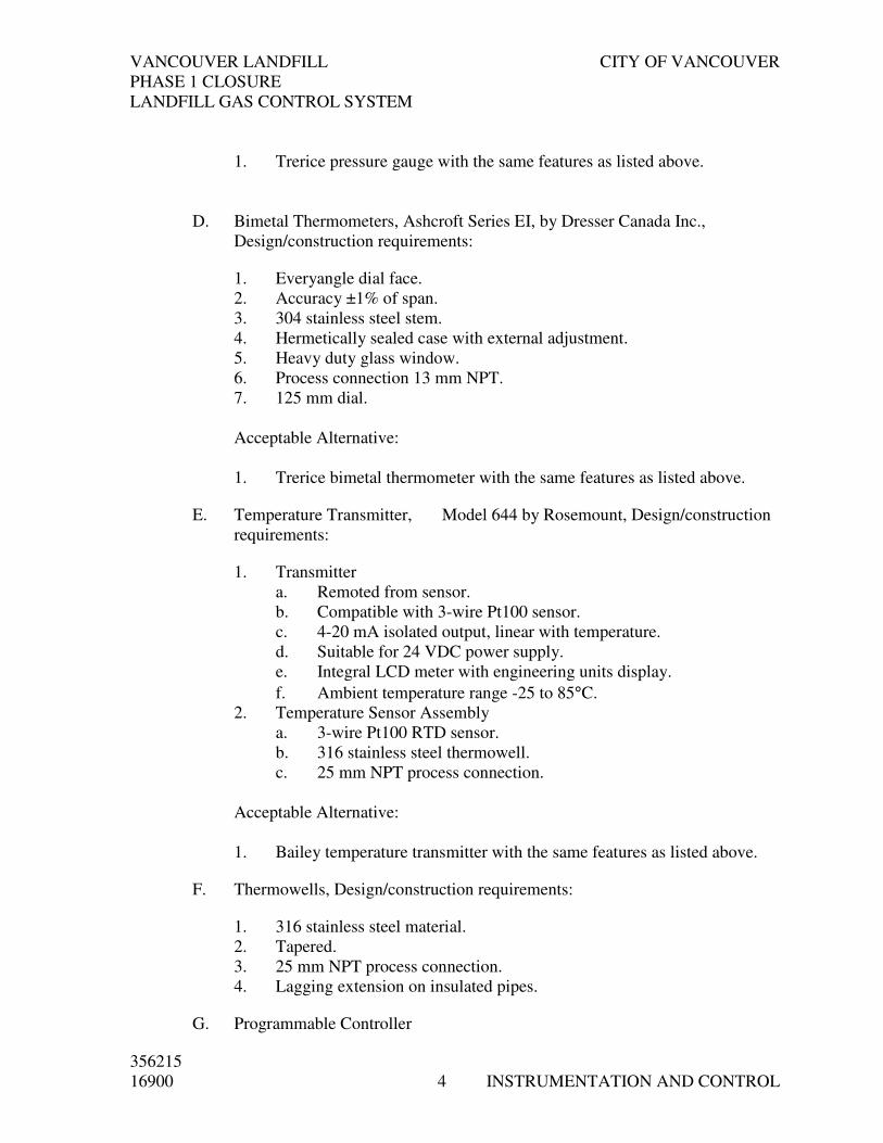
VANCOUVER LANDFILL CITY OF VANCOUVER
PHASE 1 CLOSURE
LANDFILL GAS CONTROL SYSTEM
356215
16900 4 INSTRUMENTATION AND CONTROL
1. Trerice pressure gauge with the same features as listed above.
D. Bimetal Thermometers, Ashcroft Series EI, by Dresser Canada Inc.,
Design/construction requirements:
1. Everyangle dial face.
2. Accuracy ±1% of span.
3. 304 stainless steel stem.
4. Hermetically sealed case with external adjustment.
5. Heavy duty glass window.
6. Process connection 13 mm NPT.
7. 125 mm dial.
Acceptable Alternative:
1. Trerice bimetal thermometer with the same features as listed above.
E. Temperature Transmitter, Model 644 by Rosemount, Design/construction
requirements:
1. Transmitter
a. Remoted from sensor.
b. Compatible with 3-wire Pt100 sensor.
c. 4-20 mA isolated output, linear with temperature.
d. Suitable for 24 VDC power supply.
e. Integral LCD meter with engineering units display.
f. Ambient temperature range -25 to 85°C.
2. Temperature Sensor Assembly
a. 3-wire Pt100 RTD sensor.
b. 316 stainless steel thermowell.
c. 25 mm NPT process connection.
Acceptable Alternative:
1. Bailey temperature transmitter with the same features as listed above.
F. Thermowells, Design/construction requirements:
1. 316 stainless steel material.
2. Tapered.
3. 25 mm NPT process connection.
4. Lagging extension on insulated pipes.
G. Programmable Controller
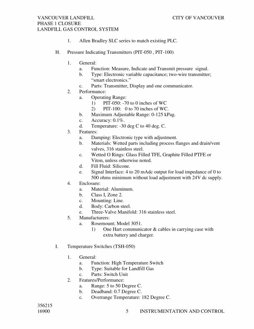
VANCOUVER LANDFILL CITY OF VANCOUVER
PHASE 1 CLOSURE
LANDFILL GAS CONTROL SYSTEM
356215
16900 5 INSTRUMENTATION AND CONTROL
1. Allen Bradley SLC series to match existing PLC.
H. Pressure Indicating Transmitters (PIT-050 , PIT-100)
1. General:
a. Function: Measure, Indicate and Transmit pressure signal.
b. Type: Electronic variable capacitance; two-wire transmitter;
“smart electronics.”
c. Parts: Transmitter, Display and one communicator.
2. Performance:
a. Operating Range:
1) PIT-050: -70 to 0 inches of WC
2) PIT-100: 0 to 70 inches of WC.
b. Maximum Adjustable Range: 0-125 kPag.
c. Accuracy: 0.1%.
d. Temperature: -30 deg C to 40 deg. C.
3. Features:
a. Damping: Electronic type with adjustment.
b. Materials: Wetted parts including process flanges and drain/vent
valves, 316 stainless steel.
c. Wetted O Rings: Glass Filled TFE, Graphite Filled PTFE or
Viton, unless otherwise noted.
d. Fill Fluid: Silicone.
e. Signal Interface: 4 to 20 mAdc output for load impedance of 0 to
500 ohms minimum without load adjustment with 24V dc supply.
4. Enclosure:
a. Material: Aluminum.
b. Class I, Zone 2.
c. Mounting: Line.
d. Body: Carbon steel.
e. Three-Valve Manifold: 316 stainless steel.
5. Manufacturers:
a. Rosemount; Model 3051.
1) One Hart communicator & cables in carrying case with
extra battery and charger.
I. Temperature Switches (TSH-050)
1. General:
a. Function: High Temperature Switch
b. Type: Suitable for Landfill Gas
c. Parts: Switch Unit
2. Features/Performance:
a. Range: 5 to 50 Degree C.
b. Deadband: 0.7 Degree C.
c. Overrange Temperature: 182 Degree C.

VANCOUVER LANDFILL CITY OF VANCOUVER
PHASE 1 CLOSURE
LANDFILL GAS CONTROL SYSTEM
356215
16900 6 INSTRUMENTATION AND CONTROL
d. Max. Process Pressure: 700 kPag.
e. Process Connection: 13mm (1/2”) NPT(M)
f. Conduit Connection: 19mm (3/4”) NPT(F)
3. Electrical Ratings:
a. Connections: Screw Terminal.
b. Contacts: 15A @ 120Vac.
c. Contact Arrangement: One form “C”.
d. Reset: Automatic.
4. Enclosure:
a. Class 1, zone 2
b. Mounting: Direct
5. Manufacturer and Model Number:
a. SOR model 201L or Engineer approved equal.
2.03 FABRICATION
A. Instrument Panels: Comply with Section 16991 - Control Panels.
PART 3 EXECUTION
3.01 GENERAL
A. Locate field-mounted instruments, enclosures, panels and junction boxes to
avoid sources of leakage and spillage.
B. Locate field-mounted indicators and gauges to be clearly visible from normal
walkways.
C. Protect each instrument circuit by means of a panel-mounted, terminal block-
type, overcurrent-interrupting device.
D. Comply with Section 16010 - Basic Electrical Requirements.
3.02 EXAMINATION
A. Before proceeding with the work, report construction defects which will affect
the work of this Section. Proceed only when defects have been corrected.
3.03 INSTALLATION
A. Install instrumentation, control devices, and accessories necessary for
operation of the system.
B. For each device, follow manufacturers’ instructions for installation and
connection. Meet grounding, power supply, air supply and physical
requirements.

VANCOUVER LANDFILL CITY OF VANCOUVER
PHASE 1 CLOSURE
LANDFILL GAS CONTROL SYSTEM
356215
16900 7 INSTRUMENTATION AND CONTROL
C. Provide 30 mm diameter stainless steel identification tags with punched
markings for each field-mounted device. Permanently attach tags to devices
with stainless steel lightweight chain.
D. Install equipment per manufacturer’s recommendations.
E. For Landfill Gas Flowmeter, Gas Analyzer, and Combustible Gas Monitoring
System, include the following:
1. Factory trained and authorized technician to inspect for correct
installation.
2. Factory trained and authorized technician to prepare inspection reports.
3.04 LANDFILL GAS FLOWMETER
A. Install flowmeter according to manufacturer’s recommendations.
B. Provide additional piping and valve(s) as required to comply with installation
requirements.
3.05 GAS ANALYZER
A. Install the Gas Analyzer according to manufacturer’s recommendations.
B. Provide additional piping, fittings and valve(s) as required to comply with
installation requirements.
3.06 FIELD QUALITY CONTROL
A. Calibrate instruments on site. Follow the standards of calibration prescribed
by the manufacturer of each instrument.
B. Supply and use calibration equipment at least three times as accurate as the
instrument being calibrated. Submit calibration equipment test data.
C. Engage manufacturers’ representatives to inspect equipment installation and
to supervise the control system start-up.
D. Test and adjust each device and verify its operation in conjunction with
related equipment in the same control loop and in the overall system.
E. Ensure that wires connecting field- and panel-mounted equipment to
programmable logic controller (PLC) input and output modules are correctly
terminated.
1. For all input and output points, perform a complete continuity test
including intermediate terminations.

VANCOUVER LANDFILL CITY OF VANCOUVER
PHASE 1 CLOSURE
LANDFILL GAS CONTROL SYSTEM
356215
16900 8 INSTRUMENTATION AND CONTROL
2. For digital input points, separately test the operation of each signal-
generating device.
3. For digital output points, separately test the operation of each signal-
receiving device.
4. For analog input points, separately test the operation of each signal-
transmitting device.
5. For analog output points, separately test the operation of each controlled
device.
F. At least two weeks before commissioning is to begin, submit three copies of a
formal Input/Output Test Report to the Engineer to review. A sample form is
included with this Section.
G. Complete the first 3 columns of the Input/Output Test Report using an up-to-
date version of a popular spreadsheet software package.
H. Treat the submission of the Input/Output Test Report as an assurance that
wiring, connections and terminations have been thoroughly checked.
3.07 DEMONSTRATION
A. Demonstrate the accuracy and functional ability of each device, each
monitoring and control loop, and the overall system.
B. Demonstrate the maintenance and trouble-shooting procedures developed and
prescribed by the manufacturer of each device.
3.08 INSTRUMENT SUMMARY
A. The following instrument summary lists the instruments, devices and work of
this Section.
B. The following is a tabulation of the instruments and devices that form part of
this work and should be used in conjunction with the Process &
Instrumentation Diagrams and the Schematic Control Diagrams.
C. The figures that appear under the column “RANGE/SET POINT” in the
instrument summary indicate calibrated process ranges for the transmitters,
scales for the gauges, the indicators or indicating controllers, and adjustable
ranges/set points for the switches.
END OF SECTION

VANCOUVER LANDFILL CITY OF VANCOUVER
PHASE 1 CLOSURE
LANDFILL GAS CONTROL SYSTEM
356215
16900 9 INSTRUMENTATION AND CONTROL
INSTRUMENT SUMMARY
TAG NO. DEVICE SERVICE P&ID/ RANGE/ UNITS PLAN/
SET
POINT PANEL
BUV-201 Blower 2 Inlet Valve LFG M-3 NA M-9
BUV-201 Blower 2 Outlet LFG M-3 NA M-9
BUV-101 Blower 1 Bypass Valve LFG M-3 NA M-9
BUV-201 Blower 2 Inlet Valve LFG M-3 NA M-9
BUV-201 Blower 2 Outlet LFG M-3 NA M-9
BUV-201 Blower 2 Bypass LFG M-3 NA M-9
BUV-301 Blower 3 Inlet Valve LFG M-3 NA M-9
BUV-301 Blower 3 Outlet Valve LFG M-3 NA M-9
BUV-301 Blower 3 Bypass Valve LFG M-3 NA M-9
Inlet Header LFG Inlet Pressure
Transmitter
LFG M-3
-65
Inch
W.C. M-9
Inlet Header LFG Inlet High Temperature
Switch
LFG M-3
50 0C M-9
Knockout Pot
CKT-1
Knockout Pot Differential
Pressure Indicator
LFG M-3
NA M-9
Knockout Pot
CKT-2
Knockout Pot Differential
Pressure Indicator
LFG M-3
NA M-9
Knockout Pot
CKT-3
Knockout Pot Differential
Pressure Indicator
LFG M-3
NA M-9
Knockout Pot
CKT-1
Knockout Pot Level Gauge LFG M-3
NA M-9
Knockout Pot
CKT-2
Knockout Pot Level Gauge LFG M-3
NA M-9
Knockout Pot
CKT-3
Knockout Pot Level Gauge LFG M-3
NA M-9
BL-1 Inlet Blower 1 Inlet Pressure Gauge LFG M-3
-80~0
Inch
W.C.
BL-2 Inlet Blower 2 Inlet Pressure Gauge LFG M-3
-80~0
Inch
W.C.
BL-3 Inlet Blower 3 Inlet Pressure Gauge LFG M-3
-80~0
Inch
W.C.
BL-1 Inlet Blower 1 Inlet Temperature
Gauge
LFG M-3
0~50 0C
BL-2 Inlet Blower 2 Inlet Temperature
Gauge
LFG M-3
0~50 0C
BL-3 Inlet Blower 3 Inlet Temperature
Gauge
LFG M-3
0~50 0C
BL-1 Outlet Blower 1 Outlet Pressure
Gauge
LFG M-3
0~30
Inch
W.C.
BL-2 Outlet Blower 2 Outlet Pressure LFG M-3 0~30 Inch

VANCOUVER LANDFILL CITY OF VANCOUVER
PHASE 1 CLOSURE
LANDFILL GAS CONTROL SYSTEM
356215
16900 10 INSTRUMENTATION AND CONTROL
TAG NO. DEVICE SERVICE P&ID/ RANGE/ UNITS PLAN/
SET
POINT PANEL
Gauge W.C.
BL-3 Outlet Blower 3 Outlet Pressure
Gauge
LFG M-3
0~30
Inch
W.C.
BL-1 Outlet Blower 1 Outlet Temperature
Gauge
LFG M-3
0~50 0C
BL-2 Outlet Blower 2 Outlet Temperature
Gauge
LFG M-3
0~50 0C
BL-3 Outlet Blower 3 Outlet Temperature
Gauge
LFG M-3
0~50 0C
AE/AIT-101 Gas Composition Analyzer LFG M-3 Refer to
Section
11400-01 M-9
FE/FT-100 Gas Flow Transmitter LFG M-3 375~
9000 scfm M-9
PT-050 Blowers Outlet Pressure
Transmitter
LFG M-3
0~30
Inch
W.C. M-9
FCV-050 Blower Discharge Flow By-
pass Control Valve
LFG M-3
0~625 scfm M-9
XSV-110 Flare 1 propane inlet valve Propane M-4 NA
XSV-120 Flare 2 propane inlet valve Propane M-4 NA
XSV-130 Flare 3 propane inlet valve Propane M-4 NA
XSV-140 Flare 4 propane inlet valve Propane M-4 NA
PSL-100 Propane supply low pressure
switch
Propane M-4
NA
PCV-101 Nitrogen supply pressure
control valve Nitrogen
M-4
NA
PI-101 Nitrogen supply pressure
gauge Nitrogen
M-4
NA
PCV-110 Flare 1 propane pressure
control valve Propane
M-4
NA
PCV-120 Flare 2 propane pressure
control valve
Propane M-4
NA
PI-110 Flare 1 ignition propane
pressure gauge
Propane M-4
NA
PI-120 Flare 2 ignition propane
pressure gauge
Propane M-4
NA
PCV-130 Flare 3 propane pressure
control valve
Propane M-4
12 psi
PCV-140 Flare 4 propane pressure
control valve
Propane M-4
12 psi
PI-130 Flare 3 ignition propane
pressure gauge
Propane M-4
0~50 psi
PI-140 Flare 4 ignition propane Propane M-4 0~50 psi

VANCOUVER LANDFILL CITY OF VANCOUVER
PHASE 1 CLOSURE
LANDFILL GAS CONTROL SYSTEM
356215
16900 11 INSTRUMENTATION AND CONTROL
TAG NO. DEVICE SERVICE P&ID/ RANGE/ UNITS PLAN/
SET
POINT PANEL
pressure gauge
FCV-810 Flare 3 LFG Inlet valve LFG M-6 NA E-5
XV-810 Flare 3 LFG Inlet Valve
Solenoid LFG
M-6
NA E-5
FA-800 Flare 3 Inlet Flame Arrestor LFG M-6 NA E-5
FA-900 Flare 3 Inlet High
Temperature Detection TC
M-6
NA E-5
TCV-130 Flare 3 Automatic Louvre M-6 NA E-5
TCV-131 Flare 3 Manual Louvre NA E-5
TE-130 Flare 3 upper stack
temperature
M-6
NA
TE-131 Flare 3 middle stack
temperature
M-6
NA
TE-132 Flare 3 lower stack
temperature
M-6
NA E-5
BE-130 Flare 3 Pilot flame detection M-6 NA E-5
FR/TR130 Flare 3 flow recorder /
temperature controller
M-6
NA PLC
PNL-106 Flare 3 Ignition panel M-6 NA
FV-600 Flare 1 LFG Inlet valve LFG M-5 NA E-4
XV-600 Flare 1 LFG Inlet Valve
Solenoid
LFG M-5
NA E-4
FA-600 Flare 1 Inlet Flame Arrestor LFG M-5 NA E-4
Flare 1 LFG
Inlet
Flare 1 Inlet High
Temperature Detection TC
LFG M-5
NA E-4
TCV-110 Flare 1 Automatic Louvre M-5 NA E-4
TCV-111 Flare 1 Manual Louvre M-5 NA E-4
TE-110 Flare 1 upper stack
temperature
M-5
NA E-4
TE-111 Flare 1 middle stack
temperature
M-5
NA E-4
TE-112 Flare 1 lower stack
temperature
M-5
NA E-4
BE-110 Flare 1 Pilot flame detection M-5 NA E-4
FR/TR110 Flare 1 flow recorder /
temperature controller
M-5
NA PLC
PNL-104 Flare 1 Ignition panel M-5 NA E-4
PI-605 Flare 1 LFG Inlet Pressure
Gauge LFG
M-5
NA
FV-700 Flare 2 LFG Inlet valve LFG M-5 NA E-4
XV-700 Flare 2 LFG Inlet Valve
Solenoid LFG
M-5
NA E-4
Flare 2 LFG Flare 2 Inlet Flame Arrestor LFG M-5 NA E-4
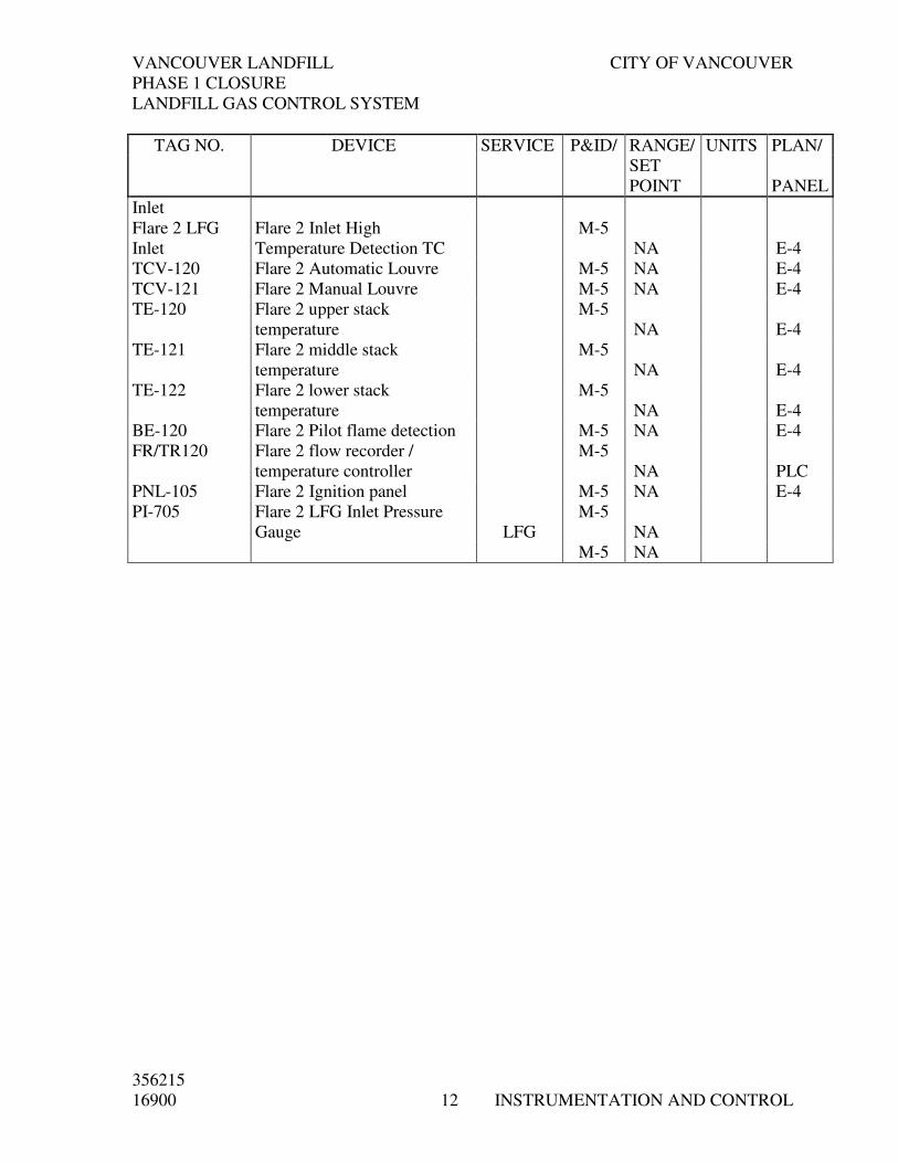
VANCOUVER LANDFILL CITY OF VANCOUVER
PHASE 1 CLOSURE
LANDFILL GAS CONTROL SYSTEM
356215
16900 12 INSTRUMENTATION AND CONTROL
TAG NO. DEVICE SERVICE P&ID/ RANGE/ UNITS PLAN/
SET
POINT PANEL
Inlet
Flare 2 LFG
Inlet
Flare 2 Inlet High
Temperature Detection TC
M-5
NA E-4
TCV-120 Flare 2 Automatic Louvre M-5 NA E-4
TCV-121 Flare 2 Manual Louvre M-5 NA E-4
TE-120 Flare 2 upper stack
temperature
M-5
NA E-4
TE-121 Flare 2 middle stack
temperature
M-5
NA E-4
TE-122 Flare 2 lower stack
temperature
M-5
NA E-4
BE-120 Flare 2 Pilot flame detection M-5 NA E-4
FR/TR120 Flare 2 flow recorder /
temperature controller
M-5
NA PLC
PNL-105 Flare 2 Ignition panel M-5 NA E-4
PI-705 Flare 2 LFG Inlet Pressure
Gauge LFG
M-5
NA
M-5 NA
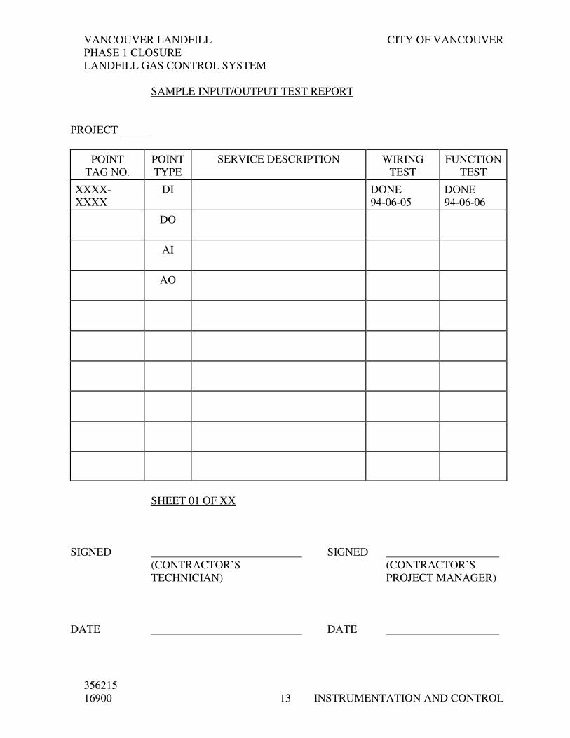
VANCOUVER LANDFILL CITY OF VANCOUVER
PHASE 1 CLOSURE
LANDFILL GAS CONTROL SYSTEM
356215
16900 13 INSTRUMENTATION AND CONTROL
SAMPLE INPUT/OUTPUT TEST REPORT
PROJECT
POINT
TAG NO.
POINT
TYPE
SERVICE DESCRIPTION WIRING
TEST
FUNCTION
TEST
XXXX-
XXXX
DI DONE
94-06-05
DONE
94-06-06
DO
AI
AO
SHEET 01 OF XX
SIGNED SIGNED
(CONTRACTOR’S (CONTRACTOR’S
TECHNICIAN) PROJECT MANAGER)
DATE DATE

VANCOUVER LANDFILL CITY OF VANCOUVER
PHASE 1 CLOSURE
LANDFILL GAS CONTROL SYSTEM
356215
16900 14 INSTRUMENTATION AND CONTROL
SAMPLE INSTRUMENT CALIBRATION SHEET
INSTRUMENT CALIBRATION SHEET
CONTRACT NUMBER:_______________
TAG NUMBER: _______________
MANUFACTURER: ______________________________
MODEL NUMBER: ______________________________
SERIAL NO: ______________________________
PROCESS SERVICE: __________________________________________
__________________________________________
INPUT OUTPUT
0.0% _______________ _______________
25.0% _______________ _______________
50.0% _______________ _______________
75.0% _______________ _______________
100.0% _______________ _______________
CALIBRATION EQUIPMENT USED:
NOTES: ____________________________________________________
____________________________________________________
TECHNICIAN: ______________________ DATE: ___________
COMPANY: _________________________________________________
WITNESS: ______________________ DATE: ___________

VANCOUVER LANDFILL CITY OF VANCOUVER
PHASE 1 CLOSURE
LANDFILL GAS CONTROL SYSTEM
356215
16900 15 INSTRUMENTATION AND CONTROL
SAMPLE INSTRUMENT LOOP CHECK SHEET
INSTRUMENT LOOP CHECK SHEET
CUSTOMER _____________________________________________
LOCATION ________________ CONTRACT NO. _________ DWG. _________
DESIGN AREA _____________________ LOOP _________________________
DATA SHEETS COMPLETED: YES [ ] NO [ ]
INSTALLATION APPROVED [ ] CONTINUITY TEST [ ]
POWER TEST [ ] LEAK TEST [ ] VALVE STROKED [ ]
CONTROLLER SET TO: ______________________ ACTION
______________________ GAIN / P.B.
______________________ INTEGRAL
______________________ DERIVATIVE
INTERLOCKS: _____________________________________________________
__________________________________________________________________
LOOP LEFT FUNCTIONAL: YES [ ] NO [ ]
NOTES: __________________________________________________________
_________________________________________________________________
_________________________________________________________________
CHECKED BY : ___________________ DATE: _____________________
ACCEPTED BY: ___________________ DATE: _____________________

VANCOUVER LANDFILL CITY OF VANCOUVER
PHASE 1 CLOSURE
LANDFILL GAS CONTROL SYSTEM
356215
16910 GENERAL REQUIREMENTS
1 FOR PROGRAMMABLE EQUIPMENT
SECTION 16910
GENERAL REQUIREMENTS FOR PROGRAMMABLE EQUIPMENT
PART 1 GENERAL
1.01 SUMMARY
A. Comply with Section 16010 - Basic Electrical Requirements.
B. The following requirements are applicable to programmable equipment such
as PLCs and other programmable devices.
C. Unless otherwise noted, include design, programming, documentation, supply,
delivery and commissioning of application software and equipment set-up.
1.02 SUBMITTALS - SHOP DRAWINGS
A. For devices containing dip switches, jumpers or programming keypads:
1. Functional description
2. Performance data
3. Physical, electrical and environmental requirements
4. Location drawing
5. Equipment descriptive literature
6. Wiring details
B. For programmable equipment, software, communication links and networks
submit bill of materials. Include in bill of materials hardware, software,
documentation and programming tools:
1. For hardware items include: Description, make, model, part number and
serial number.
2. For software items include: Publisher, title, version, part number, serial
number, media type and size, and information contained on label.
3. For documentation include: Title, publisher and type of media/binding
for each item.
C. For Programmable Equipment Hardware:
1. Product description for each item including:
a. Wiring and installation instructions
b. Functional description
c. Performance data
d. Physical, electrical and environmental requirements.
e. Adapters and controllers.

VANCOUVER LANDFILL CITY OF VANCOUVER
PHASE 1 CLOSURE
LANDFILL GAS CONTROL SYSTEM
356215
16910 GENERAL REQUIREMENTS
2 FOR PROGRAMMABLE EQUIPMENT
2. Equipment layout drawings showing location of hardware, boards,
jacks, cables and terminals.
3. Related field tag numbers and wire numbers, module tag assignment,
rack module assignment, terminal and terminal strip numbers.
4. Location and identifier and pin assignment of plugs, jacks and cables.
5. Switch settings and addresses.
6. Interconnection Diagrams including wiring, cables, jacks between
internal and external components, power supplies, processors,
communications modules, racks, I/O modules and peripherals. Label
terminals, jacks and pins. Show settings for jumpers and switches. Show
address for each hardware module and point.
D. For Application Software:
1. Description of operation covering internal logic, external process
equipment and control devices and the associated process and control
equipment actions.
2. Logic listing with rung/line numbers, detailed rung comments and
address descriptions. Rung comments and address descriptions must be
in comprehensive English phrases i.e., “Pump Running Status”, “Pump
Start Level”, “Well Low Level Alarm”.
3. List of the registers used, together with their functions.
4. Computer application software design document containing:
a. Graphics layouts.
b. Alarm priorities.
c. Lists of monitored points and controlled points.
d. Listings of templates.
1.03 SUBMITTALS - OPERATIONS AND MAINTENANCE MANUALS
A. As-constructed version of shop drawings.
B. For devices containing dip switches, jumpers or programmable keypads:
1. Record of switch settings, program listings and parameter settings, after
commissioning.
C. For Programmable Equipment Hardware:
1. Maintenance manuals.
2. Components and peripherals O.E.M. user guides, technical reference
and programming manuals.
3. Applicable operating system manual(s).

VANCOUVER LANDFILL CITY OF VANCOUVER
PHASE 1 CLOSURE
LANDFILL GAS CONTROL SYSTEM
356215
16910 GENERAL REQUIREMENTS
3 FOR PROGRAMMABLE EQUIPMENT
D. For Application Software
1. Hard copy source (ASCII) listing of records, fields and values of
databases, templates and files.
2. CD copies of databases and templates. Include both native format of
files and ASCII-exported version.
3. Screen dumps.
4. Explanation of usage of data on screens.
PART 2 PRODUCTS
2.01 ACCESSORIES
A. Programming tools for each different type of programmable equipment:
1. Software program complete with interconnecting cable, signal
converter, instruction manual and equipment documentation; or
2. Programming keypad and accessories, if software is not published.
B. One blank EEPROM, CD, or similar media compatible with programming
tool.
2.02 SOFTWARE
A. Backup Copies of Application Software:
1. One copy for each unique version of software program or data.
2. Machine-readable backup software copy.
END OF SECTION

VANCOUVER LANDFILL CITY OF VANCOUVER
PHASE 1 CLOSURE
LANDFILL GAS CONTROL SYSTEM
356215
16991 1 CONTROL PANELS
SECTION 16991
CONTROL PANELS
PART 1 GENERAL
1.01 SUMMARY
A. Comply with Section 16010 - Basic Electrical Requirements.
B. The PLC equipment and control devices in the existing control panel are to be
re-used in the new PLC panel as follows:
TSH-600, TSH-700, TRC 110,TRC 120, BE/BS110 & BE/BS120 are to be
relocated to the new PLC from the existing PLC panel 101 and RPI 110 &
RPI 120 are to be relocated from PNL 102 to the new PLC Panel
The contractor is to supply and install all new equipment as indicated in the
drawings and provide mounting space and wiring for the devices that are to be
relocated.
1.02 SUBMITTALS
A. Submit shop drawings of control panels and components showing
dimensioned internal and external layouts, terminal block arrangements,
construction details, material of construction and complete component Bills of
Material.
B. Submit prior to panel delivery, complete wiring diagrams showing wiring
between panel components and devices and panel terminal blocks, and
between panel terminal blocks and remote (field) equipment. Identify
components, conductors and terminal blocks, including remote terminal block
identification.
C. Submit final record wiring diagrams at completion of project. Include changes
made during field installation and start-up.
PART 2 PRODUCTS
2.01 MANUFACTURED UNITS
A. Control panels: Complete working system with instruments, meters, indicating
lights, alarm annunciators, relays, contactors, switches auxiliary devices and
similar items.
B. Arrangement of instruments and devices (face-mounted as well as rear-of-
panel mounted): Allow sufficient access for maintenance.

VANCOUVER LANDFILL CITY OF VANCOUVER
PHASE 1 CLOSURE
LANDFILL GAS CONTROL SYSTEM
356215
16991 2 CONTROL PANELS
C. Side or back face mounted devices: On removable backplate. Direct mounted
devices are not acceptable.
D. Nameplates: Lamicoid, white letters on black background, to identify panel
and equipment function, letters minimum 6 mm.
2.02 ENCLOSURE
A. Enclosure: Rigid, dead front, 2 mm steel sheet, EEMAC 12, gasketted.
B. Visible welding seams: Not acceptable.
C. Back plate: 2.7 mm steel sheet mounted on four 10 mm collar studs minimum
with stainless steel hardware.
D. Doors: Removable, gasketted, continuous piano type hinges, lockable, keyed
alike.
E. Print pocket: On inside of door, rigid, for storing manual, layout drawings and
wiring diagrams.
F. Finish: Phosphatize, zinc chromate prime, baked enamel inside and outside,
matte white interior and ANSI 61 grey exterior.
2.03 INTERNAL ASSEMBLY
A. Internal component and equipment mounting: On hinged sub-chasses, racks
and back plates, arranged for ease of access and removal.
B. Pans and rails: For mounting terminal blocks, relays, contactors, wiring and
similar devices.
C. Power supply disconnecting devices: To disconnect incoming power supply
sources and individual feeder circuit supplies, panel mount circuit breakers,
10,000 A at 120 V AC interrupting capacity.
D. Instrument disconnecting devices: circuit breakers, 3,000 A symmetrical
interrupting capacity for each instrument requiring 120 V supply.
E. Identification: Identify components, terminal blocks, power supplies, wiring
and similar devices. Comply with Sections 16010 and 16120.
F. Warning signs: Identify sources of supply. Comply with Section 16010.
G. Wiring ducts: Maximum 50% fill, with snap-on cover, by Panduit Canada.

VANCOUVER LANDFILL CITY OF VANCOUVER
PHASE 1 CLOSURE
LANDFILL GAS CONTROL SYSTEM
356215
16991 3 CONTROL PANELS
2.04 PLC
A. Provide new PLC equipment and control components as indicated in the
drawings.
2.05 TERMINAL BLOCKS
A. Terminal blocks: Modular, rated 600 V 25 A minimum, tubular clamp type,
35 mm DIN rail mounted, individually removable, with removable insulating
covers on exposed terminals carrying above 50 V, SAK Series by Weidmuller
Ltd., UL Series by Phoenix Terminal Blocks Ltd., WK/4 Series by Wieland
Electric Ltd. and Entrelec.
B. Mounting: 150 mm minimum wiring space between rows of terminal blocks.
C. Arrangement: Separate terminals and wiring by class of signal. Comply with
Section 16120.
D. Spares: Minimum 20% spare terminals for each signal class.
2.06 INSTRUMENT GROUNDING
A. Instrument cable shields and equipment ground conductors connections: With
screws and clamp washers.
B. Comply with Section 16450.
2.07 OPERATOR DEVICES
A. EEMAC 12 panels: Heavy duty, industrial, oil-tight, rated 120 V AC, Type K
by Square D Canada, Type CR104P by GE Canada, Type PB1 by Cutler-
Hammer/Westinghouse, Type 800T by Allen-Bradley Canada Ltd.
B. EEMAC 12 indicating lights: Integral transformer, push-to-test type, Type
800 T by Allen-Bradley Canada Ltd., Type KT by Square D Canada.
C. Indicator lamps: Clustered LED type, replaceable from front.
2.08 CONTROL RELAYS
A. General purpose relays: Electrically held, enclosed, two 10 A, 24 VDC and
120 V AC as required, form C contacts minimum, screw terminal socket
mount, with hold down clips, pilot light and push-to-test button.
B. Spares: As per drawings.

VANCOUVER LANDFILL CITY OF VANCOUVER
PHASE 1 CLOSURE
LANDFILL GAS CONTROL SYSTEM
356215
16991 4 CONTROL PANELS
2.09 INSULATING BARRIERS
A. Barriers: Covering exposed terminals and terminal blocks against inadvertent
contact.
2.10 WARNING LABELS:
A. Lamicoid with 3 mm white letters on red background, on front of
compartments where multiple power sources are present.
2.11 INTERNAL WIRING
A. Comply with Section 16120.
B. Wiring type: Except shielded instrumentation wiring, copper, 600 V, single
conductor, seven strands minimum, heat and flame-retardant type, RW90 or
TEW insulation. #14 AWG minimum for control circuits and #12 AWG
minimum for power circuits.
C. Wire colour coding: 120 VAC control circuits supplied from internal 120
VAC supply, red; 120 VAC control circuits supplied from external 120 VAC
supply, yellow; 24 VDC control circuits, blue.
D. Wiring devices on hinged doors or panels: Extra flexible, harnessed with
nylon cable ties.
E. Wiring terminations: On terminal blocks. Splices and soldered connections are
not permitted. Brace and support wiring.
F. Maximum number of conductors under one terminal: Two.
G. Wire markers: Identify wiring at ends with slip-on, plastic type markers,
computer printed type by Critchley, Brady, or Shur-Code by Thomas & Betts
Ltd., Z-Type by Wieland Electric Ltd.
H. Incoming cable supports: Clamp type.
I. Separation: Comply with Section 16120. Keep AC and DC conductors
separate and do not group together in same wire duct or harness. In addition,
separate DC conductors into low level and high level signal conductors.
Supply separate wiring ducts for 120 V AC signals.
PART 3 EXECUTION
3.01 INSTALLATION
A. Provide control panels as indicated.

VANCOUVER LANDFILL CITY OF VANCOUVER
PHASE 1 CLOSURE
LANDFILL GAS CONTROL SYSTEM
356215
16991 5 CONTROL PANELS
B. Wall mount panels with 6 mm nylon or lead spacers.
END OF SECTION

Vancouver LandFill Expansion ProjectGeotechnical Recommendations dated September 18, 2008

FINAL
Vancouver LandFill Gas Control System Expansion Project Page 1 of 9
I N T E R N A L T E C H N I C A L M E M O R A N D U M
Vancouver LandFill Gas Control System Expansion Project Geotechnical Recommendations
PREPARED FOR: Chuck Smith/CGY
PREPARED BY: Sean Shin/SEA
COPIES: Kris Smith/CGY
REVIEWED BY: Don Anderson/SEA
Ken Green/SEA
DATE: September 18, 2008
PROJECT NUMBER: 356215.B1.08.CH
Introduction The purpose of this memorandum is to provide geotechnical design recommendations associated with the expansion of the landfill gas control system for Vancouver Landfill Closure Project. This project was performed in accordance with an agreement between the City of Vancouver and CH2M HILL dated June 22, 2007.
Objectives and Scope The objectives of this technical memorandum are:
• Developing subsurface conditions for use in design;
• Providing recommendation for pin-pile foundation support of the proposed new flares including recommended pile embedment depths, design ultimate downward capacity, and minimum spacing.
• Summarizing seismic hazards for the site; and
• Providing general construction considerations
The scope of the geotechnical work was limited to the use of existing geotechnical explorations. No field work was conducted.
Limitations The analyses and recommendations contained in this technical memorandum are based on the data obtained from explorations performed by others at the Vancouver Landfill site.

FINAL
Vancouver LandFill Gas Control System Expansion Project Page 2 of 9
CH2M HILL cannot attest to the validity of these past explorations. Further, these explorations indicate subsurface conditions only at specific locations and times, and only to the depths penetrated. They do not necessarily reflect strata variations that may exist between such locations. If variations in subsurface condition from those described are noted during construction, recommendations in this technical memorandum must be re-evaluated.
In the event that any changes in the nature, design, or location of the flare facilities are planned, the conclusions and recommendations contained in this technical memorandum should not be considered valid unless the changes are reviewed and conclusions of this technical memorandum modified or verified in writing by CH2M HILL.
Project Description The Vancouver Landfill Gas Control Station was completed in 2001. New processing units were installed about 10 m west of the station in 2003. Two flares (flares 3 and 4) and blowers are planned to be added on the existing gas control station. Two additional flares (flares 5 and 6) may be installed in the future depending on demand.
The main geotechnical issue at the project site is the existence of a highly compressible organic peat layer and a very soft silt layer in the area of the proposed flare foundations. Increases in stress in the peat and the silt layers from loads caused by the new flares could result in significant settlement and damage to the existing facilities or to the planned new facilities. Therefore, the foundation system for the station expansion should be designed to prevent or minimize changes in stress within the peat and the silt layers.
Another important factor for the site is the effects of seismic loading on the structure and soils. Although large earthquakes are not common in the area, the potential for ground shaking exists, and this potential must be considered to meet National Building Code requirements.
Subsurface Conditions Subsurface conditions at the project site were established based on cone penetrometer test (CPT) soundings conducted by Golder Associate (1994) as part of a stability analysis project for the Vancouver Landfill, and Standard Penetration Test (SPT) borings performed at Burn Bog Landfill area (1995). No new explorations were performed as part of this project. Subsurface information was determined by extrapolating results from the Golder and Burn Bog studies. Neither of these past projects occurred at the project site.
Based on the previous studies, the subsurface conditions at the project site are estimated to include a very soft organic peat layer, underlain by a very soft silt layer which overlies medium dense sand layer.
• The thickness of the peat layer generally varies form 1 to 5 m and averages about 3 m. The soft silt layer thickness ranges from 1 to 5 m and averages about 3 m. The silt layer becomes sandier with depth and grades into the underlying sand layer.
• The sand layer is about 12 m to 30 m thick. The upper portion of this layer generally is medium dense and becomes denser with depth. The typical field SPT N value varies
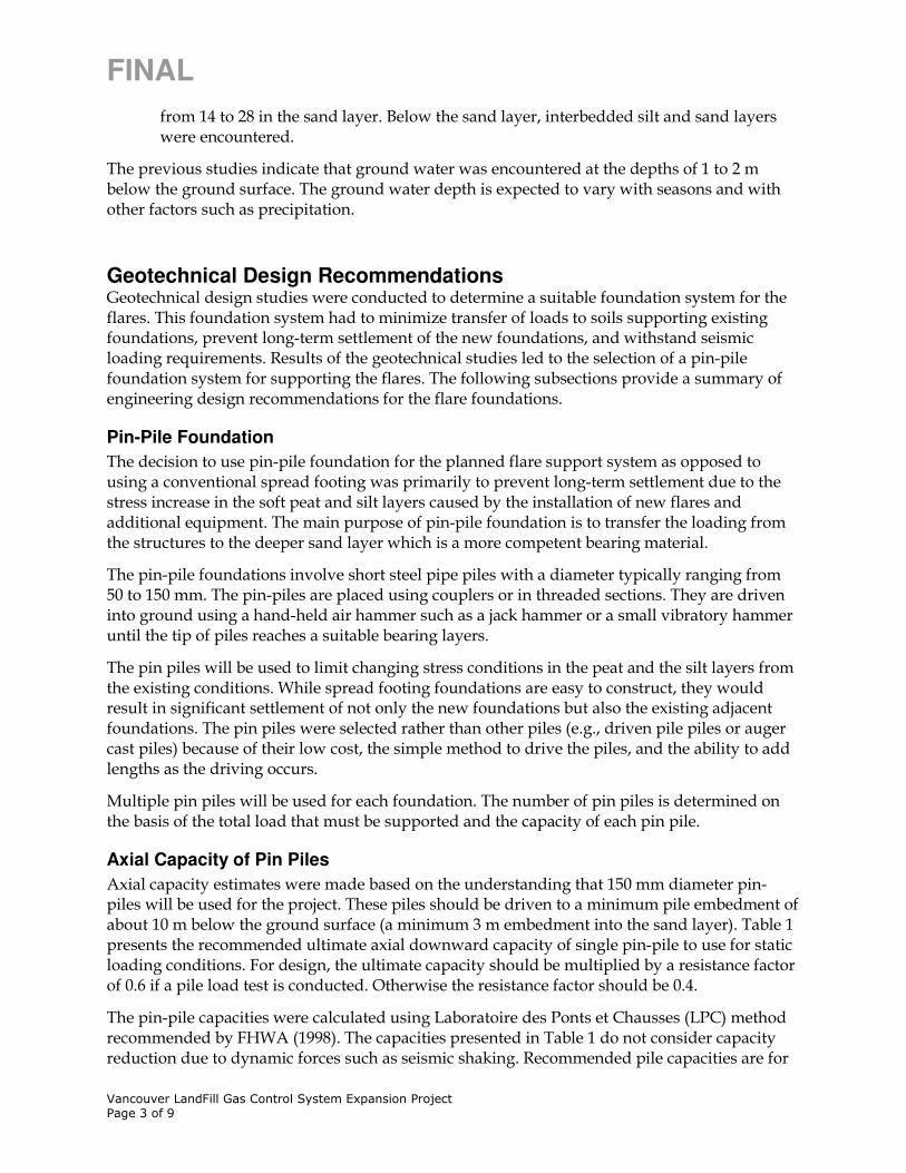
FINAL
Vancouver LandFill Gas Control System Expansion Project Page 3 of 9
from 14 to 28 in the sand layer. Below the sand layer, interbedded silt and sand layers were encountered.
The previous studies indicate that ground water was encountered at the depths of 1 to 2 m below the ground surface. The ground water depth is expected to vary with seasons and with other factors such as precipitation.
Geotechnical Design Recommendations Geotechnical design studies were conducted to determine a suitable foundation system for the flares. This foundation system had to minimize transfer of loads to soils supporting existing foundations, prevent long-term settlement of the new foundations, and withstand seismic loading requirements. Results of the geotechnical studies led to the selection of a pin-pile foundation system for supporting the flares. The following subsections provide a summary of engineering design recommendations for the flare foundations.
Pin-Pile Foundation
The decision to use pin-pile foundation for the planned flare support system as opposed to using a conventional spread footing was primarily to prevent long-term settlement due to the stress increase in the soft peat and silt layers caused by the installation of new flares and additional equipment. The main purpose of pin-pile foundation is to transfer the loading from the structures to the deeper sand layer which is a more competent bearing material.
The pin-pile foundations involve short steel pipe piles with a diameter typically ranging from 50 to 150 mm. The pin-piles are placed using couplers or in threaded sections. They are driven into ground using a hand-held air hammer such as a jack hammer or a small vibratory hammer until the tip of piles reaches a suitable bearing layers.
The pin piles will be used to limit changing stress conditions in the peat and the silt layers from the existing conditions. While spread footing foundations are easy to construct, they would result in significant settlement of not only the new foundations but also the existing adjacent foundations. The pin piles were selected rather than other piles (e.g., driven pile piles or auger cast piles) because of their low cost, the simple method to drive the piles, and the ability to add lengths as the driving occurs.
Multiple pin piles will be used for each foundation. The number of pin piles is determined on the basis of the total load that must be supported and the capacity of each pin pile.
Axial Capacity of Pin Piles
Axial capacity estimates were made based on the understanding that 150 mm diameter pin-piles will be used for the project. These piles should be driven to a minimum pile embedment of about 10 m below the ground surface (a minimum 3 m embedment into the sand layer). Table 1 presents the recommended ultimate axial downward capacity of single pin-pile to use for static loading conditions. For design, the ultimate capacity should be multiplied by a resistance factor of 0.6 if a pile load test is conducted. Otherwise the resistance factor should be 0.4.
The pin-pile capacities were calculated using Laboratoire des Ponts et Chausses (LPC) method recommended by FHWA (1998). The capacities presented in Table 1 do not consider capacity reduction due to dynamic forces such as seismic shaking. Recommended pile capacities are for

FINAL
Vancouver LandFill Gas Control System Expansion Project Page 4 of 9
individual piles. No modifications are required for groups of pin piles driven into cohesionless soils.
The recommended pile capacities are based on the closed pile tip conditions. Therefore, the tip of piles should be capped or plugged prior to driving into ground. The structural characteristics of pin-piles such as wall thickness and yield strength may impose structural limitations on the pile capacity. A check on the structural capacity of the pin piles should be performed once the number and type of pin pile material have been determined.
Table 1.
Pin-pile Static Capacity
150-mm diameter pin-pile capacity Embedment Depth (m) into Sand
Layer
Pin-pile Length
(m)
Tip Resistance
(kN)
Friction Resistance
(kN)
Ultimate Capacity (kN)
3 10 47 54 101
4 11 47 71 118
5 12 47 87 134 Resistance factor = 0.6 (pile-capacity verified with Static Loading Test). If static test is not performed, resistance factor should be reduced to 0.4.
Seismic Hazard
Table 2 presents the peak ground acceleration (PGA) and the 5 percent damped spectral response spectra acceleration (Sa) values for a 2 percent probability of exceedance in 50 years at the project site. The Sa values were found based on “2005 National Building Code of Canada Seismic Hazard Map (http://earthquakescanada.nrcan.gc.ca/)”. Table 2 also shows the site classification and the site coefficients, Fa and Fv, per 2005 National Building Code of Canada. Figure 1 shows the 5 percent damped design spectral acceleration chart.
Table 2. Seismic Design Parameters (2% in 50 years)
Period (sec) 0.2 0.5 1.0 2.0
Spectral Acceleration for Site Class C (g)
1.083 0.723 0.344 0.176
PGA (g) 0.539
Site Class F
Site Coefficient, Fa 0.9(1)
Site Coefficient, Fv 1.82(1)
(1) The design spectral ordinates in Figure 1 were developed using site Class E coefficients and not for Site Class F. Site coefficients for Site Class F are believed to be conservative at short periods. Although site coefficients for long-period motions (period greater than 0.5 sec) could be greater than used, the use of Site Class E coefficients is believed to be sufficient for the flare facility, particularly since these structures are not occupied and the risk to public safety during a design seismic event will be minimal.
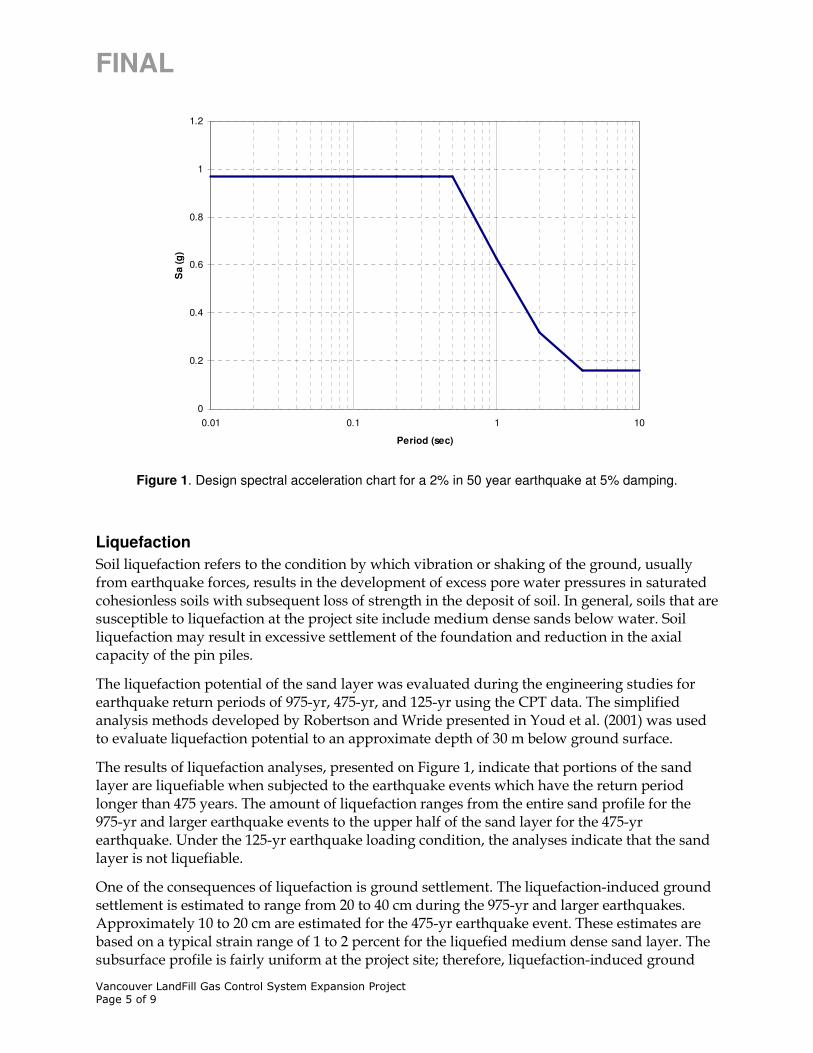
FINAL
Vancouver LandFill Gas Control System Expansion Project Page 5 of 9
0
0.2
0.4
0.6
0.8
1
1.2
0.01 0.1 1 10
Period (sec)
Sa (
g)
Figure 1. Design spectral acceleration chart for a 2% in 50 year earthquake at 5% damping.
Liquefaction
Soil liquefaction refers to the condition by which vibration or shaking of the ground, usually from earthquake forces, results in the development of excess pore water pressures in saturated cohesionless soils with subsequent loss of strength in the deposit of soil. In general, soils that are susceptible to liquefaction at the project site include medium dense sands below water. Soil liquefaction may result in excessive settlement of the foundation and reduction in the axial capacity of the pin piles.
The liquefaction potential of the sand layer was evaluated during the engineering studies for earthquake return periods of 975-yr, 475-yr, and 125-yr using the CPT data. The simplified analysis methods developed by Robertson and Wride presented in Youd et al. (2001) was used to evaluate liquefaction potential to an approximate depth of 30 m below ground surface.
The results of liquefaction analyses, presented on Figure 1, indicate that portions of the sand layer are liquefiable when subjected to the earthquake events which have the return period longer than 475 years. The amount of liquefaction ranges from the entire sand profile for the 975-yr and larger earthquake events to the upper half of the sand layer for the 475-yr earthquake. Under the 125-yr earthquake loading condition, the analyses indicate that the sand layer is not liquefiable.
One of the consequences of liquefaction is ground settlement. The liquefaction-induced ground settlement is estimated to range from 20 to 40 cm during the 975-yr and larger earthquakes. Approximately 10 to 20 cm are estimated for the 475-yr earthquake event. These estimates are based on a typical strain range of 1 to 2 percent for the liquefied medium dense sand layer. The subsurface profile is fairly uniform at the project site; therefore, liquefaction-induced ground

FINAL
Vancouver LandFill Gas Control System Expansion Project Page 6 of 9
settlements are expected to be relatively uniform over the project site without significant differential settlement that could cause major damage in the structures.
PGA = 0.336g
(5% in 50 yrs, M=7.0)
0
5
10
15
20
25
30
35
40
0.0 1.0 2.0 3.0 4.0
FOS against Liquefaction
De
pth
(m
)
PGA = 0.249g
(10% in 50 yrs, M=6.5)
0
5
10
15
20
25
30
35
40
0.0 1.0 2.0 3.0 4.0
FOS against Liquefaction
De
pth
(m
)
PGA = 0.117g
(40% in 50 yrs, M=5.7)
0
5
10
15
20
25
30
35
40
0.0 1.0 2.0 3.0 4.0
FOS against Liquefaction
De
pth
(m
)
CPT-10
CPT-12
CPT-13
Peat and Silt Layer
Sand Layer
Interbedded Sand and Silt layer
Liquefiable
Liquefiable
Figure 2. Liquefaction Analysis Results
Table 3 shows the reduced pin-pile capacity in the liquefied sand layer. The capacity was calculated based on the residual undrained strength of the liquefied sand layer. Under this condition the resistance factor for design can be taken as 1.0. When determining the number of piles to support the flare foundations, both the static and seismic loading cases should be considered. Whichever case requires more piles should be used as the basis of design.
Table 3.
Reduced Pin-pile Capacity in Liquefied Sand Layer
150-mm diameter pin-pile capacity (Liquefied)
Embedment Depth (m)
Pin-pile Length
(m)
Tip Resistance
(kN)
Friction Resistance
(kN)
Ultimate Capacity (kN)
3 10 5 45 50
4 11 5 59 64
5 12 5 72 77

FINAL
Vancouver LandFill Gas Control System Expansion Project Page 7 of 9
Corrosion Protection
The silt and peat layers above ground water table will be very corrosive to pin-piles; therefore, corrosion protection measures such as galvanizing or cathodic protection should be established. Cement grouting inside the pin-piles will protect the inside of pin-piles from corrosion.
An alternative to using cathodic protection is to increase the wall thickness of the pin piles. If the decision is made not to use corrosion protection measures, the pin-pile wall thickness should be increased by 6 mm to maintain the adequate pin-pile capacity over the life span of the structures.
Lateral Resistance
The planned concrete pad will be structurally connected to the existing pad using dowel bars. The lateral movement of the concrete pad due to the lateral forces from wind or earthquakes will be resisted by the existing concrete pad. Also, the passive pressure acting along the front face of the planned concrete pad (1.2 m thick) will provide additional resistance to the lateral forces. Therefore, the lateral movement of pin-pile foundation will be very minimal and can be ignored in the design of the foundation system.
Construction Considerations The pin pile approach was selected for use at the site primarily because of its relatively low material costs and the ability to install the pin piles with relatively simple equipment. This type of foundation system can also be adjusted in the field where site conditions are different than those discussed above. As construction specifications are developed, consideration should be given to the following issues.
Pin Pile Length
Since site-specific borings or CPTs were not available at the flare locations, the pin-pile capacities were based on the subsurface profile developed using nearby borings and CPT soundings. Although the bearing sand layer is believed to be relatively consistent, and the subsurface profile is relatively uniform based on previous experience at Vancouver land fill site, there is no confirmation of the depth to the sand layer or the density of the sand at the flare locations. Further, there is some uncertainty about the magnitude of axial load that will develop in the sand layer.
In view of these uncertainties, at the start of construction, one boring or CPT should be advanced at the flare site to confirm the depth of the bearing layer. If the confirmation boring or sounding is not practical or not within the project budget, the contractor must be prepared to adjust the length of pin-piles as required for adequate capacity.
The decision on pin-pile length could be made in the field based on the time or energy needed to advance the pin pile. An engineer would be required during the installation process to confirm that the pile was reaching its required depth and capacity. For this approach the contractor would have to have additional pin pile sections on site to allow driving to continue if the bearing layer is not reached.

FINAL
Vancouver LandFill Gas Control System Expansion Project Page 8 of 9
Pin-Pile Load Testing
In view of the uncertain capacity of the pin piles, particularly if the characteristics of the sand layer change beneath the planned flare locations, at least one pin-pile should be load tested to confirm the pin pile capacity and depth. This test should be conducted prior to finalizing order quantities for the pin piles. If the capacity of the pin pile is less than used as a basis of design, either the pin pile should be re-driven and tested again, or the number of pin piles used for the flare foundation should be revised to account for the lower capacity.
Static load testing per “ASTM-1143-81, Standard Test Method for Piles Under Static Axial Compressive Load” should be performed on about 20 percent of production pin-piles to verify the capacity used in the foundation design. Heavy construction equipment could provide enough reaction force for the static load test. The head movement is recorded as the pile is jacked downward. A load cell is required to determine the amount of imposed load on the head of the pile.
Pin-Pile Installation
As noted previously, the pin piles can be installed with a small jack hammer system or with a small vibrator hammer. The installation of each pin pile should be monitored to confirm that it is being installed at the proposed location, in a vertical direction, and to the planned depth. Monitoring should include recording the number of blows or the duration required to install each pin pile. More frequent monitoring will be required near the top of the sand layer. The objectives of the more frequent monitoring will be to record the change in rate of penetration as the pile penetrates the sand. This change in rate should provide a qualitative assessment of the bearing conditions at the toe of the pin pile. As part of the monitoring, the length and location of each pin pile should be recorded. The final head position of the pin pile must be driven or cut off to be consistent with elevation requirements for concrete pad construction, as discussed below. If the pin piles meet refusal before the planned depth, the geotechnical group should be contacted to determine whether the pin pile is acceptable at the refusal depth or should be driven deeper.
Concrete Pad Construction
A concrete pad will be installed as a part of the foundation system to distribute the loads from the structures to the pin-pile foundations. In order to minimize changing the stress conditions in the peat and silt layers during the concrete pad construction, the structural concrete should be cast in two steps. First, an initial lift of about 30 cm of concrete should be placed to assure that the pin-pile heads are embedded into the concrete pad with a minimum depth of 15 cm. The next placement of concrete should be delayed until the first pour achieves a suitable strength to resist the weight of the additional concrete and transfer of the new concrete weight to the pin-piles.
The subgrade for the concrete pad should be prepared by placing a minimum 75 mm thick layer of crushed rock or gravel. The crushed rock or gravel should be tamped to develop a solid foundation layer. If soils are extremely soft, it may be necessary to use a stabilization geotextile below the rock or gravel. Sumps or other methods should be used during construction of the pad and concrete pours to maintain a dry foundation bottom.

FINAL
Vancouver LandFill Gas Control System Expansion Project Page 9 of 9
All construction activities should be performed with caution to minimize the disturbance to the existing foundation system and subsurface soils.
Appendices:
1. Pile Capacity Calculation
2. Residual Strength Calculation
3. Project Site Hazard Values, Seismic Lateral Force Calculation (should be checked by Structural Engineer)
4. Liquefaction Analysis