Embed Size (px)
Citation preview
109-006 (January 2016) City of Salem Administrative Rules
CITY OF SALEM DEPARTMENT OF PUBLIC WORKS
ADMINISTRATIVE RULES CHAPTER 109 DIVISION 006
STREET DESIGN STANDARDS
SECTION
6.1 ―INTRODUCTION....................................................................................................................... 1
(a) Objectives .......................................................................................................................1 (b) Americans with Disabilities Act .....................................................................................1 (c) Reference Standards .......................................................................................................2 (d) Drafting and Drawing Requirements ............................................................................3
6.2 ―STREET CLASSIFICATIONS AND CROSS SECTIONS .................................................................. 3
(a) Classified Street Sections ...............................................................................................3 (b) Crown Location and Cross Slope ..................................................................................6 (c) Shed Section....................................................................................................................6
6.3 ―LANES AND TRANSITIONS ...................................................................................................... 7
(a) Lane Widths ....................................................................................................................7 (b) Left Turn Lanes ..............................................................................................................7 (c) Widening Transition .......................................................................................................7 (d) Narrowing Transition .....................................................................................................8 (e) Redirection .....................................................................................................................9
6.4 ―PEDESTRIAN ACCESS ROUTES ................................................................................................ 9
(a) Components ....................................................................................................................9 (b) Continuous Width ...........................................................................................................9 (c) Grade ..............................................................................................................................9 (d) Cross Slope ...................................................................................................................10 (e) Surfaces ........................................................................................................................10
6.5 ―INTERSECTIONS .................................................................................................................... 11
(a) Intersection Angle ........................................................................................................11 (b) Tangents .......................................................................................................................12 (c) Intersection Approach ..................................................................................................12 (d) Intersection Grades ......................................................................................................13 (e) Pedestrian Street Crossing ...........................................................................................14
6.6 ―CUL-DE-SAC AND KNUCKLES ............................................................................................... 14
(a) Horizontal Alignment ...................................................................................................14 (b) Vertical Alignment........................................................................................................15
Division 006―Streets Design Standards
109-006 (January 2016) City of Salem Administrative Rule
6.7 ―DESIGN SPEEDS .................................................................................................................... 15
(a) Classified Streets ..........................................................................................................15 (b) Existing Posted Speed ..................................................................................................15 (c) Local Street Intersections .............................................................................................16
6.8 ―HORIZONTAL CURVES AND SUPERELEVATION ..................................................................... 16
(a) General .........................................................................................................................16 (b) Centerline Radius―Normal Crown .............................................................................16 (c) Superelevation ..............................................................................................................17 (d) Centerline Radius―Superelevation .............................................................................17 (e) Pedestrian Street Crossings in Superelevation ............................................................18 (f) Superelevation Transition .............................................................................................18
6.9 ―VERTICAL CURVES ............................................................................................................... 20
(a) General .........................................................................................................................20 (b) Length ...........................................................................................................................20 (c) Design Constant (K) .....................................................................................................20
6.10 ―GRADES ............................................................................................................................. 21
(a) Maximum Street Grade ................................................................................................21 (b) Grade Changes .............................................................................................................22
6.11 ―CURBS ................................................................................................................................ 22
(a) General .........................................................................................................................22 (b) Types ............................................................................................................................22 (c) Minimum Grade............................................................................................................23 (d) Exposure .......................................................................................................................23 (e) Curb Returns at Intersection ........................................................................................23 (f) Alignment Changes .......................................................................................................24 (g) Cross Slope at Curb Ramps and Blended Transitions .................................................24
6.12 ―SIDEWALKS ........................................................................................................................ 24
(a) Accessible Routes .........................................................................................................24 (b) Sidewalk Width & Location..........................................................................................24 (c) Sidewalk Slope ..............................................................................................................25 (d) Sidewalk Thickness .......................................................................................................25 (e) Construction Timing .....................................................................................................25 (f) Temporary Transitions ..................................................................................................25
6.13 ―DRIVEWAYS ....................................................................................................................... 25
(a) General .........................................................................................................................25 (b) Angle ............................................................................................................................25 (c) Driveway Width ............................................................................................................26 (d) Grade ............................................................................................................................26 (e) Driveway Approaches ..................................................................................................26 (f) Pedestrian Crossing ......................................................................................................27
Division 006―Streets Design Standards
109-006 (January 2016) City of Salem Administrative Rule
(g) Driveway Closure .........................................................................................................27
6.14 ―CURB BULB-OUTS .............................................................................................................. 27
(a) General .........................................................................................................................27 (b) Curb ............................................................................................................................27 (c) Sidewalk ........................................................................................................................27
6.15 ―TRAFFIC CALMING ............................................................................................................. 28
(a) General .........................................................................................................................28 (b) Speed Humps ................................................................................................................28
6.16 ―MEDIANS ............................................................................................................................ 28
(a) Raised Medians ............................................................................................................28
6.17 ―SHOULDERS ........................................................................................................................ 29
(a) Position.........................................................................................................................29 (b) Cross Slope ...................................................................................................................29
6.18 ―ROADSIDE DITCHES ........................................................................................................... 30
(a) Cross Slopes .................................................................................................................30 (b) Invert ............................................................................................................................30
6.19 ―CURB RAMPS AND BLENDED TRANSITIONS ........................................................................ 30
(a) General .........................................................................................................................30 (b) Construction Timing .....................................................................................................30 (c) Separate Curb Ramp ....................................................................................................31
6.20 ―ACCESSIBLE ON-STREET PARKING .................................................................................... 31
(a) Threshold Requirements ...............................................................................................31 (b) Parking Spaces and Access Aisles―General ..............................................................32 (c) Parallel Parking Spaces ...............................................................................................33
6.21 ―CENTRALIZED MAILBOX UNIT (CMU)............................................................................... 34
(a) Location ........................................................................................................................34 (b) Accessibility Requirements ...........................................................................................34 (c) Construction Timing .....................................................................................................34 (d) Construction Plans .......................................................................................................35
6.22 ―SIGNS ................................................................................................................................. 35
(a) General .........................................................................................................................35 (b) Location ........................................................................................................................35
6.23 ―PAVEMENT MARKINGS ....................................................................................................... 36
6.24 ―ASPHALT CONCRETE (AC) PAVEMENT .............................................................................. 36
Division 006―Streets Design Standards
109-006 (January 2016) City of Salem Administrative Rule
(a) Site Exploration ............................................................................................................36 (b) Geotechnical Report .....................................................................................................37 (c) Subgrade Class .............................................................................................................37 (d) Traffic ...........................................................................................................................37 (e) Pavement Design Procedure ........................................................................................38 (f) Prescriptive Pavement Thickness Design Method ........................................................38 (g) Pavement Design Submittals ........................................................................................39
6.25 ―PERMEABLE AC PAVEMENT ............................................................................................... 39
(a) General .........................................................................................................................39
6.26 ―PORTLAND CEMENT CONCRETE (PCC) PAVEMENT ........................................................... 39
(a) General .........................................................................................................................39 (b) Design Life ...................................................................................................................40 (c) Minimum Thicknesses ...................................................................................................40 (d) Joint Spacing ................................................................................................................40 (e) Aggregate Base .............................................................................................................40
6.27 ―TRAFFIC SIGNALS ............................................................................................................... 41
(a) General .........................................................................................................................41 (b) Preliminary Design Meeting ........................................................................................41 (c) Traffic Signal Requirements .........................................................................................41 (d) Pedestrian Signals ........................................................................................................42 (e) Electrical Power ...........................................................................................................42
6.28 ―STREET LIGHTING .............................................................................................................. 42
(a) General .........................................................................................................................42 (b) Prescriptive Standard ...................................................................................................43 (c) Pavement Illumination Design .....................................................................................43 (d) Luminaire Mounting Height .........................................................................................44 (e) Location ........................................................................................................................44 (f) Luminaire Type .............................................................................................................44
6.29 ―STREET TREES .................................................................................................................... 45
(a) General .........................................................................................................................45 (b) New Trees in the ROW .................................................................................................45 (c) Protection of Existing City Trees .................................................................................47 (d) Temporary Irrigation ...................................................................................................48
6.30 ―ALLEYS .............................................................................................................................. 48
(a) General .........................................................................................................................48 (b) Pavement Structure ......................................................................................................48 (c) Clearance Strip .............................................................................................................48 (d) Drainage.......................................................................................................................48 (e) Approach ......................................................................................................................48
Division 006―Streets Design Standards
109-006 (January 2016) City of Salem Administrative Rule
6.31 ―SHARED USE PATHS ........................................................................................................... 49
(a) Grade ............................................................................................................................49 (b) Continuous Width .........................................................................................................49 (c) Protruding Objects .......................................................................................................49 (d) Curb Ramps ..................................................................................................................49
6.32 ―BRIDGES AND CULVERTS ................................................................................................... 49
(a) Environmental Permits .................................................................................................49 (b) Spans Exceeding 20 feet ...............................................................................................50 (c) Headwalls .....................................................................................................................50 (d) Design Submittals .........................................................................................................50
6.33 ―TRAFFIC IMPACT ANALYSIS (TIA) ..................................................................................... 50
(a) Standards ......................................................................................................................50 (b) Analysis ........................................................................................................................51 (c) Extent of Study Area .....................................................................................................51 (d) Impacts to Other Jurisdictions .....................................................................................51 (e) Horizon Year ................................................................................................................51 (f) Peak Traffic Hours ........................................................................................................52 (g) Background Growth and Trip Distribution ..................................................................52 (h) Site Generated Traffic ..................................................................................................52 (i) Mitigation ......................................................................................................................52 (j) Report Certification and Format ..................................................................................53
6.34 ―STREETSCAPE ..................................................................................................................... 53
(a) General .........................................................................................................................53 (b) Streetscape Areas .........................................................................................................53 (c) Sidewalks ......................................................................................................................56 (d) Curb Extensions and Transit Pullouts .........................................................................56 (e) Trees ............................................................................................................................56 (f) Pedestrian Light Standards ...........................................................................................59 (g) Street Lights..................................................................................................................60 (h) Street Furniture ............................................................................................................61
FIGURES
FIGURE 6-1. LOCAL STREET IMPROVEMENTS .................................................................................. 3
FIGURE 6-2. COLLECTOR “A” STREET IMPROVEMENTS ................................................................... 4
FIGURE 6-3. COLLECTOR “B” STREET IMPROVEMENTS ................................................................... 4
FIGURE 6-4. COLLECTION “C” STREET IMPROVEMENTS.................................................................. 4
FIGURE 6-5. MINOR ARTERIAL STREET IMPROVEMENTS ................................................................. 5
Division 006―Streets Design Standards
109-006 (January 2016) City of Salem Administrative Rule
FIGURE 6-6. MAJOR ARTERIAL STREET IMPROVEMENTS ................................................................ 5
FIGURE 6-7. PARKWAY STREET IMPROVEMENTS............................................................................. 6
FIGURE 6-8. SHED STREET CROSS SECTION .................................................................................... 7
FIGURE 6-9. RIGHT TURN LANES AND THROUGH LANES AT INTERSECTIONS .................................. 8
FIGURE 6-10. VERTICAL SURFACE DISCONTINUITIES .................................................................... 11
FIGURE 6-11. HORIZONTAL OPENINGS IN GRATINGS AND JOINTS ................................................. 11
FIGURE 6-12. INTERSECTION COMPONENTS .................................................................................. 12
FIGURE 6-13. PROFILE OF STREET INTERSECTION ON HILL ........................................................... 12
FIGURE 6-14. PROFILE OF CROWN STREET INTERSECTION ............................................................ 13
FIGURE 6-15. CUL-DE-SAC LAYOUT .............................................................................................. 14
FIGURE 6-16. REDUCED SPEED SECTION ON A LOCAL STREET ...................................................... 16
FIGURE 6-17. SUPERELEVATION TRANSITION ............................................................................... 18
FIGURE 6-18. SUPERELEVATION RUNOFF ALTERNATE 2 ............................................................... 20
FIGURE 6-19. GRADES AT INTERSECTIONS .................................................................................... 22
FIGURE 6-20. CURB EXPOSURE ..................................................................................................... 23
FIGURE 6-21. PEDESTRIAN CROSSINGS IN RAISED MEDIAN ISLANDS ............................................ 29
FIGURE 6-22. ROADSIDE DITCHES ................................................................................................. 30
FIGURE 6-23. LOCATION OF CURB RAMPS AND BLENDED TRANSITIONS ...................................... 31
FIGURE 6-24. PERPENDICULAR AND ANGLED VEHICLE PARKING SPACE AND ACCESS AISLE ....... 33
FIGURE 6-25. ACCESSIBLE PARALLEL PARKING FOR WIDE SIDEWALKS ....................................... 33
FIGURE 6-26. CLUSTER MAILBOX LOCATION ............................................................................... 35
FIGURE 6-27. TYPES OF TREES ...................................................................................................... 45
FIGURE 6-28. MAP OF DOWNTOWN STREETSCAPE AREAS WITH SPECIFIC DESIGN CONSIDERATIONS ............................................................................................................................................. 54
FIGURE 6-29. MAP OF WEST SALEM/EDGEWATER URA STREETSCAPE AREAS WITH SPECIFIC DESIGN CONSIDERATIONS.............................................................................................................. 55
FIGURE 6-30. STREETSCAPE CURB EXTENSIONS ........................................................................... 57
Division 006―Streets Design Standards
109-006 (January 2016) City of Salem Administrative Rule
FIGURE 6-31. TYPICAL LAYOUT FOR BLOCK WITH PEDESTRIAN AND STREET LIGHTS .................. 59
FIGURE 6-32. DIAGRAM OF STREETSCAPE FURNITURE AREA ........................................................ 61
TABLES
TABLE 6-1. LANE WIDTHS (FEET) FOR VARIOUS STREET CLASSIFICATIONS ................................... 7
TABLE 6-2. MINIMUM TAPER TRANSITION RATIO ............................................................................ 8
TABLE 6-3. MINIMUM TAPER FOR LANE DROP ................................................................................. 9
TABLE 6-4. MINIMUM TANGENT LENGTHS FOR VARIOUS STREET CLASSIFICATIONS ................... 12
TABLE 6-5. MINIMUM APPROACH LENGTHS FOR VARIOUS STREET CLASSIFICATIONS ................. 13
TABLE 6-6. STREET CLASSIFICATION DESIGN SPEEDS .................................................................. 15
TABLE 6-7. DESIGN SPEEDS EXCEPTIONS...................................................................................... 15
TABLE 6-8. CENTERLINE RADIUS FOR NORMAL CROWN STREETS ................................................ 17
TABLE 6-9. MAXIMUM SUPERELEVATION RATES .......................................................................... 17
TABLE 6-10. MINIMUM CENTERLINE RADIUS FOR SUPERELEVATED STREETS .............................. 17
TABLE 6-11. MINIMUM RUNOUT AND RUNOFF LENGTHS (ONE LANE) .......................................... 18
TABLE 6-12. MINIMUM RUNOUT AND RUNOFF LENGTHS (TWO LANES) ........................................ 19
TABLE 6-13. SUPERELEVATION RUNOFF LOCATION...................................................................... 19
TABLE 6-14. MINIMUM DESIGN CONSTANT (K-VALUE) FOR VARIOUS DESIGN SPEEDS................. 21
TABLE 6-15. MAXIMUM STREET GRADE FOR VARIOUS STREET CLASSIFICATIONS ......................... 21
TABLE 6-16. TYPE C CURBS ......................................................................................................... 22
TABLE 6-17. STANDARD CURB RADII ........................................................................................... 23
TABLE 6-18. ALLOWABLE WIDTHS FOR DRIVEWAY APPROACHES ............................................... 26
TABLE 6-19. COMMERCIAL DRIVEWAY CRITERIA ........................................................................ 26
TABLE 6-20. ON-STREET PARKING SPACE REQUIREMENT ............................................................ 32
TABLE 6-21. MINIMUM FREQUENCY FOR SUBSURFACE EXPLORATIONS ....................................... 36
TABLE 6-22. SUBGRADE CLASSIFICATION..................................................................................... 37
Division 006―Streets Design Standards
109-006 (January 2016) City of Salem Administrative Rule
TABLE 6-23. DEFAULT TRAFFIC COUNTS FOR VARIOUS STREET CLASSIFICATIONS ...................... 37
TABLE 6-24. MINIMUM AC/BASE ROCK THICKNESS FOR VARIOUS CLASSIFIED STREETS ............ 38
TABLE 6-25. MINIMUM AC/BASE ROCK THICKNESS (INCHES) FOR VARIOUS EALS AND SUBGRADE SOILS ............................................................................................................................................. 39
TABLE 6-26. MAXIMUM JOINT SPACING ....................................................................................... 40
TABLE 6-27. PRESCRIPTIVE STANDARD FOR STREET LIGHTING .................................................... 43
TABLE 6-28. REQUIRED PAVEMENT ILLUMINATION LEVELS ......................................................... 44
TABLE 6-29. LUMINAIRE MOUNTING HEIGHT (FEET) .................................................................... 44
TABLE 6-30. MINIMUM LINEAR SPACING OF TREES IN THE ROW................................................. 45
TABLE 6-31. MINIMUM HORIZONTAL DISTANCES FROM NEW OR EXISTING UTILITIES OR INFRASTRUCTURE .......................................................................................................................... 46
TABLE 6-32. LEVEL OF SERVICE STANDARDS FOR VARIOUS TRAFFIC CONTROL DEVICES ........... 51
TABLE 6-33. HORIZON YEAR FOR VARIOUS PROPOSED DEVELOPMENTS ...................................... 52
Division 006―Streets Design Standards
109-006 (January 2016) 006#1 City of Salem Administrative Rules
6.1―Introduction The requirements in this Division shall apply where required by the SRC or where referenced by a requirement in these Standards. All newly constructed streets, altered portions of existing streets, and elements added to existing streets shall comply with the requirements of this Division.
(a)
Objectives
The objectives of the street design standards include, but are not limited to:
(1). Provide standards which are consistent with the SRC and Salem TSP.
(2). Provide designs that meet the traffic needs of the City.
(3). Provide design guidance criteria to City staff and the private sector regarding the design of streets within the City.
(4). Implement right-of-way (ROW) widths and improvement requirements as established in the SRC and Salem TSP, consistent with the City street classification system.
(5). Provide streets which are designed in a manner which allows economical future maintenance.
(6). Use materials and a design which ensures a minimum street design life of 20 years for arterial and collector streets, and 25 years for local streets.
(b)
Americans with Disabilities Act
All pedestrian and transportation facilities shall comply with the Americans with Disabilities Act of 1990 (ADA), including any amendments thereto, and all applicable federal rules and regulations implementing the ADA, including, but not limited to, the ADA Standards for Accessible Design and the Uniform Federal Accessibility Standards (UFAS).
Certain facilities such as bus shelters, pedestrian loading zones, and protruding objects, etc., are not addressed in this Division and shall comply with the above-mentioned standards.
Additionally, the United States Access Board has issued Proposed Accessibility Guidelines for Pedestrian Facilities in the Public Right of Way (PROWAG). At the time of the adoption of these Design Standards, PROWAG has not been adopted as an official Standard. The PROWAG can be considered as recommended best practices and can be used for areas not fully addressed by the current standards.
Division 006―Streets Design Standards
109-006 (January 2016) 006#2 City of Salem Administrative Rules
(c)
Reference Standards
The following are standards, manuals, and guidelines that are either referenced within this Division, or provide useful reference material:
(1). Manual on Uniform Traffic Control Devices for Streets and Highways, 2009 Edition (MUTCD) (2). Proposed Accessibility Guidelines for Pedestrian Facilities in the Public Right-of-Way, July 26, 2011 (PROWAG) (3). National Electrical Code (NEC) (4). Institute of Transportation Engineers (ITE) Trip Generation Manual (5). ODOT Bridge Design and Drafting Manual (BDDM) (6). ODOT Geotechnical Design Manual (7). ODOT Hydraulics Manual (8). A Policy on Geometric Design of Highways and Streets, AASHTO (9). Roadside Design Guide, AASHTO (10). Guide For Design of Pavement Structures, AASHTO (11). Pavement Design Guide, FHWA (12). Asphalt Pavement Design Guide, Asphalt Pavement Association of Oregon (APAO) (13). Standard Specifications For Highway Bridges, AASHTO (14). Institute of Traffic Engineers, Trip Generation (15). Highway Design Manual, ODOT (16). Signal Design Manual, ODOT (17). Traffic Lighting Design Manual, ODOT (18). American National Standard Practice for Roadway Lighting, ANSI/IESNA (19). Striping Design Guidelines, ODOT (20). Traffic Line Manual, ODOT
Division 006―Streets Design Standards
109-006 (January 2016) 006#3 City of Salem Administrative Rules
(21). Traffic Sign Design Manual, ODOT (22). Oregon Bicycle And Pedestrian Plan, ODOT (23). Oregon Standard Specifications For Construction, ODOT and Oregon APWA
(d)
Drafting and Drawing Requirements
See Division 002―Drafting and Drawing Standards for drafting and drawing requirements for street improvement plans.
6.2―Street Classifications and Cross Sections
(a)
Classified Street Sections
SRC Chapter 803 sets forth minimum pavement widths and minimum ROW widths for various classified streets. These requirements are repeated below. In the event of an apparent conflict between the requirements in the SRC and requirements in this Standard, the requirements in the SRC shall govern. Except where turn lanes are required by Section 6.3–Lanes and Transitions or where additional lanes are required by a City approved Traffic Impact Analysis, street sections for various classified streets shall conform to the following:
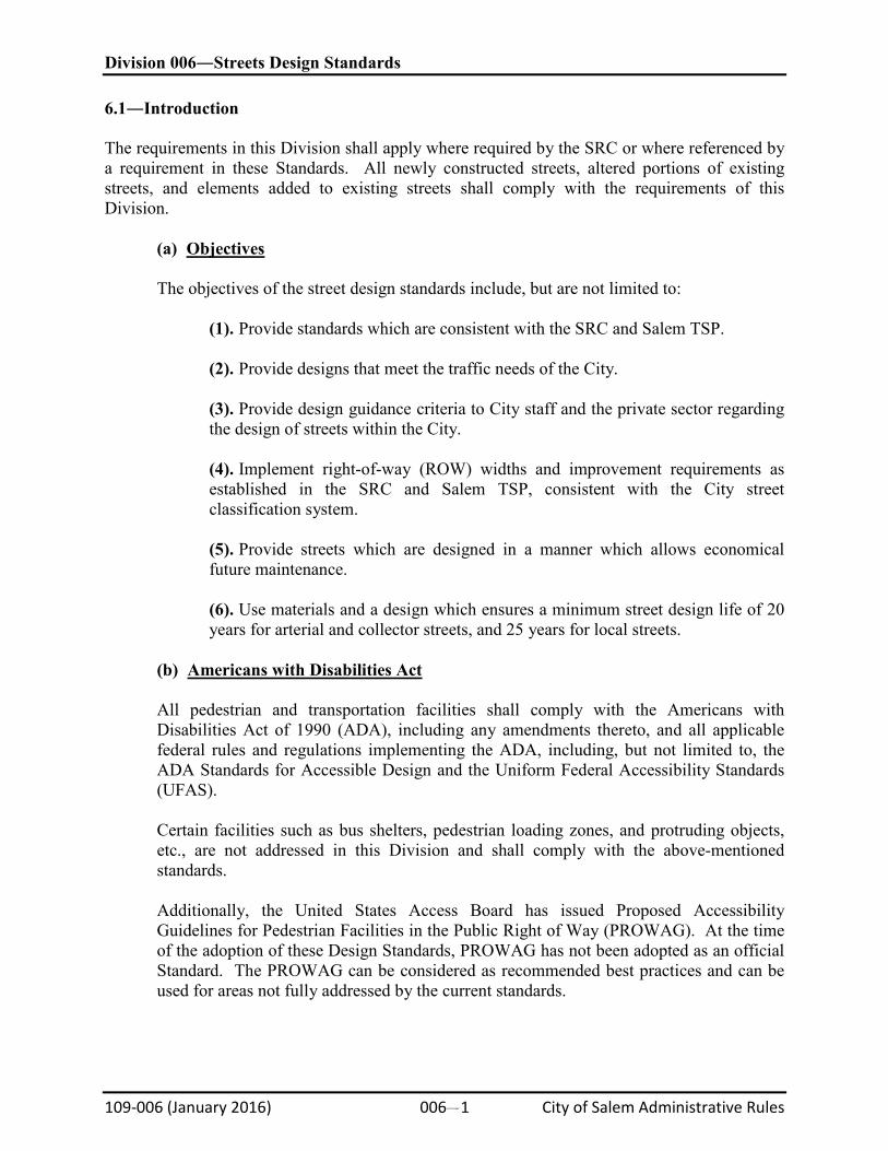
(1). Local streets shall be a curbed improvement, 30 feet wide, measured between the curb faces. The Local street improvement shall be centered within the ROW (see Figure 6-1).
Figure 6-1. Local Street Improvements
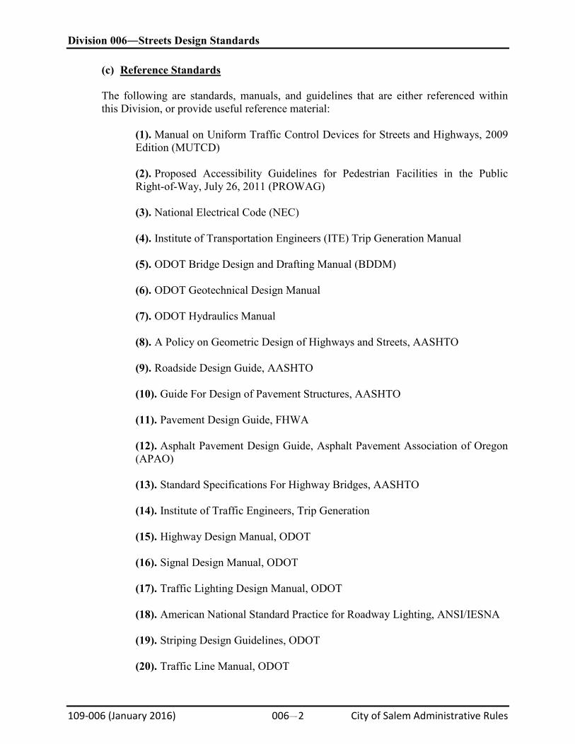
(2). Collector “A” streets shall be a 34-foot-wide, curbed improvement and shall have striped lanes conforming to these standards. The Collector “A” street improvement shall be centered within the ROW (see Figure 6-2).
Division 006―Streets Design Standards
109-006 (January 2016) 006#4 City of Salem Administrative Rules
Figure 6-2. Collector “A” Street Improvements
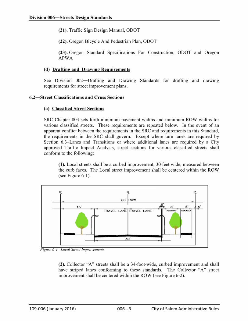
(3). Collector “B” streets shall be a 40-foot-wide, curbed improvement, except at intersections with local streets where, in those cases, a curb extension shall be provided to reduce the pedestrian crossing distance to 34 feet. Collector “B” shall provide striped centerline, parking on one side, and striped bike lanes conforming to these standards (see Figure 6-3).
Figure 6-3. Collector “B” Street Improvements
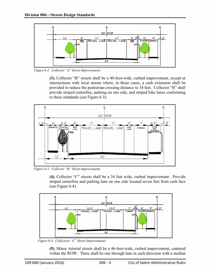
(4). Collector “C” streets shall be a 34 feet wide, curbed improvement. Provide striped centerline and parking lane on one side located seven feet from curb face (see Figure 6-4).
Figure 6-4. Collection “C” Street Improvements
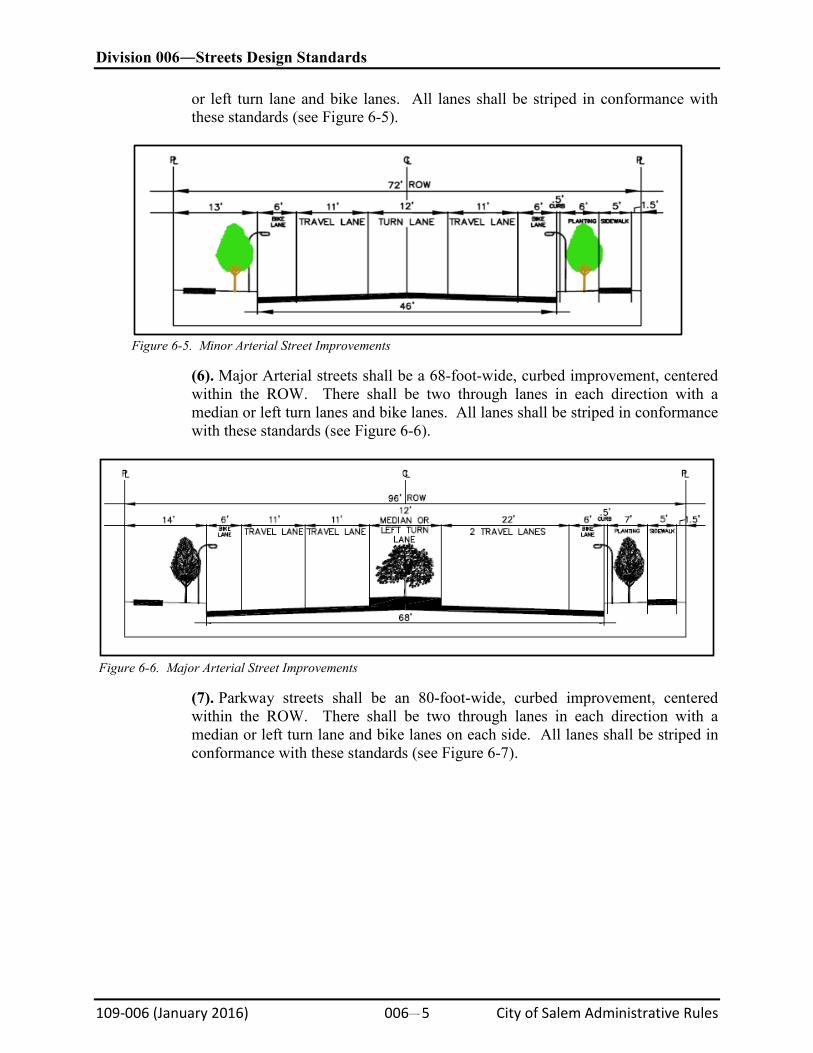
(5). Minor Arterial streets shall be a 46-foot-wide, curbed improvement, centered within the ROW. There shall be one through lane in each direction with a median
Division 006―Streets Design Standards
109-006 (January 2016) 006#5 City of Salem Administrative Rules
or left turn lane and bike lanes. All lanes shall be striped in conformance with these standards (see Figure 6-5).
Figure 6-5. Minor Arterial Street Improvements
(6). Major Arterial streets shall be a 68-foot-wide, curbed improvement, centered within the ROW. There shall be two through lanes in each direction with a median or left turn lanes and bike lanes. All lanes shall be striped in conformance with these standards (see Figure 6-6).
Figure 6-6. Major Arterial Street Improvements
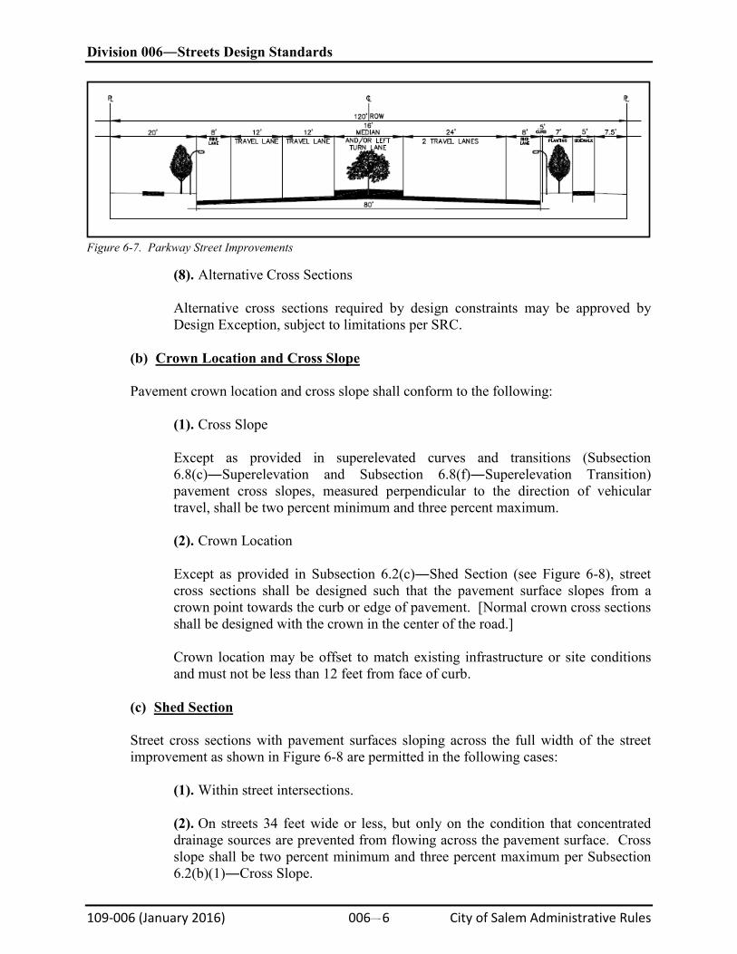
(7). Parkway streets shall be an 80-foot-wide, curbed improvement, centered within the ROW. There shall be two through lanes in each direction with a median or left turn lane and bike lanes on each side. All lanes shall be striped in conformance with these standards (see Figure 6-7).
Division 006―Streets Design Standards
109-006 (January 2016) 006#6 City of Salem Administrative Rules
Figure 6-7. Parkway Street Improvements
(8). Alternative Cross Sections
Alternative cross sections required by design constraints may be approved by Design Exception, subject to limitations per SRC.
(b)
Crown Location and Cross Slope
Pavement crown location and cross slope shall conform to the following:
(1). Cross Slope
Except as provided in superelevated curves and transitions (Subsection 6.8(c)―Superelevation and Subsection 6.8(f)―Superelevation Transition) pavement cross slopes, measured perpendicular to the direction of vehicular travel, shall be two percent minimum and three percent maximum.
(2). Crown Location
Except as provided in Subsection 6.2(c)―Shed Section (see Figure 6-8), street cross sections shall be designed such that the pavement surface slopes from a crown point towards the curb or edge of pavement. [Normal crown cross sections shall be designed with the crown in the center of the road.]
Crown location may be offset to match existing infrastructure or site conditions and must not be less than 12 feet from face of curb.
(c)
Shed Section
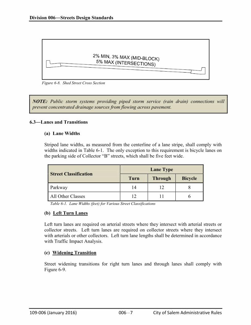
Street cross sections with pavement surfaces sloping across the full width of the street improvement as shown in Figure 6-8 are permitted in the following cases:
(1). Within street intersections.
(2). On streets 34 feet wide or less, but only on the condition that concentrated drainage sources are prevented from flowing across the pavement surface. Cross slope shall be two percent minimum and three percent maximum per Subsection 6.2(b)(1)―Cross Slope.
Division 006―Streets Design Standards
109-006 (January 2016) 006#7 City of Salem Administrative Rules
Figure 6-8. Shed Street Cross Section
NOTE: Public storm systems providing piped storm service (rain drain) connections will prevent concentrated drainage sources from flowing across pavement.
6.3―Lanes and Transitions
(a) Lane Widths
Striped lane widths, as measured from the centerline of a lane stripe, shall comply with widths indicated in Table 6-1. The only exception to this requirement is bicycle lanes on the parking side of Collector “B” streets, which shall be five feet wide.
Street Classification Lane Type
Turn Through Bicycle
Parkway 14 12 8
All Other Classes 12 11 6 Table 6-1. Lane Widths (feet) for Various Street Classifications
(b)
Left Turn Lanes
Left turn lanes are required on arterial streets where they intersect with arterial streets or collector streets. Left turn lanes are required on collector streets where they intersect with arterials or other collectors. Left turn lane lengths shall be determined in accordance with Traffic Impact Analysis.
(c)
Widening Transition
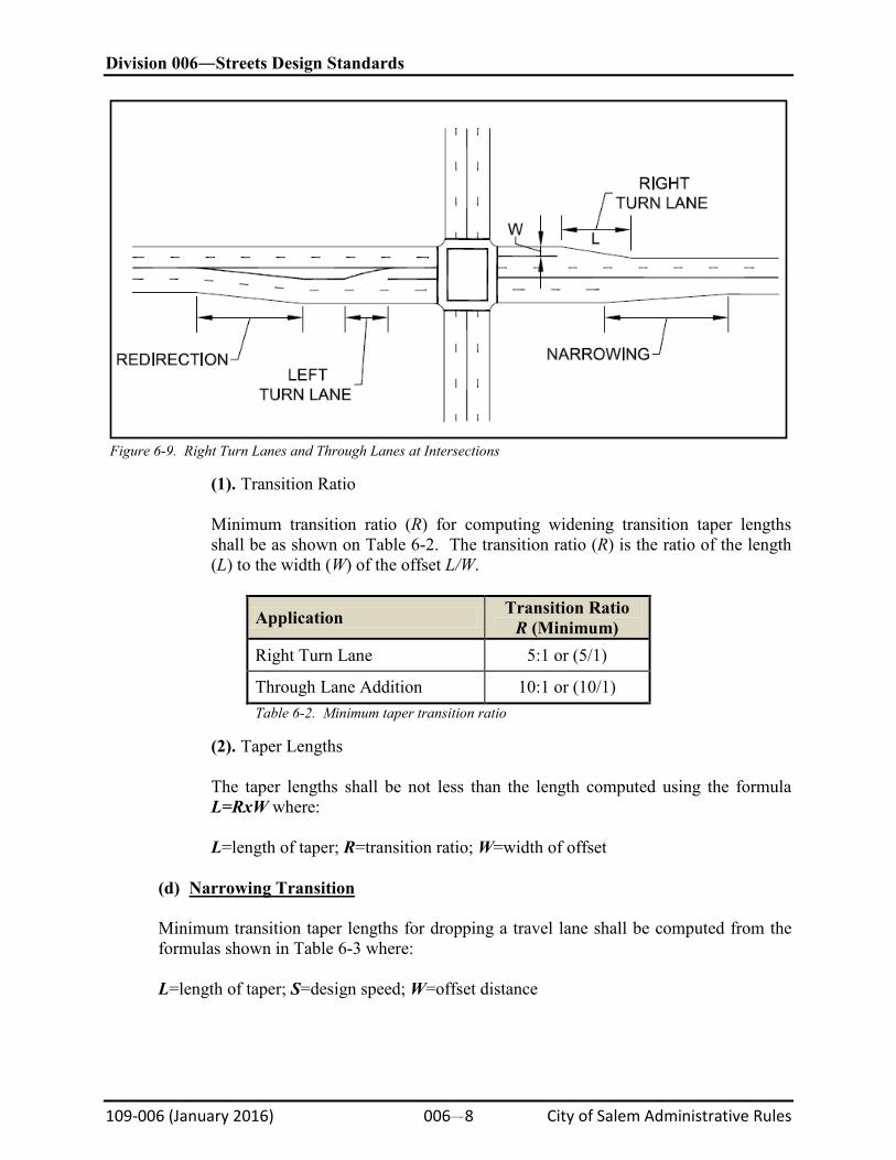
Street widening transitions for right turn lanes and through lanes shall comply with Figure 6-9.
Division 006―Streets Design Standards
109-006 (January 2016) 006#8 City of Salem Administrative Rules
Figure 6-9. Right Turn Lanes and Through Lanes at Intersections
(1). Transition Ratio
Minimum transition ratio (R) for computing widening transition taper lengths shall be as shown on Table 6-2. The transition ratio (R) is the ratio of the length (L) to the width (W) of the offset L/W.
Application Transition Ratio R (Minimum)
Right Turn Lane 5:1 or (5/1)
Through Lane Addition 10:1 or (10/1) Table 6-2. Minimum taper transition ratio
(2). Taper Lengths
The taper lengths shall be not less than the length computed using the formula L=RxW where:
L=length of taper; R=transition ratio; W=width of offset
(d)
Narrowing Transition
Minimum transition taper lengths for dropping a travel lane shall be computed from the formulas shown in Table 6-3 where:
L=length of taper; S=design speed; W=offset distance
Division 006―Streets Design Standards
109-006 (January 2016) 006#9 City of Salem Administrative Rules
Design Speed Minimum Length
Less than 45 mph L=WS2/60
45 mph or Greater L=WS Table 6-3. Minimum taper for lane drop
(e)
Redirection
Minimum transition lengths for redirecting travel lanes shall be computed from the formula L=WxS where:
L=length of taper; S=design speed; W=offset distance
6.4―Pedestrian Access Routes Accessible routes are defined as a continuous, unobstructed walking surface that connects all accessible elements.
(a)
Components
Pedestrian access routes shall consist of one or more of the following components:
(1). Sidewalks and other pedestrian circulation paths, or a portion of sidewalks and other pedestrian circulation paths. (2). Pedestrian street crossings and at-grade rail crossings. (3). Pedestrian overpasses and underpasses and similar structures. (4). Curb ramps and blended transitions.
(b)
Continuous Width
The continuous width of pedestrian access routes shall be a minimum of four feet, exclusive of the width of the curb, except, if within a median or pedestrian refuge island, in which case, the width shall be a minimum of five feet by five feet. Passing spaces are permitted to overlap pedestrian access routes.
(c)
Grade
Except as provided below, where pedestrian access routes are contained within ROW, the grade of pedestrian access routes shall not exceed the general grade established for the adjacent street. Where pedestrian routes are not contained within the ROW, the grade of pedestrian access routes shall be five percent maximum.
Division 006―Streets Design Standards
109-006 (January 2016) 006#10 City of Salem Administrative Rules
(1). Pedestrian Street Crossings
Where pedestrian access routes are contained within pedestrian street crossings, the grade of the pedestrian access route shall be five percent maximum.
(d)
Cross Slope
Except as provided in Subsections 1 and 2 below, the cross slope of pedestrian access routes shall be two percent maximum.
(1). Pedestrian Street Crossings Without Yield or Stop Control
Where pedestrian access routes are contained within pedestrian street crossings without or stop control, the cross lope of the pedestrian access route shall be five percent maximum.
(2). Midblock Pedestrian Street Crossings
Where pedestrian access routes are contained within midblock pedestrian street crossings, the cross slope of the pedestrian access route shall be permitted to equal the street or highway grade.
(e)
Surfaces
The surfaces of pedestrian access routes, elements, and spaces that connect to pedestrian access routes shall be firm, stable, and slip resistant and shall comply with the following:
(1). Vertical Alignment
Vertical alignment shall be generally planar within pedestrian access routes (including curb ramp runs, blended transitions, turning spaces, and gutter areas within pedestrian access routes) and surfaces within other elements and spaces required to connect to pedestrian access routes. Grade breaks shall be flush. Where pedestrian access routes cross rails at grade, the pedestrian access route surface shall be level and flush with the top of rail at the outer edges of the rails and the surface between the rails shall be aligned with the top of rail.
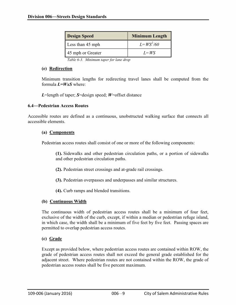
(2). Vertical Surface Discontinuities
Vertical surface discontinuities shall be 0.5 inch maximum. Vertical surface discontinuities between 0.25 inch and 0.5 inch shall be beveled with a slope not steeper than 50 percent. The bevel shall be applied across the entire vertical surface discontinuity.
Division 006―Streets Design Standards
109-006 (January 2016) 006#11 City of Salem Administrative Rules
Figure 6-10. Vertical Surface Discontinuities
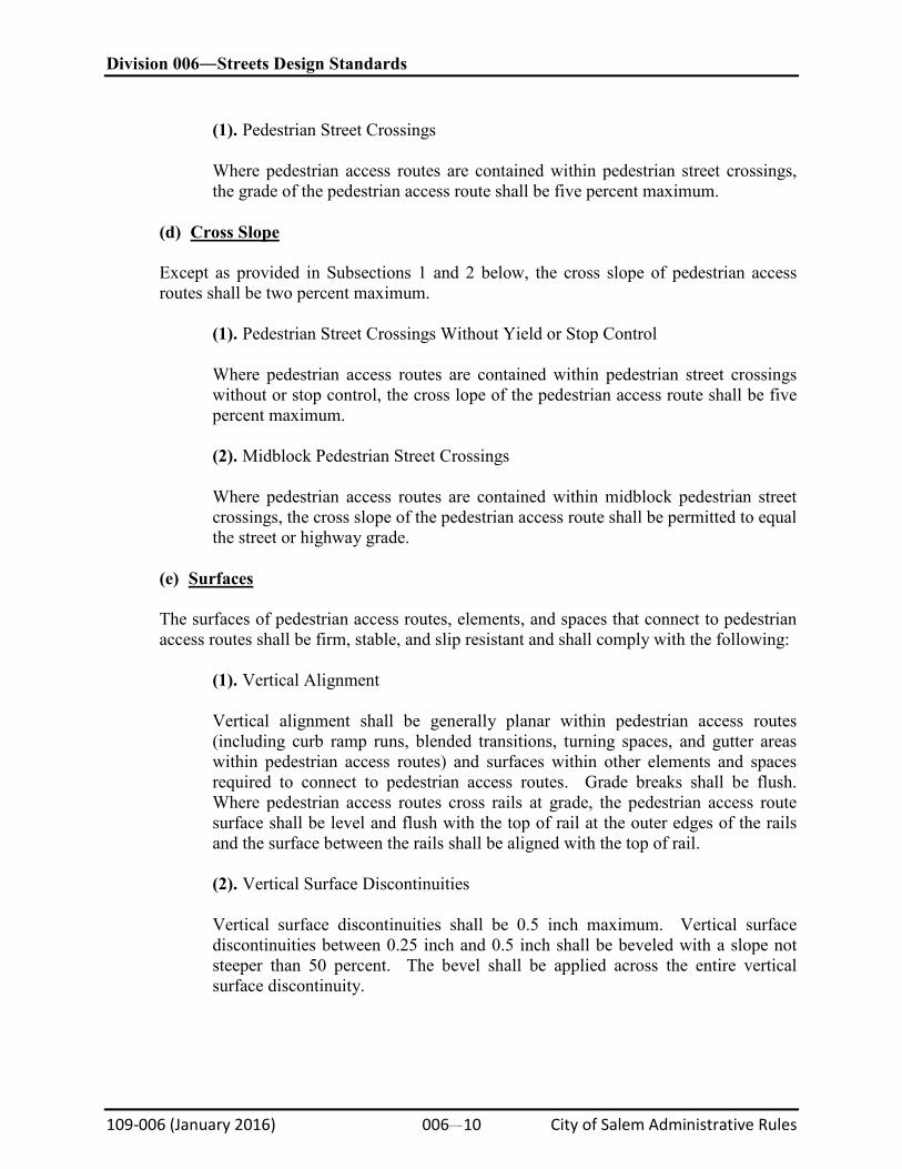
(3). Horizontal Openings
Horizontal openings in gratings and joints shall not permit passage of a sphere more than 0.5 inches in diameter. Elongated openings in gratings shall be placed so that the long dimension is perpendicular to the dominant direction of travel.
Figure 6-11. Horizontal Openings in Gratings and Joints
(4). Flangeway Gaps
Flangeway gaps at pedestrian at-grade rail crossings shall be 2.5 inch maximum on non-freight rail track and three inch maximum on freight rail track.
6.5―Intersections
(a)
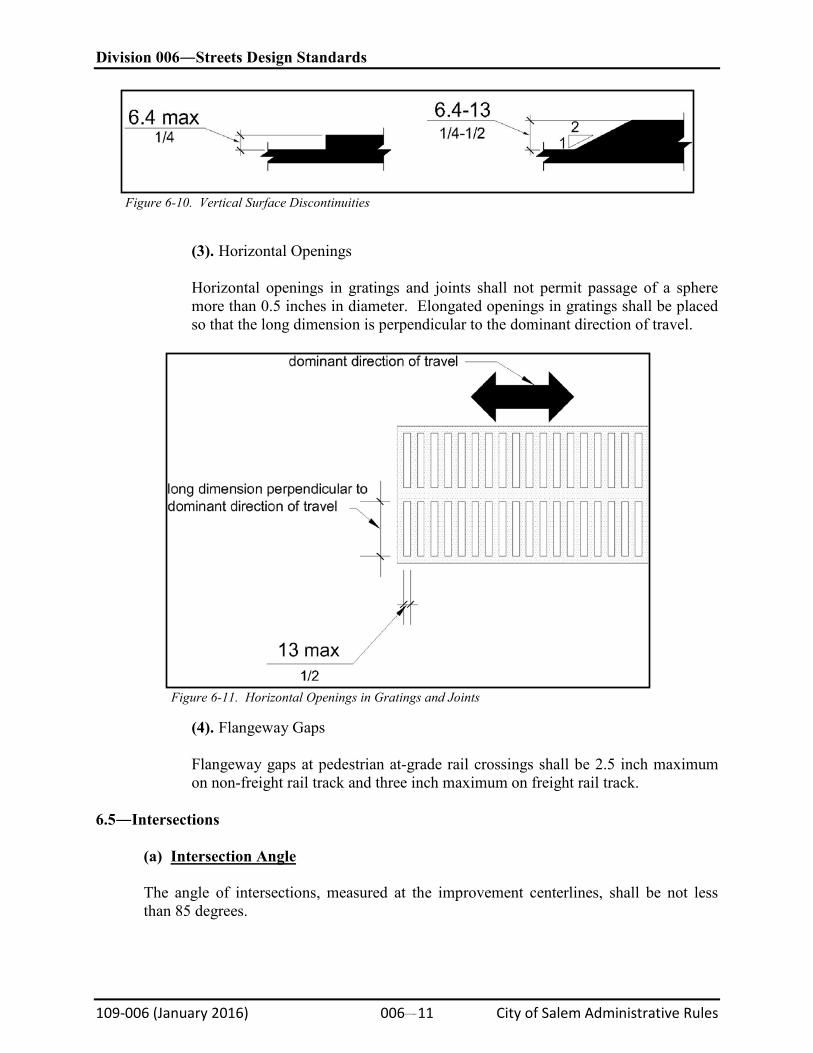
Intersection Angle
The angle of intersections, measured at the improvement centerlines, shall be not less than 85 degrees.
Division 006―Streets Design Standards
109-006 (January 2016) 006#12 City of Salem Administrative Rules
Figure 6-12. Intersection Components
(b)
Tangents
There shall be a straight tangent section on each leg of an intersection having a length not less than as shown in Table 6-4. The length of the tangent is to be measured beginning at an extension of the cross street curb line.
Street Classification Minimum Tangent Length (Feet)
Arterial 100 Collector 75 Residential 50 Table 6-4. Minimum Tangent Lengths for Various Street Classifications
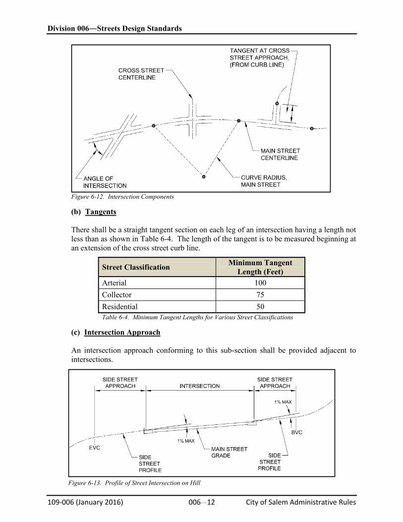
(c)
Intersection Approach
An intersection approach conforming to this sub-section shall be provided adjacent to intersections.
Figure 6-13. Profile of Street Intersection on Hill
Division 006―Streets Design Standards
109-006 (January 2016) 006#13 City of Salem Administrative Rules
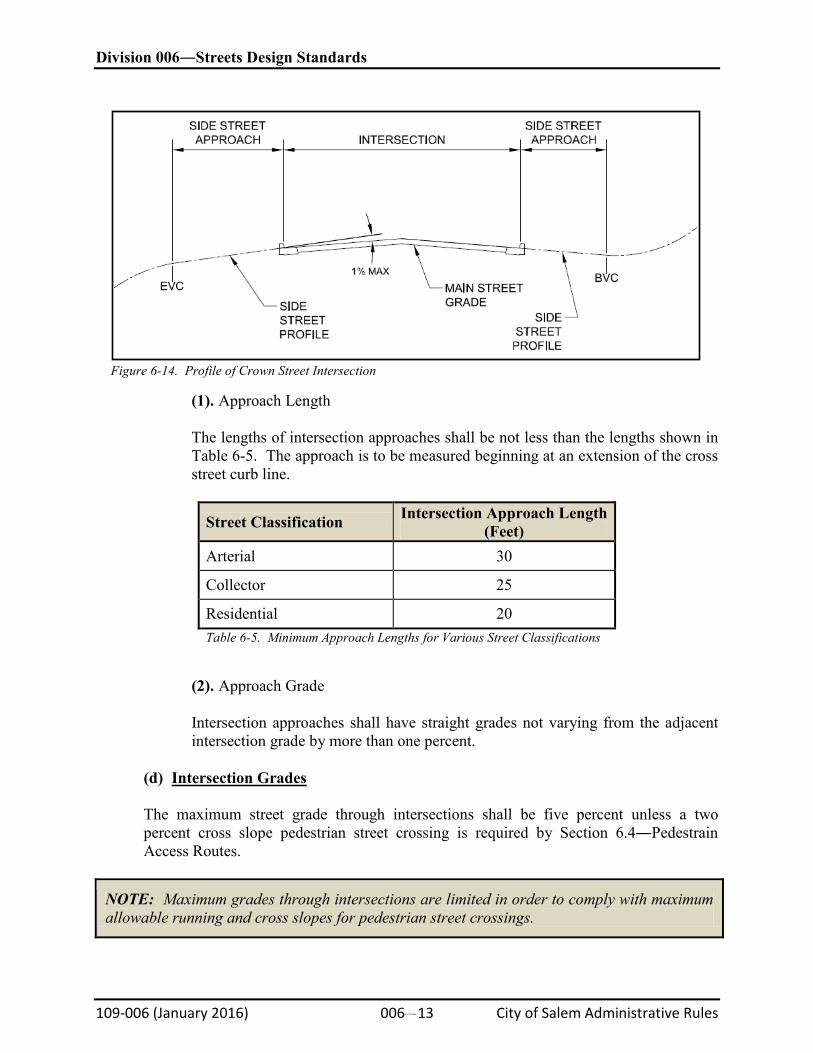
Figure 6-14. Profile of Crown Street Intersection
(1). Approach Length
The lengths of intersection approaches shall be not less than the lengths shown in Table 6-5. The approach is to be measured beginning at an extension of the cross street curb line.
Street Classification Intersection Approach Length (Feet)
Arterial 30
Collector 25
Residential 20 Table 6-5. Minimum Approach Lengths for Various Street Classifications
(2). Approach Grade
Intersection approaches shall have straight grades not varying from the adjacent intersection grade by more than one percent.
(d)
Intersection Grades
The maximum street grade through intersections shall be five percent unless a two percent cross slope pedestrian street crossing is required by Section 6.4―Pedestrain Access Routes.
NOTE: Maximum grades through intersections are limited in order to comply with maximum allowable running and cross slopes for pedestrian street crossings.
Division 006―Streets Design Standards
109-006 (January 2016) 006#14 City of Salem Administrative Rules
(e)
Pedestrian Street Crossing
A pedestrian street crossing shall be provided for all legal crossing locations as required by state law, unless the City Engineer determines a crossing should not be provided in consideration of safety and traffic issues. Pedestrian street crossings shall contain a pedestrian access route that complies with Section 6.4–Pedestrian Access Routes.
6.6―Cul-de-sac and Knuckles SRC Chapter 803 sets forth minimum ROW and street widths, including radius dimensions for culs-de-sac. These requirements are repeated below. In the event of an apparent conflict between the requirements in the SRC and requirements in this Standard, the requirements in the SRC shall govern.
(a)
Horizontal Alignment
(1). Minimum curb radius reversing curve transitions to culs-de-sac and knuckles shall be 25 feet.
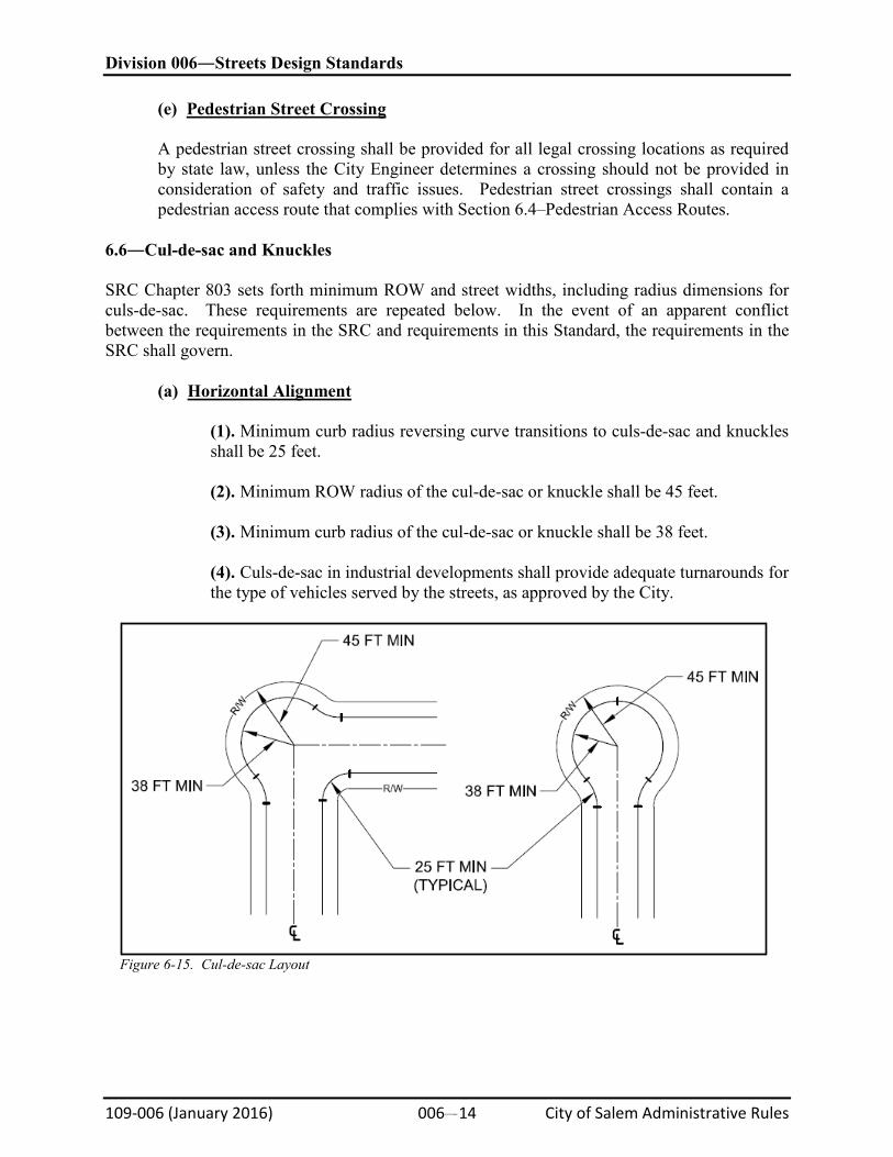
(2). Minimum ROW radius of the cul-de-sac or knuckle shall be 45 feet. (3). Minimum curb radius of the cul-de-sac or knuckle shall be 38 feet. (4). Culs-de-sac in industrial developments shall provide adequate turnarounds for the type of vehicles served by the streets, as approved by the City.
Figure 6-15. Cul-de-sac Layout
Division 006―Streets Design Standards
109-006 (January 2016) 006#15 City of Salem Administrative Rules
(b)
Vertical Alignment
(1). Maximum Curb Grade
Maximum curb grade shall be ten percent.
(2). Vertical Alignments
Cul-de-sac curb profiles shall be designed to provide smooth vertical alignment. Curb grade changes in excess of one percent shall conform to the requirements of a vertical curve (Section 6.9–Vertical Curves), with a K-value not less than 3.0.
6.7―Design Speeds A major local street is the intersecting street with greater traffic volume, larger cross section, and higher functional class A minor local street is the intersection street which, in the judgment of the City Engineer, is likely to have less traffic volume and lower functional classification than the major street.
(a)
Classified Streets
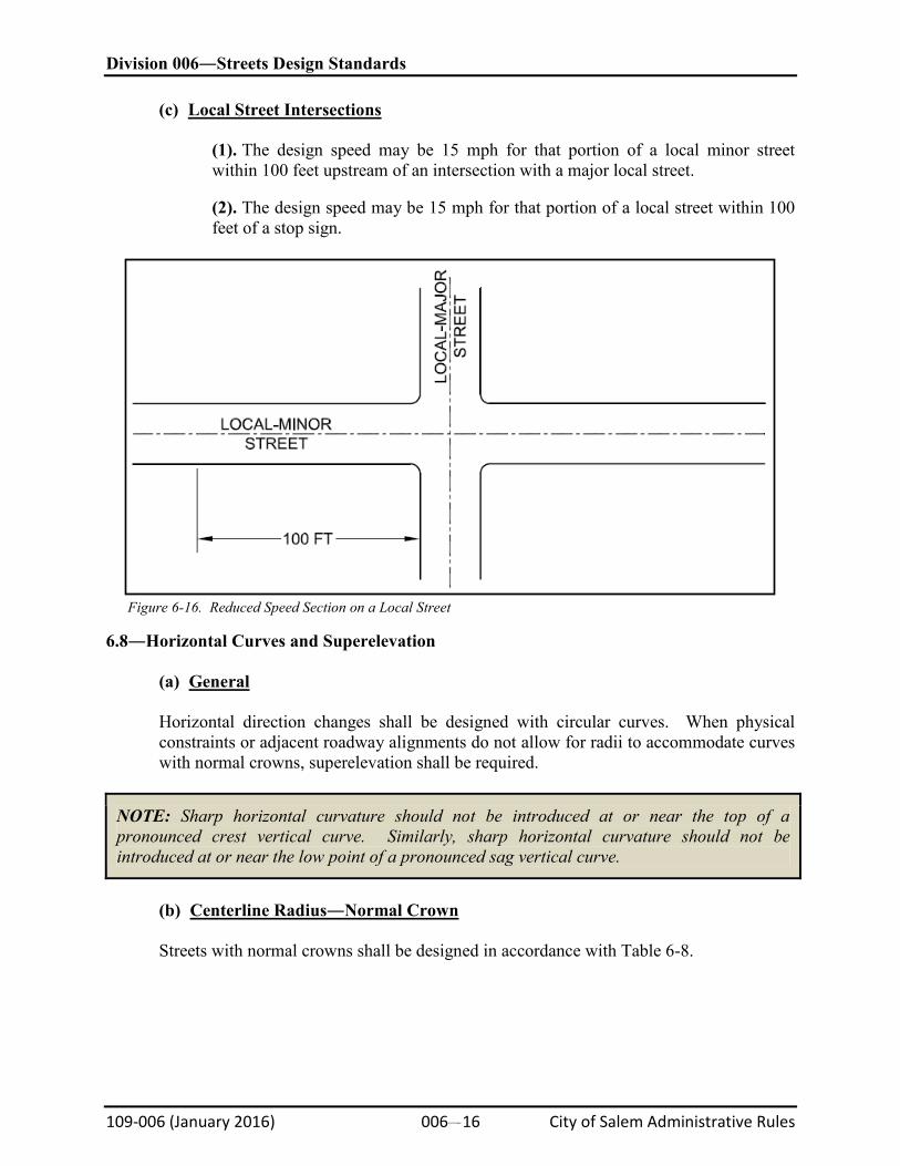
Except as provided in Subsection 6.7(b)―Existing Posted Speed and Subsection 6.7(c)―Local Street Intersections, the minimum design speeds for streets shall be as shown in Table 6-6.
Street Classification Design Speed
Alleys 15 mph Local Streets 25 mph Collectors, and Arterials in CB District 35 mph Arterials 45 mph Parkway 55 mph Table 6-6. Street Classification Design Speeds
(b)
Existing Posted Speed
Where the City Traffic Engineer determines that a street will have a posted speed less than the speeds in Table 6-6, the design speed is permitted to equal:
Classification Design Speed
Local Streets Posted Speed Collectors Posted Speed +5 mph Arterials Posted Speed +10 mph Parkway Posted Speed +10 mph Table 6-7. Design Speeds Exceptions
Division 006―Streets Design Standards
109-006 (January 2016) 006#16 City of Salem Administrative Rules
(c)
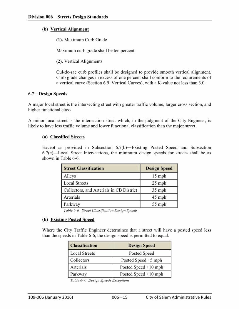
Local Street Intersections
(1). The design speed may be 15 mph for that portion of a local minor street within 100 feet upstream of an intersection with a major local street.
(2). The design speed may be 15 mph for that portion of a local street within 100 feet of a stop sign.
Figure 6-16. Reduced Speed Section on a Local Street
6.8―Horizontal Curves and Superelevation
(a)
General
Horizontal direction changes shall be designed with circular curves. When physical constraints or adjacent roadway alignments do not allow for radii to accommodate curves with normal crowns, superelevation shall be required.
NOTE: Sharp horizontal curvature should not be introduced at or near the top of a pronounced crest vertical curve. Similarly, sharp horizontal curvature should not be introduced at or near the low point of a pronounced sag vertical curve.
(b)
Centerline Radius―Normal Crown
Streets with normal crowns shall be designed in accordance with Table 6-8.
Division 006―Streets Design Standards
109-006 (January 2016) 006#17 City of Salem Administrative Rules
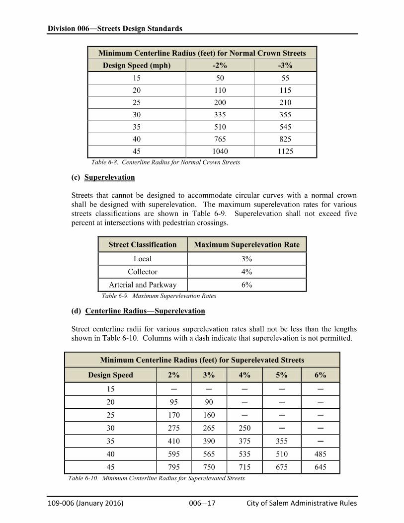
Minimum Centerline Radius (feet) for Normal Crown Streets Design Speed (mph) -2% -3%
15 50 55 20 110 115 25 200 210 30 335 355 35 510 545 40 765 825 45 1040 1125
Table 6-8. Centerline Radius for Normal Crown Streets
(c)
Superelevation
Streets that cannot be designed to accommodate circular curves with a normal crown shall be designed with superelevation. The maximum superelevation rates for various streets classifications are shown in Table 6-9. Superelevation shall not exceed five percent at intersections with pedestrian crossings.
Street Classification Maximum Superelevation Rate
Local 3% Collector 4%
Arterial and Parkway 6% Table 6-9. Maximum Superelevation Rates
(d)
Centerline Radius―Superelevation
Street centerline radii for various superelevation rates shall not be less than the lengths shown in Table 6-10. Columns with a dash indicate that superelevation is not permitted.
Minimum Centerline Radius (feet) for Superelevated Streets
Design Speed 2% 3% 4% 5% 6%
15 ─ ─ ─ ─ ─ 20 95 90 ─ ─ ─ 25 170 160 ─ ─ ─ 30 275 265 250 ─ ─
35 410 390 375 355 ─ 40 595 565 535 510 485 45 795 750 715 675 645
Table 6-10. Minimum Centerline Radius for Superelevated Streets
Division 006―Streets Design Standards
109-006 (January 2016) 006#18 City of Salem Administrative Rules
(e)
Pedestrian Street Crossings in Superelevation
Superelevations shall comply with Subsection 6.4(c)―Grade where pedestrian crossings are required.
(f)
Superelevation Transition
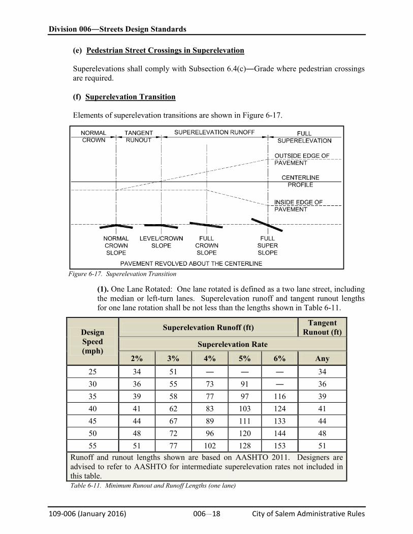
Elements of superelevation transitions are shown in Figure 6-17.
Figure 6-17. Superelevation Transition
(1). One Lane Rotated: One lane rotated is defined as a two lane street, including the median or left-turn lanes. Superelevation runoff and tangent runout lengths for one lane rotation shall be not less than the lengths shown in Table 6-11.
Design Speed (mph)
Superelevation Runoff (ft) Tangent Runout (ft)
Superelevation Rate
2% 3% 4% 5% 6% Any 25 34 51 ― ― ― 34 30 36 55 73 91 ― 36 35 39 58 77 97 116 39 40 41 62 83 103 124 41 45 44 67 89 111 133 44 50 48 72 96 120 144 48 55 51 77 102 128 153 51
Runoff and runout lengths shown are based on AASHTO 2011. Designers are advised to refer to AASHTO for intermediate superelevation rates not included in this table. Table 6-11. Minimum Runout and Runoff Lengths (one lane)
Division 006―Streets Design Standards
109-006 (January 2016) 006#19 City of Salem Administrative Rules
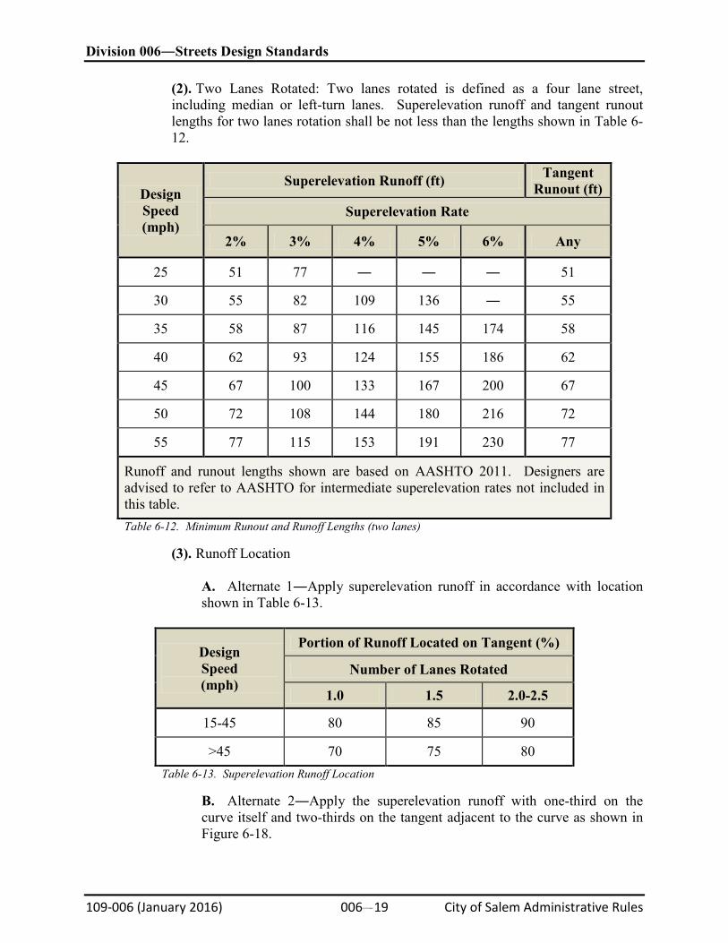
(2). Two Lanes Rotated: Two lanes rotated is defined as a four lane street, including median or left-turn lanes. Superelevation runoff and tangent runout lengths for two lanes rotation shall be not less than the lengths shown in Table 6-12.
Design Speed (mph)
Superelevation Runoff (ft) Tangent Runout (ft)
Superelevation Rate
2% 3% 4% 5% 6% Any
25 51 77 ― ― ― 51
30 55 82 109 136 ― 55
35 58 87 116 145 174 58
40 62 93 124 155 186 62
45 67 100 133 167 200 67
50 72 108 144 180 216 72
55 77 115 153 191 230 77
Runoff and runout lengths shown are based on AASHTO 2011. Designers are advised to refer to AASHTO for intermediate superelevation rates not included in this table. Table 6-12. Minimum Runout and Runoff Lengths (two lanes)
(3). Runoff Location
A. Alternate 1―Apply superelevation runoff in accordance with location shown in Table 6-13.
Design Speed (mph)
Portion of Runoff Located on Tangent (%)
Number of Lanes Rotated
1.0 1.5 2.0-2.5
15-45 80 85 90
>45 70 75 80 Table 6-13. Superelevation Runoff Location
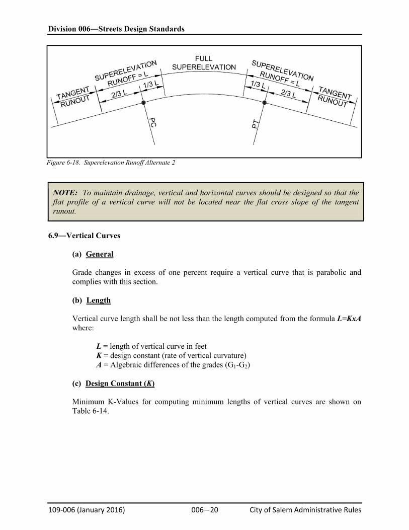
B. Alternate 2―Apply the superelevation runoff with one-third on the curve itself and two-thirds on the tangent adjacent to the curve as shown in Figure 6-18.
Division 006―Streets Design Standards
109-006 (January 2016) 006#20 City of Salem Administrative Rules
Figure 6-18. Superelevation Runoff Alternate 2
NOTE: To maintain drainage, vertical and horizontal curves should be designed so that the flat profile of a vertical curve will not be located near the flat cross slope of the tangent runout.
6.9―Vertical Curves
(a)
General
Grade changes in excess of one percent require a vertical curve that is parabolic and complies with this section.
(b)
Length
Vertical curve length shall be not less than the length computed from the formula L=KxA where:
L = length of vertical curve in feet K = design constant (rate of vertical curvature) A = Algebraic differences of the grades (G1-G2)
(c)
Design Constant (K)
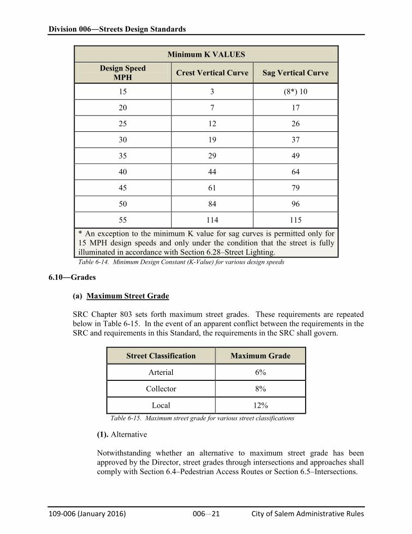
Minimum K-Values for computing minimum lengths of vertical curves are shown on Table 6-14.
Division 006―Streets Design Standards
109-006 (January 2016) 006#21 City of Salem Administrative Rules
Minimum K VALUES
Design Speed MPH Crest Vertical Curve Sag Vertical Curve
15 3 (8*) 10
20 7 17
25 12 26
30 19 37
35 29 49
40 44 64
45 61 79
50 84 96
55 114 115
* An exception to the minimum K value for sag curves is permitted only for 15 MPH design speeds and only under the condition that the street is fully illuminated in accordance with Section 6.28–Street Lighting. Table 6-14. Minimum Design Constant (K-Value) for various design speeds
6.10―Grades
(a)
Maximum Street Grade
SRC Chapter 803 sets forth maximum street grades. These requirements are repeated below in Table 6-15. In the event of an apparent conflict between the requirements in the SRC and requirements in this Standard, the requirements in the SRC shall govern.
Street Classification Maximum Grade
Arterial 6%
Collector 8%
Local 12% Table 6-15. Maximum street grade for various street classifications
(1). Alternative
Notwithstanding whether an alternative to maximum street grade has been approved by the Director, street grades through intersections and approaches shall comply with Section 6.4–Pedestrian Access Routes or Section 6.5–Intersections.
Division 006―Streets Design Standards
109-006 (January 2016) 006#22 City of Salem Administrative Rules
(b)
Grade Changes
Except as provided in Subsection 6.10(b)(1)―Grade Change Execptions below, grade changes in excess of one percent shall comply with Section 6.9–Vertical Curves.
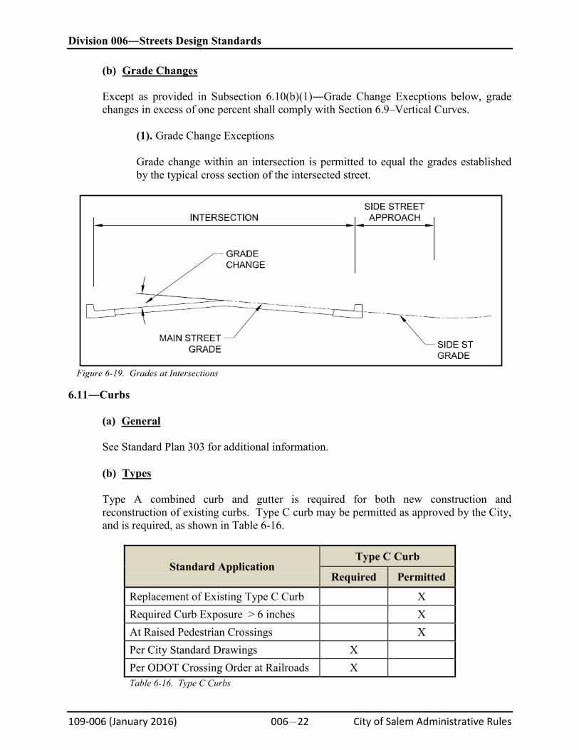
(1). Grade Change Exceptions
Grade change within an intersection is permitted to equal the grades established by the typical cross section of the intersected street.
Figure 6-19. Grades at Intersections
6.11―Curbs
(a)
General
See Standard Plan 303 for additional information.
(b)
Types
Type A combined curb and gutter is required for both new construction and reconstruction of existing curbs. Type C curb may be permitted as approved by the City, and is required, as shown in Table 6-16.
Standard Application Type C Curb
Required Permitted
Replacement of Existing Type C Curb X Required Curb Exposure > 6 inches X At Raised Pedestrian Crossings X Per City Standard Drawings X Per ODOT Crossing Order at Railroads X Table 6-16. Type C Curbs
Division 006―Streets Design Standards
109-006 (January 2016) 006#23 City of Salem Administrative Rules
(c)
Minimum Grade
Curb grade shall be not less than 0.25 percent for Type A and 0.4 percent for Type C.
(d)
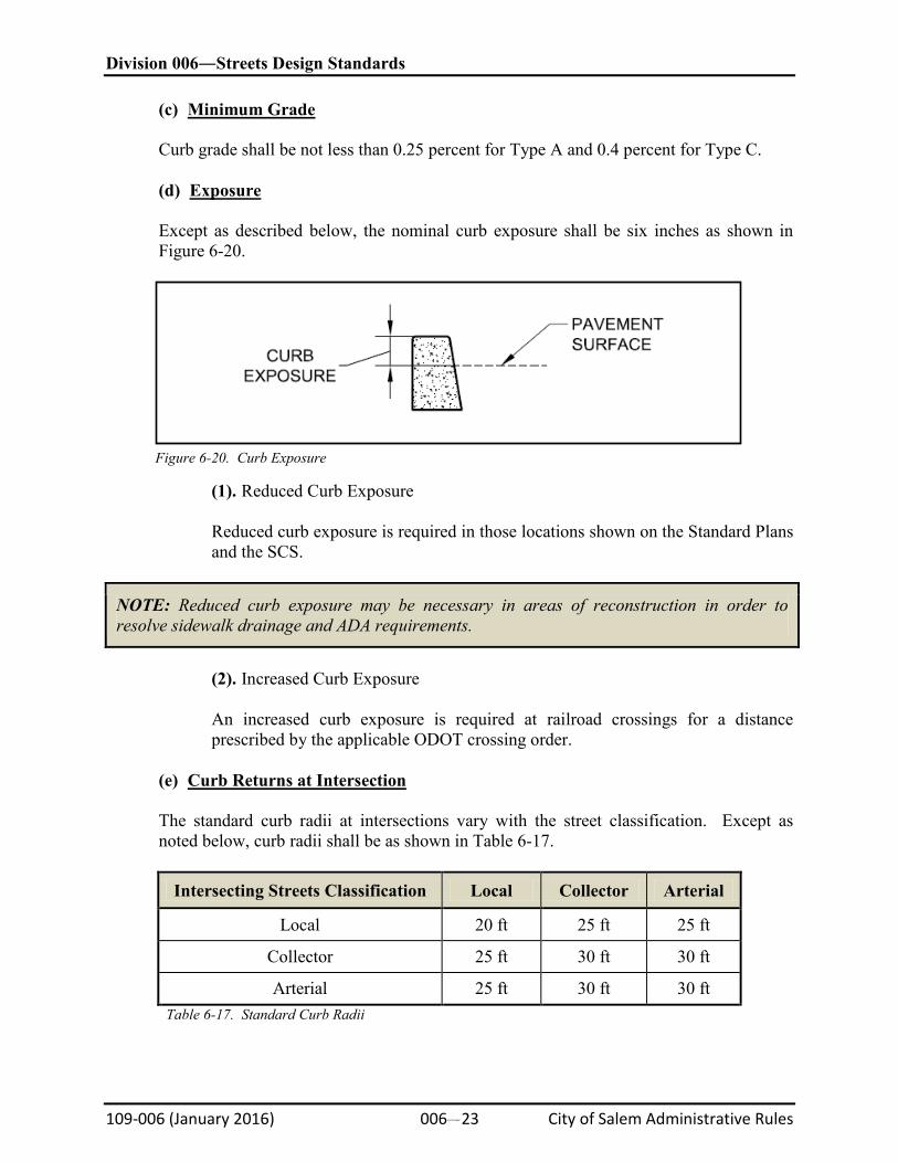
Exposure
Except as described below, the nominal curb exposure shall be six inches as shown in Figure 6-20.
Figure 6-20. Curb Exposure
(1). Reduced Curb Exposure
Reduced curb exposure is required in those locations shown on the Standard Plans and the SCS.
NOTE: Reduced curb exposure may be necessary in areas of reconstruction in order to resolve sidewalk drainage and ADA requirements.
(2). Increased Curb Exposure
An increased curb exposure is required at railroad crossings for a distance prescribed by the applicable ODOT crossing order.
(e)
Curb Returns at Intersection
The standard curb radii at intersections vary with the street classification. Except as noted below, curb radii shall be as shown in Table 6-17.
Intersecting Streets Classification Local Collector Arterial
Local 20 ft 25 ft 25 ft
Collector 25 ft 30 ft 30 ft
Arterial 25 ft 30 ft 30 ft Table 6-17. Standard Curb Radii
Division 006―Streets Design Standards
109-006 (January 2016) 006#24 City of Salem Administrative Rules
(1). Reduced Curb Radius
Curb radius may be reduced to five feet less than standard radius in any of the following circumstances:
A. To prevent conflict with immovable obstructions, B. To fit required improvements within available ROW, C. At intersections of one-way streets where vehicle turning movements are prohibited.
(2). Increased Curb Radius
Curb radius shall be increased above the standard radii when directed by City Traffic Engineer in order to accommodate truck turning movements.
(3). Curb Return Vertical Alignment
Curb returns shall be designed to provide smooth vertical profiles. Grade changes shall not exceed one percent. Grade changes exceeding one percent shall require a vertical curve. Profile shall be designed to provide adequate drainage. Low points shall not be located in curb ramps.
(f)
Alignment Changes
Horizontal alignment changes in curbs shall be designed as a circular curve having a radius not less than 15 feet.
(g)
Cross Slope at Curb Ramps and Blended Transitions
The gutter cross slope of Type A curb shall not exceed five percent at curb ramps and blended transitions.
6.12―Sidewalks
(a)
Accessible Routes
All sidewalks shall contain a pedestrian access route per the requirements of Section 6.4–Pedestrian Access Routes.
(b)
Sidewalk Width & Location
SRC Chapter 803 sets forth minimum sidewalk widths and locations. These standards are repeated and expanded in this section. All sidewalks shall be a minimum of five feet in width. Sidewalks that provide a direct access to a school shall be a minimum of eight feet in width for a distance of 600 feet from the point of connection. Curbline sidewalks on the striped parking side of Collector “B” Streets shall be a minimum of 6.5 feet in
Division 006―Streets Design Standards
109-006 (January 2016) 006#25 City of Salem Administrative Rules
width. In the event of an apparent conflict between the requirements in the SRC and requirements in this Standard, the requirements in the SRC shall govern.
(c)
Sidewalk Slope
Sidewalk cross slopes shall be a minimum of 0.5 percent and a maximum of two percent. The running slope of sidewalks shall remain as flat as possible, up to a maximum of five percent. A sidewalk may follow the slope of the adjacent roadway when achieving less than five percent is not practicable. (d)
Sidewalk Thickness
The minimum sidewalk thickness is four inches except in the following locations:
Location
Driveway approaches
Minimum Thickness
Six inches
Curb Ramps and turning areas (see Curb Ramp Standard Plans)
Six inches
(e)
Construction Timing
Sidewalks shall be constructed prior to City acceptance of street improvements, except as provided below.
(1). Exception
Sidewalk construction adjacent to the full frontage portion of a residential building lot designated for driveway access may be deferred until it is required by the SRC or until a building permit is issued, whichever occurs sooner.
(f)
Temporary Transitions
Temporary transitions conforming to Standard Plans and the SRC are required where sidewalks terminate.
6.13―Driveways
(a)
General
SRC Chapter 804 sets forth locations, widths, and slopes for driveways. These requirements are repeated below. In addition, Standard Plan Nos. 301, 302, and 315 provide detailed layout information.
(b)
Angle
The angle between a driveway centerline and the parallel vehicle travel lane shall not be less than 75 degrees.
Division 006―Streets Design Standards
109-006 (January 2016) 006#26 City of Salem Administrative Rules
(c)
Driveway Width
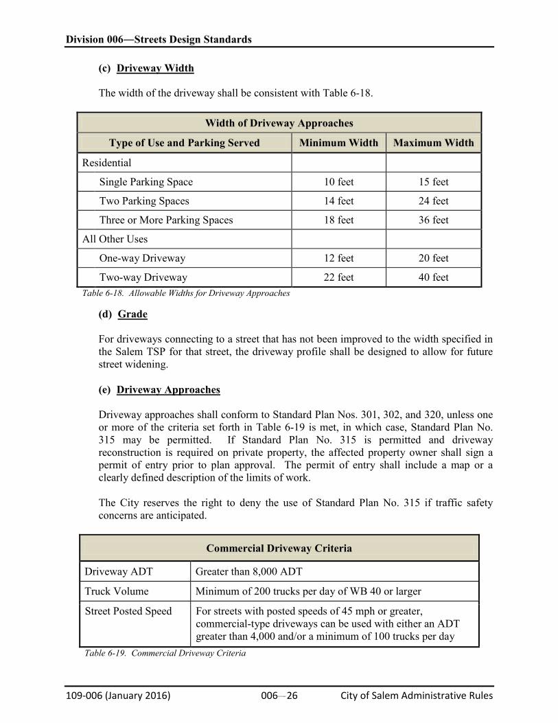
The width of the driveway shall be consistent with Table 6-18.
Width of Driveway Approaches
Type of Use and Parking Served Minimum Width Maximum Width
Residential
Single Parking Space 10 feet 15 feet
Two Parking Spaces 14 feet 24 feet
Three or More Parking Spaces 18 feet 36 feet
All Other Uses
One-way Driveway 12 feet 20 feet
Two-way Driveway 22 feet 40 feet Table 6-18. Allowable Widths for Driveway Approaches
(d)
Grade
For driveways connecting to a street that has not been improved to the width specified in the Salem TSP for that street, the driveway profile shall be designed to allow for future street widening.
(e)
Driveway Approaches
Driveway approaches shall conform to Standard Plan Nos. 301, 302, and 320, unless one or more of the criteria set forth in Table 6-19 is met, in which case, Standard Plan No. 315 may be permitted. If Standard Plan No. 315 is permitted and driveway reconstruction is required on private property, the affected property owner shall sign a permit of entry prior to plan approval. The permit of entry shall include a map or a clearly defined description of the limits of work.
The City reserves the right to deny the use of Standard Plan No. 315 if traffic safety concerns are anticipated.
Commercial Driveway Criteria
Driveway ADT Greater than 8,000 ADT
Truck Volume Minimum of 200 trucks per day of WB 40 or larger
Street Posted Speed For streets with posted speeds of 45 mph or greater, commercial-type driveways can be used with either an ADT greater than 4,000 and/or a minimum of 100 trucks per day
Table 6-19. Commercial Driveway Criteria
Division 006―Streets Design Standards
109-006 (January 2016) 006#27 City of Salem Administrative Rules
(f)
Pedestrian Crossing
A pedestrian access route per Section 6.4–Pedestrian Access Routes shall be provided across driveways.
(g)
Driveway Closure
Where an existing driveway is to be closed, the curb (if any) shall be replaced with a new section of curb and the parking strip and sidewalk shall be made to conform to adjoining sidewalk and parking strip.
6.14―Curb Bulb-Outs
(a)
General
Curb extensions shall be provided per Section 6.2#Street Classifications and Cross Sections or as required by the City. Intersection bulb-outs are generally required whenever pedestrian visibility or reduced crossing time or distance is a concern or to comply with pedestrian access route requirements.
(b)
Curb
(1). Radii
Curb radii for bulb-outs shall be designed in accordance with Table 6-16. Inside radii where the curb extension ties back into the existing curb alignment shall be a minimum of 15 feet to provide for street sweeping capabilities. Compound radii are acceptable.
(2). Elevation
Curb low points shall not fall within a curb ramp throat, blended transition, or ADA access point. Curb elevations shall be provided at the beginning, ¼ point, ½ point, ¾ point, and end of each radius.
(c)
Sidewalk
(1). Slope and Drainage
Sidewalk slopes shall comply with Section 6.12–Sidewalks for accessible routes. Sidewalks shall slope away from buildings and to the adjacent street unless restricted by the difference between street elevations and building elevations, or where required to slope to green stormwater infrastructure. In situations where the sidewalk cannot slope to the street for this reason, drainage can be accommodated within the bulb-out or pull-out through the use of ADA compliant grates over standard catch basins.
Division 006―Streets Design Standards
109-006 (January 2016) 006#28 City of Salem Administrative Rules
(2). Thickness
Sidewalk thickness shall comply with Section 6.12–Sidewalks. Bulb-outs and pull-outs that are subject to heavy traffic shall be six inches thick and shall be reinforced with either wire mesh or reinforcing bar.
(3). Joints and Texture
The panel sizes and surface textures shall be in accordance with Section 6.33―Streetscape.
6.15―Traffic Calming
(a)
General
Traffic Calming structures are not permitted unless they are warranted as determined by Neighborhood Traffic Management Program criteria.
(b)
Speed Humps
Speed Humps shall be located only where all of the following criteria are met:
(1). On a street designated as a local street. (2). Where the street grade does not exceed eight percent for a distance of 75 feet upstream and 75 feet downstream of the speed hump. (3). Speed humps shall not be installed in front of driveways, over utility manholes, or valves. (4). Where speed humps are employed for traffic calming, two speed humps minimum are required and shall have a spacing 300 feet minimum and 500 feet maximum between any two speed humps.
6.16―Medians
(a)
Raised Medians
Raised medians may be required on arterial streets where it is necessary to regulate left turn movements. Raised median widths vary in width as shown in Section 6.2–Street Classifications and Cross Sections and Standard Plan Nos. 319, 320, and 321.
(1). Turning Radius
Raised medians shall be designed to allow for the proper turning radius of all vehicles at intersections.
Division 006―Streets Design Standards
109-006 (January 2016) 006#29 City of Salem Administrative Rules
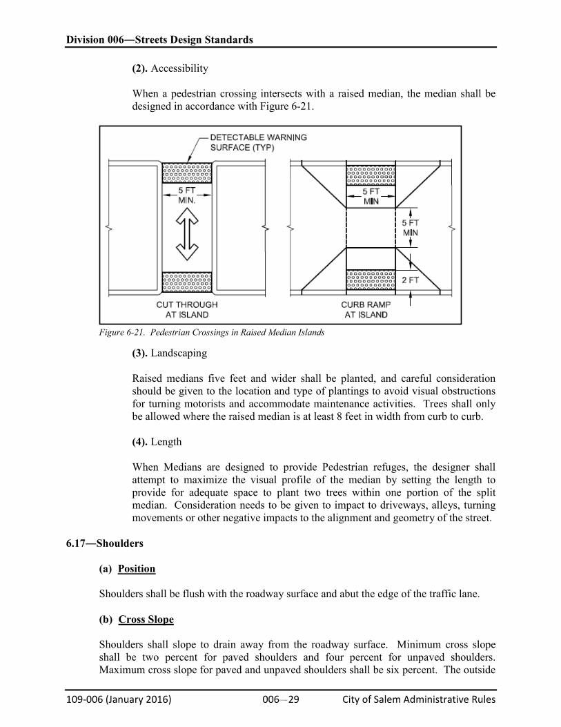
(2). Accessibility
When a pedestrian crossing intersects with a raised median, the median shall be designed in accordance with Figure 6-21.
Figure 6-21. Pedestrian Crossings in Raised Median Islands
(3). Landscaping
Raised medians five feet and wider shall be planted, and careful consideration should be given to the location and type of plantings to avoid visual obstructions for turning motorists and accommodate maintenance activities. Trees shall only be allowed where the raised median is at least 8 feet in width from curb to curb.
(4). Length
When Medians are designed to provide Pedestrian refuges, the designer shall attempt to maximize the visual profile of the median by setting the length to provide for adequate space to plant two trees within one portion of the split median. Consideration needs to be given to impact to driveways, alleys, turning movements or other negative impacts to the alignment and geometry of the street.
6.17―Shoulders
(a)
Position
Shoulders shall be flush with the roadway surface and abut the edge of the traffic lane.
(b)
Cross Slope
Shoulders shall slope to drain away from the roadway surface. Minimum cross slope shall be two percent for paved shoulders and four percent for unpaved shoulders. Maximum cross slope for paved and unpaved shoulders shall be six percent. The outside
Division 006―Streets Design Standards
109-006 (January 2016) 006#30 City of Salem Administrative Rules
(high side) cross slope break at the pavement edge of a superelevated curve shall not exceed eight percent.
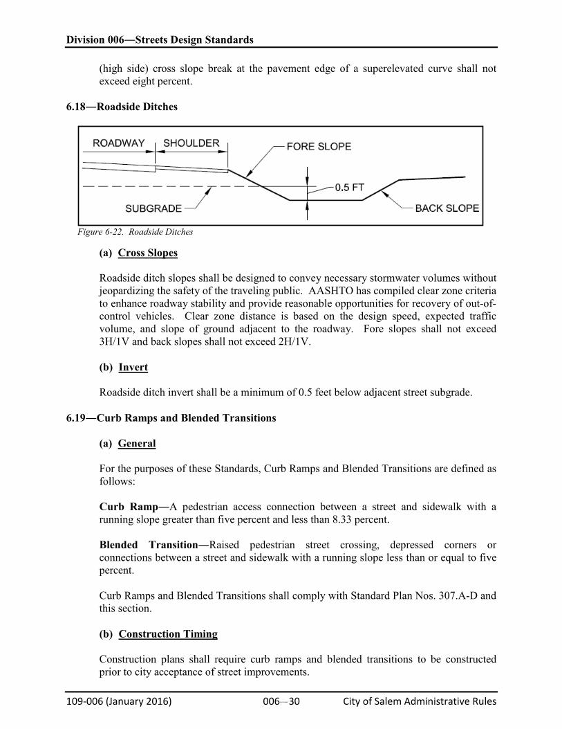
6.18―Roadside Ditches
Figure 6-22. Roadside Ditches
(a)
Cross Slopes
Roadside ditch slopes shall be designed to convey necessary stormwater volumes without jeopardizing the safety of the traveling public. AASHTO has compiled clear zone criteria to enhance roadway stability and provide reasonable opportunities for recovery of out-of-control vehicles. Clear zone distance is based on the design speed, expected traffic volume, and slope of ground adjacent to the roadway. Fore slopes shall not exceed 3H/1V and back slopes shall not exceed 2H/1V.
(b)
Invert
Roadside ditch invert shall be a minimum of 0.5 feet below adjacent street subgrade. 6.19―Curb Ramps and Blended Transitions
(a)
General
For the purposes of these Standards, Curb Ramps and Blended Transitions are defined as follows:
Curb Ramp―A pedestrian access connection between a street and sidewalk with a running slope greater than five percent and less than 8.33 percent.
Blended Transition―Raised pedestrian street crossing, depressed corners or connections between a street and sidewalk with a running slope less than or equal to five percent.
Curb Ramps and Blended Transitions shall comply with Standard Plan Nos. 307.A-D and this section.
(b)
Construction Timing
Construction plans shall require curb ramps and blended transitions to be constructed prior to city acceptance of street improvements.
Division 006―Streets Design Standards
109-006 (January 2016) 006#31 City of Salem Administrative Rules
(c)
Separate Curb Ramp
Except as noted below, a separate curb ramp, blended transition, or a combination of curb ramps and blended transitions shall connect the pedestrian access routes at each pedestrian street crossing.
(1). Alterations
In alterations where existing physical constraints prevent construction of a separate curb ramp or blended transition for each pedestrian street crossing, a single diagonal curb ramp may be permitted to serve both pedestrian street crossings.
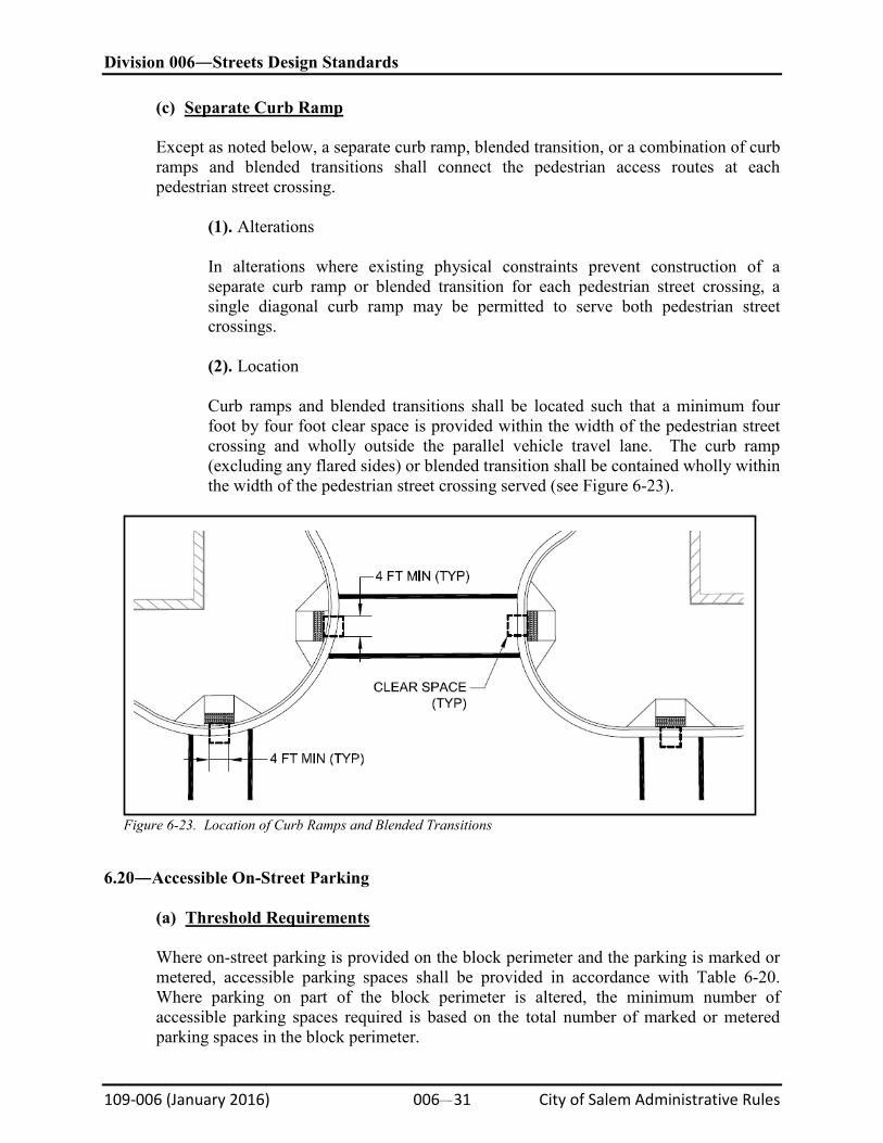
(2). Location
Curb ramps and blended transitions shall be located such that a minimum four foot by four foot clear space is provided within the width of the pedestrian street crossing and wholly outside the parallel vehicle travel lane. The curb ramp (excluding any flared sides) or blended transition shall be contained wholly within the width of the pedestrian street crossing served (see Figure 6-23).
Figure 6-23. Location of Curb Ramps and Blended Transitions
6.20―Accessible On-Street Parking
(a)
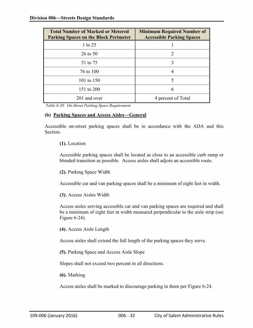
Threshold Requirements
Where on-street parking is provided on the block perimeter and the parking is marked or metered, accessible parking spaces shall be provided in accordance with Table 6-20. Where parking on part of the block perimeter is altered, the minimum number of accessible parking spaces required is based on the total number of marked or metered parking spaces in the block perimeter.
Division 006―Streets Design Standards
109-006 (January 2016) 006#32 City of Salem Administrative Rules
Total Number of Marked or Metered Parking Spaces on the Block Perimeter
Minimum Required Number of Accessible Parking Spaces
1 to 25 1
26 to 50 2
51 to 75 3
76 to 100 4
101 to 150 5
151 to 200 6
201 and over 4 percent of Total Table 6-20. On-Street Parking Space Requirement
(b)
Parking Spaces and Access Aisles―General
Accessible on-street parking spaces shall be in accordance with the ADA and this Section.
(1). Location
Accessible parking spaces shall be located as close to an accessible curb ramp or blended transition as possible. Access aisles shall adjoin an accessible route.
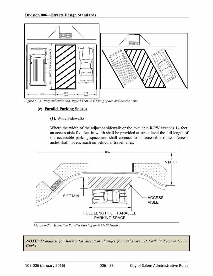
(2). Parking Space Width
Accessible car and van parking spaces shall be a minimum of eight feet in width.
(3). Access Aisles Width
Access aisles serving accessible car and van parking spaces are required and shall be a minimum of eight feet in width measured perpendicular to the aisle strip (see Figure 6-24).
(4). Access Aisle Length
Access aisles shall extend the full length of the parking spaces they serve.
(5). Parking Space and Access Aisle Slope
Slopes shall not exceed two percent in all directions.
(6). Marking
Access aisles shall be marked to discourage parking in them per Figure 6-24.
Division 006―Streets Design Standards
109-006 (January 2016) 006#33 City of Salem Administrative Rules
Figure 6-24. Perpendicular and Angled Vehicle Parking Space and Access Aisle
(c)
Parallel Parking Spaces
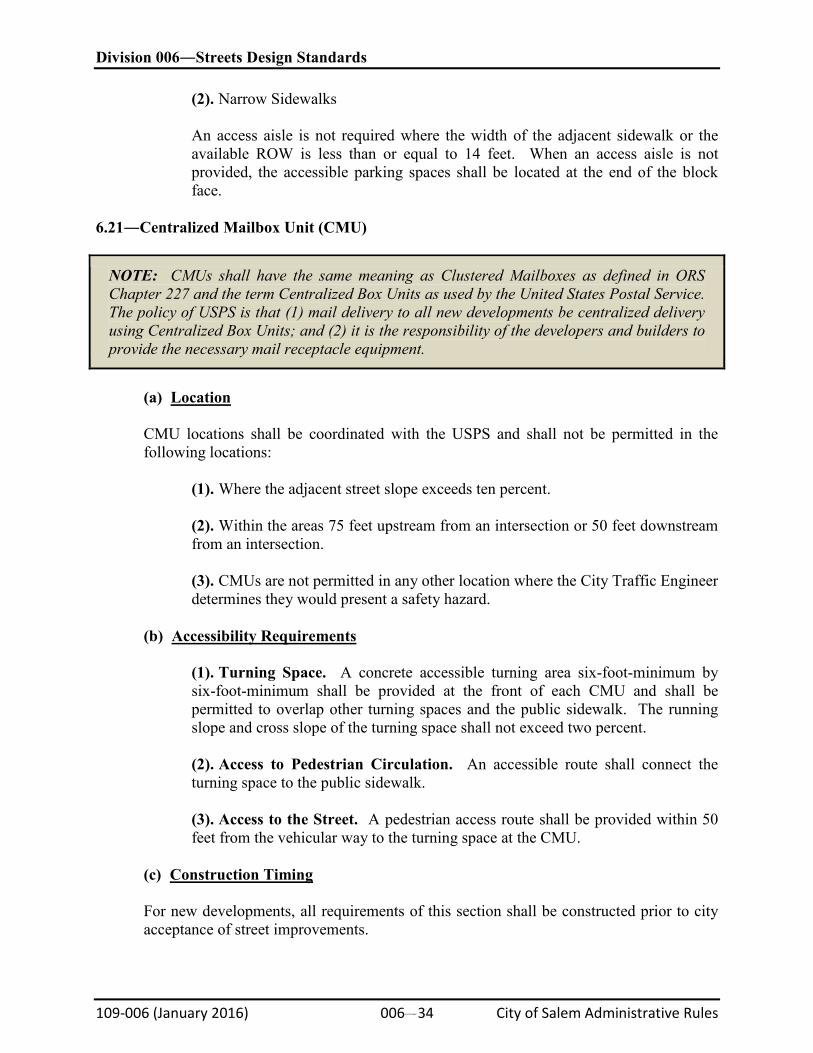
(1). Wide Sidewalks
Where the width of the adjacent sidewalk or the available ROW exceeds 14 feet, an access aisle five feet in width shall be provided at street level the full length of the accessible parking space and shall connect to an accessible route. Access aisles shall not encroach on vehicular travel lanes.
Figure 6-25. Accessible Parallel Parking for Wide Sidewalks
NOTE: Standards for horizontal direction changes for curbs are set forth in Section 6.11–Curbs.
Division 006―Streets Design Standards
109-006 (January 2016) 006#34 City of Salem Administrative Rules
(2). Narrow Sidewalks
An access aisle is not required where the width of the adjacent sidewalk or the available ROW is less than or equal to 14 feet. When an access aisle is not provided, the accessible parking spaces shall be located at the end of the block face.
6.21―Centralized Mailbox Unit (CMU)
NOTE: CMUs shall have the same meaning as Clustered Mailboxes as defined in ORS Chapter 227 and the term Centralized Box Units as used by the United States Postal Service. The policy of USPS is that (1) mail delivery to all new developments be centralized delivery using Centralized Box Units; and (2) it is the responsibility of the developers and builders to provide the necessary mail receptacle equipment.
(a)
Location
CMU locations shall be coordinated with the USPS and shall not be permitted in the following locations:
(1). Where the adjacent street slope exceeds ten percent.
(2). Within the areas 75 feet upstream from an intersection or 50 feet downstream from an intersection. (3). CMUs are not permitted in any other location where the City Traffic Engineer determines they would present a safety hazard.
(b)
Accessibility Requirements
(1). Turning Space. A concrete accessible turning area six-foot-minimum by six-foot-minimum shall be provided at the front of each CMU and shall be permitted to overlap other turning spaces and the public sidewalk. The running slope and cross slope of the turning space shall not exceed two percent. (2). Access to Pedestrian Circulation. An accessible route shall connect the turning space to the public sidewalk. (3). Access to the Street. A pedestrian access route shall be provided within 50 feet from the vehicular way to the turning space at the CMU.
(c)
Construction Timing
For new developments, all requirements of this section shall be constructed prior to city acceptance of street improvements.
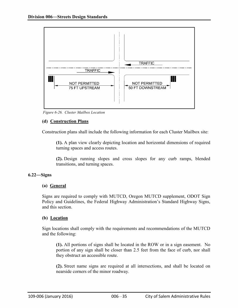
Division 006―Streets Design Standards
109-006 (January 2016) 006#35 City of Salem Administrative Rules
Figure 6-26. Cluster Mailbox Location
(d)
Construction Plans
Construction plans shall include the following information for each Cluster Mailbox site:
(1). A plan view clearly depicting location and horizontal dimensions of required turning spaces and access routes.
(2). Design running slopes and cross slopes for any curb ramps, blended transitions, and turning spaces.
6.22―Signs
(a)
General
Signs are required to comply with MUTCD, Oregon MUTCD supplement, ODOT Sign Policy and Guidelines, the Federal Highway Administration’s Standard Highway Signs, and this section.
(b)
Location
Sign locations shall comply with the requirements and recommendations of the MUTCD and the following:
(1). All portions of signs shall be located in the ROW or in a sign easement. No portion of any sign shall be closer than 2.5 feet from the face of curb, nor shall they obstruct an accessible route. (2). Street name signs are required at all intersections, and shall be located on nearside corners of the minor roadway.
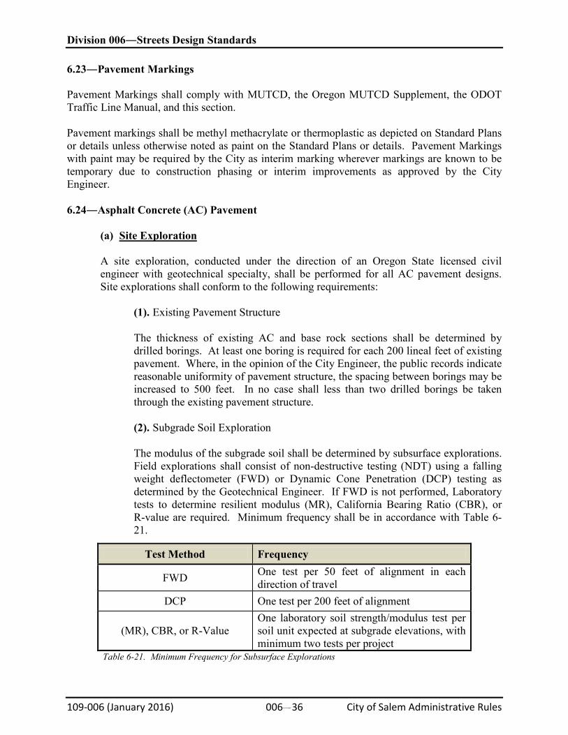
Division 006―Streets Design Standards
109-006 (January 2016) 006#36 City of Salem Administrative Rules
6.23―Pavement Markings Pavement Markings shall comply with MUTCD, the Oregon MUTCD Supplement, the ODOT Traffic Line Manual, and this section. Pavement markings shall be methyl methacrylate or thermoplastic as depicted on Standard Plans or details unless otherwise noted as paint on the Standard Plans or details. Pavement Markings with paint may be required by the City as interim marking wherever markings are known to be temporary due to construction phasing or interim improvements as approved by the City Engineer. 6.24―Asphalt Concrete (AC) Pavement
(a)
Site Exploration
A site exploration, conducted under the direction of an Oregon State licensed civil engineer with geotechnical specialty, shall be performed for all AC pavement designs. Site explorations shall conform to the following requirements:
(1). Existing Pavement Structure
The thickness of existing AC and base rock sections shall be determined by drilled borings. At least one boring is required for each 200 lineal feet of existing pavement. Where, in the opinion of the City Engineer, the public records indicate reasonable uniformity of pavement structure, the spacing between borings may be increased to 500 feet. In no case shall less than two drilled borings be taken through the existing pavement structure.
(2). Subgrade Soil Exploration
The modulus of the subgrade soil shall be determined by subsurface explorations. Field explorations shall consist of non-destructive testing (NDT) using a falling weight deflectometer (FWD) or Dynamic Cone Penetration (DCP) testing as determined by the Geotechnical Engineer. If FWD is not performed, Laboratory tests to determine resilient modulus (MR), California Bearing Ratio (CBR), or R-value are required. Minimum frequency shall be in accordance with Table 6-21.
Test Method Frequency
FWD One test per 50 feet of alignment in each direction of travel
DCP One test per 200 feet of alignment
(MR), CBR, or R-Value One laboratory soil strength/modulus test per soil unit expected at subgrade elevations, with minimum two tests per project
Table 6-21. Minimum Frequency for Subsurface Explorations
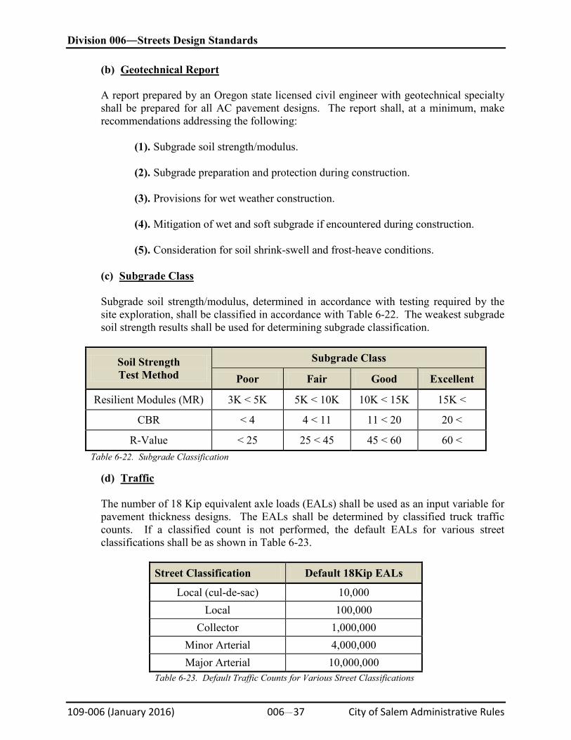
Division 006―Streets Design Standards
109-006 (January 2016) 006#37 City of Salem Administrative Rules
(b)
Geotechnical Report
A report prepared by an Oregon state licensed civil engineer with geotechnical specialty shall be prepared for all AC pavement designs. The report shall, at a minimum, make recommendations addressing the following:
(1). Subgrade soil strength/modulus.
(2). Subgrade preparation and protection during construction.
(3). Provisions for wet weather construction.
(4). Mitigation of wet and soft subgrade if encountered during construction.
(5). Consideration for soil shrink-swell and frost-heave conditions.
(c)
Subgrade Class
Subgrade soil strength/modulus, determined in accordance with testing required by the site exploration, shall be classified in accordance with Table 6-22. The weakest subgrade soil strength results shall be used for determining subgrade classification.
Soil Strength Test Method
Subgrade Class
Poor Fair Good Excellent
Resilient Modules (MR) 3K < 5K 5K < 10K 10K < 15K 15K <
CBR < 4 4 < 11 11 < 20 20 <
R-Value < 25 25 < 45 45 < 60 60 < Table 6-22. Subgrade Classification
(d)
Traffic
The number of 18 Kip equivalent axle loads (EALs) shall be used as an input variable for pavement thickness designs. The EALs shall be determined by classified truck traffic counts. If a classified count is not performed, the default EALs for various street classifications shall be as shown in Table 6-23.
Street Classification Default 18Kip EALs
Local (cul-de-sac) 10,000 Local 100,000
Collector 1,000,000 Minor Arterial 4,000,000 Major Arterial 10,000,000
Table 6-23. Default Traffic Counts for Various Street Classifications
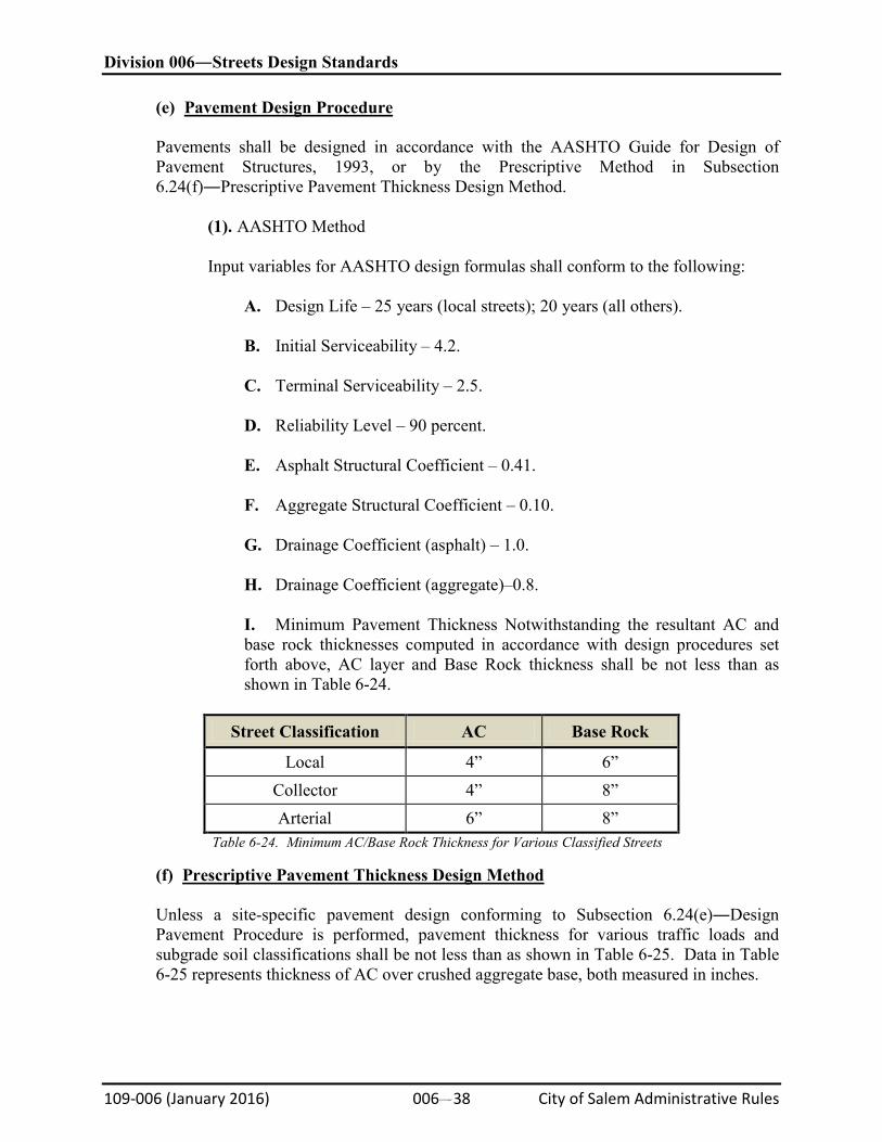
Division 006―Streets Design Standards
109-006 (January 2016) 006#38 City of Salem Administrative Rules
(e)
Pavement Design Procedure
Pavements shall be designed in accordance with the AASHTO Guide for Design of Pavement Structures, 1993, or by the Prescriptive Method in Subsection 6.24(f)―Prescriptive Pavement Thickness Design Method.
(1). AASHTO Method
Input variables for AASHTO design formulas shall conform to the following:
A. Design Life – 25 years (local streets); 20 years (all others). B. Initial Serviceability – 4.2. C. Terminal Serviceability – 2.5. D. Reliability Level – 90 percent. E. Asphalt Structural Coefficient – 0.41. F. Aggregate Structural Coefficient – 0.10. G. Drainage Coefficient (asphalt) – 1.0. H. Drainage Coefficient (aggregate)–0.8. I. Minimum Pavement Thickness Notwithstanding the resultant AC and base rock thicknesses computed in accordance with design procedures set forth above, AC layer and Base Rock thickness shall be not less than as shown in Table 6-24.
Street Classification AC Base Rock
Local 4” 6” Collector 4” 8” Arterial 6” 8”
Table 6-24. Minimum AC/Base Rock Thickness for Various Classified Streets
(f)
Prescriptive Pavement Thickness Design Method
Unless a site-specific pavement design conforming to Subsection 6.24(e)―Design Pavement Procedure is performed, pavement thickness for various traffic loads and subgrade soil classifications shall be not less than as shown in Table 6-25. Data in Table 6-25 represents thickness of AC over crushed aggregate base, both measured in inches.
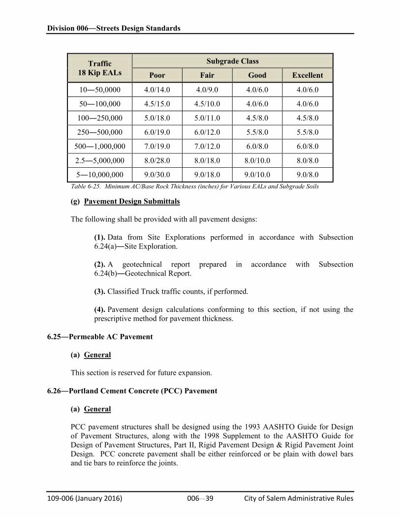
Division 006―Streets Design Standards
109-006 (January 2016) 006#39 City of Salem Administrative Rules
Traffic 18 Kip EALs
Subgrade Class
Poor Fair Good Excellent
10―50,0000 4.0/14.0 4.0/9.0 4.0/6.0 4.0/6.0
50―100,000 4.5/15.0 4.5/10.0 4.0/6.0 4.0/6.0
100―250,000 5.0/18.0 5.0/11.0 4.5/8.0 4.5/8.0
250―500,000 6.0/19.0 6.0/12.0 5.5/8.0 5.5/8.0
500―1,000,000 7.0/19.0 7.0/12.0 6.0/8.0 6.0/8.0
2.5―5,000,000 8.0/28.0 8.0/18.0 8.0/10.0 8.0/8.0
5―10,000,000 9.0/30.0 9.0/18.0 9.0/10.0 9.0/8.0 Table 6-25. Minimum AC/Base Rock Thickness (inches) for Various EALs and Subgrade Soils
(g)
Pavement Design Submittals
The following shall be provided with all pavement designs:
(1). Data from Site Explorations performed in accordance with Subsection 6.24(a)―Site Exploration.
(2). A geotechnical report prepared in accordance with Subsection 6.24(b)―Geotechnical Report.
(3). Classified Truck traffic counts, if performed.
(4). Pavement design calculations conforming to this section, if not using the prescriptive method for pavement thickness.
6.25―Permeable AC Pavement
(a)
General
This section is reserved for future expansion. 6.26―Portland Cement Concrete (PCC) Pavement
(a)
General
PCC pavement structures shall be designed using the 1993 AASHTO Guide for Design of Pavement Structures, along with the 1998 Supplement to the AASHTO Guide for Design of Pavement Structures, Part II, Rigid Pavement Design & Rigid Pavement Joint Design. PCC concrete pavement shall be either reinforced or be plain with dowel bars and tie bars to reinforce the joints.
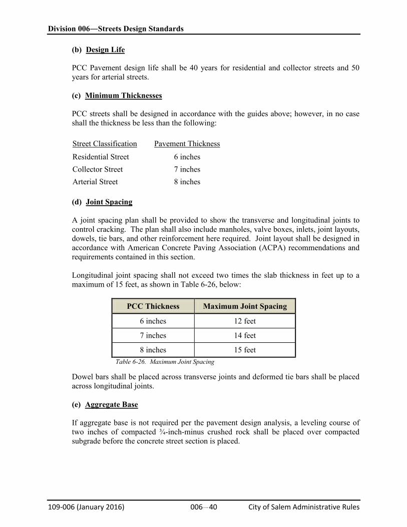
Division 006―Streets Design Standards
109-006 (January 2016) 006#40 City of Salem Administrative Rules
(b)
Design Life
PCC Pavement design life shall be 40 years for residential and collector streets and 50 years for arterial streets.
(c)
Minimum Thicknesses
PCC streets shall be designed in accordance with the guides above; however, in no case shall the thickness be less than the following:
Street Classification
Residential Street
Pavement Thickness
6 inches Collector Street 7 inches Arterial Street 8 inches
(d)
Joint Spacing
A joint spacing plan shall be provided to show the transverse and longitudinal joints to control cracking. The plan shall also include manholes, valve boxes, inlets, joint layouts, dowels, tie bars, and other reinforcement here required. Joint layout shall be designed in accordance with American Concrete Paving Association (ACPA) recommendations and requirements contained in this section.
Longitudinal joint spacing shall not exceed two times the slab thickness in feet up to a maximum of 15 feet, as shown in Table 6-26, below:
PCC Thickness Maximum Joint Spacing
6 inches 12 feet
7 inches 14 feet
8 inches 15 feet Table 6-26. Maximum Joint Spacing
Dowel bars shall be placed across transverse joints and deformed tie bars shall be placed across longitudinal joints.
(e)
Aggregate Base
If aggregate base is not required per the pavement design analysis, a leveling course of two inches of compacted ¾-inch-minus crushed rock shall be placed over compacted subgrade before the concrete street section is placed.
Division 006―Streets Design Standards
109-006 (January 2016) 006#41 City of Salem Administrative Rules
6.27―Traffic Signals
(a)
General
Traffic Signals shall be fully actuated with protective/permissive left turn phases, operated by video detection, equipped with video transmission, interconnected to other traffic signals, and have emergency preemptive systems. All signal equipment shall be located within the ROW.
NOTE: ODOT Traffic Signal Design Manual, ODOT Standard Drawings TM400 and TM600 and MUTCD provide general guidance for traffic signal design.
(b)
Preliminary Design Meeting
A preliminary design meeting between Design Engineer and City Engineering staff is required prior to application for plan review for the purpose of reviewing Traffic Impact Analysis and resolving design requirements applicable for the signal.
(c)
Traffic Signal Requirements
(1). Traffic Signal Poles. Traffic signal poles shall:
A. Be designed for mast arm installation. B. Be located behind current or future sidewalk. C. Incorporate street light for pavement illumination.
(2). Street Light. The street light requirements are as follows:
A. Mount luminaires at 35 feet high extending in the same plane as the signal mast arm. B. Design a single master photocell to control the intersection lighting with a test switch located in the service cabinet.
(3). Signal Control. Signals shall be controlled by Type 2070 traffic signal controllers in Model 332 controller cabinets. Control programs will be furnished by City. Controller cabinets shall:
A. Be located near the intersection and oriented such that the doors open parallel with the adjacent roadway with a view of the intersection facing the front of the controller. B. Be located minimum 25 feet downstream from the intersection, or as approved by City Traffic Engineer.
Division 006―Streets Design Standards
109-006 (January 2016) 006#42 City of Salem Administrative Rules
(4). Fire Preemptive System. Signals shall be designed with fire preemptive systems conforming to the following:
A. “Opticom” brand system shall be used as manufactured by the Traffic Control Products Division of the 3M Company. “Opticom” brand Model 752 Discriminator modules shall be specified for the Type 170 controller.
B. Locate detectors on the end of mast arms, oriented for emergency vehicles approaching the intersection in the direction opposite the direction of the signal head on the mast arm.
C. Video Detection. The video cameras shall be mounted to the traffic signal luminaire arms for each approach of the intersection and shall provide a minimum of 300 feet of detection in advance of each stop bar. Bicycle detection will be accomplished with the same cameras. D. Video Transmission. The traffic signal shall incorporate video transmission compatible the City’s facilities and equipment and shall include the installation of modems or other equipment along the City’s existing interconnect cables to transmit the video signals from the intersection to the City’s Traffic Operation Center. E. Interconnect. Traffic signal interconnect shall be provided with three-inch electrical conduit, hand holes, splice vaults, and fiber optic interconnect cable to the nearest location in accordance with the City of Salem Interconnect Master Plan.
(d)
Pedestrian Signals
Pedestrian signal heads shall be symbolic, single section type, mounted to independent pedestrian signal poles traffic signal mast arm poles. Pedestrian signals shall be audible and conform to ADA Standards and the MUTCD.
(e)
Electrical Power
Underground power service shall be provided. Electrical service shall terminate at a free standing electrical service cabinet located at the traffic signal controller. Service conductors for street light circuit and interior illuminated sign circuit shall not be routed through the traffic signal controller cabinet. Separate breakers shall be provided for all services.
6.28―Street Lighting
(a)
General
Street Lighting shall comply with NEC. For new streets, street lighting shall be provided by street light only poles, energized by an underground power system of conduit, wiring, and junction boxes.
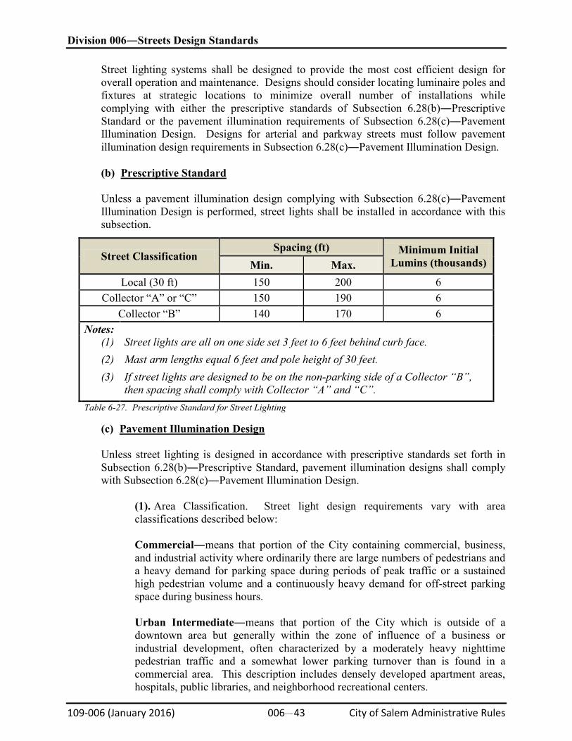
Division 006―Streets Design Standards
109-006 (January 2016) 006#43 City of Salem Administrative Rules
Street lighting systems shall be designed to provide the most cost efficient design for overall operation and maintenance. Designs should consider locating luminaire poles and fixtures at strategic locations to minimize overall number of installations while complying with either the prescriptive standards of Subsection 6.28(b)―Prescriptive Standard or the pavement illumination requirements of Subsection 6.28(c)―Pavement Illumination Design. Designs for arterial and parkway streets must follow pavement illumination design requirements in Subsection 6.28(c)―Pavement Illumination Design.
(b)
Prescriptive Standard
Unless a pavement illumination design complying with Subsection 6.28(c)―Pavement Illumination Design is performed, street lights shall be installed in accordance with this subsection.
Street Classification Spacing (ft) Minimum Initial
Lumins (thousands) Min. Max. Local (30 ft) 150 200 6
Collector “A” or “C” 150 190 6 Collector “B” 140 170 6
Notes: (1) (2) (3)
Street lights are all on one side set 3 feet to 6 feet behind curb face. Mast arm lengths equal 6 feet and pole height of 30 feet. If street lights are designed to be on the non-parking side of a Collector “B”, then spacing shall comply with Collector “A” and “C”.
Table 6-27. Prescriptive Standard for Street Lighting
(c)
Pavement Illumination Design
Unless street lighting is designed in accordance with prescriptive standards set forth in Subsection 6.28(b)―Prescriptive Standard, pavement illumination designs shall comply with Subsection 6.28(c)―Pavement Illumination Design.
(1). Area Classification. Street light design requirements vary with area classifications described below:
Commercial―means that portion of the City containing commercial, business, and industrial activity where ordinarily there are large numbers of pedestrians and a heavy demand for parking space during periods of peak traffic or a sustained high pedestrian volume and a continuously heavy demand for off-street parking space during business hours.
Urban Intermediate―means that portion of the City which is outside of a downtown area but generally within the zone of influence of a business or industrial development, often characterized by a moderately heavy nighttime pedestrian traffic and a somewhat lower parking turnover than is found in a commercial area. This description includes densely developed apartment areas, hospitals, public libraries, and neighborhood recreational centers.
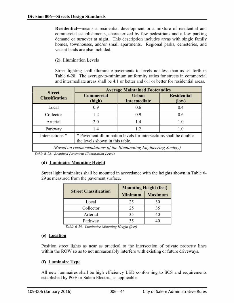
Division 006―Streets Design Standards
109-006 (January 2016) 006#44 City of Salem Administrative Rules
Residential―means a residential development or a mixture of residential and commercial establishments, characterized by few pedestrians and a low parking demand or turnover at night. This description includes areas with single family homes, townhouses, and/or small apartments. Regional parks, cemeteries, and vacant lands are also included.
(2). Illumination Levels
Street lighting shall illuminate pavements to levels not less than as set forth in Table 6-28. The average-to-minimum uniformity ratios for streets in commercial and intermediate areas shall be 4:1 or better and 6:1 or better for residential areas.
Street Classification
Average Maintained Footcandles Commercial
(high) Urban
Intermediate Residential
(low) Local 0.9 0.6 0.4
Collector 1.2 0.9 0.6 Arterial 2.0 1.4 1.0 Parkway 1.4 1.2 1.0
Intersections * * Pavement illumination levels for intersections shall be double the levels shown in this table.
(Based on recommendations of the Illuminating Engineering Society) Table 6-28. Required Pavement Illumination Levels
(d)
Luminaire Mounting Height
Street light luminaires shall be mounted in accordance with the heights shown in Table 6-29 as measured from the pavement surface.
Street Classification Mounting Height (feet) Minimum Maximum
Local 25 30 Collector 25 35 Arterial 35 40 Parkway 35 40
Table 6-29. Luminaire Mounting Height (feet)
(e)
Location
Position street lights as near as practical to the intersection of private property lines within the ROW so as to not unreasonably interfere with existing or future driveways.
(f)
Luminaire Type
All new luminaires shall be high efficiency LED conforming to SCS and requirements established by PGE or Salem Electric, as applicable.
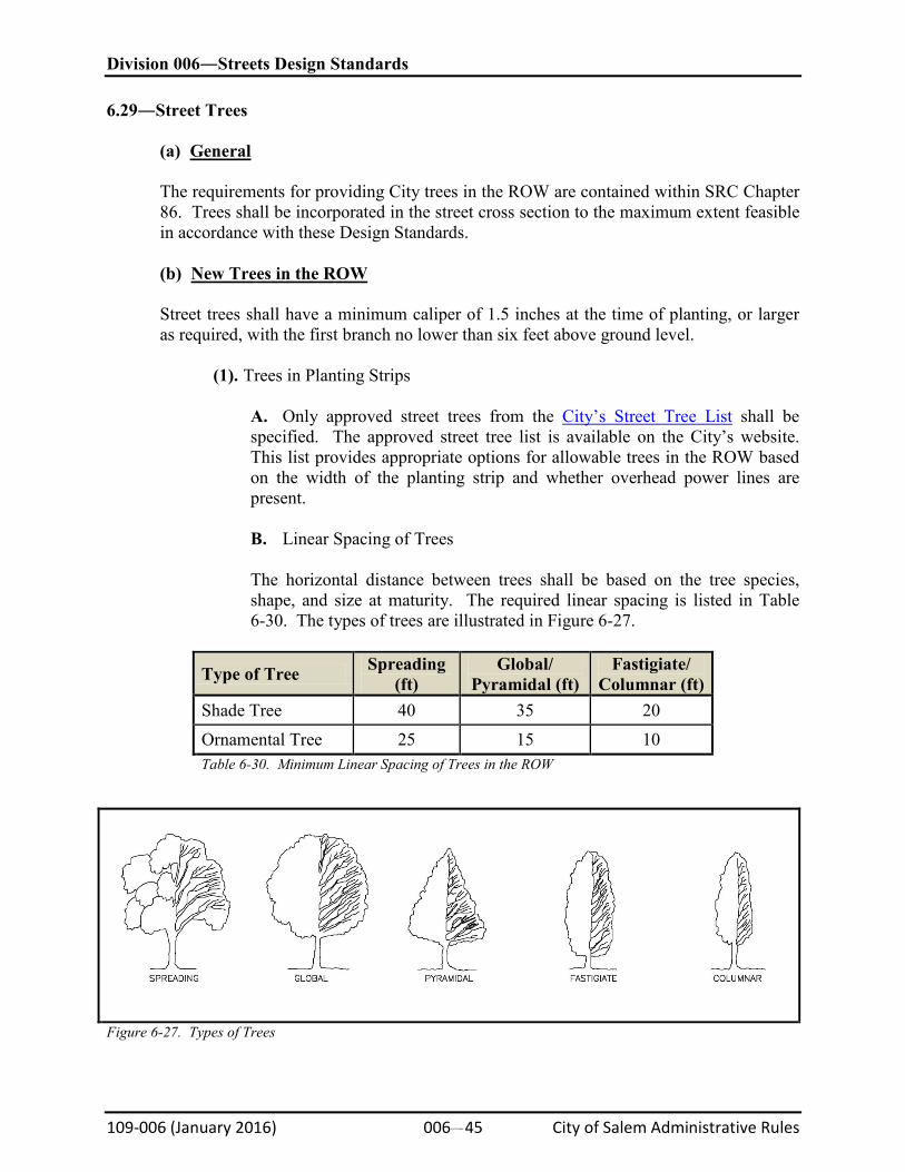
Division 006―Streets Design Standards
109-006 (January 2016) 006#45 City of Salem Administrative Rules
6.29―Street Trees
(a)
General
The requirements for providing City trees in the ROW are contained within SRC Chapter 86. Trees shall be incorporated in the street cross section to the maximum extent feasible in accordance with these Design Standards. (b)
New Trees in the ROW
Street trees shall have a minimum caliper of 1.5 inches at the time of planting, or larger as required, with the first branch no lower than six feet above ground level.
(1). Trees in Planting Strips
A. Only approved street trees from the City’s Street Tree List shall be specified. The approved street tree list is available on the City’s website. This list provides appropriate options for allowable trees in the ROW based on the width of the planting strip and whether overhead power lines are present.
B. Linear Spacing of Trees
The horizontal distance between trees shall be based on the tree species, shape, and size at maturity. The required linear spacing is listed in Table 6-30. The types of trees are illustrated in Figure 6-27.
Type of Tree Spreading (ft)
Global/ Pyramidal (ft)
Fastigiate/ Columnar (ft)
Shade Tree 40 35 20 Ornamental Tree 25 15 10 Table 6-30. Minimum Linear Spacing of Trees in the ROW
Figure 6-27. Types of Trees
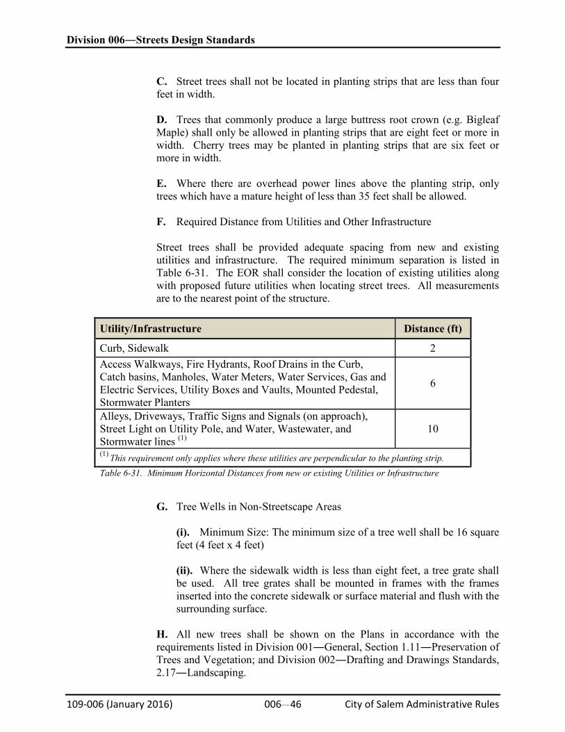
Division 006―Streets Design Standards
109-006 (January 2016) 006#46 City of Salem Administrative Rules
C. Street trees shall not be located in planting strips that are less than four feet in width.
D. Trees that commonly produce a large buttress root crown (e.g. Bigleaf Maple) shall only be allowed in planting strips that are eight feet or more in width. Cherry trees may be planted in planting strips that are six feet or more in width.
E. Where there are overhead power lines above the planting strip, only trees which have a mature height of less than 35 feet shall be allowed.
F. Required Distance from Utilities and Other Infrastructure
Street trees shall be provided adequate spacing from new and existing utilities and infrastructure. The required minimum separation is listed in Table 6-31. The EOR shall consider the location of existing utilities along with proposed future utilities when locating street trees. All measurements are to the nearest point of the structure.
Utility/Infrastructure Distance (ft)
Curb, Sidewalk 2 Access Walkways, Fire Hydrants, Roof Drains in the Curb, Catch basins, Manholes, Water Meters, Water Services, Gas and Electric Services, Utility Boxes and Vaults, Mounted Pedestal, Stormwater Planters
6
Alleys, Driveways, Traffic Signs and Signals (on approach), Street Light on Utility Pole, and Water, Wastewater, and Stormwater lines (1)
10
(1) This requirement only applies where these utilities are perpendicular to the planting strip. Table 6-31. Minimum Horizontal Distances from new or existing Utilities or Infrastructure
G. Tree Wells in Non-Streetscape Areas
(i). Minimum Size: The minimum size of a tree well shall be 16 square feet (4 feet x 4 feet)
(ii). Where the sidewalk width is less than eight feet, a tree grate shall be used. All tree grates shall be mounted in frames with the frames inserted into the concrete sidewalk or surface material and flush with the surrounding surface.
H. All new trees shall be shown on the Plans in accordance with the requirements listed in Division 001―General, Section 1.11―Preservation of Trees and Vegetation; and Division 002―Drafting and Drawings Standards, 2.17―Landscaping.
Division 006―Streets Design Standards
109-006 (January 2016) 006#47 City of Salem Administrative Rules
(c)
Protection of Existing City Trees
(1). Existing City trees that are not permitted for removal must be protected in accordance with Standard Plan 820 and Administrative Rule 109-500-2. The City’s Urban Forester shall make the final determination regarding the location of the Tree Protection area based on the type of work being performed and the existing site constraints.
(2). Removing Existing Hardscape
A. Where sidewalks or other structures are being removed from within the CTZ, the following notes shall be added to the demolition plan:
(i). Remove hardscape in such a manner to minimize disturbance to tree roots, base rock, and underlying soil.
(ii). Keep heavy equipment on undisturbed hardscape and off of exposed roots.
(iii). Minimize removal of base rock or underlying material that has established roots.
(iv). If roots 2-inch or larger are encountered which must be removed, call the City Urban Forester for an inspection.
(3). Trenching in the Critical Tree Zone
A. Removing hardscape and trenching in the CTZ shall be avoided wherever possible. Where trenching must be performed in the TPA below the level of hardscape, the following measures shall be listed on the plans:
(i). Excavation within the TPA below the level of hardscape (for hardscape removal see Subsection 6.29(c)(2)) shall be limited to hand driven trencher wherever the trench is less that 12-inches wide and 36-inches deep. In some cases hand tools may be required to minimize root damage. Where deeper and wider trenches are required, a backhoe or track hoe may be used. Heavy equipment use within the TPA shall be minimized and appropriately sized for the installation. Surface protection measures provided in Standard Plan 821 shall be used to support the equipment. Measures to protect the tree trunks shall also be used in accordance with the SCS.
(ii). No trenching is allowed within two feet of any City tree, as measured from the side of the trench to the nearest point on the trunk.
(iii). Trench width shall be limited to the minimum width necessary to provide safe installation of the utility.
Division 006―Streets Design Standards
109-006 (January 2016) 006#48 City of Salem Administrative Rules
(iv). If roots are exposed, supplemental watering of exposed roots shall be provided in conformance with the SCS. Supplemental watering shall not jeopardize OSHA trench safety requirements.
(4). Boring, Tunneling, and Jacking within the Critical Tree Zone
See Division 001 for requirements of Boring, Tunneling, and Jacking near or under City trees.
(d)
Temporary Irrigation
Temporary irrigation systems are not required for City trees when planted; however, supplemental watering may be required during construction to maintain tree health. New trees must be watered in accordance with the SCS.
6.30―Alleys
(a)
General
Alley width and improvement requirements shall comply with Standard Plan Numbers 304 or 305. Alleys shall be designed to meet the following conditions:
(b)
Pavement Structure
Alley pavement structures in residential areas shall be designed to conform to local street pavement standards set forth in Section 6.24–Asphalt Concrete (AC) Pavement, or Section 6.25–Permeable AC Pavement, or Section 6.26–Portland Cement Concrete (PCC) Pavement.
(c)
Clearance Strip
All alley improvements shall require a one-foot clearance strip between the edge of alley and ROW line except for alleys ten feet wide or less. In this case, the clearance strip shall be six inches in width.
(d)
Drainage
Alleys shall have piped drainage systems conforming to Division 004―Stormwater System. Not more than 2,000 square feet of surface drainage shall be permitted to flow from alley across the alley approach.
(e)
Approach
(1). The curb radius connecting the alley to the street is typically equal to the distance from the street curb face to the street property line. The minimum radius shall be 15 feet. Where the radius would be less than 15 feet, a “dust pan” drive approach is acceptable.
Division 006―Streets Design Standards
109-006 (January 2016) 006#49 City of Salem Administrative Rules
(2). Where a sidewalk intersects with an alley, a pedestrian access route shall be provided across the alley approach per Section 6.4–Pedestrian Access Routes.
(3). Dead-end alleys shall also have a public turnaround to prevent the need to trespass on private property. Due to the limited room normally available, a hammer-head turnaround per Standard Drawing 316 may be acceptable as approved by the City Engineer.
(4). Parking dimensions and layout shall be per SRC Chapter 133 and Table 133-3.
6.31―Shared Use Paths
(a)
Grade
(1). Within Street ROW. Where shared use paths are contained within a street ROW, the grade of shared use paths shall not exceed the general grade established for the adjacent street.
(2). Not Within Street ROW. Where shared use paths are not contained within a street or highway ROW, the grade of shared use paths shall be five percent maximum.
(3). Within Pedestrian Street Crossings. Where shared use paths are contained within a pedestrian street crossing, the grade of shared use paths shall be five percent maximum.
(b)
Continuous Width
Shared Use Paths shall have a continuous width not less than ten feet measured perpendicular to the direction of travel. A pedestrian access route shall be provided for the full width of the shared use path per Section 6.4–Pedestrian Access Routes.
(c)
Protruding Objects
Objects shall not overhang or protrude into any portion of a shared use path at or below eight feet measured from the finish surface.
(d)
Curb Ramps
The width of curb ramps runs and blended transitions shall be equal to the width of the shared use path.
6.32―Bridges and Culverts
(a)
Environmental Permits
Division 006―Streets Design Standards
109-006 (January 2016) 006#50 City of Salem Administrative Rules
Unless exempted by the USACE or Oregon DSL, environmental permits are required for all bridges and culverts that cross natural waterways, intermittent streams, or wetlands.
(b)
Spans Exceeding 20 feet
Bridges and box culverts having spans 20 feet and greater shall comply with the following:
(1). Design. Design shall comply with the current edition of the ODOT Bridge Design and Drafting Manual (BDDM).
(2). Geotechnical Report. A report prepared by an Oregon State licensed civil engineer with geotechnical specialty shall be prepared for all bridge and culvert designs. The report shall comply with the current edition of the ODOT Geotechnical Design Manual.
(3). Hydraulic Analysis. A hydraulic analysis report complying with ODOT Hydraulics Manual, shall be prepared for bridge and culvert designs.
(c)
Headwalls
(1). Culverts 30-inch diameter and larger crossing a street shall be designed with headwalls and wing walls. For additional information on the design of culverts, See Division 004―Stormwater System.
(2). Headwalls are required for all box culverts.
(d)
Design Submittals
The following shall be provided with all bridge and culvert designs:
(1). The geotechnical report conforming to Appendix 1B―Requirements for Geotechnical Reports.
(2). The hydraulic analysis conforming to Division 004―Stormwater System, as applicable.
(3). Environmental Permits or documentation that no permit is required.
6.33―Traffic Impact Analysis (TIA) SRC Chapter 803 identifies the threshold for requiring a TIA.
(a)
Standards
Level of Service (LOS) Standards. Maximum operational standards (LOS E) for intersections shall be as shown in Table 6-32.
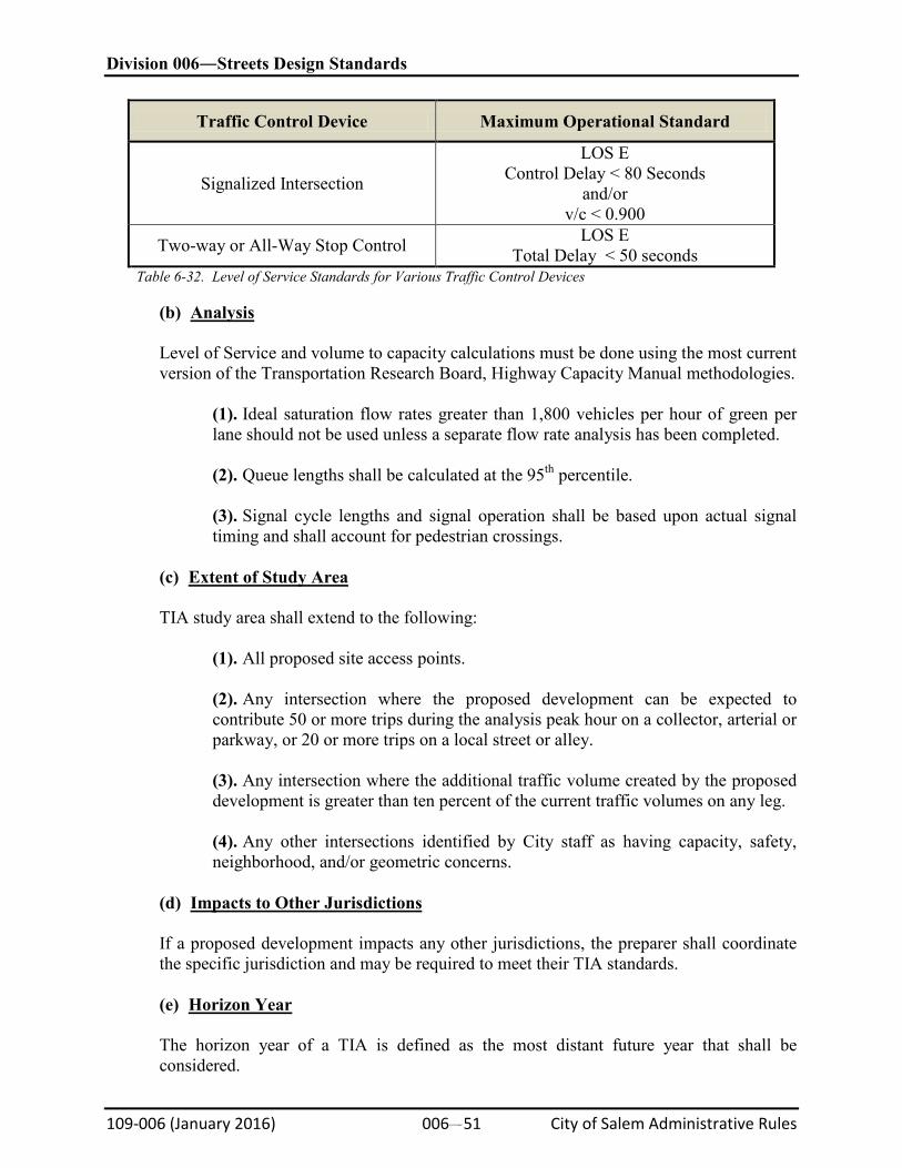
Division 006―Streets Design Standards
109-006 (January 2016) 006#51 City of Salem Administrative Rules
Traffic Control Device Maximum Operational Standard
Signalized Intersection
LOS E Control Delay < 80 Seconds
and/or v/c < 0.900
Two-way or All-Way Stop Control LOS E Total Delay < 50 seconds
Table 6-32. Level of Service Standards for Various Traffic Control Devices
(b)
Analysis
Level of Service and volume to capacity calculations must be done using the most current version of the Transportation Research Board, Highway Capacity Manual methodologies.
(1). Ideal saturation flow rates greater than 1,800 vehicles per hour of green per lane should not be used unless a separate flow rate analysis has been completed.
(2). Queue lengths shall be calculated at the 95th percentile.
(3). Signal cycle lengths and signal operation shall be based upon actual signal timing and shall account for pedestrian crossings.
(c)
Extent of Study Area
TIA study area shall extend to the following:
(1). All proposed site access points.
(2). Any intersection where the proposed development can be expected to contribute 50 or more trips during the analysis peak hour on a collector, arterial or parkway, or 20 or more trips on a local street or alley.
(3). Any intersection where the additional traffic volume created by the proposed development is greater than ten percent of the current traffic volumes on any leg.
(4). Any other intersections identified by City staff as having capacity, safety, neighborhood, and/or geometric concerns.
(d)
Impacts to Other Jurisdictions
If a proposed development impacts any other jurisdictions, the preparer shall coordinate the specific jurisdiction and may be required to meet their TIA standards.
(e)
Horizon Year
The horizon year of a TIA is defined as the most distant future year that shall be considered.
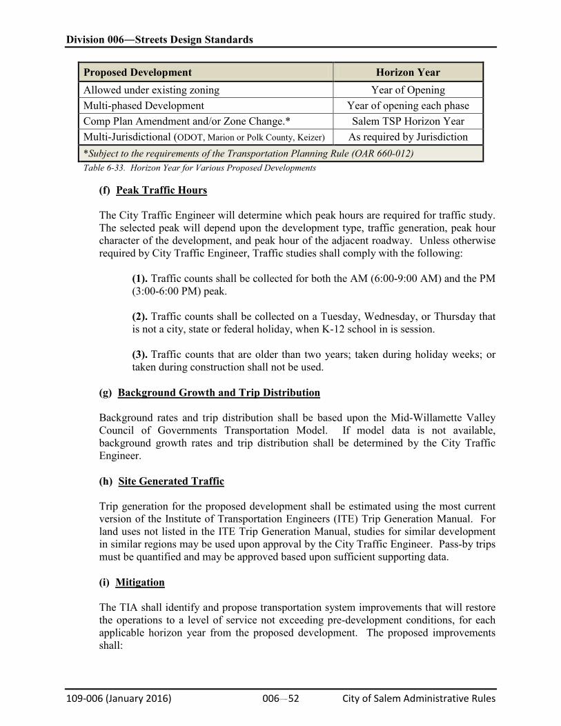
Division 006―Streets Design Standards
109-006 (January 2016) 006#52 City of Salem Administrative Rules
Proposed Development Horizon Year Allowed under existing zoning Year of Opening Multi-phased Development Year of opening each phase Comp Plan Amendment and/or Zone Change.* Salem TSP Horizon Year Multi-Jurisdictional (ODOT, Marion or Polk County, Keizer) As required by Jurisdiction *Subject to the requirements of the Transportation Planning Rule (OAR 660-012) Table 6-33. Horizon Year for Various Proposed Developments
(f)
Peak Traffic Hours
The City Traffic Engineer will determine which peak hours are required for traffic study. The selected peak will depend upon the development type, traffic generation, peak hour character of the development, and peak hour of the adjacent roadway. Unless otherwise required by City Traffic Engineer, Traffic studies shall comply with the following:
(1). Traffic counts shall be collected for both the AM (6:00-9:00 AM) and the PM (3:00-6:00 PM) peak.
(2). Traffic counts shall be collected on a Tuesday, Wednesday, or Thursday that is not a city, state or federal holiday, when K-12 school in is session.
(3). Traffic counts that are older than two years; taken during holiday weeks; or taken during construction shall not be used.
(g)
Background Growth and Trip Distribution
Background rates and trip distribution shall be based upon the Mid-Willamette Valley Council of Governments Transportation Model. If model data is not available, background growth rates and trip distribution shall be determined by the City Traffic Engineer.
(h)
Site Generated Traffic
Trip generation for the proposed development shall be estimated using the most current version of the Institute of Transportation Engineers (ITE) Trip Generation Manual. For land uses not listed in the ITE Trip Generation Manual, studies for similar development in similar regions may be used upon approval by the City Traffic Engineer. Pass-by trips must be quantified and may be approved based upon sufficient supporting data.
(i)
Mitigation
The TIA shall identify and propose transportation system improvements that will restore the operations to a level of service not exceeding pre-development conditions, for each applicable horizon year from the proposed development. The proposed improvements shall:
Division 006―Streets Design Standards
109-006 (January 2016) 006#53 City of Salem Administrative Rules
(1). Be described and/or designed in sufficient detail for the City to determine if they meet the Design Standards.
(2). Identify required ROW acquisition or dedication.
(3). Be accompanied by an estimate of construction costs and ROW acquisition if applicable.
(j)
Report Certification and Format
Traffic Impact Analyses shall be prepared under the direction of a Traffic Engineer or a Civil Engineer with experience in traffic engineering registered in the State of Oregon. The preparer is encouraged to coordinate the Traffic Impact Analysis with City staff and the other jurisdictions as appropriate to ensure the necessary components are included. Refer to Appendix 1C#Traffic Impact Analysis Report Format for a suggested report format.
6.34―Streetscape
(a)
General
Streetscape requirements apply to special service areas as identified in the SRC. In general, streetscape requirements apply to the area between the curb and ROW line and include elements such as sidewalk treatments; curb ramp areas; tree wells; landscape, irrigation “pedestrian scale” lighting, bike racks, benches, newspaper and magazine racks, information kiosks, and trash receptacles, etc. Streetscape elements shall comply with sight distance requirements as shown in SRC Chapter 76. The selection of materials and amenities which are placed in streetscape areas shall require a minimum amount of maintenance.
(b)
Streetscape Areas
Streetscape areas are currently in and around the downtown area; however, they have been used on entryway arterial streets. Each streetscape area may have a special design theme appropriate to that area. Current streetscape areas include the following areas with boundaries shown in Figure 6-28 and 6-29.
(1). Broadway―High Overlay Zones per SRC Chapters 613, 614, and 615.
(2). Central Business District per SRC Chapter 524.
(3). Historic Core District per SRC Chapter 154.055(b).
(4). South Waterfront Mixed-Use Zone Area per SRC Chapter 531.
(5). Edgewater Street Corridor Overlay Zone per SRC Chapter 610 and Second Street Corridor Overlay Zone per SRC Chapter 611.
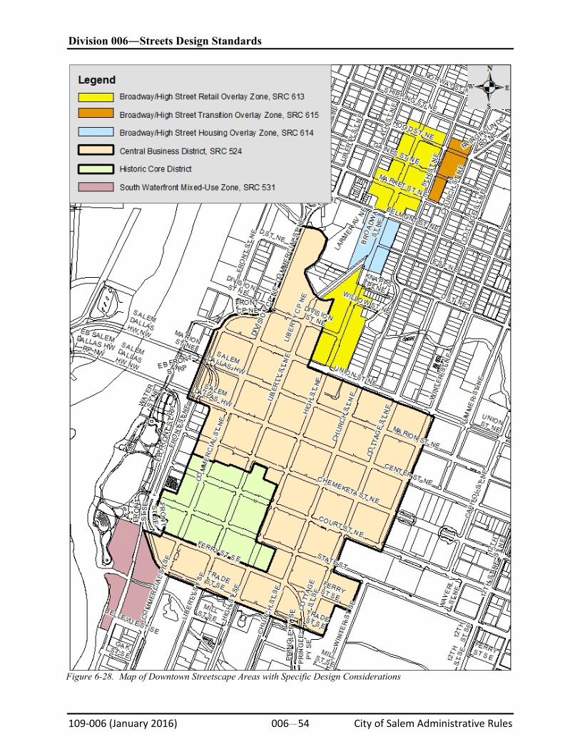
Division 006―Streets Design Standards
109-006 (January 2016) 006#54 City of Salem Administrative Rules
Figure 6-28. Map of Downtown Streetscape Areas with Specific Design Considerations
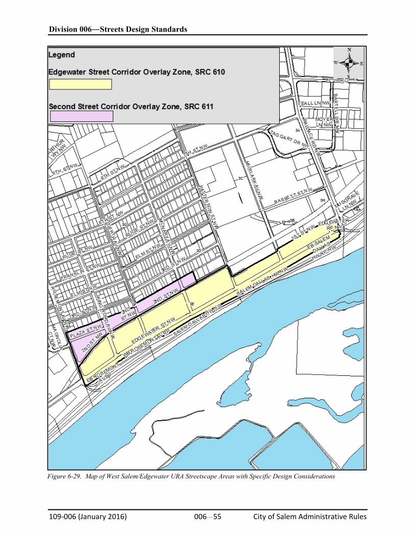
Division 006―Streets Design Standards
109-006 (January 2016) 006#55 City of Salem Administrative Rules
Figure 6-29. Map of West Salem/Edgewater URA Streetscape Areas with Specific Design Considerations
Division 006―Streets Design Standards
109-006 (January 2016) 006#56 City of Salem Administrative Rules
(c)
Sidewalks
(1). Sidewalks shall meet the general requirements of this Division, including accessibility requirements.
(2). Sidewalks shall have a light broomed finish with shallow contraction joints, a shined joint is not to be used.
(3). Provide ADA Ramps per the Standard Drawings.
(4). When sidewalks cover the entire area between the curb and ROW line, use a three-foot by three-foot square pattern starting at the street ROW and working toward curb.
(5). When development initiates a frontage improvement, where improvements are conditioned, and the frontage improvement intersect with the streetscape area boundary at an intersection, the following shall apply: replace the existing five-foot-wide sidewalk, if such exists, with a six-foot-wide sidewalk utilizing the three-foot by three-foot scoring pattern.
(d)
Curb Extensions and Transit Pullouts
(1). There may be curb extensions at intersections to improve visibility, provide ADA access, and/or to reduce crosswalk distances and time per Section 6.2–Street Classifications and Cross Sections. No street furniture is allowed in intersection curb extensions due to ADA requirements for clearance and maneuvering.
(2). Transit pullouts provide loading/unloading areas for transit users along with elements such as waiting areas, covers, benches, trash receptacles, schedule information, etc. Streetscape elements in transit pullouts shall be coordinated and located in accordance with the Salem/Keizer Transit District recommendations.
(3). Sidewalk in the accessible route and outside the decorative finishing zone shall have a three-foot by three-foot pattern.
(4). Curb extensions in streetscape areas shall include decorative finishing zones in the two quadrants directly outside of the accessible routes. The sidewalk pattern in the decorative finishing zones shall be a one-foot by one-foot smooth trowel with final light sandblast finish pattern surrounded with a continuous 12-inch-wide band with a sponge trowel finish. Figure 6-30 provides a typical layout.
(e)
Trees
(1). General tree and shrub requirements are included in SRC Chapter 86. The Urban Forester has a list of approved street trees for downtown and other locations.
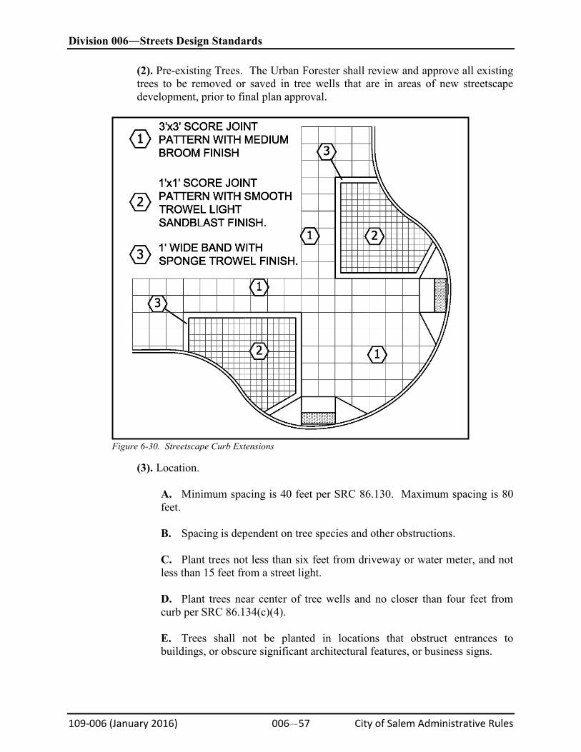
Division 006―Streets Design Standards
109-006 (January 2016) 006#57 City of Salem Administrative Rules
(2). Pre-existing Trees. The Urban Forester shall review and approve all existing trees to be removed or saved in tree wells that are in areas of new streetscape development, prior to final plan approval.
Figure 6-30. Streetscape Curb Extensions
(3). Location.
A. Minimum spacing is 40 feet per SRC 86.130. Maximum spacing is 80 feet.
B. Spacing is dependent on tree species and other obstructions.
C. Plant trees not less than six feet from driveway or water meter, and not less than 15 feet from a street light.
D. Plant trees near center of tree wells and no closer than four feet from curb per SRC 86.134(c)(4).
E. Trees shall not be planted in locations that obstruct entrances to buildings, or obscure significant architectural features, or business signs.
Division 006―Streets Design Standards
109-006 (January 2016) 006#58 City of Salem Administrative Rules
(4). Tree Wells
A. Tree wells shall be located to allow for compliance with all ADA requirements.
B. Tree wells shall contain pervious materials to provide drainage to the underlying soils.
C. No other facilities or added utilities shall be placed within the tree well.
D. Tree wells shall be located adjacent to back of curb, rectangular in shape, generally six-foot width (perpendicular to curb) by six-foot-long (parallel to curb) by 3.5-foot minimum depth of soil. Other shapes are not allowed.
E. Where necessary to work around obstacles, the tree wells shall be a minimum of 24 square feet of surface area with a minimum of six feet in one direction.
F. The outside edge of tree well shall be aligned with adjacent sidewalk scoring pattern.
G. The plans shall include a note stating that no tree well shall be dug or prepared until its location and size is approved by the Urban Forester.
H. The area between the soil surface and the top of the tree grate shall be filled with material in accordance with Standard No. 810.
I. Only pervious material shall be placed over the opening of the tree well.
J. Tree wells may be planted with groundcover. Such groundcover may be partially or totally trimmed, replaced, or removed as necessary to properly maintain the tree and ground cover. Tree grates shall not be removed to place ground cover.
(5). Tree Grates
A. Tree grates around trees are required, construct per Standard Plan 810.
B. Tree grates shall be manufactured of cast iron materials shall a have locking mechanism.
C. Tree grates must be level with the adjoining sidewalk or curb and not create a tripping hazard.
D. Tree grates need to be designed for the growth of the tree trunk, which may include removable sections to accommodate the growth.
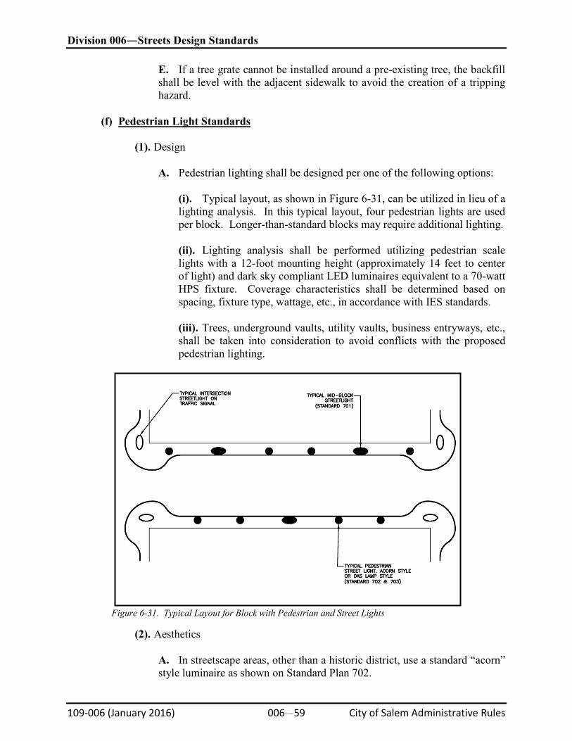
Division 006―Streets Design Standards
109-006 (January 2016) 006#59 City of Salem Administrative Rules
E. If a tree grate cannot be installed around a pre-existing tree, the backfill shall be level with the adjacent sidewalk to avoid the creation of a tripping hazard.
(f)
Pedestrian Light Standards
(1). Design
A. Pedestrian lighting shall be designed per one of the following options:
(i). Typical layout, as shown in Figure 6-31, can be utilized in lieu of a lighting analysis. In this typical layout, four pedestrian lights are used per block. Longer-than-standard blocks may require additional lighting.
(ii). Lighting analysis shall be performed utilizing pedestrian scale lights with a 12-foot mounting height (approximately 14 feet to center of light) and dark sky compliant LED luminaires equivalent to a 70-watt HPS fixture. Coverage characteristics shall be determined based on spacing, fixture type, wattage, etc., in accordance with IES standards.
(iii). Trees, underground vaults, utility vaults, business entryways, etc., shall be taken into consideration to avoid conflicts with the proposed pedestrian lighting.
Figure 6-31. Typical Layout for Block with Pedestrian and Street Lights
(2). Aesthetics
A. In streetscape areas, other than a historic district, use a standard “acorn” style luminaire as shown on Standard Plan 702.
Division 006―Streets Design Standards
109-006 (January 2016) 006#60 City of Salem Administrative Rules
B. In the historic district, which is within the streetscape area, use a standard “gas lamp” style luminaire as shown on Standard Plan 703.
C. Provide hanging basket bracket for 100-pound basket per the applicable Standard Plan.
D. Provide banner brackets for top of a banner per the applicable Standard Plan.
E. Pole and fixture color shall be in accordance with the applicable Standard Plan.
(3). Electrical Requirements
A. Provide 120v, 15 AMP ground fault interrupted (GFI) duplex electrical outlet(s) with weatherproof covers located in line with hand-hole, per applicable Standard Plan. A transformer may be required to adjust fixture voltage to outlet voltage.
B. Street light circuits can be with 220 single phase (2-110v to ground wires, plus a ground wire) or a 220v to ground wire with a ground wire, depending on the location and service provider (Salem Electric or Portland General Electric).
(g)
Street Lights
(1). See General Standards in Section 6.28–Street Lighting.
(2). Design.
A. Utilize street lights with a 30- to 36-foot mounting height and dark sky-compliant luminaires per Standard Plan 701.
B. Use LED equivalent cobra heads on mid-block lights.
C. Designers may follow the typical layout, as shown in Figure 6-30, in lieu of a lighting analysis. In this typical layout, two street lights are used per block. Longer-than-standard blocks may require additional lighting.
D. Poles shall be per Standard Plan 701.
(3). Electrical Requirements
A. Street light circuits shall be either 220 single phase (2–110v to ground wires, plus a ground wire) or a 220v to ground wire with a ground wire, depending on the location and service provider (Salem Electric or Portland General Electric).
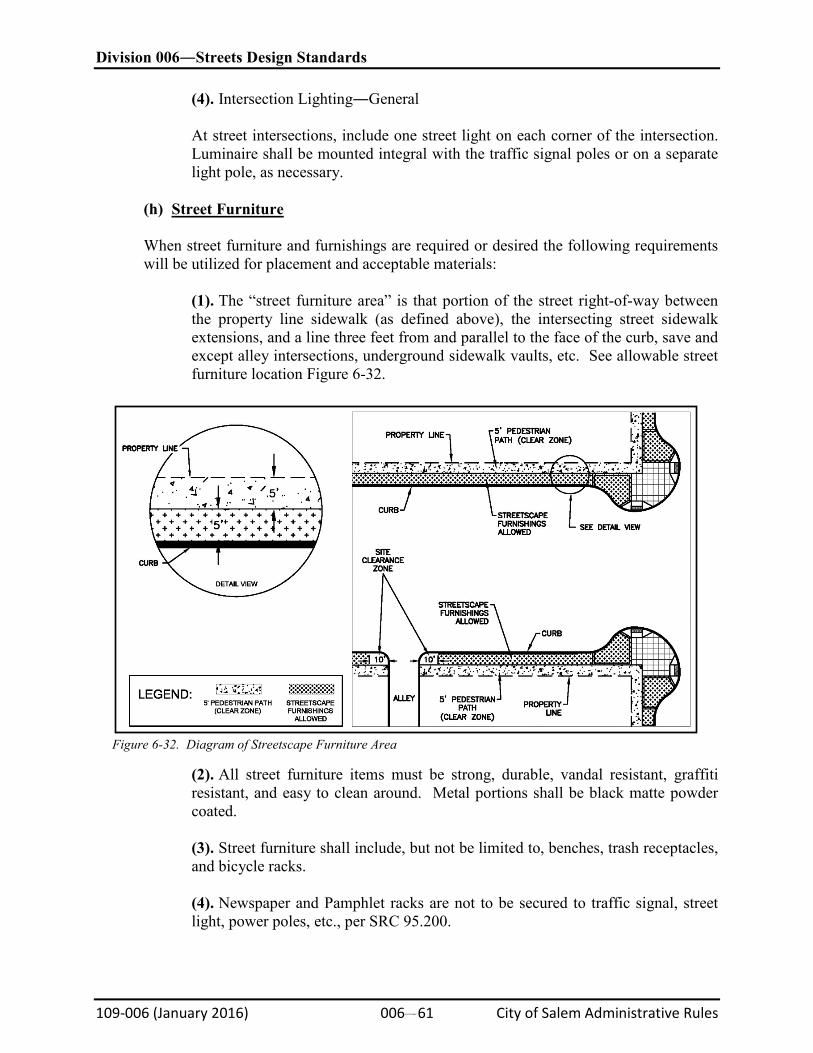
Division 006―Streets Design Standards
109-006 (January 2016) 006#61 City of Salem Administrative Rules
(4). Intersection Lighting―General
At street intersections, include one street light on each corner of the intersection. Luminaire shall be mounted integral with the traffic signal poles or on a separate light pole, as necessary.
(h)
Street Furniture
When street furniture and furnishings are required or desired the following requirements will be utilized for placement and acceptable materials:
(1). The “street furniture area” is that portion of the street right-of-way between the property line sidewalk (as defined above), the intersecting street sidewalk extensions, and a line three feet from and parallel to the face of the curb, save and except alley intersections, underground sidewalk vaults, etc. See allowable street furniture location Figure 6-32.
Figure 6-32. Diagram of Streetscape Furniture Area
(2). All street furniture items must be strong, durable, vandal resistant, graffiti resistant, and easy to clean around. Metal portions shall be black matte powder coated.
(3). Street furniture shall include, but not be limited to, benches, trash receptacles, and bicycle racks.
(4). Newspaper and Pamphlet racks are not to be secured to traffic signal, street light, power poles, etc., per SRC 95.200.